Embed Size (px)
Citation preview

Networking
Prof. Sirer
CS 4410
Cornell University

Ethernet
and
Local Area NetworkingLocal Area Networking

Ethernet
1976, Metcalfe & Boggs at Xerox� Later at 3COM
Based on the Aloha network in Hawaii� Named after the “luminiferous ether”
Centered around a broadcast busCentered around a broadcast bus
Can use different physical links
Simple link-level protocol, scales well
Simple algorithm for sharing the network well under load

Ethernet Goals
Connect local area networks� Few buildings, short distances (<1 km)
Inexpensively� Low infrastructure costs
Without bottlenecksWithout bottlenecks� No expensive routers, bridges, switches etc.
� No state in the network, no store-and-forward
Tremendously successful
Simple conceptual model still in use� Despite two orders of magnitude increase in bandwidth
“CSMA/CD”
Carrier sense
� Listen before you speak
Multiple access
Multiple hosts can access the network� Multiple hosts can access the network
Collision detect
� Detect and respond to cases where two hosts
collide

Ethernet basics
An ethernet packet
Destination Address
Type
Source Address
…Data…
Checksum

Sending packets
Carrier sense, broadcast if ether is available

Addressing & ARP
128.84.96.90128.84.96.89
128.84.96.91
ARP is used to discover physical addresses� ARP = Address Resolution Protocol
“What is the physical
address of the host
named
128.84.96.89”
128.84.96.91
“I’m at 1a:34:2c:9a:de:cc”

Addressing & DHCP
128.84.96.90
DHCP Server
???
128.84.96.91
DHCP is used to discover network addresses
“I just got here. My
physical address is
1a:34:2c:9a:de:cc.
What’s my IP?”
128.84.96.91
“Your IP is 128.84.96.89
for the next 24 hours”
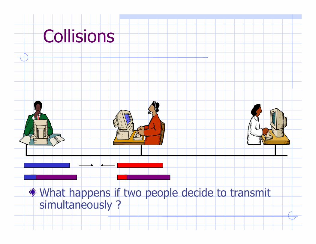
Collisions
What happens if two people decide to transmit simultaneously ?

Collision Detection &
RetransmissionThe hosts involved in the collision stop data transmission, sleep for a while, and attempt to retransmit
How long they sleep is determined by how many collisions have occurred beforecollisions have occurred before
They abort after 16 retries, hence no guarantee that a packet will get to its destination
Advantages:� Packet can be retransmitted at the link level immediately without high-level timeouts,
� Packets are truncated early to avoid wasting bandwidth
� Collision rates can be used to gauge net usage
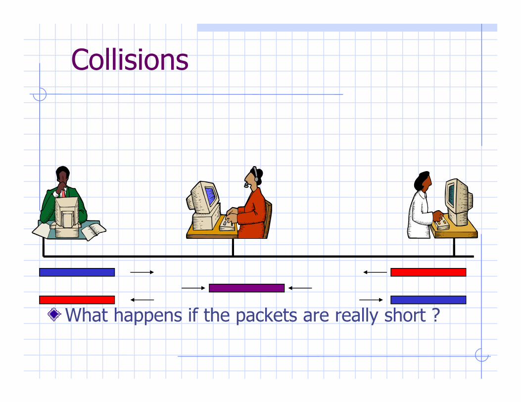
Collisions
What happens if the packets are really short ?
Odds & Ends
Minimum packet size is 64 bytes, which is
just right for the given length for all hosts
to detect a collision
Truncated packets are filtered out of the Truncated packets are filtered out of the
network
CRC is used to detect malformed packets,
e.g. electrical interference, noise

Ethernet Features
Completely distributed� No central arbiter
Inexpensive� No state in the network� No state in the network
� No arbiter
� Cheap physical links (twisted pair of wires)

Ethernet Problems
The endpoints are trusted to follow the collision-detect and retransmit protocol
� Certification process tries to assure compliance
� Not everyone always backs off exponentially
Hosts are trusted to only listen to packets Hosts are trusted to only listen to packets destined for them
� But the data is available for all to see
� Can place ethernet card in promiscuous mode and listen

Ethernet Lessons
Best-effort delivery simplifies network design
A simple, distributed protocol can tolerate failures and be easy to administertolerate failures and be easy to administer
Networking infrastructure represents a large sunk cost
� Best to keep it simple
� Interoperable
�Hard to upgrade means change occurs infrequently, when the gains are sizeable

Internet Structure & Protocols

Internetworking Origins
Expensive supercomputers scattered throughout
the US
Researchers scattered differently throughout the
USUS
Need way to connect researchers to expensive
machinery
Point-to-point connections might have sufficed

Point to point connections

Internetworking Origins
Department of Defense initiated studies on how
to build a resilient global network� How do you coordinate a nuclear attack ?
� Especially, how do you tell people to stop firing missiles during
a nuclear war ?a nuclear war ?
Interoperability and dynamic routing are a must� Along with a lot of other properties
Result: Internet
A complex system with simple components

Internet Overview
Every host is assigned, and identified by, an IP address
Each packet contains a header that specifies the destination address
The network routes the packets from the source The network routes the packets from the source to the destination
Question: What kinds of properties should the network provide?

Internet, The Big Picture
Routers
Endpoints

The Big Picture
Presentation
Application
Presentation
Application
Transport
Network
Data Link
Physical
Transport
Network
Data Link
Physical
Network
Data Link
Physical
Network
Data Link
Physical
Router1 Router2

End-to-End Example
Should the network guarantee packet delivery ?� Think about a file transfer program
� Read file from disk, send it, the receiver reads packets and writes them to the disk
If the network guaranteed packet delivery, one If the network guaranteed packet delivery, one might think that the applications would be simpler
� No need to worry about retransmits
� But still need to check that the file was written to the remote disk intact
A check is necessary if nodes can fail� Consequently, applications need to be written to perform their own retransmits
� No need to burden the internals of the network with properties that can, and must, be implemented at the periphery

End-to-End Argument
An Occam’s Razor for Internet architecture
Application-specific properties are best
provided by the applications, not the network� Guaranteed, or ordered, packet delivery, duplicate
suppression, security, etc.
The internet performs the simplest packet
routing and delivery service it can� Packets are sent on a best-effort basis
� Higher-level applications do the rest

Naming
Every host on the Internet is identified by an IP address
� For now, 32-bit descriptor, like a phone number
� Plans underway to change the underlying protocols to use longer addresses
� Plans underway to change the underlying protocols to use longer addresses
IP addresses are assigned to hosts by their internet service providers
� Not physical addresses: IP address does not identify a single node, can swap machines and reuse the same IP address
� Not entirely virtual: the IP address determines how packets get to you, and changes when you change your ISP
Need completely virtual names

DNS
Protocol for converting textual names to IP addresses
�www.cnn.com = 207.25.71.25
Namespace is hierarchical, i.e. a tree.
Names are separated by dots into components
Components are looked up from the right to the left

DNS Tree
“root”
edu milgovcom net
•All siblings must have
unique names
•Root is owned by ICANN
cornell mit
cs math ece arts
www falcon
•Lookup occurs from the
top down
•DNS stores arbitrary tuples
(resource records)
•The address field contains
the IP address, other fields
contain mail routing info,
owner info, etc.

DNS Lookup
1. the client asks its local nameserver
2. the local nameserver asks one of the root nameservers
3. the root nameserver replies with the 3. the root nameserver replies with the
address of the authoritative nameserver
4. the server then queries that nameserver
5. repeat until host is reached, cache result.

DNS Lessons
Simple, hierarchical namespace works well� Can name anything, can share names
Scales OK� Caching
� Even though it was meant to be hierarchical, people like short � Even though it was meant to be hierarchical, people like short names, and use it like a flat namespace
Arbitrary tuple database� Can delegate selected services to other hosts
No security!
Namespace = money� Innovations in this space are met with resistance from people who control name resolution

TCP/IP
Emin Gun Sirer

IP
Internetworking protocol� Network layer
Common packet format for the Internet� Specifies what packets look like
� Fragments long packets into shorter packets� Fragments long packets into shorter packets
� Reassembles fragments into original shape
Some parts are fundamental, and some are arbitrary
� IPv4 is what most people use
� IPv6 clears up some of the messy parts, but is not yet in wide use

IPv4 packet layout
Version IHL TOS Total LengthIdentification Flags Fragment Offset
TTL Protocol Header Checksum
Source Address
Destination Address
Options
Data

IPv4 packet layout
Version IHL TOS Total LengthIdentification Flags Fragment Offset
TTL Protocol Header Checksum
Source Address
Destination Address
Options
Data

IP Fragmentation
Networks have different maximum packet sizes� Big packets are sometimes desirable – less overhead
� Huge packets are not desirable – reduced response time for others
Higher level protocols (e.g. TCP or UDP) could Higher level protocols (e.g. TCP or UDP) could figure out the max transfer unit and chop data into smaller packets
� The endpoints do not necessarily know what the MTU is on the path
� The route can change underneath
Consequently, IP transparently fragments and reassembles packets

IP Fragmentation Mechanics
IP divides a long datagram into N smaller datagrams
Copies the header
Assigns a Fragment ID to each part
Sets the More Fragments bitSets the More Fragments bit
Receiving end puts the fragments together based on the new IP headers
Throws out fragments after a certain amount of time if they have not be reassembled

IP Options
Source Routing: The source specifies the set of hosts that the packet should traverse
Record Route: If this option appears in a packet, every router along a path attaches its packet, every router along a path attaches its own IP address to the packet
Timestamp: Every router along the route attaches a timestamp to the packet
Security: Packets are marked with user info, and the security classification of the person on whose behalf they travel on the network
� Most of these options pose security holes and are generally not implemented

UDP
Unreliable Datagram Protocol
IP goes from host to host
We need a way to get datagrams from one application to anotherapplication to another
How do we identify applications on the hosts ?
� Assign port numbers
� E.g. port 13 belongs to the time service
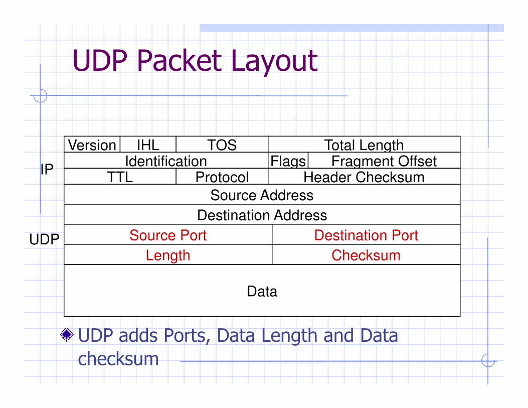
UDP Packet Layout
Version IHL TOS Total LengthIdentification Flags Fragment Offset
TTL Protocol Header Checksum
Source Address
IP
UDP adds Ports, Data Length and Data
checksum
Destination Address
Source Port
Data
Destination Port
Length ChecksumUDP

UDP
UDP is unreliable� A UDP packet may get dropped at any time
� It may get duplicated
� A series of UDP packets may get reordered
Applications need to deal with reordering, Applications need to deal with reordering, duplicate suppression, reliable delivery
� Some apps can ignore these effects and still function
Unreliable datagrams are the bare-bones network service
� Good to build on, esp for multimedia applications

TCP
Transmission Control Protocol� Reliable, ordered communication
Enough applications demand reliable ordered delivery that they should not have to implement their own protocoltheir own protocol
A standard, adaptive protocol that delivers good-enough performance and deals well with congestion
All web traffic travels over TCP/IP
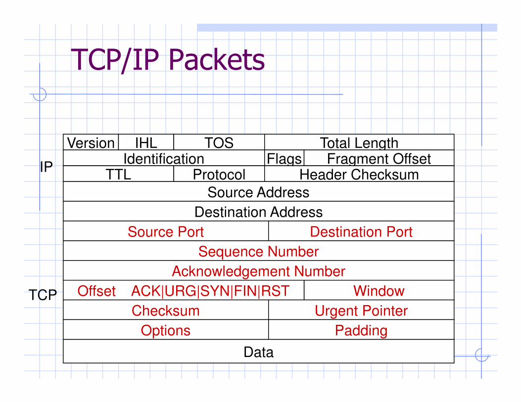
TCP/IP Packets
Version IHL TOS Total LengthIdentification Flags Fragment Offset
TTL Protocol Header Checksum
Source Address
IP
Destination Address
Source Port
Data
Destination Port
Sequence Number
Acknowledgement Number
TCP WindowOffset ACK|URG|SYN|FIN|RST
Checksum Urgent Pointer
Options Padding
TCP Packets
Each packet carries a unique ID� The initial number is chosen randomly
� The ID is incremented by the data length
Each packet carries an acknowledgementEach packet carries an acknowledgement� Can acknowledge a set of packets by ack’ing the
latest one received
Reliable transport is implemented using
these identifiers

TCP Connections
TCP is connectionoriented
A connection is initiated with a
SYN
initiated with a three-way handshake
Three-way handshake ensures against duplicate SYN packets
Takes 3 packets, 1.5 RTT
SYN, ACK of SYN
ACK of SYN

Typical TCP Usage
Three round-trips to set up
a connection, send a data
packet, receive a response,
tear down connection
SYN
SYN, ACK of SYN
ACK of SYN tear down connection
FINs work (mostly) like
SYNs to tear down
connection� Need to wait after a FIN for
straggling packets
ACK of SYN
DATA
DATA, ACK
FIN, ACKFIN, ACK

Reliable transport
TCP keeps a copy of all
sent, but unacknowledged
packets
If acknowledgement does
DATA, id=17
DATA 23, ACK 17If acknowledgement does
not arrive within a “send
timeout” period, packet is
resent
Send timeout adjusts to the
round-trip delay
DATA 23, ACK 17
DATA, id=18
DATA, id=18
Send timeout

TCP timeouts
What is a good timeout period ?� Want to improve throughput without unnecessary transmissions
Timeout is thus a function of RTT and deviation
NewAverageRTT = (1 - α) OldAverageRTT + α LatestRTT
NewAverageDev = (1 - α) OldAverageDev + α LatestDev
where LatestRTT = (ack_receive_time – send_time),
LatestDev = |LatestRTT – AverageRTT|,
α = 1/8, typically.
Timeout = AverageRTT + 4*AverageDev

TCP Windows
Multiple outstanding packets can increase throughput

TCP Windows
Can have more than one
packet in transit
Especially over fat pipes,
e.g. satellite connection
DATA, id=17DATA, id=18DATA, id=19DATA, id=20 e.g. satellite connection
Need to keep track of all
packets within the window
Need to adjust window size
DATA, id=20
ACK 17
ACK 18
ACK 19
ACK 20

TCP Congestion Control
TCP Increases its window size as long as no packets are dropped
It halves the window size when a packet drop occurs
� A packet drop is evident from the acknowledgements� A packet drop is evident from the acknowledgements
Therefore, it will slowly build up to the max bandwidth, and hover around the max
� It doesn’t achieve the max possible though
� Instead, it shares the bandwidth well with other TCP connections
This linear-increase, exponential backoff in the face of congestion is termed TCP-friendliness

TCP Window Size
Linear increase
Exponential backoffMax Bandwidth
Assuming no other losses in the network except those due to bandwidth
Time
Ba
nd
wid
th

TCP Fairness
Want to
share the
bottleneck
Ba
nd
wid
th fo
r H
ost A
B
A
Bottleneck
Link
D
bottleneck
link fairly
between two
flows
Bandwidth for Host B
Ba
nd
wid
th fo
r H
ost A

TCP Slow Start
Linear increase takes a long time to build up a window size that matches the link bandwidth*delay
Most file transactions are not long enough
Consequently, TCP can spend a lot of time with Consequently, TCP can spend a lot of time with small windows, never getting the chance to reach a sufficiently large window size
Fix: Allow TCP to build up to a large window size initially by doubling the window size until first loss

TCP Slow Start
Initial phase of exponential increaseMax Bandwidth
Assuming no other losses in the network except those due to bandwidth
Time
Ba
nd
wid
th

TCP Summary
Reliable ordered message delivery� Connection oriented, 3-way handshake
Transmission window for better throughput� Timeouts based on link parameters� Timeouts based on link parameters
Congestion control� Linear increase, exponential backoff
Fast adaptation� Exponential increase in the initial phase
Routing
Emin Gun Sirer

Challenge
Need to discover and maintain paths through the network between communicating endpoints
Metrics of importance� Latency
Bandwidth� Bandwidth
� Packet Overhead (“Goodput”)
� Jitter
� Memory space per node
� Computational overhead per node

Domains
Wired networks� Stable, administered, lots of infrastructure
� E.g. the Internet
Wireless networksWireless, dynamic, self-organizing� Wireless, dynamic, self-organizing
� Infrastructure-based wireless networks� A.k.a. cell-based, access-point-based
� E.g. Cornell’s “rover”
� Infrastructure-less wireless networks� A.k.a. ad hoc
� E.g. the 414/415 ad hoc network

Classification
Route discovery and dissemination
� Proactive vs. reactive
Route selection and usage
Single path vs. multipath� Single path vs. multipath

Model
A graph G(V,E), where vertices represent routers,
edges represent available links
� Assume a unity weight associated with each link
Centralized algorithms for finding suitable routes Centralized algorithms for finding suitable routes
are straightforward
� All pairs shortest paths
� Need distributed algorithms

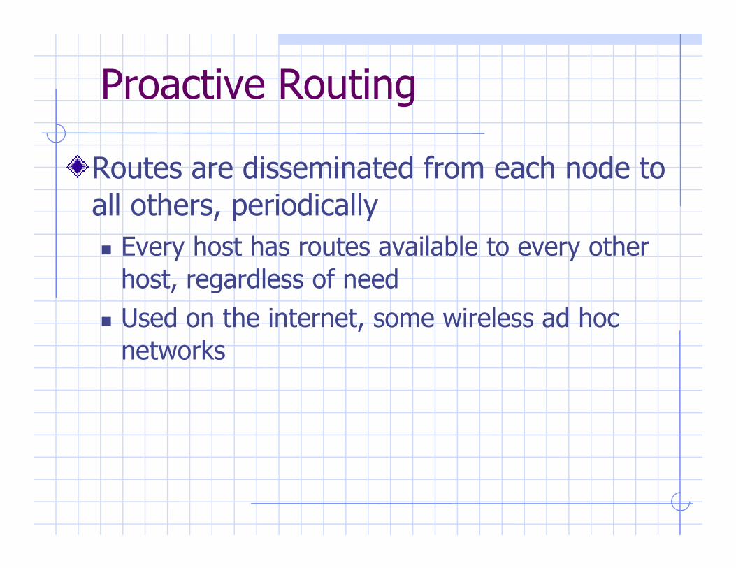
Proactive Routing
Routes are disseminated from each node to
all others, periodically
� Every host has routes available to every other
host, regardless of needhost, regardless of need
� Used on the internet, some wireless ad hoc
networks
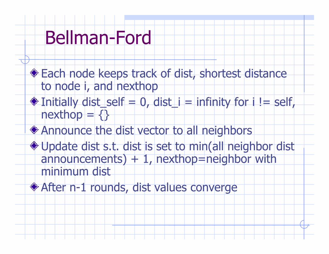
Bellman-Ford
Each node keeps track of dist, shortest distance to node i, and nexthop
Initially dist_self = 0, dist_i = infinity for i != self, nexthop = {}
Announce the dist vector to all neighborsAnnounce the dist vector to all neighbors
Update dist s.t. dist is set to min(all neighbor dist announcements) + 1, nexthop=neighbor with minimum dist
After n-1 rounds, dist values converge

Proactive Routing
Pros
� Route discovery latency is very low
Cons
O(N) state in every router� O(N) state in every router
� Constant background communication
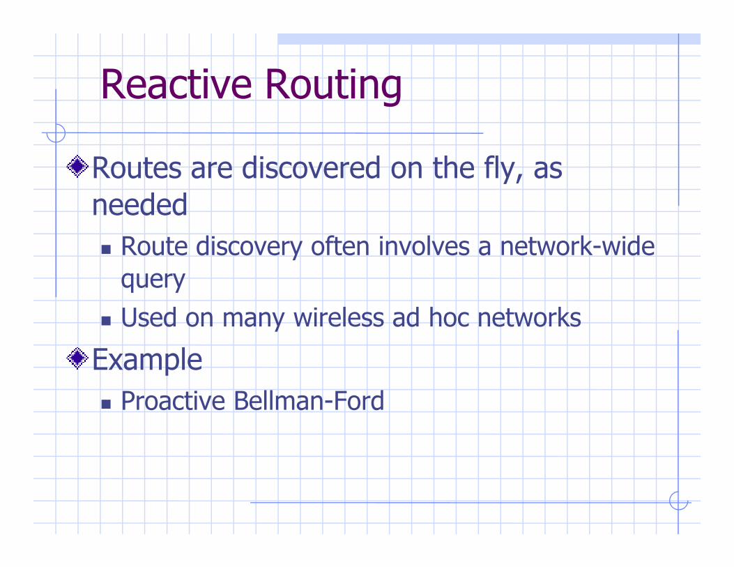
Reactive Routing
Routes are discovered on the fly, as
needed
� Route discovery often involves a network-wide
queryquery
� Used on many wireless ad hoc networks
Example
� Proactive Bellman-Ford

DSR
� Source routing
AODV
Ad hoc on demand distance vector� Ad hoc on demand distance vector

Reactive Routing
Pros
� State proportional to # of used routes
� Communication proportional to # of used
routes and failure rateroutes and failure rate
Cons
� Route discovery latency is high
� Jitter (variance of packet interarrival times) is
high
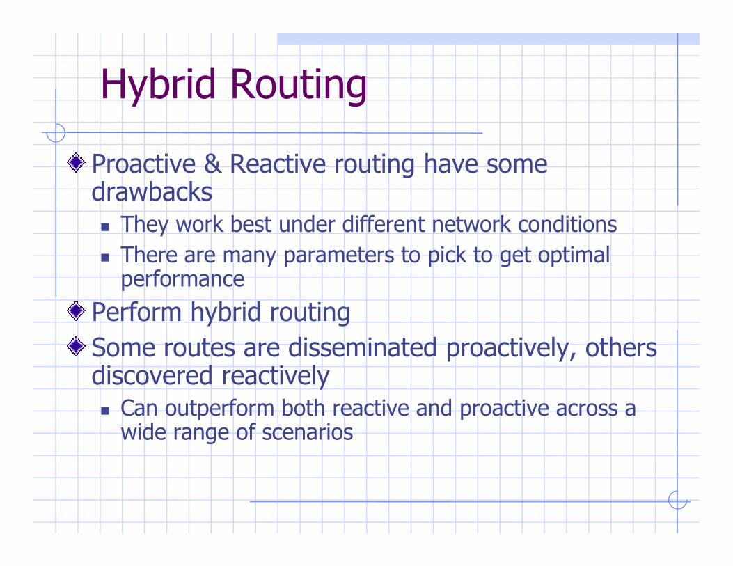
Hybrid Routing
Proactive & Reactive routing have some drawbacks� They work best under different network conditions
� There are many parameters to pick to get optimal performanceperformance
Perform hybrid routing
Some routes are disseminated proactively, others discovered reactively � Can outperform both reactive and proactive across a wide range of scenarios

Remote Procedure Call

Clients and Servers
A common model for structuring distributed computation is via the
client/server paradigm
A server is a program (or collection of programs) that provide some
service, e.g., file service, name service, …
The server may exist on one or more nodes.
A client is a program that uses the service.
10/20/2010 70
A client is a program that uses the service.
A client first binds to the server, I.e., locates it in the network and establishes a connection.
The client then sends requests to perform actions; this is done by
sending messages that indicate which service is desired, along with
params. The server returns a response.

The Problem with Messages
While messages provide very flexible communication, they
also have certain problems:
� requires that programmer worry about message formats
� messages must be packed and unpacked
� messages have to be decoded by server to figure out what is
10/20/2010 71
� messages have to be decoded by server to figure out what is
requested
� messages are often asynchronous
� they may require special error handling functions
Basically, messages are not a natural programming model
for most programmers.

Procedure Call
A more natural way to communicate is through procedure call:
� every language supports it
� semantics are well defined and understood
� natural for programmers to use
Basic idea: let’s just define a server as a module that exports a set of procedures that can be called by client programs.
10/20/2010 72
procedures that can be called by client programs.
To use the server, the client just does a procedure call, as if it were
linked with the servercall
return
Client Server
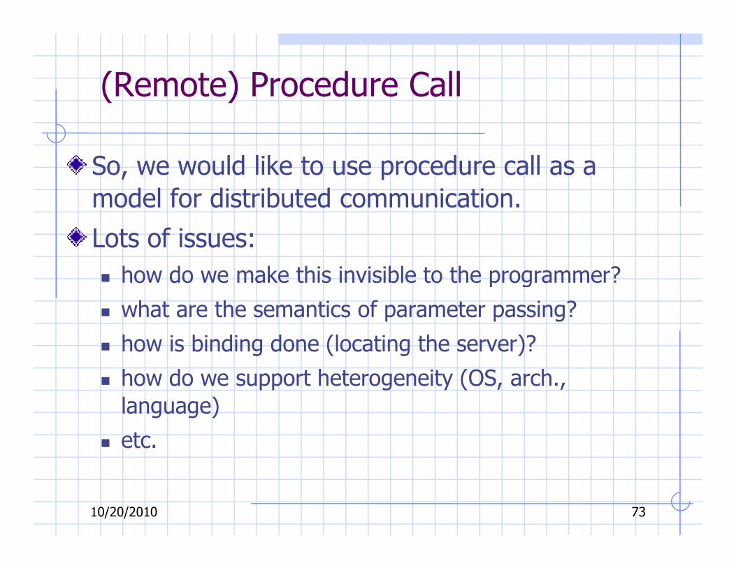
(Remote) Procedure Call
So, we would like to use procedure call as a
model for distributed communication.
Lots of issues:
� how do we make this invisible to the programmer?
10/20/2010 73
� how do we make this invisible to the programmer?
� what are the semantics of parameter passing?
� how is binding done (locating the server)?
� how do we support heterogeneity (OS, arch.,
language)
� etc.

Remote Procedure Call
The basic model for Remote Procedure Call (RPC) was
described by Birrell and Nelson in 1980, based on work
done at Xerox PARC.
Goals was to make RPC look as much like local PC as
possible.
10/20/2010 74
possible.
Used computer/language support.
There are 3 components on each side:
� a user program (client or server)
� a set of stub procedures
� RPC runtime support

RPC
Basic process for building a server:
� Server program defines the server’s interface using an interface definition language (IDL)
� The IDL specifies the names, parameters, and types for all client-
callable server procedures
10/20/2010 75
� A stub compiler reads the IDL and produces two stub procedures for each server procedure: a client-side stub and a server-side
stub
� The server writer writes the server and links it with the server-side
stubs; the client writes her program and links it with the client-
side stubs.
� The stubs are responsible for managing all details of the remote
communication between client and server.

RPC Stubs
Basically, a client-side stub is a procedure that looks to
the client as if it were a callable server procedure.
A server-side stub looks to the server as if it’s a calling
client.
The client program thinks it is calling the server; in fact,
10/20/2010 76
The client program thinks it is calling the server; in fact,
it’s calling the client stub.
The server program thinks it’s called by the client; in fact,
it’s called by the server stub.
The stubs send messages to each other to make the RPC
happen.

RPC Call Structure
call foo(x,y)proc foo(a,b)
begin foo...
end foo
clientprogram server
programclient makeslocal call tostub proc.
server iscalled byits stub
call foo call foo
10/20/2010 77
proc foo(a,b) call foo(x,y)clientstub
RPCruntime RPC
runtime
serverstub
Call
stub builds msgpacket, insertsparams
runtime sendsmsg to remotenode
stub unpacksparams andmakes call
runtimereceives msgand calls stub
send msg msg received

RPC Return Structure
call foo(x,y)proc foo(a,b)
begin foo...
end foo
clientprogram server
programclient continues server procreturns
stub builds
return return
10/20/2010 78
proc foo(a,b) call foo(x,y)clientstub
RPCruntime RPC
runtime
serverstub
return
stub unpacksmsg, returns to caller
runtimereceives msg, calls stub
stub buildsresult msgwith outputargs
runtime respondsto originalmsg
msg received send msg

RPC Binding
Binding is the process of connecting the client and server
The server, when it starts up, exports its interface, identifying itself to a network name server and telling the
local runtime its dispatcher address.
The client, before issuing any calls, imports the server,
10/20/2010 79
The client, before issuing any calls, imports the server, which causes the RPC runtime to lookup the server
through the name service and contact the requested
server to setup a connection.
The import and export are explicit calls in the code.

RPC Marshalling
Marshalling is the packing of procedure parameters into a
message packet.
The RPC stubs call type-specific procedures to marshall
(or unmarshall) all of the parameters to the call.
On the client side, the client stub marshalls the
10/20/2010 80
On the client side, the client stub marshalls the
parameters into the call packet; on the server side the
server stub unmarshalls the parameters in order to call
the server’s procedure.
On the return, the server stub marshalls return
parameters into the return packet; the client stub
unmarshalls return parameters and returns to the client.
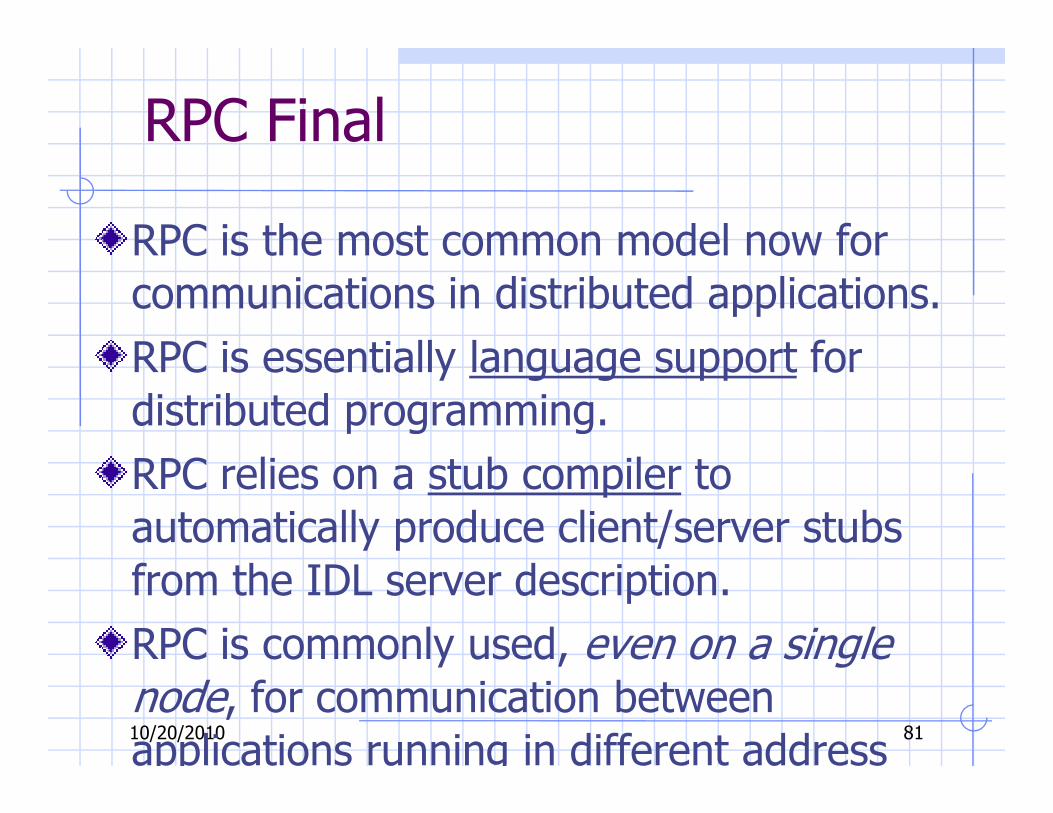
RPC Final
RPC is the most common model now for
communications in distributed applications.
RPC is essentially language support for
distributed programming.
10/20/2010 81
distributed programming.
RPC relies on a stub compiler to
automatically produce client/server stubs
from the IDL server description.
RPC is commonly used, even on a single node, for communication between
applications running in different address