Embed Size (px)
Citation preview
Waspmote 802.15.4 Networking Guide
-2- v7.1
Index
Document Version: v7.1 - 07/2017© Libelium Comunicaciones Distribuidas S.L.
INDEX1. Introduction ..........................................................................................................................4
2. Hardware ...............................................................................................................................52.1. Specifications ..................................................................................................................................... 52.2. How to connect the module ............................................................................................................ 72.3. Expansion Radio Board (Xbee 802.15.4) ........................................................................................ 8
3. General Considerations ......................................................................................................103.1. Waspmote Libraries ........................................................................................................................ 10
3.1.1. Waspmote XBee files ..........................................................................................................103.1.2. Constructor ..........................................................................................................................10
3.2. API functions .................................................................................................................................... 103.3. API extension ................................................................................................................................... 123.4. Waspmote reboot ........................................................................................................................... 123.5. Constants pre-defined .................................................................................................................... 12
4. Initialization ........................................................................................................................134.1. Setting on ......................................................................................................................................... 134.2. Setting off ......................................................................................................................................... 13
5. Node parameters ................................................................................................................145.1. MAC address .................................................................................................................................... 145.2. Network address ............................................................................................................................. 155.3. PAN ID .............................................................................................................................................. 155.4. Node identifier ................................................................................................................................ 155.5. Channel ............................................................................................................................................ 16
6. Power gain and sensitivity ................................................................................................176.1. Power level ....................................................................................................................................... 176.2. Received Signal Strength Indicator ............................................................................................... 18
7. Radio channels ....................................................................................................................197.1. Scan channels .................................................................................................................................. 197.2. Energy scan ...................................................................................................................................... 197.3. Random delay .................................................................................................................................. 207.4. CCA threshold .................................................................................................................................. 217.5. CCA failures ...................................................................................................................................... 217.6. ACK failures ...................................................................................................................................... 217.7. Retries ............................................................................................................................................... 22
-3- v7.1
Index
8. Networking methods .........................................................................................................238.1. Topology ........................................................................................................................................... 238.2. Addressing ....................................................................................................................................... 238.3. Maximum payloads ........................................................................................................................ 248.4. Sending data .................................................................................................................................... 24
8.4.1. Using Waspmote Frame .....................................................................................................248.4.2. Sending function .................................................................................................................248.4.3. Examples ..............................................................................................................................25
8.5. Receiving data ................................................................................................................................. 268.5.1. Receiving function ...............................................................................................................268.5.2. Examples .............................................................................................................................27
8.6. 802.15.4 compliance ....................................................................................................................... 27
9. Node Discovery ...................................................................................................................289.1. Structure used in Node Discovery ............................................................................................... 289.2. Searching specific nodes ................................................................................................................ 299.3. Node discovery to a specific node ............................................................................................... 299.4. Node Discovery Time ..................................................................................................................... 299.5. Node Discover options .................................................................................................................. 309.6. Questions related to discovering nodes ..................................................................................... 30
10. Sleep options .....................................................................................................................3110.1. Sleep Mode .................................................................................................................................... 3110.2. Pin Hibernate Mode...................................................................................................................... 3110.3. Pin Doze Mode .............................................................................................................................. 32
11. Security and data encryption ..........................................................................................3311.1. IEEE 802.15.4 security and data encryption overview .............................................................. 3311.2. Security in API libraries ................................................................................................................ 33
11.2.1. Encryption enable .............................................................................................................3311.2.2. Encryption key ...................................................................................................................34
11.3. Security in a network ................................................................................................................... 34
12. Certifications .....................................................................................................................35
13. Code examples and extended information ...................................................................36
14. API changelog ....................................................................................................................37
15. Documentation changelog ..............................................................................................38
-4- v7.1
Introduction
1. IntroductionThis guide explains the XBee 802.15.4 features and functions. There are no great variations in this library for our new product lines Waspmote v15 and Plug & Sense! v15, released on October 2016.
Anyway, if you are using previous versions of our products, please use the corresponding guides, available on our Development website.
You can get more information about the generation change on the document “New generation of Libelium product lines”.
Important:
• All documents and any examples they contain are provided as-is and are subject to change without notice. Except to the extent prohibited by law, Libelium makes no express or implied representation or warranty of any kind with regard to the documents, and specifically disclaims the implied warranties and conditions of merchantability and fitness for a particular purpose.
• The information on Libelium’s websites has been included in good faith for general informational purposes only. It should not be relied upon for any specific purpose and no representation or warranty is given as to its accuracy or completeness.
-5- v7.1
Hardware
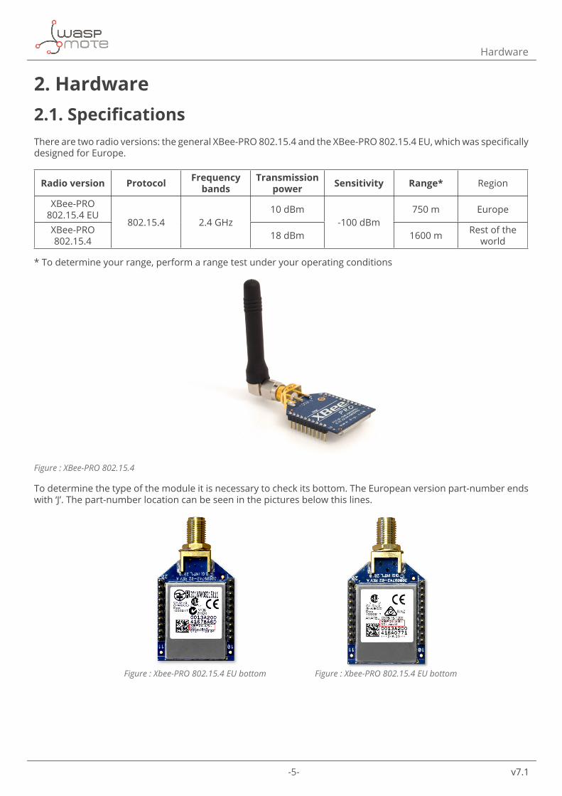
2. Hardware2.1. SpecificationsThere are two radio versions: the general XBee-PRO 802.15.4 and the XBee-PRO 802.15.4 EU, which was specifically designed for Europe.
Radio version Protocol Frequency bands
Transmission power Sensitivity Range* Region
XBee-PRO 802.15.4 EU
802.15.4 2.4 GHz10 dBm
-100 dBm750 m Europe
XBee-PRO 802.15.4 18 dBm 1600 m Rest of the
world
* To determine your range, perform a range test under your operating conditions
Figure : XBee-PRO 802.15.4
To determine the type of the module it is necessary to check its bottom. The European version part-number ends with ‘J’. The part-number location can be seen in the pictures below this lines.
Figure : Xbee-PRO 802.15.4 EU bottom Figure : Xbee-PRO 802.15.4 EU bottom
-6- v7.1
Hardware
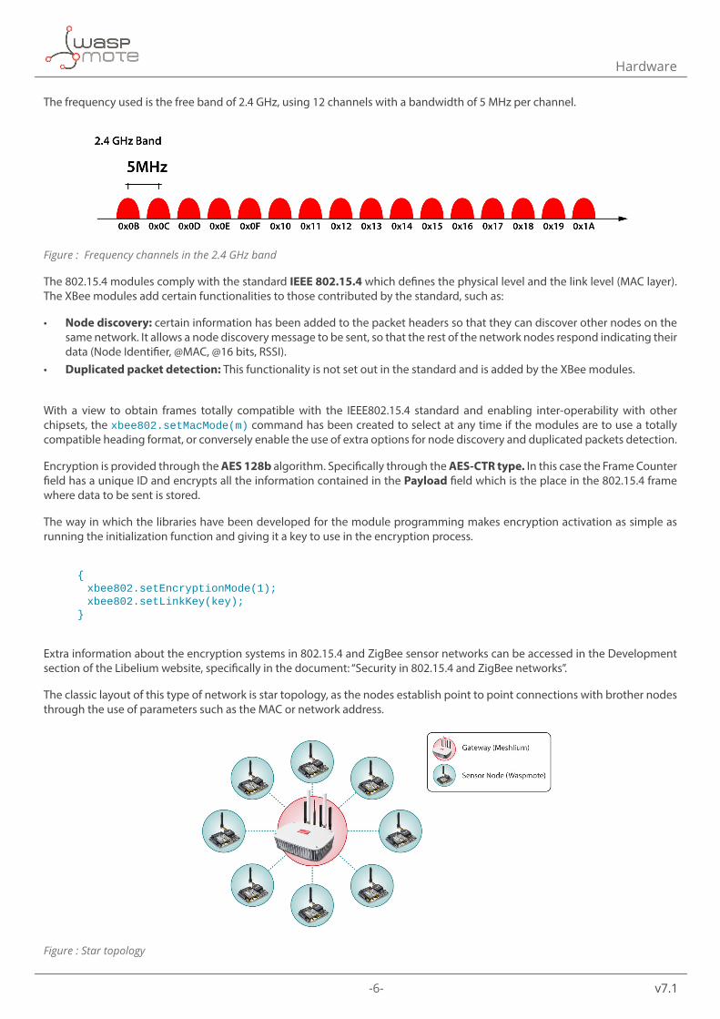
The frequency used is the free band of 2.4 GHz, using 12 channels with a bandwidth of 5 MHz per channel.
Figure : Frequency channels in the 2.4 GHz band
The 802.15.4 modules comply with the standard IEEE 802.15.4 which defines the physical level and the link level (MAC layer). The XBee modules add certain functionalities to those contributed by the standard, such as:
• Node discovery: certain information has been added to the packet headers so that they can discover other nodes on the same network. It allows a node discovery message to be sent, so that the rest of the network nodes respond indicating their data (Node Identifier, @MAC, @16 bits, RSSI).
• Duplicated packet detection: This functionality is not set out in the standard and is added by the XBee modules.
With a view to obtain frames totally compatible with the IEEE802.15.4 standard and enabling inter-operability with other chipsets, the xbee802.setMacMode(m) command has been created to select at any time if the modules are to use a totally compatible heading format, or conversely enable the use of extra options for node discovery and duplicated packets detection.
Encryption is provided through the AES 128b algorithm. Specifically through the AES-CTR type. In this case the Frame Counter field has a unique ID and encrypts all the information contained in the Payload field which is the place in the 802.15.4 frame where data to be sent is stored.
The way in which the libraries have been developed for the module programming makes encryption activation as simple as running the initialization function and giving it a key to use in the encryption process.
{ xbee802.setEncryptionMode(1); xbee802.setLinkKey(key); }
Extra information about the encryption systems in 802.15.4 and ZigBee sensor networks can be accessed in the Development section of the Libelium website, specifically in the document: “Security in 802.15.4 and ZigBee networks”.
The classic layout of this type of network is star topology, as the nodes establish point to point connections with brother nodes through the use of parameters such as the MAC or network address.
Figure : Star topology
-7- v7.1
Hardware
Regarding the energy section, the transmission power can be adjusted to several values:
Parameter XBee-PRO 802.15.4 XBee-PRO 802.15.4 EU
0 10 dBm -3 dBm1 12 dBm -3 dBm2 14 dBm 2 dBm3 16 dBm 8 dBm4 18 dBm 10 dBm
Figure : Transmission power values
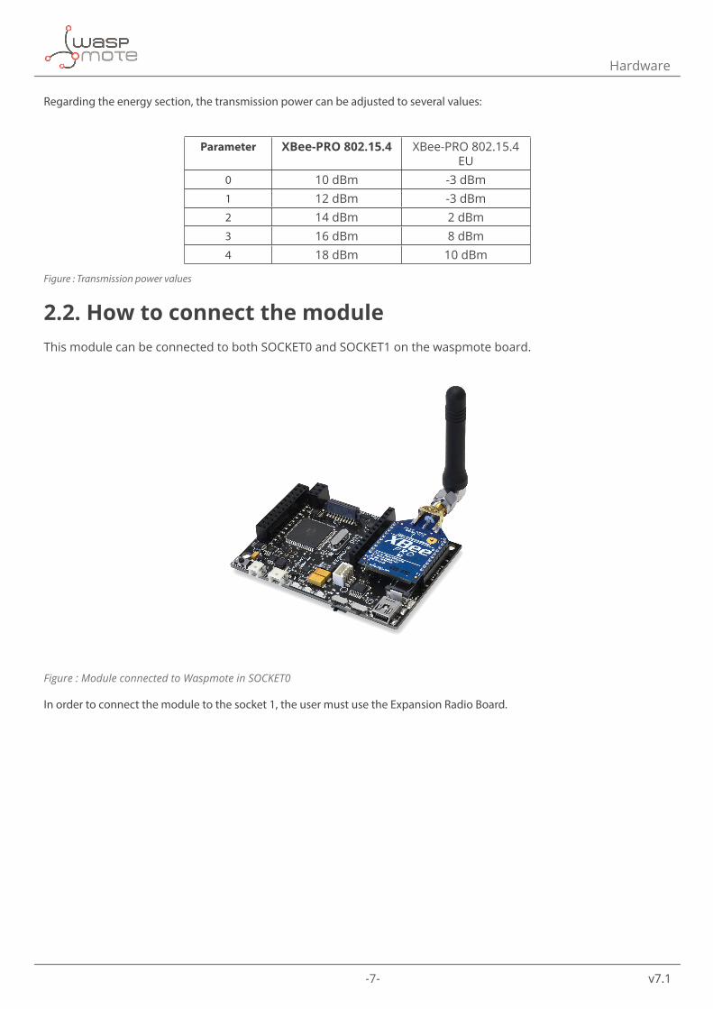
2.2. How to connect the moduleThis module can be connected to both SOCKET0 and SOCKET1 on the waspmote board.
Figure : Module connected to Waspmote in SOCKET0
In order to connect the module to the socket 1, the user must use the Expansion Radio Board.
-8- v7.1
Hardware
2.3. Expansion Radio Board (Xbee 802.15.4)The Expansion Board allows to connect two communication modules at the same time in the Waspmote sensor platform. This means a lot of different combinations are possible using any of the wireless radios available for Waspmote: 802.15.4, ZigBee, DigiMesh, 868 MHz, 900 MHz, LoRa, WiFi, GPRS, GPRS+GPS, 3G, 4G, Sigfox, LoRaWAN, Bluetooth Pro, Bluetooth Low Energy and RFID/NFC. Besides, the following Industrial Protocols modules are available: RS-485/Modbus, RS-232 Serial/Modbus and CAN Bus. Some of the possible combinations are:
• LoRaWAN - GPRS • 802.15.4 - Sigfox • 868 MHz - RS-485 • RS-232 - WiFi • DigiMesh - 4G • RS-232 - RFID/NFC • WiFi - 3G • CAN Bus - Bluetooth • etc.
Remark: GPRS, GPRS+GPS, 3G and 4G modules do not need the Expansion Board to be connected to Waspmote. They can be plugged directly in the socket1.
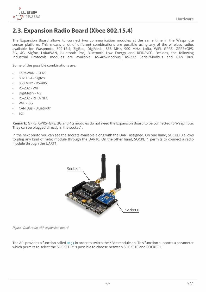
In the next photo you can see the sockets available along with the UART assigned. On one hand, SOCKET0 allows to plug any kind of radio module through the UART0. On the other hand, SOCKET1 permits to connect a radio module through the UART1.
Figure : Dual radio with expansion board
The API provides a function called ON() in order to switch the XBee module on. This function supports a parameter which permits to select the SOCKET. It is possible to choose between SOCKET0 and SOCKET1.
-9- v7.1
Hardware
Selecting SOCKET0 (both are valid):
xbee802.ON();
xbee802.ON(SOCKET0);
Selecting SOCKET1:
xbee802.ON(SOCKET1);
In the case two XBee-802.15.4 modules are needed (each one in each socket), it will be necessary to create a new object from WaspXBee802 class. By default, there is already an object called xbee802 normally used for regular SOCKET0.
In order to create a new object it is necessary to put the following declaration in your Waspmote code:
WaspXBee802 xbee802_2 = WaspXBee802();
Finally, it is necessary to initialize both modules. For example, xbee802 is initialized in SOCKET0 and xbee802_2 in SOCKET1 as follows:
xbee802.ON(SOCKET0);
xbee802_2.ON(SOCKET1);
The rest of functions are used the same way as they are used with older API versions. In order to understand them we recommend to read this guide.
Warnings:
• Avoid to use DIGITAL7 pin when working with the Expansion Board. This pin is used for setting the XBee into sleep mode.
• Avoid to use DIGITAL6 pin when working with the Expansion Board. This pin is used as power supply for the Expansion Board.
• Incompatibility with Sensor Boards: - Agriculture v30 and Agriculture PRO v30: Incompatible with Watermark and solar radiation sensors - Events v30: Incompatible with interruption shift register - Gases v30: DIGITAL6 is incompatible with CO2 (SOCKET_2) and DIGITAL7 is incompatible with NO2
(SOCKET_3) - Smart Water v30: DIGITAL7 incompatible with conductivity sensor - Smart Water Ions v30: Incompatible with ADC conversion (sensors cannot be read if the Expansion Board
is in use) - Gases PRO v30: Incompatible with SOCKET_2 and SOCKET_3 - Cities PRO v30: Incompatible with SOCKET_3. I2C bus can be used. No gas sensor can be used.
-10- v7.1
General Considerations
3. General Considerations3.1. Waspmote Libraries3.1.1. Waspmote XBee files
WaspXBeeCore.h, WaspXBeeCore.cpp, WaspXBee802.h, WaspXBee802.cpp
It is mandatory to include the XBee802 library when using this module. The following line must be introduced at the beginning of the code:
#include <WaspXBee802.h>
3.1.2. Constructor
To start using the Waspmote XBee library, an object from class ‘WaspXBee802’ must be created. This object, called xbee802, is created inside the Waspmote XBee library and it is public to all libraries. It is used through the guide to show how the Waspmote XBee library works.
When creating this constructor, some variables are defined with a value by default.
3.2. API functionsThrough the guide there are many examples of using parameters. In these examples, API functions are called to execute the commands, storing in their related variables the parameter value in each case.
Example of use:{ xbee802.getOwnMacLow(); // Get 32 lower bits of MAC Address xbee802.getOwnMacHigh(); // Get 32 upper bits of MAC Address}
Related variables:
xbee802.sourceMacHigh[0-3] → stores the 32 upper bits of MAC address xbee802.sourceMacLow [0-3] → stores the 32 lower bits of MAC address
-11- v7.1
General Considerations
When returning from xbee802.getOwnMacLow() the related variable xbee802.sourceMacLow will be filled with the appropriate values. Before calling the function, the related variable is created but it is empty or with a default value.
There are three error flags that are filled when the function is executed:
• error_AT: it stores if some error occurred during the execution of an AT command function • error_RX: it stores if some error occurred during the reception of a packet • error_TX: it stores if some error occurred during the transmission of a packet
All the functions also return a flag to know if the function called was successful or not. Available values for this flag:
• 0 : Success. The function was executed without errors and the exposed variable was filled. • 1 : Error. The function was executed but an error occurred while executing. • 2 : Not executed. An error occurred before executing the function. • -1 : Function not allowed in this module.
To store parameter changes after power cycles, it is needed to execute the writeValues() function.
Example of use:{ xbee802.writeValues(); // Keep values after power down
}
-12- v7.1
General Considerations
3.3. API extensionAll the relevant and useful functions have been included in the Waspmote API, although any XBee command can be sent directly to the transceiver.
Example of use:
{ xbee802.sendCommandAT(“CH#”); // Executes command ATCH}
Related variables:
xbee802.commandAT[0-100] → stores the response given by the module up to 100 bytes
Sending AT commands example:
http://www.libelium.com/development/waspmote/examples/802-12-send-atcommand
3.4. Waspmote rebootWhen Waspmote is rebooted the application code will start again, creating all the variables and objects from the beginning.
3.5. Constants pre-definedThere are some constants pre-defined in a file called ‘WaspXBeeCore.h’. These constants define some parameters like the maximum data size. The most important constants are explained next:
• MAX_DATA: (default value is 300) it defines the maximum available data size for a packet. This constant must be equal or bigger than the data is sent on each packet. This size shouldn’t be bigger than 1500.
• MAX_PARSE: (default value is 300) it defines the maximum data that is parsed in each call to treatData(). If more data are received, they will be stored in the UART buffer until the next call to treatData(). However, if the UART buffer is full, the following data will be written on the buffer, so be careful with this matter.
• MAX_BROTHERS: (default value is 5) it defines the maximum number of brothers that can be stored.
-13- v7.1
Initialization
4. InitializationBefore starting to use a module, it needs to be initialized. During this process, the UART to communicate with the module has to be opened and the XBee switch has to be set on.
4.1. Setting onThe ON() function initializes all the global variables, opens the correspondent UART and switches the XBee ON. The baud rate used to open the UART is defined on the library (115200 bps by default). It returns nothing.
The initialized variables are:
• protocol: specifies the protocol used (802.15.4 in this case). • pos: specifies the position to use in received packets. • discoveryOptions: specifies the options in Node Discovery. • awakeTime: specifies the time to be awake before go sleeping. • sleepTime: specifies the time to be sleeping. • scanChannels: specifies the channels to scan. • scanTime: specifies the time to scan each channel. • encryptMode: specifies if encryption mode is enabled. • powerLevel: specifies the power transmission level. • timeRSSI: specifies the time RSSI LEDs are on. • sleepOptions: specifies the options for sleeping. • retries: specifies the number of retries to execute in addition to the three retries defined in the 802.15.4 protocol. • delaySlots: specifies the minimum value of the back-off exponent in CSMA/CA. • macMode: specifies the Mac Mode used. • energyThreshold: specifies the energy threshold used to determine if the channel is free. • counterCCA: specifies the number of times too much energy was found in the channel. • counterACK: specifies the number of times an ACK was lost.
Example of use:
{ xbee802.ON();}
4.2. Setting offThe OFF() function closes the UART and switches the XBee OFF.
Example of use:
{ xbee802.OFF();}
-14- v7.1
Node parameters
5. Node parametersWhen configuring a node, it is necessary to set some parameters which will be used lately in the network, and some parameters necessary for using the API functions.
5.1. MAC addressA 64-bit RF module’s unique IEEE address. It is divided in two groups of 32 bits (High and Low).
It identifies uniquely a node inside a network due to it can not be modified and it is given by the manufacturer. It is used in 64-bit unicast transmissions.
Example of use:
{ xbee802.getOwnMacLow(); // Get 32 lower bits of MAC Address xbee802.getOwnMacHigh(); // Get 32 upper bits of MAC Address}
Related variables:
xbee802.sourceMacHigh[0-3]→ stores the 32 upper bits of MAC address xbee802.sourceMacLow [0-3]→ stores the 32 lower bits of MAC address
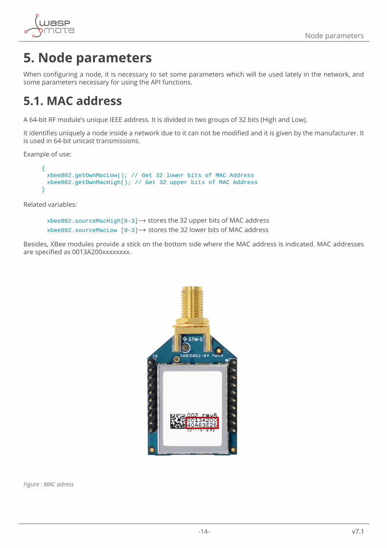
Besides, XBee modules provide a stick on the bottom side where the MAC address is indicated. MAC addresses are specified as 0013A200xxxxxxxx.
Figure : MAC adress
-15- v7.1
Node parameters
5.2. Network addressA 16-bit Network Address. It identifies a node inside a network, it can be modified at running time. It is used to send data to a node in 16-bit unicast transmissions.
Example of use:
{ xbee802.setOwnNetAddress(0x12,0x34); xbee802.getOwnNetAddress();}
Related variables:
xbee802.sourceNA[0-1] → stores the 16-bit network address
5.3. PAN ID16-bit number that identifies the network. It must be unique to differentiate a network. All the nodes in the same network should have the same PAN ID.
Example of use:
{ uint8_t panid[2]={0x33,0x31}; xbee802.setPAN(panid); xbee802.getPAN(); }
Related variables:
xbee802.PAN_ID[0-1] → stores the PAN ID
• XBee configuration example:
http://www.libelium.com/development/waspmote/examples/802-01-configure-xbee-parameters
Related variables:
xbee802.PAN_ID[0-7] → stores the 16-bit PAN ID. It is stored in the two first positions.
5.4. Node identifierIt is an ASCII string of 20 character at most which identifies the node in a network. It is used to identify a node in the application level. It is also used to search a node using its NI.
Example of use:
{ xbee802.setNodeIdentifier(“node01”); xbee802.getNodeIdentifier();}
Related variables:
xbee802.nodeID[0-19] → stores the 20-byte max string Node Identifier
-16- v7.1
Node parameters
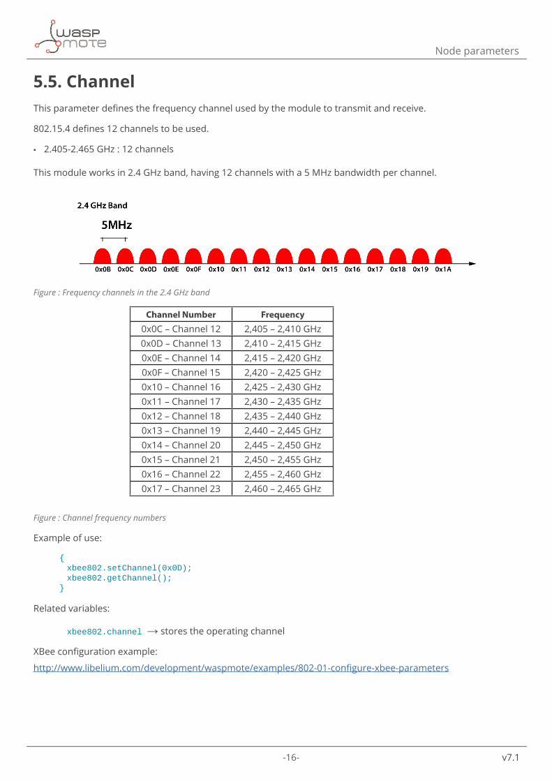
5.5. ChannelThis parameter defines the frequency channel used by the module to transmit and receive.
802.15.4 defines 12 channels to be used.
• 2.405-2.465 GHz : 12 channels
This module works in 2.4 GHz band, having 12 channels with a 5 MHz bandwidth per channel.
Figure : Frequency channels in the 2.4 GHz band
Channel Number Frequency
0x0C – Channel 12 2,405 – 2,410 GHz0x0D – Channel 13 2,410 – 2,415 GHz0x0E – Channel 14 2,415 – 2,420 GHz0x0F – Channel 15 2,420 – 2,425 GHz0x10 – Channel 16 2,425 – 2,430 GHz0x11 – Channel 17 2,430 – 2,435 GHz0x12 – Channel 18 2,435 – 2,440 GHz0x13 – Channel 19 2,440 – 2,445 GHz0x14 – Channel 20 2,445 – 2,450 GHz0x15 – Channel 21 2,450 – 2,455 GHz0x16 – Channel 22 2,455 – 2,460 GHz0x17 – Channel 23 2,460 – 2,465 GHz
Figure : Channel frequency numbers
Example of use:
{ xbee802.setChannel(0x0D); xbee802.getChannel();}
Related variables:
xbee802.channel → stores the operating channel
XBee configuration example:
http://www.libelium.com/development/waspmote/examples/802-01-configure-xbee-parameters
-17- v7.1
Power gain and sensitivity
6. Power gain and sensitivityWhen configuring a node and a network, one important parameter is related with power gain and sensitivity.
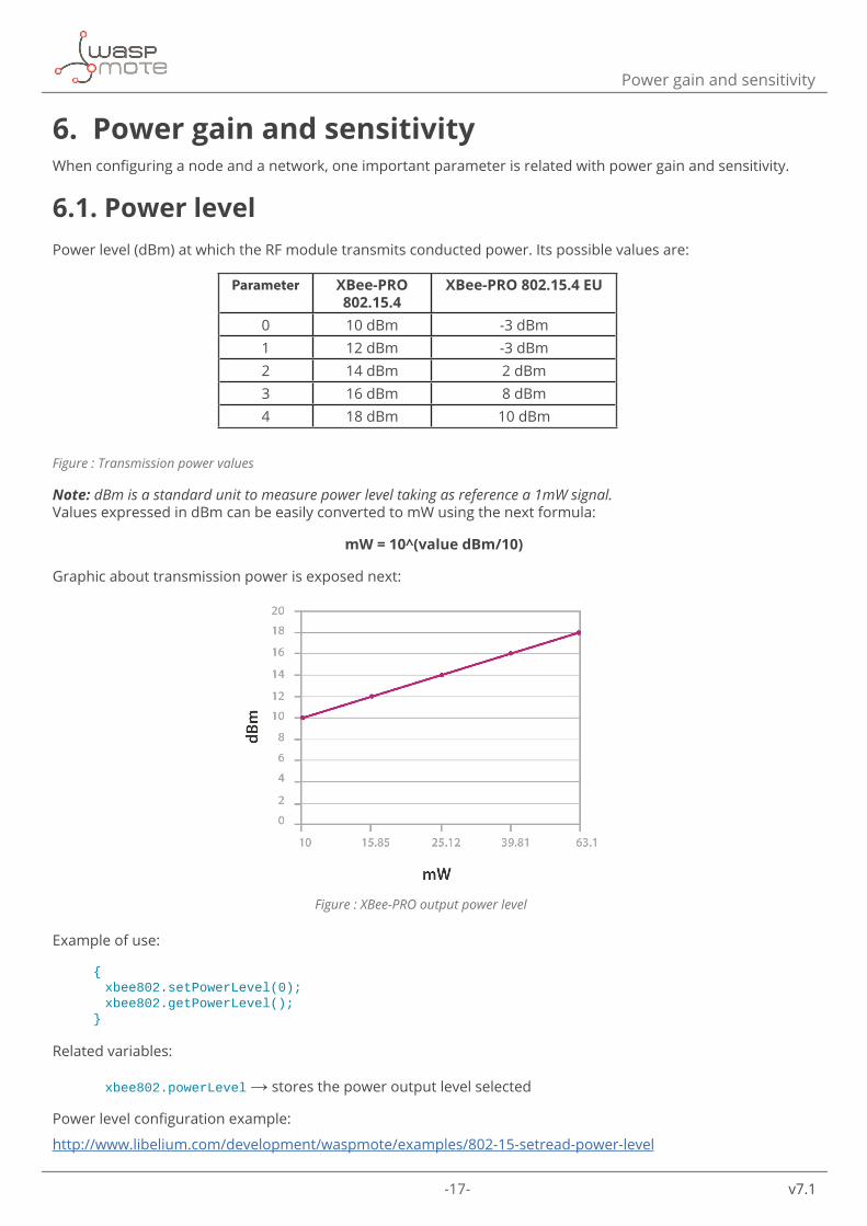
6.1. Power levelPower level (dBm) at which the RF module transmits conducted power. Its possible values are:
Parameter XBee-PRO 802.15.4
XBee-PRO 802.15.4 EU
0 10 dBm -3 dBm1 12 dBm -3 dBm2 14 dBm 2 dBm3 16 dBm 8 dBm4 18 dBm 10 dBm
Figure : Transmission power values
Note: dBm is a standard unit to measure power level taking as reference a 1mW signal.Values expressed in dBm can be easily converted to mW using the next formula:
mW = 10^(value dBm/10)
Graphic about transmission power is exposed next:
Figure : XBee-PRO output power level
Example of use:
{ xbee802.setPowerLevel(0); xbee802.getPowerLevel();}
Related variables:
xbee802.powerLevel → stores the power output level selected
Power level configuration example:
http://www.libelium.com/development/waspmote/examples/802-15-setread-power-level
-18- v7.1
Power gain and sensitivity
6.2. Received Signal Strength IndicatorIt reports the Received Signal Sñtrength of the last received RF data packet. It only indicates the signal strength of the last hop, so it does not provide an accurate quality measurement of a multihop link.
Example of use:
{ xbee802.getRSSI();}
Related variables:
xbee802.valueRSSI → stores the RSSI of the last received packet
The returned command value is measured in -dBm. For example if xbee802.valueRSSI=0x60, then the RSSI of the last packet received was -96 dBm. The ideal working mode is getting the maximum coverage with the minimum power level. Thereby, a compromise between power level and coverage appears. Each application scenario will need some tests to find the best combination of both parameters.
Getting RSSI example:
http://www.libelium.com/development/waspmote/examples/802-08-get-rssi
-19- v7.1
Radio channels
7. Radio channels
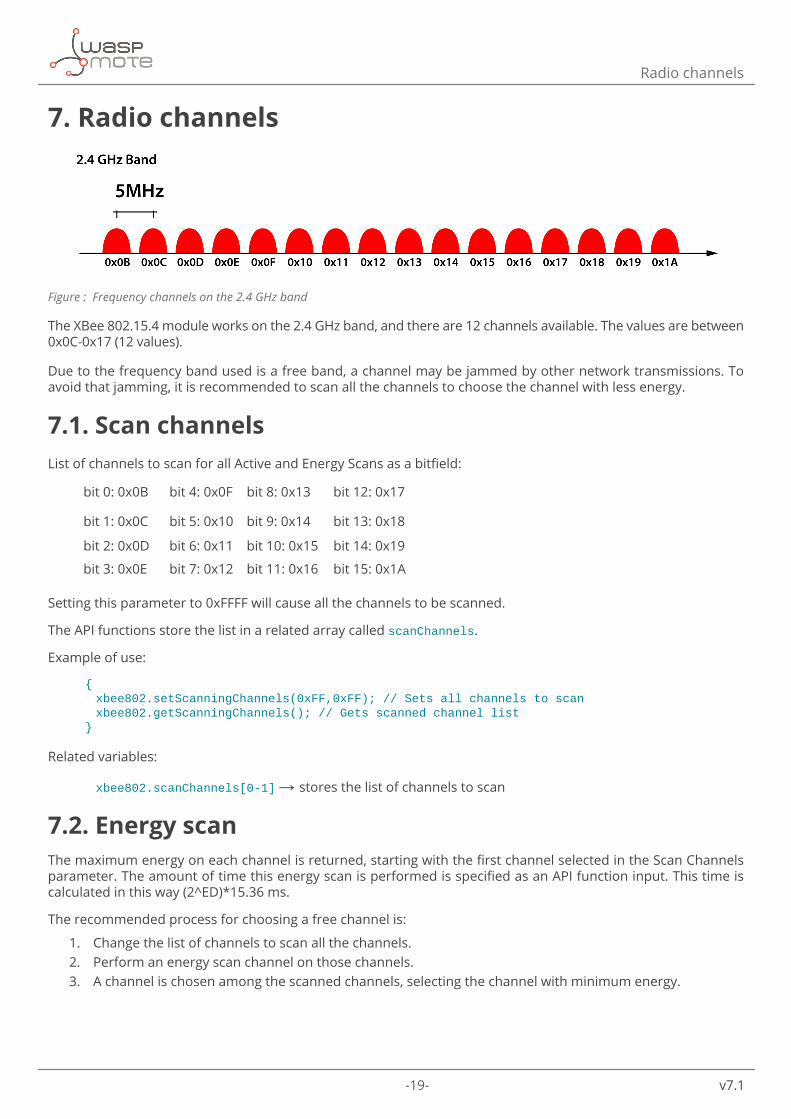
Figure : Frequency channels on the 2.4 GHz band
The XBee 802.15.4 module works on the 2.4 GHz band, and there are 12 channels available. The values are between 0x0C-0x17 (12 values).
Due to the frequency band used is a free band, a channel may be jammed by other network transmissions. To avoid that jamming, it is recommended to scan all the channels to choose the channel with less energy.
7.1. Scan channelsList of channels to scan for all Active and Energy Scans as a bitfield:
bit 0: 0x0B bit 4: 0x0F bit 8: 0x13 bit 12: 0x17
bit 1: 0x0C bit 5: 0x10 bit 9: 0x14 bit 13: 0x18
bit 2: 0x0D bit 6: 0x11 bit 10: 0x15 bit 14: 0x19
bit 3: 0x0E bit 7: 0x12 bit 11: 0x16 bit 15: 0x1A
Setting this parameter to 0xFFFF will cause all the channels to be scanned.
The API functions store the list in a related array called scanChannels.
Example of use:
{ xbee802.setScanningChannels(0xFF,0xFF); // Sets all channels to scan xbee802.getScanningChannels(); // Gets scanned channel list}
Related variables:
xbee802.scanChannels[0-1] → stores the list of channels to scan
7.2. Energy scanThe maximum energy on each channel is returned, starting with the first channel selected in the Scan Channels parameter. The amount of time this energy scan is performed is specified as an API function input. This time is calculated in this way (2^ED)*15.36 ms.
The recommended process for choosing a free channel is:
1. Change the list of channels to scan all the channels.2. Perform an energy scan channel on those channels.3. A channel is chosen among the scanned channels, selecting the channel with minimum energy.
-20- v7.1
Radio channels
Example of use:
{ xbee802.setDurationEnergyChannels(3); // Performs the energy scan}
Related variables: xbee802.energyChannel[0-15] → stores the energy found on each scanned channel
Energy scan example:
http://www.libelium.com/development/waspmote/examples/802-07-energy-scan
Note: The amount of time specified to scan each channel may affect the detected energy. In our tests, selecting the minimum value was not sufficient to detect the energy, so it is recommended to select a higher value.
Note 2: After testing, a usual energy value for a free channel is around -84 dBm and -37 dBm for an occupied one. When the energy scan is performed, these values may be used to determine whether a channel is occupied or not.
This protocol provides some parameters to diagnose the current state of the network. 802.15.4 uses CSMA-CA to avoid various nodes start transmitting at the same time. The process is described next:
1. A random delay is waited for. This time is specified by a back-off algorithm.2. Performs a Clear Channel Assessment. 3. If the detected energy is above the CCA threshold, steps 1-3 will be repeated up to 4 times. If the detected
energy is under the CCA threshold, the packet is transmitted.4. Broadcast transmissions has already finished because ACKs are not sent. Unicast transmissions wait for
ACK. If ACK is not received, steps 1-4 will be repeated up to 3 times.
7.3. Random delayIt specifies the minimum value at which the back-off algorithm starts. First time this algorithm is executed, it waits a random delay: (2^BE-1)*0.32 ms. BE is the back-off algorithm exponent and it starts at the value ‘Random Delay’. In the same attempting of sending a packet, the exponent is increased in one.
Example of use:
{ xbee802.setDelaySlots(1); // Sets the exponent to start xbee802.getDelaySlots(); // Gets the exponent to start}
Related variables:
xbee802.delaySlots → stores the exponent

-21- v7.1
Radio channels
7.4. CCA thresholdClear Channel Assessment Threshold. Prior to transmitting a packet, a CCA is performed to detect energy on the channel. If the detected energy is above the CCA Threshold, the module will not transmit the packet. By default, this value is -44 dBm. In our tests, an occupied channel with some nodes transmitting has around -37 dBm, so it is a tighten value.
Example of use:
{ xbee802.setEnergyThreshold(0x2C); // Sets the threshold xbee802.getEnergyThreshold (); // Gets the threshold}
Related variables:
xbee802.energyThreshold → stores the energy threshold
7.5. CCA failuresCounter of Clear Channel Assessment in CSMA-CA process. It specifies the number of times a packet has been discarded due to the energy on the channel was above the CCA Threshold.
Example of use:
{ xbee802.getCCAcounter(); // Gets the CCA counter xbee802.resetCCAcounter(); // Resets the CCA counter }
Related variables:
xbee802.counterCCA[0-1] → stores the CCA counter
7.6. ACK failuresCounter of acknowledgment failures. It specifies the number of times a packet has been sent and its ACK has not been received.
Example of use:
{ xbee802.getACKcounter(); // Get the ACK counter xbee802.resetACKcounter(); // Reset the ACK counter }
Related Variables:
xbee802.counterACK[0-1] → stores the ACK counter
-22- v7.1
Radio channels
7.7. RetriesMaximum number of retries the module will execute in addition to the 3 retries specified by 802.15.4 protocol. For each XBee retry, the 802.15.4 can execute up to 3 retries. If the transmitting module does not receive an ACK after 200ms, it will re-send the packet up to 3 times. This is an upper-MAC level, so the CSMA-CA process explained before is executed each retry.
Example of use:
{ xbee802.setRetries(2); // Set the additional retries xbee802.getRetries(); // Get the additional retries}
Related variables:
xbee802.retries[0-1] → stores the retries
Using these parameters, a bad behaviour of a channel could be detected, and the process to choose a new channel should be executed.
-23- v7.1
Networking methods
8. Networking methods
Note: It is important to keep in mind that XBee networks are defined by the networking parameters. Every XBee module within a network must share the same networking parameters. In the case of the XBee 802.15.4, every node in a network must have the same:
• PAN ID
• Channel
• Encryption configuration
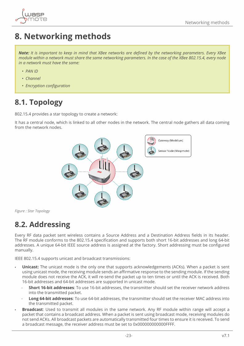
8.1. Topology802.15.4 provides a star topology to create a network:
It has a central node, which is linked to all other nodes in the network. The central node gathers all data coming from the network nodes.
Figure : Star Topology
8.2. AddressingEvery RF data packet sent wireless contains a Source Address and a Destination Address fields in its header. The RF module conforms to the 802.15.4 specification and supports both short 16-bit addresses and long 64-bit addresses. A unique 64-bit IEEE source address is assigned at the factory. Short addressing must be configured manually.
IEEE 802.15.4 supports unicast and broadcast transmissions:
• Unicast: The unicast mode is the only one that supports acknowledgements (ACKs). When a packet is sent using unicast mode, the receiving module sends an affirmative response to the sending module. If the sending module does not receive the ACK, it will re-send the packet up to ten times or until the ACK is received. Both 16-bit addresses and 64-bit addresses are supported in unicast mode. - Short 16-bit addresses: To use 16-bit addresses, the transmitter should set the receiver network address
into the transmitted packet. - Long 64-bit addresses: To use 64-bit addresses, the transmitter should set the receiver MAC address into
the transmitted packet. • Broadcast: Used to transmit all modules in the same network. Any RF module within range will accept a
packet that contains a broadcast address. When a packet is sent using broadcast mode, receiving modules do not send ACKs. All broadcast packets are automatically transmitted four times to ensure it is received. To send a broadcast message, the receiver address must be set to 0x000000000000FFFF.
-24- v7.1
Networking methods
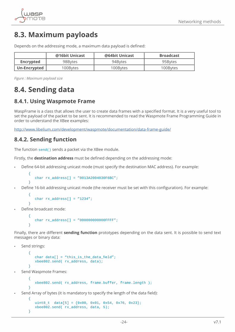
8.3. Maximum payloadsDepends on the addressing mode, a maximum data payload is defined:
@16bit Unicast @64bit Unicast Broadcast Encrypted 98Bytes 94Bytes 95Bytes
Un-Encrypted 100Bytes 100Bytes 100Bytes
Figure : Maximum payload size
8.4. Sending data8.4.1. Using Waspmote Frame
WaspFrame is a class that allows the user to create data frames with a specified format. It is a very useful tool to set the payload of the packet to be sent. It is recommended to read the Waspmote Frame Programming Guide in order to understand the XBee examples:
http://www.libelium.com/development/waspmote/documentation/data-frame-guide/
8.4.2. Sending function
The function send() sends a packet via the XBee module.
Firstly, the destination address must be defined depending on the addressing mode:
• Define 64-bit addressing unicast mode (must specify the destination MAC address). For example: { char rx_address[] = ”0013A2004030F6BC”; }
• Define 16-bit addressing unicast mode (the receiver must be set with this configuration). For example: { char rx_address[] = ”1234”; }
• Define broadcast mode: { char rx_address[] = ”000000000000FFFF”; }
Finally, there are different sending function prototypes depending on the data sent. It is possible to send text messages or binary data:
• Send strings: { chardata[]=“this_is_the_data_field”; xbee802.send( rx_address, data); }
• Send Waspmote Frames: { xbee802.send( rx_address, frame.buffer, frame.length ); }
• Send Array of bytes (it is mandatory to specify the length of the data field): { uint8_t data[5] = {0x00, 0x01, 0x54, 0x76, 0x23}; xbee802.send( rx_address, data, 5); }
-25- v7.1
Networking methods
The sending function implements application-level retries. By default, up to 3 retries are done in the case the sending process fails. If a different number of maximum retries is needed, the setSendingRetries() function permits to do it. This function changes the value of the API variable. When a new send() function is called, the new maximum number of retries will be used.
Keep in mind that using a high number of retries could lead to a longer execution time of the send() function, which means more power consumption on Waspmote and less channel availability for the rest of network nodes. Probably, after 3 or 4 (failed) retries, it does not make sense to keep on trying.
Parameter range: From 0 to 10Default: 3
Example of use:
{ xbee802.setSendingRetries(10);}
Related variables:
xbee802._send_retries → stores the maximum number of application-level retries
8.4.3. Examples
Send packets in unicast mode. Set 64-bit destination address: http://www.libelium.com/development/waspmote/examples/802-02-send-packets
Send packets in unicast mode. Set 16-bit destination address:http://www.libelium.com/development/waspmote/examples/802-04a-send-unicast-16b-address
Send packets in broadcast mode:http://www.libelium.com/development/waspmote/examples/802-06a-send-broadcast
Send packets using the expansion board:http://www.libelium.com/development/waspmote/examples/802-09a-expansion-board-send
Complete example, send packets in unicast 64-bit addresing mode and wait for a response:http://www.libelium.com/development/waspmote/examples/802-11a-complete-example-send
-26- v7.1
Networking methods
8.5. Receiving data
8.5.1. Receiving function
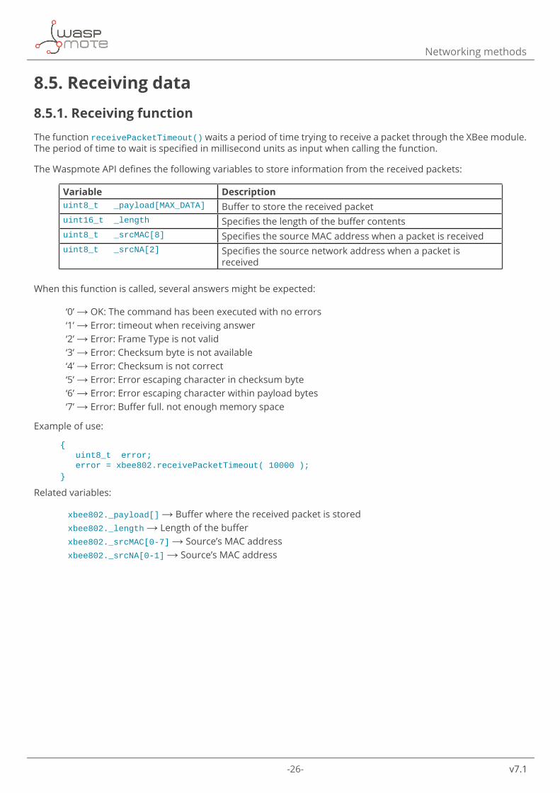
The function receivePacketTimeout() waits a period of time trying to receive a packet through the XBee module. The period of time to wait is specified in millisecond units as input when calling the function.
The Waspmote API defines the following variables to store information from the received packets:
Variable Descriptionuint8_t _payload[MAX_DATA] Buffer to store the received packetuint16_t _length Specifies the length of the buffer contentsuint8_t _srcMAC[8] Specifies the source MAC address when a packet is receiveduint8_t _srcNA[2] Specifies the source network address when a packet is
received
When this function is called, several answers might be expected:
‘0’ → OK: The command has been executed with no errors ‘1’ → Error: timeout when receiving answer ‘2’ → Error: Frame Type is not valid ‘3’ → Error: Checksum byte is not available ‘4’ → Error: Checksum is not correct ‘5’ → Error: Error escaping character in checksum byte ‘6’ → Error: Error escaping character within payload bytes ‘7’ → Error: Buffer full. not enough memory space
Example of use:
{ uint8_t error; error = xbee802.receivePacketTimeout( 10000 );}
Related variables:
xbee802._payload[] → Buffer where the received packet is stored xbee802._length → Length of the buffer xbee802._srcMAC[0-7] → Source’s MAC address xbee802._srcNA[0-1] → Source’s MAC address
-27- v7.1
Networking methods
8.5.2. Examples
Receive packets in unicast mode:http://www.libelium.com/development/waspmote/examples/802-03-receive-packets
Receive packets in unicast mode. Get 16-bit source address:http://www.libelium.com/development/waspmote/examples/802-04b-receive-unicast-16b-address
Receive packets in broadcast mode (the same procedure as if it was unicast mode):http://www.libelium.com/development/waspmote/examples/802-06b-receive-broadcast
Receive packets using the expansion board:http://www.libelium.com/development/waspmote/examples/802-09b-expansion-board-reception
Complete example, receive packets and send a response back to the sender:http://www.libelium.com/development/waspmote/examples/802-11b-complete-example-receive
8.6. 802.15.4 complianceThe Waspmote XBee transceiver is IEEE 802.15.4 compliant when the ‘Mac Mode’ is set to a value = 2. For other values, this parameter adds an extra header which let some new features to 802.15.4 protocol.
These features are:
• Node Discover: It performs a scan in the network and reports other nodes working on the network. • Destination Node: It performs a scan in the network to look for a specific node. • Duplicate Detection: 802.15.4 does not detect duplicate packets. Using Digi extra header, this problem is
solved, discarding automatically the duplicate packets. If Digi header is not enabled, the application level will have to deal with this problem.
These features and extra header are enabled by default. Possible values for this parameter are:
• 0: Digi Mode. 802.15.4 header + Digi header. It enables features as Discover Node and Destination Node. • 1: 802.15.4 without ACKs. It doesn’t support DN and ND features. It is 802.15.4 protocol without generating
ACKs when a packet is received. • 2: 802.15.4 with ACKs. It doesn’t support DN and ND features. It is the standard 802.15.4 protocol. • 3: Digi Mode without ACKs. 802.15.4 header + Digi header. It enables features as Discover Node and Destination
Node. It doesn’t generate ACKs when a packet is received.
Example of use:
{ xbee802.setMacMode(2); xbee802.getMacMode(); }
Related variables:
xbee802.macMode → stores the Mac Mode selected
-28- v7.1
Node Discovery
9. Node DiscoveryXBee modules provide some features for discovering and searching nodes. These features added to 802.15.4 allow a node to send a broadcast message to discover other nodes in the network within its coverage.
9.1. Structure used in Node Discovery Discovering nodes is used to discover and report all modules on its current operating channel and PAN ID.
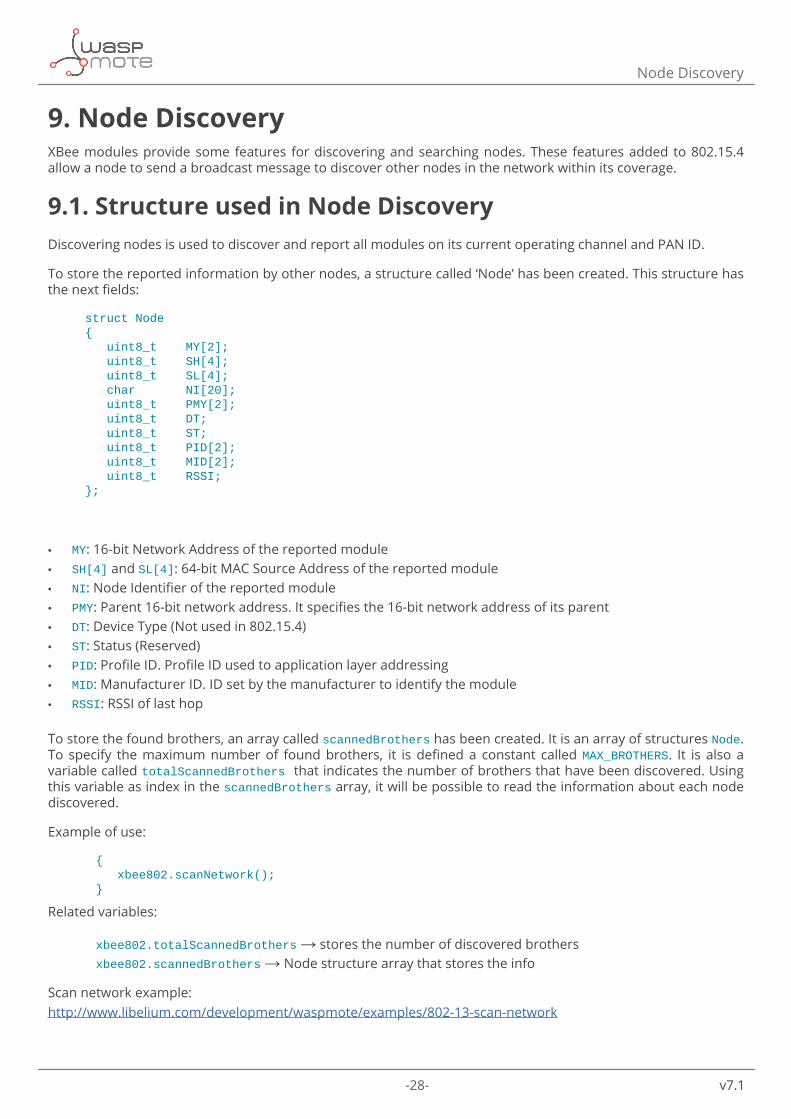
To store the reported information by other nodes, a structure called ‘Node’ has been created. This structure has the next fields:
struct Node{ uint8_t MY[2]; uint8_t SH[4]; uint8_t SL[4]; char NI[20]; uint8_t PMY[2]; uint8_t DT; uint8_t ST; uint8_t PID[2]; uint8_t MID[2]; uint8_t RSSI;};
• MY: 16-bit Network Address of the reported module • SH[4] and SL[4]: 64-bit MAC Source Address of the reported module • NI: Node Identifier of the reported module • PMY: Parent 16-bit network address. It specifies the 16-bit network address of its parent • DT: Device Type (Not used in 802.15.4) • ST: Status (Reserved) • PID: Profile ID. Profile ID used to application layer addressing • MID: Manufacturer ID. ID set by the manufacturer to identify the module • RSSI: RSSI of last hop
To store the found brothers, an array called scannedBrothers has been created. It is an array of structures Node. To specify the maximum number of found brothers, it is defined a constant called MAX_BROTHERS. It is also a variable called totalScannedBrothers that indicates the number of brothers that have been discovered. Using this variable as index in the scannedBrothers array, it will be possible to read the information about each node discovered.
Example of use:
{ xbee802.scanNetwork(); }
Related variables:
xbee802.totalScannedBrothers → stores the number of discovered brothers xbee802.scannedBrothers → Node structure array that stores the info
Scan network example:http://www.libelium.com/development/waspmote/examples/802-13-scan-network
-29- v7.1
Node Discovery
9.2. Searching specific nodesAnother possibility is searching for a specific node. This search is based on using the Node Identifier. The NI of the node to discover is used as the input in the API function responsible of this purpose. This function provides the 16-bit network address of the searched node.
Example of use:
{ uint8_t naD[2]; xbee802.nodeSearch(“node01”, naD); }
Related variables:
naD[0] and naD[1] → Store the 16-bit address of the searched node
Node search example:http://www.libelium.com/development/waspmote/examples/802-14a-node-search-txhttp://www.libelium.com/development/waspmote/examples/802-14b-node-search-rx
9.3. Node discovery to a specific node When executing a Node Discovery all the nodes respond to it. If its Node Identifier is known, a Node Discovery using its NI as an input can be executed.
Example of use:
{ xbee802.scanNetwork(“node01”); }
Related variables:
xbee802.totalScannedBrothers → stores the number of discovered brothers. Must be ‘1’.
xbee802.scannedBrothers → Node structure array that stores the info
9.4. Node Discovery Time It is the amount of time (NT) a node will wait for responses from other nodes when performing a ND. Range: 0x01 - 0xFC [x 100 ms]. Default: 0x19.
Example of use:
{ uint8_ttime[2]={0x19,0x00};//In802.15.4isonlyusedfirstarrayposition xbee802.setScanningTime(time); xbee802.getScanningTime(); }
Available Information
xbee802.scanTime[0] → stores the time a node will wait for responses.
-30- v7.1
Node Discovery
9.5. Node Discover options Enables node discover self-response on the module.
Example of use:
{ xbee802.setDiscoveryOptions(); // Set Discovery Options for ND xbee802.getDiscoveryOptions(); // Get Discovery Options for ND }
Available Information
xbee802.discoveryOptions → stores the selected options for ND
Note: If Node Discovery Time is a long time, the API function may exit before receiving a response, but the module will wait for it, crashing the code. If this time is too short, it is possible the modules don’t answer. After testing several times, the best values are between 1-2 seconds, setting the API function appropriately.
9.6. Questions related to discovering nodes While testing, many questions came up about discovering nodes. Now these questions are going to be exposed an explained to help the developer.
• ¿What are the network parameters needed to perform a ND? After testing a network, PAN ID and channel are needed to perform a ND. If one of these parameters is unknown, when performing a ND no node will response. If security is enabled in a network, the security key will be needed too.
• ¿Is a node obliged to answer a ND? DoS Attack. Yes, it is obliged to answer. The only way to prevent a network form DoS attack is using encryption, since the attacker will have to know the key to perform the ND.
• ¿What happens when ND is performed using PANID=0xFFFF? When performing a ND using this PANID no response is received. Broadcast PANID is not as useful as in a broadcast message, since the nodes does not receive any message.
• Node Discover Time. Tests. By default, this parameter is 0x19 (2.5 seconds). This is a great value, that can be reduced to make the ND process shorter. Tests have demonstrated this value can be reduced up to 0.5 seconds and the nodes still answer.
However, it is recommended not to reduce this parameter so much. When reducing this time, a node may answer after this time, the code crashing.
During this discovery time, the module is waiting for an answer and will not accept any data via serial port, so the API function scanNetwork() will have to be modified if this parameter is changed. If it is not modified, the API function will exit but the module will be still waiting, making the next functions don’t work.
If this discovery time is reduced and a node answers when the module and the API function have exit ND, the next called function will not work because the data sent by the module via serial will correspond with the response of ND.
-31- v7.1
Sleep options
10. Sleep optionsSleep Modes enable the RF module to enter into states of low-power consumption when not in use. To set sleep mode on, there are some parameters involved.
10.1. Sleep ModeBy default, Sleep Modes are disabled and the RF module remains in Idle/Receive Mode. When in this state, the module is constantly ready to respond to either serial or RF activity.
Different options can be set:
• 0: Disabled. • 1: Pin Hibernate Mode. • 2: Pin Doze Mode.
Example of use:
{ xbee802.setSleepMode(0); // Disable sleep mode xbee802.setSleepMode(1); // Set Sleep Mode to Pin Sleep xbee802.getSleepMode(); // Get the Sleep Mode used}
Related variables:
xbee802.sleepMode → stores the sleep mode in a module
Sleep mode example:http://www.libelium.com/development/waspmote/examples/802-10-set-low-power-mode
10.2. Pin Hibernate ModePin Hibernate Mode minimizes power consumption (<10 uA). This mode is voltage level-activated; when Sleep_RQ (pin 9 of XBee) is asserted, the module will finish any transmission, reception or association activities, enter Idle Mode, and then enter a state of sleep. The module will not respond to either serial or RF activity while in pin sleep.
To wake up a sleeping module operating in Pin Hibernate Mode, de-assert Sleep_RQ (pin 9 of XBee). The module will be awake after 13.2 ms.
Example of use:
{ xbee802.setSleepMode(1); // Set Sleep Mode to Hibernate Mode xbee802.sleep(); // Set XBee to sleep delay(5000); // wait 5 seconds xbee802.wake(); // Wake up the XBee }
-32- v7.1
Sleep options
10.3. Pin Doze ModePin Doze Mode works as Pin Hibernate Mode. However, Pin Doze features faster wake-up time (2 ms) and higher power consumption (<50 uA).
Example of use:
{ xbee802.setSleepMode(2); // Set Sleep Mode to Doze Mode xbee802.sleep(); // Set XBee to sleep delay(5000); // wait 5 seconds xbee802.wake(); // Wake up the XBee }
-33- v7.1
Security and data encryption
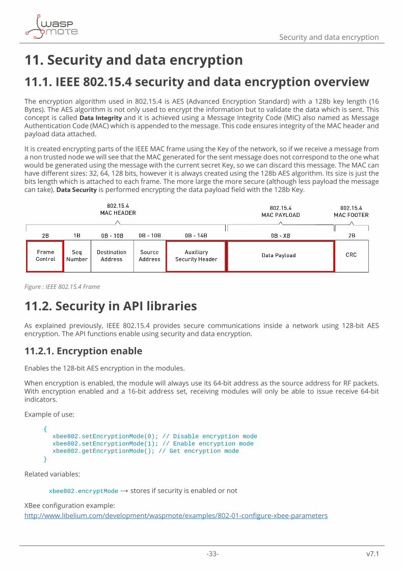
11. Security and data encryption11.1. IEEE 802.15.4 security and data encryption overviewThe encryption algorithm used in 802.15.4 is AES (Advanced Encryption Standard) with a 128b key length (16 Bytes). The AES algorithm is not only used to encrypt the information but to validate the data which is sent. This concept is called Data Integrity and it is achieved using a Message Integrity Code (MIC) also named as Message Authentication Code (MAC) which is appended to the message. This code ensures integrity of the MAC header and payload data attached.
It is created encrypting parts of the IEEE MAC frame using the Key of the network, so if we receive a message from a non trusted node we will see that the MAC generated for the sent message does not correspond to the one what would be generated using the message with the current secret Key, so we can discard this message. The MAC can have different sizes: 32, 64, 128 bits, however it is always created using the 128b AES algorithm. Its size is just the bits length which is attached to each frame. The more large the more secure (although less payload the message can take). Data Security is performed encrypting the data payload field with the 128b Key.
Figure : IEEE 802.15.4 Frame
11.2. Security in API librariesAs explained previously, IEEE 802.15.4 provides secure communications inside a network using 128-bit AES encryption. The API functions enable using security and data encryption.
11.2.1. Encryption enable
Enables the 128-bit AES encryption in the modules.
When encryption is enabled, the module will always use its 64-bit address as the source address for RF packets. With encryption enabled and a 16-bit address set, receiving modules will only be able to issue receive 64-bit indicators.
Example of use:
{ xbee802.setEncryptionMode(0); // Disable encryption mode xbee802.setEncryptionMode(1); // Enable encryption mode xbee802.getEncryptionMode(); // Get encryption mode}
Related variables:
xbee802.encryptMode → stores if security is enabled or not
XBee configuration example:http://www.libelium.com/development/waspmote/examples/802-01-configure-xbee-parameters
-34- v7.1
Security and data encryption
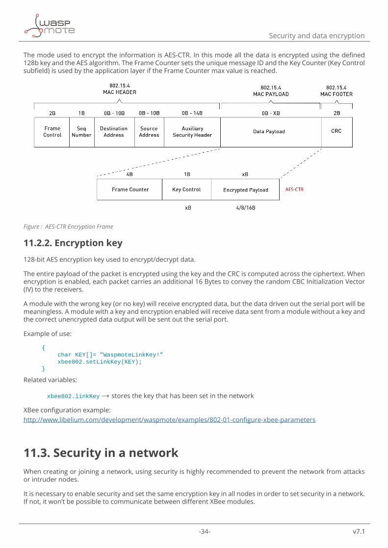
The mode used to encrypt the information is AES-CTR. In this mode all the data is encrypted using the defined 128b key and the AES algorithm. The Frame Counter sets the unique message ID and the Key Counter (Key Control subfield) is used by the application layer if the Frame Counter max value is reached.
Figure : AES-CTR Encryption Frame
11.2.2. Encryption key
128-bit AES encryption key used to encrypt/decrypt data.
The entire payload of the packet is encrypted using the key and the CRC is computed across the ciphertext. When encryption is enabled, each packet carries an additional 16 Bytes to convey the random CBC Initialization Vector (IV) to the receivers.
A module with the wrong key (or no key) will receive encrypted data, but the data driven out the serial port will be meaningless. A module with a key and encryption enabled will receive data sent from a module without a key and the correct unencrypted data output will be sent out the serial port.
Example of use:
{ char KEY[]= ”WaspmoteLinkKey!” xbee802.setLinkKey(KEY);}
Related variables:
xbee802.linkKey → stores the key that has been set in the network
XBee configuration example:http://www.libelium.com/development/waspmote/examples/802-01-configure-xbee-parameters
11.3. Security in a network When creating or joining a network, using security is highly recommended to prevent the network from attacks or intruder nodes.
It is necessary to enable security and set the same encryption key in all nodes in order to set security in a network. If not, it won’t be possible to communicate between different XBee modules.
-35- v7.1
Certifications
12. CertificationsLibelium offers 2 types of sensor platforms, Waspmote OEM and Plug & Sense!:
• Waspmote OEM is intended to be used for research purposes or as part of a major product so it needs final certification on the client side. More info at: http://www.libelium.com/products/waspmote/
• Plug & Sense! is the line ready to be used out of the box. It includes market certifications. See below the specific list of regulations passed. More info at: http://www.libelium.com/products/plug-sense/
“Plug & Sense! 802.15.4 EU” is certified for:
• CE (Europe)
“Plug & Sense! 802.15.4” is certified for:
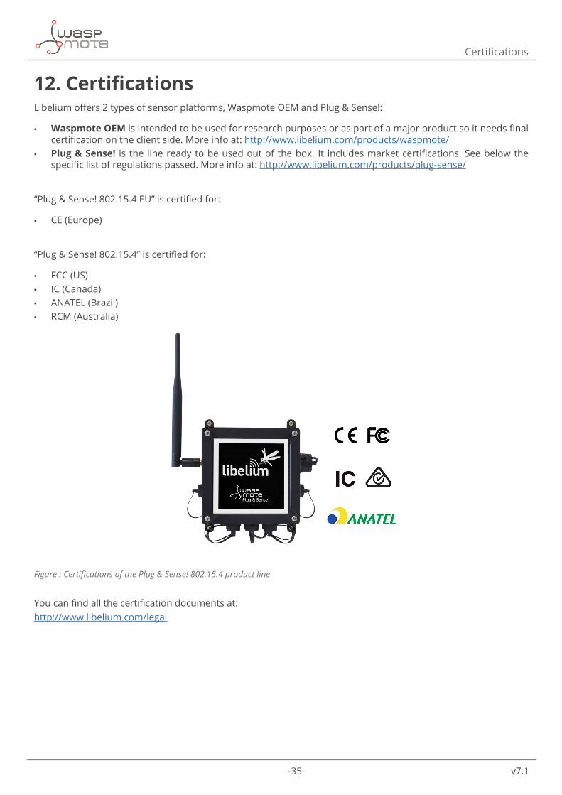
• FCC (US) • IC (Canada) • ANATEL (Brazil) • RCM (Australia)
Figure : Certifications of the Plug & Sense! 802.15.4 product line
You can find all the certification documents at: http://www.libelium.com/legal
-36- v7.1
Code examples and extended information
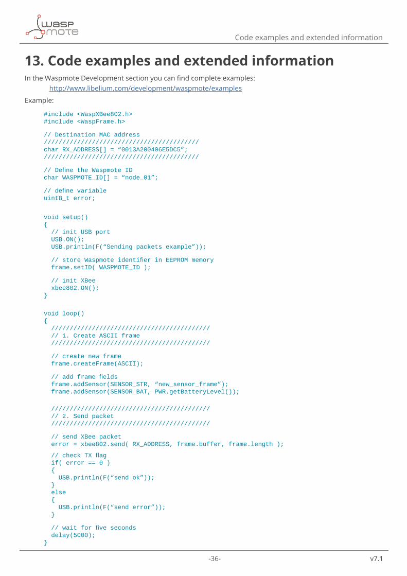
13. Code examples and extended informationIn the Waspmote Development section you can find complete examples: http://www.libelium.com/development/waspmote/examples
Example:
#include <WaspXBee802.h>#include <WaspFrame.h>
// Destination MAC address//////////////////////////////////////////char RX_ADDRESS[] = “0013A200406E5DC5”;//////////////////////////////////////////
//DefinetheWaspmoteIDchar WASPMOTE_ID[] = “node_01”;
//definevariableuint8_t error;
void setup(){ // init USB port USB.ON(); USB.println(F(“Sending packets example”));
//storeWaspmoteidentifierinEEPROMmemory frame.setID( WASPMOTE_ID );
// init XBee xbee802.ON();}
void loop(){ /////////////////////////////////////////// // 1. Create ASCII frame ///////////////////////////////////////////
// create new frame frame.createFrame(ASCII);
//addframefields frame.addSensor(SENSOR_STR, “new_sensor_frame”); frame.addSensor(SENSOR_BAT, PWR.getBatteryLevel());
/////////////////////////////////////////// // 2. Send packet ///////////////////////////////////////////
// send XBee packet error = xbee802.send( RX_ADDRESS, frame.buffer, frame.length );
//checkTXflag if( error == 0 ) { USB.println(F(“send ok”)); } else { USB.println(F(“send error”)); }
//waitforfiveseconds delay(5000);}

-37- v7.1
API changelog
14. API changelogKeep track of the software changes on this link:
www.libelium.com/development/waspmote/documentation/changelog/#802_15_4

-38- v7.1
Documentation changelog
15. Documentation changelog
From v7.0 to v7.1
• Added a new section to show the user how to connect the module to Waspmote

-39- v7.1