Embed Size (px)
Citation preview
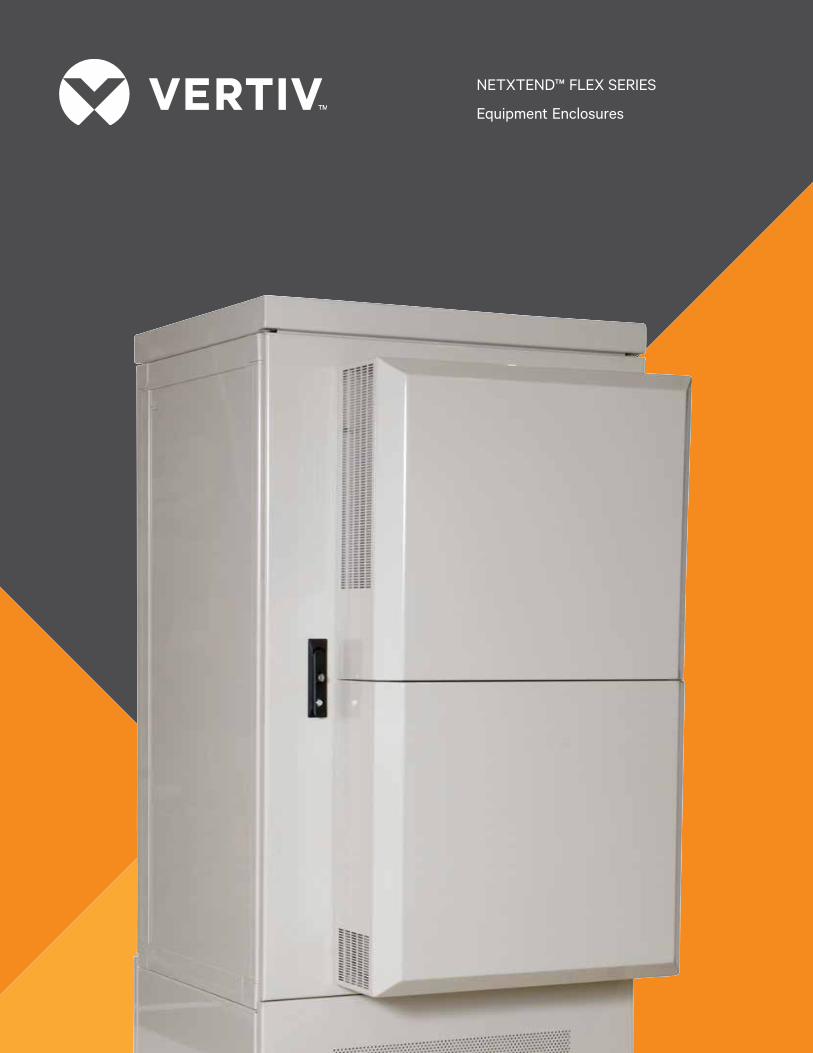
NETXTEND™ FLEX SERIES
Equipment Enclosures

yy Full flexibility and scalability — one enclosure for various wireless and wireline telecom applications
yy Multiple climate control solutions — satisfy your specific equipment heat dissipation and environmental demands
yy Increased ability to customize — diverse configuration, cooling and mounting options available
yy One standard enclosure platform for multiple applications — means fewer configurations and cabinet types to specify, install and maintain
yy Industry standards — platform designed to meet Telcordia GR-487-CORE, IP55, UL 60950/NWIN Type 3R, NEMA, NEC as well as other local requirements
yy Environmentally friendly cooling — low-energy consumption and low-noise fans are ideal for residential areas
yy Pad, pole and wall-mounting options — accommodate site requirements and limitations
yy Field-upgradable climate units — door-mounted with slide-off hinge to simplify service and replacement
yy Permanent ventilation ports — eliminate replacement of screens and filters, reducing field maintenance cost
yy NetXtend Cabinet Controller — cycles fan to maintain desired temperature, reducing power consumption and acoustic noise
FEATURES & BENEFITS
As subscriber interest for the ever-increasing array of broadband service grows, more and more sophisticated electronic equipment is being deployed in the outside plant. To provide the proper protection and controlled operating environment for this sensitive equipment and preserve the reliability of your network, Vertiv™ has developed the NetXtend Flex Series of integrated outdoor enclosure solutions. Its flexibility enables you to support a wide variety of OEM equipment with a single platform, under the wide range of weather extremes, thermal and electrical issues, and physical stresses encountered in the OSP environment.
By standardizing on the NetXtend Flex Series, you simplify network expansion and reduce the burden of stocking service parts, with the confidence that you will be able to deploy any OSP equipment--anywhere in your network – that the next generation of technology is sure to bring.
Description
The NetXtend Flex platform is a proven structural system, with integrated climate control and power options. NetXtend Flex enclosures are offered in a broad range of standard sizes designated by the rack unit (RU) capacity of the equipment chamber. Sizes range from 8 RU (Flex 8) to 43 RU (Flex 43). Single-bay, 2-bay and 4-bay enclosures are available as standard configurations, with a variety of door, base and side-chamber (SC) options. Pad, pole and wall mount options are offered.
The NetXtend™ Flex Series of integrated outdoor enclosures delivers best-in-class performance and flexibility for a wide variety of wireline and wireless applications. By leveraging simplicity, flexibility and scalability across the platform, the NetXtend Flex Series provides a rapidly deployable, cost-efficient solution to service providers around the world.
2
NETXTEND™ FLEX SERIES

Protection against destructive weather,thermal, electrical, environmental and mechanical forces is vital to assuring the reliability and revenue-producing capability of your wireless and wireline networks
NetXtend™ Flex Series — scalable, flexible, global
2
3
4
5
3
2
6
10 11
8
7
9
NetXtend Flex Series (shown with integrated heat exchanger)
NetXtend Flex Series NetXtend Flex Series (shown with open side chamber)
1. Painted Frame (Optional)
2. Climate System (Optional)
3. External Battery Base (Optional)
4. Standard Frame
5. Standard Door
6. Swing Handle or 1/4 Turn Lock
7. AC Load Center (Optional)
8. Vertiv™ Protection (Optional)
9. Side Chamber
10. Cable Entry
11. Ground Bar
1
3
4
NETXTEND™ FLEX SERIES
Typical Configurations
NetXtend™ Flex enclosures are designated by rack units (RU): Flex 8, Flex 12, etc. The height of the cabinet is determined by the required rack space, solar shield, and battery base or plinth options.
The cabinet footprint (width and depth) is determined by the number of equipment bays (4 maximum) and side chambers (2 maximum). See Dimension Table on page 7 and 8.
A solar shield is standard on all NetXtend Flex cabinets, which provides additional solar protection. All NetXtend Flex enclosures are constructed of recyclable materials.
Enclosure Options
(remote and audible). Heat exchangers, thermoelectric coolers, and fan/filter climate systems are available with +24VDC and -48VDC voltage inputs.
DC Power Systems
NetXtend Flex enclosures may be integrated with utilize NetSure DC power technology to ensure the reliability of every active OSP enclosure. NetSure DC power delivers constant power to meet load or recharge demand.Units are available to provide -48 VDC and +24 VDC power equipped with distribution options and low-voltage disconnect (LVD). Flex enclosures are optimized for use with NetSure 211, 502, 700 and 701 DC power systems, ranging from 30 to 400 amps.
AC Systems
AC options include a 4x4 junction box, power distribution panel/load center with AC distribution to power shelf, and GFCI-protected outlets.
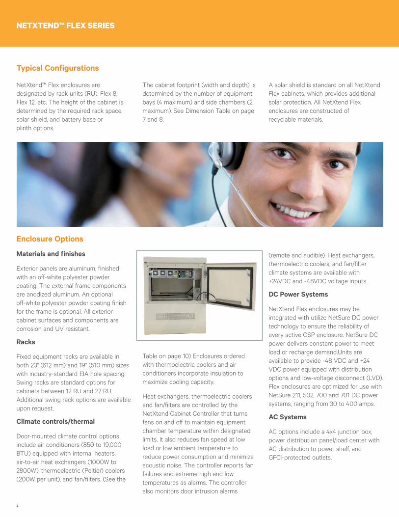
Materials and finishes
Exterior panels are aluminum, finished with an off-white polyester powder coating. The external frame components are anodized aluminum. An optional off-white polyester powder coating finish for the frame is optional. All exterior cabinet surfaces and components are corrosion and UV resistant.
Racks
Fixed equipment racks are available in both 23" (612 mm) and 19" (510 mm) sizes with industry-standard EIA hole spacing. Swing racks are standard options for cabinets between 12 RU and 27 RU. Additional swing rack options are available upon request.
Climate controls/thermal
Door-mounted climate control options include air conditioners (850 to 19,000 BTU) equipped with internal heaters, air-to-air heat exchangers (1000W to 2800W), thermoelectric (Peltier) coolers (200W per unit), and fan/filters. (See the
Table on page 10) Enclosures ordered with thermoelectric coolers and air conditioners incorporate insulation to maximize cooling capacity.
Heat exchangers, thermoelectric coolers and fan/filters are controlled by the NetXtend Cabinet Controller that turns fans on and off to maintain equipment chamber temperature within designated limits. It also reduces fan speed at low load or low ambient temperature to reduce power consumption and minimize acoustic noise. The controller reports fan failures and extreme high and low temperatures as alarms. The controller also monitors door intrusion alarms
5
Standardizing on a single enclosure platform increases your network reliability, leaves less chance for errors, simplifies network expansion, and reduces the burden of stocking service parts and repairing damage to panels, doors and other enclosure components.
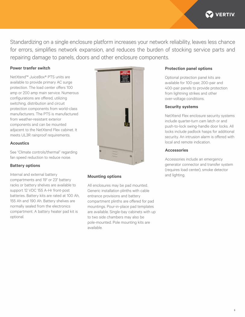
Power tranfer switch
NetXtend™ JuiceBox® PTS units are available to provide primary AC surge protection. The load center offers 100 amp or 200 amp main service. Numerous configurations are offered, utilizing switching, distribution and circuit protection components from world-class manufacturers. The PTS is manufactured from weather-resistant exterior components and can be mounted adjacent to the NetXtend Flex cabinet. It meets UL3R rainproof requirements.
Acoustics
See “Climate controls/thermal” regarding fan speed reduction to reduce noise.
Battery options
Internal and external battery compartments and 19" or 23" battery racks or battery shelves are available to support 12 VDC 155 A-Hr front-post batteries. Battery kits are rated at 100 Ah, 155 Ah and 190 Ah. Battery shelves are normally sealed from the electronics compartment. A battery heater pad kit is optional.
Mounting options
All enclosures may be pad mounted. Generic installation plinths with cable entrance provisions and battery compartment plinths are offered for pad mountings. Pour-in-place pad templates are available. Single-bay cabinets with up to two side chambers may also be pole-mounted. Pole mounting kits are available.
Protection panel options
Optional protection panel kits are available for 100-pair, 200-pair and 400-pair panels to provide protection from lightning strikes and other over-voltage conditions.
Security systems
NetXtend Flex enclosure security systems include quarter-turn cam latch or and push-to-lock swing-handle door locks. All locks include padlock hasps for additional security. An intrusion alarm is offered with local and remote indication.
Accessories
Accessories include an emergency generator connector and transfer system (requires load center), smoke detector and lighting.
6
NETXTEND™ FLEX SERIES
Application
The NetXtend™ Flex Series of enclosures houses a variety of next-generation roadband electronic equipment for both wireline and wireless outside plant applications where physical protection and environmental stability are required.
Enclosure Assembly, Integration and Testing
Vertiv™ has the industry experience and in-house product knowledge to recommend, engineer, integrate, implement and support NetXtend Flex enclosures that you can confidently deploy as your network grows. When we configure a new Flex enclosure in one of our regional configuration centers, we integrate the climate control, DC power and backup, alarms, accessories and customer equipment. Prior to production, a skilled test team operates the completed enclosure in our thermal and acoustic chambers. If necessary, we modify the configuration to reduce the chance of encountering any unexpected glitches once the units are installed in the field.
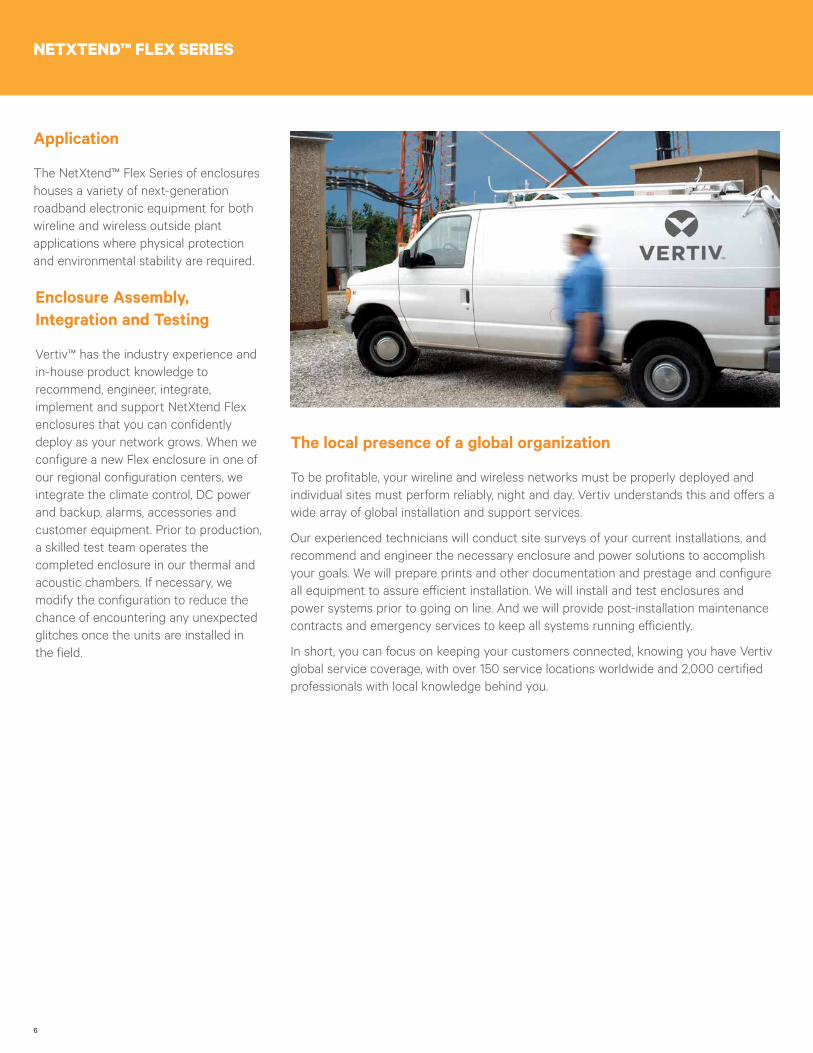
The local presence of a global organization
To be profitable, your wireline and wireless networks must be properly deployed and individual sites must perform reliably, night and day. Vertiv understands this and offers a wide array of global installation and support services.
Our experienced technicians will conduct site surveys of your current installations, and recommend and engineer the necessary enclosure and power solutions to accomplish your goals. We will prepare prints and other documentation and prestage and configure all equipment to assure efficient installation. We will install and test enclosures and power systems prior to going on line. And we will provide post-installation maintenance contracts and emergency services to keep all systems running efficiently.
In short, you can focus on keeping your customers connected, knowing you have Vertiv global service coverage, with over 150 service locations worldwide and 2,000 certified professionals with local knowledge behind you.
7
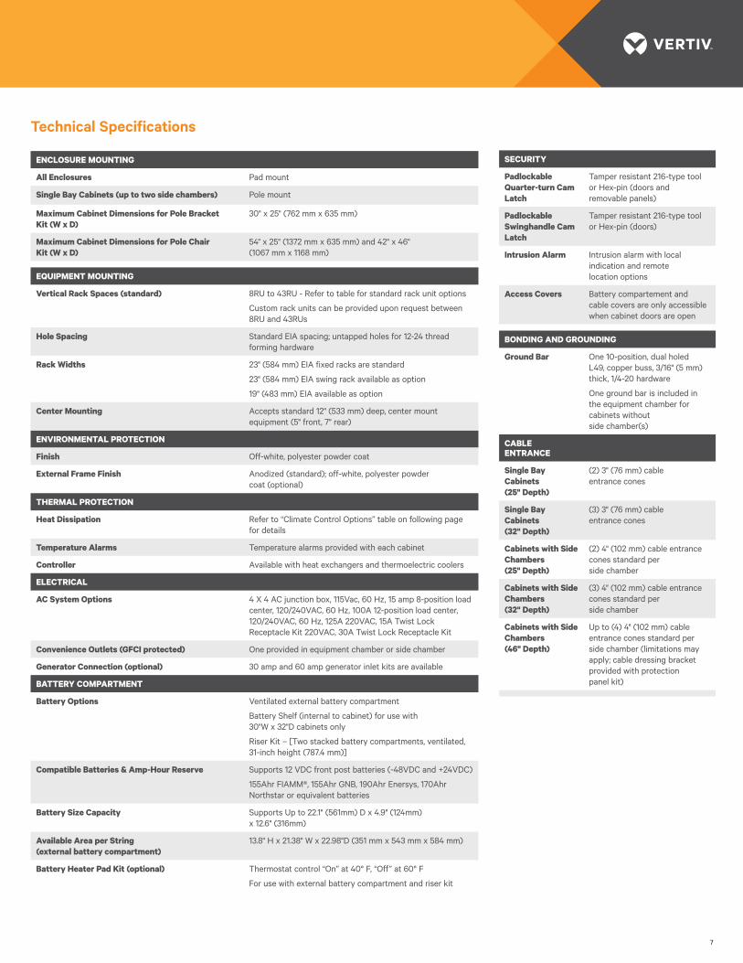
Technical Specifications
ENCLOSURE MOUNTING
All Enclosures Pad mount
Single Bay Cabinets (up to two side chambers) Pole mount
Maximum Cabinet Dimensions for Pole Bracket Kit (W x D)
30" x 25" (762 mm x 635 mm)
Maximum Cabinet Dimensions for Pole Chair Kit (W x D)
54" x 25" (1372 mm x 635 mm) and 42" x 46" (1067 mm x 1168 mm)
EQUIPMENT MOUNTING
Vertical Rack Spaces (standard) 8RU to 43RU - Refer to table for standard rack unit options
Custom rack units can be provided upon request between 8RU and 43RUs
Hole Spacing Standard EIA spacing; untapped holes for 12-24 thread forming hardware
Rack Widths 23" (584 mm) EIA fixed racks are standard
23" (584 mm) EIA swing rack available as option
19" (483 mm) EIA available as option
Center Mounting Accepts standard 12" (533 mm) deep, center mount equipment (5" front, 7" rear)
ENVIRONMENTAL PROTECTION
Finish Off-white, polyester powder coat
External Frame Finish Anodized (standard); off-white, polyester powder coat (optional)
THERMAL PROTECTION
Heat Dissipation Refer to “Climate Control Options” table on following page for details
Temperature Alarms Temperature alarms provided with each cabinet
Controller Available with heat exchangers and thermoelectric coolers
ELECTRICAL
AC System Options 4 X 4 AC junction box, 115Vac, 60 Hz, 15 amp 8-position load center, 120/240VAC, 60 Hz, 100A 12-position load center, 120/240VAC, 60 Hz, 125A 220VAC, 15A Twist Lock Receptacle Kit 220VAC, 30A Twist Lock Receptacle Kit
Convenience Outlets (GFCI protected) One provided in equipment chamber or side chamber
Generator Connection (optional) 30 amp and 60 amp generator inlet kits are available
BATTERY COMPARTMENT
Battery Options Ventilated external battery compartment
Battery Shelf (internal to cabinet) for use with 30"W x 32"D cabinets only
Riser Kit – [Two stacked battery compartments, ventilated, 31-inch height (787.4 mm)]
Compatible Batteries & Amp-Hour Reserve Supports 12 VDC front post batteries (-48VDC and +24VDC)
155Ahr FIAMM®, 155Ahr GNB, 190Ahr Enersys, 170Ahr Northstar or equivalent batteries
Battery Size Capacity Supports Up to 22.1" (561mm) D x 4.9" (124mm) x 12.6" (316mm)
Available Area per String (external battery compartment)
13.8" H x 21.38" W x 22.98"D (351 mm x 543 mm x 584 mm)
Battery Heater Pad Kit (optional) Thermostat control “On” at 40° F, “Off” at 60° F
For use with external battery compartment and riser kit
SECURITY
Padlockable Quarter-turn Cam Latch
Tamper resistant 216-type tool or Hex-pin (doors and removable panels)
Padlockable Swinghandle Cam Latch
Tamper resistant 216-type tool or Hex-pin (doors)
Intrusion Alarm Intrusion alarm with local indication and remote location options
Access Covers Battery compartement and cable covers are only accessible when cabinet doors are open
BONDING AND GROUNDING
Ground Bar One 10-position, dual holed L49, copper buss, 3/16" (5 mm) thick, 1/4-20 hardware
One ground bar is included in the equipment chamber for cabinets without side chamber(s)
CABLE ENTRANCE
Single Bay Cabinets (25" Depth)
(2) 3" (76 mm) cable entrance cones
Single Bay Cabinets (32" Depth)
(3) 3" (76 mm) cable entrance cones
Cabinets with Side Chambers (25" Depth)
(2) 4" (102 mm) cable entrance cones standard per side chamber
Cabinets with Side Chambers (32" Depth)
(3) 4" (102 mm) cable entrance cones standard per side chamber
Cabinets with Side Chambers (46" Depth)
Up to (4) 4" (102 mm) cable entrance cones standard per side chamber (limitations may apply; cable dressing bracket provided with protection panel kit)
8
NETXTEND™ FLEX SERIES
Cabinet Type NF = NetXtend™ Flex Cabinet
Rack Units per Equipment Bay 08 = 8 rack units in each bay (standard rack units: 08, 12, 17, 22, 27, 32)
Door Configuration S = Single-sided cabinet (front doors only)
D = Dual sided cabinet (front & rear doors)
X = Single-sided cabinet (front & rear doors)
Equipment Bays 1 = One bay per side
2 = Two bays per side
Side Bays 0 = No side bay
1 = One side bay on left side
2 = Two side bay on left side
AC Type 0 = None
J = 4x4 junction box, 115VAC
1 = 8-position 100A load center
2 = 12-position 125A load center
3 = 220VAC, 15A, twist lock receptacle kit
4 = 220VAC, 30A, twist lock receptacle kit
Battery* 0 = No base
B = External Battery Compartment
I = Internal Battery Shelf
R = Battery Riser Kit
Solar Shield 0 = No shield
S = Solar shield (standard)
Cooling System* Heat Exchangers
Fan/Vent Filter Kit
H1 = 990W/1000W TE Coolers
H2 = 14500W/1600W
H3 = 2800W Air Conditioners
F1 =
F2 =
F3 =
T1 = 200W
T2 = 400W
A1 = 850 BTU w/150W heater
A2 = 2000BTU w/500W heater
A3 = 4000BTU w/1000W heater
A4 = 8000BTU w/2000W heater
A5 = 19000BTU w/3000W heater
Door Security/Locking 1 = Quarter-turn Cam Latch – Hex/Pin
2 = Quarter-turn Cam Latch – 216 (7/16 Hex)
3 = Swinghandle Cam Latch – Hex/Pin
4 = Swinghandle Cam Latch – 216 (7/16 Hex)
Generator Connection 0 = No connection option
A = 30 Amp
B = 60 Amp
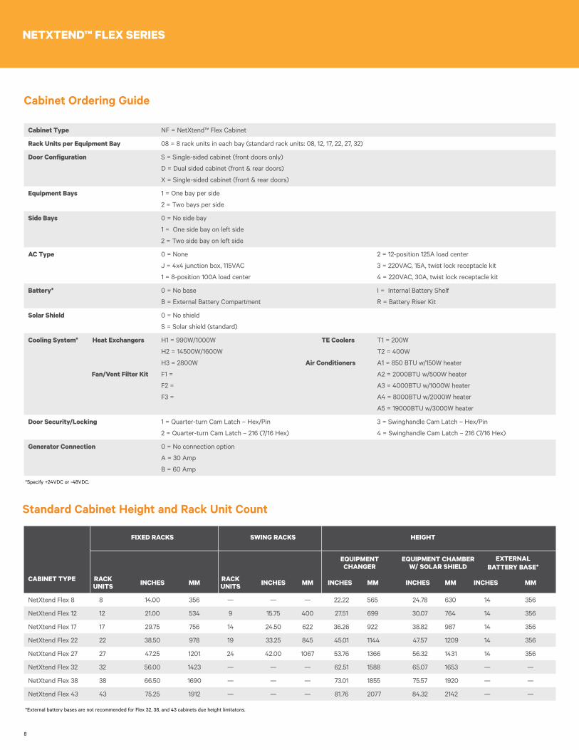
Cabinet Ordering Guide
*Specify +24VDC or -48VDC.
Standard Cabinet Height and Rack Unit Count
FIXED RACKS SWING RACKS HEIGHT
CABINET TYPE RACK UNITS INCHES MM RACK
UNITS INCHES MM INCHES MM INCHES MM INCHES MM
NetXtend Flex 8 8 14.00 356 — — — 22.22 565 24.78 630 14 356
NetXtend Flex 12 12 21.00 534 9 15.75 400 27.51 699 30.07 764 14 356
NetXtend Flex 17 17 29.75 756 14 24.50 622 36.26 922 38.82 987 14 356
NetXtend Flex 22 22 38.50 978 19 33.25 845 45.01 1144 47.57 1209 14 356
NetXtend Flex 27 27 47.25 1201 24 42.00 1067 53.76 1366 56.32 1431 14 356
NetXtend Flex 32 32 56.00 1423 — — — 62.51 1588 65.07 1653 — —
NetXtend Flex 38 38 66.50 1690 — — — 73.01 1855 75.57 1920 — —
NetXtend Flex 43 43 75.25 1912 — — — 81.76 2077 84.32 2142 — —
*External battery bases are not recommended for Flex 32, 38, and 43 cabinets due height limitatons.
EXTERNAL BATTERY BASE*
EQUIPMENT CHAMBER W/ SOLAR SHIELD
EQUIPMENT CHANGER
9
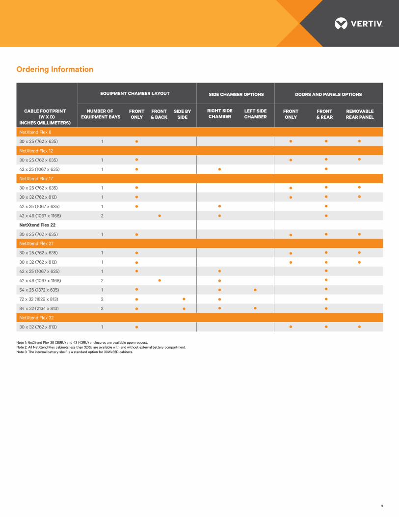
Ordering Information
CABLE FOOTPRINT (W X D)
INCHES (MILLIMETERS)
EQUIPMENT CHAMBER LAYOUT
NUMBER OF EQUIPMENT BAYS
SIDE CHAMBER OPTIONS DOORS AND PANELS OPTIONS
NetXtend Flex 8
30 x 25 (762 x 635) 1
NetXtend Flex 12
30 x 25 (762 x 635) 1
42 x 25 (1067 x 635) 1
NetXtend Flex 17
30 x 25 (762 x 635) 1
30 x 32 (762 x 813) 1
42 x 25 (1067 x 635) 1
42 x 46 (1067 x 1168) 2
NetXtend Flex 22
30 x 25 (762 x 635) 1
NetXtend Flex 27
30 x 25 (762 x 635) 1
30 x 32 (762 x 813) 1
42 x 25 (1067 x 635) 1
42 x 46 (1067 x 1168) 2
54 x 25 (1372 x 635) 1
72 x 32 (1829 x 813) 2
84 x 32 (2134 x 813) 2
NetXtend Flex 32
30 x 32 (762 x 813) 1
REMOVABLEREAR PANEL
RIGHT SIDECHAMBER
LEFT SIDECHAMBER
FRONTONLY
FRONT& REAR
Note 1: NetXtend Flex 38 (38RU) and 43 (43RU) enclosures are available upon request.Note 2: All NetXtend Flex cabinets less than 32RU are available with and without external battery compartment.Note 3: The internal battery shelf is a standard option for 30Wx32D cabinets.
FRONT ONLY
FRONT & BACK
SIDE BYSIDE
10
NETXTEND™ FLEX SERIES
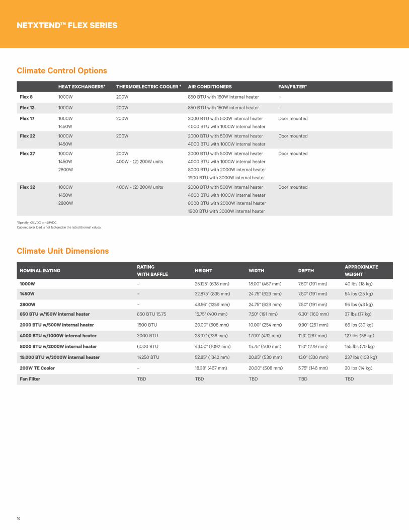
Climate Control Options
HEAT EXCHANGERS* THERMOELECTRIC COOLER * AIR CONDITIONERS FAN/FILTER*
Flex 8 1000W 200W 850 BTU with 150W internal heater –
Flex 12 1000W 200W 850 BTU with 150W internal heater –
Flex 17 1000W
1450W
200W 2000 BTU with 500W internal heater
4000 BTU with 1000W internal heater
Door mounted
Flex 22 1000W
1450W
200W 2000 BTU with 500W internal heater
4000 BTU with 1000W internal heater
Door mounted
Flex 27 1000W
1450W
2800W
200W
400W - (2) 200W units
2000 BTU with 500W internal heater
4000 BTU with 1000W internal heater
8000 BTU with 2000W internal heater
1900 BTU with 3000W internal heater
Door mounted
Flex 32 1000W
1450W
2800W
400W - (2) 200W units 2000 BTU with 500W internal heater
4000 BTU with 1000W internal heater
8000 BTU with 2000W internal heater
1900 BTU with 3000W internal heater
Door mounted
*Specify +24VDC or -48VDC. Cabinet solar load is not factored in the listed thermal values.
NOMINAL RATINGRATING WITH BAFFLE
HEIGHT WIDTH DEPTHAPPROXIMATEWEIGHT
1000W – 25.125" (638 mm) 18.00" (457 mm) 7.50" (191 mm) 40 lbs (18 kg)
1450W – 32.875" (835 mm) 24.75" (629 mm) 7.50" (191 mm) 54 lbs (25 kg)
2800W – 49.56" (1259 mm) 24.75" (629 mm) 7.50" (191 mm) 95 lbs (43 kg)
850 BTU w/150W internal heater 850 BTU 15.75 15.75" (400 mm) 7.50" (191 mm) 6.30" (160 mm) 37 lbs (17 kg)
2000 BTU w/500W internal heater 1500 BTU 20.00" (508 mm) 10.00" (254 mm) 9.90" (251 mm) 66 lbs (30 kg)
4000 BTU w/1000W internal heater 3000 BTU 28.97" (736 mm) 17.00" (432 mm) 11.3" (287 mm) 127 lbs (58 kg)
8000 BTU w/2000W internal heater 6000 BTU 43.00" (1092 mm) 15.75" (400 mm) 11.0" (279 mm) 155 lbs (70 kg)
19,000 BTU w/3000W internal heater 14250 BTU 52.85" (1342 mm) 20.85" (530 mm) 13.0" (330 mm) 237 lbs (108 kg)
200W TE Cooler – 18.38" (467 mm) 20.00" (508 mm) 5.75" (146 mm) 30 lbs (14 kg)
Fan Filter TBD TBD TBD TBD TBD
Climate Unit Dimensions
11
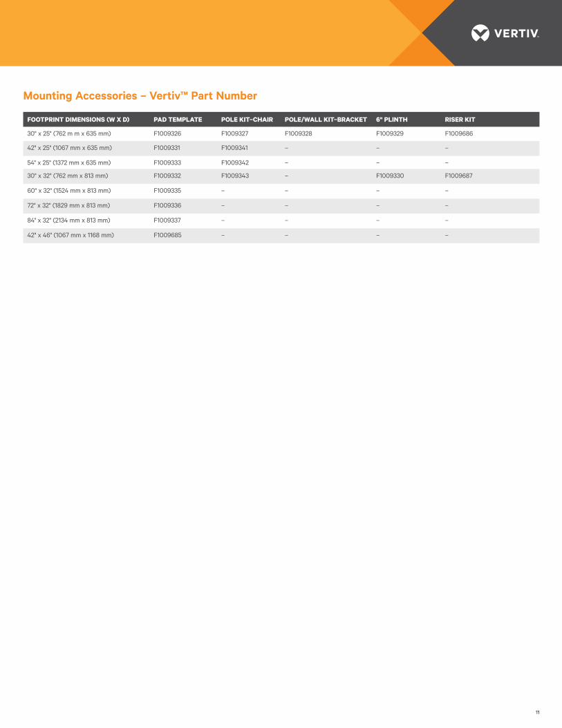
Mounting Accessories – Vertiv™ Part Number
FOOTPRINT DIMENSIONS (W X D) PAD TEMPLATE POLE KIT–CHAIR POLE/WALL KIT–BRACKET 6" PLINTH RISER KIT
30" x 25" (762 m m x 635 mm) F1009326 F1009327 F1009328 F1009329 F1009686
42" x 25" (1067 mm x 635 mm) F1009331 F1009341 – – –
54" x 25" (1372 mm x 635 mm) F1009333 F1009342 – – –
30" x 32" (762 mm x 813 mm) F1009332 F1009343 – F1009330 F1009687
60" x 32" (1524 mm x 813 mm) F1009335 – – – –
72" x 32" (1829 mm x 813 mm) F1009336 – – – –
84" x 32" (2134 mm x 813 mm) F1009337 – – – –
42" x 46" (1067 mm x 1168 mm) F1009685 – – – –

OE-12861 (R12/16)
VertivCo.com | Vertiv Headquarters, 1050 Dearborn Drive, Columbus, OH, 43085, USA
© 2016 Vertiv Co. All rights reserved. Vertiv and the Vertiv logo are trademarks or registered trademarks of Vertiv Co. All other names and logos referred to are trade names, trademarks or registered trademarks of their respective owners. While every precaution has been taken to ensure accuracy and completeness herein, Vertiv Co. assumes no responsibility, and disclaims all liability, for damages resulting from use of this information or for any errors or omissions. Specifications are subject to change without notice.