Embed Size (px)
Citation preview
L IFTPARKER SERIES C AR STACKERS
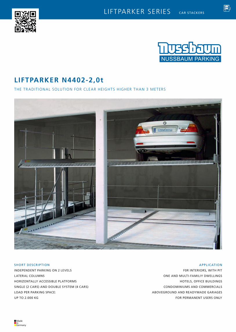
LIFTPARKER N4402-2,0t
SHORT DESCRIPTION
INDEPENDENT PARKING ON 2 LEVELS
LATERAL COLUMNS
HORIZONTALLY ACCESSIBLE PLATFORMS
SINGLE (2 CARS) AND DOUBLE SYSTEM (4 CARS)
LOAD PER PARKING SPACE:
UP TO 2.000 KG
APPLIC ATION
F0R INTERIORS, WITH PIT
ONE AND MULTI-FAMILIY DWELLINGS
HOTELS, OFFICE BUILDINGS
CONDOMINIUMS AND COMMERCIALS
ABOVEGROUND AND READYMADE GARAGES
FOR PERMANENT USERS ONLY
THE TRADIT IONAL SOLUT ION FOR CLEAR HEIGHTS H IGHER THAN 3 METERS
40
530
40
80
100-150
2%2%
40 25 25
min.18
56
46
38
90 max. 290 120
500(520)
2760
170
22
15
56
46
38
90 max. 290 120
500(520)
45
2760
170 905565
22
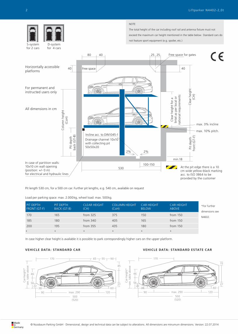
NOTE
The total height of the car including roof rail and antenna fixture must not
exceed the maximum car height mentioned in the table below. Standard cars do
not feature sport equipment (e.g. spoiler, etc.)D-system for 4 cars
S-system for 2 cars
Car
-hei
ght*
see.
tab
le a
bov
e
Car
-hei
ght*
see.
tab
le a
bov
e
At the pit edge there is a 10 cm wide yellow-black marking acc. to ISO 3864 to be provided by the customer
Drainage channel 10x10with collecting pit 50x50x20
Incline acc. to DIN1045-1
Col
umn
heig
ht
(Co
H)
max. 3% incline
Cle
ar h
eigh
t fo
r a
linte
l as
per
loca
l or
nati
onal
req
uire
men
ts
Pit
dept
hba
ck (G
T-B)
Horizontally accessible platforms
For permanent and instructed users only
All dimensions in cm
PIT DEPTH FRONT (GT-F)
PIT DEPTH BACK (GT-B)
CLEAR HEIGHT (CH)
COLUMN HEIGHT (CoH)
CAR HEIGHT BELOW
CAR HEIGHT ABOVE
170 165 from 325 375 150 from 150
185 180 from 340 405 165 from 150
200 195 from 355 435 180 from 150
* * * * * *
Load per parking space: max. 2.000kg, wheel load: max. 500kg.
max. 10% pitch.
Pit length 530 cm, for a 500 cm car. Further pit lengths, e.g. 540 cm, available on request
Free space
Free space for gates
Cle
ar h
eigh
t (C
H)
VEHICLE DATA: STANDARD ESTATE C ARVEHICLE DATA: STANDARD C AR
*For further
dimensions see
N4602.
Pit
dept
h fr
ont
(GT-
F)
© Nussbaum Parking GmbH · Dimensional, design and technical data can be subject to alterations. All dimensions are minumum dimensions. Version: 22.07.2014
In case of partition walls: 10x10 cm wall opening (position: +/- 0 m) for electrical and hydraulic lines
In case higher clear height is available it is possible to park correspondingly higher cars on the upper platform.
2 L i f tparker N4402-2,0t
+/- 01
4
120
180
5
6
7
8
9 10
2 3
Y11
Y10
POS. QUANTITY DESCRIPTION POSITION FREQUENCY
4 1x Electricity meter in the supply line
5 1x Blade fuse or circuit breaker 3x 16A, slow acc. to DIN VDE 0100 part 430 in the supply line 1x power unit
6 1x Supply line 5x 2,5mm² (3 PH + N + PE) with marked leads + protective earth conductor to the mains switch 1x power unit
7 1x Lockable network facility (main control switch) near power unit 1x power unit
8 1x Supply line 5x 2,5mm² (3 PH + N + PE) with marked leads + protective earth conductor to the power unit 1x power unit
9 1x Foundation earth electrodes pit fl oor corner 1x pit
10 1xEquipotential bonding according to DIN EN 60204 from the connector of the foundation earth electrodes to the system
At the column foot 1x system
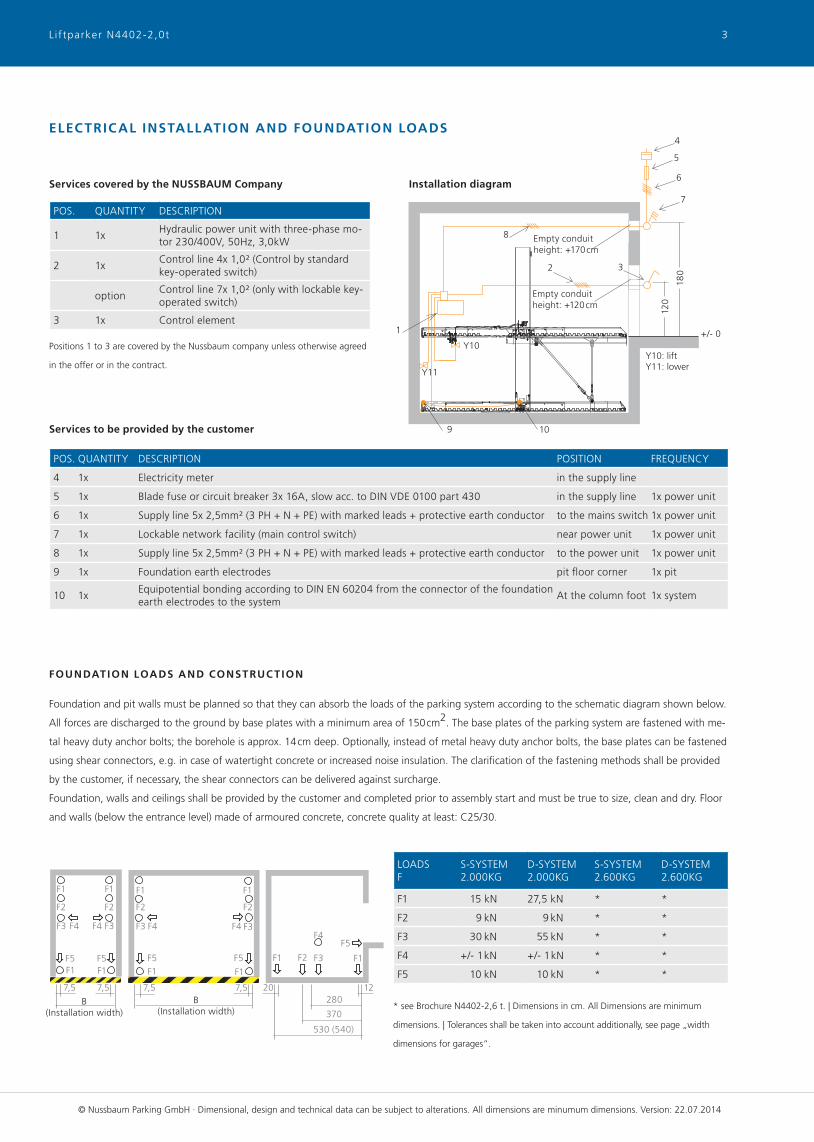
FOUNDATION LOADS AND CONSTRUC TION
Foundation and pit walls must be planned so that they can absorb the loads of the parking system according to the schematic diagram shown below.
All forces are discharged to the ground by base plates with a minimum area of 150cm2. The base plates of the parking system are fastened with me-
tal heavy duty anchor bolts; the borehole is approx. 14cm deep. Optionally, instead of metal heavy duty anchor bolts, the base plates can be fastened
using shear connectors, e.g. in case of watertight concrete or increased noise insulation. The clarifi cation of the fastening methods shall be provided
by the customer, if necessary, the shear connectors can be delivered against surcharge.
Foundation, walls and ceilings shall be provided by the customer and completed prior to assembly start and must be true to size, clean and dry. Floor
and walls (below the entrance level) made of armoured concrete, concrete quality at least: C25/30.
POS. QUANTITY DESCRIPTION
1 1xHydraulic power unit with three-phase mo-tor 230/400V, 50Hz, 3,0kW
2 1xControl line 4x 1,0² (Control by standard key-operated switch)
optionControl line 7x 1,0² (only with lockable key-operated switch)
3 1x Control element
Services to be provided by the customer
Services covered by the NUSSBAUM Company Installation diagram
LOADSF
S-SYSTEM2.000KG
D-SYSTEM2.000KG
S-SYSTEM2.600KG
D-SYSTEM2.600KG
F1 15 kN 27,5 kN * *
F2 9 kN 9 kN * *
F3 30 kN 55 kN * *
F4 +/- 1 kN +/- 1 kN * *
F5 10 kN 10 kN * *
* see Brochure N4402-2,6 t. | Dimensions in cm. All Dimensions are minimum
dimensions. | Tolerances shall be taken into account additionally, see page „width
dimensions for garages“.
ELECTRICAL INSTALL ATION AND FOUNDATION LOADS
Positions 1 to 3 are covered by the Nussbaum company unless otherwise agreed
in the offer or in the contract.Y10: liftY11: lower
Empty conduitheight: +170cm
Empty conduitheight: +120cm
VEHICLE DATA: STANDARD ESTATE C AR
© Nussbaum Parking GmbH · Dimensional, design and technical data can be subject to alterations. All dimensions are minumum dimensions. Version: 22.07.2014
B(Installation width)
B(Installation width)
530 (540)
280
370
20 127,5 7,57,5 7,5
F2F2 F2F2
F2F5F5
F1F1
F4F4 F3F3
F1F1
F5F5F1F1
F4F4 F3F3
F1F1
F4
F3
F5
F1 F1
3Liftparker N4402-2,0t
D
B B B
D
B2B1B2B1B2B1
max. 200
min. 20*
max. 200
min. 20*
max. 200
min. 20*DDDD
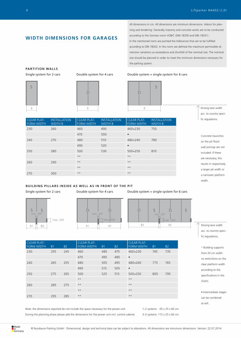
All dimensions in cm. All dimensions are minimum dimensions. Advice for plan-
ning and tendering: Generally masonry and concrete works are to be conducted
according to the German norm VOB/C (DIN 18330 and DIN 18331) .
In the mentioned norm are pointed the tollerances that are to be fulfilled
according to DIN 18202. In this norm are defined the maximum permissible di-
mension variations as exceedance and shortfall of the nominal size. The nominal
size should be planned in order to meet the minimum dimensions necessary for
the parking system.
1–2 systems: 65 x 25 x 60 cm
3–5 systems: 115 x 25 x 60 cm
Note: the dimensions reported do not include the space necessary for the power unit.
During the planning phase please add the dimensions for the power unit incl. control cabinet.
CLEAR PLAT-FORM WIDTH B1 B2
CLEAR PLAT-FORM WIDTH B1 B2
CLEAR PLAT-FORM WIDTH B1 B2
230 255 245 460 485 475 460+230 745 735
470 495 485 •
240 265 255 480 505 495 480+240 775 765
490 515 505 •
250 275 265 500 525 515 500+250 805 795
** **
260 285 275 ** **
** **
270 295 285 ** **
CLEAR PLAT-FORM WIDTH
INSTALLATION WIDTH B
CLEAR PLAT-FORM WIDTH
INSTALLATION WIDTH B
CLEAR PLAT-FORM WIDTH
INSTALLATION WIDTH B
230 260 460 490 460+230 750
470 500 •
240 270 480 510 480+240 780
490 520 •
250 280 500 530 500+250 810
** **
260 290 ** **
** **
270 300 ** **
* Building supports
from 20 cm width:
no restrictions on the
clear platform width
according to the
specifications in the
charts.
• Intermediate stages
can be combined
at will.
Driving lane width
acc. to country speci-
fic regulations.
SS
Double system + single system for 6 carsDouble system for 4 carsSingle system for 2 cars
BUILDING P ILL ARS INSIDE AS WELL AS IN FRONT OF THE P IT
S
Double system + single system for 6 carsDouble system for 4 carsSingle system for 2 cars
PARTIT ION WALLS
WIDTH DIMENSIONS FOR GARAGES
S
SS
Driving lane width
acc. to country speci-
fic regulations.
Concrete haunches
on the pit floor/
wall joinings are not
included. If these
are necessary, this
results in respectively
a larger pit width or
a narrower platform
width.
© Nussbaum Parking GmbH · Dimensional, design and technical data can be subject to alterations. All dimensions are minumum dimensions. Version: 22.07.2014
4 L i f tparker N4402-2,0t
TA
B
DB15 15B
DB15 15TA
D
DD
TA
BDB
BDB 30303015
BDB
BDB 303015
BDB
TA
All dimensions in cm. All dimensions are minimum dimensions. Advice for plan-
ning and tendering: Generally masonry and concrete works are to be conducted
according to the German norm VOB/C (DIN 18330 and DIN 18331) .
In the mentioned norm are pointed the tollerances that are to be fulfilled
according to DIN 18202. In this norm are defined the maximum permissible di-
mension variations as exceedance and shortfall of the nominal size. The nominal
size should be planned in order to meet the minimum dimensions necessary for
the parking system.
SINGLE AND DOUBLE GAR AGE
CLEAR PLAT-FORM WIDTH
INSTALLATION WIDTH B
DRIVE-INWIDTH DB
CLEAR PLAT-FORM WIDTH
INSTALLATION WIDTH B
DRIVE-INWIDTH DB
230 260 230 460 490 460
470 500 470
240 270 240 480 510 480
490 520 490
250 280 250 500 530 500
**
260 290 260 **
**
270 300 270 **
GAR AGES WITH S INGLE AND DOUBLE GATES
CLEAR PLAT-FORM WIDTH
INSTALLATION WIDTH B
DRIVE-INWIDTH DB
CLEAR PLAT-FORM WIDTH
INSTALLATION WIDTH B
DRIVE-INWIDTH DB
230 260 230 460 490 460
470 500 470
240 270 240 480 510 480
490 520 490
250 280 250 500 530 500
**
260 290 260 **
**
270 300 270 **
Driving lane width
acc. to country speci-
fic regulations.
** For more
D-system‘s parking
space widths: see
brochure N4602.
TA = seat engaging
surface for gates.
Dimensions to be
agreed on site with
gate manufacturer.
Driving lane width
acc. to country speci-
fic regulations.
WIDTH DIMENSIONS FOR GAR AGES WITH GATES
1–2 systems: 65 x 25 x 60 cm
3–5 systems: 115 x 25 x 60 cm
Note: the dimensions reported do not include the space necessary for the power unit.
During the planning phase please add the dimensions for the power unit incl. control cabinet.
S S S
Double system for 4 carsSingle system for 2 cars
S
Double system for 4 carsSingle system for 2 cars
Concrete haunches
on the pit floor/
wall joinings are not
included. If these
are necessary, this
results in respectively
a larger pit width or
a narrower platform
width.
© Nussbaum Parking GmbH · Dimensional, design and technical data can be subject to alterations. All dimensions are minumum dimensions. Version: 22.07.2014
5L i f tparker N4402-2,0t
COMPONENT PARTS
Single system consisting of 2 Platforms, 2
packed columns with hydraulic cylinders,
lifting slide and hydraulic block, 2 tension
rods and struts
and/or:
Double system consisting of 4 Platforms, 2
packed columns with hydraulic cylinders,
lifting slide and hydraulic block, 2 tension
rods and struts.
Platforms with sidewalls and driving
sheets made of Trapezoidal sheet.
DIMENSIONS OF THE SYSTEM
Standard system
Parking space length: 500 cm
Parking space width: 230 cm (for
max. 190 cm wide cars)
Pit depth: 170/165 cm.
Load per parking space: 2000 kg.
KEY SWITCH
Control unit composed of
key-switch with Emer-
gency-off in dead-man‘s
control and with cabling
to the hydraulic power
unit.
HYDR AULIC POWER UNIT INCL .
ELEC TRIC AL SWITCH BOX
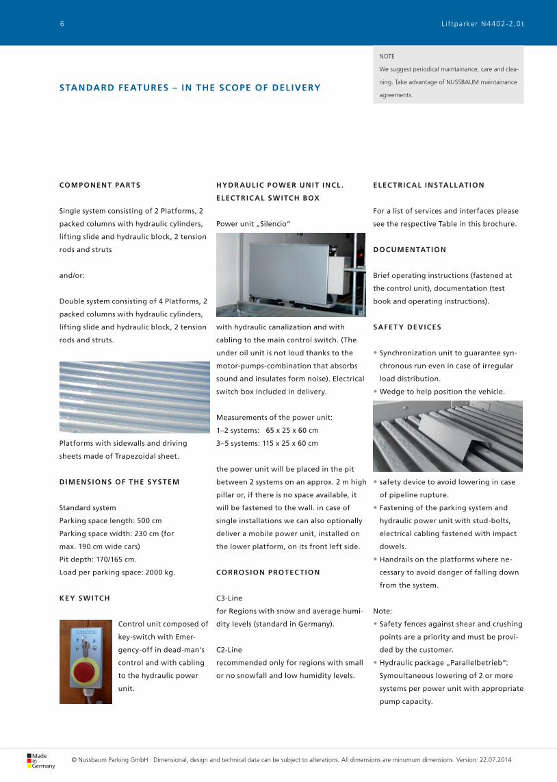
Power unit „Silencio“
with hydraulic canalization and with
cabling to the main control switch. (The
under oil unit is not loud thanks to the
motor-pumps-combination that absorbs
sound and insulates form noise). Electrical
switch box included in delivery.
Measurements of the power unit:
1–2 systems: 65 x 25 x 60 cm
3–5 systems: 115 x 25 x 60 cm
the power unit will be placed in the pit
between 2 systems on an approx. 2 m high
pillar or, if there is no space available, it
will be fastened to the wall. in case of
single installations we can also optionally
deliver a mobile power unit, installed on
the lower platform, on its front left side.
CORROSION PROTEC TION
C3-Line
for Regions with snow and average humi-
dity levels (standard in Germany).
C2-Line
recommended only for regions with small
or no snowfall and low humidity levels.
ELEC TRIC AL INSTALL ATION
For a list of services and interfaces please
see the respective Table in this brochure.
DOCUMENTATION
Brief operating instructions (fastened at
the control unit), documentation (test
book and operating instructions).
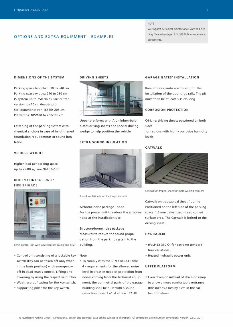
SAFET Y DEVICES
• Synchronization unit to guarantee syn-
chronous run even in case of irregular
load distribution.
• Wedge to help position the vehicle.
• safety device to avoid lowering in case
of pipeline rupture.
• Fastening of the parking system and
hydraulic power unit with stud-bolts,
electrical cabling fastened with impact
dowels.
• Handrails on the platforms where ne-
cessary to avoid danger of falling down
from the system.
Note:
• Safety fences against shear and crushing
points are a priority and must be provi-
ded by the customer.
• Hydraulic package „Parallelbetrieb“:
Symoultaneous lowering of 2 or more
systems per power unit with appropriate
pump capacity.
NOTE
We suggest periodical maintainance, care and clea-
ning. Take advantage of NUSSBAUM maintainance
agreements.STANDARD FEATURES – IN THE SCOPE OF DELIVERY
© Nussbaum Parking GmbH · Dimensional, design and technical data can be subject to alterations. All dimensions are minumum dimensions. Version: 22.07.2014
6 Liftparker N4402-2,0t
NOTE
We suggest periodical maintainance, care and clea-
ning. Take advantage of NUSSBAUM maintainance
agreements.OPTIONS AND EX TR A EQUIPMENT – EX AMPLES
DIMENSIONS OF THE SYSTEM
Parking space lengths: 510 to 540 cm
Parking space widths: 240 to 250 cm
(S-system up to 350 cm as Barrier free
version, by 10 cm deeper pit).
Stellplatzhöhe: von 165 bis 205 cm
Pit depths: 185/180 to 200/195 cm.
Fastening of the parking system with
chemical anchors in case of heighthened
foundation requirements or sound insu-
lation.
VEHICLE WEIGHT
Higher load per parking space:
up to 2.600 kg: see N4402-2,6t
BERLIN CONTROL UNIT/
FIRE BRIGADE
Berlin control unit with weatherproof casing and pillar
• Control unit consisting of a lockable key
switch (key can be taken off only when
in the basis position) with emergency-
off in dead-man‘s control. Lifting and
lowering by using the respective button.
• Weatherproof casing for the key switch.
• Supporting pillar for the key switch.
DRIVING SHEETS
Upper platforms with Aluminium-bulb
plates driving sheets and special driving
wedge to help position the vehicle.
EX TR A SOUND INSUL ATION
Sound insulation hood for the power unit
Airborne noise package - hood
For the power unit to reduce the airborne
noise at the installation site.
Structure/borne noise package
Measures to reduce the sound propa-
gation from the parking system to the
building.
Note
• To comply with the DIN 4109/A1 Table
4 - requirements for the allowed noise
level in areas in need of protection from
noises coming from the technical equip-
ment, the perimetral parts of the garage
building shall be built with a sound
reduction index Rw´ of at least 57 dB.
GAR AGE GATES‘ INSTALL ATION
Ramp if doorjambs are missing for the
installation of the door slide rails. The pit
must then be at least 535 cm long.
CORROSION PROTEC TION
C4-Line: driving sheets powdered on both
sides
for regions with highly corrosive humidity
levels.
C AT WALK
Catwalk on trapez. sheet for more walking comfort
Catwalk on trapezoidal sheet fl ooring
Positioned on the left side of the parking
space. 1,5 mm galvanized sheet, coined
surface area. The Catwalk is bolted to the
driving sheet.
HYDR AULIK
• HVLP 32-330 Öl for extreme tempera-
ture variations.
• Heated hydraulic power unit.
UPPER PL ATFORM
• Even drive-on instead of drive-on ramp
to allow a more comfortable entrance
(this means a loss by 8 cm in the car-
height below).
© Nussbaum Parking GmbH · Dimensional, design and technical data can be subject to alterations. All dimensions are minumum dimensions. Version: 22.07.2014
7Liftparker N4402-2,0t
Data subject to alteration. | Version 22.07.2014 - VM © Nussbaum Parking GmbH | Otto-Nussbaum-Str. 10 | D-04420 Markranstädt
Tel.: +49 (0) 34205 - 93 - 0 | Fax: +49 (0) 34205 - 93 - 191 | [email protected] | www.nussbaum-parking.com
SERVICES TO BE PROVIDED BY THE CUSTOMER AND PL ANNING INDICATIONS
During the planning phase please observe and comply with the following notes!
SERVICES TO BE PROVIDED BY THE CUSTOMER
Safety fences
Safety fences acc. to DIN EN ISO 13857
must be provided by the customer.
Parking space‘s numeration
For the allocation of the parking spaces
we suggest our customers to numerate
the parking spaces.
Noise abatement measures
The compliance with these measures
must be carried out by the customer acc.
to norm DIN 4109: „Sound insulation in
building construction“.
Lighting
To be carried out by the customer acc. to
DIN 67528: „Lighting for parking areas
and indoor car parks“.
Pit-foundation
to be carried out by the customer acc. to
the specifications in this brochure.
Electrical installation
Prior to starting the assembly the custo-
mer must provide a lockable main control
switch out of the system/pit and close
to the power unit. Electrical services to
be provided by the customer acc. to this
brochure‘s spec.
Installation requirements
The compliance with installation require-
ments acc. to quotation.
Drainage
Drainage channel 10 cm x 10 cm with
collecting pit 50 cm x 50 cm x 20 cm acc. to
this brochure‘s spec to be carried out by
the customer.
Fire protection
The customer must agree upon the fire
protection requirements and the required
measures with the local fire department
and realise them.
Marking
The customer must provide a 10 cm wide
yellow-black marking on the front pit
edge according to the norm ISO 3864.
Wall openings
In case of partition walls the customer
must realise a 10 cm x 10 cm wall opening
for hosting hydraulic and electrical cables.
Building permit
The customer must apply for and get the
required permits in order to allow the
installation of the parking system.
Control unit
The customer must make sure that a plan
surface of (L x W) 50 cm x 20 cm for the
installation of the control unit is directly
close to the power unit and out of the
platforms‘ moving area.
PL ANNING INDIC ATIONS
Parking space width and driving lanes
While planning the parking space and dri-
ving lane dimensions please observe and
comply with the local/national prescrip-
tions for the Garages‘ construction. For
more parking comfort we suggest you
to plan parking spaces of at least 250 cm
width.
Group of users
Our parking systems are conceived for a
permanent and instructed group of users.
Maintenance and care
We suggest a timely conclusion of a main-
tenance agreement.
We suggest also to perform maintainance,
care and cleaning at regular time inter-
vals.
EG-Machinery directive
Our parking systems comply with the EG-
Machinery directive and are CE certified
according to the norm DIN EN 14010.
Ramps‘ inclination
Ramps leading to garages shall not have
more than 15% inclination.
Modifications
The company Nussbaum Parking GmbH
reserves the right to make dimensional,
design and technical modifications.
8 L i f tparker N4402-2,0t


![halle-neu-Stadt-2050 Dokumentation DRUCK · PDF 2050. Vorgelegt von: Stadt Halle ] ... hier auf einen international renommierten Forsch ungs- und Gründungsstandort, der seine Kom](https://img.pdfslide.net/doc/110x75/5a78e99e7f8b9a5a148d9367/halle-neu-stadt-2050-dokumentation-druck-2050-vorgelegt-von-stadt-halle-.jpg)