Embed Size (px)
Citation preview

Neue Wege in der Kältetechnik –der Energiesparmotor (ESM)
Dies ist der neue Claim von ebm-papst
New approach in refrigerationenergy-saving motor (ESM)
„Ich halte den Strom-verbrauch von Kühltheken immer noch für zu hoch.Und Sie?“
„In my opinion, the power consumption of cooling counters is still far too high.Don’t you think so, too?“

2
Resourcen schonen
Soft on resources
Der Energiesparmotor ESM bietet einen hohen Wirkungsgrad und damit deutliche Energieeinsparung bei hoher Lebensdauer. Die Alternative zum Spaltpol-Q-Motor.
The energy-saving motor (ESM) is highly efficient,consumes significantly little energy and has a high lifetime.It is the perfect alternative to the shaded-pole Q-motor.

3
Inhaltsverzeichnis
Table of content
5 - 13 Energiespar-AxialventilatorEnergy-saving axial fan
4 Vorteile und Eigenschaften auf einen BlickAdvantages and characteristics at a glance
Energiesparmotor (ESM)Energy-saving motor (ESM)
Quadratischer Spaltmotor (Q-Motor)Square shaded-pole motor (Q-motor)
30.09.2003Datumdate
14 - 18
19 - 43
Die Vertretungen der ebm-papstebm-papst subsidiaries and agencies
44 - 47
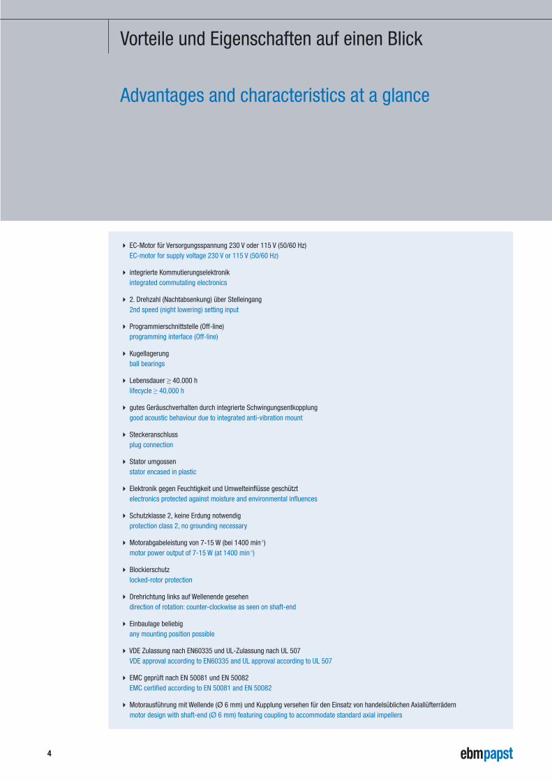
Vorteile und Eigenschaften auf einen Blick
Advantages and characteristics at a glance
� EC-Motor für Versorgungsspannung 230 V oder 115 V (50/60 Hz)EC-motor for supply voltage 230 V or 115 V (50/60 Hz)
� integrierte Kommutierungselektronikintegrated commutating electronics
� 2. Drehzahl (Nachtabsenkung) über Stelleingang2nd speed (night lowering) setting input
� Programmierschnittstelle (Off-line)programming interface (Off-line)
� Kugellagerungball bearings
� Lebensdauer ≥ 40.000 h lifecycle ≥ 40,000 h
� gutes Geräuschverhalten durch integrierte Schwingungsentkopplunggood acoustic behaviour due to integrated anti-vibration mount
� Steckeranschlussplug connection
� Stator umgossenstator encased in plastic
� Elektronik gegen Feuchtigkeit und Umwelteinflüsse geschütztelectronics protected against moisture and environmental influences
� Schutzklasse 2, keine Erdung notwendigprotection class 2, no grounding necessary
� Motorabgabeleistung von 7-15 W (bei 1400 min-1)motor power output of 7-15 W (at 1400 min-1)
� Blockierschutzlocked-rotor protection
� Drehrichtung links auf Wellenende gesehendirection of rotation: counter-clockwise as seen on shaft-end
� Einbaulage beliebigany mounting position possible
� VDE Zulassung nach EN60335 und UL-Zulassung nach UL 507VDE approval according to EN60335 and UL approval according to UL 507
� EMC geprüft nach EN 50081 und EN 50082EMC certified according to EN 50081 and EN 50082
� Motorausführung mit Wellende (Ø 6 mm) und Kupplung versehen für den Einsatz von handelsüblichen Axiallüfterrädernmotor design with shaft-end (Ø 6 mm) featuring coupling to accommodate standard axial impellers
4
5
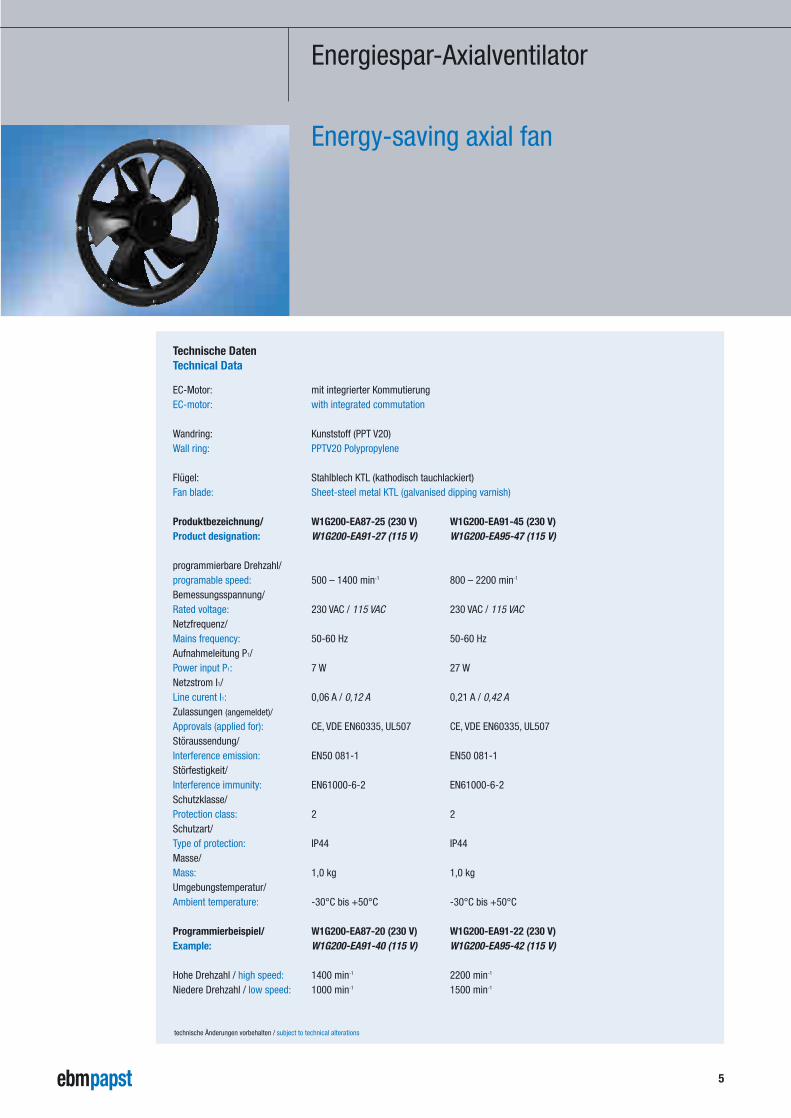
Energiespar-Axialventilator
Energy-saving axial fan
technische Änderungen vorbehalten / subject to technical alterations
EC-Motor: mit integrierter Kommutierung EC-motor: with integrated commutation
Wandring: Kunststoff (PPT V20) Wall ring: PPTV20 Polypropylene
Flügel: Stahlblech KTL (kathodisch tauchlackiert) Fan blade: Sheet-steel metal KTL (galvanised dipping varnish)
Produktbezeichnung/ W1G200-EA87-25 (230 V) W1G200-EA91-45 (230 V)Product designation: W1G200-EA91-27 (115 V) W1G200-EA95-47 (115 V)
programmierbare Drehzahl/ programable speed: 500 – 1400 min-1 800 – 2200 min-1
Bemessungsspannung/ Rated voltage: 230 VAC / 115 VAC 230 VAC / 115 VACNetzfrequenz/ Mains frequency: 50-60 Hz 50-60 HzAufnahmeleitung P1/ Power input P1: 7 W 27 WNetzstrom I1/ Line curent I1: 0,06 A / 0,12 A 0,21 A / 0,42 AZulassungen (angemeldet)/
Approvals (applied for): CE, VDE EN60335, UL507 CE, VDE EN60335, UL507Störaussendung/ Interference emission: EN50 081-1 EN50 081-1Störfestigkeit/ Interference immunity: EN61000-6-2 EN61000-6-2Schutzklasse/ Protection class: 2 2Schutzart/ Type of protection: IP44 IP44Masse/ Mass: 1,0 kg 1,0 kgUmgebungstemperatur/ Ambient temperature: -30°C bis +50°C -30°C bis +50°C
Programmierbeispiel/ W1G200-EA87-20 (230 V) W1G200-EA91-22 (230 V)Example: W1G200-EA91-40 (115 V) W1G200-EA95-42 (115 V)
Hohe Drehzahl / high speed: 1400 min-1 2200 min-1
Niedere Drehzahl / low speed: 1000 min-1 1500 min-1
Technische DatenTechnical Data
6
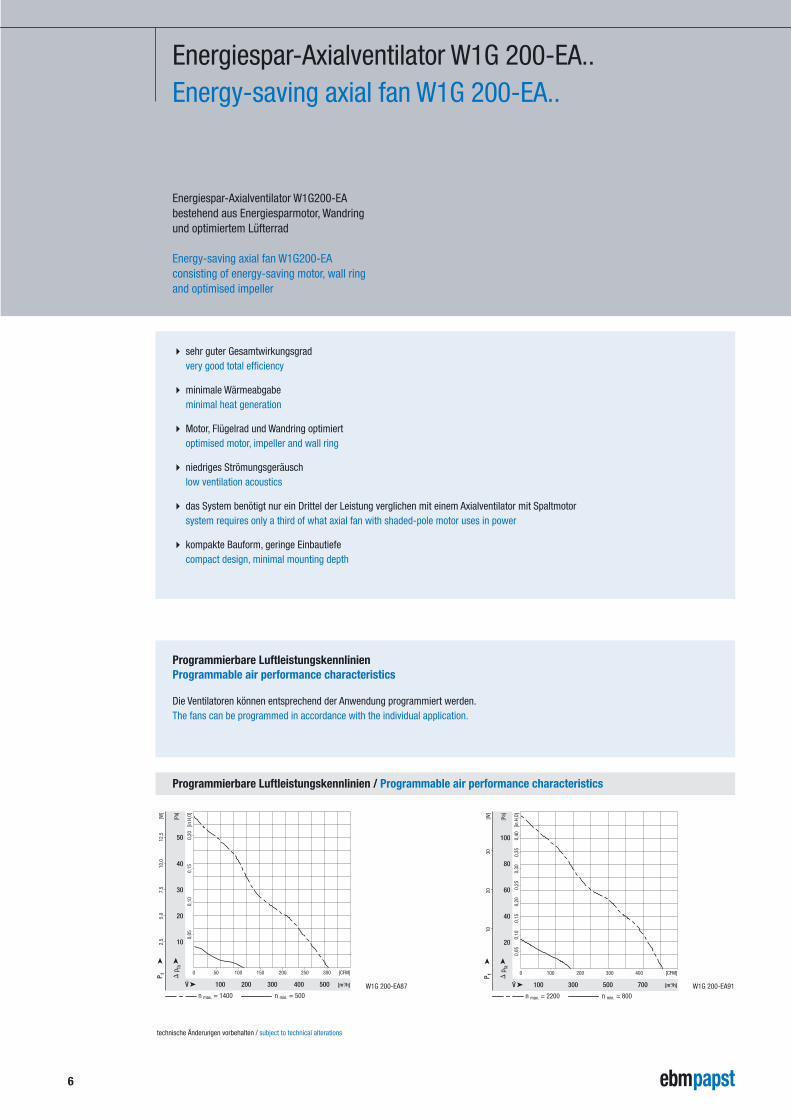
Energiespar-Axialventilator W1G 200-EA..Energy-saving axial fan W1G 200-EA..
Energiespar-Axialventilator W1G200-EA bestehend aus Energiesparmotor, Wandringund optimiertem Lüfterrad
Energy-saving axial fan W1G200-EA consisting of energy-saving motor, wall ringand optimised impeller
� sehr guter Gesamtwirkungsgradvery good total efficiency
� minimale Wärmeabgabeminimal heat generation
� Motor, Flügelrad und Wandring optimiertoptimised motor, impeller and wall ring
� niedriges Strömungsgeräuschlow ventilation acoustics
� das System benötigt nur ein Drittel der Leistung verglichen mit einem Axialventilator mit Spaltmotorsystem requires only a third of what axial fan with shaded-pole motor uses in power
� kompakte Bauform, geringe Einbautiefecompact design, minimal mounting depth
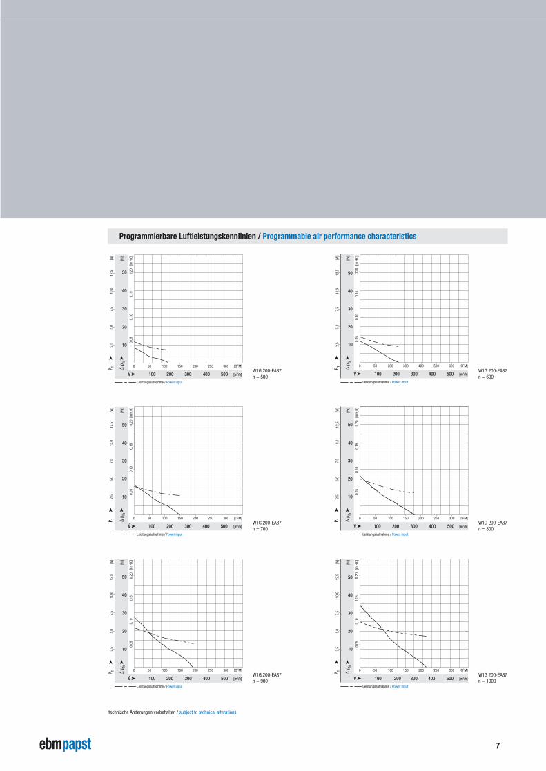
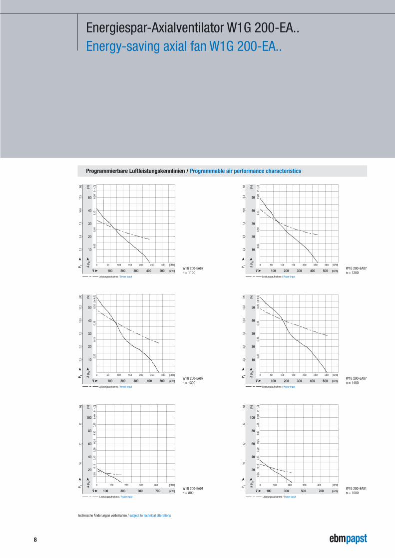
Programmierbare Luftleistungskennlinien / Programmable air performance characteristics
Programmierbare LuftleistungskennlinienProgrammable air performance characteristics
Die Ventilatoren können entsprechend der Anwendung programmiert werden.The fans can be programmed in accordance with the individual application.
100 200 300 400 500
0 50 [CFM]100 150 200 250 300
[Pa]
10
0,05
0,10
0,15
0,20
[in H
2O]
[m3/h]
[W]
2,5
5,0
7,5
10,0
12,5
n max. = 1400 n min. = 500
P 1
20
30
40
50
100 300 500 700
0 [CFM]100 200 300 400
[Pa]
20
0,05
0,10
0,15
0,40
[in H
2O]
0,20
0,25
0,30
0,35
[m3/h]
[W]
1020
30
n max. = 2200 n min. = 800
P 1
40
60
80
100
technische Änderungen vorbehalten / subject to technical alterations
W1G 200-EA87 W1G 200-EA91
7
Programmierbare Luftleistungskennlinien / Programmable air performance characteristics
100 200 300 400 500
0 50 [CFM]100 150 200 250 300
[Pa]
10
0,05
0,10
0,15
0,20
[in H
2O]
[m3/h]
[W]
2,5
12,5
10,0
Leistungsaufnahme / Power input
P 15,
07,
5
20
30
40
50
100 200 300 400 500
0 50 [CFM]100 150 200 250 300
[Pa]
10
20
30
40
50
0,05
0,10
0,15
0,20
[in H
2O]
[m3/h]
[W]
2,5
5,0
10,0
12,5
7,5
Leistungsaufnahme / Power input
P 1
0 50 200 [CFM]300 400 500 600
[Pa]
10
20
30
40
50
0,05
0,10
0,15
0,20
[in H
2O]
[m3/h]
[W]
2,5
5,0
7,5
10,0
12,5
Leistungsaufnahme / Power input
P 1
100 200 300 400 500
100 200 300 400 500
0 50 100 300 [CFM]150 200 250
[Pa]
10
20
30
40
50
0,05
0,10
0,15
0,20
[in H
2O]
[m3/h]
[W]
2,5
5,0
12,5
7,5
10,0
Leistungsaufnahme / Power input
P 1
100 200 300 400 500
0 50 [CFM]100 150 200 250 300
[Pa]
10
0,05
0,10
0,15
0,20
[in H
2O]
[m3/h]
[W]
2,5
5,0
7,5
10,0
12,5
Leistungsaufnahme / Power input
P 1
20
30
40
50
100 200 300 400 500
0 50 [CFM]100 150 200 250 300
[Pa]
10
20
30
40
50
0,05
0,10
0,15
0,20
[in H
2O]
[m3/h]
[W]
2,5
5,0
7,5
10,0
12,5
Leistungsaufnahme / Power input
P 1
technische Änderungen vorbehalten / subject to technical alterations
W1G 200-EA87n = 900
W1G 200-EA87n = 700
W1G 200-EA87n = 500
W1G 200-EA87n = 1000
W1G 200-EA87n = 800
W1G 200-EA87n = 600
Programmierbare Luftleistungskennlinien / Programmable air performance characteristics
100 200 300 400 500
0 50 [CFM]100 150 200 250 300
[Pa]
10
0,05
0,10
0,15
0,20
[in H
2O]
[m3/h]
[W]
2,5
5,0
7,5
10,0
12,5
Leistungsaufnahme / Power input
P 1
20
30
40
50
100 200 300 400 500
0 50 [CFM]100 150 200 250 300
[Pa]
10
0,05
0,10
0,15
0,20
[in H
2O]
[m3/h]
[W]
2,5
5,0
7,5
10,0
12,5
Leistungsaufnahme / Power input
P 1
20
30
40
50
100 200 300 400 500
0 50 [CFM]100 150 200 250 300
[Pa]
10
0,05
0,10
0,15
0,20
[in H
2O]
[m3/h]
[W]
2,5
5,0
7,5
10,0
12,5
Leistungsaufnahme / Power input
P 1
20
30
40
50
100 200 300 400 500
0 50 250 [CFM]100 150 200 300
[Pa]
10
30
40
0,05
0,10
0,15
0,20
[in H
2O]
[m3/h]
[W]
2,5
5,0
10,0
12,5
7,5
Leistungsaufnahme / Power input
P 1
20
50
100 300 500 700
0 [CFM]100 200 400300
[Pa]
20
0,10
0,05
0,15
0,40
[in H
2O]
0,20
0,25
0,30
0,35
[m3/h]
[W]
1020
30
Leistungsaufnahme / Power input
P 1
40
60
80
100
100 300 500 700
0 [CFM]100 200 400300
[Pa]
20
0,10
0,05
0,15
0,40
[in H
2O]
0,20
0,25
0,30
0,35
[m3/h]
[W]
1020
30
Leistungsaufnahme / Power input
P 1
40
60
80
100
8
Energiespar-Axialventilator W1G 200-EA..Energy-saving axial fan W1G 200-EA..
technische Änderungen vorbehalten / subject to technical alterations
W1G 200-EA91n = 800
W1G 200-EA87n = 1300
W1G 200-EA87n = 1100
W1G 200-EA91n = 1000
W1G 200-EA87n = 1400
W1G 200-EA87n = 1200

Programmierbare Luftleistungskennlinien / Programmable air performance characteristics
100 300 500 700
0 [CFM]100 200 400300
[Pa]
20
0,10
0,05
0,15
0,40
[in H
2O]
0,20
0,25
0,30
0,35
[m3/h]
[W]
1020
30
Leistungsaufnahme / Power input
P 1
40
60
80
100
100 300 500 700
0 [CFM]100 200 400300
[Pa]
20
0,10
0,05
0,15
0,40
[in H
2O]
0,20
0,25
0,30
0,35
[m3/h]
[W]
1020
30
Leistungsaufnahme / Power input
P 1
40
60
80
100
100 300 500 700
0 [CFM]100 200 400300
[Pa]
20
0,10
0,05
0,15
0,40
[in H
2O]
0,20
0,25
0,30
0,35
[m3/h]
[W]
1020
30
Leistungsaufnahme / Power input
P 1
40
60
80
100
100 300 500 700
0 [CFM]100 200 400300
[Pa]
20
0,10
0,05
0,15
0,40
[in H
2O]
0,20
0,25
0,30
0,35
[m3/h]
[W]
1020
30
Leistungsaufnahme / Power input
P 1
40
60
80
100
100 300 500 700
0 [CFM]100 200 400300
[Pa]
20
0,10
0,05
0,15
0,40
[in H
2O]
0,20
0,25
0,30
0,35
[m3/h]
[W]
1020
30
Leistungsaufnahme / Power input
P 1
40
60
80
100
100 300 500 700
0 [CFM]100 200 400300
[Pa]
20
0,10
0,05
0,15
0,40
[in H
2O]
0,20
0,25
0,30
0,35
[m3/h]
[W]
1020
30
Leistungsaufnahme / Power input
P 1
40
60
80
100
9
technische Änderungen vorbehalten / subject to technical alterations
W1G 200-EA91n = 2000
W1G 200-EA91n = 1600
W1G 200-EA91n = 1200
W1G 200-EA91n = 2200
W1G 200-EA91n = 1800
W1G 200-EA91n = 1400
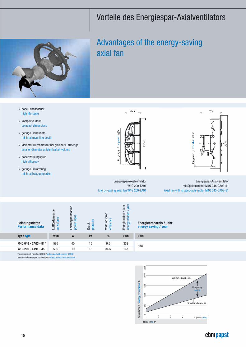
Typ / type
M4Q 045 - CA03 - 51(1)
W1G 200 - EA91 - 45
� hohe Lebensdauerhigh life-cycle
� kompakte Maßecompact dimensions
� geringe Einbautiefeminimal mounting depth
� kleinerer Durchmesser bei gleicher Luftmengesmaller diameter at identical air volume
� hoher Wirkungsgradhigh efficency
� geringe Erwärmungminimal heat generation
10
Vorteile des Energiespar-Axialventilators
Advantages of the energy-saving axial fan
kWh
185
Leistungsdaten Performance data
Energieersparnis / Jahrenergy saving / year
technische Änderungen vorbehalten / subject to technical alterations
(1) gemessen mit Flügelrad Ø 230 / determined with impeller Ø 230
Druc
k
Luftf
örde
rmen
geai
r vol
ume
Leis
tung
sauf
nahm
epo
wer
inpu
t
pres
sure
Wirk
ungs
grad
effic
ienc
y
ener
gy n
eede
d / y
ear
Ener
gieb
edar
f / J
ahr
m3/h W Pa % kWh
595 40 15 9,5 352
595 19 15 34,5 167
Einsparungsaving
2000
[kW
h]15
0010
0050
00
Ener
gieb
edar
f / e
nerg
y re
quire
men
t ➤
Zeit / time ➤
M4Q 045 - CA03 - 51
W1G 200 - EA91 - 45
2 3 4 51 [Jahre / years]
Energiespar-Axialventilator W1G 200-EA91
Energy-saving axial fan W1G 200-EA91
Energiespar-Axialventilator mit Spaltpolmotor M4Q 045-CA03-51
Axial fan with shaded-pole motor M4Q 045-CA03-51
11
Energiespar-Axialventilator
Energy-saving axial fan
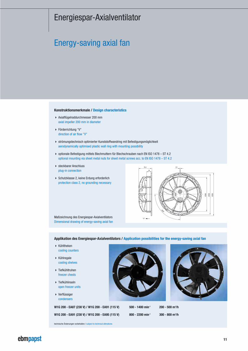
Konstruktionsmerkmale / Design characteristics
� Axialflügelraddurchmesser 200 mmaxial impeller 200 mm in diameter
� Förderrichtung "V"direction of air flow "V"
� strömungstechnisch optimierter Kunststoffwandring mit Befestigungsmöglichkeitaerodynamically optimised plastic wall ring with mounting possibility
� optionale Befestigung mittels Blechmuttern für Blechschrauben nach EN ISO 1478 – ST 4.2optional mounting via sheet metal nuts for sheet metal screws acc. to EN ISO 1478 – ST 4.2
� steckbarer Anschlussplug-in connection
� Schutzklasse 2, keine Erdung erforderlichprotection class 2, no grounding necessary
Maßzeichnung des Energiespar-AxialventilatorsDimensional drawing of energy-saving axial fan
Applikation des Energiespar-Axialventilators / Application possibilities for the energy-saving axial fan
W1G 200 - EA87 (230 V) / W1G 200 - EA91 (115 V) 500 - 1400 min-1 200 - 500 m3/h
W1G 200 - EA91 (230 V) / W1G 200 - EA95 (115 V) 800 - 2200 min-1 300 - 800 m3/h
� Kühlthekencooling counters
� Kühlregalecooling shelves
� Tiefkühltruhenfreezer chests
� Tiefkühlinselnopen freezer units
� Verflüssigercondensers
30
Ø25
0
Ø23
6
Ø20
0
76,4
4x90°
4,3
"V"
technische Änderungen vorbehalten / subject to technical alterations
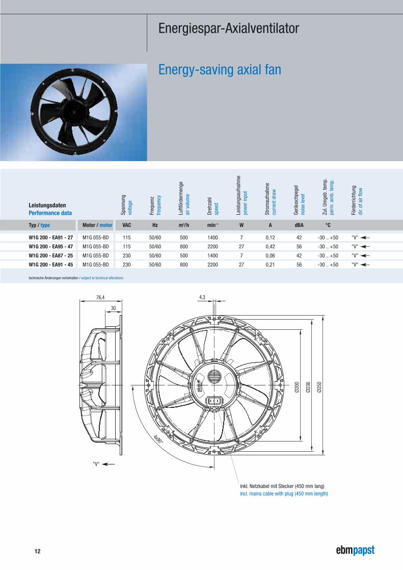
Typ / type
W1G 200 - EA91 - 27
W1G 200 - EA95 - 47
W1G 200 - EA87 - 25
W1G 200 - EA91 - 45
12
Luftf
örde
rmen
ge
Dreh
zahl
Span
nung
volta
ge
Freq
uenz
frequ
ency
air v
olum
e
spee
d
pow
er in
put
curr
ent d
raw
nois
e le
vel
perm
.am
b.te
mp.
Leis
tung
sauf
nahm
e
Stro
mau
fnah
me
Gerä
usch
pege
l
Zul.
Umge
b.te
mp.
dir.
of a
ir flo
wFö
rder
richt
ung
technische Änderungen vorbehalten / subject to technical alterations
VAC Hz m3/h min-1 W A dBA °C
115 50/60 500 1400 7 0,12 42 -30 .. +50 "V"
115 50/60 800 2200 27 0,42 56 -30 .. +50 "V"
230 50/60 500 1400 7 0,06 42 -30 .. +50 "V"
230 50/60 800 2200 27 0,21 56 -30 .. +50 "V"
Motor / motor
M1G 055-BD
M1G 055-BD
M1G 055-BD
M1G 055-BD
Leistungsdaten Performance data
30
Ø25
0
Ø23
6
Ø20
076,4
4x90°
4,3
"V"
Energiespar-Axialventilator
Energy-saving axial fan
inkl. Netzkabel mit Stecker (450 mm lang)incl. mains cable with plug (450 mm length)
13
technische Änderungen vorbehalten / subject to technical alterations
Anschlussplanelectrical connections
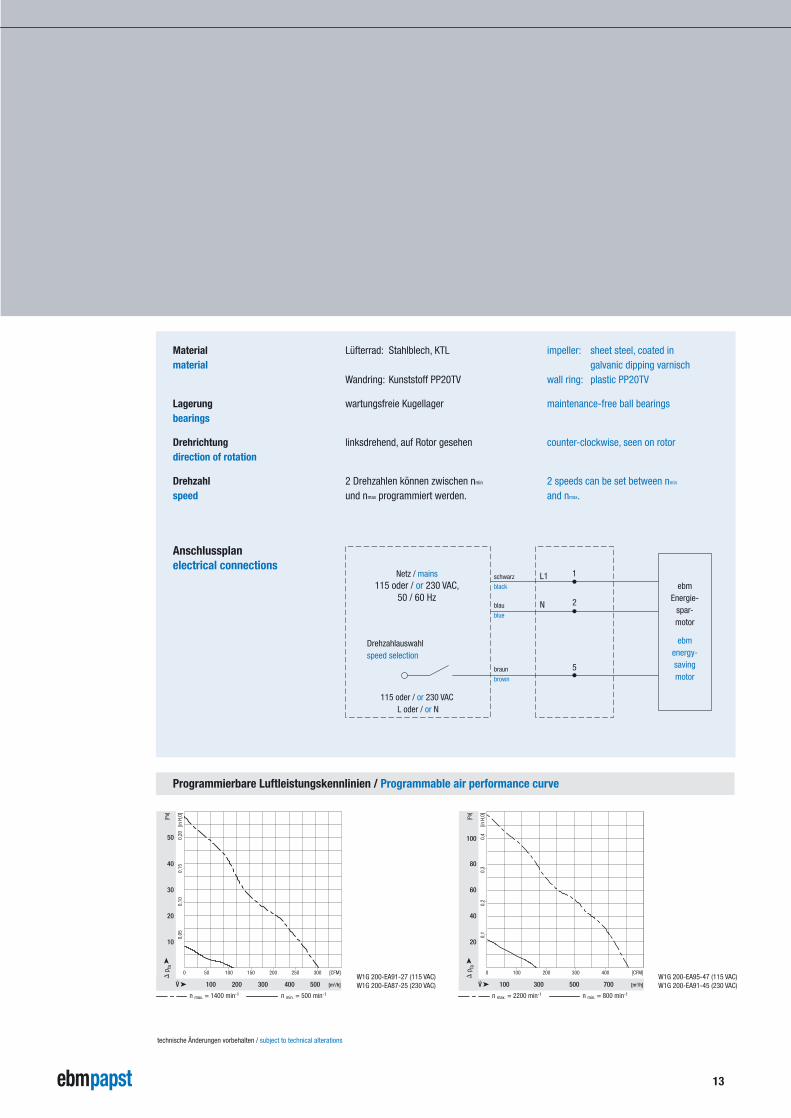
Materialmaterial
Lagerungbearings
Drehrichtungdirection of rotation
Drehzahlspeed
Lüfterrad: Stahlblech, KTL
Wandring: Kunststoff PP20TV
wartungsfreie Kugellager
linksdrehend, auf Rotor gesehen
2 Drehzahlen können zwischen nmin
und nmax programmiert werden.
impeller: sheet steel, coated ingalvanic dipping varnisch
wall ring: plastic PP20TV
maintenance-free ball bearings
counter-clockwise, seen on rotor
2 speeds can be set between nmin
and nmax.
schwarz
black
blau
blue
braun
brown
Netz / mains 115 oder / or 230 VAC,
50 / 60 Hz
115 oder / or 230 VAC L oder / or N
Drehzahlauswahlspeed selection
L1
N
ebmEnergie-
spar-motor
ebmenergy-savingmotor
1
2
5
100 200 300 400 500
0 50 [CFM]100 150 200 250 300
[Pa]
10
0,05
0,10
0,15
0,20
[in H
2O]
[m3/h]
n max. = 1400 min-1 n min. = 500 min-1
20
30
40
50
100 300 700500
0 [CFM]100 200 300 400
[Pa]
20
0,1
0,2
0,3
0,4
[in H
2O]
[m3/h]
n max. = 2200 min-1 n min. = 800 min-1
40
60
80
100
Programmierbare Luftleistungskennlinien / Programmable air performance curve
W1G 200-EA91-27 (115 VAC)W1G 200-EA87-25 (230 VAC)
W1G 200-EA95-47 (115 VAC)W1G 200-EA91-45 (230 VAC)
14
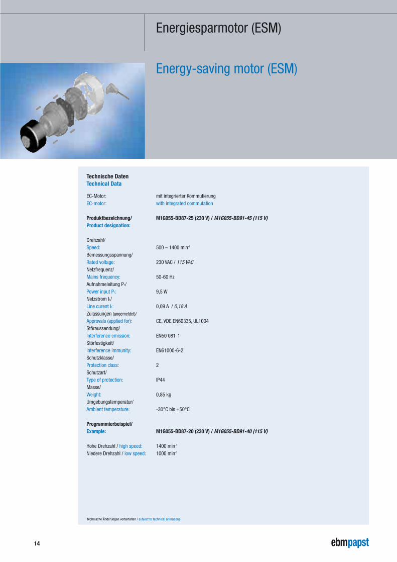
Energiesparmotor (ESM)
Energy-saving motor (ESM)
technische Änderungen vorbehalten / subject to technical alterations
EC-Motor: mit integrierter Kommutierung EC-motor: with integrated commutation
Produktbezeichnung/ M1G055-BD87-25 (230 V) / M1G055-BD91-45 (115 V)Product designation:
Drehzahl/ Speed: 500 – 1400 min-1
Bemessungsspannung/ Rated voltage: 230 VAC / 115 VACNetzfrequenz/ Mains frequency: 50-60 HzAufnahmeleitung P1/ Power input P1: 9,5 WNetzstrom I1/ Line curent I1: 0,09 A / 0,18 AZulassungen (angemeldet)/
Approvals (applied for): CE, VDE EN60335, UL1004Störaussendung/ Interference emission: EN50 081-1Störfestigkeit/ Interference immunity: EN61000-6-2Schutzklasse/ Protection class: 2Schutzart/ Type of protection: IP44Masse/ Weight: 0,85 kgUmgebungstemperatur/ Ambient temperature: -30°C bis +50°C
Programmierbeispiel/Example: M1G055-BD87-20 (230 V) / M1G055-BD91-40 (115 V)
Hohe Drehzahl / high speed: 1400 min-1
Niedere Drehzahl / low speed: 1000 min-1
Technische DatenTechnical Data
15
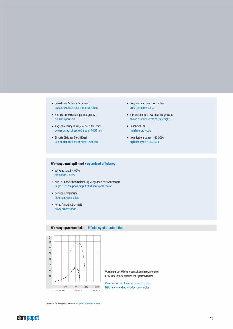
Wirkungsgradkennlinien Efficiency characteristics
600 1200 1800
�[%
]
10
20
30
40
50
60
70
n [min-1]
M1G 055-BD87 M4Q 045-CF M4Q 045-CA
� bewährtes Außenläuferprinzipproven external-rotor motor principle
� Betrieb am WechselspannungsnetzAC-line operation
� Abgabeleistung bis 6,2 W bei 1400 min-1
power output of up to 6.2 W at 1400 min-1
� Einsatz üblicher Blechflügeluse of standard sheet metal impellers
� Wirkungsgrad > 65%efficiency > 65%
� nur 1/3 der Aufnahmeleistung verglichen mit Spaltmotoronly 1/3 of the power input of shaded-pole motor
� geringe Erwärmunglittle heat generation
� kurze Amortisationszeitquick amortization
� programmierbare Drehzahlenprogrammable speed
� 2 Drehzahlstufen wählbar (Tag/Nacht)choice of 2 speed steps (day/night)
� Feuchtschutzmoisture protection
� hohe Lebensdauer ≥ 40.000hhigh life-cycle ≥ 40,000h
Wirkungsgrad optimiert / optimised efficiency
Vergleich der Wirkungsgradkennlinie zwischenESM und handelsüblichem Spaltpolmotor
Comparison in efficiency curves of the ESM and standard shaded-pole motor
technische Änderungen vorbehalten / subject to technical alterations
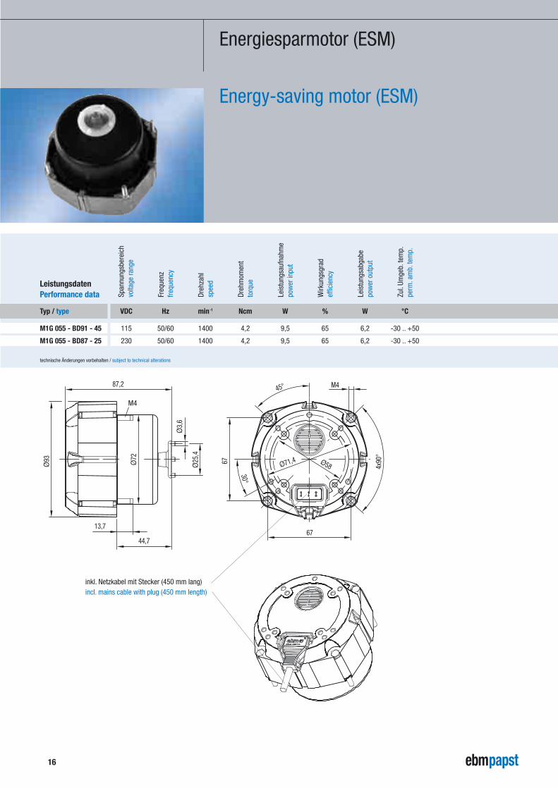
Typ / type
M1G 055 - BD91 - 45
M1G 055 - BD87 - 25
VDC Hz min-1 Ncm W % W °C
115 50/60 1400 4,2 9,5 65 6,2 -30 .. +50
230 50/60 1400 4,2 9,5 65 6,2 -30 .. +50
Leistungsdaten Performance data Dr
ehza
hl
Span
nung
sber
eich
volta
ge ra
nge
Freq
uenz
frequ
ency
spee
d
Dreh
mom
ent
torq
ue
pow
er in
put
effic
ienc
y
pow
er o
utpu
t
perm
.am
b.te
mp.
Leis
tung
sauf
nahm
e
Wirk
ungs
grad
Leis
tung
sabg
abe
Zul.
Umge
b.te
mp.
technische Änderungen vorbehalten / subject to technical alterations
Energiesparmotor (ESM)
Energy-saving motor (ESM)
Ø93
87,2
Ø3,
6
Ø25
,4
Ø72 Ø58Ø71,4
67
30°
M4
67
4x90
°
45°
13,7
44,7
M4
16
inkl. Netzkabel mit Stecker (450 mm lang)incl. mains cable with plug (450 mm length)
17
technische Änderungen vorbehalten / subject to technical alterations
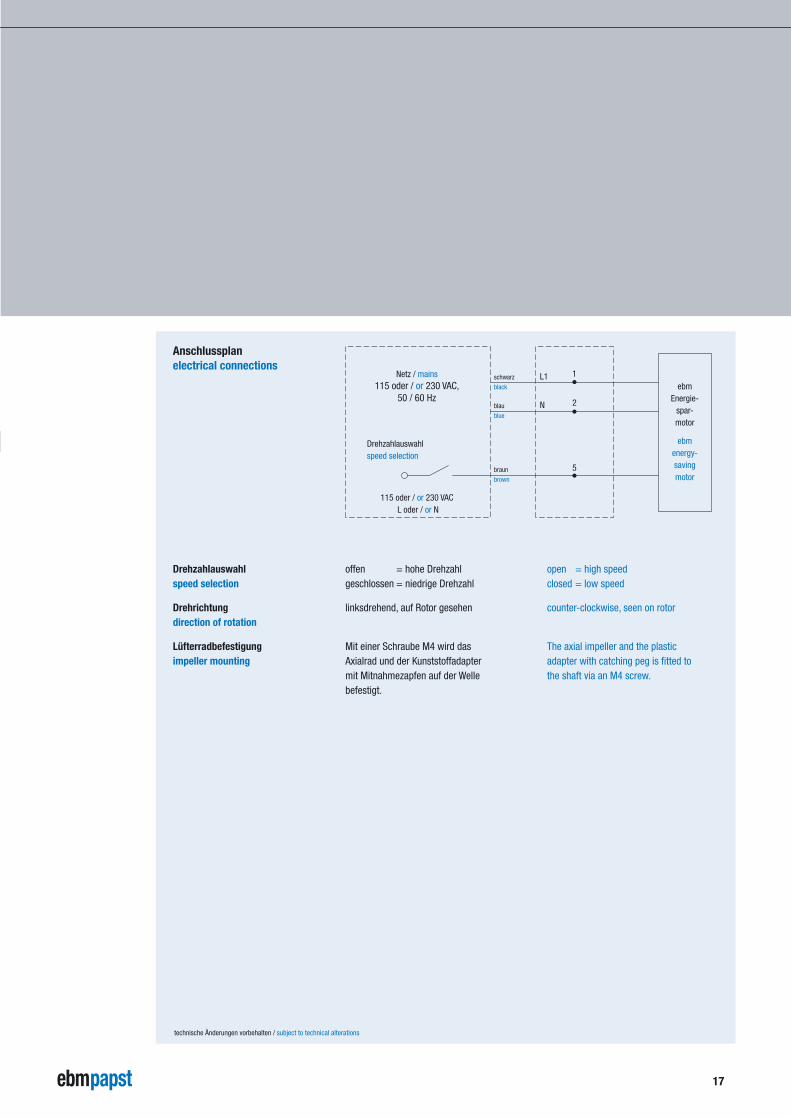
Anschlussplanelectrical connections
Drehzahlauswahlspeed selection
Drehrichtungdirection of rotation
Lüfterradbefestigungimpeller mounting
offen = hohe Drehzahlgeschlossen = niedrige Drehzahl
linksdrehend, auf Rotor gesehen
Mit einer Schraube M4 wird das Axialrad und der Kunststoffadaptermit Mitnahmezapfen auf der Welle befestigt.
open = high speedclosed = low speed
counter-clockwise, seen on rotor
The axial impeller and the plasticadapter with catching peg is fitted tothe shaft via an M4 screw.
schwarz
black
blau
blue
braun
brown
Netz / mains 115 oder / or 230 VAC,
50 / 60 Hz
115 oder / or 230 VAC L oder / or N
Drehzahlauswahlspeed selection
L1
N
ebmEnergie-
spar-motor
ebmenergy-savingmotor
1
2
5
18
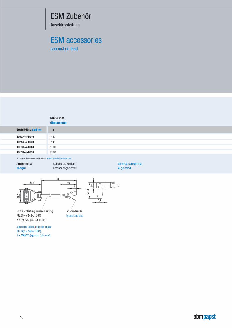
ESM ZubehörAnschlussleitung
ESM accessoriesconnection lead
Bestell-Nr. / part no.
10637-4-1040
10640-4-1040
10638-4-1040
10639-4-1040
a
450
600
1500
2000
Maße mmdimensions
technische Änderungen vorbehalten / subject to technical alterations
a31,5
22,5
740
27,5
10
9,3
Aderendkrallebrass lead tips
Schlauchleitung, innere Leitung(UL Style 2464/1061)3 x AWG20 (ca. 0,5 mm2)
Jacketed cable, internal leads(UL Style 2464/1061)3 x AWG20 (approx. 0.5 mm2)
Leitung UL-konform,Stecker abgedichtet
Ausführung:design:
cable UL-conforming,plug sealed
19
Quadratischer Spaltpolmotor (Q-Motor)
Square shaded-pole motor (Q-motor)
Technischer Hinweistechnical features
Schutzarttype of protection
Befestigungmounting
Leistungsangabenperformance data
Isolationsklasseinsulation class
Axialflügelräderaxial impellers
Der Q-Motor ist ein Spaltpolmotor mit quadratischenAußenabmessungen. Die quadratische Form wurdegewählt, um bei der Herstellung (Stanzen) desStatorpaketes eine optimale Materialausnutzungzu bekommen. Außerdem ist diese quadratischeForm mit dem Maß 83 x 83 mm ein allgemeinerStandard.
Q-Motoren sind geschlossen und entsprechen der Schutzklasse IP 42.
Die beidseitigen Druckgusslagerschilde (A- und B-Seite) beinhalten mehrere Befestigungsmöglich-keiten. Die Zuordnungen können aus der Auswahl-tabelle S. 21 entnommen werden.Die überstehenden Gewindeenden auf der A-Seitewerden zur Befestigung von Schutzgitter undWandringen verwendet. Der Q-Motor kann auchmit den Befestigungsfüßen, die in den Lagerschildenangebracht sind, angeschraubt werden. Wir bietenAusführungen mit 26 mm (Achshöhe 51 mm) oder18 mm (Achshöhe 48 mm) Fußabstandsmaß.Die Multifunktionsausführung hat beide Fußbe-festigungsmaße in einem Motor vereint.
Die Leistungsangaben beziehen sich auf diegeschlossene Ausführung IP 42 unter Ausnutzung der Isolationsklasse "B" und der Nennspannung 230 VAC, 50 Hz.Bei 60 Hz muss der Schaufelwinkel der Axialräderum jeweils 6° reduziert werden.Bei niedrigen Umgebungstemperaturen, sehr guterKühlung sowie bei Kurzzeitbetrieb (S2) können dieQ-Motoren auch stärker ausgelegt werden.
"B"
Wir stellen Axialflügelräder vom Durchmesser 154bis 300 mm in den Schaufelwinkelstellungen 22°,28° und 34° jeweils in beiden Förderrichtungenzur Verfügung.Aus der Liste (Seite 23) kann die jeweilige Kombination Motorbaugröße zu Axialrad entnommen werden.
Our Q-motor is a shaded-pole motor with squareouter dimensions. This square shape was chosenin order to make optimal use of the material at theproduction (punching) of the stator laminations.Also, this square shape with the dimensions 83 x 83 mm is considered to be a general standard.
Q-motors are encased and correspond to protection class IP 42.
The die-cast end shields (side A and B) make forvarious mounting configurations. For the relevantpossibilities, please refer to the table given on p. 21.The threaded bolt ends protruding on the A-sidecan be used to mount guard grilles and wall rings.The Q-motor may also be screwed into place viathe mounting flanges cast into the end shields.Customers may chose between the followingdimensions: either a 26 mm centre line with 51 mmshaft height or a 18 mm centre line with 48 mmhigh axis. The multi-functional motor incorporatesboth possible mounting flange dimensions in onesingle motor.
The given performance data refer to the encasedversion in IP 42, in insulation class "B" and at nominal voltage 230 VAC, 50 Hz.At 60 Hz, the pitch of the axial impeller blades has to be reduced by 6° each.Q-motors with higher output are also available onrequest for those cases where ambient tempera-tures are low, excellent cooling is provided for andthe pump is set on intermittent operation (S2).
"B"
Axial impellers with diameters ranging from 154 to300 mm and pitch angles of 22°, 28°, and 34° areavailable for both air flow directions.
Possible combinations of motor size and axialimpeller are listed on pages 23.
technische Änderungen vorbehalten / subject to technical alterations
20
technische Änderungen vorbehalten / subject to technical alterations
Die Axialräder mit 5 Schaufeln sind gestanzt, geprägtund bestehen aus Aluminium. Die Befestigung derRäder auf der Motorwelle erfolgt durch einen Kunst-stoffadapter mit Mitnahmezapfen.Mit einer Schraube M4, ab der Baugröße DA M5,wird das Axialrad mit dem Adapter mittels Innenge-winde auf der Welle befestigt.
Die Drehrichtung ist linksdrehend auf Wellenendegesehen. Dadurch kann sich die Radbefestigungnicht lösen.
Die Förderrichtung "V" oder "A" wird durch den Aufbau der entsprechenden Lüfterräder realisiert.
Impedanzschutz oder Temperaturwächter
Je nach Anwendungsfall können die Q-Motoren inverschiedenen Leitungsausführungen gefertigtwerden. Die Standardausführung ist 3 x 0,5 mm2.Die Leitungslängen entnehmen Sie bitte derAuswahltabelle (siehe Seiten 21, 32, 39).
Selbsteinstellende Kalottenlager aus Sintermaterialmit selbstschmieren der Wirkung und großem Öldepot.Das Wellenende hat einen Durchmesser von 6,35 mm,bei der Baugröße DA und EA 8 mm und bei EF 9,52 mm. Die mittlere Lebensdauer, bei Raum-temperatur ermittelt, liegt bei ca. 30.000 Betriebs-stunden (Welle horizontal eingebaut).
Auf Anfrage stehen Kugellagerausführungen zur Verfügung. Die Wellenenden bei Kugellager habengenerell einen Durchmesser von 8 mm.Die mittlere Lebensdauer L10 bei Raumtemperaturliegt bei ca. 40.000 Betriebsstunden.
Bei Gleitlagerausführung wird die horizontale Lagebevorzugt. In der Kugellagerausführung ist dieEinbaulage beliebig.
Lüfterradbefestigungimpeller mounting
Drehrichtungdirection of rotation
Förderrichtungdirection of air flow
Blockierschutzlocked-rotor protection
elektrischer Anschlussconnection leads
Gleitlagerungsleeve bearings
Kugellagerungball bearings
Einbaulagemounting position
Our axial impellers have 5 aluminium blades whichare punched and pressed to shape. This impeller islocked onto the motor shaft via a plastic bracketwith integrated carrier bolt.As of size DA M5, an M4 screw has to be used andthe axial impeller and the adapter are mounted onthe shaft via internal screw thread.
Counter-clockwise rotation when looking towardsthe shaft. This ensures that the screws remain tightand in place.
Discharge over motor ("V") or inlet over motor ("A")can be realised by simply mounting the relevantimpeller blades.
Impedance protection or thermal overload protector(TOP).
Depending on the application, Q-motors can besupplied with different lead connections (see pages 21, 32 and 39).Our standard lead connection is 3 x 0.5 mm2.Lead lengths are listed in the selection table.
Self-aligning calotte sleeve bearings of sinteredmaterial with self-lubricating effect and large oilreservoir. The shaft end diameter is 6.35 mm, 8 mmfor sizes DA and EA, and 9.52 mm for size EF.The average life cycle, determined at ambient temperature, is about 30,000 operating hours forhorizontal mounting position of shaft.
Versions with ball bearings are available on request.For these ball bearing versions, the diameter of theshaft ends is always 8 mm.Average life cycle L10 of the bearings at ambienttemperature is about 40,000 operating hours.
With sleeve bearings, mounting with horizontal shaftposition is preferred and advised. With ball bearings,any mounting positions are possible.
Quadratischer Spaltpolmotor (Q-Motor)
Square shaded-pole motor (Q-motor)
21
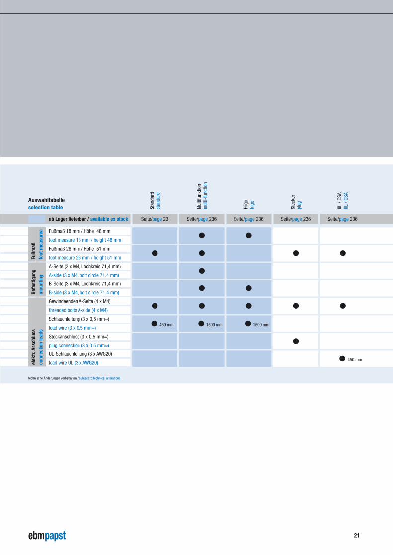
Auswahltabelle selection table
technische Änderungen vorbehalten / subject to technical alterations
Seite/page 23 Seite/page 236 Seite/page 236 Seite/page 236 Seite/page 236
Frig
o
Stan
dard
stan
dard
Mul
tifun
ktio
nm
ulti-
func
tion
frigo
Stec
ker
plug
UL /
CSA
UL /
CSA
ab Lager lieferbar / available ex stock
Fußmaß 18 mm / Höhe 48 mm
foot measure 18 mm / height 48 mm
Fußmaß 26 mm / Höhe 51 mm
foot measure 26 mm / height 51 mm
A-Seite (3 x M4, Lochkreis 71,4 mm)
A-side (3 x M4, bolt circle 71.4 mm)
B-Seite (3 x M4, Lochkreis 71,4 mm)
B-side (3 x M4, bolt circle 71.4 mm)
Gewindeenden A-Seite (4 x M4)
threaded bolts A-side (4 x M4)
Schlauchleitung (3 x 0,5 mm≈)
lead wire (3 x 0.5 mm≈)
Steckanschluss (3 x 0,5 mm≈)
plug connection (3 x 0.5 mm≈)
UL-Schlauchleitung (3 x AWG20)
lead wire UL (3 x AWG20)
●
●
●
● ●
● ●
● ●●
●
● 450 mm
● 450 mm ● 1500 mm ● 1500 mm
●●
●
●
Fußm
aßfo
ot m
easu
rea
Befe
stig
ung
mou
ntin
gel
ektr.
Ansc
hlus
sco
nnec
tion
lead
s
22
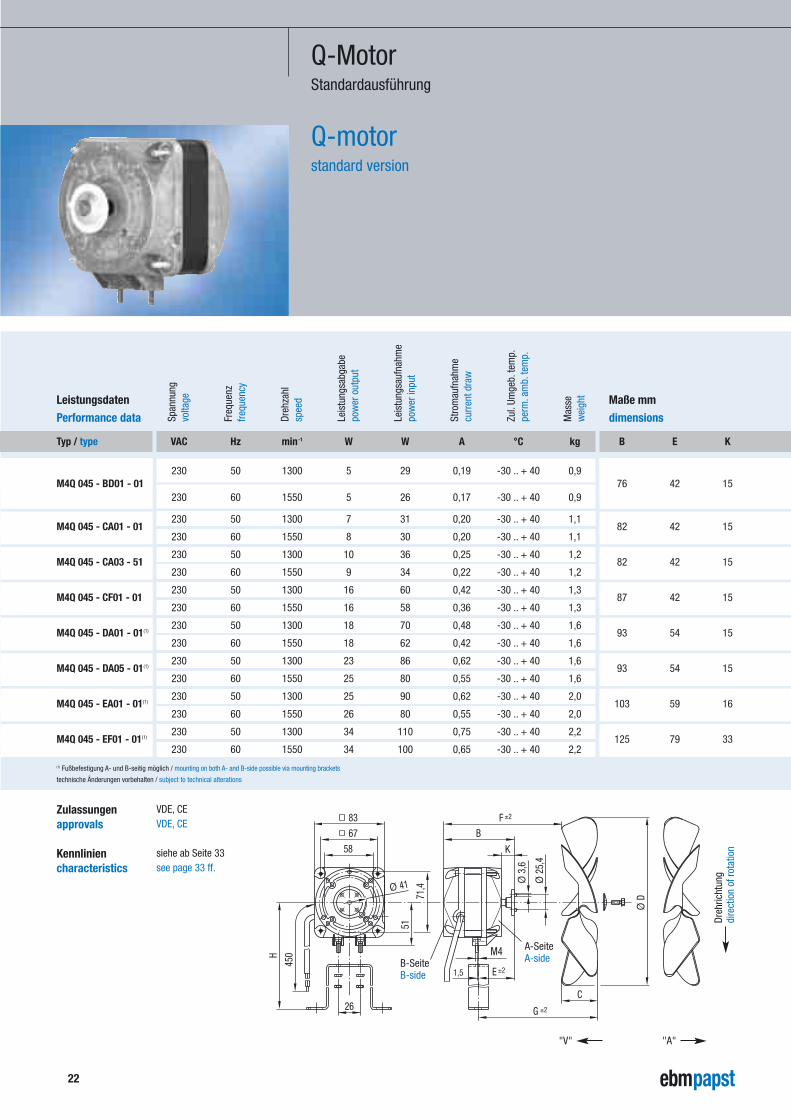
Q-MotorStandardausführung
Q-motorstandard version
Dreh
zahl
Leis
tung
sabg
abe
Span
nung
volta
ge
Freq
uenz
frequ
ency
spee
d
pow
er o
utpu
t
pow
er in
put
curr
ent d
raw
perm
.am
b.te
mp.
Leis
tung
sauf
nahm
e
Stro
mau
fnah
me
Zul.
Umge
b.te
mp.
wei
ght
Mas
se
technische Änderungen vorbehalten / subject to technical alterations
(1) Fußbefestigung A- und B-seitig möglich / mounting on both A- and B-side possible via mounting brackets
VAC Hz min-1 W W A °C kg
230 50 1300 5 29 0,19 -30 .. + 40 0,9
230 60 1550 5 26 0,17 -30 .. + 40 0,9
230 50 1300 7 31 0,20 -30 .. + 40 1,1
230 60 1550 8 30 0,20 -30 .. + 40 1,1
230 50 1300 10 36 0,25 -30 .. + 40 1,2
230 60 1550 9 34 0,22 -30 .. + 40 1,2
230 50 1300 16 60 0,42 -30 .. + 40 1,3
230 60 1550 16 58 0,36 -30 .. + 40 1,3
230 50 1300 18 70 0,48 -30 .. + 40 1,6
230 60 1550 18 62 0,42 -30 .. + 40 1,6
230 50 1300 23 86 0,62 -30 .. + 40 1,6
230 60 1550 25 80 0,55 -30 .. + 40 1,6
230 50 1300 25 90 0,62 -30 .. + 40 2,0
230 60 1550 26 80 0,55 -30 .. + 40 2,0
230 50 1300 34 110 0,75 -30 .. + 40 2,2
230 60 1550 34 100 0,65 -30 .. + 40 2,2
B E K
76 42 15
82 42 15
82 42 15
87 42 15
93 54 15
93 54 15
103 59 16
125 79 33
Leistungsdaten
Performance data
Maße mm
dimensions
Typ / type
M4Q 045 - BD01 - 01
M4Q 045 - CA01 - 01
M4Q 045 - CA03 - 51
M4Q 045 - CF01 - 01
M4Q 045 - DA01 - 01(1)
M4Q 045 - DA05 - 01(1)
M4Q 045 - EA01 - 01(1)
M4Q 045 - EF01 - 01(1)
K
51
H
450
26
1,5
67
83
B
±2G
E ±2
M4
C
Ø 3
,6
Ø 2
5,4
F ±2
58
71,4Ø 41
Ø D
"V" "A"
A-SeiteA-sideB-Seite
B-side
Dreh
richt
ung
dire
ctio
n of
rota
tion
Zulassungenapprovals
Kennliniencharacteristics
VDE, CEVDE, CE
siehe ab Seite 33see page 33 ff.
23
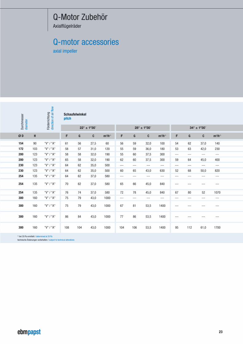
Q-Motor ZubehörAxialflügelräder
Q-motor accessoriesaxial impeller
Förd
erric
htun
g
Durc
hmes
ser
diam
eter
dire
ctio
n of
air
flow
technische Änderungen vorbehalten / subject to technical alterations
(1) bei 20 Pa ermittelt / determined at 20 Pa
Ø D H
154 90 "V" / "A"
172 103 "V" / "A"
200 123 "V" / "A"
200 123 "V" / "A"
230 123 "V" / "A"
230 123 "V" / "A"
254 135 "V" / "A"
254 135 "V" / "A"
254 135 "V" / "A"
300 160 "V" / "A"
300 160 "V" / "A"
300 160 "V" / "A"
300 160 "V" / "A"
22° ± 1º30´
F G C m3/h(1)
61 56 27,5 60
58 57 31,0 120
58 58 32,0 190
65 58 32,0 190
64 62 35,0 500
64 62 35,0 500
64 62 37,0 580
70 62 37,0 580
76 74 37,0 580
75 79 43,0 1000
75 79 43,0 1000
86 84 43,0 1000
108 104 43,0 1000
28° ± 1º30´
F G C m3/h(1)
56 59 32,0 100
55 59 36,0 180
55 60 37,5 300
62 60 37,5 300
--- --- --- ---
60 65 43,0 630
--- --- --- ---
65 66 45,0 840
72 78 45,0 840
--- --- --- ---
67 81 53,5 1400
77 86 53,5 1400
104 106 53,5 1400
34° ± 1º30´
F G C m3/h(1)
54 62 37,0 140
53 63 42,0 230
--- --- --- ---
59 64 45,0 400
--- --- --- ---
52 68 50,0 820
--- --- --- ---
--- --- --- ---
67 80 52 1070
--- --- --- ---
--- --- --- ---
--- --- --- ---
95 112 61,0 1700
Schaufelwinkelpitch
24
Dreh
zahl
Leis
tung
sabg
abe
Span
nung
volta
ge
Freq
uenz
frequ
ency
spee
d
pow
er o
utpu
t
pow
er in
put
curr
ent d
raw
perm
.am
b.te
mp.
Leis
tung
sauf
nahm
e
Stro
mau
fnah
me
Zul.
Umge
b.te
mp.
wei
ght
Mas
se
technische Änderungen vorbehalten / subject to technical alterations
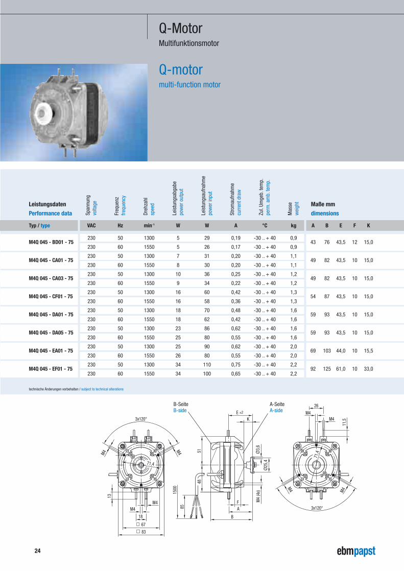
VAC Hz min-1 W W A °C kg
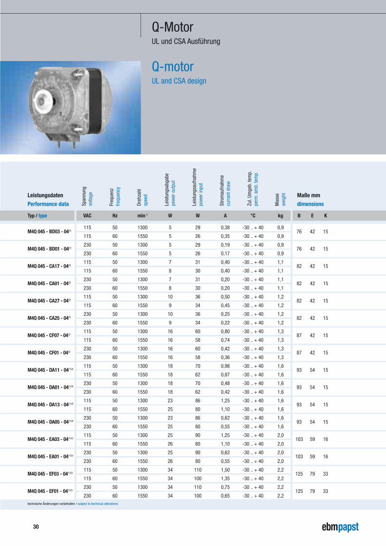
230 50 1300 5 29 0,19 -30 .. + 40 0,9
230 60 1550 5 26 0,17 -30 .. + 40 0,9
230 50 1300 7 31 0,20 -30 .. + 40 1,1
230 60 1550 8 30 0,20 -30 .. + 40 1,1
230 50 1300 10 36 0,25 -30 .. + 40 1,2
230 60 1550 9 34 0,22 -30 .. + 40 1,2
230 50 1300 16 60 0,42 -30 .. + 40 1,3
230 60 1550 16 58 0,36 -30 .. + 40 1,3
230 50 1300 18 70 0,48 -30 .. + 40 1,6
230 60 1550 18 62 0,42 -30 .. + 40 1,6
230 50 1300 23 86 0,62 -30 .. + 40 1,6
230 60 1550 25 80 0,55 -30 .. + 40 1,6
230 50 1300 25 90 0,62 -30 .. + 40 2,0
230 60 1550 26 80 0,55 -30 .. + 40 2,0
230 50 1300 34 110 0,75 -30 .. + 40 2,2
230 60 1550 34 100 0,65 -30 .. + 40 2,2
Leistungsdaten
Performance data
Maße mm
dimensions
Typ / type
M4Q 045 - BD01 - 75
M4Q 045 - CA01 - 75
M4Q 045 - CA03 - 75
M4Q 045 - CF01 - 75
M4Q 045 - DA01 - 75
M4Q 045 - DA05 - 75
M4Q 045 - EA01 - 75
M4Q 045 - EF01 - 75
Ø3,
6
67
71,4
3x120°
M4 71,4
M4
3x120°
M4
11,5M4
M4
26
4851
Ø25
,4
M4
(4x)
85
1500
83
18
M4M4
13
M4
A
B
E ±2
F
K
A-SeiteA-side
B-SeiteB-side
Q-MotorMultifunktionsmotor
Q-motormulti-function motor
A B E F K
43 76 43,5 12 15,0
49 82 43,5 10 15,0
49 82 43,5 10 15,0
54 87 43,5 10 15,0
59 93 43,5 10 15,0
59 93 43,5 10 15,0
69 103 44,0 10 15,5
92 125 61,0 10 33,0
25
- Die Fußbefestigung ist mit Spurmaß 26 mm (Höhe 51 mm) oder 18 mm (Höhe 48 mm) möglich.
- In den Lagerschilden sind jeweils auf den gegenüberliegenden Seiten die M4 Schrauben in den Füßen unverlierbar montiert.Befestigungsmuttern mit Sperrverzahnung gehören nicht zum Lieferumfang und müssen bei Bedarf separat bestellt werden.
- Lagerschilde A- und B-seitig,Gewindebohrungen 3 x M4,Lochkreisdurchmesser 71,4 mm.
- M4 Gewindeenden auf A-seitigem Lagerschild zur Befestigung von Schutzgitter und Wandring.
- Kabellänge 1500 mm,Schlauchleitung 3 x 0,5 mm2 mit Aderendkralle
VDE, CE
siehe ab Seite 33
Allgemeine Beschreibunggeneral discription
Zulassungenapprovals
Kennliniencharacteristics
- Mounting bosses of two different centre-lines are combined in one motor:26 mm (51 mm high) and 18 mm (48 mm).
- Captive screws M4 in the end shields are mounted on opposite sides. Knurled hex nuts are not included and will have to be ordered separately.
- End shields available on A- and B-side.They feature threaded holes 3 x M4 at 71.4 mm bolt circle.
- Threaded bolts protruding on drive side formounting of guard grilles or wall rings.
- Jacketed cable 3 x 0.5 mm2 in 1,500 mm lengthwith brass lead tips.
VDE, CE
see page 33 ff.
technische Änderungen vorbehalten / subject to technical alterations
26
Dreh
zahl
Leis
tung
sabg
abe
Span
nung
volta
ge
Freq
uenz
frequ
ency
spee
d
pow
er o
utpu
t
pow
er in
put
curr
ent d
raw
perm
.am
b.te
mp.
Leis
tung
sauf
nahm
e
Stro
mau
fnah
me
Zul.
Umge
b.te
mp.
wei
ght
Mas
se
technische Änderungen vorbehalten / subject to technical alterations
VAC Hz min-1 W W A °C kg
230 50 1300 5 29 0,19 -30 .. + 40 0,9
230 60 1550 5 26 0,17 -30 .. + 40 0,9
230 50 1300 7 31 0,20 -30 .. + 40 1,1
230 60 1550 8 30 0,20 -30 .. + 40 1,1
230 50 1300 10 36 0,25 -30 .. + 40 1,2
230 60 1550 9 34 0,22 -30 .. + 40 1,2
230 50 1300 16 60 0,42 -30 .. + 40 1,3
230 60 1550 16 58 0,36 -30 .. + 40 1,3
230 50 1300 18 70 0,48 -30 .. + 40 1,6
230 60 1550 18 62 0,42 -30 .. + 40 1,6
230 50 1300 23 86 0,62 -30 .. + 40 1,6
230 60 1550 25 80 0,55 -30 .. + 40 1,6
230 50 1300 25 90 0,62 -30 .. + 40 2,0
230 60 1550 26 80 0,55 -30 .. + 40 2,0
230 50 1300 34 110 0,75 -30 .. + 40 2,2
230 60 1550 34 100 0,65 -30 .. + 40 2,2
Leistungsdaten
Performance data
Maße mm
dimensions
Typ / type
M4Q 045 - BD01 - A4
M4Q 045 - CA01 - N4
M4Q 045 - CA03 - A4
M4Q 045 - CF01 - A4
M4Q 045 - DA01 - A4
M4Q 045 - DA05 - A4
M4Q 045 - EA01 - A4
M4Q 045 - EF01 - A4
M4
M4(
4x)
Ø25
,4
Ø3,
6
4813
A
B
F
K
M4
71,4
3x12
0°
M418
M4
6783
85
1500
A-SeiteA-side
B-SeiteB-side
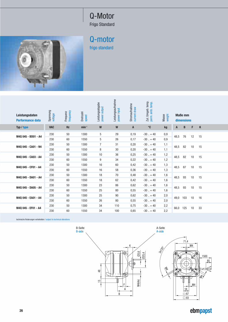
Q-MotorFrigo Standard
Q-motorfrigo standard
A B F K
48,5 76 12 15
48,5 82 10 15
48,5 82 10 15
48,5 87 10 15
48,5 93 10 15
48,5 93 10 15
49,0 103 10 16
66,0 125 10 33
27
Dieser Motor ist gezielt für den Ersatzbedarf ent-wickelt worden und enthält die folgenden Optionen:
- Fußmaß 18 mm, Höhe 48 mm.
- Lagerschild B-seitig,Gewindebohrungen 3 x M4,Lochkreisdurchmesser 71,4 mm.
- M4 Gewindeenden auf A-seitigem Lagerschild zur Befestigung von Schutzgitter und Wandring.
- Kabellänge 1500 mm,Schlauchleitung 3 x 0,5 mm2 mit Aderendkralle.
- M4 Sechskantmuttern (2 Stück) mit Sperrverzahnung lose beigelegt.
VDE, CE
siehe ab Seite 33
Allgemeine Beschreibunggeneral discription
Zulassungenapprovals
Kennliniencharacteristics
This motor has been specifically designed for retrofitting in the refrigeration field and offers the following options:
- Centre-line of mounting bosses is 18 mm,at a height of 48 mm.
- B-side (non drive) end shield is equipped with threaded holes 3 x M4 at 71.4 mm bolt circle.
- Threaded bolts M4 protruding at the A-side (drive side) end shield for mounting of guardgrilles and wall rings.
- Jacketed cable 3 x 0.5 mm2 in 1,500 mm lengthwith brass lead tips.
- 2 x knurled hexagonal nuts M4 enclosedunpacked.
VDE, CE
see page 33 ff.
technische Änderungen vorbehalten / subject to technical alterations
28
Dreh
zahl
Leis
tung
sabg
abe
Span
nung
volta
ge
Freq
uenz
frequ
ency
spee
d
pow
er o
utpu
t
pow
er in
put
curr
ent d
raw
perm
.am
b.te
mp.
Leis
tung
sauf
nahm
e
Stro
mau
fnah
me
Zul.
Umge
b.te
mp.
wei
ght
Mas
se
technische Änderungen vorbehalten / subject to technical alterations
VAC Hz min-1 W W A °C kg
230 50 1300 5 29 0,19 -30 .. + 40 0,9
230 60 1550 5 26 0,17 -30 .. + 40 0,9
230 50 1300 7 31 0,20 -30 .. + 40 1,1
230 60 1550 8 30 0,20 -30 .. + 40 1,1
230 50 1300 10 36 0,25 -30 .. + 40 1,2
230 60 1550 9 34 0,22 -30 .. + 40 1,2
230 50 1300 16 60 0,42 -30 .. + 40 1,3
230 60 1550 16 58 0,36 -30 .. + 40 1,3
230 50 1300 18 70 0,48 -30 .. + 40 1,6
230 60 1550 18 62 0,42 -30 .. + 40 1,6
230 50 1300 23 86 0,62 -30 .. + 40 1,6
230 60 1550 25 80 0,55 -30 .. + 40 1,6
230 50 1300 25 90 0,62 -30 .. + 40 2,0
230 60 1550 26 80 0,55 -30 .. + 40 2,0
230 50 1300 34 110 0,75 -30 .. + 40 2,2
230 60 1550 34 100 0,65 -30 .. + 40 2,2
Leistungsdaten
Performance data
Maße mm
dimensions
Typ / type
M4Q 045 - BD01 - 08
M4Q 045 - CA01 - 08
M4Q 045 - CA03 - 08
M4Q 045 - CF01 - 08
M4Q 045 - DA01 - 52(1)
M4Q 045 - DA05 - 52(1)
M4Q 045 - EA01 - 52(1)
M4Q 045 - EF01 - 52(1)
18
20
14,5
9
8367
M4
26
K
E
F
9
5
B
5111
,5
Ø25
,4Ø
3,6
M4(
4x)
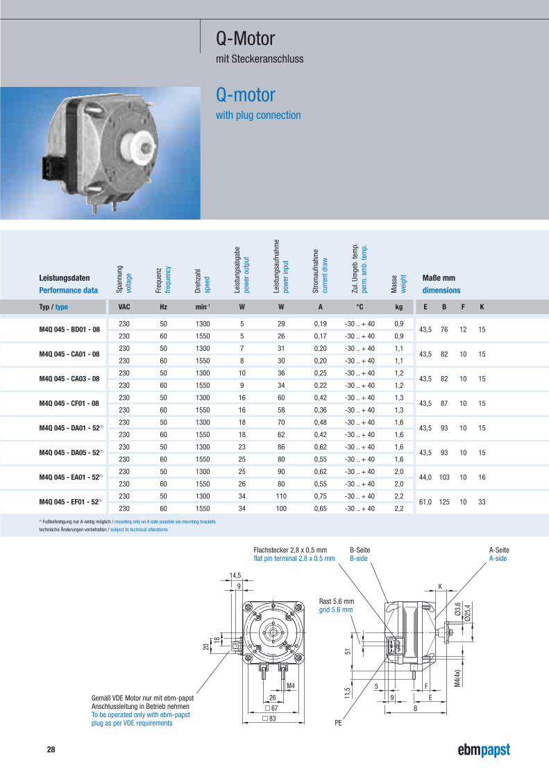
Q-Motormit Steckeranschluss
Q-motorwith plug connection
E B F K
43,5 76 12 15
43,5 82 10 15
43,5 82 10 15
43,5 87 10 15
43,5 93 10 15
43,5 93 10 15
44,0 103 10 16
61,0 125 10 33
(1) Fußbefestigung nur A-seitig möglich / mounting only on A-side possible via mounting brackets
A-SeiteA-side
B-SeiteB-side
Rast 5,6 mmgrid 5.6 mm
PE
Flachstecker 2,8 x 0,5 mmflat pin terminal 2.8 x 0.5 mm
Gemäß VDE Motor nur mit ebm-papstAnschlussleitung in Betrieb nehmenTo be operated only with ebm-papstplug as per VDE requirements
29
- Steckanschluss Rast 5,6 mm,Flachstecker 2,8 x 0,5 mm (seitlich am B-seitigen Lagerschild).
- Die Anschlussleitung mit Stecker ist codiert undkann nicht verdreht werden.
- Der Erdleiteranschluss ist im Stecker integriert und laut VDE voreilend.
- Der Stecker ist durch eine Rastsicherung gegenLockern geschützt.
- Die Sicherheitsabstände wie Luft- und Kriech-strecken nach EN 60335-1 sind sichergestellt.
- Der Steckanschluss ist VDE zugelassen unter ÜG 5458.
- Anschlussleitung mit Stecker in den Längen 420 mm bis 4.970 mm.
Gemäß VDE Motor nur mit ebm-papstAnschlussleitung in Betrieb nehmen.
VDE, CE
see page 33 ff.
Allgemeine Beschreibunggeneral discription
Achtung!Attention!
Zulassungenapprovals
Kennliniencharacteristics
- Plug connector with grid 5.6 mm and flat pin terminal 2.8 x 0.5 mm protruding on end shield of the non-drive or B-side.
- The connection lead with plug is coded and cannot be altered.
- The ground connection is integrated in theplug and is leading, as required by VDE.
- The plug features a grid protection mechanism preventing the plug from coming loose.
- Air and creeping distances are maintainedaccording to EN 60335-1.
- The plug connector is VDE-approved,see ÜG 5458.
- Connection lead with plug for cable lengthbetween 420 mm and 4,970 mm.
To be operated only with ebm-papst plug as per VDE requirements.
VDE, CE
see page 33 ff.
technische Änderungen vorbehalten / subject to technical alterations
30
Dreh
zahl
Leis
tung
sabg
abe
Span
nung
volta
ge
Freq
uenz
frequ
ency
spee
d
pow
er o
utpu
t
pow
er in
put
curr
ent d
raw
perm
.am
b.te
mp.
Leis
tung
sauf
nahm
e
Stro
mau
fnah
me
Zul.
Umge
b.te
mp.
wei
ght
Mas
se
technische Änderungen vorbehalten / subject to technical alterations
VAC Hz min-1 W W A °C kg
115 50 1300 5 29 0,38 -30 .. + 40 0,9
115 60 1550 5 26 0,35 -30 .. + 40 0,9
230 50 1300 5 29 0,19 -30 .. + 40 0,9
230 60 1550 5 26 0,17 -30 .. + 40 0,9
115 50 1300 7 31 0,40 -30 .. + 40 1,1
115 60 1550 8 30 0,40 -30 .. + 40 1,1
230 50 1300 7 31 0,20 -30 .. + 40 1,1
230 60 1550 8 30 0,20 -30 .. + 40 1,1
115 50 1300 10 36 0,50 -30 .. + 40 1,2
115 60 1550 9 34 0,45 -30 .. + 40 1,2
230 50 1300 10 36 0,25 -30 .. + 40 1,2
230 60 1550 9 34 0,22 -30 .. + 40 1,2
115 50 1300 16 60 0,80 -30 .. + 40 1,3
115 60 1550 16 58 0,74 -30 .. + 40 1,3
230 50 1300 16 60 0,42 -30 .. + 40 1,3
230 60 1550 16 58 0,36 -30 .. + 40 1,3
115 50 1300 18 70 0,98 -30 .. + 40 1,6
115 60 1550 18 62 0,87 -30 .. + 40 1,6
230 50 1300 18 70 0,48 -30 .. + 40 1,6
230 60 1550 18 62 0,42 -30 .. + 40 1,6
115 50 1300 23 86 1,25 -30 .. + 40 1,6
115 60 1550 25 80 1,10 -30 .. + 40 1,6
230 50 1300 23 86 0,62 -30 .. + 40 1,6
230 60 1550 25 80 0,55 -30 .. + 40 1,6
115 50 1300 25 90 1,25 -30 .. + 40 2,0
115 60 1550 26 80 1,10 -30 .. + 40 2,0
230 50 1300 25 90 0,62 -30 .. + 40 2,0
230 60 1550 26 80 0,55 -30 .. + 40 2,0
115 50 1300 34 110 1,50 -30 .. + 40 2,2
115 60 1550 34 100 1,35 -30 .. + 40 2,2
230 50 1300 34 110 0,75 -30 .. + 40 2,2
230 60 1550 34 100 0,65 -30 .. + 40 2,2
Leistungsdaten
Performance data
Maße mm
dimensions
Typ / type
M4Q 045 - BD03 - 04(2)
M4Q 045 - BD01 - 04(2)
M4Q 045 - CA17 - 04(2)
M4Q 045 - CA01 - 04(2)
M4Q 045 - CA27 - 04(2)
M4Q 045 - CA25 - 04(2)
M4Q 045 - CF07 - 04(2)
M4Q 045 - CF01 - 04(2)
M4Q 045 - DA11 - 04(1)(3)
M4Q 045 - DA01 - 04(1)(3)
M4Q 045 - DA13 - 04(1)(3)
M4Q 045 - DA05 - 04(1)(3)
M4Q 045 - EA03 - 04(1)(3)
M4Q 045 - EA01 - 04(1)(3)
M4Q 045 - EF03 - 04(1)(3)
M4Q 045 - EF01 - 04(1)(3)
Q-MotorUL und CSA Ausführung
Q-motorUL and CSA design
B E K
76 42 15
76 42 15
82 42 15
82 42 15
82 42 15
82 42 15
87 42 15
87 42 15
93 54 15
93 54 15
93 54 15
93 54 15
103 59 16
103 59 16
125 79 33
125 79 33
31
(1) Fußbefestigung A- und B-seitig möglich / mounting on both A- and B-side possible via mounting brackets(2) File-Nr. E 171165 / file no. E 171165(3) File-Nr. E 76226 / file no. E 76226
K
51
H
450
26
1,5
67
83
B
±2G
E ±2
M4
C
Ø 3
,6
Ø 2
5,4
F ±2
58
71,4Ø 41
Ø D
"V" "A"
A-SeiteA-sideB-Seite
B-side
Dreh
richt
ung
dire
ctio
n of
rota
tion
technische Änderungen vorbehalten / subject to technical alterations
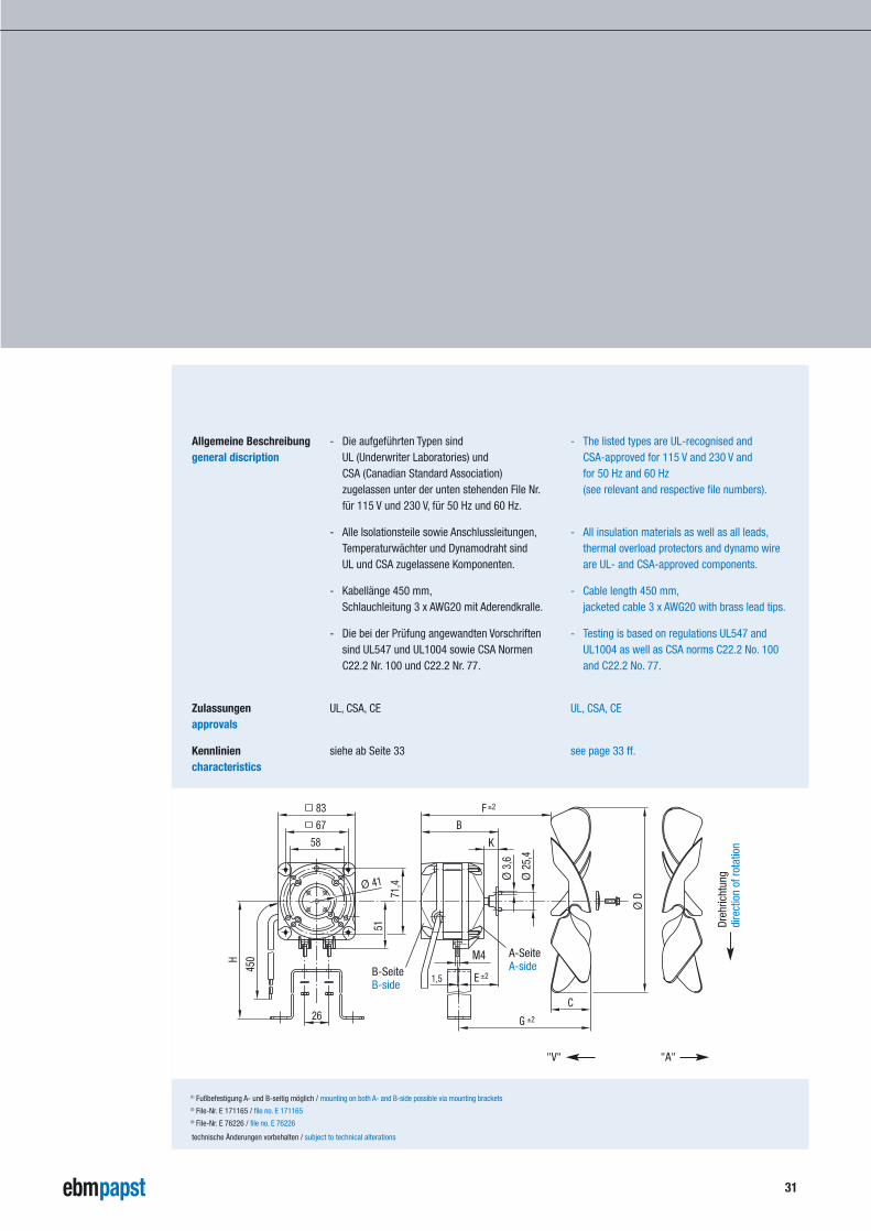
- Die aufgeführten Typen sind UL (Underwriter Laboratories) und CSA (Canadian Standard Association) zugelassen unter der unten stehenden File Nr.für 115 V und 230 V, für 50 Hz und 60 Hz.
- Alle Isolationsteile sowie Anschlussleitungen,Temperaturwächter und Dynamodraht sind UL und CSA zugelassene Komponenten.
- Kabellänge 450 mm,Schlauchleitung 3 x AWG20 mit Aderendkralle.
- Die bei der Prüfung angewandten Vorschriftensind UL547 und UL1004 sowie CSA NormenC22.2 Nr. 100 und C22.2 Nr. 77.
UL, CSA, CE
siehe ab Seite 33
Allgemeine Beschreibunggeneral discription
Zulassungenapprovals
Kennliniencharacteristics
- The listed types are UL-recognised and CSA-approved for 115 V and 230 V and for 50 Hz and 60 Hz (see relevant and respective file numbers).
- All insulation materials as well as all leads,thermal overload protectors and dynamo wire are UL- and CSA-approved components.
- Cable length 450 mm,jacketed cable 3 x AWG20 with brass lead tips.
- Testing is based on regulations UL547 andUL1004 as well as CSA norms C22.2 No. 100 and C22.2 No. 77.
UL, CSA, CE
see page 33 ff.
32
Q-MotorOptionen
Q-motoroptions
Standard:- Schlauchleitung 3 x 0,5 mm2
- Steckeranschluss 3 x 0,5 mm2
- UL/CSA Schlauchleitung 3 x AWG20, 600 V
Option:- Schlauchleitung 2 x 0,5 mm2
- Steckeranschluss 3 x 0,75 mm2
- UL/CSA Schlauchleitung 2 x AWG20, 600 V
- Befestigungsmöglichkeiten auf A- und B-Seite- Lochkreis Ø 58 mm, 4 x M4
Lochkreis Ø 71,4 mm, 3 x M4 oder 4 x M4(jeweils mit oder ohne Erdleiterbohrung möglich)
- 4 x M4 Gewindeenden 10 oder 12 mm lang (Standard)
- Sonderspannungen- ohne Befestigungsfüße- Lagerschild am Paket genietet
- Kugellager- unterschiedliche Wellenlänge- Kältelagerung bis -40 °C
- Feuchtschutz:Lackierung von Paket und Lagerschilde(ca. 5 mm überdeckend) einschließlich Schraubenköpfe und Muttern.An der Kabelausführung wird zur Abdichtung eine Silikontülle eingesetzt.Auf dem Wellenende sitzt eine Kunststoff-schleuderscheibe.
Option Anschlussleitungenavailable lead connections
Option Befestigungpossible mounting
Sonderausfertigungenspecial designs
standard:- jacketed cable 3 x 0.5 mm2
- plug connection 3 x 0.5 mm2
- UL/CSA jacketed cable 3 x AWG20, 600 V
option:- jacketed cable 2 x 0.5 mm2
- plug connection 3 x 0.75 mm2
- UL/CSA jacketed cable 2 x AWG20, 600 V
- mounting possible on A- and B-side- bolt circle Ø 58 mm, 4 x M4
bolt circle Ø 71.4 mm, 3 x M4 or 4 x M4(available with or without ground lead thread)
- 4 x M4 threaded bolts in 10 or 12 mm length (standard)
- special voltages- without mounting brackets- end shield riveted to stator lamination
- ball bearings- different shaft lengths- anti-freeze bearing version down to -40 °C
- humidity protection:Stator lamination and end shields varnished (overlapping of about 5 mm) and screw heads and nuts also coated in varnish.Sealing of cable exit via inserted silicone socket.Plastic centrifugal disk mounted on shaft end.
M4
4x90
°
Ø58
3x12
0°
Ø71,4
10/12
M4
(4x)
Ø41
67
technische Änderungen vorbehalten / subject to technical alterations
33
technische Änderungen vorbehalten / subject to technical alterations
Luftleistungskennlinien / air performance characteristics
50 100 150 200 250
[Pa]
10
[m3/h]
20
30
40
50
60
70
80
90
22° 28° 34°
50 100 150 200 250 300
[Pa]
10
[m3/h]
20
30
40
50
22° 28° 34°
M4Q 045-BD01Ø172, 50 Hz
M4Q 045-BD01Ø154, 50 Hz 50 100 150 200 250
[Pa]
10
[m3/h]
20
30
40
50
60
70
80
90
22° 28° 34°
M4Q 045-BD01Ø154, 60 Hz
50 100 150 200 250 300 350
[Pa]
10
[m3/h]
20
30
40
50
60
70
22° 28° 34°
M4Q 045-BD01Ø172, 60 Hz
50 100 150 200 250 300 350 400
[Pa]
10
[m3/h]
20
30
40
50
22° 28°
M4Q 045-BD01Ø200, 60 Hz50 100 150 200 250 300 350
[Pa]
10
[m3/h]
20
30
40
50
22° 28°
M4Q 045-BD01Ø200, 50 Hz
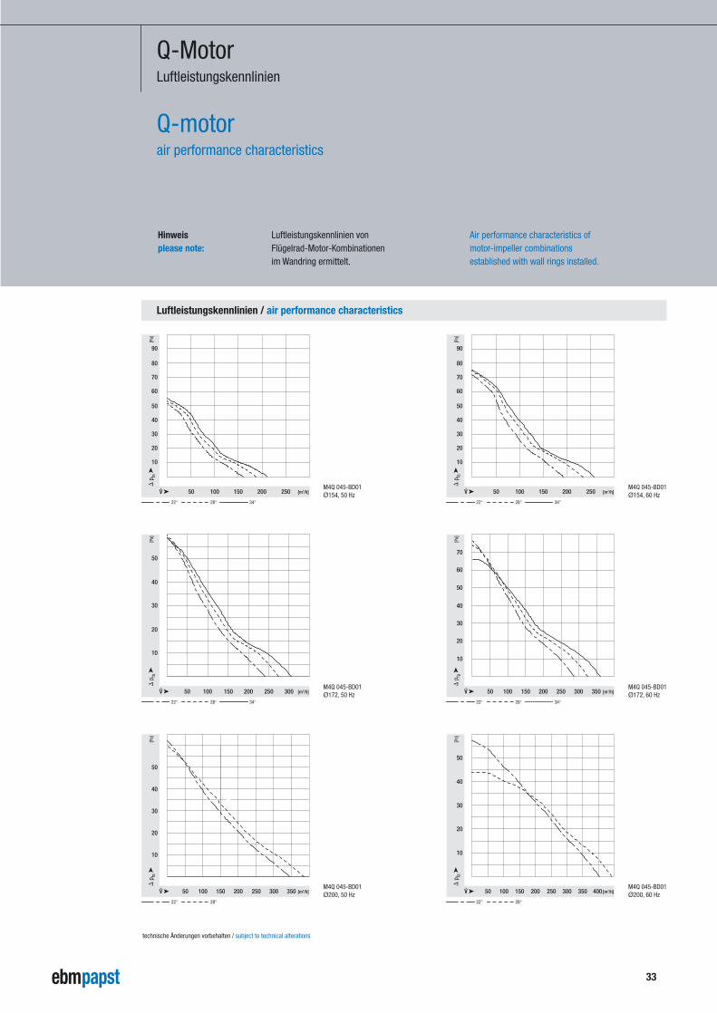
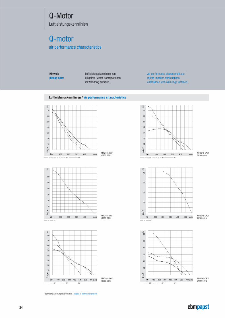
Q-MotorLuftleistungskennlinien
Q-motorair performance characteristics
Luftleistungskennlinien vonFlügelrad-Motor-Kombinationenim Wandring ermittelt.
Hinweisplease note:
Air performance characteristics ofmotor-impeller combinationsestablished with wall rings installed.
Luftleistungskennlinien / air performance characteristics
100 200 300 400
[Pa]
10
[m3/h]
20
30
40
50
60
70
22° 28° 34°
100 200 300 400
[Pa]
10
[m3/h]
20
30
40
50
60
22°
M4Q 045-CA01Ø230, 50 Hz
M4Q 045-CA01Ø200, 50 Hz 100 200 300 400
[Pa]
10
[m3/h]
20
30
40
50
60
70
22° 28° 34°
M4Q 045-CA01Ø200, 60 Hz
100 200 300 500400
[Pa]
10
[m3/h]
20
30
40
22°
M4Q 045-CA01Ø230, 60 Hz
100 200 300 400 500 600 700
[Pa]
10
[m3/h]
20
30
40
50
60
22° 28° 34°
M4Q 045-CA03Ø230, 60 Hz100 200 300 400 500 600 700
[Pa]
10
[m3/h]
20
30
40
50
60
70
80
22° 28° 34°
M4Q 045-CA03Ø230, 50 Hz
34
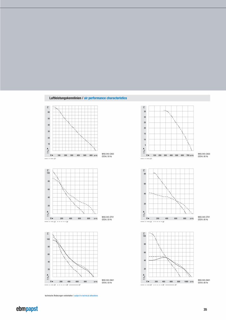
Q-MotorLuftleistungskennlinien
Q-motorair performance characteristics
Luftleistungskennlinien vonFlügelrad-Motor-Kombinationenim Wandring ermittelt.
Hinweisplease note:
Air performance characteristics ofmotor-impeller combinationsestablished with wall rings installed.
technische Änderungen vorbehalten / subject to technical alterations
35
Luftleistungskennlinien / air performance characteristics
100 200 300 400 500 600
[Pa]
10
[m3/h]
20
30
40
50
60
22°
200 400 600 800
[Pa]
[m3/h]
20
40
60
80
100
22° 28°
M4Q 045-CF01Ø254, 50 Hz
M4Q 045-CA03Ø254, 50 Hz 100 200 300 400 500 600 700
[Pa]
5
[m3/h]
10
15
20
25
30
35
22°
M4Q 045-CA03Ø254, 60 Hz
200 400 600 800
[Pa]
[m3/h]
20
40
60
80
22° 28°
M4Q 045-CF01Ø254, 60 Hz
200 400 600 800 1000
[Pa]
[m3/h]
20
40
60
80
100
22° 28° 34°
M4Q 045-DA01Ø254, 60 Hz200 400 600 800
[Pa]
[m3/h]
20
40
60
80
100
22° 28° 34°
M4Q 045-DA01Ø254, 50 Hz
technische Änderungen vorbehalten / subject to technical alterations
Luftleistungskennlinien / air performance characteristics
200 400 600 800 1000 1200
[Pa]
10
[m3/h]
20
30
40
50
60
22°
200 400 800600 1000
[Pa]
[m3/h]
20
40
60
80
100
22°
1200M4Q 045-DA05Ø300, 50 Hz
M4Q 045-DA01Ø300, 50 Hz 200 400 800600 1000 1200
[Pa]
5
[m3/h]
10
15
20
25
30
22°
M4Q 045-DA01Ø300, 60 Hz
200 800400 1000600 1200
[Pa]
10
[m3/h]
20
30
40
22°
M4Q 045-DA05Ø300, 60 Hz
200 400 600 800 1000 1200 1400
[Pa]
10
[m3/h]
20
30
40
50
22°
M4Q 045-EA01Ø300, 60 Hz200 400 800600 1000 1200
[Pa]
[m3/h]
20
40
60
100
80
22°
M4Q 045-EA01Ø300, 50 Hz
36
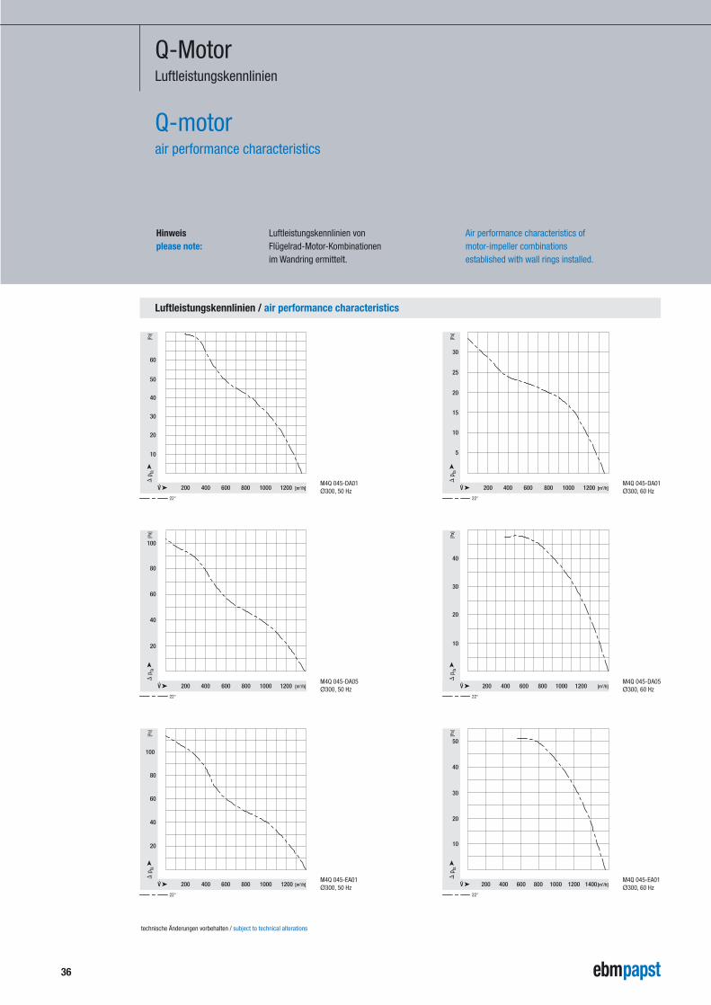
Q-MotorLuftleistungskennlinien
Q-motorair performance characteristics
Luftleistungskennlinien vonFlügelrad-Motor-Kombinationenim Wandring ermittelt.
Hinweisplease note:
Air performance characteristics ofmotor-impeller combinationsestablished with wall rings installed.
technische Änderungen vorbehalten / subject to technical alterations
37
Luftleistungskennlinien / air performance characteristics
200 800 1000600
[Pa]
[m3/h]
20
40
60
100
80
22° 28° 34°
M4Q 045-EF01Ø300, 50 Hz 400 800 1200 1600
[Pa]
[m3/h]
20
40
60
80
22° 28° 34°
M4Q 045-EF01Ø300, 60 Hz
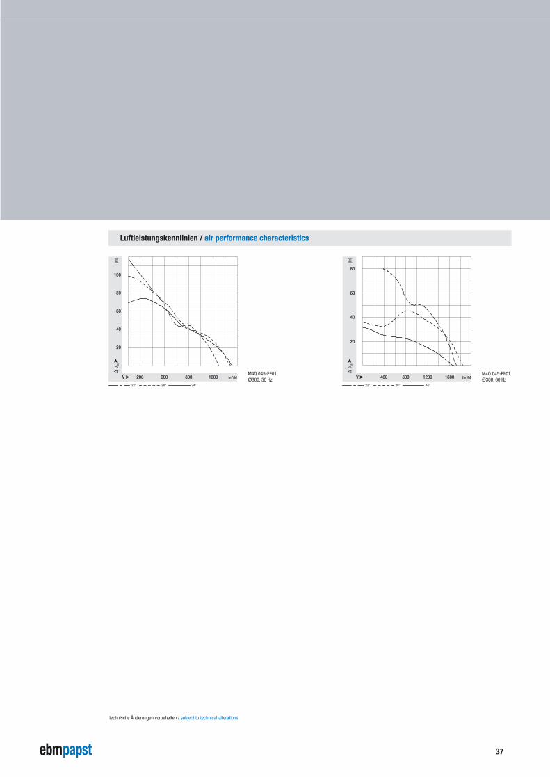
technische Änderungen vorbehalten / subject to technical alterations
38
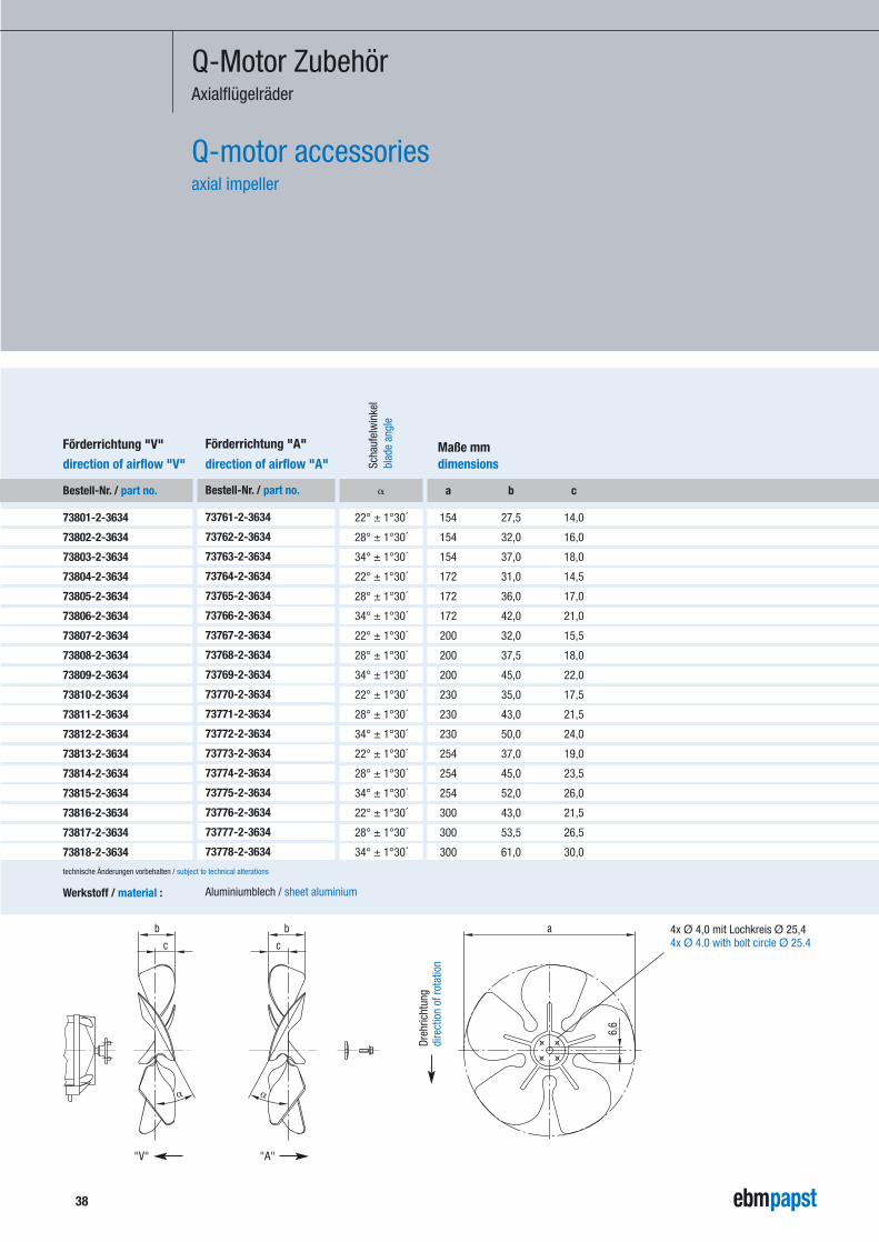
Q-Motor ZubehörAxialflügelräder
Q-motor accessoriesaxial impeller
Bestell-Nr. / part no.
73801-2-3634
73802-2-3634
73803-2-3634
73804-2-3634
73805-2-3634
73806-2-3634
73807-2-3634
73808-2-3634
73809-2-3634
73810-2-3634
73811-2-3634
73812-2-3634
73813-2-3634
73814-2-3634
73815-2-3634
73816-2-3634
73817-2-3634
73818-2-3634
Förderrichtung "V"
direction of airflow "V"
Werkstoff / material : Aluminiumblech / sheet aluminium
Bestell-Nr. / part no.
73761-2-3634
73762-2-3634
73763-2-3634
73764-2-3634
73765-2-3634
73766-2-3634
73767-2-3634
73768-2-3634
73769-2-3634
73770-2-3634
73771-2-3634
73772-2-3634
73773-2-3634
73774-2-3634
73775-2-3634
73776-2-3634
73777-2-3634
73778-2-3634
Förderrichtung "A"
direction of airflow "A" Scha
ufel
win
kel
blad
e an
gle
�
22° ± 1°30´
28° ± 1°30´
34° ± 1°30´
22° ± 1°30´
28° ± 1°30´
34° ± 1°30´
22° ± 1°30´
28° ± 1°30´
34° ± 1°30´
22° ± 1°30´
28° ± 1°30´
34° ± 1°30´
22° ± 1°30´
28° ± 1°30´
34° ± 1°30´
22° ± 1°30´
28° ± 1°30´
34° ± 1°30´
a b c
154 27,5 14,0
154 32,0 16,0
154 37,0 18,0
172 31,0 14,5
172 36,0 17,0
172 42,0 21,0
200 32,0 15,5
200 37,5 18,0
200 45,0 22,0
230 35,0 17,5
230 43,0 21,5
230 50,0 24,0
254 37,0 19,0
254 45,0 23,5
254 52,0 26,0
300 43,0 21,5
300 53,5 26,5
300 61,0 30,0
Maße mmdimensions
�
a
6,6
c
b
�
c
b 4x Ø 4,0 mit Lochkreis Ø 25,44x Ø 4.0 with bolt circle Ø 25.4
Dreh
richt
ung
dire
ctio
n of
rota
tion
"V" "A"
technische Änderungen vorbehalten / subject to technical alterations
39
Q-Motor ZubehörAnschlussleitung
Q-motor accessoriesconnection lead
Bestell-Nr. / part no.
79572-4-6711
79573-4-6711
79574-4-6711
79575-4-6711
79576-4-6711
79577-4-6711
79578-4-6711
79579-4-6711
79580-4-6711
62402-4-6711
a
420
970
1470
1970
2470
2970
3470
3970
4470
4970
Maße mmdimensions
technische Änderungen vorbehalten / subject to technical alterations
41
a
85
8
24
12,9Aderendkrallebrass lead tips
Kabelquerschnitt 3 x 0,75 mm2
leads 3 x 0.75 mm2
40
Q-Motor ZubehörSchutz- und Korbschutzgitter
Q-motor accessoriesguard grilles and basket guard grilles
Bestell-Nr. / part no.
50967-2-4039
50968-2-4039
50969-2-4039
50970-2-4039
50971-2-4039
50972-2-4039(1)
Schutzgitter
guard grilles max
.Sch
aufe
lwin
kel
max
.bla
de a
ngle
"V" "A"
34° 34°
34° 34°
34° 28°
28° 28°
28° 28°
---- 22°
Flüg
elra
dim
pelle
r
Ø
154
172
200
230
254
300
a b c
170 190 11,5
188 208 11,5
214 236 11,5
246 266 17,5
270 290 17,5
324 344 17,5
Maße mmdimensions
technische Änderungen vorbehalten / subject to technical alterations
(1) bei Verwendung mit M4Q 045-EF sind Schaufelwinkel bis 34° möglich.(1) When using the M4Q 045-EF, blade angles of up to 34° are possible.
Werkstoff / material : Stahldraht, galvanisch verzinkt und blau chromatiertsteel wire, galvanized and chromatised in blue
2,7c
Øa
5
b
94,5
Bestell-Nr. / part no.
66309-2-4039
66310-2-4039
66311-2-4039
66312-2-4039
66313-2-4039
Korbschutzgitter basked guard grilles m
ax.S
chau
felw
inke
lm
ax.b
lade
ang
le
"V" "A"
34° 34°
34° 28°
28° 28°
28° 28°
---- 22°
Flüg
elra
dim
pelle
r
Ø
172
200
230
254
300
a b c
188 208 37,5
212 236 37,5
246 266 40,0
270 290 40,0
324 344 46,8
Maße mmdimensions
technische Änderungen vorbehalten / subject to technical alterations
(1) bei Verwendung mit M4Q 045-EF sind Schaufelwinkel bis 34° möglich.(1) When using the M4Q 045-EF, blade angles of up to 34° are possible.
Werkstoff / material : Stahldraht, galvanisch verzinkt und blau chromatiertsteel wire, galvanized and chromatised in blue
Øa
Øb
c
94,5
5
2,7
92
41
Q-Motor ZubehörWandringe
Q-motor accessorieswall rings
Bestell-Nr. / part no.
52542-2-4037
52543-2-4037
52544-2-4037
52545-2-4037
52546-2-4037
52547-2-4037(1)
Förderrichtung "V"
direction of airflow "V" max
.Sch
aufe
lwin
kel
max
.bla
de a
ngle
34°
34°
34°
28°
28°
22°
Flüg
elra
dim
pelle
r
Ø
154
172
200
230
254
300
a b c d
164 190 200 24
182 208 223 24
210 236 246 24
240 266 276 24
264 290 300 24
308 344 356 24
Maße mmdimensions
technische Änderungen vorbehalten / subject to technical alterations
(1) bei Verwendung mit M4Q 045-EF sind Schaufelwinkel bis 34° möglich.(1) When using the M4Q 045-EF, blade angles of up to 34° are possible.
Werkstoff / material : Stahldraht, kunststoffbeschichtet in RAL Nr. 7032, kieselgrausteel wire, plastic coated in RAL No. 7032, pebble-grey
4,3b
67
4,3c
248
R3,5
d
67
1
Øa
"V"
Bestell-Nr. / part no.
52550-2-4037
52551-2-4037
52552-2-4037
52553-2-4037
52554-2-4037
52555-2-4037(1)
Förderrichtung "A"direction of airflow "A" m
ax.S
chau
felw
inke
lm
ax.b
lade
ang
le
34°
34°
28°
28°
28°
22°
Flüg
elra
dim
pelle
r
Ø
154
172
200
230
254
300
a b c d
162 190 200 24
180 208 223 24
208 236 246 24
238 266 276 24
262 290 300 24
308 344 356 29
Maße mmdimensions
technische Änderungen vorbehalten / subject to technical alterations
(1) bei Verwendung mit M4Q 045-EF sind Schaufelwinkel bis 34° möglich.(1) When using the M4Q 045-EF, blade angles of up to 34° are possible.
Werkstoff / material : Stahldraht, kunststoffbeschichtet in RAL Nr. 7032, kieselgrausteel wire, plastic coated in RAL No. 7032, pebble-grey
4,3
b
c
6767
4,3
36R4,5
2
d
Øa
1
"A"
42
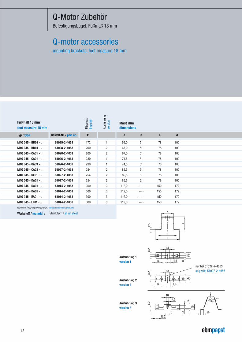
Q-Motor ZubehörBefestigungsbügel, Fußmaß 18 mm
Q-motor accessoriesmounting brackets, foot measure 18 mm
Typ / type
M4Q 045 - BD01 - ..
M4Q 045 - BD01 - ..
M4Q 045 - CA01 - ..
M4Q 045 - CA01 - ..
M4Q 045 - CA03 - ..
M4Q 045 - CA03 - ..
M4Q 045 - CF01 - ..
M4Q 045 - DA01 - ..
M4Q 045 - DA01 - ..
M4Q 045 - DA05 - ..
M4Q 045 - EA01 - ..
M4Q 045 - EF01 - ..
Fußmaß 18 mm
foot measure 18 mm Ausf
ühru
ngve
rsio
n
1
2
2
1
1
2
2
2
3
3
3
3
Flüg
elra
dim
pelle
r
Ø
172
200
200
230
230
254
254
254
300
300
300
300
a b c d
56,0 51 78 100
67,0 51 78 100
67,0 51 78 100
74,5 51 78 100
74,5 51 78 100
85,5 51 78 100
85,5 51 78 100
85,5 51 78 100
112,0 ---- 150 172
112,0 ---- 150 172
112,0 ---- 150 172
112,0 ---- 150 172
Maße mmdimensions
Bestell-Nr. / part no.
51025-2-4053
51028-2-4053
51028-2-4053
51026-2-4053
51026-2-4053
51027-2-4053
51027-2-4053
51027-2-4053
51014-2-4053
51014-2-4053
51014-2-4053
51014-2-4053
Werkstoff / material : Stahlblech / sheet steel
technische Änderungen vorbehalten / subject to technical alterations
2,5
cd
b
a
18
4,314
8,2
825
14
8,2 18
4,3
2516
6,2
16,25
184,2
4024
18 26
109°
Ausführung 1version 1
Ausführung 2version 2
Ausführung 3version 3
nur bei 51027-2-4053only with 51027-2-4053
43
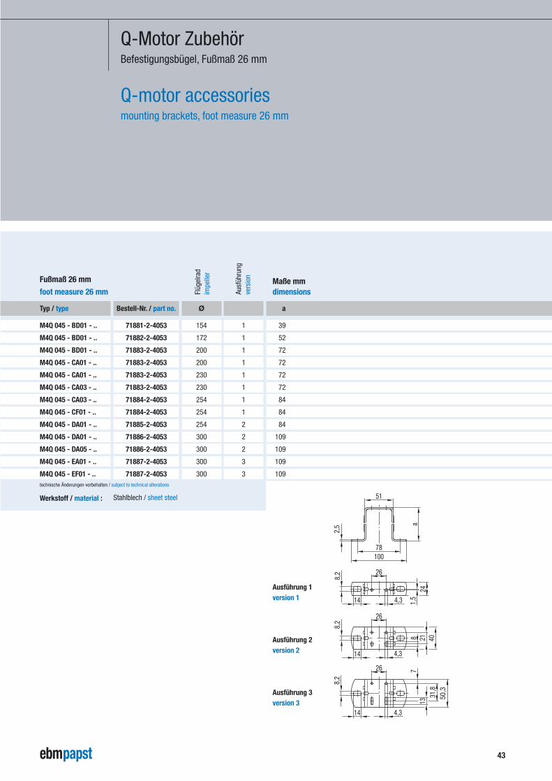
Q-Motor ZubehörBefestigungsbügel, Fußmaß 26 mm
Q-motor accessoriesmounting brackets, foot measure 26 mm
Typ / type
M4Q 045 - BD01 - ..
M4Q 045 - BD01 - ..
M4Q 045 - BD01 - ..
M4Q 045 - CA01 - ..
M4Q 045 - CA01 - ..
M4Q 045 - CA03 - ..
M4Q 045 - CA03 - ..
M4Q 045 - CF01 - ..
M4Q 045 - DA01 - ..
M4Q 045 - DA01 - ..
M4Q 045 - DA05 - ..
M4Q 045 - EA01 - ..
M4Q 045 - EF01 - ..
Fußmaß 26 mm
foot measure 26 mm Ausf
ühru
ngve
rsio
n
1
1
1
1
1
1
1
1
2
2
2
3
3
Flüg
elra
dim
pelle
r
Ø
154
172
200
200
230
230
254
254
254
300
300
300
300
a
39
52
72
72
72
72
84
84
84
109
109
109
109
Maße mmdimensions
Bestell-Nr. / part no.
71881-2-4053
71882-2-4053
71883-2-4053
71883-2-4053
71883-2-4053
71883-2-4053
71884-2-4053
71884-2-4053
71885-2-4053
71886-2-4053
71886-2-4053
71887-2-4053
71887-2-4053
Werkstoff / material : Stahlblech / sheet steel
technische Änderungen vorbehalten / subject to technical alterations
2,5 a
26
4,3 1,5
8,2
14
24
26
4,3
21 40
14
8
8,2
26
4,3
8,2
14
7
31,8
13
50,3
51
78100
Ausführung 1version 1
Ausführung 2version 2
Ausführung 3version 3
Dies ist der neue Claim von ebm-papst
ebm-papst
Mulfingen GmbH & Co. KG
Bachmühle 2
D-74673 Mulfingen
Phone +49 (0) 7938 / 81-0
Fax +49 (0) 7938 / 81-110
www.ebmpapst.com
Art.-Nr. 37573-7-8610 - SC-09/03-2’