Embed Size (px)
Citation preview

P r o d u c t G u i d e
Q u a l i t y T h i n k i n g - Q u a l i t y D e s i g n

2
A b o u t N e u t r i k ®
Neutrik® is an international corporation with three decades of know-how and experience in the manufacture of innovative electrical and electronic interconnection products and systems.We are the world leader in the design, manufacture and marketing of audio, coaxial, power and circular connectors. Our main priority is to be "one step ahead", i. e. to understand the future market needs before they become obvious and to accommodate demands before they occur.From the beginning we have concentrated on the development of innovative audio connector products. Today Neutrik® leads the way in the professional audio market.Our audio range includes XLR-connectors, plugs, jacks, speaker-connectors and patchbays. Many patents granted, numerous patents pending and the many license agreements since our beginning in 1975, evidence Neutrik‘s innovation and creative achievements. No doubt, our customers have the confidence in having high quality products at an unsurpassed cost/performance ratio whenever they come across Neutrik®.
H e a d q u a r t e r s
Neutrik® Headquarters are located in the Principality of Liechtenstein in the heart of Europe and include the center of all operations such as management, R&D, logistics, manufacturing and finance.
Q u a l i t y
For Neutrik®, quality is the utmost priority. Uncompromising selection of designs, materials and subcontractors as well as manufacturing technologies guarantee the highest level of quality. Neutrik® holds several approvals with manufacturing compliance organizations like UL, cUL, VDE, SEV, CSA. A sophisticated quality system is in place based on ISO 9001-2000 with full traceability of production runs and the supply chain.
C u s t o m e r S e r v i c e
It is the Neutrik® philosophy to be customer-orientated and to stay in close contact with our customers all over the world, using an international network of subsidiaries, associated companies and distributors, Neutrik® takes care of consultation, sales and after-sales-service.
Neutrik's endeavour to meet the market's requests goes without saying. Protection of our environment at the same time is another challenge Neutrik® is willing to accept:
All production methods are based on environmentally sound handling and the abandonment of hazardous material. Some time before the amended EU Directive RoHS (Reduction of Hazardous Substances) will come into force on July 1st 2006, Neutrik® already complies with these requirements laid down
therein and stopped using lead in the soldering process at the end of 2004. In addition Neutrik® conforms to the following EU Directives and regulations:
EU 76/769/EECEU 2000/53/ECEU 2002/95/ECSony Technical Standard SS-00259 (Sony Green Partner)
E n v i r o n m e n t a l – C o m p a t i b i l i t y
L o o k f o r t h e L o g o

w w w . n e u t r i k . c o m 3
P r o d u c t O v e r v i e w
X L RC o n n e c t o r s
P l u g s&J a c k s
S p e a k o n®
C o n n e c t o r s
D a t a C o n n e c t o r s
B N CC o n n e c t o r s
C i r c u l a r C o n n e c t o r s
A c c e s s o r i e s
P a t c h P a n e l s
P. 23 - 38
P. 39 - 54
P. 55 - 68
P. 69 - 80
P. 81 - 94
P. 95 - 104
P. 105 - 119
P. 5 - 22
t o i d e n t i f y t h e o r i g i n a l

P a r t N u m b e r G u i d e
N e u t r i k ® P a r t N u m b e r G u i d e
N C 3 FA H 1 - 0 - XShell: B Black shell, gold contacts
BAG Black shell, silver contacts
Retention: w/o Latch Lock
-0 Retention Spring
Grounding: 0 Separate ground contact connected to shell, male only
1 Pin 1 & Panel & Shell connected, no separate ground contact
2 Separate ground contact connected to shell & panel, separate Pin 1
E Additional ground contacts
w/o number No ground / Shell contact (except 4 / 5 pole), female only
Termination: H Horizontal PCB mount
HL Laterial left PCB mount
HR Laterial right PCB mount
L Solder Cups
V Verticale PCB mount
Y IDC for wires (no ground)
M3 Mounting holes with M3 thread
M25 Mounting holes with M2.5 thread
- Not applicable
Series: A, AA, B, BA, D, DL, MPR, P
Gender: F Female
M Male
Number of Contacts: 3, 4, 5, 6, 7
A Adapter
AC PowerCon®
B BNC
C Connector
E RJ45
F RCA / CINCH
J (MJ, RJ, SJ) Jack
K Cable Assembles
L Loudspeaker
M Modules
O Fiber Connector
P Plugs
PP Patch Panel
R Circular Connector
T Transformer
4

X L R C o n n e c t o r s
5
C o n t e n t P a g e
Cable Connectors:XX Series . . . . . . . . . . . . . . . . . . . . . . . . . . . . . . . . . . . . . . . . 7EMC-XLR Series . . . . . . . . . . . . . . . . . . . . . . . . . . . . . . . . . . 7RX Series . . . . . . . . . . . . . . . . . . . . . . . . . . . . . . . . . . . . . . . . 8XX-HE . . . . . . . . . . . . . . . . . . . . . . . . . . . . . . . . . . . . . . . . . . . 8X Series . . . . . . . . . . . . . . . . . . . . . . . . . . . . . . . . . . . . . . . . . . 9X-HD Series . . . . . . . . . . . . . . . . . . . . . . . . . . . . . . . . . . . . . . 9XCC Series . . . . . . . . . . . . . . . . . . . . . . . . . . . . . . . . . . . . . . . 10FXS Series . . . . . . . . . . . . . . . . . . . . . . . . . . . . . . . . . . . . . . . 10FX-SPEC-Series . . . . . . . . . . . . . . . . . . . . . . . . . . . . . . . . . . . 10Technical Data . . . . . . . . . . . . . . . . . . . . . . . . . . . . . . . . . . . . 11Ordering Information . . . . . . . . . . . . . . . . . . . . . . . . . . . . . 12
Receptacles:A Series . . . . . . . . . . . . . . . . . . . . . . . . . . . . . . . . . . . . . . . . . 13AA Series . . . . . . . . . . . . . . . . . . . . . . . . . . . . . . . . . . . . . . . . 13B Series . . . . . . . . . . . . . . . . . . . . . . . . . . . . . . . . . . . . . . . . . 14BA Series . . . . . . . . . . . . . . . . . . . . . . . . . . . . . . . . . . . . . . . . . 14A / B Series 5 pole switch . . . . . . . . . . . . . . . . . . . . . . . . . . 15D Series . . . . . . . . . . . . . . . . . . . . . . . . . . . . . . . . . . . . . . . . 15DL Series . . . . . . . . . . . . . . . . . . . . . . . . . . . . . . . . . . . . . . . . . . 16MPR-HD Series . . . . . . . . . . . . . . . . . . . . . . . . . . . . . . . . . . . . 16P Series . . . . . . . . . . . . . . . . . . . . . . . . . . . . . . . . . . . . . . . . . . 17Combo . . . . . . . . . . . . . . . . . . . . . . . . . . . . . . . . . . . . . . . . . . 17Accessories . . . . . . . . . . . . . . . . . . . . . . . . . . . . . . . . . . . . . . . 18Technical Data . . . . . . . . . . . . . . . . . . . . . . . . . . . . . . . . . . . . 19Ordering Information A / AA Serie . . . . . . . . . . . . . . . . . . . . 20Ordering Information B / BA / D / DL / P/Combo Serie . . . . . 21Panel Cutouts, Assembly Tools . . . . . . . . . . . . . . . . . . . . . . 22
6
Q u a l i t y T h i n k i n g
I n t r o d u c t i o n
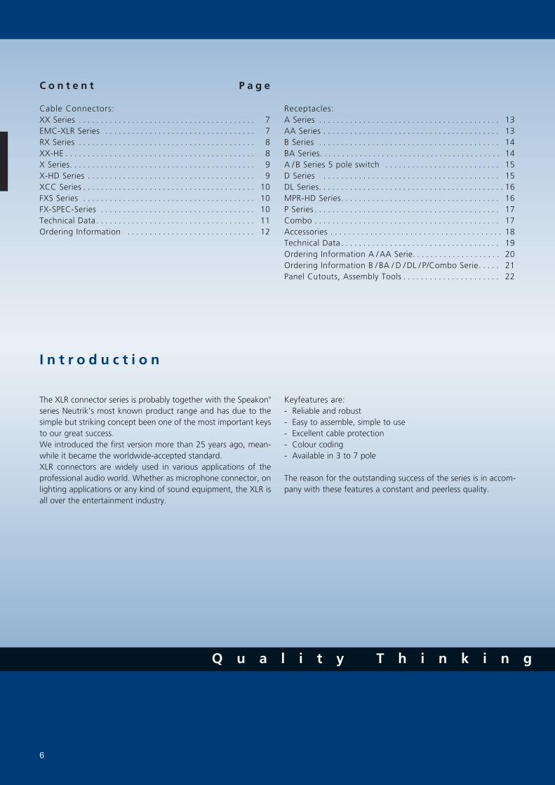
The XLR connector series is probably together with the Speakon® series Neutrik's most known product range and has due to the simple but striking concept been one of the most important keys to our great success.We introduced the first version more than 25 years ago, mean-while it became the worldwide-accepted standard.XLR connectors are widely used in various applications of the professional audio world. Whether as microphone connector, on lighting applications or any kind of sound equipment, the XLR is all over the entertainment industry.
Keyfeatures are:- Reliable and robust- Easy to assemble, simple to use- Excellent cable protection- Colour coding- Available in 3 to 7 pole
The reason for the outstanding success of the series is in accom-pany with these features a constant and peerless quality.

X L R C a b l e C o n n e c t o r s
w w w . n e u t r i k . c o m 7
X X S e r i e s
The next generation of the worldwide accepted standard.
Unique cage type female contact - increases conductivity.
Female contact with “solder stop” for ease soldering.
Male connector without locking “window” - more strigent
housing, increases durability.
Improved chuck type strain relief - increases retention force
and makes assembly easier and faster.
New ground contact - excellent contact integrity between
chassis and cable connector.
Customized branding using translucent ring.
Sleek and ergonomic design - valuable and handy.
NC3FXX NC3MXX-B
NC*FXX
NC*MXX
* ... 3 - 7 contacts
3-pole male / female XLR cable connector with integrated capacitive shield to shell connection to avoid RF-interference and LF-noise. 360° shield contact on female connector ensures best possible shielding and chassis contact. Patent pending
E M C - X L R S e r i e s
NC3FXX-EMC NC3MXX-EMC
Design guarantees a continuous RF-shield connection but avoids ground loops (no LF-shield connection)Circular capacitor enables low-inductive shield connection to connector housingCable shield - PIN 1 connection includes EMI suppression bead (blocks high frequencies)
1
2
3
cable shield
ground contacts
signal contacts
ferrite bead
connector shell
3
2
1
2
3
1Contact #1
Connector shell
Cable shield
Inductance
Annular capacitor
- Q u a l i t y D e s i g n

X L R C a b l e C o n n e c t o r s
8
R X S e r i e s
Extra slim right-angle connector
Neutrik chuck type strain relief
5 selectable cable outlet positions
Only 20 mm wide
NC*MRX
NC*FRX
* ... 3 - 7 contacts
NC3FRX
X X - H E S e r i e s
Exclusive version of standard XX Series
Valuable velour chromium plating
Extra high temperature resistant insulator material
Machined female contacts
NC3FXX-HE
NC3MXX-HE
NC3FXX-HE NC3MXX-HEOutlet position
L o o k f o r t h e L o g o

X L R C a b l e C o n n e c t o r s
w w w . n e u t r i k . c o m 9
X - H D S e r i e s
"Heavy duty" cable connectors for outdoor use
All metal design, stainless steel
NC*FX-HD mates with our new NC*MPR-HD
chassis connector
Dust and water protected according IP 65 in mated
combination with NC*MPR-HD
Available in 3 - 5 pin configuration
NC5FX-HD NC4MX-HD
NC*FX-HD
NC*MX-HD
X S e r i e s
The worldwide accepted XLR connector standard
Rugged diecast shell
Compact design (shortest available XLR cable connector)
Time saving assembly – 4 parts only, no screws
Neutrik unique chuck type strain relief
Gold or silver plated contacts
UL Recognized components
Available in 3 - 7 pin configuration
NC3FX NC3MX
NC*FX
NC*MX
* ... 3 - 7 contacts * ... 3 - 5 contacts
t o i d e n t i f y t h e o r i g i n a l

X L R C a b l e C o n n e c t o r s
F X S S e r i e s F X - S P E C S e r i e s
FX connector with noiseless ON-OFF
switch short-circuiting contacts 2 + 3.
For use on a microphone without
switch.
Solid female cable connector with
locking ring for highest security of
connection.
Uninterrupted EMI protection.
Protects against accidental disconnects.
Thief-prove, grub screw secure connector
onto microphone or gooseneck.
Avoids movements and noises
10
Q u a l i t y T h i n k i n g
X C C S e r i e s
NC3FXCC
NC3MXCC
3 pole cable connector with a circum-
ferential shield contact for best EMI
protection.
Featuring a coaxial ground spring and
coaxial hex crimp ferrule at the cable
entrance for proper and reliable
transition of the cable shield to the shell.
Zebra coding ring to indicate digital
AES signals included.
NC3FXS NC3FX-SPEC
NC3FXCC NC3FXS NC3FX-SPEC

T e c h n i c a l D a t a
11
- Q u a l i t y D e s i g n
w w w . n e u t r i k . c o m
Specification XX EMC X XCC X-HD FXS XX-HE FX-SPEC RX Series Series Series Series Series Series Series Series Series
E l e c t r i c a l
M e c h a n i c a l
M a t e r i a l
Shell Zinc diecast (ZnAI4Cu1) -
(gal Ni or black Cr) gal Ni black Cr
Stainless steel - - - - - - - -Insert Polyamide PA 6.6 30% GR
Contacts - female 3 pole: Bronze (CuSn8)
- female 4 - 7 pole & male: Brass (CuZn39Pb3) - - -
Contact surface Silver gal 2 µm Ag Au Au
or Gold gal 0.2 µm Au hard alloy over 2 µm NiLatch lock St3K32 (latch) / Ck 67 (spring) - - - - Zinc diecast (ZnAI4Cu1) - - - - -
Strain-relief clamp POM
Bushing PA / PU
Circumferential ground spring CuSn6, Ni plated - - - - - - -Crimp ferrule CuZn39Pb3, Ni plated - - - - - - - -Coding ring PA 6 15% GR - - - - - - - -Sealing jacket EPDM - - - - - - - -Securing ring Brass (CuZn39Pb3) - - - - - - - -
Lifetime > 1`000 cycles
Insertion / withdrawal force ≤ 20 N
Cable O.D. range 3.5 - 8.0 mm - 5.4 - 6.2 mm
Max. wire size 3 pole: 2.5 mm2 / AWG 14 AWG 20
4 pole: 1.5 mm2 / AWG 16 - - - - -
5, 6, 7 pole: 1.0 mm2 / AWG 18 - - - - -
Crimp tool: 6.5 mm Hex die (size "E" acc. to IEC 60803) - - - - - - - -
Number of contacts 3 - 7 3 3 - 7 3 3 - 5 3 3 3 3 - 7Contact resistance ≤ 3 mΩ
Insulation resistance - initial: > 2 GΩ
- after damp heat test: > 1 GΩ
Dielectric strength 1500 V dc
Cable shield-shell connection choosable - - -
determined - capacitive - crimp - - - - -Shielding effectiveness > 55 dB @ 1.3 GHz - - - - - - -Lossy ferrite bead on PIN 1 - - - - - - - -Rated current per contact @ 35°C 3 pole: 16 A 5 A
4 pole: 10 A - - - - -
5, 6 pole: 7.5 A - - - - -
7 pole: 5 A - - - - - -
Capacitance between contacts 3 pole: ≤ 4 pF
4, 5, 6 pole: ≤ 7 pF - - - - -
7 pole: ≤ 9 pF - - - - - -
Rated Voltage 50 V ac
E n v i r o n m e n t a l
Operating temperature -30°C to +80°C
Flammability UL 94 HB
Protection class IP 40 IP 65
Solderability complies with IEC 68-2-20
Manufacturing Standard IEC 61076-2-103

O r d e r i n g I n f o r m a t i o n
12
O r d e r i n g I n f o r m a t i o n f o r C a b l e C o n n e c t o r s
Female Male Shell Contact - plating 3 pole 4 pole 5 pole 6 pole 7 pole
X S e r i e s
NC*FX NC*MX Nickel Silver
NC*FX-B NC*MX-B Black Cr Gold
NC*FX-BAG NC*MX-BAG Black Cr Silver
NC3FX-**-D1 NC3MX-**-D1 Nickel / Black Cr Silver / Gold - - - -NC6FSX2 NC6MSX2 Nickel Silver - - - -NC6FSX-B2 NC6MSX-B2 Black Cr Gold - - - -NC6FSX-BAG2 NC6MSX-BAG2 Black Cr Silver - - - -
NC3FXCC NC3MXCC Nickel Gold - - - -
X C C S e r i e s
X - H D S e r i e s
NC3FXS - Nickel Gold - - - -NC3FXS-B - Black Cr Gold - - - -
F X S S e r i e s
NC3FX-SPEC - Black Cr Silver - - - -
F X - S P E C S e r i e s
R X S e r i e s
NC*FRX NC*MRX Nickel Silver
NC*FRX-B NC*MRX-B Black Cr Gold
NC*FRX-BAG NC*MRX-BAG Black Cr Silver
X X S e r i e s
NC*FXX NC*MXX Nickel Silver
NC*FXX-B NC*MXX-B Black Cr Gold
NC*FXX-BAG NC*MXX-BAG Black Cr Silver
NC3FXX-**-D1 NC3MXX-**-D1 Nickel / Black Cr Silver / Gold - - - -
X X - H E S e r i e s
NC3FXX-HE NC3MXX-HE Velour Chromium Gold - - - -
NC*FX-HD NC*MX-HD Nickel Gold - -NC3FX-HD-B NC3MX-HD-B Metal Black Gold - - - -
* ..... Number of Contacts
** ..... Nickel or Black
..... Available Spring 2006
–D1 .... Bulk packed, to be ordered in multiples of 100 pcs. 2 ..... Switchcraft Equivalent
X X - E M C S e r i e s
NC3FXX-EMC NC3MXX-EMC Nickel Gold - - - -
L o o k f o r t h e L o g o

X L R C h a s s i s C o n n e c t o r s
13w w w . n e u t r i k . c o m
A S e r i e s
Smallest XLR receptacles, highest packing density.
Plastic housing, steel retention lug.
Fork type female contacts.
Polished contact areas and hard gold plating.
Various grounding options.
A A S e r i e s
NC5FAV
NC3MAV-0
NC5FAH NC3FAAH NC3FAAV-0
NC5MAH
Front panel cutout and PCB layout 100% compatible to the
A Series.
Most cost-effective series.
"Tulip"type female contact design with high contact pressure.
Selective gold plated contact and PCB termination area for
best conductivity and solderability.
Plastic housing flammability UL 94 HB.
Grounding Options (A / AA / B / BA Series):1 ... Pin 1 & Panel & Shell connected, no separate ground contact.
2 ... Separate ground contact connected to shell & panel, separate Pin 1
w/o number: No ground / Shell contact (except 4 / 5 pole)
NC3FAH1 NC3MAHR NC3FAAV2 NC3MAAH-1
t o i d e n t i f y t h e o r i g i n a l

Q u a l i t y T h i n k i n g
X L R C h a s s i s C o n n e c t o r s
14
B S e r i e s
Same as A Series but except of a metal mounting flange
enabling continuous circumferential ground contact to
chassis for best EMC and RF protection.
Fastening of 3 pole version with B-screw, 4 / 5 pole
use A-screw.
B A S e r i e s
More economical version of B Series with modified metal
flange, similar to 4 / 5 pole.
Fastening with A-screw.
3 pole version only.
NC3FBY
NC3MBH
NC3FBH1
NC3MBV
NC3FBA-V
NC3MBA-V
NC3FBA-H
NC3MBA-H
NC3FBV NC3MBV NC3FBAV2 NC3MBAH

w w w . n e u t r i k . c o m
- Q u a l i t y D e s i g n
X L R C h a s s i s C o n n e c t o r s
15
A / B S e r i e s 5 - p o l e s w i t c h
NC5FAV-SW NC5MAV-SW
A and B-Series 5 pole connector with additional switch.
Normally open, normally closed (NO - NC) contact.
Switch activated by mating XLR cable connector.
Available in 5 pole, 3 or 4 pole on request.
NC5FAV-SW
D S e r i e s
NC3FD-V NC3MDM3-V
"D" Shape metal shell
Optimal RF protection using 3 shield contacts.
Horizontal and vertical PCB mount with separate
ground contact.
Mounting holes with M3 threads available.
2 piece connector, insert is removable from shell.
Front locked / unlocked insert.
NC3FD-V / NC3FD-H
NC3MD-V / NC3MD-H
Inserting (Schematic):
NC5MBV-SW
Q u a l i t y T h i n k i n g
X L R C h a s s i s C o n n e c t o r s
16
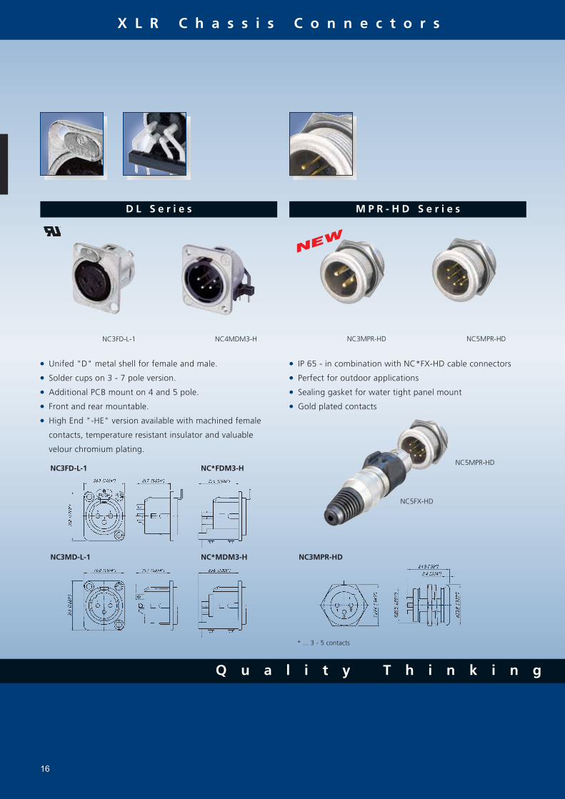
D L S e r i e s
NC3FD-L-1 NC4MDM3-H
Unifed "D" metal shell for female and male.
Solder cups on 3 - 7 pole version.
Additional PCB mount on 4 and 5 pole.
Front and rear mountable.
High End "-HE" version available with machined female
contacts, temperature resistant insulator and valuable
velour chromium plating.
NC3FD-L-1
NC3MD-L-1
NC*FDM3-H
NC*MDM3-H
M P R - H D S e r i e s
IP 65 - in combination with NC*FX-HD cable connectors
Perfect for outdoor applications
Sealing gasket for water tight panel mount
Gold plated contacts
NC3MPR-HD
NC5MPR-HD
* ... 3 - 5 contacts
NC3MPR-HD NC5MPR-HD
NC5FX-HD

w w w . n e u t r i k . c o m
- Q u a l i t y D e s i g n
X L R C h a s s i s C o n n e c t o r s
17
P S e r i e s
Smallest available hard wiring receptacles with large solder cups.
Short female receptacle.
Compatible with Switchcraft DxM, DxF; Cannon XLRx31, XLRx32
6 pole version available with Switchcraft contact arrangement
(NC6FSP-1, NC6MSP)
NC4FP-1 NC6MP-B
NC3FP-1
NC3MP
Combined XLR receptacle and 1/4” phone jack New attractive “front end” design Saves rack space by combining 2 connectors in one housing Horizontal or vertical PCB mounting or hard wire soldering Fully normalled Stereo or mono version Very low conductor capacitance, therefore suitable for digital audio Fastening: Self-tapping PT® screws with thread 2.9 x 1.06 and tri-rondular configuration Front dimension: 30 x 27 mm
C o m b o S e r i e s
NCJ9FI-V NCJ10FI-S
NCJ10FI-H

Q u a l i t y T h i n k i n g
18
A c c e s s o r i e s
C o l o u r C o d e d A c c e s s o r i e s
Part No. Description Black Brown Red Orange Yellow Green Blue Violet Grey White
0 1 2 3 4 5 6 7 8 9
X L R C a b l e C o n n e c t o r s
BSX-* Coloured bushing for X Series
BXX-* Coloured bushing for XX Series
XCR-* Coloured coding ring for X Series XXR-* Coloured coding ring for XX Series
ACRF-* Coloured ring for female 4 + 5 pole A Series and 3 pole BA Series ACRM-* Coloured ring for male 4 + 5 pole A Series and 3 pole BA SeriesDSS-* Lettering plate for D Series
DBA Dummy-plate for D Series panel cut outs
SCD* Rubber sealing cover for female and male D Series
SC* Rubber sealing cab for female and male D Series, Speakon®, USB & Firewire, BNC
SFAV Rubber frame for A / B Serie to mount between the front plate and rear verticale print
A-Screw-1-8 Plastite screw 2.9 x 8*
B-Screw-1-8 Taptite screw 2.5 x 8*
* ... Minimum order quantity of 1000 pcs.
SCDF SCDM
SCF SCM
A Screw B Screw
Example
X L R C h a s s i s C o n n e c t o r s
A c c e s s o r i e s
X L R C a b l e C o n n e c t o r s
XXCR Translucent coding ring for XX Series
XCCR Coding ring for X Serie digital signals
Example
SFAV
X L R C h a s s i s C o n n e c t o r s

w w w . n e u t r i k . c o m
- Q u a l i t y D e s i g n
19
T e c h n i c a l D a t a
Specification A AA B BA D DL MPR-HD P Combo Series Series Series Series Series Series Series Series Series
E l e c t r i c a l
M e c h a n i c a l
M a t e r i a l
E n v i r o n m e n t a l
Number of contacts 3 - 5 3 3 - 5 3 3 3 - 7 3 - 5 3 - 7 (6**) 5 - 10Contact resistance ≤ 5 mΩ ≤ 8 mΩ ≤ 10 mΩInsulation resistance - initial: > 2 GΩ
- after damp heat test: > 1 GΩ > 500 MΩDielectric strength 1500 V dc
Rated voltage 50 V ac
Rated current per contact 3 pole: 6 A 16 A 16 A 16 A - 4 pole: 6 A - - - 10 A 10 A 10 A - 5, 6 pole: 3 A - - - 7.5 A 7.5 A 7.5 A - 7 pole: 5 A - - - - - - -Combo XLR + Jack contact 7.5 A - - - - - - - - Capacitance between contacts 3 pole: ≤ 7 pF - ≤ 4 pF ≤ 4 pF ≤ 4 pF ≤ 2 pF 4, 5, 6 pole: ≤ 7 pF - - - - 7 pole: ≤ 9 pF - - - - - - -
Lifetime > 1`000 mating cycles
Insertion / withdrawal force ≤ 20 N 25 NRetention method - standard: latch lock (XLR) - "0" Version: ≥ 20 N separating force 25 N
Insert Polyamide PA 6.6 30% GR
Shell Zinc diecast (ZnAI4Cu1) - - - - - (gal Ni or black Cr plated) - - - - Ni plated -Ring Zinc diecast (ZnAI4Cu1) - - - - - - -Contacts - female 3 pole: Bronze CuSn6 -
4 - 5 pole: Bronze CuSn6 - - - - - - - 4 - 7 pole: Brass CuZn39Pb3 - - - - - - - - male: Brass CuZn35Pb2 -Contact surface gal 0.2 µm AuCo over 2 µm NiP15 (Tribor ®) - - - -
gal 2 µm Ag or gal 0.2 µm Au hard alloy over 2 µm Ni - - - - Au -Latch lock & spring Ck 67 steel, treated -
1) .... B Series 3 pole connectors > B-screw, 4 & 5 pole versions > A-screw** .... P Series male 3 - 6 pole
Operating temperature -30°C to +80°C
Protection class IP 40 IP 65
Flammability UL 94 HB
UL 94 V-0 3 pole - 3 pole - - - - - -Solderability complies with IEC 68-2-20
Mounting screw A A 1) A - - - - AColour coding ACR-* - - ACR-* DSS DSS - - - (4 + 5 pole only)

Q u a l i t y T h i n k i n g
O r d e r i n g I n f o r m a t i o n
20
O r d e r i n g I n f o r m a t i o n f o r R e c e p t a c l e
Female Male Shell Contact 3 4 5
pole pole pole
A S e r i e s A A S e r i e s
Female Male Shell Contact 3
pole
NC*FAH NC*MAH Black Plastic Gold
NC*FAH-0 Black Plastic Gold
NC3MAH-0 Black Plastic Gold - -NC3FAHL-0 Black Plastic Gold - -NC3FAHR-0 Black Plastic Gold - -NC3FAH1 NC3MAH-1 Black Plastic Gold - -NC3FAH1-0 Black Plastic Gold - -NC3FAHL1 Black Plastic Gold - - NC3MAHL Black Plastic Gold - -NC3FAHL1-0 Black Plastic Gold - -NC3FAHR1 Black Plastic Gold - - NC3MAHR Black Plastic Gold - -NC3FAHR1-0 Black Plastic Gold - -NC3FAH2 Black Plastic Gold - -NC3FAH2-0 Black Plastic Gold - -NC3FAHR2 Black Plastic Gold - -NC3FAHR2-0 Black Plastic Gold - -NC*FAV NC*MAV Black Plastic Gold
NC*FAV-0 Black Plastic Gold
NC3MAV-0 Black Plastic Gold - -NC3FAV1 NC3MAV-1 Black Plastic Gold - -NC3FAV1-0 Black Plastic Gold - -NC3FAV2 Black Plastic Gold - -NC3FAV2-0 Black Plastic Gold - -NC3FAY NC3MAY Black Plastic Gold - -NC3FAY-0 Black Plastic Gold - -NC5FAV-SW NC5MAV-SW Black Plastic Gold - -
NC3FAAH NC3MAAH Black Plastic Gold
NC3FAAH-0 Black Plastic Gold
NC3FAAH1 NC3MAAH-1 Black Plastic Gold
NC3FAAH1-0 Black Plastic Gold
NC3MAAH-0 Black Plastic Gold
NC3FAAH2 Black Plastic Gold
NC3AAH2-0 Black Plastic Gold
NC3FAAV NC3MAAV Black Plastic Gold
NC3FAAV-0 Black Plastic Gold
NC3FAAV1 NC3MAAV-1 Black Plastic Gold
NC3AAV1-0 Black Plastic Gold
NC3MAAV-0 Black Plastic Gold
NC3FAAV2 Black Plastic Gold
NC3FAAV2-0 Black Plastic Gold
A / AA Series rear mount only, all PCB mount except Y version = IDC
G r o u n d i n g O p t i o n s
Female
Male
"1" "2"
w/o number "0" "1"
A / AA Series and B / BA Series
Shell*
Frontpanel*
Pin 1
Ground
Shell*
Frontpanel*
Pin 1
Shell*
Frontpanel*
Pin 1
Ground
Shell*
Frontpanel*
Pin 1
Ground
Shell*
Frontpanel*
Pin 1
... Contact to shell of mating connector
... Connection to frontpanel by fastening screwShell*
Frontpanel*

w w w . n e u t r i k . c o m
- Q u a l i t y D e s i g n
O r d e r i n g I n f o r m a t i o n
21
O r d e r i n g I n f o r m a t i o nO r d e r i n g I n f o r m a t i o n f o r R e c e p t a c l e
Female Male Flange Contact 3 4 5
pole pole pole
B S e r i e s B A S e r i e s
Female Male Shell Contact 3 4 5 6 7
pole pole pole
pole
pole
D S e r i e s
NC3FD-V NC3MD-V Nickel Silver - - - -NC3FD-V-B NC3MD-V-B Black Cr Gold - - - -NC3FD-V-BAG NC3MD-V-BAG Black Cr Silver - - - -NC3FDM3-V NC3MDM3-V Nickel Silver - - - -NC3FDM3-V-B NC3MDM3-V-B Black Cr Gold - - - -NC3FD-H NC3MD-H Nickel Silver - - - -NC3FD-H-B NC3MD-H-B Black Cr Gold - - - -NC3FD-H-BAG NC3MD-H-BAG Black Cr Silver - - - -NC*FDM3-H NC*MDM3-H Nickel Silver - -NC3FDM3-H-B NC3MDM3-H-B Black Cr Gold - - - -NC3FDM3-H-BAG NC3MDM3-H-BAG Black Cr Gold - - - -
D L S e r i e s
NC*FD-L-1 NC*MD-L-1 Nickel Silver NC*FD-L-B-1 NC*MD-L-B-1 Black Cr Gold NC*FD-L-BAG-1 NC*MD-L-BAG-1 Black Cr Silver -NC*FDM3-L-1 NC*MDM3-L-1 Nickel Silver - -NC3FDM3LBAG-1 NC3MDM3LBAG-1 Black Cr Silver - - - -NC3FD-L-1-HE NC3MD-L-1-HE Velour Cr Gold - - - -
P S e r i e s
NC*FP-1 Nickel Silver NC*MP Nickel Silver -NC*FP-B-1 Black Cr Gold NC*MP-B Black Cr Gold -NC*FP-BAG-1 NC*MP-BAG Black Cr Silver -
M P R - H D S e r i e s
- NC*MPR-HD Nickel Gold - -
B A S e r i e s
NC3FBAH1 Metal Gold - - NC3MBAH Metal Gold - -NC3FBAH1-0 Metal Gold - - NC3MBAH-0 Metal Gold - -NC3FBAH2 Metal Gold - - NC3MBAH-1 Metal Gold - -NC3FBAH2-0 Metal Gold - -NC3FBAV1 Metal Gold - - NC3MBAV Metal Gold - -NC3FBAV1-0 Metal Gold - - NC3MBAV-0 Metal Gold - -NC3FBAV2 Metal Gold - - NC3MBAV-1 Metal Gold - -NC3FBAV2-0 Metal Gold - -Special version for 3 pole B-Series with M2.5 mounting holes (-M25) on request.B / BA Series rear mount only, all PCB mount except Y version = IDC
NC*FBH Metal Gold -
NC*MBH Metal Gold
NC*FBH-B Black Metal Gold -
NC*MBH-B Black Metal Gold -
NC3FBH1 Metal Gold - -NC3FBH1-B Black Metal Gold - -NC3FBHL1 Metal Gold - - NC3MBHL Metal Gold - -NC3FBHL1-B Black Metal Gold - - NC3MBHL-B Black Metal Gold - -NC3FBHR1 Metal Gold - -NC3FBHR1-B Black Metal Gold - -NC3FBH2 Metal Gold - -NC3FBH2-B Black Metal Gold - -NC3FBHR2 Metal Gold - - NC3MBHR Metal Gold - -NC3FBHR2-B Black Metal Gold - - NC3MBHR-B Black Metal Gold - -NC*FBV Metal Gold -
NC*MBV Metal Gold
NC*FBV-B Black Metal Gold -
NC*MBV-B Black Metal Gold -
NC3FBV1 Metal Gold - -NC3FBV1-B Black Metal Gold - -NC3FBV2 Metal Gold - -NC3FBV2-B Black Metal Gold - -NC3FBY NC3MBY Metal Gold - -NC3FBY-B NC3MBY-B Black Metal Gold - -NC5FBV-SW NC5MBV-SW Metal Gold - -
NC3FBH1-E NC3MBV-E Metal Gold - -NC3FBH2-E Metal Gold - -NC3FBV1-E Metal Gold - - NC3MBH-E Metal Gold - -
C o m b o S e r i e s
NCJ*FI-H Black plastic Gold NCJ*FI-H-0 Black plastic Gold NCJ*FI-S Black plastic Gold NCJ*FI-S-0 Black plastic Gold NCJ*FI-V Black plastic Gold NCJ*FI-V-0 Black plastic Gold
Contact # 1 2 3 T R S TN RN SN G GNNCJ5FI-* x x x x x x NCJ6FI-* x x x x x x x NCJ9FI-* x x x x x x x x x x NCJ10FI-* x x x x x x x x x x x
5 6 9 10
pole pole pole
pole

O r d e r i n g I n f o r m a t i o n
22
P a n e l C u t o u t s
A / B S e r i e s D S e r i e s P S e r i e s C o m b o M P R S e r i e s
A s s e m b l y T o o l s
HTX Hand tool to tighten the X / XX-bushing BTXX Assembly fixture to tightening the XX-bushing
HX-R-BNC Crimp tool for XCC Series DIE-R-BNC-PT Crimp die for XCC Series (6.5 mm HEX)

P l u g s & J a c k s
23

24
C o n t e n t P a g e
Plugs:1/4" Phone Plugs - PX Serie ......................................... 251/4" Phone Plugs - Silent Plug ...................................... 261/4" Professional Phone Plugs - P Serie ........................ 27MIL/B-Gauge Type Phone Plugs .................................... 270.173" Bantam Type Miniature Plugs ........................... 283.5 mm right-angle stereo Plug .................................... 28Technical Data ............................................................ 29Accessories ................................................................. 29Ordering Information ................................................... 30
Jacks:Locking 1/4" Cable and Chassis Jacks .......................... 311/4" Vertical Jacks ...................................................... 32M Jacks ...................................................................... 33Slim Jacks .................................................................. 34Stacking Jacks ............................................................. 35Technical Data ............................................................ 36Ordering Information ............................................ 37 + 38
I n t r o d u c t i o n
The Neutrik® plug and jack program offers a wide range of professional phone connectors including 1/4", 3,5 mm, MIL/B-gauge style and TT or bantam style plugs. The jack range offers an exceptional "slim" 1/4" PCB jack that is almost 20% smaller than most other designs. The heavy duty M line combines a wide range of options such as three different nose forms and four styles of contacts including 3 PCB and one solder tab. It includes also a 1/4" chassis and cable jack line with the secure locking feature, well known from the XLR range. All jacks are manufactured from strong high-grade thermoplastics and are available in all common versions which make them suitable for audio and indus-trial applications.
The plug line features:- Mono (TS) and Stereo (TRS) plugs- Straight and right angle versions- Rugged diecast shell in Nickel or black Chromium- Nickel or gold plated contacts- Chuck type strain relief- Precision machined plugfinger without rivets- Coloured boots and rings for coding- True 3.5 mm stereo plug- Silent Plug for instrument (guitar) applications
All plugs and jacks are specified to IEC 60603-11 and EIA RS-453 or the respective MIL standard.
Neutrik® offers also a special jack version which is a combined 3 pole XLR receptacle and a 1/4" phone jack for balanced mic or line inputs in one XLR shell. This "one for two" panel mount offers substantial cost saving, labor and material. For more information on the Combo products look in the XLR Guide or visit our website at www.neutrik.com.
L o o k f o r t h e L o g o

P l u g s
1/4" Phone P lug - PX Ser ie
Slim 1/4” plug with million fold proven chuck type strain relief
Precision machined one piece contacts - no rivets
Sleek attractive design for best handling convenience
14.5 mm only in diameter - serves highest packing density of 15.88 mm jack pitch
Nickel or gold plugfinger in mono (TS) and stereo (TRS)
NP2X NP3X-B NP3X + XXR-5
NP3X
15.88 mm jack pitch:
w w w . n e u t r i k . c o m 25
t o i d e n t i f y t h e o r i g i n a l

P l u g s
26
1/4" Phone P lug - S i lent P lug
NP2C-AU-SILENT
Attention!
Use only for instrument (guitar) applica-
tions. Connecting an amplifier output
may blow your amp!
Gold plated contacts
Detail Silent Switch:
Springloadedmoving magnet
Hermetically sealedGold plated contacts
Moving magnetREED SWITCH
Cannot corrode or pollute
No wear, constant contact resistance
Decoupled from switching mechanism
Reed Switch
Avoid pops and squeals
Hermetically sealed switching contacts
Lifetime beyond 10.000 mating cycles
S
N
NP2C-AU-SILENT
Q u a l i t y T h i n k i n g
D e s i g n C r i t e r i a
The Silent Plug automatically mutes (shorts)
an instrument (guitar) cable to avoid pops and
squeals when changing the instrument (guitar)
under load.
The integrated silent switch (pat. pending) is
based on REED-technology and guarantees a
lifetime beyond 10`000 mating cycles.

P l u g s
w w w . n e u t r i k . c o m 27
NP3C NP3TB-B
M I L / B - G a u g e Ty p e P h o n e P l u g s 1/4" Profess ional Phone P lugs
NP2C NP2RCS NP3TB-R NP3CM-B
Available in mono (TS) or stereo (TRS) Meets EIA / IEC standards Unique plug finger design without rivets Sturdy diecast metal shell Excellent Neutrik® chuck type strain relief
1/4" "B-Gauge” and "MIL" Type Plugs All metal design, chuck type strain relief, no rivets Meets all prevailing standards Available as plug fingers only for overmolding
NP3CM-BNP2RCS
- Q u a l i t y D e s i g n

P l u g s
28
0 .173" Bantam Type Min iature P lugs
NP3TT-1-B NP3TT-2
3 . 5 m m R i g h t - A n g l e S t e r e o P l u g
NTP3RC
Very robust ergonomic design Gold contact version in combination with the NJ3TTA jack eliminates contact problems due to corrosion or dirt The new single plug NP3TT-P and the new dual plug NP3TT-2 are made for assembling with a standard HEX crimping tool as used with coax cables
The only available 3.5 mm plug with chuck type strain relief All metal housing - reliable and robust Easy to assemble, simple to use Slim design - space saving Excellent cable protection All Nickel or black housing, available with gold plated contacts
NP3TT-1
NP3TT-P
NTP3RC
Q u a l i t y T h i n k i n g

T e c h n i c a l D a t a
w w w . n e u t r i k . c o m 29
Specifications 1/4" Phone Plugs MIL / B-gauge Type 0.173" Bantam Type 3.5 mm Stereo Plugs & SILENT Plug
E l e c t r i c a l
M e c h a n i c a l
E n v i r o n m e n t a l
Temperature range: -20 °C to +65 °C
Solderability: Complies with IEC 68-2-20
M a t e r i a l s
Shell: Zinc diecast Brass Brass (CuZn39Pb3) Zinc diecast (ZnAl4Cu1) Ni or (CuZn39Pb3) 2 µm Ni (Su) plated (ZnAl4Cu1) Ni or black Cr plated black or red coated PA 6 30 % GR black Cr plated
Insulation: Polyamide (PA 6.6 30 % GR) PA 6.6 15% GR
Contacts: Brass (CuZn39Pb3)
(Tip: CuSn6)
2 µm Ni (Su) or Au plated or Au or Brass 2 µm TRIBOR® (NiP-AuCo) or AuChuck: POM POM - POMBushing: POM + PU - - CuZn39Pb3 + PU (Ni or black Chrome)
Rated current: depends on mating connector
Contact resistance: depends on mating connector
Insulation resistance: - initial: > 2 GΩ
- after damp heat test: ≥ 1 GΩ
Dielectric strength 1 kV dc
BSP-* BSTT-* BSTP-*
A c c e s s o r i e s
BSP-* Coloured bushing for NP*C Series BSTP-* Coloured sleeves for NP3TT-P SeriesBPX-* Coloured bushing for NP*X Series PXR-* Coloured marking rings for NP*X SeriesBSTT-* Coloured sleeves for NP3TT Series PCR-* Coloured marking rings for NP*C Series *: 0 - Black, 1- Brown, 2 - Red, 3 - Orange, 4 - Yellow, 5 - Green, 6 - Blue, 7 - Violet, 8 - Grey, 9 - White; Must be ordered in multiples of 100.
Assembly toolHX-TT-1 Assembly and crimp tool for NP3TT-1/AUHX-R-BNC HEX crimp tool for NP3TT-P*DIE-R-BNC-PJ HEX crimp die for NP3TT-P* (5.4 mm)
PCR-*BPX-* PXR-*
- Q u a l i t y D e s i g n
Wiring: solder terminals
Wire size mm2 1 1 (NP3CM: 0.5) 0.25 0.22
AWG 18 18 (NP3CM: 20) 24 24Cable O.D.: mm 4 - 7 4 - 7 4.8 max 2 - 4.5

O r d e r i n g I n f o r m a t i o n
30
1 / 4 " P r o f e s s i o n a l P h o n e P l u g s - P C S e r i e s
M I L / B - g a u g e T y p e P h o n e P l u g s
NP3TB-B Black Nickel B-GAUGE BP0316 1/4" B-Gauge plug, chuck type strain reliefNP3TB-R Red Nickel 1/4" B-Gauge plug, chuck type strain reliefNP3TM-B Black Nickel MIL-P-642/2 1/4" MIL plug , chuck type strain reliefNP3TM-R Red Nickel 1/4" MIL plug , chuck type strain reliefNP2CM-B Black Brass MIL-P-642/4 Mono 1/4" MIL plug, chuck type strain reliefNP2CM-R Red Brass Mono 1/4" MIL plug, chuck type strain reliefNP3CM-B Black Brass MIL-P642/5A Stereo 5.23 mm (0.206") MIL plug, chuck type strain reliefNP3CM-R Red Brass Stereo 5.23 mm (0.206") MIL plug, chuck type strain relief
0 . 1 7 3 " B a n t a m T y p e M i n i a t u r e P l u g s
NP3TT-1-B Nickel + black plastic Nickel MIL-P-642/13 4.4 mm (0.173") Bantam plug with solder contacts, black sleeveNP3TT-1-R Nickel + red plastic Nickel 4.4 mm (0.173") Bantam plug with solder contacts, red sleeveNP3TT-AU-B Nickel + black plastic Gold 4.4 mm (0.173") Bantam plug with solder contacts, black sleeveNP3TT-AU-R Nickel + red plastic Gold 4.4 mm (0.173") Bantam plug with solder contacts, red sleeveNP3TT-P-B Black plastic Nickel 4.4 mm (0.173") Bantam plug with solder contacts, black sleeveNP3TT-P-R Red plastic Nickel 4.4 mm (0.173") Bantam plug with solder contacts, red sleeveNP3TT-P-AU-B Black plastic Gold 4.4 mm (0.173") Bantam plug with solder contacts, black sleeveNP3TT-P-AU-R Red plastic Gold 4.4 mm (0.173") Bantam plug with solder contacts, red sleeveNP3TT-2 Black plastic Nickel 4.4 mm (0.173") Twin Bantam plug with solder contacts, black sleeve
3 . 5 m m R i g h t - A n g l e S t e r e o P l u g
NTP3RC Nickel Nickel 3.5 mm audio plug with chuck and bushingNTP3RC-B Black Cr Gold 3.5 mm audio plug with chuck and bushing
Part Number Shell Contacts Standards Remarks
Compatibility
S I L E N T G u i t a r P l u g
NP2C-AU-SILENT red coated Gold IEC 60603-11 / EIA RS-453 Mono plug, chuck-type strain relief, silent switch
1 / 4 " P r o f e s s i o n a l P h o n e P l u g s - P X S e r i e s
NP2X Nickel Nickel IEC 60603-11 / EIA RS-453 Mono plug, black bushing, chuck type strain reliefNP2X-BAG Black Cr Nickel Mono plug, black bushing, chuck type strain reliefNP2X-B Black Cr Gold Mono plug, black bushing, chuck type strain reliefNP3X Nickel Nickel Stereo plug, black bushing, chuck type strain reliefNP3X-BAG Black Cr Nickel Stereo plug, black bushing, chuck type strain reliefNP3X-B Black Cr Gold Stereo plug, black bushing, chuck type strain relief*-D Bulk packed to be ordered in multiples of 100
NP2C Nickel Nickel IEC 60603-11 / EIA RS-453 Mono plug, black bushing, chuck type strain reliefNP3C Nickel Nickel Stereo plug, black bushing, chuck type strain reliefNP2C-BAG Black Cr Nickel Mono plug, black bushing, chuck type strain reliefNP3C-BAG Black Cr Nickel Stereo plug, black bushing, chuck type strain reliefNP2C/B Black Cr Gold Mono plug, black bushing and gold contacts, chuck type strain reliefNP3C/B Black Cr Gold Stereo plug, black bushing and gold contacts, chuck type strain reliefNP2C-BAG-T-AU Black Cr Nickel + T: Gold Mono plug, black bushing with gold tip, chuck type strain reliefNP2C-T10AA Nickel Nickel Built-in 1:10 transformer to convert mic level to guitar inputs NP2RCS Nickel + black plastic Nickel Mono right-angle plug, black bushing, chuck type strain reliefNP3RCS Nickel + black plastic Nickel Stereo right-angle plug, black bushing, chuck type strain reliefNP*C-D Bulk packed to be ordered in multiples of 100NP2C-T10AA Nickel Nickel Mono plug, red bushing, with built-in transformer to convert microphone levels to guitar inputs, chuck type strain relief
L o o k f o r t h e L o g o

L o c k i n g J a c k s
w w w . n e u t r i k . c o m 31
L o c k i n g 1 / 4 " C a b l e J a c k s
Mates with all mono or stereo plugs specified to EIA RS-453 Dimensionally compatible with D Series (31 x 26 mm) Securely locking chassis jack Solder terminals Special version with black plastic shell
L o c k i n g 1 / 4 " C h a s s i s J a c k s
Securely locking cable jack Mates with all mono or stereo plugs specified to EIA RS-453 Extremely robust and reliable Excellent Neutrik® cable retention Colored boots available in 10 colours For cable O.D. up to 8 mm
NJ3FC6 NJ3FC6-BAG
NJ3FC6 NJ3FP6C
NJ3FP6C-BAGNJ3FP6C
t o i d e n t i f y t h e o r i g i n a l

V e r t i c a l P C B J a c k s
32
1 / 4 " V e r t i c a l J a c k s
NJ*FD-V
NJ*FD-V
Q u a l i t y T h i n k i n g
Quick Cap Fixing System drastically reduces assembly time through snapping mounting cap The retention force is provided by a special spring element, independent from contacts All common circuits available Two versions for mating of plugs acc. to EIA RS-453 (NJ*FD-V) or B-gauge BP0316 (NJ*TB-V)

H o r i z o n t a l P C B J a c k s
w w w . n e u t r i k . c o m 33
M J a c k s
Wide body and extremely durable contacts. Available in all common versions: - mono - stereo - switched - unswitched Either hardwire or PCB versions Nose type in - half threaded - fully threaded - chrome ferrule nose Full threaded and Chrome nose M Jacks are supplied with washer and fixing nut Fascia appearance can be in plastic or Chrome
NMJ4HHD2 NMJ2HC-S NMJ6HFD2-SAU
NMJ4HHD2
NMJ4HC-S
NMJ6HFD2NRJ-NUT-B NRJ-WB (washer)
- Q u a l i t y D e s i g n
Q u a l i t y T h i n k i n g
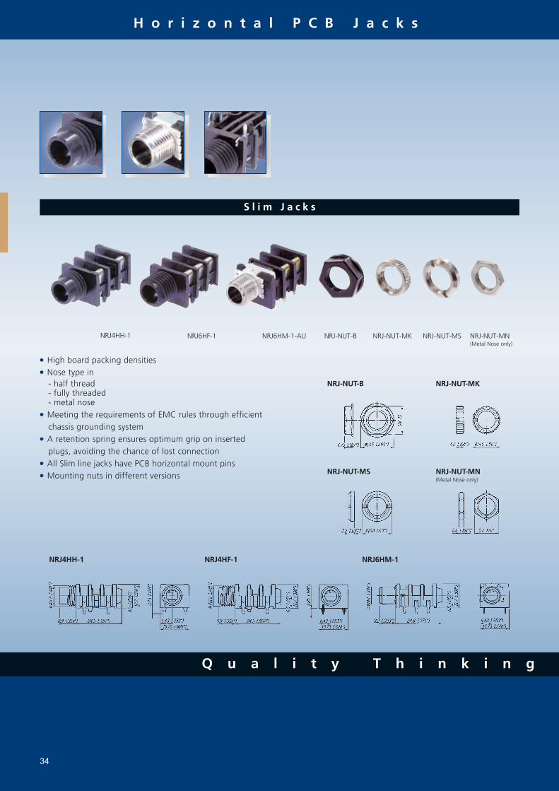
S l i m J a c k s
High board packing densities Nose type in - half thread - fully threaded - metal nose Meeting the requirements of EMC rules through efficient chassis grounding system A retention spring ensures optimum grip on inserted plugs, avoiding the chance of lost connection All Slim line jacks have PCB horizontal mount pins Mounting nuts in different versions
34
NRJ4HH-1 NRJ6HF-1 NRJ6HM-1-AU
NRJ4HH-1 NRJ4HF-1 NRJ6HM-1
NRJ-NUT-MK NRJ-NUT-MS NRJ-NUT-MN(Metal Nose only)
NRJ-NUT-B
NRJ-NUT-B NRJ-NUT-MK
NRJ-NUT-MS NRJ-NUT-MN(Metal Nose only)
H o r i z o n t a l P C B J a c k s
w w w . n e u t r i k . c o m
- Q u a l i t y D e s i g n
35
P C B M o u n t S t a c k i n g J a c k s
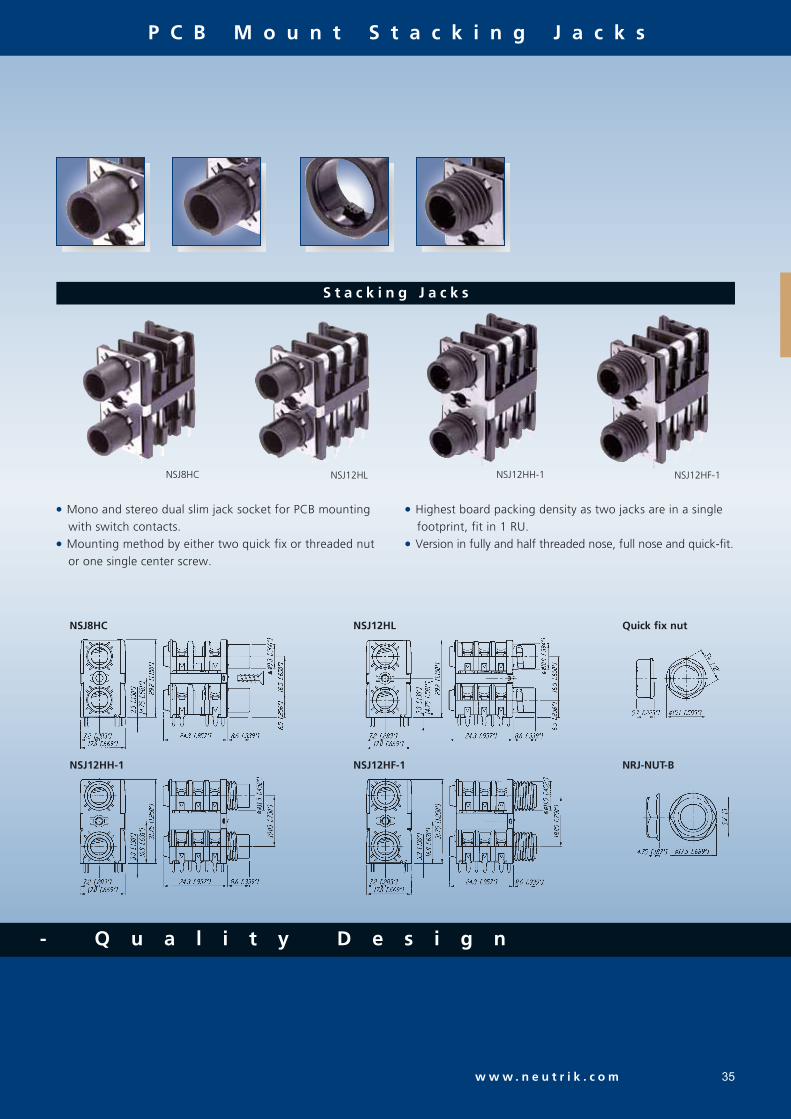
S t a c k i n g J a c k s
Mono and stereo dual slim jack socket for PCB mounting with switch contacts. Mounting method by either two quick fix or threaded nut or one single center screw.
NSJ8HC NSJ12HL
NSJ8HC
NSJ12HH-1
NSJ12HL
NSJ12HF-1
Highest board packing density as two jacks are in a single footprint, fit in 1 RU. Version in fully and half threaded nose, full nose and quick-fit.
NSJ12HH-1 NSJ12HF-1
Quick fix nut
NRJ-NUT-B

T e c h n i c a l D a t a
36
S p e c D r a w i n g s a r e a v a i l a b l e
Specifications Vertical Locking M Jack
Slim Jack
Stacking
Jack Cable & Chassis
Jack Jack
E l e c t r i c a l
M e c h a n i c a l
Lifetime > 10`000 cycles
Insertion / withdrawal force: < 10 N / > 8 N < 20 N / < 20N < 20 N / > 10 N < 20 N / > 10 N < 20 N / > 10 NCap opening torque: 25 N cm / 9.84 N in - - - -Locking force: - > 80 N - - -Wire size: - 1 mm2 / 18 AWG 1 - - -Cable O.D. (FC6 only) - 3.5 - 8.0 mm - - -Solderability complies with IEC 68-2-20:
Standard Compatibility: EIA RS 453 + IEC 60603-11 NJ*FD
B-GAUGE BPO 316, MIL-J-641/3 NJ*TB - - - -Panel thickness: 1.2 - 1.5 mm [0.047 - 0.06"] - - - - - Full nose type: - - < 3.0 mm < 3.0 mm - - Half nose type: - - < 1.0 mm < 1.0 mm - - Chrome nose: - - < 4.7 mm - - - NSJ*HL: - - - - 1.0 - 1.6 mm - NSJ*HC: - - - - > 1.0 mm
M a t e r i a l
Contact resistance - initial: < 10 mΩ < 6 mΩ < 15 mΩ < 10 mΩ - - Top row: - - - - < 15 mΩ - Bottom row: - - - - < 10 mΩSwitch contact resistance: - for silver: - - < 30 mΩ < 25 mΩ - - for gold: < 15 mΩ - - < 10 mΩ - - Top row: - - - - < 15 mΩ - Bottom row: - - - - < 10 mΩInsulation resistance: ≥ 1GΩ @ 500 V dc
Dielectric strength 1 kV dc
Rated current: 3 A 10 A 3 A 3 A 3 ARated switch contact current: 0.25 A @ 12 V N/A 0.5 A @ 50 V 0.5 A @ 50 V 0.5 A @ 50 V
Shell / Handle: PA 6.6 30% GR ZnAI4Cu1 PA 6.6 15% GR PA 6.6 15% GR PA 6 15% GR Ni plated or black coated - FP6P: - PA 6.6 30% GR - - -Insulation: - PA 6.6 30% GR - Contacts: CuSn6 CuBe2/CuZn37 (ground) Ni-Silver CuSn6 CuSn6Contact surface: 0.2 µm Au 2 µm Ag - gal 2 µm Ag / 0.2 µm Au gal 2 µm AgCap / Nut / Washer: POM - PA 6.6 15% GR PA 6.6 15% GR PA 6.6 15% GRRing Nut: - - - Brass (Ni plated) Brass (Ni plated)Chuck: - POM - - -Bushing: - PA 6.6 15% GR + PUR - - -Temperature range: -25°C to +70°C
1... max. for soldering tag
Circuits: Mono unswitched Mono switched Stereo unswitched 2x switching 3x switching (normalling) Stereo (normalling) Stereo

O r d e r i n g I n f o r m a t i o n
37
o n t h e W e b - w w w . n e u t r i k . c o m
S l i m J a c k
PCB Mount Sockets - SwitchedNRJ3HF-1 Black/Plastic Silver Horizontal PCB soldering IEC 60603-11/EIA RS 453 Mono, full threaded nose, chassis ground contactNRJ4HF Mono, full threaded noseNRJ4HF-1 Mono, full threaded nose, chassis ground contactNRJ6HF Stereo, full threaded noseNRJ6HF-1 Stereo, full threaded nose, chassis ground contactNRJ4HH Mono, half threaded noseNRJ4HH-1 Mono, half threaded nose, chassis ground contactNRJ6HH Stereo, half threaded noseNRJ6HH-1 Stereo, half threaded nose, chassis ground contactNRJ6HF-AU Gold Stereo, full threaded nose, gold plated contactsNRJ6HF-1-AU Gold Stereo, full threaded nose, chassis ground contact, gold plated contactsNRJ6HH-AU Stereo, half threaded nose, gold plated contactsNRJ-NUT-B Hexagonal black plastic nutNRJ-NUT-R Red/Plastic Hexagonal red plastic nutNRJ-NUT-MK Metal/Ni plated Metal ring nut, knurledNRJ-NUT-MS Metal/Ni plated Metal ring nut
PCB Mount Sockets - Switched with Metal NoseNRJ4HM-1 Black/Plastic Silver Horizontal PCB soldering IEC 60603-11/EIA RS 453 Mono, metal threaded noseNRJ4HM-1-AU Gold Mono, metal threaded nose, gold plated contactsNRJ6HM-1 Silver Stereo, metal threaded noseNRJ6HM-1-AU Gold Stereo, metal threaded nose, gold plated contactsNRJ-NUT-MN Metal Hexogonal metal nut (for metal nose jack only)
Part Number Shell Contacts Terminations Standards Remarks
Compatibility
S t a c k i n g J a c k
NSJ8HL Polyamid PA 6.6 GR Silver Horizontal PCB soldering IEC 60603-11/EIA RS 453 Mono, quick fix noseNSJ12HL Stereo, quick fix noseNSJ8HC Mono, full noseNSJ12HC Stereo, full noseNSJ12HF-1 Full threaded noseNSJ12HH-1 Half threaded noseNSJ-NUT-B Black/Plastic Quick fix nut
All Slim jacks are for PCB mount only.Mounting nuts must be ordered separately, except for Stacking Jack type NSJ8HL and NSJ12HL.
Ordering Key:
NRJ*H NEUTRIK Jack Horizontal * number of contacts: H half threaded nose 2 mono unswitched F full threaded nose 4 mono switched L quick fix nose 6 stereo switched M metall threaded nose 8 mono stacking jack C plane nose 12 stereo stacking jack -1 chassis ground contact
Nose: -H -F -M -L -C

38
1 / 4 " L o c k i n g J a c k
NJ3FC6-BAG Black Silver Wire soldering IEC 60603-11/EIA RS 453 Cable JackNJ3FP6C Nickel Chassis JackNJ3FP6C-B Black Gold
NJ3FP6C-BAG Black Silver
NJ3FP6F-P Nickel
NJ3FP6P-BAG Black/Plastic Plastic Chassis
Part Number Shell Contacts Terminations Standards Remarks
Compatibility
M J a c k
1 / 4 " V e r t i c a l J a c k
NJ2FD-V Black/Plastic Gold Vertical PCB soldering IEC 60603-11/EIA RS 453 Non-switching Mono Jack (T/S)NJ3FD-V Non-switching Stereo Jack (T/R/S)NJ5FD-V 2 x switching (normalling) Stereo jack (T/TN/R/RN/S)NJ6FD-V 3 x switching (normalling) Stereo jack (T/TN/R/RN/S/SN)NJ5TB-V B-Gauge BPO316 Mil-J-641/3 2 x switching (normalling) Stereo jack (T/TN/R/RN/S)NJ6TB-V 3 x switching (normalling) Stereo jack (T/TN/R/RN/S/SN)
NMJ2HF-S Black/Plastic Silver Horizontal PCB soldering IEC 60603-11/EIA RS 453 Mono, unswitched, full threaded nose, solder tagsNMJ3HF-S Mono, switched, full threaded nose, solder tagsNMJ4HF-S Mono, switched, full threaded nose, solder tagsNMJ2HC-S Mono, unswitched, Chrome ferrule, solder tagsNMJ4HC-S Mono, switched, Chrome ferrule, solder tagsNMJ4HFD2 Mono, switched, full threaded nose, PCB mountNMJ4HFD3 Mono, switched, full threaded nose, offset PCB mountNMJ4HCD2 Mono, switched, Chrome ferrule, PCB mount,NMJ4HHD2 Mono, switched, half threaded nose, PCB mount, without nut and washerNMJ6HF-S Stereo, switched, full threaded nose, solder tagsNMJ6HC-S Stereo, switched, Chrome ferrule, solder tagsNMJ6HCD2 Stereo, switched, Chrome ferrule, solder tagsNMJ6HHD2 Stereo, switched, half threaded nose, PCB mount, without nut and washerNMJ6HFD2 Stereo, switched, full threaded nose, PCB mountNMJ6HFD2-SAU Stereo, switched, full threaded nose, PCB mount, gold plated sleeve contactNMJ6HFD2-TAU Stereo, switched, full threaded nose, PCB mount, gold plated tip contactNMJ6HFD2-TRAU Stereo, switched, full threaded nose, PCB mount, gold plated tip and ring contactNMJ6HFD3 Stereo, switched, full threaded nose, offset PCB mountNMJ6HCD3 Stereo, switched, Chrome ferrule, offset PCB mountNMJ6HFD4 Stereo, switched, full threaded nose, offset PCB mount
Full threaded and Chrome nose M-Jacks are supplied with fixing nut and washers.Special options are subject to minimum order quantities.
Ordering Key: -S -D2
NMJ*H NEUTRIK M Jack Horizontal * number of contacts: H half threaded nose 2 mono unswitched F fully threaded nose 3 stereo unswitched C chrome nose 4 mono switched -S solder tag 5 stereo switched (T/S) -D3 -D4 D2 PCB pins 02 6 stereo switched (T/R/S) D3 PCB pins 03 D4 PCB pins 04
O r d e r i n g I n f o r m a t i o n

S p e a k o n ® C o n n e c t o r s
39

C o n t e n t P a g e
Speakon® SPX Series 4 Pole Cable Connector ................ 41Speakon® FC Series, 2 and 8 Pole Cable Connector ....... 43Speakon® Adapter ......................................................... 44Speakon® Chassis Connector ........................................ 45Speakon® Combo ........................................................ 47
Speakon® STX Series Cable Connector ........................... 48Speakon® STX Series Chassis Connector ......................... 49Technical Data ............................................................. 51Wiring ......................................................................... 52RCA Series .................................................................. 53
I n t r o d u c t i o n
The Neutrik® Speakon® Series, also in the Pro Audio industry often called "The loudspeaker connector", became the state of the art for speaker and amplifier connections.Invented by Neutrik® as a result of various customer requests, the first Speakon® had been introduced in 1987. The pro audio market realized very quickly the advantages of this completely new connection system. The design has been optimized for loudspeaker applications with an outstanding cost-performance ratio.As market leader for speaker connections we are proud to offer an all-embracing product line for the specific needs of this market today. Latest designs as the STX series or the Speakon® Combo also meet the demands of niche applications or extremely rough conditions and complete the product range.
I n t e g r a t e d D e s i g n
Neutrik's aim to be distinctively recognizable is realized by the technological head start on the one hand as well as both pat-
ent and trademark protection on the other hand. To draw a clear line between Neutrik® and competition products we give our customer the possibility to easily identify the origi-
nal. Therefore all of our new products as the SPX and the STX series are designed according the protected integrated design. (EU-Pat.: DM/057 379, US-Pat. Pending, CHINA-Pat.: 02305192.2/193.0/194.9/195.7)
F e a t u r e s & B e n e f i t s
Today's Speakon® series is a result of a continuous product improvement process. The principal idea has been kept and opti-mized with material and design modifications over the years.
A traditional Speakon® stands for: Reliable and robust, easy and fast to assemble 2, 4 and 8-pole cable and chassis connectors in various versions Optimal "Quick Lock" system for speaker applications Neutrik® proven and unique chuck type cable strain relief Outstanding cost-performance ratio De-facto standard Meets all Worldwide Safety requirements (IEC, UL, ...)
Beyond that, the latest designs as the SPX and STX series offer: Up to 50 Amps current rating Only 3 parts with 1 piece strain relief design for even easier assembly Convertable right-angle version Weatherproof and extremely robust all metal designs Complete system, 4 pole female chassis and male cable connector
Q u a l i t y T h i n k i n g
40
S p e a k o n ® S e r i e s

- Q u a l i t y D e s i g n
w w w . n e u t r i k . c o m 41
S p e a k o n ® S P X S e r i e s 4 P o l e C a b l e C o n n e c t o r
NL4FX NL4FRX
F e a t u r e s
1 Progressive clamping as wire is pushed for- ward2 3 Large combi drive - M4 screw4 Wire size 1.5 - 4 mm2 (AWG 12) for 6 mm2 (AWG 10) remove screw & solder5 Pullout force > 300 N @ 80 cNm6 Gas tight connection
Up to 50 A rms current rating Only 3 parts, easy to assemble High Impact Materials
1 Easy and extremely precise locking system
"Quick Look"
2 Improved grip on latch
3 1 piece strain relief, chuck for 6 to 14.5 mm
cable O.D.
4 Color coding possible
5 Integrated Design guaranties "Made by
Neutrik®"
1
Improved SPX-Series screw contacts! (Wire position after assembly.)
6
1
2
3
4
5
3 4 52
S p e a k o n ® S e r i e s

S p e a k o n ® S e r i e s
42
NL4FX NL4FRX
Accessories
Colored coding rings for SPX Series. Available in blue (Standard), white, red, green and yellow LCR-*Right-angle Speakon® Conversion Kit for changing the straight connector into a right-angel LRXversion without removing the cable from the insert.
O r d e r i n g I n f o r m a t i o n
Cable Connector with chuck and bushing NL4FXCable Connector with chuck and red bushing NL4FX-2Cable Connector with chuck and yellow bushing NL4FX-4Cable Connector with chuck and green bushing NL4FX-5Cable Connector with chuck and white bushing NL4FX-9Right-angle Cable Connector with chuck and bushing NL4FRX
D e s i g n C r i t e r i a
This second generation of Speakon® connectors features higher current rating for the operation of high power speak-ers and amplifiers carrying more than 1000 Watts. Only 3 parts make it fast and easy to assemble with a more reliable
performance. Our unique design makes it possible to change easily and quickly from a straight connector to the right-angle version, even without disconnecting the cable.
A s s e m b l y
Prepare cable as shown.
12 mm [0.5"]
25 mm [1.0"]
HINT:
For easy wiring especially on big cables, first screw on the inner contacts 1+ and 2+ and afterwards the outer contacts 1- and 2- !
LCR-* LRX
L o o k f o r t h e L o g o
S p e a k o n ® S e r i e s
w w w . n e u t r i k . c o m 43
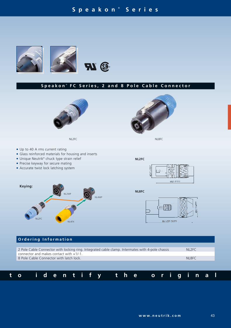
S p e a k o n ® F C S e r i e s , 2 a n d 8 P o l e C a b l e C o n n e c t o r
NL2FC NL8FC
NL2FC
NL8FC
O r d e r i n g I n f o r m a t i o n
2 Pole Cable Connector with locking ring. Integrated cable clamp. Intermates with 4-pole chassis NL2FCconnector and makes contact with +1/-1. 8 Pole Cable Connector with latch lock. NL8FC
Up to 40 A rms current rating Glass reinforced materials for housing and inserts Unique Neutrik® chuck type strain relief Precise keyway for secure mating Accurate twist lock latching system
Keying:
NL2MP
NL4MP
NL2FCNL4FX
t o i d e n t i f y t h e o r i g i n a l

Q u a l i t y T h i n k i n g
S p e a k o n ® S e r i e s
44
S p e a k o n ® A d a p t e r
NA4LJX NL4MMX NL8MM
NA4LJ
NL4MMX
NL8MM
O r d e r i n g I n f o r m a t i o n
Adapter from Speakon® Cable Connector to 2 pole 1/4" Jack. Wiring: +1 to TIP and -1 to SLEEVE. NA4LJX 4 Pole lockable coupler to extend two 4-pole cables NL4MMX8 Pole coupler to extend two 8-pole cables NL8MM
NL4MMX:
Features permanent secure connection on a Speakon® cable connector using 2nd lock.
NL4MMX + NL4FX
(locked on the cable)
Secure Lock!
Changes gender to male when permanently locked on the cable.

- Q u a l i t y D e s i g n
S p e a k o n ® S e r i e s
45w w w . n e u t r i k . c o m
S p e a k o n ® C h a s s i s C o n n e c t o r
Standard version up to 40 A rms, ultra hight current version up to 50 A rms Glass reinforced materials Precise keyway for secure mating Accurate twist lock latching system Metal front plate (8-pole) or metal insert in locking area (2 & 4-pole) Various mounting and wiring possibilities "Air tight design", optimized for speaker applications D or G panel cutouts to be easily mounted on audio industry
standard panels
NL2MP NL4MD-H-1 NL4MD-H-3 NL4MPR NL8MPR
NL4MP
NL4MPR
NL8MPR
NL4MD-V
NL4MD-H

Q u a l i t y T h i n k i n g
S p e a k o n ® S e r i e s
46
Accessories
NLFASTON A-Screw-1-8 SCDF
Faston® receptacle for tabs with "positiv lock" for use with NL4MP, NL4MPR, NL8MPR. Pack of 100 pcs. NLFASTON Black self tapping Plastite® screw 2.9 x 8 for rear panel mount. A-Screw-1-8Rubber sealing covers for the Speakon® receptacles to protect the connectors against dust and moisture. SCDF
O r d e r i n g I n f o r m a t i o n
A B D EC
D-size standard hole direction
D-size reflected hole direction
Self tapping screw holes (A-screw)
Metal M3 thread
Thru holesG-size flange with four holes F
Hole layout:
Pole Flange size Flange layout Hole layout Color Wiring Remarks
NL2MP 2 D-size A D black 3/16" flat tabs* Does not intermate with 4-pole cable connector
NL2MD-H 2 D-size A D black horizontal PCB Does not intermate with 4-pole cable connector
NL2MD-V 2 D-size A D black vertical PCB Does not intermate with 4-pole cable connector
NL4MP 4 D-size A D black 3/16" flat tabs* NL4MP-1 4 D-size A E grey 3/16" flat tabs* NL4MP-2 4 D-size B E black 3/16" flat tabs* NL4MP-3 4 D-size A E black 3/16" flat tabs* NL4MP-M3 4 D-size A F black 3/16" flat tabs* NL4MD-H 4 D-size A E grey horizontal PCB NL4MD-H-1 4 D-size A D black horizontal PCB NL4MD-H-2 4 D-size B E black horizontal PCB NL4MD-H-3 4 D-size A E black horizontal PCB NL4MD-V 4 D-size A D black vertical PCB NL4MD-V-1 4 D-size A E grey vertical PCB NL4MD-V-2 4 D-size B E black vertical PCB NL4MP-ST 4 D-size A D black screw terminal NL4MP-UC 4 D-size A D black 1/4" flat tabs* Ultra high current, up to 50 A rms
NL4MPR 4 round G-size flange C D black 3/16" flat tabs* NL8MD-V 8 square G-size flange C D Ni vertical PCB NL8MD-V-BAG 8 square G-size flange C D black chrome vertical PCB NL8MD-V-1 8 square G-size flange C E Ni vertical PCB NL8MPR 8 square G-size flange C D Ni 3/16" flat tabs* NL8MPR-BAG 8 square G-size flange C D black chrome 3/16" flat tabs*
*: flat tabs to be used with FASTON® connectors or to solder the wire (FASTON® is a trademark of AMP Inc.)
Flange layout:

w w w . n e u t r i k . c o m
- Q u a l i t y D e s i g n
S p e a k o n ® S e r i e s
47
S p e a k o n ® C o m b o
D-size flange Compatible PCB layout and Panel mount to NL4MD-V-1 (NL4MD-H) Cost saving, combines to in one Mates with all 2, 4-pole Speakon® and 1/4" Phone Plugs Space saving and eliminates the need of a 1/4” phone jack. PA-wiring: 1+ is connected to TIP, 1- to the SLEEVE.
NLJ2MD-V
NLJ2MD-V
Combines a Speakon®
and 1/4" Phone Jack - one for two
O r d e r i n g I n f o r m a t i o n
2 Pole Chassis Connector, vertical PCB version NLJ2MD-V2 Pole Chassis Connector, horizontal PCB version NLJ2MD-H
Black self tapping Plastite® screw 2.9 x 8 for rear panel mount. A-Screw-1-8
Accessories

S p e a k o n ® S e r i e s
48
S p e a k o n ® S T X S e r i e s C a b l e C o n n e c t o r
NLT4FX NLT8FX
NLT4FX-BAG NLT4MX NLT8FX
F e a t u r e s
Up to 50 A rms current rating Only 3 parts, easy to assemble All metal housing IP 54 sealing gasket
1
23 4 5
1 Easy and extremely precise locking system
"Quick Look", reinforced with metal
2 Improved grip on latch
3 1 piece strain relief, chuck for cable from
9 to 16 mm O.D.
4 Rugged Extreme "Touring Approved"
5 Rubber sealing boot6 Integrated Design garanties "Made by Neutrik®"7 X-large solder contacts for up to 6 mm2 (AWG 10) wires
4
76
L o o k f o r t h e L o g o

w w w . n e u t r i k . c o m
S p e a k o n ® S e r i e s
49
S p e a k o n ® S T X S e r i e s C h a s s i s C o n n e c t o r
Extremely robust metal housing designed for harsh and demanding environment Weatherproof design features sealing gaskets 4 type range - also male cable connector and female receptacle on 4-pole version All-metal housing makes the STX Series rugged and durable Weatherproof built-in gasket meets IP 54 protection class (4 pole) Ideal product for touring applications and harsh environments Best electrical performance up to 50 Amps Uses precise “quick lock” system Mates with all currently available Speakon® products
NLT4MP
NLT4FP
NLT4FP-BAG NLT4MP NLT4MD-V NLT8MP-BAG
NLT8MP
t o i d e n t i f y t h e o r i g i n a l

Q u a l i t y T h i n k i n g
S p e a k o n ® S e r i e s
50
Accessories
Gasket for NLT4MP. SCNLT(To make a cabinet with an Amphenol EP cutout airtight, the rubber scaling covers the entire hole.) Black self tapping Plastite® screw 2.9 x 8 for rear panel mount. A-Screw-1-8
SCNLT Example: SCNLT + NL4MP A-Screw-1-8
O r d e r i n g I n f o r m a t i o n
Cable Connector
4 Pole Female Cable Connector in nickel metal housing, chuck and bushing NLT4FX4 Pole Female Cable Connector in black-chrome metal housing, chuck and bushing NLT4FX-BAG4 Pole Male Cable Connector in nickel metal housing, chuck and bushing NLT4MX4 Pole Male Cable Connector in black-chrome metal housing, chuck and bushing NLT4MX-BAG
8 Pole Female Cable Connector in nickel metal housing, chuck and bushing NLT8FX8 Pole Female Cable Connector in black-chrome metal housing, chuck and bushing NLT8FX-BAG
Receptacle
4 Pole Female Chassis Connector in nickel metal housing, solder contacts NLT4FP4 Pole Female Chassis Connector in black-chrome metal housing, solder contacts NLT4FP-BAG4 Pole Male Chassis Connector in nickel metal housing, 1/4" flat tabs* NLT4MP4 Pole Male Chassis Connector in black-chrome metal housing, 1/4" flat tabs* NLT4MP-BAG4 Pole Male Chassis Connector in nickel metal housing, PCB contacts NLT4MD-V
8 Pole Male Chassis Connector in nickel metal housing, 1/4" flat tabs* NLT8MP8 Pole Male Chassis Connector in black-chrome metal housing, 1/4" flat tabs* NLT8MP-BAG*: flat tabs to be used with FASTON® connectors or to solder the wire (FASTON® is a trademark of AMP Inc.)
D e s i g n C r i t e r i a
The new Speakon® STX Series is the next generation of 4 & 8 pole Speakon® connectors especially designed for loudspeaker - amplifier applications in harsh and demanding environment such as professional touring.The STX Series features a metal housing which is extremely
rugged and durable; built-in gaskets make it weatherproof. This new series offers beside the female cable connector and male receptacle now also a 4 pole male cable and female chas-sis connector.
w w w . n e u t r i k . c o m
- Q u a l i t y D e s i g n
T e c h n i c a l D a t a
51
Specification SPX STX Speakon® Speakon® Adapter STX Series Series FC Chassis Series Cable Con. Cable Con. Cable Con + Combo Chassis
E l e c t r i c a l
M e c h a n i c a l
M a t e r i a l
E n v i r o n m e n t
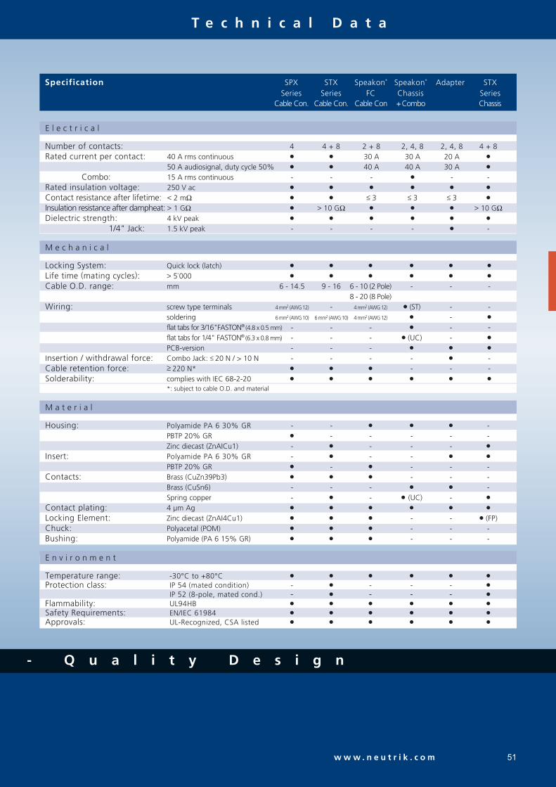
Number of contacts: 4 4 + 8 2 + 8 2, 4, 8 2, 4, 8 4 + 8Rated current per contact: 40 A rms continuous 30 A 30 A 20 A
50 A audiosignal, duty cycle 50% 40 A 40 A 30 A
Combo: 15 A rms continuous - - - - -Rated insulation voltage: 250 V ac
Contact resistance after lifetime: < 2 mΩ ≤ 3 ≤ 3 ≤ 3
Insulation resistance after dampheat: > 1 GΩ > 10 GΩ > 10 GΩDielectric strength: 4 kV peak
1/4" Jack: 1.5 kV peak - - - - -
Locking System: Quick lock (latch)
Life time (mating cycles): > 5`000
Cable O.D. range: mm 6 - 14.5 9 - 16 6 - 10 (2 Pole) - - - 8 - 20 (8 Pole) Wiring: screw type terminals 4 mm2 (AWG 12) - 4 mm2 (AWG 12) (ST) - - soldering 6 mm2 (AWG 10) 6 mm2 (AWG 10) 4 mm2 (AWG 12) -
flat tabs for 3/16"FASTON® (4.8 x 0.5 mm) - - - - - flat tabs for 1/4" FASTON® (6.3 x 0.8 mm) - - - (UC) -
PCB-version - - -
Insertion / withdrawal force: Combo Jack: ≤ 20 N / > 10 N - - - - -Cable retention force: ≥ 220 N* - - -Solderability: complies with IEC 68-2-20
*: subject to cable O.D. and material
Housing: Polyamide PA 6 30% GR - - - PBTP 20% GR - - - - - Zinc diecast (ZnAICu1) - - - -
Insert: Polyamide PA 6 30% GR - - -
PBTP 20% GR - - - -Contacts: Brass (CuZn39Pb3) - - - Brass (CuSn6) - - - - Spring copper - - (UC) -
Contact plating: 4 µm Ag
Locking Element: Zinc diecast (ZnAI4Cu1) - - (FP)Chuck: Polyacetal (POM) - - -Bushing: Polyamide (PA 6 15% GR) - - -
Temperature range: -30°C to +80°C
Protection class: IP 54 (mated condition) - - - -
IP 52 (8-pole, mated cond.) - - - -
Flammability: UL94HB
Safety Requirements: EN/IEC 61984
Approvals: UL-Recognized, CSA listed

S p e a k o n ® W i r i n g
52
Stereo("HiFi")
POWER ("PA")Standard
Bridged mono
Bi-Amp
W i r i n g S u g g e s t i o n
Positive signal on speaker pin "+" produces positive wave-form from driver (moves cone outwardly)
"+" = In phase (high) "-" = Ground (out of phase, low) Lower numbers for lower frequencies.
AMPLIF IER CABLE SPEAKERone NL4MP socketleft channel pins 1+/1-right channel pins 2+/2-
three NL4MP sockets"A" socket:left channel pins 1+/1-"B" socket:right channel pins 1+/1-
"M" socket:left channel pins 1+/1-right channel pins 2+/2-
one NL4MP socketlow frequency pins 1+/1-high frequency pins 2+/2-
NL4FC on amplifier end, four conductorcable splits into two pairs with NL4FC oneach end
a two-conductor cable for each channel with NL4FC on both ends
a special two-conductor cable, on bothends wired to pin 1+/2+ of NL4FC
a four-conductor cable on both endswired to pins 1+/1-, 2+/2- of NL4FC
one NL4MP per speakerleft speaker pins 1+/1-right speaker pins 2+/2-
NL4MP pins 1+ to speaker coil "+"NL4MP pins 1- and 2+ to speaker coil "-"
NL4MP pin 1+ to speaker coil "+"NL4MP pins 1- and 2+ to speaker coil "-"
one NL4MP socketlow frequency pins 1+/1-high frequency pins 2+/2-
two cable
AA
B
+1 +1
-1 -1
+2 +2
-2 -2
+1
-1
+2
-2
+1 +1
-1 -1
+2 +2
-2 -2
+1 +1
-1 -1
+2+2
-2-2
+1 +1
-1 -1
+2+2
-2-2
B
Y- cable
LEFT
RIGHT B
A
B
+1 +1
-1 -1
+2 +2
-2 -2
+1 +1
-1 -1
+2 +2
-2 -2
+1 +1
-1 -1+2 +2
-2 -2
A
+2 +2
-2 -2
-1 -1
+1 +1
+2 +2
-2 -2SIG-
-1 -1
+1 +1
SIG+
one cable
LF
HF
LF
HF
+1 +1
-1 -1
+2 +2
-2 -2
+1 +1
-1 -1
+2 +2
-2 -2
AMPLIF IER CABLECABLE SPEAKER AMPLIF IER CABLECABLE SPEAKER
Po
we
r "P
A"
Ste
reo
"H
iFi"
"10
0V
ap
pli
cati
on
"
Bi-
Am
pP
ow
er
"PA
"
- 2
ch
ann
el w
irin
g
-
Mo
no
bri
ged
wir
ing
one cable
A
B
A
+1
-1
+2
-2
+1 +1
-1 -1
+2 +2
-2 -2
+1
-1
+2
-2
+1 +1
-1 -1
+2 +2
-2 -2
Q u a l i t y T h i n k i n g

R C A S e r i e s
w w w . n e u t r i k . c o m 53
Makes ground before signal contact and breaks signal before ground No more disturbing noise and broken speaker cones Precisely machined to our demanding quality standards Neutrik® unique chuck type strain relief Gold plated contacts
P r o f i ® R C A S e r i e s
NF2C-B/2
Makes ground before signal contact and breaks signal before ground No more disturbing noise and broken speaker cones Precisely machined to our demanding quality standards Neutrik® unique chuck type strain relief Gold plated contacts
P h o n o S o c k e t
NF2D-4 NF2D-B-6
NF2C NF2D-*
- Q u a l i t y D e s i g n

R C A S e r i e s
54
Specification
Profi® Phono Socket
E l e c t r i c a l
M e c h a n i c a l
M a t e r i a l
E n v i r o n m e n t
Rated current per contact: 16 A rms continuous
Rated insulation voltage: 50 V ac
Contact resistance: > 100 GΩ < 5 GΩDielectric strength: 1500 V dc 500 V dcCapacitance (pin to shell): 7 pf -
Life time (mating cycles): > 5000
Cable O.D. range: mm 3.0 - 7.3 -Wiring: soldering
Max. wire size : 2.5 m2 / 14 AWG -Cable anchoring: Neutrik® chuck type strain relief -Solderability: complies with IEC 68-2-20
Housing: Brass (CuZn39Pb3) - Zinc diecast (ZnAICu1) -
Insert: PBTP 20% GR -Contacts: Brass (CuZn39Pb3)
Contact plating: 5 µm Au plated over 5 µm Ni
Chuck: Polyacetal (POM) -
Temperature range: -30°C to +80°C
Protection class: IP 40
Flammability: UL 94 HB
O r d e r i n g I n f o r m a t i o n
Phono Profi®
Professional "phono Plug" (RCA or CINCH type), two plugs with red and black coding, two NF2C-B-2strain relief chuck for a second cable diameter
Phono (RCA) Socket
Chassis Phono (RCA) socket in D Shape housing NF2D-*Chassis Phono (RCA) socket in black D Shape housing NF2D-B-*
* color coding: 0 - Black, 1- Brown, 2 - Red, 3 - Orange, 4 - Yellow, 5 - Green, 6 - Blue, 7 - Violet, 8 - Grey, 9 - White

D a t a C o n n e c t o r s
55

Q u a l i t y T h i n k i n g
56
C o n t e n t P a g e
OpticalCon® - Cable Connector Assembly ...................... 57OpticalCon® - Chassis Connector ................................... 58OpticalCon® - Coupler ................................................... 58Technical Data ............................................................. 60Ordering Information ................................................... 61EtherCon® - Cable Carrier .............................................. 62EtherCon® - Receptacle ................................................. 63Technical Data ............................................................. 65Ordering Information .................................................... 65USB and Firewire Adapter ............................................. 67
Neutrik’s data connector range copes with the increasing demand of digital connections in the professional audio and entertainment industry. Digitalization in the audio business for networking and computerized controls requires also reliable and rugged interconnection systems. Neutrik® early understood this trend and realized Pro Audio proof connector systems based on standard digital interconnection products like fiber optic, Ethernet, USB or Firewire. The Neutrik® data connector line fulfils the stringent requirements of the Pro Audio market and offers ruggedized and reliable optical and RJ45 cable and chassis connectors as well USB and Firewire panel mount connectors.
I n t r o d u c t i o n
Example of EtherCon® RJ45 Data Connector.

57w w w . n e u t r i k . c o m
- Q u a l i t y D e s i g n
O p t i c a l C o n ®
C a b l e C o n n e c t o r A s s e m b l y
Ruggedized and dirt protected fiber optic connection system Cable connector comes pre-assembled with a choice of three mobile field cables Accommodates standard optical LC-Duplex connectors Cable connector features rugged all metal housing and heavy duty cable retention Excellent dust and dirt protection due to automatic sealing shutter with silicone gasket Reliable Push-Pull locking mechanism Easy to clean, no tools required Range of cables include rugged hybrid (fiber + 4 copper wires), robust and lightweight mobile field cable with 2 multi- or singlemode fibers and a SMPTE type cable Cable packed in case, on drum or air spool
D e s i g n C r i t e r i a
During the past few years signal digitalization found its way into the Pro Audio & Entertainment business, revolution-izing equipment and applications.Nowadays one fiber optic cable can transmit hundreds of channels, is light and easy to pass, and avoids grounding problems or noise.
The weak spot has been again the connector. Fragile fiber optic network connectors like the ST, SC, LC etc. are opti-mized for a one time permanent connection but can not meet the rough requirements of the entertainment indus-try. Military extended beam lens coupling connectors are very expensive and have the disadvantage of an extensive attenuation increase.
Neutrik®, as Pro Audio & Video technology leader when it comes to cables and connectors, kept up with the time and developed a suitable fiber optic connection system - the OpticalCon®.
The system is based on a standardized optical LC-Duplex connection but eliminates its weakness and guarantees a safe and rugged connection.
Because of the compatibility with conventional LC connec-tors it offers the choice of using a cost effective LC con-nector as a permanent connection (e.g. patch cable) or our rugged OpticalCon® cable connector for mobile applica-tions. The system enables a run of up to 4 copper wires for power supply or any data signal, a special SMPTE-version has been optimized for broadcast applications and offers an additional ground-shell contact. The chassis connector acts as “feed through” and guarantees a simple installation by simply connecting a conventional LC-Duplex connector (e.g. with a permanent installation cable) on the rear.
The cable connector comes pre-assembled onto a choice of mobile field cables, currently 3 types and their varia-tions (Multimode, Singlemode, APC) can be offered in any length.
NKO2M-4S75
NO2MX
NO2M-4MX

O p t i c a l C o n ® - F i b e r O p
58
C h a s s i s C o n n e c t o r
NO2-4FD
C o u p l e r
NO2-4FD
Designed as feedthrough with automatic sealing shutter Shutter with silcone gasket protects optical connection from dust and dirt Accommodates standard LC connectors on the rear for simple installation Connection on the front side either by rugged OpticalCon® or standard LC connector Colour coding to identify fiber mode: - Multimode – black - Singlemode PC – blue - Singlemode APC – green
OpticalCon® coupler (adapter) in „D“ size housing for cable extensions Available in three versions - LC-Duplex multi and single mode all with 4 copper wires Colour coding to indicate fiber mode
NO2-4FD-R NKO2M-4S75
L o o k f o r t h e L o g o

t i c C o n n e c t i o n S y s t e m
w w w . n e u t r i k . c o m 59
F e a t u r e s a n d B e n e f i t s
6
4
5
1 D-housing
2 4 additional female copper contacts
3 Mates and locks also with standard
LC-Duplex connectors
Wiring:
4 Big solder cups (AWG 18)
5 Mates with conventional LC-Duplex
6 Dirtprotection
7
8
9 10
11
12
13
1415 Includes coloured labeling plates to identify
the fiber mode
15
1
3
2
7 All metal rugged housing
8 Sealing shutter (inside)
9 Push-Pull locking mechanism
10 Standard LC-Duplex connectors, easy to clean
11 4 additional copper contacts
12 Heavy duty cable retention
13 All metal bushing
14 Cable protection boot
t o i d e n t i f y t h e o r i g i n a l

O p t i c a l C o n ® - F i b e r O p
60
Q u a l i t y T h i n k i n g
E l e c t r i c a l
M a t e r i a l
Te c h n i c a l D a t a
O p t i c a l Cable Connector Chassis Connector
Shell Zinc diecast (ZnAl4Cu1) (hard Nickel or Ruthenium plating)
Insert / Insulation Polyamid PA 6, PBT 30% GR, PBT 50% GR
Contacts - male: Brass (CuZn39Pb3) - - female: Bronze (CuSn6) -
Contact surface Gold (gal 0.2 µm Au over 2 µm Ni)
Strain relief POM (brass) -Bushing EPDM, ZnAI4Cu1, diecast rubber boot -Slit sleeve - ceramics
E n v i r o n m e n t a l
Operating temperature -25°C to +75°C flammability UL94 HB
Solderability complies with IEC 68-2-20 1 ... Not compatible to the SMPTE standard, suitable for indoor studio applications acc. IEC 60664-1 (pollution degree 1, over voltage category 1)
M e c h a n i c a l
M o b i l e C a b l e s
2M-4S75 2M 2S 2SA 2S-SMPTE 2SA-SMPTE
Number of Fibers 2 2 2 2 2 2Fiber type Multimode Multimode Singlemode Singlemode Singlemode SinglemodeCore diameter 50 µm 50 µm 9 µm 9 µm 9 µm 9 µmCladding diameter 125 µm 125 µm 125 µm 125 µm 125 µm 125 µmCopper wires 4 x AWG 18 (0.75mm2) - - - 2 x AWG 24 + AWG 16 2 x AWG 24 + AWG 16Outer shield - - - - Copperbraid-Tinned Copperbraid-TinnedStrength member GFK - - - Stainless Steel Stainless SteelCable retention Aramid yarn Aramid yarn Aramid yarn Aramid yarn Crimp type Crimp typeOveral diameter 8.9 mm 5 mm 5 mm 5 mm 9.2 mm 9.2 mmJacket PUR PUR PUR PUR PVC PVCOptical connector LC-Duplex LC-Duplex LC-Duplex LC-Duplex LC-Duplex LC-DuplexType Multimode Multimode Singlemode PC Singlemode APC Singlemode PC Singlemode APCColour black, matte black, matte black, matte black, matte black, matte black, matteMin. bending radius 10 cm 4 cm 4 cm 4 cm 10 cm 10 cmWeight 78 kg/km 23 kg/km 23 kg/km 23 kg/km 118 kg/km 118 kg/km
Optical connector LC-Duplex LC-Duplex FeedthroughFiber Multimode, Singlemode PC, Singlemode APC
Insertion loss < 0.5 dB / connection
Insertion / withdrawal force < 45 N
Lifetime > 1`000 cycles
Cable retention force 2M-4S75 500 N - 2S/2M 500 N - SMPTE 350 N -
Number of electrical contacts 4 4 (5) Rated current 6 A NKO2M-4S75*
10 A (contact 1+4) NKO2S(A)-SMPTE*
Contact resistance < 7 mΩ Insulation resistance - initial: > 10 GΩ
- after damp heat test: > 1 GΩ
Dielectric strength 1500 V dc Rated voltage 50 V ac 1 1

p t i c C o n n e c t i o n S y s t e m
61
- Q u a l i t y D e s i g n
w w w . n e u t r i k . c o m
O r d e r i n g I n f o r m a t i o n
Coding of Mob i le Cab les
Packaging
0 ... Airspool 1 ... OpticalCon Case 2 ... Drum Schill GT310 3 ... Drum Schill GT380 4 ... Drum Schill HT582
Chass i s Connector s Colour Plating Fiber Solder contacts Shell ground contact
Length [m]Packaging 0 to 5Plating: R ... Ruthenium, No suffix ... hard NickelCable (Assembled)Neutrik Optical Cable
N K O 2 M - 4 S 7 5 - R - 1 - 1 5 0 (Example)
NO2-4FD * hard Nickel 2 x 4 x -NO2-4FD-R * Ruthenium 2 x 4 x -NO2-4FD-1 * hard Nickel 2 x 4 x 1 xNO2-4FD-1-R * Ruthenium 2 x 4 x 1 x
* ... Coloured labeling plates to indicate the fiber mode included.
A 1 2 3 4 B
A1234B
Cable Hybrid field cable 2 pole field cable SMPTE cable
2x Fiber
PUR Jacket
Strain relief(Aramid yarn)
Multimode PC (black) 2M-4S75 2M Singlemode PC (blue) 2S 2S-SMPTESinglemode APC (green) 2SA 2SA-SMPTE
Coup le r Colour (fiber mode) Plating Fiber Copper wire
NAO2M-4S75 black black LC-Duplex Multimode PC 4 x 0.75 mm2
NAO2S-4S75 blue black LC-Duplex Singlemode PC 4 x 0.75 mm2
NAO2SA-4S75 green black LC-Duplex Singlemode APC 4 x 0.75 mm2 A1
23
4B
A1
23
4B
2x Fiber
2x AWG 16
2x AWG 24PUR Jacket
Strength member
Shield
A 1 2 3 4 B
A1234B
2x Fiber
4x AWG 18
PUR Jacket
Strength member
Strain relief(Aramid yarn)
A 1 2 3 4 B
A1234B

E t h e r C o n ®
62
C a b l e C a r r i e r
The RJ45 system for harsh and demanding environment Cable connector carrier accepts the most common RJ45 plugs Cable carrier has rugged diecast shell and unique chuck type strain relief NE8MC-1 version with weatherproof Collinox plating and O-ring gasket Protects Ethernet connections in a variety of commercial type applications and is designed to prevent breakage of the fragile components of standard RJ45 connectors Cable carrier does not include RJ45 plug
NE8MC-B-1
NE8MC
NE8MC-1
NE8MC
R u g g e d i z e d R J 4 5 D a t a C o n n e c t o r
Ethercon® provides solutions for data transfer in harsh and demanding applications. These connectors are especially applicable for Ethernet networking in audio, commercial, entertainment, live stage production, DMX lighting, indus-trial and outdoor internet access environments.
The Ethercon® series offers male cable carriers, assembled female receptacles, feedthrough jacks, cable coupler and new shielded versions with or without illumination possi-bilities by LEDs. The male cable end offers a rugged diecast metal shell as a carrier for pre-assembled RJ45 plugs, which does not require the re-termination of the cable assembly. Female chassis receptacles are based on the current Neu-trik® “A & B” series as well the “D” series of XLR receptacles with secure latching system - a feature not found on other RJ45 receptacles. Terminations include horizontal and verti-cal PCB or IDC. Colour coding is available for both the cable carrier and the receptacles for ease of identification.
Neutrik® Ethercon® receptacles comply with CAT5e (IDC versions) or Class D (PCB versions) shielded or unshielded according to TIA / EIA 586B and ISO / EC 11801 standards.
L o o k f o r t h e L o g o

E t h e r C o n ®
63w w w . n e u t r i k . c o m
R e c e p t a c l e
NE8FAV NE8FBH NE8FAV-YK NE8FDV NE8FDV-Y110-B
NE8FAV-SD
NE8FDV
NE8FAV
"A / B" and "D" sized receptacles available in vertical and horizontal PCB or IDC terminations Accommodates NE8MC carriers or any standard RJ45 Plug D-versions with unified metal flange equal to “D” series- XLR, Speakon®, PowerCon® and BNC Bulkhead
Receptacles comply with Class D (PCB versions) or CAT 5e (IDC versions) according to TIA / EIA 568B and ISO / IEC 11801 standard D-version mountable from the front or rear of the panel Version with screw domes to fix connector onto PCB securely (NE8FAV-SD)
NE8FAV-YK
NE8FBH
NE8FAV-Y110
t o i d e n t i f y t h e o r i g i n a l

Q u a l i t y T h i n k i n g
E t h e r C o n ®
64
F e e d t h r o u g h
Comprehensive shielding granted by completely closed metal housing Improves EMC performance of appliance even in unmated condition Lighted version offers in addition various illuminating indi- cation possibilities by means of two separate light pipes Light pipes illuminated by standard 3 mm LEDs - to be mounted on PCB by customer
NE8FDP NE8FF
S h i e l d e d & L i g h t e d
NE8FBH-S NE8FBH-LED
NE8FF
NE8FDPNE8FBH-S
Feedthrough as panel mount receptacle and as cable coupler NE8FDP feedthrough connector in D series housing for use in patchfields - rear side accommodates standard RJ45 plug NE8FF coupler (adapter) for cable to cable mating - use with NE8MC carriers or any standard RJ45 plugs
NE8FBH-LED

w w w . n e u t r i k . c o m
- Q u a l i t y D e s i g n
E t h e r C o n ®
65
C a b l e C o n n e c t o r R e c e p t a c l e
E l e c t r i c a l
Specs depend on type of RJ45 plugs used! Frequency bandwidth: 1 - 100 MHzCable O.D. range : max 8 mm / 0.315´ Number of contacts: 8 Rated current: 1.5 A Dielectric strength: 1000 V ac rms Contact resistance: < 10 mΩ Insulation resistance: > 500 MΩ
M e c h a n i c a l
Lifetime: > 1`000 mating cycles Retention method: latch lock Panel thickness: max. 3 mm / 0.12”
M a t e r i a l s
Housing: Zinc diecast (ZnAl4Cu1, gal Ni / bl Cr / Collinox) Housing: PBTP 15% GRStrain relief clamp: POM D-flange: Zinc diecast (ZnAl4Cu1, gal Ni / bl Cr)Bushing: Polyamide (PA 6 15% GR) Strain relief clamp: CuZn35Pb2, Tin platedBoot: Polyamide (PA 6) Contacts: Bronze (CuSn6) Contact surface: Au (gal 0.2 µm over Ni plating)
E n v i r o n m e n t a l
Temperature range: -30°C to +80°C Temperature range: -30°C to +80°C
Cable Connector
Te c h n i c a l D a t a
O r d e r i n g I n f o r m a t i o n
Feedthrough
Receptacle NE8FDP **Coupler NE8FF**: includes 2 mounting screws
Cable housing with chuck and bushing (two antikink boots, one up to 5 mm and one up to 8 mm cable O.D.)(standard bushing in black, 9 different coding colours on request) NE8MC
Black chromium housing with chuck and bushing (two antikink boots, one for 5 mm and one for 8 mm cable O.D.)(standard bushing in black, 9 different coding colours on request) NE8MC-B
Cable housing with chuck and X-series bushing, Collinox plating and O-ring gasket (perfect for waterproof applications)(standard bushing in black, 9 different coding colours on request) NE8MC-1
Black chromium housing with chuck and X-series bushing(standard bushing in black, 9 different coding colours on request) NE8MC-B-1
IMPORTANT: Cable connectors do not include RJ 45 plug. RJ 45 cable assembly must be provided by end-user!
Receptac le A-shape (all plastic) B-shape (Nickel ring) D-shape
Horizontal PCB NE8FAH NE8FBHVertical PCB NE8FAV NE8FBV NE8FDVVertical PCB with additional screw domes NE8FAV-SD** IDC terminals NE8FAV-YK ** NE8FDV-YK **IDC 110 punch down terminals NE8FAV-Y110 ** NE8FDV-Y110 **Horizontal PCB with metal housing (shielded) NE8FBH-S Horizontal PCB with metal housing and light pipe NE8FBH-LED

Q u a l i t y T h i n k i n g
E t h e r C o n ®
66
Accessor ies
Mounting screw for A / B -shape (black self-tapping PLASTITE® screw 2.9 x 8, panhead) A-ScrewMounting screw for D-shape (black self-tapping PLASTITE® screw 2.9 x 12, countersunk) E-ScrewMounting screw for D-shape (Nickel self-tapping PLASTITE® screw 2.9 x 12, countersunk) E-Screw-NiColoured coding rings for A-shape receptacles (Box of 100 pcs.) ACRF-*Coloured boot for cable connector carrier (Box of 100 pcs.) BSE-*Coloured bushing for NE8MC-1 and NE8MC-B-1 cable connectors BSX-*Lettering plate for D series, coloured plastic DSS-*
*: 0 - Black, 1- Brown, 2 - Red, 3 - Orange, 4 - Yellow, 5 - Green, 6 - Blue, 7 - Violet, 8 - Grey, 9 - White
A screw E screw E screw Nickel DSS-*
O r d e r i n g I n f o r m a t i o n
Waterproof assembly kit - SE8FD
BSE-* BSX-*
Waterproof k i t for EtherCon ® D-Ser ies
Waterproof kit, IP 54, consists of push, gasket, frontplate SE8FDSuitable for all NE8FD*, perfect in combination with NE8MC-1 (with Colinox plating and sealing gasket)
ACRF-*

w w w . n e u t r i k . c o m
- Q u a l i t y D e s i g n
U S B a n d F i r e w i r e A d a p t e r
67
U S B
NAUSB
NAUSB
Ideal for audio networking and integration of computer- based equipment into audio systems USB gender changer type A-B (B-A) Reversible insert offerring type A or B on front or rear end Built in universally accepted standard D-shape housing
F i r e w i r e
NA1394-6-B
Ideal for audio networking and integration of digital equip- ment into audio systems Firewire feedthrough with 6-pole IEEE 1394 receptacle at both ends Built in universally accepted standard D-shape housing
NA1394-6

U S B a n d F i r e w i r e A d a p t e r
68
USB
USB A – USB B Adapter (reversible), Nickel housing NAUSBUSB A – USB B Adapter (reversible), black housing NAUSB-B
Firewire
6-pole Firewire Adapter (IEEE 1394), Nickel housing NA 1394-66-pole Firewire Adapter (IEEE 1394), black housing NA 1394-6-B
Accessor ies
Lettering plate for D series, coloured plastic DSS-*
*: 0 - Black, 1- Brown, 2 - Red, 3 - Orange, 4 - Yellow, 5 - Green, 6 - Blue, 7 - Violet, 8 - Grey, 9 - White
Te c h n i c a l D a t a
E l e c t r i c a l
M a t e r i a l
Rated current 1.5 A
Contact resistance < 30 mΩ (mated pair)
Insulation resistance > 1 GΩ > 100 MΩDielectric withstanding voltage 500 V ac (1 min)
Rated voltage < 30 V ac < 40 V dc
E n v i r o n m e n t a l
Operating temperature 0°C to +50°C 0°C to +50°C +15°C to +85°C
Flammability UL94 V-0
M e c h a n i c a l USB Firewire
Insertion / withdrawal force < 35 N / > 10 N
Lifetime > 1`500 cycles
O r d e r i n g I n f o r m a t i o n
DSS-*
Shell Zinc diecast (ZnAl4Cu1) Nickel or black Chrome
Insert / Insulation Polyamid PA 6
Contacts Brass (CuZn39Pb3) -Contact finish Gold
Shell finish Nickel

7 5 O h m B N C C o n n e c t o r s
69

C o n t e n t P a g e
Cable Connector:Rear Twist Cable Connectors ................................... 71Push Pull Cable Connectors ..................................... 73
Chassis Connectors ................................................ 75Accessories ............................................................ 76Technical Data ....................................................... 77Cable to Connector Guide ..................................... 78
With the introduction of HD signals the impedance of BNC con-nectors become more important than ever. Every deviate imped-ance has a negative influence on the „return loss“ / „VSWR“ (Voltage Standing Wave Ratio) which are important measure-ments for reflected signals in a transmission line. Especially on high frequencies - as they occur when transmitting HD signals (typical transmission @ 2.25 GHz) - an impedance mismatch results in a lot of return loss.Neutrik´s BNC connectors feature a true 75 Ω design that meets the stringent requirements of HDTV and sustain a consistent impedance at high frequencies up to 3 GHz. To achieve this result every Neutrik® BNC connector has been adapted to the measurements of a small group of cables, this guarantees the best possible performance and a little return loss.
The higher the frequencies the more pronounced is the „skin effect“, which means the energy moves to the outside of the conductor. Therefore the plating of outer and center contact is more important than on audio connectors with low frequencies - both contacts of our BNC connectors are gold plated.
T r u e 7 5 Ω H D T V C o n n e c t o r s N E W 2 0 0 5 V E R S I O N w i t h e n h a n c e d h i g h f r e q u e n c y s h i e l d i n g !
70
N E U T R I K ® 7 5 Ω B N C C o n n e c t o r s
Frequency [MHz]
Re
turn
Lo
ss
[-d
B]
0 500 1000 1500 2000 2500 3000
-45
-40
-35
-30
-25
-20
Frequ. RL
[GHz] [dB]
1 39.83
2 34.17
3 32.82
Neutrik® offers a variety of 75 Ω cable and chassis BNC connectors. The Push-Pull and RearTwist® cable connectors are easy to handle in high density applications such as video patchbays and switches, provide a tactile and fast assembly and offer color coding as a standard. All parts of our BNC series are precisely machined to our high quality standards.
In times of rising frequencies the connector shielding becomes to an important value in order to avoid EMI problems and crosstalking. The lately introduced 2005 version takes this fact into account and has been equipped with an optimized ground contact design for maximum shielding effectiveness.
-20
Sc
ree
nin
ga
tte
n./
[-d
B]
Frequency [GHz]
-30
-40
-50
-60
-70
-80
-90
-100
1.1 1.2 1.4 1.6 1.8 2.0 2.2 2.4 2.6 2.8 3.0
Gold plated ground contact with improved shielding effectiveness
optimized for high frequency HDTV signal up to 3 GHz.
L o o k f o r t h e L o g o

71w w w . n e u t r i k . c o m
R e a r T w i s t C a b l e C o n n e c t o r s
“Rear Twist® Principle” locking/unlocking using the easily accessible soft touch boot (Patent DE 100 48507). Ideal for recessed bulkheads where access to the “head” of the connector might be an issue. These connectors turn from the back and not the front. True 75 Ω design meets the stringent HDTV / DVD requirements. Snug-fit center pin insert provides tactile feedback. Shield and jacket crimp technology prevents the problem of an exposed grounding braid on cable assemblies. Excellent cable protection and retention. Large version for cable RG 11 cables. Precise Swiss machined brass parts for outstanding durability. Accessories include color coded boots in 10 standard colours, crimp tool and dies. Sleek female cable jack e.g. for Y-cables. Mountable panel version of cable jack for fixed installations.
R e a r T w i s t ® ( S t a n d a r d , L a r g e & T i n y ) a n d C a b l e J a c k s
NBTC75BLI4 NBNC75BLP7 NBNB75GLP9 NBTB75CFI4
t o i d e n t i f y t h e o r i g i n a l

F e a t u r e s & B e n e f i t s
F o r f u r t h e r t e c h n i c a l i n f o r m a t i o n
72
R e a r T w i s t C a b l e C o n n e c t o r s
Screen and cable jacket crimp instead of
screen crimp only.
Grooved inner surface holds the cable jacket
to prevent tearing braids.
Rear Twist® boot in 10 colours
for easy access in high density
applications.
Leading area: Avoids tilting due to side forces to
protect the contacts from deformation. Guarantees
a lifetime of min. 1`000 mating cycles!
Gold plated ground contact with improved
shielding effectiveness optimized for high
frequency HDTV signal up to 3 GHz.
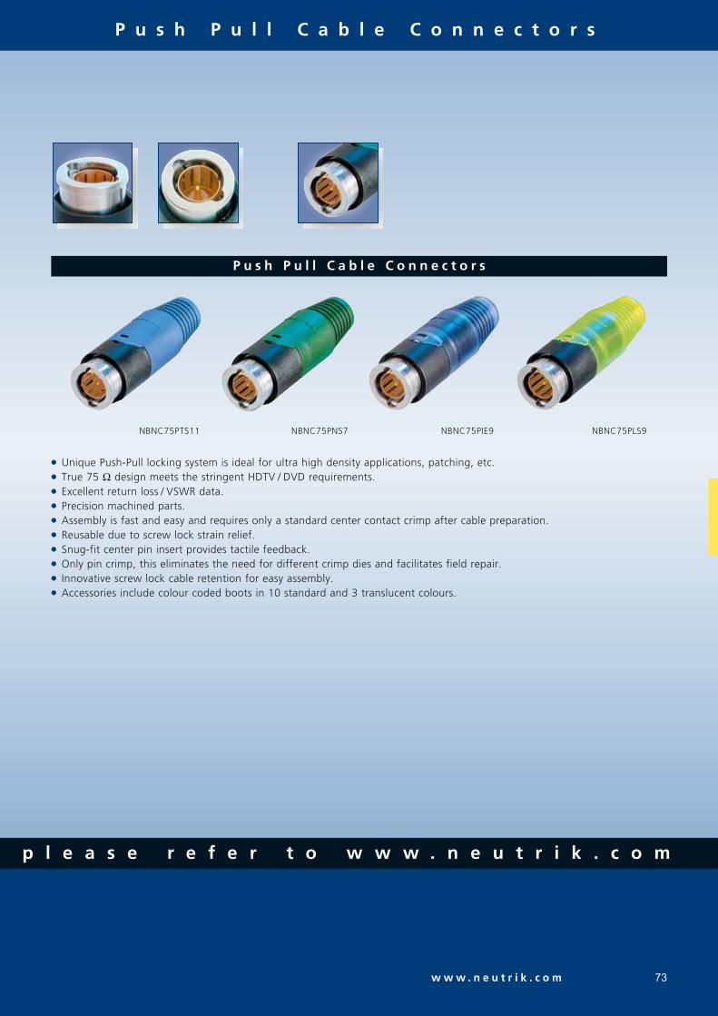
73w w w . n e u t r i k . c o m
p l e a s e r e f e r t o w w w . n e u t r i k . c o m
P u s h P u l l C a b l e C o n n e c t o r s
Unique Push-Pull locking system is ideal for ultra high density applications, patching, etc. True 75 Ω design meets the stringent HDTV / DVD requirements. Excellent return loss / VSWR data. Precision machined parts. Assembly is fast and easy and requires only a standard center contact crimp after cable preparation. Reusable due to screw lock strain relief. Snug-fit center pin insert provides tactile feedback. Only pin crimp, this eliminates the need for different crimp dies and facilitates field repair. Innovative screw lock cable retention for easy assembly. Accessories include colour coded boots in 10 standard and 3 translucent colours.
P u s h P u l l C a b l e C o n n e c t o r s
NBNC75PTS11 NBNC75PNS7 NBNC75PIE9 NBNC75PLS9

P u s h P u l l C a b l e C o n n e c t o r s
F e a t u r e s & B e n e f i t s
74
Gold plated ground contact with improved
shielding effectiveness optimized for high
frequency HDTV signal up to 3 GHz.
Leading area: Avoids tilting due to side forces to
protect the contacts from deformation. Guarantees
a lifetime of min. 1`000 mating cycles!
Neutrik® chuck type strain relief offers
flexibility and field repair.
Push Pull sleeve in various colours for easy
access in high density applications.
Push Pull locking mechanism for convenient handling,
perfect for patching applications.
L o o k f o r t h e L o g o

C h a s s i s C o n n e c t o r s
75w w w . n e u t r i k . c o m
Gold plated center contact. “D” shaped housing or single feed through mountings. Excellent return loss / VSWR rating. Isolated or grounded versions. Metal threads available on isolated feed through jack for added strength. Based on a new production technology, the machined brass connector body provides an extremely rugged and non-abrasive connection over longterm use. When used in conjunction with Neutrik® 75 Ohm BNC Rear Twist® or Push-Pull cable connectors, they are the ideal combination for BNC applications. Recessed bulkhead jacks in the “D” size housing use the same hole cutout size as other Neutrik® “D” series sized connectors such as the Speakon® NL4MP and the XLR receptacles in the “D-L-1” series. “D” shaped housing provides flush mounting and protection of the jacks from damage. Isolated versions solve potential grounding problems and prevent common-mode influence with other connections conducted over the same panel ground potential. Isolated and grounded solder versions.
B u l k h e a d J a c k s
NBB75FI NBB75DFG NBB75DFGB NBB75SI
NBB75FI
NBB75DFG
t o i d e n t i f y t h e o r i g i n a l

A c c e s s o r i e s
76
F o r f u r t h e r t e c h n i c a l i n f o r m a t i o n
B o o t s , t o o l s , . . .
BNC tool case equipped with- HX-R-BNC - PT-BNC: Plier tool - CS-BNC: Stripping tool
HX-R-BNC DIE-R-BNCCAS-BNC-T Note: Dies have to be ordered separately.
Crimp tool, frame. Crimp tool die for pin and shield for HX-R-BNC.
BS-BNC BST-BNC HX-BNC DIE-BNC HT-BNC DSS
Boot for Push-Pull BNCs in black, 9 different colours available, as well as 3 trans lucent variants.
Standard boot for the Rear Twist® BNCs in black, 9 different colours available.
Crimp tool, frame. (heavy duty)
Crimp tool die for pin and shield for HX-BNC.
Spanner tool for the Push-Pull BNCs.
Lettering plate for D Shape-bulkheads.
C r i m p d i e a s s i g n m e n t f o r H X - B N C
Crimp die Hex crimp Hex crimp Center pin mm inch mm A B A B (square crimp)
DIE-BNC-CS 4.06 7.01 0.160 0.276 1.6
DIE-BNC-JD 5.41 4.53 0.213 0.178 1.6
DIE-BNC-PG 6.47 5.00 0.255 0.197 1.6
DIE-BNC-S 7.01 - 0.276 - 1.6
DIE-BNC-U 7.36 - 0.290 - 1.6
DIE-BNC-Y 8.23 - 0.324 - 1.6
C r i m p d i e a s s i g n m e n t f o r H X - R - B N C
Crimp die Hex crimp Hex crimp Center pin mm inch mm A B C A B C (square crimp)
DIE-R-BNC-PDC 6.47 4.53 4.06 0.255 0.178 0.160 1.6
DIE-R-BNC-PG 6.47 5.00 0.255 0.197 1.6
DIE-R-BNC-PJ 6.47 5.41 0.255 0.213 1.6
DIE-R-BNC-PS 6.47 7.01 0.255 0.276 1.6
DIE-R-BNC-PU 6.47 7.36 0.255 0.290 1.6
DIE-R-BNC-PY 6.47 8.23 0.255 0.324 1.6
DIE-R-BNC-Z 9.73 0.383 1.75 (Hex crimp)

T e c h n i c a l S p e c i f i c a t i o n s
77w w w . n e u t r i k . c o m
p l e a s e r e f e r t o w w w . n e u t r i k . c o m
Specifications Rear Twist® & Rear Twist® Push Pull Bulkheads Rear Twist Large Tiny & Cable 75 Ohm Connectors & Cable Jack Jack Tiny Panel
E l e c t r i c a l
M e c h a n i c a lCable anchoring Jacket crimping Neutrik® chuck principle N / A
Cable O.D. range mm 4.0 - 7.7 2.5 - 3.8 4.0 - 8.0 N / A - Rear Twist Large 10.3 - - -
Center contact retention > 30 N -
Engagement force < 25 N < 20 N
Lifetime 1`000 mating cycles
E n v i r o n m e n t a lTemperature range -30°C to +85°C -30°C to +40°C
Solderability Complies with IEC 68-2-20 N / A
Contact crimpability Complies with IEC 60803 N / A
and IEC 60352-2
M a t e r i a l sShell: Brass (CuZn39Pb3), OPTALLOY coated
PA6 (Push Pull only) N / A N / A X N / A
D-Shape housing: Zinc diecast (ZnAl4Cu1) N / A N / A N / A
gal Ni or black Cr plating
Ground contact: Bronze (CuSn6), 0.2 µm AuCo over 2 µm NiP15 -Brass (CuZn39Pb3), OPTALLOY coated - - -
Center contact: Brass (CuZn35Pb2), 0.2 µm AuCo or -Brass (CuZn39Pb3), 0.2 µm AuCo - - -
Insulator: Teflon PTFE
Chuck: Polyacetal POM N / A N / A X N / A
Insulation Shell: Polyacetal POM N / A N / A N / A
C e n t e r C o n t a c t :
I.D. in mm Materials Plating Coding Ring (# of rings on base of contact)
0.4 Brass (CuZn39Pb3) 2 µm AuCo 00.5 50.6 10.7 20.9 31.1 61.2 41.7 0
Impedance 75 Ω
Rated voltage 500 V ac rms 250 V ac rms
Insulation resistance > 5 GΩ
Dielectric withstanding voltage 1500 V ac rms 750 V ac rms
VSWR / Return Loss ≤ 1.050 / > 32 dB up to 1 GHz ≤ 1.10 / > 26 dB up to 1 GHz ≤ 1.03 / > 37 dB up to 1 GHz ≤ 1.065 / > 30 dB up to 2 GHz ≤ 1.14 / > 24 dB up to 2 GHz ≤ 1.05 / > 32 dB up to 2 GHz ≤ 1.100 / > 26 dB up to 3 GHz ≤ 1.22 / > 20 dB up to 3 GHz ≤ 1.08 / > 28 dB up to 3 GHz
Inner contact resistance ≤ 3 mΩ (initial)
Outer contact resistance ≤ 2 mΩ (initial)

C a b l e t o C o n n e c t o r G u i d e
78
Push Rear Rear Twist Cable Jack Cable Jack Hex Crimp Pull Twist Tiny Tiny Panel in mm
B e l d e n
1406B, 1407B, 1417B NBTC75BVV5 5.001426A NBNC75PLS9 NBNC75BLP9 NBNB75GLP9 6.471505A NBNC75PLS9 NBNC75BLP9 NBNB75GLP9 6.471505F NBNC75PLS9 NBNC75BJP9 6.471506A NBNC75PIE9 NBNC75BIJ9 5.411520A, 1521A, 1522A, 179DT NBTC75BFI4 NBTB75CFI4 4.061694A NBNC75PTS11 NBNC75BTU11 7.361695A NBNC75PQS11 NBNC75BQP11 6.471855A NBNC75PDE6 NBNC75BDD6 4.531865A NBTC75BXX6 5.001855ENH NBNC75PFE7 NBNC75BFG7 5.007731A NBLC75BVZ17 9.738218 NBTC75BXX5 5.008241 NBNC75PNS7 NBNC75BLP7 6.478241F NBNC75PLS9 NBNC75BLP9 NBNB75GLP9 6.478281 NBNC75BXY9 8.238281F NBNC75BYY9 8.239221 NBTC75BLI4 4.06
C A N A R E
L-4CFB NBNC75PLS9 NBNC75BLP9 NBNB75GLP9 6.47L-5CFB NBNC75BYY11 8.23LV-61S NBNC75PNS7 NBNC75BLP7 6.47LV-77S NBNC75BYY9 8.23V(3-5)-3C NBNC75PGE7 NBNC75BGG7 5.00V(3-5)-4CFB NBNC75PLE9 NBNC75BJJ9 5.41V(3-5)-5C NBNC75PVS9 NBNC75BRS9 7.01V(3-5)-5CFB NBNC75PVS11 NBNC75BWS11 7.01L-1.5C2VS NBTC75BLI4 4.06
C O M M S C O P E
2065V NBNC75PIE9 NBNC75BIJ9 5.412279V NBNC75PQS11 NBNC75BQP11 6.475563 NBNC75PNS7 NBNC75BLP7 6.475565 NBNC75PLS9 NBNC75BLP9 NBNB75GLP9 6.475765 NBNC75PTS11 NBNC75BTU11 7.367536 (03-05) NBTC75BXX6 5.007538 NBNC75PDE6 NBNC75BDD6 4.53
C A N F O R D
SDV NBNC75PFE7 NBNC75BFG7 5.00SDV-L NBNC75PVS11 NBNC75BWS11 7.01
G E P C O
VPM2000 NBNC75PLS9 NBNC75BLP9 NBNB75GLP9 6.47VSD2001 NBNC75PTS11 NBNC75BTU11 7.36
D R A K A M U L T I M E D I A C A B L E
0.31 / 1.45 AF, 753-1304(2), 755-1302 NBTC75BFI4 NBTB75CFI4 4.060.41 / 1.9 AF, 753-1104, 755-1103, 755-1101 NBTC75BNN5 NBTB75CNN5 4.530.51 / 2.3 Dz, 757-1001, VADN 7243 NBTC75BVX6 5.000.6 / 2.8 AF, 0.6 L / 2.8 AF NBNC75PFE7 NBNC75BFG7 5.000.6 / 3.7, 0.6L / 3.7 NBNC75PNS7 NBNC75BLP7 6.470.6 / 3.7 Dz NBNC75PNS7 NBNC75BLS7 6.47
L o o k f o r t h e L o g o

C a b l e t o C o n n e c t o r G u i d e
79w w w . n e u t r i k . c o m
Push Rear Rear Twist Cable Jack Cable Jack Hex Crimp Pull Twist Tiny Tiny Panel in mm
D R A K A M U L T I M E D I A C A B L E
S U H N E R
G02233 NBTC75BFI4 NBTB75CFI4 4.06G04233D NBNC75PNS7 NBNC75BLS7 7.01S02223 NBTC75BLI4 4.06S04233, S04263 NBNC75PLS9 NBNC75BLP9 NBNB75GLP9 6.47S05133-07 NBNC75PTS11 NBNC75BTU11 7.36S05163-02 NBNC75PTS11 NBNC75BTU11 7.36
O T H E R S
0.8 / 3.7 AF, 755-801(803, 804) NBNC75PLS9 NBNC75BLP9 NBNB75GLP9 6.470.8 / 4.9 Dz NBNC75BXY9 8.231.0 / 4.8 AF, 755-901/5, Image 1000 NBNB75PTS11 NBNC75BUU11 NBNB75GUU11 7.361.2L / 4.8Dz, 1.2L / 4.95AF NBNC75BWU13 7.361.6 / 7.3AF NBLC75BVZ17 9.73
AT&T 735 COMM-TEC RGBHV
NBTC75BSS5 4.53
BBC PSF 1/3* NBNC75PNS7 NBNC75BLS7 7.01CAE MC75 NTBC75BLI5 NBTB75CLI5 4.06CAE MC75.39 NBTC75BVX6 5.00CAE KX6A NBNC75PNS7 NBNC75BLP7 6.47CAE VCB75 NBNC75PNS9 NBNC75BNP9 6.47CAE VCB 100 NBNC75BXU13 7.36Cordial CVI 3-7 NBNC75PFE7 NBNC75BFG7 4.53Cordial CVI 06-28 NBNC75PFE7 NBNC75BFG7 5.00Cordial CVI (CVM) 06-37 NBNC75PNS7 NBNC75BLP7 6.47COVID CVD 1300-1500 NBTC75BLI5 NBTB75CLI5 4.06ELF Inc. cable NBNC75PTS11 NBNC75BWS11 7.01Eupen 705 CRT 5V-HS/ELF Inc. Cable
NBNC75PTS11 NBNC75BTS11 7.36
Extron BNC-5HR NBTC75BNN5 NBTB75CNN5 4.53Extron BNC-5RC NBNC75PGE7 NBNC75BFG7 5.00Helix 734 NBNC75PNS9 NBNC75BNP9 6.47Helix 735 NBTC75BSS5 4.53Hirschmann KOKA 712Cu NBNC75PTS9 NBNC75BTS9 6.47Kansai 0.5M3C-2V NBNC75PGE7 -Kansai 3C-5S NBNC75PFE6 NBNC75BFH6 5.00KROSCHU (341 270, 341 280)
NBTC75BLI4 4.06
RG59B/U NBNC75PNS7 NBNC75BLP7 6.47RG 179 B/U NBTC75BLI4 4.06SOMMER600-0051 (M/L/S) 600-0054 (M/L/S)
NBNC75PNS7 NBNC75BLP7 6.47
600-0101M 600-0104M
NBNC75PFE7 NBNC75BFG7 5.00
600-162(F) NBNC75PLS9 NBNC75BLP9 6.47600-025* -03 (05) 600-0701 600-020* -03 (05)
NBTC75BLI5 NBTB75CLI5 4.06
600-0451 NBNC75PLS9 NBNC75BLP9 NBNB75GLP9 6.47600-0751 NBTC75BVX6 5.00Wisi MK 99A NBNC75PVS12 NBNC75BWS12 7.01ZNK CM14B NBTC75BFI4 NBTB75CFI4 4.06
* Registered trademark of BBC
t o i d e n t i f y t h e o r i g i n a l

80
P r o d u c t i o n
The professional entertainment industry depends on reliable components - night in, night out. Neutrik - the world‘s lea-ding manufacturer of professional connector systems - sets the standards in technical reliability, warranty and durabili-ty. Availability of products as well as technical support and excellent service are to be understood as priority objectives.
Besides, cutting-edge precision, functionality and design make the difference and build the basis for our complex demand for high quality standards.
To realize our innovative product ideas and to meet the requirements of our customers we make use of all possibilities modern R&D and production technologies can offer. Neutrik has developed and proven its own automated manufacturing methods. The professional mechanics of the automation department work with state-of-the-art technologies like video control systems and robotics.
Together with the systematic quality control the high preci-sion robotic production processes ensure continuous quality and efficient delivery of goods to the right place at the right time.

C i r c u l a r C o n n e c t o r s
81

82
C o n t e n t P a g e
PowerCon® Series . . . . . . . . . . . . . . . . . . . . . . . . . . . . . . . . . 83NanoCon® Series . . . . . . . . . . . . . . . . . . . . . . . . . . . . . . . . . . 85MiniCon Series . . . . . . . . . . . . . . . . . . . . . . . . . . . . . . . . . . . 87Neutricon® Series . . . . . . . . . . . . . . . . . . . . . . . . . . . . . . . . . 90Technical Data . . . . . . . . . . . . . . . . . . . . . . . . . . . . . . . . . . . 93Assembly Tools . . . . . . . . . . . . . . . . . . . . . . . . . . . . . . . . . . . 94
I n t r o d u c t i o n
The Neutrik® circular connector program is a range of metal, multi-pole connectors specifically designed for industrial appli-cations. This series provide a variety of male and female cable connectors and receptacles that can be terminated by solde-ring and crimping or to printed circuit boards. An easy to use and reliable quick-lock system ensures a perfect connection and cannot be released accidentally. The circular connec-tors offer the unique chuck type strain relief and reinforced housing for robust dependability.
The Neutrik® industrial connector range features also a uni-que power connector for single phase applications up to 20 Amps.
Further features are:- Number of contacts is 1 to 12- Self-locking system- Robust all-metal housing- Front or rear mounting- Chuck and crimp type strain relief- Gold plated contacts- Solder or crimp termination- Printed circuit board mounting- Excellent shielding (crimp type strain relief)
The main area of applications are in the measurement, test and control, automotive and machine tool industry as well medical technique.
L o o k f o r t h e L o g o
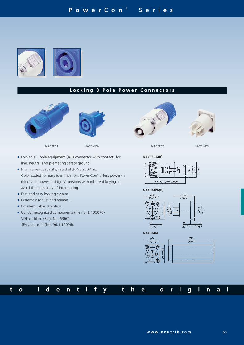
83w w w . n e u t r i k . c o m
P o w e r C o n ® S e r i e s
L o c k i n g 3 P o l e P o w e r C o n n e c t o r s
Lockable 3 pole equipment (AC) connector with contacts for
line, neutral and premating safety ground.
High current capacity, rated at 20A / 250V ac.
Color coded for easy identification, PowerCon® offers power-in
(blue) and power-out (grey) versions with different keying to
avoid the possibility of intermating.
Fast and easy locking system.
Extremely robust and reliable.
Excellent cable retention.
UL, cUl recognized components (file no. E 135070)
VDE certified (Reg. No. 6360),
SEV approved (No. 96.1 10096).
NAC3FCA NAC3MPA NAC3FCB NAC3MPB
NAC3FCA(B)
NAC3MPA(B)
NAC3MM
t o i d e n t i f y t h e o r i g i n a l

P o w e r C o n ® S e r i e s
Q u a l i t y T h i n k i n g
84
CODING
With the two non-interchangeable types of connectors (A type and B type) it is impossible to produce a short circuit. Mating connectors (combination) are identified by mechanical keyways and by color.
ATTENTION
The technical data of the PowerCon® connectors refer to connectors, meaning connecting devices not to be engaged and disengaged in normal use when live or under load.
NAC3FCA
NAC3MPA
NAC3FCB
NAC3MPB
Ordering Information
NAC3FCA Cable connector, quick lock with securing lever, A-type for power inlet, screw terminals NAC3MPA Air tight chassis connector, A-type for power inlet, flat tab terminals NAC3FCB Cable connector, quick lock with securing lever, B-type for power outlet, screw terminals NAC3MPB Air tight chassis connector, B-type for power outlet, flat tab terminals NAC3MM Coupler for linking cables (couples NAC3FCA to NAC3FCB) NLFASTON Faston receptacle for flat tabs with "positive lock"

N a n o C o n ® S e r i e s
w w w . n e u t r i k . c o m
- Q u a l i t y D e s i g n
85
3 P o l e S u b m i n i a t u r e C o n n e c t o r s
World's smallest circular lockable multipole connector.
Robust metal housing with gold plated contacts.
Male and female receptacles for vertical or horizontal PCB
mount or solder termination.
Cable connector and receptacle with interchangeable male
and female inserts.
Reliable and versatile in applications like medical equipment,
control systems, sensors or audio applications such as
miniature and wireless microphones and portable mixers.
Pre-mating contact 1.
NP3F-H NSC3F NR3M-S
NSC3F(M)
NR3F(M)-S
NP3F(M)-HM 1:1
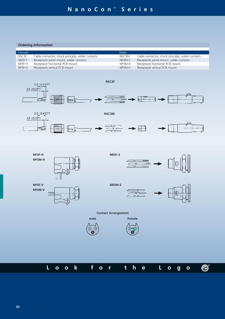
N a n o C o n ® S e r i e s
G
2 3
G
23
NSC3F
Contact Arrangement
male female
NSC3M
NP3F-H
NP3M-H
NP3F-V
NP3M-V
NR3F-S
NR3M-S
Ordering Information
NSC3F Cable connector, chuck principle, solder contacts NSC3M Cable connector, chuck principle, solder contacts NR3F-S Receptacle panel mount, solder contacts NR3M-S Receptacle panel mount, solder contacts NP3F-H Receptacle horizontal PCB mount NP3M-H Receptacle horizontal PCB mount NP3F-V Receptacle vertical PCB mount NP3M-V Receptacle vertical PCB mount
Female Male
86
L o o k f o r t h e L o g o

M i n i C o n S e r i e s
87
1 2 P o l e M i n i a t u r e C o n n e c t o r s
Up to 12 pole miniature connector.
Complete set or modular system.
Push-pull self-locking system.
Precisely machined, rugged all metal design.
Fully loaded male and female receptacles horizontal or vertical
PCB mount.
Gold plated contacts, crimp or solder.
Special crimp type strain relief establishes an ideal coaxial
connection of the cable shield to the connector shell for best
EMC shielding.
MSCM12 MRF12 MMC* (no set)
MPF(M)12-V
MRF(M)12
MSCF(M)12 (+MSRC) MPF(M)12-H
t o i d e n t i f y t h e o r i g i n a l

Modular system
Q u a l i t y T h i n k i n g
M i n i C o n S e r i e s
88
MRMMRF
Ordering Information for modular MiniCon system
Housing and insert pre-assembled, contacts must be ordered separately.
MSRC
MPC
MPS
MBC
MBS
MMI
MFI
MSC
MMC
Reduction ferrule 2
Reduction ferrule 1
MBC
MBS
MPC
MPS
Ordering Information for complete MiniCon set
Complete set (consisting of housing, insert, 12 contacts and chuck for cable connector) MSCF12 Cable connector, chuck principle, solder contacts MSCM12 Cable connector, chuck principle, solder contacts MRF12 Receptacle panel mount, solder contacts MRM12 Receptacle panel mount, solder contacts MPF12-H Receptacle horizontal PCB mount MPM12-H Receptacle horizontal PCB mount MPF12-V Receptacle vertical PCB mount MPM12-V Receptacle vertical PCB mount
Female Male
MFI Insert for cable connector MMI Insert for cable connector MBC Crimp contacts for cable connector and receptacle MPC Crimp contacts for cable connector and receptacle MBS Solder contacts for cable connector and receptacle MPS Solder contacts for cable connector and receptacle MRF Receptacle housing and insert pre-assembled MRM Receptacle housing and insert pre-assembled MMC Cable connector extension, incl. chuck (for male and female) MSC Cable connector housing, incl. chuck (for male and female) MSRC Set of strain relief crimp version (tools see page 15, crimp ferrule & reduction ferrule 1 + 2)
Female Male
MPF(M)12-V MPF(M)12-HMSCF(M)12

w w w . n e u t r i k . c o m
- Q u a l i t y D e s i g n
M i n i C o n S e r i e s
89
A A
B
C
D
E
B
F
C
G
G
F
G
F
G
G
G 2
3
4
56
117
12108
9 2
3
5 6
11 7
12
9
4
10 8
G
[0.157"]
4.0 mm[0.590"]
15.0 mm
D
E
Assembly Instruct ions MiniConCable connector - s tandard and cr imp vers ion
Put bushing onto the cable.
Prepare cable as shown.
Crimp version MSRC only:Fold back the shield and slide crimp ferrule onto the cable.- Use our HX-R-BNC crimptool with the appropriate die (see ordering information) to crimp the ferrule.- Crimp ferrule only, for cable O.D. 4.5 - 6.0 mm- Crimp ferrule + reduction ferrule 1, for cable O.D. 3.3 - 4.4 mm- Crimp ferrule + reduction ferrule 2, for cable O.D. 2.5 - 3.2 mm
Wire contacts:Solder standard contacts.- For crimp contacts (MBC, MPC) use our HX-CONTACT crimp tool with the appropriate positioner (see ordering information)
Snap the contacts into the insert.Contact arrangement: Male Female
Press the distance sleeve / chuck onto the cable.
Slide insert and chuck into the housing and fasten the bushing.
Same procedure for MSC & MMC housing withfemale or male inserts!
Crimp versionMSRC only
Crimp ferrule
reduction ferrule 2
reduction ferrule 1
Crimp version MSRC only:
When using standard chuck twist shield
Crimp version only

N e u t r i c o n ® S e r i e s
V e r s a t i l e C i r c u l a r C o n n e c t o r s
90
Complete set or modular system for any desirable configuration.
Contact configuration can be selected from 1 to 8 contacts.
Special crimp type strain relief establishes an ideal circum-
ferential connection of the cable shield to the connector shell
as required by best EMC working practice.
Precise and robust all metal housing absorbs vibration forces
and protects contact inserts.
Easy, fast and screwless assembly.
Push-pull self-locking system.
ORP8F-Ni OSC8F ORP8M
Polar izat ion
Housing: Two variants of metal polarizing guides (90° and 180°).
Insert: The male and female insert can be assembled in all three housings.
Coding 90° Coding 180°
OSC8F / OSC8M
MODULAR SYSTEM
ORP8F / ORP8M
MC8 + SR8A/B + insert
L o o k f o r t h e L o g o

w w w . n e u t r i k . c o m
N e u t r i c o n ® S e r i e s
91
Modular system FI8 Insert for cable connector and receptacle MI8 Insert for cable connector and receptacle BS1 Solder contact PS1 Solder contact BC1 Crimp contact PC1 Crimp contact BP1 PCB contact PP1 PCB contact SC8 Cable housing, black coated, 180° coding MC8 Mating cable housing, black coated, 180° coding SC8-Ni Cable housing, nickel coated, 180° coding MC8-Ni Mating cable housing, nickel coated, 180° coding SC81 Cable housing, black coated, 90° coding MC81 Mating cable housing, black coated, 90° coding SC81-Ni Cable housing, nickel coated, 90° coding MC81-Ni Mating cable housing, nickel coated, 90° coding RP8 Receptacle, black coated, 180° coding RP8-Ni Receptacle, nickel coated, 180° coding RP81 Receptacle, black coated, 90° coding RP81-Ni Receptacle, nickel coated, 90° coding SR8 Bushing and chuck type strain relief (standard) SR8A Crimp type strain relief for cable O.D. 3 - 3.8 mm (Hex crimp 5.41 mm acc. IEC 803, see also page 15) SR8B Crimp type strain relief for cable O.D. 6 - 7 mm (Hex crimp 7.01 mm acc. IEC 803, see also page 15) BSP-(1-10) Colored boots, available in 10 resistor colors
Female Male
Ordering Information for modular Neutricon system
Cable Connector:
Receptacle:
Ordering Information for complete Neutricon set
Complete set (consisting of housing, insert, 8 contacts and chuck for cable connector) OSC8F Female cable connector, chuck principle, black housing, solder contacts OSC8F-Ni Female cable connector, chuck principle, nickel housing, solder contacts OSC8M Male cable connector, chuck principle, black housing, solder contacts OSC8M-Ni Male cable connector, chuck principle, nickel housing, solder contacts ORP8F Female panel mount receptacle, black housing, solder contacts ORP8F-Ni Female panel mount receptacle, nickel housing, solder contacts ORP8M Male panel mount receptacle, black housing, solder contacts ORP8M-Ni Male panel mount receptacle, nickel housing, solder contacts
t o i d e n t i f y t h e o r i g i n a l
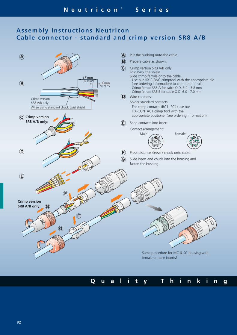
Q u a l i t y T h i n k i n g
N e u t r i c o n ® S e r i e s
92
A
B
C
D
E
A
B
F
C
D
G
E
[0.157"]
4 mm[0.670"]
17 mm
F
G
G2
3
45
6
7
8
G2
3
4 5
6
7
8
G
F
Assembly Instruct ions Neutr iconCable connector - s tandard and cr imp vers ion SR8 A/B
Put the bushing onto the cable.
Prepare cable as shown.
Crimp version SR8 A/B only:Fold back the shield.Slide crimp ferrule onto the cable.- Use our HX-R-BNC crimptool with the appropriate die (see ordering information) to crimp the ferrule.- Crimp ferrule SR8 A for cable O.D. 3.0 - 3.8 mm- Crimp ferrule SR8 B for cable O.D. 6.0 - 7.0 mm
Wire contacts:Solder standard contacts.- For crimp contacts (BC1, PC1) use our HX-CONTACT crimp tool with the appropriate positioner (see ordering information).
Snap contacts into insert.
Contact arrangement: Male Female
Press distance sleeve / chuck onto cable.
Slide insert and chuck into the housing andfasten the bushing.
Same procedure for MC & SC housing with female or male inserts!
Crimp versionSR8 A/B only:
Crimp versionSR8 A/B only:
When using standard chuck twist shield
Crimp versionSR8 A/B only:

w w w . n e u t r i k . c o m
- Q u a l i t y D e s i g n
T e c h n i c a l D a t a
93
Specifications PowerCon® NanoCon® MiniCon Neutricon®
Series Series Series Series
E l e c t r i c a l
Number of contacts 2 + PE 3 12 (1-12 modular system) 8 (1-8 modular system)
Rated current per contact 20 A rms 2 A 3 A 7.5 A (solder), 5 A (crimp)
Rated voltage 250 V ac 50 V ac 50 V ac 50 V ac
Dielectric strength 4000 V dc 1000 V dc 1000 V dc 1500 Vdc
Contact resistance ≤ 3 mΩ ≤ 12 mΩ ≤ 8 mΩ ≤ 5 mΩ Insulation resistance after damp
> 100 MΩ > 1 GΩ > 500 MΩ > 500 MΩ heat test (IEC 68-2-30)
M e c h a n i c a l
Retention method Quicklock with securing lever latch Push-pull Push-pull
Cable O.D. range 3 - 5 mm (grey chuck) 3 - 7 mm 5 - 15 mm 3.4 mm max. 5 - 7 mm (white chuck) 3 - 3.8 mm (SR8A)
2.5 - 6 mm (crimp version MSRC) 6 - 7 mm (SR8B)
Wiring Cable: screw type terminals or soldering 0.2 mm2 / 24 AWG 0.5 mm2 / 20 AWG 1.0 mm2 / 18 AWG 2.5 mm2 / 14 AWG for solid wire for solder for solder
Chassis: flat tabs for FASTON® 0.14 mm2 / 26 AWG 0.22 mm2 / 24 AWG 0.14 - 0.34 mm2 / 22-26 AWG
4.8 x 0.5 mm or soldering for stranded wire for crimp for crimp Solderability
complies with IEC 68-2-20
M a t e r i a l s
Housing cable connector PA 6 30% GR CuSn4Pb4Zn4 ZnAl4Cu1 / CuZn39Pb3 ZnAl4Cu1 gal Ni or black chrome
Housing receptacle PA 6 30% GR CuZn39Pb2 ZnAl4Cu1 ZnAl4Cu1, gal Ni or black chrome
Insert PA 6 30% GR PETP PA 6.6 PBTP 15% GR
Contacts CuZn39Pb3 / CuSn6 CuZn35Pb2 CuZn35Pb2 (solder) CuZn35Pb2 (solder)
CuZn39Pb3 (crimp) CuZn39Pb3 (crimp)
CuSn6
Contact surface 4 µm / 20 µm Ag plated 0.5 µm Au 0.2 µm AuCo 0.3 µm Au hard alloy over 2 µm Ni
Chuck POM
E n v i r o n m e n t a l
Flammability UL 94 HB UL 94 V-0 UL 94 V-0
Temperature range -30°C to +80°C
Protection class (mated) IP 20 IP 40 IP 5X IP5X
Safety Requirements EN/IC61984 - - -
FASTON® is a trademark of AMP Inc.

A s s e m b l y T o o l s
94
C o n t a c t a n d c o n n e c t o r a s s e m b l y
* DIE-R-BNC-PJ or PS also possible
DMC crimptool AFM8acc. M22520/2-01
Modified DMC positioner (K155) Contact positioner helds contact in position when crimping.
Crimptool HX-R-BNC DIE-R-BNC-*
Neutrik HEX crimptool Neutrik DIE's for various HEX sizes.
Cable O.D. / Wire Crimptool Die/Positioner HEX-Size/Standard
Cable O.D. / Wire Crimptool Die/Positioner HEX-Size/Standard
MPOS-*Crimptool HX-CONTACT
N e u t r i c o n - O r d e r i n g I n f o r m a t i o n A s s e m b l y T o o l s
SR8A Strain relief 3 - 3.8 mm HX-R-BNC DIE-R-BNC-PJ 5.41 mm / IEC 803 SR8B Strain relief 6 - 7 mm HX-R-BNC DIE-R-BNC-PS 7.01 mm / IEC 803 BC1 Female crimp contact AWG 22 -26 HX-CONTACT MPOS-BC1 No. 5 / M22520/2-01 PC1 Male crimp contact AWG 22 -26 HX-CONTACT MPOS-PC1 No. 5 / M22520/2-01
M i n i C o n - O r d e r i n g I n f o r m a t i o n A s s e m b l y T o o l s
MSRC Crimp ferrule only 4.5 - 6 mm HX-R-BNC DIE-R-BNC-PDC* 6.47 mm / IEC 803 MSRC Crimp ferrule & reduction ferrule 1 3.3 - 4.4 mm HX-R-BNC DIE-R-BNC-PDC* 6.47 mm / IEC 803 MSRC Crimp ferrule & reduction ferrule 2 2.5 - 3.2 mm HX-R-BNC DIE-R-BNC-PDC* 6.47 mm / IEC 803 MBC Female crimp contact 24 AWG/0.22 mm2 HX-CONTACT MPOS-MBC No. 5 / M22520/2-01 MPC Male crimp contact 24 AWG/0.22 mm2 HX-CONTACT MPOS-MPC No. 5 / M22520/2-01

A c c e s s o r i e s
95

96
C o n t e n t P a g e
Circular Adapter . . . . . . . . . . . . . . . . . . . . . . . . . . . . . . . . . 97D Shape Adapter . . . . . . . . . . . . . . . . . . . . . . . . . . . . . . . . . 98Ordering Information . . . . . . . . . . . . . . . . . . . . . . . . . . . . . 99AES / EBU Digital Impedance Transformer . . . . . . . . . . . 100DMX Adapter . . . . . . . . . . . . . . . . . . . . . . . . . . . . . . . . . . . . 101Modules & Audio Transformers . . . . . . . . . . . . . . . . . . . . 102Ordering Information . . . . . . . . . . . . . . . . . . . . . . . . . . . . . 103Goosenecks . . . . . . . . . . . . . . . . . . . . . . . . . . . . . . . . . . . . . 104
Various connector standards in the professional and semi-pro-fessional audio and video world lead constantly to intercon-nection problems.Neutrik® made it as a rule to serve our customers‘ needs in all connector belongings and offer therefore a variety of problem solvers.With our adapter series we have a solution for the most known interconnection difficulties and on top of this we offer modules of the most common connector types to fulfill spe-cific needs beyond that.Miniature balancing adapters are the answer to known noise and grounding problems and for customized designs we rec-ommend our proven audio transformers in combination with our modules.
N E U T R I K ® A C C E S S O R I E S
All our adapters and conectors are soldered with lead free ROHS compliant solder.
Neutrik is proud of being ROHS compliant with all our prod-ucts and on top of this we became „Sony Green Partner“ already in the year 2003.
L o o k f o r t h e L o g o

97w w w . n e u t r i k . c o m
A d a p t e r
C i r c u l a r A d a p t e r s
Versatile, pre-wired and ready to use adapters to reliably interlock various connector systems
Professional look and compact space saving design, based on the X Series (XLR worldwide accepted standard)
Rugged diecast shell for best reliability
NA2FP NA2MPMM NA3FJ
NA3FP
NA4FC-F
NA3FM
NA3MJ NA3FBNC
Example drawing. Find more info on www.neutrik.com
t o i d e n t i f y t h e o r i g i n a l

A d a p t e r
Q u a l i t y T h i n k i n g
98
D S h a p e A d a p t e r s
Problem solvers for various intermating problems for professional and semi-professional applications
Rugged aluminium extrusion housings for best reliability
Colour coding on all RCA types
NA2BBNC-D9B NA2M-D2B-TX NA4MP-J NA4MP-MX
Miniature transformer balancing adapters NA2*-TX
1:1 transformer 200 Ω : 200 Ω Low cost solution for unbalanced/balanced line conversion and passive
DI applications, where no earth or gain switching is required.
MAX INPUT LEVEL FOR 1% THD
+4dBu @ 60Hz (SOURCE=200OHM/LOAD=200OHM)
–6dBu @ 60Hz (SOURCE=200OHM/LOAD=10KOHM) NA2F-D0B-TX
NA2BBNC-D9B NA2MP-J
Example drawing. Find more info on www.neutrik.com

O r d e r i n g I n f o r m a t i o n
w w w . n e u t r i k . c o m
- Q u a l i t y D e s i g n
99
C i r c u l a r A d a p t e r s
Part No. Port 1 Port 2 Comments
NA2FBNC 3 pole XLR female BNC socket 1) NA2FP 3 pole XLR female TS 2),1/4" plug 1) NA2FPMF 3 pole XLR female RCA / phono socket 1) NA2FPMM 3 pole XLR female RCA / phono plug 1) NA2MBNC 3 pole XLR male BNC socket 1) NA2MP 3 pole XLR male TS 2),1/4" plug 1) NA2MPMF 3 pole XLR male RCA / phono socket 1) NA2MPMM 3 pole XLR male RCA / phono plug 1) NA3FF 3 pole XLR female 3 pole XLR female gender conversion adapterNA3FF-B 3 pole XLR female 3 pole XLR female gender conversion, black platingNA3FJ 3 pole XLR female TRS 2),1/4" jack locking jackNA3FM 3 pole XLR female 3 pole XLR male extention adapterNA3FMX 3 pole XLR female 3 pole XLR male contacts 2 - 3 invertedNA3FP 3 pole XLR female TRS 2), 1/4" plug NA3JJ stereo 1/4" jack TRS 2), 1/4" jack extension adapter, locking jackNA3MJ 3 pole XLR male TRS 2), 1/4" jack locking jackNA3MM 3 pole XLR male 3 pole XLR male gender conversion adapterNA3MM-B 3 pole XLR male 3 pole XLR male gender conversion, black platingNA3MP 3 pole XLR male TRS 2),1/4" plug NA4FC-F Speakon® NL4FC 3 pole XLR female speaker adapter 3)
NA4FC-M Speakon® NL4FC 3 pole XLR male speaker adapter 3)
NA4LJX Speakon® NL4FX TS 2), 1/4" jack speaker adapter 3)
NA4MP-F Speakon® NL4MP 3 pole XLR female speaker adapter 3)
NA4MP-J Speakon® NL4MP TS 2), 1/4" jack speaker adapter 3)
NA4MP-M Speakon® NL4MP 3 pole XLR male speaker adapter 3)
NA4MP-M-X Speakon® NL4MP Speakon® NL4MP speaker adapter 1+ / 1- inverted 3)
NA5FF-B 5 pole XLR female 5 pole XLR female gender conversion adapter, black platingNA5MM-B 5 pole XLR male 5 pole XLR male gender conversion adapter, black plating
D S h a p e A d a p t e r s
NA2BBNC-D4B BNC socket RCA / phono socket colour coded yellowNA2BBNC-D9B BNC socket RCA / phono socket colour coded whiteNA2F-D0B-TX 3 pole XLR female RCA / phono socket colour coded black, 4)
NA2F-D2B-TX 3 pole XLR female RCA / phono socket colour coded red, 4)
NA2F-J-TX 3 pole XLR female 1/4" jack ground liftedNA2M-D0B-TX 3 pole XLR male RCA / phono socket colour coded black, 4)
NA2M-D2B-TX 3 pole XLR male RCA / phono socket colour coded red, 4)
NA2M-J-TX 3 pole XLR male 1/4" jack ground lifted, 4)
NE8FF EtherCon® EtherCon® RJ45 couplerNL4MMX 4 pole Speakon® 4 pole Speakon® lockable couplerNL8MM 8 pole Speakon® 8 pole Speakon® lockable coupler
1) ... Wired according to IEC 268-12: pin 2 = signal, pin 1 and 3: connected to ground2) ... TRS-Tip, Ring, Sleeve contact (stereo); TS-Tip, Sleeve contact (mono)3) ... Detailed wiring info on www.neutrik.com4) ... Unbalanced / balanced line conversion, 1:1 transformer 200 Ω : 200 Ω

Q u a l i t y T h i n k i n g
A d a p t e r
100
A E S / E B U D i g i t a l I m p e d a n c e T r a n s f o r m e r A d a p t e r s
Allow long cable runs for digital audio signals via low
attenuation coax lines
Matche balanced to coaxial lines
Matche impedances 110 Ω to 75 Ω Simple use, passive units
NADITBNC-F NADITBNC-FX NADITBNC-MX
NADITBNC-FX
Part No. Port 1 Port 2 Comments
O r d e r i n g I n f o r m a t i o n
Input OutputNADITBNC-F 3 pole XLR female chassis female BNC chassis 110 Ω XLR input and 75 Ω BNC outputNADITBNC-M 3 pole XLR male chassis female BNC chassis 75 Ω BNC input and 110 Ω XLR outputNADITBNC-FX 3 pole XLR female cable con. female BNC chassis 110 Ω XLR input and 75 Ω BNC outputNADITBNC-MX 3 pole XLR male cable con. female BNC chassis 75 Ω BNC input and 110 Ω XLR output
T e c h n i c a l D a t a
Maximum voltage / Max. power: 5 Vp-p / 250mWFrequency band: 0.1 MHz to 6 MHzInsertion loss: < 0.3 dB @ 0.1 MHz to 10 MHzVSWR / Return loss: < 1.1 / > 26.4 dB NADITBNC-F NADITBNC-M

- Q u a l i t y D e s i g n
A d a p t e r
101w w w . n e u t r i k . c o m
D M X A d a p t e r s
Compact XLR 3 to 5 pole adapter for lighting (DMX) applications
Solve interconnection problems of the old (3-pole) and new (5-pole) DMX standard
Enables usage of standard 3-pole microphone cable for DMX applications
Based on the worldwide accepted standard XLR connectors
Reliable and rugged diecast shell
NA3F5M NA3F5M NA3M5F
Part No. Port 1 Port 2 Comments
NA3F5M 3 pole XLR female 5 pole XLR male for DMX lighting applicationsNA3M5F 3 pole XLR male 5 pole XLR female for DMX lighting applications
O r d e r i n g I n f o r m a t i o n
3-pole 5-poleNA3F5M

Q u a l i t y T h i n k i n g
M o d u l e s & A u d i o T r a n s f o r m e r
102
M o d u l e s & A u d i o T r a n s f o r m e r s
Multifunctional modules allow to design of customized adapters to suit specific needs
Based on the X Series connector system
NTE transformers and switch can be built in
Professional look, rugged diecast shell
NM3FXI NM3P KMX SM2/2
A u d i o T r a n s o r m e r T o n G u i d e
Part No. Source / load Turns Ratio Max. Input Applications Wiring impedance in Ω (prim : sec) Voltage
1% THD @ 60 Hz
NTE1 200 / 200 1 : 1 1.2 V rms Mic input free wiresNTE4 200 / 3 K 1 : 4 0.4 V rms Mic input free wiresNTE10/3 200 / 2 K / 20 K 1 : 3 : 10 0.5 V rms Mic input free wires
1% THD @ 30 Hz NTL1 600 / 600 1 : 1 6 V rms Studio line PCB mount, shieldedNTM1 200 / 200 1 : 1 1.5 V rms Studio line PCB mount, shieldedNTM4 200 / 3 K 1 : 4 1.2 V rms Microphone input PCB mount, shieldedFind detailed specifications on www.neutrik.com
Audio Transformer
Professional audio transformers for multiple applications, as e.g.
microphone or line inputs
Very low distortion, excellent frequency response
Cost effective cable version for free wiring
Fully permalloy-shielded studio versions NTE10-3 NTL1
NM3FD-B

w w w . n e u t r i k . c o m
- Q u a l i t y D e s i g n
O r d e r i n g I n f o r m a t i o n
103
Connector module Coupler / housing Transformer / switch
NM3FXIXLR femaleM17x1 outside
NM3MXIXLR maleM17x1 outside
NM2Pmono 1/4" plugM17x1 inside
NM3Pstereo 1/4" plugM17x1 inside
NM3Jstereo 1/4" jackM17x1 inside
NMPMMRCA maleM17x1 inside
NMPMFRCA femaleM17x1 inside
NM3FD-Bblack plated
NM3MD-Bblack plated
KMM 17x1 inside
KMXM 17x1 inside
VMM 17x1 outside
VMXM 17x1 outside
CMcable outletM 17x1 inside
NA-Housingblack platedscrews included
NTE11:1
NTE41:4
NTE10/31:3:10
SM2/22x2 switchM17x1 outside
M o d u l e S e l e c t i o n G u i d e
1)
1) ... Combinations possible with all D Shape connectors like e.g. NC3FD-L-1, NF2D, NBB75DSI, etc.
NM3FXI
KM
SM2/2
NTE1 (inside)
KMX
NM3MXI
NM3FXI KM SM2/2NTE1 KMX NM3MXI
Example:

G o o s e n e c k s
104
G o o s e n e c k s
GNS18 GNS50
Part No. Description
O r d e r i n g I n f o r m a t i o n
GN36
GN18 M17x1 inside thread at both ends (∅ 12 mm, 230 mm length)GN36 M17x1 inside thread at both ends (∅ 13 mm, 360 mm length)GN50 M17x1 inside thread at both ends (∅ 15 mm, 500 mm length)Gosseneck se t s :GNS18 Gooseneck set GN18, NC3FX-Spec., cable outlet, NAM5 adapter, M17x1 bolt threadGNS36 Gooseneck set GN16, NC3FX-Spec., cable outlet, NAM5 adapter, M17x1 bolt threadGNS50 Gooseneck set GN50, NC3FX-Spec., cable outlet, NAM5 adapter, M17x1 bolt threadAccessor ie s :NAM4 M17x1 outside thread, 5/8" 27 UNS inside thread 1)
NAM5 3/8" inside thread, 5/8" 27 UNS outside thread 1)
GF1 Panel-mounting kit: Flange ∅ 63.5 mm including mounting bolt M17x1, 30 mm length 1)
MSG Mounting bolt M17x1, 30 mm lenght 1) 1) ... Find detailed specifications on www.neutrik.com
GNS Set consisting of:
NC3FX-Spec GN Cable outlet NAM5 M17x1 bolt
For flexible and secure mounting of microphones, lamps etc.
Versatile, modular system, allows varions combinations
Durable stainless steel spiral, no rust, no noise, non-reflective black finish
Theft proof microphone connection on GNS version (securing ring and fixing screw)

P a t c h P a n e l s
105
Patch_Panel_PG.indd Abs11 07.04.2006 10:23:00

C o n t e n t P a g e
NPPA-Series - 96 Bantam (TT) Jacks .. . . . . . . . . . . . . . . . . . . . . 107NPPA-TB-Series - 48 B-Gauge Jacks . . . . . . . . . . . . . . . . . . . . . . 1091/4" Patch Panel . . . . . . . . . . . . . . . . . . . . . . . . . . . . . . . . . . . . . . . . . . . . . 111MA 96 and XPM 96 Bantam Patchbays . . . . . . . . . . . . . . . . . . . 113LF 48 B-Gauge Patchbays . . . . . . . . . . . . . . . . . . . . . . . . . . . . . . . . . . . 115Technical Data . . . . . . . . . . . . . . . . . . . . . . . . . . . . . . . . . . . . . . . . . . . . . . . 117Ordering Information . . . . . . . . . . . . . . . . . . . . . . . . . . . . . . . . . . . . . . . 118
106
Audio Normal l ing
Audio Normalling is usually used with audio patch panels and is a wiring pattern in which a circuit path is established from one piece of audio equipment to another without the use of a patch cord. This pattern is then considered to be the „normal“ circuit path that is desired most of the time. If a patch cord is inserted, the normal circuit path is interrupted and rerouted to a different circuit path.Normalled patch panels are most commonly found in vertical jack pairs: the top jack is designated as the source and the bottom jack is the destination.
Normalling example: HALF NORMALLED BOTTOM ROW
It is the most common configuration, very often called HALF NORMALLED. In this configuration internal normalling contacts
connect the top jack contact with the corresponding bottom jack contact. Inserting a plug in the bottom jack will interrupt this internal normalling con-nection, while inserting a patch cord into the top jack doesn‘t interrupt the circuit. (Can be used to monitor the normalling circuit.)
Other versions of normalling are Half Normalled Top, Full Normalled, Parallel and Isolated.
I n t r o d u c t i o n
Patch Panels are central switching gears between audio equip-ments. They are used to switch and route analog and digital audio signals from and to equipments in recording or broadcast studios, OB vans, churches, theatres, stadiums, arenas, etc.Neutrik® Patch Panels are available in a varity of jack types, wiring and grounding possibilities. Common versions accommodating Bantam TT, 1/4“ A-gauge and longframe B-gauge jacks on the front rows. The mechanical size is designed to fit into 1U 19“ standard racks. All Neutrik Patch Panels offer various normalling possibilities between top and bottom row as well multiple groun-ding and termination options.
All Neutrik® Patch Panels are able to handle digital audio signales acc. AES3, 48kHz sampling rate.
Q u a l i t y T h i n k i n g
Patch_Panel_PG.indd Abs12 07.04.2006 10:24:08
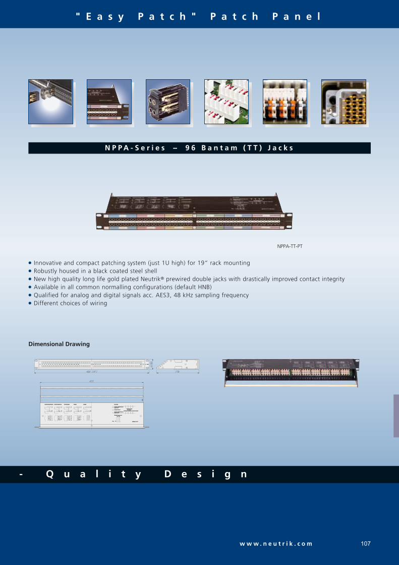
107w w w . n e u t r i k . c o m
" E a s y P a t c h " P a t c h P a n e l
Innovative and compact patching system (just 1U high) for 19“ rack mounting Robustly housed in a black coated steel shell New high quality long life gold plated Neutrik® prewired double jacks with drastically improved contact integrity Available in all common normalling configurations (default HNB) Qualified for analog and digital signals acc. AES3, 48 kHz sampling frequency Different choices of wiring
N P P A - S e r i e s - 9 6 B a n t a m ( T T ) J a c k s
NPPA-TT-PT
Half Normalled TopHalf Normalled Top
RN
TN
TR
S
RT
S
Half Normalled BottomHalf Normalled Bottom
SRT
RT
RN
TNS
RT
S
RN
TN
RN
STN
RT
S
Full NormalledFull Normalled
S
TR
SRT
Parallel
RT
TR
S
RT
S S
TR
Isolated
SRT
RT
S
KeyKeyNPPA-TT-PTNPPA-TT-PT
Individual Grounds to Common GroundIndividual Grounds to Common Ground
Chassis GroundChassis Ground
Bottom RowBottom RowCommon Signal GroundCommon Signal Ground
Module ArrangementModule Arrangement
Top ViewTop View
Upper RowUpper RowCommon Signal GroundCommon Signal Ground
GroundingGrounding
to connectto connect
Soldering PadsSoldering Pads
1 2 3 4 5 6 7 8 9 10 11 12 13 14 15 16 17 18 19 20 25 26 4827 28
Dimensional Drawing
- Q u a l i t y D e s i g n
Patch_Panel_PG.indd Abs13 07.04.2006 10:24:09

N e u t r i k P a
" E a s y P a t c h " P a t c h P a n e l
C o n f i g u r a t i o n
The standard version of the NPPA Panel is delivered bottom row half normalled for each jack pair by default. Further patch ver-sions are available with fully loaded jack-pairs as:
Full Normalled Half Normalled Top Row Isolated Parallel
For individual normalling single pre-configured jack-pairs are offered.
Note: Take care when handling digital signals. Do not use parallel configuration and avoid other parallel paths when using half normalled configurations. Parallel paths may lead to mismatching.
G r o u n d i n g
The flexible grounding system provides the following versions:
Individual: Each channel is individually grounded by its corresponding cable shield (default configuration). Group: Selected channel grounds are connected via the ground bus on the PCB using solder bridges and track cuts to form a group that is connected to one common cable shield. Central: All channel grounds (individual top and bottom row) are connected via the ground bus on the PCB using solder bridges and wired with only one cable shield. Chassis-Common: The same as central grounding but with the addition of the common ground bus (top and / or bottom rows) connected to the patch panel chassis by means of jumpers
W i r i n g T e r m i n a t i o n s
TT Patch Panels offer different choices of wiring:
Spring loaded push terminals 56 pin Elco/Edac male connectors 90 pin Elco/Edac connectors 50 pin D-subminiature connectors IDC-Krone terminals Solder lugs
The spring loaded terminal blocks enable fast and easy wir-ing. No soldering and screwing necessary. Simply insert the stripped wire after pressing down the white key. Terminals accommodate stranded wires up to AWG 20 (0.5 mm2) and solid wires up to AWG 18 (0.75 mm2). Push terminals are gas tight connections.
S
S
R
R
T
T
RT
SRT
S
S
TR
SRT
RT
S S
TR
SRT
RT
S
Half Normalled Bottom Half Normalled Top Full Normalled Parallel Isolated
D e s i g n C r i t e r i a
All panels are fitted with high quality, long life Neutrik® NJ3TTA gold plated double contact jacks (2x48), featuring drastically improved contact integrity and are available with a wide choice of wiring terminations. The unit is finished off with a built in cable bar and two large channel ident strips for perfect management of the system.The new generation of the Neutrik® ”Easy-Patch” is easily programmable for any one of five configurations (standard is half normalled bottom row) and for the grounding system of your choice. Each individual pair of jacks can be changed
or reconfigured quickly and without fuss even while the panel is ”on air”. The NJ3TTA jacks offer also two contact points per terminal (TRS) with a special designed mechanism for the normalling contact. Simply remove the front panel to reveal the easy access jack. Remove, replace or reconfigure the jack and refix the panel.The ”Easy-Patch” is an innovative and compact patching system (just 1U high) for 19" rack mounting. Robustly housed in a black coated steel shell and featuring precision aluminium fittings it is built to last.
For Pin assignment of ELCO / EDAC and D-Sub connectors please refer to website.
108
Patch_Panel_PG.indd Abs14 07.04.2006 10:24:15

t c h P a n e l
" E a s y P a t c h " P a t c h P a n e l
109w w w . n e u t r i k . c o m
Features 2x24 Neutrik® NJ6TB-V long frame 1/4" TRS jacks to BPO 316 / MIL-P-641/3 Very robust and compact galvanized metal housing Eye catching channel identification through colored snap-on coding tabs Six easily programmable switching configurations Qualified for analog and digital signals acc. AES3, 48 kHz sampling frequency With high quality long life gold plated Neutrik® jacks
N P P - T B - S e r i e s - 4 8 B - G a u g e J a c k s
NPP-S (Accessories)
NPP-S
Dimensional Drawing
NPP-TB-HN NPP-TB
Patch_Panel_PG.indd Abs15 07.04.2006 10:24:15

" E a s y P a t c h " P a t c h P a n e l
C o n f i g u r a t i o n
Due to the jumper blocks capability provided, the switching configurations available per jack channel are:
Full Normalled Isolated Half Normalled Bottom Row Parallel Half Normalled Bottom Row Half Normalled Bottom Row
The TB Panel is delivered in a full normalled configuration for each jack channel. A non-configurable half normalled ("-HN") bottom row version with solder lugs is also available.
NOTE: Take care when handling digital signals. Do not use Parallel configuration and avoid other parallel paths with Half / Double Normalled configurations. Parallel paths may lead to mismatching.
G r o u n d i n g
The flexible grounding system allows four possibilities to fit your needs:
Individual: Each channel ground is separately connected with the corresponding cable shield (default configuration). Group: Some channel grounds are PCB connected by making soldering joints on the PCB and by cutting tracks respectively to form a group that is connected to one common cable shield. Central: All channel grounds are PCB connected by making soldering joints and wired with only one cable shield. Chassis-Common: Same as central grounding with additional connection of the common ground to the Patch Panel chassis by means of a jumper.
W i r i n g T e r m i n a t i o n s
TB Patch Panels are available with:
Spring loaded push terminals (NPP-TB) Solder lugs (NPP-TB-HN)
The spring loaded terminal blocks are fast and easy to connect and disconnect the wires.No soldering and screwing necessary. Simply insert the stripped wire after pressing down the white key.Accommodates stranded wires up to AWG 20 (0.5 mm2) and solid wires up to AWG 18 (0.75 mm2).
D e s i g n C r i t e r i a
The TB Patch Panel is a very robust and compactly designed Patch Panel for 19" rack mount (19" x 1U) with galvanized metal housing, a built-in cable bar on the rear for securing wires. There is a rear extention bar (NPP-S) available as an option for some panel types. On the front side we have an attractive additional lettering facility for each channel pair with a marking strip and individual snap-on colour coding plates.
The NPP is easily programmable for six switching configura-tions and for changing the flexible grounding system. All panels have the high quality long life gold plated Neutrik® NJ6TB-V Jack for the BPO / MIL style plugs. We have two variants of rear connection. The standard is equipped with spring loaded terminals strips and an optional version offers solder lugs.
Half Normalled Bottom Half Normalled Top Full Normalled Parallel Isolated Double Normalled
110
Q u a l i t y T h i n k i n g
Patch_Panel_PG.indd Abs16 07.04.2006 10:24:17

N Y S S e r i e s
w w w . n e u t r i k . c o m 111
1 / 4 " P a t c h P a n e l
Economic and versatile designed 1/4" modular Patch Panel with 2 rows of jack sockets 48 balanced channels with fully PCB wired jack (24 vertical PC boards), 24 front pairs and corresponding 24 rear pairs Jack PC card contains 4 balanced 1/4" jacks with non-tarnishing contacts, is held securely in place without the use of nuts - no little pieces to drop, break or lose Easy to change configuration by just flipping individual PC board Normalling jack is coloured grey for easy identification 4 designation strip included for front and rear panel Patch Box with 8 Send / Return modules
111 2 3 4 85 6 7 9 10 12 13 14 1615 17 1918 20 2221 23 24
NYS-SPP-L
A
B
A
B
Dimensional Drawing
NYS-SPP-L NYS-SSR-8
ModuleNYS-SPCR
Patch BoxNYS-SSR8
- Q u a l i t y D e s i g n
Patch_Panel_PG.indd Abs17 07.04.2006 10:24:17

112
N e u t r i k P a
N Y S S e r i e s
Plug
Plug
T
T
RT
front rearfront rear front rear front rear
Front jack A for "listen in" Grey B jack for signalinsertion
Allows 1 output to feed 2 inputs Upper (A) and lower (B)channel separated
A
B
A
B B
A A
B
A
B
A
B
A
B
A
B
Solution for insert jack of mixing consolesSplit print by-passes the use of a specially wired Y-cable.
A FrontMono - Send
RearSend - Return(Stereo Jack)
B FrontMono - Return
(Red Jack)
NEW! With Switching Contacts
NYS-SPCR
C o n f i g u r a t i o n
Half Normalled Split Isolated Split Print
D e s i g n C r i t e r i a
The Patch Panel shows 2 rows of 1/4" A-Gauge jacks, 24 front pairs (top A and bottom B row) and corresponding 24 rear pairs. Principally the corresponding front and rear jacks are connected straight through.The configuration determines the link between bottom and top row.With conventional 1/4“ patchbays the individual jacks are fixed to the panel with nuts. Thus two disadvantages occur: flipping of channel PCBs is complicated, PCBs are not well fixed. The NYS-SPP with its metal brekets to hold the boards securely in place makes flipping brackets the boards also quite simple.
If the grey jack („N-jack“) is located at the front, the channel is in a Half-Normalled configuration (as seen from the front side). This is how the unit is delivered.If no plug is inserted into the grey jack, Afront is connected to Arear and Brear. With plug inserted into the grey N-jack, the link between A and B jacks is opened and the upper and lower signal paths are isolated against each other.You can now turn each of the 24 channel PCBs separately by 180°. Thus the configuration as seen from the front changes to Split or Isolated depending upon the rear side installation, i.e. N-jack unplugged or plugged.
Patch_Panel_PG.indd Abs18 07.04.2006 10:24:19

113w w w . n e u t r i k . c o m
t c h P a n e l
B a n t a m P a t c h P a n e l s
M A 9 6 a n d X P M 9 6 B a n t a m P a t c h b a y s
Robust designed patchbay to accept standard Bantam jack connectors Fitted with 96 Rean die-cast jack sockets Constructed from rigid aluminium extrusion which includes 2 integral slots for designation strips 96 channels grouped in two row 12 x 8 stereo jacks XPM96 features traditional 2 row, 4 x 24 stereo jacks Available in 4 colours: black, silver, red or blue Suitable for audio, broadcast, data and industrial applications XPM96
Dimensional Drawing
Patch_Panel_PG.indd Abs19 07.04.2006 10:24:19

R e a n P a t c h b a y m
114
B a n t a m P a t c h P a n e l s
M A J 5 0 0 B a n t a m J a c k S o c k e t
Circuit DetailEnd Elevations Plan Elevations
5-point Bantam jack socket (Tip, Ring, Sleeve, Tip Normal, Ring Normal) 5 terminal variants including solder terminals and 4 PCB versions Rigid nickel plated die-cast frame, featuring considerable frame strength eliminating physical distortion when plug is inserted Nickel-silver spring contacts, palladium plated switch contacts Tinned tags for easy soldering
02 04 06 08
Terminal Variants
01
Patch_Panel_PG.indd Abs110 07.04.2006 10:24:23

w w w . n e u t r i k . c o m
a d e b y N e u t r i k
115
L o n g f r a m e B - G a u g e P a t c h P a n e l s
L F 4 8 B - G a u g e P a t c h b a y s
48 way Longframe B-Gauge patchbay Accepts both European BPO 316 and US MIL-P-642/2 style phono plugs 2 rows of 24 LF501 jack connectors Jack designed from rigid nickel-plated die-cast aluminium with nickel-silver spring contacts Available in 4 colours: black, silver, red or blue Reliable support for connecting looms by steel lacing bar
Dimensional Drawing
Patch_Panel_PG.indd Abs111 07.04.2006 10:24:24

116
L F J 5 0 0 B - G a u g e J a c k S o c k e t
Circuit Detail
LFJ 501 Plan Elevations
5-point B-Gauge jack socket Nickel-silver spring contacts Palladium plated switch contacts Durable die-cast body with bright nickel plated nose Termination solder lugs
L o n g f r a m e B - G a u g e P a t c h P a n e l s
Q u a l i t y T h i n k i n g
Patch_Panel_PG.indd Abs112 07.04.2006 10:24:27

w w w . n e u t r i k . c o m 117
T e c h n i c a l D a t a
Specifications NPPA NPP-TB NYS MA 96 and LF 48 Series Series Series XPM 96 Series
E l e c t r i c a l
M e c h a n i c a l
M a t e r i a l s
Contact resistance: < 20 mΩ < 10 mΩ < 10 mΩ < 24 mΩ < 20 mΩSwitch contact resistance: < 25 mΩ < 15 mΩ < 10 mΩ < 26 mΩ < 15 mΩInsulation resistance: > 1 GΩ @ 500 V dc
Dielectric strength: > 500 V ac
> 1`000 V dc - -Frequency range: DC to > 50 MHz
Channel separation: > 100 dB @ 10 kHz, 600 Ω terminated
> 40 dB @ 6 MHz, 110 Ω terminated
AES / EBU Signals (digital) suitable:
Handles Phantom Power:
Housing: Steel Steel Steel anodised Al anodised AlFront panel: anodised Al Pocan B 3225 Steel anodised Al anodised AlLacing bar: Brass Steel N / A coated steel coated steelJack housing: PA 66 blend PA 6.6 30% GR ABS diecast alloy diecast AlJack contacts: CuSn6 CuSn6 CuSn6 Ni-Silver Ni-Silver Tribor®
plated Au plated tin plated (CuNi18Zn20) (CuNi18Zn20)Switch contacts: Au plated Au plated Bronze, tin plated Palladium plated Palladium plated
O p e r a t i n g A c c e s s o r i e s
Labeling software:
Patchlabel is a program to Label Patch Panel designation strips. Free Download of Patch Label Program (ZIP - 347 KB) on the Web "www.neutrik.com" section "Products".
Life time: > 20`000 cycles - - -
> 10`000 cycles - - - - > 5`000 cycles - - -Insertion force: < 25 N - - -
< 20 N - - - - < 10 N - - -Withdrawal force: > 10 N
> 8 N - - -Dimensions: 482 x 44 mm (19" x 1U)
Depth: 178 mm (7") 140 mm (5.5") 61 mm (2.4") 110 mm (4.33") 115 mm (4.53")Dimension Patch Box: 168 x 77 x 77 mm (6.0 x 3 x 3") Temperature range: - 30°C to + 80°C
Mating plug: 4.4 mm (0.173") B-Gauge 1/4" plug A-Gauge 1/4" plug 4.4 mm (0.173") Longframe Bantam plug acc. EIA RS-453 Bantam plug B-Gauge plug according MIL-P-642/13 BPO316/MIL-P-642/2 TEC60603-11 MIL-P-642/13 BPO316/MIL-P-642/2
- Q u a l i t y D e s i g n
Patch_Panel_PG.indd Abs113 07.04.2006 10:24:28

118
O r d e r i n g I n f o r m a t i o n
N P P A S e r i e s Configuration* Wiring Grounding
N P P A - T B S e r i e s Configuration Wiring
Pa r t Number Description
NPP-TB 2 x 24 TB (BP0316/MIL-P-642/2) jacks programmable for all commonly used configurations push terminalsNPP-TB-HN 2 x 24 TB (BP0316/MIL-P-642/2) jacks half Normalled Bottom Row solder tags
AccessoriesNPP-LB-* Channel identification and status plates, pack of 100 per color, 9 different colorsNPP-C Metal dust coverNPP-S A second rear extention bar for fix the very large cables.NKTB0x Patch cord with NP3TB plugs. Available in black and red. Lenght: 30, 40, 60, 90 cm
N Y S S e r i e s
NYS-SPP-L 1/4" Patch Panel, 2 x 24 channels, configurations half normalled, isolated, split (Delivered in HNB)NYS-SSR-8 1/4" Patch Box, 8 Send / Return modules (Split Print)NYS-SPCR Send / Return module (Split Print)
R e'a n B a n t a m P a t c h b a y s
MA96-1A 96 way, Red front panel - grouped 12 x 8MA96-1D 96 way, Blue front panel - grouped 12 x 8MA96-1O 96 way, Black front panel -grouped 12 x 8MA96-1S 96 way, Silver front panel - grouped 12 x 8XPM-96SS 96 way, Silver front panel - grouped 4 x 24XPM-96SO 96 way, Black front panel - grouped 4 x 24
Bantam Jack SocketMAJ 5 01 Standard Solder TagMAJ 5 02 PCB MountMAJ 5 04 PCB MountMAJ 5 06 PCB Mount 90°MAJ 5 08 PCB Straight
NPPA-TT-PT* 2 x 48 jacks half normalled bottom 288 push terminals individualNPPA-TT-IDC* 2 x 48 jacks half normalled bottom 288 IDC terminals (KRONE-Type) individualNPPA-TT-S* 2 x 48 jacks half normalled bottom 288 solder terminals individualNPPA-TT-PT-PH 2 x 48 jacks half normalled bottom 288 Phoenix push terminals individualNPPA-TT-SD50* 2 x 48 jacks half normalled bottom 4 x 50 pole D-Sub groups of 12 channelsNPPA-TT-E56* 2 x 48 jacks half normalled bottom 6 x 56 pole ELCO male connectors individualNPPA-TT48-E5*6 2 x 24 jacks half normalled bottom 3 x 56 pole ELCO male connectors individualNPPA-TT-E90* 2 x 48 jacks half normalled bottom 4 x 90 pole ELCO male connectors individual* ... no soffix default configuration HNB, suffix -HNT, -FN, -P, -I on request
Pre-configured Jack-PairsNJ3TTA-4-HNB blocks of 2 channels half normalled bottom row cover ident color: clearNJ3TTA-4-HNT blocks of 2 channels half normalled top row cover ident color: yellowNJ3TTA-4-FN blocks of 2 channels full normalled cover ident color: greenNJ3TTA-4-P blocks of 2 channels parallel cover ident color: redNJ3TTA-4-I blocks of 2 channels isolated cover ident color: orange
AccessoriesNPPA-S Strain Relief barNKTT0x Patch cords with NP3TT-1 plugs. Available in black, blue, green, red and yellow. Lenght: 30, 40, 60, 90, 120 cm
Q u a l i t y T h i n k i n g
Patch_Panel_PG.indd Abs114 07.04.2006 10:24:28

w w w . n e u t r i k . c o m 119
O r d e r i n g I n f o r m a t i o n
R e'a n L o n g f r a m e B - G a u g e P a t c h b a y s
LF48-1A 48 way, Red front panelLF48-1D 48 way, Blue front panelLF48-1O 48 way, Black front panelLF48-1S 48 way, Silver front panelLFJ-501 Longframe B-Gauge jack socket, standard solder tag
Pa r t Number Description
- Q u a l i t y D e s i g n
Patch_Panel_PG.indd Abs115 07.04.2006 10:24:28