Embed Size (px)
Citation preview

VxRack™ System 1000 withNeutrinoVersion 1.1
Hardware Guide302-003-039
01

Copyright © 2016 EMC Corporation. All rights reserved. Published in the USA.
Published August 2016
EMC believes the information in this publication is accurate as of its publication date. The information is subject to changewithout notice.
The information in this publication is provided as is. EMC Corporation makes no representations or warranties of any kind withrespect to the information in this publication, and specifically disclaims implied warranties of merchantability or fitness for aparticular purpose. Use, copying, and distribution of any EMC software described in this publication requires an applicablesoftware license.
EMC², EMC, and the EMC logo are registered trademarks or trademarks of EMC Corporation in the United States and othercountries. All other trademarks used herein are the property of their respective owners.
For the most up-to-date regulatory document for your product line, go to EMC Online Support (https://support.emc.com).
EMC CorporationHopkinton, Massachusetts 01748-91031-508-435-1000 In North America 1-866-464-7381www.EMC.com
2 VxRack System 1000 with Neutrino 1.1 Hardware Guide
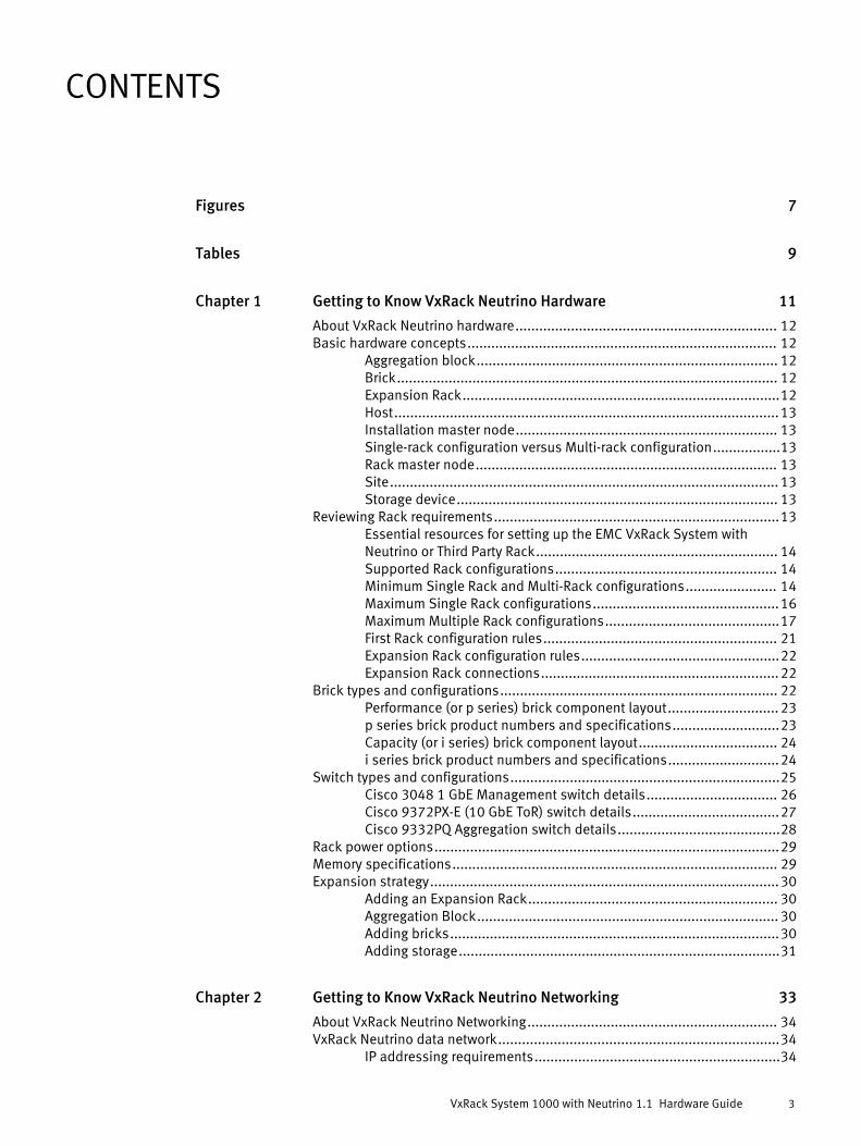
7
9
Getting to Know VxRack Neutrino Hardware 11
About VxRack Neutrino hardware.................................................................. 12Basic hardware concepts.............................................................................. 12
Aggregation block............................................................................ 12Brick................................................................................................ 12Expansion Rack................................................................................12Host.................................................................................................13Installation master node.................................................................. 13Single-rack configuration versus Multi-rack configuration.................13Rack master node............................................................................ 13Site.................................................................................................. 13Storage device................................................................................. 13
Reviewing Rack requirements........................................................................13Essential resources for setting up the EMC VxRack System withNeutrino or Third Party Rack............................................................. 14Supported Rack configurations........................................................ 14Minimum Single Rack and Multi-Rack configurations....................... 14Maximum Single Rack configurations...............................................16Maximum Multiple Rack configurations............................................17First Rack configuration rules........................................................... 21Expansion Rack configuration rules..................................................22Expansion Rack connections............................................................22
Brick types and configurations...................................................................... 22Performance (or p series) brick component layout............................ 23p series brick product numbers and specifications...........................23Capacity (or i series) brick component layout................................... 24i series brick product numbers and specifications............................24
Switch types and configurations....................................................................25Cisco 3048 1 GbE Management switch details................................. 26Cisco 9372PX-E (10 GbE ToR) switch details.....................................27Cisco 9332PQ Aggregation switch details.........................................28
Rack power options.......................................................................................29Memory specifications.................................................................................. 29Expansion strategy........................................................................................30
Adding an Expansion Rack............................................................... 30Aggregation Block............................................................................ 30Adding bricks...................................................................................30Adding storage.................................................................................31
Getting to Know VxRack Neutrino Networking 33
About VxRack Neutrino Networking............................................................... 34VxRack Neutrino data network.......................................................................34
IP addressing requirements..............................................................34
Figures
Tables
Chapter 1
Chapter 2
CONTENTS
VxRack System 1000 with Neutrino 1.1 Hardware Guide 3

Required subnets.............................................................................35Review potential subnet conflicts.................................................................. 37Management network scheme.......................................................................37Data network scheme....................................................................................37
VxRack Neutrino data network connection options...........................39Single Rack network layout.............................................................. 39Multi-Rack network layout................................................................ 40
AC Power Cabling and Network Connection Diagrams 43
AC power cabling.......................................................................................... 44First Rack without Aggregation AC power cabling (i series)................44First Rack without Aggregation AC power cabling (p series).............. 45First Rack with Aggregation AC power cabling (i series).....................46First Rack with Aggregation AC power cabling (p series)....................47Expansion Rack AC power cabling (i series)...................................... 48Expansion Rack AC power cabling (p series).....................................49
Network cabling............................................................................................ 50Cisco 3048 front cabling.................................................................. 51First Rack without Aggregation ethernet cabling (1 GbE switch) (iseries)..............................................................................................52First Rack without Aggregation ethernet cabling (1 GbE switch) (pseries)..............................................................................................53First Rack without Aggregation ethernet cabling (10 GbE switch) (iseries)..............................................................................................54First Rack without Aggregation ethernet cabling (10 GbE switch) (pseries)..............................................................................................55First Rack with Aggregation ethernet cabling (1 GbE switch) (i series)........................................................................................................ 56First Rack with Aggregation ethernet cabling (1 GbE switch) (p series)........................................................................................................ 57First Rack with Aggregation ethernet cabling (10 GbE switch) (i series)........................................................................................................ 58First Rack with Aggregation ethernet cabling (10 GbE switch) (p series)........................................................................................................ 59Expansion Rack ethernet cabling (1 GbE switch) (i series)................ 60Expansion Rack ethernet cabling (1 GbE switch) (p series)............... 61Expansion Rack ethernet cabling (10 GbE switch) (i series).............. 62Expansion Rack ethernet cabling (10 GbE switch) (p series)............. 63
System Information and Default Settings 65
Environmental, power, and floor space requirements.................................... 66Environmental requirements............................................................ 66Power and AC cable requirements (First Rack).................................. 66Power and AC cable requirements (Expansion Rack).........................67Space requirements (First and Expansion Rack)............................... 67
Default system passwords.............................................................................67Rack ID and Rack color reference...................................................................67Host names reference................................................................................... 68
Common Service Procedures 71
Gracefully shutting down the system............................................................. 72Gracefully starting up the system.................................................................. 74
Chapter 3
Appendix A
Appendix B
CONTENTS
4 VxRack System 1000 with Neutrino 1.1 Hardware Guide

Installing Customer Replaceable Units (CRUs) 79
Server System Disk Replacement (i series).................................................... 80Replacing the Server System Disk.....................................................80Pre-site tasks................................................................................... 80Parts................................................................................................ 81Tools................................................................................................81Common procedures ....................................................................... 81Logging into the VxRack Neutrino UI................................................. 84Remove the node from service......................................................... 84Deleting the disk from the node....................................................... 86Powering off the node...................................................................... 86Replacing a disk drive assembly.......................................................87Powering on the node...................................................................... 87Reinstalling the bezel.......................................................................88Adding the node to the service (Cloud Compute).............................. 88Returning parts to EMC.....................................................................89
Server Cache and Storage Disk Replacement (i series)...................................89Overview..........................................................................................89Pre-site tasks................................................................................... 90Parts................................................................................................ 90Tools................................................................................................90Common procedures ....................................................................... 90Logging into the VxRack Neutrino UI................................................. 94Removing the storage device from service (Cloud Compute).............94Deleting the disk from the node....................................................... 95Replacing a disk drive assembly.......................................................95Adding the disk to the service (Cloud Compute)............................... 98Returning parts to EMC.....................................................................98
Server System Disk Replacement (p series)................................................... 99Replacing the Server System Disk.....................................................99Pre-site tasks................................................................................... 99Parts.............................................................................................. 100Tools..............................................................................................100Common procedures ..................................................................... 100Logging into the VxRack Neutrino UI...............................................103Transfer the node (Platform)...........................................................104Remove the node from service (Cloud Compute)............................ 105Deleting the disk from the node..................................................... 106Powering off the node.................................................................... 106Replacing a disk drive assembly.....................................................107Powering on the node.................................................................... 110Reinstalling the bezel.....................................................................111Adding the node to the service (Cloud Compute)............................111Transferring a Platform Service node (optional).............................. 112Returning parts to EMC...................................................................112
Server Storage Disk Replacement (p series).................................................113Overview........................................................................................113Pre-site tasks................................................................................. 113Parts.............................................................................................. 114Tools..............................................................................................114Common procedures ..................................................................... 114Logging into the VxRack Neutrino UI...............................................117Transferring a node that is online and accessible (Platform)...........118Removing the storage device from service (Cloud Compute)...........118Deleting the disk from the node..................................................... 119
Appendix C
CONTENTS
VxRack System 1000 with Neutrino 1.1 Hardware Guide 5

Replacing a disk drive assembly.....................................................119Adding the disk to the service (Cloud Compute)............................. 123Transferring a Platform Service node (optional).............................. 123Returning parts to EMC...................................................................124
Ordering EMC Parts 125
Server FRU part numbers............................................................................. 126Switch FRU part numbers............................................................................ 127Rack component FRU part numbers............................................................. 128
Appendix D
CONTENTS
6 VxRack System 1000 with Neutrino 1.1 Hardware Guide

Minimum Single Rack and Multi-Rack configurations..................................................... 15Maximum Single Rack configurations............................................................................ 16Maximum Multi-Rack configuration with performance bricks..........................................18Maximum Multi-Rack configuration with capacity bricks................................................ 19Maximum Multi-Rack example with mixed performance and capacity bricks.................. 20p series brick component layout.................................................................................... 23i series brick component layout..................................................................................... 24Cisco 3048 front view ................................................................................................... 27Cisco 3048 rear view .....................................................................................................27Cisco 9372PX-E switch...................................................................................................28Front and rear views.......................................................................................................29VxRack Neutrino end-to-end network connections......................................................... 34IP addressing layout for 40 GbE versus 10 GbE connections.......................................... 351GbE Management switch vPC port layout..................................................................... 37Data network diagram — Single Rack ............................................................................ 40Data network diagram — Multi-Rack...............................................................................41Power tee breaker ON (1) and OFF (2) positions............................................................. 74Power tee breaker ON (1) and OFF (2) positions ............................................................ 74Disk slot diagram...........................................................................................................87Installing the bezel........................................................................................................ 88Removing the bezel....................................................................................................... 96Removing the faulted disk drive assembly..................................................................... 97Installing the replacement disk drive assembly..............................................................97Installing the bezel........................................................................................................ 98Disk slot diagram.........................................................................................................107Removing the bezel..................................................................................................... 108Removing the faulted disk drive assembly................................................................... 109Removing the faulted disk drive assembly................................................................... 110Installing the replacement disk drive assembly............................................................110Installing the bezel...................................................................................................... 111Disk slot diagram.........................................................................................................119Removing the bezel..................................................................................................... 120Removing the faulted disk drive assembly................................................................... 121Removing the faulted disk drive assembly................................................................... 122Installing the replacement disk drive assembly............................................................122Installing the bezel...................................................................................................... 123
123456789101112131415161718192021222324252627282930313233343536
FIGURES
VxRack System 1000 with Neutrino 1.1 Hardware Guide 7

FIGURES
8 VxRack System 1000 with Neutrino 1.1 Hardware Guide

Minimum Rack specifications........................................................................................ 15Maximum Single Rack specifications............................................................................. 17Maximum Multi-Rack specifications...............................................................................20p series product numbers and specifications.................................................................23i series product numbers and specifications.................................................................. 25Switch details................................................................................................................25Allocated memory..........................................................................................................29Expansion Rack support................................................................................................ 30p series brick upgrade summary.................................................................................... 30i series brick upgrade summary..................................................................................... 31VxRack Neutrino system subnets................................................................................... 35Important data networking considerations.....................................................................38Planning data network connections............................................................................... 39Cables........................................................................................................................... 441 GbE and 10 GbE cables...............................................................................................51Power specifications for the First Rack .......................................................................... 66Power specifications for the Expansion Rack..................................................................67Rack dimensions........................................................................................................... 67Rack ID 1-100 ............................................................................................................... 67Default host names....................................................................................................... 68Disk replacement tasks................................................................................................. 80Part list..........................................................................................................................81Hardware acclimation times (systems and components)................................................82Disk replacement tasks................................................................................................. 89Part list..........................................................................................................................90Hardware acclimation times (systems and components)................................................92Disk replacement tasks................................................................................................. 99Part list........................................................................................................................100Hardware acclimation times (systems and components)..............................................102Disk replacement tasks............................................................................................... 113Part list........................................................................................................................114Hardware acclimation times (systems and components)..............................................116Server option part numbers......................................................................................... 126Switch FRU part numbers.............................................................................................127Switch option part numbers.........................................................................................127
1234567891011121314151617181920212223242526272829303132333435
TABLES
VxRack System 1000 with Neutrino 1.1 Hardware Guide 9

TABLES
10 VxRack System 1000 with Neutrino 1.1 Hardware Guide

CHAPTER 1
Getting to Know VxRack Neutrino Hardware
This chapter includes the following sections:
l About VxRack Neutrino hardware.......................................................................... 12l Basic hardware concepts...................................................................................... 12l Reviewing Rack requirements................................................................................13l Brick types and configurations.............................................................................. 22l Switch types and configurations............................................................................25l Rack power options...............................................................................................29l Memory specifications.......................................................................................... 29l Expansion strategy................................................................................................30
Getting to Know VxRack Neutrino Hardware 11

About VxRack Neutrino hardwareThe EMC® VxRack™ System with Neutrino is built from:
l Node increments (called bricks)
l Switches
l Storage disks
l Required number of power distribution units (PDUs)
l EMC VxRack™ System with Neutrino (or the 40-unit Rack)
Basic hardware conceptsThis section describes important hardware terms.
Aggregation blockDesignates the four switches that provide multiple network connections when installingor expanding to a Multi-Rack configuration. The Aggregation Block consists of thefollowing switches, and is installed in the First Rack:
l Two 40GbE, 32-port switches
l Two 1GbE, 48-port switches
BrickThe VxRack Neutrino system is made up of node increments known as "bricks" that runthe individual services. Bricks consist of 1/2U nodes enclosed in a 2U chassis. Eachnode is attached to four internal 2.5 inch solid state disks (SSDs); totaling sixteen SSDsper brick. The front of the brick contains the disks, and the back of the brick contains thenodes that are connected to the disks. The bricks are interconnected via the 1GbEswitches. Release 1.1.0.0 supports two brick types. Customers can expand their systemby purchasing the following brick options:
l Performance brick (short name is p series brick)
l Capacity brick (short name is i series brick)
Customers must adhere to a set of VxRack Neutrino Rack configuration rules when addingbricks, see:
l First Rack Configuration Rules on page 21
l Expansion Rack Configuration Rules on page 22
Expansion RackRepresents additional Racks installed after the First Rack. This 1.1.0.0 release, supports amaximum of three Expansion Racks. Customers can expand from one (First Rack) to threeExpansion Racks for a maximum of four Racks. Adding Expansion Racks requires that youinstall the Aggregation Block in your First Rack to increase the number of customerconnections.
Getting to Know VxRack Neutrino Hardware
12 VxRack System 1000 with Neutrino 1.1 Hardware Guide
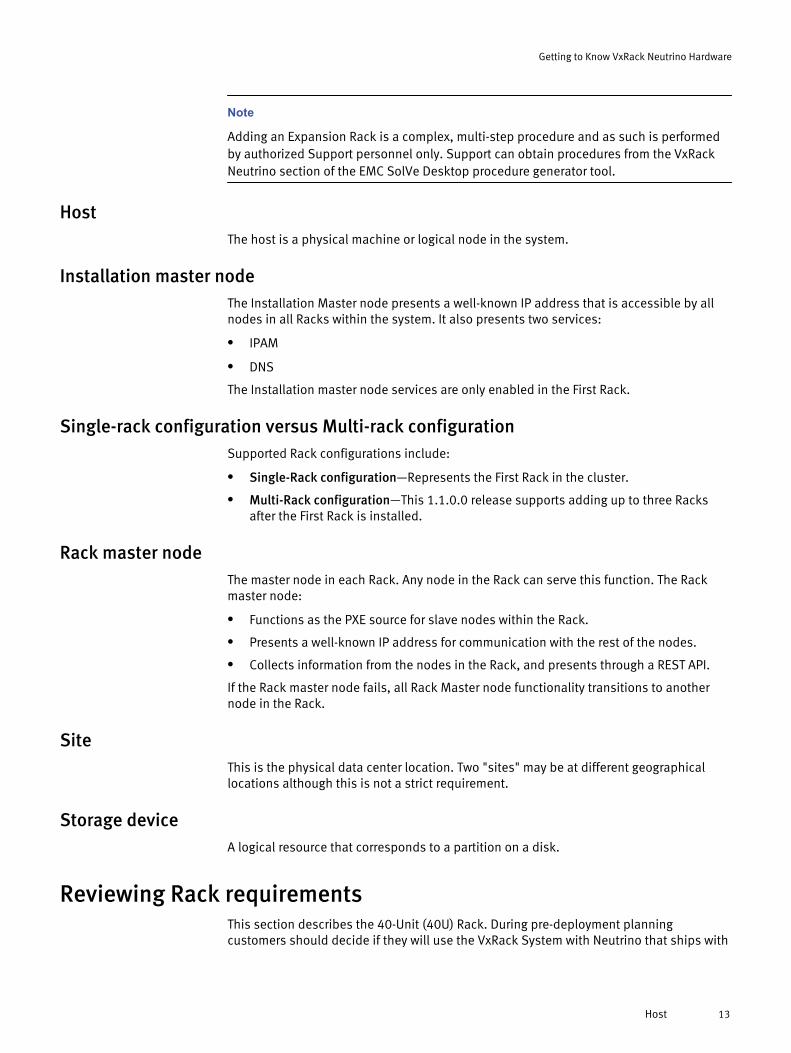
Note
Adding an Expansion Rack is a complex, multi-step procedure and as such is performedby authorized Support personnel only. Support can obtain procedures from the VxRackNeutrino section of the EMC SolVe Desktop procedure generator tool.
HostThe host is a physical machine or logical node in the system.
Installation master nodeThe Installation Master node presents a well-known IP address that is accessible by allnodes in all Racks within the system. It also presents two services:
l IPAM
l DNS
The Installation master node services are only enabled in the First Rack.
Single-rack configuration versus Multi-rack configurationSupported Rack configurations include:
l Single-Rack configuration—Represents the First Rack in the cluster.
l Multi-Rack configuration—This 1.1.0.0 release supports adding up to three Racksafter the First Rack is installed.
Rack master nodeThe master node in each Rack. Any node in the Rack can serve this function. The Rackmaster node:
l Functions as the PXE source for slave nodes within the Rack.
l Presents a well-known IP address for communication with the rest of the nodes.
l Collects information from the nodes in the Rack, and presents through a REST API.
If the Rack master node fails, all Rack Master node functionality transitions to anothernode in the Rack.
SiteThis is the physical data center location. Two "sites" may be at different geographicallocations although this is not a strict requirement.
Storage deviceA logical resource that corresponds to a partition on a disk.
Reviewing Rack requirementsThis section describes the 40-Unit (40U) Rack. During pre-deployment planningcustomers should decide if they will use the VxRack System with Neutrino that ships with
Getting to Know VxRack Neutrino Hardware
Host 13

the system, or a Third-Party Rack. In either case, adhere to the site requirements outlinedhere, and in the EMC resources listed next.
Essential resources for setting up the EMC VxRack System with Neutrino or ThirdParty Rack
Refer to the following guides for important Rack setup information. Access from the EMCOnline Support website: http://Support.EMC.com
l EMC VxRack™ System with Neutrino Site Preparation Guide
l EMC VxRack™ System with Neutrino Unpacking and Setup Guide
l EMC VxRack™ System with Neutrino Third Party Rack Installation Guide
Supported Rack configurationsThe initial VxRack Neutrino 1.0.0.0 release supported up to two Racks only. The 1.1.0.0release supports a maximum four Rack configuration consisting of one fully- loaded FirstRack, and three fully-loaded Expansion Racks.
The two Rack types that ship from EMC Manufacturing include:
l Single Rack
l Expansion Rack
The VxRack Neutrino system utilizes a 40-unit (or 40U) Rack system named the EMCVxRack System with Neutrino. Each 40U Rack supports up to forty-eight nodes dependingon the node type and switch configuration.
EMC developed a specific set of rules that govern Rack expansion. Adherence to theserules is mandatory to ensure warranty and service coverage. Refer to the followingsections in this chapter:
l First Rack Configuration Rules on page 21
l Expansion Rack Configuration Rules on page 22
Minimum Single Rack and Multi-Rack configurations
The minimum configuration is a Single Rack. The minimum Multi-Rack configuration istwo Racks (one First Rack with one Expansion Rack) as shown in the following figure.
Getting to Know VxRack Neutrino Hardware
14 VxRack System 1000 with Neutrino 1.1 Hardware Guide
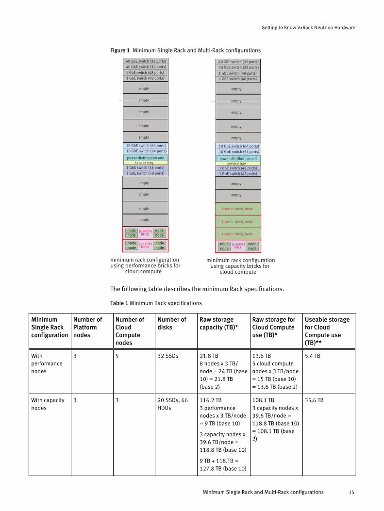
Figure 1 Minimum Single Rack and Multi-Rack configurations
40 GbE switch (32 ports)
40 GbE switch (32 ports)
1 GbE switch (48 ports)
1 GbE switch (48 ports)
10 GbE switch (64 ports)
10 GbE switch (64 ports)
1 GbE switch (48 ports)
1 GbE switch (48 ports)
p-series brick
empty
nodenode
nodenode
p-series bricknode
nodenodenode
power distribution unit
minimum rack configurationusing performance bricks for cloud compute
minimum rack configuration using capacity bricks for cloud compute
empty
empty
empty
empty
empty
empty
empty
empty
40 GbE switch (32 ports)
40 GbE switch (32 ports)
1 GbE switch (48 ports)
1 GbE switch (48 ports)
10 GbE switch (64 ports)
10 GbE switch (64 ports)
1 GbE switch (48 ports)
1 GbE switch (48 ports)
p-series brick
empty
nodenode
nodenode
power distribution unit
empty
empty
empty
empty
empty
empty
i-series brick/node
i-series brick/node
i-series brick/node
service tray service tray
The following table describes the minimum Rack specifications.
Table 1 Minimum Rack specifications
MinimumSingle Rackconfiguration
Number ofPlatformnodes
Number ofCloudComputenodes
Number ofdisks
Raw storagecapacity (TB)*
Raw storage forCloud Computeuse (TB)*
Useable storagefor CloudCompute use(TB)**
Withperformancenodes
3 5 32 SSDs 21.8 TB8 nodes x 3 TB/node = 24 TB (base10) = 21.8 TB(base 2)
13.6 TB5 cloud computenodes x 3 TB/node= 15 TB (base 10)= 13.6 TB (base 2)
5.4 TB
With capacitynodes
3 3 20 SSDs, 66HDDs
116.2 TB3 performancenodes x 3 TB/node= 9 TB (base 10)
3 capacity nodes x39.6 TB/node =118.8 TB (base 10)
9 TB + 118.TB =127.8 TB (base 10)
108.1 TB3 capacity nodes x39.6 TB/node =118.8 TB (base 10)= 108.1 TB (base2)
35.6 TB
Getting to Know VxRack Neutrino Hardware
Minimum Single Rack and Multi-Rack configurations 15

Table 1 Minimum Rack specifications (continued)
MinimumSingle Rackconfiguration
Number ofPlatformnodes
Number ofCloudComputenodes
Number ofdisks
Raw storagecapacity (TB)*
Raw storage forCloud Computeuse (TB)*
Useable storagefor CloudCompute use(TB)**
= 116.2 TB (base2)
*TB calculated using the binary system (base 2) of measurement.
**The useable Cloud Compute storage is considerably less than the raw storage available for Cloud Compute use due to ScaleIOdata protection and spare capacity requirements.
Maximum Single Rack configurations
In the First Rack, performance bricks can be added individually up to a maximum of 9total performance bricks. For a First Rack configuration using capacity bricks, after theminimum 3 capacity brick minimum is met, capacity bricks can be added individually upto a maximum of 8 total capacity bricks, as shown in the following figure.
Figure 2 Maximum Single Rack configurations
maximum single rack configuration with capacity bricks
40 GbE switch (32 ports)
40 GbE switch (32 ports)
1 GbE switch (48 ports)
1 GbE switch (48 ports)
10 GbE switch (64 ports)
10 GbE switch (64 ports)
1 GbE switch (48 ports)
1 GbE switch (48 ports)
p-series brick
empty
nodenode
nodenode
power distribution unit
empty
i-series brick/node
i-series brick/node
i-series brick/node
service tray
i-series brick/node
i-series brick/node
i-series brick/node
i-series brick/node
i-series brick/node
40 GbE switch (32 ports)
40 GbE switch (32 ports)
1 GbE switch (48 ports)
1 GbE switch (48 ports)
10 GbE switch (64 ports)
10 GbE switch (64 ports)
1 GbE switch (48 ports)
1 GbE switch (48 ports)
p-series brick
empty
nodenode
nodenode
p-series bricknode
nodenodenode
power distribution unit
maximum single rack configuration with performance bricks
empty
service tray
p-series bricknode
nodenodenode
p-series bricknode
nodenodenode
p-series bricknode
nodenodenode
p-series bricknode
nodenodenode
p-series bricknode
nodenodenode
p-series bricknode
nodenodenode
p-series bricknode
nodenodenode
single rack configuration example with mixed performance and capacity bricks
40 GbE switch (32 ports)
40 GbE switch (32 ports)
1 GbE switch (48 ports)
1 GbE switch (48 ports)
10 GbE switch (64 ports)
10 GbE switch (64 ports)
1 GbE switch (48 ports)
1 GbE switch (48 ports)
empty
power distribution unit
empty
service tray
i-series brick/node
i-series brick/node
i-series brick/node
p-series bricknode
nodenodenode
p-series bricknode
nodenodenode
p-series bricknode
nodenodenode
p-series bricknode
nodenodenode
p-series bricknode
nodenodenode
p-series bricknode
nodenodenode
The following table describes the maximum Single Rack specifications.
Getting to Know VxRack Neutrino Hardware
16 VxRack System 1000 with Neutrino 1.1 Hardware Guide

Table 2 Maximum Single Rack specifications
MaximumSingle Rackconfiguration
Number ofPlatformnodes
Number ofCloudComputenodes
Number ofdisks
Raw storagecapacity (TB)*
Raw storagecapacity forCloud Computeuse (TB)*
Useable storagefor CloudCompute use(TB)**
Withperformancenodes
3 33 144 SSDs 98.2 TB36 nodes x 3 TB/node = 108 TB(base 10) = 98.2TB (base 2)
90.0 TB33 cloud computenodes x 3 TB/node= 99 TB (base 10)= 90.0 TB (base 2)
43.2 TB
With capacitynodes
3 8 32 SSDs, 176HDDs
299.0 TB4 performancenodes x 3 TB/node= 12 TB (base 10)
8 capacity nodes x39.6 TB/node =316.8 TB (base 10)
12 TB + 316.8 TB =328.8 TB (base 10)= 299.0 TB (base2)
288.1 TB8 capacity nodes x39.6 TB/node =316.8 TB (base 10)= 288.1 TB (base2)
125.3 TB
*TB calculated using the binary system (base 2) of measurement.
** The useable cloud compute storage is considerably less than the raw storage available for cloud compute use due to ScaleIOdata protection and spare capacity requirements.
Maximum Multiple Rack configurations
When adding Expansion Racks to the First Rack, an Aggregation Block is required on theFirst Rack. The Aggregation Block consists of two 40 GbE switches and two 1 GbEswitches. The following figure shows the maximum 4-rack configuration usingperformance bricks.
Getting to Know VxRack Neutrino Hardware
Maximum Multiple Rack configurations 17

Figure 3 Maximum Multi-Rack configuration with performance bricks
3 expansion 40U racksfirst 40U rack
40 GbE switch (32 ports)
40 GbE switch (32 ports)
1 GbE switch (48 ports)
1 GbE switch (48 ports)
10 GbE switch (64 ports)
10 GbE switch (64 ports)
1 GbE switch (48 ports)
1 GbE switch (48 ports)
p-series brick
empty
empty
nodenode
nodenode
p-series bricknode
nodenodenode
p-series bricknode
nodenodenode
p-series bricknode
nodenodenode
p-series bricknode
nodenodenode
p-series bricknode
nodenodenode
power distribution unit
nodenode
nodenode
nodenode
nodenode
nodenode
nodenodep-series
brick
p-series brick
p-series brick
p-series bricknode
nodenodenode
p-series bricknode
nodenodenode
p-series bricknode
nodenodenode
p-series bricknode
nodenodenode
10 GbE switch (64 ports)
10 GbE switch (64 ports)
1 GbE switch (48 ports)
1 GbE switch (48 ports)
power distribution unit
power distribution unit
nodenode
nodenode
nodenode
nodenode
p-series brick
p-series brick
p-series bricknode
nodenodenode
p-series bricknode
nodenodenode
p-series bricknode
nodenodenode
p-series bricknode
nodenodenode
nodenode
nodenode
nodenode
nodenode
p-series brick
p-series brick
service trayservice tray
p-series bricknode
nodenodenode
p-series bricknode
nodenodenode
p-series bricknode
nodenodenode
p-series bricknode
nodenodenode
10 GbE switch (64 ports)
10 GbE switch (64 ports)
1 GbE switch (48 ports)
1 GbE switch (48 ports)
power distribution unit
power distribution unit
nodenode
nodenode
nodenode
nodenode
p-series brick
p-series brick
p-series bricknode
nodenodenode
p-series bricknode
nodenodenode
p-series bricknode
nodenodenode
p-series bricknode
nodenodenode
nodenode
nodenode
nodenode
nodenode
p-series brick
p-series brick
service tray
p-series bricknode
nodenodenode
p-series bricknode
nodenodenode
p-series bricknode
nodenodenode
p-series bricknode
nodenodenode
10 GbE switch (64 ports)
10 GbE switch (64 ports)
1 GbE switch (48 ports)
1 GbE switch (48 ports)
power distribution unit
power distribution unit
nodenode
nodenode
nodenode
nodenode
p-series brick
p-series brick
p-series bricknode
nodenodenode
p-series bricknode
nodenodenode
p-series bricknode
nodenodenode
p-series bricknode
nodenodenode
nodenode
nodenode
nodenode
nodenode
p-series brick
p-series brick
service tray
aggregation block
The following figure shows the maximum 4-rack configuration using capacity bricks.
Getting to Know VxRack Neutrino Hardware
18 VxRack System 1000 with Neutrino 1.1 Hardware Guide

Figure 4 Maximum Multi-Rack configuration with capacity bricks
3 expansion 40U racksfirst 40U rack
40 GbE switch (32 ports)
40 GbE switch (32 ports)
1 GbE switch (48 ports)
1 GbE switch (48 ports)
10 GbE switch (64 ports)
10 GbE switch (64 ports)
1 GbE switch (48 ports)
1 GbE switch (48 ports)
p-series brick
empty
empty
nodenode
nodenode
power distribution unit
i-series brick/node
i-series brick/node
i-series brick/node
i-series brick/node
i-series brick/node
i-series brick/node
i-series brick/node
i-series brick/node
service tray
aggregation block
10 GbE switch (64 ports)
10 GbE switch (64 ports)
1 GbE switch (48 ports)
1 GbE switch (48 ports)
power distribution unit
power distribution unit
i-series brick/node
i-series brick/node
i-series brick/node
i-series brick/node
i-series brick/node
i-series brick/node
i-series brick/node
i-series brick/node
i-series brick/node
i-series brick/node
i-series brick/node
service tray
i-series brick/node
10 GbE switch (64 ports)
10 GbE switch (64 ports)
1 GbE switch (48 ports)
1 GbE switch (48 ports)
power distribution unit
power distribution unit
i-series brick/node
i-series brick/node
i-series brick/node
i-series brick/node
i-series brick/node
i-series brick/node
i-series brick/node
i-series brick/node
i-series brick/node
i-series brick/node
i-series brick/node
service tray
i-series brick/node
The following figure shows an example of a 4-rack configuration with mixed performanceand capacity bricks.
Getting to Know VxRack Neutrino Hardware
Maximum Multiple Rack configurations 19

Figure 5 Maximum Multi-Rack example with mixed performance and capacity bricks
3 expansion 40U racksfirst 40U rack
40 GbE switch (32 ports)
40 GbE switch (32 ports)
1 GbE switch (48 ports)
1 GbE switch (48 ports)
10 GbE switch (64 ports)
10 GbE switch (64 ports)
1 GbE switch (48 ports)
1 GbE switch (48 ports)
p-series brick
empty
empty
nodenode
nodenode
i-series brick/node
p-series bricknode
nodenodenode
p-series bricknode
nodenodenode
p-series bricknode
nodenodenode
p-series bricknode
nodenodenode
p-series bricknode
nodenodenode
i-series brick/node
i-series brick/node
power distribution unitservice tray
p-series bricknode
nodenodenode
p-series bricknode
nodenodenode
p-series bricknode
nodenodenode
p-series bricknode
nodenodenode
10 GbE switch (64 ports)
10 GbE switch (64 ports)
i-series brick/node
i-series brick/node
i-series brick/node
i-series brick/node
i-series brick/node
i-series brick/node
i-series brick/node
i-series brick/node
power distribution unit
power distribution unitservice tray
1 GbE switch (48 ports)
1 GbE switch (48 ports)
p-series bricknode
nodenodenode
p-series bricknode
nodenodenode
p-series bricknode
nodenodenode
p-series bricknode
nodenodenode
10 GbE Switch (64 ports)
10 GbE Switch (64 ports)
i-series brick/node
i-series brick/node
i-series brick/node
i-series brick/node
p-series bricknode
nodenodenode
p-series bricknode
nodenodenode
p-series bricknode
nodenodenode
p-series bricknode
nodenodenode
service tray
1 GbE switch (48 ports)
1 GbE switch (48 ports)
power distribution unit
power distribution unit
p-series bricknode
nodenodenode
p-series bricknode
nodenodenode
10 GbE switch (64 ports)
10 GbE switch (64 ports)
i-series brick/node
i-series brick/node
i-series brick/node
i-series brick/node
i-series brick/node
i-series brick/node
i-series brick/node
i-series brick/node
i-series brick/node
i-series brick/node
power distribution unit
service tray
1 GbE switch (48 ports)
1 GbE switch (48 ports)
power distribution unit
aggregation block
The following table describes the specifications of maximum four-rack configurationsusing performance and capacity nodes.
Table 3 Maximum Multi-Rack specifications
Node type Number ofplatformnodes
Number ofCloudComputenodes
Number ofdisks
Raw storagecapacity (TB)*
Raw storagecapacityavailable forCloud Computeuse (TB)*
Useable storagefor CloudCompute use(TB)**
Withperformancenodes
3 177 720 SSDs 491.1 TB180 nodes x 3 TB/node = 540 TB(base 10) = 491.1TB (base 2)
482.9 TB177 cloud computenodes x 3 TB/node= 531 TB (base 10)= 482.9 TB (base2)
239.0 TB
With capacitynodes
3 44 98 SSDs, 902HDDs
1,592.9 TB3 performancenodes x 3 TB/node= 9 TB (base 10)
44 capacity nodesx 39.6 TB/node =1,742.4 TB (base10)
1,584.7 TB44 capacity nodesx 39.6 TB/node =1,742.4 TB (base10) = 1,584.7 TB(base 2)
716.7 TB
Getting to Know VxRack Neutrino Hardware
20 VxRack System 1000 with Neutrino 1.1 Hardware Guide

Table 3 Maximum Multi-Rack specifications (continued)
Node type Number ofplatformnodes
Number ofCloudComputenodes
Number ofdisks
Raw storagecapacity (TB)*
Raw storagecapacityavailable forCloud Computeuse (TB)*
Useable storagefor CloudCompute use(TB)**
9 TB +1,742.4 TB=1,751.4 TB (base10) = 1,592.9(base 2)
*TB calculated using the binary system (base 2) of measurement.
** The useable Cloud Compute storage is considerably less than the raw storage available for Cloud Compute use due to ScaleIOdata protection and spare capacity requirements.
First Rack configuration rulesThe following rules govern the First Rack configuration:
l A minimum of one performance (or p series brick) is required in the First Rack.
l If installing capacity (or i series) nodes:
n A minimum of three i series bricks are required in the First Rack
n Add i series bricks in single Increments up to maximum of 8 bricks
l The First Rack supports up to nine bricks only (for a maximum of 36 nodes).
l First Rack configurations require one of the following PDU types:
n Single Phase Power
n Three Phase Power
n Three Phase Wye
Rules for installing both Performance and Capacity bricks in the First RackIt is important that you adhere to the following guidelines when adding different bricktypes.
l Install bricks from the bottom to the top of the Rack. One performance (or p-series)brick is always required to start.
l A minimum of one p-series brick is required before you can intermix brick types in aRack.
l A minimum of three capacity (or i-series) bricks is required before you can intermixbrick types in a Rack.
l Add both p-series and i-series bricks in single node increments once the startingminimum (noted above) is achieved.
l p-series bricks are populated first (before i-series bricks) when shipped frommanufacturing. However during brick expansions at a customer site, there js no strictorder.
l Install p-series and i-series bricks in single increments up to the sixth server.
l When adding the seventh brick, a second PDU is added to the Expansion Rack.
Getting to Know VxRack Neutrino Hardware
First Rack configuration rules 21

Expansion Rack configuration rulesThe following rules govern the Expansion Rack configuration:
l This release supports a maximum of three Expansion Racks in addition to the FirstRack (for a total of four Racks).
l A minimum of one performance (or p series brick) is required for a maximum of 4nodes.
l Each Expansion Rack supports up to twelve or p series bricks for a maximum of 48nodes.
l Each Expansion Rack supports a minimum of three capacity (or i series) bricks for amaximum of twelve nodes.
l When adding an Expansion Rack, you must first install the Aggregation Block to yourFirst Rack:
n Two 1GbE Management switches (Cisco 3048)
n Two 40GbE Data switches (Cisco 9332PQ)
l A second set of PDUs are required if there are seven or more bricks in the ExpansionRack. Customers can choose:
n Single Phase Power
n Three Phase Delta
n Three Phase Wye
Expansion Rack connectionsWhen installing a Multi-Rack configuration, the Aggregation Block is installed in the FirstRack. Only one Aggregation Block is needed per system. The Aggregation Block consistsof:
l Two 40 GbE switches (Cisco 9332PQ)
l Two 1 GbE switches (Cisco 3048)
One Rack-to-rack Connection Kit is required to connect an Expansion Rack to the FirstRack. Three connection options are available for connecting Expansion Racks to FirstRacks:
l 8 Meter Inter-connect Kit
l 25 Meter Inter-connect Kit
l 50 Meter Inter-connect Kit
The kits also include:
l Four CAT6 cables used for the 1 GbE switch connection to the Expansion Rack
l Eight 40 GbE Optical GBICs
l Four 40 GbE Optical Cables
Brick types and configurationsThe First Rack supports a maximum of nine bricks (or thirty 36 nodes) in a configuration.The Expansion Rack supports a maximum of three bricks (or twelve nodes) in a
Getting to Know VxRack Neutrino Hardware
22 VxRack System 1000 with Neutrino 1.1 Hardware Guide

configuration. Bricks are a configurable component in the system, and as such mustfollow the Racking Rules outlined in:
l First Rack Configuration Rules on page 21
l Expansion Rack Configuration Rules on page 22
Performance (or p series) brick component layoutThe following figure highlights p series brick components. Only p series nodes canfunction as Platform nodes. There are three Platform nodes in the cluster.
Figure 6 p series brick component layout
disks attached to Node 1
Front of brick (disk view)
disk slots
disks attached to Node 2
disks attached to Node 3 disks attached to Node 4
Back of brick (node view)
Node 4 Node 3
Node 1Node 2 power supply 1
power supply 2
p series brick product numbers and specificationsThe following table lists specifications, and the product naming conventions used torepresent p series bricks in the VxRack Neutrino UI.
Note
For information on ordering p series bricks, and part numbers see p series brick orderableconfigurations on page 126.
Table 4 p series product numbers and specifications
Brick product # (as shownin the VxRack Neutrino UI)
CPU frequency CPU cores Logical cores(hyperthreaded)
Memory Raw storage*
p412 (400 GB SSDs) 2.4 GHz 48 96 512 GB 5.6 TB**
p812 (800 GB SSDs) 2.4 GHz 48 96 512 GB 12 TB***
p416 (400 GB SSDs) 2.6 GHz 64 128 1,024 GB 5.6 TB**
p816 (800 GB SSDs) 2.6 GHz 64 128 1,024 GB 12 TB***
p420 (400 GB SSDs) 2.6 GHz 80 160 2,048 GB 5.6 TB**
Getting to Know VxRack Neutrino Hardware
Performance (or p series) brick component layout 23

Table 4 p series product numbers and specifications (continued)
Brick product # (as shownin the VxRack Neutrino UI)
CPU frequency CPU cores Logical cores(hyperthreaded)
Memory Raw storage*
p820 (800 GB SSDs) 2.6 GHz 80 160 2,048 GB 12 TB***
*The raw storage numbers use the decimal system (base 10). Storage device manufacturers measure capacity using the decimalsystem (base 10), so 1 gigabyte (GB) is calculated as 1 billion bytes.
**The brick raw storage subtracts out the 200 GB operating system storage requirement per node. For bricks with 400 GB SSDs:1,600 GB/node - 200 GB for operating system = 1,400 GB/node. 1,400 GB/node x 4 nodes = 5.6 TB/brick.
***The brick raw storage subtracts out the 200 GB operating system storage requirement per node. For bricks with 800 GB SSDs:3,200 GB/node - 200 GB for operating system = 3,000 GB/node. 3,000/GB node x 4 nodes = 12 TB/brick.
Capacity (or i series) brick component layoutThe following figure highlights i series brick components.
Figure 7 i series brick component layout
Front of brick (disk view)
Back of brick (node view)
node
Disk 0 is 400 GB OS SSD
Disk 1 is 800 GB caching SSD
Disks 2-23 are 1.8 TB HDDs
i series brick product numbers and specificationsThe following table lists specifications, and the product naming conventions used torepresent i series bricks in the VxRack Neutrino UI.
Note
For information on ordering i series bricks, and part numbers see i series brick orderableconfigurations on page 126.
Getting to Know VxRack Neutrino Hardware
24 VxRack System 1000 with Neutrino 1.1 Hardware Guide

Table 5 i series product numbers and specifications
Brick product #(as shown in theVxRack NeutrinoUI)
CPU frequency CPU cores Logical cores(hyperthreaded)
Memory Raw storage*
i1812 2.4 GHz 12 24 128 GB 39.6 TB
i1816 2.6 GHz 16 32 256 GB
i1820 2.6 GHz 20 40 512 GB
*22 HDDs x 1.8 TB HDD = 39.6 TB. This raw storage number uses the decimal system (base 10).
Switch types and configurationsThis table lists the switches used in the system.
Table 6 Switch details
Quantity
Model and port details Usage
2 Cisco 3048, 1 GbE (Management switch)
l 1 GbE, 48 ports
l Four 1/10 GbE SFP+ ports
Note
1 GbE switches are pre-configured from EMCmanufacturing.
l Connects to the Managementswitch via port 48.
2 Cisco 9372PX-E (Top of Rack, ToR Dataswitch )
l Forty eight 10 GbE SFP+ ports
l Four 40 GbE QSFP+ ports
l Connects to the data network,and may connect to the customernetwork (Single Rack only).
l Connects to the customernetwork in a Single Rack. Also, inan Expansion Rack theseswitches are installed in the 2ndRack connecting to all of thenodes.
l The switch integrates four 40 GbEports. Only two ports per switchare used for customerconnections (a total of four).
l Each port can be used as one 40GbE interconnect, or four 10 GbEinterconnects
l Total # of available connections:Four 40 GbE ports, or sixteen 10GbE ports
Getting to Know VxRack Neutrino Hardware
Switch types and configurations 25

Table 6 Switch details (continued)
Quantity
Model and port details Usage
2 Cisco 9332PQ (ToR Aggregation switch)
l Thirty two 40 GbE QSFP+ ports
l Connects to the data network.Provides aggregation acrossRacks.
l Used for First Rack data networkconnection (with Expansion Rack)
l When you add the ExpansionRack, the site networkconnections move from the FirstRack 10 GbE switches to the FirstRack Aggregation 40 GbEswitches.
l Each 40 GbE switch has four 40GbE capable QSFPs ports (total ofeight QSFP ports with bothswitches) that are reserved forcustomer connections.
l Each port can be used as one 40GbE interconnect or four 10 GbEinterconnects.
l Total # of Customer Connectionswith an Aggregation switch pair:Eight 40 GbE ports, or thirty two10 GbE ports
Cisco 3048 1 GbE Management switch detailsThe Cisco 3048 1 GbE switch is used in the Aggregation Block, and for the managementconnection during service activities.
Note
The 1 GbE Management switch is pre-configured from EMC Manufacturing, and requiresno Field Support intervention during first-time deployment engagements.
Main features include:
l Forty eight 10/100/1000 RJ45 ports
l Four 10 GbE SFP+ ports
l Two Fixed Power Supplies
l Single Fan Module (FRU)
Getting to Know VxRack Neutrino Hardware
26 VxRack System 1000 with Neutrino 1.1 Hardware Guide

Figure 8 Cisco 3048 front view
Figure 9 Cisco 3048 rear view
Cisco 9372PX-E (10 GbE ToR) switch detailsThe Cisco 9372PX-E top of rack (ToR) switch is used in Single Rack and Multi-Rackconfigurations. Main features include:
l Forty eight 1/10Gb SFP+ ports
l Four 40 GbE QSFP+ ports
l Two Replaceable Power Supplies, Field Replaceable Unit (FRU)
l Four hot-swappable Fan Modules (FRU)
For Base OS Release 1.1.0.0 and later, 10 GbE customer port connections now use ports41 through 48. There is no change to the 40 GbE port connections (use ports 51 and 52).The following figure identifies switch components and designated ports.
Note
The Cisco 9372PX-E switch does not support the use of a 4x10GbE breakout cable. If the9372PX-E is the switch that connects to the customer network, 10 GbE SFPs are requiredto connect to a customer's 10 GbE network. If the customer connection is 40 GbE, thenthe Cisco 40GbE optic is used.
Getting to Know VxRack Neutrino Hardware
Cisco 9372PX-E (10 GbE ToR) switch details 27

Figure 10 Cisco 9372PX-E switch
Cisco 9332PQ Aggregation switch detailsThe Cisco 9332PQ top of rack (TOR) Data switch is used for the First Rack with ExpansionRack network connections.
Main features include:
l Thirty two 40 GbE QSFP+ ports
l Two Replaceable Power Supplies (FRUs)
l Four hot-swappable Fan Modules (FRUs)
The following figure identifies the designated switch ports.
Getting to Know VxRack Neutrino Hardware
28 VxRack System 1000 with Neutrino 1.1 Hardware Guide

Figure 11 Front and rear views
Rack power optionsSystems ship equipped with the appropriate pre-installed power distribution units(PDUs). Customers will need to purchase a second set of PDUs if adding Expansion Racksto an existing Single Rack configuration:
l Single Phase Power CI1-VX-RACK (QTY 1/rack)
l Three Phase Delta CI1-VX-RACK-P3D (QTY 1/rack)
l Three Phase Wye CI1-VX-RACK-P3W (QTY 1/rack)
Memory specificationsThe table lists available system memory per model.
Table 7 Allocated memory
Memory by brick type Configuration # of DIMMs per channel
VxRack Neutrino-Small, 128 GB 8x16 GB DDR4-2133 1
VxRack NeutrinoMedium, 256 GB 16x16 GB DDR4-2133 2
VxRack Neutrino-Large, 512 GB 8x32 GB DDR4-2133 2
Getting to Know VxRack Neutrino Hardware
Rack power options 29

Expansion strategyThis section discusses the available options for adding nodes, storage, and Racks.
Adding an Expansion RackExpansion Rack support varies depending on the software release, as follows.
Table 8 Expansion Rack support
Base OS release Maximum supported Rack configuration
Base OS version 1.0.0.0 Does not support adding Expansion Racks. The maximum supportedRack configuration is two Racks (First Rack plus one Expansion Rack)during first-time deployment.
Base OS version 1.0.0.1 Two Racks (First Rack plus one Expansion Rack)
Base OS version 1.1.0.0 Three Racks (First Rack plus three Expansion Racks)
Aggregation BlockWhen installing Expansion Racks, you first need to add the Aggregation Block to the FirstRack. Only one Aggregation Block is needed per system to support Multi-Rackconfigurations. When you add the Expansion Rack, the customer connections move fromthe First Rack 10 GbE Switches to the First Rack Aggregation 40 GbE switches.
The Aggregation Block consists of the following:
l Two 40 GbE switches (Cisco 9332PQ)
l Two 1 GbE switches (Cisco 3048)
Adding bricksUpgrades are allowable in single brick increments. The table lists the brick models, types,and available drive packs assigned to each combination. Customers should contact EMCTechnical Support, as this upgrade is performed by Professional Services only.
Note
For information on ordering bricks, and part numbers see brick orderableconfigurations on page 126.
System configurations rules must be followed when determining if the existing systemhas space to add bricks. See the Racking Rules outlined in:
l First Rack Configuration Rules on page 21
l Expansion Rack Configuration Rules on page 22
Table 9 p series brick upgrade summary
Model # and Product # (as shown in Neutrino UI) Brick size Drive pack
CI1-SVR-SMR-400 (p412) Neutrino-Small 400 GB SSD
Getting to Know VxRack Neutrino Hardware
30 VxRack System 1000 with Neutrino 1.1 Hardware Guide

Table 9 p series brick upgrade summary (continued)
Model # and Product # (as shown in Neutrino UI) Brick size Drive pack
CI1-SVR-MDR-400 (p416) Neutrino-Medium 400 GB SSD
CI1-SVR-LGR-400 (p420) Neutrino-Large 400 GB SSD
CI1-SVR-SMR-800 (p812) Neutrino-Small 800 GB SSD
CI1-SVR-MDR-800 (p816) Neutrino-Medium 800 GB SSD
CI1-SVR-LGR-800 (p820) Neutrino-Large 800 GB SSD
Table 10 i series brick upgrade summary
Model # and Product # (as shown in Neutrino UI) Brick size Drive pack
CI1-SVR-SMH-18T (i1812) Neutrino-Small 1.8 TB HDD
CI1-SVR-MDR-400 (i1816 ) Neutrino-Medium 1.8 TB HDD
CI1-SVR-LGR-400 (i1820) Neutrino-Large 1.8 TB HDD
Adding storageAvailable disk drive options include:
l Up to sixteen 400 GB SSD drive packs
l Up to sixteen 800 GB SSD drive packs
Getting to Know VxRack Neutrino Hardware
Adding storage 31

Getting to Know VxRack Neutrino Hardware
32 VxRack System 1000 with Neutrino 1.1 Hardware Guide

CHAPTER 2
Getting to Know VxRack Neutrino Networking
This section discusses system networking.
l About VxRack Neutrino Networking....................................................................... 34l VxRack Neutrino data network...............................................................................34l Review potential subnet conflicts.......................................................................... 37l Management network scheme...............................................................................37l Data network scheme............................................................................................37
Getting to Know VxRack Neutrino Networking 33

About VxRack Neutrino NetworkingThe VxRack Neutrino platform implements a leaf-spine architecture with Layer 3 (L3)routing. This design provides optimal load balancing for traffic across all links. Each Racktransmits data over the network using 160 Gbps of bandwidth to the core; and 320 Gbpsof bandwidth from the system to the data center. Nodes interconnect in the data centerusing:
l L3 top of rack (ToR) switches
l 10 GbE Leaf-Spine technology, and
l 1 GbE management network
Figure 12 VxRack Neutrino end-to-end network connections
VxRack Neutrino data networkThese sections define VxRack Neutrino data network requirements.
IP addressing requirementsThe number of required IP addresses will vary depending on the customer network.Consider the following factors when planning network setup:
l Number of hosts
l Number of public-facing applications
l Data Network connection type (10 GbE or 40 GbE)
l Addressing scheme doesn't have to be contiguous
l Nodes use a bonded interface. This means that from the host there is just one IPaddress.
Getting to Know VxRack Neutrino Networking
34 VxRack System 1000 with Neutrino 1.1 Hardware Guide

Figure 13 IP addressing layout for 40 GbE versus 10 GbE connections
Required subnetsThe subnet requirements depend on the Rack configuration (Single Rack or Multi-Rack),and the customer network in place (10 GbE connections or 40 GbE connections).Thesystem uses up to six subnets. Ensure that these subnets do not conflict with any othersin the data center:
l Subnet 1 : Customer Network Connections
l Subnet 2 : Aggregation Switch Network (only used with Multiple Rack configurations)
l Subnet 3 : Neutrino Host Network
l Subnet 4 : Neutrino Virtual IP Subnet
l Subnet 5 : OpenStack Public Floating Network
l Subnet 6 : OpenStack Private Network
Note
A floating IP address is needed even if there is no requirement for a public facing IP. Avirtual machine (VM) will require a floating IP address if it needs to connect to the Internetor another Neutrino logical network.
Table 11 VxRack Neutrino system subnets
Item IP addressing scheme Guidelines
Subnet 1 :CustomerNetworkConnections
l For a site utilizing 10GbE connections:
n /26 ( up to 64 IPsmaximum needed)
l For a site utilizing 40GbE connections:
n /28
l The first IP address in the subnet should startwith an even IP address value.
l The number of IP addresses equal the numberof uplinks to the customer switch (or thenumber of ports on the customer network.)
l For example, 10.242.42.30 is specified as thestarting IP address with two uplinks:
n Uplink 1 on the customer switch port isassigned to 10.242.42.30, and its pair onthe Neutrino switch is assigned to10.242.42.31.
n Uplink 2 on the customer switch port isassigned to 10.242.42.32, and its pair on
Getting to Know VxRack Neutrino Networking
Required subnets 35

Table 11 VxRack Neutrino system subnets (continued)
Item IP addressing scheme Guidelines
the Neutrino switch is assigned to10.242.42.33.
Subnet 2 :AggregationSwitch Network
Use /27 for the internalAggregation switchconnection to the internalToR switches (enough toaccount for 2 Racks) whichmay require up to thirty twoIPs.
Only use for sites with more than one Rack.
Subnet 3 :Neutrino HostNetwork
l Use /25 for physicalnode IPs (enough toaccount for 2 Racks)which may require upto 128 IPs.
l Each Rackrequires /26.
l Note that Neutrino automatically assigns thedifferent subnets for each Rack.
l Ensure that this subnet is routable from thecustomer network, and can reach differentservices such as DNS and NTP.
Subnet 4 :NeutrinoVirtual IPSubnet
Use /29 for the VxRackNeutrino Virtual IPs (usedduring the VxRack Neutrinoinstallation process).
l Note that these IPs are used individually asa /32. The subnet is requested as VxRackNeutrino has multiple IP addresses used asVirtual IPs within the cluster.
l Create a static route for the first IP which sothat it is routable from the customer network,and able to reach the different services suchas DNS and NTP.
Subnet 5 :OpenStackPublic FloatingNetwork
/19 is stronglyrecommended (up to 8,192IPs)
l A floating IP network is needed even if there isno need for a public facing IP. A VM requires afloating IP for connecting to the Internet (todownload software, for example) or anotherVxRack Neutrino logical network. If thecustomer plans to expand to a Multi-Rackconfiguration, then providing a large subnet atinitial deployment is beneficial for futureupgrades.
l Ensure that this subnet is routable from thecustomer network, and can reach differentservices such as DNS and NTP.
Subnet 6 :OpenStackPrivateNetwork
/19 is stronglyrecommended (up to 8,192IPs)
l The site admin needs to ensure that the CIDRblocks used for the VM private IP addressesDO NOT conflict with any IP block used byVxRack Neutrino or the site's network.
l It is not required for the OpenStack PrivateNetwork subnet addressing scheme to becontiguous.
Getting to Know VxRack Neutrino Networking
36 VxRack System 1000 with Neutrino 1.1 Hardware Guide

Review potential subnet conflictsVerify that the following subnets used by VxRack Neutrino in the data center do notconflict with any other subnets used by the customer network, or the private IPs.
l 172.17.42.1/16
l 10.0.0.0/31
l 192.168.219.0/24
l 169.254.0.0/16
Management network schemeCluster management is provided by the Cisco 3048 switch, which is a standard piece ofequipment in the VxRack Neutrino cluster. It enables you to connect to the switch'sservice connection (port 48) to perform:
l System management
l Upgrades
l Service activities (for example, installing replacement parts)
Note
You will not need to modify the Cisco 3048 switch configuration. Use the defaultconfiguration shipped from EMC Manufacturing.
Figure 14 1GbE Management switch vPC port layout
Data network schemeThe two supported methods to connect to the data network are via static routes or BorderGateway Protocol (BGP) using an autonomous system (AS). Additional characteristics ofthe VxRack Neutrino data network include:
l Physical Fabric
n Leaf-Spine architecture using 10 GbE or 40 GbE interconnects
n Layer 3 top of rack (ToR) layout
l Uses Multi-Chassis Link Agregation (MLAG) with VINES Address Resolution Protocol(VARP) for ToR high availability (HA)
n Connects a pair of ToRs to a pair of 40 GbE core switches using only L3 links
n Uses Open Shortest Path First (OSPF) to distribute the routes (default routes,subnet announcements, Virtual IP announcements)
Getting to Know VxRack Neutrino Networking
Review potential subnet conflicts 37

l The existing network must contain the following services
n DNS, requires PTR (Provide Reverse DNS) records for Virtual IPs
n Network Time Protocol (NTP)
Note
The customer's NTP servers are specified via IP instead of FQDN for version1.1.0.0.
n Simple Mail Transfer Protocol (SMTP)
n Equal Cost Multi-Path (ECMP) routing for load balancing
l Logical Networking: Software-defined networking (SDN) overlay
Table 12 Important data networking considerations
Item Requirements
OSPF or staticroutes?
If choosing to connect to the network via the static routes method, youwill need to disable OSPF.
Routing? Routing is performed internally by the VxRack Neutrino system.
Switch port IPaddress assignment?
Because the system implements Layer 3 (IP routing) each switch port isassigned an IP address.
Switch router ID? Each switch requires its own unique router ID.
Router statements? Router statements are required for each port or connection. For example: Swift(config) #ip route 0.0.0.0/0 x.x.x.x
IP addressingconflicts?
Ensure that the IP blocks for the management network (169.254.xxx.xxx)don’t conflict with any other IP block used by VxRack Neutrino, includingthe site's network or the private IPs for the virtual machines (VMs).
Active Directory/LDAP?
Active Directory/LDAP can be optionally used for login information for theadministrators or users.
Gateway IP address? The Gateway IP address is provided by the VxRack Neutrino switch.
Firewall information? l For both VxRack Neutrino, and any ports needed for OpenStackApplications
l Default for VxRack Neutrino user interface (UI) and Horizon UI ports
l Port 22 for ssh access for testing public access
l Floating IP ports
Refer to the latest version of the VxRack System with Neutrino 1.1 SecurityConfiguration Guide for a list of exposed versus secure ports.
Getting to Know VxRack Neutrino Networking
38 VxRack System 1000 with Neutrino 1.1 Hardware Guide

VxRack Neutrino data network connection optionsEMC-supported options for connecting to the data network to the VxRack Neutrino 10 GbESwitch and 40 GbE Switch are defined next.
Note
Refer to Ordering EMC Parts on page 125 for a complete list of EMC optional equipmentand associated part numbers.
l 10 GbE OM3 short reach (SR) and long reach (LR) connectors
n 10 meter
n 30 meter
n 50 meter
l 10 GbE OM4 SR and LR connectors
n 10 meter
n 30 meter
n 50 meter
l 40 GbE MPO SR and LR connectors
n 10 meter
n 30 meter
n 50 meter
Table 13 Planning data network connections
Item Option
Data network connection? 40 GbE or 10 GbE
Optic cable type? l 10 GbE OM3 short reach (SR) and long reach (LR)
n 10 meter
n 30 meter
n 50 meter
Number of uplinks? This is site-specific.
Single Rack network layoutConnect to the data network using:
l Up to 160 Gbps utilizing all available onsite connections
l Use 40 GbE or 10 GbE connections from ToR switches
l 10 GbE connections require customers to purchase 10 GbE SFP optics
l 40 GbE connections require customers to purchase 10 GbE QSFP optics
Getting to Know VxRack Neutrino Networking
VxRack Neutrino data network connection options 39

Figure 15 Data network diagram — Single Rack
Multi-Rack network layoutThis section defines the Multi-Rack layout.
Note
For this VxRack Neutrino 1.1.0.0 release, any references to Multi-Rack configurations referto the following as up to four Racks are supported:
l First Rack
l Three Expansion Racks
Connectivity to the network is accomplished using:
l Up to 320 Gbps utilizing all available customer connections
l 40 GbE or 10 GbE connections from the Aggregation switches
l 10 GbE connections require the purchase of an optional Break-out cable from EMC(see Ordering EMC Parts on page 125 for part numbers)
Getting to Know VxRack Neutrino Networking
40 VxRack System 1000 with Neutrino 1.1 Hardware Guide

Figure 16 Data network diagram — Multi-Rack
Getting to Know VxRack Neutrino Networking
Multi-Rack network layout 41

Getting to Know VxRack Neutrino Networking
42 VxRack System 1000 with Neutrino 1.1 Hardware Guide

CHAPTER 3
AC Power Cabling and Network ConnectionDiagrams
This chapter includes the following sections:
l AC power cabling.................................................................................................. 44l Network cabling.................................................................................................... 50
AC Power Cabling and Network Connection Diagrams 43

AC power cablingThe following table lists the AC power cables.
Table 14 Cables
Part number Length Color
038-004-030 66" Black
038-004-031 66" Gray
038-004-400 30" Black
038-004-401 30" Gray
038-004-402 84" Black
038-004-403 84" Gray
First Rack without Aggregation AC power cabling (i series)Switches plug in front of the rack and route through the rails to the rear using the038-004-398 Black and 038-004-399 Gray C13 to Mate-N-Lok.
AC Power Cabling and Network Connection Diagrams
44 VxRack System 1000 with Neutrino 1.1 Hardware Guide

First Rack without Aggregation AC power cabling (p series)Switches plug in front of the rack and route through the rails to the rear using the038-004-398 Black and 038-004-399 Gray C13 to Mate-N-Lok.
AC Power Cabling and Network Connection Diagrams
First Rack without Aggregation AC power cabling (p series) 45

First Rack with Aggregation AC power cabling (i series)AC cable plugs in to front of switch and routes through the rails to the rear using the038-004-398 34" Black C-13 Mate and lock and 038-004-399 34" Gray C-13 Mate andlock to Mate-N-Lok.
AC Power Cabling and Network Connection Diagrams
46 VxRack System 1000 with Neutrino 1.1 Hardware Guide

First Rack with Aggregation AC power cabling (p series)AC cable plugs in to front of switch and routes through the rails to the rear using the038-004-398 34" Black C-13 Mate and lock and 038-004-399 34" Gray C-13 Mate andlock to Mate-N-Lok.
AC Power Cabling and Network Connection Diagrams
First Rack with Aggregation AC power cabling (p series) 47
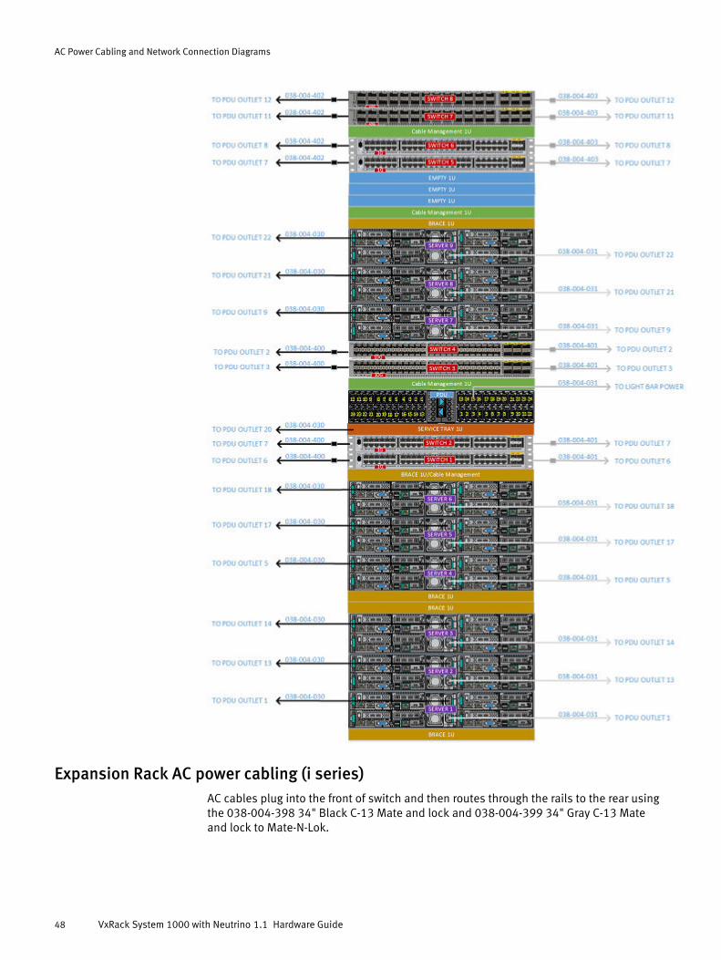
Expansion Rack AC power cabling (i series)AC cables plug into the front of switch and then routes through the rails to the rear usingthe 038-004-398 34" Black C-13 Mate and lock and 038-004-399 34" Gray C-13 Mateand lock to Mate-N-Lok.
AC Power Cabling and Network Connection Diagrams
48 VxRack System 1000 with Neutrino 1.1 Hardware Guide

Expansion Rack AC power cabling (p series)AC cables plug into the front of switch and then routes through the rails to the rear usingthe 038-004-398 34" Black C-13 Mate and lock and 038-004-399 34" Gray C-13 Mateand lock to Mate-N-Lok.
AC Power Cabling and Network Connection Diagrams
Expansion Rack AC power cabling (p series) 49

Network cablingThe following table lists the network cables.
AC Power Cabling and Network Connection Diagrams
50 VxRack System 1000 with Neutrino 1.1 Hardware Guide

Table 15 1 GbE and 10 GbE cables
Part number Length Color / Note
038-002-064-0X 1M (QSFP) All four cables must be connected. Two cables used for vPC PeerKeepalives (Eth1/49-50) and the other two for vPC Peer Links(Eth1/51-52)
038-002-066-0X 3M (QSFP) -
038-003-167 36" Blue
038-004-138 84" Blue
038-004-176 1M Twin-ax -
038-004-181 24" White. RJ45 connection with a cat6 copper cable for the vPCKeepalives link
038-004-323-0x 2M -
038-004-409 71" Lime Green
038-004-410 71" Violet
038-004-436 100" Red
100-400-069-0X 1M -
100-400-070-0X 3M -
Cisco 3048 front cablingRJ45 connection with a cat6 copper cable for the vPC Keepalives link.
AC Power Cabling and Network Connection Diagrams
Cisco 3048 front cabling 51

First Rack without Aggregation ethernet cabling (1 GbE switch) (i series)
AC Power Cabling and Network Connection Diagrams
52 VxRack System 1000 with Neutrino 1.1 Hardware Guide

First Rack without Aggregation ethernet cabling (1 GbE switch) (p series)
AC Power Cabling and Network Connection Diagrams
First Rack without Aggregation ethernet cabling (1 GbE switch) (p series) 53

First Rack without Aggregation ethernet cabling (10 GbE switch) (i series)
AC Power Cabling and Network Connection Diagrams
54 VxRack System 1000 with Neutrino 1.1 Hardware Guide

First Rack without Aggregation ethernet cabling (10 GbE switch) (p series)
AC Power Cabling and Network Connection Diagrams
First Rack without Aggregation ethernet cabling (10 GbE switch) (p series) 55

First Rack with Aggregation ethernet cabling (1 GbE switch) (i series)
AC Power Cabling and Network Connection Diagrams
56 VxRack System 1000 with Neutrino 1.1 Hardware Guide

First Rack with Aggregation ethernet cabling (1 GbE switch) (p series)
AC Power Cabling and Network Connection Diagrams
First Rack with Aggregation ethernet cabling (1 GbE switch) (p series) 57

First Rack with Aggregation ethernet cabling (10 GbE switch) (i series)
AC Power Cabling and Network Connection Diagrams
58 VxRack System 1000 with Neutrino 1.1 Hardware Guide

First Rack with Aggregation ethernet cabling (10 GbE switch) (p series)
AC Power Cabling and Network Connection Diagrams
First Rack with Aggregation ethernet cabling (10 GbE switch) (p series) 59
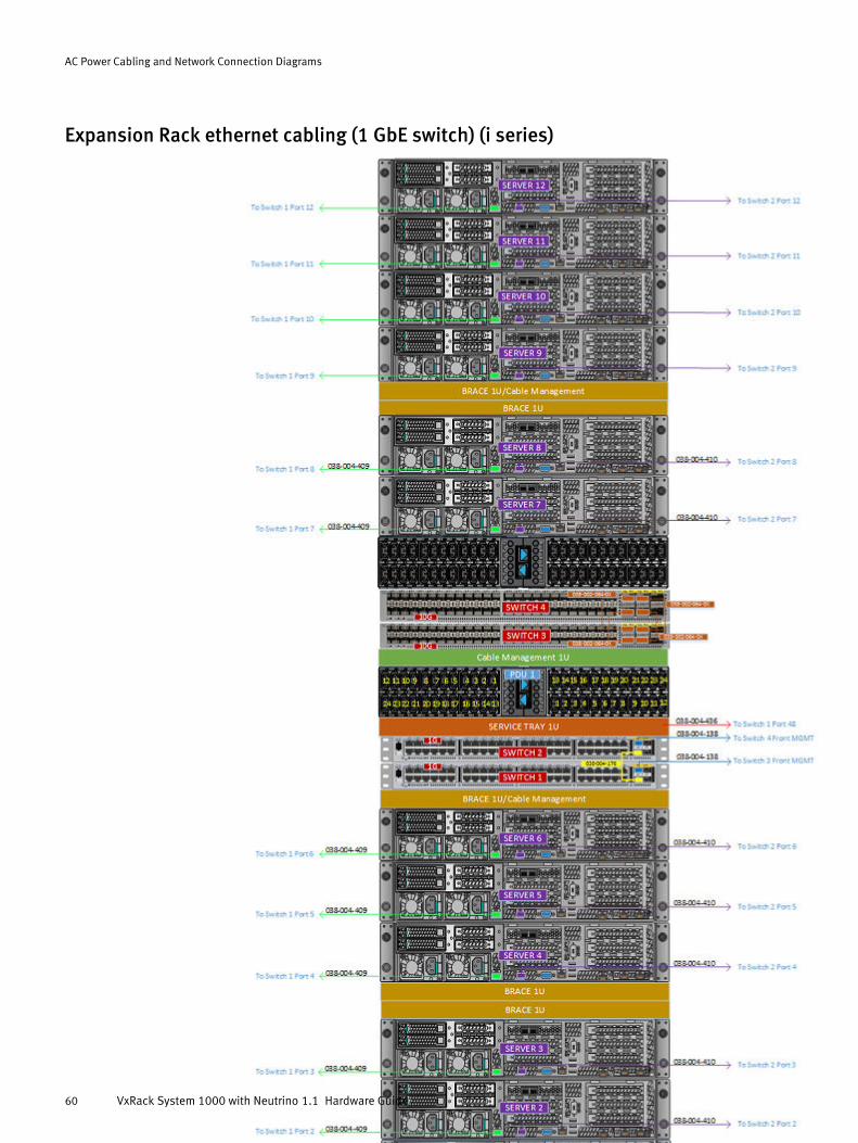
Expansion Rack ethernet cabling (1 GbE switch) (i series)
AC Power Cabling and Network Connection Diagrams
60 VxRack System 1000 with Neutrino 1.1 Hardware Guide

Expansion Rack ethernet cabling (1 GbE switch) (p series)
AC Power Cabling and Network Connection Diagrams
Expansion Rack ethernet cabling (1 GbE switch) (p series) 61

Expansion Rack ethernet cabling (10 GbE switch) (i series)
AC Power Cabling and Network Connection Diagrams
62 VxRack System 1000 with Neutrino 1.1 Hardware Guide

Expansion Rack ethernet cabling (10 GbE switch) (p series)
AC Power Cabling and Network Connection Diagrams
Expansion Rack ethernet cabling (10 GbE switch) (p series) 63

AC Power Cabling and Network Connection Diagrams
64 VxRack System 1000 with Neutrino 1.1 Hardware Guide

APPENDIX A
System Information and Default Settings
This appendix includes the following sections:
l Environmental, power, and floor space requirements............................................ 66l Default system passwords.....................................................................................67l Rack ID and Rack color reference...........................................................................67l Host names reference........................................................................................... 68
System Information and Default Settings 65

Environmental, power, and floor space requirementsThis section lists required site and power specifications.
Environmental requirementsl Operating Environment:
n Temperature: +15°C to +32°C (59°F to 89.6°F) site temperature.*A Rack fully configured with EMC products may produce up to 50,000 BTUs perhour.
n Relative Humidity: 20% to 80% (non-condensing) relative humidity
n 0 to 1981.2 meters (0 to 6,500 feet) above sea level operating altitude*
l The VCE VxRack total shipping weight for an empty Rack is 640 lb (290.23kg) basedon the following weights:
n Rack = 346 lb (157 kg)
n Pallet = 120 lb (54.43 kg)
n Side panels (two per side) = 134 lb (43.45)
n Packaging = 40 lb (18.14 kg)
Make sure your flooring can safely support your configuration. Calculate the minimumload-bearing requirements for your site using the product-specific weights for yoursystem components at http://powercalculator.emc.com
l Packaged cabinet height = 85.75 in (2,178 mm)
l Storage Recommendation: Do not exceed six consecutive months of poweredstorage.
* Recommended operating parameters. Contents of the cabinet may be qualified outsidethese limits; refer to the product-specific documentation for system specifications.
Power and AC cable requirements (First Rack)
Table 16 Power specifications for the First Rack
Item Requirement
First Rack maximum power 14,444VA
Single Phase l 2 Line Cords for up to 3 bricks
l 4 Line Cords up to 6 bricks
l 6 Line Cords for more than 6 bricks
Three Phase Delta 2 Line Cords (Max)
Three Phase WYE 2 Line Cords (Max)
System Information and Default Settings
66 VxRack System 1000 with Neutrino 1.1 Hardware Guide

Power and AC cable requirements (Expansion Rack)
Table 17 Power specifications for the Expansion Rack
Item Requirement
Expansion Rack maximum power 17,862VA
EMC PDU option Number of power cords required per Rack
Single Phase 8 Line Cords (Max)
Three Phase Delta 4 Line Cords (Max)
Three Phase WYE 4 Line Cords (Max)
Space requirements (First and Expansion Rack)
Table 18 Rack dimensions
Item Requirement
Height 75 in / 190.8 cm
Width 24 in / 60.96 cm
Depth 44 in / 111.76 cm
Default system passwordsThe default Administrator password is ChangeMe.
Rack ID and Rack color referenceUse this reference when configuring the Rack id/rack color of a VxRack Neutrino systemduring an installation or expansion.
All Racks must have a unique color/ID. The Rack color/ID can be set from the commandline on any node either by setting the ID or the color using the setrackinfo command.For example: setrackinfo -i <RackID> or setrackinfo -n <RackColor>.
Table 19 Rack ID 1-100
Rack ID Rack Color Rack ID Rack Color Rack ID Rack Color Rack ID Rack Color
1 red 26 mint 51 quartz 76 burgundy
2 green 27 cobalt 52 daffodil 77 almond
3 blue 28 fern 53 soap 78 pansy
4 yellow 29 sienna 54 cottoncandy 79 aqua
5 magenta 30 mantis 55 mauve 80 umber
System Information and Default Settings
Power and AC cable requirements (Expansion Rack) 67

Table 19 Rack ID 1-100 (continued)
Rack ID Rack Color Rack ID Rack Color Rack ID Rack Color Rack ID Rack Color
6 cyan 31 denim 56 flamingo 81 saffron
7 azure 32 aquamarine 57 cardinal 82 wheat
8 violet 33 baby 58 scarlet 83 olive
9 rose 34 eggplant 59 firebrick 84 jet
10 orange 35 cornsilk 60 harlequin 85 dirt
11 chartreuse 36 ochre 61 sinopia 86 boysenberry
12 pink 37 lavender 62 flax 87 pearl
13 brown 38 ginger 63 moonstone 88 sky
14 white 39 ivory 64 sangria 89 brass
15 gray 40 carnelian 65 iceberg 90 cinnabar
16 beige 41 taupe 66 platinum 91 grape
17 silver 42 navy 67 wine 92 bisque
18 carmine 43 indigo 68 chocolate 93 blond
19 auburn 44 veronica 69 champagne 94 imperial
20 bronze 45 citron 70 coral 95 manatee
21 apricot 46 sand 71 cream 96 teal
22 jasmine 47 russet 72 ferrari 97 orchid
23 army 48 brick 73 jasper 98 tangerine
24 copper 49 avocado 74 tuscan 99 malachite
25 amaranth 50 bubblegum 75 coffee 100 pine
Host names referenceNodes are assigned host names based on their order within the chassis, and within theRack itself. The following table lists the default host names.
Table 20 Default host names
Node Host name Node Host name Node Host name
1 provo 17 memphis 33 tampa
2 sandy 18 seattle 34 toledo
3 orem 19 denver 35 aurora
4 ogden 20 portland 36 stockton
5 layton 21 tucson 37 buffalo
6 logan 22 atlanta 38 newark
System Information and Default Settings
68 VxRack System 1000 with Neutrino 1.1 Hardware Guide

Table 20 Default host names (continued)
Node Host name Node Host name Node Host name
7 Lehi 23 fresno 39 glendale
8 murray 24 mesa 40 lincoln
9 boston 25 omaha 41 norfolk
10 chicago 26 oakland 42 chandler
11 houston 27 miami 43 madison
12 phoenix 28 tulsa 44 orlando
13 dallas 29 honolulu 45 garland
14 detroit 30 wichita 46 akron
15 columbus 31 raleigh 47 reno
16 austin 32 anaheim 48 laredo
Nodes positioned in the same slot in different Racks at a site will have the same hostname. For example node 4 is always named ogden.
System outputs will identify nodes by a unique combination of node host name and Rackname. For example, node 4 in Rack 4 and node 4 in Rack 5 will be identified as:
ogden-yellowogden-magenta
System Information and Default Settings
Host names reference 69

System Information and Default Settings
70 VxRack System 1000 with Neutrino 1.1 Hardware Guide

APPENDIX B
Common Service Procedures
This appendix includes the following sections:
l Gracefully shutting down the system..................................................................... 72l Gracefully starting up the system.......................................................................... 74
Common Service Procedures 71

Gracefully shutting down the systemUse this procedure to gracefully shut down the components and minimize disruptions.
Before you begin
l Before performing a graceful shutdown, at least one Platform node must be on thefirst rack. DNS runs only on the first rack. This Platform node on the first rack shouldbe the last node to shut down and the first node to start up. If no Platform nodes areon the first rack then you must perform a transfer on the first rack.
l Ensure that the rack master is running without issue on each Platform node beforeshutting them down. For example, if shutting down Cloud Compute or unallocatednodes caused the rack master to move.
Gracefully shutting down the system is needed for power upgrade to the Data Center, ifthe VxRack Neutrino installation itself is being moved, and going from a single rack tousing aggregation switches.
Procedure
1. Log into the OpenStack Dashboard and take note of the VMs that are running.
Log in as Cloud Admin User.
a. In the VxRack Neutrino UI, navigate to Services > Cloud Compute.
The Cloud Compute Management page displays.
b. Click OpenStack Dashboard.
c. Navigate to Admin > Instances to see the running instances.
The host column has the name of the host running the instances.
2. Navigate to Infrastructure > Nodes and verify that no Cloud Compute nodes have astatus of suspended.
3. Verify that none of the Cloud Compute nodes are participating in storage rebuilding orbalancing.
a. Navigate to Infrastructure > Storage > Backend.
b. Click View > Overview.
c. Click Actions > Arrange by Storage Pools.
d. Select Compute_Performance.
e. Select the Enable/Disable Rebuild/Rebalance action to verify.
4. Inactivate the Cloud Compute service.
a. Navigate to Services > Cloud Compute.
b. Click Manage and then select Inactivate Service.
c. Click Yes to inactivate the Cloud Compute service.
Inactivation takes some time. The Cloud Compute Service will stop all VMs on eachnode. It will then call into the ScaleIO Controller to inactivate all the protectiondomains belonging to the Cloud Compute Service. All I/O will be flushed to storagedisks as part of the inactivation process.
d. Verify that the Cloud Compute Service deactivated successfully.
Navigate to Services > Cloud Compute. The red Inactive indicator appears.
Common Service Procedures
72 VxRack System 1000 with Neutrino 1.1 Hardware Guide

Instances under Cloud Compute Service Inactive widget shows zero.
5. Navigate to Infrastructure > Nodes.
The Node Management page displays.
6. Filter by Unallocated nodes and then select the Suspend action.
This action suspends one unallocated node at a time.
The VxRack Neutrino UI indicates Offline and the Hardware Health indicates Unknown.If the UI does not refresh, exit the Nodes page and then re-enter.
7. Select a Compute or Unallocated node and then select the Shutdown action.
Shutdown nodes one at a time. This can take several hours. Wait until the UI showsthe node as shutdown (offline) before selecting the next node. If the UI does notrefresh, exit the Nodes page and then re-enter.
For Cloud Compute nodes, enable the force option.
8. Turn on the three Platform node ID lights before shutting them down and then note orphysically mark them (such as, with a sticker or other indicator).
ipmitool -H <RMM_IP> -U root -P <password> chassis identify force
Make note of which Platform node is running on the first rack.
Contact your EMC Customer Support Representative for assistance with the password,if needed.
9. SSH into the Platform nodes and then shut them down.
Ensure that you shutdown a Platform node on the first rack last.
shutdown -h now
This operation gracefully shuts down each service on the nodes including the dockerdaemon.
10. Power off the PDUs.
Note
If you are performing a Rack Expansion then you can skip this step. You do not need topower off the PDUs.
From the rear of the system, pull power tee breakers 1-6 for Zone A PDU and then 1-6for Zone B PDU.
NOTICE
Do not pull the two blue arrow shaped tabs located between the power tee breakers.Pulling the blue arrows unlatches the PDU locking mechanism and allows the PDU tobe removed.
Common Service Procedures
Gracefully shutting down the system 73

Figure 17 Power tee breaker ON (1) and OFF (2) positions
2
1
Gracefully starting up the systemUse this procedure to start the system after a graceful shutdown.
Procedure
1. Power on the PDUs.
Note
If you are performing a Rack Expansion then you can skip this step. You do not need topower on the PDUs.
On the rear door of each bay, push in the power tee breakers (1-6) for zone A to theON position and then immediately push in the power tee breakers (1-6) of zone B.
Figure 18 Power tee breaker ON (1) and OFF (2) positions
2
1
Common Service Procedures
74 VxRack System 1000 with Neutrino 1.1 Hardware Guide

Upon power up, the array starts the initialization procedure. This may vary dependingon the size and configuration type.
2. After all switches are fully powered on, power on each Platform node manually on thephysical node or using RMM.
If you use RMM, RMM requires one node to be up.
a. Manually power on one Platform node located in the first rack.
b. Use ipmitool or the VxRack Neutrino UI to power on the other Platform nodes.
ipmitool -H <RMM_IP> -U root -P <password> chassis power on
Contact your EMC Customer Support Representative for assistance with thepassword, if needed.
c. After approximately 20 minutes, confirm that all Platform nodes appear in theoutput.
getrackinfo
d. Confirm that none of the containers show a Restarting status.
domulti docker ps
3. Power on Cloud Compute nodes.
l Power on all nodes simultaneously.
a. In the VxRack Neutrino UI, navigate to Infrastructure > Nodes. The NodeManagement page displays.
b. Click the All Nodes drop-down menu on the right of the page.
c. Filter by Cloud Compute nodes.
d. Click Select all Cloud Compute nodes > Power On.
l Power on each node individually.
a. In the VxRack Neutrino UI, navigate to Infrastructure > Nodes. The NodeManagement page displays.
b. Select the Cloud Compute node and then select the Power On action.
The SDS containers will automatically come up. Do not proceed to the next step untilthe UI no longer shows the Offline icon and the Hardware Health changes to Good.
4. In the VxRack Neutrino UI, navigate to Services > Cloud Compute.
The Cloud Compute Service page displays.
5. Click Manage and then select Activate Service.
This will take some time as the ScaleIO Protection Domains used by the CloudCompute Service will be activated.
6. Power on Unallocated nodes.
a. Navigate to Infrastructure > Nodes.
The Node Management page displays.
b. Click the Unallocated nodes drop-down menu on the right of the page.
c. Filter by unallocated nodes.
d. Click Bulk Actions > Power On.
Common Service Procedures
Gracefully starting up the system 75

7. Select all Unallocated nodes and then click Bulk Actions > Resume.
Alternatively, select an Unallocated node and then select the Resume action. Thisresumes nodes one at a time. Wait until the UI shows the node as resumed beforeselecting the next node.
8. In the VxRack Neutrino UI, navigate to Infrastructure > Nodes to verify that the nodes'status indicates Operational.
9. Restart the VM instances.
Instances need to be manually restarted by an OpenStack Administrator.
l Restart all project instances simultaneously.
a. In the OpenStack Dashboard, navigate to Project > Instances > Select allInstances.
b. Click the More Actions drop-down menu, and then click Bulk Actions > StartInstances.
c. Repeat for each project.
l Restart each instance individually.
a. In the OpenStack Dashboard, navigate to Admin > Instances.
b. Locate the instances that are Shutdown.
c. Select edit instance > Hard Reboot Instance.
10. Perform a health check of the system.
a. Review the dashboard to ensure that all metrics are available.
b. Navigate to Infrastructure > Nodes and verify that all nodes are up with the statusof Good.
c. SSH into the node.
d. Run the following commands.
getrackinfo
getrackinfo -s
getrackinfo -r
e. If BMC alert exists in dashboard, then reset the BMC in the affected server.
syscfg /rbmc
f. Perform a hardware and OS check.
viprexec -i "/opt/emc/bin/emc-hw-check.sh" 2>&1 | tee emc-hw-check_post-upgrade.out
viprexec -i "/opt/emc/bin/emc-os-health.sh" 2>&1 | tee emc-os-health_post-upgrade.out | grep -iv "passed"
g. If dashboard is missing the health metrics, then the mnr-allinone container mustbe restarted.
a. Identify the Platform nodes in Infrastructure > Components > Platform and thenexpand mnr-allinone.
Common Service Procedures
76 VxRack System 1000 with Neutrino 1.1 Hardware Guide

b. Log into each Platform node running the container and then determine if mnr isrunning.
docker ps |grep mnrc. If mnr-allinone is listed then run the following command to restart it.
docker restart mnr-allinone
Common Service Procedures
Gracefully starting up the system 77

Common Service Procedures
78 VxRack System 1000 with Neutrino 1.1 Hardware Guide

APPENDIX C
Installing Customer Replaceable Units (CRUs)
This appendix includes the following sections:
l Server System Disk Replacement (i series)............................................................ 80l Server Cache and Storage Disk Replacement (i series)...........................................89l Server System Disk Replacement (p series)........................................................... 99l Server Storage Disk Replacement (p series).........................................................113
Installing Customer Replaceable Units (CRUs) 79

Server System Disk Replacement (i series)This document describes how to replace a faulted system disk.
Replacing the Server System DiskThis procedure applies when replacing the server SSD disk that holds the systemsoftware image.
Some tasks in the following table apply to specific services. Use the table to identify thetasks that you need to perform. "No" means that the task does not apply and thereforeyou can skip the task.
Note
Throughout this procedure, brick and server are used interchangeably are refer to thesame hardware component.
Table 21 Disk replacement tasks
Task Cloud Compute Service Platform Service Unallocated
Remove the node from service Yes No No
Delete the disk Yes No Yes
Power off the node Yes No Yes
Hardware replacement tasks Yes No Yes
Power on the node Yes No Yes
Add the node to the service Yes No No
Return parts to EMC Yes No Yes
Pre-site tasksThe following list identifies the tasks that need to be completed before arriving at thecustomer site.
l Verify that the ordered replacement part number is correct based on the parts table.
l Transferring platform services to an unallocated node for node/disk removalprocedures can take several hours. Perform the transfer steps remotely beforeheading for the customer site.
Note
Be advised that many maintenance procedures, like replacing system or storage disks,will require transferring Platform Services to an unallocated node. An unallocated node isone that is not assigned to run Platform Services or Cloud Compute during first-timeinstallation (more specifically, when selecting three nodes to run Platform Services). It ishighly recommended that Professional Services advise customers to reserve at least oneunallocated node for general maintenance and system failover purposes. Not complyingwill result in an increased maintenance window.
Installing Customer Replaceable Units (CRUs)
80 VxRack System 1000 with Neutrino 1.1 Hardware Guide

PartsThis procedure explains how to replace the hardware identified in the following table.
Table 22 Part list
Part number Part description
105-000-521-00 SSD-400GB
ToolsYou need the following tools to complete this procedure.
ESD gloves or ESD wristband
Common proceduresThis topic contains procedures which are common to the handling of field replaceableunits (FRU) within a device.
Listing of common proceduresThe following are the common procedures which are used for the handling FRUs:
l Avoiding electro-static discharge (ESD) damage
l Emergency procedures without an ESD kit
l Hardware acclimation times
l Identifying faulty parts
Handling replaceable units
This section describes the precautions that you must take and the general proceduresthat you must follow when removing, installing, and storing any replaceable unit.
Avoiding electrostatic discharge (ESD) damage
When replacing or installing hardware units, you can inadvertently damage the sensitiveelectronic circuits in the equipment by simply touching them. Electrostatic charge thathas accumulated on your body discharges through the circuits. If the air in the work areais very dry, running a humidifier in the work area will help decrease the risk of ESDdamage. Follow the procedures below to prevent damage to the equipment.
Be aware of the following requirements:
l Provide enough room to work on the equipment.
l Clear the work site of any unnecessary materials or materials that naturally build upelectrostatic charge, such as foam packaging, foam cups, cellophane wrappers, andsimilar items.
l Do not remove replacement or upgrade units from their antistatic packaging until youare ready to install them.
l Before you begin service, gather together the ESD kit and all other materials you willneed.
l Once servicing begins, avoid moving away from the work site; otherwise, you maybuild up an electrostatic charge.
Installing Customer Replaceable Units (CRUs)
Parts 81

l Use ESD anti-static gloves or an ESD wristband (with strap).If using an ESD wristband with a strap:
n Attach the clip of the ESD wristband to the ESD bracket or bare metal on acabinet/rack or enclosure.
n Wrap the ESD wristband around your wrist with the metal button against yourskin.
n If a tester is available, test the wristband.
l If an emergency arises and the ESD kit is not available, follow the procedures inEmergency Procedures (without an ESD kit).
Emergency procedures (without an ESD kit)
In an emergency when an ESD kit is not available, use the following procedures to reducethe possibility of an electrostatic discharge by ensuring that your body and thesubassembly are at the same electrostatic potential.
NOTICE
These procedures are not a substitute for the use of an ESD kit. Follow them only in theevent of an emergency.
l Before touching any unit, touch a bare (unpainted) metal surface of the cabinet/rackor enclosure.
l Before removing any unit from its antistatic bag, place one hand firmly on a baremetal surface of the cabinet/rack or enclosure, and at the same time, pick up the unitwhile it is still sealed in the antistatic bag. Once you have done this, do not movearound the room or touch other furnishings, personnel, or surfaces until you haveinstalled the unit.
l When you remove a unit from the antistatic bag, avoid touching any electroniccomponents and circuits on it.
l If you must move around the room or touch other surfaces before installing a unit,first place the unit back in the antistatic bag. When you are ready again to install theunit, repeat these procedures.
Hardware acclimation times
Systems and components must acclimate to the operating environment before applyingpower. This requires the unpackaged system or component to reside in the operatingenvironment for up to 16 hours in order to thermally stabilize and prevent condensation.
Refer to the table, Table 23 on page 82, to determine the precise amount ofstabilization time required.
Table 23 Hardware acclimation times (systems and components)
If the last 24 hours of theTRANSIT/STORAGEenvironment was this:
…and the OPERATINGenvironment is this:
…then let the system orcomponent acclimate inthe new environmentthis many hours:
Temperature Humidity
Nominal68-72°F (20-22°C)
Nominal40-55% RH
Nominal 68-72°F (20-22°C)40-55% RH
0-1 hour
Cold Dry <86°F (30°C) 4 hours
Installing Customer Replaceable Units (CRUs)
82 VxRack System 1000 with Neutrino 1.1 Hardware Guide

Table 23 Hardware acclimation times (systems and components) (continued)
If the last 24 hours of theTRANSIT/STORAGEenvironment was this:
…and the OPERATINGenvironment is this:
…then let the system orcomponent acclimate inthe new environmentthis many hours:
<68°F (20°C) <30% RH
Cold<68°F (20°C)
Damp≥30% RH
<86°F (30°C) 4 hours
Hot>72°F (22°C)
Dry<30% RH
<86°F (30°C) 4 hours
Hot>72°F (22°C)
Humid30-45% RH
<86°F (30°C) 4 hours
Humid45-60% RH
<86°F (30°C) 8 hours
Humid≥60% RH
<86°F (30°C) 16 hours
Unknown <86°F (30°C) 16 hours
NOTICE
l If there are signs of condensation after the recommended acclimation time haspassed, allow an additional eight (8) hours to stabilize.
l Systems and components must not experience changes in temperature and humiditythat are likely to cause condensation to form on or in that system or component. Donot exceed the shipping and storage temperature gradient of 45°F/hr (25°C/hr).
l Do NOT apply power to the system for at least the number of hours specified in thetable, Table 23 on page 82. If the last 24 hours of the transit/storage environment isunknown, then you must allow the system or component 16 hours to stabilize in thenew environment.
Removing, installing, or storing replaceable units
Use the following precautions when removing, handling, or storing replaceable units:
CAUTION
Some replaceable units have the majority of their weight in the rear of the component.Ensure that the back end of the replaceable unit is supported while installing orremoving it. Dropping a replaceable unit could result in personal injury or damage to theequipment.
NOTICE
l For a module that must be installed into a slot in an enclosure, examine the rearconnectors on the module for any damage before attempting its installation.
l A sudden jar, drop, or even a moderate vibration can permanently damage somesensitive replaceable units.
Installing Customer Replaceable Units (CRUs)
Common procedures 83

l Do not remove a faulted replaceable unit until you have the replacement available.
l When handling replaceable units, avoid electrostatic discharge (ESD) by wearing ESDanti-static gloves or an ESD wristband with a strap. For additional information, refer to Avoiding electrostatic discharge (ESD) damage on page 81.
l Avoid touching any exposed electronic components and circuits on the replaceableunit.
l Never use excessive force to remove or install a replaceable unit. Take time to readthe instructions carefully.
l Store a replaceable unit in the antistatic bag and the specially designed shippingcontainer in which you received it. Use the antistatic bag and special shippingcontainer when you need to return the replaceable unit.
l Replaceable units must acclimate to the operating environment before applyingpower. This requires the unpackaged component to reside in the operatingenvironment for up to 16 hours in order to thermally stabilize and preventcondensation. Refer to Hardware acclimation times on page 82 to ensure thereplaceable unit has thermally stabilized to the operating environment.
NOTICE
Your storage system is designed to be powered on continuously. Most components arehot swappable; that is, you can replace or install these components while the storagesystem is running. However, the system requires that:
l Front bezels should always be attached to ensure EMI compliance. Make sure youreattach the bezel after replacing a component.
l Each slot should contain a component or filler panel to ensure proper air flowthroughout the system.
Logging into the VxRack Neutrino UILog into the VxRack Neutrino UI with a web browser using the VxRack Neutrino virtual IPsupplied by the customer.
Procedure
1. Type in one of the following URL into your browser.
https://<virtual_IP>
https://<neutrino_virtual_hostname>
For example,
https://10.242.242.190
https://customer-cloud.customer-domain.com2. At the login, type the Account (Domain), Username, and Password.
Remove the node from serviceThis section applies when replacing the node from service. The drive to be removedshould have its LED light turned on to minimize the potential of removing a wrong drive.
1. Verify if the node is online and accessible or not.
2. Perform one of the following tasks.
Installing Customer Replaceable Units (CRUs)
84 VxRack System 1000 with Neutrino 1.1 Hardware Guide

l If the node is online and accessible, then proceed to Removing the node fromservice when Cloud Compute nodes are online and accessible on page 85
l If the node is offline or inaccessible, then proceed to Retrieving the diskinformation when the Cloud Compute node is offline or inaccessible(workaround) on page 85
Removing the node from service when Cloud Compute nodes are online and accessible
If your compute node is running and accessible, then proceed with this task. If, however,the node is offline and inaccessible then proceed with Removing the node from servicewhen Cloud Compute nodes are offline or inaccessible (workaround) on page 105.
This task applies only to Cloud Compute nodes. If your node was not a Cloud Computenode then proceed to the next task.
Procedure
1. In Infrastructure > Nodes, click Manage > Remove from Service.
2. Select the node to remove.
3. Click Remove Service.
4. Monitor and verify.
a. Navigate to Infrastructure > Storage and then click Backend.
b. Under View > Overview, expand Rebuild/Rebalance.
c. Once rebalance is complete it should be removed from the Protection Domain.
Results
Instances running on ths node will be terminated at the end of the removal process. Thenode transitions to Unallocated. This might take some time due to ScaleIO rebalancing.
Retrieving the disk information when the Cloud Compute node is offline or inaccessible(workaround)
Procedure
1. Navigate to Infrastructure > Nodes.
The Node Management page displays.
2. Select the disk that has the OS label and is not type DOM.
3. Note the Slot number of the disk.
Use this number to correlate with the disk slot diagram to locate the disk to remove.
After you finish
Proceed to delete the disk.
Evacuating instances through OpenStack Dashboard (Cloud Compute)Procedure
1. In the VxRack Neutrino UI, navigate to Services > Cloud Compute.
The Cloud Compute Management page displays.
2. Click OpenStack Dashboard.
3. Navigate to Admin > Hypervisors > Compute Host.
4. For the affected node, click Evacuate Host.
Installing Customer Replaceable Units (CRUs)
Remove the node from service 85
5. Select a Target Host and then click Shared Storage > Evacuate Host.
Deleting the disk from the nodeProcedure
1. In Infrastructure > Nodes, select the node.
2. Select the disk with the OS label and then click Delete Disk.
The node must be Unallocated.
Results
The disk status transitions to Modifying.
Powering off the nodeProcedure
1. In the VxRack Neutrino UI, navigate to Infrastructure > Nodes.
The Node Management page displays.
2. Select the node whose disk was deleted and then select Actions > Power Off.
3. Click True to re-image and enable the System ID LED to ensure that the correct nodecan be located.
If you have Cloud Compute that is offline and allocated, then the re-image is notvisible. Proceed to the next step.
4. Click Power Off and confirm re-image.
Results
The node status is Modifying and the health transitions to Unknown. Verify that theSystem Power button on the front panel LED indicates "Off". If any System Powerindicators are illuminated Green (power is on) then repeat the above step.
Installing Customer Replaceable Units (CRUs)
86 VxRack System 1000 with Neutrino 1.1 Hardware Guide

Replacing a disk drive assemblyA disk drive assembly consists of a hard disk drive supplied in special hot-swappablehard-drive carrier that fits in a disk slot. Disk slots are accessible from the front of theserver.
Figure 19 Disk slot diagram
Front of brick (disk view)
Back of brick (node view)
node
Disk 0 is 400 GB OS SSD
Disk 1 is 800 GB caching SSD
Disks 2-23 are 1.8 TB HDDs
NOTICE
To maintain proper system cooling, any hard-drive bay without a disk drive assembly ordevice installed must be occupied by filler module. Do not turn off or reboot your systemwhile the drive is being formatted. Doing so can cause a drive failure. Use appropriateESD precautions, including the use of a grounding strap, when performing the drivemodule replacement procedure.
Before you replace a disk drive assembly, review the section on handling fieldreplaceable units (FRUs).
Powering on the nodeProcedure
1. In the VxRack Neutrino UI, navigate to Infrastructure > Nodes.
The Node Management page displays.
2. Select the node and then select Actions > Power On.
3. Click Power On on the confirmation page.
Results
Verify that the System Power button on the front panel LED indicates "On". If any SystemPower indicators are not illuminated Green (power is on) then repeat the above step.This might take some time due to a new OS image going on the node. Once the node hasfinished re-imaging, the node hardware health transitions to Good and status transitionsto Operational.
Installing Customer Replaceable Units (CRUs)
Replacing a disk drive assembly 87

Note
Do not proceed to the next task until the above changes have occurred.
Reinstalling the bezelIf a bezel covered the front of the server, reinstall the bezel using the procedure thatfollows. Refer to Figure 20 on page 88 while performing the procedure.
Procedure
1. Pushing on the ends, not the middle, of the bezel, press the bezel onto the latchbrackets until is snaps into place.
2. If the bezel has a key lock, lock the bezel with the provided key and store the key in asecure place.
Figure 20 Installing the bezel
CL5021
Adding the node to the service (Cloud Compute)This task applies only to a node that was previously a Cloud Compute node. If your nodewas not a Cloud Compute node then proceed to the next task.
Procedure
1. In the VxRack Neutrino UI, navigate to Infrastructure > Nodes.
The Node Management page displays.
2. Click Manage > Add to Service.
3. Select the node to add.
4. Click Add Service.
5. Monitor and verify.
a. Navigate to Infrastructure > Storage and then click Backend.
b. Under Protection Domain, expand the node to verify the disks.
Installing Customer Replaceable Units (CRUs)
88 VxRack System 1000 with Neutrino 1.1 Hardware Guide

Results
The node transitions from Unallocated to Cloud Compute.
Returning parts to EMCProcedure
1. Locate the Parts Return Label package and fill out the shipping label.
Apply the label to box for return to EMC.
2. Read the enclosed Shipping Instructions sheet.
3. Apply other labels appropriate to this returning part. Check for any engineeringbulletin or service request (SR), or check with the customer, to determine if thedefective part is FA or Priority FA bound.
Note
If Engineering has requested that the part be shipped back for an FA, ensure that theproper ship-to information has been entered, and that the attention-to and/orcontact-name information has been provided in the shipping label.
4. Securely tape the box and ship the failed part back to EMC.
Server Cache and Storage Disk Replacement (i series)This document describes how to replace a faulted disk.
OverviewThis procedure applies when replacing the server cache and storage (non-system) disk. Ifthe disk partition on the system disk that is being used as a cache disk fails, then refer tothe Server System Disk Replacement procedure.
Some tasks in the following table apply to specific services. Use the table to identify thetasks that you need to perform. "No" means that the task does not apply and thereforeyou can skip the task.
Note
Throughout this procedure, brick and server are used interchangeably to refer to thesame hardware component.
Table 24 Disk replacement tasks
Task Cloud Compute Service Platform Service Unallocated
Remove the disk from service Yes No No
Delete the disk from the node Yes No Yes
Hardware replacement tasks Yes No Yes
Add the disk to the service Yes No No
Return parts to EMC Yes No Yes
Installing Customer Replaceable Units (CRUs)
Returning parts to EMC 89

Note
If you delete and remove a disk, you can not re-install the same disk. The VxRackNeutrino UI will not rediscover the disk. This procedure applies only when replacing adisk with a new, different one.
Pre-site tasksThe following list identifies the tasks that need to be completed before arriving at thecustomer site.
l Verify that the ordered replacement part number is correct based on the parts table.
l Transferring platform services to an unallocated node for node/disk removalprocedures can take several hours. Perform the transfer steps remotely beforeheading for the customer site.
Note
Be advised that many maintenance procedures, like replacing system or storage disks,will require transferring Platform Services to an unallocated node. An unallocated node isone that is not assigned to run Platform Services or Cloud Compute during first-timeinstallation (more specifically, when selecting three nodes to run Platform Services). It ishighly recommended that Professional Services advise customers to reserve at least oneunallocated node for general maintenance and system failover purposes. Not complyingwill result in an increased maintenance window.
PartsThis procedure explains how to replace the hardware identified in the following table.
Table 25 Part list
Part number Part description
105-000-521-00 SSD-400GB
ToolsYou need the following tools to complete this procedure.
ESD gloves or ESD wristband
Common proceduresThis topic contains procedures which are common to the handling of field replaceableunits (FRU) within a device.
Listing of common proceduresThe following are the common procedures which are used for the handling FRUs:
l Avoiding electro-static discharge (ESD) damage
l Emergency procedures without an ESD kit
l Hardware acclimation times
l Identifying faulty parts
Installing Customer Replaceable Units (CRUs)
90 VxRack System 1000 with Neutrino 1.1 Hardware Guide

Handling replaceable units
This section describes the precautions that you must take and the general proceduresthat you must follow when removing, installing, and storing any replaceable unit.
Avoiding electrostatic discharge (ESD) damage
When replacing or installing hardware units, you can inadvertently damage the sensitiveelectronic circuits in the equipment by simply touching them. Electrostatic charge thathas accumulated on your body discharges through the circuits. If the air in the work areais very dry, running a humidifier in the work area will help decrease the risk of ESDdamage. Follow the procedures below to prevent damage to the equipment.
Be aware of the following requirements:
l Provide enough room to work on the equipment.
l Clear the work site of any unnecessary materials or materials that naturally build upelectrostatic charge, such as foam packaging, foam cups, cellophane wrappers, andsimilar items.
l Do not remove replacement or upgrade units from their antistatic packaging until youare ready to install them.
l Before you begin service, gather together the ESD kit and all other materials you willneed.
l Once servicing begins, avoid moving away from the work site; otherwise, you maybuild up an electrostatic charge.
l Use ESD anti-static gloves or an ESD wristband (with strap).If using an ESD wristband with a strap:
n Attach the clip of the ESD wristband to the ESD bracket or bare metal on acabinet/rack or enclosure.
n Wrap the ESD wristband around your wrist with the metal button against yourskin.
n If a tester is available, test the wristband.
l If an emergency arises and the ESD kit is not available, follow the procedures inEmergency Procedures (without an ESD kit).
Emergency procedures (without an ESD kit)
In an emergency when an ESD kit is not available, use the following procedures to reducethe possibility of an electrostatic discharge by ensuring that your body and thesubassembly are at the same electrostatic potential.
NOTICE
These procedures are not a substitute for the use of an ESD kit. Follow them only in theevent of an emergency.
l Before touching any unit, touch a bare (unpainted) metal surface of the cabinet/rackor enclosure.
l Before removing any unit from its antistatic bag, place one hand firmly on a baremetal surface of the cabinet/rack or enclosure, and at the same time, pick up the unitwhile it is still sealed in the antistatic bag. Once you have done this, do not movearound the room or touch other furnishings, personnel, or surfaces until you haveinstalled the unit.
Installing Customer Replaceable Units (CRUs)
Common procedures 91

l When you remove a unit from the antistatic bag, avoid touching any electroniccomponents and circuits on it.
l If you must move around the room or touch other surfaces before installing a unit,first place the unit back in the antistatic bag. When you are ready again to install theunit, repeat these procedures.
Hardware acclimation times
Systems and components must acclimate to the operating environment before applyingpower. This requires the unpackaged system or component to reside in the operatingenvironment for up to 16 hours in order to thermally stabilize and prevent condensation.
Refer to the table, Table 26 on page 92, to determine the precise amount ofstabilization time required.
Table 26 Hardware acclimation times (systems and components)
If the last 24 hours of theTRANSIT/STORAGEenvironment was this:
…and the OPERATINGenvironment is this:
…then let the system orcomponent acclimate inthe new environmentthis many hours:
Temperature Humidity
Nominal68-72°F (20-22°C)
Nominal40-55% RH
Nominal 68-72°F (20-22°C)40-55% RH
0-1 hour
Cold<68°F (20°C)
Dry<30% RH
<86°F (30°C) 4 hours
Cold<68°F (20°C)
Damp≥30% RH
<86°F (30°C) 4 hours
Hot>72°F (22°C)
Dry<30% RH
<86°F (30°C) 4 hours
Hot>72°F (22°C)
Humid30-45% RH
<86°F (30°C) 4 hours
Humid45-60% RH
<86°F (30°C) 8 hours
Humid≥60% RH
<86°F (30°C) 16 hours
Unknown <86°F (30°C) 16 hours
Installing Customer Replaceable Units (CRUs)
92 VxRack System 1000 with Neutrino 1.1 Hardware Guide

NOTICE
l If there are signs of condensation after the recommended acclimation time haspassed, allow an additional eight (8) hours to stabilize.
l Systems and components must not experience changes in temperature and humiditythat are likely to cause condensation to form on or in that system or component. Donot exceed the shipping and storage temperature gradient of 45°F/hr (25°C/hr).
l Do NOT apply power to the system for at least the number of hours specified in thetable, Table 26 on page 92. If the last 24 hours of the transit/storage environment isunknown, then you must allow the system or component 16 hours to stabilize in thenew environment.
Removing, installing, or storing replaceable units
Use the following precautions when removing, handling, or storing replaceable units:
CAUTION
Some replaceable units have the majority of their weight in the rear of the component.Ensure that the back end of the replaceable unit is supported while installing orremoving it. Dropping a replaceable unit could result in personal injury or damage to theequipment.
NOTICE
l For a module that must be installed into a slot in an enclosure, examine the rearconnectors on the module for any damage before attempting its installation.
l A sudden jar, drop, or even a moderate vibration can permanently damage somesensitive replaceable units.
l Do not remove a faulted replaceable unit until you have the replacement available.
l When handling replaceable units, avoid electrostatic discharge (ESD) by wearing ESDanti-static gloves or an ESD wristband with a strap. For additional information, refer to Avoiding electrostatic discharge (ESD) damage on page 81.
l Avoid touching any exposed electronic components and circuits on the replaceableunit.
l Never use excessive force to remove or install a replaceable unit. Take time to readthe instructions carefully.
l Store a replaceable unit in the antistatic bag and the specially designed shippingcontainer in which you received it. Use the antistatic bag and special shippingcontainer when you need to return the replaceable unit.
l Replaceable units must acclimate to the operating environment before applyingpower. This requires the unpackaged component to reside in the operatingenvironment for up to 16 hours in order to thermally stabilize and preventcondensation. Refer to Hardware acclimation times on page 82 to ensure thereplaceable unit has thermally stabilized to the operating environment.
Installing Customer Replaceable Units (CRUs)
Common procedures 93

NOTICE
Your storage system is designed to be powered on continuously. Most components arehot swappable; that is, you can replace or install these components while the storagesystem is running. However, the system requires that:
l Front bezels should always be attached to ensure EMI compliance. Make sure youreattach the bezel after replacing a component.
l Each slot should contain a component or filler panel to ensure proper air flowthroughout the system.
Logging into the VxRack Neutrino UILog into the VxRack Neutrino UI with a web browser using the VxRack Neutrino virtual IPsupplied by the customer.
Procedure
1. Type in one of the following URL into your browser.
https://<virtual_IP>
https://<neutrino_virtual_hostname>
For example,
https://10.242.242.190
https://customer-cloud.customer-domain.com2. At the login, type the Account (Domain), Username, and Password.
Removing the storage device from service (Cloud Compute)This task applies only to Cloud Compute nodes. If your node was not a Cloud Computenode then proceed to the next task.
Procedure
1. In the VxRack Neutrino UI, navigate to Infrastructure > Nodes.
The Node Management page displays.
2. Click the affected node.
The Node details page displays.
3. Click Remove from Service next to the storage device with the ScaleIO label, whichbelongs to the affected disk.
The affected disk will report health as either SUSPECT or BAD.
4. Monitor and verify that the storage device is removed.
a. Navigate to Infrastructure > Storage and then click Backend.
b. Select Rebuild and Rebalance from the View list box.
c. Click the drop down arrow on the Protection Domain and then click the drop downon the node that is having the storage device removed from service.
The storage device shows a state of removing.
d. Once rebalance is complete it should be removed from the node.
Installing Customer Replaceable Units (CRUs)
94 VxRack System 1000 with Neutrino 1.1 Hardware Guide

Results
This might take several minutes due to ScaleIO rebalancing.
Deleting the disk from the nodeProcedure
1. In Infrastructure > Nodes, select the node.
2. Select the disk that had the storage device removed from Service.
The disk should not have a label.
3. Click Delete.
Results
The disk is deleted from the Node Details Disk View and the disk ID LED is on.
Replacing a disk drive assemblyA disk drive assembly consists of a hard disk drive supplied in special hot-swappablehard-drive carrier that fits in a disk slot. Disk slots are accessible from the front of theserver.
NOTICE
To maintain proper system cooling, any hard-drive bay without a disk drive assembly ordevice installed must be occupied by filler module. Do not turn off or reboot your systemwhile the drive is being formatted. Doing so can cause a drive failure. Use appropriateESD precautions, including the use of a grounding strap, when performing the drivemodule replacement procedure.
To replace a disk drive assembly, you must perform the tasks below in the order listed.The rest of the section describes how to perform each task.
1. Review the section on handling disk drive assemblies.
2. Identify the faulted disk drive assembly.
3. Remove the bezel from the server.
4. Replace the fault disk drive assembly.
5. Reinstall the bezel on the server.
Before you replace a disk drive assembly, review the section on handing field replaceableunits (FRUs).
Handling disk drive assembliesl Do not remove a disk drive filler until you have a replacement disk drive assembly
available to replace it.
l Disk drive assemblies are sensitive to the extreme temperatures that are sometimesencountered during shipping. We recommend that you leave the new disk driveassembly in its shipping material and expose the package to ambient temperature forat least four hours before attempting to use the new disk drive assemblies in yoursystem.
l Avoid touching any exposed electronic components and circuits on the disk driveassembly.
l Do not stack disk drive assemblies upon one another, or place them on hardsurfaces.
Installing Customer Replaceable Units (CRUs)
Deleting the disk from the node 95

l When installing multiple disk drive assemblies in a powered up system, wait at least6 seconds before sliding the next disk drive assembly into position.
Identifying the faulted disk drive assembly
A faulted disk drive assembly may have an amber LED indicator on its carrier, which isvisible when you remove the server’s bezel.
Removing the bezelThe front of the server may be covered by a bezel. Bezels are application specific, andmay not appear as shown. Bezels may include a key lock. If the server has a bezel,remove it.
Refer to Figure 21 on page 96 while performing the procedure that follows.
Procedure
1. If the bezel has a key lock, unlock the bezel with the provided key.
2. Press the two tabs on either side of the bezel to release the bezel from its latches, andpull the bezel off the latches.
Figure 21 Removing the bezel
CL5022
Replacing the faulted disk drive assemblyProcedure
1. Attach an ESD wristband to your wrist and the server chassis.
2. Remove the faulted disk drive assembly (Figure 22 on page 97):
a. Press the green button on the top of the disk drive assembly to unlock themodule’s lever.
b. Pull the lever open and slide the disk drive assembly from the server.
Installing Customer Replaceable Units (CRUs)
96 VxRack System 1000 with Neutrino 1.1 Hardware Guide

Figure 22 Removing the faulted disk drive assembly
CL5012
A B
3. Unpack the replacement disk drive assembly and save the packing material forreturning the faulted disk drive assembly.
4. Install the replacement disk drive assembly (Figure 23 on page 97):
a. With the lever on the replacement disk drive assembly in the fully open position,slide the module into the server.
b. When the lever begins to close by itself, push on the lever to lock it into place.
Figure 23 Installing the replacement disk drive assembly
CL5014
5. Remove and store the ESD wristband.
Reinstalling the bezel
If a bezel covered the front of the server, reinstall the bezel using the procedure thatfollows. Refer to Figure 24 on page 98 while performing the procedure.
Procedure
1. Pushing on the ends, not the middle, of the bezel, press the bezel onto the latchbrackets until is snaps into place.
2. If the bezel has a key lock, lock the bezel with the provided key and store the key in asecure place.
Installing Customer Replaceable Units (CRUs)
Replacing a disk drive assembly 97

Figure 24 Installing the bezel
CL5021
Adding the disk to the service (Cloud Compute)This task applies only to Cloud Compute nodes. If your node was not a Cloud Computenode then proceed to the next task.
Procedure
1. In the VxRack Neutrino UI, navigate to Infrastructure > Nodes.
The Node Management page displays.
2. Click the node name's direct link to get to Node Details.
3. Verify the disk appears in the disk inventory.
4. Select the storage device that belongs to the disk that was replaced and then clickAdd to Service.
5. Click Yes to add the disk to the service.
6. Verify that the disk was added.
a. Navigate to Infrastructure > Storage and then click Backend.
b. Under Protection Domain, expand the node to verify that the disk is listed.
Returning parts to EMCProcedure
1. Locate the Parts Return Label package and fill out the shipping label.
Apply the label to box for return to EMC.
2. Read the enclosed Shipping Instructions sheet.
3. Apply other labels appropriate to this returning part. Check for any engineeringbulletin or service request (SR), or check with the customer, to determine if thedefective part is FA or Priority FA bound.
Installing Customer Replaceable Units (CRUs)
98 VxRack System 1000 with Neutrino 1.1 Hardware Guide

Note
If Engineering has requested that the part be shipped back for an FA, ensure that theproper ship-to information has been entered, and that the attention-to and/orcontact-name information has been provided in the shipping label.
4. Securely tape the box and ship the failed part back to EMC.
Server System Disk Replacement (p series)This document describes how to replace a faulted system disk.
Replacing the Server System DiskThis procedure applies when replacing the server SSD disk that holds the systemsoftware image.
Some tasks in the following table apply to specific services. Use the table to identify thetasks that you need to perform. "No" means that the task does not apply and thereforeyou can skip the task.
Note
Throughout this procedure, brick and server are used interchangeably to refer to thesame hardware component.
Table 27 Disk replacement tasks
Task Cloud ComputeService
Platform Service Unallocated
Transfer a platform service node No Yes Yes
Remove the node from service Yes No No
Delete the disk Yes Yes Yes
Power off the node Yes Yes Yes
Hardware replacement tasks Yes Yes Yes
Power on the node Yes Yes Yes
Add the node to the service Yes No No
Transfer a platform service node(optional)
No Yes No
Return parts to EMC Yes Yes Yes
Pre-site tasksThe following list identifies the tasks that need to be completed before arriving at thecustomer site.
l Verify that the ordered replacement part number is correct based on the parts table.
Installing Customer Replaceable Units (CRUs)
Server System Disk Replacement (p series) 99

l Transferring platform services to an unallocated node for node/disk removalprocedures can take several hours. Perform the transfer steps remotely beforeheading for the customer site.
Note
Be advised that many maintenance procedures, like replacing system or storage disks,will require transferring Platform Services to an unallocated node. An unallocated node isone that is not assigned to run Platform Services or Cloud Compute during first-timeinstallation (more specifically, when selecting three nodes to run Platform Services). It ishighly recommended that Professional Services advise customers to reserve at least oneunallocated node for general maintenance and system failover purposes. Not complyingwill result in an increased maintenance window.
PartsThis procedure explains how to replace the hardware identified in the following table.
Table 28 Part list
Part number Part description
105-000-477-00 CASPIAN SMALL FULL SSD BLADE ASSY
105-000-479-00 CASPIAN MEDIUM FULL SSD BLADE ASSY
105-000-481-00 CASPIAN LARGE FULL SSD BLADE ASSY
105-000-532-00 Type B 400Gb Sunset Cove Plus
105-000-533-00 800GB TY B SC+ SSD 512 w encryp dis 2.5
ToolsYou need the following tools to complete this procedure.
ESD gloves or ESD wristband
Common proceduresThis topic contains procedures which are common to the handling of field replaceableunits (FRU) within a device.
Listing of common proceduresThe following are the common procedures which are used for the handling FRUs:
l Avoiding electro-static discharge (ESD) damage
l Emergency procedures without an ESD kit
l Hardware acclimation times
l Identifying faulty parts
Handling replaceable units
This section describes the precautions that you must take and the general proceduresthat you must follow when removing, installing, and storing any replaceable unit.
Installing Customer Replaceable Units (CRUs)
100 VxRack System 1000 with Neutrino 1.1 Hardware Guide

Avoiding electrostatic discharge (ESD) damage
When replacing or installing hardware units, you can inadvertently damage the sensitiveelectronic circuits in the equipment by simply touching them. Electrostatic charge thathas accumulated on your body discharges through the circuits. If the air in the work areais very dry, running a humidifier in the work area will help decrease the risk of ESDdamage. Follow the procedures below to prevent damage to the equipment.
Be aware of the following requirements:
l Provide enough room to work on the equipment.
l Clear the work site of any unnecessary materials or materials that naturally build upelectrostatic charge, such as foam packaging, foam cups, cellophane wrappers, andsimilar items.
l Do not remove replacement or upgrade units from their antistatic packaging until youare ready to install them.
l Before you begin service, gather together the ESD kit and all other materials you willneed.
l Once servicing begins, avoid moving away from the work site; otherwise, you maybuild up an electrostatic charge.
l Use ESD anti-static gloves or an ESD wristband (with strap).If using an ESD wristband with a strap:
n Attach the clip of the ESD wristband to the ESD bracket or bare metal on acabinet/rack or enclosure.
n Wrap the ESD wristband around your wrist with the metal button against yourskin.
n If a tester is available, test the wristband.
l If an emergency arises and the ESD kit is not available, follow the procedures inEmergency Procedures (without an ESD kit).
Emergency procedures (without an ESD kit)
In an emergency when an ESD kit is not available, use the following procedures to reducethe possibility of an electrostatic discharge by ensuring that your body and thesubassembly are at the same electrostatic potential.
NOTICE
These procedures are not a substitute for the use of an ESD kit. Follow them only in theevent of an emergency.
l Before touching any unit, touch a bare (unpainted) metal surface of the cabinet/rackor enclosure.
l Before removing any unit from its antistatic bag, place one hand firmly on a baremetal surface of the cabinet/rack or enclosure, and at the same time, pick up the unitwhile it is still sealed in the antistatic bag. Once you have done this, do not movearound the room or touch other furnishings, personnel, or surfaces until you haveinstalled the unit.
l When you remove a unit from the antistatic bag, avoid touching any electroniccomponents and circuits on it.
l If you must move around the room or touch other surfaces before installing a unit,first place the unit back in the antistatic bag. When you are ready again to install theunit, repeat these procedures.
Installing Customer Replaceable Units (CRUs)
Common procedures 101

Hardware acclimation times
Systems and components must acclimate to the operating environment before applyingpower. This requires the unpackaged system or component to reside in the operatingenvironment for up to 16 hours in order to thermally stabilize and prevent condensation.
Refer to the table, Table 29 on page 102, to determine the precise amount ofstabilization time required.
Table 29 Hardware acclimation times (systems and components)
If the last 24 hours of theTRANSIT/STORAGEenvironment was this:
…and the OPERATINGenvironment is this:
…then let the system orcomponent acclimate inthe new environmentthis many hours:
Temperature Humidity
Nominal68-72°F (20-22°C)
Nominal40-55% RH
Nominal 68-72°F (20-22°C)40-55% RH
0-1 hour
Cold<68°F (20°C)
Dry<30% RH
<86°F (30°C) 4 hours
Cold<68°F (20°C)
Damp≥30% RH
<86°F (30°C) 4 hours
Hot>72°F (22°C)
Dry<30% RH
<86°F (30°C) 4 hours
Hot>72°F (22°C)
Humid30-45% RH
<86°F (30°C) 4 hours
Humid45-60% RH
<86°F (30°C) 8 hours
Humid≥60% RH
<86°F (30°C) 16 hours
Unknown <86°F (30°C) 16 hours
NOTICE
l If there are signs of condensation after the recommended acclimation time haspassed, allow an additional eight (8) hours to stabilize.
l Systems and components must not experience changes in temperature and humiditythat are likely to cause condensation to form on or in that system or component. Donot exceed the shipping and storage temperature gradient of 45°F/hr (25°C/hr).
l Do NOT apply power to the system for at least the number of hours specified in thetable, Table 29 on page 102. If the last 24 hours of the transit/storage environment isunknown, then you must allow the system or component 16 hours to stabilize in thenew environment.
Removing, installing, or storing replaceable units
Use the following precautions when removing, handling, or storing replaceable units:
Installing Customer Replaceable Units (CRUs)
102 VxRack System 1000 with Neutrino 1.1 Hardware Guide

CAUTION
Some replaceable units have the majority of their weight in the rear of the component.Ensure that the back end of the replaceable unit is supported while installing orremoving it. Dropping a replaceable unit could result in personal injury or damage to theequipment.
NOTICE
l For a module that must be installed into a slot in an enclosure, examine the rearconnectors on the module for any damage before attempting its installation.
l A sudden jar, drop, or even a moderate vibration can permanently damage somesensitive replaceable units.
l Do not remove a faulted replaceable unit until you have the replacement available.
l When handling replaceable units, avoid electrostatic discharge (ESD) by wearing ESDanti-static gloves or an ESD wristband with a strap. For additional information, refer to Avoiding electrostatic discharge (ESD) damage on page 81.
l Avoid touching any exposed electronic components and circuits on the replaceableunit.
l Never use excessive force to remove or install a replaceable unit. Take time to readthe instructions carefully.
l Store a replaceable unit in the antistatic bag and the specially designed shippingcontainer in which you received it. Use the antistatic bag and special shippingcontainer when you need to return the replaceable unit.
l Replaceable units must acclimate to the operating environment before applyingpower. This requires the unpackaged component to reside in the operatingenvironment for up to 16 hours in order to thermally stabilize and preventcondensation. Refer to Hardware acclimation times on page 82 to ensure thereplaceable unit has thermally stabilized to the operating environment.
NOTICE
Your storage system is designed to be powered on continuously. Most components arehot swappable; that is, you can replace or install these components while the storagesystem is running. However, the system requires that:
l Front bezels should always be attached to ensure EMI compliance. Make sure youreattach the bezel after replacing a component.
l Each slot should contain a component or filler panel to ensure proper air flowthroughout the system.
Logging into the VxRack Neutrino UILog into the VxRack Neutrino UI with a web browser using the VxRack Neutrino virtual IPsupplied by the customer.
Procedure
1. Type in one of the following URL into your browser.
https://<virtual_IP>
https://<neutrino_virtual_hostname>
Installing Customer Replaceable Units (CRUs)
Logging into the VxRack Neutrino UI 103

For example,
https://10.242.242.190
https://customer-cloud.customer-domain.com2. At the login, type the Account (Domain), Username, and Password.
Transfer the node (Platform)This section applies when transferring a node.
1. Verify if the node is online and accessible or not.
2. Perform one of the following tasks.
l If the node is online and accessible, then proceed to Transferring a node that isonline and accessible on page 104.
l If the node is offline or inaccessible, then proceed to Transferring a node that isoffline or inaccessible on page 104.
Transferring a node that is online and accessible (Platform)This task applies to Platform Service and Unallocated nodes. If your nodes are CloudCompute then proceed to the next task.
Before you begin
The destination node in step 3 below must be Unallocated. If there no Unallocated nodesavailable, remove the Cloud Compute nodes from service and then transfer the Platformnode.
Procedure
1. In the VxRack Neutrino UI, navigate to Infrastructure > Nodes.
The Node Management page displays.
2. Select the Platform Service node and then select Actions > Transfer.
To select the correct node to transfer from, match the information on the replacementpart with information in the details of the node.
3. Select the destination/temporary node and then click Transfer.
The destination node must be Unallocated. Perform this step in consultation with theCloud Operator.
Results
The original platform service node transitions from Platform to Unallocated. Thedestination/temporary node transitions from Unallocated to Platform.
Transferring a node that is offline or inaccessible (Platform)Procedure
1. Navigate to Infrastructure > Nodes.
The Node Management page displays.
2. Select the Platform Service node and then select Actions > Transfer.
To select the correct node to transfer from, match the information on the replacementpart with information in the details of the node.
Installing Customer Replaceable Units (CRUs)
104 VxRack System 1000 with Neutrino 1.1 Hardware Guide

3. Select the destination/temporary node and then enable the Force option.
The destination node must be Unallocated. Perform this step in consultation with theCloud Operator.
4. Click Transfer.
Results
The original platform service node transitions from Platform to Unallocated. Thedestination/temporary node transitions from Unallocated to Platform.
After you finish
Proceed to power off the node on page 86.
Remove the node from service (Cloud Compute)This section applies when replacing the node from service. The drive to be removedshould have its LED light turned on to minimize the potential of removing a wrong drive.
1. Verify if the node is online and accessible or not.
2. Perform one of the following tasks.
l If the node is online and accessible, then proceed to Removing the node fromservice when Cloud Compute nodes are online and accessible on page 85
l If the node is offline or inaccessible, then proceed to Removing the node fromservice when Cloud Compute nodes are offline or inaccessible (workaround) onpage 105
Removing the node from service when Cloud Compute nodes are online and accessible
If your compute node is running and accessible, then proceed with this task. If, however,the node is offline and inaccessible then proceed with Removing the node from servicewhen Cloud Compute nodes are offline or inaccessible (workaround) on page 105.
This task applies only to Cloud Compute nodes. If your node was not a Cloud Computenode then proceed to the next task.
Procedure
1. In Infrastructure > Nodes, click Manage > Remove from Service.
2. Select the node to remove.
3. Click Remove Service.
4. Monitor and verify.
a. Navigate to Infrastructure > Storage and then click Backend.
b. Under View > Overview, expand Rebuild/Rebalance.
c. Once rebalance is complete it should be removed from the Protection Domain.
Results
Instances running on ths node will be terminated at the end of the removal process. Thenode transitions to Unallocated. This might take some time due to ScaleIO rebalancing.
Removing the node from service when Cloud Compute nodes are offline or inaccessible(workaround)
This task applies only to Cloud Compute nodes. If your nodes are Platform Service orUnallocated then proceed to the next task.
Installing Customer Replaceable Units (CRUs)
Remove the node from service (Cloud Compute) 105
If the node is offline or inaccessible, you might receive the following SSH Error if youattempt to remove the node using Removing the node from service when Cloud Computenodes are online and accessible on page 85:
data could not be sent to the remote host. Make sure this host can be reached over ssh
This task provides the steps to remove the node from service manually if the node isoffline or inaccessible in order to avoid the error.
Procedure
1. In Infrastructure > Nodes, click Manage > Remove from Service.
2. Select the node to remove.
3. Enable the Force option.
4. Click Remove Service.
5. Monitor and verify that storage devices that do not contain the OS are removed fromScaleIO.
a. Navigate to Infrastructure > Storage and then click Backend.
b. Expand Protection Domain and then expand Rebuild/Rebalance.
c. Once rebalance is complete it should be removed from the Protection Domain.
Results
The node transitions from Cloud Compute to Unallocated.
Evacuating instances through OpenStack Dashboard (Cloud Compute)
Procedure
1. In the VxRack Neutrino UI, navigate to Services > Cloud Compute.
The Cloud Compute Management page displays.
2. Click OpenStack Dashboard.
3. Navigate to Admin > Hypervisors > Compute Host.
4. For the affected node, click Evacuate Host.
5. Select a Target Host and then click Shared Storage > Evacuate Host.
Deleting the disk from the nodeProcedure
1. In Infrastructure > Nodes, select the node.
2. Select the disk with the OS label and then click Delete Disk.
The node must be Unallocated.
Results
The disk status transitions to Modifying.
Powering off the nodeProcedure
1. In the VxRack Neutrino UI, navigate to Infrastructure > Nodes.
The Node Management page displays.
Installing Customer Replaceable Units (CRUs)
106 VxRack System 1000 with Neutrino 1.1 Hardware Guide

2. Select the node whose disk was deleted and then select Actions > Power Off.
3. Click True to re-image and enable the System ID LED to ensure that the correct nodecan be located.
If you have Cloud Compute that is offline and allocated, then the re-image is notvisible. Proceed to the next step.
4. Click Power Off and confirm re-image.
Results
The node status is Modifying and the health transitions to Unknown. Verify that theSystem Power button on the front panel LED indicates "Off". If any System Powerindicators are illuminated Green (power is on) then repeat the above step.
Replacing a disk drive assemblyA disk drive assembly consists of a hard disk drive supplied in special hot-swappablehard-drive carrier that fits in a disk slot. Disk slots are accessible from the front of theserver.
Figure 25 Disk slot diagram
NOTICE
To maintain proper system cooling, any hard-drive bay without a disk drive assembly ordevice installed must be occupied by filler module. Do not turn off or reboot your systemwhile the drive is being formatted. Doing so can cause a drive failure. Use appropriateESD precautions, including the use of a grounding strap, when performing the drivemodule replacement procedure.
Before you replace a disk drive assembly, review the section on handling fieldreplaceable units (FRUs).
Unpacking a partProcedure
1. Wear ESD gloves or attach an ESD wristband to your wrist and the enclosure in whichyou are installing the part.
2. Unpack the part and place it on a static-free surface.
3. If the part is a replacement for a faulted part, save the packing material to return thefaulted part.
Handling disk drive assembliesl Do not remove a disk drive filler until you have a replacement disk drive assembly
available to replace it.
Installing Customer Replaceable Units (CRUs)
Replacing a disk drive assembly 107

l Disk drive assemblies are sensitive to the extreme temperatures that are sometimesencountered during shipping. We recommend that you leave the new disk driveassembly in its shipping material and expose the package to ambient temperature forat least four hours before attempting to use the new disk drive assemblies in yoursystem.
l Avoid touching any exposed electronic components and circuits on the disk driveassembly.
l Do not stack disk drive assemblies upon one another, or place them on hardsurfaces.
l When installing multiple disk drive assemblies in a powered up system, wait at least6 seconds before sliding the next disk drive assembly into position.
Removing the bezelThe front of the server may be covered by a bezel. Bezels are application specific, andmay not appear as shown. Bezels may include a key lock. If the server has a bezel,remove it.
Refer to Figure 26 on page 108 while performing the procedure that follows.
Procedure
1. If the bezel has a key lock, unlock the bezel with the provided key.
2. Press the two tabs on either side of the bezel to release the bezel from its latches, andpull the bezel off the latches.
Figure 26 Removing the bezel
CL4992
Replacing a faulted disk drive assemblyProcedure
1. Attach an ESD wristband to your wrist and the server chassis.
Installing Customer Replaceable Units (CRUs)
108 VxRack System 1000 with Neutrino 1.1 Hardware Guide

Note
Use the method described in step 2 to remove any of the disk drive assemblies exceptthe two located behind the node control panel at right edge of the server. Use step 3to remove either of the two disk drive assemblies that are located behind the nodecontrol panel.
2. Remove a faulted disk drive assembly that is not located behind the right side nodecontrol panel as follows (Figure 27 on page 109):
a. Press the green button on the left side of the disk drive assembly to unlock themodule’s lever.
b. Pull the lever open and slide the disk drive assembly from the server.
Figure 27 Removing the faulted disk drive assembly
CL4985
Note
The node control panel, at right edge of the server, slightly interferes with removal ofthe two disk drive assemblies located behind it. As described in the following step,grasping and pulling the left side edge of the disk drive assembly will allow it to freelypass by the node control panel.
3. Remove a faulted disk drive assembly that is located behind the right side nodecontrol panel as follows (Figure 28 on page 110):
a. Swing the node control panel outward to make the faulted disk drive assemblyaccessible.
b. Press the green button on the left side of the disk drive assembly to unlock themodule’s lever.
c. Grasp the left side of the disk drive assembly and slide the disk drive assemblyfrom the server.
Installing Customer Replaceable Units (CRUs)
Replacing a disk drive assembly 109

Figure 28 Removing the faulted disk drive assembly
CL5576
1 2 3
4. Unpack the replacement disk drive assembly and save the packing material forreturning the faulted disk drive assembly.
5. Install the replacement disk drive assembly (Figure 29 on page 110):
a. With the lever on the replacement disk drive assembly in the fully open position(green button to the right), slide the module into the server.
b. When the lever begins to close by itself, push on the lever to lock it into place.
Figure 29 Installing the replacement disk drive assembly
CL4984
B
A
6. Remove and store the ESD wristband.
Powering on the nodeProcedure
1. In the VxRack Neutrino UI, navigate to Infrastructure > Nodes.
The Node Management page displays.
2. Select the node and then select Actions > Power On.
3. Click Power On on the confirmation page.
Results
Verify that the System Power button on the front panel LED indicates "On". If any SystemPower indicators are not illuminated Green (power is on) then repeat the above step.This might take some time due to a new OS image going on the node. Once the node hasfinished re-imaging, the node hardware health transitions to Good and status transitionsto Operational.
Installing Customer Replaceable Units (CRUs)
110 VxRack System 1000 with Neutrino 1.1 Hardware Guide
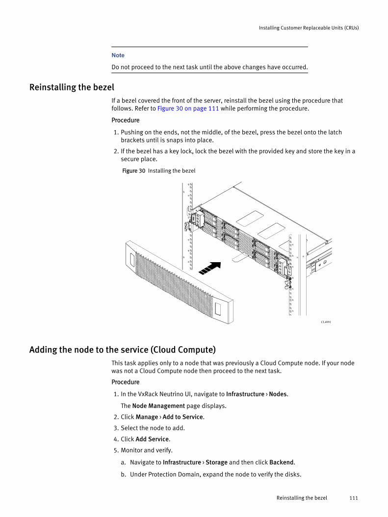
Note
Do not proceed to the next task until the above changes have occurred.
Reinstalling the bezelIf a bezel covered the front of the server, reinstall the bezel using the procedure thatfollows. Refer to Figure 30 on page 111 while performing the procedure.
Procedure
1. Pushing on the ends, not the middle, of the bezel, press the bezel onto the latchbrackets until is snaps into place.
2. If the bezel has a key lock, lock the bezel with the provided key and store the key in asecure place.
Figure 30 Installing the bezel
CL4991
Adding the node to the service (Cloud Compute)This task applies only to a node that was previously a Cloud Compute node. If your nodewas not a Cloud Compute node then proceed to the next task.
Procedure
1. In the VxRack Neutrino UI, navigate to Infrastructure > Nodes.
The Node Management page displays.
2. Click Manage > Add to Service.
3. Select the node to add.
4. Click Add Service.
5. Monitor and verify.
a. Navigate to Infrastructure > Storage and then click Backend.
b. Under Protection Domain, expand the node to verify the disks.
Installing Customer Replaceable Units (CRUs)
Reinstalling the bezel 111
Results
The node transitions from Unallocated to Cloud Compute.
Transferring a Platform Service node (optional)This task is optional and applies only to a node that was previously a Platform Servicenode. If your node was not a Platform node then proceed to the next task.
Before you begin
Note
The steps in this Before you begin section are a workaround for a known issue detailed inJIRA CP-1993. Perform the following workaround if the node or the system disk causes thenode to go offline or inaccessible.
After the Platform Service is successfully transferred from a Platform node to anunallocated node, when the Platform Service is transferred back to the original Platformnode, the transfer operation may fail.
1. Navigate to Infrastructure > Storage > Front End > Volumes.
2. Expand the storage pools to find the glance_volume and then select it in the list.
3. In the details pane next to the list, click the downward-facing arrow in the drop-downlist in the upper corner and then select Map SDC.
4. In the Actions column next to the stale entry of the previously failed node (SDC), clickRemove.
5. Click OK.
Procedure
1. In Infrastructure > Nodes, select the Platform Service node and then select Actions >Transfer.
When selecting the correct node to transfer, match the information on thereplacement part with information in the details of the node.
2. Select the original Platform service node and then click Transfer.
This is the original Platform service node from the earlier task before transferring.
The original Platform service node must be Unallocated. Perform this step inconsultation with the Cloud Operator.
Results
The destination/temporary node transitions from Platform to Unallocated. The originalPlatform service node transitions from Unallocated to Platform.
Returning parts to EMCProcedure
1. Locate the Parts Return Label package and fill out the shipping label.
Apply the label to box for return to EMC.
2. Read the enclosed Shipping Instructions sheet.
3. Apply other labels appropriate to this returning part. Check for any engineeringbulletin or service request (SR), or check with the customer, to determine if thedefective part is FA or Priority FA bound.
Installing Customer Replaceable Units (CRUs)
112 VxRack System 1000 with Neutrino 1.1 Hardware Guide

Note
If Engineering has requested that the part be shipped back for an FA, ensure that theproper ship-to information has been entered, and that the attention-to and/orcontact-name information has been provided in the shipping label.
4. Securely tape the box and ship the failed part back to EMC.
Server Storage Disk Replacement (p series)This document describes how to replace a faulted storage disk.
OverviewThis procedure applies when replacing the server cache and storage (non-system) disk. Ifthe disk partition on the system disk that is being used as a cache disk fails, then refer tothe Server System Disk Replacement procedure.
Some tasks in the following table apply to specific services. Use the table to identify thetasks that you need to perform. "No" means that the task does not apply and thereforeyou can skip the task.
Note
Throughout this procedure, brick and server are used interchangeably to refer to thesame hardware component.
Table 30 Disk replacement tasks
Task Cloud Compute Service Platform Service Unallocated
Remove the disk from service Yes No No
Delete the disk from the node Yes No Yes
Hardware replacement tasks Yes No Yes
Add the disk to the service Yes No No
Return parts to EMC Yes No Yes
Note
If you delete and remove a disk, you can not re-install the same disk. The VxRackNeutrino UI will not rediscover the disk. This procedure applies only when replacing adisk with a new, different one.
Pre-site tasksThe following list identifies the tasks that need to be completed before arriving at thecustomer site.
l Verify that the ordered replacement part number is correct based on the parts table.
l Transferring platform services to an unallocated node for node/disk removalprocedures can take several hours. Perform the transfer steps remotely beforeheading for the customer site.
Installing Customer Replaceable Units (CRUs)
Server Storage Disk Replacement (p series) 113

Note
Be advised that many maintenance procedures, like replacing system or storage disks,will require transferring Platform Services to an unallocated node. An unallocated node isone that is not assigned to run Platform Services or Cloud Compute during first-timeinstallation (more specifically, when selecting three nodes to run Platform Services). It ishighly recommended that Professional Services advise customers to reserve at least oneunallocated node for general maintenance and system failover purposes. Not complyingwill result in an increased maintenance window.
PartsThis procedure explains how to replace the hardware identified in the following table.
Table 31 Part list
Part number Part description
105-000-477-00 CASPIAN SMALL FULL SSD BLADE ASSY
105-000-479-00 CASPIAN MEDIUM FULL SSD BLADE ASSY
105-000-481-00 CASPIAN LARGE FULL SSD BLADE ASSY
105-000-532-00 Type B 400Gb Sunset Cove Plus
105-000-533-00 800GB TY B SC+ SSD 512 w encryp dis 2.5
ToolsYou need the following tools to complete this procedure.
ESD gloves or ESD wristband
Common proceduresThis topic contains procedures which are common to the handling of field replaceableunits (FRU) within a device.
Listing of common proceduresThe following are the common procedures which are used for the handling FRUs:
l Avoiding electro-static discharge (ESD) damage
l Emergency procedures without an ESD kit
l Hardware acclimation times
l Identifying faulty parts
Handling replaceable units
This section describes the precautions that you must take and the general proceduresthat you must follow when removing, installing, and storing any replaceable unit.
Avoiding electrostatic discharge (ESD) damage
When replacing or installing hardware units, you can inadvertently damage the sensitiveelectronic circuits in the equipment by simply touching them. Electrostatic charge thathas accumulated on your body discharges through the circuits. If the air in the work area
Installing Customer Replaceable Units (CRUs)
114 VxRack System 1000 with Neutrino 1.1 Hardware Guide

is very dry, running a humidifier in the work area will help decrease the risk of ESDdamage. Follow the procedures below to prevent damage to the equipment.
Be aware of the following requirements:
l Provide enough room to work on the equipment.
l Clear the work site of any unnecessary materials or materials that naturally build upelectrostatic charge, such as foam packaging, foam cups, cellophane wrappers, andsimilar items.
l Do not remove replacement or upgrade units from their antistatic packaging until youare ready to install them.
l Before you begin service, gather together the ESD kit and all other materials you willneed.
l Once servicing begins, avoid moving away from the work site; otherwise, you maybuild up an electrostatic charge.
l Use ESD anti-static gloves or an ESD wristband (with strap).If using an ESD wristband with a strap:
n Attach the clip of the ESD wristband to the ESD bracket or bare metal on acabinet/rack or enclosure.
n Wrap the ESD wristband around your wrist with the metal button against yourskin.
n If a tester is available, test the wristband.
l If an emergency arises and the ESD kit is not available, follow the procedures inEmergency Procedures (without an ESD kit).
Emergency procedures (without an ESD kit)
In an emergency when an ESD kit is not available, use the following procedures to reducethe possibility of an electrostatic discharge by ensuring that your body and thesubassembly are at the same electrostatic potential.
NOTICE
These procedures are not a substitute for the use of an ESD kit. Follow them only in theevent of an emergency.
l Before touching any unit, touch a bare (unpainted) metal surface of the cabinet/rackor enclosure.
l Before removing any unit from its antistatic bag, place one hand firmly on a baremetal surface of the cabinet/rack or enclosure, and at the same time, pick up the unitwhile it is still sealed in the antistatic bag. Once you have done this, do not movearound the room or touch other furnishings, personnel, or surfaces until you haveinstalled the unit.
l When you remove a unit from the antistatic bag, avoid touching any electroniccomponents and circuits on it.
l If you must move around the room or touch other surfaces before installing a unit,first place the unit back in the antistatic bag. When you are ready again to install theunit, repeat these procedures.
Hardware acclimation times
Systems and components must acclimate to the operating environment before applyingpower. This requires the unpackaged system or component to reside in the operatingenvironment for up to 16 hours in order to thermally stabilize and prevent condensation.
Installing Customer Replaceable Units (CRUs)
Common procedures 115

Refer to the table, Table 32 on page 116, to determine the precise amount ofstabilization time required.
Table 32 Hardware acclimation times (systems and components)
If the last 24 hours of theTRANSIT/STORAGEenvironment was this:
…and the OPERATINGenvironment is this:
…then let the system orcomponent acclimate inthe new environmentthis many hours:
Temperature Humidity
Nominal68-72°F (20-22°C)
Nominal40-55% RH
Nominal 68-72°F (20-22°C)40-55% RH
0-1 hour
Cold<68°F (20°C)
Dry<30% RH
<86°F (30°C) 4 hours
Cold<68°F (20°C)
Damp≥30% RH
<86°F (30°C) 4 hours
Hot>72°F (22°C)
Dry<30% RH
<86°F (30°C) 4 hours
Hot>72°F (22°C)
Humid30-45% RH
<86°F (30°C) 4 hours
Humid45-60% RH
<86°F (30°C) 8 hours
Humid≥60% RH
<86°F (30°C) 16 hours
Unknown <86°F (30°C) 16 hours
NOTICE
l If there are signs of condensation after the recommended acclimation time haspassed, allow an additional eight (8) hours to stabilize.
l Systems and components must not experience changes in temperature and humiditythat are likely to cause condensation to form on or in that system or component. Donot exceed the shipping and storage temperature gradient of 45°F/hr (25°C/hr).
l Do NOT apply power to the system for at least the number of hours specified in thetable, Table 32 on page 116. If the last 24 hours of the transit/storage environment isunknown, then you must allow the system or component 16 hours to stabilize in thenew environment.
Removing, installing, or storing replaceable units
Use the following precautions when removing, handling, or storing replaceable units:
CAUTION
Some replaceable units have the majority of their weight in the rear of the component.Ensure that the back end of the replaceable unit is supported while installing orremoving it. Dropping a replaceable unit could result in personal injury or damage to theequipment.
Installing Customer Replaceable Units (CRUs)
116 VxRack System 1000 with Neutrino 1.1 Hardware Guide

NOTICE
l For a module that must be installed into a slot in an enclosure, examine the rearconnectors on the module for any damage before attempting its installation.
l A sudden jar, drop, or even a moderate vibration can permanently damage somesensitive replaceable units.
l Do not remove a faulted replaceable unit until you have the replacement available.
l When handling replaceable units, avoid electrostatic discharge (ESD) by wearing ESDanti-static gloves or an ESD wristband with a strap. For additional information, refer to Avoiding electrostatic discharge (ESD) damage on page 81.
l Avoid touching any exposed electronic components and circuits on the replaceableunit.
l Never use excessive force to remove or install a replaceable unit. Take time to readthe instructions carefully.
l Store a replaceable unit in the antistatic bag and the specially designed shippingcontainer in which you received it. Use the antistatic bag and special shippingcontainer when you need to return the replaceable unit.
l Replaceable units must acclimate to the operating environment before applyingpower. This requires the unpackaged component to reside in the operatingenvironment for up to 16 hours in order to thermally stabilize and preventcondensation. Refer to Hardware acclimation times on page 82 to ensure thereplaceable unit has thermally stabilized to the operating environment.
NOTICE
Your storage system is designed to be powered on continuously. Most components arehot swappable; that is, you can replace or install these components while the storagesystem is running. However, the system requires that:
l Front bezels should always be attached to ensure EMI compliance. Make sure youreattach the bezel after replacing a component.
l Each slot should contain a component or filler panel to ensure proper air flowthroughout the system.
Logging into the VxRack Neutrino UILog into the VxRack Neutrino UI with a web browser using the VxRack Neutrino virtual IPsupplied by the customer.
Procedure
1. Type in one of the following URL into your browser.
https://<virtual_IP>
https://<neutrino_virtual_hostname>
For example,
https://10.242.242.190
https://customer-cloud.customer-domain.com2. At the login, type the Account (Domain), Username, and Password.
Installing Customer Replaceable Units (CRUs)
Logging into the VxRack Neutrino UI 117

Transferring a node that is online and accessible (Platform)This task applies to Platform Service and Unallocated nodes. If your nodes are CloudCompute then proceed to the next task.
Before you begin
The destination node in step 3 below must be Unallocated. If there no Unallocated nodesavailable, remove the Cloud Compute nodes from service and then transfer the Platformnode.
Procedure
1. In the VxRack Neutrino UI, navigate to Infrastructure > Nodes.
The Node Management page displays.
2. Select the Platform Service node and then select Actions > Transfer.
To select the correct node to transfer from, match the information on the replacementpart with information in the details of the node.
3. Select the destination/temporary node and then click Transfer.
The destination node must be Unallocated. Perform this step in consultation with theCloud Operator.
Results
The original platform service node transitions from Platform to Unallocated. Thedestination/temporary node transitions from Unallocated to Platform.
Removing the storage device from service (Cloud Compute)This task applies only to Cloud Compute nodes. If your node was not a Cloud Computenode then proceed to the next task.
Procedure
1. In the VxRack Neutrino UI, navigate to Infrastructure > Nodes.
The Node Management page displays.
2. Click the affected node.
The Node details page displays.
3. Click Remove from Service next to the storage device with the ScaleIO label, whichbelongs to the affected disk.
The affected disk will report health as either SUSPECT or BAD.
4. Monitor and verify that the storage device is removed.
a. Navigate to Infrastructure > Storage and then click Backend.
b. Select Rebuild and Rebalance from the View list box.
c. Click the drop down arrow on the Protection Domain and then click the drop downon the node that is having the storage device removed from service.
The storage device shows a state of removing.
d. Once rebalance is complete it should be removed from the node.
Results
This might take several minutes due to ScaleIO rebalancing.
Installing Customer Replaceable Units (CRUs)
118 VxRack System 1000 with Neutrino 1.1 Hardware Guide

Deleting the disk from the nodeProcedure
1. In Infrastructure > Nodes, select the node.
2. Select the disk that had the storage device removed from Service.
The disk should not have a label.
3. Click Delete.
Results
The disk is deleted from the Node Details Disk View and the disk ID LED is on.
Replacing a disk drive assemblyA disk drive assembly consists of a hard disk drive supplied in special hot-swappablehard-drive carrier that fits in a disk slot. Disk slots are accessible from the front of theserver.
Figure 31 Disk slot diagram
NOTICE
To maintain proper system cooling, any hard-drive bay without a disk drive assembly ordevice installed must be occupied by filler module. Do not turn off or reboot your systemwhile the drive is being formatted. Doing so can cause a drive failure. Use appropriateESD precautions, including the use of a grounding strap, when performing the drivemodule replacement procedure.
Before you replace a disk drive assembly, review the section on handling fieldreplaceable units (FRUs).
Unpacking a partProcedure
1. Wear ESD gloves or attach an ESD wristband to your wrist and the enclosure in whichyou are installing the part.
2. Unpack the part and place it on a static-free surface.
3. If the part is a replacement for a faulted part, save the packing material to return thefaulted part.
Handling disk drive assembliesl Do not remove a disk drive filler until you have a replacement disk drive assembly
available to replace it.
Installing Customer Replaceable Units (CRUs)
Deleting the disk from the node 119

l Disk drive assemblies are sensitive to the extreme temperatures that are sometimesencountered during shipping. We recommend that you leave the new disk driveassembly in its shipping material and expose the package to ambient temperature forat least four hours before attempting to use the new disk drive assemblies in yoursystem.
l Avoid touching any exposed electronic components and circuits on the disk driveassembly.
l Do not stack disk drive assemblies upon one another, or place them on hardsurfaces.
l When installing multiple disk drive assemblies in a powered up system, wait at least6 seconds before sliding the next disk drive assembly into position.
Removing the bezelThe front of the server may be covered by a bezel. Bezels are application specific, andmay not appear as shown. Bezels may include a key lock. If the server has a bezel,remove it.
Refer to Figure 32 on page 120 while performing the procedure that follows.
Procedure
1. If the bezel has a key lock, unlock the bezel with the provided key.
2. Press the two tabs on either side of the bezel to release the bezel from its latches, andpull the bezel off the latches.
Figure 32 Removing the bezel
CL4992
Identifying the faulted disk drive assembly
A faulted disk drive assembly may have an amber LED indicator on its carrier, which isvisible when you remove the server’s bezel.
Installing Customer Replaceable Units (CRUs)
120 VxRack System 1000 with Neutrino 1.1 Hardware Guide

Replacing a faulted disk drive assemblyProcedure
1. Attach an ESD wristband to your wrist and the server chassis.
Note
Use the method described in step 2 to remove any of the disk drive assemblies exceptthe two located behind the node control panel at right edge of the server. Use step 3to remove either of the two disk drive assemblies that are located behind the nodecontrol panel.
2. Remove a faulted disk drive assembly that is not located behind the right side nodecontrol panel as follows (Figure 33 on page 121):
a. Press the green button on the left side of the disk drive assembly to unlock themodule’s lever.
b. Pull the lever open and slide the disk drive assembly from the server.
Figure 33 Removing the faulted disk drive assembly
CL4985
Note
The node control panel, at right edge of the server, slightly interferes with removal ofthe two disk drive assemblies located behind it. As described in the following step,grasping and pulling the left side edge of the disk drive assembly will allow it to freelypass by the node control panel.
3. Remove a faulted disk drive assembly that is located behind the right side nodecontrol panel as follows (Figure 34 on page 122):
a. Swing the node control panel outward to make the faulted disk drive assemblyaccessible.
b. Press the green button on the left side of the disk drive assembly to unlock themodule’s lever.
c. Grasp the left side of the disk drive assembly and slide the disk drive assemblyfrom the server.
Installing Customer Replaceable Units (CRUs)
Replacing a disk drive assembly 121

Figure 34 Removing the faulted disk drive assembly
CL5576
1 2 3
4. Unpack the replacement disk drive assembly and save the packing material forreturning the faulted disk drive assembly.
5. Install the replacement disk drive assembly (Figure 35 on page 122):
a. With the lever on the replacement disk drive assembly in the fully open position(green button to the right), slide the module into the server.
b. When the lever begins to close by itself, push on the lever to lock it into place.
Figure 35 Installing the replacement disk drive assembly
CL4984
B
A
6. Remove and store the ESD wristband.
Reinstalling the bezel
If a bezel covered the front of the server, reinstall the bezel using the procedure thatfollows. Refer to Figure 36 on page 123 while performing the procedure.
Procedure
1. Pushing on the ends, not the middle, of the bezel, press the bezel onto the latchbrackets until is snaps into place.
2. If the bezel has a key lock, lock the bezel with the provided key and store the key in asecure place.
Installing Customer Replaceable Units (CRUs)
122 VxRack System 1000 with Neutrino 1.1 Hardware Guide

Figure 36 Installing the bezel
CL4991
Adding the disk to the service (Cloud Compute)This task applies only to Cloud Compute nodes. If your node was not a Cloud Computenode then proceed to the next task.
Procedure
1. In the VxRack Neutrino UI, navigate to Infrastructure > Nodes.
The Node Management page displays.
2. Click the node name's direct link to get to Node Details.
3. Verify the disk appears in the disk inventory.
4. Select the storage device that belongs to the disk that was replaced and then clickAdd to Service.
5. Click Yes to add the disk to the service.
6. Verify that the disk was added.
a. Navigate to Infrastructure > Storage and then click Backend.
b. Under Protection Domain, expand the node to verify that the disk is listed.
Transferring a Platform Service node (optional)This task is optional and applies only to a node that was previously a Platform Servicenode. If your node was not a Platform node then proceed to the next task.
Before you begin
Note
The steps in this Before you begin section are a workaround for a known issue detailed inJIRA CP-1993. Perform the following workaround if the node or the system disk causes thenode to go offline or inaccessible.
Installing Customer Replaceable Units (CRUs)
Adding the disk to the service (Cloud Compute) 123

After the Platform Service is successfully transferred from a Platform node to anunallocated node, when the Platform Service is transferred back to the original Platformnode, the transfer operation may fail.
1. Navigate to Infrastructure > Storage > Front End > Volumes.
2. Expand the storage pools to find the glance_volume and then select it in the list.
3. In the details pane next to the list, click the downward-facing arrow in the drop-downlist in the upper corner and then select Map SDC.
4. In the Actions column next to the stale entry of the previously failed node (SDC), clickRemove.
5. Click OK.
Procedure
1. In Infrastructure > Nodes, select the Platform Service node and then select Actions >Transfer.
When selecting the correct node to transfer, match the information on thereplacement part with information in the details of the node.
2. Select the original Platform service node and then click Transfer.
This is the original Platform service node from the earlier task before transferring.
The original Platform service node must be Unallocated. Perform this step inconsultation with the Cloud Operator.
Results
The destination/temporary node transitions from Platform to Unallocated. The originalPlatform service node transitions from Unallocated to Platform.
Returning parts to EMCProcedure
1. Locate the Parts Return Label package and fill out the shipping label.
Apply the label to box for return to EMC.
2. Read the enclosed Shipping Instructions sheet.
3. Apply other labels appropriate to this returning part. Check for any engineeringbulletin or service request (SR), or check with the customer, to determine if thedefective part is FA or Priority FA bound.
Note
If Engineering has requested that the part be shipped back for an FA, ensure that theproper ship-to information has been entered, and that the attention-to and/orcontact-name information has been provided in the shipping label.
4. Securely tape the box and ship the failed part back to EMC.
Installing Customer Replaceable Units (CRUs)
124 VxRack System 1000 with Neutrino 1.1 Hardware Guide

APPENDIX D
Ordering EMC Parts
This appendix includes the following sections:
l Server FRU part numbers..................................................................................... 126l Switch FRU part numbers.................................................................................... 127l Rack component FRU part numbers..................................................................... 128
Ordering EMC Parts 125

Server FRU part numbersThe following table lists the server FRUs supported by VxRack System with Neutrino.
Part number Description CPU Disks Memory
100-400-074-00 CASPIAN SMALL,16SSD LOAD SKU
6 Core, 2.4GHz
400 GB SSDDrive Pack /800GB SSDDrive Pack
128 GB
100-400-075-00 CASPIAN MEDIUM,16 SSD LOAD SKU
8 Core, 2.6GHz
400 GB SSDDrive Pack /800GB SSDDrive Pack
256 GB
100-400-076-00 CASPIAN LARGE 16SSD LOAD SKU
10 Core, 2.4GHz
400 GB SSDDrive Pack /800GB SSDDrive Pack
512 GB
100-400-104-02 CASPIAN MEDIUMHYDRA-24 SKU
100-400-105-02 CASPIAN LARGEHYDRA-24 SKU
100-400-113-01 CASPIAN SMALLHYDRA-24 SKU
105-000-534-02 CASPIAN HYDRA2U-24 MEDIUMCHASSIS
105-000-535-02 CASPIAN HYDRA2U-24 LARGECHASSIS
105-000-536-01 CASPIAN HYDRA2U-24 SMALLCHASSIS
Table 33 Server option part numbers
Part number Part description
105-000-532-00 400GB SSD Drive Pack / 3WPD Type B 400GbSunset Cove Plus
105-000-533-00 800GB SSD Drive Pack / 3WPD Type B 800GbSunset Cove Plus
Ordering EMC Parts
126 VxRack System 1000 with Neutrino 1.1 Hardware Guide

Switch FRU part numbersThe following table lists the switch FRUs supported by VxRack System with Neutrino.
Table 34 Switch FRU part numbers
Part number Part description
100-400-128-00 Cisco 9372PX-E 48-P 10GbE &6-P 40GbE SW
100-400-129-00 Cisco 9332PQ 32-P 40GbE SW
100-400-130-00 Cisco 3048 48-P 1GbE & 4-P1/10GbE SW
100-400-141 Cisco 100/1000Base_T SFPCopper Module
105-000-728 N2200-PAC-400W N3K PSPORT SIDE EX
105-000-729 N3K-C3048-FAN N3K PORTSIDE EX
105-000-752 N9K-PAC-650W-B 9300 PSPORT SIDE EX
105-000-756 NXA-FAN-30CFM-F 9300 FANPORT SIDE EX
999-996-038 Cisco 3048 1/10Gb EthernetSwitch TPS
999-996-038 Cisco 9372PX-E 10Gb/40GbEthernet SW TPS
999-996-039 Cisco 9332PQ 40Gb EthernetSwitch TPS
999-996-041 Cisco Optical/Copper ModuleTPS
999-997-798 40G QSFP Ethernet spec
Table 35 Switch option part numbers
Part number Part description
038-004-495 SR multi-mode breakout cable,1 meter
038-004-497 LR single mode breakout cable,1 meter
Ordering EMC Parts
Switch FRU part numbers 127
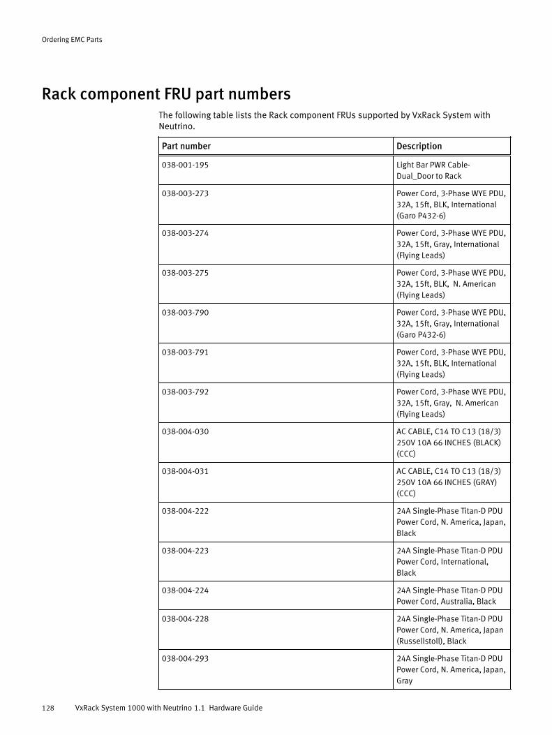
Rack component FRU part numbersThe following table lists the Rack component FRUs supported by VxRack System withNeutrino.
Part number Description
038-001-195 Light Bar PWR Cable-Dual_Door to Rack
038-003-273 Power Cord, 3-Phase WYE PDU,32A, 15ft, BLK, International(Garo P432-6)
038-003-274 Power Cord, 3-Phase WYE PDU,32A, 15ft, Gray, International(Flying Leads)
038-003-275 Power Cord, 3-Phase WYE PDU,32A, 15ft, BLK, N. American(Flying Leads)
038-003-790 Power Cord, 3-Phase WYE PDU,32A, 15ft, Gray, International(Garo P432-6)
038-003-791 Power Cord, 3-Phase WYE PDU,32A, 15ft, BLK, International(Flying Leads)
038-003-792 Power Cord, 3-Phase WYE PDU,32A, 15ft, Gray, N. American(Flying Leads)
038-004-030 AC CABLE, C14 TO C13 (18/3)250V 10A 66 INCHES (BLACK)(CCC)
038-004-031 AC CABLE, C14 TO C13 (18/3)250V 10A 66 INCHES (GRAY)(CCC)
038-004-222 24A Single-Phase Titan-D PDUPower Cord, N. America, Japan,Black
038-004-223 24A Single-Phase Titan-D PDUPower Cord, International,Black
038-004-224 24A Single-Phase Titan-D PDUPower Cord, Australia, Black
038-004-228 24A Single-Phase Titan-D PDUPower Cord, N. America, Japan(Russellstoll), Black
038-004-293 24A Single-Phase Titan-D PDUPower Cord, N. America, Japan,Gray
Ordering EMC Parts
128 VxRack System 1000 with Neutrino 1.1 Hardware Guide

Part number Description
038-004-294 24A Single-Phase Titan-D PDUPower Cord, International, Gray
038-004-295 24A Single-Phase Titan-D PDUPower Cord, Australia, Gray
038-004-296 24A Single-Phase Titan-D PDUPower Cord, N. America, Japan(Russellstoll), Gray
038-004-323-00 2 Meter SFP+ to SFP+ ActiveTwinax Cable
038-004-350 PWR CORD 24A SP 74 INCHL6-30P GRAY 4PPPNote: cabling instruction in999-997-173_03
038-004-351 PWR CORD 24A SP 74 INCHL6-30P BL 4PPPNote: cabling instruction in999-997-173_03
038-004-407 CAT6 ETHERNET STRAIGHT CBL51INCH LIME (Rinjin)
038-004-408 CAT6 ETHERNET STRAIGHT CBL51INCH VIOLET (Rinjin)
038-004-409 CAT6 ETHERNET STRAIGHT CBL71INCH LIME (Hydra)
038-004-410 CAT6 ETHERNET STRAIGHT CBL71INCH VIOLET (Hydra)
038-004-429 Power Cord, 3-Phase DELTAPDU, 40A, 15FT, BLK,International (Russellstoll9P54U2T)
038-004-430 Power Cord, 3-Phase DELTAPDU, 40A, 15FT, Gray,International (Russellstoll9P54U2T)
038-004-431 Power Cord, 3-Phase DELTAPDU, 40A, 15FT, BLK, N.America (Hubbell ProCS-8365L)
038-004-432 Power Cord, 3-Phase DELTAPDU, 40A, 15FT, Gray, N.America (Hubbell ProCS-8365L)
038-004-433 Power Cord, 3-Phase DELTAPDU, 40A, 15FT, Gray, N.America (Hubbell ProCS-8365L)
Ordering EMC Parts
Rack component FRU part numbers 129

Part number Description
038-004-434 Power Cord, 3-Phase DELTAPDU, 40A, 15FT, BLK, N.America (Hubbell ProCS-8365L)
038-004-436 CAT6 LAN CABLE, RED 100INCHES
038-004-917 Power Cord, 3-Phase WYE PDU,30A, 15ft, BLK, N. America(L22-30P)
038-004-918 Power Cord, 3-Phase WYE PDU,30A, 15ft, Gray, N. America(L22-30P)
042-023-116 ADJUSTABLE RAIL ASSY: REARARISTA
042-023-373 ADJUSTABLE RAIL ASSY: FRONT1U CISCO
100-400-092 CASPIAN 2U BEZEL ASSY
100-400-093-00 CASPIAN FRONT DOOR ASSYHEX LIGHTBARS
100-564-177-00 Single Phase Horizontal 2UPDUNotes:PDU2A is on the right lookingfrom the rearPDU2B is on the left lookingfrom the rearPDU's click into rail without HW
100-564-440 Intel Custom Server RailAssembly
100-887-100 2U PDU Mount Rail AssemblyNotes:Rail install procedures insection 6.1 of 999-997-173_03
100-887-111-00 EVEREST 5v 30w AC/DCpowerassy
100-887-121-00(100-564-175-01 is a valid sub to burn off inventory)
3-Phase Delta Horizontal 2UPDUNotes:PDU2A is on the right lookingfrom the rearPDU2B is on the left lookingfrom the rearPDU's click into rail without HW
100-887-122-00(100-564-176-00 is a valid sub to burn off inventory)
3-Phase Wye Horizontal 2UPDUNotes:
Ordering EMC Parts
130 VxRack System 1000 with Neutrino 1.1 Hardware Guide

Part number Description
PDU2A is on the right lookingfrom the rearPDU2B is on the left lookingfrom the rearPDU's click into rail without HW
106-400-119 ASSY CISCO SWITCH RAIL FIXEDLENGTH
106-400-120 ASSY CISCO SWITCH RAIL ADJLENGTH
106-563-001 ANTI-MOVE KIT
106-887-012 1U Service Tray Kit
Ordering EMC Parts
Rack component FRU part numbers 131

Ordering EMC Parts
132 VxRack System 1000 with Neutrino 1.1 Hardware Guide