Embed Size (px)
Citation preview

Neutron deep-penetration calculations & shielding design of proton therapy accelerators
7th Int. Workshop on Radiation Safety at Synchrotron Radiation Sources (RADSYNCH2013)
Rong-Jiun Sheu
Institute of Nuclear Engineering and Science
National Tsing Hua University

New accelerators in Taiwan
Taiwan Photon Source NSRRC, Hsinchu 3 GeV electron synchrotron Installation 2013, commissioning 2014
Proton therapy center
Chang Gung Memorial Hospital, Linkou 235 MeV proton cyclotron Commissioning 2013, clinical trial 2014
Heavy ion therapy center
Veterans General Hospital, Taipei 400 MeV/A carbon cyclotron In planning

Accelerator shielding
Key issues in shielding design Neutrons produced from hadronic cascade or EM cascade with
photonuclear interaction are dominant dose component Neutron production and deep-penetration calculations
Selected experiments on thick-target neutron yield 256 MeV proton on iron (Meier et al., 1990)1 400 MeV/A carbon on copper (Nakamura et al., 2006)2 2.04 GeV electron on copper (Lee et al., 2005)3
(1) (2) (3)
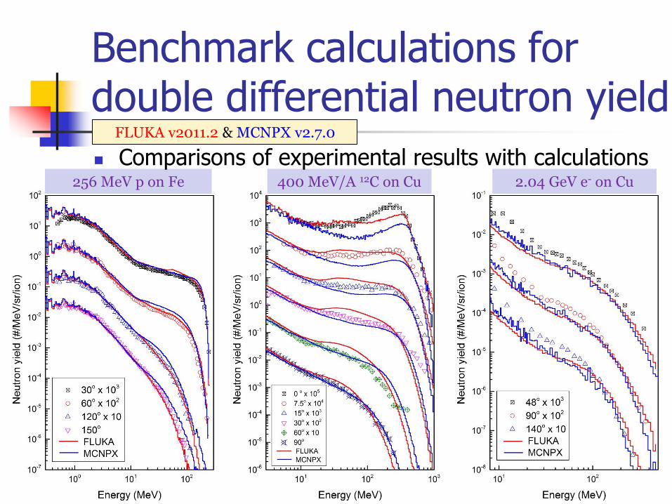
400 MeV/A 12C on Cu 256 MeV p on Fe 2.04 GeV e- on Cu
Comparisons of experimental results with calculations
Benchmark calculations for double differential neutron yield
FLUKA v2011.2 & MCNPX v2.7.0

Ranges of neutron source intensities
For three accelerators of main concern 235 MeV proton cyclotron 400 MeV/A carbon cyclotron 3.0 GeV electron synchrotron Total number of neutrons produced per incident primary
particle (n/p) calculated by FLUKA and MCNPX:
Beam Target FLUKA MCNPX
235 MeV proton Iron 0.70 0.13% 0.79 0.24%
400 MeV/A carbon Copper 9.02 0.14% 5.92 0.24%
3.0 GeV electron Copper 0.63 0.36% 0.51 0.21%

Neutron production from proton bombardment
For various proton energies and target materials LHS: total neutron yield RHS: percentage of high-energy neutrons (𝐸𝑛 > 20 𝑀𝑒𝑉)
100 150 200 250 300
0.0
0.2
0.4
0.6
0.8
1.0
1.2
1.4
Target: Iron Carbon Tissue
To
tal N
eu
tro
n Y
ield
(n
/p)
Proton Energy (MeV)
100 150 200 250 300
0.0
0.2
0.4
0.6
0.8
1.0
Pe
rce
nta
ge
(En >
20
Me
V)
• Neutron yield increases significantly as increasing proton energies, especially for high-Z targets.
• Low-Z targets cause harder neutron spectra, i.e. more forward-peaked neutrons and anisotropy of dose distribution.

Parameters for shielding design
A simplified method ~
Source term H0 and attenuation length = ? Literature data (a wide range of variability) Radiation transport calculations (neutron deep penetration)
Calculation model (Agosteo et al., 2007)
Primary beam: 200 MeV protons Shielding material: concrete & iron Use FLUKA & MCNPX to simulate the production and
transport of all secondary radiation produced from proton bombardment
Depth dose distributions in shield Curve fitting Source terms & attenuation lengths
...)(
exp),(
)/,,(2
0
g
d
r
EHdEH
p
p
Point- source line-of-sight model
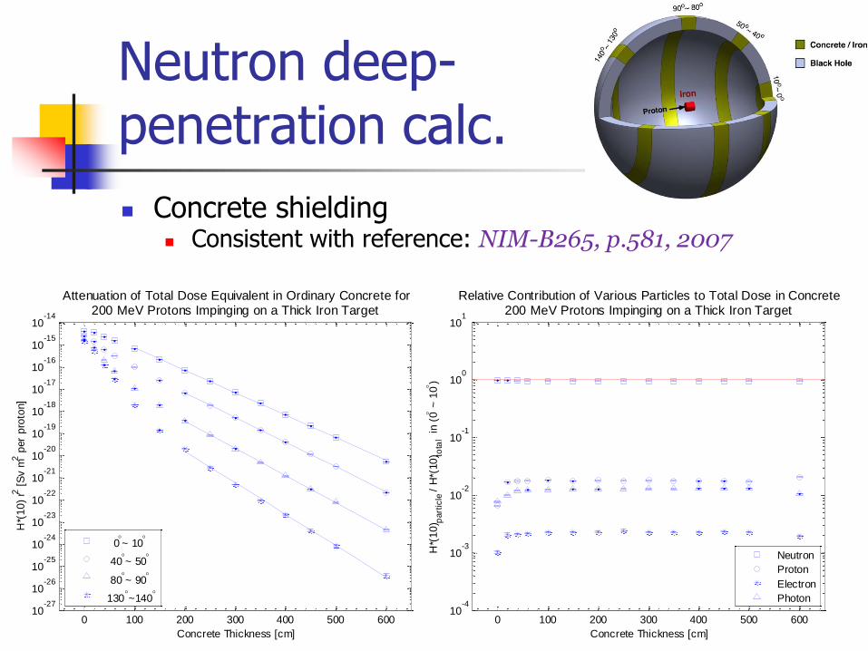
Neutron deep- penetration calc.
Concrete shielding Consistent with reference: NIM-B265, p.581, 2007
0 100 200 300 400 500 60010
-27
10-26
10-25
10-24
10-23
10-22
10-21
10-20
10-19
10-18
10-17
10-16
10-15
10-14
Concrete Thickness [cm]
H*(
10
) r2
[S
v m
2 p
er
pro
ton]
Attenuation of Total Dose Equivalent in Ordinary Concrete for200 MeV Protons Impinging on a Thick Iron Target
0~ 10
40~ 50
80~ 90
130~140
0 100 200 300 400 500 60010
-4
10-3
10-2
10-1
100
101
Concrete Thickness [cm]
H*(
10
) part
icle /
H*(
10
) tota
l in
(0
~ 1
0)
Relative Contribution of Various Particles to Total Dose in Concrete200 MeV Protons Impinging on a Thick Iron Target
Neutron
Proton
Electron
Photon

Neutron deep- penetration calc.
Iron shielding Inconsistent with reference: NIM-B266, p.3406, 2008
0 50 100 150 200 250 30010
-2510
-2410
-2310
-2210
-2110
-2010
-1910
-1810
-1710
-1610
-1510
-1410
-1310
-1210
-1110
-1010
-910
-810
-7
Iron Thickness [cm]
H*(
10
) r2
[S
v m
2 p
er
pro
ton]
Attenuation of Total Dose Equivalent in Iron for200 MeV Protons Impinging on a Thick Iron Target
0~ 10
(10
6)
40~ 50
(10
4)
80~ 90
(10
2)
130~140

10-14
10-13
10-12
10-11
10-10
10-9
10-8
10-7
10-6
10-5
10-4
10-3
10-2
10-1
100
101
0
1
2
3
4
5
x 10-10
Depth = 0m
0~ 10
40~ 50
80~ 90
130~140
10-14
10-13
10-12
10-11
10-10
10-9
10-8
10-7
10-6
10-5
10-4
10-3
10-2
10-1
100
101
0
2
4
6
x 10-11
Depth = 1m
0~ 10
40~ 50
80~ 90
130~140
10-14
10-13
10-12
10-11
10-10
10-9
10-8
10-7
10-6
10-5
10-4
10-3
10-2
10-1
100
101
0
2
4
6
8
x 10-12
Depth = 2m
0~ 10
40~ 50
80~ 90
130~140
Neutron Energy [GeV]
E
(E)
[cm
-2 s
r-1 p
er
pro
ton]
Double Differential Distributions of Neutrons in Concrete
10-14
10-13
10-12
10-11
10-10
10-9
10-8
10-7
10-6
10-5
10-4
10-3
10-2
10-1
100
101
0
1
2
3
4
5
x 10-10
Depth = 0m
0~ 10
40~ 50
80~ 90
130~140
10-14
10-13
10-12
10-11
10-10
10-9
10-8
10-7
10-6
10-5
10-4
10-3
10-2
10-1
100
101
0
1
2
3
4
x 10-9
Depth = 0.5m
0~ 10
40~ 50
80~ 90
130~140
10-14
10-13
10-12
10-11
10-10
10-9
10-8
10-7
10-6
10-5
10-4
10-3
10-2
10-1
100
101
0
0.5
1
1.5
x 10-9
Depth = 1m
0~ 10
40~ 50
80~ 90
130~140
Neutron Energy [GeV]
E
(E)
[cm
-2 s
r-1 p
er
pro
ton]
Double Differential Distributions of Neutrons in Iron
Neutron spectra at various depths in concrete and iron shield

Neutron deep- penetration calc.
Comparison: FLUKA & MCNPX En<20MeV, multigroup vs. continuous cross sections
0 100 200 300 400 500 60010
-27
10-26
10-25
10-24
10-23
10-22
10-21
10-20
10-19
10-18
10-17
10-16
10-15
10-14
Concrete Thickness [cm]
H*(
10
) r2
[S
v m
2 p
er
pro
ton]
Attenuation of Neutron Dose Equivalent in Ordinary Concrete for200 MeV Protons Impinging on a Thick Iron Target
FLUKA(5 )
FLUKA(45 )
FLUKA(85 )
FLUKA(135 )
MCNPX(5 )
MCNPX(45 )
MCNPX(85 )
MCNPX(135 )
0 50 100 150 200 250 30010
-2510
-2410
-2310
-2210
-2110
-2010
-1910
-1810
-1710
-1610
-1510
-1410
-1310
-1210
-1110
-1010
-910
-810
-7
Iron Thickness [cm]
H*(
10
) r2
[S
v m
2 p
er
pro
ton]
Attenuation of Neutron Dose Equivalent in Iron for200 MeV Protons Impinging on a Thick Iron Target
FLUKA(5 106)
FLUKA(45 104)
FLUKA(85 102)
FLUKA(135 )
MCNPX(5 106)
MCNPX(45 104)
MCNPX(85 102)
MCNPX(135 )
Concrete Iron

Neutron deep- penetration calc.
Effect of iron multigroup cross sections Group structure: 72 or 260 groups Self-shielding: infinitely dilute, partially and fully self-shielded
0 50 100 150 200 250 30010
-22
10-21
10-20
10-19
10-18
10-17
10-16
10-15
10-14
10-13
Iron Thickness [cm]
H*(
10
) r2
[S
v m
2 p
er
pro
ton]
Attenuation of Neutron Dose Equivalent in 0~10
in Iron Shield
200 MeV protons impinging on a thick iron target
FLUKA
MCNPX
72g
72g(id)
72g(ss)
260g
260g(id)
260g(ss)
0 50 100 150 200 250 30010
-28
10-27
10-26
10-25
10-24
10-23
10-22
10-21
10-20
10-19
10-18
10-17
10-16
10-15
10-14
10-13
Iron Thickness [cm]
H*(
10
) r2
[S
v m
2 p
er
pro
ton]
Attenuation of Neutron Dose Equivalent in 130~140
in Iron Shield
200 MeV protons impinging on a thick iron target
FLUKA
MCNPX
72g
72g(id)
72g(ss)
260g
260g(id)
260g(ss)
Orders of magnitude differences are possible for deep-penetration calculations!
Iron (0~10) Iron (130~140)

A shielding database for proton therapy accelerators
Point-source line-of-sight model
Source term & attenuation length: (𝐻1, 𝜆1) & (𝐻2, 𝜆2) Reasonable coverage of common beam/target/shielding/angle Proton energies: 100, 150, 200, 250, 300 MeV Target materials: iron, graphite, tissue Shielding materials: concrete, iron, lead Angles of neutron emission: 0°-10°, 40°-50°, 80°-90°, 130°-140°
Monte Carlo simulations
MCNPX with continuous-energy cross sections Generation of shielding parameters Database
Case study and verification
)),(
exp(),(
)),(
exp(),(
)/,,(2
2
2
1
2
1
p
p
p
p
pE
d
r
EH
E
d
r
EHdEH

Demo by two simple cases
Single-layer shielding: 3m concrete
Overestimation is acceptable and usually preferable
Double-layer shielding: 20cm iron + 1m concrete
Reasonably good agreement with the Monte Carlo results
0 50 100 150 200 250 30010
-21
10-20
10-19
10-18
10-17
10-16
10-15
10-14
MCNPX (0o-10
o)
MCNPX (40o-50
o)
MCNPX (80o-90
o)
MCNPX (130o-140
o)
Eq.(1) with Table 1
H*(
10)
r2 (
Sv m
2 p
er
pro
ton)
Concrete Thickness (cm)
0 10 20 30 40 50 60 70 80 90 100 110 120
10-18
10-17
10-16
10-15
10-14
MCNPX (0o-10
o)
MCNPX (40o-50
o)
MCNPX (80o-90
o)
MCNPX (130o-140
o)
Eq.(2) with data set
H*(
10)
r2 (
Sv m
2 p
er
pro
ton)
Shielding Thickness (cm)
20cm Iron + 100cm Concrete
250 MeV proton on Fe
)exp()exp( or
or
or
2
0
Con
PbFe
PbFe
PbFe ddd
r
HH
)
),(exp(
),()/,,(
2
0
p
p
pE
d
r
EHdEH
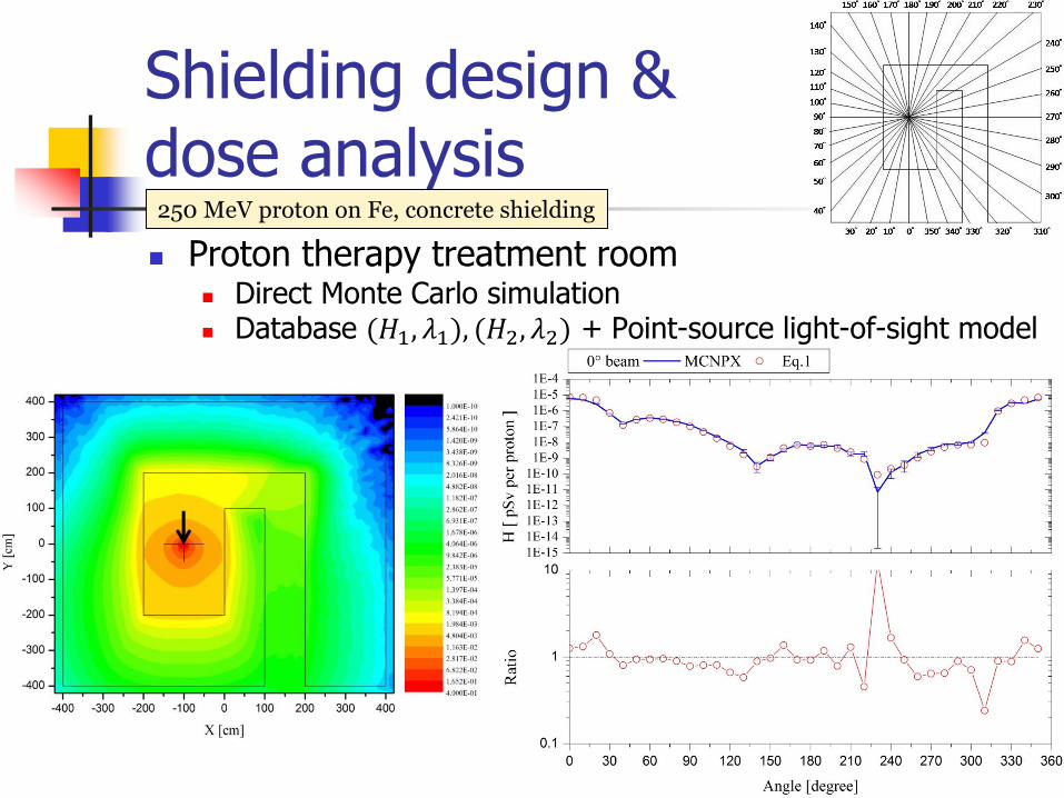
Shielding design & dose analysis
Proton therapy treatment room Direct Monte Carlo simulation Database (𝐻1, 𝜆1), (𝐻2, 𝜆2) + Point-source light-of-sight model
250 MeV proton on Fe, concrete shielding

Shielding design & dose analysis
Proton therapy treatment room Direct Monte Carlo simulation Energy spectra of neutrons and gamma rays on the surface of
the 0 shielding wall and near the maze entrance, respectively
Neutron Photon
250 MeV proton on Fe, concrete shielding

Radiation streaming
Proton therapy treatment room Direct Monte Carlo simulation Database (𝐻0/𝑟2) + Cossairt’s formula (FermiLab TM-1834, 2005)
00147.0 ,21.0 ,25.5 ,17.1 ,17.0 ,41
:are parameters fitting theand where
)1( leg for )(1
)(
leg 1for )()(
0
11
///
0
2
01
011
BAcba.r
A/dδ
iiHBA
BeAeeH
RHr
rH
ii
th
ii
cba
ii
st
iii
250 MeV proton on Fe, concrete shielding

Conclusions
Neutrons are dominant dose component at proton and heavy ion accelerators, also for high-energy electron accelerators with thick shielding.
Benchmark calculations were performed for neutron production by proton, heavy ion, and electron with energies of our interest and their agreement with experiments are generally satisfactory.
Selection of proper multigroup cross sections is important to neutron deep-penetration calculations.
This work provides a set of reliable shielding data with reasonable coverage of common target and shielding materials for 100-300 MeV proton accelerators.
General characteristics and possible applications of this data set in cases of single- and double-layer shielding are presented.