Embed Size (px)
Citation preview

Neutron Imaging of Advanced Engine Technologies Todd J. Toops, Principal InvestigatorCharles E.A. FinneyThomas E. BriggsAndrea Strzelec*Oak Ridge National LaboratoryEnergy and Transportation Science Division
Hassina Z. Bilheux & Sophie VoisinOak Ridge National LaboratoryNeutron Scattering Science Division
Jens GregorUniversity of Tennessee – KnoxvilleDept. of Electrical Engineering and Computer Science
ACE052May 11, 2011
* - Currently at Pacific Northwest National LaboratoryThis presentation does not contain any proprietary,
confidential, or otherwise restricted information
Gurpreet Singh and Ken HowdenAdvanced Combustion Engine Program
U.S. Department of Energy

2 Managed by UT-Battellefor the U.S. Department of Energy
Project Overview
• Started in FY2010• Ongoing study
• 2.3.1B: Lack of cost-effective emission control− Need to improve regeneration
efficiency in diesel particulate filters (DPFs)
• 2.3.1C: Lack of modeling capability for combustion and emission control− Need to improve models for
effective DPF regeneration with minimal fuel penalty
• 2.3.1.D: Durability− Potential for thermal runaway− Ash deposition and location in
DPFs which limit durability
Timeline
Budget
Barriers
Partners
• FY2010: $100k• FY2011: $200k• FY2012: similar funding levels
• BES-funded Neutron Scientists and facilities
• University of Tennessee• NGK

3 Managed by UT-Battellefor the U.S. Department of Energy
Objectives and Relevance
Develop non-destructive, non-invasive neutron imaging technique and implement it to improve understanding of advanced vehicle technologies
Graphic provided by Detroit Diesel.
• Current focus on diesel particulate filters (DPFs) – Improve
understanding of regeneration behavior
– fuel penalty associated with regeneration
– Improving understanding of ash build-up
• Additional areas of interest– Fuel injectors– EGR coolers
4 Managed by UT-Battellefor the U.S. Department of Energy
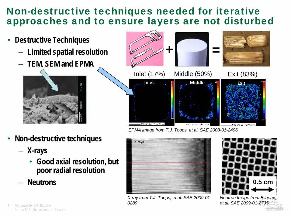
Non-destructive techniques needed for iterative approaches and to ensure layers are not disturbed
• Destructive Techniques– Limited spatial resolution– TEM, SEM and EPMA
• Non-destructive techniques – X-rays
• Good axial resolution, but poor radial resolution
– Neutrons
+ =Middle (50%) Exit (83%)Inlet (17%)
Inlet Middle Exit
EPMA image from T.J. Toops, et al. SAE 2008-01-2496.
X-ray from T.J. Toops, et al. SAE 2009-01-0289
X-rays
Neutrons
Neutron Image from Bilheux, et al. SAE 2009-01-2735
0.5 cm

5 Managed by UT-Battellefor the U.S. Department of Energy
Milestones
• Obtain images with significantly increased resolution that identifies interactions of soot and ash with DPF walls (9/30/2011).– On target
• Construct spray chamber and obtain initial spray images (9/30/2011). – On target
6 Managed by UT-Battellefor the U.S. Department of Energy
Collaborations• Basic Energy Sciences
– High Flux Isotope Reactor (HFIR) and – Spallation Neutron Source (SNS) – Development and operation of beamline facilities,
neutron scientists time• NGK
– Donating materials and contributing accelerated ash filled samples• Michael Lance, Scott Sluder and Keely Willis (Propulsion Materials project)
– Working on EGR cooler fouling project with several industrial partners– Caterpillar, Cummins, DAF Trucks, Detroit Diesel, Ford, GM, John Deere, Modine,
Navistar, PACCAR and Volvo/Mack– US Army
• University of Tennessee– Developing algorithms for improving contrast and removing artifacts
• Technical University of Munich– Initial neutron imaging efforts

7 Managed by UT-Battellefor the U.S. Department of Energy
Chopper Box
White or TOF Beam
Detector Box
Beam Stop
Translation/Rotation Stage
Monochromatic Beam
CG-1 Beamline at HFIR
ApproachOperate engine at ORNL/FEERC under targeted conditions;move device to HFIR
Receive devices from industrial partners for analysis
Record raw images of devices using neutron beam
Reconstructdevice using
neutron computed
tomographic techniques
Improved understanding published and disseminated to modelers and engine controllers

8 Managed by UT-Battellefor the U.S. Department of Energy
Summary of Technical Accomplishments• Developed and implemented fully automated neutron computed tomography
equipment and reconstruction software. Performed 3D imaging of:– 3” x 6” clean DPF to demonstrate tomography capability– 1” x 3” DPFs that have been filled with ash
• continuous regeneration and periodic regeneration (NGK)• artificially filled
– 1” x 3” DPFs with soot deposited on the walls– Catalyzed and uncatalyzed 1” x 3” DPFs for impact of washcoat
• Improved resolution of neutron detector and can now achieve:– 100 micron resolution for a 7 cm x 7 cm field of view, or– 50 micron resolution for a 5 cm x 4 cm field of view
• Calibration samples for model ash prepared and measured

9 Managed by UT-Battellefor the U.S. Department of Energy
Technical Details

10 Managed by UT-Battellefor the U.S. Department of Energy
Neutrons are absorbed by a range of elements including light elements• Neutrons are heavily absorbed by light
elements such as Hydrogen and Boron– Can penetrate metals without absorbing– Highly sensitive to water and
hydrocarbons/fuel• Can image carbon soot layer due to
absorption of water and HC– Image is based on absence of neutrons
• X-ray imaging relies upon absorption of heavy elements
Neutron imaging is a complementary analytical tool
Reference: N. Kardjilov’s presentation at IAN2006http://neutrons.ornl.gov/workshops/ian2006/MO1/IAN2006oct_Kardjilov_02.pdf
http://neutra.web.psi.ch/What/index.html

11 Managed by UT-Battellefor the U.S. Department of Energy
Neutrons offer unique imaging opportunity
• With the ability to penetrate dense materials, neutrons offer the ability non-destructively analyze working systems
• Demonstrations show the potential applications– Yet to be demonstrated under realistic operating
conditions (videos made at Paul Scherrer Inst.)• Tomography can be applied to unravel detailed 3D structure
based on neutron absorption– Relies on computed reconstruction of device– Rotating device and recording absorbed neutron allows
rebuilding device and virtual cross-sectional analysis

12 Managed by UT-Battellefor the U.S. Department of Energy
Initial images recorded at TUM show potential to visualize soot layer in DPF
• Initial results from full DPFs– ANTARES Imaging Facility in
Munich, Germany, with DPFs from ORNL
– Technical University of Munich• Soot layer is present in alternating
channels– increased contrast required for
quantitative analysis
Clean DPF
Particulate filled DPF
0.5 in (1.3 cm)
Full 5.7” x 6” DPFFilled at ORNL imaged at TUM
Neutron images from Bilheux, et al. SAE 2009-01-2735

13 Managed by UT-Battellefor the U.S. Department of Energy
Neutron imaging capabilities at ORNL• High Flux Isotope Reactor (HFIR)
– Steady (i.e., non-pulsed) neutron source; “white” beam
– Imaging capability has been developed in parallel during this program
– Imaging beamline recently incorporated into user program• Neutron scientists efforts have
been part of the development process
• Spallation Neutron Source (SNS)– Most intense pulsed neutron beams
in the world; energy selective– Multi-laboratory effort funded by
DOE Office of Science – Letter Of Intent (LOI) of imaging
beamline approved
Protons hit a Mercury target and “spall” off neutrons with a repetition rate of 60 Hz

14 Managed by UT-Battellefor the U.S. Department of Energy
Establishing high quality neutron images depends on equipment and computational technologies• Neutrons absorbed by device are combined build tomographic image• To improve image quality data is processed to improve contrast
– Techniques employed: Back-Filtered (Left) vs. Iterative (Right) Projection– Back Filtered Projection: Grainy aspect and noise prevent data analysis– Iterative projection promising with increased contrast, but lose some sharpness at edges
• Filtering algorithms still under development

15 Managed by UT-Battellefor the U.S. Department of Energy
Distinguishing Ca-based model ash is difficult• Model ash (calcium carbonate) standards
– pressed into disks– two densities studied
• a: 507 g/cm3
• b: 370 g/cm3
– Model ash approach by NGK*• Ash artificially loaded in portion of DPF
– difficult to distinguish from sample• Ca adequately simulates exhaust ash, BUT
has poor Neutron absorbtivity– Visualization relies on water adsorption
Artificially ash-loaded
Cle
an S
ampl
e
Ash
Calcium carbonate (model ash) standards
1a 2a 3a 4a 5a
0.18g 0.45g 0.54g 0.91g 1.08g
5b 4b 3b 2b 1b
0.68g 0.81g 0.44g 0.36g 0.18g
* - S. Fuji and T. Asako, SAE 2010-01-2171

16 Managed by UT-Battellefor the U.S. Department of Energy
• Imaging process methodology
Neutron computed tomography and data analysis employed to show particulate profile in DPFs
Slice # 692
Maskfor signal over 0.01
Maskfor signal
over 0.0375
Deposit
0 5 10 15 20 25 30 35 40 45 50 55 Length from inlet (mm)
0 5 10 15 20 25 30 35 40 45 50 55 Length from inlet (mm)
flow
CLE
ANFI
LLED
Side
-vie
w o
f fil
led
DPF
* - W. Kockelmann et al., Nuclear Instruments and Methods in Physics Research A 578 (2007) 421
• 1”x3” DPF with unique particulate profile• Particulate cross-section as a function
of the length of the DPF– Elemental ID possible w/pulsed source*
17 Managed by UT-Battellefor the U.S. Department of Energy
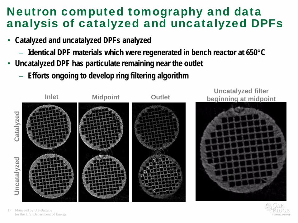
Neutron computed tomography and data analysis of catalyzed and uncatalyzed DPFs• Catalyzed and uncatalyzed DPFs analyzed
– Identical DPF materials which were regenerated in bench reactor at 650°C• Uncatalyzed DPF has particulate remaining near the outlet
– Efforts ongoing to develop ring filtering algorithm
Unc
atal
yzed
Cat
alyz
ed
Inlet Midpoint OutletUncatalyzed filter
beginning at midpoint

18 Managed by UT-Battellefor the U.S. Department of Energy
Imaging Techniques also being applied EGR cooler fouling study • EGR cooler fouling being studied in Propulsion Materials project
– Michael Lance (PI) and Scott Sluder • Able to identify local and global features
– Local: like mudcracks and delamination– Global: fouled versus cleaned
~33 m
m
CleanedFouled

19 Managed by UT-Battellefor the U.S. Department of Energy
Future work
• DPF partial regeneration– Pressure drop goes to background
levels after only 50% of the DPF is regenerated
– Where is the soot being regenerated?
– Are regenerations complete?
• Ash loading with more sensitive model ash– Boron or gadolinium doped– Packing density studies
• Fuel injection systems and engine flows
0
0.05
0.1
0.15
0.2
0.25
0.3
0 0.2 0.4 0.6 0.8 1
Pin
- Pou
t (ba
r)
DPF-A
DPF-B
DPF-C
Fraction of DPF regenerated

20 Managed by UT-Battellefor the U.S. Department of Energy
Fuel spray imaging• Fundamental insight into near-nozzle and in-
nozzle fuel behavior necessary for improved simulation and design.
– Boundary conditions– Liquid break-up mechanisms– Evaporation timescales– Cavitation
• Neutron imaging provides new information which is complimentary to current methods
– Laser-based methods not well suited for dense sprays and unable to penetrate metal making in situ measurements difficult or impossible
– X-ray based methods able to penetrate metal but require fuel doping and do not interact with vapor
Bosch CR injector imaging performed at Institu Laue-Langevin (Grenoble) with steady neutron beam. Adapted from van Overberghe 2006
21 Managed by UT-Battellefor the U.S. Department of Energy
Summary• Relevance: Develop non-destructive, non-invasive neutron imaging technique and
implement it to improve understanding of lean-burn vehicle systems– Improved understanding targeting fuel economy improvements and durability
• Approach: Neutron Imaging as a unique tool applied to Automotive Research areas to visualize, map and quantify H-rich deposit (soot/ash) in engine parts as well as looking at fuel dynamics inside spray (not achievable with x-rays)– DPFs, EGR coolers, Fuel Spray
• Collaborations: BES, Industrial (NGK), Govt. Labs (ORNL and PNNL) and Universities• Technical Accomplishments:
– The HFIR CG1 beamline is operating and offers both 2D and 3D capabilities– Demonstration of usefulness of neutron imaging techniques for automotive
research• Future Work:
– Filtering algorithms and full data analysis on remaining samples– Several more samples to measure (DPFs, EGR coolers and batteries)– New challenge: Looking at running fuel spray

22 Managed by UT-Battellefor the U.S. Department of Energy
Technical back-up slides

23 Managed by UT-Battellefor the U.S. Department of Energy
He-filled Al flight tubesSample stage (translation and rotation for neutron Computed Tomography)
Detector housing (CCD, lens, mirror and scintillator)
Chopper Box
Lens
CCD
Mirror
LiF/ZnS scintillator (25 to 200 microns thick)
HFIR CG1D beamlineAchievable Resolution:-50 microns- ∆λ/λ ~ 10% (in TOF mode)

24 Managed by UT-Battellefor the U.S. Department of Energy
Techniques still under development to enable image enhancement and elemental contrast• Bragg edges
• Phase Contrast
W. Treimer et al., Appl. Phys. Lett. 89 (2006). 5 min exposure, 150 microns detector resolution, 2 x 104 cm-2 s-1 Courtesy of N. Kardjilov.
Sharper image
N. Kardjilov et al., NIMA 527 (2004) 519-530.

25 Managed by UT-Battellefor the U.S. Department of Energy
Ash loading in 3”x6” DPF
• Because the ORNL CG1D imaging prototype beamline is NOT designed/optimized for neutron imaging measurements:– image processing is very demanding– currently working on data filtering and artifact
correction algorithms
• The deposition of Na ash is clearly visible
3 in (7.5 cm)
Clean DPF
DPF with Ash