Embed Size (px)
Citation preview

Operator Manual
FOR
Model/s: AC2E
(Rev 1504)
INSTRUCTION MANUAL
FOR DISHWASHING
Mod.
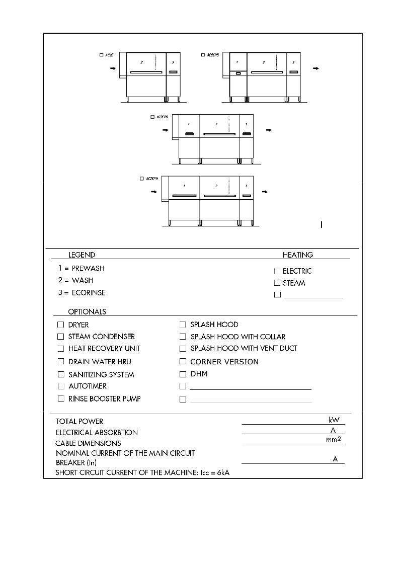
AC2E
AC2E P5
AC2E P6
AC2E P9
CORNER VERSION
DHM
instruction for the user
3
INDEX
Introduction .......................................................................................................................... 5 INSTRUCTIONS FOR USE ................................................................................................. 9 Notes before washing ........................................................................................................ 10 Operation and use ............................................................................................................. 10 Switching on ...................................................................................................................... 10 Washing ............................................................................................................................. 11 Instruction during washing ................................................................................................. 11 Instruction after the washing session ................................................................................. 12 Useful advice ..................................................................................................................... 12 Maintenance ...................................................................................................................... 12 Hygienic care ..................................................................................................................... 13 Removal of lime scale encrustation’s ................................................................................ 13 Optimum results ................................................................................................................. 13 Prolonged standstill of the machine ................................................................................... 13 Self cleaning (optional) ...................................................................................................... 14 Safety device ..................................................................................................................... 14 Micro limit switch SS1 ........................................................................................................ 14 Doors micro switches SS2…SS20..................................................................................... 14 Emergency stop push-button S3 ....................................................................................... 14 Slip clutch .......................................................................................................................... 14 Motor protection ................................................................................................................. 15 Element protection ............................................................................................................. 15 Other risks ......................................................................................................................... 15 Risk of trapping the upper limbs ........................................................................................ 15 Risks of burning the upper limbs ....................................................................................... 15 INSTRUCTION FOR INSTALLATION AND MAINTENANCE ........................................... 16 Location ............................................................................................................................. 17 Installation and connections .............................................................................................. 17 Electrical connection .......................................................................................................... 17 Hot water connection (B) ................................................................................................... 19 Cold water connection (D) ................................................................................................. 19 Steam connection (E) (only for steam heated machines) .................................................. 19 Water drain (A) .................................................................................................................. 19 Steam discharge (F) (only for steam heated machines) .................................................... 19 Steam elimination .............................................................................................................. 20 Before starting the machine ............................................................................................... 20 Setting ............................................................................................................................... 21 Torque limiter ..................................................................................................................... 21 Alarms ............................................................................................................................... 22 Loading and unloading of the machine .............................................................................. 22 Machine dismantling .......................................................................................................... 22 Some problems which may occur during the use of the dishwasher, their reasons and remedies ............................................................................................................................ 23
instruction for the user
4
instruction for the user
5
INTRODUCTION 1. Please read carefully the remarks contained in this manual, as they confirm important
information for the correct installation, use and maintenance. Keep this manual for future reference by the staff.
2. After removal of the packing, check the machine is not damaged and is complete. In case of any doubt, do not use the machine and contact the service technician. The packing case (plastic bags, expanded polystyrene, nails etc.) must not be left on site as they are a potential danger source and must be disposed of carefully.
3. Before connecting the machine to services, check that the details on the data plate correspond to the services provided on site.
4. The installation has to be completed by qualified staff in accordance with all relevant regulations and the manufacturers instructions.
5. This machine must only be used for the purpose designed: washing of dishes such as plates, glasses, cups, cutlery, trays etc. Any other use such as washing of machine parts or objects with higher dimensions than the working passage of which the machine allows is not recommended and will cause damage to the machine and danger to the operators.
6. The machine must be used only by trained staff.
7. The staff handling the objects after the washing cycles must comply with hygiene regulations.
8. Do not keep the machine in places with temperatures below 0°C.
9. The protection degree of the machine is IPX4 and it must therefore not be washed with water jets.
10.After isolating the electrical supply, only qualified staff are allowed access to the control panel.
11.The machine is built according to EEC 2004/108 Directive relating to the elimination of radio interferences and to the electromagnetic compatibility.
12.In conformity with I.E.C.-standard our dishwashers are manufactured according to the standard of excellent technical level valid in Italy and abroad.
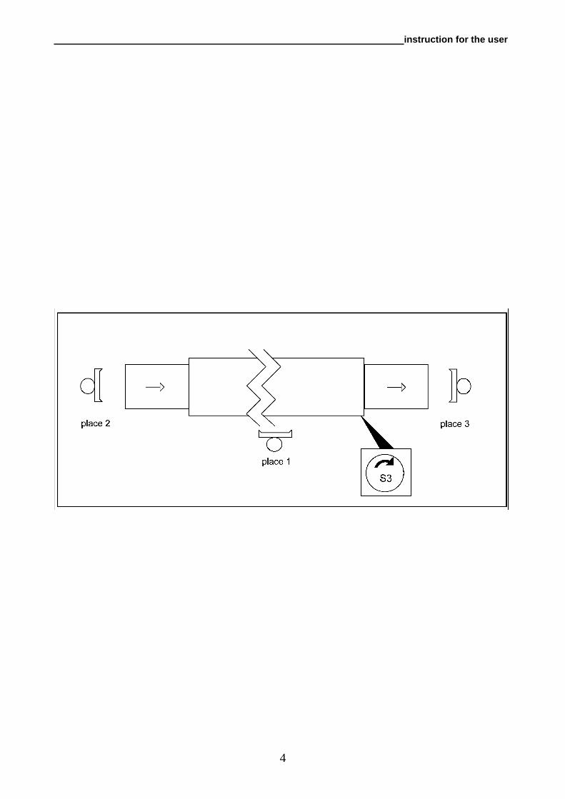
13.Noise of empty machine operation, measured at the working places (fig. 1) at 1.6 m height, are as follows:
place 1 place 2 place 3 LeqA level equivalent to the acoustic pressure dB(A)
The peak of the acoustic pressure level is not indicated, as far below 130 dB(A):
instruction for the user
6
instruction for the user
7
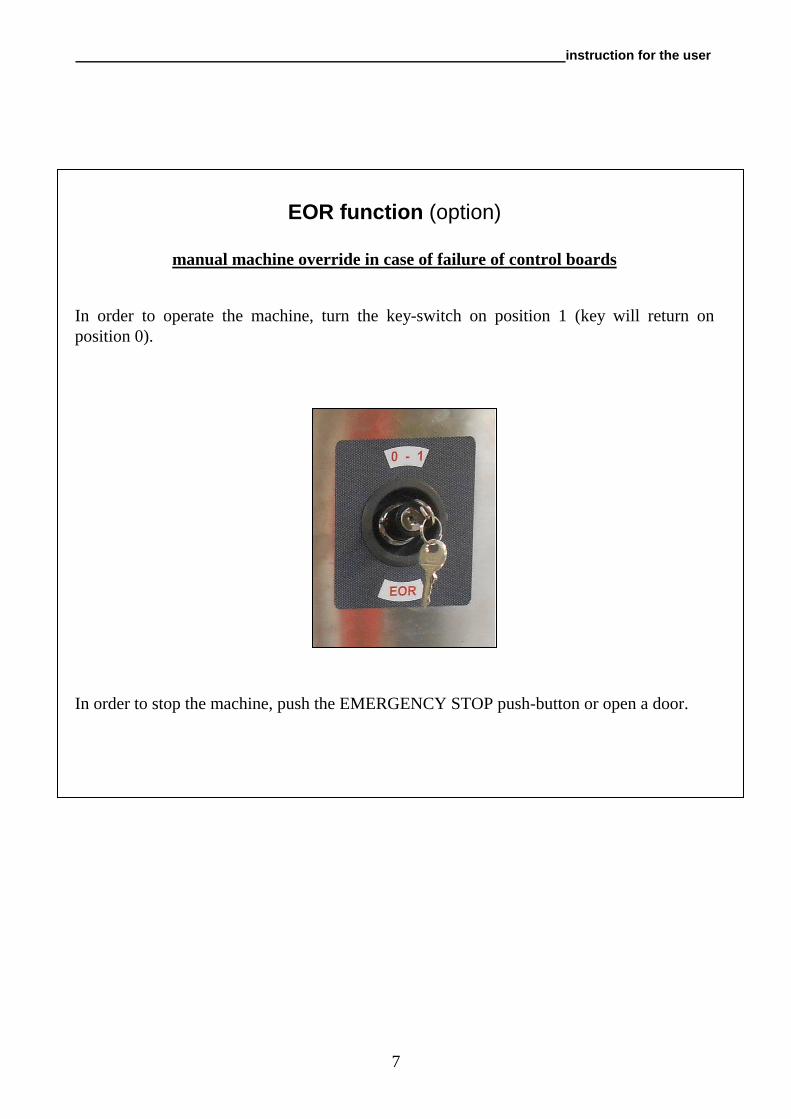
EOR function (option)
manual machine override in case of failure of control boards
In order to operate the machine, turn the key-switch on position 1 (key will return on position 0).
In order to stop the machine, push the EMERGENCY STOP push-button or open a door.
instruction for the user
8
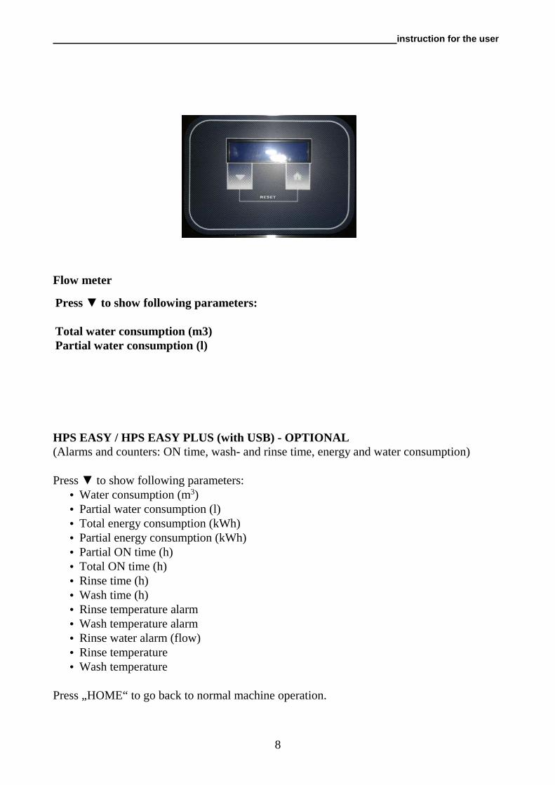
Flow meter HPS EASY / HPS EASY PLUS (with USB) - OPTIONAL (Alarms and counters: ON time, wash- and rinse time, energy and water consumption) Press ▼ to show following parameters:
• Water consumption (m3) • Partial water consumption (l) • Total energy consumption (kWh) • Partial energy consumption (kWh) • Partial ON time (h) • Total ON time (h) • Rinse time (h) • Wash time (h) • Rinse temperature alarm • Wash temperature alarm • Rinse water alarm (flow) • Rinse temperature • Wash temperature
Press „HOME“ to go back to normal machine operation.
Press ▼ to show following parameters: Total water consumption (m3) Partial water consumption (l)
instruction for the user
9
INSTRUCTIONS FOR USE
instruction for the user
10
NOTES BEFORE WASHING 1)Make sure that: • wall isolating switch is connected • water and steam taps* are open • there is no lack of water and steam* in the supply net • tank and pump suction filters are clean and are located correctly and the overflow pipe is
in position and closed • curtains are correctly placed • inspection doors are closed • detergent and rinse aid dispensers are full • dimensions of the dishware do not exceed those prescribed
OPERATION AND USE
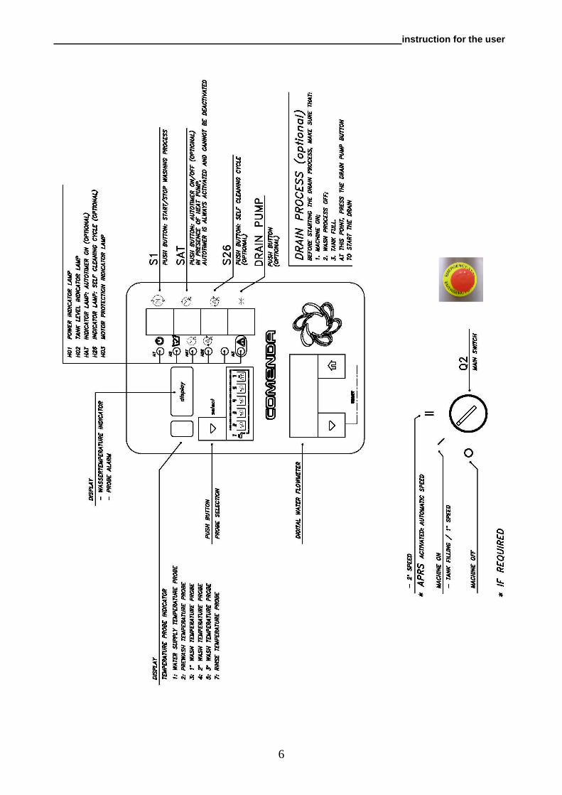
Switching on In order to turn the machine on simply rotate the main switch "Q2" to the right on to position "I". Lamp "H01" will illuminate.
Close all machine doors.
Wait for lamp "H02" to turn on indicating tank is full.
Every time the button "SELECT" is pushed the display show: 1 : water supply temperature probe (55°C) 2 : prewash temperature probe (40-45°C) 3,4,5,6 : wash temperatures probes (55-60°C) 7 : rinse temperature probe (80-85°C)
Wait until the wash tank temperature reaches 55/60°C; at this point the machine is ready for use.
Select the machine speed, using the main switch " Q2": - position I - for heavily soiled dishes; - position II - for lightly soiled items;
- position II - automatic speed change witch APRS -IF REQUIRED.
Push switch "S1" to start or stop washing process. The lamp "H03" indicates that the pump is overheating, technical assistance required
Push switch "SAT" to start the autotimer function; lamp "HAT" will illuminate. The autotimer function with automatic reset temporarily stops the operation, if no racks have been introduced into the machine. Placing a rack into the machine, this restarts automatically. _________________________________________ (*)this applies only to machines with steam heating
instruction for the user
11
WASHING 1) Before starting the wash operations remove from the dishes all possible food leftovers
and grease. 2) Pre-soak cutlery and also any dishes before washing, if they have been left for some time
after being used. 3) Place the items to be washed in the baskets. 4) Make sure that the plates are turned towards the exit of the machine. 5) If the operator using the machine does not remove the racks from the exit table, a limit
switch ensures the conveyor and rinse cycle is stopped. Removing the rack from the limit switch re starts the washing sequence.
INSTRUCTION DURING WASHING 1) Do not put your bare hands in the hot and detergent water in the tanks, as this may cause
burns and skin irritations. Should this happen rinse your hands immediately under fresh water.
2) When the machine is functioning do not open inspection doors quickly. 3) Use only commercial non-foaming detergents for industrial dishwashers, supplied by
well-known and reputable companies. 4) Isolate the electrical supply to the machine in the case of a breakdown or defective
operation. For all repair work, rely exclusively on a Technical Assistance, approved by the manufacturer and request that original spare parts be used.
5) At periodic intervals stop the machine, remove tank filters and remove the residues which
have accumulated. Do not remove the pump suction filters when the tank is full. 6) If the rack advancing system has stopped due to the safety device (slip clutch) operating,
stop the machine by pressing the mushroom-shaped emergency push-button "S3" and remove the obstruction which caused the problem.
7) Ensure the detergent and rinse aid levels, in the respective dispensers are kept topped up. 8) Make sure that water temperatures maintain their regulated values: prewash (probe 2)
40/45°C, wash (probe 3,4,5,6) 50/60°C, rinse (probe 7) 75/85°C. The non-observance of the above mentioned points may compromise the safety of the machine and the staff.
instruction for the user
12
INSTRUCTION AFTER THE WASHING SESSION When the wash operations are complete:
1. Press button "S1" and turn switch "Q2" into position "O" to switch off the machine.
2. Isolate the machine by means of the wall switch and close the water valve and steam supply (this applies only to steam heating machines).
3. Lift the inspection doors and make sure that they are perfectly hooked onto the support. 4. Take off the overflow pipe in order to empty the tanks. 5. Take out the anti -splash curtains and the filters for cleaning. 6. Check and, if necessary, clean the wash and rinse nozzles. Clean out the wash tanks with
a wash spray hose assembly. 7. Clean the external surface of the machine with a damp cloth; do not use jets of water, as,
apart from being dangerous, damage to electric components may occur; do not use abrasive detergents or those containing chlorine.
8. Reassemble all devices into their locations, taking care that: • the curtains are turned with the short side towards the entry of the items being washed • the wash nozzles are turned towards the items being washed
9. Keep doors open in order to avoid unpleasant odours, when not in use.
USEFUL ADVICE
Maintenance IMPORTANT: Before undertaking cleaning and maintenance work, isolate the machine from the electric supply by switching off the wall switch or the disconnecting switch "Q1". ATTENTION: do not unplug the disconnecting switch "Q1" when machine is switched on. Regular check and cleaning of the nozzles is advisable. The frequency of cleaning depends on the quantity of leftovers and foodsoiling left on the crockery, insufficient cleaning of nozzles will give poor wash results. Do not use corrosive products such as hypochloride sodium (bleaching products), acids in general, steel wool and steel brushes for cleaning the machine inside and outside. To ensure the machine is kept in a perfect hygienic condition, it is advisable to carry out the following periodic operations. Ensure the procedures and frequency recommended by the detergent supplier are followed, also ensure that the correct products and equipment are used. In order to avoid damages to the machine, do not exceed the recommended dosing and at the end of the procedures, rinse thoroughly.
instruction for the user
13
Hygienic care A thorough cleaning of the machine is essential. For this operation the use of sanitizing detergent/disinfectant is advisable. The use of such a product offers the following advantages: • guarantee for perfect hygienic conditions, as it is composed of active detergents and
disinfectants. • maintenance of perfect hygienic conditions, also if the machine is not used. After completion of above procedures the machine has to be rinsed by completing a short washing cycle without load or by using the sanitizing cycle (optional).
Removal of lime scale encrustation’s In case of hard water a periodic descaling should be carried out to ensure hygiene and proper operation.
Optimum results Traces of dirt or marks are the result of a possible deficiency in the wash operation. If this problem occurs ensure that the wash nozzles are clean and that there is an adequate water supply/pressure available. Also check the following points • wash nozzles are not blocked • water supply temperature (probe 1) is 50/55°C (excluding machines with heat recovery
unit or machines functioning with cold water feed) • prewash temperature (probe 2) is 40/45°C • wash temperatures (probes 3....6) is 55/60°C • rinse temperature (probe 7) is 80/85°C • detergent is used in the correct concentration • filters are clean • water is not too dirty • dishes are not stacked one upon or inside the other, as the water needs to circulate freely
and directly contact all surfaces.
Prolonged standstill of the machine In case of a prolonged standstill lasting several weeks it is advisable, in order to avoid unpleasant odours and the accumulation of dirt, to empty the machine, refill and run with clean water. If the standstill lasts for a very long time, it is recommendable to lubricate the stainless steel surfaces with Vaseline oil.
instruction for the user
14
Self cleaning (optional) At least once a week a thorough cleaning of the machine is necessary. For this purpose a specific detergent/disinfectant is advisable. The use of such a product offers the following advantages: • guarantee of perfect hygienic conditions as it is composed of active detergents and
disinfectants • maintenance of the machine in perfect hygienic conditions, also if the machine is not
used. For starting the self cleaning sanitizing cycle, switch "Q2" has to be put into position "O". Empty the tanks by lifting and take off the overflow pipes, remove the curtains, close the inspection doors and press push-button "S26". The lamp "H26" is illuminated during the whole period of the cycle.
SAFETY DEVICE This machine is provided with numerous devices for ensuring the safety of the staff and the machine.
Micro limit switch SS1 When the rack reaches the end of the exit table, the limit switch operates and stops the conveyor and consequently the breaking of the crockery. By removing above, the conveyor automatically restarts.
Doors micro switches SS2…SS20.. The door is provided with one safety micro switch. If the doors is opened, the functioning of the pumps, the motor reduction gear of the conveyor unit and the rinse solenoid valve are interrupted. The operation is resumed only after the doors are closed again and by pressing the start push-button "S1". In case of dishwashers with a complex lay-out, several push-buttons near the working stations may be necessary.
Emergency stop push-button S3 The machine is provided with an emergency red mushroom-shaped push-button on yellow background which easy accessible from operator, if pressed, stops all motors on the machine. After elimination of the problem, the machine can only be started after turning and releasing the push-button and pressing again the start push-button "S1". In case of complex lay-out more push-buttons may require releasing near the work stations.
Slip clutch The rack conveyor system is provided with a clutch-type mechanical torque control, which is fitted to the drive mechanism of the conveyor system. If something gets erroneously jammed in between the machine and rack or the rack is overloaded, the conveyor system quickly slows down to nearly zero. In this case it is necessary to switch off the machine by means of stop or emergency push-buttons, remove the obstacle and press again the start push-button. For adjustment of this safety device refer to paragraph MAINTENANCE.
instruction for the user
15
Motor protection Each motor is protected against overload by overload relays QF1, QF2.... placed in the control box (see electric diagram). Lamp "H03" is on, if one of the overload relays is activated. In this case the machine must be switched off and qualified staff are to be contacted for the repair work. (see paragraph MAINTENANCE).
Element protection Each element is protected against short-circuits by the fuses (FE3...) or with automatics (QFE10). The tank elements are protected against operation without water in the tanks, by pressure switches and those in the boiler and dryer by safety thermostats which have to be manually reset. In case of intermittent problems contact qualified and authorised staff. (see paragraph MAINTENANCE).
Other risks Although the machine is provided with the above mentioned safety devices, there are still the risks listed below.
Risk of trapping the upper limbs
As previously pointed out above, the conveyor system is provided with a clutch-type mechanical torque control, the adjustment must be related to the mechanical torque required for the transport of the items being washed. The mechanical risks of trapping the upper limbs have been eliminated by protecting and isolating the dangerous moving parts. When the machine is operating do not introduce your arms into the wash tunnel.
Risks of burning the upper limbs
Under the paragraph INSTRUCTION DURING THE WASHING we have previously advised that you must not put your hands into the hot and detergent water of the tanks. This might cause burns and skin irritations. In case this should happen immediately rinse under fresh water and follow the instructions of the product being used.
instruction for the service people
16
INSTRUCTION FOR INSTALLATION AND MAINTENANCE
The following instructions are for qualified staff, who are authorised to carry out inspections and repair work, if necessary.
The manufacturer declines all liability for damages due to incorrect installation or any repairs when original spare parts have not been used.
instruction for the service people
17
LOCATION The machine has to be installed in a “normal” room or environment, which is adequately ventilated, dust free, well illuminated and without risk of explosion.
INSTALLATION AND CONNECTIONS The installation of the dishwasher requires previously prepared supplies for the electrical and hydraulic connections, as indicated on the enclosed installation plan and data plates which refer to the model of your choice.
In order to prevent damage due to the emission of steam from the machine, ensure that adequate ventilation/extraction is available.
Remove lower panels and position the machine over service connections. Fit the standard rubber absorbers supplied under the adjustable feet of the machine and adjust them to level it, if necessary.
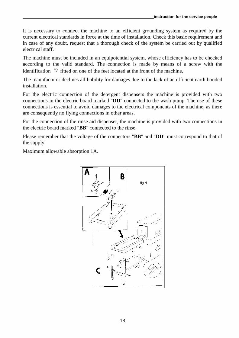
Connect the load and unload tables. It is advisable to fit a table crowding switch "SS1" on the unload table. For the electrical connection, see fig.4.
The supplier of detergents has to provide the required dispensers.
Attention: The supply of detergents and hygienic products should be provided by the use of automatic dispensers, as it is not possible to obtain adequate quantities, when pouring the detergent directly into the tank. There is also the risk that brown spots may appear on the surfaces due to the reaction of chloride.
The introduction of the detergents must take place near the suction tube of the pump, the minimum distance from the bottom must be 15 cm in order to avoid corrosion.
ELECTRICAL CONNECTION The electrical supply voltage must correspond with the machines electrical requirements, as indicated on the machines data plate
Electric supply has to be isolated via a wall mounted three-pole circuit breaker having a contact separation in all poles that provide full disconnection under overvoltage category III conditions in accordance with the wiring rules. For the dimensions of above refer to the “Technical data sheet” on page 1 of this instruction manual (Recommended residual current circuit breaker Type A, 400V, Id=0,03A).
The section of the supply cables must not be inferior to that indicated in the “Technical data sheet”. If the cable is not protected use a flexible cable with protective covering in polychloropene with characteristics matching at least type H07RN-F.
The cable must be connected to the terminal “PE” of the grounding bar.
The electrical safety of this machine is guaranteed only on condition that it is connected as follows.
instruction for the service people
18
It is necessary to connect the machine to an efficient grounding system as required by the current electrical standards in force at the time of installation. Check this basic requirement and in case of any doubt, request that a thorough check of the system be carried out by qualified electrical staff.
The machine must be included in an equipotential system, whose efficiency has to be checked according to the valid standard. The connection is made by means of a screw with the identification fitted on one of the feet located at the front of the machine.
The manufacturer declines all liability for damages due to the lack of an efficient earth bonded installation.
For the electric connection of the detergent dispensers the machine is provided with two connections in the electric board marked "DD" connected to the wash pump. The use of these connections is essential to avoid damages to the electrical components of the machine, as there are consequently no flying connections in other areas.
For the connection of the rinse aid dispenser, the machine is provided with two connections in the electric board marked "BB" connected to the rinse.
Please remember that the voltage of the connectors "BB" and "DD" must correspond to that of the supply.
Maximum allowable absorption 1A.
instruction for the service people
19
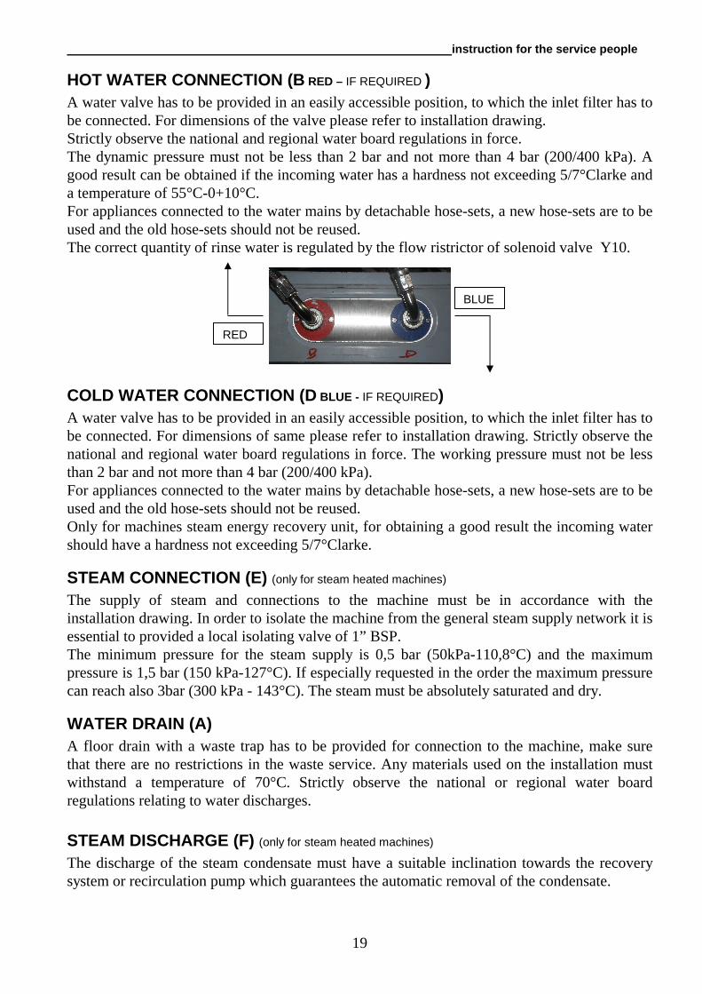
HOT WATER CONNECTION (B RED – IF REQUIRED ) A water valve has to be provided in an easily accessible position, to which the inlet filter has to be connected. For dimensions of the valve please refer to installation drawing. Strictly observe the national and regional water board regulations in force. The dynamic pressure must not be less than 2 bar and not more than 4 bar (200/400 kPa). A good result can be obtained if the incoming water has a hardness not exceeding 5/7°Clarke and a temperature of 55°C-0+10°C. For appliances connected to the water mains by detachable hose-sets, a new hose-sets are to be used and the old hose-sets should not be reused. The correct quantity of rinse water is regulated by the flow ristrictor of solenoid valve Y10.
COLD WATER CONNECTION (D BLUE - IF REQUIRED) A water valve has to be provided in an easily accessible position, to which the inlet filter has to be connected. For dimensions of same please refer to installation drawing. Strictly observe the national and regional water board regulations in force. The working pressure must not be less than 2 bar and not more than 4 bar (200/400 kPa). For appliances connected to the water mains by detachable hose-sets, a new hose-sets are to be used and the old hose-sets should not be reused. Only for machines steam energy recovery unit, for obtaining a good result the incoming water should have a hardness not exceeding 5/7°Clarke.
STEAM CONNECTION (E) (only for steam heated machines)
The supply of steam and connections to the machine must be in accordance with the installation drawing. In order to isolate the machine from the general steam supply network it is essential to provided a local isolating valve of 1” BSP. The minimum pressure for the steam supply is 0,5 bar (50kPa-110,8°C) and the maximum pressure is 1,5 bar (150 kPa-127°C). If especially requested in the order the maximum pressure can reach also 3bar (300 kPa - 143°C). The steam must be absolutely saturated and dry.
WATER DRAIN (A) A floor drain with a waste trap has to be provided for connection to the machine, make sure that there are no restrictions in the waste service. Any materials used on the installation must withstand a temperature of 70°C. Strictly observe the national or regional water board regulations relating to water discharges.
STEAM DISCHARGE (F) (only for steam heated machines)
The discharge of the steam condensate must have a suitable inclination towards the recovery system or recirculation pump which guarantees the automatic removal of the condensate.
RED
BLUE
instruction for the service people
20
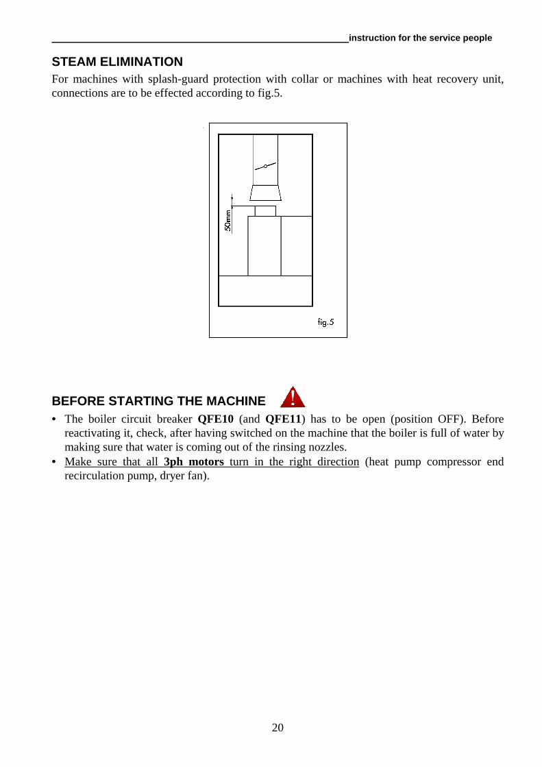
STEAM ELIMINATION For machines with splash-guard protection with collar or machines with heat recovery unit, connections are to be effected according to fig.5.
BEFORE STARTING THE MACHINE • The boiler circuit breaker QFE10 (and QFE11) has to be open (position OFF). Before
reactivating it, check, after having switched on the machine that the boiler is full of water by making sure that water is coming out of the rinsing nozzles.
• Make sure that all 3ph motors turn in the right direction (heat pump compressor end recirculation pump, dryer fan).
instruction for the service people
21
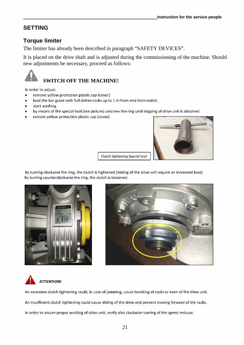
SETTING
Torque limiter The limiter has already been described in paragraph “SAFETY DEVICES”.
It is placed on the drive shaft and is adjusted during the commissioning of the machine. Should new adjustments be necessary, proceed as follows:
SWITCH OFF THE MACHINE!
instruction for the service people
22
ALARMS The display show: A2 probe (1...7): temperature over 105°C or probe in short circuit A3 probe (1...7) not connected
LOADING AND UNLOADING OF THE MACHINE For the transportation of the machine from the delivery point to the final installation position, use a fork lift or adequate lifting equipment used by authorised staff. Lift the machine by its frame, taking care that any protruding parts are not damaged (discharges, wiring etc.).
MACHINE DISMANTLING At the end of its normal lifetime, the machine has to be taken apart according to the local regulations in force by separating the components as follows:
• metal parts: hood, platforms, frames, filters • electrical parts: motors, remote control switches, microswitches, wiring • plastic parts: racks, connections • rubber parts: tubes, sleeves
instruction for the service people
23
SOME PROBLEMS WHICH MAY OCCUR DURING THE USE OF THE DISHWASHER, THEIR REASONS AND REMEDIES
PROBLEMS TROUBLE SHOOTING When switching on the machine, a)make sure that the wall isolating switch is Lamp "H01" does not light up making contact and the relevant fuses are not
burnt. b)make sure that the wall switch is connected c)make sure that the fuses "F15" and "F16" of
the transformer "T1" are not burnt. Warning lamp "H03" is switched on a)check the overload and contactor of each
motor and reset any which have tripped b)make sure that the supply doesn’t fluctuate
more than 6% of the nominal value c)make sure that the motors are not drawing
more current than the value shown on the plate of the motor
d)make sure that there are three phases to the
motors If not, check the contactor Incorrect filling of the tanks; a)Check and adjust the pressure switch "SL3" lamp "H02" does not illuminat if required
b)make sure that the local isolating valve for the water supply is open and that there is water in the supply pipes
c)check and ensure that the overflowpipe is seated correctly and in its correct position
d)make sure that the coil of the solenoid valve for the tank fill is not damaged and that there is voltage at the valve
Continuous filling of tanks a)make sure that the air trap of the pressure
switch is not damaged and that the connection to the hose is not detached.
b)check the pressure switch operates correctly
instruction for the service people
24
PROBLEMS TROUBLE SHOOTING c)make sure that no dirt has accumulated in
the solenoid valve. This defect causes the machine to fill also when the main switch is switched off.
d)in case the tank remains full for many hours
(e.g. during the night) the machine might continue to fill. Therefore empty the machine completely and refill it.
e)check that the air trap is in a vertical
position. Insufficient wash results a)make sure that detergent equipment is
working and is suitable for commercial dishwashers and that the concentration of the dosing is correct
b)make sure that the dispenser of the
detergent is not empty and that the detergent injector functions correctly
c)make sure that the wash jets are not
blocked, clean them if required. d)make sure that the temperature in the
prewash and wash tank are correct. e)make sure that the plugs of the spray arms
are fitted correctly f)if the pump is not running; check the
following: - the overload relay of the motor protector has
not excluded the respective pump; in this case reset it (this fault is signalled by the lamp "H03" being illuminated)
- the coil of the relevant contactor are not
faulty - the pump itself is not blocked, and is not
going in the wrong direction or has a worn or broken impeller.
instruction for the service people
25
PROBLEMS TROUBLE SHOOTING
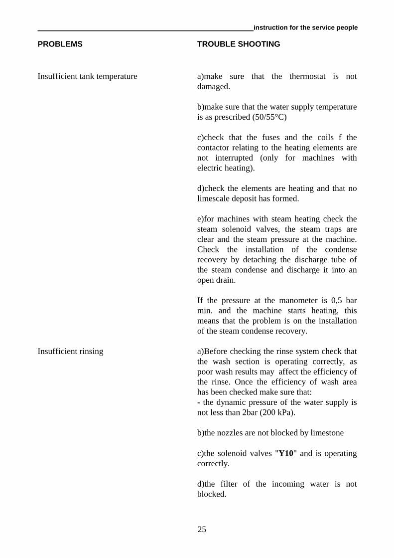
Insufficient tank temperature a)make sure that the thermostat is not
damaged. b)make sure that the water supply temperature
is as prescribed (50/55°C) c)check that the fuses and the coils f the
contactor relating to the heating elements are not interrupted (only for machines with electric heating).
d)check the elements are heating and that no limescale deposit has formed.
e)for machines with steam heating check the
steam solenoid valves, the steam traps are clear and the steam pressure at the machine. Check the installation of the condense recovery by detaching the discharge tube of the steam condense and discharge it into an open drain.
If the pressure at the manometer is 0,5 bar
min. and the machine starts heating, this means that the problem is on the installation of the steam condense recovery.
Insufficient rinsing a)Before checking the rinse system check that
the wash section is operating correctly, as poor wash results may affect the efficiency of the rinse. Once the efficiency of wash area has been checked make sure that:
- the dynamic pressure of the water supply is not less than 2bar (200 kPa).
b)the nozzles are not blocked by limestone c)the solenoid valves "Y10" and is operating
correctly. d)the filter of the incoming water is not
blocked.
instruction for the service people
26
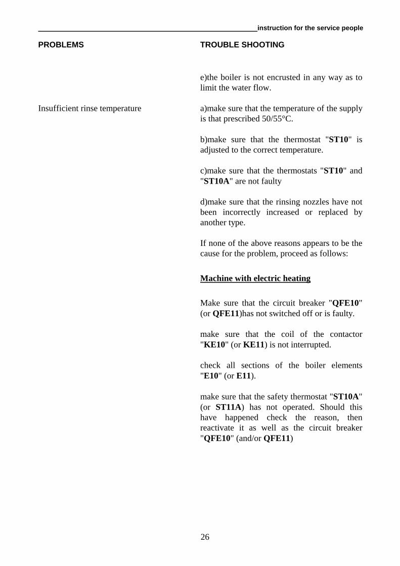
PROBLEMS TROUBLE SHOOTING e)the boiler is not encrusted in any way as to
limit the water flow. Insufficient rinse temperature a)make sure that the temperature of the supply
is that prescribed 50/55°C. b)make sure that the thermostat "ST10" is
adjusted to the correct temperature. c)make sure that the thermostats "ST10" and
"ST10A" are not faulty d)make sure that the rinsing nozzles have not
been incorrectly increased or replaced by another type.
If none of the above reasons appears to be the
cause for the problem, proceed as follows:
Machine with electric heating
Make sure that the circuit breaker "QFE10" (or QFE11)has not switched off or is faulty.
make sure that the coil of the contactor
"KE10" (or KE11) is not interrupted. check all sections of the boiler elements
"E10" (or E11). make sure that the safety thermostat "ST10A"
(or ST11A) has not operated. Should this have happened check the reason, then reactivate it as well as the circuit breaker "QFE10" (and/or QFE11)
instruction for the service people
27
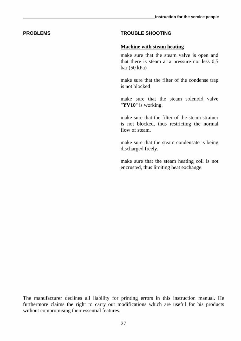
PROBLEMS TROUBLE SHOOTING Machine with steam heating
make sure that the steam valve is open and that there is steam at a pressure not less 0,5 bar (50 kPa)
make sure that the filter of the condense trap
is not blocked make sure that the steam solenoid valve
"YV10" is working. make sure that the filter of the steam strainer
is not blocked, thus restricting the normal flow of steam.
make sure that the steam condensate is being
discharged freely.
make sure that the steam heating coil is not encrusted, thus limiting heat exchange.
The manufacturer declines all liability for printing errors in this instruction manual. He furthermore claims the right to carry out modifications which are useful for his products without compromising their essential features.

AC2E… tech - eng
04.2015