Embed Size (px)
Citation preview

2013 3rd International Conference on Electric Power and Energy Conversion Systems, Yildiz Teclmical University, Istanbul, Turkey, October 2-4,2013
New Algorithm to Detect Balanced Three Phase Fault during Power Swing on Transmission Lines with
Communication Linl(s
Mohammed H. Qais
Electrical Engineering Department King Saud University Riyadh, Saudi Arabia
Qais65 _ [email protected]
Abstract- distinguishing a balanced three phase fault from a
power swing is difficult since both have similar characteristics. In
this paper a new algorithm to detect three phase faults during
power swings is proposed. The algorithm is based on separating
the power swing blocking (PSB) schemes into two distinct
schemes, namely PSBI and PSB2. The first scheme (PSBl) is
dedicated to blocking of zones 2 and 3, whereas the second
scheme (PSB2) is dedicated to blocking of zone 1. Every relay
send signal to the other relay, then coordination is applied
between relays at both ends of protected transmission line using
communication link. The proposed algorithm increases the
reliability and speed of distance protection to detect three phase
faults during power swings.
Keywords-component; Power swings, transmission line protection, distance relays, relay blocking schemes.
I. INTRODUCTION
Distance relays see impedances during power swings which are similar to the impedance seen during a balanced threephase fault with the exception that due to power swing oscillations the impedances oscillate back and forth, entering and leaving the relay protection zone. However if the relay time setting is fast, and the power swing oscillation is slow, it might operate unnecessarily due to the power swing. The power swing oscillation frequency is determined by the inertia of the systems and the line impedances ( lengths) between different generators [ I ].
Power swings can cause undesirable operation of distance relays which might lead to a complete blackout especially for stressed power systems. By analyzing the data obtained from the national control center of Yemeni Power System. The system blackout is occurring in Yemeni Grid repeats about three times per year. The outage of some generating units in overloaded system result to power swing in the system. Power Swing is seen by some distance relays as a three phase fault which trip the protected transmission lines (TLs). Tripping TLs leads to system blackout.
The most popular method to detect a power swing is to measure the rate of change of impedance as it travels into the
Saad M. Alghuwainem
Electrical Engineering Department King Saud University Riyadh, Saudi Arabia [email protected]
protection zones of the relay. This is known as "decrease impedance" method [2].
II. IMPEDANCE CALCULATION
If the power swing trajectory enters the operating characteristics of a distance relay, the distance relay will detect the power swing as a three phase fault.
The impedance seen by a distance relay during a power
swing condition for the simple two-source system shown in
Fg.l, will be calculated. The receiving-end source R will be
used as a reference ER LO. We can express the sending-end
source as Es L 0 . The current flowing on the transmission line
is,
(1)
Where X is the total inductive reactance of circuit. The voltage
measured at the sending-end bus can be found as following:
V= EsL13-Xs.! (2)
Then the impedance seen by a relay located at the sending bus is given by: Z = VII = -Xs+X (EsL13 I (EsL13 -EIJ) ( 3)
Suppose that IEsl=IERI then the impedance is calculated as the following
Z= XI2 - x:� -j (XI2)cot (13 12) (4)
Figure I. Figure 1. Two source system
978-1-4799-0688-8/13/$31.00 ©20 13 IE E E

2013 3rd International Conference on Electric Power and Energy Conversion Systems, Yildiz Teclmical University, Istanbul, Turkey, October 2-4,2013
III. POWER SWING TRAJECTORY DETECTION
A power swing can be best detected by analyzing its impedance trajectory behavior in a certain time window. The impedance is calculated Every 5 milliseconds to check its continuity. A power swing "suspicion" is established, if the impedance changes at least 50 milliohms during each calculation for six consecutive calculations.
The continuity test checks that the rate of change of the impedance in R and in X is not beyond a limit. Thus it guarantees that the impedance trajectory has a uniformly smooth movement without abrupt changes.
There is alternative limit used instead of fixed limit. The limit is calculated based on previously calculated values, this leads to a dynamic calculation of the limits [3].
Fig. 2 shows the moving of the impedance trajectory from the load area towards the characteristic zones of relay. During the fault the impedance trajectories jmnp quickly into protected zones area. During power swing the impedance trajectory takes longer time to enter protected zones area. According to the time of this movement the relay algorithms can decide whether it is a fault or a power swing.
Load Impedance
FauR Trajectory •• ' •• ;1# ... ....... •••••• dR(k-n)
•••••••••••••• dX(k-n) V dR(k) �
dX(k),_ .I!;..-I-- Power Swing Trajectory
R
Figure 2. Figure 2. Continuous monitoring of the impedance trajectory [3]
IV. LITERATURE REVIEW OF PUBLISHED ALGORITHMS TO
DETECT POWER SWING
Many algorithms have been proposed to detect symmetrical faults during power swings. In [4-7] the authors presented new methods to detect symmetrical and asymmetrical faults during power swings. The presented methods are based on the current, voltage, three-phase active and reactive power signals, and based on the damping frequency component of 50 (or 60) Hz.
In [8] a new fast detector of symmetrical fault during power swing is presented, based on the sudden reduction of absolute value of the rate of change of power swing center voltage.
V. NEW PROPOSED ALGORITHM TO DETECT FAULTS
DURING POWER SWING
Transmission lines (TLs) are protected by directional distance relays which are located at both ends of line. The relays at both ends look in one direction, so both relays see the protected TL in opposite direction. In Fig. 3 relay Rl at the left side of TL can see the power swing impedance locus inside the protection zones (1, 2 and 3). Relay R2 at the right side of TL
see power swing impedance locus inside zone 3 only or outside all protected zones.
As long as distance relays R 1 and R2 see the power swing impedance in different locations, they can operate together with the presence of a communication link. Every Relay sends and receives signal transmitted by communication link to enhance the reliability and speed of distance relays.
Power swing affects distance relays according to the location of the disturbance. The disturbances that can lead to power swing are: generation unit's outage and tripping faulted transmission lines.
The main and common protected zone for both relays Rl and R2 at both sides of TL is zone 1. The power swing impedance commonly enters zone 3 of both relays. Sometimes power swing impedance trajectory enters zones 2 & 3 at one side and enters all zones at other side. The power swing blocking (PSB) will block all protected zones of distance relay during power swing. If three phase fault incepted in the presence of PSB the relay will not operate because it is blocked.
In this paper, New Algorithm is presented to detect faults incepted in the presence of power swing blocking as shown in the flowchart in Fig. 5. Two proposals are presented in the proposed algorithm: The first proposal is to separate the power swing blocking PSB area into two areas PSB 1 and PSB2 as shown in Fig. 4. PSB I is to block zones 2 and 3 only, whereas PSB2 is to block zone 1. The second proposal is to send trip signals (SR 1 and SR2) between R 1 and R2 through communication link. The sent trip signal from any side will unblock the blocked relay due to power swings.
If relay Rl is totally blocked by PSB 1 and PSB2, then in the other side only zones 2 and 3 of relay R2 are blocked. Therefore, if any fault is incepted to the protected line ( zone 1) the relay R2 will operate.
IlI.lS I QR(1}f[' B
line I
[nil. Bus
Figure 3. Figure 3. Single line diagram of modeled power system
Figure 4. Figure 4. PSBl and PSB2 areas

2013 3rd International Conference on Electric Power and Energy Conversion Systems, Yildiz Teclmical University, Istanbul, Turkey, October 2-4,2013
Powerswing
detection algorithm
for zones 2,3 (PSBd
Power swing
detection algorithm
for zone ! (PSB1)
No +----- Timeof
zone3
IsZI! inside
zone!
No
Figure 5. Flow Chart of new algorithm for detecting fault during power swing
VI. SIMULATION AND RESULTS
The power system model is simulated using PSCAD as shown in Fig. 6. The simulated system consists of one equivalent large 11-kV, 206-MVA generator, 230-kV infmite bus-bar, two parallel transmission lines, and I I -kV 1230 kV transformer. The length of transmission line TLl is 300 km. The positive sequence impedance of TLI is ZI =10.4+jI13 ohm, and the zero sequence impedance ZO=74.l+j387 ohm.
The TLI is protected by two distance relays RI and R2 located at both sides of TL 1. The zone 1 impedance setting (ZRI ) is 80% of total impedance ZI of TLI (ZRI < 91 ohm).
Zone 2 impedance setting (ZR2) is 120 % ofZl of TLl (ZR2 <
136.5 ohm). Zone 3 impedance setting (ZR3) is 100% of Z of TLI plus 120% of adjacent transmission line (ZR3 < 250.25 ohm).
The measured voltage and current signals are filtered by Digital Fast Fourier Transform FFT block in PSCAD. The fundamental signals of V and 1 are used to calculate the impedance seen by relays Rl and R2.
Power swing occurs after tripping the faulted TL2 (400 km) by CBs located at both ends of TL2. The impedance trajectory locus seen by relays R 1 and R2 located at the ends of TL 1 will enter and leave the protected zones as shown in Fig. 8, Fig. 9.
A mho characteristic of zone 1 is the reference for all figures from Fig. 7 to Fig. 12. It is clear in Fig. 9 at left side that the impedance trajectory is entering all zones I , 2 and 3 of relay Rl. The relay Rl will be blocked by the power swing blocking PSB 1 and PSB2. The impedance trajectories seen by relay R2 as shown in Fig. 9. Only zones 2 and 3 will be blocked by PSB 1 whereas zone 1 will not be blocked.
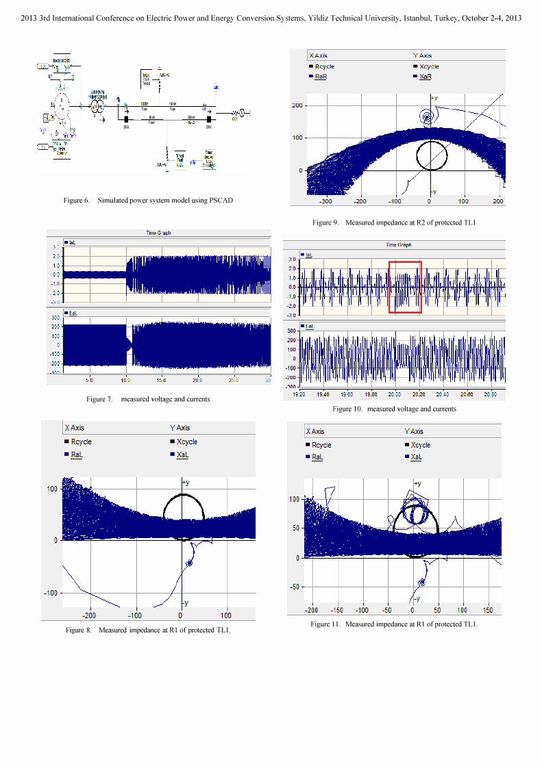
Fig. 10 to Fig. 12 shows the occurrence of a fault during power swing. The impedance seen during fault is inside zone 1 of relays Rl and R2. It is clear from Fig. 11 that zone 1 of RI is blocked by PSB2 but zone 1 of R2 is not blocked because the power swing is outside zone 1.
The unblocked zone 1 of relay R2 will decide to trip the fault instantly and send signal SR2 through communication link to unblock the relay RI at left side. The sent signal will unblock zone 1 only of relay Rl so the security of the relays will not be affected and the reliability of relays increased.
The proposed algorithm in this paper should work in parallel with other published algorithms, then by changing the location of source of power swing and the location of faults will not affect the security of relays.
The advantage of the proposed algorithm is its fast detection of faults during power swing keeping the reliability of relays. The simulation is repeated for different locations of source of power swing. It is rare that all zones of both relays see the power swing trajectory.
2013 3rd International Conference on Electric Power and Energy Conversion Systems, Yildiz Teclmical University, Istanbul, Turkey, October 2-4,2013
l� IlIC->C Faul run� fiq
'"1m I ... ru. ru. ""-7
." lIO" ru.1 1U>e2
!Ill( !Ill(
Figure 6. Simulated power system model using PSCAD
3.0 .}I ====;=====;=====;r======;=====;=====\ 2.0 -1----+------+""71"11:
1.0 -1---+----
0.0 ••••• -1.0 -1----+------2.0 -I----+------+--'-Ill -3.0
I- EaL 100
--� �
200
100
-100
-200
��==�,======�,======�,======�,======�, ====�, 5.0 10.0 15.0 20.0 25.0 10
Figure 7. measured voltage and currents
I X Axis Y Axis
• Rcycle • Xcycle
• RaL • XaL
-200 -100 o 100
Figure 8. Measured impedance at RI of protected TLI .
I X Axis Y Axis
- Rcyc le -Xcycle
- RaR -XaR
200---�-------+--------+--------1��----+---��+-
1 00---�-------+-�
o
Figure 9. Measured impedance at R2 of protected TLI
Time G r . �h
-laL 1.0
2.0
1.0
0.0
-1.0
-2.0
-3.0
100
200
100
-100
-200
19.20 19.80 20.20 20.40 20.60 20.80
I X Axis
• Rcycle
• RaL
Figure 10. measured voltage and currents
YAxis
• Xcycle
· XaL
1 00 �� +��---4----+-- ����r-�--4----4--
50
-50 --r----+----r---_r---- ��_r----r---_r--
-200 -150 -100 -50 o 50 100
Figure II . Measured impedance at RI of protected TLI.
150

2013 3rd International Conference on Electric Power and Energy Conversion Systems, Yildiz Teclmical University, Istanbul, Turkey, October 2-4,2013
I X Axis
• Rcycle • RaR
1 Q() ----+--=
()
YAxis
• Xcycle ·XaR
-10()A----+-�-=--+-----f�--�---�-� -20() -100 o 100 20()
Figure 12. Measured impedance at R2 of protected TLI with fault
VII. CONCLUSION
The simulation shows that Relays at both sides of protected transmission line can see the measured impedance during power swing in different locations. The impedance trajectory of power swing can enter all zones of one relay at one side but in the other side will enter third zone or second zone. If there is a fault at protected transmission line during power swing it will be exactly inside the first zone, which is not blocked by power swing blocking. The unblocked zone 1 of relay will send trip signal through communication link to the relay at the opposite side of transmission line. The sent signal will unblock the first zone of the other relay which directly detect the fault. According to the results and proposed algorithm, both relays will trip the faulted transmission line during power swing.
REFERENCES
[1] H. Khoradshadi-Zadeh, "Evaluation and performance comparison of power swing detection algorithms," in Power Engineering Society General Meeting, 2005. IEEE, 2005, pp. 1842-1848 Vol. 2.
[2] H. K. Karegar and B. Mohamedi, "A new method for fault detection during power swing in distance protection," in Electrical Engineering/Electronics, Computer, Telecommunications and
Information Technology. 2009. ECTJ-CON 2009. 6th International Conference on, 2009, pp. 230-233.
[3] L. Martuscello, E. Krizauskas, J. Holbach, and L. Yuchen, "Tests of distance relay performance on stable and unstable power swings reported using simulated data of the August 14<sup>th</sup> 2003 system disturbance," in Protective Relay Engineers, 2009 62nd Annual
Conference for, 2009, pp. 236-255. [4] B. Mahamedi and Z. Jian Guo, "A Novel Approach to Detect
Symmetrical Faults Occurring During Power Swings by Using Frequency Components of Instantaneous Three-Phase Active Power," Power
Delivery, IEEE Transactions on, vol. 27, pp. 1368-1376,2012. [5] N. Z. Mohamad, A. F. Abidin, and W. N. W. A. Munim, "A new tracking
method of symmetrical fault during Power Swing Based on S-Transform," in Power Engineering and Optimization Conference (PEDCO) Melaka.
MalaYSia, 2012 Ieee International, 2012, pp. 141-146. [6] S. Saeid Taheri and HoseinAskarian, "Detecting of a Power Swing
Phenomenon duringTwo Worst Simultaneous Faults Using System
Characteristics," International Conference on Advancements in
Electronics and Power Engineering, Bangkok, 2011 . [7] 1. Shaohua, B. Zhiqian, L. Wanshu, and Y. Qixun, "New Principles to
Detect Faults During Power Swing," IEEE Seventh International
Conference on Developments in Power System Protection, 2001, pp. 515-518.
[8] B. Su, X. Z. Dong, Z. Q. Bo, Y. Z. Sun, B. R. J. Caunce, D. Tholomier, and A. Apostolov, "Fast Detector of Symmetrical Fault During Power Swing for Distance Relay," IEEE Power Engineering Society General
Meeting, 2005, pp. 1836-1841 Vol. 2.