Embed Size (px)
Citation preview

l.
TRANSPORTATION RESEARCH RECORD 1129 31
New Bedding Factors for Vitrified Clay Sewer Pipes
JEY K. JEYAPALAN AND NAIYI JIANG
The present bedding factors used by the clay pipe indu try are dependent only on the bedding type. This practice has led to extremely conservative designs of these buried pipes and to their perceived inability to support deep covers of soil. Due to this conservative approach, clay pipe installations under deep fills were considered to be impossible and other materials have been u ed instead despite the many advantages clay pipe has offered for these project . In this study, new bedding factors were predicted by the finite element analyses of buried vitrified clay pipes with four types of backfill and bedding materials. These bedding factors were calculated as the ratio of the maximum tensile strain in the computer-simulated three-edge bearing test of vitrified clay pipes to that in the finite element analyses of buried pipes. The new bedding factors are generally higher than those given in the current ASTM spedfications. It is sbown that the bedding factors are affected by the backfill material type and compaction density, backfill height, trench width, and pipe diameter. Design practice around the world is also summarized in this paper.
The design of buried vitrified clay pipes involves determining the maximum loads to which the vitrified clay pipes will be subjected in service and ensuring that the installed vitrified clay pipes under a certain bedding condition will provide field-supporting strength great enough to withstand the loads with a reasonable degree of safety. For vitrified clay pipes transporting sewage and other industrial effluents, the backfill loads, which were discussed in another paper (J) by the same authors, are usually the most important loads to be considered. The purpose of this paper is to study the field-supporting strength of buried vitrified clay pipes.
The field-supporting strength of vitrified clay pipes is influenced by many factors, such as physical properties of the vitrified clay pipes, bedding materials, depth of soil cover, trench width, degree of compaction of the trench materials, and workmanship. The physical properties of vitrified clay pipe determine its inherent strength (2). The beddiiig factor is the ratio of the field-supporting strength to the three-edge bearing test strength of the vitrified clay pipe. The three-edge strength of the pipe is measured in the test laboratory at the manufacturing plant using a statistically significant sampling technique.
Vitrified clay pipes are installed under various bedding conditions. Different bedding conditions provide varying levels of support around vitrified clay pipes and, hence, give different bedding factors. Currently used bedding conditions ·
Wisconsin Hazardous Waste Management Center, 2304 Engineering Building, University of Wisconsin, Madison, Wis. 53706.
and their corresponding bedding factors in the United States are given in ASTM Standards (3), as shown in Figure I. These bedding factors, except that for crushed stone encasement, are based on the research conducted in the early part of thi century by Spangler (4) and Schlick (5). Since then, there have not been any changes in these bedding factors in the United States.
In addition, the loads used on these clay pipes in the United States are still based on the worst possible predictions by the old Marston theory. The authors calculated much lower loads in comparison to Marston loads and these results were reported recently in another paper (J), in which details of the finite element model used, distributions of soil pressures around the pipe for various bedding conditions, and locations of critical stresses and strains in the clay pipe wall were provided. Thus, in U.S. design practice conservative bedding factors and Marston loads resulted in con ervative de igns of clay pipe installations. During these 50 years of conservative design practice, several advances have taken place in the field of soil-pipe interaction. Large-scale laboratory research on the bedding factors of vitrified clay pipes has been conducted by Bland et al. (6) and Sikora (7). The soil-pipe interaction problems have been successfully analyzed using the finite element method by Duncan et al. (8-11), Jeyapalan et al. (12-17), Katona (18), Krizek et al. (19), and Leonards (20). Thus, the finite element method can provide an accurate method of evaluating bedding factors for vitrified clay pipes under various bedding conditions.
The purpose of this paper is to present the bedding factors of buried vitrified clay pipes under different bedding conditions as computed by finite element analyses.
MATERIAL PROPERTIES
The properties of three different sizes of vitrified clay pipes used in the analyses are presented in Table I based on published data (20). The Young's modulus for vitrified clay pipe listed in Table I is based on the test results reported by Sikora (7).
Four types of backfill and bedding conditions were used in the analyses; two degrees of compaction level were chosen for each type, as follows:
I. Well-graded gravel compacted to 85 and 95 percent of standard AASHTO dry density (GW85 and GW95).
2. Silty sand at 80 and 95 percent (SM80 and SM95).

32 TRANSPORTATION RESEARCH RECORD l129
BEDDING
BEDDING
(a) LOAD FACTOR 2.2 (b) LOAD FACTOR 1.9
BACKFILL BACKFILL
BEDDING
(c) LOAD FACTOR 1.5 (d) LOAD FACTOR 1.1 FIGURE I Current bedding conditions and their bedding factors for buried vitrified clay pipes: (a) Crushed stone encasement, (b) Class B, (c) Class C, and (d) Class D.
TABLE 1 PROPERTIES OF VITRIFIED CLAY PIPES USED IN ANALYSES
Inner Diameter Outer Diameter Thickness Pipes (in.) (in.) (in.)
6-in. 6 7.375 0.6875 21-in. 21 25.5 2.25 42-in. 42 51 4.5
3. Sand-clay-silt mixture at 80 and 95 percent (SM-SC80 and SM-SC95).
4. Low-plastic clay at 80 and 95 percent (CL80 and CL95).
Native soil used in all the analyses is low-plastic clay at 90 percent (CL90). The hyperbolic soil model parameters of soils used in the analyses are presented in Table 2.
FINITE ELEMENT ANALYSES
The interaction between the vitrified clay pipe and the surrounding soils was studied using the finite element method.
Area Moment of Young's Modulus (ft2 I ft) Inertia (ft4 /ft) (ksf)
0.05729 0.00001567 835,200 0.1875 0.0005493 835,200 0.3750 0.004395 835,200
The computer program used in the analyses is a plane-slrain soil-pipe interaction finite element program. The hyperbolic stress-strain relationship of soils developed by Duncan et al. (11) was used in the program to approximate the nonlinear and stress-dependent stress-strain properties of the soils. The actual sequence of construction operation was simulated by a number of construction layers. The geometry of the trench was simulated in the analyses by using a finite width for the soil elements placed in each compaction lift. The load from the construction lift was applied in the analyses by converting the soil weight to equivalent nodal point forces .
A typical finite element mesh used in the analyses is shown in Figure 2. This mesh was used to model a 42-in. vitrified clay pipe with a backfill height of 50 ft and a trench width of 8 ft.

TABLE 2 SOIL PROPERTIES
Unified RC Standard y c cp Acp K n Rf Kb m K 0
Classification AASHTO kc.f ksf degrees degrees
cw 85 0.130 0 30 2 100 0 .11 0.7 25 0.2 0.5
95 0.1110 0 36 5 300 0.11 0.7 75 0.2 0.5
SM 80 0.115 0 28 75 0.25 0.7 50 0 0.5
95 0.130 0 311 6 1150 0.25 0.7 350 0 0.5
SM,.,SC 80 0.115 0.1 33 0 50 0.6 0.1 25 0.5 0.5
95 0.130 0 .11 33 0 200 0.6 0.7 100 0.5 0.5
CL 80 0. 115 0.05 30 0 30 0.115 0.7 20 0.2 0.5
95 0.130 0.3 30 0 120 0.115 0.7 110 0.2 0.5
BACKFILL TRENCH WALL NATIVE SOIL
............ ..........._
" .. j - - ""' ;u;: :26 270 71 272 273 274 275 117 118 119
26 26 262 63 264 ' 265 266 267 114 115 116
H2 2S 25 254 ~s 256 257 258 259 111 112 113
24 24 246 A1 248 249 250 251 108 109 no
I ~J 23 238 39 240 241 242 243 105 106 107
H ~2 22 230 31 232 233 234 235 102 103 104
tl2 22 222 23 224 225 226 227 99 100 101
H1 ~I 21 214 IS 216 217 218: 219 96 97 98
20 20 206 07 208 209 210 211 93 94 9S
19 19 198 99 200 201 202 203 90 91 92
8! 89 901 ~I 192 193 194 195 87 88 89
XCD 181 IR 182 83 1R4 lRS 186 .1R7 84 85 86 ,, , 17 17 174 7S 176 177 178 179 81 82 83
'. """'""' 168 169 170 171 78 79 80
166 167 "'1. 6)\.163 \ 164 16S 1S 76 77
~s~1s9\ 160 161 72 7J 74
'54\lS~ IS6 IS? 69 70 71
ISO - - Sl 152 153 66 67 68 146- I- 47 148 149 6J 64 6S
DM 142 - ~ 41 144 14S 60 61 62 138 - - 39 140 141 S? S8 S9
J. 3'J.3s1 136 137 S4 SS S6
p3o/m / 132 133 SI S2 SJ
121 fi1¥121 I 128 129 48 49 so 1 >< ~ 122 123 124 12S 4S 46 47
I XID 34 JS 36 :n 38 39 40 41 42 43 44
' 2 24 2S 21 27 28 29 30 31 32 33
XFD 12 13 14 IS 16 17 18 19 20 21 22
XBD I 2 3 4 s 6 7 8 9 10 II ,, XS XSD XED XPH - -
FIGURE 2 Typical finite element mesh used in analyses.
34
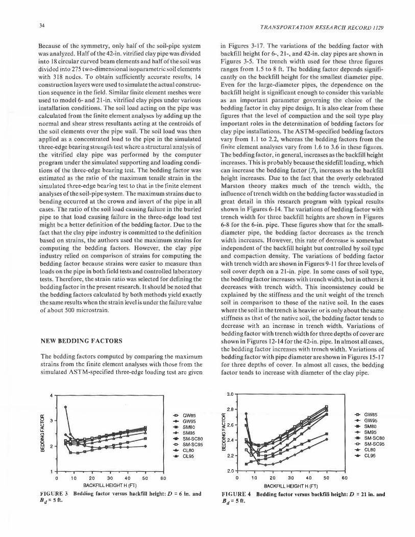
Because of the symmetry only half of the oil-pipe system was analyzed. Half of the 42-in. vitrified clay pipe wa divided into 18 circu lar curved beam elements and half of thes ii was divided into 275 two-dimensional isoparametric soil elements with 318 nodes. To obtain sufficiently accurate r ults, 14 construclion layers were used to imulatc the actua l construction sequence in lhe field .• imilar fin ite element me hes were used to model 6- and 21-in. vitrified clay pjpe under variou installation condition . he oil load acting on the pipe was ca lculated from the finite clement analyse by adding up the normal and shear tress resultants acting at the centroids of the oi l elements over the pipe wall. The soil load was then app lied as a concentrated load to the pipe in the simu lated three-edge bearing slnrngth test where a structural analy ·is of the vitrified clay pipe was performed by the computer program under the simulated supporting and loading cond itions of the three-edge bearing lest. The bedding factor wa. estimated a tbe ratio of the maximum ten ile strain in the simulated three-edge bearing test to that in the finite element analyses of the soil-pipe system. he maximum stra ins due to bending occurred at the crown and invert of the pipe in all cases. T he ratio of the soi l load cau ing fai lure in the buried pipe to that load causing fai lure in the three-edge load test might be a better definition of the bedding fact.or. Due to the fact that the clay pipe industry is committed to the definition based on strains, the authors used the maximum strains for computing the bedding facto.rs. However, the clay pipe industry relied on comparison of strain for computing the bedding factor because strains were ca ier to measure than load on the pipe in both field test · and controlled laboratory test . Therefore the strain ratio wa. selected for defining the bedding factor in the present research. 1t should be noted that the bedding factors calculated by both methods yield exactly the ·ame result when the strain le cl is iinder the fai lure vaJuc of about 500 microstrain.
NEW BEDDING FACTORS
The bedding factors computed by comparing the maximum strains from the finite element arialyses with those from the simulated ASTM-specified three-edge loading test are given
§ -& GW85 3 ... GW95
~ .... SMBO
~ ... SM95 ... SM-SCBO ; 2 -0- SM-SC95 -CLBO -CL95
0 10 20 30 40 50 60
BACKFILL HEIGHT H (FT)
FIGURE 3 Bedding factor versus backfill height: D = 6 in. and Bd=5ft.
TRANSPORTATION RESEARCH RECORD 1129
in igure 3-17. The variiitions of the bedding factor with backfill height for 6-, 2 1- and 42-in. clay pipes are shown in Figures 3-5. The trench width used for these three figures ranges from 1.5 to 8 ft. The bedding factor depends significantly on the backfill height for the sma llest di.amcter pipe. . ·ven for the large-diameter pipes, the dependence on the backfill height is significant enough to con ider thi variable as an important pa.rameter governing the choice of the bedding factor in clay pipe design. It is also clear from these figure that the level of compaction and the oil type play important roles in the determination of bedding factors for clay pipe installations. he ASTM- pecified bedding factors vary from I. I to 2.2 whereas the bedding factors from the finite clement analyses vary from 1.6 to 3.6 in these figures. The bedding factor. in general, increases a· the backfill height increases. This is probably becau e the sidefill loading, which can increase the bedding factor (7) increases a the back.fill height increases. Due to the fact that the overly celebrated Marston theory makes much of the trench width the influence of trench width on the bedding factorwa tudied in great detail in thi research program with typica l results shown in Figures 6- 14. The variations of bedding factor with trench width for three backfill heights arc shown in Figur 6-8 for the 6-in. pipe. These figures how that for the smalldiameter pipe, the bedding factor decreases as the trench width increases. However thi rate of decrea. e is somewhat independent of the backfill height but controlled by soi l type and compaction density. The variation of bedding factor with trench width are shown in ig1.1re 9-11 for three levels of soil cover depth on a 21-in. pipe. In omc cases of soil type the bedding factor increa es with trench width but in others it decrease with trench width. T hi inconsistency could be explained by the stiffness and Lhc unit weight of the trench soil in compari on to t hose of the native soil. In the cases where the oil in che trench is heavier or i, only about the same stiffnes as that of the native soil, the bedding factor tend to decrease with an increa e in trench width. Variations of bedding factor with trench width for three depths of cover are shown in Figures 12- 14 fort he 42-in. pipe. In almost all ca e , the bedding factor increases with trench width. Variations of bedding factor with pipe diameter are hown in Figures 15-J 7 for three depths of cover. In almost all cases, the beddjng factor tends Lo increase with diameter of the clay pipe.
3.0
2.8
§ ~ 2.6 u.
~ ~ 2.4
-& GWB5 ... GW95 ... SMBO ... SM95 -SM-SCBO -0- SM-SC95 -CLBO
2.2 -CL95
2.0
0 10 20 30 40 50 60
BACKFILL HEIGHT H (FT)
FIGURE 4 Bedding factor versus backfill height: D = 21 in. and Bd=5ft.

Jeyapalan and Jiang
3.2
3.0
§ 2.8 + GW85 ... GW95
~ 2.6 ... SMBO
~ ... SM95
2.4 ... SM-SC80 8 -0- SM-SC95 ~ 2.2 ... CL80 ... CL95
2.0
1.8 - ----...-.---.---.---.- .---.---.---.....-.---t 0 10 20 30 40 50 60
BACKFILL HEIGHT H (FT)
FIGURE 5 Bedding factor versus backfill height: D = 42 in. and Bd = 8 ft.
.. GW85 ... GW95 ... SMBO ... SM95 ... SM-SC80 -0- SM-SC95 ... CL80 ... CL95
10 20 30 40 50
TRENCH WIDTH (INCHES)
FIGURE 6 Bedding factor versus trench width: D = 6 in. and H = 8 ft.
§ + GW85
3 ... GW95
5:f ... SMBO u.. ... SM95
!i ... SM-SC80
~ 2 -0- SM-SC95 ... CL80 ... CL95
10 20 30 40 50
TRENCH WIDTH (INCHES)
FIGURE 7 Bedding factor versus trench width: D = 6 in. and H = 20ft.
INTERNATIONAL CLAY PIPE DESIGN PRACTICE
At the conclusion of this research program, the senior author visited a number of clay pipe design engi neers and manufacturing faci lit ies .in Europe to review the procedure in effect in Europe and other countries fo r the design o f underground clay pipes. D uri ng these visits, it was appa rent tha t severa l countries had abandoned the u e of Marston ' load theory and its resu lt ing conservative bedding facto rs. A summary of the bedding factors used by the various countries
35
4
~ 3 -GW85 ... GW95
~ ... SMBO
~ ... SM95 ... SM-SCSO
~ 2 -0- SM-SC95 ... CL80 ... CL95
1+--..--.-----..-----.--...---.----..--~
10 20 30 40 50
TRENCH WIDTH (INCHES)
FIGURE 8 Bedding factor versus trench width: D = 6 in. and H = 32 ft.
3.0
2.8
§ 2.6 -a- GW85 ... GW95
() ... SMBO Lt. ... SM95 ~ 2.4 ... SM-SC80 i5 -0- SM-SC95 ~ 22 ... CLBO
2.0 ... CL95
1.8
30 40 50 60 70 80 90
TRENCH WIDTH (INCHES)
FIGURE 9 Bedding factor versus trench width: D = 21 in. and H = 8 ft.
3 2.6 -GW85
b ... GW95
Lt. ... SM80
~ 2.4 ... SM95 ... SM-SC80 8 -0- SM-SC95
~ 2.2 ... CL80 ... CL95
30 40 50 60 70 80 90
TRENCH WIDTH (INCHES)
FIGURE 10 Bedding factor versus trench width: D = 21 in. and H = 20 ft.
is given in Table 3. Austra lia is the only country using compaction density a one of the parameters contro ll ing the choice of the bedd ing facto r used in the design of clay pipes. Jn the U.S.S. R. bedd ing factors ignificantly higher than those in the United S tates are used. The bedd ing factor used in the U.S.S. R. for the weakest bedding y tern is 2.8, which is higher than the 2.2 used in the Uni ted S tate for the strongest bedding system. T he loads used by the des igners in the U.S.S. R. are also lower than those used in the United S tates. A review of safety factors used by various countries a lso

36
2.9
2.8
§ 2.7 -GW85
(.) 2.6 ... GW95
~ ... SM80
~ 2.5 ... SM95
Cl ... SM-SC80
~ 2.4 -0- SM-SC95 ... Cl80
2.3
2.2
30 40 50 60 70 80 90
TRENCH WIDTH (INCHES)
FIGURE 11 Bedding factor versus trench width: D = 21 in. and H = 32 ft.
2.8
2.6
§ -GWBS ... GW95 (.) 2.4 ... SM80 ~ SM95 ~
... 2.2 ... SM-SCBO
Cl Cl -0- SM-SC95 ~
~ ... Cl80
2.0 ... Cl95
1.8
40 60 80 100 120 140
TRENCH WIDTH (INCHES)
FIGURE 12 Bedding factor versus trench width: D = 42 in. and H = 8 ft.
2.8
2.6
§ ~ 2.4 l.L
~ 8 2.2
-GW85 ... GW95 ... SM80 ... SM95 ... SM-SC80 -0- SM·SC95
~ ... Cl80 2.0 ... Cl95
1.8
40 60 BO 100 120 140
TRENCH WIDTH (INCHES) FIGURE 13 Bedding factor versus trench width: D = 42 in. and H = 20 ft.
revealed some interesting information, as presented in Table 4. In Table 4, the new West German ATV rigorous design method is used as the standard in arriving at the relative margins of safety. In the United States, a factor of safety of 1.5 is used relative to the ATV rigorous method, and in the U.S.S.R., the factor of safety used is 0.9. Switzerland uses a factor of safety of 2.0, but it should be recognized that the loads used on clay pipes are only half as high as those calculated by the Marston load theory.
TRANSPORTATION RESEA RCH R ECORD 1129
3.0
2.8
§ -GW85 ... GW95 (.) 2.6 ~ ~ 8 2.4
~
... SM80 ... SM95 ... SM·SC80 -0- SM-SC95 ... Cl80
2.2 ... Cl95
2.0
40 60 80 100 120 140
TRENCH WIDTH (INCHES)
FIGURE 14 Bedding factor versus trench width: D = 32 in. and H = 32 ft.
2.6
2.4
§ ~ 2.2 l.L
~ g 2.0
-GWBS ... GW95 ... SMBO ...... SM95 ... SM-SC80 -0- SM-SC95
~ ... CLBO 1.B ... CL95
1.6
0 10 20 30 40 50
PIPE DIAMETER (INCHES)
FIGURE 15 Bedding factor versus pipe diameter: H = 8 ft.
2,6
a: 2.4 -GW85
f2 ... GW95
~ ... SM80
~ 2.2 ...... SM95 z ... SM-SC80
8 -0- SM-SC95
~ 2.0 ... Cl80 ... Cl95
0 10 20 30 40 50
PIPE DIAMETER (INCHES)
FIGURE 16 Bedding factor versus pipe diameter: H = 20 ft.
CONCLUSIONS
Based on the results of this research study, the following conclusions can be made:
1. The bedding factor is dependent on the type of backfill and bedding materials used. Well-graded gravel material gives the highest bedding factors, while silty and or sandclay-silt materials gi e the lowest bedding factors. The d gree

Jeyapalan and Jiang 37
2.8
2.6
~ ~ 2.4 u. C!l
~ 2.2 0 ~
2.0
1.8
0 10 20 30 40
PIPE DIAMETER (INCHES)
-GWBS .... GW95 ... SMBO .... SM95 ... SM-SCBO .g. SM-SC95 .... CLBO .... CL95
50
of compaction of the backfill and bedding materials is also an important parameter.
2. The bedding factor is affected by the backfill height. The bedding factor generally increases as the backfill height increases.
3. The bedding factor increases with the diameter of the pipe. The trench width also controls the magnitude of the bedding factor to be used in design.
FIGURE 17 Bedding factor versus pipe diameter: H = 32 ft.
4. The loads used for the design of clay pipes in the United States based on the Marston load theory are too high, and improved loads are given by the authors in another paper elsewhere (J) . The loads used by several other countries around the world compare better with the loads reported by the authors than with those developed by Marston.
TABLE 3 SUMMARY OF BEDDING FACTORS USED INTERNATIONALLY
Bedding U.K U.S. Australia lrda Japan Switzerland W.Germany W.Germany aass (Frarx:e) Clayppeind ATV
(Marston (Marston (Marston (Marston (Marston (Wetzorke load theory) load theory) load theory' load theory) load theory) load theory
s 22 22 I I 2.31 1.5 I I
B 1.9 1.9 2.5 -1.9 1.9 2.03 I I 2.18
c I 1.5 1.9 -1.5 1.5 1.68 I 1.5 1.59
D 1.1 1.1 1.1 1.1 1.08 I I I
I Bed:fng rot aR)ICalJe.
TABLE 4 RELATIVE MARGIN OF SAFETY FOR VARIO US DESIGN PROCEDURES
Country Margin of safety Countries with Relative to West Similar Design German ATV Rigorous Procedures and Method Standards
I I I -50% +100% +200%
Switzerland
Sweden, India U.S. Australia (unless
Russia
(Emilianov load theory)
32
3.1
3.0
2.8
very well compacted)
U.K.
Japan France
West Germany (A TV rapid method)
U.S.S.R. I West Germany -(ATV rigorous method)
Sweden
(Marston load theory)
I
1.88
I
I
38
5. The factor of safety used in U.S . practice is also high, particularly when the low bedding factor in effect are taken into consideration. T hu , use of higher bedding factors, lower factor of safety, or lower loads on these vitrified clay pipe are more appropriate. These procedures would enable pipe design engineers to use ma terials more efficiently while the United States is u ndergoi n.g a major infrastructure re ha bi.litation program in many of its olde. l cities .
6. Based on the available information, it appears that a bedding factor of 3.5 for crushed stone encasement and 2.5 for Class D beddings could be used when the loads calculated for the pipe are ba ·cd on Ma r ton theory.
7. Although the re ea rch and conclusions thereof are for vitrified clay pipe ·, the results' ould also be applica ble for concrete pipes with some minor modifications .
ACKNOWLEDGMENTS
The re ult reported in th i pa per were obtained as part of an ongoing resea rch program on vitri!ied clay p.ipe funded by the Nationa l lay Pipe Institute at the University of Wi -consin, Madiso n. A major field observation program i being planned a t the time of writing this paper to verify the results of Lhe finite element analyses. In thi s field test program, a series of strain-gauged vitrified clay p.ipcs will be monitored at actual in tallations under varying backfill and load conditions, and the results will be compared with those obtained from the finite element analyses. The results of this field test program will be reported in another paper at a later date. The technical a. sistance provided by Edward Sikora and Howard Lund is greatly appreciated. Audrey Miller typed the manuscript.
REFERENCES
!. J . K. Jcyapalan and . Jiang. Load Reduction Factors for Buried lay Pipes. Journal of Tran. por1a1io11 E11gi11eeri11g, A £. Vol. 112. o. 3. Ma , 1986, PP- 23&-249.
2. S tandard Metltotlrof Tes1i11g Vitrified Clay Pipe. Annual Book of A TM Stnndards, Vol. 4.05, Philadelphia, Pa .. 1983.
3. Stamlt1rd Prartice fo r /11s1al/i11g Vitrified Clay Pipe Unes. Annual Book of /\STM Standard . Vol. 4.05, Philadelphia , Pa ., 1983.
4. M. G. Spangler. The upponing trengrh of Rigid Pipe Culverls. Bulletin 112, Iowa State College, 1933.
5. W. J. Schlick. Supporting S1re11g1h of Cast Iron Pipe for Water and Gas Service. Bulletin 146. Iowa Engin·ecring Experimental
talion, 1940. 6. C. E. G. Bland and K. J. ' hcppard. lnvc. ligation into the
Structural Performance of Clay Pipe .. Proc .. !111ema1io11al onference 011Advances111 Underground Pipeline Engineering.
Univcr ity of Wisconsin, Madison, Aug. 1985, 610 pp. 7. E. J . Sikora. Load Factor and Non-Destructive Testing of
lay Pipes. Jo11mal of Wawr Pol/111io11 Co111rol Federation , Vol. 52, No. 12, Dec. 1980.
8. J . M. Duncan. Behavior and Design of Long Span Metal Culverts. Journal of /he Geotedmic.al Engineering Division, ASCE, Vol. 105, o. T3, 1977, pp. 399-418.
9. J . M. Duncan and J. K. Jeyapalan. Desig11 Studies for Kaiser Alumi1111m Ellipriral Culver/ 1mrt11res Pinson Mounds,
TRANSPORTATION RESEARCH RECORD 1129
Jackson, Tennessee. Preprint for the State of Tennessee Department of Tran porla1ion, 1979.
IO. .J . M. Duncan and J . K. Jeyapalan. DeflecLion or Flexible Cul verls Due t Backfill ompaclion. ln Trai1spo1·tatio11 Researrh Record 878. TRB, ational Resea rch Council , Washington, D . ., Dec. 1982, pp. 10-17.
11. J . M. Duncan P. M. Byrne, K. . Wong, nnd P. . Mabry. Hyperbolic Volume Change Parameters for Nonlinear Finile Elemelll Analysis of tresses and MovemenM in Soil Mt1sses. Geotcchnical Engine ring Repol'l , University of alifornia, Berkeley, 1978.
12. J . K. Jeyapalan. Geofabric tabilization of Sofl Backfill Materials for Plaslic s~wer• Pipe lnstnllntion. Proc .. !nter-11a1io11a/ Conference on Pipeline in Adverse Enviro11111ems fl,
an Diego, alif.. L983. 13. J. K. Jcyapalan and A. M. Abdclrnagid. Significance of Pipe
. oil Stiffness Ratio in Flexible 'Pipe De ign. Paper pre.~ented at the Caliiornia \Vater PuBution Control Associrtticn ,A .. nnua! Mectin.g. Palo Alto, May 3 and 4, 1984.
14. J. K. Jeya pala n and A . M . Abdclmagicl . Analysi and Design of Large Diameter Plas tic ewer Pipe . Paper presented at the 1984 AS E Spring Convention, Atlanta, Ga., 1984.
15. J . K. Jeyapalan irnd B. A. Boldon. Perfo tmance and election of Rigid and Flex ible Pipes. Journal of Tra11sportatio11 Engineering, A CE, Vol. 112, o. 5, cpt. 19 6, pp. 507-524.
16. J . K. Jeyapalan, F. Oseguedu, and W. J. Horn. Soil-S1ruc1ure lnum 1c1ion A11(1/yses of Plastic Pipes. A E onvenlion and -xhibit, Preprint 82-5 1 I , ew Orleans. a. Oct. 19 2.
17. M. G. Katona . .I. M. Smith, R. J. Odello and J . R. Allgood. CANDE: £111-:ineering Manual- A M odem Approach 10 the S1mc111ral Design and A 110/ysi of Buried Culvert . HWA, U.S. Department ofTransportation, ivil Engineering l .aboratory. Port Hueneme, Calif .. 1976.
18. R. J. Krizek and P. V. McQuadc. Behavior of Buried CoDcrcte Pipes. Jo11rnal of the Geo1eclmical £11gi11eeri11g Division. A E. Vol. 104, o. GT7. July 1978, pp. 815-836.
19. G. A. Leonards. . H. Juang, T. H. Wu, and R. E. telkar. Predicting Performance of Buried Mclal onduits. In Transportation Research R ecord 1008. TRB, at ional Re earch
ounci l, Wa hington D. ., 1985, pp. 42-52. 20. Vi1rified Clay Pipe Engineer's Handbook. Southern lay Pipe
In titutc, Atlanta, Ga., 1960. 21. lay Pipe E11gineering Manual. National Clay Pipe Institute,
Washington, D.C., 1982.
APPENDIX
Notations
The following symbols are used in this paper:
BC = outer diameter of vitrified clay pipes ,
Bd = horizontal width of trench at top of vitrified clay pipes,
D = inner diameter of vitrified clay pipes, H = backfill height,
Kb = bulk modulus number,
Ko = coefficient of earth pressure at rest , m = bulk modulus exponent, n = modulus exponent,
Rf = failure ratio , y = unit weight of backfill materials,
A</J = friction angle parameter, and
</J = friction angle.