Embed Size (px)
Citation preview


INDEX 00005-1
New Blowout Preventer building & New Coil Tubing Building Transocean Offshore Deepwater Drilling, Inc.
Amelia, Louisiana Project Number 12-167A
INDEX OF SPECIFICATIONS
Bidding Requirements and Conditions of the Contract Section 00005 – Index of Specifications Section 00010 – Invitation for Bids Section 00500 – Master Purchase Agreement (to be used as the Contract Between Contractor and
Transocean) DIVISION 1 - GENERAL REQUIREMENTS Section 01100 – SUMMARY Section 01250 – CONTRACT MODIFICATION PROCEDURES Section 01290 – PAYMENT PROCEDURES Section 01310 – PROJECT MANAGEMENT AND COORDINATION Section 01320 – CONSTRUCTION PROGRESS DOCUMENTATION Section 01330 – SUBMITTAL PROCEDURES Section 01400 – QUALITY REQUIREMENTS Section 01420 – REFERENCES Section 01500 – TEMPORARY FACILITIES & CONTROLS Section 01600 – PRODUCT REQUIREMENTS Section 01635 – SUBSTITUTION PROCEDURES Section 01700 – EXECUTION REQUIREMENTS Section 01731 – CUTTING AND PATCHING Section 01770 – CLOSEOUT PROCEDURES Section 01781 – PROJECT RECORD DOCUMENTS Section 01782 – OPERATION AND MAINTENANCE DATA Section 01820 – DEMONSTRATION AND TRAINING DIVISION 2 – SITEWORK Section 02200 – EXCAVATION, FILLING & GRADING FOR BUILDING Section 02300 – PILING Section 02361 – TERMITE CONTROL DIVISION 3 – CONCRETE Section 03100 – CONCRETE FORMWORK Section 03200 – CONCRETE REINFORCING STEEL Section 03300 – CAST-IN-PLACE CONCRETE DIVISION 4 – MASONRY Section 04200 – UNIT MASONRY ASSEMBLIES

INDEX 00005-2
DIVISION 5 – METALS Section 05500 – METAL FABRICATIONS DIVISION 6 – WOOD & PLASTICS Section 06105 – MISCELLANEOUS CARPENTRY DIVISION 7 – THERMAL AND MOISTURE PROTECTION Section 07210 – BUILDING INSULATION Section 07840 – FIRESTOPPING Section 07920 – JOINT SEALANTS DIVISION 8 – DOORS AND WINDOWS Section 08110 – STEEL DOORS AND FRAMES Section 08211 – FLUSH WOOD DOORS Section 08331 – OVERHEAD COILING DOORS Section 08410 – ALUMINUM FRAMED ENTRANCES & STOREFRONTS Section 08710 – HARDWARE Section 08800 – GLAZING DIVISION 9 – FINISHES Section 09250 – GYPSUM BOARD ASSEMBLIES Section 09511 – ACOUSTICAL CEILING TILES Section 09650 – RESILIENT TILE FLOORING Section 09653 – RESILIENT WALL BASE AND ACCESSORIES Section 09900 – PAINTING DIVISION 10 – SPECIALTIES Section 10431 – SIGNS Section 10520 – FIRE-PROTECTION SPECIALTIES Section 10800 – TOILET AND BATH ACCESSORIES DIVISION 11 – EQUIPMENT NOT APPLICAPLE DIVISION 12 – FURNISHINGS Section 12304 - MANUFACTURED MODULAR LAMINATE CASEWORK DIVISION 13 – SPECIAL CONSTRUCTION Section 13125 – METAL BUILDING SYSTEMS Section 13852 – DIGITAL, ADDRESSABLE FIRE ALARM SYSTEM DIVISION 14 – CONVEYING SYSTEMS NOT APPLICAPLE

INDEX 00005-3
DIVISION 15 – MECHANICAL Section 15057 – COMMON MOTOR REQUIREMENTS FOR PLUMBING EQUIPMENT Section 15058 – COMMON MOTOR REQUIREMENTS FOR HVAC EQUIPMENT Section 15061 – HANGERS AND SUPPORTS FOR PLUMBING PIPING AND EQUIPMENT Section 15062 – HANGERS AND SUPPORTS FOR HVAC PIPING AND EQUIPMENT Section 15068 – VIBRATION CONTROLS FOR HVAC Section 15073 – VIBRATION CONTROLS FOR PLUMBING PIPING AND EQUIPMENT Section 15076 – IDENTIFICATION FOR PLUMBING PIPING AND EQUIPMENT Section 15077 – IDENTIFICATION FOR HVAC PIPING AND EQUIPMENT Section 15085 – PLUMBING PIPING INSULATION Section 15086 – DUCT INSULATION Section 15088 – HVAC PIPING INSULATION Section 15092 – SLEEVES AND SLEEVE SEALS FOR PLUMBING PIPING Section 15093 – SLEEVES AND SLEEVE SEALS FOR HVAC PIPING Section 15097 – ESCUTCHEONS FOR PLUMBING PIPING Section 15111 – GENERAL-DUTY VALVES FOR PLUMBING PIPING Section 15140 – DOMESTIC WATER PIPING Section 15145 – DOMESTIC WATER PIPING SPECIALTIES Section 15150 – SANITARY WASTE AND VENT PIPING Section 15155 – SANITARY WASTE PIPING SPECIALTIES Section 15183 – REFRIGERANT PIPING Section 15211 – GENERAL-SERVICE COMPRESSED-AIR PIPING Section 15251 – GENERAL-SERVICE PACKAGED AIR COMPRESSORS AND RECEIVERS Section 15485 – ELECTRIC, DOMESTIC WATER HEATERS Section 15738 – SPLIT-SYSTEM AIR-CONDITIONERS Section 15815 – METAL DUCTS Section 15820 – AIR DUCT ACCESSORIES Section 15838 – HVAC POWER VENTILATORS Section 15950 – TESTING, ADJUSTING, AND BALANCING FOR HVAC DIVISION 16 – ELECTRICAL Section 16060 – GROUNDING AND BONDING Section 16062 – GROUNDING AND BONDING FOR COMMUNICATIONS SYSTEMS Section 16073 – HANGERS AND SUPORTS FOR ELECTRICAL SYSTEMS Section 16075 – ELECTRICAL IDENTIFICATIONS Section 16091 – SLEEVES AND SLEEVE SEALS FOR ELECTRICAL, COMMUNICATION,
SAFETY AND SECURITY REACEWAYS AND CABLING Section 16120 – CONDUCTORS AND CABLES Section 16123 – CONTROL-VOLTAGE ELECTRICAL POWER CABLES Section 16130 – RACEWAYS AND BOXES Section 16140 – WIRING DEVICES Section 16145 – LIGHTING CONTROL DEVICES Section 16410 – ENCLOSED SWITCHES AND CIRCUIT BREAKERS Section 16442 – PANELBOARDS Section 16461 – LOW-VOLTAGE TRANSFORMERS

INDEX 00005-4
Section 16491 – FUSES Section 16511 – INTERIOR LIGHTING Section 16521 – EXTERIOR LIGHTING Section 16711 – PATHWAYS FOR COMMUNICATIONS AND ELECTRONIC SAFETY AND
SECURITY Section 16713 – CONDUCTORS AND CABLES FOR ELECTRONIC SAFETY AND SECURITY Section 16714 – COMMUNICATIONS EQUIPMENT ROOM FITTINGS Section 16717 – COMMUNICATIONS HORIZONTAL CABLING END OF INDEX

INVITATION TO BID 00010-1
INVITATION TO BID Sealed bids will be received by Transocean Offshore Deepwater Drilling, Inc., until 2:00 P.M. on Thursday, March 28, 2013. Bids shall be addressed to Transocean Offshore Deepwater Drilling, 926 DeGravelle Road, Amelia, LA 70340; attention: Ronnie Arceneaux. FOR: New Blow-Out Preventer and Coil Tubing Buildings Transocean – North Yard
Duhon Bypass Road Amealia, Louisiana
ARCHITECT’S PROJECT NO.: 12-167A Any questions shall be submitted to the Architect in writing to:
Duplantis Design Group, PC 314 East Bayou Rd. Thibodaux, La. 70301 Tel.: (985) 447-0090 Attn: L. “Andy” Positerry, II, AIA
No bid may be withdrawn for a period of thirty (30) days after receipt of bids. The Owner reserves the right to reject any and all bids. The Owner shall incur no obligation to the Contractor until the Contract Between Owner and Contractor is fully executed.

INVITATION TO BID 00010-2
This Page Intentionally Left Blank

US GENERAL MARITIME LAW MASTER PURCHASING AGREEMENT– 23 August 2012 Page 1
THIS AGREEMENT CONTAINS INDEMNITY AND RELEASE OF LIABILITY PROVISIONS
Master Purchasing Agreement (U.S. Law)
This Master Purchasing Agreement (together with Exhibits A and B attached hereto and made a part hereof), hereinafter referred to as this "MPA", is made and is effective as of this day of , 20 , by and between with offices at (“Transocean”) and with offices at (“Counterparty”). NOW THEREFORE, in consideration of the mutual promises and agreements herein contained, the parties hereto mutually agree as follows:
1. DEFINITIONS
The following definitions shall be applied in this MPA:
1.1 “Affiliate” shall mean any company or legal entity which: (i) controls, either directly or indirectly, the party in question; or (ii) is directly or indirectly controlled by a company or entity that controls, directly or indirectly, the party in question; or (iii) is directly or indirectly controlled by the party in question. “Control” shall mean the right to exercise fifty per cent (50%) or more of the voting rights of such company or entity.
1.2 “Claims” shall mean any and all claims, awards, judgments, liabilities, costs (including legal costs), damages and expenses of every kind and nature.
1.3 “Customer” shall mean any entity or person for which Purchaser has undertaken to provide services and in conjunction with which the Goods are being supplied or Services are being performed.
1.4 “Customer Group” shall mean and include Customer, any co-venturer of Customer in any licence block or concession area in which or in connection with the Services are being performed or the Goods are being supplied and its and their Affiliates, its and their respective officers, directors, employees, agents, servants, insurers, invitees and, only to the extent that Customer provides substantially reciprocal indemnity protection to Supplier Group in its contract with Purchaser or any of its Affiliates, Customer’s and its Affiliates’ other contractors, sub-contractors and suppliers of any tier (excluding Supplier Group and Purchasing Group), its and their Affiliates and its and their respective officers, directors, shareholders, employees, representatives, consultants, agents, servants, heirs, assigns, insurers, subrogees and invitees.
1.5 “Consequential Loss” shall mean (i) all loss or deferment of profit, loss of use of equipment, services or materials, loss of contract, loss or deferral of production, loss of revenue, business interruption or increased cost of working, whether any of the foregoing are direct, indirect, or

US GENERAL MARITIME LAW MASTER PURCHASING AGREEMENT– 23 August 2012 Page 2
consequential and whether or not foreseeable at the date of a Purchase Order; and/or (ii) any indirect or consequential loss under applicable law.
1.6 “Goods” shall mean the materials, equipment, or products (or parts thereof) to be purchased or to be supplied in accordance with and as specified in the Purchase Order.
1.7 “Party” shall mean Purchaser or Supplier as the context shall require.
1.8 “Personnel” shall mean any personnel provided by Supplier and utilised to perform the Services at the Site.
1.9 “Purchase Order” shall mean (i) the written instruction by Purchaser issued to Supplier for the provision of Goods or Services under this MPA, which shall include the specific requirements with respect to the scope of work, applicable rates and charges and the location of the Site; and (ii) if applicable, the oral instruction under this MPA which shall be reduced to writing as soon as practicably possible including the specific requirements described above.
1.10 “Purchaser” shall mean Transocean or any of its Affiliates issuing a Purchase Order.
1.11 “Purchasing Group” shall mean and include Purchaser, its Affiliates and its and their other suppliers or sub-suppliers of any tier and its and their respective Affiliates, officers, directors, shareholders, employees, representatives, consultants, agents, servants, heirs, assigns, insurers, subrogees, invitees and any drilling unit operated by any of the foregoing and the legal and beneficial owners thereof.
1.12 “Services” means the tools, equipment, materials, supplies and Personnel to be provided by Supplier and the work to be carried out as specified in the Purchase Order.
1.13 “Site” shall mean the mobile offshore drilling unit or other offshore or onshore location where Purchaser wishes Supplier to provide the Goods or Services.
1.14 “Supplier” shall mean Counterparty or any of its Affiliates to whom the Purchase Order is issued.
1.15 “Supplier Group” shall mean and include Supplier, its Affiliates and its and their sub-suppliers and suppliers of any tier and its and their respective Affiliates, officers, directors, shareholders, employees, representatives, consultants, agents, servants, heirs, assigns, insurers, subrogees and invitees.
2. PREVAILING EFFECT OF THIS MPA AND RELEVANT PURCHASE ORDER(S)
2.1 This MPA shall apply and shall be incorporated by reference in any Purchase Order issued hereunder and shall prevail at all times between the Parties over any other terms and conditions with respect to the provision of Services or Goods, except as modified, supplemented, or amended either: (i) by formal written amendment of this MPA; or (ii) by incorporation of any special conditions into any Purchase Order. This MPA, together with the Purchase Order, shall solely and exclusively form the contract between Purchaser and Supplier for the purchase of the Goods and/or Services to the exclusion of all other terms and conditions (including any terms or conditions which Supplier purports to apply to any purchase order, confirmation of order, specification, invoice or other document).
2.2 Nothing in this MPA shall obligate Transocean or any of its Affiliates to order any Goods or Services from Supplier nor shall Supplier be obligated to accept any Purchase Order issued hereunder. If Purchaser desires to have Supplier provide certain Goods or Services pursuant to this MPA, Purchaser shall issue a Purchase Order specifying the Goods to be provided and/or Services to be performed by Supplier. Supplier’s acknowledgement, shipment or performance under any Purchase Order, or any part thereof, will constitute acceptance by Supplier of all terms and conditions of the Purchase Order without reservation.

US GENERAL MARITIME LAW MASTER PURCHASING AGREEMENT– 23 August 2012 Page 3
3. DELIVERY/PERFORMANCE
Unless stated to the contrary in the Purchase Order, time shall be of the essence and any Services performed or Goods delivered shall be in strict accordance with any time or schedule specified in the Purchase Order.
4. CARRIAGE AND DELIVERY INSTRUCTIONS RELATING TO GOODS
Delivery instructions shall be governed by and construed in accordance with the provisions of “Incoterms 2010” published by the International Chamber of Commerce as may be amended from time to time. In the event of conflict between the provisions of Incoterms 2010 and the provisions of any Purchase Order, the provisions of such Purchase Order shall prevail. Unless otherwise stipulated in such Purchase Order, all Goods supplied under the Purchase Order shall be delivered Carriage and Insurance Paid (CIP) to the delivery address specified in the Purchase Order. Goods shall be adequately packed, palletised and protected to withstand transit and short term storage. Packages shall be clearly and conspicuously marked with the Purchase Order number, and a packing note shall be enclosed within the package. Dangerous Goods shall, at all times, be accompanied by the relevant material safety data sheet(s) (“MSDS”).
5. TRANSPORTATION RELATING TO SERVICES
In the event Services are provided onshore, Supplier shall, unless otherwise stipulated in the Purchase Order, be responsible for all onshore transportation of the Personnel, equipment and materials from Supplier’s shore base, or other location, to any onshore Site or, in the event Services are provided offshore or being utilised offshore, to the heliport or quayside designated in the Purchase Order.
Purchaser shall provide, or procure the provision of, all routine transportation for Personnel, equipment and materials, at no extra cost to Supplier, between the designated heliport or quayside and the offshore Site.
Purchaser reserves the right to recover the costs of non-routine transportation due to default of Supplier.
6. RISK AND PROPERTY
6.1 Unless otherwise stipulated in such Purchase Order, title to and risk of loss for the Goods shall remain with Supplier and shall only pass to Purchaser following full delivery of the Goods to the delivery address specified in the Purchase Order. Likewise, title to and risk of loss for the Services shall remain with Supplier and shall only pass to Purchaser following full payment specified in the Purchase Order.
6.2 Whenever Purchaser is not the ultimate consumer of the Goods, all rights, benefits and remedies conferred upon Purchaser by the provisions of this MPA, including specifically the benefit of any warranties and transfer of title, shall accrue to and shall be for the express benefit of any Customer and on whose behalf Purchaser has purchased the Goods.
7. PERFORMANCE OF THE SERVICES
7.1 Supplier shall diligently perform all Services in a safe, skilful and workmanlike manner throughout the term of any Purchase Order.
7.2 Supplier covenants that it shall comply with all instructions from Purchaser or its designated personnel consistent with the provisions of the Purchase Order.
7.3 Purchaser shall have the option to select or decline any Personnel, which shall not be unreasonably exercised, and Supplier shall forthwith replace such Personnel at Supplier’s cost.
7.4 All Personnel shall be trained, skilled, experienced, qualified and of type and number for the Services that they will be required to perform, including all offshore safety and/or survival training and certification for personnel working offshore.

US GENERAL MARITIME LAW MASTER PURCHASING AGREEMENT– 23 August 2012 Page 4
7.5 All offshore Personnel shall have been examined by a registered physician in accordance with current recommended medical standards and be certified as fully fit and suitable to work in an offshore environment prior to commencing work offshore. Such certificates shall be made available to Purchaser.
7.6 Supplier agrees that all Personnel shall be subject to and shall agree to be bound by Purchaser’s and/or Customer’s policies regarding safety, security, and drug and alcohol testing, and in particular the Transocean Corporate Policy Directive ("Possession of Contraband Items") attached hereto as Exhibit A and related policies at any time when such Personnel are present at the Site, provided said Corporate Policy Directive and/or its related policies are not in violation of applicable statutes, laws, rules or regulations.
7.7 Unless otherwise specified in the Purchase Order, Supplier shall, at its own expense, sufficiently furnish all tools, equipment, machines, appliances, parts, material and supplies necessary for the efficient and continuous performance of its obligations. Throughout the term of the Purchase Order, Supplier covenants that equipment supplied by it will be fully certified, will meet all relevant government standards, will have been tested and will be in full working order without any damage or defect.
7.8 Supplier shall, at its own expense, furnish to its Personnel all personal protective equipment (“PPE”) including, but not limited to, gloves, hard hats, safety glasses, steel toed boots and task specific safety gear (e.g., fall protection, respiratory protection, radios, tripods, etc.), etc., necessary for the performance of its obligations at the Site. All Supplier equipment to be used at heights shall be tethered, no-drop tools specifically engineered and manufactured for the purpose of working at heights. Supplier shall maintain all PPE and no-drop tools in first class condition, properly maintained, of best quality for their respective purpose, free from defects and in certification throughout the duration of the Purchase Order. Purchaser shall have the option to suspend work at no additional cost to Purchaser and/or to remove any or all Personnel from the Site should such Personnel fail to comply with these requirements and Supplier shall forthwith replace such Personnel at Supplier’s sole cost and expense.
7.9 Supplier shall not reassign any key Personnel during the course of performing the Services without first securing Purchaser’s written consent. Purchaser in its sole discretion may direct Supplier in writing to remove and/or replace any Personnel at Supplier’s cost.
8. STATUS OF SUPPLIER
Supplier shall be an independent contractor with respect to the supply of Goods or performance of Services hereunder; and neither Supplier, nor its principals, agents, partners, or subcontractors, nor its or their employees shall be servants, agents, or employees of Purchaser. Purchaser shall have no direction or control of such parties, except for monitoring the results to be obtained and in Purchaser’s general right of inspection to require that the Goods are being supplied or Services are being performed in accordance with this MPA or any applicable Purchase Order.
9. PAYMENT
9.1 Unless otherwise stated in the Purchase Order, payment will be made within thirty (30) days of receipt of Supplier’s invoice, in the currency specified in the Purchase Order. Each invoice shall make specific reference to the relevant Purchase Order number and shall be accompanied by all relevant supporting documents. Supplier shall submit its invoices for the provision of Goods and/or Services together with all other rates and charges which are due in accordance with any Purchase Order within fifteen (15) days following the end of each calendar month. Failure to submit final invoice(s) within ninety (90) calendar days after completion of the Purchase Order shall be deemed waiver of Supplier’s right to such amounts.

US GENERAL MARITIME LAW MASTER PURCHASING AGREEMENT– 23 August 2012 Page 5
9.2 If Purchaser disputes all or any part of any invoice, it shall notify Supplier specifying the disputed parts thereof. Supplier shall submit an amended invoice for the undisputed amount and Purchaser shall pay this amount within thirty (30) days of the date of receipt of the amended invoice. Purchaser and Supplier shall endeavour to settle the disputed amount as quickly as possible. Following settlement, Supplier shall issue an invoice for the amount, if any, agreed and payment of such amount shall be made within thirty (30) days of the date of receipt.
10. ACCESS
Purchaser shall have the right of access to Supplier’s premises to inspect the progress of manufacture, testing and commissioning of the Goods and the performance of Services to otherwise satisfy itself as to compliance of the Goods and/or Services with the Purchase Order. Supplier shall procure similar rights of access for Purchaser at the premises of any sub-supplier. Inspection of the progress of manufacture, testing and commissioning of the Goods and the performance of the Services by Purchaser shall in no way relieve Supplier of its liabilities and obligations under the Purchase Order or otherwise.
11. CONFIDENTIALITY
11.1 All data, information, documents, calculations, reports, systems, notes, sketches or material provided to, obtained or acquired by any member of Supplier Group in connection with this MPA or any Purchase Order (“Confidential Information”) shall be held confidential and shall not be shared with or divulged to any other person except by express written permission of Purchaser or except insofar as Confidential Information has been published by Purchaser, has been made available to the public generally through non-confidential sources, or has been required to be disclosed by any member of Supplier Group in order to comply with a statutory obligation.
11.2 All Confidential Information developed by Supplier Group as a result of performance of the Services or supply of Goods shall be the property of Purchaser. All such Confidential Information shall be delivered to Purchaser within fifteen (15) days after completion of any applicable Purchase Order. Purchaser shall have the unrestricted right to use and disclose such information in any manner and for any purpose without payment of further compensation. Such Confidential Information is proprietary information of Purchaser and subject to the terms of this Clause 11.
11.3 No member of Supplier Group shall make use of the name or logo of Transocean or any company associated with Transocean for publicity purposes, nor shall publish or permit to be published any information or photographs in connection with this MPA or any Purchase Order without the prior written consent of Purchaser.
12. SUSPENSION AND/OR TERMINATION OF PURCHASE ORDER(S)
12.1 Notwithstanding anything in this MPA to the contrary, Purchaser may, at its sole discretion, suspend and/or terminate any Purchase Order, in whole or in part, upon twenty-four (24) hours written notice to Supplier for any reason whatsoever. In such event and subject to Clause 12.2 below, Supplier shall have the right to receive payment in accordance with such Purchase Order for all Goods and/or Services accepted by Purchaser and fair and reasonable compensation for any Goods in the course of manufacture. The foregoing shall be the total compensation to be received by Supplier, and Purchaser shall not be liable to pay any bonus, damage or other claim asserted by Supplier for its expected profit on the uncompleted portion of the Purchase Order.
12.2 In the event of written notice pursuant to Clause 12.1, and Supplier’s failure to perform the Purchase Order to the standards required by the Purchase Order or Supplier’s material breach of any of its obligations under a Purchase Order, no payment for such Purchase Order shall be due by Purchaser, or, in the case of suspension, until the failure or breach has been remedied to the reasonable satisfaction of Purchaser.

US GENERAL MARITIME LAW MASTER PURCHASING AGREEMENT– 23 August 2012 Page 6
12.3 In the event of suspension of a Purchase Order, the Goods being supplied under such Purchase Order shall, at Purchaser’s discretion, either be delivered to the delivery address or shall be securely and separately stored at Supplier’s premises, at Purchaser’s sole cost and expense, and marked as the property of Purchaser until either the manufacture and/or provision of such Goods is resumed or Purchaser terminates the Purchase Order and instructs Supplier with regard to the disposal of the Goods stored at Supplier’s premises.
13. TERMINATION OF THE MPA
Notwithstanding anything in this MPA to the contrary, either Party may terminate this MPA by giving thirty (30) days written notice to the other Party. If any Purchase Order(s) is in effect on the date of written notice to terminate this MPA and continues in effect for longer than thirty (30) days thereafter, then such cancellation of this MPA shall not be effective until the Purchase Order(s) has been completed to the satisfaction of Purchaser or otherwise terminated in accordance with the Purchase Order terms.
14. INDEMNITY
14.1 Supplier shall at all times be responsible for, shall release and shall defend, protect, indemnify and hold harmless Purchasing Group and Customer Group from and against any and all Claims in respect of:
(i) personal injury to or sickness, illness or disease or death of any person who is a member of Supplier Group arising out of or relating to or in connection with any Purchase Order; and/or
(ii) loss of or damage to any property procured, owned, hired or leased by any member of Supplier Group arising out of or relating to or in connection with any Purchase Order; and/or
(iii) from pollution or contamination (including without limitation the control and/or removal thereof) which originates from Supplier Group’s equipment or materials under the control of any member of Supplier Group including, but not limited to, fuels, lubricants, motor oils, pipe dope, paints, solvents, garbage or debris) arising out of or relating to or in connection with any Purchase Order; and/or
(iv) from the storage, transportation and/or disposal of any and all waste generated during the performance of the work by any member of Supplier Group arising out of or relating to or in connection with any Purchase Order.
14.2 Purchaser shall at all times be responsible for, shall release and shall defend, protect, indemnify and hold harmless Supplier Group from and against any and all Claims in respect of:
(i) personal injury to or sickness, illness or disease or death of any person who is a member of Purchasing Group or of Customer Group arising out of or relating to or in connection with any Purchase Order; and/or
(ii) loss of or damage to any property procured, hired or leased (excluding any property referred to in Clause 14.1) or owned by any member of Purchasing Group or by any member of Customer Group arising out of or relating to or in connection with any Purchase Order.
14.3 Subject to the provisions of Clause 14.1 and 14.2 above but notwithstanding any other provision in this MPA or Purchase Order to the contrary, Purchaser shall at all times be responsible for, shall release and shall defend, protect, indemnify and hold harmless Supplier Group from and against the Consequential Loss of any member of Purchasing Group and/or Customer Group, whether or not foreseeable at the date of entering into the Purchase Order and arising out of or relating to or in connection with any Purchase Order.

US GENERAL MARITIME LAW MASTER PURCHASING AGREEMENT– 23 August 2012 Page 7
14.4 Subject to the provisions of Clause 14.1 and 14.2 above but notwithstanding any other provision in this MPA or Purchase Order to the contrary, Supplier shall at all times be responsible for, shall release and shall defend, protect, indemnify and hold harmless Purchasing Group and Customer Group from and against the Consequential Loss of any member of Supplier Group, whether or not foreseeable at the date of entering into the Purchase Order and arising out of or relating to or in connection with any Purchase Order.
14.5 All persons or entities who are or who may become a member of Purchaser Group, Supplier Group or Customer Group, other than Purchaser and Supplier, shall be deemed to be third party beneficiaries of this MPA or a Purchase Order for the purposes solely of enforcing an indemnity expressed to be for their benefit.
14.6 Supplier shall at all times be responsible for, shall release and shall defend, protect, indemnify and hold Purchasing Group harmless from and shall keep Purchaser’s equipment and property free and clear of all liens, claims, assessments, fines and levies incurred, created, caused or committed by Supplier Group.
Purchaser shall have the right to retain out of any payment to be made to the Supplier an amount sufficient to indemnify it completely against any such lien, claim, assessment, fine or levy exercised or made and all associated costs.
14.7 The making of any payments by Purchaser to Supplier shall not prejudice the rights or remedies of Purchaser provided in the Purchase Order.
14.8 It is the express intention of the Parties hereto that the provisions of this MPA and the applicable Purchase Order shall exclusively govern the allocation of risks and liabilities of said Parties, it being acknowledged that the agreement reflected herein has been based upon such express understanding. It is acknowledged that the compensation payable to Supplier as specified in this MPA and/or applicable Purchase Order has been based upon the express understanding that risks and liabilities shall be determined in accordance with the provisions of this MPA and/or applicable Purchase Order.
14.9 If it is judicially determined that the monetary limits of insurance required under Exhibit C or of the indemnities voluntarily and mutually assumed under Section 14 which Purchaser and Supplier hereby agree will be supported either by available liability insurance, under which the insurer has no right of subrogation against the indemnitee, or voluntarily self-insured, in whole or in part, exceed the maximum limits permitted under applicable law, it is agreed that said insurance requirements or indemnities shall automatically be amended to conform to the maximum monetary limits permitted under such law.
14.10 Purchaser and Supplier acknowledge and agree that all Services performed by Supplier Group pursuant to this MPA are an integral part of and are essential to the ability of Purchaser to generate Purchaser’s goods, products, or services. Without limiting the foregoing, Purchaser and Supplier agree that Purchaser is and shall be deemed a statutory employer of Supplier’s employees for purposes of LA.R.S.23:1061(a)(3), as the same may be amended from time to time. In further consideration of the amounts to be received by Supplier pursuant to this MPA and/or any Purchase Order, Purchaser and Supplier agree that Supplier shall be responsible for the payment of all compensation benefits paid to or for the benefit of Supplier’s employees. Supplier and/or Supplier’s underwriters agree that they shall have no right to seek and shall not seek any contribution or indemnity from Purchaser for any compensation benefits paid by Supplier and/or Supplier’s underwriters.

US GENERAL MARITIME LAW MASTER PURCHASING AGREEMENT– 23 August 2012 Page 8
14.11 Supplier shall at all times be responsible for, shall release and shall defend, protect, indemnify and hold harmless Purchasing Group and Customer Group from and against any and all Claims as specified in Clauses 17, 18.3, 24.1, 24.8 and 24.10.
14.12 Except as otherwise expressly limited in this MPA, it is the express intention of the Parties hereto that the release, defense, and indemnity obligations and/or liabilities assumed by the Parties under Clauses 14.1, 14.2, 14.3, 14.4 and 14.6 shall be without limit and without regard to the cause or causes thereof, including, but not limited to, preexisting conditions, whether such conditions be patent or latent and whether or not preexisting; the unseaworthiness or operation of any vessel or vessels (including, but not limited to drilling units and the transportation, ingress and egress to and from work locations, and loading and unloading of cargo and personnel); breach of representation or warranty (express or implied); strict liability and/or ruin or defective premises, equipment, facilities, or appurtenances of any party under any code, law or other type of strict liability, whether or not preexisting and/or is latent, patent or otherwise; breach of contract; any theory of tort, products liability, breach of duty (statutory, contractual, regulatory, common law or otherwise); or the negligence or fault of any degree or character, of any party or parties, including, but not limited to, the party seeking the benefit of a release, indemnity or assumption of liability, whether such be sole, joint or concurrent, active, passive or gross; or any other theory of legal liability; and shall apply to all types of liabilities specifically covered by the indemnifications whether such liabilities are incurred directly by the indemnitee or indirectly through the operation of an indemnification agreement with another contractor, subcontractor or other entity (including, without limitation and as to Purchaser, its Customers); provided that the liability for which such indemnification is sought, arose from or occurred as the result of or incident to the performance of the Services or supply of Goods hereunder.
14.13 Supplier agrees to pay or reimburse Purchasing Group for any and all legal fees, expenses and costs incurred by Purchasing Group in the non-judicial or judicial enforcement of any provision of this MPA or Purchase Order including, but not limited to, the provisions of Clauses 14 and 19 herein.
15. WARRANTY
15.1 Supplier warrants and guarantees that: (i) all Goods shall be supplied in accordance with the provisions of the Purchase Order and with generally accepted industry standards with regard to quality, specification, quantity, measurement, performance and/or functionality and are free from defects in material and workmanship; (ii) if the Goods are manufactured by reference to Supplier’s data or other specified data provided to Purchaser, the Goods shall have been manufactured in accordance with such data; (iii) if the Goods are sold by sample then they shall conform to the sample; and (iv) if the Goods are manufactured to designs supplied by Purchaser, the Goods shall have been manufactured in conformity with such designs and any approved working drawings.
15.2 Without prejudice to any other rights which Purchaser may have hereunder, Supplier shall, at Purchaser’s option and Supplier’s cost, either repair or replace any and all Goods which fail or are found to be defective for a period of eighteen (18) months from the date of delivery or twelve (12) months from the date of commencement of use, whichever is the earlier. Failing satisfactory repair or replacement, Supplier shall refund the cost of any such Goods. However, Supplier shall not be liable for:
(i) the costs of routine maintenance of the Goods; and/or
(ii) the costs of correcting any such defects which result from the following:

US GENERAL MARITIME LAW MASTER PURCHASING AGREEMENT– 23 August 2012 Page 9
(a) incorrect operation by Purchaser with respect the instructions set forth in Supplier’s operations and maintenance manual as provided to Purchaser;
(b) actual operating conditions being different from those specified in the Purchase Order; or
(c) defects in materials or equipment supplied by Purchaser which could not reasonably have been discovered by the Supplier.
15.3 If Supplier is required to repair or replace defective Goods, the warranty period of Clause 15.2 shall renew for the repaired or replaced Goods.
15.4 If Supplier is required to re-perform or repair defective Services, then such re-performance or repair shall be carried out at no charge to Purchaser. Purchaser shall continue to provide such services, materials, equipment and personnel as would normally be provided by Purchaser to Supplier in connection with the performance of the Services at no cost to Supplier.
15.5 All warranties and guarantees shall survive inspection, test, and acceptance of and payment for the Goods or Services and shall accrue to Purchaser, its successors and assigns. Whenever Purchaser is not the ultimate consumer of Goods or Services ordered under the Purchase Order, all rights, benefits and remedies conferred upon Purchaser by the Purchase Order, including specifically the benefit of any warranties and transfer of title, shall accrue to and are for the express benefit of any Customer on whose behalf Purchaser has procured the Goods or Services.
16. SPECIFICATION CHANGES
Purchaser may, at any time, make changes within the general scope of the Purchase Order by giving written notice to Supplier. Such changes may include changes to the technical specification of the Goods (where such Goods are manufactured to order), quantities, method of shipping and/or packing, inspection standards and place of delivery. If any such change affects the purchase price and/or delivery date, Purchaser and Supplier shall agree upon an adjustment to the price and/or delivery date. The change to the Purchase Order, together with any adjustment to price and/or delivery date, shall be set forth in a revised Purchase Order issued by Purchaser and acknowledged by Supplier in writing.
17. INTELLECTUAL PROPERTY
If any Goods purchased or supplied or Services performed or provided under the Purchase Order involves a patent, copyright, trademark, or proprietary information, Supplier hereby grants Purchasing Group and Customer Group a permanent, worldwide, non-exclusive license to use the same without additional charge.
Supplier shall at all times be responsible for, shall release and shall defend, protect, indemnify, hold harmless and defend Purchasing Group and Customer Group, from and against any Claim by a third party for infringement of patents, copyrights, trademarks, registered designs or other proprietary rights which may arise out of the sale and/or use of the Goods supplied or the Services performed and/or provided by Supplier. 18. COMPLIANCE WITH LAWS AND REGULATIONS
18.1 Supplier shall comply with all laws, rules, regulations or directives of any government authority having jurisdiction over Supplier’s activities which are effective at the date of the Purchase Order or which may in the future become applicable to Supplier’s business and shall release, defend and indemnify Purchasing Group and Customer Group against any fines and penalties which may be asserted or assessed against any member of the Purchasing and/or Customer Group by reason of violation of such laws, rules, regulations or directives by any member of Supplier Group.

US GENERAL MARITIME LAW MASTER PURCHASING AGREEMENT– 23 August 2012 Page 10
18.2 Supplier agrees that all matters of citizenship, visas, exemptions from and/or compliance with statutory or administrative requirements relating to citizenship and nationality of the personnel of Supplier Group shall be resolved prior to the date the said personnel present themselves for travel to the Site.
18.3 Without prejudice to Clause 14, Supplier shall at all times be responsible for, shall release and shall defend, protect, indemnify and hold harmless Purchasing Group from and against all penalties, demurrages, work interdictions and/or stoppages, drilling unit or vessel arrests, seizures and attachments, fines, and any other form of penalty levied or assessed against Purchasing Group by any governmental authority as a result of the failure of Supplier to obtain valid immigration documentation or governmental authorizations for the personnel Supplier Group or for any other breach of Supplier’s obligations to abide by applicable laws, rules and regulations.
18.4 Purchaser is obligated to ensure that its suppliers meet the criteria for security mandated by the Customs-Trade Partnership Against Terrorism (C-TPAT) program. In order to comply with these requirements, Purchaser requires Supplier to be a C-TPAT certified participant where applicable, or satisfy comparable security program policies and procedures as follows:
(i) If Supplier is C-TPAT Certified, upon receipt and certification of the SVI # (Status Verification Indicator), Purchaser requests a copy of the official letter, a copy of the C-TPAT Certificate to Supplier, and the Supplier SVI letter for file and audit record.
(ii) If Supplier is not C-TPAT certified or does not qualify under Customs terms to be C-TPAT certified, Supplier must provide evidence its approved under a similar supply chain security program that is endorsed and sponsored by its local country (For e.g., P.I.P. in Canada) OR must provide a statement from a company senior executive officer of its intent and plan to provide its supply chain security policy and procedure that describes its supply chain security systems that meet or exceed those expectations in U.S. C-TPAT. Upon written request, Supplier shall provide Purchaser with copies of its written tracking procedures to verify the Supplier’s compliance with comparable supply chain security measures as required under C-TPAT.
(iii) Supplier shall grant to Purchaser or its designated representative the right from time to time, upon prior written notice to Supplier and at reasonable date and hours, to visit Supplier’s facilities to perform an audit of Supplier compliance with its security obligations. Upon completion of any review by Purchaser, Supplier will be advised in writing if any corrective action is required to assure compliance with the C-TPAT program. Based on the type of corrective action required, the parties will mutually establish a time period for implementation of the corrective measures required. If Supplier does not comply within a reasonable time period with the requirements for C-TPAT compliance, Purchaser will be entitled to treat Supplier’s failure to comply as a material breach of this MPA.
19. INSURANCE REQUIREMENTS FOR PURCHASE ORDER FOR GOODS AND FOR SERVICES
19.1 Without limiting Supplier’s obligations, liabilities, and responsibilities under any Purchase Order or at law, Supplier shall when providing Goods or Services, at its cost, obtain or procure or cause others to obtain or procure the insurances required by Exhibit B, Parts C-1 Goods and C-2 Services, as may be applicable and which is attached hereto and incorporated herein. Supplier shall ensure that the same are maintained in full force and effect for the duration of any Purchase Order.
19.2 All the insurance policies described in Exhibit B, Parts C-1 and C-2, except workers’ compensation and employer’s liability shall, to the extent of the insurable liabilities assumed and indemnities given by Supplier hereunder, be written or endorsed with Purchasing Group and Customer Group as additional insured or shall contain indemnity to principal provisions, and all policies described in

US GENERAL MARITIME LAW MASTER PURCHASING AGREEMENT– 23 August 2012 Page 11
Exhibit B, Parts C-1 and C-2, including workers’ compensation and employer’s liability, shall provide that the insurance company shall have no right of recovery or subrogation against Purchasing Group or Customer Group. All liability policies required herein shall provide a Severability of Interests or Cross Liability clause. All policies required of Supplier herein shall, to the extent of the insurable liabilities assumed and indemnities given by Supplier hereunder, provide that the insurance coverages shall be primary and not excess to or contributing with any insurance or self-insurance maintained by Purchasing Group or Customer Group. In all cases all applicable Supplier Group deductibles, self-insured retentions, and excesses will be borne by Supplier.
19.3 Supplier shall provide a valid certificate/s of insurance evidencing compliance with the provisions of this Clause 19 and the applicable Parts of Exhibit B prior to commencement of any Purchase Order and at each renewal of any of the required insurances.
19.4 All insurances taken out by Supplier in accordance with the provisions of this Clause 19 shall provide that Supplier’s underwriters of insurance give not less than thirty (30) days notice of cancellation of any such policy of insurance to Purchaser. No such cancellation shall relieve Supplier of its obligation to maintain insurance in accordance with this MPA and any Purchase Order.
19.5 To the extent Supplier has sub-suppliers of any tier, Supplier agrees that should any sub-supplier’s insurance lapse, is cancelled, has insufficient limits of insurance available or is not carried, Supplier’s obligations under this Clause 19 are in no way relieved or diminished. Supplier shall use its best endeavours to obtain from its sub-suppliers additional insured, or indemnity to principals, status, a waiver of subrogation and a primary insurance statement, both in favour of Purchasing Group and Customer Group. Upon request, Supplier shall obtain and provide Purchaser with valid certificates of insurance from such sub-suppliers evidencing compliance with this Clause 19.
19.6 In no event shall the amount or scope of the insurance required hereunder place any limitation on the liability of Supplier assumed elsewhere in this MPA. The insolvency, bankruptcy, or failure of any insurance company to pay any claims accruing thereunder, shall not relieve Supplier of any of its obligations herein.
19.7 Neither the delivery to Purchaser of any certificates of insurance, nor any failure on the part of Purchaser to discover and notify Supplier of any errors or omissions in certificates of insurance, nor the rejection of certificates of insurance that do not conform to the requirements described herein, shall be construed to imply an acceptance of such certificates of insurance or the coverages/endorsements reflected therein, or a waiver of the coverages/endorsements requirements contained herein. Review by Purchaser of any certificate of insurance shall not relieve Supplier from any obligation to secure the insurance coverages and endorsements required herein, and nothing shall operate to shift responsibility for insurance coverages from Supplier to Purchaser.
20. FORCE MAJEURE
Neither Party hereto shall be liable to the other, except under the indemnities provided herein and for the payment of monies due under any Purchase Order, for failure to perform under the Purchase Order when performance is hindered or prevented by national or industry wide strikes or lockout, riot, war (declared or undeclared), act of god, insurrection, interference by government or other cause beyond the reasonable control of such Party, hereinafter referred to as force majeure.
In the event that Purchaser is the Party claiming force majeure and such force majeure causes the suspension of Purchaser’s operations in connection with or related to any Purchase Order for a period exceeding three (3) days or is anticipated to exceed three (3) days then Purchaser shall be entitled to terminate the Goods or Services to be provided under the Purchase Order by giving forty-eight (48) hours written notice of termination to Supplier.
US GENERAL MARITIME LAW MASTER PURCHASING AGREEMENT– 23 August 2012 Page 12
In the event that Supplier is the Party claiming force majeure and such force majeure causes the suspension of Purchaser’s operations in connection with or related to any Purchase Order then Purchaser shall, at its sole discretion, be entitled to either (i) terminate forthwith the Goods or Services provided under the Purchase Order by giving written notice of termination to Supplier; or (ii) require Supplier to remain at the Site until such time as the force majeure ceases or until Supplier elects to terminate the Purchase Order.
21. AUDIT
At all reasonable times during the term of this MPA and/or any Purchase Order, and for a period of four (4) years after the completion of any Purchase Order, Purchaser’s duly authorised representative (including any third party designated consultant) may request and Supplier shall produce and grant Purchaser’s representative access and the right to question: personnel of Supplier Group, Supplier Group's respective books, records, correspondence, instructions, plans, drawings, receipts, vouchers, computer records, bid files of sub-suppliers (both successful and unsuccessful), original estimates, change order files, general ledger entries, payment vouchers and documentation of business entertainment expenses pertaining to the Goods and/or Services hereunder for the purposes of auditing and verifying that the charges or costs presented by Supplier to Purchaser for payment are in accordance with a Purchase Order, or for any other reasonable purpose, including verifying Supplier’s compliance with its obligations under a Purchase Order or Clause 27 of this MPA. However, in no such event shall Purchaser have the right to audit the composition of any lump sum prices, percentage overlays or fixed sums.
Supplier shall ensure that any subcontract entered into in accordance with a Purchase Order confers upon Supplier the same audit rights in relation to such sub-supplier as are conferred upon Purchaser in this Clause.
The right to conduct audits in accordance with the provisions of Clause 21 shall extend to Customer and its co-venturers in any applicable license block or concession area.
22. ASSIGNMENT AND SUBCONTRACTING
Supplier may not assign, sublet or subcontract its rights or obligations under any Purchase Order, in whole or in part, to any third party without the prior written consent of Purchaser, which consent will not be unreasonably withheld.
Purchaser shall have the right to assign any Purchase Order to Customer.
This MPA shall inure to and be binding upon the respective successors and assignees of the Parties.
Supplier shall have a written contract in place for each approved sub-supplier prior to such sub-supplier performing any Services or supplying any Goods. Supplier shall assume full responsibility for the acts or omissions of Supplier’s sub-suppliers of any tier. All of Supplier’s subcontracts, if any, for performance of the Services or the supply of Goods shall contain terms and conditions substantially similar to those contained in this MPA and/or the applicable Purchase Order which protect and do not restrict Purchaser’s rights as set forth in this MPA and/or in the applicable Purchase Order.
23. SPECIAL CONDITIONS
Where special conditions, including modified, supplemental and/or amended terms and conditions are incorporated into the Purchase Order such special conditions shall apply equally with this MPA except where there is any inconsistency between the provisions of this MPA and such special conditions, in which case such special conditions shall apply.
24. TAXES
24.1 Except as expressly provided for in this Clause 24, Supplier shall bear and pay and at all times be responsible for, shall release and shall defend, protect, indemnify and hold harmless

US GENERAL MARITIME LAW MASTER PURCHASING AGREEMENT– 23 August 2012 Page 13
Purchasing Group and Customer Group from and against any and all tax liabilities and Claims- of every kind and nature including, but not limited to, liabilities or claims for payment of income taxes, profit taxes, property taxes, stamp taxes, document taxes, value added taxes, sales taxes, excise taxes, surtaxes and/or surcharges imposed, assessed or levied against Supplier Group by any government authority (including any political sub-division thereof) claiming jurisdiction over Supplier Group, this MPA, any Purchase Order, or the area in which the Goods and/or Services are being provided on account of or resulting from Supplier executing or performing this MPA and/or any Purchase Order.
24.2 All compensation and payments due Supplier under any Purchase Order shall be quoted, and shall be exclusive of any value added tax, sales tax or similar tax which may be levied on such compensation or payments. Any such tax if imposed shall be separately stated on the applicable invoice and shall, if required, be paid by Purchaser to Supplier who shall, if required, make appropriate payments to the appropriate taxing authorities. Except as provided in Clause 24.1, any such tax paid by Supplier Group on invoices or payments to third parties are exclusively for Supplier Group’s account.
24.3 Supplier shall bear the cost and be responsible for making all necessary arrangements for and the payment of all import and re-export charges including, but not limited to, customs duties, fees, licenses, import tariffs or similar charges imposed, including any brokerage fees, fines and penalties, and other ancillary fees in connection therewith on any tools, equipment, machines, appliances, parts, material and supplies imported and employed or used by Supplier Group in executing or performing this MPA and/or any Purchase Order.
24.4 Supplier shall pay all taxes assessed or levied against or on account of salaries or other benefits paid to Supplier Group’s employees and all unemployment compensation insurance, old age benefits, social security or any other taxes upon the wages of any member of Supplier Group imposed by any governmental authority having jurisdiction over Supplier Group, this MPA, any Purchase Order, or the area in which the Goods and/or Services are being provided on account of or resulting from Supplier executing or performing this MPA and/or any Purchase Order. Supplier agrees to require the same agreements and to be liable for any breach of such agreements by any of Supplier’s suppliers and/or sub-suppliers of any tier. Supplier shall, if requested, furnish Purchaser with satisfactory evidence of the payment of all taxes, contributions and/or governmental charges. Supplier agrees to furnish Purchaser with the information required to enable it to make the necessary reports and to pay such taxes or charges. At its election, Purchaser is authorized to deduct all sums so paid for such taxes and governmental charges from such amount as may be or become due to Supplier hereunder.
24.5 Purchaser and Supplier shall cooperate and assist each other in securing any beneficial tax treatment and in legally minimizing the tax obligations covered under this Clause 24.
24.6 Supplier agrees to withhold from wages, salaries, fees or other remuneration of any member of Supplier Group all sums required to be withheld by the laws of any country having jurisdiction over such persons, this MPA, the applicable Purchase Order and/or the Services and/or Goods and to pay the same promptly when due to the proper authority.
24.7 Supplier agrees to make all reports and take all other actions necessary to satisfy tax, accounting and reporting requirements of any governmental authority (including any political sub-division thereof) claiming jurisdiction over any member of Supplier Group, this MPA, the applicable Purchase Order and/or the Services and/or Goods, at Supplier’s sole cost and expense.
24.8 Purchaser, in the event that it is so required by law, regulation or decree, will withhold any tax or governmental charge imposed, levied or assessed on account of Supplier’s performance and execution of this MPA and/or any applicable Purchase Order. In such an event, Purchaser shall furnish to Supplier all receipts obtained for all taxes and governmental charges so paid. Supplier

US GENERAL MARITIME LAW MASTER PURCHASING AGREEMENT– 23 August 2012 Page 14
shall at all times be responsible for, shall release and shall defend, protect, indemnify and hold harmless Purchasing Group and Customer Group from and against any and all Claims of every kind and nature which any such governmental authority may impose, assess or levy against Supplier Group.
24.9 Upon request, Supplier shall furnish Purchaser evidence of its payment and compliance with its tax obligations under this Clause 24 and to timely provide Purchaser with any information concerning Supplier requested by Purchaser.
24.10 Supplier shall at all times be responsible for, shall release and shall defend, protect, indemnify and hold harmless Purchasing Group and Customer Group against any Claims for taxes on Supplier’s income, salaries and wages of any employees of Supplier Group and any sales or value added taxes levied against Supplier Group by any governmental authority. Should any governmental authority demand payment of Supplier or Supplier Group’s taxes from Purchaser, Purchaser shall notify Supplier prior to making such payment and give Supplier a reasonable length of time to come to terms with the government authority. If Suppler is not able to come to terms with the government authority and Purchaser is required to pay on Supplier’s behalf, Purchaser shall invoice Supplier for the amount of taxes so paid and Supplier shall pay Purchaser within thirty (30) days of the invoice date.
25. SEVERANCE
Any provision of this MPA or any Purchase Order that is now or hereafter prohibited, illegal or unenforceable in any applicable jurisdiction shall be ineffective to the extent of such prohibition, illegality or unenforceability without invalidating the remaining provisions hereof. In the event any act required under this MPA or any Purchase Order is inconsistent with, penalised by or prohibited under the laws of the country having jurisdiction over the MPA, Purchase Order and/or either of the Parties hereto, the Party obligated hereunder to perform such act shall be excused from such performance and this MPA and any Purchase Order construed as if such obligation had not been set forth herein.
26. NOTICES
All notices and other communications provided for in this MPA or any Purchase Order shall be in writing and shall be delivered by post, telefax or hand to an authorised representative of the Party to whom such notice is directed at the address shown on any Purchase Order, to the address of the registered office, or such other address as may, from time to time, be notified to the other Party. Any notices served hereunder shall be deemed effective upon actual receipt by the receiving Party.
27. ANTI-BRIBERY, MONEY LAUNDERING AND ANTI-TERRORISM REPRESENTATIONS
27.1 The following definitions shall apply to this Clause 27:
“Anti-Corruption Laws” means the United States Foreign Corrupt Practices Act (“FCPA”), the United Kingdom Anti-Bribery Acts (UKBA), and any other applicable anti-bribery and anti-corruption laws and any other applicable anti-bribery laws.
“Anti-Terrorism Laws” means laws prohibiting the engagement of, or becoming involved in, supporting financially, or otherwise sponsoring, facilitating, or giving aid or comfort to any terrorist person, activity or organisation.
“Government” means any federal, national, provincial, state, regional, local, municipal, tribal, or any other government.
“Government Official” means any appointed, elected, or honorary official, or officer or any employee of any government, government ministry or department, agency or instrumentality thereof, or any company or corporation that is owned or controlled by a government (such as a National Oil

US GENERAL MARITIME LAW MASTER PURCHASING AGREEMENT– 23 August 2012 Page 15
Company) or any public international organisation or any person acting in an official capacity for or on behalf of any such entity or organisation.
“Money Laundering Laws” means laws relating to the receipt, transfer, transportation, use, structuring, diverting, or hiding of the proceeds of any criminal activity whatsoever.
“Political Official” means any political party, official of any political parties, or candidates for political office.
“Private Parties” include any person or party that is not working for a government or government controlled entity. Examples include employees, agents, or intermediaries of non-government organizations such as publicly traded companies like Transocean.
“Related Parties” means any of Supplier, Supplier’s Affiliates, directors, officers, employees, agents, contractors or representatives who perform any part of this MPA or any Purchase Order
27.2 Representation. Supplier agrees and represents that it and Related Parties shall at all times abide by Anti-Corruption, Money Laundering and Anti-Terrorism Laws. Supplier further represents that Related Parties will agree to participate in any compliance related training required by Purchaser.
27.3 Government Officials and Private Parties. Supplier shall not offer, give or agree to give any person in Purchaser’s service, any Customer or any Government Official or Private Party or any family member of such person, any gift or thing of value of any kind (i) for the purpose of influencing such Government Official’s or Private Party’s acts or decisions or to induce such Government Official or Private Party to use his/her influence to affect the official decision or actions of others in order to obtain, retain or direct business or to obtain any other improper advantage for Supplier, its Related Parties or Purchaser or its Affiliates or (ii) in furtherance of any prohibited act covered by the Anti-Corruption Laws.
27.4 Political Officials. With respect to contributions to Political Officials, Supplier represents that it and its Related Parties will make contributions only to the extent that such contributions are permitted under the relevant provisions of local law and are not offers, payments, promises to pay, or authorisations for the payment of any money, or gift, promise to give anything of value to a Political Official in furtherance of any prohibited act covered by the Anti-Corruption Laws.
27.5 Supplier Ownership. Supplier hereby represents and warrants to Purchaser that no ownership interest, direct or indirect, in Supplier or any Related Party or in the contractual relationship established by this MPA or any Purchase Order, is held or controlled by any Government Official or Political Official.
27.6 Change in Ownership. In the event that during the term of this MPA a Government Official or Political Official acquires an interest of any sort or nature, direct or indirect, in Supplier or a Related Party or in this MPA or any Purchase Order, Supplier covenants and agrees to make immediate, complete and accurate written disclosure to Purchaser thereof, and that following such disclosure, this MPA and any Purchase Order issued hereunder shall immediately become terminable by Purchaser upon written notice to Supplier.
27.7 No Cash Payments. Supplier acknowledges that all payments to Supplier or any Related Party under this MPA and any Purchase Order shall be made by check or wire transfer, and that none shall be made by cash or other negotiable instrument.
27.8 Records. Supplier shall (and shall cause its Related Parties to) maintain full and correct records pertaining to work performed under any Purchase Order and all transactions related thereto, and shall keep such records for at least four (4) years after the termination of this MPA or any extensions thereof.

US GENERAL MARITIME LAW MASTER PURCHASING AGREEMENT– 23 August 2012 Page 16
27.9 Audit. Supplier agrees that its books and records (and those of its Related Parties) shall be subject to audit with Supplier’s assistance and at reasonable times as Purchaser or its Affiliates shall consider necessary to ensure compliance with the Anti-Corruption Laws. Purchaser’s auditors shall have full and unrestricted access to all records with respect to:
a. compliance with Purchaser Standards, b. the origin and legitimacy of any funds or disbursements paid on behalf of Purchaser or to
Purchaser (including its employees), c. Supplier’s and its Affiliates’ books, records and accounts related to work, Goods or Services
provided to Purchaser, and d. all funds received from Purchaser in connection with this MPA and any Purchase Order
issued hereunder.
27.10 Compliance with Laws.
Supplier agrees to comply with the provisions of all applicable laws, regulations and ordinances and shall be responsible for obtaining any and all authorisations from any applicable governmental authority that may be required for Supplier to supply the Goods or to perform the Services under any applicable Purchase Order.
Without prejudice to the generality of the foregoing, Supplier warrants and represents that it shall adhere to and comply with, and shall indemnify and hold Purchasing Group and Customer Group harmless from and against any and all costs (including without limitation legal costs), damages, liabilities, expenses, fines, penalties and claims of whatever nature in respect of the breach or failure of Supplier or any member of Supplier Group to adhere to and comply with, the provisions of any and all applicable laws, regulations, orders and the like with regard to import and export including specifically, for the avoidance of doubt, the Export Administration Regulations of the United States of America, as regards any equipment, materials, supplies or other items which Supplier wishes to locate or utilise at any Site whether onshore or offshore.
27.11 Duty to Report. Supplier agrees that should it learn or have reason to know of (i) any payment, offer, or agreement to make a payment to a Government Official, Private Party or Political Official in violation of this Clause, or (ii) any other development during the term of this MPA that in any way makes inaccurate or incomplete the representations, warranties and certifications of Supplier or its Related Parties given hereunder relating to the Anti-Corruption Laws, Supplier will immediately advise Purchaser in writing of such knowledge or suspicion.
27.12 Right of Investigation. If Purchaser has a reasonable basis to believe that Supplier or any Related Party has taken or failed to take any action that may subject Purchaser or its Affiliates to liability under the Anti-Corruption Laws, Supplier agrees that Purchaser shall have the right (but not the obligation) upon written notice to Supplier, to conduct an investigation and audit of Supplier to determine to Purchaser’s reasonable satisfaction whether any actions or failures to act on behalf of Supplier or its Related Parties may subject Purchaser to such liability. As a part of the written notice to Supplier, Purchaser agrees to disclose to Supplier the basis for Purchaser’s belief that Supplier or its Related Parties has taken or failed to take any action that may subject Purchaser to liability under the Anti-Corruption Laws. Supplier agrees to, and to cause its Related Parties to, cooperate fully with such investigation.
27.13 Breach. In the event Supplier breaches this Clause, then Supplier forfeits, waives and agree to forever forego any rights to compensation of any sort under this MPA and any Purchase Order.
27.14 Early Termination, Indemnity. Purchaser may terminate this MPA and any Purchase Order issued hereunder in the event that it determines, in its sole discretion exercised in good faith, that Supplier has violated the representations set out herein. Supplier shall indemnify and hold Purchasing

US GENERAL MARITIME LAW MASTER PURCHASING AGREEMENT– 23 August 2012 Page 17
Group harmless from any claims, costs (including legal costs), liabilities, obligations and damages that may incur as a result of such a violation.
27.15 Statement of Compliance. Supplier will provide to Purchaser or its Affiliates such documents or other evidence (whether written, oral or otherwise) as Purchaser or its Affiliates may request, attesting to compliance with the foregoing.
27.16 Material Provision. Supplier and Purchaser agree that this Clause 27 is a material provision of this MPA and all Purchase Orders.
27.17 Survival. The provisions of this Clause 27 shall survive termination, expiration or cancellation of this MPA and any Purchase Order.
28. STATUS OF THE PARTIES
Supplier shall look only to Purchaser for the due performance of the Purchase Order and nothing therein contained shall impose any liability upon, or entitle Supplier to commence any proceedings against Customer.
Purchaser shall be entitled to enforce any Purchase Order on behalf of any Customer in connection with the Purchase Order as well as for itself and for this purpose, only Purchaser may commence proceedings against Supplier.
The obligations and liabilities of Transocean and the Affiliates issuing Purchase Orders are several and not joint.
29. GENERAL PROVISIONS
The headings used in this MPA are intended for convenience only and shall not form part of, or be used in the construction or interpretation of, this MPA.
Words importing the singular only shall also include the plural and vice versa always where the context so requires.
Failure by Purchaser to enforce all or any part of this MPA shall not be interpreted as a waiver of all or any part of this MPA unless such waiver is expressly given in writing.
30. LAW
This MPA together with any Purchase Order and the rights and obligations of the Parties thereto shall be exclusively interpreted, governed, construed, litigated and take effect in accordance with United States General Maritime Law, excluding any conflicts of law or choice of law rules that would apply the laws of another jurisdiction. For the avoidance of doubt, the United Nations Convention on the International Sale of Goods shall not apply to this MPA and any Purchase Order. With respect to any disputes remaining unresolved, each Party irrevocably: (1) submits to the exclusive jurisdiction of the courts of the United States District Court located in Harris County, Texas, and (2) waives any objection which it may have at any time to the laying of venue of any proceedings brought in such court, waives any claim that such Proceedings have been brought in an inconvenient forum and further waives the right to object, with respect to such proceedings, that such court does not have personal jurisdiction over such Party.
31. SURVIVAL
The expiration or termination of this MPA and/or any Purchase Order for any reason shall not extinguish or reduce (a) either Party’s rights under the provisions of this MPA and/or the applicable Purchase Order that accrued prior to expiration or termination, or (b) any provisions reasonably requiring some action or forbearance after such termination.

US GENERAL MARITIME LAW MASTER PURCHASING AGREEMENT– 23 August 2012 Page 18
32. ENTIRE AGREEMENT
The terms and conditions set out in this MPA and the relevant Purchase Order(s) together with any subsequent amendments made in accordance with Clause 2 represents the entire terms and conditions of agreement between Purchaser and Supplier with respect to the Goods and/or Services. No agent, employee or representative of Purchaser has any authority to bind Purchaser to any affirmation, representation or warranty outside of or in conflict with the stated terms of this MPA and/or any Purchase Order unless such affirmation, representation or warranty is in writing and signed by an authorized representative of Purchaser and Supplier. Supplier hereby stipulates that it has not relied and will not rely on such affirmation, representation or warranty unless in writing and signed by such an authorized representative. No additional or contrary terms contained in any price list, invoice, receipt, delivery ticket, field ticket or similar document prepared by Supplier, even if signed, accepted or approved by an agent, employee or representative of Purchaser, shall modify or add to the terms of this MPA and/or any Purchase Order or create a new agreement.
The provisions of any Purchase Order shall, with respect to the indemnities contained herein and as between Purchaser and Supplier, take precedence over the provisions of any mutual indemnity and hold harmless scheme administered by Oil and Gas UK or its successors, administered pursuant to any other industry initiative or administered by any operator. IN WITNESS WHEREOF the Parties hereto have executed and delivered this MPA as of the date first above written. Transocean: Counterparty Company: Company: Signed: Signed: Name: Name: Position: Position:
Date: Date:

US GENERAL MARITIME LAW MASTER PURCHASING AGREEMENT– 23 August 2012 Page 19
EXHIBIT A
CORPORATE POLICY DIRECTIVE POSSESSION OF CONTRABAND ITEMS
It is the policy of Transocean to maintain a safe work environment for its employees. To this end, the possession of any illegal drug, drug paraphernalia, alcoholic beverage, explosive, weapon or any other similar item or substance which could cause or contribute to injury to Transocean personnel or damage to its property ("contraband") is strictly prohibited at work locations or other business premises ("work areas") of Transocean. This policy may be implemented by such reasonable means as may from time to time be determined appropriate, including searches of the person and personal effects of any person. Compliance with this policy is a condition of employment of Transocean and employees who decline to be searched or who are otherwise found in violation of this policy will be subject to immediate termination. Non-employees who decline to be searched or are otherwise found in violation of this policy or Transocean's Substance Abuse Policy will be excluded from Transocean work areas. Below is a Notice outlining Transocean's Substance Abuse Policy. NOTICE DRUGS, ALCOHOL, FIREARMS, SEARCHES Transocean is concerned about the effects of the use of illegal drugs and the abuse of alcohol on the health and safety of its employees. We recognize that alcoholism and the illegal use of drugs leads to increased accidents and medical claims, and can lead to the destruction of an employee's health, and adversely affect his or her personal life. Employees who abuse drugs and alcohol are a danger not only to themselves, but also to their fellow employees. In addition, the medical costs incurred by employees with drug or alcohol problems are much higher than those of other employees, and the decreased productivity of these individuals can adversely affect a company's ability to operate competitively. To help prevent substance abuse among our employees, Transocean has a policy and practice of testing applicants, employees, and others that may regularly work in or on Transocean premises. Applicants for employment will be required to undergo a drug-screening test as part of consideration for employment. Employees and others will be required, under certain circumstances, to cooperate with drug testing procedures and drug searches. The unauthorized possession or use of illegal, drugs, narcotics, alcohol and firearms is not permitted on any Transocean property or job site that is not Transocean property, and the use of, possession of, and/or distribution of such items by any person on any Transocean installations, property, or facilities poses a serious threat to the safety of our employees, other personnel and operations. SEARCHES, INSPECTIONS, AND ANALYSES We reserve the right, at all times, to have authorized personnel conduct reasonable searches or inspections on Transocean property of personal effects, lockers, baggage, vehicles, and quarters of employees and other personnel for the purpose of determining if any such persons are in possession of any illegal or unauthorized items. These searches will be conducted in cases where the Transocean receives reliable information indicating that reasonable cause exists to conduct a search.

US GENERAL MARITIME LAW MASTER PURCHASING AGREEMENT– 23 August 2012 Page 20
Any Transocean employee who refuses to submit to a search, urinalysis, blood test, or who is found in possession of any such illegal or unauthorized items without an explanation satisfactory to us will be subject to disciplinary action up to and including immediate discharge. When appropriate, such items discovered through these Transocean searches may be taken into custody and may be turned over to the proper law enforcement authorities.

US GENERAL MARITIME LAW MASTER PURCHASING AGREEMENT– 23 August 2012 Page 21
EXHIBIT B INSURANCE
Part C-1 - APPLICABLE ONLY TO PURCHASE ORDERS FOR GOODS
Requirements A and B immediately below apply only if Supplier Group personnel will be on the onshore premises or offshore installations of Purchaser Group or Customer Group.
A. Workers’ Compensation Insurance, or similar insurance in accordance with all applicable statutory requirements in the location where Services will be provided in fulfillment of the applicable Purchase Order, and including if applicable, United States Longshore and Harbor Workers’ Compensation Act coverage. Such insurance shall contain an Alternate Employer or Borrowed Servant Endorsement. Supplier expressly agrees to comply with all provisions of the Workers’ Compensation (onshore and maritime) laws, regulations, statutes and conventions of the state or country(ies) wherein Supplier will be providing Services.
Supplier expressly agrees to comply with all provisions of any Workers’ Compensation (onshore and maritime) laws, regulations, statutes, and conventions of the state or country(ies) wherein Supplier will have personnel, or where required by the classification society or flag state of the Purchaser’s applicable drilling unit/s.
B. Employer’s Liability Insurance, in accordance with all (onshore and maritime) applicable statutory requirements. If Goods are provided through Supplier’s United States entities or offices (if any) in the United States, such insurance shall be written for at least US$1,000,000 each accident, US$1,000,000 disease – each employee, US$1,000,000 disease – policy limit.
If Goods are provided through Supplier’s non-United States entities or offices (if any) outside the United States, such insurance shall be provided in accordance with all applicable statutory requirements. If no statutory requirements apply, such insurance shall be written for limits of the equivalent of GB£5,000,000.
If there is an exposure of injury or illness under the Outer Continental Shelf Lands Act, the Jones Act, Admiralty Act, Death on the High Seas Act or under United States or any other laws, regulations, statutes, or conventions applicable to maritime employees, Maritime Employer’s Liability coverage shall be included for such claims, written for an amount of insurance of at least US$1,000,000 and shall have a territorial extension for the area in which Supplier Group personnel will be in fulfilment of the applicable Purchase Order. Such insurance shall contain an In Rem endorsement. Supplier expressly agrees to comply with all provisions of any Employer’s Liability (onshore and maritime) laws, regulations, statutes, and conventions of the state or country (ies) wherein Supplier will have personnel or where required by the classification society or flag state of the Purchaser’s applicable drilling unit/s.
C. General Liability Insurance, written for the equivalent of at least a combined single limit for bodily
injury and property damage of US$1,000,000 per occurrence. Such policy shall include coverage for

US GENERAL MARITIME LAW MASTER PURCHASING AGREEMENT– 23 August 2012 Page 22
premises and operations, products and completed operations, contractual liability (including the transfer of tort liability by contract), broad form property damage, independent contractors, coverage for third party action over claims, and if applicable – sudden and accidental pollution liability, and have a territorial extension for the area in which the Goods are being provided. Aggregate limits, if any, shall apply separately to each annual policy period. If this insurance is written on a claims made form, then the policy shall contain an extended reporting period of at least three (3) years.
D. Commercial Automobile Insurance (if automotive equipment will be used), written for the equivalent of at least a combined single limit for bodily injury and property damage of US$1,000,000 each accident. If automotive equipment will be used in the United Kingdom, Supplier Group will comply with all regulations and requirements of the Motor Insurers’ Bureau (MIB).
E. Excess Liability Insurance, written for the equivalent of at least US$5,000,000. The insurance shall be in excess of the underlying limits, terms, and conditions of the insurances required in A and B above. Aggregate limits, if any, shall apply separately to each annual policy period. If this insurance is written on a claims made form, then the policy/(ies) shall contain an extended reporting period of at least three (3) years.
Part C-2 – APPLICABLE ONLY TO PURCHASE ORDERS FOR SERVICES A. Workers’ Compensation Insurance, or similar insurance in accordance with all applicable statutory
requirements in the location where Services will be provided in fulfillment of the applicable Purchase Order, and including if applicable, United States Longshore and Harbor Workers’ Compensation Act coverage. Such insurance shall contain an Alternate Employer or Borrowed Servant Endorsement. Supplier expressly agrees to comply with all provisions of the Workers’ Compensation (onshore and maritime) laws, regulations, statutes and conventions of the state or country(ies) wherein Supplier will be providing Services.
B. Employer’s Liability Insurance, in accordance with all (onshore and maritime) applicable statutory
requirements. If Services are provided through Supplier’s United States entities or offices (if any) in the United States, such insurance shall be written for at least US$1,000,000 each accident, US$1,000,000 disease – each employee, US$1,000,000 disease – policy limit.
If Services are provided through Supplier’s non-United States entities or offices (if any) outside the United States, such insurance shall be provided in accordance with all applicable statutory requirements. If no statutory requirements apply, such insurance shall be written for limits of the equivalent of GB£5,000,000.
If there is an exposure of injury or illness under the Outer Continental Shelf Lands Act, the Jones Act, Admiralty Act, Death on the High Seas Act or under United States or any other laws, regulations, statutes or conventions applicable to maritime employees, Maritime Employer’s Liability coverage shall be included for such claims, written for an amount of insurance of at least US$1,000,000 and shall have a territorial extension for the area in which Services are performed in fulfillment of the applicable Purchase Order. Such insurance shall contain an In Rem endorsement.

US GENERAL MARITIME LAW MASTER PURCHASING AGREEMENT– 23 August 2012 Page 23
Supplier expressly agrees to comply with all provisions of any Employer’s Liability (onshore and maritime) laws, regulations, statutes, and conventions of the states or country(ies) wherein Supplier will be providing Services or where required by the classification society or flag state of the Purchaser’s applicable drilling unit/s.
Such insurances shall contain an In Rem endorsement. C. General Liability Insurance, written for the equivalent of at least a combined single limit for bodily
injury and property damage of US$1,000,000 per occurrence. Such policy shall include coverage for premises and operations, products and completed operations, contractual liability (including the transfer of tort liability by contract), broad form property damage, independent contractors, coverage for third party action over claims, and if applicable – sudden and accidental pollution liability, and have a territorial extension for the area in which the Services are being provided. Aggregate limits, if any, shall apply separately to each annual policy period. If this insurance is written on a claims made form, then the policy shall contain an extended reporting period of at least three (3) years.
D. Commercial Automobile Insurance, (if automotive equipment will be used), written for the equivalent of at least a combined single limit for bodily injury and property damage of US$1,000,000 each accident. If automotive equipment will be used in the United Kingdom, Supplier Group will comply with all regulations and requirements of the Motor Insurers’ Bureau (MIB)
E. Excess Liability Insurance, written for the equivalent of at least US$5,000,000. The insurance shall be in excess of the underlying limits, terms, and conditions of the insurances required in B, C, and D above. Aggregate limits, if any, shall apply separately to each annual policy period. If this insurance is written on a claims made form, then the policy shall contain an extended reporting period of at least three (3) years.

SUMMARY 01100 - 1
SECTION 01100 - SUMMARY
PART 1 - GENERAL
1.1 SUMMARY
A. Section includes:
1. Project information. 2. Work covered by Contract Documents. 3. Phased construction. 4. Work under separate contracts. 5. Access to site. 6. Coordination with occupants. 7. Work restrictions. 8. Specification and drawing conventions.
B. Related Section:
1. Division 1 Section "Temporary Facilities and Controls" for limitations and procedures governing temporary use of Owner's facilities.
1.2 PROJECT INFORMATION
A. Project Identification: New Blow Out Preventer and Coil Tubing Buildings
1. Project Location: Amelia, Louisiana, see Vicinity Map (G1.0 of Construction Drawings).
B. Owner: Transocean Offshore Deepwater Drilling, Inc.
1. Owner's Representative: Ronnie Arceneaux, Base Manager.
C. Architect: Duplantis Design Group, 314 East Bayou Rd., Thibodaux, LA 70301. Attn: L. Andy Positerry. Phone: 985-447-0090; email: [email protected].
1.3 WORK COVERED BY CONTRACT DOCUMENTS
A. The Work of the Project is defined by the Contract Documents and consists of the following:
1. Construction of a new, 19,595 square feet single-story Blow Out Preventer Building and a new 10,555 square foot Coil Tubing Building. Both buildings are of Type III(B) Construction in accordance with IBC Major exterior construction elements of the building include a pile-supported concrete slab-on-grade foundation, pre-engineered steel building framing, metal panel exterior walls, and metal roofing. Interior elements include wood stud and gypsum wallboard partitions with paint finish, stained solid-core flush wood doors in painted hollow metal frames, VCT / ceramic tile.

SUMMARY 01100 - 2
B. Type of Contract.
1. Project will be constructed under a single prime contract.
1.4 ACCESS TO SITE
A. General: Contractor shall have full use of Project site for construction operations during construction period. Contractor's use of Project site is limited only by Owner's right to perform work or to retain other contractors on portions of Project.
B. Use of Site: Limit use of Project site to areas within the Contract limits indicated. Do not disturb portions of Project site beyond areas in which the Work is indicated.
1. Limits: Confine construction operations to areas shown on the Drawings. 2. Driveways, Walkways and Entrances: Keep driveways, loading areas, and entrances
serving adjacent premises clear and available to Owner, Owner's employees, and emergency vehicles at all times. Do not use these areas for parking or storage of materials.
a. Schedule deliveries to minimize use of driveways and entrances by construction operations.
b. Schedule deliveries to minimize space and time requirements for storage of materials and equipment on-site.
c. Do not block driveways and entrances of the adjacent school.
1.5 COORDINATION WITH OCCUPANTS
A. Owner Limited Occupancy of Completed Areas of Construction: Owner reserves the right to occupy and to place and install equipment in completed portions of the Work, prior to Substantial Completion of the Work, provided such occupancy does not interfere with completion of the Work. Such placement of equipment and limited occupancy shall not constitute acceptance of the total Work.
1. Architect will prepare a Certificate of Substantial Completion for each specific portion of the Work to be occupied prior to Owner acceptance of the completed Work.
2. Obtain a Certificate of Occupancy from authorities having jurisdiction before limited Owner occupancy.
3. Before limited Owner occupancy, mechanical and electrical systems shall be fully operational, and required tests and inspections shall be successfully completed. On occupancy, Owner will operate and maintain mechanical and electrical systems serving occupied portions of Work.
4. On occupancy, Owner will assume responsibility for maintenance and custodial service for occupied portions of Work.
1.6 WORK RESTRICTIONS
A. Work Restrictions, General: Comply with restrictions on construction operations.

SUMMARY 01100 - 3
1. Comply with limitations on use of public streets and other requirements of authorities having jurisdiction.
B. On-Site Work Hours: Limit work in the existing building to normal business working hours of 7:00 a.m. to 5:00 p.m., Monday through Friday, except as otherwise indicated.
1. Contractor shall be allowed to work during the weekends and other-than-normal work hours subject to compliance with local noise ordinances. It shall be the Contractor’s responsibility to verify any applicable noise ordinance with authorities having jurisdiction.
2. Contractor may be restricted from working during the day if noises disrupt the adjacent building operations – particularly during work hours. Additional time may be granted as directed by the Owner; however, no additional compensation will be provided should the Contractor be asked to suspend work due to excessive noise.
C. Existing Utility Interruptions: Do not interrupt utilities serving facilities occupied by Owner or others unless permitted under the following conditions and then only after providing temporary utility services according to requirements indicated:
1. Notify Architect and Owner not less than two days in advance of proposed utility interruptions.
2. Obtain Owner's written permission before proceeding with utility interruptions.
D. Noise, Vibration, and Odors: Coordinate operations that may result in high levels of noise and vibration, odors, or other disruption to Owner occupancy with Owner.
1. Notify Architect and Owner not less than two days in advance of proposed disruptive operations.
2. Obtain Owner's written permission before proceeding with disruptive operations.
E. Nonsmoking Building: Smoking is not permitted within the building or within 25 feet (8 m) of entrances, operable windows, or outdoor air intakes.
1.7 SPECIFICATION AND DRAWING CONVENTIONS
A. Specification Content: The Specifications use certain conventions for the style of language and the intended meaning of certain terms, words, and phrases when used in particular situations. These conventions are as follows:
1. Imperative mood and streamlined language are generally used in the Specifications. The words "shall," "shall be," or "shall comply with," depending on the context, are implied where a colon (:) is used within a sentence or phrase.
2. Specification requirements are to be performed by Contractor unless specifically stated otherwise.
B. Division 1 General Requirements: Requirements of Sections in Division 1 apply to the Work of all Sections in the Specifications.

SUMMARY 01100 - 4
C. Drawing Coordination: Requirements for materials and products identified on the Drawings are described in detail in the Specifications. One or more of the following are used on the Drawings to identify materials and products:
1. Terminology: Materials and products are identified by the typical generic terms used in the individual Specifications Sections.
2. Abbreviations: Materials and products are identified by abbreviations scheduled on Drawings.
3. Keynoting: Materials and products shown on the Drawings are identified by reference keynotes. Keynotes shown on the Drawings do not necessarily reference Specification Section numbers found in this Project Manual.
PART 2 - PRODUCTS (Not Used)
PART 3 - EXECUTION (Not Used)
END OF SECTION 01100
CONTRACT MODIFICATION PROCEDURES 01250 - 1
SECTION 01250 - CONTRACT MODIFICATION PROCEDURES
PART 1 - GENERAL
1.1 SUMMARY
A. This Section specifies administrative and procedural requirements for handling and processing Contract modifications.
B. See Division 1 Section "Unit Prices" for administrative requirements for using unit prices.
1.2 MINOR CHANGES IN THE WORK
A. Architect will issue supplemental instructions authorizing Minor Changes in the Work, not involving adjustment to the Contract Sum or the Contract Time, on AIA Document G710, "Architect's Supplemental Instructions."
1.3 PROPOSAL REQUESTS
A. Owner-Initiated Proposal Requests: Architect will issue a detailed description of proposed changes in the Work that may require adjustment to the Contract Sum or the Contract Time. If necessary, the description will include supplemental or revised Drawings and Specifications. 1. Proposal Requests issued by Architect are for information only. Do not consider them
instructions either to stop work in progress or to execute the proposed change. 2. Within time specified in Proposal Request, submit a quotation estimating cost
adjustments to the Contract Sum and the Contract Time necessary to execute the change. a. Include a list of quantities of products required or eliminated and unit costs, with
total amount of purchases and credits to be made. If requested, furnish survey data to substantiate quantities.
b. Indicate applicable taxes, delivery charges, equipment rental, and amounts of trade discounts.
c. Include costs of labor and supervision directly attributable to the change. d. Include an updated Contractor's Construction Schedule that indicates the effect of
the change, including, but not limited to, changes in activity duration, start and finish times, and activity relationship. Use available total float before requesting an extension of the Contract Time.
B. Contractor-Initiated Proposals: If latent or unforeseen conditions require modifications to the Contract, Contractor may propose changes by submitting a request for a change to Architect. 1. Include a statement outlining reasons for the change and the effect of the change on the
Work. Provide a complete description of the proposed change. Indicate the effect of the proposed change on the Contract Sum and the Contract Time.
2. Include a list of quantities of products required or eliminated and unit costs, with total amount of purchases and credits to be made. If requested, furnish survey data to substantiate quantities.
3. Indicate applicable taxes, delivery charges, equipment rental, and amounts of trade discounts.
4. Include costs of labor and supervision directly attributable to the change. 5. Include an updated Contractor's Construction Schedule that indicates the effect of the
change, including, but not limited to, changes in activity duration, start and finish times,

CONTRACT MODIFICATION PROCEDURES 01250 - 2
and activity relationship. Use available total float before requesting an extension of the Contract Time.
6. Comply with requirements in Division 1 Section "Product Requirements" if the proposed change requires substitution of one product or system for product or system specified.
C. Proposal Request Form: Use Contractor’s standard form.
1.4 CHANGE ORDER PROCEDURES
A. On Owner's approval of a Proposal Request, Architect will issue a Change Order for signatures of Owner and Contractor on Owner’s form included in Section 00806 of the Bidding Requirements.
1.5 CONSTRUCTION CHANGE DIRECTIVE
A. Construction Change Directive: Architect may issue a Construction Change Directive on AIA Document G714. Construction Change Directive instructs Contractor to proceed with a change in the Work, for subsequent inclusion in a Change Order. 1. Construction Change Directive contains a complete description of change in the Work. It
also designates method to be followed to determine change in the Contract Sum or the Contract Time.
B. Documentation: Maintain detailed records on a time and material basis of work required by the Construction Change Directive. 1. After completion of change, submit an itemized account and supporting data necessary to
substantiate cost and time adjustments to the Contract.
PART 2 - PRODUCTS (Not Used)
PART 3 - EXECUTION (Not Used)
END OF SECTION 01250

PAYMENT PROCEDURES 01290 - 1
SECTION 01290 - PAYMENT PROCEDURES
PART 1 - GENERAL
1.1 SUMMARY
A. This Section specifies administrative and procedural requirements necessary to prepare and process Applications for Payment.
1.2 SCHEDULE OF VALUES
A. Coordination: Coordinate preparation of the Schedule of Values with preparation of Contractor's Construction Schedule 1. Correlate line items in the Schedule of Values with other required administrative forms
and schedules, including Application for Payment forms with Continuation Sheets, Submittals Schedule, and Contractor's Construction Schedule.
2. Submit the Schedule of Values to Architect at earliest possible date but no later than fifteen days before the date scheduled for submittal of initial Applications for Payment.
B. Format and Content: Use the Project Manual table of contents as a guide to establish line items for the Schedule of Values. Provide at least one line item for each Specification Section. 1. Identification: Include the following Project identification on the Schedule of Values:
a. Project name and location. b. Name of Architect. c. Architect's project number. d. Contractor's name and address. e. Date of submittal.
2. Submit draft of AIA Document G703 Continuation Sheets. 3. Provide a breakdown of the Contract Sum in enough detail to facilitate continued
evaluation of Applications for Payment and progress reports. Coordinate with the Project Manual table of contents. Provide several line items for principal subcontract amounts, where appropriate.
4. Round amounts to nearest whole dollar; total shall equal the Contract Sum. 5. Provide a separate line item in the Schedule of Values for each part of the Work where
Applications for Payment may include materials or equipment purchased or fabricated and stored, but not yet installed.
6. Provide separate line items in the Schedule of Values for initial cost of materials, for each subsequent stage of completion, and for total installed value of that part of the Work.
7. Each item in the Schedule of Values and Applications for Payment shall be complete. Include total cost and proportionate share of general overhead and profit for each item. a. Temporary facilities and other major cost items that are not direct cost of actual
work-in-place may be shown either as separate line items in the Schedule of Values or distributed as general overhead expense, at Contractor's option.
8. Schedule Updating: Update and resubmit the Schedule of Values before the next Applications for Payment when Change Orders or Construction Change Directives result in a change in the Contract Sum.
1.3 APPLICATIONS FOR PAYMENT
A. Each Application for Payment shall be consistent with previous applications and payments as certified by Architect and paid for by Owner.

PAYMENT PROCEDURES 01290 - 2
1. Initial Application for Payment, Application for Payment at time of Substantial Completion, and final Application for Payment involve additional requirements.
B. Payment Application Times: The date for each progress payment is indicated in the Agreement between Owner and Contractor. The period of construction Work covered by each Application for Payment is the period indicated in the Agreement.
C. Payment Application Times: Progress payments shall be submitted to Architect by the fifth day of the month. The period covered by each Application for Payment is one month, ending on the last day of the month.
D. Payment Application Forms: Use AIA Document G702 and AIA Document G703 Continuation Sheets as form for Applications for Payment.
E. Application Preparation: Complete every entry on form. Notarize and execute by a person authorized to sign legal documents on behalf of Contractor. Architect will return incomplete applications without action. 1. Entries shall match data on the Schedule of Values and Contractor's Construction
Schedule. Use updated schedules if revisions were made. 2. Include amounts of Change Orders and Construction Change Directives issued before last
day of construction period covered by application.
F. Transmittal: Submit four (4) signed and notarized original copies of each Application for Payment to Architect by a method ensuring receipt within 24 hours. One copy shall include waivers of lien and similar attachments if required. 1. Transmit each copy with a transmittal form listing attachments and recording appropriate
information about application.
G. Waivers of Mechanic's Lien: With each Application for Payment, submit waivers of mechanic's lien from every entity who is lawfully entitled to file a mechanic's lien arising out of the Contract and related to the Work covered by the payment. 1. Submit partial waivers on each item for amount requested in previous application, after
deduction for retainage, on each item. 2. When an application shows completion of an item, submit final or full waivers. 3. Owner reserves the right to designate which entities involved in the Work must submit
waivers. 4. Waiver Forms: Submit waivers of lien on forms, executed in a manner acceptable to
Owner.
H. Initial Application for Payment: Administrative actions and submittals that must precede or coincide with submittal of first Application for Payment include the following: 1. List of subcontractors. 2. Schedule of Values. 3. Contractor's Construction Schedule (preliminary if not final). 4. Schedule of unit prices (if any). 5. Submittals Schedule (preliminary if not final). 6. List of Contractor's staff assignments. 7. List of Contractor's principal consultants. 8. Copies of building permits. 9. Copies of authorizations and licenses from authorities having jurisdiction for
performance of the Work.

PAYMENT PROCEDURES 01290 - 3
10. Initial progress report. 11. Report of preconstruction conference. 12. Certificates of insurance and insurance policies.
I. Application for Payment at Substantial Completion: After issuing the Certificate of Substantial Completion, submit an Application for Payment showing 100 percent completion for portion of the Work claimed as substantially complete. 1. Include documentation supporting claim that the Work is substantially complete and a
statement showing an accounting of changes to the Contract Sum. 2. This application shall reflect Certificates of Partial Substantial Completion issued
previously for Owner occupancy of designated portions of the Work.
J. Final Payment Application: Submit final Application for Payment with releases and supporting documentation not previously submitted and accepted, including, but not limited, to the following: 1. Evidence of completion of Project closeout requirements. 2. Insurance certificates for products and completed operations where required and proof
that taxes, fees, and similar obligations were paid. 3. Updated final statement, accounting for final changes to the Contract Sum. 4. AIA Document G706, "Contractor's Affidavit of Payment of Debts and Claims." 5. AIA Document G706A, "Contractor's Affidavit of Release of Liens." 6. AIA Document G707, "Consent of Surety to Final Payment." 7. Evidence that claims have been settled. 8. Final meter readings for utilities, a measured record of stored fuel, and similar data as of
date of Substantial Completion or when Owner took possession of and assumed responsibility for corresponding elements of the Work.
9. Final, liquidated damages settlement statement.
PART 2 - PRODUCTS (Not Used)
PART 3 - EXECUTION (Not Used)
END OF SECTION 01290

PAYMENT PROCEDURES 01290 - 4
This Page Intentionally Left Blank

PROJECT MANAGEMENT AND COORDINATION 01310 - 1
SECTION 01310 - PROJECT MANAGEMENT AND COORDINATION
PART 1 - GENERAL
1.1 SUMMARY
A. Section includes administrative provisions for coordinating construction operations on Project including, but not limited to, the following: 1. Coordination drawings. 2. Requests for Information (RFIs). 3. Project meetings.
B. Related Sections: 1. Division 1 Section "Execution Requirements" for procedures for coordinating general
installation and field-engineering services, including establishment of benchmarks and control points.
1.2 DEFINITIONS
A. RFI: Request from Owner, Architect, or Contractor seeking information from each other during construction.
1.3 COORDINATION
A. Coordination: Coordinate construction operations included in different Sections of the Specifications to ensure efficient and orderly installation of each part of the Work. Coordinate construction operations, included in different Sections, that depend on each other for proper installation, connection, and operation. 1. Schedule construction operations in sequence required to obtain the best results where
installation of one part of the Work depends on installation of other components, before or after its own installation.
2. Coordinate installation of different components to ensure maximum performance and accessibility for required maintenance, service, and repair.
3. Make adequate provisions to accommodate items scheduled for later installation.
B. Prepare memoranda for distribution to each party involved, outlining special procedures required for coordination. Include such items as required notices, reports, and list of attendees at meetings. 1. Prepare similar memoranda for Owner and separate contractors if coordination of their
Work is required.
C. Administrative Procedures: Coordinate scheduling and timing of required administrative procedures with other construction activities and activities of other contractors to avoid conflicts and to ensure orderly progress of the Work. Such administrative activities include, but are not limited to, the following: 1. Preparation of Contractor's construction schedule. 2. Preparation of the schedule of values. 3. Installation and removal of temporary facilities and controls. 4. Delivery and processing of submittals. 5. Progress meetings. 6. Preinstallation conferences.

PROJECT MANAGEMENT AND COORDINATION 01310 - 2
7. Project closeout activities. 8. Startup and adjustment of systems. 9. Training of Owner’s personnel. 10. Project closeout activities.
1.4 COORDINATION DRAWINGS
A. Coordination Drawings, General: Prepare coordination drawings in accordance with requirements in individual Sections, where installation is not completely shown on Shop Drawings, where limited space availability necessitates coordination, or if coordination is required to facilitate integration of products and materials fabricated or installed by more than one entity. 1. Content: Project-specific information, drawn accurately to a scale large enough to
indicate and resolve conflicts. Do not base coordination drawings on standard printed data. Include the following information, as applicable: a. Indicate functional and spatial relationships of components of architectural,
structural, civil, mechanical, and electrical systems. b. Indicate dimensions shown on the Drawings. Specifically note dimensions that
appear to be in conflict with submitted equipment and minimum clearance requirements. Provide alternate sketches to Architect indicating proposed resolution of such conflicts. Minor dimension changes and difficult installations will not be considered changes to the Contract.
B. Coordination Drawing Organization: Organize coordination drawings as follows: 1. Floor Plans and Reflected Ceiling Plans: Show architectural and structural elements, and
mechanical, plumbing, fire protection, fire alarm, and electrical Work. Show locations of visible ceiling-mounted devices relative to acoustical ceiling grid.
2. Plenum Space: Indicate subframing for support of ceiling and wall systems, mechanical and electrical equipment, and related Work. Locate components within ceiling plenum to accommodate layout of light fixtures indicated on Drawings.
3. Mechanical Rooms: Provide coordination drawings for mechanical rooms showing plans and elevations of mechanical, plumbing, fire protection, fire alarm, and electrical equipment.
4. Structural Penetrations: Indicate penetrations and openings required for all disciplines. 5. Slab Edge and Embedded Items: Indicate slab edge locations and sizes and locations of
embedded items for metal fabrications, sleeves, anchor bolts, bearing plates, angles, door floor closers, slab depressions for floor finishes, curbs and housekeeping pads, and similar items.
6. Review: Architect will review coordination drawings to confirm that the Work is being coordinated, but not for the details of the coordination, which are the Contractor's responsibility.
1.5 REQUESTS FOR INFORMATION (RFIs)
A. General: Immediately on discovery of the need for additional information or interpretation of the Contract Documents, Contractor shall prepare and submit an RFI in the form specified. 1. Architect will return RFIs submitted to Architect by other entities controlled by
Contractor with no response. 2. Coordinate and submit RFIs in a prompt manner so as to avoid delays in Contractor's
work or work of subcontractors.

PROJECT MANAGEMENT AND COORDINATION 01310 - 3
B. Content of the RFI: Include a detailed, legible description of item needing information or interpretation and the following: 1. Project name. 2. Project number. 3. Date. 4. Name of Contractor. 5. Name of Architect. 6. RFI number, numbered sequentially. 7. RFI subject. 8. Specification Section number and title and related paragraphs, as appropriate. 9. Drawing number and detail references, as appropriate. 10. Field dimensions and conditions, as appropriate. 11. Contractor's suggested resolution. If Contractor's solution(s) impacts the Contract Time
or the Contract Sum, Contractor shall state impact in the RFI. 12. Contractor's signature. 13. Attachments: Include sketches, descriptions, measurements, photos, Product Data, Shop
Drawings, coordination drawings, and other information necessary to fully describe items needing interpretation.
C. RFI Forms: Software-generated form with substantially the same content as indicated above, acceptable to Architect.
D. Architect's Action: Architect and Owner’s representative will review each RFI, determine action required, and respond. Allow seven working days for Architect's response for each RFI. RFIs received by Architect after 1:00 p.m. will be considered as received the following working day. 1. The following RFIs will be returned without action:
a. Requests for approval of submittals. b. Requests for approval of substitutions. c. Requests for coordination information already indicated in the Contract
Documents. d. Requests for adjustments in the Contract Time or the Contract Sum. e. Requests for interpretation of Architect's actions on submittals. f. Incomplete RFIs or inaccurately prepared RFIs.
2. Architect's action may include a request for additional information, in which case Architect's time for response will date from time of receipt of additional information.
3. Architect's action on RFIs that may result in a change to the Contract Time or the Contract Sum may be eligible for Contractor to submit Change Proposal according to Division 1 Section "Contract Modification Procedures." a. If Contractor believes the RFI response warrants change in the Contract Time or
the Contract Sum, notify Architect in writing within 10 days of receipt of the RFI response.
E. On receipt of Architect's action, update the RFI log and immediately distribute the RFI response to affected parties. Review response and notify Architect within seven days if Contractor disagrees with response.
F. RFI Log: Prepare, maintain, and submit a tabular log of RFIs organized by the RFI number. Submit log at least 3 days prior to the progress meeting date. Include the following: 1. Project name. 2. Name and address of Contractor.

PROJECT MANAGEMENT AND COORDINATION 01310 - 4
3. Name and address of Architect. 4. RFI number including RFIs that were dropped and not submitted. 5. RFI description. 6. Date the RFI was submitted. 7. Date Architect's response was received. 8. Identification of related Minor Change in the Work, Construction Change Directive, and
Proposal Request, as appropriate. 9. Identification of related Field Order, Work Change Directive, and Proposal Request, as
appropriate.
1.6 PROJECT MEETINGS
A. General: Schedule and conduct meetings and conferences at Project site, unless otherwise indicated. 1. Attendees: Inform participants and others involved, and individuals whose presence is
required, of date and time of each meeting. Notify Owner and Architect of scheduled meeting dates and times.
2. Agenda: Prepare the meeting agenda. Distribute the agenda to all invited attendees. 3. Minutes: Entity responsible for conducting meeting will record significant discussions
and agreements achieved. Distribute the meeting minutes to everyone concerned, including Owner and Architect, within three days of the meeting.
B. Preconstruction Conference: Architect will schedule and conduct a preconstruction conference before starting construction, at a time convenient to Owner and Architect, but no later than 15 days after execution of the Agreement. 1. Attendees: Authorized representatives of Owner Architect, and their consultants;
Contractor and its superintendent; major subcontractors; suppliers; and other concerned parties shall attend the conference. Participants at the conference shall be familiar with Project and authorized to conclude matters relating to the Work.
2. Agenda: Discuss items of significance that could affect progress, including the following: a. Tentative construction schedule. b. Phasing. c. Critical work sequencing and long-lead items. d. Designation of key personnel and their duties. e. Procedures for processing field decisions and Change Orders. f. Procedures for RFIs. g. Procedures for testing and inspecting. h. Procedures for processing Applications for Payment. i. Distribution of the Contract Documents. j. Submittal procedures. k. Sustainable design requirements. l. Preparation of record documents. m. Use of the premises and existing building. n. Work restrictions. o. Working hours. p. Owner's occupancy requirements. q. Responsibility for temporary facilities and controls. r. Procedures for moisture and mold control. s. Procedures for disruptions and shutdowns. t. Construction waste management and recycling.

PROJECT MANAGEMENT AND COORDINATION 01310 - 5
u. Parking availability. v. Office, work, and storage areas. w. Equipment deliveries and priorities. x. First aid. y. Security. z. Progress cleaning.
3. Minutes: Entity responsible for conducting meeting will record and distribute meeting minutes.
C. Preinstallation Conferences: Conduct a preinstallation conference at Project site before each construction activity that requires coordination with other construction. 1. Attendees: Installer and representatives of manufacturers and fabricators involved in or
affected by the installation and its coordination or integration with other materials and installations that have preceded or will follow, shall attend the meeting. Advise Architect and Owner of scheduled meeting dates.
2. Agenda: Review progress of other construction activities and preparations for the particular activity under consideration, including requirements for the following: a. Contract Documents. b. Options. c. Related RFIs. d. Related Change Orders. e. Purchases. f. Deliveries. g. Submittals. h. Review of mockups. i. Possible conflicts. j. Compatibility problems. k. Time schedules. l. Weather limitations. m. Manufacturer's written recommendations. n. Warranty requirements. o. Compatibility of materials. p. Acceptability of substrates. q. Temporary facilities and controls. r. Space and access limitations. s. Regulations of authorities having jurisdiction. t. Testing and inspecting requirements. u. Installation procedures. v. Coordination with other work. w. Required performance results. x. Protection of adjacent work. y. Protection of construction and personnel.
3. Record significant conference discussions, agreements, and disagreements, including required corrective measures and actions.
4. Reporting: Distribute minutes of the meeting to each party present and to other parties requiring information.
5. Do not proceed with installation if the conference cannot be successfully concluded. Initiate whatever actions are necessary to resolve impediments to performance of the Work and reconvene the conference at earliest feasible date.
D. Progress Meetings: Conduct progress meetings at regular intervals.

PROJECT MANAGEMENT AND COORDINATION 01310 - 6
1. Attendees: In addition to representatives of Owner and Architect, each contractor, subcontractor, supplier, and other entity concerned with current progress or involved in planning, coordination, or performance of future activities shall be represented at these meetings. All participants at the meeting shall be familiar with Project and authorized to conclude matters relating to the Work.
2. Agenda: Review and correct or approve minutes of previous progress meeting. Review other items of significance that could affect progress. Include topics for discussion as appropriate to status of Project. a. Contractor's Construction Schedule: Review progress since the last meeting.
Determine whether each activity is on time, ahead of schedule, or behind schedule, in relation to Contractor's construction schedule. Determine how construction behind schedule will be expedited; secure commitments from parties involved to do so. Discuss whether schedule revisions are required to ensure that current and subsequent activities will be completed within the Contract Time. 1) Review schedule for next period.
b. Review present and future needs of each entity present, including the following: 1) Interface requirements. 2) Sequence of operations. 3) Status of submittals. 4) Deliveries. 5) Off-site fabrication. 6) Access. 7) Site utilization. 8) Temporary facilities and controls. 9) Progress cleaning. 10) Quality and work standards. 11) Status of correction of deficient items. 12) Field observations. 13) Status of RFIs. 14) Status of proposal requests. 15) Pending changes. 16) Status of Change Orders. 17) Pending claims and disputes. 18) Documentation of information for payment requests.
3. Minutes: Entity responsible for conducting the meeting will record and distribute the meeting minutes to each party present and to parties requiring information. a. Schedule Updating: Revise Contractor's construction schedule after each progress
meeting where revisions to the schedule have been made or recognized. Issue revised schedule concurrently with the report of each meeting.
PART 2 - PRODUCTS (Not Used)
PART 3 - EXECUTION (Not Used)
END OF SECTION 01310

CONSTRUCTION PROGRESS DOCUMENTATION 01320 - 1
SECTION 01320 - CONSTRUCTION PROGRESS DOCUMENTATION
PART 1 - GENERAL
1.1 SUMMARY
A. Section includes administrative and procedural requirements for documenting the progress of construction during performance of the Work, including the following: 1. Contractor's construction schedule. 2. Daily construction reports. 3. Field condition reports.
1.2 DEFINITIONS
A. Activity: A discrete part of a project that can be identified for planning, scheduling, monitoring, and controlling the construction project. Activities included in a construction schedule consume time and resources. 1. Critical Activity: An activity on the critical path that must start and finish on the planned
early start and finish times. 2. Predecessor Activity: An activity that precedes another activity in the network. 3. Successor Activity: An activity that follows another activity in the network.
B. CPM: Critical path method, which is a method of planning and scheduling a construction project where activities are arranged based on activity relationships. Network calculations determine when activities can be performed and the critical path of the Project.
C. Critical Path: The longest connected chain of interdependent activities through the network schedule that establishes the minimum overall Project duration and contains no float.
D. Float: The measure of leeway in starting and completing an activity. 1. Float time is not for the exclusive use or benefit of either Owner or Contractor, but is a
jointly owned, expiring Project resource available to both parties as needed to meet schedule milestones and Contract completion date.
1.3 INFORMATIONAL SUBMITTALS
A. Format for Submittals: Submit required submittals in the following format: 1. PDF electronic file.
B. Start-up Network Diagram: Of size required to display entire network for entire construction period. Show logic ties for activities.
C. Contractor's Construction Schedule: Initial schedule, of size required to display entire schedule for entire construction period. 1. Submit a working electronic copy of schedule, using software indicated, and labeled to
comply with requirements for submittals. Include type of schedule (initial or updated) and date on label.
D. CPM Reports: Concurrent with CPM schedule, submit each of the following reports. Format for each activity in reports shall contain activity number, activity description, original duration, remaining duration, early start date, early finish date, late start date, late finish date, and total float in calendar days.

CONSTRUCTION PROGRESS DOCUMENTATION 01320 - 2
1. Activity Report: List of all activities sorted by activity number and then early start date, or actual start date if known.
2. Logic Report: List of preceding and succeeding activities for all activities, sorted in ascending order by activity number and then early start date, or actual start date if known.
3. Total Float Report: List of all activities sorted in ascending order of total float. 4. Earnings Report: Compilation of Contractor's total earnings from the Notice to Proceed
until most recent Application for Payment.
E. Field Condition Reports: Submit at time of discovery of differing conditions.
1.4 COORDINATION
A. Coordinate preparation and processing of schedules and reports with performance of construction activities and with scheduling and reporting of separate contractors.
B. Coordinate Contractor's construction schedule with the schedule of values, list of subcontracts, submittal schedule, progress reports, payment requests, and other required schedules and reports. 1. Secure time commitments for performing critical elements of the Work from entities
involved. 2. Coordinate each construction activity in the network with other activities and schedule
them in proper sequence.
PART 2 - PRODUCTS
2.1 CONTRACTOR'S CONSTRUCTION SCHEDULE, GENERAL
A. Time Frame: Extend schedule from date established for the Notice to Proceed to date of Substantial Completion. 1. Contract completion date shall not be changed by submission of a schedule that shows an
early completion date, unless specifically authorized by Change Order.
B. Activities: Treat each story or separate area as a separate numbered activity for each principal element of the Work. Comply with the following: 1. Activity Duration: Define activities so no activity is longer than 30 days, unless
specifically allowed by Architect. 2. Procurement Activities: Include procurement process activities for the following long
lead items and major items, requiring a cycle of more than 60 days, as separate activities in schedule. Procurement cycle activities include, but are not limited to, submittals, approvals, purchasing, fabrication, and delivery. a. Pre-engineered metal building system. b. Sprinkler system design fire marshal review. c. Fire alarm system fire marshal review. d. Electrical distribution equipment.
3. Submittal Review Time: Include review and resubmittal times indicated in Division 1 Section "Submittal Procedures" in schedule. Coordinate submittal review times in Contractor's construction schedule with submittal schedule.
4. Startup and Testing Time: Include not less than 15 days for startup and testing. 5. Substantial Completion: Indicate completion in advance of date established for
Substantial Completion, and allow time for Architect's administrative procedures necessary for certification of Substantial Completion.

CONSTRUCTION PROGRESS DOCUMENTATION 01320 - 3
6. Punch List and Final Completion: Include not more than 30 days for punch list and final completion.
C. Constraints: Include constraints and work restrictions indicated in the Contract Documents and as follows in schedule, and show how the sequence of the Work is affected. 1. Phasing: Arrange list of activities on schedule by phase. 2. Work under More Than One Contract: Include a separate activity for each contract. 3. Work by Owner: Include a separate activity for each portion of the Work performed by
Owner. 4. Work Restrictions: Show the effect of the following items on the schedule:
a. Coordination with existing construction. b. Limitations of continued occupancies. c. Uninterruptible services. d. Partial occupancy before Substantial Completion. e. Use of premises restrictions. f. Provisions for future construction. g. Seasonal variations. h. Environmental control.
5. Work Stages: Indicate important stages of construction for each major portion of the Work.
D. Upcoming Work Summary: Prepare summary report indicating activities scheduled to occur or commence prior to submittal of next schedule update. Summarize the following issues: 1. Unresolved issues. 2. Unanswered RFIs. 3. Rejected or unreturned submittals. 4. Notations on returned submittals.
E. Recovery Schedule: When periodic update indicates the Work is 14 or more calendar days behind the current approved schedule, submit a separate recovery schedule indicating means by which Contractor intends to regain compliance with the schedule.
F. Computer Scheduling Software: Prepare schedules using current version of a program that has been developed specifically to manage construction schedules.
2.2 CONTRACTOR'S CONSTRUCTION SCHEDULE (GANTT CHART)
A. Gantt-Chart Schedule: Submit a comprehensive, fully developed, horizontal Gantt-chart-type, Contractor's construction schedule within 15 days of date established for the Notice to Proceed.
B. Preparation: Indicate each significant construction activity separately. Identify first workday of each week with a continuous vertical line. 1. For construction activities that require three months or longer to complete, indicate an
estimated completion percentage in 10 percent increments within time bar.
2.3 REPORTS
A. Daily Construction Reports: Prepare a daily construction report recording the following information concerning events at Project site: 1. List of subcontractors at Project site. 2. List of separate contractors at Project site. 3. Approximate count of personnel at Project site.

CONSTRUCTION PROGRESS DOCUMENTATION 01320 - 4
4. Equipment at Project site. 5. Material deliveries. 6. High and low temperatures and general weather conditions, including presence of rain or
snow. 7. Accidents. 8. Meetings and significant decisions. 9. Unusual events. 10. Stoppages, delays, shortages, and losses. 11. Meter readings and similar recordings. 12. Emergency procedures. 13. Orders and requests of authorities having jurisdiction. 14. Change Orders received and implemented. 15. Construction Change Directives received and implemented. 16. Services connected and disconnected. 17. Equipment or system tests and startups. 18. Partial completions and occupancies. 19. Substantial Completions authorized.
B. Field Condition Reports: Immediately on discovery of a difference between field conditions and the Contract Documents, prepare and submit a detailed report. Submit with a Request for Information. Include a detailed description of the differing conditions, together with recommendations for changing the Contract Documents.
PART 3 - EXECUTION
3.1 CONTRACTOR'S CONSTRUCTION SCHEDULE
A. Contractor's Construction Schedule Updating: At monthly intervals, update schedule to reflect actual construction progress and activities. Issue schedule 3 days before each regularly scheduled progress meeting. 1. Revise schedule immediately after each meeting or other activity where revisions have
been recognized or made. Issue updated schedule concurrently with the report of each such meeting.
2. Include a report with updated schedule that indicates every change, including, but not limited to, changes in logic, durations, actual starts and finishes, and activity durations.
3. As the Work progresses, indicate final completion percentage for each activity.
B. Distribution: Distribute copies of approved schedule to Architect Owner, separate contractors, testing and inspecting agencies, and other parties identified by Contractor with a need-to-know schedule responsibility. 1. Post copies in Project meeting rooms and temporary field offices. 2. When revisions are made, distribute updated schedules to the same parties and post in the
same locations. Delete parties from distribution when they have completed their assigned portion of the Work and are no longer involved in performance of construction activities.
END OF SECTION 01320

SUBMITTAL PROCEDURES 01330 - 1
SECTION 01330 - SUBMITTAL PROCEDURES
PART 1 - GENERAL
1.1 SUMMARY
A. Section includes requirements for the submittal schedule and administrative and procedural requirements for submitting Shop Drawings, Product Data, Samples, and other submittals.
B. Related Sections: 1. Division 1 Section "Construction Progress Documentation" for submitting schedules and
reports, including Contractor's construction schedule. 2. Division 1 Section "Project Record Documents" for submitting record Drawings, record
Specifications, and record Product Data. 3. Division 1 Section "Operation and Maintenance Data" for submitting operation and
maintenance manuals. 4. Division 1 Section "Demonstration and Training" for submitting video recordings of
demonstration of equipment and training of Owner's personnel.
1.2 DEFINITIONS
A. Action Submittals: Written and graphic information and physical samples that require Architect's responsive action.
B. Informational Submittals: Written and graphic information and physical samples that do not require Architect's responsive action. Submittals may be rejected for not complying with requirements.
1.3 ACTION SUBMITTALS
A. Submittal Schedule: Submit a schedule of submittals, arranged in chronological order by dates required by construction schedule. Include time required for review, ordering, manufacturing, fabrication, and delivery when establishing dates. Include additional time required for making corrections or modifications to submittals noted by the Architect and additional time for handling and reviewing submittals required by those corrections.
1.4 SUBMITTAL ADMINISTRATIVE REQUIREMENTS
A. Architect's Digital Data Files: Electronic copies of CAD Drawings of the Contract Drawings will be provided by Architect for Contractor's use in preparing submittals. 1. Architect will furnish Contractor one set of digital data drawing files of the Contract
Drawings for use in preparing Shop Drawings. a. Architect makes no representations as to the accuracy or completeness of digital
data drawing files as they relate to the Contract Drawings. b. Contractor shall execute a data licensing agreement in the form of an Agreement
form acceptable to the Owner and Architect.
B. Coordination: Coordinate preparation and processing of submittals with performance of construction activities. 1. Coordinate each submittal with fabrication, purchasing, testing, delivery, other
submittals, and related activities that require sequential activity.

SUBMITTAL PROCEDURES 01330 - 2
2. Coordinate transmittal of different types of submittals for related parts of the Work so processing will not be delayed because of need to review submittals concurrently for coordination. a. Architect reserves the right to withhold action on a submittal requiring
coordination with other submittals until related submittals are received. b. Submittals requiring color or finish selections shall be submitted as soon as
possible so as to allow sufficient time for Architect and Owner coordination, selection, and approval of final colors. Contractor’s failure to submit color selection submittals in a timely manner shall not be cause for additional Contract Sum or extensions of Contract Time.
C. Processing Time: Allow time for submittal review, including time for resubmittals, as follows. Time for review shall commence on Architect's receipt of submittal. No extension of the Contract Time will be authorized because of failure to transmit submittals enough in advance of the Work to permit processing, including resubmittals. 1. Initial Review: Allow 15 days for initial review of each submittal. Allow additional time
if coordination with subsequent submittals is required. Architect will advise Contractor when a submittal being processed must be delayed for coordination.
2. Intermediate Review: If intermediate submittal is necessary, process it in same manner as initial submittal.
3. Resubmittal Review: Allow 15 days for review of each resubmittal.
D. Identification and Information: Place a permanent label or title block on each paper copy submittal item for identification. 1. Indicate name of firm or entity that prepared each submittal on label or title block. 2. Provide a space approximately 6 by 8 inches on label or beside title block to record
Contractor's review and approval markings and action taken by Architect. 3. Include the following information for processing and recording action taken:
a. Project name. b. Date. c. Name of Architect. d. Name of Construction Manager. e. Name of Contractor. f. Name of subcontractor. g. Name of supplier. h. Name of manufacturer. i. Submittal number or other unique identifier, including revision identifier.
1) Submittal number shall use Specification Section number followed by a decimal point and then a sequential number (e.g., 06100.01). Resubmittals shall include an alphabetic suffix after another decimal point (e.g., 06100.01.A).
j. Number and title of appropriate Specification Section. k. Drawing number and detail references, as appropriate. l. Location(s) where product is to be installed, as appropriate. m. Other necessary identification.
E. Identification and Information: Identify and incorporate information in each electronic submittal file as follows: 1. Assemble complete submittal package into a single indexed file with links enabling
navigation to each item. 2. Name file with submittal number or other unique identifier, including revision identifier.

SUBMITTAL PROCEDURES 01330 - 3
a. File name shall use project identifier and Specification Section number followed by a decimal point and then a sequential number (e.g., LNHS-06100.01). Resubmittals shall include an alphabetic suffix after another decimal point (e.g., LNHS-06100.01.A).
3. Provide means for insertion to permanently record Contractor's review and approval markings and action taken by Architect.
4. Include the following information on an inserted cover sheet: a. Project name. b. Date. c. Name and address of Architect. d. Name of Construction Manager. e. Name of Contractor. f. Name of firm or entity that prepared submittal. g. Name of subcontractor. h. Name of supplier. i. Name of manufacturer. j. Number and title of appropriate Specification Section. k. Drawing number and detail references, as appropriate. l. Location(s) where product is to be installed, as appropriate. m. Related physical samples submitted directly. n. Other necessary identification.
F. Options: Identify options requiring selection by the Architect.
G. Deviations: Identify deviations from the Contract Documents on submittals.
H. Additional Paper Copies: Unless additional copies are required for final submittal, and unless Architect observes noncompliance with provisions in the Contract Documents, initial submittal may serve as final submittal. 1. Submit one copy of submittal to concurrent reviewer in addition to specified number of
copies to Architect.
I. Transmittal: Assemble each submittal individually and appropriately for transmittal and handling. Transmit each submittal using a transmittal form. Architect will discard submittals received from sources other than Contractor. 1. Transmittal Form: Use AIA Document G810. 2. On an attached separate sheet, prepared on Contractor's letterhead, record relevant
information, requests for data, revisions other than those requested by Architect on previous submittals, and deviations from requirements in the Contract Documents, including minor variations and limitations. Include same identification information as related submittal.
J. Resubmittals: Make resubmittals in same form and number of copies as initial submittal. 1. Note date and content of previous submittal. 2. Note date and content of revision in label or title block and clearly indicate extent of
revision. 3. Resubmit submittals until they are marked with approval notation from Architect's action
stamp.

SUBMITTAL PROCEDURES 01330 - 4
K. Distribution: Furnish copies of final submittals to manufacturers, subcontractors, suppliers, fabricators, installers, authorities having jurisdiction, and others as necessary for performance of construction activities. Show distribution on transmittal forms.
L. Use for Construction: Use only final submittals that are marked with approval notation from Architect's action stamp.
1.5 CONTRACTOR'S USE OF ARCHITECT'S CAD FILES
A. General: At Contractor's written request, copies of Architect's CAD files will be provided to Contractor, at a fee to be determined by Architect, for Contractor's use in connection with Project, subject to the following conditions: 1. It is understood that the electronic files are not contract documents. Significant
differences may exist between electronic files and corresponding hard copy Contract Documents due to addenda, change orders, or other revisions which have not been incorporated into electronic drawings. Electronic drawings might not be drawn to scale. Additional related work and materials might be shown on other drawings or may be required by the specifications. Duplantis Design Group, PC (DDG) makes no representation regarding the accuracy or completeness of electronic files. In the event that a conflict arises between the signed Contract Documents and electronic files, the signed Contract Documents shall govern. The User of the electronic files is responsible for determining if any conflicts exist. By use of electronic files, User is not relieved of his duty to fully comply with the Contract Documents, including and without limitation, the responsibility to check, confirm and coordinate all dimensions and details, take field measurements, verify field conditions and coordinate all work with that of other contractors for the project.
2. User agrees to make no claim and hereby waives, to the fullest extent permitted by law, any claim or cause of action of any nature against DDG, its officers, directors, employees, agents or subconsultants which may arise out of or in connection with the use of these electronic files.
3. User further agrees, to the fullest extent permitted by law, to indemnify and hold harmless DDG, its officers, directors, employees, agents or subconsultants, from all claims, damages losses and expenses, including attorney's fees arising out of or resulting from the use of these electronic files.
PART 2 - PRODUCTS
2.1 SUBMITTAL PROCEDURES
A. General Submittal Procedure Requirements: 1. Action Submittals: Submit not less than 5 paper copies of each submittal, unless
otherwise indicated. Architect will return 2 copies. 2. Informational Submittals: Submit 2 paper copies of each submittal, unless otherwise
indicated. Architect will not return copies. 3. Closeout Submittals and Maintenance Material Submittals: Comply with requirements
specified in Division 1 Section "Closeout Procedures." 4. Certificates and Certifications Submittals: Provide a statement that includes signature of
entity responsible for preparing certification. Certificates and certifications shall be signed by an officer or other individual authorized to sign documents on behalf of that entity.

SUBMITTAL PROCEDURES 01330 - 5
a. Provide a digital signature with digital certificate on electronically-submitted certificates and certifications where indicated.
b. Provide a notarized statement on original paper copy certificates and certifications where indicated.
5. Test and Inspection Reports Submittals: Comply with requirements specified in Division 1 Section "Quality Requirements."
6.
B. Product Data: Collect information into a single submittal for each element of construction and type of product or equipment. 1. If information must be specially prepared for submittal because standard published data
are not suitable for use, submit as Shop Drawings, not as Product Data. 2. Mark each copy of each submittal to show which products and options are applicable. 3. Include the following information, as applicable:
a. Manufacturer's catalog cuts. b. Manufacturer's product specifications. c. Standard color charts. d. Statement of compliance with specified referenced standards. e. Testing by recognized testing agency. f. Application of testing agency labels and seals. g. Notation of coordination requirements. h. Availability and delivery time information.
4. For equipment, include the following in addition to the above, as applicable: a. Wiring diagrams showing factory-installed wiring. b. Printed performance curves. c. Operational range diagrams. d. Clearances required to other construction, if not indicated on accompanying Shop
Drawings. 5. Submit Product Data before or concurrent with Samples. 6. Submit Product Data in the following format:
a. PDF electronic file; or, b. Five paper copies of Product Data, unless otherwise indicated. Architect will
return two copies.
C. Shop Drawings: Prepare Project-specific information, drawn accurately to scale. Do not base Shop Drawings on reproductions of the Contract Documents or standard printed data, unless submittal based upon Architect's digital data drawing files is otherwise permitted. 1. Preparation: Fully illustrate requirements in the Contract Documents. Include the
following information, as applicable: a. Identification of products. b. Schedules. c. Compliance with specified standards. d. Notation of coordination requirements. e. Notation of dimensions established by field measurement. f. Relationship and attachment to adjoining construction clearly indicated. g. Seal and signature of professional engineer if specified.
2. Sheet Size: Except for templates, patterns, and similar full-size drawings, submit Shop Drawings on sheets at least 8-1/2 by 11 inches (215 by 280 mm) but no larger than 30 by 42 inches (750 by 1067 mm).
3. Submit Shop Drawings in the following format: a. PDF electronic file; or,

SUBMITTAL PROCEDURES 01330 - 6
b. Five opaque copies of each submittal. Architect will retain 2 copies; remainder will be returned.
D. Samples: Submit Samples for review of kind, color, pattern, and texture for a check of these characteristics with other elements and for a comparison of these characteristics between submittal and actual component as delivered and installed. 1. Transmit Samples that contain multiple, related components such as accessories together
in one submittal package. 2. Identification: Attach label on unexposed side of Samples that includes the following:
a. Generic description of Sample. b. Product name and name of manufacturer. c. Sample source. d. Number and title of applicable Specification Section.
3. Disposition: Maintain sets of approved Samples at Project site, available for quality-control comparisons throughout the course of construction activity. Sample sets may be used to determine final acceptance of construction associated with each set. a. Samples that may be incorporated into the Work are indicated in individual
Specification Sections. Such Samples must be in an undamaged condition at time of use.
b. Samples not incorporated into the Work, or otherwise designated as Owner's property, are the property of Contractor.
4. Samples for Initial Selection: Submit manufacturer's color charts consisting of units or sections of units showing the full range of colors, textures, and patterns available. a. Number of Samples: Submit one full set of available choices where color, pattern,
texture, or similar characteristics are required to be selected from manufacturer's product line. Architect will return submittal with options selected.
5. Samples for Verification: Submit full-size units or Samples of size indicated, prepared from same material to be used for the Work, cured and finished in manner specified, and physically identical with material or product proposed for use, and that show full range of color and texture variations expected. Samples include, but are not limited to, the following: partial sections of manufactured or fabricated components; small cuts or containers of materials; complete units of repetitively used materials; swatches showing color, texture, and pattern; color range sets; and components used for independent testing and inspection. a. Number of Samples: Submit 3 sets of Samples. Architect will retain 2 Sample
sets; remainder will be returned. Mark up and retain one returned Sample set as a Project record sample. 1) If variation in color, pattern, texture, or other characteristic is inherent in
material or product represented by a Sample, submit at least 3 sets of paired units that show approximate limits of variations.
E. Contractor's Construction Schedule: Comply with requirements specified in Division 1 Section "Construction Progress Documentation."
F. Application for Payment: Comply with requirements specified in Division 1 Section "Payment Procedures."
G. Schedule of Values: Comply with requirements specified in Division 1 Section "Payment Procedures."

SUBMITTAL PROCEDURES 01330 - 7
H. Subcontract List: Prepare a written summary identifying individuals or firms proposed for each portion of the Work, including those who are to furnish products or equipment fabricated to a special design. 1. Submit subcontract list in the following format:
a. PDF electronic file; or, b. Number of Copies: Three paper copies of subcontractor list, unless otherwise
indicated. Architect will return one copy.
I. Coordination Drawings: Comply with requirements specified in Division 1 Section "Project Management and Coordination."
J. Qualification Data: Prepare written information that demonstrates capabilities and experience of firm or person. Include lists of completed projects with project names and addresses, contact information of architects and owners, and other information specified.
K. Welding Certificates: Prepare written certification that welding procedures and personnel comply with requirements in the Contract Documents. Submit record of Welding Procedure Specification and Procedure Qualification Record on American Welding Society (AWS) forms. Include names of firms and personnel certified.
L. Installer Certificates: Submit written statements on manufacturer's letterhead certifying that Installer complies with requirements in the Contract Documents and, where required, is authorized by manufacturer for this specific Project.
M. Manufacturer Certificates: Submit written statements on manufacturer's letterhead certifying that manufacturer complies with requirements in the Contract Documents. Include evidence of manufacturing experience where required.
N. Product Certificates: Submit written statements on manufacturer's letterhead certifying that product complies with requirements in the Contract Documents.
O. Material Certificates: Submit written statements on manufacturer's letterhead certifying that material complies with requirements in the Contract Documents.
P. Material Test Reports: Submit reports written by a qualified testing agency, on testing agency's standard form, indicating and interpreting test results of material for compliance with requirements in the Contract Documents.
Q. Product Test Reports: Submit written reports indicating current product produced by manufacturer complies with requirements in the Contract Documents. Base reports on evaluation of tests performed by manufacturer and witnessed by a qualified testing agency, or on comprehensive tests performed by a qualified testing agency.
R. Research Reports: Submit written evidence, from a model code organization acceptable to authorities having jurisdiction, that product complies with building code in effect for Project.
S. Schedule of Tests and Inspections: Comply with requirements specified in Division 1 Section "Quality Requirements."

SUBMITTAL PROCEDURES 01330 - 8
T. Preconstruction Test Reports: Submit reports written by a qualified testing agency, on testing agency's standard form, indicating and interpreting results of tests performed before installation of product, for compliance with performance requirements in the Contract Documents.
U. Compatibility Test Reports: Submit reports written by a qualified testing agency, on testing agency's standard form, indicating and interpreting results of compatibility tests performed before installation of product. Include written recommendations for primers and substrate preparation needed for adhesion.
V. Field Test Reports: Submit reports indicating and interpreting results of field tests performed either during installation of product or after product is installed in its final location, for compliance with requirements in the Contract Documents.
W. Maintenance Data: Comply with requirements specified in Division 1 Section "Operation and Maintenance Data."
X. Design Data: Prepare and submit written and graphic information, including, but not limited to, performance and design criteria, list of applicable codes and regulations, and calculations. Include list of assumptions and other performance and design criteria and a summary of loads. Include load diagrams if applicable. Provide name and version of software, if any, used for calculations. Include page numbers.
2.2 DELEGATED-DESIGN SERVICES
A. Performance and Design Criteria: Where professional design services or certifications by a design professional are specifically required of Contractor by the Contract Documents, provide products and systems complying with specific performance and design criteria indicated. 1. If criteria indicated are not sufficient to perform services or certification required, submit
a written request for additional information to Architect.
B. Delegated-Design Services Certification: In addition to Shop Drawings, Product Data, and other required submittals, submit digitally-signed PDF electronic file and three paper copies of certificate, signed and sealed by the responsible design professional, for each product and system specifically assigned to Contractor to be designed or certified by a design professional. 1. Indicate that products and systems comply with performance and design criteria in the
Contract Documents. Include list of codes, loads, and other factors used in performing these services.
PART 3 - EXECUTION
3.1 CONTRACTOR'S REVIEW
A. Action and Informational Submittals: Review each submittal and check for coordination with other Work of the Contract and for compliance with the Contract Documents. Note corrections and field dimensions. Mark with approval stamp before submitting to Architect.
B. Project Closeout and Maintenance/Material Submittals: Refer to requirements in Division 1 Section "Closeout Procedures."
C. Approval Stamp: Stamp each submittal with a uniform, approval stamp. Include Project name and location, submittal number, Specification Section title and number, name of reviewer, date

SUBMITTAL PROCEDURES 01330 - 9
of Contractor's approval, and statement certifying that submittal has been reviewed, checked, and approved for compliance with the Contract Documents.
3.2 ARCHITECT'S ACTION
A. General: Architect will not review submittals that do not bear Contractor's approval stamp and will return them without action.
B. Action Submittals: Architect will review each submittal, make marks to indicate corrections or modifications required, and return it. Architect will stamp each submittal with an action stamp and will mark stamp appropriately to indicate action.
C. Informational Submittals: Architect will review each submittal and will not return it, or will return it if it does not comply with requirements. Architect will forward each submittal to appropriate party.
D. Incomplete submittals are not acceptable, will be considered nonresponsive, and will be returned without review.
E. Submittals not required by the Contract Documents may not be reviewed and may be discarded.
END OF SECTION 01330

SUBMITTAL PROCEDURES 01330 - 10
This Page Intentionally Left Blank

QUALITY REQUIREMENTS 01400 - 1
SECTION 01400 - QUALITY REQUIREMENTS
PART 1 - GENERAL
1.1 SUMMARY
A. Section includes administrative and procedural requirements for quality assurance and quality control.
B. Testing and inspecting services are required to verify compliance with requirements specified or indicated. These services do not relieve Contractor of responsibility for compliance with the Contract Document requirements. 1. Specified tests, inspections, and related actions do not limit Contractor's other quality-
assurance and -control procedures that facilitate compliance with the Contract Document requirements.
2. Requirements for Contractor to provide quality-assurance and -control services required by Architect, Owner, or authorities having jurisdiction are not limited by provisions of this Section.
C. Related Sections: 1. Divisions 2 through 16 Sections for specific test and inspection requirements.
D. See attached list of Owner-approved testing agencies following this Section. Contractor shall obtain testing services from one of the Owner-approved vendors.
1.2 DEFINITIONS
A. Quality-Assurance Services: Activities, actions, and procedures performed before and during execution of the Work to guard against defects and deficiencies and substantiate that proposed construction will comply with requirements.
B. Quality-Control Services: Tests, inspections, procedures, and related actions during and after execution of the Work to evaluate that actual products incorporated into the Work and completed construction comply with requirements. Services do not include contract enforcement activities performed by Architect.
C. Mockups: Full size physical assemblies that are constructed on-site. Mockups are constructed to verify selections made under sample submittals; to demonstrate aesthetic effects and, where indicated, qualities of materials and execution; to review coordination, testing, or operation; to show interface between dissimilar materials; and to demonstrate compliance with specified installation tolerances. Mockups are not Samples. Unless otherwise indicated, approved mockups establish the standard by which the Work will be judged. 1. Laboratory Mockups: Full-size, physical assemblies constructed at testing facility to
verify performance characteristics.
D. Preconstruction Testing: Tests and inspections performed specifically for the Project before products and materials are incorporated into the Work to verify performance or compliance with specified criteria.

QUALITY REQUIREMENTS 01400 - 2
E. Product Testing: Tests and inspections that are performed by an NRTL, an NVLAP, or a testing agency qualified to conduct product testing and acceptable to authorities having jurisdiction, to establish product performance and compliance with specified requirements.
F. Source Quality-Control Testing: Tests and inspections that are performed at the source, i.e., plant, mill, factory, or shop.
G. Field Quality-Control Testing: Tests and inspections that are performed on-site for installation of the Work and for completed Work.
H. Testing Agency: An entity engaged to perform specific tests, inspections, or both. Testing laboratory shall mean the same as testing agency.
I. Installer/Applicator/Erector: Contractor or another entity engaged by Contractor as an employee, Subcontractor, or Sub-subcontractor, to perform a particular construction operation, including installation, erection, application, and similar operations. 1. Use of trade-specific terminology in referring to a trade or entity does not require that
certain construction activities be performed by accredited or unionized individuals, or that requirements specified apply exclusively to specific trade or trades.
J. Experienced: When used with an entity or individual, "experienced" means having successfully completed a minimum of five previous projects similar in nature, size, and extent to this Project; being familiar with special requirements indicated; and having complied with requirements of authorities having jurisdiction.
1.3 CONFLICTING REQUIREMENTS
A. Referenced Standards: If compliance with two or more standards is specified and the standards establish different or conflicting requirements for minimum quantities or quality levels, comply with the most stringent requirement. Refer conflicting requirements that are different, but apparently equal, to Architect for a decision before proceeding.
B. Minimum Quantity or Quality Levels: The quantity or quality level shown or specified shall be the minimum provided or performed. The actual installation may comply exactly with the minimum quantity or quality specified, or it may exceed the minimum within reasonable limits. To comply with these requirements, indicated numeric values are minimum or maximum, as appropriate, for the context of requirements. Refer uncertainties to Architect for a decision before proceeding.
1.4 INFORMATIONAL SUBMITTALS
A. Contractor's Statement of Responsibility: When required by authorities having jurisdiction, submit copy of written statement of responsibility sent to authorities having jurisdiction before starting work on the following systems. 1. Seismic-force resisting system, designated seismic system, or component listed in the
designated seismic system quality assurance plan prepared by the Architect. 2. Main wind-force resisting system or a wind-resisting component listed in the wind-force-
resisting system quality assurance plan prepared by the Architect.

QUALITY REQUIREMENTS 01400 - 3
B. Testing Agency Qualifications: For testing agencies specified in "Quality Assurance" Article to demonstrate their capabilities and experience. Include proof of qualifications in the form of a recent report on the inspection of the testing agency by a recognized authority.
1.5 REPORTS AND DOCUMENTS
A. Test and Inspection Reports: Prepare and submit certified written reports specified in other Sections. Include the following: 1. Date of issue. 2. Project title and number. 3. Name, address, and telephone number of testing agency. 4. Dates and locations of samples and tests or inspections. 5. Names of individuals making tests and inspections. 6. Description of the Work and test and inspection method. 7. Identification of product and Specification Section. 8. Complete test or inspection data. 9. Test and inspection results and an interpretation of test results. 10. Record of temperature and weather conditions at time of sample taking and testing and
inspecting. 11. Comments or professional opinion on whether tested or inspected Work complies with
the Contract Document requirements. 12. Name and signature of laboratory inspector. 13. Recommendations on retesting and reinspecting.
B. Manufacturer's Field Reports: Prepare written information documenting tests and inspections specified in other Sections. Include the following: 1. Name, address, and telephone number of representative making report. 2. Statement on condition of substrates and their acceptability for installation of product. 3. Summary of installation procedures being followed, whether they comply with
requirements and, if not, what corrective action was taken. 4. Results of operational and other tests and a statement of whether observed performance
complies with requirements. 5. Other required items indicated in individual Specification Sections.
C. Permits, Licenses, and Certificates: For Owner's records, submit copies of permits, licenses, certifications, inspection reports, releases, jurisdictional settlements, notices, receipts for fee payments, judgments, correspondence, records, and similar documents, established for compliance with standards and regulations bearing on performance of the Work.
1.6 QUALITY ASSURANCE
A. General: Qualifications paragraphs in this article establish the minimum qualification levels required; individual Specification Sections specify additional requirements.
B. Manufacturer Qualifications: A firm experienced in manufacturing products or systems similar to those indicated for this Project and with a record of successful in-service performance, as well as sufficient production capacity to produce required units.
C. Fabricator Qualifications: A firm experienced in producing products similar to those indicated for this Project and with a record of successful in-service performance, as well as sufficient production capacity to produce required units.

QUALITY REQUIREMENTS 01400 - 4
D. Installer Qualifications: A firm or individual experienced in installing, erecting, or assembling work similar in material, design, and extent to that indicated for this Project, whose work has resulted in construction with a record of successful in-service performance.
E. Professional Engineer Qualifications: A professional engineer who is legally qualified to practice in jurisdiction where Project is located and who is experienced in providing engineering services of the kind indicated. Engineering services are defined as those performed for installations of the system, assembly, or product that are similar to those indicated for this Project in material, design, and extent.
F. Specialists: Certain Specification Sections require that specific construction activities shall be performed by entities who are recognized experts in those operations. Specialists shall satisfy qualification requirements indicated and shall be engaged for the activities indicated. 1. Requirements of authorities having jurisdiction shall supersede requirements for
specialists.
G. Testing Agency Qualifications: An NRTL, an NVLAP, or an independent agency with the experience and capability to conduct testing and inspecting indicated, as documented according to ASTM E 329; and with additional qualifications specified in individual Sections; and where required by authorities having jurisdiction, that is acceptable to authorities. 1. NRTL: A nationally recognized testing laboratory according to 29 CFR 1910.7. 2. NVLAP: A testing agency accredited according to NIST's National Voluntary
Laboratory Accreditation Program.
H. Manufacturer's Representative Qualifications: An authorized representative of manufacturer who is trained and approved by manufacturer to observe and inspect installation of manufacturer's products that are similar in material, design, and extent to those indicated for this Project.
I. Preconstruction Testing: Where testing agency is indicated to perform preconstruction testing for compliance with specified requirements for performance and test methods, comply with the following: 1. Contractor responsibilities include the following:
a. Provide test specimens representative of proposed products and construction. b. Submit specimens in a timely manner with sufficient time for testing and analyzing
results to prevent delaying the Work. c. Build laboratory mockups at testing facility using personnel, products, and
methods of construction indicated for the completed Work. d. When testing is complete, remove test specimens, assemblies, mockups, and
laboratory mockups; do not reuse products on Project. 2. Testing Agency Responsibilities: Submit a certified written report of each test,
inspection, and similar quality-assurance service to Architect, with copy to Contractor. Interpret tests and inspections and state in each report whether tested and inspected work complies with or deviates from the Contract Documents.
J. Mockups: Before installing portions of the Work requiring mockups, build mockups for each form of construction and finish required to comply with the following requirements, using materials indicated for the completed Work: 1. Build mockups in location and of size indicated or, if not indicated, as directed by
Architect. 2. Notify Architect 7 days in advance of dates and times when mockups will be constructed.

QUALITY REQUIREMENTS 01400 - 5
3. Demonstrate the proposed range of aesthetic effects and workmanship. 4. Obtain Architect's approval of mockups before starting work, fabrication, or construction.
a. Allow 7 days for initial review and each re-review of each mockup. 5. Maintain mockups during construction in an undisturbed condition as a standard for
judging the completed Work. 6. Demolish and remove mockups when directed, unless otherwise indicated.
1.7 QUALITY CONTROL
A. Owner Responsibilities: Where quality-control services are indicated as Owner's responsibility, Owner will engage a qualified testing agency to perform these services. 1. Owner will furnish Contractor with names, addresses, and telephone numbers of testing
agencies engaged and a description of types of testing and inspecting they are engaged to perform.
2. Costs for testing, along with retesting, and reinspecting construction that replaces or is necessitated by work that failed to comply with the Contract Documents will be charged to the Contractor.
B. Contractor Responsibilities: Tests and inspections not explicitly assigned to Owner are Contractor's responsibility. Perform additional quality-control activities required to verify that the Work complies with requirements, whether specified or not. 1. Where services are indicated as Contractor's responsibility, engage a qualified testing
agency to perform these quality-control services. a. Contractor shall not employ same entity engaged by Owner, unless agreed to in
writing by Owner. 2. Notify testing agencies at least 48 hours in advance of time when Work that requires
testing or inspecting will be performed. 3. Where quality-control services are indicated as Contractor's responsibility, submit a
certified written report, in duplicate, of each quality-control service. 4. Testing and inspecting requested by Contractor and not required by the Contract
Documents are Contractor's responsibility. 5. Submit additional copies of each written report directly to authorities having jurisdiction,
when they so direct.
C. Manufacturer's Field Services: Where indicated, engage a manufacturer's representative to observe and inspect the Work. Manufacturer's representative's services include examination of substrates and conditions, verification of materials, inspection of completed portions of the Work, and submittal of written reports.
D. Retesting/Reinspecting: Regardless of whether original tests or inspections were Contractor's responsibility, provide quality-control services, including retesting and reinspecting, for construction that replaced Work that failed to comply with the Contract Documents.
E. Testing Agency Responsibilities: Cooperate with Architect and Contractor in performance of duties. Provide qualified personnel to perform required tests and inspections. 1. Notify Architect and Contractor promptly of irregularities or deficiencies observed in the
Work during performance of its services. 2. Determine the location from which test samples will be taken and in which in-situ tests
are conducted. 3. Conduct and interpret tests and inspections and state in each report whether tested and
inspected work complies with or deviates from requirements.

QUALITY REQUIREMENTS 01400 - 6
4. Submit a certified written report, in duplicate, of each test, inspection, and similar quality-control service through Contractor.
5. Do not release, revoke, alter, or increase the Contract Document requirements or approve or accept any portion of the Work.
6. Do not perform any duties of Contractor.
F. Associated Services: Cooperate with agencies performing required tests, inspections, and similar quality-control services, and provide reasonable auxiliary services as requested. Notify agency sufficiently in advance of operations to permit assignment of personnel. Provide the following: 1. Access to the Work. 2. Incidental labor and facilities necessary to facilitate tests and inspections. 3. Adequate quantities of representative samples of materials that require testing and
inspecting. Assist agency in obtaining samples. 4. Facilities for storage and field curing of test samples. 5. Delivery of samples to testing agencies. 6. Preliminary design mix proposed for use for material mixes that require control by testing
agency. 7. Security and protection for samples and for testing and inspecting equipment at Project
site.
G. Coordination: Coordinate sequence of activities to accommodate required quality-assurance and -control services with a minimum of delay and to avoid necessity of removing and replacing construction to accommodate testing and inspecting. 1. Schedule times for tests, inspections, obtaining samples, and similar activities.
1.8 SPECIAL TESTS AND INSPECTIONS
A. Special Tests and Inspections: Conducted by a qualified testing agency or special inspector as required by authorities having jurisdiction, as indicated in individual Specification Sections, and as follows: 1. Verifying that manufacturer maintains detailed fabrication and quality-control procedures
and reviewing the completeness and adequacy of those procedures to perform the Work. 2. Notifying Architect and Contractor promptly of irregularities and deficiencies observed
in the Work during performance of its services. 3. Submitting a certified written report of each test, inspection, and similar quality-control
service to Architect with copy to Contractor and to authorities having jurisdiction. 4. Submitting a final report of special tests and inspections at Substantial Completion,
which includes a list of unresolved deficiencies. 5. Interpreting tests and inspections and stating in each report whether tested and inspected
work complies with or deviates from the Contract Documents. 6. Retesting and reinspecting corrected work.
PART 2 - PRODUCTS (Not Used)
PART 3 - EXECUTION
3.1 REPAIR AND PROTECTION
A. General: On completion of testing, inspecting, sample taking, and similar services, repair damaged construction and restore substrates and finishes.

QUALITY REQUIREMENTS 01400 - 7
1. Provide materials and comply with installation requirements specified in other Specification Sections or matching existing substrates and finishes. Restore patched areas and extend restoration into adjoining areas with durable seams that are as invisible as possible. Comply with the Contract Document requirements for cutting and patching in Division 1 Section "Execution Requirements."
B. Protect construction exposed by or for quality-control service activities.
C. Repair and protection are Contractor's responsibility, regardless of the assignment of responsibility for quality-control services.
END OF SECTION 01400

QUALITY REQUIREMENTS 01400 - 8
This Page Intentionally Left Blank

REFERENCES 01420 - 1
SECTION 01420 - REFERENCES
PART 1 - GENERAL
1.1 DEFINITIONS
A. General: Basic Contract definitions are included in the Conditions of the Contract.
B. "Approved": When used to convey Architect's action on Contractor's submittals, applications, and requests, "approved" is limited to Architect's duties and responsibilities as stated in the Conditions of the Contract.
C. "Directed": A command or instruction by Architect. Other terms including "requested," "authorized," "selected," "required," and "permitted" have the same meaning as "directed."
D. "Indicated": Requirements expressed by graphic representations or in written form on Drawings, in Specifications, and in other Contract Documents. Other terms including "shown," "noted," "scheduled," and "specified" have the same meaning as "indicated."
E. "Regulations": Laws, ordinances, statutes, and lawful orders issued by authorities having jurisdiction, and rules, conventions, and agreements within the construction industry that control performance of the Work.
F. "Furnish": Supply and deliver to Project site, ready for unloading, unpacking, assembly, installation, and similar operations.
G. "Install": Operations at Project site including unloading, temporarily storing, unpacking, assembling, erecting, placing, anchoring, applying, working to dimension, finishing, curing, protecting, cleaning, and similar operations.
H. "Provide": Furnish and install, complete and ready for the intended use.
I. "Project Site": Space available for performing construction activities. The extent of Project site is shown on Drawings and may or may not be identical with the description of the land on which Project is to be built.
1.2 INDUSTRY STANDARDS
A. Applicability of Standards: Unless the Contract Documents include more stringent requirements, applicable construction industry standards have the same force and effect as if bound or copied directly into the Contract Documents to the extent referenced. Such standards are made a part of the Contract Documents by reference.
B. Publication Dates: Comply with standards in effect as of date of the Contract Documents unless otherwise indicated.
C. Copies of Standards: Each entity engaged in construction on Project should be familiar with industry standards applicable to its construction activity. Copies of applicable standards are not bound with the Contract Documents.
1. Where copies of standards are needed to perform a required construction activity, obtain copies directly from publication source.

REFERENCES 01420 - 2
1.3 ABBREVIATIONS AND ACRONYMS
A. Industry Organizations: Where abbreviations and acronyms are used in Specifications or other Contract Documents, they shall mean the recognized name of the entities indicated in Thomson Gale's "Encyclopedia of Associations" or in Columbia Books' "National Trade & Professional Associations of the U.S."
B. Industry Organizations: Where abbreviations and acronyms are used in Specifications or other Contract Documents, they shall mean the recognized name of the entities in the following list.
PRIVATE tbl1 AA Aluminum Association, Inc. (The) AAADM American Association of Automatic Door Manufacturers AABC Associated Air Balance Council AAMA American Architectural Manufacturers Association AASHTO American Association of State Highway and Transportation Officials AATCC American Association of Textile Chemists and Colorists ABAA Air Barrier Association of America ABMA American Bearing Manufacturers Association ACI American Concrete Institute ACPA American Concrete Pipe Association AEIC Association of Edison Illuminating Companies, Inc. (The) AF&PA American Forest & Paper Association AGA American Gas Association AGC Associated General Contractors of America (The) AHA American Hardboard Association (Now part of CPA) AHAM Association of Home Appliance Manufacturers AI Asphalt Institute AIA American Institute of Architects (The) AISC American Institute of Steel Construction AISI American Iron and Steel Institute

REFERENCES 01420 - 3
AITC American Institute of Timber Construction ALCA Associated Landscape Contractors of America (Now PLANET - Professional Landcare Network) ALSC American Lumber Standard Committee, Incorporated AMCA Air Movement and Control Association International, Inc. ANSI American National Standards Institute AOSA Association of Official Seed Analysts, Inc. APA Architectural Precast Association APA APA - The Engineered Wood Association APA EWS APA - The Engineered Wood Association; Engineered Wood Systems (See APA - The Engineered Wood Association) API American Petroleum Institute ARI Air-Conditioning & Refrigeration Institute ARMA Asphalt Roofing Manufacturers Association ASCE American Society of Civil Engineers ASCE/SEI American Society of Civil Engineers/Structural Engineering Institute (See ASCE) ASHRAE American Society of Heating, Refrigerating and Air-Conditioning Engineers ASME ASME International (American Society of Mechanical Engineers International) ASSE American Society of Sanitary Engineering ASTM ASTM International (American Society for Testing and Materials International) AWCI Association of the Wall and Ceiling Industry AWCMA American Window Covering Manufacturers Association (Now WCMA) AWI Architectural Woodwork Institute AWPA American Wood Protection Association (Formerly: American Wood Preservers' Association)

REFERENCES 01420 - 4
AWS American Welding Society AWWA American Water Works Association BHMA Builders Hardware Manufacturers Association BIA Brick Industry Association (The) BICSI BICSI, Inc. BIFMA BIFMA International (Business and Institutional Furniture Manufacturer's Association International) BISSC Baking Industry Sanitation Standards Committee BWF Badminton World Federation (Formerly: IBF - International Badminton Federation) CCC Carpet Cushion Council CDA Copper Development Association CEA Canadian Electricity Association CEA Consumer Electronics Association CFFA Chemical Fabrics & Film Association, Inc. CGA Compressed Gas Association CIMA Cellulose Insulation Manufacturers Association CISCA Ceilings & Interior Systems Construction Association CISPI Cast Iron Soil Pipe Institute CLFMI Chain Link Fence Manufacturers Institute CRRC Cool Roof Rating Council CPA Composite Panel Association CPPA Corrugated Polyethylene Pipe Association CRI Carpet and Rug Institute (The) CRSI Concrete Reinforcing Steel Institute CSA Canadian Standards Association CSA CSA International

REFERENCES 01420 - 5
(Formerly: IAS - International Approval Services) CSI Cast Stone Institute CSI Construction Specifications Institute (The) CSSB Cedar Shake & Shingle Bureau CTI Cooling Technology Institute (Formerly: Cooling Tower Institute) DHI Door and Hardware Institute EIA Electronic Industries Alliance EIMA EIFS Industry Members Association EJCDC Engineers Joint Contract Documents Committee EJMA Expansion Joint Manufacturers Association, Inc. ESD ESD Association (Electrostatic Discharge Association) ETL SEMCO Intertek ETL SEMCO (Formerly: ITS - Intertek Testing Service NA) FIBA Federation Internationale de Basketball (The International Basketball Federation) FIVB Federation Internationale de Volleyball (The International Volleyball Federation) FM Approvals FM Approvals LLC FM Global FM Global (Formerly: FMG - FM Global) FMRC Factory Mutual Research (Now FM Global) FRSA Florida Roofing, Sheet Metal & Air Conditioning Contractors Association, Inc. FSA Fluid Sealing Association FSC Forest Stewardship Council GA Gypsum Association GANA Glass Association of North America

REFERENCES 01420 - 6
GRI (Part of GSI) GS Green Seal GSI Geosynthetic Institute HI Hydraulic Institute HI Hydronics Institute HMMA Hollow Metal Manufacturers Association (Part of NAAMM) HPVA Hardwood Plywood & Veneer Association HPW H. P. White Laboratory, Inc. IAS International Approval Services (Now CSA International) IBF International Badminton Federation (Now BWF) ICEA Insulated Cable Engineers Association, Inc. ICRI International Concrete Repair Institute, Inc. IEC International Electrotechnical Commission IEEE Institute of Electrical and Electronics Engineers, Inc. (The) IESNA Illuminating Engineering Society of North America IEST Institute of Environmental Sciences and Technology IGCC Insulating Glass Certification Council IGMA Insulating Glass Manufacturers Alliance ILI Indiana Limestone Institute of America, Inc. ISO International Organization for Standardization Available from ANSI ISSFA International Solid Surface Fabricators Association ITS Intertek Testing Service NA (Now ETL SEMCO) ITU International Telecommunication Union

REFERENCES 01420 - 7
KCMA Kitchen Cabinet Manufacturers Association LMA Laminating Materials Association (Now part of CPA) LPI Lightning Protection Institute MBMA Metal Building Manufacturers Association MFMA Maple Flooring Manufacturers Association, Inc. MFMA Metal Framing Manufacturers Association, Inc. MH Material Handling (Now MHIA) MHIA Material Handling Industry of America MIA Marble Institute of America MPI Master Painters Institute MSS Manufacturers Standardization Society of The Valve and Fittings Industry Inc. NAAMM National Association of Architectural Metal Manufacturers NACE NACE International (National Association of Corrosion Engineers International) NADCA National Air Duct Cleaners Association NAGWS National Association for Girls and Women in Sport NAIMA North American Insulation Manufacturers Association NBGQA National Building Granite Quarries Association, Inc. NCAA National Collegiate Athletic Association (The) NCMA National Concrete Masonry Association NCPI National Clay Pipe Institute NCTA National Cable & Telecommunications Association NEBB National Environmental Balancing Bureau NECA National Electrical Contractors Association NeLMA Northeastern Lumber Manufacturers' Association

REFERENCES 01420 - 8
NEMA National Electrical Manufacturers Association NETA InterNational Electrical Testing Association NFHS National Federation of State High School Associations NFPA NFPA (National Fire Protection Association) NFRC National Fenestration Rating Council NGA National Glass Association NHLA National Hardwood Lumber Association NLGA National Lumber Grades Authority NOFMA NOFMA: The Wood Flooring Manufacturers Association (Formerly: National Oak Flooring Manufacturers Association) NOMMA National Ornamental & Miscellaneous Metals Association NRCA National Roofing Contractors Association NRMCA National Ready Mixed Concrete Association NSF NSF International (National Sanitation Foundation International) NSSGA National Stone, Sand & Gravel Association NTMA National Terrazzo & Mosaic Association, Inc. (The) NTRMA National Tile Roofing Manufacturers Association (Now TRI) NWWDA National Wood Window and Door Association (Now WDMA) OPL Omega Point Laboratories, Inc. (Now ITS) PCI Precast/Prestressed Concrete Institute PDCA Painting & Decorating Contractors of America PDI Plumbing & Drainage Institute PGI PVC Geomembrane Institute PLANET Professional Landcare Network

REFERENCES 01420 - 9
(Formerly: ACLA - Associated Landscape Contractors of America) PTI Post-Tensioning Institute RCSC Research Council on Structural Connections RFCI Resilient Floor Covering Institute RIS Redwood Inspection Service SAE SAE International SDI Steel Deck Institute SDI Steel Door Institute SEFA Scientific Equipment and Furniture Association SEI/ASCE Structural Engineering Institute/American Society of Civil Engineers (See ASCE) SGCC Safety Glazing Certification Council SIA Security Industry Association SIGMA Sealed Insulating Glass Manufacturers Association (Now IGMA) SJI Steel Joist Institute SMA Screen Manufacturers Association SMACNA Sheet Metal and Air Conditioning Contractors' National Association SMPTE Society of Motion Picture and Television Engineers SPFA Spray Polyurethane Foam Alliance (Formerly: SPI/SPFD - The Society of the Plastics Industry, Inc.; Spray
Polyurethane Foam Division) SPIB Southern Pine Inspection Bureau (The) SPRI Single Ply Roofing Industry SSINA Specialty Steel Industry of North America SSPC SSPC: The Society for Protective Coatings STI Steel Tank Institute

REFERENCES 01420 - 10
SWI Steel Window Institute SWRI Sealant, Waterproofing, & Restoration Institute TCA Tile Council of America, Inc. (Now TCNA) TCNA Tile Council of North America, Inc. TIA/EIA Telecommunications Industry Association/Electronic Industries Alliance TMS The Masonry Society TPI Truss Plate Institute, Inc. TPI Turfgrass Producers International TRI Tile Roofing Institute UL Underwriters Laboratories Inc. UNI Uni-Bell PVC Pipe Association USAV USA Volleyball USGBC U.S. Green Building Council USITT United States Institute for Theatre Technology, Inc. WASTEC Waste Equipment Technology Association WCLIB West Coast Lumber Inspection Bureau WCMA Window Covering Manufacturers Association WCSC Window Covering Safety Council (Formerly: WCMA - Window Covering Manufacturers Association) WDMA Window & Door Manufacturers Association (Formerly: NWWDA - National Wood Window and Door Association) WI Woodwork Institute (Formerly: WIC - Woodwork Institute of California) WIC Woodwork Institute of California (Now WI) WMMPA Wood Moulding & Millwork Producers Association WSRCA Western States Roofing Contractors Association WWPA Western Wood Products Association

REFERENCES 01420 - 11
C. Code Agencies: Where abbreviations and acronyms are used in Specifications or other Contract Documents, they shall mean the recognized name of the entities in the following list.
IAPMO International Association of Plumbing and Mechanical Officials ICC International Code Council ICC-ES ICC Evaluation Service, Inc. UBC Uniform Building Code (See ICC)
D. Federal Government Agencies: Where abbreviations and acronyms are used in Specifications or other Contract Documents, they shall mean the recognized name of the entities in the following list. Names, telephone numbers, and Web sites are subject to change and are believed to be accurate and up-to-date as of the date of the Contract Documents.
CE Army Corps of Engineers CPSC Consumer Product Safety Commission DOC Department of Commerce DOD Department of Defense DOE Department of Energy EPA Environmental Protection Agency FAA Federal Aviation Administration FCC Federal Communications Commission FDA Food and Drug Administration GSA General Services Administration HUD Department of Housing and Urban Development LBL Lawrence Berkeley National Laboratory NCHRP National Cooperative Highway Research Program (See TRB) NIST National Institute of Standards and Technology OSHA Occupational Safety & Health Administration

REFERENCES 01420 - 12
PBS Public Buildings Service (See GSA) PHS Office of Public Health and Science RUS Rural Utilities Service (See USDA) SD State Department TRB Transportation Research Board USDA Department of Agriculture USPS Postal Service
E. Standards and Regulations: Where abbreviations and acronyms are used in Specifications or other Contract Documents, they shall mean the recognized name of the standards and regulations in the following list. Names, telephone numbers, and Web sites are subject to change and are believed to be accurate and up-to-date as of the date of the Contract Documents.
ADAAG Americans with Disabilities Act (ADA) Architectural Barriers Act (ABA) Accessibility Guidelines for Buildings and Facilities Available from U.S. Access Board CFR Code of Federal Regulations Available from Government Printing Office DOD Department of Defense Military Specifications and Standards Available from Department of Defense Single Stock Point DSCC Defense Supply Center Columbus (See FS) FED-STD Federal Standard (See FS) FS Federal Specification Available from Department of Defense Single Stock Point Available from Defense Standardization Program Available from General Services Administration Available from National Institute of Building Sciences FTMS Federal Test Method Standard

REFERENCES 01420 - 13
(See FS) MIL (See MILSPEC) MIL-STD (See MILSPEC) MILSPEC Military Specification and Standards Available from Department of Defense Single Stock Point UFAS Uniform Federal Accessibility Standards Available from Access Board
F. State Government Agencies: Where abbreviations and acronyms are used in Specifications or other Contract Documents, they shall mean the recognized name of the entities in the following list. Names, telephone numbers, and Web sites are subject to change and are believed to be accurate and up-to-date as of the date of the Contract Documents.
CBHF State of California, Department of Consumer Affairs Bureau of Home Furnishings and Thermal Insulation
CCR California Code of Regulations CPUC California Public Utilities Commission TFS Texas Forest Service Forest Resource Development
PART 2 - PRODUCTS (Not Used)
PART 3 - EXECUTION (Not Used)
END OF SECTION 01420

REFERENCES 01420 - 14
This Page Intentionally Left Blank

TEMPORARY FACILITIES AND CONTROLS 01500 - 1
SECTION 01500 - TEMPORARY FACILITIES AND CONTROLS
PART 1 - GENERAL
1.1 SUMMARY
A. Section includes requirements for temporary utilities, support facilities, and security and protection facilities.
B. Related Requirements: 1. Section 01100 "Summary" for limitations on work restrictions and utility interruptions.
1.2 USE CHARGES
A. General: Installation and removal of and use charges for temporary facilities shall be included in the Contract Sum unless otherwise indicated. Allow other entities to use temporary services and facilities without cost, including, but not limited to, Owner's construction and maintenance forces, Architect, testing agencies, and authorities having jurisdiction.
1.3 INFORMATIONAL SUBMITTALS
A. Site Plan: Show temporary facilities, utility hookups, staging areas, and parking areas for construction personnel.
B. Erosion- and Sedimentation-Control Plan: Show compliance with requirements of EPA Construction General Permit, other parts of the Construction Documents, or authorities having jurisdiction, whichever is more stringent.
C. Fire-Safety Program: Show compliance with requirements of NFPA 241 and authorities having jurisdiction. Indicate Contractor personnel responsible for management of fire prevention program.
1.4 QUALITY ASSURANCE
A. Electric Service: Comply with NECA, NEMA, and UL standards and regulations for temporary electric service. Install service to comply with NFPA 70.
B. Tests and Inspections: Arrange for authorities having jurisdiction to test and inspect each temporary utility before use. Obtain required certifications and permits.
1.5 PROJECT CONDITIONS
A. Temporary Use of Permanent Facilities: Engage Installer of each permanent service to assume responsibility for operation, maintenance, and protection of each permanent service during its use as a construction facility before Owner's acceptance, regardless of previously assigned responsibilities.

TEMPORARY FACILITIES AND CONTROLS 01500 - 2
PART 2 - PRODUCTS
2.1 MATERIALS
A. Chain-Link Fencing: Minimum 2-inch (50-mm), 0.148-inch- (3.8-mm-) thick, galvanized-steel, chain-link fabric fencing; minimum 6 feet (1.8 m) high with galvanized-steel pipe posts; minimum 2-3/8-inch- (60-mm-) OD line posts and 2-7/8-inch- (73-mm-) OD corner and pull posts, with 1-5/8-inch- (42-mm-) OD top rails.
2.2 TEMPORARY FACILITIES
A. Field Offices, General: Prefabricated or mobile units with serviceable finishes, temperature controls, and foundations adequate for normal loading.
B. Common-Use Field Office: Of sufficient size to accommodate needs of Owner, Architect, and construction personnel office activities and to accommodate Project meetings specified in other Division 01 Sections. Keep office clean and orderly. 1. In a conspicuous location, post a list of important telephone numbers:
a. Police and fire departments. b. Ambulance service. c. Contractor's home office. d. Contractor's emergency after-hours telephone number. e. Architect's office. f. Engineers' offices. g. Owner's office. h. Principal subcontractors' field and home offices.
C. Storage and Fabrication Sheds: Provide sheds sized, furnished, and equipped to accommodate materials and equipment for construction operations.
2.3 EQUIPMENT
A. Fire Extinguishers: Portable, UL rated; with class and extinguishing agent as required by locations and classes of fire exposures.
B. HVAC Equipment: Unless Owner authorizes use of permanent HVAC system, provide vented, self-contained, liquid-propane-gas or fuel-oil heaters with individual space thermostatic control. 1. Use of gasoline-burning space heaters, open-flame heaters, or salamander-type heating
units is prohibited. 2. Heating Units: Listed and labeled for type of fuel being consumed, by a qualified testing
agency acceptable to authorities having jurisdiction, and marked for intended location and application.
3. Permanent HVAC System: If Owner authorizes use of permanent HVAC system for temporary use during construction, provide filter with MERV of 8 at each return-air grille in system and remove at end of construction and clean HVAC system as required in Section 01770 "Closeout Procedures".

TEMPORARY FACILITIES AND CONTROLS 01500 - 3
PART 3 - EXECUTION
3.1 INSTALLATION, GENERAL
A. Locate facilities where they will serve Project adequately and result in minimum interference with performance of the Work. Relocate and modify facilities as required by progress of the Work.
B. Provide each facility ready for use when needed to avoid delay. Do not remove until facilities are no longer needed or are replaced by authorized use of completed permanent facilities.
3.2 TEMPORARY UTILITY INSTALLATION
A. General: Install temporary service or connect to existing service. 1. Arrange with utility company, Owner, and existing users for time when service can be
interrupted, if necessary, to make connections for temporary services.
B. Sewers and Drainage: Provide temporary utilities to remove effluent lawfully. 1. Connect temporary sewers to municipal system and or adjacent school’s lift station as
indicated in the Construction Documents or as directed by authorities having jurisdiction.
C. Water Service: Install water service and distribution piping in sizes and pressures adequate for construction.
D. Sanitary Facilities: Provide temporary toilets, wash facilities, and drinking water for use of construction personnel. Comply with requirements of authorities having jurisdiction for type, number, location, operation, and maintenance of fixtures and facilities.
E. Heating and Cooling: Provide temporary heating and cooling required by construction activities for curing or drying of completed installations or for protecting installed construction from adverse effects of low temperatures or high humidity. Select equipment that will not have a harmful effect on completed installations or elements being installed.
F. Ventilation and Humidity Control: Provide temporary ventilation required by construction activities for curing or drying of completed installations or for protecting installed construction from adverse effects of high humidity. Select equipment that will not have a harmful effect on completed installations or elements being installed. Coordinate ventilation requirements to produce ambient condition required and minimize energy consumption.
G. Electric Power Service: Provide electric power service and distribution system of sufficient size, capacity, and power characteristics required for construction operations. 1. Install temporary electric power service overhead unless otherwise indicated.
H. Lighting: Provide temporary lighting with local switching that provides adequate illumination for construction operations, observations, inspections, and traffic conditions. 1. Install and operate temporary lighting that fulfills security and protection requirements
without operating entire system.
I. Telephone Service: Provide superintendent and all other key personnel with cellular telephone or portable two-way radio for use at all times.

TEMPORARY FACILITIES AND CONTROLS 01500 - 4
J. Electronic Communication Service: Provide a desktop or laptop computer in the primary field office adequate for use by Architect and Owner to access project electronic documents and maintain electronic communications. Equip computer with not less than the following: 1. Processor: Intel Pentium D or Intel CoreDuo, 3.0 GHz processing speed. 2. Memory: 4 gigabyte. 3. Disk Storage: 300 gigabyte hard-disk drive and combination DVD-RW/CD-RW drive. 4. Display: 22-inch (300-mm) LCD monitor with 128 Mb dedicated video RAM. 5. Network Connectivity: 10/100BaseT Ethernet. 6. Productivity Software:
a. Microsoft Office Professional, XP or higher, including Word, Excel, and Outlook. b. Adobe Reader 7.0 or higher. c. WinZip 7.0 or higher.
7. Printer: "All-in-one" unit equipped with printer server, combining color printing, photocopying, scanning, and faxing, or separate units for each of these three functions.
8. Internet Service: DSL modem or wireless “air card”. 9. Internet Security: Integrated software, providing software firewall, virus, spyware,
phishing, and spam protection in a combined application.
3.3 SUPPORT FACILITIES INSTALLATION
A. General: Comply with the following: 1. Provide construction for temporary offices, shops, and sheds located within construction
area or within 30 feet (9 m) of building lines that is noncombustible according to ASTM E 136. Comply with NFPA 241.
2. Maintain support facilities until Architect schedules Substantial Completion inspection. Remove before Substantial Completion. Personnel remaining after Substantial Completion will be permitted to use permanent facilities, under conditions acceptable to Owner.
B. Temporary Roads and Paved Areas: Construct and maintain temporary roads and paved areas adequate for construction operations. Locate temporary roads and paved areas within construction limits indicated on Drawings. 1. Provide dust-control treatment that is nonpolluting and nontracking. Reapply treatment
as required to minimize dust.
C. Traffic Controls: Comply with requirements of authorities having jurisdiction. 1. Protect existing site improvements to remain including curbs, pavement, and utilities. 2. Maintain access for fire-fighting equipment and access to fire hydrants.
D. Parking: Provide temporary parking areas for construction personnel.
E. Dewatering Facilities and Drains: Comply with requirements of authorities having jurisdiction. Maintain Project site, excavations, and construction free of water. 1. Dispose of rainwater in a lawful manner that will not result in flooding Project or
adjoining properties or endanger permanent Work or temporary facilities. 2. Remove snow and ice as required to minimize accumulations.
F. Project Signs: Provide Project signs as indicated. Unauthorized signs are not permitted. 1. Identification Signs: Provide Project identification signs as indicated on Drawings. 2. Temporary Signs: Provide other signs as indicated and as required to inform public and
individuals seeking entrance to Project.

TEMPORARY FACILITIES AND CONTROLS 01500 - 5
a. Provide temporary, directional signs for construction personnel and visitors. 3. Maintain and touchup signs so they are legible at all times.
G. Waste Disposal Facilities: Provide waste-collection containers in sizes adequate to handle waste from construction operations. Comply with requirements of authorities having jurisdiction. Comply with progress cleaning requirements in Section 01700 "Execution Requirements."
H. Lifts and Hoists: Provide facilities necessary for hoisting materials and personnel.
3.4 SECURITY AND PROTECTION FACILITIES INSTALLATION
A. Protection of Existing Facilities: Protect existing vegetation, equipment, structures, utilities, and other improvements at Project site and on adjacent properties, except those indicated to be removed or altered. Repair damage to existing facilities.
B. Environmental Protection: Provide protection, operate temporary facilities, and conduct construction as required to comply with environmental regulations and that minimize possible air, waterway, and subsoil contamination or pollution or other undesirable effects.
C. Temporary Erosion and Sedimentation Control: Comply with requirements of 2003 EPA Construction General Permit, authorities having jurisdiction, or other parts of the Construction Documents, whichever is more stringent.
D. Stormwater Control: Comply with requirements of authorities having jurisdiction. Provide barriers in and around excavations and subgrade construction to prevent flooding by runoff of stormwater from heavy rains.
E. Site Enclosure Fence: Before construction operations begin, furnish and install site enclosure fence in a manner that will prevent people and animals from easily entering site except by entrance gates. 1. Extent of Fence: As required to enclose entire Project site or portion determined
sufficient to accommodate construction operations. 2. Maintain security by limiting number of keys and restricting distribution to authorized
personnel.
F. Security Enclosure and Lockup: Install temporary enclosure around partially completed areas of construction. Provide lockable entrances to prevent unauthorized entrance, vandalism, theft, and similar violations of security. Lock entrances at end of each work day.
G. Barricades, Warning Signs, and Lights: Comply with requirements of authorities having jurisdiction for erecting structurally adequate barricades, including warning signs and lighting.
H. Temporary Egress: Maintain temporary egress from existing occupied facilities as indicated and as required by authorities having jurisdiction.
I. Temporary Enclosures: Provide temporary enclosures for protection of construction, in progress and completed, from exposure, foul weather, other construction operations, and similar activities. Provide temporary weathertight enclosure for building exterior. 1. Where heating or cooling is needed and permanent enclosure is not complete, insulate
temporary enclosures.

TEMPORARY FACILITIES AND CONTROLS 01500 - 6
J. Temporary Fire Protection: Install and maintain temporary fire-protection facilities of types needed to protect against reasonably predictable and controllable fire losses. Comply with NFPA 241; manage fire prevention program. 1. Prohibit smoking in construction areas. 2. Supervise welding operations, combustion-type temporary heating units, and similar
sources of fire ignition according to requirements of authorities having jurisdiction. 3. Develop and supervise an overall fire-prevention and -protection program for personnel
at Project site. Review needs with local fire department and establish procedures to be followed. Instruct personnel in methods and procedures. Post warnings and information.
4. Provide temporary standpipes and hoses for fire protection. Hang hoses with a warning sign stating that hoses are for fire-protection purposes only and are not to be removed. Match hose size with outlet size and equip with suitable nozzles.
3.5 MOISTURE AND MOLD CONTROL
A. Contractor's Moisture Protection Plan: Avoid trapping water in finished work. Document visible signs of mold that may appear during construction.
B. Exposed Construction Phase: Before installation of weather barriers, when materials are subject to wetting and exposure and to airborne mold spores, protect materials from water damage and keep porous and organic materials from coming into prolonged contact with concrete.
C. Partially Enclosed Construction Phase: After installation of weather barriers but before full enclosure and conditioning of building, when installed materials are still subject to infiltration of moisture and ambient mold spores, protect as follows: 1. Do not load or install drywall or other porous materials or components, or items with
high organic content, into partially enclosed building. 2. Keep interior spaces reasonably clean and protected from water damage. 3. Discard or replace water-damaged and wet material. 4. Discard, replace, or clean stored or installed material that begins to grow mold. 5. Perform work in a sequence that allows any wet materials adequate time to dry before
enclosing the material in drywall or other interior finishes.
D. Controlled Construction Phase of Construction: After completing and sealing of the building enclosure but prior to the full operation of permanent HVAC systems, maintain as follows: 1. Control moisture and humidity inside building by maintaining effective dry-in conditions. 2. Remove materials that cannot be completely restored to their manufactured moisture
level within 48 hours.
3.6 OPERATION, TERMINATION, AND REMOVAL
A. Supervision: Enforce strict discipline in use of temporary facilities. To minimize waste and abuse, limit availability of temporary facilities to essential and intended uses.
B. Maintenance: Maintain facilities in good operating condition until removal. 1. Maintain operation of temporary enclosures, heating, cooling, humidity control,
ventilation, and similar facilities on a 24-hour basis where required to achieve indicated results and to avoid possibility of damage.
C. Temporary Facility Changeover: Do not change over from using temporary security and protection facilities to permanent facilities until Substantial Completion.

TEMPORARY FACILITIES AND CONTROLS 01500 - 7
D. Termination and Removal: Remove each temporary facility when need for its service has ended, when it has been replaced by authorized use of a permanent facility, or no later than Substantial Completion. Complete or, if necessary, restore permanent construction that may have been delayed because of interference with temporary facility. Repair damaged Work, clean exposed surfaces, and replace construction that cannot be satisfactorily repaired. 1. Materials and facilities that constitute temporary facilities are property of Contractor.
Owner reserves right to take possession of Project identification signs. 2. At Substantial Completion, repair, renovate, and clean permanent facilities used during
construction period. Comply with final cleaning requirements specified in Section 01770 "Closeout Procedures."
END OF SECTION 01500

TEMPORARY FACILITIES AND CONTROLS 01500 - 8
This Page Intentionally Left Blank

PRODUCT REQUIREMENTS 01600 - 1
SECTION 01600 - PRODUCT REQUIREMENTS
PART 1 - GENERAL
1.1 SUMMARY
A. Section includes administrative and procedural requirements for selection of products for use in Project; product delivery, storage, and handling; manufacturers' standard warranties on products; special warranties; and comparable products.
B. Related Section: 1. Division 1 Section "Substitution Procedures" for requests for substitutions.
1.2 DEFINITIONS
A. Products: Items obtained for incorporating into the Work, whether purchased for Project or taken from previously purchased stock. The term "product" includes the terms "material," "equipment," "system," and terms of similar intent. 1. Named Products: Items identified by manufacturer's product name, including make or
model number or other designation shown or listed in manufacturer's published product literature, that is current as of date of the Contract Documents.
2. New Products: Items that have not previously been incorporated into another project or facility. Products salvaged or recycled from other projects are not considered new products.
3. Comparable Product: Product that is demonstrated and approved through submittal process to have the indicated qualities related to type, function, dimension, in-service performance, physical properties, appearance, and other characteristics that equal or exceed those of specified product.
B. Basis-of-Design Product Specification: A specification in which a specific manufacturer's product is named and accompanied by the words "basis-of-design product," including make or model number or other designation, to establish the significant qualities related to type, function, dimension, in-service performance, physical properties, appearance, and other characteristics for purposes of evaluating comparable products of additional manufacturers named in the specification.
1.3 ACTION SUBMITTALS
A. Comparable Product Requests: Submit request for consideration of each comparable product. Identify product or fabrication or installation method to be replaced. Include Specification Section number and title and Drawing numbers and titles. 1. Architect's Action: If necessary, Architect will request additional information or
documentation for evaluation within one week of receipt of a comparable product request. Architect will notify Contractor of approval or rejection of proposed comparable product request within 15 days of receipt of request, or 7 days of receipt of additional information or documentation, whichever is later. a. Form of Approval: As specified in Division 1 Section "Submittal Procedures." b. Use product specified if Architect does not issue a decision on use of a comparable
product request within time allocated.

PRODUCT REQUIREMENTS 01600 - 2
B. Basis-of-Design Product Specification Submittal: Comply with requirements in Division 1 Section "Submittal Procedures." Show compliance with requirements.
1.4 QUALITY ASSURANCE
A. Compatibility of Options: If Contractor is given option of selecting between two or more products for use on Project, select product compatible with products previously selected, even if previously selected products were also options.
1.5 PRODUCT DELIVERY, STORAGE, AND HANDLING
A. Deliver, store, and handle products using means and methods that will prevent damage, deterioration, and loss, including theft and vandalism. Comply with manufacturer's written instructions.
B. Delivery and Handling: 1. Schedule delivery to minimize long-term storage at Project site and to prevent
overcrowding of construction spaces. 2. Coordinate delivery with installation time to ensure minimum holding time for items that
are flammable, hazardous, easily damaged, or sensitive to deterioration, theft, and other losses.
3. Deliver products to Project site in an undamaged condition in manufacturer's original sealed container or other packaging system, complete with labels and instructions for handling, storing, unpacking, protecting, and installing.
4. Inspect products on delivery to determine compliance with the Contract Documents and to determine that products are undamaged and properly protected.
C. Storage: 1. Store products to allow for inspection and measurement of quantity or counting of units. 2. Store materials in a manner that will not endanger Project structure. 3. Store products that are subject to damage by the elements, under cover in a weathertight
enclosure above ground, with ventilation adequate to prevent condensation. 4. Store foam plastic from exposure to sunlight, except to extent necessary for period of
installation and concealment. 5. Comply with product manufacturer's written instructions for temperature, humidity,
ventilation, and weather-protection requirements for storage. 6. Protect stored products from damage and liquids from freezing.
1.6 PRODUCT WARRANTIES
A. Warranties specified in other Sections shall be in addition to, and run concurrent with, other warranties required by the Contract Documents. Manufacturer's disclaimers and limitations on product warranties do not relieve Contractor of obligations under requirements of the Contract Documents. 1. Manufacturer's Warranty: Written warranty furnished by individual manufacturer for a
particular product and specifically endorsed by manufacturer to Owner. 2. Special Warranty: Written warranty required by the Contract Documents to provide
specific rights for Owner.
B. Special Warranties: Prepare a written document that contains appropriate terms and identification, ready for execution.

PRODUCT REQUIREMENTS 01600 - 3
1. Manufacturer's Standard Form: Modified to include Project-specific information and properly executed.
2. Specified Form: When specified forms are included with the Specifications, prepare a written document using indicated form properly executed.
3. Refer to Divisions 2 through 16. Sections for specific content requirements and particular requirements for submitting special warranties.
C. Submittal Time: Comply with requirements in Division 1 Section "Closeout Procedures."
PART 2 - PRODUCTS
2.1 PRODUCT SELECTION PROCEDURES
A. General Product Requirements: Provide products that comply with the Contract Documents, are undamaged and, unless otherwise indicated, are new at time of installation. 1. Provide products complete with accessories, trim, finish, fasteners, and other items
needed for a complete installation and indicated use and effect. 2. Standard Products: If available, and unless custom products or nonstandard options are
specified, provide standard products of types that have been produced and used successfully in similar situations on other projects.
3. Owner reserves the right to limit selection to products with warranties not in conflict with requirements of the Contract Documents.
4. Where products are accompanied by the term "as selected," Architect will make selection.
5. Descriptive, performance, and reference standard requirements in the Specifications establish salient characteristics of products.
B. Product Selection Procedures: 1. Product: Where Specifications name a single manufacturer and product, provide the
named product that complies with requirements. Comparable products or substitutions for Contractor's convenience will not be considered.
2. Manufacturer/Source: Where Specifications name a single manufacturer or source, provide a product by the named manufacturer or source that complies with requirements. Comparable products or substitutions for Contractor's convenience will not be considered.
3. Products: a. Restricted List: Where Specifications include a list of names of both
manufacturers and products, provide one of the products listed that complies with requirements. Comparable products or substitutions for Contractor's convenience will not be considered.
b. Nonrestricted List: Where Specifications include a list of names of both available manufacturers and products, provide one of the products listed, or an unnamed product, that complies with requirements. Comply with requirements in "Comparable Products" Article for consideration of an unnamed product.
4. Manufacturers: a. Restricted List: Where Specifications include a list of manufacturers' names,
provide a product by one of the manufacturers listed that complies with requirements. Comparable products or substitutions for Contractor's convenience will not be considered.
b. Nonrestricted List: Where Specifications include a list of available manufacturers, provide a product by one of the manufacturers listed, or a product by an unnamed

PRODUCT REQUIREMENTS 01600 - 4
manufacturer, that complies with requirements. Comply with requirements in "Comparable Products" Article for consideration of an unnamed manufacturer's product.
5. Basis-of-Design Product: Where Specifications name a product, or refer to a product indicated on Drawings, and include a list of manufacturers, provide the specified or indicated product or a comparable product by one of the other named manufacturers. Drawings and Specifications indicate sizes, profiles, dimensions, and other characteristics that are based on the product named. Comply with requirements in "Comparable Products" Article for consideration of an unnamed product by one of the other named manufacturers.
C. Visual Matching Specification: Where Specifications require "match Architect's sample" or “match existing”, provide a product that complies with requirements and matches Architect's sample or existing material/product. Architect's decision will be final on whether a proposed product matches. 1. If no product available within specified category matches and complies with other
specified requirements, comply with requirements in Division 1 Section "Substitution Procedures" for proposal of product.
D. Visual Selection Specification: Where Specifications include the phrase "as selected by Architect from manufacturer's full range" or similar phrase, select a product that complies with requirements. Architect will select color, gloss, pattern, density, or texture from manufacturer's product line that includes both standard and premium items.
2.2 COMPARABLE PRODUCTS
A. Conditions for Consideration: Architect will consider Contractor's request for comparable product when the following conditions are satisfied. If the following conditions are not satisfied, Architect may return requests without action, except to record noncompliance with these requirements: 1. Evidence that the proposed product does not require revisions to the Contract Documents,
that it is consistent with the Contract Documents and will produce the indicated results, and that it is compatible with other portions of the Work.
2. Detailed comparison of significant qualities of proposed product with those named in the Specifications. Significant qualities include attributes such as performance, weight, size, durability, visual effect, and specific features and requirements indicated.
3. Evidence that proposed product provides specified warranty. 4. List of similar installations for completed projects with project names and addresses and
names and addresses of architects and owners, if requested. 5. Samples, if requested.
PART 3 - EXECUTION (Not Used)
END OF SECTION 01600

SUBSTITUTION PROCEDURES 01635 - 1
SECTION 01635 - SUBSTITUTION PROCEDURES
PART 1 - GENERAL
1.1 SUMMARY
A. Section includes administrative and procedural requirements for substitutions.
B. Related Section: 1. Division 01 Section "Product Requirements" for requirements for submitting comparable
product submittals for products by listed manufacturers.
1.2 DEFINITIONS
A. Substitutions: Changes in products, materials, equipment, and methods of construction from those required by the Contract Documents and proposed by Contractor.
1.3 SUBMITTALS
A. Substitution Requests: Submit four copies of each request for consideration. Identify product or fabrication or installation method to be replaced. Include Specification Section number and title and Drawing numbers and titles. 1. Substitution Request Form: Contractor’s option. 2. Documentation: Show compliance with requirements for substitutions and the following,
as applicable: a. Statement indicating why specified product or fabrication or installation cannot be
provided, if applicable. b. Coordination information, including a list of changes or modifications needed to
other parts of the Work and to construction performed by Owner and separate contractors, that will be necessary to accommodate proposed substitution.
c. Detailed comparison of significant qualities of proposed substitution with those of the Work specified. Include annotated copy of applicable specification section. Significant qualities may include attributes such as performance, weight, size, durability, visual effect, sustainable design characteristics, warranties, and specific features and requirements indicated. Indicate deviations, if any, from the Work specified.
d. Product Data, including drawings and descriptions of products and fabrication and installation procedures.
e. Samples, where applicable or requested. f. Certificates and qualification data, where applicable or requested. g. List of similar installations for completed projects with project names and
addresses and names and addresses of architects and owners. h. Material test reports from a qualified testing agency indicating and interpreting test
results for compliance with requirements indicated. i. Research reports evidencing compliance with building code in effect for Project,
from ICC-ES. j. Detailed comparison of Contractor's construction schedule using proposed
substitution with products specified for the Work, including effect on the overall Contract Time. If specified product or method of construction cannot be provided within the Contract Time, include letter from manufacturer, on manufacturer's

SUBSTITUTION PROCEDURES 01635 - 2
letterhead, stating date of receipt of purchase order, lack of availability, or delays in delivery.
k. Cost information, including a proposal of change, if any, in the Contract Sum. l. Contractor's certification that proposed substitution complies with requirements in
the Contract Documents except as indicated in substitution request, is compatible with related materials, and is appropriate for applications indicated.
m. Contractor's waiver of rights to additional payment or time that may subsequently become necessary because of failure of proposed substitution to produce indicated results.
3. Architect's Action: If necessary, Architect will request additional information or documentation for evaluation within 7 days of receipt of a request for substitution. Architect will notify Contractor of acceptance or rejection of proposed substitution within 15 days of receipt of request, or 7 days of receipt of additional information or documentation, whichever is later. a. Forms of Acceptance: Change Order, Construction Change Directive, or
Architect's Supplemental Instructions for minor changes in the Work. b. Use product specified if Architect does not issue a decision on use of a proposed
substitution within time allocated.
1.4 QUALITY ASSURANCE
A. Compatibility of Substitutions: Investigate and document compatibility of proposed substitution with related products and materials. Engage qualified testing agency to perform compatibility tests recommended by manufacturers.
PART 2 - PRODUCTS
2.1 SUBSTITUTIONS
A. Substitutions for Cause: Submit requests for substitution immediately upon discovery of need for change, but not later than 15 days prior to time required for preparation and review of related submittals. 1. Conditions: Architect will consider Contractor's request for substitution when the
following conditions are satisfied: a. Requested substitution is consistent with the Contract Documents and will produce
indicated results. b. Requested substitution will not adversely affect Contractor's construction schedule. c. Requested substitution has received necessary approvals of authorities having
jurisdiction. d. Requested substitution is compatible with other portions of the Work. e. Requested substitution has been coordinated with other portions of the Work. f. Requested substitution provides specified warranty. g. If requested substitution involves more than one contractor, requested substitution
has been coordinated with other portions of the Work, is uniform and consistent, is compatible with other products, and is acceptable to all contractors involved.
B. Substitutions for Convenience: Not allowed.
PART 3 - EXECUTION (Not Used)
END OF SECTION 01635

EXECUTION REQUIREMENTS 01700 - 1
SECTION 01700 - EXECUTION REQUIREMENTS
PART 1 - GENERAL
1.1 SUMMARY
A. Section includes general administrative and procedural requirements governing execution of the Work including, but not limited to, the following: 1. Construction layout. 2. Field engineering and surveying. 3. Installation of the Work. 4. Cutting and patching. 5. Coordination of Owner-installed products. 6. Progress cleaning. 7. Starting and adjusting. 8. Protection of installed construction. 9. Correction of the Work.
B. Related Sections: 1. Division 1 Section "Closeout Procedures" for submitting final property survey with
Project Record Documents, recording of Owner-accepted deviations from indicated lines and levels, and final cleaning.
2. Division 7 Section "Through-Penetration Firestop Systems" for patching penetrations in fire-rated construction.
1.2 INFORMATIONAL SUBMITTALS
A. Certificates: Submit certificate signed by Louisiana registered land surveyor certifying that location and elevation of improvements comply with requirements.
B. Landfill Receipts: Submit copy of receipts issued by a landfill facility, licensed to accept hazardous materials, for hazardous waste disposal, if applicable.
C. Certified Surveys: Submit 2 copies signed by Louisiana registered land surveyor.
D. Final Property Survey: Submit 5 copies showing the Work performed and record survey data.
1.3 QUALITY ASSURANCE
A. Land Surveyor Qualifications: A professional land surveyor who is legally qualified to practice in jurisdiction where Project is located and who is experienced in providing land-surveying services of the kind indicated.
B. Cutting and Patching: Comply with requirements for and limitations on cutting and patching of construction elements. 1. Structural Elements: When cutting and patching structural elements, notify Architect of
locations and details of cutting and await directions from the Architect before proceeding. Shore, brace, and support structural element during cutting and patching. Do not cut and patch structural elements in a manner that could change their load-carrying capacity or increase deflection.

EXECUTION REQUIREMENTS 01700 - 2
2. Operational Elements: Do not cut and patch operating elements and related components in a manner that results in reducing their capacity to perform as intended or that results in increased maintenance or decreased operational life or safety.
3. Other Construction Elements: Do not cut and patch other construction elements or components in a manner that could change their load-carrying capacity, that results in reducing their capacity to perform as intended, or that results in increased maintenance or decreased operational life or safety.
4. Visual Elements: Do not cut and patch construction in a manner that results in visual evidence of cutting and patching. Do not cut and patch exposed construction in a manner that would, in Architect's opinion, reduce the building's aesthetic qualities. Remove and replace construction that has been cut and patched in a visually unsatisfactory manner.
1.4 WARRANTY
A. Existing Warranties: Remove, replace, patch, and repair materials and surfaces cut or damaged during installation or cutting and patching operations, by methods and with materials so as not to void existing warranties.
PART 2 - PRODUCTS
2.1 MATERIALS
A. General: Comply with requirements specified in other Sections.
B. In-Place Materials: Use materials for patching identical to in-place materials. For exposed surfaces, use materials that visually match in-place adjacent surfaces to the fullest extent possible. 1. If identical materials are unavailable or cannot be used, use materials that, when installed,
will provide a match acceptable to the Architect for the visual and functional performance of in-place materials.
PART 3 - EXECUTION
3.1 EXAMINATION
A. Existing Conditions: The existence and location of underground and other utilities and construction indicated as existing are not guaranteed. Before beginning sitework, investigate and verify the existence and location of underground utilities, mechanical and electrical systems, and other construction affecting the Work. 1. Before construction, verify the location and invert elevation at points of connection of
sanitary sewer, storm sewer, and water-service piping; underground electrical services, and other utilities.
2. Furnish location data for work related to Project that must be performed by public utilities serving Project site.
B. Examination and Acceptance of Conditions: Before proceeding with each component of the Work, examine substrates, areas, and conditions, with Installer or Applicator present where indicated, for compliance with requirements for installation tolerances and other conditions affecting performance. Record observations.

EXECUTION REQUIREMENTS 01700 - 3
1. Verify compatibility with and suitability of substrates, including compatibility with existing finishes or primers.
2. Examine roughing-in for mechanical and electrical systems to verify actual locations of connections before equipment and fixture installation.
3. Examine walls, floors, and roofs for suitable conditions where products and systems are to be installed.
4. Proceed with installation only after unsatisfactory conditions have been corrected. Proceeding with the Work indicates acceptance of surfaces and conditions.
3.2 PREPARATION
A. Existing Utility Information: Furnish information to local utility company and Owner that is necessary to adjust, move, or relocate existing utility structures, utility poles, lines, services, or other utility appurtenances located in or affected by construction. Coordinate with authorities having jurisdiction.
B. Field Measurements: Take field measurements as required to fit the Work properly. Recheck measurements before installing each product. Where portions of the Work are indicated to fit to other construction, verify dimensions of other construction by field measurements before fabrication. Coordinate fabrication schedule with construction progress to avoid delaying the Work.
C. Space Requirements: Verify space requirements and dimensions of items shown diagrammatically on Drawings.
D. Review of Contract Documents and Field Conditions: Immediately on discovery of the need for clarification of the Contract Documents caused by differing field conditions outside the control of the Contractor, submit a request for information to Architect according to requirements in Division 1 Section "Project Management and Coordination."
3.3 CONSTRUCTION LAYOUT
A. Verification: Before proceeding to lay out the Work, verify layout information shown on Drawings, in relation to the property survey and existing benchmarks. If discrepancies are discovered, notify Architect promptly.
B. General: Engage a Louisiana registered land surveyor to lay out the Work using accepted surveying practices. 1. Establish benchmarks and control points to set lines and levels at each story of
construction and elsewhere as needed to locate each element of Project. 2. Establish dimensions within tolerances indicated. Do not scale Drawings to obtain
required dimensions. 3. Inform installers of lines and levels to which they must comply. 4. Check the location, level and plumb, of every major element as the Work progresses. 5. Notify Architect when deviations from required lines and levels exceed allowable
tolerances. 6. Close site surveys with an error of closure equal to or less than the standard established
by authorities having jurisdiction.
C. Site Improvements: Locate and lay out site improvements, including pavements, grading, fill and topsoil placement, utility slopes, and rim and invert elevations.

EXECUTION REQUIREMENTS 01700 - 4
D. Building Lines and Levels: Locate and lay out control lines and levels for structures, building foundations, column grids, and floor levels, including those required for mechanical and electrical work. Transfer survey markings and elevations for use with control lines and levels. Level foundations and piers from two or more locations.
E. Record Log: Maintain a log of layout control work. Record deviations from required lines and levels. Include beginning and ending dates and times of surveys, weather conditions, name and duty of each survey party member, and types of instruments and tapes used. Make the log available for reference by Architect.
3.4 FIELD ENGINEERING
A. Reference Points: Locate existing permanent benchmarks, control points, and similar reference points before beginning the Work. Preserve and protect permanent benchmarks and control points during construction operations.
B. Benchmarks: Establish and maintain a minimum of 2 permanent benchmarks on Project site, referenced to data established by survey control points. Comply with authorities having jurisdiction for type and size of benchmark. 1. Record benchmark locations, with horizontal and vertical data, on Project Record
Documents.
C. Certified Survey: On completion of foundation walls, major site improvements, and other work requiring field-engineering services, prepare a certified survey showing dimensions, locations, angles, and elevations of construction and sitework.
D. Final Property Survey: Engage a Louisiana registered land surveyor to prepare a final property survey showing significant features (real property) for Project. Include on the survey a certification, signed by land surveyor, that principal metes, bounds, lines, and levels of Project are accurately positioned as shown on the survey. 1. Recording: At Substantial Completion, have the final property survey recorded by or
with authorities having jurisdiction as the official "property survey."
3.5 INSTALLATION
A. General: Locate the Work and components of the Work accurately, in correct alignment and elevation, as indicated. 1. Make vertical work plumb and make horizontal work level. 2. Where space is limited, install components to maximize space available for maintenance
and ease of removal for replacement. 3. Conceal pipes, ducts, and wiring in finished areas, unless otherwise indicated.
B. Comply with manufacturer's written instructions and recommendations for installing products in applications indicated.
C. Install products at the time and under conditions that will ensure the best possible results. Maintain conditions required for product performance until Substantial Completion.
D. Conduct construction operations so no part of the Work is subjected to damaging operations or loading in excess of that expected during normal conditions of occupancy.

EXECUTION REQUIREMENTS 01700 - 5
E. Tools and Equipment: Do not use tools or equipment that produce harmful noise levels.
F. Templates: Obtain and distribute to the parties involved templates for work specified to be factory prepared and field installed. Check Shop Drawings of other work to confirm that adequate provisions are made for locating and installing products to comply with indicated requirements.
G. Attachment: Provide blocking and attachment plates and anchors and fasteners of adequate size and number to securely anchor each component in place, accurately located and aligned with other portions of the Work. Where size and type of attachments are not indicated, verify size and type required for load conditions. 1. Mounting Heights: Where mounting heights are not indicated, mount components at
heights directed by Architect. 2. Allow for building movement, including thermal expansion and contraction. 3. Coordinate installation of anchorages. Furnish setting drawings, templates, and
directions for installing anchorages, including sleeves, concrete inserts, anchor bolts, and items with integral anchors, that are to be embedded in concrete or masonry. Deliver such items to Project site in time for installation.
H. Joints: Make joints of uniform width. Where joint locations in exposed work are not indicated, arrange joints for the best visual effect. Fit exposed connections together to form hairline joints.
I. Hazardous Materials: Use products, cleaners, and installation materials that are not considered hazardous.
3.6 CUTTING AND PATCHING
A. Cutting and Patching, General: Employ skilled workers to perform cutting and patching. Proceed with cutting and patching at the earliest feasible time, and complete without delay. 1. Cut in-place construction to provide for installation of other components or performance
of other construction, and subsequently patch as required to restore surfaces to their original condition.
B. Temporary Support: Provide temporary support of work to be cut.
C. Protection: Protect in-place construction during cutting and patching to prevent damage. Provide protection from adverse weather conditions for portions of Project that might be exposed during cutting and patching operations.
D. Adjacent Occupied Areas: Avoid interference with use of adjoining areas or interruption of free passage to adjoining areas.
E. Existing Utility Services and Mechanical/Electrical Systems: Where existing services/systems are required to be removed, relocated, or abandoned, bypass such services/systems before cutting to prevent interruption to occupied areas.
F. Cutting: Cut in-place construction by sawing, drilling, breaking, chipping, grinding, and similar operations, including excavation, using methods least likely to damage elements retained or adjoining construction. If possible, review proposed procedures with original Installer; comply with original Installer's written recommendations.

EXECUTION REQUIREMENTS 01700 - 6
1. In general, use hand or small power tools designed for sawing and grinding, not hammering and chopping. Cut holes and slots neatly to minimum size required, and with minimum disturbance of adjacent surfaces. Temporarily cover openings when not in use.
2. Finished Surfaces: Cut or drill from the exposed or finished side into concealed surfaces. 3. Concrete and Masonry: Cut using a cutting machine, such as an abrasive saw or a
diamond-core drill. 4. Excavating and Backfilling: Comply with requirements in applicable Division 2 Sections
where required by cutting and patching operations. 5. Mechanical and Electrical Services: Cut off pipe or conduit in walls or partitions to be
removed. Cap, valve, or plug and seal remaining portion of pipe or conduit to prevent entrance of moisture or other foreign matter after cutting.
6. Proceed with patching after construction operations requiring cutting are complete.
G. Patching: Patch construction by filling, repairing, refinishing, closing up, and similar operations following performance of other work. Patch with durable seams that are as invisible as practicable. Provide materials and comply with installation requirements specified in other Sections, where applicable. 1. Inspection: Where feasible, test and inspect patched areas after completion to
demonstrate physical integrity of installation. 2. Exposed Finishes: Restore exposed finishes of patched areas and extend finish
restoration into retained adjoining construction in a manner that will minimize evidence of patching and refinishing.
3. Floors and Walls: Where walls or partitions that are removed extend one finished area into another, patch and repair floor and wall surfaces in the new space. Provide an even surface of uniform finish, color, texture, and appearance. Remove in-place floor and wall coverings and replace with new materials, if necessary, to achieve uniform color and appearance.
4. Ceilings: Patch, repair, or rehang in-place ceilings as necessary to provide an even-plane surface of uniform appearance.
5. Exterior Building Enclosure: Patch components in a manner that restores enclosure to a weathertight condition.
H. Cleaning: Clean areas and spaces where cutting and patching are performed. Remove paint, mortar, oils, putty, and similar materials from adjacent finished surfaces.
3.7 PROGRESS CLEANING
A. General: Clean Project site and work areas daily, including common areas. Enforce requirements strictly. Dispose of materials lawfully. 1. Comply with requirements in NFPA 241 for removal of combustible waste materials and
debris. 2. Do not hold waste materials more than seven days during normal weather or three days if
the temperature is expected to rise above 80 deg F (27 deg C). 3. Containerize hazardous and unsanitary waste materials separately from other waste.
Mark containers appropriately and dispose of legally, according to regulations.
B. Site: Maintain Project site free of waste materials and debris.
C. Work Areas: Clean areas where work is in progress to the level of cleanliness necessary for proper execution of the Work. 1. Remove liquid spills promptly.

EXECUTION REQUIREMENTS 01700 - 7
2. Where dust would impair proper execution of the Work, broom-clean or vacuum the entire work area, as appropriate.
D. Installed Work: Keep installed work clean. Clean installed surfaces according to written instructions of manufacturer or fabricator of product installed, using only cleaning materials specifically recommended. If specific cleaning materials are not recommended, use cleaning materials that are not hazardous to health or property and that will not damage exposed surfaces.
E. Concealed Spaces: Remove debris from concealed spaces before enclosing the space.
F. Exposed Surfaces in Finished Areas: Clean exposed surfaces and protect as necessary to ensure freedom from damage and deterioration at time of Substantial Completion.
G. Waste Disposal: Do not bury or burn waste materials on-site. Do not wash waste materials down sewers or into waterways.
H. During handling and installation, clean and protect construction in progress and adjoining materials already in place. Apply protective covering where required to ensure protection from damage or deterioration at Substantial Completion.
I. Clean and provide maintenance on completed construction as frequently as necessary through the remainder of the construction period. Adjust and lubricate operable components to ensure operability without damaging effects.
J. Limiting Exposures: Supervise construction operations to assure that no part of the construction, completed or in progress, is subject to harmful, dangerous, damaging, or otherwise deleterious exposure during the construction period.
3.8 STARTING AND ADJUSTING
A. Start equipment and operating components to confirm proper operation. Remove malfunctioning units, replace with new units, and retest.
B. Adjust equipment for proper operation. Adjust operating components for proper operation without binding.
C. Test each piece of equipment to verify proper operation. Test and adjust controls and safeties. Replace damaged and malfunctioning controls and equipment.
D. Manufacturer's Field Service: Comply with qualification requirements in Division 1 Section "Quality Requirements."
3.9 PROTECTION OF INSTALLED CONSTRUCTION
A. Provide final protection and maintain conditions that ensure installed Work is without damage or deterioration at time of Substantial Completion.
B. Comply with manufacturer's written instructions for temperature and relative humidity.
3.10 CORRECTION OF THE WORK
A. Repair or remove and replace defective construction. Restore damaged substrates and finishes.

EXECUTION REQUIREMENTS 01700 - 8
1. Repairing includes replacing defective parts, refinishing damaged surfaces, touching up with matching materials, and properly adjusting operating equipment.
B. Restore permanent facilities used during construction to their specified condition.
C. Remove and replace damaged surfaces that are exposed to view if surfaces cannot be repaired without visible evidence of repair.
D. Repair components that do not operate properly. Remove and replace operating components that cannot be repaired.
E. Remove and replace chipped, scratched, and broken glass or reflective surfaces.
END OF SECTION 01700

CUTTING AND PATCHING 01731 - 1
SECTION 01731 - CUTTING AND PATCHING
PART 1 - GENERAL
1.1 SUMMARY
A. This Section includes procedural requirements for cutting and patching.
B. See Divisions 2 through 16 Sections for specific requirements and limitations applicable to cutting and patching individual parts of the Work.
C. See Division 7 Section "Through-Penetration Firestop Systems" for patching fire-rated construction.
1.2 QUALITY ASSURANCE
A. Structural Elements: Do not cut and patch structural elements in a manner that could change their load-carrying capacity or load-deflection ratio.
B. Operational Elements: Do not cut and patch operating elements and related components in a manner that results in reducing their capacity to perform as intended or that results in increased maintenance or decreased operational life or safety.
C. Miscellaneous Elements: Do not cut and patch miscellaneous elements or related components in a manner that could change their load-carrying capacity, that results in reducing their capacity to perform as intended, or that results in increased maintenance or decreased operational life or safety.
D. Visual Requirements: Do not cut and patch construction in a manner that results in visual evidence of cutting and patching. Do not cut and patch construction exposed on the exterior or in occupied spaces in a manner that would, in Architect's opinion, reduce the building's aesthetic qualities. Remove and replace construction that has been cut and patched in a visually unsatisfactory manner.
1.3 WARRANTY
A. Existing Warranties: Remove, replace, patch, and repair materials and surfaces cut or damaged during cutting and patching operations, by methods and with materials so as not to void existing warranties.
PART 2 - PRODUCTS
2.1 MATERIALS
A. General: Comply with requirements specified in other Sections.
CUTTING AND PATCHING 01731 - 2
B. In-Place Materials: Use materials identical to in-place materials. For exposed surfaces, use materials that visually match in-place adjacent surfaces to the fullest extent possible.
1. If identical materials are unavailable or cannot be used, use materials that, when installed, will match the visual and functional performance of in-place materials.
PART 3 - EXECUTION
3.1 EXAMINATION
A. Examine surfaces to be cut and patched and conditions under which cutting and patching are to be performed.
1. Compatibility: Before patching, verify compatibility with and suitability of substrates, including compatibility with in-place finishes or primers.
2. Proceed with installation only after unsafe or unsatisfactory conditions have been corrected.
3.2 PREPARATION
A. Temporary Support: Provide temporary support of Work to be cut.
B. Protection: Protect in-place construction during cutting and patching to prevent damage. Provide protection from adverse weather conditions for portions of Project that might be exposed during cutting and patching operations.
C. Adjoining Areas: Avoid interference with use of adjoining areas or interruption of free passage to adjoining areas.
D. Existing Utility Services and Mechanical/Electrical Systems: Where existing services/systems are required to be removed, relocated, or abandoned, bypass such services/systems before cutting to minimize interruption to occupied areas.
3.3 PERFORMANCE
A. General: Employ skilled workers to perform cutting and patching. Proceed with cutting and patching at the earliest feasible time, and complete without delay.
1. Cut in-place construction to provide for installation of other components or performance of other construction, and subsequently patch as required to restore surfaces to their original condition.
B. Cutting: Cut in-place construction by sawing, drilling, breaking, chipping, grinding, and similar operations, including excavation, using methods least likely to damage elements retained or adjoining construction. If possible, review proposed procedures with original Installer; comply with original Installer's written recommendations.

CUTTING AND PATCHING 01731 - 3
1. In general, use hand or small power tools designed for sawing and grinding, not hammering and chopping. Cut holes and slots as small as possible, neatly to size required, and with minimum disturbance of adjacent surfaces. Temporarily cover openings when not in use.
2. Finished Surfaces: Cut or drill from the exposed or finished side into concealed surfaces. 3. Concrete and Masonry: Cut using a cutting machine, such as an abrasive saw or a
diamond-core drill. 4. Excavating and Backfilling: Comply with requirements in applicable Division 2 Sections
where required by cutting and patching operations. 5. Mechanical and Electrical Services: Cut off pipe or conduit in walls or partitions to be
removed. Cap, valve, or plug and seal remaining portion of pipe or conduit to prevent entrance of moisture or other foreign matter after cutting.
6. Proceed with patching after construction operations requiring cutting are complete.
C. Patching: Patch construction by filling, repairing, refinishing, closing up, and similar operations following performance of other Work. Patch with durable seams that are as invisible as possible. Provide materials and comply with installation requirements specified in other Sections.
1. Inspection: Where feasible, test and inspect patched areas after completion to demonstrate integrity of installation.
2. Exposed Finishes: Restore exposed finishes of patched areas and extend finish restoration into retained adjoining construction in a manner that will eliminate evidence of patching and refinishing.
3. Floors and Walls: Where walls or partitions that are removed extend one finished area into another, patch and repair floor and wall surfaces in the new space. Provide an even surface of uniform finish, color, texture, and appearance. Remove in-place floor and wall coverings and replace with new materials, if necessary, to achieve uniform color and appearance.
4. Ceilings: Patch, repair, or rehang in-place ceilings as necessary to provide an even-plane surface of uniform appearance.
5. Exterior Building Enclosure: Patch components in a manner that restores enclosure to a weathertight condition.
D. Cleaning: Clean areas and spaces where cutting and patching are performed. Completely remove paint, mortar, oils, putty, and similar materials.
END OF SECTION 01731

CUTTING AND PATCHING 01731 - 4
This Page Left Blank Intentionally

CLOSEOUT PROCEDURES 01770 - 1
SECTION 01770 - CLOSEOUT PROCEDURES
PART 1 - GENERAL
1.1 SUMMARY
A. Section includes administrative and procedural requirements for contract closeout, including, but not limited to, the following: 1. Substantial Completion procedures. 2. Final completion procedures. 3. Warranties. 4. Final cleaning.
B. Related Sections: 1. Division 1 Section "Project Record Documents" for submitting Record Drawings, Record
Specifications, and Record Product Data. 2. Division 1 Section "Operation and Maintenance Data" for operation and maintenance
manual requirements. 3. Division 1 Section "Demonstration and Training" for requirements for instructing
Owner's personnel. 4. Divisions 2 through 16 Sections for specific closeout and special cleaning requirements
for the Work in those Sections.
1.2 SUBSTANTIAL COMPLETION
A. Preliminary Procedures: Before requesting inspection for determining date of Substantial Completion, complete the following. List items below that are incomplete with request. 1. Prepare a list of items to be completed and corrected (punch list), the value of items on
the list, and reasons why the Work is not complete. 2. Advise Owner of pending insurance changeover requirements. 3. Submit specific warranties, workmanship bonds, maintenance service agreements, final
certifications, and similar documents. 4. Obtain and submit releases permitting Owner unrestricted use of the Work and access to
services and utilities. Include occupancy permits, operating certificates, and similar releases.
5. Prepare and submit Project Record Documents, operation and maintenance manuals, final completion construction photographic documentation, damage or settlement surveys, property surveys, and similar final record information.
6. Deliver tools, spare parts, extra materials, and similar items to location designated by Owner. Label with manufacturer's name and model number where applicable.
7. Make final changeover of permanent locks and deliver keys to Owner. Advise Owner's personnel of changeover in security provisions.
8. Complete startup testing of systems. 9. Submit test/adjust/balance records. 10. Terminate and remove temporary facilities from Project site, along with mockups,
construction tools, and similar elements. 11. Advise Owner of changeover in heat and other utilities. 12. Submit changeover information related to Owner's occupancy, use, operation, and
maintenance. 13. Complete final cleaning requirements, including touchup painting.

CLOSEOUT PROCEDURES 01770 - 2
14. Touch up and otherwise repair and restore marred exposed finishes to eliminate visual defects.
B. Inspection: Submit a written request for inspection for Substantial Completion. On receipt of request, Architect will either proceed with inspection or notify Contractor of unfulfilled requirements. Architect will prepare the Certificate of Substantial Completion after inspection or will notify Contractor of items, either on Contractor's list or additional items identified by Architect, that must be completed or corrected before certificate will be issued. 1. Reinspection: Request reinspection when the Work identified in previous inspections as
incomplete is completed or corrected. 2. Results of completed inspection will form the basis of requirements for final completion.
1.3 FINAL COMPLETION
A. Preliminary Procedures: Before requesting final inspection for determining final completion, complete the following: 1. Submit a final Application for Payment according to Division 1 Section "Payment
Procedures." 2. Submit certified copy of Architect's Substantial Completion inspection list of items to be
completed or corrected (punch list), endorsed and dated by Architect. The certified copy of the list shall state that each item has been completed or otherwise resolved for acceptance.
3. Submit evidence of final, continuing insurance coverage complying with insurance requirements.
4. Submit pest-control final inspection report and warranty. 5. Instruct Owner's personnel in operation, adjustment, and maintenance of products,
equipment, and systems.
B. Inspection: Submit a written request for final inspection for acceptance. On receipt of request, Architect will either proceed with inspection or notify Contractor of unfulfilled requirements. Architect will prepare a final Certificate for Payment after inspection or will notify Contractor of construction that must be completed or corrected before certificate will be issued. 1. Reinspection: Request reinspection when the Work identified in previous inspections as
incomplete is completed or corrected.
1.4 LIST OF INCOMPLETE ITEMS (PUNCH LIST)
A. Organization of List: Include name and identification of each space and area affected by construction operations for incomplete items and items needing correction including, if necessary, areas disturbed by Contractor that are outside the limits of construction. 1. Organize list of spaces in sequential order, starting with exterior areas first. 2. Organize items applying to each space by major element, including categories for ceiling,
individual walls, floors, equipment, and building systems. 3. Submit list of incomplete items in the following format:
a. PDF electronic file; or, b. Three paper copies, unless otherwise indicated. Architect will return one copy.

CLOSEOUT PROCEDURES 01770 - 3
1.5 WARRANTIES
A. Submittal Time: Submit written warranties on request of Architect for designated portions of the Work where commencement of warranties other than date of Substantial Completion is indicated.
B. Organize warranty documents into an orderly sequence based on the table of contents of the Project Manual. 1. Bind warranties and bonds in heavy-duty, 3-ring, vinyl-covered, loose-leaf binders,
thickness as necessary to accommodate contents, and sized to receive 8-1/2-by-11-inch (215-by-280-mm) paper.
2. Provide heavy paper dividers with plastic-covered tabs for each separate warranty. Mark tab to identify the product or installation. Provide a typed description of the product or installation, including the name of the product and the name, address, and telephone number of Installer.
3. Identify each binder on the front and spine with the typed or printed title "WARRANTIES," Project name, and name of Contractor.
4. Scan warranties and bonds and assemble complete warranty and bond submittal package into a single indexed electronic PDF file with links enabling navigation to each item. Provide table of contents at beginning of document.
C. Provide additional copies of each warranty to include in operation and maintenance manuals.
PART 2 - PRODUCTS
2.1 MATERIALS
A. Cleaning Agents: Use cleaning materials and agents recommended by manufacturer or fabricator of the surface to be cleaned. Do not use cleaning agents that are potentially hazardous to health or property or that might damage finished surfaces.
PART 3 - EXECUTION
3.1 FINAL CLEANING
A. General: Perform final cleaning. Conduct cleaning and waste-removal operations to comply with local laws and ordinances and Federal and local environmental and antipollution regulations.
B. Cleaning: Employ experienced workers or professional cleaners for final cleaning. Clean each surface or unit to condition expected in an average commercial building cleaning and maintenance program. Comply with manufacturer's written instructions. 1. Complete the following cleaning operations before requesting inspection for certification
of Substantial Completion for entire Project or for a portion of Project: a. Clean Project site, yard, and grounds, in areas disturbed by construction activities,
including landscape development areas, of rubbish, waste material, litter, and other foreign substances.
b. Sweep paved areas broom clean. Remove petrochemical spills, stains, and other foreign deposits.
c. Rake grounds that are neither planted nor paved to a smooth, even-textured surface.

CLOSEOUT PROCEDURES 01770 - 4
d. Remove tools, construction equipment, machinery, and surplus material from Project site.
e. Remove snow and ice (where applicable) to provide safe access to building. f. Clean exposed exterior and interior hard-surfaced finishes to a dirt-free condition,
free of stains, films, and similar foreign substances. Avoid disturbing natural weathering of exterior surfaces. Restore reflective surfaces to their original condition.
g. Remove debris and surface dust from limited access spaces, including roofs, plenums, shafts, trenches, equipment vaults, manholes, attics, and similar spaces.
h. Sweep concrete floors broom clean in unoccupied spaces. i. Vacuum carpet and similar soft surfaces, removing debris and excess nap;
shampoo if visible soil or stains remain. j. Clean transparent materials, including mirrors and glass in doors and windows.
Remove glazing compounds and other noticeable, vision-obscuring materials. Replace chipped or broken glass and other damaged transparent materials. Polish mirrors and glass, taking care not to scratch surfaces.
k. Remove labels that are not permanent. l. Touch up and otherwise repair and restore marred, exposed finishes and surfaces.
Replace finishes and surfaces that cannot be satisfactorily repaired or restored or that already show evidence of repair or restoration. 1) Do not paint over "UL" and other required labels and identification,
including mechanical and electrical nameplates. m. Wipe surfaces of mechanical and electrical equipment and similar equipment.
Remove excess lubrication, paint and mortar droppings, and other foreign substances.
n. Replace parts subject to operating conditions during construction that may impede operation or reduce longevity.
o. Clean plumbing fixtures to a sanitary condition, free of stains, including stains resulting from water exposure.
p. Replace disposable air filters and clean permanent air filters. Clean exposed surfaces of diffusers, registers, and grills.
q. Clean light fixtures, lamps, globes, and reflectors to function with full efficiency. Replace burned-out bulbs, and those noticeably dimmed by hours of use, and defective and noisy starters in fluorescent and mercury vapor fixtures to comply with requirements for new fixtures.
r. Leave Project clean and ready for occupancy.
C. Pest Control: Engage an experienced, licensed exterminator to make a final inspection and rid Project of rodents, insects, and other pests. Prepare a report.
END OF SECTION 01770

PROJECT RECORD DOCUMENTS 01781 - 1
SECTION 01781 - PROJECT RECORD DOCUMENTS
PART 1 - GENERAL
1.1 SUMMARY
A. Section includes administrative and procedural requirements for project record documents, including the following: 1. Record Drawings. 2. Record Specifications. 3. Record Product Data.
B. Related Sections: 1. Division 1 Section "Operation and Maintenance Data" for operation and maintenance
manual requirements. 2. Divisions 2 through 16 Sections for specific requirements for project record documents of
the Work in those Sections.
1.2 CLOSEOUT SUBMITTALS
A. Record Drawings: Comply with the following: 1. Number of Copies: Submit 2 sets of marked-up record prints.
B. Record Specifications: Submit 2 copies of Project's Specifications, including addenda and contract modifications.
C. Record Product Data: Submit 2 copies of each submittal.
PART 2 - PRODUCTS
2.1 RECORD DRAWINGS
A. Record Prints: Maintain one set of marked-up paper copies of the Contract Drawings and Shop Drawings. 1. Preparation: Mark record prints to show the actual installation where installation varies
from that shown originally. Require individual or entity who obtained record data, whether individual or entity is Installer, subcontractor, or similar entity, to provide information for preparation of corresponding marked-up record prints. a. Give particular attention to information on concealed elements that would be
difficult to identify or measure and record later. b. Record data as soon as possible after obtaining it. c. Record and check the markup before enclosing concealed installations.
2. Mark the Contract Drawings and Shop Drawings completely and accurately. Utilize personnel proficient at recording graphic information in production of marked-up record prints.
3. Mark record sets with erasable, red-colored pencil. Use other colors to distinguish between changes for different categories of the Work at same location.
4. Note Construction Change Directive numbers, alternate numbers, Change Order numbers, and similar identification, where applicable.

PROJECT RECORD DOCUMENTS 01781 - 2
B. Record Digital Data Files: Immediately before inspection for Certificate of Substantial Completion, review marked-up record prints with Architect. When authorized, prepare a full set of corrected digital data files of the Contract Drawings, as follows: 1. Format: Same digital data software program, version, and operating system as the
original Contract Drawings. 2. Incorporate changes and additional information previously marked on record prints.
Delete, redraw, and add details and notations where applicable. 3. Refer instances of uncertainty to Architect for resolution. 4. Architect will furnish Contractor one set of digital data files of the Contract Drawings for
use in recording information.
C. Format: Identify and date each record Drawing; include the designation "PROJECT RECORD DRAWING" in a prominent location. 1. Record Prints: Organize record prints and newly prepared record Drawings into
manageable sets. Bind each set with durable paper cover sheets. Include identification on cover sheets.
2. Format: Annotated PDF electronic file. 3. Record Digital Data Files: Organize digital data information into separate electronic files
that correspond to each sheet of the Contract Drawings. Name each file with the sheet identification. Include identification in each digital data file.
4. Identification: As follows: a. Project name. b. Date. c. Designation "PROJECT RECORD DRAWINGS." d. Name of Architect. e. Name of Contractor.
2.2 RECORD SPECIFICATIONS
A. Preparation: Mark Specifications to indicate the actual product installation where installation varies from that indicated in Specifications, addenda, and contract modifications. 1. Give particular attention to information on concealed products and installations that
cannot be readily identified and recorded later. 2. Mark copy with the proprietary name and model number of products, materials, and
equipment furnished, including substitutions and product options selected. 3. Record the name of manufacturer, supplier, Installer, and other information necessary to
provide a record of selections made. 4. Note related Change Orders, record Product Data, and record Drawings where applicable.
B. Format: Submit record Specifications as scanned PDF electronic file(s) of marked up paper copy of Specifications.
2.3 RECORD PRODUCT DATA
A. Preparation: Mark Product Data to indicate the actual product installation where installation varies substantially from that indicated in Product Data submittal. 1. Give particular attention to information on concealed products and installations that
cannot be readily identified and recorded later. 2. Include significant changes in the product delivered to Project site and changes in
manufacturer's written instructions for installation.

PROJECT RECORD DOCUMENTS 01781 - 3
3. Note related Change Orders, record Specifications, and record Drawings where applicable.
B. Format: Submit record Product Data as scanned PDF electronic file(s) of marked up paper copy of Product Data.
2.4 MISCELLANEOUS RECORD SUBMITTALS
A. Assemble miscellaneous records required by other Specification Sections for miscellaneous record keeping and submittal in connection with actual performance of the Work. Bind or file miscellaneous records and identify each, ready for continued use and reference.
B. Format: Submit miscellaneous record submittals as scanned PDF electronic file(s) of marked up miscellaneous record submittals.
PART 3 - EXECUTION
3.1 RECORDING AND MAINTENANCE
A. Recording: Maintain one copy of each submittal during the construction period for project record document purposes. Post changes and modifications to project record documents as they occur; do not wait until the end of Project.
B. Maintenance of Record Documents and Samples: Store record documents and Samples in the field office apart from the Contract Documents used for construction. Do not use project record documents for construction purposes. Maintain record documents in good order and in a clean, dry, legible condition, protected from deterioration and loss. Provide access to project record documents for Architect's reference during normal working hours.
END OF SECTION 01781

PROJECT RECORD DOCUMENTS 01781 - 4
This Page Intentionally Left Blank

OPERATION AND MAINTENANCE DATA 01782 - 1
SECTION 01782 - OPERATION AND MAINTENANCE DATA
PART 1 - GENERAL
1.1 SUMMARY
A. Section includes administrative and procedural requirements for preparing operation and maintenance manuals, including the following: 1. Operation and maintenance documentation directory. 2. Operation manuals for systems, subsystems, and equipment. 3. Product maintenance manuals. 4. Systems and equipment maintenance manuals.
B. Related Sections: 1. Divisions 2 through 16 Sections for specific operation and maintenance manual
requirements for the Work in those Sections.
1.2 CLOSEOUT SUBMITTALS
A. Format: Submit operations and maintenance manuals in either of the following format: 1. PDF electronic file. Assemble each manual into a composite electronically-indexed file.
Submit on digital media acceptable to Architect. a. Name each indexed document file in composite electronic index with applicable
item name. Include a complete electronically-linked operation and maintenance directory.
b. Enable inserted reviewer comments on draft submittals. 2. Three paper copies. Include a complete operation and maintenance directory. Enclose
title pages and directories in clear plastic sleeves. Architect will return 1 copy.
B. Manual Submittal: Submit each manual in final form prior to requesting inspection for Substantial Completion and at least 15 days before commencing demonstration and training. Architect will return copy with comments. 1. Correct or modify each manual to comply with Architect's comments. Submit copies of
each corrected manual within 15 days of receipt of Architect's comments and prior to commencing demonstration and training.
PART 2 - PRODUCTS
2.1 REQUIREMENTS FOR EMERGENCY, OPERATION, AND MAINTENANCE MANUALS
A. Organization: Unless otherwise indicated, organize each manual into a separate section for each system and subsystem, and a separate section for each piece of equipment not part of a system. Each manual shall contain the following materials, in the order listed: 1. Title page. 2. Table of contents. 3. Manual contents.
B. Title Page: Include the following information: 1. Subject matter included in manual. 2. Name and address of Project. 3. Name and address of Owner.

OPERATION AND MAINTENANCE DATA 01782 - 2
4. Date of submittal. 5. Name and contact information for Contractor. 6. Name and contact information for Construction Manager. 7. Name and contact information for Architect. 8. Name and contact information for Commissioning Agent. 9. Names and contact information for major consultants to the Architect that designed the
systems contained in the manuals. 10. Cross-reference to related systems in other operation and maintenance manuals.
C. Table of Contents: List each product included in manual, identified by product name, indexed to the content of the volume, and cross-referenced to Specification Section number in Project Manual.
D. Manual Contents: Organize into sets of manageable size. Arrange contents alphabetically by system, subsystem, and equipment. If possible, assemble instructions for subsystems, equipment, and components of one system into a single binder.
E. Manuals, Electronic Files: Submit manuals in the form of a multiple file composite electronic PDF file for each manual type required. 1. Electronic Files: Use electronic files prepared by manufacturer where available. Where
scanning of paper documents is required, configure scanned file for minimum readable file size.
2. File Names and Bookmarks: Enable bookmarking of individual documents based upon file names. Name document files to correspond to system, subsystem, and equipment names used in manual directory and table of contents. Group documents for each system and subsystem into individual composite bookmarked files, then create composite manual, so that resulting bookmarks reflect the system, subsystem, and equipment names in a readily navigated file tree. Configure electronic manual to display bookmark panel upon opening file.
F. Manuals, Paper Copy: Submit manuals in the form of hard copy, bound and labeled volumes. 1. Binders: Heavy-duty, three-ring, vinyl-covered, loose-leaf binders, in thickness
necessary to accommodate contents, sized to hold 8-1/2-by-11-inch (215-by-280-mm) paper; with clear plastic sleeve on spine to hold label describing contents and with pockets inside covers to hold folded oversize sheets. a. Identify each binder on front and spine, with printed title "OPERATION AND
MAINTENANCE MANUAL," Project title or name and subject matter of contents. Indicate volume number for multiple-volume sets.
2. Dividers: Heavy-paper dividers with plastic-covered tabs for each section of the manual. Mark each tab to indicate contents. Include typed list of products and major components of equipment included in the section on each divider, cross-referenced to Specification Section number and title of Project Manual.
3. Protective Plastic Sleeves: Transparent plastic sleeves designed to enclose diagnostic software storage media for computerized electronic equipment.
4. Drawings: Attach reinforced, punched binder tabs on drawings and bind with text. a. If oversize drawings are necessary, fold drawings to same size as text pages and
use as foldouts. b. If drawings are too large to be used as foldouts, fold and place drawings in labeled
envelopes and bind envelopes in rear of manual. At appropriate locations in manual, insert typewritten pages indicating drawing titles, descriptions of contents, and drawing locations.

OPERATION AND MAINTENANCE DATA 01782 - 3
2.2 OPERATION MANUALS
A. Content: In addition to requirements in this Section, include operation data required in individual Specification Sections and the following information: 1. System, subsystem, and equipment descriptions. Use designations for systems and
equipment indicated on Contract Documents. 2. Performance and design criteria if Contractor is delegated design responsibility. 3. Operating standards. 4. Operating procedures. 5. Operating logs. 6. Wiring diagrams. 7. Control diagrams. 8. Piped system diagrams. 9. Precautions against improper use. 10. License requirements including inspection and renewal dates.
B. Descriptions: Include the following: 1. Product name and model number. Use designations for products indicated on Contract
Documents. 2. Manufacturer's name. 3. Equipment identification with serial number of each component. 4. Equipment function. 5. Operating characteristics. 6. Limiting conditions. 7. Performance curves. 8. Engineering data and tests. 9. Complete nomenclature and number of replacement parts.
C. Operating Procedures: Include the following, as applicable: 1. Startup procedures. 2. Equipment or system break-in procedures. 3. Routine and normal operating instructions. 4. Regulation and control procedures. 5. Instructions on stopping. 6. Normal shutdown instructions. 7. Seasonal and weekend operating instructions. 8. Required sequences for electric or electronic systems. 9. Special operating instructions and procedures.
D. Systems and Equipment Controls: Describe the sequence of operation, and diagram controls as installed.
E. Piped Systems: Diagram piping as installed, and identify color-coding where required for identification.
2.3 PRODUCT MAINTENANCE MANUALS
A. Content: Organize manual into a separate section for each product, material, and finish. Include source information, product information, maintenance procedures, repair materials and sources, and warranties and bonds, as described below.

OPERATION AND MAINTENANCE DATA 01782 - 4
B. Source Information: List each product included in manual, identified by product name and arranged to match manual's table of contents. For each product, list name, address, and telephone number of Installer or supplier and maintenance service agent, and cross-reference Specification Section number and title in Project Manual.
C. Product Information: Include the following, as applicable: 1. Product name and model number. 2. Manufacturer's name. 3. Color, pattern, and texture. 4. Material and chemical composition. 5. Reordering information for specially manufactured products.
D. Maintenance Procedures: Include manufacturer's written recommendations and the following: 1. Inspection procedures. 2. Types of cleaning agents to be used and methods of cleaning. 3. List of cleaning agents and methods of cleaning detrimental to product. 4. Schedule for routine cleaning and maintenance. 5. Repair instructions.
E. Repair Materials and Sources: Include lists of materials and local sources of materials and related services.
F. Warranties and Bonds: Include copies of warranties and bonds and lists of circumstances and conditions that would affect validity of warranties or bonds.
2.4 SYSTEMS AND EQUIPMENT MAINTENANCE MANUALS
A. Content: For each system, subsystem, and piece of equipment not part of a system, include source information, manufacturers' maintenance documentation, maintenance procedures, maintenance and service schedules, spare parts list and source information, maintenance service contracts, and warranty and bond information, as described below.
B. Source Information: List each system, subsystem, and piece of equipment included in manual, identified by product name and arranged to match manual's table of contents. For each product, list name, address, and telephone number of Installer or supplier and maintenance service agent, and cross-reference Specification Section number and title in Project Manual.
C. Manufacturers' Maintenance Documentation: Manufacturers' maintenance documentation including the following information for each component part or piece of equipment: 1. Standard maintenance instructions and bulletins. 2. Drawings, diagrams, and instructions required for maintenance, including disassembly
and component removal, replacement, and assembly. 3. Identification and nomenclature of parts and components. 4. List of items recommended to be stocked as spare parts.
D. Maintenance Procedures: Include the following information and items that detail essential maintenance procedures: 1. Test and inspection instructions. 2. Troubleshooting guide. 3. Precautions against improper maintenance. 4. Disassembly; component removal, repair, and replacement; and reassembly instructions.

OPERATION AND MAINTENANCE DATA 01782 - 5
5. Aligning, adjusting, and checking instructions. 6. Demonstration and training video recording, if available.
E. Maintenance and Service Schedules: Include service and lubrication requirements, list of required lubricants for equipment, and separate schedules for preventive and routine maintenance and service with standard time allotment.
F. Spare Parts List and Source Information: Include lists of replacement and repair parts, with parts identified and cross-referenced to manufacturers' maintenance documentation and local sources of maintenance materials and related services.
G. Maintenance Service Contracts: Include copies of maintenance agreements with name and telephone number of service agent.
H. Warranties and Bonds: Include copies of warranties and bonds and lists of circumstances and conditions that would affect validity of warranties or bonds.
PART 3 - EXECUTION
3.1 MANUAL PREPARATION
A. Emergency Manual: Assemble a complete set of emergency information indicating procedures for use by emergency personnel and by Owner's operating personnel for types of emergencies indicated.
B. Product Maintenance Manual: Assemble a complete set of maintenance data indicating care and maintenance of each product, material, and finish incorporated into the Work.
C. Operation and Maintenance Manuals: Assemble a complete set of operation and maintenance data indicating operation and maintenance of each system, subsystem, and piece of equipment not part of a system.
D. Manufacturers' Data: Where manuals contain manufacturers' standard printed data, include only sheets pertinent to product or component installed. Mark each sheet to identify each product or component incorporated into the Work. If data include more than one item in a tabular format, identify each item using appropriate references from the Contract Documents. Identify data applicable to the Work and delete references to information not applicable.
E. Drawings: Prepare drawings supplementing manufacturers' printed data to illustrate the relationship of component parts of equipment and systems and to illustrate control sequence and flow diagrams. Coordinate these drawings with information contained in record Drawings to ensure correct illustration of completed installation.
1. Do not use original project record documents as part of operation and maintenance manuals.
F. Comply with Division 1 Section "Closeout Procedures" for schedule for submitting operation and maintenance documentation.
END OF SECTION 01782

OPERATION AND MAINTENANCE DATA 01782 - 6
This Page Intentionally Left Blank

DEMONSTRATION AND TRAINING 01820 - 1
SECTION 01820 - DEMONSTRATION AND TRAINING
PART 1 - GENERAL
1.1 SUMMARY
A. Section includes administrative and procedural requirements for instructing Owner's personnel, including the following: 1. Demonstration of operation of systems, subsystems, and equipment. 2. Training in operation and maintenance of systems, subsystems, and equipment.
1.2 INFORMATIONAL SUBMITTALS
A. Instruction Program: Submit outline of instructional program for demonstration and training, including a list of training modules and a schedule of proposed dates, times, length of instruction time, and instructors' names for each training module. Include learning objective and outline for each training module. 1. Indicate proposed training modules utilizing manufacturer-produced demonstration and
training video recordings for systems, equipment, and products in lieu of video recording of live instructional module.
1.3 QUALITY ASSURANCE
A. Facilitator Qualifications: A firm or individual experienced in training or educating maintenance personnel in a training program similar in content and extent to that indicated for this Project, and whose work has resulted in training or education with a record of successful learning performance.
B. Instructor Qualifications: A factory-authorized service representative, complying with requirements in Division 1 Section "Quality Requirements," experienced in operation and maintenance procedures and training.
1.4 COORDINATION
A. Coordinate instruction schedule with Owner's operations. Adjust schedule as required to minimize disrupting Owner's operations.
B. Coordinate content of training modules with content of approved emergency, operation, and maintenance manuals. Do not submit instruction program until operation and maintenance data has been reviewed and approved by Architect.
PART 2 - PRODUCTS
2.1 INSTRUCTION PROGRAM
A. Program Structure: Develop an instruction program that includes individual training modules for each system and for equipment not part of a system, as required by individual Specification Sections.
B. Training Modules: Develop a learning objective and teaching outline for each module. Include a description of specific skills and knowledge that participant is expected to master. For each

DEMONSTRATION AND TRAINING 01820 - 2
module, include instruction for the following as applicable to the system, equipment, or component: 1. Basis of System Design, Operational Requirements, and Criteria: Include the following:
a. System, subsystem, and equipment descriptions. b. Performance and design criteria if Contractor is delegated design responsibility. c. Operating standards. d. Regulatory requirements. e. Equipment function. f. Operating characteristics. g. Limiting conditions. h. Performance curves.
2. Documentation: Review the following items in detail: a. Emergency manuals. b. Operations manuals. c. Maintenance manuals. d. Project record documents. e. Identification systems. f. Warranties and bonds. g. Maintenance service agreements and similar continuing commitments.
3. Emergencies: Include the following, as applicable: a. Instructions on meaning of warnings, trouble indications, and error messages. b. Instructions on stopping. c. Shutdown instructions for each type of emergency. d. Operating instructions for conditions outside of normal operating limits. e. Sequences for electric or electronic systems. f. Special operating instructions and procedures.
4. Operations: Include the following, as applicable: a. Startup procedures. b. Equipment or system break-in procedures. c. Routine and normal operating instructions. d. Regulation and control procedures. e. Control sequences. f. Safety procedures. g. Instructions on stopping. h. Normal shutdown instructions. i. Operating procedures for emergencies. j. Operating procedures for system, subsystem, or equipment failure. k. Seasonal and weekend operating instructions. l. Required sequences for electric or electronic systems. m. Special operating instructions and procedures.
5. Adjustments: Include the following: a. Alignments. b. Checking adjustments. c. Noise and vibration adjustments. d. Economy and efficiency adjustments.
6. Troubleshooting: Include the following: a. Diagnostic instructions. b. Test and inspection procedures.
7. Maintenance: Include the following: a. Inspection procedures. b. Types of cleaning agents to be used and methods of cleaning.

DEMONSTRATION AND TRAINING 01820 - 3
c. List of cleaning agents and methods of cleaning detrimental to product. d. Procedures for routine cleaning e. Procedures for preventive maintenance. f. Procedures for routine maintenance. g. Instruction on use of special tools.
8. Repairs: Include the following: a. Diagnosis instructions. b. Repair instructions. c. Disassembly; component removal, repair, and replacement; and reassembly
instructions. d. Instructions for identifying parts and components. e. Review of spare parts needed for operation and maintenance.
PART 3 - EXECUTION
3.1 PREPARATION
A. Assemble educational materials necessary for instruction, including documentation and training module. Assemble training modules into a training manual organized in coordination with requirements in Division 1 Section "Operations and Maintenance Data."
3.2 INSTRUCTION
A. Facilitator: Engage a qualified facilitator to prepare instruction program and training modules, to coordinate instructors, and to coordinate between Contractor and Owner for number of participants, instruction times, and location.
B. Engage qualified instructors to instruct Owner's personnel to adjust, operate, and maintain systems, subsystems, and equipment not part of a system. 1. Architect will furnish an instructor to describe basis of system design, operational
requirements, criteria, and regulatory requirements. 2. Owner will furnish an instructor to describe Owner's operational philosophy. 3. Owner will furnish Contractor with names and positions of participants.
C. Scheduling: Provide instruction at mutually agreed on times. For equipment that requires seasonal operation, provide similar instruction at start of each season. 1. Schedule training with Owner with at least 7 days' advance notice.
D. Evaluation: At conclusion of each training module, assess and document each participant's mastery of module by use of an oral performance-based test.
3.3 DEMONSTRATION AND TRAINING VIDEO RECORDINGS
A. Pre-Produced Video Recordings: Provide video recordings used as a component of training modules in same format as recordings of live training.
END OF SECTION 01820

DEMONSTRATION AND TRAINING 01820 - 4
This Page Intentionally Left Blank

EXCAVATION, FILLING AND GRADING 02200 - 1 OF 3
SECTION 02200 - EXCAVATION, FILLING AND GRADING PART 1 - GENERAL Provide all materials and equipment required for site clearing, excavation and backfill and site grading specifically required or implied by Contract Documents. Examine and investigate the building site prior to bid to become fully informed of conditions and problems to be encountered during the Work. No allowance will be made for conditions encountered during construction which were identifiable in nature prior to starting the Work. Contractor shall comply with L.R.S. 40:1749.13 which states that no person shall excavate or demolish without first ascertaining the location of underground utilities by serving telephonic notice to a regional notification program. In the State of Louisiana, the regional notification program is Louisiana One Call (formerly DOTTIE). In order to serve notice of excavation, this program can be reached by calling 1-800-272-3020. QUALITY CONTROL The Owner shall hire the Geotechnical Engineer of Record to test the proposed fill and certify its compliance with these specifications. If it becomes necessary to change source of material, or if original borrow pit material changes, certification of the new material shall be identical to the first. DEFECTIVE WORK AND RETESTING When quality control tests performed by the testing laboratory show that materials fail to meet the specified requirements, the Contractor shall correct and/or remove and replace all defective work and shall coordinate retesting with the testing laboratory. All costs associated with reinspection and retesting of defective work shall be the sole responsibility of the Contractor and shall be withheld from the first subsequent pay request. PART 2 - PRODUCTS FILL BENEATH PILE SUPPORTED SLABS AND FOUNDATIONS Fill beneath pile supported slabs and foundations is intended to provide a firm and stable base to act as a form until the concrete reaches its specified 28 day strength. This material shall be sand or silty clay with a Plasticity Index of 20% or less. Fill shall be completely free of debris, organic matter and chlorides. There is no minimum compaction requirement for this fill and no testing is required. Contractor shall assure that the fill is compacted adequately to maintain grade and elevation suitable for the pouring and curing of the structural concrete slab.

EXCAVATION, FILLING AND GRADING 02200 - 2 OF 3
PART 3 - EXECUTION SITE DRAINAGE Grade and cut trenches on the site as required to assure drainage away from the work area of any free water which collects during the earthwork operations. Use pumps if necessary. Clear the site of all obstructions to the Work, including aboveground and underground utilities. EXISTING UTILITIES Locate all existing underground utilities in areas of excavation work. If utilities are to remain in place, provide adequate support and protection during earthwork operations. If uncharted, or incorrectly charted utilities are encountered, contact utility owner immediately before proceeding. Do not interrupt existing utility services without prior notice to the Owner and to the respective utility authorities. All temporary interruption of utility services must be coordinated with utility companies. PROTECTION OF PUBLIC Barricade all open excavations and post with warning lights. SUBGRADE PREPARATION BENEATH PILE SUPPORTED SLABS AND FOUNDATIONS In the area where fill is to be placed remove all surface vegetation and all organic materials such as grass, roots, tree stumps, etc. Prepare the subgrade as necessary to facilitate placement of the earth fill. No compaction and testing is required for the subgrade beneath pile supported slabs and foundations. EXCAVATION Excavation shall be made to the dimensions and elevations shown on the Drawings. Dimensions may be increased only the minimum required for tolerances of machine excavation or for the placement of edge forms. Bottoms of excavations shall be level, free from loose material and brought to the required elevations in undisturbed earth or compacted fill. Should excavations be oversized because of machine digging tolerances or because of error, such additional volume shall be filled with concrete poured monolithically with the structural section. BACKFILL Remove all forms and debris from excavation prior to backfilling.

EXCAVATION, FILLING AND GRADING 02200 - 3 OF 3
The backfill material and compaction for each excavation shall be identical to the fill used above the excavation. Excavated material may be used as backfill only if it is certified as meeting these specifications. SITE GRADING Grade all areas where changes of grade are indicated on the Drawings or where stockpiled materials, equipment, etc. has disturbed the original ground surface. TOLERANCES All graded surfaces shall be finished to uniform levels, slopes and texture within the following tolerances: beneath building slabs: at all points finished surface shall be within plus 1/8 inch or
minus ½ inch of required elevation and shall not vary more than ½ inch in any 10 foot length.
CLEAN UP Remove from the site, all debris resulting from the Work and leave the entire site in neat and clean condition. All surplus material resulting from excavation and grading operations shall be removed from the site and disposed of in a legal manner. END OF SECTION 02200

PILING 02300 - 1 OF 4
SECTION 02300 - PILING PART 1 - GENERAL Provide a complete piling foundation as shown on the Drawings, including the furnishing and driving of pilings, proper cutoffs, etc. Investigate and locate existing utilities and use all reasonable precautions necessary to prevent damage to existing buildings and utilities due to the execution of piling work. Items damaged because of Contractor's failure to exercise this care shall be completely restored or replaced at no cost to the Owner. All references herein to standards of the American Society for Testing Materials (ASTM) and the American Wood Preservers Association (AWPA) apply to the latest revisions thereof. Cooperate with the Testing Inspectors in their performance of services pertaining to piling as specified herein. PART 2 - PRODUCTS All treated timber piling shall be Southern Yellow Pine conforming to ASTM Specification D25. All piling shall be treated by one of the following methods: OPTION NO. 1: Piling shall be treated by the empty cell pressure process using creosote preservative conforming to AWPA Specification P-1. Piling requiring preservative treatment of 8 pounds per cubic foot final retention shall be treated in accordance with AWPA Specifications C1 and C4. Piling requiring preservative retention of 12 pounds per cubic foot shall be treated in accordance with AWPA Specifications C1 and C3. OPTION NO. 2: Piling shall be treated using chromated copper arsenate (CCA) conforming to AWPA Specification P-5. Pile preservative treatment shall be 0.80 pounds per cubic foot final retention and shall conform to AWPA Specifications C1 and C3. Size of piling and preservative shall be as shown on Drawings.

PILING 02300 - 2 OF 4
PART 3 - EXECUTION HANDLING AND DRIVING Use a driving rig of adequate size and design to efficiently position and drive all piling to their final tip elevation. Piling damaged by improper driving or driving equipment shall be replaced at the Contractor's expense. Driving rig shall develop at least 15,000 and not more than 20,000 foot pounds of energy per blow. Leads shall be fixed and plumb during driving. Pile butts shall be cut square with the pile axis and shall be protected during driving by a properly fitted hood. If unusual or unexpected conditions are encountered during driving, inform the Architect of these variations on the same day that they occur. Drive piling plumb with a maximum variation of 1/4 inch per ten feet and locate cut-off within 1" of the cut-off elevation shown on the Drawings. After cut-off, the location of any single pile shall not vary from its location shown on the Drawings by more than 3 inches. Re-drive to the correct tip elevation, any piling that become unseated and heave due to driving of other piling. Any piling that are damaged beyond serviceability shall be removed, if possible, and replaced with new piling which conform to these Specifications. If modifications to the foundation and building structure become necessary due to piling being damaged by improper handling or driving, or because of piling locations exceeding specified tolerances, the cost of the design and construction of these modifications shall be the sole responsibility of the Contractor. If driving characteristics, such as a sharp decrease in resistance, indicate pile breakage, such a pile shall be abandoned. A structurally sound pile shall be driven immediately adjacent to any broken piling or, if deemed necessary by the Architect, additional piling shall be driven to balance footing loads. No piling shall be driven within 100 feet of freshly poured concrete less than seven days old, unless cylinder tests demonstrate such concrete to have attained 75% of the specified strength. REFUSAL Thirty (30) blows per foot with a 15,000 foot pound hammer shall be considered refusal. If pile resistance builds gradually to 30 blows per foot with at least 2 consecutive feet of penetration higher than 20 blows per foot and if the pile tip is more than 40 feet below grade, driving on that pile shall cease. Such a pile shall be incorporated into the foundation. If the tip of such a pile is less than 40 feet below grade when refusal occurs, or if driving resistance increases sharply to

PILING 02300 - 3 OF 4
30 blows per foot, the driving characteristics of the adjacent piling shall be supplied to the Architect who will render a decision on the questionable pile. PRE-DRILLING The Contractor shall provide any pre-drilling that is required to drive piling through or into high resistance strata. The pre-drilling bit shall not exceed 6-inches in diameter. Maximum pre-drilling depth shall be 30 feet. PROBE PILING AND PILE LOAD TEST Before ordering production piles and commencing full scale pile driving operations, the pile-driving contractor shall drive probe piles at the locations shown on the plans to establish driving characteristics. Probe pile tip and butt diameter shall be no larger than the minimum specified diameters. One probe pile shall be selected for testing. The pile-driving contractor shall drive four (4) anchor piles, and shall furnish and install steel beam and anchorage devices as required to load test the test pile to failure or to 300% of the design load (pile design load is 25 tons). Contractor shall coordinate probe pile activities and schedule with the Geotechnical Engineer of Record. Perform load test no sooner than 14 days after test pile is driven. Once load test has been successfully completed, production piles may be ordered. Production pile tip and butt diameters shall be no larger than the probe piles. Probe piles, test piles, and all production piles shall be driven with the same driving rig and driving arrangement. PILE CUT-OFF Cut off all timber piling far enough below the driving butt to remove all crushed or broomed wood fibers. Piling with cut-off lengths exceeding 3'- 0" must be replaced if they are intended to carry the full design load. Inform the Architect before proceeding if cut-off exceeds this length. Coat the butt of all cut-off piling with a layer of mastic. If damage necessitates cut off below specified elevation, the pile cap or footing will be modified as directed by the Architect. Cost of modification is the Contractor's responsibility. Piling may be mandrel driven to final butt elevations below grade if each pile butt is inspected and found undamaged after butt is driven to approximately 1'- 0" above grade.

PILING 02300 - 4 OF 4
PILING INSPECTION SERVICES The Owner shall retain the Geotechnical Engineer of Record to provide the following inspection services on all piling:
Provide copies of a numbered pile plan and distribute copies to the Architect, Structural Engineer, Contractor, and to other parties if so instructed by the Architect prior to the start of pile driving.
Inspect all treated piling at point of treatment for size, for conformance to the specified timber standards and for conformance to the specified preservative treatment. Certify each piling by an appropriate mark near the butt.
During driving, log the blows per foot for each foot of penetration. Number each piling for reference and record date and type of equipment on each log sheet.
At the end of each driving day, provide neat, organized copies of the day’s driving logs to the Architect, Structural Engineer, Contractor and to other parties if so instructed by the Architect.
Supervise and provide written report for the pile load test as herein specified.
The Contractor shall cooperate with the Inspectors as necessary to allow thorough and complete performance of their duties. Specifically, the Contractor shall inform the Inspector of the source of supply and shall give adequate advance notice of preservative treatment and pile driving operations. DEFECTIVE WORK AND RETESTING When quality control tests performed by the testing laboratory show that materials or installation fail to meet the specified requirements, the Contractor shall correct and/or remove and replace all defective work and shall coordinate retesting with the testing laboratory. All costs associated with reinspection and retesting of defective work shall be the sole responsibility of the Contractor and shall be withheld from the first subsequent pay request. END OF SECTION 02300

TERMITE CONTROL 02361 - 1
SECTION 02361 - TERMITE CONTROL
PART 1 - GENERAL
1.1 RELATED DOCUMENTS
A. Drawings and general provisions of the Contract, including General and Supplementary Conditions and Division 1 Specification Sections, apply to this Section.
1.2 SUMMARY
A. Section Includes: 1. Soil treatment with termiticide.
1.3 SUBMITTALS
A. Product Data: For each type of termite control product. 1. Include the EPA-Registered Label for termiticide products.
B. Qualification Data: For qualified Installer.
C. Product Certificates: For termite control products, from manufacturer.
D. Soil Treatment Application Report: After application of termiticide is completed, submit report for Owner's records and include the following: 1. Date and time of application. 2. Moisture content of soil before application. 3. Termiticide brand name and manufacturer. 4. Quantity of undiluted termiticide used. 5. Dilutions, methods, volumes used, and rates of application. 6. Areas of application. 7. Water source for application.
E. Warranties: Sample of special warranties.
1.4 QUALITY ASSURANCE
A. Installer Qualifications: A specialist who is licensed according to regulations of authorities having jurisdiction to apply termite control treatment and products in jurisdiction where Project is located, and who is accredited by manufacturer.
B. Regulatory Requirements: Formulate and apply termiticides and termiticide devices according to the EPA-Registered Label.
C. Source Limitations: Obtain termite control products from single source from single manufacturer.
1.5 PROJECT CONDITIONS
A. Environmental Limitations: To ensure penetration, do not treat soil that is water saturated or frozen. Do not treat soil while precipitation is occurring. Comply with requirements of the EPA-Registered Label and requirements of authorities having jurisdiction.

TERMITE CONTROL 02361 - 2
B. Coordinate soil treatment application with excavating, filling, grading, and concreting operations. Treat soil under footings, grade beams, and ground-supported slabs before construction.
1.6 WARRANTY
A. Soil Treatment Special Warranty: Manufacturer's standard form, signed by Applicator and Contractor, certifying that termite control work, consisting of applied soil termiticide treatment, will prevent infestation of subterranean termites. If subterranean termite activity or damage is discovered during warranty period, re-treat soil and repair or replace damage caused by termite infestation. 1. Warranty Period: Three years from date of Substantial Completion.
1.7 MAINTENANCE SERVICE
A. Continuing Service: Beginning at Substantial Completion, provide 12 months' continuing service including monitoring, inspection, and re-treatment for occurrences of termite activity. Provide a standard continuing service agreement. State services, obligations, conditions, terms for agreement period, and terms for future renewal options.
PART 2 - PRODUCTS
2.1 SOIL TREATMENT
A. Termiticide: Provide an EPA-Registered termiticide, complying with requirements of authorities having jurisdiction, in an aqueous solution formulated to prevent termite infestation. Provide quantity required for application at the label volume and rate for the maximum termiticide concentration allowed for each specific use, according to product's EPA-Registered Label. 1. Products: Subject to compliance with requirements, available products that may be
incorporated into the Work include, but are not limited to, the following: a. BASF Corporation, Agricultural Products; Termidor. b. Bayer Environmental Science; Premise 75. c. FMC Corporation, Agricultural Products Group; Talstar. d. Syngenta; Prelude.
2. Service Life of Treatment: Soil treatment termiticide that is effective for not less than three years against infestation of subterranean termites.
PART 3 - EXECUTION
3.1 EXAMINATION
A. Examine substrates, areas, and conditions, with Applicator present, for compliance with requirements for moisture content of soil per termiticide label requirements, interfaces with earthwork, slab and foundation work, landscaping, utility installation, and other conditions affecting performance of termite control.
B. Proceed with application only after unsatisfactory conditions have been corrected.
3.2 PREPARATION
A. General: Comply with the most stringent requirements of authorities having jurisdiction and with manufacturer's written instructions for preparation before beginning application of termite control treatment. Remove all extraneous sources of wood cellulose and other edible materials such as

TERMITE CONTROL 02361 - 3
wood debris, tree stumps and roots, stakes, formwork, and construction waste wood from soil within and around foundations.
B. Soil Treatment Preparation: Remove foreign matter and impermeable soil materials that could decrease treatment effectiveness on areas to be treated. Loosen, rake, and level soil to be treated except previously compacted areas under slabs and footings. Termiticides may be applied before placing compacted fill under slabs if recommended in writing by termiticide manufacturer. 1. Fit filling hose connected to water source at the site with a backflow preventer, complying
with requirements of authorities having jurisdiction.
3.3 APPLICATION, GENERAL
A. General: Comply with the most stringent requirements of authorities having jurisdiction and with manufacturer's EPA-Registered Label for products.
3.4 APPLYING SOIL TREATMENT
A. Application: Mix soil treatment termiticide solution to a uniform consistency. Provide quantity required for application at the label volume and rate for the maximum specified concentration of termiticide, according to manufacturer's EPA-Registered Label, to the following so that a continuous horizontal and vertical termiticidal barrier or treated zone is established around and under building construction. Distribute treatment evenly. 1. Slabs-on-Grade and Basement Slabs: Under ground-supported slab construction, including
footings, building slabs, and attached slabs as an overall treatment. Treat soil materials before concrete footings and slabs are placed.
2. Foundations: Adjacent soil, including soil along the entire inside perimeter of foundation walls; along both sides of interior partition walls; around plumbing pipes and electric conduit penetrating the slab; around interior column footers, piers, and chimney bases; and along the entire outside perimeter, from grade to bottom of footing. Avoid soil washout around footings.
3. Masonry: Treat voids. 4. Penetrations: At expansion joints, control joints, and areas where slabs will be penetrated.
B. Avoid disturbance of treated soil after application. Keep off treated areas until completely dry.
C. Protect termiticide solution, dispersed in treated soils and fills, from being diluted until ground-supported slabs are installed. Use waterproof barrier according to EPA-Registered Label instructions.
D. Post warning signs in areas of application.
E. Reapply soil treatment solution to areas disturbed by subsequent excavation, grading, landscaping, or other construction activities following application.
END OF SECTION 02361

TERMITE CONTROL 02361 - 4
This Page Intentionally Left Blank

CONCRETE FORMWORK 03100 - 1 OF 2
SECTION 03100 - CONCRETE FORMWORK PART 1 - GENERAL Provide all materials, labor, equipment and incidental services for the installation of all forms for structural concrete. All formwork shall conform to all requirements of ACI 301, Standard Specifications for Structural Concrete and ACI 318, Building Code Requirements for Reinforced Concrete, published by the American Concrete Institute, Detroit, Michigan, except as modified by the requirements of these Contract Documents. The design and engineering of formwork, as well as its construction shall be the responsibility of the Contractor. All formwork shall comply with the American Concrete Institute (ACI) Standard "Recommended Practice for Concrete Formwork" (ACI-347). Contractor shall adjust formwork construction as required to accommodate all inserts, openings, chases, thimbles, etc. necessary to complete work of other trades described in architectural, mechanical and electrical contract documents. Forms shall have sufficient strength to withstand all forces resulting from placement and vibration of the concrete and shall have sufficient rigidity to maintain specified tolerances. PART 2 - PRODUCTS Earth cuts may be used as forms for footings and grade beams if the surfaces can be held true to line and grade without wetting. Earth cut forming may not be used on concrete surfaces to be exposed. If a previously acceptable earth cut form is ruined by rain, sloughing or other such phenomenon, the Contractor shall remove reinforcing steel, re-excavate and provide form materials as required to meet specified tolerances. All lumber and plywood shall be sound and undamaged and shall conform to requirements of ACI Special Publication No. 4, Formwork for Concrete. For exposed concrete surfaces, use form liners or special coatings to prevent wood grain marks on the concrete surface. PART 3 - EXECUTION Construct all formwork so as to insure that the concrete surfaces will not exceed the following tolerances: Footing Dimensions: plan..............plus 6 inch; minus 0 inch depth............plus 4 inch; minus 0 inch

CONCRETE FORMWORK 03100 - 2 OF 2
Slab variation from the designated planes........¼ inch per 10 feet but not more than ½ inch.
Variation from designated elevation (top and bottom of slabs and beams)........½ inch.
Variation of the building line from established position.............1 inch.
Variation in cross-sectional dimensions of beams and columns and in thickness of slabs and walls........plus ½ inch; minus ¼ inch.
Where those tolerances do not apply, all tolerances shall comply with those suggested in ACI 347 "Recommended Practice for Concrete Formwork". Forms shall not allow leakage of cement paste. Form coatings to prevent bond with concrete shall be applied before reinforcing is placed. Coating material shall not be allowed to stand in puddles within the forms; nor be allowed to contact concrete against which fresh concrete is to be placed. ACCESSORIES AND INSERTS Form accessories to be wholly or partially embedded in the concrete, such as ties and hangers, shall be a commercially manufactured type and shall break off not less than one inch within the concrete surface. All inserts necessary for connecting work shall be securely fastened in proper position before concrete placement begins. FORM REMOVAL All structural members shall be adequately shored until control cylinder tests indicate the concrete has reached its specified 28 day compressive strength. Side forms for grade beams may be removed 24 hours after concrete is placed. When side forms are removed within 48 hours of pour, these formed surfaces shall be cured by damp mats or curing compounds as herein specified. Immediately after stripping forms remove all projections and patch surface defects with a mortar paste of same proportions as concrete. Defects which expose reinforcing steel or which extend over an area greater than 200 square inches shall not be repaired until inspected by Architect. END OF SECTION 03100

CONCRETE REINFORCING STEEL 03200 - 1 OF 3
SECTION 03200 - CONCRETE REINFORCING STEEL PART 1 - GENERAL Provide all materials, labor, equipment, incidental services and accessories to place all reinforcing steel included in the Contract. All reinforcing steel work shall conform to all requirements of ACI 301, Standard Specifications for Structural Concrete and ACI 318, Building Code Requirements for Reinforced Concrete, published by the American Concrete Institute, Detroit, Michigan, except as modified by the requirements of these Contract Documents. Comply with requirements of the following codes and standards, except as herein modified (latest editions): American Concrete Institute, ACI 318 "Building Code Requirements for Reinforced
Concrete". American Welding Society, AWS D12.1, "Reinforcing Steel Welding Code."
American Concrete Institute, ACI 315 "Manual of Standard Practice for Detailing Reinforced Concrete Structures."
Concrete Reinforcing Steel Institute, "Recommended Practice for Placing Reinforcing Bars."
Concrete Reinforcing Steel Institute, "Manual of Standard Practice." Shop drawings shall be prepared by the Contractor to guide workmen in fabrication and placement of reinforcing and to provide additional assurance that there are no substantive discrepancies in the broader description of the project contained in the Contract Documents. Submit to the Architect for review, two prints and one sepia of all Shop Drawings showing the fabrication and placing of reinforcing steel and accessories. Before submittal to the Architect, all Shop Drawings shall be checked by the Contractor and shall be signed to certify that this has been done. The Architect will review these Drawings and return the sepia to the Contractor with marks thereon indicating any exceptions taken to the content of these Drawings. Review of Shop Drawings shall be only for general conformance with design concept of the Project and for general compliance with information given in the Contract Documents. Review of the Shop Drawings shall not be construed as approval of quantities and dimensions, of fabricating process, of construction techniques or of approval of any variance from the intent of the Contract Documents. Reinforcement shall be stored on the site to prevent damage. Provide adequate blocking to prevent bars from contacting the ground. Any mud on bars shall be removed and bar brushed clean before placing bar in form.

CONCRETE REINFORCING STEEL 03200 - 2 OF 3
PART 2 - PRODUCTS Reinforcing bars including those in footings shall conform to American Society for Testing Materials (ASTM) Specification A615 Grade 60 or ASTM A616 Grade 60 including Supplementary Requirements S1. Reinforcing bars which are welded to inserts, such as angles and plates, shall conform to ASTM A615 Grade 40 or ASTM A616 Grade 40 including Supplementary Requirements S1. PART 3 - EXECUTION DETAILING AND PLACING REINFORCEMENT Details of reinforcement, steel supports and accessories shall be in accordance with the "Manual of Standard Practice for Detailing Reinforced Concrete Structures" (ACI 315). Reinforcing in footings and in grade beams shall be supported on precast concrete blocks made of 2500 psi concrete. Thickness of the blocks shall be determined by the clear concrete cover shown on the Drawings. Plan size of the blocks shall be 2 inches by 2 inches minimum. Bottom layer of reinforcing in slabs on grade shall be supported on slab bolsters with sand plates or chairs with sand plates. Top layer of reinforcing in slabs shall be supported on standees or continuous high chairs. Place reinforcing steel to a tolerance of ±¼ inch in slabs and ±½ inch in beams and columns and tie securely in place to prevent movement during pouring of concrete. Bar supports shall be spaced as necessary to prevent reinforcement from moving out of specified tolerances due to laborers walking over it during concrete placement. Do not weld or tack crossing bars for assembly of reinforcement. All welding of reinforcement anchors to inserts shall conform to the Reinforcing Steel Welding Code (AWS D12.1). Reinforcing rods may be shifted a maximum of 6 inches from original position to accommodate slab openings. Otherwise, rods shall be cut at openings and replacement rods shall be added on each side of the opening. These replacement rods shall splice the cut rods with laps of 36 diameters. Contractor shall provide carrying bars, dowels, hangers, tie wires and other commonly used devices as required to hold reinforcement in designated position until all concrete is poured and set. MINIMUM REINFORCEMENT

CONCRETE REINFORCING STEEL 03200 - 3 OF 3
Provide 24" by 24", 90 degree corner bars at all corners and intersections of footings, foundation walls and grade beams with bars the same size and number as horizontal reinforcing, unless otherwise noted on the drawings. If slab openings exceed 12 inches on any side and no specific detail is shown on the Drawings add 2 #4 rods at 45 degrees at each corner of the opening. These rods shall be at least twice as long as the longest side of the opening. Provide additional supplemental reinforcing steel in the structure if required to accommodate the Contractor's means, methods and sequence of construction. END OF SECTION 03200

CAST-IN-PLACE CONCRETE 03300 - 1 OF 9
SECTION 03300 - CAST-IN-PLACE CONCRETE PART 1 - GENERAL Provide all materials, labor, equipment and incidental services required to complete all concrete work in the Contract. All concrete work shall conform to all requirements of ACI 301, Standard Specifications for Structural Concrete and ACI 318, Building Code Requirements for Reinforced Concrete, published by the American Concrete Institute, Detroit, Michigan, except as modified by the requirements of these Contract Documents. All references herein to standards of the American Concrete Institute (ACI) and the American Society for Testing Materials (ASTM) apply to the latest revisions thereof. Cooperate with the Testing Laboratory in its performance of services pertaining to concrete work as specified elsewhere in these Specifications. PART 2 - PRODUCTS Portland Cement shall conform to ASTM Specification C150 Type I. For pile caps, fly ash conforming to ASTM 618 Class C may be used in quantities not exceeding 20% by weight of cementitious material. Fly ash shall not be used in slabs and grade beams. Aggregates shall conform to ASTM Specification C33. The maximum size of aggregate shall be no larger than one-fifth (1/5) of the narrowest dimension between sides of forms within which the concrete is to be cast nor larger than three-fourths (3/4) of the minimum clear spacing between reinforcing bars, or between reinforcing bars and forms. Mixing water for concrete shall conform to ASTM C94. A water reducing admixture shall be used. Admixture shall conform to ASTM C494 Type A or Type D. Admixture shall be proportioned and mixed in accordance with manufacturer's recommendations. An air-entraining admixture is not required but is acceptable if it conforms to ASTM C260 and is compatible with the required water reducing admixture. Submit such admixtures for approval by the Architect prior to use. If admixtures contain chloride ions, the percent by weight of cement shall be furnished in writing to the Architect.

CAST-IN-PLACE CONCRETE 03300 - 2 OF 9
In no case shall the sum of chloride ions from all sources exceed 0.15 percent by weight of cement in conventionally reinforced concrete and 0.06 percent in prestressed concrete. All admixtures shall be used in accordance with the manufacturer's instructions. PART 3 - EXECUTION QUALITY OF CONCRETE Ready-mixed concrete shall be proportioned mixed and transported in accordance with ASTM C94 "Specifications for Ready-Mix Concrete". Pumped concrete shall be placed in accordance with "Placing Concrete by Pumping Methods" by ACI Committee 304. All proposed concrete mixes shall include documentation conforming to Building Code Requirements for Structural Concrete (ACI 318) Section 5.3 – Proportioning on the basis of field experience or trial mixtures, or both. Concrete mixes shall conform to the following table:
Construction Type of Concrete
28 Day Compressive
Strength
Minimum Sacks1 of Cement
Per Cubic Yard Slumps2
Pile Caps Normal Weight 3500 psi 5 4
Slabs, Grade Beams and Pedestals Normal Weight 4000 psi 5½ 4 1 In no case shall the cement content be less than the above minimum. If a higher cement content is required to meet the
specified strength it shall be supplied at no extra cost to the Owner. 2 Slumps of pumped concrete placed without a pump aid admixture shall not exceed 6 inches at the pump hopper and shall
not exceed the specified values at the discharge nozzle. In no case shall the concrete water-cement ratio be increased. If the Ready Mix Supplier cannot provide data to the testing lab to establish standard deviation and/or trial batch mix design, then concrete mixes shall conform to the following table:

CAST-IN-PLACE CONCRETE 03300 - 3 OF 9
MAXIMUM PERMISSIBLE WATER-CEMENT RATIOS AND MINIMUM CEMENT CONTENTS FOR CONCRETE
(WHEN STRENGTH DATA FROM TRIAL BATCHES OR FIELD EXPERIENCE IS NOT AVAILABLE)
Specified compressive
strength psi
Minimum sks. cement per cu. yd. concrete
Maximum permissible water-cement ratio
Non-air-entrained concrete Air-entrained concrete
Absolute ratio by weight
U.S. gal. per 94-lb. bag of
cement Absolute ratio by
weight
U.S. gal. per 94-lb. bag of
cement
3500 6 0.51 5.8 0.40 4.5
4000 6-1/2 0.44 5.0 0.35 4.0
The strength of concrete and its slump shall be verified by tests performed by an independent testing laboratory as specified under CONCRETE TESTING AND QUALITY CONTROL. Each truck sent from the Ready-mix Plant to the Job site shall have a delivery ticket containing at least the following information: Name of Ready-mix Plant and serial number of ticket. Date and truck number. Name of Job and Contractor. Number of sacks of cement per cubic yard. Amount of concrete. Amount of water withheld for later addition on site. Time of day truck was loaded. Any truck without a proper ticket shall be rejected. PLACING CONCRETE Concrete shall be placed according to the recommendations of ACI Committee 304. Consolidation of concrete shall conform to recommendations of ACI Committee 309. If concrete arrives at the Project with its slump below that suitable for placing, water may be added only if neither the maximum permissible water-cement ratio nor the maximum slump is exceeded. Use additional mixing as required to fully incorporate the added water. No concrete shall be placed until all of the following are accomplished: All reinforcement and other embedded items are securely fastened in proper position and all
formwork for the placement is completed. All debris is removed from the places to be occupied by the concrete. All water (in amounts large enough to appreciably alter the water-cement ratio) has been
removed from the places to be occupied by the concrete.

CAST-IN-PLACE CONCRETE 03300 - 4 OF 9
All reinforcement is thoroughly cleaned of detrimental coating or debris. All forms are thoroughly wetted (except in freezing weather) or oiled. Equipment and procedures for chuting, pumping and pneumatically conveying concrete from mixer to forms shall insure a continuous flow of concrete at the delivery end without segregation of the concrete materials. Deposit concrete as nearly as practical to its final position to avoid segregation due to rehandling or flowing. Place concrete in a continuous operation until placement of the panel or section is completed. When construction joints are necessary, make them in accordance with JOINTS AND EMBEDDED ITEMS. Consolidate all concrete during placement and work concrete thoroughly around reinforcement and embedded fixtures and into the corners of the forms. If placing concrete in atmospheric temperatures below 40 degrees F., provide adequate equipment to maintain concrete temperatures at 50 degrees F. or higher during placing. (See CURING AND PROTECTION for cold weather methods). Pump hoses used for placing concrete shall not be in contact with the reinforcing steel. All such hoses shall be supported on special brackets, troughs or such devices to prevent contact between hoses and reinforcing steel throughout the concrete work. No piling shall be driven within 100 feet of freshly poured concrete less than seven days old, unless cylinder tests demonstrate such concrete to have attained 75% of the specified strength. Finished concrete surfaces shall not exceed the tolerances specified in the CONCRETE FORMWORK specification section. SLAB ON GRADE VAPOR BARRIER All building slabs on earth fill shall be poured on a vapor retarder conforming to ASTM 1745, Class A. JOINTS AND EMBEDDED ITEMS Joint fillers shall extend full depth of joint and shall be of the thickness shown on the Drawings. Use asphalt impregnated fiberboard conforming to ASTM D-1751 for expansion joint fillers. Edges of concrete at joints shall be straight and sound. Remove unsound or unbonded material and repair all chips, spalls, cracks or other damaged edges.

CAST-IN-PLACE CONCRETE 03300 - 5 OF 9
Concrete surfaces at all construction joints shall be thoroughly cleaned and all laitance removed. Hardened concrete surfaces shall be wetted and slushed with a coat of cement grout immediately before placing fresh concrete. All sleeves, inserts, anchors and other embedded items required for other work shall be placed prior to concreting. For slabs on grade, all conduit greater than 1 inch in diameter shall be placed in the earth fill below the slab. Conduits smaller than 1 inch may be placed on top of the waterproof membrane and below the slab reinforcing. Conduits shall be routed to avoid unnecessary crossings and to avoid accumulation of conduit runs at critical areas such as directly above piling, footings, column bases and construction joints. If any such accumulation of conduits is anticipated, the Contractor shall notify the Architect for inspection and approval prior to scheduling concrete pours. Position all embedded items accurately and support them against displacement during concrete operations. CURING AND PROTECTION Cure concrete for at least 7 days after placement by keeping it in a moist condition by one of the following methods: Ponding or continuous sprinkling. Absorptive mat or fabric kept continuously wet. Curing compounds conforming to ASTM C309 "Specifications for Liquid
Membrane-Forming Compounds for Curing Concrete". Apply such compounds in two (2) coats at right angles to each other. Apply at a rate of at least 200 square feet per gallon.
Do not use curing compound on areas of concrete which must be bonded to subsequent concrete pours. The method of slab curing chosen by the Contractor shall be compatible with the subsequent floor finish and/or floor covering. Submit written verification to the Architect that the curing method chosen will not adversely affect finished floor materials and adhesives. During the curing period, protect the concrete from load stresses and damaging mechanical disturbances such as heavy shock and excessive vibration. Also protect all finished concrete surfaces from damage. If concrete is placed in atmospheric temperatures below 40 degrees F., the temperature of the concrete shall be maintained at 50 degrees F. or greater during placing and during the entire 7 day curing period.

CAST-IN-PLACE CONCRETE 03300 - 6 OF 9
During curing, the temperature of the concrete shall not be allowed to change more than plus (+) or minus (-) five degrees Fahrenheit in any one (1) hour period nor more than plus (+) or minus (-) fifty degrees Fahrenheit in any twenty-four (24) hour period. FINISHING OF CONCRETE SURFACES Slab Surfaces Contractor shall provide construction joints and divide slab into pour sizes which will assure proper finishing consistent with weather conditions, available labor and resources, and will minimize shrinkage cracking and early thermal cracking of slabs. No finishing operation shall be performed while there is excess moisture or bleeding water on the slab surface. Do not use finishing tools on slab surface until bleeding has stopped and water sheen has disappeared. Do not begin power floating if footprints in the slab surface are deeper than 1/8 inch and/or if the float blades throw mortar. Force the coarse aggregate below the surface (if necessary), then consecutively screed, float and power trowel according to the following schedule: LOCATION FINAL SURFACE FINISH Depressed slabs to receive setting beds Screed to a true plane. for tile or special surfaces Slabs to receive resilient Power trowel to a smooth, dense surface flooring or carpet free of burnishes. Exterior walks and drives Screed off, then brush with a stiff broom to
a uniform non-slip surface. Exposed floor slabs Power trowel to a smooth, dense non-slip
surface free of burnishes. Formed Surfaces Exposed sides of grade beams shall have a smooth and blemish free appearance. REPAIR OF DEFECTIVE SURFACES Defective formed surfaces shall be repaired in conformance with ACI 301. All slab surfaces which have been improperly finished or damaged and exhibit blisters, excessive shrinkage cracks and/or early temperature cracks, flaking, spalling, and delaminations shall be repaired according to the following outline:

CAST-IN-PLACE CONCRETE 03300 - 7 OF 9
1. Fill all cracks wider than one thirty second (1/32) of an inch and coat all crazed surfaces with a commercially proven crack healer/ penetrating sealer. Apply in strict conformance to recommendations of the manufacturer.
2. Remove spalls and popouts and grind and/or shot blast all unbonded, unsound and
loose surface material to expose a sound, roughened concrete surface approximately 1/8" deep. Remove all debris and blow clean with compressed air. Delaminations below the surface shall be identified by dragging a steel chain over the surface and detecting the hollow sounds which occur over delaminated areas. All prepared surfaces shall be rectangular in plan with sharp vertical edges at least 1/8" deep. Feathered edges are not acceptable.
3. Verify with the manufacturer's technical representatives that all bonding agents and repair materials which are proposed for use are designed for the specific repair applications and are compatible with the planned use of the building by the Owner.
4. Fill and uniformly finish all prepared areas with a commercially proven screed mortar
or repair mortar, depending on depth of repair. Apply these products in strict conformity to recommendations of the manufacturer.
5. If cracks wider than one sixteenth (1/16) of an inch occur in unreinforced, jointed slabs
(such as exterior paving), the cracked slabs shall be removed and replaced in sections no smaller than one half (½) of the original panel size.
6. If slab edges at joints are offset vertically by more than one quarter (¼) of an inch,
grind down the high edges so that the slab is flush across the joint to within one sixteenth (1/16) of an inch.
CONCRETE TESTING AND QUALITY CONTROL The Contractor shall pay a testing laboratory approved by the Owner to perform the following services: If the supplier proposes a mix, provide written certification that each concrete mix
proposed by the supplier complies with the field experience method of mix design as specified in ACI 318. This certification shall contain copies of the consecutive strength tests used to determine standard deviation and average strength of the proposed mix.
If the field experience method cannot be used, then design each concrete mix in accordance
with ACI 318 by the trial batch method. Submit the design mix curves for each concrete strength to the Architect at least seven (7) days before concrete is poured.
The Owner shall pay the testing laboratory to perform the following services: Each person inspecting the Work shall be certified by the American Concrete Institute as a
Concrete Field Testing Technician - Grade I.

CAST-IN-PLACE CONCRETE 03300 - 8 OF 9
Inspect the loading ticket for each concrete truck at the job site. Each ticket shall include all of the information required by these Specifications. Reject any truck which is not properly ticketed.
For each different mix placed, cast compression test cylinders according to the following
schedule. Cast cylinders in groups of four (4). Cast each group from a different truck load (or batch) and use concrete from middle portion of the truck load. Field mark each cylinder for identification.
LOCATION OF CONCRETE # OF FOUR CYLINDER GROUPS REQUIRED Pile Caps One per fifty cubic yards placed Slabs, Grade Beams One per fifty cubic yards placed If the total placement in one (1) day is less than the amounts listed above, one group of four
(4) cylinders shall be taken from the day's placement. For each group of cylinders, test one (1) at seven (7) days and two (2) at twenty-eight (28)
days. Hold one cylinder for additional testing if necessary. Submit prompt written reports of these tests to the Architect, Structural Engineer, Contractor, Ready-mix Supplier and to other parties designated by the Architect.
Cast and cure all cylinders in accordance with ASTM Specification C31. Test cylinders in
accordance with ASTM Specification C39. All slump tests shall conform to ASTM Specification C143.
Reports on test cylinders shall contain the standard data plus the following specific
information on each cylinder: The identifying mark placed on the cylinder in the field. The actual measured slump of each specimen.
Amount of concrete in truck. Amount of water withheld from truck for later addition on site. Amount of water added on site. The date and time of day the cylinder was molded. The date on which the cylinder was received by the Laboratory and placed in the
required controlled environment. The date the cylinder was tested. The total cubic yards of the pour from which the cylinders were taken. All cylinders shall be stored at the site and shipped to the Laboratory in rigid containers.
Straw or similar shock absorbing material shall be stuffed between and around each cylinder during shipment.
If the Contractor fails to notify the Testing Laboratory of a scheduled pour and as a result no cylinders are taken, the Contractor shall bear the cost of verifying that the in place concrete meets the strength requirements of the specifications. Cores shall be extracted and tested from

CAST-IN-PLACE CONCRETE 03300 - 9 OF 9
the cast-in-place concrete in accordance with ASTM C42. Location of cores shall be determined by the Architect. If any material is found not to comply with these specifications, the testing laboratory shall immediately notify the Contractor that the material is rejected. If the Contractor persists in placing the rejected material into the work, the testing laboratory shall immediately notify the Architect. If a rejected batch of concrete is poured by the Contractor, the testing laboratory shall obtain a set of cylinders from the rejected batch. DEFECTIVE WORK AND RETESTING When quality control tests performed by the testing laboratory show that materials fail to meet the specified requirements, the Contractor shall correct and/or remove and replace all defective work and shall coordinate retesting with the testing laboratory. All costs associated with reinspection and retesting of defective work shall be the sole responsibility of the Contractor. END OF SECTION 03300

UNIT MASONRY ASSEMBLIES 04200 - 1
SECTION 04200 - UNIT MASONRY ASSEMBLIES
PART 1 - GENERAL
1.01 RELATED DOCUMENTS A. Drawings and general provisions of the Contract, including General and Supplementary
Conditions and Division 1 Specification Sections, apply to this Section.
1.02 SUMMARY A. This Section includes unit masonry assemblies consisting of the following:
1. Concrete masonry units. 2. Mortar. 3. Reinforcing. 4. Grout for unit masonry. 5. Masonry cleaners.
B. Furnish and install concrete masonry units, mortar, grout and steel reinforcing. C. Build in door frames, lintels, anchors and miscellaneous items as required to receive work of
other sections. D. See Division 5 Section "Structural Steel" for installing anchor sections of adjustable masonry
anchors for connecting to structural frame. E. See Division 7 Section "Sheet Metal Flashing and Trim" for furnishing metal flashing.
1.03 SUBMITTALS A. Product Data: For each masonry unit, accessory, and other manufactured product indicated. B. Shop Drawings: For masonry reinforcing bars; comply with ACI 315, "Details and Detailing of
Concrete Reinforcement." C. Material Test Reports: For each type of masonry unit, mortar, and grout required. D. Material Certificates: For each type of masonry unit required.
1.04 QUALITY ASSURANCE A. Concrete Masonry Units: ASTM C 140. B. Mortar: For properties per ASTM C 270, and UBC Standard 21-18, as applicable. C. Grout: For compressive strength per ASTM C 1019, and UBC Standard 21-18, as applicable. D. Fire-Resistance Ratings: Where indicated, provide materials and construction identical to those of
assemblies with fire-resistance ratings determined per ASTM E 119 by a testing and inspecting agency, by equivalent concrete masonry thickness, or by another means, as acceptable to authorities having jurisdiction.
E. Mockups: Build sample panels for each type of exposed unit masonry assembly to verify selections made under sample Submittals and to demonstrate aesthetic effects, before the masonry work is started. 1. Build mockups in sizes approximately 48 inches (1200 mm) long by 24 inches (600 mm)
high by full thickness. 2. One face shall show the workmanship, coursing, bond, mortar joint thickness, tooling of
joints, and range or size, color and texture, selected by the Owner. The finished work shall match the approved sample panel.
3. Mortar color shall be of the same color range as the customized units. No customized masonry work shall proceed until the Owner has approved the panel. See Exterior Elevation Sheet for cut location.
F. Obtain regular units from a single manufacturer with uniform texture and color. G. Brick Institute of America (BIA) “Efflorescence, Prevention and Control” Part II 23A, Rev. (1-
00).

UNIT MASONRY ASSEMBLIES 04200 - 2
1.05 PROJECT CONDITIONS A. Cold-Weather Requirements: Do not build on frozen substrates. Remove and replace unit
masonry damaged by frost or by freezing conditions. Comply with cold-weather construction requirements in ACI 530.1/ASCE 6/TMS 602 and Section 2104.3 of the International Building Code, as applicable.
B. Hot-Weather Requirements: When ambient temperature exceeds 100 deg F (38 deg C), or 90 deg F (32 deg C) with a wind velocity greater than 8 mph (13 km/h), do not spread mortar beds more than 48 inches (1200 mm) ahead of masonry. Set masonry units within one minute of spreading mortar. Comply with other hot-weather requirements of Section 2104.4 of the International Building Code as applicable.
PART 2 - PRODUCTS
2.01 MANUFACTURERS A. In other Part 2 articles where subparagraph titles below introduce lists, the following
requirements apply for product selection: 1. Available Products: Subject to compliance with requirements, products that may be
incorporated into the Work include, but are not limited to, the products specified.
2.02 COLORS AND TEXTURES A. Exposed Masonry Units: Provide manufacturer’s standard color and texture.
2.03 MASONRY UNITS A. Lightweight Customized Masonry (Smooth Face):
1. Exposed Customized Concrete Masonry Units are to be manufactured and supplied by a single manufacturer. Pattern of block shall be smooth face. Color to be paintable Gray tone, unless otherwise indicated on Drawings.
2. Block submitted for approval shall be lightweight units only and meet ASTM C-90, Type II, Grade N, for hollow and solid load bearing concrete masonry.
3. Customized masonry, having a split face, shall be manufactured with chamfered edge on each side of split area to insure a controlled straight break on the face shell of the unit.
4. Customized masonry is to be manufactured in one continuous run in order to achieve consistency of color and texture. The manufacturer must submit to the Owner, certifications of being a quality customized masonry block producer for a minimum period of five (5) years or more.
5. All certifications and block submittals are to be approver by the Owner prior to contract award.
6. All customized block are to be shipped on wooden pallets. Upon delivery to the job site, customized blocks are to be covered with 4 mil plastic bags. It is then the responsibility of the purchasing contractor to keep block dry and covered throughout the duration of the masonry work.
7. At the end of each day, the masonry contractor must cover the freshly laid block walls with plastic having an 18 inch overlap on each side of the wall. The bottom of all customized block walls must also be protected in order to prevent them from being splashed with mud during rain. All customized masonry walls are to remain covered until such time that permanent caps or the roof system has been attached to the walls.
8. A sample panel is required before installing any masonry units. Mortar color shall be of the same color range as the customized units. No customized masonry work shall proceed until the Owner has approved the panel.
9. Color additive to the mortar for the purpose of mortar matching should be furnished by the customized block supplier. Mixing procedures for mortar coloring shall be as recommended by the coloring additive supplier.
UNIT MASONRY ASSEMBLIES 04200 - 3
2.04 MORTAR A. Portland cement, lime and/or prepackaged mortar cements shall be delivered to the site and stored
in unopened bags or other approved containers. These materials shall be stored in dry, weather-tight sheds or enclosures with elevated floors, which will prevent the inclusion of foreign materials and damage by water or dampness. Masonry sand shall be delivered and stored in a manner to prevent inclusion of foreign material herein.
B. Portland Cement: ASTM C 150, Type I or II. C. Hydrated Lime: ASTM C 207 Type S. D. Masonry Cement: ASTM C 91 and ASTM C 1142.
1. The mortar cement shall contain Portland cement, hydrated lime, plasticizing admixtures and/or hydraulic hydrated lime. Mortar cements which contain other materials, including ground limestone, ground slag, or other cementitous and non-cementitous materials, are not acceptable.
2. Type “S” mortar shall be used for all masonry work. Prepackaged mortars shall met the minimum requirements of: a. 1800 psi compressive strength at 28 days. b. 75% Water Rentention. c. 12% Minimum Air Content. d. Aggregate ratio of 2-1/4 to 3-1/2 times the sum of the separate volumes of cementitious
materials, for Type “S” mortar as expressed in ASTM C270 Property Specification Requirements. These requirements shall be measured under laboratory conditions at a mortar flow rate of 110+/- 5% in accordance with ASTM C270.
3. Instructions for mixing the mortar shall be published and accompany all shipments. The instructions shall be volumetric measurements and shall be developed to show proper proportions of sand to one (1) bag of the prepackaged mortar cement with volume of water to produce a flow of the proper consistency.
4. The mortar cement shall comply with the following requirements when subjected to 50 cycles of the freeze-thaw test: a. Loss of compresssive strength: 35% maximum. b. Loss of dry weight: 1.0% maximum.
5. On-the-Job Mortar Cement – Type “S” Mortar: a. Type “S” mortar meeting the minimum requirements of ASTM C270 shall be used for all
masonry work. The mortar shall be proportioned within the following volumetric limits: 1) 1 part Portland Cement. 2) ¼ to ½ part Hydrated Lime. 3) Masonry sand measured in a damp loose condition is to be not less than 2-1/4 not
more than 3 times the sum of the volumes of cement plus lime used. 6. Plasticizer per instructions of the manufacturer, the quantity of which is not to exceed 2% by
volume of the cement and lime combination. E. Mortar Cement: ASTM C-207 and ASTM C-780.
1. Acceptable Products: a. Blue Circle Cement; Magnolia Superbond Mortar Cement. b. Lafarge Corporation; Lafarge Mortar Cement. c. National Cement Company, Inc.
F. Aggregate for Mortar: ASTM C 144; except for joints less than 1/4 inch (6.5 mm) thick, use aggregate graded with 100 percent passing the No. 16 (1.18-mm) sieve. 1. Colored-Mortar Aggregates: Natural-colored sand or ground marble, granite, or other sound
stone; of color necessary to produce required mortar color. G. Cold-Weather Admixture: Nonchloride, noncorrosive, accelerating admixture complying with
ASTM C 494, Type C, and recommended by the manufacturer for use in masonry mortar of composition indicated. 1. Acceptable Products:

UNIT MASONRY ASSEMBLIES 04200 - 4
a. Euclid Chemical Co.; Accelguard 80. b. Grace, W. R. & Co., Construction Products Division; Morseled. c. Sonneborn, Div. of ChemRex, Inc.; Trimix-NCA.
2. Admixture: ASTM C260, workability and air entraining admixtures may be used. Admixtures containing calcium chloride or other ingredients having deleterious effects when in contact with ferrous metals shall not be permitted.
H. Water: Potable. I. Horizontal Joint Reinforcement:
1. Acceptable Products: a. Dur-O-Wall b. Wire Bond c. Hohmann & Barnard, Inc. d. Heckmann Building Products
2. Joint reinforcement shall be hot dip galvanized per ASTM A-153, Class B-2, with No. 9 gauge minimum deformed side rods and No. 9 gauge cross rods complying with ASTM A-82. Use heavier rods if so specified in the drawings. Width of these truss or ladder-type units, except shown otherwise, shall be manufacturer’s standard width for wall thickness in which it is to be used.
3. Reinforcement shall be furnished in flat sections 10 to 20 or more feet in length. Reinforcement furnished in rolls will not be permitted. Reinforcement shall be lapped not less than 6 inches; the lap shall contain at least one cross wire of each piece of reinforcement. Factory formed shapes shall be provided for corners and intersections.
J. Cell Vent Weep Hole Ventilator: 1. Acceptable Manufacturers:
a. Dur-O-Wall b. Hohmann & Barnard, Inc. c. Heckmann Building Products
2. Cell Vent Weep Hole Ventilator shall be manufactured from ultraviolet resistant polypropylene and shall be gray or clear in color. Size shall be 3/8” wide x 2½” high x 3⅜” long.
2.05 GROUT FOR UNIT MASONRY A. Comply with ASTM C 476. Strength of grout, determined in accordance with the provisions of
ASTM C1019. Shall be at least equal to 2000 psi. Course grout (containing pea gravel) may be used in lieu of fine grout (sand gravel) only when the minimum dimension of the space to be grouted is greater than 2-1/2 inches x 3 inches. 1. Materials:
a. Portland Cement, ASTM C150, Type I or II b. Hydrated Lime, ASTM C 207, Type S c. Aggregates, ASTM C404 d. Water Clean and potable. e. Air-entertaining admixtures, accelerators, and antifreeze compounds shall not be allowed.
2. Grout shall be placed with a slump of 8-11 inches by pumping or other method with no segregation of the mix and with minimum splatter to areas not scheduled to be grouted. Discard grout not placed within 1-1/2 hours after water is first added.
2.06 REINFORCING A. Reinforcing Steel:
1. Bar reinforcing to be used in grouted masonry shall be of sizes and at locations indicated on the drawings, and shall be of medium grade United States new billet steel conforming to ASMT A-615, Grade 60. All bars shall be deformed and shall be free of rust or other matter which would adversely affect its bonding properties.

UNIT MASONRY ASSEMBLIES 04200 - 5
2. Vertical reinforcing bars shall be placed with extreme care to insure location at center of grouted cell, unless otherwise indicated in the drawings. Allowable tolerance is one-quarter inch perpendicular to wall and one inch parallel to wall. In no case shall the clear distance between a bar and the masonry unit be less than one-half inch. a. Lapped splices shall provide sufficient lap to transfer the working stress of the
reinforcement by bond and shear. Minimum lap shall be 48 bar diameters. Welded or mechanical splices may be allowed with written approval from the Owner and must develop in tension at least 125 percent of the specified yield stress of the bars.
2.07 MASONRY CLEANERS A. Split face masonry units must be free of dirt, dust, oil grease, and efflorescence. Efflorescence
shall be removed by dry brushing or by washing with a masonry cleaner followed by through rinsing with water. Grease and oil shall be removed with solvent or with a lye solution followed be rinsing with water.
B. Job-Mixed Detergent Solution: Solution of 1/2-cup (0.14-L) dry measure tetrasodium polyphosphate and 1/2-cup (0.14-L) dry measure laundry detergent dissolved in 1 gal. (4 L) of water.
C. Proprietary Acidic Cleaner: Manufacturer's standard-strength cleaner designed for removing mortar/grout stains, efflorescence, and other new construction stains from new masonry without discoloring or damaging masonry surfaces. Use product approved for intended use by cleaner manufacturer and manufacturer of masonry units being cleaned. Use product prior to installation of aluminum frames. 1. Acceptable Products:
a. Diedrich Technologies, Inc., 202 New Masonry Detergent. b. Diedrich Technologies, Inc., 200 Lime Solvent. c. Prosoco Inc., Sure Klean No. 600 Detergent. d. Prosoco Inc., Sure Klean Vana Trol.
PART 3 - EXECUTION
3.01 INSTALLATION, GENERAL A. Masonry work is to be performed by a masonry contractor under a contract basis. Masonry
contractor shall be member of State Masonry Association in good standing. He is responsible for the performance of his contract to the General Contractor.
B. Furnish scaffolding, hoist and other equipment to complete the masonry as indicated on drawings and as specified herein.
C. The 28 day net area compressive strength of the concrete masonry units shall equal or exceed 1900 psi.
D. Cut masonry units with motor-driven saws. Allow units cut with water-cooled saws to dry before placing, unless wetting of units is specified. Install cut units with cut surfaces and, where possible, cut edges concealed.
E. Select and arrange units for exposed unit masonry to produce a uniform blend of colors and textures.
F. Wetting of Brick: Concrete masonry units shall be laid dry. Wet brick before laying if the initial rate of absorption exceeds 30 g/30 sq. in. (30 g/194 sq. cm) per minute when tested per ASTM C 67. Allow units to absorb water so they are damp but not wet at the time of laying.
G. Where masonry units are disturbed or must be moved after the mortar has begun to lose its moisture, the unit and all adjacent mortar shall be removed to reset completely.
3.02 LAYING MASONRY WALLS A. Lay out walls in advance for accurate spacing of surface bond patterns with uniform joint
thickness’ and for accurate location of openings, movement-type joints, returns, and offsets.

UNIT MASONRY ASSEMBLIES 04200 - 6
Avoid using less-than-half-size units, particularly at corners, jambs, and, where possible, at other locations.
B. Bond Pattern for Exposed Masonry: Lay exposed masonry in bond pattern indicated; do not use units with less than nominal 4-inch (100-mm) horizontal face dimensions at corners or jambs.
C. Built-in Work: As construction progresses, build in items specified under this and other Sections of the Specifications. Fill in solidly with masonry around built-in items.
D. Fill cores in hollow concrete masonry units with grout 24 inches (600 mm) under bearing plates, beams, lintels, posts, and similar items, unless otherwise indicated.
E. Concrete masonry units shall be dry at time of installation. Mortar joints in piers, columns and pilasters, and starting courses of all walls on foundations and beams and all jambs of openings, shall be full-bedded under both face shells and webs. All other work shall be laid with face shell bedding method.
F. Open ends shall not be exposed. Joints adjacent to other materials shall be filled solid with mortar as each course is laid.
3.03 MORTAR BEDDING AND JOINTING A. Lay hollow masonry units as follows:
1. With full mortar coverage on horizontal and vertical face shells. 2. Bed webs in mortar in starting course on footings and in all courses of piers, columns, and
pilasters, and where adjacent to cells or cavities to be filled with grout. 3. For starting course on footings where cells are not grouted, spread out full mortar bed,
including areas under cells. B. Lay solid brick-size masonry units with completely filled bed and head joints; butter ends with
sufficient mortar to fill head joints and shove into place. Do not deeply furrow bed joints or slush head joints.
C. All exterior and interior concrete masonry unit (CMU) walls shall have tooled concave mortar joints, except all scored CMU shall have raked mortar joints.
3.04 CONSTRUCTION TOLERANCE A. Variation from plumb:
1. For lines and surfaces of columns, wall and arises do not exceed 1/4 inch in 10 feet, 3/8 inch in a story height of 20 feet maximum, nor ½ inch in 40 feet or more, except for external corners, expansion joints and other conspicuous lines, do not exceed ¼ inch in any story of 20 feet maximum, nor 1/2 inch in 40 feet or more.
B. Variation from level: 1. For grades shown for exposed lintels, sills, parapets, horizontal grooves and other
conspicuous lines do not exceed 1/4 inch in any bay or 20 feet maximum, nor 1/2 inch in 40 feet or more.
C. Units shall be set plumb and true to line, in regular bond and bonded or anchored to adjoining construction.
3.05 MASONRY JOINT REINFORCEMENT A. Provide continuous masonry joint reinforcement as indicated. Install with a minimum cover of
5/8 inch (16 mm) on exterior side of walls, 1/2 inch (13 mm) elsewhere. Lap reinforcement a minimum of 6 inches (150 mm).
B. Provide continuity at corners and wall intersections by using prefabricated "L" and "T" sections. C. In concrete masonry of exterior walls, install reinforcing to first and second bed joints (8 inches
apart), immediately above door lintels and in every second course (16 inches apart) throughout remainder of masonry area. In interior partitions install reinforcing in first and second bed joints (8 inches apart), over door openings, and in every second course (16 inches apart) throughout remainder of masonry area.
UNIT MASONRY ASSEMBLIES 04200 - 7
3.06 ANCHORING MASONRY A. Anchor masonry to structural members where masonry abuts or faces structural members to
comply with the following: 1. Provide an open space not less than 1 inch (25 mm) in width between masonry and structural
member, unless otherwise indicated. 2. Anchor masonry to structural members with flexible anchors embedded in masonry joints and
attached to structure.
3.07 REINFORCED UNIT MASONRY INSTALLATION A. Temporary Formwork and Shores: Construct formwork and shores to support reinforced
masonry elements during construction. 1. Do not remove forms and shores until reinforced masonry members have hardened
sufficiently to carry their own weight and other temporary loads that may be placed on them during construction.
B. Placing Reinforcement: Comply with requirements in ACI 530.1/ASCE 6/TMS 602 Section 2104.5 of the Uniform Building Code.
C. Grouting: Do not place grout until entire height of masonry to be grouted has attained sufficient strength to resist grout pressure. Grout locations and maximum pour heights as indicated on drawings. 1. Comply with requirements in ACI 530.1/ASCE 6/TMS 602 Section 2104.6 of the Uniform
Building Code for cleanouts and for grout placement, including minimum grout space and maximum pour height.
3.08 WALL CONTROL JOINTS A. 3/8 inch x 3 inch closed cell neoprene control joint material shall be used (full height) where flush
end CMU are laid. Double tee rubber control joint material preformed (1/4 inch x 2 5/8 inch) and sealant at exterior and interior faces shall be used where sash CMU are laid.
B. Masonry control joints are to consist of a sealant to match the mortar of the masonry.
3.9 FIELD QUALITY CONTROL A. Contractor will engage a qualified independent testing agency to perform field quality-control
testing indicated below. Payment for these services will be determined by Division 0 and Division 1. 1. Testing Frequency: Tests and Evaluations listed in these subparagraphs will be performed
during construction for each 5000 sq. ft. (465 sq. m) of wall area or portion thereof. 2. Mortar: Properties will be tested per ASTM C 780 UBC Standard 21-16. The test specimen
shall be made in accordance with ASTM C91, Paragraph 18, 19 and 20 and be tested in accordance with ASMT C91, Paragraphs 22.1 and 22.2 and ASTM C67, Paragraphs 8.1, 8.3 and 8.4
3. Grout: Sampled and tested for compressive strength per ASTM C 1019 UBC Standard 21-18.
4. Concrete Masonry Unit Tests: For each type of concrete masonry unit indicated, units will be tested according to ASTM C 140.
3.10 CLEANING A. Clean unit masonry by dry brushing to remove mortar fins and smears before tooling joints, as
work progresses. B. Masonry Cleaning:
1. While laying masonry, good workmanship and job housekeeping practices shall be used so as to minimize the need for cleaning the masonry. Protect the base of the wall from mud splashes and mortar droppings, protect the wall by setting scaffolds so that mortar is not
UNIT MASONRY ASSEMBLIES 04200 - 8
deflected onto the wall, and at the end of each work day, set the scaffolding boards so they do not deflect rainfall onto newly laid masonry.
2. The block laying technique shall be such that mortar does not run down the face of the wall or smear the mortar onto the block face.
3. After the joints are tooled, brush excess mortar burrs and dust from the face of block. Do not bag or sack the wall, but use a bricklayer’s brush made with medium soft hair.
4. Remove all large mortar particles with a hardwood scraper. 5. Efflorescence shall be removed by dry brushing or by washing with a masonry wall cleaner
followed by thorough rinsing with water. Grease and oil shall be removed with solvents or with a lye solution followed by rinsing with water.
6. After mortar is thoroughly set and cured, clean exposed masonry by first removing large mortar particles by hand with wooden paddles and nonmetallic scrape hoes or chisels. The Owner must approve additional cleaning techniques, solutions and the test area before proceeding with the additional cleaning as follows: a. Test cleaning methods on sample wall panel; leave ½ panel uncleaned for comparison
purposes. b. Protect adjacent stone and nonmasonry surfaces from contact with cleaner. c. Wet wall surfaces with water prior to application of cleaners; remove cleaners promptly
by rinsing thoroughly with clear water. Masonry wall to be pressure washed, not to exceed 500 psi. at a safe distances from the masonry as to not damage the masonry or the mortar; follow manufacturer’s instructions
7. Clean concrete masonry by cleaning method indicated in NCMA (National Concrete Masonry Association) TEK 8-2 applicable to type of stain on exposed surfaces.
3.11 MASONRY WASTE DISPOSAL A. Masonry Waste Disposal: Dispose of clean masonry waste, including broken masonry units,
waste mortar, and excess or soil-contaminated sand. 1. Legally dispose of off Owner's property.
3.12 Cell Vent Weep Hole Ventilator A. Install ventilator as shown on drawings at 4’-0” on center. Install 1/8” back from face of
masonry.
END OF SECTION 04200

METAL FABRICATIONS 05500 - 1
SECTION 05500 - METAL FABRICATIONS
PART 1 - GENERAL
1.1 SUMMARY
A. Section Includes: 1. Miscellaneous steel framing and supports. 2. Shelf angles. 3. Miscellaneous steel trim. 4. Metal bollards. 5. Loose bearing and leveling plates. 6. Aluminum downspout boots
B. Products furnished, but not installed, under this Section: 1. Loose steel lintels. 2. Anchor bolts, steel pipe sleeves, slotted-channel inserts, and wedge-type inserts indicated
to be cast into concrete or built into unit masonry.
1.2 PERFORMANCE REQUIREMENTS
A. Delegated Design: Design ladders, including comprehensive engineering analysis by a qualified professional engineer, using performance requirements and design criteria indicated.
B. Structural Performance of Aluminum Ladders: Aluminum ladders shall withstand the effects of loads and stresses within limits and under conditions specified in ANSI A14.3.
C. Thermal Movements: Allow for thermal movements from ambient and surface temperature changes acting on exterior metal fabrications by preventing buckling, opening of joints, overstressing of components, failure of connections, and other detrimental effects. 1. Temperature Change: 120 deg F (67 deg C), ambient; 180 deg F (100 deg C), material
surfaces.
1.3 SUBMITTALS
A. Product Data: For the following: 1. Prefabricated metal ladders.
B. Shop Drawings: Show fabrication and installation details for metal fabrications. 1. Include plans, elevations, sections, and details of metal fabrications and their
connections. Show anchorage and accessory items.
C. Delegated-Design Submittal: For installed products indicated to comply with performance requirements and design criteria, including analysis data signed and sealed by the qualified professional engineer responsible for their preparation.
PART 2 - PRODUCTS
2.1 METALS, GENERAL
A. Metal Surfaces, General: Provide materials with smooth, flat surfaces without blemishes.

METAL FABRICATIONS 05500 - 2
2.2 FERROUS METALS
A. Steel Plates, Shapes, and Bars: ASTM A 36/A 36M.
B. Stainless-Steel Bars and Shapes: ASTM A 276, Type 304.
C. Steel Tubing: ASTM A 500, cold-formed steel tubing, unless otherwise specified in Section 05100.
D. Steel Pipe: ASTM A 53/A 53M, standard weight (Schedule 40) unless otherwise indicated.
E. Slotted Channel Framing: Cold-formed metal box channels (struts) complying with MFMA-4. 1. Size of Channels: As indicated. 2. Material: Galvanized steel, ASTM A 653/A 653M, structural steel, Grade 33
(Grade 230), with G90 (Z275) coating; 16 gage minimum nominal thickness.
F. Cast Iron: Either gray iron, ASTM A 48/A 48M, or malleable iron, ASTM A 47/A 47M.
2.3 NONFERROUS METALS
A. Aluminum Extrusions: ASTM B 221 (ASTM B 221M), Alloy 6063-T6.
B. Aluminum-Alloy Rolled Tread Plate: ASTM B 632/B 632M, Alloy 6061-T6.
C. Aluminum Castings: ASTM B 26/B 26M, Alloy 443.0-F.
D. Bronze Extrusions: ASTM B 455, Alloy UNS No. C38500 (extruded architectural bronze).
E. Bronze Castings: ASTM B 584, Alloy UNS No. C83600 (leaded red brass) or No. C84400 (leaded semired brass).
F. Nickel Silver Castings: ASTM B 584, Alloy UNS No. C97600 (20 percent leaded nickel bronze).
2.4 FASTENERS
A. General: Unless otherwise indicated, provide Type 304 stainless-steel fasteners for exterior use and zinc-plated fasteners with coating complying with ASTM B 633 or ASTM F 1941 (ASTM F 1941M), Class Fe/Zn 5, at exterior walls. 1. Provide stainless-steel fasteners for fastening aluminum. 2. Provide stainless-steel fasteners for fastening stainless steel. 3. Provide stainless-steel fasteners for fastening nickel silver. 4. Provide bronze fasteners for fastening bronze.
B. Cast-in-Place Anchors in Concrete: Either threaded type or wedge type unless otherwise indicated; galvanized ferrous castings, either ASTM A 47/A 47M malleable iron or ASTM A 27/A 27M cast steel. Provide bolts, washers, and shims as needed, all hot-dip galvanized per ASTM F 2329.
C. Post-Installed Anchors: Torque-controlled expansion anchors or chemical anchors.

METAL FABRICATIONS 05500 - 3
1. Material for Interior Locations: Carbon-steel components zinc plated to comply with ASTM B 633 or ASTM F 1941 (ASTM F 1941M), Class Fe/Zn 5, unless otherwise indicated.
2. Material for Exterior Locations and Where Stainless Steel is Indicated: Alloy Group 1 (A1) stainless-steel bolts, ASTM F 593 (ASTM F 738M), and nuts, ASTM F 594 (ASTM F 836M).
2.5 MISCELLANEOUS MATERIALS
A. Universal Shop Primer: Fast-curing, lead- and chromate-free, universal modified-alkyd primer complying with MPI#79 and compatible with topcoat.
B. Galvanizing Repair Paint: High-zinc-dust-content paint complying with SSPC-Paint 20 and compatible with paints specified to be used over it.
C. Bituminous Paint: Cold-applied asphalt emulsion complying with ASTM D 1187.
D. Nonshrink, Nonmetallic Grout: Factory-packaged, nonstaining, noncorrosive, nongaseous grout complying with ASTM C 1107. Provide grout specifically recommended by manufacturer for interior and exterior applications.
E. Concrete for fill at bollards: Comply with requirements in Division 3 Section "Cast-in-Place Concrete" for normal-weight, air-entrained, concrete with a minimum 28-day compressive strength of 3000 psi (20 MPa).
2.6 FABRICATION, GENERAL
A. Shop Assembly: Preassemble items in the shop to greatest extent possible. Use connections that maintain structural value of joined pieces.
B. Cut, drill, and punch metals cleanly and accurately. Remove burrs and ease edges. Remove sharp or rough areas on exposed surfaces.
C. Weld corners and seams continuously to comply with the following: 1. Use materials and methods that minimize distortion and develop strength and corrosion
resistance of base metals. 2. Obtain fusion without undercut or overlap. 3. Remove welding flux immediately. 4. At exposed connections, finish exposed welds and surfaces smooth and blended.
D. Form exposed connections with hairline joints, flush and smooth, using concealed fasteners or welds where possible. Locate joints where least conspicuous.
E. Fabricate seams and other connections that will be exposed to weather in a manner to exclude water. Provide weep holes where water may accumulate.
F. Where units are indicated to be cast into concrete or built into masonry, equip with integrally welded steel strap anchors not less than 24 inches (600 mm) o.c.

METAL FABRICATIONS 05500 - 4
2.7 MISCELLANEOUS FRAMING AND SUPPORTS
A. General: Provide steel framing and supports not specified in other Sections as needed to complete the Work.
B. Fabricate units from steel shapes, plates, and bars of welded construction unless otherwise indicated. Fabricate to sizes, shapes, and profiles indicated and as necessary to receive adjacent construction.
2.8 SHELF ANGLES
A. Fabricate shelf angles from steel angles of sizes indicated and for attachment to concrete framing. Provide horizontally slotted holes to receive 3/4-inch (19-mm) bolts, spaced not more than 6 inches (150 mm) from ends and 24 inches (600 mm) o.c., unless otherwise indicated.
B. For cavity walls, provide vertical channel brackets to support angles from backup masonry and concrete.
C. Galvanize shelf angles located in exterior walls.
D. Furnish wedge-type concrete inserts, complete with fasteners, to attach shelf angles to cast-in-place concrete.
2.9 MISCELLANEOUS STEEL TRIM
A. Unless otherwise indicated, fabricate units from steel shapes, plates, and bars of profiles shown with continuously welded joints and smooth exposed edges. Miter corners and use concealed field splices where possible.
B. Provide cutouts, fittings, and anchorages as needed to coordinate assembly and installation with other work.
C. Galvanize exterior miscellaneous steel trim.
2.10 METAL BOLLARDS
A. Fabricate metal bollards from Schedule 40 steel pipe.
B. Fabricate sleeves for bollard anchorage from steel pipe or tubing with 1/4-inch- (6.4-mm-) thick steel plate welded to bottom of sleeve.
C. Prime bollards with zinc-rich primer.
D. Install bollard cover (as manufactured by Idealshield or prior approved equal) at all bollards (color shall be selected from manufacturer’s full range).
2.11 LOOSE BEARING AND LEVELING PLATES
A. Provide loose bearing and leveling plates for steel items bearing on masonry or concrete construction. Drill plates to receive anchor bolts and for grouting.

METAL FABRICATIONS 05500 - 5
2.12 LOOSE STEEL LINTELS
A. Fabricate loose steel lintels from steel angles and shapes of size indicated for openings and recesses in masonry walls and partitions at locations indicated. Unless otherwise noted, fabricate loose steel lintels a minimum of 8 inches longer than opening width for a minimum of 4 inches of bearing on each side of opening.
B. Galvanize loose steel lintels located in exterior walls.
2.13 STEEL WELD PLATES AND ANGLES
A. Provide steel weld plates and angles not specified in other Sections, for items supported from concrete construction as needed to complete the Work. Provide each unit with no fewer than two integrally welded steel strap anchors for embedding in concrete.
2.14 EXTRUDED ALUMINUM DOWNSPOUT BOOTS
A. Provide extruded aluminum downspout boots (4’-0” in length) for both surface and subsurface drainage conditions to fit downspout sizes as indicated on plans. 1. Model DS4 and DS8 by Mckinley Ironworks or prior approved equal.
2.15 FINISHES, GENERAL
A. Comply with NAAMM's "Metal Finishes Manual for Architectural and Metal Products" for recommendations for applying and designating finishes.
B. Finish metal fabrications after assembly.
2.16 STEEL AND IRON FINISHES
A. Galvanizing: Hot-dip galvanize items as indicated to comply with ASTM A 153/A 153M for steel and iron hardware and with ASTM A 123/A 123M for other steel and iron products.
B. Shop prime iron and steel items not indicated to be galvanized unless they are to be embedded in concrete, sprayed-on fireproofing, or masonry, or unless otherwise indicated.
C. Preparation for Shop Priming: Prepare surfaces to comply with SSPC-SP 3, "Power Tool Cleaning."
D. Shop Priming: Apply shop primer to comply with SSPC-PA 1, "Paint Application Specification No. 1: Shop, Field, and Maintenance Painting of Steel," for shop painting.
PART 3 - EXECUTION
3.1 INSTALLATION, GENERAL
A. Cutting, Fitting, and Placement: Perform cutting, drilling, and fitting required for installing metal fabrications. Set metal fabrications accurately in location, alignment, and elevation; with edges and surfaces level, plumb, true, and free of rack; and measured from established lines and levels.

METAL FABRICATIONS 05500 - 6
B. Fit exposed connections accurately together to form hairline joints. Weld connections that are not to be left as exposed joints but cannot be shop welded because of shipping size limitations. Do not weld, cut, or abrade surfaces of exterior units that have been hot-dip galvanized after fabrication and are for bolted or screwed field connections.
C. Field Welding: Comply with the following requirements: 1. Use materials and methods that minimize distortion and develop strength and corrosion
resistance of base metals. 2. Obtain fusion without undercut or overlap. 3. Remove welding flux immediately. 4. At exposed connections, finish exposed welds and surfaces smooth and blended.
D. Fastening to In-Place Construction: Provide anchorage devices and fasteners where metal fabrications are required to be fastened to in-place construction.
E. Provide temporary bracing or anchors in formwork for items that are to be built into concrete, masonry, or similar construction.
3.2 INSTALLING METAL BOLLARDS
A. Fill metal-capped bollards solidly with concrete and allow concrete to cure seven days before installing.
B. Anchor bollards in concrete in formed or core-drilled holes. Fill annular space around bollard solidly with nonshrink, nonmetallic grout.
C. Fill bollards solidly with concrete, slightly mounding top surface to shed water.
3.3 INSTALLING BEARING AND LEVELING PLATES
A. Clean concrete and masonry bearing surfaces of bond-reducing materials, and roughen to improve bond to surfaces. Clean bottom surface of plates.
B. Set bearing and leveling plates on wedges, shims, or leveling nuts. After bearing members have been positioned and plumbed, tighten anchor bolts. Do not remove wedges or shims but, if protruding, cut off flush with edge of bearing plate before packing with grout.
C. Pack grout solidly between bearing surfaces and plates to ensure that no voids remain.
3.4 INSTALLING DOWNSPOUT BOOTS
A. Install downspout boots plumb and level to exterior surface of building w/ appropriate fasteners. Downspout boots shall be installed at a proper height to ensure positive drainage away from the building (installer to verify with final grading elevations on the job).
3.5 ADJUSTING AND CLEANING
A. Touchup Painting: Immediately after erection, clean field welds, bolted connections, and abraded areas. Paint uncoated and abraded areas with the same material as used for shop painting to comply with SSPC-PA 1 for touching up shop-painted surfaces.
METAL FABRICATIONS 05500 - 7
B. Galvanized Surfaces: Clean field welds, bolted connections, and abraded areas and repair galvanizing to comply with ASTM A 780.
END OF SECTION 05500

METAL FABRICATIONS 05500 - 8
This page has been intentionally left blank.

MISCELLANEOUS CARPENTRY 06105 - 1
SECTION 06105 - MISCELLANEOUS CARPENTRY
PART 1 - GENERAL
1.1 SUMMARY
A. Section Includes:
1. Framing with dimension lumber. 2. Rooftop equipment bases and support curbs. 3. Wood blocking, cants, and nailers. 4. Wood furring and grounds. 5. Wood sleepers. 6. Plywood backing panels.
1.2 ACTION SUBMITTALS
A. Product Data: For each type of process and factory-fabricated product. Indicate component materials and dimensions and include construction and application details.
1.3 INFORMATIONAL SUBMITTALS
A. Evaluation Reports: For the following, from ICC-ES:
1. Preservative-treated wood. 2. Fire-retardant-treated wood. 3. Power-driven fasteners.
PART 2 - PRODUCTS
2.1 WOOD PRODUCTS, GENERAL
A. Lumber: DOC PS 20 and applicable rules of grading agencies indicated. If no grading agency is indicated, provide lumber that complies with the applicable rules of any rules-writing agency certified by the ALSC Board of Review. Provide lumber graded by an agency certified by the ALSC Board of Review to inspect and grade lumber under the rules indicated.
1. Factory mark each piece of lumber with grade stamp of grading agency. 2. Provide dressed lumber, S4S, unless otherwise indicated.
B. Maximum Moisture Content of Lumber: 19 percent unless otherwise indicated.

MISCELLANEOUS CARPENTRY 06105 - 2
2.2 WOOD-PRESERVATIVE-TREATED MATERIALS
A. Preservative Treatment by Pressure Process: AWPA U1; Use Category UC2 for interior construction not in contact with the ground, Use Category UC3b for exterior construction not in contact with the ground.
B. Kiln-dry lumber after treatment to a maximum moisture content of 19 percent. Do not use material that is warped or does not comply with requirements for untreated material.
C. Mark lumber with treatment quality mark of an inspection agency approved by the ALSC Board of Review.
D. Application: Treat all miscellaneous carpentry unless otherwise indicated.
2.3 FIRE-RETARDANT-TREATED MATERIALS
A. Fire-Retardant-Treated Lumber and Plywood by Pressure Process: Products with a flame spread index of 25 or less when tested according to ASTM E 84, and with no evidence of significant progressive combustion when the test is extended an additional 20 minutes, and with the flame front not extending more than 10.5 feet (3.2 m) beyond the centerline of the burners at any time during the test.
1. Exterior Type: Treated materials shall comply with requirements specified above for fire-retardant-treated lumber and plywood by pressure process after being subjected to accelerated weathering according to ASTM D 2898. Use for exterior locations and where indicated.
B. Kiln-dry lumber after treatment to a maximum moisture content of 19 percent. Kiln-dry plywood after treatment to a maximum moisture content of 15 percent.
C. Identify fire-retardant-treated wood with appropriate classification marking of testing and inspecting agency acceptable to authorities having jurisdiction.
D. Application: Treat items indicated on Drawings, and the following: 1. Concealed blocking. 2. Plywood backing panels.
2.4 DIMENSION LUMBER FRAMING
A. Framing: No. 2 grade and the following species: 1. Southern pine; SPIB.
2.5 MISCELLANEOUS LUMBER
A. General: Provide miscellaneous lumber indicated and lumber for support or attachment of other construction, including the following:
1. Blocking. 2. Nailers.

MISCELLANEOUS CARPENTRY 06105 - 3
3. Rooftop equipment bases and support curbs. 4. Cants. 5. Furring. 6. Grounds.
B. For items of dimension lumber size, provide Construction or No. 2 grade lumber of any species.
C. For concealed boards, provide lumber with 19 percent maximum moisture content and the following species and grades:
1. Mixed southern pine, No. 2 grade; SPIB.
2.6 PLYWOOD BACKING PANELS
A. Equipment Backing Panels: DOC PS 1, Exterior, C-C Plugged, fire-retardant treated, in thickness indicated or, if not indicated, not less than 3/4-inch (19-mm) nominal thickness.
2.7 FASTENERS
A. General: Provide fasteners of size and type indicated that comply with requirements specified in this article for material and manufacture.
1. Where carpentry is exposed to weather, in ground contact, pressure-preservative treated, or in area of high relative humidity, provide fasteners of Type 304 stainless steel.
B. Power-Driven Fasteners: NES NER-272.
C. Screws for Fastening to Metal Framing: [ASTM C 954, length as recommended by screw manufacturer for material being fastened.
2.8 MISCELLANEOUS MATERIALS
A. Flexible Flashing for use between treated wood and metal decking: Self-adhesive butyl rubber or rubberized-asphalt compound, bonded to a high-density polyethylene film, aluminum foil, or spunbonded polyolefin to produce an overall thickness of not less than 0.025 inch (0.6 mm).
PART 3 - EXECUTION
3.1 INSTALLATION, GENERAL
A. Set carpentry to required levels and lines, with members plumb, true to line, cut, and fitted. Fit carpentry to other construction; scribe and cope as needed for accurate fit.
B. Where wood-preservative-treated lumber is installed adjacent to metal decking, install continuous flexible flashing separator between wood and metal decking.

MISCELLANEOUS CARPENTRY 06105 - 4
C. Framing Standard: Comply with AF&PA's WCD 1, "Details for Conventional Wood Frame Construction," unless otherwise indicated.
D. Install plywood backing panels by fastening to studs; coordinate locations with utilities requiring backing panels. Install fire-retardant treated plywood backing panels with classification marking of testing agency exposed to view.
E. Do not splice structural members between supports unless otherwise indicated.
F. Comply with AWPA M4 for applying field treatment to cut surfaces of preservative-treated lumber.
G. Securely attach carpentry work to substrate by anchoring and fastening as indicated, complying with the following:
1. NES NER-272 for power-driven fasteners. 2. Table 2304.9.1, "Fastening Schedule," in ICC's International Building Code.
END OF SECTION 06105

BUILDING INSULATION 07210 - 1
SECTION 07210 - BUILDING INSULATION
PART 1 - GENERAL
1.1 SUMMARY
A. Section Includes: 1. Glass-fiber blanket insulation. 2. Vapor retarders.
1.2 ACTION SUBMITTALS
A. Product Data: For each type of product indicated.
1.3 INFORMATIONAL SUBMITTALS
A. Product test reports.
B. Research/evaluation reports.
PART 2 - PRODUCTS
2.1 GLASS-FIBER BLANKET INSULATION
A. Manufacturers: Subject to compliance with requirements, available manufacturers offering products that may be incorporated into the Work include, but are not limited to, the following:
1. CertainTeed Corporation. 2. Guardian Building Products, Inc. 3. Johns Manville. 4. Owens Corning. 5. Equal products of other manufacturers when approved by the Architect prior to bidding.
B. Unfaced, Glass-Fiber Blanket Insulation: ASTM C 665, Type I; with maximum flame-spread and smoke-developed indexes of 25 and 50, respectively, per ASTM E 84; passing ASTM E 136 for combustion characteristics.
C. Where glass-fiber blanket insulation is indicated by the following thicknesses, provide blankets in batt or roll form with thermal resistances indicated: 1. Perimeter Walls at Conditioned Areas: 3-1/2 inches (89 mm) thick with a thermal resistance
of 11 deg F x h x sq. ft./Btu at 75 deg F (1.9 K x sq. m/W at 24 deg C). 2. Roof of Conditioned Areas: 8” inches (140 mm) thick with a thermal resistance of 21 deg F x
h x sq. ft./Btu at 75 deg F (3.7 K x sq. m/W at 24 deg C). a. Additional insulation for the Rubber Room and the Tool Room shall installed
using “Simple Saver” insulation system manufactured by Thermal Design (or prior approved equal). Insulation shall have an average thickness of 8 inches, or as
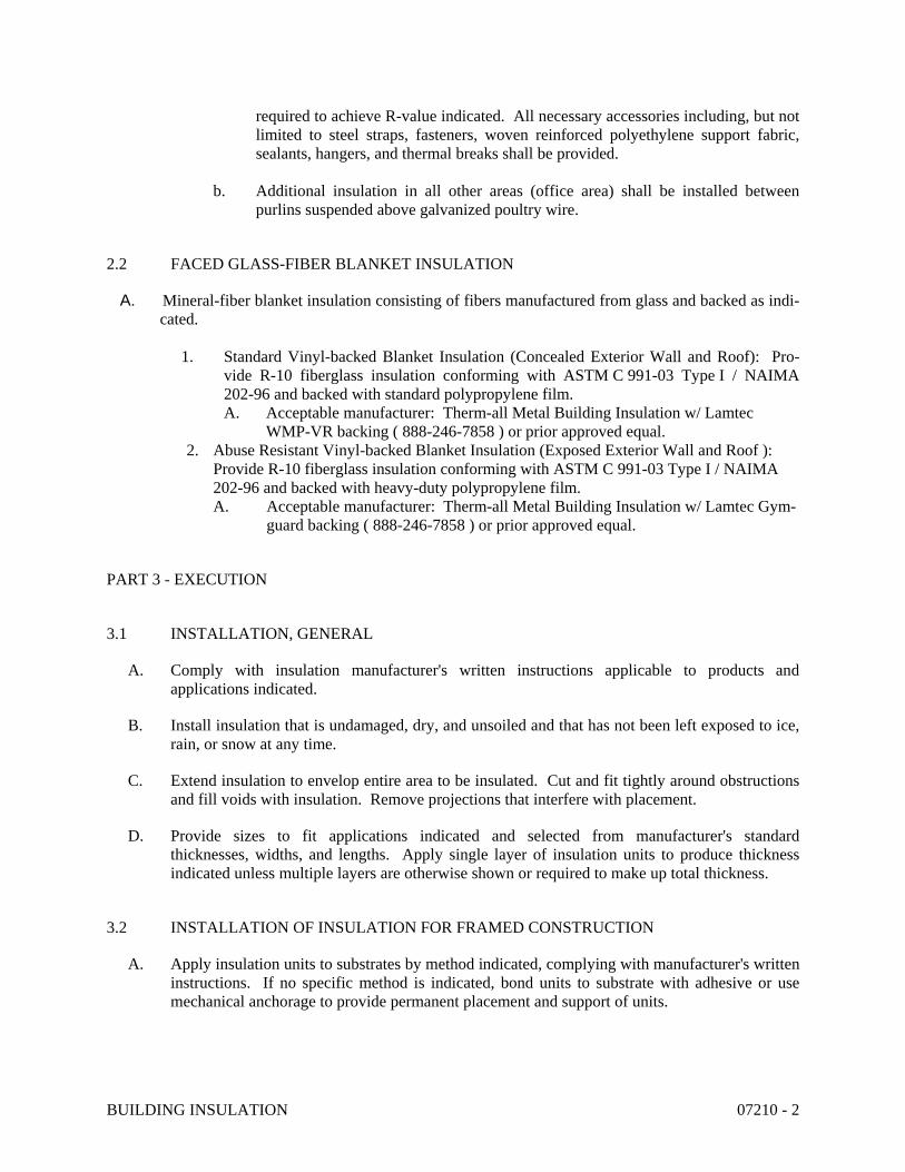
BUILDING INSULATION 07210 - 2
required to achieve R-value indicated. All necessary accessories including, but not limited to steel straps, fasteners, woven reinforced polyethylene support fabric, sealants, hangers, and thermal breaks shall be provided.
b. Additional insulation in all other areas (office area) shall be installed between purlins suspended above galvanized poultry wire.
2.2 FACED GLASS-FIBER BLANKET INSULATION
A. Mineral-fiber blanket insulation consisting of fibers manufactured from glass and backed as indi-cated.
1. Standard Vinyl-backed Blanket Insulation (Concealed Exterior Wall and Roof): Pro-
vide R-10 fiberglass insulation conforming with ASTM C 991-03 Type I / NAIMA 202-96 and backed with standard polypropylene film. A. Acceptable manufacturer: Therm-all Metal Building Insulation w/ Lamtec
WMP-VR backing ( 888-246-7858 ) or prior approved equal. 2. Abuse Resistant Vinyl-backed Blanket Insulation (Exposed Exterior Wall and Roof ):
Provide R-10 fiberglass insulation conforming with ASTM C 991-03 Type I / NAIMA 202-96 and backed with heavy-duty polypropylene film. A. Acceptable manufacturer: Therm-all Metal Building Insulation w/ Lamtec Gym-
guard backing ( 888-246-7858 ) or prior approved equal.
PART 3 - EXECUTION
3.1 INSTALLATION, GENERAL
A. Comply with insulation manufacturer's written instructions applicable to products and applications indicated.
B. Install insulation that is undamaged, dry, and unsoiled and that has not been left exposed to ice, rain, or snow at any time.
C. Extend insulation to envelop entire area to be insulated. Cut and fit tightly around obstructions and fill voids with insulation. Remove projections that interfere with placement.
D. Provide sizes to fit applications indicated and selected from manufacturer's standard thicknesses, widths, and lengths. Apply single layer of insulation units to produce thickness indicated unless multiple layers are otherwise shown or required to make up total thickness.
3.2 INSTALLATION OF INSULATION FOR FRAMED CONSTRUCTION
A. Apply insulation units to substrates by method indicated, complying with manufacturer's written instructions. If no specific method is indicated, bond units to substrate with adhesive or use mechanical anchorage to provide permanent placement and support of units.

BUILDING INSULATION 07210 - 3
B. Glass-Fiber or Mineral-Wool Blanket Insulation: Install in cavities formed by framing members according to the following requirements:
1. Use insulation widths and lengths that fill the cavities formed by framing members. If more than one length is required to fill the cavities, provide lengths that will produce a snug fit between ends.
2. Place insulation in cavities formed by framing members to produce a friction fit between edges of insulation and adjoining framing members.
3. Maintain 3-inch (76-mm) clearance of insulation around recessed lighting fixtures not rated for or protected from contact with insulation.
4. For metal-framed wall cavities where cavity heights exceed 96 inches (2438 mm), support unfaced blankets mechanically and support faced blankets by taping flanges of insulation to flanges of metal studs.
C. Miscellaneous Voids: Install insulation in miscellaneous voids and cavity spaces where required to prevent gaps in insulation using the following materials:
1. Loose-Fill Insulation: Compact to approximately 40 percent of normal maximum volume equaling a density of approximately 2.5 lb/cu. ft. (40 kg/cu. m).
2. Spray Polyurethane Insulation: Apply according to manufacturer's written instructions.
3.3 INSTALLATION OF FACED GLASS-FIBER BLANKET INSULATION
A. Apply faced insulation and support system in accordance with manufacturer’s written recommendations.
B. Coordinate with steel erector, roofing subcontractor, and other trades that involve roof-supported equipment and/or construction for a complete and proper installation around affected assemblies, systems, or equipment.
END OF SECTION 07210

BUILDING INSULATION 07210 - 4
This Page Intentionally Left Blank

FIRESTOPPING 07840-1
SECTION 07840 - FIRESTOPPING PART 1 - GENERAL 1.01 RELATED DOCUMENTS
A. Drawings and general provisions of Contract, including General and Supplementary Conditions and Division-1 Specification Section, apply to work specified in this section.
1.02 DEFINITIONS
A. Firestopping: Material or combination of materials used to retain integrity of fire-rated construction by maintaining an effective barrier against the spread of flame, smoke, and hot gases through penetrations in fire rated wall and floor assemblies.
1.03 GENERAL DESCRIPTION OF THE WORK OF THIS SECTION Only tested firestop systems shall be used in specific locations as follows:
A. Penetrations for the passage of duct, cable, cable tray, conduit, piping, electrical busways and raceways through fire-rated vertical barriers (walls and partitions), horizontal barriers (floor/ceiling assemblies), and vertical service shaft walls and partitions.
B. Safing slot gaps between edge of floor slabs and curtain walls. C. Openings between structurally separate sections of wall or floors. D. Gaps between the top of walls and ceilings or roof assemblies. E. Expansion joints in walls and floors. F. Openings and penetrations in fire-rated partitions or walls containing fire doors. G. Openings around structural members which penetrate floors or walls. 1.04 RELATED WORK OF OTHER SECTIONS
A. Coordinate work of this section with work of other sections as required to properly execute the work and as necessary to maintain satisfactory progress of the work of other sections, including:
1. Section 03300 - Concrete Work 2. Section 07900 - Joint Sealers 3. Section 04200 - Masonry Work 4. Section 09250 - Gypsum Drywall Systems 1.05 REFERENCES
A. Test Requirements: ASTM E-814, "Standard Method of Fire Tests of Through Penetration Fire Stops" (July 1983).

FIRESTOPPING 07840-2
B. Underwriters Laboratories (UL) of Northbrook, IL runs ASTM E-814 under their designation of UL 1479 and publishes the results in their "FIRE RESISTANCE DIRECTORY" that is updated annually with a midyear supplement.
1. UL Fire Resistance Directory: a. Firestop Devices (XHJI) b. Fire Resistance Ratings (BXUV) c. Through-Penetration Firestop Systems (XHEZ) d. Fill, Voids, or Cavity Material (XHHW) e. Forming Materials (XHKU)
C. Test Requirements: UL 2079, “Tests for Fire Resistance of Building Joint Systems” (November 1994).
D. ASTM E-84, Standard Test Method for Surface Burning Characteristics of Building
Materials. E. All three major building codes: ICBO, SBCCI, and BOCA F. NFPA 101 - Life Safety Code G. NFPA 70 - National Electric Code 1.06 QUALITY ASSURANCE
A. A manufacturer's direct representative (not distributor or agent) to be on-site during initial installation of firestop systems to train appropriate contractor personnel in proper selection and installation procedures. This will be done per manufacturer's written recommendations published in their literature and drawing details.
B. Firestop System installation must meet requirements of ASTM E-814, UL 1479 or UL 2079
tested assemblies that provide a fire rating equal to that of construction being penetrated. C. Proposed firestop materials and methods shall conform to applicable governing codes
having local jurisdiction. D. Firestop Systems do not reestablish the structural integrity of load bearing
partitions/assemblies, or support live loads and traffic. Installer shall consult the structural engineer prior to penetrating any load bearing assembly.
E. For those firestop applications that exist for which no UL tested system is available through
any manufacturer, a manufacturer's engineering judgment derived from similar UL system designs or other tests will be submitted to local authorities having jurisdiction for their review and approval prior to installation. Engineer judgment drawings must follow requirements set forth by the International Firestop Council (September 7, 1994).
1.07 SUBMITTALS

FIRESTOPPING 07840-3
A. Submit Product Data: Manufacturer's specifications and technical data for each material including the composition and limitations, documentation of UL firestop systems to be used and manufacturer's installation instructions to comply with Section 1300.
B. Manufacturer's engineering judgment identification number and drawing details when no
UL system is available for an application. Engineer judgment must include both project name and contractor’s name who will install firestop system as described in drawing.
C. Submit material safety data sheets provided with product delivered to job-site. 1.08 INSTALLER QUALIFICATIONS
A. Engage an experienced Installer who is certified, licensed, or otherwise qualified by the firestopping manufacture as having been provided the necessary training to install manufacture’s products per specified requirements. A manufacture’s willingness to sell its firestopping products to the Contractor or to an Installer engaged by the Contractor does not in itself confer qualification on the buyer.
1.09 DELIVERY, STORAGE, AND HANDLING
A. Deliver materials undamaged in manufacturer's clearly labeled, unopened containers, identified with brand, type, and UL label where applicable.
B. Coordinate delivery of materials with scheduled installation date to allow minimum storage
time at job-site. C. Store materials under cover and protect from weather and damage in compliance with
manufacturer's requirements. D. Comply with recommended procedures, precautions or remedies described in material
safety data sheets as applicable. E. Do not use damaged or expired materials. 1.10 PROJECT CONDITIONS
A. Do not use materials that contain flammable solvents. B. Schedule installation of firestopping after completion of penetrating item installation but
prior to covering or concealing of openings. C. Verify existing conditions and substrates before starting work. Correct unsatisfactory
conditions before proceeding. D. Weather conditions: Do not proceed with installation of firestop materials when
temperatures exceed the manufacturer's recommended limitations for installation printed on product label and product data sheet.
E. During installation, provide masking and drop cloths to prevent firestopping materials from
contaminating any adjacent surfaces.

FIRESTOPPING 07840-4
PART 2 - PRODUCTS 2.01 FIRESTOPPING, GENERAL
A. Provide firestopping composed of components that are compatible with each other, the substrates forming openings, and the items, if any, penetrating the firestopping under conditions of service and application, as demonstrated by the firestopping manufacture based on testing and field experience.
B. Provide components for each firestopping system that are needed to install fill material.
Use only components specified by the firestopping manufacture and approved by the qualified testing agency for the designated fire-resistance-rated systems.
C. Firestopping Materials are either “cast-in-place” (integral with concrete placement) or “post
installed.” Provide cast-in-place firestop devices prior to concrete placement.
2.02 ACCEPTABLE MANUFACTURERS
A. Subject to compliance with through penetration firestop systems (XHEZ) listed in Volume II of the UL Fire Resistance Directory, provide products of the following manufacturers as identified below:
1. Hilti, Inc., Tulsa, Oklahoma (800) 879-8000 2. Tremco Sealants & Coatings, Beachwood, Ohio (216) 292-5000 3. 3M Fire Protection Products, St. Paul, Minnesota (612) 736-0203 Provide products from one of the three acceptable manufacturers; no substitutions will be
accepted. 2.03 MATERIALS
A. Use only firestop products that have been UL 1479, ASTM E-814, or UL 2079 tested for specific fire-rated construction conditions conforming to construction assembly type, penetrating item type, annular space requirements, and fire-rating involved for each separate instance.
B. Cast-in place firestop devices for use with non-combustible and combustible plastic pipe
(closed and open piping systems) penetrating concrete floors, the following products are acceptable: 1. Hilti CP 680 Cast-In Place Firestop Device
C. For penetrations by non-combustible items including steel pipe, copper pipe, rigid steel
conduit and electrical metallic tubing (EMT), the following materials are acceptable: 1. Hilti FS 601 Elastomeric Firestop Sealant
2. Hilti FS-ONE High Performance Intumescent Firestop Sealant

FIRESTOPPING 07840-5
3. Hilti CP 620 FireFoam 3. 3M Fire Stop Sealant 2000 4. 3M Fire Barrier CP25 WB 5. Tremco Tremstop Fyre-Sil Sealant
D. For fire-rated construction joints and other gaps, the following materials are acceptable: 1. Hilti FS 601 Elastomeric Firestop Sealant
2. Hilti CP 601s Elastomeric Firestop Sealant 3. Hilti CP 606 Flexible Firestop Sealant
4. Hilti CP 672 Firestop Joint Spray 5. Hilti CP 604 Self-leveling Firestop Sealant
6. 3M Firestop Sealant 2000 7. Tremco Tremstop Fyre-Sil Sealant
E. For penetrations by combustible items (penetrants consumed by high heat and flame)
including insulated metal pipe, PVC jacketed, flexible cable or cable bundles and plastic pipe (closed piping systems), the following materials are acceptable: 1. Hilti FS-ONE High Performance Intumescent Firestop Sealant 2. Hilti CP 618 Firestop Putty
3. Hilti CP 642 Firestop Jacket 4. Hilti CP 643 Firestop Jacket 5. 3M Fire Barrier CP25 WB 6. 3M Fire Barrier FS-195 Wrap/Strip 7. Tremco Tremstop WBM Intumescent Firestop Sealant
F. For penetrations by combustible plastic pipe (open piping systems), the following materials are acceptable:
1. Hilti CP 642 Firestop Jacket 2. Hilti CP 643 Firestop Jacket 3. Hilti FS-ONE High Performance Intumescent Firestop Sealant 4. 3M Fire Barrier PPD Plastic Pipe Device G. For large size/complex penetrations made to accommodate cable trays, multiple steel and
copper pipes, electrical busways in raceways, the following materials are acceptable: 1. Hilti FS 635 Trowelable Firestop Compound
2. Hilti FIRE BLOCK 3. Hilti CP 620 FireFoam
3. 3M Firestop Foam 2001 4. 3M Fire Barrier CS-195 Composite Sheet
H. For openings between structurally separate sections of wall and floors. Top-of-walls, the following materials are acceptable:
1. Hilti FS 601 Elastomeric Firestop Sealant 2. Hilti CP 601s Elastomeric Firestop Sealant 3. Hilti CP 606 Flexible Firestop Sealant 4. Hilti FS-ONE High Performance Intumescent Firestop Sealant 5. 3M Fire Barrier CP 25 WB I. Provide a firestop system with a "F" Rating as determined by UL 1479 or ASTM E814
which is equal to the time rating of construction being penetrated.

FIRESTOPPING 07840-6
J. Provide a firestop system with an Assembly Rating as determined by UL 2079 which is
equal to the time rating of construction being penetrated.
PART 3 - EXECUTION 3.01 PREPARATION
A. Verification of Conditions: Examine areas and conditions under which work is to be performed and identify conditions detrimental to proper or timely completion.
1. Verify penetrations are properly sized and in suitable condition for application of
materials. 2. Surfaces to which firestop materials will be applied shall be free of dirt, grease, oil,
rust, laitance, release agents, water repellents, and any other substances that may affect proper adhesion.
3. Provide masking and temporary covering to prevent soiling of adjacent surfaces by
firestopping materials. 4. Comply with manufacturer's recommendations for temperature and humidity
conditions before, during and after installation of firestopping. 5. Do not proceed until unsatisfactory conditions have been corrected.
3.02 COORDINATION A. Coordinate location and proper selection of cast-in-place Firestop Devices with trade
responsible for the work. Ensure device is installed before placement of concrete.
B. Responsible trade to provide adequate spacing of field run pipes to allow for installation of cast-in-place firestop devices without interferences.
3.03 INSTALLATION
A. Regulatory Requirements: Install firestop materials in accordance with published "Through-Penetration Firestop Systems" in UL's Fire Resistance Directory.
B. Manufacturer's Instructions: Comply with manufacturer's instructions for installation of
through-penetration materials.
1. Seal all holes or voids made by penetrations to ensure an air and water resistant seal.

FIRESTOPPING 07840-7
2. Consult with mechanical engineer, project manager prior to installation of UL firestop systems that might hamper the performance of fire dampers as it pertains to duct work.
3. Protect materials from damage on surfaces subjected to traffic.
3.04 FIELD QUALITY CONTROL
A. Examine sealed penetration areas to ensure proper installation before concealing or enclosing areas.
B. Keep areas of work accessible until inspection by applicable code authorities. C. Perform under this section patching and repairing of firestopping caused by cutting or
penetrating of existing firestop systems already installed by other trades. 3.05 ADJUSTING AND CLEANING
A. Remove equipment, materials and debris, leaving area in undamaged, clean condition. B. Clean all surfaces adjacent to sealed holes and joints to be free of excess firestop materials
and soiling as work progresses.
3.06 U.L. APPROVED SYSTEM SCHEDULES SCHEDULES OF THROUGH PENETRATION FIRESTOP SYSTEMS
CONCRETE FLOORS
UL-CLASSIFIED SYSTEMS
CONCRETE OR BLOCK WALLS
UL-CLASSIFIED SYSTEMS
TYPE PENETRA
NT
F-RATING (HR)
HILTI 3M TREMCO
TYPE PENETR
ANT
F-RATING
HILTI 3M TREMCO
CIRCULAR BLANK OPENING
S
1 FA 0006, CAJ 0070
CAJ 0009
CAJ 0011
CIRCULAR BLANK OPENING
S
1 CAJ 0055, CAJ 0070
CAJ 0009
CAJ 0011
2 FA 0006, CAJ 0070
CAJ 0009
CAJ 0011
2 CAJ 0055, CAJ 0070
CAJ 0009
CAJ 0011
3 CAJ 0055
CAJ 0009
N/A* 3 CAJ 0055
CAJ 0009
N/A*
SINGLE METAL
PIPES OR
1 CAJ 1226,C
AJ
CAJ 1058
CAJ 1064, CAJ
SINGLE METAL
PIPES OR
1 CAJ 1226, WJ
CAJ 1058
CAJ 1064, CAJ 1302

FIRESTOPPING 07840-8
CONDUIT 1382 1302 CONDUIT 1021
2 CAJ 1226, CAJ 1382
CAJ 1058
CAJ 1064, CAJ 1302
2 CAJ 1226, WJ
1021
CAJ 1058
CAJ 1064, CAJ 1302
3 FA 1017,C
AJ 1226,C
AJ 1382
CAJ 1058
CAJ 1064
3 CAJ 1226, WJ
1041, WJ
1042
CAJ 1058
CAJ 1064
4 CBJ 1037, CBJ 1034
CAJ 1044
CAJ 1064
4 CBJ 1034, CBJ
1037, WJ
1041, WJ
1042
CAJ 1044
CAJ 1064
SINGLE NON-
METALLIC PIPE OR CONDUIT (I.E. PVC,
CPVC, ABS, ENT)
1 FA 2053, CAJ 2109, CAJ 2098, CAJ 2141, CAJ 2167, CBJ 2021
CAJ 2189, CAJ 2117, CAJ 2027
CAJ 2075, CAJ 2116, CAJ 2229
SINGLE NON-
METALLIC PIPE OR CONDUIT (I.E. PVC,
CPVC, ABS, ENT)
1 CAJ 2109, CAJ 2098
CAJ 2189, CAJ 2117, CAJ 2027
CAJ 2075, CAJ 2116, CAJ 2229
2 FA 2053, CAJ 2109, CAJ 2098, CAJ 2141, CAJ 2167, CBJ-2021
CAJ 2189, CAJ 2117
CAJ 2075, CAJ 2116, CAJ
2229, FA 2024
2 CAJ 2109, CAJ 2098
CAJ 2189, CAJ 2117, CAJ 2027
CAJ 2075, CAJ 2116, CAJ 2229
3 FA 2054,C
AJ 2109,C
AJ 2098
CAJ 2005, CAJ 2117
CAJ 2075
3 CAJ 2109, CAJ 2098
CAJ 2005, CAJ 2117, CAJ 2027
CAJ 2075

FIRESTOPPING 07840-9
4 N/A* N/A* N/A* 4 WJ 2057
N/A* N/A*
SINGLE OR
BUNDLED CABLES
1 FA 3007,C
AJ 3095,C
AJ 3096
CAJ 3021
CAJ 3141
SINGLE OR
BUNDLED
CABLES
1 WJ 3036, CAJ 3095, CAJ 3096
CAJ 3021
CAJ 3141
2 FA 3007,C
AJ 3095,C
AJ 3096
CAJ 3021
CAJ 3141
2 WJ 3036, CAJ 3095, CAJ 3096
CAJ 3021
CAJ 3141
3 CAJ 3095, FA
3007
CAJ 3030
CAJ 3141
3 CAJ 3095, CAJ 3096
CAJ 3030
CAJ 3141
4 N/A* N/A* N/A* 4 WJ 3050
N/A* N/A*
CABLE TRAY
1 CAJ 4034, CAJ 4054
CAJ 4003
N/A* CABLE TRAY
1 WJ 4016, CAJ 4034, CAJ 4054
CAJ 4003
WJ 4012
2 CAJ 4034, CAJ 4054
CAJ 4003
N/A* 2 WJ 4016, CAJ 4034, CAJ 4054
CAJ 4003
WJ 4012
3 CAJ 4034, CAJ 4035
CAJ 4003
N/A* 3 CAJ 4034, CAJ 4035
CAJ 4003
N/A*
4 N/A* N/A* N/A* 4 WJ 8007
N/A* N/A*
SINGLE INSULATED PIPES
1 FA 5015, FA
5016, CAJ 5090, CAJ 5091, CAJ 5098
CAJ 5080, CAJ 5024, CAJ 5017
CAJ 5111, CAJ 5121
SINGLE INSULATED PIPES
1 CAJ 5090, CAJ 5091, CAJ 5061
CAJ 5080, CAJ 5024, CAJ 5017
CAJ 5111, CAJ 5121
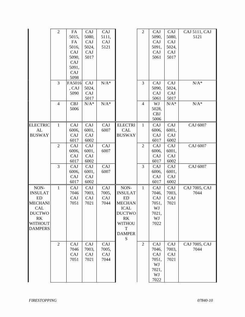
FIRESTOPPING 07840-10
2 FA 5015, FA
5016, CAJ 5090, CAJ 5091, CAJ 5098
CAJ 5080, CAJ 5024, CAJ 5017
CAJ 5111, CAJ 5121
2 CAJ 5090, CAJ 5091, CAJ 5061
CAJ 5080, CAJ 5024, CAJ 5017
CAJ 5111, CAJ 5121
3 FA5016, CAJ 5090
CAJ 5024, CAJ 5017
N/A* 3 CAJ 5090, CAJ 5061
CAJ 5024, CAJ 5017
N/A*
4 CBJ 5006
N/A* N/A* 4 WJ 5028, CBJ 5006
N/A* N/A*
ELECTRICAL
BUSWAY
1 CAJ 6006, CAJ 6017
CAJ 6001, CAJ 6002
CAJ 6007
ELECTRICAL
BUSWAY
1 CAJ 6006, CAJ 6017
CAJ 6001, CAJ 6002
CAJ 6007
2 CAJ 6006, CAJ 6017
CAJ 6001, CAJ 6002
CAJ 6007
2 CAJ 6006, CAJ 6017
CAJ 6001, CAJ 6002
CAJ 6007
3 CAJ 6006, CAJ 6017
CAJ 6001, CAJ 6002
CAJ 6007
3 CAJ 6006, CAJ 6017
CAJ 6001, CAJ 6002
CAJ 6007
NON-INSULAT
ED MECHANI
CAL DUCTWO
RK WITHOUT DAMPERS
1 CAJ 7046 CAJ 7051
CAJ 7003, CAJ 7021
CAJ 7005, CAJ 7044
NON-INSULAT
ED MECHAN
ICAL DUCTWO
RK WITHOU
T DAMPER
S
1 CAJ 7046, CAJ 7051, WJ
7021, WJ
7022
CAJ 7003, CAJ 7021
CAJ 7005, CAJ 7044
2 CAJ 7046 CAJ 7051
CAJ 7003, CAJ 7021
CAJ 7005, CAJ 7044
2 CAJ 7046, CAJ 7051, WJ
7021, WJ
7022
CAJ 7003, CAJ 7021
CAJ 7005, CAJ 7044
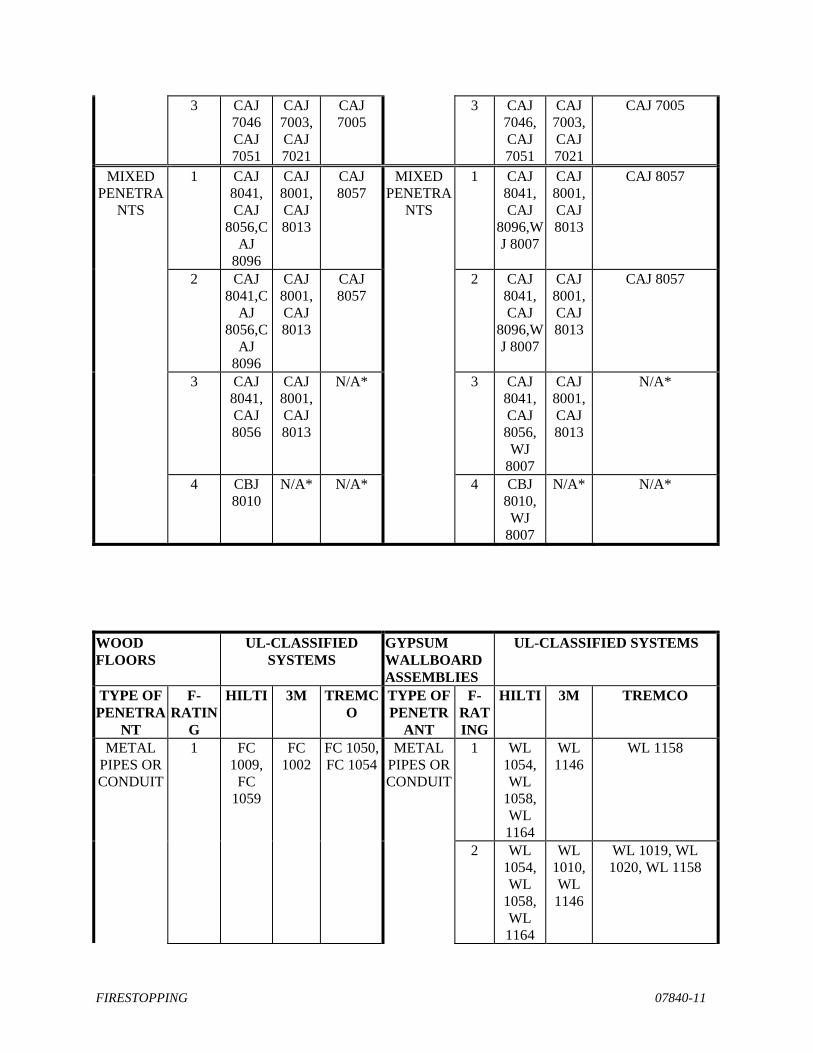
FIRESTOPPING 07840-11
3 CAJ 7046 CAJ 7051
CAJ 7003, CAJ 7021
CAJ 7005
3 CAJ 7046, CAJ 7051
CAJ 7003, CAJ 7021
CAJ 7005
MIXED PENETRA
NTS
1 CAJ 8041, CAJ
8056,CAJ
8096
CAJ 8001, CAJ 8013
CAJ 8057
MIXED PENETRA
NTS
1 CAJ 8041, CAJ
8096,WJ 8007
CAJ 8001, CAJ 8013
CAJ 8057
2 CAJ 8041,C
AJ 8056,C
AJ 8096
CAJ 8001, CAJ 8013
CAJ 8057
2 CAJ 8041, CAJ
8096,WJ 8007
CAJ 8001, CAJ 8013
CAJ 8057
3 CAJ 8041, CAJ 8056
CAJ 8001, CAJ 8013
N/A* 3 CAJ 8041, CAJ 8056, WJ
8007
CAJ 8001, CAJ 8013
N/A*
4 CBJ 8010
N/A* N/A* 4 CBJ 8010, WJ
8007
N/A* N/A*
WOOD FLOORS
UL-CLASSIFIED SYSTEMS
GYPSUM WALLBOARD ASSEMBLIES
UL-CLASSIFIED SYSTEMS
TYPE OF PENETRA
NT
F-RATIN
G
HILTI 3M TREMCO
TYPE OF PENETR
ANT
F-RATING
HILTI 3M TREMCO
METAL PIPES OR CONDUIT
1 FC 1009,
FC 1059
FC 1002
FC 1050, FC 1054
METAL PIPES OR CONDUIT
1 WL 1054, WL
1058, WL 1164
WL 1146
WL 1158
2 WL 1054, WL
1058, WL 1164
WL 1010, WL 1146
WL 1019, WL 1020, WL 1158

FIRESTOPPING 07840-12
2 FC 1009,
FC 1059
FC 1002
N/A* 4 WL 1110, WL 1111
WL 1001
N/A*
NON-
METALLIC PIPE OR CONDUIT
1 FC 2025,
FC 2030
FC 2024
FC 2049, FC 2135
NON-METALLIC PIPE OR CONDUIT
1 WL 2078, WL
2075, WL 2128
WL 2088, WL 2002
WL 2083, WL 2129
2 WL
2078, WL
2075, WL 2128
WL 2088, WL 2002
WL 2063, WL 2129, WL 2159
2 FC 2025,
FC 2029
FC 2024
FC 2049, FC 2083
4 WL 2184
N/A* N/A*
SINGLE
OR BUNDLED CABLES
1 FC 3012,
FC 3044
FC 3017
FC 3037 SINGLE OR
BUNDLED
CABLES
1 WL 3065, WL
3111, WL 3112
WL 3032, WL 3030
WL 3131
2 WL 3065, WL
3111, WL 3112
WL 3032, WL 3030
WL 3017, WL 3131
4 WL 3139
N/A* N/A*
2 FC 3012
FC 3017
N/A*
CABLE TRAY
1 WL 4011,W
L 4019,WL4054
WL 4004
N/A*
2 WL 4011,W
L
WL 4004
WL4012

FIRESTOPPING 07840-13
4019,WL4054
4 WL 8014
N/A* N/A*
INSULATED PIPES
1 FC 5004,
FC 5036,
FC 5037
FC 5014
FC 5055 INSULATED PIPES
1 WL 5028, WL
5029, WL 5047
WL 5040, WL
5001, WL 5032
WL 5070, WL 5081
2 WL 5028, WL
5029, WL 5047
WL 5040, WL
5001, WL 5032
WL 5070, WL 5081
2 FC 5004,
FC 5036,
FC 5037
N/A* N/A* 4 WL 5073
N/A* N/A*
NON-
INSULATED
MECHANICAL
DUCTWORK
WITHOUT DAMPERS
1 FC 7013
FC 7001
N/A* NON-INSULAT
ED MECHAN
ICAL DUCTWO
RK WITHOU
T DAMPER
S
1 WL 7017, WL
7040, WL 7042
WL 7008
WL 7039
2 WL
7040, WL 7042
WL 7008, WL
7013, WL 7016
WL 7039
4
MIXED PENETRA
NTS
1 FC 8009,
FC 8014
FC 8013
N/A* MIXED PENETRA
NTS
1 WL 1095, WL 8013
WL 8010
N/A*
2 WL WL N/A*

FIRESTOPPING 07840-14
1095, WL 8013
8010, WL 8002
2 N/A* N/A* N/A* 4 WL 8014
N/A* N/A*
4 WL 8014
* No UL-Classified systems for this manufacturer. Engineer Judgement Drawing Required
NOTES: 1. Jobsite conditions of each through-penetration firestop system must meet ALL details of the UL-Classified System selected. 2. If jobsite conditions do not match any UL-classified systems in the schedules above, contact firestop manufacturer for alternative systems or Engineer Judgement Drawings. 3. Where more than one applicable UL-Classified System is listed in the schedules, choose the UL System which is most economical for each. through-penetration firestop system.
4. Coordinate work with other trades to assure that penetration opening sizes are appropriate for penetrant locations, and vice versa. 5. For 3-hour rated gypsum walls, contact the firestop manufacturer for a UL-classified system or engineer judgement drawing.
SCHEDULES OF UL-2079 (DYNAMIC) JOINT FIRESTOP SYSTEMS
UL-CLASSIFIED SYSTEM
JOINT WIDTH LESS THAN OR EQUAL TO 2"
JOINT WIDTH GREATER THAN 2", LESS THAN OR EQUAL TO
6" JOINT TYPE F-
RATING
HILTI 3M TREMCO
HILTI 3M TREMCO
CONCRETE FLOOR-TO-FLOOR
1 - FF-D-0002
FF-D-0009
FF-D-1012, FF-D-1013
FF-D-1002, FF-D-1003, FF-D-1004
N/A**
2 - FF-D-0002
FF-D-0009
FF-D-1012, FF-D-1013
FF-D-1002, FF-D-1003, FF-D-1004
N/A**
3 - N/A** FF-D-0010
FF-D-1011, FF-D-1026
N/A** N/A**

FIRESTOPPING 07840-15
EDGE OF CONCRETE FLOOR SLAB-TO-WALL (SEE NOTE 1 FOR CURTAIN WALLS)
1 - - N/A** FW-D-1011,
FW-D-1012,
FW-D-1013,
FW-D-1021
FW-D-1002,
FW-D-1003,
FW-D-1009
N/A**
2 - - N/A** FW-D-1011,
FW-D-1012,
FW-D-1013,
FW-D-1021
FW-D-1002,
FW-D-1003,
FW-D-1009
N/A**
3 - - N/A** FW-D-1011,
FW-D-1021
FW-D-1002,
FW-D-1009
N/A**
CONCRETE OR BLOCK WALL TO FLAT CONCRETE SLAB FLOOR (TOP-OF-WALL)
1 HW-D-0097
HW-D-0023,
HW-D-0029
HW-D-0017
HW-D-1008,
HW-D-1009
HW-D-1003
HW-D-1011
2 HW-D-0097
HW-D-0023,
HW-D-0029
HW-D-0017
HW-D-1008,
HW-D-1009
HW-D-1003
HW-D-1011
3 - - N/A** HW-D-1008
HW-D-1002,
HW-D-1007
HW-D-1011
CONCRETE OR BLOCK WALL TO CONCRETE OVER FLUTED METAL DECK (TOP-OF-WALL)
1 HW-D-0080,
HW-D-0081,
HW-D-0098, HW-D 0181
HW-D-0022,
HW-D-0030,
HW-D-0040HW-D-0013
HW-D-0092
N/A**
2 HW-D-0080,
HW-D-0081,
HW-D-0098,
HW-D-0022,
HW-D-0030,
HW-D-0040HW-
HW-D-0092

FIRESTOPPING 07840-16
HW-D 0181
D-0013
3 N/A** N/A** N/A** GYPSUM WALL TO FLAT CONCRETE SLAB FLOOR (TOP-OF-WALL)
1 HW-D-0082,
HW-D-0083,
HW-D-0097
HW-D-0012,
HW-D-0021
HW-D-0016
N/A**
2 HW-D-0082,
HW-D-0083,
HW-D-0097
HW-D-0012,
HW-D-0021
HW-D-0016
3 N/A** N/A** N/A** GYPSUM WALL TO CONCRETE OVER FLUTED METAL DECK (TOP-OF-WALL)
1 HW-D-0042*, HW-D-0049*, HW-D-0087*, HW-D-0089*, HW-D-0045,
HW-D-0046,
HW-D-0066,
HW-D-0067
HW-D-0011,
HW-D-0020,
HW-D-0031
HW-D-0060,
HW-D-0091,
HW-D-0119
N/A**
2 HW-D-0042*, HW-D-0049*, HW-D-0087*, HW-D-0089*, HW-D-0045,
HW-D-0046
HW-D-0011,
HW-D-0020,
HW-D-0031
HW-D-0060,
HW-D-0091,
HW-D-0119
3 N/A** N/A** HW-D-0060
CONCRETE WALL-TO-
1 WW-D-0017
- WW-D-0009
WW-D-1011,
WW-D-1003,
N/A**

FIRESTOPPING 07840-17
WALL WW-D-1012
WW-D-1004,
WW-D-1010
2 WW-D-0017
- WW-D-0009
WW-D-1011,
WW-D-1012
WW-D-1003,
WW-D-1004,
WW-D-1010
N/A**
3 - - WW-D-0010
WW-D-1011
WW-D-1003,
WW-D-1010
N/A**
* SEE NOTE 6 ** CONTACT MANUFACTURER FOR CURRENT UL-CLASSIFIED SYSTEM OR ENGINEER JUDGEMENT DRAWING
NOTES: 1. FOR EDGE OF SLAB JOINTS AT UNRATED CURTAIN WALLS, UTILIZE OMEGA POINT LABORATORIES DRAWING # CEJ-216P, OR CONTACT HILTI FOR AN ENGINEER JUDGEMENT DRAWING (1-800-879-8000.) 2. CLASSIFIED SYSTEMS FOR 2" - 6" WIDE JOINTS MAY BE USED FOR JOINTS 2" WIDE AND LESS. 3. CONFIRM THAT MOVEMENT CAPABILITIES OF THE SELECTED UL SYSTEM MEETS OR EXCEEDS THE SPECIFIED MOVEMENT RANGE OF THE PARTICULAR JOINT. 4. SYSTEMS MARKED WITH ASTERIK (*) ARE SUITABLE FOR TOP-OF-WALL JOINTS WHERE THE FLUTED METAL DECK HAS SPRAY-ON MONOKOTE MK-6/HY FIREPROOFING. 5. HEAD-OF-WALL SYSTEMS SPECIFIED ONLY FOR 2- OR 3-HR SYSTEMS MAY NOT BE SUITABLE FOR MASONRY WALLS OR GYPSUM WALL ASSEMBLIES WITH LOWER HOURLY RATINGS. CONTACT THE FIRESTOP MANUFACTURER FOR CLARIFICATION
END OF SECTION

FIRESTOPPING 07840-18
This Page Intentionally Left Blank

JOINT SEALANTS 07920 - 1
SECTION 07920 - JOINT SEALANTS
PART 1 - GENERAL
1.1 SUMMARY
A. Section Includes: 1. Silicone joint sealants. 2. Latex joint sealants.
1.2 PRECONSTRUCTION TESTING
A. Preconstruction Field-Adhesion Testing: Before installing sealants, field test their adhesion to Project joint substrates. Test joint sealants according to Method A, Field-Applied Sealant Joint Hand Pull Tab, in Appendix X1 in ASTM C 1193 or Method A, Tail Procedure, in ASTM C 1521.
1.3 SUBMITTALS
A. Product Data: For each joint-sealant product indicated.
B. Samples: For each kind and color of joint sealant required.
C. Joint-Sealant Schedule: Include the following information: 1. Joint-sealant application, joint location, and designation. 2. Joint-sealant manufacturer and product name. 3. Joint-sealant formulation. 4. Joint-sealant color.
D. Product test reports.
E. Preconstruction field-adhesion test reports.
F. Field-adhesion test reports.
G. Warranties.
1.4 QUALITY ASSURANCE
A. Testing Agency Qualifications: Qualified according to ASTM C 1021 to conduct the testing indicated.
1.5 WARRANTY
A. Special Installer's Warranty: Manufacturer's standard form in which Installer agrees to repair or replace joint sealants that do not comply with performance and other requirements specified in this Section within specified warranty period. 1. Warranty Period: Two years from date of Substantial Completion.
B. Special Manufacturer's Warranty: Manufacturer's standard form in which joint-sealant manufacturer agrees to furnish joint sealants to repair or replace those that do not comply with performance and other requirements specified in this Section within specified warranty period.

JOINT SEALANTS 07920 - 2
1. Warranty Period: Five years from date of Substantial Completion.
PART 2 - PRODUCTS
2.1 MATERIALS, GENERAL
A. Liquid-Applied Joint Sealants: Comply with ASTM C 920 and other requirements indicated for each liquid-applied joint sealant specified, including those referencing ASTM C 920 classifications for type, grade, class, and uses related to exposure and joint substrates. 1. Suitability for Immersion in Liquids. Where sealants are indicated for Use I for joints
that will be continuously immersed in liquids, provide products that have undergone testing according to ASTM C 1247. Liquid used for testing sealants is deionized water, unless otherwise indicated.
B. Stain-Test-Response Characteristics: Where sealants are specified to be nonstaining to porous substrates, provide products that have undergone testing according to ASTM C 1248 and have not stained porous joint substrates indicated for Project.
C. Suitability for Contact with Food: Where sealants are indicated for joints that will come in repeated contact with food, provide products that comply with 21 CFR 177.2600.
2.2 SILICONE JOINT SEALANTS
A. Mildew-Resistant Silicone Joint Sealant: ASTM C 920. 1. Manufacturers: Subject to compliance with requirements, provide products by one of the
following: a. BASF Building Systems. b. Dow Corning Corporation. c. GE Advanced Materials - Silicones. d. Pecora Corporation. e. Sika Corporation; Construction Products Division. f. Tremco Incorporated.
2. Type: Single component (S). 3. Grade: nonsag (NS). 4. Class: 100/50. 5. Uses Related to Exposure: Nontraffic (NT).
2.3 LATEX JOINT SEALANTS
A. Latex Joint Sealant: Acrylic latex or siliconized acrylic latex, ASTM C 834, Type OP, Grade NF. 1. Manufacturers: Subject to compliance with requirements, provide products by one of the
following: a. BASF Building Systems. b. Bostik, Inc. c. May National Associates, Inc. d. Pecora Corporation. e. Tremco Incorporated.

JOINT SEALANTS 07920 - 3
2.4 JOINT SEALANT BACKING
A. Cylindrical Sealant Backings: ASTM C 1330, Type C (closed-cell material with a surface skin), and of size and density to control sealant depth and otherwise contribute to producing optimum sealant performance.
B. Bond-Breaker Tape: Polyethylene tape or other plastic tape recommended by sealant manufacturer.
2.5 MISCELLANEOUS MATERIALS
A. Primer: Material recommended by joint-sealant manufacturer where required for adhesion of sealant to joint substrates indicated, as determined from preconstruction joint-sealant-substrate tests and field tests.
B. Cleaners for Nonporous Surfaces: Chemical cleaners acceptable to manufacturers of sealants and sealant backing materials.
C. Masking Tape: Nonstaining, nonabsorbent material compatible with joint sealants and surfaces adjacent to joints.
PART 3 - EXECUTION
3.1 PREPARATION
A. Surface Cleaning of Joints: Clean out joints immediately before installing joint sealants to comply with joint-sealant manufacturer's written instructions. 1. Remove laitance and form-release agents from concrete. 2. Clean nonporous joint substrate surfaces with chemical cleaners or other means that do
not stain, harm substrates, or leave residues capable of interfering with adhesion of joint sealants.
B. Joint Priming: Prime joint substrates where recommended by joint-sealant manufacturer or as indicated by preconstruction joint-sealant-substrate tests or prior experience. Apply primer to comply with joint-sealant manufacturer's written instructions. Confine primers to areas of joint-sealant bond; do not allow spillage or migration onto adjoining surfaces.
C. Masking Tape: Use masking tape where required to prevent contact of sealant or primer with adjoining surfaces that otherwise would be permanently stained or damaged by such contact or by cleaning methods required to remove sealant smears. Remove tape immediately after tooling without disturbing joint seal.
3.2 INSTALLATION
A. Sealant Installation Standard: Comply with recommendations in ASTM C 1193 for use of joint sealants as applicable to materials, applications, and conditions indicated.
B. Install sealant backings of kind indicated to support sealants during application and at position required to produce cross-sectional shapes and depths of installed sealants relative to joint widths that allow optimum sealant movement capability. 1. Do not leave gaps between ends of sealant backings.

JOINT SEALANTS 07920 - 4
2. Do not stretch, twist, puncture, or tear sealant backings. 3. Remove absorbent sealant backings that have become wet before sealant application and
replace them with dry materials.
C. Install bond-breaker tape behind sealants where sealant backings are not used between sealants and backs of joints.
D. Install sealants using proven techniques that comply with the following and at the same time backings are installed: 1. Place sealants so they directly contact and fully wet joint substrates. 2. Completely fill recesses in each joint configuration. 3. Produce uniform, cross-sectional shapes and depths relative to joint widths that allow
optimum sealant movement capability.
E. Tooling of Nonsag Sealants: Immediately after sealant application and before skinning or curing begins, tool sealants according to requirements specified in subparagraphs below to form smooth, uniform beads of configuration indicated; to eliminate air pockets; and to ensure contact and adhesion of sealant with sides of joint. 1. Remove excess sealant from surfaces adjacent to joints. 2. Use tooling agents that are approved in writing by sealant manufacturer and that do not
discolor sealants or adjacent surfaces. 3. Provide concave joint profile per Figure 8A in ASTM C 1193, unless otherwise
indicated.
F. Clean off excess sealant or sealant smears adjacent to joints as the Work progresses by methods and with cleaning materials approved in writing by manufacturers of joint sealants and of products in which joints occur.
3.3 FIELD QUALITY CONTROL
A. Field-Adhesion Testing: Field test joint-sealant adhesion to joint substrates as follows: 1. Extent of Testing: Test completed and cured sealant joints as follows:
a. Perform 10 tests for the first 1000 feet (300 m) of joint length for each kind of sealant and joint substrate.
b. Perform 1 test for each 1000 feet (300 m) of joint length thereafter or 1 test per each floor per elevation.
2. Test Method: Test joint sealants according to Method A, Field-Applied Sealant Joint Hand Pull Tab, in Appendix X1 in ASTM C 1193 or Method A, Tail Procedure, in ASTM C 1521.
B. Evaluation of Field-Adhesion Test Results: Sealants not evidencing adhesive failure from testing or noncompliance with other indicated requirements will be considered satisfactory. Remove sealants that fail to adhere to joint substrates during testing or to comply with other requirements. Retest failed applications until test results prove sealants comply with indicated requirements.
3.4 JOINT-SEALANT SCHEDULE
A. Joint-Sealant Application: Exterior joints in vertical surfaces and horizontal nontraffic surfaces. 1. Joint Locations:
a. Control and expansion joints in unit masonry.

JOINT SEALANTS 07920 - 5
b. Joints in dimension stone cladding. c. Joints between metal panels. d. Joints between different materials listed above. e. Perimeter joints between materials listed above and frames of doors, windows,
and, louvers. f. Control and expansion joints in ceilings and other overhead surfaces. g. Other joints as indicated.
2. Joint Sealant: Silicone. 3. Joint-Sealant Color: As selected by Architect from manufacturer's full range of colors.
Note that custom colors may be required, at no additional cost, to match adjacent materials.
B. Joint-Sealant Application: Interior joints in horizontal traffic surfaces. 1. Joint Locations:
a. Control and expansion joints in tile flooring. b. Other joints as indicated.
2. Joint Sealant: Silicone. 3. Joint-Sealant Color: As selected by Architect from manufacturer's full range of colors.
Note that custom colors may be required, at no additional cost, to match adjacent materials.
C. Joint-Sealant Application: Interior joints in vertical surfaces and horizontal nontraffic surfaces. 1. Joint Locations:
a. Control and expansion joints on exposed interior surfaces of exterior walls. b. Perimeter joints of exterior openings where indicated. c. Tile control and expansion joints. d. Vertical joints on exposed surfaces of walls and partitions. e. Perimeter joints between interior wall surfaces and frames of interior doors and
windows. f. Other joints as indicated.
2. Joint Sealant: Latex. 3. Joint-Sealant Color: As selected by Architect from manufacturer's full range of colors.
D. Joint-Sealant Application: Mildew-resistant interior joints in vertical surfaces and horizontal nontraffic surfaces. 1. Joint Sealant Location:
a. Joints between plumbing fixtures and adjoining walls, floors, and counters. b. Tile control and expansion joints in food service areas and where indicated. c. Other joints as indicated.
2. Joint Sealant: Silicone. 3. Joint-Sealant Color: As selected by Architect from manufacturer's full range of colors.
Note that custom colors may be required, at no additional cost, to match adjacent materials.
END OF SECTION 07920

JOINT SEALANTS 07920 - 6
This Page Intentionally Left Blank

STANDARD STEEL DOORS AND FRAMES 08110 - 1
SECTION 08110 - STANDARD STEEL DOORS AND FRAMES
PART 1 - GENERAL
1.1 SUMMARY
A. This Section includes standard hollow-metal steel doors and frames.
1.2 SUBMITTALS
A. Product Data: Include construction details, material descriptions, core descriptions, label compliance, and finishes for each type of steel door and frame specified.
B. Shop Drawings: Provide a schedule of standard steel doors and frames using same reference numbers for details and openings as those on Drawings.
C. Product test reports.
1.3 DELIVERY, STORAGE, AND HANDLING
A. Deliver doors and frames palletized, wrapped, or crated to provide protection during transit and Project-site storage. Do not use nonvented plastic.
B. Deliver welded frames with two removable spreader bars across bottom of frames, tack welded to jambs and mullions.
PART 2 - PRODUCTS
2.1 MANUFACTURERS
A. Available Manufacturers: Subject to compliance with requirements, manufacturers offering products that may be incorporated into the Work include, but are not limited to, the following: 1. Amweld Building Products, LLC. 2. Benchmark Doors; a division of General Products Co., Inc. 3. Ceco Door Products; an ASSA ABLOY Group Company. 4. Republic Builders Products Company. 5. Steelcraft; an Ingersoll-Rand Company. 6. Prior approved equal.
B. Cold-Rolled Steel Sheet: ASTM A 1008/A 1008M, Commercial Steel (CS), Type B; suitable for exposed applications.
C. Hot-Rolled Steel Sheet: ASTM A 1011/A 1011M, Commercial Steel (CS), Type B; free of scale, pitting, or surface defects; pickled and oiled.
D. Electrolytic Zinc-Coated Steel Sheet: ASTM A 591/A 591M, Commercial Steel (CS), Class B coating; mill phosphatized.
E. Supports and Anchors: After fabricating, galvanize units to be built into exterior walls according to ASTM A 153/A 153M, Class B.

STANDARD STEEL DOORS AND FRAMES 08110 - 2
F. Inserts, Bolts, and Fasteners: Provide items to be built into exterior walls, hot-dip galvanized according to ASTM A 153/A 153M.
G. Glazing: Comply with requirements in Division 8 Section "Glazing."
H. Bituminous Coating: Cold-applied asphalt mastic, SSPC-Paint 12, compounded for 15-mil (0.4-mm) dry film thickness per coat. Provide inert-type noncorrosive compound free of asbestos fibers, sulfur components, and other deleterious impurities.
2.2 STANDARD STEEL DOORS
A. General: Provide doors of design indicated, not less than thickness indicated; fabricated with smooth surfaces, without visible joints or seams on exposed faces. Comply with ANSI A250.8. 1. Core Construction: Manufacturer's standard kraft-paper honeycomb, polystyrene,
polyurethane, mineral-board, or vertical steel-stiffener core that produces doors complying with ANSI A250.8.
2. Vertical Edges for Single-Acting Doors: Square edge. 3. Top and Bottom Edges: Closed with flush or inverted 0.042-inch- (1.0-mm-) thick end
closures or channels of same material as face sheets.
B. Exterior/Interior Doors: Face sheets fabricated from metallic-coated steel sheet. Provide doors complying with requirements indicated below by referencing ANSI A250.8 for level and model and ANSI A250.4 for physical-endurance level: 1. Exterior: Level 4 and Physical Performance Level A (Maximum Duty), Model 1 (Full
Flush). 2. Interior: Level 3 and Physical Performance Level A (Maximum Duty), Model 1 (Full
Flush).
2.3 STANDARD STEEL FRAMES
A. General: Comply with ANSI A250.8 and with details indicated for type and profile.
B. Exterior Frames: Fabricated from metallic-coated steel sheet. 1. Fabricate frames as full profile welded. 2. Frames for Level 4 Steel Doors: 14 gauge.
C. Interior Frames: Fabricated from cold-rolled steel sheet, unless otherwise indicated to comply with exterior frame requirements. 1. Fabricate frames as full profile welded. 2. Frames for Wood Doors: 16 gauge.
D. Supports and Anchors: Fabricated from electrolytic zinc-coated or metallic-coated steel sheet.
E. Jamb Anchors: Masonry, stud-wall, compression, or postinstalled expansion type; not less than 0.042 inch (1.0 mm) thick.
F. Floor Anchors: Formed from same material as frames, not less than 0.042 inch (1.0 mm) thick.
G. Plaster Guards: Formed from same material as frames, not less than 0.016-inch (0.4-mm) thick.

STANDARD STEEL DOORS AND FRAMES 08110 - 3
2.4 STOPS AND MOLDINGS
A. Moldings for Glazed Lites in Doors: Minimum 0.032 inch (0.8 mm) thick, fabricated from same material as door face sheet in which they are installed.
B. Fixed Frame Moldings: Formed integral with standard steel frames, minimum 5/8 inch (16 mm) high, unless otherwise indicated.
C. Loose Stops for Glazed Lites in Frames: Minimum 0.032 inch (0.8 mm) thick, fabricated from same material as frames in which they are installed.
2.5 FABRICATION
A. General: Fabricate standard steel doors and frames to be rigid and free of defects, warp, or buckle. Accurately form metal to required sizes and profiles, with minimum radius for thickness of metal. Where practical, fit and assemble units in manufacturer's plant. To ensure proper assembly at Project site, clearly identify work that cannot be permanently factory assembled before shipment.
B. Standard Steel Doors: 1. Exterior Doors: Provide weep-hole openings in bottom of exterior doors to permit
moisture to escape. Seal joints in top edges of doors against water penetration. 2. Glazed Lites: Factory cut openings in doors.
C. Standard Steel Frames: Where frames are fabricated in sections due to shipping or handling limitations, provide alignment plates or angles at each joint, fabricated of same thickness metal as frames. 1. Welded Frames: Weld flush face joints continuously; grind, fill, dress, and make smooth,
flush, and invisible. 2. Transom Bar Frames: Provide closed tubular members with no visible face seams or
joints; fabricated from same material as door frame. Fasten members at crossings and to jambs by butt welding.
3. Provide countersunk, flat- or oval-head exposed screws and bolts for exposed fasteners, unless otherwise indicated.
4. Plaster Guards: Weld guards to frame at back of hardware mortises in frames installed in concrete or masonry.
5. Floor Anchors: Weld anchors to bottom of jambs and mullions with at least four spot welds per anchor.
6. Jamb Anchors: Locate anchors not more than 18 inches (457 mm) from top and bottom of frame. Space anchors not more than 32 inches (813 mm) o.c.
7. Door Silencers: Except on weather-stripped doors, drill stops to receive door silencers as follows. Provide plastic plugs to keep holes clear during construction.
D. Hardware Preparation: Factory prepare standard steel doors and frames to receive templated mortised hardware; include cutouts, reinforcement, mortising, drilling, and tapping, according to the Door Hardware Schedule and templates furnished as specified in Division 8 Section "Door Hardware." 1. Comply with applicable requirements in ANSI A250.6 and ANSI/DHI A115 Series
specifications for door and frame preparation for hardware. Locate hardware as indicated on Shop Drawings or, if not indicated, according to ANSI A250.8.

STANDARD STEEL DOORS AND FRAMES 08110 - 4
E. Stops and Moldings: Provide stops and moldings around glazed lites where indicated. Form corners of stops and moldings with butted or mitered hairline joints. 1. Provide fixed stops and moldings welded on secure side of door or frame. 2. Provide loose stops and moldings on inside of doors and frames.
2.6 FINISHES
A. Steel Finish: Factory priming for field-painted finish. 1. Shop Primer: Manufacturer's standard, fast-curing, lead- and chromate-free primer
complying with ANSI A250.10 acceptance criteria.
PART 3 - EXECUTION
3.1 INSTALLATION
A. Remove welded-in shipping spreaders installed at factory.
B. Provide doors and frames of sizes, thicknesses, and designs indicated. Install standard steel doors and frames plumb, rigid, properly aligned, and securely fastened in place; comply with Drawings and manufacturer's written instructions.
C. Standard Steel Frames: Install standard steel frames for doors and transoms of size and profile indicated. Comply with SDI 105. 1. Set frames accurately in position; plumbed, aligned, and braced securely until permanent
anchors are set. After wall construction is complete, remove temporary braces, leaving surfaces smooth and undamaged. a. At fire-protection-rated openings, install frames according to NFPA 80. b. Apply bituminous coating to backs of frames that are filled with mortar, grout, and
plaster containing antifreezing agents. 2. Wood-Stud Partitions: Solidly pack mineral-fiber insulation behind frames. 3. Masonry Walls: Coordinate installation of frames to allow for solidly filling space
between frames and masonry with mortar as specified in Division 4 Section "Unit Masonry Assemblies."
4. Concrete Walls: Solidly fill space between frames and concrete with grout. Install grout in lifts and take precautions, including bracing frames, to ensure that frames are not deformed or damaged by grout forces.
D. Standard Steel Doors: Fit hollow-metal doors accurately in frames. Shim as necessary. 1. Fire-Rated Doors: Install doors with clearances according to NFPA 80.
E. Glazing: Comply with installation requirements in Division 8 Section "Glazing" and with standard steel door and frame manufacturer's written instructions.
F. Final Adjustments: Check and readjust operating hardware items immediately before final inspection. Leave work in complete and proper operating condition. Remove and replace defective work, including standard steel doors or frames that are warped, bowed, or otherwise unacceptable.
G. Prime-Coat Touchup: Immediately after erection, sand smooth rusted or damaged areas of prime coat and apply touchup of compatible air-drying primer.

STANDARD STEEL DOORS AND FRAMES 08110 - 5
END OF SECTION 08110

FLUSH WOOD DOORS 08211 - 1
SECTION 08211 - FLUSH WOOD DOORS
PART 1 - GENERAL
1.1 SUMMARY
A. This Section includes solid-core doors as follows: 1. Doors with wood-veneer faces. 2. Factory fitting wood doors to frames and factory machining for hardware.
B. See Division 8 Section "Standard Steel Doors and Frames” for steel door frames.
C. See Division 8 Section "Glazing" for glass view panels in flush wood doors.
1.2 SUBMITTALS
A. Product Data: For each type of door.
B. Shop Drawings: Indicate location, size, and hand of each door; elevation of each kind of door; construction details; location and extent of hardware blocking; mortises, holes, and cutouts; requirements for veneer matching; fire ratings; and other pertinent data.
C. Samples: For each face material and finish.
1.3 QUALITY ASSURANCE
A. Quality Standard: Comply with AWI's "Architectural Woodwork Quality Standards Illustrated."
B. Fire-Rated Wood Doors: Doors that are listed and labeled by a testing and inspecting agency acceptable to authorities having jurisdiction, for fire ratings indicated. 1. Test Pressure: After 5 minutes into the test, neutral pressure level in furnace shall be
established at 40 inches (1000 mm) or less above the sill.
PART 2 - PRODUCTS
2.1 MANUFACTURERS
A. Available Manufacturers: Subject to compliance with requirements, manufacturers offering products that may be incorporated into the Work include, but are not limited to, the following: 1. Marshfield Door Systems. 2. Chappell Door Co. 3. IPIK Door Company. 4. Mohawk Flush Doors, Inc. 5. Oshkosh Architectural Door Co. 6. Weyerhaeuser Company. 7. Prior Approved Equal.
2.2 DOOR CONSTRUCTION
A. Doors for Transparent Finish:

FLUSH WOOD DOORS 08211 - 2
1. Grade: Custom (Grade A faces). 2. Species and Cut: White birch, rotary cut. 3. Match between Veneer Leaves: Book match. 4. Assembly of Veneer Leaves on Door Faces: Running match. 5. Pair and Set Match: Provide for doors hung in same opening or separated only by
mullions. 6. Finish: Prefinished (Finish color to be selected from Manufacturer’s full range).
B. Structural-Composite-Lumber-Core Doors: 1. Structural Composite Lumber: WDMA I.S.10.
a. Screw Withdrawal, Face: 700 lbf (3100 N). b. Screw Withdrawal, Edge: 400 lbf (1780 N).
C. Fire-Rated Doors: 1. Construction: Construction and core specified above for type of face indicated or
manufacturer's standard mineral-core construction as needed to provide fire rating indicated.
2. Edge Construction: Intumescent seals concealed by outer stile matching face veneer, and laminated backing for improved screw-holding capability and split resistance.
3. Pairs: Provide fire-rated pairs with fire-retardant stiles matching face veneer that are labeled and listed for kinds of applications indicated without formed-steel edges and astragals. Provide stiles with concealed intumescent seals.
D. Blocking: For mineral-core doors, provide blocking as needed to eliminate through-bolting hardware. Use composite blocking with improved screw-holding capability.
E. Provide doors with either glued-block or structural composite lumber cores instead of particleboard cores at locations where exit devices are indicated.
F. Wood-Veneered Beads for Light Openings in Fire Doors: Manufacturer's standard wood-veneered noncombustible beads matching veneer species of door faces and approved for use in doors of fire rating indicated.
2.3 FABRICATION
A. Factory fit doors to suit frame-opening sizes indicated. Comply with clearance requirements of referenced quality standard for fitting. Comply with requirements in NFPA 80 for fire-rated doors.
B. Factory machine doors for hardware that is not surface applied.
C. Openings: Cut and trim openings through doors to comply with applicable requirements of referenced standards for kind(s) of door(s) required. 1. Light Openings: Trim openings with moldings of material and profile indicated.
PART 3 - EXECUTION
3.1 INSTALLATION
A. Install doors to comply with manufacturer's written instructions, referenced quality standard, and as indicated.

FLUSH WOOD DOORS 08211 - 3
1. Install fire-rated doors in corresponding fire-rated frames according to NFPA 80.
B. Finishing: Door shall be prefinished (Finish color to be selected from Manufacturer’s full range).
C. Factory-Fitted Doors: Align in frames for uniform clearance at each edge.
END OF SECTION 08211

FLUSH WOOD DOORS 08211 - 4
This Page Intentionally Left Blank

OVERHEAD COILING DOORS & GRILLES 08331 - 1
SECTION 08331 - OVERHEAD COILING DOORS & GRILLES
PART 1 - GENERAL
1.01 RELATED DOCUMENTS
A. Drawings and general provisions of the Contract, including General and Supplementary
Conditions and Division 1 Specification Sections, apply to this Section.
1.02 SUMMARY
A. This Section includes the following types of overhead coiling doors:
1. Service doors. B. See Division 8 Section "Door Hardware" for lock cylinders and keying. C. Division 16 Sections for electrical service, connections, disconnects, and circuit breakers for
powered operators, and accessories.
1.03 PERFORMANCE REQUIREMENTS
A. Structural Performance: Provide overhead coiling doors capable of withstanding the effects of
gravity loads and the following loads and stresses without evidencing permanent deformation of door components: 1. Wind Load: Design Wind-speed of 130 mph.
B. Operational Life: Design components to operate for not less than 50,000 cycles. 1. Operation Cycle: One complete cycle begins with door in closed position. Door is then
moved to open position and back to closed position.
1.04 SUBMITTALS
A. Product Data: For product indicated. B. Shop Drawings: Include plans, elevations, sections, details of installation, wiring diagrams,
and attachments to other Work. Use same reference designations indicated on Drawings and Door Schedule. 1. Verify openings by field measurements before fabrication and indicate measurements on
Shop Drawings.
1.05 QUALITY ASSURANCE
A. Electrical Components, Devices, and Accessories: Listed and labeled as defined in NFPA 70,
Article 100, by a testing agency acceptable to authorities having jurisdiction, and marked for intended use.
B. Guarantee: Door shall be guaranteed against defective materials and workmanship for one (1) year from date of Final Acceptance.
C. All galvanized components shall be provided in accordance with applicable standards: 1. ASTM A123 Standard Specification for Zinc (Hot-Dip Galvanized) Coatings on Iron and
Steel Products.

OVERHEAD COILING DOORS & GRILLES 08331 - 2
2. ASTM A653/A653M Standard Specification for Steel Sheet, Zinc-Coated (Galvanized) or Zinc-Iron Alloy-Coated (Galvannealed) by the Hot-Dip Process.
PART 2 - PRODUCTS
2.01 MANUFACTURERS
A. Manufacturers: 1. Wayne-Dalton Corp. (Model 800-C-insulated) @ Doors 109A and 108A. 2. Wayne-Dalton Corp. (Model 800) @ all other locations. 3. Prior approved equal of each type listed above.
2.02 DOOR CURTAIN AND CONSTRUCTION
A. Door Curtain (Exterior): Interlocking slats in continuous length for width of door. Unless
otherwise indicated, slats of material thickness recommended by door manufacturer for performance, size, and type of door indicated. 1. Steel Door Curtain Slats: Structural-quality, cold-rolled galvanized steel sheets with G90
(Z275) zinc coating. Minimum 1.25 of zinc per sq. ft. a. Slat Type: Flat profile, minimum 22 ga., 2 ¾ inches high, ¾ inch depth. . b. Insulation: Fill slat with rigid cellular polystyrene or polyurethane-foam-type
thermal insulation with maximum flame-spread and smoke-developed indices of 75 and 450, respectively, according to ASTM E 84. Enclose insulation completely within metal slat faces.
c. Finish: powder coated finish (Select from manufacturer’s standard finish colors). 1) Inside Curtain Slat Face: Match material of outside metal curtain slat.
2. Door Curtain (Interior): Interlocking slats in continuous length for width of door. Unless otherwise indicated, slats of material thickness recommended by door manufacturer for performance, size, and type of door indicated. 2. Steel Door Curtain Slats: Structural-quality, cold-rolled galvanized steel sheets with G90
(Z275) zinc coating. Minimum 1.25 of zinc per sq. ft. a. Slat Type: Flat profile, minimum 22 ga., 2 ¾ inches high, ¾ inch depth. .
Inside Curtain Slat Face: Match material of outside metal curtain slat. b. Finish: powder coated finish (Select from manufacturer’s standard finish colors).
2. Grille type: Structural quality, Aluminum with powder coated finish (Select from manufacturer’s standard finish colors).
B. Endlocks, General: Locate locks on every other curtain slat for curtain alignment and resistance against lateral movement. 1. Service Door Endlocks: Malleable-iron castings galvanized after fabrication, and secured
to curtain slats with galvanized rivets, or high-strength nylon. C. Windlocks: Malleable-iron castings secured to curtain slats with galvanized rivets or high-
strength nylon, as required to comply with wind load. D. Bottom Bar: 2 angles, minimum 1-1/2 by 1-1/2 by 1/8 inch (38 by 38 by 3 mm) thick,
galvanized steel or aluminum with tubular vinyl weatherseal. 1. Astragal: Replaceable, adjustable, continuous, compressible gasket of flexible vinyl,
rubber, or neoprene, that is cushion bumper for interior door.

OVERHEAD COILING DOORS & GRILLES 08331 - 3
E. Curtain Jamb Guides: Hot-dipped galvanized steel angles, or channels and angles, with sufficient depth and strength to retain curtain, to allow curtain to operate smoothly, and to withstand loading (channel department minimum 2 ½ inches, 3/16 inch steel thickness).
2.03 HOODS AND ACCESSORIES
A. Hood: Form to enclose coiled curtain and operating mechanism at opening head and act as
weatherseal. Contour to suit end brackets to which hood is attached. Roll and reinforce top and bottom edges for stiffness. Provide closed ends for surface-mounted hoods and fascia for any portion of between-jamb mounting projecting beyond wall face. Provide intermediate support brackets as required to prevent sag. 1. Steel-Door & Coiling Door Hoods: Fabricate from not less than 24 ga. thick, hot-dip
galvanized steel sheet that matches slat material. B. Weatherseals: Replaceable, adjustable, continuous, compressible weather-stripping gaskets
fitted to bottom and at top of exterior doors, unless otherwise indicated. At door head, use 1/8-inch- (3-mm-) thick, replaceable, continuous sheet secured to inside of curtain coil hood. 1. Jamb Seals: Replaceable, adjustable, continuous, flexible, 1/8-inch- (3-mm-) thick seals
of flexible vinyl, rubber, or neoprene at door jambs for weathertight installation. C. Slide Bolt (@ coiling doors): Fabricate with side locking bolts to engage through slots in
tracks for locking by padlock, located on both left and right jamb sides, operable from coil side.
D. Chain Lock Keeper (@ coiling door): Suitable for padlock. E. Cylinder lock (@ coiling grilles): Manufacturer’s standard cylinder lock assembly. F. Counterbalancing Mechanism: Adjustable, oil-tempered, heat-treated steel helical torsion
springs mounted around structural carbon-steel pipe, and contained in barrel of sufficient diameter and wall thickness to support rolled-up curtain without distortion of slats and to limit barrel deflection to not more than 0.03 in./ft. (2.5 mm/m) of span under full load; with grease-sealed bearings or self-lubricating graphite bearings. 1. Mounting Brackets: Cast-iron or cold-rolled steel plate with bell-mouth guide groove for
curtain. Minimum 8 gauge. G. Manual Door Operator (@ coiling door): Chain operated hoist mechanism.
2.04 FINISHES A. Galvanized-Steel Finish: Powder-coat finish (Select from manufacturer’s standard finish
colors) B. Aluminum: Powder-coat finish (Select from manufacturer’s standard finish colors).
PART 3 - EXECUTION
3.01 INSTALLATION A. General: Install door and operating equipment complete with necessary hardware, jamb and
head mold strips, anchors, inserts, hangers, and equipment supports. B. Lubricate bearings and sliding parts; adjust doors to operate easily, free from warp, twist, or
distortion and fitting weathertight for entire perimeter. C. Brackets shall be attached to continuous wall angle with 5/16 inch bolts.
3.02 DEMONSTRATION A. Engage a factory-authorized service representative to train Owner's maintenance personnel to
adjust, operate, and maintain doors.

OVERHEAD COILING DOORS & GRILLES 08331 - 4
END OF SECTION 08331

ALUMINUM-FRAMED ENTRANCES AND STOREFRONTS 08410 - 1
SECTION 08410 - ALUMINUM-FRAMED ENTRANCES AND STOREFRONTS
PART 1 - GENERAL
1.1 SUMMARY
A. This Section includes the following: 1. Exterior aluminum-framed storefronts.
a. Glazing is retained mechanically with gaskets on four sides. 2. Exterior manual-swing aluminum doors.
1.2 PERFORMANCE REQUIREMENTS
A. General: Provide aluminum-framed systems, including anchorage, capable of withstanding, without failure, the effects of the following: 1. Structural loads. 2. Thermal movements. 3. Movements of supporting structure indicated on Drawings including, but not limited to,
story drift and deflection from uniformly distributed and concentrated live loads. 4. Dimensional tolerances of building frame and other adjacent construction. 5. Failure includes the following:
a. Deflection exceeding specified limits. b. Thermal stresses transferred to building structure. c. Framing members transferring stresses, including those caused by thermal and
structural movements, to glazing. d. Noise or vibration created by wind and thermal and structural movements. e. Loosening or weakening of fasteners, attachments, and other components. f. Sealant failure. g. Failure of operating units to function properly.
B. Structural Loads: 1. Wind Loads: 130 mph, acting inward or outward.
C. Deflection of Framing Members Normal to Wall Plane: Limited to 1/175 of clear span for spans up to 13 feet 6 inches (4.1 m) and to 1/240 of clear span plus 1/4 inch (6.35 mm) for spans greater than 13 feet 6 inches (4.1 m) or an amount that restricts edge deflection of individual glazing lites to 3/4 inch (19 mm), whichever is less.
D. Structural-Test Performance: Systems tested according to ASTM E 330 as follows: 1. When tested at positive and negative wind-load design pressures, systems do not
evidence deflection exceeding specified limits. 2. When tested at 150 percent of positive and negative wind-load design pressures, systems,
including anchorage, do not evidence material failures, structural distress, and permanent deformation of main framing members exceeding 0.2 percent of span.
3. Test Durations: As required by design wind velocity but not less than 10 seconds.
E. Temperature Change (Range): Systems accommodate 120 deg F (67 deg C), ambient; 180 deg F (100 deg C), material surfaces.

ALUMINUM-FRAMED ENTRANCES AND STOREFRONTS 08410 - 2
F. Air Infiltration: Maximum air leakage through fixed glazing and framing areas of systems of 0.06 cfm/sq. ft. (0.03 L/s per sq. m) of fixed wall area when tested according to ASTM E 283 at a minimum static-air-pressure difference of 6.24 lbf/sq. ft. (300 Pa).
G. Water Penetration Under Static Pressure: Systems do not evidence water penetration through fixed glazing and framing areas when tested according to ASTM E 331 at a minimum static-air-pressure difference of 20 percent of positive wind-load design pressure, but not less than 6.24 lbf/sq. ft. (300 Pa).
H. Condensation Resistance: Fixed glazing and framing areas of systems have condensation-resistance factor (CRF) of not less than 53 when tested according to AAMA 1503.
I. Average Thermal Conductance: Fixed glazing and framing areas of systems have average U-factor of not more than 0.69 Btu/sq. ft. x h x deg F (3.92 W/sq. m x K) when tested according to AAMA 1503.
1.3 SUBMITTALS
A. Product Data: For each type of product indicated.
B. Shop Drawings: Include plans, elevations, sections, details, and attachments to other work. 1. Include structural analysis data signed and sealed by the qualified professional engineer
responsible for their preparation. 2. For entrances, include hardware schedule and indicate operating hardware types,
functions, quantities, and locations.
C. Product test reports.
1.4 QUALITY ASSURANCE
A. Installer Qualifications: Acceptable to manufacturer and capable of preparation of data for aluminum-framed systems including Shop Drawings based on testing and engineering analysis of manufacturer's standard units in assemblies similar to those indicated for this Project.
1.5 WARRANTY
A. Special Assembly Warranty: Manufacturer's standard form in which manufacturer agrees to repair or replace components of aluminum-framed systems that do not comply with requirements or that deteriorate as defined in this Section within specified warranty period. 1. Failures include, but are not limited to, the following:
a. Structural failures including, but not limited to, excessive deflection. b. Noise or vibration caused by thermal movements. c. Deterioration of metals, metal finishes, and other materials beyond normal
weathering. d. Water leakage through fixed glazing and framing areas. e. Failure of operating components to function properly.
2. Warranty Period: Two years from date of Substantial Completion.

ALUMINUM-FRAMED ENTRANCES AND STOREFRONTS 08410 - 3
B. Special Finish Warranty: Manufacturer's standard form in which manufacturer agrees to repair or replace components on which finishes fail within specified warranty period. Warranty does not include normal weathering. 1. Warranty Period: 2 years from date of Substantial Completion.
PART 2 - PRODUCTS
2.1 MANUFACTURERS
A. Manufacturers: Subject to compliance with requirements, provide the following: 1. Exterior (Impact Resistant) - Kawneer, IR-501UT Impact resistant framing system.
Verify maximum span height with manufacturer.
2.2 MATERIALS
A. Aluminum: Alloy and temper recommended by manufacturer for type of use and finish indicated. 1. Sheet and Plate: ASTM B 209 (ASTM B 209M). 2. Extruded Bars, Rods, Profiles, and Tubes: ASTM B 221 (ASTM B 221M). 3. Extruded Structural Pipe and Tubes: ASTM B 429. 4. Structural Profiles: ASTM B 308/B 308M.
B. Steel Reinforcement: With manufacturer's standard corrosion-resistant primer. 1. Structural Shapes, Plates, and Bars: ASTM A 36/A 36M. 2. Cold-Rolled Sheet and Strip: ASTM A 1008/A 1008M. 3. Hot-Rolled Sheet and Strip: ASTM A 1011/A 1011M.
2.3 FRAMING SYSTEMS
A. Framing Members: Manufacturer's standard extruded-aluminum framing members of thickness required and reinforced as required to support imposed loads. 1. Construction: Framing members are composite assemblies of two separate extruded-
aluminum components permanently bonded by an elastomeric material of low thermal conductance.
B. Brackets and Reinforcements: Manufacturer's standard high-strength aluminum with nonstaining, nonferrous shims for aligning system components.
C. Fasteners and Accessories: Manufacturer's standard corrosion-resistant, nonstaining, nonbleeding fasteners and accessories compatible with adjacent materials. 1. Where fasteners are subject to loosening or turning out from thermal and structural
movements, wind loads, or vibration, use self-locking devices. 2. Reinforce members as required to receive fastener threads.
D. Concrete and Masonry Inserts: Hot-dip galvanized cast-iron, malleable-iron, or steel inserts complying with ASTM A 123/A 123M or ASTM A 153/A 153M requirements.
E. Flashing: Manufacturer's standard corrosion-resistant, nonstaining, nonbleeding flashing compatible with adjacent materials. Form exposed flashing from sheet aluminum finished to

ALUMINUM-FRAMED ENTRANCES AND STOREFRONTS 08410 - 4
match framing and of sufficient thickness to maintain a flat appearance without visible deflection.
F. Framing System Gaskets and Sealants: Manufacturer's standard recommended by manufacturer for joint type.
2.4 GLAZING SYSTEMS
A. Glazing: As specified in Division 8 Section "Glazing."
B. Glazing Gaskets: Manufacturer's standard compression types, replaceable, molded or extruded, that maintain uniform pressure and watertight seal.
C. Spacers and Setting Blocks: Manufacturer's standard elastomeric types.
2.5 DOORS
A. Doors: Manufacturer's standard glazed doors, for manual swing operation. 1. Door Construction: 1-3/4-inch (44.5-mm) overall thickness, with minimum 0.125-inch-
(3.2-mm-) thick, extruded-aluminum tubular rail and stile members. Mechanically fasten corners with reinforcing brackets that are deep penetration and fillet welded or that incorporate concealed tie rods.
2. Door Design: Medium stile; 3 1/2-inch nominal width. a. Accessible Doors: Smooth surfaced for width of door in area within 10 inches
(255 mm) above floor or ground plane. 3. Glazing Stops and Gaskets: Beveled, snap-on, extruded-aluminum stops and preformed
gaskets. 4. Exterior Doors: Provide Kawneer 350 IR Entrance system manufactured to accept 9/16”
glazing infill. 5. Exterior Doors (non impact rated): Provide Kawneer 350 Medium Stile Entrance system
to accept 1” insulated glazing. 6. Interior Doors: Provide Kawneer 350 Medium Stile Entrance system to accept ¼” glazing
or pre finished wood doors (see schedule).
B. Door Hardware: As specified in Division 8 Section "Door Hardware."
2.6 ACCESSORY MATERIALS
A. Joint Sealants: For installation at perimeter of aluminum-framed systems, as specified in Division 7 Section "Joint Sealants."
B. Bituminous Paint: Cold-applied asphalt-mastic paint complying with SSPC-Paint 12 requirements except containing no asbestos, formulated for 30-mil (0.762-mm) thickness per coat.
2.7 FABRICATION
A. Form aluminum shapes before finishing.
B. Framing Members, General: Fabricate components that, when assembled, have the following characteristics:

ALUMINUM-FRAMED ENTRANCES AND STOREFRONTS 08410 - 5
1. Profiles that are sharp, straight, and free of defects or deformations. 2. Accurately fitted joints with ends coped or mitered. 3. Means to drain water passing joints, condensation occurring within framing members,
and moisture migrating within the system to exterior. 4. Physical and thermal isolation of glazing from framing members. 5. Accommodations for thermal and mechanical movements of glazing and framing to
maintain required glazing edge clearances. 6. Provisions for field replacement of glazing from exterior. 7. Fasteners, anchors, and connection devices that are concealed from view to greatest
extent possible.
C. Mechanically Glazed Framing Members: Fabricate for flush glazing (without projecting stops).
D. Door Frames: Reinforce as required to support loads imposed by door operation and for installing hardware. 1. At exterior doors, provide compression weather stripping at fixed stops.
E. Doors: Reinforce doors as required for installing hardware. 1. At pairs of exterior doors, provide sliding weather stripping retained in adjustable strip
mortised into door edge. 2. At exterior doors, provide weather sweeps applied to door bottoms.
F. Hardware Installation: Factory install hardware to the greatest extent possible. Cut, drill, and tap for factory-installed hardware before applying finishes.
G. After fabrication, clearly mark components to identify their locations in Project according to Shop Drawings.
2.8 ALUMINUM FINISHES
A. Clear Anodized Finish: AAMA 611, AA-M12C22A44, Class I, 0.7 mils or thicker.
PART 3 - EXECUTION
3.1 INSTALLATION
A. General: 1. Fit joints to produce hairline joints free of burrs and distortion. 2. Rigidly secure non-movement joints. 3. Install anchors with separators and isolators to prevent metal corrosion and electrolytic
deterioration. 4. Seal joints watertight, unless otherwise indicated.
B. Metal Protection: 1. Where aluminum will contact dissimilar metals, protect against galvanic action by
painting contact surfaces with primer or by applying sealant or tape or installing nonconductive spacers as recommended by manufacturer for this purpose.
2. Where aluminum will contact concrete or masonry, protect against corrosion by painting contact surfaces with bituminous paint.

ALUMINUM-FRAMED ENTRANCES AND STOREFRONTS 08410 - 6
C. Install components to drain water passing joints, condensation occurring within framing members, and moisture migrating within the system to exterior.
D. Set continuous sill members and flashing in full sealant bed as specified in Division 7 Section "Joint Sealants" and to produce weathertight installation.
E. Install components plumb and true in alignment with established lines and grades, without warp or rack.
F. Install glazing as specified in Division 8 Section "Glazing."
G. Entrances: Install to produce smooth operation and tight fit at contact points. 1. Exterior Entrances: Install to produce tight fit at weather stripping and weathertight
closure. 2. Field-Installed Hardware: Install surface-mounted hardware according to hardware
manufacturers' written instructions using concealed fasteners to greatest extent possible.
H. Install perimeter joint sealants as specified in Division 7 Section "Joint Sealants" and to produce weathertight installation.
I. Erection Tolerances: Install aluminum-framed systems to comply with the following maximum tolerances: 1. Location and Plane: Limit variation from true location and plane to 1/8 inch in 12 feet
(3 mm in 3.7 m); 1/4 inch (6 mm) over total length. 2. Alignment:
a. Where surfaces abut in line, limit offset from true alignment to 1/16 inch (1.5 mm). b. Where surfaces meet at corners, limit offset from true alignment to 1/32 inch
(0.8 mm). 3. Diagonal Measurements: Limit difference between diagonal measurement to 1/8 inch
(3 mm).
END OF SECTION 08410

FINISH HARDWARE 08710-1
08710 - FINISH HARDWARE PART 1 - GENERAL 1.01 - SUMMARY. A. SECTION INCLUDES. 1. Furnish all finish hardware as required and specified herein. 2. Materials of quality less than outlined by these specifications or manufacturers and products not prior
approved will not be accepted. 3. Any discrepancies or omissions noted should be brought to the attention of the Architect prior to the
bid opening for instructions. 4. Any additional items required will be of the same type and quality to be consistent with other hardware
specified. B. RELATED DOCUMENTS. 1. Drawings and General Provisions of the contract, including General and Supplementary Conditions
and Division 1 of the specifications, including all addendums, apply to this section. C. RELATED SECTIONS. 1. Coordinate with Division 8, sections for doors and frames for the installation of finish hardware. 1.02 - REFERENCES. A. CODE DOCUMENTS. 1. NFPA - Standards for life safety codes, fire and smoke doors. 2. ADA/ANSI - Standards for accessibility by the physically handicapped. 3. ANSI - Standards for finish hardware. 1.03 - SUBMITTALS. A. HARDWARE SCHEDULE. 1. Submit six ( 6 ) copies for approval, following the sequence and format as recommended by the Door
and Hardware Institute. B. PRODUCT DATA. 1. Submit three ( 3 ) copies with the finish hardware schedule, showing all items of hardware to be
furnished. C. SAMPLES. 1. Furnish samples if requested by the Architect. All samples will be returned to the hardware supplier,
and if approved may be used on the project. D. TEMPLATES. 1. Templates are to be furnished by the finish hardware supplier as required. E. KEYING SCHEDULE. 1. Furnish a keying schedule indexed by door number, showing key sets and hardware headings. Include
all special keying notes and stamping. 2. Submit three ( 3 ) copies for approval. 1.04 - QUALITY ASSURANCE. A. SUPPLIER QUALIFICATIONS. 1. The supplier must be a factory authorized distributor of all materials to be furnished on this project. 2. Purchasing products from another distributor or wholesaler does not constitute being a factory

FINISH HARDWARE 08710-2
authorized distributor. 3. Have an office and warehouse within a one hundred fifty mile radius of the project to properly service
the project. 4. Be available to make job site visits as required by the quality control requirements of these
specifications, or as requested by the Contractor or Architect. B. REQUIRED FIELD QUALITY CONTROL SERVICE BY SUPPLIER. 1. The finish hardware distributor shall provide the field quality control services as listed. 2. Furnish a complete report to the Architect and General Contractor after each field visit. 3. Prior to installation: Visit the project, and with the General Contractor and installer check the hardware for any
shortages or shipment damage. Instruct the installer on any special conditions, and the adjustments required for the proper installation of the finish hardware.
4. After installation: Check the project for the proper application of the finish hardware according to the approved
hardware schedule. Check that all items, including door control devices have been properly adjusted and are operating properly. Notify the Architect of any hardware not installed in accordance with the approved hardware schedule or properly adjusted. Where hardware is found not to be installed correctly or properly adjusted, the General Contractor must adjust, repair, or replace as directed by the Architect. Instruct the owner personnel in the proper operation, adjustments, and maintenance of the finish hardware.
5. One year review: If requested by the Architect the hardware distributor along with the hardware installer shall visit the project and make any finial adjustments required to the hardware. 1.05 - MARKING, DELIVERY, AND STORAGE. A. MARKING. 1. The hardware supplier must mark all items of hardware with the door number or item number as listed
in the approved hardware schedule. B. DELIVERY. 1. The hardware supplier must deliver all hardware to the project in manufacturers original packages. C. STORAGE. 1. All hardware will be stored by the General Contractor in a secure and dry area. 1.06 - WARRANTIES. A. FURNISH. 1. Manufacturers standard warranties to cover defects in materials and workmanship. PART 2 - PRODUCTS. 2.01 - APPROVED MANUFACTURERS AND MATERIALS. A. MANUFACTURERS. 1. Manufacturers listed in these specifications are to establish a standard of quality required for this
project. 2. Furnish material only from manufacturers listed below for each item, or from manufacturers prior
approved by addenda. B. SUBSTITUTIONS. 1. All request for substitutions must be made fifteen days prior to bid date and include complete product
data and cut sheets.

FINISH HARDWARE 08710-3
C. HINGES. 1. Provide: Non removable pins for exterior swing out doors. Three each 4.5" x 4.5" hinges per door leaf. Stainless steel hinges for exterior doors. Fasteners as required by door and frame material. 2. Finish: BHMA-630, Satin stainless steel for exterior doors. BHMA-652, Satin chrome plated for interior doors. 3. Approved manufacturers and products. McKinney Bommer Ives Stanley T4A3386 BB5005 5BB1HW-SS FBB199 T4A3786 BB5004 5BB1HW FBB168 D. KEY CYLINDERS. 1. Provide: Types as required to operated related hardware. 2. Finish: BHMA-626, Satin chrome plated. 3. Approved manufacturers and products: Yale Corbin Sargent Schlage 1109 3000 34 20-022 2153 1000 40 20-001
E. EXIT DEVICES & MULLIONS. 1. Provide: Heavy duty, grade 1 devices. UL listed as panic hardware for non rated doors. UL listed as fire hardware for rated doors. Push pads to match device. Cylinder dogging as required. Key removable mullions. Thru bolted mounting to doors and fasteners as required by frame material. 2. Finish: BHMA-630, Satin stainless steel. 3. Approved manufacturers and products. Yale Corbin Sargent Von Duprin 7155 ED5200xM52 16-8800 CD-98 AU626F N955 713ET 992L03 KRM200WS 710KM L980 KR4954 KRM200
F. LOCKS & LATCH SETS. 1. Provide: Heavy duty grade 1 cylindrical types.
Functions as listed in hardware sets. UL listed for fire rated doors.
Lever trim. Curved lip strikes w/ wrought boxes for all lock and latch sets.
Thru bolt mounting to doors and fasteners as required by frame material. 2. Finish: BHMA-626, Satin chrome plated. 3. Approved manufacturer and products. Note: due to requirements for tying into Owner’s existing
keying system, no other lock set will be allowed. Yale 5402LN

FINISH HARDWARE 08710-4
5405LN 5407LN 5408LN 5418LN AU G. DOOR CLOSERS. 1. Provide: Barrier free types for interior non rated doors. Field adjustable types as required by opening conditions. Adjustable back-check and back-check positioning.
Adjustable sweep and latching cycles. UL listed for fire rated doors. Mounting brackets or plates as required by opening conditions. Arms as required by opening conditions. Sex nuts and bolts mounting to doors and fasteners as required by frame material.
2. Finish: BHMA-689, Satin aluminum painted. 3. Approved manufacturers and products. Yale Corbin Sargent LCN PR4400 DC6210-A3 351-PED P4040EDA PA4400 DC6210 351-P9 P4040 4400 DC6200 351-0 4040 H. DOOR TRIM & PROTECTION PLATES. 1. Provide: All plates to be .050 thick. Size: Kick plates, 12" high x 2" less door width. Fasteners as required by door material for push plates and protection plates.
Note: Protection plate heights listed are for flush doors, adjust height accordingly for louvers, bottom rail heights, raised panel doors or doors with applied moldings.
2. Finish: BHMA-630, Satin stainless steel. 3. Approved manufacturers and products. Rockwood Trimco Ives Quality K1050. 50. 8400. 48. I. AUXILIARY BOLTS & COORDINATORS. 1. Provide: Manual or automatic bolts as required by opening conditions.
All necessary strikes, shims, and guides to insure proper installation and operation. Fully automatic coordinators for sequential closing of paired doors with all accessories, including carry bars and brackets as required to facilitate the installation of vertical rod exit devices and door closers. Filler pieces to close the header area for an architecturally clean line.
Fasteners as required by door and frame material. 2. Finish: BHMA-626, Satin chrome plated. 3. Approved manufacturers and products. Rockwood 1600. 1942. 570. 550. J. STANDARD DOOR STOPS.

FINISH HARDWARE 08710-5
1. Provide: Stops for all doors as required by opening conditions. Fasteners as required by mounting conditions. 2. Finish: BHMA-626 with gray rubber bumper. 3. Approved manufacturers and products. Rockwood: #442. K. OVERHEAD STOPS AND HOLDERS. 1. Provide: Overhead types as listed in the hardware sets or as required by the opening conditions. Thru-bolt mounting to doors and fasteners as required by frame material. 2. Finish: BHMA-626, Satin chrome plated for interior types. 3. Approved manufacturers and products. Rixson G. Johnson Rockwood Sargent 9 series. 900 series. 19 series. 590 series. L. WEATHER PROTECTION. 1. Provide: Seals as required by opening conditions. Fasteners as required by mounting conditions. 2. Finish: Satin aluminum. 3. Approved manufacturers and products. Pemko N. Guard Reese Hager 303AS. 135S. DS70. 891SS. 18041CP. B606. 964. 802SB. M. FIRE AND SMOKE PROTECTION. 1. Provide: Intumescent type fire seals meeting positive pressure requirements. Smoke seals for smoke doors. Adhesive mounting. 2. Finish: Black or brown. 3. Approved manufacturers and products.. Pemko N. Guard Hager HSS2000xS44. 9800. 726. N. THRESHOLDS AND SADDLES. 1. Provide: Types as required by opening conditions. All types to meet handicap requirements. Have a slip resistant abrasive finish of nickel-aluminum composite where indicated in the
hardware sets. 2. Finish: Satin aluminum. 3. Approved manufacturers and products. Pemko N. Guard Reese Hager 2005ATK. 896NSIA. PGS483. 520SN-sure step. O. DOOR SILENCERS. 1. Provide: Rubber types for all hollow metal frames. 2. Finish:

FINISH HARDWARE 08710-6
Gray rubber. 3. Approved manufacturers and products: Rockwood Trimco Ives Hager 608 1229A SR64. 307D. 2.02 - KEYING. A. REQUIREMENTS: 1. Tie into Owner’s existing keying system for this project meeting the following requirements. 2. The finish hardware supplier will meet with the Architect and Owner to establish the final keying
requirements. 3. Furnish all locks and cylinders factory keyed. 4. Furnish temporary construction keying for use by the contractor during construction. The temporary construction keys only will be issued to the General Contractor during construction.
All construction keys may be keyed alike. 5. Permanent keys and a copy of the finial keying schedule must be delivered direct to the owner by the
finish hardware supplier. 6. At completion of the project, the contractor must activate the cylinders to operate by the owners
permanent keys. 7. Provide keys with “Visual key Control”. Stamp all keys with key set number. Provide cylinders with “Concealed Key Control”. Stamp back of all cylinders with key set number. 8. All cylinders shall be Yale KeyMark cylinders, factory master-keyed, with 2 keys per cylinder. 9. All locksets shall be provided with temporary construction cores. 10. Key bitting shall be sent directly from the manufacturer to Owner’s locksmith identified below.
Contractor shall notify Owner and Architect once bitting list is sent; however, neither the Contractor, Owner, nor Architect shall receive the bitting list directly.
B. Randy Benoit of Benoit Locksmith (Tel: 985-447-8128) is the school system’s current keying/hardware consultant. Contractor shall coordinate with Benoit Locksmith for all keying and bitting requirements.
PART 3 - EXECUTION 3.01 - EXAMINATION A. FIELD CONDITIONS: 1. The finish hardware installer and the General Contractor will examine all doors, frames and related
items for conditions that would prevent the proper installation of the finish hardware. Do not proceed until all corrections are made.
3.02 - PREPARATION AND INSTALLATION A. PREPARATION: 1. The hardware installer must read all notes included, and become familiar with the finish hardware
schedule. 2. The hardware installer must read and understand the installation instructions packed with each item of
hardware. B. INSTALLATION: 1. Installation must be done by skilled workman, who work with proper tools and be in accord with the
manufacturer’s instruction. 2. Hardware must be installed accurately, applied securely, and adjusted properly. 3. Install the hardware only with fasteners furnish by the manufacturer, warranties and/or labels will be
void on material installed with unauthorized fasteners. 3.03 - ADJUSTING AND CLEANING

FINISH HARDWARE 08710-7
A. ADJUSTING: 1. The installer will make final adjustments of each item of hardware to insure proper operation and
function. Adjust door control devices for final operation after air handling equipment is operational. B. CLEANING: 1. Clean all hardware with non-abrasive cleaners, and leave clean and free of disfigurements. 3.04 - PROTECTION A. DAMAGE CONTROL: 1. Protect all items of hardware from damage until the Owner has accepted the project as complete. 3.05 - HARDWARE SETS SET – 1 (Exit Door, Hollow-Metal, Exit) Door 100, 100A, 100B, 110D, 110E, 110F, 110G, 200B, 200C, 200D, 200E Provide. Hinges - T4A3386 NRP. Exit device - 7155 x AU626F. Key cylinders - 1109 & 2153. Door closer - PR4400. Kick plate - K1050.. Weather seal - 303AS. Threshold - 2005ATK. SET – 2 (Lockable Restrooms) Doors 106, 107 Provide Hinges - T4A3786. Lock set - AU 5402LN. Door closer - 4400. Kick plates (ea. side) - K1050. Door stop - 442. Door silencers - 608. SET – 3 (Lockable offices) Doors 101, 102, 103, 104 Provide Hinges - T4A3786. Lock set - AU 5407LN. Kick plates (ea. side) - K1050. Door stop - 442. Door silencers - 608. SET – 4 (Storage, Lockable, no closer) Doors 108, 109, 105A Provide Hinges - T4A3386 NRP Lock set - AU 5405LN Overhead Stop – Rixson 9 Series. Kick plate - K1050 Door silencers – 608

FINISH HARDWARE 08710-8
SET – 5 (Tele/Data with closer) Doors 113 Provide Hinges - T4A3786. Lock set - AU 5405LN Door closer/stop - PA4400. Kick plate - K1050. End of section.

GLAZING 08800 - 1
SECTION 08800 - GLAZING
PART 1 - GENERAL
1.1 SUMMARY
A. This Section includes glazing for the following products and applications, including those specified in other Sections where glazing requirements are specified by reference to this Section: 1. Doors. 2. Windows. 3. Storefronts.
1.2 DEFINITIONS
A. Interspace: Space between lites of an insulating-glass unit that contains dehydrated air or a specified gas.
B. Deterioration of Insulating Glass: Failure of hermetic seal under normal use that is attributed to the manufacturing process and not to causes other than glass breakage and practices for maintaining and cleaning insulating glass contrary to manufacturer's written instructions. Evidence of failure is the obstruction of vision by dust, moisture, or film on interior surfaces of glass.
C. Deterioration of Laminated Glass: Defects developed from normal use that are attributed to the manufacturing process and not to causes other than glass breakage and practices for maintaining and cleaning laminated glass contrary to manufacturer's written instructions. Defects include edge separation, delamination materially obstructing vision through glass, and blemishes exceeding those allowed by referenced laminated-glass standard.
1.3 PERFORMANCE REQUIREMENTS
A. General: Provide glazing systems capable of withstanding normal thermal movement and wind and impact loads (where applicable) without failure, including loss or glass breakage attributable to the following: defective manufacture, fabrication, and installation; failure of sealants or gaskets to remain watertight and airtight; deterioration of glazing materials; or other defects in construction.
B. Glass Design: Glass thickness designations indicated are minimums and are for detailing only. Confirm glass thicknesses by analyzing Project loads and in-service conditions. Provide glass lites in the thickness designations indicated for various size openings, but not less than thicknesses and in strengths (annealed or heat treated) required to meet or exceed the following criteria: 1. Glass Thicknesses: Select minimum glass thicknesses to comply with ASTM E 1300,
according to the following requirements: a. Specified Design Wind Loads: 130 m.p.h., acting inward or outward. b. Specified Design Snow Loads: In accordance with International Building Code,
but not less than snow loads applicable to Project as required by ASCE 7, "Minimum Design Loads for Buildings and Other Structures": Section 7.0, "Snow Loads."

GLAZING 08800 - 2
c. Probability of Breakage for Vertical Glazing: 8 lites per 1000 for lites set vertically or not more than 15 degrees off vertical and under wind action. 1) Load Duration: 60 seconds or less.
d. Minimum Glass Thickness for Exterior Lites: Not less than 1/4-inch. e. Thickness of Tinted and Heat-Absorbing Glass: Provide the same thickness for
each tint color indicated throughout Project.
C. Thermal Movements: Provide glazing that allows for thermal movements resulting from the following maximum change (range) in ambient and surface temperatures acting on glass framing members and glazing components. Base engineering calculation on surface temperatures of materials due to both solar heat gain and nighttime-sky heat loss. 1. Temperature Change (Range): 120 deg F (67 deg C), ambient; 180 deg F (100 deg C),
material surfaces.
D. Thermal and Optical Performance Properties: Provide glass with performance properties specified based on manufacturer's published test data, as determined according to procedures indicated below: 1. For monolithic-glass lites, properties are based on units with lites 1/4-inch thick. 2. For insulating-glass units, properties are based on units of thickness indicated for overall
unit and for each lite 1/4-inch thick and a nominal 1/2-inch wide interspace. 3. Center-of-Glass Values: Based on using LBL-44789 WINDOW 5.0 computer program
for the following methodologies: a. U-Factors: NFRC 100 expressed as Btu/ sq. ft. x h x deg F (W/sq. m x K). b. Solar Heat Gain Coefficient: NFRC 200. c. Solar Optical Properties: NFRC 300.
1.4 SUBMITTALS
A. Product Data: For each glass product and glazing material indicated.
B. Glazing Schedule: Use same designations indicated on Drawings.
C. Preconstruction Adhesion and Compatibility Test Report: From glazing sealant manufacturer.
1.5 QUALITY ASSURANCE
A. Safety Glazing Products: Comply with testing requirements in 16 CFR 1201 and, for wired glass, ANSI Z97.1.
B. Glazing Publications: Comply with published recommendations of glass product manufacturers and organizations below, unless more stringent requirements are indicated. Refer to these publications for glazing terms not otherwise defined in this Section or in referenced standards.
1. GANA Publications: GANA's "Glazing Manual." 2. IGMA Publication for Insulating Glass: SIGMA TM-3000, "Glazing Guidelines for
Sealed Insulating Glass Units."
C. Insulating-Glass Certification Program: Permanently marked either on spacers or on at least one component lite of units with appropriate certification label of the Insulating Glass Certification Council or Associated Laboratories, Inc.
GLAZING 08800 - 3
1.6 WARRANTY
A. Manufacturer's Special Warranty on Insulating Glass: Manufacturer's standard form, made out to Owner and signed by insulating-glass manufacturer agreeing to replace insulating-glass units that deteriorate as defined in "Definitions" Article, f.o.b. the nearest shipping point to Project site, within specified warranty period indicated below. 1. Warranty Period: 10 years from date of Substantial Completion.
B. Manufacturer's Special Warranty on Laminated Glass: Manufacturer's standard form, made out to Owner and signed by laminated-glass manufacturer agreeing to replace laminated-glass units that deteriorate as defined in "Definitions" Article, f.o.b. the nearest shipping point to Project site, within specified warranty period indicated below. 1. Warranty Period: 10 years from date of Substantial Completion.
PART 2 - PRODUCTS
2.1 MANUFACTURERS
A. In other Part 2 articles where titles below introduce lists, the following requirements apply to product selection: 1. Available Products: Subject to compliance with requirements, products that may be
incorporated into the Work include, but are not limited to, products specified. 2. Available Manufacturers: Subject to compliance with requirements, manufacturers
offering products that may be incorporated into the Work include, but are not limited to, manufacturers specified.
B. Windborne-Debris-Impact Resistance: Provide exterior glazing that passes enhanced-protection testing requirements in ASTM E 1996 for Wind Zone 3 when tested according to ASTM E 1886. Test specimens shall be no smaller in width and length than glazing indicated for use on the Project and shall be installed in same manner as glazing indicated for use on the Project. 1. Large-Missile Test: For all glazing, regardless of height above grade.
2.2 GLASS PRODUCTS
A. Heat-Treated Float Glass: ASTM C 1048; Type I (transparent flat glass); Quality-Q3; class 1, kind “FT”, and condition “A”. 1. Fabrication Process: By horizontal (roller-hearth) process with roll-wave distortion
parallel to bottom edge of glass as installed, unless otherwise indicated. 2. Provide Kind HS (heat-strengthened) float glass in place of annealed float glass where
needed to resist thermal stresses induced by differential shading of individual glass lites and to comply with glass design requirements specified in Part 1 "Performance Requirements" Article.
B. Wired Glass: ASTM C 1036, Type II (patterned and wired flat glass), Class 1 (clear), Quality-Q-6; and of form and mesh pattern specified.
C. Insulating-Glass Units, General (for use in storefront systems and exterior windows): Factory-assembled units consisting of sealed lites of glass separated by a dehydrated interspace, and complying with ASTM E 774 for Class CBA units and with requirements specified in this

GLAZING 08800 - 4
Article and in Part 2 "Insulating-Glass Units" Article. ASTM C 1172, and comply with other requirements specified and with the following: 1. Provide Kind FT (Fully Tempered) float glass in place of annealed glass where needed to
resist thermal stresses induced by differential shading of individual glass lites and to comply with glass design requirements specified in Part 1 "Performance Requirements" Article.
2. Overall Unit Thickness and Thickness of Each Lite: Dimensions indicated for insulating-glass units are nominal and the overall thicknesses of units are measured perpendicularly from outer surfaces of glass lites at unit's edge.
3. Sealing System: Dual seal. 4. Spacer Specifications: Manufacturer's standard spacer material and construction. 5. Interlayer: Polyvinyl butyral or cured resin of thickness indicated with a proven record of
no tendency to bubble, discolor, or lose physical and mechanical properties after laminating glass lites and installation.
6. Basis of Design Product:
2.3 GLAZING GASKETS
A. Dense Compression Gaskets: Molded or extruded gaskets of material indicated below, complying with standards referenced with name of elastomer indicated below, and of profile and hardness required to maintain watertight seal: 1. Neoprene, ASTM C 864. 2. EPDM, ASTM C 864. 3. Silicone, ASTM C 1115. 4. Thermoplastic polyolefin rubber, ASTM C 1115. 5. Any material indicated above.
B. Soft Compression Gaskets: Extruded or molded, closed-cell, integral-skinned gaskets of material indicated below; complying with ASTM C 509, Type II, black; and of profile and hardness required to maintain watertight seal: 1. Neoprene. 2. EPDM. 3. Silicone. 4. Thermoplastic polyolefin rubber. 5. Any material indicated above.
2.4 GLAZING SEALANTS
A. General: Provide products of type indicated, complying with the following requirements: 1. Compatibility: Select glazing sealants that are compatible with one another and with
other materials they will contact, including glass products, seals of insulating-glass units, and glazing channel substrates, under conditions of service and application, as demonstrated by sealant manufacturer based on testing and field experience.
2. Suitability: Comply with sealant and glass manufacturers' written instructions for selecting glazing sealants suitable for applications indicated and for conditions existing at time of installation.
3. Colors of Exposed Glazing Sealants: As selected by Architect from manufacturer's full range.
B. Elastomeric Glazing Sealants: Refer to Section 07920.

GLAZING 08800 - 5
2.5 GLAZING TAPES
A. Back-Bedding Mastic Glazing Tapes: Preformed, butyl-based elastomeric tape with a solids content of 100 percent; nonstaining and nonmigrating in contact with nonporous surfaces; with or without spacer rod as recommended in writing by tape and glass manufacturers for application indicated; packaged on rolls with a release paper backing; and complying with ASTM C 1281 and AAMA 800 for products indicated below: 1. AAMA 804.3 tape, where indicated. 2. AAMA 806.3 tape, for glazing applications in which tape is subject to continuous
pressure. 3. AAMA 807.3 tape, for glazing applications in which tape is not subject to continuous
pressure.
B. Expanded Cellular Glazing Tapes: Closed-cell, PVC foam tapes; factory coated with adhesive on both surfaces; packaged on rolls with release liner protecting adhesive; and complying with AAMA 800 for the following types:
1. Type 1, for glazing applications in which tape acts as the primary sealant. 2. Type 2, for glazing applications in which tape is used in combination with a full bead of
liquid sealant.
2.6 MISCELLANEOUS GLAZING MATERIALS
A. General: Provide products of material, size, and shape complying with referenced glazing standard, requirements of manufacturers of glass and other glazing materials for application indicated, and with a proven record of compatibility with surfaces contacted in installation.
B. Cleaners, Primers, and Sealers: Types recommended by sealant or gasket manufacturer.
C. Setting Blocks: Elastomeric material with a Shore, Type A durometer hardness of 85, plus or minus 5.
D. Spacers: Elastomeric blocks or continuous extrusions with a Shore, Type A durometer hardness required by glass manufacturer to maintain glass lites in place for installation indicated.
E. Edge Blocks: Elastomeric material of hardness needed to limit glass lateral movement (side walking).
F. Cylindrical Glazing Sealant Backing: ASTM C 1330, Type C (closed-cell material), of size and density to control glazing sealant depth and otherwise produce optimum glazing sealant performance.
G. Perimeter Insulation for Fire-Resistive Glazing: Identical to product used in test assembly to obtain fire-resistance rating.
2.7 FABRICATION OF GLAZING UNITS
A. Fabricate glazing units in sizes required to glaze openings indicated for Project, with edge and face clearances, edge and surface conditions, and bite complying with written instructions of product manufacturer and referenced glazing publications, to comply with system performance requirements.

GLAZING 08800 - 6
2.8 MONOLITHIC FLOAT-GLASS UNITS
A. Uncoated Clear Float-Glass Units: Class 1 (clear) Kind FT (fully tempered) float glass. 1. Available Products:
a. “CLEAR Glass” from PPG Industries, Inc. b. Equal products of other manufacturers.
2. Thickness: 1/4-inch, minimum. 3. Visible Light Transmittance: 89 percent minimum. 4. Winter Nighttime U-Factor: 1.09 maximum. 5. Summer Daytime U-Factor: 1.03 maximum. 6. Solar Heat Gain Coefficient: 0.81 maximum.
2.9 LAMINATED GLASS UNITS (for exterior doors)
A. Laminated Glass Units (in all storefront doors): 1. Available Products:
a. Uncoated, clear glass from PPG Industries, Inc. b. Equal products of other manufacturers.
2. Overall Unit Thickness and Thickness of Each Lite: 9/16-inch (overall). 3. Outdoor Lite: Coated Low-E float glass.
a. Kind FT (fully tempered): 1/4” Solarcool Solarbronze (2) - Architect to verify color from actual samples prior to verification..
b. 0.060” clear PVB laminating sheet c. 1/4” clear glass.
4. Visible Light Transmittance: 82 percent minimum. 5. Winter Nighttime U-Factor: 0.95 maximum. 6. Summer Daytime U-Factor: 0.86 maximum. 7. Solar Heat Gain Coefficient: 0.65 maximum.
2.10 LAMINATED INSULATED GLASS UNITS
A. Laminated, Insulating Glass (in all storefront windows and exterior classroom windows) 1. Products: 1-5/16” insulating glass units with laminated outdoor glass and Solarban 60
coated glass indoor lite manufactured by PPG Industries and as follows: a. Outdoor Glass: 1/4” Solarcool Solarbronze (2) - Architect to verify color from
actual samples prior to verification. b. Airspace: 1/2” c. Indoor Glass:
1) 1/4” Solarban 60 (4) Clear Glass, kind FT 2) 0.060” clear PVB laminating sheet 3) 1/4” Clear Glass
2. Visible Light Transmittance: 15 percent minimum. 3. Winter Nighttime U-Factor: .46 maximum. 4. Summer Daytime U-Factor: .48 maximum. 5. Solar Heat Gain Coefficient: .25 maximum. 6. Outdoor Visible Reflectance: 14 percent maximum

GLAZING 08800 - 7
PART 3 - EXECUTION
3.1 GLAZING
A. General: Comply with combined written instructions of manufacturers of glass, sealants, gaskets, and other glazing materials, unless more stringent requirements are indicated, including those in referenced glazing publications. 1. Glazing channel dimensions, as indicated on Drawings, provide necessary bite on glass,
minimum edge and face clearances, and adequate sealant thicknesses, with reasonable tolerances. Adjust as required by Project conditions during installation.
2. Protect glass edges from damage during handling and installation. Remove damaged glass from Project site and legally dispose of off Project site. Damaged glass is glass with edge damage or other imperfections that, when installed, could weaken glass and impair performance and appearance.
3. Apply primers to joint surfaces where required for adhesion of sealants, as determined by preconstruction sealant-substrate testing.
4. Install setting blocks in sill rabbets, sized and located to comply with referenced glazing publications, unless otherwise required by glass manufacturer. Set blocks in thin course of compatible sealant suitable for heel bead.
5. Do not exceed edge pressures stipulated by glass manufacturers for installing glass lites. 6. Provide spacers for glass lites where length plus width is larger than 50 inches (1270
mm). 7. Provide edge blocking where indicated or needed to prevent glass lites from moving
sideways in glazing channel, as recommended in writing by glass manufacturer and according to requirements in referenced glazing publications.
B. Tape Glazing: Position tapes on fixed stops so that, when compressed by glass, their exposed edges are flush with or protrude slightly above sightline of stops. Install tapes continuously, but not necessarily in one continuous length. Do not stretch tapes to make them fit opening. 1. Cover vertical framing joints by applying tapes to heads and sills first and then to jambs.
Cover horizontal framing joints by applying tapes to jambs and then to heads and sills. 2. Place joints in tapes at corners of opening with adjoining lengths butted together, not
lapped. Seal joints in tapes with compatible sealant approved by tape manufacturer. 3. Apply heel bead of elastomeric sealant. 4. Center glass lites in openings on setting blocks and press firmly against tape by inserting
dense compression gaskets formed and installed to lock in place against faces of removable stops. Start gasket applications at corners and work toward centers of openings.
5. Apply cap bead of elastomeric sealant over exposed edge of tape.
C. Gasket Glazing (Dry): Fabricate compression gaskets in lengths recommended by gasket manufacturer to fit openings exactly, with allowance for stretch during installation. 1. Insert soft compression gasket between glass and frame or fixed stop so it is securely in
place with joints miter cut and bonded together at corners. 2. Center glass lites in openings on setting blocks and press firmly against soft compression
gasket by inserting dense compression gaskets formed and installed to lock in place against faces of removable stops. Start gasket applications at corners and work toward centers of openings. Compress gaskets to produce a weathertight seal without developing bending stresses in glass. Seal gasket joints with sealant recommended by gasket manufacturer.
3. Install gaskets so they protrude past face of glazing stops.

GLAZING 08800 - 8
3.2 CLEANING AND PROTECTION
A. Protect exterior glass from damage immediately after installation by attaching crossed streamers to framing held away from glass. Do not apply markers to glass surface. Remove nonpermanent labels, and clean surfaces. Protect glass from contact with contaminating substances resulting from construction operations, including weld splatter. If, despite such protection, contaminating substances do come into contact with glass, remove substances immediately as recommended by glass manufacturer.
B. Remove and replace glass that is broken, chipped, cracked, or abraded or that is damaged from natural causes, accidents, and vandalism, during construction period.
END OF SECTION 08800

GYPSUM BOARD 09250 - 1
SECTION 09250 - GYPSUM BOARD
PART 1 - GENERAL
1.1 SUMMARY
A. This Section includes the following: 1. Interior gypsum board. 2. Tile backing panels.
1.2 SUBMITTALS
A. Product Data: For each type of product indicated.
B. Samples: For the following products: 1. Textured Finishes: Manufacturer's standard size for each textured finish indicated and on
same backing indicated for Work.
1.3 QUALITY ASSURANCE
A. Fire-Resistance-Rated Assemblies: For fire-resistance-rated assemblies, provide materials and construction identical to those tested in assembly indicated according to ASTM E 119 by an independent testing agency.
B. STC-Rated Assemblies: For STC-rated assemblies, provide materials and construction identical to those tested in assembly indicated according to ASTM E 90 and classified according to ASTM E 413 by an independent testing agency.
C. Mockups: Before beginning gypsum board installation, install mockups of at least 100 sq. ft. (9 sq. m) in surface area to demonstrate aesthetic effects and set quality standards for materials and execution. 1. Install mockups for the following:
a. Each level of gypsum board finish indicated for use in exposed locations. b. Each texture finish indicated.
2. Apply or install final decoration indicated, including painting and wallcoverings, on exposed surfaces for review of mockups.
3. Simulate finished lighting conditions for review of mockups. 4. Approved mockups may become part of the completed Work if undisturbed at time of
Substantial Completion.
PART 2 - PRODUCTS
2.1 INTERIOR GYPSUM BOARD
A. General: Complying with ASTM C 36/C 36M or ASTM C 1396/C 1396M, as applicable to type of gypsum board indicated and whichever is more stringent. 1. Available Manufacturers: Subject to compliance with requirements, manufacturers offering
products that may be incorporated into the Work include, but are not limited to, the following: a. USG Corporation b. G-P Gypsum. c. National Gypsum Company.
B. Type X: UL-Classified for application in fire-rated construction. 1. Thickness: 5/8 inch.

GYPSUM BOARD 09250 - 2
2. Long Edges: Tapered. 3. Product Standard: Sheetrock® Firecode® Core Gypsum Panels as manufactured by U.S.
Gypsum Company. 4. Shall be used as indicated in construction drawings (above 8’0”A.F.F.) 5. Use Moisture & Mold resistant, Type X panels at Janitor’s closets, and Concession
(Sheetrock® Mold Tough™ Firecode®).
C. Impact-Resistant Type: Manufactured to produce greater resistance to surface indentation and through-penetration (impact resistance) than standard, regular-type and Type X gypsum board. 1. Core: 5/8 inch, Type X. 2. Long Edges: Tapered. 3. Product Standard: Sheetrock® Abuse Resistant Firecode® Gypsum Panels as manufactured
by U.S. Gypsum Company. 4. Shall be used as indicated in construction drawings (below 8’0”A.F.F.). 5. Use Moisture & Mold resistant, Abuse Resistant, Type X panels at Janitor’s closets, and
Concession (Sheetrock® Mold Tough™ AR Firecode®).
2.2 TILE BACKING PANELS
A. Cementitious Backer Units: ANSI A118.9. 1. Available Products: Subject to compliance with requirements, products that may be
incorporated into the Work include, but are not limited to, the following: a. USG Corporation; DUROCK Cement Board. b. Custom Building Products; Wonderboard. c. FinPan, Inc.; Util-A-Crete Concrete Backer Board.
2. Thickness: As indicated on Drawings.
2.3 TRIM ACCESSORIES
A. Interior Trim: ASTM C 1047. 1. Material: Galvanized or aluminum-coated steel sheet or rolled zinc. 2. Shapes:
a. Cornerbead. b. LC-Bead: J-shaped; exposed long flange receives joint compound.
2.4 JOINT TREATMENT MATERIALS
A. General: Comply with ASTM C 475/C 475M.
B. Joint Tape: 1. Interior Gypsum Wallboard: Paper. 2. Glass-Mat Gypsum Sheathing Board: 10-by-10 glass mesh.
C. Joint Compound for Interior Gypsum Wallboard: For each coat use formulation that is compatible with other compounds applied on previous or for successive coats. 1. Prefilling: At open joints and damaged surface areas, use setting-type taping compound. 2. Embedding and First Coat: For embedding tape and first coat on joints, fasteners, and trim
flanges, use drying-type, all-purpose compound. 3. Fill Coat: For second coat, use drying-type, all-purpose compound. 4. Finish Coat: For third coat, use drying-type, all-purpose compound.
GYPSUM BOARD 09250 - 3
2.5 AUXILIARY MATERIALS
A. General: Provide auxiliary materials that comply with referenced installation standards and manufacturer's written recommendations.
B. Steel Drill Screws: ASTM C 1002, unless otherwise indicated.
C. Thermal Insulation: As specified in Division 7 Section "Building Insulation."
PART 3 - EXECUTION
3.1 APPLYING AND FINISHING PANELS, GENERAL
A. Comply with ASTM C 840.
B. Examine panels before installation. Reject panels that are wet, moisture damaged, and mold damaged.
C. Isolate perimeter of gypsum board applied to non-load-bearing partitions at structural abutments, except floors. Provide 1/4- to 1/2-inch- (6.4- to 12.7-mm-) wide spaces at these locations, and trim edges with edge trim where edges of panels are exposed. Seal joints between edges and abutting structural surfaces with acoustical sealant.
D. STC-Rated Assemblies: Seal construction at perimeters, behind control joints, and at openings and penetrations with a continuous bead of acoustical sealant. Install acoustical sealant at both faces of partitions at perimeters and through penetrations. Comply with ASTM C 919 and with manufacturer's written recommendations for locating edge trim and closing off sound-flanking paths around or through assemblies, including sealing partitions above acoustical ceilings.
3.2 APPLYING INTERIOR GYPSUM BOARD
A. Install interior gypsum board in the following locations: 1. Regular Type: As indicated on Drawings. 2. Type X: As indicated on Drawings. 3. Impact-Resistant Type: As indicated on Drawings. 4. Moisture- and Mold-Resistant Type: At all patient bathroom area, and as indicated on
Drawings.
3.3 APPLYING TILE BACKING PANELS
A. Cementitious Backer Units: ANSI A108.11, at locations indicated to receive tile.
B. Areas Not Subject to Wetting: Install regular-type gypsum wallboard panels to produce a flat surface except at showers, tubs, and other locations indicated to receive water-resistant panels.
C. Where tile backing panels abut other types of panels in same plane, shim surfaces to produce a uniform plane across panel surfaces
3.4 INSTALLING TRIM ACCESSORIES
A. General: For trim with back flanges intended for fasteners, attach to framing with same fasteners used for panels. Otherwise, attach trim according to manufacturer's written instructions.
GYPSUM BOARD 09250 - 4
B. Control Joints: Install control joints according to ASTM C 840 and in specific locations approved by Architect for visual effect.
C. Interior Trim: Install in the following locations: 1. Cornerbead: Use at outside corners. 2. LC-Bead: Use at exposed panel edges.
3.5 FINISHING GYPSUM BOARD
A. General: Treat gypsum board joints, interior angles, edge trim, control joints, penetrations, fastener heads, surface defects, and elsewhere as required to prepare gypsum board surfaces for decoration. Promptly remove residual joint compound from adjacent surfaces.
B. Prefill open joints and damaged surface areas.
C. Apply joint tape over gypsum board joints, except those with trim having flanges not intended for tape.
D. Gypsum Board Finish Levels: Finish panels to levels indicated below: 1. Level 4: At panel surfaces that will be exposed to view, unless otherwise indicated.
a. Primer and its application to surfaces are specified in other Division 9 Sections.
3.6 APPLYING TEXTURE FINISHES
A. Surface Preparation and Primer: Prepare and apply primer to gypsum panels and other surfaces receiving texture finishes. Apply primer to surfaces that are clean, dry, and smooth.
B. Texture Finish Application: Mix and apply finish using powered spray equipment, to produce a uniform texture matching approved mockup and free of starved spots or other evidence of thin application or of application patterns.
C. Prevent texture finishes from coming into contact with surfaces not indicated to receive texture finish by covering them with masking agents, polyethylene film, or other means. If, despite these precautions, texture finishes contact these surfaces, immediately remove droppings and overspray to prevent damage according to texture-finish manufacturer's written recommendations.
3.7 PROTECTION
A. Protect installed products from damage from weather, condensation, direct sunlight, construction, and other causes during remainder of the construction period.
B. Remove and replace panels that are wet, moisture damaged, and mold damaged. 1. Indications that panels are wet or moisture damaged include, but are not limited to,
discoloration, sagging, or irregular shape. 2. Indications that panels are mold damaged include, but are not limited to, fuzzy or splotchy
surface contamination and discoloration.
END OF SECTION 09250

ACOUSTICAL PANEL CEILINGS 09511 - 1
SECTION 09511 - ACOUSTICAL PANEL CEILINGS
PART 1 - GENERAL
1.1 SUMMARY
A. This Section includes acoustical panels and exposed suspension systems for ceilings.
1.2 SUBMITTALS
A. Product Data: For each product indicated.
B. Coordination Drawings: Drawn to scale and coordinating penetrations and ceiling-mounted items. Show the following: 1. Ceiling suspension assembly members. 2. Method of attaching hangers to building structure. 3. Ceiling-mounted items including lighting fixtures, diffusers, grilles, speakers, sprinklers,
access panels, and special moldings.
C. Samples: For each acoustical panel, for each exposed suspension system member, and for each color and texture required.
D. Product test reports.
E. Research/evaluation reports.
F. Maintenance data.
1.3 QUALITY ASSURANCE
A. Acoustical Testing Agency Qualifications: An independent testing laboratory or an NVLAP-accredited laboratory.
B. Fire-Test-Response Characteristics: 1. Fire-Resistance Ratings: Where indicated, provide acoustical panel ceilings identical to
those of assemblies tested for fire resistance per ASTM E 119 by UL or another testing and inspecting agency acceptable to authorities having jurisdiction. Ratings are indicated by design designations from UL's "Fire Resistance Directory" or from the listings of another testing and inspecting agency. a. Identify materials with appropriate markings of applicable testing and inspecting
agency. 2. Surface-Burning Characteristics: Acoustical panels complying with ASTM E 1264 for
Class A materials, when tested per ASTM E 84.
C. Mockups: Build mockups to verify selections made under sample Submittals and to demonstrate aesthetic effects and qualities of materials and execution. 1. Approved mockups may become part of the completed Work if undisturbed at time of
Substantial Completion.

ACOUSTICAL PANEL CEILINGS 09511 - 2
PART 2 - PRODUCTS
2.1 MANUFACTURERS
A. In other Part 2 articles where titles below introduce lists, the following requirements apply for product selection: 1. Available Products: Subject to compliance with requirements, products that may be
incorporated into the Work include, but are not limited to, the products specified.
2.2 GENERAL
A. Acoustical Panel Standard: Comply with ASTM E 1264.
B. Metal Suspension System Standard: Comply with ASTM C 635.
C. Attachment Devices: Size for five times the design load indicated in ASTM C 635, Table 1, "Direct Hung," unless otherwise indicated.
D. Wire Hangers, Braces, and Ties: Zinc-coated carbon-steel wire; ASTM A 641/A 641M, Class 1 zinc coating, soft temper. 1. Size: Select wire diameter so its stress at three times hanger design load (ASTM C 635,
Table 1, "Direct Hung") will be less than yield stress of wire, but provide not less than 0.106-inch- (2.69-mm-) diameter wire.
E. Metal Edge Moldings and Trim: Type and profile indicated or, if not indicated, manufacturer's standard moldings for edges and penetrations that fit acoustical panel edge details and suspension systems indicated; formed from sheet metal of same material, finish, and color as that used for exposed flanges of suspension system runners.
2.3 ACOUSTICAL PANELS
A. Available Products: 1. Armstrong World Industries, Inc.: “Fine Fissured High NRC” in all areas other than
restrooms, janitor closets, and food service areas: a. Model Number: 1717 b. Edge Profile: Angled Tegular c. Size: 24” x 24” x 3/4” d. NRC Rating: 0.70 e. CAC Rating: 40 f. Light Reflectivity: 0.85
2. Armstrong World Industries, Inc.: “Fine Fissured Ceramaguard” in all restrooms, janitor closets, and food service areas. a. Model Number: 607 b. Edge Profile: Square c. Size: 24” x 24” x 5/8” d. NRC Rating: 0.55 e. CAC Rating: 38 f. Light Reflectivity: 0.82

ACOUSTICAL PANEL CEILINGS 09511 - 3
2.4 METAL SUSPENSION SYSTEM
A. Available Products: 1. Armstrong World Industries, Inc.: 15/16-inch Prelude. 2. Equal products from USG Interiors 3. Equal products from other manufacturers when approved by the Architect prior to
bidding.
PART 3 - EXECUTION
3.1 INSTALLATION
A. General: Install acoustical panel ceilings to comply with ASTM C 636 and seismic requirements indicated, per manufacturer's written instructions and CISCA's "Ceiling Systems Handbook."
B. Measure each ceiling area and establish layout of acoustical panels to balance border widths at opposite edges of each ceiling. Avoid using less-than-half-width tiles at borders.
C. Suspend ceiling hangers from building's structural members, plumb and free from contact with insulation or other objects within ceiling plenum. Splay hangers only where required and, if permitted with fire-resistance-rated ceilings, to miss obstructions; offset resulting horizontal forces by bracing, countersplaying, or other equally effective means. Where width of ducts and other construction within ceiling plenum produces hanger spacings that interfere with location of hangers, use trapezes or equivalent devices.
D. Install edge moldings and trim of type indicated at perimeter of acoustical ceiling area and where necessary to conceal edges of acoustical panels. Screw attach moldings to substrate with concealed fasteners at intervals not more than 16 inches (400 mm) o.c. and not more than 3 inches (75 mm) from ends, leveling with ceiling suspension system to a tolerance of 1/8 inch in 12 feet (3.2 mm in 3.66 m). Miter corners accurately and connect securely.
E. Install suspension system runners so they are square and securely interlocked with one another. Remove and replace dented, bent, or kinked members.
F. Install acoustical panels with undamaged edges and fit accurately into suspension system runners and edge moldings. Scribe and cut panels at borders and penetrations to provide a neat, precise fit.
END OF SECTION 09511

ACOUSTICAL PANEL CEILINGS 09511 - 4
This Page Intentionally Left Blank

RESILIENT FLOOR TILE 09650 - 1
SECTION 09650 - RESILIENT FLOOR TILE
PART 1 - GENERAL
1.1 SUMMARY
A. This Section includes the following: 1. Vinyl composition tile (VCT).
1.2 SUBMITTALS
A. Product Data: For each product indicated.
B. Samples: Full-size units of each color and pattern of resilient floor tile required.
1.3 PROJECT CONDITIONS
A. Maintain temperatures within range recommended by manufacturer, but not less than 70 deg F or more than 95 deg F , in spaces to receive floor tile during the following time periods: 1. 48 hours before installation. 2. During installation. 3. 48 hours after installation.
B. After post installation period, maintain temperatures within range recommended by manufacturer, but not less than 55 deg F or more than 95 deg F.
C. Close spaces to traffic during floor covering installation.
D. Close spaces to traffic for 48 hours after floor covering installation.
E. Install resilient products after other finishing operations, including painting, have been completed.
1.4 EXTRA MATERIALS
A. Furnish extra materials described below that match products installed and that are packaged with protective covering for storage and identified with labels describing contents. 1. Floor Tile: Furnish 1 box for every 50 boxes or fraction thereof, of each type, color, and
pattern of floor tile installed.
PART 2 - PRODUCTS
2.1 VINYL COMPOSITION TILE
A. Vinyl Composition Tile (VCT): ASTM F 1066. 1. Products: Subject to compliance with requirements, provide one of the following:
a. Armstrong World Industries, Inc. (Standard Excelon Imperial Texture) b. Azrock Commercial Flooring, DOMCO. (Cortina Colors & Classics) c. Mannington Mills, Inc. (Essentials/Designer Essentials) d. Prior approved equal.
B. Color and Pattern: As selected from manufacturer's full range.

RESILIENT FLOOR TILE 09650 - 2
a. Note that multiple colors will be chosen for various areas. No more than three (3) colors will be utilized. Architect will provide color schedule during submittal phase.
C. Thickness: 1/8-inch.
D. Size: 12 by 12 inches.
E. Fire-Test-Response Characteristics: 1. Critical Radiant Flux Classification: Class I, not less than 0.45 W/sq. cm per
ASTM E 648.
2.2 INSTALLATION MATERIALS
A. Trowelable Leveling and Patching Compounds: Latex-modified, portland cement based or blended hydraulic cement based formulation provided or approved by resilient product manufacturer for applications indicated.
B. Adhesives: Water-resistant type recommended by manufacturer to suit resilient products and substrate conditions indicated.
PART 3 - EXECUTION
3.1 PREPARATION
A. Prepare substrates according to manufacturer's written recommendations to ensure adhesion of resilient products.
B. Concrete Substrates: Prepare according to ASTM F 710. 1. Verify that substrates are dry and free of curing compounds, sealers, and hardeners. 2. Alkalinity and Adhesion Testing: Perform tests recommended by manufacturer. Proceed
with installation only after substrates pass testing. 3. Moisture Testing:
a. Perform anhydrous calcium chloride test, ASTM F 1869. Proceed with installation only after substrates have maximum moisture-vapor-emission rate of 3 lb of water/1000 sq. ft. in 24 hours.
b. Perform tests recommended by manufacturer. Proceed with installation only after substrates pass testing.
C. Remove substrate coatings and other substances that are incompatible with adhesives and that contain soap, wax, oil, or silicone, using mechanical methods recommended by manufacturer. Do not use solvents.
D. Use trowelable leveling and patching compound to fill cracks, holes, and depressions in substrates.
E. Move resilient products and installation materials into spaces where they will be installed at least 48 hours in advance of installation. 1. Do not install resilient products until they are same temperature as space where they are
to be installed.

RESILIENT FLOOR TILE 09650 - 3
F. Sweep and vacuum clean substrates to be covered by resilient products immediately before installation. After cleaning, examine substrates for moisture, alkaline salts, carbonation, and dust. Proceed with installation only after unsatisfactory conditions have been corrected.
3.2 INSTALLATION
A. Lay out tiles from center marks established with principal walls, discounting minor offsets, so tiles at opposite edges of room are of equal width. Adjust as necessary to avoid using cut widths that equal less than one-half tile at perimeter. 1. Lay tiles square with room axis.
B. Match tiles for color and pattern by selecting tiles from cartons in the same sequence as manufactured and packaged, if so numbered. Discard broken, cracked, chipped, or deformed tiles. 1. Lay tiles with grain direction alternating in adjacent tiles (basket-weave pattern).
C. Scribe, cut, and fit tiles to butt neatly and tightly to vertical surfaces and permanent fixtures including built-in furniture, cabinets, pipes, outlets, edgings, door frames, thresholds, and nosings.
D. Extend tiles into toe spaces, door reveals, closets, and similar openings.
E. Maintain reference markers, holes, and openings that are in place or marked for future cutting by repeating on floor tiles as marked on substrates. Use chalk or other nonpermanent, nonstaining marking device.
F. Adhere tiles to flooring substrates using a full spread of adhesive applied to substrate to produce a completed installation without open cracks, voids, raising and puckering at joints, telegraphing of adhesive spreader marks, and other surface imperfections.
G. Perform the following operations immediately after completing resilient product installation: 1. Remove adhesive and other blemishes from exposed surfaces. 2. Sweep and vacuum surfaces thoroughly. 3. Damp-mop surfaces to remove marks and soil.
a. Do not wash surfaces until after time period recommended by manufacturer.
H. Protect resilient products from mars, marks, indentations, and other damage from construction operations and placement of equipment and fixtures during remainder of construction period. Use protection methods recommended in writing by manufacturer.
END OF SECTION 09650

RESILIENT FLOOR TILE 09650 - 4
This Page Intentionally Left Blank

RESILIENT WALL BASE AND ACCESSORIES 09653 - 1
SECTION 09653 - RESILIENT WALL BASE AND ACCESSORIES
PART 1 - GENERAL
1.1 SUMMARY
A. This Section includes the following: 1. Wall base.
1.2 SUBMITTALS
A. Product Data: For each product indicated.
B. Samples: For each type of product indicated, in manufacturer's standard-size Samples but not less than 4 inches long, of each resilient product color, texture, and pattern required.
1.3 PROJECT CONDITIONS
A. Maintain temperatures within range recommended by manufacturer, but not less than 70 deg F or more than 95 deg F, in spaces to receive floor tile during the following time periods: 1. 48 hours before installation. 2. During installation. 3. 48 hours after installation.
B. After postinstallation period, maintain temperatures within range recommended by manufacturer, but not less than 55 deg F or more than 95 deg F.
C. Install resilient products after other finishing operations, including painting, have been completed.
1.4 EXTRA MATERIALS
A. Furnish extra materials described below that match products installed and that are packaged with protective covering for storage and identified with labels describing contents. 1. Furnish not less than 50 linear feet for every 500 linear feet or fraction thereof, of each
type, color, pattern, and size of resilient product installed.
PART 2 - PRODUCTS
2.1 MANUFACTURERS
A. Products: Subject to compliance with requirements, provide one of the products listed in other Part 2 articles.
2.2 COLORS AND PATTERNS
A. Colors and Patterns: As selected from manufacturer's full range
2.3 RESILIENT WALL BASE
A. Wall Base: ASTM F 1861. 1. Armstrong World Industries, Inc.

RESILIENT WALL BASE AND ACCESSORIES 09653 - 2
2. Azrock Commercial Flooring, DOMCO. 3. Johnsonite. 4. Marley Flexco (USA), Inc. 5. Roppe Corporation.
B. Type (Material Requirement): TS (rubber, vulcanized thermoset) or TP (rubber, thermoplastic).
C. Group (Manufacturing Method): I (solid, homogeneous) or II (layered).
D. Style: 1. Cove (with top-set toe) at all hard flooring (concrete and VCT). 2. Straight (toeless) at carpet flooring.
E. Minimum Thickness: 1/8-inch.
F. Height: 4 inches.
G. Lengths: Coils in manufacturer's standard length.
H. Outside Corners: Premolded.
I. Inside Corners: Job formed or premolded.
J. Surface: Smooth.
2.4 RESILIENT MOLDING ACCESSORY
A. Description: Joiner for tile and carpet. 1. Burke Mercer Flooring Products. 2. Johnsonite. 3. Roppe Corporation.
B. Material: Rubber.
C. Profile and Dimensions: Manufacturer’s standard.
2.5 INSTALLATION MATERIALS
A. Trowelable Leveling and Patching Compounds: Latex-modified, portland cement based or blended hydraulic cement based formulation provided or approved by resilient product manufacturers for applications indicated.
B. Adhesives: Water-resistant type recommended by manufacturer to suit resilient products and substrate conditions indicated.
PART 3 - EXECUTION
3.1 PREPARATION
A. Prepare substrates according to manufacturer's written recommendations to ensure adhesion of resilient products.

RESILIENT WALL BASE AND ACCESSORIES 09653 - 3
B. Remove substrate coatings and other substances that are incompatible with adhesives and that contain soap, wax, oil, or silicone, using mechanical methods recommended by manufacturer. Do not use solvents.
C. Use trowelable leveling and patching compound to fill cracks, holes, and depressions in substrates.
D. Move resilient products and installation materials into spaces where they will be installed at least 48 hours in advance of installation. 1. Do not install resilient products until they are the same temperature as the space where
they are to be installed.
E. Sweep and vacuum clean substrates to be covered by resilient products immediately before installation. After cleaning, examine substrates for moisture, alkaline salts, carbonation, and dust. Proceed with installation only after unsatisfactory conditions have been corrected.
3.2 RESILIENT WALL BASE INSTALLATION
A. Apply wall base to walls, columns, pilasters, casework and cabinets in toe spaces, and other permanent fixtures in rooms and areas where base is required.
B. Install wall base in lengths as long as practicable without gaps at seams and with tops of adjacent pieces aligned.
C. Tightly adhere wall base to substrate throughout length of each piece, with base in continuous contact with horizontal and vertical substrates.
D. Do not stretch wall base during installation.
E. Premolded Corners: Install premolded corners before installing straight pieces.
F. Job-Formed Corners: 1. Inside Corners: Use straight pieces of maximum lengths possible. Form by cutting an
inverted V-shaped notch in toe of wall base at the point where corner is formed. Shave back of base where necessary to produce a snug fit to substrate.
3.3 RESILIENT ACCESSORY INSTALLATION
A. Resilient Molding Accessories: Butt to adjacent materials and tightly adhere to substrates throughout length of each piece. Install reducer strips at edges of floor coverings that would otherwise be exposed.
3.4 CLEANING AND PROTECTION
A. Perform the following operations immediately after completing resilient product installation: 1. Remove adhesive and other blemishes from exposed surfaces. 2. Sweep and vacuum surfaces thoroughly. 3. Damp-mop surfaces to remove marks and soil.
a. Do not wash surfaces until after time period recommended by manufacturer.

RESILIENT WALL BASE AND ACCESSORIES 09653 - 4
B. Protect resilient products from mars, marks, indentations, and other damage from construction operations and placement of equipment and fixtures during remainder of construction period. Use protection methods recommended in writing by manufacturer.
END OF SECTION 09653

PAINTING 09900-1
SECTION 09900 - PAINTING
PART 1 - GENERAL
1.1 SUMMARY
A. This Section includes surface preparation and field painting of exposed exterior and interior items and surfaces.
1.2 SUBMITTALS
A. Product Data: For each product indicated.
B. Samples: For each type of finish-coat material indicated.
1.3 QUALITY ASSURANCE
A. Benchmark Samples (Mockups): Provide a full-coat benchmark finish sample for each type of coating and substrate required. Comply with procedures specified in PDCA P5. 1. Wall Surfaces: Provide samples on at least 100 sq. ft.. 2. Small Areas and Items: Architect will designate items or areas required. 3. Final approval of colors will be from benchmark samples.
1.4 PROJECT CONDITIONS
A. Store materials not in use in tightly covered containers in a well-ventilated area at a minimum ambient temperature of 45 deg F (7 deg C). Maintain storage containers in a clean condition, free of foreign materials and residue.
B. Apply waterborne paints only when temperatures of surfaces to be painted and surrounding air are between 50 and 90 deg F (10 and 32 deg C).
C. Apply solvent-thinned paints only when temperatures of surfaces to be painted and surrounding air are between 45 and 95 deg F (7 and 35 deg C).
D. Do not apply paint in snow, rain, fog, or mist; or when relative humidity exceeds 85 percent; or at temperatures less than 5 deg F (3 deg C) above the dew point; or to damp or wet surfaces.
PART 2 - PRODUCTS
2.1 MANUFACTURERS
A. Products: Subject to compliance with requirements, provide one of the products listed in other Part 2 articles.
B. Acceptable Manufacturers: Products listed in this section are based on Products by Sherwin-Williams Co. In addition to Sherwin Williams, available manufacturers include, but are not limited to the following: 1. Benjamin Moore & Co. (Benjamin Moore). 2. Equal products of other manufacturers when approved by the Architect prior to bidding.

PAINTING 09900-2
2.2 PAINT MATERIALS, GENERAL
A. Material Compatibility: Provide block fillers, primers, and finish-coat materials that are compatible with one another and with the substrates indicated under conditions of service and application, as demonstrated by manufacturer based on testing and field experience.
B. Material Quality: Provide manufacturer's best-quality paint material of the various coating types specified that are factory formulated and recommended by manufacturer for application indicated. Paint-material containers not displaying manufacturer's product identification will not be acceptable.
C. Colors: As selected from manufacturer's full range.
2.3 PREPARATORY COATS
A. Exterior Primer: Exterior latex-based primer of finish coat manufacturer and recommended in writing by manufacturer for use with finish coat and on substrate indicated. 1. Ferrous-Metal and Aluminum Substrates: Rust-inhibitive metal primer. 2. Zinc-Coated Metal Substrates: Galvanized metal primer. 3. Where manufacturer does not recommend a separate primer formulation on substrate
indicated, use paint specified for finish coat.
B. Interior Primer: Interior latex-based primer of finish coat manufacturer and recommended in writing by manufacturer for use with finish coat and on substrate indicated. 1. Ferrous-Metal Substrates: Quick drying, rust-inhibitive metal primer. 2. Zinc-Coated Metal Substrates: Galvanized metal primer. 3. Where manufacturer does not recommend a separate primer formulation on substrate
indicated, use paint specified for finish coat.
2.4 EXTERIOR FINISH COATS
A. Exterior Satin Latex: 1. Sherwin-Williams; SuperPaint Exterior Latex Satin, A89 Series. 2. Equal products of other prior-approved manufacturers.
2.5 INTERIOR FINISH COATS
A. Interior Low-Luster Acrylic Enamel: 1. Sherwin-Williams; SuperPaint Interior Latex Satin, A87-100 Series.
B. Interior Semigloss Acrylic Enamel: 1. Sherwin-Williams; SuperPaint Interior Latex Semi-Gloss, A88 Series.
2.6 INTERIOR WOOD STAINS AND VARNISHES
A. Interior Wood Stain: Alkyd based. 1. Sherwin-Williams; Wood Classics Interior Oil Stain A-48 Series.
B. Interior Waterborne Clear Satin Varnish: Acrylic-based polyurethane. 1. Sherwin-Williams; Wood Classics Waterborne Polyurethane Satin, A68 Series.

PAINTING 09900-3
C. Paste Wax: As recommended by manufacturer.
PART 3 - EXECUTION
3.1 APPLICATION
A. Examine substrates, areas, and conditions, with Applicator present, for compliance with requirements for paint application.
B. Coordination of Work: Review other Sections in which primers are provided to ensure compatibility of the total system for various substrates. On request, furnish information on characteristics of finish materials to ensure use of compatible primers.
C. Remove hardware and hardware accessories, plates, machined surfaces, lighting fixtures, and similar items already installed that are not to be painted. If removal is impractical or impossible because of size or weight of the item, provide surface-applied protection before surface preparation and painting. 1. After completing painting operations in each space or area, reinstall items removed using
workers skilled in the trades involved.
D. Surface Preparation: Clean and prepare surfaces to be painted according to manufacturer's written instructions for each particular substrate condition and as specified. 1. Provide barrier coats over incompatible primers or remove and reprime. 2. Wood: Clean surfaces of dirt, oil, and other foreign substances with scrapers, mineral
spirits, and sandpaper, as required. Sand surfaces exposed to view smooth and dust off. a. Scrape and clean small, dry, seasoned knots, and apply a thin coat of white shellac
or other recommended knot sealer before applying primer. After priming, fill holes and imperfections in finish surfaces with putty or plastic wood filler. Sand smooth when dried.
b. Prime, stain, or seal wood to be painted immediately on delivery. Prime edges, ends, faces, undersides, and back sides of wood, including cabinets, counters, cases, and paneling.
c. If transparent finish is required, backprime with spar varnish. d. Backprime paneling on interior partitions where masonry, plaster, or other wet
wall construction occurs on back side. e. Seal tops, bottoms, and cutouts of unprimed wood doors with a heavy coat of
varnish or sealer immediately on delivery. 3. Ferrous Metals: Clean ungalvanized ferrous-metal surfaces that have not been shop
coated; remove oil, grease, dirt, loose mill scale, and other foreign substances. Use solvent or mechanical cleaning methods that comply with SSPC's recommendations. a. Blast steel surfaces clean as recommended by paint system manufacturer and
according to SSPC-SP 6/NACE No. 3. b. Touch up bare areas and shop-applied prime coats that have been damaged. Wire-
brush, clean with solvents recommended by paint manufacturer, and touch up with same primer as the shop coat.
4. Galvanized Surfaces: Clean galvanized surfaces with nonpetroleum-based solvents so surface is free of oil and surface contaminants. Remove pretreatment from galvanized sheet metal fabricated from coil stock by mechanical methods.
E. Material Preparation:

PAINTING 09900-4
1. Maintain containers used in mixing and applying paint in a clean condition, free of foreign materials and residue.
2. Stir material before application to produce a mixture of uniform density. Stir as required during application. Do not stir surface film into material. If necessary, remove surface film and strain material before using.
F. Exposed Surfaces: Include areas visible when permanent or built-in fixtures, grilles, convector covers, covers for finned-tube radiation, and similar components are in place. Extend coatings in these areas, as required, to maintain system integrity and provide desired protection. 1. Paint surfaces behind movable equipment and furniture the same as similar exposed
surfaces. Before final installation of equipment, paint surfaces behind permanently fixed equipment or furniture with prime coat only.
2. Paint interior surfaces of ducts with a flat, nonspecular black paint where visible through registers or grilles.
3. Paint back sides of access panels and removable or hinged covers to match exposed surfaces.
4. Finish exterior doors on tops, bottoms, and side edges the same as exterior faces.
G. Sand lightly between each succeeding enamel or varnish coat.
H. Scheduling Painting: Apply first coat to surfaces that have been cleaned, pretreated, or otherwise prepared for painting as soon as practicable after preparation and before subsequent surface deterioration. 1. Omit primer over metal surfaces that have been shop primed and touchup painted. 2. If undercoats, stains, or other conditions show through final coat of paint, apply
additional coats until paint film is of uniform finish, color, and appearance.
I. Application Procedures: Apply paints and coatings by brush, roller, spray, or other applicators according to manufacturer's written instructions.
J. Minimum Coating Thickness: Apply paint materials no thinner than manufacturer's recommended spreading rate. Provide total dry film thickness of the entire system as recommended by manufacturer.
K. Mechanical and Electrical Work: Painting of mechanical and electrical work is limited to items exposed in equipment rooms and occupied spaces.
L. Prime Coats: Before applying finish coats, apply a prime coat, as recommended by manufacturer, to material that is required to be painted or finished and that has not been prime coated by others. Recoat primed and sealed surfaces where evidence of suction spots or unsealed areas in first coat appears, to ensure a finish coat with no burn-through or other defects due to insufficient sealing.
M. Pigmented (Opaque) Finishes: Completely cover surfaces as necessary to provide a smooth, opaque surface of uniform finish, color, appearance, and coverage. Cloudiness, spotting, holidays, laps, brush marks, runs, sags, ropiness, or other surface imperfections will not be acceptable.
N. Transparent (Clear) Finishes: Use multiple coats to produce a glass-smooth surface film of even luster. Provide a finish free of laps, runs, cloudiness, color irregularity, brush marks, orange peel, nail holes, or other surface imperfections.

PAINTING 09900-5
O. Stipple Enamel Finish: Roll and redistribute paint to an even and fine texture. Leave no evidence of rolling, such as laps, irregularity in texture, skid marks, or other surface imperfections.
3.2 CLEANING AND PROTECTING
A. At the end of each workday, remove empty cans, rags, rubbish, and other discarded paint materials from Project site.
B. Protect work of other trades, whether being painted or not, against damage from painting. Correct damage by cleaning, repairing or replacing, and repainting, as approved by Architect.
C. Provide "Wet Paint" signs to protect newly painted finishes. After completing painting operations, remove temporary protective wrappings provided by others to protect their work. 1. After work of other trades is complete, touch up and restore damaged or defaced painted
surfaces. Comply with procedures specified in PDCA P1.
3.3 EXTERIOR PAINT SCHEDULE
A. Concrete Block / CMU: 1. Acrylic Finish: Two finish coats over a block filler/surfacer/primer.
a. Primer: Sherwin-Williams PrepRite Block Filler b. Finish Coats: Sherwin-Williams SuperPaint Exterior Satin Latex.
B. Ferrous Metal: 1. Acrylic Finish: Two finish coats over a rust-inhibitive primer.
a. Primer: Sherwin-Williams All Surface Enamel Primer. b. Finish Coats: Sherwin-Williams SuperPaint Exterior Satin Latex.
C. Galvanized Steel: 1. Acrylic Finish: Two finish coats.
a. Finish Coats: Sherwin-Williams SuperPaint Exterior Satin Latex.
3.4 INTERIOR PAINT SCHEDULE
A. Gypsum Board: 1. Acrylic Finish: Two finish coats over a primer.
a. Primer: Sherwin-Williams PrepRite Classic Primer. b. Finish Coats: Sherwin-Williams SuperPaint Interior Latex Satin, A87-100 Series.
B. Concrete Block / CMU: 1. Acrylic Finish: Two finish coats over a block filler/surfacer/primer.
a. Primer: Sherwin-Williams Loxon Block Surfacer. b. Finish Coats: Sherwin-Williams SuperPaint Interior Latex Satin, A87-100 Series.
C. Ferrous Metal: 1. Acrylic Finish: Two finish coats over a primer.
a. Primer: Sherwin-Williams All Surface Enamel Primer. b. Finish Coats: Sherwin-Williams SuperPaint Interior Latex Semi-Gloss, A88
Series.

PAINTING 09900-6
D. Galvanized Metal: 1. Acrylic Finish: Two finish coats.
a. Finish Coats: Sherwin-Williams SuperPaint Interior Latex Semi-Gloss, A88 Series.
3.5 INTERIOR STAIN AND NATURAL-FINISH WOODWORK SCHEDULE
A. Stain-Varnish Finish: Two finish coats of varnish over a sealer coat and interior wood stain. 1. Stain Coat: Interior wood stain. 2. Sealer Coat: Clear sanding sealer. 3. Finish Coats: Interior waterborne clear satin varnish.
END OF SECTION 09900

SIGNS 10431 - 1
SECTION 10431 - SIGNS
PART 1 - GENERAL
1.1 SUMMARY
A. This Section includes the following: 1. Panel signs. 2. Signage accessories.
1.2 SUBMITTALS
A. Product Data: For each product indicated.
B. Shop Drawings: Include plans, elevations, sections, details, and attachments to other Work. 1. Verify dimensions by field measurements before fabrication and indicate measurements
on Shop Drawings. 2. Provide signage schedule to include message list for each sign, including large-scale
details of wording, lettering, and braille layout. a. Prior to signage fabrication, coordinate with Architect for appropriate room
numbers, room names, and additional identifying information to be included on signage.
b. Provide interior signage for the following rooms/spaces: 1) Offices 2) Restrooms 3) Storage Rooms 4) Janitor Closets 5) Break Room 6) Other permanent rooms/spaces as required. 7) Exit Signage as required.
C. Samples: For each sign material indicated that involves color selection.
1.3 QUALITY ASSURANCE
A. Regulatory Requirements: Comply with the Americans with Disabilities Act (ADA) and with code provisions as adopted by authorities having jurisdiction.
PART 2 - PRODUCTS
2.1 MANUFACTURERS
A. In other Part 2 articles where titles below introduce lists, the following requirements apply for product selection: 1. Available Manufacturers: Subject to compliance with requirements, manufacturers
offering products that may be incorporated into the Work include, but are not limited to, the manufacturers specified.

SIGNS 10431 - 2
2.2 PANEL SIGNS
A. General: Provide panel signs that comply with requirements indicated for materials, thicknesses, finishes, colors, designs, shapes, sizes, and details of construction.
B. Available Manufacturers: 1. ASI Sign Systems, Inc. 2. Best Manufacturing Co. 3. Mohawk Sign Systems. 4. Seton Identification Products. 5. Signature Signs, Inc.
C. Cast-Acrylic Sheet: Manufacturer's standard and as follows: 1. Color: As selected from manufacturer's full range.
D. Graphic Content and Style: Provide sign copy that complies with requirements indicated in ADA Accessibility Guidelines for size, style, spacing, content, mounting height and location, material, finishes, and colors of signage.
E. Tactile and Braille Copy: Manufacturer's standard process for producing copy complying with ADA Accessibility Guidelines and ICC/ANSI A117.1. Text shall be accompanied by Grade 2 braille. Produce precisely formed characters with square cut edges free from burrs and cut marks. 1. Panel Material: Opaque acrylic sheet. 2. Raised-Copy Thickness: Not less than 1/32 inch (0.8 mm).
F. Subsurface Copy: Apply minimum 4-mil- (0.10-mm-) thick vinyl copy to back face of clear acrylic sheet forming panel face to produce precisely formed opaque image. Image shall be free from rough edges.
G. Colored Coatings for Acrylic Sheet: For copy and background colors, provide Pantone Matching System (PMS) colored coatings, including inks and paints, that are recommended by acrylic manufacturers for optimum adherence to acrylic surface and are nonfading for application intended.
2.3 ACCESSORIES
A. Vinyl Film: Provide opaque nonreflective vinyl film, 0.0035-inch (0.089-mm) minimum thickness, with pressure-sensitive adhesive backing suitable for both exterior and interior applications.
B. Mounting Methods: Use double-sided vinyl tape fabricated from materials that are not corrosive to sign material and mounting surface.
C. Anchors and Inserts: Provide nonferrous-metal or hot-dip galvanized anchors and inserts for exterior installations and elsewhere as required for corrosion resistance. Use toothed steel or lead expansion-bolt devices for drilled-in-place anchors. Furnish inserts, as required, to be set into concrete or masonry work.

SIGNS 10431 - 3
2.4 ALUMINUM FINISHES
A. Clear Anodic Finish: Manufacturer's standard clear anodic coating, 0.018 mm or thicker, over a satin (directionally textured) mechanical finish.
PART 3 - EXECUTION
3.1 INSTALLATION
A. General: Locate signs and accessories where indicated, using mounting methods of types described and in compliance with manufacturer's written instructions. 1. Install signs level, plumb, and at heights indicated, with sign surfaces free from distortion
and other defects in appearance. 2. Interior Wall Signs: Install signs on walls adjacent to latch side of door where applicable.
Where not indicated or possible, such as double doors, install signs on nearest adjacent walls. Locate to allow approach within 3 inches (75 mm) of sign without encountering protruding objects or standing within swing of door.
B. Wall-Mounted Panel Signs: Attach panel signs to wall surfaces using methods indicated below: 1. Vinyl-Tape Mounting: Use double-sided foam tape to mount signs to smooth, nonporous
surfaces. Do not use this method for vinyl-covered or rough surfaces.
C. Bracket-Mounted Units: Provide manufacturer's standard brackets, fittings, and hardware as appropriate for mounting signs that project at right angles from walls and ceilings. Attach brackets and fittings securely to walls and ceilings with concealed fasteners and anchoring devices to comply with manufacturer's written instructions.
END OF SECTION 10431

SIGNS 10431 - 4
This Page Intentionally Left Blank

FIRE-PROTECTION SPECIALTIES 10520 - 1
SECTION 10520 - FIRE-PROTECTION SPECIALTIES
1.1 GENERAL
A. For bidding purposes, provide three (3) extinguishers and cabinets as specified herein. Architect will provide location during submittal phase.
B. Submittals: Submit the following: 1. Product Data: Include construction details, material descriptions, dimensions of
individual components and profiles, and finishes for fire-protection specialties. a. Fire Extinguishers: Include rating and classification.
2. Samples for Initial Selection: Manufacturer's color charts consisting of units or sections of units showing the full range of colors, textures, and patterns available for each type of cabinet finish indicated.
C. NFPA Compliance: Fabricate and label fire extinguishers to comply with NFPA 10, "Standard for Portable Fire Extinguishers."
D. Fire Extinguishers: Listed and labeled for type, rating, and classification by an independent testing agency acceptable to authorities having jurisdiction.
E. Coordinate size of cabinets to ensure that type and capacity of fire extinguishers indicated are accommodated.
F. Coordinate size of cabinets to ensure that type and capacity of hoses, hose valves, and hose racks indicated are accommodated.
1.2 PRODUCTS
A. Portable Fire Extinguishers: Provide fire extinguishers of type, size, and capacity for each cabinet and other locations indicated. 1. Multipurpose Dry-Chemical Type (general use): UL-rated 3A-40B:C, 6-lb (4.5-kg)
nominal capacity, in enameled-steel container. 2. Wet-Chemical Type (Kitchen use): UL-rated 2-A:1-B:C:K, 2.5-gal. (9.5-L) nominal
capacity, with potassium acetate-based chemical in stainless-steel container; with pressure-indicating gage.
B. Fire-Protection Cabinets: Provide manufacturer's standard box (tub), with trim, frame, door, and hardware to suit cabinet type, trim style, and door style indicated. Weld joints and grind smooth. Miter and weld perimeter door frames. 1. Fire-Rated Cabinets: Listed and labeled to meet requirements of ASTM E 814 for fire-
resistance rating of wall where it is installed. 2. Cabinet Metal: Enameled-steel sheet. 3. Cabinet Type: Suitable for the following:
a. Fire extinguisher. 4. Cabinet Mounting: Suitable for the following mounting conditions:
a. Semirecessed: Cabinet box partially recessed in walls of shallow depth to suit style of trim indicated.
5. Cabinet Trim Style: Fabricate cabinet trim in one piece with corners mitered, welded, and ground smooth.

FIRE-PROTECTION SPECIALTIES 10520 - 2
a. Trimless: Surface of surrounding wall finishes flush with exterior finished surface of cabinet frame and door, without overlapping trim attached to cabinet. Provide recessed flange, of same material as box, attached to box to act as plaster stop.
b. Trimless with hidden flange of same metal and finish as box that overlaps surrounding wall finish and that is concealed from view by an overlapping door.
c. Exposed Trim: One-piece combination trim and perimeter door frame overlapping surrounding wall surface with exposed trim face and wall return at outer edge (backbend). 1) Square-Edge Trim: 1-1/4- to 1-1/2-inch (32- to 38-mm) backbend depth.
6. Cabinet Trim Material: Manufacturer's standard, as follows: a. Same metal and finish as door.
7. Door Material: Manufacturer's standard, as follows: a. Steel sheet.
8. Door Glazing: Manufacturer's standard, as follows: a. Tempered Float Glass: ASTM C 1048, Kind FT, Condition A, Type I, Quality
q3, as follows: 1) Class 1 (clear).
9. Door Style: Manufacturer's standard design, as follows: a. Fully glazed panel with frame.
10. Door Hardware: Provide manufacturer's standard door-operating hardware of proper type for cabinet type, trim style, and door material and style indicated. Provide either lever handle with cam-action latch, or exposed or concealed door pull and friction latch. Provide concealed or continuous-type hinge permitting door to open 180 degrees.
C. Accessories: Provide the following: 1. Mounting Brackets: Manufacturer's standard steel, designed to secure extinguisher, of
sizes required for types and capacities of extinguishers indicated, with plated or baked-enamel finish.
2. Lettered Door Handle: Provide one-piece, cast-iron door handle with the word "FIRE" embossed into face.
3. Door Locks: Provide cylinder lock, with all cabinets keyed alike. 4. Identification: Provide lettering to comply with authorities having jurisdiction for letter
style, color, size, spacing, and location. Locate as indicated by Architect. a. Application Process: Silk-screened. b. Lettering Color: Red. c. Orientation: Vertical.
5. Alarm: Provide manufacturer's standard battery-powered alarm, which actuates when cabinet door is opened.
D. Cabinet and Door Finishes: Provide manufacturer's standard baked-enamel paint for the following: 1. Exterior of cabinets and doors, except for those surfaces indicated to receive another
finish. 2. Interior of cabinets and doors.
E. Steel Finishes: Clean surfaces of dirt, oil, grease, mill scale, rust, and other contaminants that could impair paint bond using manufacturer's standard methods. 1. Factory Priming for Field-Painted Finish: Apply manufacturer's or fabricator's
standard, fast-curing, lead- and chromate-free, universal shop primer immediately after surface preparation and pretreatment.

FIRE-PROTECTION SPECIALTIES 10520 - 3
2. Baked-Enamel Finish: Immediately after cleaning and pretreating, apply manufacturer's standard two-coat, baked-enamel finish consisting of prime coat and thermosetting topcoat. Comply with paint manufacturer's written instructions for applying and baking to achieve a minimum dry film thickness of 2 mils (0.05 mm). a. Color and Gloss: As selected by Architect from manufacturer's full range.
1.3 EXECUTION
A. Comply with manufacturer's written instructions for installing fire-protection specialties.
B. Install in locations and at mounting heights indicated or, if not indicated, at heights acceptable to authorities having jurisdiction. 1. Prepare recesses for cabinets as required by type and size of cabinet and trim style. 2. Fasten mounting brackets to structure and cabinets, square and plumb.
C. Install fire-rated hose and valve cabinets with not more than 1/16-inch (1.5-mm) tolerance between pipe OD and knockout OD. Center pipe within knockout. Seal through-penetrations with firestopping sealant.
D. Adjust cabinet doors that do not swing or operate freely.
END OF SECTION 10520

FIRE-PROTECTION SPECIALTIES 10520 - 4
This Page Intentionally Left Blank

TOILET AND BATH ACCESSORIES 10800 - 1
SECTION 10800 - TOILET AND BATH ACCESSORIES
PART 1 - GENERAL
1.1 RELATED DOCUMENTS
A. Drawings and general provisions of the Contract, including General and Supplementary Conditions and Division 1 Specification Sections, apply to this Section.
1.2 SUMMARY
A. This Section includes the following: 1. Toilet and bath accessories. 2. Underlavatory guards.
B. Related Sections include the following: 1. Division 10 Section "Toilet Compartments" for compartments and screens.
1.3 SUBMITTALS
A. Product Data: Include construction details, material descriptions and thicknesses, dimensions, profiles, fastening and mounting methods, specified options, and finishes for each type of accessory specified.
B. Samples: For each accessory item to verify design, operation, and finish requirements. 1. Approved full-size Samples will be returned and may be used in the Work.
C. Setting Drawings: For cutouts required in other work; include templates, substrate preparation instructions, and directions for preparing cutouts and installing anchoring devices.
D. Product Schedule: Indicating types, quantities, sizes, and installation locations by room of each accessory required. Use designations indicated in the Toilet and Bath Accessory Schedule and room designations indicated on Drawings in product schedule.
E. Maintenance Data: For accessories to include in maintenance manuals specified in Division 1. Provide lists of replacement parts and service recommendations.
1.4 QUALITY ASSURANCE
A. Source Limitations: Provide products of same manufacturer for each type of accessory unit and for units exposed to view in same areas, unless otherwise approved by Architect.
B. Product Options: Accessory requirements, including those for materials, finishes, dimensions, capacities, and performance, are established by specific products indicated in the Toilet and Bath Accessory Schedule. 1. Products of other manufacturers listed in Part 2 with equal characteristics, as judged
solely by Architect, may be provided. 2. Other manufacturers' products with equal characteristics may be considered. See
Division 1 Section "Substitutions." 3. Do not modify aesthetic effects, as judged solely by Architect, except with Architect's
approval. Where modifications are proposed, submit comprehensive explanatory data to Architect for review.
1.5 COORDINATION

TOILET AND BATH ACCESSORIES 10800 - 2
A. Coordinate accessory locations with other work to prevent interference with clearances required for access by disabled persons, proper installation, adjustment, operation, cleaning, and servicing of accessories.
B. Deliver inserts and anchoring devices set into concrete or masonry as required to prevent delaying the Work.
1.6 WARRANTY
A. General Warranty: Special warranty specified in this Article shall not deprive Owner of other rights Owner may have under other provisions of the Contract Documents and shall be in addition to, and run concurrent with, other warranties made by Contractor under requirements of the Contract Documents.
B. Manufacturer's Mirror Warranty: Written warranty, executed by mirror manufacturer agreeing to replace mirrors that develop visible silver spoilage defects within minimum warranty period indicated. 1. Minimum Warranty Period: 15 years from date of Substantial Completion.
PART 2 - PRODUCTS
2.1 MANUFACTURERS
A. Available Manufacturers: Subject to compliance with requirements, manufacturers offering accessories that may be incorporated into the Work include, but are not limited to, the following: 1. Toilet and Bath Accessories:
a. Bradley Corporation. b. Prior approved equal
2. Underlavatory Guards: a. Brocar Products, Inc. b. Truebro, Inc.
2.2 MATERIALS
A. Stainless Steel: ASTM A 666, Type 304, with No. 4 finish (satin), in 0.0312-inch (0.8-mm) minimum nominal thickness, unless otherwise indicated.
B. Sheet Steel: ASTM A 366/A 366M, cold rolled, commercial quality, 0.0359-inch (0.9-mm) minimum nominal thickness; surface preparation and metal pretreatment as required for applied finish.
C. Baked-Enamel Finish: Factory-applied, gloss-white, baked-acrylic-enamel coating.
D. Mirror Glass: ASTM C 1036, Type I, Class 1, Quality q2, nominal 6.0 mm thick, with silvering, electroplated copper coating, and protective organic coating complying with FS DD-M-411.
E. Galvanized Steel Mounting Devices: ASTM A 153/A 153M, hot-dip galvanized after fabrication.
F. Fasteners: Screws, bolts, and other devices of same material as accessory unit, tamper and theft resistant when exposed, and of galvanized steel when concealed.

TOILET AND BATH ACCESSORIES 10800 - 3
2.3 FABRICATION
A. General: Names or labels are not permitted on exposed faces of accessories. On interior surface not exposed to view or on back surface of each accessory, provide printed, waterproof label or stamped nameplate indicating manufacturer's name and product model number.
B. Surface-Mounted Toilet Accessories: Unless otherwise indicated, fabricate units with tight seams and joints, and exposed edges rolled. Hang doors and access panels with continuous stainless-steel hinge. Provide concealed anchorage where possible.
C. Recessed Toilet Accessories: Unless otherwise indicated, fabricate units of all-welded construction, without mitered corners. Hang doors and access panels with full-length, stainless steel hinge. Provide anchorage that is fully concealed when unit is closed.
D. Framed Glass-Mirror Units: Fabricate frames for glass-mirror units to accommodate glass edge protection material. Provide mirror backing and support system that permits rigid, tamper-resistant glass installation and prevents moisture accumulation. 1. Provide galvanized steel backing sheet, not less than 0.034 inch (0.85 mm) and full
mirror size, with nonabsorptive filler material. Corrugated cardboard is not an acceptable filler material.
E. Mirror-Unit Hangers: Provide mirror-unit mounting system that permits rigid, tamper- and theft-resistant installation, as follows: 1. One-piece, galvanized steel, wall-hanger device with spring-action locking mechanism
to hold mirror unit in position with no exposed screws or bolts.
F. Keys: Provide universal keys for internal access to accessories for servicing and resupplying. Provide minimum of six keys to Owner's representative.
PART 3 - EXECUTION
3.1 INSTALLATION
A. Install accessories according to manufacturers' written instructions, using fasteners appropriate to substrate indicated and recommended by unit manufacturer. Install units level, plumb, and firmly anchored in locations and at heights indicated.
B. Secure mirrors to walls in concealed, tamper-resistant manner with special hangers, toggle bolts, or screws. Set units level, plumb, and square at locations indicated, according to manufacturer's written instructions for substrate indicated.
C. Install grab bars to withstand a downward load of at least 250 lbf (1112 N), when tested according to method in ASTM F 446.
3.2 ADJUSTING AND CLEANING
A. Adjust accessories for unencumbered, smooth operation and verify that mechanisms function properly. Replace damaged or defective items.
B. Remove temporary labels and protective coatings.
C. Clean and polish exposed surfaces according to manufacturer's written recommendations.
3.3 TOILET AND BATH ACCESSORY SCHEDULE

TOILET AND BATH ACCESSORIES 10800 - 4
A. Toilet Tissue Dispenser: Where this designation is indicated, provide toilet tissue dispenser complying with the following: 1. Products:
a. Bradley: model 5234 b. Equal products of other manufacturers.
2. Type: Double-roll dispenser 3. Mounting: Surface mounted with concealed anchorage 4. Material: Stainless steel 5. Operation: Tension spring controls paper delivery. 6. Capacity: Designed for two standard core roll through 6” in diameter.
B. Towel Dispenser: Where this designation is indicated, provide stainless-steel combination unit complying with the following: 1. Products:
a. Bradley: model 2252-10 b. Equal products of other manufacturers.
2. Semi-recessed Type: Designed for semi-recessed installation with continuous, seamless wall flange.
3. Material: Stainless steel 4. Operation: Towel dispenser delivers preset length of towel per stroke. Receptacle is
removable for servicing by unlocking waste container. 5. Capacity: One standard core 8”-9”W x 800L roll paper towel / Waste container is 18 gal.
C. Grab Bar: Where this designation is indicated, provide stainless-steel grab bar complying with the following: 1. Products:
a. Bradley: model #812; configuration numbers 001-36” and 001-42” b. Equal products of other manufacturers
2. Stainless-Steel Nominal Thickness: Minimum 0.05 inch (1.3 mm). 3. Mounting: Concealed with manufacturer's standard flanges and anchors. 4. Gripping Surfaces: Manufacturer's standard slip-resistant texture 5. Outside Diameter: 1-1/2 inches (38 mm) for heavy-duty applications.
D. Mirror Unit: Where this designation is indicated, provide mirror unit complying with the following: 1. Products:
a. Bradley: model #780-2436 b. Equal products of other manufacturers
2. Stainless-Steel, Angle-Framed Mirror: Fabricate frame from minimum nominal 0.05-inch- (1.3-mm-) thick stainless-steel angles, with square corners mitered, welded, and ground smooth.
E. Soap Dispenser: Where this designation is indicated in construction documents, provide mirror unit complying with the following:
1. Products: a. Bradley: model #6562 b. Equal products of other manufacturers 2. Capacity: 40 oz. liquid soap
F. Feminine Napkin Receptacle: Provide one (1) per each female toilet fixture and at unisex restroom complying with the following:
1. Products: a. Bradley: model #4781-15 (w/ hinged cover) b. Equal products of other manufacturers

TOILET AND BATH ACCESSORIES 10800 - 5
H. Underlavatory Guard: Where this designation is indicated, provide underlavatory guard complying with the following: 1. Insulating Piping Coverings: White, antimicrobial, molded-vinyl covering for supply
and drain piping assemblies intended for use at accessible lavatories to prevent direct contact with and burns from piping. Provide components as required for applications indicated with flip tops at valves that allow service access without removing coverings.
END OF SECTION 10800

TOILET AND BATH ACCESSORIES 10800 - 6
This page has been intentionally left blank.

MANUFACTURED MODULAR LAMINATE CASEWORK 12304-1
SECTION 12304 - MANUFACTURED MODULAR LAMINATE CASEWORK PART I GENERAL 1.01 RELATED DOCUMENTS:
A. Drawings and provisions of the contract including General Conditions, Supplementary
Conditions, and Division 1, apply to this section. 1.02 WORK INCLUDED:
A. Contractor will furnish and install high-pressure laminate casework and accessories as shown and listed on drawings and specified herein. Include all countertops, sink cutouts, splashes, supports, shelving, and filler panels necessary for a complete casework installation.
B. The Casework Contractor shall verify all critical building dimensions prior to fabrication
of casework. The Casework Manufacturer shall re-engineer the casework arrangements to dimensions requiring 2-1/2" or less of filler at each end of wall to wall elevations, and to ensure a complete and satisfactory installation.
C. Provide all labor for unloading, distribution, and installation of casework and related
items as specified. 1.03 WORK RELATED:
A. Division 6: Rough Carpentry-blocking within walls to adequately support casework (to be coordinated with casework installer and provided and installed by general contractor).
B. Division 7: Joint Sealants-caulking of casework and/or countertops to abutting walls.
C. Division 15: Mechanical-furnishing, installation, and hook-up of sinks, fixtures, outlets,
strainers, tailpieces, traps, vacuum breakers, stops, etc., shall be performed by the Mechanical Contractor to state and local codes. In all cases, sink cutouts shall be by the Casework Contractor. Furnishings, installation, and final connection of all duct work to range hoods and spray booths shall be by the Mechanical Contractor.
1.04 STANDARD OF QUALITY:
A. Catalog numbers and specifications are those of Case Systems, Inc., Midland, Michigan. Casework of other nationally recognized Casework Manufacturers may be considered for approval providing it is equal in construction and design according to drawings and specified herein. The use of catalog numbers and specific requirements set forth in drawings and specifications are not intended to preclude the use of any other acceptable Casework Manufacturer’s product. Case Systems is used for the purpose of establishing quality of material, construction, and workmanship.

MANUFACTURED MODULAR LAMINATE CASEWORK 12304-2
1. Subject to compliance with the Contract Documents, equal products of the following manufacturers may be used:
a. Case Systems, Inc. b. LSI Corporation c. TMI Systems Design Corporation d. Prior approved equal.
B. Casework Contractors requesting approval to bid shall do so in writing, listing any and
all deviations to the approval in accordance with Division 1 sections of the Project Manual. As a means for evaluation, Casework Contractor shall submit to the Architect a full scale base cabinet not less than ten days prior to bid date. The sample shall be typical of construction the Casework Contractor proposes to meet the quality standards set forth by this specification. Casework Contractors seeking approval to bid shall submit evidence that the Casework Manufacturer has adequate plant, equipment, and work force to produce the quality of casework specified and be able to deliver as scheduled.
C. The Casework Manufacturer and Contractor shall guarantee casework materials and
workmanship for THREE YEARS from the date of installation. Defects reported within the guarantee period will be corrected without charge and shall warranty against structural failure of the cabinet body for a period of TEN YEARS from the date of installation. Accessories, such as: sinks, fittings, apparatus, fume hoods, countertops, etc., shall be guaranteed for ONE YEAR from date of installation.
1.05 SUBMITTALS:
A. Comply with Division 1.
B. Product Data: Submit Casework Manufacturer’s catalog showing casework construction details, and materials and hardware used.
C. Submit full range of samples including solid colors, metal patterns, and woodgrains, for
exterior high-pressure decorative laminate color selections.
D. Submit interior samples of interior finish options.
E. Submit five sets of quality shop drawings consisting of: 1. Construction options selection sheet. 2. Small scale floor plan showing casework in relation to the building. 3. Large scale elevations and plan views. 4. Cross-sections; service runs; blocking locations; and sink centerlines.
F. Shop drawings to be submitted within 45 days of casework contract award.
PART II – PRODUCTS 2.01 GENERAL

MANUFACTURED MODULAR LAMINATE CASEWORK 12304-3
A. Decorative laminate casework shall be approved manufacturer as specified featuring: 1. Reveal Overlay Door and Drawer Fronts 2. Concealed European-style Hinges with Hot Melt 3. 3MM PVC Radiused Door and Drawer Edges 4. Non-Racking, Non-Deflecting Platform Drawer Box With 1/2" Thick Bottoms 5. 1/2" Thick Inset and Captured Cabinet Backs 6. Thermally fused Laminate Interior Which Exceeds NEMA LD3-1991 for GP-28
Performance 7. Separate and Full Support Base Construction.
2.02 MATERIALS
A. Exterior Vertical Surfaces: 1. All door and drawer fronts, finished end panels, and exposed exterior backs shall
be surfaced with .028" thick high-pressure decorative laminate conforming to NEMA LD3-1995, GP-28.
2. Plastic Laminate colors shall be as selected by Architect from manufacturer’s full range of colors.
3. Woodgrain direction, where selected, shall be vertical on doors, end panels, and exposed backs; horizontal on drawer fronts and aprons.
4. All exterior vertical high-pressure laminate panels shall be balanced with textured .020" thick high-pressure cabinet liner conforming to NEMA Standard LD3-1991, CL-20.
5. All high-pressure laminate must be laminated using a PVA adhesive, set under pressure, resulting in a rigid glue line. Contact adhesives shall not be used.
B. Semi-Exposed Surfaces:
1. Interior surfaces, including cabinets without doors, cabinets with glazed doors, and underside of wall cabinet bottoms, shall be laminated with a Light Beige or Greystone Thermallyfused laminate that meets or exceeds the performance standards for NEMA LD3-1991 for GP-28. All panels shall be of “BALANCED” construction. Fast cycle thermalfused panels and other surface types that do not meet these requirements are not acceptable.
C. Edges:
1. Door and drawer edging shall be 3mm PVC. The PVC shall be applied utilizing hot melt adhesive and radiused by automatic trimmers. Hand tool applying and trimming of PVC shall not be allowed. Edging shall be available in coordinated color options. One selection per project.
2. Other edges shall be machine applied color through .020" PVC. Cabinet body edges shall match the door/drawer edge color selection. The leading edge of adjustable shelves shall be edged with .020" PVC matching the interior color.
D. Particleboard:
1. All particleboard shall be Grade M-3 Industrial, according to the American National Standard (ANSI) for Mat-Formed Wood Particleboard, ANSI-A208.1-1993 and shall meet or exceed the following: a. Density 47 lbs/cu.ft.

MANUFACTURED MODULAR LAMINATE CASEWORK 12304-4
b. Moisture Content 6% c. Modulus of Rupture 2400 psi d. Modulus of Elasticity 450,000 psi e. Internal Bond 80 psi f. Hardness 900 lbs g. Linear Expansion 0.30% h. Thickness Tolerance +/- 0.005" i. Face Screw Holding 325 lbs j. Edge Screw Holding 275 lbs
E. Hardware:
1. Pulls: a. One pull shall be located at the centerline of the drawer, regardless of width,
to ensure ease of operation and maximum drawer slide life. Pulls shall be brushed aluminum.
2. Hinges: (See 2.04.B for test criteria) a. Hinges shall be fully concealed, self-closing, 170 degree swing European
style with six way adjustment. Residential, kitchen type pivot, plain butt, or hinges with removable pins shall not be acceptable. Hinge shall permit door to swing 170 degrees without binding. Doors less than 36" in height shall have two hinges. Doors 36"-72" shall have three hinges and doors over 72" shall have four hinges.
3. Drawer Slides: (See 2.04.C for test criteria) a. Standard Drawer: Self closing, bottom mount epoxy coated with captive
roller and positive in stop. Slide shall have 100# rating, and must be self closing within last 3" of travel, and must prevent drawer fronts from contacting the cabinet body.
b. File Drawers: Full extension, bottom mount epoxy coated with captive roller and positive in stop. Slide shall have 100# rating, must be full extension, and prevent drawer fronts from contacting the cabinet body.
c. File drawers shall be equipped with “Penaflex” file frames. 4. Door Catches:
a. Base and Wall Cabinets: 7 pound magnetic catch. b. Tall Cabinets: Heavy duty spring loaded roller, with molded plastic bumper.
5. Adjustable Shelf Supports: a. Shelf supports shall be injected molded clear plastic, with a double pin
engagement 32mm on center and shall have 3/4" and 1" anti-tip locking tabs. 6. Locks: (At all Tall Storage Cabinets and Where shown or noted)
a. National Lock five disc tumbler cam locks in chrome finish b. Keyed alike, or keyed differently as directed by Owner and master keyed. c. Lock core to be removable with a control key, permitting Owner to easily
change lock arrangements without tools. d. Inactive door of base and wall cabinets shall be secured by using an elbow
catch or a chain bolt for tall cabinets.
2.03 CONSTRUCTION

MANUFACTURED MODULAR LAMINATE CASEWORK 12304-5
A. All cabinet body components shall be secured utilizing concealed interlocking mechanical fasteners as approved by the Architectural Woodwork Quality Standards 6th Edition - 1994 Sections 1600A-S-10 and AWI 1600B-S-9. They shall be especially designed for use in joining particleboard panels. All sink cabinets will use plywood core construction.
B. All joints shall be tight fitting and will not rupture or loosen due to the following:
1. Dimensional changes in the particleboard. 2. Racking of casework during shipment and installation 3. Normal use. 4. Seismic shock as tested and approved by the Woodwork Institute of California for
casework used in schools and hospitals.
C. All fastening, devices and screws shall be treated to deter or resist corrosion.
D. Construction Features - All Cabinets: 1. All structural components shall be 3/4" thick particleboard or plywood with
balanced surfaces. 2. All back panels shall be 1/2" thick particleboard or plywood surfaced both sides for
balanced construction. 3. All drawer components shall be 1/2" thick particleboard with balanced surfaces. 4. Mounting stretchers shall be 3/4" thick structural components fastened to end
panels by mechanical fasteners, and are concealed by the cabinet back. 5. When cabinet backs exposed a finished 3/4" thick decorative laminate back panel
shall be substituted for stretchers. 6. Individually attached water resistant exterior grade plywood bases for base and tall
cabinets shall support and carry the load of the end panels, and the cabinet bottom, directly to the floor. The base shall be let in from the sides and back of the cabinet to allow cabinets to be installed tightly together and tight against a wall. Also to conceal the top edge of applied vinyl base molding. There shall be a front to back center support for all bases over 30" wide.
7. Horizontal parting rails between drawers shall be 3/4" particleboard or plywood with balanced faces, secured to and further reinforcing cabinet ends. When drawer stacks are keyed individually the parting rail shall run full depth of cabinet to prevent pilfer.
8. A 5mm diameter row hole pattern 32mm (1-1/4") on center shall be bored in cabinet ends for adjustable shelves. This row hole pattern shall also serve for hardware mounting and replacement and/or relocation of cabinet components.
9. All door and drawer fronts and finished ends shall be balanced construction with “high-pressure” laminate bonded to both sides of M-3, 47# particleboard core or plywood.
10. Adjustable shelves shall be particleboard core, balanced surfaces and have a .020" thick PVC front edge matching the shelf. a. Adjustable shelves over 36" wide shall be 1" thick. b. All adjustable shelves in open cabinets shall be 1" thick. c. All other shelves shall be 1" thick.

MANUFACTURED MODULAR LAMINATE CASEWORK 12304-6
11. Fixed Interior Components such as fixed shelves, dividers, and cubicle compartments shall be full 3/4" thick particleboard attached with concealed interlocking mechanical fasteners.
12. All doors shall be a maximum of 24" wide.
E. Wall Cabinets: 1. Each end panel to be secured with a minimum of seven interlocking mechanical
fasteners for a total tensile strength of 2,450 pounds. 2. All wall cabinet bottoms shall be of 1" thick particleboard core mechanically
fastened to end panels and secured to the bottom back stretcher. 3. An upper 3/4" thick stretcher shall be located behind the back panel with two
interlocking mechanical fasteners per end and secured to the cabinet top with #8 x 2" plated flat head screws.
4. A lower 3/4" thick stretcher shall be located behind the back panel and attached to the end panels with interlocking mechanical fasteners.
F. Base Cabinets:
1. Each end panel to be secured with a minimum of seven interlocking mechanical fasteners for a total tensile strength of 2,450 pounds.
2. All base cabinets, except sink cabinets, shall have a solid 3/4" thick sub-top fastened to the ends with interlocking mechanical fasteners.
3. All sink cabinets shall have a vertically mounted front stretcher panel supporting the countertop, a split removable back panel, and four steel corner gussets used to secure the counter-top.
4. An upper 3/4" thick stretcher shall be located behind the back panel and attached to the end panels with interlocking mechanical fasteners. This stretcher is also fastened to the full sub-stop thus capturing the back panel.
G. Tall Cabinets:
1. Each end panel to be secured with a minimum of eleven interlocking mechanical fasteners for a total tensile strength of 3,850 pounds.
2. An intermediate fixed shelf shall be provided on all general storage cabinets to maintain internal dimensional stability under heavy loading conditions.
3. A 3/4" top and intermediate stretcher shall be located behind the back panels and attached to the end panels with interlocking mechanical fasteners.
4. The intermediate stretcher shall be secured to the intermediate shelf, thus capturing the back panel, with #8 x 2" plated flat head screws.
5. Tall cabinets shall be lockable.
H. Drawers: 1. Drawer box shall be constructed with a full 1/2" thick non-racking, non-deflecting
platform bottom which is carried directly by “L” shaped, bottom mount drawer glides. Sides shall be secured with 1-1/2" long screws directly into platform and into the sides.
2. Sides, back, sub-front and bottom shall be 1/2" plywood surfaced both faces with chem-surf. The top edge shall be .020" PVC matching the drawer color.
3. Corners shall be joined with fluted wood dowels and glue, minimum 32mm o/c.

MANUFACTURED MODULAR LAMINATE CASEWORK 12304-7
4. Drawer fronts shall be removable and attached drawer box sub-front with screws from inside of drawer.
I. Computer counter, brackets and grommets to be manufacturer’s standard types.
2.04 PERFORMANCE:
A. Laminates: 1. “High Pressure Laminates” shall meet the definition and performance requirements
of NEMA D3-1995. Panel manufacturer shall provide published specification. 2. Thermallyfused laminate shall meet the performance requirements of NEMA LD3-
1995 for GP-28. Panel manufacturer shall provide published specification.
B. Hinges: 1. ANSI 156.9.4.1,2, 3, 4: Two hinges mounted 23" on center on a 23-7/16" wide X
19-11/16" high cabinet doors shall be capable of supporting a 100 pound test load located 1" from the outside edge of the door. a. Cycle, open and close, from 5 degrees open through 95 degrees open with no
failure to hinges, door, or cabinet end panel. b. The maximum horizontal permanent hinge set shall not exceed .030".
C. Drawers:
1. ANSI A156.4.11: a production drawer box 21-5/16" wide x 20-3/4" deep x 3-7/8" high with an applied finished front 6-7/16" high x 23-1/8" wide with a 20" drawer slides shall be tested as follows: a. When uniformly loaded with 100 pounds and tested through 100,000 opening
and closing cycles, the drawer shall operate freely. b. When the drawer is fully extended, a 100 pound load shall be supplied to the
drawer front at a point on the centerline of the drawer for one minute. No permanent damage or distortion shall occur.
D. Adjustable Cabinet Shelving:
1. Shelving shall not deflect in excess of 1/4" when loaded as follows: a. Standard Shelving - 25 pounds / s.f.
E. Wall Hung Cabinet Load Test:
1. A 48" h x 12" d x 48" w wall hung cabinet using interlocking mechanical fastening devices shall support a 2,000 pound dead load concurrently with a 982 pound lateral pull out load. Test complies with loads specified in Title 17 with a safety factor of two.
2.05 COUNTERTOPS:
A. High-Pressure Decorative Laminate: 1. General Purpose, GP-50 or PF-42, high-pressure decorative laminate on horizontal
surface, conforming to NEMA Standard LD3, 1985. See drawings and plastic laminate colors above for colors and locations.

MANUFACTURED MODULAR LAMINATE CASEWORK 12304-8
2. Laminate bonded to 3/4" thick solid core plywood with a built-up edge 1-1/4" of overall thickness. Core shall be balanced with HPL backer. PLYWOOD TO BE USED WHERE SINKS ARE LOCATED.
3. All joints shall be secured with adhesive and tight joint fasteners. 4. Provide 4" high splashes as required. 5. Countertops shall conform to ANSI A161.2-1979 PERFORMANCE
STANDARDS FOR FABRICATED HIGH-PRESSURE DECORATIVE LAMINATE COUNTERTOPS.
6. Edges to be 3mm PVC radiused edges. PART III – EXECUTION 3.01 SHIPPING:
A. All casework shall be blanket wrapped and delivered to the job site in furniture vans. 3.02 CASEWORK INSTALLATION:
A. Casework shall not be delivered or stored at the job site until building has become adequately dry and secure. The ambient relative humidity must be maintained between 25% and 55% prior to delivery and through the life of the installation.
B. Installation shall be by Casework Manufacturer=s certified and authorized
representative.
C. Casework is to be installed plumb and true, and is to be securely anchored in place. Scribe casework fillers as necessary for a tight fit.
D. Wall cabinets shall be securely fastened to horizontal blocking provided by general
contractor, not to plaster, lath, or wallboard. Reinforcement of stud walls shall be provided by appropriate trade during erection of walls. Casework Manufacturer shall accurately locate blocking requirements on shop drawings.
E. Install countertops on base cabinets using screws.
3.03 CLEANING AND PROTECTION BY CASEWORK CONTRACTOR:
A. Empty drawers of dirt and dust. Wipe out cabinets interiors to remove dirt and dust. Remove pencil or other marks, excess adhesive, etc. from cabinets and countertops. Remove all packaging, scraps, and debris resulting from casework installation activities.
B. Make final adjustments to doors and drawers. Doors shall swing freely, catches shall
hold securely, and all other doors shall be aligned both vertically and horizontally. Drawers shall open and close smoothly, without binding and without excessive slide play.
C. Keys shall be appropriately labeled and turned over to the Owner.

MANUFACTURED MODULAR LAMINATE CASEWORK 12304-9
END OF SECTION

MANUFACTURED MODULAR LAMINATE CASEWORK 12304-10
This Page Intentionally Left Blank

METAL BUILDING SYSTEMS 13125 - 1
SECTION 13125 - METAL BUILDING SYSTEMS
PART 1 - GENERAL
1.1 SUMMARY
A. Section Includes: 1. Structural-steel framing. 2. Metal roof panels. 3. Metal wall panels. 4. Metal soffit panels. 5. Thermal insulation. 6. Doors and frames. 7. Windows. 8. Accessories.
1.2 SUBMITTALS
A. Product Data: For each type of metal building system component.
B. Shop Drawings: For metal building system components. Include plans, elevations, sections, details, and attachments to other work.
C. Samples: For each type of exposed finish required.
D. Delegated-Design Submittal: For metal building systems indicated to comply with performance requirements and design criteria, including analysis data and calculations signed and sealed by the qualified professional engineer responsible for their preparation.
E. Welding certificates.
F. Metal Building System Certificates: For each type of metal building system, from manufacturer. 1. Letter of Design Certification: Signed and sealed by a qualified professional engineer.
Include the following: a. Name and location of Project. b. Order number. c. Name of manufacturer. d. Name of Contractor. e. Building dimensions including width, length, height, and roof slope. f. Indicate compliance with AISC standards for hot-rolled steel and AISI standards
for cold-rolled steel, including edition dates of each standard. g. Governing building code and year of edition. h. Design Loads: Include dead load, roof live load, collateral loads, roof snow load,
deflection, wind loads/speeds and exposure, seismic design category or effective peak velocity-related acceleration/peak acceleration, and auxiliary loads (cranes).
i. Load Combinations: Indicate that loads were applied acting simultaneously with concentrated loads, according to governing building code.
j. Building-Use Category: Indicate category of building use and its effect on load importance factors.

METAL BUILDING SYSTEMS 13125 - 2
k. AISC Certification for Category MB: Include statement that metal building system and components were designed and produced in an AISC-Certified Facility by an AISC-Certified Manufacturer.
G. Material test reports.
H. Source quality-control reports.
I. Field quality-control reports.
J. Maintenance data.
K. Warranties: Sample of special warranties.
1.3 QUALITY ASSURANCE
A. Manufacturer Qualifications: A qualified manufacturer and member of MBMA. 1. AISC Certification for Category MB: An AISC-Certified Manufacturer that designs and
produces metal building systems and components in an AISC-Certified Facility. 2. Engineering Responsibility: Preparation of Shop Drawings and comprehensive
engineering analysis by a qualified professional engineer.
B. Erector Qualifications: An experienced erector who specializes in erecting and installing work similar in material, design, and extent to that indicated for this Project and who is acceptable to manufacturer.
C. Welding Qualifications: Qualify procedures and personnel according to the following: 1. AWS D1.1/D1.1M, "Structural Welding Code - Steel." 2. AWS D1.3, "Structural Welding Code - Sheet Steel."
D. Structural Steel: Comply with AISC 360, "Specification for Structural Steel Buildings," for design requirements and allowable stresses.
E. Cold-Formed Steel: Comply with AISI's "North American Specification for the Design of Cold-Formed Steel Structural Members" for design requirements and allowable stresses.
1.4 WARRANTY
A. Special Warranty on Metal Panel Finishes: Manufacturer's standard form in which manufacturer agrees to repair finish or replace metal panels that show evidence of deterioration of factory-applied finishes within specified warranty period. 1. Finish Warranty Period: 20 years from date of Substantial Completion.
B. Special Weathertightness Warranty for Standing-Seam Metal Roof Panels: Manufacturer's standard form in which manufacturer agrees to repair or replace standing-seam metal roof panel assemblies that leak or otherwise fail to remain weathertight within specified warranty period. 1. Warranty Period: 20 years from date of Substantial Completion.

METAL BUILDING SYSTEMS 13125 - 3
PART 2 - PRODUCTS
2.1 MANUFACTURERS
A. Manufacturers: Subject to compliance with requirements, provide products by one of the following: 1. Ideal Steel, 1289 Smede Hwy, Broussard, LA 70518, Ph. (337) 560-9667 2. Prior Approved Equal.
2.2 METAL BUILDING SYSTEM PERFORMANCE
A. Delegated Design: Design metal building system, including comprehensive engineering analysis by a qualified professional engineer, using performance requirements and design criteria indicated.
B. Structural Performance: Metal building systems shall be designed according to procedures in MBMA's "Metal Building Systems Manual." 1. Design Loads: As indicated on Drawings and as required by ASCE/SEI 7 and as follows:
a. Basic Wind Speed: 130 m.p.h. b. Exposure Category: C c. Importance Factor: 1.0 d. Enclosure Classification:
1) Fabrication Shop: Partially-enclosed 2) Warehouse: Enclosed
e. Floor Live Load: 100 psf uniform load; 2,000 lb. concentrated load. f. Floor Dead Load: 65 psf.
2. Deflection Limits: Design metal building system assemblies to withstand design loads with deflections no greater than the following: a. Purlins and Rafters: Vertical deflection of 1/240 of the span. b. Girts: Horizontal deflection of 1/240 of the span. c. Metal Roof Panels: Vertical deflection of 1/240 of the span. d. Metal Wall Panels: Horizontal deflection of 1/240 of the span. e. Design secondary-framing system to accommodate deflection of primary framing
and construction tolerances, and to maintain clearances at openings. 3. Drift Limits: Engineer building structure to withstand design loads with drift limits no
greater than the following: a. Lateral Drift: Maximum of 1/200 of the building height.
4. Metal panel assemblies shall withstand the effects of gravity loads and loads and stresses within limits and under conditions indicated according to ASTM E 1592.
C. Seismic Performance: Metal building systems shall withstand the effects of earthquake motions determined according to ASCE/SEI 7.
D. Thermal Movements: Allow for thermal movements resulting from the following maximum change (range) in ambient and surface temperatures by preventing buckling, opening of joints, overstressing of components, failure of joint sealants, failure of connections, and other detrimental effects. Base engineering calculations on surface temperatures of materials due to both solar heat gain and nighttime-sky heat loss. 1. Temperature Change (Range): 120 deg F (67 deg C), ambient; 180 deg F (100 deg C),
material surfaces.

METAL BUILDING SYSTEMS 13125 - 4
E. Air Infiltration for Metal Roof Panels: Air leakage through assembly of not more than 0.06 cfm/sq. ft. (0.3 L/s per sq. m) of roof area when tested according to ASTM E 1680 at negative test-pressure difference of 1.57 lbf/sq. ft. (75 Pa).
F. Air Infiltration for Metal Wall Panels: Air leakage through assembly of not more than 0.06 cfm/sq. ft. (0.3 L/s per sq. m) of wall area when tested according to ASTM E 283 at static-air-pressure difference of 1.57 lbf/sq. ft. (75 Pa).
G. Water Penetration for Metal Roof Panels: No water penetration when tested according to ASTM E 1646 at test-pressure difference of 2.86 lbf/sq. ft. (137 Pa).
H. Water Penetration for Metal Wall Panels: No water penetration when tested according to ASTM E 331 at a wind-load design pressure of not less than 2.86 lbf/sq. ft. (137 Pa).
I. Wind-Uplift Resistance: Provide metal roof panel assemblies that comply with UL 580 for Class 90.
2.3 STRUCTURAL-STEEL FRAMING
A. Primary Framing: Manufacturer's standard primary-framing system, designed to withstand required loads and specified requirements. Primary framing includes transverse and lean-to frames; interior columns supporting second floor; second floor beams, joists, and decking; rafter, rake, and canopy beams; sidewall, intermediate, end-wall, and corner columns; and wind bracing. 1. General: Provide frames with attachment plates, bearing plates, and splice members.
Factory drill for field-bolted assembly. 2. Frame Configuration: Single gable and Lean to, with high side connected to and
supported by another structure as identified on the Drawings. 3. Exterior Column Type: Tapered. 4. Rafter Type: Tapered.
B. End-Wall Framing: Manufacturer's standard primary end-wall framing fabricated for field-bolted assembly.
C. Secondary Framing: Manufacturer's standard secondary framing, including purlins, girts, eave struts, flange bracing, base members, gable angles, clips, headers, jambs, and other miscellaneous structural members. Unless otherwise indicated, fabricate framing from either cold-formed, structural-steel sheet or roll-formed, metallic-coated steel sheet, prepainted with coil coating.
D. Bracing: Provide adjustable wind bracing as follows and as shown on the Drawings: 1. Rods: ASTM A 36/A 36M; ASTM A 572/A 572M, Grade 50 (345); or
ASTM A 529/A 529M, Grade 50 (345); minimum 1/2-inch- (13-mm-) diameter steel; threaded full length or threaded a minimum of 6 inches (152 mm) at each end.
2. Rigid Portal Frames: Fabricated from shop-welded, built-up steel plates or structural-steel shapes to match primary framing; of size required to withstand design loads.
E. Bolts: Provide plain-finish bolts for structural-framing components that are primed or finish painted. Provide zinc-plated or hot-dip galvanized bolts for structural-framing components that are galvanized.

METAL BUILDING SYSTEMS 13125 - 5
F. Finish: Factory primed. Apply specified primer immediately after cleaning and pretreating.
2.4 METAL ROOF PANELS
A. Tapered-Rib-Profile, Lap-Seam Metal Roof Panels: Formed with raised, trapezoidal major ribs and intermediate stiffening ribs symmetrically spaced between major ribs; designed to be installed by lapping side edges of adjacent panels and mechanically attaching panels to supports using exposed fasteners in side laps. 1. Material: Zinc-coated (galvanized) steel sheet, 24 gage nominal thickness.
a. Exterior Finish: Two-coat fluoropolymer. b. Color: As selected by Architect from manufacturer's full range.
2. Major-Rib Spacing: 12 inches (305 mm) o.c. 3. Panel Coverage: 36 inches (914 mm). 4. Panel Height: 1.5 inches (38 mm), minimum.
2.5 METAL WALL PANELS
A. Tapered-Rib-Profile, Exposed-Fastener Metal Wall Panels: Formed with raised, trapezoidal major ribs and intermediate stiffening ribs symmetrically spaced between major ribs; designed to be installed by lapping side edges of adjacent panels and mechanically attaching panels to supports using exposed fasteners in side laps. 1. Material: Zinc-coated (galvanized) steel sheet, 24 gage nominal thickness.
a. Exterior Finish: Two-coat fluoropolymer. b. Color: As selected by Architect from manufacturer's full range.
2. Major-Rib Spacing: 12 inches (305 mm) o.c. 3. Panel Coverage: 36 inches (914 mm). 4. Panel Height: 1.5 inches (38 mm), minimum.
2.6 METAL SOFFIT PANELS
A. General: Provide factory-formed metal soffit panels designed to be installed by lapping and interconnecting side edges of adjacent panels and mechanically attaching through panel to supports using concealed fasteners and factory-applied sealant in side laps. Include accessories required for weathertight installation.
B. Metal Soffit Panels: Match profile and material of metal roof and wall panels. 1. Finish: Match finish and color of metal wall panels.
2.7 THERMAL INSULATION
A. Provide drape insulation (R-10) at all exterior walls and roof. See Division 7 for additional information and insulation required in some areas of the Blow Out Preventer Building. 1. Provide additional insulation thickness to achieve R values of R-30 along the roof and R-
19 along all walls at the perimeter of all conditioned spaces (low roof areas in Blow-out Preventer Building). Additional wall insulation in conditioned spaces is provided between the studs of the exterior walls and is covered in Section 07210.
B. Faced Metal Building Insulation (R-10): ASTM C 991, Type II, glass-fiber-blanket insulation; 0.5-lb/cu. ft. (8-kg/cu. m) density; 2-inch- (51-mm-) wide, continuous, vapor-tight edge tabs; with a flame-spread index of 25 or less.

METAL BUILDING SYSTEMS 13125 - 6
1. Vapor-Retarder Facing: ASTM C 1136, with permeance not greater than 0.02 perm (1.15 ng/Pa x s x sq. m) when tested according to ASTM E 96/E 96M, Desiccant Method.
2.8 DOORS AND FRAMES
A. Swinging Personnel Doors and Frames: Metal building system manufacturer's standard doors and frames; prepared and reinforced at strike and at hinges to receive factory- and field-applied hardware according to BHMA A156 Series.
B. See Division 8 for additional doors/frames not associated with the pre-engineered metal building structure.
C. Refer to Division 8 for Hardware.
2.9 WINDOWS
A. Refer to Division 8.
2.10 ACCESSORIES
A. General: Provide accessories as standard with metal building system manufacturer and as specified. Fabricate and finish accessories at the factory to greatest extent possible, by manufacturer's standard procedures and processes. Comply with indicated profiles and with dimensional and structural requirements. 1. Form exposed sheet metal accessories that are without excessive oil-canning, buckling,
and tool marks and that are true to line and levels indicated, with exposed edges folded back to form hems.
B. Roof Panel Accessories: Provide components required for a complete metal roof panel assembly including copings, fasciae, corner units, ridge closures, clips, sealants, gaskets, fillers, closure strips, and similar items. Match material and finish of metal roof panels unless otherwise indicated.
C. Wall Panel Accessories: Provide components required for a complete metal wall panel assembly including copings, fasciae, mullions, sills, corner units, clips, sealants, gaskets, fillers, closure strips, and similar items. Match material and finish of metal wall panels unless otherwise indicated.
D. Flashing and Trim: Formed from 24 gage nominal-thickness, metallic-coated steel sheet or aluminum-zinc alloy-coated steel sheet prepainted with coil coating; finished to match adjacent metal panels.
E. Gutters: Formed from 24 gage nominal-thickness, metallic-coated steel sheet or aluminum-zinc alloy-coated steel sheet prepainted with coil coating; finished to match roof fascia and rake trim. Match profile of gable trim, complete with end pieces, outlet tubes, and other special pieces as required. Fabricate in minimum 10-foot long sections, sized according to SMACNA's "Architectural Sheet Metal Manual." 1. Gutter Supports: Fabricated from same material and finish as gutters. 2. Strainers: Bronze, copper, or aluminum wire ball type at outlets.

METAL BUILDING SYSTEMS 13125 - 7
F. Downspouts: Formed from 24 gage nominal-thickness, zinc-coated (galvanized) steel sheet or aluminum-zinc alloy-coated steel sheet prepainted with coil coating; finished to match metal wall panels. Fabricate in minimum 10-foot- (3-m-) long sections, complete with formed elbows and offsets. 1. Mounting Straps: Fabricated from same material and finish as gutters.
G. Roof Ventilators (where indicated): Gravity type, complete with hardware, flashing, closures, and fittings. 1. Continuous or Sectional-Ridge Type: Factory-engineered and -fabricated, continuous
unit; fabricated from 24-gage nominal-thickness, metallic-coated steel sheet or aluminum-zinc alloy-coated steel sheet prepainted with coil coating; finished to match metal roof panels. Fabricated in minimum 10-foot- (3-m-) long sections. Provide throat size and total length indicated, complete with side baffles, ventilator assembly, end caps, splice plates, and reinforcing diaphragms. a. Bird Screening: Galvanized steel or aluminum. b. Dampers: Manually operated, spring-loaded, vertically rising type; chain and
worm gear operator; with pull chain of length required to reach within 36 inches (914 mm) of floor.
c. Throat Size: 9 or 12 inches (229 or 305 mm), as standard with manufacturer, and as required to comply with ventilation requirements.
H. Pipe Flashing: Premolded, EPDM pipe collar with flexible aluminum ring bonded to base.
2.11 SOURCE QUALITY CONTROL
A. Testing Agency: Engage a qualified testing agency to evaluate product.
B. Testing: Test and inspect shop connections for metal buildings according to the following: 1. Bolted Connections: Shop-bolted connections shall be tested and inspected according to
RCSC's "Specification for Structural Joints Using ASTM A 325 or A 490 Bolts." 2. Welded Connections: In addition to visual inspection, shop-welded connections shall be
tested and inspected according to AWS D1.1/D1.1M and the following inspection procedures, at inspector's option: a. Liquid Penetrant Inspection: ASTM E 165. b. Magnetic Particle Inspection: ASTM E 709; performed on root pass and on
finished weld. Cracks or zones of incomplete fusion or penetration will not be accepted.
c. Ultrasonic Inspection: ASTM E 164. d. Radiographic Inspection: ASTM E 94.
C. Product will be considered defective if it does not pass tests and inspections.
D. Prepare test and inspection reports.
2.12 FABRICATION
A. General: Design components and field connections required for erection to permit easy assembly. 1. Mark each piece and part of the assembly to correspond with previously prepared
erection drawings, diagrams, and instruction manuals.

METAL BUILDING SYSTEMS 13125 - 8
2. Fabricate structural framing to produce clean, smooth cuts and bends. Punch holes of proper size, shape, and location. Members shall be free of cracks, tears, and ruptures.
B. Tolerances: Comply with MBMA's "Metal Building Systems Manual" for fabrication and erection tolerances.
C. Primary Framing: Shop fabricate framing components to size and section, with baseplates, bearing plates, stiffeners, and other items required for erection welded into place. Cut, form, punch, drill, and weld framing for bolted field assembly.
D. Secondary Framing: Shop fabricate framing components to size and section by roll-forming or break-forming, with baseplates, bearing plates, stiffeners, and other plates required for erection welded into place. Cut, form, punch, drill, and weld secondary framing for bolted field connections to primary framing.
E. Metal Panels: Fabricate and finish metal panels at the factory to greatest extent possible, by manufacturer's standard procedures and processes, as necessary to fulfill indicated performance requirements. Comply with indicated profiles and with dimensional and structural requirements.
PART 3 - EXECUTION
3.1 ERECTION OF STRUCTURAL FRAMING
A. Erect metal building system according to manufacturer's written erection instructions and erection drawings.
B. Do not field cut, drill, or alter structural members without written approval from metal building system manufacturer's professional engineer.
C. Set structural framing accurately in locations and to elevations indicated, according to AISC specifications referenced in this Section. Maintain structural stability of frame during erection.
D. Base and Bearing Plates: Clean concrete- and masonry-bearing surfaces of bond-reducing materials, and roughen surfaces prior to setting plates. Clean bottom surface of plates. 1. Set plates for structural members on wedges, shims, or setting nuts as required. 2. Tighten anchor rods after supported members have been positioned and plumbed. Do not
remove wedges or shims but, if protruding, cut off flush with edge of plate before packing with grout.
3. Promptly pack grout solidly between bearing surfaces and plates so no voids remain. Neatly finish exposed surfaces; protect grout and allow to cure. Comply with manufacturer's written installation instructions for shrinkage-resistant grouts.
E. Align and adjust structural framing before permanently fastening. Before assembly, clean bearing surfaces and other surfaces that will be in permanent contact with framing. Perform necessary adjustments to compensate for discrepancies in elevations and alignment. 1. Level and plumb individual members of structure. 2. Make allowances for difference between temperature at time of erection and mean
temperature when structure will be completed and in service.

METAL BUILDING SYSTEMS 13125 - 9
F. Primary Framing and End Walls: Erect framing level, plumb, rigid, secure, and true to line. Level baseplates to a true even plane with full bearing to supporting structures, set with double-nutted anchor bolts. Use grout to obtain uniform bearing and to maintain a level base-line elevation. Moist-cure grout for not less than seven days after placement. 1. Make field connections using high-strength bolts installed according to RCSC's
"Specification for Structural Joints Using ASTM A 325 or A 490 Bolts" for bolt type and joint type specified. a. Joint Type: Snug tightened or pretensioned.
G. Secondary Framing: Erect framing level, plumb, rigid, secure, and true to line. Field bolt secondary framing to clips attached to primary framing. 1. Provide rake or gable purlins with tight-fitting closure channels and fasciae. 2. Locate and space wall girts to suit openings such as doors and windows. 3. Locate canopy framing as indicated. 4. Provide supplemental framing at entire perimeter of openings, including doors, windows,
louvers, ventilators, and other penetrations of roof and walls.
H. Steel Joists: Install joists and accessories plumb, square, and true to line; securely fasten to supporting construction according to SJI's "Standard Specifications and Load Tables for Steel Joists and Joist Girders," joist manufacturer's written instructions, and requirements in this Section. 1. Before installation, splice joists delivered to Project site in more than one piece. 2. Space, adjust, and align joists accurately in location before permanently fastening. 3. Install temporary bracing and erection bridging, connections, and anchors to ensure that
joists are stabilized during construction. 4. Bolt joists to supporting steel framework using carbon-steel bolts unless high-strength
structural bolts are required by the manufacturer. 5. Comply with RCSC's "Specification for Structural Joints Using ASTM A 325 or A 490
Bolts" for high-strength structural bolt installation and tightening requirements. 6. Install and connect bridging concurrently with joist erection, before construction loads
are applied. Anchor ends of bridging lines at top and bottom chords if terminating at walls or beams.
I. Bracing: Install bracing in roof and sidewalls where indicated on erection drawings. 1. Tighten rod and cable bracing to avoid sag. 2. Locate interior end-bay bracing only where indicated.
J. Framing for Openings: Provide shapes of proper design and size to reinforce openings and to carry loads and vibrations imposed, including equipment furnished under mechanical and electrical work. Securely attach to structural framing.
K. Erection Tolerances: Maintain erection tolerances of structural framing within AISC 303.
3.2 METAL PANEL INSTALLATION, GENERAL
A. General: Anchor metal panels and other components of the Work securely in place, with provisions for thermal and structural movement. 1. Field cut metal panels as required for doors, windows, and other openings. Cut openings
as small as possible, neatly to size required, and without damage to adjacent metal panel finishes.

METAL BUILDING SYSTEMS 13125 - 10
a. Field cutting of metal panels by torch is not permitted unless approved in writing by manufacturer.
2. Install metal panels perpendicular to structural supports unless otherwise indicated. 3. Flash and seal metal panels with weather closures at perimeter of openings and similar
elements. Fasten with self-tapping screws. 4. Locate and space fastenings in uniform vertical and horizontal alignment. 5. Locate metal panel splices over, but not attached to, structural supports with end laps in
alignment. 6. Lap metal flashing over metal panels to allow moisture to run over and off the material.
B. Lap-Seam Metal Panels: Install screw fasteners using power tools with controlled torque adjusted to compress EPDM washers tightly without damage to washers, screw threads, or metal panels. Install screws in predrilled holes. 1. Arrange and nest side-lap joints so prevailing winds blow over, not into, lapped joints.
Lap ribbed or fluted sheets one full rib corrugation. Apply metal panels and associated items for neat and weathertight enclosure. Avoid "panel creep" or application not true to line.
C. Metal Protection: Where dissimilar metals contact each other or corrosive substrates, protect against galvanic action by painting contact surfaces with corrosion-resistant coating, by applying rubberized-asphalt underlayment to each contact surface, or by other permanent separation as recommended by metal roof panel manufacturer.
D. Joint Sealers: Install gaskets, joint fillers, and sealants where indicated and where required for weatherproof performance of metal panel assemblies. Provide types of gaskets, fillers, and sealants recommended by metal panel manufacturer. 1. Seal metal panel end laps with double beads of tape or sealant the full width of panel.
Seal side joints where recommended by metal panel manufacturer. 2. Prepare joints and apply sealants to comply with requirements in Division 7 Section
"Joint Sealants."
3.3 METAL ROOF PANEL INSTALLATION
A. General: Provide metal roof panels of full length from eave to ridge unless otherwise indicated or restricted by shipping limitations. 1. Install ridge caps as metal roof panel work proceeds. 2. Flash and seal metal roof panels with weather closures at eaves and rakes. Fasten with
self-tapping screws.
B. Lap-Seam Metal Roof Panels: Fasten metal roof panels to supports with exposed fasteners at each lapped joint, at location and spacing recommended by manufacturer. 1. Provide metal-backed sealing washers under heads of exposed fasteners bearing on
weather side of metal roof panels. 2. Provide sealant tape at lapped joints of metal roof panels and between panels and
protruding equipment, vents, and accessories. 3. Apply a continuous ribbon of sealant tape to weather-side surface of fastenings on end
laps and on side laps of nesting-type metal panels, on side laps of ribbed or fluted metal panels, and elsewhere as needed to make metal panels weatherproof to driving rains.
4. At metal panel splices, nest panels with minimum 6-inch (152-mm) end lap, sealed with butyl-rubber sealant and fastened together by interlocking clamping plates.

METAL BUILDING SYSTEMS 13125 - 11
C. Metal Fascia Panels: Align bottom of metal panels and fasten with blind rivets, bolts, or self-drilling or self-tapping screws. Flash and seal metal panels with weather closures where fasciae meet soffits, along lower panel edges, and at perimeter of all openings.
3.4 METAL WALL PANEL INSTALLATION
A. General: Install metal wall panels in orientation, sizes, and locations indicated on Drawings. Install panels perpendicular to girts, extending full height of building, unless otherwise indicated. Anchor metal wall panels and other components of the Work securely in place, with provisions for thermal and structural movement. 1. Unless otherwise indicated, begin metal panel installation at corners with center of rib
lined up with line of framing. 2. Shim or otherwise plumb substrates receiving metal wall panels. 3. When two rows of metal panels are required, lap panels 4 inches (102 mm) minimum. 4. When building height requires two rows of metal panels at gable ends, align lap of gable
panels over metal wall panels at eave height. 5. Rigidly fasten base end of metal wall panels and allow eave end free movement due to
thermal expansion and contraction. Predrill panels. 6. Flash and seal metal wall panels with weather closures at eaves, rakes, and at perimeter
of all openings. Fasten with self-tapping screws. 7. Install screw fasteners in predrilled holes. 8. Install flashing and trim as metal wall panel work proceeds. 9. Apply elastomeric sealant continuously between metal base channel (sill angle) and
concrete, and elsewhere as indicated; or, if not indicated, as necessary for waterproofing. 10. Align bottom of metal wall panels and fasten with blind rivets, bolts, or self-drilling or
self-tapping screws. 11. Provide weatherproof escutcheons for pipe and conduit penetrating exterior walls.
B. Metal Wall Panels: Install metal wall panels on exterior side of girts. Attach metal wall panels to supports with fasteners as recommended by manufacturer.
3.5 METAL SOFFIT PANEL INSTALLATION
A. Provide metal soffit panels the full width of soffits. Install panels perpendicular to support framing.
B. Flash and seal metal soffit panels with weather closures where panels meet walls and at perimeter of all openings.
3.6 THERMAL INSULATION INSTALLATION
A. General: Install insulation concurrently with metal panel installation, in thickness indicated to cover entire surface, according to manufacturer's written instructions. 1. Set vapor-retarder-faced units with vapor retarder toward warm side of construction
unless otherwise indicated. Do not obstruct ventilation spaces except for firestopping. 2. Tape joints and ruptures in vapor retarder, and seal each continuous area of insulation to
the surrounding construction to ensure airtight installation. 3. Install factory-laminated, vapor-retarder-faced blankets straight and true in one-piece
lengths, with both sets of facing tabs sealed, to provide a complete vapor retarder.
B. Blanket Roof Insulation: Comply with the following installation method:

METAL BUILDING SYSTEMS 13125 - 12
1. Over-Framing Installation: Extend insulation and vapor retarder over and perpendicular to top flange of secondary framing. Hold in place by metal roof panels fastened to secondary framing.
2. Retainer Strips: Install retainer strips at each longitudinal insulation joint, straight and taut, nesting with secondary framing to hold insulation in place.
C. Blanket Wall Insulation: Extend insulation and vapor retarder over and perpendicular to top flange of secondary framing. Hold in place by metal wall panels fastened to secondary framing. 1. Retainer Strips: Install retainer strips at each longitudinal insulation joint, straight and
taut, nesting with secondary framing to hold insulation in place. 2. Sound-Absorption Insulation: Where sound-absorption requirement is indicated for
metal liner panels, cover insulation with polyethylene film and provide inserts of wire mesh to form acoustical spacer grid.
3.7 DOOR, FRAME, AND WINDOW INSTALLATION
A. Refer to Division 8 for installation of doors and windows specified elsewhere.
3.8 ACCESSORY INSTALLATION
A. General: Install accessories with positive anchorage to building and weathertight mounting, and provide for thermal expansion. Coordinate installation with flashings and other components. 1. Install components required for a complete metal roof panel assembly, including trim,
copings, ridge closures, seam covers, flashings, sealants, gaskets, fillers, closure strips, and similar items.
2. Install components for a complete metal wall panel assembly, including trim, copings, corners, seam covers, flashings, sealants, gaskets, fillers, closure strips, and similar items.
3. Where dissimilar metals contact each other or corrosive substrates, protect against galvanic action by painting contact surfaces with corrosion-resistant coating, by applying rubberized-asphalt underlayment to each contact surface, or by other permanent separation as recommended by manufacturer.
B. Flashing and Trim: Comply with performance requirements, manufacturer's written installation instructions, and SMACNA's "Architectural Sheet Metal Manual." Provide concealed fasteners where possible, and set units true to line and level as indicated. Install work with laps, joints, and seams that will be permanently watertight and weather resistant. 1. Install exposed flashing and trim that is without excessive oil-canning, buckling, and tool
marks and that is true to line and levels indicated, with exposed edges folded back to form hems. Install sheet metal flashing and trim to fit substrates and to result in waterproof and weather-resistant performance.
2. Expansion Provisions: Provide for thermal expansion of exposed flashing and trim. Space movement joints at a maximum of 10 feet (3 m) with no joints allowed within 24 inches (600 mm) of corner or intersection. Where lapped or bayonet-type expansion provisions cannot be used or would not be sufficiently weather resistant and waterproof, form expansion joints of intermeshing hooked flanges, not less than 1 inch (25 mm) deep, filled with mastic sealant (concealed within joints).
C. Gutters: Join sections with riveted-and-soldered or lapped-and-sealed joints. Attach gutters to eave with gutter hangers spaced as required for gutter size, but not more than 36 inches (914 mm) o.c. using manufacturer's standard fasteners. Provide end closures and seal watertight with sealant. Provide for thermal expansion.

METAL BUILDING SYSTEMS 13125 - 13
D. Downspouts: Join sections with 1-1/2-inch (38-mm) telescoping joints. Provide fasteners designed to hold downspouts securely 1 inch (25 mm) away from walls; locate fasteners at top and bottom and at approximately 60 inches (1524 mm) o.c. in between. 1. Provide elbows at base of downspouts to direct water away from building. 2. Tie downspouts to underground drainage system indicated.
E. Continuous Roof Ventilators (if applicable): Set ventilators complete with necessary hardware, anchors, dampers, weather guards, rain caps, and equipment supports. Join sections with splice plates and end-cap skirt assemblies where required to achieve indicated length. Install preformed filler strips at base to seal ventilator to metal roof panels.
F. Pipe Flashing: Form flashing around pipe penetration and metal roof panels. Fasten and seal to panel as recommended by manufacturer.
END OF SECTION 13125

METAL BUILDING SYSTEMS 13125 - 14
This Page Intentionally Left Blank

WDG | Engineers Project: Blowout Preventer and Coil Tubing Buildings for Transocean Offshore Deepwater Drilling, Inc. Amelia, LA
Digital, Addressable Fire-alarm System Page 1 of 25
SECTION 13852 - DIGITAL, ADDRESSABLE FIRE-ALARM SYSTEM
PART 1 - GENERAL
1.1 RELATED DOCUMENTS
A. Drawings and general provisions of the Contract, including General and Supplementary Conditions and Division 01 Specification Sections, apply to this Section.
1.2 SUMMARY
A. Section Includes:
1. Fire-alarm control unit. 2. Manual fire-alarm boxes. 3. System smoke detectors. 4. Air-sampling smoke detectors. 5. Nonsystem smoke detectors. 6. Heat detectors. 7. Notification appliances. 8. Device guards. 9. Firefighters' two-way telephone communication service. 10. Firefighters' smoke-control station. 11. Magnetic door holders. 12. Remote annunciator. 13. Graphic annunciator. 14. Addressable interface device. 15. Digital alarm communicator transmitter. 16. System printer.
B. Related Requirements:
1. Section 16713 "Conductors and Cables for Electronic Safety and Security" for cables and conductors for fire-alarm systems.
1.3 DEFINITIONS
A. EMT: Electrical Metallic Tubing.
B. FACP: Fire Alarm Control Panel.
C. HLI: High Level Interface.
D. NICET: National Institute for Certification in Engineering Technologies.

WDG | Engineers Project: Blowout Preventer and Coil Tubing Buildings for Transocean Offshore Deepwater Drilling, Inc. Amelia, LA
Digital, Addressable Fire-alarm System Page 2 of 25
E. PC: Personal computer.
F. VESDA: Very Early Smoke-Detection Apparatus.
1.4 ACTION SUBMITTALS
A. Product Data: For each type of product, including furnished options and accessories.
1. Include construction details, material descriptions, dimensions, profiles, and finishes. 2. Include rated capacities, operating characteristics, and electrical characteristics.
B. Shop Drawings: For fire-alarm system.
1. Comply with recommendations and requirements in the "Documentation" section of the "Fundamentals" chapter in NFPA 72.
2. Include plans, elevations, sections, details, and attachments to other work. 3. Include details of equipment assemblies. Indicate dimensions, weights, loads, required
clearances, method of field assembly, components, and locations. Indicate conductor sizes, indicate termination locations and requirements, and distinguish between factory and field wiring.
4. Detail assembly and support requirements. 5. Include voltage drop calculations for notification-appliance circuits. 6. Include battery-size calculations. 7. Include input/output matrix. 8. Include statement from manufacturer that all equipment and components have been tested
as a system and meet all requirements in this Specification and in NFPA 72. 9. Include performance parameters and installation details for each detector. 10. Verify that each duct detector is listed for complete range of air velocity, temperature,
and humidity possible when air-handling system is operating. 11. Provide program report showing that air-sampling detector pipe layout balances
pneumatically within the airflow range of the air-sampling detector. 12. Include plans, sections, and elevations of heating, ventilating, and air-conditioning ducts,
drawn to scale; coordinate location of duct smoke detectors and access to them.
a. Show critical dimensions that relate to placement and support of sampling tubes, detector housing, and remote status and alarm indicators.
b. Show field wiring required for HVAC unit shutdown on alarm. c. Show field wiring and equipment required for HVAC unit shutdown on alarm and
override by firefighters' control system. d. Show field wiring and equipment required for HVAC unit shutdown on alarm and
override by firefighters' smoke-evacuation system. e. Locate detectors according to manufacturer's written recommendations. f. Show air-sampling detector pipe routing.
13. Include voice/alarm signaling-service equipment rack or console layout, grounding schematic, amplifier power calculation, and single-line connection diagram.
14. Include floor plans to indicate final outlet locations showing address of each addressable device. Show size and route of cable and conduits and point-to-point wiring diagrams.

WDG | Engineers Project: Blowout Preventer and Coil Tubing Buildings for Transocean Offshore Deepwater Drilling, Inc. Amelia, LA
Digital, Addressable Fire-alarm System Page 3 of 25
C. General Submittal Requirements:
1. Submittals shall be approved by authorities having jurisdiction prior to submitting them to Architect.
2. Shop Drawings shall be prepared by persons with the following qualifications:
a. Trained and certified by manufacturer in fire-alarm system design. b. NICET-certified, fire-alarm technician; Level III minimum. c. Licensed or certified by authorities having jurisdiction.
D. Delegated-Design Submittal: For notification appliances and smoke and heat detectors, in addition to submittals listed above, indicate compliance with performance requirements and design criteria, including analysis data signed and sealed by the qualified professional engineer responsible for their preparation.
1. Drawings showing the location of each notification appliance and smoke and heat detector, ratings of each, and installation details as needed to comply with listing conditions of the device.
2. Design Calculations: Calculate requirements for selecting the spacing and sensitivity of detection, complying with NFPA 72. Calculate spacing and intensities for strobe signals and sound-pressure levels for audible appliances.
3. Indicate audible appliances required to produce square wave signal per NFPA 72.
1.5 INFORMATIONAL SUBMITTALS
A. Qualification Data: For Installer.
B. Seismic Qualification Certificates: For fire-alarm control unit, accessories, and components, from manufacturer.
1. Basis for Certification: Indicate whether withstand certification is based on actual test of assembled components or on calculation.
2. Dimensioned Outline Drawings of Equipment Unit: Identify center of gravity and locate and describe mounting and anchorage provisions.
3. Detailed description of equipment anchorage devices on which the certification is based and their installation requirements.
C. Field quality-control reports.
1.6 Sample Warranty: For special warranty.
1.7 CLOSEOUT SUBMITTALS
A. Operation and Maintenance Data: For fire-alarm systems and components to include in emergency, operation, and maintenance manuals.

WDG | Engineers Project: Blowout Preventer and Coil Tubing Buildings for Transocean Offshore Deepwater Drilling, Inc. Amelia, LA
Digital, Addressable Fire-alarm System Page 4 of 25
1. In addition to items specified in Section 01782 "Operation and Maintenance Data," include the following and deliver copies to authorities having jurisdiction:
a. Comply with the "Records" section of the "Inspection, Testing and Maintenance" chapter in NFPA 72.
b. Provide "Fire Alarm and Emergency Communications System Record of Completion Documents" according to the "Completion Documents" Article in the "Documentation" section of the "Fundamentals" chapter in NFPA 72.
c. Complete wiring diagrams showing connections between all devices and equipment. Each conductor shall be numbered at every junction point with indication of origination and termination points.
d. Riser diagram. e. Device addresses. f. Air-sampling system sample port locations and modeling program report showing
layout meets performance criteria. g. Record copy of site-specific software. h. Provide "Inspection and Testing Form" according to the "Inspection, Testing and
Maintenance" chapter in NFPA 72, and include the following:
1) Equipment tested. 2) Frequency of testing of installed components. 3) Frequency of inspection of installed components. 4) Requirements and recommendations related to results of maintenance. 5) Manufacturer's user training manuals.
i. Manufacturer's required maintenance related to system warranty requirements. j. Abbreviated operating instructions for mounting at fire-alarm control unit and each
annunciator unit.
B. Software and Firmware Operational Documentation:
1. Software operating and upgrade manuals. 2. Program Software Backup: On magnetic media or compact disk, complete with data files. 3. Device address list. 4. Printout of software application and graphic screens.
1.8 MAINTENANCE MATERIAL SUBMITTALS
A. Furnish extra materials that match products installed and that are packaged with protective covering for storage and identified with labels describing contents.
1. Lamps for Remote Indicating Lamp Units: Quantity equal to 10 percent of amount installed, but no fewer than one unit.
2. Lamps for Strobe Units: Quantity equal to 10 percent of amount installed, but no fewer than one unit.
3. Smoke Detectors, Fire Detectors: Quantity equal to 10 percent of amount of each type installed, but no fewer than one unit of each type.

WDG | Engineers Project: Blowout Preventer and Coil Tubing Buildings for Transocean Offshore Deepwater Drilling, Inc. Amelia, LA
Digital, Addressable Fire-alarm System Page 5 of 25
4. Detector Bases: Quantity equal to two percent of amount of each type installed, but no fewer than one unit of each type.
5. Keys and Tools: One extra set for access to locked or tamperproofed components. 6. Audible and Visual Notification Appliances: One of each type installed. 7. Fuses: Two of each type installed in the system. Provide in a box or cabinet with
compartments marked with fuse types and sizes. 8. Filters for Air-Sampling Detectors: Quantity equal to two percent of amount of each type
installed, but no fewer than one unit of each type. 9. Air-Sampling Fan: Quantity equal to one for every five detectors, but no fewer than one
unit of each type.
1.9 QUALITY ASSURANCE
A. Installer Qualifications: Personnel shall be trained and certified by manufacturer for installation of units required for this Project.
B. NFPA Certification: Obtain certification according to NFPA 72 by an NRTL (nationally recognized testing laboratory).
1.10 PROJECT CONDITIONS
A. Use of Devices during Construction: Protect devices during construction unless devices are placed in service to protect the facility during construction.
1.11 WARRANTY
A. Special Warranty: Manufacturer agrees to repair or replace fire-alarm system equipment and components that fail in materials or workmanship within specified warranty period.
1. Warranty Extent: All equipment and components not covered in the Maintenance Service Agreement.
2. Warranty Period: Five years from date of Substantial Completion.
PART 2 - PRODUCTS
2.1 SYSTEM DESCRIPTION
A. Source Limitations for Fire-Alarm System and Components: Components shall be compatible with, and operate as an extension of, existing system. Provide system manufacturer's certification that all components provided have been tested as, and will operate as, a system.
B. Noncoded, UL-certified addressable system, with multiplexed signal transmission and horn/strobe evacuation.

WDG | Engineers Project: Blowout Preventer and Coil Tubing Buildings for Transocean Offshore Deepwater Drilling, Inc. Amelia, LA
Digital, Addressable Fire-alarm System Page 6 of 25
C. Automatic sensitivity control of certain smoke detectors.
D. All components provided shall be listed for use with the selected system.
E. Electrical Components, Devices, and Accessories: Listed and labeled as defined in NFPA 70, by a qualified testing agency, and marked for intended location and application.
2.2 SYSTEMS OPERATIONAL DESCRIPTION
A. Fire-alarm signal initiation shall be by one or more of the following devices and systems:
1. Manual stations. 2. Heat detectors. 3. Flame detectors. 4. Smoke detectors. 5. Duct smoke detectors. 6. Automatic sprinkler system water flow. 7. Preaction system. 8. Fire-extinguishing system operation. 9. Fire standpipe system. 10. Dry system pressure flow switch.
B. Fire-alarm signal shall initiate the following actions:
1. Continuously operate alarm notification appliances. 2. Identify alarm and specific initiating device at fire-alarm control unit. 3. Transmit an alarm signal to the remote alarm receiving station. 4. Unlock electric door locks in designated egress paths. 5. Release fire and smoke doors held open by magnetic door holders. 6. Activate voice/alarm communication system. 7. Switch heating, ventilating, and air-conditioning equipment controls to fire-alarm mode. 8. Activate smoke-control system (smoke management) at firefighters' smoke-control
system panel. 9. Activate stairwell and elevator-shaft pressurization systems. 10. Close smoke dampers in air ducts of designated air-conditioning duct systems. 11. Activate preaction system. 12. Recall elevators to primary or alternate recall floors. 13. Activate elevator power shunt trip. 14. Record events in the system memory. 15. Record events by the system printer. 16. Indicate device in alarm on the graphic annunciator.
C. Supervisory signal initiation shall be by one or more of the following devices and actions:
1. Valve supervisory switch. 2. High- or low-air-pressure switch of a dry-pipe or preaction sprinkler system. 3. Alert and Action signals of air-sampling detector system. 4. Elevator shunt-trip supervision.

WDG | Engineers Project: Blowout Preventer and Coil Tubing Buildings for Transocean Offshore Deepwater Drilling, Inc. Amelia, LA
Digital, Addressable Fire-alarm System Page 7 of 25
5. Independent fire-detection and -suppression systems. 6. User disabling of zones or individual devices. 7. Loss of communication with any panel on the network.
D. System trouble signal initiation shall be by one or more of the following devices and actions:
1. Open circuits, shorts, and grounds in designated circuits. 2. Opening, tampering with, or removing alarm-initiating and supervisory signal-initiating
devices. 3. Loss of communication with any addressable sensor, input module, relay, control
module, remote annunciator, printer interface, or Ethernet module. 4. Loss of primary power at fire-alarm control unit. 5. Ground or a single break in internal circuits of fire-alarm control unit. 6. Abnormal ac voltage at fire-alarm control unit. 7. Break in standby battery circuitry. 8. Failure of battery charging. 9. Abnormal position of any switch at fire-alarm control unit or annunciator. 10. Voice signal amplifier failure. 11. Hose cabinet door open.
E. System Supervisory Signal Actions:
1. Initiate notification appliances. 2. Identify specific device initiating the event at fire-alarm control unit. 3. Record the event on system printer. 4. After a time delay of 200 seconds, transmit a trouble or supervisory signal to the remote
alarm receiving station. 5. Transmit system status to building management system. 6. Display system status on graphic annunciator.
2.3 FIRE-ALARM CONTROL UNIT
A. General Requirements for Fire-Alarm Control Unit:
1. Field-programmable, microprocessor-based, modular, power-limited design with electronic modules, complying with UL 864.
a. System software and programs shall be held in nonvolatile flash, electrically erasable, programmable, read-only memory, retaining the information through failure of primary and secondary power supplies.
b. Include a real-time clock for time annotation of events on the event recorder and printer.
c. Provide communication between the FACP and remote circuit interface panels, annunciators, and displays.
d. The FACP shall be listed for connection to a central-station signaling system service.
e. Provide nonvolatile memory for system database, logic, and operating system and event history. The system shall require no manual input to initialize in the event of

WDG | Engineers Project: Blowout Preventer and Coil Tubing Buildings for Transocean Offshore Deepwater Drilling, Inc. Amelia, LA
Digital, Addressable Fire-alarm System Page 8 of 25
a complete power down condition. The FACP shall provide a minimum 500-event history log.
2. Addressable Initiation Device Circuits: The FACP shall indicate which communication zones have been silenced and shall provide selective silencing of alarm notification appliance by building communication zone.
3. Addressable Control Circuits for Operation of Notification Appliances and Mechanical Equipment: The FACP shall be listed for releasing service.
B. Alphanumeric Display and System Controls: Arranged for interface between human operator at fire-alarm control unit and addressable system components including annunciation and supervision. Display alarm, supervisory, and component status messages and the programming and control menu.
1. Annunciator and Display: Liquid-crystal type, 80 characters, minimum. 2. Keypad: Arranged to permit entry and execution of programming, display, and control
commands.
C. Alphanumeric Display and System Controls: Arranged for interface between human operator at fire-alarm control unit and addressable system components including annunciation and supervision. Display alarm, supervisory, and component status messages and the programming and control menu.
1. Annunciator and Display: Liquid-crystal type, three line(s) of 40 characters, minimum. 2. Keypad: Arranged to permit entry and execution of programming, display, and control
commands.
D. Initiating-Device, Notification-Appliance, and Signaling-Line Circuits:
1. Pathway Class Designations: NFPA 72, Class A. 2. Pathway Survivability: Level 1. 3. Install no more than 50 addressable devices on each signaling-line circuit. 4. Serial Interfaces:
a. One dedicated RS 485 port for central-station operation using point ID DACT. b. One RS 485 port for remote annunciators, Ethernet module, or multi-interface
module (printer port). c. One RS 232 port for PC configuration. d. One RS 232 port for VESDA HLI connection. e. One RS 232 port for voice evacuation interface.
E. Stairwell and Elevator Shaft Pressurization: Provide an output signal using an addressable relay to start the stairwell and elevator shaft pressurization system. Signal shall remain on until alarm conditions are cleared and fire-alarm system is reset. Signal shall not stop in response to alarm acknowledge or signal silence commands.
1. Pressurization starts when any alarm is received at fire-alarm control unit. 2. Alarm signals from smoke detectors at pressurization air supplies have a higher priority
than other alarm signals that start the system.

WDG | Engineers Project: Blowout Preventer and Coil Tubing Buildings for Transocean Offshore Deepwater Drilling, Inc. Amelia, LA
Digital, Addressable Fire-alarm System Page 9 of 25
F. Smoke-Alarm Verification:
1. Initiate audible and visible indication of an "alarm-verification" signal at fire-alarm control unit.
2. Activate an approved "alarm-verification" sequence at fire-alarm control unit and detector.
3. Record events by the system printer. 4. Sound general alarm if the alarm is verified. 5. Cancel fire-alarm control unit indication and system reset if the alarm is not verified.
G. Notification-Appliance Circuit:
1. Audible appliances shall sound in a three-pulse temporal pattern, as defined in NFPA 72. 2. Where notification appliances provide signals to sleeping areas, the alarm signal shall be
a 520-Hz square wave with an intensity 15 dB above the average ambient sound level or 5 dB above the maximum sound level, or at least 75 dBA, whichever is greater, measured at the pillow.
3. Visual alarm appliances shall flash in synchronization where multiple appliances are in the same field of view, as defined in NFPA 72.
H. Elevator Recall:
1. Elevator recall shall be initiated only by one of the following alarm-initiating devices:
a. Elevator lobby detectors except the lobby detector on the designated floor. b. Smoke detector in elevator machine room. c. Smoke detectors in elevator hoistway.
2. Elevator controller shall be programmed to move the cars to the alternate recall floor if lobby detectors located on the designated recall floors are activated.
3. Water-flow alarm connected to sprinkler in an elevator shaft and elevator machine room shall shut down elevators associated with the location without time delay.
a. Water-flow switch associated with the sprinkler in the elevator pit may have a delay to allow elevators to move to the designated floor.
I. Door Controls: Door hold-open devices that are controlled by smoke detectors at doors in smoke-barrier walls shall not be connected to fire-alarm system.
J. Remote Smoke-Detector Sensitivity Adjustment: Controls shall select specific addressable smoke detectors for adjustment, display their current status and sensitivity settings, and change those settings. Allow controls to be used to program repetitive, time-scheduled, and automated changes in sensitivity of specific detector groups. Record sensitivity adjustments and sensitivity-adjustment schedule changes in system memory, and print out the final adjusted values on system printer.
K. Transmission to Remote Alarm Receiving Station: Automatically transmit alarm, supervisory, and trouble signals to a remote alarm station.

WDG | Engineers Project: Blowout Preventer and Coil Tubing Buildings for Transocean Offshore Deepwater Drilling, Inc. Amelia, LA
Digital, Addressable Fire-alarm System Page 10 of 25
L. Voice/Alarm Signaling Service: Central emergency communication system with redundant microphones, preamplifiers, amplifiers, and tone generators provided in a separate cabinet located in the fire command center.
1. Indicate number of alarm channels for automatic, simultaneous transmission of different announcements to different zones or for manual transmission of announcements by use of the central-control microphone. Amplifiers shall comply with UL 1711.
a. Allow the application of, and evacuation signal to, indicated number of zones and, at the same time, allow voice paging to the other zones selectively or in any combination.
b. Programmable tone and message sequence selection. c. Standard digitally recorded messages for "Evacuation" and "All Clear." d. Generate tones to be sequenced with audio messages of type recommended by
NFPA 72 and that are compatible with tone patterns of notification-appliance circuits of fire-alarm control unit.
2. Status Annunciator: Indicate the status of various voice/alarm speaker zones and the status of firefighters' two-way telephone communication zones.
3. Preamplifiers, amplifiers, and tone generators shall automatically transfer to backup units, on primary equipment failure.
M. Printout of Events: On receipt of signal, print alarm, supervisory, and trouble events. Identify zone, device, and function. Include type of signal (alarm, supervisory, or trouble) and date and time of occurrence. Differentiate alarm signals from all other printed indications. Also print system reset event, including same information for device, location, date, and time. Commands initiate the printing of a list of existing alarm, supervisory, and trouble conditions in the system and a historical log of events.
N. Primary Power: 24-V dc obtained from 120-V ac service and a power-supply module. Initiating devices, notification appliances, signaling lines, trouble signals, supervisory and digital alarm communicator transmitters shall be powered by 24-V dc source.
1. Alarm current draw of entire fire-alarm system shall not exceed 80 percent of the power-supply module rating.
O. Secondary Power: 24-V dc supply system with batteries, automatic battery charger, and automatic transfer switch.
1. Batteries: Sealed lead calcium.
P. Instructions: Computer printout or typewritten instruction card mounted behind a plastic or glass cover in a stainless-steel or aluminum frame. Include interpretation and describe appropriate response for displays and signals. Briefly describe the functional operation of the system under normal, alarm, and trouble conditions.

WDG | Engineers Project: Blowout Preventer and Coil Tubing Buildings for Transocean Offshore Deepwater Drilling, Inc. Amelia, LA
Digital, Addressable Fire-alarm System Page 11 of 25
2.4 PREACTION SYSTEM
A. Initiate Presignal Alarm: This function shall cause an audible and visual alarm and indication to be provided at the FACP. Activation of an initiation device connected as part of a preaction system shall be annunciated at the FACP only, without activation of the general evacuation alarm.
2.5 MANUAL FIRE-ALARM BOXES
A. General Requirements for Manual Fire-Alarm Boxes: Comply with UL 38. Boxes shall be finished in red with molded, raised-letter operating instructions in contrasting color; shall show visible indication of operation; and shall be mounted on recessed outlet box. If indicated as surface mounted, provide manufacturer's surface back box.
1. Single-action mechanism, pull-lever type; with integral addressable module arranged to communicate manual-station status (normal, alarm, or trouble) to fire-alarm control unit.
2. Double-action mechanism requiring two actions to initiate an alarm, pull-lever type; with integral addressable module arranged to communicate manual-station status (normal, alarm, or trouble) to fire-alarm control unit.
3. Station Reset: Key- or wrench-operated switch. 4. Indoor Protective Shield: Factory-fabricated, clear plastic enclosure hinged at the top to
permit lifting for access to initiate an alarm. Lifting the cover actuates an integral battery-powered audible horn intended to discourage false-alarm operation.
5. Weatherproof Protective Shield: Factory-fabricated, clear plastic enclosure hinged at the top to permit lifting for access to initiate an alarm.
2.6 SYSTEM SMOKE DETECTORS
A. General Requirements for System Smoke Detectors:
1. Comply with UL 268; operating at 24-V dc, nominal. 2. Detectors shall be four-wire type. 3. Integral Addressable Module: Arranged to communicate detector status (normal, alarm,
or trouble) to fire-alarm control unit. 4. Base Mounting: Detector and associated electronic components shall be mounted in a
twist-lock module that connects to a fixed base. Provide terminals in the fixed base for connection to building wiring.
5. Self-Restoring: Detectors do not require resetting or readjustment after actuation to restore them to normal operation.
6. Integral Visual-Indicating Light: LED type, indicating detector has operated and power-on status.
7. Remote Control: Unless otherwise indicated, detectors shall be digital-addressable type, individually monitored at fire-alarm control unit for calibration, sensitivity, and alarm condition.

WDG | Engineers Project: Blowout Preventer and Coil Tubing Buildings for Transocean Offshore Deepwater Drilling, Inc. Amelia, LA
Digital, Addressable Fire-alarm System Page 12 of 25
a. Rate-of-rise temperature characteristic of combination smoke- and heat-detection units shall be selectable at fire-alarm control unit for 15 or 20 deg F (8 or 11 deg C) per minute.
b. Fixed-temperature sensing characteristic of combination smoke- and heat-detection units shall be independent of rate-of-rise sensing and shall be settable at fire-alarm control unit to operate at 135 or 155 deg F (57 or 68 deg C).
c. Multiple levels of detection sensitivity for each sensor.
B. Photoelectric Smoke Detectors:
1. Detector address shall be accessible from fire-alarm control unit and shall be able to identify the detector's location within the system and its sensitivity setting.
2. An operator at fire-alarm control unit, having the designated access level, shall be able to manually access the following for each detector:
a. Primary status. b. Device type. c. Present average value. d. Present sensitivity selected. e. Sensor range (normal, dirty, etc.).
C. Ionization Smoke Detector:
1. Detector address shall be accessible from fire-alarm control unit and shall be able to identify the detector's location within the system and its sensitivity setting.
2. An operator at fire-alarm control unit, having the designated access level, shall be able to manually access the following for each detector:
a. Primary status. b. Device type. c. Present average value. d. Present sensitivity selected. e. Sensor range (normal, dirty, etc.).
D. Duct Smoke Detectors: Photoelectric type complying with UL 268A.
1. Detector address shall be accessible from fire-alarm control unit and shall be able to identify the detector's location within the system and its sensitivity setting.
2. An operator at fire-alarm control unit, having the designated access level, shall be able to manually access the following for each detector:
a. Primary status. b. Device type. c. Present average value. d. Present sensitivity selected. e. Sensor range (normal, dirty, etc.).
3. Weatherproof Duct Housing Enclosure: NEMA 250, Type 4X; NRTL listed for use with the supplied detector for smoke detection in HVAC system ducts.

WDG | Engineers Project: Blowout Preventer and Coil Tubing Buildings for Transocean Offshore Deepwater Drilling, Inc. Amelia, LA
Digital, Addressable Fire-alarm System Page 13 of 25
4. Each sensor shall have multiple levels of detection sensitivity. 5. Sampling Tubes: Design and dimensions as recommended by manufacturer for specific
duct size, air velocity, and installation conditions where applied. 6. Relay Fan Shutdown: Fully programmable relay rated to interrupt fan motor-control
circuit.
2.7 PROJECTED BEAM SMOKE DETECTORS
A. Projected Beam Light Source and Receiver: Designed to accommodate small angular movements and continue to operate and not cause nuisance alarms.
B. Detector Address: Accessible from fire-alarm control unit and able to identify the detector's location within the system and its sensitivity setting.
C. An operator at fire-alarm control unit, having the designated access level, shall be able to manually access the following for each detector:
1. Primary status. 2. Device type. 3. Present average value. 4. Present sensitivity selected. 5. Sensor range (normal, dirty, etc.).
2.8 NONSYSTEM SMOKE DETECTORS
A. General Requirements for Nonsystem Smoke Detectors:
1. Nonsystem smoke detectors shall be listed as compatible with the fire-alarm equipment installed or shall have a contact closure interface listed for the connected load.
2. Nonsystem smoke detectors shall meet the monitoring for integrity requirements in NFPA 72.
B. Single-Station Smoke Detectors:
1. Comply with UL 217; suitable for NFPA 101, residential occupancies; operating at 120-V ac with 9-V dc battery as the secondary power source. Provide with "low" or "missing" battery chirping-sound device.
2. Auxiliary Relays: One Form C, rated at 0.5 A. 3. Audible Notification Appliance: Piezoelectric sounder rated at 90 dBA at 10 feet (3 m)
according to UL 464. 4. Visible Notification Appliance: 177-cd strobe. 5. Heat sensor, 135 deg F (57 deg C)fixed temperature. 6. Test Switch: Push to test; simulates smoke at rated obscuration. 7. Tandem Connection: Allow tandem connection of number of indicated detectors; alarm
on one detector shall actuate notification on all connected detectors.

WDG | Engineers Project: Blowout Preventer and Coil Tubing Buildings for Transocean Offshore Deepwater Drilling, Inc. Amelia, LA
Digital, Addressable Fire-alarm System Page 14 of 25
8. Plug-in Arrangement: Detector and associated electronic components shall be mounted in a plug-in module that connects to a fixed base. Provide terminals in the fixed base for connection to building wiring.
9. Self-Restoring: Detectors shall not require resetting or readjustment after actuation to restore them to normal operation.
10. Integral Visual-Indicating Light: LED type, indicating detector has operated and power-on status.
C. Single-Station Duct Smoke Detectors:
1. Comply with UL 268A; operating at 120-V ac. 2. Sensor: LED or infrared light source with matching silicon-cell receiver.
a. Detector Sensitivity: Smoke obscuration between 2.5 and 3.5 percent/foot (0.008 and 0.011 percent/mm) when tested according to UL 268A.
3. Base Mounting: Detector and associated electronic components shall be mounted in a twist-lock module that connects to a fixed base. The fixed base shall be designed for mounting directly to air duct. Provide terminals in the fixed base for connection to building wiring.
a. Weatherproof Duct Housing Enclosure: NEMA 250, Type 4X; listed for use with the supplied detector.
4. Sampling Tubes: Design and dimensions as recommended by manufacturer for specific duct size, air velocity, and installation conditions where applied.
5. Relay Fan Shutdown: Rated to interrupt fan motor-control circuit.
2.9 HEAT DETECTORS
A. General Requirements for Heat Detectors: Comply with UL 521.
1. Temperature sensors shall test for and communicate the sensitivity range of the device.
B. Heat Detector, Combination Type: Actuated by either a fixed temperature of 135 deg F (57 deg C) or a rate of rise that exceeds 15 deg F (8 deg C) per minute unless otherwise indicated.
1. Mounting: Twist-lock base interchangeable with smoke-detector bases. 2. Integral Addressable Module: Arranged to communicate detector status (normal, alarm,
or trouble) to fire-alarm control unit.
C. Heat Detector, Fixed-Temperature Type: Actuated by temperature that exceeds a fixed temperature of 190 deg F (88 deg C).
1. Mounting: Twist-lock base interchangeable with smoke-detector bases. 2. Integral Addressable Module: Arranged to communicate detector status (normal, alarm,
or trouble) to fire-alarm control unit.

WDG | Engineers Project: Blowout Preventer and Coil Tubing Buildings for Transocean Offshore Deepwater Drilling, Inc. Amelia, LA
Digital, Addressable Fire-alarm System Page 15 of 25
D. Continuous Linear Heat-Detector System:
1. Detector Cable: Rated detection temperature 155 deg F (68 deg C). Listed for "regular" service and a standard environment. Cable includes two steel actuator wires twisted together with spring pressure, wrapped with protective tape, and finished with PVC outer sheath. Each actuator wire is insulated with heat-sensitive material that reacts with heat to allow the cable twist pressure to short circuit wires at the location of elevated temperature.
2. Control Unit: Two-zone or multizone unit as indicated. Provide same system power supply, supervision, and alarm features as specified for fire-alarm control unit.
3. Signals to Fire-Alarm Control Unit: Any type of local system trouble shall be reported to fire-alarm control unit as a composite "trouble" signal. Alarms on each detection zone shall be individually reported to central fire-alarm control unit as separately identified zones.
4. Integral Addressable Module: Arranged to communicate detector status (normal, alarm, or trouble) to fire-alarm control unit.
2.10 NOTIFICATION APPLIANCES
A. General Requirements for Notification Appliances: Individually addressed, connected to a signaling-line circuit, equipped for mounting as indicated, and with screw terminals for system connections.
B. General Requirements for Notification Appliances: Connected to notification-appliance signal circuits, zoned as indicated, equipped for mounting as indicated, and with screw terminals for system connections.
1. Combination Devices: Factory-integrated audible and visible devices in a single-mounting assembly, equipped for mounting as indicated, and with screw terminals for system connections.
C. Chimes, Low-Level Output: Vibrating type, 75-dBA minimum rated output.
D. Chimes, High-Level Output: Vibrating type, 81-dBA minimum rated output.
E. Horns: Electric-vibrating-polarized type, 24-V dc; with provision for housing the operating mechanism behind a grille. Comply with UL 464. Horns shall produce a sound-pressure level of 90 dBA, measured 10 feet (3 m) from the horn, using the coded signal prescribed in UL 464 test protocol.
F. Visible Notification Appliances: Xenon strobe lights complying with UL 1971, with clear or nominal white polycarbonate lens mounted on an aluminum faceplate. The word "FIRE" is engraved in minimum 1-inch- (25-mm-) high letters on the lens.
1. Rated Light Output:
a. 15 cd unless otherwise noted. b. 15/30/75/110 cd, selectable in the field.

WDG | Engineers Project: Blowout Preventer and Coil Tubing Buildings for Transocean Offshore Deepwater Drilling, Inc. Amelia, LA
Digital, Addressable Fire-alarm System Page 16 of 25
2. Mounting: Wall mounted unless otherwise indicated. 3. For units with guards to prevent physical damage, light output ratings shall be determined
with guards in place. 4. Flashing shall be in a temporal pattern, synchronized with other units. 5. Strobe Leads: Factory connected to screw terminals. 6. Mounting Faceplate: Factory finished, white.
G. Voice/Tone Notification Appliances:
1. Comply with UL 1480. 2. Speakers for Voice Notification: Locate speakers for voice notification to provide the
intelligibility requirements of the "Notification Appliances" and "Emergency Communications Systems" chapters in NFPA 72.
3. High-Range Units: Rated 2 to 15 W. 4. Low-Range Units: Rated 1 to 2 W. 5. Mounting: Flush in classroom/office areas or surface mounted and bidirectional in open
workshop areas. 6. Matching Transformers: Tap range matched to acoustical environment of speaker
location.
H. Exit Marking Audible Notification Appliance:
1. Exit marking audible notification appliances shall meet the audibility requirements in NFPA 72.
2. Provide exit marking audible notification appliances at the entrance to all building exits. 3. Provide exit marking audible notification appliances at the entrance to areas of refuge
with audible signals distinct from those used for building exit marking.
2.11 FIREFIGHTERS' TWO-WAY TELEPHONE COMMUNICATION SERVICE
A. Dedicated, two-way, supervised, telephone voice communication links between fire-alarm control unit and remote firefighters' telephone stations. Supervised telephone lines shall be connected to talk circuits by controls in a control module. Provide the following:
1. Common-talk type for firefighter use only. 2. Selective-talk type for use by firefighters and fire wardens. 3. Controls to disconnect phones from talk circuits if too many phones are in use
simultaneously. An indicator lamp shall flash if a phone is disconnected from the talk circuits.
4. Addressable firefighters' phone modules to monitor and control a loop of firefighter phones. Module shall be capable of differentiating between normal, off-hook, and trouble conditions.
5. Audible Pulse and Tone Generator, and High-Intensity Lamp: When a remote telephone is taken off the hook, it causes an audible signal to sound and a high-intensity lamp to flash at the fire-alarm control unit.
6. Selector panel controls to provide for simultaneous operation of up to six telephones in selected zones. Indicate ground faults and open or shorted telephone lines on the panel front by individual LEDs.

WDG | Engineers Project: Blowout Preventer and Coil Tubing Buildings for Transocean Offshore Deepwater Drilling, Inc. Amelia, LA
Digital, Addressable Fire-alarm System Page 17 of 25
7. Display: digital to indicate location of caller. 8. Remote Telephone Cabinet: Flush- or surface-mounted cabinet as indicated, factory-
standard red finish, with handset.
a. Install one-piece handset to cabinet with vandal-resistant armored cord. Silk-screened or engraved label on cabinet door, designating "Fire Emergency Phone."
b. With "break-glass" type door access lock.
9. Remote Telephone Jack Stations: Single-gang, stainless-steel-plate mounted plug, engraved "Fire Emergency Phone."
2.12 FIREFIGHTERS' SMOKE-CONTROL SYSTEM
A. Initiate Smoke-Management Sequence of Operation:
1. Comply with sequence of operation as described in Section 15940 "Sequence of Operation."
2. Fire-alarm system shall provide all interfaces and control points required to properly activate smoke-management systems.
3. First fire-alarm system initiating device to go into alarm condition shall activate the smoke-control functions.
4. Subsequent devices going into alarm condition shall have no effect on the smoke-control mode.
B. Addressable Relay Modules:
1. Provide address-setting means on the module. Store an internal identifying code for control panel use to identify the module type.
2. Allow the control panel to switch the relay contacts on command. 3. Have a minimum of two normally open and two normally closed contacts available for
field wiring. 4. Listed for controlling HVAC fan motor controllers.
2.13 MAGNETIC DOOR HOLDERS
A. Description: Units are equipped for wall or floor mounting as indicated and are complete with matching doorplate.
1. Electromagnets: Require no more than 3 W to develop 25-lbf (111-N) holding force. 2. Wall-Mounted Units: Flush mounted unless otherwise indicated. 3. Rating: 120-V ac.
B. Material and Finish: Match door hardware.

WDG | Engineers Project: Blowout Preventer and Coil Tubing Buildings for Transocean Offshore Deepwater Drilling, Inc. Amelia, LA
Digital, Addressable Fire-alarm System Page 18 of 25
2.14 GRAPHIC ANNUNCIATOR
A. Graphic Annunciator Panel: Mounted in an aluminum frame with nonglare, minimum 3/16-inch- (4.76-mm-) thick, clear acrylic cover over graphic representation of the facility. Detector locations shall be represented by red LED lamps. Normal system operation shall be indicated by a lighted, green LED. Trouble and supervisory alarms shall be represented by an amber LED.
1. Comply with UL 864. 2. Operating voltage shall be 24-V dc provided by a local 24-V power supply provided with
the annunciator. 3. Include built-in voltage regulation, reverse polarity protection, RS 232/422 serial
communications, and a lamp test switch. 4. Surface mounted in a NEMA 250, Type 1 cabinet, with key lock and no exposed screws
or hinges. 5. Graphic representation of the facility shall be a CAD drawing and each detector shall be
represented by an LED in its actual location. CAD drawing shall be at 1/8-inch per foot (10-mm per meter) scale or larger.
6. The LED representing a detector shall flash two times per second while detector is an alarm.
B. Graphic Annunciator Workstation: PC-based, with fire-alarm annunciator software with historical logging, report generation, and a graphic interface showing all alarm points in the system. PC with operating system software, minimum 50G hard drive, 15” minimum digital display monitor, with wireless keyboard and mouse.
2.15 REMOTE ANNUNCIATOR
A. Description: Annunciator functions shall match those of fire-alarm control unit for alarm, supervisory, and trouble indications. Manual switching functions shall match those of fire-alarm control unit, including acknowledging, silencing, resetting, and testing.
1. Mounting: Surface cabinet, NEMA 250, Type 1.
B. Display Type and Functional Performance: Alphanumeric display and LED indicating lights shall match those of fire-alarm control unit. Provide controls to acknowledge, silence, reset, and test functions for alarm, supervisory, and trouble signals.
2.16 ADDRESSABLE INTERFACE DEVICE
A. General:
1. Include address-setting means on the module. 2. Store an internal identifying code for control panel use to identify the module type. 3. Listed for controlling HVAC fan motor controllers.
B. Monitor Module: Microelectronic module providing a system address for alarm-initiating devices for wired applications with normally open contacts.

WDG | Engineers Project: Blowout Preventer and Coil Tubing Buildings for Transocean Offshore Deepwater Drilling, Inc. Amelia, LA
Digital, Addressable Fire-alarm System Page 19 of 25
C. Integral Relay: Capable of providing a direct signal to elevator controller to initiate elevator recall.
1. Allow the control panel to switch the relay contacts on command. 2. Have a minimum of two normally open and two normally closed contacts available for
field wiring.
D. Control Module:
1. Operate notification devices. 2. Operate solenoids for use in sprinkler service.
2.17 DIGITAL ALARM COMMUNICATOR TRANSMITTER
A. Digital alarm communicator transmitter shall be acceptable to the remote central station and shall comply with UL 632.
B. Functional Performance: Unit shall receive an alarm, supervisory, or trouble signal from fire-alarm control unit and automatically capture two telephone line(s) and dial a preset number for a remote central station. When contact is made with central station(s), signals shall be transmitted. If service on either line is interrupted for longer than 45 seconds, transmitter shall initiate a local trouble signal and transmit the signal indicating loss of telephone line to the remote alarm receiving station over the remaining line. Transmitter shall automatically report telephone service restoration to the central station. If service is lost on both telephone lines, transmitter shall initiate the local trouble signal.
C. Local functions and display at the digital alarm communicator transmitter shall include the following:
1. Verification that both telephone lines are available. 2. Programming device. 3. LED display. 4. Manual test report function and manual transmission clear indication. 5. Communications failure with the central station or fire-alarm control unit.
D. Digital data transmission shall include the following:
1. Address of the alarm-initiating device. 2. Address of the supervisory signal. 3. Address of the trouble-initiating device. 4. Loss of ac supply. 5. Loss of power. 6. Low battery. 7. Abnormal test signal. 8. Communication bus failure.
E. Secondary Power: Integral rechargeable battery and automatic charger.

WDG | Engineers Project: Blowout Preventer and Coil Tubing Buildings for Transocean Offshore Deepwater Drilling, Inc. Amelia, LA
Digital, Addressable Fire-alarm System Page 20 of 25
F. Self-Test: Conducted automatically every 24 hours with report transmitted to central station.
2.18 SYSTEM PRINTER
A. Printer shall be listed and labeled as an integral part of fire-alarm system.
2.19 DEVICE GUARDS
A. Description: Welded wire mesh of size and shape for the manual station, smoke detector, gong, or other device requiring protection.
1. Factory fabricated and furnished by device manufacturer. 2. Finish: Paint of color to match the protected device.
PART 3 - EXECUTION
3.1 EXAMINATION
A. Examine areas and conditions for compliance with requirements for ventilation, temperature, humidity, and other conditions affecting performance of the Work.
1. Verify that manufacturer's written instructions for environmental conditions have been permanently established in spaces where equipment and wiring are installed, before installation begins.
B. Examine roughing-in for electrical connections to verify actual locations of connections before installation.
C. Proceed with installation only after unsatisfactory conditions have been corrected.
3.2 EQUIPMENT INSTALLATION
A. Comply with NFPA 72, NFPA 101, and requirements of authorities having jurisdiction for installation and testing of fire-alarm equipment. Install all electrical wiring to comply with requirements in NFPA 70 including, but not limited to, Article 760, "Fire Alarm Systems."
1. Devices placed in service before all other trades have completed cleanup shall be replaced.
2. Devices installed but not yet placed in service shall be protected from construction dust, debris, dirt, moisture, and damage according to manufacturer's written storage instructions.
B. Install wall-mounted equipment, with tops of cabinets not more than 78 inches (1980 mm) above the finished floor.

WDG | Engineers Project: Blowout Preventer and Coil Tubing Buildings for Transocean Offshore Deepwater Drilling, Inc. Amelia, LA
Digital, Addressable Fire-alarm System Page 21 of 25
C. Manual Fire-Alarm Boxes:
1. Install manual fire-alarm box in the normal path of egress within 60 inches (1520 mm) of the exit doorway.
2. Mount manual fire-alarm box on a background of a contrasting color. 3. The operable part of manual fire-alarm box shall be between 42 inches (1060 mm) and 48
inches (1220 mm) above floor level. All devices shall be mounted at the same height unless otherwise indicated.
D. Smoke- or Heat-Detector Spacing:
1. Comply with the "Smoke-Sensing Fire Detectors" section in the "Initiating Devices" chapter in NFPA 72, for smoke-detector spacing.
2. Comply with the "Heat-Sensing Fire Detectors" section in the "Initiating Devices" chapter in NFPA 72, for heat-detector spacing.
3. Smooth ceiling spacing shall not exceed 30 feet (9 m). 4. Spacing of detectors for irregular areas, for irregular ceiling construction, and for high
ceiling areas shall be determined according to Annex Ain NFPA 72. 5. HVAC: Locate detectors not closer than 36 inches (910 mm) from air-supply diffuser or
return-air opening. 6. Lighting Fixtures: Locate detectors not closer than 12 inches (300 mm) from any part of a
lighting fixture and not directly above pendant mounted or indirect lighting.
E. Install a cover on each smoke detector that is not placed in service during construction. Cover shall remain in place except during system testing. Remove cover prior to system turnover.
F. Duct Smoke Detectors: Comply with NFPA 72 and NFPA 90A. Install sampling tubes so they extend the full width of duct. Tubes more than 36 inches (9100 mm) long shall be supported at both ends.
1. Do not install smoke detector in duct smoke-detector housing during construction. Install detector only during system testing and prior to system turnover.
G. Elevator Shafts: Coordinate temperature rating and location with sprinkler rating and location. Do not install smoke detectors in sprinklered elevator shafts.
H. Single-Station Smoke Detectors: Where more than one smoke alarm is installed within a dwelling or suite, they shall be connected so that the operation of any smoke alarm causes the alarm in all smoke alarms to sound.
I. Remote Status and Alarm Indicators: Install in a visible location near each smoke detector, sprinkler water-flow switch, and valve-tamper switch that is not readily visible from normal viewing position.
J. Audible Alarm-Indicating Devices: Install not less than 6 inches (150 mm) below the ceiling. Install bells and horns on flush-mounted back boxes with the device-operating mechanism concealed behind a grille. Install all devices at the same height unless otherwise indicated.

WDG | Engineers Project: Blowout Preventer and Coil Tubing Buildings for Transocean Offshore Deepwater Drilling, Inc. Amelia, LA
Digital, Addressable Fire-alarm System Page 22 of 25
K. Visible Alarm-Indicating Devices: Install adjacent to each alarm bell or alarm horn and at least 6 inches (150 mm) below the ceiling. Install all devices at the same height unless otherwise indicated.
L. Device Location-Indicating Lights: Locate in public space near the device they monitor.
3.3 PATHWAYS
A. Pathways above recessed ceilings and in nonaccessible locations may be routed exposed.
1. Exposed pathways located less than 96 inches (2440 mm) above the floor shall be installed in EMT.
B. Pathways shall be installed in EMT.
C. Exposed EMT and EMT above lay in ceilings shall be painted red enamel.
3.4 CONNECTIONS
A. For fire-protection systems related to doors in fire-rated walls and partitions and to doors in smoke partitions, comply with requirements in Section 08710 "Door Hardware." Connect hardware and devices to fire-alarm system.
1. Verify that hardware and devices are listed for use with installed fire-alarm system before making connections.
B. Make addressable connections with a supervised interface device to the following devices and systems. Install the interface device less than 36 inches (910 mm) from the device controlled. Make an addressable confirmation connection when such feedback is available at the device or system being controlled.
1. Alarm-initiating connection to smoke-control system (smoke management) at firefighters' smoke-control system panel.
2. Alarm-initiating connection to stairwell and elevator-shaft pressurization systems. 3. Smoke dampers in air ducts of designated HVAC duct systems. 4. Magnetically held-open doors. 5. Electronically locked doors and access gates. 6. Alarm-initiating connection to elevator recall system and components. 7. Alarm-initiating connection to activate emergency lighting control. 8. Alarm-initiating connection to activate emergency shutoffs for gas and fuel supplies. 9. Supervisory connections at valve supervisory switches. 10. Supervisory connections at low-air-pressure switch of each dry-pipe sprinkler system. 11. Supervisory connections at elevator shunt-trip breaker. 12. Data communication circuits for connection to building management system. 13. Data communication circuits for connection to mass notification system. 14. Supervisory connections at fire-extinguisher locations.

WDG | Engineers Project: Blowout Preventer and Coil Tubing Buildings for Transocean Offshore Deepwater Drilling, Inc. Amelia, LA
Digital, Addressable Fire-alarm System Page 23 of 25
15. Supervisory connections at fire-pump power failure including a dead-phase or phase-reversal condition.
16. Supervisory connections at fire-pump engine control panel.
3.5 IDENTIFICATION
A. Identify system components, wiring, cabling, and terminals. Comply with requirements for identification specified in Section 16075 "Electrical Identification."
B. Install framed instructions in a location visible from fire-alarm control unit.
3.6 GROUNDING
A. Ground fire-alarm control unit and associated circuits; comply with IEEE 1100. Install a ground wire from main service ground to fire-alarm control unit.
B. Ground shielded cables at the control panel location only. Insulate shield at device location.
3.7 FIELD QUALITY CONTROL
A. Field tests shall be witnessed by Architect and electrical engineer.
B. Manufacturer's Field Service: Engage a factory-authorized service representative to test and inspect components, assemblies, and equipment installations, including connections.
C. Perform tests and inspections.
D. Perform the following tests and inspections with the assistance of a factory-authorized service representative:
1. Visual Inspection: Conduct visual inspection prior to testing.
a. Inspection shall be based on completed record Drawings and system documentation that is required by the "Completion Documents, Preparation" table in the "Documentation" section of the "Fundamentals" chapter in NFPA 72.
b. Comply with the "Visual Inspection Frequencies" table in the "Inspection" section of the "Inspection, Testing and Maintenance" chapter in NFPA 72; retain the "Initial/Reacceptance" column and list only the installed components.
2. System Testing: Comply with the "Test Methods" table in the "Testing" section of the "Inspection, Testing and Maintenance" chapter in NFPA 72.
3. Test audible appliances for the public operating mode according to manufacturer's written instructions. Perform the test using a portable sound-level meter complying with Type 2 requirements in ANSI S1.4.
4. Test audible appliances for the private operating mode according to manufacturer's written instructions.

WDG | Engineers Project: Blowout Preventer and Coil Tubing Buildings for Transocean Offshore Deepwater Drilling, Inc. Amelia, LA
Digital, Addressable Fire-alarm System Page 24 of 25
5. Test visible appliances for the public operating mode according to manufacturer's written instructions.
6. Factory-authorized service representative shall prepare the "Fire Alarm System Record of Completion" in the "Documentation" section of the "Fundamentals" chapter in NFPA 72 and the "Inspection and Testing Form" in the "Records" section of the "Inspection, Testing and Maintenance" chapter in NFPA 72.
E. Reacceptance Testing: Perform reacceptance testing to verify the proper operation of added or replaced devices and appliances.
F. Fire-alarm system will be considered defective if it does not pass tests and inspections.
G. Prepare test and inspection reports.
H. Maintenance Test and Inspection: Perform tests and inspections listed for weekly, monthly, quarterly, and semiannual periods. Use forms developed for initial tests and inspections.
I. Annual Test and Inspection: One year after date of Substantial Completion, test fire-alarm system complying with visual and testing inspection requirements in NFPA 72. Use forms developed for initial tests and inspections.
3.8 MAINTENANCE SERVICE
A. Initial Maintenance Service: Beginning at Substantial Completion, maintenance service shall include 12 months' full maintenance by skilled employees of manufacturer's designated service organization. Include preventive maintenance, repair or replacement of worn or defective components, lubrication, cleaning, and adjusting as required for proper operation. Parts and supplies shall be manufacturer's authorized replacement parts and supplies.
1. Include visual inspections according to the "Visual Inspection Frequencies" table in the "Testing" paragraph of the "Inspection, Testing and Maintenance" chapter in NFPA 72.
2. Perform tests in the "Test Methods" table in the "Testing" paragraph of the "Inspection, Testing and Maintenance" chapter in NFPA 72.
3. Perform tests per the "Testing Frequencies" table in the "Testing" paragraph of the "Inspection, Testing and Maintenance" chapter in NFPA 72.
3.9 SOFTWARE SERVICE AGREEMENT
A. Comply with UL 864.
B. Technical Support: Beginning at Substantial Completion, service agreement shall include software support for two years.
C. Upgrade Service: At Substantial Completion, update software to latest version. Install and program software upgrades that become available within two years from date of Substantial Completion. Upgrading software shall include operating system and new or revised licenses for using software.

WDG | Engineers Project: Blowout Preventer and Coil Tubing Buildings for Transocean Offshore Deepwater Drilling, Inc. Amelia, LA
Digital, Addressable Fire-alarm System Page 25 of 25
1. Upgrade Notice: At least 30 days to allow Owner to schedule access to system and to upgrade computer equipment if necessary.
3.10 DEMONSTRATION
A. Train Owner's maintenance personnel to adjust, operate, and maintain fire-alarm system.
END OF SECTION 13852

WDG | Engineers Project: Blowout Preventer and Coil Tubing Buildings for Transocean Offshore Deepwater Drilling, Inc. Amelia, LA
Common Motor Requirements For Plumbing Equipment 15057 - 1
SECTION 15057 - COMMON MOTOR REQUIREMENTS FOR PLUMBING EQUIPMENT
PART 1 - GENERAL
1.1 SUMMARY
A. Section includes general requirements for single-phase and polyphase, general-purpose, horizontal, small and medium, squirrel-cage induction motors for use on ac power systems up to 600 V and installed at equipment manufacturer's factory or shipped separately by equipment manufacturer for field installation.
1.2 COORDINATION
A. Coordinate features of motors, installed units, and accessory devices to be compatible with the following:
1. Motor controllers. 2. Torque, speed, and horsepower requirements of the load. 3. Ratings and characteristics of supply circuit and required control sequence. 4. Ambient and environmental conditions of installation location.
PART 2 - PRODUCTS
2.1 GENERAL MOTOR REQUIREMENTS
A. Comply with NEMA MG 1 unless otherwise indicated.
2.2 MOTOR CHARACTERISTICS
A. Duty: Continuous duty at ambient temperature of 40 deg C and at altitude of 330 feet above sea level.
B. Capacity and Torque Characteristics: Sufficient to start, accelerate, and operate connected loads at designated speeds, at installed altitude and environment, with indicated operating sequence, and without exceeding nameplate ratings or considering service factor.
2.3 POLYPHASE MOTORS
A. Description: NEMA MG 1, Design B, medium induction motor.
B. Efficiency: Energy efficient, as defined in NEMA MG 1.

WDG | Engineers Project: Blowout Preventer and Coil Tubing Buildings for Transocean Offshore Deepwater Drilling, Inc. Amelia, LA
Common Motor Requirements For Plumbing Equipment 15057 - 2
C. Service Factor: 1.15.
D. Rotor: Random-wound, squirrel cage.
E. Bearings: Regreasable, shielded, antifriction ball bearings suitable for radial and thrust loading.
F. Temperature Rise: Match insulation rating.
G. Insulation: Class F.
H. Code Letter Designation:
1. Motors 15 HP and Larger: NEMA starting Code F or Code G. 2. Motors Smaller than 15 HP: Manufacturer's standard starting characteristic.
I. Enclosure Material: Cast iron for motor frame sizes 324T and larger; rolled steel for motor frame sizes smaller than 324T.
2.4 SINGLE-PHASE MOTORS
A. Motors larger than 1/20 hp shall be one of the following, to suit starting torque and requirements of specific motor application:
1. Permanent-split capacitor. 2. Split phase. 3. Capacitor start, inductor run. 4. Capacitor start, capacitor run.
B. Multispeed Motors: Variable-torque, permanent-split-capacitor type.
C. Bearings: Prelubricated, antifriction ball bearings or sleeve bearings suitable for radial and thrust loading.
D. Motors 1/20 HP and Smaller: Shaded-pole type.
E. Thermal Protection: Internal protection to automatically open power supply circuit to motor when winding temperature exceeds a safe value calibrated to temperature rating of motor insulation. Thermal-protection device shall automatically reset when motor temperature returns to normal range.
PART 3 - EXECUTION (Not Applicable)
END OF SECTION 15057

WDG | Engineers Project: Blowout Preventer and Coil Tubing Buildings for Transocean Offshore Deepwater Drilling, Inc. Amelia, LA
Common Motor Requirements For HVAC Equipment 15058 - 1
SECTION 15058 - COMMON MOTOR REQUIREMENTS FOR HVAC EQUIPMENT
PART 1 - GENERAL
1.1 SUMMARY
A. Section includes general requirements for single-phase and polyphase, general-purpose, horizontal, small and medium, squirrel-cage induction motors for use on ac power systems up to 600 V and installed at equipment manufacturer's factory or shipped separately by equipment manufacturer for field installation.
1.2 COORDINATION
A. Coordinate features of motors, installed units, and accessory devices to be compatible with the following:
1. Motor controllers. 2. Torque, speed, and horsepower requirements of the load. 3. Ratings and characteristics of supply circuit and required control sequence. 4. Ambient and environmental conditions of installation location.
PART 2 - PRODUCTS
2.1 GENERAL MOTOR REQUIREMENTS
A. Comply with NEMA MG 1 unless otherwise indicated.
2.2 MOTOR CHARACTERISTICS
A. Duty: Continuous duty at ambient temperature of 40 deg C and at altitude of 330 feet (100 m) above sea level.
B. Capacity and Torque Characteristics: Sufficient to start, accelerate, and operate connected loads at designated speeds, at installed altitude and environment, with indicated operating sequence, and without exceeding nameplate ratings or considering service factor.
2.3 POLYPHASE MOTORS
A. Description: NEMA MG 1, Design B, medium induction motor.
B. Efficiency: Energy efficient, as defined in NEMA MG 1.

WDG | Engineers Project: Blowout Preventer and Coil Tubing Buildings for Transocean Offshore Deepwater Drilling, Inc. Amelia, LA
Common Motor Requirements For HVAC Equipment 15058 - 2
C. Service Factor: 1.15.
D. Rotor: Random-wound, squirrel cage.
E. Bearings: Regreasable, shielded, antifriction ball bearings suitable for radial and thrust loading.
F. Temperature Rise: Match insulation rating.
G. Insulation: Class F.
H. Code Letter Designation:
1. Motors 15 HP and Larger: NEMA starting Code F or Code G. 2. Motors Smaller than 15 HP: Manufacturer's standard starting characteristic.
I. Enclosure Material: Cast iron for motor frame sizes 324T and larger; rolled steel for motor frame sizes smaller than 324T.
2.4 SINGLE-PHASE MOTORS
A. Motors larger than 1/20 hp shall be one of the following, to suit starting torque and requirements of specific motor application:
1. Permanent-split capacitor. 2. Split phase. 3. Capacitor start, inductor run. 4. Capacitor start, capacitor run.
B. Multispeed Motors: Variable-torque, permanent-split-capacitor type.
C. Bearings: Prelubricated, antifriction ball bearings or sleeve bearings suitable for radial and thrust loading.
D. Motors 1/20 HP and Smaller: Shaded-pole type.
E. Thermal Protection: Internal protection to automatically open power supply circuit to motor when winding temperature exceeds a safe value calibrated to temperature rating of motor insulation. Thermal-protection device shall automatically reset when motor temperature returns to normal range.
PART 3 - EXECUTION (Not Applicable)
END OF SECTION 15058

WDG | Engineers Project: Blowout Preventer and Coil Tubing Buildings for Transocean Offshore Deepwater Drilling, Inc. Amelia, LA
Hangers And Supports For Plumbing Piping And Equipment 15061 - 1
SECTION 15061 - HANGERS AND SUPPORTS FOR PLUMBING PIPING AND EQUIPMENT
PART 1 - GENERAL
1.1 SUMMARY
A. Section Includes:
1. Metal pipe hangers and supports. 2. Trapeze pipe hangers. 3. Thermal-hanger shield inserts. 4. Fastener systems. 5. Pipe positioning systems. 6. Equipment supports.
1.2 PERFORMANCE REQUIREMENTS
A. Delegated Design: Design trapeze pipe hangers and equipment supports, including comprehensive engineering analysis by a qualified professional engineer, using performance requirements and design criteria indicated.
B. Structural Performance: Hangers and supports for plumbing piping and equipment shall withstand the effects of gravity loads and stresses within limits and under conditions indicated according to ASCE/SEI 7.
1. Design supports for multiple pipes capable of supporting combined weight of supported systems, system contents, and test water.
2. Design equipment supports capable of supporting combined operating weight of supported equipment and connected systems and components.
1.3 ACTION SUBMITTALS
A. Product Data: For each type of product indicated.
B. Shop Drawings: Show fabrication and installation details and include calculations for the following; include Product Data for components:
1. Trapeze pipe hangers. 2. Equipment supports.
C. Delegated-Design Submittal: For trapeze hangers indicated to comply with performance requirements and design criteria, including analysis data signed and sealed by the qualified professional engineer responsible for their preparation.

WDG | Engineers Project: Blowout Preventer and Coil Tubing Buildings for Transocean Offshore Deepwater Drilling, Inc. Amelia, LA
Hangers And Supports For Plumbing Piping And Equipment 15061 - 2
1.4 INFORMATIONAL SUBMITTALS
A. Welding certificates.
1.5 QUALITY ASSURANCE
A. Structural Steel Welding Qualifications: Qualify procedures and personnel according to AWS D1.1/D1.1M, "Structural Welding Code - Steel."
B. Pipe Welding Qualifications: Qualify procedures and operators according to ASME Boiler and Pressure Vessel Code.
PART 2 - PRODUCTS
2.1 METAL PIPE HANGERS AND SUPPORTS
A. Carbon-Steel Pipe Hangers and Supports:
1. Description: MSS SP-58, Types 1 through 58, factory-fabricated components. 2. Galvanized Metallic Coatings: Pregalvanized or hot dipped. 3. Nonmetallic Coatings: Plastic coating, jacket, or liner. 4. Padded Hangers: Hanger with fiberglass or other pipe insulation pad or cushion to
support bearing surface of piping. 5. Hanger Rods: Continuous-thread rod, nuts, and washer made of carbon steel.
B. Copper Pipe Hangers:
1. Description: MSS SP-58, Types 1 through 58, copper-coated-steel, factory-fabricated components.
2. Hanger Rods: Continuous-thread rod, nuts, and washer made of copper-coated steel.
2.2 TRAPEZE PIPE HANGERS
A. Description: MSS SP-69, Type 59, shop- or field-fabricated pipe-support assembly made from structural carbon-steel shapes with MSS SP-58 carbon-steel hanger rods, nuts, saddles, and U-bolts.
2.3 THERMAL-HANGER SHIELD INSERTS
A. Insulation-Insert Material for Cold Piping: ASTM C 552, Type II cellular glass with 100-psig minimum compressive strength and vapor barrier.
B. Insulation-Insert Material for Hot Piping: ASTM C 552, Type II cellular glass with 100-psig minimum compressive strength.

WDG | Engineers Project: Blowout Preventer and Coil Tubing Buildings for Transocean Offshore Deepwater Drilling, Inc. Amelia, LA
Hangers And Supports For Plumbing Piping And Equipment 15061 - 3
C. For Trapeze or Clamped Systems: Insert and shield shall cover entire circumference of pipe.
D. For Clevis or Band Hangers: Insert and shield shall cover lower 180 degrees of pipe.
E. Insert Length: Extend 2 inches beyond sheet metal shield for piping operating below ambient air temperature.
2.4 FASTENER SYSTEMS
A. Powder-Actuated Fasteners: Threaded-steel stud, for use in hardened portland cement concrete with pull-out, tension, and shear capacities appropriate for supported loads and building materials where used.
B. Mechanical-Expansion Anchors: Insert-wedge-type, zinc-coated steel anchors, for use in hardened portland cement concrete; with pull-out, tension, and shear capacities appropriate for supported loads and building materials where used.
2.5 PIPE POSITIONING SYSTEMS
A. Description: IAPMO PS 42, positioning system of metal brackets, clips, and straps for positioning piping in pipe spaces; for plumbing fixtures in commercial applications.
2.6 EQUIPMENT SUPPORTS
A. Description: Welded, shop- or field-fabricated equipment support made from structural carbon-steel shapes.
2.7 MISCELLANEOUS MATERIALS
A. Structural Steel: ASTM A 36/A 36M, carbon-steel plates, shapes, and bars; black and galvanized.
B. Grout: ASTM C 1107, factory-mixed and -packaged, dry, hydraulic-cement, nonshrink and nonmetallic grout; suitable for interior and exterior applications.
1. Properties: Nonstaining, noncorrosive, and nongaseous. 2. Design Mix: 5000-psi, 28-day compressive strength.

WDG | Engineers Project: Blowout Preventer and Coil Tubing Buildings for Transocean Offshore Deepwater Drilling, Inc. Amelia, LA
Hangers And Supports For Plumbing Piping And Equipment 15061 - 4
PART 3 - EXECUTION
3.1 HANGER AND SUPPORT INSTALLATION
A. Metal Pipe-Hanger Installation: Comply with MSS SP-69 and MSS SP-89. Install hangers, supports, clamps, and attachments as required to properly support piping from the building structure.
B. Metal Trapeze Pipe-Hanger Installation: Comply with MSS SP-69 and MSS SP-89. Arrange for grouping of parallel runs of horizontal piping, and support together on field-fabricated trapeze pipe hangers.
1. Pipes of Various Sizes: Support together and space trapezes for smallest pipe size or install intermediate supports for smaller diameter pipes as specified for individual pipe hangers.
2. Field fabricate from ASTM A 36/A 36M, carbon-steel shapes selected for loads being supported. Weld steel according to AWS D1.1/D1.1M.
C. Thermal-Hanger Shield Installation: Install in pipe hanger or shield for insulated piping.
D. Fastener System Installation:
1. Install powder-actuated fasteners for use in lightweight concrete or concrete slabs less than 4 inches thick in concrete after concrete is placed and completely cured. Use operators that are licensed by powder-actuated tool manufacturer. Install fasteners according to powder-actuated tool manufacturer's operating manual.
2. Install mechanical-expansion anchors in concrete after concrete is placed and completely cured. Install fasteners according to manufacturer's written instructions.
E. Pipe Positioning-System Installation: Install support devices to make rigid supply and waste piping connections to each plumbing fixture.
F. Install hangers and supports complete with necessary attachments, inserts, bolts, rods, nuts, washers, and other accessories.
G. Equipment Support Installation: Fabricate from welded-structural-steel shapes.
H. Install hangers and supports to allow controlled thermal and seismic movement of piping systems, to permit freedom of movement between pipe anchors, and to facilitate action of expansion joints, expansion loops, expansion bends, and similar units.
I. Install lateral bracing with pipe hangers and supports to prevent swaying.
J. Install building attachments within concrete slabs or attach to structural steel. Install additional attachments at concentrated loads, including valves, flanges, and strainers, NPS 2-1/2 and larger and at changes in direction of piping. Install concrete inserts before concrete is placed; fasten inserts to forms and install reinforcing bars through openings at top of inserts.

WDG | Engineers Project: Blowout Preventer and Coil Tubing Buildings for Transocean Offshore Deepwater Drilling, Inc. Amelia, LA
Hangers And Supports For Plumbing Piping And Equipment 15061 - 5
K. Load Distribution: Install hangers and supports so that piping live and dead loads and stresses from movement will not be transmitted to connected equipment.
L. Pipe Slopes: Install hangers and supports to provide indicated pipe slopes and to not exceed maximum pipe deflections allowed by ASME B31.9 for building services piping.
M. Insulated Piping:
1. Attach clamps and spacers to piping.
a. Piping Operating above Ambient Air Temperature: Clamp may project through insulation.
b. Piping Operating below Ambient Air Temperature: Use thermal-hanger shield insert with clamp sized to match OD of insert.
c. Do not exceed pipe stress limits allowed by ASME B31.9 for building services piping.
2. Install MSS SP-58, Type 39, protection saddles if insulation without vapor barrier is indicated. Fill interior voids with insulation that matches adjoining insulation.
a. Option: Thermal-hanger shield inserts may be used. Include steel weight-distribution plate for pipe NPS 4 and larger if pipe is installed on rollers.
3. Install MSS SP-58, Type 40, protective shields on cold piping with vapor barrier. Shields shall span an arc of 180 degrees.
a. Option: Thermal-hanger shield inserts may be used. Include steel weight-distribution plate for pipe NPS 4 and larger if pipe is installed on rollers.
4. Shield Dimensions for Pipe: Not less than the following:
a. NPS 1/4 to NPS 3-1/2: 12 inches long and 0.048 inch thick. b. NPS 4: 12 inches long and 0.06 inch thick. c. NPS 5 and NPS 6: 18 inches long and 0.06 inch thick.
5. Thermal-Hanger Shields: Install with insulation same thickness as piping insulation.
3.2 EQUIPMENT SUPPORTS
A. Fabricate structural-steel stands to suspend equipment from structure overhead or to support equipment above floor.
B. Grouting: Place grout under supports for equipment and make bearing surface smooth.
C. Provide lateral bracing, to prevent swaying, for equipment supports.

WDG | Engineers Project: Blowout Preventer and Coil Tubing Buildings for Transocean Offshore Deepwater Drilling, Inc. Amelia, LA
Hangers And Supports For Plumbing Piping And Equipment 15061 - 6
3.3 METAL FABRICATIONS
A. Cut, drill, and fit miscellaneous metal fabrications for trapeze pipe hangers and equipment supports.
B. Fit exposed connections together to form hairline joints. Field weld connections that cannot be shop welded because of shipping size limitations.
C. Field Welding: Comply with AWS D1.1/D1.1M procedures for shielded, metal arc welding; appearance and quality of welds; and methods used in correcting welding work; and with the following:
1. Use materials and methods that minimize distortion and develop strength and corrosion resistance of base metals.
2. Obtain fusion without undercut or overlap. 3. Remove welding flux immediately. 4. Finish welds at exposed connections so no roughness shows after finishing and so
contours of welded surfaces match adjacent contours.
3.4 ADJUSTING
A. Hanger Adjustments: Adjust hangers to distribute loads equally on attachments and to achieve indicated slope of pipe.
B. Trim excess length of continuous-thread hanger and support rods to 1-1/2 inches.
3.5 PAINTING
A. Touchup: Clean field welds and abraded areas of shop paint. Paint exposed areas immediately after erecting hangers and supports. Use same materials as used for shop painting. Comply with SSPC-PA 1 requirements for touching up field-painted surfaces.
1. Apply paint by brush or spray to provide a minimum dry film thickness of 2.0 mils.
B. Galvanized Surfaces: Clean welds, bolted connections, and abraded areas and apply galvanizing-repair paint to comply with ASTM A 780.
3.6 HANGER AND SUPPORT SCHEDULE
A. Specific hanger and support requirements are in Sections specifying piping systems and equipment.
B. Comply with MSS SP-69 for pipe-hanger selections and applications that are not specified in piping system Sections.
WDG | Engineers Project: Blowout Preventer and Coil Tubing Buildings for Transocean Offshore Deepwater Drilling, Inc. Amelia, LA
Hangers And Supports For Plumbing Piping And Equipment 15061 - 7
C. Use hangers and supports with galvanized metallic coatings for piping and equipment that will not have field-applied finish.
D. Use nonmetallic coatings on attachments for electrolytic protection where attachments are in direct contact with copper tubing.
E. Use carbon-steel pipe hangers and supports and metal trapeze pipe hangers and attachments for general service applications.
F. Use copper-plated pipe hangers and copper attachments for copper piping and tubing.
G. Use padded hangers for piping that is subject to scratching.
H. Use thermal-hanger shield inserts for insulated piping and tubing.
I. Horizontal-Piping Hangers and Supports: Unless otherwise indicated and except as specified in piping system Sections, install the following types:
1. Adjustable, Steel Clevis Hangers (MSS Type 1): For suspension of noninsulated or insulated, stationary pipes NPS 1/2 to NPS 30.
2. Carbon- or Alloy-Steel, Double-Bolt Pipe Clamps (MSS Type 3): For suspension of pipes NPS 3/4 to NPS 36, requiring clamp flexibility and up to 4 inches of insulation.
3. Adjustable, Steel Band Hangers (MSS Type 7): For suspension of noninsulated, stationary pipes NPS 1/2 to NPS 8.
J. Vertical-Piping Clamps: Unless otherwise indicated and except as specified in piping system Sections, install the following types:
1. Extension Pipe or Riser Clamps (MSS Type 8): For support of pipe risers NPS 3/4 to NPS 24.
2. Carbon- or Alloy-Steel Riser Clamps (MSS Type 42): For support of pipe risers NPS 3/4 to NPS 24 if longer ends are required for riser clamps.
K. Hanger-Rod Attachments: Unless otherwise indicated and except as specified in piping system Sections, install the following types:
1. Steel Turnbuckles (MSS Type 13): For adjustment up to 6 inches for heavy loads. 2. Steel Clevises (MSS Type 14): For 120 to 450 deg F piping installations.
L. Building Attachments: Unless otherwise indicated and except as specified in piping system Sections, install the following types:
1. Steel or Malleable Concrete Inserts (MSS Type 18): For upper attachment to suspend pipe hangers from concrete ceiling.
2. Top-Beam C-Clamps (MSS Type 19): For use under roof installations with bar-joist construction, to attach to top flange of structural shape.
3. Side-Beam or Channel Clamps (MSS Type 20): For attaching to bottom flange of beams, channels, or angles.
4. Center-Beam Clamps (MSS Type 21): For attaching to center of bottom flange of beams.

WDG | Engineers Project: Blowout Preventer and Coil Tubing Buildings for Transocean Offshore Deepwater Drilling, Inc. Amelia, LA
Hangers And Supports For Plumbing Piping And Equipment 15061 - 8
5. Welded Beam Attachments (MSS Type 22): For attaching to bottom of beams if loads are considerable and rod sizes are large.
6. C-Clamps (MSS Type 23): For structural shapes. 7. Welded-Steel Brackets: For support of pipes from below, or for suspending from above
by using clip and rod. Use one of the following for indicated loads:
a. Light (MSS Type 31): 750 lb. b. Medium (MSS Type 32): 1500 lb. c. Heavy (MSS Type 33): 3000 lb.
8. Side-Beam Brackets (MSS Type 34): For sides of steel or wooden beams. 9. Plate Lugs (MSS Type 57): For attaching to steel beams if flexibility at beam is required.
M. Saddles and Shields: Unless otherwise indicated and except as specified in piping system Sections, install the following types:
1. Steel-Pipe-Covering Protection Saddles (MSS Type 39): To fill interior voids with insulation that matches adjoining insulation.
2. Protection Shields (MSS Type 40): Of length recommended in writing by manufacturer to prevent crushing insulation.
3. Thermal-Hanger Shield Inserts: For supporting insulated pipe.
N. Comply with MSS SP-69 for trapeze pipe-hanger selections and applications that are not specified in piping system Sections.
O. Use powder-actuated fasteners or mechanical-expansion anchors instead of building attachments where required in concrete construction.
P. Use pipe positioning systems in pipe spaces behind plumbing fixtures to support supply and waste piping for plumbing fixtures.
END OF SECTION 15061

WDG | Engineers Project: Blowout Preventer and Coil Tubing Buildings for Transocean Offshore Deepwater Drilling, Inc. Amelia, LA
Hangers And Supports For HVAC Piping And Equipment 15062 - 1
SECTION 15062 - HANGERS AND SUPPORTS FOR HVAC PIPING AND EQUIPMENT
PART 1 - GENERAL
1.1 SUMMARY
A. Section Includes:
1. Metal pipe hangers and supports. 2. Trapeze pipe hangers. 3. Thermal-hanger shield inserts. 4. Fastener systems. 5. Equipment supports.
1.2 PERFORMANCE REQUIREMENTS
A. Delegated Design: Design trapeze pipe hangers and equipment supports, including comprehensive engineering analysis by a qualified professional engineer, using performance requirements and design criteria indicated.
B. Structural Performance: Hangers and supports for HVAC piping and equipment shall withstand the effects of gravity loads and stresses within limits and under conditions indicated according to ASCE/SEI 7.
1. Design supports for multiple pipes capable of supporting combined weight of supported systems, system contents, and test water.
2. Design equipment supports capable of supporting combined operating weight of supported equipment and connected systems and components.
1.3 ACTION SUBMITTALS
A. Product Data: For each type of product indicated.
1.4 INFORMATIONAL SUBMITTALS
A. Welding certificates.
1.5 QUALITY ASSURANCE
A. Structural Steel Welding Qualifications: Qualify procedures and personnel according to AWS D1.1/D1.1M, "Structural Welding Code - Steel."
WDG | Engineers Project: Blowout Preventer and Coil Tubing Buildings for Transocean Offshore Deepwater Drilling, Inc. Amelia, LA
Hangers And Supports For HVAC Piping And Equipment 15062 - 2
B. Pipe Welding Qualifications: Qualify procedures and operators according to ASME Boiler and Pressure Vessel Code.
PART 2 - PRODUCTS
2.1 METAL PIPE HANGERS AND SUPPORTS
A. Carbon-Steel Pipe Hangers and Supports:
1. Description: MSS SP-58, Types 1 through 58, factory-fabricated components. 2. Galvanized Metallic Coatings: Pregalvanized or hot dipped. 3. Nonmetallic Coatings: Plastic coating, jacket, or liner. 4. Padded Hangers: Hanger with fiberglass or other pipe insulation pad or cushion to
support bearing surface of piping. 5. Hanger Rods: Continuous-thread rod, nuts, and washer made of carbon steel.
B. Copper Pipe Hangers:
1. Description: MSS SP-58, Types 1 through 58, copper-coated-steel, factory-fabricated components.
2. Hanger Rods: Continuous-thread rod, nuts, and washer made of copper-coated steel or stainless steel..
2.2 TRAPEZE PIPE HANGERS
A. Description: MSS SP-69, Type 59, shop- or field-fabricated pipe-support assembly made from structural carbon-steel shapes with MSS SP-58 carbon-steel hanger rods, nuts, saddles, and U-bolts.
2.3 THERMAL-HANGER SHIELD INSERTS
A. Insulation-Insert Material for Cold Piping: ASTM C 552, Type II cellular glass with 100-psig or ASTM C 591, Type VI, Grade 1 polyisocyanurate with 125-psig minimum compressive strength and vapor barrier.
B. For Trapeze or Clamped Systems: Insert and shield shall cover entire circumference of pipe.
C. For Clevis or Band Hangers: Insert and shield shall cover lower 180 degrees of pipe.
D. Insert Length: Extend 2 inches beyond sheet metal shield for piping operating below ambient air temperature.

WDG | Engineers Project: Blowout Preventer and Coil Tubing Buildings for Transocean Offshore Deepwater Drilling, Inc. Amelia, LA
Hangers And Supports For HVAC Piping And Equipment 15062 - 3
2.4 FASTENER SYSTEMS
A. Powder-Actuated Fasteners: Threaded-steel stud, for use in hardened portland cement concrete with pull-out, tension, and shear capacities appropriate for supported loads and building materials where used.
B. Mechanical-Expansion Anchors: Insert-wedge-type, zinc-coated steel anchors, for use in hardened portland cement concrete; with pull-out, tension, and shear capacities appropriate for supported loads and building materials where used.
2.5 EQUIPMENT SUPPORTS
A. Description: Welded, shop- or field-fabricated equipment support made from structural carbon-steel shapes.
2.6 MISCELLANEOUS MATERIALS
A. Structural Steel: ASTM A 36/A 36M, carbon-steel plates, shapes, and bars; black and galvanized.
B. Grout: ASTM C 1107, factory-mixed and -packaged, dry, hydraulic-cement, nonshrink and nonmetallic grout; suitable for interior and exterior applications.
1. Properties: Nonstaining, noncorrosive, and nongaseous. 2. Design Mix: 5000-psi, 28-day compressive strength.
PART 3 - EXECUTION
3.1 HANGER AND SUPPORT INSTALLATION
A. Metal Pipe-Hanger Installation: Comply with MSS SP-69 and MSS SP-89. Install hangers, supports, clamps, and attachments as required to properly support piping from the building structure.
B. Metal Trapeze Pipe-Hanger Installation: Comply with MSS SP-69 and MSS SP-89. Arrange for grouping of parallel runs of horizontal piping, and support together on field-fabricated trapeze pipe hangers.
1. Pipes of Various Sizes: Support together and space trapezes for smallest pipe size or install intermediate supports for smaller diameter pipes as specified for individual pipe hangers.
2. Field fabricate from ASTM A 36/A 36M, carbon-steel shapes selected for loads being supported. Weld steel according to AWS D1.1/D1.1M.
C. Thermal-Hanger Shield Installation: Install in pipe hanger or shield for insulated piping.

WDG | Engineers Project: Blowout Preventer and Coil Tubing Buildings for Transocean Offshore Deepwater Drilling, Inc. Amelia, LA
Hangers And Supports For HVAC Piping And Equipment 15062 - 4
D. Fastener System Installation:
1. Install powder-actuated fasteners for use in lightweight concrete or concrete slabs less than 4 inches thick in concrete after concrete is placed and completely cured. Use operators that are licensed by powder-actuated tool manufacturer. Install fasteners according to powder-actuated tool manufacturer's operating manual.
2. Install mechanical-expansion anchors in concrete after concrete is placed and completely cured. Install fasteners according to manufacturer's written instructions.
E. Install hangers and supports complete with necessary attachments, inserts, bolts, rods, nuts, washers, and other accessories.
F. Equipment Support Installation: Fabricate from welded-structural-steel shapes.
G. Install hangers and supports to allow controlled thermal and seismic movement of piping systems, to permit freedom of movement between pipe anchors, and to facilitate action of expansion joints, expansion loops, expansion bends, and similar units.
H. Install lateral bracing with pipe hangers and supports to prevent swaying.
I. Install building attachments within concrete slabs or attach to structural steel. Install additional attachments at concentrated loads, including valves, flanges, and strainers, NPS 2-1/2 and larger and at changes in direction of piping. Install concrete inserts before concrete is placed; fasten inserts to forms and install reinforcing bars through openings at top of inserts.
J. Load Distribution: Install hangers and supports so that piping live and dead loads and stresses from movement will not be transmitted to connected equipment.
K. Pipe Slopes: Install hangers and supports to provide indicated pipe slopes and to not exceed maximum pipe deflections allowed by ASME B31.9 for building services piping.
L. Insulated Piping:
1. Attach clamps and spacers to piping.
a. Piping Operating above Ambient Air Temperature: Clamp may project through insulation.
b. Piping Operating below Ambient Air Temperature: Use thermal-hanger shield insert with clamp sized to match OD of insert.
c. Do not exceed pipe stress limits allowed by ASME B31.9 for building services piping.
2. Install MSS SP-58, Type 39, protection saddles if insulation without vapor barrier is indicated. Fill interior voids with insulation that matches adjoining insulation.
a. Option: Thermal-hanger shield inserts may be used. Include steel weight-distribution plate for pipe NPS 4 and larger if pipe is installed on rollers.

WDG | Engineers Project: Blowout Preventer and Coil Tubing Buildings for Transocean Offshore Deepwater Drilling, Inc. Amelia, LA
Hangers And Supports For HVAC Piping And Equipment 15062 - 5
3. Install MSS SP-58, Type 40, protective shields on cold piping with vapor barrier. Shields shall span an arc of 180 degrees.
a. Option: Thermal-hanger shield inserts may be used. Include steel weight-distribution plate for pipe NPS 4 and larger if pipe is installed on rollers.
4. Shield Dimensions for Pipe: Not less than the following:
a. NPS 1/4 to NPS 3-1/2: 12 inches long and 0.048 inch thick. b. NPS 4: 12 inches long and 0.06 inch thick. c. NPS 5 and NPS 6: 18 inches long and 0.06 inch thick. d. NPS 8 to NPS 14: 24 inches long and 0.075 inch thick. e. NPS 16 to NPS 24: 24 inches long and 0.105 inch thick.
5. Pipes NPS 8 and Larger: Include wood or reinforced calcium-silicate-insulation inserts of length at least as long as protective shield.
6. Thermal-Hanger Shields: Install with insulation same thickness as piping insulation.
3.2 EQUIPMENT SUPPORTS
A. Fabricate structural-steel stands to suspend equipment from structure overhead or to support equipment above floor.
B. Grouting: Place grout under supports for equipment and make bearing surface smooth.
C. Provide lateral bracing, to prevent swaying, for equipment supports.
3.3 METAL FABRICATIONS
A. Cut, drill, and fit miscellaneous metal fabrications for trapeze pipe hangers and equipment supports.
B. Fit exposed connections together to form hairline joints. Field weld connections that cannot be shop welded because of shipping size limitations.
C. Field Welding: Comply with AWS D1.1/D1.1M procedures for shielded, metal arc welding; appearance and quality of welds; and methods used in correcting welding work; and with the following:
1. Use materials and methods that minimize distortion and develop strength and corrosion resistance of base metals.
2. Obtain fusion without undercut or overlap. 3. Remove welding flux immediately. 4. Finish welds at exposed connections so no roughness shows after finishing and so
contours of welded surfaces match adjacent contours.

WDG | Engineers Project: Blowout Preventer and Coil Tubing Buildings for Transocean Offshore Deepwater Drilling, Inc. Amelia, LA
Hangers And Supports For HVAC Piping And Equipment 15062 - 6
3.4 ADJUSTING
A. Hanger Adjustments: Adjust hangers to distribute loads equally on attachments and to achieve indicated slope of pipe.
B. Trim excess length of continuous-thread hanger and support rods to 1-1/2 inches.
3.5 PAINTING
A. Touchup: Clean field welds and abraded areas of shop paint. Paint exposed areas immediately after erecting hangers and supports. Use same materials as used for shop painting. Comply with SSPC-PA 1 requirements for touching up field-painted surfaces.
1. Apply paint by brush or spray to provide a minimum dry film thickness of 2.0 mils.
B. Galvanized Surfaces: Clean welds, bolted connections, and abraded areas and apply galvanizing-repair paint to comply with ASTM A 780.
3.6 HANGER AND SUPPORT SCHEDULE
A. Specific hanger and support requirements are in Sections specifying piping systems and equipment.
B. Comply with MSS SP-69 for pipe-hanger selections and applications that are not specified in piping system Sections.
C. Use hangers and supports with galvanized metallic coatings for piping and equipment that will not have field-applied finish.
D. Use nonmetallic coatings on attachments for electrolytic protection where attachments are in direct contact with copper tubing.
E. Use carbon-steel pipe hangers and supports and metal trapeze pipe hangers and attachments for general service applications.
F. Use copper-plated pipe hangers and copper or stainless-steel attachments for copper piping and tubing.
G. Use padded hangers for piping that is subject to scratching.
H. Use thermal-hanger shield inserts for insulated piping and tubing.
I. Horizontal-Piping Hangers and Supports: Unless otherwise indicated and except as specified in piping system Sections, install the following types:
1. Adjustable, Steel Clevis Hangers (MSS Type 1): For suspension of noninsulated or insulated, stationary pipes NPS 1/2 to NPS 30.

WDG | Engineers Project: Blowout Preventer and Coil Tubing Buildings for Transocean Offshore Deepwater Drilling, Inc. Amelia, LA
Hangers And Supports For HVAC Piping And Equipment 15062 - 7
2. Adjustable, Steel Band Hangers (MSS Type 7): For suspension of noninsulated, stationary pipes NPS 1/2 to NPS 8.
J. Vertical-Piping Clamps: Unless otherwise indicated and except as specified in piping system Sections, install the following types:
1. Extension Pipe or Riser Clamps (MSS Type 8): For support of pipe risers NPS 3/4 to NPS 24.
2. Carbon- or Alloy-Steel Riser Clamps (MSS Type 42): For support of pipe risers NPS 3/4 to NPS 24 if longer ends are required for riser clamps.
K. Hanger-Rod Attachments: Unless otherwise indicated and except as specified in piping system Sections, install the following types:
1. Steel Turnbuckles (MSS Type 13): For adjustment up to 6 inches for heavy loads. 2. Steel Clevises (MSS Type 14): For 120 to 450 deg F piping installations.
L. Building Attachments: Unless otherwise indicated and except as specified in piping system Sections, install the following types:
1. Steel or Malleable Concrete Inserts (MSS Type 18): For upper attachment to suspend pipe hangers from concrete ceiling.
2. Top-Beam C-Clamps (MSS Type 19): For use under roof installations with bar-joist construction, to attach to top flange of structural shape.
3. Side-Beam or Channel Clamps (MSS Type 20): For attaching to bottom flange of beams, channels, or angles.
4. Center-Beam Clamps (MSS Type 21): For attaching to center of bottom flange of beams. 5. Welded Beam Attachments (MSS Type 22): For attaching to bottom of beams if loads are
considerable and rod sizes are large. 6. C-Clamps (MSS Type 23): For structural shapes. 7. Welded-Steel Brackets: For support of pipes from below, or for suspending from above
by using clip and rod. Use one of the following for indicated loads:
a. Light (MSS Type 31): 750 lb. b. Medium (MSS Type 32): 1500 lb. c. Heavy (MSS Type 33): 3000 lb.
8. Side-Beam Brackets (MSS Type 34): For sides of steel or wooden beams. 9. Plate Lugs (MSS Type 57): For attaching to steel beams if flexibility at beam is required.
M. Saddles and Shields: Unless otherwise indicated and except as specified in piping system Sections, install the following types:
1. Steel-Pipe-Covering Protection Saddles (MSS Type 39): To fill interior voids with insulation that matches adjoining insulation.
2. Protection Shields (MSS Type 40): Of length recommended in writing by manufacturer to prevent crushing insulation.
3. Thermal-Hanger Shield Inserts: For supporting insulated pipe.

WDG | Engineers Project: Blowout Preventer and Coil Tubing Buildings for Transocean Offshore Deepwater Drilling, Inc. Amelia, LA
Hangers And Supports For HVAC Piping And Equipment 15062 - 8
N. Comply with MSS SP-69 for trapeze pipe-hanger selections and applications that are not specified in piping system Sections.
O. Use powder-actuated fasteners or mechanical-expansion anchors instead of building attachments where required in concrete construction.
END OF SECTION 15062

WDG | Engineers Project: Blowout Preventer and Coil Tubing Buildings for Transocean Offshore Deepwater Drilling, Inc. Amelia, LA
Vibration Controls For HVAC 15068 - 1
SECTION 15068 - VIBRATION CONTROLS FOR HVAC
PART 1 - GENERAL
1.1 SUMMARY
A. Section Includes:
1. Elastomeric isolation pads. 2. Elastomeric hangers. 3. Spring hangers.
1.2 ACTION SUBMITTALS
A. Product Data: For each type of product.
B. Delegated-Design Submittal: For each vibration isolation device.
1. Include design calculations for selecting vibration isolators.
PART 2 - PRODUCTS
2.1 ELASTOMERIC ISOLATION PADS
A. Elastomeric Isolation Pads:
1. Manufacturers: Subject to compliance with requirements, available manufacturers offering products that may be incorporated into the Work include, but are not limited to, the following:
a. Ace Mountings Co., Inc. b. California Dynamics Corporation. c. Isolation Technology, Inc. d. Kinetics Noise Control, Inc. e. Mason Industries, Inc. f. Vibration Eliminator Co., Inc. g. Vibration Isolation. h. Vibration Mountings & Controls, Inc.
2. Fabrication: Single or multiple layers of sufficient durometer stiffness for uniform loading over pad area.
3. Size: Factory or field cut to match requirements of supported equipment. 4. Pad Material: Oil and water resistant with elastomeric properties. 5. Surface Pattern: Waffle pattern.
WDG | Engineers Project: Blowout Preventer and Coil Tubing Buildings for Transocean Offshore Deepwater Drilling, Inc. Amelia, LA
Vibration Controls For HVAC 15068 - 2
6. Infused nonwoven cotton or synthetic fibers. 7. Load-bearing metal plates adhered to pads.
2.2 ELASTOMERIC HANGERS
A. Elastomeric Mount in a Steel Frame with Upper and Lower Steel Hanger Rods: .
1. Manufacturers: Subject to compliance with requirements, available manufacturers offering products that may be incorporated into the Work include, but are not limited to, the following:
a. Ace Mountings Co., Inc. b. California Dynamics Corporation. c. Isolation Technology, Inc. d. Kinetics Noise Control, Inc. e. Mason Industries, Inc. f. Vibration Eliminator Co., Inc. g. Vibration Mountings & Controls, Inc.
2. Frame: Steel, fabricated with a connection for an upper threaded hanger rod and an opening on the underside to allow for a maximum of 30 degrees of angular lower hanger-rod misalignment without binding or reducing isolation efficiency.
3. Dampening Element: Molded, oil-resistant rubber, neoprene, or other elastomeric material with a projecting bushing for the underside opening preventing steel to steel contact.
2.3 SPRING HANGERS
A. Combination Coil-Spring and Elastomeric-Insert Hanger with Spring and Insert in Compression: .
1. Manufacturers: Subject to compliance with requirements, available manufacturers offering products that may be incorporated into the Work include, but are not limited to, the following:
a. Ace Mountings Co., Inc. b. California Dynamics Corporation. c. Kinetics Noise Control, Inc. d. Mason Industries, Inc. e. Vibration Eliminator Co., Inc. f. Vibration Isolation. g. Vibration Mountings & Controls, Inc.
2. Frame: Steel, fabricated for connection to threaded hanger rods and to allow for a maximum of 30 degrees of angular hanger-rod misalignment without binding or reducing isolation efficiency.

WDG | Engineers Project: Blowout Preventer and Coil Tubing Buildings for Transocean Offshore Deepwater Drilling, Inc. Amelia, LA
Vibration Controls For HVAC 15068 - 3
3. Outside Spring Diameter: Not less than 80 percent of the compressed height of the spring at rated load.
4. Minimum Additional Travel: 50 percent of the required deflection at rated load. 5. Lateral Stiffness: More than 80 percent of rated vertical stiffness. 6. Overload Capacity: Support 200 percent of rated load, fully compressed, without
deformation or failure. 7. Elastomeric Element: Molded, oil-resistant rubber or neoprene. Steel-washer-reinforced
cup to support spring and bushing projecting through bottom of frame. 8. Adjustable Vertical Stop: Steel washer with neoprene washer "up-stop" on lower
threaded rod. 9. Self-centering hanger rod cap to ensure concentricity between hanger rod and support
spring coil.
PART 3 - EXECUTION
3.1 VIBRATION CONTROL DEVICE INSTALLATION
A. Installation of vibration isolators must not cause any change of position of equipment, piping, or ductwork resulting in stresses or misalignment.
END OF SECTION 15068

WDG | Engineers Project: Blowout Preventer and Coil Tubing Buildings for Transocean Offshore Deepwater Drilling, Inc. Amelia, LA
Vibration Controls For Plumbing Piping And Equipment 15073 - 1
SECTION 15073 - VIBRATION CONTROLS FOR PLUMBING PIPING AND EQUIPMENT
PART 1 - GENERAL
1.1 SUMMARY
A. Section Includes:
1. Elastomeric isolation pads. 2. Elastomeric hangers.
1.2 ACTION SUBMITTALS
A. Product Data: For each type of product.
B. Delegated-Design Submittal: For each vibration isolation device.
1. Include design calculations for selecting vibration isolators.
PART 2 - PRODUCTS
2.1 ELASTOMERIC ISOLATION PADS
A. Elastomeric Isolation Pads:
1. Manufacturers: Subject to compliance with requirements, available manufacturers offering products that may be incorporated into the Work include, but are not limited to, the following:
a. Ace Mountings Co., Inc. b. California Dynamics Corporation. c. Isolation Technology, Inc. d. Kinetics Noise Control, Inc. e. Mason Industries, Inc. f. Vibration Eliminator Co., Inc. g. Vibration Isolation. h. Vibration Mountings & Controls, Inc.
2. Fabrication: Single or multiple layers of sufficient durometer stiffness for uniform loading over pad area.
3. Size: Factory or field cut to match requirements of supported equipment. 4. Pad Material: Oil and water resistant with elastomeric properties. 5. Surface Pattern: Waffle pattern. 6. Infused nonwoven cotton or synthetic fibers.

WDG | Engineers Project: Blowout Preventer and Coil Tubing Buildings for Transocean Offshore Deepwater Drilling, Inc. Amelia, LA
Vibration Controls For Plumbing Piping And Equipment 15073 - 2
7. Load-bearing metal plates adhered to pads.
2.2 ELASTOMERIC HANGERS
A. Elastomeric Mount in a Steel Frame with Upper and Lower Steel Hanger Rods: .
1. Manufacturers: Subject to compliance with requirements, available manufacturers offering products that may be incorporated into the Work include, but are not limited to, the following:
a. Ace Mountings Co., Inc. b. California Dynamics Corporation. c. Isolation Technology, Inc. d. Kinetics Noise Control, Inc. e. Mason Industries, Inc. f. Vibration Eliminator Co., Inc. g. Vibration Mountings & Controls, Inc.
2. Frame: Steel, fabricated with a connection for an upper threaded hanger rod and an opening on the underside to allow for a maximum of 30 degrees of angular lower hanger-rod misalignment without binding or reducing isolation efficiency.
3. Dampening Element: Molded, oil-resistant rubber, neoprene, or other elastomeric material with a projecting bushing for the underside opening preventing steel to steel contact.
PART 3 - EXECUTION
3.1 VIBRATION CONTROL DEVICE INSTALLATION
A. Coordinate the location of embedded connection hardware with supported equipment attachment and mounting points and with requirements for concrete reinforcement and formwork specified in Section 03300 "Cast-in-Place Concrete."
B. Installation of vibration isolators must not cause any change of position of equipment, piping, or ductwork resulting in stresses or misalignment.
END OF SECTION 15073

WDG | Engineers Project: Blowout Preventer and Coil Tubing Buildings for Transocean Offshore Deepwater Drilling, Inc. Amelia, LA
Identification For Plumbing Piping And Equipment 15076 - 1
SECTION 15076 - IDENTIFICATION FOR PLUMBING PIPING AND EQUIPMENT
PART 1 - GENERAL
1.1 SUMMARY
A. Section Includes:
1. Equipment labels. 2. Warning signs and labels. 3. Pipe labels.
1.2 ACTION SUBMITTAL
A. Product Data: For each type of product indicated.
PART 2 - PRODUCTS
2.1 EQUIPMENT LABELS
A. Plastic Labels for Equipment:
1. Material and Thickness: Multilayer, multicolor, plastic labels for mechanical engraving, 1/16 inch thick, and having predrilled holes for attachment hardware.
2. Letter Color: White. 3. Background Color: Black. 4. Maximum Temperature: Able to withstand temperatures up to 160 deg F. 5. Minimum Label Size: Length and width vary for required label content, but not less than
2-1/2 by 3/4 inch. 6. Minimum Letter Size: 1/4 inch for name of units if viewing distance is less than 24
inches, 1/2 inch for viewing distances up to 72 inches, and proportionately larger lettering for greater viewing distances. Include secondary lettering two-thirds to three-fourths the size of principal lettering.
7. Fasteners: Stainless-steel self-tapping screws. 8. Adhesive: Contact-type permanent adhesive, compatible with label and with substrate.
B. Label Content: Include equipment's Drawing designation or unique equipment number, Drawing numbers where equipment is indicated (plans, details, and schedules), plus the Specification Section number and title where equipment is specified.
C. Equipment Label Schedule: For each item of equipment to be labeled, on 8-1/2-by-11-inch bond paper. Tabulate equipment identification number and identify Drawing numbers where equipment is indicated (plans, details, and schedules), plus the Specification Section number

WDG | Engineers Project: Blowout Preventer and Coil Tubing Buildings for Transocean Offshore Deepwater Drilling, Inc. Amelia, LA
Identification For Plumbing Piping And Equipment 15076 - 2
and title where equipment is specified. Equipment schedule shall be included in operation and maintenance data.
2.2 WARNING SIGNS AND LABELS
A. Material and Thickness: Multilayer, multicolor, plastic labels for mechanical engraving, 1/16 inch thick, and having predrilled holes for attachment hardware.
B. Letter Color: Black.
C. Background Color: Yellow.
D. Maximum Temperature: Able to withstand temperatures up to 160 deg F.
E. Minimum Label Size: Length and width vary for required label content, but not less than 2-1/2 by 3/4 inch.
F. Minimum Letter Size: 1/4 inch for name of units if viewing distance is less than 24 inches, 1/2 inch for viewing distances up to 72 inches, and proportionately larger lettering for greater viewing distances. Include secondary lettering two-thirds to three-fourths the size of principal lettering.
G. Fasteners: Stainless-steel self-tapping screws.
H. Adhesive: Contact-type permanent adhesive, compatible with label and with substrate.
I. Label Content: Include caution and warning information, plus emergency notification instructions.
2.3 PIPE LABELS
A. General Requirements for Manufactured Pipe Labels: Preprinted, color-coded, with lettering indicating service, and showing flow direction.
B. Self-Adhesive Pipe Labels: Printed plastic with contact-type, permanent-adhesive backing.
C. Pipe Label Contents: Include identification of piping service using same designations or abbreviations as used on Drawings, pipe size, and an arrow indicating flow direction.
1. Flow-Direction Arrows: Integral with piping system service lettering to accommodate both directions, or as separate unit on each pipe label to indicate flow direction.
2. Lettering Size: At least 1-1/2 inches high.

WDG | Engineers Project: Blowout Preventer and Coil Tubing Buildings for Transocean Offshore Deepwater Drilling, Inc. Amelia, LA
Identification For Plumbing Piping And Equipment 15076 - 3
PART 3 - EXECUTION
3.1 PREPARATION
A. Clean piping and equipment surfaces of substances that could impair bond of identification devices, including dirt, oil, grease, release agents, and incompatible primers, paints, and encapsulants.
3.2 EQUIPMENT LABEL INSTALLATION
A. Install or permanently fasten labels on each major item of mechanical equipment.
B. Locate equipment labels where accessible and visible.
3.3 PIPE LABEL INSTALLATION
A. Locate pipe labels where piping is exposed or above accessible ceilings in finished spaces; machine rooms; accessible maintenance spaces such as shafts, tunnels, and plenums; and exterior exposed locations as follows:
1. Near each valve and control device. 2. Near each branch connection, excluding short takeoffs for fixtures and terminal units.
Where flow pattern is not obvious, mark each pipe at branch. 3. Near penetrations through walls, floors, ceilings, and inaccessible enclosures. 4. At access doors, manholes, and similar access points that permit view of concealed
piping. 5. Near major equipment items and other points of origination and termination. 6. Spaced at maximum intervals of 50 feet along each run. Reduce intervals to 25 feet in
areas of congested piping and equipment. 7. On piping above removable acoustical ceilings. Omit intermediately spaced labels.
B. Pipe Label Color Schedule:
1. Low-Pressure, Compressed-Air Piping:
a. Background Color: Blue. b. Letter Color: White.
2. Domestic Water Piping:
a. Background Color: Green. b. Letter Color: White.
3. Sanitary Waste and Storm Drainage Piping:
a. Background Color: Green.

WDG | Engineers Project: Blowout Preventer and Coil Tubing Buildings for Transocean Offshore Deepwater Drilling, Inc. Amelia, LA
Identification For Plumbing Piping And Equipment 15076 - 4
b. Letter Color: White.
END OF SECTION 15076

WDG | Engineers Project: Blowout Preventer and Coil Tubing Buildings for Transocean Offshore Deepwater Drilling, Inc. Amelia, LA
Identification For HVAC Piping And Equipment 15077 - 1
SECTION 15077 - IDENTIFICATION FOR HVAC PIPING AND EQUIPMENT
PART 1 - GENERAL
1.1 SUMMARY
A. Section Includes:
1. Equipment labels. 2. Pipe labels. 3. Duct labels.
1.2 ACTION SUBMITTAL
A. Product Data: For each type of product indicated.
PART 2 - PRODUCTS
2.1 EQUIPMENT LABELS
A. Plastic Labels for Equipment:
1. Material and Thickness: Multilayer, multicolor, plastic labels for mechanical engraving, 1/16 inch thick, and having predrilled holes for attachment hardware.
2. Letter Color: White. 3. Background Color: Black. 4. Maximum Temperature: Able to withstand temperatures up to 160 deg F. 5. Minimum Label Size: Length and width vary for required label content, but not less than
2-1/2 by 3/4 inch. 6. Minimum Letter Size: 1/4 inch for name of units if viewing distance is less than 24
inches, 1/2 inch for viewing distances up to 72 inches, and proportionately larger lettering for greater viewing distances. Include secondary lettering two-thirds to three-fourths the size of principal lettering.
7. Fasteners: Stainless-steel self-tapping screws. 8. Adhesive: Contact-type permanent adhesive, compatible with label and with substrate.
B. Label Content: Include equipment's Drawing designation or unique equipment number, Drawing numbers where equipment is indicated (plans, details, and schedules), plus the Specification Section number and title where equipment is specified.
C. Equipment Label Schedule: For each item of equipment to be labeled, on 8-1/2-by-11-inch bond paper. Tabulate equipment identification number and identify Drawing numbers where equipment is indicated (plans, details, and schedules), plus the Specification Section number

WDG | Engineers Project: Blowout Preventer and Coil Tubing Buildings for Transocean Offshore Deepwater Drilling, Inc. Amelia, LA
Identification For HVAC Piping And Equipment 15077 - 2
and title where equipment is specified. Equipment schedule shall be included in operation and maintenance data.
2.2 PIPE LABELS
A. General Requirements for Manufactured Pipe Labels: Preprinted, color-coded, with lettering indicating service, and showing flow direction.
B. Self-Adhesive Pipe Labels: Printed plastic with contact-type, permanent-adhesive backing.
C. Pipe Label Contents: Include identification of piping service using same designations or abbreviations as used on Drawings, pipe size, and an arrow indicating flow direction.
1. Flow-Direction Arrows: Integral with piping system service lettering to accommodate both directions, or as separate unit on each pipe label to indicate flow direction.
2. Lettering Size: At least 1-1/2 inches high.
2.3 DUCT LABELS
A. Maximum Temperature: Able to withstand temperatures up to 160 deg F.
B. Minimum Label Size: Length and width vary for required label content, but not less than 2-1/2 by 3/4 inch.
C. Minimum Letter Size: 1/4 inch for name of units if viewing distance is less than 24 inches, 1/2 inch for viewing distances up to 72 inches, and proportionately larger lettering for greater viewing distances. Include secondary lettering two-thirds to three-fourths the size of principal lettering.
D. Adhesive: Contact-type permanent adhesive, compatible with label and with substrate.
E. Duct Label Contents: Include identification of duct service using same designations or abbreviations as used on Drawings, duct size, and an arrow indicating flow direction.
1. Flow-Direction Arrows: Integral with duct system service lettering to accommodate both directions, or as separate unit on each duct label to indicate flow direction.
2. Lettering Size: At least 1-1/2 inches high.
PART 3 - EXECUTION
3.1 PREPARATION
A. Clean piping and equipment surfaces of substances that could impair bond of identification devices, including dirt, oil, grease, release agents, and incompatible primers, paints, and encapsulants.

WDG | Engineers Project: Blowout Preventer and Coil Tubing Buildings for Transocean Offshore Deepwater Drilling, Inc. Amelia, LA
Identification For HVAC Piping And Equipment 15077 - 3
3.2 EQUIPMENT LABEL INSTALLATION
A. Install or permanently fasten labels on each major item of mechanical equipment.
B. Locate equipment labels where accessible and visible.
3.3 PIPE LABEL INSTALLATION
A. Locate pipe labels where piping is exposed or above accessible ceilings in finished spaces; machine rooms; accessible maintenance spaces such as shafts, tunnels, and plenums; and exterior exposed locations as follows:
1. Near each valve and control device. 2. Near each branch connection, excluding short takeoffs for fixtures and terminal units.
Where flow pattern is not obvious, mark each pipe at branch. 3. Near penetrations through walls, floors, ceilings, and inaccessible enclosures. 4. At access doors, manholes, and similar access points that permit view of concealed
piping. 5. Near major equipment items and other points of origination and termination. 6. Spaced at maximum intervals of 50 feet along each run. Reduce intervals to 25 feet in
areas of congested piping and equipment. 7. On piping above removable acoustical ceilings. Omit intermediately spaced labels.
B. Pipe Label Color Schedule:
1. Refrigerant Piping:
a. Background Color: Yellow. b. Letter Color: Black.
3.4 DUCT LABEL INSTALLATION
A. Install self-adhesive duct labels with permanent adhesive on air ducts in the following color codes:
1. Blue: For cold-air supply ducts. 2. Green: For exhaust-, outside-, relief-, return-, and mixed-air ducts.
B. Locate labels near points where ducts enter into concealed spaces and at maximum intervals of 50 feet in each space where ducts are exposed or concealed by removable ceiling system.
END OF SECTION 15077

WDG | Engineers Project: Blowout Preventer and Coil Tubing Buildings for Transocean Offshore Deepwater Drilling, Inc. Amelia, LA
Plumbing Piping Insulation 15085 - 1
SECTION 15085 - PLUMBING PIPING INSULATION
PART 1 - GENERAL
1.1 RELATED DOCUMENTS
A. Drawings and general provisions of the Contract, including General and Supplementary Conditions and Division 01 Specification Sections, apply to this Section.
1.2 SUMMARY
A. Section includes insulating the following plumbing piping services:
1. Domestic cold-water piping. 2. Domestic hot-water piping. 3. Domestic recirculating hot-water piping. 4. Supplies and drains for handicap-accessible lavatories and sinks.
1.3 ACTION SUBMITTALS
A. Product Data: For each type of product indicated. Include thermal conductivity, water-vapor permeance thickness, and jackets (both factory- and field-applied, if any).
1.4 INFORMATIONAL SUBMITTALS
A. Qualification Data: For qualified Installer.
B. Material Test Reports: From a qualified testing agency acceptable to authorities having jurisdiction indicating, interpreting, and certifying test results for compliance of insulation materials, sealers, attachments, cements, and jackets, with requirements indicated. Include dates of tests and test methods employed.
C. Field quality-control reports.
1.5 QUALITY ASSURANCE
A. Installer Qualifications: Skilled mechanics who have successfully completed an apprenticeship program or another craft training program certified by the Department of Labor, Bureau of Apprenticeship and Training.
B. Surface-Burning Characteristics: For insulation and related materials, as determined by testing identical products according to ASTM E 84 by a testing agency acceptable to authorities having

WDG | Engineers Project: Blowout Preventer and Coil Tubing Buildings for Transocean Offshore Deepwater Drilling, Inc. Amelia, LA
Plumbing Piping Insulation 15085 - 2
jurisdiction. Factory label insulation and jacket materials and adhesive, mastic, tapes, and cement material containers, with appropriate markings of applicable testing agency.
1. Insulation Installed Indoors: Flame-spread index of 25 or less, and smoke-developed index of 50 or less.
2. Insulation Installed Outdoors: Flame-spread index of 75 or less, and smoke-developed index of 150 or less.
C. Comply with the following applicable standards and other requirements specified for miscellaneous components:
1. Supply and Drain Protective Shielding Guards: ICC A117.1.
1.6 DELIVERY, STORAGE, AND HANDLING
A. Packaging: Insulation material containers shall be marked by manufacturer with appropriate ASTM standard designation, type and grade, and maximum use temperature.
1.7 COORDINATION
A. Coordinate sizes and locations of supports, hangers, and insulation shields specified in Section 15061 "Hangers and Supports for Plumbing Piping and Equipment."
B. Coordinate clearance requirements with piping Installer for piping insulation application. Before preparing piping Shop Drawings, establish and maintain clearance requirements for installation of insulation and field-applied jackets and finishes and for space required for maintenance.
C. Coordinate installation and testing of heat tracing.
1.8 SCHEDULING
A. Schedule insulation application after pressure testing systems and, where required, after installing and testing heat tracing. Insulation application may begin on segments that have satisfactory test results.
B. Complete installation and concealment of plastic materials as rapidly as possible in each area of construction.

WDG | Engineers Project: Blowout Preventer and Coil Tubing Buildings for Transocean Offshore Deepwater Drilling, Inc. Amelia, LA
Plumbing Piping Insulation 15085 - 3
PART 2 - PRODUCTS
2.1 INSULATION MATERIALS
A. Comply with requirements in "Piping Insulation Schedule, General," "Indoor Piping Insulation Schedule," "Outdoor, Aboveground Piping Insulation Schedule," and "Outdoor, Underground Piping Insulation Schedule" articles for where insulating materials shall be applied.
B. Products shall not contain asbestos, lead, mercury, or mercury compounds.
C. Products that come in contact with stainless steel shall have a leachable chloride content of less than 50 ppm when tested according to ASTM C 871.
D. Insulation materials for use on austenitic stainless steel shall be qualified as acceptable according to ASTM C 795.
E. Foam insulation materials shall not use CFC or HCFC blowing agents in the manufacturing process.
F. Flexible Elastomeric Insulation: Closed-cell, sponge- or expanded-rubber materials. Comply with ASTM C 534, Type I for tubular materials.
1. Products: Subject to compliance with requirements, provide one of the following:
a. Aeroflex USA, Inc.; Aerocel. b. Armacell LLC; AP Armaflex. c. K-Flex USA; Insul-Lock, Insul-Tube, and K-FLEX LS.
G. Mineral-Fiber, Preformed Pipe Insulation:
1. Products: Subject to compliance with requirements, provide one of the following:
a. Johns Manville; Micro-Lok. b. Knauf Insulation; 1000-Degree Pipe Insulation. c. Owens Corning; Fiberglas Pipe Insulation.
2. Type I, 850 Deg F Materials: Mineral or glass fibers bonded with a thermosetting resin. Comply with ASTM C 547, Type I, Grade A, with factory-applied ASJ-SSL. Factory-applied jacket requirements are specified in "Factory-Applied Jackets" Article.
2.2 INSULATING CEMENTS
A. Mineral-Fiber Insulating Cement: Comply with ASTM C 195.
1. Products: Subject to compliance with requirements, available products that may be incorporated into the Work include, but are not limited to, the following:
a. Ramco Insulation, Inc.; Super-Stik.

WDG | Engineers Project: Blowout Preventer and Coil Tubing Buildings for Transocean Offshore Deepwater Drilling, Inc. Amelia, LA
Plumbing Piping Insulation 15085 - 4
B. Mineral-Fiber, Hydraulic-Setting Insulating and Finishing Cement: Comply with ASTM C 449.
1. Products: Subject to compliance with requirements, available products that may be incorporated into the Work include, but are not limited to, the following:
a. Ramco Insulation, Inc.; Ramcote 1200 and Quik-Cote.
2.3 ADHESIVES
A. Materials shall be compatible with insulation materials, jackets, and substrates and for bonding insulation to itself and to surfaces to be insulated, unless otherwise indicated.
B. Flexible Elastomeric and Polyolefin Adhesive: Comply with MIL-A-24179A, Type II, Class I.
1. Products: Subject to compliance with requirements, provide one of the following:
a. Aeroflex USA, Inc.; Aeroseal. b. Armacell LLC; Armaflex 520 Adhesive. c. Foster Brand, Specialty Construction Brands, Inc., a business of H. B. Fuller
Company; 85-75. d. K-Flex USA; R-373 Contact Adhesive.
2. For indoor applications, adhesive shall have a VOC content of 50 g/L or less when calculated according to 40 CFR 59, Subpart D (EPA Method 24).
3. Adhesive shall comply with the testing and product requirements of the California Department of Health Services' "Standard Practice for the Testing of Volatile Organic Emissions from Various Sources Using Small-Scale Environmental Chambers."
C. Mineral-Fiber Adhesive: Comply with MIL-A-3316C, Class 2, Grade A.
1. Products: Subject to compliance with requirements, provide one of the following:
a. Childers Brand, Specialty Construction Brands, Inc., a business of H. B. Fuller Company; CP-127.
b. Eagle Bridges - Marathon Industries; 225. c. Foster Brand, Specialty Construction Brands, Inc., a business of H. B. Fuller
Company; 85-60/85-70. d. Mon-Eco Industries, Inc.; 22-25.
2. For indoor applications, adhesive shall have a VOC content of 80 g/L or less when calculated according to 40 CFR 59, Subpart D (EPA Method 24).
3. Adhesive shall comply with the testing and product requirements of the California Department of Health Services' "Standard Practice for the Testing of Volatile Organic Emissions from Various Sources Using Small-Scale Environmental Chambers."
D. ASJ Adhesive, and FSK Jacket Adhesive: Comply with MIL-A-3316C, Class 2, Grade A for bonding insulation jacket lap seams and joints.

WDG | Engineers Project: Blowout Preventer and Coil Tubing Buildings for Transocean Offshore Deepwater Drilling, Inc. Amelia, LA
Plumbing Piping Insulation 15085 - 5
1. Products: Subject to compliance with requirements, provide one of the following:
a. Childers Brand, Specialty Construction Brands, Inc., a business of H. B. Fuller Company; CP-82.
b. Eagle Bridges - Marathon Industries; 225. c. Foster Brand, Specialty Construction Brands, Inc., a business of H. B. Fuller
Company; 85-20. d. Mon-Eco Industries, Inc.; 22-25.
2. For indoor applications, adhesive shall have a VOC content of 50 g/L or less when calculated according to 40 CFR 59, Subpart D (EPA Method 24).
3. Adhesive shall comply with the testing and product requirements of the California Department of Health Services' "Standard Practice for the Testing of Volatile Organic Emissions from Various Sources Using Small-Scale Environmental Chambers."
E. PVC Jacket Adhesive: Compatible with PVC jacket.
1. Products: Subject to compliance with requirements, provide one of the following:
a. Dow Corning Corporation; 739, Dow Silicone. b. Johns Manville; Zeston Perma-Weld, CEEL-TITE Solvent Welding Adhesive. c. P.I.C. Plastics, Inc.; Welding Adhesive. d. Speedline Corporation; Polyco VP Adhesive.
2. For indoor applications, adhesive shall have a VOC content of 50 g/L or less when calculated according to 40 CFR 59, Subpart D (EPA Method 24).
3. Adhesive shall comply with the testing and product requirements of the California Department of Health Services' "Standard Practice for the Testing of Volatile Organic Emissions from Various Sources Using Small-Scale Environmental Chambers."
2.4 MASTICS
A. Materials shall be compatible with insulation materials, jackets, and substrates; comply with MIL-PRF-19565C, Type II.
1. For indoor applications, use mastics that have a VOC content of 50 g/L or less when calculated according to 40 CFR 59, Subpart D (EPA Method 24).
B. Vapor-Barrier Mastic: Water based; suitable for indoor use on below-ambient services.
1. Products: Subject to compliance with requirements, provide one of the following:
a. Foster Brand, Specialty Construction Brands, Inc., a business of H. B. Fuller Company; 30-80/30-90.
b. Vimasco Corporation; 749.
2. Water-Vapor Permeance: ASTM E 96/E 96M, Procedure B, 0.013 perm at 43-mil dry film thickness.

WDG | Engineers Project: Blowout Preventer and Coil Tubing Buildings for Transocean Offshore Deepwater Drilling, Inc. Amelia, LA
Plumbing Piping Insulation 15085 - 6
3. Service Temperature Range: Minus 20 to plus 180 deg F. 4. Solids Content: ASTM D 1644, 58 percent by volume and 70 percent by weight. 5. Color: White.
C. Vapor-Barrier Mastic: Solvent based; suitable for outdoor use on below-ambient services.
1. Products: Subject to compliance with requirements, provide one of the following:
a. Childers Brand, Specialty Construction Brands, Inc., a business of H. B. Fuller Company; Encacel.
b. Eagle Bridges - Marathon Industries; 570. c. Foster Brand, Specialty Construction Brands, Inc., a business of H. B. Fuller
Company; 60-95/60-96.
2. Water-Vapor Permeance: ASTM F 1249, 0.05 perm at 30-mil dry film thickness. 3. Service Temperature Range: Minus 50 to plus 220 deg F. 4. Solids Content: ASTM D 1644, 33 percent by volume and 46 percent by weight. 5. Color: White.
2.5 SEALANTS
A. ASJ Flashing Sealants, and Vinyl, PVDC, and PVC Jacket Flashing Sealants:
1. Products: Subject to compliance with requirements, provide one of the following:
a. Childers Brand, Specialty Construction Brands, Inc., a business of H. B. Fuller Company; CP-76.
2. Materials shall be compatible with insulation materials, jackets, and substrates. 3. Fire- and water-resistant, flexible, elastomeric sealant. 4. Service Temperature Range: Minus 40 to plus 250 deg F. 5. Color: White. 6. For indoor applications, sealants shall have a VOC content of 420 g/L or less when
calculated according to 40 CFR 59, Subpart D (EPA Method 24). 7. Sealants shall comply with the testing and product requirements of the California
Department of Health Services' "Standard Practice for the Testing of Volatile Organic Emissions from Various Sources Using Small-Scale Environmental Chambers."
2.6 FACTORY-APPLIED JACKETS
A. Insulation system schedules indicate factory-applied jackets on various applications. When factory-applied jackets are indicated, comply with the following:
1. ASJ: White, kraft-paper, fiberglass-reinforced scrim with aluminum-foil backing; complying with ASTM C 1136, Type I.
2. ASJ-SSL: ASJ with self-sealing, pressure-sensitive, acrylic-based adhesive covered by a removable protective strip; complying with ASTM C 1136, Type I.

WDG | Engineers Project: Blowout Preventer and Coil Tubing Buildings for Transocean Offshore Deepwater Drilling, Inc. Amelia, LA
Plumbing Piping Insulation 15085 - 7
3. FSK Jacket: Aluminum-foil, fiberglass-reinforced scrim with kraft-paper backing; complying with ASTM C 1136, Type II.
2.7 FIELD-APPLIED JACKETS
A. Field-applied jackets shall comply with ASTM C 921, Type I, unless otherwise indicated.
B. PVC Jacket: High-impact-resistant, UV-resistant PVC complying with ASTM D 1784, Class 16354-C; thickness as scheduled; roll stock ready for shop or field cutting and forming. Thickness is indicated in field-applied jacket schedules.
1. Products: Subject to compliance with requirements, provide one of the following:
a. Johns Manville; Zeston. b. P.I.C. Plastics, Inc.; FG Series. c. Proto Corporation; LoSmoke. d. Speedline Corporation; SmokeSafe.
2. Adhesive: As recommended by jacket material manufacturer. 3. Color: White. 4. Factory-fabricated fitting covers to match jacket if available; otherwise, field fabricate.
a. Shapes: 45- and 90-degree, short- and long-radius elbows, tees, valves, flanges, unions, reducers, end caps, soil-pipe hubs, traps, mechanical joints, and P-trap and supply covers for lavatories.
2.8 TAPES
A. ASJ Tape: White vapor-retarder tape matching factory-applied jacket with acrylic adhesive, complying with ASTM C 1136.
1. Products: Subject to compliance with requirements, provide one of the following:
a. ABI, Ideal Tape Division; 428 AWF ASJ. b. Avery Dennison Corporation, Specialty Tapes Division; Fasson 0836. c. Compac Corporation; 104 and 105. d. Venture Tape; 1540 CW Plus, 1542 CW Plus, and 1542 CW Plus/SQ.
2. Width: 3 inches. 3. Thickness: 11.5 mils. 4. Adhesion: 90 ounces force/inch in width. 5. Elongation: 2 percent. 6. Tensile Strength: 40 lbf/inch in width. 7. ASJ Tape Disks and Squares: Precut disks or squares of ASJ tape.
B. PVC Tape: White vapor-retarder tape matching field-applied PVC jacket with acrylic adhesive; suitable for indoor and outdoor applications.

WDG | Engineers Project: Blowout Preventer and Coil Tubing Buildings for Transocean Offshore Deepwater Drilling, Inc. Amelia, LA
Plumbing Piping Insulation 15085 - 8
1. Products: Subject to compliance with requirements, provide one of the following:
a. ABI, Ideal Tape Division; 370 White PVC tape. b. Compac Corporation; 130. c. Venture Tape; 1506 CW NS.
2. Width: 2 inches. 3. Thickness: 6 mils. 4. Adhesion: 64 ounces force/inch in width. 5. Elongation: 500 percent. 6. Tensile Strength: 18 lbf/inch in width.
2.9 SECUREMENTS
A. Bands:
1. Stainless Steel: ASTM A 167 or ASTM A 240/A 240M, Type 304 or Type 316; 0.015 inch thick, 1/2 inch wide with wing seal or closed seal.
2. Aluminum: ASTM B 209, Alloy 3003, 3005, 3105, or 5005; Temper H-14, 0.020 inch thick, 1/2 inch wide with wing seal or closed seal.
B. Staples: Outward-clinching insulation staples, nominal 3/4-inch- wide, stainless steel or Monel.
C. Wire: 0.080-inch nickel-copper alloy.
2.10 PROTECTIVE SHIELDING GUARDS
A. Protective Shielding Pipe Covers,:
1. Manufacturers: Subject to compliance with requirements, provide products by one of the following:
a. Engineered Brass Company. b. Insul-Tect Products Co.; a subsidiary of MVG Molded Products. c. McGuire Manufacturing. d. Plumberex. e. Truebro; a brand of IPS Corporation. f. Zurn Industries, LLC; Tubular Brass Plumbing Products Operation.
2. Description: Manufactured plastic wraps for covering plumbing fixture hot- and cold-water supplies and trap and drain piping. Comply with Americans with Disabilities Act (ADA) requirements.

WDG | Engineers Project: Blowout Preventer and Coil Tubing Buildings for Transocean Offshore Deepwater Drilling, Inc. Amelia, LA
Plumbing Piping Insulation 15085 - 9
PART 3 - EXECUTION
3.1 EXAMINATION
A. Examine substrates and conditions for compliance with requirements for installation tolerances and other conditions affecting performance of insulation application.
1. Verify that systems to be insulated have been tested and are free of defects. 2. Verify that surfaces to be insulated are clean and dry.
B. Proceed with installation only after unsatisfactory conditions have been corrected.
3.2 PREPARATION
A. Surface Preparation: Clean and dry surfaces to receive insulation. Remove materials that will adversely affect insulation application.
B. Coordinate insulation installation with the trade installing heat tracing. Comply with requirements for heat tracing that apply to insulation.
C. Mix insulating cements with clean potable water; if insulating cements are to be in contact with stainless-steel surfaces, use demineralized water.
3.3 GENERAL INSTALLATION REQUIREMENTS
A. Install insulation materials, accessories, and finishes with smooth, straight, and even surfaces; free of voids throughout the length of piping including fittings, valves, and specialties.
B. Install insulation materials, forms, vapor barriers or retarders, jackets, and thicknesses required for each item of pipe system as specified in insulation system schedules.
C. Install accessories compatible with insulation materials and suitable for the service. Install accessories that do not corrode, soften, or otherwise attack insulation or jacket in either wet or dry state.
D. Install insulation with longitudinal seams at top and bottom of horizontal runs.
E. Install multiple layers of insulation with longitudinal and end seams staggered.
F. Do not weld brackets, clips, or other attachment devices to piping, fittings, and specialties.
G. Keep insulation materials dry during application and finishing.
H. Install insulation with tight longitudinal seams and end joints. Bond seams and joints with adhesive recommended by insulation material manufacturer.
I. Install insulation with least number of joints practical.

WDG | Engineers Project: Blowout Preventer and Coil Tubing Buildings for Transocean Offshore Deepwater Drilling, Inc. Amelia, LA
Plumbing Piping Insulation 15085 - 10
J. Where vapor barrier is indicated, seal joints, seams, and penetrations in insulation at hangers, supports, anchors, and other projections with vapor-barrier mastic.
1. Install insulation continuously through hangers and around anchor attachments. 2. For insulation application where vapor barriers are indicated, extend insulation on anchor
legs from point of attachment to supported item to point of attachment to structure. Taper and seal ends at attachment to structure with vapor-barrier mastic.
3. Install insert materials and install insulation to tightly join the insert. Seal insulation to insulation inserts with adhesive or sealing compound recommended by insulation material manufacturer.
4. Cover inserts with jacket material matching adjacent pipe insulation. Install shields over jacket, arranged to protect jacket from tear or puncture by hanger, support, and shield.
K. Apply adhesives, mastics, and sealants at manufacturer's recommended coverage rate and wet and dry film thicknesses.
L. Install insulation with factory-applied jackets as follows:
1. Draw jacket tight and smooth. 2. Cover circumferential joints with 3-inch- wide strips, of same material as insulation
jacket. Secure strips with adhesive and outward clinching staples along both edges of strip, spaced 4 inches o.c.
3. Overlap jacket longitudinal seams at least 1-1/2 inches. Install insulation with longitudinal seams at bottom of pipe. Clean and dry surface to receive self-sealing lap. Staple laps with outward clinching staples along edge at [2 inches] [4 inches] o.c.
a. For below-ambient services, apply vapor-barrier mastic over staples.
4. Cover joints and seams with tape, according to insulation material manufacturer's written instructions, to maintain vapor seal.
5. Where vapor barriers are indicated, apply vapor-barrier mastic on seams and joints and at ends adjacent to pipe flanges and fittings.
M. Cut insulation in a manner to avoid compressing insulation more than 75 percent of its nominal thickness.
N. Finish installation with systems at operating conditions. Repair joint separations and cracking due to thermal movement.
O. Repair damaged insulation facings by applying same facing material over damaged areas. Extend patches at least 4 inches beyond damaged areas. Adhere, staple, and seal patches similar to butt joints.
P. For above-ambient services, do not install insulation to the following:
1. Vibration-control devices. 2. Testing agency labels and stamps. 3. Nameplates and data plates. 4. Cleanouts.

WDG | Engineers Project: Blowout Preventer and Coil Tubing Buildings for Transocean Offshore Deepwater Drilling, Inc. Amelia, LA
Plumbing Piping Insulation 15085 - 11
3.4 PENETRATIONS
A. Insulation Installation at Roof Penetrations: Install insulation continuously through roof penetrations.
1. Seal penetrations with flashing sealant. 2. For applications requiring only indoor insulation, terminate insulation above roof surface
and seal with joint sealant. For applications requiring indoor and outdoor insulation, install insulation for outdoor applications tightly joined to indoor insulation ends. Seal joint with joint sealant.
3. Extend jacket of outdoor insulation outside roof flashing at least 2 inches below top of roof flashing.
4. Seal jacket to roof flashing with flashing sealant.
B. Insulation Installation at Underground Exterior Wall Penetrations: Terminate insulation flush with sleeve seal. Seal terminations with flashing sealant.
C. Insulation Installation at Aboveground Exterior Wall Penetrations: Install insulation continuously through wall penetrations.
1. Seal penetrations with flashing sealant. 2. For applications requiring only indoor insulation, terminate insulation inside wall surface
and seal with joint sealant. For applications requiring indoor and outdoor insulation, install insulation for outdoor applications tightly joined to indoor insulation ends. Seal joint with joint sealant.
3. Extend jacket of outdoor insulation outside wall flashing and overlap wall flashing at least 2 inches.
4. Seal jacket to wall flashing with flashing sealant.
D. Insulation Installation at Interior Wall and Partition Penetrations (That Are Not Fire Rated): Install insulation continuously through walls and partitions.
E. Insulation Installation at Fire-Rated Wall and Partition Penetrations: Install insulation continuously through penetrations of fire-rated walls and partitions.
1. Comply with requirements in Section 078413 "Penetration Firestopping" for firestopping and fire-resistive joint sealers.
F. Insulation Installation at Floor Penetrations:
1. Pipe: Install insulation continuously through floor penetrations. 2. Seal penetrations through fire-rated assemblies. Comply with requirements in
Section 07841 "Penetration Firestopping."
3.5 GENERAL PIPE INSULATION INSTALLATION
A. Requirements in this article generally apply to all insulation materials except where more specific requirements are specified in various pipe insulation material installation articles.

WDG | Engineers Project: Blowout Preventer and Coil Tubing Buildings for Transocean Offshore Deepwater Drilling, Inc. Amelia, LA
Plumbing Piping Insulation 15085 - 12
B. Insulation Installation on Fittings, Valves, Strainers, Flanges, and Unions:
1. Install insulation over fittings, valves, strainers, flanges, unions, and other specialties with continuous thermal and vapor-retarder integrity unless otherwise indicated.
2. Insulate pipe elbows using preformed fitting insulation or mitered fittings made from same material and density as adjacent pipe insulation. Each piece shall be butted tightly against adjoining piece and bonded with adhesive. Fill joints, seams, voids, and irregular surfaces with insulating cement finished to a smooth, hard, and uniform contour that is uniform with adjoining pipe insulation.
3. Insulate tee fittings with preformed fitting insulation or sectional pipe insulation of same material and thickness as used for adjacent pipe. Cut sectional pipe insulation to fit. Butt each section closely to the next and hold in place with tie wire. Bond pieces with adhesive.
4. Insulate valves using preformed fitting insulation or sectional pipe insulation of same material, density, and thickness as used for adjacent pipe. Overlap adjoining pipe insulation by not less than two times the thickness of pipe insulation, or one pipe diameter, whichever is thicker. For valves, insulate up to and including the bonnets, valve stuffing-box studs, bolts, and nuts. Fill joints, seams, and irregular surfaces with insulating cement.
5. Insulate strainers using preformed fitting insulation or sectional pipe insulation of same material, density, and thickness as used for adjacent pipe. Overlap adjoining pipe insulation by not less than two times the thickness of pipe insulation, or one pipe diameter, whichever is thicker. Fill joints, seams, and irregular surfaces with insulating cement. Insulate strainers so strainer basket flange or plug can be easily removed and replaced without damaging the insulation and jacket. Provide a removable reusable insulation cover. For below-ambient services, provide a design that maintains vapor barrier.
6. Insulate flanges and unions using a section of oversized preformed pipe insulation. Overlap adjoining pipe insulation by not less than two times the thickness of pipe insulation, or one pipe diameter, whichever is thicker.
7. Cover segmented insulated surfaces with a layer of finishing cement and coat with a mastic. Install vapor-barrier mastic for below-ambient services and a breather mastic for above-ambient services. Reinforce the mastic with fabric-reinforcing mesh. Trowel the mastic to a smooth and well-shaped contour.
8. For services not specified to receive a field-applied jacket except for flexible elastomeric and polyolefin, install fitted PVC cover over elbows, tees, strainers, valves, flanges, and unions. Terminate ends with PVC end caps. Tape PVC covers to adjoining insulation facing using PVC tape.
9. Stencil or label the outside insulation jacket of each union with the word "union." Match size and color of pipe labels.
C. Insulate instrument connections for thermometers, pressure gages, pressure temperature taps, test connections, flow meters, sensors, switches, and transmitters on insulated pipes. Shape insulation at these connections by tapering it to and around the connection with insulating cement and finish with finishing cement, mastic, and flashing sealant.
D. Install removable insulation covers at locations indicated. Installation shall conform to the following:

WDG | Engineers Project: Blowout Preventer and Coil Tubing Buildings for Transocean Offshore Deepwater Drilling, Inc. Amelia, LA
Plumbing Piping Insulation 15085 - 13
1. Make removable flange and union insulation from sectional pipe insulation of same thickness as that on adjoining pipe. Install same insulation jacket as adjoining pipe insulation.
2. When flange and union covers are made from sectional pipe insulation, extend insulation from flanges or union long at least two times the insulation thickness over adjacent pipe insulation on each side of flange or union. Secure flange cover in place with stainless-steel or aluminum bands. Select band material compatible with insulation and jacket.
3. Construct removable valve insulation covers in same manner as for flanges, except divide the two-part section on the vertical center line of valve body.
4. When covers are made from block insulation, make two halves, each consisting of mitered blocks wired to stainless-steel fabric. Secure this wire frame, with its attached insulation, to flanges with tie wire. Extend insulation at least 2 inches over adjacent pipe insulation on each side of valve. Fill space between flange or union cover and pipe insulation with insulating cement. Finish cover assembly with insulating cement applied in two coats. After first coat is dry, apply and trowel second coat to a smooth finish.
5. Unless a PVC jacket is indicated in field-applied jacket schedules, finish exposed surfaces with a metal jacket.
3.6 INSTALLATION OF FLEXIBLE ELASTOMERIC INSULATION
A. Seal longitudinal seams and end joints with manufacturer's recommended adhesive to eliminate openings in insulation that allow passage of air to surface being insulated.
B. Insulation Installation on Pipe Flanges:
1. Install pipe insulation to outer diameter of pipe flange. 2. Make width of insulation section same as overall width of flange and bolts, plus twice the
thickness of pipe insulation. 3. Fill voids between inner circumference of flange insulation and outer circumference of
adjacent straight pipe segments with cut sections of sheet insulation of same thickness as pipe insulation.
4. Secure insulation to flanges and seal seams with manufacturer's recommended adhesive to eliminate openings in insulation that allow passage of air to surface being insulated.
C. Insulation Installation on Pipe Fittings and Elbows:
1. Install mitered sections of pipe insulation. 2. Secure insulation materials and seal seams with manufacturer's recommended adhesive to
eliminate openings in insulation that allow passage of air to surface being insulated.
D. Insulation Installation on Valves and Pipe Specialties:
1. Install preformed valve covers manufactured of same material as pipe insulation when available.
2. When preformed valve covers are not available, install cut sections of pipe and sheet insulation to valve body. Arrange insulation to permit access to packing and to allow valve operation without disturbing insulation.
3. Install insulation to flanges as specified for flange insulation application.

WDG | Engineers Project: Blowout Preventer and Coil Tubing Buildings for Transocean Offshore Deepwater Drilling, Inc. Amelia, LA
Plumbing Piping Insulation 15085 - 14
4. Secure insulation to valves and specialties and seal seams with manufacturer's recommended adhesive to eliminate openings in insulation that allow passage of air to surface being insulated.
3.7 INSTALLATION OF MINERAL-FIBER INSULATION
A. Insulation Installation on Straight Pipes and Tubes:
1. Secure each layer of preformed pipe insulation to pipe with wire or bands and tighten bands without deforming insulation materials.
2. Where vapor barriers are indicated, seal longitudinal seams, end joints, and protrusions with vapor-barrier mastic and joint sealant.
3. For insulation with factory-applied jackets on above-ambient surfaces, secure laps with outward clinched staples at 6 inches o.c.
4. For insulation with factory-applied jackets on below-ambient surfaces, do not staple longitudinal tabs. Instead, secure tabs with additional adhesive as recommended by insulation material manufacturer and seal with vapor-barrier mastic and flashing sealant.
B. Insulation Installation on Pipe Flanges:
1. Install preformed pipe insulation to outer diameter of pipe flange. 2. Make width of insulation section same as overall width of flange and bolts, plus twice the
thickness of pipe insulation. 3. Fill voids between inner circumference of flange insulation and outer circumference of
adjacent straight pipe segments with mineral-fiber blanket insulation. 4. Install jacket material with manufacturer's recommended adhesive, overlap seams at least
1 inch, and seal joints with flashing sealant.
C. Insulation Installation on Pipe Fittings and Elbows:
1. Install preformed sections of same material as straight segments of pipe insulation when available.
2. When preformed insulation elbows and fittings are not available, install mitered sections of pipe insulation, to a thickness equal to adjoining pipe insulation. Secure insulation materials with wire or bands.
D. Insulation Installation on Valves and Pipe Specialties:
1. Install preformed sections of same material as straight segments of pipe insulation when available.
2. When preformed sections are not available, install mitered sections of pipe insulation to valve body.
3. Arrange insulation to permit access to packing and to allow valve operation without disturbing insulation.
4. Install insulation to flanges as specified for flange insulation application.

WDG | Engineers Project: Blowout Preventer and Coil Tubing Buildings for Transocean Offshore Deepwater Drilling, Inc. Amelia, LA
Plumbing Piping Insulation 15085 - 15
3.8 FIELD-APPLIED JACKET INSTALLATION
A. Where PVC jackets are indicated, install with 1-inch overlap at longitudinal seams and end joints. Seal with manufacturer's recommended adhesive.
1. Apply two continuous beads of adhesive to seams and joints, one bead under lap and the finish bead along seam and joint edge.
3.9 FINISHES
A. Insulation with ASJ, Glass-Cloth, or Other Paintable Jacket Material: Paint jacket with paint system identified.
1. Flat Acrylic Finish: Two finish coats over a primer that is compatible with jacket material and finish coat paint. Add fungicidal agent to render fabric mildew proof.
a. Finish Coat Material: Interior, flat, latex-emulsion size.
B. Flexible Elastomeric Thermal Insulation: After adhesive has fully cured, apply two coats of insulation manufacturer's recommended protective coating.
C. Color: Final color as selected by Architect. Vary first and second coats to allow visual inspection of the completed Work.
D. Do not field paint aluminum or stainless-steel jackets.
3.10 FIELD QUALITY CONTROL
A. Testing Agency: Engage a qualified testing agency to perform tests and inspections.
B. Perform tests and inspections.
C. Tests and Inspections:
1. Inspect pipe, fittings, strainers, and valves, randomly selected by Architect, by removing field-applied jacket and insulation in layers in reverse order of their installation. Extent of inspection shall be limited to three locations of straight pipe, three locations of threaded fittings, three locations of welded fittings, two locations of threaded strainers, locations of welded strainers, locations of threaded valves, and locations of flanged valves for each pipe service defined in the "Piping Insulation Schedule, General" Article.
D. All insulation applications will be considered defective Work if sample inspection reveals noncompliance with requirements.

WDG | Engineers Project: Blowout Preventer and Coil Tubing Buildings for Transocean Offshore Deepwater Drilling, Inc. Amelia, LA
Plumbing Piping Insulation 15085 - 16
3.11 PIPING INSULATION SCHEDULE, GENERAL
A. Acceptable preformed pipe and tubular insulation materials and thicknesses are identified for each piping system and pipe size range. If more than one material is listed for a piping system, selection from materials listed is Contractor's option.
B. Items Not Insulated: Unless otherwise indicated, do not install insulation on the following:
1. Drainage piping located in crawl spaces. 2. Underground piping. 3. Chrome-plated pipes and fittings unless there is a potential for personnel injury.
3.12 INDOOR PIPING INSULATION SCHEDULE
A. Domestic Hot and Recirculated Hot Water:
1. NPS 1-1/4 and Smaller: Insulation shall be one of the following:
a. Flexible Elastomeric: 1 inch thick. b. Mineral-Fiber, Preformed Pipe Insulation, Type I: 1 inch thick.
2. NPS 1-1/2 and Larger: Insulation shall be one of the following:
a. Flexible Elastomeric: 1 inch thick. b. Mineral-Fiber, Preformed Pipe Insulation, Type I: 1 inch thick.
B. Exposed Sanitary Drains, Domestic Water, Domestic Hot Water, and Stops for Plumbing Fixtures for People with Disabilities:
1. All Pipe Sizes: Insulation shall be one of the following:
a. Flexible Elastomeric: 1/2 inch thick. b. Mineral-Fiber, Preformed Pipe Insulation, Type I: 1/2 inch thick.
C. Floor Drains, Traps, and Sanitary Drain Piping within 10 Feet of Drain Receiving Condensate and Equipment Drain Water below 60 Deg F:
1. All Pipe Sizes: Insulation shall be the following:
a. Flexible Elastomeric: 3/4 inch thick.
3.13 OUTDOOR OR IN UNCONDITIONED SPACES, ABOVEGROUND PIPING INSULATION SCHEDULE
A. Domestic Water Piping:
1. All Pipe Sizes: Insulation shall be one of the following:

WDG | Engineers Project: Blowout Preventer and Coil Tubing Buildings for Transocean Offshore Deepwater Drilling, Inc. Amelia, LA
Plumbing Piping Insulation 15085 - 17
a. Flexible Elastomeric: 2 inches thick. b. Mineral-Fiber, Preformed Pipe Insulation, Type I: 2 inches thick.
B. Domestic Hot and Recirculated Hot Water:
1. All Pipe Sizes: Insulation shall be one of the following:
a. Flexible Elastomeric: 2 inches thick. b. Mineral-Fiber, Preformed Pipe Insulation, Type I: 2 inches thick.
3.14 INDOOR, FIELD-APPLIED JACKET SCHEDULE
A. Install jacket over insulation material. For insulation with factory-applied jacket, install the field-applied jacket over the factory-applied jacket.
B. If more than one material is listed, selection from materials listed is Contractor's option.
C. Piping, Concealed:
1. None.
D. Piping, Exposed:
1. None. 2. PVC: 20 mils thick.
3.15 OUTDOOR OR IN UNCONDITIONED SPACES, FIELD-APPLIED JACKET SCHEDULE
A. Install jacket over insulation material. For insulation with factory-applied jacket, install the field-applied jacket over the factory-applied jacket.
B. If more than one material is listed, selection from materials listed is Contractor's option.
C. Piping:
1. PVC: 30 mils thick.
END OF SECTION 15085

WDG | Engineers Project: Blowout Preventer and Coil Tubing Buildings for Transocean Offshore Deepwater Drilling, Inc. Amelia, LA
Duct Insulation 15086 - 1
SECTION 15086 - DUCT INSULATION
PART 1 - GENERAL
1.1 SUMMARY
A. Section includes insulating the following duct services:
1. Indoor, concealed supply and outdoor air.
B. Related Sections:
1. Section 15088 "HVAC Piping Insulation." 2. Section 15815 "Metal Ducts" for duct liners.
1.2 ACTION SUBMITTALS
A. Product Data: For each type of product indicated.
1.3 QUALITY ASSURANCE
A. Surface-Burning Characteristics: For insulation and related materials, as determined by testing identical products according to ASTM E 84, by a testing agency acceptable to authorities having jurisdiction. Factory label insulation and jacket materials and adhesive, mastic, tapes, and cement material containers, with appropriate markings of applicable testing agency.
1. Insulation Installed Indoors: Flame-spread index of 25 or less, and smoke-developed index of 50 or less.
PART 2 - PRODUCTS
2.1 INSULATION MATERIALS
A. Comply with requirements in "Duct Insulation Schedule, General," "Indoor Duct and Plenum Insulation Schedule," and "Aboveground, Outdoor Duct and Plenum Insulation Schedule" articles for where insulating materials shall be applied.
B. Products shall not contain asbestos, lead, mercury, or mercury compounds.
C. Products that come in contact with stainless steel shall have a leachable chloride content of less than 50 ppm when tested according to ASTM C 871.

WDG | Engineers Project: Blowout Preventer and Coil Tubing Buildings for Transocean Offshore Deepwater Drilling, Inc. Amelia, LA
Duct Insulation 15086 - 2
D. Insulation materials for use on austenitic stainless steel shall be qualified as acceptable according to ASTM C 795.
E. Foam insulation materials shall not use CFC or HCFC blowing agents in the manufacturing process.
F. Mineral-Fiber Blanket Insulation: Mineral or glass fibers bonded with a thermosetting resin. Comply with ASTM C 553, Type II and ASTM C 1290, Type III with factory-applied FSK jacket. Factory-applied jacket requirements are specified in "Factory-Applied Jackets" Article.
1. Products: Subject to compliance with requirements, available products that may be incorporated into the Work include, but are not limited to, the following:
a. CertainTeed Corp.; SoftTouch Duct Wrap. b. Johns Manville; Microlite. c. Knauf Insulation; Friendly Feel Duct Wrap. d. Manson Insulation Inc.; Alley Wrap. e. Owens Corning; SOFTR All-Service Duct Wrap.
G. Mineral-Fiber Board Insulation: Mineral or glass fibers bonded with a thermosetting resin. Comply with ASTM C 612, Type IA or Type IB. For duct and plenum applications, provide insulation with factory-applied FSK jacket. Factory-applied jacket requirements are specified in "Factory-Applied Jackets" Article.
1. Products: Subject to compliance with requirements, available products that may be incorporated into the Work include, but are not limited to, the following:
a. CertainTeed Corp.; Commercial Board. b. Fibrex Insulations Inc.; FBX. c. Johns Manville; 800 Series Spin-Glas. d. Knauf Insulation; Insulation Board. e. Manson Insulation Inc.; AK Board. f. Owens Corning; Fiberglas 700 Series.
2.2 ADHESIVES
A. Materials shall be compatible with insulation materials, jackets, and substrates and for bonding insulation to itself and to surfaces to be insulated unless otherwise indicated.
B. Mineral-Fiber Adhesive: Comply with MIL-A-3316C, Class 2, Grade A.
1. Products: Subject to compliance with requirements, available products that may be incorporated into the Work include, but are not limited to, the following:
a. Childers Brand, Specialty Construction Brands, Inc., a business of H. B. Fuller Company; CP-127.
b. Eagle Bridges - Marathon Industries; 225.

WDG | Engineers Project: Blowout Preventer and Coil Tubing Buildings for Transocean Offshore Deepwater Drilling, Inc. Amelia, LA
Duct Insulation 15086 - 3
c. Foster Brand, Specialty Construction Brands, Inc., a business of H. B. Fuller Company; 85-60/85-70.
d. Mon-Eco Industries, Inc.; 22-25.
2. For indoor applications, adhesive shall have a VOC content of 80 g/L or less when calculated according to 40 CFR 59, Subpart D (EPA Method 24).
3. Adhesive shall comply with the testing and product requirements of the California Department of Health Services' "Standard Practice for the Testing of Volatile Organic Emissions from Various Sources Using Small-Scale Environmental Chambers."
C. ASJ Adhesive, and FSK Jacket Adhesive: Comply with MIL-A-3316C, Class 2, Grade A for bonding insulation jacket lap seams and joints.
1. Products: Subject to compliance with requirements, available products that may be incorporated into the Work include, but are not limited to, the following:
a. Childers Brand, Specialty Construction Brands, Inc., a business of H. B. Fuller Company; CP-82.
b. Eagle Bridges - Marathon Industries; 225. c. Foster Brand, Specialty Construction Brands, Inc., a business of H. B. Fuller
Company; 85-50. d. Mon-Eco Industries, Inc.; 22-25.
2. For indoor applications, adhesive shall have a VOC content of 50 g/L or less when calculated according to 40 CFR 59, Subpart D (EPA Method 24).
3. Adhesive shall comply with the testing and product requirements of the California Department of Health Services' "Standard Practice for the Testing of Volatile Organic Emissions from Various Sources Using Small-Scale Environmental Chambers."
2.3 MASTICS
A. Materials shall be compatible with insulation materials, jackets, and substrates; comply with MIL-PRF-19565C, Type II.
1. For indoor applications, use mastics that have a VOC content of 50 g/L or less when calculated according to 40 CFR 59, Subpart D (EPA Method 24).
B. Vapor-Barrier Mastic: Water based; suitable for indoor use on below ambient services.
1. Products: Subject to compliance with requirements, available products that may be incorporated into the Work include, but are not limited to, the following:
a. Foster Brand, Specialty Construction Brands, Inc., a business of H. B. Fuller Company; 30-80/30-90.
b. Vimasco Corporation; 749.
2. Water-Vapor Permeance: ASTM E 96/E 96M, Procedure B, 0.013 perm at 43-mil dry film thickness.

WDG | Engineers Project: Blowout Preventer and Coil Tubing Buildings for Transocean Offshore Deepwater Drilling, Inc. Amelia, LA
Duct Insulation 15086 - 4
3. Service Temperature Range: Minus 20 to plus 180 deg F. 4. Solids Content: ASTM D 1644, 58 percent by volume and 70 percent by weight. 5. Color: White.
2.4 SEALANTS
A. FSK and Metal Jacket Flashing Sealants:
1. Products: Subject to compliance with requirements, available products that may be incorporated into the Work include, but are not limited to, the following:
a. Childers Brand, Specialty Construction Brands, Inc., a business of H. B. Fuller Company; CP-76.
b. Eagle Bridges - Marathon Industries; 405. c. Foster Brand, Specialty Construction Brands, Inc., a business of H. B. Fuller
Company; 95-44. d. Mon-Eco Industries, Inc.; 44-05.
2. Materials shall be compatible with insulation materials, jackets, and substrates. 3. Fire- and water-resistant, flexible, elastomeric sealant. 4. Service Temperature Range: Minus 40 to plus 250 deg F. 5. Color: Aluminum. 6. For indoor applications, use sealants that have a VOC content of 420 g/L or less when
calculated according to 40 CFR 59, Subpart D (EPA Method 24). 7. Sealants shall comply with the testing and product requirements of the California
Department of Health Services' "Standard Practice for the Testing of Volatile Organic Emissions from Various Sources Using Small-Scale Environmental Chambers."
2.5 FACTORY-APPLIED JACKETS
A. Insulation system schedules indicate factory-applied jackets on various applications. When factory-applied jackets are indicated, comply with the following:
1. FSK Jacket: Aluminum-foil, fiberglass-reinforced scrim with kraft-paper backing; complying with ASTM C 1136, Type II.
2.6 TAPES
A. FSK Tape: Foil-face, vapor-retarder tape matching factory-applied jacket with acrylic adhesive; complying with ASTM C 1136.
1. Products: Subject to compliance with requirements, available products that may be incorporated into the Work include, but are not limited to, the following:
a. ABI, Ideal Tape Division; 491 AWF FSK. b. Avery Dennison Corporation, Specialty Tapes Division; Fasson 0827.

WDG | Engineers Project: Blowout Preventer and Coil Tubing Buildings for Transocean Offshore Deepwater Drilling, Inc. Amelia, LA
Duct Insulation 15086 - 5
c. Compac Corporation; 110 and 111. d. Venture Tape; 1525 CW NT, 1528 CW, and 1528 CW/SQ.
2. Width: 3 inches. 3. Thickness: 6.5 mils. 4. Adhesion: 90 ounces force/inch in width. 5. Elongation: 2 percent. 6. Tensile Strength: 40 lbf/inch in width. 7. FSK Tape Disks and Squares: Precut disks or squares of FSK tape.
B. Aluminum-Foil Tape: Vapor-retarder tape with acrylic adhesive.
1. Products: Subject to compliance with requirements, available products that may be incorporated into the Work include, but are not limited to, the following:
a. ABI, Ideal Tape Division; 488 AWF. b. Avery Dennison Corporation, Specialty Tapes Division; Fasson 0800. c. Compac Corporation; 120. d. Venture Tape; 3520 CW.
2. Width: 2 inches. 3. Thickness: 3.7 mils. 4. Adhesion: 100 ounces force/inch in width. 5. Elongation: 5 percent. 6. Tensile Strength: 34 lbf/inch in width.
2.7 SECUREMENTS
A. Aluminum Bands: ASTM B 209, Alloy 3003, 3005, 3105, or 5005; Temper H-14, 0.020 inch thick, 1/2 inch wide with wing seal.
1. Products: Subject to compliance with requirements, available products that may be incorporated into the Work include, but are not limited to, the following:
a. ITW Insulation Systems; Gerrard Strapping and Seals. b. RPR Products, Inc.; Insul-Mate Strapping, Seals, and Springs.
B. Insulation Pins and Hangers:
1. Metal, Adhesively Attached, Perforated-Base Insulation Hangers: Baseplate welded to projecting spindle that is capable of holding insulation, of thickness indicated, securely in position indicated when self-locking washer is in place. Comply with the following requirements:
a. Products: Subject to compliance with requirements, available products that may be incorporated into the Work include, but are not limited to, the following:
1) AGM Industries, Inc.; Tactoo Perforated Base Insul-Hangers.
WDG | Engineers Project: Blowout Preventer and Coil Tubing Buildings for Transocean Offshore Deepwater Drilling, Inc. Amelia, LA
Duct Insulation 15086 - 6
2) GEMCO; Perforated Base. 3) Midwest Fasteners, Inc.; Spindle.
b. Baseplate: Perforated, galvanized carbon-steel sheet, 0.030 inch thick by 2 inches square.
c. Spindle: Copper- or zinc-coated, low-carbon steel, fully annealed, 0.106-inch- diameter shank, length to suit depth of insulation indicated.
d. Adhesive: Recommended by hanger manufacturer. Product with demonstrated capability to bond insulation hanger securely to substrates indicated without damaging insulation, hangers, and substrates.
2. Self-Sticking-Base Insulation Hangers: Baseplate welded to projecting spindle that is capable of holding insulation, of thickness indicated, securely in position indicated when self-locking washer is in place. Comply with the following requirements:
a. Products: Subject to compliance with requirements, available products that may be incorporated into the Work include, but are not limited to, the following:
1) AGM Industries, Inc.; Tactoo Self-Adhering Insul-Hangers. 2) GEMCO; Peel & Press. 3) Midwest Fasteners, Inc.; Self Stick.
b. Baseplate: Galvanized carbon-steel sheet, 0.030 inch thick by 2 inches square. c. Spindle: Copper- or zinc-coated, low-carbon steel, fully annealed, 0.106-inch-
diameter shank, length to suit depth of insulation indicated. d. Adhesive-backed base with a peel-off protective cover.
3. Insulation-Retaining Washers: Self-locking washers formed from 0.016-inch- thick, galvanized-steel sheet, with beveled edge sized as required to hold insulation securely in place but not less than 1-1/2 inches in diameter.
a. Products: Subject to compliance with requirements, available products that may be incorporated into the Work include, but are not limited to, the following:
1) AGM Industries, Inc.; RC-150. 2) GEMCO; R-150. 3) Midwest Fasteners, Inc.; WA-150. 4) Nelson Stud Welding; Speed Clips.
b. Protect ends with capped self-locking washers incorporating a spring steel insert to ensure permanent retention of cap in exposed locations.
C. Staples: Outward-clinching insulation staples, nominal 3/4-inch- wide, stainless steel or Monel.
D. Wire: 0.080-inch nickel-copper alloy.

WDG | Engineers Project: Blowout Preventer and Coil Tubing Buildings for Transocean Offshore Deepwater Drilling, Inc. Amelia, LA
Duct Insulation 15086 - 7
PART 3 - EXECUTION
3.1 PREPARATION
A. Surface Preparation: Clean and dry surfaces to receive insulation. Remove materials that will adversely affect insulation application.
3.2 GENERAL INSTALLATION REQUIREMENTS
A. Install insulation materials, accessories, and finishes with smooth, straight, and even surfaces; free of voids throughout the length of ducts and fittings.
B. Install insulation materials, vapor barriers or retarders, jackets, and thicknesses required for each item of duct system as specified in insulation system schedules.
C. Install accessories compatible with insulation materials and suitable for the service. Install accessories that do not corrode, soften, or otherwise attack insulation or jacket in either wet or dry state.
D. Install insulation with longitudinal seams at top and bottom of horizontal runs.
E. Install multiple layers of insulation with longitudinal and end seams staggered.
F. Keep insulation materials dry during application and finishing.
G. Install insulation with tight longitudinal seams and end joints. Bond seams and joints with adhesive recommended by insulation material manufacturer.
H. Install insulation with least number of joints practical.
I. Where vapor barrier is indicated, seal joints, seams, and penetrations in insulation at hangers, supports, anchors, and other projections with vapor-barrier mastic.
1. Install insulation continuously through hangers and around anchor attachments. 2. For insulation application where vapor barriers are indicated, extend insulation on anchor
legs from point of attachment to supported item to point of attachment to structure. Taper and seal ends at attachment to structure with vapor-barrier mastic.
3. Install insert materials and install insulation to tightly join the insert. Seal insulation to insulation inserts with adhesive or sealing compound recommended by insulation material manufacturer.
J. Apply adhesives, mastics, and sealants at manufacturer's recommended coverage rate and wet and dry film thicknesses.
K. Install insulation with factory-applied jackets as follows:
1. Draw jacket tight and smooth.

WDG | Engineers Project: Blowout Preventer and Coil Tubing Buildings for Transocean Offshore Deepwater Drilling, Inc. Amelia, LA
Duct Insulation 15086 - 8
2. Cover circumferential joints with 3-inch- wide strips, of same material as insulation jacket. Secure strips with adhesive and outward clinching staples along both edges of strip, spaced 4 inches o.c.
3. Overlap jacket longitudinal seams at least 1-1/2 inches. Clean and dry surface to receive self-sealing lap. Staple laps with outward clinching staples along edge at 2 inches o.c.
a. For below ambient services, apply vapor-barrier mastic over staples.
4. Cover joints and seams with tape, according to insulation material manufacturer's written instructions, to maintain vapor seal.
5. Where vapor barriers are indicated, apply vapor-barrier mastic on seams and joints and at ends adjacent to duct flanges and fittings.
L. Cut insulation in a manner to avoid compressing insulation more than 75 percent of its nominal thickness.
M. Finish installation with systems at operating conditions. Repair joint separations and cracking due to thermal movement.
N. Repair damaged insulation facings by applying same facing material over damaged areas. Extend patches at least 4 inches beyond damaged areas. Adhere, staple, and seal patches similar to butt joints.
3.3 PENETRATIONS
A. Insulation Installation at Roof Penetrations: Install insulation continuously through roof penetrations.
1. Seal penetrations with flashing sealant. 2. For applications requiring only indoor insulation, terminate insulation above roof surface
and seal with joint sealant. For applications requiring indoor and outdoor insulation, install insulation for outdoor applications tightly joined to indoor insulation ends. Seal joint with joint sealant.
3. Extend jacket of outdoor insulation outside roof flashing at least 2 inches below top of roof flashing.
4. Seal jacket to roof flashing with flashing sealant.
B. Insulation Installation at Aboveground Exterior Wall Penetrations: Install insulation continuously through wall penetrations.
1. Seal penetrations with flashing sealant. 2. For applications requiring only indoor insulation, terminate insulation inside wall surface
and seal with joint sealant. For applications requiring indoor and outdoor insulation, install insulation for outdoor applications tightly joined to indoor insulation ends. Seal joint with joint sealant.
3. Extend jacket of outdoor insulation outside wall flashing and overlap wall flashing at least 2 inches.
4. Seal jacket to wall flashing with flashing sealant.
WDG | Engineers Project: Blowout Preventer and Coil Tubing Buildings for Transocean Offshore Deepwater Drilling, Inc. Amelia, LA
Duct Insulation 15086 - 9
C. Insulation Installation at Interior Wall and Partition Penetrations (That Are Not Fire Rated): Install insulation continuously through walls and partitions.
D. Insulation Installation at Fire-Rated Wall and Partition Penetrations: Terminate insulation at fire damper sleeves for fire-rated wall and partition penetrations. Externally insulate damper sleeves to match adjacent insulation and overlap duct insulation at least 2 inches.
1. Comply with requirements in Section 07841 "Penetration Firestopping" for firestopping and fire-resistive joint sealers.
E. Insulation Installation at Floor Penetrations:
1. Duct: For penetrations through fire-rated assemblies, terminate insulation at fire damper sleeves and externally insulate damper sleeve beyond floor to match adjacent duct insulation. Overlap damper sleeve and duct insulation at least 2 inches.
2. Seal penetrations through fire-rated assemblies. Comply with requirements in Section 07841 "Penetration Firestopping."
3.4 INSTALLATION OF MINERAL-FIBER INSULATION
A. Blanket Insulation Installation on Ducts and Plenums: Secure with adhesive and insulation pins.
1. Apply adhesives according to manufacturer's recommended coverage rates per unit area, for 100 percent coverage of duct and plenum surfaces.
2. Apply adhesive to entire circumference of ducts and to all surfaces of fittings and transitions.
3. Install either capacitor-discharge-weld pins and speed washers or cupped-head, capacitor-discharge-weld pins on sides and bottom of horizontal ducts and sides of vertical ducts as follows:
a. On duct sides with dimensions 18 inches and smaller, place pins along longitudinal centerline of duct. Space 3 inches maximum from insulation end joints, and 16 inches o.c.
b. On duct sides with dimensions larger than 18 inches, place pins 16 inches o.c. each way, and 3 inches maximum from insulation joints. Install additional pins to hold insulation tightly against surface at cross bracing.
c. Pins may be omitted from top surface of horizontal, rectangular ducts and plenums. d. Do not overcompress insulation during installation. e. Impale insulation over pins and attach speed washers. f. Cut excess portion of pins extending beyond speed washers or bend parallel with
insulation surface. Cover exposed pins and washers with tape matching insulation facing.
4. For ducts and plenums with surface temperatures below ambient, install a continuous unbroken vapor barrier. Create a facing lap for longitudinal seams and end joints with insulation by removing 2 inches from one edge and one end of insulation segment. Secure laps to adjacent insulation section with 1/2-inch outward-clinching staples, 1 inch

WDG | Engineers Project: Blowout Preventer and Coil Tubing Buildings for Transocean Offshore Deepwater Drilling, Inc. Amelia, LA
Duct Insulation 15086 - 10
o.c. Install vapor barrier consisting of factory- or field-applied jacket, adhesive, vapor-barrier mastic, and sealant at joints, seams, and protrusions.
a. Repair punctures, tears, and penetrations with tape or mastic to maintain vapor-barrier seal.
b. Install vapor stops for ductwork and plenums operating below 50 deg F at 18-foot intervals. Vapor stops shall consist of vapor-barrier mastic applied in a Z-shaped pattern over insulation face, along butt end of insulation, and over the surface. Cover insulation face and surface to be insulated a width equal to two times the insulation thickness, but not less than 3 inches.
5. Overlap unfaced blankets a minimum of 2 inches on longitudinal seams and end joints. At end joints, secure with steel bands spaced a maximum of 18 inches o.c.
6. Install insulation on rectangular duct elbows and transitions with a full insulation section for each surface. Install insulation on round and flat-oval duct elbows with individually mitered gores cut to fit the elbow.
7. Insulate duct stiffeners, hangers, and flanges that protrude beyond insulation surface with 6-inch- wide strips of same material used to insulate duct. Secure on alternating sides of stiffener, hanger, and flange with pins spaced 6 inches o.c.
B. Board Insulation Installation on Ducts and Plenums: Secure with adhesive and insulation pins.
1. Apply adhesives according to manufacturer's recommended coverage rates per unit area, for 100 percent coverage of duct and plenum surfaces.
2. Apply adhesive to entire circumference of ducts and to all surfaces of fittings and transitions.
3. Install either capacitor-discharge-weld pins and speed washers or cupped-head, capacitor-discharge-weld pins on sides and bottom of horizontal ducts and sides of vertical ducts as follows:
a. On duct sides with dimensions 18 inches and smaller, place pins along longitudinal centerline of duct. Space 3 inches maximum from insulation end joints, and 16 inches o.c.
b. On duct sides with dimensions larger than 18 inches, space pins 16 inches o.c. each way, and 3 inches maximum from insulation joints. Install additional pins to hold insulation tightly against surface at cross bracing.
c. Pins may be omitted from top surface of horizontal, rectangular ducts and plenums. d. Do not overcompress insulation during installation. e. Cut excess portion of pins extending beyond speed washers or bend parallel with
insulation surface. Cover exposed pins and washers with tape matching insulation facing.
4. For ducts and plenums with surface temperatures below ambient, install a continuous unbroken vapor barrier. Create a facing lap for longitudinal seams and end joints with insulation by removing 2 inches from one edge and one end of insulation segment. Secure laps to adjacent insulation section with 1/2-inch outward-clinching staples, 1 inch o.c. Install vapor barrier consisting of factory- or field-applied jacket, adhesive, vapor-barrier mastic, and sealant at joints, seams, and protrusions.

WDG | Engineers Project: Blowout Preventer and Coil Tubing Buildings for Transocean Offshore Deepwater Drilling, Inc. Amelia, LA
Duct Insulation 15086 - 11
a. Repair punctures, tears, and penetrations with tape or mastic to maintain vapor-barrier seal.
b. Install vapor stops for ductwork and plenums operating below 50 deg F at 18-foot intervals. Vapor stops shall consist of vapor-barrier mastic applied in a Z-shaped pattern over insulation face, along butt end of insulation, and over the surface. Cover insulation face and surface to be insulated a width equal to two times the insulation thickness, but not less than 3 inches.
5. Install insulation on rectangular duct elbows and transitions with a full insulation section for each surface. Groove and score insulation to fit as closely as possible to outside and inside radius of elbows. Install insulation on round and flat-oval duct elbows with individually mitered gores cut to fit the elbow.
6. Insulate duct stiffeners, hangers, and flanges that protrude beyond insulation surface with 6-inch- wide strips of same material used to insulate duct. Secure on alternating sides of stiffener, hanger, and flange with pins spaced 6 inches o.c.
3.5 FIELD-APPLIED JACKET INSTALLATION
A. Where FSK jackets are indicated, install as follows:
1. Draw jacket material smooth and tight. 2. Install lap or joint strips with same material as jacket. 3. Secure jacket to insulation with manufacturer's recommended adhesive. 4. Install jacket with 1-1/2-inch laps at longitudinal seams and 3-inch- wide joint strips at
end joints. 5. Seal openings, punctures, and breaks in vapor-retarder jackets and exposed insulation
with vapor-barrier mastic.
3.6 FIELD QUALITY CONTROL
A. Perform tests and inspections.
B. Tests and Inspections:
1. Inspect ductwork, randomly selected by Architect, by removing field-applied jacket and insulation in layers in reverse order of their installation. Extent of inspection shall be limited to one location(s) for each duct system defined in the "Duct Insulation Schedule, General" Article.
C. All insulation applications will be considered defective Work if sample inspection reveals noncompliance with requirements.
3.7 DUCT INSULATION SCHEDULE, GENERAL
A. Plenums and Ducts Requiring Insulation:

WDG | Engineers Project: Blowout Preventer and Coil Tubing Buildings for Transocean Offshore Deepwater Drilling, Inc. Amelia, LA
Duct Insulation 15086 - 12
1. Indoor, concealed supply and outdoor air.
B. Items Not Insulated:
1. Fibrous-glass ducts. 2. Metal ducts with duct liner of sufficient thickness to comply with energy code and
ASHRAE/IESNA 90.1. 3. Factory-insulated flexible ducts. 4. Factory-insulated plenums and casings. 5. Flexible connectors. 6. Vibration-control devices. 7. Factory-insulated access panels and doors.
3.8 INDOOR DUCT AND PLENUM INSULATION SCHEDULE
A. Concealed, Supply-Air and Outdoor-Air Duct and Plenum Insulation: Mineral-fiber blanket, 2 inches thick and 0.75-lb/cu. ft. nominal density.
END OF SECTION 15086

WDG | Engineers Project: Blowout Preventer and Coil Tubing Buildings for Transocean Offshore Deepwater Drilling, Inc. Amelia, LA
HVAC Piping Insulation 15088 - 1
SECTION 15088 - HVAC PIPING INSULATION
PART 1 - GENERAL
1.1 SUMMARY
A. Section includes insulating the following HVAC piping systems:
1. Refrigerant suction and hot-gas piping, indoors and outdoors.
B. Related Sections:
1. Section 15086 "Duct Insulation."
1.2 ACTION SUBMITTALS
A. Product Data: For each type of product indicated.
1.3 QUALITY ASSURANCE
A. Surface-Burning Characteristics: For insulation and related materials, as determined by testing identical products according to ASTM E 84, by a testing and inspecting agency acceptable to authorities having jurisdiction. Factory label insulation and jacket materials and adhesive, mastic, tapes, and cement material containers, with appropriate markings of applicable testing agency.
1. Insulation Installed Indoors: Flame-spread index of 25 or less, and smoke-developed index of 50 or less.
2. Insulation Installed Outdoors: Flame-spread index of 75 or less, and smoke-developed index of 150 or less.
PART 2 - PRODUCTS
2.1 INSULATION MATERIALS
A. Products shall not contain asbestos, lead, mercury, or mercury compounds.
B. Products that come in contact with stainless steel shall have a leachable chloride content of less than 50 ppm when tested according to ASTM C 871.
C. Insulation materials for use on austenitic stainless steel shall be qualified as acceptable according to ASTM C 795.

WDG | Engineers Project: Blowout Preventer and Coil Tubing Buildings for Transocean Offshore Deepwater Drilling, Inc. Amelia, LA
HVAC Piping Insulation 15088 - 2
D. Foam insulation materials shall not use CFC or HCFC blowing agents in the manufacturing process.
E. Flexible Elastomeric Insulation: Closed-cell, sponge- or expanded-rubber materials. Comply with ASTM C 534, Type I for tubular materials.
1. Products: Subject to compliance with requirements, available products that may be incorporated into the Work include, but are not limited to, the following:
a. Aeroflex USA, Inc.; Aerocel. b. Armacell LLC; AP Armaflex. c. K-Flex USA; Insul-Lock, Insul-Tube, and K-FLEX LS.
2.2 ADHESIVES
A. Materials shall be compatible with insulation materials, jackets, and substrates and for bonding insulation to itself and to surfaces to be insulated unless otherwise indicated.
B. Flexible Elastomeric and Polyolefin Adhesive: Comply with MIL-A-24179A, Type II, Class I.
1. Products: Subject to compliance with requirements, available products that may be incorporated into the Work include, but are not limited to, the following:
a. Aeroflex USA, Inc.; Aeroseal. b. Armacell LLC; Armaflex 520 Adhesive. c. Foster Brand, Specialty Construction Brands, Inc., a business of H. B. Fuller
Company; 85-75. d. K-Flex USA; R-373 Contact Adhesive.
2. For indoor applications, adhesive shall have a VOC content of 50 g/L or less when calculated according to 40 CFR 59, Subpart D (EPA Method 24).
3. Adhesive shall comply with the testing and product requirements of the California Department of Health Services' "Standard Practice for the Testing of Volatile Organic Emissions from Various Sources Using Small-Scale Environmental Chambers."
2.3 MASTICS
A. Materials shall be compatible with insulation materials, jackets, and substrates; comply with MIL-PRF-19565C, Type II.
1. For indoor applications, use mastics that have a VOC content of 50 g/L or less when calculated according to 40 CFR 59, Subpart D (EPA Method 24).
B. Vapor-Barrier Mastic: Water based; suitable for indoor use on below-ambient services.
1. Products: Subject to compliance with requirements, available products that may be incorporated into the Work include, but are not limited to, the following:

WDG | Engineers Project: Blowout Preventer and Coil Tubing Buildings for Transocean Offshore Deepwater Drilling, Inc. Amelia, LA
HVAC Piping Insulation 15088 - 3
a. Foster Brand, Specialty Construction Brands, Inc., a business of H. B. Fuller Company; 30-80/30-90.
b. Vimasco Corporation; 749.
2. Water-Vapor Permeance: ASTM E 96/E 96M, Procedure B, 0.013 perm at 43-mil dry film thickness.
3. Service Temperature Range: Minus 20 to plus 180 deg F. 4. Solids Content: ASTM D 1644, 58 percent by volume and 70 percent by weight. 5. Color: White.
2.4 FIELD-APPLIED JACKETS
A. Field-applied jackets shall comply with ASTM C 921, Type I, unless otherwise indicated.
B. PVC Jacket: High-impact-resistant, UV-resistant PVC complying with ASTM D 1784, Class 16354-C; thickness as scheduled; roll stock ready for shop or field cutting and forming. Thickness is indicated in field-applied jacket schedules.
1. Products: Subject to compliance with requirements, available products that may be incorporated into the Work include, but are not limited to, the following:
a. Johns Manville; Zeston. b. P.I.C. Plastics, Inc.; FG Series. c. Proto Corporation; LoSmoke. d. Speedline Corporation; SmokeSafe.
2. Adhesive: As recommended by jacket material manufacturer. 3. Color: White. 4. Factory-fabricated fitting covers to match jacket if available; otherwise, field fabricate.
a. Shapes: 45- and 90-degree, short- and long-radius elbows, tees, valves, flanges, unions, reducers, end caps, soil-pipe hubs, traps, mechanical joints, and P-trap and supply covers for lavatories.
2.5 TAPES
A. PVC Tape: White vapor-retarder tape matching field-applied PVC jacket with acrylic adhesive; suitable for indoor and outdoor applications.
1. Products: Subject to compliance with requirements, available products that may be incorporated into the Work include, but are not limited to, the following:
a. ABI, Ideal Tape Division; 370 White PVC tape. b. Compac Corporation; 130. c. Venture Tape; 1506 CW NS.
2. Width: 2 inches.

WDG | Engineers Project: Blowout Preventer and Coil Tubing Buildings for Transocean Offshore Deepwater Drilling, Inc. Amelia, LA
HVAC Piping Insulation 15088 - 4
3. Thickness: 6 mils. 4. Adhesion: 64 ounces force/inch in width. 5. Elongation: 500 percent. 6. Tensile Strength: 18 lbf/inch in width.
PART 3 - EXECUTION
3.1 PREPARATION
A. Surface Preparation: Clean and dry surfaces to receive insulation. Remove materials that will adversely affect insulation application.
B. Mix insulating cements with clean potable water; if insulating cements are to be in contact with stainless-steel surfaces, use demineralized water.
3.2 GENERAL INSTALLATION REQUIREMENTS
A. Install insulation materials, accessories, and finishes with smooth, straight, and even surfaces; free of voids throughout the length of piping including fittings, valves, and specialties.
B. Install insulation materials, forms, vapor barriers or retarders, jackets, and thicknesses required for each item of pipe system as specified in insulation system schedules.
C. Install accessories compatible with insulation materials and suitable for the service. Install accessories that do not corrode, soften, or otherwise attack insulation or jacket in either wet or dry state.
D. Install insulation with longitudinal seams at top and bottom of horizontal runs.
E. Install multiple layers of insulation with longitudinal and end seams staggered.
F. Do not weld brackets, clips, or other attachment devices to piping, fittings, and specialties.
G. Keep insulation materials dry during application and finishing.
H. Install insulation with tight longitudinal seams and end joints. Bond seams and joints with adhesive recommended by insulation material manufacturer.
I. Install insulation with least number of joints practical.
J. Where vapor barrier is indicated, seal joints, seams, and penetrations in insulation at hangers, supports, anchors, and other projections with vapor-barrier mastic.
1. Install insulation continuously through hangers and around anchor attachments. 2. For insulation application where vapor barriers are indicated, extend insulation on anchor
legs from point of attachment to supported item to point of attachment to structure. Taper and seal ends at attachment to structure with vapor-barrier mastic.

WDG | Engineers Project: Blowout Preventer and Coil Tubing Buildings for Transocean Offshore Deepwater Drilling, Inc. Amelia, LA
HVAC Piping Insulation 15088 - 5
3. Install insert materials and install insulation to tightly join the insert. Seal insulation to insulation inserts with adhesive or sealing compound recommended by insulation material manufacturer.
4. Cover inserts with jacket material matching adjacent pipe insulation. Install shields over jacket, arranged to protect jacket from tear or puncture by hanger, support, and shield.
K. Apply adhesives, mastics, and sealants at manufacturer's recommended coverage rate and wet and dry film thicknesses.
L. Cut insulation in a manner to avoid compressing insulation more than 75 percent of its nominal thickness.
M. Finish installation with systems at operating conditions. Repair joint separations and cracking due to thermal movement.
N. Repair damaged insulation facings by applying same facing material over damaged areas. Extend patches at least 4 inches beyond damaged areas. Adhere, staple, and seal patches similar to butt joints.
O. For above-ambient services, do not install insulation to the following:
1. Vibration-control devices. 2. Testing agency labels and stamps. 3. Nameplates and data plates. 4. Manholes. 5. Handholes. 6. Cleanouts.
3.3 PENETRATIONS
A. Insulation Installation at Roof Penetrations: Install insulation continuously through roof penetrations.
1. Seal penetrations with flashing sealant. 2. For applications requiring only indoor insulation, terminate insulation above roof surface
and seal with joint sealant. For applications requiring indoor and outdoor insulation, install insulation for outdoor applications tightly joined to indoor insulation ends. Seal joint with joint sealant.
3. Extend jacket of outdoor insulation outside roof flashing at least 2 inches below top of roof flashing.
4. Seal jacket to roof flashing with flashing sealant.
B. Insulation Installation at Aboveground Exterior Wall Penetrations: Install insulation continuously through wall penetrations.
1. Seal penetrations with flashing sealant. 2. For applications requiring only indoor insulation, terminate insulation inside wall surface
and seal with joint sealant. For applications requiring indoor and outdoor insulation,

WDG | Engineers Project: Blowout Preventer and Coil Tubing Buildings for Transocean Offshore Deepwater Drilling, Inc. Amelia, LA
HVAC Piping Insulation 15088 - 6
install insulation for outdoor applications tightly joined to indoor insulation ends. Seal joint with joint sealant.
3. Extend jacket of outdoor insulation outside wall flashing and overlap wall flashing at least 2 inches.
4. Seal jacket to wall flashing with flashing sealant.
C. Insulation Installation at Interior Wall and Partition Penetrations (That Are Not Fire Rated): Install insulation continuously through walls and partitions.
D. Insulation Installation at Fire-Rated Wall and Partition Penetrations: Install insulation continuously through penetrations of fire-rated walls and partitions.
1. Comply with requirements in Section 07841 "Penetration Firestopping" for firestopping and fire-resistive joint sealers.
E. Insulation Installation at Floor Penetrations:
1. Pipe: Install insulation continuously through floor penetrations. 2. Seal penetrations through fire-rated assemblies. Comply with requirements in
Section 07841 "Penetration Firestopping."
3.4 GENERAL PIPE INSULATION INSTALLATION
A. Requirements in this article generally apply to all insulation materials except where more specific requirements are specified in various pipe insulation material installation articles.
B. Insulation Installation on Fittings, Valves, Strainers, Flanges, and Unions:
1. Install insulation over fittings, valves, strainers, flanges, unions, and other specialties with continuous thermal and vapor-retarder integrity unless otherwise indicated.
2. Insulate pipe elbows using preformed fitting insulation or mitered fittings made from same material and density as adjacent pipe insulation. Each piece shall be butted tightly against adjoining piece and bonded with adhesive. Fill joints, seams, voids, and irregular surfaces with insulating cement finished to a smooth, hard, and uniform contour that is uniform with adjoining pipe insulation.
3. Insulate tee fittings with preformed fitting insulation or sectional pipe insulation of same material and thickness as used for adjacent pipe. Cut sectional pipe insulation to fit. Butt each section closely to the next and hold in place with tie wire. Bond pieces with adhesive.
4. Insulate valves using preformed fitting insulation or sectional pipe insulation of same material, density, and thickness as used for adjacent pipe. Overlap adjoining pipe insulation by not less than two times the thickness of pipe insulation, or one pipe diameter, whichever is thicker. For valves, insulate up to and including the bonnets, valve stuffing-box studs, bolts, and nuts. Fill joints, seams, and irregular surfaces with insulating cement.
5. Insulate strainers using preformed fitting insulation or sectional pipe insulation of same material, density, and thickness as used for adjacent pipe. Overlap adjoining pipe insulation by not less than two times the thickness of pipe insulation, or one pipe

WDG | Engineers Project: Blowout Preventer and Coil Tubing Buildings for Transocean Offshore Deepwater Drilling, Inc. Amelia, LA
HVAC Piping Insulation 15088 - 7
diameter, whichever is thicker. Fill joints, seams, and irregular surfaces with insulating cement. Insulate strainers so strainer basket flange or plug can be easily removed and replaced without damaging the insulation and jacket. Provide a removable reusable insulation cover. For below-ambient services, provide a design that maintains vapor barrier.
6. Insulate flanges and unions using a section of oversized preformed pipe insulation. Overlap adjoining pipe insulation by not less than two times the thickness of pipe insulation, or one pipe diameter, whichever is thicker.
7. Cover segmented insulated surfaces with a layer of finishing cement and coat with a mastic. Install vapor-barrier mastic for below-ambient services and a breather mastic for above-ambient services. Reinforce the mastic with fabric-reinforcing mesh. Trowel the mastic to a smooth and well-shaped contour.
8. For services not specified to receive a field-applied jacket except for flexible elastomeric and polyolefin, install fitted PVC cover over elbows, tees, strainers, valves, flanges, and unions. Terminate ends with PVC end caps. Tape PVC covers to adjoining insulation facing using PVC tape.
9. Stencil or label the outside insulation jacket of each union with the word "union." Match size and color of pipe labels.
C. Insulate instrument connections for thermometers, pressure gages, pressure temperature taps, test connections, flow meters, sensors, switches, and transmitters on insulated pipes. Shape insulation at these connections by tapering it to and around the connection with insulating cement and finish with finishing cement, mastic, and flashing sealant.
3.5 INSTALLATION OF FLEXIBLE ELASTOMERIC INSULATION
A. Seal longitudinal seams and end joints with manufacturer's recommended adhesive to eliminate openings in insulation that allow passage of air to surface being insulated.
B. Insulation Installation on Pipe Flanges:
1. Install pipe insulation to outer diameter of pipe flange. 2. Make width of insulation section same as overall width of flange and bolts, plus twice the
thickness of pipe insulation. 3. Fill voids between inner circumference of flange insulation and outer circumference of
adjacent straight pipe segments with cut sections of sheet insulation of same thickness as pipe insulation.
4. Secure insulation to flanges and seal seams with manufacturer's recommended adhesive to eliminate openings in insulation that allow passage of air to surface being insulated.
C. Insulation Installation on Pipe Fittings and Elbows:
1. Install mitered sections of pipe insulation. 2. Secure insulation materials and seal seams with manufacturer's recommended adhesive to
eliminate openings in insulation that allow passage of air to surface being insulated.
D. Insulation Installation on Valves and Pipe Specialties:

WDG | Engineers Project: Blowout Preventer and Coil Tubing Buildings for Transocean Offshore Deepwater Drilling, Inc. Amelia, LA
HVAC Piping Insulation 15088 - 8
1. Install preformed valve covers manufactured of same material as pipe insulation when available.
2. When preformed valve covers are not available, install cut sections of pipe and sheet insulation to valve body. Arrange insulation to permit access to packing and to allow valve operation without disturbing insulation.
3. Install insulation to flanges as specified for flange insulation application. 4. Secure insulation to valves and specialties and seal seams with manufacturer's
recommended adhesive to eliminate openings in insulation that allow passage of air to surface being insulated.
3.6 FIELD-APPLIED JACKET INSTALLATION
A. Where PVC jackets are indicated, install with 1-inch overlap at longitudinal seams and end joints; for horizontal applications. Seal with manufacturer's recommended adhesive.
1. Apply two continuous beads of adhesive to seams and joints, one bead under lap and the finish bead along seam and joint edge.
3.7 FINISHES
A. Flexible Elastomeric Thermal Insulation: After adhesive has fully cured, apply two coats of insulation manufacturer's recommended protective coating.
B. Color: Final color as selected by Architect. Vary first and second coats to allow visual inspection of the completed Work.
C. Do not field paint aluminum or stainless-steel jackets.
3.8 FIELD QUALITY CONTROL
A. Perform tests and inspections.
B. Tests and Inspections:
1. Inspect pipe, fittings, strainers, and valves, randomly selected by Architect, by removing field-applied jacket and insulation in layers in reverse order of their installation. Extent of inspection shall be limited to three locations of straight pipe and three locations of fittings, for each pipe service defined in the "Piping Insulation Schedule, General" Article.
C. All insulation applications will be considered defective Work if sample inspection reveals noncompliance with requirements.

WDG | Engineers Project: Blowout Preventer and Coil Tubing Buildings for Transocean Offshore Deepwater Drilling, Inc. Amelia, LA
HVAC Piping Insulation 15088 - 9
3.9 PIPING INSULATION SCHEDULE, GENERAL
A. Acceptable preformed pipe and tubular insulation materials and thicknesses are identified for each piping system and pipe size range. If more than one material is listed for a piping system, selection from materials listed is Contractor's option.
B. Items Not Insulated: Unless otherwise indicated, do not install insulation on the following:
1. Drainage piping located in crawl spaces. 2. Underground piping. 3. Chrome-plated pipes and fittings unless there is a potential for personnel injury.
3.10 INDOOR PIPING INSULATION SCHEDULE
A. Refrigerant Suction and Hot-Gas Piping: Flexible elastomeric, 1 inch thick.
B. Condensate Piping: Flexible elastomeric, 1 inch thick.
3.11 OUTDOOR, ABOVEGROUND PIPING INSULATION SCHEDULE
A. Refrigerant Suction and Hot-Gas Piping: Insulation: Flexible Elastomeric: 2 inches thick.
3.12 OUTDOOR, FIELD-APPLIED JACKET SCHEDULE
A. Install jacket over insulation material. For insulation with factory-applied jacket, install the field-applied jacket over the factory-applied jacket.
B. If more than one material is listed, selection from materials listed is Contractor's option.
C. Piping, Exposed:
1. PVC: 20 mils thick.
END OF SECTION 15088
WDG | Engineers Project: Blowout Preventer and Coil Tubing Buildings for Transocean Offshore Deepwater Drilling, Inc. Amelia, LA
Sleeves And Sleeve Seals For Plumbing Piping 15092 - 1
SECTION 15092 - SLEEVES AND SLEEVE SEALS FOR PLUMBING PIPING
PART 1 - GENERAL
1.1 SUMMARY
A. Section Includes:
1. Sleeves. 2. Sleeve-seal systems. 3. Grout.
1.2 ACTION SUBMITTALS
A. Product Data: For each type of product indicated.
PART 2 - PRODUCTS
2.1 SLEEVES
A. Cast-Iron Wall Pipes: Cast or fabricated of cast or ductile iron and equivalent to ductile-iron pressure pipe, with plain ends and integral waterstop unless otherwise indicated.
B. Galvanized-Steel Wall Pipes: ASTM A 53/A 53M, Schedule 40, with plain ends and welded steel collar; zinc coated.
C. Galvanized-Steel-Pipe Sleeves: ASTM A 53/A 53M, Type E, Grade B, Schedule 40, zinc coated, with plain ends.
D. PVC-Pipe Sleeves: ASTM D 1785, Schedule 40.
E. Galvanized-Steel-Sheet Sleeves: 0.0239-inch minimum thickness; round tube closed with welded longitudinal joint.
2.2 SLEEVE-SEAL SYSTEMS
A. Manufacturers: Subject to compliance with requirements, available manufacturers offering products that may be incorporated into the Work include, but are not limited to, the following:
1. Advance Products & Systems, Inc. 2. CALPICO, Inc. 3. Metraflex Company (The). 4. Pipeline Seal and Insulator, Inc.

WDG | Engineers Project: Blowout Preventer and Coil Tubing Buildings for Transocean Offshore Deepwater Drilling, Inc. Amelia, LA
Sleeves And Sleeve Seals For Plumbing Piping 15092 - 2
5. Proco Products, Inc.
B. Description: Modular sealing-element unit, designed for field assembly, for filling annular space between piping and sleeve.
1. Sealing Elements: EPDM-rubber interlocking links shaped to fit surface of pipe. Include type and number required for pipe material and size of pipe.
2. Pressure Plates: Carbon steel. 3. Connecting Bolts and Nuts: Carbon steel, with corrosion-resistant coating, of length
required to secure pressure plates to sealing elements.
2.3 GROUT
A. Standard: ASTM C 1107/C 1107M, Grade B, post-hardening and volume-adjusting, dry, hydraulic-cement grout.
B. Characteristics: Nonshrink; recommended for interior and exterior applications.
C. Design Mix: 5000-psi, 28-day compressive strength.
D. Packaging: Premixed and factory packaged.
PART 3 - EXECUTION
3.1 SLEEVE INSTALLATION
A. Install sleeves for piping passing through penetrations in floors, partitions, roofs, and walls.
B. For sleeves that will have sleeve-seal system installed, select sleeves of size large enough to provide 1-inch annular clear space between piping and concrete slabs and walls.
1. Sleeves are not required for core-drilled holes.
C. Install sleeves in concrete floors, concrete roof slabs, and concrete walls as new slabs and walls are constructed.
1. Cut sleeves to length for mounting flush with both surfaces.
a. Exception: Extend sleeves installed in floors of mechanical equipment areas or other wet areas 2 inches above finished floor level.
2. Using grout, seal the space outside of sleeves in slabs and walls without sleeve-seal system.
D. Install sleeves for pipes passing through interior partitions.
1. Cut sleeves to length for mounting flush with both surfaces.

WDG | Engineers Project: Blowout Preventer and Coil Tubing Buildings for Transocean Offshore Deepwater Drilling, Inc. Amelia, LA
Sleeves And Sleeve Seals For Plumbing Piping 15092 - 3
2. Install sleeves that are large enough to provide 1/4-inch annular clear space between sleeve and pipe or pipe insulation.
3. Seal annular space between sleeve and piping or piping insulation; use joint sealants appropriate for size, depth, and location of joint. Comply with requirements for sealants specified in Section 07920 "Joint Sealants."
E. Fire-Barrier Penetrations: Maintain indicated fire rating of walls, partitions, ceilings, and floors at pipe penetrations. Seal pipe penetrations with firestop materials. Comply with requirements for firestopping specified in Section 07841 "Penetration Firestopping."
3.2 SLEEVE-SEAL-SYSTEM INSTALLATION
A. Install sleeve-seal systems in sleeves in exterior concrete walls and slabs-on-grade at service piping entries into building.
B. Select type, size, and number of sealing elements required for piping material and size and for sleeve ID or hole size. Position piping in center of sleeve. Center piping in penetration, assemble sleeve-seal system components, and install in annular space between piping and sleeve. Tighten bolts against pressure plates that cause sealing elements to expand and make a watertight seal.
3.3 SLEEVE AND SLEEVE-SEAL SCHEDULE
A. Use sleeves and sleeve seals for the following piping-penetration applications:
1. Exterior Concrete Walls above Grade:
a. Piping Smaller Than NPS 6: Cast-iron wall sleeves. b. Piping NPS 6 and Larger: Galvanized-steel wall sleeves.
2. Exterior Concrete Walls below Grade:
a. Piping Smaller Than NPS 6: Cast-iron wall sleeves with sleeve-seal system.
1) Select sleeve size to allow for 1-inch annular clear space between piping and sleeve for installing sleeve-seal system.
b. Piping NPS 6 and Larger: Galvanized-steel wall sleeves with sleeve-seal system.
1) Select sleeve size to allow for 1-inch annular clear space between piping and sleeve for installing sleeve-seal system.
3. Concrete Slabs-on-Grade:
a. Piping Smaller Than NPS 6: Cast-iron wall sleeves with sleeve-seal system.

WDG | Engineers Project: Blowout Preventer and Coil Tubing Buildings for Transocean Offshore Deepwater Drilling, Inc. Amelia, LA
Sleeves And Sleeve Seals For Plumbing Piping 15092 - 4
1) Select sleeve size to allow for 1-inch annular clear space between piping and sleeve for installing sleeve-seal system.
b. Piping NPS 6 and Larger: Galvanized-steel wall sleeves with sleeve-seal system.
1) Select sleeve size to allow for 1-inch annular clear space between piping and sleeve for installing sleeve-seal system.
4. Interior Partitions:
a. Piping Smaller Than NPS 6: Galvanized-steel-pipe sleeves. b. Piping NPS 6 and Larger: Galvanized-steel-sheet sleeves.
END OF SECTION 15092

WDG | Engineers Project: Blowout Preventer and Coil Tubing Buildings for Transocean Offshore Deepwater Drilling, Inc. Amelia, LA
Sleeves And Sleeve Seals For HVAC Piping 15093 - 1
SECTION 15093 - SLEEVES AND SLEEVE SEALS FOR HVAC PIPING
PART 1 - GENERAL
1.1 SUMMARY
A. Section Includes:
1. Sleeves. 2. Sleeve-seal systems. 3. Grout.
1.2 ACTION SUBMITTALS
A. Product Data: For each type of product indicated.
PART 2 - PRODUCTS
2.1 SLEEVES
A. Cast-Iron Wall Pipes: Cast or fabricated of cast or ductile iron and equivalent to ductile-iron pressure pipe, with plain ends and integral waterstop unless otherwise indicated.
B. Galvanized-Steel Wall Pipes: ASTM A 53/A 53M, Schedule 40, with plain ends and welded steel collar; zinc coated.
C. Galvanized-Steel-Pipe Sleeves: ASTM A 53/A 53M, Type E, Grade B, Schedule 40, zinc coated, with plain ends.
D. Galvanized-Steel-Sheet Sleeves: 0.0239-inch minimum thickness; round tube closed with welded longitudinal joint.
2.2 SLEEVE-SEAL SYSTEMS
A. Manufacturers: Subject to compliance with requirements, available manufacturers offering products that may be incorporated into the Work include, but are not limited to, the following:
1. Advance Products & Systems, Inc. 2. CALPICO, Inc. 3. Metraflex Company (The). 4. Pipeline Seal and Insulator, Inc. 5. Proco Products, Inc.

WDG | Engineers Project: Blowout Preventer and Coil Tubing Buildings for Transocean Offshore Deepwater Drilling, Inc. Amelia, LA
Sleeves And Sleeve Seals For HVAC Piping 15093 - 2
B. Description: Modular sealing-element unit, designed for field assembly, for filling annular space between piping and sleeve.
1. Sealing Elements: EPDM-rubber interlocking links shaped to fit surface of pipe. Include type and number required for pipe material and size of pipe.
2. Pressure Plates: Carbon steel. 3. Connecting Bolts and Nuts: Carbon steel, with corrosion-resistant coating, of length
required to secure pressure plates to sealing elements.
2.3 GROUT
A. Standard: ASTM C 1107/C 1107M, Grade B, post-hardening and volume-adjusting, dry, hydraulic-cement grout.
B. Characteristics: Nonshrink; recommended for interior and exterior applications.
C. Design Mix: 5000-psi, 28-day compressive strength.
D. Packaging: Premixed and factory packaged.
PART 3 - EXECUTION
3.1 SLEEVE INSTALLATION
A. Install sleeves for piping passing through penetrations in floors, partitions, roofs, and walls.
B. For sleeves that will have sleeve-seal system installed, select sleeves of size large enough to provide 1-inch annular clear space between piping and concrete slabs and walls.
1. Sleeves are not required for core-drilled holes.
C. Install sleeves in concrete floors, concrete roof slabs, and concrete walls as new slabs and walls are constructed.
1. Cut sleeves to length for mounting flush with both surfaces.
a. Exception: Extend sleeves installed in floors of mechanical equipment areas or other wet areas 2 inches above finished floor level.
2. Using grout, seal the space outside of sleeves in slabs and walls without sleeve-seal system.
D. Install sleeves for pipes passing through interior partitions.
1. Cut sleeves to length for mounting flush with both surfaces. 2. Install sleeves that are large enough to provide 1/4-inch annular clear space between
sleeve and pipe or pipe insulation.

WDG | Engineers Project: Blowout Preventer and Coil Tubing Buildings for Transocean Offshore Deepwater Drilling, Inc. Amelia, LA
Sleeves And Sleeve Seals For HVAC Piping 15093 - 3
3. Seal annular space between sleeve and piping or piping insulation; use joint sealants appropriate for size, depth, and location of joint. Comply with requirements for sealants specified in Section 07920 "Joint Sealants."
E. Fire-Barrier Penetrations: Maintain indicated fire rating of walls, partitions, ceilings, and floors at pipe penetrations. Seal pipe penetrations with firestop materials. Comply with requirements for firestopping specified in Section 07841 "Penetration Firestopping."
3.2 SLEEVE-SEAL-SYSTEM INSTALLATION
A. Install sleeve-seal systems in sleeves in exterior concrete walls and slabs-on-grade at service piping entries into building.
B. Select type, size, and number of sealing elements required for piping material and size and for sleeve ID or hole size. Position piping in center of sleeve. Center piping in penetration, assemble sleeve-seal system components, and install in annular space between piping and sleeve. Tighten bolts against pressure plates that cause sealing elements to expand and make a watertight seal.
3.3 SLEEVE AND SLEEVE-SEAL SCHEDULE
A. Use sleeves and sleeve seals for the following piping-penetration applications:
1. Exterior Concrete Walls above Grade:
a. Piping Smaller Than NPS 6: Cast-iron wall sleeves. b. Piping NPS 6 and Larger: Galvanized-steel wall sleeves.
2. Exterior Concrete Walls below Grade:
a. Piping Smaller Than NPS 6: Cast-iron wall sleeves with sleeve-seal system.
1) Select sleeve size to allow for 1-inch annular clear space between piping and sleeve for installing sleeve-seal system.
b. Piping NPS 6 and Larger: Galvanized-steel wall sleeves with sleeve-seal system.
1) Select sleeve size to allow for 1-inch annular clear space between piping and sleeve for installing sleeve-seal system.
3. Concrete Slabs-on-Grade:
a. Piping Smaller Than NPS 6: Cast-iron wall sleeves with sleeve-seal system.
1) Select sleeve size to allow for 1-inch annular clear space between piping and sleeve for installing sleeve-seal system.
b. Piping NPS 6 and Larger: Galvanized-steel wall sleeves with sleeve-seal system.

WDG | Engineers Project: Blowout Preventer and Coil Tubing Buildings for Transocean Offshore Deepwater Drilling, Inc. Amelia, LA
Sleeves And Sleeve Seals For HVAC Piping 15093 - 4
1) Select sleeve size to allow for 1-inch annular clear space between piping and sleeve for installing sleeve-seal system.
4. Concrete Slabs above Grade:
a. Piping Smaller Than NPS 6: Galvanized-steel-pipe sleeves. b. Piping NPS 6 and Larger: Galvanized-steel-pipe sleeves.
5. Interior Partitions:
a. Piping Smaller Than NPS 6: Galvanized-steel-pipe sleeves. b. Piping NPS 6 and Larger: Galvanized-steel-sheet sleeves.
END OF SECTION 15093

WDG | Engineers Project: Blowout Preventer and Coil Tubing Buildings for Transocean Offshore Deepwater Drilling, Inc. Amelia, LA
Escutcheons For Plumbing Piping 15097 - 1
SECTION 15097 - ESCUTCHEONS FOR PLUMBING PIPING
PART 1 - GENERAL
1.1 SUMMARY
A. Section Includes:
1. Escutcheons. 2. Floor plates.
1.2 ACTION SUBMITTALS
A. Product Data: For each type of product indicated.
PART 2 - PRODUCTS
2.1 ESCUTCHEONS
A. One-Piece, Cast-Brass Type: With polished, chrome-plated and rough-brass finish and setscrew fastener.
B. One-Piece, Deep-Pattern Type: Deep-drawn, box-shaped brass with chrome-plated finish and spring-clip fasteners.
C. One-Piece, Stamped-Steel Type: With chrome-plated finish and spring-clip fasteners.
2.2 FLOOR PLATES
A. One-Piece Floor Plates: Cast-iron flange with holes for fasteners.
PART 3 - EXECUTION
3.1 INSTALLATION
A. Install escutcheons for piping penetrations of walls, ceilings, and finished floors.
B. Install escutcheons with ID to closely fit around pipe, tube, and insulation of piping and with OD that completely covers opening.
1. Escutcheons for New Piping:

WDG | Engineers Project: Blowout Preventer and Coil Tubing Buildings for Transocean Offshore Deepwater Drilling, Inc. Amelia, LA
Escutcheons For Plumbing Piping 15097 - 2
a. Piping with Fitting or Sleeve Protruding from Wall: One-piece, deep-pattern type. b. Chrome-Plated Piping: One-piece, cast-brass type with polished, chrome-plated
finish. c. Insulated Piping: One-piece, stamped-steel type. d. Bare Piping at Wall and Floor Penetrations in Finished Spaces: One-piece, cast-
brass type with polished, chrome-plated finish. e. Bare Piping at Ceiling Penetrations in Finished Spaces: One-piece, cast-brass type
with polished, chrome-plated finish. f. Bare Piping in Unfinished Service Spaces: One-piece, cast-brass type with rough-
brass finish. g. Bare Piping in Equipment Rooms: One-piece, cast-brass type with rough-brass
finish.
C. Install floor plates for piping penetrations of equipment-room floors.
D. Install floor plates with ID to closely fit around pipe, tube, and insulation of piping and with OD that completely covers opening.
1. New Piping: One-piece, floor-plate type.
3.2 FIELD QUALITY CONTROL
A. Replace broken and damaged escutcheons and floor plates using new materials.
END OF SECTION 15097

WDG | Engineers Project: Blowout Preventer and Coil Tubing Buildings for Transocean Offshore Deepwater Drilling, Inc. Amelia, LA
General-duty Valves For Plumbing Piping 15111 - 1
SECTION 15111 - GENERAL-DUTY VALVES FOR PLUMBING PIPING
PART 1 - GENERAL
1.1 SUMMARY
A. Section Includes:
1. Bronze ball valves. 2. Bronze swing check valves. 3. Bronze gate valves.
B. Related Sections:
1. Section 15076 "Identification for Plumbing Piping and Equipment" for valve tags and schedules.
2. Section 15140 "Domestic Water Piping" for valves applicable only to this piping. 3. Section 15155 "Sanitary Waste Piping Specialties" for valves applicable only to this
piping. 4. Section 15211 "General-Service Compressed-Air Piping" for valves applicable only to
this piping.
1.2 ACTION SUBMITTALS
A. Product Data: For each type of valve indicated.
1.3 QUALITY ASSURANCE
A. ASME Compliance: ASME B16.10 and ASME B16.34 for ferrous valve dimensions and design criteria.
B. NSF Compliance: NSF 61 for valve materials for potable-water service.
PART 2 - PRODUCTS
2.1 GENERAL REQUIREMENTS FOR VALVES
A. Refer to valve schedule articles for applications of valves.
B. Valve Pressure and Temperature Ratings: Not less than indicated and as required for system pressures and temperatures.
C. Valve Sizes: Same as upstream piping unless otherwise indicated.

WDG | Engineers Project: Blowout Preventer and Coil Tubing Buildings for Transocean Offshore Deepwater Drilling, Inc. Amelia, LA
General-duty Valves For Plumbing Piping 15111 - 2
D. Valve Actuator Types:
1. Gear Actuator: For quarter-turn valves NPS 8 and larger. 2. Handwheel: For valves other than quarter-turn types. 3. Handlever: For quarter-turn valves NPS 6 and smaller. 4. Chainwheel: Device for attachment to valve handwheel, stem, or other actuator; of size
and with chain for mounting height, as indicated in the "Valve Installation" Article.
E. Valves in Insulated Piping: With 2-inch stem extensions and the following features:
1. Ball Valves: With extended operating handle of non-thermal-conductive material, and protective sleeve that allows operation of valve without breaking the vapor seal or disturbing insulation.
F. Valve-End Connections:
1. Flanged: With flanges according to ASME B16.1 for iron valves. 2. Solder Joint: With sockets according to ASME B16.18. 3. Threaded: With threads according to ASME B1.20.1.
2.2 BRONZE BALL VALVES
A. Two-Piece, Full-Port, Bronze Ball Valves with Bronze Trim:
1. Manufacturers: Subject to compliance with requirements, available manufacturers offering products that may be incorporated into the Work include, but are not limited to, the following:
a. Conbraco Industries, Inc.; Apollo Valves. b. Crane Co.; Crane Valve Group; Crane Valves. c. NIBCO INC. d. Red-White Valve Corporation. e. Watts Regulator Co.; a division of Watts Water Technologies, Inc.
2. Description:
a. Standard: MSS SP-110. b. SWP Rating: 150 psig. c. CWP Rating: 600 psig. d. Body Design: Two piece. e. Body Material: Bronze. f. Ends: Threaded. g. Seats: PTFE or TFE. h. Stem: Bronze. i. Ball: Chrome-plated brass. j. Port: Full.
WDG | Engineers Project: Blowout Preventer and Coil Tubing Buildings for Transocean Offshore Deepwater Drilling, Inc. Amelia, LA
General-duty Valves For Plumbing Piping 15111 - 3
2.3 BRONZE SWING CHECK VALVES
A. Class 125, Bronze Swing Check Valves with Bronze Disc:
1. Manufacturers: Subject to compliance with requirements, available manufacturers offering products that may be incorporated into the Work include, but are not limited to, the following:
a. Crane Co.; Crane Valve Group; Crane Valves. b. Crane Co.; Crane Valve Group; Jenkins Valves. c. Crane Co.; Crane Valve Group; Stockham Division. d. Hammond Valve. e. Kitz Corporation. f. Milwaukee Valve Company. g. NIBCO INC. h. Watts Regulator Co.; a division of Watts Water Technologies, Inc.
2. Description:
a. Standard: MSS SP-80, Type 3. b. CWP Rating: 200 psig. c. Body Design: Horizontal flow. d. Body Material: ASTM B 62, bronze. e. Ends: Threaded. f. Disc: Bronze.
2.4 BRONZE GATE VALVES
A. Class 125, NRS Bronze Gate Valves:
1. Manufacturers: Subject to compliance with requirements, available manufacturers offering products that may be incorporated into the Work include, but are not limited to, the following:
a. Crane Co.; Crane Valve Group; Crane Valves. b. Crane Co.; Crane Valve Group; Jenkins Valves. c. Crane Co.; Crane Valve Group; Stockham Division. d. Hammond Valve. e. Milwaukee Valve Company. f. NIBCO INC. g. Watts Regulator Co.; a division of Watts Water Technologies, Inc.
2. Description:
a. Standard: MSS SP-80, Type 1. b. CWP Rating: 200 psig. c. Body Material: ASTM B 62, bronze with integral seat and screw-in bonnet. d. Ends: Threaded.

WDG | Engineers Project: Blowout Preventer and Coil Tubing Buildings for Transocean Offshore Deepwater Drilling, Inc. Amelia, LA
General-duty Valves For Plumbing Piping 15111 - 4
e. Stem: Bronze. f. Disc: Solid wedge; bronze. g. Packing: Asbestos free. h. Handwheel: Malleable iron.
PART 3 - EXECUTION
3.1 VALVE INSTALLATION
A. Install valves with unions or flanges at each piece of equipment arranged to allow service, maintenance, and equipment removal without system shutdown.
B. Locate valves for easy access and provide separate support where necessary.
C. Install valves in horizontal piping with stem at or above center of pipe.
D. Install valves in position to allow full stem movement.
E. Install swing check valves for proper direction of flow and in horizontal position with hinge pin level.
3.2 ADJUSTING
A. Adjust or replace valve packing after piping systems have been tested and put into service but before final adjusting and balancing. Replace valves if persistent leaking occurs.
3.3 GENERAL REQUIREMENTS FOR VALVE APPLICATIONS
A. If valve applications are not indicated, use the following:
1. Shutoff Service: Ball or gate valves. 2. Throttling Service: ball valves. 3. Pump-Discharge Check Valves:
a. NPS 2 and Smaller: Bronze swing check valves with bronze disc.
B. If valves with specified SWP classes or CWP ratings are not available, the same types of valves with higher SWP class or CWP ratings may be substituted.
C. Select valves, except wafer types, with the following end connections:
1. For Copper Tubing, NPS 2 and Smaller: Threaded ends except where solder-joint valve-end option is indicated in valve schedules below.
2. For Copper Tubing, NPS 2-1/2 to NPS 4: Flanged ends except where threaded valve-end option is indicated in valve schedules below.
3. For Steel Piping, NPS 2 and Smaller: Threaded ends.

WDG | Engineers Project: Blowout Preventer and Coil Tubing Buildings for Transocean Offshore Deepwater Drilling, Inc. Amelia, LA
General-duty Valves For Plumbing Piping 15111 - 5
4. For Steel Piping, NPS 2-1/2 to NPS 4: Flanged ends except where threaded valve-end option is indicated in valve schedules below.
3.4 LOW-PRESSURE, COMPRESSED-AIR VALVE SCHEDULE (150 PSIG OR LESS)
A. Pipe NPS 2 and Smaller:
1. Bronze Valves: May be provided with solder-joint ends instead of threaded ends. 2. Ball Valves: Two piece, full port, bronze with bronze trim. 3. Bronze Swing Check Valves: Class 125, bronze nonmetallic disc. 4. Bronze Gate Valves: Class 125, NRS.
3.5 DOMESTIC, HOT- AND COLD-WATER VALVE SCHEDULE
A. Pipe NPS 2 and Smaller:
1. Bronze Valves: May be provided with solder-joint ends instead of threaded ends. 2. Ball Valves: Two piece, full port, bronze with bronze trim. 3. Bronze Swing Check Valves: Class 125, bronze nonmetallic disc. 4. Bronze Gate Valves: Class 125, NRS.
END OF SECTION 15111

WDG | Engineers Project: Blowout Preventer and Coil Tubing Buildings for Transocean Offshore Deepwater Drilling, Inc. Amelia, LA
Domestic Water Piping 15140 - 1
SECTION 15140 - DOMESTIC WATER PIPING
PART 1 - GENERAL
1.1 SUMMARY
A. Section includes under-building-slab and aboveground domestic water pipes, tubes, and fittings inside buildings.
1.2 ACTION SUBMITTALS
A. Product Data: For transition fittings and dielectric fittings.
1.3 INFORMATIONAL SUBMITTALS
A. System purging and disinfecting activities report.
B. Field quality-control reports.
PART 2 - PRODUCTS
2.1 PIPING MATERIALS
A. Comply with requirements in "Piping Schedule" Article for applications of pipe, tube, fitting materials, and joining methods for specific services, service locations, and pipe sizes.
B. Potable-water piping and components shall comply with NSF 14 and NSF 61. Plastic piping components shall be marked with "NSF-pw."
2.2 COPPER TUBE AND FITTINGS
A. Hard Copper Tube: ASTM B 88, Type L water tube, drawn temper.
B. Soft Copper Tube: ASTM B 88, Type K water tube, annealed temper.
C. Cast-Copper, Solder-Joint Fittings: ASME B16.18, pressure fittings.
D. Wrought-Copper, Solder-Joint Fittings: ASME B16.22, wrought-copper pressure fittings.
E. Bronze Flanges: ASME B16.24, Class 150, with solder-joint ends.
F. Copper Unions:

WDG | Engineers Project: Blowout Preventer and Coil Tubing Buildings for Transocean Offshore Deepwater Drilling, Inc. Amelia, LA
Domestic Water Piping 15140 - 2
1. MSS SP-123. 2. Cast-copper-alloy, hexagonal-stock body. 3. Ball-and-socket, metal-to-metal seating surfaces. 4. Solder-joint or threaded ends.
G. Copper Pressure-Seal-Joint Fittings:
1. Fittings for NPS 2 and Smaller: Wrought-copper fitting with EPDM-rubber, O-ring seal in each end.
2. Fittings for NPS 2-1/2 to NPS 4: Cast-bronze or wrought-copper fitting with EPDM-rubber, O-ring seal in each end.
2.3 PIPING JOINING MATERIALS
A. Pipe-Flange Gasket Materials:
1. AWWA C110/A21.10, rubber, flat face, 1/8 inch thick or ASME B16.21, nonmetallic and asbestos free unless otherwise indicated.
2. Full-face or ring type unless otherwise indicated.
B. Metal, Pipe-Flange Bolts and Nuts: ASME B18.2.1, carbon steel unless otherwise indicated.
C. Solder Filler Metals: ASTM B 32, lead-free alloys.
D. Flux: ASTM B 813, water flushable.
2.4 DIELECTRIC FITTINGS
A. General Requirements: Assembly of copper alloy and ferrous materials with separating nonconductive insulating material. Include end connections compatible with pipes to be joined.
B. Dielectric Unions:
1. Manufacturers: Subject to compliance with requirements, provide products by one of the following:
a. Capitol Manufacturing Company; member of the Phoenix Forge Group. b. Jomar International. c. Matco-Norca. d. Watts; a division of Watts Water Technologies, Inc. e. Wilkins; a Zurn company.
2. Standard: ASSE 1079. 3. Pressure Rating: 125 psig minimum at 180 deg F. 4. End Connections: Solder-joint copper alloy and threaded ferrous.
C. Dielectric Flanges:

WDG | Engineers Project: Blowout Preventer and Coil Tubing Buildings for Transocean Offshore Deepwater Drilling, Inc. Amelia, LA
Domestic Water Piping 15140 - 3
1. Manufacturers: Subject to compliance with requirements, provide products by one of the following:
a. Capitol Manufacturing Company; member of the Phoenix Forge Group. b. Central Plastics Company. c. Matco-Norca. d. Watts; a division of Watts Water Technologies, Inc. e. Wilkins; a Zurn company.
2. Standard: ASSE 1079. 3. Factory-fabricated, bolted, companion-flange assembly. 4. Pressure Rating: 125 psig minimum at 180 deg F. 5. End Connections: Solder-joint copper alloy and threaded ferrous; threaded solder-joint
copper alloy and threaded ferrous.
D. Dielectric-Flange Insulating Kits:
1. Manufacturers: Subject to compliance with requirements, available manufacturers offering products that may be incorporated into the Work include, but are not limited to, the following:
a. Advance Products & Systems, Inc. b. Calpico, Inc. c. Central Plastics Company. d. Pipeline Seal and Insulator, Inc.
2. Nonconducting materials for field assembly of companion flanges. 3. Pressure Rating: 150 psig. 4. Gasket: Neoprene or phenolic. 5. Bolt Sleeves: Phenolic or polyethylene. 6. Washers: Phenolic with steel backing washers.
PART 3 - EXECUTION
3.1 EARTHWORK
A. Comply with requirements in Section 02300 "Earth Moving" for excavating, trenching, and backfilling.
3.2 PIPING INSTALLATION
A. Drawing plans, schematics, and diagrams indicate general location and arrangement of domestic water piping. Indicated locations and arrangements are used to size pipe and calculate friction loss, expansion, and other design considerations. Install piping as indicated unless deviations to layout are approved on coordination drawings.

WDG | Engineers Project: Blowout Preventer and Coil Tubing Buildings for Transocean Offshore Deepwater Drilling, Inc. Amelia, LA
Domestic Water Piping 15140 - 4
B. Install copper tubing under building slab according to CDA's "Copper Tube Handbook."
C. Install ductile-iron piping under building slab with restrained joints according to AWWA C600 and AWWA M41.
D. Install shutoff valve, hose-end drain valve, strainer, pressure gage, and test tee with valve inside the building at each domestic water-service entrance. Comply with requirements in Section 15145 "Domestic Water Piping Specialties."
E. Install shutoff valve immediately upstream of each dielectric fitting.
F. Install water-pressure-reducing valves downstream from shutoff valves. Comply with requirements for pressure-reducing valves in Section 15145 "Domestic Water Piping Specialties."
G. Install domestic water piping level without pitch and plumb.
H. Rough-in domestic water piping for water-meter installation according to utility company's requirements.
I. Install piping concealed from view and protected from physical contact by building occupants unless otherwise indicated and except in equipment rooms and service areas.
J. Install piping indicated to be exposed and piping in equipment rooms and service areas at right angles or parallel to building walls. Diagonal runs are prohibited unless specifically indicated otherwise.
K. Install piping above accessible ceilings to allow sufficient space for ceiling panel removal, and coordinate with other services occupying that space.
L. Install piping to permit valve servicing.
M. Install nipples, unions, special fittings, and valves with pressure ratings the same as or higher than the system pressure rating used in applications below unless otherwise indicated.
N. Install piping free of sags and bends.
O. Install fittings for changes in direction and branch connections.
P. Install unions in copper tubing at final connection to each piece of equipment, machine, and specialty.
Q. Install pressure gages on suction and discharge piping for each plumbing pump and packaged booster pump.
R. Install sleeves for piping penetrations of walls, ceilings, and floors. Comply with requirements for sleeves specified in Section 15092 "Sleeves and Sleeve Seals for Plumbing Piping."

WDG | Engineers Project: Blowout Preventer and Coil Tubing Buildings for Transocean Offshore Deepwater Drilling, Inc. Amelia, LA
Domestic Water Piping 15140 - 5
S. Install sleeve seals for piping penetrations of concrete walls and slabs. Comply with requirements for sleeve seals specified in Section 15092 "Sleeves and Sleeve Seals for Plumbing Piping."
T. Install escutcheons for piping penetrations of walls, ceilings, and floors. Comply with requirements for escutcheons specified in Section 15097 "Escutcheons for Plumbing Piping."
3.3 JOINT CONSTRUCTION
A. Ream ends of pipes and tubes and remove burrs. Bevel plain ends of steel pipe.
B. Remove scale, slag, dirt, and debris from inside and outside of pipes, tubes, and fittings before assembly.
C. Threaded Joints: Thread pipe with tapered pipe threads according to ASME B1.20.1. Cut threads full and clean using sharp dies. Ream threaded pipe ends to remove burrs and restore full ID. Join pipe fittings and valves as follows:
1. Apply appropriate tape or thread compound to external pipe threads. 2. Damaged Threads: Do not use pipe or pipe fittings with threads that are corroded or
damaged.
D. Brazed Joints for Copper Tubing: Comply with CDA's "Copper Tube Handbook," "Brazed Joints" chapter.
E. Soldered Joints for Copper Tubing: Apply ASTM B 813, water-flushable flux to end of tube. Join copper tube and fittings according to ASTM B 828 or CDA's "Copper Tube Handbook."
F. Pressure-Sealed Joints for Copper Tubing: Join copper tube and pressure-seal fittings with tools recommended by fitting manufacturer.
G. Flanged Joints: Select appropriate asbestos-free, nonmetallic gasket material in size, type, and thickness suitable for domestic water service. Join flanges with gasket and bolts according to ASME B31.9.
H. Joint Construction for Solvent-Cemented Plastic Piping: Clean and dry joining surfaces. Join pipe and fittings according to the following:
1. Comply with ASTM F 402 for safe-handling practice of cleaners, primers, and solvent cements. Apply primer.
2. CPVC Piping: Join according to ASTM D 2846/D 2846M Appendix. 3. PVC Piping: Join according to ASTM D 2855.
I. Joints for Dissimilar-Material Piping: Make joints using adapters compatible with materials of both piping systems.

WDG | Engineers Project: Blowout Preventer and Coil Tubing Buildings for Transocean Offshore Deepwater Drilling, Inc. Amelia, LA
Domestic Water Piping 15140 - 6
3.4 TRANSITION FITTING INSTALLATION
A. Install transition couplings at joints of dissimilar piping.
B. Transition Fittings in Underground Domestic Water Piping:
1. Fittings for NPS 1-1/2 and Smaller: Fitting-type coupling. 2. Fittings for NPS 2 and Larger: Sleeve-type coupling.
C. Transition Fittings in Aboveground Domestic Water Piping NPS 2 and Smaller: Plastic-to-metal transition fittings or unions.
3.5 DIELECTRIC FITTING INSTALLATION
A. Install dielectric fittings in piping at connections of dissimilar metal piping and tubing.
B. Dielectric Fittings for NPS 2 and Smaller: Use dielectric unions.
C. Dielectric Fittings for NPS 2-1/2 to NPS 4: Use dielectric flange kits.
3.6 HANGER AND SUPPORT INSTALLATION
A. Comply with requirements for pipe hanger, support products, and installation in Section 15061 "Hangers and Supports for Plumbing Piping and Equipment."
1. Vertical Piping: MSS Type 8 or 42, clamps. 2. Individual, Straight, Horizontal Piping Runs:
a. 100 Feet and Less: MSS Type 1, adjustable, steel clevis hangers. b. Longer Than 100 Feet: MSS Type 43, adjustable roller hangers. c. Longer Than 100 Feet if Indicated: MSS Type 49, spring cushion rolls.
3. Multiple, Straight, Horizontal Piping Runs 100 Feet or Longer: MSS Type 44, pipe rolls. Support pipe rolls on trapeze.
4. Base of Vertical Piping: MSS Type 52, spring hangers.
B. Support vertical piping and tubing at base and at each floor.
C. Rod diameter may be reduced one size for double-rod hangers, to a minimum of 3/8 inch.
D. Install hangers for copper tubing with the following maximum horizontal spacing and minimum rod diameters:
1. NPS 3/4 and Smaller: 60 inches with 3/8-inch rod. 2. NPS 1 and NPS 1-1/4: 72 inches with 3/8-inch rod. 3. NPS 1-1/2 and NPS 2: 96 inches with 3/8-inch rod. 4. NPS 2-1/2: 108 inches with 1/2-inch rod. 5. NPS 3 to NPS 5: 10 feet with 1/2-inch rod.

WDG | Engineers Project: Blowout Preventer and Coil Tubing Buildings for Transocean Offshore Deepwater Drilling, Inc. Amelia, LA
Domestic Water Piping 15140 - 7
6. NPS 6: 10 feet with 5/8-inch rod. 7. NPS 8: 10 feet with 3/4-inch rod.
E. Install supports for vertical copper tubing every 10 feet.
F. Install hangers for steel piping with the following maximum horizontal spacing and minimum rod diameters:
1. NPS 1-1/4 and Smaller: 84 inches with 3/8-inch rod. 2. NPS 1-1/2: 108 inches with 3/8-inch rod. 3. NPS 2: 10 feet with 3/8-inch rod. 4. NPS 2-1/2: 11 feet with 1/2-inch rod. 5. NPS 3 and NPS 3-1/2: 12 feet with 1/2-inch rod. 6. NPS 4 and NPS 5: 12 feet with 5/8-inch rod. 7. NPS 6: 12 feet with 3/4-inch rod. 8. NPS 8 to NPS 12: 12 feet with 7/8-inch rod.
G. Install supports for vertical steel piping every 15 feet.
H. Support piping and tubing not listed in this article according to MSS SP-69 and manufacturer's written instructions.
3.7 CONNECTIONS
A. Drawings indicate general arrangement of piping, fittings, and specialties.
B. When installing piping adjacent to equipment and machines, allow space for service and maintenance.
C. Connect domestic water piping to exterior water-service piping. Use transition fitting to join dissimilar piping materials.
D. Connect domestic water piping to water-service piping with shutoff valve; extend and connect to the following:
1. Domestic Water Booster Pumps: Cold-water suction and discharge piping. 2. Water Heaters: Cold-water inlet and hot-water outlet piping in sizes indicated, but not
smaller than sizes of water heater connections. 3. Plumbing Fixtures: Cold- and hot-water-supply piping in sizes indicated, but not smaller
than that required by plumbing code. 4. Equipment: Cold- and hot-water-supply piping as indicated, but not smaller than
equipment connections. Provide shutoff valve and union for each connection. Use flanges instead of unions for NPS 2-1/2 and larger.

WDG | Engineers Project: Blowout Preventer and Coil Tubing Buildings for Transocean Offshore Deepwater Drilling, Inc. Amelia, LA
Domestic Water Piping 15140 - 8
3.8 IDENTIFICATION
A. Identify system components. Comply with requirements for identification materials and installation in Section 15076 "Identification for Plumbing Piping and Equipment."
B. Label pressure piping with system operating pressur2
3.9 FIELD QUALITY CONTROL
A. Perform the following tests and inspections:
1. Piping Inspections:
a. Do not enclose, cover, or put piping into operation until it has been inspected and approved by authorities having jurisdiction.
b. During installation, notify authorities having jurisdiction at least one day before inspection must be made. Perform tests specified below in presence of authorities having jurisdiction:
1) Roughing-in Inspection: Arrange for inspection of piping before concealing or closing in after roughing in and before setting fixtures.
2) Final Inspection: Arrange for authorities having jurisdiction to observe tests specified in "Piping Tests" Subparagraph below and to ensure compliance with requirements.
c. Reinspection: If authorities having jurisdiction find that piping will not pass tests or inspections, make required corrections and arrange for reinspection.
d. Reports: Prepare inspection reports and have them signed by authorities having jurisdiction.
2. Piping Tests:
a. Fill domestic water piping. Check components to determine that they are not air bound and that piping is full of water.
b. Test for leaks and defects in new piping and parts of existing piping that have been altered, extended, or repaired. If testing is performed in segments, submit a separate report for each test, complete with diagram of portion of piping tested.
c. Leave new, altered, extended, or replaced domestic water piping uncovered and unconcealed until it has been tested and approved. Expose work that was covered or concealed before it was tested.
d. Cap and subject piping to static water pressure of 50 psig above operating pressure, without exceeding pressure rating of piping system materials. Isolate test source and allow it to stand for four hours. Leaks and loss in test pressure constitute defects that must be repaired.
e. Repair leaks and defects with new materials, and retest piping or portion thereof until satisfactory results are obtained.
f. Prepare reports for tests and for corrective action required.

WDG | Engineers Project: Blowout Preventer and Coil Tubing Buildings for Transocean Offshore Deepwater Drilling, Inc. Amelia, LA
Domestic Water Piping 15140 - 9
B. Domestic water piping will be considered defective if it does not pass tests and inspections.
C. Prepare test and inspection reports.
3.10 ADJUSTING
A. Perform the following adjustments before operation:
1. Close drain valves, hydrants, and hose bibbs. 2. Open shutoff valves to fully open position. 3. Open throttling valves to proper setting. 4. Adjust balancing valves in hot-water-circulation return piping to provide adequate flow.
a. Manually adjust ball-type balancing valves in hot-water-circulation return piping to provide hot-water flow in each branch.
b. Adjust calibrated balancing valves to flows indicated.
5. Remove plugs used during testing of piping and for temporary sealing of piping during installation.
6. Remove and clean strainer screens. Close drain valves and replace drain plugs. 7. Remove filter cartridges from housings and verify that cartridges are as specified for
application where used and are clean and ready for use. 8. Check plumbing specialties and verify proper settings, adjustments, and operation.
3.11 CLEANING
A. Clean and disinfect potable domestic water piping as follows:
1. Purge new piping and parts of existing piping that have been altered, extended, or repaired before using.
2. Use purging and disinfecting procedures prescribed by authorities having jurisdiction; if methods are not prescribed, use procedures described in either AWWA C651 or AWWA C652 or follow procedures described below:
a. Flush piping system with clean, potable water until dirty water does not appear at outlets.
b. Fill and isolate system according to either of the following:
1) Fill system or part thereof with water/chlorine solution with at least 50 ppm of chlorine. Isolate with valves and allow to stand for 24 hours.
2) Fill system or part thereof with water/chlorine solution with at least 200 ppm of chlorine. Isolate and allow to stand for three hours.
c. Flush system with clean, potable water until no chlorine is in water coming from system after the standing time.
d. Repeat procedures if biological examination shows contamination. e. Submit water samples in sterile bottles to authorities having jurisdiction.

WDG | Engineers Project: Blowout Preventer and Coil Tubing Buildings for Transocean Offshore Deepwater Drilling, Inc. Amelia, LA
Domestic Water Piping 15140 - 10
B. Prepare and submit reports of purging and disinfecting activities. Include copies of water-sample approvals from authorities having jurisdiction.
C. Clean interior of domestic water piping system. Remove dirt and debris as work progresses.
3.12 PIPING SCHEDULE
A. Transition and special fittings with pressure ratings at least equal to piping rating may be used in applications below unless otherwise indicated.
B. Flanges and unions may be used for aboveground piping joints unless otherwise indicated.
C. Fitting Option: Extruded-tee connections and brazed joints may be used on aboveground copper tubing.
D. Under-building-slab, domestic water, building-service piping, NPS 3 and smaller, shall be the following:
1. Soft copper tube, ASTM B 88, Type K; wrought-copper, solder-joint fittings; and brazed joints.
E. Aboveground domestic water piping, NPS 2 and smaller, shall be one of the following:
1. Hard copper tube, ASTM B 88, Type L; wrought-copper, solder-joint fittings; and soldered joints.
2. Hard copper tube, ASTM B 88, Type L; copper pressure-seal-joint fittings; and pressure-sealed joints.
F. Aboveground domestic water piping, NPS 2-1/2 to NPS 4, shall be one of the following:
1. Hard copper tube, ASTM B 88, Type L; wrought-copper, solder-joint fittings; and soldered joints.
2. Hard copper tube, ASTM B 88, Type L; copper pressure-seal-joint fittings; and pressure-sealed joints.
END OF SECTION 15140

WDG | Engineers Project: Blowout Preventer and Coil Tubing Buildings for Transocean Offshore Deepwater Drilling, Inc. Amelia, LA
Domestic Water Piping Specialties 15145 - 1
SECTION 15145 - DOMESTIC WATER PIPING SPECIALTIES
PART 1 - GENERAL
1.1 SUMMARY
A. Section Includes:
1. Vacuum breakers. 2. Backflow preventers. 3. Water pressure-reducing valves. 4. Balancing valves. 5. Temperature-actuated, water mixing valves. 6. Strainers. 7. Hose bibbs. 8. Wall hydrants. 9. Drain valves. 10. Water-hammer arresters. 11. Trap-seal primer valves.
B. Related Requirements:
1. Section 15140 "Domestic Water Piping" for water meters.
1.2 ACTION SUBMITTALS
A. Product Data: For each type of product.
1.3 INFORMATIONAL SUBMITTALS
A. Field quality-control reports.
1.4 CLOSEOUT SUBMITTALS
A. Operation and maintenance data.
PART 2 - PRODUCTS
2.1 GENERAL REQUIREMENTS FOR PIPING SPECIALTIES
A. Potable-water piping and components shall comply with NSF 61.

WDG | Engineers Project: Blowout Preventer and Coil Tubing Buildings for Transocean Offshore Deepwater Drilling, Inc. Amelia, LA
Domestic Water Piping Specialties 15145 - 2
2.2 PERFORMANCE REQUIREMENTS
A. Minimum Working Pressure for Domestic Water Piping Specialties: 125 psig (860 kPa) unless otherwise indicated.
2.3 VACUUM BREAKERS
A. Pipe-Applied, Atmospheric-Type Vacuum Breakers:
1. Standard: ASSE 1001. 2. Size: NPS 1/4 to NPS 3 (DN 8 to DN 80), as required to match connected piping. 3. Body: Bronze. 4. Inlet and Outlet Connections: Threaded. 5. Finish: Rough bronze.
B. Hose-Connection Vacuum Breakers:
1. Standard: ASSE 1011. 2. Body: Bronze, nonremovable, with manual drain. 3. Outlet Connection: Garden-hose threaded complying with ASME B1.20.7. 4. Finish: Rough bronze.
2.4 TEMPERATURE-ACTUATED, WATER MIXING VALVES
A. Primary, Thermostatic, Water Mixing Valves:
1. Manufacturers: Subject to compliance with requirements, provide products by one of the following:
a. Armstrong International, Inc. b. Lawler Manufacturing Company, Inc. c. Leonard Valve Company. d. Powers; a division of Watts Water Technologies, Inc. e. Symmons Industries, Inc.
2. Standard: ASSE 1017. 3. Pressure Rating: 125 psig (860 kPa)minimum unless otherwise indicated. 4. Type: Exposed-mounted, thermostatically controlled, water mixing valve. 5. Material: Bronze body with corrosion-resistant interior components. 6. Connections: Threaded inlets and outlet. 7. Accessories: Manual temperature control, check stops on hot- and cold-water supplies,
and adjustable, temperature-control handle. 8. Valve Finish: Rough bronze. 9. Piping Finish: Copper.

WDG | Engineers Project: Blowout Preventer and Coil Tubing Buildings for Transocean Offshore Deepwater Drilling, Inc. Amelia, LA
Domestic Water Piping Specialties 15145 - 3
2.5 HOSE BIBBS
A. Hose Bibbs:
1. Standard: ASME A112.18.1 for sediment faucets. 2. Body Material: Bronze. 3. Seat: Bronze, replaceable. 4. Supply Connections: NPS 1/2 or NPS 3/4 (DN 15 or DN 20) threaded or solder-joint
inlet. 5. Outlet Connection: Garden-hose thread complying with ASME B1.20.7. 6. Pressure Rating: 125 psig (860 kPa). 7. Vacuum Breaker: Integral nonremovable, drainable, hose-connection vacuum breaker
complying with ASSE 1011. 8. Finish for Equipment Rooms: Rough bronze, or chrome or nickel plated. 9. Finish for Service Areas: Rough bronze. 10. Finish for Finished Rooms: Chrome or nickel plated. 11. Operation for Equipment Rooms: Wheel handle or operating key. 12. Operation for Service Areas: Wheel handle. 13. Operation for Finished Rooms: Wheel handle. 14. Include operating key with each operating-key hose bibb. 15. Include integral wall flange with each chrome- or nickel-plated hose bibb.
2.6 DRAIN VALVES
A. Ball-Valve-Type, Hose-End Drain Valves:
1. Standard: MSS SP-110 for standard-port, two-piece ball valves. 2. Pressure Rating: 400-psig (2760-kPa) minimum CWP. 3. Size: NPS 3/4 (DN 20). 4. Body: Copper alloy. 5. Ball: Chrome-plated brass. 6. Seats and Seals: Replaceable. 7. Handle: Vinyl-covered steel. 8. Inlet: Threaded or solder joint. 9. Outlet: Threaded, short nipple with garden-hose thread complying with ASME B1.20.7
and cap with brass chain.
2.7 WATER-HAMMER ARRESTERS
A. Water-Hammer Arresters:
1. Manufacturers: Subject to compliance with requirements, provide products by one of the following:
a. AMTROL, Inc. b. Josam Company. c. MIFAB, Inc.

WDG | Engineers Project: Blowout Preventer and Coil Tubing Buildings for Transocean Offshore Deepwater Drilling, Inc. Amelia, LA
Domestic Water Piping Specialties 15145 - 4
d. Precision Plumbing Products, Inc. e. Sioux Chief Manufacturing Company, Inc. f. Smith, Jay R. Mfg. Co.; Division of Smith Industries, Inc. g. Tyler Pipe; Wade Div. h. Watts Drainage Products. i. Zurn Industries, LLC; Plumbing Products Group; Specification Drainage Products.
2. Standard: ASSE 1010 or PDI-WH 201. 3. Type: Copper tube with piston. 4. Size: ASSE 1010, Sizes AA and A through F, or PDI-WH 201, Sizes A through F.
2.8 TRAP-SEAL PRIMER DEVICE
A. Supply-Type, Trap-Seal Primer Device:
1. Manufacturers: Subject to compliance with requirements, provide products by one of the following:
a. MIFAB, Inc. b. Precision Plumbing Products, Inc. c. Sioux Chief Manufacturing Company, Inc. d. Smith, Jay R. Mfg. Co.; Division of Smith Industries, Inc. e. Watts; a division of Watts Water Technologies, Inc.; Watts Regulator Company.
2. Standard: ASSE 1018. 3. Pressure Rating: 125 psig (860 kPa) minimum. 4. Body: Bronze. 5. Inlet and Outlet Connections: NPS 1/2 (DN 15) threaded, union, or solder joint. 6. Gravity Drain Outlet Connection: NPS 1/2 (DN 15) threaded or solder joint. 7. Finish: Chrome plated, or rough bronze for units used with pipe or tube that is not
chrome finished.
B. Drainage-Type, Trap-Seal Primer Device:
1. Manufacturers: Subject to compliance with requirements, provide products by one of the following:
a. Smith, Jay R. Mfg. Co.; Division of Smith Industries, Inc.
2. Standard: ASSE 1044, lavatory P-trap with NPS 3/8 (DN 10) minimum, trap makeup connection.
3. Size: NPS 1-1/4 (DN 32) minimum. 4. Material: Chrome-plated, cast brass.

WDG | Engineers Project: Blowout Preventer and Coil Tubing Buildings for Transocean Offshore Deepwater Drilling, Inc. Amelia, LA
Domestic Water Piping Specialties 15145 - 5
PART 3 - EXECUTION
3.1 INSTALLATION
A. Install temperature-actuated, water mixing valves with check stops or shutoff valves on inlets and with shutoff valve on outlet.
B. Install water-hammer arresters in water piping according to PDI-WH 201.
C. Install supply-type, trap-seal primer valves with outlet piping pitched down toward drain trap a minimum of 1 percent, and connect to floor-drain body, trap, or inlet fitting. Adjust valve for proper flow.
D. Install drainage-type, trap-seal primer valves as lavatory trap with outlet piping pitched down toward drain trap a minimum of 1 percent, and connect to floor-drain body, trap, or inlet fitting.
3.2 ADJUSTING
A. Set field-adjustable temperature set points of temperature-actuated, water mixing valves.
END OF SECTION 15145

WDG | Engineers Project: Blowout Preventer and Coil Tubing Buildings for Transocean Offshore Deepwater Drilling, Inc. Amelia, LA
Sanitary Waste And Vent Piping 15150 - 1
SECTION 15150 - SANITARY WASTE AND VENT PIPING
PART 1 - GENERAL
1.1 SUMMARY
A. Section Includes:
1. Pipe, tube, and fittings. 2. Specialty pipe fittings.
1.2 ACTION SUBMITTALS
A. Product Data: For each type of product indicated.
1.3 INFORMATIONAL SUBMITTALS
A. Field quality-control reports.
1.4 QUALITY ASSURANCE
A. Piping materials shall bear label, stamp, or other markings of specified testing agency.
B. Comply with NSF/ANSI 14, "Plastics Piping Systems Components and Related Materials," for plastic piping components. Include marking with "NSF-dwv" for plastic drain, waste, and vent piping and "NSF-sewer" for plastic sewer piping.
PART 2 - PRODUCTS
2.1 PIPING MATERIALS
A. Comply with requirements in "Piping Schedule" Article for applications of pipe, tube, fitting materials, and joining methods for specific services, service locations, and pipe sizes.
2.2 PVC PIPE AND FITTINGS
A. Solid-Wall PVC Pipe: ASTM D 2665, Schedule 40, drain, waste, and vent.
B. PVC Socket Fittings: ASTM D 2665, made to ASTM D 3311, drain, waste, and vent patterns and to fit Schedule 40 pipe.

WDG | Engineers Project: Blowout Preventer and Coil Tubing Buildings for Transocean Offshore Deepwater Drilling, Inc. Amelia, LA
Sanitary Waste And Vent Piping 15150 - 2
C. Adhesive Primer: ASTM F 656.
1. Adhesive primer shall have a VOC content of 550 g/L or less when calculated according to 40 CFR 59, Subpart D (EPA Method 24).
2. Adhesive primer shall comply with the testing and product requirements of the California Department of Health Services' "Standard Practice for the Testing of Volatile Organic Emissions from Various Sources Using Small-Scale Environmental Chambers."
D. Solvent Cement: ASTM D 2564.
1. PVC solvent cement shall have a VOC content of 510 g/L or less when calculated according to 40 CFR 59, Subpart D (EPA Method 24).
2. Solvent cement shall comply with the testing and product requirements of the California Department of Health Services' "Standard Practice for the Testing of Volatile Organic Emissions from Various Sources Using Small-Scale Environmental Chambers."
2.3 SPECIALTY PIPE FITTINGS
A. Transition Couplings:
1. General Requirements: Fitting or device for joining piping with small differences in OD's or of different materials. Include end connections same size as and compatible with pipes to be joined.
2. Fitting-Type Transition Couplings: Manufactured piping coupling or specified piping system fitting.
3. Unshielded, Nonpressure Transition Couplings:
a. Manufacturers: Subject to compliance with requirements, available manufacturers offering products that may be incorporated into the Work include, but are not limited to, the following:
1) Dallas Specialty & Mfg. Co. 2) Fernco Inc. 3) Mission Rubber Company; a division of MCP Industries, Inc. 4) Plastic Oddities; a division of Diverse Corporate Technologies, Inc.
b. Standard: ASTM C 1173. c. Description: Elastomeric, sleeve-type, reducing or transition pattern. Include shear
ring and corrosion-resistant-metal tension band and tightening mechanism on each end.
d. Sleeve Materials:
1) For Plastic Pipes: ASTM F 477, elastomeric seal or ASTM D 5926, PVC. 2) For Dissimilar Pipes: ASTM D 5926, PVC or other material compatible
with pipe materials being joined.

WDG | Engineers Project: Blowout Preventer and Coil Tubing Buildings for Transocean Offshore Deepwater Drilling, Inc. Amelia, LA
Sanitary Waste And Vent Piping 15150 - 3
PART 3 - EXECUTION
3.1 EARTH MOVING
A. Comply with requirements for excavating, trenching, and backfilling specified in Section 02300 "Earth Moving."
3.2 PIPING INSTALLATION
A. Drawing plans, schematics, and diagrams indicate general location and arrangement of piping systems. Indicated locations and arrangements were used to size pipe and calculate friction loss, expansion, pump sizing, and other design considerations. Install piping as indicated unless deviations to layout are approved on coordination drawings.
B. Install piping in concealed locations unless otherwise indicated and except in equipment rooms and service areas.
C. Install piping indicated to be exposed and piping in equipment rooms and service areas at right angles or parallel to building walls. Diagonal runs are prohibited unless specifically indicated otherwise.
D. Install piping above accessible ceilings to allow sufficient space for ceiling panel removal.
E. Install piping at indicated slopes.
F. Install piping free of sags and bends.
G. Install fittings for changes in direction and branch connections.
H. Make changes in direction for soil and waste drainage and vent piping using appropriate branches, bends, and long-sweep bends. Sanitary tees and short-sweep 1/4 bends may be used on vertical stacks if change in direction of flow is from horizontal to vertical. Use long-turn, double Y-branch and 1/8-bend fittings if two fixtures are installed back to back or side by side with common drain pipe. Straight tees, elbows, and crosses may be used on vent lines. Do not change direction of flow more than 90 degrees. Use proper size of standard increasers and reducers if pipes of different sizes are connected. Reducing size of drainage piping in direction of flow is prohibited.
I. Lay buried building drainage piping beginning at low point of each system. Install true to grades and alignment indicated, with unbroken continuity of invert. Place hub ends of piping upstream. Install required gaskets according to manufacturer's written instructions for use of lubricants, cements, and other installation requirements. Maintain swab in piping and pull past each joint as completed.
J. Install soil and waste drainage and vent piping at the following minimum slopes unless otherwise indicated:

WDG | Engineers Project: Blowout Preventer and Coil Tubing Buildings for Transocean Offshore Deepwater Drilling, Inc. Amelia, LA
Sanitary Waste And Vent Piping 15150 - 4
1. Building Sanitary Drain: 2 percent downward in direction of flow for piping NPS 3 and smaller; 1 percent downward in direction of flow for piping NPS 4 and larger.
2. Horizontal Sanitary Drainage Piping: 2 percent downward in direction of flow. 3. Vent Piping: 1 percent down toward vertical fixture vent or toward vent stack.
K. Install aboveground PVC piping according to ASTM D 2665.
L. Install underground PVC piping according to ASTM D 2321.
M. Plumbing Specialties:
1. Install cleanouts at grade and extend to where building sanitary drains connect to building sanitary sewers in sanitary drainage gravity-flow piping. Comply with requirements for cleanouts specified in Section 15155 "Sanitary Waste Piping Specialties."
2. Install drains in sanitary drainage gravity-flow piping. Comply with requirements for drains specified in Section 15155 "Sanitary Waste Piping Specialties."
N. Do not enclose, cover, or put piping into operation until it is inspected and approved by authorities having jurisdiction.
O. Install sleeves for piping penetrations of walls, ceilings, and floors. Comply with requirements for sleeves specified in Section 15092 "Sleeves and Sleeve Seals for Plumbing Piping."
P. Install sleeve seals for piping penetrations of concrete walls and slabs. Comply with requirements for sleeve seals specified in Section 15092 "Sleeves and Sleeve Seals for Plumbing Piping."
Q. Install escutcheons for piping penetrations of walls, ceilings, and floors. Comply with requirements for escutcheons specified in Section 15097 "Escutcheons for Plumbing Piping."
3.3 JOINT CONSTRUCTION
A. Flanged Joints: Align bolt holes. Select appropriate gasket material, size, type, and thickness. Install gasket concentrically positioned. Use suitable lubricants on bolt threads. Torque bolts in cross pattern.
B. Plastic, Nonpressure-Piping, Solvent-Cement Joints: Clean and dry joining surfaces. Join pipe and fittings according to the following:
1. Comply with ASTM F 402 for safe-handling practice of cleaners, primers, and solvent cements.
2. PVC Piping: Join according to ASTM D 2855 and ASTM D 2665 Appendixes.
3.4 SPECIALTY PIPE FITTING INSTALLATION
A. Transition Couplings:
WDG | Engineers Project: Blowout Preventer and Coil Tubing Buildings for Transocean Offshore Deepwater Drilling, Inc. Amelia, LA
Sanitary Waste And Vent Piping 15150 - 5
1. Install transition couplings at joints of piping with small differences in OD's. 2. In Drainage Piping: Unshielded, nonpressure transition couplings.
3.5 HANGER AND SUPPORT INSTALLATION
A. Comply with requirements for pipe hanger and support devices and installation specified in Section 15061 "Hangers and Supports for Plumbing Piping and Equipment."
1. Install carbon-steel pipe hangers for horizontal piping in noncorrosive environments. 2. Install carbon-steel pipe support clamps for vertical piping in noncorrosive environments. 3. Vertical Piping: MSS Type 8 or Type 42, clamps. 4. Install individual, straight, horizontal piping runs:
a. 100 Feet and Less: MSS Type 1, adjustable, steel clevis hangers. b. Longer Than 100 Feet: MSS Type 43, adjustable roller hangers. c. Longer Than 100 Feet if Indicated: MSS Type 49, spring cushion rolls.
5. Multiple, Straight, Horizontal Piping Runs 100 Feet or Longer: MSS Type 44, pipe rolls. Support pipe rolls on trapeze.
6. Base of Vertical Piping: MSS Type 52, spring hangers.
B. Support horizontal piping and tubing within 12 inches of each fitting, valve, and coupling.
C. Support vertical piping and tubing at base and at each floor.
D. Rod diameter may be reduced one size for double-rod hangers, with 3/8-inch minimum rods.
E. Install hangers for PVC piping with the following maximum horizontal spacing and minimum rod diameters:
1. NPS 1-1/2 and NPS 2: 48 inches with 3/8-inch rod. 2. NPS 3: 48 inches with 1/2-inch rod. 3. NPS 4 and NPS 5: 48 inches with 5/8-inch rod. 4. NPS 6 and NPS 8: 48 inches with 3/4-inch rod.
F. Install supports for vertical PVC piping every 48 inches.
G. Support piping and tubing not listed above according to MSS SP-69 and manufacturer's written instructions.
3.6 CONNECTIONS
A. Drawings indicate general arrangement of piping, fittings, and specialties.
B. Connect soil and waste piping to exterior sanitary sewerage piping. Use transition fitting to join dissimilar piping materials.

WDG | Engineers Project: Blowout Preventer and Coil Tubing Buildings for Transocean Offshore Deepwater Drilling, Inc. Amelia, LA
Sanitary Waste And Vent Piping 15150 - 6
C. Connect drainage and vent piping to the following:
1. Plumbing Fixtures: Connect drainage piping in sizes indicated, but not smaller than required by plumbing code.
2. Plumbing Fixtures and Equipment: Connect atmospheric vent piping in sizes indicated, but not smaller than required by authorities having jurisdiction.
3. Plumbing Specialties: Connect drainage and vent piping in sizes indicated, but not smaller than required by plumbing code.
4. Install test tees (wall cleanouts) in conductors near floor and floor cleanouts with cover flush with floor.
5. Comply with requirements for cleanouts and drains specified in Section 15155 "Sanitary Waste Piping Specialties."
6. Equipment: Connect drainage piping as indicated. Provide shutoff valve if indicated and union for each connection. Use flanges instead of unions for connections NPS 2-1/2 and larger.
D. Where installing piping adjacent to equipment, allow space for service and maintenance of equipment.
E. Make connections according to the following unless otherwise indicated:
1. Install unions, in piping NPS 2 and smaller, adjacent to each valve and at final connection to each piece of equipment.
2. Install flanges, in piping NPS 2-1/2 and larger, adjacent to flanged valves and at final connection to each piece of equipment.
3.7 IDENTIFICATION
A. Identify exposed sanitary waste and vent piping. Comply with requirements for identification specified in Section 15076 "Identification for Plumbing Piping and Equipment."
3.8 FIELD QUALITY CONTROL
A. During installation, notify authorities having jurisdiction at least 24 hours before inspection must be made. Perform tests specified below in presence of authorities having jurisdiction.
1. Roughing-in Inspection: Arrange for inspection of piping before concealing or closing-in after roughing-in and before setting fixtures.
2. Final Inspection: Arrange for final inspection by authorities having jurisdiction to observe tests specified below and to ensure compliance with requirements.
B. Reinspection: If authorities having jurisdiction find that piping will not pass test or inspection, make required corrections and arrange for reinspection.
C. Reports: Prepare inspection reports and have them signed by authorities having jurisdiction.

WDG | Engineers Project: Blowout Preventer and Coil Tubing Buildings for Transocean Offshore Deepwater Drilling, Inc. Amelia, LA
Sanitary Waste And Vent Piping 15150 - 7
D. Test sanitary drainage and vent piping according to procedures of authorities having jurisdiction or, in absence of published procedures, as follows:
1. Test for leaks and defects in new piping and parts of existing piping that have been altered, extended, or repaired. If testing is performed in segments, submit separate report for each test, complete with diagram of portion of piping tested.
2. Leave uncovered and unconcealed new, altered, extended, or replaced drainage and vent piping until it has been tested and approved. Expose work that was covered or concealed before it was tested.
3. Roughing-in Plumbing Test Procedure: Test drainage and vent piping except outside leaders on completion of roughing-in. Close openings in piping system and fill with water to point of overflow, but not less than 10-foot head of water. From 15 minutes before inspection starts to completion of inspection, water level must not drop. Inspect joints for leaks.
4. Finished Plumbing Test Procedure: After plumbing fixtures have been set and traps filled with water, test connections and prove they are gastight and watertight. Plug vent-stack openings on roof and building drains where they leave building. Introduce air into piping system equal to pressure of 1-inch wg. Use U-tube or manometer inserted in trap of water closet to measure this pressure. Air pressure must remain constant without introducing additional air throughout period of inspection. Inspect plumbing fixture connections for gas and water leaks.
5. Repair leaks and defects with new materials and retest piping, or portion thereof, until satisfactory results are obtained.
6. Prepare reports for tests and required corrective action.
3.9 CLEANING AND PROTECTION
A. Clean interior of piping. Remove dirt and debris as work progresses.
B. Protect drains during remainder of construction period to avoid clogging with dirt and debris and to prevent damage from traffic and construction work.
C. Place plugs in ends of uncompleted piping at end of day and when work stops.
D. Exposed PVC Piping: Protect plumbing vents exposed to sunlight with two coats of water-based latex paint.
3.10 PIPING SCHEDULE
A. Flanges and unions may be used on aboveground pressure piping unless otherwise indicated.
B. Underground and aboveground, soil, waste and vent piping shall be the following:
1. Solid-wall PVC pipe, PVC socket fittings, and solvent-cemented joints. 2. Dissimilar Pipe-Material Couplings: Unshielded, nonpressure transition couplings.

WDG | Engineers Project: Blowout Preventer and Coil Tubing Buildings for Transocean Offshore Deepwater Drilling, Inc. Amelia, LA
Sanitary Waste And Vent Piping 15150 - 8
END OF SECTION 15150

WDG | Engineers Project: Blowout Preventer and Coil Tubing Buildings for Transocean Offshore Deepwater Drilling, Inc. Amelia, LA
Sanitary Waste Piping Specialties 15155 - 1
SECTION 15155 - SANITARY WASTE PIPING SPECIALTIES
PART 1 - GENERAL
1.1 SUMMARY
A. Section Includes:
1. Cleanouts. 2. Floor drains. 3. Roof flashing assemblies. 4. Miscellaneous sanitary drainage piping specialties. 5. Flashing materials.
1.2 ACTION SUBMITTALS
A. Product Data: For each type of product indicated. Include rated capacities, operating characteristics, and accessories for grease interceptors.
1.3 QUALITY ASSURANCE
A. Drainage piping specialties shall bear label, stamp, or other markings of specified testing agency.
PART 2 - PRODUCTS
2.1 CLEANOUTS
A. Exposed Cast-Iron Cleanouts:
1. Manufacturers: Subject to compliance with requirements, available manufacturers offering products that may be incorporated into the Work include, but are not limited to, the following:
a. Josam Company. b. MIFAB, Inc. c. Smith, Jay R. Mfg. Co. d. Tyler Pipe. e. Watts Drainage Products. f. Zurn Plumbing Products Group.
2. Standard: ASME A112.36.2M for cast iron for cleanout test tee. 3. Size: Same as connected drainage piping
WDG | Engineers Project: Blowout Preventer and Coil Tubing Buildings for Transocean Offshore Deepwater Drilling, Inc. Amelia, LA
Sanitary Waste Piping Specialties 15155 - 2
4. Body Material: Hubless, cast-iron soil pipe test tee as required to match connected piping.
5. Closure: Countersunk, plastic plug. 6. Closure Plug Size: Same as or not more than one size smaller than cleanout size.
B. Cast-Iron Floor Cleanouts:
1. Manufacturers: Subject to compliance with requirements, available manufacturers offering products that may be incorporated into the Work include, but are not limited to, the following:
a. Josam Company; Josam Div. b. Oatey. c. Sioux Chief Manufacturing Company, Inc. d. Smith, Jay R. Mfg. Co.; Division of Smith Industries, Inc. e. Tyler Pipe; Wade Div. f. Watts Drainage Products Inc. g. Zurn Plumbing Products Group; Light Commercial Operation. h. Zurn Plumbing Products Group; Specification Drainage Operation.
2. Standard: ASME A112.36.2M for heavy-duty, adjustable housing cleanout. 3. Size: Same as connected branch. 4. Type: Heavy-duty, adjustable housing. 5. Body or Ferrule: Cast iron. 6. Clamping Device: Required. 7. Outlet Connection: Inside calk. 8. Closure: Plastic plug. 9. Adjustable Housing Material: Cast iron with set-screws or other device. 10. Frame and Cover Material and Finish: Nickel-bronze, copper alloy. 11. Frame and Cover Shape: Round. 12. Top Loading Classification: Heavy Duty. 13. Riser: ASTM A 74, Service class, cast-iron drainage pipe fitting and riser to cleanout.
C. Cast-Iron Wall Cleanouts:
1. Manufacturers: Subject to compliance with requirements, available manufacturers offering products that may be incorporated into the Work include, but are not limited to, the following:
a. Josam Company; Josam Div. b. MIFAB, Inc. c. Smith, Jay R. Mfg. Co.; Division of Smith Industries, Inc. d. Tyler Pipe; Wade Div. e. Watts Drainage Products Inc. f. Zurn Plumbing Products Group; Specification Drainage Operation.
2. Standard: ASME A112.36.2M. Include wall access. 3. Size: Same as connected drainage piping. 4. Body: Hubless, cast-iron soil pipe test tee as required to match connected piping.

WDG | Engineers Project: Blowout Preventer and Coil Tubing Buildings for Transocean Offshore Deepwater Drilling, Inc. Amelia, LA
Sanitary Waste Piping Specialties 15155 - 3
5. Closure: Countersunk, brass plug. 6. Closure Plug Size: Same as or not more than one size smaller than cleanout size. 7. Wall Access: Round, flat, chrome-plated brass or stainless-steel cover plate with screw. 8. Wall Access: Round, nickel-bronze, copper-alloy, or stainless-steel wall-installation
frame and cover.
2.2 FLOOR DRAINS
A. Cast-Iron Floor Drains:
1. Manufacturers: Subject to compliance with requirements, available manufacturers offering products that may be incorporated into the Work include, but are not limited to, the following:
a. Josam Company; Josam Div. b. MIFAB, Inc. c. Prier Products, Inc. d. Smith, Jay R. Mfg. Co.; Division of Smith Industries, Inc. e. Tyler Pipe; Wade Div. f. Watts Drainage Products Inc. g. Zurn Plumbing Products Group; Light Commercial Operation. h. Zurn Plumbing Products Group; Specification Drainage Operation.
2. Standard: ASME A112.6.3. 3. Pattern: Floor drain. 4. Body Material: Gray iron. 5. Seepage Flange: Not required. 6. Anchor Flange: Not required. 7. Clamping Device: Required. 8. Outlet: Bottom. 9. Sediment Bucket: Required. 10. Top or Strainer Material: Bronze. 11. Top of Body and Strainer Finish: Nickel bronze. 12. Top Shape: Round. 13. Top Loading Classification: Heavy Duty. 14. Trap Material: Bronze. 15. Trap Pattern: Standard P-trap.
2.3 ROOF FLASHING ASSEMBLIES
A. Roof Flashing Assemblies:
1. Manufacturers: Subject to compliance with requirements, available manufacturers offering products that may be incorporated into the Work include, but are not limited to, the following:
a. Acorn Engineering Company; Elmdor/Stoneman Div.
WDG | Engineers Project: Blowout Preventer and Coil Tubing Buildings for Transocean Offshore Deepwater Drilling, Inc. Amelia, LA
Sanitary Waste Piping Specialties 15155 - 4
b. Thaler Metal Industries Ltd.
2. Description: Manufactured assembly made of 4.0-lb/sq. ft., 0.0625-inch- thick, lead flashing collar and skirt extending at least 8 inches from pipe, with galvanized-steel boot reinforcement and counterflashing fitting.
a. Open-Top Vent Cap: Without cap. b. Low-Silhouette Vent Cap: With vandal-proof vent cap. c. Extended Vent Cap: With field-installed, vandal-proof vent cap.
2.4 MISCELLANEOUS SANITARY DRAINAGE PIPING SPECIALTIES
A. Stack Flashing Fittings:
1. Description: Counterflashing-type, cast-iron fitting, with bottom recess for terminating roof membrane, and with threaded or hub top for extending vent pipe.
2. Size: Same as connected stack vent or vent stack.
B. Vent Caps:
1. Description: Cast-iron body with threaded or hub inlet and vandal-proof design. Include vented hood and setscrews to secure to vent pipe.
2. Size: Same as connected stack vent or vent stack.
2.5 FLASHING MATERIALS
A. Lead Sheet: ASTM B 749, Type L51121, copper bearing, with the following minimum weights and thicknesses, unless otherwise indicated:
1. General Use: 4.0-lb/sq. ft., 0.0625-inch thickness. 2. Vent Pipe Flashing: 3.0-lb/sq. ft., 0.0469-inch thickness. 3. Burning: 6-lb/sq. ft., 0.0938-inch thickness.
B. Fasteners: Metal compatible with material and substrate being fastened.
C. Metal Accessories: Sheet metal strips, clamps, anchoring devices, and similar accessory units required for installation; matching or compatible with material being installed.
D. Solder: ASTM B 32, lead-free alloy.
E. Bituminous Coating: SSPC-Paint 12, solvent-type, bituminous mastic.

WDG | Engineers Project: Blowout Preventer and Coil Tubing Buildings for Transocean Offshore Deepwater Drilling, Inc. Amelia, LA
Sanitary Waste Piping Specialties 15155 - 5
PART 3 - EXECUTION
3.1 INSTALLATION
A. Install cleanouts in aboveground piping and building drain piping according to the following, unless otherwise indicated:
1. Size same as drainage piping up to NPS 4. Use NPS 4 for larger drainage piping unless larger cleanout is indicated.
2. Locate at each change in direction of piping greater than 45 degrees. 3. Locate at minimum intervals of 50 feet for piping NPS 4 and smaller and 100 feet for
larger piping. 4. Locate at base of each vertical soil and waste stack.
B. For floor cleanouts for piping below floors, install cleanout deck plates with top flush with finished floor.
C. For cleanouts located in concealed piping, install cleanout wall access covers, of types indicated, with frame and cover flush with finished wall.
D. Install floor drains at low points of surface areas to be drained. Set grates of drains flush with finished floor, unless otherwise indicated.
1. Position floor drains for easy access and maintenance. 2. Set floor drains below elevation of surrounding finished floor to allow floor drainage. Set
with grates depressed according to the following drainage area radii:
a. Radius, 30 Inches or Less: Equivalent to 1 percent slope, but not less than 1/4-inch total depression.
b. Radius, 30 to 60 Inches: Equivalent to 1 percent slope. c. Radius, 60 Inches or Larger: Equivalent to 1 percent slope, but not greater than 1-
inch total depression.
3. Install floor-drain flashing collar or flange so no leakage occurs between drain and adjoining flooring. Maintain integrity of waterproof membranes where penetrated.
4. Install individual traps for floor drains connected to sanitary building drain, unless otherwise indicated.
E. Install roof flashing assemblies on sanitary stack vents and vent stacks that extend through roof.
F. Install flashing fittings on sanitary stack vents and vent stacks that extend through roof.
G. Install sleeve flashing device with each riser and stack passing through floors with waterproof membrane.
H. Install vent caps on each vent pipe passing through roof.

WDG | Engineers Project: Blowout Preventer and Coil Tubing Buildings for Transocean Offshore Deepwater Drilling, Inc. Amelia, LA
Sanitary Waste Piping Specialties 15155 - 6
I. Install traps on plumbing specialty drain outlets. Omit traps on indirect wastes unless trap is indicated.
3.2 CONNECTIONS
A. Comply with requirements in Section 15150 "Sanitary Waste and Vent Piping" for piping installation requirements. Drawings indicate general arrangement of piping, fittings, and specialties.
B. Install piping adjacent to equipment to allow service and maintenance.
3.3 FLASHING INSTALLATION
A. Fabricate flashing from single piece unless large pans, sumps, or other drainage shapes are required. Join flashing according to the following if required:
1. Lead Sheets: Burn joints of lead sheets 6.0-lb/sq. ft., 0.0938-inch thickness or thicker. Solder joints of lead sheets 4.0-lb/sq. ft., 0.0625-inch thickness or thinner.
B. Install sheet flashing on pipes, sleeves, and specialties passing through or embedded in floors and roofs with waterproof membrane.
1. Pipe Flashing: Sleeve type, matching pipe size, with minimum length of 10 inches, and skirt or flange extending at least 8 inches around pipe.
2. Sleeve Flashing: Flat sheet, with skirt or flange extending at least 8 inches around sleeve. 3. Embedded Specialty Flashing: Flat sheet, with skirt or flange extending at least 8 inches
around specialty.
C. Set flashing on floors and roofs in solid coating of bituminous cement.
D. Secure flashing into sleeve and specialty clamping ring or device.
E. Install flashing for piping passing through roofs with counterflashing or commercially made flashing fittings, according to Section 07620 "Sheet Metal Flashing and Trim."
F. Extend flashing up vent pipe passing through roofs and turn down into pipe, or secure flashing into cast-iron sleeve having calking recess.
3.4 LABELING AND IDENTIFYING
A. Equipment Nameplates and Signs: Install engraved plastic-laminate equipment nameplate or sign on or near each grease interceptor.
B. Distinguish among multiple units, inform operator of operational requirements, indicate safety and emergency precautions, and warn of hazards and improper operations, in addition to

WDG | Engineers Project: Blowout Preventer and Coil Tubing Buildings for Transocean Offshore Deepwater Drilling, Inc. Amelia, LA
Sanitary Waste Piping Specialties 15155 - 7
identifying unit. Nameplates and signs are specified in Section 15076 "Identification for Plumbing Piping and Equipment."
3.5 PROTECTION
A. Protect drains during remainder of construction period to avoid clogging with dirt or debris and to prevent damage from traffic or construction work.
B. Place plugs in ends of uncompleted piping at end of each day or when work stops.
END OF SECTION 15155

WDG | Engineers Project: Blowout Preventer and Coil Tubing Buildings for Transocean Offshore Deepwater Drilling, Inc. Amelia, LA
Refrigerant Piping 15183 - 1
SECTION 15183 - REFRIGERANT PIPING
PART 1 - GENERAL
1.1 SUMMARY
A. This Section includes refrigerant piping used for air-conditioning applications.
1.2 PERFORMANCE REQUIREMENTS
A. Line Test Pressure for Refrigerant R-410A:
1. Suction Lines for Air-Conditioning Applications: 300 psig. 2. Suction Lines for Heat-Pump Applications: 535 psig. 3. Hot-Gas and Liquid Lines: 535 psig.
1.3 CLOSEOUT SUBMITTALS
A. Operation and maintenance data.
1.4 QUALITY ASSURANCE
A. Comply with ASHRAE 15, "Safety Code for Refrigeration Systems."
B. Comply with ASME B31.5, "Refrigeration Piping and Heat Transfer Components."
1.5 PRODUCT STORAGE AND HANDLING
A. Store piping in a clean and protected area with end caps in place to ensure that piping interior and exterior are clean when installed.
PART 2 - PRODUCTS
2.1 COPPER TUBE AND FITTINGS
A. Copper Tube: ASTM B 280, Type ACR.
B. Wrought-Copper Fittings: ASME B16.22.
C. Wrought-Copper Unions: ASME B16.22.

WDG | Engineers Project: Blowout Preventer and Coil Tubing Buildings for Transocean Offshore Deepwater Drilling, Inc. Amelia, LA
Refrigerant Piping 15183 - 2
D. Solder Filler Metals: ASTM B 32. Use 95-5 tin antimony or alloy HB solder to join copper socket fittings on copper pipe.
E. Flexible Connectors:
1. Body: Tin-bronze bellows with woven, flexible, tinned-bronze-wire-reinforced protective jacket.
2. End Connections: Socket ends. 3. Offset Performance: Capable of minimum 3/4-inch misalignment in minimum 7-inch-
long assembly. 4. Pressure Rating: Factory test at minimum 500 psig. 5. Maximum Operating Temperature: 250 deg F.
2.2 VALVES AND SPECIALTIES
A. Service Valves:
1. Body: Forged brass with brass cap including key end to remove core. 2. Core: Removable ball-type check valve with stainless-steel spring. 3. Seat: Polytetrafluoroethylene. 4. End Connections: Copper spring. 5. Working Pressure Rating: 500 psig.
B. Thermostatic Expansion Valves: Comply with ARI 750.
1. Body, Bonnet, and Seal Cap: Forged brass or steel. 2. Diaphragm, Piston, Closing Spring, and Seat Insert: Stainless steel. 3. Packing and Gaskets: Non-asbestos. 4. Capillary and Bulb: Copper tubing filled with refrigerant charge. 5. Suction Temperature: 40 deg F. 6. Superheat: Adjustable. 7. Reverse-flow option (for heat-pump applications). 8. End Connections: Socket, flare, or threaded union. 9. Working Pressure Rating: 450 psig.
C. Moisture/Liquid Indicators:
1. Body: Forged brass. 2. Window: Replaceable, clear, fused glass window with indicating element protected by
filter screen. 3. Indicator: Color coded to show moisture content in ppm. 4. Minimum Moisture Indicator Sensitivity: Indicate moisture above 60 ppm. 5. End Connections: Socket or flare. 6. Working Pressure Rating: 500 psig. 7. Maximum Operating Temperature: 240 deg F.
D. Replaceable-Core Filter Dryers: Comply with ARI 730.

WDG | Engineers Project: Blowout Preventer and Coil Tubing Buildings for Transocean Offshore Deepwater Drilling, Inc. Amelia, LA
Refrigerant Piping 15183 - 3
1. Body and Cover: Painted-steel shell with ductile-iron cover, stainless-steel screws, and neoprene gaskets.
2. Filter Media: 10 micron, pleated with integral end rings; stainless-steel support. 3. Desiccant Media: Activated alumina. 4. Designed for reverse flow (for heat-pump applications). 5. End Connections: Socket. 6. Access Ports: NPS 1/4 connections at entering and leaving sides for pressure differential
measurement. 7. Maximum Pressure Loss: 2 psig. 8. Working Pressure Rating: 500 psig. 9. Maximum Operating Temperature: 240 deg F.
E. Permanent Filter Dryers: Comply with ARI 730.
1. Body and Cover: Painted-steel shell. 2. Filter Media: 10 micron, pleated with integral end rings; stainless-steel support. 3. Desiccant Media: Activated alumina. 4. Designed for reverse flow (for heat-pump applications). 5. End Connections: Socket. 6. Access Ports: NPS 1/4 connections at entering and leaving sides for pressure differential
measurement. 7. Maximum Pressure Loss: 2 psig. 8. Working Pressure Rating: 500 psig. 9. Maximum Operating Temperature: 240 deg F.
2.3 REFRIGERANTS
A. Manufacturers: Subject to compliance with requirements, provide products by one of the following:
1. Atofina Chemicals, Inc. 2. DuPont Company; Fluorochemicals Div. 3. Honeywell, Inc.; Genetron Refrigerants. 4. INEOS Fluor Americas LLC.
B. ASHRAE 34, R-410A: Pentafluoroethane/Difluoromethane.
PART 3 - EXECUTION
3.1 PIPING APPLICATIONS
A. Suction Lines NPS 1-1/2 and Smaller for Conventional Air-Conditioning Applications: Copper, Type ACR, annealed-temper tubing and wrought-copper fittings with soldered joints.
B. Hot-Gas and Liquid Lines: Copper, Type ACR, annealed-temper tubing and wrought-copper fittings with soldered joints.

WDG | Engineers Project: Blowout Preventer and Coil Tubing Buildings for Transocean Offshore Deepwater Drilling, Inc. Amelia, LA
Refrigerant Piping 15183 - 4
3.2 VALVE AND SPECIALTY APPLICATIONS
A. Install suction and liquid service valves if they are not an integral part of condensing units.
B. Install thermostatic expansion valves as close as possible to distributors on evaporators.
1. Install valve so diaphragm case is warmer than bulb. 2. Secure bulb to clean, straight, horizontal section of suction line using two bulb straps. Do
not mount bulb in a trap or at bottom of the line. 3. If external equalizer lines are required, make connection where it will reflect suction-line
pressure at bulb location.
C. Install moisture/liquid indicators in liquid line at the inlet of the thermostatic expansion valve.
D. Install filter dryers in liquid line between compressor and thermostatic expansion valve.
3.3 PIPING INSTALLATION
A. Drawing plans, schematics, and diagrams indicate general location and arrangement of piping systems; indicated locations and arrangements were used to size pipe and calculate friction loss, expansion, pump sizing, and other design considerations. Install piping as indicated unless deviations to layout are approved on Shop Drawings.
B. Install refrigerant piping according to ASHRAE 15.
C. Install piping in concealed locations unless otherwise indicated and except in equipment rooms and service areas.
D. Install piping indicated to be exposed and piping in equipment rooms and service areas at right angles or parallel to building walls. Diagonal runs are prohibited unless specifically indicated otherwise.
E. Install piping above accessible ceilings to allow sufficient space for ceiling panel removal.
F. Install piping adjacent to machines to allow service and maintenance.
G. Install piping free of sags and bends.
H. Install fittings for changes in direction and branch connections.
I. Select system components with pressure rating equal to or greater than system operating pressure.
J. Install piping as short and direct as possible, with a minimum number of joints, elbows, and fittings.
K. Arrange piping to allow inspection and service of refrigeration equipment. Install valves and specialties in accessible locations to allow for service and inspection. .

WDG | Engineers Project: Blowout Preventer and Coil Tubing Buildings for Transocean Offshore Deepwater Drilling, Inc. Amelia, LA
Refrigerant Piping 15183 - 5
L. Install refrigerant piping in protective conduit where installed belowground.
M. Install refrigerant piping in rigid or flexible conduit in locations where exposed to mechanical injury.
N. Slope refrigerant piping as follows:
1. Install horizontal hot-gas discharge piping with a uniform slope downward away from compressor.
2. Install horizontal suction lines with a uniform slope downward to compressor. 3. Install traps and double risers to entrain oil in vertical runs. 4. Liquid lines may be installed level.
O. When brazing or soldering, remove solenoid-valve coils and sight glasses; also remove valve stems, seats, and packing, and accessible internal parts of refrigerant specialties. Do not apply heat near expansion-valve bulb.
P. Install piping with adequate clearance between pipe and adjacent walls and hangers or between pipes for insulation installation.
Q. Identify refrigerant piping and valves according to Section 15077 "Identification for HVAC Piping and Equipment."
R. Install sleeves for piping penetrations of walls, ceilings, and floors. Comply with requirements for sleeves specified in Section 15093 "Sleeves and Sleeve Seals for HVAC Piping."
3.4 PIPE JOINT CONSTRUCTION
A. Soldered Joints: Construct joints according to ASTM B 828 or CDA's "Copper Tube Handbook."
3.5 HANGERS AND SUPPORTS
A. Hanger, support, and anchor products are specified in Section 15062 "Hangers and Supports for HVAC Piping and Equipment."
B. Install the following pipe attachments:
1. Adjustable steel clevis hangers for individual horizontal runs less than 20 feet long. 2. Copper-clad hangers and supports for hangers and supports in direct contact with copper
pipe.
C. Install hangers for copper tubing with the following maximum spacing and minimum rod sizes:
1. NPS 1/2: Maximum span, 60 inches; minimum rod size, 1/4 inch. 2. NPS 5/8: Maximum span, 60 inches; minimum rod size, 1/4 inch. 3. NPS 1: Maximum span, 72 inches; minimum rod size, 1/4 inch. 4. NPS 1-1/4: Maximum span, 96 inches; minimum rod size, 3/8 inch.

WDG | Engineers Project: Blowout Preventer and Coil Tubing Buildings for Transocean Offshore Deepwater Drilling, Inc. Amelia, LA
Refrigerant Piping 15183 - 6
5. NPS 1-1/2: Maximum span, 96 inches; minimum rod size, 3/8 inch. 6. NPS 2: Maximum span, 96 inches; minimum rod size, 3/8 inch. 7. NPS 2-1/2: Maximum span, 108 inches; minimum rod size, 3/8 inch. 8. NPS 3: Maximum span, 10 feet; minimum rod size, 3/8 inch. 9. NPS 4: Maximum span, 12 feet; minimum rod size, 1/2 inch.
3.6 FIELD QUALITY CONTROL
A. Perform tests and inspections and prepare test reports.
B. Tests and Inspections:
1. Comply with ASME B31.5, Chapter VI. 2. Test refrigerant piping and specialties. Isolate compressor, condenser, evaporator, and
safety devices from test pressure if they are not rated above the test pressure. 3. Test high- and low-pressure side piping of each system separately at not less than the
pressures indicated in Part 1 "Performance Requirements" Article.
a. Fill system with nitrogen to the required test pressure. b. System shall maintain test pressure at the manifold gage throughout duration of
test. c. Test joints and fittings with electronic leak detector or by brushing a small amount
of soap and glycerin solution over joints. d. Remake leaking joints using new materials, and retest until satisfactory results are
achieved.
3.7 SYSTEM CHARGING
A. Charge system using the following procedures:
1. Install core in filter dryers after leak test but before evacuation. 2. Evacuate entire refrigerant system with a vacuum pump to 500 micrometers. If vacuum
holds for 12 hours, system is ready for charging. 3. Break vacuum with refrigerant gas, allowing pressure to build up to 2 psig. 4. Charge system with a new filter-dryer core in charging line.
3.8 ADJUSTING
A. Adjust thermostatic expansion valve to obtain proper evaporator superheat.
B. Adjust high- and low-pressure switch settings to avoid short cycling in response to fluctuating suction pressure.
C. Adjust set-point temperature of air-conditioning or chilled-water controllers to the system design temperature.

WDG | Engineers Project: Blowout Preventer and Coil Tubing Buildings for Transocean Offshore Deepwater Drilling, Inc. Amelia, LA
Refrigerant Piping 15183 - 7
D. Perform the following adjustments before operating the refrigeration system, according to manufacturer's written instructions:
1. Verify that compressor oil level is correct. 2. Open compressor suction and discharge valves. 3. Open refrigerant valves except bypass valves that are used for other purposes. 4. Check open compressor-motor alignment and verify lubrication for motors and bearings.
E. Replace core of replaceable filter dryer after system has been adjusted and after design flow rates and pressures are established.
END OF SECTION 15183

WDG | Engineers Project: Blowout Preventer and Coil Tubing Buildings for Transocean Offshore Deepwater Drilling, Inc. Amelia, LA
General-service Compressed-air Piping 15211 - 1
SECTION 15211 - GENERAL-SERVICE COMPRESSED-AIR PIPING
PART 1 - GENERAL
1.1 SUMMARY
A. This Section includes piping and related specialties for general-service compressed-air systems operating at 150 psig or less.
B. See Section 15251 "General-Service Packaged Air Compressors and Receivers" for general-service air compressors and accessories.
1.2 ACTION SUBMITTALS
A. Product Data: For the following:
1. Pressure regulators. Include rated capacities and operating characteristics. 2. Automatic drain valves. 3. Filters. Include rated capacities and operating characteristics. 4. Lubricators. Include rated capacities and operating characteristics.
1.3 INFORMATIONAL SUBMITTALS
A. Field quality-control test reports.
1.4 CLOSEOUT SUBMITTALS
A. Operation and maintenance data.
1.5 QUALITY ASSURANCE
A. ASME Compliance: Comply with ASME B31.9, "Building Services Piping," for low-pressure compressed-air piping.
PART 2 - PRODUCTS
2.1 PIPES, TUBES, AND FITTINGS
A. Steel Pipe: ASTM A 53/A 53M, Type E or S, Grade B, hot-dip zinc coated with ends threaded according to ASME B1.20.1.
WDG | Engineers Project: Blowout Preventer and Coil Tubing Buildings for Transocean Offshore Deepwater Drilling, Inc. Amelia, LA
General-service Compressed-air Piping 15211 - 2
1. Steel Nipples: ASTM A 733, made of ASTM A 53/A 53M or ASTM A 106, Schedule 40, galvanized seamless steel pipe. Include ends matching joining method.
2. Malleable-Iron Fittings: ASME B16.3, Class 150 or 300, threaded. 3. Malleable-Iron Unions: ASME B16.39, Class 150 or 300, threaded. 4. Steel Flanges: ASME B16.5, Class 150 or 300, carbon steel, threaded. 5. Wrought-Steel Butt-Welding Fittings: ASME B16.9, Schedule 40. 6. Steel Flanges: ASME B16.5, Class 150 or 300, carbon steel.
B. Copper Tube: ASTM B 88, Type K or L seamless, drawn-temper, water tube.
1. Wrought-Copper Fittings: ASME B16.22, solder-joint pressure type or MSS SP-73, wrought copper with dimensions for brazed joints.
2. Cast-Copper-Alloy Flanges: ASME B16.24, Class 150 or 300. 3. Copper Unions: ASME B16.22 or MSS SP-123.
C. Transition Couplings for Metal Piping: Metal coupling or other manufactured fitting same size as, with pressure rating at least equal to and ends compatible with, piping to be joined.
2.2 JOINING MATERIALS
A. Pipe-Flange Gasket Materials: Suitable for compressed-air piping system contents.
1. ASME B16.21, nonmetallic, flat, full-face, asbestos free, 1/8-inch maximum thickness.
B. Flange Bolts and Nuts: ASME B18.2.1, carbon steel, unless otherwise indicated.
C. Solder Filler Metals: ASTM B 32, lead-free alloys. Include water-flushable flux according to ASTM B 813.
D. Brazing Filler Metals: AWS A5.8/A5.8M, BCuP Series, copper-phosphorus alloys for general-duty brazing, unless otherwise indicated.
2.3 VALVES
A. Metal Ball, Butterfly, Check, Gate, and Globe Valves: Comply with requirements in Section 15111 "General-Duty Valves for Plumbing Piping."
2.4 DIELECTRIC FITTINGS
A. General Requirements for Dielectric Fittings: Combination fitting of copper alloy and ferrous materials with insulating material; suitable for system fluid, pressure, and temperature. Include threaded, solder-joint, plain, or weld-neck end connections that match piping system materials.
B. Dielectric Unions: Factory-fabricated union assembly, for 250-psig minimum working pressure at 180 deg F.

WDG | Engineers Project: Blowout Preventer and Coil Tubing Buildings for Transocean Offshore Deepwater Drilling, Inc. Amelia, LA
General-service Compressed-air Piping 15211 - 3
2.5 FLEXIBLE PIPE CONNECTORS
A. Stainless-Steel-Hose Flexible Pipe Connectors: Corrugated-stainless-steel tubing with stainless-steel wire-braid covering and ends welded to inner tubing.
1. Working-Pressure Rating: 200 psig minimum. 2. End Connections, NPS 2 and Smaller: Threaded steel pipe nipple. 3. End Connections, NPS 2-1/2 and Larger: Flanged steel nipple.
2.6 SPECIALTIES
A. Safety Valves: ASME Boiler and Pressure Vessel Code: Section VIII, "Pressure Vessels," construction; National Board certified, labeled, and factory sealed; constructed of bronze body with poppet-type safety valve for compressed-air service.
1. Pressure Settings: Higher than discharge pressure and same or lower than receiver pressure rating.
B. Air-Main Pressure Regulators: Bronze body, pilot-operated direct acting, spring-loaded manual pressure-setting adjustment, and rated for 250-psig inlet pressure, unless otherwise indicated.
C. Air-Line Pressure Regulators: Diaphragm or pilot operated, bronze body, direct acting, spring-loaded manual pressure-setting adjustment, and rated for 200-psig minimum inlet pressure, unless otherwise indicated.
D. Automatic Drain Valves: Stainless-steel body and internal parts, rated for 200-psig minimum working pressure, capable of automatic discharge of collected condensate. Include mounting bracket if wall mounting is indicated.
E. Coalescing Filters: Coalescing type with activated carbon capable of removing water and oil aerosols; with color-change dye to indicate when carbon is saturated and warning light to indicate when selected maximum pressure drop has been exceeded. Include mounting bracket if wall mounting is indicated.
F. Mechanical Filters: Two-stage, mechanical-separation-type, air-line filters. Equip with deflector plates, resin-impregnated-ribbon-type filters with edge filtration, and drain cock. Include mounting bracket if wall mounting is indicated.
2.7 QUICK COUPLINGS
A. Available Manufacturers: Subject to compliance with requirements, manufacturers offering products that may be incorporated into the Work include, but are not limited to, the following:
B. Manufacturers: Subject to compliance with requirements, provide products by one of the following:
1. Aeroquip Corporation; Eaton Corp.

WDG | Engineers Project: Blowout Preventer and Coil Tubing Buildings for Transocean Offshore Deepwater Drilling, Inc. Amelia, LA
General-service Compressed-air Piping 15211 - 4
2. Bowes Manufacturing Inc. 3. Foster Manufacturing, Inc. 4. Milton Industries, Inc. 5. Parker Hannifin Corp.; Fluid Connectors Group; Quick Coupling Div. 6. Rectus Corp. 7. Schrader-Bridgeport; Amflo Div. 8. Schrader-Bridgeport/Standard Thomson. 9. Snap-Tite, Inc.; Quick Disconnect & Valve Division. 10. TOMCO Products Inc. 11. Tuthill Corporation; Hansen Coupling Div.
C. General Requirements for Quick Couplings: Assembly with locking-mechanism feature for quick connection and disconnection of compressed-air hose.
D. Automatic-Shutoff Quick Couplings: Straight-through brass body with O-ring or gasket seal and stainless-steel or nickel-plated-steel operating parts.
1. Socket End: With one-way valve and threaded inlet for connection to piping or threaded hose fitting.
2. Plug End: Straight-through type with barbed outlet for attaching hose.
E. Valveless Quick Couplings: Straight-through brass body with stainless-steel or nickel-plated-steel operating parts.
1. Socket End: With O-ring or gasket seal, without valve, and with barbed inlet for attaching hose.
2. Plug End: With barbed outlet for attaching hose.
2.8 HOSE ASSEMBLIES
A. Description: Compatible hose, clamps, couplings, and splicers suitable for compressed-air service, of nominal diameter indicated, and rated for 300-psig minimum working pressure, unless otherwise indicated.
1. Hose: Reinforced double-wire-braid, CR-covered hose for compressed-air service. 2. Hose Clamps: Stainless-steel clamps or bands. 3. Hose Couplings: Two-piece, straight-through, threaded brass or stainless-steel O-ring or
gasket-seal swivel coupling with barbed ends for connecting two sections of hose. 4. Hose Splicers: One-piece, straight-through brass or stainless-steel fitting with barbed
ends for connecting two sections of hose.

WDG | Engineers Project: Blowout Preventer and Coil Tubing Buildings for Transocean Offshore Deepwater Drilling, Inc. Amelia, LA
General-service Compressed-air Piping 15211 - 5
PART 3 - EXECUTION
3.1 PIPING APPLICATIONS
A. Compressed-Air Piping between Air Compressors and Receivers: Use one of the following piping materials for each size range:
1. NPS 2 and Smaller: Steel pipe; threaded, malleable-iron fittings; and threaded joints. 2. NPS 2 and Smaller: Type K or L, copper tube; wrought-copper fittings; and brazed joints.
B. Low-Pressure Compressed-Air Distribution Piping: Use one of the following piping materials for each size range:
1. NPS 2 and Smaller: Steel pipe; threaded, malleable-iron fittings; and threaded joints. 2. NPS 2 and Smaller: Type K or L, copper tube; wrought-copper fittings; and brazed or
soldered joints.
C. Drain Piping: Use the following piping materials:
1. NPS 2 and Smaller: Type M copper tube; wrought-copper fittings; and brazed or soldered joints.
3.2 VALVE APPLICATIONS
A. Comply with requirements in "Valve Applications" Article in Section 15111 "General-Duty Valves for Plumbing Piping."
B. Equipment Isolation Valves: Safety-exhaust, copper-alloy ball valve with exhaust vent and pressure rating at least as great as piping system operating pressure.
3.3 PIPING INSTALLATION
A. Drawing plans, schematics, and diagrams indicate general location and arrangement of compressed-air piping. Indicated locations and arrangements were used to size pipe and calculate friction loss, expansion, air-compressor sizing, and other design considerations. Install piping as indicated unless deviations to layout are approved on Coordination Drawings.
B. Install piping concealed from view and protected from physical contact by building occupants, unless otherwise indicated and except in equipment rooms and service areas.
C. Install piping indicated to be exposed and piping in equipment rooms and service areas at right angles or parallel to building walls. Diagonal runs are prohibited, unless otherwise indicated.
D. Install piping above accessible ceilings to allow sufficient space for ceiling panel removal and to coordinate with other services occupying that space.
E. Install piping adjacent to equipment and machines to allow service and maintenance.

WDG | Engineers Project: Blowout Preventer and Coil Tubing Buildings for Transocean Offshore Deepwater Drilling, Inc. Amelia, LA
General-service Compressed-air Piping 15211 - 6
F. Install air and drain piping with 1 percent slope downward in direction of flow.
G. Install nipples, flanges, unions, transition and special fittings, and valves with pressure ratings same as or higher than system pressure rating, unless otherwise indicated.
H. Equipment and Specialty Flanged Connections:
1. Use steel companion flange with gasket for connection to steel pipe. 2. Use cast-copper-alloy companion flange with gasket and brazed or soldered joint for
connection to copper tube. Do not use soldered joints for connection to air compressors or to equipment or machines producing shock or vibration.
I. Install branch connections to compressed-air mains from top of main. Provide drain leg and drain trap at end of each main and branch and at low points.
J. Install thermometer and pressure gage on discharge piping from each air compressor and on each receiver.
K. Install piping to permit valve servicing.
L. Install piping free of sags and bends.
M. Install fittings for changes in direction and branch connections.
N. Install seismic restraints on piping. Seismic-restraint devices are specified in Section 15073 "Vibration Controls for Plumbing Piping and Equipment."
O. Install unions, adjacent to each valve and at final connection to each piece of equipment and machine.
P. Install sleeves for piping penetrations of walls, ceilings, and floors. Comply with requirements for sleeves specified in Section 15092 "Sleeves and Sleeve Seals for Plumbing Piping."
Q. Install sleeve seals for piping penetrations of concrete walls and slabs. Comply with requirements for sleeve seals specified in Section 15092 "Sleeves and Sleeve Seals for Plumbing Piping."
R. Install escutcheons for piping penetrations of walls, ceilings, and floors. Comply with requirements for escutcheons specified in Section 15097 "Escutcheons for Plumbing Piping."
3.4 JOINT CONSTRUCTION
A. Ream ends of pipes and tubes and remove burrs. Bevel plain ends of steel pipe.
B. Remove scale, slag, dirt, and debris from pipe and fittings before assembly.
C. Threaded Joints: Thread pipe with tapered pipe threads according to ASME B1.20.1. Apply appropriate tape or thread compound to external pipe threads.

WDG | Engineers Project: Blowout Preventer and Coil Tubing Buildings for Transocean Offshore Deepwater Drilling, Inc. Amelia, LA
General-service Compressed-air Piping 15211 - 7
D. Brazed Joints for Copper Tubing: Join according to AWS's "Brazing Handbook," "Pipe and Tube" Chapter.
E. Soldered Joints: Apply ASTM B 813, water-flushable flux, unless otherwise indicated, to tube end. Join according to ASTM B 828 or CDA's "Copper Tube Handbook."
F. Flanged Joints: Use asbestos-free, nonmetallic gasket suitable for compressed air. Join flanges with gasket and bolts according to ASME B31.9 for bolting procedure.
G. Solvent-Cemented Joints for PVC Piping: Clean and dry joining surfaces. Comply with ASTM F 402 for safe-handling practice of cleaners, primers, and solvent cements. Apply primer and join according to ASME B31.9 for solvent-cemented joints and to ASTM D 2672.
H. Dissimilar Metal Piping Material Joints: Use dielectric fittings.
3.5 VALVE INSTALLATION
A. General-Duty Valves: Comply with requirements in Section 15111 "General-Duty Valves for Plumbing Piping."
B. Install shutoff valves and unions or flanged joints at compressed-air piping to air compressors.
C. Install shutoff valve at inlet to each automatic drain valve, filter, lubricator, and pressure regulator.
D. Install check valves to maintain correct direction of compressed-air flow to and from compressed-air piping specialties and equipment.
3.6 DIELECTRIC FITTING INSTALLATION
A. Install dielectric unions in piping at connections of dissimilar metal piping and tubing.
3.7 FLEXIBLE PIPE CONNECTOR INSTALLATION
A. Install flexible pipe connectors in discharge piping of each air compressor.
B. Install bronze-hose flexible pipe connectors in copper compressed-air tubing.
C. Install stainless-steel-hose flexible pipe connectors in steel compressed-air piping.
3.8 SPECIALTY INSTALLATION
A. Install safety valves on receivers in quantity and size to relieve at least the capacity of connected air compressors.
B. Install air-main pressure regulators in compressed-air piping at or near air compressors.

WDG | Engineers Project: Blowout Preventer and Coil Tubing Buildings for Transocean Offshore Deepwater Drilling, Inc. Amelia, LA
General-service Compressed-air Piping 15211 - 8
C. Install air-line pressure regulators in branch piping to equipment.
D. Install automatic drain valves on aftercoolers, receivers, and dryers. Discharge condensate onto nearest floor drain.
E. Install coalescing filters in compressed-air piping at or near air compressors and upstream from mechanical filters. Mount on wall at locations indicated.
F. Install mechanical filters in compressed-air piping at or near air compressors and downstream from coalescing filters. Mount on wall at locations indicated.
G. Install quick couplings at piping terminals for hose connections.
H. Install hose assemblies at hose connections.
3.9 HANGER AND SUPPORT INSTALLATION
A. Comply with requirements in Section 15073 "Vibration Controls for Plumbing Piping and Equipment" for seismic-restraint devices.
B. Comply with requirements in Section 15061 "Hangers and Supports for Plumbing Piping and Equipment" for pipe hanger and support devices.
C. Vertical Piping: MSS Type 8 or 42, clamps.
D. Individual, Straight, Horizontal Piping Runs:
1. 100 Feet or Less: MSS Type 1, adjustable, steel clevis hangers. 2. Longer Than 100 Feet: MSS Type 43, adjustable roller hangers.
E. Multiple, Straight, Horizontal Piping Runs 100 Feet or Longer: MSS Type 44, pipe rolls. Support pipe rolls on trapeze.
F. Base of Vertical Piping: MSS Type 52, spring hangers.
G. Support horizontal piping within 12 inches of each fitting and coupling.
H. Rod diameter may be reduced 1 size for double-rod hangers, with 3/8-inch minimum rods.
I. Install hangers for Schedule 40, steel piping with the following maximum horizontal spacing and minimum rod diameters:
1. NPS 1/4 to NPS 1/2: 96 inches with 3/8-inch rod. 2. NPS 3/4 to NPS 1-1/4: 84 inches with 3/8-inch rod. 3. NPS 1-1/2: 12 feet with 3/8-inch rod. 4. NPS 2: 13 feet with 3/8-inch rod.
J. Install supports for vertical, Schedule 40, steel piping every 15 feet.

WDG | Engineers Project: Blowout Preventer and Coil Tubing Buildings for Transocean Offshore Deepwater Drilling, Inc. Amelia, LA
General-service Compressed-air Piping 15211 - 9
K. Install hangers for copper tubing with the following maximum horizontal spacing and minimum rod diameters:
1. NPS 1/4: 60 inches with 3/8-inch rod. 2. NPS 3/8 and NPS 1/2: 72 inches with 3/8-inch rod. 3. NPS 3/4: 84 inches with 3/8-inch rod. 4. NPS 1: 96 inches with 3/8-inch rod. 5. NPS 1-1/4: 108 inches with 3/8-inch rod. 6. NPS 1-1/2: 10 feet with 3/8-inch rod. 7. NPS 2: 11 feet with 3/8-inch rod.
L. Install supports for vertical copper tubing every 10 feet.
3.10 LABELING AND IDENTIFICATION
A. Install identifying labels and devices for general-service compressed-air piping, valves, and specialties. Comply with requirements in Section 15076 "Identification for Plumbing Piping and Equipment."
3.11 FIELD QUALITY CONTROL
A. Perform field tests and inspections.
B. Tests and Inspections:
1. Piping Leak Tests: Test new and modified parts of existing piping. Cap and fill general-service compressed-air piping with oil-free dry air or gaseous nitrogen to pressure of 50 psig above system operating pressure, but not less than 150 psig. Isolate test source and let stand for four hours to equalize temperature. Refill system, if required, to test pressure; hold for two hours with no drop in pressure.
2. Repair leaks and retest until no leaks exist. 3. Inspect filters lubricators and pressure regulators for proper operation.
END OF SECTION 15211

WDG | Engineers Project: Blowout Preventer and Coil Tubing Buildings for Transocean Offshore Deepwater Drilling, Inc. Amelia, LA
General-service Packaged Air Compressors And Receivers 15251 - 1
SECTION 15251 - GENERAL-SERVICE PACKAGED AIR COMPRESSORS AND RECEIVERS
PART 1 - GENERAL
1.1 SUMMARY
A. Section Includes:
1. Lubricated, reciprocating air compressors. 2. Inlet-air filters. 3. Refrigerant compressed-air dryers.
1.2 DEFINITIONS
A. Actual Air: Air delivered from air compressors. Flow rate is delivered compressed air measured in acfm.
B. Standard Air: Free air at 68 deg F and 1 atmosphere before compression or expansion and measured in scfm.
1.3 ACTION SUBMITTALS
A. Product Data: For each type of product.
B. Shop Drawings: Diagrams for power, signal, and control wiring.
1.4 CLOSEOUT SUBMITTALS
A. Operation and maintenance data.
PART 2 - PRODUCTS
2.1 SYSTEM DESCRIPTION
A. Electrical Components, Devices, and Accessories: Listed and labeled as defined in NFPA 70, by a qualified testing agency, and marked for intended location and application.
B. ASME Compliance: Fabricate and label receivers to comply with ASME Boiler and Pressure Vessel Code.

WDG | Engineers Project: Blowout Preventer and Coil Tubing Buildings for Transocean Offshore Deepwater Drilling, Inc. Amelia, LA
General-service Packaged Air Compressors And Receivers 15251 - 2
2.2 GENERAL REQUIREMENTS
A. Compressors and Dryers are owner furnished, contractor installed.
PART 3 - EXECUTION
3.1 EQUIPMENT INSTALLATION
A. Equipment Mounting:
1. Install air compressors and air dryers on cast-in-place concrete equipment base(s). Comply with requirements for equipment bases and foundations specified in Section 03300 "Cast-in-Place Concrete."
2. Comply with requirements for vibration isolation devices specified in Section 15073 "Vibration Controls for Plumbing Piping and Equipment."
B. Install compressed-air equipment anchored to substrate.
C. Arrange equipment so controls and devices are accessible for servicing.
D. Maintain manufacturer's recommended clearances for service and maintenance.
E. Install the following devices on compressed-air equipment:
1. Thermometer, Pressure Gage, and Safety Valve: Install on each compressed-air receiver. 2. Pressure Regulators: Install downstream from air compressors and dryers. 3. Automatic Drain Valves: Install on aftercoolers, receivers, and dryers. Discharge
condensate over nearest floor drain.
3.2 CONNECTIONS
A. Comply with requirements for piping specified in Section 15211 "General-Service Compressed-Air Piping." Drawings indicate general arrangement of piping, fittings, and specialties.
B. Where installing piping adjacent to machine, allow space for service and maintenance.
3.3 IDENTIFICATION
A. Identify general-service air compressors and components. Comply with requirements for identification specified in Section 15076 "Identification for Plumbing Piping and Equipment."
END OF SECTION 15251

WDG | Engineers Project: Blowout Preventer and Coil Tubing Buildings for Transocean Offshore Deepwater Drilling, Inc. Amelia, LA
Electric, Domestic-water Heaters 15485 - 1
SECTION 15485 - ELECTRIC, DOMESTIC-WATER HEATERS
PART 1 - GENERAL
1.1 SUMMARY
A. Section Includes:
1. Commercial, electric, storage, domestic-water heaters. 2. Domestic-water heater accessories.
1.2 ACTION SUBMITTALS
A. Product Data: For each type and size of domestic-water heater indicated.
B. Shop Drawings:
1. Wiring Diagrams: For power, signal, and control wiring.
1.3 INFORMATIONAL SUBMITTALS
A. Domestic-Water Heater Labeling: Certified and labeled by testing agency acceptable to authorities having jurisdiction.
B. Source quality-control reports.
C. Field quality-control reports.
D. Warranty: Sample of special warranty.
1.4 CLOSEOUT SUBMITTALS
A. Operation and maintenance data.
1.5 QUALITY ASSURANCE
A. Electrical Components, Devices, and Accessories: Listed and labeled as defined in NFPA 70, by a qualified testing agency, and marked for intended location and application.
B. ASHRAE/IESNA Compliance: Applicable requirements in ASHRAE/IESNA 90.1.

WDG | Engineers Project: Blowout Preventer and Coil Tubing Buildings for Transocean Offshore Deepwater Drilling, Inc. Amelia, LA
Electric, Domestic-water Heaters 15485 - 2
C. ASME Compliance: Where ASME-code construction is indicated, fabricate and label commercial, domestic-water heater storage tanks to comply with ASME Boiler and Pressure Vessel Code: Section VIII, Division 1.
D. NSF Compliance: Fabricate and label equipment components that will be in contact with potable water to comply with NSF 61, "Drinking Water System Components - Health Effects."
1.6 WARRANTY
A. Special Warranty: Manufacturer's standard form in which manufacturer agrees to repair or replace components of electric, domestic-water heaters that fail in materials or workmanship within specified warranty period.
1. Warranty Periods: From date of Substantial Completion.
a. Commercial, Electric, Storage, Domestic-Water Heaters:
1) Storage Tank: Five years. 2) Controls and Other Components: Five years.
PART 2 - PRODUCTS
2.1 COMMERCIAL, ELECTRIC, DOMESTIC-WATER HEATERS
A. Commercial, Electric, Storage, Domestic-Water Heaters:
1. Manufacturers: Subject to compliance with requirements, available manufacturers offering products that may be incorporated into the Work include, but are not limited to, the following:
a. Bradford White Corporation. b. Lochinvar Corporation. c. PVI Industries, LLC. d. Rheem Manufacturing Company. e. Smith, A. O. Water Products Co.; a division of A. O. Smith Corporation. f. State Industries.
2. Standard: UL 1453. 3. Storage-Tank Construction: ASME-code, steel vertical arrangement.
a. Tappings: Factory fabricated of materials compatible with tank and piping connections. Attach tappings to tank before testing.
1) NPS 2 and Smaller: Threaded ends according to ASME B1.20.1.

WDG | Engineers Project: Blowout Preventer and Coil Tubing Buildings for Transocean Offshore Deepwater Drilling, Inc. Amelia, LA
Electric, Domestic-water Heaters 15485 - 3
2) NPS 2-1/2 and Larger: Flanged ends according to ASME B16.5 for steel and stainless-steel flanges, and according to ASME B16.24 for copper and copper-alloy flanges.
b. Pressure Rating: 150 psig. c. Interior Finish: Comply with NSF 61 barrier materials for potable-water tank
linings, including extending lining material into tappings.
4. Factory-Installed Storage-Tank Appurtenances:
a. Anode Rod: Replaceable magnesium. b. Drain Valve: Corrosion-resistant metal complying with ASSE 1005. c. Insulation: Comply with ASHRAE/IESNA 90.1. d. Jacket: Steel with enameled finish. e. Heating Elements: Electric, screw-in or bolt-on immersion type arranged in
multiples of three. f. Temperature Control: Adjustable thermostat. g. Safety Controls: High-temperature-limit and low-water cutoff devices or systems. h. Relief Valves: ASME rated and stamped for combination temperature-and-
pressure relief valves. Include one or more relief valves with total relieving capacity at least as great as heat input, and include pressure setting less than domestic-water heater working-pressure rating. Select one relief valve with sensing element that extends into storage tank.
5. Special Requirements: NSF 5 construction.
2.2 DOMESTIC-WATER HEATER ACCESSORIES
A. Drain Pans: Corrosion-resistant metal with raised edge. Comply with ANSI/CSA LC 3. Include dimensions not less than base of domestic-water heater, and include drain outlet not less than NPS 3/4 with ASME B1.20.1 pipe threads or with ASME B1.20.7 garden-hose threads.
B. Pressure Relief Valves: ASME rated and stamped. Include pressure setting less than domestic-water heater working-pressure rating.
C. Vacuum Relief Valves: ANSI Z21.22/CSA 4.4.
D. Shock Absorbers: ASSE 1010 or PDI-WH 201, Size A water hammer arrester.
E. Domestic-Water Heater Mounting Brackets: Manufacturer's factory-fabricated steel bracket for wall mounting, capable of supporting domestic-water heater and water.
2.3 SOURCE QUALITY CONTROL
A. Factory Tests: Test and inspect domestic-water heaters specified to be ASME-code construction, according to ASME Boiler and Pressure Vessel Code.

WDG | Engineers Project: Blowout Preventer and Coil Tubing Buildings for Transocean Offshore Deepwater Drilling, Inc. Amelia, LA
Electric, Domestic-water Heaters 15485 - 4
B. Hydrostatically test domestic-water heaters to minimum of one and one-half times pressure rating before shipment.
C. Electric, domestic-water heaters will be considered defective if they do not pass tests and inspections. Comply with requirements in Section 01400 "Quality Requirements" for retesting and reinspecting requirements and Section 01700 "Execution" for requirements for correcting the Work.
D. Prepare test and inspection reports.
PART 3 - EXECUTION
3.1 DOMESTIC-WATER HEATER INSTALLATION
A. Commercial, Electric, Domestic-Water Heater Mounting: Install commercial, electric, domestic-water heaters on concrete base. Comply with requirements for concrete bases specified in Section 03300 "Cast-in-Place Concrete”
1. Exception: Omit concrete bases for commercial, electric, domestic-water heaters if installation on stand, bracket, suspended platform, or directly on floor is indicated.
2. Maintain manufacturer's recommended clearances. 3. Arrange units so controls and devices that require servicing are accessible. 4. Install dowel rods to connect concrete base to concrete floor. Unless otherwise indicated,
install dowel rods on 18-inch centers around the full perimeter of concrete base. 5. For supported equipment, install epoxy-coated anchor bolts that extend through concrete
base and anchor into structural concrete floor. 6. Place and secure anchorage devices. Use setting drawings, templates, diagrams,
instructions, and directions furnished with items to be embedded. 7. Install anchor bolts to elevations required for proper attachment to supported equipment. 8. Anchor domestic-water heaters to substrate.
B. Install electric, domestic-water heaters level and plumb, according to layout drawings, original design, and referenced standards. Maintain manufacturer's recommended clearances. Arrange units so controls and devices needing service are accessible.
1. Install shutoff valves on domestic-water-supply piping to domestic-water heaters and on domestic-hot-water outlet piping. Comply with requirements for shutoff valves specified in Section 15111 "General-Duty Valves for Plumbing Piping."
C. Install pressure relief valves in water piping for electric, domestic-water heaters without storage. Extend commercial-water-heater relief-valve outlet, with drain piping same as domestic-water piping in continuous downward pitch, and discharge by positive air gap onto closest floor drain.
D. Install water-heater drain piping as indirect waste to spill by positive air gap into open drains or over floor drains. Install hose-end drain valves at low points in water piping for electric, domestic-water heaters that do not have tank drains. Comply with requirements for hose-end drain valves specified in Section 15145 "Domestic Water Piping Specialties."

WDG | Engineers Project: Blowout Preventer and Coil Tubing Buildings for Transocean Offshore Deepwater Drilling, Inc. Amelia, LA
Electric, Domestic-water Heaters 15485 - 5
E. Fill electric, domestic-water heaters with water.
3.2 CONNECTIONS
A. Comply with requirements for piping specified in Section 15140 "Domestic Water Piping." Drawings indicate general arrangement of piping, fittings, and specialties.
B. Where installing piping adjacent to electric, domestic-water heaters, allow space for service and maintenance of water heaters. Arrange piping for easy removal of domestic-water heaters.
3.3 IDENTIFICATION
A. Identify system components. Comply with requirements for identification specified in Section 15076 "Identification for Plumbing Piping and Equipment."
3.4 FIELD QUALITY CONTROL
A. Perform tests and inspections.
1. Manufacturer's Field Service: Engage a factory-authorized service representative to inspect components, assemblies, and equipment installations, including connections, and to assist in testing.
2. Leak Test: After installation, charge system and test for leaks. Repair leaks and retest until no leaks exist.
3. Operational Test: After electrical circuitry has been energized, start units to confirm proper operation.
4. Test and adjust controls and safeties. Replace damaged and malfunctioning controls and equipment.
B. Electric, domestic-water heaters will be considered defective if they do not pass tests and inspections. Comply with requirements in Section 01400 "Quality Requirements" for retesting and reinspecting requirements and Section 01700 "Execution" for requirements for correcting the Work.
C. Prepare test and inspection reports.
END OF SECTION 15485
WDG | Engineers Project: Blowout Preventer and Coil Tubing Buildings for Transocean Offshore Deepwater Drilling, Inc. Amelia, LA
Split-system Air-conditioners 15738 - 1
SECTION 15738 - SPLIT-SYSTEM AIR-CONDITIONERS
PART 1 - GENERAL
1.1 SUMMARY
A. Section includes split-system air-conditioning and heat-pump units consisting of separate evaporator-fan and compressor-condenser components.
1.2 ACTION SUBMITTALS
A. Product Data: For each type of product indicated.
B. Shop Drawings: Include plans, elevations, sections, details, and attachments to other work.
1. Detail equipment assemblies and indicate dimensions, weights, loads, required clearances, method of field assembly, components, and location and size of each field connection.
1.3 INFORMATIONAL SUBMITTALS
A. Warranty: Sample of special warranty.
1.4 CLOSEOUT SUBMITTALS
A. Operation and maintenance data.
1.5 QUALITY ASSURANCE
A. Electrical Components, Devices, and Accessories: Listed and labeled as defined in NFPA 70, by a qualified testing agency, and marked for intended location and application.
B. ASHRAE Compliance:
1. Fabricate and label refrigeration system to comply with ASHRAE 15, "Safety Standard for Refrigeration Systems."
2. ASHRAE Compliance: Applicable requirements in ASHRAE 62.1, Section 4 - "Outdoor Air Quality," Section 5 - "Systems and Equipment," Section 6 - " Procedures," and Section 7 - "Construction and System Start-up."
C. ASHRAE/IESNA Compliance: Applicable requirements in ASHRAE/IESNA 90.1.

WDG | Engineers Project: Blowout Preventer and Coil Tubing Buildings for Transocean Offshore Deepwater Drilling, Inc. Amelia, LA
Split-system Air-conditioners 15738 - 2
1.6 WARRANTY
A. Special Warranty: Manufacturer's standard form in which manufacturer agrees to repair or replace components of split-system air-conditioning units that fail in materials or workmanship within specified warranty period.
1. Warranty Period:
a. For Compressor: Five year(s) from date of Substantial Completion. b. For Parts: One year from date of Substantial Completion. c. For Labor: One year from date of Substantial Completion.
PART 2 - PRODUCTS
2.1 MANUFACTURERS
A. Manufacturers: Subject to compliance with requirements, provide products by one of the following:
1. Carrier Corporation; Home Comfort and HVAC Building & Industrial Systems. 2. Trane; a business of American Standard companies. 3. YORK; a Johnson Controls company.
2.2 INDOOR UNITS (5 TONS OR LESS)
A. Concealed Evaporator-Fan Components:
1. Chassis: Galvanized steel with flanged edges, removable panels for servicing, and insulation on back of panel.
2. Insulation: Faced, glass-fiber duct liner. 3. Refrigerant Coil: Copper tube, with mechanically bonded aluminum fins and thermal-
expansion valve. Comply with ARI 206/110. 4. Water Coil: Copper tube, with mechanically bonded aluminum fins spaced no closer than
0.1 inch; leak tested to 300 psig underwater; with a two-position control valve. 5. Electric Coil: Helical, nickel-chrome, resistance-wire heating elements; with refractory
ceramic support bushings, automatic-reset thermal cutout, built-in magnetic contactors, manual-reset thermal cutout, airflow proving device, and one-time fuses in terminal box for overcurrent protection.
6. Fan: Forward-curved, double-width wheel of galvanized steel; directly connected to motor.
7. Fan Motors:
a. Comply with NEMA designation, temperature rating, service factor, enclosure type, and efficiency requirements specified in Section 15058 "Common Motor Requirements for HVAC Equipment."

WDG | Engineers Project: Blowout Preventer and Coil Tubing Buildings for Transocean Offshore Deepwater Drilling, Inc. Amelia, LA
Split-system Air-conditioners 15738 - 3
b. Multitapped, multispeed with internal thermal protection and permanent lubrication.
c. Wiring Terminations: Connect motor to chassis wiring with plug connection.
8. Airstream Surfaces: Surfaces in contact with the airstream shall comply with requirements in ASHRAE 62.1.
9. Air Filtration Section:
a. General Requirements for Air Filtration Section:
1) Comply with NFPA 90A. 2) Minimum Arrestance: According to ASHRAE 52.1 and MERV according to
ASHRAE 52.2. 3) Filter-Holding Frames: Arranged for flat or angular orientation, with access
doors on both sides of unit. Filters shall be removable from one side or lifted out from access plenum.
b. Extended-Surface, Disposable Panel Filters:
1) Factory-fabricated, dry, extended-surface type. 2) Thickness: 1 inch. 3) Media: Fibrous material formed into deep-V-shaped pleats and held by self-
supporting wire grid. 4) Media-Grid Frame: Nonflammable cardboard. 5) Mounting Frames: Welded, galvanized steel, with gaskets and fasteners;
suitable for bolting together into built-up filter banks.
10. Condensate Drain Pans:
a. Fabricated with two percent slope in at least two planes to collect condensate from cooling coils (including coil piping connections, coil headers, and return bends) and humidifiers, and to direct water toward drain connection.
1) Length: Extend drain pan downstream from leaving face to comply with ASHRAE 62.1.
2) Depth: A minimum of 2 inches deep.
b. Single-wall, galvanized-steel sheet. c. Drain Connection: Located at lowest point of pan and sized to prevent overflow.
Terminate with threaded nipple on one end of pan.
1) Minimum Connection Size: NPS 1.
d. Pan-Top Surface Coating: Asphaltic waterproofing compound. e. Units with stacked coils shall have an intermediate drain pan to collect condensate
from top coil.

WDG | Engineers Project: Blowout Preventer and Coil Tubing Buildings for Transocean Offshore Deepwater Drilling, Inc. Amelia, LA
Split-system Air-conditioners 15738 - 4
2.3 OUTDOOR UNITS (5 TONS OR LESS)
A. Air-Cooled, Compressor-Condenser Components:
1. Casing: Steel, finished with baked enamel in color selected by Architect, with removable panels for access to controls, weep holes for water drainage, and mounting holes in base. Provide brass service valves, fittings, and gage ports on exterior of casing.
2. Compressor: Hermetically sealed with crankcase heater and mounted on vibration isolation device. Compressor motor shall have thermal- and current-sensitive overload devices, start capacitor, relay, and contactor.
a. Compressor Type: Scroll. b. Two-speed compressor motor with manual-reset high-pressure switch and
automatic-reset low-pressure switch. c. Refrigerant Charge: R-410A . d. Refrigerant Coil: Copper tube, with mechanically bonded aluminum fins and liquid
subcooler. Comply with ARI 206/110.
3. Heat-Pump Components: Reversing valve and low-temperature-air cutoff thermostat. 4. Fan: Aluminum-propeller type, directly connected to motor. 5. Motor: Permanently lubricated, with integral thermal-overload protection. 6. Low Ambient Kit: Permits operation down to 45 deg F. 7. Mounting Base: Polyethylene.
2.4 ACCESSORIES
A. Thermostat: Low voltage with subbase to control compressor and evaporator fan, with the following features:
1. Compressor time delay. 2. 24-hour time control of system stop and start. 3. Liquid-crystal display indicating temperature, set-point temperature, time setting,
operating mode, and fan speed. 4. Fan-speed selection including auto setting.
B. Automatic-reset timer to prevent rapid cycling of compressor.
PART 3 - EXECUTION
3.1 INSTALLATION
A. Install units level and plumb.
B. Install evaporator-fan components using manufacturer's standard mounting devices securely fastened to building structure.

WDG | Engineers Project: Blowout Preventer and Coil Tubing Buildings for Transocean Offshore Deepwater Drilling, Inc. Amelia, LA
Split-system Air-conditioners 15738 - 5
C. Install compressor-condenser components on equipment supports specified in Section 07720 "Roof Accessories." Anchor units to supports with removable, cadmium-plated fasteners and per contract drawings.
3.2 CONNECTIONS
A. Where piping is installed adjacent to unit, allow space for service and maintenance of unit.
B. Duct Connections: Duct installation requirements are specified in Section 15815 "Metal Ducts." Drawings indicate the general arrangement of ducts. Connect supply and return ducts to split-system air-conditioning units with flexible duct connectors. Flexible duct connectors are specified in Section 15820 "Air Duct Accessories."
3.3 FIELD QUALITY CONTROL
A. Perform tests and inspections.
1. Manufacturer's Field Service: Engage a factory-authorized service representative to inspect components, assemblies, and equipment installations, including connections, and to assist in testing.
B. Tests and Inspections:
1. Leak Test: After installation, charge system and test for leaks. Repair leaks and retest until no leaks exist.
2. Operational Test: After electrical circuitry has been energized, start units to confirm proper motor rotation and unit operation.
3. Test and adjust controls and safeties. Replace damaged and malfunctioning controls and equipment.
C. Remove and replace malfunctioning units and retest as specified above.
D. Prepare test and inspection reports.
3.4 DEMONSTRATION
A. Train Owner's maintenance personnel to adjust, operate, and maintain units.
END OF SECTION 15738

WDG | Engineers Project: Blowout Preventer and Coil Tubing Buildings for Transocean Offshore Deepwater Drilling, Inc. Amelia, LA
Metal Ducts 15815 - 1
SECTION 15815 - METAL DUCTS
PART 1 - GENERAL
1.1 SUMMARY
A. Section Includes:
1. Rectangular ducts and fittings. 2. Round ducts and fittings. 3. Sheet metal materials. 4. Sealants and gaskets. 5. Hangers and supports.
B. Related Sections:
1. Section 15950 "Testing, Adjusting, and Balancing for HVAC" for testing, adjusting, and balancing requirements for metal ducts.
2. Section 15820 "Air Duct Accessories" for dampers, sound-control devices, duct-mounting access doors and panels, turning vanes, and flexible ducts.
1.2 PERFORMANCE REQUIREMENTS
A. Delegated Duct Design: Duct construction, including sheet metal thicknesses, seam and joint construction, reinforcements, and hangers and supports, shall comply with SMACNA's "HVAC Duct Construction Standards - Metal and Flexible" and performance requirements and design criteria indicated in "Duct Schedule" Article.
B. Structural Performance: Duct hangers and supports shall withstand the effects of gravity loads and stresses within limits and under conditions described in SMACNA's "HVAC Duct Construction Standards - Metal and Flexible" and ASCE/SEI 7.
C. Airstream Surfaces: Surfaces in contact with the airstream shall comply with requirements in ASHRAE 62.1.
1.3 ACTION SUBMITTALS
A. Product Data: For each type of product indicated.
B. Delegated-Design Submittal:
1. Sheet metal thicknesses. 2. Joint and seam construction and sealing. 3. Reinforcement details and spacing. 4. Materials, fabrication, assembly, and spacing of hangers and supports.
WDG | Engineers Project: Blowout Preventer and Coil Tubing Buildings for Transocean Offshore Deepwater Drilling, Inc. Amelia, LA
Metal Ducts 15815 - 2
5. Design Calculations: Calculations for selecting hangers and supports.
1.4 QUALITY ASSURANCE
A. Welding Qualifications: Qualify procedures and personnel according to AWS D1.1/D1.1M, "Structural Welding Code - Steel," for hangers and supports and AWS D9.1M/D9.1, "Sheet Metal Welding Code," for duct joint and seam welding.
B. Welding Qualifications: Qualify procedures and personnel according to the following:
1. AWS D1.1/D1.1M, "Structural Welding Code - Steel," for hangers and supports. 2. AWS D9.1M/D9.1, "Sheet Metal Welding Code," for duct joint and seam welding.
C. ASHRAE Compliance: Applicable requirements in ASHRAE 62.1, Section 5 - "Systems and Equipment" and Section 7 - "Construction and System Start-up."
D. ASHRAE/IESNA Compliance: Applicable requirements in ASHRAE/IESNA 90.1, Section 6.4.4 - "HVAC System Construction and Insulation."
PART 2 - PRODUCTS
2.1 RECTANGULAR DUCTS AND FITTINGS
A. General Fabrication Requirements: Comply with SMACNA's "HVAC Duct Construction Standards - Metal and Flexible" based on indicated static-pressure class unless otherwise indicated.
B. Transverse Joints: Select joint types and fabricate according to SMACNA's "HVAC Duct Construction Standards - Metal and Flexible," Figure 2-1, "Rectangular Duct/Transverse Joints," for static-pressure class, applicable sealing requirements, materials involved, duct-support intervals, and other provisions in SMACNA's "HVAC Duct Construction Standards - Metal and Flexible."
C. Longitudinal Seams: Select seam types and fabricate according to SMACNA's "HVAC Duct Construction Standards - Metal and Flexible," Figure 2-2, "Rectangular Duct/Longitudinal Seams," for static-pressure class, applicable sealing requirements, materials involved, duct-support intervals, and other provisions in SMACNA's "HVAC Duct Construction Standards - Metal and Flexible."
D. Elbows, Transitions, Offsets, Branch Connections, and Other Duct Construction: Select types and fabricate according to SMACNA's "HVAC Duct Construction Standards - Metal and Flexible," Chapter 4, "Fittings and Other Construction," for static-pressure class, applicable sealing requirements, materials involved, duct-support intervals, and other provisions in SMACNA's "HVAC Duct Construction Standards - Metal and Flexible."

WDG | Engineers Project: Blowout Preventer and Coil Tubing Buildings for Transocean Offshore Deepwater Drilling, Inc. Amelia, LA
Metal Ducts 15815 - 3
2.2 ROUND DUCTS AND FITTINGS
A. General Fabrication Requirements: Comply with SMACNA's "HVAC Duct Construction Standards - Metal and Flexible," Chapter 3, "Round, Oval, and Flexible Duct," based on indicated static-pressure class unless otherwise indicated.
B. Transverse Joints: Select joint types and fabricate according to SMACNA's "HVAC Duct Construction Standards - Metal and Flexible," Figure 3-1, "Round Duct Transverse Joints," for static-pressure class, applicable sealing requirements, materials involved, duct-support intervals, and other provisions in SMACNA's "HVAC Duct Construction Standards - Metal and Flexible."
C. Longitudinal Seams: Select seam types and fabricate according to SMACNA's "HVAC Duct Construction Standards - Metal and Flexible," Figure 3-2, "Round Duct Longitudinal Seams," for static-pressure class, applicable sealing requirements, materials involved, duct-support intervals, and other provisions in SMACNA's "HVAC Duct Construction Standards - Metal and Flexible."
D. Tees and Laterals: Select types and fabricate according to SMACNA's "HVAC Duct Construction Standards - Metal and Flexible," Figure 3-5, "90 Degree Tees and Laterals," and Figure 3-6, "Conical Tees," for static-pressure class, applicable sealing requirements, materials involved, duct-support intervals, and other provisions in SMACNA's "HVAC Duct Construction Standards - Metal and Flexible."
2.3 SHEET METAL MATERIALS
A. General Material Requirements: Comply with SMACNA's "HVAC Duct Construction Standards - Metal and Flexible" for acceptable materials, material thicknesses, and duct construction methods unless otherwise indicated. Sheet metal materials shall be free of pitting, seam marks, roller marks, stains, discolorations, and other imperfections.
B. Galvanized Sheet Steel: Comply with ASTM A 653/A 653M.
1. Galvanized Coating Designation: G90. 2. Finishes for Surfaces Exposed to View: Mill phosphatized.
C. Reinforcement Shapes and Plates: ASTM A 36/A 36M, steel plates, shapes, and bars; black and galvanized.
1. Where black- and galvanized-steel shapes and plates are used to reinforce aluminum ducts, isolate the different metals with butyl rubber, neoprene, or EPDM gasket materials.
D. Tie Rods: Galvanized steel, 1/4-inch minimum diameter for lengths 36 inches or less; 3/8-inch minimum diameter for lengths longer than 36 inches.

WDG | Engineers Project: Blowout Preventer and Coil Tubing Buildings for Transocean Offshore Deepwater Drilling, Inc. Amelia, LA
Metal Ducts 15815 - 4
2.4 SEALANT AND GASKETS
A. General Sealant and Gasket Requirements: Surface-burning characteristics for sealants and gaskets shall be a maximum flame-spread index of 25 and a maximum smoke-developed index of 50 when tested according to UL 723; certified by an NRTL.
B. Water-Based Joint and Seam Sealant:
1. Application Method: Brush on. 2. Solids Content: Minimum 65 percent. 3. Shore A Hardness: Minimum 20. 4. Water resistant. 5. Mold and mildew resistant. 6. VOC: Maximum 75 g/L (less water). 7. Maximum Static-Pressure Class: 10-inch wg, positive and negative. 8. Service: Indoor or outdoor. 9. Substrate: Compatible with galvanized sheet steel (both PVC coated and bare), stainless
steel, or aluminum sheets.
2.5 HANGERS AND SUPPORTS
A. Hanger Rods for Noncorrosive Environments: Cadmium-plated steel rods and nuts.
B. Strap and Rod Sizes: Comply with SMACNA's "HVAC Duct Construction Standards - Metal and Flexible," Table 5-1, "Rectangular Duct Hangers Minimum Size," and Table 5-2, "Minimum Hanger Sizes for Round Duct."
C. Steel Cables for Galvanized-Steel Ducts: Galvanized steel complying with ASTM A 603.
D. Steel Cable End Connections: Cadmium-plated steel assemblies with brackets, swivel, and bolts designed for duct hanger service; with an automatic-locking and clamping device.
E. Duct Attachments: Sheet metal screws, blind rivets, or self-tapping metal screws; compatible with duct materials.
F. Trapeze and Riser Supports:
1. Supports for Galvanized-Steel Ducts: Galvanized-steel shapes and plates.
PART 3 - EXECUTION
3.1 DUCT INSTALLATION
A. Drawing plans, schematics, and diagrams indicate general location and arrangement of duct system. Indicated duct locations, configurations, and arrangements were used to size ducts and calculate friction loss for air-handling equipment sizing and for other design considerations.

WDG | Engineers Project: Blowout Preventer and Coil Tubing Buildings for Transocean Offshore Deepwater Drilling, Inc. Amelia, LA
Metal Ducts 15815 - 5
Install duct systems as indicated unless deviations to layout are approved on Shop Drawings and Coordination Drawings.
B. Install ducts according to SMACNA's "HVAC Duct Construction Standards - Metal and Flexible" unless otherwise indicated.
C. Install round ducts in maximum practical lengths.
D. Install ducts with fewest possible joints.
E. Install factory- or shop-fabricated fittings for changes in direction, size, and shape and for branch connections.
F. Unless otherwise indicated, install ducts vertically and horizontally, and parallel and perpendicular to building lines.
G. Install ducts close to walls, overhead construction, columns, and other structural and permanent enclosure elements of building.
H. Install ducts with a clearance of 1 inch, plus allowance for insulation thickness.
I. Route ducts to avoid passing through transformer vaults and electrical equipment rooms and enclosures.
J. Where ducts pass through non-fire-rated interior partitions and exterior walls and are exposed to view, cover the opening between the partition and duct or duct insulation with sheet metal flanges of same metal thickness as the duct. Overlap openings on four sides by at least 1-1/2 inches.
K. Where ducts pass through fire-rated interior partitions and exterior walls, install fire dampers. Comply with requirements in Section 15820 "Air Duct Accessories" for fire and smoke dampers.
L. Protect duct interiors from moisture, construction debris and dust, and other foreign materials.
3.2 INSTALLATION OF EXPOSED DUCTWORK
A. Protect ducts exposed in finished spaces from being dented, scratched, or damaged.
B. Trim duct sealants flush with metal. Create a smooth and uniform exposed bead. Do not use two-part tape sealing system.
C. Grind welds to provide smooth surface free of burrs, sharp edges, and weld splatter. When welding stainless steel with a No. 3 or 4 finish, grind the welds flush, polish the exposed welds, and treat the welds to remove discoloration caused by welding.
D. Maintain consistency, symmetry, and uniformity in the arrangement and fabrication of fittings, hangers and supports, duct accessories, and air outlets.

WDG | Engineers Project: Blowout Preventer and Coil Tubing Buildings for Transocean Offshore Deepwater Drilling, Inc. Amelia, LA
Metal Ducts 15815 - 6
E. Repair or replace damaged sections and finished work that does not comply with these requirements.
3.3 DUCT SEALING
A. Seal ducts for duct static-pressure, seal classes, and leakage classes specified in "Duct Schedule" Article according to SMACNA's "HVAC Duct Construction Standards - Metal and Flexible."
B. Seal ducts to the following seal classes according to SMACNA's "HVAC Duct Construction Standards - Metal and Flexible":
1. Comply with SMACNA's "HVAC Duct Construction Standards - Metal and Flexible." 2. Unconditioned Space, Supply-Air Ducts in Pressure Classes 2-Inch wg and Lower: Seal
Class B. 3. Unconditioned Space, Exhaust Ducts: Seal Class C. 4. Unconditioned Space, Return-Air Ducts: Seal Class B. 5. Conditioned Space, Supply-Air Ducts in Pressure Classes 2-Inch wg and Lower: Seal
Class C. 6. Conditioned Space, Exhaust Ducts: Seal Class B. 7. Conditioned Space, Return-Air Ducts: Seal Class C.
3.4 HANGER AND SUPPORT INSTALLATION
A. Comply with SMACNA's "HVAC Duct Construction Standards - Metal and Flexible," Chapter 5, "Hangers and Supports."
B. Building Attachments: Concrete inserts, powder-actuated fasteners, or structural-steel fasteners appropriate for construction materials to which hangers are being attached.
1. Where practical, install concrete inserts before placing concrete. 2. Install powder-actuated concrete fasteners after concrete is placed and completely cured. 3. Use powder-actuated concrete fasteners for standard-weight aggregate concretes or for
slabs more than 4 inches thick. 4. Do not use powder-actuated concrete fasteners for lightweight-aggregate concretes or for
slabs less than 4 inches thick. 5. Do not use powder-actuated concrete fasteners for seismic restraints.
C. Hanger Spacing: Comply with SMACNA's "HVAC Duct Construction Standards - Metal and Flexible," Table 5-1, "Rectangular Duct Hangers Minimum Size," and Table 5-2, "Minimum Hanger Sizes for Round Duct," for maximum hanger spacing; install hangers and supports within 24 inches of each elbow and within 48 inches of each branch intersection.
D. Hangers Exposed to View: Threaded rod and angle or channel supports.
E. Support vertical ducts with steel angles or channel secured to the sides of the duct with welds, bolts, sheet metal screws, or blind rivets; support at each floor and at a maximum intervals of 16 feet.

WDG | Engineers Project: Blowout Preventer and Coil Tubing Buildings for Transocean Offshore Deepwater Drilling, Inc. Amelia, LA
Metal Ducts 15815 - 7
F. Install upper attachments to structures. Select and size upper attachments with pull-out, tension, and shear capacities appropriate for supported loads and building materials where used.
3.5 CONNECTIONS
A. Make connections to equipment with flexible connectors complying with Section 15820 "Air Duct Accessories."
B. Comply with SMACNA's "HVAC Duct Construction Standards - Metal and Flexible" for branch, outlet and inlet, and terminal unit connections.
3.6 DUCT CLEANING
A. Clean new duct system(s) before testing, adjusting, and balancing.
B. Use service openings for entry and inspection.
1. Create new openings and install access panels appropriate for duct static-pressure class if required for cleaning access. Provide insulated panels for insulated or lined duct. Patch insulation and liner as recommended by duct liner manufacturer. Comply with Section 233300 "Air Duct Accessories" for access panels and doors.
2. Disconnect and reconnect flexible ducts as needed for cleaning and inspection. 3. Remove and reinstall ceiling to gain access during the cleaning process.
C. Particulate Collection and Odor Control:
1. When venting vacuuming system inside the building, use HEPA filtration with 99.97 percent collection efficiency for 0.3-micron-size (or larger) particles.
2. When venting vacuuming system to outdoors, use filter to collect debris removed from HVAC system, and locate exhaust downwind and away from air intakes and other points of entry into building.
D. Clean the following components by removing surface contaminants and deposits:
1. Air outlets and inlets (registers, grilles, and diffusers). 2. Supply, return, and exhaust fans including fan housings, plenums (except ceiling supply
and return plenums), scrolls, blades or vanes, shafts, baffles, dampers, and drive assemblies.
3. Air-handling unit internal surfaces and components including mixing box, coil section, air wash systems, spray eliminators, condensate drain pans, humidifiers and dehumidifiers, filters and filter sections, and condensate collectors and drains.
4. Coils and related components. 5. Return-air ducts, dampers, actuators, and turning vanes except in ceiling plenums and
mechanical equipment rooms. 6. Supply-air ducts, dampers, actuators, and turning vanes. 7. Dedicated exhaust and ventilation components and makeup air systems.
E. Mechanical Cleaning Methodology:

WDG | Engineers Project: Blowout Preventer and Coil Tubing Buildings for Transocean Offshore Deepwater Drilling, Inc. Amelia, LA
Metal Ducts 15815 - 8
1. Clean metal duct systems using mechanical cleaning methods that extract contaminants from within duct systems and remove contaminants from building.
2. Use vacuum-collection devices that are operated continuously during cleaning. Connect vacuum device to downstream end of duct sections so areas being cleaned are under negative pressure.
3. Use mechanical agitation to dislodge debris adhered to interior duct surfaces without damaging integrity of metal ducts, duct liner, or duct accessories.
4. Clean fibrous-glass duct liner with HEPA vacuuming equipment; do not permit duct liner to get wet. Replace fibrous-glass duct liner that is damaged, deteriorated, or delaminated or that has friable material, mold, or fungus growth.
5. Clean coils and coil drain pans according to NADCA 1992. Keep drain pan operational. Rinse coils with clean water to remove latent residues and cleaning materials; comb and straighten fins.
6. Provide drainage and cleanup for wash-down procedures. 7. Antimicrobial Agents and Coatings: Apply EPA-registered antimicrobial agents if fungus
is present. Apply antimicrobial agents according to manufacturer's written instructions after removal of surface deposits and debris.
3.7 START UP
A. Air Balance: Comply with requirements in Section 15950 "Testing, Adjusting, and Balancing for HVAC."
3.8 DUCT SCHEDULE
A. Fabricate ducts with galvanized sheet steel.:
B. Supply Ducts:
1. Ducts Connected to Fan Coil Units, Furnaces, Heat Pumps, and Terminal Units:
a. Pressure Class: Positive 2-inch wg. b. Minimum SMACNA Seal Class: B. c. SMACNA Leakage Class for Rectangular: 12. d. SMACNA Leakage Class for Round and Flat Oval: 6.
C. Return Ducts:
1. Ducts Connected to Fan Coil Units, Furnaces, Heat Pumps, and Terminal Units:
a. Pressure Class: Positive or negative 1-inch wg. b. Minimum SMACNA Seal Class: B. c. SMACNA Leakage Class for Rectangular: 12. d. SMACNA Leakage Class for Round and Flat Oval: 12.
D. Exhaust Ducts:
1. Ducts Connected to Fans Exhausting (ASHRAE 62.1, Class 1 and 2) Air:

WDG | Engineers Project: Blowout Preventer and Coil Tubing Buildings for Transocean Offshore Deepwater Drilling, Inc. Amelia, LA
Metal Ducts 15815 - 9
a. Pressure Class: Negative 1-inch wg. b. Minimum SMACNA Seal Class: C if negative pressure, and A if positive
pressure. c. SMACNA Leakage Class for Rectangular: 24. d. SMACNA Leakage Class for Round and Flat Oval: 12.
E. Outdoor-Air (Not Filtered, Heated, or Cooled) Ducts:
1. Ducts Connected to Fan Coil Units, Furnaces, Heat Pumps, and Terminal Units:
a. Pressure Class: Positive or negative 1-inch wg. b. Minimum SMACNA Seal Class: B. c. SMACNA Leakage Class for Rectangular: 12. d. SMACNA Leakage Class for Round and Flat Oval: 6.
F. Intermediate Reinforcement:
1. Galvanized-Steel Ducts: Galvanized steel.
G. Elbow Configuration:
1. Rectangular Duct: Comply with SMACNA's "HVAC Duct Construction Standards - Metal and Flexible," Figure 4-2, "Rectangular Elbows."
a. Radius Type RE 1 with minimum 1.5 radius-to-diameter ratio. b. Radius Type RE 3 with minimum 1.0 radius-to-diameter ratio and two vanes. c. Mitered Type RE 2 with vanes complying with SMACNA's "HVAC Duct
Construction Standards - Metal and Flexible," Figure 4-3, "Vanes and Vane Runners," and Figure 4-4, "Vane Support in Elbows."
2. Round Duct: Comply with SMACNA's "HVAC Duct Construction Standards - Metal and Flexible," Figure 3-4, "Round Duct Elbows."
a. Minimum Radius-to-Diameter Ratio and Elbow Segments: Comply with SMACNA's "HVAC Duct Construction Standards - Metal and Flexible," Table 3-1, "Mitered Elbows." Elbows with less than 90-degree change of direction have proportionately fewer segments.
1) Velocity 1000 fpm or Lower: 0.5 radius-to-diameter ratio and three segments for 90-degree elbow.
2) Velocity 1000 to 1500 fpm: 1.0 radius-to-diameter ratio and four segments for 90-degree elbow.
3) Velocity 1500 fpm or Higher: 1.5 radius-to-diameter ratio and five segments for 90-degree elbow.
4) Radius-to Diameter Ratio: 1.5.
b. Round Elbows, 12 Inches and Smaller in Diameter: Stamped or pleated. c. Round Elbows, 14 Inches and Larger in Diameter: Standing seam.
H. Branch Configuration:

WDG | Engineers Project: Blowout Preventer and Coil Tubing Buildings for Transocean Offshore Deepwater Drilling, Inc. Amelia, LA
Metal Ducts 15815 - 10
1. Rectangular Duct: Comply with SMACNA's "HVAC Duct Construction Standards - Metal and Flexible," Figure 4-6, "Branch Connection."
a. Rectangular Main to Rectangular Branch: 45-degree entry. b. Rectangular Main to Round Branch: Spin in.
2. Round: Comply with SMACNA's "HVAC Duct Construction Standards - Metal and Flexible," Figure 3-5, "90 Degree Tees and Laterals," and Figure 3-6, "Conical Tees." Saddle taps are permitted in existing duct.
a. Velocity 1000 fpm or Lower: 90-degree tap. b. Velocity 1000 to 1500 fpm: Conical tap. c. Velocity 1500 fpm or Higher: 45-degree lateral.
END OF SECTION 15815

WDG | Engineers Project: Blowout Preventer and Coil Tubing Buildings for Transocean Offshore Deepwater Drilling, Inc. Amelia, LA
Air Duct Accessories 15820 - 1
SECTION 15820 - AIR DUCT ACCESSORIES
PART 1 - GENERAL
1.1 SUMMARY
A. Section Includes: 1. Manual volume dampers. 2. Fire dampers. 3. Turning vanes. 4. Duct-mounted access doors. 5. Flexible connectors. 6. Flexible ducts. 7. Duct accessory hardware.
B. Related Requirements: 1. Section 13852 "Digital, Addressable Fire-Alarm System" for duct-mounted fire and
smoke detectors.
1.2 ACTION SUBMITTALS
A. Product Data: For each type of product.
1.3 CLOSEOUT SUBMITTALS
A. Operation and maintenance data.
PART 2 - PRODUCTS
2.1 ASSEMBLY DESCRIPTION
A. Comply with NFPA 90A, "Installation of Air Conditioning and Ventilating Systems," and with NFPA 90B, "Installation of Warm Air Heating and Air Conditioning Systems."
B. Comply with SMACNA's "HVAC Duct Construction Standards - Metal and Flexible" for acceptable materials, material thicknesses, and duct construction methods unless otherwise indicated. Sheet metal materials shall be free of pitting, seam marks, roller marks, stains, discolorations, and other imperfections.
2.2 MATERIALS
A. Galvanized Sheet Steel: Comply with ASTM A 653/A 653M.
WDG | Engineers Project: Blowout Preventer and Coil Tubing Buildings for Transocean Offshore Deepwater Drilling, Inc. Amelia, LA
Air Duct Accessories 15820 - 2
1. Galvanized Coating Designation: G90. 2. Exposed-Surface Finish: Mill phosphatized.
B. Extruded Aluminum: Comply with ASTM B 221, Alloy 6063, Temper T6.
C. Reinforcement Shapes and Plates: Galvanized-steel reinforcement where installed on galvanized sheet metal ducts; compatible materials for aluminum and stainless-steel ducts.
D. Tie Rods: Galvanized steel, 1/4-inch minimum diameter for lengths 36 inches or less; 3/8-inch minimum diameter for lengths longer than 36 inches.
2.3 MANUAL VOLUME DAMPERS
A. Standard, Steel, Manual Volume Dampers:
1. Manufacturers: Subject to compliance with requirements, available manufacturers offering products that may be incorporated into the Work include, but are not limited to, the following:
a. Air Balance Inc.; a division of Mestek, Inc. b. American Warming and Ventilating; a division of Mestek, Inc. c. Flexmaster U.S.A., Inc. d. McGill AirFlow LLC. e. Nailor Industries Inc. f. Pottorff. g. Ruskin Company. h. Trox USA Inc. i. Vent Products Company, Inc.
2. Standard leakage rating. 3. Suitable for horizontal or vertical applications. 4. Frames:
a. Frame: Hat-shaped, 0.094-inch- thick, galvanized sheet steel. b. Mitered and welded corners. c. Flanges for attaching to walls and flangeless frames for installing in ducts.
5. Blades:
a. Multiple or single blade. b. Parallel- or opposed-blade design. c. Stiffen damper blades for stability. d. Galvanized-steel, 0.064 inch thick.
6. Blade Axles: Galvanized steel. 7. Bearings:
a. Oil-impregnated bronze.

WDG | Engineers Project: Blowout Preventer and Coil Tubing Buildings for Transocean Offshore Deepwater Drilling, Inc. Amelia, LA
Air Duct Accessories 15820 - 3
b. Dampers in ducts with pressure classes of 3-inch wg or less shall have axles full length of damper blades and bearings at both ends of operating shaft.
8. Tie Bars and Brackets: Galvanized steel.
B. Jackshaft:
1. Size: 0.5-inch diameter. 2. Material: Galvanized-steel pipe rotating within pipe-bearing assembly mounted on
supports at each mullion and at each end of multiple-damper assemblies. 3. Length and Number of Mountings: As required to connect linkage of each damper in
multiple-damper assembly.
C. Damper Hardware:
1. Zinc-plated, die-cast core with dial and handle made of 3/32-inch- thick zinc-plated steel, and a 3/4-inch hexagon locking nut.
2. Include center hole to suit damper operating-rod size. 3. Include elevated platform for insulated duct mounting.
2.4 FIRE DAMPERS
A. Manufacturers: Subject to compliance with requirements, available manufacturers offering products that may be incorporated into the Work include, but are not limited to, the following:
1. Air Balance Inc.; a division of Mestek, Inc. 2. Arrow United Industries; a division of Mestek, Inc. 3. Cesco Products; a division of Mestek, Inc. 4. Greenheck Fan Corporation. 5. Nailor Industries Inc. 6. NCA Manufacturing, Inc. 7. Pottorff. 8. Prefco; Perfect Air Control, Inc. 9. Ruskin Company. 10. Vent Products Company, Inc. 11. Ward Industries, Inc.; a division of Hart & Cooley, Inc.
B. Type: Static; rated and labeled according to UL 555 by an NRTL.
C. Closing rating in ducts up to 4-inch wg static pressure class and minimum 2000-fpm velocity.
D. Fire Rating: 1-1/2 hours.
E. Frame: Curtain type with blades outside airstream; fabricated with roll-formed, 0.034-inch- thick galvanized steel; with mitered and interlocking corners.
F. Mounting Sleeve: Factory- or field-installed, galvanized sheet steel.

WDG | Engineers Project: Blowout Preventer and Coil Tubing Buildings for Transocean Offshore Deepwater Drilling, Inc. Amelia, LA
Air Duct Accessories 15820 - 4
1. Minimum Thickness: 0.138 inch thick, and of length to suit application. 2. Exception: Omit sleeve where damper-frame width permits direct attachment of
perimeter mounting angles on each side of wall or floor; thickness of damper frame must comply with sleeve requirements.
G. Mounting Orientation: Vertical or horizontal as indicated.
H. Blades: Roll-formed, interlocking, 0.034-inch- thick, galvanized sheet steel. In place of interlocking blades, use full-length, 0.034-inch- thick, galvanized-steel blade connectors.
I. Horizontal Dampers: Include blade lock and stainless-steel closure spring.
J. Heat-Responsive Device: Replaceable, 165 deg F rated, fusible links.
2.5 TURNING VANES
A. Manufacturers: Subject to compliance with requirements, available manufacturers offering products that may be incorporated into the Work include, but are not limited to, the following:
1. Ductmate Industries, Inc. 2. Duro Dyne Inc. 3. Elgen Manufacturing. 4. METALAIRE, Inc. 5. SEMCO Incorporated. 6. Ward Industries, Inc.; a division of Hart & Cooley, Inc.
B. Manufactured Turning Vanes for Metal Ducts: Curved blades of galvanized sheet steel; support with bars perpendicular to blades set; set into vane runners suitable for duct mounting.
1. Acoustic Turning Vanes: Fabricate airfoil-shaped aluminum extrusions with perforated faces and fibrous-glass fill.
C. General Requirements: Comply with SMACNA's "HVAC Duct Construction Standards - Metal and Flexible"; Figures 4-3, "Vanes and Vane Runners," and 4-4, "Vane Support in Elbows."
D. Vane Construction: Single wall.
2.6 DUCT-MOUNTED ACCESS DOORS
A. Manufacturers: Subject to compliance with requirements, available manufacturers offering products that may be incorporated into the Work include, but are not limited to, the following:
1. American Warming and Ventilating; a division of Mestek, Inc. 2. Cesco Products; a division of Mestek, Inc. 3. Ductmate Industries, Inc. 4. Elgen Manufacturing. 5. Flexmaster U.S.A., Inc.

WDG | Engineers Project: Blowout Preventer and Coil Tubing Buildings for Transocean Offshore Deepwater Drilling, Inc. Amelia, LA
Air Duct Accessories 15820 - 5
6. Greenheck Fan Corporation. 7. McGill AirFlow LLC. 8. Nailor Industries Inc. 9. Pottorff. 10. Ventfabrics, Inc. 11. Ward Industries, Inc.; a division of Hart & Cooley, Inc.
B. Duct-Mounted Access Doors: Fabricate access panels according to SMACNA's "HVAC Duct Construction Standards - Metal and Flexible"; Figures 7-2, "Duct Access Doors and Panels," and 7-3, "Access Doors - Round Duct."
1. Door:
a. Double wall, rectangular. b. Galvanized sheet metal with insulation fill and thickness as indicated for duct
pressure class. c. Vision panel. d. Hinges and Latches: 1-by-1-inchbutt or piano hinge and cam latches. e. Fabricate doors airtight and suitable for duct pressure class.
2. Frame: Galvanized sheet steel, with bend-over tabs and foam gaskets. 3. Number of Hinges and Locks:
a. Access Doors Less Than 12 Inches Square: No hinges and two sash locks. b. Access Doors up to 18 Inches Square: Two hinges and two sash locks. c. Access Doors up to 24 by 48 Inches: Three hinges and two compression
latches with outside and inside handles.
2.7 FLEXIBLE CONNECTORS
A. Manufacturers: Subject to compliance with requirements, available manufacturers offering products that may be incorporated into the Work include, but are not limited to, the following:
1. Ductmate Industries, Inc. 2. Duro Dyne Inc. 3. Elgen Manufacturing. 4. Ventfabrics, Inc. 5. Ward Industries, Inc.; a division of Hart & Cooley, Inc.
B. Materials: Flame-retardant or noncombustible fabrics.
C. Coatings and Adhesives: Comply with UL 181, Class 1.
D. Metal-Edged Connectors: Factory fabricated with a fabric strip 3-1/2 inches wide attached to two strips of 2-3/4-inch- wide, 0.028-inch- thick, galvanized sheet steel or 0.032-inch- thick aluminum sheets. Provide metal compatible with connected ducts.
E. Indoor System, Flexible Connector Fabric: Glass fabric double coated with neoprene.

WDG | Engineers Project: Blowout Preventer and Coil Tubing Buildings for Transocean Offshore Deepwater Drilling, Inc. Amelia, LA
Air Duct Accessories 15820 - 6
1. Minimum Weight: 26 oz./sq. yd.. 2. Tensile Strength: 480 lbf/inch in the warp and 360 lbf/inch in the filling. 3. Service Temperature: Minus 40 to plus 200 deg F.
2.8 FLEXIBLE DUCTS
A. Manufacturers: Subject to compliance with requirements, available manufacturers offering products that may be incorporated into the Work include, but are not limited to, the following:
1. Flexmaster U.S.A., Inc. 2. McGill AirFlow LLC. 3. Ward Industries, Inc.; a division of Hart & Cooley, Inc.
B. Noninsulated, Flexible Duct: UL 181, Class 1, 2-ply vinyl film supported by helically wound, spring-steel wire.
1. Pressure Rating: 10-inch wg positive and 1.0-inch wg negative. 2. Maximum Air Velocity: 4000 fpm. 3. Temperature Range: Minus 10 to plus 160 deg F.
C. Insulated, Flexible Duct: UL 181, Class 1, aluminum laminate and polyester film with latex adhesive supported by helically wound, spring-steel wire; fibrous-glass insulation; aluminized vapor-barrier film.
1. Pressure Rating: 10-inch wg positive and 1.0-inch wg negative. 2. Maximum Air Velocity: 4000 fpm. 3. Temperature Range: Minus 20 to plus 210 deg F. 4. Insulation R-value: Comply with ASHRAE/IESNA 90.1.
D. Flexible Duct Connectors:
1. Clamps: Stainless-steel band with cadmium-plated hex screw to tighten band with a worm-gear action in sizes 3 through 18 inches, to suit duct size.
2.9 DUCT ACCESSORY HARDWARE
A. Instrument Test Holes: Cast iron or cast aluminum to suit duct material, including screw cap and gasket. Size to allow insertion of pitot tube and other testing instruments and of length to suit duct-insulation thickness.
B. Adhesives: High strength, quick setting, neoprene based, waterproof, and resistant to gasoline and grease.

WDG | Engineers Project: Blowout Preventer and Coil Tubing Buildings for Transocean Offshore Deepwater Drilling, Inc. Amelia, LA
Air Duct Accessories 15820 - 7
PART 3 - EXECUTION
3.1 INSTALLATION
A. Install duct accessories according to applicable details in SMACNA's "HVAC Duct Construction Standards - Metal and Flexible" for metal ducts and in NAIMA AH116, "Fibrous Glass Duct Construction Standards," for fibrous-glass ducts.
B. Install duct accessories of materials suited to duct materials; use galvanized-steel accessories in galvanized-steel and fibrous-glass ducts, stainless-steel accessories in stainless-steel ducts, and aluminum accessories in aluminum ducts.
C. Install volume dampers at points on supply, return, and exhaust systems where branches extend from larger ducts. Where dampers are installed in ducts having duct liner, install dampers with hat channels of same depth as liner, and terminate liner with nosing at hat channel.
1. Install steel volume dampers in steel ducts. 2. Install aluminum volume dampers in aluminum ducts.
D. Set dampers to fully open position before testing, adjusting, and balancing.
E. Install test holes at fan inlets and outlets and elsewhere as indicated.
F. Install fire dampers according to UL listing.
G. Install duct access doors on sides of ducts to allow for inspecting, adjusting, and maintaining accessories and equipment at the following locations:
1. On both sides of duct coils. 2. Upstream from duct filters. 3. At outdoor-air intakes and mixed-air plenums. 4. At drain pans and seals. 5. Downstream from manual volume dampers, control dampers, backdraft dampers, and
equipment. 6. Adjacent to and close enough to fire or smoke dampers, to reset or reinstall fusible links.
Access doors for access to fire dampers having fusible links shall be pressure relief access doors and shall be outward operation for access doors installed upstream from dampers and inward operation for access doors installed downstream from dampers.
7. At each change in direction and at maximum 50-foot spacing. 8. Upstream from turning vanes. 9. Upstream or downstream from duct silencers. 10. Control devices requiring inspection. 11. Elsewhere as indicated.
H. Install access doors with swing against duct static pressure.
I. Access Door Sizes:

WDG | Engineers Project: Blowout Preventer and Coil Tubing Buildings for Transocean Offshore Deepwater Drilling, Inc. Amelia, LA
Air Duct Accessories 15820 - 8
1. One-Hand or Inspection Access: 8 by 5 inches. 2. Two-Hand Access: 12 by 6 inches. 3. Head and Hand Access: 18 by 10 inches. 4. Head and Shoulders Access: 21 by 14 inches. 5. Body Access: 25 by 14 inches. 6. Body plus Ladder Access: 25 by 17 inches.
J. Label access doors according to Section 15077 "Identification for HVAC Piping and Equipment" to indicate the purpose of access door.
K. Install flexible connectors to connect ducts to equipment.
L. Connect diffusers to ducts with maximum 60-inch lengths of flexible duct clamped or strapped in place.
M. Connect flexible ducts to metal ducts with draw bands.
N. Install duct test holes where required for testing and balancing purposes.
3.2 FIELD QUALITY CONTROL
A. Tests and Inspections:
1. Operate dampers to verify full range of movement. 2. Inspect locations of access doors and verify that purpose of access door can be
performed. 3. Operate fire and smoke dampers to verify full range of movement and verify that proper
heat-response device is installed. 4. Inspect turning vanes for proper and secure installation.
END OF SECTION 15820

WDG | Engineers Project: Blowout Preventer and Coil Tubing Buildings for Transocean Offshore Deepwater Drilling, Inc. Amelia, LA
HVAC Power Ventilators 15838 - 1
SECTION 15838 - HVAC POWER VENTILATORS
PART 1 - GENERAL
1.1 SUMMARY
A. Section Includes:
1. Centrifugal roof ventilators. 2. Propeller fans.
1.2 ACTION SUBMITTALS
A. Product Data: For each type of product indicated.
B. Shop Drawings: Include plans, elevations, sections, details, and attachments to other work.
1. Detail equipment assemblies and indicate dimensions, weights, loads, required clearances, method of field assembly, components, and location and size of each field connection.
2. Wiring Diagrams: For power, signal, and control wiring. 3. Vibration Isolation Base Details: Detail fabrication including anchorages and attachments
to structure and to supported equipment. Include adjustable motor bases, rails, and frames for equipment mounting.
4. Design Calculations: Calculate requirements for selecting vibration isolators and for designing vibration isolation bases.
1.3 CLOSEOUT SUBMITTALS
A. Operation and maintenance data.
1.4 QUALITY ASSURANCE
A. Electrical Components, Devices, and Accessories: Listed and labeled as defined in NFPA 70, by a qualified testing agency, and marked for intended location and application.
B. AMCA Compliance: Fans shall have AMCA-Certified performance ratings and shall bear the AMCA-Certified Ratings Seal.

WDG | Engineers Project: Blowout Preventer and Coil Tubing Buildings for Transocean Offshore Deepwater Drilling, Inc. Amelia, LA
HVAC Power Ventilators 15838 - 2
PART 2 - PRODUCTS
2.1 CENTRIFUGAL ROOF VENTILATORS
A. Manufacturers: Subject to compliance with requirements, provide products by one of the following:
1. Acme Engineering & Manufacturing Corporation 2. American Coolair Corporation. 3. Greenheck Fan Corporation. 4. Loren Cook Company. 5. PennBarry.
B. Housing: Removable, spun-aluminum, dome top and outlet; square, one-piece, aluminum base with venturi inlet cone.
1. Hinged Subbase: Galvanized-steel hinged arrangement permitting service and maintenance.
C. Fan Wheels: Aluminum hub and wheel with backward-inclined blades.
D. Accessories:
1. Variable-Speed Controller: Solid-state control to reduce speed from 100 to less than 50 percent.
2. Disconnect Switch: Nonfusible type, with thermal-overload protection mounted inside fan housing, factory wired through an internal aluminum conduit.
3. Bird Screens: Removable, 1/2-inch mesh, aluminum or brass wire. 4. Motorized Dampers: Parallel-blade dampers mounted in curb base with electric actuator;
wired to close when fan stops.
E. Roof Curbs: Galvanized steel; mitered and welded corners; 1-1/2-inch-thick, rigid, fiberglass insulation adhered to inside walls; and 1-1/2-inch wood nailer. Size as required to suit roof opening and fan base.
1. Configuration: Built-in cant and mounting flange. 2. Overall Height: 12 inches. 3. Sound Curb: Curb with sound-absorbing insulation. 4. Metal Liner: Galvanized steel. 5. Mounting Pedestal: Galvanized steel with removable access panel.
2.2 PROPELLER FANS
A. Manufacturers: Subject to compliance with requirements, provide products by one of the following:
1. Acme Engineering & Manufacturing Corporation.
WDG | Engineers Project: Blowout Preventer and Coil Tubing Buildings for Transocean Offshore Deepwater Drilling, Inc. Amelia, LA
HVAC Power Ventilators 15838 - 3
2. American Coolair Corporation. 3. Greenheck Fan Corporation. 4. Loren Cook Company. 5. PennBarry.
B. Housing: Galvanized-steel sheet with flanged edges and integral orifice ring with baked-enamel finish coat applied after assembly.
C. Steel Fan Wheels: Formed-steel blades riveted to heavy-gage steel spider bolted to cast-iron hub.
D. Fan Wheel: Replaceable, cast-aluminum, airfoil blades fastened to cast-aluminum hub; factory set pitch angle of blades.
E. Fan Drive: Motor mounted in airstream, factory wired to disconnect switch located on outside of fan housing.
F. Fan Drive:
1. Resiliently mounted to housing. 2. Statically and dynamically balanced. 3. Selected for continuous operation at maximum rated fan speed and motor horsepower,
with final alignment and belt adjustment made after installation. 4. Extend grease fitting to accessible location outside of unit. 5. Service Factor Based on Fan Motor Size: 1.4. 6. Fan Shaft: Turned, ground, and polished steel; keyed to wheel hub. 7. Shaft Bearings: Permanently lubricated, permanently sealed, self-aligning ball bearings.
a. Ball-Bearing Rating Life: ABMA 9, L10 of 100,000 hours.
8. Pulleys: Cast iron with split, tapered bushing; dynamically balanced at factory. 9. Motor Pulleys: Adjustable pitch for use with motors through 5 hp; fixed pitch for use
with larger motors. Select pulley so pitch adjustment is at the middle of adjustment range at fan design conditions.
10. Belts: Oil resistant, nonsparking, and nonstatic; matched sets for multiple belt drives. 11. Belt Guards: Fabricate of steel for motors mounted on outside of fan cabinet.
G. Accessories:
1. Gravity Shutters: Aluminum blades in aluminum frame; interlocked blades with nylon bearings.
2. Motor-Side Back Guard: Galvanized steel, complying with OSHA specifications, removable for maintenance.
3. Wall Sleeve: Galvanized steel to match fan and accessory size. 4. Weathershield Hood: Galvanized steel to match fan and accessory size. 5. Weathershield Front Guard: Galvanized steel with expanded metal screen. 6. Variable-Speed Controller: Solid-state control to reduce speed from 100 to less than 50
percent.

WDG | Engineers Project: Blowout Preventer and Coil Tubing Buildings for Transocean Offshore Deepwater Drilling, Inc. Amelia, LA
HVAC Power Ventilators 15838 - 4
7. Disconnect Switch: Nonfusible type, with thermal-overload protection mounted inside fan housing, factory wired through an internal aluminum conduit.
2.3 MOTORS
A. Comply with NEMA designation, temperature rating, service factor, enclosure type, and efficiency requirements for motors specified in Section 15058 "Common Motor Requirements for HVAC Equipment."
1. Motor Sizes: Minimum size as indicated. If not indicated, large enough so driven load will not require motor to operate in service factor range above 1.0.
B. Enclosure Type: Totally enclosed, fan cooled.
2.4 SOURCE QUALITY CONTROL
A. Certify sound-power level ratings according to AMCA 301, "Methods for Calculating Fan Sound Ratings from Laboratory Test Data." Factory test fans according to AMCA 300, "Reverberant Room Method for Sound Testing of Fans." Label fans with the AMCA-Certified Ratings Seal.
B. Certify fan performance ratings, including flow rate, pressure, power, air density, speed of rotation, and efficiency by factory tests according to AMCA 210, "Laboratory Methods of Testing Fans for Aerodynamic Performance Rating." Label fans with the AMCA-Certified Ratings Seal.
PART 3 - EXECUTION
3.1 INSTALLATION
A. Support suspended units from structure using threaded steel rods and elastomeric hangers having a static deflection of 1 inch. Vibration-control devices are specified in Section 230548.13 "Vibration Controls for HVAC."
B. Install units with clearances for service and maintenance.
C. Label units according to requirements specified in Section 15077 "Identification for HVAC Piping and Equipment."
3.2 CONNECTIONS
A. Drawings indicate general arrangement of ducts and duct accessories. Make final duct connections with flexible connectors. Flexible connectors are specified in Section 15820 "Air Duct Accessories."

WDG | Engineers Project: Blowout Preventer and Coil Tubing Buildings for Transocean Offshore Deepwater Drilling, Inc. Amelia, LA
HVAC Power Ventilators 15838 - 5
B. Install ducts adjacent to power ventilators to allow service and maintenance.
C. Ground equipment according to Section 16060 "Grounding and Bonding for Electrical Systems."
D. Connect wiring according to Section 16718 "Low-Voltage Electrical Power Conductors and Cables."
3.3 FIELD QUALITY CONTROL
A. Perform tests and inspections.
1. Manufacturer's Field Service: Engage a factory-authorized service representative to inspect components, assemblies, and equipment installations, including connections, and to assist in testing.
B. Tests and Inspections:
1. Verify that shipping, blocking, and bracing are removed. 2. Verify that unit is secure on mountings and supporting devices and that connections to
ducts and electrical components are complete. Verify that proper thermal-overload protection is installed in motors, starters, and disconnect switches.
3. Verify that cleaning and adjusting are complete. 4. Disconnect fan drive from motor, verify proper motor rotation direction, and verify fan
wheel free rotation and smooth bearing operation. Reconnect fan drive system, align and adjust belts, and install belt guards.
5. Adjust belt tension. 6. Adjust damper linkages for proper damper operation. 7. Verify lubrication for bearings and other moving parts. 8. Verify that manual and automatic volume control and fire and smoke dampers in
connected ductwork systems are in fully open position. 9. Disable automatic temperature-control operators, energize motor and adjust fan to
indicated rpm, and measure and record motor voltage and amperage. 10. Shut unit down and reconnect automatic temperature-control operators. 11. Remove and replace malfunctioning units and retest as specified above.
C. Test and adjust controls and safeties. Replace damaged and malfunctioning controls and equipment.
D. Prepare test and inspection reports.
3.4 ADJUSTING
A. Adjust damper linkages for proper damper operation.
B. Adjust belt tension.

WDG | Engineers Project: Blowout Preventer and Coil Tubing Buildings for Transocean Offshore Deepwater Drilling, Inc. Amelia, LA
HVAC Power Ventilators 15838 - 6
C. Comply with requirements in Section 15950 "Testing, Adjusting, and Balancing for HVAC" for testing, adjusting, and balancing procedures.
D. Replace fan and motor pulleys as required to achieve design airflow.
E. Lubricate bearings.
END OF SECTION 15838

WDG | Engineers Project: Blowout Preventer and Coil Tubing Buildings for Transocean Offshore Deepwater Drilling, Inc. Amelia, LA
Testing, Adjusting, And Balancing For HVAC 15950 - 1
SECTION 15950 - TESTING, ADJUSTING, AND BALANCING FOR HVAC
PART 1 - GENERAL
1.1 SUMMARY
A. Section Includes:
1. Balancing Air Systems:
a. Constant-volume air systems.
1.2 DEFINITIONS
A. AABC: Associated Air Balance Council.
B. NEBB: National Environmental Balancing Bureau.
C. TAB: Testing, adjusting, and balancing.
D. TABB: Testing, Adjusting, and Balancing Bureau.
E. TAB Specialist: An entity engaged to perform TAB Work.
1.3 INFORMATIONAL SUBMITTALS
A. Certified TAB reports.
1.4 QUALITY ASSURANCE
A. TAB Contractor Qualifications: Engage a TAB entity certified by AABC, NEBB or TABB.
B. Certify TAB field data reports and perform the following:
1. Review field data reports to validate accuracy of data and to prepare certified TAB reports.
2. Certify that the TAB team complied with the approved TAB plan and the procedures specified and referenced in this Specification.
C. TAB Report Forms: Use standard TAB contractor's forms approved by Architect.
D. Instrumentation Type, Quantity, Accuracy, and Calibration: As described in ASHRAE 111, Section 5, "Instrumentation."

WDG | Engineers Project: Blowout Preventer and Coil Tubing Buildings for Transocean Offshore Deepwater Drilling, Inc. Amelia, LA
Testing, Adjusting, And Balancing For HVAC 15950 - 2
E. ASHRAE Compliance: Applicable requirements in ASHRAE 62.1, Section 7.2.2 - "Air Balancing."
F. ASHRAE/IESNA Compliance: Applicable requirements in ASHRAE/IESNA 90.1, Section 6.7.2.3 - "System Balancing."
PART 2 - PRODUCTS (Not Applicable)
PART 3 - EXECUTION
3.1 EXAMINATION
A. Examine the Contract Documents to become familiar with Project requirements and to discover conditions in systems' designs that may preclude proper TAB of systems and equipment.
B. Examine systems for installed balancing devices, such as test ports, gage cocks, thermometer wells, flow-control devices, balancing valves and fittings, and manual volume dampers. Verify that locations of these balancing devices are accessible.
C. Examine the approved submittals for HVAC systems and equipment.
D. Examine design data including HVAC system descriptions, statements of design assumptions for environmental conditions and systems' output, and statements of philosophies and assumptions about HVAC system and equipment controls.
E. Examine ceiling plenums and underfloor air plenums used for supply, return, or relief air to verify that they meet the leakage class of connected ducts as specified in Section 15815 "Metal Ducts" and are properly separated from adjacent areas. Verify that penetrations in plenum walls are sealed and fire-stopped if required.
F. Examine equipment performance data including fan and pump curves.
1. Relate performance data to Project conditions and requirements, including system effects that can create undesired or unpredicted conditions that cause reduced capacities in all or part of a system.
2. Calculate system-effect factors to reduce performance ratings of HVAC equipment when installed under conditions different from the conditions used to rate equipment performance. To calculate system effects for air systems, use tables and charts found in AMCA 201, "Fans and Systems," or in SMACNA's "HVAC Systems - Duct Design." Compare results with the design data and installed conditions.
G. Examine system and equipment installations and verify that field quality-control testing, cleaning, and adjusting specified in individual Sections have been performed.
H. Examine test reports specified in individual system and equipment Sections.

WDG | Engineers Project: Blowout Preventer and Coil Tubing Buildings for Transocean Offshore Deepwater Drilling, Inc. Amelia, LA
Testing, Adjusting, And Balancing For HVAC 15950 - 3
I. Examine HVAC equipment and filters and verify that bearings are greased, belts are aligned and tight, and equipment with functioning controls is ready for operation.
J. Examine strainers. Verify that startup screens are replaced by permanent screens with indicated perforations.
K. Examine operating safety interlocks and controls on HVAC equipment.
L. Report deficiencies discovered before and during performance of TAB procedures. Observe and record system reactions to changes in conditions. Record default set points if different from indicated values.
3.2 PREPARATION
A. Prepare a TAB plan that includes strategies and step-by-step procedures.
B. Complete system-readiness checks and prepare reports. Verify the following:
1. Permanent electrical-power wiring is complete. 2. Automatic temperature-control systems are operational. 3. Equipment and duct access doors are securely closed. 4. Balance, smoke, and fire dampers are open. 5. Ceilings are installed in critical areas where air-pattern adjustments are required and
access to balancing devices is provided. 6. Windows and doors can be closed so indicated conditions for system operations can be
met.
3.3 GENERAL PROCEDURES FOR TESTING AND BALANCING
A. Perform testing and balancing procedures on each system according to the procedures contained in ASHRAE 111 and in this Section.
1. Comply with requirements in ASHRAE 62.1, Section 7.2.2 - "Air Balancing."
B. Cut insulation, ducts, pipes, and equipment cabinets for installation of test probes to the minimum extent necessary for TAB procedures.
1. After testing and balancing, patch probe holes in ducts with same material and thickness as used to construct ducts.
2. Install and join new insulation that matches removed materials. Restore insulation, coverings, vapor barrier, and finish according to Section 15086 "Duct Insulation."
C. Mark equipment and balancing devices, including damper-control positions, valve position indicators, fan-speed-control levers, and similar controls and devices, with paint or other suitable, permanent identification material to show final settings.
D. Take and report testing and balancing measurements in inch-pound (IP) units.

WDG | Engineers Project: Blowout Preventer and Coil Tubing Buildings for Transocean Offshore Deepwater Drilling, Inc. Amelia, LA
Testing, Adjusting, And Balancing For HVAC 15950 - 4
3.4 GENERAL PROCEDURES FOR BALANCING AIR SYSTEMS
A. Prepare test reports for both fans and outlets. Obtain manufacturer's outlet factors and recommended testing procedures. Crosscheck the summation of required outlet volumes with required fan volumes.
B. Prepare schematic diagrams of systems' "as-built" duct layouts.
C. Determine the best locations in main and branch ducts for accurate duct-airflow measurements.
D. Check airflow patterns from the outdoor-air louvers and dampers and the return- and exhaust-air dampers through the supply-fan discharge and mixing dampers.
E. Locate start-stop and disconnect switches, electrical interlocks, and motor starters.
F. Verify that motor starters are equipped with properly sized thermal protection.
G. Check dampers for proper position to achieve desired airflow path.
H. Check for airflow blockages.
I. Check condensate drains for proper connections and functioning.
J. Check for proper sealing of air-handling-unit components.
K. Verify that air duct system is sealed as specified in Section 15815 "Metal Ducts."
3.5 PROCEDURES FOR CONSTANT-VOLUME AIR SYSTEMS
A. Adjust fans to deliver total indicated airflows within the maximum allowable fan speed listed by fan manufacturer.
1. Measure total airflow.
a. Where sufficient space in ducts is unavailable for Pitot-tube traverse measurements, measure airflow at terminal outlets and inlets and calculate the total airflow.
2. Measure fan static pressures as follows to determine actual static pressure:
a. Measure outlet static pressure as far downstream from the fan as practical and upstream from restrictions in ducts such as elbows and transitions.
b. Measure static pressure directly at the fan outlet or through the flexible connection. c. Measure inlet static pressure of single-inlet fans in the inlet duct as near the fan as
possible, upstream from the flexible connection, and downstream from duct restrictions.
d. Measure inlet static pressure of double-inlet fans through the wall of the plenum that houses the fan.

WDG | Engineers Project: Blowout Preventer and Coil Tubing Buildings for Transocean Offshore Deepwater Drilling, Inc. Amelia, LA
Testing, Adjusting, And Balancing For HVAC 15950 - 5
3. Measure static pressure across each component that makes up an air-handling unit, rooftop unit, and other air-handling and -treating equipment.
a. Report the cleanliness status of filters and the time static pressures are measured.
4. Measure static pressures entering and leaving other devices, such as sound traps, heat-recovery equipment, and air washers, under final balanced conditions.
5. Review Record Documents to determine variations in design static pressures versus actual static pressures. Calculate actual system-effect factors. Recommend adjustments to accommodate actual conditions.
6. Obtain approval from Architect for adjustment of fan speed higher or lower than indicated speed. Comply with requirements in Sections for air-handling units for adjustment of fans, belts, and pulley sizes to achieve indicated air-handling-unit performance.
7. Do not make fan-speed adjustments that result in motor overload. Consult equipment manufacturers about fan-speed safety factors. Modulate dampers and measure fan-motor amperage to ensure that no overload will occur. Measure amperage in full-cooling, full-heating, economizer, and any other operating mode to determine the maximum required brake horsepower.
B. Adjust volume dampers for main duct, submain ducts, and major branch ducts to indicated airflows within specified tolerances.
1. Measure airflow of submain and branch ducts.
a. Where sufficient space in submain and branch ducts is unavailable for Pitot-tube traverse measurements, measure airflow at terminal outlets and inlets and calculate the total airflow for that zone.
2. Measure static pressure at a point downstream from the balancing damper, and adjust volume dampers until the proper static pressure is achieved.
3. Remeasure each submain and branch duct after all have been adjusted. Continue to adjust submain and branch ducts to indicated airflows within specified tolerances.
C. Measure air outlets and inlets without making adjustments.
1. Measure terminal outlets using a direct-reading hood or outlet manufacturer's written instructions and calculating factors.
D. Adjust air outlets and inlets for each space to indicated airflows within specified tolerances of indicated values. Make adjustments using branch volume dampers rather than extractors and the dampers at air terminals.
1. Adjust each outlet in same room or space to within specified tolerances of indicated quantities without generating noise levels above the limitations prescribed by the Contract Documents.
2. Adjust patterns of adjustable outlets for proper distribution without drafts.

WDG | Engineers Project: Blowout Preventer and Coil Tubing Buildings for Transocean Offshore Deepwater Drilling, Inc. Amelia, LA
Testing, Adjusting, And Balancing For HVAC 15950 - 6
3.6 PROCEDURES FOR MOTORS
A. Motors, 1/2 HP and Larger: Test at final balanced conditions and record the following data:
1. Manufacturer's name, model number, and serial number. 2. Motor horsepower rating. 3. Motor rpm. 4. Efficiency rating. 5. Nameplate and measured voltage, each phase. 6. Nameplate and measured amperage, each phase. 7. Starter thermal-protection-element rating.
3.7 PROCEDURES FOR CONDENSING UNITS
A. Verify proper rotation of fans.
B. Measure entering- and leaving-air temperatures.
C. Record compressor data.
3.8 PROCEDURES FOR HEAT-TRANSFER COILS
A. Measure, adjust, and record the following data for each electric heating coil:
1. Nameplate data. 2. Airflow. 3. Entering- and leaving-air temperature at full load. 4. Voltage and amperage input of each phase at full load and at each incremental stage. 5. Calculated kilowatt at full load. 6. Fuse or circuit-breaker rating for overload protection.
B. Measure, adjust, and record the following data for each refrigerant coil:
1. Dry-bulb temperature of entering and leaving air. 2. Wet-bulb temperature of entering and leaving air. 3. Airflow. 4. Air pressure drop. 5. Refrigerant suction pressure and temperature.
3.9 TOLERANCES
A. Set HVAC system's air flow rates and water flow rates within the following tolerances:
1. Supply, Return, and Exhaust Fans and Equipment with Fans: Plus or minus 10 percent. 2. Air Outlets and Inlets: Plus or minus 10 percent.

WDG | Engineers Project: Blowout Preventer and Coil Tubing Buildings for Transocean Offshore Deepwater Drilling, Inc. Amelia, LA
Testing, Adjusting, And Balancing For HVAC 15950 - 7
3.10 FINAL REPORT
A. General: Prepare a certified written report; tabulate and divide the report into separate sections for tested systems and balanced systems.
1. Include a certification sheet at the front of the report's binder, signed and sealed by the certified testing and balancing engineer.
2. Include a list of instruments used for procedures, along with proof of calibration.
B. Final Report Contents: In addition to certified field-report data, include the following:
1. Fan curves. 2. Manufacturers' test data. 3. Field test reports prepared by system and equipment installers. 4. Other information relative to equipment performance; do not include Shop Drawings and
product data.
C. General Report Data: In addition to form titles and entries, include the following data:
1. Title page. 2. Name and address of the TAB contractor. 3. Project name. 4. Project location. 5. Architect's name and address. 6. Engineer's name and address. 7. Contractor's name and address. 8. Report date. 9. Signature of TAB supervisor who certifies the report. 10. Table of Contents with the total number of pages defined for each section of the report.
Number each page in the report. 11. Summary of contents including the following:
a. Indicated versus final performance. b. Notable characteristics of systems. c. Description of system operation sequence if it varies from the Contract
Documents.
12. Nomenclature sheets for each item of equipment. 13. Notes to explain why certain final data in the body of reports vary from indicated values. 14. Test conditions for fan performance forms including the following:
a. Settings for outdoor-, return-, and exhaust-air dampers. b. Conditions of filters. c. Cooling coil, wet- and dry-bulb conditions. d. Fan drive settings including settings and percentage of maximum pitch diameter. e. Other system operating conditions that affect performance.
D. System Diagrams: Include schematic layouts of air distribution systems. Present each system with single-line diagram and include the following:

WDG | Engineers Project: Blowout Preventer and Coil Tubing Buildings for Transocean Offshore Deepwater Drilling, Inc. Amelia, LA
Testing, Adjusting, And Balancing For HVAC 15950 - 8
1. Quantities of outdoor, supply, return, and exhaust airflows. 2. Duct, outlet, and inlet sizes. 3. Terminal units. 4. Balancing stations. 5. Position of balancing devices.
3.11 ADDITIONAL TESTS
A. Within 90 days of completing TAB, perform additional TAB to verify that balanced conditions are being maintained throughout and to correct unusual conditions.
B. Seasonal Periods: If initial TAB procedures were not performed during near-peak summer and winter conditions, perform additional TAB during near-peak summer and winter conditions.
END OF SECTION 15950

WDG | Engineers Project: Blowout Preventer and Coil Tubing Buildings for Transocean Offshore Deepwater Drilling, Inc. Amelia, LA
Grounding And Bonding Page 1 of 9
SECTION 16060 - GROUNDING AND BONDING
PART 1 - GENERAL
1.1 RELATED DOCUMENTS
A. Drawings and general provisions of the Contract, including General and Supplementary Conditions and Division 01 Specification Sections, apply to this Section.
1.2 SUMMARY
A. Section includes grounding and bonding systems and equipment.
B. Section includes grounding and bonding systems and equipment, plus the following special applications:
1. Underground distribution grounding. 2. Ground bonding common with lightning protection system. 3. Foundation steel electrodes.
1.3 ACTION SUBMITTALS
A. Product Data: For each type of product indicated.
1.4 INFORMATIONAL SUBMITTALS
A. As-Built Data: Plans showing dimensioned as-built locations of grounding features specified in "Field Quality Control" Article, including the following:
1. Test wells. 2. Ground rods. 3. Ground rings. 4. Grounding arrangements and connections for separately derived systems.
B. Qualification Data: For testing agency and testing agency's field supervisor.
C. Field quality-control reports.
1.5 CLOSEOUT SUBMITTALS
A. Operation and Maintenance Data: For grounding to include in emergency, operation, and maintenance manuals.

WDG | Engineers Project: Blowout Preventer and Coil Tubing Buildings for Transocean Offshore Deepwater Drilling, Inc. Amelia, LA
Grounding And Bonding Page 2 of 9
1. In addition to items specified in Section 01782 "Operation and Maintenance Data," include the following:
a. Instructions for periodic testing and inspection of grounding features at test wells grounding connections for separately derived systems based on NETA MTS.
1) Tests shall determine if ground-resistance or impedance values remain within specified maximums, and instructions shall recommend corrective action if values do not.
2) Include recommended testing intervals.
1.6 QUALITY ASSURANCE
A. Testing Agency Qualifications: Member company of NETA or an NRTL.
1. Testing Agency's Field Supervisor: Certified by NETA to supervise on-site testing.
B. Electrical Components, Devices, and Accessories: Listed and labeled as defined in NFPA 70, by a qualified testing agency, and marked for intended location and application.
C. Comply with UL 467 for grounding and bonding materials and equipment.
PART 2 - PRODUCTS
2.1 MANUFACTURERS
A. Manufacturers: Subject to compliance with requirements, available manufacturers offering products that may be incorporated into the Work include, but are not limited to, the following:
1. Burndy; Part of Hubbell Electrical Systems. 2. Dossert; AFL Telecommunications LLC. 3. ERICO International Corporation. 4. Fushi Copperweld Inc. 5. Galvan Industries, Inc.; Electrical Products Division, LLC. 6. Harger Lightning and Grounding. 7. ILSCO. 8. O-Z/Gedney; A Brand of the EGS Electrical Group. 9. Robbins Lightning, Inc. 10. Siemens Power Transmission & Distribution, Inc. 11. Or other approved equal.
2.2 SYSTEM DESCRIPTION
A. Electrical Components, Devices, and Accessories: Listed and labeled as defined in NFPA 70, by a qualified testing agency, and marked for intended location and application.

WDG | Engineers Project: Blowout Preventer and Coil Tubing Buildings for Transocean Offshore Deepwater Drilling, Inc. Amelia, LA
Grounding And Bonding Page 3 of 9
B. Comply with UL 467 for grounding and bonding materials and equipment.
2.3 CONDUCTORS
A. Insulated Conductors: Copper wire or cable insulated for 600 V unless otherwise required by applicable Code or authorities having jurisdiction.
B. Bare Copper Conductors:
1. Solid Conductors: ASTM B 3. 2. Stranded Conductors: ASTM B 8. 3. Tinned Conductors: ASTM B 33. 4. Bonding Cable: 28 kcmil, 14 strands of No. 17 AWG conductor, 1/4 inch (6 mm) in
diameter. 5. Bonding Conductor: No. 4 or No. 6 AWG, stranded conductor. 6. Bonding Jumper: Copper tape, braided conductors terminated with copper ferrules; 1-5/8
inches (41 mm) wide and 1/16 inch (1.6 mm) thick. 7. Tinned Bonding Jumper: Tinned-copper tape, braided conductors terminated with copper
ferrules; 1-5/8 inches (41 mm) wide and 1/16 inch (1.6 mm) thick.
C. Grounding Bus: Predrilled rectangular bars of annealed copper, 1/4 by 4 inches (6.3 by 100 mm) in cross section, with 9/32-inch (7.14-mm) holes spaced 1-1/8 inches (28 mm) apart. Stand-off insulators for mounting shall comply with UL 891 for use in switchboards, 600 V and shall be Lexan or PVC, impulse tested at 5000 V.
2.4 CONNECTORS
A. Listed and labeled by an NRTL acceptable to authorities having jurisdiction for applications in which used and for specific types, sizes, and combinations of conductors and other items connected.
B. Bolted Connectors for Conductors and Pipes: Copper or copper alloy.
C. Welded Connectors: Exothermic-welding kits of types recommended by kit manufacturer for materials being joined and installation conditions.
D. Bus-Bar Connectors: Mechanical type, cast silicon bronze, solderless compression-type wire terminals, and long-barrel, two-bolt connection to ground bus bar.
2.5 GROUNDING ELECTRODES
A. Ground Rods: Copper-clad steel; 5/8 by 96 inches (16 by 2400 mm).

WDG | Engineers Project: Blowout Preventer and Coil Tubing Buildings for Transocean Offshore Deepwater Drilling, Inc. Amelia, LA
Grounding And Bonding Page 4 of 9
PART 3 - EXECUTION
3.1 APPLICATIONS
A. Conductors: Install solid conductor for No. 8 AWG and smaller, and stranded conductors for No. 6 AWG and larger unless otherwise indicated.
B. Underground Grounding Conductors: Install bare copper conductor, No. 2/0 AWG minimum unless otherwise noted.
1. Bury at least 24 inches (600 mm) below grade. 2. Duct-Bank Grounding Conductor: Bury 12 inches (300 mm) above duct bank when
indicated as part of duct-bank installation.
C. Isolated Grounding Conductors: Green-colored insulation with continuous yellow stripe. On feeders with isolated ground, identify grounding conductor where visible to normal inspection, with alternating bands of green and yellow tape, with at least three bands of green and two bands of yellow.
D. Grounding Bus: Install in electrical equipment rooms, in rooms housing service equipment, and elsewhere as indicated.
1. Install bus horizontally, on insulated spacers 2 inches (50 mm) minimum from wall, 6 inches (150 mm) above finished floor unless otherwise indicated.
2. Where indicated on both sides of doorways, route bus up to top of door frame, across top of doorway, and down; connect to horizontal bus.
E. Conductor Terminations and Connections:
1. Pipe and Equipment Grounding Conductor Terminations: Bolted connectors. 2. Underground Connections: Welded connectors except at test wells and as otherwise
indicated. 3. Connections to Ground Rods at Test Wells: Bolted connectors. 4. Connections to Structural Steel: Welded connectors.
3.2 GROUNDING AT THE SERVICE
A. Equipment grounding conductors and grounding electrode conductors shall be connected to the ground bus. Install a main bonding jumper between the neutral and ground buses.
3.3 GROUNDING SEPARATELY DERIVED SYSTEMS
A. Generator: Install grounding electrode(s) at the generator location. The electrode shall be connected to the equipment grounding conductor and to the frame of the generator.

WDG | Engineers Project: Blowout Preventer and Coil Tubing Buildings for Transocean Offshore Deepwater Drilling, Inc. Amelia, LA
Grounding And Bonding Page 5 of 9
3.4 GROUNDING UNDERGROUND DISTRIBUTION SYSTEM COMPONENTS
A. Comply with IEEE C2 grounding requirements.
B. Grounding Manholes and Handholes: Install a driven ground rod through manhole or handhole floor, close to wall, and set rod depth so 4 inches (100 mm) will extend above finished floor. If necessary, install ground rod before manhole is placed and provide No. 1/0 AWG bare, tinned-copper conductor from ground rod into manhole through a waterproof sleeve in manhole wall. Protect ground rods passing through concrete floor with a double wrapping of pressure-sensitive insulating tape or heat-shrunk insulating sleeve from 2 inches (50 mm) above to 6 inches (150 mm) below concrete. Seal floor opening with waterproof, nonshrink grout.
C. Grounding Connections to Manhole Components: Bond exposed-metal parts such as inserts, cable racks, pulling irons, ladders, and cable shields within each manhole or handhole, to ground rod or grounding conductor. Make connections with No. 4 AWG minimum, stranded, hard-drawn copper bonding conductor. Train conductors level or plumb around corners and fasten to manhole walls. Connect to cable armor and cable shields according to written instructions by manufacturer of splicing and termination kits.
D. Pad-Mounted Transformers and Switches: Install two ground rods and ground ring around the pad. Ground pad-mounted equipment and noncurrent-carrying metal items associated with substations by connecting them to underground cable and grounding electrodes. Install tinned-copper conductor not less than No. 2 AWG for ground ring and for taps to equipment grounding terminals. Bury ground ring not less than 6 inches (150 mm) from the foundation.
3.5 EQUIPMENT GROUNDING
A. Install insulated equipment grounding conductors with all feeders and branch circuits.
B. Install insulated equipment grounding conductors with the following items, in addition to those required by NFPA 70:
1. Feeders and branch circuits. 2. Lighting circuits. 3. Receptacle circuits. 4. Single-phase motor and appliance branch circuits. 5. Three-phase motor and appliance branch circuits. 6. Flexible raceway runs. 7. Armored and metal-clad cable runs. 8. Busway Supply Circuits: Install insulated equipment grounding conductor from
grounding bus in the switchgear, switchboard, or distribution panel to equipment grounding bar terminal on busway.
9. X-Ray Equipment Circuits: Install insulated equipment grounding conductor in circuits supplying x-ray equipment.
C. Air-Duct Equipment Circuits: Install insulated equipment grounding conductor to duct-mounted electrical devices operating at 120 V and more, including air cleaners, heaters,

WDG | Engineers Project: Blowout Preventer and Coil Tubing Buildings for Transocean Offshore Deepwater Drilling, Inc. Amelia, LA
Grounding And Bonding Page 6 of 9
dampers, humidifiers, and other duct electrical equipment. Bond conductor to each unit and to air duct and connected metallic piping.
D. Water Heater, Heat-Tracing, and Antifrost Heating Cables: Install a separate insulated equipment grounding conductor to each electric water heater and heat-tracing cable. Bond conductor to heater units, piping, connected equipment, and components.
E. Isolated Grounding Receptacle Circuits: Install an insulated equipment grounding conductor connected to the receptacle grounding terminal. Isolate conductor from raceway and from panelboard grounding terminals. Terminate at equipment grounding conductor terminal of the applicable derived system or service unless otherwise indicated.
F. Isolated Equipment Enclosure Circuits: For designated equipment supplied by a branch circuit or feeder, isolate equipment enclosure from supply circuit raceway with a nonmetallic raceway fitting listed for the purpose. Install fitting where raceway enters enclosure, and install a separate insulated equipment grounding conductor. Isolate conductor from raceway and from panelboard grounding terminals. Terminate at equipment grounding conductor terminal of the applicable derived system or service unless otherwise indicated.
G. Poles Supporting Outdoor Lighting Fixtures: Install grounding electrode (or grounding system as shown) and a separate insulated equipment grounding conductor in addition to grounding conductor installed with branch-circuit conductors.
H. Metallic Fences: Comply with requirements of IEEE C2.
1. Grounding Conductor: Bare copper, not less than No. 8 AWG. 2. Gates: Shall be bonded to the grounding conductor with a flexible bonding jumper. 3. Barbed Wire: Strands shall be bonded to the grounding conductor.
3.6 INSTALLATION
A. Grounding Conductors: Route along shortest and straightest paths possible unless otherwise indicated or required by Code. Avoid obstructing access or placing conductors where they may be subjected to strain, impact, or damage.
B. Ground Bonding Common with Lightning Protection System: Comply with NFPA 780 and UL 96 when interconnecting with lightning protection system. Bond electrical power system ground directly to lightning protection system grounding conductor at closest point to electrical service grounding electrode. Use bonding conductor sized same as system grounding electrode conductor, and install in conduit.
C. Ground Rods: Drive rods until tops are 2 inches (50 mm) below finished floor or final grade unless otherwise indicated.
1. Interconnect ground rods with grounding electrode conductor below grade and as otherwise indicated. Make connections without exposing steel or damaging coating if any.
WDG | Engineers Project: Blowout Preventer and Coil Tubing Buildings for Transocean Offshore Deepwater Drilling, Inc. Amelia, LA
Grounding And Bonding Page 7 of 9
2. For grounding electrode system, install at least two rods spaced at least one-rod length from each other and located at least the same distance from other grounding electrodes, and connect to the service grounding electrode conductor.
D. Test Wells: Ground rod driven through drilled hole in bottom of handhole. Handholes are specified in Section 02584 "Underground Ducts and Utility Structures," and shall be at least 12 inches (300 mm) deep, with cover.
1. Test Wells: Install at least one test well for each service unless otherwise indicated. Install at the ground rod electrically closest to service entrance. Set top of test well flush with finished grade or floor.
E. Bonding Straps and Jumpers: Install in locations accessible for inspection and maintenance except where routed through short lengths of conduit.
1. Bonding to Structure: Bond straps directly to basic structure, taking care not to penetrate any adjacent parts.
2. Bonding to Equipment Mounted on Vibration Isolation Hangers and Supports: Install bonding so vibration is not transmitted to rigidly mounted equipment.
3. Use exothermic-welded connectors for outdoor locations; if a disconnect-type connection is required, use a bolted clamp.
F. Grounding and Bonding for Piping:
1. Metal Water Service Pipe: Install insulated copper grounding conductors, in conduit, from building's main service equipment, or grounding bus, to main metal water service entrances to building. Connect grounding conductors to main metal water service pipes; use a bolted clamp connector or bolt a lug-type connector to a pipe flange by using one of the lug bolts of the flange. Where a dielectric main water fitting is installed, connect grounding conductor on street side of fitting. Bond metal grounding conductor conduit or sleeve to conductor at each end.
2. Water Meter Piping: Use braided-type bonding jumpers to electrically bypass water meters. Connect to pipe with a bolted connector.
3. Bond each aboveground portion of gas piping system downstream from equipment shutoff valve.
G. Bonding Interior Metal Ducts: Bond metal air ducts to equipment grounding conductors of associated fans, blowers, electric heaters, and air cleaners. Install bonding jumper to bond across flexible duct connections to achieve continuity.
H. Grounding for Steel Building Structure: Install a driven ground rod at base of each corner column and at intermediate exterior columns at distances not more than 60 feet (18 m) apart.
3.7 FIELD QUALITY CONTROL
A. Testing Agency: Engage a qualified testing agency to perform tests and inspections.

WDG | Engineers Project: Blowout Preventer and Coil Tubing Buildings for Transocean Offshore Deepwater Drilling, Inc. Amelia, LA
Grounding And Bonding Page 8 of 9
B. Manufacturer's Field Service: Engage a factory-authorized service representative to inspect, test, and adjust components, assemblies, and equipment installations, including connections.
C. Perform tests and inspections.
1. Manufacturer's Field Service: Engage a factory-authorized service representative to inspect components, assemblies, and equipment installations, including connections, and to assist in testing.
D. Tests and Inspections:
1. After installing grounding system but before permanent electrical circuits have been energized, test for compliance with requirements.
2. Inspect physical and mechanical condition. Verify tightness of accessible, bolted, electrical connections with a calibrated torque wrench according to manufacturer's written instructions.
3. Test completed grounding system at each location where a maximum ground-resistance level is specified, at service disconnect enclosure grounding terminal. Make tests at ground rods before any conductors are connected.
a. Measure ground resistance no fewer than two full days after last trace of precipitation and without soil being moistened by any means other than natural drainage or seepage and without chemical treatment or other artificial means of reducing natural ground resistance.
b. Perform tests by fall-of-potential method according to IEEE 81.
4. Prepare dimensioned Drawings locating each test well, ground rod and ground-rod assembly, and other grounding electrodes. Identify each by letter in alphabetical order, and key to the record of tests and observations. Include the number of rods driven and their depth at each location, and include observations of weather and other phenomena that may affect test results. Describe measures taken to improve test results.
E. Grounding system will be considered defective if it does not pass tests and inspections.
F. Prepare test and inspection reports.
G. Report measured ground resistances that exceed the following values:
1. Power and Lighting Equipment or System with Capacity of 500 kVA and Less: 10 ohms. 2. Power and Lighting Equipment or System with Capacity of 500 to 1000 kVA: 5 ohms. 3. Power and Lighting Equipment or System with Capacity More Than 1000 kVA: 3 ohms. 4. Power Distribution Units or Panelboards Serving Electronic Equipment: 3 ohm(s). 5. Substations and Pad-Mounted Equipment: 5 ohms. 6. Manhole Grounds: 10 ohms.
H. Excessive Ground Resistance: If resistance to ground exceeds specified values, notify Architect promptly and include recommendations to reduce ground resistance.

WDG | Engineers Project: Blowout Preventer and Coil Tubing Buildings for Transocean Offshore Deepwater Drilling, Inc. Amelia, LA
Grounding And Bonding Page 9 of 9
END OF SECTION 16060

WDG | Engineers Project: Blowout Preventer and Coil Tubing Buildings for Transocean Offshore Deepwater Drilling, Inc. Amelia, LA
Grounding And Bonding For Communications Systems Page 1 of 9
SECTION 16062 - GROUNDING AND BONDING FOR COMMUNICATIONS SYSTEMS
PART 1 - GENERAL
1.1 RELATED DOCUMENTS
A. Drawings and general provisions of the Contract, including General and Supplementary Conditions and Division 01 Specification Sections, apply to this Section.
1.2 SUMMARY
A. Section Includes:
1. Grounding conductors. 2. Grounding connectors. 3. Grounding busbars. 4. Grounding rods. 5. Grounding labeling.
1.3 DEFINITIONS
A. BCT: Bonding conductor for telecommunications.
B. EMT: Electrical metallic tubing.
C. TGB: Telecommunications grounding busbar.
D. TMGB: Telecommunications main grounding busbar.
1.4 ACTION SUBMITTALS
A. Product Data: For each type of product.
B. Shop Drawings: For communications equipment room signal reference grid. Include plans, elevations, sections, details, and attachments to other work.
1.5 INFORMATIONAL SUBMITTALS
A. As-Built Data: Plans showing as-built locations of grounding and bonding infrastructure, including the following:
1. Ground rods. 2. Ground and roof rings.

WDG | Engineers Project: Blowout Preventer and Coil Tubing Buildings for Transocean Offshore Deepwater Drilling, Inc. Amelia, LA
Grounding And Bonding For Communications Systems Page 2 of 9
3. BCT, TMGB, TGBs, and routing of their bonding conductors.
B. Qualification Data: For installation supervisor, and field inspector.
C. Qualification Data: For testing agency and testing agency's field supervisor.
D. Field quality-control reports.
1.6 CLOSEOUT SUBMITTALS
A. Operation and Maintenance Data: For grounding to include in emergency, operation, and maintenance manuals.
1. In addition to items specified in Section 01782 "Operation and Maintenance Data," include the following:
a. Result of the ground-resistance test, measured at the point of BCT connection. b. Result of the bonding-resistance test at each TGB and its nearest grounding
electrode.
1.7 QUALITY ASSURANCE
A. Installer Qualifications: Cabling Installer must have personnel certified by BICSI on staff.
1. Installation Supervision: Installation shall be under the direct supervision of ITS Installer 2, who shall be present at all times when Work of this Section is performed at Project site.
2. Field Inspector: Currently registered by BICSI as a registered communications distribution designer to perform the on-site inspection.
PART 2 - PRODUCTS
2.1 SYSTEM COMPONENTS
A. Comply with J-STD-607-A.
2.2 CONDUCTORS
A. Comply with UL 486A-486B.
B. Insulated Conductors: Stranded copper wire, green or green with yellow stripe insulation, insulated for 600 V, and complying with UL 83.
1. Ground wire for custom-length equipment ground jumpers shall be No. 6 AWG, 19-strand, UL-listed, Type THHN wire.
WDG | Engineers Project: Blowout Preventer and Coil Tubing Buildings for Transocean Offshore Deepwater Drilling, Inc. Amelia, LA
Grounding And Bonding For Communications Systems Page 3 of 9
2. Cable Tray Equipment Grounding Wire: No. 8 AWG.
C. Cable Tray Grounding Jumper:
1. Not smaller than No. 6 AWG and not longer than 12 inches (300 mm). If jumper is a wire, it shall have a crimped grounding lug with two holes and long barrel for two crimps. If jumper is a flexible braid, it shall have a one-hole ferrule. Attach with grounding screw or connector provided by cable tray manufacturer.
D. Bare Copper Conductors:
1. Solid Conductors: ASTM B 3. 2. Stranded Conductors: ASTM B 8. 3. Tinned Conductors: ASTM B 33. 4. Bonding Cable: 28 kcmils (14.2 sq. mm), 14 strands of No. 17 AWG conductor or as
noted on drawings, and 1/4 inch (6.3 mm) in diameter. 5. Bonding Conductor: No. 4 or No. 6 AWG or as noted on drawings, stranded conductor. 6. Bonding Jumper: Tinned-copper tape, braided conductors terminated with two-hole
copper ferrules; 1-5/8 inches (41 mm) wide and 1/16 inch (1.6 mm) thick.
2.3 CONNECTORS
A. Irreversible connectors listed for the purpose. Listed by an NRTL as complying with NFPA 70 for specific types, sizes, and combinations of conductors and other items connected. Comply with UL 486A-486B.
B. Manufacturers: Subject to compliance with requirements, available manufacturers offering products that may be incorporated into the Work include, but are not limited to, the following:
C. Compression Wire Connectors: Crimp-and-compress connectors that bond to the conductor when the connector is compressed around the conductor. Comply with UL 467.
1. Electroplated tinned copper, C and H shaped.
D. Signal Reference Grid Connectors: Combination of compression wire connectors, access floor grounding clamps, bronze U-bolt grounding clamps, and copper split-bolt connectors, designed for the purpose.
E. Busbar Connectors: Cast silicon bronze, solderless compression or exothermic-type, mechanical connector; with a long barrel and two holes spaced on 5/8- or 1-inch (15.8- or 25.4-mm) centers for a two-bolt connection to the busbar.
F. Welded Connectors: Exothermic-welding kits of types recommended by kit manufacturer for materials being joined and installation conditions.

WDG | Engineers Project: Blowout Preventer and Coil Tubing Buildings for Transocean Offshore Deepwater Drilling, Inc. Amelia, LA
Grounding And Bonding For Communications Systems Page 4 of 9
2.4 GROUNDING BUSBARS
A. Manufacturers: Subject to compliance with requirements, available manufacturers offering products that may be incorporated into the Work include, but are not limited to, the following:
1. Chatsworth Products, Inc. 2. Harger Lightning and Grounding. 3. Panduit Corp.
B. TMGB: Predrilled, wall-mounted, rectangular bars of hard-drawn solid copper, 1/4 by 4 inches (6.3 by 100 mm) in cross section, length as indicated on Drawings. The busbar shall be NRTL listed for use as TMGB and shall comply with J-STD-607-A.
1. Predrilling shall be with holes for use with lugs specified in this Section. 2. Mounting Hardware: Stand-off brackets that provide a 4-inch (100-mm) clearance to
access the rear of the busbar. Brackets and bolts shall be stainless steel. 3. Stand-off insulators for mounting shall be Lexan or PVC. Comply with UL 891 for use
in 600-V switchboards, impulse tested at 5000 V.
C. TGB: Predrilled rectangular bars of hard-drawn solid copper, 1/4 by 2 inches (6.3 by 50 mm) in cross section, length as indicated on Drawings. The busbar shall be for wall mounting, shall be NRTL listed as complying with UL 467, and shall comply with J-STD-607-A.
1. Predrilling shall be with holes for use with lugs specified in this Section. 2. Mounting Hardware: Stand-off brackets that provide at least a 2-inch (50-mm clearance
to access the rear of the busbar. Brackets and bolts shall be stainless steel.) 3. Stand-off insulators for mounting shall be Lexan or PVC. Comply with UL 891 for use
in 600-V switchboards, impulse tested at 5000 V.
D. Rack and Cabinet Grounding Busbars: Rectangular bars of hard-drawn solid copper, accepting conductors ranging from No. 14 to No. 2/0 AWG, NRTL listed as complying with UL 467, and complying with J-STD-607-A. Predrilling shall be with holes for use with lugs specified in this Section.
1. Cabinet-Mounted Busbar: Terminal block, with stainless-steel or copper-plated hardware for attachment to the cabinet.
2. Rack-Mounted Horizontal Busbar: Designed for mounting in 19- or 23-inch (483- or 584-mm) equipment racks. Include a copper splice bar for transitioning to an adjoining rack, and stainless-steel or copper-plated hardware for attachment to the rack.
3. Rack-Mounted Vertical Busbar: 72 or 36 inches (1827 or 914 mm long, with)stainless-steel or copper-plated hardware for attachment to the rack.
2.5 GROUND RODS
A. Manufacturers: Subject to compliance with requirements, available manufacturers offering products that may be incorporated into the Work include, but are not limited to, the following:
1. Harger Lightning and Grounding.

WDG | Engineers Project: Blowout Preventer and Coil Tubing Buildings for Transocean Offshore Deepwater Drilling, Inc. Amelia, LA
Grounding And Bonding For Communications Systems Page 5 of 9
2. Tyco Electronics Corp.
B. Ground Rods: Copper-clad steel; 3/4 inch by 10 feet (19 mm by 3 m) in diameter.
2.6 LABELING
A. Comply with TIA/EIA-606-A and UL 969 for a system of labeling materials, including label stocks, laminating adhesives, and inks used by label printers.
B. Adhesive Film Label with Clear Protective Overlay: Machine printed, in black, by thermal transfer or equivalent process. Minimum letter height shall be 3/8 inch (10 mm). Overlay shall provide a weatherproof and UV-resistant seal for label.
PART 3 - EXECUTION
3.1 EXAMINATION
A. Examine the ac grounding electrode system and equipment grounding for compliance with requirements for maximum ground-resistance level and other conditions affecting performance of grounding and bonding of the electrical system.
B. Inspect the test results of the ac grounding system measured at the point of BCT connection.
C. Prepare written report, endorsed by Installer, listing conditions detrimental to performance of the Work.
D. Proceed with connection of the BCT only after unsatisfactory conditions have been corrected.
3.2 INSTALLATION
A. Bonding shall include the ac utility power service entrance, the communications cable entrance, and the grounding electrode system. The bonding of these elements shall form a loop so that each element is connected to at least two others.
B. Comply with NECA 1.
C. Comply with J-STD-607-A.
3.3 APPLICATION
A. Conductors: Install solid conductor for No. 8 AWG and smaller and stranded conductors for No. 6 AWG and larger unless otherwise indicated.
1. The bonding conductors between the TGB and structural steel of steel-frame buildings shall not be smaller than No. 6 AWG.

WDG | Engineers Project: Blowout Preventer and Coil Tubing Buildings for Transocean Offshore Deepwater Drilling, Inc. Amelia, LA
Grounding And Bonding For Communications Systems Page 6 of 9
2. The bonding conductors between the TMGB and structural steel of steel-frame buildings shall not be smaller than No. 6 AWG.
B. Underground Grounding Conductors: Install bare copper conductor, No. 2 AWG minimum or as otherwise noted.
C. Conductor Terminations and Connections:
1. Pipe and Equipment Grounding Conductor Terminations: Bolted connectors. 2. Underground Connections: Welded connectors except at test wells and as otherwise
indicated. 3. Connections to Ground Rods at Test Wells: Bolted connectors. 4. Connections to Structural Steel: Welded connectors.
D. Conductor Support:
1. Secure grounding and bonding conductors at intervals of not less than 36 inches (900 mm.)
E. Grounding and Bonding Conductors:
1. Install in the straightest and shortest route between the origination and termination point, and no longer than required. The bend radius shall not be smaller than eight times the diameter of the conductor. No one bend may exceed 90 degrees.
2. Install without splices. 3. Support at not more than 36-inch (900-mm) intervals. 4. Install grounding and bonding conductors in 3/4-inch (21-mm) PVC conduit until conduit
enters a telecommunications room. The grounding and bonding conductor pathway through a plenum shall be in EMT. Conductors shall not be installed in EMT unless otherwise indicated.
a. If a grounding and bonding conductor is installed in ferrous metallic conduit, bond the conductor to the conduit using a grounding bushing that complies with requirements in Section 270528 "Pathways for Communications Systems," and bond both ends of the conduit to a TGB.
3.4 GROUNDING ELECTRODE SYSTEM
A. The BCT between the TMBG and the ac service equipment ground shall not be smaller than No. 1/0 AWG.
3.5 GROUNDING BUSBARS
A. Indicate locations of grounding busbars on Drawings. Install busbars horizontally, on insulated spacers 2 inches (50 mm) minimum from wall, 12 inches (300 mm) above finished floor unless otherwise indicated.

WDG | Engineers Project: Blowout Preventer and Coil Tubing Buildings for Transocean Offshore Deepwater Drilling, Inc. Amelia, LA
Grounding And Bonding For Communications Systems Page 7 of 9
B. Where indicated on both sides of doorways, route bus up to top of door frame, across top of doorway, and down; connect to horizontal bus.
3.6 CONNECTIONS
A. Bond metallic equipment in a telecommunications equipment room to the grounding busbar in that room, using equipment grounding conductors not smaller than No. 6 AWG.
B. Stacking of conductors under a single bolt is not permitted when connecting to busbars.
C. Assemble the wire connector to the conductor, complying with manufacturer's written instructions and as follows:
1. Use crimping tool and the die specific to the connector. 2. Pretwist the conductor. 3. Apply an antioxidant compound to all bolted and compression connections.
D. Primary Protector: Bond to the TMGB with insulated bonding conductor.
E. Interconnections: Interconnect all TGBs with the TMGB with the telecommunications backbone conductor. If more than one TMGB is installed, interconnect TMGBs using the grounding equalizer conductor. The telecommunications backbone conductor and grounding equalizer conductor size shall not be less than 2 kcmils/linear foot (1 sq. mm/linear meter) of conductor length, up to a maximum size of No. 3/0 AWG unless otherwise indicated.
F. Telecommunications Enclosures and Equipment Racks: Bond metallic components of enclosures to the telecommunications bonding and grounding system. Install top-mounted rack grounding busbar unless the enclosure and rack are manufactured with the busbar. Bond the equipment grounding busbar to the TGB No. 2 AWG bonding conductors.
G. Structural Steel: Where the structural steel of a steel frame building is readily accessible within the room or space, bond each TGB and TMGB to the vertical steel of the building frame.
H. Electrical Power Panelboards: Where an electrical panelboard for telecommunications equipment is located in the same room or space, bond each TGB to the ground bar of the panelboard.
I. Shielded Cable: Bond the shield of shielded cable to the TGB in communications rooms and spaces. Comply with TIA/EIA-568-B.1 and TIA/EIA-568-B.2 when grounding screened, balanced, twisted-pair cables.
J. Rack- and Cabinet-Mounted Equipment: Bond powered equipment chassis to the cabinet or rack grounding bar. Power connection shall comply with NFPA 70; the equipment grounding conductor in the power cord of cord- and plug-connected equipment shall be considered as a supplement to bonding requirements in this Section.
K. Access Floors: Bond all metal parts of access floors to the TGB.

WDG | Engineers Project: Blowout Preventer and Coil Tubing Buildings for Transocean Offshore Deepwater Drilling, Inc. Amelia, LA
Grounding And Bonding For Communications Systems Page 8 of 9
L. Equipment Room Signal Reference Grid: Provide a low-impedance path between telecommunications cabinets, equipment racks, and the reference grid, using No. 6 AWG bonding conductors.
1. Install the conductors in grid pattern on 4-foot (1200-mm) centers, allowing bonding of one pedestal from each access floor tile.
2. Bond the TGB of the equipment room to the reference grid at two or more locations. 3. Bond all conduits and piping entering the equipment room to the TGB at the perimeter of
the room.
3.7 GROUNDING UNDERGROUND DISTRIBUTION SYSTEM COMPONENTS
A. Duct-Bank Grounding Conductor: Bury 12 inches (300 mm) above duct bank when indicated as part of duct-bank installation.
B. Comply with IEEE C2 grounding requirements.
C. Grounding Manholes and Handholes: Install a driven ground rod through manhole or handhole floor, close to wall, and set rod depth so 4 inches (100 mm) extends above finished floor. If necessary, install ground rod before manhole is placed and provide No. 1/0 AWG bare, tinned-copper conductor from ground rod into manhole through a waterproof sleeve in manhole wall. Protect ground rods passing through concrete floor with a double wrapping of pressure-sensitive insulating tape or heat-shrunk insulating sleeve from 2 inches (50 mm) above to 6 inches (150 mm) below concrete. Seal floor opening with waterproof, nonshrink grout.
D. Grounding Connections to Manhole Components: Bond exposed-metal parts such as inserts, cable racks, pulling irons, ladders, and cable shields within each manhole or handhole, to ground rod or grounding conductor. Make connections with No. 4 AWG minimum, bonding conductor. Train conductors level or plumb around corners and fasten to manhole walls. Connect grounding conductors to cable armor and cable shields according to written instructions by manufacturer of splicing and termination kits.
3.8 IDENTIFICATION
A. Labels shall be preprinted or computer-printed type.
1. Label TMGB(s) with "fs-TMGB," where "fs" is the telecommunications space identifier for the space containing the TMGB.
2. Label TGB(s) with "fs-TGB," where "fs" is the telecommunications space identifier for the space containing the TGB.
3. Label the BCT and each telecommunications backbone conductor at its attachment point: "WARNING! TELECOMMUNICATIONS BONDING CONDUCTOR. DO NOT REMOVE OR DISCONNECT!"

WDG | Engineers Project: Blowout Preventer and Coil Tubing Buildings for Transocean Offshore Deepwater Drilling, Inc. Amelia, LA
Grounding And Bonding For Communications Systems Page 9 of 9
3.9 FIELD QUALITY CONTROL
A. Testing Agency: Engage a qualified testing agency to perform tests and inspections.
B. Perform tests and inspections.
C. Tests and Inspections:
1. Inspect physical and mechanical condition. Verify tightness of accessible, bolted, electrical connections with a calibrated torque wrench according to manufacturer's written instructions.
2. Test the bonding connections of the system using an ac earth ground-resistance tester, taking two-point bonding measurements in each telecommunications equipment room containing a TMGB and a TGB and using the process recommended by BICSI TDMM. Conduct tests with the facility in operation.
a. Measure the resistance between the busbar and the nearest available grounding electrode. The maximum acceptable value of this bonding resistance is 100 milliohms.
3. Test for ground loop currents using a digital clamp-on ammeter, with a full-scale of not more than 10 A, displaying current in increments of 0.01 A at an accuracy of plus/minus 2.0 percent.
a. With the grounding infrastructure completed and the communications system electronics operating, measure the current in every conductor connected to the TMGB. Maximum acceptable ac current level is 1 A.
D. Excessive Ground Resistance: If resistance to ground at the BCT exceeds 5 ohms, notify Architect promptly and include recommendations to reduce ground resistance.
E. Grounding system will be considered defective if it does not pass tests and inspections.
F. Prepare test and inspection reports.
END OF SECTION 16062

WDG | Engineers Project: Blowout Preventer and Coil Tubing Buildings for Transocean Offshore Deepwater Drilling, Inc. Amelia, LA
Hangers And Supports For Electrical Systems Page 1 of 6
SECTION 16073 - HANGERS AND SUPPORTS FOR ELECTRICAL SYSTEMS
PART 1 - GENERAL
1.1 RELATED DOCUMENTS
A. Drawings and general provisions of the Contract, including General and Supplementary Conditions and Division 01 Specification Sections, apply to this Section.
1.2 SUMMARY
A. This Section includes the following:
1. Hangers and supports for electrical equipment and systems. 2. Construction requirements for concrete bases.
1.3 DEFINITIONS
A. EMT: Electrical metallic tubing.
B. IMC: Intermediate metal conduit.
C. RMC: Rigid metal conduit.
1.4 PERFORMANCE REQUIREMENTS
A. Delegated Design: Design supports for multiple raceways, including comprehensive engineering analysis by a qualified professional engineer, using performance requirements and design criteria indicated.
B. Design supports for multiple raceways capable of supporting combined weight of supported systems and its contents.
C. Design equipment supports capable of supporting combined operating weight of supported equipment and connected systems and components.
D. Rated Strength: Adequate in tension, shear, and pullout force to resist maximum loads calculated or imposed for this Project, with a minimum structural safety factor of five times the applied force.
1.5 ACTION SUBMITTALS
A. Product Data: For the following:

WDG | Engineers Project: Blowout Preventer and Coil Tubing Buildings for Transocean Offshore Deepwater Drilling, Inc. Amelia, LA
Hangers And Supports For Electrical Systems Page 2 of 6
1. Steel slotted support systems. 2. Nonmetallic slotted support systems.
B. Shop Drawings: Show fabrication and installation details and include calculations for the following:
1. Trapeze hangers. Include Product Data for components. 2. Steel slotted channel systems. Include Product Data for components. 3. Nonmetallic slotted channel systems. Include Product Data for components. 4. Equipment supports.
1.6 INFORMATIONAL SUBMITTALS
A. Welding certificates.
1.7 QUALITY ASSURANCE
A. Welding: Qualify procedures and personnel according to AWS D1.1/D1.1M, "Structural Welding Code - Steel."
B. Comply with NFPA 70.
1.8 COORDINATION
A. Coordinate size and location of concrete bases. Cast anchor-bolt inserts into bases. Concrete, reinforcement, and formwork requirements are specified together with concrete Specifications.
B. Coordinate installation of roof curbs, equipment supports, and roof penetrations. These items are specified in Section 07720 "Roof Accessories."
PART 2 - PRODUCTS
2.1 SUPPORT, ANCHORAGE, AND ATTACHMENT COMPONENTS
A. Steel Slotted Support Systems: Comply with MFMA-4, factory-fabricated components for field assembly.
1. Metallic Coatings: Hot-dip galvanized after fabrication and applied according to MFMA-4.
2. Nonmetallic Coatings: Manufacturer's standard PVC, polyurethane, or polyester coating applied according to MFMA-4.
3. Painted Coatings: Manufacturer's standard painted coating applied according to MFMA-4.
4. Channel Dimensions: Selected for applicable load criteria.

WDG | Engineers Project: Blowout Preventer and Coil Tubing Buildings for Transocean Offshore Deepwater Drilling, Inc. Amelia, LA
Hangers And Supports For Electrical Systems Page 3 of 6
B. Nonmetallic Slotted Support Systems: Structural-grade, factory-formed, glass-fiber-resin channels and angles with 9/16-inch- (14-mm-) diameter holes at a maximum of 8 inches (200 mm) o.c., in at least 1 surface.
1. Fittings and Accessories: Products of channel and angle manufacturer and designed for use with those items.
2. Fitting and Accessory Materials: Same as channels and angles. 3. Rated Strength: Selected to suit applicable load criteria.
C. Raceway and Cable Supports: As described in NECA 1 and NECA 101.
D. Conduit and Cable Support Devices: Steel hangers, clamps, and associated fittings, designed for types and sizes of raceway or cable to be supported.
E. Support for Conductors in Vertical Conduit: Factory-fabricated assembly consisting of threaded body and insulating wedging plug or plugs for non-armored electrical conductors or cables in riser conduits. Plugs shall have number, size, and shape of conductor gripping pieces as required to suit individual conductors or cables supported. Body shall be malleable iron.
F. Structural Steel for Fabricated Supports and Restraints: ASTM A 36/A 36M, steel plates, shapes, and bars; black and galvanized.
G. Mounting, Anchoring, and Attachment Components: Items for fastening electrical items or their supports to building surfaces include the following:
1. Mechanical-Expansion Anchors: Insert-wedge-type, for use in hardened portland cement concrete with tension, shear, and pullout capacities appropriate for supported loads and building materials in which used.
a. Available Manufacturers: Subject to compliance with requirements, manufacturers offering products that may be incorporated into the Work include, but are not limited to, the following:
1) Cooper B-Line, Inc. 2) Empire Tool and Manufacturing Co., Inc. 3) Hilti, Inc. 4) ITW Ramset/Red Head; Illinois Tool Works, Inc. 5) MKT Fastening, LLC. 6) Or approved equal.
2. Concrete Inserts: Steel or malleable-iron, slotted support system units similar to MSS Type 18; complying with MFMA-4 or MSS SP-58.
3. Clamps for Attachment to Steel Structural Elements: MSS SP-58, type suitable for attached structural element.
4. Through Bolts: Structural type, hex head, and high strength. Comply with ASTM A 325.
5. Toggle Bolts: All-steel springhead type. 6. Hanger Rods: Threaded steel.

WDG | Engineers Project: Blowout Preventer and Coil Tubing Buildings for Transocean Offshore Deepwater Drilling, Inc. Amelia, LA
Hangers And Supports For Electrical Systems Page 4 of 6
2.2 FABRICATED METAL EQUIPMENT SUPPORT ASSEMBLIES
A. Description: Welded or bolted, structural-steel shapes, shop or field fabricated to fit dimensions of supported equipment.
B. Materials: Comply with requirements in Section 05500 "Metal Fabrications" for steel shapes and plates.
PART 3 - EXECUTION
3.1 APPLICATION
A. Comply with NECA 1 and NECA 101 for application of hangers and supports for electrical equipment and systems except if requirements in this Section are stricter.
B. Maximum Support Spacing and Minimum Hanger Rod Size for Raceway: Space supports for EMT, IMC, and RMC as required by NFPA 70. Minimum rod size shall be 1/4 inch (6 mm) in diameter.
C. Multiple Raceways or Cables: Install trapeze-type supports fabricated with steel slotted or other support system, sized so capacity can be increased by at least 25 percent in future without exceeding specified design load limits.
1. Secure raceways and cables to these supports with two-bolt conduit clamps.
D. Spring-steel clamps designed for supporting single conduits without bolts may be used for 1-1/2-inch (38-mm) and smaller raceways serving branch circuits and communication systems above suspended ceilings and for fastening raceways to trapeze supports.
3.2 SUPPORT INSTALLATION
A. Comply with NECA 1 and NECA 101 for installation requirements except as specified in this Article.
B. Raceway Support Methods: In addition to methods described in NECA 1, EMT, IMC, and RMC may be supported by openings through structure members, as permitted in NFPA 70.
C. Strength of Support Assemblies: Where not indicated, select sizes of components so strength will be adequate to carry present and future static loads within specified loading limits. Minimum static design load used for strength determination shall be weight of supported components plus 200 lb (90 kg).
D. Mounting and Anchorage of Surface-Mounted Equipment and Components: Anchor and fasten electrical items and their supports to building structural elements by the following methods unless otherwise indicated by code:

WDG | Engineers Project: Blowout Preventer and Coil Tubing Buildings for Transocean Offshore Deepwater Drilling, Inc. Amelia, LA
Hangers And Supports For Electrical Systems Page 5 of 6
1. To Wood: Fasten with lag screws or through bolts. 2. To New Concrete: Bolt to concrete inserts. 3. To Masonry: Approved toggle-type bolts on hollow masonry units and expansion anchor
fasteners on solid masonry units. 4. To Existing Concrete: Expansion anchor fasteners. 5. Instead of expansion anchors, powder-actuated driven threaded studs provided with lock
washers and nuts may be used in existing standard-weight concrete 4 inches (100 mm) thick or greater. Do not use for anchorage to lightweight-aggregate concrete or for slabs less than 4 inches (100 mm) thick.
6. To Steel: Beam clamps (MSS Type 19, 21, 23, 25, or 27) complying with MSS SP-69. 7. To Light Steel: Sheet metal screws. 8. Items Mounted on Hollow Walls and Nonstructural Building Surfaces: Mount cabinets,
panelboards, disconnect switches, control enclosures, pull and junction boxes, transformers, and other devices on slotted-channel racks attached to substrate.
E. Drill holes for expansion anchors in concrete at locations and to depths that avoid reinforcing bars.
3.3 INSTALLATION OF FABRICATED METAL SUPPORTS
A. Comply with installation requirements in Section 05500 "Metal Fabrications" for site-fabricated metal supports.
B. Cut, fit, and place miscellaneous metal supports accurately in location, alignment, and elevation to support and anchor electrical materials and equipment.
C. Field Welding: Comply with AWS D1.1/D1.1M.
3.4 CONCRETE BASES
A. Construct concrete bases of dimensions indicated but not less than 4 inches (100 mm) larger in both directions than supported unit, and so anchors will be a minimum of 10 bolt diameters from edge of the base.
B. Use 3000-psi (20.7-MPa), 28-day compressive-strength concrete. Concrete materials, reinforcement, and placement requirements are specified in Section 03300 "Cast-in-Place Concrete."
C. Anchor equipment to concrete base.
1. Place and secure anchorage devices. Use supported equipment manufacturer's setting drawings, templates, diagrams, instructions, and directions furnished with items to be embedded.
2. Install anchor bolts to elevations required for proper attachment to supported equipment. 3. Install anchor bolts according to anchor-bolt manufacturer's written instructions.

WDG | Engineers Project: Blowout Preventer and Coil Tubing Buildings for Transocean Offshore Deepwater Drilling, Inc. Amelia, LA
Hangers And Supports For Electrical Systems Page 6 of 6
3.5 PAINTING
A. Touchup: Clean field welds and abraded areas of shop paint. Paint exposed areas immediately after erecting hangers and supports. Use same materials as used for shop painting. Comply with SSPC-PA 1 requirements for touching up field-painted surfaces.
1. Apply paint by brush or spray to provide minimum dry film thickness of 2.0 mils (0.05 mm).
B. Touchup: Comply with requirements in Section 09911 "Exterior Painting" Section 09912 "Interior Painting" for cleaning and touchup painting of field welds, bolted connections, and abraded areas of shop paint on miscellaneous metal.
C. Galvanized Surfaces: Clean welds, bolted connections, and abraded areas and apply galvanizing-repair paint to comply with ASTM A 780.
END OF SECTION 16073

WDG | Engineers Project: Blowout Preventer and Coil Tubing Buildings for Transocean Offshore Deepwater Drilling, Inc. Amelia, LA
Electrical Identification Page 1 of 7
SECTION 16075 - ELECTRICAL IDENTIFICATION
PART 1 - GENERAL
1.1 SUMMARY
A. Section Includes:
1. Identification for raceways. 2. Identification of power and control cables. 3. Identification for conductors. 4. Underground-line warning tape. 5. Warning labels and signs. 6. Instruction signs. 7. Equipment identification labels. 8. Miscellaneous identification products.
1.2 ACTION SUBMITTALS
A. Product Data: For each electrical identification product indicated.
1.3 QUALITY ASSURANCE
A. Comply with ANSI A13.1.
B. Comply with NFPA 70.
C. Comply with 29 CFR 1910.144 and 29 CFR 1910.145.
D. Comply with ANSI Z535.4 for safety signs and labels.
E. Adhesive-attached labeling materials, including label stocks, laminating adhesives, and inks used by label printers, shall comply with UL 969.
PART 2 - PRODUCTS
2.1 POWER RACEWAY IDENTIFICATION MATERIALS
A. Comply with ANSI A13.1 for minimum size of letters for legend and for minimum length of color field for each raceway size.
B. Colors for Raceways Carrying Circuits at 600 V or Less:
1. Black letters on an orange field. 2. Legend: Indicate voltage.

WDG | Engineers Project: Blowout Preventer and Coil Tubing Buildings for Transocean Offshore Deepwater Drilling, Inc. Amelia, LA
Electrical Identification Page 2 of 7
C. Self-Adhesive Vinyl Labels for Raceways Carrying Circuits at 600 V or Less: Preprinted, flexible label laminated with a clear, weather- and chemical-resistant coating and matching wraparound adhesive tape for securing ends of legend label.
D. Snap-Around Labels for Raceways Carrying Circuits at 600 V or Less: Slit, pretensioned, flexible, preprinted, color-coded acrylic sleeve, with diameter sized to suit diameter of raceway or cable it identifies and to stay in place by gripping action.
E. Snap-Around, Color-Coding Bands for Raceways Carrying Circuits at 600 V or Less: Slit, pretensioned, flexible, solid-colored acrylic sleeve, 2 inches (50 mm) long, with diameter sized to suit diameter of raceway or cable it identifies and to stay in place by gripping action.
F. Write-On Tags: Polyester tag, 0.010 inch (0.25 mm) thick, with corrosion-resistant grommet and cable tie for attachment to conductor or cable.
1. Marker for Tags: Permanent, waterproof, black ink marker recommended by tag manufacturer. 2. Marker for Tags: Machine-printed, permanent, waterproof, black ink marker recommended by
printer manufacturer.
2.2 ARMORED AND METAL-CLAD CABLE IDENTIFICATION MATERIALS
A. Comply with ANSI A13.1 for minimum size of letters for legend and for minimum length of color field for each raceway and cable size.
B. Colors for Raceways Carrying Circuits at 600 V and Less:
1. Black letters on an orange field. 2. Legend: Indicate voltage.
C. Self-Adhesive Vinyl Labels: Preprinted, flexible label laminated with a clear, weather- and chemical-resistant coating and matching wraparound adhesive tape for securing ends of legend label.
D. Self-Adhesive Vinyl Tape: Colored, heavy duty, waterproof, fade resistant; 2 inches (50 mm) wide; compounded for outdoor use.
2.3 POWER AND CONTROL CABLE IDENTIFICATION MATERIALS
A. Comply with ANSI A13.1 for minimum size of letters for legend and for minimum length of color field for each raceway and cable size.
B. Self-Adhesive Vinyl Labels: Preprinted, flexible label laminated with a clear, weather- and chemical-resistant coating and matching wraparound adhesive tape for securing ends of legend label.
C. Write-On Tags: Polyester tag, 0.010 inch (0.25 mm) thick, with corrosion-resistant grommet and cable tie for attachment to conductor or cable.
1. Marker for Tags: Permanent, waterproof, black ink marker recommended by tag manufacturer. 2. Marker for Tags: Machine-printed, permanent, waterproof, black ink marker recommended by
printer manufacturer.

WDG | Engineers Project: Blowout Preventer and Coil Tubing Buildings for Transocean Offshore Deepwater Drilling, Inc. Amelia, LA
Electrical Identification Page 3 of 7
D. Snap-Around Labels: Slit, pretensioned, flexible, preprinted, color-coded acrylic sleeve, with diameter sized to suit diameter of raceway or cable it identifies and to stay in place by gripping action.
E. Snap-Around, Color-Coding Bands: Slit, pretensioned, flexible, solid-colored acrylic sleeve, 2 inches (50 mm) long, with diameter sized to suit diameter of raceway or cable it identifies and to stay in place by gripping action.
2.4 CONDUCTOR IDENTIFICATION MATERIALS
A. Color-Coding Conductor Tape: Colored, self-adhesive vinyl tape not less than 3 mils (0.08 mm) thick by 1 to 2 inches (25 to 50 mm) wide.
B. Self-Adhesive Vinyl Labels: Preprinted, flexible label laminated with a clear, weather- and chemical-resistant coating and matching wraparound adhesive tape for securing ends of legend label.
C. Marker Tapes: Vinyl or vinyl-cloth, self-adhesive wraparound type, with circuit identification legend machine printed by thermal transfer or equivalent process.
D. Write-On Tags: Polyester tag, 0.010 inch (0.25 mm) thick, with corrosion-resistant grommet and cable tie for attachment to conductor or cable.
1. Marker for Tags: Permanent, waterproof, black ink marker recommended by tag manufacturer. 2. Marker for Tags: Machine-printed, permanent, waterproof, black ink marker recommended by
printer manufacturer.
2.5 FLOOR MARKING TAPE
A. 2-inch- (50-mm-) wide, 5-mil (0.125-mm) pressure-sensitive vinyl tape, with black and white stripes and clear vinyl overlay.
2.6 UNDERGROUND-LINE WARNING TAPE
A. Tape:
1. Recommended by manufacturer for the method of installation and suitable to identify and locate underground electrical and communications utility lines.
2. Printing on tape shall be permanent and shall not be damaged by burial operations. 3. Tape material and ink shall be chemically inert, and not subject to degrading when exposed to
acids, alkalis, and other destructive substances commonly found in soils.
B. Color and Printing:
1. Comply with ANSI Z535.1 through ANSI Z535.5. 2. Inscriptions for Red-Colored Tapes: ELECTRIC LINE, HIGH VOLTAGE,. 3. Inscriptions for Orange-Colored Tapes: TELEPHONE CABLE, CATV CABLE,
COMMUNICATIONS CABLE, OPTICAL FIBER CABLE, (label appropriately).
2.7 WARNING LABELS AND SIGNS

WDG | Engineers Project: Blowout Preventer and Coil Tubing Buildings for Transocean Offshore Deepwater Drilling, Inc. Amelia, LA
Electrical Identification Page 4 of 7
A. Comply with NFPA 70 and 29 CFR 1910.145.
B. Self-Adhesive Warning Labels: Factory-printed, multicolor, pressure-sensitive adhesive labels, configured for display on front cover, door, or other access to equipment unless otherwise indicated.
C. Baked-Enamel Warning Signs:
1. Preprinted aluminum signs, punched or drilled for fasteners, with colors, legend, and size required for application.
2. 1/4-inch (6.4-mm) grommets in corners for mounting. 3. Nominal size, 7 by 10 inches (180 by 250 mm).
D. Warning label and sign shall include, but are not limited to, the following legends:
1. Multiple Power Source Warning: "DANGER - ELECTRICAL SHOCK HAZARD - EQUIPMENT HAS MULTIPLE POWER SOURCES."
2. Workspace Clearance Warning: "WARNING - OSHA REGULATION - AREA IN FRONT OF ELECTRICAL EQUIPMENT MUST BE KEPT CLEAR FOR 36 INCHES (915 MM)."
E. Arc-Flash Protection:
1. Comply with NEC 110.16 for any labels required on electrical equipment to mitigate the hazard of
an arc-flash event.
2.8 INSTRUCTION SIGNS
A. Engraved, laminated acrylic or melamine plastic, minimum 1/16 inch (1.6 mm) thick for signs up to 20 sq. inches (129 sq. cm) and 1/8 inch (3.2 mm) thick for larger sizes.
1. Engraved legend with black letters on white face. 2. Punched or drilled for mechanical fasteners. 3. Framed with mitered acrylic molding and arranged for attachment at applicable equipment.
B. Adhesive Film Label: Machine printed, in black, by thermal transfer or equivalent process. Minimum letter height shall be 3/8 inch (10 mm).
C. Adhesive Film Label with Clear Protective Overlay: Machine printed, in black, by thermal transfer or equivalent process. Minimum letter height shall be 3/8 inch (10 mm). Overlay shall provide a weatherproof and UV-resistant seal for label.
2.9 EQUIPMENT IDENTIFICATION LABELS
A. Adhesive Film Label with Clear Protective Overlay: Machine printed, in black, by thermal transfer or equivalent process. Minimum letter height shall be 3/8 inch (10 mm). Overlay shall provide a weatherproof and UV-resistant seal for label.
B. Self-Adhesive, Engraved, Laminated Acrylic or Melamine Label: Adhesive backed, with white letters on a dark-gray background. Minimum letter height shall be 3/8 inch (10 mm).

WDG | Engineers Project: Blowout Preventer and Coil Tubing Buildings for Transocean Offshore Deepwater Drilling, Inc. Amelia, LA
Electrical Identification Page 5 of 7
C. Stenciled Legend: In nonfading, waterproof, black ink or paint. Minimum letter height shall be 1 inch (25 mm).
2.10 MISCELLANEOUS IDENTIFICATION PRODUCTS
A. Paint: Comply with requirements in painting Sections for paint materials and application requirements. Select paint system applicable for surface material and location (exterior or interior).
B. Fasteners for Labels and Signs: Self-tapping, stainless-steel screws or stainless-steel machine screws with nuts and flat and lock washers.
PART 3 - EXECUTION
3.1 INSTALLATION
A. Location: Install identification materials and devices at locations for most convenient viewing without interference with operation and maintenance of equipment.
B. Apply identification devices to surfaces that require finish after completing finish work.
C. Self-Adhesive Identification Products: Clean surfaces before application, using materials and methods recommended by manufacturer of identification device.
D. Attach signs and plastic labels that are not self-adhesive type with mechanical fasteners appropriate to the location and substrate.
E. System Identification Color-Coding Bands for Raceways and Cables: Each color-coding band shall completely encircle cable or conduit. Place adjacent bands of two-color markings in contact, side by side. Locate bands at changes in direction, at penetrations of walls and floors, at 50-foot (15-m) maximum intervals in straight runs, and at 25-foot (7.6-m) maximum intervals in congested areas.
F. Underground-Line Warning Tape: During backfilling of trenches install continuous underground-line warning tape directly above line at 6 to 8 inches (150 to 200 mm) below finished grade. Use multiple tapes where width of multiple lines installed in a common trenchexceeds 16 inches (400 mm) overall.
G. Painted Identification: Comply with requirements in painting Sections for surface preparation and paint application.
3.2 IDENTIFICATION SCHEDULE
A. Accessible Raceways and Metal-Clad Cables, 600 V or Less, for Service, Feeder, and Branch Circuits More Than 30 A, and 120 V to ground: Install labels at 10-foot (3-m) maximum intervals.
B. Accessible Raceways and Cables within Buildings: Identify the covers of each junction and pull box of the electric systems with self-adhesive vinyl labels with the wiring system legend and system voltage.
C. Power-Circuit Conductor Identification, 600 V or Less: For conductors in vaults, pull and junction boxes, manholes, and handholes, use color-coding conductor tape to identify the phase.

WDG | Engineers Project: Blowout Preventer and Coil Tubing Buildings for Transocean Offshore Deepwater Drilling, Inc. Amelia, LA
Electrical Identification Page 6 of 7
1. Color-Coding for Phase Identification, 600 V or Less: Use colors listed below for ungrounded service feeder and branch-circuit conductors.
a. Color shall be factory applied or field applied with a permanent marking for sizes larger than No. 8 AWG.
b. Colors for 208/120-V Circuits:
1) Phase A: Black. 2) Phase B: Red. 3) Phase C: Blue.
c. Colors for 480/277-V Circuits:
1) Phase A: Brown. 2) Phase B: Orange. 3) Phase C: Yellow.
d. Field-Applied, Color-Coding Conductor Tape: Apply in half-lapped turns for a minimum distance of 6 inches (150 mm) from terminal points and in boxes where splices or taps are made. Apply last two turns of tape with no tension to prevent possible unwinding. Locate bands to avoid obscuring factory cable markings.
D. Install instructional sign including the color-code for grounded and ungrounded conductors using adhesive-film-type labels.
E. Auxiliary Electrical Systems Conductor Identification: Identify field-installed alarm, control, and signal connections.
1. Identify conductors, cables, and terminals in enclosures and at junctions, terminals, and pull points. Identify by system and circuit designation.
2. Use system of marker tape designations that is uniform and consistent with system used by manufacturer for factory-installed connections.
3. Coordinate identification with Project Drawings, manufacturer's wiring diagrams, and the Operation and Maintenance Manual.
F. Locations of Underground Lines: Identify with underground-line warning tape for power, lighting, communication, and control wiring and optical fiber cable. 1. Install underground-line warning tape for both direct-buried cables and cables in raceway.
G. Workspace Indication: Install floor marking tape to show working clearances in the direction of access to live parts. Workspace shall be as required by NFPA 70 and 29 CFR 1926.403 unless otherwise indicated. Do not install at flush-mounted panelboards and similar equipment in finished spaces.
H. Warning Labels for Indoor Cabinets, Boxes, and Enclosures for Power and Lighting: Self-adhesive warning labels.
1. Comply with 29 CFR 1910.145. 2. Identify system voltage with black letters on an orange background. 3. Apply to exterior of door, cover, or other access.
I. Operating Instruction Signs: Install instruction signs to facilitate proper operation and maintenance of electrical systems and items to which they connect. Install instruction signs with approved legend where instructions are needed for system or equipment operation.

WDG | Engineers Project: Blowout Preventer and Coil Tubing Buildings for Transocean Offshore Deepwater Drilling, Inc. Amelia, LA
Electrical Identification Page 7 of 7
J. Equipment Identification Labels: On each unit of equipment, install unique designation label that is consistent with wiring diagrams, schedules, and the Operation and Maintenance Manual. Apply labels to disconnect switches and protection equipment, central or master units, control panels, control stations, terminal cabinets, and racks of each system. Systems include power, lighting, control, communication, signal, monitoring, and alarm systems unless equipment is provided with its own identification.
1. Labeling Instructions:
a. Indoor Equipment: Adhesive film label. Unless otherwise indicated, provide a single line of text with 1/2-inch- (13-mm-) high letters on 1-1/2-inch- (38-mm-) high label; where two lines of text are required, use labels 2 inches (50 mm) high.
b. Outdoor Equipment: Engraved, laminated acrylic or melamine label 4 inches (100 mm) high.
c. Elevated Components: Increase sizes of labels and letters to those appropriate for viewing from the floor.
d. Unless provided with self-adhesive means of attachment, fasten labels with appropriate mechanical fasteners that do not change the NEMA or NRTL rating of the enclosure.
END OF SECTION 16075

WDG | Engineers Project: Blowout Preventer and Coil Tubing Buildings for Transocean Offshore Deepwater Drilling, Inc. Amelia, LA
Sleeves And Sleeve Seals For Electrical Raceways And Cabling Page 1 of 4
SECTION 16091 - SLEEVES AND SLEEVE SEALS FOR ELECTRICAL, COMMUNICATION, SAFETY AND SECURITY RACEWAYS AND CABLING
PART 1 - GENERAL
1.1 SUMMARY
A. Section Includes:
1. Sleeves for raceway and cable penetration of non-fire-rated construction walls and floors. 2. Sleeve-seal systems. 3. Sleeve-seal fittings. 4. Grout. 5. Silicone sealants.
B. Related Requirements:
1. Section 07841 "Through-Penetration Firestop Systems" for penetration firestopping installed in fire-resistance-rated walls, horizontal assemblies, and smoke barriers, with and without penetrating items.
1.2 ACTION SUBMITTALS
A. Product Data: For each type of product.
PART 2 - PRODUCTS
2.1 SLEEVES
A. Wall Sleeves:
1. Steel Pipe Sleeves: ASTM A 53/A 53M, Type E, Grade B, Schedule 40, zinc coated, plain ends.
2. Cast-Iron Pipe Sleeves: Cast or fabricated "wall pipe," equivalent to ductile-iron pressure pipe, with plain ends and integral waterstop unless otherwise indicated.
B. Sleeves for Conduits Penetrating Non-Fire-Rated Gypsum Board Assemblies: Galvanized-steel sheet; 0.0239-inch (0.6-mm) minimum thickness; round tube closed with welded longitudinal joint, with tabs for screw-fastening the sleeve to the board.
C. Sleeves for Rectangular Openings:
1. Material: Galvanized sheet steel. 2. Minimum Metal Thickness:

WDG | Engineers Project: Blowout Preventer and Coil Tubing Buildings for Transocean Offshore Deepwater Drilling, Inc. Amelia, LA
Sleeves And Sleeve Seals For Electrical Raceways And Cabling Page 2 of 4
a. For sleeve cross-section rectangle perimeter less than 50 inches (1270 mm) and with no side larger than 16 inches (400 mm), thickness shall be 0.052 inch (1.3 mm).
b. For sleeve cross-section rectangle perimeter 50 inches (1270 mm) or more and one or more sides larger than 16 inches (400 mm), thickness shall be 0.138 inch (3.5 mm).
2.2 SLEEVE-SEAL SYSTEMS
A. Description: Modular sealing device, designed for field assembly, to fill annular space between sleeve and raceway or cable.
1. Manufacturers: Subject to compliance with requirements, available manufacturers offering products that may be incorporated into the Work include, but are not limited to, the following:
a. Advance Products & Systems, Inc. b. CALPICO, Inc. c. Metraflex Company (The). d. Pipeline Seal and Insulator, Inc. e. Proco Products, Inc. f. Or other approved equal.
2. Sealing Elements: EPDM rubber interlocking links shaped to fit surface of pipe. Include type and number required for pipe material and size of pipe.
3. Pressure Plates: Carbon steel. 4. Connecting Bolts and Nuts: Carbon steel, with corrosion-resistant coating, of length
required to secure pressure plates to sealing elements.
2.3 SLEEVE-SEAL FITTINGS
A. Description: Manufactured plastic, sleeve-type, waterstop assembly made for embedding in concrete slab or wall. Unit shall have plastic or rubber waterstop collar with center opening to match piping OD.
1. Manufacturers: Subject to compliance with requirements, available manufacturers offering products that may be incorporated into the Work include, but are not limited to, the following:
a. Presealed Systems.
b. Or other approved equal.

WDG | Engineers Project: Blowout Preventer and Coil Tubing Buildings for Transocean Offshore Deepwater Drilling, Inc. Amelia, LA
Sleeves And Sleeve Seals For Electrical Raceways And Cabling Page 3 of 4
2.4 GROUT
A. Description: Nonshrink; recommended for interior and exterior sealing openings in non-fire-rated walls or floors.
B. Standard: ASTM C 1107/C 1107M, Grade B, post-hardening and volume-adjusting, dry, hydraulic-cement grout.
C. Design Mix: 5000-psi (34.5-MPa), 28-day compressive strength.
D. Packaging: Premixed and factory packaged.
2.5 SILICONE SEALANTS
A. Silicone Sealants: Single-component, silicone-based, neutral-curing elastomeric sealants of grade indicated below.
1. Grade: Pourable (self-leveling) formulation for openings in floors and other horizontal surfaces that are not fire rated.
B. Silicone Foams: Multicomponent, silicone-based liquid elastomers that, when mixed, expand and cure in place to produce a flexible, nonshrinking foam.
PART 3 - EXECUTION
3.1 SLEEVE INSTALLATION FOR NON-FIRE-RATED ELECTRICAL PENETRATIONS
A. Comply with NECA 1.
B. Comply with NEMA VE 2 for cable tray and cable penetrations.
C. Sleeves for Conduits Penetrating Above-Grade Non-Fire-Rated Concrete and Masonry-Unit Floors and Walls:
1. Interior Penetrations of Non-Fire-Rated Walls and Floors:
a. Seal annular space between sleeve and raceway or cable, using joint sealant appropriate for size, depth, and location of joint. Comply with requirements in Section 07920 "Joint Sealants."
b. Seal space outside of sleeves with mortar or grout. Pack sealing material solidly between sleeve and wall so no voids remain. Tool exposed surfaces smooth; protect material while curing.
2. Use pipe sleeves unless penetration arrangement requires rectangular sleeved opening. 3. Size pipe sleeves to provide 1/4-inch (6.4-mm) annular clear space between sleeve and
raceway or cable unless sleeve seal is to be installed.

WDG | Engineers Project: Blowout Preventer and Coil Tubing Buildings for Transocean Offshore Deepwater Drilling, Inc. Amelia, LA
Sleeves And Sleeve Seals For Electrical Raceways And Cabling Page 4 of 4
4. Install sleeves for wall penetrations unless core-drilled holes or formed openings are used. Install sleeves during erection of walls. Cut sleeves to length for mounting flush with both surfaces of walls. Deburr after cutting.
5. Install sleeves for floor penetrations. Extend sleeves installed in floors 2 inches (50 mm) above finished floor level. Install sleeves during erection of floors.
D. Sleeves for Conduits Penetrating Non-Fire-Rated Gypsum Board Assemblies:
1. Use circular metal sleeves unless penetration arrangement requires rectangular sleeved opening.
2. Seal space outside of sleeves with approved joint compound for gypsum board assemblies.
E. Roof-Penetration Sleeves: Seal penetration of individual raceways and cables with flexible boot-type flashing units applied in coordination with roofing work.
F. Aboveground, Exterior-Wall Penetrations: Seal penetrations using steel pipe sleeves and mechanical sleeve seals. Select sleeve size to allow for 1-inch (25-mm) annular clear space between pipe and sleeve for installing mechanical sleeve seals.
G. Underground, Exterior-Wall and Floor Penetrations: Install cast-iron pipe sleeves. Size sleeves to allow for 1-inch (25-mm) annular clear space between raceway or cable and sleeve for installing sleeve-seal system.
3.2 SLEEVE-SEAL-SYSTEM INSTALLATION
A. Install sleeve-seal systems in sleeves in exterior concrete walls and slabs-on-grade at raceway entries into building.
B. Install type and number of sealing elements recommended by manufacturer for raceway or cable material and size. Position raceway or cable in center of sleeve. Assemble mechanical sleeve seals and install in annular space between raceway or cable and sleeve. Tighten bolts against pressure plates that cause sealing elements to expand and make watertight seal.
3.3 SLEEVE-SEAL-FITTING INSTALLATION
A. Install sleeve-seal fittings in new walls and slabs as they are constructed.
B. Assemble fitting components of length to be flush with both surfaces of concrete slabs and walls. Position waterstop flange to be centered in concrete slab or wall.
C. Secure nailing flanges to concrete forms.
D. Using grout, seal the space around outside of sleeve-seal fittings.
END OF SECTION 16091

WDG | Engineers Project: Blowout Preventer and Coil Tubing Buildings for Transocean Offshore Deepwater Drilling, Inc. Amelia, LA
Conductors And Cables Page 1 of 5
SECTION 16120 - CONDUCTORS AND CABLES
PART 1 - GENERAL
1.1 SUMMARY
A. Section Includes:
1. Building wires and cables rated 600 V and less. 2. Connectors, splices, and terminations rated 600 V and less.
B. Related Requirements: 1. Section 16123 "Control-Voltage Electrical Power Cables" for control systems
communications cables and Classes 1, 2 and 3 control cables. 2. Section 16717 "Communications Horizontal Cabling" for cabling used for voice and data
circuits.
1.2 ACTION SUBMITTALS
A. Product Data: For each type of product.
1.3 INFORMATIONAL SUBMITTALS
A. Field quality-control reports.
PART 2 - PRODUCTS
2.1 CONDUCTORS AND CABLES
A. Aluminum and Copper Conductors: Comply with NEMA WC 70/ICEA S-95-658.
B. Conductor Insulation: Comply with NEMA WC 70/ICEA S-95-658 for Type THHN-2-THWN-2 Type XHHW-2 Type UF and Type SO.
C. Multiconductor Cable: Comply with NEMA WC 70/ICEA S-95-658 for metal-clad cable, Type MC and Type SO with ground wire.
D. VFD Cable:
1. Comply with UL 1277, UL 1685, and NFPA 70 for Type TC-ER cable. 2. Type TC-ER with oversized crosslinked polyethylene insulation, spiral-wrapped foil plus
85 percent coverage braided shields and insulated full-size ground wire, and sunlight- and oil-resistant outer PVC jacket.

WDG | Engineers Project: Blowout Preventer and Coil Tubing Buildings for Transocean Offshore Deepwater Drilling, Inc. Amelia, LA
Conductors And Cables Page 2 of 5
3. Comply with UL requirements for cables in direct burial applications.
2.2 CONNECTORS AND SPLICES
A. Description: Factory-fabricated connectors and splices of size, ampacity rating, material, type, and class for application and service indicated.
2.3 SYSTEM DESCRIPTION
A. Electrical Components, Devices, and Accessories: Listed and labeled as defined in NFPA 70, by a qualified testing agency, and marked for intended location and application.
B. Comply with NFPA 70.
PART 3 - EXECUTION
3.1 CONDUCTOR MATERIAL APPLICATIONS
A. Drawings show cables sized in accordance with copper ampacity charts.
B. Feeders: Copper for feeders smaller than No. 1 AWG; copper or aluminum for feeders No. 1 AWG and larger. Solid for No. 10 AWG and smaller; stranded for No. 8 AWG and larger.
C. Branch Circuits: Copper. Solid for No. 12 AWG and smaller; stranded for No. 10 AWG and larger, except VFC cable, which shall be extra flexible stranded.
3.2 CONDUCTOR INSULATION AND MULTICONDUCTOR CABLE APPLICATIONS AND WIRING METHODS
A. Service Entrance: Type THHN-2-THWN-2, single conductors in raceway.
B. Exposed Feeders: Type THHN-2-THWN-2, single conductors in raceway.
C. Feeders Concealed in Ceilings, Walls, Partitions, and Crawlspaces: Type THHN-2-THWN-2, single conductors in raceway.
D. Feeders Concealed in Concrete, below Slabs-on-Grade, and Underground: Type THHN-2-THWN-2, single conductors in raceway.
E. Feeders Installed below Raised Flooring: Type THHN-2-THWN-2, single conductors in raceway.
F. Exposed Branch Circuits, Including in Crawlspaces: Type THHN-2-THWN-2, single conductors in raceway.

WDG | Engineers Project: Blowout Preventer and Coil Tubing Buildings for Transocean Offshore Deepwater Drilling, Inc. Amelia, LA
Conductors And Cables Page 3 of 5
G. Branch Circuits Concealed in Ceilings, Walls, and Partitions: Type THHN-2-THWN-2, single conductors in raceway or Metal-clad cable, Type MC.
H. Branch Circuits Concealed in Concrete, below Slabs-on-Grade, and Underground: Type THHN-2-THWN-2, single conductors in raceway.
I. Branch Circuits Installed below Raised Flooring: Type THHN-2-THWN-2, single conductors in raceway.
J. Cord Drops and Portable Appliance Connections: Type SO, hard service cord with stainless-steel, wire-mesh, strain relief device at terminations to suit application.
K. VFD Output Circuits: Type XHHW-2 in metal conduit or Type TC-ER cable with braided shield.
3.3 INSTALLATION OF CONDUCTORS AND CABLES
A. Conceal cables in finished walls, ceilings, and floors unless otherwise indicated.
B. Complete raceway installation between conductor and cable termination points according to Section 260533 "Raceways and Boxes" prior to pulling conductors and cables.
C. Use manufacturer-approved pulling compound or lubricant where necessary; compound used must not deteriorate conductor or insulation. Do not exceed manufacturer's recommended maximum pulling tensions and sidewall pressure values.
D. Use pulling means, including fish tape, cable, rope, and basket-weave wire/cable grips, that will not damage cables or raceway.
E. Install exposed cables parallel and perpendicular to surfaces of exposed structural members, and follow surface contours where possible.
F. Support cables according to Section 16073 "Hangers and Supports for Electrical Systems."
3.4 CONNECTIONS
A. Tighten electrical connectors and terminals according to manufacturer's published torque-tightening values. If manufacturer's torque values are not indicated, use those specified in UL 486A-486B.
B. Make splices, terminations, and taps that are compatible with conductor material and that possess equivalent or better mechanical strength and insulation ratings than unspliced conductors.
1. Use oxide inhibitor in each splice, termination, and tap for aluminum conductors.
C. Wiring at Outlets: Install conductor at each outlet, with at least 6 inches (150 mm) of slack.

WDG | Engineers Project: Blowout Preventer and Coil Tubing Buildings for Transocean Offshore Deepwater Drilling, Inc. Amelia, LA
Conductors And Cables Page 4 of 5
3.5 IDENTIFICATION
A. Identify and color-code conductors and cables according to Section 16075 "Electrical Identification."
B. Identify each spare conductor at each end with identity number and location of other end of conductor, and identify as spare conductor.
3.6 SLEEVE AND SLEEVE-SEAL INSTALLATION FOR ELECTRICAL PENETRATIONS
A. Install sleeves and sleeve seals at penetrations of exterior floor and wall assemblies. Comply with requirements in Section 16091 "Sleeves and Sleeve Seals for Electrical, Communication, Safety and Security Raceways and Cabling."
3.7 FIRESTOPPING
A. Apply firestopping to electrical penetrations of fire-rated floor and wall assemblies to restore original fire-resistance rating of assembly according to Section 07841 "Through-Penetration Firestop Systems."
3.8 FIELD QUALITY CONTROL
A. Perform the following tests and inspections:
1. After installing conductors and cables and before electrical circuitry has been energized, test service entrance and feeder conductors for compliance with requirements.
2. Perform each visual and mechanical inspection and electrical test stated in NETA Acceptance Testing Specification. Certify compliance with test parameters.
3. Infrared Scanning: After Substantial Completion, but not more than 60 days after Final Acceptance, perform an infrared scan of each splice in conductors No. 3 AWG and larger. Remove box and equipment covers so splices are accessible to portable scanner. Correct deficiencies determined during the scan.
a. Follow-up Infrared Scanning: Perform an additional follow-up infrared scan of each splice 11 months after date of Substantial Completion.
b. Instrument: Use an infrared scanning device designed to measure temperature or to detect significant deviations from normal values. Provide calibration record for device.
c. Record of Infrared Scanning: Prepare a certified report that identifies splices checked and that describes scanning results. Include notation of deficiencies detected, remedial action taken, and observations after remedial action.
B. Test and Inspection Reports: Prepare a written report to record the following:
1. Procedures used.

WDG | Engineers Project: Blowout Preventer and Coil Tubing Buildings for Transocean Offshore Deepwater Drilling, Inc. Amelia, LA
Conductors And Cables Page 5 of 5
2. Results that comply with requirements. 3. Results that do not comply with requirements and corrective action taken to achieve
compliance with requirements.
C. Cables will be considered defective if they do not pass tests and inspections.
END OF SECTION 16120

WDG | Engineers Project: Blowout Preventer and Coil Tubing Buildings for Transocean Offshore Deepwater Drilling, Inc. Amelia, LA
Control-voltage Electrical Power Cables Page 1 of 8
SECTION 16123 - Control-Voltage Electrical Power Cables
PART 1 - GENERAL
1.1 SUMMARY
A. Section Includes: 1. UTP cabling. 2. RS-485 cabling. 3. Low-voltage control cabling. 4. Control-circuit conductors. 5. Identification products.
1.2 ACTION SUBMITTALS
A. Product Data: For each type of product.
1.3 INFORMATIONAL SUBMITTALS
A. Source quality-control reports.
B. Field quality-control reports.
PART 2 - PRODUCTS
2.1 SYSTEM DESCRIPTION
A. Electrical Components, Devices, and Accessories: Listed and labeled as defined in NFPA 70, by a qualified testing agency, and marked for intended location and application.
2.2 PERFORMANCE REQUIREMENTS
A. Flame Travel and Smoke Density in Plenums: As determined by testing identical products according to NFPA 262 by a qualified testing agency. Identify products for installation in plenums with appropriate markings of applicable testing agency.
1. Flame Travel Distance: 60 inches (1520 mm) or less. 2. Peak Optical Smoke Density: 0.5 or less. 3. Average Optical Smoke Density: 0.15 or less.
B. Flame Travel and Smoke Density for Riser Cables in Non-Plenum Building Spaces: As determined by testing identical products according to UL 1666.

WDG | Engineers Project: Blowout Preventer and Coil Tubing Buildings for Transocean Offshore Deepwater Drilling, Inc. Amelia, LA
Control-voltage Electrical Power Cables Page 2 of 8
C. Flame Travel and Smoke Density for Cables in Non-Riser Applications and Non-Plenum Building Spaces: As determined by testing identical products according to UL 1685.
2.3 BACKBOARDS
A. Description: Plywood, fire-retardant treated, 3/4 by 48 by 96 inches (19 by 1220 by 2440 mm). Comply with requirements for plywood backing panels in Section 06100 "Rough Carpentry."
B. Painting: Paint plywood on all sides and edges with flat color to be determined by owner/architect latex paint. Comply with requirements in Section 09912 "Interior Painting."
2.4 UTP CABLE
A. Description: 100-ohm, four-pair UTP, 25-pair UTP covered with a thermoplastic jacket. 1. Comply with ICEA S-102-700 for mechanical properties of Category 6 cables. 2. Comply with TIA-568-C.1 for performance specifications. 3. Comply with TIA-568-C.2, Category 6. 4. Listed and labeled by an NRTL acceptable to authorities having jurisdiction as complying
with UL 444 and NFPA 70 for the following types:
a. Communications, Plenum Rated: Type CMP complying with UL 1685. b. Communications, Riser Rated: Type CMP, or Type CMR in listed plenum or riser
communications raceway. c. Communications, General Purpose: Type CM, Type CMG, Type CMP,
Type CMR, or Type CMX in metallic conduit installed per NFPA 70.
2.5 UTP CABLE HARDWARE
A. Manufacturers: Subject to compliance with requirements, available manufacturers offering products that may be incorporated into the Work include, but are not limited to, the following:
1. ADC. 2. American Technology Systems Industries, Inc. 3. Belden Inc. 4. Dynacom Inc. 5. Hubbell Incorporated. 6. Leviton Commercial Networks Division. 7. Molex Premise Networks; a division of Molex, Inc. 8. Panduit Corp. 9. Siemon Company (The). 10. Tyco Electronics/AMP Netconnect; Tyco International Ltd. 11. Or other approved equal.
B. General Requirements for Cable Connecting Hardware: Comply with TIA/EIA-568-C.2, IDC type, with modules designed for punch-down caps or tools. Cables shall be terminated with connecting hardware of same category or higher.

WDG | Engineers Project: Blowout Preventer and Coil Tubing Buildings for Transocean Offshore Deepwater Drilling, Inc. Amelia, LA
Control-voltage Electrical Power Cables Page 3 of 8
C. Connecting Blocks: 110-style IDC for Category 6. Provide blocks for the number of cables terminated on the block, plus 25 percent spare. Integral with connector bodies, including plugs and jacks where indicated.
D. Patch Panel: Modular panels housing multiple-numbered jack units with IDC-type connectors at each jack for permanent termination of pair groups of installed cables.
E. Jacks and Jack Assemblies: 100-ohm, balanced, twisted-pair connector; four-pair, eight-position modular. Comply with TIA/EIA-568-C.1.
F. Patch Cords: Factory-made, four-pair cables in 36-inch (900-mm) lengths; terminated with eight-position modular plug at each end.
1. Patch cords shall have bend-relief-compliant boots and color-coded icons to ensure Category 6 performance. Patch cords shall have latch guards to protect against snagging.
2. Patch cords shall have color-coded boots for circuit identification.
G. Workstation Outlets: Two-port-connector assemblies mounted in single faceplate.
H. Faceplates:
1. Plastic Faceplate: High-impact plastic. Coordinate color with Section 16140 "Wiring Devices."
2. Metal Faceplate: Use in warehouses, work shops and other unfinished spaces. Stainless steel, complying with requirements in Section 16140 "Wiring Devices."
3. For use with snap-in jacks accommodating any combination of UTP, optical-fiber, and coaxial work area cords.
a. Flush-mounted jacks, positioning the cord at a 45-degree angle.
I. Legend:
1. Factory labeled by silk-screening or engraving. 2. Machine printed, in the field, using adhesive-tape label. 3. Snap-in, clear-label covers and machine-printed paper inserts.
2.6 RS-485 CABLE
A. Plenum-Rated Cable: NFPA 70, Type CMP.
1. Paired, one pair or otherwise noted, No. 22 AWG, stranded (7x30) tinned-copper conductors.
2. Fluorinated ethylene propylene insulation. 3. Unshielded. 4. Fluorinated ethylene propylene jacket. 5. Flame Resistance: NFPA 262.

WDG | Engineers Project: Blowout Preventer and Coil Tubing Buildings for Transocean Offshore Deepwater Drilling, Inc. Amelia, LA
Control-voltage Electrical Power Cables Page 4 of 8
2.7 LOW-VOLTAGE CONTROL CABLE
A. Plenum-Rated, Paired Cable: NFPA 70, Type CMP.
1. Twisted, No. 16 AWG, stranded (19x29) tinned-copper conductors. 2. PVC insulation. 3. Unshielded. 4. PVC jacket. 5. Flame Resistance: Comply with NFPA 262.
2.8 CONTROL-CIRCUIT CONDUCTORS
A. Class 1 Control Circuits: Stranded copper, Type THHN-2-THWN-2, in raceway.
B. Class 2 Control Circuits: Stranded copper, Type THHN-2-THWN-2, in raceway.
C. Class 3 Remote-Control and Signal Circuits: Stranded copper, Type THHN-2-THWN-2, in raceway.
D. Class 2 Control Circuits and Class 3 Remote-Control and Signal Circuits That Supply Critical Circuits: Circuit Integrity (CI) cable.
1. Smoke control signaling and control circuits.
2.9 SOURCE QUALITY CONTROL
A. Factory test UTP cables according to TIA-568-C.2.
B. Cable will be considered defective if it does not pass tests and inspections.
C. Prepare test and inspection reports.
PART 3 - EXECUTION
3.1 EXAMINATION
A. Test cables on receipt at Project site. 1. Test each pair of UTP cable for open and short circuits.
3.2 INSTALLATION OF RACEWAYS AND BOXES
A. Comply with requirements in Section 16130 "Raceways and Boxes" for raceway selection and installation requirements for boxes, conduits, and wireways as supplemented or modified in this Section.

WDG | Engineers Project: Blowout Preventer and Coil Tubing Buildings for Transocean Offshore Deepwater Drilling, Inc. Amelia, LA
Control-voltage Electrical Power Cables Page 5 of 8
1. Outlet boxes shall be no smaller than 2 inches (50 mm) wide, 3 inches (75 mm) high, and 2-1/2 inches (64 mm) deep.
2. Flexible metal conduit shall not be used.
B. Comply with TIA-569-B for pull-box sizing and length of conduit and number of bends between pull points.
C. Install manufactured conduit sweeps and long-radius elbows.
D. Raceway Installation in Equipment Rooms:
1. Position conduit ends adjacent to a corner on backboard if a single piece of plywood is installed, or in the corner of the room if multiple sheets of plywood are installed around perimeter walls of the room.
2. Install cable trays to route cables if conduits cannot be located in these positions. 3. Secure conduits to backboard if entering the room from overhead. 4. Extend conduits 3 inches (75 mm) above finished floor. 5. Install metal conduits with grounding bushings and connect with grounding conductor to
grounding system.
E. Backboards: Install backboards with 96-inch (2440-mm) dimension vertical. Butt adjacent sheets tightly and form smooth gap-free corners and joints.
3.3 INSTALLATION OF CONDUCTORS AND CABLES
A. Comply with NECA 1 and NFPA 70.
B. General Requirements for Cabling:
1. Comply with TIA-568-C Series of standards. 2. Comply with BICSI ITSIMM, Ch. 5, "Copper Structured Cabling Systems" and Ch. 6,
"Optical Fiber Structured Cabling Systems." 3. Terminate all conductors and optical fibers; no cable shall contain unterminated elements.
Make terminations only at indicated outlets, terminals, and patch panels. 4. Cables may not be spliced. 5. Secure and support cables at intervals not exceeding 30 inches (760 mm) and not more
than 6 inches (150 mm) from cabinets, boxes, fittings, outlets, racks, frames, and terminals.
6. Bundle, lace, and train conductors to terminal points without exceeding manufacturer's limitations on bending radii, but not less than radii specified in BICSI ITSIMM, Ch. 5, "Copper Structured Cabling Systems" and Ch. 6, "Optical Fiber Structured Cabling Systems." Install lacing bars and distribution spools.
7. Do not install bruised, kinked, scored, deformed, or abraded cable. Do not splice cable between termination, tap, or junction points. Remove and discard cable if damaged during installation and replace it with new cable.
8. Cold-Weather Installation: Bring cable to room temperature before dereeling. Do not use heat lamps for heating.

WDG | Engineers Project: Blowout Preventer and Coil Tubing Buildings for Transocean Offshore Deepwater Drilling, Inc. Amelia, LA
Control-voltage Electrical Power Cables Page 6 of 8
9. Pulling Cable: Comply with BICSI ITSIMM, Ch. 5, "Copper Structured Cabling Systems" and Ch. 6, "Optical Fiber Structured Cabling Systems." Monitor cable pull tensions.
10. Support: Do not allow cables to lie on removable ceiling tiles. 11. Secure: Fasten securely in place with hardware specifically designed and installed so as
to not damage cables.
C. UTP Cable Installation:
1. Comply with TIA-568-C.2. 2. Install termination hardware as specified in Section 16717 "Communications Horizontal
Cabling" unless otherwise indicated. 3. Do not untwist UTP cables more than 1/2 inch (12 mm) at the point of termination to
maintain cable geometry.
D. Open-Cable Installation:
1. Install cabling with horizontal and vertical cable guides in telecommunications spaces with terminating hardware and interconnection equipment.
2. Suspend copper cable not in a wireway or pathway a minimum of 8 inches (200 mm) above ceilings by cable supports not more than 30 inches (760 mm) apart.
3. Cable shall not be run through or on structural members or in contact with pipes, ducts, or other potentially damaging items. Do not run cables between structural members and corrugated panels.
E. Installation of Cable Routed Exposed under Raised Floors:
1. Install plenum-rated cable only. 2. Install cabling after the flooring system has been installed in raised floor areas. 3. Below each feed point, neatly coil a minimum of 72 inches (1830 mm) of cable in a coil
not less than 12 inches (305 mm) in diameter.
F. Separation from EMI Sources:
1. Comply with BICSI TDMM and TIA-569-B recommendations for separating unshielded copper voice and data communications cable from potential EMI sources including electrical power lines and equipment. a. Avoid running communication lines near electrical lines. b. Cross cables perpendicurarly if necessary.
3.4 REMOVAL OF CONDUCTORS AND CABLES
A. Remove abandoned conductors and cables. Abandoned conductors and cables are those installed that are not terminated at equipment and are not identified for future use with a tag.

WDG | Engineers Project: Blowout Preventer and Coil Tubing Buildings for Transocean Offshore Deepwater Drilling, Inc. Amelia, LA
Control-voltage Electrical Power Cables Page 7 of 8
3.5 CONTROL-CIRCUIT CONDUCTORS
A. Minimum Conductor Sizes:
1. Class 1 remote-control and signal circuits; No 14 AWG. 2. Class 2 low-energy, remote-control, and signal circuits; No. 14 AWG. 3. Class 3 low-energy, remote-control, alarm, and signal circuits; No 12 AWG.
3.6 FIRESTOPPING
A. Comply with requirements in Section 07841 "Through-Penetration Firestop Systems."
B. Comply with TIA-569-B, Annex A, "Firestopping."
C. Comply with BICSI TDMM, "Firestopping" Chapter.
3.7 GROUNDING
A. For data communication wiring, comply with ANSI-J-STD-607-A and with BICSI TDMM, "Bonding and Grounding (Earthing)" Chapter.
B. For low-voltage control wiring and cabling, comply with requirements in Section 260526 "Grounding and Bonding."
3.8 IDENTIFICATION
A. Comply with requirements for identification specified in Section 16075 "Electrical Identification."
B. Identify data and communications system components, wiring, and cabling according to TIA-606-A; label printers shall use label stocks, laminating adhesives, and inks complying with UL 969.
3.9 FIELD QUALITY CONTROL
A. Perform the following tests and inspections:
1. Visually inspect UTP cable jacket materials for UL or third-party certification markings. Inspect cabling terminations to confirm color-coding for pin assignments, and inspect cabling connections to confirm compliance with TIA-568-C.1.
2. Visually inspect cable placement, cable termination, grounding and bonding, equipment and patch cords, and labeling of all components.
3. Test UTP cabling for direct-current loop resistance, shorts, opens, intermittent faults, and polarity between conductors. Test operation of shorting bars in connection blocks. Test cables after termination but not after cross-connection.

WDG | Engineers Project: Blowout Preventer and Coil Tubing Buildings for Transocean Offshore Deepwater Drilling, Inc. Amelia, LA
Control-voltage Electrical Power Cables Page 8 of 8
a. Test instruments shall meet or exceed applicable requirements in TIA-568-C.2. Perform tests with a tester that complies with performance requirements in "Test Instruments (Normative)" Annex, complying with measurement accuracy specified in "Measurement Accuracy (Informative)" Annex. Use only test cords and adapters that are qualified by test equipment manufacturer for channel or link test configuration.
B. Document data for each measurement. Print data for submittals in a summary report that is formatted using Table 10.1 in BICSI TDMM as a guide, or transfer the data from the instrument to the computer, save as text files, print, and submit.
C. End-to-end cabling will be considered defective if it does not pass tests and inspections.
D. Prepare test and inspection reports.
END OF SECTION 16123

WDG | Engineers Project: Blowout Preventer and Coil Tubing Buildings for Transocean Offshore Deepwater Drilling, Inc. Amelia, LA
Raceways And Boxes Page 1 of 11
SECTION 16130 - RACEWAYS AND BOXES
PART 1 - GENERAL
1.1 SUMMARY
A. Section Includes:
1. Metal conduits, tubing, and fittings. 2. Nonmetal conduits, tubing, and fittings. 3. Metal wireways and auxiliary gutters. 4. Nonmetal wireways and auxiliary gutters. 5. Surface raceways. 6. Boxes, enclosures, and cabinets. 7. Handholes and boxes for exterior underground cabling.
B. Related Requirements: 1. Section 16711 "Pathways for Communications and Electronic Safety and Security
Systems" for conduits, wireways, surface pathways, innerduct, boxes, faceplate adapters, enclosures, cabinets, and handholes serving communications systems.
1.2 ACTION SUBMITTALS
A. Product Data: For surface raceways, wireways and fittings, floor boxes, hinged-cover enclosures, and cabinets.
B. Shop Drawings: For custom enclosures and cabinets. Include plans, elevations, sections, and attachment details.
1.3 INFORMATIONAL SUBMITTALS
A. Coordination Drawings: Conduit routing plans, drawn to scale, on which the following items are shown and coordinated with each other, using input from installers of items involved:
1. Structural members in paths of conduit groups with common supports. 2. HVAC and plumbing items and architectural features in paths of conduit groups with
common supports.
B. Seismic Qualification Certificates: For enclosures, cabinets, and conduit racks and their mounting provisions, including those for internal components, from manufacturer.

WDG | Engineers Project: Blowout Preventer and Coil Tubing Buildings for Transocean Offshore Deepwater Drilling, Inc. Amelia, LA
Raceways And Boxes Page 2 of 11
PART 2 - PRODUCTS
2.1 METAL CONDUITS, TUBING, AND FITTINGS
A. Listing and Labeling: Metal conduits, tubing, and fittings shall be listed and labeled as defined in NFPA 70, by a qualified testing agency, and marked for intended location and application.
B. GRC: Comply with ANSI C80.1 and UL 6.
C. ARC: Comply with ANSI C80.5 and UL 6A.
D. IMC: Comply with ANSI C80.6 and UL 1242.
E. PVC-Coated Steel Conduit: PVC-coated rigid steel conduit.
1. Comply with NEMA RN 1. 2. Coating Thickness: 0.040 inch (1 mm), minimum.
F. EMT: Comply with ANSI C80.3 and UL 797.
G. FMC: Comply with UL 1; zinc-coated steel or aluminum.
H. LFMC: Flexible steel conduit with PVC jacket and complying with UL 360.
I. Fittings for Metal Conduit: Comply with NEMA FB 1 and UL 514B.
1. Conduit Fittings for Hazardous (Classified) Locations: Comply with UL 886 and NFPA 70.
2. Fittings for EMT:
a. Material: Steel. b. Type: Setscrew (if used in dry location indoors) or compression.
3. Expansion Fittings: PVC or steel to match conduit type, complying with UL 651, rated for environmental conditions where installed, and including flexible external bonding jumper.
4. Coating for Fittings for PVC-Coated Conduit: Minimum thickness of 0.040 inch (1 mm), with overlapping sleeves protecting threaded joints.
J. Joint Compound for IMC, GRC, or ARC: Approved, as defined in NFPA 70, by authorities having jurisdiction for use in conduit assemblies, and compounded for use to lubricate and protect threaded conduit joints from corrosion and to enhance their conductivity.
2.2 NONMETALLIC CONDUITS, TUBING, AND FITTINGS
A. Listing and Labeling: Nonmetallic conduits, tubing, and fittings shall be listed and labeled as defined in NFPA 70, by a qualified testing agency, and marked for intended location and application.

WDG | Engineers Project: Blowout Preventer and Coil Tubing Buildings for Transocean Offshore Deepwater Drilling, Inc. Amelia, LA
Raceways And Boxes Page 3 of 11
B. ENT: Comply with NEMA TC 13 and UL 1653.
C. RNC: Type EPC-40-PVC, complying with NEMA TC 2 and UL 651 unless otherwise indicated.
D. LFNC: Comply with UL 1660.
E. Fittings for ENT and RNC: Comply with NEMA TC 3; match to conduit or tubing type and material.
F. Fittings for LFNC: Comply with UL 514B.
G. Solvent cements and adhesive primers shall have a VOC content of 510 and 550 g/L or less, respectively, when calculated according to 40 CFR 59, Subpart D (EPA Method 24).
H. Solvent cements and adhesive primers shall comply with the testing and product requirements of the California Department of Health Services' "Standard Practice for the Testing of Volatile Organic Emissions from Various Sources Using Small-Scale Environmental Chambers."
2.3 METAL WIREWAYS AND AUXILIARY GUTTERS
A. Description: Sheet metal, complying with UL 870 and NEMA 250, Type 1 or Type 3R (listed for location where installed) unless otherwise indicated, and sized according to NFPA 70.
1. Metal wireways installed outdoors shall be listed and labeled as defined in NFPA 70, by a qualified testing agency, and marked for intended location and application.
B. Fittings and Accessories: Include covers, couplings, offsets, elbows, expansion joints, adapters, hold-down straps, end caps, and other fittings to match and mate with wireways as required for complete system.
2.4 SURFACE RACEWAYS
A. Listing and Labeling: Surface raceways and tele-power poles shall be listed and labeled as defined in NFPA 70, by a qualified testing agency, and marked for intended location and application.
B. Surface Metal Raceways: Galvanized steel with snap-on covers complying with UL 5.
C. Surface Nonmetallic Raceways: Two- or three-piece construction, complying with UL 5A, and manufactured of rigid PVC. Product shall comply with UL 94 V-0 requirements for self-extinguishing characteristics.
D. Tele-Power Poles:
1. Material: Galvanized steel with white (or other color selected by architect) baked-enamel finish.

WDG | Engineers Project: Blowout Preventer and Coil Tubing Buildings for Transocean Offshore Deepwater Drilling, Inc. Amelia, LA
Raceways And Boxes Page 4 of 11
2. Fittings and Accessories: Dividers, end caps, covers, cutouts, wiring harnesses, devices, mounting materials, and other fittings shall match and mate with tele-power pole as required for complete system.
2.5 BOXES, ENCLOSURES, AND CABINETS
A. General Requirements for Boxes, Enclosures, and Cabinets: Boxes, enclosures, and cabinets installed in wet locations shall be listed for use in wet locations.
B. Sheet Metal Outlet and Device Boxes: Comply with NEMA OS 1 and UL 514A.
C. Cast-Metal Outlet and Device Boxes: Comply with NEMA FB 1, ferrous alloy, Type FD, with gasketed cover.
D. Nonmetallic Outlet and Device Boxes: Comply with NEMA OS 2 and UL 514C.
E. Metal Floor Boxes:
1. Material: Cast metal. 2. Type: Fully adjustable. 3. Shape: Rectangular. 4. Listing and Labeling: Metal floor boxes shall be listed and labeled as defined in
NFPA 70, by a qualified testing agency, and marked for intended location and application.
F. Luminaire Outlet Boxes: Nonadjustable, designed for attachment of luminaire weighing 50 lb (23 kg). Outlet boxes designed for attachment of luminaires weighing more than 50 lb (23 kg) shall be listed and marked for the maximum allowable weight.
G. Paddle Fan Outlet Boxes: Nonadjustable, designed for attachment of paddle fan weighing 70 lb (32 kg).
1. Listing and labeling: Paddle fan outlet boxes shall be listed and labeled as defined in NFPA 70, by a qualified testing agency, and marked for intended location and application.
H. Small Sheet Metal Pull and Junction Boxes: NEMA OS 1.
I. Cast-Metal Access, Pull, and Junction Boxes: Comply with NEMA FB 1 and UL 1773, galvanized, cast iron with gasketed cover.
J. Box extensions used to accommodate new building finishes shall be of same material as recessed box.
K. Device Box Dimensions: 4 inches square by 2-1/8 inches deep (100 mm square by 60 mm deep).
L. Gangable boxes are prohibited.

WDG | Engineers Project: Blowout Preventer and Coil Tubing Buildings for Transocean Offshore Deepwater Drilling, Inc. Amelia, LA
Raceways And Boxes Page 5 of 11
M. Hinged-Cover Enclosures: Comply with UL 50 and NEMA 250, Type 1 or Type 3R (listed for environment used) with continuous-hinge cover with flush latch unless otherwise indicated.
1. Metal Enclosures: Steel, finished inside and out with manufacturer's standard enamel. 2. Nonmetallic Enclosures: Plastic. 3. Interior Panels: Steel; all sides finished with manufacturer's standard enamel.
N. Cabinets:
1. NEMA 250, Type 1 or Type 3R (listed for environment used) galvanized-steel box with removable interior panel and removable front, finished inside and out with manufacturer's standard enamel.
2. Hinged door in front cover with flush latch and concealed hinge. 3. Key latch to match panelboards. 4. Metal barriers to separate wiring of different systems and voltage. 5. Accessory feet where required for freestanding equipment. 6. Nonmetallic cabinets shall be listed and labeled as defined in NFPA 70, by a qualified
testing agency, and marked for intended location and application.
2.6 HANDHOLES AND BOXES FOR EXTERIOR UNDERGROUND WIRING
A. General Requirements for Handholes and Boxes:
1. Boxes and handholes for use in underground systems shall be designed and identified as defined in NFPA 70, for intended location and application.
2. Boxes installed in wet areas shall be listed and labeled as defined in NFPA 70, by a qualified testing agency, and marked for intended location and application.
B. Polymer-Concrete Handholes and Boxes with Polymer-Concrete Cover: Molded of sand and aggregate, bound together with polymer resin, and reinforced with steel, fiberglass, or a combination of the two.
1. Standard: Comply with SCTE 77. 2. Configuration: Designed for flush burial with open bottom unless otherwise indicated. 3. Cover: Weatherproof, secured by tamper-resistant locking devices and having structural
load rating consistent with enclosure and handhole location. 4. Cover Finish: Nonskid finish shall have a minimum coefficient of friction of 0.50. 5. Cover Legend: Molded lettering, "ELECTRIC.". 6. Conduit Entrance Provisions: Conduit-terminating fittings shall mate with entering ducts
for secure, fixed installation in enclosure wall.
C. Fiberglass Handholes and Boxes: Molded of fiberglass-reinforced polyester resin, with frame and covers of fiberglass.
1. Standard: Comply with SCTE 77. 2. Configuration: Designed for flush burial with open bottom unless otherwise indicated. 3. Cover: Weatherproof, secured by tamper-resistant locking devices and having structural
load rating consistent with enclosure and handhole location.

WDG | Engineers Project: Blowout Preventer and Coil Tubing Buildings for Transocean Offshore Deepwater Drilling, Inc. Amelia, LA
Raceways And Boxes Page 6 of 11
4. Cover Finish: Nonskid finish shall have a minimum coefficient of friction of 0.50. 5. Cover Legend: Molded lettering, "ELECTRIC.". 6. Conduit Entrance Provisions: Conduit-terminating fittings shall mate with entering ducts
for secure, fixed installation in enclosure wall.
PART 3 - EXECUTION
3.1 RACEWAY APPLICATION
A. Outdoors: Apply raceway products as specified below unless otherwise indicated:
1. Exposed Conduit: GRC. 2. Concealed Conduit, Aboveground: RNC, Type EPC-40-PVC. 3. Underground Conduit: RNC, Type EPC-40-PVC or concrete encased (refer to drawings). 4. Connection to Vibrating Equipment (Including Transformers and Hydraulic, Pneumatic,
Electric Solenoid, or Motor-Driven Equipment): LFNC. 5. Boxes and Enclosures, Aboveground: NEMA 250, Type 3R.
B. Indoors: Apply raceway products as specified below unless otherwise indicated.
1. Exposed, Not Subject to Physical Damage: EMT or RNC. 2. Exposed, Not Subject to Severe Physical Damage: EMT. 3. Exposed and Subject to Severe Physical Damage: GRC. Raceway locations include the
following: a. Corridors used for traffic of mechanized carts, forklifts, and pallet-handling units. b. Mechanical rooms. c. Locations below 15 feet in warehouse/work areas.
4. Concealed in Ceilings and Interior Walls and Partitions: EMT or RNC, Type EPC-40-PVC.
5. Connection to Vibrating Equipment (Including Transformers and Hydraulic, Pneumatic, Electric Solenoid, or Motor-Driven Equipment): FMC, except use LFMC in damp or wet locations.
6. Damp or Wet Locations: GRC. 7. Boxes and Enclosures: NEMA 250, Type 1, except use NEMA 250, Type 4 stainless
steel in institutional and commercial kitchens and damp or wet locations.
C. Minimum Raceway Size: 1/2-inch (16-mm) trade size.
D. Raceway Fittings: Compatible with raceways and suitable for use and location.
1. Rigid and Intermediate Steel Conduit: Use threaded rigid steel conduit fittings unless otherwise indicated. Comply with NEMA FB 2.10.
2. PVC Externally Coated, Rigid Steel Conduits: Use only fittings listed for use with this type of conduit. Patch and seal all joints, nicks, and scrapes in PVC coating after installing conduits and fittings. Use sealant recommended by fitting manufacturer and apply in thickness and number of coats recommended by manufacturer.
WDG | Engineers Project: Blowout Preventer and Coil Tubing Buildings for Transocean Offshore Deepwater Drilling, Inc. Amelia, LA
Raceways And Boxes Page 7 of 11
3. EMT: Use setscrew (in interior dry locations only) or compression, steel fittings. Comply with NEMA FB 2.10.
4. Flexible Conduit: Use only fittings listed for use with flexible conduit. Comply with NEMA FB 2.20.
E. Do not install aluminum conduits, boxes, or fittings in contact with concrete or earth.
F. Install surface raceways only where indicated on Drawings.
G. Do not install nonmetallic conduit where ambient temperature exceeds 120 deg F (49 deg C).
3.2 INSTALLATION
A. Comply with NECA 1 and NECA 101 for installation requirements except where requirements on Drawings or in this article are stricter. Comply with NECA 102 for aluminum conduits. Comply with NFPA 70 limitations for types of raceways allowed in specific occupancies and number of floors.
B. Keep raceways at least 6 inches (150 mm) away from parallel runs of flues and steam or hot-water pipes. Install horizontal raceway runs above water and steam piping.
C. Comply with requirements in Section 16073 "Hangers and Supports for Electrical Systems" for hangers and supports.
D. Arrange stub-ups so curved portions of bends are not visible above finished slab.
E. Install no more than the equivalent of three 90-degree bends in any conduit run except for control wiring conduits, for which fewer bends are allowed. Support within 12 inches (300 mm) of changes in direction.
F. Conceal conduit and EMT within finished walls, ceilings, and floors unless otherwise indicated. Install conduits parallel or perpendicular to building lines.
G. Support conduit within 12 inches (300 mm)of enclosures to which attached.
H. Raceways Embedded in Slabs:
1. Run conduit larger than 1-inch (27-mm) trade size, parallel or at right angles to main reinforcement. Where at right angles to reinforcement, place conduit close to slab support. Secure raceways to reinforcement at maximum 10-foot (3-m) intervals.
2. Arrange raceways to cross building expansion joints at right angles with expansion fittings.
3. Arrange raceways to keep a minimum of 2 inches (50 mm) of concrete cover in all directions.
4. Do not embed threadless fittings in concrete unless specifically approved by Architect for each specific location.
5. Change from ENT to GRC before rising above floor.

WDG | Engineers Project: Blowout Preventer and Coil Tubing Buildings for Transocean Offshore Deepwater Drilling, Inc. Amelia, LA
Raceways And Boxes Page 8 of 11
I. Stub-ups to Above Recessed Ceilings:
1. Use EMT, IMC, or RMC for raceways. 2. Use a conduit bushing or insulated fitting to terminate stub-ups not terminated in hubs or
in an enclosure.
J. Threaded Conduit Joints, Exposed to Wet, Damp, Corrosive, or Outdoor Conditions: Apply listed compound to threads of raceway and fittings before making up joints. Follow compound manufacturer's written instructions.
K. Coat field-cut threads on PVC-coated raceway with a corrosion-preventing conductive compound prior to assembly.
L. Raceway Terminations at Locations Subject to Moisture or Vibration: Use insulating bushings to protect conductors including conductors smaller than No. 4 AWG.
M. Terminate threaded conduits into threaded hubs or with locknuts on inside and outside of boxes or cabinets. Install bushings on conduits up to 1-1/4-inch (35-mm) trade size and insulated throat metal bushings on 1-1/2-inch (41-mm) trade size and larger conduits terminated with locknuts. Install insulated throat metal grounding bushings on service conduits.
N. Install pull wires in empty raceways. Use polypropylene or monofilament plastic line with not less than 200-lb (90-kg) tensile strength. Leave at least 12 inches (300 mm) of slack at each end of pull wire. Cap underground raceways designated as spare above grade alongside raceways in use.
O. Surface Raceways:
1. Install surface raceway with a minimum 2-inch (50-mm)radius control at bend points. 2. Secure surface raceway with screws or other anchor-type devices at intervals not
exceeding 48 inches (1200 mm) and with no less than two supports per straight raceway section. Support surface raceway according to manufacturer's written instructions. Tape and glue are not acceptable support methods.
P. Install raceway sealing fittings at accessible locations according to NFPA 70 and fill them with listed sealing compound. For concealed raceways, install each fitting in a flush steel box with a blank cover plate having a finish similar to that of adjacent plates or surfaces.
Q. Install devices to seal raceway interiors at accessible locations. Locate seals so no fittings or boxes are between the seal and the following changes of environments. Seal the interior of all raceways at the following points:
1. Where conduits pass from warm to cold locations, such as boundaries of refrigerated spaces.
2. Where an underground service raceway enters a building or structure. 3. Where otherwise required by NFPA 70.
R. Expansion-Joint Fittings:

WDG | Engineers Project: Blowout Preventer and Coil Tubing Buildings for Transocean Offshore Deepwater Drilling, Inc. Amelia, LA
Raceways And Boxes Page 9 of 11
1. Install in each run of aboveground RNC that is located where environmental temperature change may exceed 30 deg F (17 deg C) and that has straight-run length that exceeds 25 feet (7.6 m).
2. Install type and quantity of fittings that accommodate temperature change listed for each of the following locations:
a. Outdoor Locations Not Exposed to Direct Sunlight: 125 deg F (70 deg C) temperature change.
b. Outdoor Locations Exposed to Direct Sunlight: 155 deg F (86 deg C) temperature change.
c. Indoor Spaces Connected with Outdoors without Physical Separation: 125 deg F (70 deg C) temperature change.
d. Attics: 135 deg F (75 deg C) temperature change.
3. Install fitting(s) that provide expansion and contraction for at least 0.00041 inch per foot of length of straight run per degree F (0.06 mm per meter of length of straight run per degree C) of temperature change for PVC conduits.
4. Install expansion fittings at all locations where conduits cross building or structure expansion joints.
5. Install each expansion-joint fitting with position, mounting, and piston setting selected according to manufacturer's written instructions for conditions at specific location at time of installation. Install conduit supports to allow for expansion movement.
S. Flexible Conduit Connections: Comply with NEMA RV 3. Use a maximum of 72 inches (1830 mm) of flexible conduit forequipment subject to vibration, noise transmission, or movement; and for transformers and motors.
1. Use LFMC in damp or wet locations subject to severe physical damage. 2. Use LFMC or LFNC in damp or wet locations not subject to severe physical damage.
T. Mount boxes at heights indicated on Drawings. If mounting heights of boxes are not individually indicated, give priority to ADA requirements. Install boxes with height measured to center of box unless otherwise indicated.
U. Recessed Boxes in Masonry Walls: Saw-cut opening for box in center of cell of masonry block, and install box flush with surface of wall. Prepare block surfaces to provide a flat surface for a raintight connection between the box and cover plate or the supported equipment and box.
V. Do not mount boxes back to back.
W. Locate boxes so that cover or plate will not span different building finishes.
X. Support boxes of three gangs or more from more than one side by spanning two framing members or mounting on brackets specifically designed for the purpose.
Y. Fasten junction and pull boxes to or support from building structure. Do not support boxes by conduits.
Z. Set metal floor boxes level and flush with finished floor surface.

WDG | Engineers Project: Blowout Preventer and Coil Tubing Buildings for Transocean Offshore Deepwater Drilling, Inc. Amelia, LA
Raceways And Boxes Page 10 of 11
AA. Set nonmetallic floor boxes level. Trim after installation to fit flush with finished floor surface.
3.3 INSTALLATION OF UNDERGROUND CONDUIT
A. Direct-Buried Conduit:
1. Excavate trench bottom to provide firm and uniform support for conduit. Prepare trench bottom as specified in Section 02300 "Earthwork" for pipe less than 6 inches (150 mm) in nominal diameter.
2. Install backfill as specified in Section 02300 "Earthwork." 3. After installing conduit, backfill and compact. Start at tie-in point, and work toward end
of conduit run, leaving conduit at end of run free to move with expansion and contraction as temperature changes during this process. Firmly hand tamp backfill around conduit to provide maximum supporting strength. After placing controlled backfill to within 12 inches (300 mm) of finished grade, make final conduit connection at end of run and complete backfilling with normal compaction as specified in Section 02300 "Earthwork."
4. Install manufactured duct elbows for stub-up at poles and equipment and at building entrances through floor unless otherwise indicated. Encase elbows for stub-up ducts throughout length of elbow.
5. Install manufactured rigid steel conduit elbows for stub-ups at poles and equipment and at building entrances through floor.
a. Couple steel conduits to ducts with adapters designed for this purpose, and encase coupling with 3 inches (75 mm) of concrete for a minimum of 12 inches (300 mm) on each side of the coupling.
b. For stub-ups at equipment mounted on outdoor concrete bases and where conduits penetrate building foundations, extend steel conduit horizontally a minimum of 60 inches (1500 mm) from edge of foundation or equipment base. Install insulated grounding bushings on terminations at equipment.
6. Underground Warning Tape: Comply with requirements in Section 16130 "Electrical Identification."
3.4 INSTALLATION OF UNDERGROUND HANDHOLES AND BOXES
A. Install handholes and boxes level and plumb and with orientation and depth coordinated with connecting conduits to minimize bends and deflections required for proper entrances.
B. Unless otherwise indicated, support units on a level bed of crushed stone or gravel, graded from 1/2-inch (12.5-mm) sieve to No. 4 (4.75-mm) sieve and compacted to same density as adjacent undisturbed earth.
C. Elevation: In paved areas, set so cover surface will be flush with finished grade. Set covers of other enclosures 1 inch (25 mm) above finished grade.
D. Install handholes with bottom below frost line, below grade.

WDG | Engineers Project: Blowout Preventer and Coil Tubing Buildings for Transocean Offshore Deepwater Drilling, Inc. Amelia, LA
Raceways And Boxes Page 11 of 11
E. Field-cut openings for conduits according to enclosure manufacturer's written instructions. Cut wall of enclosure with a tool designed for material to be cut. Size holes for terminating fittings to be used, and seal around penetrations after fittings are installed.
3.5 SLEEVE AND SLEEVE-SEAL INSTALLATION FOR ELECTRICAL PENETRATIONS
A. Install sleeves and sleeve seals at penetrations of exterior floor and wall assemblies. Comply with requirements in Section 16091 "Sleeves and Sleeve Seals for Electrical Raceways and Cabling."
3.6 FIRESTOPPING
A. Install firestopping at penetrations of fire-rated floor and wall assemblies. Comply with requirements in Section 07841 "Through-Penetration Firestop Systems."
3.7 PROTECTION
A. Protect coatings, finishes, and cabinets from damage and deterioration.
1. Repair damage to galvanized finishes with zinc-rich paint recommended by manufacturer.
2. Repair damage to PVC coatings or paint finishes with matching touchup coating recommended by manufacturer.
END OF SECTION 16130

WDG | Engineers Project: Blowout Preventer and Coil Tubing Buildings for Transocean Offshore Deepwater Drilling, Inc. Amelia, LA
Wiring Devices Page 1 of 8
SECTION 16140 - WIRING DEVICES
PART 1 - GENERAL
1.1 SUMMARY
A. Section Includes:
1. Receptacles, receptacles with integral GFCI, and associated device plates. 2. Weather-resistant receptacles. 3. Snap switches and wall-box dimmers. 4. Solid-state fan speed controls. 5. Wall-switch and exterior occupancy sensors. 6. Communications outlets.
1.2 ADMINISTRATIVE REQUIREMENTS
A. Coordination:
1. Receptacles for Owner-Furnished Equipment: Match plug configurations.
2. Coordinate plug configuration for the equipment actually installed and provide receptacles or appropriate NEMA configuration.
1.3 ACTION SUBMITTALS
A. Product Data: For each type of product.
B. Shop Drawings: List of legends and description of materials and process used for premarking wall plates.
1.4 INFORMATIONAL SUBMITTALS
A. Field quality-control reports.
1.5 CLOSEOUT SUBMITTALS
A. Operation and maintenance data.

WDG | Engineers Project: Blowout Preventer and Coil Tubing Buildings for Transocean Offshore Deepwater Drilling, Inc. Amelia, LA
Wiring Devices Page 2 of 8
PART 2 - PRODUCTS
2.1 MANUFACTURERS
A. Manufacturers' Names: Shortened versions (shown in parentheses) of the following manufacturers' names are used in other Part 2 articles:
1. Cooper Wiring Devices; Division of Cooper Industries, Inc. (Cooper). 2. Hubbell Incorporated; Wiring Device-Kellems (Hubbell). 3. Leviton Mfg. Company Inc. (Leviton). 4. Pass & Seymour/Legrand (Pass & Seymour).
B. Source Limitations: Obtain each type of wiring device and associated wall plate from single source from single manufacturer.
2.2 GENERAL WIRING-DEVICE REQUIREMENTS
A. Wiring Devices, Components, and Accessories: Listed and labeled as defined in NFPA 70, by a qualified testing agency, and marked for intended location and application.
B. Comply with NFPA 70.
C. Devices that are manufactured for use with modular plug-in connectors may be substituted under the following conditions:
1. Connectors shall comply with UL 2459 and shall be made with stranding building wire. 2. Devices shall comply with the requirements in this Section.
2.3 STRAIGHT-BLADE RECEPTACLES
A. Convenience Receptacles, 125 V, 20 A: Comply with NEMA WD 1, NEMA WD 6 Configuration 5-20R, UL 498, and FS W-C-596.
1. Products: Subject to compliance with requirements, provide one of the following:
a. Cooper; 5351 (single), CR5362 (duplex). b. Hubbell; HBL5351 (single), HBL5352 (duplex). c. Leviton; 5891 (single), 5352 (duplex). d. Pass & Seymour; 5361 (single), 5362 (duplex).
2.4 GFCI RECEPTACLES
A. General Description:
1. Straight blade, feed-through type.

WDG | Engineers Project: Blowout Preventer and Coil Tubing Buildings for Transocean Offshore Deepwater Drilling, Inc. Amelia, LA
Wiring Devices Page 3 of 8
2. Comply with NEMA WD 1, NEMA WD 6, UL 498, UL 943 Class A, and FS W-C-596. 3. Include indicator light that shows when the GFCI has malfunctioned and no longer
provides proper GFCI protection.
B. Duplex GFCI Convenience Receptacles, 125 V, 20 A:
1. Products: Subject to compliance with requirements, provide one of the following:
a. Cooper; VGF20. b. Hubbell; GFR5352L. c. Pass & Seymour; 2095. d. Leviton; 7590.
2.5 TOGGLE SWITCHES
A. Comply with NEMA WD 1, UL 20, and FS W-S-896.
B. Switches, 120/277 V, 20 A:
1. Products: Subject to compliance with requirements, provide one of the following:
1) Single Pole:
2) Cooper; AH1221. 3) Hubbell; HBL1221. 4) Leviton; 1221-2. 5) Pass & Seymour; CSB20AC1.
6) Two Pole:
7) Cooper; AH1222. 8) Hubbell; HBL1222. 9) Leviton; 1222-2. 10) Pass & Seymour; CSB20AC2.
11) Three Way:
12) Cooper; AH1223. 13) Hubbell; HBL1223. 14) Leviton; 1223-2. 15) Pass & Seymour; CSB20AC3.
16) Four Way:
17) Cooper; AH1224. 18) Hubbell; HBL1224. 19) Leviton; 1224-2. 20) Pass & Seymour; CSB20AC4.

WDG | Engineers Project: Blowout Preventer and Coil Tubing Buildings for Transocean Offshore Deepwater Drilling, Inc. Amelia, LA
Wiring Devices Page 4 of 8
C. Pilot-Light Switches, 20 A:
1. Products: Subject to compliance with requirements, provide one of the following:
a. Cooper; AH1221PL for 120 and 277 V. b. Hubbell; HBL1201PL for 120 and 277 V. c. Leviton; 1221-LH1. d. Pass & Seymour; PS20AC1RPL for 120 V, PS20AC1RPL7 for 277 V.
2. Description: Single pole, with neon-lighted handle, illuminated when switch is "off."
D. Key-Operated Switches, 120/277 V, 20 A:
1. Products: Subject to compliance with requirements, provide one of the following:
a. Cooper; AH1221L. b. Hubbell; HBL1221L. c. Leviton; 1221-2L. d. Pass & Seymour; PS20AC1-L.
2. Description: Single pole, with factory-supplied key in lieu of switch handle.
2.6 DECORATOR-STYLE DEVICES
A. Convenience Receptacles: Square face, 125 V, 15 A; comply with NEMA WD 1, NEMA WD 6 Configuration 5-15R, and UL 498.
1. Products: Subject to compliance with requirements, provide one of the following:
a. Cooper; 6252. b. Hubbell; DR15. c. Leviton; 16252. d. Pass & Seymour; 26252.
B. GFCI, Feed-Through Type, Convenience Receptacles: Square face, 125 V, 15 A; comply with NEMA WD 1, NEMA WD 6 Configuration 5-15R, UL 498, and UL 943 Class A.
1. Products: Subject to compliance with requirements, provide one of the following:
a. Cooper; VGF15. b. Hubbell; GF15LA. c. Leviton; 8599. d. Pass & Seymour; 1594.
C. Toggle Switches, Square Face, 120/277 V, 15 A: Comply with NEMA WD 1, UL 20, and FS W-S-896.
1. Products: Subject to compliance with requirements, provide one of the following:

WDG | Engineers Project: Blowout Preventer and Coil Tubing Buildings for Transocean Offshore Deepwater Drilling, Inc. Amelia, LA
Wiring Devices Page 5 of 8
a. Cooper; 7621 (single pole), 7623 (three way). b. Hubbell; DS115 (single pole), DS315 (three way). c. Leviton; 56291-2 (single pole), 5623-2 (three way). d. Pass & Seymour; 2621 (single pole), 2623 (three way).
D. Lighted Toggle Switches, Square Face, 120 V, 15 A: Comply with NEMA WD 1 and UL 20.
1. Products: Subject to compliance with requirements, provide one of the following:
a. Cooper; 7631 (single pole), 7633 (three way). b. Hubbell; DS120IL (single pole), DS320 (three way). c. Leviton; 5631-2 (single pole), 5633-2 (three way). d. Pass & Seymour; 2625 (single pole), 2626 (three way).
2. Description: With neon-lighted handle, illuminated when switch is "off."
2.7 RESIDENTIAL DEVICES
A. Fan Speed Controls:
1. Modular, 120-V, full-wave, solid-state units with integral, quiet on-off switches and audible frequency and EMI/RFI filters.
2. Comply with UL 1917. 3. Continuously adjustable slider, approved for fan used on. 4. Three-speed adjustable slider, approved for fan used on.
B. Telephone Outlet:
1. Products: Subject to compliance with requirements, provide one of the following:
a. Cooper; 3560-6. b. Leviton; 40649.
2. Description: Single RJ-45 jack for terminating 100-ohm, balanced, four-pair UTP; TIA/EIA-568-B.1; complying with Category 6. Comply with UL 1863.
C. Combination TV and Telephone Outlet:
1. Products: Subject to compliance with requirements, provide one of the following:
a. Cooper; 3562. b. Leviton; 40159.
2. Description: Single RJ-45 jack for 100-ohm, balanced, four-pair UTP; TIA/EIA-568-B.1; complying with Category 6. Comply with UL 1863.

WDG | Engineers Project: Blowout Preventer and Coil Tubing Buildings for Transocean Offshore Deepwater Drilling, Inc. Amelia, LA
Wiring Devices Page 6 of 8
2.8 WALL-BOX DIMMERS
A. Dimmer Switches: Modular, full-wave, solid-state units with integral, quiet on-off switches, with audible frequency and EMI/RFI suppression filters.
B. Control: Continuously adjustable slider; with single-pole or three-way switching. Comply with UL 1472.
C. Incandescent Lamp Dimmers: 120 V; control shall follow square-law dimming curve. On-off switch positions shall bypass dimmer module.
1. 600 W; dimmers shall require no derating when ganged with other devices.
2.9 WALL PLATES
A. Single and combination types shall match corresponding wiring devices.
1. Plate-Securing Screws: Metal with head color to match plate finish. 2. Material for Finished Spaces: Smooth, high-impact thermoplastic unless otherwise
noted. 3. Material for Unfinished Spaces: Galvanized steel. 4. Material for Damp Locations: Cast aluminum with spring-loaded lift cover, and listed
and labeled for use in wet and damp locations.
B. Wet-Location, Weatherproof Cover Plates: NEMA 250, complying with Type 3R, weather-resistant, die-cast aluminum with lockable cover.
2.10 FINISHES
A. Device Color:
1. Wiring Devices Connected to Normal Power System: As selected by Architect unless otherwise indicated or required by NFPA 70 or device listing.
2. Wiring Devices Connected to Emergency Power System: Red. 3. Surge Protective Devices: Blue.
B. Wall Plate Color: For plastic covers, match device color.
PART 3 - EXECUTION
3.1 INSTALLATION
A. Comply with NECA 1, including mounting heights listed in that standard, unless otherwise indicated.
B. Coordination with Other Trades:

WDG | Engineers Project: Blowout Preventer and Coil Tubing Buildings for Transocean Offshore Deepwater Drilling, Inc. Amelia, LA
Wiring Devices Page 7 of 8
1. Protect installed devices and their boxes. Do not place wall finish materials over device boxes and do not cut holes for boxes with routers that are guided by riding against outside of boxes.
2. Keep outlet boxes free of plaster, drywall joint compound, mortar, cement, concrete, dust, paint, and other material that may contaminate the raceway system, conductors, and cables.
3. Install device boxes in brick or block walls so that the cover plate does not cross a joint unless the joint is troweled flush with the face of the wall.
4. Install wiring devices after all wall preparation, including painting, is complete.
C. Conductors:
1. Do not strip insulation from conductors until right before they are spliced or terminated on devices.
2. Strip insulation evenly around the conductor using tools designed for the purpose. Avoid scoring or nicking of solid wire or cutting strands from stranded wire.
3. The length of free conductors at outlets for devices shall meet provisions of NFPA 70, Article 300, without pigtails.
4. Existing Conductors:
a. Cut back and pigtail, or replace all damaged conductors. b. Straighten conductors that remain and remove corrosion and foreign matter. c. Pigtailing existing conductors is permitted, provided the outlet box is large enough.
D. Device Installation:
1. Replace devices that have been in temporary use during construction and that were installed before building finishing operations were complete.
2. Keep each wiring device in its package or otherwise protected until it is time to connect conductors.
3. Do not remove surface protection, such as plastic film and smudge covers, until the last possible moment.
4. Connect devices to branch circuits using pigtails that are not less than 6 inches (152 mm) in length.
5. When there is a choice, use side wiring with binding-head screw terminals. Wrap solid conductor tightly clockwise, two-thirds to three-fourths of the way around terminal screw.
6. Use a torque screwdriver when a torque is recommended or required by manufacturer. 7. When conductors larger than No. 12 AWG are installed on 15- or 20-A circuits, splice
No. 12 AWG pigtails for device connections. 8. Tighten unused terminal screws on the device. 9. When mounting into metal boxes, remove the fiber or plastic washers used to hold
device-mounting screws in yokes, allowing metal-to-metal contact.
E. Receptacle Orientation:
1. Install ground pin of vertically mounted receptacles down, and on horizontally mounted receptacles to the left.

WDG | Engineers Project: Blowout Preventer and Coil Tubing Buildings for Transocean Offshore Deepwater Drilling, Inc. Amelia, LA
Wiring Devices Page 8 of 8
F. Device Plates: Do not use oversized or extra-deep plates. Repair wall finishes and remount outlet boxes when standard device plates do not fit flush or do not cover rough wall opening.
G. Dimmers:
1. Install dimmers within terms of their listing. 2. Verify that dimmers used for fan speed control are listed for that application. 3. Install unshared neutral conductors on line and load side of dimmers according to
manufacturers' device listing conditions in the written instructions.
H. Arrangement of Devices: Unless otherwise indicated, mount flush, with long dimension vertical and with grounding terminal of receptacles on top. Group adjacent switches under single, multigang wall plates.
I. Adjust locations of service poles to suit arrangement of partitions and furnishings.
3.2 FIELD QUALITY CONTROL
A. Perform the following tests and inspections:
1. Test Instruments: Use instruments that comply with UL 1436. 2. Test Instrument for Convenience Receptacles: Digital wiring analyzer with digital
readout or illuminated digital-display indicators of measurement.
B. Tests for Convenience Receptacles:
1. Line Voltage: Acceptable range is 105 to 132 V. 2. Percent Voltage Drop under 15-A Load: A value of higher than 5 percent is unacceptable. 3. Ground Impedance: Values of up to 2 ohms are acceptable. 4. GFCI Trip: Test for tripping values specified in UL 1436 and UL 943. 5. Using the test plug, verify that the device and its outlet box are securely mounted. 6. Tests shall be diagnostic, indicating damaged conductors, high resistance at the circuit
breaker, poor connections, inadequate fault current path, defective devices, or similar problems. Correct circuit conditions, remove malfunctioning units and replace with new ones, and retest as specified above.
C. Wiring device will be considered defective if it does not pass tests and inspections.
D. Prepare test and inspection reports.
END OF SECTION 16140

WDG | Engineers Project: Blowout Preventer and Coil Tubing Buildings for Transocean Offshore Deepwater Drilling, Inc. Amelia, LA
Lighting Control Devices Page 1 of 5
SECTION 16145 - LIGHTING CONTROL DEVICES
PART 1 - GENERAL
1.1 SUMMARY
A. Section Includes:
1. Time switches. 2. Photoelectric switches.
B. Related Requirements:
1. Section 16140 "Wiring Devices" for wall-box dimmers, wall-switch occupancy sensors, and manual light switches.
1.2 ACTION SUBMITTALS
A. Product Data: For each type of product.
1.3 INFORMATIONAL SUBMITTALS
A. Field quality-control reports.
1.4 CLOSEOUT SUBMITTALS
A. Operation and maintenance data
PART 2 - PRODUCTS
2.1 TIME SWITCHES
A. Manufacturers: Subject to compliance with requirements, provide products by one of the following:
1. Cooper Industries, Inc. 2. Intermatic, Inc. 3. Invensys Controls. 4. Leviton Manufacturing Co., Inc. 5. NSi Industries LLC; TORK Products. 6. Tyco Electronics; ALR Brand. 7. Or approved equal.

WDG | Engineers Project: Blowout Preventer and Coil Tubing Buildings for Transocean Offshore Deepwater Drilling, Inc. Amelia, LA
Lighting Control Devices Page 2 of 5
B. Electronic Time Switches: Solid state, programmable, with alphanumeric display; complying with UL 917.
1. Listed and labeled as defined in NFPA 70, by a qualified testing agency, and marked for intended location and application.
2. Contact Configuration: SPST or as noted. 3. Contact Rating: 20-A ballast load, 120 / 277-V ac. 4. Programs: channels as noted; each channel is individually programmable with two on-off
set points on a 24-hour schedule with a skip-a-day weekly schedule. 5. Astronomic Time: Selected channels. 6. Automatic daylight savings time changeover. 7. Battery Backup: Not less than seven days reserve, to maintain schedules and time clock.
C. Electromechanical-Dial Time Switches: Comply with UL 917.
1. Listed and labeled as defined in NFPA 70, by a qualified testing agency, and marked for intended location and application.
2. Contact Configuration: SPST or as noted. 3. Contact Rating: 20-A ballast load, 120 / 277-V ac. 4. Circuitry: Allows connection of a photoelectric relay as a substitute for the on-off
function of a program. 5. Astronomic time dial. 6. Eight-Day Program: Uniquely programmable for each weekday and holidays. 7. Skip-a-day mode. 8. Wound-spring reserve carryover mechanism to keep time during power failures,
minimum of 16 hours.
2.2 OUTDOOR PHOTOELECTRIC SWITCHES
A. Manufacturers: Subject to compliance with requirements, provide products by one of the following:
1. Cooper Industries, Inc. 2. Intermatic, Inc. 3. NSi Industries LLC; TORK Products. 4. Tyco Electronics; ALR Brand. 5. Or approved equal.
B. Description: Solid state, with SPST or as noted dry contacts rated for 1800 VA, to operate connected load, complying with UL 773.
1. Listed and labeled as defined in NFPA 70, by a qualified testing agency, and marked for intended location and application.
2. Light-Level Monitoring Range: 1.5 to 10 fc (16.14 to 108 lux), with an adjustment for turn-on and turn-off levels within that range.
3. Time Delay: Thirty-second minimum, to prevent false operation. 4. Lightning Arrester: Air-gap type. 5. Mounting: Twist lock complying with NEMA C136.10, with base.

WDG | Engineers Project: Blowout Preventer and Coil Tubing Buildings for Transocean Offshore Deepwater Drilling, Inc. Amelia, LA
Lighting Control Devices Page 3 of 5
2.3 SWITCHBOX-MOUNTED OCCUPANCY SENSORS
A. Manufacturers: Subject to compliance with requirements, provide products by one of the following: 1. Cooper Industries, Inc. 2. Hubbell Building Automation, Inc. 3. Leviton Manufacturing Co., Inc. 4. Lightolier Controls. 5. Lithonia Lighting; Acuity Brands Lighting, Inc. 6. Lutron Electronics Co., Inc. 7. NSi Industries LLC; TORK Products. 8. Sensor Switch, Inc. 9. Or approved equal.
B. General Requirements for Sensors: Automatic-wall-switch occupancy sensor, suitable for mounting in a single gang switchbox.
1. Listed and labeled as defined in NFPA 70, by a qualified testing agency, and marked for intended location and application.
2. Operating Ambient Conditions: Dry interior conditions, 32 to 120 deg F (0 to 49 deg C). 3. Switch Rating: Not less than 800-VA fluorescent at 120 V, 1200-VA fluorescent at
277 V, and 800-W incandescent.
C. Wall-Switch Sensor:
1. Standard Range: 180-degree field of view, field adjustable from 180 to 40 degrees; with a minimum coverage area of 900 sq. ft. (84 sq. m) unless otherwise notes.
2. Sensing Technology: Dual technology - PIR and ultrasonic. 3. Switch Type: SP, field selectable automatic "on," or manual "on" automatic "off." 4. Voltage: Match the circuit voltage; dual-technology type. 5. Ambient-Light Override: Concealed, field-adjustable, light-level sensor from 10 to 150 fc
(108 to 1600 lux). The switch prevents the lights from turning on when the light level is higher than the set point of the sensor.
6. Concealed, field-adjustable, "off" time-delay selector at up to 30 minutes. 7. Concealed "off" time-delay selector at 30 seconds, and 5, 10, and 20 minutes. 8. Adaptive Technology: Self-adjusting circuitry detects and memorizes usage patterns of
the space and helps eliminate false "off" switching.
2.4 LIGHTING CONTACTORS
A. Manufacturers: Subject to compliance with requirements, provide products by one of the following:
1. Allen-Bradley/Rockwell Automation. 2. ASCO Power Technologies, LP. 3. Eaton Corporation. 4. General Electric Company 5. Square D.
WDG | Engineers Project: Blowout Preventer and Coil Tubing Buildings for Transocean Offshore Deepwater Drilling, Inc. Amelia, LA
Lighting Control Devices Page 4 of 5
6. Or approved equal.
B. Description: Electrically operated and electronically held (unless otherwise noted), combination-type lighting contactors with nonfused disconnect, complying with NEMA ICS 2 and UL 508.
1. Current Rating for Switching: Listing or rating consistent with type of load served, including tungsten filament, inductive, and high-inrush ballast (ballast with 15 percent or less total harmonic distortion of normal load current).
2. Fault Current Withstand Rating: Equal to or exceeding the available fault current at the point of installation.
3. Provided an enclosure appropriately suited for the environment installed: Comply with NEMA 250.
4. Provide with control and pilot devices as indicated on Drawings or scheduled, matching the NEMA type specified for the enclosure.
2.5 CONDUCTORS AND CABLES
A. Power Wiring to Supply Side of Remote-Control Power Sources: Not smaller than No. 12 AWG. Comply with requirements in Section 16120 "Conductors and Cables."
B. Classes 2 and 3 Control Cable: Multiconductor cable with stranded-copper conductors not smaller than No. 14 AWG. Comply with requirements in Section 16120 "Conductors and Cables."
C. Class 1 Control Cable: Multiconductor cable with stranded-copper conductors not smaller than No. 14 AWG. Comply with requirements in Section 16120 "Conductors and Cables."
PART 3 - EXECUTION
3.1 INSTALLATION
A. Install and aim sensors in locations to achieve not less than 90 percent coverage of areas indicated. Do not exceed coverage limits specified in manufacturer's written instructions.
B. Occupancy Adjustments: When requested within 6 months from date of Substantial Completion, provide on-site assistance in adjusting sensors to suit actual occupied conditions. Provide up to two visits to Project during other-than-normal occupancy hours for this purpose.
1. For occupancy and motion sensors, verify operation at outer limits of detector range. Set time delay to suit Owner's operations.
C. Mount electrically held lighting contactors with elastomeric isolator pads to eliminate structure-borne vibration, unless contactors are installed in an enclosure with factory-installed vibration isolators.
WDG | Engineers Project: Blowout Preventer and Coil Tubing Buildings for Transocean Offshore Deepwater Drilling, Inc. Amelia, LA
Lighting Control Devices Page 5 of 5
D. Wiring Method: Comply with Section 16120 "Conductors and Cables." Minimum conduit size is 1/2 inch (13 mm).
E. Identify components and power and control wiring according to Section 16075 "Electrical Identification."
3.2 FIELD QUALITY CONTROL
A. Testing Agency: Owner will engage a qualified testing agency to evaluate lighting control devices and perform tests and inspections.
B. Perform the following tests and inspections:
1. Operational Test: After installing time switches and sensors, and after electrical circuitry has been energized, start units to confirm proper unit operation.
2. Test and adjust controls and safeties. Replace damaged and malfunctioning controls and equipment.
C. Lighting control devices will be considered defective if they do not pass tests and inspections.
D. Prepare test and inspection reports.
END OF SECTION 16145

WDG | Engineers Project: Blowout Preventer and Coil Tubing Buildings for Transocean Offshore Deepwater Drilling, Inc. Amelia, LA
Enclosed Switches And Circuit Breakers Page 1 of 7
SECTION 16410 - ENCLOSED SWITCHES AND CIRCUIT BREAKERS
PART 1 - GENERAL
1.1 SUMMARY
A. Section Includes:
1. Fusible switches. 2. Nonfusible switches. 3. Receptacle switches. 4. Shunt trip switches. 5. Molded-case circuit breakers (MCCBs). 6. Enclosures.
1.2 DEFINITIONS
A. NC: Normally closed.
B. NO: Normally open.
C. SPDT: Single pole, double throw.
1.3 ACTION SUBMITTALS
A. Product Data: For each type of enclosed switch, circuit breaker, accessory, and component indicated.
B. Shop Drawings: For enclosed switches and circuit breakers. Include plans, elevations, sections, details, and attachments to other work.
1. Wiring Diagrams: For power, signal, and control wiring.
1.4 INFORMATIONAL SUBMITTALS
A. Seismic Qualification Certificates: For enclosed switches and circuit breakers, accessories, and components, from manufacturer.
B. Field quality-control reports.
1.5 CLOSEOUT SUBMITTALS
A. Operation and maintenance data.
WDG | Engineers Project: Blowout Preventer and Coil Tubing Buildings for Transocean Offshore Deepwater Drilling, Inc. Amelia, LA
Enclosed Switches And Circuit Breakers Page 2 of 7
1.6 QUALITY ASSURANCE
A. Electrical Components, Devices, and Accessories: Listed and labeled as defined in NFPA 70, by a qualified testing agency, and marked for intended location and application.
B. Comply with NFPA 70.
PART 2 - PRODUCTS
2.1 FUSIBLE SWITCHES
A. Manufacturers: Subject to compliance with requirements, provide products by one of the following:
1. Eaton Electrical Inc.; Cutler-Hammer Business Unit. 2. General Electric Company; GE Consumer & Industrial - Electrical Distribution. 3. Siemens Energy & Automation, Inc. 4. Square D; a brand of Schneider Electric. 5. Or approved equal.
B. Type GD, General Duty, Single Throw, 240-V ac, 800 A and Smaller: UL 98 and NEMA KS 1, horsepower rated, with cartridge fuse interiors to accommodate fuses, lockable handle with capability to accept two padlocks, and interlocked with cover in closed position.
C. Type HD, Heavy Duty, Single Throw, 600-V ac, 1200 A and Smaller: UL 98 and NEMA KS 1, horsepower rated, with clips or bolt pads to accommodate fuses, lockable handle with capability to accept three padlocks, and interlocked with cover in closed position.
D. Type HD, Heavy Duty, Six Pole, Single Throw, 240 or 600-V ac (to be equal to or greater than equipment voltage), 200 A and Smaller: UL 98 and NEMA KS 1, horsepower rated, with clips or bolt pads to accommodate fuses, lockable handle with capability to accept three padlocks, and interlocked with cover in closed position.
E. Type HD, Heavy Duty, Double Throw, 240 or 600-V ac (to be equal to or greater than equipment voltage), 1200 A and Smaller: UL 98 and NEMA KS 1, horsepower rated, with clips or bolt pads to accommodate fuses, lockable handle with capability to accept three padlocks, and interlocked with cover in closed position.
F. Accessories:
1. Equipment Ground Kit: Internally mounted and labeled for copper and aluminum ground conductors.
2. Neutral Kit: Internally mounted; insulated, capable of being grounded and bonded; labeled for copper and aluminum neutral conductors.
3. Class R Fuse Kit: Provides rejection of other fuse types when Class R fuses are specified. 4. Lugs: Suitable for number, size, and conductor material. 5. Service-Rated Switches: Labeled for use as service equipment.

WDG | Engineers Project: Blowout Preventer and Coil Tubing Buildings for Transocean Offshore Deepwater Drilling, Inc. Amelia, LA
Enclosed Switches And Circuit Breakers Page 3 of 7
2.2 NONFUSIBLE SWITCHES
A. Manufacturers: Subject to compliance with requirements, provide products by one of the following:
1. Eaton Electrical Inc.; Cutler-Hammer Business Unit. 2. General Electric Company; GE Consumer & Industrial - Electrical Distribution. 3. Siemens Energy & Automation, Inc. 4. Square D; a brand of Schneider Electric. 5. Or approved equal.
B. Type GD, General Duty, Single Throw, 600 A and Smaller: UL 98 and NEMA KS 1, horsepower rated, lockable handle with capability to accept two padlocks, and interlocked with cover in closed position.
C. Type HD, Heavy Duty, Single Throw, 600-V ac, 1200 A and Smaller: UL 98 and NEMA KS 1, horsepower rated, lockable handle with capability to accept three padlocks, and interlocked with cover in closed position.
D. Type HD, Heavy Duty, Six Pole, Single Throw, 240 or 600-V ac (to be equal to or greater than equipment voltage), 200 A and Smaller: UL 98 and NEMA KS 1, horsepower rated, lockable handle with capability to accept three padlocks, and interlocked with cover in closed position.
E. Type HD, Heavy Duty, Double Throw, 240 or 600-V ac (to be equal to or greater than equipment voltage), 1200 A and Smaller: UL 98 and NEMA KS 1, horsepower rated, lockable handle with capability to accept three padlocks, and interlocked with cover in closed position.
F. Accessories:
1. Equipment Ground Kit: Internally mounted and labeled for copper and aluminum ground conductors.
2. Neutral Kit: Internally mounted; insulated, capable of being grounded and bonded; labeled for copper and aluminum neutral conductors.
3. Lugs: Suitable for number, size, and conductor material.
2.3 RECEPTACLE SWITCHES
A. Manufacturers: Subject to compliance with requirements, provide products by one of the following:
1. Eaton Electrical Inc.; Cutler-Hammer Business Unit. 2. General Electric Company; GE Consumer & Industrial - Electrical Distribution. 3. Siemens Energy & Automation, Inc. 4. Square D; a brand of Schneider Electric. 5. Meltric. 6. Or approved equal.

WDG | Engineers Project: Blowout Preventer and Coil Tubing Buildings for Transocean Offshore Deepwater Drilling, Inc. Amelia, LA
Enclosed Switches And Circuit Breakers Page 4 of 7
B. Type HD, Heavy-Duty, Single-Throw Fusible Switch: 240 or 600-V ac (to be equal to or greater than equipment voltage), amperage as noted on drawings; UL 98 and NEMA KS 1; horsepower rated, with clips or bolt pads to accommodate fuses; lockable handle with capability to accept three padlocks; interlocked with cover in closed position.
C. Type HD, Heavy-Duty, Single-Throw Nonfusible Switch: 240 or 600-V ac (to be equal to or greater than equipment voltage), amperage as noted; UL 98 and NEMA KS 1; horsepower rated, lockable handle with capability to accept three padlocks; interlocked with cover in closed position.
D. Interlocking Linkage: Provided between the receptacle and switch mechanism to prevent inserting or removing plug while switch is in the on position, inserting any plug other than specified, and turning switch on if an incorrect plug is inserted or correct plug has not been fully inserted into the receptacle.
E. Receptacle: as noted on drawings.
2.4 SHUNT TRIP SWITCHES
A. Manufacturers: Subject to compliance with requirements, provide products by one of the following:
1. Cooper Bussmann, Inc. 2. Ferraz Shawmut, Inc. 3. Littelfuse, Inc. 4. Square D; a brand of Schneider Electric 5. Or approved equal.
B. General Requirements: Comply with UL 50, and UL 98, with 200-kA interrupting and short-circuit current rating when fitted with Class J fuses.
C. Switches: Three-pole, horsepower rated, with integral shunt trip mechanism and Class J fuse block; lockable handle with capability to accept three padlocks; interlocked with cover in closed position.
D. Accessories:
1. Oiltight key switch for key-to-test function. 2. Oiltight ON pilot light. 3. Isolated neutral lug. 4. Mechanically interlocked auxiliary contacts that change state when switch is opened and
closed.
2.5 MOLDED-CASE CIRCUIT BREAKERS
A. Manufacturers: Subject to compliance with requirements, provide products by one of the following:

WDG | Engineers Project: Blowout Preventer and Coil Tubing Buildings for Transocean Offshore Deepwater Drilling, Inc. Amelia, LA
Enclosed Switches And Circuit Breakers Page 5 of 7
1. Eaton Electrical Inc.; Cutler-Hammer Business Unit. 2. General Electric Company; GE Consumer & Industrial - Electrical Distribution. 3. Siemens Energy & Automation, Inc. 4. Square D; a brand of Schneider Electric.
B. General Requirements: Comply with UL 489, NEMA AB 1, and NEMA AB 3, with interrupting capacity to comply with available fault currents.
C. Thermal-Magnetic Circuit Breakers: Inverse time-current element for low-level overloads and instantaneous magnetic trip element for short circuits. Adjustable magnetic trip setting for circuit-breaker frame sizes 250 A and larger.
D. Electronic Trip Circuit Breakers: Field-replaceable rating plug, rms sensing, with the following field-adjustable settings:
1. Instantaneous trip. 2. Long- and short-time pickup levels. 3. Long- and short-time time adjustments. 4. Ground-fault pickup level, time delay, and I2t response (if required on drawings)
E. Current-Limiting Circuit Breakers: Frame sizes 400 A and smaller, and let-through ratings less than NEMA FU 1, RK-5.
F. Features and Accessories:
1. Standard frame sizes, trip ratings, and number of poles. 2. Lugs: Suitable for number, size, trip ratings, and conductor material. 3. Application Listing: Appropriate for application; Type SWD for switching fluorescent
lighting loads; Type HID for feeding fluorescent and high-intensity discharge lighting circuits.
4. Ground-Fault Protection: Comply with UL 1053; integrally mounted, self-powered type with mechanical ground-fault indicator; relay with adjustable pickup and time-delay settings, push-to-test feature, internal memory, and shunt trip unit; and three-phase, zero-sequence current transformer/sensor.
5. Shunt Trip: Trip coil energized from separate circuit, with coil-clearing contact.
2.6 ENCLOSURES
A. Enclosed Switches and Circuit Breakers: NEMA AB 1, NEMA KS 1, NEMA 250, and UL 50, to comply with environmental conditions at installed location. Shown below or as noted on drawings.
1. Indoor, Dry and Clean Locations: NEMA 250, Type 1. 2. Outdoor Locations: NEMA 250, Type 3R. 3. Wash-Down Areas: NEMA 250, Type 4X, stainless steel. 4. Other Wet or Damp, Indoor Locations: NEMA 250, type 3R. 5. Indoor Locations Subject to Dust, Falling Dirt, and Dripping Noncorrosive Liquids:
NEMA 250, Type 12.

WDG | Engineers Project: Blowout Preventer and Coil Tubing Buildings for Transocean Offshore Deepwater Drilling, Inc. Amelia, LA
Enclosed Switches And Circuit Breakers Page 6 of 7
PART 3 - EXECUTION
3.1 INSTALLATION
A. Install individual wall-mounted switches and circuit breakers with tops at uniform height unless otherwise indicated.
B. Temporary Lifting Provisions: Remove temporary lifting eyes, channels, and brackets and temporary blocking of moving parts from enclosures and components.
C. Install fuses in fusible devices.
D. Comply with NECA 1.
3.2 IDENTIFICATION
A. Comply with requirements in Section 16075 "Electrical Identification."
1. Identify field-installed conductors, interconnecting wiring, and components; provide warning signs.
2. Label each enclosure with engraved metal or laminated-plastic nameplate.
3.3 FIELD QUALITY CONTROL
A. Perform tests and inspections.
B. Acceptance Testing Preparation:
1. Test insulation resistance for each enclosed switch and circuit breaker, component, connecting supply, feeder, and control circuit.
2. Test continuity of each circuit.
C. Tests and Inspections:
1. Perform each visual and mechanical inspection and electrical test stated in NETA Acceptance Testing Specification. Certify compliance with test parameters.
2. Correct malfunctioning units on-site, where possible, and retest to demonstrate compliance; otherwise, replace with new units and retest.
D. Enclosed switches and circuit breakers will be considered defective if they do not pass tests and inspections.
E. Prepare test and inspection reports, including a certified report that identifies enclosed switches and circuit breakers and that describes scanning results. Include notation of deficiencies detected, remedial action taken, and observations after remedial action.

WDG | Engineers Project: Blowout Preventer and Coil Tubing Buildings for Transocean Offshore Deepwater Drilling, Inc. Amelia, LA
Enclosed Switches And Circuit Breakers Page 7 of 7
END OF SECTION 16410

WDG | Engineers Project: Blowout Preventer and Coil Tubing Buildings for Transocean Offshore Deepwater Drilling, Inc. Amelia, LA
Panelboards Page 1 of 6
SECTION 16442 - PANELBOARDS
PART 1 - GENERAL
1.1 SUMMARY
A. Section includes distribution panelboards and lighting and appliance branch-circuit panelboards.
1.2 ACTION SUBMITTALS
A. Product Data: For each type of product indicated.
B. Shop Drawings: For each panelboard and related equipment.
1. Include dimensioned plans, elevations, sections, and details. Show tabulations of installed devices, equipment features, and ratings.
2. Detail enclosure types and details for types other than NEMA 250, Type 1. 3. Detail bus configuration, current, and voltage ratings. 4. Short-circuit current rating of panelboards and overcurrent protective devices. 5. Include evidence of NRTL listing for series rating of installed devices. 6. Detail features, characteristics, ratings, and factory settings of individual overcurrent
protective devices and auxiliary components. 7. Include wiring diagrams for power, signal, and control wiring. 8. Include time-current coordination curves for each type and rating of overcurrent
protective device included in panelboards.
1.3 INFORMATIONAL SUBMITTALS
A. Field quality-control reports.
B. Panelboard schedules for installation in panelboards.
1.4 CLOSEOUT SUBMITTALS
A. Operation and maintenance data.
1.5 QUALITY ASSURANCE
A. Electrical Components, Devices, and Accessories: Listed and labeled as defined in NFPA 70, by a qualified testing agency, and marked for intended location and application.
B. Comply with NEMA PB 1.

WDG | Engineers Project: Blowout Preventer and Coil Tubing Buildings for Transocean Offshore Deepwater Drilling, Inc. Amelia, LA
Panelboards Page 2 of 6
C. Comply with NFPA 70.
1.6 WARRANTY
A. Special Warranty: Manufacturer's standard form in which manufacturer agrees to repair or replace transient voltage suppression devices that fail in materials or workmanship within specified warranty period.
1. Warranty Period: Five years from date of Substantial Completion.
PART 2 - PRODUCTS
2.1 GENERAL REQUIREMENTS FOR PANELBOARDS
A. Enclosures: Flush- and surface-mounted cabinets.
1. Rated for environmental conditions at installed location or as otherwise noted.
a. Indoor Dry and Clean Locations: NEMA 250, Type 1. b. Outdoor Locations: NEMA 250, Type 3R. c. Wash-Down Areas: NEMA 250, Type 4X, stainless steel. d. Other Wet or Damp Indoor Locations: NEMA 250, Type 3R.
2. Front: Secured to box with concealed trim clamps. For surface-mounted fronts, match box dimensions; for flush-mounted fronts, overlap box.
3. Hinged Front Cover: Entire front trim hinged to box and with standard door within hinged trim cover.
4. Directory Card: Inside panelboard door, mounted in transparent card holder.
B. Incoming Mains Location: Top and bottom.
C. Phase, Neutral, and Ground Buses: Tin-plated aluminum.
D. Conductor Connectors: Suitable for use with conductor material and sizes.
1. Material: Tin-plated aluminum. 2. Main and Neutral Lugs: Mechanical type. 3. Ground Lugs and Bus Configured Terminators: Mechanical type. 4. Feed-Through Lugs: Mechanical type, suitable for use with conductor material. Locate at
opposite end of bus from incoming lugs or main device. 5. Subfeed (Double) Lugs: Mechanical type suitable for use with conductor material.
Locate at same end of bus as incoming lugs or main device.
E. Service Equipment Label: NRTL labeled for use as service equipment for panelboards with one or more main service disconnecting and overcurrent protective devices.

WDG | Engineers Project: Blowout Preventer and Coil Tubing Buildings for Transocean Offshore Deepwater Drilling, Inc. Amelia, LA
Panelboards Page 3 of 6
F. Future Devices: Mounting brackets, bus connections, filler plates, and necessary appurtenances required for future installation of devices.
G. Panelboard Short-Circuit Current Rating: Rated for series-connected system with integral or remote upstream overcurrent protective devices and labeled by an NRTL. Include size and type of allowable upstream and branch devices, and listed and labeled for series-connected short-circuit rating by an NRTL.
H. Panelboard Short-Circuit Current Rating: Fully rated to interrupt symmetrical short-circuit current available at terminals.
2.2 DISTRIBUTION PANELBOARDS
A. Manufacturers: Subject to compliance with requirements, provide products by one of the following:
1. Eaton Electrical Inc.; Cutler-Hammer Business Unit. 2. General Electric Company; GE Consumer & Industrial - Electrical Distribution. 3. Siemens Energy & Automation, Inc. 4. Square D; a brand of Schneider Electric. 5. Or approved equal.
B. Panelboards: NEMA PB 1, power and feeder distribution type.
C. Doors: Secured with vault-type latch with tumbler lock; keyed alike.
D. Mains: Circuit breaker or Lugs only as shown on drawings.
E. Branch Overcurrent Protective Devices: For Circuit-Breaker Frame Sizes 125 A and Smaller: Plug-in circuit breakers.
F. Branch Overcurrent Protective Devices: For Circuit-Breaker Frame Sizes Larger Than 125 A: Bolt-on circuit breakers; plug-in circuit breakers where individual positive-locking device requires mechanical release for removal.
G. Branch Overcurrent Protective Devices: Fused switches.
2.3 LIGHTING AND APPLIANCE BRANCH-CIRCUIT PANELBOARDS
A. Manufacturers: Subject to compliance with requirements, provide products by one of the following:
1. Eaton Electrical Inc.; Cutler-Hammer Business Unit. 2. General Electric Company; GE Consumer & Industrial - Electrical Distribution. 3. Siemens Energy & Automation, Inc. 4. Square D; a brand of Schneider Electric. 5. Or approved equal.
WDG | Engineers Project: Blowout Preventer and Coil Tubing Buildings for Transocean Offshore Deepwater Drilling, Inc. Amelia, LA
Panelboards Page 4 of 6
B. Panelboards: NEMA PB 1, lighting and appliance branch-circuit type.
C. Mains: Circuit breaker or lugs only as shown on drawings.
D. Branch Overcurrent Protective Devices: Plug-in circuit breakers, replaceable without disturbing adjacent units.
E. Doors: Concealed hinges; secured with flush latch with tumbler lock; keyed alike.
F. Column-Type Panelboards: Narrow gutter extension, with cover, to overhead junction box equipped with ground and neutral terminal buses.
2.4 DISCONNECTING AND OVERCURRENT PROTECTIVE DEVICES
A. Manufacturers: Subject to compliance with requirements, provide products by one of the following:
1. Eaton Electrical Inc.; Cutler-Hammer Business Unit. 2. General Electric Company; GE Consumer & Industrial - Electrical Distribution. 3. Siemens Energy & Automation, Inc. 4. Square D; a brand of Schneider Electric. 5. Or approved equal.
B. Molded-Case Circuit Breaker (MCCB): Comply with UL 489, with interrupting capacity to meet available fault currents.
1. Thermal-Magnetic Circuit Breakers: Inverse time-current element for low-level overloads, and instantaneous magnetic trip element for short circuits. Adjustable magnetic trip setting for circuit-breaker frame sizes 250 A and larger.
2. Adjustable Instantaneous-Trip Circuit Breakers: Magnetic trip element with front-mounted, field-adjustable trip setting.
3. Electronic trip circuit breakers with rms sensing; field-replaceable rating plug or field-replicable electronic trip; and the following field-adjustable settings:
a. Instantaneous trip. b. Long- and short-time pickup levels. c. Long- and short-time time adjustments. d. Ground-fault pickup level, time delay, and I2t response (if required on drawings).
4. Current-Limiting Circuit Breakers: Frame sizes 400 A and smaller; let-through ratings less than NEMA FU 1, RK-5.
5. GFCI Circuit Breakers: Single- and two-pole configurations with Class A ground-fault protection (6-mA trip).
6. Ground-Fault Equipment Protection (GFEP) Circuit Breakers: Class B ground-fault protection (30-mA trip).
7. Arc-Fault Circuit Interrupter (AFCI) Circuit Breakers: Comply with UL 1699; 120/240-V, single-pole configuration.
8. Molded-Case Circuit-Breaker (MCCB) Features and Accessories:

WDG | Engineers Project: Blowout Preventer and Coil Tubing Buildings for Transocean Offshore Deepwater Drilling, Inc. Amelia, LA
Panelboards Page 5 of 6
a. Standard frame sizes, trip ratings, and number of poles. b. Lugs: Mechanical style, suitable for number, size, trip ratings, and conductor
materials. c. Application Listing: Appropriate for application; Type SWD for switching
fluorescent lighting loads; Type HID for feeding fluorescent and high-intensity discharge (HID) lighting circuits.
d. Ground-Fault Protection: Integrally mounted relay and trip unit with adjustable pickup and time-delay settings, push-to-test feature, and ground-fault indicator.
e. Handle Padlocking Device: Fixed attachment, for locking circuit-breaker handle in on or off position.
f. Handle Clamp: Loose attachment, for holding circuit-breaker handle in on position.
C. Fused Switch: NEMA KS 1, Type HD; clips to accommodate specified fuses; lockable handle.
1. Fuses, and Spare-Fuse Cabinet: Comply with requirements specified in Section 16491 "Fuses."
2.5 ACCESSORY COMPONENTS AND FEATURES
A. Portable Test Set: For testing functions of solid-state trip devices without removing from panelboard. Include relay and meter test plugs suitable for testing panelboard meters and switchboard class relays.
PART 3 - EXECUTION
3.1 INSTALLATION
A. Mount top of trim 84 inches (2134 mm) above finished floor unless otherwise indicated.
B. Mount panelboard cabinet plumb and rigid without distortion of box. Mount recessed panelboards with fronts uniformly flush with wall finish and mating with back box.
C. Install overcurrent protective devices and controllers not already factory installed.
1. Set field-adjustable, circuit-breaker trip ranges.
D. Install filler plates in unused spaces.
E. Stub four 1-inch (27-GRC) empty conduits from panelboard into accessible ceiling space or space designated to be ceiling space in the future. Stub four 1-inch (27-GRC) empty conduits into raised floor space or below slab not on grade.
F. Arrange conductors in gutters into groups and bundle and wrap with wire ties.
G. Comply with NECA 1.

WDG | Engineers Project: Blowout Preventer and Coil Tubing Buildings for Transocean Offshore Deepwater Drilling, Inc. Amelia, LA
Panelboards Page 6 of 6
3.2 IDENTIFICATION
A. Identify field-installed conductors, interconnecting wiring, and components; provide warning signs complying with Section 16075 "Electrical Identification."
B. Create a directory to indicate installed circuit loads and incorporating Owner's final room designations. Obtain approval before installing. Use a computer or typewriter to create directory; handwritten directories are not acceptable.
C. Panelboard Nameplates: Label each panelboard with a nameplate complying with requirements for identification specified in Section 16075 "Electrical Identification."
D. Device Nameplates: Label each branch circuit device in distribution panelboards with a nameplate complying with requirements for identification specified in Section 16075 "Electrical Identification."
3.3 FIELD QUALITY CONTROL
A. Perform tests and inspections.
B. Acceptance Testing Preparation:
1. Test insulation resistance for each panelboard bus, component, connecting supply, feeder, and control circuit.
2. Test continuity of each circuit.
C. Tests and Inspections:
1. Perform each visual and mechanical inspection and electrical test stated in NETA Acceptance Testing Specification. Certify compliance with test parameters.
2. Correct malfunctioning units on-site, where possible, and retest to demonstrate compliance; otherwise, replace with new units and retest.
D. Panelboards will be considered defective if they do not pass tests and inspections.
E. Prepare test and inspection reports, including a certified report that identifies panelboards included and that describes scanning results. Include notation of deficiencies detected, remedial action taken, and observations after remedial action.
END OF SECTION 16442
WDG | Engineers Project: Blowout Preventer and Coil Tubing Buildings for Transocean Offshore Deepwater Drilling, Inc. Amelia, LA
Low-voltage Transformers Page 1 of 4
SECTION 16461 - LOW-VOLTAGE TRANSFORMERS
PART 1 - GENERAL
1.1 SUMMARY
A. This Section includes the following types of dry-type transformers rated 600 V and less, with capacities up to 1000 kVA:
1. Distribution transformers. 2. Buck-boost transformers.
1.2 ACTION SUBMITTALS
A. Product Data: For each product indicated.
B. Shop Drawings: Indicate dimensions and weights.
1. Wiring Diagrams: Power, signal, and control wiring.
1.3 INFORMATIONAL SUBMITTALS
A. Field quality-control test reports.
1.4 CLOSEOUT SUBMITTALS
A. Operation and maintenance data.
1.5 QUALITY ASSURANCE
A. Electrical Components, Devices, and Accessories: Listed and labeled as defined in NFPA 70, Article 100, by a testing agency acceptable to authorities having jurisdiction, and marked for intended use.
B. Comply with IEEE C57.12.91, "Test Code for Dry-Type Distribution and Power Transformers."

WDG | Engineers Project: Blowout Preventer and Coil Tubing Buildings for Transocean Offshore Deepwater Drilling, Inc. Amelia, LA
Low-voltage Transformers Page 2 of 4
PART 2 - PRODUCTS
2.1 MANUFACTURERS
A. Available Manufacturers: Subject to compliance with requirements, include one of the following manufacturers:
B. Manufacturers: Subject to compliance with requirements, provide products by one of the following:
1. Acme Electric Corporation. 2. Challenger Electrical Equipment Corp. 3. Controlled Power Company. 4. Eaton Electrical Sector; Eaton Corporation; Cutler-Hammer Products. 5. Federal Pacific Transformer Company. 6. General Electric Company. 7. Hammond Co. 8. Magnetek Power Electronics Group. 9. Micron Industries Corp. 10. Myers Power Products, Inc. 11. Siemens Energy & Automation, Inc. 12. Sola/Hevi-Duty. 13. Square D Co./Groupe Schneider NA; Schneider Electric. 14. Or approved equal.
2.2 GENERAL TRANSFORMER REQUIREMENTS
A. Description: Factory-assembled and -tested, air-cooled units for 60-Hz service.
B. Cores: Grain-oriented, non-aging silicon steel.
C. Coils: Continuous windings without splices except for taps.
1. Internal Coil Connections: Brazed or pressure type. 2. Coil Material: Aluminum or copper.
2.3 DISTRIBUTION TRANSFORMERS
A. Comply with NEMA ST 20, and list and label as complying with UL 1561.
B. Cores: One leg per phase.
C. Enclosure: Ventilated unless otherwise noted, NEMA 250, Type 2.
1. Core and coil shall be encapsulated within resin compound, sealing out moisture and air.

WDG | Engineers Project: Blowout Preventer and Coil Tubing Buildings for Transocean Offshore Deepwater Drilling, Inc. Amelia, LA
Low-voltage Transformers Page 3 of 4
D. Enclosure: Ventilated unless otherwise noted, NEMA 250, Type 3R.
1. Core and coil shall be encapsulated within resin compound, sealing out moisture and air.
E. Transformer Enclosure Finish: Comply with NEMA 250.
1. Finish Color: Gray.
F. Taps for Transformers Smaller Than 3 kVA: None.
G. Taps for Transformers 7.5 to 24 kVA: One 5 percent tap above and one 5 percent tap below normal full capacity.
H. Taps for Transformers 25 kVA and Larger: Two 2.5 percent taps above and two 2.5 percent taps below normal full capacity.
I. Insulation Class: 220 deg C, UL-component-recognized insulation system.
J. Energy Efficiency for Transformers Rated 15 kVA and Larger:
1. Complying with NEMA TP 1, Class 1 efficiency levels. 2. Tested according to NEMA TP 2.
K. K-Factor Rating: Transformers indicated to be K-factor rated shall comply with UL 1561 requirements for nonsinusoidal load current-handling capability to the degree defined by designated K-factor.
1. Unit shall not overheat when carrying full-load current with harmonic distortion corresponding to designated K-factor.
2. Indicate value of K-factor on transformer nameplate.
L. Electrostatic Shielding: Each winding shall have an independent, single, full-width copper electrostatic shield arranged to minimize interwinding capacitance.
M. Wall Brackets: Manufacturer's standard brackets.
2.4 BUCK-BOOST TRANSFORMERS
A. Description: Self-cooled, two-winding dry type, rated for continuous duty and with wiring terminals suitable for connection as autotransformer. Transformers shall comply with NEMA ST 1 and shall be listed and labeled as complying with UL 506 or UL 1561.
B. Enclosure: Ventilated, NEMA 250, Type 2.
1. Finish Color: Gray.

WDG | Engineers Project: Blowout Preventer and Coil Tubing Buildings for Transocean Offshore Deepwater Drilling, Inc. Amelia, LA
Low-voltage Transformers Page 4 of 4
2.5 IDENTIFICATION DEVICES
A. Nameplates: Engraved, laminated-plastic or metal nameplate. Nameplates are specified in Section 16075 "Electrical Identification."
PART 3 - EXECUTION
3.1 INSTALLATION
A. Install wall-mounting transformers level and plumb with wall brackets fabricated by transformer manufacturer.
3.2 FIELD QUALITY CONTROL
A. Perform tests and inspections.
B. Tests and Inspections:
1. Perform each visual and mechanical inspection and electrical test stated in NETA Acceptance Testing Specification. Certify compliance with test parameters.
2. Infrared Scanning: Two months after Substantial Completion, perform an infrared scan of transformer connections.
a. Use an infrared-scanning device designed to measure temperature or detect significant deviations from normal values. Provide documentation of device calibration.
b. Perform 2 follow-up infrared scans of transformers, one at 4 months and the other at 11 months after Substantial Completion.
c. Prepare a certified report identifying transformer checked and describing results of scanning. Include notation of deficiencies detected, remedial action taken, and scanning observations after remedial action.
3.3 ADJUSTING
A. Adjust transformer taps to provide optimum voltage conditions at secondary terminals. Optimum is defined as not exceeding nameplate voltage plus 10 percent and not being lower than nameplate voltage minus 3 percent at maximum load conditions. Submit recording and tap settings as test results.
B. Connect buck-boost transformers to provide nameplate voltage of equipment being served, plus or minus 5 percent, at secondary terminals.
C. Output Settings Report: Prepare a written report recording output voltages and tap settings.
END OF SECTION 16461

WDG | Engineers Project: Blowout Preventer and Coil Tubing Buildings for Transocean Offshore Deepwater Drilling, Inc. Amelia, LA
Fuses Page 1 of 2
SECTION 16491 - FUSES
PART 1 - GENERAL
1.1 SUMMARY
A. Section Includes: Cartridge fuses rated 600-V ac and less for use in control circuits enclosed switches panelboards switchboards enclosed controllers and motor-control centers.
1.2 ACTION SUBMITTALS
A. Product Data: For each type of product indicated.
1.3 CLOSEOUT SUBMITTALS
A. Operation and maintenance data.
1.4 QUALITY ASSURANCE
A. Electrical Components, Devices, and Accessories: Listed and labeled as defined in NFPA 70, by a qualified testing agency, and marked for intended location and application.
B. Comply with NEMA FU 1 for cartridge fuses.
C. Comply with NFPA 70.
PART 2 - PRODUCTS
2.1 MANUFACTURERS
A. Manufacturers: Subject to compliance with requirements, provide products by one of the following:
1. Cooper Bussmann, Inc. 2. Edison Fuse, Inc. 3. Ferraz Shawmut, Inc. 4. Littelfuse, Inc. 5. Or approved equal.

WDG | Engineers Project: Blowout Preventer and Coil Tubing Buildings for Transocean Offshore Deepwater Drilling, Inc. Amelia, LA
Fuses Page 2 of 2
2.2 CARTRIDGE FUSES
A. Characteristics: NEMA FU 1, nonrenewable cartridge fuses with voltage ratings consistent with circuit voltages.
PART 3 - EXECUTION
3.1 FUSE APPLICATIONS
A. Motor Branch Circuits: Class RK1, time delay.
B. Other Branch Circuits: Class RK1, time delay.
C. Control Circuits: Class CC, fast acting.
3.2 INSTALLATION
A. Install fuses in fusible devices. Arrange fuses so rating information is readable without removing fuse.
3.3 IDENTIFICATION
A. Install labels complying with requirements for identification specified in Section 16075 "Electrical Identification" and indicating fuse replacement information on inside door of each fused switch and adjacent to each fuse block and holder.
END OF SECTION 16491

WDG | Engineers Project: Blowout Preventer and Coil Tubing Buildings for Transocean Offshore Deepwater Drilling, Inc. Amelia, LA
Interior Lighting Page 1 of 8
SECTION 16511 - INTERIOR LIGHTING
PART 1 - GENERAL
1.1 SUMMARY
A. Section Includes:
1. Interior lighting fixtures, lamps, and ballasts. 2. Emergency lighting units. 3. Exit signs. 4. Lighting fixture supports.
B. Related Sections: 1. Section 16140 "Wiring Devices" for manual wall-box dimmers for incandescent lamps. 2. Section 16145 "Lighting Control Devices" for automatic control of lighting, including
time switches, photoelectric relays, occupancy sensors, and multipole lighting relays and contactors.
1.2 ACTION SUBMITTALS
A. Product Data: For each type of lighting fixture, arranged in order of fixture designation. Include data on features, accessories, and finishes.
B. Shop Drawings: Show details of nonstandard or custom lighting fixtures. Indicate dimensions, weights, methods of field assembly, components, features, and accessories. Product Certificates: For each type of ballast for bi-level and dimmer-controlled fixtures, from manufacturer.
1.3 INFORMATIONAL SUBMITTALS
A. Field quality-control reports.
1.4 QUALITY ASSURANCE
A. Electrical Components, Devices, and Accessories: Listed and labeled as defined in NFPA 70, by a qualified testing agency, and marked for intended location and application.
B. Comply with NFPA 70.

WDG | Engineers Project: Blowout Preventer and Coil Tubing Buildings for Transocean Offshore Deepwater Drilling, Inc. Amelia, LA
Interior Lighting Page 2 of 8
PART 2 - PRODUCTS
2.1 MANUFACTURERS
A. Products: Subject to compliance with requirements, provide product indicated on Drawings.
2.2 GENERAL REQUIREMENTS FOR LIGHTING FIXTURES AND COMPONENTS
A. Recessed Fixtures: Comply with NEMA LE 4 for ceiling compatibility for recessed fixtures.
B. Incandescent Fixtures: Comply with UL 1598. Where LER is specified, test according to NEMA LE 5A.
C. Fluorescent Fixtures: Comply with UL 1598. Where LER is specified, test according to NEMA LE 5 and NEMA LE 5A as applicable.
D. HID Fixtures: Comply with UL 1598. Where LER is specified, test according to NEMA LE 5B.
E. Metal Parts: Free of burrs and sharp corners and edges.
F. Sheet Metal Components: Steel unless otherwise indicated. Form and support to prevent warping and sagging.
G. Doors, Frames, and Other Internal Access: Smooth operating, free of light leakage under operating conditions, and designed to permit relamping without use of tools. Designed to prevent doors, frames, lenses, diffusers, and other components from falling accidentally during relamping and when secured in operating position.
H. Diffusers and Globes:
1. Acrylic Lighting Diffusers: 100 percent virgin acrylic plastic. High resistance to yellowing and other changes due to aging, exposure to heat, and UV radiation.
a. Lens Thickness: At least 0.125 inch (3.175 mm) minimum unless otherwise indicated.
b. UV stabilized.
2. Glass: Annealed crystal glass unless otherwise indicated.
I. Air-Handling Fluorescent Fixtures: For use with plenum ceiling for air return and heat extraction and for attaching an air-diffuser-boot assembly specified in Section 15855 "Diffusers, Registers, and Grilles" if applicable.
1. Air-Supply Units: Slots in one or both side trims join with air-diffuser-boot assemblies. 2. Heat-Removal Units: Air path leads through lamp cavity. 3. Combination Heat-Removal and Air-Supply Unit: Heat is removed through lamp cavity
at both ends of the fixture door with air supply same as for air-supply units.

WDG | Engineers Project: Blowout Preventer and Coil Tubing Buildings for Transocean Offshore Deepwater Drilling, Inc. Amelia, LA
Interior Lighting Page 3 of 8
4. Dampers: Operable from outside fixture for control of return-air volume. 5. Static Fixture: Air-supply slots are blanked off, and fixture appearance matches active
units.
2.3 BALLASTS FOR LINEAR FLUORESCENT LAMPS
A. General Requirements for Electronic Ballasts:
1. Comply with UL 935 and with ANSI C82.11. 2. Designed for type and quantity of lamps served. 3. Ballasts shall be designed for full light output unless another BF, dimmer, or bi-level
control is indicated. 4. Operating Frequency: 42 kHz or higher. 5. BF: 0.88 or higher. 6. Power Factor: 0.95 or higher.
B. luminaires controlled by occupancy sensors shall have programmed-start ballasts.
1. Ballast Manufacturer Certification: Indicated by label.
C. Single Ballasts for Multiple Lighting Fixtures: Factory wired with ballast arrangements and bundled extension wiring to suit final installation conditions without modification or rewiring in the field.
D. Ballasts for Low-Temperature Environments: Electronic type rated for 0 deg F (minus 17 deg C) starting and operating temperature with indicated lamp types.
E. Ballasts for Residential Applications: Fixtures designated as "Residential" may use low-power-factor electronic ballasts having a Class B sound rating and total harmonic distortion of approximately 30 percent.
F. Ballasts for Bi-Level Controlled Lighting Fixtures: Electronic type.
1. Operating Modes: Ballast circuit and leads provide for remote control of the light output of the associated lamp between high- and low-level and off.
a. High-Level Operation: 100 percent of rated lamp lumens. b. Low-Level Operation: 30 percent of rated lamp lumens or otherwise noted.
2. Ballast shall provide equal current to each lamp in each operating mode. 3. Compatibility: Certified by manufacturer for use with specific bi-level control system and
lamp type indicated.

WDG | Engineers Project: Blowout Preventer and Coil Tubing Buildings for Transocean Offshore Deepwater Drilling, Inc. Amelia, LA
Interior Lighting Page 4 of 8
2.4 BALLASTS FOR COMPACT FLUORESCENT LAMPS
A. Description: Electronic-programmed rapid-start type, complying with UL 935 and with ANSI C 82.11, designed for type and quantity of lamps indicated. Ballast shall be designed for full light output unless dimmer or bi-level control is indicated:
1. Lamp end-of-life detection and shutdown circuit. 2. Automatic lamp starting after lamp replacement. 3. Total Harmonic Distortion Rating: Less than 20 percent. 4. Operating Frequency: 20 kHz or higher. 5. BF: 0.95 or higher unless otherwise indicated. 6. Power Factor: 0.95, except fixtures designated as "Residential" may use low-power-
factor electronic ballasts or higher. 7. Interference: Comply with 47 CFR 18, Ch. 1, Subpart C, for limitations on
electromagnetic and radio-frequency interference for nonconsumer equipment.
2.5 EMERGENCY FLUORESCENT POWER UNIT
A. Internal Type: Self-contained, modular, battery-inverter unit, factory mounted within lighting fixture body and compatible with ballast. Comply with UL 924.
1. Emergency Connection: Operate all fluorescent lamps continuously unless otherwise noted. Connect unswitched circuit to battery-inverter unit and switched circuit to fixture ballast.
2. Nightlight Connection: Operate all fluorescent lamps continuously. 3. Test Push Button and Indicator Light: Visible and accessible without opening fixture or
entering ceiling space.
a. Push Button: Push-to-test type, in unit housing, simulates loss of normal power and demonstrates unit operability.
b. Indicator Light: LED indicates normal power on. Normal glow indicates trickle charge; bright glow indicates charging at end of discharge cycle.
4. Battery: Sealed, maintenance-free, nickel-cadmium type. 5. Charger: Fully automatic, solid-state, constant-current type with sealed power transfer
relay. 6. Integral Self-Test: Factory-installed electronic device automatically initiates code-
required test of unit emergency operation at required intervals. Test failure is annunciated by an integral audible alarm and a flashing red LED.
2.6 BALLASTS FOR HID LAMPS
A. Electromagnetic Ballast for Metal-Halide Lamps: Comply with ANSI C82.4 and UL 1029. Include the following features unless otherwise indicated:
1. Ballast Circuit: Constant-wattage autotransformer or regulating high-power-factor type.

WDG | Engineers Project: Blowout Preventer and Coil Tubing Buildings for Transocean Offshore Deepwater Drilling, Inc. Amelia, LA
Interior Lighting Page 5 of 8
2. Minimum Starting Temperature: Minus 22 deg F (Minus 30 deg C) for single-lamp ballasts.
3. Rated Ambient Operating Temperature: 104 deg F (40 deg C). 4. Open-circuit operation that will not reduce average life. 5. Low-Noise Ballasts: Manufacturers' standard epoxy-encapsulated models designed to
minimize audible fixture noise.
B. Electronic Ballast for Metal-Halide Lamps: Include the following features unless otherwise indicated:
1. Minimum Starting Temperature: Minus 20 deg F (Minus 29 deg C) for single-lamp ballasts.
2. Rated Ambient Operating Temperature: 130 deg F (54 deg C). 3. Sound Rating: Class A. 4. Power Factor: 0.90 or higher. 5. Interference: Comply with 47 CFR 18, Ch. 1, Subpart C, for limitations on
electromagnetic and radio-frequency interference for nonconsumer equipment. 6. Protection: Class P thermal cutout.
C. High-Pressure Sodium Ballasts: Electromagnetic type, with solid-state igniter/starter. Igniter/starter shall have an average life in pulsing mode of 10,000 hours at an igniter/starter-case temperature of 90 deg C.
1. Instant-Restrike Device: Integral with ballast, or solid-state potted module, factory installed within fixture and compatible with lamps, ballasts, and mogul sockets up to 150 W.
2. Minimum Starting Temperature: Minus 40 deg F (Minus 40 deg C).
2.7 EXIT SIGNS
A. General Requirements for Exit Signs: Comply with UL 924; for sign colors, visibility, luminance, and lettering size, comply with authorities having jurisdiction.
B. Internally Lighted Signs:
1. Lamps for AC Operation: LEDs, 50,000 hours minimum rated lamp life. 2. Self-Powered Exit Signs (Battery Type): Integral automatic charger in a self-contained
power pack.
a. Battery: Sealed, maintenance-free, nickel-cadmium type. b. Charger: Fully automatic, solid-state type with sealed transfer relay. c. Operation: Relay automatically energizes lamp from battery when circuit voltage
drops to 80 percent of nominal voltage or below. When normal voltage is restored, relay disconnects lamps from battery, and battery is automatically recharged and floated on charger.
d. Test Push Button: Push-to-test type, in unit housing, simulates loss of normal power and demonstrates unit operability.

WDG | Engineers Project: Blowout Preventer and Coil Tubing Buildings for Transocean Offshore Deepwater Drilling, Inc. Amelia, LA
Interior Lighting Page 6 of 8
e. LED Indicator Light: Indicates normal power on. Normal glow indicates trickle charge; bright glow indicates charging at end of discharge cycle.
2.8 EMERGENCY LIGHTING UNITS
A. General Requirements for Emergency Lighting Units: Self-contained units complying with UL 924.
1. Battery: Sealed, maintenance-free, lead-acid type. 2. Charger: Fully automatic, solid-state type with sealed transfer relay. 3. Operation: Relay automatically turns lamp on when power-supply circuit voltage drops to
80 percent of nominal voltage or below. Lamp automatically disconnects from battery when voltage approaches deep-discharge level. When normal voltage is restored, relay disconnects lamps from battery, and battery is automatically recharged and floated on charger.
4. Test Push Button: Push-to-test type, in unit housing, simulates loss of normal power and demonstrates unit operability.
5. LED Indicator Light: Indicates normal power on. Normal glow indicates trickle charge; bright glow indicates charging at end of discharge cycle.
6. Wire Guard: Heavy-chrome-plated wire guard protects lamp heads or fixtures. 7. Integral Time-Delay Relay: Holds unit on for fixed interval of 10 minutes when power is
restored after an outage.
2.9 FLUORESCENT LAMPS
1. As indicated on lighting fixture schedule – coordinate with architect for lamp color
temperature if not specified.
2.10 HID LAMPS
A. High-Pressure Sodium Lamps: ANSI C78.42, CRI 21 (minimum), color temperature 1900 K, and average rated life of 24,000 hours, minimum.
B. Metal-Halide Lamps: ANSI C78.43, with minimum CRI 65, and color temperature 4000 K.
C. Pulse-Start, Metal-Halide Lamps: Minimum CRI 65, and color temperature 4000 K.
D. Ceramic, Pulse-Start, Metal-Halide Lamps: Minimum CRI 80, and color temperature 4000 K.
2.11 LIGHTING FIXTURE SUPPORT COMPONENTS
A. Comply with Section 16073 "Hangers and Supports for Electrical Systems" for channel- and angle-iron supports and nonmetallic channel and angle supports.

WDG | Engineers Project: Blowout Preventer and Coil Tubing Buildings for Transocean Offshore Deepwater Drilling, Inc. Amelia, LA
Interior Lighting Page 7 of 8
B. Single-Stem Hangers: 1/2-inch (13-mm) steel tubing with swivel ball fittings and ceiling canopy. Finish same as fixture.
C. Twin-Stem Hangers: Two, 1/2-inch (13-mm) steel tubes with single canopy designed to mount a single fixture. Finish same as fixture.
D. Wires: ASTM A 641/A 641M, Class 3, soft temper, zinc-coated steel, 12 gage (2.68 mm).
E. Wires for Humid Spaces: ASTM A 580/A 580M, Composition 302 or 304, annealed stainless steel, 12 gage (2.68 mm).
F. Rod Hangers: 3/16-inch (5-mm) minimum diameter, cadmium-plated, threaded steel rod.
G. Hook Hangers: Integrated assembly matched to fixture and line voltage and equipped with threaded attachment, cord, and locking-type plug.
PART 3 - EXECUTION
3.1 INSTALLATION
A. Lighting fixtures: Set level, plumb, and square with ceilings and walls. Install lamps in each fixture.
B. Comply with NFPA 70 for minimum fixture supports.
C. Suspended Lighting Fixture Support:
1. Pendants and Rods: Where longer than 48 inches (1200 mm), brace to limit swinging. 2. Stem-Mounted, Single-Unit Fixtures: Suspend with twin-stem hangers. 3. Continuous Rows: Use tubing or stem for wiring at one point and tubing or rod for
suspension for each unit length of fixture chassis, including one at each end.
D. Air-Handling Lighting Fixtures: Install with dampers closed and ready for adjustment.
E. Adjust aimable lighting fixtures to provide required light intensities.
F. Connect wiring according to Section 16120 "Conductors and Cables."
3.2 FIELD QUALITY CONTROL
A. Test for Emergency Lighting: Interrupt power supply to demonstrate proper operation. Verify transfer from normal power to battery and retransfer to normal.
B. Prepare a written report of tests, inspections, observations, and verifications indicating and interpreting results. If adjustments are made to lighting system, retest to demonstrate compliance with standards.

WDG | Engineers Project: Blowout Preventer and Coil Tubing Buildings for Transocean Offshore Deepwater Drilling, Inc. Amelia, LA
Interior Lighting Page 8 of 8
END OF SECTION 16511

WDG | Engineers Project: Blowout Preventer and Coil Tubing Buildings for Transocean Offshore Deepwater Drilling, Inc. Amelia, LA
Exterior Lighting Page 1 of 10
SECTION 16521 - EXTERIOR LIGHTING
PART 1 - GENERAL
1.1 SUMMARY
A. Section Includes:
1. Exterior luminaires with lamps and ballasts. 2. Luminaire-mounted photoelectric relays. 3. Poles and accessories.
1.2 STRUCTURAL ANALYSIS CRITERIA FOR POLE SELECTION
A. Dead Load: Weight of luminaire and its horizontal and vertical supports, lowering devices, and supporting structure, applied as stated in AASHTO LTS-4-M.
B. Live Load: Single load of 500 lbf (2224 N), distributed as stated in AASHTO LTS-4-M.
C. Wind Load: Pressure of wind on pole and luminaire and banners and banner arms, calculated and applied as stated in AASHTO LTS-4-M.
1. Basic wind speed for calculating wind load for poles exceeding 49.2 feet (15 m) in height is 150 mph.
a. Wind Importance Factor: 1.0. b. Minimum Design Life: 50 years. c. Velocity Conversion Factors: 1.0.
2. Basic wind speed for calculating wind load for poles 50 feet (15 m) high or less is 100 mph (45 m/s).
a. Wind Importance Factor: 1.0. b. Minimum Design Life: 25 years. c. Velocity Conversion Factors: 1.0.
1.3 ACTION SUBMITTALS
A. Product Data: For each luminaire, pole, and support component, arranged in order of lighting unit designation. Include data on features, accessories, and finishes.
B. Shop Drawings: Anchor-bolt templates keyed to specific poles and certified by manufacturer.

WDG | Engineers Project: Blowout Preventer and Coil Tubing Buildings for Transocean Offshore Deepwater Drilling, Inc. Amelia, LA
Exterior Lighting Page 2 of 10
1.4 QUALITY ASSURANCE
A. Electrical Components, Devices, and Accessories: Listed and labeled as defined in NFPA 70, by a qualified testing agency, and marked for intended location and application.
B. Comply with IEEE C2, "National Electrical Safety Code."
C. Comply with NFPA 70.
PART 2 - PRODUCTS
2.1 MANUFACTURERS
A. Products: Subject to compliance with requirements, provide product indicated on Drawings.
2.2 GENERAL REQUIREMENTS FOR LUMINAIRES
A. Luminaires shall comply with UL 1598 and be listed and labeled for installation in wet locations by an NRTL acceptable to authorities having jurisdiction.
1. LER Tests Incandescent Fixtures: Where LER is specified, test according to NEMA LE 5A.
2. LER Tests HID Fixtures: Where LER is specified, test according to NEMA LE 5B.
B. Lateral Light Distribution Patterns: Comply with IESNA RP-8 for parameters of lateral light distribution patterns indicated for luminaires.
C. Metal Parts: Free of burrs and sharp corners and edges.
D. Sheet Metal Components: Corrosion-resistant aluminum unless otherwise indicated. Form and support to prevent warping and sagging.
E. Housings: Rigidly formed, weather- and light-tight enclosures that will not warp, sag, or deform in use. Provide filter/breather for enclosed luminaires.
F. Doors, Frames, and Other Internal Access: Smooth operating, free of light leakage under operating conditions, and designed to permit relamping without use of tools. Designed to prevent doors, frames, lenses, diffusers, and other components from falling accidentally during relamping and when secured in operating position. Doors shall be removable for cleaning or replacing lenses. Designed to disconnect ballast when door opens.
G. Exposed Hardware Material: Stainless steel.
H. Plastic Parts: High resistance to yellowing and other changes due to aging, exposure to heat, and UV radiation.

WDG | Engineers Project: Blowout Preventer and Coil Tubing Buildings for Transocean Offshore Deepwater Drilling, Inc. Amelia, LA
Exterior Lighting Page 3 of 10
I. Light Shields: Metal baffles, factory installed and field adjustable, arranged to block light distribution to indicated portion of normally illuminated area or field.
J. Reflecting surfaces shall have minimum reflectance as follows unless otherwise indicated:
1. White Surfaces: 85 percent. 2. Specular Surfaces: 83 percent. 3. Diffusing Specular Surfaces: 75 percent.
K. Lenses and Refractors Gaskets: Use heat- and aging-resistant resilient gaskets to seal and cushion lenses and refractors in luminaire doors.
L. Luminaire Finish: Manufacturer's standard paint applied to factory-assembled and -tested luminaire before shipping. Where indicated, match finish process and color of pole or support materials.
M. Factory-Applied Finish for Steel Luminaires: Comply with NAAMM's "Metal Finishes Manual for Architectural and Metal Products" for recommendations for applying and designating finishes.
1. Surface Preparation: Clean surfaces to comply with SSPC-SP 1, "Solvent Cleaning," to remove dirt, oil, grease, and other contaminants that could impair paint bond. Grind welds and polish surfaces to a smooth, even finish. Remove mill scale and rust, if present, from uncoated steel, complying with SSPC-SP 5/NACE No. 1, "White Metal Blast Cleaning," or SSPC-SP 8, "Pickling."
2. Exterior Surfaces: Manufacturer's standard finish consisting of one or more coats of primer and two finish coats of high-gloss, high-build polyurethane enamel.
a. Color: As selected from manufacturer's standard catalog of colors. b. Color: Match Architect's sample of manufacturer's standard color. c. Color: As selected by Architect from manufacturer's full range.
N. Factory-Applied Finish for Aluminum Luminaires: Comply with NAAMM's "Metal Finishes Manual for Architectural and Metal Products" for recommendations for applying and designating finishes.
1. Finish designations prefixed by AA comply with the system established by the Aluminum Association for designating aluminum finishes.
2. Natural Satin Finish: Provide fine, directional, medium satin polish (AA-M32); buff complying with AA-M20; and seal aluminum surfaces with clear, hard-coat wax.
3. Class I, Clear Anodic Finish: AA-M32C22A41 (Mechanical Finish: medium satin; Chemical Finish: etched, medium matte; Anodic Coating: Architectural Class I, clear coating 0.018 mm or thicker) complying with AAMA 611.
4. Class I, Color Anodic Finish: AA-M32C22A42/A44 (Mechanical Finish: medium satin; Chemical Finish: etched, medium matte; Anodic Coating: Architectural Class I, integrally colored or electrolytically deposited color coating 0.018 mm or thicker) complying with AAMA 611.
a. Color: consult architect.

WDG | Engineers Project: Blowout Preventer and Coil Tubing Buildings for Transocean Offshore Deepwater Drilling, Inc. Amelia, LA
Exterior Lighting Page 4 of 10
O. Factory-Applied Labels: Comply with UL 1598. Include recommended lamps and ballasts. Labels shall be located where they will be readily visible to service personnel, but not seen from normal viewing angles when lamps are in place.
1. Label shall include the following lamp and ballast characteristics:
a. "USES ONLY" and include specific lamp type. b. Lamp tube configuration (twin, quad, triple), base type, and nominal wattage for
compact fluorescent luminaires. c. Lamp type, wattage, bulb type (ED17, BD56, etc.) and coating (clear or coated) for
HID luminaires. d. Start type (preheat, rapid start, instant start) compact fluorescent luminaires. e. ANSI ballast type (M98, M57, etc.) for HID luminaires. f. CCT and CRI for all luminaires.
2.3 LUMINAIRE-MOUNTED PHOTOELECTRIC RELAYS
A. Comply with UL 773 or UL 773A.
B. Contact Relays: Factory mounted, single throw, designed to fail in the on position, and factory set to turn light unit on at 1.5 to 3 fc (16 to 32 lx) and off at 4.5 to 10 fc (48 to 108 lx) with 15-second minimum time delay.
1. Relay with locking-type receptacle shall comply with ANSI C136.10. 2. Adjustable window slide for adjusting on-off set points.
2.4 FLUORESCENT BALLASTS AND LAMPS
A. Ballasts for Low-Temperature Environments:
1. Temperatures 0 Deg F (Minus 17 Deg C) and Higher: Electronic type rated for 0 deg F (minus 17 deg C) starting and operating temperature with indicated lamp types.
2. Temperatures Minus 20 Deg F (Minus 29 Deg C) and Higher: Electromagnetic type designed for use with indicated lamp types.
B. Ballast Characteristics:
1. Power Factor: 90 percent, minimum. 2. Total Harmonic Distortion Rating: Less than 10 percent. 3. Case Temperature for Compact Lamp Ballasts: 65 deg C, maximum. 4. Transient-Voltage Protection: Comply with IEEE C62.41.1 and IEEE C62.41.2,
Category A or better.
C. Low-Temperature Lamp Capability: Rated for reliable starting and operation with ballast provided at temperatures 0 deg F (minus 18 deg C) and higher.

WDG | Engineers Project: Blowout Preventer and Coil Tubing Buildings for Transocean Offshore Deepwater Drilling, Inc. Amelia, LA
Exterior Lighting Page 5 of 10
2.5 BALLASTS FOR HID LAMPS
A. Comply with ANSI C82.4 and UL 1029 and capable of open-circuit operation without reduction of average lamp life. Include the following features unless otherwise indicated:
1. Ballast Circuit: Constant-wattage autotransformer or regulating high-power-factor type. 2. Minimum Starting Temperature: Minus 22 deg F (Minus 30 deg C). 3. Normal Ambient Operating Temperature: 104 deg F (40 deg C). 4. Ballast Fuses: One in each ungrounded power supply conductor. Voltage and current
ratings as recommended by ballast manufacturer.
B. High-Pressure Sodium Ballasts: Electromagnetic type with solid-state igniter/starter and capable of open-circuit operation without reduction of average lamp life. Igniter/starter shall have an average life in pulsing mode of 10,000 hours at an igniter/starter-case temperature of 90 deg C.
2.6 HID LAMPS
A. High-Pressure Sodium Lamps: ANSI C78.42, CRI 21 (minimum), CCT color temperature 1900 K, and average rated life of 24,000 hours, minimum.
1. Dual-Arc Tube Lamp: Arranged so only one of two arc tubes is lighted at one time and, when power is restored after an outage, the cooler arc tube, with lower internal pressure, lights instantly, providing an immediate 8 to 15 percent of normal light output.
B. Metal-Halide Lamps: ANSI C78.43, with minimum CRI 65, and CCT color temperature 4000 K.
C. Pulse-Start, Metal-Halide Lamps: Minimum CRI 65, and CCT color temperature 4000 K.
D. Ceramic, Pulse-Start, Metal-Halide Lamps: Minimum CRI 80, and CCT color temperature 4000 K.
2.7 GENERAL REQUIREMENTS FOR POLES AND SUPPORT COMPONENTS
A. Structural Characteristics: Comply with AASHTO LTS-4-M.
1. Wind-Load Strength of Poles: Adequate at indicated heights above grade without failure, permanent deflection, or whipping in steady winds of speed indicated in "Structural Analysis Criteria for Pole Selection" Article.
2. Strength Analysis: For each pole, multiply the actual equivalent projected area of luminaires and brackets by a factor of 1.1 to obtain the equivalent projected area to be used in pole selection strength analysis.
B. Luminaire Attachment Provisions: Comply with luminaire manufacturers' mounting requirements. Use stainless-steel fasteners and mounting bolts unless otherwise indicated.

WDG | Engineers Project: Blowout Preventer and Coil Tubing Buildings for Transocean Offshore Deepwater Drilling, Inc. Amelia, LA
Exterior Lighting Page 6 of 10
C. Mountings, Fasteners, and Appurtenances: Corrosion-resistant items compatible with support components.
1. Materials: Shall not cause galvanic action at contact points. 2. Anchor Bolts, Leveling Nuts, Bolt Caps, and Washers: Hot-dip galvanized after
fabrication unless otherwise indicated. 3. Anchor-Bolt Template: Plywood or steel.
D. Handhole: Oval-shaped, with minimum clear opening of 2-1/2 by 5 inches (65 by 130 mm), with cover secured by stainless-steel captive screws.
E. Concrete Pole Foundations: Cast in place, with anchor bolts to match pole-base flange. Concrete, reinforcement, and formwork are specified in Section 03300 "Cast-in-Place Concrete."
F. Power-Installed Screw Foundations: Factory fabricated by pole manufacturer, with structural steel complying with ASTM A 36/A 36M and hot-dip galvanized according to ASTM A 123/A 123M; and with top-plate and mounting bolts to match pole base flange and strength required to support pole, luminaire, and accessories.
2.8 STEEL POLES
A. Poles: Comply with ASTM A 500, Grade B, carbon steel with a minimum yield of 46,000 psig (317 MPa); one-piece construction up to 40 feet (12 m) in height with access handhole in pole wall.
1. Shape: as indicated on drawings. 2. Mounting Provisions: Butt flange for bolted mounting on foundation or breakaway
support.
B. Steel Mast Arms: continuously welded to pole attachment plate. Material and finish same as pole.
C. Brackets for Luminaires: Detachable, cantilever, without underbrace.
1. Adapter fitting welded to pole, allowing the bracket to be bolted to the pole mounted adapter, then bolted together with galvanized-steel bolts.
2. Cross Section: Tapered oval, with straight tubular end section to accommodate luminaire. 3. Match pole material and finish.
D. Pole-Top Tenons: Fabricated to support luminaire or luminaires and brackets indicated, and securely fastened to pole top.
E. Grounding and Bonding Lugs: Welded 1/2-inch (13-mm) threaded lug, complying with requirements in Section 16060 "Grounding and Bonding," listed for attaching grounding and bonding conductors of type and size listed in that Section, and accessible through handhole.

WDG | Engineers Project: Blowout Preventer and Coil Tubing Buildings for Transocean Offshore Deepwater Drilling, Inc. Amelia, LA
Exterior Lighting Page 7 of 10
F. Cable Support Grip: Wire-mesh type with rotating attachment eye, sized for diameter of cable and rated for a minimum load equal to weight of supported cable times a 5.0 safety factor.
G. Prime-Coat Finish: Manufacturer's standard prime-coat finish ready for field painting.
H. Galvanized Finish: After fabrication, hot-dip galvanize complying with ASTM A 123/A 123M.
I. Factory-Painted Finish: Comply with NAAMM's "Metal Finishes Manual for Architectural and Metal Products" for recommendations for applying and designating finishes.
1. Surface Preparation: Clean surfaces to comply with SSPC-SP 1, "Solvent Cleaning," to remove dirt, oil, grease, and other contaminants that could impair paint bond. Grind welds and polish surfaces to a smooth, even finish. Remove mill scale and rust, if present, from uncoated steel, complying with SSPC-SP 5/NACE No. 1, "White Metal Blast Cleaning," or with SSPC-SP 8, "Pickling."
2. Interior Surfaces of Pole: One coat of bituminous paint, or otherwise treat for equal corrosion protection.
3. Exterior Surfaces: Manufacturer's standard finish consisting of one or more coats of primer and two finish coats of high-gloss, high-build polyurethane enamel.
a. Color: As selected by Architect from manufacturer's full range.
2.9 ALUMINUM POLES
A. Poles: Seamless, extruded structural tube complying with ASTM B 429/B 429M, Alloy 6063-T6 with access handhole in pole wall.
B. Poles: ASTM B 209 (ASTM B 209M), 5052-H34 marine sheet alloy with access handhole in pole wall.
1. Shape: as indicated on drawings. 2. Mounting Provisions: Butt flange for bolted mounting on foundation or breakaway
support.
C. Pole-Top Tenons: Fabricated to support luminaire or luminaires and brackets indicated, and securely fastened to pole top.
D. Grounding and Bonding Lugs: Welded 1/2-inch (13-mm) threaded lug, complying with requirements in Section 16060 "Grounding and Bonding," listed for attaching grounding and bonding conductors of type and size listed in that Section, and accessible through handhole.
E. Brackets for Luminaires: Detachable, with pole and adapter fittings of cast aluminum. Adapter fitting welded to pole and bracket, then bolted together with stainless-steel bolts.
1. Tapered oval cross section, with straight tubular end section to accommodate luminaire. 2. Finish: Same as pole.
F. Prime-Coat Finish: Manufacturer's standard prime-coat finish ready for field painting.

WDG | Engineers Project: Blowout Preventer and Coil Tubing Buildings for Transocean Offshore Deepwater Drilling, Inc. Amelia, LA
Exterior Lighting Page 8 of 10
G. Aluminum Finish: Comply with NAAMM's "Metal Finishes Manual for Architectural and Metal Products" for recommendations for applying and designating finishes.
1. Finish designations prefixed by AA comply with the system established by the Aluminum Association for designating aluminum finishes.
2. Natural Satin Finish: Provide fine, directional, medium satin polish (AA-M32); buff complying with AA-M20; and seal aluminum surfaces with clear, hard-coat wax.
3. Class I, Clear Anodic Finish: AA-M32C22A41 (Mechanical Finish: medium satin; Chemical Finish: etched, medium matte; Anodic Coating: Architectural Class I, clear coating 0.018 mm or thicker) complying with AAMA 611.
4. Class I, Color Anodic Finish: AA-M32C22A42/A44 (Mechanical Finish: medium satin; Chemical Finish: etched, medium matte; Anodic Coating: Architectural Class I, integrally colored or electrolytically deposited color coating 0.018 mm or thicker) complying with AAMA 611.
5. Coordinate finish with architect/owner.
PART 3 - EXECUTION
3.1 LUMINAIRE INSTALLATION
A. Install lamps in each luminaire.
B. Fasten luminaire to indicated structural supports.
1. Use fastening methods and materials selected to resist seismic forces defined for the application and approved by manufacturer.
C. Adjust luminaires that require field adjustment or aiming. Include adjustment of photoelectric device to prevent false operation of relay by artificial light sources, favoring a north orientation.
3.2 POLE INSTALLATION
A. Alignment: Align pole foundations and poles for optimum directional alignment of luminaires and their mounting provisions on the pole.
B. Clearances: Maintain the following minimum horizontal distances of poles from surface and underground features unless otherwise indicated on Drawings:
1. Fire Hydrants and Storm Drainage Piping: 60 inches (1520 mm). 2. Water, Gas, Electric, Communication, and Sewer Lines: 10 feet (3 m). 3. Trees: 15 feet (5 m) from tree trunk.
C. Concrete Pole Foundations: Set anchor bolts according to anchor-bolt templates furnished by pole manufacturer. Concrete materials, installation, and finishing requirements are specified in Section 03300 "Cast-in-Place Concrete."

WDG | Engineers Project: Blowout Preventer and Coil Tubing Buildings for Transocean Offshore Deepwater Drilling, Inc. Amelia, LA
Exterior Lighting Page 9 of 10
D. Foundation-Mounted Poles: Mount pole with leveling nuts, and tighten top nuts to torque level recommended by pole manufacturer.
1. Use anchor bolts and nuts selected to resist seismic forces defined for the application and approved by manufacturer.
2. Grout void between pole base and foundation. Use nonshrink or expanding concrete grout firmly packed to fill space.
3. Install base covers unless otherwise indicated. 4. Use a short piece of 1/2-inch- (13-mm-) diameter pipe to make a drain hole through
grout. Arrange to drain condensation from interior of pole.
E. Embedded Poles with Tamped Earth Backfill: Set poles to depth below finished grade indicated on Drawings, but not less than one-sixth of pole height.
1. Dig holes large enough to permit use of tampers in the full depth of hole. 2. Backfill in 6-inch (150-mm) layers and thoroughly tamp each layer so compaction of
backfill is equal to or greater than that of undisturbed earth.
F. Embedded Poles with Concrete Backfill: Set poles in augered holes to depth below finished grade indicated on Drawings, but not less than one-sixth of pole height.
1. Make holes 6 inches (150 mm) in diameter larger than pole diameter. 2. Fill augered hole around pole with air-entrained concrete having a minimum compressive
strength of 3000 psi (20 MPa) at 28 days, and finish in a dome above finished grade. 3. Use a short piece of 1/2-inch- (13-mm-) diameter pipe to make a drain hole through
concrete dome. Arrange to drain condensation from interior of pole. 4. Cure concrete a minimum of 72 hours before performing work on pole.
G. Poles and Pole Foundations Set in Concrete Paved Areas: Install poles with minimum of 6-inch- (150-mm-) wide, unpaved gap between the pole or pole foundation and the edge of adjacent concrete slab. Fill unpaved ring to a level 1 inch (25 mm) below top of concrete slab.
H. Raise and set poles using web fabric slings (not chain or cable).
3.3 BOLLARD LUMINAIRE INSTALLATION
A. Align units for optimum directional alignment of light distribution.
B. Install on concrete base with top 4 inches (100 mm) above finished grade or surface at bollard location. Cast conduit into base, and shape base to match shape of bollard base. Finish by troweling and rubbing smooth. Concrete materials, installation, and finishing are specified in Section 03300 "Cast-in-Place Concrete."

WDG | Engineers Project: Blowout Preventer and Coil Tubing Buildings for Transocean Offshore Deepwater Drilling, Inc. Amelia, LA
Exterior Lighting Page 10 of 10
3.4 INSTALLATION OF INDIVIDUAL GROUND-MOUNTING LUMINAIRES
A. Install on concrete base with top 4 inches (100 mm) above finished grade or surface at luminaire location. Cast conduit into base, and finish by troweling and rubbing smooth. Concrete materials, installation, and finishing are specified in Section 03300 "Cast-in-Place Concrete."
3.5 INSTALLATION OF IN-GROUND LUMINAIRES
A. Install according to drawings and manufacturer recommendations.
3.6 CORROSION PREVENTION
A. Aluminum: Do not use in contact with earth or concrete. When in direct contact with a dissimilar metal, protect aluminum by insulating fittings or treatment.
B. Steel Conduits: Comply with Section 16130 "Raceways and Boxes." In concrete foundations, wrap conduit with 0.010-inch- (0.254-mm-) thick, pipe-wrapping plastic tape applied with a 50 percent overlap.
3.7 GROUNDING
A. Ground metal poles and support structures according to Section 16060 "Grounding and Bonding."
1. Install grounding electrode for each pole unless otherwise indicated. 2. Install grounding conductor pigtail in the base for connecting luminaire to grounding
system.
B. Ground nonmetallic poles and support structures according to Section 16060 "Grounding and Bonding."
1. Install grounding electrode for each pole. 2. Install grounding conductor and conductor protector. 3. Ground metallic components of pole accessories and foundations.
END OF SECTION 16521

WDG | Engineers Project: Blowout Preventer and Coil Tubing Buildings for Transocean Offshore Deepwater Drilling, Inc. Amelia, LA
Pathways For Electronic Safety And Security Page 1 of 10
SECTION 16711 - PATHWAYS FOR ELECTRONIC SAFETY AND SECURITY
PART 1 - GENERAL
1.1 SUMMARY
A. Section Includes:
1. Metal conduits, tubing, and fittings. 2. Nonmetallic conduits, tubing, and fittings. 3. Optical-fiber-cable pathways and fittings. 4. Surface pathways. 5. Boxes, enclosures, and cabinets. 6. Handholes and boxes for exterior underground cabling.
B. Related Requirements:
1. Section 16130 "Raceways and Boxes" for conduits, wireways, surface raceways, boxes, enclosures, cabinets, handholes, and faceplate adapters serving electrical systems.
1.2 ACTION SUBMITTALS
A. Product Data: For surface pathways, wireways and fittings, floor boxes, hinged-cover enclosures, and cabinets.
B. Shop Drawings: For custom enclosures and cabinets.
1.3 INFORMATIONAL SUBMITTALS
A. Seismic Qualification Certificates: For pathway racks, enclosures, cabinets, and equipment racks and their mounting provisions, including those for internal components, from manufacturer.
PART 2 - PRODUCTS
2.1 METAL CONDUITS, TUBING, AND FITTINGS
A. General Requirements for Metal Conduits and Fittings:
1. Listed and labeled as defined in NFPA 70, by a qualified testing agency, and marked for intended location and application.
2. Comply with TIA-569-B.

WDG | Engineers Project: Blowout Preventer and Coil Tubing Buildings for Transocean Offshore Deepwater Drilling, Inc. Amelia, LA
Pathways For Electronic Safety And Security Page 2 of 10
B. GRC: Comply with ANSI C80.1 and UL 6.
C. ARC: Comply with ANSI C80.5 and UL 6A.
D. EMT: Comply with ANSI C80.3 and UL 797.
E. FMC: Comply with UL 1; zinc-coated steel or aluminum.
F. Fittings for Metal Conduit: Comply with NEMA FB 1 and UL 514B.
1. Conduit Fittings for Hazardous (Classified) Locations: Comply with UL 886 and NFPA 70.
2. Fittings for EMT:
a. Material: Steel. b. Type: Setscrew (if used indoors) or compression.
3. Expansion Fittings: PVC or steel to match conduit type, complying with UL-467, rated for environmental conditions where installed, and including flexible external bonding jumper.
G. Joint Compound for GRC or ARC: Approved, as defined in NFPA 70, by authorities having jurisdiction for use in conduit assemblies, and compounded for use to lubricate and protect threaded conduit joints from corrosion and to enhance their conductivity.
2.2 NONMETALLIC CONDUITS, TUBING, AND FITTINGS
A. General Requirements for Nonmetallic Conduits and Fittings:
1. Listed and labeled as defined in NFPA 70, by a qualified testing agency, and marked for intended location and application.
2. Comply with TIA-569-B.
B. ENT: Comply with NEMA TC 13 and UL 1653.
C. RNC: Type EPC-40-PVC, complying with NEMA TC 2 and UL 651 unless otherwise indicated.
D. Continuous HDPE: Comply with UL 651B.
E. Fittings for ENT and RNC: Comply with NEMA TC 3; match to conduit or tubing type and material.
F. Solvent cements and adhesive primers shall have a VOC content of 510 and 550 g/L or less, respectively, when calculated according to 40 CFR 59, Subpart D (EPA Method 24).

WDG | Engineers Project: Blowout Preventer and Coil Tubing Buildings for Transocean Offshore Deepwater Drilling, Inc. Amelia, LA
Pathways For Electronic Safety And Security Page 3 of 10
2.3 OPTICAL-FIBER-CABLE PATHWAYS AND FITTINGS
A. Description: Comply with UL 2024; flexible-type pathway, approved for plenum, riser, or general-use installation unless otherwise indicated.
1. Listed and labeled as defined in NFPA 70, by a qualified testing agency, and marked for intended location and application.
2. Comply with TIA-569-B.
2.4 SURFACE PATHWAYS
A. General Requirements for Surface Pathways:
1. Listed and labeled as defined in NFPA 70, by a qualified testing agency, and marked for intended location and application.
2. Comply with TIA-569-B.
B. Surface Metal Pathways: Galvanized steel with snap-on covers complying with UL 5. Manufacturer's standard enamel finish.
C. Surface Nonmetallic Pathways: Two- or three-piece construction, complying with UL 5A, and manufactured of rigid PVC with texture and color selected by Architect from manufacturer's standard colors. Product shall comply with UL-94 V-0 requirements for self-extinguishing characteristics.
D. Tele-Power Poles:
1. Material: Galvanized steel with baked-enamel finish. 2. Fittings and Accessories: Dividers, end caps, covers, cutouts, wiring harnesses, devices,
mounting materials, and other fittings shall match and mate with tele-power pole as required for complete system.
2.5 BOXES, ENCLOSURES, AND CABINETS
A. General Requirements for Boxes, Enclosures, and Cabinets:
1. Comply with TIA-569-B. 2. Boxes, enclosures and cabinets installed in wet locations shall be listed for use in wet
locations.
B. Sheet-Metal Outlet and Device Boxes: Comply with NEMA OS 1 and UL 514A.
C. Cast-Metal Outlet and Device Boxes: Comply with NEMA FB 1, ferrous alloy, Type FD, with gasketed cover.
D. Box extensions used to accommodate new building finishes shall be of same material as recessed box.

WDG | Engineers Project: Blowout Preventer and Coil Tubing Buildings for Transocean Offshore Deepwater Drilling, Inc. Amelia, LA
Pathways For Electronic Safety And Security Page 4 of 10
E. Metal Floor Boxes:
1. Material: Cast or sheet metal. 2. Type: Fully adjustable. 3. Listing and Labeling: Metal floor boxes shall be listed and labeled as defined in
NFPA 70, by a qualified testing agency, and marked for intended location and application.
F. Nonmetallic Floor Boxes: Nonadjustable, rectangular.
1. Listing and Labeling: Nonmetallic floor boxes shall be listed and labeled as defined in NFPA 70, by a qualified testing agency, and marked for intended location and application.
G. Small Sheet Metal Pull and Junction Boxes: NEMA OS 1.
H. Cast-Metal Access, Pull, and Junction Boxes: Comply with NEMA FB 1 and UL 1773, galvanized, cast iron with gasketed cover.
I. Device Box Dimensions: 4 inches square by 2-1/8 inches deep (100 mm square by 60 mm deep).
J. Gangable boxes are prohibited.
K. Nonmetallic Outlet and Device Boxes: Comply with NEMA OS 2 and UL 514C.
L. Hinged-Cover Enclosures: Comply with UL 50 and NEMA 250, Type 1 or Type 3R (listed for environment used) with continuous-hinge cover with flush latch unless otherwise indicated.
1. Metal Enclosures: Steel, finished inside and out with manufacturer's standard enamel. 2. Nonmetallic Enclosures: Plastic or fiberglass. 3. Interior Panels: Steel; all sides finished with manufacturer's standard enamel.
M. Cabinets:
1. NEMA 250, Type 1 or Type 3R (listed for environment used) , galvanized-steel box with removable interior panel and removable front, finished inside and out with manufacturer's standard enamel.
2. Hinged door in front cover with flush latch and concealed hinge. 3. Key latch to match panelboards. 4. Metal barriers to separate wiring of different systems and voltage. 5. Accessory feet where required for freestanding equipment. 6. Nonmetallic cabinets shall be listed and labeled as defined in NFPA 70, by a qualified
testing agency, and marked for intended location and application.
2.6 HANDHOLES AND BOXES FOR EXTERIOR UNDERGROUND CABLING
A. General Requirements for Handholes and Boxes:

WDG | Engineers Project: Blowout Preventer and Coil Tubing Buildings for Transocean Offshore Deepwater Drilling, Inc. Amelia, LA
Pathways For Electronic Safety And Security Page 5 of 10
1. Boxes and handholes for use in underground systems shall be designed and identified as defined in NFPA 70, for intended location and application.
2. Boxes installed in wet areas shall be listed and labeled as defined in NFPA 70, by a qualified testing agency, and marked for intended location and application.
3. Comply with TIA-569-B.
B. Polymer-Concrete Handholes and Boxes with Polymer-Concrete Cover: Molded of sand and aggregate, bound together with polymer resin, and reinforced with steel, fiberglass, or a combination of the two.
1. Standard: Comply with SCTE 77. 2. Configuration: Designed for flush burial with open bottom unless otherwise indicated. 3. Cover: Weatherproof, secured by tamper-resistant locking devices and having structural
load rating consistent with enclosure and handhole location. 4. Cover Finish: Nonskid finish shall have a minimum coefficient of friction of 0.50. 5. Cover Legend: Molded lettering, "ELECTRIC.".
C. Fiberglass Handholes and Boxes: Molded of fiberglass-reinforced polyester resin, with covers of fiberglass.
1. Standard: Comply with SCTE 77. 2. Color of Frame and Cover: Gray. 3. Configuration: Designed for flush burial with open bottom unless otherwise indicated. 4. Cover: Weatherproof, secured by tamper-resistant locking devices and having structural
load rating consistent with enclosure and handhole location. 5. Cover Finish: Nonskid finish shall have a minimum coefficient of friction of 0.50. 6. Cover Legend: Molded lettering, "ELECTRIC."
PART 3 - EXECUTION
3.1 PATHWAY APPLICATION
A. Outdoors: Apply pathway products as specified below unless otherwise indicated:
1. Exposed Conduit: GRC. 2. Concealed Conduit, Aboveground: RNC, Type EPC-40-PVC. 3. Underground Conduit: RNC, Type EPC-40-PVC or concrete encased (refer to drawings). 4. Boxes and Enclosures, Aboveground: NEMA 250, Type 3R.
B. Indoors: Apply pathway products as specified below unless otherwise indicated:
1. Exposed, Not Subject to Physical Damage: EMT or RNC. 2. Exposed, Not Subject to Severe Physical Damage: EMT. 3. Exposed and Subject to Severe Physical Damage: GRC. 4. Concealed in Ceilings and Interior Walls and Partitions: EMT or RNC, Type EPC-40-
PVC.

WDG | Engineers Project: Blowout Preventer and Coil Tubing Buildings for Transocean Offshore Deepwater Drilling, Inc. Amelia, LA
Pathways For Electronic Safety And Security Page 6 of 10
5. Connection to Vibrating Equipment (Including Transformers and Hydraulic, Pneumatic, Electric-Solenoid, or Motor-Driven Equipment): FMC.
6. Damp or Wet Locations: GRC. 7. Pathways for Optical-Fiber or Communications Cable in Spaces Used for Environmental
Air: Plenum-type, communications-cable pathway. 8. Pathways for Optical-Fiber or Communications-Cable Risers in Vertical Shafts: Riser-
type, communications-cable pathway. 9. Pathways for Concealed General-Purpose Distribution of Optical-Fiber or
Communications Cable: General-use, communications-cable pathway. 10. Boxes and Enclosures: NEMA 250 Type 1, except use NEMA 250, Type 4 stainless steel
in institutional and commercial kitchens and damp or wet locations.
C. Minimum Pathway Size: 1/2-inch (16-mm) trade size. Minimum size for optical-fiber cables is 1 inch (27 mm).
D. Pathway Fittings: Compatible with pathways and suitable for use and location.
1. Rigid Steel Conduit: Use threaded rigid steel conduit fittings unless otherwise indicated. Comply with NEMA FB 2.10.
2. EMT: Use setscrew (if located indoors in a dry environment) or compression, steel fittings. Comply with NEMA FB 2.10.
3. Flexible Conduit: Use only fittings listed for use with flexible conduit. Comply with NEMA FB 2.20.
E. Do not install aluminum conduits, boxes, or fittings in contact with concrete or earth.
F. Install surface pathways only where indicated on Drawings.
G. Do not install nonmetallic conduit where ambient temperature exceeds 120 deg F (49 deg C).
3.2 INSTALLATION
A. Comply with NECA 1, NECA 101, and TIA-569-B for installation requirements except where requirements on Drawings or in this article are stricter. Comply with NECA 102 for aluminum pathways. Comply with NFPA 70 limitations for types of pathways allowed in specific occupancies and number of floors.
B. Keep pathways at least 6 inches (150 mm) away from parallel runs of flues and steam or hot-water pipes. Install horizontal pathway runs above water and steam piping.
C. Comply with requirements in Section 260529 "Hangers and Supports for Electrical Systems" for hangers and supports.
D. Install no more than the equivalent of three 90-degree bends in any conduit run except for communications wiring conduits for which only two 90-degree bends are allowed. Support within 12 inches (300 mm) of changes in direction.

WDG | Engineers Project: Blowout Preventer and Coil Tubing Buildings for Transocean Offshore Deepwater Drilling, Inc. Amelia, LA
Pathways For Electronic Safety And Security Page 7 of 10
E. Conceal conduit and EMT within finished walls, ceilings, and floors unless otherwise indicated. Install conduits parallel or perpendicular to building lines.
F. Pathways Embedded in Slabs:
1. Run conduit larger than 1-inch (27-mm) trade size, parallel or at right angles to main reinforcement. Where at right angles to reinforcement, place conduit close to slab support. Secure pathways to reinforcement at maximum 10-foot (3-m) intervals.
2. Arrange pathways to cross building expansion joints at right angles with expansion fittings.
3. Arrange pathways to keep a minimum of 2 inches (50 mm) of concrete cover in all directions.
4. Do not embed threadless fittings in concrete unless specifically approved by Architect for each specific location.
G. Stub-ups to Above Recessed Ceilings:
1. Use a conduit bushing or insulated fitting to terminate stub-ups not terminated in hubs or in an enclosure.
H. Coat field-cut threads on PVC-coated pathway with a corrosion-preventing conductive compound prior to assembly.
I. Terminate threaded conduits into threaded hubs or with locknuts on inside and outside of boxes or cabinets. Install insulated bushings on conduits terminated with locknuts.
J. Install pathways square to the enclosure and terminate at enclosures with locknuts. Install locknuts hand tight plus 1/4 turn more.
K. Do not rely on locknuts to penetrate nonconductive coatings on enclosures. Remove coatings in the locknut area prior to conduit assembly to assure a continuous ground path.
L. Spare Pathways: Install pull wires in empty pathways. Cap underground pathways designated as spare above grade alongside pathways in use.
M. Surface Pathways:
1. Install surface pathway for surface electrical outlet boxes only where indicated on Drawings.
N. Pathways for Optical-Fiber and Communications Cable: Install pathways as follows:
1. 3/4-Inch (21-mm) Trade Size and Smaller: Install pathways in maximum lengths of 50 feet (15 m).
2. 1-Inch (27-mm) Trade Size and Larger: Install pathways in maximum lengths of 75 feet (23 m).
3. Install with a maximum of two 90-degree bends or equivalent for each length of pathway unless Drawings show stricter requirements.
4. Use long sweet elbows for fiber optic pathways.

WDG | Engineers Project: Blowout Preventer and Coil Tubing Buildings for Transocean Offshore Deepwater Drilling, Inc. Amelia, LA
Pathways For Electronic Safety And Security Page 8 of 10
O. Install pathway sealing fittings at accessible locations according to NFPA 70 and fill them with listed sealing compound.
P. Locate seals so no fittings or boxes are between the seal and the following changes of environments. Seal the interior of all pathways at the following points:
1. Where conduits pass from warm to cold locations, such as boundaries of refrigerated spaces.
2. Where an underground service pathway enters a building or structure. 3. Where otherwise required by NFPA 70.
Q. Expansion-Joint Fittings:
1. Install in each run of aboveground RNC that is located where environmental temperature change may exceed 30 deg F (17 deg C), and that has straight-run length that exceeds 25 feet (7.6 m). Install in each run of aboveground RMC that is located where environmental temperature change may exceed 100 deg F (55 deg C) and that has straight-run length that exceeds 100 feet (30 m).
2. Install type and quantity of fittings that accommodate temperature change listed for each of the following locations:
a. Outdoor Locations Not Exposed to Direct Sunlight: 125 deg F (70 deg C) temperature change.
b. Outdoor Locations Exposed to Direct Sunlight: 155 deg F (86 deg C) temperature change.
c. Indoor Spaces Connected with Outdoors without Physical Separation: 125 deg F (70 deg C) temperature change.
d. Attics: 135 deg F (75 deg C) temperature change.
3. Install fitting(s) that provide expansion and contraction for at least 0.00041 inch per foot of length of straight run per deg F (0.06 mm per meter of length of straight run per deg C) of temperature change for PVC conduits. Install fitting(s) that provide expansion and contraction for at least 0.000078 inch per foot of length of straight run per deg F (0.0115 mm per meter of length of straight run per deg C) of temperature change for metal conduits.
4. Install expansion fittings at all locations where conduits cross building or structure expansion joints.
5. Install each expansion-joint fitting with position, mounting, and piston setting selected according to manufacturer's written instructions for conditions at specific location at time of installation. Install conduit supports to allow for expansion movement.
R. Flexible Conduit Connections: Comply with NEMA RV 3. Use a maximum of 72 inches (1830 mm) of flexible conduit forequipment subject to vibration, noise transmission, or movement; and for transformers and motors.
S. Mount boxes at heights indicated on Drawings according to ADA requirements. Install boxes with height measured to center of box unless otherwise indicated.

WDG | Engineers Project: Blowout Preventer and Coil Tubing Buildings for Transocean Offshore Deepwater Drilling, Inc. Amelia, LA
Pathways For Electronic Safety And Security Page 9 of 10
T. Horizontally separate boxes mounted on opposite sides of walls so they are not in the same vertical channel.
3.3 INSTALLATION OF UNDERGROUND CONDUIT
A. Direct-Buried Conduit:
1. Excavate trench bottom to provide firm and uniform support for conduit. Prepare trench bottom as specified in Section 02300 "Earthwork" for pipe less than 6 inches (150 mm) in nominal diameter.
2. Install backfill as specified in Section 02300 "Earthwork." 3. After installing conduit, backfill and compact. After placing controlled backfill to within
12 inches (300 mm) of finished grade, make final conduit connection at end of run and complete backfilling with normal compaction as specified in Section 02300 "Earthwork."
4. Install manufactured rigid steel conduit elbows for stub-ups at poles and equipment and at building entrances through floor.
a. Couple steel conduits to ducts with adapters designed for this purpose. b. For stub-ups at equipment mounted on outdoor concrete bases and where conduits
penetrate building foundations, extend steel conduit horizontally a minimum of 60 inches (1500 mm) from edge of foundation or equipment base. Install insulated grounding bushings on terminations at equipment.
5. Underground Warning Tape: Comply with requirements in Section 16075 "Electrical Identification."
3.4 INSTALLATION OF UNDERGROUND HANDHOLES AND BOXES
A. Install handholes and boxes level and plumb and with orientation and depth coordinated with connecting conduits to minimize bends and deflections required for proper entrances.
B. Elevation: In paved areas, set so cover surface will be flush with finished grade. Set covers of other enclosures 1 inch (25 mm) above finished grade.
C. Install handholes with bottom below frost line, below grade.
D. Field cut openings for conduits according to enclosure manufacturer's written instructions.
3.5 SLEEVE AND SLEEVE-SEAL INSTALLATION FOR ELECTRONIC SAFETY AND SECURITY PENETRATIONS
A. Install sleeves and sleeve seals at penetrations of exterior floor and wall assemblies. Comply with requirements in Section 16091 "Sleeves and Sleeve Seals for Electronic Safety and Security Pathways and Cabling."
WDG | Engineers Project: Blowout Preventer and Coil Tubing Buildings for Transocean Offshore Deepwater Drilling, Inc. Amelia, LA
Pathways For Electronic Safety And Security Page 10 of 10
3.6 FIRESTOPPING
A. Install firestopping at penetrations of fire-rated floor and wall assemblies. Comply with requirements in Section 07841 "Through-Penetration Firestop Systems."
3.7 PROTECTION
A. Protect coatings, finishes, and cabinets from damage and deterioration.
END OF SECTION 16711

WDG | Engineers Project: Blowout Preventer and Coil Tubing Buildings for Transocean Offshore Deepwater Drilling, Inc. Amelia, LA
Conductors And Cables For Electronic Safety And Security Page 1 of 10
SECTION 16713 - CONDUCTORS AND CABLES FOR ELECTRONIC SAFETY AND SECURITY
PART 1 - GENERAL
1.1 RELATED DOCUMENTS
A. Drawings and general provisions of the Contract, including General and Supplementary Conditions and Division 01 Specification Sections, apply to this Section.
1.2 SUMMARY
A. Section Includes:
1. UTP cabling. 2. RS-232 cabling. 3. RS-485 cabling. 4. Low-voltage control cabling. 5. Control-circuit conductors. 6. Fire alarm wire and cable. 7. Identification products.
1.3 ACTION SUBMITTALS
A. Product Data: For each type of product.
1.4 INFORMATIONAL SUBMITTALS
A. Qualification Data: For qualified layout technician, installation supervisor, and field inspector.
B. Source quality-control reports.
C. Field quality-control reports.
1.5 DELIVERY, STORAGE, AND HANDLING
A. Test cables upon receipt at Project site. Test each pair of UTP cable for open and short circuits.
1.6 FIELD CONDITIONS
A. Do not install conductors and cables that are wet, moisture damaged, or mold damaged.

WDG | Engineers Project: Blowout Preventer and Coil Tubing Buildings for Transocean Offshore Deepwater Drilling, Inc. Amelia, LA
Conductors And Cables For Electronic Safety And Security Page 2 of 10
1. Indications that wire and cables are wet or moisture damaged include, but are not limited to, discoloration and sagging of factory packing materials.
B. Environmental Limitations: Do not deliver or install UTP cable and connecting materials until wet work in spaces is complete and dry, and temporary HVAC system is operating and maintaining ambient temperature and humidity conditions at occupancy levels during the remainder of the construction period.
PART 2 - PRODUCTS
2.1 PERFORMANCE REQUIREMENTS
A. Surface-Burning Characteristics: Comply with ASTM E 84; testing by a qualified testing agency. Identify products with appropriate markings of applicable testing agency.
1. Flame-Spread Index: 25 or less. 2. Smoke-Developed Index: 50 or less.
B. Electrical Components, Devices, and Accessories: Listed and labeled as defined in NFPA 70, by a qualified testing agency, and marked for intended location and application.
2.2 BACKBOARDS
A. Backboards: Plywood, fire-retardant treated, 3/4 by 48 by 96 inches (19 by 1220 by 2440 mm). Comply with requirements for plywood backing panels in Section 06100 "Rough Carpentry."
2.3 UTP CABLE
A. Description: 100-ohm, four-pair UTP, covered with a blue thermoplastic jacket.
1. Comply with ICEA S-90-661 for mechanical properties. 2. Comply with TIA/EIA-568-B.1 for performance specifications. 3. Comply with TIA/EIA-568-B.2, Category 6. 4. Listed and labeled by an NRTL acceptable to authorities having jurisdiction as complying
with UL 444 and NFPA 70 for the following types:
a. Communications, General Purpose: Type CM or CMG. b. Communications, Plenum Rated: Type CMP, complying with NFPA 262. c. Communications, Riser Rated: Type CMR, complying with UL 1666. d. Communications, Limited Purpose: Type CMX. e. Multipurpose: Type MP or MPG. f. Multipurpose, Plenum Rated: Type MPP, complying with NFPA 262. g. Multipurpose, Riser Rated: Type MPR, complying with UL 1666.

WDG | Engineers Project: Blowout Preventer and Coil Tubing Buildings for Transocean Offshore Deepwater Drilling, Inc. Amelia, LA
Conductors And Cables For Electronic Safety And Security Page 3 of 10
2.4 UTP CABLE HARDWARE
A. UTP Cable Connecting Hardware: IDC type, using modules designed for punch-down caps or tools. Cables shall be terminated with connecting hardware of the same category or higher.
B. Connecting Blocks: 110-style for Category 6. Provide blocks for the number of cables terminated on the block, plus 25 percent spare. Integral with connector bodies, including plugs and jacks where indicated.
2.5 RS-232 CABLE
A. Standard Cable: NFPA 70, Type CM.
1. Paired, 2 pairs, No. 22 AWG, stranded (7x30) tinned copper conductors. 2. Polypropylene insulation. 3. Individual aluminum foil-polyester tape shielded pairs with 100 percent shield coverage. 4. PVC jacket. 5. Pairs are cabled on common axis with No. 24 AWG, stranded (7x32) tinned copper drain
wire. 6. Flame Resistance: Comply with UL 1581.
B. Plenum-Rated Cable: NFPA 70, Type CMP.
1. Paired, 2 pairs, No. 22 AWG, stranded (7x30) tinned copper conductors. 2. Plastic insulation. 3. Individual aluminum foil-polyester tape shielded pairs with 100 percent shield coverage. 4. Plastic jacket. 5. Pairs are cabled on common axis with No. 24 AWG, stranded (7x32) tinned copper drain
wire. 6. Flame Resistance: Comply with NFPA 262.
2.6 RS-485 CABLE
A. Standard Cable: NFPA 70, Type CM.
1. Paired, 2 pairs, twisted, No. 22 AWG, stranded (7x30) tinned copper conductors. 2. PVC insulation. 3. Unshielded. 4. PVC jacket. 5. Flame Resistance: Comply with UL 1581.
B. Plenum-Rated Cable: NFPA 70, Type CMP.
1. Paired, 2 pairs, No. 22 AWG, stranded (7x30) tinned copper conductors. 2. Fluorinated ethylene propylene insulation. 3. Unshielded. 4. Fluorinated ethylene propylene jacket.

WDG | Engineers Project: Blowout Preventer and Coil Tubing Buildings for Transocean Offshore Deepwater Drilling, Inc. Amelia, LA
Conductors And Cables For Electronic Safety And Security Page 4 of 10
5. Flame Resistance: NFPA 262, Flame Test.
2.7 LOW-VOLTAGE CONTROL CABLE
A. Paired Cable: NFPA 70, Type CMG.
1. One pair, twisted, No. 16 AWG, stranded (19x29) tinned copper conductors. 2. PVC insulation. 3. Unshielded. 4. PVC jacket. 5. Flame Resistance: Comply with UL 1581.
B. Plenum-Rated, Paired Cable: NFPA 70, Type CMP.
1. One pair, twisted, No. 16 AWG, stranded (19x29) tinned copper conductors. 2. PVC insulation. 3. Unshielded. 4. PVC jacket. 5. Flame Resistance: Comply with NFPA 262.
2.8 CONTROL-CIRCUIT CONDUCTORS
A. Class 1 Control Circuits: Stranded copper, Type THHN-THWN, complying with UL 83, in raceway.
B. Class 2 Control Circuits: Stranded copper, Type THHN-THWN, complying with UL 83, in raceway.
C. Class 3 Remote-Control and Signal Circuits: Stranded copper, Type TW or TF, complying with UL 83.
2.9 FIRE ALARM WIRE AND CABLE
A. General Wire and Cable Requirements: NRTL listed and labeled as complying with NFPA 70, Article 760.
B. Signaling Line Circuits: Twisted, shielded pair, not less than size as recommended by system manufacturer.
1. Circuit Integrity Cable: Twisted shielded pair, NFPA 70, Article 760, Classification CI, for power-limited fire alarm signal service Type FPL. NRTL listed and labeled as complying with UL 1424 and UL 2196 for a 2-hour rating.
C. Non-Power-Limited Circuits: Solid-copper conductors with 600-V rated, 75 deg C, color-coded insulation.

WDG | Engineers Project: Blowout Preventer and Coil Tubing Buildings for Transocean Offshore Deepwater Drilling, Inc. Amelia, LA
Conductors And Cables For Electronic Safety And Security Page 5 of 10
1. Low-Voltage Circuits: No. 16 AWG, minimum. 2. Line-Voltage Circuits: No. 12 AWG, minimum. 3. Multiconductor Armored Cable: NFPA 70, Type MC, copper conductors,
Type TFN/THHN conductor insulation, copper drain wire, copper armor with red identifier stripe, NTRL listed for fire alarm and cable tray installation, plenum rated, and complying with requirements in UL 2196 for a 2-hour rating.
2.10 IDENTIFICATION PRODUCTS
A. Comply with UL 969 for a system of labeling materials, including label stocks, laminating adhesives, and inks used by label printers.
B. Comply with requirements in Section 16075 "Electrical Identification."
2.11 SOURCE QUALITY CONTROL
A. Testing Agency: Engage a qualified testing agency to evaluate cables.
B. Factory test UTP cables on reels according to TIA/EIA-568-B.1.
C. Factory test UTP cables according to TIA/EIA-568-B.2.
D. Cable will be considered defective if it does not pass tests and inspections.
E. Prepare test and inspection reports.
PART 3 - EXECUTION
3.1 INSTALLATION OF HANGERS AND SUPPORTS
A. Comply with requirements in Section 16073 "Hangers and Supports for Electrical Systems" for installation of supports for cables.
3.2 WIRING METHOD
A. Install wiring in metal pathways and wireways.
1. Minimum conduit size shall be 3/4 inch (21 mm). Control and data transmission wiring shall not share conduit with other building wiring systems.
2. Comply with requirements in Section 270528 "Pathways for Electronic Safety and Security."
B. Install cable, concealed in accessible ceilings, walls, and floors when possible.
C. Wiring within Enclosures:

WDG | Engineers Project: Blowout Preventer and Coil Tubing Buildings for Transocean Offshore Deepwater Drilling, Inc. Amelia, LA
Conductors And Cables For Electronic Safety And Security Page 6 of 10
1. Bundle, lace, and train conductors to terminal points with no excess and without exceeding manufacturer's limitations on bending radii.
2. Install lacing bars and distribution spools. 3. Separate power-limited and non-power-limited conductors as recommended in writing by
manufacturer. 4. Install conductors parallel with or at right angles to sides and back of enclosure. 5. Connect conductors that are terminated, spliced, or interrupted in any enclosure
associated with intrusion system to terminal blocks. 6. Mark each terminal according to system's wiring diagrams. 7. Make all connections with approved crimp-on terminal spade lugs, pressure-type terminal
blocks, or plug connectors.
3.3 INSTALLATION OF CONDUCTORS AND CABLES
A. Comply with NECA 1.
B. Conductors: Size according to system manufacturer's written instructions unless otherwise indicated.
C. General Requirements for Cabling:
1. Comply with TIA/EIA-568-B.1. 2. Comply with BICSI ITSIM, Ch. 6, "Cable Termination Practices." 3. Terminate all conductors; no cable shall contain unterminated elements. Make
terminations only at indicated outlets, terminals, and cross-connect and patch panels. 4. Cables may not be spliced. Secure and support cables at intervals not exceeding 30 inches
(760 mm) and not more than 6 inches (150 mm) from cabinets, boxes, fittings, outlets, racks, frames, and terminals.
5. Bundle, lace, and train conductors to terminal points without exceeding manufacturer's limitations on bending radii, but not less than radii specified in BICSI ITSIM, "Cabling Termination Practices" Chapter. Install lacing bars and distribution spools.
6. Do not install bruised, kinked, scored, deformed, or abraded cable. Do not splice cable between termination, tap, or junction points. Remove and discard cable if damaged during installation and replace it with new cable.
7. Cold-Weather Installation: Bring cable to room temperature before dereeling. Heat lamps shall not be used for heating.
8. Pulling Cable: Comply with BICSI ITSIM, Ch. 4, "Pulling Cable." Monitor cable pull tensions.
D. UTP Cable Installation: Install using techniques, practices, and methods that are consistent with Category 6 rating of components and that ensure Category 6 performance of completed and linked signal paths, end to end.
1. Comply with TIA/EIA-568-B.2. 2. Install 110-style IDC termination hardware unless otherwise indicated. 3. Do not untwist UTP cables more than 1/2 inch (12 mm) from the point of termination to
maintain cable geometry.

WDG | Engineers Project: Blowout Preventer and Coil Tubing Buildings for Transocean Offshore Deepwater Drilling, Inc. Amelia, LA
Conductors And Cables For Electronic Safety And Security Page 7 of 10
E. Open-Cable Installation:
1. Install cabling with horizontal and vertical cable guides in telecommunications spaces with terminating hardware and interconnection equipment.
2. Suspend copper cable not in a wireway or pathway a minimum of 8 inches (200 mm) above ceilings by cable supports not more than 60 inches (1525 mm) apart.
3. Cable shall not be run through structural members or in contact with pipes, ducts, or other potentially damaging items.
F. Installation of Cable Routed Exposed under Raised Floors:
1. Install plenum-rated cable only. 2. Install cabling after the flooring system has been installed in raised floor areas. 3. Coil cable 72 inches (1830 mm) long shall be neatly coiled not less than 12 inches (300
mm) in diameter below each feed point.
G. Separation from EMI Sources:
1. Comply with BICSI TDMM and TIA-569-B recommendations for separating unshielded copper voice and data communication cable from potential EMI sources, including electrical power lines and equipment.
2. Separation between open communications cables or cables in nonmetallic raceways and unshielded power conductors and electrical equipment shall be as follows:
a. Electrical Equipment Rating Less Than 2 kVA: A minimum of 5 inches (127 mm). b. Electrical Equipment Rating between 2 and 5 kVA: A minimum of 12 inches (300
mm). c. Electrical Equipment Rating More Than 5 kVA: A minimum of 24 inches (600
mm).
3. Separation between communications cables in grounded metallic raceways and unshielded power lines or electrical equipment shall be as follows:
a. Electrical Equipment Rating Less Than 2 kVA: A minimum of 2-1/2 inches (64 mm).
b. Electrical Equipment Rating between 2 and 5 kVA: A minimum of 6 inches (150 mm).
c. Electrical Equipment Rating More Than 5 kVA: A minimum of 12 inches (300 mm).
4. Separation between cables in grounded metallic raceways and power lines and electrical equipment located in grounded metallic conduits or enclosures shall be as follows:
a. Electrical Equipment Rating Less Than 2 kVA: No requirement. b. Electrical Equipment Rating between 2 and 5 kVA: A minimum of 3 inches (75
mm). c. Electrical Equipment Rating More Than 5 kVA: A minimum of 6 inches (150
mm).

WDG | Engineers Project: Blowout Preventer and Coil Tubing Buildings for Transocean Offshore Deepwater Drilling, Inc. Amelia, LA
Conductors And Cables For Electronic Safety And Security Page 8 of 10
5. Separation between Cables and Electrical Motors and Transformers, 5 kVA or HP and Larger: A minimum of 48 inches (1200 mm).
6. Separation between Cables and Fluorescent Fixtures: A minimum of 5 inches (127 mm).
3.4 FIRE ALARM WIRING INSTALLATION
A. Comply with NECA 1 and NFPA 72.
B. Wiring Method: Install wiring in metal raceway according to Section 16130 "Raceways and Boxes."
1. Install plenum cable in environmental air spaces, including plenum ceilings. 2. Fire alarm circuits and equipment control wiring associated with the fire alarm system
shall be installed in a dedicated raceway system. This system shall not be used for any other wire or cable.
C. Wiring Method:
1. Cables and raceways used for fire alarm circuits, and equipment control wiring associated with the fire alarm system, may not contain any other wire or cable.
2. Fire-Rated Cables: Use of 2-hour, fire-rated fire alarm cables, NFPA 70, Types MI is permitted.
3. Signaling Line Circuits: Power-limited fire alarm cables shall not be installed in the same cable or raceway as signaling line circuits.
D. Wiring within Enclosures: Separate power-limited and non-power-limited conductors as recommended by manufacturer. Install conductors parallel with or at right angles to sides and back of the enclosure. Bundle, lace, and train conductors to terminal points with no excess. Connect conductors that are terminated, spliced, or interrupted in any enclosure associated with the fire alarm system to terminal blocks. Mark each terminal according to the system's wiring diagrams. Make all connections with approved crimp-on terminal spade lugs, pressure-type terminal blocks, or plug connectors.
E. Cable Taps: Use numbered terminal strips in junction, pull, and outlet boxes, cabinets, or equipment enclosures where circuit connections are made.
F. Color-Coding: Color-code fire alarm conductors differently from the normal building power wiring. Use one color-code for alarm circuit wiring and another for supervisory circuits. Color-code audible alarm-indicating circuits differently from alarm-initiating circuits. Use different colors for visible alarm-indicating devices. Paint fire alarm system junction boxes and covers red.
G. Risers: Install at least two vertical cable risers to serve the fire alarm system. Separate risers in close proximity to each other with a minimum one-hour-rated wall, so the loss of one riser does not prevent the receipt or transmission of signals from other floors or zones.

WDG | Engineers Project: Blowout Preventer and Coil Tubing Buildings for Transocean Offshore Deepwater Drilling, Inc. Amelia, LA
Conductors And Cables For Electronic Safety And Security Page 9 of 10
H. Wiring to Remote Alarm Transmitting Device: 1-inch (25-mm) conduit between the fire alarm control panel and the transmitter. Install number of conductors and electrical supervision for connecting wiring as needed to suit monitoring function.
3.5 POWER AND CONTROL-CIRCUIT CONDUCTORS
A. 120-V Power Wiring: Install according to Section 16120 "Conductors and Cables" unless otherwise indicated.
B. Minimum Conductor Sizes:
1. Class 1 remote-control and signal circuits, No. 14 AWG. 2. Class 2 low-energy, remote-control and signal circuits, No. 16 AWG. 3. Class 3 low-energy, remote-control, alarm and signal circuits, No. 12 AWG.
3.6 CONNECTIONS
A. Comply with requirements in Section 13710 "Perimeter Security" for connecting, terminating, and identifying wires and cables.
B. Comply with requirements in Section 13720 "Intrusion Detection" for connecting, terminating, and identifying wires and cables.
C. Comply with requirements in Section 13730 "Security Access" for connecting, terminating, and identifying wires and cables.
D. Comply with requirements in Section 13760 "Video Surveillance" for connecting, terminating, and identifying wires and cables.
E. Comply with requirements in Section 13832 "PLC Electronic Detention Monitoring and Control Systems" for connecting, terminating, and identifying wires and cables.
F. Comply with requirements in "Section 13852 "Digital, Addressable Fire- Alarm System" for connecting, terminating, and identifying wires and cables.
G. Comply with requirements in Section 15635 "Refrigerant Detection and Alarm" for connecting, terminating, and identifying wires and cables.
3.7 FIRESTOPPING
A. Comply with requirements in Section 07841 "Through-Penetration Firestop Systems."
3.8 GROUNDING
A. For communications wiring, comply with J-STD-607-A and with BICSI TDMM, "Grounding, Bonding, and Electrical Protection" Chapter.

WDG | Engineers Project: Blowout Preventer and Coil Tubing Buildings for Transocean Offshore Deepwater Drilling, Inc. Amelia, LA
Conductors And Cables For Electronic Safety And Security Page 10 of 10
B. For low-voltage wiring and cabling, comply with requirements in Section 16060 "Grounding and Bonding."
3.9 IDENTIFICATION
A. Identify system components, wiring, and cabling complying with TIA/EIA-606-A. Comply with requirements for identification specified in Section 16075 "Electrical Identification."
3.10 FIELD QUALITY CONTROL
A. Perform the following tests and inspections:
1. Visually inspect UTP cable jacket materials for NRTL certification markings. Inspect cabling terminations to confirm color-coding for pin assignments, and inspect cabling connections to confirm compliance with TIA/EIA-568-B.1.
2. Visually inspect cable placement, cable termination, grounding and bonding, equipment and patch cords, and labeling of all components.
3. Test UTP cabling for DC loop resistance, shorts, opens, intermittent faults, and polarity between conductors. Test operation of shorting bars in connection blocks. Test cables after termination but not cross connection.
a. Test instruments shall meet or exceed applicable requirements in TIA/EIA-568-B.2. Perform tests with a tester that complies with performance requirements in "Test Instruments (Normative)" Annex, complying with measurement accuracy specified in "Measurement Accuracy (Informative)" Annex. Use only test cords and adapters that are qualified by test equipment manufacturer for channel or link test configuration.
B. Document data for each measurement. Print data for submittals in a summary report that is formatted using Table 10.1 in BICSI TDMM as a guide, or transfer the data from the instrument to the computer, save as text files, print, and submit.
C. End-to-end cabling will be considered defective if it does not pass tests and inspections.
D. Prepare test and inspection reports.
END OF SECTION 16713

WDG | Engineers Project: Blowout Preventer and Coil Tubing Buildings for Transocean Offshore Deepwater Drilling, Inc. Amelia, LA
Communications Equipment Room Fittings Page 1 of 6
SECTION 16714 - COMMUNICATIONS EQUIPMENT ROOM FITTINGS
PART 1 - GENERAL
1.1 SUMMARY
A. Section Includes:
1. Telecommunications mounting elements. 2. Backboards. 3. Telecommunications equipment racks and cabinets. 4. Grounding.
B. Related Requirements: 1. Section 16717 "Communications Horizontal Cabling" for voice and data cabling
associated with system panels and devices. 2. Section 16713 "Conductors and Cables for Electronic Safety and Security" for voice and
data cabling associated with system panels and devices.
1.2 ACTION SUBMITTALS
A. Product Data: For each type of product.
B. Shop Drawings: For communications equipment room fittings. Include plans, elevations, sections, details, and attachments to other work.
1. Detail equipment assemblies and indicate dimensions, weights, loads, required clearances, method of field assembly, components, and location and size of each field connection.
2. Equipment Racks and Cabinets: Include workspace requirements and access for cable connections.
3. Grounding: Indicate location of grounding bus bar and its mounting detail showing standoff insulators and wall mounting brackets.
1.3 INFORMATIONAL SUBMITTALS
A. Qualification Data: For qualified layout technician, installation supervisor, and field inspector.
B. Seismic Qualification Certificates: For equipment frames from manufacturer.

WDG | Engineers Project: Blowout Preventer and Coil Tubing Buildings for Transocean Offshore Deepwater Drilling, Inc. Amelia, LA
Communications Equipment Room Fittings Page 2 of 6
PART 2 - PRODUCTS
2.1 BACKBOARDS
A. Backboards: Plywood, fire-retardant treated, 3/4 by 48 by 96 inches (19 by 1220 by 2440 mm). Comply with requirements for plywood backing panels specified in Section 06100 "Rough Carpentry."
2.2 EQUIPMENT FRAMES
A. Manufacturers: Subject to compliance with requirements, provide products by one of the following:
1. ADC. 2. Belden Inc. 3. Cooper B-Line. 4. Emerson Network Power Connectivity Solutions. 5. Hubbell Premise Wiring. 6. Leviton Commercial Networks Division. 7. Middle Atlantic Products, Inc. 8. Ortronics, Inc. 9. Panduit Corp. 10. Siemon Co. (The). 11. Tyco Electronics Corporation; AMP Products. 12. Or approved equal.
B. General Frame Requirements:
1. Distribution Frames: Freestanding and wall-mounting, modular-steel units designed for telecommunications terminal support and coordinated with dimensions of units to be supported.
2. Module Dimension: Width compatible with EIA 310-D standard, 19-inch (480-mm) panel mounting.
3. Finish: Manufacturer's standard, baked-polyester powder coat.
C. Floor-Mounted Racks: Modular-type, steel construction.
1. Vertical and horizontal cable management channels, top and bottom cable troughs, grounding lug.
2. Baked-polyester powder coat finish.
D. Modular Freestanding Cabinets:
1. Removable and lockable side panels. 2. Hinged and lockable front and rear doors. 3. Adjustable feet for leveling. 4. Screened ventilation openings in the roof and rear door.
WDG | Engineers Project: Blowout Preventer and Coil Tubing Buildings for Transocean Offshore Deepwater Drilling, Inc. Amelia, LA
Communications Equipment Room Fittings Page 3 of 6
5. Cable access provisions in the roof and base. 6. Grounding bus bar. 7. Roof-mounted, 550-cfm (260-L/s) fan with filter. 8. Power strip. 9. Baked-polyester powder coat finish. 10. All cabinets keyed alike.
E. Modular Wall Cabinets:
1. Wall mounting. 2. Steel construction. 3. Treated to resist corrosion. 4. Lockable front doors. 5. Louvered side panels. 6. Cable access provisions top and bottom. 7. Grounding lug. 8. Roof-mounted, 250-cfm (118-L/s) fan. 9. Power strip. 10. All cabinets keyed alike.
F. Cable Management for Equipment Frames:
1. Metal, with integral wire retaining fingers. 2. Baked-polyester powder coat finish. 3. Vertical cable management panels shall have front and rear channels, with covers. 4. Provide horizontal crossover cable manager at the top of each relay rack, with a
minimum height of two rack units each.
2.3 POWER STRIPS
A. Power Strips: Comply with UL 1363.
1. Listed and labeled as defined in NFPA 70, by a qualified testing agency, and marked for intended location and application.
2. Rack mounting. 3. Six, 20-A, 120-V ac, NEMA WD 6, Configuration 5-20R receptacles. 4. LED indicator lights for power and protection status. 5. LED indicator lights for reverse polarity and open outlet ground. 6. Circuit Breaker and Thermal Fusing: When protection is lost, circuit opens and cannot be
reset. 7. Circuit Breaker and Thermal Fusing: Unit continues to supply power if protection is lost. 8. Cord connected with 15-foot (4.5-m) line cord. 9. Rocker-type on-off switch, illuminated when in on position. 10. Peak Single-Impulse Surge Current Rating: 26 kA per phase. 11. Protection modes shall be line to neutral, line to ground, and neutral to ground. UL 1449
clamping voltage for all three modes shall be not more than 330 V.

WDG | Engineers Project: Blowout Preventer and Coil Tubing Buildings for Transocean Offshore Deepwater Drilling, Inc. Amelia, LA
Communications Equipment Room Fittings Page 4 of 6
2.4 GROUNDING
A. Comply with requirements in Section 16060 "Grounding and Bonding" for grounding conductors and connectors.
B. Telecommunications Main Bus Bar:
1. Connectors: Mechanical type, cast silicon bronze, solderless compression-type wire terminals, and long-barrel, two-bolt connection to ground bus bar.
2. Ground Bus Bar: Copper, minimum 1/4 inch thick by 4 inches wide (6 mm thick by 100 mm wide) with 9/32-inch (7.14-mm) holes spaced 1-1/8 inches (28 mm) apart.
3. Stand-Off Insulators: Comply with UL 891 for use in switchboards, 600 V. Lexan or PVC, impulse tested at 5000 V.
C. Comply with J-STD-607-A.
2.5 LABELING
A. Comply with TIA/EIA-606-A and UL 969 for a system of labeling materials, including label stocks, laminating adhesives, and inks used by label printers.
PART 3 - EXECUTION
3.1 ENTRANCE FACILITIES
A. Contact telecommunications service provider and arrange for installation of demarcation point, protected entrance terminals, and a housing when so directed by service provider.
B. Comply with requirements in Section 16711 "Pathways for Communications Systems" for materials and installation requirements for pathways.
3.2 INSTALLATION
A. Comply with NECA 1.
B. Comply with BICSI TDMM for layout and installation of communications equipment rooms.
C. Bundle, lace, and train conductors and cables to terminal points without exceeding manufacturer's limitations on bending radii. Install lacing bars and distribution spools.
D. Coordinate layout and installation of communications equipment with Owner's telecommunications and LAN equipment and service suppliers. Coordinate service entrance arrangement with local exchange carrier.

WDG | Engineers Project: Blowout Preventer and Coil Tubing Buildings for Transocean Offshore Deepwater Drilling, Inc. Amelia, LA
Communications Equipment Room Fittings Page 5 of 6
1. Meet jointly with telecommunications and LAN equipment suppliers, local exchange carrier representatives, and Owner to exchange information and agree on details of equipment arrangements and installation interfaces.
2. Record agreements reached in meetings and distribute them to other participants. 3. Adjust arrangements and locations of distribution frames, cross-connects, and patch
panels in equipment rooms to accommodate and optimize arrangement and space requirements of telephone switch and LAN equipment.
4. Adjust arrangements and locations of equipment with distribution frames, cross-connects, and patch panels of cabling systems of other communications, electronic safety and security, and related systems that share space in the equipment room.
E. Coordinate location of power raceways and receptacles with locations of communications equipment requiring electrical power to operate.
3.3 SLEEVE AND SLEEVE SEAL INSTALLATION FOR ELECTRICAL PENETRATIONS
A. Install sleeves and sleeve seals at penetrations of exterior floor and wall assemblies. Comply with requirements in Section 16091 "Sleeves and Sleeve Seals for Electrical, Communications Pathways and Cabling."
3.4 FIRESTOPPING
A. Comply with requirements in Section 07841 "Through-Penetration Firestop Systems."
3.5 GROUNDING
A. Install grounding according to BICSI TDMM, "Grounding, Bonding, and Electrical Protection" Chapter.
B. Comply with J-STD-607-A.
C. Locate grounding bus bar to minimize the length of bonding conductors. Fasten to wall allowing at least 2-inch (50-mm) clearance behind the grounding bus bar. Connect grounding bus bar with a minimum No. 4 AWG grounding electrode conductor from grounding bus bar to suitable electrical building ground.
D. Bond metallic equipment to the grounding bus bar, using not smaller than No. 6 AWG equipment grounding conductor.
1. Bond the shield of shielded cable to the grounding bus bar in communications rooms and spaces.
WDG | Engineers Project: Blowout Preventer and Coil Tubing Buildings for Transocean Offshore Deepwater Drilling, Inc. Amelia, LA
Communications Equipment Room Fittings Page 6 of 6
3.6 IDENTIFICATION
A. Identify system components, wiring, and cabling complying with TIA/EIA-606-A. Comply with requirements in Division 16 Section "Electrical Identification."
B. Comply with requirements in Division 9 Section "Interior Painting" for painting backboards. For fire-resistant plywood, do not paint over manufacturer's label.
C. Labels shall be preprinted or computer-printed type.
END OF SECTION 16714

WDG | Engineers Project: Blowout Preventer and Coil Tubing Buildings for Transocean Offshore Deepwater Drilling, Inc. Amelia, LA
Communications Horizontal Cabling Page 1 of 11
SECTION 16717 - COMMUNICATIONS HORIZONTAL CABLING
PART 1 - GENERAL
1.1 SUMMARY
A. Section Includes:
1. UTP cabling. 2. Multiuser telecommunications outlet assemblies. 3. Cable connecting hardware, patch panels, and cross-connects. 4. Telecommunications outlet/connectors. 5. Cabling system identification products.
B. Related Requirements: 1. Section 16120 "Conductors and Cables" for voice and data cabling associated with
system panels and devices.
1.2 ADMINISTRATIVE REQUIREMENTS
A. Coordinate layout and installation of telecommunications cabling with Owner's telecommunications and LAN equipment and service suppliers.
B. Coordinate telecommunications outlet/connector locations with location of power receptacles at each work area.
1.3 ACTION SUBMITTALS
A. Product Data: For each type of product.
B. Shop Drawings:
1. System Labeling Schedules: Electronic copy of labeling schedules that are part of the cabling and asset identification system of the software.
2. Wiring diagrams to show typical wiring schematics, including the following:
a. Cross-connects. b. Patch panels. c. Patch cords.
3. Cross-connects and patch panels. Detail mounting assemblies, and show elevations and physical relationship between the installed components.

WDG | Engineers Project: Blowout Preventer and Coil Tubing Buildings for Transocean Offshore Deepwater Drilling, Inc. Amelia, LA
Communications Horizontal Cabling Page 2 of 11
1.4 INFORMATIONAL SUBMITTALS
A. Qualification Data: For qualified layout technician, installation supervisor, and field inspector.
B. Source quality-control reports.
C. Field quality-control reports.
1.5 CLOSEOUT SUBMITTALS
A. Maintenance data.
1.6 DELIVERY, STORAGE, AND HANDLING
A. Test cables upon receipt at Project site. Test each pair of UTP cable for open and short circuits.
PART 2 - PRODUCTS
2.1 HORIZONTAL CABLING DESCRIPTION
A. Horizontal cable and its connecting hardware provide the means of transporting signals between the telecommunications outlet/connector and the horizontal cross-connect located in the communications equipment room. This cabling and its connecting hardware are called a "permanent link," a term that is used in the testing protocols.
1. TIA/EIA-568-B.1 requires that a minimum of two telecommunications outlet/connectors be installed for each work area.
2. Horizontal cabling shall contain no more than one transition point or consolidation point between the horizontal cross-connect and the telecommunications outlet/connector.
3. Bridged taps and splices shall not be installed in the horizontal cabling.
2.2 PERFORMANCE REQUIREMENTS
A. General Performance: Horizontal cabling system shall comply with transmission standards in TIA/EIA-568-B.1 when tested according to test procedures of this standard.
B. Surface-Burning Characteristics: Comply with ASTM E 84; testing by a qualified testing agency. Identify products with appropriate markings of applicable testing agency.
1. Flame-Spread Index: 25 or less. 2. Smoke-Developed Index: 50 or less.
C. Electrical Components, Devices, and Accessories: Listed and labeled as defined in NFPA 70, by a qualified testing agency, and marked for intended location and application.

WDG | Engineers Project: Blowout Preventer and Coil Tubing Buildings for Transocean Offshore Deepwater Drilling, Inc. Amelia, LA
Communications Horizontal Cabling Page 3 of 11
D. Grounding: Comply with J-STD-607-A.
2.3 BACKBOARDS
A. Backboards: Plywood, fire-retardant treated, 3/4 by 48 by 96 inches (19 by 1220 by 2440 mm). Comply with requirements in Section 06100 "Rough Carpentry" for plywood backing panels.
2.4 UTP CABLE
A. Description: 100-ohm, four-pair UTP, formed into 25-pair, binder groups covered with a blue thermoplastic jacket.
1. Comply with ICEA S-90-661 for mechanical properties. 2. Comply with TIA/EIA-568-B.1 for performance specifications. 3. Comply with TIA/EIA-568-B.2, Category 6. 4. Listed and labeled by an NRTL acceptable to authorities having jurisdiction as complying
with UL 444 and NFPA 70 for the following types:
a. Communications, General Purpose: Type CM or CMG. b. Communications, Plenum Rated: Type CMP, complying with NFPA 262. c. Communications, Riser Rated: Type CMR, complying with UL 1666. d. Communications, Limited Purpose: Type CMX. e. Multipurpose: Type MP or MPG. f. Multipurpose, Plenum Rated: Type MPP, complying with NFPA 262. g. Multipurpose, Riser Rated: Type MPR, complying with UL 1666.
2.5 UTP CABLE HARDWARE
A. General Requirements for Cable Connecting Hardware: Comply with TIA/EIA-568-B.2, IDC type, with modules designed for punch-down caps or tools. Cables shall be terminated with connecting hardware of same category or higher.
B. Connecting Blocks: 110-style IDC for Category 6. Provide blocks for the number of cables terminated on the block, plus 25 percent spare. Integral with connector bodies, including plugs and jacks where indicated.
C. Cross-Connect: Modular array of connecting blocks arranged to terminate building cables and permit interconnection between cables.
1. Number of Terminals per Field: One for each conductor in assigned cables.
D. Patch Panel: Modular panels housing multiple-numbered jack units with IDC-type connectors at each jack for permanent termination of pair groups of installed cables.
1. Number of Jacks per Field: One for each four-pair conductor group of indicated cables, plus spares and blank positions adequate to suit specified expansion criteria.

WDG | Engineers Project: Blowout Preventer and Coil Tubing Buildings for Transocean Offshore Deepwater Drilling, Inc. Amelia, LA
Communications Horizontal Cabling Page 4 of 11
E. Jacks and Jack Assemblies: Modular, color-coded, eight-position modular receptacle units with integral IDC-type terminals.
F. Patch Cords: Factory-made, four-pair cables in 36-inch (900 mm) lengths; terminated with eight-position modular plug at each end.
1. Patch cords shall have bend-relief-compliant boots and color-coded icons to ensure Category 6 performance. Patch cords shall have latch guards to protect against snagging.
2. Patch cords shall have color-coded boots for circuit identification.
2.6 CONSOLIDATION POINTS
A. Description: Consolidation points shall comply with requirements for cable connecting hardware.
1. Number of Terminals per Field: One for each conductor in assigned cables. 2. Number of Connectors per Field:
a. One for each four-pair UTP cable indicated. b. One for each four-pair conductor group of indicated cables, plus 25 percent spare
positions.
3. Mounting: Recessed in ceiling, Wall, Desk, or Furniture. 4. NRTL listed as complying with UL 50 and UL 1863. 5. When installed in plenums used for environmental air, NRTL listed as complying with
UL 2043.
2.7 MULTIUSER TELECOMMUNICATIONS OUTLET ASSEMBLY (MUTOA)
A. Description: MUTOAs shall meet the requirements for cable connecting hardware.
1. Number of Terminals per Field: One for each conductor in assigned cables. 2. Number of Connectors per Field:
a. One for each four-pair UTP cable indicated. b. One for each four-pair conductor group of indicated cables, plus 25 percent spare
positions.
3. Mounting: Recessed in ceiling, Wall, Desk, or Furniture. 4. NRTL listed as complying with UL 50 and UL 1863. 5. Label shall include maximum length of work area cords, based on TIA/EIA-568-B.1. 6. When installed in plenums used for environmental air, NRTL listed as complying with
UL 2043.

WDG | Engineers Project: Blowout Preventer and Coil Tubing Buildings for Transocean Offshore Deepwater Drilling, Inc. Amelia, LA
Communications Horizontal Cabling Page 5 of 11
2.8 TELECOMMUNICATIONS OUTLET/CONNECTORS
A. Jacks: 100-ohm, balanced, twisted-pair connector; four-pair, eight-position modular. Comply with TIA/EIA-568-B.1.
B. Workstation Outlets: Two-port-connector assemblies mounted in single faceplate.
1. Plastic Faceplate: High-impact plastic. Coordinate color with Section 16140 "Wiring Devices."
2. Metal Faceplate: Stainless steel, complying with requirements in Section 16140 "Wiring Devices."
3. For use with snap-in jacks accommodating any combination of UTP work area cords.
a. Flush mounting jacks, positioning the cord at a 45-degree angle.
4. Legend: Factory labeled by silk-screening or engraving for stainless steel. 5. Legend: Machine printed, in the field, using adhesive-tape label. 6. Legend: Snap-in, clear-label covers and machine-printed paper inserts.
2.9 GROUNDING
A. Comply with requirements in Section 16060 "Grounding and Bonding" for grounding conductors and connectors.
B. Comply with J-STD-607-A.
2.10 IDENTIFICATION PRODUCTS
A. Comply with TIA/EIA-606-A and UL 969 for labeling materials, including label stocks, laminating adhesives, and inks used by label printers.
B. Comply with requirements in Section 16075 "Electrical Identification."
2.11 SOURCE QUALITY CONTROL
A. Testing Agency: Engage a qualified testing agency to evaluate cables.
B. Factory test UTP cables on reels according to TIA/EIA-568-B.1.
C. Factory test UTP cables according to TIA/EIA-568-B.2.
D. Cable will be considered defective if it does not pass tests and inspections.
E. Prepare test and inspection reports.

WDG | Engineers Project: Blowout Preventer and Coil Tubing Buildings for Transocean Offshore Deepwater Drilling, Inc. Amelia, LA
Communications Horizontal Cabling Page 6 of 11
PART 3 - EXECUTION
3.1 ENTRANCE FACILITIES
A. Coordinate backbone cabling with the protectors and demarcation point provided by communications service provider.
3.2 WIRING METHODS
A. Install cables in pathways and cable trays except within consoles, cabinets, desks, and counters and except in accessible ceiling spaces and in gypsum board partitions where unenclosed wiring method may be used. Conceal pathways and cables except in unfinished spaces.
1. Install plenum cable in environmental air spaces, including plenum ceilings. 2. Comply with requirements in Section 16711 "Pathways for Communications Systems."
B. Conceal conductors and cables in accessible ceilings, walls, and floors where possible.
C. Wiring within Enclosures:
1. Bundle, lace, and train conductors to terminal points with no excess and without exceeding manufacturer's limitations on bending radii.
2. Install lacing bars and distribution spools. 3. Install conductors parallel with or at right angles to sides and back of enclosure.
3.3 INSTALLATION OF CABLES
A. Comply with NECA 1.
B. General Requirements for Cabling:
1. Comply with TIA/EIA-568-B.1. 2. Comply with BICSI ITSIM, Ch. 6, "Cable Termination Practices." 3. Install 110-style IDC termination hardware unless otherwise indicated. 4. MUTOA shall not be used as a cross-connect point. 5. Consolidation points may be used only for making a direct connection to
telecommunications outlet/connectors:
a. Do not use consolidation point as a cross-connect point, as a patch connection, or for direct connection to workstation equipment.
b. Locate consolidation points for UTP at least 49 feet (15 m) from communications equipment room.
6. Terminate conductors; no cable shall contain unterminated elements. Make terminations only at indicated outlets, terminals, cross-connects, and patch panels.

WDG | Engineers Project: Blowout Preventer and Coil Tubing Buildings for Transocean Offshore Deepwater Drilling, Inc. Amelia, LA
Communications Horizontal Cabling Page 7 of 11
7. Cables may not be spliced. Secure and support cables at intervals not exceeding 30 inches (760 mm) and not more than 6 inches (150 mm) from cabinets, boxes, fittings, outlets, racks, frames, and terminals.
8. Install lacing bars to restrain cables, to prevent straining connections, and to prevent bending cables to smaller radii than minimums recommended by manufacturer.
9. Bundle, lace, and train conductors to terminal points without exceeding manufacturer's limitations on bending radii, but not less than radii specified in BICSI ITSIM, "Cabling Termination Practices" Chapter. Install lacing bars and distribution spools.
10. Do not install bruised, kinked, scored, deformed, or abraded cable. Do not splice cable between termination, tap, or junction points. Remove and discard cable if damaged during installation and replace it with new cable.
11. Cold-Weather Installation: Bring cable to room temperature before dereeling. Heat lamps shall not be used for heating.
12. In the communications equipment room, install a 10-foot- (3-m-) long service loop on each end of cable.
13. Pulling Cable: Comply with BICSI ITSIM, Ch. 4, "Pulling Cable." Monitor cable pull tensions.
C. UTP Cable Installation:
1. Comply with TIA/EIA-568-B.2. 2. Do not untwist UTP cables more than 1/2 inch (12 mm) from the point of termination to
maintain cable geometry.
D. Open-Cable Installation:
1. Install cabling with horizontal and vertical cable guides in telecommunications spaces with terminating hardware and interconnection equipment.
2. Suspend UTP cable not in a wireway or pathway a minimum of 8 inches (200 mm) above ceilings by cable supports not more than 60 inches (1524 mm) apart.
3. Cable shall not be run through structural members or in contact with pipes, ducts, or other potentially damaging items.
E. Installation of Cable Routed Exposed under Raised Floors:
1. Install plenum-rated cable only. 2. Install cabling after the flooring system has been installed in raised floor areas. 3. Coil cable 6 feet (1800 mm) long not less than 12 inches (300 mm) in diameter below
each feed point.
F. Group connecting hardware for cables into separate logical fields.
G. Separation from EMI Sources:
1. Comply with BICSI TDMM and TIA-569-B for separating unshielded copper voice and data communication cable from potential EMI sources, including electrical power lines and equipment.
2. Separation between open communications cables or cables in nonmetallic raceways and unshielded power conductors and electrical equipment shall be as follows:

WDG | Engineers Project: Blowout Preventer and Coil Tubing Buildings for Transocean Offshore Deepwater Drilling, Inc. Amelia, LA
Communications Horizontal Cabling Page 8 of 11
a. Electrical Equipment Rating Less Than 2 kVA: A minimum of 5 inches (127 mm). b. Electrical Equipment Rating between 2 and 5 kVA: A minimum of 12 inches (300
mm). c. Electrical Equipment Rating More Than 5 kVA: A minimum of 24 inches (610
mm).
3. Separation between communications cables in grounded metallic raceways and unshielded power lines or electrical equipment shall be as follows:
a. Electrical Equipment Rating Less Than 2 kVA: A minimum of 2-1/2 inches (64 mm).
b. Electrical Equipment Rating between 2 and 5 kVA: A minimum of 6 inches (150 mm).
c. Electrical Equipment Rating More Than 5 kVA: A minimum of 12 inches (300 mm).
4. Separation between communications cables in grounded metallic raceways and power lines and electrical equipment located in grounded metallic conduits or enclosures shall be as follows:
a. Electrical Equipment Rating Less Than 2 kVA: No requirement. b. Electrical Equipment Rating between 2 and 5 kVA: A minimum of 3 inches (76
mm). c. Electrical Equipment Rating More Than 5 kVA: A minimum of 6 inches (150
mm).
5. Separation between Communications Cables and Electrical Motors and Transformers, 5 kVA or HP and Larger: A minimum of 48 inches (1200 mm).
6. Separation between Communications Cables and Fluorescent Fixtures: A minimum of 5 inches (127 mm).
3.4 FIRESTOPPING
A. Comply with requirements in Section 07841 "Through-Penetration Firestop Systems."
3.5 GROUNDING
A. Install grounding according to BICSI TDMM, "Grounding, Bonding, and Electrical Protection" Chapter.
B. Comply with J-STD-607-A.
C. Locate grounding bus bar to minimize the length of bonding conductors. Fasten to wall allowing at least 2-inch (50-mm) clearance behind the grounding bus bar. Connect grounding bus bar with a minimum No. 4 AWG grounding electrode conductor from grounding bus bar to suitable electrical building ground.

WDG | Engineers Project: Blowout Preventer and Coil Tubing Buildings for Transocean Offshore Deepwater Drilling, Inc. Amelia, LA
Communications Horizontal Cabling Page 9 of 11
D. Bond metallic equipment to the grounding bus bar, using not smaller than No. 6 AWG equipment grounding conductor.
3.6 IDENTIFICATION
A. Comply with requirements for identification specified in Section 16075 "Electrical Identification."
B. Comply with requirements in Section 09912 "Interior Painting" for painting backboards. For fire-resistant plywood, do not paint over manufacturer's label.
C. Cable Schedule: Post in prominent location in each equipment room and wiring closet. List incoming and outgoing cables and their designations, origins, and destinations. Protect with rigid frame and clear plastic cover. Furnish an electronic copy of final comprehensive schedules for Project.
D. Cabling Administration Drawings: Show building floor plans with cabling administration-point labeling. Identify labeling convention and show labels for telecommunications closets, backbone pathways and cables, terminal hardware and positions, horizontal cables, work areas and workstation terminal positions, grounding buses and pathways, and equipment grounding conductors. Follow convention of TIA/EIA-606-A. Furnish electronic record of all drawings, in software and format selected by Owner.
E. Cable and Wire Identification:
1. Label each cable within 4 inches (100 mm) of each termination and tap, where it is accessible in a cabinet or junction or outlet box, and elsewhere as indicated.
2. Each wire connected to building-mounted devices is not required to be numbered at device if color of wire is consistent with associated wire connected and numbered within panel or cabinet.
3. Exposed Cables and Cables in Cable Trays and Wire Troughs: Label each cable at intervals not exceeding 15 feet (4.5 m).
4. Label each terminal strip and screw terminal in each cabinet, rack, or panel.
a. Individually number wiring conductors connected to terminal strips, and identify each cable or wiring group being extended from a panel or cabinet to a building-mounted device shall be identified with name and number of particular device as shown.
b. Label each unit and field within distribution racks and frames.
5. Identification within Connector Fields in Equipment Rooms and Wiring Closets: Label each connector and each discrete unit of cable-terminating and connecting hardware. Where similar jacks and plugs are used for both voice and data communication cabling, use a different color for jacks and plugs of each service.
6. Uniquely identify and label work area cables extending from the MUTOA to the work area. These cables may not exceed the length stated on the MUTOA label.

WDG | Engineers Project: Blowout Preventer and Coil Tubing Buildings for Transocean Offshore Deepwater Drilling, Inc. Amelia, LA
Communications Horizontal Cabling Page 10 of 11
F. Labels shall be preprinted or computer-printed type with printing area and font color that contrasts with cable jacket color but still complies with requirements in TIA/EIA-606-A.
1. Cables use flexible vinyl or polyester that flex as cables are bent.
3.7 FIELD QUALITY CONTROL
A. Perform the following tests and inspections:
1. Visually inspect UTP jacket materials for NRTL certification markings. Inspect cabling terminations in communications equipment rooms for compliance with color-coding for pin assignments, and inspect cabling connections for compliance with TIA/EIA-568-B.1.
2. Visually confirm Category 6, marking of outlets, cover plates, outlet/connectors, and patch panels.
3. Visually inspect cable placement, cable termination, grounding and bonding, equipment and patch cords, and labeling of all components.
4. Test UTP backbone copper cabling for DC loop resistance, shorts, opens, intermittent faults, and polarity between conductors. Test operation of shorting bars in connection blocks. Test cables after termination but not cross-connection.
a. Test instruments shall meet or exceed applicable requirements in TIA/EIA-568-B.2. Perform tests with a tester that complies with performance requirements in "Test Instruments (Normative)" Annex, complying with measurement accuracy specified in "Measurement Accuracy (Informative)" Annex. Use only test cords and adapters that are qualified by test equipment manufacturer for channel or link test configuration.
5. UTP Performance Tests:
a. Test for each outlet and MUTOA. Perform the following tests according to TIA/EIA-568-B.1 and TIA/EIA-568-B.2:
1) Wire map. 2) Length (physical vs. electrical, and length requirements). 3) Insertion loss. 4) Near-end crosstalk (NEXT) loss. 5) Power sum near-end crosstalk (PSNEXT) loss. 6) Equal-level far-end crosstalk (ELFEXT). 7) Power sum equal-level far-end crosstalk (PSELFEXT). 8) Return loss. 9) Propagation delay. 10) Delay skew.
6. Final Verification Tests: Perform verification tests for UTP systems after the complete communications cabling and workstation outlet/connectors are installed.
a. Voice Tests: These tests assume that dial tone service has been installed. Connect to the network interface device at the demarcation point. Go off-hook and listen

WDG | Engineers Project: Blowout Preventer and Coil Tubing Buildings for Transocean Offshore Deepwater Drilling, Inc. Amelia, LA
Communications Horizontal Cabling Page 11 of 11
and receive a dial tone. If a test number is available, make and receive a local, long distance, and digital subscription line telephone call.
b. Data Tests: These tests assume the Information Technology Staff has a network installed and is available to assist with testing. Connect to the network interface device at the demarcation point. Log onto the network to ensure proper connection to the network.
B. Document data for each measurement. Data for submittals shall be printed in a summary report that is formatted similar to Table 10.1 in BICSI TDMM, or transferred from the instrument to the computer, saved as text files, and printed and submitted.
C. End-to-end cabling will be considered defective if it does not pass tests and inspections.
D. Prepare test and inspection reports.
3.8 DEMONSTRATION
A. Train Owner's maintenance personnel in cable-plant management operations, including changing signal pathways for different workstations, rerouting signals in failed cables, and keeping records of cabling assignments and revisions when extending wiring to establish new workstation outlets.
END OF SECTION 16717