Embed Size (px)
Citation preview
Australia - Chile - Indonesia - Great Britain - New Zealand - Panama - Philippines - South Korea - Thailand - USAE: [email protected] (sales) - E: [email protected] (accounts)
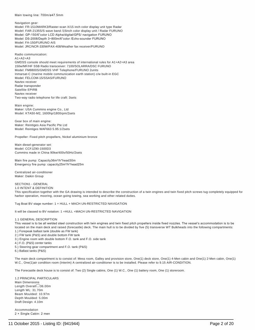
NEW BUILD - 36m Twin Screw TugListing ID: 941944
DESCRIPTION: 36m Twin Screw Tug
DATE LAUNCHED: New Build
LENGTH: 36m (118ft)
BEAM: 10.97m (35ft 11in)
DRAFT: 4.2m (13ft 9in)
LOCATION: Qingdao, China
BROKER: Peter Cookson
PRICE: USD1.85 million Ex-Shipyard
General Description
Ship particular of 36m/3200hp ocean-going tug boatKind of vessel� Ocean-going tug boatShip flag� In shipyard now for saleWhen built: 2011Where built: joint venture with Singapore shipyardClassification: BV/ 1+HULL+MACH, UN-RESTRICTED NAVIGATIONNavigator/Business area: Ocean-going/A1+A2+A3Length overall: 36.00mLength WL: 31.70mBeam Mould: 10.97mDepth Mould: 5.00mDraft Design: 4.20mFree speed: 12 Knots at sail conditionBollard Pull: Continuity fully 100% MCR 40TStern main deck cargo area: length 12.5m X width 8.5m = 106m2 Tank Capacity:Fresh water: ~100m3Fuel oil: ~393m3Ballast tanks: 46.74mLube oil: ~1m3 Accommodation: Total: 14P2 x single cabin 2P2 x 2men cabin 4P2 x 4men cabin 8P Life craft: 15P*2 Steering gear: Elect-hydraulic rydder steering gear; Model: DYB2-63/28-DK/63KNm Anchor windlass: Elect-hydraulic windlassModel: DMA30/33.2KN Anchor / chain: Rod anchors Stockless bow anchors / 660kg / ø26mm / 412.5m Towing winch: Electric towing winchModel: YKBTW12double drums / double gypsiesTowing load: 40TBreak holding load: 80TElectric motor power: 45kwRemote in W/H & local at site
Page 1 of 2011 October 2015 - Listing ID: {941944}
Main towing line: 700m/ø47.5mm Navigation gear:Model: FR-1510MARK3/Raster-scan X/15 inch color display unit type RadarModel: FAR-2135S/S wave band /15inch color display unit / Radar FURUNOModel: GP150/6”color LCD Alpha/digital/GPS/ navigation FURUNOModel: DS2008/Depth 3~800m/6”color /Echosounder FURUNOModel: FA-150/FURUNO AISModel: JRC/NCR-330W/FAX-408/Weather fax receiver/FURUNO Radio communication:A1+A2+A3GMDSS console should meet requirements of international rules for A1+A2+A3 area150w/MF/HF SSB Radio transceiver: 7100/SOLARRA/DSC FURUNOModel: FM8800S/GMDSS VHF Telephone/FURUNO 2unitsInmarsat-C (marine mobile communication earth station) c/w built-in EGCModel: FELCOM-15/SSAS/FURUNONavtex receiverRadar transponderSatellite EPIRBNavtex receiverTwo-way radio telephone for life craft: 3sets Main engine:Maker: USA Cummins engine Co., LtdModel: KTA50-M2, 1600hp/1800rpm/2sets Gear box of main engine:Maker: Reintiges Asia Pacific Pte LtdModel: Reintiges WAF663 5.95:1/2sets Propeller: Fixed pitch propellers, Nickel aluminium bronze Main diesel-generator set:Model: CCFJZ90-1500D3Cummins made in China 90kw/400v/50Hz/2sets Main fire pump: Capacity36m³/h*head30mEmergency fire pump: capacity25m³/h*head25m Centralized air-conditionerMaker: Daikin Group SECTION1 - GENERAL1.0 INTENT & DEFINITIONThis specification together with the GA drawing is intended to describe the construction of a twin engines and twin fixed pitch screws tug completely equipped forharbor operation, mooring, ocean going towing, sea working and other related duties. Tug Boat BV stage number: 1 + HULL + MACH UN-RESTRICTED NAVIGATION It will be classed to BV notation: 1 +HULL +MACH UN-RESTRICTED NAVIGATION 1.1 GENERAL DESCRIPTIONThis vessel is to be all welded steel construction with twin engines and twin fixed pitch propellers inside fixed nozzles. The vessel’s accommodation is to belocated on the main deck and raised (forecastle) deck. The main hull is to be divided by five (5) transverse WT Bulkheads into the following compartments:1.) Forepeak ballast tank (double as FW tank)2.) FW tank (P&S) and double bottom FW tank3.) Engine room with double bottom F.O. tank and F.O. side tank4.) F.O. (P&S) center tanks5.) Steering gear compartment and F.O. tank (P&S)6.) Ballast tanks (P&S) The main deck compartment is to consist of: Mess room, Galley and provision store, One(1) deck store, One(1) 4-Men cabin and One(1) 2-Men cabin, One(1)W.C., One(1)air condition room (Interim) A centralized air-conditioner is to be installed. Please refer to 9.15 AIR-CONDITION. The Forecastle deck house is to consist of: Two (2) Single cabins, One (1) W.C., One (1) battery room, One (1) storeroom. 1.2 PRINCIPAL PARTICULARSMain DimensionsLength Overall� 36.00mLength WL: 31.70mBeam Moulded: 10.97mDepth Moulded: 5.00mDraft Design: 4.10m Accommodation2 × Single Cabin: 2 men
Page 2 of 2011 October 2015 - Listing ID: {941944}
2 × 2Men Cabin: 4 men2 × 4Men Cabin: 8 menTotal: 14 Tank Capacity (approx.)Freshwater: 100 M³Fuel oil: 393 M³Lube Oil: 1.0 M³ Main Engines� 2 x Cummins KTA50 M2, 1600BHP/1800rpm“Reintiges”WAF663 5.95:1. To be joined to gear box WAF 663 (Reintjies), ratio 5.95:1 PerformanceFree speed: 12knots at sail conditionBollard Pull: more than 40T at 100% MCR and continuity pulling 1.3 CLASSIFICATIONThe vessel is to be constructed, machinery and electrical equipments fitted and installed in accordance with the latest Rules for Shipbuilding of BV Class. Classnotation is: 1 +HULL +MACH UN-RESTRICTED NAVIGATION (to be confirmed). The vessel to be registry under the flag of Singapore. 1.4 REGULATIONSThe vessel is to comply with: (Interim)a.) 1981 Merchant Shipping Non convention vessel (safety) Regulations 1981b.) International load line convention 1966 and the latest amendments.c.) Radio Communication Equipment to Government regulations.d.) IMO Stability Guideline A167 & A562e.) Convention on International Regulations for Preventing Collisions at Sea 1972 andAmendments of 1981f.) 1969 International Tonnage Measurement Convention 1969g.) International Convention for the Prevention of Pollution from Ships Marpol 73/78 (including statements issued by BV)h.) International Convention for the Safety of Life at Sea SOLAS 1974 and the latest Amendmenti.) Regulation and rule for MPA of Singaporej.) Related rules by Class Society 1.5 CERTIFICATESThe following certificates are to be supplied to the ship owner at the time of delivery:1. Builder Certificate2. Classification Certification (Hull and Machinery)3. Safety Equipment certificate4. Safety Construction certificate5. Tonnage Certificate6. Load line Certificate7. Radio Safety Certificate8. Marpol Annex I, IV and VI Certificate (to be complied with Marpol 73/78)9. Compass Adjustment Certificate10. Bollard Pull Test Certificate issued by BV class.11. Deratting Exemption Certificate12. Non-asbestos Certificate13. Certificate for Anchor & Chains by the Classification Society14. NOX Certificate. All the survey fee, class fee and charges incidental to certificates should be on account of the Seller. 1.6 MATERIAL & WORKMANSHIPA.) All materials and workmanship are to be of good quality. All steel plates, section, hull forging and casting and equipments should be meet classification’sequipments, which test certificates required by classification to be supplied.B.) All smith work or fabricated fittings are to be of neat design, smooth and free from defects.C.) Steel casting of good quality, close grained and free from all cracks, blow holes and other defects. Steel casting to be manufactured comply withClassification requirements and approval. 1.7 WELDINGThe vessel to be all welded construction in accordance with contract Plans, Specifications and Rules of Classification. Automatic Welding and CO² Welding to beused as far as possible. Welding should meet the requirements of Classification. All welding for Ballast Tank, FW tank and the area exposed to weather which contact with the Sea Water to be of double continuous welding. All electrodes shall be of good quality, free from laminations and other harmful defects and also class approved. Welding seam should be satisfied with the CSQS standard. Adopt the high standard latest welding schedule and welding procedure in order to reach accurate calibration, smoothness and welding seal width. X rayphotograph to be taken for the butt welding seam of big fold and deck joint plate welding seam according to the classification requirement. If possible, preassemble structures shall be carried out in subsection and assemble subsection in order to obtain Maximum quantity down hand welding. 1.8 INSPECTION/SUPERVISION
Page 3 of 2011 October 2015 - Listing ID: {941944}

Throughout the construction period prior to the delivery of vessel, the surveyors and owners’ representative and councillor are to be given free access to theBuilder’s shipyard during normal working hours for supervision and inspection. Builder Shipyard shall keep good cooperation during the construction period. 1.9 TESTSPrior to the delivery, hull construction, hull tightness, all machinery, electrical, piping, all equipment installed, machinery and deck fitting are to be thoroughlytested in the presence of the classification’s attending surveyor, owners and their representative. 1.11 MOORING TESTUpon the completion of the vessel, the following trails are to be carried out:1.) All Piping systems are to be fully tested, including the checking of valve and name plates2.) Electrical power plants together with all lights3.) Auxiliary machinery including Generator load test4.) All deck machinery5.) Main engine and propulsion system6.) All pumps etc.7.) All outdoors, windows and hatch WT test 1.12 SEA TRIALSSea trials are to be arranged and carried out in accordance with a program approved by the class and owners. The Builder should supply master, crews andnecessary equipment and victuals. All diesel oil, lubrication oil, F.W. and dues for the trials are to be paid by the Builder. The remaining oil on board after thetrials to be charged to owner at acquisition cost. The compass is to be adjusted before sea trials. The following tests should be finished before the vessel completion:1.) Steering test2.) Anchoring test3.) Speed test4.) Endurance Test at Main engine load Four (4) hours5.) Navigation equipments debugging test6.) Static state towing pull test 1.13 DELIVERYDelivery of vessel is to be taken afloat in Builder’s Shipyard Dock. If the vessel cannot be delivered after 6 months upon the vessel launched, the Builder shall be responsible for the Dock Inspection before delivery, which chargesare to be borne by Builder. 1.14 DRAWINGSOn completion, three (3) sets of the following as fitting drawings in English language in blue prints as approved by Classification to be supplied to Ship owner.1.) General Arrangement5.) Tank Calibration Table (Plan)6.) Structural Profile & Deck7.) Main engine seating Details8.) Forward section & bulkheads9.) Aft section & bulkheads10.) Shell Expansion11.) Superstructure Details12.) Shafting Arrangement and stern tube Details13.) Rudder Assembly14.) Nozzle Details A1915.) Steering Gear Arrangement16.) Engine Room Layout17.) Bilge, Ballast and Fire main System18.) Ship’s Fuel System19.) Diesel Engine cooling system20.) F.W. & S.W. piping system21.) Life Saving & Fire Fighting Arrangement22.) Position of Tank Vents, Sounding & Filling Pipes23.) Wiring Diagram and Related Accessories24.) Main Switch board Wiring Diagram25.) 24V DC Radio Storage Battery Charging Panel & 24V Distribution Board Plan26.) Ventilation Arrangement27.) Tank Calibration Plan28.) Docking Plan And other necessary drawings such as tightness plan, anchor winch plan, steering gear hydraulic plan. Thereinto 1), 5), 17), 21) are to be framed for display in the position specified by the ship owner. 1.15 MANUALS OF MACHINERY & EQUIPMENTThree (3) sets of manuals of all machinery and equipment in English language to be supplied by the Builder. 1.16 SPARES & TOOLSThe Builder shall supply full set standard spaces and special tools according to legal recommendation and manufactory standard. Spare parts to be put on trellis at engine room, store room and steering gear compartment.
Page 4 of 2011 October 2015 - Listing ID: {941944}
1.17 BUILDER RESPONSIBILITYThe Builder shall responsibility for contact with the equipment’s subcontractor in order to insure the equipments compatibly. The Builder shall guarantee thequality of the vessel construction and the all equipments. Final drawings and practice parameters shall be supplied to ship owner or his representatives forapproval. Under no circumstances must the builder release from above responsibility. During the vessel construction and equipments installation, the Builder shall protect and clear the equipments on board and pipes at any time, especially protectthe equipments from failure, dirt entering, weld splashing, paint covering and mechanism damage. Any damage should be repaired and met to the Shipowner’ssatisfaction, which charges arisen should be born to the Builder. 1.18 VESSEL NAME, PORT REGISTRYThe name of the vessel is to be welded and painted on the bow port and starboard, the name and port of registry are to be welded on and painted on the stern.All letters are to be cut from the steel plate and full weld. Ship owner mark should be installed on the position of the port and starboard specified by the shipowner. 1.19 SIGNALThe Builder should supply the Safety Signal (symbol) and IMO Number in accordance with the requirements of flag nation government and Ship owner. SECTION 2 – STRUCTURE 2.0 GENERALThe hull and deckhouse are to be of all welded construction. Transverse framing system is to be used throughout, frame space is 500mm. Generally, the hullplate thickness shall more than 20% of the least requirement of the Classification. The following scantlings are for guidance only and will be subjected to classapproval. 2.1 KEELA flat plate keel of 800x12mm thick is to be fitted. 2.2 STEMBAR & SOFT NOSEThe stem is to be made up by a 250x14mm thick vertical plate welded to a cone shape soft nose of 12mm plate. 2.3 SKEGA box shape skeg is to be fitted at the center line on stern bottom. The bottom of the skeg is 14mm with sides and webs 10mm thick. 2.4 BILGE KEELBilge keel is to be made up of 250x12mm plate and φ18mm round bar, which to be fitted at port and starboard. 2.5 BOTTOM CONSTRUCTIONThe bottom is to be of single bottom except in crew’s accommodation and part of the engine room where double bottom construction is to be adopted. In orderto give a structural continuity in the bottom, two engine girders P& S, together with the center girder are to be extended as far as forward as possible and are tobe linked with the longitudinal bulkheads of aft tanks. 2.6 SHELL PLATEThe bottom and side plating should be longitudinally plated and to be butt welded, plate thick 12mm, but the plate 14mm thick where the opening of seaconnection and stern propulsion, which contacted with the hull structure. 2.7 FRAMESFrames for main hull to be 125x75x10mm, spaced at 500mm, T shape welded on side hull. 2.8 BEAMSBeams for main deck are to be 125x75x8mm, and fitted at every frame. They are to incorporate with strong beams of 8mm plate fabricated section fitted in wayof deck openings and other locations. 2.9 GIRDERS & PALLARSGirders of 8mm plate fabricated sections together with 3’’or 4’’diameter round pipe pillars are to be fitted in engine room. 2.10 DIESEL ENGINE GIRDERDiesel engine girder should be made up of 22mm vertical plate and 300x30mm face plate. Diesel engine packing piece is about 30mm epoxy type. 2.11 DECKThe main deck plate is 10mm thick. 2.12 WATER TIGHT/ OIL TIGHT BULKHEADSThe W.T./O.T Bulkheads are 8mm or 10mm plates.( subject to the approval drawings by Classification) 2.13 WHEELHOUSEThe wheel house is to have 6mm plate and sides with 75x50x6mm for vertical stiffeners and beams respectively. 2.14 FENDERSRubber fender Dia. 500mm shall be installed forward and aft of the vessel as shown on the GA drawing. Pipe fenderHalf section 10’’ pipe fenders are to be welded to side shell as shown on the GA drawing. Tyre fenderEnough Tyre fenders with galvanizing chain are to be fitted around the vessel.
Page 5 of 2011 October 2015 - Listing ID: {941944}

SECTION- 3 ACCOMMODATION, WHEELHOUSE & STORE 3.0 GENERALScheme of decoration together with colours for bulkhead, ceiling, furnishing fabrics and floor etc., are to be pleasant. The owners are free to make their selectionfrom samples given by the Builder. All bureaus in accommodation are to be of wood for crew’s personal effects clothing and to be fitted brass locks. All internal and exterior doors should meetSOLAS, which to be fitted good quality locks with three (3) labelled keys each, and three (3) Skeleton Keys to be supplied for doors on the vessel. The bottom ofdoorframe in accommodation should have stainless steel sheet pieces. Minimum headroom in all accommodation areas is to be 2M and as high as possible.Accommodation should be arranged in accordance with the GA drawing. All sockets should be marine type. 3.1 DECK COVERINGS (FIRE PROOFING TYPE)Steel decks are to be thoroughly cleaned before the installation of deck coverings, which are to be laid under all furniture including the built-ins.Position of deck coverings: Wheelhouse interior, Mess, Lobby, Crew’s cabin, interior corridors and stairways: Covered with PVC tiles on 10mm thick latexW.C. and Galley: Covered with anti-skid ceramic tiles on cement.Engine Room, steering gear compartment: Covered with chequered plates on bottomDeck store, wheelhouse top and exposed deck: Covered with deck paint (2 tier stuffing fitting). 3.2 MINOR BULKHEAD & LININGComposite Rockwool Panels finished with PVC surface to be installed on wheelhouse, crew’s cabin, mess, interior corridors. After installing the bulkheads, whichsurface should be protected, but the protecting plastic films are to be moved after trial; stainless steel finfish face TC plate is to be installed on interior wallboardand ceiling of galley; Interior corridors adopt the stainless steel storm rail. Steel bulkheads and ceilings surface in way of washrooms, provision store, and deck stores are to be generally white painted finish, but the galvanized iron shallbe laid on insulation area of W.C. and Provision store. 3.3 SOLAS INSULATION (TO BE MEET SOLAS)All exposed steel work is to be insulated on the inside, with aluminium foil on insulation surface.Wheelhouse and exposed deckhead of other cabins ----- 100mm Rockwool 3.4 WINDOWS & SCUTTLESAll windows are to be aluminium framed type with tempered glass to suit the Classification’s requirements. 3.5 STEEL DOORSAll exterior doors on the vessel to be of steel (Except wheelhouse doors), the doors on Main deck shall be set coaming with certain height according to the Loadline convention. Six dogs workable from both sides are to be fitted with clips and grease fittings. The doors to be channel- framed tightened to gaskets of softneoprene or similar. Doors to be fitted with sturdy padlocks and hold-back arranged to retain them in open positions.External wheelhouse weather tight doors to be of aluminium type (to be hose tested.) 3.6 WHEEL HOUSEThe wheelhouse to be fitted with all navigation, communication and control equipments as specified below. The helmsman’s position and main engine consoleare to be arranged at forward of the wheelhouse. Wheelhouse windows are to be arranged to give maximum visibility all round.The wheelhouse control console forward is to be fitted with: Main engine and gear box controls and M.E. tachometersShaft tachometersMain and aux. engine audible & visual alarms for high water temperature, low oil pressure and low water levelEmergency Engine telegraph with buttons.Steering handle2 nos. Rudder angle indicators for each rudder (1 on wheelhouse console,1 wheelhouse front ceiling mounted)Horn button2 radar1 depth sounder display1 speed log display ( for option)1 GPS1 compass repeater (supplied from magnetic compass repeater)Towing winch controlsMorse light signal buttonsintercom talk- back system control unit1 sound powered telephonesmoke and fire detection and alarm control panelNavigation signal light panelStainless steel storm rail2 built in ashtrays by console’s side Other equipment in wheelhouse to be fitted out as follows: Flag box and 1 set of international code of signal flag2 binocular box and 2 binocularsChart table c/w drawers, light with dimmer switch, prevent drawer of chart table from slipping when sailing.1 radio telegraph operator1 combined type radio stations and outside communication equipment( Detail 7.3.1)
Page 6 of 2011 October 2015 - Listing ID: {941944}

1x Helmsman's chair with arms, 200mmhighBook rack with enough size1 x anemoscope1 x electric whistle1 x Dia.300mm brass ship's bell engraved with vessel's name, built date and vessel hull No. should be fixed on the right side of bridge1 x quartz electric clock1 x Clinometer, to be fitted on ship centre1 x thermometer2 x1000W search light handle control in wheelhouse1 x aid signal light2 x book rack4 x 220V power points1 x 310mm Dia. rotation screens to be fitted forward windows2 x window wiper, each on forward and backward 3.7 CAPITAL’S/CHIEF ENGINEERS CABINThe captain and Chief engineer are to be situated forward raised deck as shown on the drawings and fitted out as follows:1 x 1900x800 built-in berth with drawers under bunklight1 x Desk with drawers and light, 1x desk light socket and 2 x 220Vspare power points to be arranged on desk1 x built-in wardrobes c/w shelf, hanger rod and hooks, with fiddles for lifejackets stowage on top.1 x Chair with arms1 x Wall Mounting Shake head fan2 x Book racks1 x Steel File cabinet with drawers1 x Corner sofa2 x Coat and hat hook 3.9 2-MEN CABINS (2 OFF)These cabins are to be situated under main deck and below main deck each one and each to be fitted out as follows:1 x 2- tier berth with spring mattress c/w bunklights, curtains, drawers under, and ladder for upper berth.2 x built-in wardrobes c/w shelf, with fiddles for lifejackets stowage on top.1 x Desk with drawers and light, 1 x desk light socket and 2 x 220V spare power points to be arranged on desk2 x Book rack1 x Wall Mounting Shake head fan4 x Coat and hat hook1 x Chair with arms 3.10 4-MEN CABINS (2 OFF)These cabins are to be arranged under main deck and below main deck each one and to be fitted out as follows:2 x 2- tier berth with spring mattress c/w bunklights, curtains, drawers under, and ladder for upper berth.4 x built-in wardrobes c/w shelf, with fiddles for lifejackets stowage on top.1 x Desk with drawers and light, 1 x desk light socket and 2 x 220V spare power points to be arranged on desk2 x Book rack2 x Wall Mounting Shake head fan8 x Coat and hat hook1 x Chair with arms 3.11 MESSThe mess area is to be situated on the main deck and fitted out as follows:1 x built –in settees with storage under2 x 1200×600 dining tables with 6 chairs1 x Book rack1 x cupboard ( with clapboard inside)3 x spare power points, 220/1/502 x dia. 250mm Portlight c w deadlight1 x wall clock1 x 21’’ color TV set (with outside TV antenna) 3.12 MAIN DECK WASHROOMThe washroom situated on main deck to be fitted out as follows:2 x shower recesses c/w soap dish and storm rail2 x washbasin with hot and cold water supplies, with mirror box over1 x exhaust fan and wind tunnel2 x pedestals with seat and lid and toilet roll holder, storm rail.2 x water heater for bath1 x 6 kg washing machine with spin drying capability1 x ironing board1 x electric iron4 x coat and hat hook 3.13 RAISE DECK WASHROOMThe washroom situated on main deck to be fitted out as follows:1 x shower recesses c/w soap dish and lifesaving rail1 x washbasin with hot and cold water supplies, with mirror box upper1 x exhaust fan and wind tunnel1 x pedestals with seat and lid and toilet roll holder, storm rail.
Page 7 of 2011 October 2015 - Listing ID: {941944}
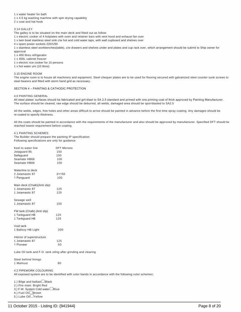
1 x water heater for bath1 x 4.5 kg washing machine with spin drying capability2 x coat and hat hook 3.14 GALLEYThe galley is to be situated on the main deck and fitted out as follow:1 x electric cooker of 4 hotplates with oven and retainer bars with vent hood and exhaust fan over1 x twin bowl stainless steel sink c/w hot and cold water taps, with wall cupboard and shelves over4 x spare power sockets 220/1/501 x stainless steel workbenches(table), c/w drawers and shelves under and plates and cup rack over, which arrangement should be submit to Ship owner forapproval1 x 400 litres refrigerator1 x 400L cabinet freezer1 x electric rice cooker for 15 persons1 x hot water urn (10 litres) 3.15 ENGINE ROOMThe engine room is to house all machinery and equipment. Steel chequer plates are to be used for flooring secured with galvanized steel counter sunk screws tosteel bearers and fitted with storm hand grid as necessary. SECTION 4 – PAINTING & CATHODIC PROTECTION 4.0 PAINTING GENERALAll steel plates’ surfaces should be fabricated and girtblast to SA 2.5 standard and primed with one priming coat of thick approved by Painting Manufacturer.The surface should be cleared; raw edge should be deburred, all welds, damaged area should be spot-blasted to SA2.5 All the welds, edges, free holes and other areas difficult to arrive should be painted in advance before the first time spray coating. Any damages should bere-coated to specify thickness. All the coats should be painted in accordance with the requirements of the manufacturer and also should be approved by manufacturer. Specified DFT should bereached lowest requirement before coating. 4.1 PAINTING SCHEMESThe Builder should prepare the painting IP specification.Following specifications are only for guidance. Keel to water line DFT MicronsJotaguard 85 150Safeguard 100Seamate HB66 100Seamate HB66 100 Waterline to deck2 Jotamastic 87 2×1501 Penguard 100 Main deck (Chalk)(Anti slip)1 Jotamastic 87 1251 Jotamastic 87 125 Sewage well1 Jotamastic 87 150 FW tank (Chalk) (Anti slip)1 Tankguard HB 1251 Tankguard HB 125 Void tank1 Balloxy HB Light 200 Interior of superstructure1 Jotamastic 87 1251 Pioneer 50 Lube Oil tank and F.O. tank oiling after grinding and clearing Steel behind linings1 Mamuut 80 4.2 PIPEWORK COLOURINGAll exposed system are to be identified with color bands in accordance with the following color schemes: 1.) Bilge and ballast � Black2.) Fire main: Bright Red3.) F.W. System Cold water� Blue4.) Fuel Oil� Brown5.) Lube Oil� Yellow
Page 8 of 2011 October 2015 - Listing ID: {941944}
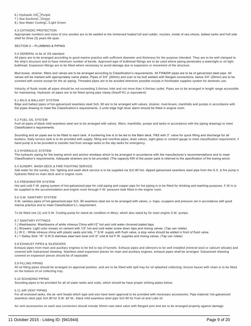
6.) Hydraulic Oil� Purple7.) Sea Suctions� Green8.) Sea Water Cooling� Light Green 4.3 CATHODIC PROTECTIONAppropriate numbers and sizes of zinc anodes are to be welded to the immersed loaded full and rudder, nozzles, inside of sea chests, ballast tanks and hull sideshell for three (3) years life span. SECTION 5 – PLUMBING & PIPING 5.0 GENERAL to be of JIS standardAll pipes are to be arranged according to good marine practice with sufficient diameter and thickness for the purpose intended. They are to be well clamped tothe ship's structure and to have minimum number of bends. Approved type of bulkhead fittings are to be used where piping penetrates a watertight or oil tightbulkhead. Expansion fittings are to be fitted where necessary to avoid damage due to expansion or movement of the structure. Mud boxes, strainer, filters and valves are to be arranged according to Classification’s requirements. All FW&SW pipes are to be of galvanized steel pipe. Allvalves will be marked with appropriately name plates. Pipes of 3/4” (20mm) and over to be butt welded with flanged connections, below 3/4” (20mm) are to bescrewed with unions except for the air piping. Threaded pipes are to be avoided wherever possible except in freshwater supplies system for domestic use. Velocity of fluids inside all pipes should be not exceeding 3.0m/sec inlet and not more than 4.0m/sec outlet. Pipes are to be arranged in length range accessiblefor maintaining. Hydraulic oil pipes are to be fitted spring pipe clamp (Stauff R1 or equivalent) 5.1 BILG & BALLAST SYSTEMBilge and ballast pipes of hot-galvanized seamless steel Sch. 80 are to be arranged with valves, strainer, mud-boxes, manifolds and pumps in accordance withthe pipes drawing to meet the Classification’s requirements. 2 units bilge high lever alarm should be fitted in engine room. 5.2 FUEL OIL SYSTEMFuel oil pipes of black mild seamless steel are to be arranged with valves, filters, manifolds, pumps and tanks in accordance with the piping drawings to meetClassification’s requirements. Sounding and air pipes are to be fitted to each tank. A bunkering line is to be led to the Main deck, P&S with 3’’ valve for quick filling and discharge for allbunkers. Daily service tank is to be provided with supply, filling and overflow pipes, drain valves, sight glass or content gauge to meet classification requirement. Ahand pump is to be provided to transfer fuel from storage tanks to the day tanks for emergency. 5.3 HYDRAULIC SYSTEMThe hydraulic piping for the towing winch and anchor windlass which to be arranged in accordance with the manufacturer’s recommendations and to meetClassification’s requirements. Adequate strainers are to be provided. (The capacity KW of the power pack is referred to the specification of the towing winch. 5.4 SUNDRY, WASH DECK & FIRE FIGHTING SERVICESalt water for the sundry, fire- fighting and wash deck service is to be supplied via Sch 80 hot- dipped galvanised seamless steel pipe from the G.S. & fire pump tohydrants fitted on main deck and in engine room. 5.5 FRESHWATER SYSTEMHot and cold F.W. piping system of hot-galvanized pipe for cold piping and copper pipe for hot piping is to be fitted for drinking and washing purposes. F.W is tobe supplied to the accommodation and engine room through F.W. pressure tank fitted in the engine room. 5.6 S.W. SANITARY SYSTEMS.W. sanitary pipes of hot-galvanized pipe Sch. 80 seamless steel are to be arranged with valves, s- traps, scuppers and pressure set in accordance with goodmarine practice and to meet Classification’s L requirement. To be fitted one (1) unit S.W. Cooling pump for stand air condition in Mess, which also stand by for main engine S.W. pumps. 5.7 SANITARY FITTINGS1.) Washbasins: Washbasins of white vitreous China with1/2” hot and cold water chromed plated taps.2.) Showers: Light color mosaic on cement with 1/2” hot and cold water screw down taps and mixing valves. (Tap can rotate).3.) W.C.: White vitreous china with plastic seats and lids, 1” S.W. supply with flush valve, a stop valve should be added in front of flush valve.4.) 1 Galley Sink: 16’’ S.W.G stainless steel twin bowl unit /2” cold & hot F.W. supplies and mixing valves. (Tap can rotate) 5.8 EXHAUST PIPES & SILENCERSExhaust pipes from main and auxiliary engines to be led to top of funnels. Exhaust pipes and silencers to be well installed (mineral wool or calcium silicate) andcovered with Galvanized sheeting. Stainless steel expansion pieces for main and auxiliary engines, exhaust pipes shall be arranged. Galvanized sheetingcovered on expansion pieces should be of separable. 5.9 FILLING PIPINGAll oil filling pipes should be arranged on approval position, and are to be fitted with spill tray for oil splashed collecting; bronze faucet with chain is to be fittedon the bottom of oil collecting tray. 5.10 SOUNDING PIPINGSounding pipes to be provided for all oil water tanks and voids, which should be have proper striking plates below. 5.11 AIR VENT PIPINGFor all enclosed tanks, the air vent heads which type and size have been approval to be provided with necessary accessories. Pipe material: hot-galvanizedseamless steel pipe Sch 80 for S.W. &F.W., black mild seamless steel pipe Sch 80 for Fuel oil and Lube oil. Air vent accessories on each sea connection should include 50mm cast steel valve with flanged joint and are to be arranged properly against damage.
Page 9 of 2011 October 2015 - Listing ID: {941944}
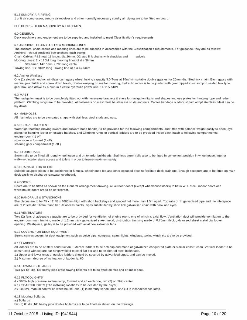
5.12 SUNDRY AIR PIPING1 unit air compressor, sundry air receiver and other normally necessary sundry air piping are to be fitted on board. SECTION 6 – DECK MACHINERY & EQUIPMENT 6.0 GENERALDeck machinery and equipment are to be supplied and installed to meet Classification’s requirements. 6.1 ANCHORS, CHAIN CABLES & MOORING LINESThe anchors, chain cables and mooring lines are to be supplied in accordance with the Classification’s requirements. For guidance, they are as follows:Anchors: Two (2) stockless bow anchors, each 660kg;Chain Cables: P&S total 15 knots, dia 26mm. Q2 stud link chains with shackles and swivelsMooring Lines: 2 x 120M long mooring lines of dia 36mm Streamer: 147.5mm × 700 long cableTowing line: 1 x 700M long Towing line of dia 47.5mm 6.2 Anchor WindlassOne (1) electric anchor windlass cum gypsy wheel having capacity 3.0 Tons at 10m/min suitable double gypsies for 26mm dia. Stud link chain. Each gypsy withmanual jaw clutch and screw down break, double warping drums for mooring, hydraulic motor is to be jointed with gear dipped in oil sump in sealed box typegear box, and drove by a built-in electric hydraulic power unit. 11/11/7.5KW 6.3 MASTThe navigation mast is to be completely fitted out with necessary brackets & stays for navigation lights and shapes and eye plates for hanging rope and radarplatform. Climbing rungs are to be provided. All fasteners on mast must be stainless studs and nuts. Cables bandage outdoor should adopt stainless. Mast can belay down. 6.4 MANHOLESAll manholes are to be elongated shape with stainless steel studs and nuts. 6.6 ESCAPE HATCHESWatertight hatches (having inward and outward hand handle) to be provided for the following compartments, and fitted with balance weight easily to open, eyeplates for hanging locker on escape hatches, and Climbing rungs or vertical ladders are to be provided inside each hatch to following compartments:engine room ( 1 off)store room in forward (1 off)steering gear compartment (1 off ) 6.7 STORM RAILSStorm rails to be fitted all round wheelhouse and on exterior bulkheads. Stainless storm rails also to be fitted in convenient position in wheelhouse, interiorwalkway, interior stairs access and toilets in order to insure maximum safety. 6.8 DRAINAGE FOR DECKSSuitable scupper pipes to be positioned in funnels, wheelhouse top and other exposed deck to facilitate deck drainage. Enough scuppers are to be fitted on maindeck easily to discharge rainwater overboard. 6.9 DOORSDoors are to be fitted as shown on the General Arrangement drawing. All outdoor doors (except wheelhouse doors) to be in W.T. steel, indoor doors andwheelhouse doors are to be of fireproof. 6.10 HANDRAILS & STANCHIONSStanchions are to be 75 x 12 FB x 1000mm high with short backstays and spaced not more than 1.5m apart. Top rails of 1’’ galvanised pipe and the interspaceare of 2 tiers dia.16mm round bar. At access points, pipes substituted by short link galvanised chain with hook and eyes. 6.11 VENTILATORSTwo (2) fans of adequate capacity are to be provided for ventilation of engine room, one of which is axial flow. Ventilation duct will provide ventilation to theengine room main trunking made of 1.2mm thick galvanized sheet metal, distribution trunking made of 0.75mm thick galvanized sheet metal c/w louveropening. Washplace, galley is to be provided with axial flow extractor fans. 6.12 COVERS FOR DECK EQUIPMENTStrong canvas covers for deck equipment such as voice pipe, compass, searchlights, windlass, towing winch etc are to be provided. 6.13 LADDERSAll ladders are to be of steel construction. External ladders to be anti-slip and made of galvanized chequered plate or similar construction. Vertical ladder to beconstructed with square bar rungs welded to steel flat bar and to be clear of steel bulkheads.1.) Upper and lower ends of outside ladders should be secured by galvanized studs, and can be moved.2.) Maximum degree of inclination of ladder is: 60 6.14 TOWING BOLLARDSTwo (2) 12’’ dia. NB heavy pipe cross towing bollards are to be fitted on fore and aft main deck. 6.15 FLOODLIGHTS4 x 500W high pressure sodium lamp, forward and aft each one, two (2) on Ship center.6.17 SEARCHLIGHTS (The installing locations to be decided by the buyer)2 x 1000W, manual control on wheelhouse, one (1) is mercury xenon lamp, one (1) is incandescence lamp. 6.18 Mooring Bollardsa.) BollardsSix (6) 8’’ dia. NB heavy pipe double bollards are to be fitted as shown on the drawings.
Page 10 of 2011 October 2015 - Listing ID: {941944}

b.) FairleadsFour (4) fairleads are to be fitted on forward bulwark as shown on the drawings. 6.19 HAWSE PIPES & ANCHOR RECESSESTwo (2) 10’’ dia. NB, Sch 80 hawse pipes welded to 14mm hull anchor recesses. 6.20 TOWING WINCHOne (1) towing winch is to be driven by electric-hydraulic, which to be fitted on main deck. The capacity and parameters as followings: TYPE: Double drums, double gypsiesDrum Capacity: 47.5mm×700m, 700m of mm dia. SWRClutch: electromagneticControl: remote in W/H & local at siteRated Pull: 10t6m/minPull� 40T Towing winch can be controlled remote in wheelhouse and local at site. Control box aside the winch should be fitted on exposed deck, and setup with steel boxwith cover against damage from storm. Section 7 – SAFETY & NAVIGATION EQUIPMENT 7.0 LIFT SAVING EQUIPMENTLifesaving equipment is to be in accordance with the requirements of the Government authority for the intended trade & Solas 1974 of Merchant Shipping Nonconvention vessel for a complement of 14 men.1.) LIFERAFTS2 (15) SOLAS 74Two (2) 15- man inflatable liferafts with full emergency pack in rigid fibre glass container conforming to SOLAS 74 convention. The liferafts are to be stowed onthe raised deck in hinged type cradles for quick sideway launching. 2.) LIFEBUOYSTotal eight (8) lifebuoys to be supplied in accordance with rules:Four (4) lifebuoys with 30m buoyancy lineFour (4) self- igniting electric lights, two (2) lifebuoys with s smoke signals. 3.) LIFEJACKETS with whistles and lightsTwenty (20) approved type lifejackets are to be supplied and stowed adjacent to each berth. 4.) PYROTECHNICSOne (1) line throwing apparatus (with 4 projectiles, 4 lines)Twelve (12) parachute distress rocketsTwo (2) orange smoke signals each to have 120 seconds discharge time and be waterproof. 5.) RETRO-REFLECTIVE TAPETo be fitted to all lifesaving appliances 7.1 FIRE-FIGHTING EQUIPMENTFire-fighting equipment is to be provided to meet classification, government regulations and generally in accordance with the following: 1.) FIRE MAINA fire main and five (5) 1 /2” bronze hydrants are to be fitted, one (1) on wheelhouse deck, two (2) on main deck and two (2) in engine room. 15m canvas fire hosec/w brass coupling and nozzle is to be supplied and stowed alongside each hydrant in a protective box. 2.) FIREMAN’S OUTFITSOne (1) complete set of fireman's outfit are to be provided:a.) One (1) protective clothingb.) One (1) breathing apparatus and safety linec.) Cone (1) fireman’s axed.) One (1) safety lamp of portable battery typee.) One (1) set of gloves and bootsf.) One 1 pressure gauge tester 3.) PORTABLE FIRE EXTINGUISHERSFire extinguishers as required by the classification/government authority are to be supplied and installed. For guidance, they are as followings: (subject to finalapproval)
POSITION NO TYPEDeck accommodation 2 9 liters water CO2Deck store room 1 9 liters foamEngine room entrance 1 9 liters foam
Under deck crew’s cabins 1 9 liters water CO2Engine room 10 45 liters foam-mechanical
4.) EMERGENCY FIRE PUMPOne (1) portable diesel engine driven emergency fire pump of capacity 25m3/h at 25m head. 7.2 NAVIGATION EQUIPMENT (IMPORT)1.) Two (2) RADAR (IMO approval type)
Page 11 of 2011 October 2015 - Listing ID: {941944}
One Rasterscan X and one S wave band Radar, Power supply AC220V, 6’’ scanners,10KW emitter,15 inch color display units 180mm PPI ,range: 0.125~48nm, including:1 x Scanner1 x Display1 x Antenna and radiator1 x Compass repeater1 x Handle1 x 30m Standard installation material including 30m combination cable1 x Standard spares1 x Operation manual1 x Alternating current rectifier1 x NJU-64J 30m Radar performance monitor NJU-64J c/w 30m cables & bracket 2.) ECHO SOUNDER1 x 6” color echo sounder, depth 3 800m, 200KHz/220VAC including:1 x Display/recorder1 x Alternating current rectifier1 x 1.5m Power cable1 x 30m Cable transducer1 x Standard spares & installation manual &operation manual 3.) GPS NAVIGATION6 inch color LCD Alpha/digital GPS navigation, power supply DC 24V, including:1 x Display1 x antenna1 x Standard installation material1 x 15m cable1 x Standard spares1 x AC power supply 4.) MAGNETIC COMPASS two piecesOne (1) reflector compass, dia. 165mm, stand type, corrector and reflector are to be fitted in wheelhouse. Lamps are to be fitted on compass for using in night.Analog signal conversion device and one (1) compass repeated (Signal can be output to radar, GPS and automatic rudder) are to be supplied for magneticcompass. 7.3 COMUNICATION EQUIPMENT (IM PORT, JRC OR FURUNO)1.) GMDSS CONSOLEGMDSS console should meet requirements of international rules for A1 A2 A3 area. For guidance, they are as followings:a.) One (1) SSB radio transceiver, 150w MF/HF, DC 24V, Frequency range 1.6~27.5 MHz, including:1 x control unit1 x antenna and joint1 x watch keeping receiver1 x 5m control cable1 x 5m RF cable1 x Transceiver1 x Power supply1 x Standard spares1 x Bracket & standard accessories1 x Operation manual b.) One (1) MF/HF-DSC terminal, DC 24V, including:1 x DSCDSC terminal 3m DSC Power cable, 1.5m AF cable, 1.5m control cable, control unit.1 x Standard installation material1 x Standard accessories including outdoor horn and two (2) 3A standby fuse1 x 18’ whip antenna, 12’ whip antenna, AC rectifier, battery antocharger, emergency lamp. c.) One unit Inmarsat-C (marine mobile communication earth station) c/w built-in EGC, AC 110V and emergency DC 24V, including:1 x Exterior installation equipment1 x Interior installation equipment1 x Antenna with 30m coaxial cable for connection EME to IME1 x DTE1 x Keyboard1 x RO Printer2 x Distress signal push button1 x Received signal device1 x Power supply device1 x Option switch box1 x Remote distress signal push button1 x Standard spares & using installation material1 x Operation manual d.) GMDSS VHF TELEPHONE (2 UNITS) Semi- amphistyly, DC 24V, including:1 x DSC Receiver c/w built-in DSC1 x hand held telephone with foundation1 x standard installation material (except antenna)1 x Operation manual
Page 12 of 2011 October 2015 - Listing ID: {941944}
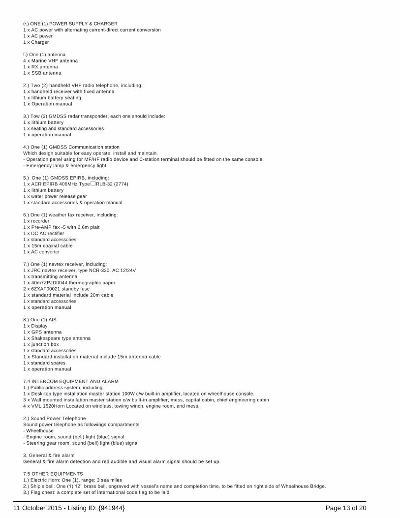
e.) ONE (1) POWER SUPPLY & CHARGER1 x AC power with alternating current-direct current conversion1 x AC power1 x Charger f.) One (1) antenna4 x Marine VHF antenna1 x RX antenna1 x SSB antenna 2.) Two (2) handheld VHF radio telephone, including:1 x handheld receiver with fixed antenna1 x lithium battery seating1 x Operation manual 3.) Tow (2) GMDSS radar transponder, each one should include:1 x lithium battery1 x seating and standard accessories1 x operation manual 4.) One (1) GMDSS Communication stationWhich design suitable for easy operate, install and maintain.- Operation panel using for MF/HF radio device and C-station terminal should be fitted on the same console.- Emergency lamp & emergency light 5.) One (1) GMDSS EPIRB, including:1 x ACR EPIRB 406MHz Type� RLB-32 (2774)1 x lithium battery1 x water power release gear1 x standard accessories & operation manual 6.) One (1) weather fax receiver, including:1 x recorder1 x Pre-AMP fax -5 with 2.6m plait1 x DC AC rectifier1 x standard accessories1 x 15m coaxial cable1 x AC converter 7.) One (1) navtex receiver, including:1 x JRC navtex receiver, type NCR-330, AC 12/24V1 x transmitting antenna1 x 40m7ZPJD0044 thermographic paper2 x 6ZXAF00021 standby fuse1 x standard material include 20m cable1 x standard accessories1 x operation manual 8.) One (1) AIS1 x Display1 x GPS antenna1 x Shakespeare type antenna1 x junction box1 x standard accessories1 x Standard installation material include 15m antenna cable1 x standard spares1 x operation manual 7.4 INTERCOM EQUIPMENT AND ALARM1.) Public address system, including:1 x Desk-top type installation master station 100W c/w built-in amplifier, located on wheelhouse console.3 x Wall mounted installation master station c/w built-in amplifier, mess, capital cabin, chief engineering cabin4 x VML 1520Horn Located on windlass, towing winch, engine room, and mess. 2.) Sound Power TelephoneSound power telephone as followings compartments- Wheelhouse- Engine room, sound (bell) light (blue) signal- Steering gear room, sound (bell) light (blue) signal 3. General & fire alarmGeneral & fire alarm detection and red audible and visual alarm signal should be set up. 7.5 OTHER EQUIPMENTS1.) Electric Horn: One (1), range: 3 sea miles2.) Ship’s bell: One (1) 12’’ brass bell, engraved with vessel's name and completion time, to be fitted on right side of Wheelhouse Bridge.3.) Flag chest: a complete set of international code flag to be laid
Page 13 of 2011 October 2015 - Listing ID: {941944}

4.) Navigation lights and signal lamps: a complete set of DC 24V navigation lights and signal lamps to be fitted in accordance with the Rules, and control panelfor navigation lights and signal lamps should be located in wheelhouse console. One (1) portable aid signal light in wheelhouse.5.) Clinometers: Two (2) wall mounted - one (1) in the wheelhouse and one (1) in the Mess6.) Searchlight: 2 x 1000w, to be controlled inside wheelhouse.7.) Chart table: c/w drawers and chart light with dimmer8.) Rotation View Screens: One (1) 310mm rotation view screens to be fitted on front window centre of wheelhouse.9.) Clock: Two (2) quartz clocks with battery (one (1) in wheelhouse, one (1) in mess)10.) Television antenna: television reception sockets to be fitted in mess, capital’s cabin and chief engineering’s cabin.11.) Anemorumbometer: to be fitted on wheelhouse console.12.) Engine telegraph: emergency Engine telegraphs are to be fitted nearby control station in engine room and in wheelhouse.13.) Anchor ball: 0.6m dia. two balls; one diamond14.) Bilge alarm: yellow audible and visual alarm signal to be fitted for bilge alarm.15.) Window wiper: Each one (1) window wiper to be fitted outside front and behind window in wheelhouse. SECTION-8 ELECTRICAL8.0 GENERALElectrical apparatus and wiring system are to comply with the Classification’s requirements. All electrical components used to be of good quality and suitable fortropical and marine environment. 8.1 SYSTEM OF SUPPLYa.) 400V3φ50Hz For power supply (motor)b.) 230V 1φ 50Hz – 3kW for general lightings and power supply less than 3Kw (motor)c.) 24 V – For alarm, emergency lights, radio, navigational aids, navigation lights and other emergency loads. 8.2 POWER SUPPLYa.) AC SUPPLYThe A.C. main power supply system is to be obtained from T two (2) in number generator sets, each rated about 9kW. 400V/3φ/50 Hz COSφ 0.8. The generatorsare to run in parallel, but each is to be capable of supplying the vessel's electrical requirement under normal sea load condition, specific capacity to beconfirmed after calculation of electrical balance. b.) (24V DC) SUPPLY1.) The 24V DC supply for emergency lights and navigation aids is to be obtained from 2 banks of 24V, 200AH batteries.2.) A 24V D.C. supply for radio is to be obtained from 2 banks of 24V, 144AH batteries.3.) One (1) battery chargers, 40 amp, 24V DC output is to be provided for charging the above batteries. One another charger also to be supplied for standby. Totaltwo pieces4.) Batteries to be stored in the GRP boxes fitted with hinged cover and provide with sufficient ventilation and drainage. c.) SHORE POWER SUPPLY80A, 440V, 50Hz shore power supply system is to be made up of a shore power connection box and an ampere meter. Shore supply connection box to beprovided c/w phase sequence indications, pilot lamp and circuit breaker. Ampere meter with phase sequence selected switch for shore power supply circuit to befitted on main switchboard. Shore power supply flexible cable (60m length) to be jointed securely to shore power connection box. 8.3 CABLESAll cables installed in the vessel are to be tinned copper conductors, EPR insulated and woven wire sheathed to meet classification’s requirements. 8.4 INSTALLATION CABLESCables are generally supported by a perforated hot-dipped galvanised steel cable tray and secured by stainless steel cable clips or similar. Where cables passthrough W.T. /O.T. bulkheads, decks or tanks, approved W.T. cable sealing glands is to be fitted. Cables run on exposed deck are to be run through conduits. 8.5 SWITCHBOARD - GENERALThe switchboard is to be dust and drip- proof and dead front type with sheet steel construction and self- supporting framework c/w handrail and ventilation louvres,suitable for marine duty to be installed in the engine room. Power supply 400/230V 50Hz. All indicators, knobs and handles clearly marked by name plates. The switchboard shall be designed, constructed and installed forthe control of the diesel engine driven alternators operating in parallel and feeder distribution board. a.) AC SWITCHBOARDSwitchboard is to consist of the following controls and instrumentation for each generator:MCCB c/w over-current and reverse power relaysVoltmeter c/w selector switchAmmeter c/w selector switchKilowatt meterFrequency meterVoltage trimmerEmergency push buttonIndicator lightsSynchronizing facilityGovernor switchEarth test systemReverse power relaysThe following outgoing circuits are to be fed from the bus- bar via plug- in moulded cased circuit breaker: total 14 circuit breakers.Fuel oil transfer pumpGeneral service fire fighting pumpEngine room ventilation fansS.W. pressure setGalley equipmentsAnchor windlass
Page 14 of 2011 October 2015 - Listing ID: {941944}

Bilge and ballast pumpF.W. pressure setOily bilge water separatorBattery chargerGeneral light and power supplyNavigation equipmentsTowing winchAir-condition S.W. pump b.) 24V DC SWITCHBOARDThe instrumentation and controls are to consist of the following:Battery charger switchMoulded-case Circuit breakerAmmeterVoltmeterIndication lightsBattery change- over switchEarth test systemThe following outgoing circuits to be fed from the bus- bar via moulded case circuit- breakers:Navigation equipmentsAlarm( general, fire, engine and lower lever)Navigation lightsMain engine instrumentsRadio c.) RADIO CHARGING PANELBattery charger switchBattery change- over switchAmmeterVoltmeterIndication lightsMoulded-case Circuit breakerEarth test system 8.6 DISTRIBUTIONA.C. and D.C. distribution boards are to be T.P & N and double pole respectively and provided c/w miniature circuit breakers. A.) AC DISTRIBUTION BOARDBelow main deck distribution boardMain deck distribution boardForecastle deck distribution boardWheelhouse distribution boardExterior lighting exterior lighting B.) DC DISTRIBUTION BOARD24V DC distribution boardEmergency lights distribution board C.) POWER DISTRIBUTION BOARDAbout 3 nos. 8.7 MOTORS & STARTERSMotors are generally to be of squirrel cage type with totally enclosed fan cooled construction. The protect form for outdoor areas is IP56, the protect form forengine room or indoor areas is IP23. All starters for electric motors are to be suitable for marine use and provided with single phase and overload protection andrunning indication. Fuel pumps, and all supply i.e. outside the engine exhaust ventilation fans are to have remote push- stop controls mounted in the main deckand clearly marked. 8.8 LIGHTING WITH GLASS COVERSAll lighting throughout the vessel is to be fluorescent built-in type except for deck area, steering gear compartment, toilet and store and emergency lightingwhere incandescent lights are to be used. 24V D.C. floodlight fittings are to be mounted in way of liferafts areas. Compass light and chart table light to beprovided with dimmer switch. 8.9 SWITCHES, SOCKETS & SWITCH SOCKETAll switches, sockets and switch-sockets in the accommodation are to be flush mounted moulded-cased type and in the engine room and other machinery andW.T. compartments are to be Watertight. An adequate number of switch-sockets to be provided in accommodation, galley, mess room, store and other machineryspaces for portable equipment. 8.10 LIGHTING TRANSFORMERTow (2), 400V/230V, 25KVA, dry type transformer. 8.11 One (1) alarm box meet to rules requirements is to be fitted nearby distribution board in engine room, alarm set point including: Main & Aux. engine, gearbox cooling water high temperature, Lube Oil lower pressure, bilge water high lever and oily tank high lever alarm etc. Main & Aux. engine, gear box alarm pointshould extend to wheelhouse console. SECTION -9 MACHINERY9.0 GENERALMain engine is to be approved type and supplied with certificates as required by Classification.
Page 15 of 2011 October 2015 - Listing ID: {941944}
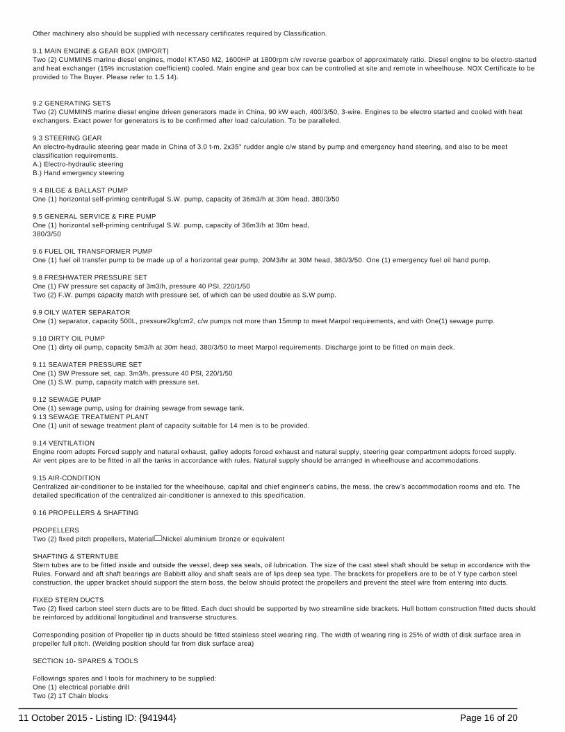
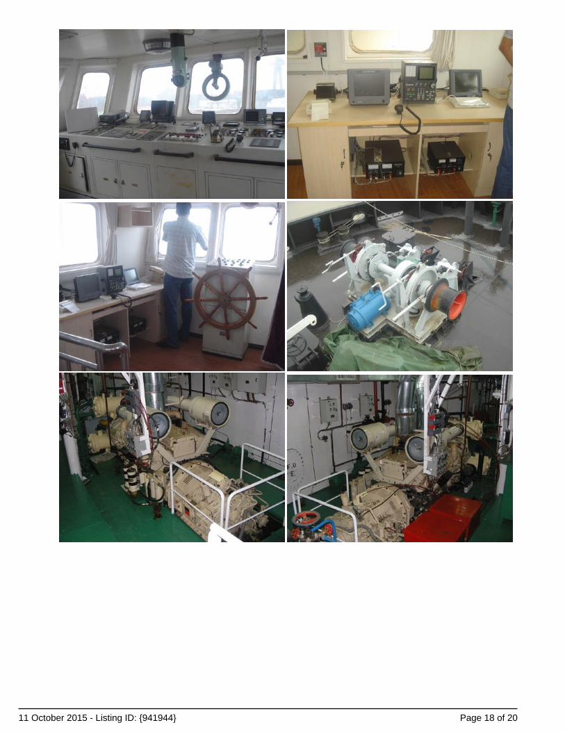
Other machinery also should be supplied with necessary certificates required by Classification. 9.1 MAIN ENGINE & GEAR BOX (IMPORT)Two (2) CUMMINS marine diesel engines, model KTA50 M2, 1600HP at 1800rpm c/w reverse gearbox of approximately ratio. Diesel engine to be electro-startedand heat exchanger (15% incrustation coefficient) cooled. Main engine and gear box can be controlled at site and remote in wheelhouse. NOX Certificate to beprovided to The Buyer. Please refer to 1.5 14). 9.2 GENERATING SETSTwo (2) CUMMINS marine diesel engine driven generators made in China, 90 kW each, 400/3/50, 3-wire. Engines to be electro started and cooled with heatexchangers. Exact power for generators is to be confirmed after load calculation. To be paralleled. 9.3 STEERING GEARAn electrohydraulic steering gear made in China of 3.0 tm, 2x35° rudder angle c/w stand by pump and emergency hand steering, and also to be meetclassification requirements.A.) Electro-hydraulic steeringB.) Hand emergency steering 9.4 BILGE & BALLAST PUMPOne (1) horizontal self-priming centrifugal S.W. pump, capacity of 36m3/h at 30m head, 380/3/50 9.5 GENERAL SERVICE & FIRE PUMPOne (1) horizontal self-priming centrifugal S.W. pump, capacity of 36m3/h at 30m head,380/3/50 9.6 FUEL OIL TRANSFORMER PUMPOne (1) fuel oil transfer pump to be made up of a horizontal gear pump, 20M3/hr at 30M head, 380/3/50. One (1) emergency fuel oil hand pump. 9.8 FRESHWATER PRESSURE SETOne (1) FW pressure set capacity of 3m3/h, pressure 40 PSI, 220/1/50Two (2) F.W. pumps capacity match with pressure set, of which can be used double as S.W pump. 9.9 OILY WATER SEPARATOROne (1) separator, capacity 500L, pressure2kg/cm2, c/w pumps not more than 15mmp to meet Marpol requirements, and with One(1) sewage pump. 9.10 DIRTY OIL PUMPOne (1) dirty oil pump, capacity 5m3/h at 30m head, 380/3/50 to meet Marpol requirements. Discharge joint to be fitted on main deck. 9.11 SEAWATER PRESSURE SETOne (1) SW Pressure set, cap. 3m3/h, pressure 40 PSI, 220/1/50One (1) S.W. pump, capacity match with pressure set. 9.12 SEWAGE PUMPOne (1) sewage pump, using for draining sewage from sewage tank.9.13 SEWAGE TREATMENT PLANTOne (1) unit of sewage treatment plant of capacity suitable for 14 men is to be provided. 9.14 VENTILATIONEngine room adopts Forced supply and natural exhaust, galley adopts forced exhaust and natural supply, steering gear compartment adopts forced supply.Air vent pipes are to be fitted in all the tanks in accordance with rules. Natural supply should be arranged in wheelhouse and accommodations. 9.15 AIR-CONDITIONCentralized airconditioner to be installed for the wheelhouse, capital and chief engineer’s cabins, the mess, the crew’s accommodation rooms and etc. Thedetailed specification of the centralized air-conditioner is annexed to this specification. 9.16 PROPELLERS & SHAFTING PROPELLERSTwo (2) fixed pitch propellers, Material� Nickel aluminium bronze or equivalent SHAFTING & STERNTUBEStern tubes are to be fitted inside and outside the vessel, deep sea seals, oil lubrication. The size of the cast steel shaft should be setup in accordance with theRules. Forward and aft shaft bearings are Babbitt alloy and shaft seals are of lips deep sea type. The brackets for propellers are to be of Y type carbon steelconstruction, the upper bracket should support the stern boss, the below should protect the propellers and prevent the steel wire from entering into ducts. FIXED STERN DUCTSTwo (2) fixed carbon steel stern ducts are to be fitted. Each duct should be supported by two streamline side brackets. Hull bottom construction fitted ducts shouldbe reinforced by additional longitudinal and transverse structures. Corresponding position of Propeller tip in ducts should be fitted stainless steel wearing ring. The width of wearing ring is 25% of width of disk surface area inpropeller full pitch. (Welding position should far from disk surface area) SECTION 10- SPARES & TOOLS Followings spares and l tools for machinery to be supplied:One (1) electrical portable drillTwo (2) 1T Chain blocks
Page 16 of 2011 October 2015 - Listing ID: {941944}

One (1) sounding scale for F.O.One (1) sounding scale for waterOne (1) lot M.E. & Generators standard toolsOne (1) vice mounted on the workbench and one (1) grinder wheelOne (1) set (6 27) openended spanner,8’’ and 12’’ monkey spanner each oneOne (1) aluminium ladder/gangwayTwo (2) keys for sounding pipes screws plugsTwo (2) cross screwdriver, two(2)One (1) propeller nut keyOne (1) lug suitable for chain blockEach two (2) lifting lugs above M.E., G.B., and Generating setOne (1) lifting lug above each rudders stock on The underside of main deckTwo(2) lugs on the outside of the hull and adjacent to each rudder stockOne (1) lug above other equipments (ex. pump, pressure set) and center shaft.One (1) dia.20mm hand oil pumpTen (1) each of M8 M18 usual studs and nuts
IMPORTANT: The Company offers the details of this vessel in good faith but cannot guarantee or warrant the accuracy of this information nor warrant thecondition of the vessel. A buyer should instruct their agents, or their surveyors, to investigate such details as the buyer desires validated. This vessel is offeredsubject to prior sale, price change, or withdrawal without notice.
NEW BUILD - 36m Twin Screw Tug Images
Page 17 of 2011 October 2015 - Listing ID: {941944}
Page 18 of 2011 October 2015 - Listing ID: {941944}
Page 19 of 2011 October 2015 - Listing ID: {941944}

Page 20 of 2011 October 2015 - Listing ID: {941944}

![DAMEN RSD TUG 2513 Twin Fin - Damen GreenX100 A1 Escort Tug Fire Fighting Ship 1 (2400 m³) [X] ... BOLLARD PULL AHEAD 71.0 ton (m) ... DAMEN RSD ® TUG 2513 Twin Fin ... · 2016-10-20](https://img.pdfslide.net/doc/110x75/5ac7c8d97f8b9a42358bc472/damen-rsd-tug-2513-twin-fin-damen-greenx100-a1-escort-tug-fire-fighting-ship-1.jpg)