Embed Size (px)
Citation preview
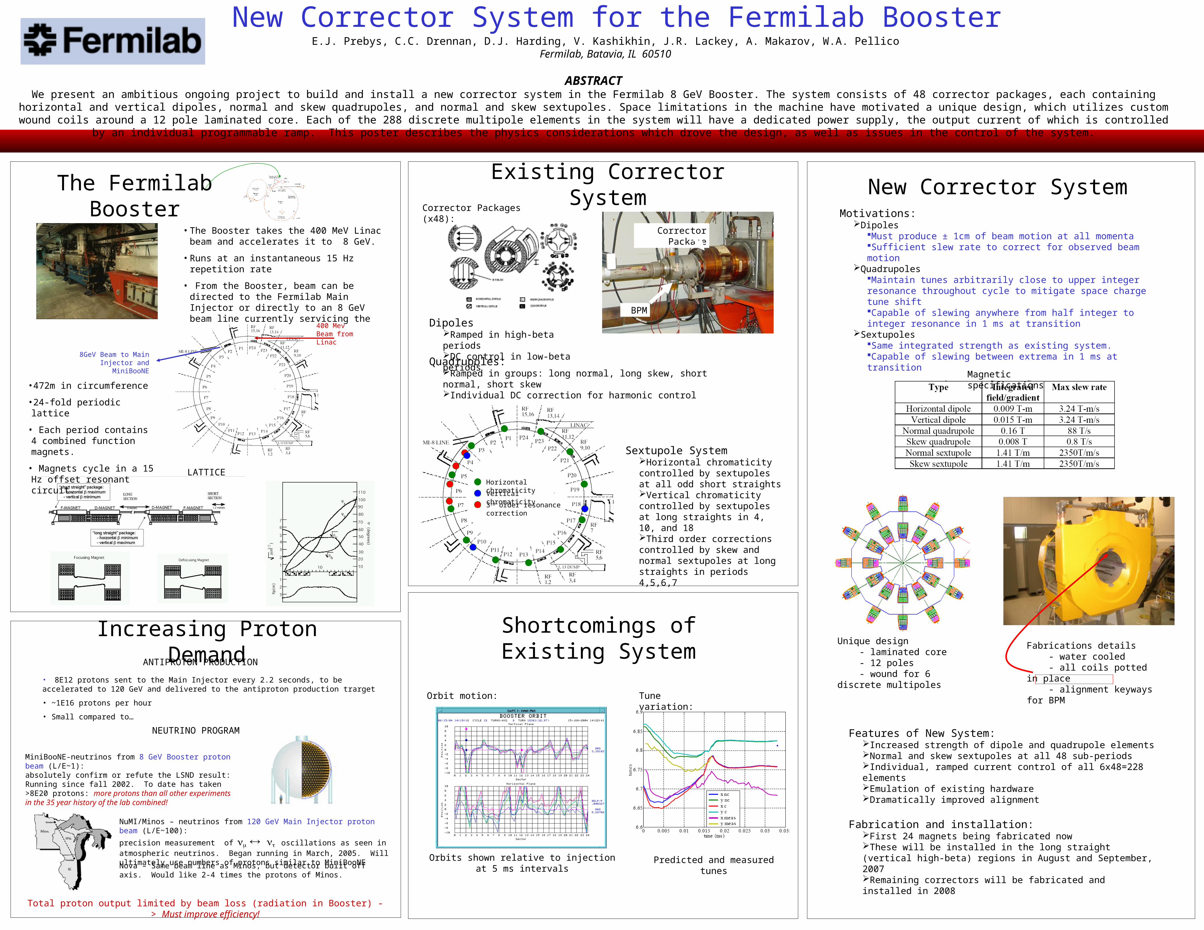
New Corrector System for the Fermilab BoosterE.J. Prebys, C.C. Drennan, D.J. Harding, V. Kashikhin, J.R. Lackey, A. Makarov, W.A. Pellico
Fermilab, Batavia, IL 60510
MiniBooNE-neutrinos from 8 GeV Booster proton beam (L/E~1): absolutely confirm or refute the LSND result: Running since fall 2002. To date has taken >8E20 protons: more protons than all other experiments in the 35 year history of the lab combined!
NuMI/Minos – neutrinos from 120 GeV Main Injector proton beam (L/E~100):
precision measurement of oscillations as seen in atmospheric neutrinos. Began running in March, 2005. Will ultimately use numbers of protons similar to MiniBooNE
The Fermilab Booster• The Booster takes the 400 MeV Linac beam and
accelerates it to 8 GeV.
• Runs at an instantaneous 15 Hz repetition rate
• From the Booster, beam can be directed to the Fermilab Main Injector or directly to an 8 GeV beam line currently servicing the MiniBooNE Experiment
400 Mev Beam from Linac
8GeV Beam to Main Injector and MiniBooNE
•472m in circumference
•24-fold periodic lattice
• Each period contains 4 combined function magnets.
• Magnets cycle in a 15 Hz offset resonant circuit.
LATTICE
Increasing Proton Demand
NEUTRINO PROGRAM
ANTIPROTON PRODUCTION
• 8E12 protons sent to the Main Injector every 2.2 seconds, to be accelerated to 120 GeV and delivered to the antiproton production trarget
• ~1E16 protons per hour
• Small compared to…
ABSTRACTWe present an ambitious ongoing project to build and install a new corrector system in the Fermilab 8 GeV Booster. The system consists of 48 corrector packages, each containing horizontal and vertical dipoles, normal and skew quadrupoles, and normal and skew
sextupoles. Space limitations in the machine have motivated a unique design, which utilizes custom wound coils around a 12 pole laminated core. Each of the 288 discrete multipole elements in the system will have a dedicated power supply, the output current of which is controlled by an individual programmable ramp. This poster describes the physics considerations which drove the design, as well as issues in the control of the system.
Nova – Same beam line as Minos, but detector built off axis. Would like 2-4 times the protons of Minos.
Existing Corrector SystemCorrector Packages (x48):
Corrector Package
BPM
Horizontal chromaticity
Vertical chromaticity
3rd order resonance correction
Shortcomings of Existing System
Orbit motion: Tune variation:
Orbits shown relative to injection at 5 ms intervals Predicted and measured tunes
New Corrector SystemMotivations:
DipolesMust produce ± 1cm of beam motion at all momentaSufficient slew rate to correct for observed beam motion
QuadrupolesMaintain tunes arbitrarily close to upper integer resonance throughout cycle to mitigate space charge tune shiftCapable of slewing anywhere from half integer to integer resonance in 1 ms at transition
SextupolesSame integrated strength as existing system.Capable of slewing between extrema in 1 ms at transition
Magnetic specifications
Unique design - laminated core - 12 poles - wound for 6 discrete multipoles
Fabrications details - water cooled - all coils potted in place - alignment keyways for BPM
Sextupole SystemHorizontal chromaticity controlled by sextupoles at all odd short straightsVertical chromaticity controlled by sextupoles at long straights in 4, 10, and 18Third order corrections controlled by skew and normal sextupoles at long straights in periods 4,5,6,7
DipolesRamped in high-beta periodsDC control in low-beta periods
Quadrupoles:Ramped in groups: long normal, long skew, short normal, short skewIndividual DC correction for harmonic control
Features of New System:Increased strength of dipole and quadrupole elementsNormal and skew sextupoles at all 48 sub-periodsIndividual, ramped current control of all 6x48=228 elementsEmulation of existing hardwareDramatically improved alignment
Fabrication and installation:First 24 magnets being fabricated nowThese will be installed in the long straight (vertical high-beta) regions in August and September, 2007Remaining correctors will be fabricated and installed in 2008
Total proton output limited by beam loss (radiation in Booster) -> Must improve efficiency!
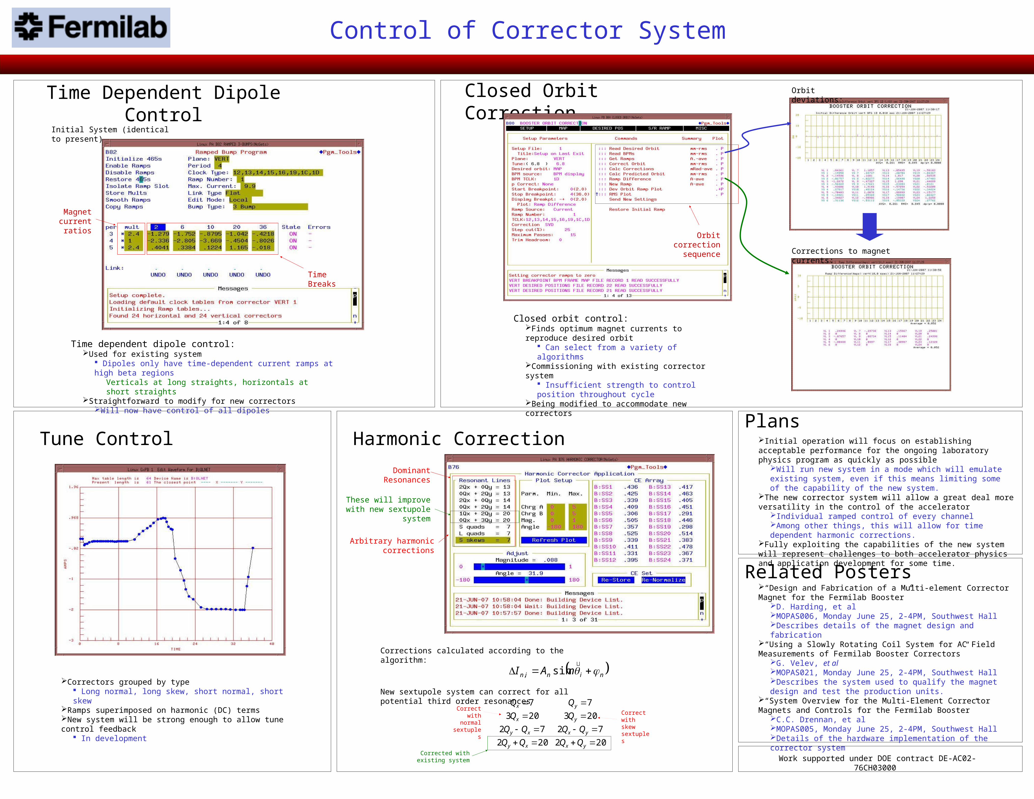
Dominant Resonances
Arbitrary harmonic corrections
These will improve with new sextupole system
Magnet current ratios
Time Breaks
Time Dependent Dipole ControlInitial System (identical to present)
Closed Orbit Correction
Orbit correction sequence
Orbit deviations:
Corrections to magnet currents:
Harmonic Correction
202202
7272
203203
77
yxxy
yxxy
yx
yx
QQQQ
QQQQ
QQCorrect
with normal sextuples
Correct with skew sextuples
New sextupole system can correct for all potential third order resonances
Corrected with existing system
Time dependent dipole control:Used for existing system
Dipoles only have time-dependent current ramps at high beta regionsVerticals at long straights, horizontals at short straights
Straightforward to modify for new correctorsWill now have control of all dipoles
Closed orbit control:Finds optimum magnet currents to reproduce desired orbit
Can select from a variety of algorithmsCommissioning with existing corrector system
Insufficient strength to control position throughout cycleBeing modified to accommodate new correctors
Control of Corrector System
Tune Control
Correctors grouped by type Long normal, long skew, short normal, short skew
Ramps superimposed on harmonic (DC) termsNew system will be strong enough to allow tune control feedback
In development
Related Posters“Design and Fabrication of a Multi-element Corrector Magnet for the Fermilab Booster”
D. Harding, et alMOPAS006, Monday June 25, 2-4PM, Southwest HallDescribes details of the magnet design and fabrication
“Using a Slowly Rotating Coil System for AC Field Measurements of Fermilab Booster Correctors”
G. Velev, et alMOPAS021, Monday June 25, 2-4PM, Southwest HallDescribes the system used to qualify the magnet design and test the production units.
“System Overview for the Multi-Element Corrector Magnets and Controls for the Fermilab Booster”
C.C. Drennan, et alMOPAS005, Monday June 25, 2-4PM, Southwest HallDetails of the hardware implementation of the corrector system
Work supported under DOE contract DE-AC02-76CH03000
Corrections calculated according to the algorithm:
ninin nAI
sin,
PlansInitial operation will focus on establishing acceptable performance for the ongoing laboratory physics program as quickly as possible
Will run new system in a mode which will emulate existing system, even if this means limiting some of the capability of the new system.
The new corrector system will allow a great deal more versatility in the control of the accelerator
Individual ramped control of every channelAmong other things, this will allow for time dependent harmonic corrections.
Fully exploiting the capabilities of the new system will represent challenges to both accelerator physics and application development for some time.