Embed Size (px)
Citation preview
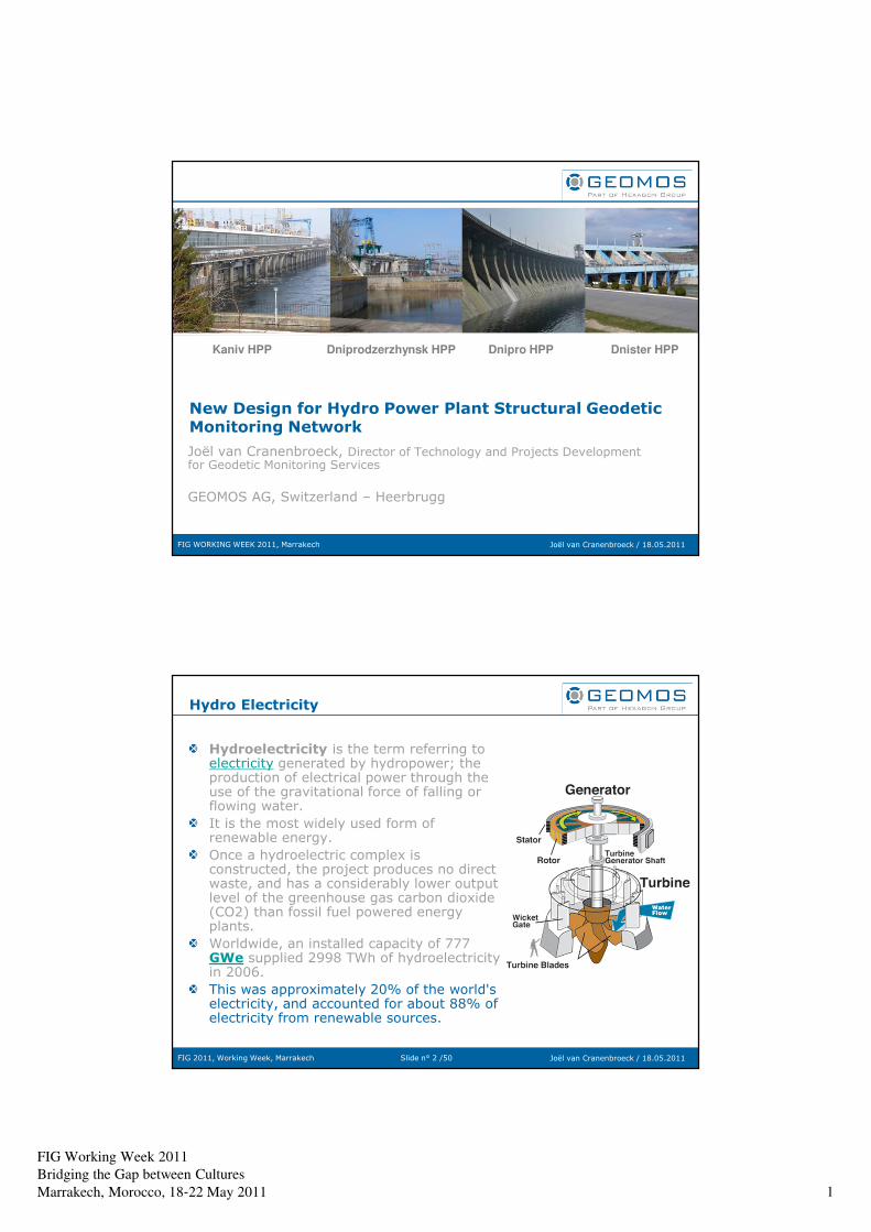
FIG Working Week 2011
Bridging the Gap between Cultures
Marrakech, Morocco, 18‐22 May 2011 1
FIG WORKING WEEK 2011, Marrakech Joël van Cranenbroeck / 18.05.2011
New Design for Hydro Power Plant Structural Geodetic Monitoring Network
Joël van Cranenbroeck, Director of Technology and Projects Development for Geodetic Monitoring Services
GEOMOS AG, Switzerland – Heerbrugg
Kaniv HPP Dniprodzerzhynsk HPP Dnipro HPP Dnister HPP
Slide n° 2 /50FIG 2011, Working Week, Marrakech Joël van Cranenbroeck / 18.05.2011
Hydro Electricity
Hydroelectricity is the term referring to electricity generated by hydropower; the production of electrical power through the use of the gravitational force of falling or flowing water.
It is the most widely used form of renewable energy.
Once a hydroelectric complex is constructed, the project produces no direct waste, and has a considerably lower output level of the greenhouse gas carbon dioxide (CO2) than fossil fuel powered energy plants.
Worldwide, an installed capacity of 777 GWe supplied 2998 TWh of hydroelectricity in 2006.
This was approximately 20% of the world's electricity, and accounted for about 88% of electricity from renewable sources.
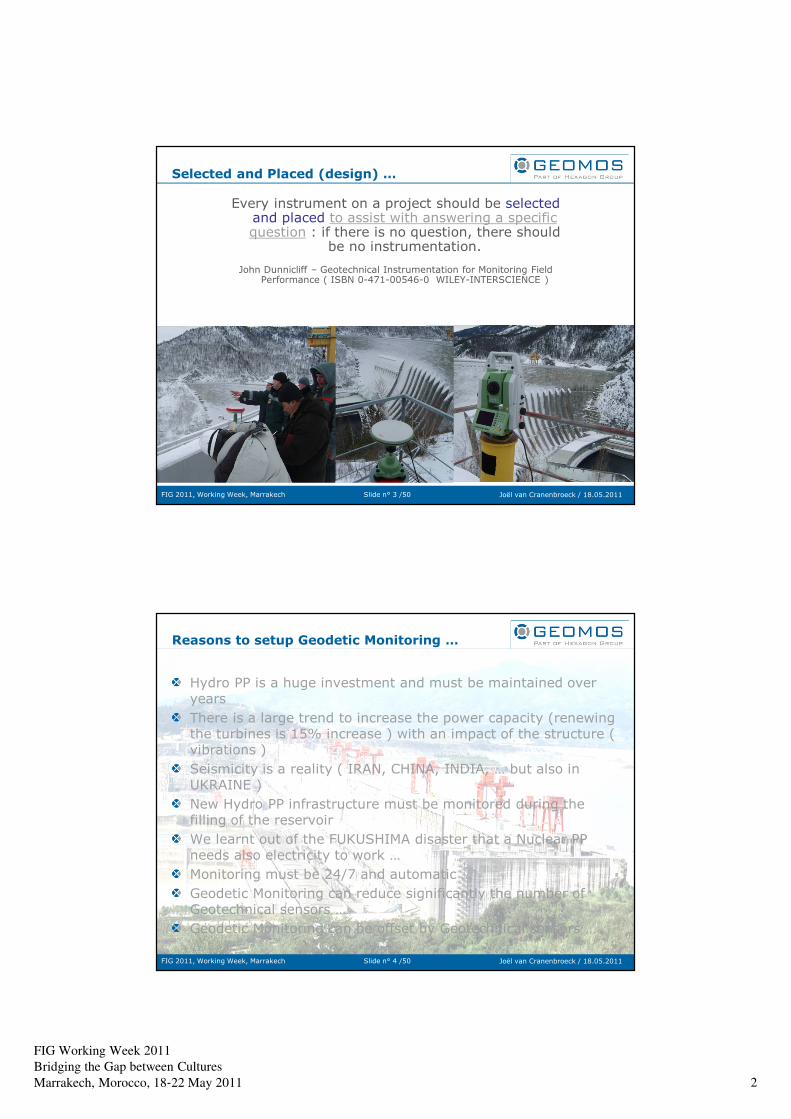
FIG Working Week 2011
Bridging the Gap between Cultures
Marrakech, Morocco, 18‐22 May 2011 2
Slide n° 3 /50FIG 2011, Working Week, Marrakech Joël van Cranenbroeck / 18.05.2011
Selected and Placed (design) …
Every instrument on a project should be selected and placed to assist with answering a specific question : if there is no question, there should
be no instrumentation.
John Dunnicliff – Geotechnical Instrumentation for Monitoring Field Performance ( ISBN 0-471-00546-0 WILEY-INTERSCIENCE )
Slide n° 4 /50FIG 2011, Working Week, Marrakech Joël van Cranenbroeck / 18.05.2011
Reasons to setup Geodetic Monitoring …
Hydro PP is a huge investment and must be maintained over years
There is a large trend to increase the power capacity (renewing the turbines is 15% increase ) with an impact of the structure ( vibrations )
Seismicity is a reality ( IRAN, CHINA, INDIA, … but also in UKRAINE )
New Hydro PP infrastructure must be monitored during the filling of the reservoir
We learnt out of the FUKUSHIMA disaster that a Nuclear PP needs also electricity to work …
Monitoring must be 24/7 and automatic …
Geodetic Monitoring can reduce significantly the number of Geotechnical sensors …
Geodetic Monitoring can be offset by Geotechnical sensors …
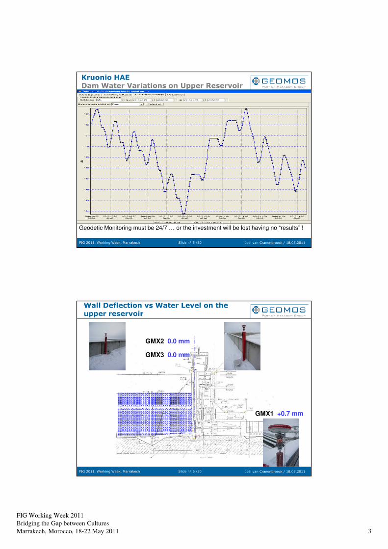
FIG Working Week 2011
Bridging the Gap between Cultures
Marrakech, Morocco, 18‐22 May 2011 3
Slide n° 5 /50FIG 2011, Working Week, Marrakech Joël van Cranenbroeck / 18.05.2011
Kruonio HAEDam Water Variations on Upper Reservoir
Geodetic Monitoring must be 24/7 … or the investment will be lost having no “results” !
Slide n° 6 /50FIG 2011, Working Week, Marrakech Joël van Cranenbroeck / 18.05.2011
Wall Deflection vs Water Level on the upper reservoir
GMX2 0.0 mm
GMX3 0.0 mm
GMX1 +0.7 mm
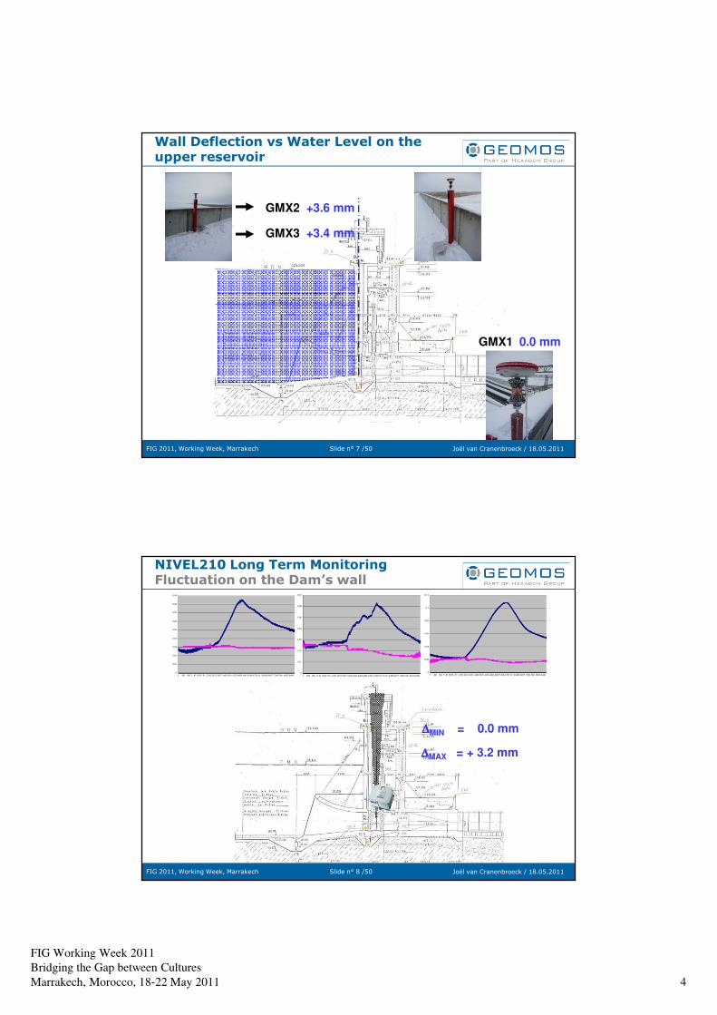
FIG Working Week 2011
Bridging the Gap between Cultures
Marrakech, Morocco, 18‐22 May 2011 4
Slide n° 7 /50FIG 2011, Working Week, Marrakech Joël van Cranenbroeck / 18.05.2011
Wall Deflection vs Water Level on the upper reservoir
GMX2 +3.6 mm
GMX3 +3.4 mm
GMX1 0.0 mm
Slide n° 8 /50FIG 2011, Working Week, Marrakech Joël van Cranenbroeck / 18.05.2011
NIVEL210 Long Term MonitoringFluctuation on the Dam’s wall
∆∆∆∆MIN = 0.0 mm
∆∆∆∆MAX = + 3.2 mm
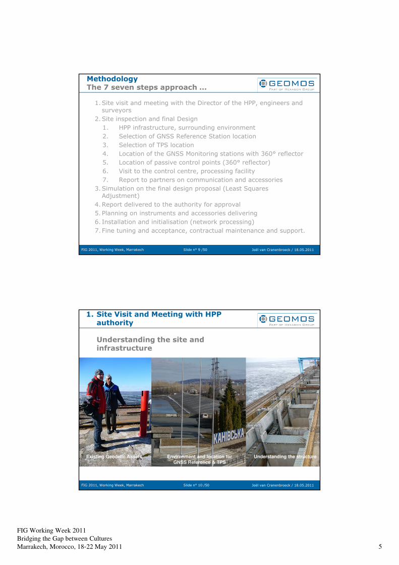
FIG Working Week 2011
Bridging the Gap between Cultures
Marrakech, Morocco, 18‐22 May 2011 5
Slide n° 9 /50FIG 2011, Working Week, Marrakech Joël van Cranenbroeck / 18.05.2011
Methodology The 7 seven steps approach …
1.Site visit and meeting with the Director of the HPP, engineers and surveyors
2.Site inspection and final Design
1. HPP infrastructure, surrounding environment
2. Selection of GNSS Reference Station location
3. Selection of TPS location
4. Location of the GNSS Monitoring stations with 360° reflector
5. Location of passive control points (360° reflector)
6. Visit to the control centre, processing facility
7. Report to partners on communication and accessories
3.Simulation on the final design proposal (Least Squares Adjustment)
4.Report delivered to the authority for approval
5. Planning on instruments and accessories delivering
6. Installation and initialisation (network processing)
7. Fine tuning and acceptance, contractual maintenance and support.
Slide n° 10 /50FIG 2011, Working Week, Marrakech Joël van Cranenbroeck / 18.05.2011
1. Site Visit and Meeting with HPP authority
Understanding the site and infrastructure
Existing Geodetic Assets Environment and location for
GNSS Reference & TPS
Understanding the structure
FIG Working Week 2011
Bridging the Gap between Cultures
Marrakech, Morocco, 18‐22 May 2011 6
Slide n° 11 /50FIG 2011, Working Week, Marrakech Joël van Cranenbroeck / 18.05.2011
1. Site Visit and Meeting with HPP authority
Understanding the site and infrastructure
Existing Geodetic Assets Environment and location for
GNSS Reference & TPS
Understanding the structure
Slide n° 12 /50FIG 2011, Working Week, Marrakech Joël van Cranenbroeck / 18.05.2011
1. Site Visit and Meeting with HPP authority
Understanding the past Geodetic history (X,Y)
Previous Geodetic Monitoring Campaign executed by University, Geodesy Department using
GPS on pillars. Control points and monitoring points on red steel pillars anchored on massive
concrete foundations.
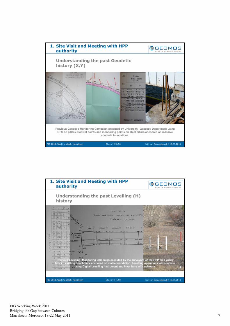
FIG Working Week 2011
Bridging the Gap between Cultures
Marrakech, Morocco, 18‐22 May 2011 7
Slide n° 13 /50FIG 2011, Working Week, Marrakech Joël van Cranenbroeck / 18.05.2011
1. Site Visit and Meeting with HPP authority
Understanding the past Geodetic history (X,Y)
Previous Geodetic Monitoring Campaign executed by University, Geodesy Department using
GPS on pillars. Control points and monitoring points on steel pillars anchored on massive
concrete foundations.
Slide n° 14 /50FIG 2011, Working Week, Marrakech Joël van Cranenbroeck / 18.05.2011
1. Site Visit and Meeting with HPP authority
Understanding the past Levelling (H) history
Previous Levelling Monitoring Campaign executed by the surveyors of the HPP on a yearly
basis. Levelling benchmark anchored on stable foundation. Levelling operations will continue
using Digital Levelling instrument and Invar bars with software.
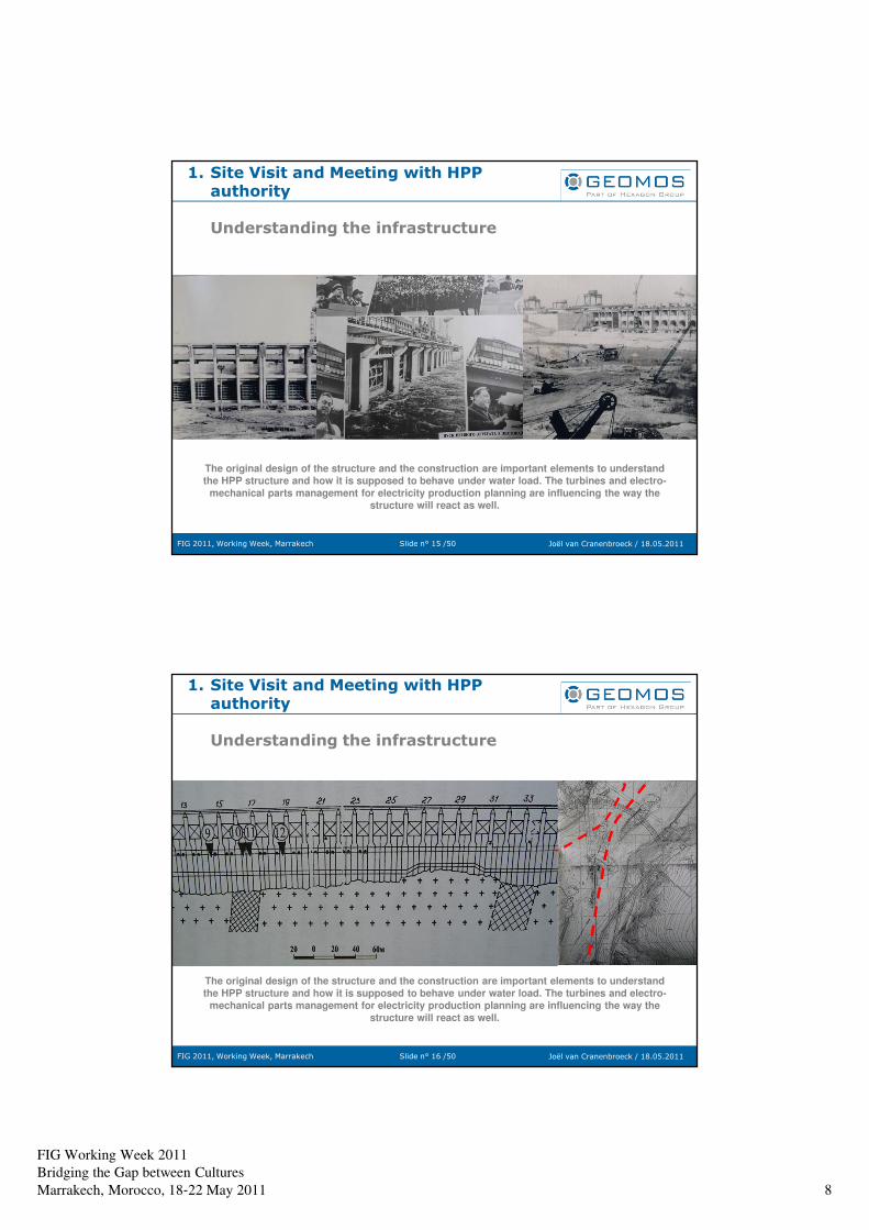
FIG Working Week 2011
Bridging the Gap between Cultures
Marrakech, Morocco, 18‐22 May 2011 8
Slide n° 15 /50FIG 2011, Working Week, Marrakech Joël van Cranenbroeck / 18.05.2011
The original design of the structure and the construction are important elements to understand
the HPP structure and how it is supposed to behave under water load. The turbines and electro-
mechanical parts management for electricity production planning are influencing the way the
structure will react as well.
1. Site Visit and Meeting with HPP authority
Understanding the infrastructure
Slide n° 16 /50FIG 2011, Working Week, Marrakech Joël van Cranenbroeck / 18.05.2011
The original design of the structure and the construction are important elements to understand
the HPP structure and how it is supposed to behave under water load. The turbines and electro-
mechanical parts management for electricity production planning are influencing the way the
structure will react as well.
1. Site Visit and Meeting with HPP authority
Understanding the infrastructure
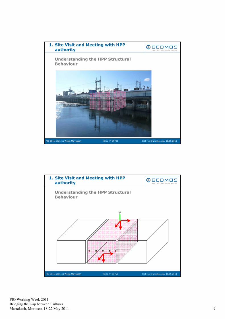
FIG Working Week 2011
Bridging the Gap between Cultures
Marrakech, Morocco, 18‐22 May 2011 9
Slide n° 17 /50FIG 2011, Working Week, Marrakech Joël van Cranenbroeck / 18.05.2011
1. Site Visit and Meeting with HPP authority
Understanding the HPP Structural Behaviour
Slide n° 18 /50FIG 2011, Working Week, Marrakech Joël van Cranenbroeck / 18.05.2011
1. Site Visit and Meeting with HPP authority
Understanding the HPP Structural Behaviour
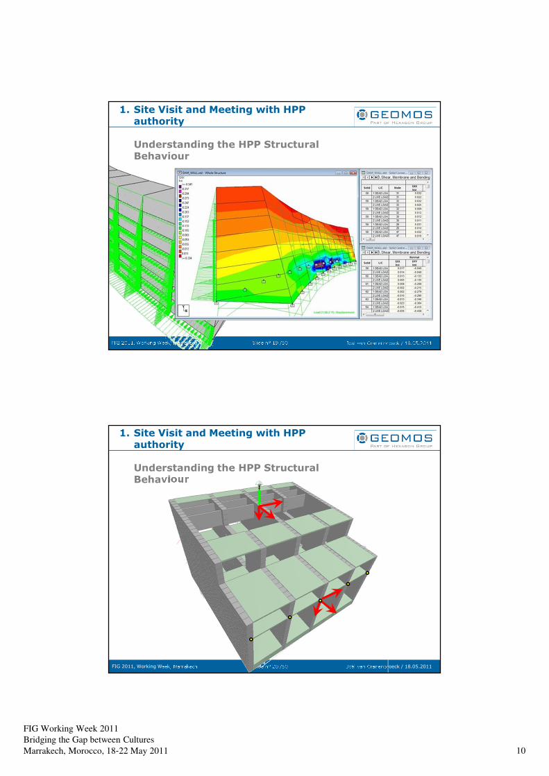
FIG Working Week 2011
Bridging the Gap between Cultures
Marrakech, Morocco, 18‐22 May 2011 10
Slide n° 19 /50FIG 2011, Working Week, Marrakech Joël van Cranenbroeck / 18.05.2011
1. Site Visit and Meeting with HPP authority
Understanding the HPP Structural Behaviour
Slide n° 20 /50FIG 2011, Working Week, Marrakech Joël van Cranenbroeck / 18.05.2011
1. Site Visit and Meeting with HPP authority
Understanding the HPP Structural Behaviour
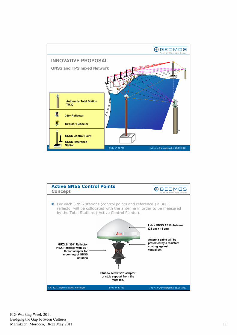
FIG Working Week 2011
Bridging the Gap between Cultures
Marrakech, Morocco, 18‐22 May 2011 11
Slide n° 21 /50FIG 2011, Working Week, Marrakech Joël van Cranenbroeck / 18.05.2011
Automatic Total Station
TM30
360°Reflector
Circular Reflector
GNSS Control Point
GNSS Reference
Station
INNOVATIVE PROPOSAL
GNSS and TPS mixed Network
Slide n° 22 /50FIG 2011, Working Week, Marrakech Joël van Cranenbroeck / 18.05.2011
Active GNSS Control PointsConcept
For each GNSS stations (control points and reference ) a 360°reflector will be collocated with the antenna in order to be measured by the Total Stations ( Active Control Points ).
Antenna cable will be
protected by a resistant
coating against
vandalism.
GRZ121 360°Reflector
PRO. Reflector with 5/8”
thread adapter for
mounting of GNSS
antenna
Leica GNSS AR10 Antenna
(24 cm x 14 cm)
Stub to screw 5/8” adaptor
or stub support from the
mast top.
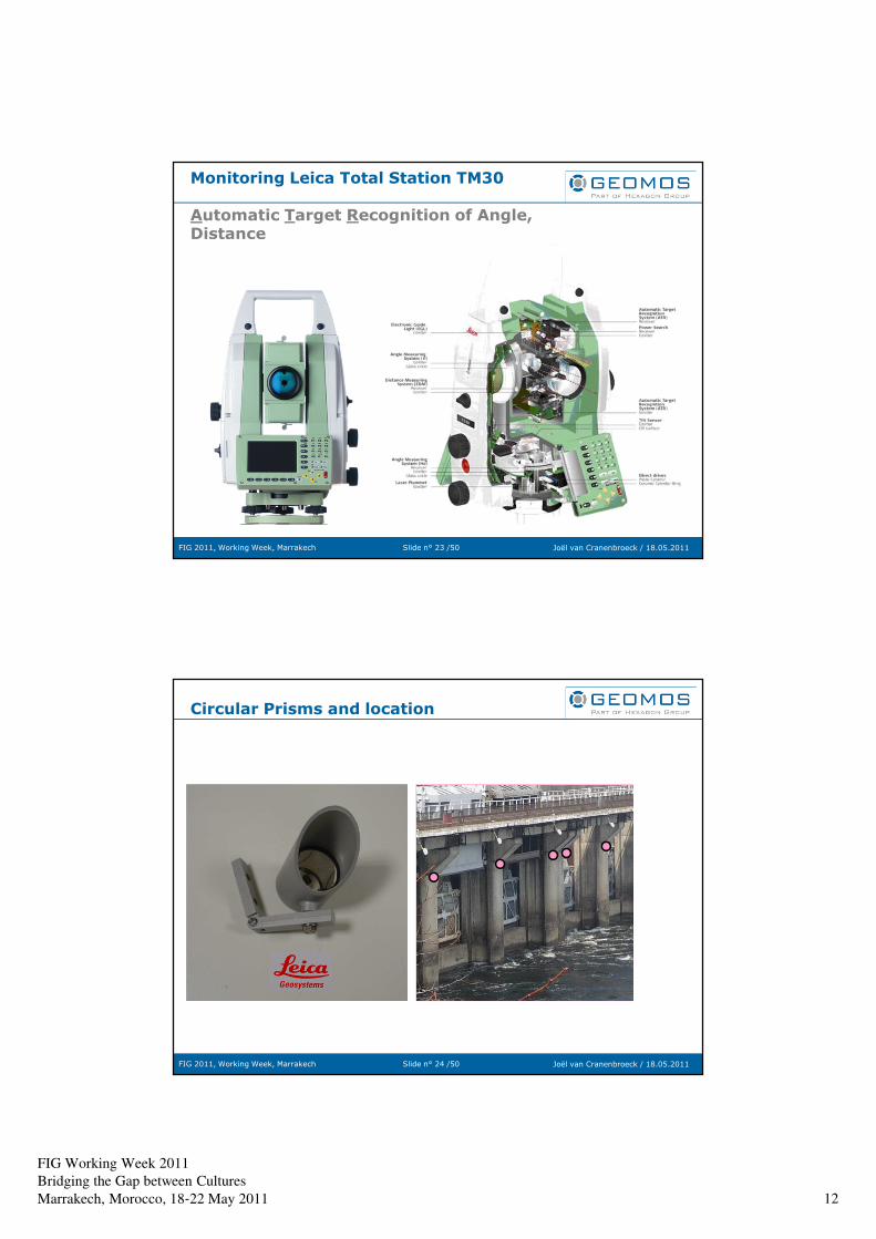
FIG Working Week 2011
Bridging the Gap between Cultures
Marrakech, Morocco, 18‐22 May 2011 12
Slide n° 23 /50FIG 2011, Working Week, Marrakech Joël van Cranenbroeck / 18.05.2011
Monitoring Leica Total Station TM30
Automatic Target Recognition of Angle, Distance
Slide n° 24 /50FIG 2011, Working Week, Marrakech Joël van Cranenbroeck / 18.05.2011
Circular Prisms and location
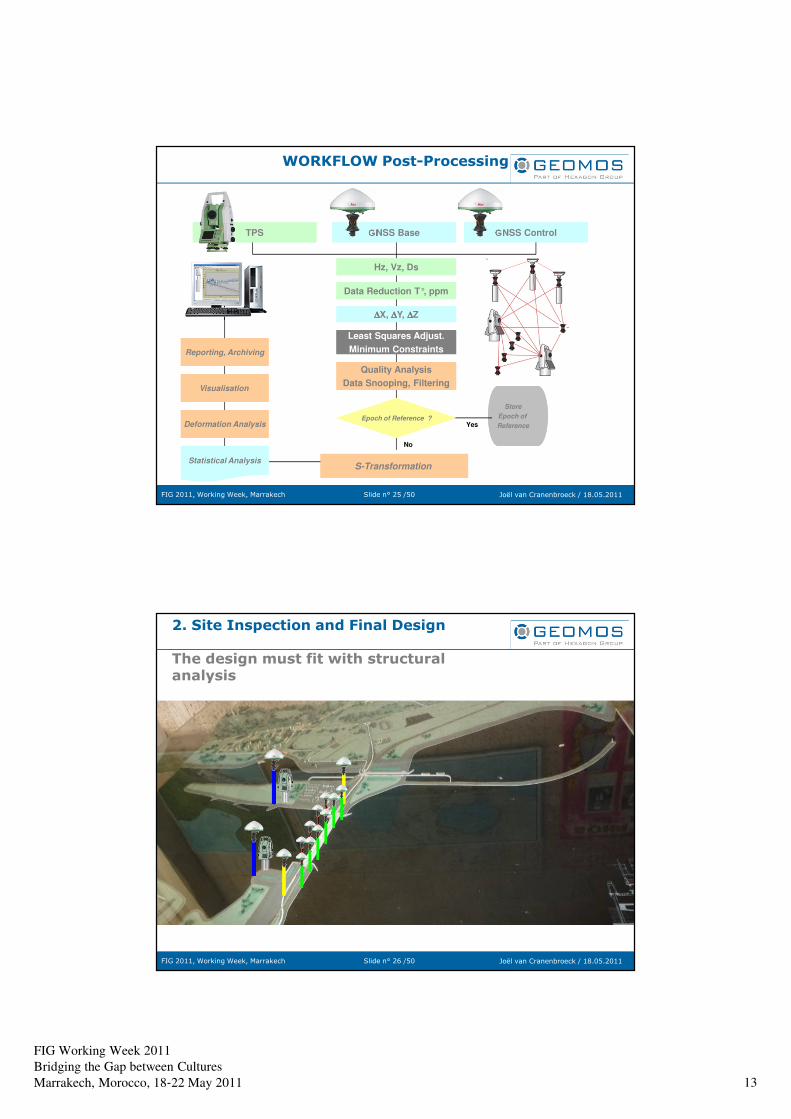
FIG Working Week 2011
Bridging the Gap between Cultures
Marrakech, Morocco, 18‐22 May 2011 13
Slide n° 25 /50FIG 2011, Working Week, Marrakech Joël van Cranenbroeck / 18.05.2011
WORKFLOW Post-Processing
TPS GNSS Base GNSS Control
∆∆∆∆X, ∆∆∆∆Y, ∆∆∆∆Z
Data Reduction T°, ppm
Store
Epoch of
ReferenceEpoch of Reference ?
Yes
No
S-TransformationStatistical Analysis
Deformation Analysis
Visualisation
Reporting, Archiving
Quality Analysis
Data Snooping, Filtering
Least Squares Adjust.
Minimum Constraints
Hz, Vz, Ds
Slide n° 26 /50FIG 2011, Working Week, Marrakech Joël van Cranenbroeck / 18.05.2011
2. Site Inspection and Final Design
The design must fit with structural analysis
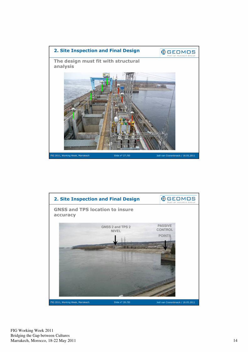
FIG Working Week 2011
Bridging the Gap between Cultures
Marrakech, Morocco, 18‐22 May 2011 14
Slide n° 27 /50FIG 2011, Working Week, Marrakech Joël van Cranenbroeck / 18.05.2011
2. Site Inspection and Final Design
The design must fit with structural analysis
Slide n° 28 /50FIG 2011, Working Week, Marrakech Joël van Cranenbroeck / 18.05.2011
2. Site Inspection and Final Design
GNSS and TPS location to insure accuracy
GNSS 2 and TPS 2 NIVEL
PASSIVE CONTROL
POINTS
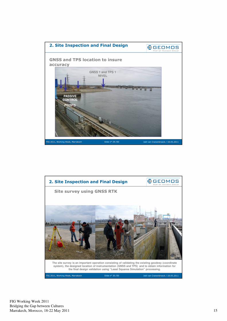
FIG Working Week 2011
Bridging the Gap between Cultures
Marrakech, Morocco, 18‐22 May 2011 15
Slide n° 29 /50FIG 2011, Working Week, Marrakech Joël van Cranenbroeck / 18.05.2011
2. Site Inspection and Final Design
GNSS and TPS location to insure accuracy
GNSS 1 and TPS 1 NIVEL
PASSIVE CONTROL
POINTS
Slide n° 30 /50FIG 2011, Working Week, Marrakech Joël van Cranenbroeck / 18.05.2011
2. Site Inspection and Final Design
Site survey using GNSS RTK
The site survey is an important operation consisting of validating the existing geodesy (coordinate
system), the designed location of instrumentation (GNSS and TPS) and to obtain information for
the final design validation using “Least Squares Simulation” processing.
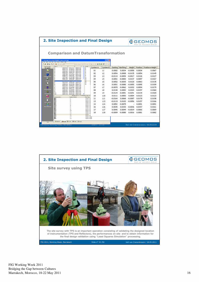
FIG Working Week 2011
Bridging the Gap between Cultures
Marrakech, Morocco, 18‐22 May 2011 16
Slide n° 31 /50FIG 2011, Working Week, Marrakech Joël van Cranenbroeck / 18.05.2011
2. Site Inspection and Final Design
Comparison and DatumTransformation
Slide n° 32 /50FIG 2011, Working Week, Marrakech Joël van Cranenbroeck / 18.05.2011
2. Site Inspection and Final Design
Site survey using TPS
The site survey with TPS is an important operation consisting of validating the designed location
of instrumentation (TPS and Reflectors), the performances on site and to obtain information for
the final design validation using “Least Squares Simulation” processing.
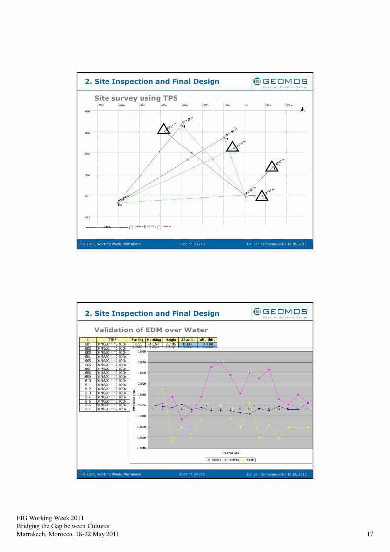
FIG Working Week 2011
Bridging the Gap between Cultures
Marrakech, Morocco, 18‐22 May 2011 17
Slide n° 33 /50FIG 2011, Working Week, Marrakech Joël van Cranenbroeck / 18.05.2011
2. Site Inspection and Final Design
Site survey using TPS
Slide n° 34 /50FIG 2011, Working Week, Marrakech Joël van Cranenbroeck / 18.05.2011
2. Site Inspection and Final Design
Validation of EDM over Water
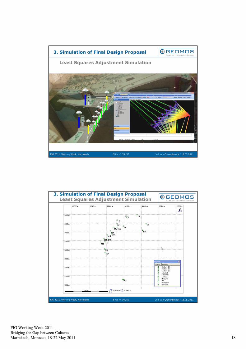
FIG Working Week 2011
Bridging the Gap between Cultures
Marrakech, Morocco, 18‐22 May 2011 18
Slide n° 35 /50FIG 2011, Working Week, Marrakech Joël van Cranenbroeck / 18.05.2011
3. Simulation of Final Design Proposal
Least Squares Adjustment Simulation
Slide n° 36 /50FIG 2011, Working Week, Marrakech Joël van Cranenbroeck / 18.05.2011
3. Simulation of Final Design ProposalLeast Squares Adjustment Simulation
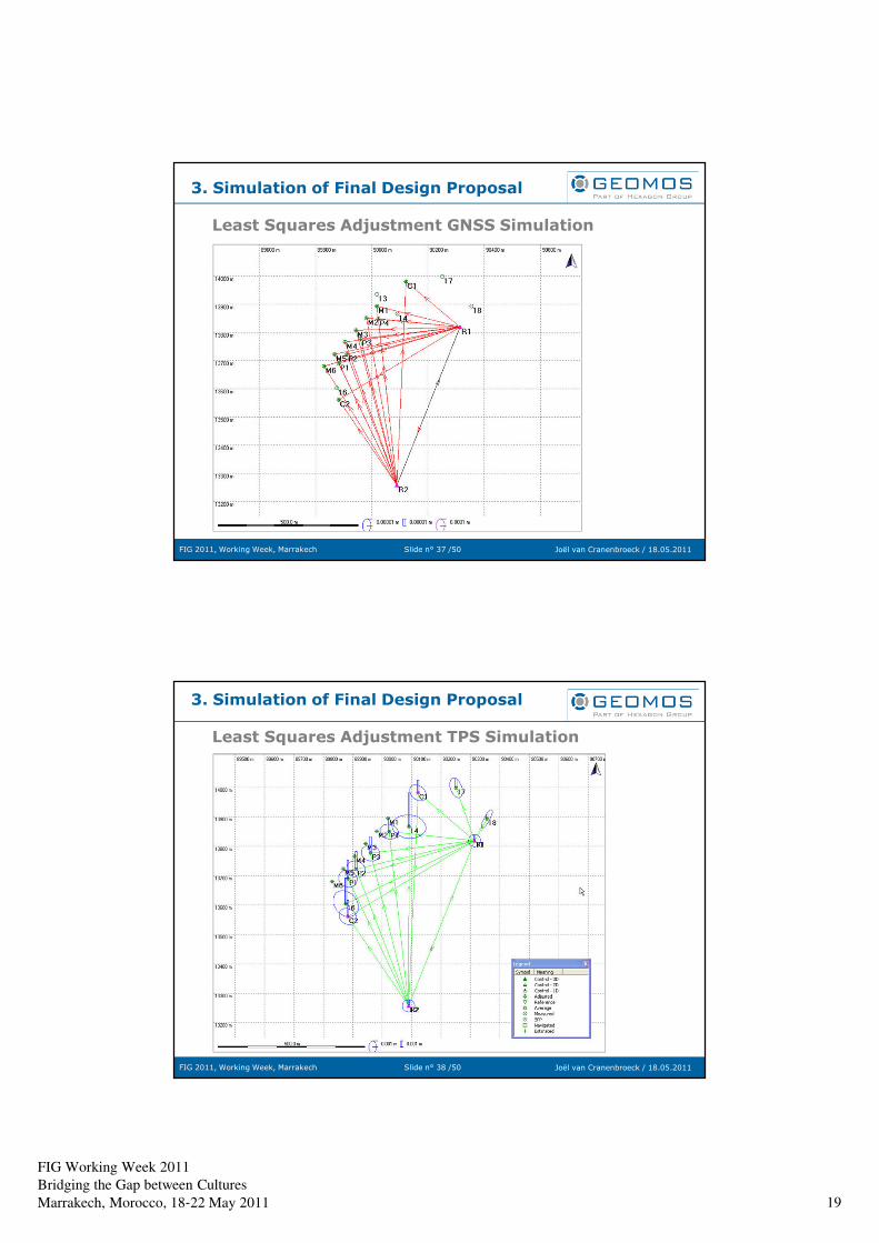
FIG Working Week 2011
Bridging the Gap between Cultures
Marrakech, Morocco, 18‐22 May 2011 19
Slide n° 37 /50FIG 2011, Working Week, Marrakech Joël van Cranenbroeck / 18.05.2011
3. Simulation of Final Design Proposal
Least Squares Adjustment GNSS Simulation
Slide n° 38 /50FIG 2011, Working Week, Marrakech Joël van Cranenbroeck / 18.05.2011
3. Simulation of Final Design Proposal
Least Squares Adjustment TPS Simulation
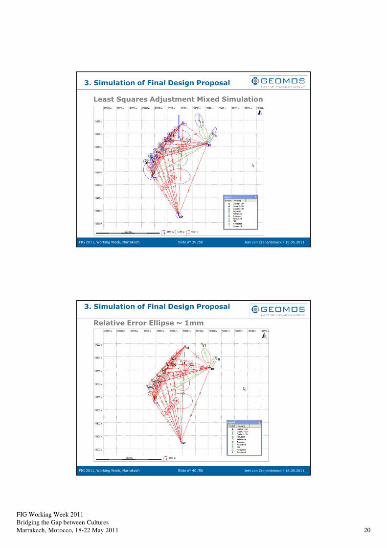
FIG Working Week 2011
Bridging the Gap between Cultures
Marrakech, Morocco, 18‐22 May 2011 20
Slide n° 39 /50FIG 2011, Working Week, Marrakech Joël van Cranenbroeck / 18.05.2011
3. Simulation of Final Design Proposal
Least Squares Adjustment Mixed Simulation
Slide n° 40 /50FIG 2011, Working Week, Marrakech Joël van Cranenbroeck / 18.05.2011
3. Simulation of Final Design Proposal
Relative Error Ellipse ~ 1mm
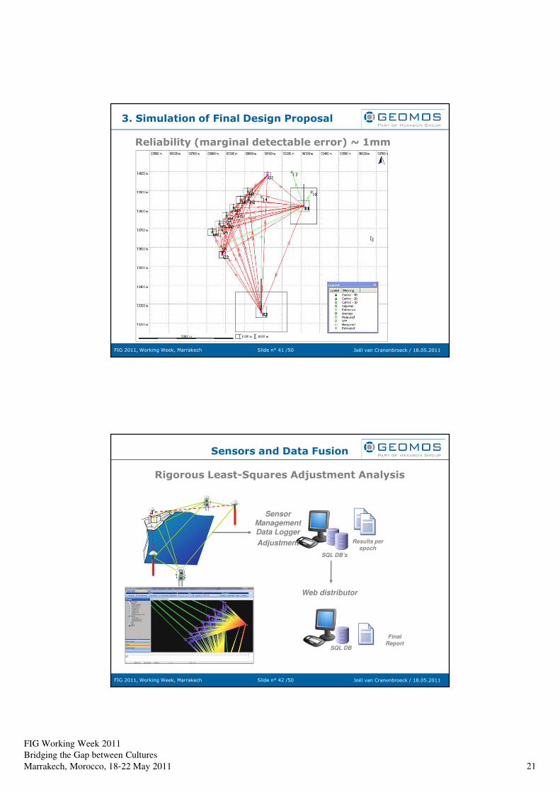
FIG Working Week 2011
Bridging the Gap between Cultures
Marrakech, Morocco, 18‐22 May 2011 21
Slide n° 41 /50FIG 2011, Working Week, Marrakech Joël van Cranenbroeck / 18.05.2011
3. Simulation of Final Design Proposal
Reliability (marginal detectable error) ~ 1mm
Slide n° 42 /50FIG 2011, Working Week, Marrakech Joël van Cranenbroeck / 18.05.2011
Sensors and Data Fusion
Rigorous Least-Squares Adjustment Analysis
Web distributor
Final Report
SQL DB’s
Results per epoch
Sensor Management Data Logger
Adjustment
SQL DB
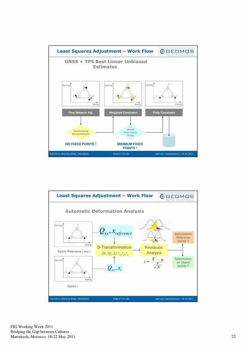
FIG Working Week 2011
Bridging the Gap between Cultures
Marrakech, Morocco, 18‐22 May 2011 22
Slide n° 43 /50FIG 2011, Working Week, Marrakech Joël van Cranenbroeck / 18.05.2011
Least Squares Adjustment – Work Flow
GNSS + TPS Best Linear Unbiased Estimates
Free Network Adj. Weighted Constraint Fully Constraint
Data Snooping
Blunder Detection
Identify
Fixed Control
Points
NO FIXED POINTS ! MINIMUM FIXED POINTS !
Slide n° 44 /50FIG 2011, Working Week, Marrakech Joël van Cranenbroeck / 18.05.2011
Least Squares Adjustment – Work Flow
Automatic Deformation Analysis
Epoch Reference ( any )
Epoch i
ixx xQ , ixx xQ ,
S-Transformation
∆x,∆y,∆z,rx,ry,rz
Residuals
Analysis
Deformation
on Object
points ?
Deformation
Reference
points ?
referencexx xQ , referencexx xQ ,
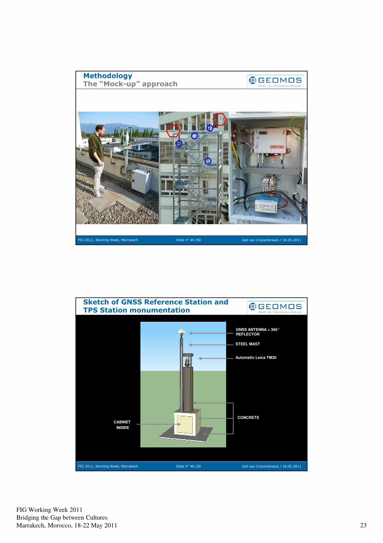
FIG Working Week 2011
Bridging the Gap between Cultures
Marrakech, Morocco, 18‐22 May 2011 23
Slide n° 45 /50FIG 2011, Working Week, Marrakech Joël van Cranenbroeck / 18.05.2011
Methodology The “Mock-up” approach
Slide n° 46 /50FIG 2011, Working Week, Marrakech Joël van Cranenbroeck / 18.05.2011
Sketch of GNSS Reference Station and TPS Station monumentation
GNSS ANTENNA + 360°REFLECTOR
Automatic Leica TM30
CABINET
INSIDE
CONCRETE
STEEL MAST
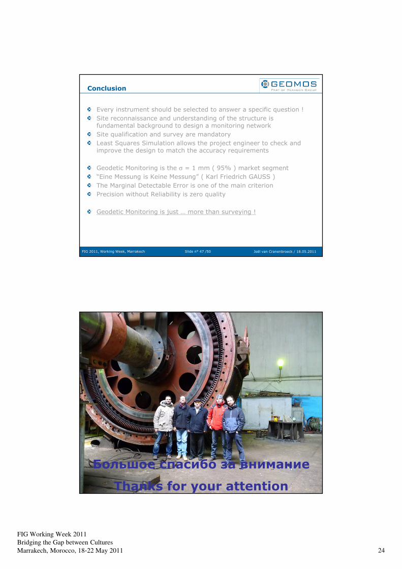
FIG Working Week 2011
Bridging the Gap between Cultures
Marrakech, Morocco, 18‐22 May 2011 24
Slide n° 47 /50FIG 2011, Working Week, Marrakech Joël van Cranenbroeck / 18.05.2011
Conclusion
Every instrument should be selected to answer a specific question !
Site reconnaissance and understanding of the structure is fundamental background to design a monitoring network
Site qualification and survey are mandatory
Least Squares Simulation allows the project engineer to check and improve the design to match the accuracy requirements
Geodetic Monitoring is the σ = 1 mm ( 95% ) market segment
“Eine Messung is Keine Messung” ( Karl Friedrich GAUSS )
The Marginal Detectable Error is one of the main criterion
Precision without Reliability is zero quality
Geodetic Monitoring is just … more than surveying !
Slide n° 48 /50FIG 2011, Working Week, Marrakech Joël van Cranenbroeck / 18.05.2011
Большое спасибо за внимание
Thanks for your attention


![TS05B IVAN 5139 ppt1.ppt [Kompatibilitetstilstand] · FIG Working Week 2011 Bridging the Gap between Cultures Marrakech, Morocco, 18‐22 May 2011 4 Legal Framework on Land Registry](https://img.pdfslide.net/doc/110x75/5f04cb117e708231d40fbc11/ts05b-ivan-5139-ppt1ppt-kompatibilitetstilstand-fig-working-week-2011-bridging.jpg)


![TSO8I 5410.ppt [Kompatibilitetstilstand]FIG Working Week 2011 Bridging the Gap between Cultures Marrakech, Morocco, 18‐22 May 2011 3 MALAYSIA Land Area: 329,758 square km Population:](https://img.pdfslide.net/doc/110x75/60929a87027a7938cc0d2e3b/tso8i-5410ppt-kompatibilitetstilstand-fig-working-week-2011-bridging-the-gap.jpg)

![TS08A Talbi Alami 5347.ppt [Kompatibilitetstilstand] · Mohamed TALBI ALAMI, Aziz HIALI, Khalid YOUSFI topocart2006@yahoo.fr FIG Working Week 2011 Marrakech, Morocco May 18-22, 2011](https://img.pdfslide.net/doc/110x75/60b8cf13bbfe4d10ed38dd45/ts08a-talbi-alami-5347ppt-kompatibilitetstilstand-mohamed-talbi-alami-aziz-hiali.jpg)


![TS07a Salzmann 4817 ppt.ppt [Kompatibilitetstilstand] · 2011-06-06 · FIG Working Week 2011 Bridging the Gap between Cultures Marrakech, Morocco, 18‐22 May 2011 1 Co-creating](https://img.pdfslide.net/doc/110x75/5e984f8347296a75f75f0ad0/ts07a-salzmann-4817-pptppt-kompatibilitetstilstand-2011-06-06-fig-working-week.jpg)