Embed Size (px)
Citation preview
New Developments and Applications in Scan Head Technology
Andreas Engelmayer SCANLAB AG Benzstrasse 28
82178 Puchheim, Germany
ABSTRACT
Galvanometer technology uses high-dynamic-performance rotating mirrors to move and position laser beams – and thereby significantly speed-up laser processing in a wide variety of applications. This
paper examines the fundamentals of galvanometer-based scan head technology as well as a variety of applications and their respective setups. We conclude with a look at novel setups for high-precision
manufacturing and welding scan systems using multi-kW lasers and robots.
INTRODUCTION TO SCAN HEAD TECHNOLOGY
Over the past 20 years, laser processing systems have found their way into countless industrial applications such as welding, cutting, scribing, engraving, drilling and marking. Galvanometers are most often used for rapid and precise positioning of the laser focus on the work piece. Galvanometers are rotational drives with high resolution and acceleration to which laser-grade mirrors are attached. Typically, galvanometers are found in two-axis setups that deflect the laser beam in two dimensions. The laser beam can be positioned with pinpoint accuracy and specified patterns can be traversed by the beam at defined speeds. The contour traced by the laser focus is determined solely by the scan head’s controller.
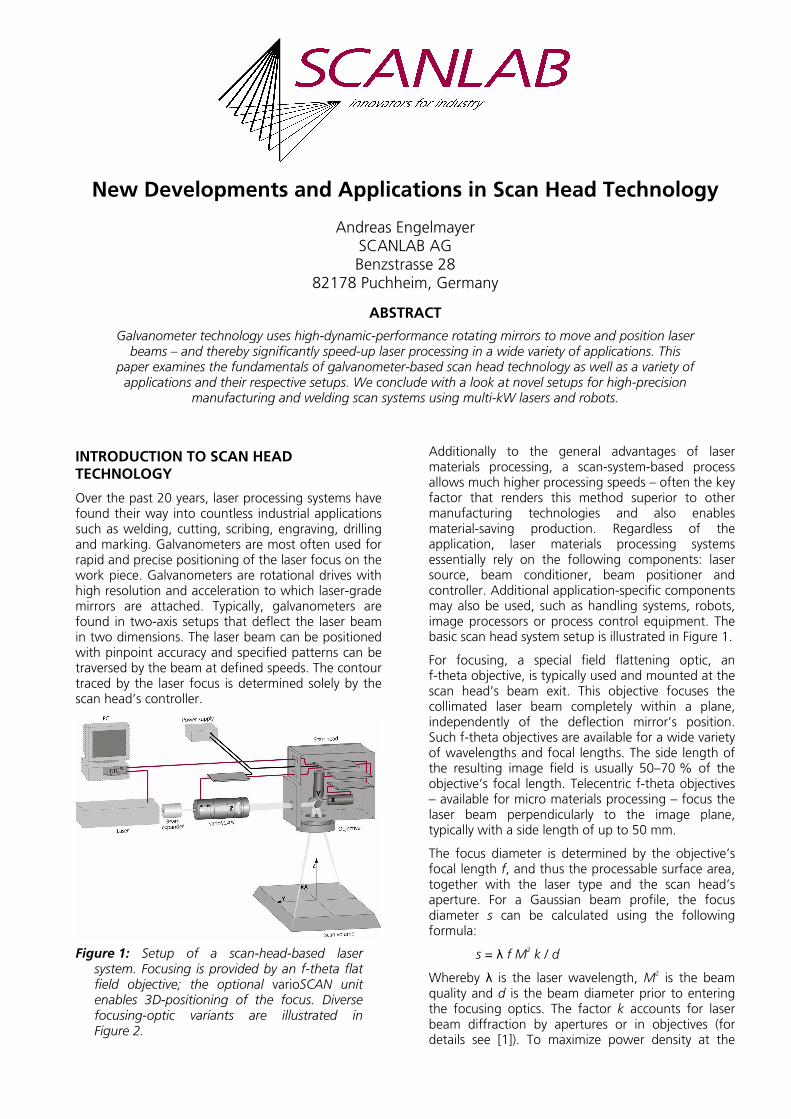
Figure 1: Setup of a scan-head-based laser system. Focusing is provided by an f-theta flat field objective; the optional varioSCAN unit enables 3D-positioning of the focus. Diverse focusing-optic variants are illustrated in Figure 2.
Additionally to the general advantages of laser materials processing, a scan-system-based process allows much higher processing speeds – often the key factor that renders this method superior to other manufacturing technologies and also enables material-saving production. Regardless of the application, laser materials processing systems essentially rely on the following components: laser source, beam conditioner, beam positioner and controller. Additional application-specific components may also be used, such as handling systems, robots, image processors or process control equipment. The basic scan head system setup is illustrated in Figure 1.
For focusing, a special field flattening optic, an f-theta objective, is typically used and mounted at the scan head’s beam exit. This objective focuses the collimated laser beam completely within a plane, independently of the deflection mirror’s position. Such f-theta objectives are available for a wide variety of wavelengths and focal lengths. The side length of the resulting image field is usually 50–70 % of the objective’s focal length. Telecentric f-theta objectives – available for micro materials processing – focus the laser beam perpendicularly to the image plane, typically with a side length of up to 50 mm.
The focus diameter is determined by the objective’s focal length f, and thus the processable surface area, together with the laser type and the scan head’s aperture. For a Gaussian beam profile, the focus diameter s can be calculated using the following formula:
s = λ f M2 k / d
Whereby λ is the laser wavelength, M2 is the beam
quality and d is the beam diameter prior to entering the focusing optics. The factor k accounts for laser beam diffraction by apertures or in objectives (for details see [1]). To maximize power density at the

focus, and thus processing speed, the beam width should be expanded to nearly equal the scan head’s aperture. In this case, k = 1.83. Typical configurations and their achievable spot sizes, together with example applications, are listed in Table 1.
For some applications, rapidly moving lens systems are placed in front of the scanners to focus the laser beam (by adapting the focal length to the distance between the deflection mirror and the laser beam’s destination point on the work piece). Such varioSCAN optics are particularly useful when no appropriate f-theta objectives are available – e.g. for wide beam diameters or large image fields, high laser powers or exotic laser wavelengths. Moreover, the varioSCAN optics enable 3D processing within scan volumes and can be used alone or in conjunction with f-theta objectives. Various focusing setups for laser scanning systems are depicted in Figure 2.
Figure 2: Laser beam focusing via scan systems (from left): pre-focusing lens, f-theta objective, dynamic pre-focusing and combining dynamic pre-focusing with an f-theta objective.
DSP control boards, with on-board memory, function as the hardware interface between the application software, scan head and laser. These boards synchronize laser control with the scanner movements and implement image correction to ensure that text is precisely positioned without pin-cushion distortion and marked at a constant speed along each vector. Third-party software packages are available for many standard laser marking applications (Figure 3).
Figure 3: User-friendly GUI software (© Alase Technologies Inc. and American LaserWare Inc.) provides the interface between the user and the scanner controller.
TYPICAL SCAN HEAD APPLICATIONS
Laser marking is a key application for galvanometer scan technology, with thousands of systems sold annually. Laser-marked text is permanent, has good legibility and requires no consumables. This application is ideal for expiration codes on food packaging, text on credit cards or personal IDs, and many other labeling tasks.
In the automotive industry, laser marking is used for manufacturing day-and-night design components, and for serializing on glass, metal or labels for traceability. Other scan-head-based laser processes, like stereo lithography and laser sintering, are used for rapid prototyping and manufacturing, which enables the creation of new parts or models within only a few days. In these applications, data from a 3D CAD model is sliced into layers a few hundred microns thick, which are then built-up on top of each other in the laser system by processing a UV-curable resin or a metal, sand or plastic-based powder. Plastics welding with diode or Nd: YAG lasers in the 100-W range is utilized, for example, to manufacture car lights or containers for windshield washing fluid. New applications include cutting of inorganic materials, e.g. for manufacturing air-bags or car seats, as well as spot welding of metals via scan systems (described later).
Besides marking and automotive applications, scan systems find use in numerous other applications such as high-precision material processing for the electronics industry (discussed later), medical technology (Lasik eye surgery, OCT), and textile and leather processing (cutting, marking or creating “distressed” effects).
Figure 4: Scan heads are available in various configurations for a range of requirements and applications.

To address the widely differing requirements concerning laser power, precision and processing speeds, numerous scan system configurations are on the market. Figure 4 depicts the relationship between
various applications, their requirements and appropriate scan heads. Table 1 lists the corresponding technical requirements.
Laser Scan Head Aperture
Focal Length
Focus Image Field Scan Speed Application
CO2
10.6 µm M
2 = 1.15
50 W
7 mm 100 mm 330 µm 70 x 70 mm2
800–1100 CPS, 3.5 m/s marking speed
Marking
Nd:YAG 1,064 nm M
2 = 1,3
10 mm 160 mm 45 µm 100 x 100 mm2
500–800 CPS, 2.5 m/s marking speed
Marking
CO2
10.6 µm M
2 = 1.15
1–2 kW
36/33 mm (40 mm at focusing optics)
550 mm 350 µm 0.3 x 0.3 m2
5.0 m/s cutting speed
Cutting
CO2
10.6 µm M
2 = 1.25
5 kW
76/70 mm (80 mm at focusing optics)
1.65 m 600 µm 1 x 1 m2
15 m/s positioning speed
Remote welding
Nd:YAG 1,064 nm M
2 = 5
14 mm 163 mm 120 µm 100 x 100 mm2
140–220 CPS, 0.7 m/s marking speed
Marking, engraving
Nd:YAG 1,064 nm 150 µm fiber NA = 0.22
25 mm 80 mm 220 µm 25 x 25 mm2
170–260 CPS, 0.8 m/s marking speed, 3.5 m/s positioning speed
Micro-welding, spot welding
Nd:YAGx2 532 nm M
2 = 1.3
14 mm 100 mm 10 µm 50 x 50 mm2
220–350 CPS, 1.0 m/s marking speed, 7.0 m/s positioning speed, 1 kHz jumps
Subsurface engraving
Nd:YAGx3 355 nm M
2 = 1.3
10 mm 100 mm 10 µm 50 x 50 mm2
1,5 m/s processing speed
Drilling, structuring
Table 1: Overview of typical scan systems and applications. Photos © Sator Laser GmbH, NWL Laser Technologie GmbH, LasX Industries, Inc., BMW Group, Laservall S.p.A., Vitro Laser GmbH, Trumpf Inc. Laser Technology Center, Potomac Photonics, Inc.

SCAN SYSTEM FOR MICROMACHINING
The trend toward better, smaller, lighter and lower-priced products, e.g. cell phones, is in part made possible by laser-based manufacturing processes. Typical applications include drilling, cutting, structuring and material removal on components such as circuit boards, silicon, ceramics, III-V compounds, ITO coatings, Mylar and Kapton (see Figure 6). The structural dimensions involved generally range from ten to more than a hundred micrometers. The beam sources employed are often UV lasers such as frequency-tripled Nd:YVO4 lasers.
Thanks to their beam-positioning performance, galvanometer-based scan systems, either alone or in conjunction with XY tables, offer numerous advantages:
• High processing speeds
• Optimized processing strategies
• Minimal thermal loading of work pieces through heat transfer
• Ability to process complex geometries
Scan system selection is determined primarily by image field requirements, focus size, processing speed and precision. A typical scan system for micro materials processing is equipped with a 10-mm aperture and designed for a wavelength of 355 nm. Such a scan system, with a telecentric objective of 100 mm focal length, can achieve a focus diameter of less than 10 µm in an image field with 50-mm sides. Obtainable processing speeds are governed by the scan system’s dynamic performance and are typically several hundred millimeters per second for micromachining.
Achievable precision is determined by static and dynamic repeatability as well as controller resolution. Dynamic repeatability – the scan system’s ability to travel a straight line to the target position without oscillation or noise – is described by its wobble, jitter and dither values. Wobble and jitter are mechanical oscillations of the mirror perpendicular or parallel to the scan direction. Dither is imprecision introduced by residual noise of the scanner electronics. This effect is usually only a factor when processing with lasers of short wavelength and good beam quality and therefore plays no role in most conventional applications. For micromachining, specially optimized scan systems are available with tracking accuracy to within just a few micrometers.
Figure 5: Laser micromachining with scan systems. Top: 3D Teflon web for fluidic systems (© Lumera Laser GmbH) and 15-µm HDIs manufactured with “mill-and-fill” technology (© Potomac Photonics, Inc.). Bottom: Kapton processing and micro vias in copper/dielectric (© Photomachining, Inc.).
The achievable static precision of a conventionally calibrated scan system is determined by the sum of its gain, offset and orthogonality errors, nonlinearities and tolerances of the employed optics. With a precisely aligned laser, this is on the order of a few tens of micrometers. To achieve yet higher precision requires more sophisticated scan system calibration (see Figure 6).
Figure 6: Software for precisely calibrating scan systems.
Without correction, scan system drift over eight hours can reach up to 60 µm with the scan system

described above. Drift can be minimized by thermally stabilizing the electronics and motor unit (Figure 7). For even higher precision, scan systems can be equipped with a supplemental high-precision position detector that enables automatic self-calibration to compensate for thermal and long term drift.
Figure 7: Special scan head for micromachining, with optimized low-noise tuning and active water-cooling capabilities for electronics and/or motors.
In addition to the scan system, other components such as the laser and the overall mechanical setup can induce drift. To determine the total drift of a laser system, inspection systems or sensors can be placed in the image field to measure the difference between the actual and target position. The drift can then be corrected via appropriate control values.
The highest level of processing precision requires periodic recalibration, which is a technically demanding and time-intensive process. Such measures, though, often result in long-term accuracy of a few micrometers.
Figure 8: The camera system (bottom) placed in the laser beam path (top) provides the basis for precise beam positioning.
Camera systems through the scan head are primarily employed for ascertaining the exact orientations and geometries of work pieces to be processed and facilitate control of subsequent processing. Figure 9 illustrates the setup. This method requires neither tight component tolerances nor precise positioning and works well with a near-IR or visible laser source. The special optics required for UV processing often prohibit use of a vision system through the scan head.
Figure 9: Fully digital intelliSCAN 10 for highly
demanding applications.
Next-generation scan systems will be equipped with fully digital scanner motor control electronics (Figure 10). Based on a digital servo board with a DSP system for each galvanometer axis, these scan heads feature highly advanced control algorithms and achieve performance far superior to the fastest analog driven systems. Also, the extensive array of signals and information from the scan head bring a multitude of benefits to the system user. Real time monitoring makes advanced diagnostics possible – key galvanometer status parameters such as position, speed, current, and temperature enable advanced remote diagnosis and process documentation. Operational status history provides traceability of process consistency, thereby verifying quality control. Monitoring system operating statistics at the component level offer the opportunity to schedule routine maintenance intervals, avoid unnecessary downtime during critical production periods, and enhance the serviceability of the scan head system. Monitoring of the scanned tracks and speed lets the user optimize both the scan head’s and laser’s parameters for best productivity and quality. Advanced scan head control enables on-the-fly modification of tunings specific to the current scan track, with the objective of maintaining optimal dynamic performance. As a further process enhancement, data from the digital servo can be used to synchronize the laser frequency to the galvanometer dynamics. Future generations of digital

scan heads will enable firmware updates that add new control algorithms and customized parameters – thus ensuring that galvanometer-based laser processing continues to push the technology envelope [2].
SCAN HEADS ON ROBOTS
Mounting a scan head on a robot can be an ideal partnership that unites both systems’ advantages while overcoming their specific weaknesses. Compared to robots, scan heads are very fast and dynamic – scan systems can process even filigree features at high speed or optimize process patterns (e.g. by using many jumps between weld points, which minimizes heat-induced material stress). On the other hand, robot-based systems can process large working areas with a small spot, adjust the angle between the laser beam and work piece, process off-plane and access areas which are not reachable by a scan head due to obstruction of line of sight.
Laser welding typically requires multi-kW lasers and spot sizes in the range of 0.6 mm. Until recently, such requirements could only be achieved by scan systems together with CO
2 lasers. A few of these remote
welding systems are successfully used in automotive manufacturing. Nevertheless, such scan systems have many limitations: The setup is usually static, as CO
2
lasers cannot be fiber-guided and their interaction with many materials in not ideal. The scanning mirrors are quite large and heavy, as they must have large apertures to achieve a sufficiently small spot size and handle the high laser power. Also, the geometry of the parts to be processed is very restricted, as the positions of the scan head and work piece are usually fixed.
Recently introduced disc and fiber lasers offer high beam quality and high power in the near-IR regime. As both lasers can be easily delivered to the scan head via fiber they offer a multi-position solution for scanner welding applications.
Scan heads with apertures of 25 mm to 30 mm are sufficient to handle the high laser power and achieve the required spot in a 150–200-mm field. These scan heads are a fraction of the size of CO
2 remote scan
heads and more closely resemble their counterparts used for marking applications. The first tests with such a setup are described in [3].
To focus the laser beam, an f-theta flat field objective is typically used. A huge selection of such objectives is available for laser marking and at laser powers up to 1 kW. When used with high duty cycles and higher laser powers, these objectives show thermal lensing and can be damaged. For such laser powers, customized fused silica objectives are available. A
typical objective achieving a 0.6 mm spot in a 150–200 mm field has a focal length of around 300–400 mm and a free working distance of around 400–500 mm. Shorter focal lengths are susceptible to contamination of the optics while longer focal lengths make it difficult to weld inside a car body. Long focal lengths usually require large robot movements when processing at a constant angle of incidence on a curved part. If such a scan system is additionally equipped with a special varioSCAN for high laser powers, the focal plane can be shifted by about 50–100 mm as depicted in Figure 1 and Figure 2 (right).
The easiest but less effective way to control a scan head-robot combination is to move robot and scanners alternately. To significantly enhance productivity, the scanner controller has “processing-on-the-fly” capability, which is scanning the laser beam simultaneously with the linear robotic motion. Both setups are already successfully used for different marking, cutting or welding applications.
The highest productivity and flexibility would be achieved with a more integrated solution where the robot can be moved continuously on an arbitrary trajectory and at variable speeds. Such control is a considerable challenge, as the real robot movement will change with the programmed speed. Therefore, the scan system will have to compensate the tolerances of the robot movement, as well as the process pattern, on the fly in 3D. Controlling the scanner requires updating coordinates at a periodicity much shorter than the scanner’s time lag (see Figure 10). Otherwise the scanner jumps between guiding points, resulting in an uneven deposition of
laser energy on the target. For the hurrySCAN 30
scan head, the time lag is in the range of half a millisecond and the update period should be less than 30–50 µs. Typically, a robot system cannot deliver information to the scanner at this rate as its own control is optimized to its much longer time lag.
Figure 10: Command and real position for a vector scan differ by a time lag which is about 0.5 ms for a typical remote welding scan head.

Nevertheless, the robot must act as a master, also controlling the scan head. Therefore the data available from the robot must be further processed though an intelligent real-time scanner controller. Such a controller interpolates between robot coordinates and performs all necessary scanner specific transformations to output coordinates to the scanner at the required update rate.
The current controller boards used in laser scanning are not optimized for such an integrated operation. Position data is currently written from a PC into a buffer on the controller board. There, it is further processed (micro-vectorization, image field correction, etc.) and then output with some delay to scanner and laser. There is no common robot interface currently available that can be developed into a standardized controller.
Even without such an integrated controller, a combination of robot and scan head brings tremendous benefits to the user due to the high dynamic performance, enabling high laser duty cycles, precision and optimized processing strategies, as well as the flexibility, large process area and versatility of a robot process.
CONCLUSION
Laser scanning systems are the ideal laser beam positioning tool in many industrial applications. They enable the throughputs necessary for competitive manufacturing and material-saving – thanks to very high scanning and positioning speeds. Combining scan heads with other handling systems, such as robots, will offer benefits not available through the use of scan systems alone.
REFERENCES / LITERATURE
[1] Melles Griot Catalog, “Optics Guide”, chapter: “Introduction to Gaussian Beam Optics”
[2] D. Sabo, D. Brunner and A. Engelmayer: “Advantages of Digital Servo Amplifiers for Control of a Galvanometer Based Optical Scanning System”, SPIE Optics & Photonics 2005 Proceedings
[3] W. Penn, “Precision Cutting and Welding with Fiber Laser”, ALAC 2004 Proceedings
[4] D. Sabo & A. Engelmayer: Laser Beam Positioning Using Galvanometer Technology, ICALEO 2004 Short Course
[5] A. Engelmayer: “Galvanometer Scanning Speeds Laser Processing”, Industrial Laser Solutions, February 2005
[6] A. Engelmayer: „Mikrobearbeitung mit Scan-Systemen“, Europäischer Lasermarkt 2005
[7] R. Schaeffer: “Seeing the Light – Galvo Based Laser Scanning Systems”, CircuiTree (Sep. 2003)
[8] B. Gu, “Laser-Micro-Machining in Semiconductor and Electronics Industries”, ALAC 2004 Proceedings
[9] M. Li and H. Endert, “Microfabrication Using Diode-Pumped Solid-State Lasers”, ALAC 2004 Proceedings