Embed Size (px)
Citation preview

DSNGO
rig
inal
lan
gu
age:
En
glis
h
Man
usc
rip
t re
ceiv
ed: 2
/10/
98.
New DVB standard for DSNG– and contribution satellite links
A. Morello and V. MignoneRAI Research Centre
In July 1997, the Technical Module of the DVB Project set up an Ad-hoc Group on Digital Satellite News Gathering (DSNG) under the chairmanship of the RAI. Its tasks were: (i) to define the specification of the modulation/channel coding for DSNG and other contribution applications by satellite, (ii) to define the specification for the auxiliary co-ordination channels and (iii) to co-operate with other DVB groups in order to define the user guidelines for source coding, Service Information (SI) and scrambling for Conditional Access (CA).
A flexible DVB-DSNG system [1] has now been defined and is described here. Mainly based on the DVB system for satellite broadcasting (DVB-S), it offers a range of different picture-quality levels at various bit-rates by using the MPEG-2 MP@ML and 422P@ML algorithms. The specification for the auxiliary co-ordination channels [2] was finalized by the group in Autumn 1998 and the approval procedure is still in progress within DVB and ETSI. It is not described in this article for reasons of conciseness.
1. Introduction
Today’s broadcasting is dominated by increasing competition and, consequently, the real-timeacquisition of news material (e.g. sports events, interviews, concerts, calamities) – in both thedomestic and the international environments – is a major factor in the search for audience rat-ings. In this context, light-weight satellite news-gathering (SNG) transmit terminals – with 90to 150 cm antennas – offer a cost-effective solution to establishing rapid connections betweenoutside broadcast (OB) vans and TV studios without requiring local access to the fixed telecomnetwork.
In the case of PAL, SECAM and NTSC, analogue SNG systems using frequency modulation (FM)are currently operated in both the C and Ku bands. In Europe, the TV satellite contribution
EBU Technical Review - Autumn 1998 1A. Morello and V. Mignone
DSNG
links are commonly in the Ku band (using the 14 - 14.5 GHz band for the up-link and the10.71 - 12.75 GHz band for the down-link). Although there have been progressive improve-ments in antenna and amplifier design, and the original bulky and heavy analogue SNGequipment has been reduced in weight and size, portability is still very much a key issuerequiring adequate solutions in the analogue world.
The required EIRP of an up-link of course depends on the footprint of the satellite which willreceive its signals. The EIRP of analogue up-links are typically 69 - 75 dBW, depending on thesize of the antenna and the high-power amplifier (HPA) in use. Antenna sizes vary from 1.5 to2.4 m and the HPA powers range from 300 to 600 W.
The commercial introduction of small digital equipment in the domains of video/sound com-pression, advanced error protection and modulation has recently enabled the development ofoperational digital SNG (DSNG) systems. These new systems have a number of advantagesover analogue systems, including:
� miniaturization of the up-link terminal;
� lower required EIRPs;
� more efficient use of the frequency spectrum.
Digital SNG systems permit multiple signals to be transmitted simultaneously through thesatellite transponders, significantly increasing the flexibility of the transponder access, andreducing the cost per channel. The inherent flexibility of DSNG systems allows us to fulfil thedifferent quality requirements of news, sports events and entertainment by operating thevideo/audio compression algorithm at the most appropriate bit-rate. Moreover, the rugged-ness of a digital system against noise and interference enables constant picture and soundquality to be obtained at the receiving site, down to a certain threshold signal level.
Before the development of the DVB-DSNG standard, digital contribution links by satellite wereoften based on the ETSI 300 174 standard for video compression [3]. This system, which wasdesigned for contribution applications at 34 and 45 Mbit/s, also became available in proprie-tary scaled versions at 17 Mbit/s and 8.5 Mbit/s which were more suitable for pure DSNGapplications. The modulation and channel coding were usually based on the IDR specifica-tion, using QPSK modulation and convolutional coding.
In 1993-94, the DVB Project developed the specification of a digital multi-programme tele-vision system for satellite broadcasting (DVB-S), under the direct responsibility of the RAIResearch Centre [4][5]. With the world-wide success of this system, it became more and moreclear that it could be suitable also for DSNG applications, with significant advantages in cost,performance and flexibility over the previous systems [6]. In the summer of 1997, the DVBProject decided to start the development of a new specification for DSNG, based on the DVB-Ssystem [4] but with a number of new features designed to cover the commercial and opera-tional requirements of contribution applications. This project was also the responsibility ofthe RAI.
The DVB-DSNG system [1] is transparent to any signal in the MPEG-2 Transport Stream formatand can transport video signals encoded in either the MP@ML format, or in the 422P@ML for-mat when higher quality and enhanced editing facilities are required. Other MPEG-2 profilesand levels may be transported as well, e.g. 422P@HL which is suitable for HDTV contributionlinks.
The DVB-DSNG system is based on QPSK modulation and convolutional coding, which wereoriginally developed to provide DTH television services via satellite in the MCPC mode, but
EBU Technical Review - Autumn 1998 2A. Morello and V. Mignone

DSNG
which are also suitable for DSNG and contribution applications in the SCPC mode. Neverthe-less, two optional transmission modes have been added to the DVB-DSNG system: trellis-coded 8PSK and 16QAM. These offer higher spectrum efficiency in those applications whichare less affected by power limitations (e.g. vehicle-based DSNG up-links). The main feature ofthe DVB-DSNG system is thus the flexibility of its modulation and channel-coding schemeswhich – on a case by case basis – allow the most appropriate modulation scheme, symbol rateand coding rate to be selected in order to optimize the satellite link performance (i.e. the spec-tral occupancy within the satellite transponder and the power requirements).
Specific technical solutions have been defined by DVB for the transport of MPEG signals onterrestrial telecom networks such as PDH and SDH, by mapping the Transport Stream packetsinto ATM cells. These adapters can be used to connect the DSNG receiving stations to the TVstudios.
2. Basic user requirements
The technical characteristics of DVB systems are largely market-driven. Based on an analysisof the market needs, the DVB Commercial Module (CM) produces Commercial Users’ Require-ments for input to the DVB Technical Module (TM) which is responsible for developing therequired specifications.
In accordance with the ITU, the CM has adopted the following definition of SNG (ITU-R Rec.SNG.770-1): “Temporary and occasional transmissions with short notice of television or sound forbroadcasting purposes, using highly portable or transportable up-link earth stations operating in theframework of the Fixed-Satellite Service (FSS)”.
A DSNG “terminal” or “up-link” is a portable (or transportable) earthstation which can bemoved to a remote location in order to transmit back the video programme with its associatedsound, or sound-only programme signals, either “off-tape” or “live”. It can either be pack-aged in “fly-away” form (i.e. in flight cases suitable for air transportation) or integrated into avehicle.
DSNG up-link terminals should be highly reliable and have reduced size and weight, whilethe receiving station should be dimensioned appropriately to ensure the required link availa-bility. Therefore the transmission format should provide both high ruggedness against noiseand interference and the best exploitation of satellite capacity.
High intervention promptness and low set-up complexity are required. In particular, “theequipment should be capable of being set up and operated by a crew of no more than two people within areasonably short time (for example, one hour)”. Interoperability between different pieces of equip-ment is another key feature of DSNG, especially in an international programme-exchangeenvironment. In particular, the CM has identified within the complex DVB/MPEG SI/PSItables a possible source of problems for DSNG, affecting equipment interoperability and rapidlink set-up.
By nature, DSNG links are contribution links, the quality objectives of which are defined byITU-R Rec. BT.1121: “There is no need to define lower quality objectives, if it is understood that, due tocircumstances, possible relaxations are to be accepted by the user. For DSNG links, the typical bit-rateused by fly-away and small transportable terminals are about 8 Mbit/s, using MPEG-2 MP@ML. How-ever for transportable stations”, when higher quality and enhanced editing facilities are
EBU Technical Review - Autumn 1998 3A. Morello and V. Mignone

DSNG
required, “use of MPEG-2 422P@ML should be supported. … In this case, bit-rates should be higherthan 8 Mbit/s and lower than 34 Mbit/s”.
As regards multiplexing, although DSNG transmissions usually transport a single TV pro-gramme and its associated sound signals (SCPC), “advantage should be taken of the flexibility ofthe MPEG-DVB multiplex” to convey multiple programmes (MCPC).
The processing delays of digital compression systems may be very high (even exceeding onesecond), especially with today’s sophisticated coding algorithms which allow high bit-ratecompression ratios. Short video-coding delays are important characteristics for those applica-tions where the DSNG transmission is mixed together with a live programme, since longdelays would prevent dialogues between journalists in the studio and in the field.
Optionally, DSNG equipment should be capable of providing two or more duplex co-ordina-tion (communication) circuits by satellite, whenever possible in the same transponder as themain DSNG signal. These channels should be available prior to, during and after the DSNGtransmission in order to connect the DSNG operator, the satellite operator and the broadcaster.This equipment may also provide for data transmission and faxes. The specification [2] wasfinalized within the DSNG group in Autumn 1998 and the approval procedure by DVB andETSI is now in progress.
Regarding the equipment cost, the CM pointed out that “the total cost of the system and its opera-tion should be considered, and not just the receiver cost. A non-negligible part of the overall cost of anSNG transmission lies in the requirements for satellite capacity. Modulation techniques, additional toQPSK, such as 8PSK and 16QAM, should be investigated to optimize the efficient use of satellite capac-ity”.
3. Source coding and multiplexing
The success of the DVB standards is also due to the adoption on all media (e.g. satellite, CATV,terrestrial VHF/UHF and MMDS networks) of a “common solution” for video/audio codingand digital multiplexing, making possible the mass production of VLSI chips for consumerIRDs.
3.1. Video coding
The MPEG-2 MP@ML format may be used as the baseline solution for picture coding in DSNGapplications. It allows high flexibility, being able to operate with variable bit-rates from 1.5 to15 Mbit/s.
MPEG-2 codecs are based on Hybrid DPCM/DCT algorithms with motion compensation, oper-ating on I-frames (intra), P-frames (predicted) and B-frames (bi-directional prediction). Itshould be noted that MP@ML is a 4:2:0 system which was designed for distribution rather thancontribution. At bit-rates of 6 Mbit/s and 9 Mbit/s, it allows a subjective quality for currentprogramme material that, respectively, is equivalent to PAL and 4:2:2 pictures. Lower bit-ratesmay be acceptable for specific applications (e.g. films, news, educational), where power andbandwidth limitations are dominant over the picture quality requirements.
EBU Technical Review - Autumn 1998 4A. Morello and V. Mignone

DSNG
In 1995, MPEG-2 defined a picture coding “profile” called 422P@ML to fulfil the requirementsof the production environment. It offers a number of additional features compared with theMP@ML format such as (i) the coding rate can be increased up to 50 Mbit/s and (ii) the chromacomponents maintain the same 4:2:2 format as the uncompressed studio format. This allows:higher picture quality; better chroma resolution; post-processing after co-decoding; and shortGoPs to improve the editability in compressed form and to shorten the coding delay. Subjec-tive quality tests (non-expert viewers, 4H distance) have been carried out by the RAI ResearchCentre and other organizations [7] on computer-simulated 422P@ML sequences, with singleand multiple generations (eight co-decoding processes) and colour matte post-processing.
Different GoP structures have been analyzed:
� a purely intra-frame configuration which allows one-frame editing precision at theexpense of low compression efficiency, running at 50 and 30 Mbit/s (indicated as I@50and I@30);
� one I-frame and one B-frame, which allows a good compromise between editing and com-pression ratio, running at 30 and 20 Mbit/s (indicated as IB@30 and IB@20);
� the traditional MP@ML GoP, with 15 IBBP frames, running at 20 Mbit/s (indicated asIBBP@20).
With reference to the double-stimulus continuous quality 100-grade scale, the following qual-ity levels are arbitrarily defined in MPEG documents:
� “transparent” (0 to 12.5);
� “nearly-transparent” (12.5 to 20);
� “good” (20 to 40).
The subjective test results indicate that after eight co-decoding processes, the I@50 (includingchromakey) and IB@30 coding structures fulfil the “transparency” ratings and, after a singleco-decoding process, chromakey can be performed “transparently” on I@30 and IB@20. Inaddition, all the coding structures gave ratings which matched well the “nearly transparent”quality, apart from a few tests which moderately exceeded the 20% target.
Summarizing, to fulfil the wide range of picture-quality levels and bit-rates required by DSNGand other contribution applications, MP@ML at bit-rates from 1.5 to 15 Mbit/s can cover theapplications where no (or very limited) post-processing is performed in the studio before re-broadcasting. The 422P@ML format at bit-rates from 15 to 30 Mbit/s can, on the other hand,cover high-quality applications where post-production and cascaded co-decoding arerequired.
In any case, it must be kept in mind that the switching and editing of MPEG-2 transportstreams in the studio, without decoding, can be very difficult because of the problems relatedto clock handling and buffer overflow control. Therefore, in many cases the DSNG contribu-tions (independently of the adopted compression scheme) must be re-converted into 4:2:2 for-mat in the studio, edited and then re-encoded for final broadcasting (in MP@ML format).
3.2. Audio coding
All the DVB systems – in line with the trend toward international standardization – haveadopted the MPEG Layer II audio coding method which allows a wide range of bit-rates (e.g.from 64 to 256 kbit/s) in order to satisfy the various service requirements. Bit-rates as low as
EBU Technical Review - Autumn 1998 5A. Morello and V. Mignone

DSNG
64 kbit/s may be applicable for some DSNG applications with mono channels. The optionaluse of linear (uncompressed) audio coding is also under evaluation by DVB for contributionapplications that require maximum audio quality.
4. Transport Multiplexing and ServiceInformation (SI)
The DVB-S system adopts a common framing structure, based on the MPEG-2 transport multi-plex, with fixed length packets of 188 bytes, comprising one sync byte, three header bytes and184 useful bytes. This structure allows easy interworking between broadcast channels and tel-ecom networks using ATM protocols.
The MPEG-2 multiplex is very flexible for merging a variety of video, sound and data servicesin the transport stream, as well as additional information (e.g. Service Information, Condi-tional Access). Therefore it allows SCPC as well as MCPC services.
The DVB-MPEG Service Information tables defined for broadcasting applications describe indetail the multiplex configuration and the programme content, and allow the user to accesseasily a wide programme offer through the Electronic Programme Guide (EPG). Annex D ofthe DSNG specification deals with a simplified Service Information mechanism based on fewfixed tables. It avoids the need to compile SI information in the field, thereby accelerating thelink set-up time and simplifying any interoperability problems. Up-link station identificationis also provided, for emergency interference situations.
Of the MPEG2-defined SI tables that have been introduced to describe the multiplex configura-tion and the programme content in broadcasting services, only the Programme AssociatedTable (PAT), the Programme Map Table (PMT) and the Transport Stream Descriptor Table(TSDT) are kept in the DSNG specification as mandatory. These tables may be fixed for a DSNGstation. In the TSDT table, a descriptor indicates that the Transport Stream is for ContributionApplications (not for the general public). Furthermore, for DSNG transmissions, anotherdescriptor is inserted to allow fast identification of the up-link station in cases of transmissionproblems (e.g. access to the wrong transponder or satellite). These SI structures may preventcompatibility with consumer IRDs and, therefore, if this compatibility is required by the oper-ator, all the SI tables must be compiled according to the DVB-SI specification.
Since no forward error correction (FEC) protects the TS packet headers, a rugged “channeladapter” is required to provide an error-free datastream to the demultiplexer input, asdescribed in the following section.
5. Channel coding and modulation
The transmission performance of a typical DSNG system depends on the various componentsincluded in the satellite chain:
� the transmit earthstation;
� the space segment (up-links and down-links);
� the satellite transponder (IMUX, OMUX filters, TWTA);
EBU Technical Review - Autumn 1998 6A. Morello and V. Mignone

DSNG
� the receive earthstation.
The satellite channel is basically non-linear, wide-band and power limited. The main signalimpairments are introduced by noise, rain attenuation and interference on the space segment,and eventually by incorrect alignment of the transmit and receive stations and equipment.The non-linearity (amplitude and phase distortions) of the on-board TWTA is responsible forimpairments to the overall system performance.
In the case of digital DTH services, a single QPSK carrier is transmitted in the transponder and,to achieve the maximum power efficiency, the satellite TWTA is usually operated close to satu-ration. The effects of TWTA non-linearity are waveform distortion and side-lobe regenerationof the power spectrum. In these applications, due to the reduced dimensions of the receivingantennas, the service availability is mainly limited by the down-link noise.
For DSNG and contribution applications, the usual method of accessing the transponders isFDM where part of the transponder bandwidth (frequency slot) is allocated to each signal, inSCPC mode. In order to reduce the effect of intermodulation noise introduced on adjacent car-riers occupying the same transponder, the TWTA must be operated significantly below the sat-uration point. The linearity requirements are raised also by the fact that the aggregated FDMsignal is no longer characterized by a constant envelope, even if each individual signal has aquasi-constant envelope (e.g. QPSK or 8PSK). The higher the spectrum efficiency of the modu-lation/coding scheme, the more stringent are the linearity requirements, because of the reduc-tion of the system ruggedness against intermodulation interference from the adjacent signals.
In FDM transmissions, the down-link level of any one signal does not noticeably change as afunction of the total transponder load, making it straightforward to set and monitor thedown-link EIRP. This more linear type of operation also provides more protection against sin-gle up-link drive fluctuations.
Efficient and reliable transmission of digital television signals over satellite channels isfocused on the design of the “channel adapter”, which performs the adaptation of the multi-plexed video/audio/data bitstream to the physical channel, by adopting powerful channelcoding and modulation techniques. In the definition of the DSNG system, the design targethas been the minimization of the effects of the various channel impairments, such as additivenoise, interference from analogue and digital signals, and linear and non-linear distortion.The specified system offers many transmission modes (inner coding and modulations), givingdifferent trade-offs between power and spectrum efficiency. QPSK modulation has beenadopted (and optionally the 8PSK and 16QAM modulation schemes) and the concatenation ofconvolutional and Reed-Solomon codes is introduced.
The QPSK mode is compliant with the DVB-S system defined in [4] while for 8PSK and 16QAM,“pragmatic” trellis coding [8] has been applied, optimizing the error protection of the sameconvolutional code. The convolutional code is able to be configured flexibly, allowing theoptimization of the system performance for a given satellite transponder bandwidth. TheQPSK and 8PSK modes, thanks to their quasi-constant envelopes, are suitable for operationwith saturated satellite power amplifiers, in a single-carrier-per-transponder configuration.16QAM (as well as QPSK and 8PSK) is appropriate for operation in quasi-linear satellite chan-nels, in multi-carrier FDM-type applications, where better spectrum efficiency is attained.
EBU Technical Review - Autumn 1998 7A. Morello and V. Mignone

DSNG
Fig. 1 gives a functional blockdiagram of the DVB-DSNGtransmission system. Theinput stream, organized in188-byte packets followingthe MPEG-2 transport multi-plexer [9], is randomized bitby bit through a scramblingPRBS, in order to comply withthe Radio Regulations inter-ference requirements (thetransmitted signal must havea regular spectrum shape),and also to facilitate clockrecovery in the receiver. Thenthe shortened R-S code(204,188, t = 8) – derived from the original R-S (255, 239, t = 8) code – is applied to each rand-omized transport packet.
Since, on the receiver side, the residual errors at the output of the Viterbi decoder are not sta-tistically independent, but are grouped in a burst which may overload the R-S code correctioncapability, the error distribution is randomized through a convolutional interleaver withdepth I equal to 12 bytes applied to the error-protected packets. The interleaved packets arethen passed to the convolutional encoder, which is based on a rate 1/2 mother convolutionalcode with constraint length equal to 7 (64 trellis states), and which allows the selection of themost appropriate level of error correction for a given service or data-rate.
Punctured convolutional cod-ing is associated with QPSKmodulation (according to theDVB-S system specification[4]) with the possibility ofoperating at five possiblerates: 1/2, 2/3, 3/4, 5/6, 7/8.Pragmatic Trellis CodedModulation (TCM) [8] on theother hand is associated with8PSK and 16QAM. The oper-ating principle of the prag-matic trellis encoder is shownin Fig. 2.
The byte-parallel stream at the output of the convolutional interleaver is conveyed to a paral-lel-to-parallel (P/P) converter which splits the input bits into two branches, depending on theselected modulation / inner coding mode. It has been designed to reduce, on average, thebyte error-ratio at the input of the R-S decoder (high concentration of bit-errors in bytes) and,therefore, to reduce the bit error ratio (BER) after the R-S decoder.
In the non-encoded branch, the symbol sequencer generates a sequence of signals U, each to betransmitted in a modulated symbol. These bits generate parallel transitions in the trellis code,and are only protected by a large Euclidean distance in the signal space. In the encoded branch,the signals first pass through a parallel-to-serial (P/S) converter for subsequent processing bythe punctured convolutional encoder. These bits generate, through the symbol sequencer, asequence of signals C, each to be transmitted in a modulated symbol.
MUXadaptation& energydispersal
Outercoder
Interleaver(I = 12)
Innercoder
Bit-mappinginto
constellation
Basebandshaping
Quadraturemodulator
Satellite Channel Adaptor
R-S(204,188)Convol-utional
QPSK or8PSK / 16QAM(both optional) α = 0.35*
* α = 0.25 for 8PSK and 16QAM (additional and optional)To the RF
satellite channelMPEG-2 source codingand multiplexing
According to EN 300 421 According to EN 300 421 for QPSK
Figure 1Functional block diagram of the DVB-DSNG system.
P/PP/S
Convolutionalencoder
Puncturing
Bit-mappinginto
constellation
Symbolsequencer
over Dsymbols
P0
P7
I
Q
Byt
es f
rom
inte
rlea
ver
P1
. .
.
Non-encoded branch
Encoded branch Rate k/nconvolutional code
1 or 2 coded bitsper symbol
U
C
I = In-phase signalQ = Quadrature signal
Figure 2Principle of the inner trellis coder.
EBU Technical Review - Autumn 1998 8A. Morello and V. Mignone

DSNG
The 8PSK 5/6 and 8/9 schemes are characterized by one coded bit per symbol (referred to as1CBPS), while the 8PSK 2/3 and 16QAM 3/4 and 7/8 schemes have two coded bits per symbol(2CBPS). The optimum bit-mapping into constellations are different for 1CBPS and 2CBPS. Theselection of the trellis coding schemes, from a number of different proposals, was based onaccurate computer simulations carried out by the RAI Research Centre.
The selected schemes were the ones which offer the best performance on a linear channelaffected by Additive White Gaussian Noise (AWGN). With comparable performance in mind,the 1CBPS schemes are preferred since they require a lower processing speed in the TCMViterbi decoder, compared with 2CBPS schemes, and therefore they allow the implementationof higher-speed modems (for high-quality contribution applications or MCPC transmissions).
Finally, baseband shaping and quadrature modulation are applied to the signal. Square-rootraised-cosine base-band shaping, with a roll-off factor of α = 0.35, is considered for all constel-lations, as in the DVB-S system [4]. An additional roll-off factor α = 0.25 may be used for the8PSK and 16QAM modulation schemes, in order to increase the spectrum efficiency within thetransponder bandwidth. This choice was based on extensive computer simulations, includingsatellite TWTA effects, carried out by the RAI.
6. Performance on the AWGN channel
Sensitivity to transmission noise is expressed, for the various rates of the convolutional code,by the Eb/N0 ratio required to achieve a target residual BER. Eb is the energy per useful bit andN0 is the spectral density of the AWGN. The DVB-DSNG system has been designed to providea QEF quality target, i.e. approximately less than one incorrect error event per transmissionhour at the input of the MPEG-2 demultiplexer. This target, achievable by interleaving and byR-S error correction, corresponds to a BER of about 2 x 10⁻⁴ at the output of the TCM Viterbidecoder and to a byte error ratio of between 7 x 10⁻⁴ and 2 x 10⁻³ depending on the codingscheme.
It should be noted that these evaluations take into account stationary noise only, and idealdemodulation. Furthermore, the effects of phase noise and carrier-recovery instabilities mightgenerate bursts of uncorrectable errors, separated by large time intervals. DVB-DSNG codingschemes are not rotationally invariant (i) because, in the majority of cases, pragmatic schemeswere not available and (ii) in order to optimize the BER performance. Therefore, care shouldbe taken in the design of the frequency converters and the carrier-recovery systems, in orderto avoid “cycle skipping” and “phase snaps” which may produce service interruptions. Thesegoals may be achieved easily in professional front-ends
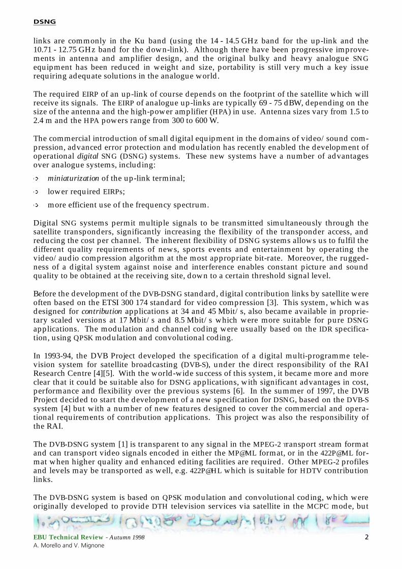
Table 1 gives the IF Loop system performance requirements for the different modes, in terms ofthe required Eb/N0 to provide BER = 2 x 10⁻⁴ (Quasi Error Free quality target). The figures forEb/N0 are with reference to the useful bit-rate Ru (188-byte format, before R-S coding), andtake into account the factor 10 Log 188/204 ≅ 0.36 dB due to the R-S outer code and themodem implementation margins. For QPSK, the figures are derived from [4]. For 8PSK and16QAM, modem implementation margins which increase with the spectrum efficiency areadopted, to cope with the larger sensitivity associated with these schemes.
EBU Technical Review - Autumn 1998 9A. Morello and V. Mignone
DSNG
The ruggedness against noise ofdigital TV (QPSK-3/4) and ana-logue PAL/FM on a satellitechannel are shown in Fig. 3.The quality impairment isexpressed in terms of the C/Nratio, assuming as reference ananalogue receiver bandwidthBRX of 36 MHz, which is typicalof satellite FM/TV transmis-sions with 25 MHz/V fre-quency deviation. To perform afair comparison, the digital sys-tem is operated in single-signal-per-transponder configuration, and the C/N ratio is measured in the same bandwidth BRX of36 MHz as the analogue signal (about 1 dB additional degradation on the transponder shouldbe considered):
C/N (dB) = Eb/N0 (dB) + 10 Log (Ru/ BRX)
From Fig. 3, it can be seen that a DSNG signal at 17 Mbit/s, providing near-contribution qual-ity, would require about 3 dB C/N (in 36 MHz) to operate quasi-error-free compared with the12 - 13 dB required by analogue FM/PAL for an acceptable picture quality. If the transmissionrate is reduced to 8.5 Mbit/s, which is suitable for DSNG applications with PAL quality, therequired C/N ratio would approach 0 dB.
Thanks to this remarkable performance, the digital solution is capable of delivering the pic-ture and sound quality of the “compressed” source, provided that adequate margin againstrain attenuation is allowed for in the link budget design to ensure that the system operatesabove the service continuity threshold.
Table 1IF-Loop performance of the DVB-DSNG system.
ModulationInner code
rateSpectral
efficiency(bits/symbol)
Modemimplementation
margin [dB]
Required Eb/N0 [dB]
for BER = 2x10⁻⁴ before R-S
QPSK
1/2 0.92 0.8 4.5
2/3 1.23 0.8 5.0
3/4 1.38 0.8 5.5
5/6 1.53 0.8 6.0
7/8 1.61 0.8 6.4
8PSK(optional)
2/3 1.84 1.0 6.9
5/6 2.30 1.4 8.9
8/9 2.46 1.5 9.4
16QAM(optional)
3/4 2.76 1.5 9.0
7/8 3.22 2.1 10.7
Imperceptible 5
3
4
1
2
Perceptiblebut not annoying
Slightly annoying
Annoying
Very Annoying
ITU
-R im
pai
rmen
t sc
ale
-1 10 2 3 4 5 6 7 8 9 10 11 12
C/N (dB) in 36 MHz
8.5 Mbit/s
17 Mbit/s
34 Mbit/sPAL FM
(25 MHz/V)
Figure 3Picture impairment vs. C/N: digital TV (QPSK-3/4) and ana-logue FM/TV on a satellite channel.
EBU Technical Review - Autumn 1998 10A. Morello and V. Mignone

DSNG
7. Examples of the system in use
One of the main features of the DVB-DSNG system is its flexibility. It allows, on a case-by-casebasis, the selection of the modulation scheme, the symbol rate and the coding rate in order tooptimize the satellite link performance (i.e. the spectral occupancy of the satellite transponderand the power requirements). On the other hand, in order to achieve rapid interoperabilityand link set-up in emergency situations, the DSNG specification mandates that at least one“user-definable” set-up is available in DSNG equipment. This set-up includes the video/audio coding parameters, the modulation scheme and the symbol rate.
Although DSNG applications usually exploit the satellite bandwidth in the FDM configura-tion, the DSNG system is suitable also for single-carrier-per-transponder transmissions. In thistype of configuration, the transmission symbol rate RS can be matched to the given trans-ponder bandwidth BW (at –3 dB), to achieve the maximum transmission capacity compatiblewith the acceptable signal degradation due to transponder bandwidth limitations. To takeinto account possible thermal and ageing instabilities, reference can be made to the frequencyresponse mask of the transponder.
In multi-carrier FDM configurations, RS can be matched to the frequency slot BS allocated tothe service by the frequency plan, in order to optimize the transmission capacity while keep-ing the mutual interference between adjacent carriers at an acceptable level.
Fig. 4 gives examples of themaximum useful bit-ratecapacity Ru achievable by thesystem, versus the allocatedbandwidths BW or BS. Ru isthe useful bit-rate (188-byteformat) after MPEG-2 MUXwhile RS (symbol rate) corre-sponds to the –3 dB band-width of the modulatedsignal. RS(1 + α) correspondsto the theoretical total signalbandwidth after the modula-tor. The figures for very lowand very high bit-rates may beirrelevant for specific applica-tions. In these examples theadopted BW/ RS or BS/ RSratios are η= 1 + α = 1.35,where α is the roll-off factor ofthe modulation. This choiceallows us to obtain a negligible Eb/N0 degradation due to transponder bandwidth limitationsand adjacent channel interference on a linear channel. Higher bit-rates can be achieved withthe narrow roll-off factor α = 0.25 (optional for 8PSK and 16QAM) and BW/ RS or BS/ RS equalto:
η= 1 + α = 1.25
BW/ RS or BS/ RS ratios which are different from 1 + α may be adopted for different servicerequirements. The adoption of figures significantly lower than 1 + α (e.g. η= 1.21 associated
1/2 2/3 3/4 5/6 7/8 2/3 5/6 8/9 3/4 7/8
5.1
10.7
9.2
8.17.6
6.15.3
4.64.0
3.0
40.9
86.0
73.7
65.561.4
49.143.0
36.832.7
24.5
43.0
36.8
32.730.7
24.5
20.4
16.318.4
12.2
QPSK 8PSK 16QAM
BW
= 4
.5
BW
= 9
10.2
21.5
18.4
16.315.3
12.210.7
9.28.1
6.1
21.5
RuRuRuRu
BW
= 1
8
BW
= 3
6
Figure 4Bit-rate capacity vs. available bandwidth.
EBU Technical Review - Autumn 1998 11A. Morello and V. Mignone

DSNG
with α = 0.35), in order to improve the spectrum exploitation, should be carefully studied on acase-by-case basis, since severe performance degradations may arise due to bandwidth limita-tions and/or adjacent channel interference, especially with 8PSK and 16QAM modulations andhigh coding rates (e.g. 5/6 or 7/8).
Table 2 considers possible examples of the system used in the single-carrier-per-transponderconfiguration. Different modulation and inner code rates are given with the relevant bit-rates.According to typical practical applications, a BW/ RS ratio equal to 1.31 is considered, offeringa slightly better spectrum efficiency than the examples of Fig. 4 for the same modulation/cod-ing schemes. The 36 MHz transponder bandwidth considered here is wide enough to allowhigh-quality 422P@ML SCPC transmissions, as well as MP@ML and 422P@ML MCPC transmis-sions.
Quasi-constant envelope modulations, such as QPSK and 8PSK, are power efficient in a single-carrier-per-transponder configuration, since they can operate on transponders driven near tosaturation. Conversely, 16QAM is not power efficient since it can only operate on quasi-lineartransponders, i.e. with large OBOs. (In the Appendix to this article, Fig. A7 shows the Eb/N0degradation versus the transponder input back-off for three modulation and channel codingschemes in a single-carrier-per-transponder configuration.) The use of the narrow roll-offα = 0.25 with 8PSK can produce a larger non-linear degradation in a satellite system.
Analogously, Table 3 considers possible examples of the system used in the multi-carrier FDMconfiguration and in SCPC mode. Different modulation/coding modes are given with the rel-evant bit-rates. The Eb/N0 figures refer to the IF loop specification for QEF operation. Theoverall linear, non-linear and interference degradations of the satellite should be evaluated ona case-by-case basis; typical figures are of the order of 0.5 to 1.5 dB.
Link budget evaluations have been carried out to estimate the earthstation characteristicsrequired to achieve a suitable service continuity target (i.e. 99.9% or 99.6% of the average year)
Table 2Examples of System configurations by satellite: single-carrier-per-transponder.
SatelliteBW
(at –3 dB)
Systemmode
SymbolRate RS
[Mbaud]
Bit-rate Ru
(after MUX)[Mbit/s]
Eb/N0
(specification)[dB]
36 QPSK 3/4 27.500 38.015 5.5
36 8PSK 2/3 27.500 50.686 6.9
Table 3Examples of system configurations by satellite: multi-carrier FDM transmissions, SCPC mode.
SatelliteBW
[MHz]
SlotBS
[MHz]
Numberof Slotsin BW
VideoCoding
Systemmode
SymbolRate
[Mbaud]
BS/RS
[Hz/Baud]Bit-rate
Ru
[Mbit/s]
Eb/N0 [dB]
(specification)
36 9 4 MP@ML QPSK 3/4 6.1113 1.47 8.4480 5.5
36 18 2 422P@ML QPSK 7/8 13.3332 1.35 21.5030 6.4
36 12 3 422P@ML 8PSK 5/6 9.3332 1.28 21.5030 8.9
36 9 4 422P@ML 16QAM 7/8 6.6666 1.35 21.5030 10.7
EBU Technical Review - Autumn 1998 12A. Morello and V. Mignone

DSNG
in Italy, on a typical Ku-band satellite with Europe-wide up-link and down-link coverage.Two Italian up-link locations were chosen to represent (i) a typical case (Palermo, ITU climaticzone K) and (ii) a worst case (Turin, ITU climatic zone L); the chosen reception location wasRome (climatic zone K).
To allow a fair comparison of the results, the link budgets were optimized at each location,although it is clear that operation in Italy would require the adoption of a uniform set of trans-mission parameters, such as the satellite transponder gain setting. For DSNG applications, theup-link antenna diameters were minimized, while neglecting the possibility of receiving thetransmitted TV signal by the DSNG terminal. For contribution links connecting fixed stations,the same antenna diameters were adopted at the transmitting and receiving sites, in order toallow a bi-directional exchange of programme material.
The following link characteristics were adopted:
Up-link Terminals
See Table 4.
Up-link propagation
The atmospheric loss and rain attenuation were:� 0.2 + 5.6 dB (Turin) and 0.1 + 3.9 dB (Palermo) for 99.9% of an average year (ay)� 0.2 + 2.9 dB (Turin) and 0.1 + 2.0 dB (Palermo) for 99.6% ay.
Satellite
The G/T (dB/°K) were:� 4.3 (Turin);� 3.6 (Palermo).
The IPFD for saturation (from the –0.5 dB/°K contour) was:
� variable (–80 dBW/m2 nominal gain setting).
The transmitted EIRP at saturation was:� 46.5 dBW (to Rome);
Table 4Characteristics of the up-link terminal.
Parameter Value
Locations Turin (zone L)Palermo (zone K)
Frequency (GHz) 14.29
Antenna efficiency (%) 60
Coupling loss (dB) 0.3
Pointing loss (dB) 0.3
OBO (dB): – QPSK / 8PSK – 16QAM
26
EBU Technical Review - Autumn 1998 13A. Morello and V. Mignone

DSNG
Down-link propagation
The atmospheric loss and rain attenuation at the Rome site were:
� 0.1 + 2.4 dB for 99.9% ay;
� 0.1 + 1.2 dB for 99.6% ay.
Receiving Station
See Table 5.
The link analysis method was based on the figures of Table 1 (IF loop performance) and oncomputer simulations to estimate the noise margin losses due to the non-linearity, the input/output signal power levels and the intermodulation interference (C/I) between the signals,following the simplified analysis method described in the Appendix [10][11]. An additionallink margin of 1 dB was introduced, in order to cope with possible inaccuracies in the simpli-fied analysis method. The link budgets were balanced to achieve the target service continuity(99.9% or 99.6% of the average year) under up-link fading; subsequently the availability ofpositive margins were verified under down-link fading (for the same service continuity tar-get).
Table 6 shows the results of this analysis for a 36 MHz transponder.
From the examples of Table 6, the following considerations may be drawn. For DSNG applica-tions, four QPSK-3/4 signals at 8 Mbit/s may be placed in a 36 MHz transponder (9 MHz fre-quency slots, see the first row in Table 4). In this configuration, very small fly-away up-linkterminals may be used, with EIRPs in the range 56 - 59 dBW, and 3 m receiving antennas.When higher picture quality is needed (e.g. when using 422P@ML at bit-rates of 21.5 Mbit/s)while at the same time keeping the DSNG up-link antenna small (1.5 m), the satellite band-width exploitation has to be reduced from four to two FDM signals (see row 2 in Table 6). Thisconfiguration requires a larger receiving antenna (4 m). Using 8PSK 5/6 signals (see rows 3and 4 in Table 6), three to four carriers may share the satellite transponder, offering bit-rates ofabout 20 Mbit/s and 15 Mbit/s, respectively. These configurations require large vehicle-mounted DSNG up-link stations (2.4 m antennas) and large receiving antennas (6 m). Signifi-cantly better results, in terms of the requested antenna diameters, may be obtained using sat-ellites with smaller up-link coverage (e.g. national instead of pan-European), since the higherG/T of these satellites directly improves the up-link performance.
Table 5Characteristics of thereceiving station.
Parameter Value
Location Rome (zone K)
Frequency (GHz) 11.99
Antenna efficiency (%) 60
Coupling loss (dB) 0.5
Pointing loss (dB) 0.5
LNB noise figure (dB) 1.1
EBU Technical Review - Autumn 1998 14A. Morello and V. Mignone

DSNG
For fixed contribution links, high bit-rates (422P@ML video) and high spectrum efficiencies areoften required. In the examples of Table 6 (rows 5 and 6), four 16QAM signals at 18.4 or at21.5 Mbit/s are allocated in 9 MHz frequency slots, using large transmitting and receiving sta-tions (6 to 8 m antennas). At 21.5 Mbit/s, due to the high C/N+I requirements of 16QAM-7/8,a slightly reduced service availability is accepted in order to keep the antenna diameters at areasonable level.
It should be noted that in typical operational environments, the optimization of the trans-ponder gain setting (see “IPFD at saturation” in Table 6) is limited to about ±3 dB with respectto the nominal gain setting, in order to keep the up-link power levels balanced in cross-polartransponders and to avoid severe interference problems on the up-link. Nevertheless, in thegiven examples, a significantly wider adaptation has been allowed (in the range +7 to –18 dB),requiring careful interference handling by the satellite operator. This is necessary with high-level modulations, demanding both high C/N+I ratios on the up-link and good transponderlinearity.
Table 6Example use of the system for DSNG and fixed contribution applications: N digital signals in FDMA in a 36 MHz transponder.
Signals Up-link terminal Satellite Rxstation
Useful
bit-rate
(Mbit/s)
Modul.
&
coding
N Target service
availa-
bility a (%)
a. Percentage of average year; up-link fading.
Type ITU
clim.
zone
HPA power
b
(W)
b. At saturation.
Anten.
diame-ter
(m)
EIRP c
dBW
c. At OBO = 2 dB (QPSK and 8PSK), OBO = 6 dB (16QAM).
IPFD d
(dBW/m2)
d. IPFD at saturation for up-links on the –0.5 dB/°K contour (the nominal gain setting is –80 dBW/m2).
IBO e
percarrier
(dB)
e. Nominal in clear sky.
OBO 5
total
(dB)
Antenna
diameter
(m)
1 8.448 QPSK 3/4
4 99.9 DSNG
flya-way
L
K
110
70
0.9 58.5
56.5
-84
-87
15.7
15.2
4.2
3.9
3
2 21.50 QPSK 7/8
2 99.9 DSNG
vehicle
L
K
100
70
1.5 62.5
61.0
-82
-86
13.7
11.8
3.7
2.7
4
3 20.48 8PSK5/6
3 99.9 DSNG
vehicle
L
K
230
90
2.4 70.2
66.1
-70
-74
18.0
18.6
6.6
7.1
6
4 15.357 8PSK5/6
4 99.9 DSNG
vehicle
L
K
300
75
2.4 71.4
65.3
-68
-74
18.9
19.4
6.8
7.2
6
5 18.43 16QAM
3/4
4 99.9 Fixed
con-trib.
L
K
250
60
7
6
75.9
68.3
-62
-71
20.4
19.4
8.0
7.3
7
6
6 21.50 16QAM
7/8
4 99.6 Fixed
con-trib.
L
K
60
70
8
7
70.8
70.3
-67
-68
20.4
20.4
8.1
8.1
8
7
EBU Technical Review - Autumn 1998 15A. Morello and V. Mignone

DSNG
8. Conclusions
The DVB-DSNG system described here offers significant advantages in terms of picture quality(MPEG-2 coding with 4:2:0 and 4:2:2 image formats), modulation/coding flexibility and rapidlink set-up for DSNG applications.
Thanks to its flexibility, it allows the required trade-offs between ruggedness against noise/interference and spectrum efficiency to be achieved. For example, on a typical Pan-Europeansatellite, one to four digital TV signals may be allocated within a 36 MHz transponder, in fre-quency division multiplex (FDM) format. The resulting link budgets indicate that, when usingQPSK modulation, DSNG services at 8 Mbit/s may be established with small “fly-away” ter-minals using 0.9 m antennas.
When higher picture quality is required (e.g. from 15 to 21 Mbit/s), DSNG services may beestablished by vehicle-mounted terminals (1.5 - 2.4 m antennas) if QPSK or 8PSK modulation isused. In the case of fixed-contribution links at high bit-rates (e.g. 18 to 21 Mbit/s), 16QAMmodulation may be chosen to increase the space segment exploitation, but with a requirementfor larger transmitting/receiving antennas (e.g. from 6 to 8 m).
The new DVB-DSNG standard represents a significant step forward in Digital Satellite NewsGathering and for fixed contribution links by satellite.
Acknowledgements
The Authors would like to thank the members of the DVB Ad-hoc Group on DSNG for theireffort and co-operative spirit in the development of the DSNG specification.
Bibliography
[1] EN 301 210: DVB: Framing structure, channel coding and modulation for DSNG andother contribution applications by satelliteETSI, July 1998http://www.etsi.fr
[2] PrEN 301 222: DVB: Co-ordination Channels associated with DSNGETSI, October 1998http://www.etsi.fr
[3] ETS 300 174: Network Aspects, Digital Coding of component television signals forcontribution quality applications in the range 34-45 Mbit/sETSI, June 1991http://www.etsi.fr
[4] ETS 300 421: Digital broadcasting systems for television, sound and data services;Framing structure, channel coding and modulation for 11-12 GHz satellite servicesETSI, August 1997http://www.etsi.fr
[5] M. Cominetti, A. Morello, M. Visintin: Digital Multi-programme TV/HDTV by satelliteEBU Technical Review, No. 256, Summer 1993.
EBU Technical Review - Autumn 1998 16A. Morello and V. Mignone
DSNG
[6] M. Cominetti, R. Vitalone: Satellite News Gathering (SNG) – The digital solutionASBU/ITU Symposium, Hammamet, 23-25 October 1996.
[7] Barbero et al.: Towards Digital Production and Storage of Compressed Video: Howto Find the Right Path?Broadcast Asia '96 Conference Records.
[8] A. Viterbi et al.: A pragmatic approach to trellis-coded modulationIEEE Comm. Magazine, July 1989.
[9] ISO/IEC 13818-1: Generic coding of moving pictures and associated audio informa-tion: Systems.http://www.iec.ch
[10] A. Morello, M. Visintin: Transmission of TC-8PSK digital television signals over Euro-vision satellite linksEBU Technical Review, No. 269, Autumn 1996.
[11] A. Morello, V. Mignone: The new DVB standard for Digital Satellite News GatheringIBC ‘98 Conference, September 1998.http://www.ibc.org.uk/ibc/index98.html
Alberto Morello graduated in Electronic Engineering from Turin Poly-technic in 1982 and took his doctorate degree in 1987. He joined theResearch Centre of RAI-Radiotelevisione Italiana in 1984 and is now Headof the Digital Communication Laboratory. He is engaged in research ondigital modulation and coding techniques for video, audio and data trans-mission and broadcasting, via terrestrial and satellite channels.
Dr Morello is a member of several international EBU, ITU-R and CEPTgroups and has participated in various EUREKA and ACTS projects. He wasChairman of the DVB ad-hoc groups which defined the technical specifica-tions for the DVB-S and DVB-DSNG systems. He is the author of various
technical and scientific articles and has presented numerous papers relevant to his studies andresearch work at national and international events.
Vittoria Mignone was born in 1966 and received the “Laurea in Ingegne-ria Elettronica” degree from Turin Polytechnic in 1990.
In 1991, in co-operation with the Electronics Department of Turin Poly-technic, Ms Mignone was engaged in studies on satellite broadcasting onbehalf of the National Research Council. Since 1992, she has been withthe RAI Research Centre in Turin, involved in studies to define the ETSIStandards for digital television broadcasting via satellite, cable and terres-trial channels and, more recently, for DSNG. Her current activities are inthe field of advanced digital modulation and channel coding techniquesfor satellite and terrestrial transmissions. She is the author of varioustechnical papers.
EBU Technical Review - Autumn 1998 17A. Morello and V. Mignone

DSNG
Abbreviations
422P@ML(MPEG-2) 4:2:2 Profile at MainLevel
8PSK Eight-phase-shift keying16-QAM 16-state quadrature amplitude
modulation64-QAM 64-state quadrature amplitude
modulationATM Asynchronous transfer modeAWGN Additive white Gaussian noiseBER Bit error rateC/I Carrier-to-interference ratioC/N Carrier-to-noise ratioCA Conditional accessCATV Community antenna televisionCBPS Coded bit per symbolCM (DVB) Commercial ModuleDCT Discrete cosine transformDPCM Differential pulse code modulationDSNG Digital satellite news gatheringDTH Direct-to-homeDVB Digital Video BroadcastingDVB-S DVB - SatelliteEb/No Ratio between energy-per-useful-
bit and the spectral density of the noise
EIRP Effective isotropic radiated powerEPG Electronic programme guideETSI European Telecommunication
Standards InstituteFDM Frequency division multiplexFDMA Frequency division multiple accessFEC Forward error correctionG/T Gain/temperature ratioGoP Group of picturesHPA High power amplifierIBO Input back-offIDR Intermediate data-rateIEC International Electrotechnical
CommissionIMUX Input multiplexerIPFD Isotropic power flux
density
IRD Integrated receiver/decoder
ISI Inter-symbol interference
ISO International Organization for Standardization
ITU International Telecommunication Union
ITU-R International Telecommunication Union, Radiocommunication Sector
LNB Low-noise block
MCPC Multiple channels per carrier
MMDS Multipoint microwave distribution system
MP@ML (MPEG-2) Main Profile at Main Level
MPEG (ISO/IEC) Moving Picture Experts Group
OBO Output back-off
OMUX Output multiplexer
PAT (MPEG) Programme AssociatedTable
PDH Plesiochronous digital hierarchy
PMT (MPEG) Programme Map Table
PRBS Pseudo-random binary sequence
PSI (DVB) Programme Service Information
QEF Quasi-error-free
QPSK Quadrature (quaternary) phase-shift keying
R-S Reed-Solomon
RAI Radiotelevisione Italiana
SCPC Single channel per carrier
SDH Synchronous digital hierarchy
SI (DVB) Service Information
SNG Satellite news gathering
TCM Trellis-coded modulation
TSDT (MPEG) Transport Stream Descriptor Table
TS (MPEG) Transport Stream
TWTA Travelling-wave-tube amplifier
VLSI Very large-scale integration
XPD Cross-polar antenna discrimination
EBU Technical Review - Autumn 1998 18A. Morello and V. Mignone
DSNG
Appendix:Simplified analysis method
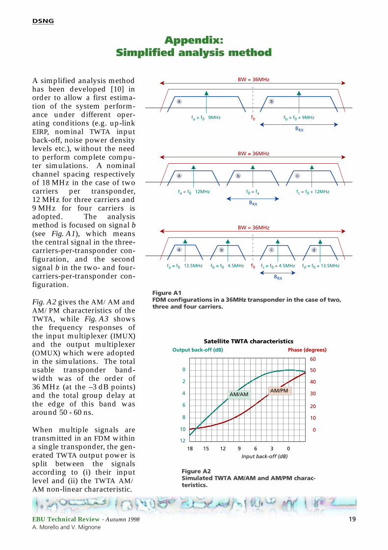
A simplified analysis methodhas been developed [10] inorder to allow a first estima-tion of the system perform-ance under different oper-ating conditions (e.g. up-linkEIRP, nominal TWTA inputback-off, noise power densitylevels etc.), without the needto perform complete compu-ter simulations. A nominalchannel spacing respectivelyof 18 MHz in the case of twocarriers per transponder,12 MHz for three carriers and9 MHz for four carriers isadopted. The analysismethod is focused on signal b(see Fig. A1), which meansthe central signal in the three-carriers-per-transponder con-figuration, and the secondsignal b in the two- and four-carriers-per-transponder con-figuration.
Fig. A2 gives the AM/AM andAM/PM characteristics of theTWTA, while Fig. A3 showsthe frequency responses ofthe input multiplexer (IMUX)and the output multiplexer(OMUX) which were adoptedin the simulations. The totalusable transponder band-width was of the order of36 MHz (at the –3 dB points)and the total group delay atthe edge of this band wasaround 50 - 60 ns.
When multiple signals aretransmitted in an FDM withina single transponder, the gen-erated TWTA output power issplit between the signalsaccording to (i) their inputlevel and (ii) the TWTA AM/AM non-linear characteristic.
BW = 36MHz
fa = f0 9MHz fb = f0 + 9MHz
BRX
a
f0
b
fa = f0 12MHz fc = f0 + 12MHzf0 = fa
fa = f0 13.5MHz fb = f0 4.5MHz fd = f0 + 13.5MHzfc = f0 + 4.5MHz
BW = 36MHz
a b c
BRX
BW = 36MHz
BRX
a
f0
b c d
Figure A1FDM configurations in a 36MHz transponder in the case of two, three and four carriers.
Output back-off (dB)
Input back-off (dB)
Phase (degrees)
0
2
4
6
8
10
12
60
50
40
30
20
10
0
18 15 12 9 6 3 0
Satellite TWTA characteristics
AM/AMAM/PM
Figure A2Simulated TWTA AM/AM and AM/PM charac-teristics.
EBU Technical Review - Autumn 1998 19A. Morello and V. Mignone

DSNG
Fig. A4 gives OBOb (the output back-off ofsignal b with respect to the transponder out-put saturation power) as a function of IBOb(the input back-off of signal b with respect tothe transponder input saturation power), fordifferent values of the input back-off of theinterfering signals IBOa,c,d. The results,obtained by computer simulations, refer to aconfiguration with four signals in the trans-ponder, where interfering signals were mod-ulated using QPSK, but signal b wasunmodulated (Fig. A5). The power of signal bwas measured after a narrow-band filter(200 kHz) which suppressed the interferencefrom the other signals. In a first approxima-tion, the cases where N = 2 and N = 3 signalsper transponder can be derived from Fig. A4through the formula:
OBOb(N) = OBOb(4) + 10 log10(N/4)
8PSK and 16QAM modulations give approxi-mately the same results and thus Fig. A4 maybe used also for these modulations.
In the simplified analysis method, the follow-ing sources of degradation are considered:
a) Gaussian noise:
Neglecting the noise compression on the satellite TWTA, the assumption is made that up-link and down-link noise of equal power have the same effect on the system BER, andtheir powers can be freely added.
Amplitude (dB) Group delay (ns)IMUX filter characteristics
-60
-40
0
-20
Frequency offset (MHz)
5 15 25 350 10 20 30 40
0
20
40
Amplitude (dB) Group delay (ns)OMUX filter characteristics
-60
-40
0
-20
Frequency offset (MHz)
5 15 25 350 10 20 30 40
0
20
40
Figure A3Simulated IMUX and OMUX amplitude and group delay characteristics.
Signal cSignal a
demodulatorfilter
Cb
IBRX
Figure A5Measurement of the interfering power IBRX in the demodulator filter.
IBOb (dB)
OB
Ob (
dB
)
5
10
15
20
25
10 12 14 16 18 20 22 24 26 28 30
IBOa,c,d
(dB)
812
16
20
24
Figure A4OBOb vs. IBOb for different values of IBOa,c,d in the case of four signals per transponder (simulation results).
EBU Technical Review - Autumn 1998 20A. Morello and V. Mignone

DSNG
b) Interference (intermodulation) from adjacent signals in FDM:
Assuming that the channel spacing is larger than the total signal bandwidth includingthe roll-off, the mutual interference between the signals on a quasi-linear up-link is neg-ligible.
On the down-link, the equivalence and additivity of noise and interference is assumed.In other words an interfering signal of power IBRX (in the receiver bandwidth) isassumed to produce the same BER as a Gaussian noise of equal power (i.e. NBRX = IBRX).
This approximation neglects the fact that the envelope of the intermodulation signals isnot Gaussian and that it is correlated with the signal itself. It should be noted that thenoise and interference contributions must be evaluated and added after the demodulatorreceiving filter (with noise bandwidth BRX equal to the symbol rate Rs). A practical prob-lem is how to measure the interference power (IBRX) in the demodulator filter withoutremoving the useful signal or modifying the TWTA working point.
16QAMQPSK
FDM
of
4 ca
rrie
rsFD
M o
f 3
carr
iers
FDM
of
2 ca
rrie
rs
0
5
10
15
20
25
30
0 10 20 30 40
(C/I)
b (
dB
)
IBOb (dB)
IBOa,c,d
(dB)
8
16
12
20
8
(C/I)
b (
dB
)
IBOb (dB)
IBOa,c,d
(dB)
16
12
20
0
5
10
15
20
25
30
0 10 20 30 40
16(C/I)
b (
dB
)
IBOb (dB)
IBOa,c,d
(dB)
8
12
20
0
5
10
15
20
25
30
0 10 20 30 40
(C/I)
b (
dB
)
IBOb (dB)
IBOa,c,d
(dB)
8
16
12
20
0
5
10
15
20
25
30
0 10 20 30 40
(C/I)
b (
dB
)
IBOb (dB)
IBOa,c,d
(dB)
8
16
12
20
0
5
10
15
20
25
30
0 10 20 30 40
(C/I)
b (
dB
)
IBOb (dB)
IBOa,c,d
(dB)
8
16
12
20
0
5
10
15
20
25
30
0 10 20 30 40
8PSK
Figure A6(C/I)b curves vs. IBOb for different values of IBOa,c,d (simulation results).
EBU Technical Review - Autumn 1998 21A. Morello and V. Mignone

DSNG
In the computer simulations, while the interfering signals were modulated, the wantedsignal was un-modulated (see Fig. A5). The interference power IBRX has been measuredby filtering the received signal through a notch filter, centred at the frequency of theunmodulated useful signal, with rejection bandwidth 200 kHz. The parameter Cb corre-sponds to the TWTA saturation power attenuated by OBOb. Fig. A6, obtained by compu-ter simulations, shows – for the different FDM configurations and modulation schemes –the (C/I)b curves for the wanted signal b versus IBOb , for different values of IBOa,c,d of theother signals.
c) Inter-symbol interference:
The inter-symbol interference (ISI) pro-duced by the TWTA non-linearitydepends on the working point (IBO)which, in turn, is determined not onlyby the signal itself, but also by the othersignals that are multiplexed in the trans-ponder. In the simplified analysisdescribed here, it is assumed that the ISIdegradation in the FDM configuration isthe same as for the single-signal config-uration for the same total IBO (thepower sum of the input signals). For asingle carrier, the noise margin loss ∆ ISIwith respect to the AWGN channel tendsto 0 dB for high back-offs (quasi-linearTWTA) while, approaching the TWTAsaturation, the values depend on themodulation and coding rate.
In Fig. A7 the noise margin loss is givenwith respect to the performance on an AWGN channel for the three different modulationschemes of the DVB-DSNG system, for one representative coding rate. In link-budgetcomputations, since the variation of ∆ ISI with the coding rate is very low (about 0.1 dB atthe typical quasi-linear TWTA operating points in FDM configurations), the curves ofFig. A7 have been adopted for any coding rate.
d) Cross-polar co-channel digital interference:
It is assumed that cross-polar co-channel digital interference has similar effects on thesystem BER as Gaussian noise with equal power in the receiving filter. When the cross-polar transponder carries the same signal configuration as the wanted transponder, theinterference power (I) is equal to the wanted power (C) attenuated by the cross-polarantenna discrimination (XPD): i.e. C/I = XPD.
The simplified analysis method described in this Appendix adds all the interference, inter-modulation and noise power contributions (measured within the receiver filter bandwidth) inorder to evaluate the available C/(N+I) ratio on the satellite links, and compares it with the C/(N+I) ratio required by the modulation system to deliver a target BER of 2x10⁻⁴. The servicecontinuity and quality is assured when C/(N+I) (available) > C/(N+I) (required). The detailedcomputation procedure is summarized in Table A1.
0
1
2
3
4
5
0 2 4 6 8 10 12 14 16 18 20
IBO (dB)
16QAM 7/8
8PSK 5/6QPSK 3/4
∆Eb/N
o (
dB
)
Figure A7Noise margin loss ∆Eb/N0 vs. TWTA IBO.
EBU Technical Review - Autumn 1998 22A. Morello and V. Mignone

DSNG
Table A1Simpified analysis method.
Step What to evaluate: Formulae, constants & figures to use
Evaluation of the required C/(N + I) in the noise bandwidth BRX
1 Required Eb/N0 on AWGN at BER = 2 x 10⁻⁴ From Table 1 (IF loop) + 1 dB margin, to allow for possibleinaccurancies of the simplified analysis method
2 IBOtot Add TWTA input powers, normalized with respect to the saturation point
3 ISI noise margin loss on TWTA at IBOtot from Fig. A7
4 Required Eb/N0 by satellite at IBOtot Combine the results from 1 and 3
5 Required C/(N + I) by satellite in BRX C/(N + I) (required) = Eb/N0 + 10 Log(Ru/BRX)
Evaluation of the available C/(N + I) in the noise bandwidth BRX
6 OBOb versus IBOb , IBOa,c,d from Fig. A4
7 Available C/Nu and C/Nd in BRX,
at IBOb and OBOb
Eb/N0,u = EIRPu – Au – Lu – PLu – ALu + G/Ts – k – Ru
Eb/N0,d = EIRPsat – OBOb – Ad – Ld – PLd – ALd + G/TRX – k – Ru
C/Nu = Eb/N0,u + 10 Log(Ru/BRX)
C/Nd = Eb/N0,d + 10 Log(Ru/BRX)
where:
k = Boltzmann constant
A = rain attenuation
L = free space loss
PL = pointing loss
AL = atmospheric loss
The sub-script “u” refers to the up-link and “d” to the down-link
8 C/Id(b) (intermodulation) in BRX at IBOa,b,c from Fig. A6
9 Available C/(Nu + Nd + Iu + Id) Combine results from 7 and 8
The service quality is guaranteed if C/(N+I) (available) > C/(N+I) (required)
EBU Technical Review - Autumn 1998 23A. Morello and V. Mignone


![DVB-S2 & DVB-S2X Signal Generation in K-band and Analysis ... · contribution, VSAT and DSNG [5]. Emerging markets such as Mobile (air, sea and rail) have their eye set on increasing](https://img.pdfslide.net/doc/110x75/5e6c64996c4de85dc55f0cc7/dvb-s2-dvb-s2x-signal-generation-in-k-band-and-analysis-contribution.jpg)