Embed Size (px)
Citation preview
Electronics2018, 7, 159; doi:10.3390/electronics7090159 www.mdpi.com/journal/electronics
Article
New Fault-Tolerant Control Strategy of Five-Phase
Induction Motor with Four-Phase and Three-Phase
Modes of Operation
Sonali Chetan Rangari 1,*, Hiralal Murlidhar Suryawanshi 2 and Mohan Renge 1
1 Department of Electrical Engineering, Shri Ramdeobaba College of Engineering and Management,
Nagpur 440013, India, [email protected] 2 Department of Electrical Engineering, Visvesvaraya National Institute of Technology, Nagpur 44013, India;
* Correspondence: [email protected]; Tel.: +91-982-247-0026
Received: 20 June 2018; Accepted: 7 August 2018; Published: 23 August 2018
Abstract: The developed torque with minimum oscillations is one of the difficulties faced when
designing drive systems. High ripple torque contents result in fluctuations and acoustic noise that
impact the life of a drive system. A multiphase machine can offer a better alternative to a
conventional three-phase machine in faulty situations by reducing the number of interruptions in
industrial operation. This paper proposes a unique fault-tolerant control strategy for a five-phase
induction motor. The paper considers a variable-voltage, variable-frequency control five-phase
induction motor in one- and two-phase open circuit faults. The four-phase and three-phase
operation modes for these faults are utilized with a modified voltage reference signal. The suggested
remedial strategy is the method for compensating a faulty open phase of the machine through a
modified reference signal. A modified voltage reference signal can be efficiently executed by a
carrier-based pulse width modulation (PWM) system. A test bench for the execution of the fault-
tolerant control strategy of the motor drive system is presented in detail along with the experimental
results.
Keywords: five-phase machine; fault-tolerant control; induction motor; one phase open circuit fault
(1-Ph); adjacent two-phase open circuit fault (A2-Ph); volt-per-hertz control (scalar control)
1. Introduction
In electric drives and machines, a three-phase machine is the default implementation in
industrial applications. Emphasis should be placed on possibilities with more than a three-phase
machine which is difficult to achieve with conventional three-phase machines. The simple expansion
of three-phase drives to multiphase drives is not sufficient. It is highly important to investigate
inventive employment of the extra degrees of flexibility. Incorporation of more than three phases is
advised to improve performance. The advantages that can be achieved with the utilization of
multiphase systems are investigated in [1]. Numerous endeavors concluded that multiphase
machines have some inherent advantages such as higher reliability, higher frequency of torque
pulsation with lower amplitude, lower rotor harmonic current, reduction in current per phase
without expanding the voltage per phase, and less current ripple in the DC link [1–5].
Multiphase system reliability is most important in safety-critical applications, such as, electric
ships, compressors, pumps, electric aircraft, hybrid vehicles and marine applications. In recent high
power industrial applications, a multi-leg voltage source inverter (VSI) was used for multi-phase
induction motors for variable-voltage, variable-frequency control.
Electronics 2018, 7, 159 2 of 16
In many industrial applications, if open-circuit fault exists in any phase of three-phase machine,
it leads to considerably large torque oscillations. These oscillations are double the electrical line
frequency, which may affect the shaft of the machine. For fault-tolerant control of three-phase
machine requires separate current control for remaining healthy phases by enabling the connection
of motor star point to the DC link midpoint [6]. Broad investigations have been accounted for open-
circuit fault-tolerant mode of operation for three-phase AC machines [7–14]. Increasing the number
of phases provides better sinusoidal Magneto Motive Force (MMF) distribution, which decreases
torque ripples and harmonic currents compared to three-phase machines [15,16]. A five-phase
machine is superior to a three-phase machine for fault-tolerant operation modes. When single-phase
(1-Ph) or adjacent double-phase (A2-Ph) open circuit faults occur, the machines can remain in
operation using other healthy phases without additional hardware and control [17–20].
A five-phase machine with the star-connected stator winding with no neutral connection can
work as a four-phase machine when a single-phase open circuit fault (1-Ph) occurs. Similarly, it works
as a three-phase machine when adjacent double phase open circuit faults (A2-Ph) occur. These faulty
conditions generate torque oscillations due to unbalanced rotating MMF present in the air gap [21].
Connecting a load neutral point to the DC link midpoint reduces the negative sequence MMF
component in the air gap and the oscillation without any additional control strategy.
Phase sequences are highly important when considering AC motors, as the production of the
torque via the sequential “rotation” of the applied five-phase power is responsible for the mechanical
rotation of the rotor. The frequency of positive-sequence is used to drive the rotor in the required
direction, whereas the frequency of negative-sequence operates motor in the opposite direction of the
rotation of the rotor. However, the frequency of the zero-sequence neither adds to nor detracts from
the torque of the rotor. Because of the distortion in the current, an excessive number of harmonics of
negative-sequence (5th, 11th, 17th and/or 23rd) is observed in the power, and if this power is applied
to a five-phase AC machine, it will result in deterioration of the performance as well as possible
overheating.
Many investigations have been accounted for the open-phase fault-tolerant operation of
multiphase induction machines [6,20,21], developed fault-tolerant control algorithm including non-
linearities of machine and converter in the modeling of open-phase fault drive system.The speed
control of five-phase induction motor by using finite-control set model-based predictive control for
fault-tolerant condition is introduced in [22].The fundamental and third-harmonic component of
current is used as a fault-tolerant control technique for the excitation of healthy stator phases has
been proposed in [23]. The aim of this work is to represent reconfiguration of motor phase currents
under one-phase and two-phase open fault condition. This paper presents the implementation of a
remedial strategy to neutralize ripple in the torque and analyzed the motor-performance in four-
phase and three-phase modes of operation.
The contribution of this work is
i. Insight into the asymmetrical post-fault mode of operation and the remedial strategy
compensates the unbalanced rotating MMF present in the air gap of the machine by a modified
reference signal.
ii. The control strategy is emphasized on the reduction in torque oscillations and verified with a
reduction in unbalanced line current.
iii. By using volt-per-hertz (V/f) scalar control, a voltage compensation control algorithm is
developed in the dsPIC33EP256MU810 Digital Signal Controller.
iv. Pre-fault and post-fault mode of operation with fault remedial technique is experimentally
verified and discussed.
v. The method presented here enhances the continuity of the star-connected five-phase induction
motor in case of one-phase and two-phase open faults.
It is assumed that the stator winding is opened in a five-phase induction motor because of gate
failure of the inverter, i.e., an open switch condition.
Electronics 2018, 7, 159 3 of 16
2. Fault-Tolerant Remedial Strategy of a Five-Phase System
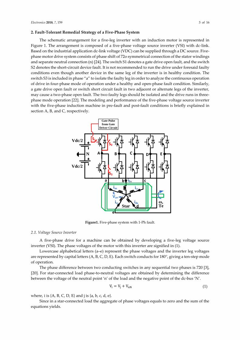
The schematic arrangement for a five-leg inverter with an induction motor is represented in
Figure 1. The arrangement is composed of a five-phase voltage source inverter (VSI) with dc-link.
Based on the industrial application dc-link voltage (VDC) can be supplied through a DC source. Five-
phase motor drive system consists of phase shift of 72o symmetrical connection of the stator windings
and separate neutral connection (n) [24]. The switch S1 denotes a gate drive open fault, and the switch
S2 denotes the short-circuit device fault. It is not recommended to run the drive under foresaid faulty
conditions even though another device in the same leg of the inverter is in healthy condition. The
switch S3 is included in phase “a” to isolate the faulty leg in order to analyze the continuous operation
of drive in four-phase mode of operation under a healthy and open-phase fault condition. Similarly,
a gate drive open fault or switch short circuit fault in two adjacent or alternate legs of the inverter,
may cause a two-phase open fault. The two faulty legs should be isolated and the drive runs in three-
phase mode operation [22]. The modeling and performance of the five-phase voltage source inverter
with the five-phase induction machine in pre-fault and post-fault conditions is briefly explained in
section A, B, and C, respectively.
Vdc/2
n
a b c
d
e
D ECBAN
Star
Vdc/2
ωs
Te
Van
S1S2
S3
ias
ibs
ics
idsies
Gate Pulse
from Gate
Driver Circuit
Figure1. Five-phase system with 1-Ph fault.
2.1. Voltage Source Inverter
A five-phase drive for a machine can be obtained by developing a five-leg voltage source
inverter (VSI). The phase voltages of the motor with this inverter are signified in (1).
Lowercase alphabetical letters (a–e) represent the phase voltages and the inverter leg voltages
are represented by capital letters (A, B, C, D, E). Each switch conducts for 180°, giving a ten-step mode
of operation.
The phase difference between two conducting switches in any sequential two phases is 720 [3],
[20]. For star-connected load phase-to-neutral voltages are obtained by determining the difference
between the voltage of the neutral point ‘n’ of the load and the negative point of the dc-bus ‘N’.
Vi = Vj + VnN (1)
where, i is {A, B, C, D, E} and j is {a, b, c, d, e}.
Since in a star-connected load the aggregate of phase voltages equals to zero and the sum of the
equations yields.
Electronics 2018, 7, 159 4 of 16
VnN =1
5× (VA + VB + VC + VD + VE)
(2)
Replacing (2) into (1), the loads with phase-to-neutral voltages are as follows:
VnN =1
5× (VA + VB + VC + VD + VE)
Vb =4
5VB −
1
5(VA + VC + VD + VE)
Vc =4
5VC −
1
5(VA + VB + VD + VE)
Vd =4
5VD −
1
5(VA + VB + VC + VE)
Ve =4
5VE −
1
5(VE + VB + VC + VD)
(3)
The phase values of inverter-leg voltages are ±0.5VDC. For a fixed modulation index M and dc-
link voltage VDC, the fundamental inverter leg voltages analogous to a star-connected winding can
be given as [3,20].
VPhStar= M
VDC
2× sin(ωst)
(4)
2.2.Modeling of a Five-Phase Induction Motor
The five-phase induction motor is provided with an IGBT-based five-phase voltage source
converter (VSCs) drive system. A DC-link voltage is provided from a diode bridge rectifier, which
exclusively permits unidirectional power flow. The Clarke matrix for this particular case is:
𝑇(𝜃) =2
5
[ 𝐶𝑜𝑠𝜃𝐶𝑜𝑠 (𝜃 −
2𝜋
5) 𝐶𝑜𝑠 (𝜃 −
4𝜋
5) 𝐶𝑜𝑠 (𝜃 +
4𝜋
5) 𝐶𝑜𝑠 (𝜃 +
2𝜋
5)
𝑆𝑖𝑛𝜃𝑆𝑖𝑛 (𝜃 −2𝜋
5) 𝑆𝑖𝑛 (𝜃 −
4𝜋
5) 𝑆𝑖𝑛 (𝜃 +
4𝜋
5) 𝑆𝑖𝑛 (𝜃 +
2𝜋
5)
𝐶𝑜𝑠𝜃𝐶𝑜𝑠 (𝜃 +4𝜋
5) 𝐶𝑜𝑠 (𝜃 −
2𝜋
5) 𝐶𝑜𝑠 (𝜃 +
2𝜋
5) 𝐶𝑜𝑠 (𝜃 −
4𝜋
5)
𝑆𝑖𝑛𝜃𝑆𝑖𝑛 (𝜃 +4𝜋
5) 𝑆𝑖𝑛 (𝜃 −
2𝜋
5) 𝑆𝑖𝑛 (𝜃 +
2𝜋
5) 𝐶𝑜𝑠 (𝜃 −
4𝜋
5)
1
2
1
2
1
2
1
2
1
2 ]
(5)
[idsiqsixsiysios]t= T(θ)[iasibsicsidsies]
t (6)
Clark transformation is used to disintegrate the phase a, b, c, d, e variable into two subspaces,
the d-q, x-y and the zero variable components. The d-q subspaces are orthogonal to each other and
provide basic torque and flux production. In healthy operation, they can be independently controlled;
the x-y subspace is not coupled with the d-q subspace. In case of 1-Ph and A2-Ph open circuit faults,
the d-q and x-y components are coupled with each other. The mapping of the various harmonics with
the subspaces are as follows: order of the harmonics 10n ± 1 (where n = 1, 2, 3, 4…) are mapped with
the q-d subspace including the fundamental component while the order of the harmonics 5n ± 1 (n =
1, 3, 5, 7…) are mapped with the x-y subspace.
The mathematical modelling equations of the machine assuming sinusoidal distributed
symmetrical windings and linear flux path are represented below. Using vector space decomposition
phase voltage equations of the stator winding in a stationary reference frame [1] are,
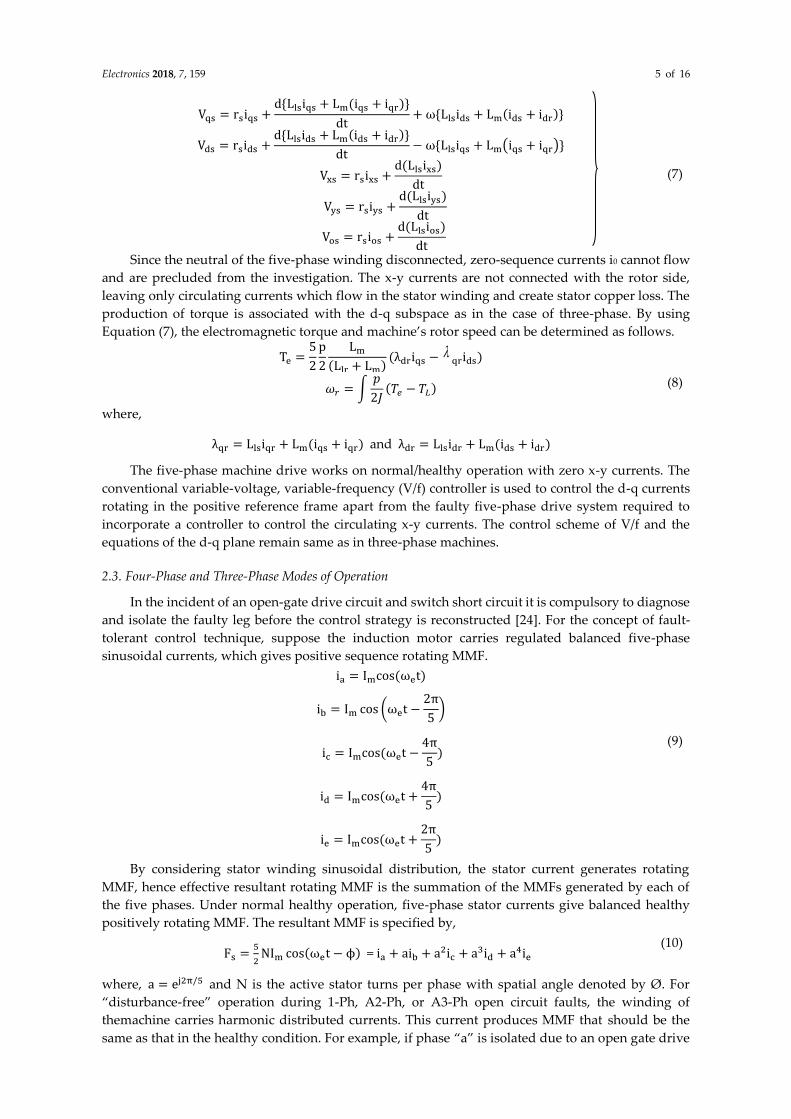
Electronics 2018, 7, 159 5 of 16
Vqs = rsiqs +d{Llsiqs + Lm(iqs + iqr)}
dt+ ω{Llsids + Lm(ids + idr)}
Vds = rsids +d{Llsids + Lm(ids + idr)}
dt− ω{Llsiqs + Lm(iqs + iqr)}
Vxs = rsixs +d(Llsixs)
dt
Vys = rsiys +d(Llsiys)
dt
Vos = rsios +d(Llsios)
dt
(7)
Since the neutral of the five-phase winding disconnected, zero-sequence currents i0 cannot flow
and are precluded from the investigation. The x-y currents are not connected with the rotor side,
leaving only circulating currents which flow in the stator winding and create stator copper loss. The
production of torque is associated with the d-q subspace as in the case of three-phase. By using
Equation (7), the electromagnetic torque and machine’s rotor speed can be determined as follows.
Te =5
2
p
2
Lm
(Llr + Lm)(λdriqs −
qrids)
𝜔𝑟 = ∫𝑝
2𝐽(𝑇𝑒 − 𝑇𝐿) (8)
where,
λqr = Llsiqr + Lm(iqs + iqr) and λdr = Llsidr + Lm(ids + idr)
The five-phase machine drive works on normal/healthy operation with zero x-y currents. The
conventional variable-voltage, variable-frequency (V/f) controller is used to control the d-q currents
rotating in the positive reference frame apart from the faulty five-phase drive system required to
incorporate a controller to control the circulating x-y currents. The control scheme of V/f and the
equations of the d-q plane remain same as in three-phase machines.
2.3. Four-Phase and Three-Phase Modes of Operation
In the incident of an open-gate drive circuit and switch short circuit it is compulsory to diagnose
and isolate the faulty leg before the control strategy is reconstructed [24]. For the concept of fault-
tolerant control technique, suppose the induction motor carries regulated balanced five-phase
sinusoidal currents, which gives positive sequence rotating MMF.
ia = Imcos(ωet)
ib = Im cos (ωet −2π
5)
ic = Imcos(ωet −4π
5)
(9)
id = Imcos(ωet +4π
5)
ie = Imcos(ωet +2π
5)
By considering stator winding sinusoidal distribution, the stator current generates rotating
MMF, hence effective resultant rotating MMF is the summation of the MMFs generated by each of
the five phases. Under normal healthy operation, five-phase stator currents give balanced healthy
positively rotating MMF. The resultant MMF is specified by,
Fs =5
2NIm cos(ωet − ϕ) =ia + aib + a2ic + a3id + a4ie
(10)
where, a = ej2π/5 and N is the active stator turns per phase with spatial angle denoted by Ø. For
“disturbance-free” operation during 1-Ph, A2-Ph, or A3-Ph open circuit faults, the winding of
themachine carries harmonic distributed currents. This current produces MMF that should be the
same as that in the healthy condition. For example, if phase “a” is isolated due to an open gate drive
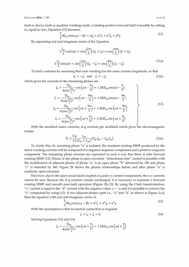
Electronics 2018, 7, 159 6 of 16
fault or device fault or machine windings fault, a rotating positive forward field is feasible by setting
ia, equal to zero, Equation (10) becomes, 5
2NIm cos(ωet − ∅) = aib
′ + a2ic′ + a3id
′ + a4ie′
(11)
By separating real and imaginary terms of the Equation
5Im2
cos(ωt) = cos (2π
5) (ib
′ + ie′ ) + cos (
4π
5) (ic
′ + id′ )
5Im2
sin(ωt) = sin (2π
5) (ib
′ − ie′ ) + sin (
4π
5) (ic
′ − id′ )
(11a)
To find a solution by assuming that each winding has the same current magnitude, so that
ib′ = −id
′ andic′ = −ie
′ (11b)
which gives the currents in the remaining phases are
ib′ =
5im
4(sin2π
5)2
cos (ωt −π
5) = 1.382Imcos(ωt −
π
5)
ic′ =
5im
4(sin2π
5)2
cos (ωt −4π
5) = 1.382Imcos(ωt −
4π
5)
id′ =
5im
4(sin2π
5)2
cos (ωt +4π
5) = 1.382Im cos (ωt +
4π
5)
ie′ =
5im
4(sin2π
5)2
cos (ωt +π
5) = 1.382Im cos (ωt +
π
5)
(12)
With the modified stator currents, d-q currents get modified which gives the electromagnetic
torque,
Te′ =
5
2
p
2
Lm
(Llr + Lm)(λdr
′ iqs′ − λqr
′ ids′ ) (12a)
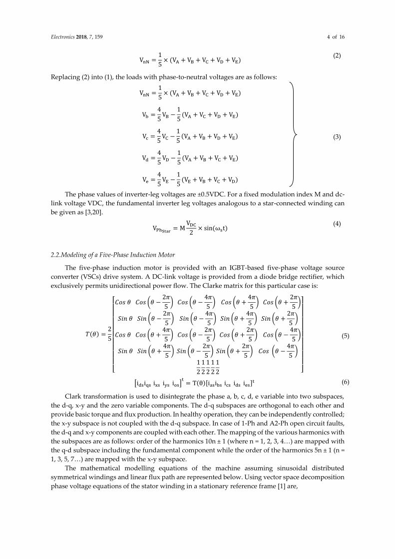
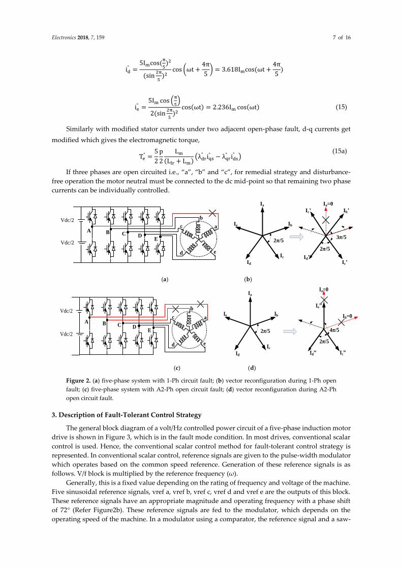
To clarify this, by assuming phase “a” is isolated, the resultant rotating MMF produced by the
stator winding currents will be composed of a negative-sequence component and a positive-sequence
component. The remaining phase currents are expressed in such a way that there is only forward
rotating MMF [13]. Hence, if any phase is open-circuited, “disturbance-free” control is possible with
the modification of adjacent phases. If phase “a” is an open phase “b” advanced by 360 and phase
“c” is retarded by 360. Figure 2b shows the phasor relationships before and after phase “a” is
suddenly open-circuited.
However, due to the open circuit fault coupled d-q and x-y current components, the x-y currents
cannot be zero. Because the d-q currents remain unchanged, it is necessary to maintain a forward
rotating MMF and smooth post-fault operation (Figure 2b) [3]. By using the Clark transformation,
“x” current is equal to the “d” current with the negative value: ix = −id and it is possible to remove the
“x” component by using (12). If two adjacent phases open i.e., “a” and “b” as shown in Figure 2c,d,
then the equation with real and imaginary terms of, 5
2NImcos(ωet − ∅) = a2ic
" + a3id" + a4ie
" (13)
With the assumption is that no neutral connection is required
ic" + id
" + ie" = 0 (14)
Solving Equations (13) and (14)
ie′ =
5im
4(sin2π
5)2
cos (ωt +π
5) = 1.382Im cos (ωt +
π
5)
Electronics 2018, 7, 159 7 of 16
id" =
5Imcos(π
5)2
(sin2π
5)2
cos (ωt +4π
5) = 3.618Imcos(ωt +
4π
5)
ie" =
5Im cos (π
5)
2(sin2π
5)2
cos(ωt) = 2.236Im cos(ωt) (15)
Similarly with modified stator currents under two adjacent open-phase fault, d-q currents get
modified which gives the electromagnetic torque,
Te" =
5
2
p
2
Lm
(Llr + Lm)(λdr
" iqs" − λqr
" ids" )
(15a)
If three phases are open circuited i.e., “a”, “b” and “c”, for remedial strategy and disturbance-
free operation the motor neutral must be connected to the dc mid-point so that remaining two phase
currents can be individually controlled.
Ia=0
Ib’
Ic’Id’
Ic’
3π/5BA
C DE
Vdc/2
Vdc/2
b
ac
d e2π/5
Ia
Ib
Ic
Id
Ie
2π/5
(a) (b)
BAC D
E
Vdc/2
Vdc/2
b
ac
d e
Ia
Ib
Ic
Id
Ie
2π/5
Ia=0
Ib=0
Ic”Id”
Ie”
2π/5
4π/5
(c) (d)
Figure 2. (a) five-phase system with 1-Ph circuit fault; (b) vector reconfiguration during 1-Ph open
fault; (c) five-phase system with A2-Ph open circuit fault; (d) vector reconfiguration during A2-Ph
open circuit fault.
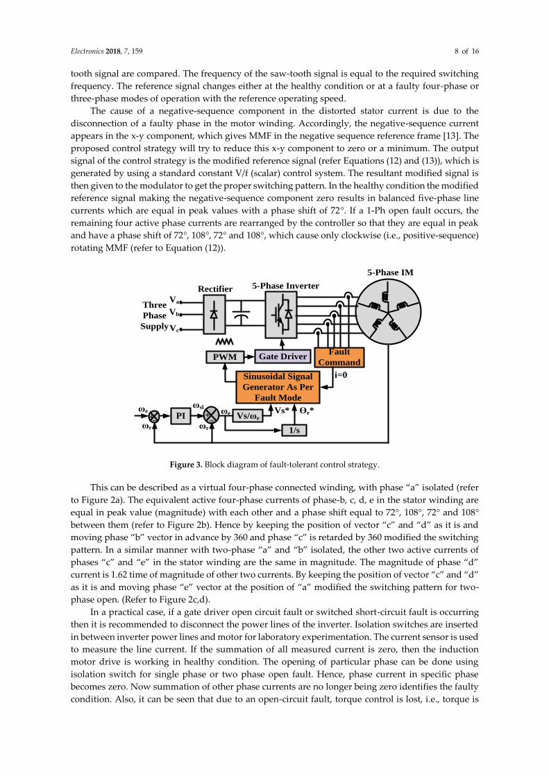
3. Description of Fault-Tolerant Control Strategy
The general block diagram of a volt/Hz controlled power circuit of a five-phase induction motor
drive is shown in Figure 3, which is in the fault mode condition. In most drives, conventional scalar
control is used. Hence, the conventional scalar control method for fault-tolerant control strategy is
represented. In conventional scalar control, reference signals are given to the pulse-width modulator
which operates based on the common speed reference. Generation of these reference signals is as
follows. V/f block is multiplied by the reference frequency (ω).
Generally, this is a fixed value depending on the rating of frequency and voltage of the machine.
Five sinusoidal reference signals, vref a, vref b, vref c, vref d and vref e are the outputs of this block.
These reference signals have an appropriate magnitude and operating frequency with a phase shift
of 72° (Refer Figure2b). These reference signals are fed to the modulator, which depends on the
operating speed of the machine. In a modulator using a comparator, the reference signal and a saw-
Electronics 2018, 7, 159 8 of 16
tooth signal are compared. The frequency of the saw-tooth signal is equal to the required switching
frequency. The reference signal changes either at the healthy condition or at a faulty four-phase or
three-phase modes of operation with the reference operating speed.
The cause of a negative-sequence component in the distorted stator current is due to the
disconnection of a faulty phase in the motor winding. Accordingly, the negative-sequence current
appears in the x-y component, which gives MMF in the negative sequence reference frame [13]. The
proposed control strategy will try to reduce this x-y component to zero or a minimum. The output
signal of the control strategy is the modified reference signal (refer Equations (12) and (13)), which is
generated by using a standard constant V/f (scalar) control system. The resultant modified signal is
then given to the modulator to get the proper switching pattern. In the healthy condition the modified
reference signal making the negative-sequence component zero results in balanced five-phase line
currents which are equal in peak values with a phase shift of 72°. If a 1-Ph open fault occurs, the
remaining four active phase currents are rearranged by the controller so that they are equal in peak
and have a phase shift of 72°, 108°, 72° and 108°, which cause only clockwise (i.e., positive-sequence)
rotating MMF (refer to Equation (12)).
ωslVs*ωe
+ωr
ωe
5-Phase IM
Ɵe*
Gate DriverPWMFault
Command
Sinusoidal Signal
Generator As Per
Fault Mode
Vs/ωePI +
1/s
Va
Vb
Vc
ωr
_ _
5-Phase InverterRectifier
Three
Phase
Supply
i=0
Figure 3. Block diagram of fault-tolerant control strategy.
This can be described as a virtual four-phase connected winding, with phase “a” isolated (refer
to Figure 2a). The equivalent active four-phase currents of phase-b, c, d, e in the stator winding are
equal in peak value (magnitude) with each other and a phase shift equal to 72°, 108°, 72° and 108°
between them (refer to Figure 2b). Hence by keeping the position of vector “c” and “d” as it is and
moving phase “b” vector in advance by 360 and phase “c” is retarded by 360 modified the switching
pattern. In a similar manner with two-phase “a” and “b” isolated, the other two active currents of
phases “c” and “e” in the stator winding are the same in magnitude. The magnitude of phase “d”
current is 1.62 time of magnitude of other two currents. By keeping the position of vector “c” and “d”
as it is and moving phase “e” vector at the position of “a” modified the switching pattern for two-
phase open. (Refer to Figure 2c,d).
In a practical case, if a gate driver open circuit fault or switched short-circuit fault is occurring
then it is recommended to disconnect the power lines of the inverter. Isolation switches are inserted
in between inverter power lines and motor for laboratory experimentation. The current sensor is used
to measure the line current. If the summation of all measured current is zero, then the induction
motor drive is working in healthy condition. The opening of particular phase can be done using
isolation switch for single phase or two phase open fault. Hence, phase current in specific phase
becomes zero. Now summation of other phase currents are no longer being zero identifies the faulty
condition. Also, it can be seen that due to an open-circuit fault, torque control is lost, i.e., torque is
Electronics 2018, 7, 159 9 of 16
oscillating which oscillates the speed. Hence in V/f control, the speed control loop gets weak and
oscillation in torque.
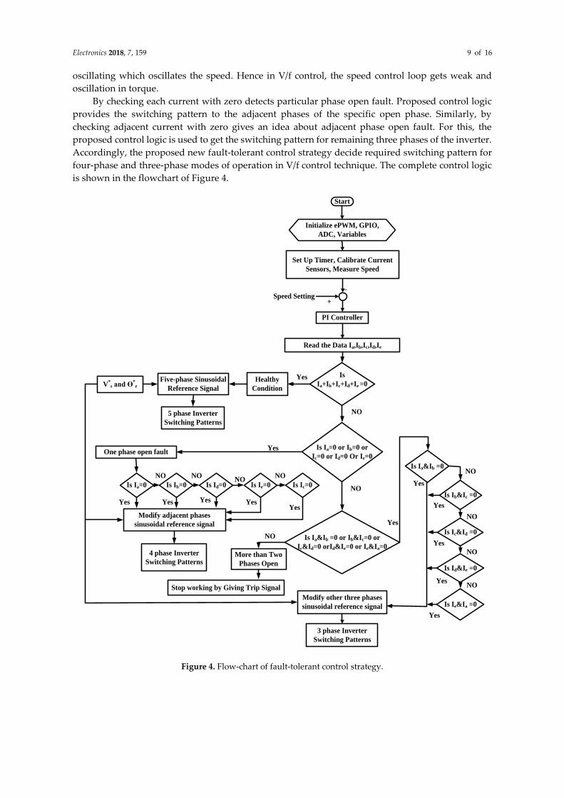
By checking each current with zero detects particular phase open fault. Proposed control logic
provides the switching pattern to the adjacent phases of the specific open phase. Similarly, by
checking adjacent current with zero gives an idea about adjacent phase open fault. For this, the
proposed control logic is used to get the switching pattern for remaining three phases of the inverter.
Accordingly, the proposed new fault-tolerant control strategy decide required switching pattern for
four-phase and three-phase modes of operation in V/f control technique. The complete control logic
is shown in the flowchart of Figure 4.
Start
Initialize ePWM, GPIO,
ADC, Variables
Set Up Timer, Calibrate Current
Sensors, Measure Speed
PI Controller
Read the Data Ia,Ib,Ic,Id,Ie
Is
Ia+Ib+Ic+Id+Ie =0
Is Ia=0 or Ib=0 or
Ic=0 or Id=0 Or Ie=0
Is Ia&Ib =0 or Ib&Ic=0 or
Ic&Id=0 orId&Ie=0 or Ie&Ia=0
V*s and Ɵ
*e
Five-phase Sinusoidal
Reference Signal
5 phase Inverter
Switching Patterns
4 phase Inverter
Switching Patterns
3 phase Inverter
Switching Patterns
Modify adjacent phases
sinusoidal reference signal
More than Two
Phases Open
Stop working by Giving Trip Signal
Speed Setting
_
+
NO
Yes
Yes
NO
Yes
NO
Modify other three phases
sinusoidal reference signal
Healthy
Condition
One phase open fault
Is Ia=0 Is Ib=0 Is Ic=0 Is Id=0 Is Ie=0
Is Ia&Ib =0
Is Ib&Ic =0
Is Id&Ie =0
Is Ic&Id =0
Is Ie&Ia =0
NO
NO
NO
NO
NONONO
NO
Yes Yes Yes YesYes Yes
Yes
Yes
Yes
Yes
Figure 4. Flow-chart of fault-tolerant control strategy.
Electronics 2018, 7, 159 10 of 16
4. Experimental Results
4.1.Test Experimental Setup
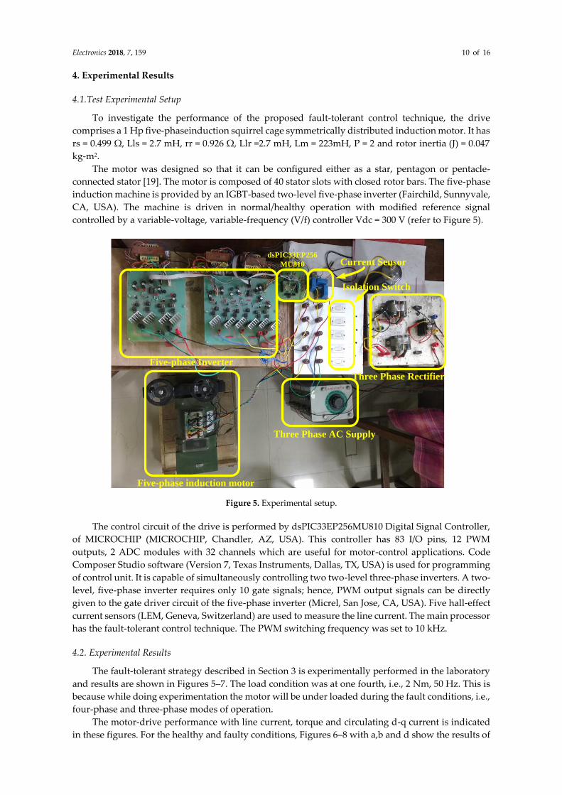
To investigate the performance of the proposed fault-tolerant control technique, the drive
comprises a 1 Hp five-phaseinduction squirrel cage symmetrically distributed induction motor. It has
rs = 0.499 Ω, Lls = 2.7 mH, rr = 0.926 Ω, Llr =2.7 mH, Lm = 223mH, P = 2 and rotor inertia (J) = 0.047
kg-m2.
The motor was designed so that it can be configured either as a star, pentagon or pentacle-
connected stator [19]. The motor is composed of 40 stator slots with closed rotor bars. The five-phase
induction machine is provided by an IGBT-based two-level five-phase inverter (Fairchild, Sunnyvale,
CA, USA). The machine is driven in normal/healthy operation with modified reference signal
controlled by a variable-voltage, variable-frequency (V/f) controller Vdc = 300 V (refer to Figure 5).
Five-phase Inverter
dsPIC33EP256
MU810
Five-phase induction motor
Three Phase AC Supply
Three Phase Rectifier
Isolation Switch
Current Sensor
Figure 5. Experimental setup.
The control circuit of the drive is performed by dsPIC33EP256MU810 Digital Signal Controller,
of MICROCHIP (MICROCHIP, Chandler, AZ, USA). This controller has 83 I/O pins, 12 PWM
outputs, 2 ADC modules with 32 channels which are useful for motor-control applications. Code
Composer Studio software (Version 7, Texas Instruments, Dallas, TX, USA) is used for programming
of control unit. It is capable of simultaneously controlling two two-level three-phase inverters. A two-
level, five-phase inverter requires only 10 gate signals; hence, PWM output signals can be directly
given to the gate driver circuit of the five-phase inverter (Micrel, San Jose, CA, USA). Five hall-effect
current sensors (LEM, Geneva, Switzerland) are used to measure the line current. The main processor
has the fault-tolerant control technique. The PWM switching frequency was set to 10 kHz.
4.2. Experimental Results
The fault-tolerant strategy described in Section 3 is experimentally performed in the laboratory
and results are shown in Figures 5–7. The load condition was at one fourth, i.e., 2 Nm, 50 Hz. This is
because while doing experimentation the motor will be under loaded during the fault conditions, i.e.,
four-phase and three-phase modes of operation.
The motor-drive performance with line current, torque and circulating d-q current is indicated
in these figures. For the healthy and faulty conditions, Figures 6–8 with a,b and d show the results of
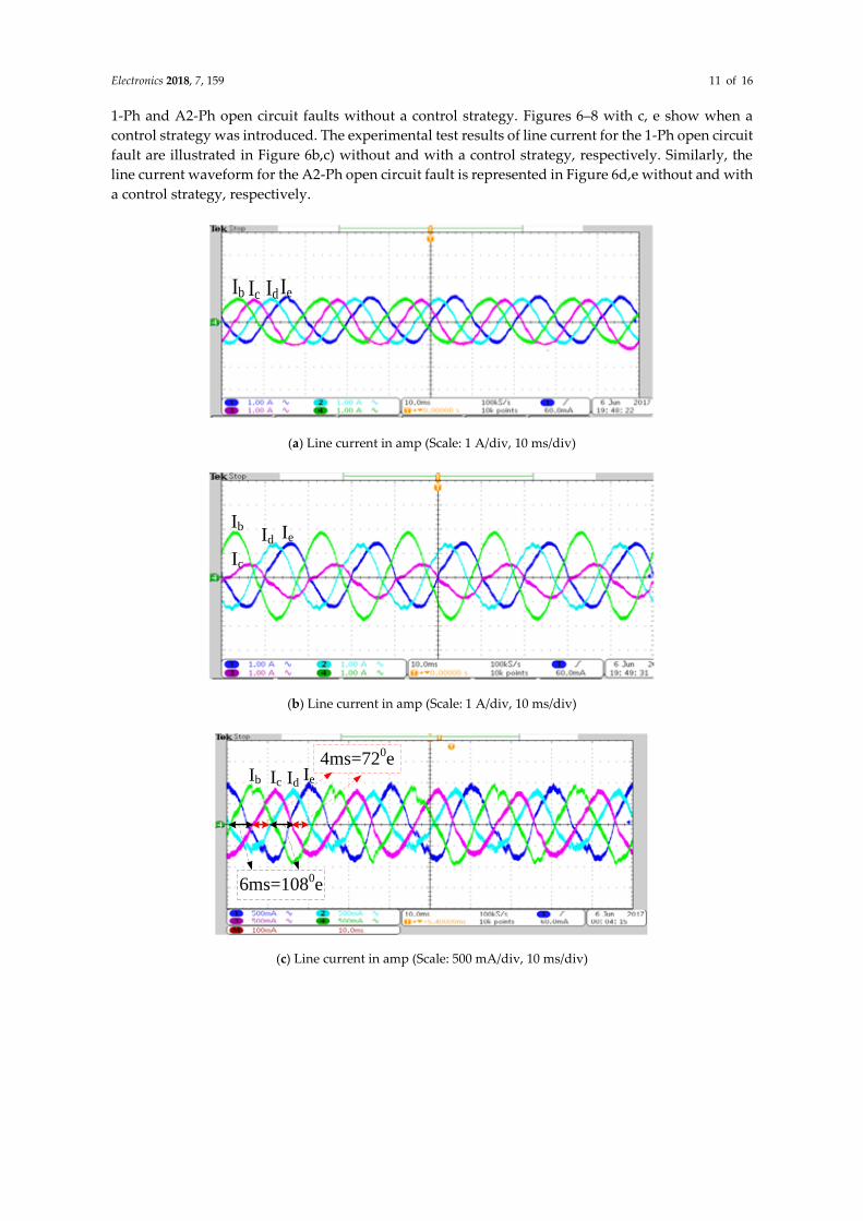
Electronics 2018, 7, 159 11 of 16
1-Ph and A2-Ph open circuit faults without a control strategy. Figures 6–8 with c, e show when a
control strategy was introduced. The experimental test results of line current for the 1-Ph open circuit
fault are illustrated in Figure 6b,c) without and with a control strategy, respectively. Similarly, the
line current waveform for the A2-Ph open circuit fault is represented in Figure 6d,e without and with
a control strategy, respectively.
Ib Ic IdIe
(a) Line current in amp (Scale: 1 A/div, 10 ms/div)
Ib
Ic
Id Ie
(b) Line current in amp (Scale: 1 A/div, 10 ms/div)
Ib Ic IdIe
6ms=1080e
4ms=720e
(c) Line current in amp (Scale: 500 mA/div, 10 ms/div)
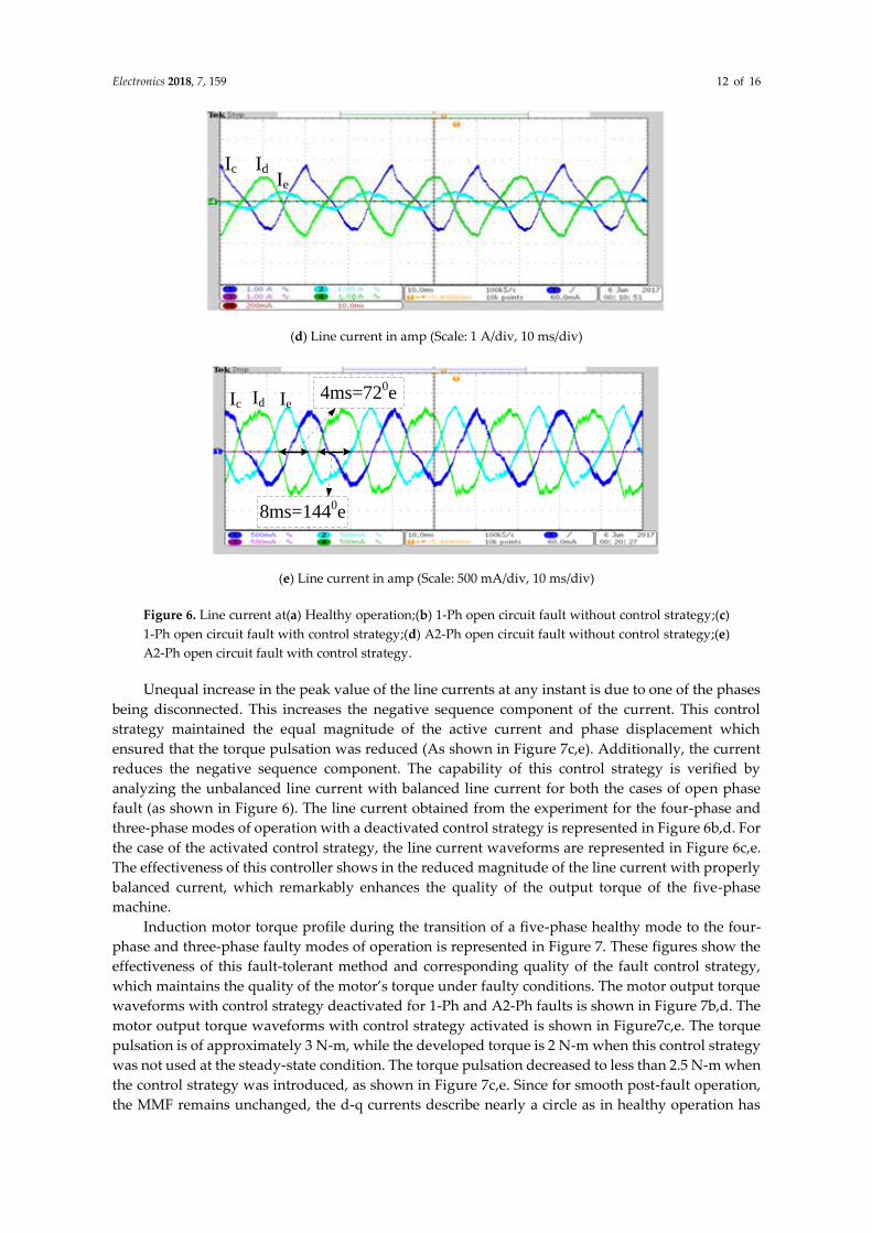
Electronics 2018, 7, 159 12 of 16
Ic IdIe
(d) Line current in amp (Scale: 1 A/div, 10 ms/div)
Ic Id Ie
8ms=1440e
4ms=720e
(e) Line current in amp (Scale: 500 mA/div, 10 ms/div)
Figure 6. Line current at(a) Healthy operation;(b) 1-Ph open circuit fault without control strategy;(c)
1-Ph open circuit fault with control strategy;(d) A2-Ph open circuit fault without control strategy;(e)
A2-Ph open circuit fault with control strategy.
Unequal increase in the peak value of the line currents at any instant is due to one of the phases
being disconnected. This increases the negative sequence component of the current. This control
strategy maintained the equal magnitude of the active current and phase displacement which
ensured that the torque pulsation was reduced (As shown in Figure 7c,e). Additionally, the current
reduces the negative sequence component. The capability of this control strategy is verified by
analyzing the unbalanced line current with balanced line current for both the cases of open phase
fault (as shown in Figure 6). The line current obtained from the experiment for the four-phase and
three-phase modes of operation with a deactivated control strategy is represented in Figure 6b,d. For
the case of the activated control strategy, the line current waveforms are represented in Figure 6c,e.
The effectiveness of this controller shows in the reduced magnitude of the line current with properly
balanced current, which remarkably enhances the quality of the output torque of the five-phase
machine.
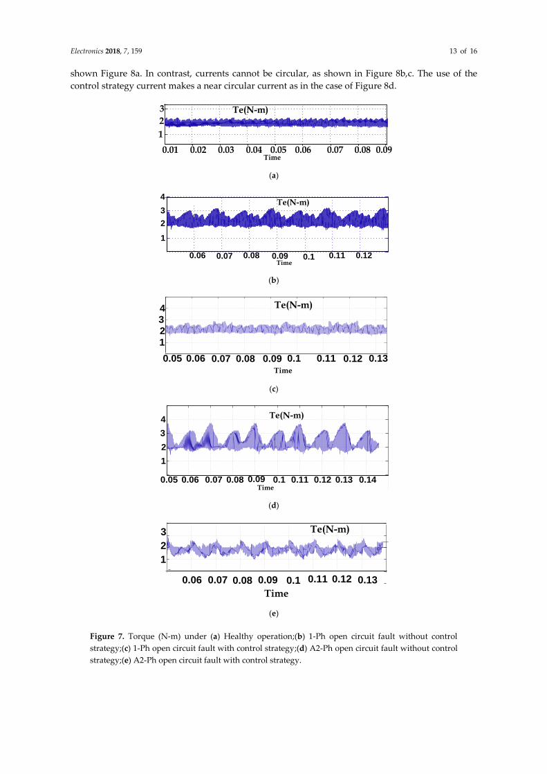
Induction motor torque profile during the transition of a five-phase healthy mode to the four-
phase and three-phase faulty modes of operation is represented in Figure 7. These figures show the
effectiveness of this fault-tolerant method and corresponding quality of the fault control strategy,
which maintains the quality of the motor’s torque under faulty conditions. The motor output torque
waveforms with control strategy deactivated for 1-Ph and A2-Ph faults is shown in Figure 7b,d. The
motor output torque waveforms with control strategy activated is shown in Figure7c,e. The torque
pulsation is of approximately 3 N-m, while the developed torque is 2 N-m when this control strategy
was not used at the steady-state condition. The torque pulsation decreased to less than 2.5 N-m when
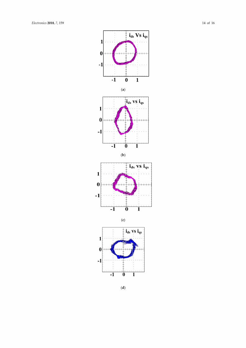
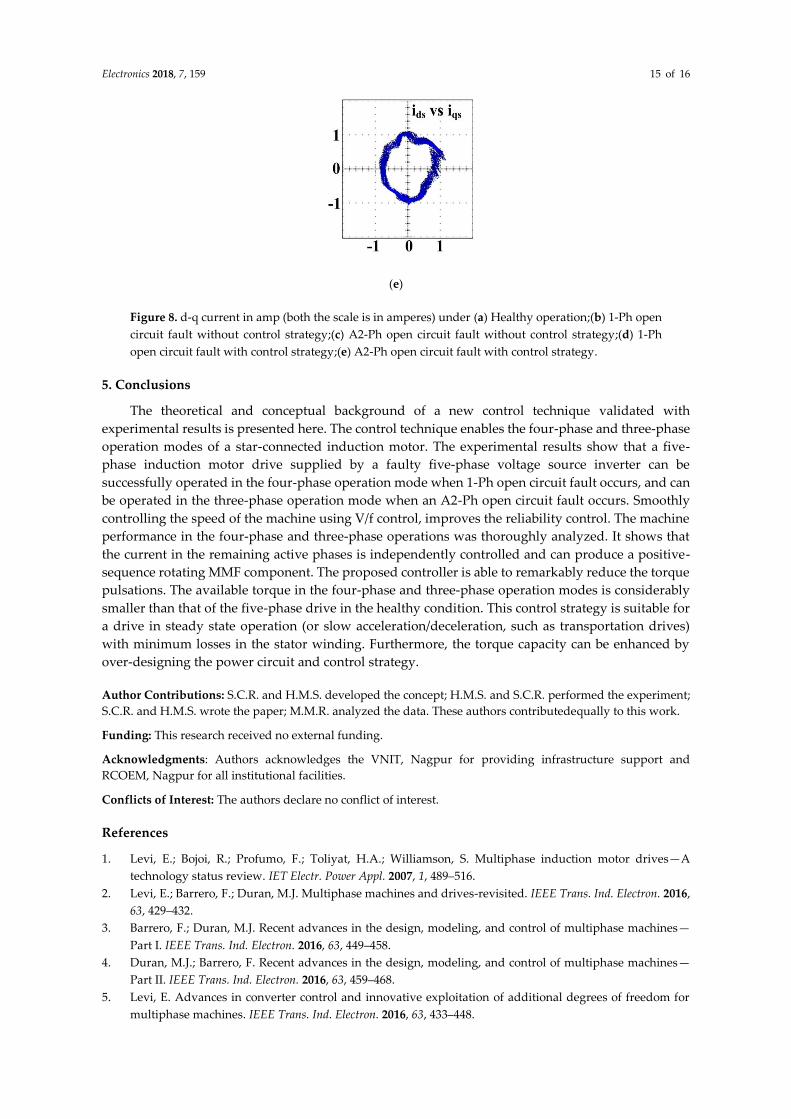
the control strategy was introduced, as shown in Figure 7c,e. Since for smooth post-fault operation,
the MMF remains unchanged, the d-q currents describe nearly a circle as in healthy operation has
Electronics 2018, 7, 159 13 of 16
shown Figure 8a. In contrast, currents cannot be circular, as shown in Figure 8b,c. The use of the
control strategy current makes a near circular current as in the case of Figure 8d.
1
2
3
0.01 0.02 0.03 0.04 0.05 0.06 0.07 0.08 0.09
Te(N-m)
Time
(a)
0.06 0.07 0.08 0.09 0.1 0.11 0.12
1
2
3
4Te(N-m)
Time
(b)
1234
0.05 0.06 0.07 0.08 0.09 0.1 0.11 0.12 0.13
Te(N-m)
Time
(c)
0.05
1
2
3
4
0.06 0.07 0.08 0.09 0.1 0.11 0.12 0.13 0.14
Te(N-m)
Time
(d)
1
2
3
0.06 0.07 0.08 0.09 0.1 0.11 0.12 0.13
Te(N-m)
Time
(e)
Figure 7. Torque (N-m) under (a) Healthy operation;(b) 1-Ph open circuit fault without control
strategy;(c) 1-Ph open circuit fault with control strategy;(d) A2-Ph open circuit fault without control
strategy;(e) A2-Ph open circuit fault with control strategy.
Electronics 2018, 7, 159 14 of 16
0
1
-1
0-1 1
ids Vs iqs
(a)
(b)
(c)
(d)
Electronics 2018, 7, 159 15 of 16
(e)
Figure 8. d-q current in amp (both the scale is in amperes) under (a) Healthy operation;(b) 1-Ph open
circuit fault without control strategy;(c) A2-Ph open circuit fault without control strategy;(d) 1-Ph
open circuit fault with control strategy;(e) A2-Ph open circuit fault with control strategy.
5. Conclusions
The theoretical and conceptual background of a new control technique validated with
experimental results is presented here. The control technique enables the four-phase and three-phase
operation modes of a star-connected induction motor. The experimental results show that a five-
phase induction motor drive supplied by a faulty five-phase voltage source inverter can be
successfully operated in the four-phase operation mode when 1-Ph open circuit fault occurs, and can
be operated in the three-phase operation mode when an A2-Ph open circuit fault occurs. Smoothly
controlling the speed of the machine using V/f control, improves the reliability control. The machine
performance in the four-phase and three-phase operations was thoroughly analyzed. It shows that
the current in the remaining active phases is independently controlled and can produce a positive-
sequence rotating MMF component. The proposed controller is able to remarkably reduce the torque
pulsations. The available torque in the four-phase and three-phase operation modes is considerably
smaller than that of the five-phase drive in the healthy condition. This control strategy is suitable for
a drive in steady state operation (or slow acceleration/deceleration, such as transportation drives)
with minimum losses in the stator winding. Furthermore, the torque capacity can be enhanced by
over-designing the power circuit and control strategy.
Author Contributions: S.C.R. and H.M.S. developed the concept; H.M.S. and S.C.R. performed the experiment;
S.C.R. and H.M.S. wrote the paper; M.M.R. analyzed the data. These authors contributedequally to this work.
Funding: This research received no external funding.
Acknowledgments: Authors acknowledges the VNIT, Nagpur for providing infrastructure support and
RCOEM, Nagpur for all institutional facilities.
Conflicts of Interest: The authors declare no conflict of interest.
References
1. Levi, E.; Bojoi, R.; Profumo, F.; Toliyat, H.A.; Williamson, S. Multiphase induction motor drives—A
technology status review. IET Electr. Power Appl. 2007, 1, 489–516.
2. Levi, E.; Barrero, F.; Duran, M.J. Multiphase machines and drives-revisited. IEEE Trans. Ind. Electron. 2016,
63, 429–432.
3. Barrero, F.; Duran, M.J. Recent advances in the design, modeling, and control of multiphase machines—
Part I. IEEE Trans. Ind. Electron. 2016, 63, 449–458.
4. Duran, M.J.; Barrero, F. Recent advances in the design, modeling, and control of multiphase machines—
Part II. IEEE Trans. Ind. Electron. 2016, 63, 459–468.
5. Levi, E. Advances in converter control and innovative exploitation of additional degrees of freedom for
multiphase machines. IEEE Trans. Ind. Electron. 2016, 63, 433–448.
Electronics 2018, 7, 159 16 of 16
6. Liu, T.H.; Fu, J.R.; Lipo, T.A. A strategy for improving reliability of field-oriented controlled induction
motor drives. IEEE Trans. Ind. Appl. 1993, 29, 910–918.
7. Wallmark, O.; Harnefors, L.; Carlson, O. Control algorithms for a fault-tolerant PMSM drive. IEEE Trans.
Ind. Electron. 2007, 54, 1973–1980.
8. Zhao, W.; Cheng, M.; Hua, W.; Jia, H.; Cao, R. Back-EMF harmonic analysis and fault-tolerant control of
flux-switching permanent-magnet machine with redundancy. IEEE Trans. Ind. Electron. 2011, 58, 1926–1935.
9. De Lillo, L.; Empringham, L.; Wheeler, P.W.; Khwan-On, S.; Gerada, C.; Othman, M.N.; Huang, X.
Multiphase power converter drive for fault-tolerant machine development in aerospace applications. IEEE
Trans. Ind. Electron. 2010, 57, 575–583.
10. Bianchi, N.; Bolognani, S.; Zigliotto, M.; Zordan, M.A.Z.M. Innovative remedial strategies for inverter faults
in IPM synchronous motor drives. IEEE Trans. Energy Convers. 2003, 18, 306–314.
11. Errabelli, R.R.; Mutschler, P. Fault-tolerant voltage source inverter for permanent magnet drives. IEEE
Trans. Power Electron. 2012, 27, 500–508.
12. Aghili, F. Fault-tolerant torque control of BLDC motors. IEEE Trans. Power Electron.2011, 26, 355–363.
13. Sayed-Ahmed, A.; Mirafzal, B.; Demerdash, N.A. Fault-tolerant technique for Δ-connected AC-motor
drives. IEEE Trans. Energy Convers. 2011, 26, 646–653.
14. Mendes, A.M.; Cardoso, A.M. Fault-tolerant operating strategies applied to three-phase induction-motor
drives. IEEE Trans. Ind. Electron. 2006, 53, 1807–1817.
15. Abdel-Khalik, A.S.; Ahmed, S.; Elserougi, A.A.; Massoud, A.M. Effect of stator winding connection of five-
phase induction machines on torque ripples under open line condition. IEEE/ASME Trans. Mechatron.2 015,
20, 580–593.
16. Yepes, A.G.; Riveros, J.A.; Doval-Gandoy, J.; Barrero, F.; López, O.; Bogado, B.; Jones M.; Levi, E. Parameter
identification of multiphase induction machines with distributed windings—Part 1: Sinusoidal excitation
methods. IEEE Trans. Energy Convers. 2012, 27, 1056–1066.
17. Mecrow, B.C.; Jack, A.G.; Haylock, J.A.; Coles, J. Fault-tolerant permanent magnet machine drives. IEE
Proc.-Electr. Power. Appl. 1996, 143, 437–442.
18. Parsa, L. On advantages of multi-phase machines. In Proceedings of the 31st Annual Conference of IEEE
Industrial Electronics Society, Raleigh, NC, USA, 6–10 November 2005; pp. 1574–1579.
19. Parsa, L.; Toliyat, H.A. Fault-tolerant interior-permanent-magnet machines for hybrid electric vehicle
applications. IEEE Trans. Veh. Technol. 2007, 56, 1546–1552.
20. Mohammadpour, A.; Sadeghi, S.; Parsa, L. A generalized fault-tolerant control strategy for five-phase PM
motor drives considering star, pentagon, and pentacle connections of stator windings. IEEE Trans. Ind.
Electron. 2014, 61, 63–75.
21. Jasim, O.; Sumner, M.; Gerada, C.; Arellano-Padilla, J. Development of a new fault-tolerant induction motor
control strategy using an enhanced equivalent circuit model. IET Electr. Power Appl. 2011, 5, 618–627.
22. Guzman, H.; Duran, M.J.; Barrero, F.; Bogado, B.; Sergio, L.; Marín, T. Speed control of five-phase induction
motors with integrated open-phase fault operation using model-based predictive current control
techniques. IEEE Trans. Ind. Electron. 2014, 61, 4474–4484.
23. Dwari, S.; Parsa, L. Fault-tolerant control of five-phase permanent-magnet motors with trapezoidal back
EMF. IEEE Trans. Ind. Electron. 2011, 58, 476–485.
24. Kastha, D.; Bose, B.K. Fault mode single-phase operation of a variable frequency induction motor drive
and improvement of pulsating torque characteristics. IEEE Trans. Ind. Electron.1994, 41, 426–433.
© 2018 by the authors. Licensee MDPI, Basel, Switzerland. This article is an open access
article distributed under the terms and conditions of the Creative Commons Attribution (CC
BY) license (http://creativecommons.org/licenses/by/4.0/).