Embed Size (px)
Citation preview
Atomic Energy. VoL 89. No. 1, 2000
N E W - G E N E R A T I O N SPACE T H E R M I O N I C N U C L E A R
P O W E R S Y S T E M S W I T H O U T - O F - C O R E E L E C T R I C I T Y
G E N E R A T I N G S Y S T E M S
V. I. Yarygin, I V. I. Ionkin, t
G. A. Kuptsov, t M. K. Ovcharenko, l
V. A. Ruzhnikov, l A. P. Pyshko, 1
A. S. Mikheev, l D. V. Yarygin, l
V. A. Evtikhin, 2 I. P. Bogush, 2
I. E. Lyublinskii, 2 and A. N. Chumanov 2
UDC 629.19:621.039.578
The basic problems of the development of hmg service life thermionic mwlear power .2vstems for space
applications fi~r supplying power m transport power modules, intended fi~r plachlg spacecraft in a
geostationa O' orbit using electrorocket motors and fi)r providing prohmged operation qf onboard systems for
up to 10-15 years, are examined. Concepts for power .Systems witb multi- and single-element thermionic
low-temperature energy-converskm systems, which are placed outside the reactor core and in which heat is
delivered to the emitters ushTg molybdemml-lithium heat pipes at 1600-1670 K. are discussed as an exanwle.
Computathmal results are presented .['or rite electro- and thermoph3wical characteristi~w of electrici~
generating systems and power systems with dtfferent variants of the design-technologh'al solutions, hwhulhlg
the possibilir}, qf im'reasing the sera,k'e I~, by reservhTg a part qf the thermionic electrical powen The
massZ~i_e characteristics qf the power systems with bash" variants of the .Lvstems are obtahwd and
recommen&ttions based (m research and development work arc" made. 8 figures. 8 rc:ferences.
In accordance with the concept for the development of space nuclear power, which was adopted in State Resolution
No. 144 dated February 2, 1998, following the current requirements developers are working on the development of nuclear power
systems for transport power modules that which make it possible to place space vehicles, using electrorocket motors, into high geo-
stationary and geosynchronous orbits and then supply power for a long period of time for the on-board systems of the spacecraft at
an electric power level decreased by approximately a factor of 2. These systems are based on several basic tenets: electric power -
120-150 kW in the transport mode and 50-60 kW in the nominal (pilot) mode, service life - 7 yr and longer (up to 10-15), and
the mass-size characteristics should be much ~eater than --4000 kg with maximum longitudinal size 4--4.5 m. In addition, the
development time for thermionic nuclear power systems must be substantially decreased, and at the same time the cost must be
decreased and the number of reactor systems, in which the conventional electricity-generating channels (EGC) are now being test-
ed with the fuel-element cavities and interelectrode space of the thermionic transducers combined together, must also be decreased.
This makes it virtually impossible to confirm experimentally for such EGC the stability of the output electrical characteristics dur-
ing the required working lifetime and the characteristics of the thermionic nuclear power systems themselves.
To satisfy these requirements, at the present stage of the research and development work the conventional concept of
thermionic nuclear power systems with EGC built into the core should, in our opinion, be rejected and a new generation of nucle-
ar power systems in which the thermionic electricity-generating systems are located outside of the reactor core should be devel-
1 State Science Center of the Russian Federation - A. I. Leipunskii Physics and Power-Engineering Institute.
2 State Enterprise Krasnaya Zvezda.
Translated from Atomnaya l~nergiya, Vol. 89, No. 1, pp. 22-34, July, 2000.
528 1063-4258/00/8901-0528525.00 @2000 Kluwer Academic/Plenum Publishers
P. W/cm 2
3 ~ " ~
(1.4 0.8 1.2 1.6 2.0 d, mm
W/c m
qel.231
13(X) t 4IX) 1500 1600 T~.K
~d
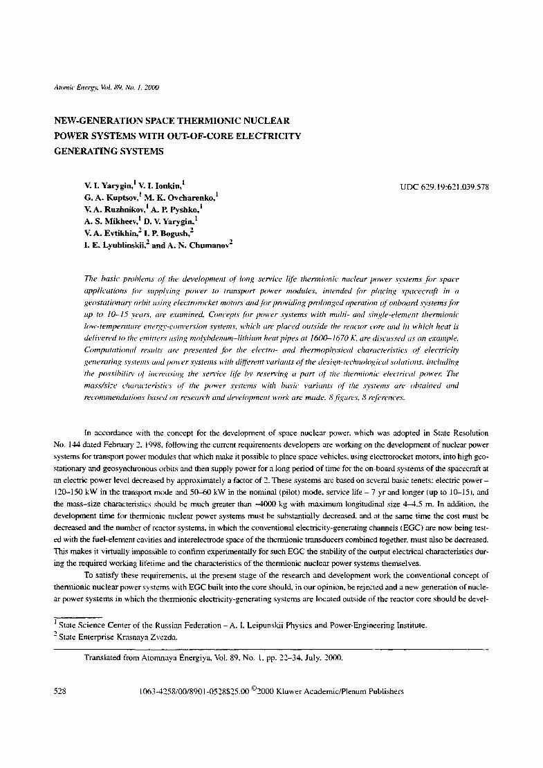
Fig. 1. Maximum electric power density versus the interelectrode gap width at the emitter
temperature 1300 (111), 1400 (e), 1500 (A), and 1600 K (e), collector temperature 830-850 K,
optimal cesium vapor pressure (a), and the output electric power density versus emitter
temperature at collector temperature 830-850 K, interelectrode gap 0.8 ram, and optimal
cesium vapor pressure Ib).
oped. This approach will enable the developers to separate the problem of developing and testing the reactor itself and the EGC,
the lifetime stability of whose output electrical characteristics can be confirmed experimentally during tests on stands with elec-
tric heating. In principle, either a liquid-metal loop or high-temperature heat pipes can be used to extract heat from the reactor
core, depending on the characteristics and type of nuclear power system. However, the possibility of attaining and maintaining
the required electrical characteristics and efficiency during the intended service life of the thermionic nuclear power system will
largely depend on decreasing the working temperature of the fuel elements and the radiator shell to <1700 K while maintaining
the efficiency at not less than 10% Igeneralized efficiency indica tor - the so-called barrier index - less than 1.95 eV), the devel-
opment of high-temperature heat pipes which can operate stably tbr a long period of time, "'wet" and "'dry'" ceramic insulation
at emitter and collector temperatures, nuclear and radiation safety of the system, and advances in the development of a new gen-
eration of cooler-radiators which are folded in the transport regime and unfolded in the operational regime.
Two schemes of thermionic electricity-generating systems, based on molybdenum-lithium high-temperature heat pipes
and a corresponding nuclear power system concept, are discussed in this paper: one based on a low-temperature multielement
EGC with wet emitter ceramic insulation and another based on a single-diode all-metal high-current electricity-generating ele-
ment with a shunt interconnection of the electrodes and dry ceramic insulation for some components of the EGC.
Output Electric Character is t ics of Low-Tempera tu re Thermionic Converters with Efficient Electrode Mater ials .
Recent investigations of various emitter and collector materials and of the working process in a thermionic converter with elec-
trical heating, which were performed at the State Science Center of the Russian Federation - Physics and Power Engineering
Institute. have made it possible to select efficient electrode materials that give in low-temperature arc regimes of operation at
the emitter temperature T e = 1300-1600 K the minimum barrier index =1.9 eV, which corresponds to electrode efficiency 13%
(at T e = 1600 K). These electrode materials are called "series KI7." The emitters of such converters are based on tungsten or
molybdenum and the collectors are based on a metal-oxygen system [ 1].
The K 17 electrode pair contains modified platinum and vanadium emitter and collector materials. In a low-temperature
thermionic converter, this pair makes it possible to obtain the output electric characteristics in isothermal and equipotential arc
regimes shown in Fig. 1,
Efficient electrode materials and an optimally organized working process in a thermionic converter, which maintains
the composition of the interelectrode working medium unchanged, give a new quality to the low-temperature thermionic con-
version of heat into electricity, making it possible to obtain with an interelectrode gap 0.6-0.8 mm high output electric charac-
teristics in conventional low-temperature arc regime. It is attractive for optimizing the characteristics of an out-of-core multi-
element EGC whose emitters are heated by heat pipes.
The current-voltage characteristics obtained for a thermionic converter with a KI7 electrode pair in the range
T e = 1250-1650 K, T c = 730-900 K, interelectrode gap 0.1-2.5 mm, and cesium pressure 6.5--6.5.10- Pa made it possible to
perform self-consistent electric and thermal calculations of the characteristics of EGC of various sizes and to match them with
529
LA 16O
120
80
40 0 4 8 12
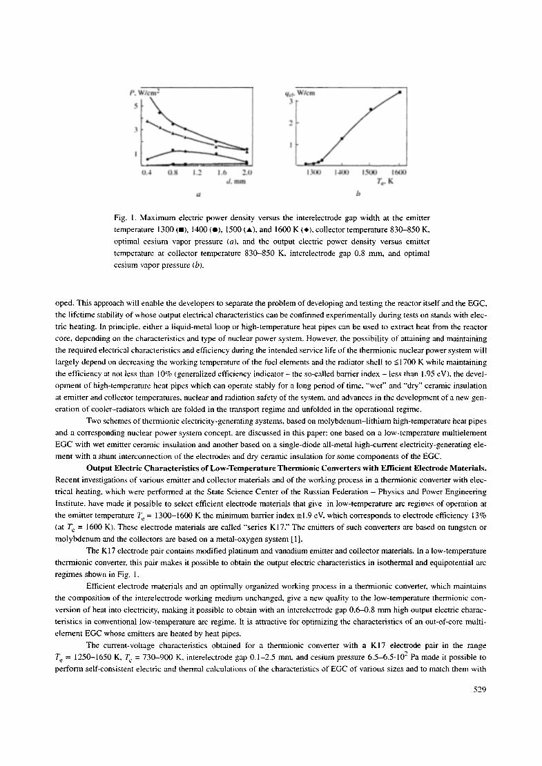
Fig. 2. Isopower current-voltage characteristics of a
20-element EGC with the K 17 electrode pair at thermal
power 9.4 (1), 8 (2), 6.2 kW (3), collector temperature
-850 K, and cesium vapor pressure 144 Pa.
the requirements that follow from the computed neutron-physical characteris t ics of a converter reactor with out-of-core
thermionic converters operating on heat pipes. The computational optimization o f the EGC characteristics was geared toward
generating electric power - 120 kK of the reactor-converter output voltage - 125 V in the forced operating regime and - 6 0 kW
in the nominal, long-term operating regime.
E n e r g y Character i s t i cs o f EGC and the Reac tor -Conver te r . We examined the possibility of a thermionic converter
reactor operating in the forced mode and generating an output electric power of about 120 kW at a voltage of 125 V with max-
imum emitter temperature not exceeding 1600 K as well as a decrease of the output electric power to 60 kW on switching into
the long-term operat ing regime in a variant with mult ie lement EGC, in a variant o f a thermionic converter reactor based on sin-
gle-diode all-metal high-current electricity-generating elements with shunt interconect ion of the electrodes - 150 and 50 kW,
respectively, with output voltage of about 60 V and T c = 1673 K.
Analysis of the interconnection schemes of multielement EGC in a thermionic reactor-converter showed that an
arrangement with 120 EGC, combined into eight parallel branches with 15 serially connected EGC in each branch, could satis-
fy these requirements. Since the output voltage of such reactors-converters shou ld be 125 V, each EGC should operate at an aver-
age voltage UEG C = 8.33 V. To obtain an output electric power of 120 kW from the reactor-converter in the forced regime, each
EGC should generate at this voltage -1 kW on the average. To determine the condi t ions under which this is possible, computa-
tional optimization of the basic geometric parameters of the EGC was performed and its output characteristics and the electrode
temperature were calculated. The basic geometric parameters of the EGC which were chosen in the course of the computation-
al optimization are as follows:
Length of the electricity generating part of a channel, m m . . . . . . . . . . . . . . . . . . 650
Number of electricity-generating elements in the EGC . . . . . . . . . . . . . . . . . . . . . 20
Length o f electricity generating element (all elements of equal lengthj , mm . . . . . 31
L e n ~ h of interconnection intervals, mm . . . . . . . . . . . . . . . . . . . . . . . . . . . . . . . . 2
Outer diameter of the emitters, m m . . . . . . . . . . . . . . . . . . . . . . . . . . . . . . . . . . . . 23
Emit ter thickness, mm . . . . . . . . . . . . . . . . . . . . . . . . . . . . . . . . . . . . . . . . . . . . . . 1
lnterelectrode gap width, mm . . . . . . . . . . . . . . . . . . . . . . . . . . . . . . . . . . . . . . . . 0.6
Collector thickness, mm . . . . . . . . . . . . . . . . . . . . . . . . . . . . . . . . . . . . . . . . . . . . 1
Total emission area, cm 2 . . . . . . . . . . . . . . . . . . . . . . . . . . . . . . . . . . . . . . . . . . . . 450
The number of electricity generating elements (20) was chosen on the basis of the need to ensure a maximum emitter
temperature no higher than 1600 K and at the same time an EGC output voltage 8.33 V at the working point. The isopower cur-
rent-voltage characterist ics of an EGC with a K 17 electrode pair were calculated using the TFEDM program [ I ] with average
collector temperature 850 K, which is close to the optimal value (Fig. 2). The ces ium vapor pressure for 6 .2-9 .4 kW(t) was cho-
sen to be constant (144 Pa) and equal to the optimal value 9.4 kW.
530

T~lllax, K
1800
1650
! 50(1
1350
1200
I I [ 2/)00 /
9 - 1500
�9 0
Ncl. W
6 8 10 C). kW
Fig. 3. Output electric power of a 20-element EGC (1),
maximum emitter temperature (2), and efficiency (3)
versus the thermal power with voltage UEG c. = 8.33 V
(T c = 850 K, Tcs = 144 Pal.
According to Fig. 3, the required output electric power of the EGC Ncl = 1 kW can be obtained with a thermal power
of about 9.4 kW and maximum emitter temperature -1595 K. The efficiency of the EGC is 10.64%.
We shall now examine a different possible implementation of a thermionic electricity generating module in a variant with
a thermionic electric power reserve. It is obtained by dividing the themaionic conversion zone into two equal p,'u'ts. Each part con- I
sists of 120 10-element EGC of half the leng~da. We note that the dimensions of the electricity-generating elements remain the s,'une
,'ts in the basic 20-element variant. The reactor construction with this implementation of the thermionic electricity generating module
allows tbr the tact that because of the change in the operating regime of the heat pipes delivering heat to the emitters of the EGC out-
side the core, by delivering in them a noncondensing gas (argon), i.e., by switching to a regime of gas-regulated heat pipes, the
thermionic converting zones of the EGC can operate simultaneously o.s well as in succession. With both thermionic zones operating
simultaneously, the reactor generates electric power ~ 120 kW at 120 V, and one thermionic zone operating ,'done generates -60 kW
at the same voltage. The second thermionic conversion zone is at this time in "'themlal reserve" and does not generate electric power.
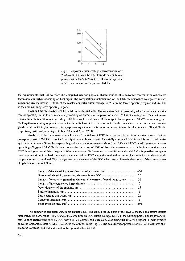
Figure 4 shows the conceptual schemes of the basic variant of a 20-element EGC (Fig. 4a) and two schemes of a I 0-ele-
ment EGC with thermionic electric power held in reserve: in the variant with two 10-element EGC connected in parallel inside
a single housing (Fig. 4b) and in a possible variant with a 10-element thermionic EGC placed in the conversion units on differ-
ent sides of the core of the reactor-converter but on the same high-temperature heat pipes (Fig. 4c).
The computed output characteristics, the thermal characteristics of the thermionic electricity generating module, and
correspondingly the thermionic reactor-converter are, in our opinion, most attractive: at emitter temperature ~ 1600 K (low-tem-
perature regime), the efficiency is 10.6%. They substantially exceed the characteristics of conventional EGC I built into the core)
on account of the following distinguishing features:
- use of efficient electrode materials, giving a low-temperature arc operating regime with barrier index 1.9 eV, and in
turn corresponding to an electrode efficiency of 13% (no thermal and electric losses in the electrodes and connections):
- high isothermality of electrodes with optimized interconnection, thermal, and electric losses (optimized choice of
length, thickness of the electricity generating elements, connecting interelectrode bridge, and others);
- compensation of the intrinsic magnetic field as a result of the use of a cathode reverse current output, giving a uni-
form distribution of cesium pressure along a relatively long working part of the EGC and, correspondingly, a uniform distribu-
tion of the current density over the entire working surface of the EGC.
Here, a thermionic electricity-generating module and, correspondingly, a reactor-converter with thermionic electric
power held in reserve is most attractive from our point of view. Calculations established the following for this variant:
- the interconnection scheme of the EGC in the reactor-converter must include four parallel branches with each branch
containing 30 serially connected EGC (120 EGC in all);
- t h e parameters of the working point of the average EGC (Te max = 1595-t600 K, T c = 850 K, Pcs = t44 Pa, interelec-
trode gap 0.6 mm) are: voltage 4.17 V, current 120 A. electric power 500 W with thermal power 4.7 kW, and efficiency 10,64%;
- the thermal power of all EGC in the fourth regime 1128 kW and in the prolonged operation regime 564 kW.
531
6 7 R (p
lO
1!
12
/3
14
16
/7
19
20 /7
A
I 2
4
21 I 2 3 4 5 6
7 8 v
I0 11 12 t3 14
15 A ,..- 1 6
17
I,~ IO 2o 17
21
A
I 0 t) ,,,;
A(2 : I)
Fig. 4. Conceptual scheme for different variants of a thermionic electricity generating module: 1, 3) cathode
and anode current output, respectively; 2) metal-ceramic unit ("hot" sealed input): 4) "cold" sealed input;
5) cesium vapor input; 6) guard electrode; 7) collector dry ceramic insulation; 8) electrically neutral case;
9. 13) collector and emitter wet ceramic insulation, respectively; 10) collector: l l ) emitter; 12) interelectrode
connection of electricity generating elements; 14) high-temperature molybdenum-lithium heat pipe;
15) wick of the high-temperature heat pipe (capillary-porous structure); 16) channel for extracting gaseous
fission fragments; 17) reflector; 18) ring-shaped fuel element; 19) fuel element jacket; 20) screen-vacuum
insulation of a fuel element; 21) channel for feeding nondensing gas (argon) into the gas-regulated high-tem-
perature heat pipes; 22) end ceramic insulation.
Thermionic Electricity Generating Module with Multielement EGC and a Reactor-Converter. The therrnionic
electricity generating module (see Fig. 4) is a functionally complete part of the reactor core with a system for converting heat
into electricity, which is placed on a molybdenum-lithium high-temperature heat pipe and placed outside the core.
The thermionic electricity generating module is a component of the reactor-converter, one of the basic functional com-
ponents of a space nuclear power system (Fig. 5).
532
17
18
16 15 14
. . . . . 13 ~ " " ......... :" 12 11 lO
7
4
; ~ '..
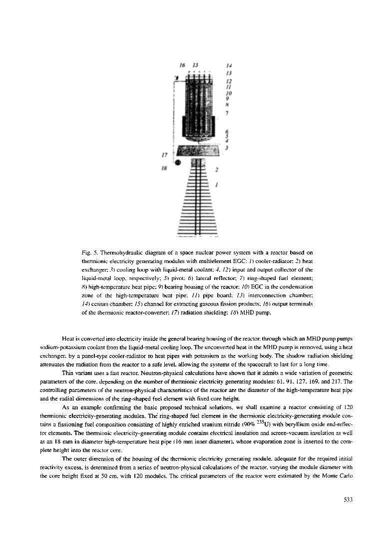
Fig. 5. Thermohydraulic diagram of a space nuclear power system with a reactor based on
thermionic electricity generating modules with multielement EGC: 1) cooler-radiator; 2) heat
exchanger; 3) cooling loop with liquid-metal coolant; 4, 12) input and output collector of the
liquid-metal loop, respectively; 5) pivot: 6) lateral reflector: 7) ring-shaped fuel element;
8) high-temperature heat pipe; 9) bearing housing of the reactor; 10) EGC in the condensation
zone of the high-temperature heat pipe: 11) pipe board: 13) interconnection chamber:
14) cesium chamber: 15) channel tbr extracting gaseous fission products; 16) output terminals
of the thermionic reactor-converter; 17) radiation shielding; 18) MHD pump.
Heat is converted into electricity inside the general bearing housing of the reactor, through which an MHD pump pumps
sodium-potassium coolant from the liquid-metal cooling loop. The unconverted heat in the MHD pump is removed, using a heat
exchanger, by a panel-type cooler-radiator to heat pipes with potassium as the working body. The shadow radiation shielding
attenuates the radiation from the reactor to a safe level, allowing the systerrts of the spacecraft to last for a long time.
This variant uses a fast reactor. Neutron-physical calculations have shown that it admits a wide variation of geometric
parameters of the core, depending on the number of thermionic electricity generating modules: 61, 9 I. 127, 169, and 217. The
controlling parameters of the neutron-physical characteristics of the reactor are the diameter of the high-temperature heat pipe
and the radial dimensions of the ring-shaped fuel element with fixed core height.
As an example confirming the basic proposed technical solutions, we shall examine a reactor consisting of 120
thermionic electricity-generating modules. The" ring-shaped fuel element in the thermionic electricity-generating module con-
tains a fissioning fuel composition consisting of highly enriched uranium nitride (90% 235U) with beryllium oxide end-reflec-
tor elements. The thermionic electricity-generating module contains electrical insulation and screen-vacuum insulation as well
as an i 8 mm in diameter high-temperature heat pipe ( 16 nun inner diameter), whose evaporation zone is inserted to the com-
plete height into the reactor core.
The outer dimension of the housing of the thermionic electricity generating module, adequate for the required initial
reactivity excess, is determined from a series of neutron-physical calculations of the reactor, varying the module diameter with
the core height fixed at 50 cm, with 120 modules. The critical parameters of the reactor were estimated by the Monte Carlo
533
method [3] in a heterogeneous computational model with detailed representation of the structural components of the module and
the reactor as a whole.
The construction of the reactor itself is conventional for fast reactors with a moderating reflector and includes the work-
ing organs of a rotating-type shielding control system, active safety means {safety rods) for compensating a hypothetical posi-
tive hydrogen effect of reactivity associated with filling of the reactor with water.
The core contains 120 thermionic electricity-generating modules with a diameter of 32 mm ~the spacing of the trian-
gular lattice is 33 mm). The core housing is 3 mm thick and the beryllium side reflector is 11 cm thick with 12 working organs
of the rotating-type control rod system. The basic characteristics of the reactor generating 120 kW(e) are as tbllows:
Core: 235U load, kg . . . . . . . . . . . . . . . . . . . . . . . . . . . . . . . . . . . 173.4
effective diameter, cm . . . . . . . . . . . . . . . . . . . . . . . . . . . . . 39
height, cm . . . . . . . . . . . . . . . . . . . . . . . . . . . . . . . . . . . . . 50
volume, liters . . . . . . . . . . . . . . . . . . . . . . . . . . . . . . . . . . . 60
vessel diameter, cm . . . . . . . . . . . . . . . . . . . . . . . . . . . . . . 43.6
Outer diameter of the side reflector, cm . . . . . . . . . . . . . . . . . . 66
Height o f the end reflectors, cm . . . . . . . . . . . . . . . . . . . . . . . . 10
Reactor:
effective neutron multiplication factor . . . . . . . . . . . . . . . . . 1.06
mass, including thermionic modules, kg . . . . . . . . . . . . . . . 900-1000
The lithium high-temperature heat pipes bring heat from the jacket of the ring-shaped fuel element to the EGC radia-
tors. In this design, the classical cylindrical heat pipes with a wick placed along their walls are used. The heat pipes can be made
of molybdenum or molybdenum alloys. The technology for filling heat pipes with lithium employs the experience gained at the
State Science Center of the Russian Federation - Physics and Power-Engineering Institute and the state enterprise Krasnaya
Zvezda [4. 5].
The system tbr removing heat from the housing of the thermionic electricity-generating module to the radiator icool-
er-radiator) is a single-loop circulation scheme (see Fig. 5). The coolant is a sodium-potassium eutectic alloy because this alloy
possesses a low melting point and because its technology has been worked out in ~eatest detail. Moreover, the State Science
Center of the Russian Federation - Physics and Power-Engineering Institute has experience in operating the space nuclear power
systems Buk and Topaz using this coolant. A panel-type heat-pipe radiator-emitter is used as the cooler-radiator.
The basic technical characteristics of the individual systems of the power system and the nuclear power system ms a
whole are as follows:
Power, kW:
generated electrical power
thermal power
Output voltage, V
Operating lifetime, yr
Variant 1 (basic) Variant 2 ~with reserve)
Regime
forced nominal forced nominal
Regime parameters
120 60
1200 750
125 125
up to ! n o t l e s s t h a n 6
Maximum emitter temperature, K
Electrode pair of materials
Interelectrode gap, mm
Absorbed dose:
according to neutrons (E > 0.1 MeV), cm -
according to y rays, rad
1595 1400
KI7
0.6
120 60
1200 600
125 125
up to ! not less than 6
for each unit
1600 1600
1.1012
1.106
534
Distance between the reactor and the detected object, m
Temperature of emitting surface of the cooler-radiator panels, K
Emitting surface area (with unilateral heat shedding), m 2
Dimensions, m, not greater than:
in the transport position
maximum diameter 2
maximum len~h 4.5
in the working position
maximum diameter 3
maximum length 13
Mass, kg. not greater than:
reactor unit (with EGC and fuel) 1000
radiation shielding 635
moving-aside system + electric cables 735
coolant in the circulation loop 150
MHD pump of the circulation loop 100
tubes of the circulation loop 100
cooler-radiator (with heat exchanger, panels, working body, and pipest 830
securing components (frame. brackets, and others) 200
Total 3750
not ~eater than 24
not less than 800
Mass/size characteristics
not ~eater than 70
The technology tor thbricating multilayer elements Me-ceramic-Me on the emitters and Me-ceramic-Me--ceram-
ic-Me on the collectors of the thermionic electricity generating modules is based on matched, with respect to the linear expan-
sion coefficient, coupling of layers obtained with gas-static compression, and vacuum soldering of different layers by a combi-
nation of these methods, in many ways it is analogous to the well-known technology of [6]. It contains technical solutions for
fabricating multilayer systems with wet and dry ceramic electric insulation based on AI203 at a temperature higher than in our
case, 1770 K.
Thermionic Power Module Based on a Single-Diode All-Metal Electricity Generating Element with Shunt Inter-
connection of the Electrodes and a Reactor-Converter. Despite the attractiveness of using multielement EGC in a thermion-
ic electricity generating module and reactor-converter, at the present time a complete technology does not exist for fabricating
a three-layer package Me-ceramic-Me for emitters and the five-layer package Me-ceramic-Me--ceramic-Me for collectors [6].
It is obvious that this complex technological problem can and will undoubtedly be solved in the near future, especially for
low-temperature EGC with T c < 1600 K.
However, even now the concept of a reactor-converter with the thermionic converters placed outside of the core on
molybdenum-lithium heat pipes is close to practical implementation and correspondingly to the development of a new genera-
tion of space nuclear power systems as a whole using a simplified (due to rejection of the ceramic insulation on the electrodes)
thermionic power module based on single-element electricity generating components with metallic shunt interconnection of the
electrodes [7].
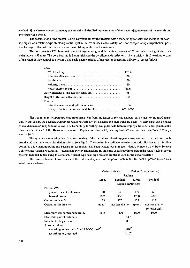
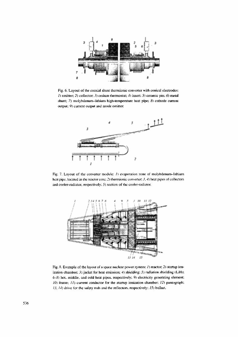
Figure 6 displays the layout of such a module, containing electricity generating elements connected in parallel and
placed on one (common) high-temperature heat pipe. A special feature of these single-element electricity generating elements
is the use of a metallic shunt (bellows), whose electrical resistance is 10-15 times greater than that of the interelectrode medi-
um (low-temperature cesium plasma) during ignition of a low-voltage arc discharge between the electrodes, as the interelectrode
electrical insulation between the coaxial emitter and collector.
Figure 7 shows a dia~am of the converter modules as a whole. It is intended for use in space nuclear power systems,
in which all heat-delivery and heat-extraction systems are constructed on heat pipes and in which it was possible to do away
with the liquid-metal loop tbr cooling the reactor and the heat exchanger between the loop and the heat pipes of the cooler-radi-
ator [8]. The basic element of such modules and the reactor-converter is the electricity generating element itself: whose devel-
opment is substantially advanced compared with multielement EGC. It is now possible to fabricate several experimental sam-
pies of electricity generating elements 11/2 module, a prototype of which is shown in Fig. 6). Platinum on the emitter and nick-
535
3 , 4 ~ 3
~ ~ t
,.~ ~~~i'~~..,,.'~ :i:::i .... LL~iL ~ = .... ~'~'~"~ '~." '
Fig. 6. Layout of the coaxial shunt thermionic converter with conical electrodes:
1) emitter; 2) collector; 3) cesium thermostat; 4) insert: 5) ceramic pin: 6) metal
shunt; 7) molybdenum-lithium high-temperature heat pipe: 8) cathode current
output; 9) current output and anode emitter.
1
Fig. 7. Layout of the converter module: 1) evaporation zone of molybdenum-lithium
heat pipe, located in the reactor core; 2) thermionic converter: 3.4) heat pipes of collectors
and cooler-radiator, respectively: 5) section of the cooler-radiator.
1 2 3 4 5 6 7 8 4 9 5 3 I0 I I 12
i . ~ , , I ' , ', ; ', ~ ~ ~'~"~:
. !
13 14 15
Fig. 8. Example of the layout of a space nuclear power system: 1) reactor: 2) startup ion-
ization chamber; 3) jacket for heat emission; 4) shielding; 5) radiation shielding (LiH);
6-8) hot, middle, and cold heat pipes, respectively; 9) electricity generating element;
10) frame; 11) current conductor for the startup ionization chamber; 12) pantograph;
13, 14) drive for the safety rods and the reflectors, respectively; 15) ballast.
536
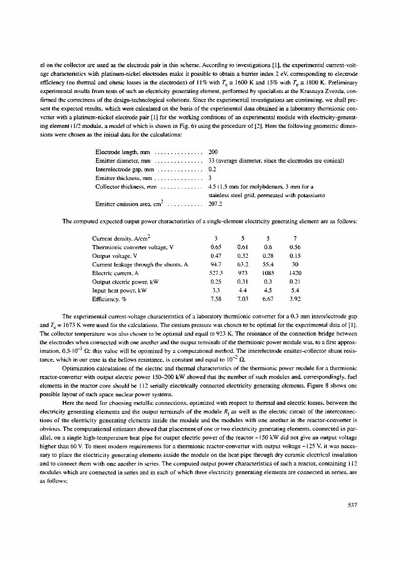
el on the collector are used as the electrode pair in this scheme. According to investigations [1], the experimental current-volt-
age characteristics with platinum-nickel electrodes make it possible to obtain a barrier index 2 eV, corresponding to electrode
eff• (no thermal and ohmic losses in the electrodes) of 11% with T e _= 1600 K and 15% with T e _= 1800 K. Preliminary
experimental results f rom tests of such an electricity generating element, performed by specialists at the Krasnaya Zvezda` con-
firmed the correctness of the design-technological solutions. Since the experimental investigations are continuing, we shall pre-
sent the expected results, which were calculated on the basis of the experimental data obtained in a laboratory thermionic con-
vener with a platinum-nickel electrode pair [ 1] for the working conditions of an experimental module with electricity-generat-
ing element ( 1/2 module, a model of which is shown in Fig. 6) using the procedure of [2]. Here the following geometric dimen-
sions were chosen as the initial data for the calculations:
Electrode length, mm
Emitter diameter, mm . . . . . . . . . . . . . . .
lnterelectrode gap, mm . . . . . . . . . . . . . .
Emit ter thickness, mm . . . . . . . . . . . . . . .
Collector thickness, mm . . . . . . . . . . . . .
Emit ter emission area. cm 2 . . . . . . . . . . .
. . . . . . . . . . . . . . . 200
33 (average diameter, since the electrodes are conical)
0.2
3
4.5 t 1.5 mm for molybdenum, 3 mm for a
stainless steel grid, permeated with potassium)
207.2
The computed expected output power characteristics of a single-element electricity generating element are as follows:
Current density, A/cm 2 3 5 5 7
Thermionic convener voltage, V 0.65 0.61 0.6 0.56
Output voltage, V 0.47 0.32 0.28 0.15
Current leakage through the shunts, A 94.7 63.2 55.4 30
Electric current. A 527.3 973 1085 1420
Output electric power, kW 0.25 0.31 0.3 0.21
Input heat power, kW 3.3 4.4 4.5 5.4
Efficiency, % 7.58 7.03 6.67 3.92
The experimental current-voltage characteristics of a laboratory thermionic converter for a 0.3 mm interelectrode gap
and T c = 1673 K were used for the calculations. The cesium pressure was chosen to be optimal for the experimental data of [1].
The collector temperature was also chosen to be optimal and equal to 923 K. The resistance of the connection bridge between
the electrodes when connected with one another and the output terminals of the thermionic power module was, to a first approx-
imation, 0.5.10 -3 ~ ; this value Will be optimized by a computational method. The interelectrode emitter--collector shunt resis-
tance, which in our case is the bellows resistance, is constant and equal to 10 -2 ~2.
Optimization calculations of the electric and thermal characteristics of the thermionic power module for a thermionic
reactor-converter with output electric power 150-200 kW showed that the number of such modules and, correspondingly, fuel
elements in the reactor core should be 112 serially electrically connected electricity generating elements. Figure 8 shows one
possible layout of such space nuclear power systems.
Here the need for choosing metallic connections, optimized with respect to thermal and electric losses, between the
electricity generating elements and the output terminals o f the module R t as well as the electric circuit of the interconnec-
tions of the electricity generating elements inside the module and the modules with one another in the reactor-converter is
obvious. The computational estimates showed that placement of one or two electricity generating elements, connected in par-
allel, on a single high-temperature heat pipe for output electric power of the reactor ~ 150 kW did not give an output voltage
higher than 60 V. To meet modem requirements for a thermionic reactor-converter with output voltage ~ 125 V, it was neces-
sary to place the electricity generating elements inside the module on the heat pipe through dry ceramic electrical insulation
and to connect them with one another in series. The computed output power characteristics of such a reactor, containing 112
modules which are connected in series and in each o f which three electricity generating elements are connected in series, are
as follows:
537

Current density, A /cm 2 7 7
Resistance of connect ion bridge between the
electricity generat ing elements R c. ~ 0.1-10 -3 0.15-10 -3
Output voltage, V 147,5 135
Output electric power, k W 210 185
Thermal power, k W 2016 1934
Efficiency, % 9.97 9.58
It is obvious that even using three-element serially connected electricity generating e lements in a module on a single
heat pipe the electric power and output voltage of the reactor are. respectively, ~ 185 kW and ~ 135 V, which is close to the desired
values, and the expected efficiency reaches 9.6%. It is obvious that a further increase in efficiency and energy characteristics
will require an electrode pair that is more efficient than platinum-nickel, optimization of the sizes o f the electricity generating
e lements and the interconnections, and the thermal and electric losses, optimization of the electrical connect ion circuit of the
electricity generating elements in the modules, modules in the reactor-converter under conditions o f 7 - 1 0 times higher current
than in mult ielement EGC (up to - 1 4 0 0 A), and it will require methods for electrical insulation of e lements and modules, which
are under the electrical potential of the electricity generating elements, and determining the mass of the spacecraft as a whole.
However. at the current stage of "'ground-based'" adjustment of the reactor-converter, this cost is jus t i f ied in connection with the
great simplification of the electricity generat ing elements themselves and the thermionic power module. The basic characteris-
tics of a space nuclear power system with such a reactor-converter are as follows:
Number of fuel e lements . . . . . . . . . . . . . . . . . . . . . . . . . . . . . . . . 112
Number of working organs of the control and shielding system . . . 12
Number of safety rods . . . . . . . . . . . . . . . . . . . . . . . . . . . . . . . . . . 4
Effective core diameter, cm . . . . . . . . . . . . . . . . . . . . . . . . . . . . . . 51
Core height, cm . . . . . . . . . . . . . . . . . . . . . . . . . . . . . . . . . . . . . . . 60
- " U load, kg . . . . . . . . . . . . . . . . . . . . . . . . . . . . . . . . . . . . . . . . . 28.5
Diameter of the core vessel, cm . . . . . . . . . . . . . . . . . . . . . . . . . . . 61.8
Reactor mass, kg . . . . . . . . . . . . . . . . . . . . . . . . . . . . . . . . . . . . . . 1120
Effective neutron multiplication factor . . . . . . . . . . . . . . . . . . . . . . 1.06
Power, kW:
generated electrical . . . . . . . . . . . . . . . . . . . . . . . . . . . . . . . . . . 185
thermal . . . . . . . . . . . . . . . . . . . . . . . . . . . . . . . . . . . . . . . . . . . 1934
Output voltage, V . . . . . . . . . . . . . . . . . . . . . . . . . . . . . . . . . . . . . . 135
Service life, yr . . . . . . . . . . . . . . . . . . . . . . . . . . . . . . . . . . . . . . . . > 10
Maximum emitter temperature. K . . . . . . . . . . . . . . . . . . . . . . . . . . 1673
Electrode pair materials . . . . . . . . . . . . . . . . . . . . . . . . . . . . . . . . . P t - N i
Interelectrode gap, m m . . . . . . . . . . . . . . . . . . . . . . . . . . . . . . . . . . 0.3
Absorbed dose:
for neutrons (E > 0.1 MeV), cm - . . . . . . . . . . . . . . . . . . . . . . . 1.1012
for 7 rays, rad . . . . . . . . . . . . . . . . . . . . . . . . . . . . . . . . . . . . . . 1-106
Distance between the reactor and the shielding object, m . . . . . . . . not greater than 25
Temperature of the emitt ing surface of the cooler-radiator, K . . . . . 920
Emitting surface area (with bilateral heat emission), m 2 . . . . . . . . . 40
Dimensions, m, not greater than:
in the travel position:
max imum diameter . . . . . . . . . . . . . . . . . . . . . . . . . . . . . . . 2.4
max imum length . . . . . . . . . . . . . . . . . . . . . . . . . . . . . . . . . 4
in the working position:
maximum diameter . . . . . . . . . . . . . . . . . . . . . . . . . . . . . . . 3.5
maximum length . . . . . . . . . . . . . . . . . . . . . . . . . . . . . . . . . 7.8
538
Mass, kg:
reactor unit (with fuel) . . . . . . . . . . . . . . . . . . . . . . . . . . . . . . . 1120
radiation shielding . . . . . . . . . . . . . . . . . . . . . . . . . . . . . . . . . . . 1600
screen-radiator . . . . . . . . . . . . . . . . . . . . . . . . . . . . . . . . . . . . . 150
thermionic generator . . . . . . . . . . . . . . . . . . . . . . . . . . . . . . . . . 1069
molybdenum-li thium high-temperature heat pipes . . . . . . . . . . 280
cooler-emitter . . . . . . . . . . . . . . . . . . . . . . . . . . . . . . . . . . . . . . 318
moving-aside system . . . . . . . . . . . . . . . . . . . . . . . . . . . . . . . . . 372
frame . . . . . . . . . . . . . . . . . . . . . . . . . . . . . . . . . . . . . . . . . . . . 70
connecting bus . . . . . . . . . . . . . . . . . . . . . . . . . . . . . . . . . . . . . 22
thermal insulation . . . . . . . . . . . . . . . . . . . . . . . . . . . . . . . . . . . 120
drives . . . . . . . . . . . . . . . . . . . . . . . . . . . . . . . . . . . . . . . . . . . . 35
automatic control system . . . . . . . . . . . . . . . . . . . . . . . . . . . . . . 100
Total . . . . . . . . . . . . . . . . . . . . . . . . . . . . . . . . . . . . . . . . . . . . . . . . 5256
Analysis of the data shows that there is a high degree of readiness in the experimental and technological adjustment
and fabrication of the electricity generating elements, high-temperature molybdenum-lithium heat pipes, middle-temperature
vanadium-potassium heat pipes, elements of the core. and others, as well as the optimization system in performing design inves-
tigations and development of space nuclear power system for practical verification of the reactor-converter concept with the
thermionic energy-conversion system placed outside the reactor core.
Conclusions. Analysis of the possibility of developing a new-generation space nuclear power system with a thermion-
ic reactor-converter based on thermionic modules with molybdenum-lithium high-temperature heat pipes with working tem-
perature in the range 160(O1673 K using one- and multi-element thermionic electricity generating elements/electricity generat-
ing channels placed outside the core has shown that the present status of the thermionic component base, technology for fabri-
cating heat pipes and metal-ceramic units lbr the electrode systems, as well as the level of current development of fast reactors
with a liquid-metal cooling loop and compact radiation shielding and nuclear safety meets the expectations of the designers of the
new-generation space nuclear power systems based on a new technology with substantially improved service life up to 10-15 yr
and mass/size characteristics for the transport power modules.
The fundamentally new aspect associated with the possibility of constructing thermionic conversion system based on
gas-regulated high-temperature heat pipes is a reserve of thermionic electric power, which help to increase reliability and the
service life of space nuclear power systems as a whole.
The next problem is to go on to the experimental stage of the development work and to tests of the key systems, specif-
ically, thermionic efficient electrode materials, gas-regulated high-temperature heat pipes, metal-ceramic multilayer packets,
ring-shaped fuel elements, and others.
REFERENCES
1.
3.
Jr.
5.
D. V. Yarygin, V. S. Mironov, N. P. Solov'ev, et al."Thermionic converter with high output electric characteristics with
Me--O system on the collector," in: Abstracts of Reports at the Second International Seminar ol7 Space Nuclear Power
for the 21st Century (April 19-21, 2000), pp. 71-72.
V. A. Ruzhnikov and V. M. Dmitrieva~ "Numerical method for simultaneous solution of the heat and electric problems
for a thermionic EGC," Preprint No. 774, Physics and Power-Engineering Institute (1977).
V. B. Polevoi, V. V. Lenot'ev, A. V. Ovchinnikov, et al., "*Basic package of programs in the MMKFK-2 system for Monte
Carlo solution of neutron transfer problems in reactor physics (MMKFK-2-BASE), Sector fund of algorithms and pro-
grams for nuclear reactors," No. 00371, Moscow (1996).
M. N. Ivanovskii, V. P. Sorokin, B. A. Chulkov, and I. V. Yagodkin, Technological Principles of Heat Pipes [in Rus-
sian], Atomizdat, Moscow (1980).
V. N. Mikhailov, V. A. Evtikhin, I. E. Lyublinskii, et al., Lithium in Thermonuclear and Space Power Production ~fthe
21st Centur 3, [in Russian], l~nergoatomizdat, Moscow (1999).
539
6.
7.
8.
H. Streckert, L. Begg, Yu. B. Nikolaev, et al., "'Development and testing of conductively coupled multicell TFE com-
ponents," in: Proceedings of Space Technology and Applications Intenlational Forum-2000, Albuquerque, USA (2000L
pp. 1307-1312.
N. M. Afanas'ev, A. V. Vertkov, V. A. Evtikhin, et al., "'Thermionic power module. Useful model No. 9084:" priority
July 28, 1998, PolezdTve Modeli i Prom. Obraztsy, No. 1, 68 (1999).
V. A. Evtikhin and A. N. Chumanov, "Space nuclear power system;' Russian Federation Patent No, 2129740, priority
July 28, 1998; Izobretel~iya, No. 12, 515 (1999).
540