Embed Size (px)
Citation preview
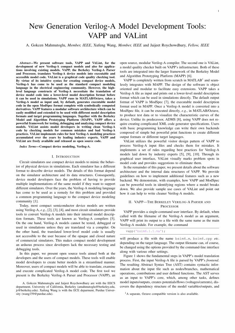
New Generation Verilog-A Model Development Tools:VAPP and VALint
A. Gokcen MahmutogluXufeng WangJaijeet Roychowdhury
Electrical Engineering and Computer SciencesUniversity of California at Berkeley
Technical Report No. UCB/EECS-2018-89http://www2.eecs.berkeley.edu/Pubs/TechRpts/2018/EECS-2018-89.html
July 4, 2018

Copyright © 2018, by the author(s).All rights reserved.
Permission to make digital or hard copies of all or part of this work forpersonal or classroom use is granted without fee provided that copies arenot made or distributed for profit or commercial advantage and that copiesbear this notice and the full citation on the first page. To copy otherwise, torepublish, to post on servers or to redistribute to lists, requires prior specificpermission.
1
New Generation Verilog-A Model Development Tools:VAPP and VALint
A. Gokcen Mahmutoglu, Member, IEEE, Xufeng Wang, Member, IEEE and Jaijeet Roychowdhury, Fellow, IEEE
Abstract—We present software tools, VAPP and VALint, for thedevelopment of new Verilog-A compact models and also for applica-tions involving existing models. VAPP, the Berkeley Verilog-A Parserand Processor, translates Verilog-A device models into executable andaccessible model code. VALint is a graphical code quality checking tool.By virtue of its intuitive syntax for creating compact device models,Verilog-A has come to be used as the standard compact modelinglanguage in the electrical engineering community. However, the high-level language constructs of Verilog-A necessitate the translation ofdevice model code into a lower-level model description format beforeit can be used in simulations. VAPP runs in MATLAB/Octave, takes aVerilog-A model as input and, by default, generates executable modelcode in the open ModSpec format complete with symbolically computedderivatives. VAPP features a modular software architecture which can beeasily modified and extended to be used with different model descriptionformats and target programming languages. Together with the BerkeleyModel and Algorithm Prototyping Platform (MAPP), VAPP offers apowerful framework for testing, debugging and analyzing compact devicemodels. VALint assists model developers in writing clean Verilog-Acode by checking models for common mistakes and bad Verilog-Apractices. VALint implements rules for best Verilog-A modeling practicesaccumulated over the years by leading industry experts. VAPP andVALint are freely available and released as open source code.
Index Terms—Compact device modeling, Verilog-A.
I. INTRODUCTION
Circuit simulators use compact device models to mimic the behav-ior of physical devices in simulations. Each simulator has a differentformat to describe device models. The details of this format dependon the simulator architecture and its data structures. Consequently,device model developers face the problem of having to providemultiple implementations of the same model if they want to supportdifferent simulators. Over the years, the Verilog-A modeling languagehas come to be used as a remedy for this problem and provideda common programming language to the compact device modelingcommunity [1].
Today, most compact semiconductor device models are writtenusing Verilog-A, e.g., [2], [3], [4], and most circuit simulators providetools to convert Verilog-A models into their internal model descrip-tion formats. These tools are known as Verilog-A compilers [5].On the one hand, Verilog-A models cannot be tested, debugged orused in simulations unless they are translated via a compiler. Onthe other hand, the translated lower-level model code is usuallynot accessible to the user because of the opaque and closed natureof commercial simulators. This makes compact model developmentan arduous process since developers lack the necessary testing anddebugging tools.
In this paper, we present open source tools aimed both at thedevelopers and the users of compact models. These tools will enablemodel developers to create better models in a streamlined manner.Moreover, users of compact models will be able to translate, examineand execute complicated Verilog-A model code. The first tool wepresent is the Berkeley Verilog-A Parser and Processor (VAPP), an
A. Gokcen Mahmutoglu and Jaijeet Roychowdhury are with the EECSdepartment, University of California, Berkeley ([email protected],[email protected]). Xufeng Wang is with the ECE deparment, Purdue Univer-sity ([email protected]).
open source, modular Verilog-A compiler. The second one is VALint,a model quality checker built on VAPP’s infrastructure. Both of thesetools are integrated into the larger framework of the Berkeley Modeland Algorithm Prototyping Platform (MAPP) [6].
VAPP is completely written from scratch in MATLAB1 and seam-lessly integrates with MAPP. The design of the software is objectoriented and modular to facilitate easy extensions. VAPP takes aVerilog-A file as input and prints out a lower-level model descriptionformat which can be used in simulations directly. The default outputformat of VAPP is ModSpec [7], the executable model descriptionformat used in MAPP. Once a Verilog-A model is converted into aModSpec file, it can be executed directly, e.g., in MATLAB/Octave,to produce test data or to visualize the characteristic curves of thedevice. Unlike its predecessor, ADMS [8], using VAPP does not re-quire creating complicated XML code generator specifications. Userswith basic programming knowledge can write their own backendscomposed of simple but powerful print functions to create differentoutput formats or different target languages.
VALint utilizes the powerful visitor design pattern of VAPP toprocess Verilog-A input files and checks them for mistakes. Itimplements a set of rules regarding best practices for Verilog-Amodels laid down by industry experts [5], [9], [10]. Through itsgraphical user interface, VALint visually marks problem spots inmodel code and provides suggestions to eliminate them.
In the remainder of this paper, we present details about the softwarearchitecture and the internal data structures of VAPP. We provideguidelines on how to implement additional features such as a newbackend. We demonstrate, with examples, how VAPP and ModSpeccan be powerful tools in identifying regions where a model breaksdown. We also provide sample use cases of VALint and point outhow it can help to write cleaner Verilog-A models.
II. VAPP—THE BERKELEY VERILOG-A PARSER AND
PROCESSOR
VAPP provides a single-command user interface. By default, whencalled with the filename of the Verilog-A model as an argument,VAPP will print its output to a file with the same name as the mainVerilog-A module. For example, the command
vapp('bsim6.1.1.va');
will produce a file with the name bsim6.m, bsim6.cpp etc.depending on the target language. The output filename can, of course,be changed using the options provided by the command-line interfacealong with various other settings.
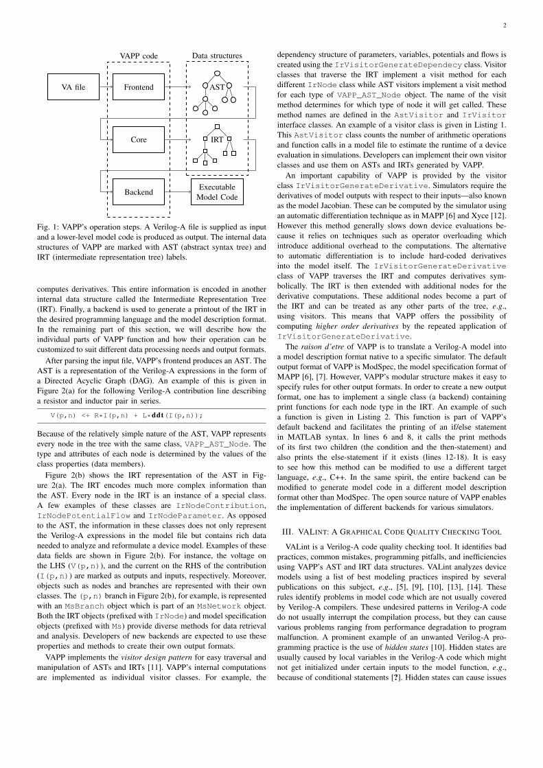
Figure 1 shows the fundamental steps in VAPP’s model translationprocess. First, the input Verilog-A file is parsed by VAPP’s frontend.The resulting Abstract Syntax Tree (AST) contains syntactic infor-mation about the input file such as nodes/branches, mathematicaloperations, contributions and user defined functions. The AST servesas an input to VAPP’s core, which, among other tasks, definesmodel inputs/outputs, creates potentials/flows (voltages/currents), dis-covers the dependency structure of the model variables/outputs, and
1A separate, Octave compatible version is also available.
2
VA file Frontend AST
Core IRT
BackendExecutable
Model Code
VAPP code Data structures
Fig. 1: VAPP’s operation steps. A Verilog-A file is supplied as inputand a lower-level model code is produced as output. The internal datastructures of VAPP are marked with AST (abstract syntax tree) andIRT (intermediate representation tree) labels.
computes derivatives. This entire information is encoded in anotherinternal data structure called the Intermediate Representation Tree(IRT). Finally, a backend is used to generate a printout of the IRT inthe desired programming language and the model description format.In the remaining part of this section, we will describe how theindividual parts of VAPP function and how their operation can becustomized to suit different data processing needs and output formats.
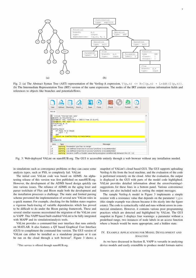
After parsing the input file, VAPP’s frontend produces an AST. TheAST is a representation of the Verilog-A expressions in the form ofa Directed Acyclic Graph (DAG). An example of this is given inFigure 2(a) for the following Verilog-A contribution line describinga resistor and inductor pair in series.
V(p,n) <+ R*I(p,n) + L*ddt(I(p,n));
Because of the relatively simple nature of the AST, VAPP representsevery node in the tree with the same class, VAPP_AST_Node. Thetype and attributes of each node is determined by the values of theclass properties (data members).
Figure 2(b) shows the IRT representation of the AST in Fig-ure 2(a). The IRT encodes much more complex information thanthe AST. Every node in the IRT is an instance of a special class.A few examples of these classes are IrNodeContribution,IrNodePotentialFlow and IrNodeParameter. As opposedto the AST, the information in these classes does not only representthe Verilog-A expressions in the model file but contains rich dataneeded to analyze and reformulate a device model. Examples of thesedata fields are shown in Figure 2(b). For instance, the voltage onthe LHS (V(p,n)), and the current on the RHS of the contribution(I(p,n)) are marked as outputs and inputs, respectively. Moreover,objects such as nodes and branches are represented with their ownclasses. The (p,n) branch in Figure 2(b), for example, is representedwith an MsBranch object which is part of an MsNetwork object.Both the IRT objects (prefixed with IrNode) and model specificationobjects (prefixed with Ms) provide diverse methods for data retrievaland analysis. Developers of new backends are expected to use theseproperties and methods to create their own output formats.
VAPP implements the visitor design pattern for easy traversal andmanipulation of ASTs and IRTs [11]. VAPP’s internal computationsare implemented as individual visitor classes. For example, the
dependency structure of parameters, variables, potentials and flows iscreated using the IrVisitorGenerateDependecy class. Visitorclasses that traverse the IRT implement a visit method for eachdifferent IrNode class while AST visitors implement a visit methodfor each type of VAPP_AST_Node object. The name of the visitmethod determines for which type of node it will get called. Thesemethod names are defined in the AstVisitor and IrVisitorinterface classes. An example of a visitor class is given in Listing 1.This AstVisitor class counts the number of arithmetic operationsand function calls in a model file to estimate the runtime of a deviceevaluation in simulations. Developers can implement their own visitorclasses and use them on ASTs and IRTs generated by VAPP.
An important capability of VAPP is provided by the visitorclass IrVisitorGenerateDerivative. Simulators require thederivatives of model outputs with respect to their inputs—also knownas the model Jacobian. These can be computed by the simulator usingan automatic differentiation technique as in MAPP [6] and Xyce [12].However this method generally slows down device evaluations be-cause it relies on techniques such as operator overloading whichintroduce additional overhead to the computations. The alternativeto automatic differentiation is to include hard-coded derivativesinto the model itself. The IrVisitorGenerateDerivativeclass of VAPP traverses the IRT and computes derivatives sym-bolically. The IRT is then extended with additional nodes for thederivative computations. These additional nodes become a part ofthe IRT and can be treated as any other parts of the tree, e.g.,using visitors. This means that VAPP offers the possibility ofcomputing higher order derivatives by the repeated application ofIrVisitorGenerateDerivative.
The raison d’etre of VAPP is to translate a Verilog-A model intoa model description format native to a specific simulator. The defaultoutput format of VAPP is ModSpec, the model specification format ofMAPP [6], [7]. However, VAPP’s modular structure makes it easy tospecify rules for other output formats. In order to create a new outputformat, one has to implement a single class (a backend) containingprint functions for each node type in the IRT. An example of sucha function is given in Listing 2. This function is part of VAPP’sdefault backend and facilitates the printing of an if/else statementin MATLAB syntax. In lines 6 and 8, it calls the print methodsof its first two children (the condition and the then-statement) andalso prints the else-statement if it exists (lines 12-18). It is easyto see how this method can be modified to use a different targetlanguage, e.g., C++. In the same spirit, the entire backend can bemodified to generate model code in a different model descriptionformat other than ModSpec. The open source nature of VAPP enablesthe implementation of different backends for various simulators.
III. VALINT: A GRAPHICAL CODE QUALITY CHECKING TOOL
VALint is a Verilog-A code quality checking tool. It identifies badpractices, common mistakes, programming pitfalls, and inefficienciesusing VAPP’s AST and IRT data structures. VALint analyzes devicemodels using a list of best modeling practices inspired by severalpublications on this subject, e.g., [5], [9], [10], [13], [14]. Theserules identify problems in model code which are not usually coveredby Verilog-A compilers. These undesired patterns in Verilog-A codedo not usually interrupt the compilation process, but they can causevarious problems ranging from performance degradation to programmalfunction. A prominent example of an unwanted Verilog-A pro-gramming practice is the use of hidden states [10]. Hidden states areusually caused by local variables in the Verilog-A code which mightnot get initialized under certain inputs to the model function, e.g.,because of conditional statements [?]. Hidden states can cause issues
3
<+
V
p n
+
*
R I
p n
*
L ddt
I
p n
(a)
Contributiontype: explicit
Potentialbranch: p_ntype: outputdependencies: I(p,n), R, L
Operationtype: add
Operationtype: mult
Parameterlabel: R
Flowbranch: p_ntype: input
Operationtype: mult
Parameterlabel: L
Functionname ddtnInput: 1nOutput: 1
Flowbranch: p_ntype: input
(b)
Fig. 2: (a) The Abstract Syntax Tree (AST) representation of the Verilog-A expression, V(p,n) <+ R*I(p,n) + L*ddt(I(p,n)).(b) The Intermediate Representation Tree (IRT) version of the same expression. The nodes of the IRT contain various information fields andreferences to objects like branches and potentials/flows.
Fig. 3: Web-deployed VALint on nanoHUB.org. The GUI is accessible entirely through a web browser without any installation needed.
in simulations such as convergence problems or they can cause someanalysis types, such as PSS, to completely fail. VALint
The initial core VALint code was based on ADMS. An alpha-testing release of this version was first published on nanoHUB.org.However, the development of the ADMS based design quickly raninto various issues. The reliance of ADMS on the aging lexer andparser toolchain of Flex and Bison made both the development andthe installation processes a challenge. The static and limited parsingscheme prevented the implementation of several new VALint rules ina quick manner. For example, checking for the hidden states requiresa vigorous back-tracing of variable dependencies which has provedto be difficult to do under the Bison parsing framework. These andseveral similar reasons necessitated the migration of the VALint coreto VAPP. This VAPP based built enabled VALint to be fully integratedwith MAPP and its simulation/analysis tools.
VALint provides a command-line user interface that runs entirelyon MATLAB. It also features a QT based Graphical User Interface(GUI) to compliment the command-line version. The GUI version ofVALint can either be installed as a standalone program or it canbe run on the cloud through a web browser2. Figure 3 shows a
2This service is offered through nanoHUB.org.
snapshot of VALint’s cloud based GUI. The GUI supports uploadingVerilog-A file from the local machine, and the evaluation of the codeis performed remotely on the cloud. After the evaluation, the outputis displayed in the GUI with parts of the model code highlighted.VALint provides detailed information about the errors/warnings/-suggestions for these lines in a bottom panel. Various conveniencefeatures are also included such as sorting the output messages.
The sample Verilog-A model in Figure 3 implements a simpleresistor with a resistance value that depends on the parameter type(this simple example was chosen because it fits nicely into the figureestate). The code is syntactically valid and runs without errors in com-mercial simulators. However, it contains various poor programmingpractices which are detected and highlighted by VALint. The GUIsnapshot in Figure 3 displays four warnings: a parameter without apredefined range, two instances of node labels in an access functionwhere a branch would be more appropriate, and a hidden state.
IV. EXAMPLE APPLICATIONS FOR MODEL DEVELOPMENT AND
ANALYSIS
As we have discussed in Section II, VAPP is versatile in analyzingdevice models and easily extendible to produce model formats native
4
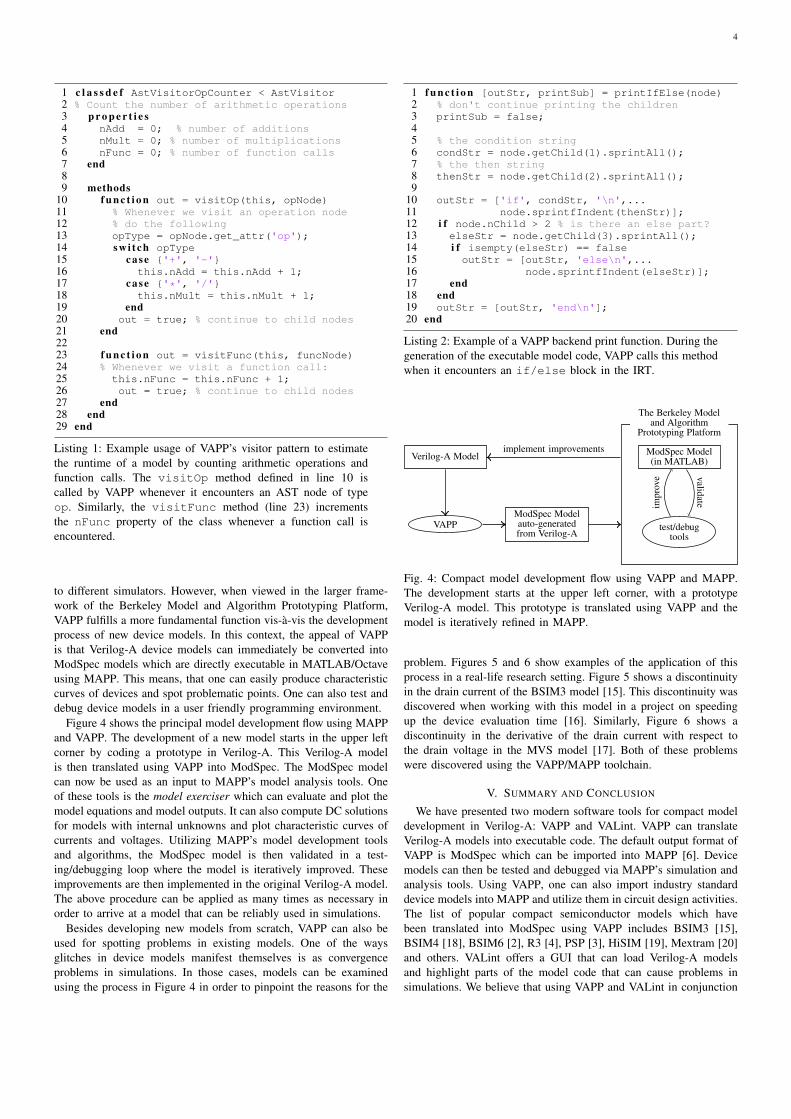
1 c l a s s d e f AstVisitorOpCounter < AstVisitor2 % Count the number of arithmetic operations3 p r o p e r t i e s4 nAdd = 0; % number of additions5 nMult = 0; % number of multiplications6 nFunc = 0; % number of function calls7 end89 methods
10 f u n c t i o n out = visitOp(this, opNode)11 % Whenever we visit an operation node12 % do the following13 opType = opNode.get_attr('op');14 sw i t ch opType15 case {'+', '-'}16 this.nAdd = this.nAdd + 1;17 case {'*', '/'}18 this.nMult = this.nMult + 1;19 end20 out = true; % continue to child nodes21 end2223 f u n c t i o n out = visitFunc(this, funcNode)24 % Whenever we visit a function call:25 this.nFunc = this.nFunc + 1;26 out = true; % continue to child nodes27 end28 end29 end
Listing 1: Example usage of VAPP’s visitor pattern to estimatethe runtime of a model by counting arithmetic operations andfunction calls. The visitOp method defined in line 10 iscalled by VAPP whenever it encounters an AST node of typeop. Similarly, the visitFunc method (line 23) incrementsthe nFunc property of the class whenever a function call isencountered.
to different simulators. However, when viewed in the larger frame-work of the Berkeley Model and Algorithm Prototyping Platform,VAPP fulfills a more fundamental function vis-a-vis the developmentprocess of new device models. In this context, the appeal of VAPPis that Verilog-A device models can immediately be converted intoModSpec models which are directly executable in MATLAB/Octaveusing MAPP. This means, that one can easily produce characteristiccurves of devices and spot problematic points. One can also test anddebug device models in a user friendly programming environment.
Figure 4 shows the principal model development flow using MAPPand VAPP. The development of a new model starts in the upper leftcorner by coding a prototype in Verilog-A. This Verilog-A modelis then translated using VAPP into ModSpec. The ModSpec modelcan now be used as an input to MAPP’s model analysis tools. Oneof these tools is the model exerciser which can evaluate and plot themodel equations and model outputs. It can also compute DC solutionsfor models with internal unknowns and plot characteristic curves ofcurrents and voltages. Utilizing MAPP’s model development toolsand algorithms, the ModSpec model is then validated in a test-ing/debugging loop where the model is iteratively improved. Theseimprovements are then implemented in the original Verilog-A model.The above procedure can be applied as many times as necessary inorder to arrive at a model that can be reliably used in simulations.
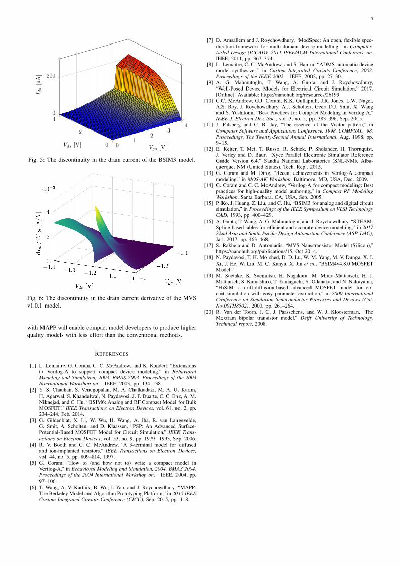
Besides developing new models from scratch, VAPP can also beused for spotting problems in existing models. One of the waysglitches in device models manifest themselves is as convergenceproblems in simulations. In those cases, models can be examinedusing the process in Figure 4 in order to pinpoint the reasons for the
1 f u n c t i o n [outStr, printSub] = printIfElse(node)2 % don't continue printing the children3 printSub = false;45 % the condition string6 condStr = node.getChild(1).sprintAll();7 % the then string8 thenStr = node.getChild(2).sprintAll();9
10 outStr = ['if', condStr, '\n',...11 node.sprintfIndent(thenStr)];12 i f node.nChild > 2 % is there an else part?13 elseStr = node.getChild(3).sprintAll();14 i f isempty(elseStr) == false15 outStr = [outStr, 'else\n',...16 node.sprintfIndent(elseStr)];17 end18 end19 outStr = [outStr, 'end\n'];20 end
Listing 2: Example of a VAPP backend print function. During thegeneration of the executable model code, VAPP calls this methodwhen it encounters an if/else block in the IRT.
ModSpec Model(in MATLAB)
test/debugtools
The Berkeley Modeland Algorithm
Prototyping Platform
Verilog-A Model
VAPPModSpec Modelauto-generatedfrom Verilog-A
validateimpr
ove
implement improvements
Fig. 4: Compact model development flow using VAPP and MAPP.The development starts at the upper left corner, with a prototypeVerilog-A model. This prototype is translated using VAPP and themodel is iteratively refined in MAPP.
problem. Figures 5 and 6 show examples of the application of thisprocess in a real-life research setting. Figure 5 shows a discontinuityin the drain current of the BSIM3 model [15]. This discontinuity wasdiscovered when working with this model in a project on speedingup the device evaluation time [16]. Similarly, Figure 6 shows adiscontinuity in the derivative of the drain current with respect tothe drain voltage in the MVS model [17]. Both of these problemswere discovered using the VAPP/MAPP toolchain.
V. SUMMARY AND CONCLUSION
We have presented two modern software tools for compact modeldevelopment in Verilog-A: VAPP and VALint. VAPP can translateVerilog-A models into executable code. The default output format ofVAPP is ModSpec which can be imported into MAPP [6]. Devicemodels can then be tested and debugged via MAPP’s simulation andanalysis tools. Using VAPP, one can also import industry standarddevice models into MAPP and utilize them in circuit design activities.The list of popular compact semiconductor models which havebeen translated into ModSpec using VAPP includes BSIM3 [15],BSIM4 [18], BSIM6 [2], R3 [4], PSP [3], HiSIM [19], Mextram [20]and others. VALint offers a GUI that can load Verilog-A modelsand highlight parts of the model code that can cause problems insimulations. We believe that using VAPP and VALint in conjunction
5
01
23
4
0
2
40
200
Vgs [V]Vds [V]
I ds[µA]
Fig. 5: The discontinuity in the drain current of the BSIM3 model.
Fig. 6: The discontinuity in the drain current derivative of the MVSv1.0.1 model.
with MAPP will enable compact model developers to produce higherquality models with less effort than the conventional methods.
REFERENCES
[1] L. Lemaitre, G. Coram, C. C. McAndrew, and K. Kundert, “Extensionsto Verilog-A to support compact device modeling,” in BehavioralModeling and Simulation, 2003. BMAS 2003. Proceedings of the 2003International Workshop on. IEEE, 2003, pp. 134–138.
[2] Y. S. Chauhan, S. Venugopalan, M. A. Chalkiadaki, M. A. U. Karim,H. Agarwal, S. Khandelwal, N. Paydavosi, J. P. Duarte, C. C. Enz, A. M.Niknejad, and C. Hu, “BSIM6: Analog and RF Compact Model for BulkMOSFET,” IEEE Transactions on Electron Devices, vol. 61, no. 2, pp.234–244, Feb. 2014.
[3] G. Gildenblat, X. Li, W. Wu, H. Wang, A. Jha, R. van Langevelde,G. Smit, A. Scholten, and D. Klaassen, “PSP: An Advanced Surface-Potential-Based MOSFET Model for Circuit Simulation,” IEEE Trans-actions on Electron Devices, vol. 53, no. 9, pp. 1979 –1993, Sep. 2006.
[4] R. V. Booth and C. C. McAndrew, “A 3-terminal model for diffusedand ion-implanted resistors,” IEEE Transactions on Electron Devices,vol. 44, no. 5, pp. 809–814, 1997.
[5] G. Coram, “How to (and how not to) write a compact model inVerilog-A,” in Behavioral Modeling and Simulation, 2004. BMAS 2004.Proceedings of the 2004 International Workshop on. IEEE, 2004, pp.97–106.
[6] T. Wang, A. V. Karthik, B. Wu, J. Yao, and J. Roychowdhury, “MAPP:The Berkeley Model and Algorithm Prototyping Platform,” in 2015 IEEECustom Integrated Circuits Conference (CICC), Sep. 2015, pp. 1–8.
[7] D. Amsallem and J. Roychowdhury, “ModSpec: An open, flexible spec-ification framework for multi-domain device modelling,” in Computer-Aided Design (ICCAD), 2011 IEEE/ACM International Conference on.IEEE, 2011, pp. 367–374.
[8] L. Lemaitre, C. C. McAndrew, and S. Hamm, “ADMS-automatic devicemodel synthesizer,” in Custom Integrated Circuits Conference, 2002.Proceedings of the IEEE 2002. IEEE, 2002, pp. 27–30.
[9] A. G. Mahmutoglu, T. Wang, A. Gupta, and J. Roychowdhury,“Well-Posed Device Models for Electrical Circuit Simulation,” 2017.[Online]. Available: https://nanohub.org/resources/26199
[10] C.C. McAndrew, G.J. Coram, K.K. Gullapalli, J.R. Jones, L.W. Nagel,A.S. Roy, J. Roychowdhury, A.J. Scholten, Geert D.J. Smit, X. Wangand S. Yoshitomi, “Best Practices for Compact Modeling in Verilog-A,”IEEE J. Electron Dev. Soc., vol. 3, no. 5, pp. 383–396, Sep. 2015.
[11] J. Palsberg and C. B. Jay, “The essence of the Visitor pattern,” inComputer Software and Applications Conference, 1998. COMPSAC ’98.Proceedings. The Twenty-Second Annual International, Aug. 1998, pp.9–15.
[12] E. Keiter, T. Mei, T. Russo, R. Schiek, P. Sholander, H. Thornquist,J. Verley and D. Baur, “Xyce Parallel Electronic Simulator ReferenceGuide Version 6.4.” Sandia National Laboratories (SNL-NM), Albu-querque, NM (United States), Tech. Rep., 2015.
[13] G. Coram and M. Ding, “Recent achievements in Verilog-A compactmodeling,” in MOS-AK Workshop, Baltimore, MD, USA, Dec. 2009.
[14] G. Coram and C. C. McAndrew, “Verilog-A for compact modeling: Bestpractices for high-quality model authoring,” in Compact RF ModelingWorkshop, Santa Barbara, CA, USA, Sep. 2005.
[15] P. Ko, J. Huang, Z. Liu, and C. Hu, “BSIM3 for analog and digital circuitsimulation,” in Proceedings of the IEEE Symposium on VLSI TechnologyCAD, 1993, pp. 400–429.
[16] A. Gupta, T. Wang, A. G. Mahmutoglu, and J. Roychowdhury, “STEAM:Spline-based tables for efficient and accurate device modelling,” in 201722nd Asia and South Pacific Design Automation Conference (ASP-DAC),Jan. 2017, pp. 463–468.
[17] S. Rakheja and D. Antoniadis, “MVS Nanotransistor Model (Silicon),”https://nanohub.org/publications/15, Oct 2014.
[18] N. Paydavosi, T. H. Morshed, D. D. Lu, W. M. Yang, M. V. Dunga, X. J.Xi, J. He, W. Liu, M. C. Kanyu, X. Jin et al., “BSIM4v4.8.0 MOSFETModel.”
[19] M. Suetake, K. Suematsu, H. Nagakura, M. Miura-Mattausch, H. J.Mattausch, S. Kumashiro, T. Yamaguchi, S. Odanaka, and N. Nakayama,“HiSIM: a drift-diffusion-based advanced MOSFET model for cir-cuit simulation with easy parameter extraction,” in 2000 InternationalConference on Simulation Semiconductor Processes and Devices (Cat.No.00TH8502), 2000, pp. 261–264.
[20] R. Van der Toorn, J. C. J. Paasschens, and W. J. Kloosterman, “TheMextram bipolar transistor model,” Delft University of Technology,Technical report, 2008.