Embed Size (px)
Citation preview

K. Amine (PI)
H. Wu, Y. Li, Z. Chen, J. Lu, R. Xu, C.K. Lin and A. Abouimrane
Argonne National Laboratory DOE merit reviewJune 8-12, 2015
This presentation does not contain any proprietary, confidential, or otherwise restricted information.
New High-Energy Electrochemical Couple for Automotive Applications
Project ID: ES208

Overview
Start - October 1st, 2013. Finish - September 30, 2015. 60% Completed
Barriers addressed– High energy (>200wh/kg)– Long calendar and cycle life– Abuse tolerance
• Total project funding– DOE share: 2500K
• Funding received in FY13: 1250K• Funding for FY14: $1250K
Timeline
Budget
Barriers
• Project lead: Khalil Amine• Interactions/ collaborations:- X. Q. Yang (BNL) diagnostic of FCG cathode and SEI
of Si-Sn composite anode - G. Liu (LBNL) development and optimization of
conductive binder for Si-Sn composite anode - ECPRO: provide baseline cathode material- Utah University: provide facility to scale up the
baseline Si-Sn composite anode for baseline cell- Andy Jansen & Polzin, Bryant (ANL) fabrication of
baseline cell- Paul Nelson (ANL) design of cell using BatPac
Partners

Relevance and project Objectives Objective: develop very high energy redox couple (250wh/kg)
based on high capacity full gradient concentration cathode (FCG) (230mAh/g) and Si-Sn composite anode (900mAh/g) with long cycle life and excellent abuse tolerance to enable 40 miles PHEV and EVs
This technology, If successful, will have a significant impact on: – Reducing battery cost and expending vehicle electrification– Reduce greenhouse gases– Reduce our reliance on foreign oil

Milestones
• March 2015:– Improve efficiency of SiO-SnCoC anode to over 80% (completed)
• August 2015:– Finalize the Optimization of the processing of SiO-SnCoC-MAG to
get uniform electrodes and demonstrate up to 500 cycles of SiO-SnCoC-MAG using new LiPAA binder (on schedule)
• September 2015: – Optimize and scale up of Improve further FCG cathode with
230mA/g at 4.5V and demonstrate 250wh/kg at the cell level using improved FCG cathode and SiO-SnCoC-MAG anode (on schedule).
4

CenterNi - Rich Composition
: high capacity
Full Gradient CompositionFrom Ni-Rich Composition, To Mn – Rich Composition
SurfaceMn – Rich
Composition: high thermal
stability
0 200 400 600 800 1000 1200 1400 16000.0
0.2
0.4
0.6
0.8
1.0
1.2
1.4
1.6
Vol
rage
Vs.
Li/L
i+
b 1st D 1st C 3rd D 3rd C 100th D 100th C
Specific capacity (mA h g-1)
Approach
0 50 100 150 2002.5
3.0
3.5
4.0
4.5
Core F.G
2.7-4.3V, 0.2 C, R.T
Volta
ge /
VDischarge capacity / mAhg-1
ANODESSiO-SnyCo1-xFexCz composite
coupled with conductive binder
ELECTROLYTESHigh voltage electrolytes with additives to stabilize interface of cathode and
anode
CATHODESFull Gradient concentration
(FCG) LiNixMnyCozO2 with high concentration of Mn at
the surface of the particle
Fluorine based electrolyte with additives:
Floating test at different voltages of LiNi0.5Mn1.5O4/Li4Ti5O12
Cell using fluorinated electrolyteInitial charge & discharge of FCG
cathodeConductive binder
Initial charge & discharge of SiO-SnCoC anode FCG cathode
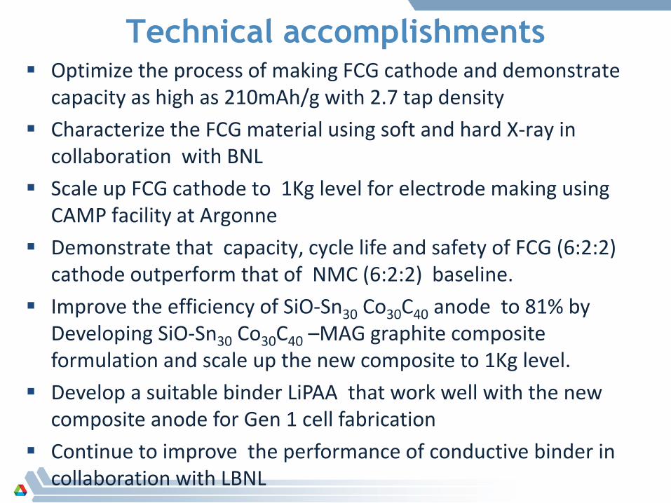
Technical accomplishments Optimize the process of making FCG cathode and demonstrate
capacity as high as 210mAh/g with 2.7 tap density Characterize the FCG material using soft and hard X-ray in
collaboration with BNL Scale up FCG cathode to 1Kg level for electrode making using
CAMP facility at Argonne Demonstrate that capacity, cycle life and safety of FCG (6:2:2)
cathode outperform that of NMC (6:2:2) baseline. Improve the efficiency of SiO-Sn30 Co30C40 anode to 81% by
Developing SiO-Sn30 Co30C40 –MAG graphite composite formulation and scale up the new composite to 1Kg level.
Develop a suitable binder LiPAA that work well with the new composite anode for Gen 1 cell fabrication
Continue to improve the performance of conductive binder in collaboration with LBNL

FCG Cathode development approach
1. Design of full concentration gradient
cathode material
2. Preparation of full concentration
gradient (FCG) precursor via CSTR Co-
precipitation with optimized
condition
3. Calcination of FCG cathode with
optimized condition
4. Physical characterization
5. Electrochemical evaluation
FCG material design
CFF for pouch cell evaluation
Electrochemicalevaluation (coin cell)
Optimize the precursor
Optimize the calcination
Characterization(XRD, SEM, TEM)
Reactor Setup

Characteristics of FCG gradient precursor & final active material made from hydroxide process after optimization
High tap density: 2.7 g/ccparticle distribution: D50=11.64 um
The average composition: ~LiNi0.6Co0.2Mn0.2O2Outer: ~LiNi0.46Co0.23Mn0.41O2Inner: ~LiNi0.8Co0.1Mn0.1O2
FCG (6:2:2) : LiNi0.6Co0.2Mn0.2O2
Ni0.6Co0.2Mn0.2(OH)2
0
10
20
30
40
50
60
70
80
00.
120.
240.
360.
48 0.6
0.72
0.84
0.96
1.08
1.21
1.33
1.45
1.57
1.69
1.81
1.93
2.05
2.17
2.29
2.41
2.53
2.65
2.77
2.89
3.01
3.13
3.25
3.38 3.
53.
623.
743.
863.
98 4.1
4.22
Mn K
Co K
Ni KRela
tive
inte
nsity
Distance (µm)center edge
Ni
Mn
Co

Main impact factors on the performance of FCG cathode
Precursors Prehea=ng T&t Lithium amount Calcina=on T&t
Calcina*on temperature and *me of calcina*on have a great impact on cathode performance
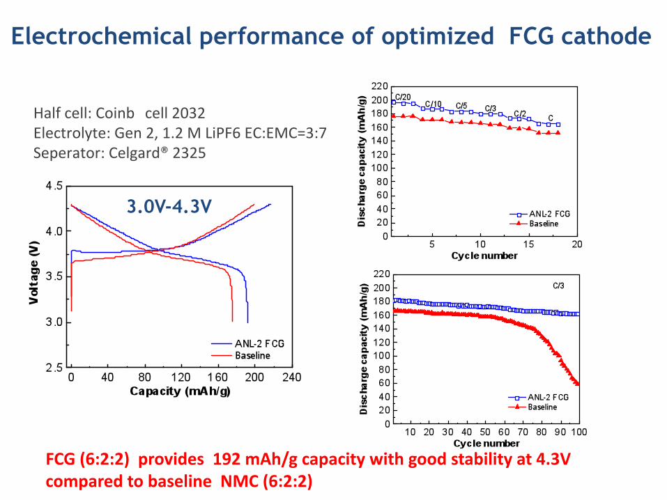
Electrochemical performance of optimized FCG cathode
FCG (6:2:2) provides 192 mAh/g capacity with good stability at 4.3V compared to baseline NMC (6:2:2)
Half cell: Coinb cell 2032 Electrolyte: Gen 2, 1.2 M LiPF6 EC:EMC=3:7 Seperator: Celgard® 2325
3.0V-4.3V

• 2.7 – 4.3 V (192 mAh/g)• 2.7 – 4.4 V (198 mAh/g)• 2.7 – 4.5 V (210 mAh/g)
Electrochemical performance of FCG cathode at different cut-off voltages

Excellent cycling stability at 55oC
ANL-2 (FCG-6:2:2)
Electrochemical performance of FCG cathode at 55oC
(3V~4.3V) (3V~4.3V)

TR-XRD/MS of FCG (6:2:2) and NMC (6:2:2) baseline
-‐ Sharp O2 gas release (at ca. 150 oC) during phase transi*on from layered to disordered spinel phase
LiNi0.6Mn0.2Co0.2O4 (Baseline NMC 622) LiNi0.6Mn0.2Co0.2O4 (FCG-6:2:2))
-‐Concentra*on gradient (FCG) sample shows much bener thermal stability than baseline NMC 622 : 1st phase transi*on occurred at ca. 190°C

845 850 855 860 865 870 875 880
Nor
mal
ized
inte
nsity
(arb
.uni
t)
Energy (eV)845 850 855 860 865 870 875 880
Nor
mal
ized
inte
nsity
(arb
.uni
t)
Energy (eV)
Ni L-edge soft XAS for baseline NMC622 (left ) and FCG-622 (right) Using Fluorescence detection (FY, bulk probing)
25 oC
150 oC
200 oC
250 oC
300 oC
350 oC
400 oC
450 oC
500 oC
25 oC
150 oC
200 oC
250 oC
300 oC
350 oC
400 oC
450 oC
500 oC
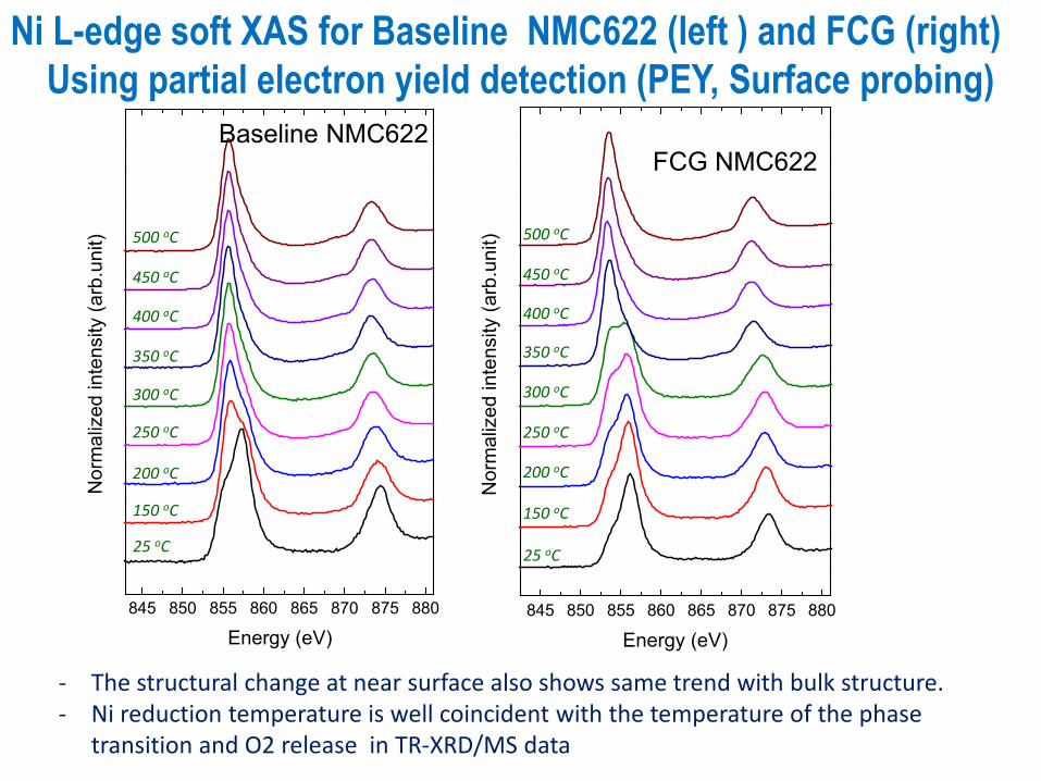
Ni reduction reflected as the lower energy peak occurred quickly at low temperature (~150 oC) in baseline NMC622. In contrast, FCG-622 is more stable and Ni is stable up to 250 oC and gradually reduced, and completed at 350 oC
Baseline-NMC622FCG-622
845 850 855 860 865 870 875 880
Nor
mal
ized
inte
nsity
(arb
.uni
t)
Energy (eV)845 850 855 860 865 870 875 880
Nor
mal
ized
inte
nsity
(arb
.uni
t)
Energy (eV)
25 oC
150 oC
200 oC
250 oC
300 oC
350 oC
400 oC
450 oC
500 oC
25 oC
150 oC
200 oC
250 oC
300 oC
350 oC
400 oC
450 oC
500 oC
- The structural change at near surface also shows same trend with bulk structure.- Ni reduction temperature is well coincident with the temperature of the phase
transition and O2 release in TR-XRD/MS data
Ni L-edge soft XAS for Baseline NMC622 (left ) and FCG (right)Using partial electron yield detection (PEY, Surface probing)
Baseline NMC622FCG NMC622

0 10 200
100
200
Cap
acity
Cycle number
Disch,mAh/g Ch,mAh/g
(a)
YC722PFM60% SiO-SnCoC+30%PFM +10%SP+C6H5Cl
Low efficiency: 65%~70%.
Optimization of SiO-SnCoC composite anode
0 300 600 900 1200 15000
1
2
3(b)
Vol
tage
(V)
Capacity (mAh/g)
1 cycle 2 cycle 3 cycle
Half cell SiO-SnCoC : 90/5%Timecal/5%PI
Electrode loading: 2.5mg/cm2
1st cycle reversibility between 70 to 72%.
Main Issues:Conductive binder (PFM) shows poor
performance with Si-SnCoC composite
16

Active material composition optimization:- Mixing appropriate amount of graphite with SiO-SnCoC- Best composition based on graphite mixing optimization is:
(33%SiO-SnCoC +57% MAG graphite)
Binder optimization:
PFM conductive binder from LBNLPVDFPolyimide biner(PI)Polyacrylic acid binder (PAA)PVDF mix with PIPVDF mix with PAALiPAA
Approaches to resolving SiO-SnCoCcomposite anode issues
17
LAWRENCE BERKELEY NATIONAL LABORATORY | ENVIRONMENTAL ENERGY TECHNOLOGIES DIVISION
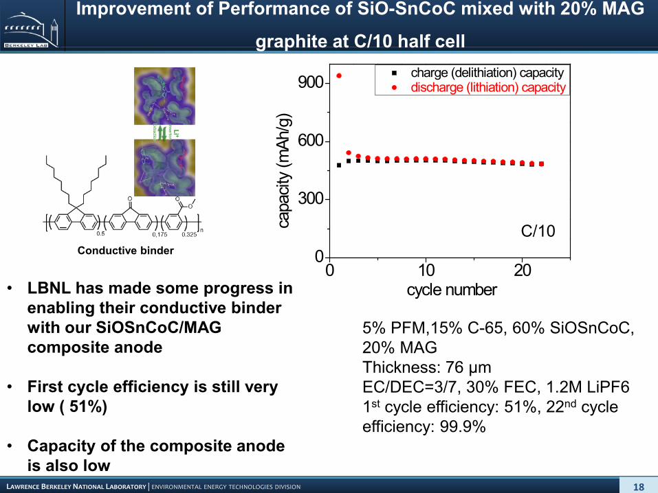
Improvement of Performance of SiO-SnCoC mixed with 20% MAG
graphite at C/10 half cell
5% PFM,15% C-65, 60% SiOSnCoC, 20% MAGThickness: 76 µmEC/DEC=3/7, 30% FEC, 1.2M LiPF61st cycle efficiency: 51%, 22nd cycle efficiency: 99.9%
0 10 200
300
600
900 charge (delithiation) capacity discharge (lithiation) capacity
capa
city
(mAh
/g)
cycle number
Conductive binderC/10
• LBNL has made some progress in enabling their conductive binder with our SiOSnCoC/MAG composite anode
• First cycle efficiency is still very low ( 51%)
• Capacity of the composite anode is also low
18

Effects of different binders on the cycling performance of electrode containing SiO-Sn30Co30C40/MAG graphite
0 20 40 60 80 1000
200400600800
100012001400
Cap
acity
(mA
h/g)
Cycle number
Ch Disch
90% SiO-Sn30Co30C40+4%C45+5%PVDF+1%PI
1st cycle C.E. 47.7 %.
PVDF
49.5% SiO-Sn30Co30C40+49.5%MAG+1%PI
0 20 40 60 80 1000
200
400
600
800
1000
Cap
acity
(mA
h/g)
Cycle number
Ch Disch
(a)
1st cycle C.E. 57 %.
(PI)
0 20 40 60 80 1000
200
400
600
800
1000
Cap
acity
(mA
h/g)
Cycle number
Ch Disch
30% SiO-Sn30Co30C40+60%MAG+5%PAA+5%C-45
1st cycle C.E. 81 %.
(PAA)
0 20 40 60 80 1000
200
400
600
800
1000
C
apac
ity (m
Ah/
g)
Cycle number
Ch Disch
33% SiO-Sn30Co30C40+57%Graphite+4%LiPAA+5%C-45
550 mAh/g
1st cycle C.E. 80.5 %.

0 20 400
200
400
600
800
1000
Cap
acity
(mA
h/g)
Cycle number
Ch Disch
33% SiO-SnCoC+57%GC+5%LiPAA+5%C-45
1st cycle C.E. 81 %.
00.20.40.60.8
11.21.41.6
0 200 400 600 800
Volta
ge, (
V)
Capacity (mAh/g)
1. The cell shows high 1st C.E. efficiency (81%).2. The cell shows good rate performance.3. The cell shows high capacity (670 mAh/g) and
excellent cycle life so far.
33%SiO-Sn30Co30C40/57%MAG graphite with 5%LiPAA shows the best performance with 81% 1st cycle efficiency
33%SiO-Sn30Co30C40/57%MAG graphite /5%LiPAA/ 5%C-45 formulation was used by CAMP facility to fabricate electrode for cell
build

0
50
100
150
200
250
0 5 10 15 20 25 30
Cap
acit
y, m
Ah
/g
Cycle Number
CYCLE PERFORMANCE
0.0
0.5
1.0
1.5
2.0
2.5
3.0
3.5
4.0
4.5
0 50 100 150 200 250
Vo
ltag
e, V
Capacity, mAh/g
VOLTAGE PROFILE
Initial performance of Full cell SiO-SnCoC-MAG/FCG cathode
• The first discharge capacity increases to 180 mAh/g with a high efficiency 79.1% which is almost the full efficiency of the anode.
• Cyclability of the cell is unsatisfactory even though both cathode and anode half cell shows excellent cyclability
21

Poor Distribution of negative active material loading in the electrode is responsible for low cycle
life in the full cell
5.6 5.8 6.0 6.2 6.4 6.6 6.8 7.00
2
4
6
Cou
nts
Active material weight in electrode(mg)
Negative active material loading made by CAMP shows varying distribution within the electrode; Possible reason could be 1) the particle size of the negative active material is not uniform and/ or 2) more time is needed to
optimize the electrode processing at CAMP since this is a new material

1st C cap (mAh/g) 2181st D Cap (mAh/g) 1891st Cycle Eff (%) 86.5
Coupling FCG with Graphite instead of SiO-SnCoC-MAG shows excellent cycle life
00.5
11.5
22.5
33.5
44.5
0 100 200 300
Volta
ge, (
V)
Capacity (mAh/g) 020406080
100120140160180200
0 10 20 30
Capa
city
, (m
Ah/g
)Cycle Number
Discharge Capacity vs Cycle Life
By replacing SiO-SnCoC-MAG composite with graphite, the cycle life of the full cell with FCG cathode improved significantly,
confirming the observed uniformity issue of our SiO-SnCoC-MAG composite during the electrode making process at scale.

Deliverable Device
Battery Performance (Cell Level)
Usable Specific Energy(Wh/kg)
Energy Usable Density (Wh/l)
Power at SOCmin
(W/kg,10sec)
TechnologyInfo
*Baseline 20Ah Cell40Ah CellBatPac Design
(~199)(~237)
(~453)(~548)
(~1591)(~950)
SiO-SnCoCAnd
NMC (6:2:2)
Energy and power of baseline and FCG cells based on BatPac Design
Gen1 20Ah Cell40Ah CellBatPac Design
(~229)(~280)
(~541)(~659)
(~1837)(~1120)
SiO-SnCoC-MAGAnd
FCG (6:2:2)
* Data provided on baseline last year was higher than the one in the table above as we found a mistake in the Pat Pac model input.

Responses to Previous Year Reviewers’ Comments
• Question: Reviewer 7 has a question regarding the synthesis of FCG. The reviewer misunderstood our process. the reviewer believe we use a continuous process which require reaching a steady state!
• Answer: The FCG material was made using a batch process! The reaction starts from half full reactor, and end when the reactor is full. All the materials are collected as FCG precursor. The process is easy to control and to scale up
• Question : The reviewer No:4 question the alloying of Sn and Si• Response: since the material is amorphous , it is difficult to carry out bulk
characterization. The alloying assumption was based on the PDF result only.
• Question: Reviewer 5 would like to see full cell evaluation using cylindrical cells• Response: since the project was new and started only few months before the
AMR review, it was not possible to carry out cell evaluation using 18650 size cell. The project anticipate making full cell with gradient and Si-composite once optimized at the end of the project. the 1st cycle efficiency of our Si-Sn composite (55%) was significantly improved by incorporating MAG graphite to the system (81%) see page 20 of this presentation.
25

Responses to previous year reviewers' comments
• Question: Reviewer 6 has a question regarding the rate capability of FCG cathode and third party validation.
• Answer: The FCG material shows very good rate capability (see Fig 10 & 11 ) of this presentation. It is our plan to deliver full pouch cell to INL for validation by late June of this year.
• Question: reviewer 6 want to see data beyond proof of concept. He want full cell build and tested and he request doing some cost analysis
• Response: our plan was to build full pouch cell data based on the optimized FCG and Si-Sn-MAG graphite anode with high efficiency by late June of this year and carry out all the test requested by the reviewer. We are planning to send cells to INL for independent testing. The cost analysis will be made on the final optimized cell.
• Question: the reviewer 7 didn't not believe that FCG material meet the target value• Response: The BatPac model shows that FCG coupled with Si-Sn-MAG graphite
can provide up 280Wh/kg ( see page 24) which is higher than the 200Wh/kg targeted by DOE
26

Collaborations• X.Q. Yang of BNL
• Diagnostic of FCG and SEI of Si-Sn composite electrodes using soft & hard X-ray.
• G. Liu (LBNL) •Development and optimization of conductive binder for Si-Sn composite anode
•H. Wu (ANL) •Optimize the synthesis of FCG cathode
•A. Abouimrane (ANL) •Development of SiO-SnyCo1-xFexCz anode
•J.Lu & Z. Chen (ANL)•Characterization of cathode, anode and cell during cycling using In-situ techniques
• ECPRO : Baseline cathode material
•University of Utah : Facility to scale up the baseline Si-Sn composite anode for baseline cell
• A. Jansen & B. Polzin (ANL)•Design & fabrication of baseline cell
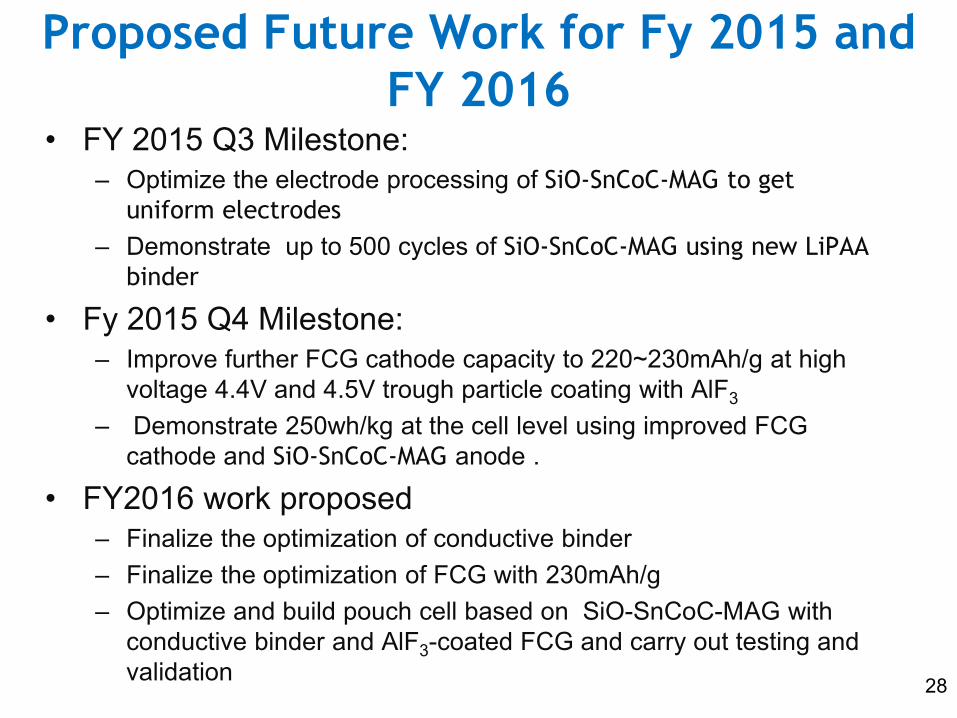
Proposed Future Work for Fy 2015 and FY 2016
• FY 2015 Q3 Milestone:– Optimize the electrode processing of SiO-SnCoC-MAG to get
uniform electrodes– Demonstrate up to 500 cycles of SiO-SnCoC-MAG using new LiPAA
binder
• Fy 2015 Q4 Milestone: – Improve further FCG cathode capacity to 220~230mAh/g at high
voltage 4.4V and 4.5V trough particle coating with AlF3
– Demonstrate 250wh/kg at the cell level using improved FCG cathode and SiO-SnCoC-MAG anode .
• FY2016 work proposed– Finalize the optimization of conductive binder– Finalize the optimization of FCG with 230mAh/g– Optimize and build pouch cell based on SiO-SnCoC-MAG with
conductive binder and AlF3-coated FCG and carry out testing and validation 28

Summary Relevance
• enable low battery cost by increasing energy density • Low battery cost will lead to mass electrification of vehicle and reduction of both
greenhouse gases and our reliance on foreign oil Approaches
• develop very high energy redox couple (250wh/kg) based on high capacity full gradient concentration cathode (FCG) (230mAh/g) and Si-Sn composite anode (670mAh/g) with long cycle life and excellent abuse tolerance to enable 40 miles PHEV and EVs
Technical Accomplishments• Optimize the process of making FCG cathode and demonstrate capacity as high as
210mAh/g with 2.7 tap density• Scale up FCG cathode to 1Kg level for electrode making using CAMP facility at Argonne• Improve the efficiency of SiO-Sn30 Co30C40 anode to 81% by Developing SiO-Sn30
Co30C40 –MAG graphite composite formulation and scale up the new composite to 1Kg level.
Proposed Future work• Optimize the electrode processing of SiO-SnCoC-MAG to get uniform electrodes• Demonstrate up to 500 cycles of SiO-SnCoC-MAG using new LiPAA binder • Improve further FCG cathode capacity to 220~230mAh/g at high voltage 4.4V and 4.5V
trough particle coating with AlF3
• Demonstrate 250wh/kg at the cell level using improved FCG cathode and SiO-SnCoC-MAG anode . 29