Embed Size (px)
Citation preview
It is well known that vibration during drillingoperations has a large effect on both thebottomhole assemblies and the drill bit. Whilelarge vibration levels cause reduced rates ofpenetration and catastrophic failures, lower levelsmay lead to a reduced operating life if allowedover a sufficient time period. In the past, mucheffort has been invested in measuring andunderstanding vibration. The benefits ofaddressing this problem are obvious and includereduced drilling time and costs, reducedmaintenance, and lower equipment turnover.
Many of the previous attempts to isolate MWDtools from the drilling environment have resultedin marginal improvement. The development ofthe Isolation Sub began with our examination ofthe performance of a MWD tool that was alreadyisolated from vibration. It was determined thatimproved shock and vibration isolation wasneeded to reduce frequent maintenance andprevent the less-frequent failure. For example,
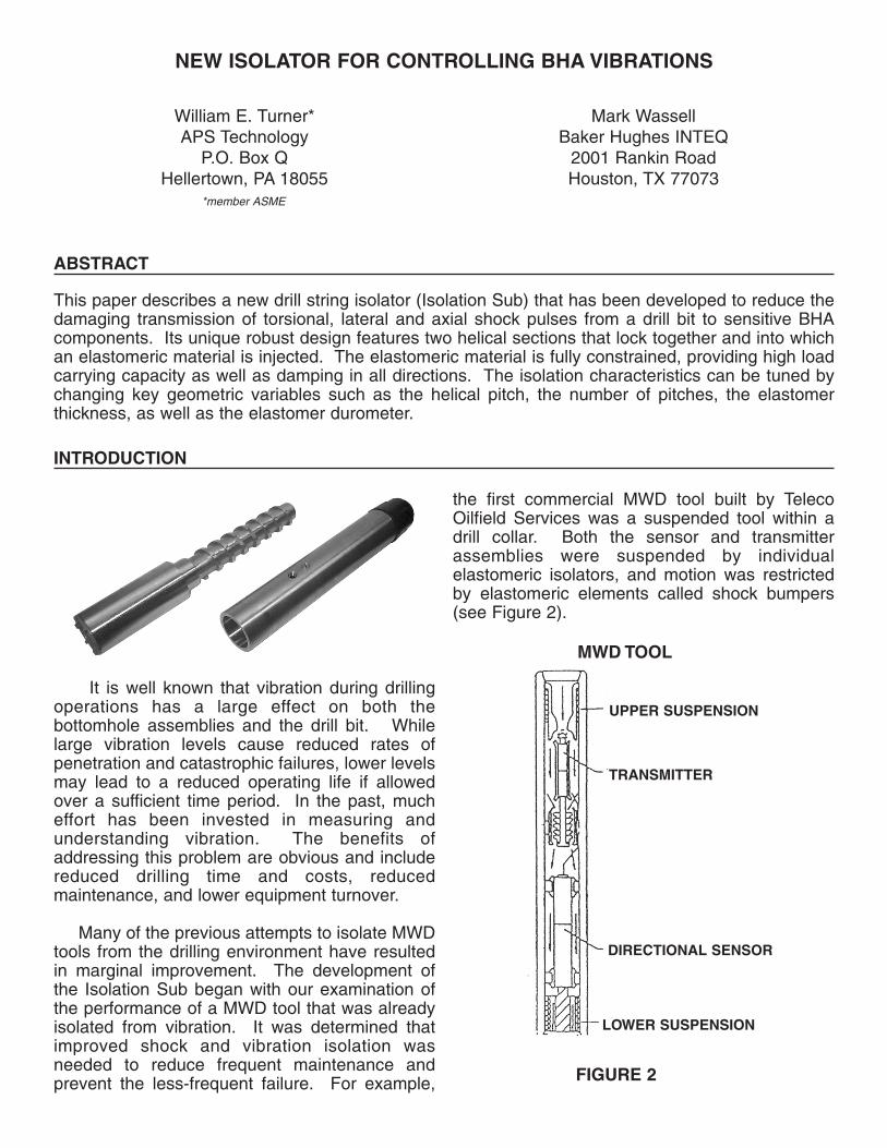
the first commercial MWD tool built by TelecoOilfield Services was a suspended tool within adrill collar. Both the sensor and transmitterassemblies were suspended by individualelastomeric isolators, and motion was restrictedby elastomeric elements called shock bumpers(see Figure 2).
NEW ISOLATOR FOR CONTROLLING BHA VIBRATIONS
William E. Turner*APS Technology
P.O. Box QHellertown, PA 18055
*member ASME
Mark WassellBaker Hughes INTEQ
2001 Rankin RoadHouston, TX 77073
MWD TOOL
FIGURE 2
UPPER SUSPENSION
TRANSMITTER
DIRECTIONAL SENSOR
LOWER SUSPENSION
ABSTRACT
This paper describes a new drill string isolator (Isolation Sub) that has been developed to reduce thedamaging transmission of torsional, lateral and axial shock pulses from a drill bit to sensitive BHAcomponents. Its unique robust design features two helical sections that lock together and into whichan elastomeric material is injected. The elastomeric material is fully constrained, providing high loadcarrying capacity as well as damping in all directions. The isolation characteristics can be tuned bychanging key geometric variables such as the helical pitch, the number of pitches, the elastomerthickness, as well as the elastomer durometer.
INTRODUCTION
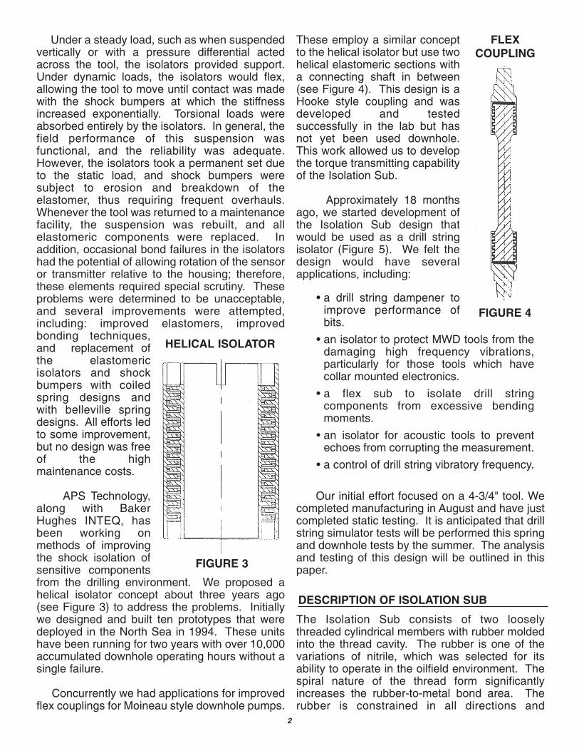
Under a steady load, such as when suspendedvertically or with a pressure differential actedacross the tool, the isolators provided support.Under dynamic loads, the isolators would flex,allowing the tool to move until contact was madewith the shock bumpers at which the stiffnessincreased exponentially. Torsional loads wereabsorbed entirely by the isolators. In general, thefield performance of this suspension wasfunctional, and the reliability was adequate.However, the isolators took a permanent set dueto the static load, and shock bumpers weresubject to erosion and breakdown of theelastomer, thus requiring frequent overhauls.Whenever the tool was returned to a maintenancefacility, the suspension was rebuilt, and allelastomeric components were replaced. Inaddition, occasional bond failures in the isolatorshad the potential of allowing rotation of the sensoror transmitter relative to the housing; therefore,these elements required special scrutiny. Theseproblems were determined to be unacceptable,and several improvements were attempted,including: improved elastomers, improvedbonding techniques,and replacement ofthe elastomericisolators and shockbumpers with coiledspring designs andwith belleville springdesigns. All efforts ledto some improvement,but no design was freeof the highmaintenance costs.
APS Technology,along with BakerHughes INTEQ, hasbeen working onmethods of improvingthe shock isolation ofsensitive componentsfrom the drilling environment. We proposed ahelical isolator concept about three years ago(see Figure 3) to address the problems. Initiallywe designed and built ten prototypes that weredeployed in the North Sea in 1994. These unitshave been running for two years with over 10,000accumulated downhole operating hours without asingle failure.
Concurrently we had applications for improvedflex couplings for Moineau style downhole pumps.
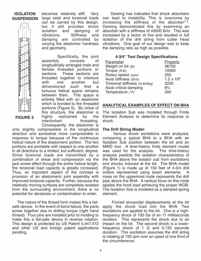
These employ a similar conceptto the helical isolator but use twohelical elastomeric sections witha connecting shaft in between(see Figure 4). This design is aHooke style coupling and wasdeveloped and testedsuccessfully in the lab but hasnot yet been used downhole.This work allowed us to developthe torque transmitting capabilityof the Isolation Sub.
Approximately 18 monthsago, we started development ofthe Isolation Sub design thatwould be used as a drill stringisolator (Figure 5). We felt thedesign would have severalapplications, including:
Our initial effort focused on a 4-3/4" tool. Wecompleted manufacturing in August and have justcompleted static testing. It is anticipated that drillstring simulator tests will be performed this springand downhole tests by the summer. The analysisand testing of this design will be outlined in thispaper.
The Isolation Sub consists of two looselythreaded cylindrical members with rubber moldedinto the thread cavity. The rubber is one of thevariations of nitrile, which was selected for itsability to operate in the oilfield environment. Thespiral nature of the thread form significantlyincreases the rubber-to-metal bond area. Therubber is constrained in all directions and
• a drill string dampener toimprove performance ofbits.
• an isolator to protect MWD tools from thedamaging high frequency vibrations,particularly for those tools which havecollar mounted electronics.
• a flex sub to isolate drill stringcomponents from excessive bendingmoments.
• an isolator for acoustic tools to preventechoes from corrupting the measurement.
• a control of drill string vibratory frequency.
FLEXCOUPLING
FIGURE 4
FIGURE 3
HELICAL ISOLATOR
DESCRIPTION OF ISOLATION SUB
2
becomes relatively stiff. Verylarge axial and torsional loadscan be carried by this design,but it still provides shockisolation and damping ofvibrations. Stiffness anddamping are controlled byvarying the elastomer hardnessand geometry.
Specifically, the jointassembly consists oflongitudinally arranged male andfemale threaded portions orsections. These sections arethreaded together to interlockwith one another butdimensioned such that atortuous helical space remainsbetween them. This space isentirely filled with an elastomerwhich is bonded to the threadedportions (Figure 5). By virtue ofthis structure, the elastomer ishighly restrained by theinterlocked threading.Consequently, the elastomer is
only slightly compressible in the longitudinaldirection and somewhat more compressible inresponse to torque because of the continuoushelical nature of the elastomeric portion. The twoportions are pivotable with respect to one anotherin all directions to a limited, but sufficient, degree.Since torsional loads are transmitted by acombination of shear and compression via thejack screw effect through the entire helical length,the torsional load capacity is greatly increased.Thus, an important aspect of the concept isprovision of an elastomeric joint assembly withimproved torsional capacity. Further, because therelatively moving surfaces are completely isolatedfrom the surrounding environment, there is nopotential for abrasives or contamination to enter.
The nature of the thread form makes this a fail-safe device. In the event of bond failure, the partsscrew together due to drilling torque (right handthread). Four pins are installed prior to molding tomake this a fail-safe device in reverse rotation.This design is protected by US Patent 5,447,472and other US and foreign patent applicationspending.
Dareing has indicated that shock absorberscan lead to instability. This is overcome byincreasing the stiffness of the absorber1,4.Dareing demonstrated this by examining anabsorber with a stiffness of 43000 lb/in. This wasincreased by a factor of five and resulted in fullisolation of the drill string from cutter headvibrations. One goal of our design was to keepthe damping ratio as high as possible.
The Isolation Sub was modeled through FiniteElement Analysis to determine its response toshock.
The Drill String Model:Various shock excitations were analyzed,
comparing a typical BHA to a BHA with anIsolation Sub position between the bit and anMWD tool. A time-history finite element modelwas used for the analysis. The time-historyanalysis predicts the isolation characteristics ofthe BHA above the isolator sub from excitationsand shocks induced at the bit. The BHA model(Figure 1) is made up of 150 feet of 4-3/4 drillcollars represented using beam elements. Amass on the uppermost node represents the drillpipe above the BHA. A vertical force on this nodeapplies the hook load achieving the proper WOB.The Isolation Sub is modeled as a damped springelement.
Forced sinusoidal displacements at the bitapply the shock load into the BHA. Twoexcitations are applied to the bit. One is a high-frequency shock of 100 Gs of an 11 millisecondsduration. This represents the shock due to animpact on the bit. The second shock is a lower-frequency shock of 1 G and 0.133 secondsduration. This excitation assumes the drill stringis rotating at 150 rpm over an upset of one third ofthe circumference.
ANALYTICAL EXAMPLES OF EFFECT ON BHA
ISOLATIONSUSPENSION
FIGURE 5
4-3/4" Tool Design SpecificationsParameter PropertyWeight on bit (lb) 36750Torque (ft-lb) 10000Rotary speed (rpm) 250Axial stiffness (lb/in) 1.2 x 10⁶
Torsional stiffness (in-lb/deg) 3200Axial critical damping 8%Temperature (°F) 300
3
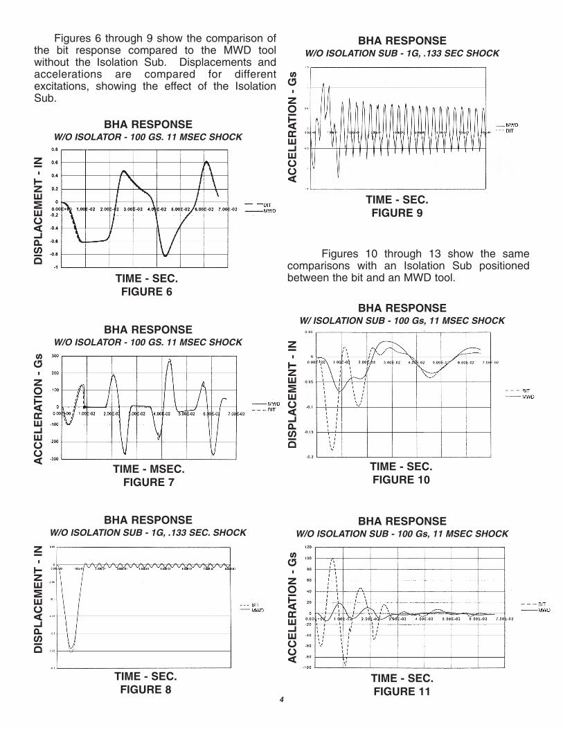
Figures 6 through 9 show the comparison ofthe bit response compared to the MWD toolwithout the Isolation Sub. Displacements andaccelerations are compared for differentexcitations, showing the effect of the IsolationSub.
Figures 10 through 13 show the samecomparisons with an Isolation Sub positionedbetween the bit and an MWD tool.
BHA RESPONSEW/O ISOLATOR - 100 GS. 11 MSEC SHOCK
TIME - SEC.FIGURE 6
DIS
PL
AC
EM
EN
T -
INBHA RESPONSE
W/O ISOLATION SUB - 1G, .133 SEC SHOCK
TIME - SEC.FIGURE 9
AC
CE
LE
RA
TIO
N -
Gs
BHA RESPONSEW/ ISOLATION SUB - 100 Gs, 11 MSEC SHOCK
TIME - SEC.FIGURE 10
DIS
PL
AC
EM
EN
T -
IN
BHA RESPONSEW/O ISOLATION SUB - 100 Gs, 11 MSEC SHOCK
AC
CE
LE
RA
TIO
N -
Gs
BHA RESPONSEW/O ISOLATOR - 100 GS. 11 MSEC SHOCK
AC
CE
LE
RA
TIO
N -
Gs
TIME - MSEC.FIGURE 7
BHA RESPONSEW/O ISOLATION SUB - 1G, .133 SEC. SHOCK
DIS
PL
AC
EM
EN
T -
IN
TIME - SEC.FIGURE 8
4
TIME - SEC.FIGURE 11
a
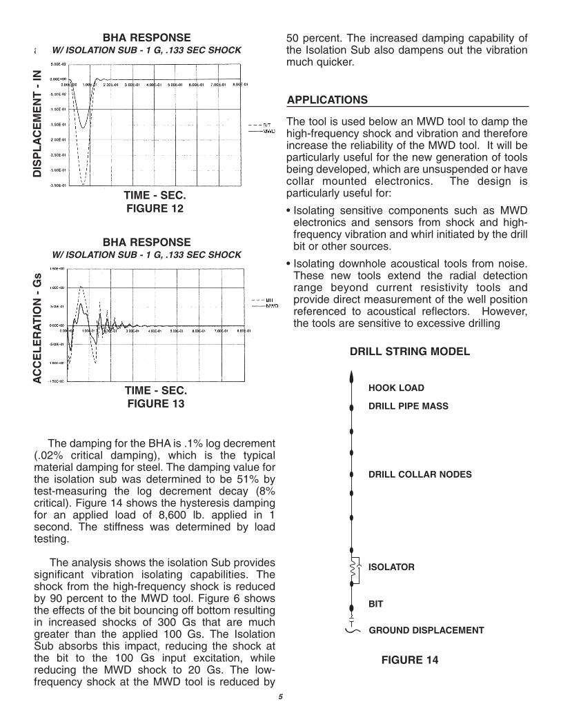
The damping for the BHA is .1% log decrement(.02% critical damping), which is the typicalmaterial damping for steel. The damping value forthe isolation sub was determined to be 51% bytest-measuring the log decrement decay (8%critical). Figure 14 shows the hysteresis dampingfor an applied load of 8,600 lb. applied in 1second. The stiffness was determined by loadtesting.
The analysis shows the isolation Sub providessignificant vibration isolating capabilities. Theshock from the high-frequency shock is reducedby 90 percent to the MWD tool. Figure 6 showsthe effects of the bit bouncing off bottom resultingin increased shocks of 300 Gs that are muchgreater than the applied 100 Gs. The IsolationSub absorbs this impact, reducing the shock atthe bit to the 100 Gs input excitation, whilereducing the MWD shock to 20 Gs. The low-frequency shock at the MWD tool is reduced by
50 percent. The increased damping capability ofthe Isolation Sub also dampens out the vibrationmuch quicker.
The tool is used below an MWD tool to damp thehigh-frequency shock and vibration and thereforeincrease the reliability of the MWD tool. It will beparticularly useful for the new generation of toolsbeing developed, which are unsuspended or havecollar mounted electronics. The design isparticularly useful for:
• Isolating sensitive components such as MWDelectronics and sensors from shock and high-frequency vibration and whirl initiated by the drillbit or other sources.
• Isolating downhole acoustical tools from noise.These new tools extend the radial detectionrange beyond current resistivity tools andprovide direct measurement of the well positionreferenced to acoustical reflectors. However,the tools are sensitive to excessive drilling
BHA RESPONSEW/ ISOLATION SUB - 1 G, .133 SEC SHOCK
DIS
PL
AC
EM
EN
T -
IN
BHA RESPONSEW/ ISOLATION SUB - 1 G, .133 SEC SHOCK
AC
CE
LE
RA
TIO
N -
Gs
APPLICATIONS
DRILL STRING MODEL
FIGURE 14
HOOK LOAD
DRILL PIPE MASS
DRILL COLLAR NODES
ISOLATOR
BIT
GROUND DISPLACEMENT
5
TIME - SEC.FIGURE 13
TIME - SEC.FIGURE 12
noise and vibrations from mudmotors.Measurements are ideally performed during pipeconnections3. The Isolation Sub may increase theconditions under which the acousticmeasurements can be successfully obtained.
• Changing the natural frequencies of BHAs.
• Improved PDC bit performance throughreduction of bit bounce by the ability to absorbshock, vibration, and whirl. Dareing has shownhow shearing action between drag bit cuttersand rock cause drillstrings to self-excite, leadingto dynamic instability4.
• Absorbing the high-frequency shocks of tri-conebit teeth.
• Isolating specialized tools from bendingmoments.
Benefits include:
• increased MWD tool life
• increased bit life due to isolating it from drillstring bounce
• damping and shock isolation over a wide rangeof drilling parameters
• increased rate of penetration of PDC bits
• short length (6') compared to shock subs (16')
REFERENCES
1. Zamudio, C.A., Tlusty, J., and Dareing, D.W., 1988, "Effect of Shock Absorber on Drag Bit Chatter,Proceedings," SPE 17194, 1988 IADC/SPE Drilling Conference, SPE, Richardson, TX, pp 153-160.
2. Lindley, P.B., 1978, "Engineering Design With Natural Rubber," Malaysian Rubber Producer'sResearch Association, Hertford, GB,
3. Nakken, E.I., 1995, "A New MWD Concept for Geological Positioning of Horizontal Wells," SPE30454, SPE 1995 Annual Technical Conference and Exhibition, SPE, Richardson, TX, pp. 851-856.
4. Zamudio, C.A., Tlusty, J.L., and Dareing, D.W., 1987, "Self-Excited Vibrations in Drillstrings," SPE16661, SPE 62nd Technical Conference and Exhibition, SPE, Richardson, TX, pp. 117-124.
5. Schabtach, Carl and Fehr, R.O., June 1943, "Measurement of the Damping of EngineeringMaterials during flexural Vibration at Elevated Temperatures." Journal of Applied Mechanics, pp.A86-A92.
6