Embed Size (px)
Citation preview
NEW JERSEY TURNPIKE AUTHORITY GARDEN STATE PARKWAY
NEW JERSEY TURNPIKE
LOAD RATING MANUAL
LRFR METHODOLOGY
Version 9.3
September 2017
Prepared By:
HNTB Corporation
1
Table of Contents CONTENTS_______________________________________________________PAGE SUMMARY OF VERSION 9.3 REVISIONS……….……………………………………. 3 SUMMARY OF VERSION 9.2 REVISIONS……….……………………………………. 3 SUMMARY OF VERSION 9.1 REVISIONS……….……………………………………. 4 SUMMARY OF VERSION 9.0 REVISIONS……….……………………………………. 4 SECTION 1 INTRODUCTION AND GENERAL OVERVIEW …………………….. 5
1.1 Introduction 1.2 Purpose of this Document 1.3 Load and Resistance Factor Rating Methodology
SECTION 2 GENERAL LOAD RATING REQUIREMENTS ……………………… 5
2.1 Load Rating Requirements
2.1.1 New or Reconstructed Bridges 2.1.2 Existing Bridges 2.1.3 Member Deterioration
2.2 Qualifications and Responsibilities 2.3 Elements to be Load Rated 2.4 Analysis Methods and Rating Software 2.5 Curved Girder Rating 2.6 Reporting LRFR Ratings to the NBI
SECTION 3 LOAD AND RESISTANCE FACTOR
RATING GUIDELINES ………………………………………………. 10 3.1 Data Collection for LRFR Load Rating
3.1.1 Review of Existing Bridge Plans and Documents 3.1.2 Bridge Inspection for Load Rating 3.1.3 Truck Traffic Conditions at Bridge Site 3.1.4 Surface Roughness Rating 3.1.5 Span and Member Numbering
3.2 Live Loads and Load Factors
3.2.1 Overview of LRFR Load Rating Process for NJTA Bridges 3.2.2 Design Load Rating for HL-93 Loading 3.2.3 Legal Load Rating for Routine Commercial Traffic 3.2.4 Legal Load Rating for Specialized Hauling Vehicles 3.2.5 Load Rating for Overweight Permits
3.2.6 Reduced Dynamic Load Allowance for Rating 3.3 Resistance Factors and Resistance Modifiers for the Strength Limit States
3.3.1 Resistance Factor: 3.3.2 Condition Factor: C

2
3.3.3 System Factor: S
3.4 Resistance Factors and Resistance Modifiers for the Service Limit States
3.5 Service and Fatigue Limit States for Load Rating 3.5.1 General Overview
3.5.2 Concrete Bridges 3.5.3 Steel Bridges
SECTION 4 LOAD RATING DELIVERABLES …………………………………. 26
4.1 Load Rating Report 4.1.1 Load Rating Report Deliverables 4.1.2 File Naming 4.1.3 InspectTech – Plan Uploading and Load Rating Input 4.1.4 Interpretation of Rating Results and Low Ratings
4.2 Load Rating Summary Sheets
4.3 Quality Control and Quality Assurance Review of Load Ratings 4.4 Requirements for Load Rating of New or Rehabilitated Structures 4.5 Dissemination of Load Ratings to Other Entities
SECTION 5 LOAD RATING OF CULVERTS…………………………………….. 38
5.1. Introduction
5.2 AASHTO MBE Provisions for Culverts
5.3 BrR Capabilities for Culverts
5.4. Load Rating Requirements 5.4.1 Sections 5.4.2 Limit States
5.5. LRFR Load Rating Equation for Culverts 5.5.1 Condition Factor 5.5.2 System Factor 5.5.3 Resistance Factors
5.6. Live Loads and Distributions 5.6.1 Live Load Distribution 5.6.2 Impact Factor 5.6.3 Permit Loads
REFERENCE PUBLICATIONS ……………………………………………………….. 44 APPENDIX A BrR Guidance…………………………...…………………………… A1
A1. BrR - Guidelines for LRFR Ratings…....………………...………………... A1 A2. BrR - Questions and Answers………………................………………….. A16 A3. Load Rating Updates of Existing Structures………………................……… A21

3
SUMMARY OF VERSION 9.3 REVISIONS (SEPTEMBER 2017) The NJTA LRFR Load Rating Manual, LRFR Methodology, Version 9.2, December 2016 has been updated to Version 9.3 in September 2017. These updates include, but are not limited to, the following changes to the Manual:
Added reference to the required section loss sheets in Section 2.1.3 (Member Deterioration), Section 3.1.2 (Bridge Inspection for Load Rating), and Section 4.1 (Load Rating Report), and also mentioned the optional BrR Section Loss Forms available for use
Added Figure 4.4 which shows the BrR Section Loss Forms Clarified the proper date to be used when copying and reusing previously created load rating
summary sheets in bridge inspection reports in Section 4.1.1 (Load Rating Report Deliverables)
Added discussion in Sections 3.2.2 (Design Load Rating for HL-93 Loading) and 4.4 (Requirements of Load Rating for New or Rehabilitated Structures) regarding As-Designed ratings and the new requirement for these ratings to also include Authority-specific design vehicles as specified in the NJTA Design Manual (Structures Design)
Added specific direction regarding file naming for As-Designed load ratings in Section 4.1.2 (File Naming)
Made minor revisions and enhancements to all three appendices (A1, A2, A3) Please review the entire Load Rating Manual for revisions not listed above but included as part of the Version 9.3 revisions. SUMMARY OF VERSION 9.2 REVISIONS (DECEMBER 2016) The NJTA LRFR Load Rating Manual, LRFR Methodology, Version 9.1, October 2015 has been updated to Version 9.2 in December 2016. These updates include, but are not limited to, the following changes to the Manual:
Made minor revisions to select ADTT values included in Tables 1A and 1B based on the Authority’s latest traffic data (2015)
Updated Appendix A1 with regards to “BrR Guidelines for Ratings of Concrete Box and Frame Culverts”, as well as other program guidance based on the latest version of BrR (Version 6.8)(See new BrR Modeling Note No. 15)
Added Appendix A3 (Load Rating Updates of Existing Structures using LRFR Methodology) to this manual, made slight revisions to the “Rating Specification Changes” section of Appendix A3, and also added references to A3 in Section 2.1.2
Removed the 3rd paragraph in Section 2.5 (Curved Girder Rating), which related to design load ratings using influence lines
Enhanced the guidance and direction included in Section 2.6 (Reporting LRFR Ratings to the NBI)
Modified Section 3.3.2 (Condition Factor) regarding the use of an increased condition factor Minor revisions were made to Section 4.1 (Load Rating Report) Modified Section 4.1.3 (InspectTech Plan Uploading) based on current Authority policy and
requirements Please review the entire Load Rating Manual for revisions not listed above but included as part of the Version 9.2 revisions.

4
SUMMARY OF VERSION 9.1 REVISIONS (OCTOBER 2015) The NJTA LRFR Load Rating Manual, LRFR Methodology, Version 9.0, December 2014 has been updated to Version 9.1 in October 2015. These updates include, but are not limited to, the following changes to the Manual:
Clarified in Section 2.1.2 that load rating updates shall include a review of the previous load ratings for accuracy
Noted in Section 2.5 that curved girders rated with software other than BrR should consider performing initial ratings using the same software used for design
Added specific mention to Section 4.1.4 that the load rating engineer can consider use of a reduced travelway per MBE Section 6A.2.3.2 in cases where low legal load ratings are obtained
Added to Section 4.4 that consultants involved in rehabilitation of existing structures are required to review and update (if needed) the existing load rating files to ensure accuracy
Added a new section (Section 4.5) pertaining to policies and procedures regarding dissemination of load rating files to other entities
Included a note on all standard load rating summary sheets regarding confidentiality Please review the entire Load Rating Manual for revisions not listed above but included as part of the Version 9.1 revisions. SUMMARY OF VERSION 9.0 REVISIONS (DECEMBER 2014) The NJTA LRFR Load Rating Manual, LRFR Methodology, Version 8.0, November 2013 has been updated to Version 9.0 in December 2014. These updates include, but are not limited to, the following changes to the Manual:
Revised requirements in Section 2.2 to permit the 2 day LRFR course on a five year interval following the initial 4 day course, and also explicitly added the ability to use engineers in the load rating process other than the LRE or LRR.
Modified Section 3.1.3, including revisions to the requirements for determining ADTT (no increase needed beyond 2008), and clarifications for determining ADTT for structures located within interchanges or north of E117.60 or W114.00.
Updated Section 3.2.2 to clarify the design vehicle to be used for load rating in lieu of the recent revisions to the design vehicle per the NJTA Design Manual, Structures Design, Section 2.2.2
Clarified the required deliverables for load ratings completed as part of bridge inspection contracts or design contracts
Added a new section (Section 4.4) for load ratings of new or rehabilitated structures Modified Sections 2.1.1, 2.4, and 2.5 to clarify load ratings of curved girder structures, and
when to generate influence lines as part of the load rating report Added clarifications for load ratings of culverts using BrR in Appendix A1 Added questions and answers in Appendix A2
Please review the entire Load Rating Manual for revisions not listed above but included as part of the Version 9.0 revisions.
5
SECTION 1 INTRODUCTION AND GENERAL OVERVIEW 1.1 Introduction Bridge load rating is the determination of the live load carrying capacity of a newly designed or existing bridge. Load ratings are typically determined by analytical methods based on information taken from bridge plans supplemented by information gathered from field inspections or field testing. Knowledge of the capacity of each bridge to carry loads is critical for several reasons, including (but not limited to) the following:
To determine which structures have substandard load capacities that may require posting or other remedial action.
To assist in the most effective use of available resources for rehabilitation or replacement. To assist in the overload permit review process. To satisfy FHWA requirements for submitting load ratings. The NBIS (Title 23, Code of
Federal Regulations, Section 650.313 (c)), requires that load ratings be in accordance with the latest AASHTO Manual. The results are used in conjunction with other bridge inventory and inspection information to determine the Federal Bridge Sufficiency Rating.
1.2 Purpose of this Document This document was developed using the American Association of State Highway and Transportation Officials (AASHTO) Manual for Bridge Evaluation, Second Edition, including 2016 Interims, hereinafter referred to as the MBE. This document provides guidance to engineers for performing and submitting load rating calculations using the Load and Resistance Factor (LRFR) methodology. The procedures stated in this document are to provide guidelines that will result in consistent and reproducible load rating inputs and deliverables. This document serves as a supplement to the AASHTO MBE and deals primarily with New Jersey Turnpike Authority (NJTA) specific load rating requirements, interpretations, and policy decisions. While this Manual is intended to provide bridge load rating policy for work done by or for the NJTA, it does not preclude justifiable exceptions, subject to the approval of the NJTA. This Manual is a living document in that changes will be issued as warranted because of changes in policy, loadings, or evaluation criteria. 1.3 Load and Resistance Factor Rating Methodology
Load and Resistance Factor Rating is consistent with the LRFD Specifications in using a reliability-based limit states philosophy and extends the provisions of the LRFD Specifications to the areas of inspection, load rating, posting and permit rules, fatigue evaluation, and load testing of existing bridges. The LRFR methodology has been developed to provide uniform reliability in bridge load ratings, load postings and permit decisions. The LRFR procedures provide live load factors for load rating that have been calibrated to provide a uniform and acceptable level of reliability. SECTION 2 GENERAL LOAD RATING REQUIREMENTS 2.1 Load Rating Requirements
2.1.1 New or Reconstructed Bridges
6
Load ratings by the LRFR method, for the live load models defined in Section 3.2 of this document, are required for all new and replacement bridges, and for all rehabilitation and repair designs involving a substantial structural alteration. LRFR load rating calculations shall be performed as part of the design process and reflect the bridge’s As-Built or As-Rehabilitated condition. When ratings are initially performed in conjunction with the preparation of design drawings, the As-Designed load rating results shall be shown on the structural drawings following the structural notes for all new, replaced and rehabilitated bridge projects in accordance with Section 4.4 of this document. Load rating shall not include the future wearing surface as a dead load because it is not part of the as-built condition. The Load Rating Summary Sheet and all electronic files for use in future re-analyses shall be created by the Design Engineer and provided to the NJTA in accordance with the requirements of Section 2.4 of this document. Input files shall be created using AASHTOWare’s Bridge Rating Software (BrR) (See Appendix A1 for current version) unless the structure cannot be modeled using BrR, such as complex curved girder structures or other unique structure types. It is also required that the live load distribution factors used in the design and initial load rating for structures not originally designed using line girder methodology and which cannot be modeled using BrR be noted on the structural drawings. Ratings performed using the latest version of BrR shall utilize the most current version of the LRFD specifications (See Appendix A1). If rating results based on the latest version of BrR differ from those based on the LRFD specifications at the time of original design, with approval of the Authority, ratings using BrR and the LRFD design specifications may be used. Please see Section 4.1.4 for additional information pertaining to load ratings of bridges recently designed in accordance with LRFR methodology, and associated issues encountered during the load rating process.
2.1.2 Existing Bridges
The engineer shall review the bridge file after each inspection to see if a re-analysis is required. Load ratings are typically updated if there is a change in condition or loading of the structure or when the structure is being rehabilitated or replaced. For all bridges previously rated using load and resistance factor methodology, the biennial bridge inspection consultant shall adhere to the requirements identified in Appendix A3 (Load Rating Updates of Existing Structures Previously Rated using LRFR Methodology) for load rating updates. In general terms, a re-rating would usually be necessary if any of the following have occurred since the last load rating was completed:
The primary member general condition rating has changed Dead load has changed due to resurfacing or other non-structural alterations Section properties of controlling or non-controlling members have changed due to
deterioration, rehabilitation, re-decking or other alterations Damage due to vessel or vehicular hits Cracking in primary members Losses at critical connections Significant changes in truck traffic volume used for selecting the live load factor Rating specification changes An increase in the surface roughness rating (worsened rideability) Review of previous load ratings reveals significant errors or inaccuracies
If a structure is found to require load rating updates per Appendix A3, the load rating consultant shall first contact the Authority project manager prior to commencing with load rating updates. Load rating updates should not be commenced without prior approval from the Authority project manager.
7
When approved, all existing bridge load rating updates shall be performed using LRFR in accordance with the requirements of this Manual and the MBE. During these updates, the consultant shall review the previous load rating calculations and bridge model files to ensure accuracy. Once updates are performed, the consultant performing these updates shall be fully responsible for the correctness of the complete load rating submission. Refer to Section 3.1.5 for proper span and member numbering during load rating updates. For load rating updates of previously load rated structures, a Summary of Updates shall be created, which lists all updates made to the load rating calculations and/or load rating software files. This summary shall be included in the load rating report immediately following the Load Rating Summary Sheet, and should clearly identify all changes made to the load rating since the previous load rating (See Example, Figure 4.3).
2.1.3 Member Deterioration
Load ratings or load rating updates should consider both As-Built and As-Inspected conditions during the analysis. Often times, there is no significant deterioration which would affect the ratings, in which case the As-Built member section would be the same as the As-Inspected member section. For cases where there is member deterioration, it shall be considered in the load rating for the As-Inspected condition. Refer to Appendix A1 for specific modeling directions and requirements regarding As-Inspected ratings using BrR. Note that the load rating engineer is expected to use the existing load rating files for all re-rating efforts. All modifications and corrections to the existing files, if any, shall be listed on the Summary of Updates sheet, as discussed in Section 4.1.1. In addition, performance of load rating updates shall also be noted on the Load Rating Summary Sheet (See Section 4.2). The required section loss documentation sheets, as discussed in Section 4.1, shall also be utilized and included in the load rating report. 2.2 Qualifications and Responsibilities The engineering expertise necessary to properly evaluate a bridge varies widely with the complexity of the bridge. Evaluation in accordance with the MBE shall be performed and checked by suitably qualified engineers in the type of bridges being load rated. At a minimum, the load rating team shall consist of a Load Rating Engineer (LRE) and a Load Rating Reviewer (LRR). The LRE is responsible for performing load ratings in accordance with this manual, as well as the AASHTO LRFD Bridge Design Specifications (current version) and Manual for Bridge Evaluation (current version), as needed. The LRR is responsible for independently checking the load rating calculations using sound engineering judgment, and signing, dating and sealing the Load Rating Summary Sheet. Assistance in performing the load ratings may be provided by engineers other than the LRE or LRR, however, all load rating work shall be reviewed by the LRR. It is expected that the LRE and LRR will have a working knowledge of the LRFD Specifications. Specific qualifications for the LRE and LRR are as follows:
a. The LRE and LRR shall each (1) possess a minimum of five years of bridge design and/or load rating experience; (2) demonstrate a working knowledge of LRFD Specifications and the NJTA Load Rating Manual; (3) have successfully completed NHI Course No. 130092 Fundamentals of LRFR and Applications of LRFR for Bridge Superstructures (4 days); and (4) successfully complete NHI Course No. 130092 or 130092B Fundamentals of LRFR and Applications of LRFR for Bridge Superstructures (4 days or 2 days) every five years following the initial 4 day course.
8
b. The LRR shall be a Licensed Professional Engineer registered in the State of New Jersey, and shall sign, date, and seal the Load Rating Summary Sheet, as shown in Section 4.2 of this Manual.
The above noted qualifications apply to all load ratings being created or updated under bridge inspection assignments, and also apply to design assignments involving new construction or bridge rehabilitation. 2.3 Elements to be Load Rated Load rating will include analysis of the following items:
All elements defined as “primary members” Capacity of gusset plates and connection elements for non-redundant steel truss bridges Other connections of non-redundant systems (e.g. floorbeam connections, pin and hanger
assemblies) Non-redundant steel pier caps Other substructure elements on an as-needed basis, as directed by the Authority
For ratings performed using AASHTOWare’s Bridge Rating (BrR) software, the entire bridge superstructure shall be rated as a girder system which includes rating of all girders. 2.4 Analysis Methods and Rating Software Where applicable, bridges shall be rated in accordance with the LRFD live load distribution factors. Where LRFD distribution methods are not applicable, refined methods of analysis should be considered. Refined methods of analysis are also justified where needed to avoid load restrictions. Refined analysis shall not be undertaken without the prior approval of the NJTA. Standard analysis tools applicable to the NJTA bridge inventory can maximize efficiency, provide consistency, and also facilitate future revisions of load ratings by different parties. To this end NJTA has specified BrR (See Appendix A for current version) as the acceptable load rating software to be used. If a bridge is capable of being defined within the parameters of the BrR software, it must be rated using BrR. Please refer to Appendix A of this document for guidelines regarding creation of the BrR .xml file, reference to past questions raised during the load rating process, as well as corresponding answers to these questions. This Appendix should be reviewed prior to performing any load ratings. Structures that cannot be modeled in BrR shall be analyzed using BRASS-Girder (LRFD), STAAD, GTStrudl, CSiBridge, Descus, MDX, or PCAColumn and load rated in accordance with the requirements of this Manual. See the following list for clarification regarding the selection of proper load rating software for various structure types. Superstructure Type and Required Load Rating Software
Multi-stringer / multi-girder (steel or concrete) – BrR
Reinforced Concrete Beams – BrR
Reinforced Concrete Slabs - BrR
Prestressed Concrete I-beams or Box Beams - BrR
Girder / Floorbeam / Stringer Systems - Stringers (BrR), Floorbeams (BrR or BRASS), Girders (BrR or BRASS)
9
Curved Girders – BrR, Descus, MDX, or Influence Lines from Original Design
Transverse Steel I-Girders (BRASS)
Transverse Steel Box Girders (Spreadsheet Tool)
Reinforced Concrete Box Culverts (with or without a bottom slab) (BrR)
Unique, complex structures which cannot be modeled as noted above shall be modeled using CSiBridge, STAAD, GTStrudl, or other approved software. The load rating engineer shall utilize one of these programs to model the structure and obtain the required live load and dead load effects. Actual LRFR rating calculations must be performed via a spreadsheet tool (Microsoft Excel required). This spreadsheet tool should be clearly documented in order to facilitate future updates if the condition of the structure changes due to section losses, structural modifications, rehabilitations, etc. Below is a list of possible unique, complex structures: Unique, Complex Structure Types (to be load rated using CSiBridge, STAAD, GTStrudl, SAP, or other approved software)
Trusses
Post-Tensioned members (steel and concrete)
Other
The following structure types currently do not need to be rated using LRFR methodology: Pedestrian Bridges
Structures Carrying Rail Traffic
Approval shall first be obtained from NJTA prior to moving forward with the use of any type of rating software. A copy of the computer models, load rating documentation, and referenced plans shall be submitted to NJTA (See Section 4.1). The top ½ inch of the concrete deck slab thickness shall be considered as dead load only. The dead load considered as supported by the outside roadway stringer or beam shall be in accordance with the NJTA Design Manual Section 2.2.2(4.6.2.2). 2.5 Curved Girder Rating The LRFR provisions of MBE Article 6A.6 apply to components of straight or horizontally curved I-girder bridges and straight or horizontally curved single or multiple closed-box or tub girder bridges. Recent improvements to BrR have added the capability to analyze and load rate basic curved girder structures. Existing structures capable of being load rated using BrR shall be modeled and load rated using BrR. Existing structures which cannot currently be modeled using BrR shall be analyzed using refined methods of analysis. A 2D grid analysis would be an acceptable approach in most cases for curved girder ratings. A 3D FEM analysis may be considered for curved girders with tight radius, severe skews, or irregular framing. Load ratings of curved girder structures and cross bracing/diaphragms using finite element based software should be mindful of the software used during design, and, whenever possible, should utilize that same software for load ratings. This recommendation is based on differences in the method of solution of various software packages which can lead to differences in load distribution throughout the structure. 2.6 Reporting LRFR Ratings to the NBI
All load rating data shall be reported to the NBI by the Authority’s Bridge Inspection Program Technical Manager (HNTB) in accordance with the below information.
10
All Authority load ratings shall typically be reported to the NBI in accordance with load and resistance factor methodology. For LRFR methodology, the load rating data shall be reported to the FHWA as a Rating Factor multiplied by a factor of 100, for Structural Inventory and Appraisal (SI&A) Items 31, 63, 64, 65 and 66, using the HL-93 loadings. See the New Jersey Department of Transportation (NJDOT) Memorandum regarding Updates and Clarifications for Load and Resistance Factor Rating Implementation, dated May 10, 2012 for additional clarification and guidance. Also see the revised NJDOT Memorandum regarding New Fields for Load Rating and Revised LRFR Implementation, dated January 13, 2017.
For rare cases where load and resistance factor legal load ratings are found to be less than 1.00 for the State legal loads, and the structure was also designed using methodology other than LRFD, load factor ratings shall be reported to the NBI. SECTION 3 LOAD AND RESISTANCE FACTOR RATING GUIDELINES 3.1 Data Collection for LRFR Load Rating
3.1.1 Review of Existing Bridge Plans and Documents As-Built plans are the contract design plans which have been modified as-required to reflect changes made during construction. As-Built plans are used to determine loads, bridge geometry, and section and material properties. Shop drawings are also useful sources of information about the bridge. Other appropriate bridge history records, testing reports, repair or rehabilitation plans shall be reviewed to determine their impact on the load carrying capacity of the structure.
3.1.2 Bridge Inspection for Load Rating Bridges being investigated for load capacity must be inspected for condition as per the latest edition of the AASHTO MBE and the FHWA Bridge Inspector’s Reference Manual. Bridge inspections are conducted to determine the physical and functional condition of the bridge and to form the basis for the evaluation and load rating of the bridge. The inspector shall verify the accuracy of existing plans or sketches in lieu of plans with field measurements. It is especially important to measure and document items that may affect the load capacity, such as dead loads and section deterioration and damage. Only sound material shall be considered in determining the nominal resistance of the deteriorated section.
Section losses shall be measured during the field inspection, not estimated by visual observations. The area and thickness of section loss shall be documented. Calipers or D-meter readings shall be taken to document the remaining section. These findings have a significant influence on the section property calculations and the member resistance used for load rating. Location of section loss within the cross section shall be documented. Also note the location of the deteriorated section longitudinally within the span. Refer to the NJTA inspection manuals for additional guidance. All section loss measurements which are considered in the As-Inspected ratings shall be documented on the Authority’s standard section loss sheets and included in the load rating report (See Section 4.1 for details). Where present, utilities, attachments, depth of fill, and thickness of wearing surface shall be field verified at the time of inspection. Wearing surface thicknesses are also highly variable. Multiple measurements at curbs shall be used to determine an average wearing surface thickness. The load factor for DW at the strength limit state may be taken as 1.25 when the wearing surface thickness has been field measured.
11
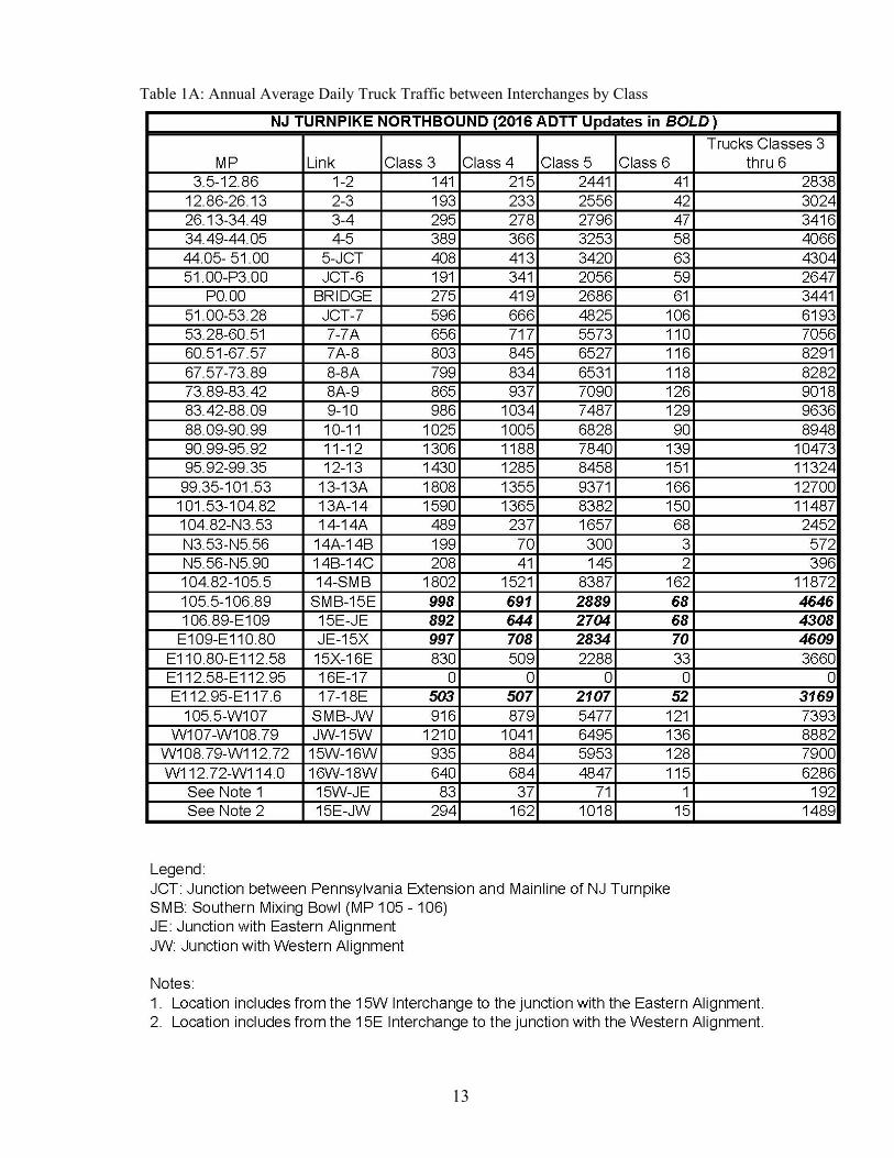
3.1.3 Truck Traffic Conditions at Bridge Site
LRFR live load factors appropriate for use with legal loads are defined based upon current Average Daily Truck Traffic (ADTT) for the bridge site. ADTT values, by class of vehicles between Turnpike interchanges, are given in Table 1A and Table 1B and have been determined based upon the Authority’s daily tolling records. The truck class number also denotes the number of axles. Trucks belonging to Classes 3 thru 6 are included in the ADTT count for a site. Milepost ranges between interchanges and other points of interest have been added for ease of use. Tables 1A and 1B consisted of data from 2008 when first prepared as part of the earliest versions of the Authority’s Load Rating Manual. Since that time, the tables have been updated annually to reflect any observed increases in truck traffic. When the truck traffic has decreased or remained the same, the existing data has been conservatively maintained in Tables 1A and 1B. Sections of the Turnpike roadway that have seen increases in total ADTT in 2016 have been shown in BOLD. While some ADTT increases may appear significant, the actual increase in live load factors for legal loads related to these increases is minimal, and should therefore not have a major effect on the load ratings. All load rating updates and load ratings of new construction shall utilize the data shown in Table 1A and 1B. It should be noted that prior versions of the Load Rating Manual (Versions 8 and prior) required an average increase of 1% per year be used to compute ADTT values for subsequent years. Thus, load rating updates utilizing later versions of the load rating manual may lead to a reduction in total ADTT. Structures located along the Garden State Parkway, regardless of location, shall be assumed to carry truck traffic. Traffic data obtained for the Garden State Parkway in 2012 shows that one way ADTT does not exceed 1000. Thus, it should be assumed during load ratings that all structures carrying Garden State Parkway mainline traffic shall utilize an ADTT of 1000. For structures which do not directly carry New Jersey Turnpike or Garden State Parkway mainline traffic (local roads over, etc.), the ADTT values for these structures shall be computed. Calculations should utilize the most current SI&A data via the NJTA InspectTech website, and shall also reference data from the NJDOT Straight Line Diagrams to verify accuracy. Inner roadway structures, located along the New Jersey Turnpike and which routinely carry vehicular traffic only shall utilize an ADTT of 1000. This ADTT value considers the periodic closures of the outer roadway, which shifts all traffic (including trucks) to the inner roadway. Specific traffic data for structures located within interchange areas of the New Jersey Turnpike is not included in Tables 1A or 1B. As a conservative approach, the total ADTT as shown in Tables 1A or 1B may be used for load rating of these structures. However, if low legal load ratings are obtained, the load rating engineer should review the traffic patterns and consider possible reductions in the ADTT such that low legal load ratings can be eliminated. Any reductions made to the ADTT should be clearly documented within the load rating report. ADTT for New Jersey Turnpike structures located north of mile points E117.60 or W114.00 is not included in Tables 1A or 1B, and also is not typically available using NJDOT’s Straight Line Diagrams. For these structures, an ADTT value of 5000 shall be used unless a more accurate ADTT can be determined. Where legal load rating factors are less than 1.00 in this
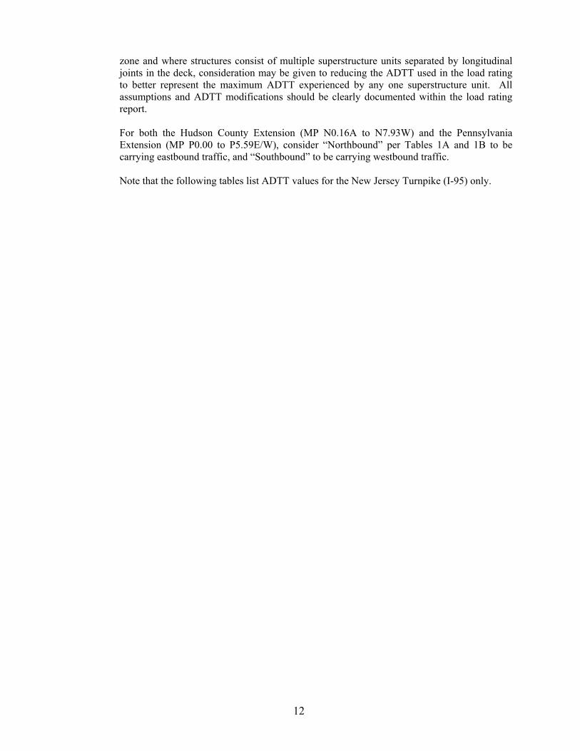
12
zone and where structures consist of multiple superstructure units separated by longitudinal joints in the deck, consideration may be given to reducing the ADTT used in the load rating to better represent the maximum ADTT experienced by any one superstructure unit. All assumptions and ADTT modifications should be clearly documented within the load rating report. For both the Hudson County Extension (MP N0.16A to N7.93W) and the Pennsylvania Extension (MP P0.00 to P5.59E/W), consider “Northbound” per Tables 1A and 1B to be carrying eastbound traffic, and “Southbound” to be carrying westbound traffic.
Note that the following tables list ADTT values for the New Jersey Turnpike (I-95) only.
13
Table 1A: Annual Average Daily Truck Traffic between Interchanges by Class
14
Table 1B: Annual Average Daily Truck Traffic between Interchanges by Class
15
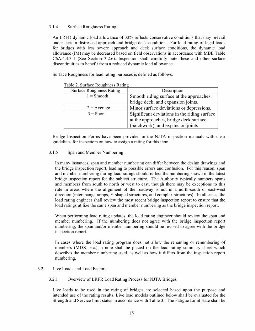
3.1.4 Surface Roughness Rating An LRFD dynamic load allowance of 33% reflects conservative conditions that may prevail under certain distressed approach and bridge deck conditions. For load rating of legal loads for bridges with less severe approach and deck surface conditions, the dynamic load allowance (IM) may be decreased based on field observations in accordance with MBE Table C6A.4.4.3-1 (See Section 3.2.6). Inspection shall carefully note these and other surface discontinuities to benefit from a reduced dynamic load allowance.
Surface Roughness for load rating purposes is defined as follows:
Table 2. Surface Roughness Rating Surface Roughness Rating Description
1 = Smooth Smooth riding surface at the approaches, bridge deck, and expansion joints.
2 = Average Minor surface deviations or depressions. 3 = Poor Significant deviations in the riding surface
at the approaches, bridge deck surface (patchwork), and expansion joints
Bridge Inspection Forms have been provided in the NJTA inspection manuals with clear guidelines for inspectors on how to assign a rating for this item.
3.1.5 Span and Member Numbering
In many instances, span and member numbering can differ between the design drawings and the bridge inspection report, leading to possible errors and confusion. For this reason, span and member numbering during load ratings should reflect the numbering shown in the latest bridge inspection report for the subject structure. The Authority typically numbers spans and members from south to north or west to east, though there may be exceptions to this rule in areas where the alignment of the roadway is not in a north-south or east-west direction (interchange ramps, Y-shaped structures, and complex structures). In all cases, the load rating engineer shall review the most recent bridge inspection report to ensure that the load ratings utilize the same span and member numbering as the bridge inspection report. When performing load rating updates, the load rating engineer should review the span and member numbering. If the numbering does not agree with the bridge inspection report numbering, the span and/or member numbering should be revised to agree with the bridge inspection report. In cases where the load rating program does not allow the renaming or renumbering of members (MDX, etc.), a note shall be placed on the load rating summary sheet which describes the member numbering used, as well as how it differs from the inspection report numbering.
3.2 Live Loads and Load Factors
3.2.1 Overview of LRFR Load Rating Process for NJTA Bridges
Live loads to be used in the rating of bridges are selected based upon the purpose and intended use of the rating results. Live load models outlined below shall be evaluated for the Strength and Service limit states in accordance with Table 3. The Fatigue Limit state shall be
16
evaluated during a load rating analysis when directed by the Authority. Each bridge shall be load rated for the following live load models:
1) Design load rating is a first-level rating performed for all bridges (including bridges designed using the Standard Specifications) using the HL-93 loading at the Inventory (Design) and Operating levels.
2) Legal load rating for routine commercial traffic: Rate for the NJ state legal loads: Type 3, Type 3-S2, Type 3-3. Legal lane loads given in Figure 1 (Section 3.2.3) are to be used for spans greater than 200 ft and for negative moment areas. Note that the NJTA Type 3S2 (See Figure 1a) varies from the standard gross vehicle weight of a standard AASHTO legal load.
3) Legal load rating for specialized hauling vehicles: Rate for AASHTO Specialized Hauling Vehicles (SHV) SU4, SU5, SU6, and SU7 given in Figure 2 (Section 3.2.4).
4) Load Rating for overweight permits may be performed when required following the provisions of Section 3.2.5.
Table 3. LRFR Limit States
Bridge Type Limit State
Design State Legal Legal SHV
HL-93
Type 3, Type 3-S2, Type 3-3 Lane Loads
SU4, SU5, SU6, SU7
Steel Strength I Service II Fatigue
Reinforced Concrete
Strength I
Prestressed Concrete
Strength I Service III
Note: Bullets indicate applicable limit states Annual Permits and Trip Permits may be authorized for vehicles exceeding the legal limit, as specified in the NJTA permit regulations. Load rating for overweight permits shall be in accordance with Section 3.2.5.
3.2.2 Design Load Rating for HL-93 Loading
The design-load rating (or HL-93 rating) assesses the performance of existing bridges utilizing the LRFD HL-93 design loading and design standards with dimensions and properties for the bridge in its present condition. It is a measure of the performance of existing bridges to new bridge design standards contained in the LRFD Specifications. The design-load rating produces Inventory and Operating level rating factors for the HL-93 loading. The evaluation live-load factors for the Strength I limit state shall be taken as given in MBE Table MBE 6A.4.3.2.2-1. Modifications to the design loading per the NJTA Design Manual, Structures Design, Section 2.2.2 for use in the design of new or rehabilitated structures shall not be considered during As-Built or As-Inspected load rating analyses. However, modified design loads shall be included when performing As-Designed load ratings. For all load ratings, the standard design
17
loading as specified in the LRFD Specifications shall be considered and included on the load rating summary sheet (for uniform means of comparison for all bridges).
Table MBE 6A.4.3.2.2-1 Load Factors for Design Load: γL
Evaluation Level Load Factor Inventory 1.75 Operating 1.35
The dynamic load allowance specified in the LRFD Specifications for new bridge design (LRFD Article 3.6.2) shall apply. For design load rating, regardless of the riding surface condition or the span length, always use 33% for the dynamic load allowance (IM). The results of the HL-93 rating are to be reported to the FHWA as a Rating Factor multiplied by 100 for Structural Inventory and Appraisal (SI&A) Items 63, 64, 65 and 66, using the HL-93 loadings.
3.2.3 Legal Load Rating for Routine Commercial Traffic
In LRFR, load ratings for legal loads determine a single safe load capacity of a bridge. The previously existing distinction of Operating and Inventory level ratings is no longer maintained when performing load ratings for legal loads.
The live load to be used in the LRFR rating for routine commercial traffic shall be any of the State legal loads shown in Table 3.
It is unnecessary to place more than one vehicle in a lane for spans less than 200 ft. because the LRFR live load factors provided have been modeled for this possibility (no lane load to be used). For negative moments and for span lengths greater than 200 ft., critical load effects shall be obtained by lane-type legal load models given in MBE APPENDIX D6A-4, also shown in Figure 1 below. The live-load factors for legal loads for the Strength I limit state shall be taken as given in Table MBE 6A.4.4.2.3a-1.
Table MBE 6A.4.4.2.3a.-1 Live-Load Factors, γL for NJ Legal Loads
Traffic Volume (One direction)
Load Factor for Type 3, Type 3S2, Type 3-3 and
lane loads
Unknown 1.45
ADTT ≥ 5000 1.45
ADTT ≤ 1000 1.30
Note: A linear interpolation is permitted for other ADTT values
18
a) Truck Type Legal Loads (Type 3S2 modified by NJTA)
b) Lane-Type Legal Load Model—Apply for spans greater than 200 ft. and all load effects.
MBE APPENDIX D6A-, Figure D6A-4
c) Lane-Type Legal Load Model—Apply for negative moment and interior reaction for all span
lengths.
MBE APPENDIX D6A, Figure D6A-5
19
Figure 1 - Legal Load Models
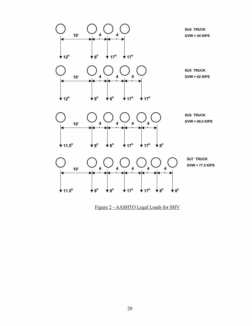
3.2.4 Legal Load Rating for Specialized Hauling Vehicles
In recent years, the trucking industry has introduced single unit Specialized Hauling Vehicles (SHV) with closely-spaced multiple axles that make it possible for these short wheelbase trucks to carry the maximum load of up to 80,000 lbs and still meet Federal Bridge Formula B and the axle weight limits. Because of the higher load effects of these vehicles, especially on short span bridges, AASHTO has adopted a new rating live load model and four new single unit trucks as legal loads. The four single unit posting trucks SU4, SU5, SU6 and SU7 shown in Figure 2 in this Section, model the short wheelbase multi-axle SHVs that are becoming increasingly more common in New Jersey. The live-load factors for the SHV legal loads for the Strength I limit state shall be taken as given in Table MBE 6A.4.4.2.3b-1. These load factors are identical to those for Routine Commercial Traffic in Section 3.2.3.
Table MBE 6A.4.4.2.3b.-1 Live-Load Factors, γL
for Specialized Hauling Vehicles
Traffic Volume (One direction)
Load Factor for SU4, SU5, SU6 and SU7
Unknown 1.45
ADTT ≥ 5000 1.45
ADTT ≤ 1000 1.30
Note: A linear interpolation is permitted for other ADTT values.
20
Figure 2 - AASHTO Legal Loads for SHV
SU4 TRUCK
GVW = 54 KIPS
SU5 TRUCK
GVW = 62 KIPS
SU6 TRUCK
GVW = 69.5 KIPS
SU7 TRUCK
GVW = 77.5 KIPS4’
4’
4’
4’
4’
10’
11.5K 8K 8K 17K 17K 8K 8K
4’
4’
4’
4’
10’
11.5K 8K 8K 17K 17K 8K
4’
4’
4’
10’
12K 8K 8K 17K 17K
4’
4’
10’
12K 8K 17K17K
21
3.2.5 Load Rating for Overweight Permits
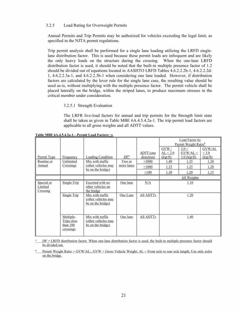
Annual Permits and Trip Permits may be authorized for vehicles exceeding the legal limit, as specified in the NJTA permit regulations. Trip permit analysis shall be performed for a single lane loading utilizing the LRFD single-lane distribution factor. This is used because these permit loads are infrequent and are likely the only heavy loads on the structure during the crossing. When the one-lane LRFD distribution factor is used, it should be noted that the built-in multiple presence factor of 1.2 should be divided out of equations located in AASHTO LRFD Tables 4.6.2.2.2b-1, 4.6.2.2.2d-1, 4.6.2.2.3a-1, and 4.6.2.2.3b-1 when considering one lane loaded. However, if distribution factors are calculated by the lever rule for the single lane case, the resulting value should be used as-is, without multiplying with the multiple presence factor. The permit vehicle shall be placed laterally on the bridge, within the striped lanes, to produce maximum stresses in the critical member under consideration.
3.2.5.1 Strength Evaluation The LRFR live-load factors for annual and trip permits for the Strength limit state shall be taken as given in Table MBE 6A.4.5.4.2a-1. The trip permit load factors are applicable to all gross weights and all ADTT values.
Table MBE 6A.4.5.4.2a-1—Permit Load Factors: γL
Permit Type Frequency Loading Condition DFa ADTT (one direction)
Load Factor by Permit Weight Ratiob
GVW / AL < 2.0 (kip/ft)
2.0 < GVW/AL < 3.0 (kip/ft)
GVW/AL > 3.0 (kip/ft)
Routine or Annual
Unlimited Crossings
Mix with traffic (other vehicles may be on the bridge)
Two or more lanes
>5000 1.40 1.35 1.30
=1000 1.35 1.25 1.20
<100 1.30 1.20 1.15
All Weights
Special or Limited Crossing
Single-Trip Escorted with no other vehicles on the bridge
One lane N/A 1.10
Single Trip Mix with traffic (other vehicles may be on the bridge)
One Lane All ADTTs 1.20
Multiple-Trips (less than 100 crossings
Mix with traffic (other vehicles may be on the bridge)
One lane All ADTTs 1.40
a DF = LRFD distribution factor. When one-lane distribution factor is used, the built-in multiple presence factor should be divided out.
b Permit Weight Ratio = GVW/AL;. GVW = Gross Vehicle Weight; AL = Front axle to rear axle length; Use only axles on the bridge.
22
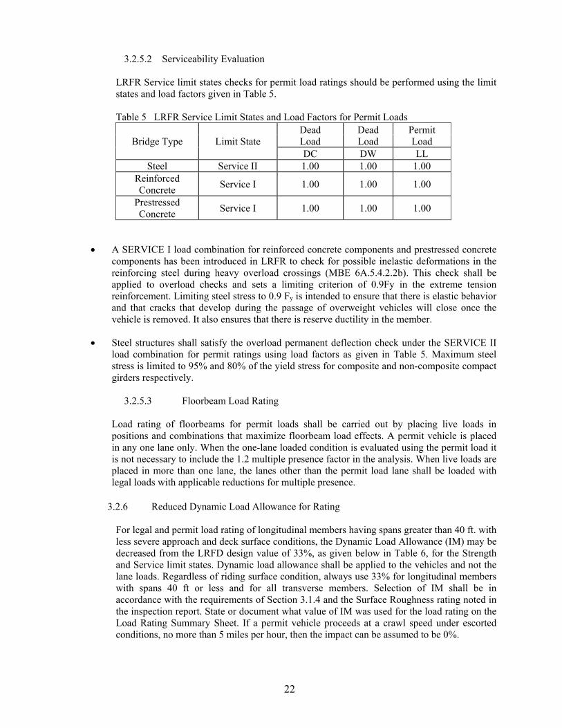
3.2.5.2 Serviceability Evaluation LRFR Service limit states checks for permit load ratings should be performed using the limit states and load factors given in Table 5. Table 5 LRFR Service Limit States and Load Factors for Permit Loads
Bridge Type Limit State Dead Load
Dead Load
Permit Load
DC DW LL Steel Service II 1.00 1.00 1.00
Reinforced Concrete
Service I 1.00 1.00 1.00
Prestressed Concrete
Service I 1.00 1.00 1.00
A SERVICE I load combination for reinforced concrete components and prestressed concrete components has been introduced in LRFR to check for possible inelastic deformations in the reinforcing steel during heavy overload crossings (MBE 6A.5.4.2.2b). This check shall be applied to overload checks and sets a limiting criterion of 0.9Fy in the extreme tension reinforcement. Limiting steel stress to 0.9 Fy is intended to ensure that there is elastic behavior and that cracks that develop during the passage of overweight vehicles will close once the vehicle is removed. It also ensures that there is reserve ductility in the member.
Steel structures shall satisfy the overload permanent deflection check under the SERVICE II load combination for permit ratings using load factors as given in Table 5. Maximum steel stress is limited to 95% and 80% of the yield stress for composite and non-composite compact girders respectively.
3.2.5.3 Floorbeam Load Rating
Load rating of floorbeams for permit loads shall be carried out by placing live loads in positions and combinations that maximize floorbeam load effects. A permit vehicle is placed in any one lane only. When the one-lane loaded condition is evaluated using the permit load it is not necessary to include the 1.2 multiple presence factor in the analysis. When live loads are placed in more than one lane, the lanes other than the permit load lane shall be loaded with legal loads with applicable reductions for multiple presence.
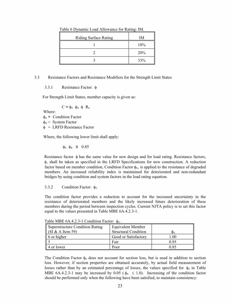
3.2.6 Reduced Dynamic Load Allowance for Rating
For legal and permit load rating of longitudinal members having spans greater than 40 ft. with less severe approach and deck surface conditions, the Dynamic Load Allowance (IM) may be decreased from the LRFD design value of 33%, as given below in Table 6, for the Strength and Service limit states. Dynamic load allowance shall be applied to the vehicles and not the lane loads. Regardless of riding surface condition, always use 33% for longitudinal members with spans 40 ft or less and for all transverse members. Selection of IM shall be in accordance with the requirements of Section 3.1.4 and the Surface Roughness rating noted in the inspection report. State or document what value of IM was used for the load rating on the Load Rating Summary Sheet. If a permit vehicle proceeds at a crawl speed under escorted conditions, no more than 5 miles per hour, then the impact can be assumed to be 0%.
23
Table 6 Dynamic Load Allowance for Rating: IM.
Riding Surface Rating IM
1 10%
2 20%
3 33%
3.3 Resistance Factors and Resistance Modifiers for the Strength Limit States
3.3.1 Resistance Factor:
For Strength Limit States, member capacity is given as:
C = c s Rn
Where: c = Condition Factor s = System Factor = LRFD Resistance Factor
Where, the following lower limit shall apply:
c s ≥ 0.85
Resistance factor has the same value for new design and for load rating. Resistance factors, , shall be taken as specified in the LRFD Specifications for new construction. A reduction factor based on member condition, Condition Factor c, is applied to the resistance of degraded members. An increased reliability index is maintained for deteriorated and non-redundant bridges by using condition and system factors in the load rating equation.
3.3.2 Condition Factor: C The condition factor provides a reduction to account for the increased uncertainty in the resistance of deteriorated members and the likely increased future deterioration of these members during the period between inspection cycles. Current NJTA policy is to set this factor equal to the values presented in Table MBE 6A.4.2.3-1. Table MBE 6A.4.2.3-1 Condition Factor: c .
Superstructure Condition Rating (SI & A Item 59)
Equivalent Member Structural Condition c
6 or higher Good or Satisfactory 1.00 5 Fair 0.95 4 or lower Poor 0.85
The Condition Factor c does not account for section loss, but is used in addition to section loss. However, if section properties are obtained accurately, by actual field measurement of losses rather than by an estimated percentage of losses, the values specified for c in Table MBE 6A.4.2.3-1 may be increased by 0.05 (c ≤ 1.0). Increasing of the condition factor should be performed only when the following have been satisfied, to maintain consistency:
24
1. Section properties are obtained accurately, via field measurements. 2. Ratings are first computed using the actual c value (< 1.00) and result in legal load
rating factors less than 1.00. 3. The Authority Project Manager has been contacted and has given approval regarding
the use of an increased condition factor. This type of scenario would most commonly be encountered when dealing with steel beams exhibiting section loss. On the other hand, a concrete member may receive a low condition rating due to heavy cracking and spalling or due to the deterioration of the concrete matrix. Such deterioration of concrete components may not necessarily reduce their calculated flexural resistance. But it is appropriate to apply the reduced condition factor in the LRFR load rating analysis. If there are also losses in the reinforcing steel of this member, they shall be measured and accounted for in the load rating. It is appropriate to also apply the reduced condition factor in the LRFR load rating analysis, even when the as-inspected section properties are used in the load rating as this reduction by itself does not fully account for the impaired resistance of the concrete component.
3.3.3 System Factor: S
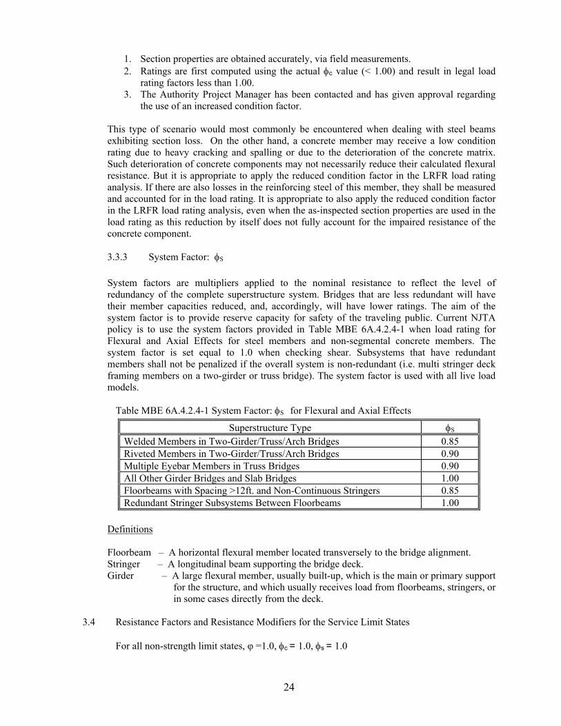
System factors are multipliers applied to the nominal resistance to reflect the level of redundancy of the complete superstructure system. Bridges that are less redundant will have their member capacities reduced, and, accordingly, will have lower ratings. The aim of the system factor is to provide reserve capacity for safety of the traveling public. Current NJTA policy is to use the system factors provided in Table MBE 6A.4.2.4-1 when load rating for Flexural and Axial Effects for steel members and non-segmental concrete members. The system factor is set equal to 1.0 when checking shear. Subsystems that have redundant members shall not be penalized if the overall system is non-redundant (i.e. multi stringer deck framing members on a two-girder or truss bridge). The system factor is used with all live load models.
Table MBE 6A.4.2.4-1 System Factor: S for Flexural and Axial Effects
Superstructure Type S Welded Members in Two-Girder/Truss/Arch Bridges 0.85 Riveted Members in Two-Girder/Truss/Arch Bridges 0.90 Multiple Eyebar Members in Truss Bridges 0.90 All Other Girder Bridges and Slab Bridges 1.00 Floorbeams with Spacing >12ft. and Non-Continuous Stringers 0.85 Redundant Stringer Subsystems Between Floorbeams 1.00
Definitions Floorbeam – A horizontal flexural member located transversely to the bridge alignment. Stringer – A longitudinal beam supporting the bridge deck. Girder – A large flexural member, usually built-up, which is the main or primary support
for the structure, and which usually receives load from floorbeams, stringers, or in some cases directly from the deck.
3.4 Resistance Factors and Resistance Modifiers for the Service Limit States
For all non-strength limit states, φ =1.0, c = 1.0, s = 1.0
25
3.5 Service & Fatigue Limit States for Load Rating
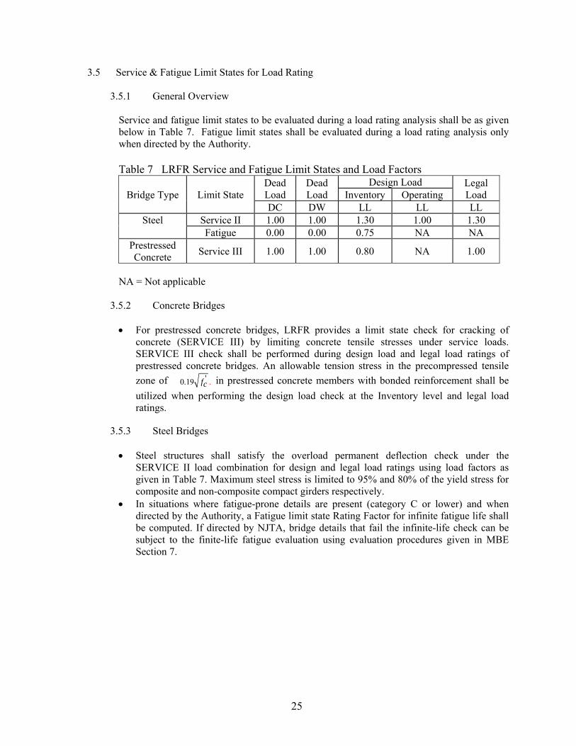
3.5.1 General Overview
Service and fatigue limit states to be evaluated during a load rating analysis shall be as given below in Table 7. Fatigue limit states shall be evaluated during a load rating analysis only when directed by the Authority. Table 7 LRFR Service and Fatigue Limit States and Load Factors
Bridge Type Limit State Dead Load
Dead Load
Design Load Legal Load Inventory Operating
DC DW LL LL LL Steel Service II 1.00 1.00 1.30 1.00 1.30
Fatigue 0.00 0.00 0.75 NA NA Prestressed Concrete
Service III 1.00 1.00 0.80 NA 1.00
NA = Not applicable
3.5.2 Concrete Bridges For prestressed concrete bridges, LRFR provides a limit state check for cracking of
concrete (SERVICE III) by limiting concrete tensile stresses under service loads. SERVICE III check shall be performed during design load and legal load ratings of prestressed concrete bridges. An allowable tension stress in the precompressed tensile
zone of '0.19 .fc in prestressed concrete members with bonded reinforcement shall be
utilized when performing the design load check at the Inventory level and legal load ratings.
3.5.3 Steel Bridges Steel structures shall satisfy the overload permanent deflection check under the
SERVICE II load combination for design and legal load ratings using load factors as given in Table 7. Maximum steel stress is limited to 95% and 80% of the yield stress for composite and non-composite compact girders respectively.
In situations where fatigue-prone details are present (category C or lower) and when directed by the Authority, a Fatigue limit state Rating Factor for infinite fatigue life shall be computed. If directed by NJTA, bridge details that fail the infinite-life check can be subject to the finite-life fatigue evaluation using evaluation procedures given in MBE Section 7.

26
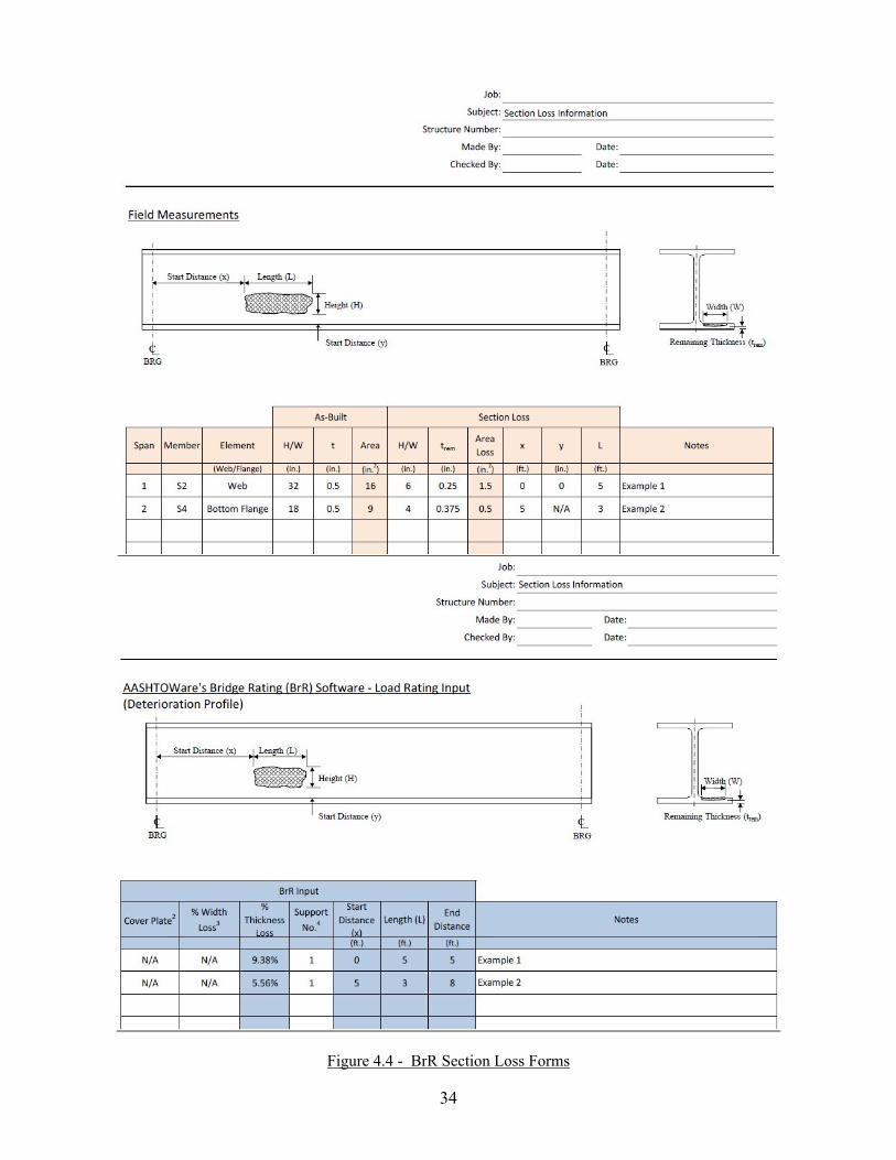
SECTION 4 LOAD RATING DELIVERABLES 4.1 Load Rating Report Load rating calculations and documentation shall be incorporated into a comprehensive report to facilitate updating of the information and calculations in the future. The load rating shall be completely documented in writing including all background information such as field inspection reports, material and load test data, all supporting computations, referenced drawings, and a clear statement of all assumptions used in calculating the load rating. The drawings included in the load rating report shall include all drawings that were referenced during the load rating, including the general notes, framing plans, cross sections, beam details, as well as any other unique details. Sketches shall also be provided to document member section losses incorporated in the analysis, and shall utilize section loss forms located on the Inspecttech website. These forms are currently accessible via the HELP / DOCUMENTATION menu within InspectTech, and primarily consist of beam elevation sketches. Also included with this document are supplemental field measurement and AASHTOWare Bridge Rating (BrR) load rating input forms designed specifically for use with members modeled in BrR (See Figure 4.4). For simplicity, these forms will be referred to as “BrR Section Loss Forms”. These BrR Section Loss Forms are provided for the inspection consultant’s convenience, are not required for inclusion in the load rating report, but are recommended. Inspection reports, testing reports, and articles referenced as part of the load rating shall be documented. When refined methods of analysis or load testing are used, the load rating report shall include live load distribution factors for all rated members, determined through such methods. For more complex structures where computer models are used in the analysis, a copy of the computer models with documentation shall be made and submitted to NJTA. For new, replaced or rehabilitated bridges designed using LRFD, the LRFR As-Designed load ratings shall be computed at the time of design and shown on the structural drawings following the structural notes (See Section 4.4).
4.1.1 Load Rating Report Deliverables
The following list details the required components of the load rating report, to be submitted via uploading to the InspectTech website for NJTA (http://njta.bridgeinspect.com), and placed within the “Load Ratings” section for the applicable bridge inspection report. The following listed info shall be provided in pdf format (unless identified as “optional”):
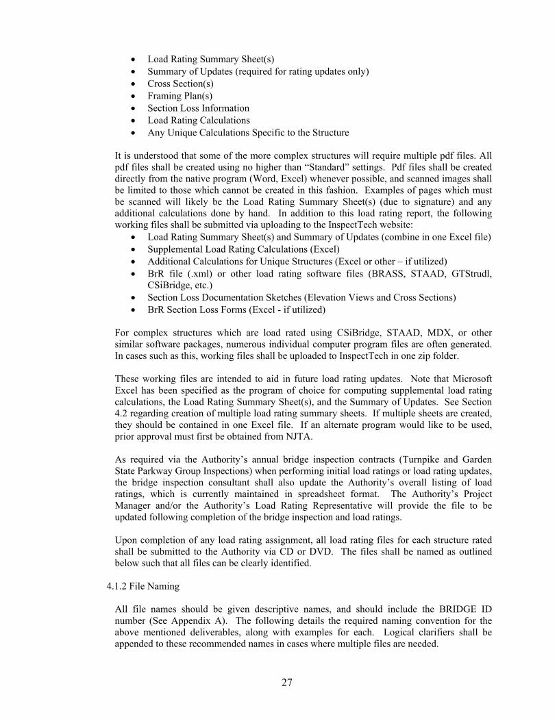
Load Rating Summary Sheet(s) Summary of Updates (required for rating updates only) Supplemental Load Rating Calculations Additional Calculations for Unique Structures (if needed) Section Loss Documentation Sketches (Elevation Views) BrR Section Loss Forms (Optional) Reference Drawings
When uploading files to the InspectTech(IT) website, each file shall be assigned a “file date”. For all load rating files, this date should reflect the date of the signed and sealed load rating summary sheet(s). Further, when copying a load rating summary sheet in IT from a prior bridge inspection report for inclusion in a current bridge inspection report, this process should be followed and the load rating summary sheet date assigned within IT should match the initial date on the load rating summary sheet.
The load rating consultant shall make every effort to contain the above documents in ONE pdf file for ease of future use and reference. At a minimum, the pdf shall include bookmarks for the following sections of the load rating report:
27
Load Rating Summary Sheet(s) Summary of Updates (required for rating updates only) Cross Section(s) Framing Plan(s) Section Loss Information Load Rating Calculations Any Unique Calculations Specific to the Structure
It is understood that some of the more complex structures will require multiple pdf files. All pdf files shall be created using no higher than “Standard” settings. Pdf files shall be created directly from the native program (Word, Excel) whenever possible, and scanned images shall be limited to those which cannot be created in this fashion. Examples of pages which must be scanned will likely be the Load Rating Summary Sheet(s) (due to signature) and any additional calculations done by hand. In addition to this load rating report, the following working files shall be submitted via uploading to the InspectTech website:
Load Rating Summary Sheet(s) and Summary of Updates (combine in one Excel file) Supplemental Load Rating Calculations (Excel) Additional Calculations for Unique Structures (Excel or other – if utilized) BrR file (.xml) or other load rating software files (BRASS, STAAD, GTStrudl,
CSiBridge, etc.) Section Loss Documentation Sketches (Elevation Views and Cross Sections) BrR Section Loss Forms (Excel - if utilized)
For complex structures which are load rated using CSiBridge, STAAD, MDX, or other similar software packages, numerous individual computer program files are often generated. In cases such as this, working files shall be uploaded to InspectTech in one zip folder. These working files are intended to aid in future load rating updates. Note that Microsoft Excel has been specified as the program of choice for computing supplemental load rating calculations, the Load Rating Summary Sheet(s), and the Summary of Updates. See Section 4.2 regarding creation of multiple load rating summary sheets. If multiple sheets are created, they should be contained in one Excel file. If an alternate program would like to be used, prior approval must first be obtained from NJTA. As required via the Authority’s annual bridge inspection contracts (Turnpike and Garden State Parkway Group Inspections) when performing initial load ratings or load rating updates, the bridge inspection consultant shall also update the Authority’s overall listing of load ratings, which is currently maintained in spreadsheet format. The Authority’s Project Manager and/or the Authority’s Load Rating Representative will provide the file to be updated following completion of the bridge inspection and load ratings. Upon completion of any load rating assignment, all load rating files for each structure rated shall be submitted to the Authority via CD or DVD. The files shall be named as outlined below such that all files can be clearly identified.
4.1.2 File Naming All file names should be given descriptive names, and should include the BRIDGE ID number (See Appendix A). The following details the required naming convention for the above mentioned deliverables, along with examples for each. Logical clarifiers shall be appended to these recommended names in cases where multiple files are needed.
28
1. Load Rating Summary Sheet – The summary sheet working Excel file name shall begin with MP, and shall be directly followed by the milepoint of the structure, a space, then LOAD RATING SUMMARY SHEET. This file shall also contain the SUMMARY OF UPDATES data on a separate worksheet. Ex. For NJ Turnpike Structure located at MP 23.12, the summary sheet file shall be named “MP23.12 Load Rating Summary Sheet.xls”.
2. Supplemental Load Rating Calculations – The load rating calculations working Excel file shall begin with MP, and shall be directly followed by the milepoint of the structure, a space, then SUPPLEMENTAL CALCS. Multiple files can be specified by adding incremental numeric values at the end of this file name (i.e., 1, 2, 3, etc.). Ex. For NJ Turnpike Structure located at MP 23.12, the load rating calculations file shall be named “MP23.12 Supplemental Calcs.xls”.
3. Additional Calculations for Unique Structures – The additional load rating calculations working Excel file (if needed) shall begin with MP, and shall be directly followed by the milepoint of the structure, a space, then ADDITIONAL CALCS. Multiple files can be specified by adding incremental numeric values at the end of this file name (i.e., 1, 2, 3, etc.). Ex. For NJ Turnpike Structure located at MP 23.12, the additional load rating calculations file shall be named “MP23.12 Additional Calcs.xls”.
4. BrR File – The BrR working file shall begin with MP, and shall be directly followed by the milepoint of the structure. Other program file names should be similarly named. Ex. For NJ Turnpike Structure located at MP 23.12, the BrR file shall be named “MP23.12.xml”.
5. Load Rating Report (pdf version) – The Final Load Rating Report shall begin with MP, and shall be directly followed by the milepoint of the structure, a space, then LRFR LOAD RATING REPORT. Ex. For NJ Turnpike Structure located at MP 23.12, the final load rating report shall be named “MP23.12 LRFR Load Rating Report.pdf”.
As-Designed ratings should utilize the above noted file naming conventions, and should append “(As-Designed)” to all load rating files. See Section 4.4 for additional details regarding As-Designed ratings.
4.1.3 InspectTech – Plan Uploading and Load Rating Input
Upon completion of the load rating, the consultant shall input the required load rating data directly into a master load rating summary table provided by the Authority and maintained by the Authority’s Load Rating Representative. In addition to the input of required load rating data into this table, all relevant plans should also be uploaded to the “drawings” location within InspectTech as part of the initial LRFR ratings for each structure. The term “relevant” refers to any drawing specific to the structure
29
in question, regardless of whether it was referenced during the load rating process. This includes but is not limited to original design drawings, original contract drawings, and structure rehabilitation drawings. Note that this is in addition to including the referenced drawings in the Load Rating Report pdf. Please confirm with the Authority Project Manager the appropriate method to use for submitting the load rating data and relevant plans prior to start of work.
4.1.4 Interpretation of Rating Results and Low Ratings Load ratings are performed to ensure bridge safety, to comply with federal regulations, to assist with determining needs for bridge replacement or rehabilitation, to determine needs for posting, and to assist with the processing of overload permits. For these reasons, it is important that accurate load rating results are reported to the bridge owner. In cases where load ratings for legal loads fall below the required 1.00 rating factor, the load rating engineer shall review the ratings to ensure that overly conservative assumptions have not led to overly conservative rating results. If applicable, ensure that any dynamic load allowance reductions based on the riding surface have been incorporated into the analysis. In cases where fascia members exhibit low ratings, consider reducing the travelway (and live load effects) in accordance with MBE Section 6A.2.3.2. The Authority should be notified immediately if rating results continue to yield rating factors less than 1.00 for legal loads. Also reference Section 2.6 regarding reporting of load rating data to the NBI in cases where low ratings are determined. Load and Resistance Factor ratings of recently designed structures on the NJ Turnpike have identified issues that the load rating engineer and load rating reviewer should understand, in the event that these issues arise again when performing load ratings of recently designed structures. The following is a summary of findings. The Authority shall be notified immediately if any of the below issues are encountered during the load rating process. Once notified, the Authority will review and provide a recommended course of action. 1. Curved girder structures designed using the 4th Edition of the AASHTO LRFD
Specifications will most likely yield low ratings for single angle diaphragm members when rated using later editions of the specifications due to significant member capacity calculation changes in the 5th and 6th Editions of the AASHTO LRFD Specifications. If directed by the Authority, the specifications used in the load rating program can be modified such that ratings are performed using the design specifications. Further, a note can be added to the load rating summary sheet indicating that load ratings utilize an earlier edition of the LRFD specifications.
2. Ratings of structures using BrR which were designed using other software programs (STLRFD v1.6.0.0) have identified an error in the design program related to the Cb value. Cb should be set to 1.0 in cases where the member is nonprismatic, but this version of STLRFD only considered a change in web depth as being nonprismatic, and did not consider a change in flange thickness as also being nonprismatic. This was most likely due to a recent change in the LRFD specifications. As a result, the load rating engineer can expect rating results using BrR to be lower than those determined from the design software. Discuss with the Authority for a recommended course of action when this issue is encountered. Note that LRFD Section 6.10.8.2.3 discusses the current
30
LRFD criteria in more detail. The error with the STLRFD design program has since been corrected.
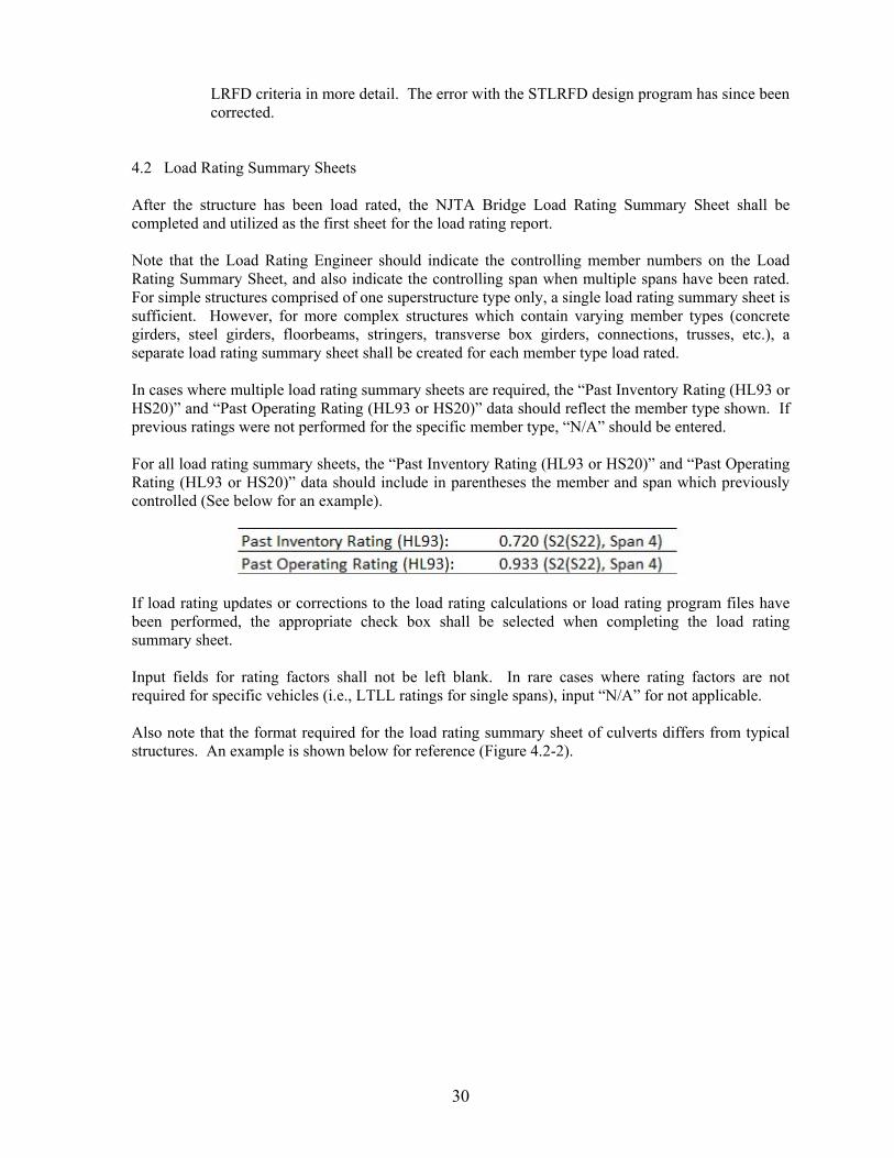
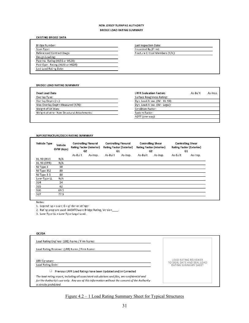
4.2 Load Rating Summary Sheets After the structure has been load rated, the NJTA Bridge Load Rating Summary Sheet shall be completed and utilized as the first sheet for the load rating report. Note that the Load Rating Engineer should indicate the controlling member numbers on the Load Rating Summary Sheet, and also indicate the controlling span when multiple spans have been rated. For simple structures comprised of one superstructure type only, a single load rating summary sheet is sufficient. However, for more complex structures which contain varying member types (concrete girders, steel girders, floorbeams, stringers, transverse box girders, connections, trusses, etc.), a separate load rating summary sheet shall be created for each member type load rated. In cases where multiple load rating summary sheets are required, the “Past Inventory Rating (HL93 or HS20)” and “Past Operating Rating (HL93 or HS20)” data should reflect the member type shown. If previous ratings were not performed for the specific member type, “N/A” should be entered. For all load rating summary sheets, the “Past Inventory Rating (HL93 or HS20)” and “Past Operating Rating (HL93 or HS20)” data should include in parentheses the member and span which previously controlled (See below for an example).
If load rating updates or corrections to the load rating calculations or load rating program files have been performed, the appropriate check box shall be selected when completing the load rating summary sheet. Input fields for rating factors shall not be left blank. In rare cases where rating factors are not required for specific vehicles (i.e., LTLL ratings for single spans), input “N/A” for not applicable. Also note that the format required for the load rating summary sheet of culverts differs from typical structures. An example is shown below for reference (Figure 4.2-2).
31
Figure 4.2 – 1 Load Rating Summary Sheet for Typical Structures

32
Figure 4.2 – 2 Load Rating Summary Sheet for Culverts

33
Figure 4.3 – Summary of Updates (Example)
34
Figure 4.4 - BrR Section Loss Forms
35
4.3 Quality Control and Quality Assurance Review of Load Ratings Quality control procedures are intended to maintain the quality of the bridge load ratings and are usually performed continuously within the load rating teams/units. All load rating calculations shall be performed by the Load Rating Engineer (LRE), and shall be reviewed by the Load Rating Reviewer (LRR). The LRE and LRR shall satisfy the requirements of Section 2.2, Qualifications and Responsibilities. Upon completion of the load rating, the initials of the LRR shall be placed on every sheet of the calculations. Failure to do this will be grounds for rejection of the submittal by NJTA. When computer programs are used, the LRR shall perform independent checks to validate the accuracy of the load rating results generated by the program. The LRR shall verify all input data, verify that the summary of load capacity information accurately reflects the analysis, and be satisfied with the accuracy and suitability of the computer program. Quality assurance procedures are used to verify the adequacy of the quality control procedures to meet or exceed the standards established by the agency or the consultant performing the load ratings. Quality assurance procedures are usually performed independent of the load rating teams (LRE & LRR) on a sample of their work. Guidance on quality measures for load rating may be found in MBE Article 1.4. 4.4 Requirements for Load Rating of New or Rehabilitated Structures
While the majority of existing bridge load ratings for the Authority have been performed as part
of various New Jersey Turnpike and Garden State Parkway Group Bridge Inspections contracts, load ratings shall also be performed by design engineers in association with bridge design contracts.
The Design Engineer shall submit, as a part of the Phase C submission, the complete As-
Designed load rating analysis for all new bridges, and for all existing bridges subject to substantial modification (See the NJTA Design Manual, Structures Design, Section 2.2.1.2). The Authority’s Project Manager as well as the Authority’s Load Rating Representative should be included in all load rating correspondence and submissions to maintain load rating consistency and eliminate duplication of work. When ratings are performed in conjunction with the preparation of design drawings, the load rating results for all investigated live load models shall be shown on the General Notes sheet for each structure. See Figure 4.4.1 for a sample rating factor summary table and associated analysis notes. However, please refer to the current NJTA Design Manual, Structures Design for a complete list of required design vehicles. Live load distribution factors used in the design and rating of structures shall also be noted on the structural drawings for all rating analyses other than line girder analyses.
For load ratings of rehabilitated structures, the consultant shall review and update (if needed) the
previous load rating calculations and bridge model files to ensure accuracy prior to incorporating the rehabilitation. The consultant performing these updates shall be fully responsible for the correctness of the complete load rating submission (See Section 2.1.2).

36
1. Load and resistance factor ratings have been performed using (BrR, Version x.x.x / BRASS
Version x.x.x / specify other software). 2. The analysis of the girder to determine dead load and live load effects has been performed
based on a (Line Girder Analysis / Finite Element Analysis / Grid Analysis considering the diaphragms to act as primary members).
3. The controlling HL-93 vehicle for the above members is the (Design Truck & Lane / Design Tandem & Lane / 90% of Two Design Trucks & 90% Lane).
Figure 4.4.1 – Sample Load Factor Table and Associated Notes
The load rating summary sheet, as shown in Section 4.2, shall be used, but should be modified as
follows: In lieu of the typical As-Built and As-Inspected rating conditions, the Design Engineer
shall modify the sheet to identify the rating as an As-Designed rating. This indicates that the rating has been based entirely on the design drawings, and has not been built and/or verified in the field via inspection. During the first cycle inspection, the bridge inspection consultant will be responsible for verification of the design drawings, and updating of the ratings to consider both the As-Built and As-Inspected conditions.
For rehabilitation and repair design, the design loading may differ between original members and new members. In this case, separate load rating summary sheets shall be created for the original members and any new members designed based upon different design loads.
For all new bridges or new primary bridge members, the As-Designed superstructure rating summary section should include ratings for all design vehicles, as well as the standard design and legal vehicles specified in this manual for load ratings (HL-93 and AASHTO legal loads). Inclusion of all additional design vehicles in the As-Designed load rating analysis is intended to serve as a verification of the design, whereas all design rating factors are expected to be greater than 1.00 at the Inventory Level. Refer to the NJTA Design Manual, Structures Design (current version) for design criteria.
Fatigue ratings shall be performed as per the NJTA Design Manual (Structures Design Section
2.2.1) and for the necessary design rating factors to be shown on the drawings. However, Fatigue ratings are not required to be shown on the load rating summary sheet nor included in the LRFR load rating report.

37
The electronic input file for the load rating summary sheet and all other applicable load rating data shall be created by the Design Engineer and provided to the Authority in accordance with the requirements of Section 4.1. 4.5 Dissemination of Load Rating Results to Other Entities
All load rating files, reports, calculations, and bridge models are solely the property of the New Jersey Turnpike Authority. Further, the load rating results contained in the load rating report are confidential and for the use of the Authority or their consultants who are engaged in active contracts with the Authority. Any use of this information without the consent of the Authority is strictly prohibited. To obtain access to load rating files, written permission shall be obtained from an Authority representative. Transmission of load rating data to the State as part of the biennial bridge inspection is part of the consultant’s scope of work and is therefore exempt from the above requirement.
38
SECTION 5 – LOAD RATING OF CULVERTS 5.1. Introduction With the addition of culvert rating capabilities in Virtis Version 6.4 and in subsequent versions of AASHTOWare’s Bridge Rating (BrR) software, numerous culverts located throughout the New Jersey Turnpike (Turnpike) and Garden State Parkway (Parkway) roadways now require load rating. Current culverts located throughout both roadways consist of single cell box culverts, multiple cell box culverts, three-sided culverts and multi-span reinforced concrete arch culverts. The National Bridge Inspection Standards (23 CFR 650.3) generally define bridges as structures with a span length greater than 20ft. Load ratings of structures less than 20 feet are not currently required. Other structures which often are less than 20 feet in span length consist of reinforced concrete pipes and corrugated metal pipes. A small number of single span arch culverts exist throughout the length of the two roadways, but are not considered bridge structures since the span lengths are less than or equal to 8 feet. The few multi span arches with span lengths greater than 20ft are, however, under significant earth fill (greater than 8 ft) and are not required to be load rated. The LRFR rating guidelines provided herein pertain to various bridge culvert types which are defined as “bridges” in the current NJTA bridge inventory. 5.2. AASHTO MBE Provisions for Culverts The AASHTO Manual for Bridge Evaluation (MBE) 2013 Interim Revisions initially introduced LRFR provisions specific to the load rating of single and multiple cell reinforced concrete box culverts. Culverts experience loadings that are not applicable to most bridge superstructures, including vertical and horizontal soil loads, and live load surcharge. MBE Article 6A.5.12.1 incorporates LRFR provisions for cast-in-place and precast reinforced concrete box culverts, but does not address culvert types such as three-sided culverts and arches. The procedures described herein apply to the LRFR rating of box culverts and three-sided culverts and supplement the MBE provisions. 5.3. BrR Capabilities for Culverts
All culvert ratings shall be performed using the most current version of the AASHTOWare Bridge Rating (BrR) software, following the guidelines provided in this section and the Appendices. This program can perform LRFR ratings of single or multi cell box culverts, with or without a bottom slab, in accordance with the MBE (latest edition). This program currently does not have the capability to rate arch shaped culverts. Specific guidance on modeling of reinforced concrete box culverts and three-sided culverts can be found in Appendices A1 and A2. 5.4. Load Rating Requirements
5.4.1 Sections
Culverts shall be evaluated at their critical sections for the force effects. Force demands at several critical sections must be calculated in order to establish the lowest load rating for a culvert structure. As shown in Figure 1, the typical critical sections are shown at the member ends, mid span and at shear critical locations. The load rating engineer shall review the culvert plans and verify that all critical sections have been included in the rating.
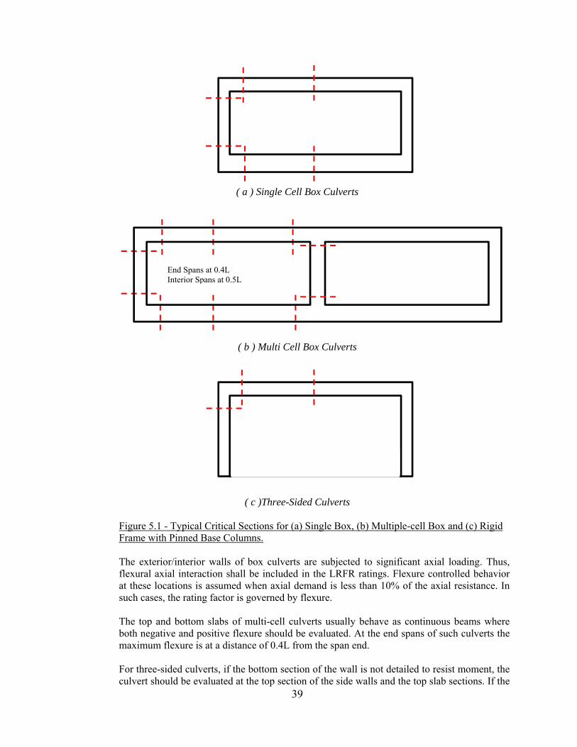
39
( a ) Single Cell Box Culverts
( b ) Multi Cell Box Culverts
( c )Three-Sided Culverts
Figure 5.1 - Typical Critical Sections for (a) Single Box, (b) Multiple-cell Box and (c) Rigid Frame with Pinned Base Columns. The exterior/interior walls of box culverts are subjected to significant axial loading. Thus, flexural axial interaction shall be included in the LRFR ratings. Flexure controlled behavior at these locations is assumed when axial demand is less than 10% of the axial resistance. In such cases, the rating factor is governed by flexure.
The top and bottom slabs of multi-cell culverts usually behave as continuous beams where both negative and positive flexure should be evaluated. At the end spans of such culverts the maximum flexure is at a distance of 0.4L from the span end.
For three-sided culverts, if the bottom section of the wall is not detailed to resist moment, the culvert should be evaluated at the top section of the side walls and the top slab sections. If the
End Spans at 0.4L Interior Spans at 0.5L
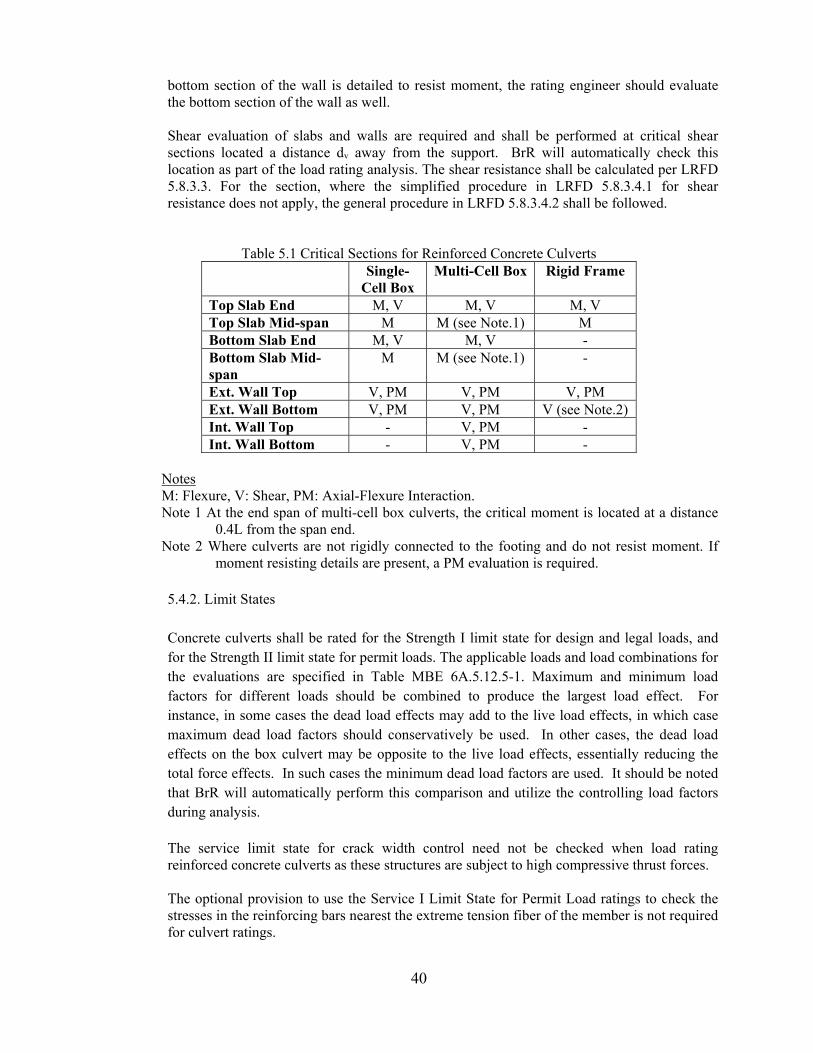
40
bottom section of the wall is detailed to resist moment, the rating engineer should evaluate the bottom section of the wall as well.
Shear evaluation of slabs and walls are required and shall be performed at critical shear sections located a distance dv away from the support. BrR will automatically check this location as part of the load rating analysis. The shear resistance shall be calculated per LRFD 5.8.3.3. For the section, where the simplified procedure in LRFD 5.8.3.4.1 for shear resistance does not apply, the general procedure in LRFD 5.8.3.4.2 shall be followed.
Table 5.1 Critical Sections for Reinforced Concrete Culverts Single-
Cell Box Multi-Cell Box Rigid Frame
Top Slab End M, V M, V M, V Top Slab Mid-span M M (see Note.1) M Bottom Slab End M, V M, V - Bottom Slab Mid-span
M M (see Note.1) -
Ext. Wall Top V, PM V, PM V, PM Ext. Wall Bottom V, PM V, PM V (see Note.2) Int. Wall Top - V, PM - Int. Wall Bottom - V, PM -
Notes M: Flexure, V: Shear, PM: Axial-Flexure Interaction. Note 1 At the end span of multi-cell box culverts, the critical moment is located at a distance
0.4L from the span end. Note 2 Where culverts are not rigidly connected to the footing and do not resist moment. If
moment resisting details are present, a PM evaluation is required. 5.4.2. Limit States Concrete culverts shall be rated for the Strength I limit state for design and legal loads, and for the Strength II limit state for permit loads. The applicable loads and load combinations for the evaluations are specified in Table MBE 6A.5.12.5-1. Maximum and minimum load factors for different loads should be combined to produce the largest load effect. For instance, in some cases the dead load effects may add to the live load effects, in which case maximum dead load factors should conservatively be used. In other cases, the dead load effects on the box culvert may be opposite to the live load effects, essentially reducing the total force effects. In such cases the minimum dead load factors are used. It should be noted that BrR will automatically perform this comparison and utilize the controlling load factors during analysis. The service limit state for crack width control need not be checked when load rating reinforced concrete culverts as these structures are subject to high compressive thrust forces.
The optional provision to use the Service I Limit State for Permit Load ratings to check the stresses in the reinforcing bars nearest the extreme tension fiber of the member is not required for culvert ratings.
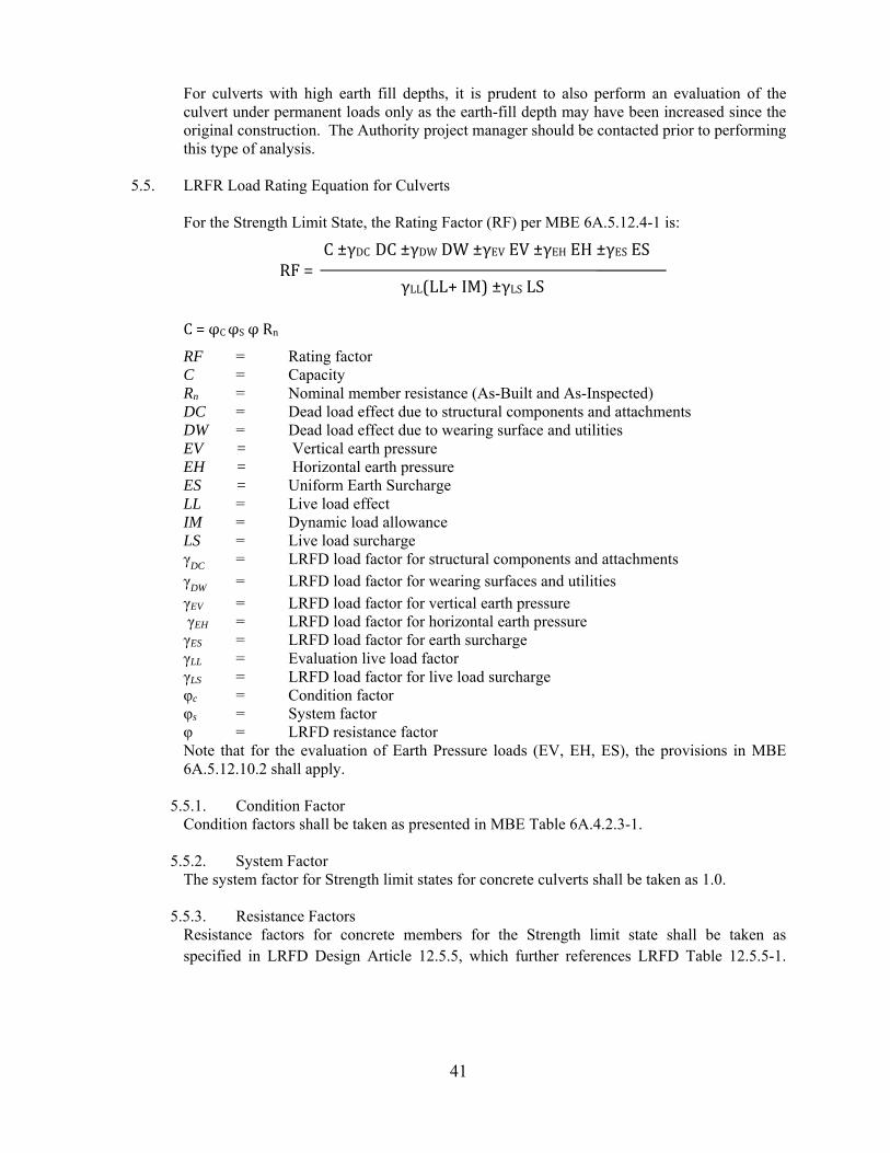
41
For culverts with high earth fill depths, it is prudent to also perform an evaluation of the culvert under permanent loads only as the earth-fill depth may have been increased since the original construction. The Authority project manager should be contacted prior to performing this type of analysis.
5.5. LRFR Load Rating Equation for Culverts
For the Strength Limit State, the Rating Factor (RF) per MBE 6A.5.12.4-1 is:
C=φCφSφRn
RF = Rating factor C = Capacity Rn = Nominal member resistance (As-Built and As-Inspected) DC = Dead load effect due to structural components and attachments DW = Dead load effect due to wearing surface and utilities EV = Vertical earth pressure EH = Horizontal earth pressure ES = Uniform Earth Surcharge LL = Live load effect IM = Dynamic load allowance LS = Live load surcharge
γDC = LRFD load factor for structural components and attachments γDW = LRFD load factor for wearing surfaces and utilities γEV = LRFD load factor for vertical earth pressure γEH = LRFD load factor for horizontal earth pressure γES = LRFD load factor for earth surcharge γLL = Evaluation live load factor γLS = LRFD load factor for live load surcharge φc = Condition factor φs = System factor
φ = LRFD resistance factor Note that for the evaluation of Earth Pressure loads (EV, EH, ES), the provisions in MBE 6A.5.12.10.2 shall apply.
5.5.1. Condition Factor
Condition factors shall be taken as presented in MBE Table 6A.4.2.3-1.
5.5.2. System Factor The system factor for Strength limit states for concrete culverts shall be taken as 1.0.
5.5.3. Resistance Factors Resistance factors for concrete members for the Strength limit state shall be taken as specified in LRFD Design Article 12.5.5, which further references LRFD Table 12.5.5-1.
C±γDCDC±γDWDW±γEVEV±γEHEH±γESES
γLL(LL+IM)±γLSLSRF=
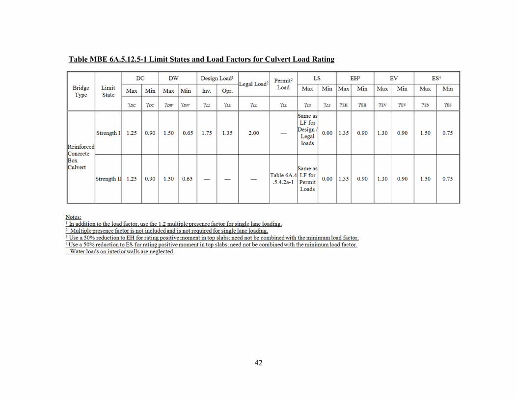
42
Table MBE 6A.5.12.5-1 Limit States and Load Factors for Culvert Load Rating
43
5.6 Live Loads and Distributions
5.6.1 Live Load Distribution
For load rating culverts for the HL-93 design load, only the axle loads of the design truck or the design tandem, without the lane load, shall be applied. For traffic traveling parallel to the span, box culverts shall be load rated for a single loaded lane with the following multiple presence factors:
• Design Load— LRFD single-lane multiple presence factor (1.2) shall be applied to the load. • Legal Loads — Only the single lane loaded condition needs to be checked for legal load ratings,
even when the culvert carries multiple lanes. A single legal load factor of 2.00 is specified for all traffic volumes. Omit the 1.2 single lane multiple presence factor.
Load factors for load rating shall be selected from Table MBE 6A.5.12.5-1.
The distribution of wheel loads for culverts with less than 2.0 ft of fill shall be taken as specified in LRFD Design Article 4.6.2.10. Distribution of wheel loads to culverts with 2.0 ft or more of fill shall be as specified in LRFD Design Article 3.6.1.2.6. Single span culverts with depth of fill more than 8 ft need not be load rated since the live load will constitute a negligible portion of the overall loading. For multiple span culverts, the effects of live load may be neglected where the depth of fill exceeds the distance between faces of end walls. For such cases, the capacity should be checked against permanent loads only for the possible ultimate demand obtained by the minimum and maximum load factors. The Authority project manager should be contacted prior to performing this type of analysis.
5.6.2 Impact Factor The dynamic load allowance for culverts shall be taken as given in LRFD Design 3.6.2.2 except that, for slow moving (≤ 10 mph) permit vehicles, the dynamic load allowance shall be taken equal to zero.
5.6.3 Permit Loads Only the single lane loaded condition needs to be checked for permit load ratings, even when the culvert carries multiple lanes. Culvert permit load ratings shall be based on the Strength II limit state and the permit truck live load factor shall be taken from MBE Table 6A.4.5.4.2a-1.

44
REFERENCE PUBLICATIONS
1. AASHTO Manual for Bridge Evaluation, Second Edition, 2011, including all subsequent interim revisions.
2. New Jersey Turnpike Authority, Bentley InspectTech Collector (current version).
3. New Jersey Turnpike Authority Design Manual, January 2017.
4. FHWA. 2002. Bridge Inspector’s Reference Manual (BIRM), Federal Highway
Administration, U.S. Department of Transportation, Washington, DC.
5. AASHTO LRFD Bridge Design Specifications, 7th Edition, including all subsequent interim revisions.
6. NCHRP Report 575; Legal Truck Loads and AASHTO Legal Loads for Posting, 2006.
7. NCHRP Report 454; Calibration of Load Factors for LRFR Evaluation, 2001.
8. NJDOT Bridges and Structures Design Manual, Latest Edition.
A1
APPENDIX A1 AASHTOWARE BRR - GUIDELINES FOR LRFR RATINGS
This Appendix will be utilized to provide more specific BrR load rating guidance, and has been based primarily upon BrR, Version 6.6. This Appendix assumes the reader is familiar with the BrR load rating software. Also, this document is not to be treated as a User’s Manual, but instead is intended to provide some useful program notes and specific guidance regarding LRFR load ratings for NJTA. Unless noted as (OPTIONAL), all direction listed below must be utilized when creating the BrR model or performing load ratings. Items in all capital letters refer directly to specific BrR commands, windows, tabs, etc.
BRR CURRENT VERSION
1. The current version of AASHTOWare’s Bridge Rating software is version 6.8.2. All load ratings performed for the Authority shall utilize this version, including all applicable Maintenance Releases and Technical Note updates to the software, unless otherwise directed by the Authority.
BRR UPDATES, CRITICAL BUGS, ETC.
1. At least one contact from each company performing load ratings should subscribe to the AASHTO BrDR Mailing List. This list is the sole means of communication between AASHTOWare and the user. By providing an email address via the below website, this ensures that proper notifications will be received when program updates are available (Service Packs), critical errors have been uncovered or corrected, or general BrR information must be distributed. This takes only minutes and can be done by visiting the below website:
https://aashto.mbakercorp.com/Pages/eNotification.aspx
FILE NAMING
1. All BrR files will possess two unique identifiers, a BRIDGE ID and a NBI STRUCTURE ID. The bridge ID should consist of the MP appended to the actual milepoint (and direction, if applicable) of the structure. The NBI STRUCTURE ID should be identical to the NBI Structure ID as noted on the structure’s SI&A forms, and can be a maximum of 8 characters. Below are two examples:
Structure at MP 28.0S on the Garden State Parkway: BRIDGE ID= MP28.0S NBI STRUCTURE ID=360280S
Structure at MP 23.12 on the New Jersey Turnpike: BRIDGE ID = MP23.12 NBI STRUCTURE ID = M023120
2. The BrR .xml file name should be identical to the above mentioned BRIDGE ID.
BRR LIBRARY
1. It should be noted that the existing Type 3S2 vehicle in BrR (72 kips) is not the same as the NJTA Type 3S2 (80 kips) vehicle per this Load Rating Manual and NJTA specifications. Therefore, the load rating engineer should create a new Type 3S2 vehicle in the LIBRARY (recommended name: NJTA Type 3S2). Be sure to select the correct 3S2 vehicle when performing NJTA load ratings.
MEMBER ALTERNATIVE DESCRIPTION – SPECS
A2
This tab has been added as part of BrR version 6.3. See below for specific notes pertaining to its use.
1. For LRFR ratings, the AASHTO engine should be used for all ratings. The previously available BRASS engine, which was available in Version 6.2, is no longer available directly from BrR. If required, the BRASS load rating engine capabilities can be enabled if the engineering firm or agency possesses a separate BRASS license. Contact AASHTOWare or BRASS (Wyoming DOT) for guidance.
2. For all LRFR load ratings, the load rating engineer should select the most current SPEC VERSION, which based on Version 6.8 is MBE 2ND 2016i, LRFD 7th 2016i. Note that Versions 6.3 and later now allow for both Legal loads and Specialized Hauling Vehicles to be run using the same FACTORS file.
MEMBER ALTERNATIVE DESCRIPTION - CONTROL OPTIONS
The BrR default settings are typically sufficient for load rating purposes, however, the following specific direction should be followed when performing LRFR load ratings using BrR.
1. POINTS OF INTEREST shall be generated at TENTH POINTS, SECTION CHANGE POINTS, AND USER-DEFINED POINTS. If needed, the load rating engineer can also generate points of interest at STIFFENERS.
2. The CONTROL OPTIONS tab within each MEMBER ALTERNATIVE window lists various settings for the different types of analyses and design. For LRFR, one specific control option listed is ALLOW PLASTIC ANALYSIS. This option should be selected for the rating of all steel members, with the exception of built-up riveted members (See MBE Section 6A.6.9.6). This will allow BrR to compute various plastic section properties required for the LRFD compactness checks (AASHTO sec. 6.10.6.2.2) for composite sections in positive flexure.
3. For LRFR for non-composite sections or composite sections in negative flexure, USE APPENDIX A6 FOR FLEXURAL RESISTANCE should be considered under CONTROL OPTIONS. The AASHTO LRFD code, sec. 6.10.6.2.3 does not perform compactness checks and will automatically assume a non-compact section for these member types. By using Appendix A6, additional compactness checks will be performed, and increased flexural resistances will be used if the section is indeed compact. Note that BrR will automatically check several criteria prior to use based on checking this box. It is recommended that Appendix A6 be considered in cases where continuous steel structures are present and are yielding low rating results (OPTIONAL).
BrR MODELING
These BrR MODELING notes have generally been provided in order of BrR input, and following the BrR tree view from the top down.
1. Average Daily Truck Traffic (ADTT) is required for input, must be based on one-way traffic, and shall be determined based upon Section 3.1.3 of this manual. For analysis, ADTT shall be input in the RECENT text box. BrR will not use any ADTT values input in the DESIGN text box when performing LRFR load ratings.
2. Member shapes can often be selected from the BrR library of shapes, however, the load rating engineer should review all member dimensions to ensure they match with those shown on As-Built drawings, contract drawings, or previous rating calculations. Older structures may require manual input of member properties.
A3
3. Parapet dead load (placed after the deck has cured) should be distributed to the fascia, first interior, and second interior members via a 50/35/15 percent distribution. This can be accomplished multiple ways. Options 1 and 2 have been used for several years, while Option 3 has recently been added via enhanced features first included in Version 6.7.
1. One way this can be accomplished is to set the SUPERSTRUCTURE LOADS / DL DISTRIBUTION / STAGE 2 DL DISTRIBUTION method to USER DEFINED. The user can then input the appropriate dead load values (typically DC2 load case) for each member within each MEMBER ALTERNATIVE using the MEMBER LOADS window. Note that for cases with wearing surface input via the STRUCTURE TYPICAL SECTION / WEARING SURFACE tab, setting the DL distribution to USER DEFINED will cause BrR to ignore any wearing surface dead load information. Thus, the user must also manually compute this wearing surface dead load per member, and input the computed values using the MEMBER LOADS window.
2. A second option for dead load application in BrR would be to maintain the default setting of SUPERSTRUCTURE LOADS / DL DISTRIBUTION / STAGE 2 DL DISTRIBUTION / UNIFORMLY TO ALL GIRDERS. This would allow the wearing surface to be computed correctly if input using the STRUCTURE TYPICAL SECTION / WEARING SURFACE tab. However, the user should change the concrete unit weight within all parapet and median APPURTENANCES to 0.00 kcf, and further manually compute these values and input in the MEMBER LOADS window for each affected member. This allows for the parapets or medians to remain to be assigned via the STRUCTURE TYPICAL SECTION / PARAPET tab, and also display in the STRUCTURE TYPICAL SECTION SCHEMATIC view. It is recommended that the actual parapet dimensions be input via the APPURTENANCES window to allow for correct display in the SCHEMATIC view, and to help to visually confirm that the travelway data agrees with the roadway width and parapet dimensions.
3. A new feature has been added to Version 6.7 and later which allows for Stage 1 and/or Stage 2 dead load distribution by percentage. This distribution can be accessed via the SUPERSTRUCTURE LOADS / DL DISTRIBUTION tab. Since this version was released in the summer of 2015 at a time when nearly all Authority bridges were already modeled in BrR, it is unlikely that this method of parapet dead load distribution has been utilized for existing BrR models. However, the load rating engineer should be aware of this feature, as it could be used in the event of barrier replacement, bridge replacement, or new bridge construction.
4. NEW FOR VERSION 6.3: Only one NJTA specific LRFR load factor file currently needs to be created under FACTORS / LRFR. Please compare the library rating factors with those outlined in this manual. They should be identical. Note that separate load factor files, previously named Load Case A (HL-93, 3, 3S2, 33) and Load Case C (SU4, SU5, SU6, SU7), are no longer needed.
5. All BrR model superstructures shall be created as a GIRDER SYSTEM, such that ALL longitudinal primary members are individually modeled (MEMBER ALTERNATIVES). BrR Version 6.5 now allows for slab system ratings to be performed, in lieu of modeling them as a GIRDER LINE as was required in Versions 6.4 and prior.
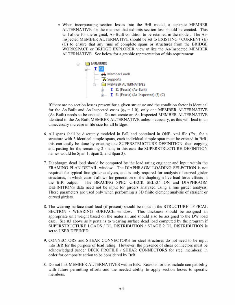
A4
o When incorporating section losses into the BrR model, a separate MEMBER ALTERNATIVE for the member that exhibits section loss should be created. This will allow for the original, As-Built condition to be retained in the model. The As-Inspected MEMBER ALTERNATIVE should be set to EXISTING / CURRENT (E) (C) to ensure that any runs of complete spans or structures from the BRIDGE WORKSPACE or BRIDGE EXPLORER view utilize the As-Inspected MEMBER ALTERNATIVE. See below for a graphic representation of this requirement:
If there are no section losses present for a given structure and the condition factor is identical for the As-Built and As-Inspected cases (φc = 1.0), only one MEMBER ALTERNATIVE (As-Built) needs to be created. Do not create an As-Inspected MEMBER ALTERNATIVE identical to the As-Built MEMBER ALTERNATIVE unless necessary, as this will lead to an unnecessary increase in file size for all bridges.
6. All spans shall be discretely modeled in BrR and contained in ONE .xml file (Ex., for a structure with 3 identical simple spans, each individual simple span must be created in BrR; this can easily be done by creating one SUPERSTRUCTURE DEFINITION, then copying and pasting for the remaining 2 spans; in this case the SUPERSTRUCTURE DEFINITION names would be Span 1, Span 2, and Span 3).
7. Diaphragm dead load should be computed by the load rating engineer and input within the FRAMING PLAN DETAIL window. The DIAPHRAGM LOADING SELECTION is not required for typical line girder analyses, and is only required for analysis of curved girder structures, in which case it allows for generation of the diaphragm live load force effects in the BrR output. The BRACING SPEC CHECK SELECTION and DIAPHRAGM DEFINITIONS data need not be input for girders analyzed using a line girder analysis. These parameters are used only when performing a 3D finite element analysis of straight or curved girders.
8. The wearing surface dead load (if present) should be input in the STRUCTURE TYPICAL SECTION / WEARING SURFACE window. This thickness should be assigned an appropriate unit weight based on the material, and should also be assigned to the DW load case. See #3 above as it pertains to wearing surface dead load computed by the program if SUPERSTRUCTURE LOADS / DL DISTRIBUTION / STAGE 2 DL DISTRIBUTION is set to USER DEFINED.
9. CONNECTORS and SHEAR CONNECTORS for steel structures do not need to be input into BrR for the purpose of load rating. However, the presence of shear connectors must be acknowledged (under DECK PROFILE / SHEAR CONNECTORS for steel members) in order for composite action to be considered by BrR.
10. Do not link MEMBER ALTERNATIVES within BrR. Reasons for this include compatibility with future permitting efforts and the needed ability to apply section losses to specific members.
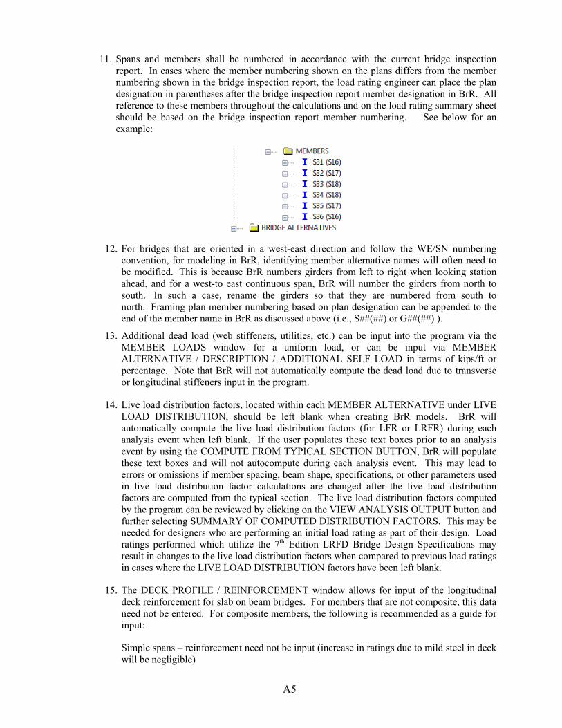
A5
11. Spans and members shall be numbered in accordance with the current bridge inspection report. In cases where the member numbering shown on the plans differs from the member numbering shown in the bridge inspection report, the load rating engineer can place the plan designation in parentheses after the bridge inspection report member designation in BrR. All reference to these members throughout the calculations and on the load rating summary sheet should be based on the bridge inspection report member numbering. See below for an example:
12. For bridges that are oriented in a west-east direction and follow the WE/SN numbering convention, for modeling in BrR, identifying member alternative names will often need to be modified. This is because BrR numbers girders from left to right when looking station ahead, and for a west-to east continuous span, BrR will number the girders from north to south. In such a case, rename the girders so that they are numbered from south to north. Framing plan member numbering based on plan designation can be appended to the end of the member name in BrR as discussed above (i.e., S##(##) or G##(##) ).
13. Additional dead load (web stiffeners, utilities, etc.) can be input into the program via the MEMBER LOADS window for a uniform load, or can be input via MEMBER ALTERNATIVE / DESCRIPTION / ADDITIONAL SELF LOAD in terms of kips/ft or percentage. Note that BrR will not automatically compute the dead load due to transverse or longitudinal stiffeners input in the program.
14. Live load distribution factors, located within each MEMBER ALTERNATIVE under LIVE LOAD DISTRIBUTION, should be left blank when creating BrR models. BrR will automatically compute the live load distribution factors (for LFR or LRFR) during each analysis event when left blank. If the user populates these text boxes prior to an analysis event by using the COMPUTE FROM TYPICAL SECTION BUTTON, BrR will populate these text boxes and will not autocompute during each analysis event. This may lead to errors or omissions if member spacing, beam shape, specifications, or other parameters used in live load distribution factor calculations are changed after the live load distribution factors are computed from the typical section. The live load distribution factors computed by the program can be reviewed by clicking on the VIEW ANALYSIS OUTPUT button and further selecting SUMMARY OF COMPUTED DISTRIBUTION FACTORS. This may be needed for designers who are performing an initial load rating as part of their design. Load ratings performed which utilize the 7th Edition LRFD Bridge Design Specifications may result in changes to the live load distribution factors when compared to previous load ratings in cases where the LIVE LOAD DISTRIBUTION factors have been left blank.
15. The DECK PROFILE / REINFORCEMENT window allows for input of the longitudinal deck reinforcement for slab on beam bridges. For members that are not composite, this data need not be entered. For composite members, the following is recommended as a guide for input:
Simple spans – reinforcement need not be input (increase in ratings due to mild steel in deck will be negligible)
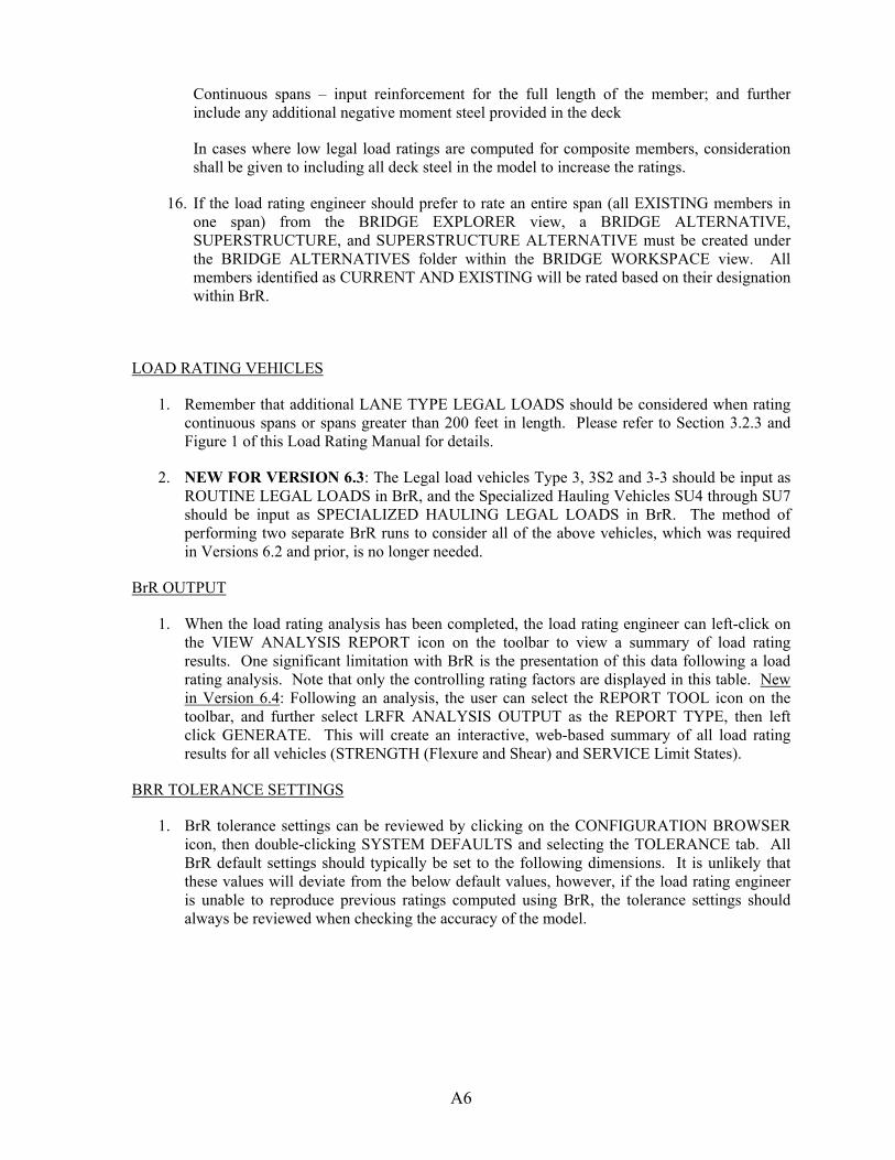
A6
Continuous spans – input reinforcement for the full length of the member; and further include any additional negative moment steel provided in the deck
In cases where low legal load ratings are computed for composite members, consideration shall be given to including all deck steel in the model to increase the ratings.
16. If the load rating engineer should prefer to rate an entire span (all EXISTING members in one span) from the BRIDGE EXPLORER view, a BRIDGE ALTERNATIVE, SUPERSTRUCTURE, and SUPERSTRUCTURE ALTERNATIVE must be created under the BRIDGE ALTERNATIVES folder within the BRIDGE WORKSPACE view. All members identified as CURRENT AND EXISTING will be rated based on their designation within BrR.
LOAD RATING VEHICLES
1. Remember that additional LANE TYPE LEGAL LOADS should be considered when rating continuous spans or spans greater than 200 feet in length. Please refer to Section 3.2.3 and Figure 1 of this Load Rating Manual for details.
2. NEW FOR VERSION 6.3: The Legal load vehicles Type 3, 3S2 and 3-3 should be input as ROUTINE LEGAL LOADS in BrR, and the Specialized Hauling Vehicles SU4 through SU7 should be input as SPECIALIZED HAULING LEGAL LOADS in BrR. The method of performing two separate BrR runs to consider all of the above vehicles, which was required in Versions 6.2 and prior, is no longer needed.
BrR OUTPUT
1. When the load rating analysis has been completed, the load rating engineer can left-click on the VIEW ANALYSIS REPORT icon on the toolbar to view a summary of load rating results. One significant limitation with BrR is the presentation of this data following a load rating analysis. Note that only the controlling rating factors are displayed in this table. New in Version 6.4: Following an analysis, the user can select the REPORT TOOL icon on the toolbar, and further select LRFR ANALYSIS OUTPUT as the REPORT TYPE, then left click GENERATE. This will create an interactive, web-based summary of all load rating results for all vehicles (STRENGTH (Flexure and Shear) and SERVICE Limit States).
BRR TOLERANCE SETTINGS
1. BrR tolerance settings can be reviewed by clicking on the CONFIGURATION BROWSER icon, then double-clicking SYSTEM DEFAULTS and selecting the TOLERANCE tab. All BrR default settings should typically be set to the following dimensions. It is unlikely that these values will deviate from the below default values, however, if the load rating engineer is unable to reproduce previous ratings computed using BrR, the tolerance settings should always be reviewed when checking the accuracy of the model.
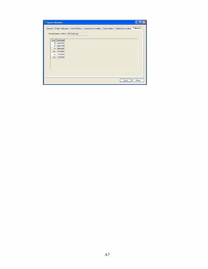
A7

A8
BRR GUIDELINES FOR RATINGS OF CONCRETE BOX AND FRAME CULVERTS Version 6.4 (and later versions) of BrR Software includes LRFR evaluation capabilities for reinforced concrete culverts. The program is capable of analyzing and rating single and multi-cell box culverts with and without a bottom slab. MODELING CULVERTS IN BRR All NJTA culverts capable of being load rated using this software shall be rated in accordance with the requirements of this section. Some of the required input for load ratings of reinforced concrete box culverts using AASHTOWare’s Bridge Rating (BrR) software has been reviewed, and the following information has been provided for use in performing culverts ratings for the Authority. Focus below is on the input parameters unique to the rating of reinforced concrete box culverts. Note that this guidance does not supersede sound engineering judgment, nor should it be blindly used for all culvert ratings. It is the responsibility of the load rating engineer and load rating reviewer to ensure that the parameters input into BrR are reasonable and appropriate for the structure being load rated. Also, in the event of legal load rating factors less than 1.00, all assumptions made in the load rating should be reviewed to ensure they are not overly conservative. A tree view of a typical culvert model in BrR (Version 6.4 shown) is given in Figure.A5.2
A9
Figure.A5.2 Tree View of AASHTO-MBE Example Box Culvert

A10
Figure A5.3 – Materials - Soil Figure A5.3 represents the input window required for any soil defined within BrR. In most cases, this information is not included on the design drawings. Further, the Manual for Bridge Evaluation (current version) also does not necessarily specify values to be used when this information may not be known. Below is a brief discussion of the above, with guidance regarding selection of values if unknown. Soil Unit Load The above value of 120 pcf is an acceptable value to use when this is unknown. See LRFD Table 3.5.1-1, which shows that this value represents a typical unit weight for a sand, silt, and clay type soil. Saturated Unit Load The above value of 125 pcf is an acceptable value to use when this value is unknown. Earth Pressure Coefficients The following earth pressure coefficients may be used in situations where this information is not specified on the drawings or in the design calculations (if available). It should be noted that these values are typically conservative, and appear to be based upon a drained friction angle (Φ) of 30 degrees.
At-rest lateral earth pressure coefficient (LRFD/LRFR) = 0.5 Active lateral earth pressure coefficient (LRFD/LRFR) = 0.33 Passive lateral earth pressure coefficient (LRFD/LRFR) = 3.00
Maximum and Minimum Lateral Soil Pressure (LFD) This input parameter is not required for LRFR load ratings. It is acceptable to utilize the above noted values of 60 pcf (maximum) and 30 pcf (minimum) for all LRFR load ratings.
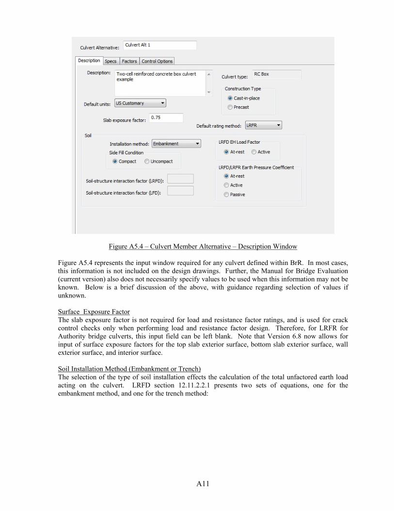
A11
Figure A5.4 – Culvert Member Alternative – Description Window
Figure A5.4 represents the input window required for any culvert defined within BrR. In most cases, this information is not included on the design drawings. Further, the Manual for Bridge Evaluation (current version) also does not necessarily specify values to be used when this information may not be known. Below is a brief discussion of the above, with guidance regarding selection of values if unknown. Surface Exposure Factor The slab exposure factor is not required for load and resistance factor ratings, and is used for crack control checks only when performing load and resistance factor design. Therefore, for LRFR for Authority bridge culverts, this input field can be left blank. Note that Version 6.8 now allows for input of surface exposure factors for the top slab exterior surface, bottom slab exterior surface, wall exterior surface, and interior surface. Soil Installation Method (Embankment or Trench) The selection of the type of soil installation effects the calculation of the total unfactored earth load acting on the culvert. LRFD section 12.11.2.2.1 presents two sets of equations, one for the embankment method, and one for the trench method:
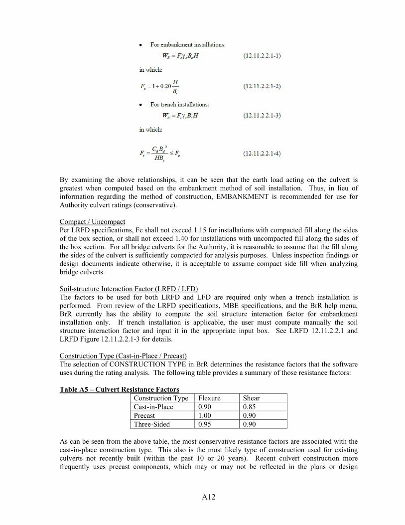
A12
By examining the above relationships, it can be seen that the earth load acting on the culvert is greatest when computed based on the embankment method of soil installation. Thus, in lieu of information regarding the method of construction, EMBANKMENT is recommended for use for Authority culvert ratings (conservative). Compact / Uncompact Per LRFD specifications, Fe shall not exceed 1.15 for installations with compacted fill along the sides of the box section, or shall not exceed 1.40 for installations with uncompacted fill along the sides of the box section. For all bridge culverts for the Authority, it is reasonable to assume that the fill along the sides of the culvert is sufficiently compacted for analysis purposes. Unless inspection findings or design documents indicate otherwise, it is acceptable to assume compact side fill when analyzing bridge culverts. Soil-structure Interaction Factor (LRFD / LFD) The factors to be used for both LRFD and LFD are required only when a trench installation is performed. From review of the LRFD specifications, MBE specifications, and the BrR help menu, BrR currently has the ability to compute the soil structure interaction factor for embankment installation only. If trench installation is applicable, the user must compute manually the soil structure interaction factor and input it in the appropriate input box. See LRFD 12.11.2.2.1 and LRFD Figure 12.11.2.2.1-3 for details. Construction Type (Cast-in-Place / Precast) The selection of CONSTRUCTION TYPE in BrR determines the resistance factors that the software uses during the rating analysis. The following table provides a summary of those resistance factors: Table A5 – Culvert Resistance Factors
Construction Type Flexure Shear Cast-in-Place 0.90 0.85 Precast 1.00 0.90 Three-Sided 0.95 0.90
As can be seen from the above table, the most conservative resistance factors are associated with the cast-in-place construction type. This also is the most likely type of construction used for existing culverts not recently built (within the past 10 or 20 years). Recent culvert construction more frequently uses precast components, which may or may not be reflected in the plans or design
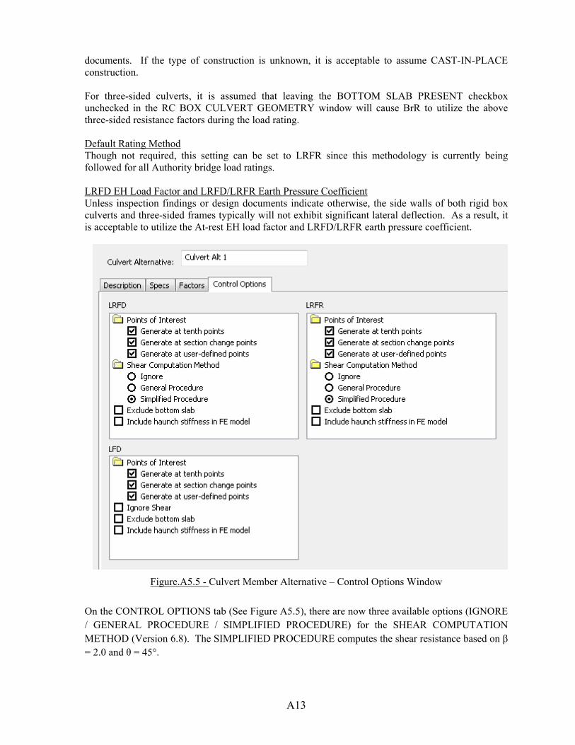
A13
documents. If the type of construction is unknown, it is acceptable to assume CAST-IN-PLACE construction. For three-sided culverts, it is assumed that leaving the BOTTOM SLAB PRESENT checkbox unchecked in the RC BOX CULVERT GEOMETRY window will cause BrR to utilize the above three-sided resistance factors during the load rating. Default Rating Method Though not required, this setting can be set to LRFR since this methodology is currently being followed for all Authority bridge load ratings. LRFD EH Load Factor and LRFD/LRFR Earth Pressure Coefficient Unless inspection findings or design documents indicate otherwise, the side walls of both rigid box culverts and three-sided frames typically will not exhibit significant lateral deflection. As a result, it is acceptable to utilize the At-rest EH load factor and LRFD/LRFR earth pressure coefficient.
Figure.A5.5 - Culvert Member Alternative – Control Options Window
On the CONTROL OPTIONS tab (See Figure A5.5), there are now three available options (IGNORE / GENERAL PROCEDURE / SIMPLIFIED PROCEDURE) for the SHEAR COMPUTATION METHOD (Version 6.8). The SIMPLIFIED PROCEDURE computes the shear resistance based on β = 2.0 and θ = 45°.
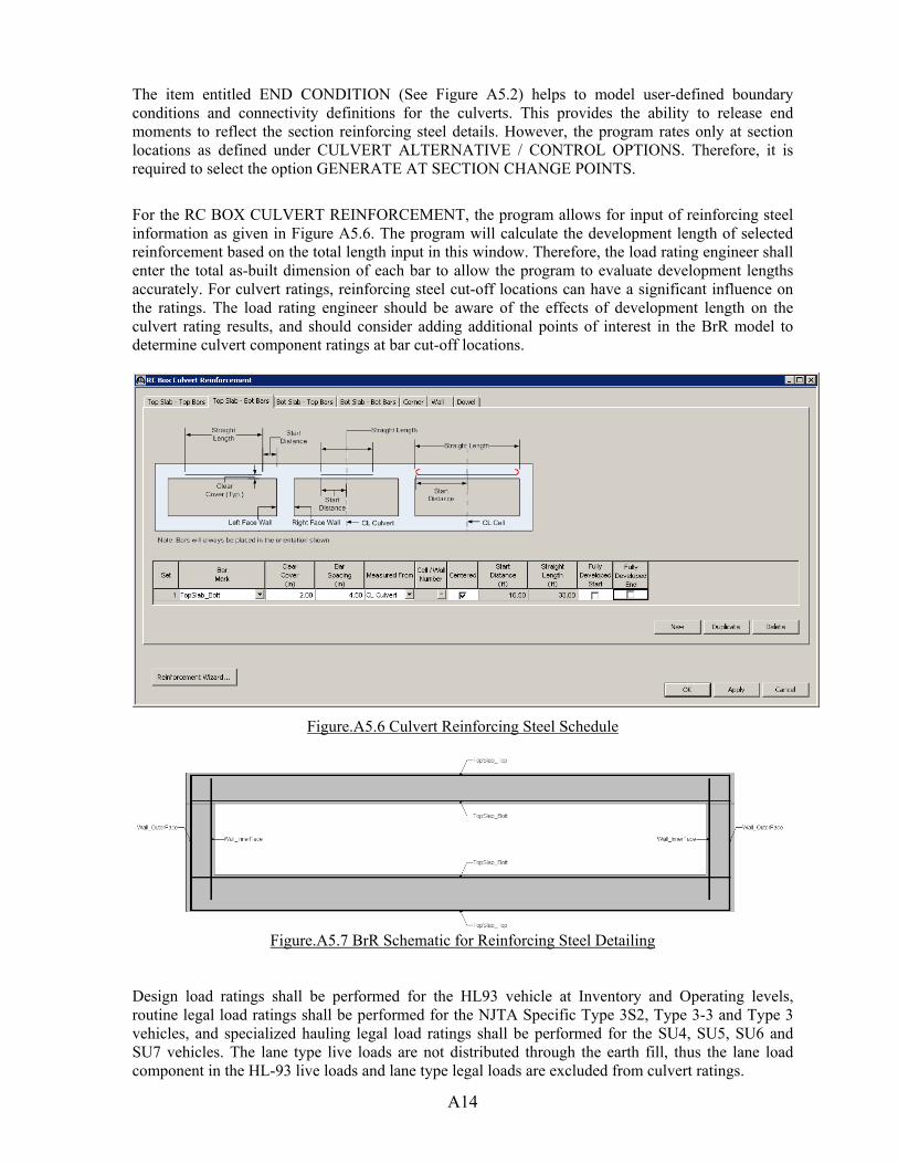
A14
The item entitled END CONDITION (See Figure A5.2) helps to model user-defined boundary conditions and connectivity definitions for the culverts. This provides the ability to release end moments to reflect the section reinforcing steel details. However, the program rates only at section locations as defined under CULVERT ALTERNATIVE / CONTROL OPTIONS. Therefore, it is required to select the option GENERATE AT SECTION CHANGE POINTS.
For the RC BOX CULVERT REINFORCEMENT, the program allows for input of reinforcing steel information as given in Figure A5.6. The program will calculate the development length of selected reinforcement based on the total length input in this window. Therefore, the load rating engineer shall enter the total as-built dimension of each bar to allow the program to evaluate development lengths accurately. For culvert ratings, reinforcing steel cut-off locations can have a significant influence on the ratings. The load rating engineer should be aware of the effects of development length on the culvert rating results, and should consider adding additional points of interest in the BrR model to determine culvert component ratings at bar cut-off locations.
Figure.A5.6 Culvert Reinforcing Steel Schedule
Figure.A5.7 BrR Schematic for Reinforcing Steel Detailing
Design load ratings shall be performed for the HL93 vehicle at Inventory and Operating levels, routine legal load ratings shall be performed for the NJTA Specific Type 3S2, Type 3-3 and Type 3 vehicles, and specialized hauling legal load ratings shall be performed for the SU4, SU5, SU6 and SU7 vehicles. The lane type live loads are not distributed through the earth fill, thus the lane load component in the HL-93 live loads and lane type legal loads are excluded from culvert ratings.

A15
BrR Software Culvert Rating Limitations and Issues Based on review of the culvert load rating capabilities in BrR, the following limitations or issues were previously noted and remain in Version 6.8: User-Defined Dead Load: As given in the MBE example, the culvert top slab can be subjected to
dead loads from non-structural components. The current BrR version does not provide a way to assign such user-defined dead load.
Report Tool: This tool currently cannot be selected for culverts. This is an important feature as it
provides an easy way to summarize all (shear/moment/moment-axial) ratings separately.

A16
APPENDIX A2 BrR – Questions and Answers This Appendix has been created to provide useful guidance regarding some of the most frequent questions raised during implementation of Load and Resistance Factor Ratings (LRFR) for the New Jersey Turnpike Authority.
If additional questions not covered in this Appendix arise, please contact your NJTA Project Manager, as well as NJTA’s load rating representative for guidance. NJTA’s current load rating representative and contact information is as follows:
Scott Cavanaugh, P.E. HNTB Corporation Telephone: 201-528-9069 Email: [email protected]
Questions and Answers:
1. Question: Is there a preferred way to enter the cross section information into BrR, since the BrR software will automatically number the bridge members from LEFT to RIGHT?
Answer: Yes. It is most important that the girder or stringer numbering in BrR match and agree with the numbering established by the Authority for the particular structure in question. This numbering convention can be found in the bridge inspection report for the structure. In general, this numbering typically progresses from the west to the east, or from south to north. Verify the already established member numbering for the structure in question before creating the BrR model. Do not make assumptions.
2. Question: The load rating manual currently specifies that the top 0.5” of the concrete deck slab be considered as dead load only. If a wearing surface or overlay exists as part of the original construction, can the load rating engineer consider the top 0.5” of the deck part of the effective structural deck?
Answer: Yes, if overlay exists as part of the original construction for the structure being load rated, it is acceptable to use the full slab thickness for the structural depth of the slab.
3. Question: How should the load rating engineer approach a structure with splayed stringers (varying spacing along the length of the member)?
Answer: Virtis version 6.1 and prior had limitations regarding input of splayed stringers. Virtis version 6.2 and beyond has improved capabilities, and can now handle spans with splayed stringers (spacing varies at adjacent substructure units). Therefore, average beam spacing no longer needs to be input, as was previously required in Virtis v6.1. Further, BrR Version 6.7 has improved the computation of live load distribution factors of splayed stringers. Prior to Version 6.7, an average value was used for limited LLDF calculations. Now, in Version 6.7, the software computes LLDFs at 10th points. This may lead to slight differences when compared to ratings computed using earlier versions.
4. Question: The current structure I am rating contains multiple superstructures (parallel spans), but has only one ADTT value. How should I split up the ADTT since this number is provided for the entire structure only?
A17
Answer: As discussed in Section 3.1.3, the inner roadways of the NJ Turnpike shall utilize an ADTT of 1000. For other structures (Garden State Parkway and NJ Turnpike), use the maximum one way ADTT value, distributing ADTT to each superstructure unit based on number of lanes per superstructure, or some other reasonable distribution if unique conditions exist. Any unique conditions or modifications to the ADTT value should be well documented so that future load rating updates are done correctly.
5. Question: We have a single span reinforced concrete slab structure with 4’ of fill above the slab. How should we perform the load ratings?
Answer: For single span slab or multi-stringer structures with fill less than or equal to 6’, BrR can be used and live load distribution factors can be calculated by hand based on the current depth of fill. Close review of the output should be performed to ensure actual conditions are being considered in the BrR model. Structures with fill greater than 6’ are not ideally rated using BrR.
6. Question: When creating the NJTA specific Type 3S2 Legal Load within the BrR Library, what WHEEL CONTACT WIDTH should be used for each axle?
Answer: Though this parameter has no effect on the load rating of the longitudinal girders or stringers, the load rating engineer should utilize AASHTO’s LRFD Specification 3.6.1.2.5 and the associated commentary which provides an equation to be used for the width, W = P / 0.8. Use this equation for consistency.
7. Question: Stay-in-Place (SIP) forms are present on this structure, but available plans do not provide a weight to be used in the BrR model for dead load. What dead load value should be used?
Answer: Since the majority of structures have previous load ratings (LFR), review of these rating calculations will generally reveal a previous assumption or value used. If reasonable, these previous assumptions should be maintained. If previous ratings and plans do not provide this data, the load rating engineer should reference the NJTA Design Manual, Section 2, Structures Design which recommends a value of 13 lbs./ft.2 for SIP dead load. In lieu of any other information, this is a valid assumption for SIP dead load.
8. Question: We are getting a 0.661 rating in Shear from BrR for a reinforced concrete slab. AASHTO LRFD 5.14.4.1 says that slab bridges designed as per AASHTO 4.6.2.3 shall be considered satisfactory for shear. The MBE supports this in 6A.5.8. Do we need to report shear ratings for this member?
Answer: As long as the member shows no visible signs of shear distress, shear ratings need not be reported in SIA Items 63 through 66 for reinforced concrete slab bridges (See MBE, Section 6A.5.8 for details). However, shear ratings shall always be computed and shown on the load rating summary sheet for each structure rated.
9. Question: We are load rating complex continuous structures on the NJ Turnpike that are slightly kinked at the continuous pier. In some cases we also have kinked and splayed stringers, which results in varying stringer spacing at all supports. These conditions cannot be exactly modeled in BrR. How should we load rate and model this structure?
Answer: If these conditions are found to exist, the load rating engineer should first bring this to the attention of the NJTA load rating representative.
Kinked girders only

A18
1. Ignore the kink and model the stringers as straight, which would allow for use of the same stringer spacing and span length, but would require modification of the skew angles in BrR to get the true span lengths of members. This change in the skew angle, which should generally be minor, should not greatly affect the rating results. The skew correction factor for LLDFs for shear should not need to be recomputed. Use of BrR values should be sufficient.
Kinked and splayed girders (splay varies at more than two support locations) 2. Ignore the kink and model the stringers as straight, and also hold the MAXIMUM girder
spacing. This will be conservative, and will lead to more dead load and more live load distributed to the splayed girders.
If low ratings are obtained using either of the two approaches, further refinement should be made. Such modifications as live load distribution factor revisions (#2) or skew correction factor calculations and revisions (#1 & #2) could be considered.
10. Question: What deck thickness input value is used by BrR for dead load calculations? I see that deck thickness is input via the SUPERSTRUCTURE TYPICAL SECTION WINDOW / DECK(CONT.) / TOTAL DECK THICKNESS, and is also input within each MEMBER ALTERNATIVE within DECK PROFILE / DECK CONCRETE. Please advise. Answer: The deck information input via the DECK PROFILE window for each MEMBER ALTERNATIVE is used only for computation of section properties when a composite section has been defined. Review of the BrR help section also states that the input of deck info via the STRUCTURE TYPICAL SECTION window is considered during the analysis for dead load.
11. Question: A structure we are rating has a smooth riding surface (1). How do we apply a reduced impact factor in BrR during analysis? Answer: It is recommended that the impact value be modified via the ANALYSIS SETTINGS/ADVANCED/IMPACT. In the IMPACT text box, BrR requires input of the factor by which the full impact (33%) shall be multiplied by to obtain the reduced impact value. In this case, the value input to obtain 10% impact should be 0.303 (0.303*33 = 10). For 20%, the value input should be .606.
12. Question: For curved girder structures, diaphragm members are considered primary members and must also be rated in accordance with the NJTA LRFR load rating manual. Do the connections of the diaphragm to the curved girder require load rating? Answer: Since the diaphragm to girder connection in a curved girder structure would not be considered a non-redundant connection, these connections need not be rated according to the current load rating manual. This same concept would also apply to multi-stringer-floobeam superstructures. For instance, it is not required to perform stringer connection ratings for the case where redundant stringers are connected directly to floorbeam webs. This would also qualify as a redundant connection and would not require rating. As discussed in the NJTA load rating manual, only connections of non-redundant systems require load rating.
13. Question: Section 2.2.3.2 (Concrete) of the NJ Turnpike Authority Structures Design Manual states that: “Concrete…shall be High Performance Concrete (HPC) with a minimum compressive strength (f’c) of 4,400 psi unless otherwise directed by the Authority’s Engineering Department. The concrete strength for design using HPC shall be 4,000 psi.” Further, “The value of the concrete strength (f’c) to be used for the design of reinforced
A19
concrete using Class A, B or C concrete shall be 500 psi less than the specified minimum compressive strength except for items using high performance concrete.” For newly designed bridges what f’c value shall be used for load ratings? Answer: For all ratings of new or widened structures which may have been designed based on the above noted design manual requirements, the f’c value indicated on the design drawings shall be used. Thus, a reduction of 400 psi (HPC) or 500 psi (Class A, B or C) shall not be made to the concrete member or deck strength during ratings.
14. Question: Should the As-Built condition consider wearing surface if the bridge was not initially designed with a wearing surface? Answer: For NJTA load ratings, the As-Built load rating should consider the structure as currently configured, with no section loss. This would typically involve review of the original As-Built drawings, supplemented with any information regarding median or fascia barrier revisions, superstructure widening or rehabilitation, new or additional wearing surface as observed and measured during the current bridge inspection, or any other modifications. As such, the As-Inspected load rating will primarily involve revisions due to member section loss or corrosion only. As-Inspected ratings may also involve a change in the surface roughness rating, superstructure condition factor, or ADTT. Due to the extensive superstructure modifications to many Authority bridges since initial construction, it is not required to have the As-Built load rating represent the condition of the bridge at the time of construction, especially since the load and resistance factor ratings are typically being performed well after the original construction.
15. Question: For modeling of a three-sided culvert in BrR, should the support conditions of the walls be set as pinned or fixed at the footing? Answer: For three-sided culverts, the connection of the side walls to the footing is modeled based on the reinforcing steel details. The plans should be reviewed, and if the three-sided culvert details show that a moment resisting connection is present at the wall connection to the footing, then the three-sided culvert shall be modeled with fixed supports.
16. Question: I am currently updating a load rating for a structure which has been widened. The members added are located to the LEFT looking station ahead in the BrR model. In order to make use of the existing BrR model, it seems that I have to go through several steps (See below) to update the model and was wondering if there was an easier way to simply add members to the left of the leftmost member in an existing model?
1. Modify the NUMBER OF GIRDERS within the SUPERSTRUCTURE DEFINITION
2. COPY and PASTE existing MEMBER ALTERNATIVES as necessary, and create NEW MEMBER ALTERNATIVES for the widening members
3. Revise the FRAMING PLAN DETAIL/GIRDER SPACING data as necessary to reflect the correct member spacing
Answer: The method you describe above is currently the only way to make use of the existing model data when a structure has members added on the left side (looking station ahead). Note that when you increase the number of members in BrR for a SUPERSTRUCTURE ALTERNATIVE, BrR will always add the new members on the right side (looking station ahead).

A20
17. Question: My firm recently designed a bridge for the Authority which utilized the newer HL-93 tandem axle weight (increased from 25 kips to 50 kips) and HL-93 lane load (increased from 0.640 k/ft to 0.700 k/ft) per the NJTA Design Manual, Structures Design, Section 2.2.2. Should these same modified vehicles also be used for the load rating?
Answer: No, these modified vehicles should not be used for the load rating. The standard HL-93 design vehicle should be used and not be modified for the load rating. This ensures that all load ratings utilize the same design vehicle and can be equally compared. The actual design vehicle should be noted on the load rating summary sheet under “Design Loading:”. Further, a clarifying note is recommended below the rating factor summary to clearly note that the load rating has utilized the unmodified (Standard) HL-93 design vehicle. NEW IN 2017: The As-Designed rating should also include the design vehicles as specified in the NJTA Design Manual (Structures Design). See Sections 3.2.2 and 4.4 for details.
18. Question: In all BrR models, both the SUPERSTRUCTURE DEFINITION and each MEMBER ALTERNATIVE have a SPECS tab. Are they both used by the software?
Answer: The SPECS tab within the SUPERSTRUCTURE DEFINITION is used by BrR only when performing a 3D analysis. BrR uses the SPECS tab within each MEMBER ALTERNATIVE when performing a line girder analysis (common method of analysis for NJTA ratings). Thus, if not performing a 3D analysis, the SPECS tab within each SUPERSTRUCTURE DEFINITION need not be updated or modified as part of NJTA LRFR load ratings.
19. Question: We are load rating a structure that was recently widened, and the widened portion of the deck is thicker than the original deck. BrR does not allow for consideration of multiple deck thicknesses for a single SUPERSTRUCTURE. What is recommended for modeling this condition in BrR?
Answer: It is recommended that the minimum deck thickness be used for the entire cross section, and additional dead load (DC1 typically) be calculated due to the thicker deck and applied to the necessary members in the BrR model.
20. Question: We are creating a bridge inspection report for our current inspection assignment. What date should be assigned to the load rating summary sheet file when copied from the 2011 report and saved to the 2017 report in InspectTech?
Answer: Per Section 4.1.1 of this Manual, and a new requirement as of 2017-2018, the date used should match the date on the copied (and unchanged) load rating summary sheet. In this case, the date should be 04/01/2011. See the below image for details.

A21
APPENDIX A3 – LOAD RATING UPDATES OF EXISTING STRUCTURES PREVIOUSLY RATED USING LRFR METHODOLOGY The current NJTA Load Rating Manual (LRM) discusses re-rating of existing bridges in Section 2.1.2. Based on LRFR methodology, there are several important structure specific conditions or parameters which, if changed since the latest inspection referenced during the load rating, may lead to the need for load rating updates. These include the following:
As-Inspected Conditions
Change in Loading
SIA Item 59 Coding Changes
Significant ADTT Revisions
Changes to the Surface Roughness Rating
Evidence of Inaccuracies in Previous Load Ratings
Rating Specification Changes
At any time during the bridge inspection contract, the consultant may contact the Authority’s Load Rating Representative for further guidance regarding Authority load ratings or load rating updates. As-Inspected Conditions Existing LRM Guidance: As noted in Section 2.1.2 of the current Load Rating Manual, a re-rating would usually be necessary if “section properties of controlling or non-controlling members have changed due to deterioration, rehabilitation, re-decking, or other structural alterations.” Also, Section 2.1.3 provides additional guidance regarding ratings based on member deterioration. Additional Guidance: During the biennial bridge inspection, any areas of section loss which could have an effect on the rating results shall be documented in the field. Section loss measurements must be detailed as discussed in Section 4.1 and shall include all information necessary for potential load rating updates (remaining thickness, location of loss, area of loss (length/width/height) and a photo of the deteriorated area). Subsequent to the field inspection, the load rating engineer shall review the field notes, and through the use of engineering judgment (as defined below), determine if load rating updates are warranted. ‘Engineering judgment’ in certain instances may allow the load rating engineer to conservatively neglect losses where they do not negatively affect the controlling load rating of the investigated member. However, each individual bridge and its condition / deficiencies is unique, thus section losses must be evaluated individually by both the bridge inspection team leader and load rating engineer prior to determining that the losses can be neglected. For example, see below for possible scenarios regarding observed section loss in steel members and the subsequent engineering judgment that allowed conservative neglecting of the losses.
Example 1: Moderate section loss to the web of simple span members near midspan o Since web losses occur in an area of low shear effect where current shear rating
factors are much greater than 1.00, section losses may be considered negligible and need not be explicitly input in the load rating model.
Example 2: Moderate section loss to flanges of single span beams near beam ends o Since flange losses occur in an area of low flexural effects where current flexural
rating factors are much greater than 1.00, section losses may be considered negligible and need not be explicitly input in the load rating model.
For load rating updates, the Authority will allow the load rating engineer to exercise this level of engineering judgment for steel members. However, this is not a recommended practice for concrete
A22
members (reinforced concrete T-beams, Prestressed I-Beams, reinforced concrete slabs, etc.). Please note that As-Inspected findings should always be reviewed and assessed to determine the need to apply them to the As-Inspected load ratings. Where deteriorations or section losses are to be conservatively neglected, the load rating engineer shall document all instances where this is done, and also provide an inventory and written rationale of such instances with the load rating report. The written summaries shall be similar to the above listed examples. It is ultimately the load rating engineer’s responsibility to utilize their knowledge and engineering judgment to determine the criticality of the section loss findings. The information provided above is intended as a guide only. Summary: It is the responsibility of the load rating engineer to determine what deterioration, if any, shall be included in the load rating calculations for any given structure. As noted above, engineering judgment may be utilized during the load rating update process to determine which structures (if any) shall be recommended for load rating updates. Changes in Loading Existing LRM Guidance: As noted in Section 2.1.2 of the current Load Rating Manual, a re-rating would usually be necessary if “dead load has changed due to resurfacing or other non-structural alterations”. Additional Guidance: At the current time, any significant superstructure rehabilitation or re-decking that could significantly affect the dead load of any rated member is typically being load rated by the Design Consultant in accordance with the current NJTA Design Manual and the NJTA Load Rating Manual. Thus, it is not expected to have many cases where updates due to changes in loading are needed. Summary: The load rating engineer is not expected to review in detail the existing load rating report and model to compare to existing conditions. Instead, the load rating engineer assisted by the bridge inspection team leader, shall review available NJTA records to determine if any work has been performed on the structure since the last load rating which could affect the rating results. If it is found that work has been done since the previous inspection which could affect the ratings, the structure shall be recommended for load rating updates. SIA Item 59 Coding Changes Existing LRM Guidance: As noted in Section 2.1.2 of the current Load Rating Manual, a re-rating would usually be necessary if “The primary member general condition rating has changed”. Member condition and the condition factor (φc) are further discussed in Section 3.3.2. Additional Guidance: Based on load and resistance factor rating methodology, the condition factor is tied directly to Structural Inventory and Appraisal Item 59 (Superstructure). See the below table, referenced from both the LRM and the MBE:
Based on review of this table, only SIA Item 59 coding of 5 or lower affects the rating results. For structures with this coding, the condition factor reduces to a value less than 1.00, which reduces the member capacity at the Strength Limit State. See below for the member resistance equation as taken from Section 3.3.1 of the NJTA LRM:
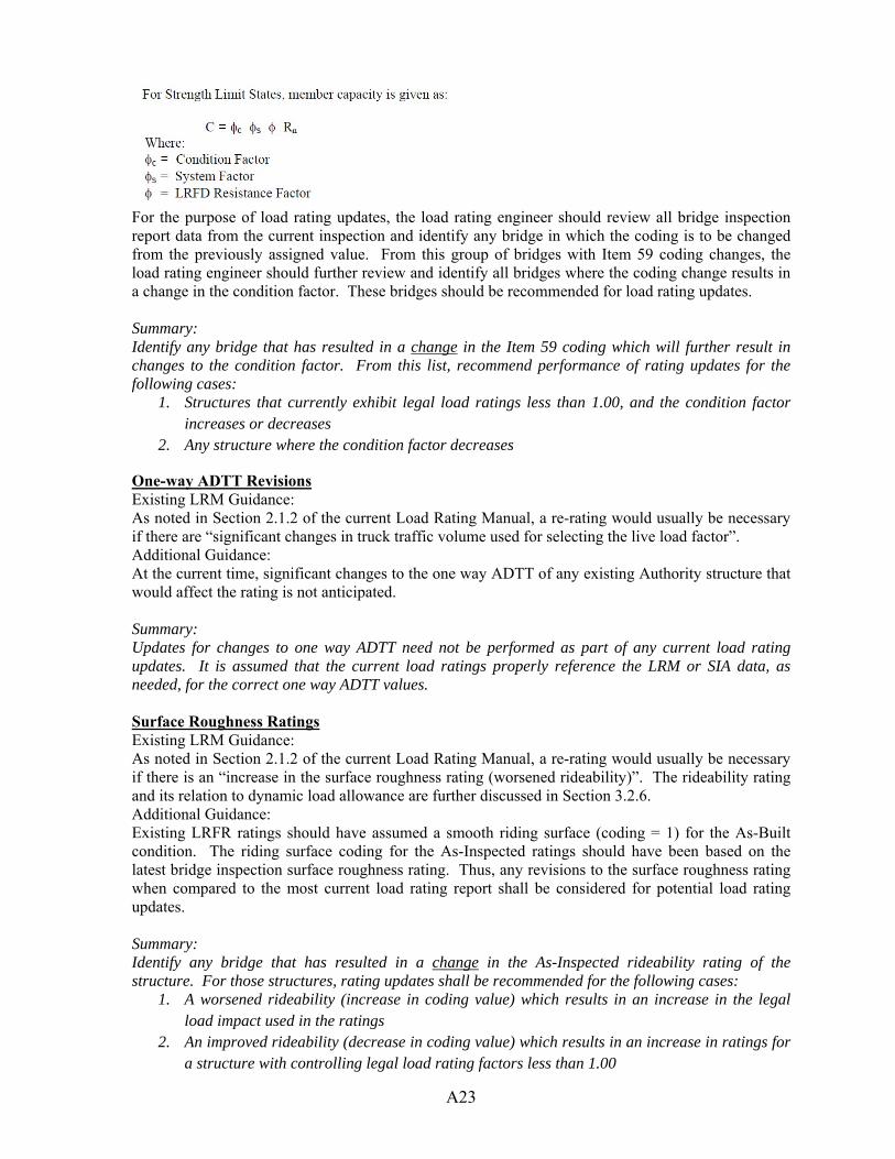
A23
For the purpose of load rating updates, the load rating engineer should review all bridge inspection report data from the current inspection and identify any bridge in which the coding is to be changed from the previously assigned value. From this group of bridges with Item 59 coding changes, the load rating engineer should further review and identify all bridges where the coding change results in a change in the condition factor. These bridges should be recommended for load rating updates. Summary: Identify any bridge that has resulted in a change in the Item 59 coding which will further result in changes to the condition factor. From this list, recommend performance of rating updates for the following cases:
1. Structures that currently exhibit legal load ratings less than 1.00, and the condition factor increases or decreases
2. Any structure where the condition factor decreases
One-way ADTT Revisions Existing LRM Guidance: As noted in Section 2.1.2 of the current Load Rating Manual, a re-rating would usually be necessary if there are “significant changes in truck traffic volume used for selecting the live load factor”. Additional Guidance: At the current time, significant changes to the one way ADTT of any existing Authority structure that would affect the rating is not anticipated. Summary: Updates for changes to one way ADTT need not be performed as part of any current load rating updates. It is assumed that the current load ratings properly reference the LRM or SIA data, as needed, for the correct one way ADTT values. Surface Roughness Ratings Existing LRM Guidance: As noted in Section 2.1.2 of the current Load Rating Manual, a re-rating would usually be necessary if there is an “increase in the surface roughness rating (worsened rideability)”. The rideability rating and its relation to dynamic load allowance are further discussed in Section 3.2.6. Additional Guidance: Existing LRFR ratings should have assumed a smooth riding surface (coding = 1) for the As-Built condition. The riding surface coding for the As-Inspected ratings should have been based on the latest bridge inspection surface roughness rating. Thus, any revisions to the surface roughness rating when compared to the most current load rating report shall be considered for potential load rating updates. Summary: Identify any bridge that has resulted in a change in the As-Inspected rideability rating of the structure. For those structures, rating updates shall be recommended for the following cases:
1. A worsened rideability (increase in coding value) which results in an increase in the legal load impact used in the ratings
2. An improved rideability (decrease in coding value) which results in an increase in ratings for a structure with controlling legal load rating factors less than 1.00
A24
Identification of Previous Load Rating Errors or Omissions Existing LRM Guidance: As noted in Section 2.1.2 of the current Load Rating Manual, a re-rating would usually be necessary if “review of previous load ratings reveals significant errors or inaccuracies”. Additional Guidance: As part of biennial bridge inspections, the consultant is expected to perform a cursory review of the current load rating summary sheet and associated files to ensure that the current bridge condition is reflected in the load rating analysis. It is not the Authority’s intention to require detailed reviews of past consultant’s load rating models, calculations, and final load rating reports. If significant load rating errors or omissions are identified by the consultant, these issues should be brought to the Authority’s immediate attention for possible action. For example, some issues that have been identified during past load rating reviews which would be classified as significant errors or omissions are:
Past load ratings which did not include all members (perhaps by omission of past or recent bridge widening contracts)
Missing load rating deliverables (working files, load rating report PDF, or necessary reference drawings)
Common Error: Past load ratings which did not utilize the condition factor that was identified in the most recent bridge inspection report (note that this is not a change in the condition factor, but instead an error in initially establishing the condition factor during load rating)
Other incorrect rating parameters used for the analysis (dynamic load allowance, system factor, ADTT, etc.)
Summary: Notify the Authority Project Manager immediately of any bridge load rating that contains significant errors or omissions. The Authority Project Manager will then determine the proper course of action (performance of missing member ratings, acquisition of missing files from previous consultants, etc.). Rating Specification Changes Existing LRM Guidance: As noted in Section 2.1.2 of the current Load Rating Manual, a re-rating would usually be necessary due to “rating specification changes”. Additional Guidance: At the current time, it is not the Authority’s intention to perform rating updates of the entire bridge inventory due to minor specification changes. As specifications are refined and updated in the future, this position will be revisited and reassessed. Since initial ratings using LRFR methodology have been performed for the Authority since 2010, several editions of the design and load rating specifications have been used. The load rating engineer shall determine if specification changes will affect the critical ratings for a given structure, and if so, rating updates should be recommended. Rating updates shall also be recommended in the rare case where state legal load rating factors are currently less than 1.00, and brief review of the load ratings indicates that an increase in the controlling ratings may be realized by updating using the latest specifications. Based on the current status of the Authority’s LRFR inventory, updates for this reason are not expected. Summary: Rating updates based on specification changes shall be recommended if: 1. Specification changes are expected to affect the critical ratings of a given structure. 2. The subject structure currently exhibits controlling legal load rating factors less than 1.00 and
may result in rating increases if using the revised specifications.

A25
Authority Notification As a MANDATORY action item prior to ANY load rating update, the bridge inspection and load rating consultant shall first notify the Authority of the recommended updates, and receive permission from the Authority Project Manager before proceeding with the updates.