Embed Size (px)
Citation preview
NEW METHODOLOGY APPLYING RESONANT
INSPECTION FOR QUALITY TESTING OF
VERY SMALL POWDER METAL COMPONENTS
Richard W. Bono, Scott A. Sorensen, Gail R. Stultz
The Modal Shop, Inc.
Cincinnati, OH 45241
ABSTRACT
Resonant Inspection is commonly used for quality assurance testing of powder metal components,
providing a volumetric whole body approach that detects both external and internal structural flaws or
anomalies. This technique measures a metal component’s mechanical resonances by striking the part
with an impact and analyzing the acoustic ringing produced. Traditionally this technique has been limited
to small to medium components with sizes ranging from about a “dime to a dinner plate” due to the
requirements to align and impact the part. However, using a new methodology that employs a drop
testing fixture to excite the part rather than an electromechanical impactor, very small components such as
those commonly manufactured by powder metal MIM processes can be 100% inspected reliably, quickly
and cost-effectively. This paper presents the new drop test methodology supported with case study and
experimental results.
INTRODUCTION TO RAM NDT
Resonant Ultrasound Spectroscopy (RUS) [1], the general classification of Resonant Acoustic Method
RAM NDT [2], was originally approved as an ASTM International standard in 1998, with its current
edition approved July 1, 2008. In commercial nondestructive testing methodologies, RUS is also known
by the terms Acoustic Resonance Spectroscopy (ARS) and, more commonly, Resonant Inspection (RI).
RUS based NDT techniques all vibrate a part mechanically, and detect defects based upon measurable
changes in the given part’s resonant frequency pattern. These techniques have become commonly used
for quality inspection in the manufacture of steel, sintered and ceramic parts.
RAM NDT is a volumetric resonant inspection technique that measures the structural integrity of each
part to detect defects on a component level. This technique can be easily automated to eliminate human
errors with fast throughput, providing cost effective 100% inspection with minimal disruption to
production. With a large number of successes on the production lines of powder metal and cast parts,
RAM NDT is the simple and effective solution to manufacturers’ zero PPM challenge.
Traditional NDT techniques, for example magnetic particle or dye penetrant testing, focus on detecting
and diagnosing defects. They use visual or imaging techniques that scan for indications of specific
defects. For production line quality inspection, identifying the type of defect itself is secondary to
identifying the defective parts themselves. While diagnosing specific defects is applicable when
evaluating and inspecting some systems, such as using ultrasonics to inspect gas pipelines, it is not
appropriate for high volume 100% inspection of manufactured metal parts. For these production lines it
is of primary importance to detect if a part is non-conforming rather than why. Therefore, an end-of-line
“go/no go” objective inspection which can provide reliable 100% sorting is preferred to subjective
diagnosis. RAM NDT can provide such inspections and can also prove useful in root cause analysis of
defects.
Resonant Inspection (RI) measures the structural response of a part and evaluates it against the statistical
variation from a control set of good parts to screen defects. Its volumetric approach tests the whole part,
both for external and internal structural flaws or deviations, providing objective and quantitative results.
This structural response is a unique and measurable signature, defined by a component’s mechanical
resonances. These resonances are a function of part geometry and material properties and are the basis
for RI techniques. By measuring the resonances of a part, one determines the structural characteristics of
that part in a single test. Typical flaws and defects that can adversely affect the structural characteristics
of a part are given in Table 1 for powder metal, cast and forged applications. Many of the traditional
NDT techniques can detect these flaws as well, but often only RI can detect all in a single test, throughout
the entire part (including deep sub-surface defects), in an automated and objective fashion.
Table 1: Typical structural defects commonly detectable by resonant
inspection technique for powder metal, cast and forged processes.
Powder Metal Cast Forged
Cracks Cracks Cracks
Chips Cold shuts Double strikes
Voids Nodularity Porosity
Hardness Porosity Hardness
Inclusions Hardness Inclusions
Heat treatment Inclusions Heat treatment
Decarb Heat treatment Quenching
Oxides Stresses Laps
Contaminants Contaminants Contaminants
Missed ops Missed ops Missed ops
After defective parts have been sorted with RI, complimentary traditional NDT techniques may provide a
means for subjective diagnosis on the smaller subset of “rejected” parts. This is useful for determining a
defect’s root cause and ultimately improving the production processes. The ASME has published
standards that detail each of the traditional NDT methodologies.
SCIENCE OF RESONANT INSPECTION
Modal analysis is defined as the study of the dynamic characteristics of a mechanical structure or system.
All structures, even structures such as metal gears or similar parts that are apparently rigid to the human
eye, undergo elastic deformation as a result of applied forces. The structure itself deforms in a distinct,
specific pattern. This structural dynamic behavior is defined by the mass, stiffness and damping of a
given part’s material properties and geometry. The deformations are described using modal analysis, see
reference [3]. Specifically, all structures have mechanical resonances, where the structure itself amplifies
any energy imparted to it at certain frequencies. For example, tuning forks or bells will vibrate at very
specific frequencies, their natural frequencies, for relatively long periods of time with just a small tap.
The sound that is generated is directly due to these natural frequencies. In fact, any noise made by a
structure is done so by its vibration. RAM NDT utilizes this structural dynamic behavior to evaluate the
integrity and consistency of parts.
The natural frequencies are global properties of a given structure and the presence of structural defects
causes shifts in some or all of these resonances depending upon how the flaw interacts with the specific
deformation pattern. In general, resonant frequencies are proportional to changes in stiffness and
inversely proportional to changes in mass. For example, a crack will change the stiffness in the region
near the crack and a variation in density or the presence of porosity will change the mass. A crack defect
typically reduces the stiffness in the material, thus decreasing the natural frequency. Similarly, porosity
in a cast part reduces mass, thus increasing the natural frequency. These shifts are measurable if the
defect is structurally significant with respect to the either the size or location of the flaw within a specific
resonance mode shape. With some defects, a shift in resonant frequency can also be noticed audibly, such
as a cracked bell that obviously does not ring true.
PRACTICAL APPLICATION OF RESONANT ACOUSTIC METHOD
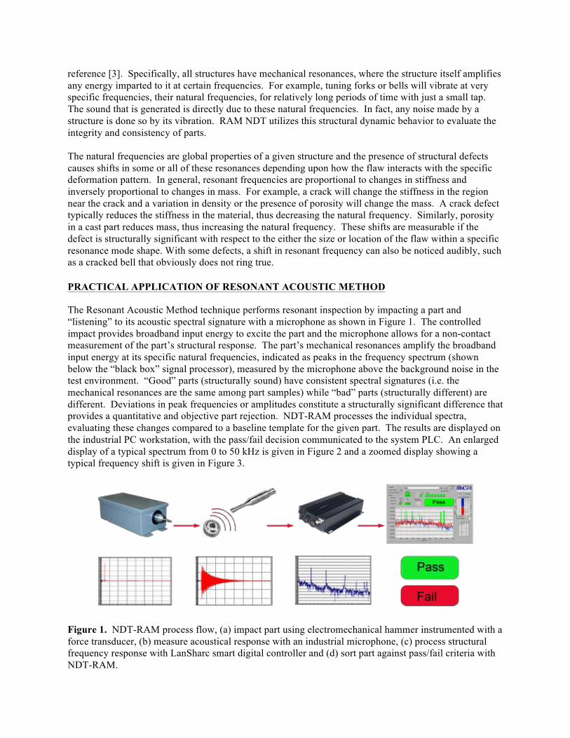
The Resonant Acoustic Method technique performs resonant inspection by impacting a part and
“listening” to its acoustic spectral signature with a microphone as shown in Figure 1. The controlled
impact provides broadband input energy to excite the part and the microphone allows for a non-contact
measurement of the part’s structural response. The part’s mechanical resonances amplify the broadband
input energy at its specific natural frequencies, indicated as peaks in the frequency spectrum (shown
below the “black box” signal processor), measured by the microphone above the background noise in the
test environment. “Good” parts (structurally sound) have consistent spectral signatures (i.e. the
mechanical resonances are the same among part samples) while “bad” parts (structurally different) are
different. Deviations in peak frequencies or amplitudes constitute a structurally significant difference that
provides a quantitative and objective part rejection. NDT-RAM processes the individual spectra,
evaluating these changes compared to a baseline template for the given part. The results are displayed on
the industrial PC workstation, with the pass/fail decision communicated to the system PLC. An enlarged
display of a typical spectrum from 0 to 50 kHz is given in Figure 2 and a zoomed display showing a
typical frequency shift is given in Figure 3.
Figure 1. NDT-RAM process flow, (a) impact part using electromechanical hammer instrumented with a
force transducer, (b) measure acoustical response with an industrial microphone, (c) process structural
frequency response with LanSharc smart digital controller and (d) sort part against pass/fail criteria with
NDT-RAM.
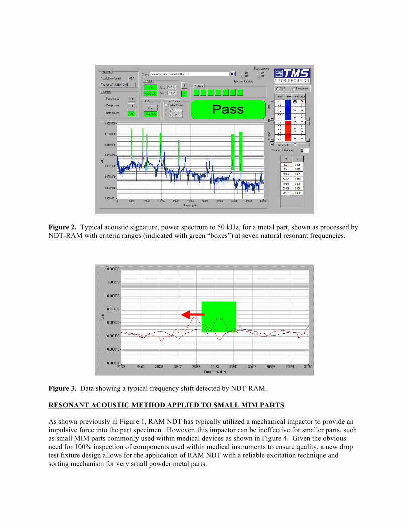
Figure 2. Typical acoustic signature, power spectrum to 50 kHz, for a metal part, shown as processed by
NDT-RAM with criteria ranges (indicated with green “boxes”) at seven natural resonant frequencies.
Figure 3. Data showing a typical frequency shift detected by NDT-RAM.
RESONANT ACOUSTIC METHOD APPLIED TO SMALL MIM PARTS
As shown previously in Figure 1, RAM NDT has typically utilized a mechanical impactor to provide an
impulsive force into the part specimen. However, this impactor can be ineffective for smaller parts, such
as small MIM parts commonly used within medical devices as shown in Figure 4. Given the obvious
need for 100% inspection of components used within medical instruments to ensure quality, a new drop
test fixture design allows for the application of RAM NDT with a reliable excitation technique and
sorting mechanism for very small powder metal parts.
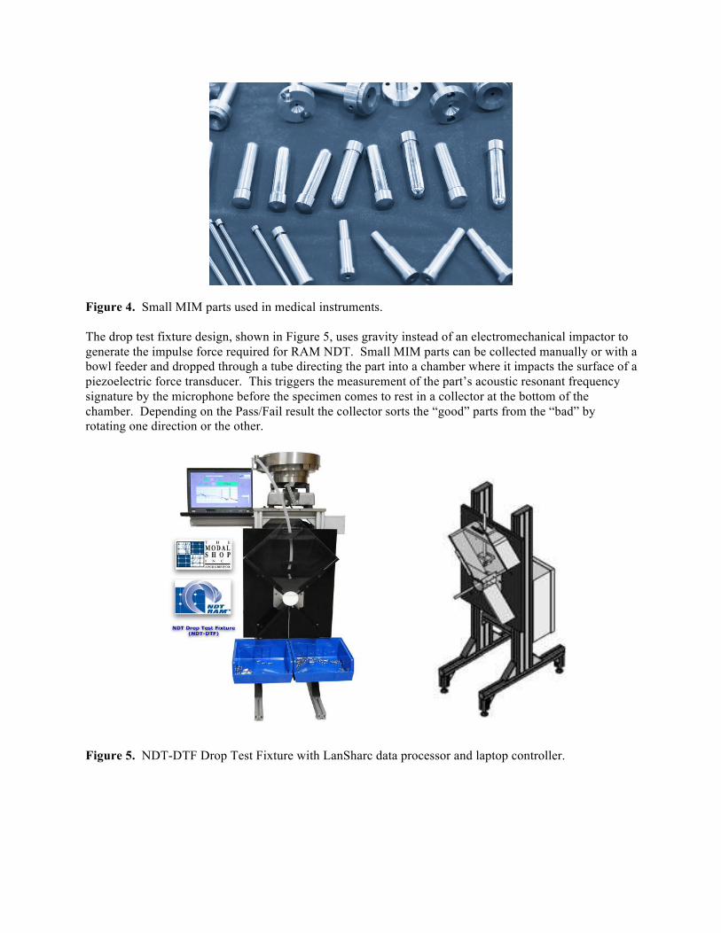
Figure 4. Small MIM parts used in medical instruments.
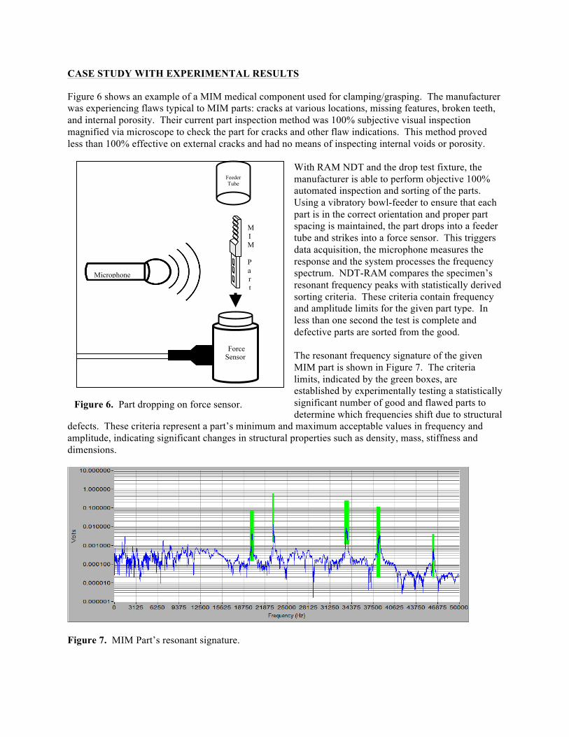
The drop test fixture design, shown in Figure 5, uses gravity instead of an electromechanical impactor to
generate the impulse force required for RAM NDT. Small MIM parts can be collected manually or with a
bowl feeder and dropped through a tube directing the part into a chamber where it impacts the surface of a
piezoelectric force transducer. This triggers the measurement of the part’s acoustic resonant frequency
signature by the microphone before the specimen comes to rest in a collector at the bottom of the
chamber. Depending on the Pass/Fail result the collector sorts the “good” parts from the “bad” by
rotating one direction or the other.
Figure 5. NDT-DTF Drop Test Fixture with LanSharc data processor and laptop controller.
CASE STUDY WITH EXPERIMENTAL RESULTS
Figure 6 shows an example of a MIM medical component used for clamping/grasping. The manufacturer
was experiencing flaws typical to MIM parts: cracks at various locations, missing features, broken teeth,
and internal porosity. Their current part inspection method was 100% subjective visual inspection
magnified via microscope to check the part for cracks and other flaw indications. This method proved
less than 100% effective on external cracks and had no means of inspecting internal voids or porosity.
With RAM NDT and the drop test fixture, the
manufacturer is able to perform objective 100%
automated inspection and sorting of the parts.
Using a vibratory bowl-feeder to ensure that each
part is in the correct orientation and proper part
spacing is maintained, the part drops into a feeder
tube and strikes into a force sensor. This triggers
data acquisition, the microphone measures the
response and the system processes the frequency
spectrum. NDT-RAM compares the specimen’s
resonant frequency peaks with statistically derived
sorting criteria. These criteria contain frequency
and amplitude limits for the given part type. In
less than one second the test is complete and
defective parts are sorted from the good.
The resonant frequency signature of the given
MIM part is shown in Figure 7. The criteria
limits, indicated by the green boxes, are
established by experimentally testing a statistically
significant number of good and flawed parts to
determine which frequencies shift due to structural
defects. These criteria represent a part’s minimum and maximum acceptable values in frequency and
amplitude, indicating significant changes in structural properties such as density, mass, stiffness and
dimensions.
Figure 7. MIM Part’s resonant signature.
Force Sensor
Feeder Tube
Microphone
M
I
M
P
a
r
t
Figure 6. Part dropping on force sensor.
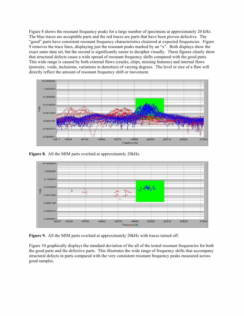
Figure 8 shows the resonant frequency peaks for a large number of specimens at approximately 20 kHz.
The blue traces are acceptable parts and the red traces are parts that have been proven defective. The
“good” parts have consistent resonant frequency characteristics clustered at expected frequencies. Figure
9 removes the trace lines, displaying just the resonant peaks marked by an “x”. Both displays show the
exact same data set, but the second is significantly easier to decipher visually. These figures clearly show
that structural defects cause a wide spread of resonant frequency shifts compared with the good parts.
This wide range is caused by both external flaws (cracks, chips, missing features) and internal flaws
(porosity, voids, inclusions, variations in densities) of varying degrees. The level or size of a flaw will
directly reflect the amount of resonant frequency shift or movement.
Figure 8. All the MIM parts overlaid at approximately 20kHz.
Figure 9. All the MIM parts overlaid at approximately 20kHz with traces turned off.
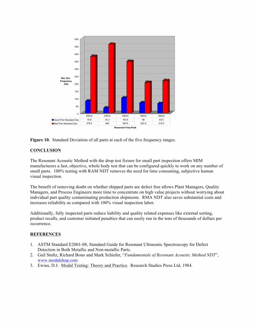
Figure 10 graphically displays the standard deviation of the all of the tested resonant frequencies for both
the good parts and the defective parts. This illustrates the wide range of frequency shifts that accompany
structural defects in parts compared with the very consistent resonant frequency peaks measured across
good samples.
79.8
379.5
34.3
460
100.6
345.6
68
203.9
63.5
216.5
0
50
100
150
200
250
300
350
400
450
500
Std. Dev.
Frequency
(Hz)
Resonant Freq Peak
Good Part Standard Dev 79.8 34.3 100.6 68 63.5
Bad Part Standard Dev 379.5 460 345.6 203.9 216.5
20kHz 23kHz 32kHz 38kHz 46kHz
Figure 10. Standard Deviation of all parts at each of the five frequency ranges.
CONCLUSION
The Resonant Acoustic Method with the drop test fixture for small part inspection offers MIM
manufacturers a fast, objective, whole body test that can be configured quickly to work on any number of
small parts. 100% testing with RAM NDT removes the need for time consuming, subjective human
visual inspection.
The benefit of removing doubt on whether shipped parts are defect free allows Plant Managers, Quality
Managers, and Process Engineers more time to concentrate on high value projects without worrying about
individual part quality contaminating production shipments. RMA NDT also saves substantial costs and
increases reliability as compared with 100% visual inspection labor.
Additionally, fully inspected parts reduce liability and quality related expenses like external sorting,
product recalls, and customer initiated penalties that can easily run in the tens of thousands of dollars per
occurrence.
REFERENCES
1. ASTM Standard E2001-08, Standard Guide for Resonant Ultrasonic Spectroscopy for Defect
Detection in Both Metallic and Non-metallic Parts.
2. Gail Stultz, Richard Bono and Mark Schiefer, “Fundamentals of Resonant Acoustic Method NDT”,
www.modalshop.com
3. Ewins, D.J. Modal Testing: Theory and Practice. Research Studies Press Ltd, 1984.