Embed Size (px)
Citation preview
www.daytonlamina.comCheck our website for the latest
technical information.
Flat or Contoured Surface
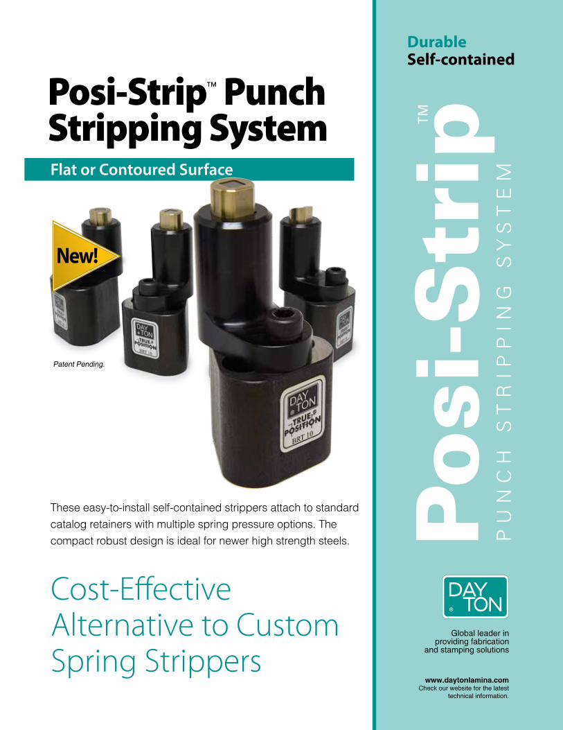
Posi-Strip™ PunchStripping System
These easy-to-install self-contained strippers attach to standard catalog retainers with multiple spring pressure options. The compact robust design is ideal for newer high strength steels.
Cost-Effective Alternative to Custom Spring Strippers
DurableSelf-contained
New!
Global leader in providing fabrication
and stamping solutions
Patent Pending.
Po
si-S
trip
™
PU
NC
H S
TR
IPP
ING
SY
ST
EM
Po
si-S
trip
™
PU
NC
H S
TR
IPP
ING
SY
ST
EM
2
Posi-Strip™ Features and Benefits
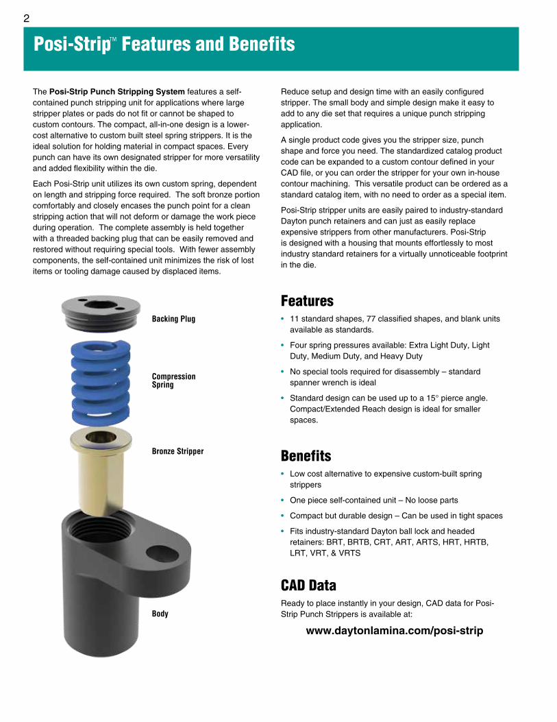
Backing Plug
Compression Spring
Bronze Stripper
Body
The Posi-Strip Punch Stripping System features a self-contained punch stripping unit for applications where large stripper plates or pads do not fit or cannot be shaped to custom contours. The compact, all-in-one design is a lower-cost alternative to custom built steel spring strippers. It is the ideal solution for holding material in compact spaces. Every punch can have its own designated stripper for more versatility and added flexibility within the die.
Each Posi-Strip unit utilizes its own custom spring, dependent on length and stripping force required. The soft bronze portion comfortably and closely encases the punch point for a clean stripping action that will not deform or damage the work piece during operation. The complete assembly is held together with a threaded backing plug that can be easily removed and restored without requiring special tools. With fewer assembly components, the self-contained unit minimizes the risk of lost items or tooling damage caused by displaced items.
Reduce setup and design time with an easily configured stripper. The small body and simple design make it easy to add to any die set that requires a unique punch stripping application.
A single product code gives you the stripper size, punch shape and force you need. The standardized catalog product code can be expanded to a custom contour defined in your CAD file, or you can order the stripper for your own in-house contour machining. This versatile product can be ordered as a standard catalog item, with no need to order as a special item.
Posi-Strip stripper units are easily paired to industry-standard Dayton punch retainers and can just as easily replace expensive strippers from other manufacturers. Posi-Strip is designed with a housing that mounts effortlessly to most industry standard retainers for a virtually unnoticeable footprint in the die.
Features• 11 standard shapes, 77 classified shapes, and blank units
available as standards.
• Four spring pressures available: Extra Light Duty, Light Duty, Medium Duty, and Heavy Duty
• No special tools required for disassembly – standard spanner wrench is ideal
• Standard design can be used up to a 15° pierce angle. Compact/Extended Reach design is ideal for smaller spaces.
Benefits• Low cost alternative to expensive custom-built spring
strippers
• One piece self-contained unit – No loose parts
• Compact but durable design – Can be used in tight spaces
• Fits industry-standard Dayton ball lock and headed retainers: BRT, BRTB, CRT, ART, ARTS, HRT, HRTB, LRT, VRT, & VRTS
CAD DataReady to place instantly in your design, CAD data for Posi-Strip Punch Strippers is available at:
www.daytonlamina.com/posi-strip
3
Technical Information
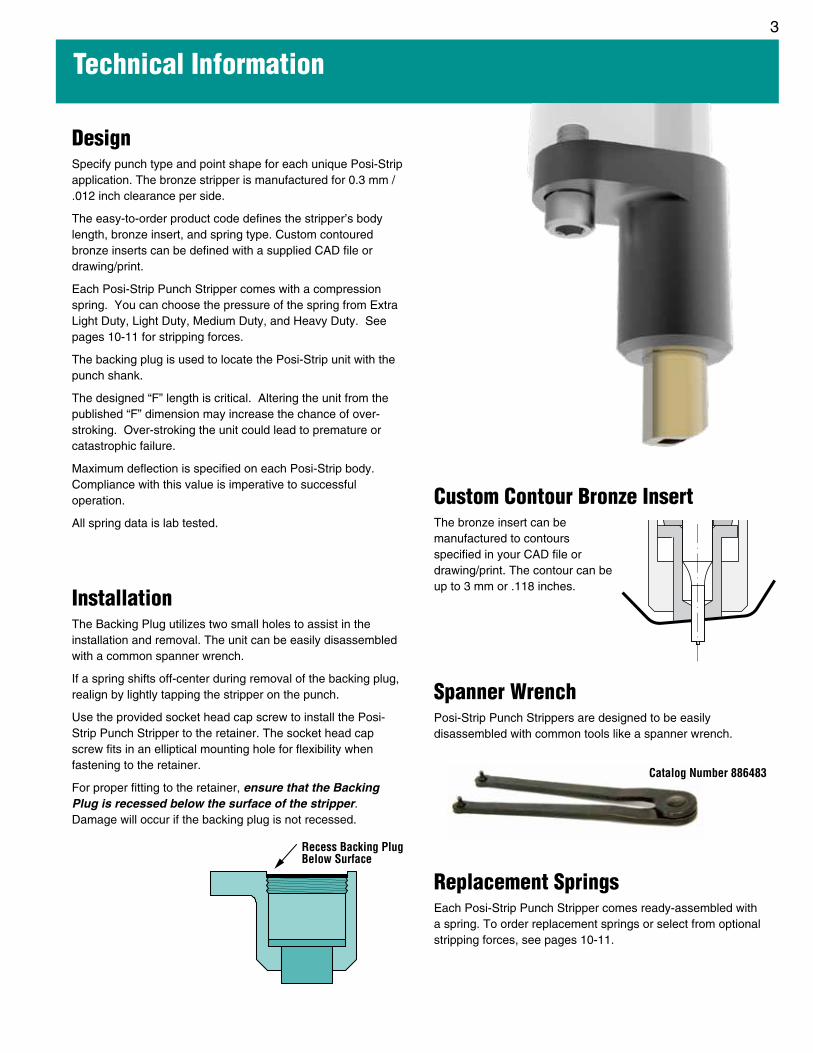
Recess Backing Plug Below Surface
Spanner WrenchPosi-Strip Punch Strippers are designed to be easily disassembled with common tools like a spanner wrench.
Replacement SpringsEach Posi-Strip Punch Stripper comes ready-assembled with a spring. To order replacement springs or select from optional stripping forces, see pages 10-11.
Custom Contour Bronze InsertThe bronze insert can be manufactured to contours specified in your CAD file or drawing/print. The contour can be up to 3 mm or .118 inches.
L2 L2 m
in
Catalog Number 886483
DesignSpecify punch type and point shape for each unique Posi-Strip application. The bronze stripper is manufactured for 0.3 mm / .012 inch clearance per side.
The easy-to-order product code defines the stripper’s body length, bronze insert, and spring type. Custom contoured bronze inserts can be defined with a supplied CAD file or drawing/print.
Each Posi-Strip Punch Stripper comes with a compression spring. You can choose the pressure of the spring from Extra Light Duty, Light Duty, Medium Duty, and Heavy Duty. See pages 10-11 for stripping forces.
The backing plug is used to locate the Posi-Strip unit with the punch shank.
The designed “F” length is critical. Altering the unit from the published “F” dimension may increase the chance of over-stroking. Over-stroking the unit could lead to premature or catastrophic failure.
Maximum deflection is specified on each Posi-Strip body. Compliance with this value is imperative to successful operation.
All spring data is lab tested.
InstallationThe Backing Plug utilizes two small holes to assist in the installation and removal. The unit can be easily disassembled with a common spanner wrench.
If a spring shifts off-center during removal of the backing plug, realign by lightly tapping the stripper on the punch.
Use the provided socket head cap screw to install the Posi-Strip Punch Stripper to the retainer. The socket head cap screw fits in an elliptical mounting hole for flexibility when fastening to the retainer.
For proper fitting to the retainer, ensure that the Backing Plug is recessed below the surface of the stripper. Damage will occur if the backing plug is not recessed.
4
HOW TO ORDER
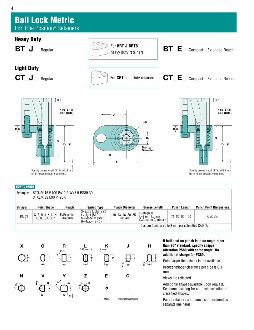
BT_J_ Regular
SF1 F
41.0 (BRT)32.0 (CRT)
6.3
10.0
Specify bronze length “L” to add 3 mmfor in-house contour machining.
Example: BTOJM 16 R100 P=12.5 W=8.5 PS89 30 CTXEM 32 L90 P=20.0
BT_E_ Compact – Extended Reach
S
F1 F
41.0 (BRT)32.0 (CRT)
6.3
10.0
Specify bronze length “L” to add 3 mmfor in-house contour machining.
Stripper Point Shape Reach Spring Type Punch Diameter Bronze Length Punch Length Punch Point Dimensions
BT, CT C, E, H, J, K, L, N, O, R, V, X, Y, Z
E=ExtendedJ=Regular
S=Extra Light (SSD)L=Light (SLD)M=Medium (SMD)H=Heavy (SHD)
10, 13, 16, 20, 25, 32, 40
R=RegularL=3 mm LongerC=Custom Contour †
71, 80, 90, 100 P, W, etc.
†Custom Contour up to 3 mm per submitted CAD file.
Heavy Duty
CT_J_ Regular CT_E_ Compact – Extended Reach
Light Duty
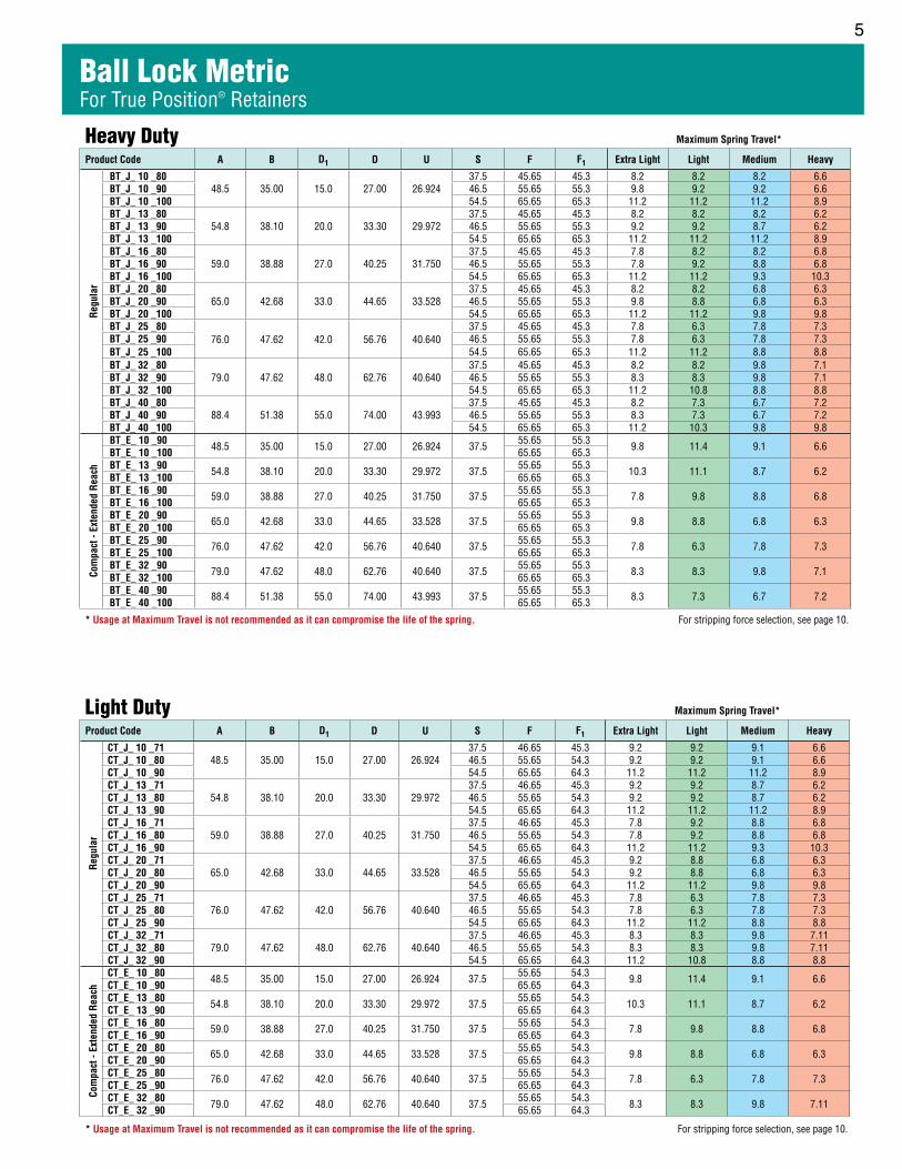
Ball Lock MetricFor True Position® Retainers
For CRT light duty retainers
For BRT & BRTB heavy duty retainers
If ball seat on punch is at an angle other than 90° standard, specify stripper alteration PS89 with same angle. No additional charge for PS89.
Point larger than shank is not available.
Bronze stripper clearance per side is 0.3 mm.
Views are reflected.
Additional shapes available upon request. See punch catalog for complete selection of classified shapes.
Paired retainers and punches are ordered as separate line items.
ZYVN E
G2R=
J HL KROXSpecify
(Blank)
C
(Classified Shape Number)
0.5R mm ± .13
A
B
U
∅D
D1
BronzeDiameter
5
Heavy Duty Maximum Spring Travel*
Product Code A B D1 D U S F F1 Extra Light Light Medium Heavy
Regu
lar
BT_J_ 10 _8048.5 35.00 15.0 27.00 26.924
37.5 45.65 45.3 8.2 8.2 8.2 6.6BT_J_ 10 _90 46.5 55.65 55.3 9.8 9.2 9.2 6.6BT_J_ 10 _100 54.5 65.65 65.3 11.2 11.2 11.2 8.9BT_J_ 13 _80
54.8 38.10 20.0 33.30 29.97237.5 45.65 45.3 8.2 8.2 8.2 6.2
BT_J_ 13 _90 46.5 55.65 55.3 9.2 9.2 8.7 6.2BT_J_ 13 _100 54.5 65.65 65.3 11.2 11.2 11.2 8.9BT_J_ 16 _80
59.0 38.88 27.0 40.25 31.75037.5 45.65 45.3 7.8 8.2 8.2 6.8
BT_J_ 16 _90 46.5 55.65 55.3 7.8 9.2 8.8 6.8BT_J_ 16 _100 54.5 65.65 65.3 11.2 11.2 9.3 10.3BT_J_ 20 _80
65.0 42.68 33.0 44.65 33.52837.5 45.65 45.3 8.2 8.2 6.8 6.3
BT_J_ 20 _90 46.5 55.65 55.3 9.8 8.8 6.8 6.3BT_J_ 20 _100 54.5 65.65 65.3 11.2 11.2 9.8 9.8BT_J_ 25 _80
76.0 47.62 42.0 56.76 40.64037.5 45.65 45.3 7.8 6.3 7.8 7.3
BT_J_ 25 _90 46.5 55.65 55.3 7.8 6.3 7.8 7.3BT_J_ 25 _100 54.5 65.65 65.3 11.2 11.2 8.8 8.8BT_J_ 32 _80
79.0 47.62 48.0 62.76 40.64037.5 45.65 45.3 8.2 8.2 9.8 7.1
BT_J_ 32 _90 46.5 55.65 55.3 8.3 8.3 9.8 7.1BT_J_ 32 _100 54.5 65.65 65.3 11.2 10.8 8.8 8.8BT_J_ 40 _80
88.4 51.38 55.0 74.00 43.99337.5 45.65 45.3 8.2 7.3 6.7 7.2
BT_J_ 40 _90 46.5 55.65 55.3 8.3 7.3 6.7 7.2BT_J_ 40 _100 54.5 65.65 65.3 11.2 10.3 9.8 9.8
Com
pact
- Ex
tend
ed R
each
BT_E_ 10 _90 48.5 35.00 15.0 27.00 26.924 37.5 55.65 55.3 9.8 11.4 9.1 6.6BT_E_ 10 _100 65.65 65.3BT_E_ 13 _90 54.8 38.10 20.0 33.30 29.972 37.5 55.65 55.3 10.3 11.1 8.7 6.2BT_E_ 13 _100 65.65 65.3BT_E_ 16 _90 59.0 38.88 27.0 40.25 31.750 37.5 55.65 55.3 7.8 9.8 8.8 6.8BT_E_ 16 _100 65.65 65.3BT_E_ 20 _90 65.0 42.68 33.0 44.65 33.528 37.5 55.65 55.3 9.8 8.8 6.8 6.3BT_E_ 20 _100 65.65 65.3BT_E_ 25 _90 76.0 47.62 42.0 56.76 40.640 37.5 55.65 55.3 7.8 6.3 7.8 7.3BT_E_ 25 _100 65.65 65.3BT_E_ 32 _90 79.0 47.62 48.0 62.76 40.640 37.5 55.65 55.3 8.3 8.3 9.8 7.1BT_E_ 32 _100 65.65 65.3BT_E_ 40 _90 88.4 51.38 55.0 74.00 43.993 37.5 55.65 55.3 8.3 7.3 6.7 7.2BT_E_ 40 _100 65.65 65.3
* Usage at Maximum Travel is not recommended as it can compromise the life of the spring. For stripping force selection, see page 10.
Light Duty Maximum Spring Travel*
Product Code A B D1 D U S F F1 Extra Light Light Medium Heavy
Regu
lar
CT_J_ 10 _7148.5 35.00 15.0 27.00 26.924
37.5 46.65 45.3 9.2 9.2 9.1 6.6CT_J_ 10 _80 46.5 55.65 54.3 9.2 9.2 9.1 6.6CT_J_ 10 _90 54.5 65.65 64.3 11.2 11.2 11.2 8.9CT_J_ 13 _71
54.8 38.10 20.0 33.30 29.97237.5 46.65 45.3 9.2 9.2 8.7 6.2
CT_J_ 13 _80 46.5 55.65 54.3 9.2 9.2 8.7 6.2CT_J_ 13 _90 54.5 65.65 64.3 11.2 11.2 11.2 8.9CT_J_ 16 _71
59.0 38.88 27.0 40.25 31.75037.5 46.65 45.3 7.8 9.2 8.8 6.8
CT_J_ 16 _80 46.5 55.65 54.3 7.8 9.2 8.8 6.8CT_J_ 16 _90 54.5 65.65 64.3 11.2 11.2 9.3 10.3CT_J_ 20 _71
65.0 42.68 33.0 44.65 33.52837.5 46.65 45.3 9.2 8.8 6.8 6.3
CT_J_ 20 _80 46.5 55.65 54.3 9.2 8.8 6.8 6.3CT_J_ 20 _90 54.5 65.65 64.3 11.2 11.2 9.8 9.8CT_J_ 25 _71
76.0 47.62 42.0 56.76 40.64037.5 46.65 45.3 7.8 6.3 7.8 7.3
CT_J_ 25 _80 46.5 55.65 54.3 7.8 6.3 7.8 7.3CT_J_ 25 _90 54.5 65.65 64.3 11.2 11.2 8.8 8.8CT_J_ 32 _71
79.0 47.62 48.0 62.76 40.64037.5 46.65 45.3 8.3 8.3 9.8 7.11
CT_J_ 32 _80 46.5 55.65 54.3 8.3 8.3 9.8 7.11CT_J_ 32 _90 54.5 65.65 64.3 11.2 10.8 8.8 8.8
Com
pact
- Ex
tend
ed R
each
CT_E_ 10 _80 48.5 35.00 15.0 27.00 26.924 37.5 55.65 54.3 9.8 11.4 9.1 6.6CT_E_ 10 _90 65.65 64.3CT_E_ 13 _80 54.8 38.10 20.0 33.30 29.972 37.5 55.65 54.3 10.3 11.1 8.7 6.2CT_E_ 13 _90 65.65 64.3CT_E_ 16 _80 59.0 38.88 27.0 40.25 31.750 37.5 55.65 54.3 7.8 9.8 8.8 6.8CT_E_ 16 _90 65.65 64.3CT_E_ 20 _80 65.0 42.68 33.0 44.65 33.528 37.5 55.65 54.3 9.8 8.8 6.8 6.3CT_E_ 20 _90 65.65 64.3CT_E_ 25 _80 76.0 47.62 42.0 56.76 40.640 37.5 55.65 54.3 7.8 6.3 7.8 7.3CT_E_ 25 _90 65.65 64.3CT_E_ 32 _80 79.0 47.62 48.0 62.76 40.640 37.5 55.65 54.3 8.3 8.3 9.8 7.11CT_E_ 32 _90 65.65 64.3
* Usage at Maximum Travel is not recommended as it can compromise the life of the spring. For stripping force selection, see page 10.
Ball Lock MetricFor True Position® Retainers
6
SF1 F
1.625 (HRT)1.250 (LRT)
.250
.39
Specify bronze length “L” to add .118 inchfor in-house contour machining.
S
F1 F
1.625 (HRT)1.250 (LRT)
.250
.39
Specify bronze length “L” to add .118 inchfor in-house contour machining.
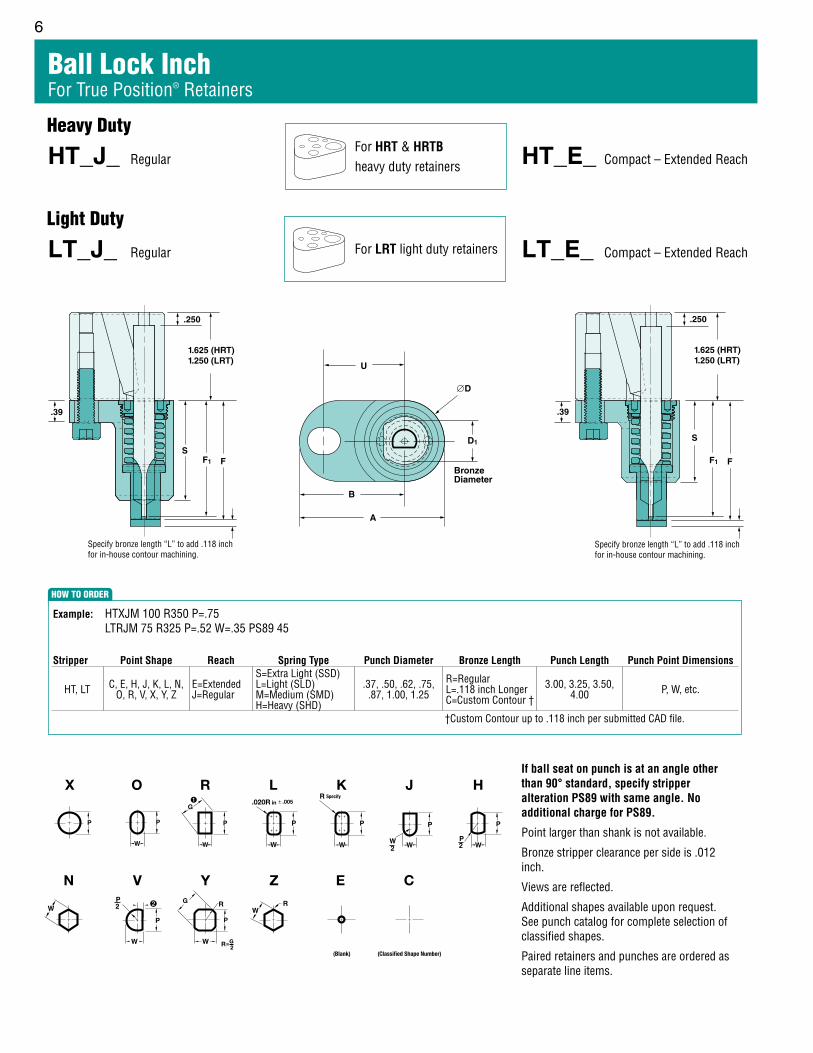
Ball Lock InchFor True Position® Retainers
HOW TO ORDER
HT_J_ Regular
Example: HTXJM 100 R350 P=.75 LTRJM 75 R325 P=.52 W=.35 PS89 45
HT_E_ Compact – Extended Reach
Stripper Point Shape Reach Spring Type Punch Diameter Bronze Length Punch Length Punch Point Dimensions
HT, LT C, E, H, J, K, L, N, O, R, V, X, Y, Z
E=ExtendedJ=Regular
S=Extra Light (SSD)L=Light (SLD)M=Medium (SMD)H=Heavy (SHD)
.37, .50, .62, .75, .87, 1.00, 1.25
R=RegularL=.118 inch LongerC=Custom Contour †
3.00, 3.25, 3.50, 4.00 P, W, etc.
†Custom Contour up to .118 inch per submitted CAD file.
Heavy Duty
LT_J_ Regular LT_E_ Compact – Extended Reach
Light DutyFor LRT light duty retainers
For HRT & HRTB heavy duty retainers
If ball seat on punch is at an angle other than 90° standard, specify stripper alteration PS89 with same angle. No additional charge for PS89.
Point larger than shank is not available.
Bronze stripper clearance per side is .012 inch.
Views are reflected.
Additional shapes available upon request. See punch catalog for complete selection of classified shapes.
Paired retainers and punches are ordered as separate line items.
ZYVN E
G2R=
J HL KROXSpecify
(Blank)
C
(Classified Shape Number)
.020R in ± .005
A
B
U
∅D
D1
BronzeDiameter
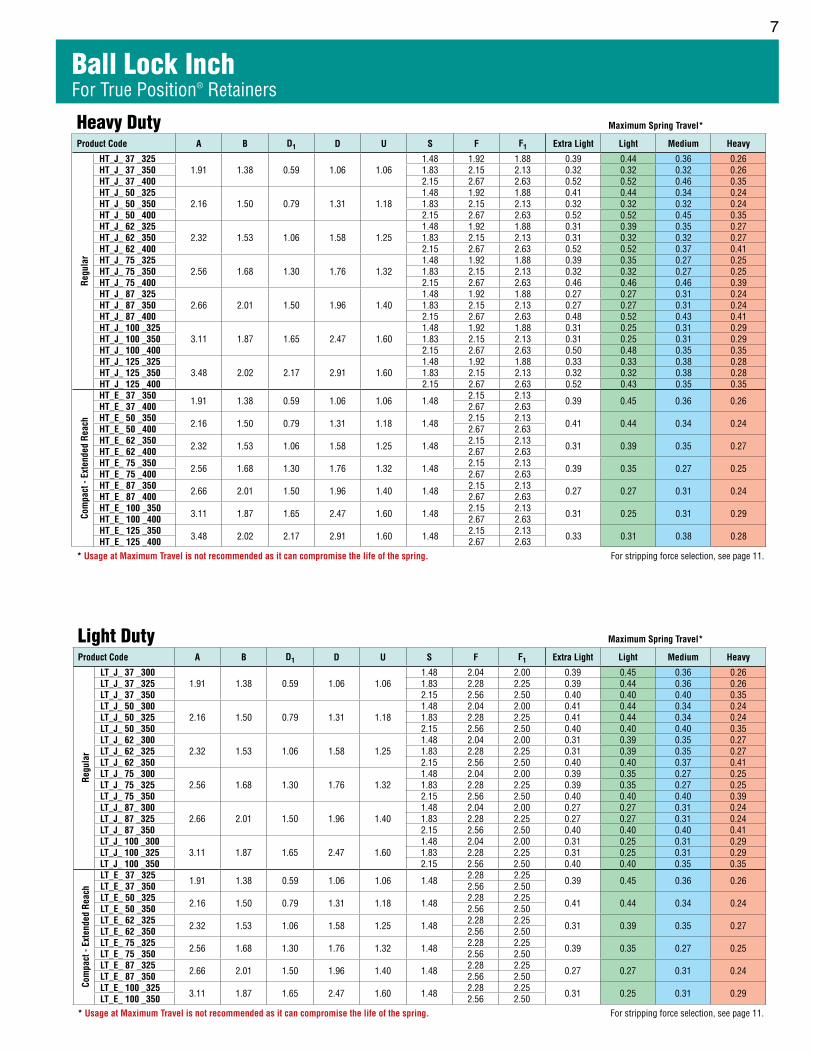
7
Ball Lock InchFor True Position® Retainers
Light Duty Maximum Spring Travel*
Product Code A B D1 D U S F F1 Extra Light Light Medium Heavy
Regu
lar
LT_J_ 37 _3001.91 1.38 0.59 1.06 1.06
1.48 2.04 2.00 0.39 0.45 0.36 0.26LT_J_ 37 _325 1.83 2.28 2.25 0.39 0.44 0.36 0.26LT_J_ 37 _350 2.15 2.56 2.50 0.40 0.40 0.40 0.35LT_J_ 50 _300
2.16 1.50 0.79 1.31 1.181.48 2.04 2.00 0.41 0.44 0.34 0.24
LT_J_ 50 _325 1.83 2.28 2.25 0.41 0.44 0.34 0.24LT_J_ 50 _350 2.15 2.56 2.50 0.40 0.40 0.40 0.35LT_J_ 62 _300
2.32 1.53 1.06 1.58 1.251.48 2.04 2.00 0.31 0.39 0.35 0.27
LT_J_ 62 _325 1.83 2.28 2.25 0.31 0.39 0.35 0.27LT_J_ 62 _350 2.15 2.56 2.50 0.40 0.40 0.37 0.41LT_J_ 75 _300
2.56 1.68 1.30 1.76 1.321.48 2.04 2.00 0.39 0.35 0.27 0.25
LT_J_ 75 _325 1.83 2.28 2.25 0.39 0.35 0.27 0.25LT_J_ 75 _350 2.15 2.56 2.50 0.40 0.40 0.40 0.39LT_J_ 87_ 300
2.66 2.01 1.50 1.96 1.401.48 2.04 2.00 0.27 0.27 0.31 0.24
LT_J_ 87 _325 1.83 2.28 2.25 0.27 0.27 0.31 0.24LT_J_ 87 _350 2.15 2.56 2.50 0.40 0.40 0.40 0.41LT_J_ 100 _300
3.11 1.87 1.65 2.47 1.601.48 2.04 2.00 0.31 0.25 0.31 0.29
LT_J_ 100 _325 1.83 2.28 2.25 0.31 0.25 0.31 0.29LT_J_ 100 _350 2.15 2.56 2.50 0.40 0.40 0.35 0.35
Com
pact
- Ex
tend
ed R
each
LT_E_ 37 _325 1.91 1.38 0.59 1.06 1.06 1.48 2.28 2.25 0.39 0.45 0.36 0.26LT_E_ 37 _350 2.56 2.50LT_E_ 50 _325 2.16 1.50 0.79 1.31 1.18 1.48 2.28 2.25 0.41 0.44 0.34 0.24LT_E_ 50 _350 2.56 2.50LT_E_ 62 _325 2.32 1.53 1.06 1.58 1.25 1.48 2.28 2.25 0.31 0.39 0.35 0.27LT_E_ 62 _350 2.56 2.50LT_E_ 75 _325 2.56 1.68 1.30 1.76 1.32 1.48 2.28 2.25 0.39 0.35 0.27 0.25LT_E_ 75 _350 2.56 2.50LT_E_ 87 _325 2.66 2.01 1.50 1.96 1.40 1.48 2.28 2.25 0.27 0.27 0.31 0.24LT_E_ 87 _350 2.56 2.50LT_E_ 100 _325 3.11 1.87 1.65 2.47 1.60 1.48 2.28 2.25 0.31 0.25 0.31 0.29LT_E_ 100 _350 2.56 2.50
* Usage at Maximum Travel is not recommended as it can compromise the life of the spring. For stripping force selection, see page 11.
Heavy Duty Maximum Spring Travel*
Product Code A B D1 D U S F F1 Extra Light Light Medium Heavy
Regu
lar
HT_J_ 37 _3251.91 1.38 0.59 1.06 1.06
1.48 1.92 1.88 0.39 0.44 0.36 0.26HT_J_ 37 _350 1.83 2.15 2.13 0.32 0.32 0.32 0.26HT_J_ 37 _400 2.15 2.67 2.63 0.52 0.52 0.46 0.35HT_J_ 50 _325
2.16 1.50 0.79 1.31 1.181.48 1.92 1.88 0.41 0.44 0.34 0.24
HT_J_ 50 _350 1.83 2.15 2.13 0.32 0.32 0.32 0.24HT_J_ 50 _400 2.15 2.67 2.63 0.52 0.52 0.45 0.35HT_J_ 62 _325
2.32 1.53 1.06 1.58 1.251.48 1.92 1.88 0.31 0.39 0.35 0.27
HT_J_ 62 _350 1.83 2.15 2.13 0.31 0.32 0.32 0.27HT_J_ 62 _400 2.15 2.67 2.63 0.52 0.52 0.37 0.41HT_J_ 75 _325
2.56 1.68 1.30 1.76 1.321.48 1.92 1.88 0.39 0.35 0.27 0.25
HT_J_ 75 _350 1.83 2.15 2.13 0.32 0.32 0.27 0.25HT_J_ 75 _400 2.15 2.67 2.63 0.46 0.46 0.46 0.39HT_J_ 87 _325
2.66 2.01 1.50 1.96 1.401.48 1.92 1.88 0.27 0.27 0.31 0.24
HT_J_ 87 _350 1.83 2.15 2.13 0.27 0.27 0.31 0.24HT_J_ 87 _400 2.15 2.67 2.63 0.48 0.52 0.43 0.41HT_J_ 100 _325
3.11 1.87 1.65 2.47 1.601.48 1.92 1.88 0.31 0.25 0.31 0.29
HT_J_ 100 _350 1.83 2.15 2.13 0.31 0.25 0.31 0.29HT_J_ 100 _400 2.15 2.67 2.63 0.50 0.48 0.35 0.35HT_J_ 125 _325
3.48 2.02 2.17 2.91 1.601.48 1.92 1.88 0.33 0.33 0.38 0.28
HT_J_ 125 _350 1.83 2.15 2.13 0.32 0.32 0.38 0.28HT_J_ 125 _400 2.15 2.67 2.63 0.52 0.43 0.35 0.35
Com
pact
- Ex
tend
ed R
each
HT_E_ 37 _350 1.91 1.38 0.59 1.06 1.06 1.48 2.15 2.13 0.39 0.45 0.36 0.26HT_E_ 37 _400 2.67 2.63HT_E_ 50 _350 2.16 1.50 0.79 1.31 1.18 1.48 2.15 2.13 0.41 0.44 0.34 0.24HT_E_ 50 _400 2.67 2.63HT_E_ 62 _350 2.32 1.53 1.06 1.58 1.25 1.48 2.15 2.13 0.31 0.39 0.35 0.27HT_E_ 62 _400 2.67 2.63HT_E_ 75 _350 2.56 1.68 1.30 1.76 1.32 1.48 2.15 2.13 0.39 0.35 0.27 0.25HT_E_ 75 _400 2.67 2.63HT_E_ 87 _350 2.66 2.01 1.50 1.96 1.40 1.48 2.15 2.13 0.27 0.27 0.31 0.24HT_E_ 87 _400 2.67 2.63HT_E_ 100 _350 3.11 1.87 1.65 2.47 1.60 1.48 2.15 2.13 0.31 0.25 0.31 0.29HT_E_ 100 _400 2.67 2.63HT_E_ 125 _350 3.48 2.02 2.17 2.91 1.60 1.48 2.15 2.13 0.33 0.31 0.38 0.28HT_E_ 125 _400 2.67 2.63
* Usage at Maximum Travel is not recommended as it can compromise the life of the spring. For stripping force selection, see page 11.
8
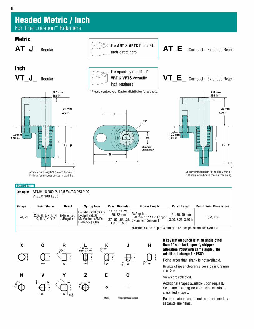
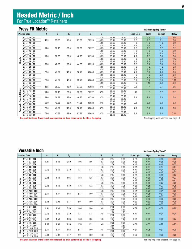
Headed Metric / InchFor True Location™ Retainers
AT_J_ Regular AT_E_ Compact – Extended Reach
Metric
SF1 F
25 mm
5.0 mm
10.0 mm
.188 in**
1.00 in‡
0.39 in
Specify bronze length “L” to add 3 mm or.118 inch for in-house contour machining.
S
F1 F
25 mm
5.0 mm
10.0 mm
.188 in**
1.00 in‡
0.39 in
Specify bronze length “L” to add 3 mm or.118 inch for in-house contour machining.
For ART & ARTS Press Fit metric retainers
VT_J_ Regular VT_E_ Compact – Extended Reach
Inch For specially modified* VRT & VRTS Versatile inch retainers
HOW TO ORDER
Example: ATJJH 16 R90 P=10.5 W=7.3 PS89 90 VTELM 100 L350
Stripper Point Shape Reach Spring Type Punch Diameter Bronze Length Punch Length Punch Point Dimensions
AT, VT C, E, H, J, K, L, N, O, R, V, X, Y, Z
E=ExtendedJ=Regular
S=Extra Light (SSD)L=Light (SLD)M=Medium (SMD)H=Heavy (SHD)
10, 13, 16, 20, 25, 32 mm
.37, .50, .62, .75, 1.00, 1.25 in
R=RegularL=3 mm or .118 in LongerC=Custom Contour †
71, 80, 90 mm3.00, 3.25, 3.50 in
P, W, etc.
†Custom Contour up to 3 mm or .118 inch per submitted CAD file.
If key flat on punch is at an angle other than 0° standard, specify stripper alteration PS89 with same angle. No additional charge for PS89.
Point larger than shank is not available.
Bronze stripper clearance per side is 0.3 mm / .012 in.
Views are reflected.
Additional shapes available upon request. See punch catalog for complete selection of classified shapes.
Paired retainers and punches are ordered as separate line items.
ZYVN E
G2R=
J HL KROXSpecify
(Blank)
C
(Classified Shape Number)
0.5R mm ± .13.020R in ± .005
A
B
U
∅D
D1
BronzeDiameter
* Please contact your Dayton distributor for a quote.
9
Versatile Inch Maximum Spring Travel*
Product Code A B D1 D U S F F1 Extra Light Light Medium Heavy
Regu
lar
VT_J_ 37 _3001.91 1.38 0.59 1.06 1.06
1.48 2.04 2.00 0.39 0.45 0.36 0.26VT_J_ 37 _325 1.83 2.28 2.25 0.39 0.44 0.36 0.26VT_J_ 37 _350 2.15 2.56 2.50 0.40 0.40 0.40 0.35VT_J_ 50 _300
2.16 1.50 0.79 1.31 1.181.48 2.04 2.00 0.41 0.44 0.34 0.24
VT_J_ 50 _325 1.83 2.28 2.25 0.41 0.44 0.34 0.24VT_J_ 50 _350 2.15 2.56 2.50 0.40 0.40 0.40 0.35VT_J_ 62 _300
2.32 1.53 1.06 1.58 1.251.48 2.04 2.00 0.31 0.39 0.35 0.27
VT_J_ 62 _325 1.83 2.28 2.25 0.31 0.39 0.35 0.27VT_J_ 62 _350 2.15 2.56 2.50 0.40 0.40 0.37 0.41VT_J_ 75 _300
2.56 1.68 1.30 1.76 1.321.48 2.04 2.00 0.39 0.35 0.27 0.25
VT_J_ 75 _325 1.83 2.28 2.25 0.39 0.35 0.27 0.25VT_J_ 75 _350 2.15 2.56 2.50 0.40 0.40 0.40 0.39VT_J_ 100 _300
3.11 1.87 1.65 2.47 1.601.48 2.04 2.00 0.31 0.25 0.31 0.29
VT_J_ 100 _325 1.83 2.28 2.25 0.31 0.25 0.31 0.29VT_J_ 100 _350 2.15 2.56 2.50 0.40 0.40 0.35 0.35VT_J_ 125 _300
3.48 2.02 2.17 2.91 1.601.48 2.04 2.00 0.33 0.33 0.38 0.28
VT_J_ 125 _325 1.83 2.28 2.25 0.33 0.33 0.38 0.28VT_J_ 125 _350 2.15 2.56 2.50 0.40 0.40 0.35 0.35
Com
pact
- Ex
tend
ed R
each
VT_E_ 37 _325 1.91 1.38 0.59 1.06 1.06 1.48 2.28 2.25 0.39 0.45 0.36 0.26VT_E_ 37 _350 2.56 2.50VT_E_ 50 _325 2.16 1.50 0.79 1.31 1.18 1.48 2.28 2.25 0.41 0.44 0.34 0.24VT_E_ 50 _350 2.56 2.50VT_E_ 62 _325 2.32 1.53 1.06 1.58 1.25 1.48 2.28 2.25 0.31 0.39 0.35 0.27VT_E_ 62 _350 2.56 2.50VT_E_ 75 _325 2.56 1.68 1.30 1.76 1.32 1.48 2.28 2.25 0.39 0.35 0.27 0.25VT_E_ 75 _350 2.56 2.50VT_E_ 100 _325 3.11 1.87 1.65 2.47 1.60 1.48 2.28 2.25 0.31 0.25 0.31 0.29VT_E_ 100 _350 2.56 2.50VT_E_ 125 _325 3.48 2.02 2.17 2.91 1.60 1.48 2.28 2.25 0.33 0.33 0.38 0.28VT_E_ 125 _350 2.56 2.50
* Usage at Maximum Travel is not recommended as it can compromise the life of the spring. For stripping force selection, see page 11.
Headed Metric / InchFor True Location™ Retainers
Press Fit Metric Maximum Spring Travel*
Product Code A B D1 D U S F F1 Extra Light Light Medium Heavy
Regu
lar
AT_J_ 10 _7148.5 35.00 15.0 27.00 26.924
37.5 46.65 46.00 9.2 9.2 9.1 6.6AT_J_ 10 _80 46.5 55.65 55.00 9.2 9.2 9.1 6.6AT_J_ 10 _90 54.5 65.65 65.00 11.2 11.2 11.2 8.9AT_J_ 13 _71
54.8 38.10 20.0 33.30 29.97237.5 46.65 46.00 9.2 9.2 8.7 6.2
AT_J_ 13 _80 46.5 55.65 55.00 9.2 9.2 8.7 6.2AT_J_ 13 _90 54.5 65.65 65.00 11.2 11.2 11.2 8.9AT_J_ 16 _71
59.0 38.88 27.0 40.25 31.75037.5 46.65 46.00 7.8 9.2 8.8 6.8
AT_J_ 16 _80 46.5 55.65 55.00 7.8 9.2 8.8 6.8AT_J_ 16 _90 54.5 65.65 65.00 11.2 11.2 9.3 10.3AT_J_ 20 _71
65.0 42.68 33.0 44.65 33.52837.5 46.65 46.00 9.2 8.8 6.8 6.3
AT_J_ 20 _80 46.5 55.65 55.00 9.2 8.8 6.8 6.3AT_J_ 20 _90 54.5 65.65 65.00 11.2 11.2 11.2 9.8AT_J_ 25 _71
76.0 47.62 42.0 56.76 40.64037.5 46.65 46.00 7.8 6.3 7.8 7.3
AT_J_ 25 _80 46.5 55.65 55.00 7.8 6.3 7.8 7.3AT_J_ 25 _90 54.5 65.65 65.00 11.2 11.2 8.8 8.8AT_J_ 32 _71
79.0 47.62 48.0 62.76 40.64037.5 46.65 46.00 8.3 8.3 9.8 7.11
AT_J_ 32 _80 46.5 55.65 55.00 8.3 8.3 9.8 7.11AT_J_ 32 _90 54.5 65.65 65.00 11.2 10.8 8.8 8.8
Com
pact
- Ex
tend
ed R
each
AT_E_ 10 _80 48.5 35.00 15.0 27.00 26.924 37.5 55.65 55.00 9.8 11.4 9.1 6.6AT_E_ 10 _90 65.65 65.00AT_E_ 13 _80 54.8 38.10 20.0 33.30 29.972 37.5 55.65 55.00 10.3 11.1 8.7 6.2AT_E_ 13 _90 65.65 65.00AT_E_ 16 _80 59.0 38.88 27.0 40.25 31.750 37.5 55.65 55.00 7.8 9.8 8.8 6.8AT_E_ 16 _90 65.65 65.00AT_E_ 20 _80 65.0 42.68 33.0 44.65 33.528 37.5 55.65 55.00 9.8 8.8 6.8 6.3AT_E_ 20 _90 65.65 65.00AT_E_ 25 _80 76.0 47.62 42.0 56.76 40.640 37.5 55.65 55.00 7.8 6.3 7.8 7.3AT_E_ 25 _90 65.65 65.00AT_E_ 32 _80 79.0 47.62 48.0 62.76 40.640 37.5 55.65 55.00 8.3 8.3 9.8 7.11AT_E_ 32 _90 65.65 65.00
* Usage at Maximum Travel is not recommended as it can compromise the life of the spring. For stripping force selection, see page 10.
10
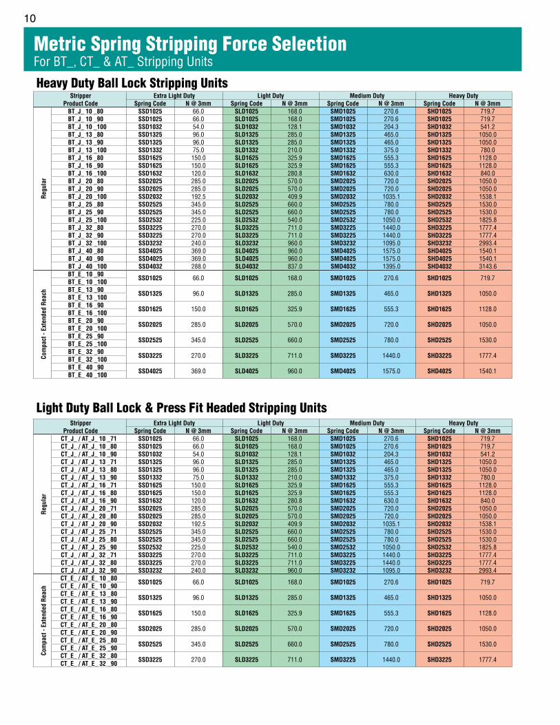
Metric Spring Stripping Force SelectionFor BT_, CT_ & AT_ Stripping Units
Heavy Duty Ball Lock Stripping UnitsStripper
Product CodeExtra Light Duty Light Duty Medium Duty Heavy Duty
Spring Code N @ 3mm Spring Code N @ 3mm Spring Code N @ 3mm Spring Code N @ 3mm
Regu
lar
BT_J_ 10 _80 SSD1025 66.0 SLD1025 168.0 SMD1025 270.6 SHD1025 719.7BT_J_ 10 _90 SSD1025 66.0 SLD1025 168.0 SMD1025 270.6 SHD1025 719.7BT_J_ 10 _100 SSD1032 54.0 SLD1032 128.1 SMD1032 204.3 SHD1032 541.2BT_J_ 13 _80 SSD1325 96.0 SLD1325 285.0 SMD1325 465.0 SHD1325 1050.0BT_J_ 13 _90 SSD1325 96.0 SLD1325 285.0 SMD1325 465.0 SHD1325 1050.0BT_J_ 13 _100 SSD1332 75.0 SLD1332 210.0 SMD1332 375.0 SHD1332 780.0BT_J_ 16 _80 SSD1625 150.0 SLD1625 325.9 SMD1625 555.3 SHD1625 1128.0BT_J_ 16 _90 SSD1625 150.0 SLD1625 325.9 SMD1625 555.3 SHD1625 1128.0BT_J_ 16 _100 SSD1632 120.0 SLD1632 280.8 SMD1632 630.0 SHD1632 840.0BT_J_ 20 _80 SSD2025 285.0 SLD2025 570.0 SMD2025 720.0 SHD2025 1050.0BT_J_ 20 _90 SSD2025 285.0 SLD2025 570.0 SMD2025 720.0 SHD2025 1050.0BT_J_ 20 _100 SSD2032 192.5 SLD2032 409.9 SMD2032 1035.1 SHD2032 1538.1BT_J_ 25 _80 SSD2525 345.0 SLD2525 660.0 SMD2525 780.0 SHD2525 1530.0BT_J_ 25 _90 SSD2525 345.0 SLD2525 660.0 SMD2525 780.0 SHD2525 1530.0BT_J_ 25 _100 SSD2532 225.0 SLD2532 540.0 SMD2532 1050.0 SHD2532 1825.8BT_J_ 32 _80 SSD3225 270.0 SLD3225 711.0 SMD3225 1440.0 SHD3225 1777.4BT_J_ 32 _90 SSD3225 270.0 SLD3225 711.0 SMD3225 1440.0 SHD3225 1777.4BT_J_ 32 _100 SSD3232 240.0 SLD3232 960.0 SMD3232 1095.0 SHD3232 2993.4BT_J_ 40 _80 SSD4025 369.0 SLD4025 960.0 SMD4025 1575.0 SHD4025 1540.1BT_J_ 40 _90 SSD4025 369.0 SLD4025 960.0 SMD4025 1575.0 SHD4025 1540.1BT_J_ 40 _100 SSD4032 288.0 SLD4032 837.0 SMD4032 1395.0 SHD4032 3143.6
Com
pact
- Ex
tend
ed R
each
BT_E_ 10 _90 SSD1025 66.0 SLD1025 168.0 SMD1025 270.6 SHD1025 719.7BT_E_ 10 _100BT_E_ 13 _90 SSD1325 96.0 SLD1325 285.0 SMD1325 465.0 SHD1325 1050.0BT_E_ 13 _100BT_E_ 16 _90 SSD1625 150.0 SLD1625 325.9 SMD1625 555.3 SHD1625 1128.0BT_E_ 16 _100BT_E_ 20 _90 SSD2025 285.0 SLD2025 570.0 SMD2025 720.0 SHD2025 1050.0BT_E_ 20 _100BT_E_ 25 _90 SSD2525 345.0 SLD2525 660.0 SMD2525 780.0 SHD2525 1530.0BT_E_ 25 _100BT_E_ 32 _90 SSD3225 270.0 SLD3225 711.0 SMD3225 1440.0 SHD3225 1777.4BT_E_ 32 _100BT_E_ 40 _90 SSD4025 369.0 SLD4025 960.0 SMD4025 1575.0 SHD4025 1540.1BT_E_ 40 _100
Light Duty Ball Lock & Press Fit Headed Stripping UnitsStripper
Product CodeExtra Light Duty Light Duty Medium Duty Heavy Duty
Spring Code N @ 3mm Spring Code N @ 3mm Spring Code N @ 3mm Spring Code N @ 3mm
Regu
lar
CT_J_ / AT_J_ 10 _71 SSD1025 66.0 SLD1025 168.0 SMD1025 270.6 SHD1025 719.7CT_J_ / AT_J_ 10 _80 SSD1025 66.0 SLD1025 168.0 SMD1025 270.6 SHD1025 719.7CT_J_ / AT_J_ 10 _90 SSD1032 54.0 SLD1032 128.1 SMD1032 204.3 SHD1032 541.2CT_J_ / AT_J_ 13 _71 SSD1325 96.0 SLD1325 285.0 SMD1325 465.0 SHD1325 1050.0CT_J_ / AT_J_ 13 _80 SSD1325 96.0 SLD1325 285.0 SMD1325 465.0 SHD1325 1050.0CT_J_ / AT_J_ 13 _90 SSD1332 75.0 SLD1332 210.0 SMD1332 375.0 SHD1332 780.0CT_J_ / AT_J_ 16 _71 SSD1625 150.0 SLD1625 325.9 SMD1625 555.3 SHD1625 1128.0CT_J_ / AT_J_ 16 _80 SSD1625 150.0 SLD1625 325.9 SMD1625 555.3 SHD1625 1128.0CT_J_ / AT_J_ 16 _90 SSD1632 120.0 SLD1632 280.8 SMD1632 630.0 SHD1632 840.0CT_J_ / AT_J_ 20 _71 SSD2025 285.0 SLD2025 570.0 SMD2025 720.0 SHD2025 1050.0CT_J_ / AT_J_ 20 _80 SSD2025 285.0 SLD2025 570.0 SMD2025 720.0 SHD2025 1050.0CT_J_ / AT_J_ 20 _90 SSD2032 192.5 SLD2032 409.9 SMD2032 1035.1 SHD2032 1538.1CT_J_ / AT_J_ 25 _71 SSD2525 345.0 SLD2525 660.0 SMD2525 780.0 SHD2525 1530.0CT_J_ / AT_J_ 25 _80 SSD2525 345.0 SLD2525 660.0 SMD2525 780.0 SHD2525 1530.0CT_J_ / AT_J_ 25 _90 SSD2532 225.0 SLD2532 540.0 SMD2532 1050.0 SHD2532 1825.8CT_J_ / AT_J_ 32 _71 SSD3225 270.0 SLD3225 711.0 SMD3225 1440.0 SHD3225 1777.4CT_J_ / AT_J_ 32 _80 SSD3225 270.0 SLD3225 711.0 SMD3225 1440.0 SHD3225 1777.4CT_J_ / AT_J_ 32 _90 SSD3232 240.0 SLD3232 960.0 SMD3232 1095.0 SHD3232 2993.4
Com
pact
- Ex
tend
ed R
each
CT_E_ / AT_E_ 10 _80 SSD1025 66.0 SLD1025 168.0 SMD1025 270.6 SHD1025 719.7CT_E_ / AT_E_ 10 _90CT_E_ / AT_E_ 13 _80 SSD1325 96.0 SLD1325 285.0 SMD1325 465.0 SHD1325 1050.0CT_E_ / AT_E_ 13 _90CT_E_ / AT_E_ 16 _80 SSD1625 150.0 SLD1625 325.9 SMD1625 555.3 SHD1625 1128.0CT_E_ / AT_E_ 16 _90CT_E_ / AT_E_ 20 _80 SSD2025 285.0 SLD2025 570.0 SMD2025 720.0 SHD2025 1050.0CT_E_ / AT_E_ 20 _90CT_E_ / AT_E_ 25 _80 SSD2525 345.0 SLD2525 660.0 SMD2525 780.0 SHD2525 1530.0CT_E_ / AT_E_ 25 _90CT_E_ / AT_E_ 32 _80 SSD3225 270.0 SLD3225 711.0 SMD3225 1440.0 SHD3225 1777.4CT_E_ / AT_E_ 32 _90

11
Inch Spring Stripping Force SelectionFor HT_, LT_ & VT_ Stripping Units
Heavy Duty Ball Lock Stripping UnitsStripper
Product CodeExtra Light Duty Light Duty Medium Duty Heavy Duty
Spring Code lbf / 0.12 in Spring Code lbf / 0.12 in Spring Code lbf / 0.12 in Spring Code lbf / 0.12 in
Regu
lar
HT_J_ 37 _325 SSD1025 14.84 SLD1025 31.98 SMD1025 51.51 SHD1025 136.99HT_J_ 37 _350 SSD1025 14.84 SLD1025 31.98 SMD1025 51.51 SHD1025 136.99HT_J_ 37 _400 SSD1032 12.14 SLD1032 24.38 SMD1032 38.89 SHD1032 103.01HT_J_ 50 _325 SSD1325 21.57 SLD1325 54.25 SMD1325 88.51 SHD1325 199.86HT_J_ 50 _350 SSD1325 21.57 SLD1325 54.25 SMD1325 88.51 SHD1325 199.86HT_J_ 50 _400 SSD1332 16.86 SLD1332 39.97 SMD1332 71.38 SHD1332 148.46HT_J_ 62 _325 SSD1625 33.72 SLD1625 62.02 SMD1625 105.70 SHD1625 214.70HT_J_ 62 _350 SSD1625 33.72 SLD1625 62.02 SMD1625 105.70 SHD1625 214.70HT_J_ 62 _400 SSD1632 26.98 SLD1632 53.44 SMD1632 119.91 SHD1632 159.88HT_J_ 75 _325 SSD2025 64.07 SLD2025 108.49 SMD2025 137.04 SHD2025 199.86HT_J_ 75 _350 SSD2025 64.07 SLD2025 108.49 SMD2025 137.04 SHD2025 199.86HT_J_ 75 _400 SSD2032 43.28 SLD2032 78.03 SMD2032 197.02 SHD2032 293.20HT_J_ 87 _325 SSD87100 47.21 SLD87100 91.93 SMD87100 138.76 SHD87100 239.83HT_J_ 87 _350 SSD87100 47.21 SLD87100 91.93 SMD87100 138.76 SHD87100 239.83HT_J_ 87 _400 SSD87125 44.51 SLD87125 77.09 SMD87125 95.93 SHD87125 179.87HT_J_ 100 _325 SSD2525 77.56 SLD2525 125.62 SMD2525 148.46 SHD2525 291.22HT_J_ 100 _350 SSD2525 77.56 SLD2525 125.62 SMD2525 148.46 SHD2525 291.22HT_J_ 100 _400 SSD2532 50.58 SLD2532 102.78 SMD2532 199.86 SHD2532 348.05HT_J_ 125 _325 SSD3225 60.70 SLD3225 135.33 SMD3225 274.09 SHD3225 338.82HT_J_ 125 _350 SSD3225 60.70 SLD3225 135.33 SMD3225 274.09 SHD3225 338.82HT_J_ 125 _400 SSD3232 53.95 SLD3232 182.72 SMD3232 208.42 SHD3232 570.62
Com
pact
- Ex
tend
ed R
each
HT_E_ 37 _350 SSD1025 14.84 SLD1025 31.98 SMD1025 51.51 SHD1025 136.99HT_E_ 37 _400HT_E_ 50 _350 SSD1325 21.57 SLD1325 54.25 SMD1325 88.51 SHD1325 199.86HT_E_ 50 _400HT_E_ 62 _350 SSD1625 33.72 SLD1625 62.02 SMD1625 105.70 SHD1625 214.70HT_E_ 62 _400HT_E_ 75 _350 SSD2025 64.07 SLD2025 108.49 SMD2025 137.04 SHD2025 199.86HT_E_ 75 _400HT_E_ 87 _350 SSD87100 47.21 SLD87100 91.93 SMD87100 138.76 SHD87100 239.83HT_E_ 87 _400HT_E_ 100 _350 SSD2525 77.56 SLD2525 125.62 SMD2525 148.46 SHD2525 291.22HT_E_ 100 _400HT_E_ 125 _350 SSD3225 60.70 SLD3225 135.33 SMD3225 274.09 SHD3225 338.82HT_E_ 125 _400
Light Duty Ball Lock & Versatile Headed Stripping UnitsStripper
Product CodeExtra Light Duty Light Duty Medium Duty Heavy Duty
Spring Code lbf / 0.12 in Spring Code lbf / 0.12 in Spring Code lbf / 0.12 in Spring Code lbf / 0.12 in
Regu
lar
LT_J_ / VT_J_ 37 _300 SSD1025 14.84 SLD1025 31.98 SMD1025 51.51 SHD1025 136.99LT_J_ / VT_J_ 37 _325 SSD1025 14.84 SLD1025 31.98 SMD1025 51.51 SHD1025 136.99LT_J_ / VT_J_ 37 _350 SSD1032 12.14 SLD1032 24.38 SMD1032 38.89 SHD1032 103.01LT_J_ / VT_J_ 50 _300 SSD1325 21.57 SLD1325 54.25 SMD1325 88.51 SHD1325 199.86LT_J_ / VT_J_ 50 _325 SSD1325 21.57 SLD1325 54.25 SMD1325 88.51 SHD1325 199.86LT_J_ / VT_J_ 50 _350 SSD1332 16.86 SLD1332 39.97 SMD1332 71.38 SHD1332 148.46LT_J_ / VT_J_ 62 _300 SSD1625 33.72 SLD1625 62.02 SMD1625 105.70 SHD1625 214.70LT_J_ / VT_J_ 62 _325 SSD1625 33.72 SLD1625 62.02 SMD1625 105.70 SHD1625 214.70LT_J_ / VT_J_ 62 _350 SSD1632 26.98 SLD1632 53.44 SMD1632 119.91 SHD1632 159.88LT_J_ / VT_J_ 75 _300 SSD2025 64.07 SLD2025 108.49 SMD2025 137.04 SHD2025 199.86LT_J_ / VT_J_ 75 _325 SSD2025 64.07 SLD2025 108.49 SMD2025 137.04 SHD2025 199.86LT_J_ / VT_J_ 75 _350 SSD2032 43.28 SLD2032 78.03 SMD2032 197.02 SHD2032 293.20
LT_J_ 87_ 300 SSD87100 47.21 SLD87100 91.93 SMD87100 138.76 SHD87100 239.83LT_J_ 87 _325 SSD87100 47.21 SLD87100 91.93 SMD87100 138.76 SHD87100 239.83LT_J_ 87 _350 SSD87125 44.51 SLD87125 77.09 SMD87125 95.93 SHD87125 179.87
LT_J_ / VT_J_ 100 _300 SSD2525 77.56 SLD2525 125.62 SMD2525 148.46 SHD2525 291.22LT_J_ / VT_J_ 100 _325 SSD2525 77.56 SLD2525 125.62 SMD2525 148.46 SHD2525 291.22LT_J_ / VT_J_ 100 _350 SSD2532 50.58 SLD2532 102.78 SMD2532 199.86 SHD2532 348.05LT_J_ / VT_J_ 125 _300 SSD3225 60.70 SLD3225 135.33 SMD3225 274.09 SHD3225 338.82LT_J_ / VT_J_ 125 _325 SSD3225 60.70 SLD3225 135.33 SMD3225 274.09 SHD3225 338.82LT_J_ / VT_J_ 125 _350 SSD3232 53.95 SLD3232 182.72 SMD3232 208.42 SHD3232 570.62
Com
pact
- Ex
tend
ed R
each
LT_E_ / VT_E_ 37 _325 SSD1025 14.84 SLD1025 31.98 SMD1025 51.51 SHD1025 136.99LT_E_ / VT_E_ 37 _350LT_E_ / VT_E_ 50 _325 SSD1325 21.57 SLD1325 54.25 SMD1325 88.51 SHD1325 199.86LT_E_ / VT_E_ 50 _350LT_E_ / VT_E_ 62 _325 SSD1625 33.72 SLD1625 62.02 SMD1625 105.70 SHD1625 214.70LT_E_ / VT_E_ 62 _350LT_E_ / VT_E_ 75 _325 SSD2025 64.07 SLD2025 108.49 SMD2025 137.04 SHD2025 199.86LT_E_ / VT_E_ 75 _350
LT_E_ 87 _325 SSD87100 47.21 SLD87100 91.93 SMD87100 138.76 SHD87100 239.83LT_E_ 87 _350LT_E_ / VT_E_ 100 _325 SSD2525 77.56 SLD2525 125.62 SMD2525 148.46 SHD2525 291.22LT_E_ / VT_E_ 100 _350LT_E_ / VT_E_ 125 _325 SSD3225 60.70 SLD3225 135.33 SMD3225 274.09 SHD3225 338.82LT_E_ / VT_E_ 125 _350
© 2018 Dayton Lamina Corporation. All rights reserved.
Commitment to Quality & Customer Satisfaction
Dayton Lamina is a leading manufacturer of tool, die and mold components for the metal-working and plastics industries. As a customer-focused, world-class supplier of choice, we provide the brands, product breadth, distribution network and technical support for all your metal forming needs.
Our goal is to give our customers the most innovative and value-added products and services.
www.daytonlamina.com
*
*Dayton Lamina’s line of Danly products is available only to North America.
Form 8089 2/19