Embed Size (px)
Citation preview

New paradigm for rapid production oflarge precision optics: frozen membranemirror technology
Mike LieberStephen KendrickSarah LipscyDennis EbbetsScott ActonScott Knight
Downloaded From: https://www.spiedigitallibrary.org/journals/Optical-Engineering on 08 Feb 2022Terms of Use: https://www.spiedigitallibrary.org/terms-of-use
New paradigm for rapid production of large precisionoptics: frozen membrane mirror technology
Mike LieberStephen KendrickSarah LipscyDennis EbbetsScott ActonScott KnightBall Aerospace1600 Commerce StreetBoulder, Colorado 80301E-mail: [email protected]
Abstract. Traditional mirror manufacturing, particularly for astronomicalpurposes, requires substantial lead time, due to the nature of the materialsand the grinding/polishing process. We propose a new technique for rapid,low-cost production of large, lightweight precision optics by fusing severaltechnologies which in combination we call frozen membrane mirror tech-nology (FMMT). FMMT combines well-understood subsystem technolo-gies, including electrostatic control of membrane mirrors, adaptiveoptics, wavefront sensing and control, and inflatable structures technologyto shorten production time. The basic technique is to control the surface ofa reflective coated membrane mirror with electrostatic actuation and wave-front sensor feedback and freeze the membrane shape. We discuss thedetails of the concept and present results of early lab testing. We focus onthe optical regime, but this technology has applicability from the micro-wave to x-ray spectral bands. Starting with a flexible membrane mirror,one can envision techniques for deployment of large apertures inspace. © The Authors. Published by SPIE under a Creative Commons Attribution 3.0Unported License. Distribution or reproduction of this work in whole or in part requires full attri-bution of the original publication, including its DOI. [DOI: 10.1117/1.OE.52.9.091810]
Subject terms: membrane mirrors; large optics; controlled optics; space-basedtelescopes.
Paper 130206SS received Feb. 4, 2013; revised manuscript received Apr. 20, 2013;accepted for publication May 6, 2013; published online Jul. 15, 2013.
1 IntroductionThe needs of the astronomy and defense communities forhigher-resolution imaging and more signal collectioncapability have driven increases in telescope aperturesizes, optical surface quality requirements, and system align-ment tolerances. Since primary mirrors are the fundamentalenabling technology to realize these new systems, muchattention has been directed toward evaluation of differentmanufacturing methodologies, the associated materialtechnologies, and combinations of multiple subsystemtechnologies.1 The need for low-cost precision optical manu-facturing and/or deployment technologies extends acrossthe spectrum from x-ray to microwave. Beyond the estab-lished grinding and polishing of rigid blanks, new technol-ogies have been developed for advanced imaging systemssuch as:
1. segmented mirror telescopes that address the large-optics manufacturing issue and provide a means fordeployment in space from limited launch shrouddiameters;
2. replicated optics technologies using mandrels;3. active optics with either embedded actuation elements
or proximity actuation using electrostatic or magneticfields;
4. large transmissive diffractive optical membranes suchas the MOIRE2 program sponsored by DARPA;
5. synthesized or sparse apertures;6. new system approaches that combine several technol-
ogies, such as the nanolaminate construction formedon mandrels with embedded solid-state actuators.
This paper discusses an approach to the mirror manufac-turing process,3 called frozen membrane mirror technology(FMMT), which shows promise for enabling the rapid pro-duction of low-cost, large precision optics and increasing theviability of other competing technologies. FMMT falls underthe last category in the above list as a new system approach tomirror manufacturing.
FMMT takes a very different approach to the mirrormanufacturing process. During the mirror formation process,electrostatic actuators controlled by feedback from a wave-front sensor shape the membrane into a precisely defined sur-face. The mirror figure, described by the design opticalprescription, is generated by commands loaded into thewavefront sensing and control (WFS&C) software. Afluid matrix is applied to the back side of a rim-mountedmembrane and allowed to harden (or freeze) while theWFS&C system maintains the desired figure. When fullycured, the mirror can be removed from the facility for furthertesting and integration into the telescope. The process simul-taneously manufactures the mirror and provides detailed sur-face figure measurements often requiring a separate testsetup. The main virtue of this process is that it is veryfast—a high-precision mirror can be fabricated in days,not in months or a year. As a result, the optical surface ofthe primary mirror costs significantly less than thosemade by other technologies. The schedule and cost advan-tages ripple through the system, allowing a larger apertureto be made for a given cost or a similar aperture size tobe made at a lower cost.
The FMMT manufacturing process has three fundamentalattributes that differ with the traditional grinding and polish-ing process. First, it inverts the methodology of obtaining a
Optical Engineering 091810-1 September 2013/Vol. 52(9)
Optical Engineering 52(9), 091810 (September 2013)
Downloaded From: https://www.spiedigitallibrary.org/journals/Optical-Engineering on 08 Feb 2022Terms of Use: https://www.spiedigitallibrary.org/terms-of-use

figure by grinding and then polishing to obtain a high surfacequality. It starts with a precoated and tensioned membraneexhibiting high surface quality, which is then shaped witha feedback control system. This opens the possibility formembrane deployment in space with WFS&C substitutedfor precision deployment mechanisms. We have donesome preliminary work on deployable versions that can sup-port future large optical telescopes and very large reflectorsfor the microwave antennas. Second, those both traditionalgrinding/polishing processes and electrostatic actuation arelocalized (derivative actuation), the pulldown and tensioningof the membrane is a global or integrative process that inher-ently forms a smooth surface. Finally, the manufacturingprocess is very adaptive to changes in prescription, limitedonly by the boundary conditions formed by the membranemounting surface and membrane stresses. The adaptivenature of the manufacturing process suggests that both seg-mented optics production and generation of the precisionmandrels used for replicated optics are viable applicationsfor the FMMT process. Segmented optical elements are typ-ically generated from the figure specification of a parentconic, but each individual ring segment has a different pre-scription. For the FMMT approach, this translates into a setof different figure commands and solving the edge mountinggeometry problem. With recent discussion of in-spacedeployment, assembly,4 and manufacturing5 of large tele-scopes, the FMMT process is a viable candidate for enablingthe production of large telescopes in space. This is in partbecause the precision membrane material is deployableand transportable in a rolled form. The same FMMT manu-facturing facility can be configured in software to adaptivelymanufacture a different optical figure and even off-axisoptics.
In Sec. 2, we describe this manufacturing approach indetail, emphasizing the previously developed subsystemtechnologies that feed into the FMMT concept. FMMT isshown to be a natural evolution of several existing technol-ogies combined together as a system. In Sec. 3, some initialexperimental results are provided that show the ability tomanufacture membrane mirrors with a ∼20-Å surface rough-ness. In Sec. 4, we discuss system modeling and the multi-disciplinary nature required to represent the complicatedphysics of FMMT during the mirror formation process.In Sec. 5, we discuss the further work needed to makethis concept viable for ground and space applications.Although we believe this technology can impact deployablemicrowave systems and possibly provide a path for grazingincident x-ray mirrors, we focus the discussion on produc-tion of large mirrors in the optical wavelengths.
2 Description of the TechnologyFMMT is a directed technique of a more general capabilityfor rapid production of precision surfaces called frozen sur-face technology.3 It is a fusion of several previously devel-oped technologies: high-optical-quality membranes fromspace-qualified materials,6 electrostatic control of membranemirrors (ECMM), adaptive optics and WS&C, and ultra-lightweight (Gossamer) structures.6 We will describe theoverall process and then discuss the individual subsystemtechnologies that support FMMT.
As shown in Fig. 1, the mirror surface is measured by awavefront sensor. This provides a feedback signal to the
controller, which, when summed with figure command, gen-erates an array of voltage commands. Electrostatic control ofthe metalized membrane surface is achieved by controlledcharging of the patch actuator array etched on to a rigidcontrol surface or shell structure behind the membrane.7
These charged actuator pads form an electrostatic attractiveforce through a small gap with the metalized membrane sur-face, so they do not actually contact the membrane. Thedownward pressure on the membrane is directly proportionalto the voltage level and the permittivity of the gap andinversely proportional to the control surface to membranegap squared. This attraction causes an overall increase inmembrane tension, thereby correcting any local surface devi-ations from a commanded surface profile. The number ofactuation elements required for a membrane mirror is relatedto the global figure quality required. The mirror surfaceobtained is ultimately limited by the membrane surfaceroughness, which is shown to be several nanometers.Because the front surface is controlled, membrane thicknessvariations at scales larger than the actuation resolution scaleshould be minimized; this remains to be verified.
To freeze the controlled membrane figure, a curable fluidmatrix is injected into a sealed chamber behind the mem-brane. Active control is maintained as the injected fluidcures at room temperature, adhering to and thereby freezingthe mirror surface (hence the terminology “FMMT”).Because the surface is constantly monitored by a wavefrontsensor, the error or feedback signal automatically adjusts tochanges in capacitance with fluid injection or orthotropicmembrane modulus properties, and so the quality of controlis not affected. Note that we are losing controllability of thesurface as the fluid solidifies, but simultaneously the tension
Fig. 1 Conceptual diagram of the FMMT process for producing arigidized membrane mirror.
Optical Engineering 091810-2 September 2013/Vol. 52(9)
Lieber et al.: New paradigm for rapid production of large precision optics. . .
Downloaded From: https://www.spiedigitallibrary.org/journals/Optical-Engineering on 08 Feb 2022Terms of Use: https://www.spiedigitallibrary.org/terms-of-use

force in the membrane is increasingly being opposed by thecuring fluid, rather than the electrostatic force. The electro-static power is turned off after the mirror figure stabilizes andthe composite structure completely cures. Afterward, therigidized membrane can be removed from the manufacturingfacility for environmental testing and integration into thetelescope assembly. The WFS and actuation system willnot be part of the system for space operation unless a deploy-able version is developed.
There are many variations on the approach describedabove. The schematic does not include a central hole, aswould be expected with a Cassegrain design. This featurecan be included but was not for illustrative purposes. It isalso possible to repeat this process to build up multiple layersor, with the right tooling, to form a complex shape with anegg crate architecture. Some relaxation would be expected,and this will need to be precomputed, as is done in the stresspolishing process of standard mirror blanks.
2.1 Membrane and Mounting Technology
As described in several technical papers, there has been rapiddevelopment over the last 15 years in high-quality membranematerials for optical elements. Pellicle membrane elementshave been used for years in optical elements such as beamsplitters. For space-based operation, the focus has been oncustom formulations of polyimide polymers. Polyimidematerials offers many advantages, including the recentlydemonstrated capability either to have a coefficient of ther-mal expansion (CTE) near zero8 or to match its polymer CTEto that of the rim mounting structure.9,10 Polyimide polymersare well characterized in a space environment (thermal man-agement and solar reflectors), and with coatings applied, theyare among the better polymers in terms of radiation andatomic oxygen resistance. Special coatings can be appliedto enhance the adhesion properties for the fluid matrix.The membrane materials can be obtained precoated withaluminum, but for UV applications, an additional coatingof MgF2 is required to retain high reflectivity. One issueis whether to precoat the reflective surface (which will intro-duce stresses into the coatings during manufacturing) or coatafterward (which makes surface control more challenging).Two vendors currently producing high-quality polyimidemembrane materials are Nexolve and UBE Industries.
2.2 Electrostatic Control
ECMM is a well-developed technology, having been inves-tigated and experimentally validated in the late 1970s andearly 1980s at Massachusetts Institute of Technology11,12
and other places.13,14 The ECMM is characterized by nonlin-ear multivariable equations, and Lang12 noted that feedbackcontrol can introduce system instabilities. Nonetheless,Lang was able to demonstrate stable control on a one-meter prototype. One of the key issues is the electrostaticactuators—how much voltage is required, how many actua-tors are needed, and what is the additional effect on controlwith the addition of a fluid matrix. The number of actuators,N, is related to the surface tolerance required, ε, the diameterof the mirror, D, and the focal ratio (focus∕diameter ¼ δ) ofthe mirror. If we apply bias offset voltage on a parabolic con-trol surface, the relationship, as derived by Lang12 for aparabola, can be used to approximate the number of discreteactuator pads.
D∕ε≈93δN
·
����3.3 ffiffiffiffiffiffiNδ
psin h
� ffiffiffiffiffiffiffiffiffiffiffiffiffiffiffiffiffiffiffi3.9Nδ∕D
p �−cos h
� ffiffiffiffiffiffiffiffiffiffiffiffiffiffiffiffiffiffiffi3.9Nδ∕D
p �����:(1)
As an example, for a 4-m membrane mirror and a focalratio of 1, we require 50 electrostatic actuator pads to achievea 71-nm root mean square (rms) surface quality. This is underideal conditions and assumes an equipotential bias voltagecondition. In addition, the membrane and reflective coatingstress levels would need to be evaluated. As we deviate fromthese ideal conditions, a higher-density actuation array willbe required. However, the addition of a fluid behind themembrane has many benefits over the standard ECMMapproach. It greatly increases the membrane structural damp-ing, thereby decreasing both the control loop bandwidth andthe sample rate requirements of the wavefront feedback sen-sor. Because the dielectric constant is much higher with thefluid matrix present, voltage levels are decreased for thesame force field. Finally, it distributes the force on the mem-brane surface, requiring fewer electrostatic actuators. Theeffect of changing fluid matrix properties during curinghas yet to be evaluated analytically.
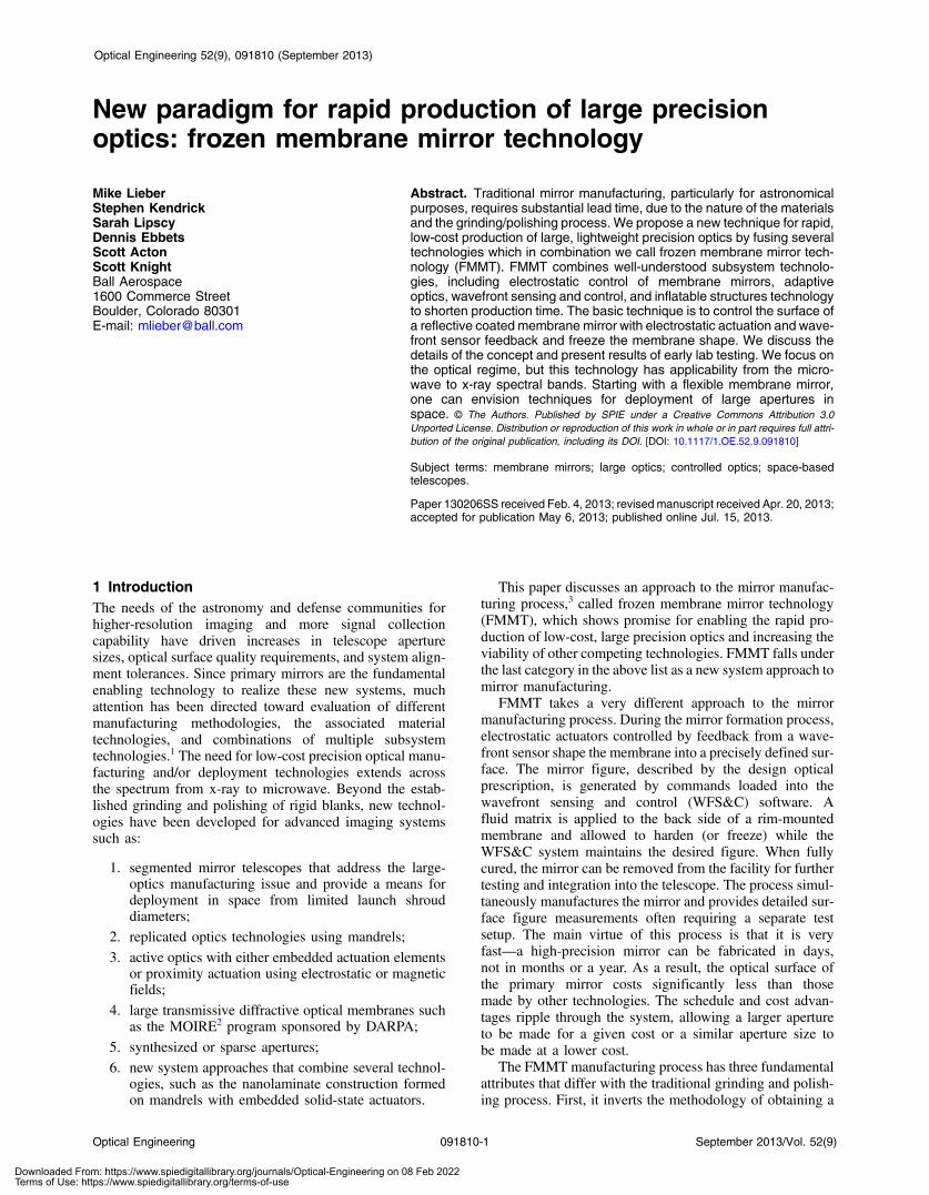
The other aspect of the electrostatic actuation is the use ofWFS&C. Commercially available wavefront sensors canmeasure the figure down to small fractions of a wavelengthof visible light. However, the WFS must typically measurethe surface at a rate of 10× to 20× the closed-loop bandwidthto maintain loop stability due to phase delays. Therefore,additional damping is also important for reducing thedemands on the WFS sample rate. The controller designcan be implemented with field programmable gate arrays(FPGAs), adding tremendous flexibility for control design.Figure 2 shows a small testbed from early testing of theJames Webb Space Telescope, which can be configuredfor testing a 1-m mirror. Awavefront control sensor approachto measuring the membrane and generating a feedback con-trol signal is also shown. Ball has additional facilities toaccommodate the testing of larger optics. In the configura-tion shown, the membrane reflective surface can be moni-tored for wavefront quality using an interferometercapable of short integration times. A polarizing beam splittersplits the outgoing source laser from the aberrated returnbeam to the interferometer, allowing wavefront errors tobe computed. These signals need to be processed to generatethe global wavefront error, and then the signals must be par-titioned and converted to an appropriate voltage for eachelectrostatic actuation pad. To take advantage of the adaptivefiguring capability, the collimating lens or assembly wouldneed to have autofocus capability.
2.3 Fluid Matrix
The two areas of consideration are how to introduce the fluidmatrix material and what properties are desirable for the fluidmatrix. The simplest introduction method is simply to pourthe fluid matrix on to the backside of the membrane and thenseal the surface and invert. This approach, although simple,was found to introduce imperfections in the rigidized mem-brane due to entrapped air. The other two approaches, shownin Fig. 3, rely on injecting the fluid matrix and spraying itinto the sealed chamber. These approaches also have
Optical Engineering 091810-3 September 2013/Vol. 52(9)
Lieber et al.: New paradigm for rapid production of large precision optics. . .
Downloaded From: https://www.spiedigitallibrary.org/journals/Optical-Engineering on 08 Feb 2022Terms of Use: https://www.spiedigitallibrary.org/terms-of-use
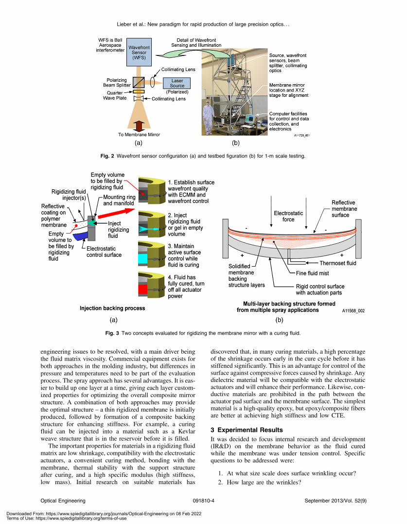
engineering issues to be resolved, with a main driver beingthe fluid matrix viscosity. Commercial equipment exists forboth approaches in the molding industry, but differences inpressure and temperatures need to be part of the evaluationprocess. The spray approach has several advantages. It is eas-ier to build up one layer at a time, giving each layer custom-ized properties for optimizing the overall composite mirrorstructure. A combination of both approaches may providethe optimal structure – a thin rigidized membrane is initiallyproduced, followed by formation of a composite backingstructure for enhancing stiffness. For example, a curingfluid can be injected into a material such as a Kevlarweave structure that is in the reservoir before it is filled.
The important properties for materials in a rigidizing fluidmatrix are low shrinkage, compatibility with the electrostaticactuators, a convenient curing method, bonding with themembrane, thermal stability with the support structureafter curing, and a high specific modulus (high stiffness,low mass). Initial research on suitable materials has
discovered that, in many curing materials, a high percentageof the shrinkage occurs early in the cure cycle before it hasstiffened significantly. This is an advantage for control of thesurface against compressive forces caused by shrinkage. Anydielectric material will be compatible with the electrostaticactuators and will enhance their performance. Likewise, con-ductive materials are prohibited in the path between theactuator pad surface and the membrane surface. The simplestmaterial is a high-quality epoxy, but epoxy/composite fibersare better at achieving high stiffness and low CTE.
3 Experimental ResultsIt was decided to focus internal research and development(IR&D) on the membrane behavior as the fluid curedwhile the membrane was under tension control. Specificquestions to be addressed were:
1. At what size scale does surface wrinkling occur?2. How large are the wrinkles?
Fig. 3 Two concepts evaluated for rigidizing the membrane mirror with a curing fluid.
Fig. 2 Wavefront sensor configuration (a) and testbed figuration (b) for 1-m scale testing.
Optical Engineering 091810-4 September 2013/Vol. 52(9)
Lieber et al.: New paradigm for rapid production of large precision optics. . .
Downloaded From: https://www.spiedigitallibrary.org/journals/Optical-Engineering on 08 Feb 2022Terms of Use: https://www.spiedigitallibrary.org/terms-of-use

3. How should the fluid be introduced?4. What’s the best way to mount the membrane to
the rim?5. What surface roughness is achievable?6. How does the surface change with time as the mem-
brane is pulled down?7. How does one incorporate all the physics into a model
and then validate it with testing?
Not all goals could be accomplished with the fundingavailable, so some questions were only partially answered.One decision made early was to use the Upilex-S polyimidemade by UBE Industries, rather than the polyimide mem-branes from Nexolve, since the cost differential was morethan an order of magnitude. For applications involving apath to space, the cost of Nexolve polyimide membrane isa small factor, and this would be considered the prime can-didate material. The most important result from testingwas verifying that the curing fluid/membrane interface didnot produce micro-wrinkles that cannot be removed. Theglobal figure and mid-frequency errors are controlled bythe electrostatic actuator density and the pad design. Thecomplex interactions between the fluid matrix and the mem-brane mechanics were considered the most difficult aspect toverify through modeling alone, and this was considered theNo. 1 output of the testing. Therefore, two types of surfacemetrology were incorporated into the testing: coarse three-dimensional surface tracking while the membrane wasbeing pulled down and the fluid was curing, and small-scale high-fidelity surface measurement after completion.The system modeling, discussed in Sec. 4, was regrettablydeferred to a future effort.
The test setup involved mounting an Upilex-S polyimidemembrane 180 mm in diameter and 51 μm thick on a rigidaluminum frame and evacuating the backside. Upilex has alinear thermal coefficient of expansion of 16 ppm∕K,slightly less than the mounting frame. The vacuum emulatedthe actuation process, although no usable optical figure isobtained, due to residual higher-order surface error terms(dominated by spherical aberration). Unlike electrostaticactuation, vacuum actuation does not allow global figurecontrol. However, it permitted fine-scale measurements con-firming that the fluid matrix curing was compatible with apolyimide membrane as an optical element, demonstratedexcellent cohesion, and provided a methodology for mem-brane mounting and adjustable pretensioning. The mem-brane mounting process and mount geometry establish theboundary conditions and are key to minimizing unevenstresses in the membrane and maintaining the vacuum andfluid seals. To minimize uneven strain into the membraneand vary the membrane tension, we borrowed a conceptdeveloped at the air force research laboratory15 that involvesstretching the membrane over a raised ring inside the mainmounting ring. This allows radial self-equilibration of thestrains, since the membrane is free to slide. Variable tensionwas applied to the membrane using a small ring channel thatcould be evacuated in a controlled manner.
We evaluated a range of fluid matrix materials before set-tling on two candidates for further testing. To set a baseline,the initial testing was conducted with Epotek 301 epoxy.Although the tensile strength and thermoelastic propertiesare nonideal compared to the desirable properties previously
listed, they would be used to set a baseline and help definethe research on candidate fluid matrix materials. The othermaterial we investigated further was an epoxy/silicon carbidewhisker matrix. Test strips of the epoxy and the epoxy/silicon carbide whisker matrix, as shown in Fig. 4, weretested for adhesion to the polyimide before any mirror testingwas conducted. To enhance adhesion, the Upilex membranewas purchased with an optional surface treatment.
Because the modeling portion of the R&D was deferred,we needed some measure of test parameters for a startingpoint and future validation. One advantage of using vacuumactuation is that there are solutions to the membrane equationfor deflection versus a uniform differential pressure. Westart with the von Karman equation7,16 for a thin circularplate,
1
rd
dr
�rTr
dwdr
�þ pðrÞ ¼ 0 (2)
Eh2
�dwdr
�2
þ rd
dr1
rd
drðr2TrÞ ¼ 0; (3)
where r is the radial coordinate of the membrane, h is themembrane thickness, w is the deformation of the membranesurface, Tr is the membrane tension, E is Young’s modulus,and P is the differential pressure. The Hencky seriessolution,
WðrÞ¼h3
ffiffiffiffiffiffiffiffiffiffiffiffiffiffiffiffiffiffiffiffiffiffiffiffiffiffiffiffiffiffiffiffiffiffiffiffiffiffiffiffiffiffiffiffiffiffiffiffiffiffiffiffiffiffiffiffiffiffiffiffiffiffiffiffiffiffiffiffiffiffiffiffiffiffiffiffiffiffiffiffiffiffiffiffiffiffiffica4pð1−υ2Þ
Eh2∕2ð1−υ2Þ
�gðaÞ− r2
a2g
�cr2
a2
��s;
(4)
where a is the radius of the mirror, υ is Poisson’s ratio, c is aconstant given by
c ¼ 2ð1 − υÞ3 − υ
−X∞n¼2
ðbncnÞ; (5)
and g is defined by
Fig. 4 Epoxy/silicon carbide (a) and epoxy only (b) deposited on pol-yimide for adhesion testing.
Optical Engineering 091810-5 September 2013/Vol. 52(9)
Lieber et al.: New paradigm for rapid production of large precision optics. . .
Downloaded From: https://www.spiedigitallibrary.org/journals/Optical-Engineering on 08 Feb 2022Terms of Use: https://www.spiedigitallibrary.org/terms-of-use
gðxÞ ¼ 1þ 1
4xþ 5
36x2 þ 55
576x3 þ 7
96x4 þ 305
3456x5
þ 51153
1016064x6 þ : : : ; (6)
applies to a stress-free mounting configuration. The gener-alization to a prestressed membrane requires the modifiedHencky–Campbell formulation laid out by Marker.7
These equations can then be used as a starting point forexpected deflection, as long as the initial tension is not large.
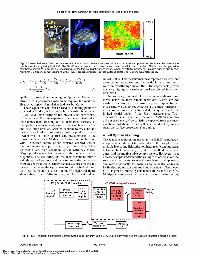
For FMMT manufacturing, the interest is in figure controlof the surface. For this experiment, we were interested inthree-dimensional tracking of the membrane surface, sowe applied a regular pattern on to the membrane surfaceand used three uniquely oriented cameras to track the dotpattern. It took 24 h from start to finish to produce a stabi-lized mirror for follow-up fine-scale measurements of themirror surface. PhotoModeler software, in combinationwith 3D motion control of the cameras, enabled surfacemotion tracking to approximately 1 μm. We followed thisup with a very high-resolution optical metrology system(Zygo profilometer) that measured subnanometer surfaceroughness. The test setup, the mounted membrane mirrorwith the applied patterns, and the resulting surface measure-ment are shown in Fig. 5. Ultraviolet ink was used for the dotpatterns to increase the signal-to-noise ratio, which allowedus to get the micron-level resolution. The righthand figureshows that, over a 0.8-mm span, we have achieved an
rms of ∼20 Å. This measurement was repeated over differentareas of the membrane, and the quadratic curvature termswere removed through curve fitting. The experiments provedthat very high-quality surfaces can be produced in a shorttimeframe.
Unfortunately, the results from the larger-scale measure-ments using the three-camera metrology system are notavailable for this paper, because they will require furtherprocessing. We did not see evidence of thickness variations15
in the surface measurements, and this may be due to thelimited spatial scale of the Zygo measurement. Two-dimensional maps over an area of 0.72 × 0.54 mm alsodid not show the surface deviations expected from thicknessvariations. Additional testing will be required to fully under-stand the surface properties after curing.
4 Full System ModelingThe equations representing the complete FMMTmanufactur-ing process are difficult to model, due to the complexity ofmultiple interacting fields, the nonlinear membrane structuralbehavior, the time-varying properties of the fluid matrix as itcures, and the multivariable control system. However, it is anecessary step to understand the scaling relationships from thesubscale experiments, to size the mechanical components,and, most importantly, to generate a digital controller designfor field programmable gate array implementation. Themodelis still in process, but the systemmodel utilizes the COMSOLMultiphysics software environment to capture the interacting
Fig. 5 Research done at Ball has demonstrated the ability to create a concave surface on a tensioned polyimide membrane then freeze themembrane with a rigidizing fluid. Left: The FMMT internal research and development membrane/fluid matrix testbed. Middle: mounted polyimidemembrane under UV illumination for measuring surface targets. Right: surface measurement over 0.8 mm showing 2-nm rms surface quality aftermembrane is frozen, demonstrating that the FMMT process produces optical surfaces suitable for astronomical telescopes.
Fig. 6 FMMT coupled multivariable control system block diagram using COMSOL multiphysics and the EOSyM integrated modeling tools.
Optical Engineering 091810-6 September 2013/Vol. 52(9)
Lieber et al.: New paradigm for rapid production of large precision optics. . .
Downloaded From: https://www.spiedigitallibrary.org/journals/Optical-Engineering on 08 Feb 2022Terms of Use: https://www.spiedigitallibrary.org/terms-of-use

fields and nonlinear membrane structural behavior. We theninterface our integratedmodeling toolset, the end-to-end opti-cal system modeling (EOSyM) tools, to capture the controlsystem and optical wavefront properties. EOSyM is usedextensively in support of the James Webb Space Telescope(JWST) program (called ITM for that program). EOSyM isbuilt from the Matlab/Simulink toolset and readily interfaceswith COMSOL. A representation of the coupled model isshown in the diagram of Fig. 6. For fluid modeling, wecan borrow from the substantial work done in support ofresin transfer molding.17 Our intent is to publish a follow-on paper that discusses the modeling results.
5 Future DirectionsThis technology has applications for ground telescopes andspace-based platforms. Further testing and development isnecessary to ensure the long-term stability and to desensitizethe mirror to changes in the thermal environment. There areseveral avenues for addressing these issues, including furtherwork with fluid matrices that have low CTE and high specificstrength properties. The specific strength is less of a concern,since additional stiffness can be designed into a backingstructure. However, with all large optics, print-through ofthe supporting structure will need to be addressed. An addi-tional consideration with most composites is water absorp-tion and the associated dimensional changes that occur.Progress has been made in this area with the use of barrierfilms. For space applications, additional requirements occur,due to the launch environment, uneven thermal loading,18
and the effect of high-energy particles on the mirror.Deployment in space is very difficult and costly, as evi-denced by the price tag associated with the JWST.Deployment of a membrane is feasible, as was demonstratedby the NASA-sponsored Inflatable Antenna Experiment pro-gram.19 However, attaining a precision figure in space afterdeployment is difficult without active control. With FMMT,the active components would need to be included to rigidizethe mirror after deployment. The FMMT concept offers thepotential for in-space fabrication in the future, perhaps as afacility on the space station. Once the technology has beenproven and the membrane/fluid interaction and evolutionduring rigidization is understood, a mirror system couldbe launched that will be unfurled, surface controlled, and fro-zen in space, potentially changing the paradigm and limitsfor primary mirror size and therefore expanding the goalsof the scientific community.
Finally, we have not discussed microwave, infrared, orx-ray opportunities, but the unique manufacturing processoffers distinct advantages for manufacturing in each spectralregion.
6 ConclusionIn this paper, we have presented a new methodology, FMMT,to mass-produce large precision optics. Initial testing indi-cates that surface roughness levels of ∼20 Å can beachieved. The global figure is obtained through the use ofelectrostatic actuation with feedback from a wavefront sen-sor. We have calculated that, for a 4-m membrane mirrorusing a biased voltage or differential vacuum actuation,only 50 actuation pads are required under ideal geometryconditions to form a parabola. Actual numbers will requirea complete multiphysics model to investigate many
interacting effects. Finally, we have discussed briefly awide range of applications and the key developmentsrequired for both ground and space operation.
AcknowledgmentsThe authors would like to thank Ball Aerospace for fundingthe initial research work on the FMMT concept. In addition,the first author would like to thank R&D coworkers RobertPierce, Beth Kelsic, Paul Kaptchen, Jim Eraker, and SteveKendrick for their many hours supporting the first successfuldemonstration of this technology. I would like to thank theanonymous reviewer for his many helpful comments andexcellent questions that lead to further explanation inthe text.
References
1. D. Baiocchi and P. Stahl, “Enabling future space telescopes: mirror tech-nology review and development roadmap,” National Academies Report(2010).
2. T. Blake, “MOIRE Membrane Optic Image Real-Time Exploitation,”presented at SeeMe Industry Day (27 March 2011).
3. M. Lieber, “Frozen Surface Technology,” Patent 13/052,894 (2011).4. W. R. Oegerle et al., “Concept for a large scalable space telescope: in-
space assembly,” Proc. SPIE 6265, 62652C (2006).5. J. T. Mooney et al., “Novel in-space manufacturing concepts for the
development of large space telescopes,” Proc. SPIE 6265, 62652W(2006).
6. C. H. M. Jenkins, Ed., Gossamer Spacecraft: Membrane and InflatableStructures Technology for Space Applications, Vol. 191, AIAA,Virginia (2001).
7. D. K. Marker, “Fundamentals of membrane optics,” in GossamerSpacecraft: Membrane and Inflatable Structures Technology forSpace Applications, pp. 111–201, AIAA, Virginia (2001).
8. G. Poe and B. Patrick, “Zero CTE polyimides for athermal optical mem-branes,” Proc. SPIE 7061, 706114 (2008).
9. J. D. Moore et al., “Design and Testing of a One-meter MembraneMirror with Active Boundary Control,” AFRL-DE-PS-TP-2006-1006(2005).
10. J. D. Moore et al., “Design, Fabrication, and Validation of an Ultra-lightweight Membrane Mirror,” AFRL-DE-PS-TP-2006-1007 (2005).
11. J. H. Lang, “Computer control of stochastic distributed systems withapplications to very large electrostatically figured satellite antennas,”Ph.D. Thesis, MIT (1980).
12. J. H. Lang and D. H. Staelin, “Electrostatically figured reflecting mem-brane antennas for satellites,” IEEE Trans. AC 27(3), 666–670 (1982).
13. J. M. Renno, “Dynamic and Control of Membrane Mirrors for AdaptiveOptics Application,” Ph.D. Thesis, Virginia Polytechnic Institute &State University (2008).
14. X. Chen, M. Tang, and W. Shen, “Membrane mirror deformed byelectrostatic pressure,” Proc. SPIE 6721, 67210K (2007).
15. J. R. Rotke, “Large optically flat membrane mirrors,” Proc. SPIE 3760,207–212 (1999).
16. G. Zhang et al., “Analysis and simulation of the surface shape of mem-brane mirror applied by non-uniform load, large mirrors and tele-scopes,” Proc. SPIE 7654, 76541A (2010).
17. N. D. Ngo and K. K. Tamma, “Computational developments for sim-ulation based design: multi-scale physics and flow/ thermal/ stress mod-eling, analysis, and validation for advanced manufacturing ofcomposites with complex microstructures,” Arch. Comput. Meth.Eng. 10(1–2), 3–206 (2003).
18. C. H. Jenkins and S. M. Faisal, “Thermal load effects on precision mem-branes,” J. Spacecraft Rockets 38(2), 207–211 (2001).
19. R. E. Freeland et al., Inflatable Deployable Space StructuresTechnology Summary, presented at 49th Int. Astronautical Congress,Jet Propulsion Laboratory, Melbourne, Australia (1998).
Mike Lieber is a principal system engineer atBall Aerospace and the inventor of the FMMTapproach presented in this paper. His mainareas of expertise are in control systemsand integrated modeling of complex opticalsystems. He is also taking a lead role indeveloping mission system modeling toolsto support a broad range of programs. Hedeveloped the original integrated modelingtools used on JWST’s wavefront control sys-tem and has applied these system tools to
Optical Engineering 091810-7 September 2013/Vol. 52(9)
Lieber et al.: New paradigm for rapid production of large precision optics. . .
Downloaded From: https://www.spiedigitallibrary.org/journals/Optical-Engineering on 08 Feb 2022Terms of Use: https://www.spiedigitallibrary.org/terms-of-use
interferometers, large ground and space telescopes, spectrometersand lidar systems. He was the program manager for the IRADwhich did the developmental work on the FMMT.
Stephen Kendrick is a senior project engi-neer at Ball Aerospace and is theirTechnology Area Lead for SpaceTelescopes. He has been working withspaceborne optics for 40 years includingstar trackers and sensors, Hubble SpaceTelescope, Spitzer Space Telescope,James Webb Space Telescope, TerrestrialPlanet Finder, JDEM, and several lightweightdemonstration mirrors. In addition, he hasbeen program manager for a number of
deformable mirrors and IR low observable technology programs.
Sarah Lipscy is currently the chief scientistfor the Ozone Mapping Profiler Suite (OMPS)at Ball Aerospace & Technologies Corp. Inthis role, she manages the performancerequirements, including calibration, of theJPSS-1 instruments currently in test,responds to inquiries regarding the on-orbitperformance of the NPP-OMPS, and inter-acts with the science community users ofthe OMPS data. As a systems engineer atBall Aerospace, she has worked on the
OMPS program for a total of 7 years and also on the ground
calibration of the Operational Land Imager (OLI) for the LandsatData Continuity Mission (LDCM). She received her PhD in astrophys-ics and astronomy at the University of California at Los Angeles(UCLA) where she studied the physics involved in the evolution ofmassive stars using observations from various ground basedobservatories including the Keck observatory and the Very LargeArray radio observatory. Prior to beginning her PhD thesis work,she was involved in helioseismology projects using satellite data atUCLA and space weather projects using both ground and satelliteobservations at the University of Colorado—Boulder for herMaster’s and undergraduate theses’, respectively.
Dennis Ebbets has 32 years of experiencein space astronomy, including 28 years atBall Aerospace. He has served as a calibra-tion scientist, systems engineer and memberof the Investigation Definition Teams for threescience instruments for NASA’s HubbleSpace Telescope, and was Ball’s project sci-entist during the development of the NGST/JWST mission concept. Dennis has beenthe Business Development Manager forastrophysics since 2005. An important part
of his work is identifying and advocating for new technologies thatmay add value to future missions and instruments. He is a frequentspeaker at public events, with HST, JWST, and Kepler being amongthe most popular topics.
Biographies and photographs of the other authors are not available.
Optical Engineering 091810-8 September 2013/Vol. 52(9)
Lieber et al.: New paradigm for rapid production of large precision optics. . .
Downloaded From: https://www.spiedigitallibrary.org/journals/Optical-Engineering on 08 Feb 2022Terms of Use: https://www.spiedigitallibrary.org/terms-of-use