Embed Size (px)
Citation preview
Med. & biol. Engng. Vol. 10, pp. 43-55. Pergamon Press, 1972. Printed in Great Britain
N E W P H O N O C A R D I O G R A P H I C T R A N S D U C E R S
U T I L I Z I N G T H E H O T - W I R E A N E M O M E T E R P R I N C I P L E *
D. E. LAUGHLIN and R. P. MAHONEYt
Cardiovascular Laboratory, Department of Internal Medicine, College of Medicine, University of Iowa, Iowa City, Iowa 52240, U.S.A.
Abstract--Hot thermistors and hot wires have been adapted to detect vascular and precordial pulses and heart sounds, respectively. The activity from the skin is amplified hydraulically by sealing a plastic cup over the area of interest and mounting the sensing elements in the centre of a small exit port plugged into a hole in the cup. Two thermistors can be mounted physically and electrically in such a way as to produce biphasie unbalancing of a Wheatstone bridge for sub-audio pulses. Fine heated wires sense higher frequency sound waves.
Records of external carotid, jugular venous and apex pulses and heart sounds are presented and comparisons are made with two standard transducers as evidence of the usefulness of the devices. A compact, low impedance transducer, rugged enough to withstand dropping from ceiling to floor, with a superior signal-to-noise ratio and insensitive to ambient sounds is evident.
INTRODUCTION
GREAT emphasis has been placed on the develop- ment of non-invasive techniques for cardiac diagnosis and study of cardiac function. When heart sounds and pulses are detected and recorded accurately their analysis can produce generous amounts of information (BENCHIMOL and DIAMOND, 1963, 1966; DIAMOND, 1964; EDMONDS, 1966; LUISADA and MAGRI, 1952; TAFUR e t a L , 1964a, b). Present methods and equipment while providing adequate information are often cumbersome, time consuming and may require nearly soundproof rooms for good results. A microphone system was devised utilizing a pair of heated thermistors and shows promise of overcoming some of these deficiencies. After development of the low frequency trans- ducer the method was extended to the hot-wire system for higher frequencies.
The hot-wire anemometer was first discussed in detail by KING (1914). HUBBARD (1957) used constant temperature hot-wire bridges for air velocity fluctuations up to 10 kHz. Our wires are operating in a mode that is neither constant
temperature, constant voltage nor constant cur- rent. Our bridges are energized with a constant voltage, but with respect to the actual wire con- ditions all three of these parameters vary. The results to date have been encouraging, al though a higher frequency response can be achieved with other bridge drive systems.
The problem of determining the frequency response of the microphones was considered. O~T~ICI-mR (1951) suggests that over the audio range most of the vibratory energy is propagated in body tissue in the form of transverse shear waves and not in the form of longitudinal com- pressional waves. Sound energy f rom an ear- phone comes via longitudinal waves, thus, if Oestreicher's theory is correct an earphone would not form an adequate basis for calibrating a microphone. BERSON and PIPBERGER (1966) measured chest wall movements in three separate planes and in some cases found larger transverse components than normal components. Accord- ing to VON GmRKE (1959) the mechanical impedance of the skin is important to the sound transmission, and we felt we could not accurately
* Received I July 1971. t Dr. Mahoney was the recipient of a cardiovascular training grant (5T-12HE-05729). Present address: Cardiology
Associates, St. Joseph's Professional Building, 2000 Crawford Street, Houston, Texas 77002, U.S.A. 43
44 D.E. LAUGHLIN and R. P. MAHONEY
simulate this with an earphone, nor simulate the acoustic coupling between the skin and trans- ducer. In spite of these difficulties it was deemed important to attempt frequency response com- parisons between several microphones. For the subaudio transducers a pulse technique was used and for the sound transducers a calibrated ear- phone was driven from an audio oscillator. LITTAUER (1965) gives simple equations relating the step input response of a system to its frequency response.
ABBOTt (1969) presented a detailed study of the fidelity of externally recorded pulses and it is not our intent to duplicate his work. We will present evidence that heated elements can be superior transducers for whatever information in the form of skin displacement comes to the sur- face of the body. Our method for verifying the quality of the instrument desc~'ibed in this report is to compare clinical data with data obtained using other equipment available in our hospital.
THEORY
There are two aspects of the theory which must be described. One is the electrical method of driving the sensing element and obtaining information from it. The second is the hydraulic amplification that takes place in this application which produces the high signal-to-noise ratio. The latter feature is particularly fortunate because it allows sensitivity to the sounds from the body while producing insensititivity to ambient sounds.
A pair of fine heated wires is used to detect heart sounds and a pair of heated thermistors to detect pulses. Both heart sounds and pulses are transmitted through the skin at various points on the body. Pulses are considered to be slow waves from 0.2 Hz to perhaps 15 Hz while sounds range from 50 to 1000 Hz. The ther- mistors have enough thermal inertia not to respond to sounds, but enough thermal activity to respond to cardiac pulses. In order to detect pulses with high fidelity both inward and out- ward movements of the skin must be detected. Two thermistors placed physically in a longitu-
dinal position in a stream of air and electrically in two arms of a Wheatstone bridge will produce a biphasic unbalancing of the bridge as the direction of air flow reverses. The thermistor proximal to the flow will cool more than the distal one so that an unbalance of a certain polarity will be produced; as the flow reverses the proximal, or coolest, thermistor takes the opposite position in the bridge hence an un- balance of opposite polarity appears, accom- plishing the detection of inward and outward movements of the skin. Two wires, both of which cool in moving air are sufficient for sounds since they are superimposed on the side of the large pulse wave, and thus modulate a mean velocity of air. The wires form two arms of a Wheatstone bridge and unbalance is produced as heat is driven away from them decreasing their resis- tance.
The characteristic of a fine wire and a ther- mistor which allows them to sense acoustic energy is their change in resistance as a function of temperature. Metal wire has a small positive temperature coefficient of resistance in the range of + 0 . 4 5 per cent per ~ Thermistors, on the other hand have a large negative temperature coefficient of resistance in the range of - -4 per cent per ~ For this instrument these elements are self-heated by an electric current flowing through them. This same current is used to detect changes in resistance of the wire or thermistors. The cold resistance, Ro, of each wire was approximately 30 f2 depending on its length. Using the equation
R = Ro (1 4- aAT)
where: R = 52 f~ = resistance of wire at operat- ing temperature
Ro = 30 f2
a ---- 0" 0045 ~ 1
the temperature of the wire above ambient (AT) was calculated to be close to 163~ Measure- ments on the thermistors at room temperature and at operating temperature showed a change
NEW PHONOCARDIOGRAPHIC TRANSDUCERS 45
in resistance due to heating of 172 f~. Using the equation
R = Roc~AT
where: a = --0.034 ~ and Ro = cold resis- tance of the thermistor = 2K the temperature of the thermistors was calculated to be 2"5~ above ambient. Ro was determined by energizing the bridge with the minimum voltage (17 mV) necessary to obtain a balance of the bridge by adjusting two arms. Then from the usual Wheatstone bridge resistance relationships the cold resistance of the wire was calculated. R was determined in the same way except that the bridge was energized with the normal operating voltage of 1.5 V.
Measurable surface vibrations are known to represent events in the heart, and are capable of being amplified hydraulically. This is accom- plished as described under "construction" and can be demonstrated by introducing a hole in the cup so that the trapped air is not forced in and out over the sensors. In this case no signal can be produced. Hydraulic amplification is usually thought of as a multiplication of force with a concomitant reduction of displacement. Our application defines hydraulic amplification simply as a multiplication of velocity, and comes about through the law of hydraulic continuity. This law states that under adiabatic and isobaric conditions the fluid input to an isometric system must equal the output. In our case the volume of air displaced by the movement of the skin was forced through the small bore tubing containing the sensor. The velocity over the sensor must be faster than that of the skin by the square of the ratio of the diameter of the skin moving to the diameter of the sensor tubing. If it is assumed that the skin is bulging with a simple harmonic motion according to the equation
h = H cos oJt (1)
then the velocity of air past the sensors is given by
v = ~rfAn ( - - H sin o~t) (2)
where: H ----- maximum skin displacement h ----- instantaneous skin displacement v = instantaneous velocity past sensor
f = frequency of pulse or sound wave An ~- hydraulic amplification
t = time.
Equation (2) shows the velocity to vary sinusoidaly, but 90 ~ out of phase with the skin, and to increase as the frequency increases. But the most significant term is the hydraulic ampli- fication factor, An, without which the transducer is insensitive. See the appendix for the derivation and further explanation of equation (2).
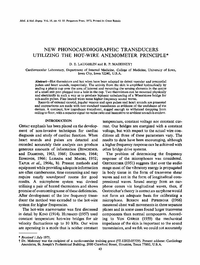
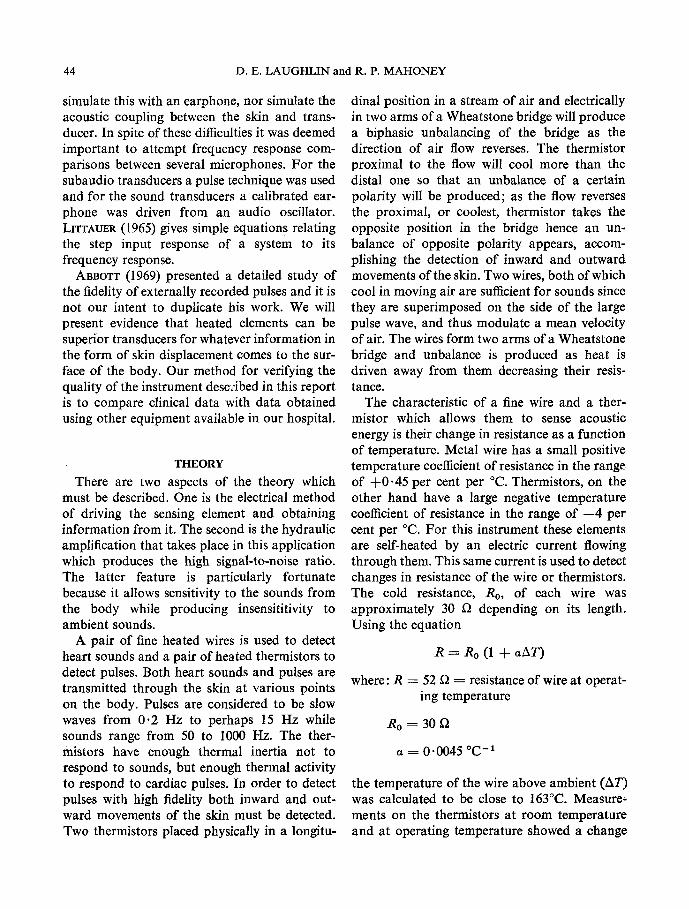
Two separate Wheatstone bridges were used for the two different sensing devices. Figure 1B shows the pulse bridge with the hot thermistors in the two lower arms. At zero velocity the voltage at point X, Vx, equals the voltage at point I1, Vy, and both are positive. Under con- ditions produced by velocity A, V~ rises more than Vy because Thl cools more than Th2 and its resistance, therefore, increases more than that of Th2. Velocity B, on the other hand, causes Vy to become more positive than Vx because Th2 cools more than Thl. The bridge output voltage, eo, is Vx -- Vy with any steady difference elimi- nated by capacitor coupling to a differential amplifier.
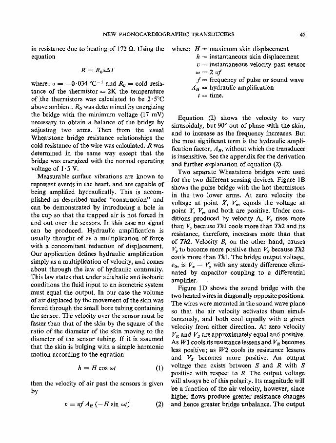
Figure 1D shows the sound bridge with the two heated wires in diagonally opposite positions. The wires were mounted in the sound wave plane so that the air velocity activates them simul- taneously, and both cool equally with a given velocity from either direction. At zero velocity Va and Vs are approximately equal and positive. As W1 cools its resistance lessens and VR becomes less positive; as W2 cools its resistance lessens and Vs becomes more positive. An output voltage then exists between S and R with S positive with respect to R. The output voltage will always be of this polarity. Its magnitude will be a function of the air velocity, however, since higher flows produce greater resistance changes and hence greater bridge unbalance. The output
46 D.E. LAUGHLIN and R. P. MAHONEY
coupling is identical to that of the pulse bridge to produce the same effect.
Figures 1, B and D, are complete electrical schematics of transducer circuits. The whole power source was a 1- 5 V battery for each trans- ducer and the output voltage, co, should drive any recorder with a differential input and a sensi- tivity of 1 mV/cm of pen deflection. There is no electrical shock hazard to the patient for two reasons. Firstly, the box containing the bridges and batteries to drive them is earthed through the recorder earth and need not be within reach of the patient. Secondly, there are no metal parts in contact with the patient; all driving and signal voltages are carried in shielded, jacketed cables, and the transducers themselves are completely encased in nylon or epoxy resin. A study of Figs. 1 and 2 reveals these details.
CONSTRUCTION
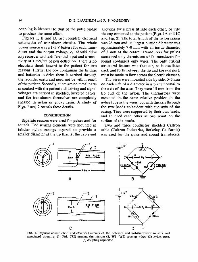
Separate sensors were used for pulses and for sounds. The sensing elements were mounted in tubular nylon casings tapered to provide a smaller diameter at the tip than at the cable end
allowing for a press fit into each other, or into the cup cemented to the patient (Figs. 1A and 1C and Fig. 2). The total length of the nylon casing was 28 mm and its largest outside diameter was approximately 7.0 mm with an inside diameter of 2 mm at the centre. Transducers for pulses contained only thermistors while transducers for sound contained only wires. The only critical structural feature was that air, as it oscillates back and forth between the tip and the exit port, must be made to flow across the electric dement.
The wires were mounted side by side, 0-5 mm on each side of a diameter in a plane normal to the axis of the ease. They were 15 mm from the tip end of the nylon. The thermistors were mounted in the same relative position in the nylon tube as the wires, but with the axis through the two beads coincident with the axis of the casing. They were supported by their own leads, and touched each other at one point on the surface of the beads.
Two and three conductor shielded Caltron cable (Caltron Industries, Berkeley, California) was used for the pulse and sound transducers
] - .,R 2mm
t
A
1"5V~
8 ~
L
L
C
1'5V~
D "-~ FiG. 1. Physical construction and electrical circuits of the hot-wire and hot-thermistor sensors and associated circuitry. (1, Thl, Th2) sensing thermistors (2, Wl, W2) sensing wires, (3) nylon case,
(c) coupling capacitor.
NEW PHONOCARDIOGRAPHIC TRANSDUCERS 47
respectively. One end of each thermistor was connected to the shield and the two remaining leads were connected to separate conductors. Both ends of each wire were attached to a separate lead in the sound microphone; one end being connected to the shield and the other three to conductors. In one form of the transducer the cable was attached to the side of the nylon case, thus the exit port remained open to receive the tip of another transducer. With the sensors thus plugged in, tandem heart sounds and pulses were obtained at the same site from the same cup (Fig. 2). In another form the cable was attached to the end of the nylon case with exit ports being provided just ahead of the end of the cable. This transducer could only be plugged into another one. Epoxy resin held the cables in place. The Caltron product is a soft flexible cable with a silicone rubber jacket covering the shield. This is not a rugged cable and must be handled with reasonable care. It was chosen, however, for its flexibility and light weight in an effort to reduce distortion on the skin at the sounding site. A complete transducer including the cup and 6 in. (15 cm) of cable weighs about 3 g.
The thermistors used were glass coated beads 0.33 mm in diameter with platinum-iridium leads 0.0254 mm in diameter. They had a time constant of 1 s; a dissipation constant of 0.1 mW/~ and a resistance of 2 kt2 at 25~ The wire used was tungsten with a gold flash coat; the total diameter was 0.0033 ram. Its temperature coefficient of resistance (a) was 0.0045 ~ -1 and its resistance was 8576 ~ /m at 27~
Another important feature of the construction was the small thin-walled plastic cup 35 mm in diameter and 5 mm deep, cemented to the skin wherever sounds or pulses were to be recorded. A hole in the side allowed the nylon sensor unit to be press fitted into it. Skin Bond Cement (United Surgical, Largo, Florida) secured the cup to the skin with no air leaks, so that air set in motion by the vibrating skin was forced over the sensor elements. Weight was added by cementing lead discs to the cup. Carotid pulse measurements were made with a plastic cup of
15 mm i.d. with a hole in the side to receive the sensor unit.
MATERIALS AND METHODS
For frequency response information on the sub-audio transducers a step input was generated in different ways for different microphones. The commercial instruments were all contact micro- phones so that it was possible to displace the contact by gently forcing a light-weight link, formed by a piece of Teflon tubing about the size of a common pin, between it and some rigid support. The link was then suddenly snapped away and the contact returned to its centre position in what was assumed to be a step (zero time) function. For the thermistor transducer a rubber diaphragm of dental dam was stretched tightly over a plastic cup in place of the skin. This was displaced slightly with the Teflon link. In snapping it away the diaphragm returned to its neutral position against a metal screen and thus sucked in one short pulse of air through the pulse transducer. This was assumed to be a step function of displacement. The curves thus obtained were smooth and reasonable. Rise times and tilt times were measured and the data of Table 1 tabulated.
For sounds from 50 to 600 Hz a standard dynamic earphone driven by an audio oscillator, and plastic coupler was first calibrated with a Bruel and Kjaer, Type 4132 microphone. A sound pressure level of 316 /zb was delivered to the standard microphone and did not vary over this frequency range by more than 4- 3 db. To test the heart sound microphones the standard microphone and plastic coupler were replaced with a stretched rubber diaphragm over a brass coupler to form a vibrating surface with which to contact the commercial microphones. The cup for the hot-wire microphone was cemented over the rubber diaphragm, and an optimum hydraulic bias consisting of 500 cm 3 of air per minute was caused to flow over the wires to simulate the pulsing of the skin. The rubber diaphragm and brass coupler possibly affected the sound pressure level reaching the instruments under test so that the most valid
48 D.E. LAUGHLIN and R. P. MAHONEY
conclusion is that the microphones can be com- pared, but that the curves given do not necessarily represent them accurately.
Pulse and sound records were taken on ten healthy, young men and women with the various transducers available to us. Six patients with heart disease documented by cardiac catheteriza- tion were studied. Recordings were made with all subjects conscious, in a supine posture, with- out medication except for routine pre-catheter- ization drugs. Representative samples f rom these groups are shown. In the latter group, external pulse recording preceded cardiac catheterization by not more than 24 h.
The sounding site was located on each subject by auscultation, and marked with a pen; the appropriate site for pulses was marked after palpation or visual observation. Recordings were taken at these marked points with the various pieces of equipment. Comparative recordings of the jugular venous pulse QVP) were obtained using HARTMAN'S (1960) technique with a modi- fication for the application of our pick-up. This utilized the maximal area of venous pulsations medial to the sterno cleido-mastoid muscle in the anterior triangle of the neck. The head position was varied to produce this maximal deflection. Carotid pulses were recorded using manual application for all the pick-up devices. Apex cardiograms (ACG) were obtained accord- ing to the technique of BENCHIMOL and DIAMOblD
(1963). A simultaneous reference standard E C G lead I or I I was obtained. All observations were made during breath holding.
All sound records were made on an Electronics for Medicine D R 12 recorder. The Electronics for Medicine (E for M) sensor was a Statham P23Db pressure transducer for the carotid pulses and jugular venous pulse and a crystal contact microphone for apex cardiograms and sounds.
RESULTS
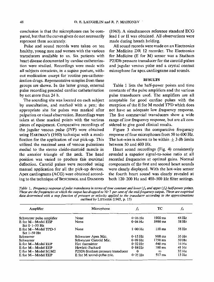
Table 1 lists the half-power points and time constants of the pulse amplifiers and the Various pulse transducers used. The amplifiers are all acceptable for good cardiac pulses with the exception of the E for M model T P D which does not have an adequate low frequency response. The five commercial transducers show a wide range of low frequency response, but are all con- sidered to give good clinical results.
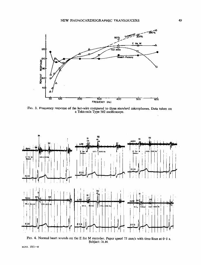
Figure 3 shows the comparative frequency response of four microphones f rom 50 to 600 Hz. The hot-wire is shown to be within • 3 db limits between 50 and 600 Hz.
Hear t sound recordings (Fig. 4) consistently revealed a superior signal-to-noise ratio at all recorded frequencies at optimal gains. Normal components of the first and second heart sounds were clearly displayed. With the hot-wire sensor the fourth heart sound was clearly revealed at both 120-200 Hz and 400-500 Hz filter settings.
Table 1. Frequency response o f pulse transducers in terms o f time constant and lower ( f l and upper ( f 2) half-power points. These are the freqUencies at which the output has dropped to 70" 7 per cent o f the mid-frequency oUtpUt. These are empirical data determined with a step function o f pressure or velocity applied to the transducer according to the approximations
outlined by LITrAUER (I965, p. 15)
Amplifier Microphone f, TC f2
Schwarzer pulse amplifier E for M--Model EEP
Set 0" 1-50 Hz E for M--Model TPD-5
Set 1-50 Hz Schwarzer Sehwarzer E for M--Model EEP E for M--Model EEP E for M--Model SGM2 E for M--Model EEP
None 0.06 Hz 1900 ms 64 Hz None 0-04 Hz 3900 ms 58 Hz
None 1 "00 Hz 110 ms 58 Hz
Schwarzer Apex Mic. 0" 15 Hz 900 ms 35 Hz Schwarzer Carotid Mie. 0" 09 Hz 1750 ms 50 Hz Hot thermistor 0" 32 Hz 440 ms 16 Hz Hewlett-Packard 0" 84 Hz 180 ms 41 Hz P23Db Statham pressure transducer 0 oo 32 Hz E for M sound-pulse mic. 0-25 Hz 517 ms 13 Hz
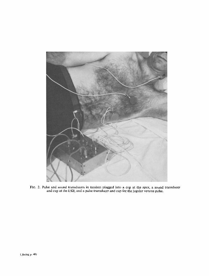
FIG. 2. Pulse and sound transducers in tandem plugged into a cup at the apex, a sound transducer and cup at the LSB, and a pulse transducer and cup for the jugular venous pulse.
( facing p. 48)
NEW PHONOCARDIOGRAPHIC TRANSDUCERS 49
E ~ M
120
f
~ec if
4c
�9 5 ~o zbo 36o ~o ~o FREOUEI~"Y (Hz)
FIG. 3. Frequency response of the hot-wire compared to three standard microphones. Data taken on a Tektronix Type 502 oscilloscope.
s,:l 2~! , $ 1 , , .
'~ . , i I , . " o o , : ! i i ,.,.,,,,,,, , ~ ' i c ! i ~ ~
, . . ,,IfrrJ',l i , , i ~ i
: L ~ . 4 1 '
FiG, 4. Normal heart sounds on the E for M recorder. Paper speed 75 mm/s with time lines at 0.1 s. Subject: H.H.
M . B . E . I O / 1 - - D
50 D.E. LAUGHLIN and R. P. MAHONEY
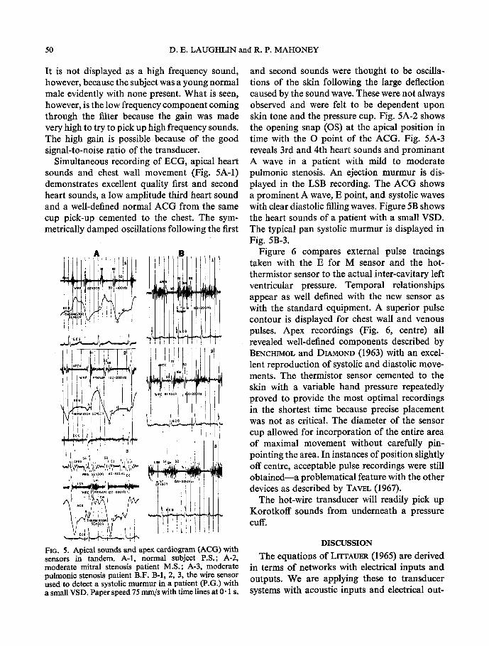
It is not displayed as a high frequency sound, however, because the subject was a young normal male evidently with none present. What is seen, however, is the low frequency component coming through the filter because the gain was made very high to try to pick up high frequency sounds. The high gain is possible because of the good signal-to-noise ratio of the transducer.
Simultaneous recording of ECG, apical heart sounds and chest wall movement (Fig. 5A-l) demonstrates excellent quality first and second heart sounds, a low amplitude third heart sound and a well-defined normal ACG from the same cup pick-up cemented to the chest. The sym- metrically damped oscillations following the first
i ' ' ' 3 L ~ + s, . .
I I ~ P e X L ' t t ' t S 3 i t
,~ raRE S~HSOR 4O-IO0,z E r
s M i
�9 . A I I .
FIG. 5. Apical sounds and apex cardiogram (ACG) with sensors in tandem. A-I, normal subject P.S.; A-2, moderate mitral stenosis patient M.S.; A-3, moderate pulmonic stenosis patient B.F. B-I, 2, 3, the wire sensor used to detect a systolic murmur in a patient (P.G.) with a small VSD. Paper speed 75 mm/s with time lines at 0.1 s.
and second sounds were thought to be oscilla- tions of the skin following the large deflection caused by the sound wave. These were not always observed and were felt to be dependent upon skin tone and the pressure cup. Fig. 5A-2 shows the opening snap (OS) at the apical position in time with the O point of the ACG. Fig. 5A-3 reveals 3rd and 4th heart sounds and prominant A wave in a patient with mild to moderate pulmonic stenosis. An ejection murmur is dis- played in the LSB recording. The A CG shows a prominent A wave, E point, and systolic waves with clear diastolic filling waves. Figure 5B shows the heart sounds of a patient with a small VSD. The typical pan systolic murmur is displayed in Fig. 5B-3.
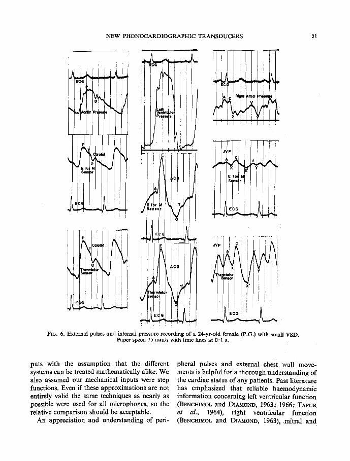
Figure 6 compares external pulse tracings taken with the E for M sensor and the hot- thermistor sensor to the actual inter-cavitary left ventricular pressure. Temporal relationships appear as well defined with the new sensor as with the standard equipment. A superior pulse contour is displayed for chest wall and venous pulses. Apex recordings (Fig. 6, centre) all revealed well-defined components described by BENCHIMOL and DIAMOND (1963) with an excel- lent reproduction of systolic and diastolic move- ments. The thermistor sensor cemented to the skin with a variable hand pressure repeatedly proved to provide the most optimal recordings in the shortest time because precise placement was not as critical. The diameter of the sensor cup allowed for incorporation of the entire area of maximal movement without carefully pin- pointing the area. In instances of position slightly off centre, acceptable pulse recordings were still obtained--a problematical feature with the other devices as described by TAWL (1967).
The hot-wire transducer will readily pick up Korotkoff sounds from underneath a pressure cuff.
DISCUSSION
The equations of LITTAUER (1965) are derived in terms of networks with electrical inputs and outputs. We are applying these to transducer systems with acoustic inputs and electrical out-
NEW PHONOCARDIOGRAPHIC TRANSDUCERS 51
Pr( i I I~
G I L . ~ , . . . , E ~ G I~r ! ~
/ �9 k,J q a,~ ] . . . . . . . . . . .
J I Cc
~q
I
i ! E,e!
6
J~P
t' bet
FIG. 6. External pulses and internal pressure recording of a 24-yr-old female (P.G.) with small VSD. Paper speed 75 mm/s with time lines at 0" 1 s.
puts with the assumption that the different systems can be treated mathematically alike. We also assumed our mechanical inputs were step functions. Even if these approximations are not entirely valid the same techniques as nearly as possible were used for all microphones, so the relative comparison should be acceptable.
An appreciation and understanding of peri-
pheral pulses and external chest wall move- ments is helpful for a thorough understanding of the cardiac status of any patients. Past literature has emphasized that reliable haemodynamie information concerning left ventricular function (BENCHIMOL and DIAMOND, 1963; !966; TAFUR
et aL, 1964), right ventricular function (BENCHIMOL and DIAMOND, 1963), mitral and
52 D.E. LAUGHLIN and R. P. MAHONEY
tricuspid valvular disease, and pericardial disease (BIOCOURT et aL, 1965) is available from care- fully made bedside recording s of the normal and abnormal pulses created by cardiac action. Detailed evaluations and studies by BENCHIMOL and DIAMOND, 1963; LUISADA and MAGRI, 1952; FOWLER, 1968 ; HARTMAN, 1960; DIAMOND, 1964; and TAVEL, 1967, have produced the charac- teristic patterns that help to differentiate normal from abnormal. Recording techniques have been formulated to produce optimal graphic represen- tations of external waveforms with a minimum of artefactual distortion. Although standardiza- tion of the techniques has not been possible, an accurate qualitative recording provides an in- valuable amplification of the cardiac evalution. Systems already in use have provided reliable records but in some instances considerable time and effort is required with equipment that becomes somewhat cumbersome. The recording of the apex cardiogram often taxes the patience of both patient and examiner particularly when simultaneous pulse and sound recordings are attempted. Inaccurate placement of the pulse recorder can produce confusing pulse recordings with reference to left ventricular effects. Similarly the jugular venous pulse with its rapid low amplitude pulsations requires special recording methods. Problems with current recording de- vices relate to under and over damping created by variable amounts of neck tissue (ABBott, 1969). Similar problems have been observed with the carotid pulse recording.
That intracardiac events accurately relate to external recorded events is especially true with regard to the apex cardiogram which is represen- tative of both atrial and ventricular movements and intensive volume pressure changes. "It reflects both the movements of the heart in the chest cavity and the intrinsic volume-pressure changes in the cardiac chambers" (TArtrR, 1964). Right sided cardiac events, e.g. right atrial pulses often show quantitative alteration depending on the recording technique and site but preserva- tion of qualitative characteristics. Carotid pulse recordings are affected by pulse amplitude and accessibility through the neck structures.
There is a great need for a recording tech- nique that will allow for the accurate graphic representation of external pulses with a minimum of time and effort. Such a device should be durable, compact and versatile to allow for application to both direct and indirect writing instruments.
Our experience with the hot-wire principle and its application to heart sound and pulse recording have clearly demonstrated several critical advantages.
The quality of information obtained in the recording of superficial pulses has proven equal to that of comparable devices. The ability to reliably reproduce low frequency heart sounds including $3 and $4 is clearly demonstrated. Through a superior signal-to-noise ratio minute skin pulsations can be amplified to any desired recording level.
With small sensors, light weight wire, and dis- posable plastic cups applied to the skin with cement, a compact, efficient, durable sound-pulse system was built (Fig. 2). The adhesive feature allowed for a stable recording site during patient positioning while minimizing movement artifact. Inherent overdamping features are obviated by the light weight yet provide for the addition of optimal weight where needed. This was found to be about 35 g for sounds, and was variable for carotid and ACG depending on body mor- phology. No weights were required for quality JVP. The principle of hydraulic amplification provides a unique phonocardiographic feature in that the problem of ambient sound artifacts is eliminated.
The durability of the units was proven by repeat- edly (10 times each) dropping them onto a hard surface from a height of 8 ft (2.4 m). No change in recording quality followed this impact test.
The microphones can be readily applied and removed and lend themselves to rapid use at multiple sites; no change in pick-up device is required, merely a change in the inserted sensor. This raises the possibility of the application of this device to pulse and heart sound recording following exercise as an additional parameter of cardiac evaluation (EDMONDS, 1966).
NEW PHONOCARDIOGRAPHIC TRANSDUCERS 53
REFERENCES
ABBOTT, J. A. (1969) The fidelity of the externally recorded human pulse. Am. J. med. Sci. 258, 40.
BENCmMOL, A. and DIAMOND, E. G. (1966) Apex cardio- gram in the diagnosis of congenital heart disease. Am. J. Cardiol. 17, 63-71.
BENCHIMOL, A. and DIAMOND, E. G. (1963) The normal and abnormal apex cardiogram. Am. J. Cardiol. 12, 368-383.
BERSON, A. S. and PIPBERGER, H. V. (1966) Measurement of chest wall vibrations due to the activity of the heart. J. appl. Physiol. 21, 370-374.
BOICOURT, O. W., NAGLE, R. E. and MOUNSEY, J. P. D. (1965) The clinical significance of systolic retraction of the apical impulse. Br. Heart d. 27, 379-391.
DIAMOND, E. G. (1964) Precordial vibrations. Circulation 30, 284-300.
EDMONDS, R. E. (1966) An assesssment of the utility of the resting apex cardiogram in the epidemiology of cardio- vascular disease. Am. J. Cardiol. 17, 180-188.
FOWLER, N. O. (1968) Cardiac Diagnosis. Harper & Roe, New York.
HARTMAN, H. (1960) The jugular venous tracing. Am. Heart J. 59, 698.
HUBBARD, P. G. (1957) Operating manual for the I IHR hot-wire and hot-film anemometers. University of Iowa, Studies in Engineering, Bulletin 37.
KING, L. V. (1914) On the convection of heat from small cylinder in a stream of fluid: Determination of the con- vection constants of small platinum wires with applica- tions to hot-wire anemometry. Phil. Trans. o f Roy. Soc. Lend. A214, 373-432.
LITrAUER, R. (1965) In Pulse Electronics, p. 15. McGraw- Hill, New York
LtJISADA, A. A. and MAGm, G. (1952) The low frequency tracings of the precordium and epigastrium in normal subjects and cardiac patients. Am. Heartd. 44, 545-564.
OESTREICHER, H. L. (1951) Field and impedance of an oscillating sphere in a visceolastic medium with an application to biophysics, d. acoust. Soc. Am. 23, 707- 714.
TAFtm, E., COHEN, L. S. and LEWNE, H. D. (1964a) Apex cardiogram in left ventricular outflow tract obstruction. Circulation 30, 392-399.
TAFOR, E., COHEN, L. S. and LEVlNE, H. D. (1964b) The normal apex cardiogram. Circulation 30, 381-391.
TAVEL, M. D. (1967) Clinical Phonocardiography and External Pulse Recording. Year Book Medical Pub- lishers, Inc., Chicago.
VON GIERKE, H. E. (1959) TansmisSion o f vibratory energy through human body tissue. Proceedings o f the First National Biophysics Conference, pp. 647-669. New Haven, Yale Univ. Press.
APPENDIX
Derivation and discussion o f equation (2).
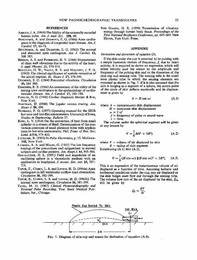
If the skin under the cup is assumed to be pulsing with a simple harmonic motion of frequency, f, due to heart activity, it is required to derive an expression which will relate velocity past the sensor to the amplitude and frequency of the pulsing skin and to the diameters of the skin cup aild sensing tube. The sensing tube is the small bore plastic tube in which the sensing elements are mounted as shown in Fig. 7. If it is also assumed that the skin is bulging as a segment of a sphere, the centre point of the circle of skin deflects maximally and its displace- ment is given by
h = Hcos oJt (A.1)
where h = instantaneous skin displacement H = maximum skin displacement o, = 2 , ~ f f = frequency of pulse or sound wave t = time.
The volume under the spherical segment will be given at any instant by
V = 1 h(h2 + 3R2) (A.2) O
where V = volume of air displaced by skin R = radius of skin segment.
Substituting (A.1) into (A.2),
1 V = ~ (Hcos <ot) [(H cos tot) 2 + 3R2]. (A.3)
This is an expression of the instantaneous volume of air displaced as a function of time. Assuming isobaric and isothermal conditions under the cup, any air displaced as the skin bulges must flow out through the sensing tube. The volume flow rate of the air displaced by the skin, Q~, will be given by
dV Q s - dt"
Plostic Cup Sealed To Skin Hot Wire
h / / / / / Skin / / / /
2R
FIG. 7. Diagram of skin cup and sensor for derivation of equation (A.9).
54 D . E . L A U G H L I N and R. P. M A H O N E Y
Also from the laws of hydraulic continuity the volume flow rate past the sensor, Q,, must equal the volume flow rate caused by the skin movement, or
Q, = Q~.
Also Q, = va
dV and - - = va (A.4)
dt
where v = velocity of air in sensing tube a = area of cross section of sensing tube.
By taking the first derivative of the instantaneous volume equation (A.3) and applying appropriate equalities we have
dV Hlrco . dt 2 sin to t (H 2 cos 2 cot + R2). (A.5)
This is the volume flow in cubic centimetres per second if distances are expressed in eentimetres and time in seconds. Solving equation (A.4) for velocity and combining it with equation (A.5) we have
H~'i'co . - 2 v ~a sm cot (H ~ cos cot + R2) . (A.6)
Since the waves coming through the skin do not move it very much we can assume
H 2 , :~ R 2 .
In this case equation (A.6) can be simplified to
HlrcoR2 sin cot v 2a
Hrr2fR z and v sin oJt (A.7)
a
since co = 2 ~rf.
If the area, a, of the sensor tube is now related to the radius, r, by the equation
a = ~rr 2
we can rewrite equation (A.7) in terms of a ratio of the radii of interest.
Hrr2fR 2 . Thus v - - sin cot
~.r 2
= - - H ~ r f ( R ) 2 sincot. (A.8)
Now if we define the term (R / r ) 2 as the hydraulic amplifica- tion An, the final equation for velocity through the sensor tube can be written
v = ~rfAn ( - - H sin cot). (A.9)
In this equation the - - H sin cot indicates that as the skin bulges away from the body the velocity is positive, and as it moves toward and dips into the body to form a hollow the velocity is negative. The minus sign and the 90 ~ phase shift (cosine input to sine output) are necessary to repre- sent this. Equation (A.9) also shows an inherent amplifica- tion of higher frequencies since the output velocity is directly proportional to frequency. Finally, equation (2) indicates the importance of the size of the cup, and shows that the output velocity increases as the square of the cup diameter.
D E S N O U V E A U X T R A N S D U C T E U R S P H O N O C A R D I O G R A P H I Q U E S
U T I L I S A N T L E P R I N C I P E D E L ' A N E M O M E T R E A
F I L - E C H A U F F E
Sommaire--Des thermistors 6chauff6s et des ills 6chauff6s ont 6t6 adapt6s pour d6tecter des pouls vasculaires et pr6cordiaux et les battements du coeur. L'activit6 de la peau est amplifi6e hydrauliquement en fixant fermement une coupe en plastique sur la surface en question et en montant les 616ments d6tecteurs dans le centre d 'un petit point de sortie, branch6s darts un orifice de la coupe. Deux thermistors peuvent ~tre mont6s physiquement et 61ectriquement d 'une telle mani~re, de sorte que de produire un des6quilibre diphas6 d 'un pont de Wheatstone pour des pouls sous-acoustiques. Des ills fins, 6chauff6s, d6tectent les ondes acoustiques de plus haute fr&luence.
On pr6sente des enregistremente de la carotide externe, les pouls veineux jugulaire et de l 'apex et les bruits cardiaques et on fait des comparaisons avec deux transducteurs standard comme 6vidence de l'utilit6 des inventions. Il est 6vident que celui-ci est un transducteur compacte, d'imp6dance basse, bien fort, pour r6sister ~t la chute du plafond au plancher, ayant une proportion sup6rieure de signalisation du bruit et 6tant insensible aux sons ambiants.
N E U E P H O N O K A R D I O G R A P H I S C H E U M W A N D L E R U N T E R
V E R W E N D U N G D E S H I T Z D R A H T A N E M O M E T E R P R I N Z I P S
Zusammenfassung--Hitzthermistoren und Hitzdriihte sind fiir Feststellung von Gefiiss- und priikordialen Pulsschliigen beziehungsweise Herzschliigen angepasst worden. Die Aktivitiit von der Hant wird hydraulisch durch Versiegeln einer plastischen Kappe fiber dem Interesse- gebiet und durch Anbringen der Messfiihlerelemente im Mittelpunkt einer kleinen Auslass/Sff-
NEW PHONOCARDIOGRAPHIC TRANSDUCERS 55
nung und, eingesteckt in ein Loch in der Kappe, verst~irkt. Es k6nnen zwei Thermistoren kSrperlich und elektrisch in solcher Weise angebracht werden, dass sie zweiphasische Unaus- geglichenheit einer Wheatstone Briicke fiir subaudio Impulse erzeugen. Fein erhitzte Dr~ihte ffihlen Schallwellen h6herer Frequenz.
Es werden BAnder [iusserer, die Karotis betreffcnder Impulse, jugularer Venen- und Apex- pulse und Herzger~iusche gebracht, und es werden zwei Standardumwandler als Beweis fox die Nfitzlichkeit der Vorrichtungen verglichen. Ein kompakter Umwandler mit niedriger Im- pedanz, der geniigend robust ist, um ein Fallen yon der Deeke zum Boden auszuhalten, mit einem iiberlegenen StSrspannungsverh~iltnis und Unempfindlichkeit fiir Aussenger~iusche ist einleuchtend.