Embed Size (px)
Citation preview

New Safe Confinement
Purpose and background
The purpose of the NSC construction is to
create a barrier against dissemination of
radioactive substances contained in the
OS and to create conditions for further OS
deconstruction operations.
The Project is financed from the
Chernobyl Shelter Fund (CSF).
Engineering and construction are
performed by the Contractor (JV
NOVARKA) that consists of two French
companies: VINCI Construction Grands
Projets and BOUYGUES Travaux Publics.
Around 50 Ukrainian organizations
participate in the NSC Project
implementation.
Design
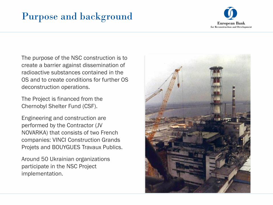
NSC is designed for operation during 100 years and is resistant to seismic impact up to
6 points magnitude as well as tornado class 3.
In view of the radiation conditions this construction is performed under, the NSC facility is
one-of-a-kind in the world
Protection of the environment from impact of radioactive materials contained in the
Object Shelter is ensured by leak-tightness of the NSC.
Leak-tightness functions are performed by:
• the Annular Space – a gap between the internal and external claddings where the ventilation system
maintains permanent overpressure relative to the Main Volume effectively preventing egress of
radioactive substances into the environment;
• Elastic membrane that connects the Arch structure with the Object Shelter existing structures
ensuring on one hand the leak-tightness and on the other – minimization of impacts from the Arch to
the existing structures of the OS.

Design
NSC main elements are:
• Arch
• Foundations
• Technological Building
• Auxiliary Facilities:
• Electrical Equipment Building, Fire Water Pump
Station with two 1500m3 fire tanks, Diesel Power
Stations with diesel fuel stock tanks, North and
South Storm Water Catching Basins, Storm Water
Treatment Facilities.
• NSC facility fully envelopes the OS and the
territory directly adjacent thereto and is intended
to perform the entire range of activities on
conversion of the OS into an ecologically safe
system.
Design
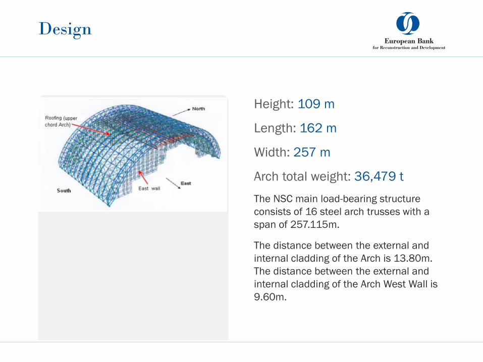
Height: 109 m
Length: 162 m
Width: 257 m
Arch total weight: 36,479 t
The NSC main load-bearing structure
consists of 16 steel arch trusses with a
span of 257.115m.
The distance between the external and
internal cladding of the Arch is 13.80m.
The distance between the external and
internal cladding of the Arch West Wall is
9.60m.

Arch external cladding
A multilayer system of physical barriers
preventing dissemination of moisture and
heat.
• Provides resistance to weather impact (rain,
extreme snow, extreme wind) for the entire
100 year operation life of the facility;
• Withstands temperature fluctuations and
impact of Tornado class 1.5 without causing
the steel permanent strain;
• Withstands Tornado class 3, allowing steel
permanent strain without destruction of the
structure;
• Preserves integrity and insulating effect in
case of internal fire;
• Maintains required properties under
exposure to radiation reaching 0.1 Gy/h.
Arch internal cladding
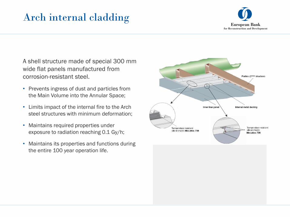
A shell structure made of special 300 mm
wide flat panels manufactured from
corrosion-resistant steel.
• Prevents ingress of dust and particles from
the Main Volume into the Annular Space;
• Limits impact of the internal fire to the Arch
steel structures with minimum deformation;
• Maintains required properties under
exposure to radiation reaching 0.1 Gy/h;
• Maintains its properties and functions during
the entire 100 year operation life.

Arch assembly
Arch assembly is performed
away from the Object Shelter in
a special Erection Zone,
allowing to reduce radioactive
exposure doses for personnel.
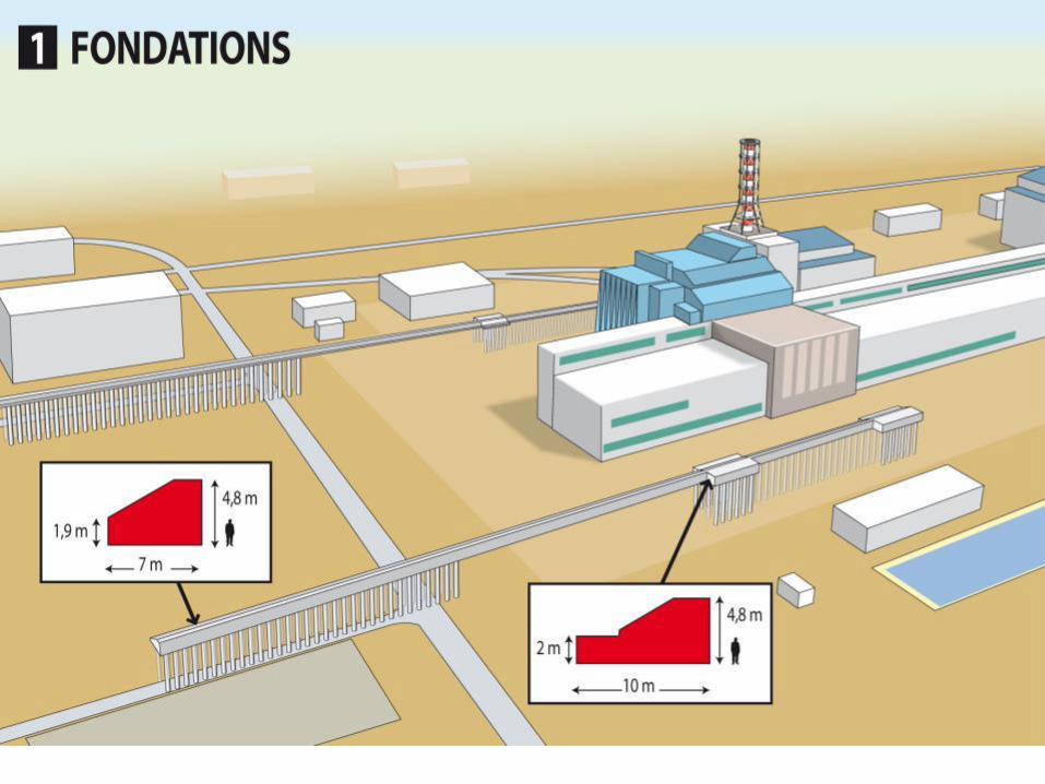

Service Zone Foundations
The Service zone foundation is designed as two Ground beams arranged symmetrically
with respect to the Arch axis on pile foundations, 175.275 m long each. The northern
Ground beam consists of three expansion units, 58,635; 65.335 and 51.305 m long,
which are separated by two expansion joints. The southern Ground beam consists of three
expansion units 69,335; 54,635 and 51,305 m long.
Design of contraction joints envisions arrangement of shear key to exclude relative linear
displacement of adjacent blocks both in vertical and horizontal plane in the “north-south”
direction and ensure free movement along the foundation axis.
Ground beams will be supported by 1,0 m diameter reinforced concrete piles: 184 piles in
the south Ground beam and 192 piles in the north beam.
The piles will be CFA made of reinforced concrete with diameter of 1,0 m and a length of
19,0 m. In extreme expansion units, the piles are located in 4 rows and 3 rows in the
middle unit.
The Service zone foundations are connected to the Transfer zone foundations by
expansion joints with connection tabs.

Transfer and Erection Zone
Foundations
In the Transfer zone, the foundation will consist of two Ground beams, each of them being
10,50 m wide and 121,81 m long, symmetrical relative to the Arch axis.
The foundation will be a strip one, willow depth, with 114,000 bottom level.
The foundations will be made as one unit, without any expansion joint.
Foundation of the Erection zone is designed as two Ground beams arranged
symmetrically about the Arch axis on pile foundations, with 8,50 m wide Ground beam
bottom and 209,91 m long each. The Ground beams are composed of three expansion
units 52,81; 75,00 and 82,10 m long separated by two expansion joints. The Erection
zone foundations will be supported by 1,00 m diameter steel tube piles.
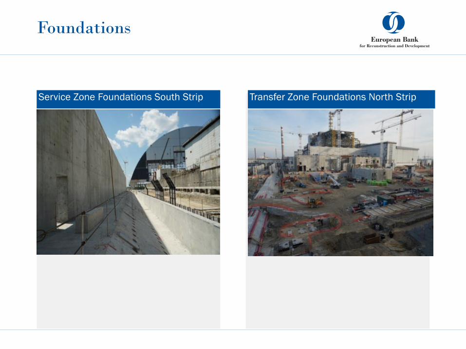
Foundations
Service Zone Foundations South Strip Transfer Zone Foundations North Strip

NSC is complete with all necessary
process systems
• Radiation Monitoring
• Electrical Power Supply
• Heating, Ventilation and Air Conditioning
• Main Cranes
• Fire Protection
• Integrated Control System
• Access Control
• Communication and CCTV
• Water Supply and Sewage
• Structural Monitoring
• Radioactive Waste Management System
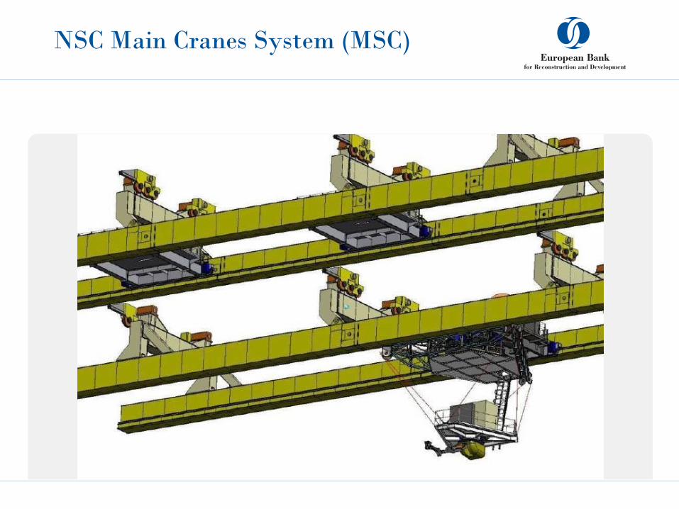
NSC Main Cranes System (MSC)
Main Crane System (MCS)
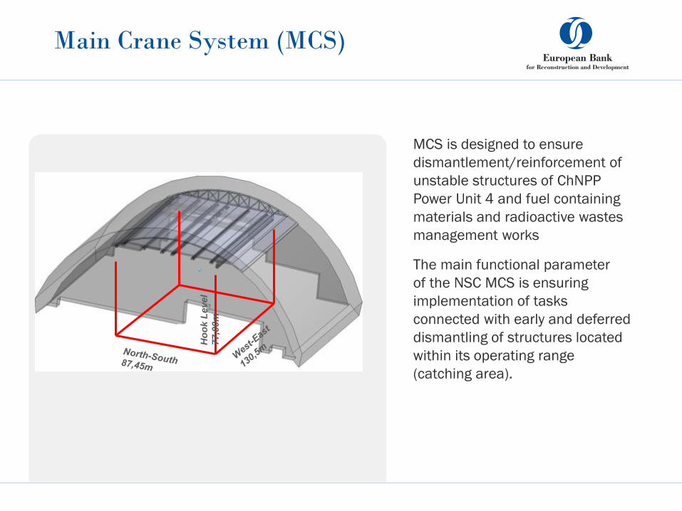
MCS is designed to ensure
dismantlement/reinforcement of
unstable structures of ChNPP
Power Unit 4 and fuel containing
materials and radioactive wastes
management works
The main functional parameter
of the NSC MCS is ensuring
implementation of tasks
connected with early and deferred
dismantling of structures located
within its operating range
(catching area).
Ho
ok L
evel
77,0
0m
Main Crane System (MCS)
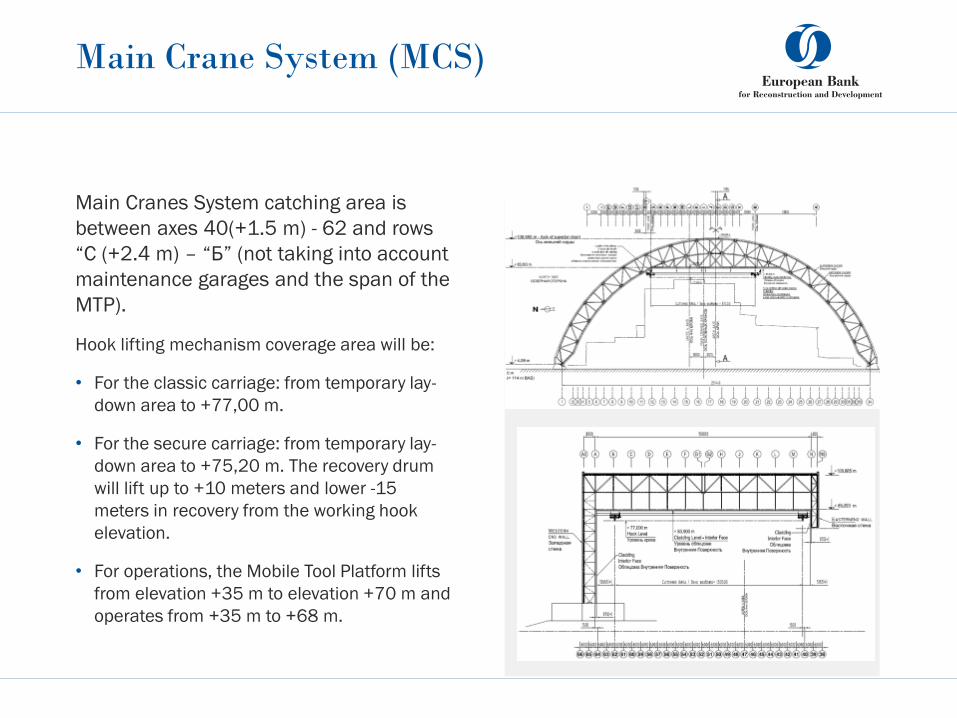
Main Cranes System catching area is
between axes 40(+1.5 m) - 62 and rows
“С (+2.4 m) – “Б” (not taking into account
maintenance garages and the span of the
MTP).
Hook lifting mechanism coverage area will be:
• For the classic carriage: from temporary lay-
down area to +77,00 m.
• For the secure carriage: from temporary lay-
down area to +75,20 m. The recovery drum
will lift up to +10 meters and lower -15
meters in recovery from the working hook
elevation.
• For operations, the Mobile Tool Platform lifts
from elevation +35 m to elevation +70 m and
operates from +35 m to +68 m.

Dimensions of the MCS
vs. dimensions of Boeing 737
Main Crane System (MCS)
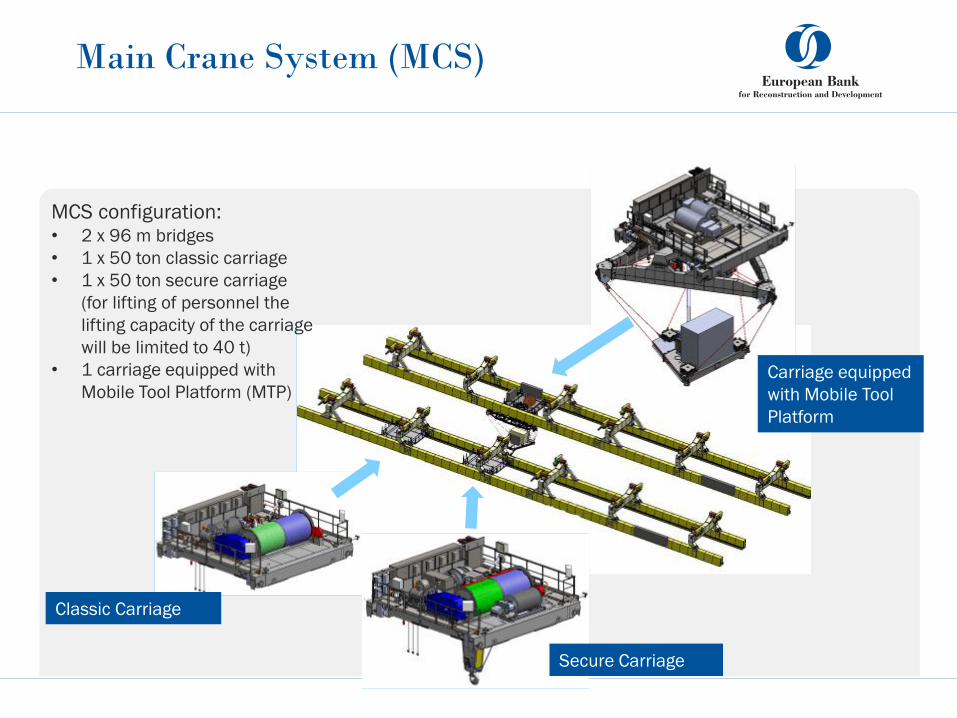
MCS configuration: • 2 х 96 m bridges
• 1 х 50 ton classic carriage
• 1 х 50 ton secure carriage
(for lifting of personnel the
lifting capacity of the carriage
will be limited to 40 t)
• 1 carriage equipped with
Mobile Tool Platform (MTP)
Classic Carriage
Secure Carriage
Carriage equipped
with Mobile Tool
Platform

Classic Carriage
Specifiation:
• Capacity: 50 t
• Lifting speed: step speed adjustment from
1m/min up to 10 m/min,
• Loaded hook location relative to a defined
position shall not exceed +/-50 mm.
• Hook lifting distance: from Lay Down Area
level to elevation +77m
• Load weighing system with operator display
(+/- 5% of full weighted value)
• Overload limiter that automatically shuts
down the hoisting mechanism if the load
mass exceeds passport lifting capacity of the
crane by more than 15%. A possibility to
disconnect the overload limiters during
testing of the MCS shall be envisioned.
• Speed: step speed adjustment from 1 m/min
up to 15 m/min,
• Carriage location relative to a defined
position shall not exceed ±50 mm.
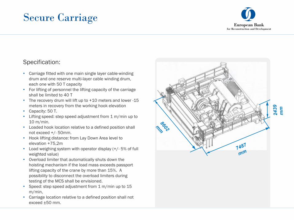
Secure Carriage
Specification:
• Carriage fitted with one main single layer cable-winding
drum and one reserve multi-layer cable winding drum,
each one with 50 T capacity
• For lifting of personnel the lifting capacity of the carriage
shall be limited to 40 T
• The recovery drum will lift up to +10 meters and lower -15
meters in recovery from the working hook elevation
• Capacity: 50 T.
• Lifting speed: step speed adjustment from 1 m/min up to
10 m/min.
• Loaded hook location relative to a defined position shall
not exceed +/- 50mm.
• Hook lifting distance: from Lay Down Area level to
elevation +75,2m
• Load weighing system with operator display (+/- 5% of full
weighted value)
• Overload limiter that automatically shuts down the
hoisting mechanism if the load mass exceeds passport
lifting capacity of the crane by more than 15%. A
possibility to disconnect the overload limiters during
testing of the MCS shall be envisioned.
• Speed: step speed adjustment from 1 m/min up to 15
m/min,
• Carriage location relative to a defined position shall not
exceed ±50 mm.

Carriage equipped with Mobile Tool
Platform
Specification:
• For operations Mobile Tool Platform lifts from
elevation +35 m to elevation +70 m;
• The MTP tools operate within elevations from
+35 m to +68 m;
• Concrete drill and jaw crusher fitted will be
fitted on end of carrier arm 2.5m long
• Loads at the bottom platform at elevation
35m at the centre of the tensile truss
connection triangle tooling dead weight
between 10 000kg and 19 500kg shall be
12
40
0
mm

Crane assembly
West Bridge lift
East Bridge assembly Assembled West Bridge with Classic Carriage
and Secure Carriage
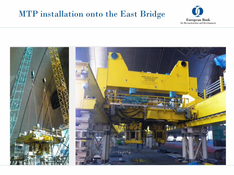
MTP installation onto the East Bridge

Arch sliding
Turbine Hall
Deaerator Stack Block “V”
Block “ASRU”
Sliding operation
After completion of Arch assembly in the Erection Zone the Arch will be slid over the OS.
Arch sliding system includes the following components:
• Skid tracks;
• Jack boxes (shoes) including:
• Hydraulic suspension jack (main jack) fitted with a lock-nut and a swivel;
• Side shift;
• Skidding surface;
• Connection bars;
• Power packs and their manifold boxes;
• Control computer;
• Laser control system.
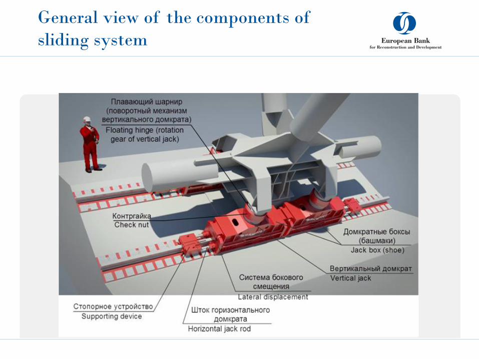
General view of the components of
sliding system

Push-pull units
There are 4 push-pull units per arch
supporting nodes for the arches A0, A, B,
C, D, E, F, G1+G2, H, J, K, L, M and N+N0,
i.e. a total of 14 x 4 x 2 = 112 push-pull
units for the skidding of the whole arch.
Each push-pull unit consists of 2 hydraulic
jacks with a stroke of 600mm and a
gripper head (stop device), fixed on the
retractable rod i.e. the total number of
push-pull jacks of 224 units.
The combined capacity of the 2 hydraulic
push-pull jacks is 125 T in pushing mode
and 90 T in pulling mode.
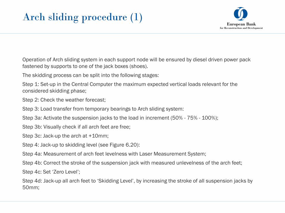
Operation of Arch sliding system in each support node will be ensured by diesel driven power pack
fastened by supports to one of the jack boxes (shoes).
The skidding process can be split into the following stages:
Step 1: Set-up in the Central Computer the maximum expected vertical loads relevant for the
considered skidding phase;
Step 2: Check the weather forecast;
Step 3: Load transfer from temporary bearings to Arch sliding system:
Step 3a: Activate the suspension jacks to the load in increment (50% - 75% - 100%);
Step 3b: Visually check if all arch feet are free;
Step 3c: Jack-up the arch at +10mm;
Step 4: Jack-up to skidding level (see Figure 6.20):
Step 4a: Measurement of arch feet levelness with Laser Measurement System;
Step 4b: Correct the stroke of the suspension jack with measured unlevelness of the arch feet;
Step 4c: Set ‘Zero Level’;
Step 4d: Jack-up all arch feet to ‘Skidding Level’, by increasing the stroke of all suspension jacks by
50mm;
Arch sliding procedure (1)

Arch sliding procedure (2)
Step 6: Continuation of skidding:
Step 6a: Repeat step 5a;
Step 6b: Repeat step 5b;
Step 7: Arrival at final position:
Step 7a: Lock the push-pull units;
Step 7b: Lower the suspension jacks to zero level;
Step 7c: Measure deviation between actual and final position;
Step 7d: Correct the deviation using the push-pull units;
Step 7e: Transfer the load to the permanent/temporary bearings.
The speed of 10 m/h (or 11.2m/h without contingencies) is an average speed during the skidding
process. As highlighted above, the skidding process is made of a succession of stages when travelling
occurs and stages without travelling of the arch.
Arch sliding procedure (3)
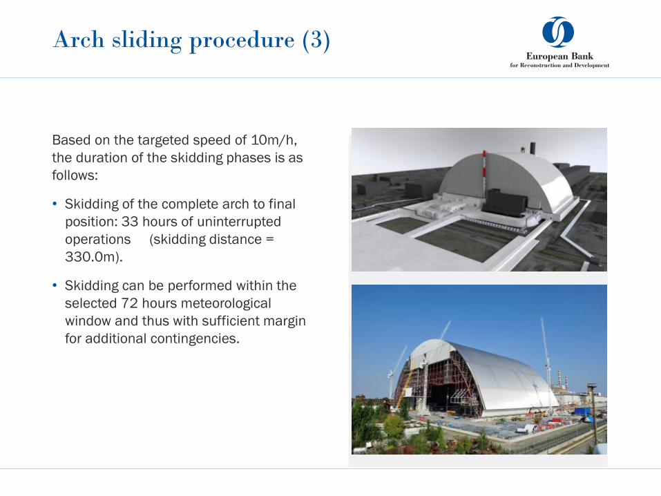
Based on the targeted speed of 10m/h,
the duration of the skidding phases is as
follows:
• Skidding of the complete arch to final
position: 33 hours of uninterrupted
operations (skidding distance =
330.0m).
• Skidding can be performed within the
selected 72 hours meteorological
window and thus with sufficient margin
for additional contingencies.