Embed Size (px)
Citation preview

SMCTR--UAD-A269 758~II~~ I ll~I iltII~ illlii ~t IIAEROSPACE REPORT NO.
TR-93(3935)-5
New Test Method to Determine Modulus of Elasticityof Rocket Grain Material
Prepared by
D. J. CHANG 1, R. W. GROSS2 , and F. BABANIlMechanics and Materials Technology Center
2E1ectronics Technology CenterTechnology Operations
15 January 1993 D T ICELECTE~SP2419931
Prepared for SUSPACE AND MISSILE SYSTEMS CENTER
AIR FORCE MATERIEL COMMdAND2430 E. El Segundo Boulevard
Los Angeles Air Force Base, CA 90245
Contract No. F04701-88-C-0089
Enginering and Technology Group
* ~THE AEROSPACE CORPORATION A
El Segundo, California/LA
APPROVED FOR PUBUC RELEASEOI3TRUIhO UNUMn:ED 93-22 299 ao~
1k , 3o4,.?1113i

This report was submitted by The Aerospace Corporation, El Segundo, CA 90245-4691, underContract No. F04701-88-C-0089 with the Space and Missile Systems Center, 2430 E. El SegundoBlvd., Los Angeles Air Force Base, CA 90245. It was reviewed and approved for The AerospaceCorporation by R. W. Fillers, Principal Director, Mechanics and Materials Technology Center, andB. K. Janousek, Principal Director, Electronics Technology Center.
This report has been reviewed by the Public Affairs Office (PAS) and is releasable to the NationalTechnical Information Service (NTIS). At NTIS, it will be available to the general public,including foreign nationals.
This technical report has been reviewed and is approved for publication. Publication of thisreport does not constitute Air Force approval of the report's findings or conclusions. It ispublished only for the exchange and stimulation of ideas.
J. Liu -W. KYLE SNEDDON, Capt., USAFOL-AC PLJRKCP MOLE Programn Manager

UNCLASSIFIEDSECURITY CLASSIFICATION OF THIS PAGE
REPORT DOCUMENTATION PAGE
la. REPORT SECURITY CLASSIFICATION lb. RESTRICTIVE MARKINGS
Unclassified2a. SECURITY CLASSIFICATION AUTHORITY 3. DISTRIBUTION/AVAILABILrTY OF REPORT
2b. DECLASSIFICATIONKDOWNGRADING SCHEDULE Approved for public release; distribution unlimited
4. PERFORMING ORGANIZATION REPORT NUMBER(S) 5. MONITORING ORGANIZATION REPORT NUMBER(S)
TR-93(3935)-5 SMC-TR-93-48
6a. NAME OF PERFORMING ORGANIZATION 61b. OFFICE SYMBOL 7a. NAME OF MONITORING ORGANIZATION
The Aerospace Corporation ( , )Space and Missile Systems CenterTechnology Operations S
6c. ADDRESS (Cy, State, and ZIP Code) 7b. ADDRESS fCU,.y Slate, and ZIP Code)
El Segundo, CA 90245-4691 Los Angeles Air Force BaseLos Angeles, CA 90009-2960
Sa. NAME OF FUNDING/SPONSORING 8b. OFFICE SYMBOL 9. PROCUREMENT INSTRUMENT IDENTIFICATION NUMBERORGANIZATION I) F04701-88-C-0089
8c. ADDRESS (CW State, andZP Code) 10. SOURCE OF FUNDING NUMBERS
PROGRAM I PROJECT TASK W WORK UNITELEMENT NO. NO. NO- ACCESSION NO.
11. TITLE (Inclde SewTly Cleslcatton)
New Test Method to Determine Modulus of Elasticity of Rocket Grain Material
12. PERSONAL AUTHOR(S)Chang, Dick J., Gross, Rolf W., and Baban, Farzad
13a. TYPE OF REPORT 13b. TIME COVERED 14. DATE OF REPORT (Yer, Month, Day) 1S. PAGE COUNT
'FROM TO_ 1993 January 15 1916. SUPPLEMENTARY NOTATION
17. COSATI CODES 18. SUBJECT TERMS (Con*we on rere I neceawy and w yby btkicnumno)FIELD GROUP SUB-GROUP
___FIELD _GROUP___________ Propellant grain, Modulus, Test Method
19. ABSTRACT (Contnwe on wwse rnecesmaryandIden/ffyby bcknantwer)
A new testing technique was demonstrated for measuring the modulus of elasticity of low-modulusmaterials such as rocket propellant grains. The technique described herein offers substantial advantagesover the dog bone testing method. The testing procedure is less complicated, and data reduction issimpler. More importantly, a biaxial stress field can be established in the test specimen to simulateconditions encountered during pressurization of a nonlinear and viscoelastic material (e.g., propellantused in solid rocket motors). For metals or linearly elastic materials, dog bone testing may be considereda viable technique through which material properties such as the modulus of elasticity can be extractedaccurately. However, for highly filled materials or propellants that exhibit nonlinear and viscoelasticbehavior, results obtained through the uniaxial stress data of dog bone tests do not provide materialcharacteristics under biaxial strain conditions. Lack of such material properties will be detrimental to theability in evaluating and predicting the integrity of the components.
20. 011STRUIWVALMT OF, ABS.RACT 21. ABTATSECURT CLASSIFICATIOI@ UNCLASSIIEOU•o MITED OE SAME AS RPT. E- OTIC USERS Unclassified22. NAME OF RESPONSBUE IMDIUIAL 22D. TELEPHONE (f Ams Code) 22. OFFICE SYMBOL
00 FORM 1473.84 MAR 83APRsdffl b u d wded Y 1S PAQEUNCLASSIFIED

UNCLASSIFIEDSECURITY CLASSIFICATION OF THIS PAGE
The technique uses a thick, circular disk constrained at its outer diameter surface and loaded uniformlyover one circular face by gas pressure. The technique was demonstrated by using a circular disk castfrom EZ-CastTM 521 thermosetting plastic material. Normal displacement at the center of the disk as afunction of static pressure was measured. Modulus of elasticity versus deformation calculations weremade using a closed-form solution and finite-element computer codes. Modulus values of 300 and 210psi were obtained using the two approaches, respectively, based on the measured center displacement.These values correlate reasonably well with the previously generated modulus value of 250 psi using theuniaxial "dog bone" method. As expected, the dynamic pressurization tests yield a higher modulus thanthat obtained by static pressure. However, a change of pressurization rate from 0.1 to 90 psi/s gives onlya 10% increase in modulus.
UNCLASSIFIEDSECU~rIY CLMMFIATION OP ThI PAGE

PREFACE
The authors are grateful to Dr. Sherrie L. Zacharius for her suggestions regarding the
determination of glass transition temperature and the dynamic modulus of EZ-CastTMmaterial and the extensive discussions regarding the behaviors of polymeric materials.We also wish to thank Emil M. Kaegi for his assistance in acquiring the data and Dr.
Munson A. Kwok for the technical discussions during the preparation of the manuscript.In addition, Tim J. Bixler and Randy L Williams' efforts in preparing the cast samples,and Mr. Robert Shenk's efforts in performing DSC and rheovibron tests for several EZ-Castf specimens are appreciated.
Accesion ForNTIS CRA&IDTIC TAB
Unannounced 5Justification............................
By*...
Distribution IAvailability Codes
Avail and I orDist Special
DtIO Q.AL... ......

CONTENTS
I. IN TRO DUCTIO N ............................................................................................................ 5
II. EXPERIM ENTS ............................................................................................................... 7
A . PREPARATION OF SAM PLE ................................................................................. 7
B. DESCRIPTION OF THE APPARATUS ................................................................. 8
C. STATIC TESTS ..................................................................................................... 8
D . DYNAM IC TESTS ............................................................................................... 8
III. AN ALYTICAL CALCULATION S ............................................................................... 11
A. APPROXIMATE CLOSED-FORM SOLUTION .................................................... 11
B. FINITE-ELEMENT DISPLACEMENT ANALYSIS ............................................. 11
IV . D ISCU SSION OF RESULTS ........................................................................................ 15
V . CONCLUSIONS ............................................................................................................. 19
REFEREN CES ......................................................................................................................... 21
3

FIGURES
1. Geometric configurations of EZ-CASTTM specimen and PVC tube .................................... 7
2. Schematic of pressure cell for disk testing ...................................................................... 8
3. Deflection at center of disk vs static pressure .................................................................. 9
4. Deflection at center of disk vs dynamic pressure ............................................................. 9
5. Dynamic modulus of EZ-CASTTM 521 vs pressurization rate ........................................ 12
6. Differential scanning calorimeter results for five EZ-CastTM rods with differentcure tim e at 250 °F .......................................................................................................... 16
7. Differential scanning calorimeter results for dog-bone and disk ................................... 16
TABLES
1. Comparison of Normal Displacement at Center of Disk Under 50 psi AppliedPressure and E = 250 psi With Experimental Results .................................................... 13
2. Dynamic Modulus of EZ-CastTM Material ...................................................................... 15
4

I. INTRODUCTION
The determination of the modulus of elasticity of low-modulus materials such as rocket propel-lants by the conventional, uniaxial "dog bone" technique has certain limitations. The specimensneed to be cast or fabricated precisely into the required dimensions. Because of the low modulus(high compliance) of the material, prestresses may exist in the specimen before testing as a resultof alignment. In addition, the stiffness of the deformation measuring device, such as an exten-someter, has been shown to be comparable in magnitude to that of the specimen. I The term"stiffness" is defined here as the ratio of the applied force to the deflection in a linear structuralelement, e.g., the K value in F = Kx for a linear spring. Consequently, this stiffness needs to bedetermined experimentally and extracted from the measured overall stiffness. This procedureundoubtedly complicates the dog bone testing and data reduction.
One important characteristic of nonlinear viscoelastic materials such as rocket propellants in SRMUis that their mechanical response under biaxial stresses cannot be accurately derived or predictedfrom uniaxial test data. Thus, the response under biaxial stresses needs to be experimentally mea-sured. This necessitates biaxial testing to generate the mechanical properties for these materials.Lack of these properties will lessen the ability to evaluate and predict the operational integrity ofthe components.
A new test technique has beer, demonstrated that alleviates many of the above-described prob-lems. This method uses a thick, circular disk made of a low-modulus polymer material. The diskis constrained at its outer cylindrical surface and loaded uniformly over one circular face by gaspressure. The normal displacement at the center of the disk is measured by a displacement gage.
The diameter of the disk specimen is based upon the dimensions of the test chamber and the fix-tures. The thickness of the specimen was chosen by considering the requirements necessary formeasurement and analysis. Generally speaking, the diameter of the disk specimen should be suf-ficiently large so that the normal displacement at the center of the specimen can be accuratelymeasured. The specimen needs to be thick enough such that no nonlinear large deformationsoccur and yet thin enough so that the theory of plates can be applied. It is judged that the chosenthickness satisfies these requirements.
This report presents a description of the test arrangement, specimen configuration, experimentaldata, and the results of a closed-form solution and a finite element analysis from which the valueof the modulus of elasticity for EZ-CASTT
M 521 is determined.
5
II. EXPERIMENTS
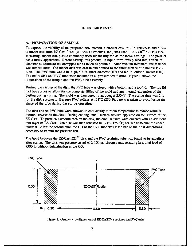
A. PREPARATION OF SAMPLETo explore the viability of the proposed new method, a circular disk of 2-in. thickness and 5.5-in.diameter cast from EZ-CastTM 521 (AREMCO Products, Inc.) was used. EZ-CastTM 521 is a ther-mosetting, rubber-like plastic commonly used for making molds for metal castings. The producthas a milky appearance. Before casting, this product, in liquid form, was placed into a vacuumchamber to eliminate the entrapped air as much as possible. After vacuum treatment, the materialwas almost clear. The rubber disk was cast in and bonded to the inner surface of a hollow PVCtube. The PVC tube was 2 in. high, 5.5 in. inner diameter (ID) and 6.5 in. outer diameter (OD).The entire disk and PVC tube were mounted in a pressure test fixture. Figure I shows thedimensions of the sample and the PVC tube assembly.
During the casting of the disk, the PVC tube was closed with a bottom and a top lid. The top lidhad two sprues to allow for the complete filling of the mold and any thermal expansion of thecasting during curing. The mold was then cured in an oven at 250 0 F. The curing time was 2 hrfor the disk specimen. Because PVC softens at 121 0C (2500F), care was taken to avoid losing theshape of the tube during the curing operation.
The disk and its PVC tube were allowed to cool slowly to room temperature to reduce residualthermal stresses in the disk. During cooling, small surface fissures appeared on the surface of theEZ-Cast. To produce a smooth face on the disk, the circular faces were covered with an additionalthin layer of EZ-Cast. The disk was then reheated to 1210C (250WF) for 1/2 hr to cure the addedmaterial. After the second cure, the OD of the PVC tube was machined to the final dimensionsnecessary to fit into the pressure cell.
The bond between the EZ-Cast 521TM disk and the PVC retaining tube was found to be excellentafter curing. The disk was pressure tested with 100 psi nitrogen gas, resulting in a total load of9500 lb without delamination at the OD.
PVC Tube
2.00 EZ-CAST Plastic
IA0.50 5.-0.0
Figure 1. Geometric configurations of EZ-CASTTm specimen and PVC tube.
7

B. DESCRIPTION OF THE APPARATUS
Figure 2 shows the pressure cell with the specimen installed. The volume of the pressurizedregion above the sample was kept small (about 100 cm 3, or 6.1 in 3) to permit fast filling with thegas. A calibrated, linear, electronic extensometer was used to measure the center deflection of thedisk. The pressure was measured by an electronic pressure transducer. The accuracy of the pres-sure measuring capability is better than 0.1 psi. Data from both sensors were registered by anautomated data collection system utilizing a PC. The computer could be manually activated totake data for static tests or could be also run in an automatic mode to take 20 sample pairs persecond for dynamic tests. In the dynamic mode, the computer also activated a fast electric valveto admit the pressurizing gas into the chamber. Calibration factors for both sensors were appliedto the data by the computer.
C. STATIC TESTS
A series of static load tests of the disk was performed. The results of four separate tests are shownin Fig. 3. All data fall along a linear deflection vs pressure line. The resolution of the deflectionmeasurements was + 0.005 in. The average value of the pressure-to-deflection differential ratiowas (57.2 ± 1.3) psi/in.
D. DYNAMIC TESTS
Dynamic pressure tests were conducted using a realistic pressurization rate such as that measuredin the SRMU PQM-1 firing test and to determine the modulus change as a function of pressur-ization rate. The purpose of the tests was to show that the test fixture is capable of simulatinghigh pressure rates.
In these tests, the disk was subjected to rapid pressure changes ranging from near static (0.1 psi/s)to 90 psi/s. Figure 4 shows the results of a number of these tests. As expected, the materialappeared slightly stiffer when subjected to rapid pressure increases. However, the deflection vspressure relationship remained linear and was a weak function of the pressurization rate.
THICK PLATE
PVC TUBE
PRESSURE=-" CHAMBER
PRESSURE SENSOR GSNEEXTENSIOMETER GSINE
Figure 2. Schematic of pressure cell for disk testing.
8

0.40
0.35
0.30
:z 0.25
2 0.20
u- 0.15l-J
LL", 0.10
0.05
0
14 16 18 20 22 24 26 28 30 32 34 36PRESSURE - PSIA
Figure 3. Deflection at center of disk vs static press••e.
0.40
0.35STATIC
0.30 0 0
S0.25 00 60.7
I 0.20 dP
0w, 0.15,J
wo 0.10
0.05
0
-0.0514 16 18 20 22 24 26 28 30 32 34 36
PRESSURE - PSIAFigure 4. Deflection at center of disk vs dynamic pressure.

I1. ANALYTICAL CALCULATIONS
A. APPROXIMATE CLOSED-FORM SOLUTION
The normal displacement at the center of a thick circular disk that is rigidly held at its outercylindrical surface and loaded uniformly over one face is determined approximately by2
3p = E a4 (I1-V2)1rI+ 4h2 1 Iii(1
016 L _Eh3 ". a2(l-v)j'
where
Uo (in) = the normal displacement at center,h (in) = thickness of the disk,a (in) = disk radius,E (psi) = Modulus of elasticity of the disk material,V = Poisson's ratio of the disk material It is assumed to be 0.5
here, andP (psi) = applied uniform pressure.
Inserting the values of the specimen dimensions into Eq. (1), the relation of E, P, and Uo isexpressed as
E = 5.2592 P/U0 . (2)
By applying the (57.2 ± 1.3)psi/in. slope for P/Uo to Eq. (2), a modulus of elasticity value of 301:1 5 psi is obtained. This value is 20% higher than the 250 psi determined by "dog-bone" tests ofthe same material, 1
Values for the modulus determined by Eq. (2) from the dynamic test results of Fig. 4 aredepicted in Fig. 5. In Fig. 5, the E values for a number of dynamic tests are plotted against dp/dt,the rate of pressure increase. It is seen that the measured increase in E is about 10% for a changein dpfdt of 3 orders of magnitude.
B. FINITE-ELEMENT DISPLACEMENT ANALYSIS
A linear, elastic, finite-element analysis was performed for the EZ-CastTM 521 rubber disk to pre-dict the displacement response to the application of a uniform pressure at one surface of the disk.The results of this analysis and the experimental displacement data serve as a viable tool indetermining the Young's modulus, E, of the rubber material. Two computer codes were used forthe analysis. The first is an Aerospace-developed elastic-plastic code, "SAAS III," for axisym-metric or plane-strain (stress) solids.3 The second is the "ABAQUS" code developed by Hibbitt,
11

350 -
"340- 0 MEASURED DATAC- "- LEAST SQUARE FIT
t330
._1
0
m 310-
3000.10 1.00 10.00 100.00
PRESSURIZATION RATE, DP/DT (psi/sec)
Figure 5. Dynamic modulus ,'EZ-CastT'M 521 vs pressurization rate.
Karlson, and Sorensen.4 The SAAS Ill uses 4-node elements with a constant strain formulation,while the selected CAX8RH elements in ABAQUS use an 8-node, biquadratic displacement fieldwith reduced integration. The latter is formulated particularly for materials with incompressibleor nearly incompressible material behavior.
In the SAAS III analysis, two different meshes were used. One has 25 equally spaced nodes inthe radial direction between the center and the OD of the disk and 20 equally spaced nodes in theacross-thickness direction. This corresponds to 456 elements. The other mesh has 40 equallyspaced nodes in the radial direction and 20 nodes in the across-thickness direction. This gives741 elements.
For the ABAQUS model, 25 nodes in the radial direction and 21 nodes across the thickness wereused. Because of the 8-node element configuration, only 120 elements were generated by thecodes, as compared to 456 elements in the first SAAS III mesh configuration.
In both SAAS III and ABAQUS calculations, a 250 psi Young's modulus was input. This 250 psivalue was obtained from the results summarized in Ref. 1. Regarding the input value of Poisson'sratio, v, both 0.499 and 0.4999 were used. The boundary condition wr, such that the degrees offreedom at the OD surface of the disk were suppressed. It was expected that the value of thePoisson's ratio when approaching 0.500 from the lower end would have a significant impact on theresults. However, it was later found from the results that the Poisson's ratio was a weak function of
12

the displacement and stress predictions for this loading and geometric configuration. This is pri-marily due to the lack of constraint at both flat surfaces of the disk. except at the OD surface.
The predicted and measured normal displacement at the center of the disk under a 50-psi, uni-form pressure at one circular surface of the disk and E = 250 psi is shown in T, '-,ý1e 1.
It is noted that the predicted displacements from the two SAAS III meshes are very close, indicat-ing the results are converging to the limit. The ABAQUS code predicts a slightly larger normaldisplacement (1.1%) than the SAAS III predictions. These results show that the ABAQUS codegives comparable predictions to those produced by SAAS.
Based on an experimental pressure/displacement slope of 57.2 (Fig. 3), Young's moduli of 209 and211 psi, respectively, are calculated using the SAAS III and ABAQUS analytical displacementvalues shown in Table 1. These are approximately 16% lower than the value of 250 psi in Table 1.
Table 1. Comparison of Predicted NormalDisplacement at Center of Disk Under 50 psi AppliedPressure and E = 250 psi with Experimental Results
Model Type Normal Displacement (in.)
SAAS 11125 x 20 mesh 0.729
SAASIII 40 x 20 mesh 0.732
ABAGUS 25 x 21 mesh 0.738
Experimental Results 0.870
13

IV. DISCUSSION OF RESULTS
The new testing technique is an improvement over the uniaxial "dog bone" method for low-modulus materials. It is free from alignment prestress. The disk is under a biaxial stress field,which simulates the stress in the live propellant better than a uniaxial specimen can. The test maybe simpler to build and easier to execute than other related efforts such as the LightweightAnalog Model (LAM) series conducted by Hercules. 5
The testing technique was successfully demonstrated by the use of EZ-Cast TM 521, a thermosettingplastic material with predominantly elastic properties. Normal displacements at the center of thedisk were measured by either statically or dynamically applied pressure on one circular face ofthe disk specimen. The linear deflection pressure curve suggests that the modulus of elasticity isconstant over the strain range tested.
Based on the center displacement measurements, we calculated from the formula for a thick cir-cular plate and from two finite-element codes (ABAQUS and SAAS III) moduli of elasticity of300 psi and 210 psi, respectively. The results show +20% and -16% differences from the uniax-ial test results. The differences are probably caused by two sources: the over-prediction by theclosed-form solution because Eq. (1) is for small deformation and underprediction by the finiteele;nent codes. More importantly, the variation in moduli between the dog-bone and disk speci-mens is primarily due to the difference in curing process.
In order to investigate the possible modulus variation among different cure operations for theEZ-CastTM 521 compound, five l/2-in.-diam. rods were cast at 121°C (250'F) with cure time rang-ing from 1/2 to 3 hr. Both the 1.5(A) and 1.5(B) specimens had the same 1.5 hr cure time.
Differential scanning calorimeter (DSC) and dynamic mechanical modulus tests using a rheovi-bron were conducted for pieces cut from the five rods, the dog-bone specimen, and the diskspecimens. The former technique measures the heat capacity (specific heat multiplied by themass) of the specimen as a function of temperature. The measured results provide the informa-tion to determine the glass transition temperature, Tg, of the material. The latter determines thedynamic modulus of the material as a function of both temperature and frequency. When thetesting frequency decreases, the measured dynamic modulus approaches the static value.
Figure 6 depicts the DSC results for the five rods. The curves indicate that the glass transitiontemperatures for the five rods are very close (which is in the neighborhood of -400C). Figure 7depicts similar results for the dog-bone and the disk specimens. These DSC results indicate thatthe cures among all prepared specimens are comparable.
The dynamic modulus values from rheovibron tests for the five rods at 20 0C (680F) and 1.1 Hzare listed in Table 2.
Table 2. Dynamic Modulus of EZ-CastTM Materiala
Cure Time, hr Dynamic Modulus, psi
3 328
1.5(A) 338
1.5(B) 4100.5+1 309
0.5 242
15

LIJ
1 1/21(8)! xL 3 hr
LU
1/2+
11/2 (A)
1/2 hr
-80 -W6 -40 -20 0
TEMPERATURE, C
Figure 6. Differential scanning calorimeter results for five EZ-CastTM rods withdifferent cure time at 2500F. (Curves are displaced separately for clarity.)
cc
DEF-BME SPECIMED
Lii
SI I I
-80 -60 -40 -20 0TEMPERATURE, C
Figure 7. Differential scanning calorimeter results for dog-bone and disk.
16

When considering the limited number of samples and the experimental scatter, the results fromthe dynamic mechanical tests indicate that the samples have a comparable degree of cure. Formore quantitative modulus values, however, more sample testing is required.
TUThe data in Table 2 demonstrate that different modulus values for EZ-Cast are expected to existfor different specimens, such as what was observed in the dog-bone and disk specimens. A -16 to20% variation in modulus is not uncommon for polymeric materials. Therefore, it is concludedthat our proposed disk testing technique will provide accurate modulus values for any low-modulus material.
17

V. CONCLUSIONS
A new testing technique was demonstrated for measuring the modulus of elasticity of low-modulus materials such as rocket propellant grains. The technique offers substantial advantagesover the dog bone testing method. The testing procedure is less complicated, and data reductionis simpler. More importantly, a biaxial stress field can be established in the test specimen to simu-late conditions encountered during pressurization of a nonlinear and viscoelastic material (e.g.,propellant used in solid rocket motors).
The technique was demonstrated by using a circular disk cast from EZ-CastTM 521 thermosettingplastic material. Normal displacement at the center of the disk as a function of static pressure wasmeasured. Modulus of elasticity versus deformation calculations were made using a closed-formsolution and finite-element computer codes. Modulus values of 300 and 210 psi were obtainedusing the two approaches, respectively, based on the measured center displacement. These valuesshow a -16 to 20% difference to the 250 psi value determined by the dog-bone method.
Differential scanning calorimeter and dynamic mechanical modulus tests were conducted for EZ-CastTM 521 cast specimens of different cure conditions (1/2 to 3 hr). Results show that the glasstransition temperatures for all specimens tested are very close; whereas, the dynamic modulus valuesvary as much as 70%. This indicates that the reported difference in modulus measurements is pri-marily caused by the property variation between the EZ-CastTM 521 dog-bone and disk specimens.
The effects of the dynamic pressurization rate on the Young's modulus is about a 10% increasewhen the pressurization rate increases from 0.1 to 90 psi/s. Other advantages of this test methodinclude the capability to determine the viscoelasticity of materials such as inert and live propel-lants under biaxial stress field. It can also be used to evaluate the bond strength between thematerial and its case. We might expect greater differences with dynamic pressurization with atruly viscoelastic material.
One must bear in mind that the propellant in a solid rocket motor is cast as a long annulus beforefiing. Thus, the optimum geometry for simulating the stress field in a live propellant is an annu-lus. However, the test procedure for exerting a desired biaxial stress field on an annulus is farmore complicated to achieve and monitor. The complication is due to the difficulty in applyingunequal pressure on the forward face of the annulus relative to its bore. Separating the face andthe bore by means of a diaphragm introduces a host of other complications that are not trivial toovercome. On the other hand, by applying a biaxial stress field on a disk-shaped specimen, nodiaphragm is necessary. Hence, all the problems associated with using a diaphragm are entirelyavoided. The question remains, however, whether or not the strain rate in the disk-shaped speci-men closely resembles that in an annulus-shaped specimen. Although the question cannot beanswered in this work, the information on material behavior generated from a thick-disk speci-men with its outer edge clamped is a major improvement over the dog bone-shaped specimen forhighly nonlinear viscoelastic materials in providing data for anchoring and verification of propel-lant structural codes.
19

REFERENCES
1. D. J. Chang and W. D. Hanna, "Young's Moduli of EZ-CASTT 521 and 580 PlasticCompounds," Aerospace ATM-92(2530-03)-17, 17 March 1992.
2. S. Timoshenko and S. Woinowsky-Krieger, Theory of Plates and Shells, McGraw-Hill BookCompany, second edition, 1959, p. 74.
3. James G. Crose and Robert M. Jones, "SAAS III - Finite Element Stress Analysis ofAxisymmetric and Plane Solids With Different Orthrotropic, Temperature-DependentMaterial Properties in Tension and Compression," Aerospace TR-0059 (56816-53)-l.
4. Hibbitt, Karlsson, and Sorensen, ABAQUS - User's Manual, Revision 4.8, 1989.
5. M.G. Anderson, "Real-Time Radiography Support for Titan LAM,"AIAAISAE/ASME/ASEE 28th Joint Propulsion Conference and Exhibit, 6-8 July 1992,Nashville, TN.
21

TECHNOLOGY OPERATIONS
The Aerospace Corporation functions as an "architect-engineer" for national securityprograms, specializing in advanced military space systems. The Corporation's TechnologyOperations supports the effective and timely development and operation of national securitysystems through scientific research and the application of advanced technology. Vital to thesuccess of the Corporation is the technical staffs wide-ranging expertise and its ability to stayabreast of new technological developments and program support issues associated with rapidlyevolving space systems. Contributing capabilities are provided by these individual TechnologyCenters:
Electronics Technology Center: Microelectronics, solid-state device physics,VLSI reliability, compound semiconductors, radiation hardening, data storagetechnologies, infrared detector devices and testing; electro-optics, quantum electronics,solid-state lasers, optical propagation and communications; cw and pulsed chemicallaser development, optical resonators, beam control, atmospheric propagation, andlaser effects and countermeasures; atomic frequency standards, applied laserspectroscopy, laser chemistry, laser optoelectronics, phase conjugation and coherentimaging, solar cell physics, battery electrochemistry, battery testing and evaluation.
Mechanics and Materials Technology Center: Evaluation and characterizationof new materials: metals, alloys, ceramics, polymers and their composites, and newforms of carbon; development and analysis of thin films and deposition techniques;nondestructive evaluation, component failure analysis and reliability; fracturemechanics and stress corrosion; development and evaluation of hardened components;analysis and evaluation of materials at cryogenic and elevated temperatures; launchvehicle and reentry fluid mechanics, heat transfer and flight dynamics; chemical andelectric propulsion; spacecraft structural mechanics, spacecraft survivability andvulnerability assessment; contamination, thermal and structural control; hightemperature thermomechanics, gas kinetics and radiation; lubrication and surfacephenomena.
Space and Environment Technology Center: Magnetospheric, auroral andcosmic ray physics, wave-particle interactions, magnetospheric plasma waves;atmospheric and ionospheric physics, density and composition of the upperatmosphere, remote sensing using atmospheric radiation; solar physics, infraredastronomy, infrared signature analysis; effects of solar activity, magnetic storms andnuclear explosions on the earth's atmosphere, ionosphere and magnetosphere; effectsof electromagnetic and particulate radiations on space systems; space instrumentation;propellant chemistry, chemical dynamics, environmental chemistry, trace detection;atmospheric chemical reactions, atmospheric optics, light scattering, state-specificchemical reactions and radiative signatures of missile plumes, and sensor out-of-field-of-view rejection.