Embed Size (px)
Citation preview
RULES FOR CLASSIFICATION OF
DET NORSKE VERITAS AS
The content of this service document is the subject of intellectual property rights reserved by Det Norske Veritas AS (DNV). The useraccepts that it is prohibited by anyone else but DNV and/or its licensees to offer and/or perform classification, certification and/orverification services, including the issuance of certificates and/or declarations of conformity, wholly or partly, on the basis of and/orpursuant to this document whether free of charge or chargeable, without DNV's prior written consent. DNV is not responsible for theconsequences arising from any use of this document by others.
The electronic pdf version of this document found through http://www.dnv.com is the officially binding version
Ships / High Speed, Light Craft andNaval Surface Craft
PART 6 CHAPTER 13
NEWBUILDINGS
SPECIAL EQUIPMENT AND SYSTEMS – ADDITIONAL CLASS
Gas Fuelled Ship InstallationsJANUARY 2013
This chapter has been amended since the main revision (January 2013), most recently in July 2013.
See “Changes” on page 3.
FOREWORD
DNV is a global provider of knowledge for managing risk. Today, safe and responsible business conduct is both a licenseto operate and a competitive advantage. Our core competence is to identify, assess, and advise on risk management. Fromour leading position in certification, classification, verification, and training, we develop and apply standards and bestpractices. This helps our customers safely and responsibly improve their business performance. DNV is an independentorganisation with dedicated risk professionals in more than 100 countries, with the purpose of safeguarding life, propertyand the environment.
The Rules lay down technical and procedural requirements related to obtaining and retaining a Class Certificate. It is usedas a contractual document and includes both requirements and acceptance criteria.
© Det Norske Veritas AS January 2013
Any comments may be sent by e-mail to [email protected]
If any person suffers loss or damage which is proved to have been caused by any negligent act or omission of Det Norske Veritas, then Det Norske Veritas shall pay compensation tosuch person for his proved direct loss or damage. However, the compensation shall not exceed an amount equal to ten times the fee charged for the service in question, provided thatthe maximum compensation shall never exceed USD 2 million.In this provision “Det Norske Veritas” shall mean the Foundation Det Norske Veritas as well as all its subsidiaries, directors, officers, employees, agents and any other acting on behalfof Det Norske Veritas.
Rules for Ships / High Speed, Light Craft and Naval Surface Craft, January 2013Pt.6 Ch.13 Changes – Page 3
DET NORSKE VERITAS AS
CHANGES – CURRENT
General
This document supersedes the January 2012 edition.
Text affected by the main changes in this edition is highlighted in red colour. However, if the changes involvea whole chapter, section or sub-section, normally only the title will be in red colour.
Amendments July 2013
• Sec.8 Manufacture, Workmanship and Testing
— In items B301 and B401 references to Pt.5 Ch.5 have been corrected.
Main changes coming into force 1 January 2013
• Sec.4 Fire Safety
The requirement in Sec.4 E to spark arrestors (introduced in January 2010) has been removed due to thefollowing:
— Combustion of gas produces a very clean exhaust gas virtually free from particles. — Spark arrestors for large diameter exhaust outlets are currently not available in the maritime industry. — The draft IGF Code does not have a requirement for spark arrestors.
In addition to the above stated main changes, editorial corrections may have been made.
Editorial Corrections
Amended July 2013, see page 3 Rules for Ships / High Speed, Light Craft and Naval Surface Craft, January 2013 Pt.6 Ch.13 Contents – Page 4
DET NORSKE VERITAS AS
CONTENTS
Sec. 1 General Requirements ....................................................................................................................... 7
A. Classification.................................................................................................................................................................. 7A 100 Objective ............................................................................................................................................................... 7A 200 Scope..................................................................................................................................................................... 7A 300 Application............................................................................................................................................................ 7A 400 Class notation........................................................................................................................................................ 7A 500 Survey extent ........................................................................................................................................................ 8
B. Definitions ...................................................................................................................................................................... 8B 100 Terms .................................................................................................................................................................... 8
C. Documentation ............................................................................................................................................................ 10C 100 Plans and particulars ........................................................................................................................................... 10
D. Certification................................................................................................................................................................. 12D 100 Gas engines ......................................................................................................................................................... 12D 200 Pressure vessels................................................................................................................................................... 12D 300 Valves ................................................................................................................................................................. 12D 400 Pumps and compressors...................................................................................................................................... 12D 500 Control and monitoring system........................................................................................................................... 12D 600 Electric motors and motor-starters...................................................................................................................... 12
E. Onboard documentation............................................................................................................................................. 13E 100 Contents .............................................................................................................................................................. 13
F. Signboards .................................................................................................................................................................. 13F 100 General................................................................................................................................................................ 13
Sec. 2 Materials ........................................................................................................................................... 14
A. General ......................................................................................................................................................................... 14A 100 Material requirements ......................................................................................................................................... 14
Sec. 3 Arrangement and System Design.................................................................................................... 15
A. Location and separation of spaces, arrangement of entrances and other openings ............................................. 15A 100 General................................................................................................................................................................ 15A 200 Gas compressor or pump room........................................................................................................................... 15A 300 Engine rooms ...................................................................................................................................................... 15A 400 Tank connection spaces ...................................................................................................................................... 16A 500 Fuel storage hold space....................................................................................................................................... 16A 600 Other spaces containing gas equipment ............................................................................................................. 16
B. Arrangement of air locks............................................................................................................................................ 17B 100 General................................................................................................................................................................ 17
C. General gas piping design........................................................................................................................................... 17C 100 General................................................................................................................................................................ 17
D. Exhaust system ............................................................................................................................................................ 18D 100 General................................................................................................................................................................ 18
E. System configuration .................................................................................................................................................. 19E 100 General................................................................................................................................................................ 19E 200 Engine room configuration options .................................................................................................................... 19E 300 Inherently gas safe machinery spaces ................................................................................................................. 19E 400 ESD protected machinery spaces........................................................................................................................ 19
F. Gas supply system arrangement ................................................................................................................................ 19F 100 Gas supply system general.................................................................................................................................. 19F 200 Distribution outside of machinery spaces ........................................................................................................... 22F 300 Gas heating ......................................................................................................................................................... 22
G. Gas supply system in machinery spaces.................................................................................................................... 22G 100 Gas supply system for inherently gas safe machinery spaces............................................................................. 22G 200 Gas supply system for ESD protected machinery spaces ................................................................................... 23
H. Gas fuel storage tanks................................................................................................................................................. 23H 100 General................................................................................................................................................................ 23H 200 Liquefied gas storage tanks ............................................................................................................................... 23H 300 Compressed gas storage tanks ........................................................................................................................... 24H 400 Storage on open deck ......................................................................................................................................... 24
Amended July 2013, see page 3 Rules for Ships / High Speed, Light Craft and Naval Surface Craft, January 2013 Pt.6 Ch.13 Contents – Page 5
DET NORSKE VERITAS AS
H 500 Storage in enclosed spaces ................................................................................................................................ 25H 600 Portable tanks..................................................................................................................................................... 26
I. Fuel bunkering system................................................................................................................................................. 26I 100 Fuel bunkering station ...................................................................................................................................... 26I 200 Bunkering system ............................................................................................................................................... 26
J. Ventilation systems ..................................................................................................................................................... 26J 100 General................................................................................................................................................................ 26J 200 Non-hazardous spaces......................................................................................................................................... 27J 300 Tank connection space ...................................................................................................................................... 27J 400 Engine room........................................................................................................................................................ 27J 500 Pump and compressor rooms.............................................................................................................................. 28J 600 Ducts and double pipes ....................................................................................................................................... 28
K. Nitrogen installations .................................................................................................................................................. 28K 100 Inert gas systems ................................................................................................................................................ 28K 200 Nitrogen installation spaces .............................................................................................................................. 29
Sec. 4 Fire Safety ......................................................................................................................................... 30
A. General ......................................................................................................................................................................... 30A 100 General................................................................................................................................................................ 30
B. Fire protection.............................................................................................................................................................. 30B 100 Construction ....................................................................................................................................................... 30
C. Fire extinction .............................................................................................................................................................. 30C 100 Fire main ............................................................................................................................................................ 30C 200 Water spray systems ........................................................................................................................................... 30C 300 Dry chemical powder fire extinguishing system ............................................................................................... 31
D. Fire detection and alarm systems ................................................................................................................................ 31D 100 Detection............................................................................................................................................................. 31
Sec. 5 Electrical Systems............................................................................................................................. 32
A. General ......................................................................................................................................................................... 32A 100 General................................................................................................................................................................ 32
B. Area classification ....................................................................................................................................................... 32B 100 General................................................................................................................................................................ 32B 200 Definition of zones.............................................................................................................................................. 32
C. Inspection and testing ................................................................................................................................................. 33C 100 General................................................................................................................................................................ 33
D. Maintenance ................................................................................................................................................................ 34D 100 General................................................................................................................................................................ 34
Sec. 6 Control, Monitoring and Safety Systems ....................................................................................... 35
A. General ......................................................................................................................................................................... 35A 100 System arrangement............................................................................................................................................ 35A 200 Gas engine shut down prevention system........................................................................................................... 35
B. Gas control system ...................................................................................................................................................... 35B 100 General................................................................................................................................................................ 35B 200 Field instrumentation ........................................................................................................................................ 35B 300 Bunkering and tank monitoring........................................................................................................................ 35B 400 Gas supply monitoring........................................................................................................................................ 36
C. Gas safety system ........................................................................................................................................................ 36C 100 General................................................................................................................................................................ 36C 200 Bunkering and tank safety................................................................................................................................. 36C 300 Gas detection....................................................................................................................................................... 36C 400 Fire detection ...................................................................................................................................................... 37C 500 Ventilation .......................................................................................................................................................... 37C 600 Manual shutdown buttons ................................................................................................................................... 38C 700 Safety actions ...................................................................................................................................................... 38
D. Ventilation control, monitoring and safety............................................................................................................... 40D 100 Ventilation monitoring........................................................................................................................................ 40D 200 Spaces dependent on ventilation for its area classification................................................................................. 40D 300 Safety .................................................................................................................................................................. 40
Amended July 2013, see page 3 Rules for Ships / High Speed, Light Craft and Naval Surface Craft, January 2013 Pt.6 Ch.13 Contents – Page 6
DET NORSKE VERITAS AS
E. Gas engine monitoring................................................................................................................................................ 40E 100 General................................................................................................................................................................ 40
Sec. 7 Compressors and Gas Engines........................................................................................................ 41
A. Gas compressors.......................................................................................................................................................... 41A 100 General................................................................................................................................................................ 41A 200 Vibrations............................................................................................................................................................ 41
B. Gas engine design ........................................................................................................................................................ 41B 100 General................................................................................................................................................................ 41B 200 Functional requirements dual fuel engines ......................................................................................................... 41B 300 Functional requirements gas-only engines.......................................................................................................... 41
Sec. 8 Manufacture, Workmanship and Testing...................................................................................... 43
A. Gas tanks ...................................................................................................................................................................... 43A 100 Manufacture and testing.................................................................................................................................... 43
B. Gas piping systems ...................................................................................................................................................... 43B 100 Gas pipes............................................................................................................................................................. 43B 200 Ducting................................................................................................................................................................ 43B 300 Valves ................................................................................................................................................................. 43B 400 Expansion bellows .............................................................................................................................................. 43
C. Onboard testing........................................................................................................................................................... 43C 100 General................................................................................................................................................................ 43
Amended July 2013, see page 3 Rules for Ships / High Speed, Light Craft and Naval Surface Craft, January 2013 Pt.6 Ch.13 Sec.1 – Page 7
DET NORSKE VERITAS AS
SECTION 1 GENERAL REQUIREMENTS
A. Classification
A 100 Objective
101 The goal of this rule chapter is to provide criteria for the arrangement and installation of machinery forpropulsion and auxiliary purposes, using gas as fuel, which will have an equivalent level of integrity in termsof safety and availability as that which can be achieved with a new and comparable conventional oil-fuelledmain and auxiliary machinery.
A 200 Scope
201 This rule chapter includes requirements from the ship’s gas fuel bunkering connection up to andincluding the gas consumers. The chapter has requirements for arrangement and location of gas fuel tanks andall spaces with gas piping and installations, including requirements to entrances to such spaces.
Hazardous areas and spaces due to the gas fuel installations are defined.
Requirements for control, monitoring and safety systems for the gas installations are included, also additionalmonitoring requirements for gas engines and compressors.
For tank design and gas piping detail design reference is made to Pt.5 Ch.5.
Requirements for manufacture, workmanship and testing are included, mainly referring to details given in Pt.5 Ch.5.
Bunkering procedures are required for approval, but apart from this the bunkering processes are not part of thescope for this rule chapter. Crew training is not part of the scope for this rule chapter.
A 300 Application
301 The rules in this chapter apply to internal combustion engine installations in ships. Application of theESD concept for LNG carriers requires acceptance by the Flag Administration under the equivalency clause inthe IGC Code. The engines may be either single fuel gas engines or dual fuel engines, and the gas may be ingaseous or liquid state.
Guidance note 1:
The use of gas as fuel in ships other than LNG carriers is not covered by international conventions and suchinstallations will need additional acceptance by flag authorities.
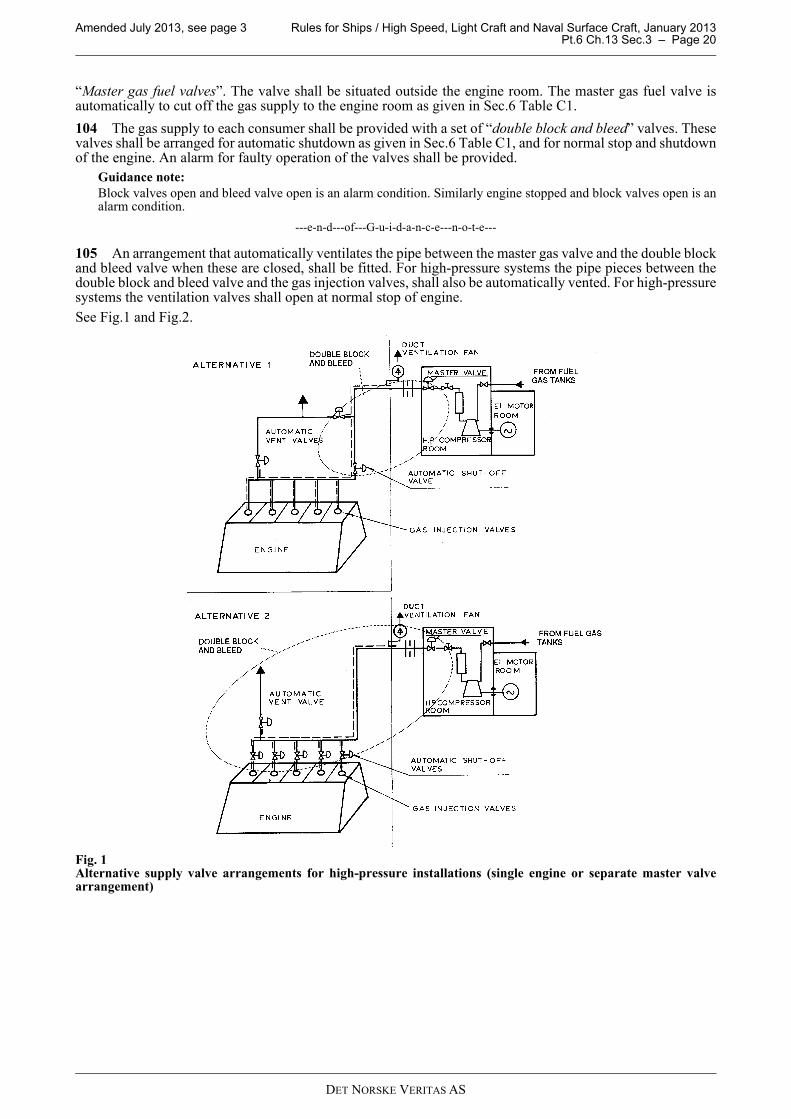
---e-n-d---of---G-u-i-d-a-n-c-e---n-o-t-e---
Guidance note 2:
IMO resolution MSC.285(86) ‘Interim Guidelines on Safety for Gas Fuelled Engine Installations in Ships’ providesinternational guidelines, and may be enforced by the flag. In addition to what is required in this rule chapter, theInterim Guidelines require safety assessments to be done for new designs and concepts.
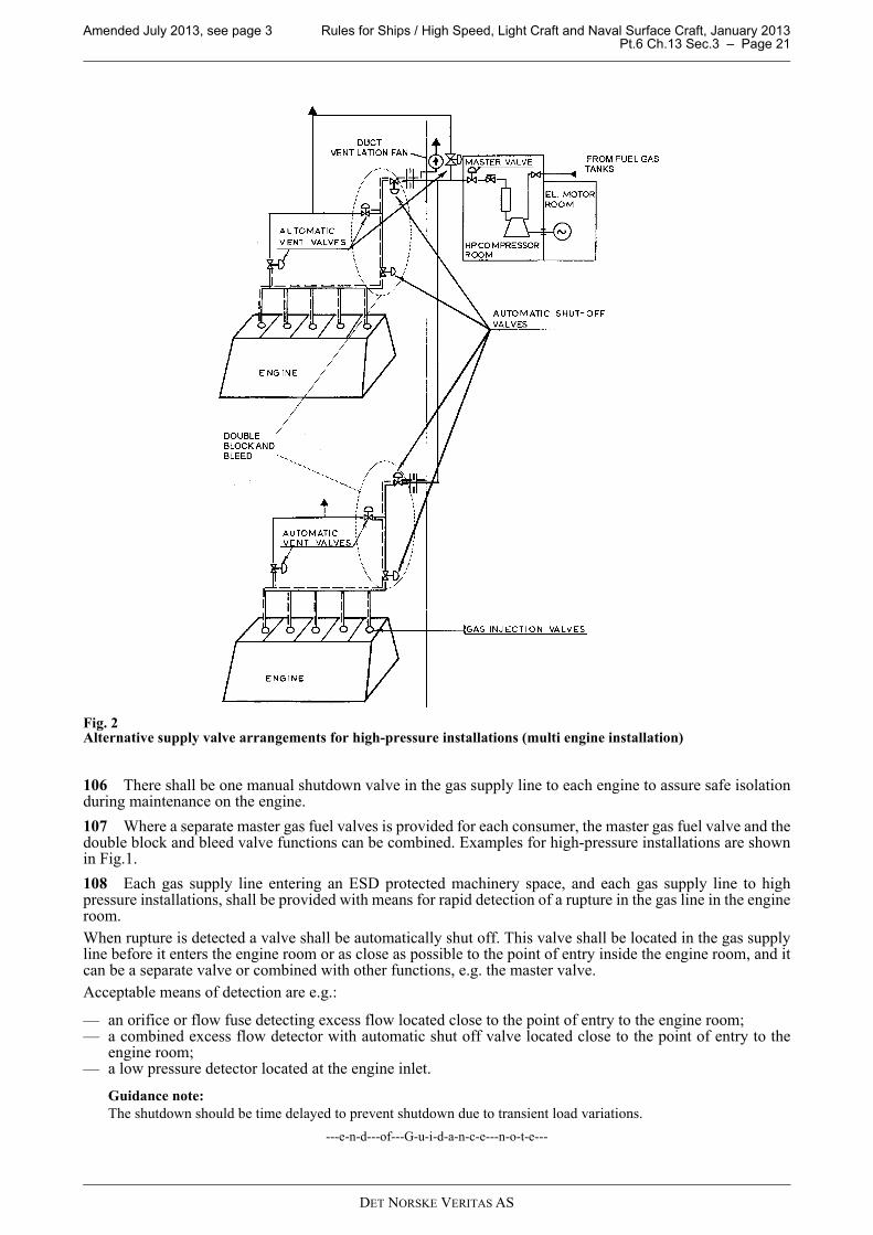
---e-n-d---of---G-u-i-d-a-n-c-e---n-o-t-e---
Guidance note 3:
Requirements not relevant for LNG carriers are shown in bold italic text.
---e-n-d---of---G-u-i-d-a-n-c-e---n-o-t-e---
302 This rule chapter can also be applied to gas fuelled gas turbine and boiler installations in ships.
Guidance note:
Dual fuel boilers: Rules for Classification of Ships Pt.5 Ch.5 Sec.16 should be used for approval of main boilers forpropulsion or other main functions, while safety related requirements from the same chapter should be used for boilersthat are not supporting the ship main functions.
Gas turbines: Gas turbine requirements are found in Pt.4 Ch.3 Sec.2. A gas tight turbine enclosure can be approvedusing the ESD protected engine room principles, even though the pressure exceeds 10 bar in the piping. Particularfocus should be given to ventilation rate in such an enclosure.
---e-n-d---of---G-u-i-d-a-n-c-e---n-o-t-e---
303 The rules are applicable for installations where natural gas is used as fuel. If other gases are used as fuelspecial considerations will have to be done, and additional requirements may be relevant.
A 400 Class notation
401 Ships built with machinery satisfying the requirements in this chapter will be given class notation:
GAS FUELLED.
Amended July 2013, see page 3 Rules for Ships / High Speed, Light Craft and Naval Surface Craft, January 2013 Pt.6 Ch.13 Sec.1 – Page 8
DET NORSKE VERITAS AS
A 500 Survey extent
501 Survey requirements for ships with the class notation GAS FUELLED are given in the Rules forClassification of Ships, Pt.7 Ch.1 Sec.2 A and C, Pt.7 Ch.1 Sec.3 C and Pt.7 Ch.1 Sec.4 C.
B. Definitions
B 100 Terms
101 Accommodation spaces are those spaces used for public spaces, corridors, lavatories, cabins, offices,hospitals, cinemas, game and hobby rooms, barber shops, pantries containing no cooking appliances andsimilar spaces.
102 Control stations are those spaces in which the ship's radio or main navigating equipment or the emergencysource of power is located or where the fire recording or fire control equipment is centralized. Spaces where thefire recording or fire control equipment is centralized are also considered to be a fire control station.
Guidance note:
This does not include special fire control equipment that can be most practically located in the cargo area (if the vesselis a cargo ship).
---e-n-d---of---G-u-i-d-a-n-c-e---n-o-t-e---
103 Double block and bleed valve is a set of three automatic valves located at the fuel supply to each of thegas engines. Two of these valves shall be in series in the gas fuel pipe to the consuming equipment. The thirdvalve shall be in a pipe that vents to a safe location in the open air, that portion of the gas fuel piping that isbetween the two valves in series.
Alternatively, the function of one of the valves in series and the ventilation valve can be incorporated into onevalve body, so arranged that the flow to the gas utilisation unit will be blocked and the ventilation opened.
104 Dual fuel engines are in this context engines that can burn gaseous and liquid fuel simultaneously and ina wide variety of proportions, or can operate successively on oil fuel and gas.
105 ESD means emergency shutdown.
106 Enclosed space means any space within which, in the absence of artificial ventilation, the ventilation willbe limited and any explosive atmosphere will not be dispersed naturally.
Guidance note:
See also definition in IEC 60092-502:1999.
---e-n-d---of---G-u-i-d-a-n-c-e---n-o-t-e---
107 Engine room is in this chapter used for machinery spaces containing gas fuelled engines.
108 Fuel containment system is the arrangement for the storage of fuel including tank connections. It includeswhere fitted, a primary and secondary barrier, associated insulation and any intervening spaces, and adjacentstructure if necessary for the support of these elements. If the secondary barrier is part of the hull structure itmay be a boundary of the fuel storage hold space.
109 Fuel storage hold space is the space enclosed by the ship's structure in which a fuel containment systemis situated. If tank connections are located in the fuel storage hold space, it will also be a tank connection space,and will have to fulfil the requirements for both spaces.
110 Gas is defined as a fluid having a vapour pressure exceeding 2.8 bar absolute at a temperature of 37.8°C.
111 Gas control systems are providing control and monitoring for bunkering, gas storage and gas supply tomachinery.
112 Gas safety systems are the safety systems for bunkering, gas storage and gas supply to machinery.
113 Gas valve unit spaces are spaces or boxes containing valves for control and regulation of gas supplybefore the consumer.
Guidance note:
The gas valve unit is by different suppliers also called for instance GVU, gas regulating unit, GRU or gas train.
---e-n-d---of---G-u-i-d-a-n-c-e---n-o-t-e---
114 Hazardous area
Area in which an explosive gas atmosphere or a flammable gas with a flash point below 60°C is or may beexpected to be present, in quantities such as to require special precautions for the construction, installation anduse of electrical apparatus.
Amended July 2013, see page 3 Rules for Ships / High Speed, Light Craft and Naval Surface Craft, January 2013 Pt.6 Ch.13 Sec.1 – Page 9
DET NORSKE VERITAS AS
Hazardous areas are divided into Zone 0, 1 and 2 as defined below and according to the area classificationspecified in Sec.5 B.
Zone 0
Area in which an explosive gas atmosphere or a flammable gas with a flash point below 60°C is presentcontinuously or is present for long periods
Zone 1
Area in which an explosive gas atmosphere or a flammable gas with a flash point below 60°C is likely to occurin normal operation
Zone 2
Area in which an explosive gas atmosphere or a flammable gas with a flash point below 60°C is not likely tooccur in normal operation and, if it does occur, is likely to do so only infrequently and will exist for a shortperiod only.
Guidance note:
The definition of hazardous area is only related to the risk of explosion. In this context, health, safety andenvironmental issues, i.e. toxicity, is not considered.
---e-n-d---of---G-u-i-d-a-n-c-e---n-o-t-e---
115 Non-hazardous area
An area not considered to be hazardous, i.e. gas safe, provided certain conditions are being met.
116 Sources of release are valves or detachable pipe joints in the fuel gas system. Also compressors and sealsof pumps in the fuel gas system are regarded as sources of release.
117 High-pressure piping is in this context piping with maximum working pressure above 10 bar.
118 LEL is lower explosion limit.
119 Main tank valve is the remote operated valve on the gas supply outlet from a gas storage tank.
120 MARVS is the maximum allowable relief valves setting of a gas tank.
121 Master gas fuel valve is an automatic valve in the gas supply line to each engine located outside theengine room.
122 Open deck means a deck that is open at one or both ends and equipped with adequate natural ventilationthat is effective over the entire length of the deck through permanent openings distributed in the side panels orin the deck above.
123 Semi-enclosed spaces are locations where natural conditions of ventilation are notably different fromthose on open decks due to the presence of structures such as roofs, wind breakers and bulkheads and whichare so arranged that dispersion of gas may not occur.
124 Service spaces are spaces outside the cargo area used for galleys, pantries containing cooking appliances,lockers, mail and specie rooms, store rooms, workshops other than those forming part of the machinery spacesand similar spaces and trunks to such spaces.
125 Single gas fuel system is a power generating system consisting of gas-only engines, not able to switchover to fuel oil running.
126 Tank connection space means the gastight space surrounding the bunker tank connections and tank valves.
Amended July 2013, see page 3 Rules for Ships / High Speed, Light Craft and Naval Surface Craft, January 2013 Pt.6 Ch.13 Sec.1 – Page 10
DET NORSKE VERITAS AS
C. Documentation
C 100 Plans and particulars
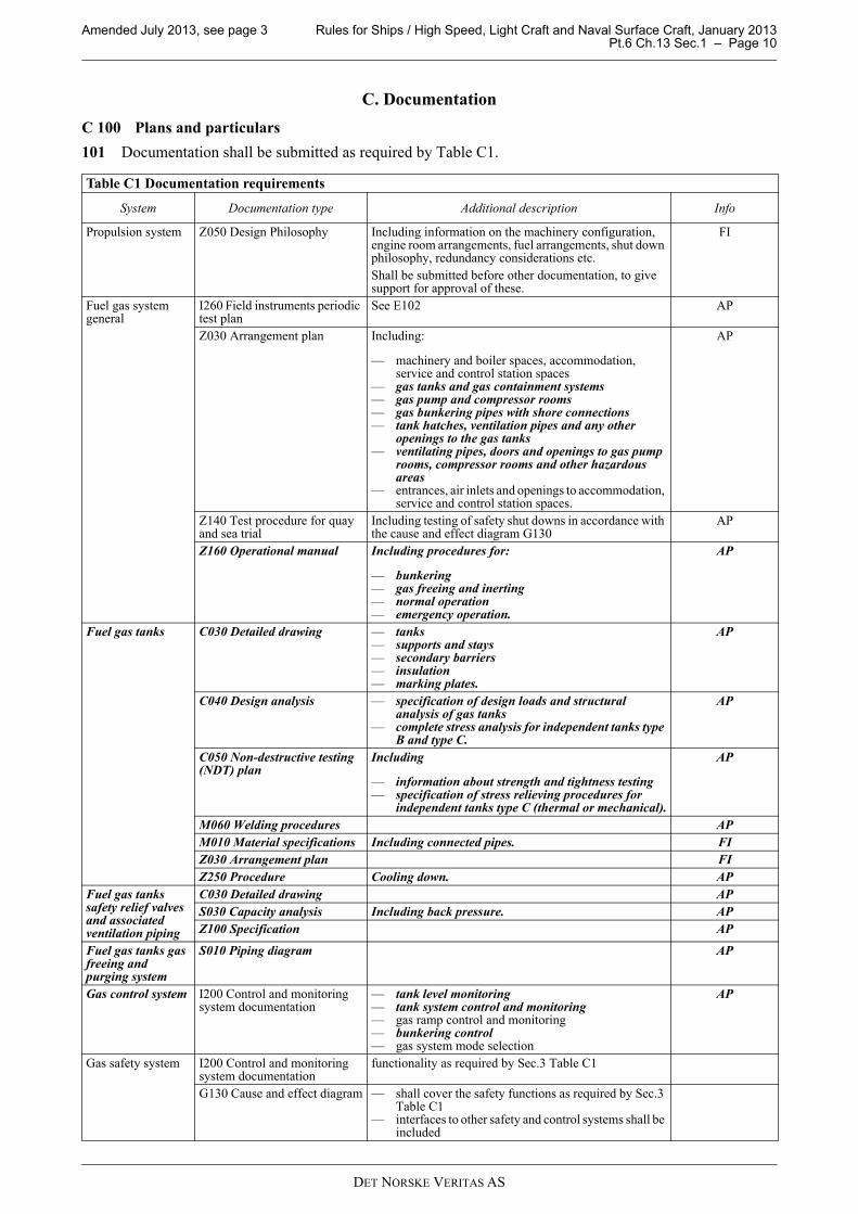
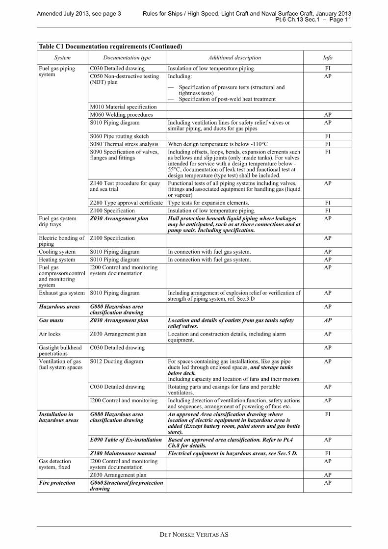
101 Documentation shall be submitted as required by Table C1.
Table C1 Documentation requirements
System Documentation type Additional description Info
Propulsion system Z050 Design Philosophy Including information on the machinery configuration, engine room arrangements, fuel arrangements, shut down philosophy, redundancy considerations etc.
Shall be submitted before other documentation, to give support for approval of these.
FI
Fuel gas system general
I260 Field instruments periodic test plan
See E102 AP
Z030 Arrangement plan Including:
— machinery and boiler spaces, accommodation, service and control station spaces
— gas tanks and gas containment systems— gas pump and compressor rooms— gas bunkering pipes with shore connections— tank hatches, ventilation pipes and any other
openings to the gas tanks— ventilating pipes, doors and openings to gas pump
rooms, compressor rooms and other hazardous areas
— entrances, air inlets and openings to accommodation, service and control station spaces.
AP
Z140 Test procedure for quay and sea trial
Including testing of safety shut downs in accordance with the cause and effect diagram G130
AP
Z160 Operational manual Including procedures for:
— bunkering— gas freeing and inerting— normal operation— emergency operation.
AP
Fuel gas tanks C030 Detailed drawing — tanks— supports and stays— secondary barriers— insulation— marking plates.
AP
C040 Design analysis — specification of design loads and structural analysis of gas tanks
— complete stress analysis for independent tanks type B and type C.
AP
C050 Non-destructive testing (NDT) plan
Including
— information about strength and tightness testing— specification of stress relieving procedures for
independent tanks type C (thermal or mechanical).
AP
M060 Welding procedures AP
M010 Material specifications Including connected pipes. FI
Z030 Arrangement plan FI
Z250 Procedure Cooling down. AP
Fuel gas tanks safety relief valves and associated ventilation piping
C030 Detailed drawing AP
S030 Capacity analysis Including back pressure. AP
Z100 Specification AP
Fuel gas tanks gas freeing and purging system
S010 Piping diagram AP
Gas control system I200 Control and monitoring system documentation
— tank level monitoring— tank system control and monitoring— gas ramp control and monitoring— bunkering control— gas system mode selection
AP
Gas safety system I200 Control and monitoring system documentation
functionality as required by Sec.3 Table C1
G130 Cause and effect diagram — shall cover the safety functions as required by Sec.3 Table C1
— interfaces to other safety and control systems shall be included
Amended July 2013, see page 3 Rules for Ships / High Speed, Light Craft and Naval Surface Craft, January 2013 Pt.6 Ch.13 Sec.1 – Page 11
DET NORSKE VERITAS AS
Fuel gas piping system
C030 Detailed drawing Insulation of low temperature piping. FI
C050 Non-destructive testing (NDT) plan
Including:
— Specification of pressure tests (structural and tightness tests)
— Specification of post-weld heat treatment
AP
M010 Material specification
M060 Welding procedures AP
S010 Piping diagram Including ventilation lines for safety relief valves or similar piping, and ducts for gas pipes
AP
S060 Pipe routing sketch FI
S080 Thermal stress analysis When design temperature is below -110°C FI
S090 Specification of valves, flanges and fittings
Including offsets, loops, bends, expansion elements such as bellows and slip joints (only inside tanks). For valves intended for service with a design temperature below -55°C, documentation of leak test and functional test at design temperature (type test) shall be included.
FI
Z140 Test procedure for quay and sea trial
Functional tests of all piping systems including valves, fittings and associated equipment for handling gas (liquid or vapour)
AP
Z280 Type approval certificate Type tests for expansion elements. FI
Z100 Specification Insulation of low temperature piping. FI
Fuel gas system drip trays
Z030 Arrangement plan Hull protection beneath liquid piping where leakages may be anticipated, such as at shore connections and at pump seals. Including specification.
AP
Electric bonding of piping
Z100 Specification AP
Cooling system S010 Piping diagram In connection with fuel gas system. AP
Heating system S010 Piping diagram In connection with fuel gas system. AP
Fuel gas compressors control and monitoring system
I200 Control and monitoring system documentation
AP
Exhaust gas system S010 Piping diagram Including arrangement of explosion relief or verification of strength of piping system, ref. Sec.3 D
AP
Hazardous areas G080 Hazardous area classification drawing
AP
Gas masts Z030 Arrangement plan Location and details of outlets from gas tanks safety relief valves.
AP
Air locks Z030 Arrangement plan Location and construction details, including alarm equipment.
AP
Gastight bulkhead penetrations
C030 Detailed drawing AP
Ventilation of gas fuel system spaces
S012 Ducting diagram For spaces containing gas installations, like gas pipe ducts led through enclosed spaces, and storage tanks below deck.Including capacity and location of fans and their motors.
AP
C030 Detailed drawing Rotating parts and casings for fans and portable ventilators.
AP
I200 Control and monitoring Including detection of ventilation function, safety actions and sequences, arrangement of powering of fans etc.
AP
Installation in hazardous areas
G080 Hazardous area classification drawing
An approved Area classification drawing where location of electric equipment in hazardous area is added (Except battery room, paint stores and gas bottle store).
FI
E090 Table of Ex-installation Based on approved area classification. Refer to Pt.4 Ch.8 for details.
AP
Z180 Maintenance manual Electrical equipment in hazardous areas, see Sec.5 D. FI
Gas detection system, fixed
I200 Control and monitoring system documentation
AP
Z030 Arrangement plan AP
Fire protection G060 Structural fire protection drawing
AP
Table C1 Documentation requirements (Continued)
System Documentation type Additional description Info
Amended July 2013, see page 3 Rules for Ships / High Speed, Light Craft and Naval Surface Craft, January 2013 Pt.6 Ch.13 Sec.1 – Page 12
DET NORSKE VERITAS AS
102 For general requirements to documentation, including definition of the Info codes, see Pt.0 Ch.3 Sec.1.
103 For a full definition of the documentation types, see Pt.0 Ch.3 Sec.2.
D. Certification
D 100 Gas engines
101 Gas engines shall, in addition to the requirements in this chapter, be certified in accordance with Pt.4 Ch.3.
D 200 Pressure vessels
201 Pressure vessels, which under normal operations will contain gas in the liquid and/or gaseous state, shallbe certified as class I pressure vessels in accordance with Pt.4 Ch.7.
Tanks for compressed natural gas (CNG) may also be certified based on Rules Pt.5 Ch.15 Compressed NaturalGas Carriers.
D 300 Valves
301 For valves used in high pressure gas systems or systems with working temperature below 0°C productcertification as given in Rules for Classification of Ships, Pt.5 Ch.5 Sec.6 H is required.
Valves in low temperature service of which correct operation is important for safety shall have DNV productcertificate even for diameters below 100 mm.
For valves used in gas piping systems with low pressure and temperature above 0°C product certification isrequired, as given in the Rules for Classification of Ships, Pt.4 Ch.6.
D 400 Pumps and compressors
401 Pumps and compressors in gas systems shall be delivered with the Society’s product certificate.
402 For general requirements and with regard to testing of pumps: See the Rules for Classification of Ships,Pt.4 Ch.6.
403 For general requirements and with regard to testing of compressors: See Pt.4 Ch.5.
D 500 Control and monitoring system
501 The following control and monitoring system shall be certified according to Pt.4 Ch.9:
— gas control system— gas safety system— ventilation control system — gas detection system.
D 600 Electric motors and motor-starters
601 Electric motors and motor-starters for gas supply system and ventilation system are considered to beimportant consumers, and shall be certified in accordance with Pt.4 Ch.8 Sec.1 B300.
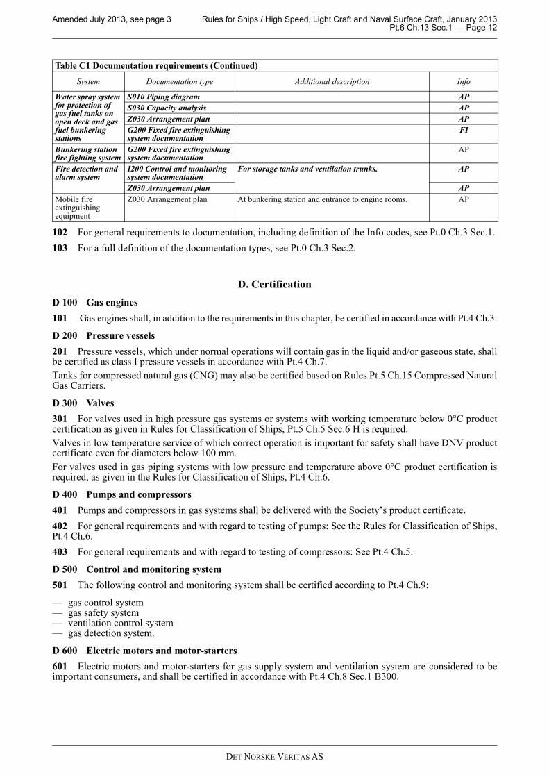
Water spray system for protection of gas fuel tanks on open deck and gas fuel bunkering stations
S010 Piping diagram AP
S030 Capacity analysis AP
Z030 Arrangement plan AP
G200 Fixed fire extinguishing system documentation
FI
Bunkering station fire fighting system
G200 Fixed fire extinguishing system documentation
AP
Fire detection and alarm system
I200 Control and monitoring system documentation
For storage tanks and ventilation trunks. AP
Z030 Arrangement plan AP
Mobile fire extinguishing equipment
Z030 Arrangement plan At bunkering station and entrance to engine rooms. AP
Table C1 Documentation requirements (Continued)
System Documentation type Additional description Info
Amended July 2013, see page 3 Rules for Ships / High Speed, Light Craft and Naval Surface Craft, January 2013 Pt.6 Ch.13 Sec.1 – Page 13
DET NORSKE VERITAS AS
E. Onboard documentation
E 100 Contents
101 An operational manual as described in Table C1 shall be kept onboard.
102 A plan for periodic test of all field instruments specified in these rules shall be kept onboard. The planshall include test intervals, description of how to perform the tests and description of what to observe duringthe tests.
Test intervals for shutdown inputs and outputs (as required by Sec.6 Table C1) shall not exceed 6 months. Forother signals the test intervals shall not exceed 12 months.
The plan may be included in the plan required for the class notation E0.
Guidance note:
See Pt.6 Ch.3 Sec.1 D for information about plan for periodic test.
---e-n-d---of---G-u-i-d-a-n-c-e---n-o-t-e---
F. Signboards
F 100 General
101 If the gas supply is shut off due to activation of an automatic valve, the gas supply shall not be openeduntil the reason for the disconnection is ascertained and the necessary precautions taken. A readily visiblenotice giving instruction to this effect shall be placed at the operating station for the shut-off valves in the gassupply lines.
102 If a gas leak leading to a gas supply shutdown occurs, the gas fuel supply shall not be operated until theleak has been found and dealt with. Instructions to this effect shall be placed in a prominent position in themachinery space.
103 A signboard shall be permanently fitted in the engine room stating that heavy lifting, implying danger ofdamage to the gas pipes, shall not be done when the engine(s) is running on gas.
104 A signboard shall be permanently fitted on access hatches to tank connection spaces stating that the spacecontaining the access hatch will be hazardous when the hatch is open, and that all non ex certified equipmentshall be de-energized prior to the opening of this hatch. This is not necessary if the access to the tank connectionspace is arranged with an air lock.
105 A signboard shall be permanently fitted on direct access doors or hatches to gas valve unit spaces/boxesin engine rooms (without air lock) stating that the door or hatch shall only be opened after the gas supply systemis shut down and gas free.
Amended July 2013, see page 3 Rules for Ships / High Speed, Light Craft and Naval Surface Craft, January 2013 Pt.6 Ch.13 Sec.2 – Page 14
DET NORSKE VERITAS AS
SECTION 2 MATERIALS
A. General
A 100 Material requirements
101 Materials are in general to be in accordance with the requirements in Pt.2.
102 Materials used in gas tanks, gas piping, process pressure vessels and other components in contact withgas with high pressure or a working temperature below 0°C shall be in accordance with the Rules forClassification of Ships, Pt.5 Ch.5 Sec.2 D. For piping see the Rules for Classification of Ships, Pt.5 Ch.5 Sec.6C200.
For CNG tanks, the use of materials not covered by Rules for Classification of Ships, Pt.5 Ch.5 may bespecially considered and approved by the Society.
103 The materials used in gas piping systems with high pressure or temperature below 0°C shall be furnishedwith documentation in accordance with the Rules for Classification of Ships, Pt.5 Ch.5 Sec.2 Table E1.
The materials used in gas piping systems with low pressure and temperature above 0°C shall be furnished withdocumentation in accordance with the Rules for Classification of Ships, Pt.4 Ch.6 Sec.2 Table A2. Gas pipingis pertaining to the same pipe class as fuel oil piping in Pt.4 Ch.6 Sec.1 Table B1.
For the definition of material documentation see the Rules for Classification of Ships, Pt.1 Ch.1 Sec.4.
104 The outer pipe in enclosed spaces with high pressure gas in the inner pipe is as least required to fulfil thematerial requirements for pipe materials with design temperature down to -55°C in the Rules for Classificationof Ships, Pt.5 Ch.5 Sec.2 Table D4.
105 The outer pipe or duct around gas pipes with liquid gas shall be made of cold resistant steel unless it isefficiently protected from possible leakages from the inner pipe.
The same applies if a duct or outer pipe containing warm gas pipes can be exposed to liquid gas leakage fromother sources or spaces.
Amended July 2013, see page 3 Rules for Ships / High Speed, Light Craft and Naval Surface Craft, January 2013 Pt.6 Ch.13 Sec.3 – Page 15
DET NORSKE VERITAS AS
SECTION 3 ARRANGEMENT AND SYSTEM DESIGN
A. Location and separation of spaces, arrangement of entrances and other openings
A 100 General
101 Access from a hazardous space or hazardous open deck area to a non-hazardous space shall be throughan air lock which complies with the requirements of B100. Specific requirements and restrictions for access todifferent types of spaces are found below.
Guidance note:
Gas valve unit spaces in gas safe engine rooms will not need to comply with the requirement for an air lock on thecondition that the gas valve unit space is normally locked, and shall only be entered after gas supply system is shutdown and gas free. The door must be fitted with a signboard to this effect. The gas valve unit room is considered partof the double duct in the engine room and shall therefore be extraction ventilated with at least 30 air changes per hourand fitted with a gas detection system typically giving shut down of gas supply into the area at detection of gas.
---e-n-d---of---G-u-i-d-a-n-c-e---n-o-t-e---
102 Cofferdams shall be of sufficient size for easy access to all parts. Minimum distance between bulkheads:600 mm.
Guidance note:
For cofferdams protecting gas fuel tanks from fire risk spaces see A404, and for access around tanks see H211.
---e-n-d---of---G-u-i-d-a-n-c-e---n-o-t-e---
103 Spaces containing piping or equipment for cryogenic liquids shall be fitted with low temperature driptrays under leakage points (sources of release). For high pressure compressed gas, low temperature steelshielding should be provided to prevent cold jets impinging on surrounding structure.
The surrounding hull or deck structures shall not be exposed to unacceptable cooling, in case of leakage ofliquid or compressed gas.
If the piping and equipment in such a space is connected to liquid gas tanks in such a way that risk of leakagesfrom the tanks into the space cannot be efficiently excluded, the requirements as for tank connection spaces in400 shall be made applicable to this space.
104 Bilge suctions from the tank connection space, compressor room, pump room or similar spaces withgas equipment, if provided, shall not be connected to the bilge system for the rest of the ship.
A 200 Gas compressor or pump room
201 Compressor or pump rooms, if arranged, shall be located on open deck, or arranged in accordancewith A400 Tank connection spaces.
202 If the compressor room is located below open deck the room shall have an independent access directfrom the open deck. Where a separate access from deck is not practicable, an air lock which complies withthe requirements of B100 shall be provided.
203 Where compressors are driven by shafting passing through a bulkhead or deck, the bulkheadpenetration shall be of gas tight type.
A 300 Engine rooms
301 When more than one engine room is required (ESD protected engine rooms) and these rooms areseparated by a single bulkhead, the bulkhead shall have sufficient strength to withstand a local gas explosion.A strength standard of the bulkhead corresponding to that of a watertight bulkhead is considered adequate.
302 Engine rooms of the ESD protected type shall have as simple geometrical shape as possible and bearranged to minimize potential gas-traps e.g. between beams and bulkheads.
303 An engine room containing gas engines shall have at least two completely independent exits. However,if the engine room is very small, this requirement can be waived after special consideration by the Society.
304 If the access to an engine room of ESD protected type is from another enclosed space in the ship, theentrances shall be arranged with self-closing doors. Audible and visible alarm shall sound at a permanentlymanned location if the door is open continuously for more than 1 minute. As an alternative an arrangement withtwo self-closing doors in series can be approved.
305 Access to engine rooms shall not be from hazardous spaces. It is however accepted to have access to gasvalve units in engine rooms.
Amended July 2013, see page 3 Rules for Ships / High Speed, Light Craft and Naval Surface Craft, January 2013 Pt.6 Ch.13 Sec.3 – Page 16
DET NORSKE VERITAS AS
A 400 Tank connection spaces
401 The fuel storage tank connections, flanges and tank valves not located on open deck must be enclosedin a tank connection space. The space shall be able to safely contain leakage from the tank in case of leakagein the tank connections. This implies that the material shall be in accordance with the Rules forClassification of Ships, Pt.5 Ch.5 Sec.2 D, for secondary barriers. However, based on maximum leakagecalculations, arrangements without full extent of the low temperature material barriers may be approved.Ship movements must be taken into consideration.
The space shall be designed to withstand the maximum pressure build up. Alternatively, pressure reliefventing to a safe location (mast) can be provided.
The space shall be isolated thermally so that the surrounding hull is not exposed to unacceptable cooling,in case of leakage of liquid gas. This secondary barrier space is in other parts of this chapter called “tankconnection space”.
402 A leakage of liquid gas into the gas connection space shall not render necessary safety functions outof order due to the cryogenic temperatures.
Guidance note:
Valves, actuators, control systems are to be designed and arranged for being able to operate after liquid gasleakage.
---e-n-d---of---G-u-i-d-a-n-c-e---n-o-t-e---
403 Tank connection space boundaries shall be gas tight towards other enclosed spaces in the ship.
404 Gas fuel tanks in enclosed spaces including secondary barriers where required and tank connectionspaces shall not be located adjacent to machinery spaces of category A or other high fire risk areas.
The protective cofferdam shall have a minimum distance of 900 mm between bulkheads or decks.
For vacuum insulated type C fuel tanks the fuel storage hold space may act as the protective cofferdam, ifthe bulkhead is at least 900 mm from the outer shell of the tank. This can however not be applied to tankslocated directly above machinery spaces of category A or other high fire risk areas.
Common boundaries of protective cofferdams with engine rooms or high fire risk areas shall kept to aminimum.
Fuel gas tanks shall be protected from external fires by class divisions as given in Sec.4.
Guidance note:
High fire risk areas are for instance cargo areas for carriage of dangerous goods and cargo decks for cars withfuel in the tanks.
---e-n-d---of---G-u-i-d-a-n-c-e---n-o-t-e---
405 The tank connection space entrance shall be arranged with a sill height of at least 300 mm or the levelof liquid gas based on calculated maximum leakage.
406 Access to the tank connection space is as far as practicable to be independent and direct from opendeck. This requirement shall be applied to the room where the opening to the tank connection space islocated, if the tank connection space access is through a hatch.
Where a separate access from deck is not practicable, an air lock which complies with the requirements ofB100 shall be provided. It should not be possible to have unauthorized access to the tank connection spaceduring normal operation of the gas system.
407 If the tank connection space access is not from open deck and is not arranged with an air lock directlyon the tank connection space access, certain requirements will be made applicable to the room containingthe access to the tank connection space:
— Separate ventilation with at least 8 air changes per hour.— The room is considered non- hazardous under normal conditions, but when access to tank connection
space is required it has potential to become gas hazardous.
In this case non-explosion protected equipment shall be de-energized, while equipment in use shall beof explosion protected design suitable at least for zone 2. Electrical cables led through the spaces areexempted.
A 500 Fuel storage hold space
501 The fuel storage hold space shall not be used for machinery or equipment that may have a fire risk.
A 600 Other spaces containing gas equipment
601 Other spaces containing gas equipment like valves, vaporizers, heaters etc. should generally follow therequirements for compressor and pump rooms in A200.
Amended July 2013, see page 3 Rules for Ships / High Speed, Light Craft and Naval Surface Craft, January 2013 Pt.6 Ch.13 Sec.3 – Page 17
DET NORSKE VERITAS AS
B. Arrangement of air locks
B 100 General
101 An air lock is a space enclosed by gastight steel bulkheads with two substantially gastight doors spacedat least 1.5 m and not more than 2.5 m apart. The doors shall be self-closing without any holding backarrangements.
102 Air locks shall be mechanically ventilated at an overpressure relative to the adjacent hazardous area orspace. The ventilation inlets and outlets for air locks are to be located in open air. For ventilation of theprotected space see J201.
103 Air locks shall have a simple geometrical form. They shall provide free and easy passage, and shall havea deck area not less than about 1.5 m2. Air locks shall not be used for other purposes, for instance as store rooms.
104 An audible and visual alarm system to give a warning on both sides of the air lock shall be provided toindicate if more than one door is moved from the closed position.
105 The air lock space shall be monitored for flammable gas.
106 For gas safe spaces with access from hazardous open deck where the access is protected by an air-lock,electrical equipment which is not of the certified safe shall be de-energized upon loss of overpressure in thespace.
For gas safe spaces with access from hazardous spaces where the access is protected by an air-lock, electricalequipment which is not of the certified safe type shall be de-energized upon loss of underpressure in thehazardous space.
The requirement for de-energizing is not applicable for safe spaces having access through air lock from a gassafe space containing a tank connection space access (as outlined in A407). It is also not applicable to enginerooms with access to gas valve unit spaces.
Guidance note:
The de-energizing requirement consequently means that electrical equipment needed for maintaining ship mainfunctions or safety functions cannot be located in spaces protected by air locks unless the equipment is of certifiedsafe type.
---e-n-d---of---G-u-i-d-a-n-c-e---n-o-t-e---
C. General gas piping design
C 100 General
101 All automatic and remotely operated valves are to be provided with indications for open and closed valvepositions at the location where the valves are remotely operated.
102 Valves shall fail to a safe position.
Guidance note:
“Fail to close” is generally considered to be the safe mode. For Double-Block-and-Bleed arrangements, the bleedvalve shall fail to open position. Valves in vent lines intended to relieve trapped liquid gas in piping systems shall alsofail to open.
---e-n-d---of---G-u-i-d-a-n-c-e---n-o-t-e---
103 Gas pipes shall in general comply with the applicable parts of the Rules for Classification of Ships, Pt.5Ch.5 Sec.6.
104 Gas piping shall not be located less than 800 mm from the ship's side.
105 An arrangement for purging gas bunkering lines and supply lines (only up to the double block and bleedvalves if these are located close to the engine) with nitrogen shall be provided.
106 The gas piping system shall be installed with sufficient flexibility. Bellows shall not be arranged inenclosed spaces.
107 Gas pipes shall be colour marked based on a recognized standard.
Guidance note:
Refer to EN ISO 14726:2008 Ships and marine technology - Identification colours for the content of piping systems.
---e-n-d---of---G-u-i-d-a-n-c-e---n-o-t-e---
108 If the fuel gas contains heavier components that may condense in the system, knock out drums orequivalent means for collecting the liquid shall be fitted.
Amended July 2013, see page 3 Rules for Ships / High Speed, Light Craft and Naval Surface Craft, January 2013 Pt.6 Ch.13 Sec.3 – Page 18
DET NORSKE VERITAS AS
109 High pressure gas piping systems shall have sufficient constructive strength. This shall be confirmed bycarrying out stress analysis and taking into account:
— stresses due to the weight of the piping system— acceleration loads when significant— internal pressure and loads induced by hog and sag of the ship.
[IACS UR M59]
Guidance note:
Significant acceleration loads is in this context acceleration loads that give a stress equal to more than 20% of thestress from the internal pressure in the pipe.
---e-n-d---of---G-u-i-d-a-n-c-e---n-o-t-e---
110 All valves and expansion joints used in high pressure gas systems shall be of an approved type.
[IACS UR M59]
111 All gas piping and tanks shall be electrically bonded to the ship's hull. Bonding straps across stainlesssteel flanges with bolts and nuts of stainless steel are not required. If carbon-manganese steel is not fitted withbonding straps across the flanges, it shall be checked for electric bonding. The electrical bonding is sufficient,when the electrical resistance between piping and the hull does not exceed 106 Ohm.
Gas piping sections of piping components which are not permanently connected to the hull by permanentpiping connections, or where such connections are removable e.g. for removal of spool pieces, shall beelectrically bonded to the hull by special bonding straps.
Guidance note:
The value of resistance 106 Ohm may be achieved without the use of bonding straps where gas piping systems andequipment are directly, or via their supports, either welded or bolted to the hull of the ship. It will be generallynecessary initially to achieve a resistance value below 106 Ohm, to allow for deterioration in service.
---e-n-d---of---G-u-i-d-a-n-c-e---n-o-t-e---
112 Gas piping shall be protected against mechanical damage.
Guidance note:
Gas pipes lead through ro-ro spaces on open deck shall be provided with guards or bollards to prevent vehicle collisiondamage. Gas pipes in other types of cargo areas with risk of damage from cargo operations shall be similarlyprotected.
Gas pipes in double ducts in other areas are generally regarded as sufficiently protected.
Gas pipes in ESD protected machinery spaces shall be mechanically protected if they are so located that objects canfall onto them. If the pipes are located high up and close to the bulkheads additional protection is not needed.
---e-n-d---of---G-u-i-d-a-n-c-e---n-o-t-e---
113 High-pressure gas lines shall be installed and protected so as to minimise the risk of injury to personnelin case of rupture.
D. Exhaust system
D 100 General
101 The exhaust system shall be equipped with explosion relief ventilation sufficiently dimensioned toprevent excessive explosion pressures in the event of ignition failure of one cylinder followed by ignition ofthe unburned gas in the system.
102 The explosion venting shall be led away from where personnel may normally be present.
Guidance note:
Both explosion impact and amount of potentially suffocating combustion gases shall be taken into account whendeciding where explosion relief can be located. The distance from a relief valve to gangways and working areas shouldgenerally be at least 3 meters, unless efficient shielding is provided. Bursting discs shall not open into engine rooms,but may be located inside the casing.
---e-n-d---of---G-u-i-d-a-n-c-e---n-o-t-e---
103 As an alternative to explosion venting, documentation showing that the exhaust system has sufficientstrength to contain the worst case explosion can be accepted.
104 Exhaust gas piping shall be arranged to avoid possibility for accumulation of unburned gas.
Amended July 2013, see page 3 Rules for Ships / High Speed, Light Craft and Naval Surface Craft, January 2013 Pt.6 Ch.13 Sec.3 – Page 19
DET NORSKE VERITAS AS
E. System configuration
E 100 General
101 The propulsion and fuel supply system shall be so designed that the remaining power after any safetyactions required by Sec.6 Table C1 (except fire alarm) shall be sufficient to maintain propulsion, powergeneration and other main functions defined in Pt.1 Ch.1 Sec.1 A200.
E 200 Engine room configuration options
201 Two alternative system configurations may be accepted:
i) Inherently gas safe machinery spaces: Arrangements in machinery spaces are such that the spaces areconsidered gas safe under all conditions, normal as well as abnormal conditions i.e. inherently gas safe.
ii) ESD protected machinery spaces: Arrangements in machinery spaces are such that the spaces areconsidered non- hazardous under normal conditions, but under certain abnormal conditions may have thepotential to become gas hazardous. In the event of abnormal conditions involving gas hazards, emergencyshutdown (ESD) of non-safe equipment (ignition sources) and machinery shall be automatically executedwhile equipment or machinery in use or active during these conditions shall be of explosion protecteddesign.
E 300 Inherently gas safe machinery spaces
301 All gas supply piping within machinery space boundaries must be enclosed in a gas tight enclosure, i.e.double wall piping or ducting.
302 For low pressure gas systems ventilation inlet openings for the double wall piping or duct can be acceptedlocated in the engine room on the condition that a gas detection system is fitted in the engine room.
E 400 ESD protected machinery spaces
401 Gas supply piping within machinery spaces may be accepted without a gas tight external enclosure onthe following conditions:
a) Engines for generating propulsion power and electric power are located in two or more engine rooms nothaving any common boundaries unless it can be documented that the common boundary can withstand anexplosion in one of the rooms. Distribution of engines between the different engine rooms are such that inthe case of shutdown of fuel supply to any one engine room it is possible to maintain sufficient propulsionpower plus normal electrical power supply for sea going services. Incinerators, inert gas generators, otheroil fired boilers or other ignition sources which can not be de-energized are not located within the ESDprotected machinery space.
b) Pressure in gas supply lines within machinery spaces is less than 10 bar.
c) A gas detection system is arranged in the engine room. At gas detection the safety system shallautomatically shutdown the gas supply (also oil fuel supply if dual fuel) and de-energize all non-explosionprotected equipment or installations in the engine room.
F. Gas supply system arrangement
F 100 Gas supply system general
101 For single gas fuel systems (gas only) the fuel supply system shall be arranged with redundancy andsegregation all the way from the gas tank to the consumer, so that a leakage in the fuel supply system withfollowing necessary safety actions does not lead to loss of propulsion, power generation or other mainfunctions.
The fuel storage shall be divided between two or more tanks, including separate secondary barriers whenrequired.
If transfer piping is arranged between tanks, this is to be so arranged that a leakage will not affect both supplysystems.
In the case LNG tanks of type C are used, one tank may be accepted if two completely separate tank connectionspaces are installed for the one tank.
102 Gas storage tank inlets and outlets shall be provided with valves located as close to the tank as possible.
Valves required to be operated during normal operation which are not accessible shall be remotely operated.Normal operation in this context is when gas is supplied to consumers and during bunkering operations.Regarding automatic operation of tank valves, see Sec.6 Table C1.
103 The main supply lines for gas to each engine room shall be equipped with automatically operated
Amended July 2013, see page 3 Rules for Ships / High Speed, Light Craft and Naval Surface Craft, January 2013 Pt.6 Ch.13 Sec.3 – Page 20
DET NORSKE VERITAS AS
“Master gas fuel valves”. The valve shall be situated outside the engine room. The master gas fuel valve isautomatically to cut off the gas supply to the engine room as given in Sec.6 Table C1.
104 The gas supply to each consumer shall be provided with a set of “double block and bleed” valves. Thesevalves shall be arranged for automatic shutdown as given in Sec.6 Table C1, and for normal stop and shutdownof the engine. An alarm for faulty operation of the valves shall be provided.
Guidance note:
Block valves open and bleed valve open is an alarm condition. Similarly engine stopped and block valves open is analarm condition.
---e-n-d---of---G-u-i-d-a-n-c-e---n-o-t-e---
105 An arrangement that automatically ventilates the pipe between the master gas valve and the double blockand bleed valve when these are closed, shall be fitted. For high-pressure systems the pipe pieces between thedouble block and bleed valve and the gas injection valves, shall also be automatically vented. For high-pressuresystems the ventilation valves shall open at normal stop of engine.
See Fig.1 and Fig.2.
Fig. 1Alternative supply valve arrangements for high-pressure installations (single engine or separate master valvearrangement)
Amended July 2013, see page 3 Rules for Ships / High Speed, Light Craft and Naval Surface Craft, January 2013 Pt.6 Ch.13 Sec.3 – Page 21
DET NORSKE VERITAS AS
Fig. 2Alternative supply valve arrangements for high-pressure installations (multi engine installation)
106 There shall be one manual shutdown valve in the gas supply line to each engine to assure safe isolationduring maintenance on the engine.
107 Where a separate master gas fuel valves is provided for each consumer, the master gas fuel valve and thedouble block and bleed valve functions can be combined. Examples for high-pressure installations are shownin Fig.1.
108 Each gas supply line entering an ESD protected machinery space, and each gas supply line to highpressure installations, shall be provided with means for rapid detection of a rupture in the gas line in the engineroom.
When rupture is detected a valve shall be automatically shut off. This valve shall be located in the gas supplyline before it enters the engine room or as close as possible to the point of entry inside the engine room, and itcan be a separate valve or combined with other functions, e.g. the master valve.
Acceptable means of detection are e.g.:
— an orifice or flow fuse detecting excess flow located close to the point of entry to the engine room;— a combined excess flow detector with automatic shut off valve located close to the point of entry to the
engine room;— a low pressure detector located at the engine inlet.
Guidance note:
The shutdown should be time delayed to prevent shutdown due to transient load variations.
---e-n-d---of---G-u-i-d-a-n-c-e---n-o-t-e---
Amended July 2013, see page 3 Rules for Ships / High Speed, Light Craft and Naval Surface Craft, January 2013 Pt.6 Ch.13 Sec.3 – Page 22
DET NORSKE VERITAS AS
F 200 Distribution outside of machinery spaces
201 Gas fuel piping shall normally not be lead through accommodation spaces, service spaces or controlstations.
202 Where gas pipes pass through enclosed spaces in the ship, they shall be enclosed in a duct that is gastight towards surrounding spaces. This duct shall be ventilated as outlined in J600, and gas detection asrequired in Sec.6 shall be provided.
203 The duct shall be dimensioned according to G103 and G104.
F 300 Gas heating
301 If the heating medium for the liquefied gas vaporizer has a freezing point above the boiling temperatureof the liquefied gas the following arrangement shall be provided:
— alarm for low temperature of outlet of heating medium— automatic stop of liquefied gas feed pump (if fitted) and closing of tank valve at stop of circulation of
heating fluid.
302 Circulation pumps for the heating fluid shall be arranged with redundancy, if circulation is necessary toprevent freezing in the heating circuit. Power supply shall then be from an UPS or alternative means formaintaining circulation for a sufficiently long period in case of loss of electric power supply.
303 The heating circuit expansion tank shall be fitted with a gas detector and shall be vented to open air.
G. Gas supply system in machinery spaces
G 100 Gas supply system for inherently gas safe machinery spaces
101 Gas supply lines in inherently gas safe machinery spaces shall be completely enclosed by a double pipeor duct. This double pipe or duct shall fulfil one of the following:
a) The gas piping shall be a double wall piping system with the gas fuel contained in the inner pipe. The spacebetween the concentric pipes shall be pressurised with inert gas at a pressure greater than the gas fuelpressure. Suitable alarms shall be provided to indicate a loss of inert gas pressure between the pipes.
When the inner pipe contains high pressure gas the system shall be so arranged so that the pipe between themaster gas valve and the engine is automatically purged with inert gas when the master gas valve is closed.
[IACS UR M59]
b) The gas fuel piping shall be installed within a ventilated pipe or duct. The air space between the gas fuelpiping and the wall of the outer pipe or duct shall be equipped with mechanical extraction ventilationhaving a capacity of at least 30 air changes per hour. This ventilation capacity can be reduced to 10 airchanges per hour provided automatic filling of the duct with nitrogen upon detection of gas is arranged for.The ventilation outlet shall be covered by a protection screen and placed in a position where no flammablegas-air mixture may be ignited.
102 The connecting of gas piping and ducting to the gas injection valves must be so as to provide completecoverage by the ducting. The arrangement must facilitate replacement and or overhaul of injection valves andcylinder covers.
Double ducting is also required for gas pipes on the engine and up to where the gas is supplied into thecombustion chamber.
Guidance note:
If gas is supplied into the air inlet pipe on a low pressure engine, double ducting may be omitted on the air inlet pipeon the condition that a gas detector is fitted above the engine.
---e-n-d---of---G-u-i-d-a-n-c-e---n-o-t-e---
103 For high-pressure piping the design pressure of the ducting shall be taken as the higher of the following:
— the maximum built up pressure: static pressure in way of the rupture resulting from the gas flowing in theannular space
— local instantaneous peak pressure in way of the rupture p*: this pressure shall be taken as the criticalpressure and is given by the following expression:
p∗ p02
k 1+------------
k
k 1–------------
=
Amended July 2013, see page 3 Rules for Ships / High Speed, Light Craft and Naval Surface Craft, January 2013 Pt.6 Ch.13 Sec.3 – Page 23
DET NORSKE VERITAS AS
p0 = maximum working pressure of the inner pipe
k = Cp/Cv constant pressure specific heat divided by the constant volume specific heat
k = 1.31 for CH4
The tangential membrane stress of a straight pipe shall not exceed the tensile strength divided by 1.5 (Rm/1.5)when subjected to the above pressure. The pressure ratings of all other piping components shall reflect the samelevel of strength as straight pipes.
As an alternative to using the peak pressure from the above formula, the peak pressure found fromrepresentative tests can be used. Test reports must then be submitted.
104 For low pressure piping the duct shall be dimensioned for a design pressure not less than the maximumworking pressure of the gas pipes. As an alternative the calculated maximum built up pressure in the duct inthe case of a pipe rupture when ventilation is not running may be approved used for dimensioning of the duct.
105 The arrangement and installation of the high-pressure gas piping must provide the necessary flexibilityfor the gas supply piping to accommodate the oscillating movements of the engine, without running the risk offatigue problems. The length and configuration of the branch lines are important factors in this regard.
G 200 Gas supply system for ESD protected machinery spaces
201 The pressure in the gas supply system shall not exceed 10 bar.
202 The gas supply lines shall have a design pressure not less than 10 bar.
H. Gas fuel storage tanks
H 100 General
101 A fuel gas containment system located below deck shall be gas tight towards adjacent spaces. For fuelgas containment systems where leakage through the primary barrier is part of the design assumptions thegas tight barrier will be the secondary barrier or in case of partial secondary barriers, the fuel storage holdspace.
H 200 Liquefied gas storage tanks
201 The storage tank used for liquefied gas shall be an independent tank or a membrane tank designed inaccordance with the Rules for Classification of Ships, Pt.5 Ch.5 Sec.5.
Guidance note:
Additional requirements for membrane tanks, A and B type tanks used as fuel tanks will be considered specially.Particular focus will be given on having sufficient operational simplicity of membrane tank systems. Location ofmembrane tanks below accommodation will not be accepted unless the leakage risks are properly considered andmitigated.
---e-n-d---of---G-u-i-d-a-n-c-e---n-o-t-e---
202 The secondary barrier requirements for the tank type will apply as outlined in Pt.5 Ch.5.
203 Pipe connections to the tank shall be in accordance with the Rules for Classification of Ships, Pt.5Ch.5 Sec.6 C304.
204 Pressure relief valves as required in the Rules for Classification of Ships, Pt.5 Ch.5 Sec.9 B200 toB400 shall be fitted.
205 All tanks shall have at least two completely independent pressure relief valves.
206 Stop valves are to be fitted before and after the pressure relief valves. This is to enable in-servicemaintenance, to stop gas from escaping in case of a leaking pressure relief valve and to be able to maintaintank pressure in cases where this is used to drive gas supply to engine room.
An interlocking mechanism shall be arranged in order to prevent all pressure relief valves for the same tankfrom being out of service simultaneously.
The in service remaining pressure relief valves shall have the combined relieving capacity required by Pt.5Ch.5 Sec.9 B300, when one valve is disconnected.
207 The outlet from the pressure relief valves shall be located at least B/3 or 6 m, whichever is greater,above the weather deck and 6 m above the working area and gangways, where B is the greatest mouldedbreadth of the ship in metres. The outlets shall be located at least 10 m from the nearest:
— air intake, air outlet or opening to accommodation, service and control spaces, or other non hazardousspaces
— exhaust outlet from machinery or from furnace installation.
Amended July 2013, see page 3 Rules for Ships / High Speed, Light Craft and Naval Surface Craft, January 2013 Pt.6 Ch.13 Sec.3 – Page 24
DET NORSKE VERITAS AS
For small ships and ship types where the operation limits the possible location of the outlet, smaller heightand distances than given above may be accepted.
208 Storage tanks for liquid gas with vapour pressure above the design pressure at 45°C shall be fitted withefficient insulation.
209 Storage tanks for liquid gas shall not be filled to more than 98% full at the reference temperature,where the reference temperature is as defined in the Rules for Classification of Ships, Pt.5 Ch.5 Sec.17A105. A filling limit curve for actual filling temperatures shall be prepared from the formula given in theRules for Classification of Ships, Pt.5 Ch.5 Sec.17 A102. However, when the tank insulation and tanklocation makes the probability very small for the tank contents to be heated up due to external fire, specialconsiderations can be made to allow a higher filling limit than calculated using the reference temperature,but never above 95%.
210 It shall be possible to empty, inert and purge bunker tanks and associated gas piping systems.Procedures shall be developed in accordance with Rules for Classification of Ships, Pt.5 Ch.5 Sec.9.
211 Access for external inspection of gas fuel tanks shall be in accordance with Pt.5 Ch.5 Sec.4 A100.
212 Access for internal inspection of gas fuel tanks is generally required.
Guidance note:
Vacuum insulated type C tanks below about 700 m3 size may be accepted without access.
---e-n-d---of---G-u-i-d-a-n-c-e---n-o-t-e---
213 With the exception of gas fuel tanks designed to withstand the full gauge vapour pressure of the fuelunder conditions of the upper ambient design temperature, means should be provided to keep the tankpressure below the MARVS by safely utilizing or disposing of the boil-off at all times, including when in port,while manoeuvring or standing by. Systems and arrangements that may be used for this purpose mayinclude one or a combination of the following:
— energy consumption by the ship (engines, gas turbines, boilers etc.)— re-liquefaction— thermal oxidation of vapours (gas combustion unit) — tank insulation or tank design pressure sufficient to maintain the tank pressure below the MARVS and
for the tank not to become liquid full for a period of 15 days under all tank filling conditions, starting atthe tank working pressure
Guidance note:
For design of re-liquefaction systems and gas combustion units, Classification Note No.61.2 can be used asguidance.
---e-n-d---of---G-u-i-d-a-n-c-e---n-o-t-e---
214 Venting of fuel vapour for control of the tank pressure is not acceptable except in emergencysituations.
H 300 Compressed gas storage tanks
301 The storage tanks to be used for compressed gas shall be in accordance with Pt.4 Ch.7 or Pt.5 Ch.15and shall be certified by the Society.
302 Tanks for compressed gas shall be fitted with pressure relief valves with a set point below the designpressure of the tank and with outlet located as required in 104.
H 400 Storage on open deck
401 Both gases of the compressed and the liquefied type will be accepted stored on open deck.
402 The storage tanks or tank batteries shall be located at least B/5 from the ship's side. For ships otherthan passenger ships a tank location closer than B/5 may be accepted.
The inboard distance shall in no case be less than the distance ‘d’ as following:
(i) for Vc below or equal 1000 m3, d = 0.80 m
(ii) for 1000 m3 < Vc < 5000 m3, d = 0.75+ Vc × 0.20/4000
(iii) for 5000 m3 =< Vc < 30 000 m3, d = 0.8 + Vc/25000
(iv) for Vc >= 30 000 m3, d = 2 m
where Vc corresponds to 100% of the gross design volume of the individual gas fuel tank at 20°C, includingdomes and appendages.
Note: ‘d’ is measured at any cross section at a right angle from the moulded line of outer shell.
Amended July 2013, see page 3 Rules for Ships / High Speed, Light Craft and Naval Surface Craft, January 2013 Pt.6 Ch.13 Sec.3 – Page 25
DET NORSKE VERITAS AS
403 The gas storage tanks or tank batteries and equipment shall be located to assure sufficient naturalventilation, so as to prevent accumulation of escaped gas.
404 Gas storage tanks on open deck shall be protected against mechanical damage.
405 Deck tanks shall be fitted with drip trays under potential leakage points. Drip trays shall be ofsufficient size to contain the calculated maximum leakage volume, but need not be intended to hold the fullvolume of the tank. Ship movement shall be taken into consideration when deciding drip tray volume. Driptrays shall be drained over board.
The material of the drip tray shall be stainless steel or other material suitable for low temperatures, and thereshall be efficient separation or insulation so that the hull or deck structures are not exposed to unacceptablecooling, in case of leakage of liquid gas.
Guidance note:
The maximum leakage shall be determined based on detail design, detection and shut down systems.
---e-n-d---of---G-u-i-d-a-n-c-e---n-o-t-e---
406 If tank connection spaces are arranged instead of drip trays, and these spaces are fully located in openair the ventilation rate required in J300 may be reduced to 8 air changes per hour, and fan redundancy isnot required.
H 500 Storage in enclosed spaces
501 Gas in a liquid state with a maximum acceptable working pressure of 10 bar may be stored in enclosedspaces. Storage of compressed gas in enclosed spaces and location of gas tanks with a higher pressure than10 bar in enclosed spaces is not acceptable unless the following is fulfilled in addition to A400:
— adequate means are provided to depressurize the tank in case of a fire which can affect the tank; and— all surfaces within the tank connection space and fuel storage hold space are provided with suitable
thermal protection against any lost high-pressure gas and resulting condensation unless the bulkheadsare designed for the lowest temperature that can arise from gas expansion leakage; and
— a fixed fire-extinguishing system is installed in the tank connection space and the fuel storage holdspace.
Guidance note:
An approved water based high pressure fog system would fulfil this requirement.
---e-n-d---of---G-u-i-d-a-n-c-e---n-o-t-e---
502 The gas storage tank(s) shall be located as close as possible to the centreline and:
— minimum, the lesser of B/5 and 11.5 m from the ship side.
The distance shall be measured inboard from the moulded line of the outer shell at right angles to thecentreline at the level of the summer water line.
— minimum, the lesser of B/15 and 2 m from the bottom plating,
measured from the moulded line of the bottom shell plating at centreline
The inboard distance shall in no case be less than the distance ‘d’ as following:
(i) for Vc below or equal 1000 m3, d = 0.80 m
(ii) for 1000 m3 < Vc < 5000 m3, d = 0.75 + Vc × 0.20/4000
(iii) for 5000 m3 =< Vc < 30 000 m3, d = 0.8 + Vc/25000
(iv) for Vc >= 30 000 m3, d = 2 m
where Vc corresponds to 100% of the gross design volume of the individual gas fuel tank at 20°C, includingdomes and appendages.
Note: ‘d’ is measured at any cross section at a right angle from the moulded line of the outer shell.
Gas fuel tanks located closer than B/5 from the ship side may be accepted and approved by the Society. Thisdoes not apply to tanks in passenger ships and to tanks located below accommodation in cargo ships, whichwill have to fulfil the B/5 requirement.
Guidance note:
For independent tanks the protective distance shall be measured to the tank shell (the primary barrier of the tankcontainment system). For membrane or semi-membrane tanks the distance shall be measured to the bulkheadssurrounding the tank insulation.
---e-n-d---of---G-u-i-d-a-n-c-e---n-o-t-e---
503 For multi-hulls the breadth B to be used for the above calculations can be taken as the combined
Amended July 2013, see page 3 Rules for Ships / High Speed, Light Craft and Naval Surface Craft, January 2013 Pt.6 Ch.13 Sec.3 – Page 26
DET NORSKE VERITAS AS
breadth of each single hull, where the single hull breadth is as defined in the HSC code. Additional tankprotection may however be needed for high speed light craft.
H 600 Portable tanks
601 Portable tanks shall be certified by the Society.
602 Gas fuel systems utilising portable gas fuel tanks shall be specially considered, and shall haveequivalent safety as permanent gas fuel tanks.
As a minimum the following aspects shall be considered:
— The tanks shall be located in dedicated areas fitted with:
— spill protection — arrangements for supporting/fixing the tanks— water spray systems for cooling if located on open deck— mechanical protection of the tanks depending on location and cargo operations— if in enclosed spaces: tank connection spaces as for permanent tanks.
— Connections to the ship systems, including shut down systems for tank valves and a fixed safety reliefvalve outlet
— Tank monitoring systems and their interface with ship systems— Leak/ gas detection systems.
I. Fuel bunkering system
I 100 Fuel bunkering station
101 The bunkering station shall be so located that sufficient natural ventilation is provided. Closed orsemi-enclosed bunkering stations will be subject to special consideration.
102 Drip trays shall be fitted below liquid gas bunkering connections and where leakage may occur. Thedrip trays shall be made of stainless steel, and should be drained over the ship's side by a pipe that preferablyleads down near the sea. This pipe may be temporarily fitted for bunkering operations. The surrounding hullor deck structures shall not be exposed to unacceptable cooling, in case of leakage of liquid gas. A watercurtain shall be fitted for high capacity bunkering systems as outlined in Sec.4.
For compressed gas bunkering stations, low temperature steel shielding shall be provided to prevent thepossible escape of cold jets impinging on surrounding hull structure.
103 Control of the bunkering shall be possible from a safe location in regard to bunkering operations. Atthis location tank pressure and tank level shall be monitored. Overfill alarm and automatic shutdown arealso to be indicated at this location, as well as monitoring of ventilation and gas detection for the ductcontaining bunkering pipes.
Guidance note:
See section 6 for detail requirements for control, monitoring and safety requirements.
---e-n-d---of---G-u-i-d-a-n-c-e---n-o-t-e---
I 200 Bunkering system
201 The bunkering system shall be so arranged that no gas is discharged to air during filling of the storagetanks.
202 A manually operated stop valve and a remote operated shutdown valve in series, or a combinedmanually operated and remote valve shall be fitted in every bunkering line close to the shore connectingpoint.
203 Bunkering pipes shall be self draining.
204 Bunkering lines shall be arranged for inerting and gas freeing. During operation of the vessel thebunkering pipes shall be gas free, unless the consequences of not gas freeing is evaluated and approved.
J. Ventilation systems
J 100 General
101 Any ducting used for the ventilation of hazardous spaces shall be separate from that used for theventilation of non-hazardous spaces. Electric fan motors shall not be located in ventilation ducts for hazardous
Amended July 2013, see page 3 Rules for Ships / High Speed, Light Craft and Naval Surface Craft, January 2013 Pt.6 Ch.13 Sec.3 – Page 27
DET NORSKE VERITAS AS
spaces unless the motor is certified for the same hazard zone as the space served.
102 For design of ventilation fans serving spaces containing sources of release see requirements in the Rulesfor Classification of Ships, Pt.5 Ch.5 Sec.10 A200.
103 Air inlets for hazardous enclosed spaces shall be taken from areas which, in the absence of the consideredinlet, would be non-hazardous.
Air inlets for non-hazardous enclosed spaces shall be taken from non-hazardous areas at least 1.5 m away fromthe boundaries of any hazardous area.
Where the inlet duct passes through a more hazardous space, the duct shall have over-pressure relative to thisspace, unless mechanical integrity and gas-tightness of the duct will ensure that gases will not leak into it.
104 Air outlets from non-hazardous spaces shall be located outside hazardous areas.
105 Air outlets from hazardous enclosed spaces shall be located in an open area which, in the absence of theconsidered outlet, would be of the same or lesser hazard than the ventilated space.
106 The required capacity of the ventilation plant is normally based on the total volume of the room. Anincrease in required ventilation capacity may be necessary for rooms having a complicated form.
107 Ventilation inlets and outlets for spaces required to be fitted with mechanical ventilation in this rulechapter shall be so located that they according to the International Load Line Convention will not be requiredto have closing appliances.
J 200 Non-hazardous spaces
201 Spaces with opening to a hazardous area on open deck, shall be arranged with an air-lock, and bemaintained at overpressure, relative to the external hazardous area.
The overpressure ventilation shall be arranged according to the following requirements:
1) During initial start-up or after loss of overpressure ventilation, it is required before energising any electricalinstallations not certified safe for the space in the absence of pressurisation, to:
— proceed with purging (at least 5 air changes) or confirm by measurements that the space is non-hazardous; and
— pressurise the space.
2) Operation of the overpressure ventilation shall be monitored.
3) In the event of failure of the overpressure ventilation:
— an audible and visual alarm shall be given at a manned location.— if overpressure cannot be immediately restored, automatic or programmed de-energizing of electrical
installations is required according to IEC 60092-502, Table 5.
J 300 Tank connection space
301 The tank connection space below deck shall be provided with an effective mechanical ventilationsystem of the extraction type, providing a ventilation capacity of at least 30 air changes per hour.
302 The number and power of the ventilation fans for tank connection spaces shall be such that thecapacity is not reduced by more than 50%, if a fan with a separate circuit from the main switchboard oremergency switchboard or a group of fans with common circuit from the main switchboard or emergencyswitchboard, is out of action.
J 400 Engine room
401 The ventilation system for double piping and for gas valve unit spaces in inherently gas safe enginerooms shall be independent of all other ventilation systems.
402 The ventilation system for ESD protected machinery spaces shall be independent of all other ventilation.
403 ESD protected engine rooms shall have ventilation with a capacity of at least 30 air changes per hour.The ventilation system shall ensure a good air circulation in all spaces, and in particular ensure that anyformation of gas pockets in the room are detected. As an alternative, arrangements whereby under normaloperation the machinery spaces is ventilated with at least 15 air changes per hour is acceptable provided that,if gas is detected in the machinery space, the number of air changes will automatically be increased to 30 perhour.
404 The number and power of the ventilation fans for ESD protected engine rooms and for double pipeventilation systems for inherently gas safe engine rooms shall be such that the capacity is not reduced by morethan 50%, if a fan with a separate circuit from the main switchboard or emergency switchboard or a group offans with common circuit from the main switchboard or emergency switchboard, is out of action.
Amended July 2013, see page 3 Rules for Ships / High Speed, Light Craft and Naval Surface Craft, January 2013 Pt.6 Ch.13 Sec.3 – Page 28
DET NORSKE VERITAS AS
J 500 Pump and compressor rooms
501 Pump and compressor rooms shall be fitted with effective mechanical ventilation system of theunderpressure type, providing a ventilation capacity of at least 30 air changes per hour.
502 The number and power of the ventilation fans for compressor rooms and pump rooms shall be such thatthe capacity is not reduced by more than 50%, if a fan with a separate circuit from the main switchboard oremergency switchboard, or a group of fans with common circuit from the main switchboard or emergencyswitchboard, is out of action.
503 Ventilation systems for pump and compressor rooms shall be in operation when pumps or compressorsare working. Warning notices to this effect shall be placed in an easily visible position near the control stand.
504 When the space is dependent on ventilation for its area classification, the following requirements apply:
1) During initial start-up, and after loss of ventilation, the space shall be purged (at least 5 air changes), beforeconnecting electrical installations which are not certified for the area classification in absence of ventilation.
2) Operation of the ventilation shall be monitored.
3) In the event of failure of ventilation, the following requirements apply;
— an audible and visual alarm shall be given at a manned location.— immediate action shall be taken to restore ventilation.— electrical installations shall be disconnected if ventilation cannot be restored for an extended period.
The disconnection shall be made outside the hazardous areas, and be protected against unauthorised re-connection, e.g. by lockable switches.
Guidance note:
Intrinsically safe equipment suitable for Zone 0, is not required to be switched off. Certified flameproof lighting, mayhave a separate switch-off circuit.
---e-n-d---of---G-u-i-d-a-n-c-e---n-o-t-e---
J 600 Ducts and double pipes
601 Ducts and double pipes containing gas piping shall be fitted with effective mechanical ventilation systemof the extraction type, providing a ventilation capacity of at least 30 air changes per hour.
This is not applicable to double pipes in engine room if fulfilling G101 a).
602 The ventilation inlet for the duct is always to be located in open air, away from ignition sources.
Guidance note:
E302 gives an exemption for ventilation inlets in inherently gas safe engine rooms, applicable for gases lighter thanair only.
---e-n-d---of---G-u-i-d-a-n-c-e---n-o-t-e---
K. Nitrogen installations
K 100 Inert gas systems
101 To prevent the return of flammable gas to any gas safe spaces, the inert gas supply line shall be fitted withtwo shutoff valves in series with a venting valve in between (double block and bleed valves). In addition aclosable non-return valve shall be installed between the double block and bleed arrangement and the gas fuelsystem.
These valves shall be located outside non-hazardous spaces and must function under all normal conditionsof trim, list and motion of the ship.
The following conditions apply:
a) The operation of the valves shall be automatically executed.
Signals for opening and closing shall be taken from the process directly, e.g. inert gas flow or differentialpressure.
b) An alarm for faulty operation of the valves shall be provided.
102 Where the connections to the gas piping systems are non-permanent, two non-return valves maysubstitute the non-return devices required in 101.
103 Nitrogen pipes shall only be led through well ventilated spaces. Nitrogen pipes in enclosed spacesshall:
Amended July 2013, see page 3 Rules for Ships / High Speed, Light Craft and Naval Surface Craft, January 2013 Pt.6 Ch.13 Sec.3 – Page 29
DET NORSKE VERITAS AS
— be fully welded— have only a minimum of flange connections as needed for fitting of valves— be as short as possible.
The need for other precautions to prevent suffocation of personnel in case of leakage should be consideredin each case
K 200 Nitrogen installation spaces
201 Where a nitrogen generator or nitrogen storage facilities are installed in a separate compartment,outside of the engine room, the separate compartment shall be fitted with an independent mechanicalextraction ventilation system, providing 6 air changes per hour. A low oxygen alarm shall be fitted. Suchseparate compartments shall be treated as one of other machinery spaces, with respect to fire protection.
Amended July 2013, see page 3 Rules for Ships / High Speed, Light Craft and Naval Surface Craft, January 2013 Pt.6 Ch.13 Sec.4 – Page 30
DET NORSKE VERITAS AS
SECTION 4 FIRE SAFETY
A. General
A 100 General
101 The requirements in this chapter are additional to those given in SOLAS Ch.II-2.
102 A compressor room or gas pump room shall be regarded as a machinery space of category A for fireprotection purposes.
B. Fire protection
B 100 Construction
101 Any boundary of accommodation up to bridge windows, machinery spaces and cargo spaces facinggas fuel tanks on open deck shall have A-60 fire integrity and bridge windows A-0 (with fire load fromoutside).
102 Tank connection spaces, their ventilation trunks and fuel storage tank hold spaces with theirprotective cofferdams (if required) shall be fire insulated to class A-60 standard towards machinery spacesof category A, accommodation, and high fire risk spaces. For fire integrity towards other spaces the fuel tankhold space and the tank connection spaces shall be treated as machinery spaces having little or no fire risk.
Guidance note:
High fire risk spaces are for instance cargo areas for carriage of dangerous goods and cargo decks for cars with fuelin the tanks.
---e-n-d---of---G-u-i-d-a-n-c-e---n-o-t-e---
103 Boundaries of gas fuel bunkering stations shall normally be enclosed by permanent steel bulkheadstowards inboard ship structure and be open towards outboard during bunkering.
An alternative to fitting steel bulkheads is to add the same fire integrity requirement as required with gastanks on open deck in 101 to accommodation/ cargo areas/ machinery space boundaries facing thebunkering station.
If the bunkering station is arranged more than 10 meters away from accommodation or other deck houses,bulkheads and fire protection may be omitted.
104 When more than one engine room is required and these rooms are separated by a single bulkhead, thebulkhead shall be fire insulated to class A-60 standard.
105 A compressor room in a ship that is not a gas carrier shall be regarded as a machinery space ofcategory A for fire insulation requirements.
C. Fire extinction
C 100 Fire main
101 The water spray system required below may be part of the fire main system provided that the requiredfire pump capacity and pressure is sufficient for operation of both the required numbers of hydrants andhoses and the water spray system simultaneously.
102 When the storage tank is located on open deck, the fire main serving the weather deck shall bearranged as a ring main supplied by fire pumps or as a single main by fire pumps positioned fore and aft.Isolating valves shall be fitted in the fire main in order to isolate damaged sections of the main.
C 200 Water spray systems
201 A water spray system shall be fitted for cooling and fire prevention and to cover exposed parts ofstorage tank located on open deck as well as tank connection spaces above deck.
202 The system shall be designed to cover all areas as specified above with an application rate of 10 l/min/m2 for horizontal projected surfaces and 4 l/min/m2 for vertical surfaces.
203 For the purpose of isolating damaged sections, stop valves shall be fitted or the system may be dividedinto two sections with control valves located in a safe and readily accessible position not likely to be cut-offin case of fire.
Amended July 2013, see page 3 Rules for Ships / High Speed, Light Craft and Naval Surface Craft, January 2013 Pt.6 Ch.13 Sec.4 – Page 31
DET NORSKE VERITAS AS
204 The capacity of the water spray pump shall be sufficient to deliver the required amount of water to thehydraulically most demanding area as specified above.
205 A connection to the ships fire main through a stop valve shall be provided.
206 Remote start of pumps supplying the water spray system and remote operation of any normally closedvalves to the system should be located in a readily accessible position which is not likely to be cut off in caseof fire in the areas protected.
207 The nozzles to be of full bore type and they shall be arranged to ensure an effective and evendistribution of water towards the protected objects/ surfaces.
Guidance note:
Alternatives to full bore may be accepted if data sheets for nozzles confirm correct application rate at the workingpressure and area coverage.
---e-n-d---of---G-u-i-d-a-n-c-e---n-o-t-e---
208 An equivalent system to the water spray system may be fitted provided it has been tested for its on-deckcooling capability to the satisfaction of the Society.
209 For fuel temperatures below –110°C and when bunkering flow through the bunkering station is morethan 150 m3/ hour, a water distribution system shall be fitted in way of the hull under the shore connectionsto provide a low-pressure water curtain for additional protection of the hull steel and the ship's sidestructure. This system shall be operated when fuel transfer is in progress.
C 300 Dry chemical powder fire extinguishing system
301 In the bunkering station area a permanently installed dry chemical powder extinguishing system shallcover all possible leak points. The capacity shall be at least 3.5 kg/s for a minimum of 45 s discharge. Thesystem shall be arranged for easy manual release from a safe location outside the protected area.
302 One portable dry powder extinguisher of at least 5 kg capacity shall be located near the bunkeringstation during bunkering operation.
303 Main engine rooms where the gas fuel is heavier than air shall be provided with at least one dry powderextinguisher located at the entrance to the room.
D. Fire detection and alarm systems
D 100 Detection
101 An approved fixed addressable fire detection system shall be provided for the fuel storage hold spacebelow deck and served by a loop not serving machinery spaces of category A.
Amended July 2013, see page 3 Rules for Ships / High Speed, Light Craft and Naval Surface Craft, January 2013 Pt.6 Ch.13 Sec.5 – Page 32
DET NORSKE VERITAS AS
SECTION 5 ELECTRICAL SYSTEMS
A. General
A 100 General
101 The requirements in this chapter are additional to those given in Pt.4 Ch.8.
102 Electrical equipment and wiring shall in general not to be installed in hazardous areas unless essentialfor operational purposes. The type of equipment and installation requirements shall comply with Pt.4 Ch.8Sec.11 according to the area classification as specified in B.
Guidance note:
With reference to IEC 60079-20, the following temperature class and equipment groups can be used for potential shipfuels:
---e-n-d---of---G-u-i-d-a-n-c-e---n-o-t-e---
103 Electrical equipment fitted in an ESD protected machinery space shall fulfil the following:
— In addition to fire and hydrocarbon detectors and fire and gas alarms, lighting and ventilation fans shall becertified safe for hazardous area zone 1.
— all electrical equipment in the engine room not certified for zone 1 shall be automatically disconnected ifgas concentrations above 20% LEL is detected on two detectors in the engine room.
B. Area classification
B 100 General
101 Area classification is a method of analysing and classifying the areas where explosive gas atmospheresmay occur. The object of the classification is to allow the selection of electrical apparatus able to be operatedsafely in these areas.
102 In order to facilitate the selection of appropriate electrical apparatus and the design of suitable electricalinstallations, hazardous areas are divided into zones 0, 1 and 2 according to the principles of the standards IEC60079-10 and guidance and informative examples given in IEC 60092-502 for tankers. Main features of theguidance are given in 200.
103 Areas and spaces other than those classified in 200 shall be subject to special consideration. Theprinciples of the IEC standards shall be applied.
104 Area classification of a space may be dependent of ventilation as specified in IEC 60092-502, Table 1.Requirements for such ventilation are given in Sec.3 J400.
105 A space with opening to an adjacent hazardous area on open deck, may be made into a less hazardous ornon-hazardous space, by means of overpressure. Requirements for such pressurisation are given in Sec.3 H200.
106 Ventilation ducts shall have the same area classification as the ventilated space.
B 200 Definition of zones
201 Hazardous areas zone 0
The interiors of gas tanks, pipes and equipment containing gas, any pipework of pressure-relief or other ventingsystems for gas tanks.
Guidance note:
Instrumentation and electrical apparatus in contact with the gas or liquid should be of a type suitable for zone 0.Temperature sensors installed in thermo wells, and pressure sensors without additional separating chamber should beof intrinsically safe type Ex-ia.
---e-n-d---of---G-u-i-d-a-n-c-e---n-o-t-e---
Temperature class Equipment group
Natural gas T1 IIA
LPG (propane, butane) T2 IIA
Methanol T2 IIA
DME (dimethylether) T3 IIB
Amended July 2013, see page 3 Rules for Ships / High Speed, Light Craft and Naval Surface Craft, January 2013 Pt.6 Ch.13 Sec.5 – Page 33
DET NORSKE VERITAS AS
202 Hazardous areas zone 1
1) Tank connection space, as defined in Sec.3 A400.
2) Gas compressor or pump room arranged with ventilation according to Sec.3 J503.
3) Areas on open deck, or semi- enclosed spaces on deck, within 3 m of any gas tank outlet, gas or vapouroutlet (see note), bunker manifold valve, other gas valve, gas pipe flange, ventilation outlets from zone 1hazardous spaces and gas tank openings for pressure release provided to permit the flow of small volumesof gas or vapour mixtures caused by thermal variation.
Guidance note:
Such areas are, for example, all areas within 3 m of gas tank hatches, ullage openings or sounding pipes for gas tankslocated on open deck and gas vapour outlets
---e-n-d---of---G-u-i-d-a-n-c-e---n-o-t-e---
4) Areas on open deck or semi-enclosed spaces on deck, within 1.5 m of gas compressor and pump roomentrances, gas pump and compressor room ventilation inlets and other openings into zone 1 spaces.
5) Areas on the open deck within spillage coamings surrounding gas bunker manifold valves and 3 m beyondthese, up to a height of 2.4 m above the deck.
6) Enclosed or semi-enclosed spaces in which pipes containing gas are located, e.g. ducts around gas pipes,semi-enclosed bunkering stations.
Guidance note 1:
The ESD protected machinery space is considered as non-hazardous area during normal operation, but changes tozone 1 at gas detection.
---e-n-d---of---G-u-i-d-a-n-c-e---n-o-t-e---
Guidance note 2:
Open ended ventilation pipes from gas piping systems will not create a hazardous zone in a surrounding wellventilated space.
---e-n-d---of---G-u-i-d-a-n-c-e---n-o-t-e---
203 1)Hazardous areas zone 2
1) Areas within 1.5 m surrounding open or semi-enclosed spaces of zone 1 as specified in 202, if not otherwisespecified in this standard.
2) Air locks.
C. Inspection and testing
C 100 General
101 Before the electrical installations in hazardous areas are put into service or considered ready for use, theyshall be inspected and tested. All equipment, including cables, shall be verified as having been installed inaccordance with installation procedures and guidelines issued by the manufacturer of the equipment and cables,and that the installations have been carried out in accordance to Pt.4 Ch.8 Sec.11.
102 For spaces protected by pressurisation it shall be examined and tested that purging can be fullyaccomplished. Purge time at minimum flow rate shall be documented. Required shutdowns and / or alarmsupon ventilation overpressure falling below prescribed values shall be tested.
For other spaces where area classification depends on mechanical ventilation it shall be tested that ventilationflow rate is sufficient, and that required ventilation failure alarm operates correctly.
103 For equipment for which safety in hazardous areas depends upon correct operation of protective devices(for example overload protection relays) and / or operation of an alarm (for example loss of pressurisation foran Ex(p) control panel) it shall be verified that the devices have correct settings and / or correct operation ofalarms.
104 Intrinsically safe circuits shall be verified to ensure that the equipment and wiring are correctly installed.
105 Verification of the physical installation shall be documented by the yard. Verification documentationshall be available for the Society's surveyor at the site.
Amended July 2013, see page 3 Rules for Ships / High Speed, Light Craft and Naval Surface Craft, January 2013 Pt.6 Ch.13 Sec.5 – Page 34
DET NORSKE VERITAS AS
D. Maintenance
D 100 General
101 The maintenance manual referred to in Sec.1 Table C1, shall be in accordance with the recommendationsin IEC 60079-17 and 60092-502 and shall contain necessary information on:
— overview of classification of hazardous areas, with information about gas groups and temperature class— records sufficient to enable the certified safe equipment to be maintained in accordance with its type of
protection (list and location of equipment, technical information, manufacturer's instructions, spares etc.)— inspection routines with information about level of detail and time intervals between the inspections,
acceptance/rejection criteria— register of inspections, with information about date of inspections and name(s) of person(s) who carried out
the inspection and maintenance work.
102 Updated documentation and maintenance manual, shall be kept onboard, with records of date and namesof companies and persons who have carried out inspections and maintenance.
Inspection and maintenance of installations shall be carried out only by experienced personnel whose traininghas included instruction on the various types of protection of apparatus and installation practices to be foundon the vessel. Appropriate refresher training shall be given to such personnel on a regular basis.
Amended July 2013, see page 3 Rules for Ships / High Speed, Light Craft and Naval Surface Craft, January 2013 Pt.6 Ch.13 Sec.6 – Page 35
DET NORSKE VERITAS AS
SECTION 6 CONTROL, MONITORING AND SAFETY SYSTEMS
A. General
A 100 System arrangement
101 A dedicated gas safety system, independent of the gas control system, shall be arranged in accordancewith the general principles in Pt.4 Ch.9 Sec.3 A103.
Guidance note:
Given the propulsion system arrangement of the vessel, two independent gas safety systems may be required, seeC100.
---e-n-d---of---G-u-i-d-a-n-c-e---n-o-t-e---
102 The gas control system shall be so arranged that the remaining power after single failure shall besufficient to maintain propulsion and other main functions defined in Pt.1 Ch.1 Sec.1 A200.
103 The gas safety system shall be so arranged that the remaining power after single failure shall be sufficientto maintain propulsion and other main functions defined in Pt.1 Ch.1 Sec.1 A200.
A 200 Gas engine shut down prevention system
201 Measures must be taken to prevent unintentionally shut down of gas engines in case of other enginessuddenly failing.
Guidance note:
For gas engine driven generators operating in parallel, a control system may be installed preventing consequential tripof an engine caused by sudden overload in case one engine is shut down.
---e-n-d---of---G-u-i-d-a-n-c-e---n-o-t-e---
B. Gas control system
B 100 General
101 Two independent gas control systems shall be fitted for propulsion arrangements where two gas supplysystems are required.
102 Independent power supplies to gas control systems shall be arranged in accordance with Pt.4 Ch.8 Sec.2F303. In addition each gas control system shall be arranged with uninterruptible power supply (UPS) inaccordance with Pt.4 Ch.8 Sec.2 F305.
B 200 Field instrumentation
201 A local reading pressure gauge shall be fitted between the stop valve and the connection to shore ateach bunker pipe.
202 Pressure gauges shall be fitted to gas pump discharge lines and to the bunkering lines.
B 300 Bunkering and tank monitoring
301 Monitoring related to bunkering shall be available at the control location for bunkering.
302 Gas tanks level shall be monitored. Tanks for liquefied gas shall have monitoring arranged as outlinedin the Rules for Classification of Ships, Pt.5 Ch.5 Sec.13 B100 and B201. Sensors for gauging and for highalarm can be handled by a common control system.
303 Each tank shall be monitored for pressure and also fitted with local indicating instrument.
The indicators shall be clearly marked with the highest and lowest pressure permitted in the tank.
High-pressure alarm, and if vacuum protection is required, low pressure alarm shall be provided. Thesealarms shall also be indicated on the bridge. The alarms shall be activated before the set pressures of thesafety valves are reached.
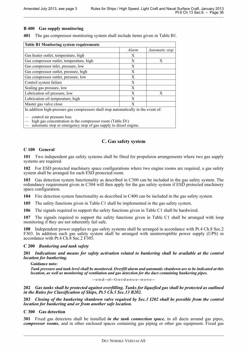
Amended July 2013, see page 3 Rules for Ships / High Speed, Light Craft and Naval Surface Craft, January 2013 Pt.6 Ch.13 Sec.6 – Page 36
DET NORSKE VERITAS AS
B 400 Gas supply monitoring
401 The gas compressor monitoring system shall include items given in Table B1.
C. Gas safety system
C 100 General
101 Two independent gas safety systems shall be fitted for propulsion arrangements where two gas supplysystems are required.
102 For ESD protected machinery space configurations where two engine rooms are required, a gas safetysystem shall be arranged for each ESD protected room.
103 Gas detection system functionality as described in C300 can be included in the gas safety system. Theredundancy requirement given in C304 will then apply for the gas safety system if ESD protected machineryspace configuration.
104 Fire detection system functionality as described in C400 can be included in the gas safety system.
105 The safety functions given in Table C1 shall be implemented in the gas safety system.
106 The signals required to support the safety functions given in Table C1 shall be hardwired.
107 The signals required to support the safety functions given in Table C1 shall be arranged with loopmonitoring if they are not inherently fail safe.
108 Independent power supplies to gas safety systems shall be arranged in accordance with Pt.4 Ch.8 Sec.2F303. In addition each gas safety system shall be arranged with uninterruptible power supply (UPS) inaccordance with Pt.4 Ch.8 Sec.2 F305.
C 200 Bunkering and tank safety
201 Indications and means for safety activation related to bunkering shall be available at the controllocation for bunkering.
Guidance note:
Tank pressure and tank level shall be monitored. Overfill alarm and automatic shutdown are to be indicated at thislocation, as well as monitoring of ventilation and gas detection for the duct containing bunkering pipes.
---e-n-d---of---G-u-i-d-a-n-c-e---n-o-t-e---
202 Gas tanks shall be protected against overfilling. Tanks for liquefied gas shall be protected as outlinedin the Rules for Classification of Ships, Pt.5 Ch.5 Sec.13 B202.
203 Closing of the bunkering shutdown valve required by Sec.3 I202 shall be possible from the controllocation for bunkering and or from another safe location.
C 300 Gas detection
301 Fixed gas detectors shall be installed in the tank connection space, in all ducts around gas pipes,compressor rooms, and in other enclosed spaces containing gas piping or other gas equipment. Fixed gas
Table B1 Monitoring system requirements
Alarm Automatic stop
Gas heater outlet, temperature, high X
Gas compressor outlet, temperature, high X X
Gas compressor inlet, pressure, low X
Gas compressor outlet, pressure, high X
Gas compressor outlet, pressure, low X
Control system failure X
Sealing gas pressure, low X
Lubrication oil pressure, low X X
Lubrication oil temperature, high X
Master gas valve close X
In addition high-pressure gas compressors shall stop automatically in the event of:
— control air pressure loss— high gas concentration in the compressor room (Table D1)— automatic stop or emergency stop of gas supply to diesel engine.
Amended July 2013, see page 3 Rules for Ships / High Speed, Light Craft and Naval Surface Craft, January 2013 Pt.6 Ch.13 Sec.6 – Page 37
DET NORSKE VERITAS AS
detectors shall be installed in ESD protected machinery space configuration gas engine rooms. In spaces whereall gas pipes are completely ducted gas detectors are not required.
Guidance note:
Gas detectors may be required also in inherently gas safe engine rooms in any of the following cases:
- the ventilation air to the double pipe/duct is taken from the engine room - the gas is supplied into the charge air before the inlet valve in the cylinder head if the components in contact with
the gas air mixture are not protected by a double duct.
---e-n-d---of---G-u-i-d-a-n-c-e---n-o-t-e---
302 Where gas detection shall cause shutdown in accordance with Table C1, detector voting shall be applied.
Guidance note:
A common voting principle is 2oo2 (meaning two out of two) where both units must detect gas to activate shutdown.A failed detector shall be considered as being active.
---e-n-d---of---G-u-i-d-a-n-c-e---n-o-t-e---
303 Two independent gas detector systems shall be fitted for propulsion arrangements where two gas supplysystems are required.
304 For ESD protected machinery space configuration a gas detector system of redundant design shall bearranged for each gas engine room.
305 The number of detectors in each space must be considered taking size, layout and ventilation of the spaceinto account.
306 The detectors shall be located where gas may accumulate and/or in the ventilation outlets. Gas dispersalanalysis or a physical smoke test shall be used to find the best arrangement.
307 Gas detection shall be alarmed on the bridge, in the engine control room and at the control location forbunkering, as well as locally. Gas alarms are required as specified in Table C1. Gas alarms with no safety actioncan be handled by the gas detection system.
308 Gas detection shall be continuous.
C 400 Fire detection
401 Where fire detection shall cause shutdown in accordance with Table C1, detector voting shall be applied.
Guidance note:
A common voting principle is 2oo2 (meaning two out of two) where both units must detect gas to activate shutdown.A failed detector shall be considered as being active.
---e-n-d---of---G-u-i-d-a-n-c-e---n-o-t-e---
402 Failure in, or loss of the fire central shall not initiate shutdown as required by 401.
C 500 Ventilation
501 Loss of ventilation shall cause shut down in accordance with Table C1. A running signal from theventilation fan motor is normally not sufficient to verify the performance of the ventilation; a flow- oroverpressure detection or an equivalent detection principle is required.
502 Full stop of ventilation in an ESD protected engine room shall, additionally to what is given in Table C1,lead to one of the following actions:
a) For a gas electric propulsion system: Engine(s) in another space shall start. When the engine in the otherspace is connected to bus-bar the engine in the space without ventilation shall be shutdown automatically.
b) For a direct propulsion system: The engine in the room with defect ventilation shall be manually shutdownwhen sufficient propulsion power is available after the shutdown.
503 Full stop of ventilation in the double pipe supplying gas to single fuel gas engine(s) shall, additionally towhat is given in Table C1, lead to one of the following actions:
a) If another gas supply system is arranged, the one with defect ventilation shall shut down as soon as the othersupply system is ready to deliver.
b) For a direct propulsion system with only one gas supply line: The engine with defect ventilation in the gassupply system shall be manually or automatically shutdown if sufficient propulsion power is still availableafter such a shutdown. If the ventilation system is without any openings in the engine room, continuedoperation after ventilation failure may be approved.
c) For a gas electric propulsion system: Another engine supplied by a different fuel system shall start. Whenthe second engine is connected to bus-bar the first engine shall be shutdown automatically.
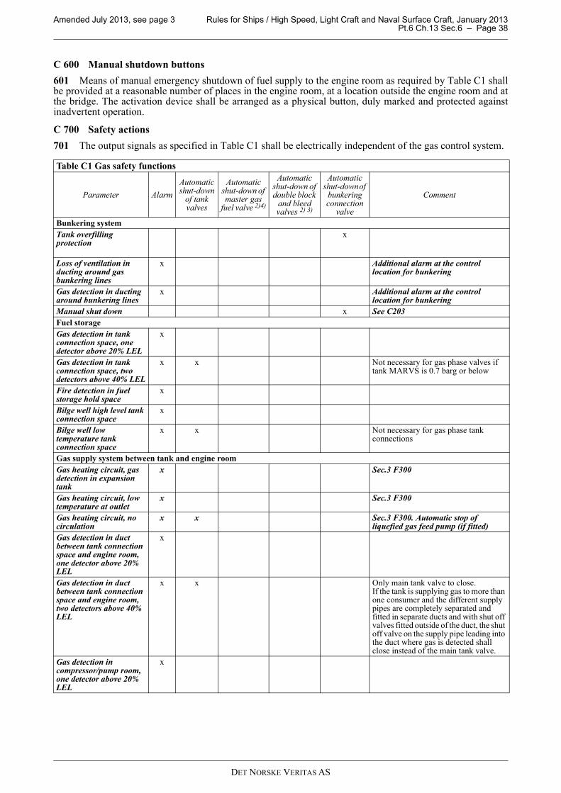
Amended July 2013, see page 3 Rules for Ships / High Speed, Light Craft and Naval Surface Craft, January 2013 Pt.6 Ch.13 Sec.6 – Page 38
DET NORSKE VERITAS AS
C 600 Manual shutdown buttons
601 Means of manual emergency shutdown of fuel supply to the engine room as required by Table C1 shallbe provided at a reasonable number of places in the engine room, at a location outside the engine room and atthe bridge. The activation device shall be arranged as a physical button, duly marked and protected againstinadvertent operation.
C 700 Safety actions
701 The output signals as specified in Table C1 shall be electrically independent of the gas control system.
Table C1 Gas safety functions
Parameter Alarm
Automatic shut-down
of tank valves
Automatic shut-down of master gas
fuel valve 2)4)
Automatic shut-down of double block
and bleed valves 2) 3)
Automatic shut-down of
bunkering connection
valve
Comment
Bunkering system
Tank overfilling protection
x
Loss of ventilation in ducting around gas bunkering lines
x Additional alarm at the control location for bunkering
Gas detection in ducting around bunkering lines
x Additional alarm at the control location for bunkering
Manual shut down x See C203
Fuel storage
Gas detection in tank connection space, one detector above 20% LEL
x
Gas detection in tank connection space, two detectors above 40% LEL
x x Not necessary for gas phase valves if tank MARVS is 0.7 barg or below
Fire detection in fuel storage hold space
x
Bilge well high level tank connection space
x
Bilge well low temperature tank connection space
x x Not necessary for gas phase tank connections
Gas supply system between tank and engine room
Gas heating circuit, gas detection in expansion tank
x Sec.3 F300
Gas heating circuit, low temperature at outlet
x Sec.3 F300
Gas heating circuit, no circulation
x x Sec.3 F300. Automatic stop of liquefied gas feed pump (if fitted)
Gas detection in duct between tank connection space and engine room, one detector above 20% LEL
x
Gas detection in duct between tank connection space and engine room, two detectors above 40% LEL
x x Only main tank valve to close.If the tank is supplying gas to more than one consumer and the different supply pipes are completely separated and fitted in separate ducts and with shut off valves fitted outside of the duct, the shut off valve on the supply pipe leading into the duct where gas is detected shall close instead of the main tank valve.
Gas detection in compressor/pump room, one detector above 20% LEL
x
Amended July 2013, see page 3 Rules for Ships / High Speed, Light Craft and Naval Surface Craft, January 2013 Pt.6 Ch.13 Sec.6 – Page 39
DET NORSKE VERITAS AS
Gas detection in compressor/pump room, two detectors above 40% LEL
x x Only main tank valve to close.If the tank is supplying gas to more than one consumer and the different supply systems are completely separated and fitted in separate rooms and with shut off valves fitted outside of the room, the shut off valve on the supply pipe leading into the room where gas is detected shall close instead of the main tank valve.
Loss of ventilation in duct between tank connection space and engine room
x x If the duct is protected by inert gas, loss of inert gas overpressure shall lead to the same actions.This parameter shall only lead to gas supply shutdown for dual fuel engines.
Engine room general
Fire detection in engine room, one detector
x
Fire detection in engine room, two detectors activated
x x x This parameter shall only lead to gas supply shutdown for dual fuel engines, and for gas supply for ESD protected engine rooms.
Rupture detection in gas supply piping (applicable for ESD protected engine room and for high pressure gas supply)
x x 1) Disconnection of non-safe equipment (ignition sources) and machinery in ESD protected engine room
Faulty operation of double block and bleed valves
x Refer to Sec.3 F104
Engine room inherently gas safe
Gas detection in duct/double pipe inside engine room, one detector above 30% LEL
x
Gas detection in duct/double pipe inside engine room, two detectors above 40% LEL
x x x If the duct/double pipe is protected by inert gas, loss of inert gas overpressure shall lead to the same actions.Manual shut-down may be approved for ventilated ducts if the duct has no openings in ER.
Loss of ventilation in duct inside engine room
x x x If the duct is protected by inert gas, loss of inert gas overpressure shall lead to the same actions.This parameter shall only lead to gas supply shutdown for dual fuel engines.
Gas detection in inherently gas safe engine room 10% LEL
x If gas detectors required by Sec.3 E302 or Sec.3 G102.
Engine room ESD protected
Gas detection in ESD protected engine room, one detector above 20% LEL
x
Gas detection in ESD protected engine room, two detectors above 40% LEL
x x x Disconnection of non-safe equipment (ignition sources) and machinery
Loss of ventilation in ESD protected engine room
x x x
General
Manual shutdown x See C600
1) May utilise a dedicated valve in case of pipe rupture in engine room, see F108.
2) Vent valves to open as specified in Sec.3 F104 and 105.
3) Double block and bleed valves will normally be controlled by the engine control and /or safety system. Hence a signal shall be given from the safety system to the engine system that this valve action is to be performed.
4) High pressure compressors to stop automatically.
Table C1 Gas safety functions (Continued)
Parameter Alarm
Automatic shut-down
of tank valves
Automatic shut-down of master gas
fuel valve 2)4)
Automatic shut-down of double block
and bleed valves 2) 3)
Automatic shut-down of
bunkering connection
valve
Comment
Amended July 2013, see page 3 Rules for Ships / High Speed, Light Craft and Naval Surface Craft, January 2013 Pt.6 Ch.13 Sec.6 – Page 40
DET NORSKE VERITAS AS
D. Ventilation control, monitoring and safety
D 100 Ventilation monitoring
101 Reduced ventilation from what is required per area in Sec.3 J shall be alarmed.
102 Reduced ventilation in the ducting around the gas bunkering lines during bunkering operations shallalso be alarmed at the control location for bunkering.
D 200 Spaces dependent on ventilation for its area classification
201 Functional requirements for ventilation in safe spaces protected by air locks and spaces dependent onventilation for its area classification are given in Sec.3 J201 and J504.
D 300 Safety
301 Requirements for ventilation related inputs to the gas safety system are given in C500 and Table C1.
E. Gas engine monitoring
E 100 General
101 In addition to the requirements given in Pt.4 Ch.3 Sec.1 E, control and monitoring as given in Table E1is required for gas engines.
Table E1 Monitoring of dual fuel diesel or gas-only engines
System Item Gr.1 Indication alarm load reduction
Gr.2 Automatic start of
standby pump with alarm 1)
Gr.3 Shutdown with alarm
Comments
1.0 Ignition system
Ignition failure each cylinder 2)
AAutomatic stop of gas supply 3)
2.0 Lubricating oil system
Cylinder lubrication flow 4)
LA
3.0 Fuel injection valve cooling system 5)
Fuel injection valve cooling medium pressure
LA AS
Automatic start of standby pump is not required if main pump is engine driven
Fuel injection valve cooling medium temperature
HA
4.0 Gas injection valve sealing oil system
Gas injection valve sealing oil pressure
LAFor high-pressure injection only
5.0 Gas fuel knock-out drums, if fitted
Gas fuel knock-out drums liquid level
HA
6.0 Combustion Knocking A
Gr 1: Common sensor for indication, alarm, load reductionGr 2: Sensor for automatic start of standby pumpGr 3: Sensor for shut down.
LA = Alarm for low valueHA = Alarm for high valueA = Alarm activatedAS = Automatic start of standby pump with alarmLR = Alarm with request for either manual or automatic load reduction. For auxiliary engines other than prime mover
of generators, slow down may be accepted (depending on application) as alternative means of load reductionSH = Shut down.
1) Only for propulsion engines
2) Exhaust temperature deviation may be accepted as means of detecting ignition failure, individually on each cylinder
3) Gas shut down to the specific cylinder or the engine can be accepted
4) At least one measuring point for each lubricator unit
5) Dual fuel engines only.
Amended July 2013, see page 3 Rules for Ships / High Speed, Light Craft and Naval Surface Craft, January 2013 Pt.6 Ch.13 Sec.7 – Page 41
DET NORSKE VERITAS AS
SECTION 7 COMPRESSORS AND GAS ENGINES
A. Gas compressors
A 100 General
101 The fuel gas compressor shall be fitted with accessories and instrumentation necessary for efficient andreliable function.
102 The gas compressor and its fuel gas supply shall be arranged for manual remote emergency stop fromthe following locations:
— navigation bridge— engine control room.
A 200 Vibrations
201 The possibility for fatigue problem of the high-pressure gas piping due to vibration caused by the high-pressure gas compressor must be considered. Such vibrations may be caused by unbalanced forces in thecompressor itself, by resonant vibrations in the piping system or by resonance in the gas column of the gasdischarge lines. Calculations may be required to verify that resonance problems will not occur.
B. Gas engine design
B 100 General
101 When gas is supplied in a mixture with air via a common inlet manifold, explosion relief venting of themanifold shall be arranged; alternatively the manifold shall be of sufficient strength to withstand an explosion.
B 200 Functional requirements dual fuel engines
201 Start, normal stop and low power operation shall be on oil fuel only. Gas injection shall not be possiblewithout a corresponding pilot oil injection.
In case of shut-off of the gas fuel supply, the engines shall be capable of continuous operation by oil fuel only.
Guidance note:
If it can be documented that a dual fuel engine can safely start, stop and operate on low load in gas mode, this may beapproved.
---e-n-d---of---G-u-i-d-a-n-c-e---n-o-t-e---
202 Changeover to and from gas fuel operation is only to be possible at a power level where it can be donewith acceptable reliability as demonstrated through testing. On completion of preparations for changeover togas operation including checks of all essential conditions for changeover, the changeover process itself shallbe automatic. On power reduction the changeover to oil fuel shall be automatic (compressor and auxiliariesmay continue to run unloaded).
203 On normal shutdown as well as emergency shutdown, gas fuel supply shall be shut off not later thansimultaneously with the oil fuel. Shut off of the gas fuel shall not be dependent on the shut off of the oil fuel.
204 Firing of the gas-air mixture in the cylinders shall be initiated by injection of pilot fuel. The amount ofpilot fuel fed to each cylinder shall be sufficient to ensure a positive ignition of the gas mixture. It shall not bepossible to shut off the supply pilot fuel without first or simultaneously closing the gas supply to each cylinderor to the complete engine.
B 300 Functional requirements gas-only engines
301 The starting sequence must be such that fuel gas is not admitted to the cylinders until ignition is activatedand the engine has reached a minimum rotational speed.
302 If ignition has not been detected by the engine monitoring system within 10 s after opening of gasinjection valve the gas supply shall be automatically shut off and the starting sequence terminated.
Guidance note:
More than 10 seconds may be accepted between gas injection start and automatic starting sequence shut off, if the gasis not injected directly to each cylinder or to each cylinder air inlet, but is mixed with combustion air in a commonsystem.
---e-n-d---of---G-u-i-d-a-n-c-e---n-o-t-e---
303 When restarting after a failed start attempt admission of fuel gas to the cylinders shall not be possible
Amended July 2013, see page 3 Rules for Ships / High Speed, Light Craft and Naval Surface Craft, January 2013 Pt.6 Ch.13 Sec.7 – Page 42
DET NORSKE VERITAS AS
before the exhaust gas system has been purged with a volume of air at least equal to 3 times the volume of theexhaust gas system before the turbocharger(s). Purging may be carried out through for example running theengine on starting air for a predetermined number of revolutions.
Amended July 2013, see page 3 Rules for Ships / High Speed, Light Craft and Naval Surface Craft, January 2013 Pt.6 Ch.13 Sec.8 – Page 43
DET NORSKE VERITAS AS
SECTION 8 MANUFACTURE, WORKMANSHIP AND TESTING
A. Gas tanks
A 100 Manufacture and testing
101 Tests related to welding and tank testing shall be in accordance with the Rules for Classification ofShips, Pt.5 Ch.5 Sec.5 K, L, M, and N.
B. Gas piping systems
B 100 Gas pipes
101 The gas pipes shall be tested as given in the Rules for Classification of Ships, Pt.5 Ch.5 Sec.6 C600 andC700. Butt welded joints of high-pressure gas pipes and gas supply pipes in ESD protected engine rooms shallbe subjected to 100% radiographic testing.
B 200 Ducting
201 If the gas piping duct contains high-pressure pipes the ducting shall be pressure tested to at least 10 bar.Ducts for low pressure gas piping shall be tightness tested.
B 300 Valves
301 Each type of valve to be used at working temperatures below minus 55°C shall be prototype tested asgiven in the Rules for Classification of Ships, Pt.5 Ch.5 Sec.6 H201.
B 400 Expansion bellows
401 Expansion bellows intended for use in gas systems shall be prototype tested as given in the Rules forClassification of Ships, Pt.5 Ch.5 Sec.6 I101.
C. Onboard testing
C 100 General
101 Control, monitoring and safety systems required by these rules, shall be tested onboard in accordancewith Pt.4 Ch.9 Sec.1 D500.
102 The functionality of the cause and effect diagram required by Sec.1 Table C1 shall be tested onboard.