Embed Size (px)
DESCRIPTION
Nexsys Workstation user Guide
Citation preview
TEC DOC # LIT-TD-2038 04/2001
NeNeNeNeNexSys xSys xSys xSys xSys WWWWWorororororkstakstakstakstakstationtiontiontiontionUser’s Guide - 2.0User’s GuideUser’s GuideUser’s GuideUser’s Guide

ii Copyright ©1999 Electronic Systems USA, Inc. All Rights Reserved
Table of Contents NexSys Workstation User’s Guide Rev 1.3
Electronic Systems USA, a wholly owned subsidiary of Johnson Controls, Inc., reserves the right to updatespecifications when appropriate. Information contained in this document is based on specifications believed tobe correct at the time of publication.
Echelon ©, Coactive©, Windows NT©, and General Electric© are registered trademarks and service marks ofcompanies other than Electronic Systems USA. FSC™, CPL™ and NexSys™ are trademarks of ElectronicSystems USA.
© 2000 Johnson Controls, Inc. All Rights Reserved
Rev 1.3 NexSys Workstation User’s Guide Table of Contents
Copyright ©1999 Electronic Systems USA, Inc. All Rights Reserved iii
Table of Contents
Chapter One - Computer Basics SWO-5Overview .....................................................................................................................SWO-6
The Computer ..................................................................................................SWO-6Keyboard ...............................................................................................SWO-6Mouse ....................................................................................................SWO-6Basic Mouse Actions..............................................................................SWO-7Cursor ....................................................................................................SWO-7Scroll Bars ............................................................................................SWO-8
Basic Window Concepts .............................................................................................SWO-8Opening/Closing a Window ..............................................................................SWO-9Re-sizing a Window .........................................................................................SWO-9Moving a Window .............................................................................................SWO-9Maximizing a Window.......................................................................................SWO-9Restoring a Window .........................................................................................SWO-9Minimizing a Window .......................................................................................SWO-9Selecting an Open Window ..............................................................................SWO-9
Basic Menu Concepts ...............................................................................................SWO-10Pull-Down Menus ...........................................................................................SWO-10
Selecting a Pull-Down Menu ...............................................................SWO-10Exiting a Pull-down Menu ...................................................................SWO-10Selecting a Pull-Down Menu (with the Cursor (Arrow) Keys) ............... SWO-11Selecting a Pull-Down Menu (with the Text keys) ................................ SWO-11Canceling a Menu Selection (with the Text keys) ................................. SWO-11
Pop-Up (Shortcut) Menus ............................................................................... SWO-11Selecting Pop-up Menus (with text keys) ............................................. SWO-11
Dialog Boxes ..................................................................................................SWO-12Keyboard Shortcuts for Dialog boxes ..................................................SWO-12Mouse Operation in Dialog Boxes .......................................................SWO-13Getting Help Inside a Dialog Box .........................................................SWO-13
Windows NT Overview ..............................................................................................SWO-14Desktop ..........................................................................................................SWO-14
Windows NT Help ................................................................................SWO-15My Computer .......................................................................................SWO-15Network Neighborhood ........................................................................SWO-15Recycle Bin .........................................................................................SWO-16Shortcut Menus ....................................................................................SWO-16Create a Folder ....................................................................................SWO-16Delete a Folder ....................................................................................SWO-16Move an Object ....................................................................................SWO-16Copy an Object ....................................................................................SWO-16Rename an Object ...............................................................................SWO-16
Task Bar ..........................................................................................................SWO-16Start Menu ......................................................................................................SWO-17
Windows NT Explorer ...............................................................................................SWO-17
iv Copyright ©1999 Electronic Systems USA, Inc. All Rights Reserved
Table of Contents NexSys Workstation User’s Guide Rev 1.3
Find an Object ................................................................................................SWO-17Printer Setup ........................................................................................SWO-18
MS DOS Window ...........................................................................................SWO-18Shutting Down the System .............................................................................SWO-19
Emergency Shut Down ........................................................................SWO-19
Chapter Two - NWS Software Architecture SWO-21NexSys Software Architecture ...................................................................................SWO-22
NexSys Workstation (NWS).........................................................................................SWO-23LNServer ........................................................................................................SWO-23LNS ................................................................................................................SWO-23OPC LonWorks Server ...................................................................................SWO-23M-Series Workstation .....................................................................................SWO-23
Software Overview Index SWO-25
Software Installation and Startup (ISU)
Chapter One - NexSys Software Installation ISU-31Four Types Of PC Configurations................................................................................ ISU-32
Installation Checklist .............................................................................. ISU-33Before You Begin Installing: ........................................................................................ ISU-34
Installing A Network Adapter Or MS Loopback Adapter .................................... ISU-34Installing Network Protocols ............................................................................. ISU-36
Installing NexSys For The First time............................................................................ ISU-38Configuring LNServer ....................................................................................... ISU-39
Opening The LNServer Configuration Wizard ....................................... ISU-39Configuring LNServer For A Local Location ........................................... ISU-40Configuring LNServer For A Remote Location ....................................... ISU-43
Installing Remote Access Services (RAS) ................................................................... ISU-46Setting RAS Server To Automatic Start ............................................................. ISU-50Creating A User With RAS Login Privileges ..................................................... ISU-51Setting Up A Client To Access The Server ........................................................ ISU-53Setting Up A Modem ......................................................................................... ISU-56Dialing The Server From A Remote Site ........................................................... ISU-58Disconnecting A Remote Site From A Server PC.............................................. ISU-59
Chapter Two - Hardware Installation ISU-63Introduction .................................................................................................................. ISU-64Disabling And Removing The Full-Size PCLTA Card ................................................. ISU-65Installing The Hardware Drivers .................................................................................. ISU-66Installing The PCLTA-10/20 Card................................................................................ ISU-73Installing The PCC-10 (Laptop Only) .......................................................................... ISU-73
Chapter Three - Getting Started ISU-75Start-Up Procedure...................................................................................................... ISU-76
Add ESUSA Resources To Catalog ................................................................. ISU-76
Rev 1.3 NexSys Workstation User’s Guide Table of Contents
Copyright ©1999 Electronic Systems USA, Inc. All Rights Reserved v
Adding ESUSA Resources To Catalog .................................................. ISU-76Starting NexSys Workstation (NWS) And LnServer .......................................... ISU-78
Starting NWS And LNServer Together ................................................... ISU-78Starting NWS ......................................................................................... ISU-78Starting LNServer .................................................................................. ISU-78
NWS Main Window ..................................................................................................... ISU-79Title Bar ............................................................................................................ ISU-79Version Number Of NWS software ................................................................... ISU-80Resizing The NexSys Windows ....................................................................... ISU-80Menu Bar .......................................................................................................... ISU-80Toolbar .............................................................................................................. ISU-81Physical Tree .................................................................................................... ISU-81Working Panels ................................................................................................ ISU-81Server Status Bar ............................................................................................. ISU-82
Exiting NWS ................................................................................................................ ISU-82Exiting LNServer ......................................................................................................... ISU-82
Installation and Startup Index ISU-85
System Setup (SSU)
Chapter One - Common Node Functions SSU-95Overview ....................................................................................................................SSU-96Node Menu.................................................................................................................SSU-96
Node Commands ............................................................................................SSU-96Wink ......................................................................................................SSU-96Offline ...................................................................................................SSU-97Reset ....................................................................................................SSU-98Test .......................................................................................................SSU-98
Plug-Ins ...........................................................................................................SSU-99Registering A Plug-In ............................................................................SSU-99Running A Plug-In ...............................................................................SSU-100
Move ..............................................................................................................SSU-101Add ................................................................................................................SSU-102Setup Node ...................................................................................................SSU-103
Check Box Explanations.....................................................................SSU-104Replace Node ...............................................................................................SSU-105Edit/View Binding ..........................................................................................SSU-106Delete ............................................................................................................SSU-107Config Data Set .............................................................................................SSU-107Set Time/Date On Node.................................................................................SSU-109Rename ......................................................................................................... SSU-110Load Firmware .............................................................................................. SSU-110MultiNode Operations .................................................................................... SSU-113Connection Description Template (CDT) ....................................................... SSU-114
Adding A Connection Description Template (CDT) ............................. SSU-115Modifying Connection Description Templates (CDT) .......................... SSU-117
vi Copyright ©1999 Electronic Systems USA, Inc. All Rights Reserved
Table of Contents NexSys Workstation User’s Guide Rev 1.3
Deleting Connection Description Templates (CDT) ............................ SSU-117Node Configuration Wizard ........................................................................... SSU-118
Chapter Two - Setting Up a Router SSU-119Overview ..................................................................................................................SSU-120
Router Classification Types ...........................................................................SSU-120Far-Side Transceiver Types...........................................................................SSU-121
Echelon Routers ......................................................................SSU-121Adding a Router to the Physical Tree ............................................................SSU-121
Coactive Routers .....................................................................SSU-121CTI Routers ..............................................................................SSU-121
Commissioning a Defined Router ..................................................................SSU-123Adding Nodes To A Router ............................................................................SSU-124
Commissioning the PEC.....................................................................SSU-125Check Box Explanations ..........................................................SSU-126
Chapter Three - Setting Up an FSC/FLC SSU -129Setting Up an FSC/FLC ...........................................................................................SSU-130
FSC Overview ...............................................................................................SSU-130FLC Overview................................................................................................SSU-130Adding an FSC or FLC to the Physical Tree ..................................................SSU-130
Defining an FSC/FLC .........................................................................SSU-131Commissioning the FSC/FLC .............................................................SSU-132
Check Box Explanations ..........................................................SSU-133FSC/FLC Configuration Wizard .....................................................................SSU-134FSC/FLC Wizard Page 1 - Configure FSC Time Values ...............................SSU-135FSC/FLC Wizard Page 2 - Enable Daylight Savings Time ............................SSU-136FSC/FLC Wizard Page 3 - Configure Daylight Savings Time........................SSU-136FSC/FLC Wizard Page 4 - Select FSC Modules ...........................................SSU-137
Chapter Four - Setting Up a VAV SSU -139Setting up a VAV ......................................................................................................SSU-140
Adding a VAV to the Physical Tree ................................................................SSU-140Defining a VAV....................................................................................SSU-140Commissioning the VAV .....................................................................SSU-141
Check Box Explanations ..........................................................SSU-142VAV Configuration Wizard .............................................................................SSU-143
VAV Wizard Page 1 - Room Sensor Type ...........................................SSU-145VAV Wizard Page 2 - Thermostat Configuration .................................SSU-146VAV Wizard Page 3 - Default Setpoints and Thermal Load Parameters ...SSU-147VAV Wizard Page 4 - Setpoint Configuration ......................................SSU-147VAV Wizard Page 5 - Thermal Load Parameters ................................SSU-148VAV Wizard Page 6 - K-Factor ............................................................SSU-149VAV Wizard Page 7 - Flow Parameters ..............................................SSU-151VAV Wizard Page 8 - Accept Air Flow PID Parameters?.....................SSU-152VAV Wizard Page 9 - Flow PID Parameters .......................................SSU-152VAV Wizard Page 10 - Fan Type ........................................................SSU-154VAV Wizard Page 11 - Reheat Parameters .........................................SSU-154
Rev 1.3 NexSys Workstation User’s Guide Table of Contents
Copyright ©1999 Electronic Systems USA, Inc. All Rights Reserved vii
VAV Wizard Page 12 - Floating Reheat ..............................................SSU-155VAV Wizard Page 13 - Electric Reheat ...............................................SSU-156VAV Wizard Page 14 - PWM Reheat ..................................................SSU-156VAV Wizard Page 15 - Broadcast Damper Inc Output? .......................SSU-158VAV Wizard Page 16 - Broadcast Damper DEC Output? ...................SSU-158VAV Wizard Page 17 - Broadcast Fan Output? ...................................SSU-159VAV Wizard Page 18 - Broadcast Reheat INC/ST 1 Output? ..............SSU-159VAV Wizard Page 19 - Broadcast Reheat DEC/ST 2 Output? ............SSU-160
Advanced Point Editing .................................................................................SSU-161
Chapter Five - Setting Up a Heat Pump SSU -163Setting up a Heat Pump ...........................................................................................SSU-164
Adding a Heat Pump to the Physical Tree .....................................................SSU-164Defining a Heat Pump.........................................................................SSU-164Commissioning the Heat Pump ..........................................................SSU-165
Check Box Explanations ..........................................................SSU-167Heat Pump Configuration Wizard ..................................................................SSU-168Heat Pump Wizard Page 1 - Room Sensor Type...........................................SSU-169Heat Pump Wizard Page 2 - Thermostat Configuration .................................SSU-169Heat Pump Wizard Page 3 - Default Setpoints & Thermal Load Parameters SSU-170Heat Pump Wizard Page 4 - Setpoint Configuration ......................................SSU-171Heat Pump Wizard Page 5 - PID Parameters For Thermal Load...................SSU-172Heat Pump Wizard Page 6 - Local Emergency Shutdown ............................SSU-173Heat Pump Wizard Page 7 - Economizer Type.............................................SSU-173Heat Pump Wizard Page 8 - Economizer Enable ..........................................SSU-174Heat Pump Wizard Page 9 - Local Economizer .............................................SSU-174Heat Pump Wizard Page 10 - Mixed Air Parameters .....................................SSU-175Heat Pump Wizard Page 11 - Low Limit Shutdown Parameters ....................SSU-176Heat Pump Wizard Page 12 - Fan Controller Parameters .............................SSU-177Heat Pump Wizard Page 13 - Number of Stages For Compressor? ..............SSU-178Heat Pump Wizard Page 14 - Compressor Controller ...................................SSU-179Heat Pump Wizard Page 15 - Reverse Valve Setup......................................SSU-180Heat Pump Wizard Page 16 - Loop Enable ...................................................SSU-181Heat Pump Wizard Page 17 - Broadcast Output For Damper? ......................SSU-181Heat Pump Wizard Page 18 - Broadcast Output For Fan Output? .................SSU-182Heat Pump Wizard Page 19 - Broadcast Output For Reverse Valve? ...........SSU-182Heat Pump Wizard Page 20 - Broadcast Output For Compressor 1? ............SSU-183Heat Pump Wizard Page 21 - Broadcast Output For Compressor 2? ............SSU-183Heat Pump Wizard Page 22 - Broadcast Output For Compressor 3/EH? ......SSU-184
Chapter Six - Setting Up a PEC SSU -185Setting up a PEC......................................................................................................SSU-186
Adding a PEC to the Physical Tree ...............................................................SSU-186Defining a PEC ...................................................................................SSU-186Commissioning the PEC.....................................................................SSU-187
Check Box Explanations ..........................................................SSU-189Configuration Wizard (PEC) .....................................................................................SSU-190
PEC Wizard Page 1 - Room Sensor Type .....................................................SSU-191
viii Copyright ©1999 Electronic Systems USA, Inc. All Rights Reserved
Table of Contents NexSys Workstation User’s Guide Rev 1.3
PEC Wizard Page 2 - Thermostat Configuration ...........................................SSU-192PEC Wizard Page 3 - Default Setpoints and Thermal Load Parameters .......SSU-193PEC Wizard Page 4 - Setpoint Configuration ................................................SSU-193PEC Wizard Page 5 - PID Parameters For Thermal Load .............................SSU-194PEC Wizard Page 6 - Local Emergency Shutdown .......................................SSU-195PEC Wizard Page 7 - Economizer Type ........................................................SSU-196PEC Wizard Page 8 - Economizer Enable ....................................................SSU-196PEC Wizard Page 9 - Local Economizer .......................................................SSU-197PEC Wizard Page 10 - Mixed Air Parameters ...............................................SSU-198PEC Wizard Page 11 - Low Limit Shutdown Parameters ..............................SSU-199PEC Wizard Page 12 - Fan Controller Parameters .......................................SSU-200PEC Wizard Page 13 - Discharge Air Reset From Thermal Load .................SSU-202PEC Wizard Page 14 - Discharge Air Reset ..................................................SSU-202PEC Wizard Page 15 - Number of Valves .....................................................SSU-203PEC Wizard Page 16 - Winter/Summer Controller ........................................SSU-204PEC Wizard Page 17 - Local Winter/Summer Controller ...............................SSU-205PEC Wizard Page 18 - Heating Type ............................................................SSU-205PEC Wizard Page 19 - Floating Heating Parameters ....................................SSU-206PEC Wizard Page 20 - Discrete Heating Parameters ....................................SSU-206PEC Wizard Page 21 - Cooling Type ............................................................SSU-207PEC Wizard Page 22 - Floating Cooling Parameters ....................................SSU-208PEC Wizard Page 23 - Discrete Cooling .......................................................SSU-209PEC Wizard Page 24 - Broadcast Output For Damper? ................................SSU-209PEC Wizard Page 25 - Broadcast Output For Fan Output? ...........................SSU-210PEC Wizard Page 26 - Broadcast Output For Cooling Increment? ................ SSU-211PEC Wizard Page 27 - Broadcast Output For Cooling Decrement? ..............SSU-212PEC Wizard Page 28 - Broadcast Output For Heating Increment? ................SSU-212PEC Wizard Page 29 - Broadcast Output For Heating Decrement? ..............SSU-213
Advanced PEC Editing ............................................................................................SSU-214Editing Points ................................................................................................SSU-214
Editing Point #1 - Discharge Air Temp (Analog Input) .........................SSU-214Editing Point #2 - Mixed Air Temp (Analog Input) ................................SSU-214Editing Point #3 - Space Temp (Analog Input) ....................................SSU-215Editing Point #4 - Outside AIr/Supply Water Temp (analog Input) .......SSU-215Editing Point #5 - Fan Status Input (Digital Input) ...............................SSU-215Editing Point #6 - Emergency Shutdown (Digital Input) ......................SSU-215Editing Point #7 - Space Temp Controller ...........................................SSU-215Editing Point #8 - Indoor Air Quality Controller ....................................SSU-215Editing Point #9 - Outside Air Temp ....................................................SSU-215Editing Point #10 - Manual Occupancy Controller ..............................SSU-215Editing Point #11 - User Setpoint Controller .......................................SSU-216Editing Point #12 - Override Controller ...............................................SSU-216Editing Point #13 - Application Mode Controller .................................SSU-216Editing Point #14 - Manual Reset .......................................................SSU-216Editing Point #15 - Low Limit Shutdown .............................................SSU-216Editing Point #16 - Local Emergency Shutdown .................................SSU-216Editing Point #17 - LON Emergency Shutdown ..................................SSU-216
Rev 1.3 NexSys Workstation User’s Guide Table of Contents
Copyright ©1999 Electronic Systems USA, Inc. All Rights Reserved ix
Editing Point #18 - Setpoint Controller ................................................SSU-217Editing Point #19 - Mixed Air PID Controller .......................................SSU-217Editing Point #20 - Emergency Command Controller .........................SSU-217Editing Point #21 - Winter/Summer Controller ....................................SSU-218Editing Point #22 - Temp PID Controller .............................................SSU-218Editing Point #23 - Economizer Controller ..........................................SSU-218Editing Point #24 - Fan Controller .......................................................SSU-218Editing Point #25 - Heating/Cooling Controller ...................................SSU-218Editing Point #26 - Analog Output .......................................................SSU-218Editing Point #27 - Digital Output #1 Fan Actuator Output ..................SSU-218
System Setup Index SSU-1219
Programming (PRO)
Chapter One - Binding Network Variables PRO-231Overview ................................................................................................................. PRO-232
Editing and Viewing Bindings ...................................................................... PRO-232Refresh .............................................................................................. PRO-233Adding A Bind .................................................................................... PRO-234Deleting a Bind .................................................................................. PRO-235
Chapter Two - Using CPL PRO-237Overview ................................................................................................................. PRO-238
CPL Pages Subtree ...................................................................................... PRO-238Working With Individual Pages .........................................................................PRO-239CPL Page Menu Commands ............................................................. PRO-239
CPL Blocks.............................................................................................................. PRO-241Block Types ....................................................................................... PRO-242
Arithmetic Blocks .................................................................... PRO-242Comparison Blocks ................................................................. PRO-242Constant Blocks ...................................................................... PRO-242Function Blocks ...................................................................... PRO-242Global Variable Blocks ............................................................ PRO-243Logical Blocks ......................................................................... PRO-243Point Blocks ............................................................................ PRO-243Time Blocks ............................................................................ PRO-243
Block Colors ...................................................................................... PRO-243CPL Editor ............................................................................................................... PRO-243
CPL Editor Toolbar ....................................................................................... PRO-244Selection Mode .................................................................................. PRO-244Zoom Modes ...................................................................................... PRO-244Best Fit ............................................................................................... PRO-244Show Grid .......................................................................................... PRO-245Monitor Mode ..................................................................................... PRO-245
Zoom Control Box......................................................................................... PRO-246CPL Block Menu ........................................................................................... PRO-247
x Copyright ©1999 Electronic Systems USA, Inc. All Rights Reserved
Table of Contents NexSys Workstation User’s Guide Rev 1.3
Creating And Editing CPL Pages ............................................................................ PRO-247To Add A New CPL Page: ............................................................................. PRO-247
Adding CPL Blocks ............................................................................ PRO-248Editing CPL Blocks ....................................................................................... PRO-249
Editing Multiple Blocks ...................................................................... PRO-249Direct/Reverse Acting ............................................................. PRO-250
Deleting A Block................................................................................. PRO-250Deleting Multiple Blocks .................................................................... PRO-251Moving A Block .................................................................................. PRO-251Moving Multiple Blocks ...................................................................... PRO-252
Block Connections .................................................................................................. PRO-252Connecting Blocks ....................................................................................... PRO-252
Multiple Inputs .................................................................................... PRO-253Deleting A Block Connection ............................................................. PRO-253
CPL User Library ..................................................................................................... PRO-254CPL Library Window ..................................................................................... PRO-254
Accessing the CPL Library from NWS ............................................... PRO-255Closing The CPL Library.................................................................... PRO-255
Library Pages Window ................................................................................. PRO-255Library Pages Toolbar ........................................................................ PRO-256
CPL Library Block Editor Window................................................................. PRO-256Creating A New CPL Library Page ..................................................... PRO-257Importing A CPL Library Page ............................................................ PRO-257Exporting A CPL library page ............................................................. PRO-257
Summary Of Blocks ...................................................................................... PRO-258
Chapter Three - CPL Blocks PRO-261CPL Blocks .............................................................................................................. PRO-262
CPL Block Settings ....................................................................................... PRO-262Ignore Error Check Box...................................................................... PRO-263
Entering Block Information - Constants......................................................... PRO-263Analog Constant ................................................................................ PRO-264
Settings ................................................................................... PRO-264Digital Constant ................................................................................. PRO-264
Settings ................................................................................... PRO-264Entering Block Information - Functions ......................................................... PRO-265
2-Position........................................................................................... PRO-266Settings ................................................................................... PRO-266
Accumulator ....................................................................................... PRO-267Settings ................................................................................... PRO-267
Calculation......................................................................................... PRO-267Settings ................................................................................... PRO-268
Counter .............................................................................................. PRO-269Settings ................................................................................... PRO-269
Dial Provider ...................................................................................... PRO-269Settings ................................................................................... PRO-269
Enthalpy............................................................................................. PRO-270Settings ................................................................................... PRO-270
Rev 1.3 NexSys Workstation User’s Guide Table of Contents
Copyright ©1999 Electronic Systems USA, Inc. All Rights Reserved xi
Error - Analog (A-error) ....................................................................... PRO-270Settings ................................................................................... PRO-270
Error - Digital (D-Error) ....................................................................... PRO-271Settings ................................................................................... PRO-271
Hi/Lo/Average .................................................................................... PRO-271Settings ................................................................................... PRO-271
Lead/Lag ............................................................................................ PRO-272 Settings .................................................................................. PRO-272
Min/Max ............................................................................................. PRO-273Settings ................................................................................... PRO-273
Minimum On/Off ................................................................................. PRO-274Settings ................................................................................... PRO-274
One Shot ............................................................................................ PRO-274Settings ................................................................................... PRO-275
PID Loop ............................................................................................ PRO-276Settings ................................................................................... PRO-276Timing ..................................................................................... PRO-276
Psychro .............................................................................................. PRO-277Settings ................................................................................... PRO-277
Ramp ................................................................................................. PRO-277Settings ................................................................................... PRO-278Timing ..................................................................................... PRO-278
Relay - Analog .................................................................................. PRO-278Settings ................................................................................... PRO-278
Relay - digital .................................................................................... PRO-278Settings ................................................................................... PRO-279
Reset ................................................................................................. PRO-279Settings ................................................................................... PRO-280
Rolling Average ................................................................................. PRO-280Settings ................................................................................... PRO-280Timing ..................................................................................... PRO-280
Runtime ............................................................................................. PRO-281Settings ................................................................................... PRO-281
Schedule ........................................................................................... PRO-282Settings ................................................................................... PRO-282Timing ..................................................................................... PRO-283
Sequencer ......................................................................................... PRO-283Settings ................................................................................... PRO-283Descriptor ................................................................................ PRO-283
Startup ............................................................................................... PRO-284Settings ................................................................................... PRO-284
Start/Stop ........................................................................................... PRO-284Settings ................................................................................... PRO-284
Time Event ......................................................................................... PRO-284Settings ..................................................................................................PRO-285
Entering Block Information - Global Variables .............................................. PRO-285
xii Copyright ©1999 Electronic Systems USA, Inc. All Rights Reserved
Table of Contents NexSys Workstation User’s Guide Rev 1.3
Settings ................................................................................... PRO-286Global Analog Input ........................................................................... PRO-286Global Digital Input ............................................................................ PRO-286Global Analog Output ......................................................................... PRO-286Global Digital Output.......................................................................... PRO-286
Entering Block Information - Logical ............................................................. PRO-287AND ................................................................................................... PRO-287
Settings ................................................................................... PRO-287OR ..................................................................................................... PRO-288
Settings ................................................................................... PRO-288NOT ................................................................................................... PRO-288
Settings ................................................................................... PRO-288XOR ................................................................................................... PRO-288
Settings ................................................................................... PRO-289Entering Block Information - Comparison ..................................................... PRO-289
A-Equal .............................................................................................. PRO-290Settings ................................................................................... PRO-290
A-Not Equal ...................................................................................... PRO-290Settings ................................................................................... PRO-290
D-Equal ............................................................................................. PRO-290Settings ................................................................................... PRO-290
D-Not Equal ....................................................................................... PRO-291Settings ................................................................................... PRO-291
Greater Equal..................................................................................... PRO-291Settings ................................................................................... PRO-291
Greater Than ...................................................................................... PRO-291Settings ................................................................................... PRO-291
Less Equal ......................................................................................... PRO-292Setting ..................................................................................... PRO-292
Less Than .......................................................................................... PRO-292Settings ................................................................................... PRO-292
Entering Block Information - Arithmetic ......................................................... PRO-292Add .................................................................................................... PRO-293
Settings ................................................................................... PRO-293Divide ................................................................................................ PRO-293
Settings ................................................................................... PRO-293Modulus ............................................................................................. PRO-294
Settings ................................................................................... PRO-294Multiply .............................................................................................. PRO-294
Settings ................................................................................... PRO-294Negate ............................................................................................... PRO-294
Settings ................................................................................... PRO-294Sq. Root (Square Root) ...................................................................... PRO-295
Settings ................................................................................... PRO-295Subtract ............................................................................................. PRO-295
Settings ................................................................................... PRO-295Entering Block Information - Points ............................................................... PRO-295
Rev 1.3 NexSys Workstation User’s Guide Table of Contents
Copyright ©1999 Electronic Systems USA, Inc. All Rights Reserved xiii
AI (Analog Input) ................................................................................ PRO-296Settings ................................................................................... PRO-296
DI (Digital Input) ................................................................................. PRO-296Settings ................................................................................... PRO-296
AO (Analog Output) ............................................................................ PRO-296Settings ................................................................................... PRO-297
D0 (Digital Output) ............................................................................. PRO-297Settings ................................................................................... PRO-297
MAI (Multiple Analog Input) ................................................................ PRO-297Settings ................................................................................... PRO-298
MDI (Multiple Digital Input) ................................................................. PRO-298Settings ................................................................................... PRO-298
Point State ......................................................................................... PRO-299Settings ................................................................................... PRO-299
Entering Block Information - Time ................................................................. PRO-299Constant Time.................................................................................... PRO-300
Settings ................................................................................... PRO-300Convert Time ..................................................................................... PRO-300
Settings ................................................................................... PRO-300Current Time ...................................................................................... PRO-301
Settings ................................................................................... PRO-301
Chapter Four - Schedules PRO-303SCHEDULING ........................................................................................................ PRO-304
The Schedule Subtree .................................................................................. PRO-304Viewing Individual Schedules ........................................................... PRO-304
Creating A New Schedule ............................................................................ PRO-305Adding A New Schedule: ................................................................... PRO-305Entering Values For A New Schedule: ............................................... PRO-306
Editing An Existing Schedule ....................................................................... PRO-308Renaming A Schedule .................................................................................. PRO-308Deleting A Schedule ..................................................................................... PRO-308Copying Schedules To Another FSC ............................................................ PRO-309Refresh Schedules ....................................................................................... PRO-309
Programming Index PRO-311
Operations (OPS)
Chapter One - Workstation Basics OPS-321NexSys Work Station (NWS) Window Overview ......................................................OPS-322
Menu Bar .......................................................................................................OPS-323Tool Bar .........................................................................................................OPS-325
Physical Tree ...........................................................................................................OPS-326NexSys Network Interface .............................................................................OPS-326
Editing The NexSys Network Interface ...............................................OPS-327To Access The NexSys Network Interface Editor: ....................OPS-327NexSys Network Interface Editor Options: ...............................OPS-327
xiv Copyright ©1999 Electronic Systems USA, Inc. All Rights Reserved
Table of Contents NexSys Workstation User’s Guide Rev 1.3
Connection Description Template (CDT) ............................................OPS-328Adding A Connection Description Template (CDT) ..................OPS-329Modifying Connection Description Templates (CDT) ...............OPS-331Deleting Connection Description Templates (CDT) .................OPS-331
Multi-Node Operations ........................................................................OPS-332Selecting the node(s): ..............................................................OPS-332Selecting the options ................................................................OPS-333Confirming your selections .......................................................OPS-333
Routers ..........................................................................................................OPS-333Controller Nodes ...........................................................................................OPS-334Node Pop-up Menu Commands ....................................................................OPS-334Points ............................................................................................................OPS-342
Adding FSC/FLC points ......................................................................OPS-342Editing FSC/FLC Points .....................................................................OPS-343Deleting FSC/FLC Points ...................................................................OPS-343
LMOs (LonMark Objects) ...............................................................................OPS-344Network Variables .........................................................................................OPS-344
Binding: Connecting NVOs To NVIs ..................................................OPS-345Configuration Properties ................................................................................OPS-345Point, LMO, NV, and CP Working Panels ......................................................OPS-346Additional FSC Subtrees ...............................................................................OPS-348
CPL Pages..........................................................................................OPS-348Schedules ...........................................................................................OPS-350
Node Working Panels ..............................................................................................OPS-352Detail Panel ...................................................................................................OPS-353
Query Options .....................................................................................OPS-354Trend Setup Panel .........................................................................................OPS-354
Trend During Occupancy .........................................................OPS-355Sampling ............................................................................................OPS-356
Trend Setup For ASCs .............................................................OPS-356 Trend Setup For FSCs ............................................................OPS-357
Trend Harvest Panel ......................................................................................OPS-357Trend Channels Window ...................................................................OPS-358 Trend Samples Window ....................................................................OPS-358Trend Harvest Graph window .............................................................OPS-359The Harvest Button .............................................................................OPS-361To View Trending Data: .......................................................................OPS-361
ASG (Application Specific Graphics) Panel ...................................................OPS-361Occupancy Modes ..............................................................................OPS-362
Occupied ..................................................................................OPS-362Unoccupied ..............................................................................OPS-362Economy ..................................................................................OPS-362
Controller Status Data.........................................................................OPS-363Line Graph ..........................................................................................OPS-363
Operations Index OPS-367Appendix A - Standard Network Variable Types A PP-373SNVTs ...................................................................................................................... APP-374
Rev 1.3 NexSys Workstation User’s Guide Table of Contents
Copyright ©1999 Electronic Systems USA, Inc. All Rights Reserved xv
Digital Points And SNVTs .............................................................................. APP-374Analog Points And SNVTs ............................................................................. APP-378
Appendix B - Glossary APP -381Glossary ................................................................................................................... APP-382
Appendix C - NexSys Architecture APP -393Overview Of NexSys And LNS Architecture ............................................................. APP-394
NexSys Software ........................................................................................... APP-394NexSys Workstation (NWS) ................................................................ APP-394LNServer ............................................................................................ APP-395
LNS 3.0 Architecture ...................................................................................... APP-395LCA Object Server ActiveX Control ..................................................... APP-395Network Services Server (NSS).......................................................... APP-395Network Services Interface (NSI) ........................................................ APP-395
Example Of NexSys Software Interaction ...................................................... APP-395
Appendix D - LNServer APP -399Overview Of LNServer .............................................................................................. APP-400
Starting LNServer .......................................................................................... APP-400Title Bar .............................................................................................. APP-400Menu Bar ............................................................................................ APP-401User Connection Window ................................................................... APP-401LNServer Messages Window ............................................................. APP-401UI Activity Window .............................................................................. APP-402Tree Poll Thread Window ................................................................... APP-402System Status Window ....................................................................... APP-402
Exiting LNServer ........................................................................................... APP-403
Appendices Index APP-405

xvi Copyright ©1999 Electronic Systems USA, Inc. All Rights Reserved
Table of Contents NexSys Workstation User’s Guide Rev 1.3
Chapters
1. Computer Basics
2. NexSys Software Architecture
© 2000 Johnson Controls, Inc.
SOFTWARE OVERVIEWSECTION ONE

Electronic Systems USA, a wholly owned subsidiary of Johnson Controls, Inc., reserves the right to updatespecifications when appropriate. Information contained in this document is based on specifications believed tobe correct at the time of publication.
Echelon ©, Coactive©, Windows NT©, and General Electric© are registered trademarks and service marks ofcompanies other than Electronic Systems USA. FSC™, CPL™ and NEXSYS™ are trademarks of ElectronicSystems USA.
© 2000 Johnson Controls, Inc. All Rights Reserved
Software Overview
Chapter One - Computer Basics 5Overview .............................................................................................................................. 6
The Computer........................................................................................................... 6Keyboard......................................................................................................... 6Mouse ............................................................................................................. 6Basic Mouse Actions ...................................................................................... 7Cursor ............................................................................................................. 7Scroll Bars ..................................................................................................... 8
Basic Window Concepts ....................................................................................................... 8Opening/Closing a Window ....................................................................................... 9Re-sizing a Window ................................................................................................... 9Moving a Window ...................................................................................................... 9Maximizing a Window ................................................................................................ 9Restoring a Window................................................................................................... 9Minimizing a Window ................................................................................................. 9Selecting an Open Window ....................................................................................... 9
Basic Menu Concepts ........................................................................................................ 10Pull-Down Menus .................................................................................................... 10
Selecting a Pull-Down Menu ......................................................................... 10Exiting a Pull-down Menu ............................................................................ 10Selecting a Pull-Down Menu (with the Cursor (Arrow) Keys) ........................ 11Selecting a Pull-Down Menu (with the Text keys) ......................................... 11Canceling a Menu Selection (with the Text keys) .......................................... 11
Pop-Up (Shortcut) Menus ........................................................................................ 11Selecting Pop-up Menus (with text keys) ...................................................... 11
Dialog Boxes............................................................................................................ 12Keyboard Shortcuts for Dialog boxes ............................................................ 12Mouse Operation in Dialog Boxes ................................................................ 13Getting Help Inside a Dialog Box .................................................................. 13
Windows NT Overview ....................................................................................................... 14Desktop ................................................................................................................... 14
Windows NT Help ......................................................................................... 15My Computer ................................................................................................ 15Network Neighborhood ................................................................................. 15Recycle Bin ................................................................................................... 16Shortcut Menus ............................................................................................ 16Create a Folder ............................................................................................. 16Delete a Folder ............................................................................................. 16Move an Object ............................................................................................. 16Copy an Object ............................................................................................. 16Rename an Object ........................................................................................ 16
Task Bar................................................................................................................... 16Start Menu ............................................................................................................... 17
4 Software Overview © 2000 Johnson Controls, Inc.
Software Overview Introduction NexSys Workstation User’s Guide Rev 2.0
Windows NT Explorer ......................................................................................................... 17Find an Object ......................................................................................................... 17
Printer Setup ................................................................................................. 18MS DOS Window ..................................................................................................... 18Shutting Down the System ...................................................................................... 19
Emergency Shut Down ................................................................................. 19
Chapter Two - NWS Software Architecture 21NexSys Software Architecture ............................................................................................ 22
NexSys Workstation (NWS) ..................................................................................... 23LNServer ................................................................................................................. 23LNS ......................................................................................................................... 23OPC LonWorks Server ............................................................................................ 23M-Series Workstation .............................................................................................. 23
Software Overview Index 25
Chapter One
Computer Basics
This chapter contains information on:
� Basic Computer Information
� Basic Window Concepts
� Basic Information on Windows NT
© 2000 Johnson Controls, Inc.
6 Software Overview © 2000 Johnson Controls, Inc.
Computer Basics NexSys Workstation User’s Guide Rev 2.0
OVERVIEWWindows NT, the operating system NexSys uses, coordinates the functions performed by the microprocessor toallow true multi-tasking. You can be working in a spreadsheet, writing a letter in a word processor, and usingNexSys to interface with your building all at the same time. This is an overview of computer basics withinformation on the use of Windows NT. Refer to your Windows NT manuals for more information.
NOTE: If you are unfamiliar with Windows NT operations, please see Section XXXX, WindowsNT Help.
The main difference between Windows NT and DOS is multi-tasking. Multi-tasking describes an operatingsystem that can perform more than one task at a time. With NexSys, multi-tasking is important because itguarantees that alarms and other critical operations are always given proper attention.
THE COMPUTER
KEYBOARDThere are six types of keys on the keyboard:
Standard keys - These are the keys that correspond to typewriter keys (a, b, 1, 2, SHIFT, TAB, RETURN, etc.).Use the standard keys to enter and edit text.
Cursor keys - These are the keys to the right of the standard keys. The four arrow keys (Left, Right, Up,and Down) and the six page keys (Insert, Delete, Home, End, Page Up, and Page Down) are includedin this group.
Keypad keys - These are the keys that correspond to the regular calculator functions (1, 2, 3, +, *, ENTER,etc.) and are located on the right side of the keyboard.
Function keys - These are special keys located at the top of your keyboard that can be custom defined byapplications. Some applications provide an overlay sheet to remind you of the function key assign-ments. NexSys has several function keys.
Modifier keys - These are special keys that are used to alter the operation of other keys. The most com-monly used are the CTRL (Control) and ALT (Alternate) keys. They are usually held down in acombination with another key (see the specific application manual for details). The SHIFT and ESCkeys are also frequently used.
Escape key - The ESC (Escape) key is used to abort an application. While in a dialog box, it is the same aschoosing Cancel.
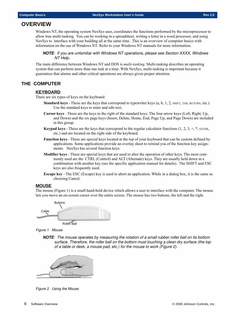
MOUSEThe mouse (Figure 1) is a small hand-held device which allows a user to interface with the computer. The mouselets you move an on-screen cursor over the entire screen. The mouse has two buttons, the left and the right.
Roller Ball
Cable
Buttons
Figure 1. Mouse
NOTE: The mouse operates by measuring the rotation of a small rubber roller ball on its bottomsurface. Therefore, the roller ball on the bottom must touching a clean dry surface (the topof a table or desk, a mouse pad, etc.) for the mouse to work (Figure 2).
Figure 2. Using the Mouse
© 2000 Johnson Controls, Inc. Software Overview 7
Rev 2.0 NexSys Workstation User’s Guide Computer Basics
BASIC MOUSE ACTIONSBelow is an explanation of the basic mouse actions:
Pointing - Move the mouse until the tip of the cursor rests on a specific item or area. Although the itemmay appear highlighted, pointing alone does nothing.
Clicking or Selecting - Point at an item, then press and release the left mouse button. Clicking is used toselect an on-screen item.
Double Clicking - Press and release the left mouse button twice in rapid succession. Double clicking isused to select an item from a list.
Dragging - Point at an item to be moved, press and hold down either the left or right mouse button, andthen move the mouse (and therefore the cursor-item) to a new location. Release the left or rightbutton only when the cursor-item is in the correct position.
Swiping (Highlighting) - This is basically the same technique used for dragging, but is used for selectingtext. Point to the left of the first character to include, press and hold down the left mouse button.Drag the pointer to the right and/or down until the pointer passes the last character to include, thenrelease the button. Text will appear highlighted.
Right Clicking - Click the right mouse button only. This is used to display the shortcut menu of the item(folder, window, or icon) that the cursor is positioned on. If no menu exists for that item, none willbe displayed.
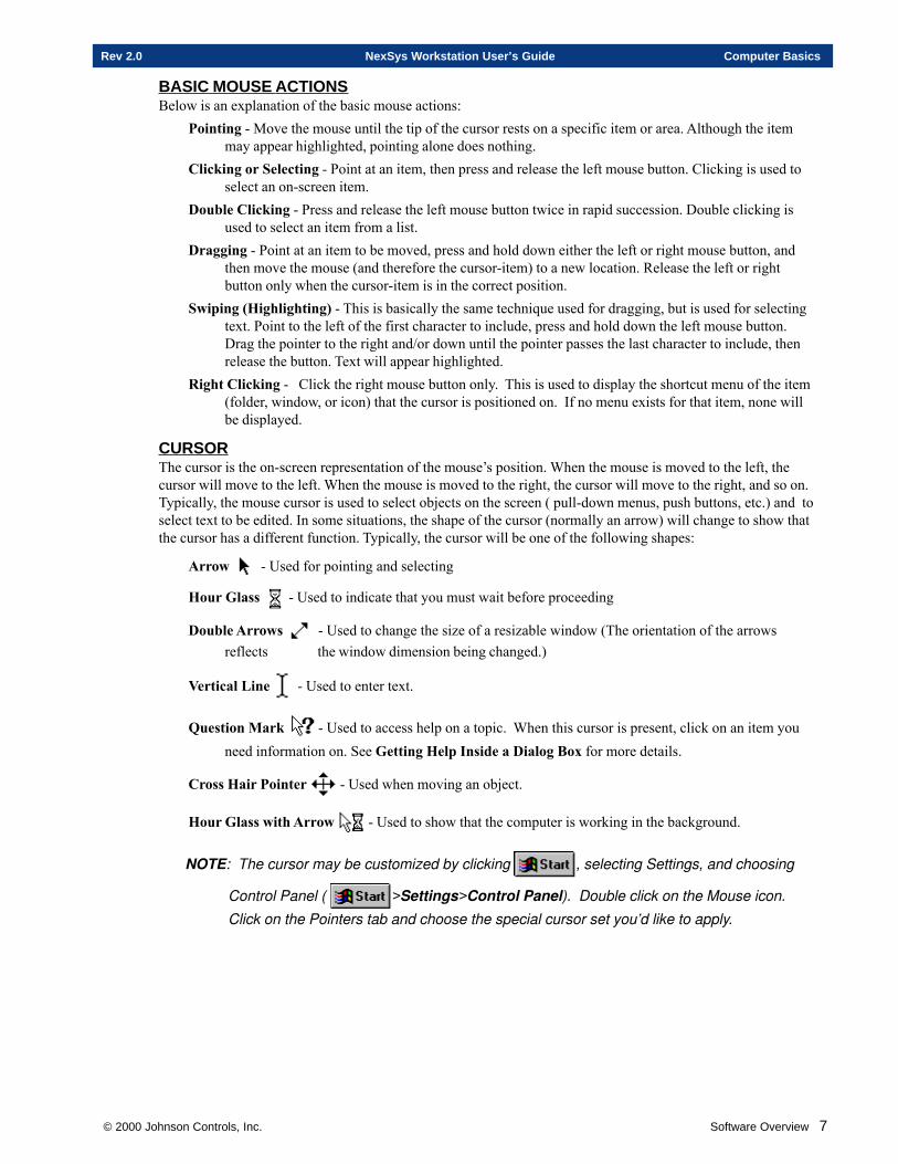
CURSORThe cursor is the on-screen representation of the mouse’s position. When the mouse is moved to the left, thecursor will move to the left. When the mouse is moved to the right, the cursor will move to the right, and so on.Typically, the mouse cursor is used to select objects on the screen ( pull-down menus, push buttons, etc.) and toselect text to be edited. In some situations, the shape of the cursor (normally an arrow) will change to show thatthe cursor has a different function. Typically, the cursor will be one of the following shapes:
Arrow - Used for pointing and selecting
Hour Glass - Used to indicate that you must wait before proceeding
Double Arrows - Used to change the size of a resizable window (The orientation of the arrowsreflects the window dimension being changed.)
Vertical Line - Used to enter text.
Question Mark - Used to access help on a topic. When this cursor is present, click on an item youneed information on. See Getting Help Inside a Dialog Box for more details.
Cross Hair Pointer - Used when moving an object.
Hour Glass with Arrow - Used to show that the computer is working in the background.
NOTE: The cursor may be customized by clicking , selecting Settings, and choosing
Control Panel ( >Settings>Control Panel). Double click on the Mouse icon.
Click on the Pointers tab and choose the special cursor set you’d like to apply.
8 Software Overview © 2000 Johnson Controls, Inc.
Computer Basics NexSys Workstation User’s Guide Rev 2.0
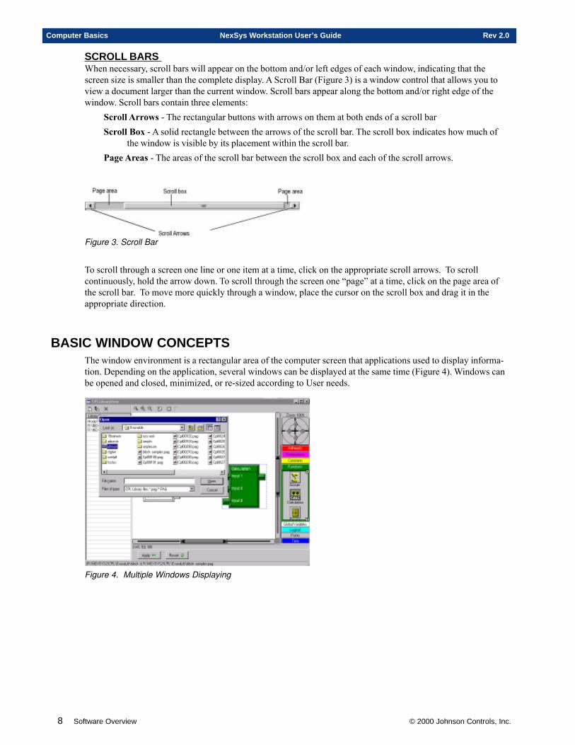
SCROLL BARS When necessary, scroll bars will appear on the bottom and/or left edges of each window, indicating that thescreen size is smaller than the complete display. A Scroll Bar (Figure 3) is a window control that allows you toview a document larger than the current window. Scroll bars appear along the bottom and/or right edge of thewindow. Scroll bars contain three elements:
Scroll Arrows - The rectangular buttons with arrows on them at both ends of a scroll barScroll Box - A solid rectangle between the arrows of the scroll bar. The scroll box indicates how much of
the window is visible by its placement within the scroll bar.Page Areas - The areas of the scroll bar between the scroll box and each of the scroll arrows.
Figure 3. Scroll Bar
To scroll through a screen one line or one item at a time, click on the appropriate scroll arrows. To scrollcontinuously, hold the arrow down. To scroll through the screen one “page” at a time, click on the page area ofthe scroll bar. To move more quickly through a window, place the cursor on the scroll box and drag it in theappropriate direction.
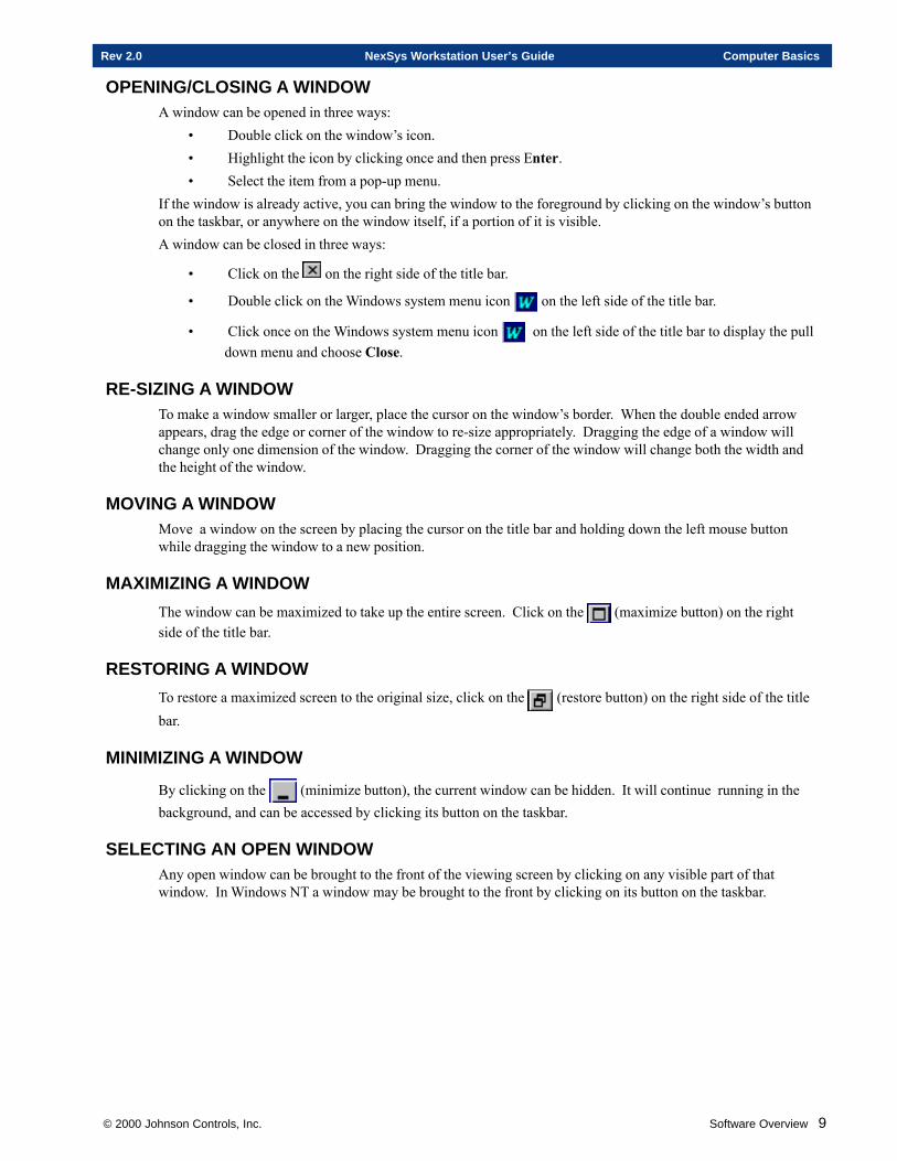
BASIC WINDOW CONCEPTSThe window environment is a rectangular area of the computer screen that applications used to display informa-tion. Depending on the application, several windows can be displayed at the same time (Figure 4). Windows canbe opened and closed, minimized, or re-sized according to User needs.
Figure 4. Multiple Windows Displaying
© 2000 Johnson Controls, Inc. Software Overview 9
Rev 2.0 NexSys Workstation User’s Guide Computer Basics
OPENING/CLOSING A WINDOWA window can be opened in three ways:
• Double click on the window’s icon.• Highlight the icon by clicking once and then press Enter.• Select the item from a pop-up menu.
If the window is already active, you can bring the window to the foreground by clicking on the window’s buttonon the taskbar, or anywhere on the window itself, if a portion of it is visible.A window can be closed in three ways:
• Click on the on the right side of the title bar.
• Double click on the Windows system menu icon on the left side of the title bar.
• Click once on the Windows system menu icon on the left side of the title bar to display the pulldown menu and choose Close.
RE-SIZING A WINDOWTo make a window smaller or larger, place the cursor on the window’s border. When the double ended arrowappears, drag the edge or corner of the window to re-size appropriately. Dragging the edge of a window willchange only one dimension of the window. Dragging the corner of the window will change both the width andthe height of the window.
MOVING A WINDOWMove a window on the screen by placing the cursor on the title bar and holding down the left mouse buttonwhile dragging the window to a new position.
MAXIMIZING A WINDOW
The window can be maximized to take up the entire screen. Click on the (maximize button) on the rightside of the title bar.
RESTORING A WINDOW
To restore a maximized screen to the original size, click on the (restore button) on the right side of the titlebar.
MINIMIZING A WINDOW
By clicking on the (minimize button), the current window can be hidden. It will continue running in thebackground, and can be accessed by clicking its button on the taskbar.
SELECTING AN OPEN WINDOWAny open window can be brought to the front of the viewing screen by clicking on any visible part of thatwindow. In Windows NT a window may be brought to the front by clicking on its button on the taskbar.
10 Software Overview © 2000 Johnson Controls, Inc.
Computer Basics NexSys Workstation User’s Guide Rev 2.0
BASIC MENU CONCEPTSWindows NT uses toolbars, shortcut keys, and toolbar buttons to execute menu commands. It also uses thesetools to access information through dialog boxes, and to manipulate the window environment.A title bar is located at the top of each window. Below the Title Bar appears the Menu Toolbar. Menu commandsare listed in logical groups. These groups can be located in the menu bar, and are also accessed from within theapplication. Both pull-down and pop-up (shortcut) menus are available. A right pointing arrow at the right of acommand indicates a submenu. A submenu contains a list of nested commands for the item you selected.
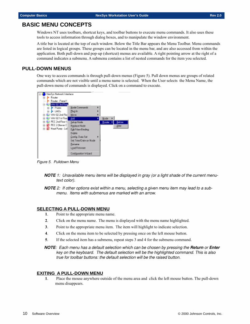
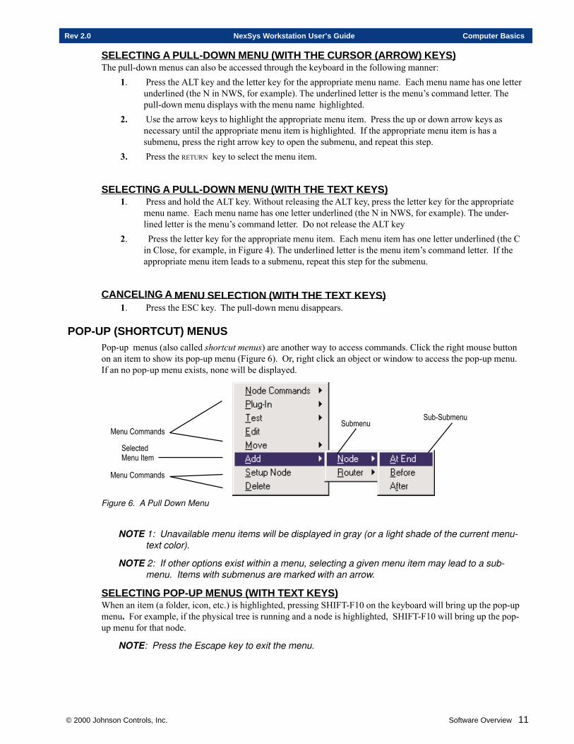
PULL-DOWN MENUSOne way to access commands is through pull-down menus (Figure 5). Pull down menus are groups of relatedcommands which are not visible until a menu name is selected. When the User selects the Menu Name, thepull-down menu of commands is displayed. Click on a command to execute.
Figure 5. Pulldown Menu
NOTE 1: Unavailable menu items will be displayed in gray (or a light shade of the current menu-text color).
NOTE 2: If other options exist within a menu, selecting a given menu item may lead to a sub-menu. Items with submenus are marked with an arrow.
SELECTING A PULL-DOWN MENU1. Point to the appropriate menu name.2. Click on the menu name. The menu is displayed with the menu name highlighted.3. Point to the appropriate menu item. The item will highlight to indicate selection.4. Click on the menu item to be selected by pressing once on the left mouse button.5. If the selected item has a submenu, repeat steps 3 and 4 for the submenu command.
NOTE: Each menu has a default selection which can be chosen by pressing the Return or Enterkey on the keyboard. The default selection will be the highlighted command. This is alsotrue for toolbar buttons: the default selection will be the raised button.
EXITING A PULL-DOWN MENU1. Place the mouse anywhere outside of the menu area and click the left mouse button. The pull-down
menu disappears.
© 2000 Johnson Controls, Inc. Software Overview 11
Rev 2.0 NexSys Workstation User’s Guide Computer Basics
SELECTING A PULL-DOWN MENU (WITH THE CURSOR (ARROW) KEYS)The pull-down menus can also be accessed through the keyboard in the following manner:
1. Press the ALT key and the letter key for the appropriate menu name. Each menu name has one letterunderlined (the N in NWS, for example). The underlined letter is the menu’s command letter. Thepull-down menu displays with the menu name highlighted.
2. Use the arrow keys to highlight the appropriate menu item. Press the up or down arrow keys asnecessary until the appropriate menu item is highlighted. If the appropriate menu item is has asubmenu, press the right arrow key to open the submenu, and repeat this step.
3. Press the RETURN key to select the menu item.
SELECTING A PULL-DOWN MENU (WITH THE TEXT KEYS)1. Press and hold the ALT key. Without releasing the ALT key, press the letter key for the appropriate
menu name. Each menu name has one letter underlined (the N in NWS, for example). The under-lined letter is the menu’s command letter. Do not release the ALT key
2. Press the letter key for the appropriate menu item. Each menu item has one letter underlined (the Cin Close, for example, in Figure 4). The underlined letter is the menu item’s command letter. If theappropriate menu item leads to a submenu, repeat this step for the submenu.
CANCELING A MENU SELECTION (WITH THE TEXT KEYS)1. Press the ESC key. The pull-down menu disappears.
POP-UP (SHORTCUT) MENUSPop-up menus (also called shortcut menus) are another way to access commands. Click the right mouse buttonon an item to show its pop-up menu (Figure 6). Or, right click an object or window to access the pop-up menu.If an no pop-up menu exists, none will be displayed.
�����������
�� �������������
�����������
������������������
Figure 6. A Pull Down Menu
NOTE 1: Unavailable menu items will be displayed in gray (or a light shade of the current menu-text color).
NOTE 2: If other options exist within a menu, selecting a given menu item may lead to a sub-menu. Items with submenus are marked with an arrow.
SELECTING POP-UP MENUS (WITH TEXT KEYS)When an item (a folder, icon, etc.) is highlighted, pressing SHIFT-F10 on the keyboard will bring up the pop-upmenu. For example, if the physical tree is running and a node is highlighted, SHIFT-F10 will bring up the pop-up menu for that node.
NOTE: Press the Escape key to exit the menu.
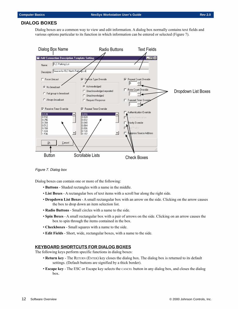
12 Software Overview © 2000 Johnson Controls, Inc.
Computer Basics NexSys Workstation User’s Guide Rev 2.0
DIALOG BOXESDialog boxes are a common way to view and edit information. A dialog box normally contains text fields andvarious options particular to its function in which information can be entered or selected (Figure 7).
�� ���������� �������� �
������
�����������
������������������
���� � ������� � ��!������
Figure 7. Dialog box
Dialog boxes can contain one or more of the following:• Buttons - Shaded rectangles with a name in the middle.• List Boxes - A rectangular box of text items with a scroll bar along the right side.• Dropdown List Boxes - A small rectangular box with an arrow on the side. Clicking on the arrow causes
the box to drop down an item selection list.• Radio Buttons - Small circles with a name to the side.• Spin Boxes - A small rectangular box with a pair of arrows on the side. Clicking on an arrow causes the
box to spin through the items contained in the box.• Checkboxes - Small squares with a name to the side.• Edit Fields - Short, wide, rectangular boxes, with a name to the side.
KEYBOARD SHORTCUTS FOR DIALOG BOXESThe following keys perform specific functions in dialog boxes:
• Return key - The RETURN (ENTER) key closes the dialog box. The dialog box is returned to its defaultsettings. (Default buttons are signified by a thick border).
• Escape key - The ESC or Escape key selects the CANCEL button in any dialog box, and closes the dialogbox.
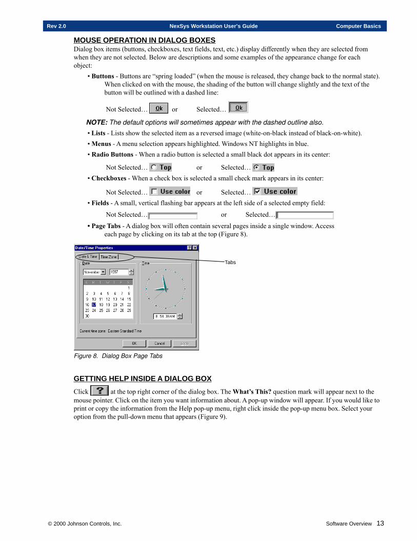
© 2000 Johnson Controls, Inc. Software Overview 13
Rev 2.0 NexSys Workstation User’s Guide Computer Basics
MOUSE OPERATION IN DIALOG BOXESDialog box items (buttons, checkboxes, text fields, text, etc.) display differently when they are selected fromwhen they are not selected. Below are descriptions and some examples of the appearance change for eachobject:
• Buttons - Buttons are “spring loaded” (when the mouse is released, they change back to the normal state).When clicked on with the mouse, the shading of the button will change slightly and the text of thebutton will be outlined with a dashed line:
Not Selected… or Selected…
NOTE: The default options will sometimes appear with the dashed outline also.
• Lists - Lists show the selected item as a reversed image (white-on-black instead of black-on-white).• Menus - A menu selection appears highlighted. Windows NT highlights in blue.• Radio Buttons - When a radio button is selected a small black dot appears in its center:
Not Selected… or Selected… • Checkboxes - When a check box is selected a small check mark appears in its center:
Not Selected… or Selected… • Fields - A small, vertical flashing bar appears at the left side of a selected empty field:
Not Selected… or Selected…
• Page Tabs - A dialog box will often contain several pages inside a single window. Accesseach page by clicking on its tab at the top (Figure 8).
Tabs
Figure 8. Dialog Box Page Tabs
GETTING HELP INSIDE A DIALOG BOX
Click at the top right corner of the dialog box. The What’s This? question mark will appear next to themouse pointer. Click on the item you want information about. A pop-up window will appear. If you would like toprint or copy the information from the Help pop-up menu, right click inside the pop-up menu box. Select youroption from the pull-down menu that appears (Figure 9).
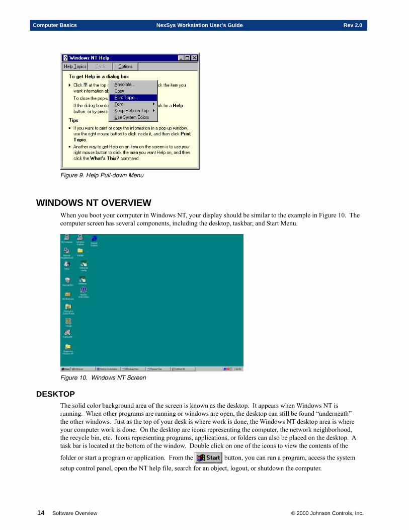
14 Software Overview © 2000 Johnson Controls, Inc.
Computer Basics NexSys Workstation User’s Guide Rev 2.0
Figure 9. Help Pull-down Menu
WINDOWS NT OVERVIEWWhen you boot your computer in Windows NT, your display should be similar to the example in Figure 10. Thecomputer screen has several components, including the desktop, taskbar, and Start Menu.
Figure 10. Windows NT Screen
DESKTOPThe solid color background area of the screen is known as the desktop. It appears when Windows NT isrunning. When other programs are running or windows are open, the desktop can still be found “underneath”the other windows. Just as the top of your desk is where work is done, the Windows NT desktop area is whereyour computer work is done. On the desktop are icons representing the computer, the network neighborhood,the recycle bin, etc. Icons representing programs, applications, or folders can also be placed on the desktop. Atask bar is located at the bottom of the window. Double click on one of the icons to view the contents of the
folder or start a program or application. From the button, you can run a program, access the systemsetup control panel, open the NT help file, search for an object, logout, or shutdown the computer.
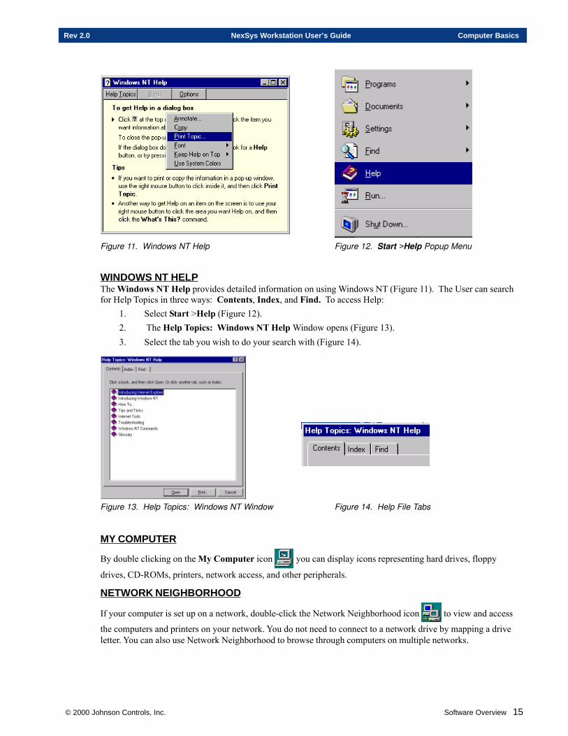
© 2000 Johnson Controls, Inc. Software Overview 15
Rev 2.0 NexSys Workstation User’s Guide Computer Basics
Figure 11. Windows NT Help Figure 12. Start >Help Popup Menu
WINDOWS NT HELPThe Windows NT Help provides detailed information on using Windows NT (Figure 11). The User can searchfor Help Topics in three ways: Contents, Index, and Find. To access Help:
1. Select Start >Help (Figure 12).2. The Help Topics: Windows NT Help Window opens (Figure 13).3. Select the tab you wish to do your search with (Figure 14).
Figure 13. Help Topics: Windows NT Window Figure 14. Help File Tabs
MY COMPUTER
By double clicking on the My Computer icon you can display icons representing hard drives, floppy
drives, CD-ROMs, printers, network access, and other peripherals.
NETWORK NEIGHBORHOOD
If your computer is set up on a network, double-click the Network Neighborhood icon to view and access
the computers and printers on your network. You do not need to connect to a network drive by mapping a driveletter. You can also use Network Neighborhood to browse through computers on multiple networks.
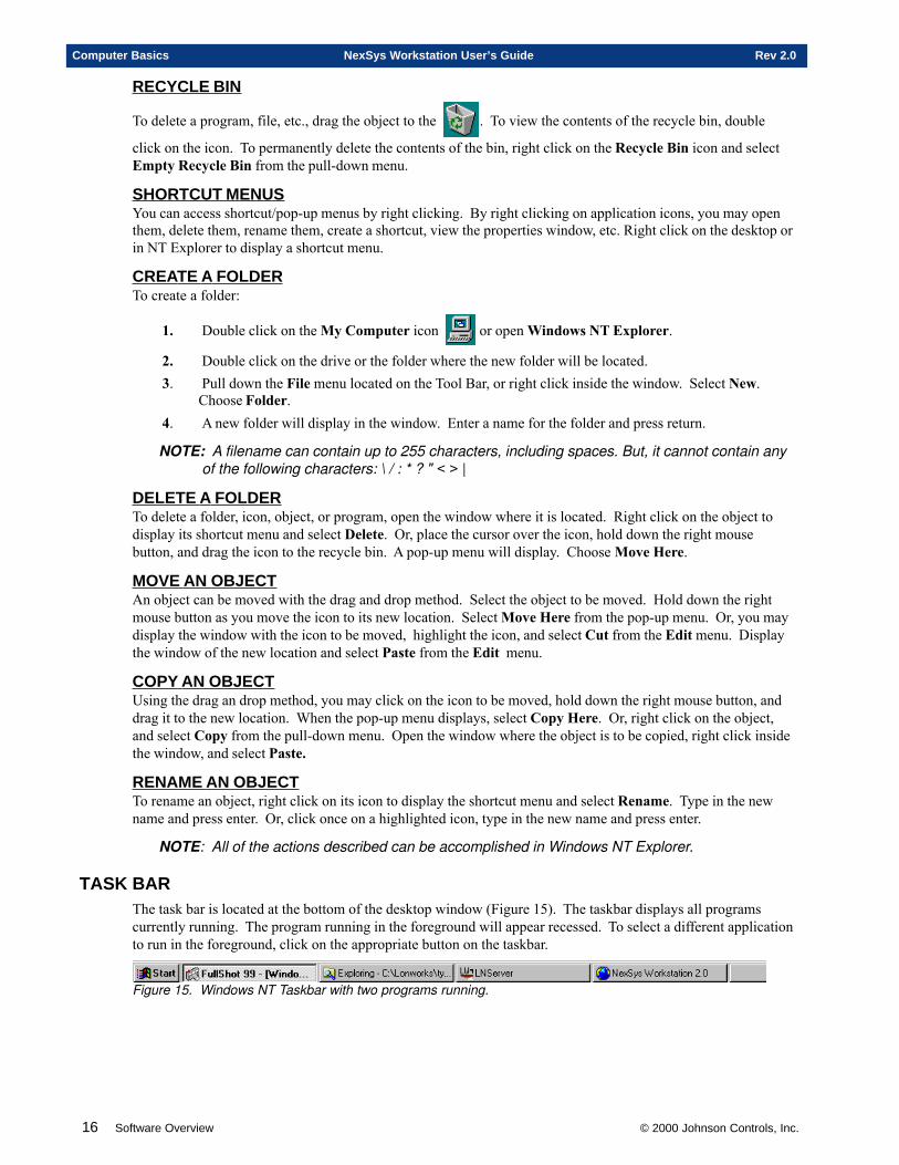
16 Software Overview © 2000 Johnson Controls, Inc.
Computer Basics NexSys Workstation User’s Guide Rev 2.0
RECYCLE BIN
To delete a program, file, etc., drag the object to the . To view the contents of the recycle bin, double
click on the icon. To permanently delete the contents of the bin, right click on the Recycle Bin icon and selectEmpty Recycle Bin from the pull-down menu.
SHORTCUT MENUSYou can access shortcut/pop-up menus by right clicking. By right clicking on application icons, you may openthem, delete them, rename them, create a shortcut, view the properties window, etc. Right click on the desktop orin NT Explorer to display a shortcut menu.
CREATE A FOLDERTo create a folder:
1. Double click on the My Computer icon or open Windows NT Explorer.
2. Double click on the drive or the folder where the new folder will be located.3. Pull down the File menu located on the Tool Bar, or right click inside the window. Select New.
Choose Folder.4. A new folder will display in the window. Enter a name for the folder and press return.
NOTE: A filename can contain up to 255 characters, including spaces. But, it cannot contain anyof the following characters: \ / : * ? " < > |
DELETE A FOLDERTo delete a folder, icon, object, or program, open the window where it is located. Right click on the object todisplay its shortcut menu and select Delete. Or, place the cursor over the icon, hold down the right mousebutton, and drag the icon to the recycle bin. A pop-up menu will display. Choose Move Here.
MOVE AN OBJECTAn object can be moved with the drag and drop method. Select the object to be moved. Hold down the rightmouse button as you move the icon to its new location. Select Move Here from the pop-up menu. Or, you maydisplay the window with the icon to be moved, highlight the icon, and select Cut from the Edit menu. Displaythe window of the new location and select Paste from the Edit menu.
COPY AN OBJECTUsing the drag an drop method, you may click on the icon to be moved, hold down the right mouse button, anddrag it to the new location. When the pop-up menu displays, select Copy Here. Or, right click on the object,and select Copy from the pull-down menu. Open the window where the object is to be copied, right click insidethe window, and select Paste.
RENAME AN OBJECTTo rename an object, right click on its icon to display the shortcut menu and select Rename. Type in the newname and press enter. Or, click once on a highlighted icon, type in the new name and press enter.
NOTE: All of the actions described can be accomplished in Windows NT Explorer.
TASK BARThe task bar is located at the bottom of the desktop window (Figure 15). The taskbar displays all programscurrently running. The program running in the foreground will appear recessed. To select a different applicationto run in the foreground, click on the appropriate button on the taskbar.
Figure 15. Windows NT Taskbar with two programs running.
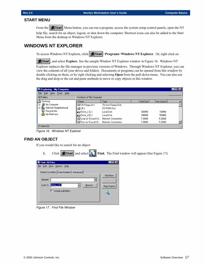
© 2000 Johnson Controls, Inc. Software Overview 17
Rev 2.0 NexSys Workstation User’s Guide Computer Basics
START MENU
From the Menu button, you can run a program, access the system setup control panels, open the NThelp file, search for an object, logout, or shut down the computer. Shortcut icons can also be added to the StartMenu from the desktop or Windows NT Explorer.
WINDOWS NT EXPLORER
To access Windows NT Explorer, click >Programs>Windows NT Explorer. Or, right click on
, and select Explore. See the sample Window NT Explorer window in Figure 16. Windows NTExplorer replaces the file manager in previous versions of Windows. Through Windows NT Explorer, you canview the contents of all your drives and folders. Documents or programs can be opened from this window bydouble clicking on them, or by right clicking and selecting Open from the pull-down menu. You can also usethe drag and drop or the cut and paste methods to move or copy objects in this window.
Figure 16. Windows NT Explorer
FIND AN OBJECTIf you would like to search for an object:
1. Click and select Find. The Find window will appear (See Figure 17).
Figure 17. Find File Window
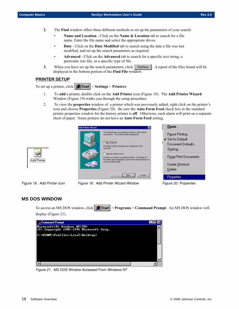
18 Software Overview © 2000 Johnson Controls, Inc.
Computer Basics NexSys Workstation User’s Guide Rev 2.0
2. The Find window offers three different methods to set up the parameters of your search:• Name and Location - Click on the Name & Location tab to search for a file
name. Enter the file name and select the appropriate drives.• Date - Click on the Date Modified tab to search using the date a file was last
modified, and set up the search parameters as required.• Advanced - Click on the Advanced tab to search for a specific text string, a
particular size file, or a specific type of file.3. When you have set up the search parameters, click . A report of the files found will be
displayed in the bottom portion of the Find File window.
PRINTER SETUP
To set up a printer, click > Settings > Printers:
1. To add a printer, double click on the Add Printer icon (Figure 18). The Add Printer WizardWindow (Figure 19) walks you through the setup procedure.
2. To view the properties window of a printer which was previously added, right click on the printer’sicon and choose Properties (Figure 20). Be sure the Auto Form Feed check box in the standardprinter properties window for the history printer is off. Otherwise, each alarm will print on a separatesheet of paper. Some printers do not have an Auto Form Feed setting.
Figure 18. Add Printer Icon Figure 19. Add Printer Wizard Window Figure 20. Properties
MS DOS WINDOW
To access an MS DOS window, click > Programs > Command Prompt. An MS DOS window willdisplay (Figure 21).
Figure 21. MS DOS Window Accessed From Windows NT
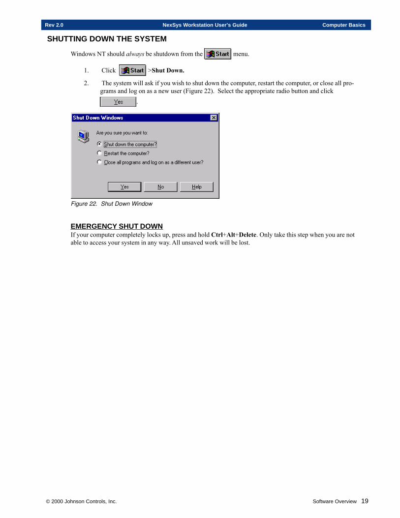
© 2000 Johnson Controls, Inc. Software Overview 19
Rev 2.0 NexSys Workstation User’s Guide Computer Basics
SHUTTING DOWN THE SYSTEM
Windows NT should always be shutdown from the menu.
1. Click >Shut Down.
2. The system will ask if you wish to shut down the computer, restart the computer, or close all pro-grams and log on as a new user (Figure 22). Select the appropriate radio button and click
.
Figure 22. Shut Down Window
EMERGENCY SHUT DOWNIf your computer completely locks up, press and hold Ctrl+Alt+Delete. Only take this step when you are notable to access your system in any way. All unsaved work will be lost.

20 Software Overview © 2000 Johnson Controls, Inc.
Computer Basics NexSys Workstation User’s Guide Rev 2.0
NWS Software Architecture
This chapter contains information on:
� The NexSys Workstation (NWS)
� The LNServer
� LONWORKS® Network Services (LNS)
� OPC LONWORKS® Server
� The M-Series Workstation
© 2000 Johnson Controls, Inc.
Chapter Two
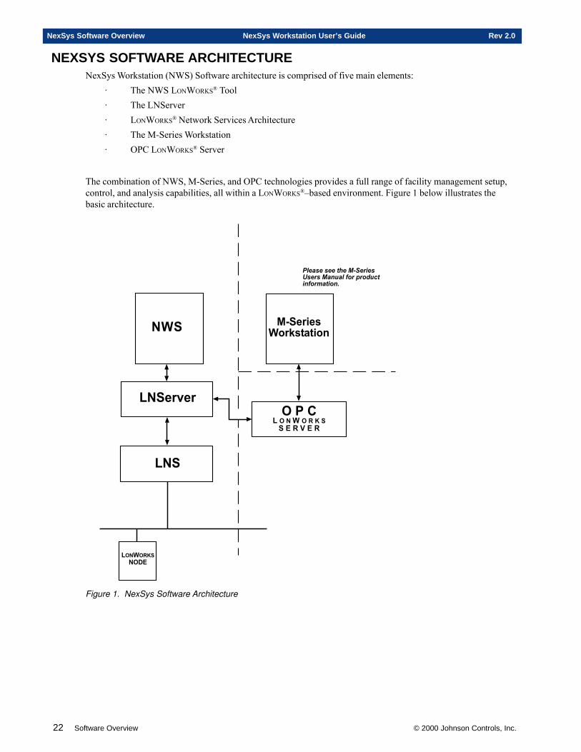
22 Software Overview © 2000 Johnson Controls, Inc.
NexSys Software Overview NexSys Workstation User’s Guide Rev 2.0
NEXSYS SOFTWARE ARCHITECTURENexSys Workstation (NWS) Software architecture is comprised of five main elements:
· The NWS LONWORKS® Tool· The LNServer· LONWORKS® Network Services Architecture· The M-Series Workstation· OPC LONWORKS® Server
The combination of NWS, M-Series, and OPC technologies provides a full range of facility management setup,control, and analysis capabilities, all within a LONWORKS®–based environment. Figure 1 below illustrates thebasic architecture.
������������������ ������������������������� ������� ���
� � �� � � � � � �
� � �
����������
�� �� �
��
�� �� ��������������
Figure 1. NexSys Software Architecture
© 2000 Johnson Controls, Inc. Software Overview 23
Rev 2.0 NexSys Workstation User’s Guide NexSys Software Overview
NEXSYS WORKSTATION (NWS)The NexSys Workstation (NWS) is a LONWORKS® tool used for the setup and configuration of the buildingautomation system. All node configuration, node operations, point binding, and execution of plug-ins is per-formed with NWS. NWS is also used for writing and editing specialty programs for the Flexible System Con-troller (FSC) using Control Programming Language (CPL), and scheduling of the FSC.
LNSERVERLNServer allows NWS to communicate with the LNS architecture. It serves as the interface between NWS andthe LNS Component Object Model (COM) technology. When the user makes a request in NWS, the data is sentto LNServer using TCP-IP protocol. LNServer then communicates the data to LNS. Information is returned toNWS and ultimately the user in the same way.
LNSLONWORKS® Network Services (LNS) 3.0 Architecture is a set of network services that provides inter-operabilitybetween tools. LNS features an Active X “wrapper” that allows it to interface with a variety of applications. LNScommunicates directly with devices on the LONWORKS® network using LONTALK® protocol, and then passes thisinformation back to the LNServer.
OPC LONWORKS SERVERThe OPC LONWORKS® Server is the “plug-and-play” interface between the M-Series Workstation and the LNSArchitecture. It utilizes Object Linking and Embedding – for Process Control (OPC) technology for plug-and-play software, providing communications between building control systems. The OPC Server accesses data fromthe field through LNS, and provides that data to the M-Series Workstation. The OPC LONWORKS® Server ismulti-tasking, and communicates with all LONTALK® media.
M-SERIES WORKSTATIONThe M-Series Workstation is the dynamic graphical display for the building control system. The M-SeriesWorkstation provides trending, graphics, and alarm features to assist users in analyzing system efficiency andenergy consumption. Users can also add navigation links, issue commands, and set up interactive displays of thefacility. M-Series receives information from the field via the OPC Server.

24 Software Overview © 2000 Johnson Controls, Inc.
NexSys Software Overview NexSys Workstation User’s Guide Rev 2.0
©2000 Johnson Controls, Inc. Software Overview 25
Rev 2.0 NexSys Workstation User’s Guide Software Overview Index
Software Overview IndexB
Basic Menu Concepts 10Basic Mouse Actions 7Basic Window Concepts 8Buttons 12
C
Checkboxes 12Clicking 7Cursor 7
D
Dialog Boxes 12Double Click 7Drag 7Dropdown List Boxes 12
E
Emergency Shut Down 19Escape Key 6
F
Function Keys 6
H
Highlight 7
K
Keyboard 6
L
List Boxes 12LNS 23LNServer 23
M
M3 Workstation 23Menus 10Mouse 6Multi-tasking 6My Computer 15
N
Network Neighborhood 15Nexsys Workstation (NWS) 23NT Explorer 7
O
OPC LonWorks® Server 23Overview 6
P
Point 7Pop-Up Menus 11
Shortcut Menus 11Printer Setup 18Pull-Down Menus 10
R
Radio Buttons 12Right Click 7
S
Scroll Bars 8Scroll Box 8Select 7Shortcut Menus 16Spin Boxes 12Start Menu 17Swipe 7
T
Task Bar 16
W
WindowMaximize 9Minimize 9Move 9Resize 9Restore 9
Windows NT 14Accessing Information
Pull-Down Menus 10Copy an Object 16Create a Folder 16

26 Software Overview ©2000 Johnson Controls, Inc.
Software Overview Index NexSys Workstation User’s Guide Rev 2.0
Delete a Folder 16Desktop 14Find an Object 17Peripherals 6Move an Object 16MS DOS Window 40Overview 14Recycle Bin 16Rename an Object 16Screen Breakdown
Cursor 7Scroll Bars 8Windows 9
Windows NT Help 16
Chapters
1. NexSys Software Installation
2. Hardware Installation3. Getting Started
© 2000 Johnson Controls, Inc.
INSTALL ATION and STARTUPSECTION TWO

28 Installation and Startup © 2000 Johnson Controls, Inc.
Installation and Startup Introduction NexSys Workstation User’s Guide Rev 2.0
Electronic Systems USA, a wholly owned subsidiary of Johnson Controls, Inc., reserves the right to updatespecifications when appropriate. Information contained in this document is based on specifications believed tobe correct at the time of publication.
Echelon ©, Coactive©, Windows NT©, and General Electric© are registered trademarks and service marks ofcompanies other than Electronic Systems USA. FSC™, CPL™ and NexSys™ are trademarks of ElectronicSystems USA.
Copyright © 2000 Johnson Controls, Inc. All Rights Reserved
Rev 2.0 NexSys Workstation User’s Guide Installation and Startup Introduction
© 2000 Johnson Controls, Inc. Installation and Startup 29
Installation/Startup Table of Contents
Chapter One - NexSys Software Installation 31Four Types Of PC Configurations ...................................................................................... 32
Installation Checklist ..................................................................................... 33Before You Begin Installing: ............................................................................................... 34
Installing A Network Adapter Or MS Loopback Adapter .......................................... 34Installing Network Protocols .................................................................................... 36
Installing NexSys For The First time .................................................................................. 38Configuring LNServer .............................................................................................. 39
Opening The LNServer Configuration Wizard .............................................. 39Configuring LNServer For A Local Location .................................................. 40Configuring LNServer For A Remote Location .............................................. 43
Installing Remote Access Services (RAS).......................................................................... 46Setting RAS Server To Automatic Start ................................................................... 50Creating A User With RAS Login Privileges ............................................................ 51Setting Up A Client To Access The Server ............................................................... 53Setting Up A Modem ................................................................................................ 56Dialing The Server From A Remote Site .................................................................. 58Disconnecting A Remote Site From A Server PC .................................................... 59
Chapter Two - Hardware Installation 63Introduction ........................................................................................................................ 64Disabling And Removing The Full-Size PCLTA Card ......................................................... 65Installing The Hardware Drivers ......................................................................................... 66Installing The PCLTA-10/20 Card ....................................................................................... 73Installing The PCC-10 (Laptop Only) ................................................................................. 73
Chapter Three - Getting Started 75Start-Up Procedure ............................................................................................................ 76
Add ESUSA Resources To Catalog ......................................................................... 76Adding ESUSA Resources To Catalog ......................................................... 76
Starting NexSys Workstation (NWS) And LnServer ................................................ 78Starting NWS And LNServer Together .......................................................... 78Starting NWS ................................................................................................ 78Starting LNServer ......................................................................................... 78
NWS Main Window ............................................................................................................ 79Title Bar ................................................................................................................... 79Version Number Of NWS software .......................................................................... 80Resizing The NexSys Windows ............................................................................... 80Menu Bar ................................................................................................................. 80Toolbar ..................................................................................................................... 81Physical Tree ........................................................................................................... 81Working Panels ....................................................................................................... 81Server Status Bar .................................................................................................... 82
Exiting NWS ....................................................................................................................... 82Exiting LNServer ................................................................................................................ 82
Installation and Startup Index.......................................................... 85

30 Installation and Startup © 2000 Johnson Controls, Inc.
Installation and Startup Introduction NexSys Workstation User’s Guide Rev 2.0
Chapter One
NexSys Software Installation
This chapter contains information on:
� Types of PC Configurations
� Minimum System Requirements
� Installing a Network Adapter or Loopback Adapter
� Installing Network Protocols
� Installing NexSys Workstation (NWS)
� Configuring LNServer
� Installing Remote Access Services (RAS)
� Setting Up a Modem
© 2000 Johnson Controls, Inc.
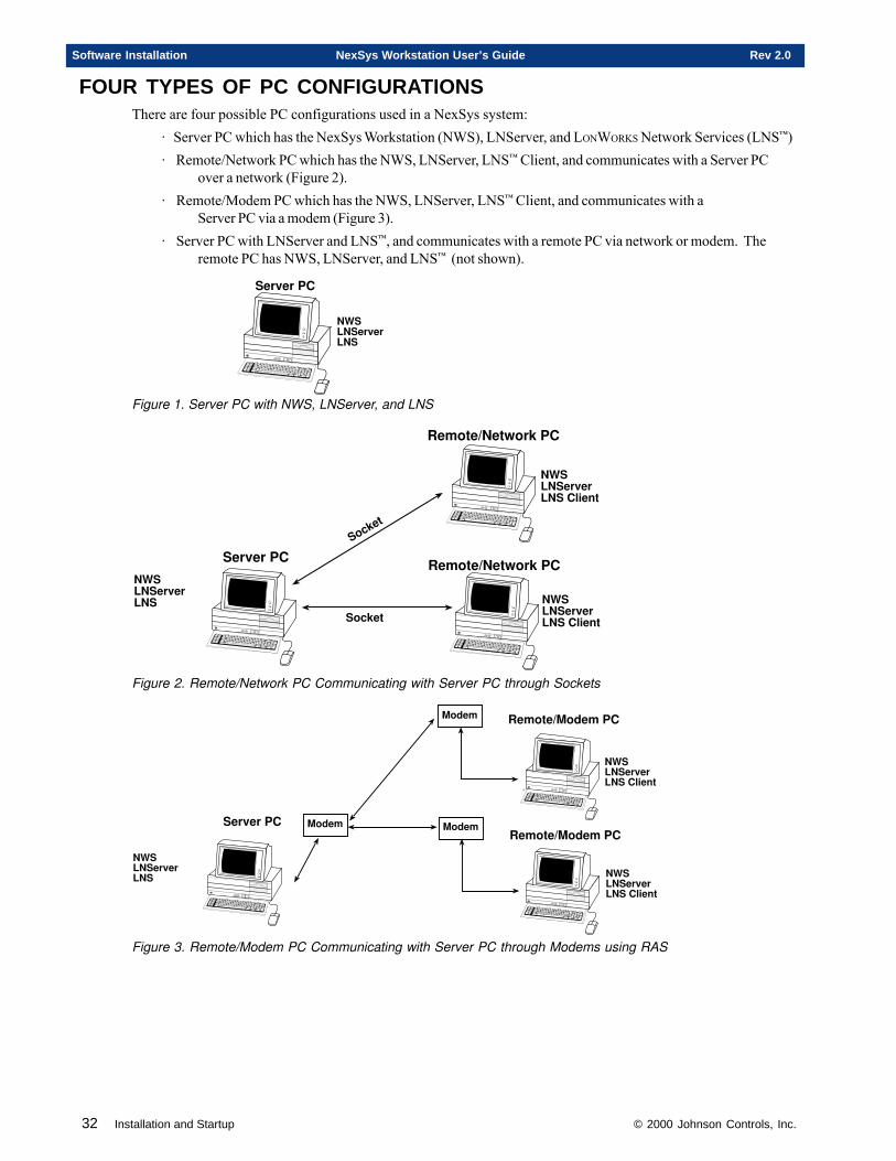
32 Installation and Startup © 2000 Johnson Controls, Inc.
Software Installation NexSys Workstation User’s Guide Rev 2.0
FOUR TYPES OF PC CONFIGURATIONSThere are four possible PC configurations used in a NexSys system:
· Server PC which has the NexSys Workstation (NWS), LNServer, and LONWORKS Network Services (LNS™)· Remote/Network PC which has the NWS, LNServer, LNS™ Client, and communicates with a Server PC
over a network (Figure 2).· Remote/Modem PC which has the NWS, LNServer, LNS™ Client, and communicates with a
Server PC via a modem (Figure 3).· Server PC with LNServer and LNS™, and communicates with a remote PC via network or modem. The
remote PC has NWS, LNServer, and LNS™ (not shown).
���������
�����������
Figure 1. Server PC with NWS, LNServer, and LNS
�����������
���������
���������������� �
���������������� �
������
������
�����������������
�����������������
Figure 2. Remote/Network PC Communicating with Server PC through Sockets
�����
�����������
���������
�����
���������������� �
���������������
�����
���������������� �
���������������
Figure 3. Remote/Modem PC Communicating with Server PC through Modems using RAS
© 2000 Johnson Controls, Inc. Installation and Startup 33
Rev 2.0 NexSys Workstation User’s Guide Software Installation
INSTALLA TION CHECKLIST
Use this checklist as a guide through the Installation and Startup proce-dures, beginning with Step 1. If a step is not applicable to your particularsetup, skip that step and proceed with the one immediately following it.
• Step One: Install Network Adapter or MS Loopback Adapter• Step Two: Install Network Protocols• Step Three: Install NexSys Work Station (NWS)• Step Four Install Remote Access Services (RAS)• Step Five: Setting Up A Modem• Step Six: Disable and Remove Full-Size PCLTA• Step Seven: Install Drivers For Your PCLTA/PCC-10 Card• Step Eight: Install PCLTA-10/PCLTA-20/PCC-10• Step Nine: Reinstall Service Pack 6.0• Step Ten: Starting NexSys
• Step Eleven: Configure LNServer
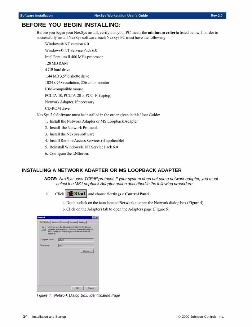
34 Installation and Startup © 2000 Johnson Controls, Inc.
Software Installation NexSys Workstation User’s Guide Rev 2.0
BEFORE YOU BEGIN INSTALLING:Before you begin your NexSys install, verify that your PC meets the minimum criteria listed below. In order tosuccessfully install NexSys software, each NexSys PC must have the following:
Windows® NT version 4.0Windows® NT Service Pack 6.0Intel Pentium II 400 MHz processor128 MB RAM4 GB hard drive1.44 MB 3.5" diskette drive1024 x 768 resolution, 256 color monitorIBM-compatible mousePCLTA-10, PCLTA-20 or PCC-10 (laptop)Network Adapter, if necessaryCD-ROM drive
NexSys 2.0 Software must be installed in the order given in this User Guide:1. Install the Network Adapter or MS Loopback Adapter2. Install the Network Protocols3. Install the NexSys software4. Install Remote Access Services (if applicable)5. Reinstall Windows® NT Service Pack 6.06. Configure the LNServer.
INSTALLING A NETWORK ADAPTER OR MS LOOPBACK ADAPTER
NOTE: NexSys uses TCP/IP protocol. If your system does not use a network adapter, you mustselect the MS Loopback Adapter option described in the following procedure.
1. Click and choose Settings > Control Panel.
a. Double click on the icon labeled Network to open the Network dialog box (Figure 4).b. Click on the Adapters tab to open the Adapters page (Figure 5).
Figure 4. Network Dialog Box, Identification Page
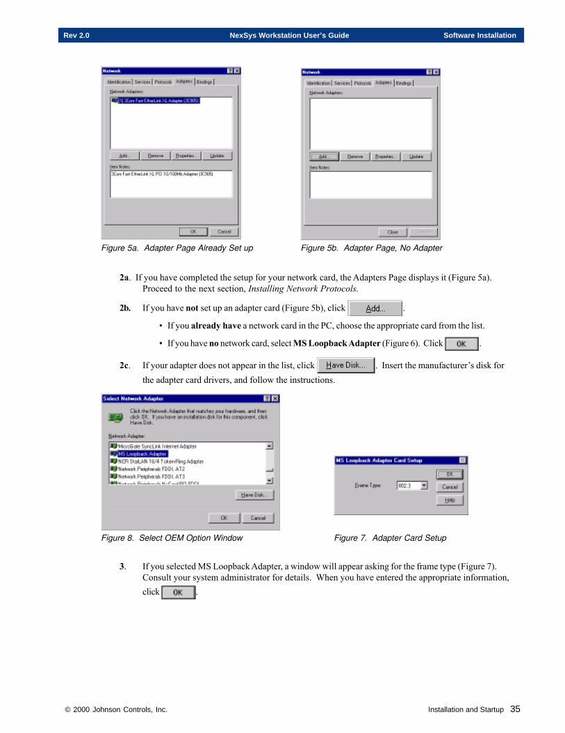
© 2000 Johnson Controls, Inc. Installation and Startup 35
Rev 2.0 NexSys Workstation User’s Guide Software Installation
Figure 5a. Adapter Page Already Set up Figure 5b. Adapter Page, No Adapter
2a. If you have completed the setup for your network card, the Adapters Page displays it (Figure 5a).Proceed to the next section, Installing Network Protocols.
2b. If you have not set up an adapter card (Figure 5b), click .
• If you already have a network card in the PC, choose the appropriate card from the list.
• If you have no network card, select MS Loopback Adapter (Figure 6). Click .
2c. If your adapter does not appear in the list, click . Insert the manufacturer’s disk forthe adapter card drivers, and follow the instructions.
Figure 8. Select OEM Option Window Figure 7. Adapter Card Setup
3. If you selected MS Loopback Adapter, a window will appear asking for the frame type (Figure 7).Consult your system administrator for details. When you have entered the appropriate information,click .
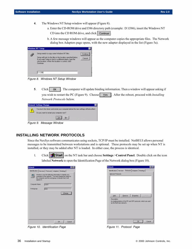
36 Installation and Startup © 2000 Johnson Controls, Inc.
Software Installation NexSys Workstation User’s Guide Rev 2.0
4. The Windows NT Setup window will appear (Figure 8).a. Enter the CD-ROM drive and I386 directory path (example: D:\I386), insert the Windows NT
CD into the CD ROM drive, and click .
b. A few message windows will appear as the computer copies the appropriate files. The Networkdialog box Adapters page opens, with the new adapter displayed in the list (Figure 5a).
Figure 8. Windows NT Setup Window
5. Click . The computer will update binding information. Then a window will appear asking if
you wish to restart the PC (Figure 9). Choose . After the reboot, proceed with InstallingNetwork Protocols below.
Figure 9. Message Window
INSTALLING NETWORK PROTOCOLSSince the NexSys software communicates using sockets, TCP/IP must be installed. NetBEUI allows personalmessages to be transmitted between workstations and is optional. These protocols may be set up when NT isinstalled, or they may be added after NT is loaded. In either case, the process is identical.
1. Click on the NT task bar and choose Settings >Control Panel. Double click on the icon
labeled Network to open the Identification Page of the Network dialog box (Figure 10).
Figure 10. Identification Page Figure 11. Protocol Page
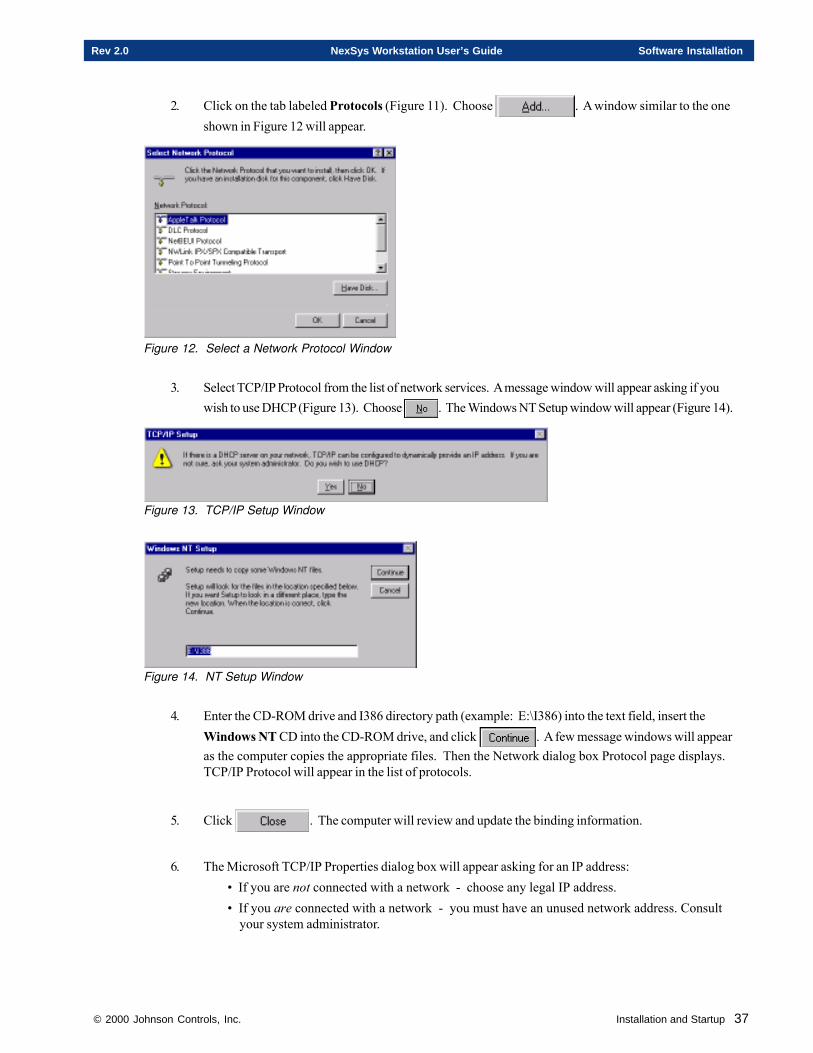
© 2000 Johnson Controls, Inc. Installation and Startup 37
Rev 2.0 NexSys Workstation User’s Guide Software Installation
2. Click on the tab labeled Protocols (Figure 11). Choose . A window similar to the oneshown in Figure 12 will appear.
Figure 12. Select a Network Protocol Window
3. Select TCP/IP Protocol from the list of network services. A message window will appear asking if youwish to use DHCP (Figure 13). Choose . The Windows NT Setup window will appear (Figure 14).
Figure 13. TCP/IP Setup Window
Figure 14. NT Setup Window
4. Enter the CD-ROM drive and I386 directory path (example: E:\I386) into the text field, insert theWindows NT CD into the CD-ROM drive, and click . A few message windows will appearas the computer copies the appropriate files. Then the Network dialog box Protocol page displays.TCP/IP Protocol will appear in the list of protocols.
5. Click . The computer will review and update the binding information.
6. The Microsoft TCP/IP Properties dialog box will appear asking for an IP address:• If you are not connected with a network - choose any legal IP address.• If you are connected with a network - you must have an unused network address. Consult
your system administrator.
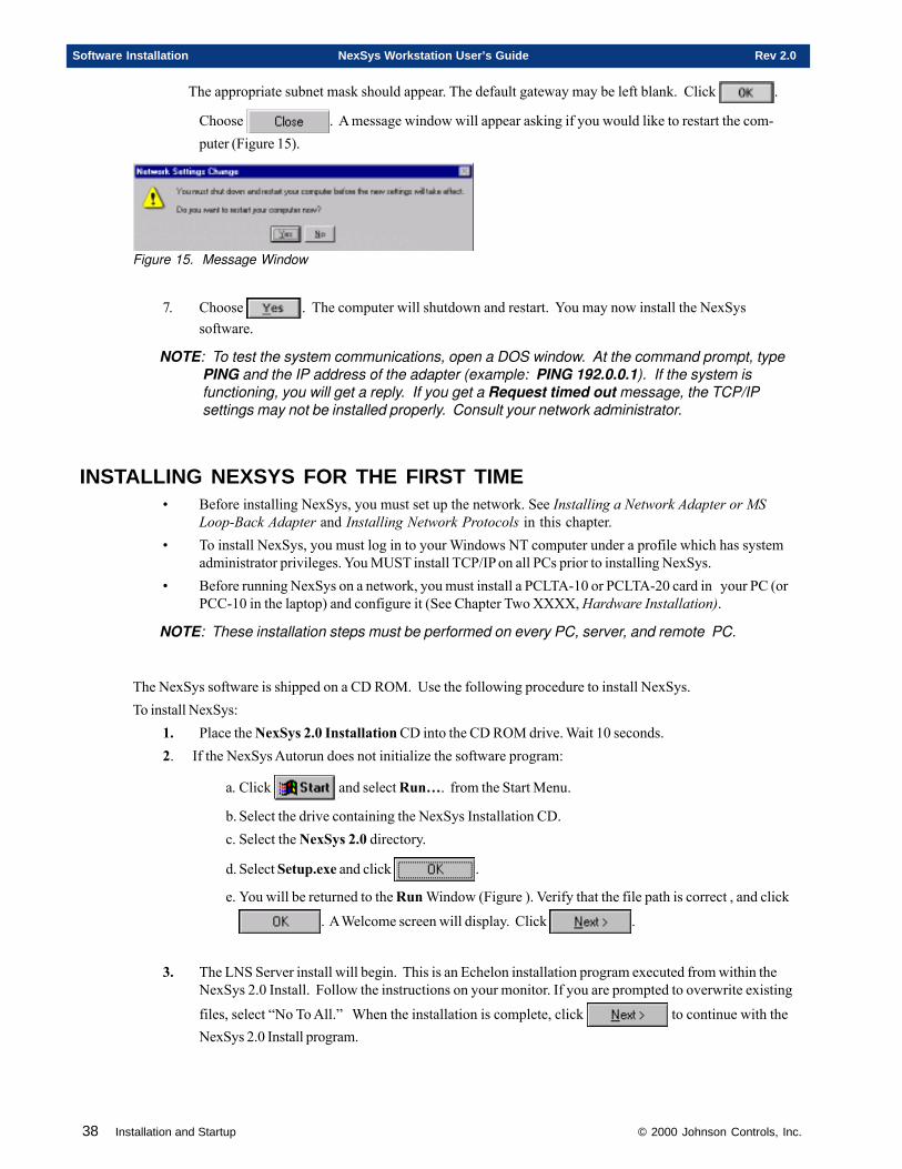
38 Installation and Startup © 2000 Johnson Controls, Inc.
Software Installation NexSys Workstation User’s Guide Rev 2.0
The appropriate subnet mask should appear. The default gateway may be left blank. Click .
Choose . A message window will appear asking if you would like to restart the com-puter (Figure 15).
Figure 15. Message Window
7. Choose . The computer will shutdown and restart. You may now install the NexSyssoftware.
NOTE: To test the system communications, open a DOS window. At the command prompt, typePING and the IP address of the adapter (example: PING 192.0.0.1). If the system isfunctioning, you will get a reply. If you get a Request timed out message, the TCP/IPsettings may not be installed properly. Consult your network administrator.
INSTALLING NEXSYS FOR THE FIRST TIME• Before installing NexSys, you must set up the network. See Installing a Network Adapter or MS
Loop-Back Adapter and Installing Network Protocols in this chapter.• To install NexSys, you must log in to your Windows NT computer under a profile which has system
administrator privileges. You MUST install TCP/IP on all PCs prior to installing NexSys.• Before running NexSys on a network, you must install a PCLTA-10 or PCLTA-20 card in your PC (or
PCC-10 in the laptop) and configure it (See Chapter Two XXXX, Hardware Installation).
NOTE: These installation steps must be performed on every PC, server, and remote PC.
The NexSys software is shipped on a CD ROM. Use the following procedure to install NexSys.To install NexSys:
1. Place the NexSys 2.0 Installation CD into the CD ROM drive. Wait 10 seconds.2. If the NexSys Autorun does not initialize the software program:
a. Click and select Run…. from the Start Menu.
b. Select the drive containing the NexSys Installation CD.c. Select the NexSys 2.0 directory.
d. Select Setup.exe and click .
e. You will be returned to the Run Window (Figure ). Verify that the file path is correct , and click
. A Welcome screen will display. Click .
3. The LNS Server install will begin. This is an Echelon installation program executed from within theNexSys 2.0 Install. Follow the instructions on your monitor. If you are prompted to overwrite existing
files, select “No To All.” When the installation is complete, click to continue with theNexSys 2.0 Install program.
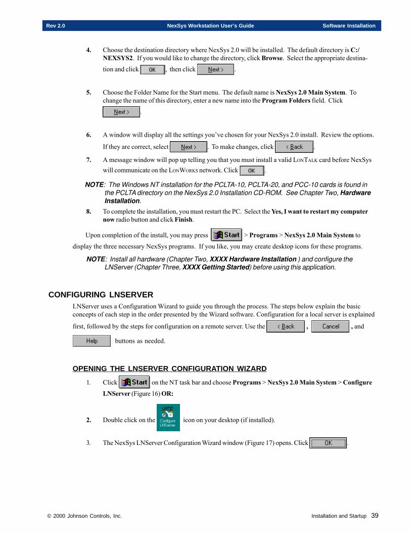
© 2000 Johnson Controls, Inc. Installation and Startup 39
Rev 2.0 NexSys Workstation User’s Guide Software Installation
4. Choose the destination directory where NexSys 2.0 will be installed. The default directory is C:/NEXSYS2. If you would like to change the directory, click Browse. Select the appropriate destina-
tion and click , then click .
5. Choose the Folder Name for the Start menu. The default name is NexSys 2.0 Main System. Tochange the name of this directory, enter a new name into the Program Folders field. Click
.
6. A window will display all the settings you’ve chosen for your NexSys 2.0 install. Review the options.
If they are correct, select . To make changes, click .
7. A message window will pop up telling you that you must install a valid LONTALK card before NexSyswill communicate on the LONWORKS network. Click .
NOTE: The Windows NT installation for the PCLTA-10, PCLTA-20, and PCC-10 cards is found inthe PCLTA directory on the NexSys 2.0 Installation CD-ROM. See Chapter Two, HardwareInstallation.
8. To complete the installation, you must restart the PC. Select the Yes, I want to restart my computernow radio button and click Finish.
Upon completion of the install, you may press > Programs > NexSys 2.0 Main System to
display the three necessary NexSys programs. If you like, you may create desktop icons for these programs.
NOTE: Install all hardware (Chapter Two, XXXX Hardware Installation ) and configure theLNServer (Chapter Three, XXXX Getting Started) before using this application.
CONFIGURING LNSERVERLNServer uses a Configuration Wizard to guide you through the process. The steps below explain the basicconcepts of each step in the order presented by the Wizard software. Configuration for a local server is explained
first, followed by the steps for configuration on a remote server. Use the , , and
buttons as needed.
OPENING THE LNSERVER CONFIGURATION WIZARD
1. Click on the NT task bar and choose Programs > NexSys 2.0 Main System > Configure
LNServer (Figure 16) OR:
2. Double click on the icon on your desktop (if installed).
3. The NexSys LNServer Configuration Wizard window (Figure 17) opens. Click .
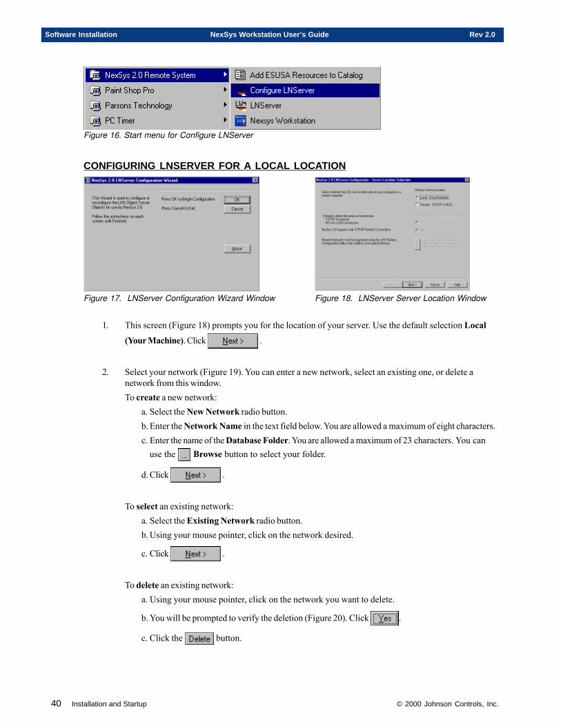
40 Installation and Startup © 2000 Johnson Controls, Inc.
Software Installation NexSys Workstation User’s Guide Rev 2.0
Figure 16. Start menu for Configure LNServer
CONFIGURING LNSERVER FOR A LOCAL LOCATION
Figure 17. LNServer Configuration Wizard Window Figure 18. LNServer Server Location Window
1. This screen (Figure 18) prompts you for the location of your server. Use the default selection Local
(Your Machine). Click .
2. Select your network (Figure 19). You can enter a new network, select an existing one, or delete anetwork from this window.To create a new network:
a. Select the New Network radio button.b. Enter the Network Name in the text field below. You are allowed a maximum of eight characters.c. Enter the name of the Database Folder. You are allowed a maximum of 23 characters. You can
use the Browse button to select your folder.
d. Click .
To select an existing network:a. Select the Existing Network radio button.b. Using your mouse pointer, click on the network desired.
c. Click .
To delete an existing network:a. Using your mouse pointer, click on the network you want to delete.
b. You will be prompted to verify the deletion (Figure 20). Click .
c. Click the button.
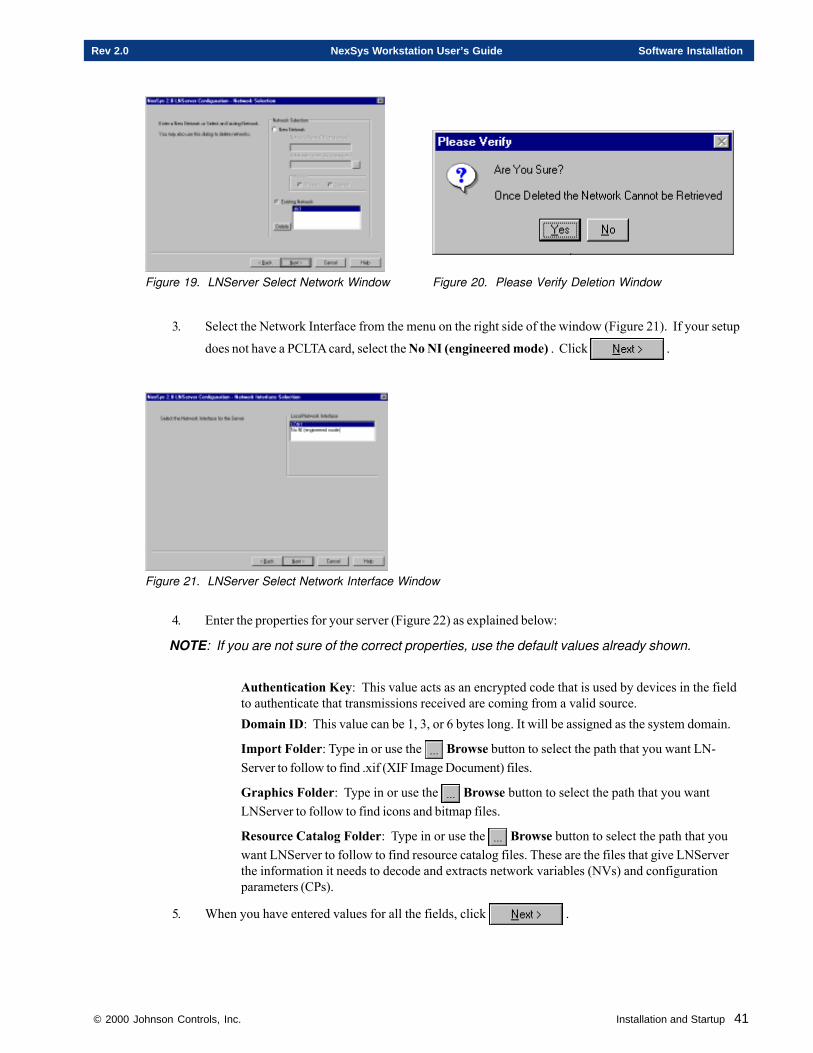
© 2000 Johnson Controls, Inc. Installation and Startup 41
Rev 2.0 NexSys Workstation User’s Guide Software Installation
Figure 19. LNServer Select Network Window Figure 20. Please Verify Deletion Window
3. Select the Network Interface from the menu on the right side of the window (Figure 21). If your setup
does not have a PCLTA card, select the No NI (engineered mode) . Click .
Figure 21. LNServer Select Network Interface Window
4. Enter the properties for your server (Figure 22) as explained below:
NOTE: If you are not sure of the correct properties, use the default values already shown.
Authentication Key: This value acts as an encrypted code that is used by devices in the fieldto authenticate that transmissions received are coming from a valid source.Domain ID: This value can be 1, 3, or 6 bytes long. It will be assigned as the system domain.
Import Folder: Type in or use the Browse button to select the path that you want LN-Server to follow to find .xif (XIF Image Document) files.
Graphics Folder: Type in or use the Browse button to select the path that you wantLNServer to follow to find icons and bitmap files.
Resource Catalog Folder: Type in or use the Browse button to select the path that youwant LNServer to follow to find resource catalog files. These are the files that give LNServerthe information it needs to decode and extracts network variables (NVs) and configurationparameters (CPs).
5. When you have entered values for all the fields, click .

42 Installation and Startup © 2000 Johnson Controls, Inc.
Software Installation NexSys Workstation User’s Guide Rev 2.0
6. The Local IP/Remote Channel Settings window (Figure 23) allows you to restrict who can connect toyour network. The permission string specifies the access permission for remote IP clients. It appliesto all remote IP clients with an IP address that satisfies the rules of the permission string.
You can leave the fields blank if you don’t want this option. Click to continue.
Figure 22. Local Server Properties Window Figure 23. Local IP/Remote Channel Settings Window
7. Use the Subsystem Selection window (Figure 24) to enter a new or existing subsystem. This sub-system will have all new nodes assigned to it. You can also delete a subsystem with this window.
NOTE: The subsystem can not have the same name as the main system.
To create a new subsystem:a. Select the New Subsystem radio button.b. Enter the Subsystem Name in the text field below. You are allowed a maximum of sixteen
characters.
c. Click .
To select an existing subsystem:a. Select the Existing Subsystem radio button.b. Using your mouse pointer, click on the subsystem desired.
c. Click .
To delete an existing subsystem:a. Using your mouse pointer, click on the subsystem you want to delete.
b. Click the button.
8. The Verify and Exit window (Figure 25) is the last step in the configuration process. Once you haveverified that the LNServer configuration information listed is correct, you can select to exit with orwithout starting LNServer.
If the listed information is not correct, use the button to select the correct parameters.
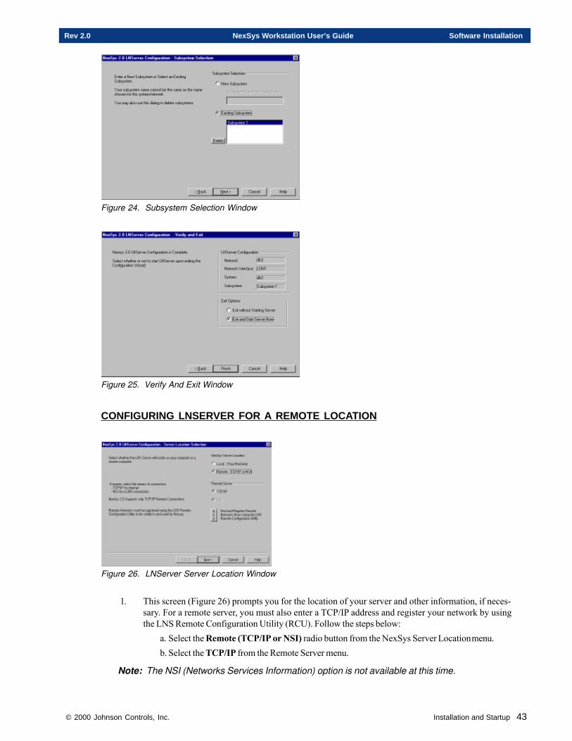
© 2000 Johnson Controls, Inc. Installation and Startup 43
Rev 2.0 NexSys Workstation User’s Guide Software Installation
Figure 24. Subsystem Selection Window
Figure 25. Verify And Exit Window
CONFIGURING LNSERVER FOR A REMOTE LOCATION
Figure 26. LNServer Server Location Window
1. This screen (Figure 26) prompts you for the location of your server and other information, if neces-sary. For a remote server, you must also enter a TCP/IP address and register your network by usingthe LNS Remote Configuration Utility (RCU). Follow the steps below:
a. Select the Remote (TCP/IP or NSI) radio button from the NexSys Server Locationmenu.b. Select the TCP/IP from the Remote Server menu.
Note: The NSI (Networks Services Information) option is not available at this time.
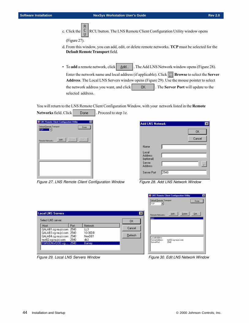
44 Installation and Startup © 2000 Johnson Controls, Inc.
Software Installation NexSys Workstation User’s Guide Rev 2.0
c. Click the RCU button. The LNS Remote Client Configuration Utility window opens
(Figure 27).d. From this window, you can add, edit, or delete remote networks. TCP must be selected for the
Default Remote Transport field.
• To add a remote network, click . The Add LNS Network window opens (Figure 28).
Enter the network name and local address (if applicable). Click Browse to select the ServerAddress. The Local LNS Servers window opens (Figure 29). Use the mouse pointer to select
the network address you want, and click . The Server Port will update to theselected address.
You will return to the LNS Remote Client Configuration Window, with your network listed in the Remote
Networks field. Click . Proceed to step 1e.
Figure 27. LNS Remote Client Configuration Window Figure 28. Add LNS Network Window
Figure 29. Local LNS Servers Window Figure 30. Edit LNS Network Window
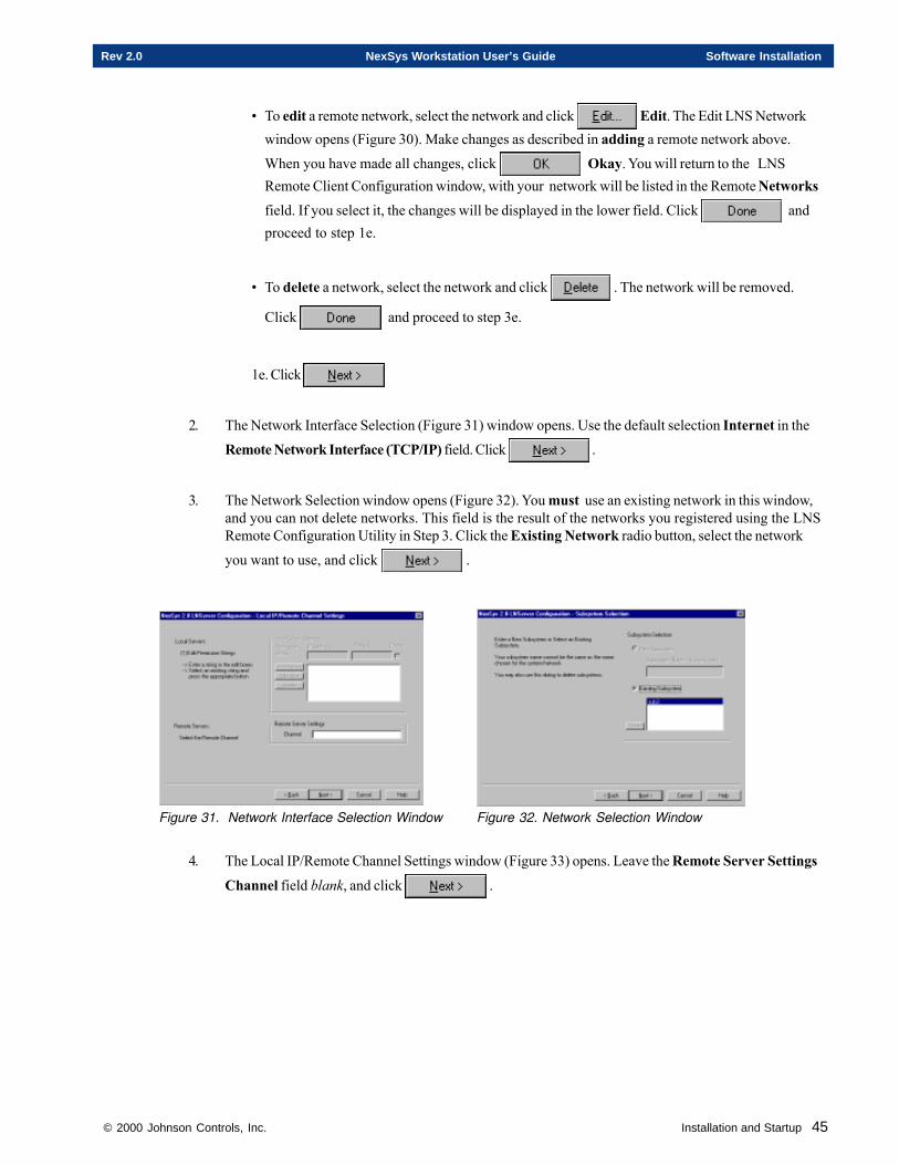
© 2000 Johnson Controls, Inc. Installation and Startup 45
Rev 2.0 NexSys Workstation User’s Guide Software Installation
• To edit a remote network, select the network and click Edit. The Edit LNS Networkwindow opens (Figure 30). Make changes as described in adding a remote network above.
When you have made all changes, click Okay. You will return to the LNSRemote Client Configuration window, with your network will be listed in the Remote Networksfield. If you select it, the changes will be displayed in the lower field. Click andproceed to step 1e.
• To delete a network, select the network and click . The network will be removed.
Click and proceed to step 3e.
1e. Click
2. The Network Interface Selection (Figure 31) window opens. Use the default selection Internet in the
Remote Network Interface (TCP/IP) field. Click .
3. The Network Selection window opens (Figure 32). You must use an existing network in this window,and you can not delete networks. This field is the result of the networks you registered using the LNSRemote Configuration Utility in Step 3. Click the Existing Network radio button, select the network
you want to use, and click .
Figure 31. Network Interface Selection Window Figure 32. Network Selection Window
4. The Local IP/Remote Channel Settings window (Figure 33) opens. Leave the Remote Server Settings
Channel field blank, and click .
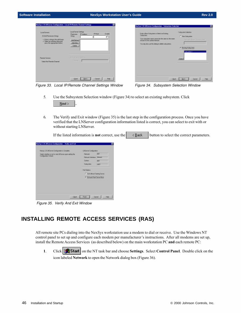
46 Installation and Startup © 2000 Johnson Controls, Inc.
Software Installation NexSys Workstation User’s Guide Rev 2.0
Figure 33. Local IP/Remote Channel Settings Window Figure 34. Subsystem Selection Window
5. Use the Subsystem Selection window (Figure 34) to select an existing subsystem. Click
..
6. The Verify and Exit window (Figure 35) is the last step in the configuration process. Once you haveverified that the LNServer configuration information listed is correct, you can select to exit with orwithout starting LNServer.
If the listed information is not correct, use the button to select the correct parameters.
Figure 35. Verify And Exit Window
INSTALLING REMOTE ACCESS SERVICES (RAS)
All remote site PCs dialing into the NexSys workstation use a modem to dial or receive. Use the Windows NTcontrol panel to set up and configure each modem per manufacturer’s instructions. After all modems are set up,install the Remote Access Services (as described below) on the main workstation PC and each remote PC:
1. Click on the NT task bar and choose Settings. Select Control Panel. Double click on the
icon labeled Network to open the Network dialog box (Figure 36).
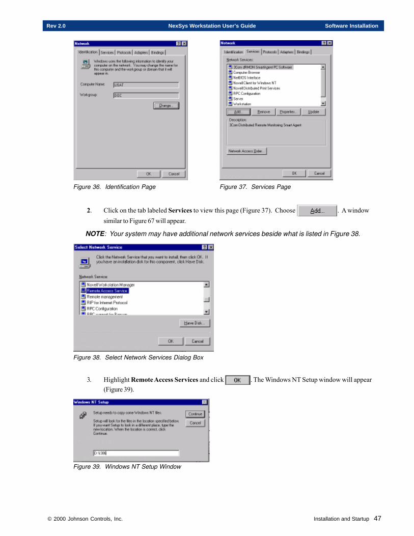
© 2000 Johnson Controls, Inc. Installation and Startup 47
Rev 2.0 NexSys Workstation User’s Guide Software Installation
Figure 36. Identification Page Figure 37. Services Page
2. Click on the tab labeled Services to view this page (Figure 37). Choose . A windowsimilar to Figure 67 will appear.
NOTE: Your system may have additional network services beside what is listed in Figure 38.
Figure 38. Select Network Services Dialog Box
3. Highlight Remote Access Services and click . The Windows NT Setup window will appear(Figure 39).
Figure 39. Windows NT Setup Window
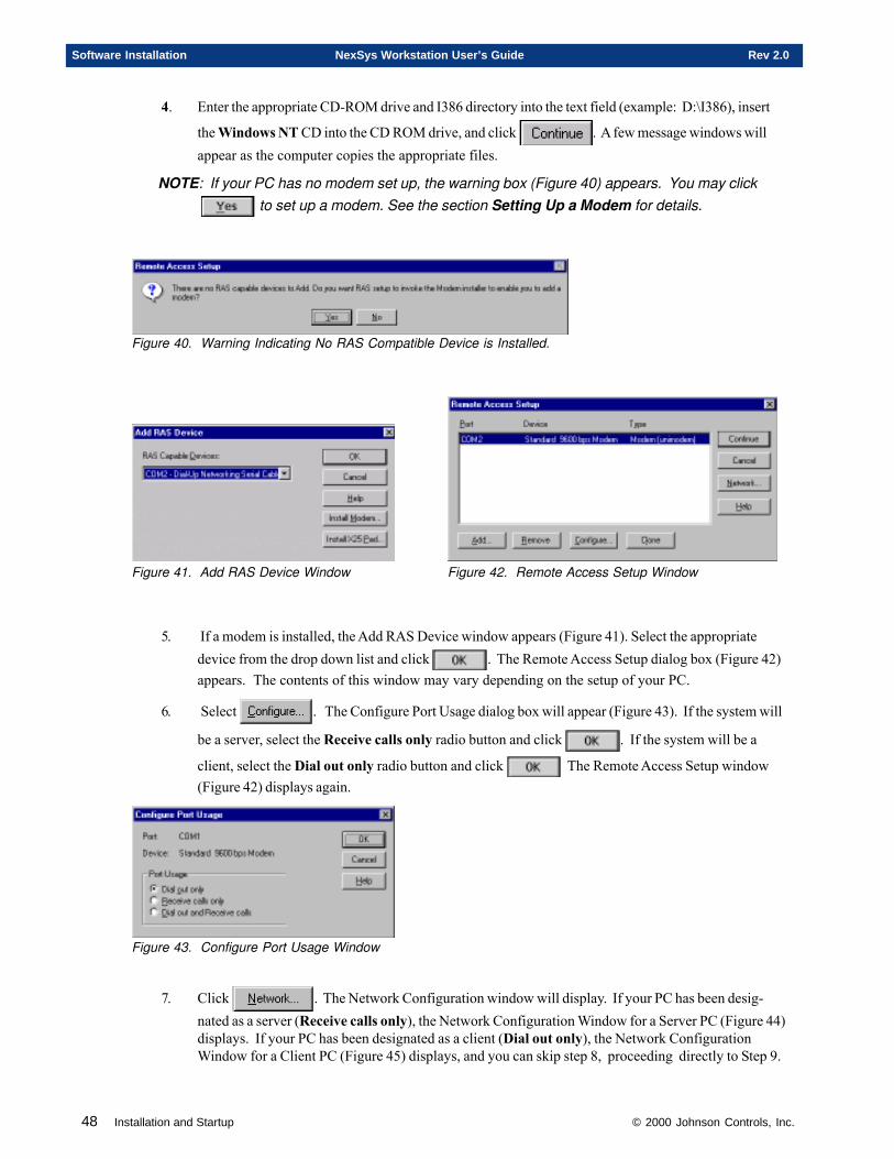
48 Installation and Startup © 2000 Johnson Controls, Inc.
Software Installation NexSys Workstation User’s Guide Rev 2.0
4. Enter the appropriate CD-ROM drive and I386 directory into the text field (example: D:\I386), insert
the Windows NT CD into the CD ROM drive, and click . A few message windows willappear as the computer copies the appropriate files.
NOTE: If your PC has no modem set up, the warning box (Figure 40) appears. You may click to set up a modem. See the section Setting Up a Modem for details.
Figure 40. Warning Indicating No RAS Compatible Device is Installed.
Figure 41. Add RAS Device Window Figure 42. Remote Access Setup Window
5. If a modem is installed, the Add RAS Device window appears (Figure 41). Select the appropriatedevice from the drop down list and click . The Remote Access Setup dialog box (Figure 42)appears. The contents of this window may vary depending on the setup of your PC.
6. Select . The Configure Port Usage dialog box will appear (Figure 43). If the system will
be a server, select the Receive calls only radio button and click . If the system will be a
client, select the Dial out only radio button and click The Remote Access Setup window(Figure 42) displays again.
Figure 43. Configure Port Usage Window
7. Click . The Network Configuration window will display. If your PC has been desig-nated as a server (Receive calls only), the Network Configuration Window for a Server PC (Figure 44)displays. If your PC has been designated as a client (Dial out only), the Network ConfigurationWindow for a Client PC (Figure 45) displays, and you can skip step 8, proceeding directly to Step 9.
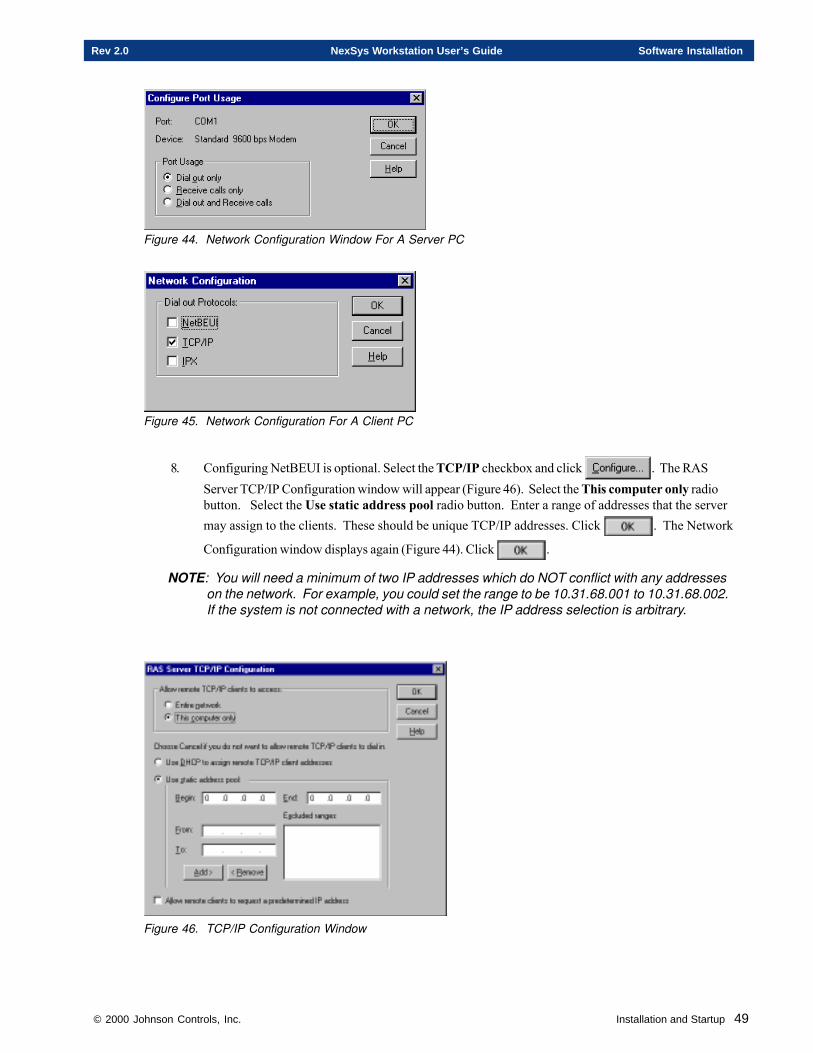
© 2000 Johnson Controls, Inc. Installation and Startup 49
Rev 2.0 NexSys Workstation User’s Guide Software Installation
Figure 44. Network Configuration Window For A Server PC
Figure 45. Network Configuration For A Client PC
8. Configuring NetBEUI is optional. Select the TCP/IP checkbox and click . The RASServer TCP/IP Configuration window will appear (Figure 46). Select the This computer only radiobutton. Select the Use static address pool radio button. Enter a range of addresses that the servermay assign to the clients. These should be unique TCP/IP addresses. Click . The Network
Configuration window displays again (Figure 44). Click .
NOTE: You will need a minimum of two IP addresses which do NOT conflict with any addresseson the network. For example, you could set the range to be 10.31.68.001 to 10.31.68.002.If the system is not connected with a network, the IP address selection is arbitrary.
Figure 46. TCP/IP Configuration Window
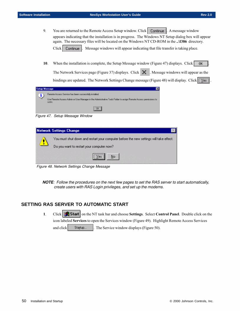
50 Installation and Startup © 2000 Johnson Controls, Inc.
Software Installation NexSys Workstation User’s Guide Rev 2.0
9. You are returned to the Remote Access Setup window. Click . A message windowappears indicating that the installation is in progress. The Windows NT Setup dialog box will appearagain. The necessary files will be located on the Windows NT CD-ROM in the ..\I386 directory.
Click . Message windows will appear indicating that file transfer is taking place.
10. When the installation is complete, the Setup Message window (Figure 47) displays. Click .
The Network Services page (Figure 37) displays. Click . Message windows will appear as the
bindings are updated. The Network Settings Change message (Figure 48) will display. Click .
Figure 47. Setup Message Window
Figure 48. Network Settings Change Message
NOTE: Follow the procedures on the next few pages to set the RAS server to start automatically,create users with RAS Login privileges, and set up the modems.
SETTING RAS SERVER TO AUTOMATIC START
1. Click on the NT task bar and choose Settings. Select Control Panel. Double click on the
icon labeled Services to open the Services window (Figure 49). Highlight Remote Access Services
and click . The Service window displays (Figure 50).
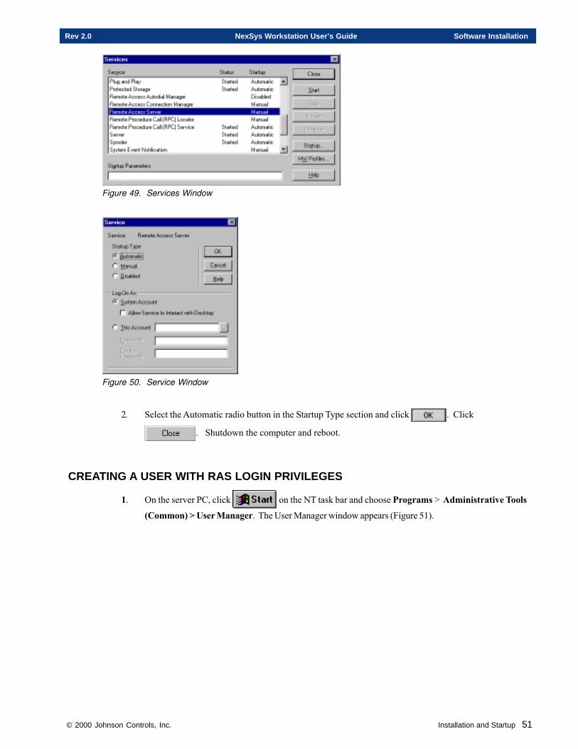
© 2000 Johnson Controls, Inc. Installation and Startup 51
Rev 2.0 NexSys Workstation User’s Guide Software Installation
Figure 49. Services Window
Figure 50. Service Window
2. Select the Automatic radio button in the Startup Type section and click . Click
. Shutdown the computer and reboot.
CREATING A USER WITH RAS LOGIN PRIVILEGES
1. On the server PC, click on the NT task bar and choose Programs > Administrative Tools
(Common) > User Manager. The User Manager window appears (Figure 51).
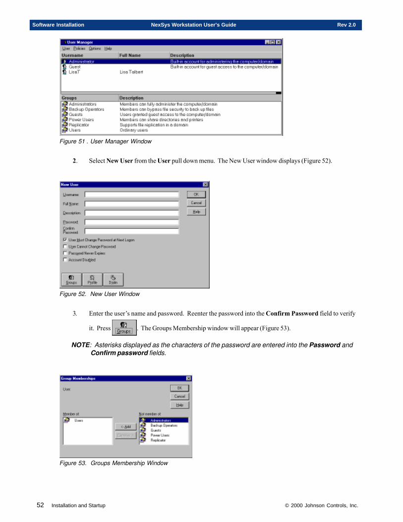
52 Installation and Startup © 2000 Johnson Controls, Inc.
Software Installation NexSys Workstation User’s Guide Rev 2.0
Figure 51 . User Manager Window
2. Select New User from the User pull down menu. The New User window displays (Figure 52).
Figure 52. New User Window
3. Enter the user’s name and password. Reenter the password into the Confirm Password field to verify
it. Press . The Groups Membership window will appear (Figure 53).
NOTE: Asterisks displayed as the characters of the password are entered into the Password andConfirm password fields.
Figure 53. Groups Membership Window
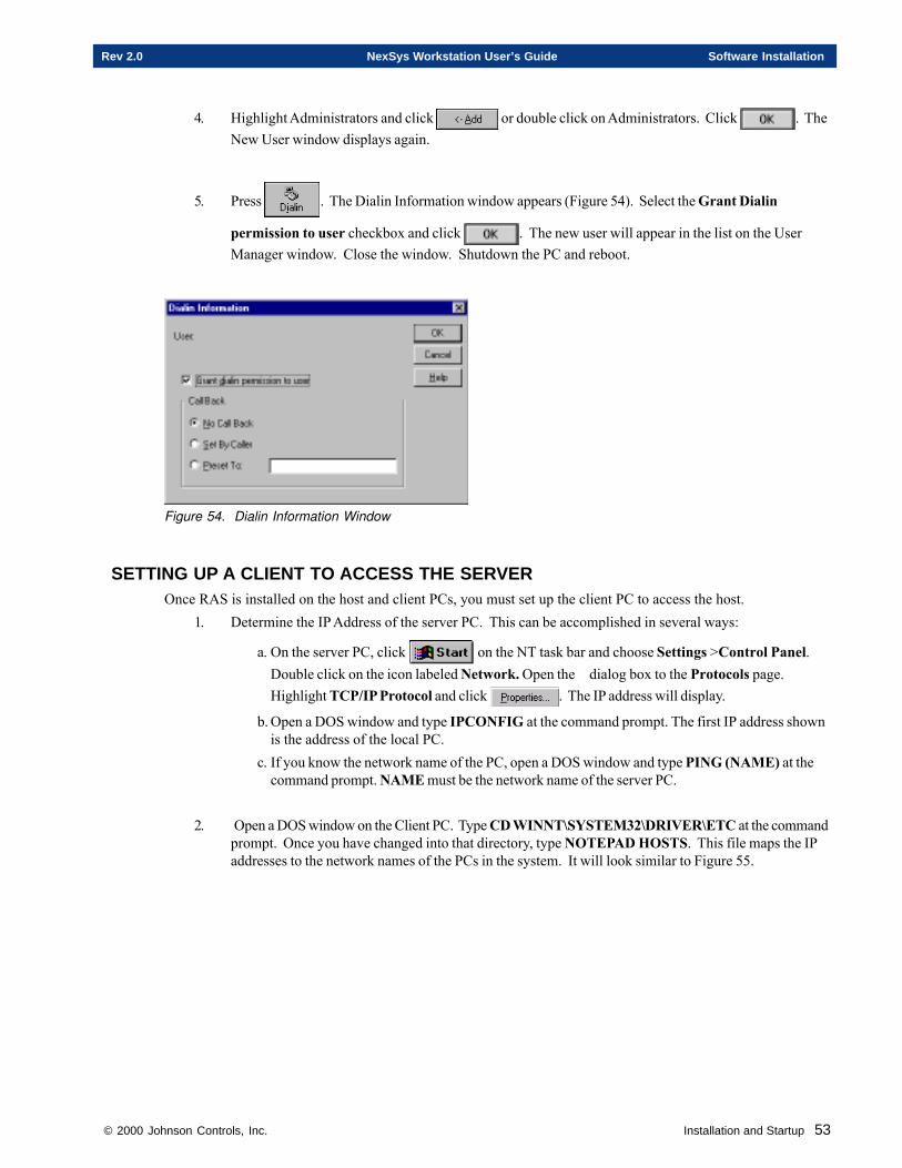
© 2000 Johnson Controls, Inc. Installation and Startup 53
Rev 2.0 NexSys Workstation User’s Guide Software Installation
4. Highlight Administrators and click or double click on Administrators. Click . TheNew User window displays again.
5. Press . The Dialin Information window appears (Figure 54). Select the Grant Dialin
permission to user checkbox and click . The new user will appear in the list on the UserManager window. Close the window. Shutdown the PC and reboot.
Figure 54. Dialin Information Window
SETTING UP A CLIENT TO ACCESS THE SERVEROnce RAS is installed on the host and client PCs, you must set up the client PC to access the host.
1. Determine the IP Address of the server PC. This can be accomplished in several ways:
a. On the server PC, click on the NT task bar and choose Settings >Control Panel.Double click on the icon labeled Network. Open the dialog box to the Protocols page.Highlight TCP/IP Protocol and click . The IP address will display.
b. Open a DOS window and type IPCONFIG at the command prompt. The first IP address shownis the address of the local PC.
c. If you know the network name of the PC, open a DOS window and type PING (NAME) at thecommand prompt. NAME must be the network name of the server PC.
2. Open a DOS window on the Client PC. Type CD WINNT\SYSTEM32\DRIVER\ETC at the commandprompt. Once you have changed into that directory, type NOTEPAD HOSTS. This file maps the IPaddresses to the network names of the PCs in the system. It will look similar to Figure 55.
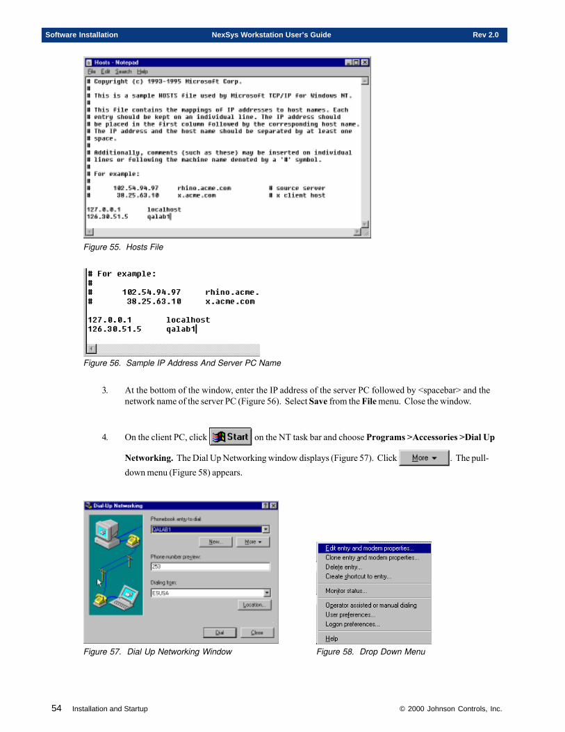
54 Installation and Startup © 2000 Johnson Controls, Inc.
Software Installation NexSys Workstation User’s Guide Rev 2.0
Figure 55. Hosts File
Figure 56. Sample IP Address And Server PC Name
3. At the bottom of the window, enter the IP address of the server PC followed by <spacebar> and thenetwork name of the server PC (Figure 56). Select Save from the File menu. Close the window.
4. On the client PC, click on the NT task bar and choose Programs >Accessories >Dial Up
Networking. The Dial Up Networking window displays (Figure 57). Click . The pull-down menu (Figure 58) appears.
Figure 57. Dial Up Networking Window Figure 58. Drop Down Menu
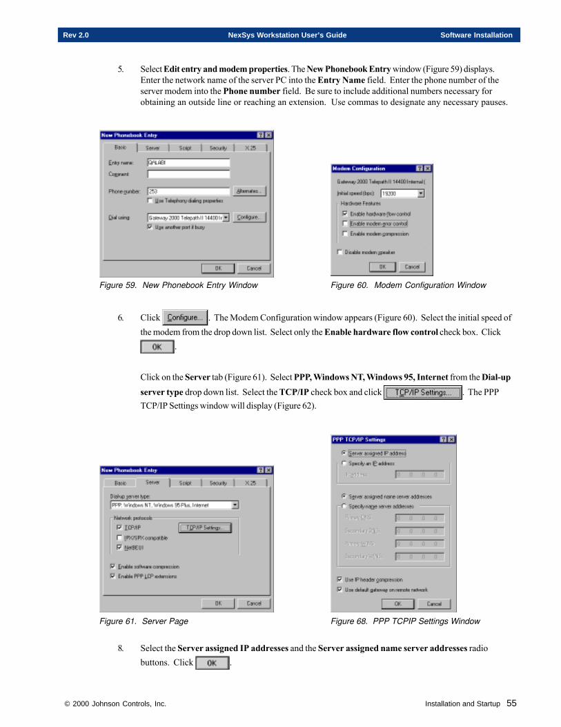
© 2000 Johnson Controls, Inc. Installation and Startup 55
Rev 2.0 NexSys Workstation User’s Guide Software Installation
5. Select Edit entry and modem properties. The New Phonebook Entry window (Figure 59) displays.Enter the network name of the server PC into the Entry Name field. Enter the phone number of theserver modem into the Phone number field. Be sure to include additional numbers necessary forobtaining an outside line or reaching an extension. Use commas to designate any necessary pauses.
Figure 59. New Phonebook Entry Window Figure 60. Modem Configuration Window
6. Click . The Modem Configuration window appears (Figure 60). Select the initial speed ofthe modem from the drop down list. Select only the Enable hardware flow control check box. Click
.
Click on the Server tab (Figure 61). Select PPP, Windows NT, Windows 95, Internet from the Dial-upserver type drop down list. Select the TCP/IP check box and click . The PPPTCP/IP Settings window will display (Figure 62).
Figure 61. Server Page Figure 68. PPP TCPIP Settings Window
8. Select the Server assigned IP addresses and the Server assigned name server addresses radiobuttons. Click .
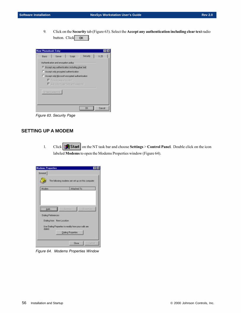
56 Installation and Startup © 2000 Johnson Controls, Inc.
Software Installation NexSys Workstation User’s Guide Rev 2.0
9. Click on the Security tab (Figure 63). Select the Accept any authentication including clear text radiobutton. Click .
Figure 63. Security Page
SETTING UP A MODEM
1. Click on the NT task bar and choose Settings > Control Panel. Double click on the icon
labeled Modems to open the Modems Properties window (Figure 64).
Figure 64. Modems Properties Window
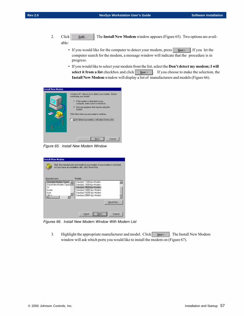
© 2000 Johnson Controls, Inc. Installation and Startup 57
Rev 2.0 NexSys Workstation User’s Guide Software Installation
2. Click . The Install New Modem window appears (Figure 65). Two options are avail-able:
• If you would like for the computer to detect your modem, press . If you let thecomputer search for the modem, a message window will indicate that the procedure is inprogress.
• If you would like to select your modem from the list, select the Don’t detect my modem; I willselect it from a list checkbox and click . If you choose to make the selection, theInstall New Modem window will display a list of manufacturers and models (Figure 66).
Figure 65. Install New Modem Window
Figures 66. Install New Modem Window With Modem List
3. Highlight the appropriate manufacturer and model. Click . The Install New Modemwindow will ask which ports you would like to install the modem on (Figure 67).
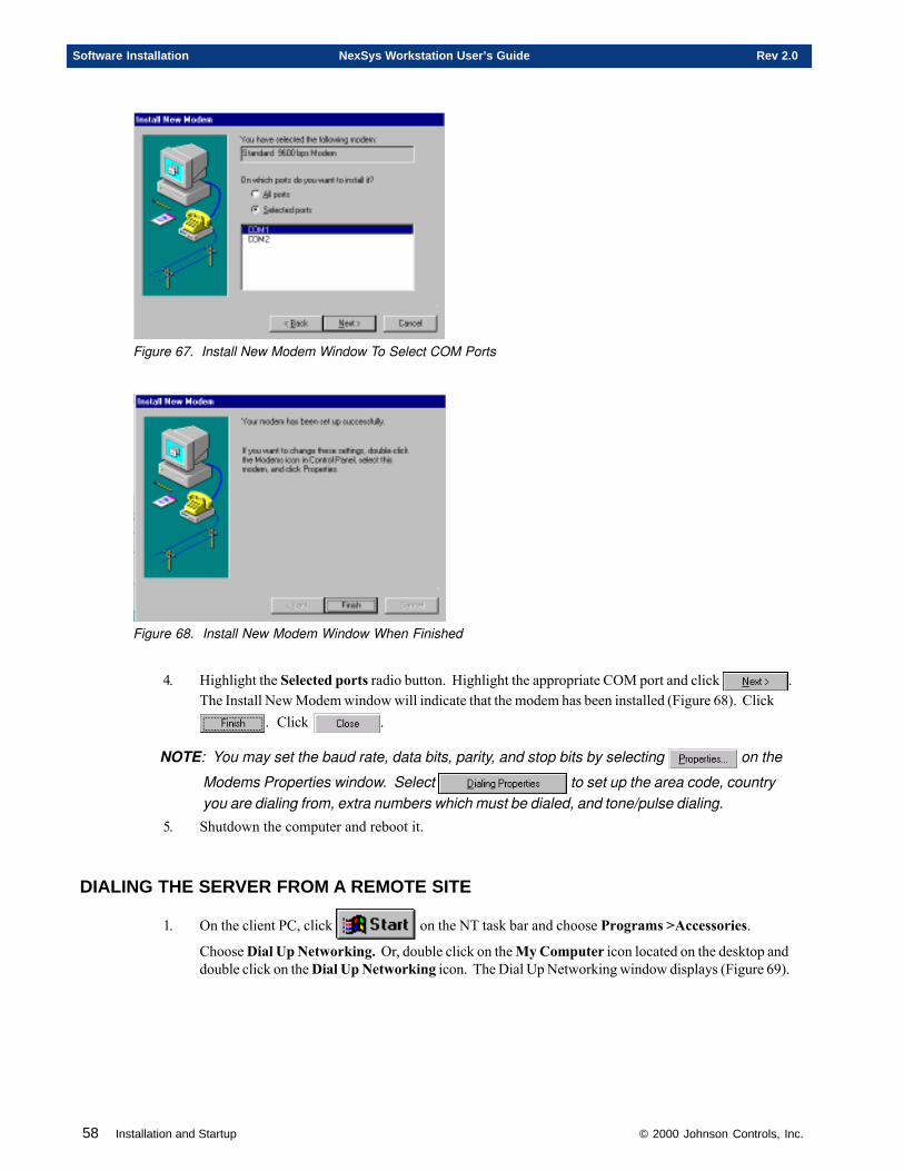
58 Installation and Startup © 2000 Johnson Controls, Inc.
Software Installation NexSys Workstation User’s Guide Rev 2.0
Figure 67. Install New Modem Window To Select COM Ports
Figure 68. Install New Modem Window When Finished
4. Highlight the Selected ports radio button. Highlight the appropriate COM port and click .The Install New Modem window will indicate that the modem has been installed (Figure 68). Click
. Click .
NOTE: You may set the baud rate, data bits, parity, and stop bits by selecting on the
Modems Properties window. Select to set up the area code, countryyou are dialing from, extra numbers which must be dialed, and tone/pulse dialing.
5. Shutdown the computer and reboot it.
DIALING THE SERVER FROM A REMOTE SITE
1. On the client PC, click on the NT task bar and choose Programs >Accessories.
Choose Dial Up Networking. Or, double click on the My Computer icon located on the desktop anddouble click on the Dial Up Networking icon. The Dial Up Networking window displays (Figure 69).
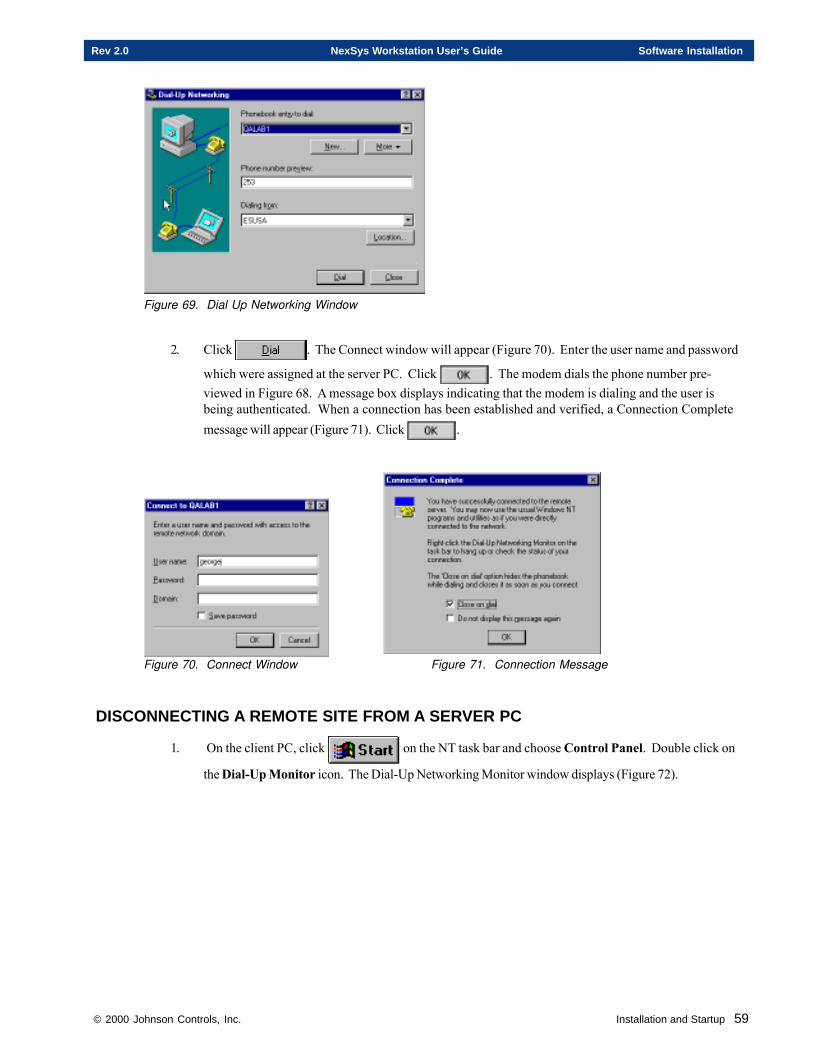
© 2000 Johnson Controls, Inc. Installation and Startup 59
Rev 2.0 NexSys Workstation User’s Guide Software Installation
Figure 69. Dial Up Networking Window
2. Click . The Connect window will appear (Figure 70). Enter the user name and password
which were assigned at the server PC. Click . The modem dials the phone number pre-viewed in Figure 68. A message box displays indicating that the modem is dialing and the user isbeing authenticated. When a connection has been established and verified, a Connection Completemessage will appear (Figure 71). Click .
Figure 70. Connect Window Figure 71. Connection Message
DISCONNECTING A REMOTE SITE FROM A SERVER PC
1. On the client PC, click on the NT task bar and choose Control Panel. Double click on
the Dial-Up Monitor icon. The Dial-Up Networking Monitor window displays (Figure 72).
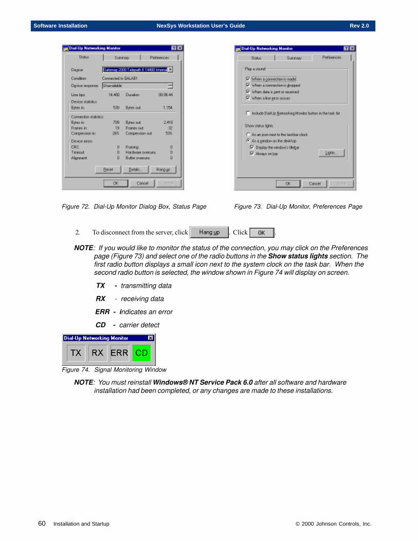
60 Installation and Startup © 2000 Johnson Controls, Inc.
Software Installation NexSys Workstation User’s Guide Rev 2.0
Figure 72. Dial-Up Monitor Dialog Box, Status Page Figure 73. Dial-Up Monitor, Preferences Page
2. To disconnect from the server, click . Click .
NOTE: If you would like to monitor the status of the connection, you may click on the Preferencespage (Figure 73) and select one of the radio buttons in the Show status lights section. Thefirst radio button displays a small icon next to the system clock on the task bar. When thesecond radio button is selected, the window shown in Figure 74 will display on screen.
TX - transmitting data
RX - receiving data
ERR - indicates an error
CD - carrier detect
Figure 74. Signal Monitoring Window
NOTE: You must reinstall Windows® NT Service Pack 6.0 after all software and hardwareinstallation had been completed, or any changes are made to these installations.

© 2000 Johnson Controls, Inc. Installation and Startup 61
Rev 2.0 NexSys Workstation User’s Guide Software Installation

62 Installation and Startup © 2000 Johnson Controls, Inc.
Software Installation NexSys Workstation User’s Guide Rev 2.0

© 2000 Johnson Controls, Inc. Installation and Startup 63
Rev 2.0 NexSys Workstation User’s Guide Hardware Installation
Chapter Two
Hardware Installation
This chapter contains information on:
�Disabling and Removing a Full-Size PCLTA
� Installing the Drivers for Your Card
� Installing a PCLTA-10/20
� Installing a PCC-10
© 2000 Johnson Controls, Inc.
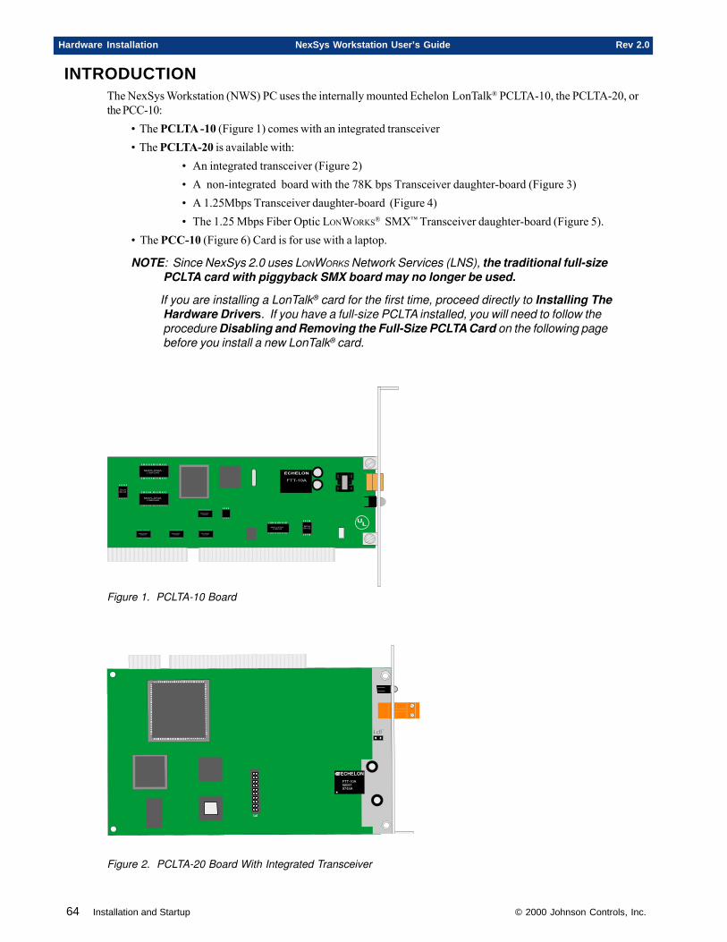
64 Installation and Startup © 2000 Johnson Controls, Inc.
Hardware Installation NexSys Workstation User’s Guide Rev 2.0
INTRODUCTIONThe NexSys Workstation (NWS) PC uses the internally mounted Echelon LonTalk® PCLTA-10, the PCLTA-20, orthe PCC-10:
• The PCLTA -10 (Figure 1) comes with an integrated transceiver• The PCLTA-20 is available with:
• An integrated transceiver (Figure 2)• A non-integrated board with the 78K bps Transceiver daughter-board (Figure 3)• A 1.25Mbps Transceiver daughter-board (Figure 4)• The 1.25 Mbps Fiber Optic LONWORKS® SMX™ Transceiver daughter-board (Figure 5).
• The PCC-10 (Figure 6) Card is for use with a laptop.
NOTE: Since NexSys 2.0 uses LONWORKS Network Services (LNS), the traditional full-sizePCLTA card with piggyback SMX board may no longer be used.
If you are installing a LonTalk® card for the first time, proceed directly to Installing TheHardware Drivers. If you have a full-size PCLTA installed, you will need to follow theprocedure Disabling and Removing the Full-Size PCLTA Card on the following pagebefore you install a new LonTalk® card.
MAYLASIALSBR549
MAYLASIALSBR549
MAYLASIALSBR549
ECH96-01
ECH96-01
��
MAYLASIALSBR549
MAYLASIALSBR549
MAYLASIALSBR549
MAYLASIALSBR549
�����
�������
Figure 1. PCLTA-10 Board
��
��� ���
������
�������������
Figure 2. PCLTA-20 Board With Integrated Transceiver
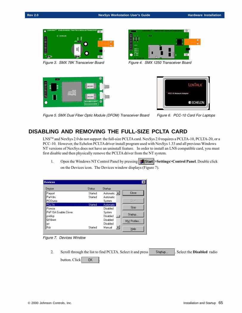
© 2000 Johnson Controls, Inc. Installation and Startup 65
Rev 2.0 NexSys Workstation User’s Guide Hardware Installation
��
�
��
�
��
�
�!
�"#$
��
�
��
�
�!
�"#$
��$
���%
�
�
��
&$
��
��
�
�"%'%'%$#'#"'
����(������������������)����%#%�*+�,�%���)&���+������ -��
��.
+�
��������������
��
�/
���� %
!&
�
*�
��
��/� %
��
�
��
�
��
�
�!
�"
#$
��
�
��
�
�!
�"
#$
��$
���%
�
�
&$
�/
��������������
)��
�
��
����(���������+ �+�)��� �����)&���+������ -��+�
Figure 3. SMX 78K Transceiver Board Figure 4. SMX 1250 Transceiver Board
����� ��!�"#$
�
����� ������� �!�"�#���$%�&'%�
�#"!�#0�
�#"!�#0�
���������������������
Figure 5. SMX Dual Fiber Optic Module (DFOM) Transceiver Board Figure 6. PCC-10 Card For Laptops
DISABLING AND REMOVING THE FULL-SIZE PCLTA CARDLNSTM and NexSys 2.0 do not support the full-size PCLTA card. NexSys 2.0 requires a PCLTA-10, PCLTA-20, or aPCC-10. However, the Echelon PCLTA driver install program used with NexSys 1.33 and all previous WindowsNT versions of NexSys does not have an uninstall feature. In order to install an LNS compatible card, you mustfirst disable and then physically remove the PCLTA driver from the NT system.
1. Open the Windows NT Control Panel by pressing >Settings>Control Panel. Double clickon the Devices icon. The Devices window displays (Figure 7).
Figure 7. Devices Window
2. Scroll through the list to find PCLTA. Select it and press . Select the Disabled radio
button. Click .
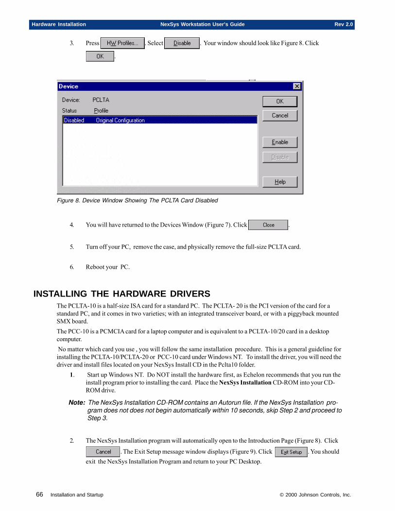
66 Installation and Startup © 2000 Johnson Controls, Inc.
Hardware Installation NexSys Workstation User’s Guide Rev 2.0
3. Press . Select . Your window should look like Figure 8. Click
.
Figure 8. Device Window Showing The PCLTA Card Disabled
4. You will have returned to the Devices Window (Figure 7). Click .
5. Turn off your PC, remove the case, and physically remove the full-size PCLTA card.
6. Reboot your PC.
INSTALLING THE HARDWARE DRIVERSThe PCLTA-10 is a half-size ISA card for a standard PC. The PCLTA- 20 is the PCI version of the card for astandard PC, and it comes in two varieties; with an integrated transceiver board, or with a piggyback mountedSMX board.The PCC-10 is a PCMCIA card for a laptop computer and is equivalent to a PCLTA-10/20 card in a desktopcomputer. No matter which card you use , you will follow the same installation procedure. This is a general guideline forinstalling the PCLTA-10/PCLTA-20 or PCC-10 card under Windows NT. To install the driver, you will need thedriver and install files located on your NexSys Install CD in the Pclta10 folder.
1. Start up Windows NT. Do NOT install the hardware first, as Echelon recommends that you run theinstall program prior to installing the card. Place the NexSys Installation CD-ROM into your CD-ROM drive.
Note: The NexSys Installation CD-ROM contains an Autorun file. If the NexSys Installation pro-gram does not does not begin automatically within 10 seconds, skip Step 2 and proceed toStep 3.
2. The NexSys Installation program will automatically open to the Introduction Page (Figure 8). Click
. The Exit Setup message window displays (Figure 9). Click . You shouldexit the NexSys Installation Program and return to your PC Desktop.
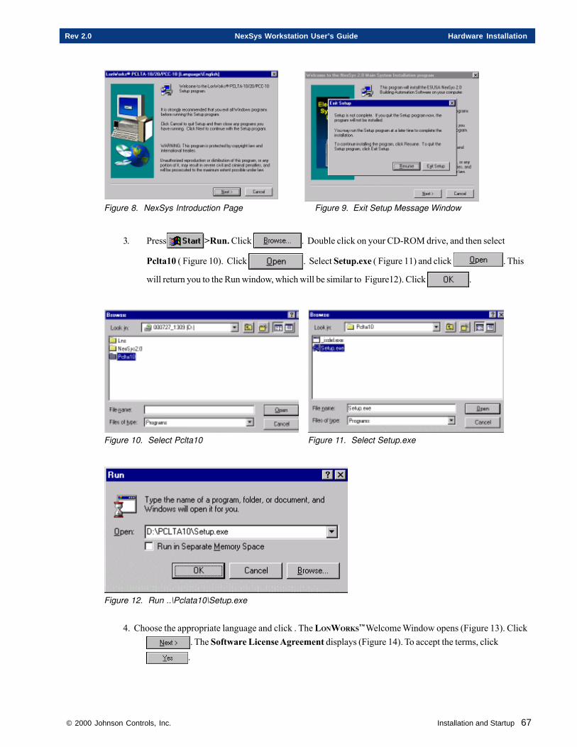
© 2000 Johnson Controls, Inc. Installation and Startup 67
Rev 2.0 NexSys Workstation User’s Guide Hardware Installation
Figure 8. NexSys Introduction Page Figure 9. Exit Setup Message Window
3. Press >Run. Click . Double click on your CD-ROM drive, and then select
Pclta10 ( Figure 10). Click . Select Setup.exe ( Figure 11) and click . This
will return you to the Run window, which will be similar to Figure12). Click .
Figure 10. Select Pclta10 Figure 11. Select Setup.exe
Figure 12. Run ..\Pclata10\Setup.exe
4. Choose the appropriate language and click . The LONWORKS™ Welcome Window opens (Figure 13). Click. The Software License Agreement displays (Figure 14). To accept the terms, click.
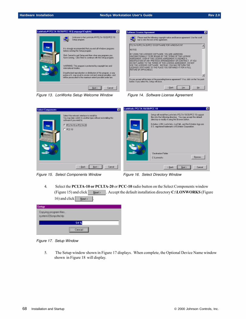
68 Installation and Startup © 2000 Johnson Controls, Inc.
Hardware Installation NexSys Workstation User’s Guide Rev 2.0
Figure 13. LonWorks Setup Welcome Window Figure 14. Software License Agreement
Figure 15. Select Components Window Figure 16. Select Directory Window
4. Select the PCLTA-10 or PCLTA-20 or PCC-10 radio button on the Select Components window(Figure 15) and click . Accept the default installation directory C:\LONWORKS (Figure16) and click .
Figure 17. Setup Window
5. The Setup window shown in Figure 17 displays. When complete, the Optional Device Name windowshown in Figure 18 will display.
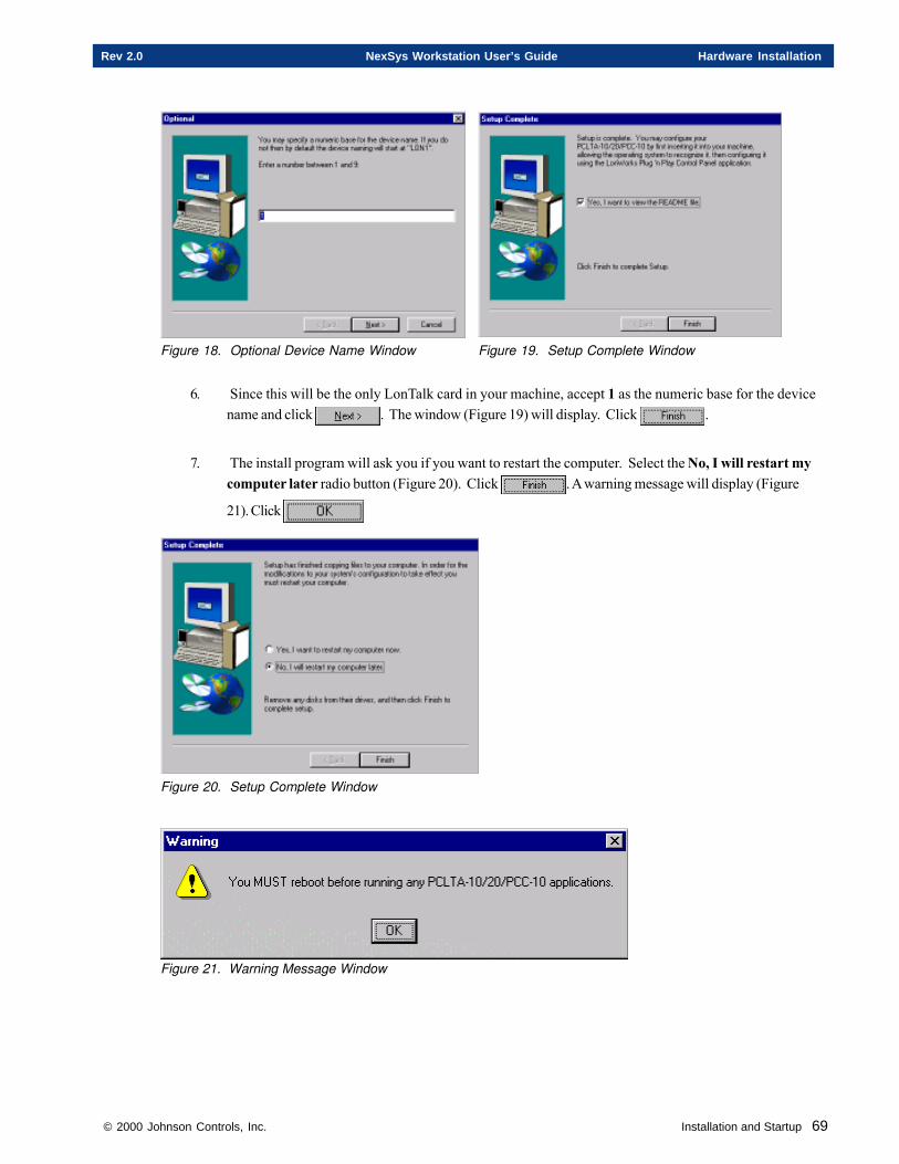
© 2000 Johnson Controls, Inc. Installation and Startup 69
Rev 2.0 NexSys Workstation User’s Guide Hardware Installation
Figure 18. Optional Device Name Window Figure 19. Setup Complete Window
6. Since this will be the only LonTalk card in your machine, accept 1 as the numeric base for the devicename and click . The window (Figure 19) will display. Click .
7. The install program will ask you if you want to restart the computer. Select the No, I will restart mycomputer later radio button (Figure 20). Click . A warning message will display (Figure
21). Click
Figure 20. Setup Complete Window
Figure 21. Warning Message Window
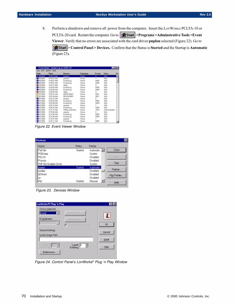
70 Installation and Startup © 2000 Johnson Controls, Inc.
Hardware Installation NexSys Workstation User’s Guide Rev 2.0
8. Perform a shutdown and remove all power from the computer. Insert the LONWORKS PCLTA-10 or
PCLTA-20 card. Restart the computer. Go to >Programs >Adminstrative Tools >EventViewer. Verify that no errors are associated with the card driver pnplon selected (Figure 22). Go to
> Control Panel > Devices. Confirm that the Status is Started and the Startup is Automatic(Figure 23).
Figure 22. Event Viewer Window
Figure 23. Devices Window
Figure 24. Control Panel’s LonWorks® Plug ‘n Play Window
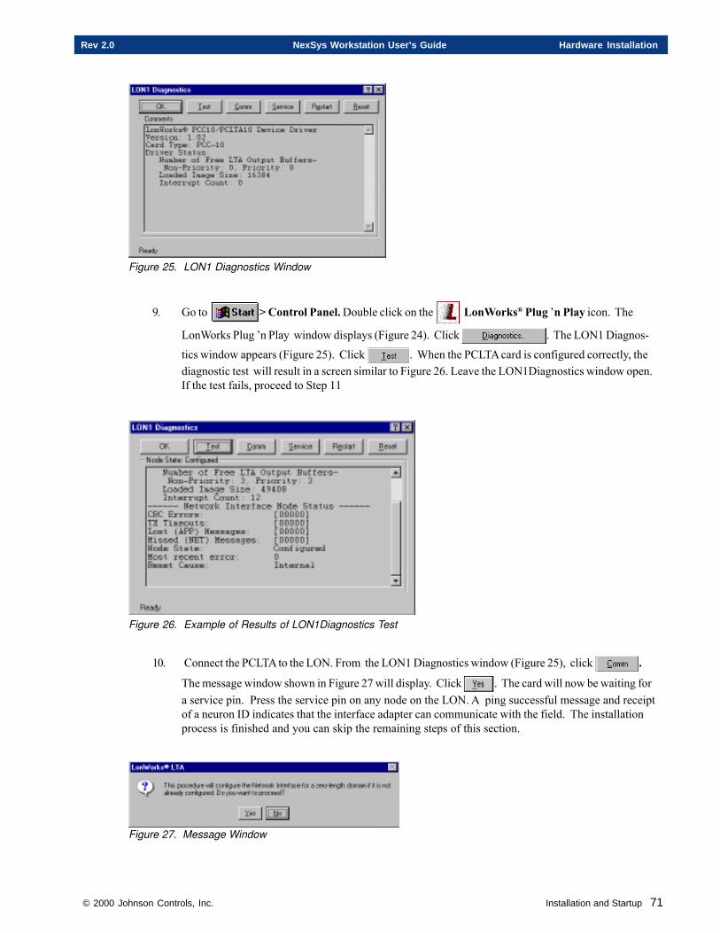
© 2000 Johnson Controls, Inc. Installation and Startup 71
Rev 2.0 NexSys Workstation User’s Guide Hardware Installation
Figure 25. LON1 Diagnostics Window
9. Go to > Control Panel. Double click on the LonWorks® Plug ’n Play icon. The
LonWorks Plug ’n Play window displays (Figure 24). Click . The LON1 Diagnos-
tics window appears (Figure 25). Click . When the PCLTA card is configured correctly, thediagnostic test will result in a screen similar to Figure 26. Leave the LON1Diagnostics window open.If the test fails, proceed to Step 11
Figure 26. Example of Results of LON1Diagnostics Test
10. Connect the PCLTA to the LON. From the LON1 Diagnostics window (Figure 25), click .
The message window shown in Figure 27 will display. Click . The card will now be waiting fora service pin. Press the service pin on any node on the LON. A ping successful message and receiptof a neuron ID indicates that the interface adapter can communicate with the field. The installationprocess is finished and you can skip the remaining steps of this section.
Figure 27. Message Window
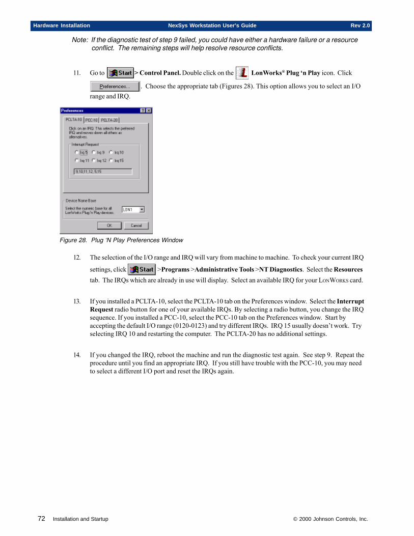
72 Installation and Startup © 2000 Johnson Controls, Inc.
Hardware Installation NexSys Workstation User’s Guide Rev 2.0
Note: If the diagnostic test of step 9 failed, you could have either a hardware failure or a resourceconflict. The remaining steps will help resolve resource conflicts.
11. Go to > Control Panel. Double click on the LonWorks® Plug ‘n Play icon. Click
. Choose the appropriate tab (Figures 28). This option allows you to select an I/Orange and IRQ.
Figure 28. Plug ‘N Play Preferences Window
12. The selection of the I/O range and IRQ will vary from machine to machine. To check your current IRQ
settings, click >Programs >Administrative Tools >NT Diagnostics. Select the Resourcestab. The IRQs which are already in use will display. Select an available IRQ for your LONWORKS card.
13. If you installed a PCLTA-10, select the PCLTA-10 tab on the Preferences window. Select the InterruptRequest radio button for one of your available IRQs. By selecting a radio button, you change the IRQsequence. If you installed a PCC-10, select the PCC-10 tab on the Preferences window. Start byaccepting the default I/O range (0120-0123) and try different IRQs. IRQ 15 usually doesn’t work. Tryselecting IRQ 10 and restarting the computer. The PCLTA-20 has no additional settings.
14. If you changed the IRQ, reboot the machine and run the diagnostic test again. See step 9. Repeat theprocedure until you find an appropriate IRQ. If you still have trouble with the PCC-10, you may needto select a different I/O port and reset the IRQs again.

© 2000 Johnson Controls, Inc. Installation and Startup 73
Rev 2.0 NexSys Workstation User’s Guide Hardware Installation
INSTALLING THE PCLTA-10/20 CARDOnce the software has been installed, you can now physically install your PCLTA-10 (Figure ) or PCLTA-20(Figure ) card. Power down the system and mount the board into a 16-bit ISA slot of the NexSys Workstation asdirected below:
1. Power down the system completely, and remove the AC power source.
2. Remove the cover and select on the motherboard:• an open 16-bit ISA slot (PCLTA-10)• an open PCI slot (PCLTA-20)
3. Align the card’s edge connector with the PC slot and press the card firmly into place. Be sure to seat theboard’s edge connector carefully and securely.
4. Secure the card to the case using the correct screw for that slot.
5. Connect the LON wiring to the board’s network terminal block.
6. Replace the cover and power up the NexSys Workstation.
INSTALLING THE PCC-10 (LAPTOP ONLY)Once the software has been installed, you can now physically install your PCC-10 card. Power down the systemand insert the card.
1. Power down the system completely, and remove the AC power source.
2. Insert the PCC-10 into the Type II slot.
3. Connect the network cable that came with the PCC-10.
4. Connect the LON wiring to the board’s network terminal block.
5. Power up the NexSys Workstation laptop.

74 Installation and Startup © 2000 Johnson Controls, Inc.
Hardware Installation NexSys Workstation User’s Guide Rev 2.0
Chapter Three
Getting Started
This chapter contains information on:
� Adding Resource Files to Catalog
� Start-Up Procedure
� NexSys Main Window
� Exiting NexSys
� Exiting LNServer
© 2000 Johnson Controls, Inc.
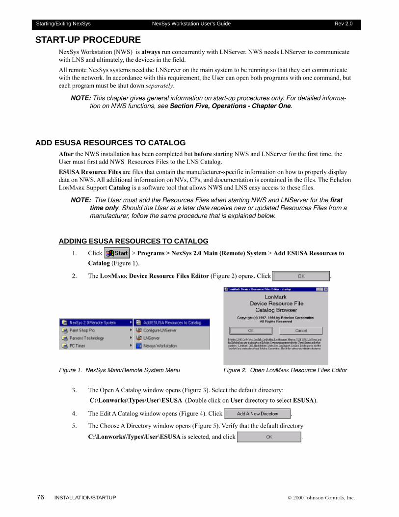
76 INSTALLATION/STARTUP © 2000 Johnson Controls, Inc.
Starting/Exiting NexSys NexSys Workstation User’s Guide Rev 2.0
START-UP PROCEDURENexSys Workstation (NWS) is always run concurrently with LNServer. NWS needs LNServer to communicatewith LNS and ultimately, the devices in the field.All remote NexSys systems need the LNServer on the main system to be running so that they can communicatewith the network. In accordance with this requirement, the User can open both programs with one command, buteach program must be shut down separately.
NOTE: This chapter gives general information on start-up procedures only. For detailed informa-tion on NWS functions, see Section Five, Operations - Chapter One.
ADD ESUSA RESOURCES TO CATALOGAfter the NWS installation has been completed but before starting NWS and LNServer for the first time, theUser must first add NWS Resources Files to the LNS Catalog.ESUSA Resource Files are files that contain the manufacturer-specific information on how to properly displaydata on NWS. All additional information on NVs, CPs, and documentation is contained in the files. The EchelonLONMARK Support Catalog is a software tool that allows NWS and LNS easy access to these files.
NOTE: The User must add the Resources Files when starting NWS and LNServer for the firsttime only. Should the User at a later date receive new or updated Resources Files from amanufacturer, follow the same procedure that is explained below.
ADDING ESUSA RESOURCES TO CATALOG
1. Click > Programs > NexSys 2.0 Main (Remote) System > Add ESUSA Resources toCatalog (Figure 1).
2. The LONMARK Device Resource Files Editor (Figure 2) opens. Click .
Figure 1. NexSys Main/Remote System Menu Figure 2. Open LONMARK Resource Files Editor
3. The Open A Catalog window opens (Figure 3). Select the default directory: C:\Lonworks\Types\User\ESUSA (Double click on User directory to select ESUSA).
4. The Edit A Catalog window opens (Figure 4). Click .
5. The Choose A Directory window opens (Figure 5). Verify that the default directory
C:\Lonworks\Types\User\ESUSA is selected, and click .
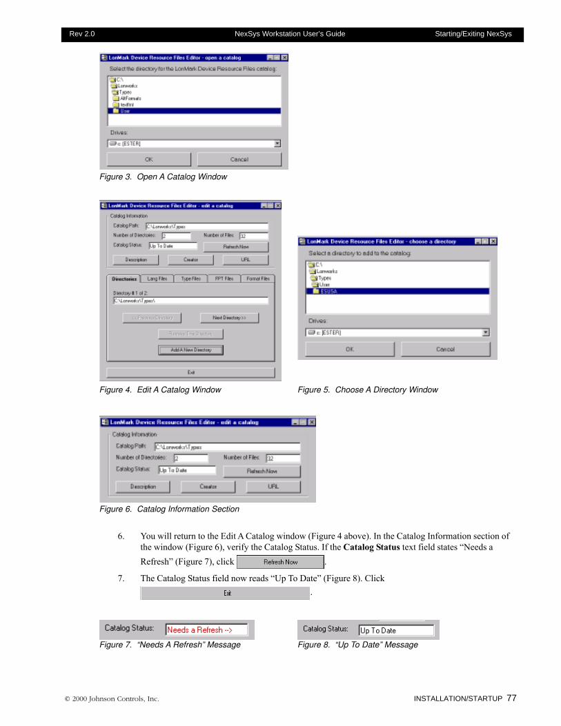
© 2000 Johnson Controls, Inc. INSTALLATION/STARTUP 77
Rev 2.0 NexSys Workstation User’s Guide Starting/Exiting NexSys
Figure 3. Open A Catalog Window
Figure 4. Edit A Catalog Window Figure 5. Choose A Directory Window
Figure 6. Catalog Information Section
6. You will return to the Edit A Catalog window (Figure 4 above). In the Catalog Information section ofthe window (Figure 6), verify the Catalog Status. If the Catalog Status text field states “Needs aRefresh” (Figure 7), click .
7. The Catalog Status field now reads “Up To Date” (Figure 8). Click.
Figure 7. “Needs A Refresh” Message Figure 8. “Up To Date” Message
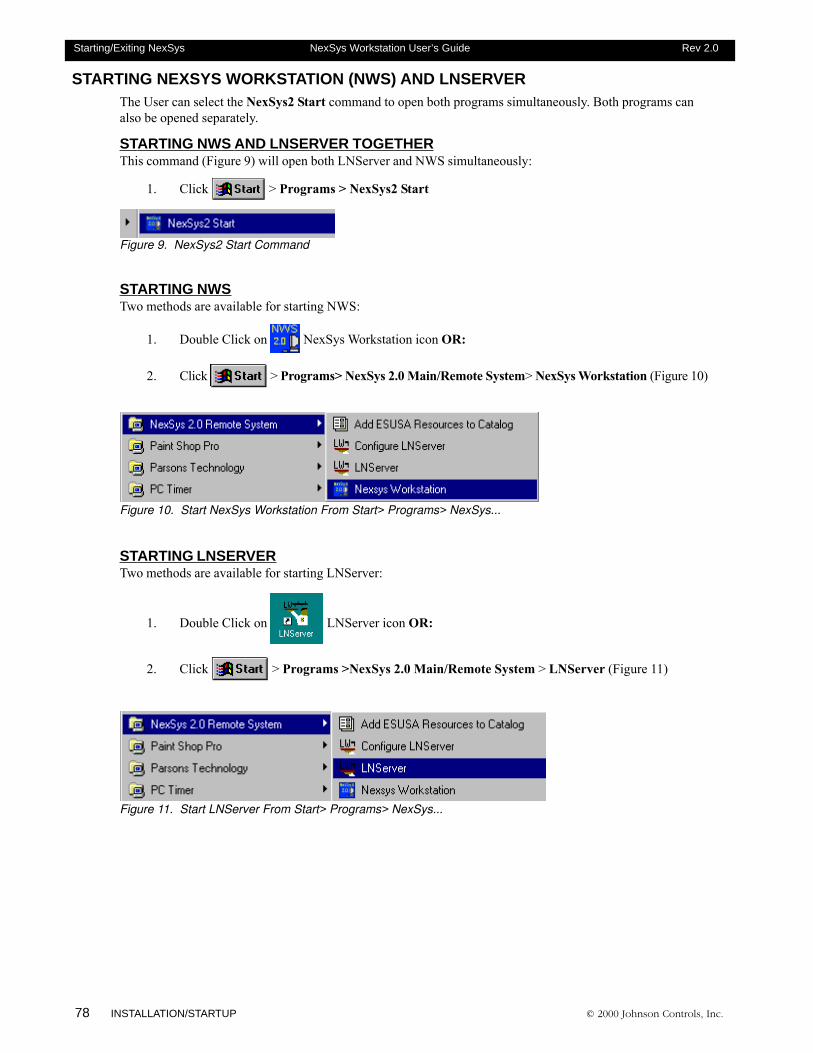
78 INSTALLATION/STARTUP © 2000 Johnson Controls, Inc.
Starting/Exiting NexSys NexSys Workstation User’s Guide Rev 2.0
STARTING NEXSYS WORKSTATION (NWS) AND LNSERVERThe User can select the NexSys2 Start command to open both programs simultaneously. Both programs canalso be opened separately.
STARTING NWS AND LNSERVER TOGETHERThis command (Figure 9) will open both LNServer and NWS simultaneously:
1. Click > Programs > NexSys2 Start
Figure 9. NexSys2 Start Command
STARTING NWSTwo methods are available for starting NWS:
1. Double Click on NexSys Workstation icon OR:
2. Click > Programs> NexSys 2.0 Main/Remote System> NexSys Workstation (Figure 10)
Figure 10. Start NexSys Workstation From Start> Programs> NexSys...
STARTING LNSERVERTwo methods are available for starting LNServer:
1. Double Click on LNServer icon OR:
2. Click > Programs >NexSys 2.0 Main/Remote System > LNServer (Figure 11)
Figure 11. Start LNServer From Start> Programs> NexSys...
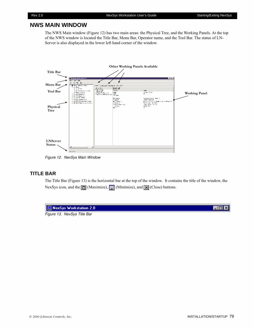
© 2000 Johnson Controls, Inc. INSTALLATION/STARTUP 79
Rev 2.0 NexSys Workstation User’s Guide Starting/Exiting NexSys
NWS MAIN WINDOWThe NWS Main window (Figure 12) has two main areas: the Physical Tree, and the Working Panels. At the topof the NWS window is located the Title Bar, Menu Bar, Operator name, and the Tool Bar. The status of LN-Server is also displayed in the lower left hand corner of the window.
�����������
������������
��������������������������
����������
��������
�������
�������
Figure 12. NexSys Main Window
TITLE BARThe Title Bar (Figure 13) is the horizontal bar at the top of the window. It contains the title of the window, theNexSys icon, and the (Maximize), (Minimize), and (Close) buttons.
Figure 13. NexSys Title Bar
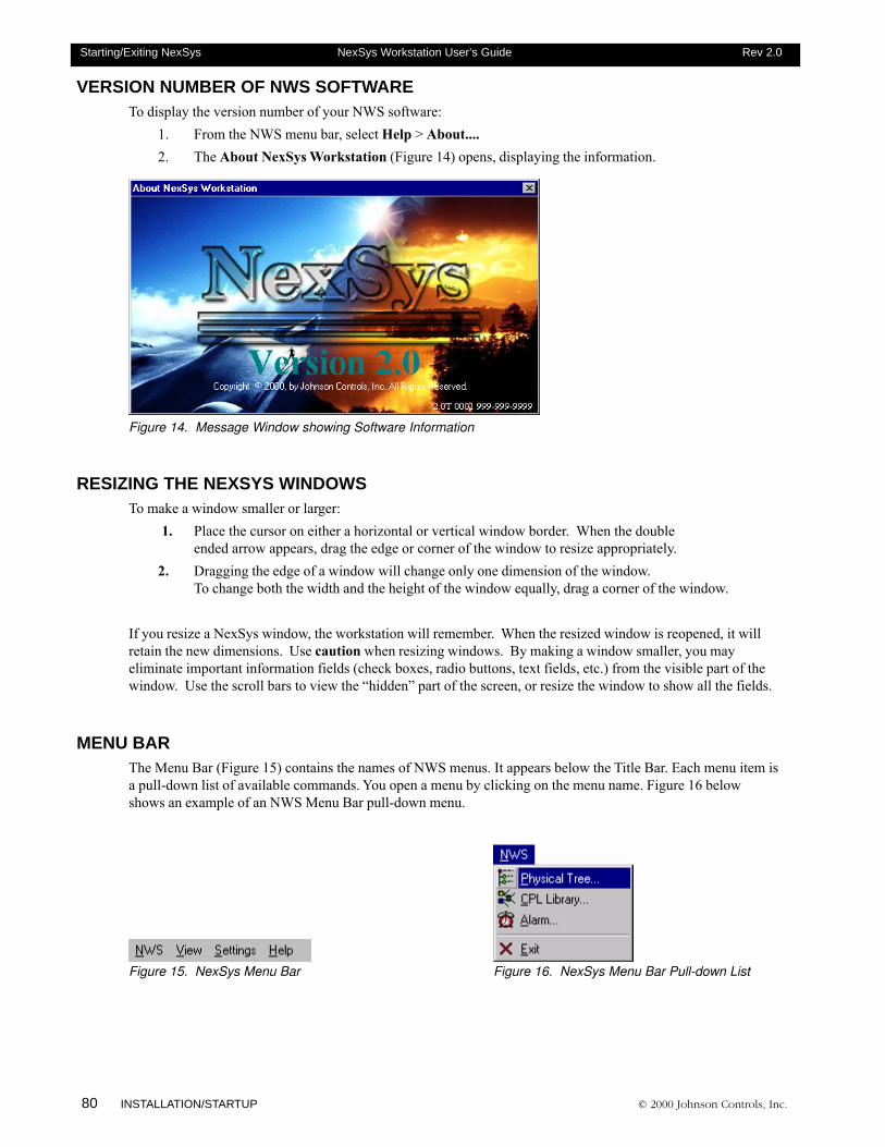
80 INSTALLATION/STARTUP © 2000 Johnson Controls, Inc.
Starting/Exiting NexSys NexSys Workstation User’s Guide Rev 2.0
VERSION NUMBER OF NWS SOFTWARETo display the version number of your NWS software:
1. From the NWS menu bar, select Help > About....2. The About NexSys Workstation (Figure 14) opens, displaying the information.
Figure 14. Message Window showing Software Information
RESIZING THE NEXSYS WINDOWSTo make a window smaller or larger:
1. Place the cursor on either a horizontal or vertical window border. When the doubleended arrow appears, drag the edge or corner of the window to resize appropriately.
2. Dragging the edge of a window will change only one dimension of the window.To change both the width and the height of the window equally, drag a corner of the window.
If you resize a NexSys window, the workstation will remember. When the resized window is reopened, it willretain the new dimensions. Use caution when resizing windows. By making a window smaller, you mayeliminate important information fields (check boxes, radio buttons, text fields, etc.) from the visible part of thewindow. Use the scroll bars to view the “hidden” part of the screen, or resize the window to show all the fields.
MENU BARThe Menu Bar (Figure 15) contains the names of NWS menus. It appears below the Title Bar. Each menu item isa pull-down list of available commands. You open a menu by clicking on the menu name. Figure 16 belowshows an example of an NWS Menu Bar pull-down menu.
Figure 15. NexSys Menu Bar Figure 16. NexSys Menu Bar Pull-down List
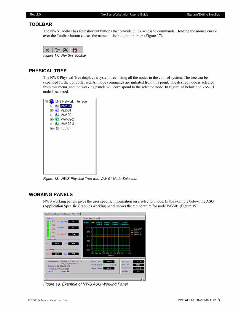
© 2000 Johnson Controls, Inc. INSTALLATION/STARTUP 81
Rev 2.0 NexSys Workstation User’s Guide Starting/Exiting NexSys
TOOLBARThe NWS Toolbar has four shortcut buttons that provide quick access to commands. Holding the mouse cursorover the Toolbar button causes the name of the button to pop up (Figure 17).
Figure 17. NexSys Toolbar
PHYSICAL TREEThe NWS Physical Tree displays a system tree listing all the nodes in the control system. The tree can beexpanded further, or collapsed. All node commands are initiated from this point. The desired node is selectedfrom this menu, and the working panels will correspond to the selected node. In Figure 18 below, the VAV-01node is selected.
Figure 18. NWS Physical Tree with VAV-01 Node Selected.
WORKING PANELSNWS working panels gives the user specific information on a selection node. In the example below, the ASG(Application Specific Graphic) working panel shows the temperature for node VAV-01 (Figure 19).
Figure 19. Example of NWS ASG Working Panel
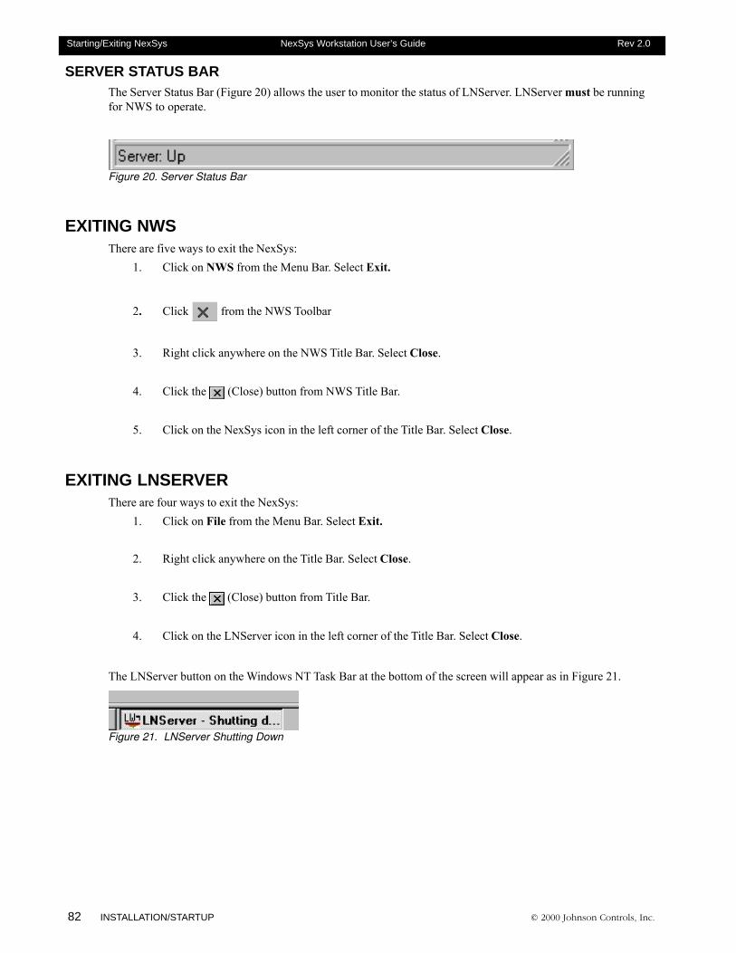
82 INSTALLATION/STARTUP © 2000 Johnson Controls, Inc.
Starting/Exiting NexSys NexSys Workstation User’s Guide Rev 2.0
SERVER STATUS BARThe Server Status Bar (Figure 20) allows the user to monitor the status of LNServer. LNServer must be runningfor NWS to operate.
Figure 20. Server Status Bar
EXITING NWSThere are five ways to exit the NexSys:
1. Click on NWS from the Menu Bar. Select Exit.
2. Click from the NWS Toolbar
3. Right click anywhere on the NWS Title Bar. Select Close.
4. Click the (Close) button from NWS Title Bar.
5. Click on the NexSys icon in the left corner of the Title Bar. Select Close.
EXITING LNSERVERThere are four ways to exit the NexSys:
1. Click on File from the Menu Bar. Select Exit.
2. Right click anywhere on the Title Bar. Select Close.
3. Click the (Close) button from Title Bar.
4. Click on the LNServer icon in the left corner of the Title Bar. Select Close.
The LNServer button on the Windows NT Task Bar at the bottom of the screen will appear as in Figure 21.
Figure 21. LNServer Shutting Down

© 2000 Johnson Controls, Inc. INSTALLATION/STARTUP 83
Rev 2.0 NexSys Workstation User’s Guide Starting/Exiting NexSys

84 INSTALLATION/STARTUP © 2000 Johnson Controls, Inc.
Starting/Exiting NexSys NexSys Workstation User’s Guide Rev 2.0
© 2000 Johnson Controls, Inc. Installation and Startup 85
Rev 2.0 NexSys Workstation User’s Guide Installation and Startup Index
Installation and Startup Index
C
Catalog 76
D
DHCP 37Dial Up Networking 54, 58Dial-Up Monitor 59Dialin Information, RAS 53
E
ESUSA Resources 76
H
Hardware Drivers 66
I
Installation Checklist 33Installing
PCC-10 73PCLTA-10/20 Card 73
Installing a Network Adapter 34Installing NexSys 38Interrupt Request (IRQ)
Selecting 72IP Address 55IPCONFIG 53
L
LNServerConfiguration Wizard 39Configure for Local Location 40Configure for Remote Location 43Configuring 39Exiting 82Starting LNServer 78Status Bar 82
M
Minimum Criteria 34Modem 56MS Loopback Adapter 35
N
NetBEUI 36, 49Network Adapter
Installing 34Network Protocols 36, 53NexSys Work Station (NWS)
Exiting NWS 82Starting NWS 78
NWS Main Window 79Menu Bar 81Physical Tree 81Resizing the NexSys Window 80Title 79Toolbar 81Version Number 80
P
PC Configurations 32PCC-10 66PCLTA Card, Full Size
Disabling 65Removing 65
PCLTA-10 66PCLTA-20 66PING 53
R
RASClient 53Dial the Server 58Dialin Information 53Disconnect a Remote Site 59Installing 46Setting to Automatic Start 50User Login Privileges 51
Resource Files 76Adding ESUSA Resources to Catalog 76
RX 60
86 Installation and Startup © 2000 Johnson Controls, Inc.
Installation and Startup Index NexSys Workstation User’s Guide Rev 2.0
S
SMX1250 Transceiver Board 6578K Transceiver Board 65DFOM Transceiver Board 65
Start-Up Procedure 76Exiting LNServer 82Exiting NWS 82Starting LNServer 78Starting LNServer And NWS Together 78Starting NWS 78
Starting NexSys 78, 79
T
TCP/IP 36, 37, 49, 55TX 60
Chapters
1. Common Node Functions2. Setting Up Routers3. Setting Up an FSC/FLC4. Setting Up a VAV5. Setting Up a Heat Pump6. Setting Up a Packaged Equipment Controller
SYSTEM SETUPSECTION THREE
© 2000 Johnson Controls, Inc.

88 System Setup © 2000 Johnson Controls, Inc.
System Setup Introduction NexSys Workstation User’s Guide Rev 2.0
Electronic Systems USA, a wholly owned subsidiary of Johnson Controls, Inc.,reserves the right to update specifications when appropriate. Information containedin this document is based on specifications believed to be correct at the time ofpublication.
Echelon ©, Coactive©, Windows NT©, and General Electric© are registered trademarks and service marks of companiesother than Electronic Systems USA. FSC™, CPL™ and NEXSYS™ are trademarks of Electronic Systems USA.
© 2000 Electronic Systems USA
© 2000 Johnson Controls, Inc. System Setup 89
Rev 2.0 NexSys Workstation User’s Guide System Setup Introduction
System Setup Table of Contents
Chapter One - Common Node Functions 95Overview ............................................................................................................................ 96Node Menu......................................................................................................................... 96
Node Commands..................................................................................................... 96Wink .............................................................................................................. 96Offline ........................................................................................................... 97Reset ............................................................................................................ 98Test ............................................................................................................... 98
Plug-Ins ................................................................................................................... 99Registering A Plug-In .................................................................................... 99Running A Plug-In ....................................................................................... 100
Move ...................................................................................................................... 101Add ........................................................................................................................ 102Setup Node ........................................................................................................... 103
Check Box Explanations ............................................................................. 104Replace Node ........................................................................................................ 105Edit/View Binding................................................................................................... 106Delete .................................................................................................................... 107Config Data Set ..................................................................................................... 107Set Time/Date On Node ........................................................................................ 109Rename ..................................................................................................................110Load Firmware........................................................................................................110MultiNode Operations .............................................................................................113Connection Description Template (CDT) ................................................................114
Adding A Connection Description Template (CDT) ......................................115Modifying Connection Description Templates (CDT) ...................................117Deleting Connection Description Templates (CDT) .....................................117
Node Configuration Wizard ....................................................................................118
Chapter Two - Setting Up a Router 119Overview .......................................................................................................................... 120
Router Classification Types ................................................................................... 120Far-Side Transceiver Types ................................................................................... 121
Echelon Routers .............................................................................. 121Adding a Router to the Physical Tree .................................................................... 121
Coactive Routers ............................................................................. 121CTI Routers ...................................................................................... 121
Commissioning a Defined Router .......................................................................... 123Adding Nodes To A Router .................................................................................... 124
Commissioning the PEC ............................................................................. 125Check Box Explanations .................................................................. 126
Chapter Three - Setting Up an FSC/FLC 129FSC Overview ....................................................................................................... 130FLC Overview ........................................................................................................ 130
90 System Setup © 2000 Johnson Controls, Inc.
System Setup Introduction NexSys Workstation User’s Guide Rev 2.0
Adding an FSC or FLC to the Physical Tree .......................................................... 130Defining an FSC/FLC.................................................................................. 131Commissioning the FSC/FLC ..................................................................... 132
Check Box Explanations .................................................................. 133FSC/FLC Configuration Wizard ............................................................................. 134FSC/FLC Wizard Page 1 - Configure FSC Time Values ........................................ 135FSC/FLC Wizard Page 2 - Enable Daylight Savings Time .................................... 136FSC/FLC Wizard Page 3 - Configure Daylight Savings Time ................................ 136FSC/FLC Wizard Page 4 - Select FSC Modules ................................................... 137
Chapter Four - Setting Up a VAV 139Setting up a VAV............................................................................................................... 140
Adding a VAV to the Physical Tree ........................................................................ 140Defining a VAV ............................................................................................ 140Commissioning the VAV.............................................................................. 141
Check Box Explanations .................................................................. 142VAV Configuration Wizard ..................................................................................... 143
VAV Wizard Page 1 - Room Sensor Type ................................................... 145VAV Wizard Page 2 - Thermostat Configuration ......................................... 146VAV Wizard Page 3 - Default Setpoints and Thermal Load Parameters .... 147VAV Wizard Page 4 - Setpoint Configuration .............................................. 147VAV Wizard Page 5 - Thermal Load Parameters ........................................ 148VAV Wizard Page 6 - K-Factor .................................................................... 149VAV Wizard Page 7 - Flow Parameters ...................................................... 151VAV Wizard Page 8 - Accept Air Flow PID Parameters? ............................ 152VAV Wizard Page 9 - Flow PID Parameters ............................................... 152VAV Wizard Page 10 - Fan Type ................................................................ 154VAV Wizard Page 11 - Reheat Parameters ................................................ 154VAV Wizard Page 12 - Floating Reheat ...................................................... 155VAV Wizard Page 13 - Electric Reheat ....................................................... 156VAV Wizard Page 14 - PWM Reheat .......................................................... 156VAV Wizard Page 15 - Broadcast Damper Inc Output? .............................. 158VAV Wizard Page 16 - Broadcast Damper DEC Output? ........................... 158VAV Wizard Page 17 - Broadcast Fan Output? .......................................... 159VAV Wizard Page 18 - Broadcast Reheat INC/ST 1 Output? ..................... 159VAV Wizard Page 19 - Broadcast Reheat DEC/ST 2 Output? .................... 160
Advanced Point Editing ......................................................................................... 161
Chapter Five - Setting Up a Heat Pump 163Setting up a Heat Pump ................................................................................................... 164
Adding a Heat Pump to the Physical Tree ............................................................. 164Defining a Heat Pump................................................................................. 164Commissioning the Heat Pump .................................................................. 165
Check Box Explanations .................................................................. 167Heat Pump Configuration Wizard .......................................................................... 168Heat Pump Wizard Page 1 - Room Sensor Type .................................................. 169Heat Pump Wizard Page 2 - Thermostat Configuration ........................................ 169Heat Pump Wizard Page 3 - Default Setpoints & Thermal Load Parameters ....... 170
© 2000 Johnson Controls, Inc. System Setup 91
Rev 2.0 NexSys Workstation User’s Guide System Setup Introduction
Heat Pump Wizard Page 4 - Setpoint Configuration.............................................. 171Heat Pump Wizard Page 5 - PID Parameters For Thermal Load .......................... 172Heat Pump Wizard Page 6 - Local Emergency Shutdown .................................... 173Heat Pump Wizard Page 7 - Economizer Type .................................................... 173Heat Pump Wizard Page 8 - Economizer Enable .................................................. 174Heat Pump Wizard Page 9 - Local Economizer .................................................... 174Heat Pump Wizard Page 10 - Mixed Air Parameters............................................. 175Heat Pump Wizard Page 11 - Low Limit Shutdown Parameters ........................... 176Heat Pump Wizard Page 12 - Fan Controller Parameters..................................... 177Heat Pump Wizard Page 13 - Number of Stages For Compressor? ..................... 178Heat Pump Wizard Page 14 - Compressor Controller ........................................... 179Heat Pump Wizard Page 15 - Reverse Valve Setup ............................................. 180Heat Pump Wizard Page 16 - Loop Enable........................................................... 181Heat Pump Wizard Page 17 - Broadcast Output For Damper? ............................. 181Heat Pump Wizard Page 18 - Broadcast Output For Fan Output? ....................... 182Heat Pump Wizard Page 19 - Broadcast Output For Reverse Valve? .................. 182Heat Pump Wizard Page 20 - Broadcast Output For Compressor 1? ................... 183Heat Pump Wizard Page 21 - Broadcast Output For Compressor 2? ................... 183Heat Pump Wizard Page 22 - Broadcast Output For Compressor 3/EH? ............. 184
Chapter Six - Setting Up a PEC 185Setting up a PEC.............................................................................................................. 186
Adding a PEC to the Physical Tree ....................................................................... 186Defining a PEC ........................................................................................... 186Commissioning the PEC ............................................................................. 187
Check Box Explanations .................................................................. 189Configuration Wizard (PEC) ............................................................................................. 190
PEC Wizard Page 1 - Room Sensor Type ............................................................. 191PEC Wizard Page 2 - Thermostat Configuration ................................................... 192PEC Wizard Page 3 - Default Setpoints and Thermal Load Parameters .............. 193PEC Wizard Page 4 - Setpoint Configuration ........................................................ 193PEC Wizard Page 5 - PID Parameters For Thermal Load .................................... 194PEC Wizard Page 6 - Local Emergency Shutdown............................................... 195PEC Wizard Page 7 - Economizer Type ................................................................ 196PEC Wizard Page 8 - Economizer Enable ............................................................ 196PEC Wizard Page 9 - Local Economizer ............................................................... 197PEC Wizard Page 10 - Mixed Air Parameters ....................................................... 198PEC Wizard Page 11 - Low Limit Shutdown Parameters ...................................... 199PEC Wizard Page 12 - Fan Controller Parameters ............................................... 200PEC Wizard Page 13 - Discharge Air Reset From Thermal Load ......................... 202PEC Wizard Page 14 - Discharge Air Reset .......................................................... 202PEC Wizard Page 15 - Number of Valves ............................................................. 203PEC Wizard Page 16 - Winter/Summer Controller ................................................ 204PEC Wizard Page 17 - Local Winter/Summer Controller ...................................... 205PEC Wizard Page 18 - Heating Type .................................................................... 205PEC Wizard Page 19 - Floating Heating Parameters ............................................ 206PEC Wizard Page 20 - Discrete Heating Parameters ........................................... 206PEC Wizard Page 21 - Cooling Type .................................................................... 207
92 System Setup © 2000 Johnson Controls, Inc.
System Setup Introduction NexSys Workstation User’s Guide Rev 2.0
PEC Wizard Page 22 - Floating Cooling Parameters ............................................ 208PEC Wizard Page 23 - Discrete Cooling ............................................................... 209PEC Wizard Page 24 - Broadcast Output For Damper? ....................................... 209PEC Wizard Page 25 - Broadcast Output For Fan Output? .................................. 210PEC Wizard Page 26 - Broadcast Output For Cooling Increment? ........................211PEC Wizard Page 27 - Broadcast Output For Cooling Decrement? ..................... 212PEC Wizard Page 28 - Broadcast Output For Heating Increment? ....................... 212PEC Wizard Page 29 - Broadcast Output For Heating Decrement? ..................... 213
Advanced PEC Editing ..................................................................................................... 214Editing Points ........................................................................................................ 214
Editing Point #1 - Discharge Air Temp (Analog Input) ................................. 214Editing Point #2 - Mixed Air Temp (Analog Input) ....................................... 214Editing Point #3 - Space Temp (Analog Input) ............................................ 215Editing Point #4 - Outside AIr/Supply Water Temp (analog Input) .............. 215Editing Point #5 - Fan Status Input (Digital Input) ....................................... 215Editing Point #6 - Emergency Shutdown (Digital Input) .............................. 215Editing Point #7 - Space Temp Controller ................................................... 215Editing Point #8 - Indoor Air Quality Controller ........................................... 215Editing Point #9 - Outside Air Temp ............................................................ 215Editing Point #10 - Manual Occupancy Controller ...................................... 215Editing Point #11 - User Setpoint Controller ............................................... 216Editing Point #12 - Override Controller ....................................................... 216Editing Point #13 - Application Mode Controller ......................................... 216Editing Point #14 - Manual Reset ............................................................... 216Editing Point #15 - Low Limit Shutdown ..................................................... 216Editing Point #16 - Local Emergency Shutdown ......................................... 216Editing Point #17 - LON Emergency Shutdown .......................................... 216Editing Point #18 - Setpoint Controller ........................................................ 217Editing Point #19 - Mixed Air PID Controller ............................................... 217Editing Point #20 - Emergency Command Controller ................................. 217Editing Point #21 - Winter/Summer Controller ............................................ 218Editing Point #22 - Temp PID Controller ..................................................... 218Editing Point #23 - Economizer Controller .................................................. 218Editing Point #24 - Fan Controller ............................................................... 218Editing Point #25 - Heating/Cooling Controller ........................................... 218Editing Point #26 - Analog Output............................................................... 218Editing Point #27 - Digital Output #1 Fan Actuator Output ......................... 218
System Setup Index ....................................................................................................... 219

© 2000 Johnson Controls, Inc. System Setup 93
Rev 2.0 NexSys Workstation User’s Guide System Setup Introduction

94 System Setup © 2000 Johnson Controls, Inc.
System Setup Introduction NexSys Workstation User’s Guide Rev 2.0
Chapter One
Common Node Functions
This chapter contain information on:
� Node Commands
� Plug-ins
� Moving a Node
� Adding a Node
� Node Setup
� Replacing a Node
� Edit/View Binding
� Deleting a Node
� Configuration Data Set
� Set Time/Date On A Node
� Renaming a Node
� Loading Firmware
� MultiNode Operations
� Connection Template
� The Node Configuration Wizard
© 2000 Johnson Controls, Inc.
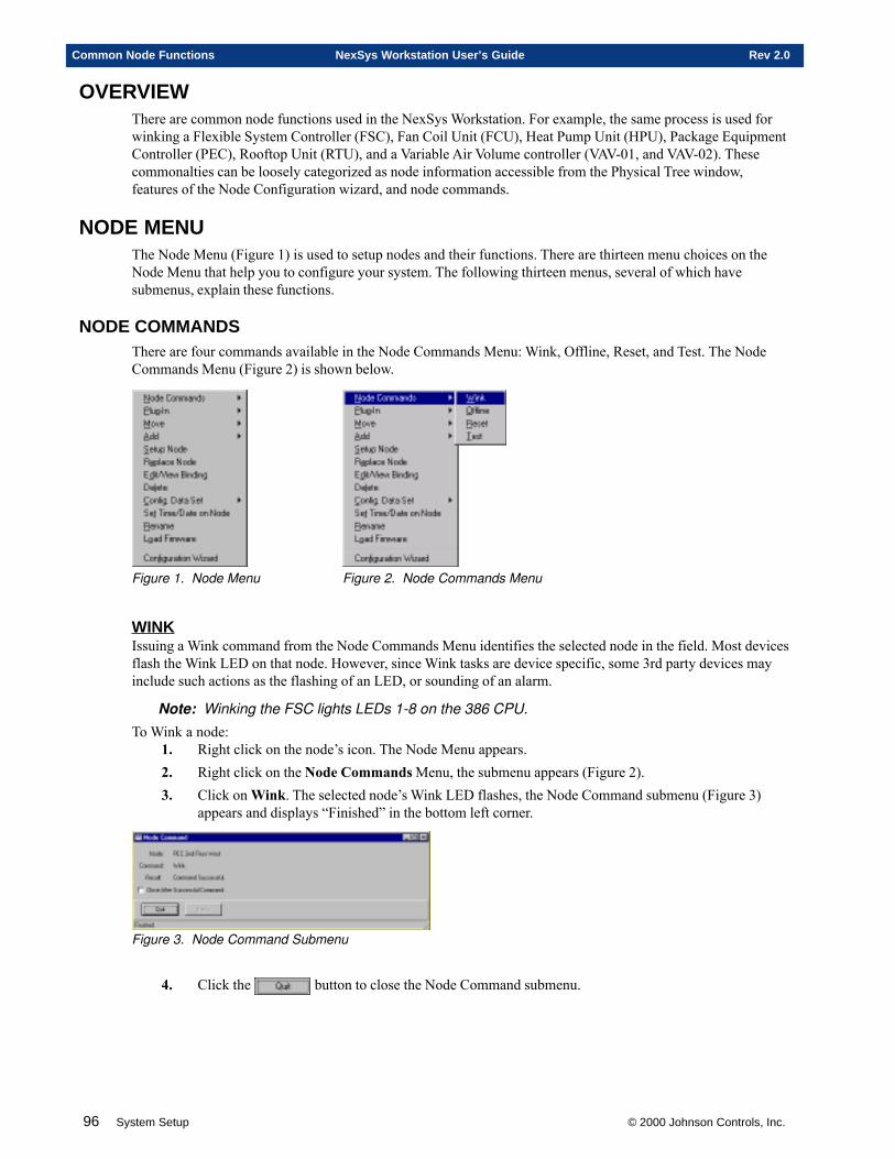
96 System Setup © 2000 Johnson Controls, Inc.
Common Node Functions NexSys Workstation User’s Guide Rev 2.0
OVERVIEWThere are common node functions used in the NexSys Workstation. For example, the same process is used forwinking a Flexible System Controller (FSC), Fan Coil Unit (FCU), Heat Pump Unit (HPU), Package EquipmentController (PEC), Rooftop Unit (RTU), and a Variable Air Volume controller (VAV-01, and VAV-02). Thesecommonalties can be loosely categorized as node information accessible from the Physical Tree window,features of the Node Configuration wizard, and node commands.
NODE MENUThe Node Menu (Figure 1) is used to setup nodes and their functions. There are thirteen menu choices on theNode Menu that help you to configure your system. The following thirteen menus, several of which havesubmenus, explain these functions.
NODE COMMANDSThere are four commands available in the Node Commands Menu: Wink, Offline, Reset, and Test. The NodeCommands Menu (Figure 2) is shown below.
Figure 1. Node Menu Figure 2. Node Commands Menu
WINKIssuing a Wink command from the Node Commands Menu identifies the selected node in the field. Most devicesflash the Wink LED on that node. However, since Wink tasks are device specific, some 3rd party devices mayinclude such actions as the flashing of an LED, or sounding of an alarm.
Note: Winking the FSC lights LEDs 1-8 on the 386 CPU.
To Wink a node:1. Right click on the node’s icon. The Node Menu appears.2. Right click on the Node Commands Menu, the submenu appears (Figure 2).3. Click on Wink. The selected node’s Wink LED flashes, the Node Command submenu (Figure 3)
appears and displays “Finished” in the bottom left corner.
Figure 3. Node Command Submenu
4. Click the button to close the Node Command submenu.
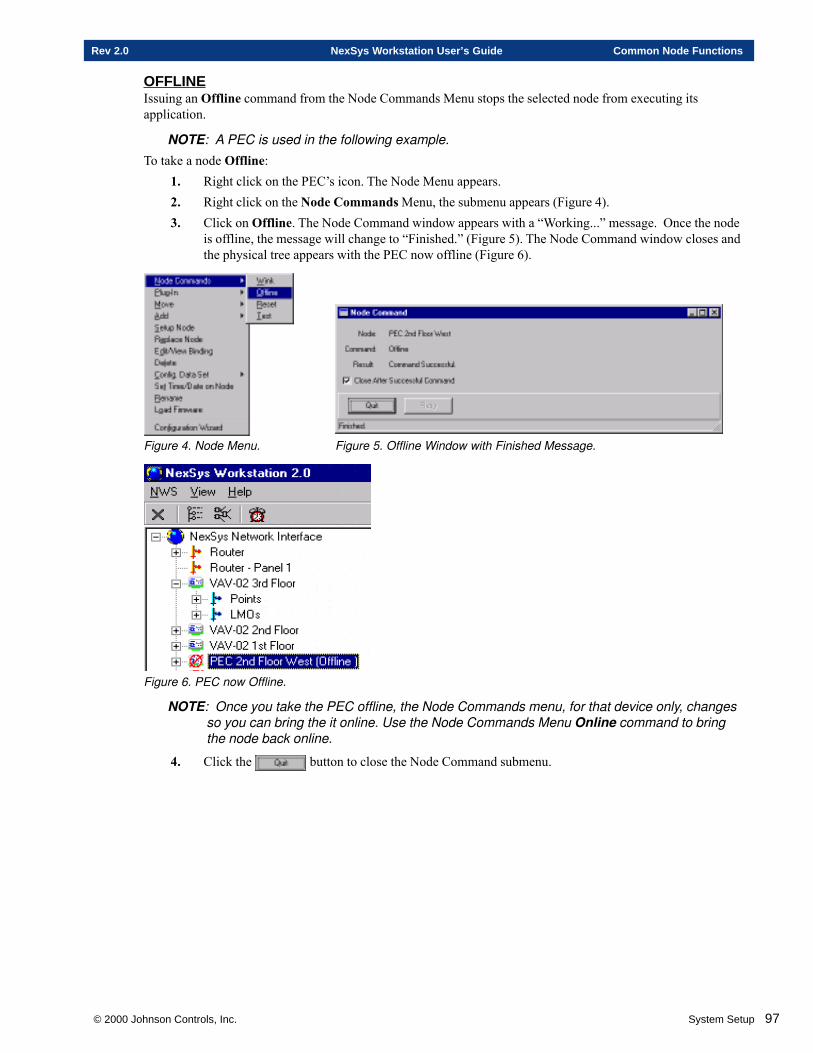
© 2000 Johnson Controls, Inc. System Setup 97
Rev 2.0 NexSys Workstation User’s Guide Common Node Functions
OFFLINEIssuing an Offline command from the Node Commands Menu stops the selected node from executing itsapplication.
NOTE: A PEC is used in the following example.
To take a node Offline:1. Right click on the PEC’s icon. The Node Menu appears.2. Right click on the Node Commands Menu, the submenu appears (Figure 4).3. Click on Offline. The Node Command window appears with a “Working...” message. Once the node
is offline, the message will change to “Finished.” (Figure 5). The Node Command window closes andthe physical tree appears with the PEC now offline (Figure 6).
Figure 4. Node Menu. Figure 5. Offline Window with Finished Message.
Figure 6. PEC now Offline.
NOTE: Once you take the PEC offline, the Node Commands menu, for that device only, changesso you can bring the it online. Use the Node Commands Menu Online command to bringthe node back online.
4. Click the button to close the Node Command submenu.
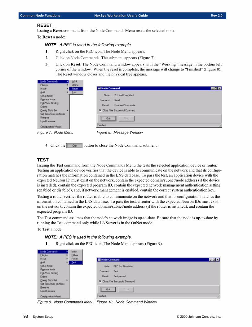
98 System Setup © 2000 Johnson Controls, Inc.
Common Node Functions NexSys Workstation User’s Guide Rev 2.0
RESETIssuing a Reset command from the Node Commands Menu resets the selected node.To Reset a node:
NOTE: A PEC is used in the following example.
1. Right click on the PEC icon. The Node Menu appears.2. Click on Node Commands. The submenu appears (Figure 7).3. Click on Reset. The Node Command window appears with the “Working” message in the bottom left
corner of the window. When the reset is complete, the message will change to “Finished” (Figure 8).The Reset window closes and the physical tree appears.
Figure 7. Node Menu Figure 8. Message Window
4. Click the button to close the Node Command submenu.
TESTIssuing the Test command from the Node Commands Menu the tests the selected application device or router.Testing an application device verifies that the device is able to communicate on the network and that its configu-ration matches the information contained in the LNS database. To pass the test, an application device with theexpected Neuron ID must exist on the network, contain the expected domain/subnet/node address (if the deviceis installed), contain the expected program ID, contain the expected network management authentication setting(enabled or disabled), and, if network management is enabled, contain the correct system authentication key.Testing a router verifies the router is able to communicate on the network and that its configuration matches theinformation contained in the LNS database. To pass the test, a router with the expected Neuron IDs must existon the network, contain the expected domain/subnet/node address (if the router is installed), and contain theexpected program ID.The Test command assumes that the node's network image is up-to-date. Be sure that the node is up-to-date byrunning the Test command only while LNServer is in the OnNet mode.To Test a node:
NOTE: A PEC is used in the following example.
1. Right click on the PEC icon. The Node Menu appears (Figure 9).
Figure 9. Node Commands Menu Figure 10. Node Command Window
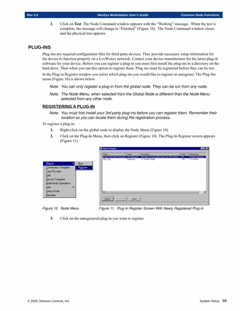
© 2000 Johnson Controls, Inc. System Setup 99
Rev 2.0 NexSys Workstation User’s Guide Common Node Functions
2. Click on Test. The Node Command window appears with the “Working” message. When the test iscomplete, the message will change to “Finished” (Figure 10). The Node Command window closesand the physical tree appears.
PLUG-INSPlug-Ins are required configuration files for third party devices. They provide necessary setup information forthe device to function properly on a LONWORKS network. Contact your device manufacturer for the latest plug-insoftware for your device. Before you can register a plug-in you must first install the plug-ins to a directory on thehard drive. Then when you run this option to register them. Plug-ins must be registered before they can be run.In the Plug-in Register window you select which plug-ins you would like to register or unregister. The Plug-Insmenu (Figure 10) is shown below.
Note: You can only register a plug-in from the global node. They can be run from any node.
Note: The Node Menu, when selected from the Global Node is different than the Node Menuselected from any other node.
REGISTERING A PLUG-INNote: You must first install your 3rd party plug-ins before you can register them. Remember their
location so you can locate them during the registration process.
To register a plug-in:1. Right-click on the global node to display the Node Menu (Figure 10).2. Click on the Plug-In Menu, then click on Register (Figure 10). The Plug-In Register screen appears
(Figure 11).
Figure 10. Node Menu Figure 11. Plug-In Register Screen With Newly Registered Plug-In
3. Click on the unregistered plug-in you want to register.
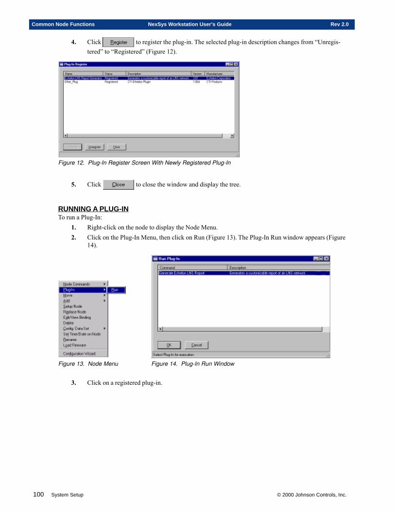
100 System Setup © 2000 Johnson Controls, Inc.
Common Node Functions NexSys Workstation User’s Guide Rev 2.0
4. Click to register the plug-in. The selected plug-in description changes from “Unregis-tered” to “Registered” (Figure 12).
Figure 12. Plug-In Register Screen With Newly Registered Plug-In
5. Click to close the window and display the tree.
RUNNING A PLUG-INTo run a Plug-In:
1. Right-click on the node to display the Node Menu.2. Click on the Plug-In Menu, then click on Run (Figure 13). The Plug-In Run window appears (Figure
14).
Figure 13. Node Menu Figure 14. Plug-In Run Window
3. Click on a registered plug-in.
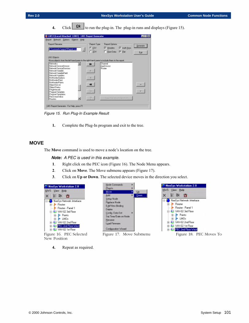
© 2000 Johnson Controls, Inc. System Setup 101
Rev 2.0 NexSys Workstation User’s Guide Common Node Functions
4. Click to run the plug-in. The plug-in runs and displays (Figure 15).
Figure 15. Run Plug-In Example Result
1. Complete the Plug-In program and exit to the tree.
MOVEThe Move command is used to move a node’s location on the tree.
Note: A PEC is used in this example.
1. Right click on the PEC icon (Figure 16). The Node Menu appears.2. Click on Move. The Move submenu appears (Figure 17).3. Click on Up or Down. The selected device moves in the direction you select.
Figure 16. PEC Selected Figure 17. Move Submenu Figure 18. PEC Moves ToNew Position
4. Repeat as required.
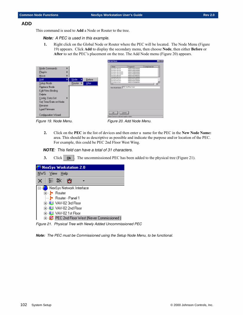
102 System Setup © 2000 Johnson Controls, Inc.
Common Node Functions NexSys Workstation User’s Guide Rev 2.0
ADDThis command is used to Add a Node or Router to the tree.
Note: A PEC is used in this example.
1. Right click on the Global Node or Router where the PEC will be located. The Node Menu (Figure19) appears. Click Add to display the secondary menu, then choose Node, then either Before orAfter to set the PEC’s placement on the tree. The Add Node menu (Figure 20) appears.
Figure 19. Node Menu. Figure 20. Add Node Menu.
2. Click on the PEC in the list of devices and then enter a name for the PEC in the New Node Name:area. This should be as descriptive as possible and indicate the purpose and/or location of the PEC.For example, this could be PEC 2nd Floor West Wing.
NOTE: This field can have a total of 31 characters.
3. Click . The uncommissioned PEC has been added to the physical tree (Figure 21).
Figure 21. Physical Tree with Newly Added Uncommissioned PEC
Note: The PEC must be Commissioned using the Setup Node Menu, to be functional.
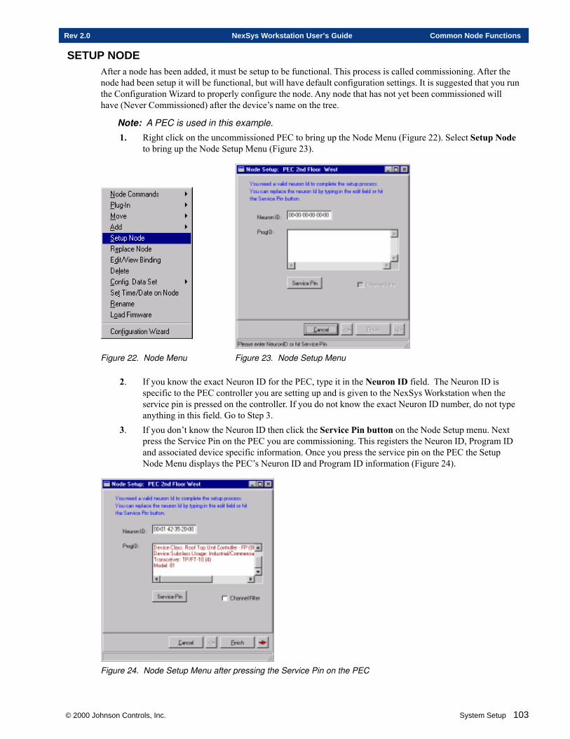
© 2000 Johnson Controls, Inc. System Setup 103
Rev 2.0 NexSys Workstation User’s Guide Common Node Functions
SETUP NODEAfter a node has been added, it must be setup to be functional. This process is called commissioning. After thenode had been setup it will be functional, but will have default configuration settings. It is suggested that you runthe Configuration Wizard to properly configure the node. Any node that has not yet been commissioned willhave (Never Commissioned) after the device’s name on the tree.
Note: A PEC is used in this example.
1. Right click on the uncommissioned PEC to bring up the Node Menu (Figure 22). Select Setup Nodeto bring up the Node Setup Menu (Figure 23).
Figure 22. Node Menu Figure 23. Node Setup Menu
2. If you know the exact Neuron ID for the PEC, type it in the Neuron ID field. The Neuron ID isspecific to the PEC controller you are setting up and is given to the NexSys Workstation when theservice pin is pressed on the controller. If you do not know the exact Neuron ID number, do not typeanything in this field. Go to Step 3.
3. If you don’t know the Neuron ID then click the Service Pin button on the Node Setup menu. Nextpress the Service Pin on the PEC you are commissioning. This registers the Neuron ID, Program IDand associated device specific information. Once you press the service pin on the PEC the SetupNode Menu displays the PEC’s Neuron ID and Program ID information (Figure 24).
Figure 24. Node Setup Menu after pressing the Service Pin on the PEC
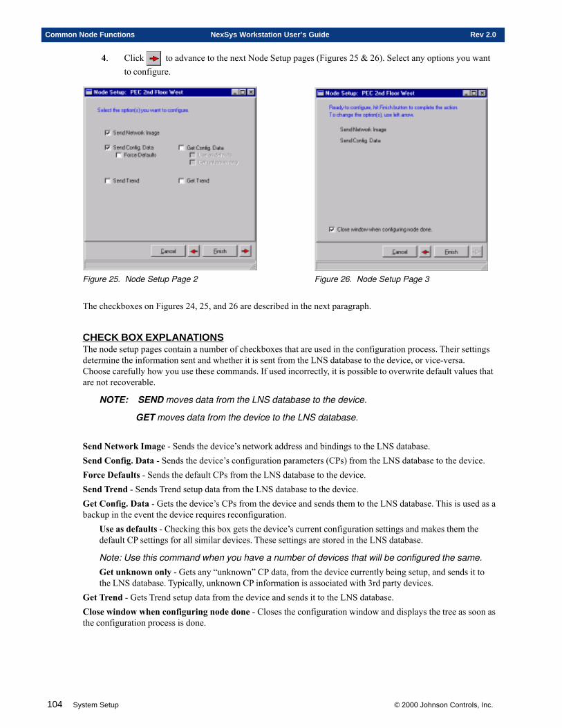
104 System Setup © 2000 Johnson Controls, Inc.
Common Node Functions NexSys Workstation User’s Guide Rev 2.0
4. Click to advance to the next Node Setup pages (Figures 25 & 26). Select any options you wantto configure.
Figure 25. Node Setup Page 2 Figure 26. Node Setup Page 3
The checkboxes on Figures 24, 25, and 26 are described in the next paragraph.
CHECK BOX EXPLANA TIONSThe node setup pages contain a number of checkboxes that are used in the configuration process. Their settingsdetermine the information sent and whether it is sent from the LNS database to the device, or vice-versa.Choose carefully how you use these commands. If used incorrectly, it is possible to overwrite default values thatare not recoverable.
NOTE: SEND moves data from the LNS database to the device.
GET moves data from the device to the LNS database.
Send Network Image - Sends the device’s network address and bindings to the LNS database.Send Config. Data - Sends the device’s configuration parameters (CPs) from the LNS database to the device.Force Defaults - Sends the default CPs from the LNS database to the device.Send Trend - Sends Trend setup data from the LNS database to the device.Get Config. Data - Gets the device’s CPs from the device and sends them to the LNS database. This is used as abackup in the event the device requires reconfiguration.
Use as defaults - Checking this box gets the device’s current configuration settings and makes them thedefault CP settings for all similar devices. These settings are stored in the LNS database.
Note: Use this command when you have a number of devices that will be configured the same.
Get unknown only - Gets any “unknown” CP data, from the device currently being setup, and sends it tothe LNS database. Typically, unknown CP information is associated with 3rd party devices.
Get Trend - Gets Trend setup data from the device and sends it to the LNS database.Close window when configuring node done - Closes the configuration window and displays the tree as soon asthe configuration process is done.
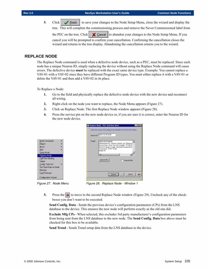
© 2000 Johnson Controls, Inc. System Setup 105
Rev 2.0 NexSys Workstation User’s Guide Common Node Functions
5. Click to save your changes to the Node Setup Menu, close the wizard and display the
tree. This will complete the commissioning process and remove the Never Commissioned label from
the PEC on the tree. Click to abandon your changes to the Node Setup Menu. If you
cancel you will be prompted to confirm your cancellation. Confirming the cancellation closes thewizard and returns to the tree display. Abandoning the cancellation returns you to the wizard.
REPLACE NODEThe Replace Node command is used when a defective node device, such as a PEC, must be replaced. Since eachnode has a unique Neuron ID, simply replacing the device without using the Replace Node command will causeerrors. The defective device must be replaced with the exact same device type. Example: You cannot replace aVAV-01 with a VAV-02 since they have different Program ID types. You must either replace it with a VAV-01 ordelete the VAV-01 and then add a VAV-02 in its place.
To Replace a Node:1. Go to the field and physically replace the defective node device with the new device and reconnect
all wiring.2. Right-click on the node you want to replace, the Node Menu appears (Figure 27).3. Click on Replace Node. The first Replace Node window appears (Figure 28).4. Press the service pin on the new node device or, if you are sure it is correct, enter the Neuron ID for
the new node device.
Figure 27. Node Menu Figure 28. Replace Node - Window 1
5. Press the to move to the second Replace Node window (Figure 29). Uncheck any of the check-boxes you don’t want to be executed.
Send Config. Data - Sends the previous device’s configuration parameters (CPs) from the LNSdatabase to the device. This ensures the new node will perform exactly as the old one did.Exclude Mfg CPs - When selected, this excludes 3rd party manufacturer’s configuration parametersfrom being sent from the LNS database to the new node. The Send Config. Data box above must bechecked for this box to be available.Send Trend - Sends Trend setup data from the LNS database to the device.
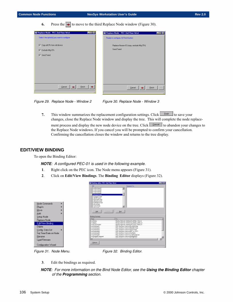
106 System Setup © 2000 Johnson Controls, Inc.
Common Node Functions NexSys Workstation User’s Guide Rev 2.0
6. Press the to move to the third Replace Node window (Figure 30).
Figure 29. Replace Node - Window 2 Figure 30. Replace Node - Window 3
7. This window summarizes the replacement configuration settings. Click to save yourchanges, close the Replace Node window and display the tree. This will complete the node replace-ment process and display the new node device on the tree. Click to abandon your changes tothe Replace Node windows. If you cancel you will be prompted to confirm your cancellation.Confirming the cancellation closes the window and returns to the tree display.
EDIT/VIEW BINDINGTo open the Binding Editor:
NOTE: A configured PEC-01 is used in the following example.
1. Right click on the PEC icon. The Node menu appears (Figure 31).2. Click on Edit/View Bindings. The Binding Editor displays (Figure 32).
Figure 31. Node Menu. Figure 32. Binding Editor.
3. Edit the bindings as required.
NOTE: For more information on the Bind Node Editor, see the Using the Binding Editor chapterof the Programming section.
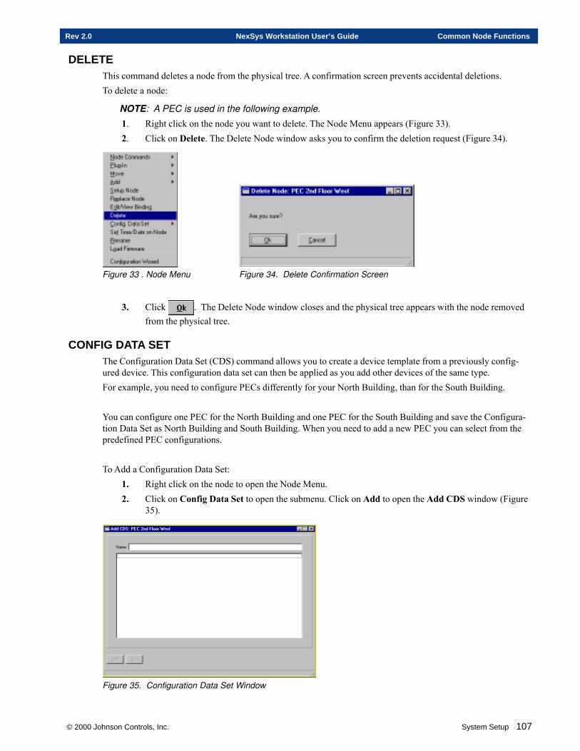
© 2000 Johnson Controls, Inc. System Setup 107
Rev 2.0 NexSys Workstation User’s Guide Common Node Functions
DELETEThis command deletes a node from the physical tree. A confirmation screen prevents accidental deletions.To delete a node:
NOTE: A PEC is used in the following example.
1. Right click on the node you want to delete. The Node Menu appears (Figure 33).2. Click on Delete. The Delete Node window asks you to confirm the deletion request (Figure 34).
Figure 33 . Node Menu Figure 34. Delete Confirmation Screen
3. Click . The Delete Node window closes and the physical tree appears with the node removedfrom the physical tree.
CONFIG DATA SETThe Configuration Data Set (CDS) command allows you to create a device template from a previously config-ured device. This configuration data set can then be applied as you add other devices of the same type.For example, you need to configure PECs differently for your North Building, than for the South Building.
You can configure one PEC for the North Building and one PEC for the South Building and save the Configura-tion Data Set as North Building and South Building. When you need to add a new PEC you can select from thepredefined PEC configurations.
To Add a Configuration Data Set:1. Right click on the node to open the Node Menu.2. Click on Config Data Set to open the submenu. Click on Add to open the Add CDS window (Figure
35).
Figure 35. Configuration Data Set Window
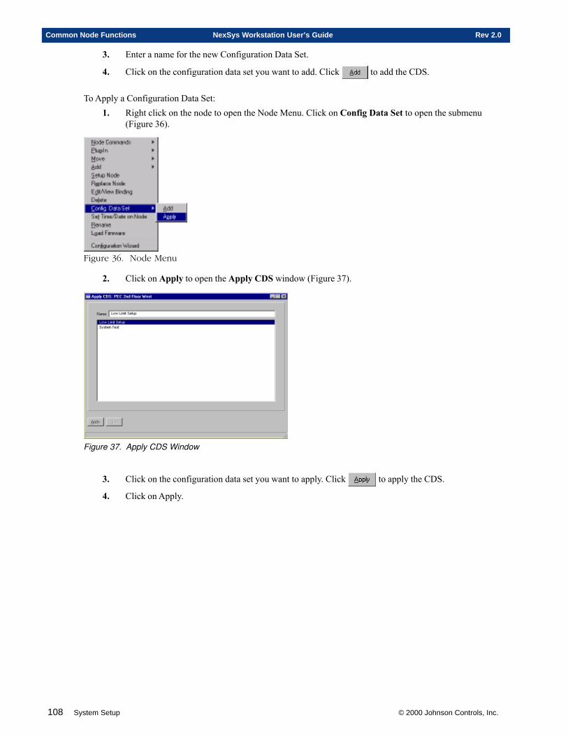
108 System Setup © 2000 Johnson Controls, Inc.
Common Node Functions NexSys Workstation User’s Guide Rev 2.0
3. Enter a name for the new Configuration Data Set.
4. Click on the configuration data set you want to add. Click to add the CDS.
To Apply a Configuration Data Set:1. Right click on the node to open the Node Menu. Click on Config Data Set to open the submenu
(Figure 36).
Figure 36. Node Menu
2. Click on Apply to open the Apply CDS window (Figure 37).
Figure 37. Apply CDS Window
3. Click on the configuration data set you want to apply. Click to apply the CDS.
4. Click on Apply.
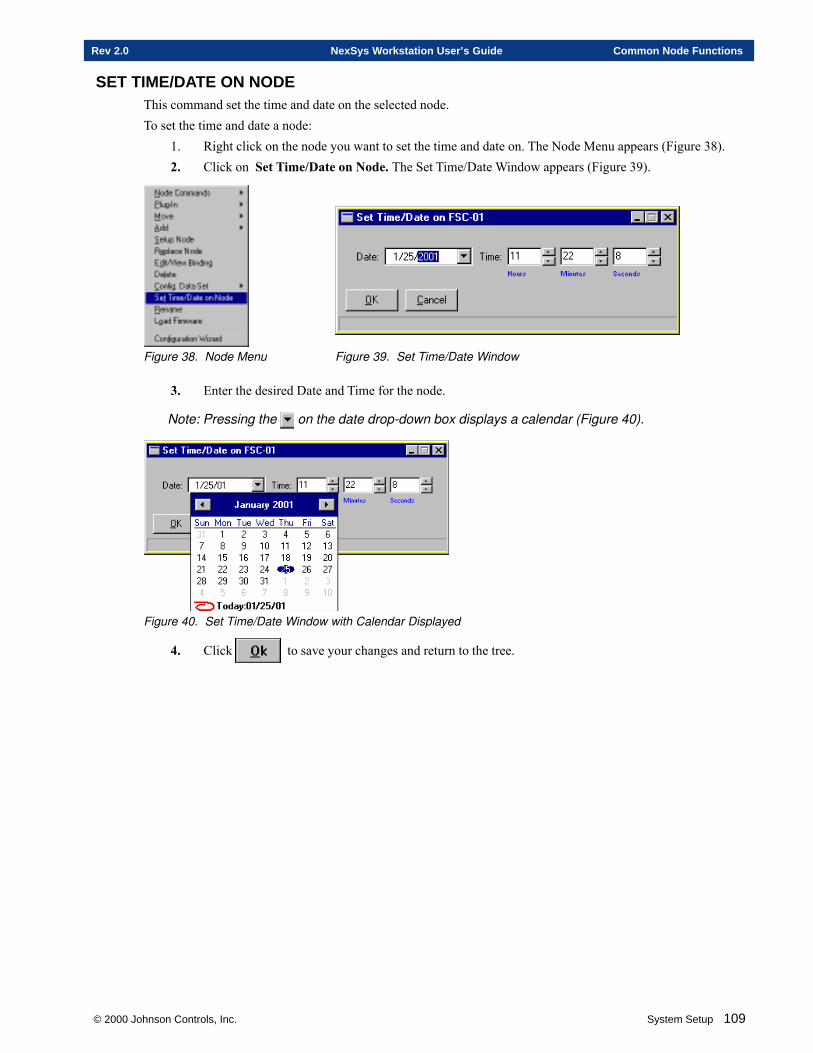
© 2000 Johnson Controls, Inc. System Setup 109
Rev 2.0 NexSys Workstation User’s Guide Common Node Functions
SET TIME/DATE ON NODEThis command set the time and date on the selected node.To set the time and date a node:
1. Right click on the node you want to set the time and date on. The Node Menu appears (Figure 38).2. Click on Set Time/Date on Node. The Set Time/Date Window appears (Figure 39).
Figure 38. Node Menu Figure 39. Set Time/Date Window
3. Enter the desired Date and Time for the node.
Note: Pressing the on the date drop-down box displays a calendar (Figure 40).
Figure 40. Set Time/Date Window with Calendar Displayed
4. Click to save your changes and return to the tree.
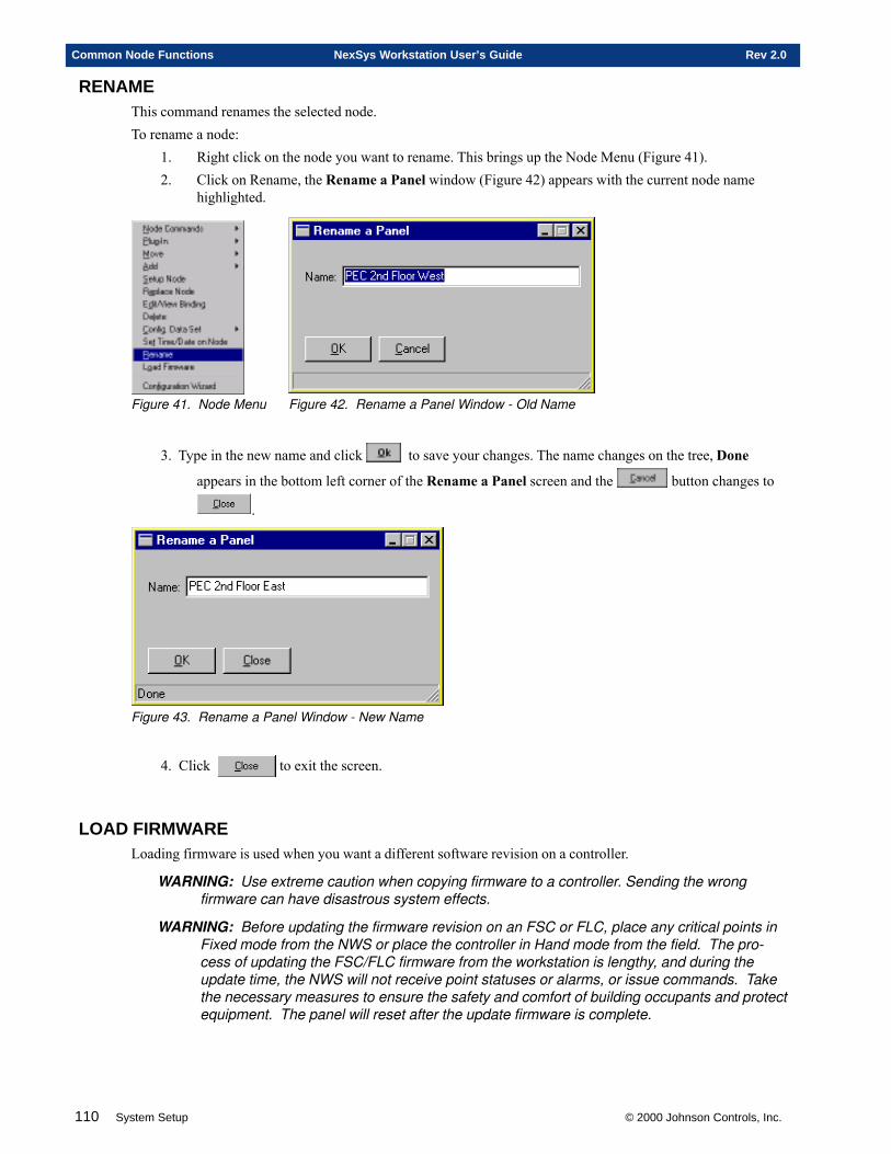
110 System Setup © 2000 Johnson Controls, Inc.
Common Node Functions NexSys Workstation User’s Guide Rev 2.0
RENAMEThis command renames the selected node.To rename a node:
1. Right click on the node you want to rename. This brings up the Node Menu (Figure 41).2. Click on Rename, the Rename a Panel window (Figure 42) appears with the current node name
highlighted.
Figure 41. Node Menu Figure 42. Rename a Panel Window - Old Name
3. Type in the new name and click to save your changes. The name changes on the tree, Done
appears in the bottom left corner of the Rename a Panel screen and the button changes to
.
Figure 43. Rename a Panel Window - New Name
4. Click to exit the screen.
LOAD FIRMWARELoading firmware is used when you want a different software revision on a controller.
WARNING: Use extreme caution when copying firmware to a controller. Sending the wrongfirmware can have disastrous system effects.
WARNING: Before updating the firmware revision on an FSC or FLC, place any critical points inFixed mode from the NWS or place the controller in Hand mode from the field. The pro-cess of updating the FSC/FLC firmware from the workstation is lengthy, and during theupdate time, the NWS will not receive point statuses or alarms, or issue commands. Takethe necessary measures to ensure the safety and comfort of building occupants and protectequipment. The panel will reset after the update firmware is complete.
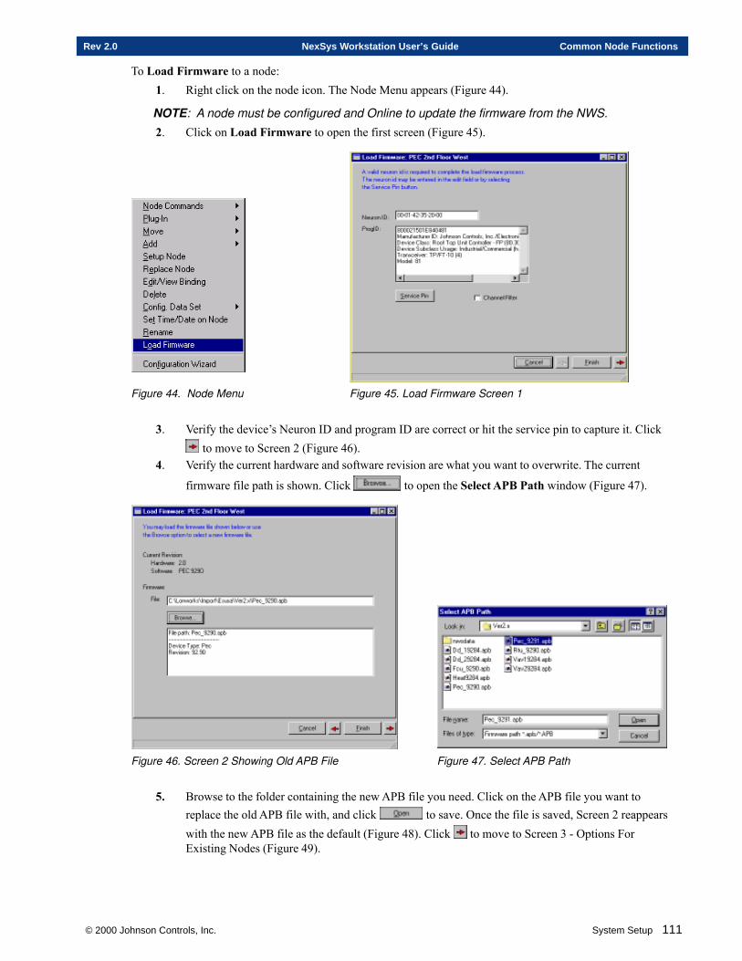
© 2000 Johnson Controls, Inc. System Setup 111
Rev 2.0 NexSys Workstation User’s Guide Common Node Functions
To Load Firmware to a node:1. Right click on the node icon. The Node Menu appears (Figure 44).
NOTE: A node must be configured and Online to update the firmware from the NWS.
2. Click on Load Firmware to open the first screen (Figure 45).
Figure 44. Node Menu Figure 45. Load Firmware Screen 1
3. Verify the device’s Neuron ID and program ID are correct or hit the service pin to capture it. Click to move to Screen 2 (Figure 46).
4. Verify the current hardware and software revision are what you want to overwrite. The current
firmware file path is shown. Click to open the Select APB Path window (Figure 47).
Figure 46. Screen 2 Showing Old APB File Figure 47. Select APB Path
5. Browse to the folder containing the new APB file you need. Click on the APB file you want toreplace the old APB file with, and click to save. Once the file is saved, Screen 2 reappearswith the new APB file as the default (Figure 48). Click to move to Screen 3 - Options ForExisting Nodes (Figure 49).
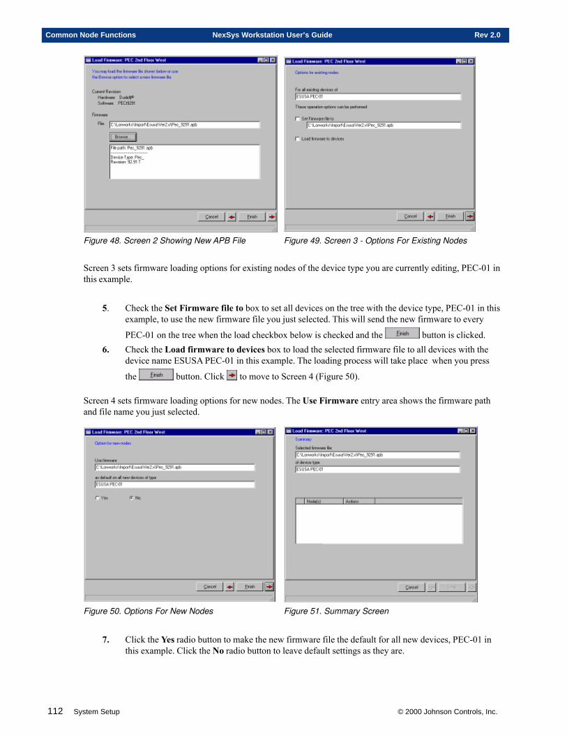
112 System Setup © 2000 Johnson Controls, Inc.
Common Node Functions NexSys Workstation User’s Guide Rev 2.0
Figure 48. Screen 2 Showing New APB File Figure 49. Screen 3 - Options For Existing Nodes
Screen 3 sets firmware loading options for existing nodes of the device type you are currently editing, PEC-01 inthis example.
5. Check the Set Firmware file to box to set all devices on the tree with the device type, PEC-01 in thisexample, to use the new firmware file you just selected. This will send the new firmware to every
PEC-01 on the tree when the load checkbox below is checked and the button is clicked.6. Check the Load firmware to devices box to load the selected firmware file to all devices with the
device name ESUSA PEC-01 in this example. The loading process will take place when you press
the button. Click to move to Screen 4 (Figure 50).
Screen 4 sets firmware loading options for new nodes. The Use Firmware entry area shows the firmware pathand file name you just selected.
Figure 50. Options For New Nodes Figure 51. Summary Screen
7. Click the Yes radio button to make the new firmware file the default for all new devices, PEC-01 inthis example. Click the No radio button to leave default settings as they are.
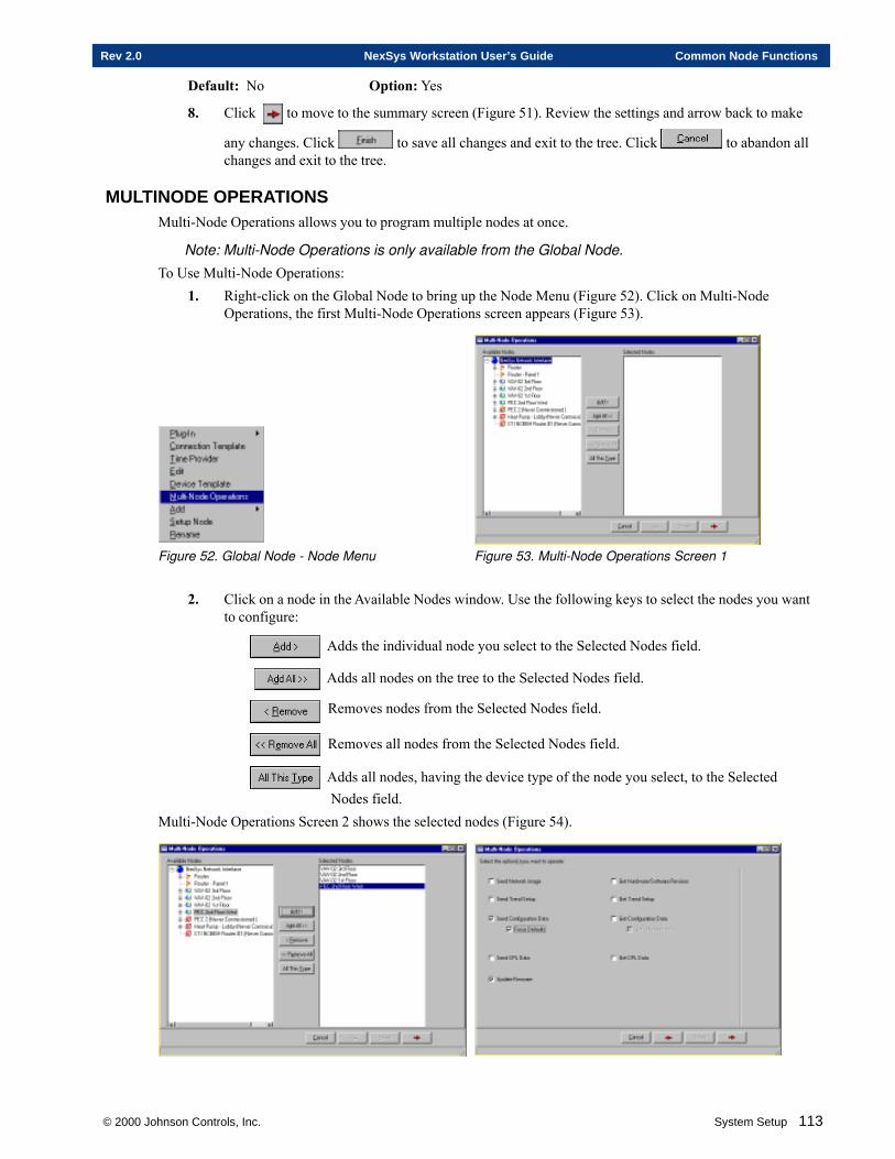
© 2000 Johnson Controls, Inc. System Setup 113
Rev 2.0 NexSys Workstation User’s Guide Common Node Functions
Default: No Option: Yes
8. Click to move to the summary screen (Figure 51). Review the settings and arrow back to make
any changes. Click to save all changes and exit to the tree. Click to abandon allchanges and exit to the tree.
MULTINODE OPERATIONSMulti-Node Operations allows you to program multiple nodes at once.
Note: Multi-Node Operations is only available from the Global Node.
To Use Multi-Node Operations:1. Right-click on the Global Node to bring up the Node Menu (Figure 52). Click on Multi-Node
Operations, the first Multi-Node Operations screen appears (Figure 53).
Figure 52. Global Node - Node Menu Figure 53. Multi-Node Operations Screen 1
2. Click on a node in the Available Nodes window. Use the following keys to select the nodes you wantto configure:
Adds the individual node you select to the Selected Nodes field.
Adds all nodes on the tree to the Selected Nodes field.
Removes nodes from the Selected Nodes field.
Removes all nodes from the Selected Nodes field.
Adds all nodes, having the device type of the node you select, to the Selected Nodes field.
Multi-Node Operations Screen 2 shows the selected nodes (Figure 54).
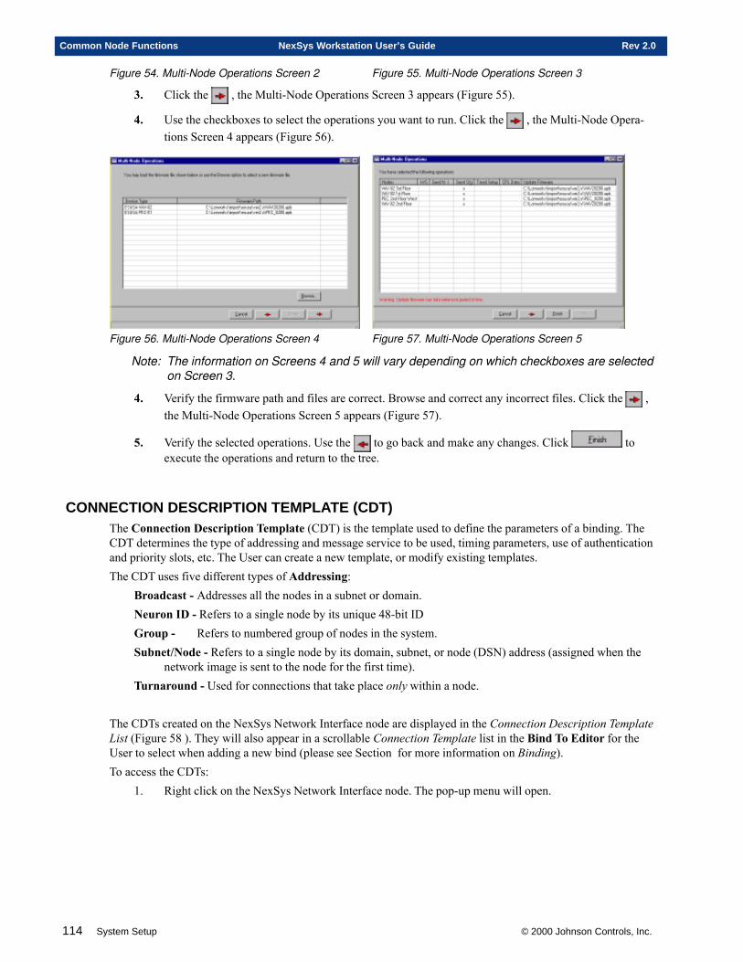
114 System Setup © 2000 Johnson Controls, Inc.
Common Node Functions NexSys Workstation User’s Guide Rev 2.0
Figure 54. Multi-Node Operations Screen 2 Figure 55. Multi-Node Operations Screen 3
3. Click the , the Multi-Node Operations Screen 3 appears (Figure 55).
4. Use the checkboxes to select the operations you want to run. Click the , the Multi-Node Opera-tions Screen 4 appears (Figure 56).
Figure 56. Multi-Node Operations Screen 4 Figure 57. Multi-Node Operations Screen 5
Note: The information on Screens 4 and 5 will vary depending on which checkboxes are selectedon Screen 3.
4. Verify the firmware path and files are correct. Browse and correct any incorrect files. Click the ,the Multi-Node Operations Screen 5 appears (Figure 57).
5. Verify the selected operations. Use the to go back and make any changes. Click toexecute the operations and return to the tree.
CONNECTION DESCRIPTION TEMPLATE (CDT)The Connection Description Template (CDT) is the template used to define the parameters of a binding. TheCDT determines the type of addressing and message service to be used, timing parameters, use of authenticationand priority slots, etc. The User can create a new template, or modify existing templates.The CDT uses five different types of Addressing:
Broadcast - Addresses all the nodes in a subnet or domain.Neuron ID - Refers to a single node by its unique 48-bit IDGroup - Refers to numbered group of nodes in the system.Subnet/Node - Refers to a single node by its domain, subnet, or node (DSN) address (assigned when the
network image is sent to the node for the first time).Turnaround - Used for connections that take place only within a node.
The CDTs created on the NexSys Network Interface node are displayed in the Connection Description TemplateList (Figure 58 ). They will also appear in a scrollable Connection Template list in the Bind To Editor for theUser to select when adding a new bind (please see Section for more information on Binding).To access the CDTs:
1. Right click on the NexSys Network Interface node. The pop-up menu will open.
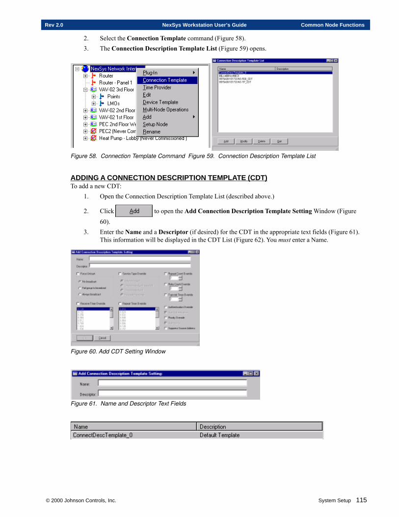
© 2000 Johnson Controls, Inc. System Setup 115
Rev 2.0 NexSys Workstation User’s Guide Common Node Functions
2. Select the Connection Template command (Figure 58).3. The Connection Description Template List (Figure 59) opens.
Figure 58. Connection Template Command Figure 59. Connection Description Template List
ADDING A CONNECTION DESCRIPTION TEMPLATE (CDT)To add a new CDT:
1. Open the Connection Description Template List (described above.)
2. Click to open the Add Connection Description Template Setting Window (Figure
60).3. Enter the Name and a Descriptor (if desired) for the CDT in the appropriate text fields (Figure 61).
This information will be displayed in the CDT List (Figure 62). You must enter a Name.
Figure 60. Add CDT Setting Window
Figure 61. Name and Descriptor Text Fields
116 System Setup © 2000 Johnson Controls, Inc.
Common Node Functions NexSys Workstation User’s Guide Rev 2.0
Figure 62. Name and Descriptor as displayed in the CDT List
4. Enter values for the following parameters:
Addressing:Force Unicast - Forces LNS to use DSN (domain/subnet/node) or NID (Neuron ID) addressing
where it would normally use group (or broadcast) addressing.No broadcast - Tells LNS to fail if there is no other way to address the message besides broadcast.Fail group to broadcast - Tells LNS to use broadcast addressing if it has trouble using group
addressing.Always broadcast - Tells LNS to always use broadcast addressing.
Service Types:Service Type Override - Tells LNS that you will choose the service type explicitly rather than
allowing LNS to determine it.Acknowledged - The message is sent out and acknowledged by the receiver (not to be used for large
group bindings causing failure to received Acknowledge messages.Unacknowledged repeated - The message is sent out many times to ensure the probability of it
reaching its destination.Unacknowledged - The message is sent out once.Request Response - Used only for out-and-back messages (e.g.,. NV polls), not used for binds.
Timing Parameters:Repeat Count Override - Enter a value for the number of times LNS should repeat an unacknowl-edged-repeated message.Retry Count Override - Enter a value for the number of times LNS should retry an acknowledged
message if it does not receive an acknowledgment in time.Transmit Timer Override - Enter a value for the interval rate LNS waits between retries of
acknowledged and request/response messages.Receive Timer Override - Select a value that tells LNS the time period within which receiving
devices will treat messages from the same source with the same reference ID asduplicate messages. Repeats of messages using the above service types all use thesame reference ID as the original to identify them as duplicates.
Repeat Timer Override - Select a value for the interval LNS waits between repeats for unacknowl-edged-repeated messages.
Other:Authentication Override - Manually overrides control of the LNS message Authentication option.Use Authentication - Turns the message Authentication option on, telling NexSys to begin sendingand receiving authentication packets for messages on the network.Priority Override - Manually overrides control of the LNS message Priority Override option.Use Priority - Tells LNS that the binding should use a reserved time slot on the network,
helping the message to arrive more quickly to its destination.
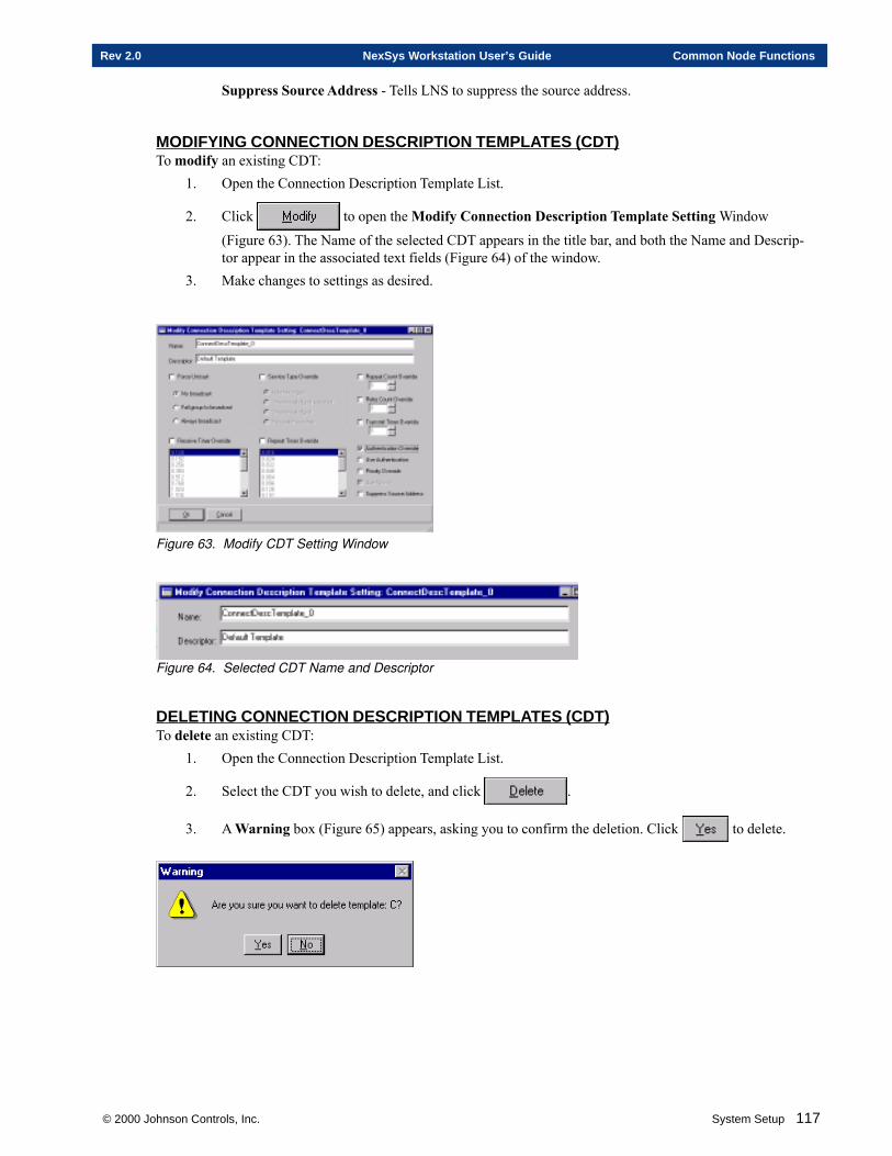
© 2000 Johnson Controls, Inc. System Setup 117
Rev 2.0 NexSys Workstation User’s Guide Common Node Functions
Suppress Source Address - Tells LNS to suppress the source address.
MODIFYING CONNECTION DESCRIPTION TEMPLATES (CDT)To modify an existing CDT:
1. Open the Connection Description Template List.
2. Click to open the Modify Connection Description Template Setting Window
(Figure 63). The Name of the selected CDT appears in the title bar, and both the Name and Descrip-tor appear in the associated text fields (Figure 64) of the window.
3. Make changes to settings as desired.
Figure 63. Modify CDT Setting Window
Figure 64. Selected CDT Name and Descriptor
DELETING CONNECTION DESCRIPTION TEMPLATES (CDT)To delete an existing CDT:
1. Open the Connection Description Template List.
2. Select the CDT you wish to delete, and click .
3. A Warning box (Figure 65) appears, asking you to confirm the deletion. Click to delete.

118 System Setup © 2000 Johnson Controls, Inc.
Common Node Functions NexSys Workstation User’s Guide Rev 2.0
Figure 65. Delete CDT Warning Box
NODE CONFIGURATION WIZARDThe Node Configuration Wizard uses a series of editor screens to configure a device. Each device type has adifferent editor to address the device’s specific configuration. See the configuration wizards for each device inthe following System Setup sections. You are currently in Section 2 of System Setup.Section 4 - FSC/FLCSection 5 - VAVSection 6 - Heat PumpSection 7 - PEC
Chapter Two
Setting Up a Router
This chapter contains information on:
� Adding a Router
� Setting up a Router
� Adding Nodes To A Router
© 2000 Johnson Controls, Inc.
120 System Setup ©2000 Johnson Controls, Inc.
Setting Up a Router NexSys Workstation User’s Guide Rev 2.0
OVERVIEWThis guide is intended for someone familiar with routers, TCP/IP and LONWORKS networks. If you are unfamiliarwith any of these please refer to the:1. Network Basics book for information on TCP/IP, Router Specifications, and NexSys Networks.2. Installation and Startup section of this manual for information on setting up TCP/IP.3. Network Wiring Specifications book for information on LONWORKS network wiring.
Before you begin you should know:1. Router classification type - How will this router be used?2. Transceiver type of the router you want to install.3. A descriptive name for the router that designates a specific location.4. The Neuron ID of the router should you choose not to use the service pin method.5. Do you need a “plug-in”? A plug-in is a software configuration file that may be required for some routers.NexSys provides plug-ins for several common routers. Confirm that the plug-in for the router you are installingis provided by NexSys. If not you must have the plug-in file provided by the router manufacturer.
The steps to add a router are listed below:1. Add the router to the physical tree. This is known as Defining.2. Setup the router. This is known as Commissioning.3. Add nodes to the router.4. Setup the nodes on the router.
ROUTER CLASSIFICATION TYPESNexSys supports six different router classification types using one of four LONWORKS routing algorithms. Duringthe router installation process you must choose a classification type from the list shown below:
1. Configured Router - A configured router forwards only messages received on either of the router’sdomains. A forwarding table at each end is used for each domain.
2. Learning Router - A learning router forwards only messages that have met specific forwarding rules.The messages are received on either of the router’s domains. Installation is simplified since networktopology information is not required to configure the learning router.
3. Repeater Router - A repeater router forwards all valid messages, in both directions, regardless of thedestination or domain of the message.
Permanent Repeater Router - A permanent repeater router is a repeater router that, once configured,cannot be readily reconfigured as a standard repeater. It must be deleted, along with all its associatednodes, and then reinstalled as a standard repeater router.
4. Bridge Router - A bridge router forwards all messages received on either of the router’s domainsregardless of the message’s domain. Bridges are typically used to span one or two domains.
Permanent Bridge Router - A permanent bridge router is a bridge router that, once configured, cannotbe readily reconfigured as a standard bridge router. It must be deleted, along with all its associatednodes, and then reinstalled as a standard bridge router.
You will need to know the classification type when you install a router.
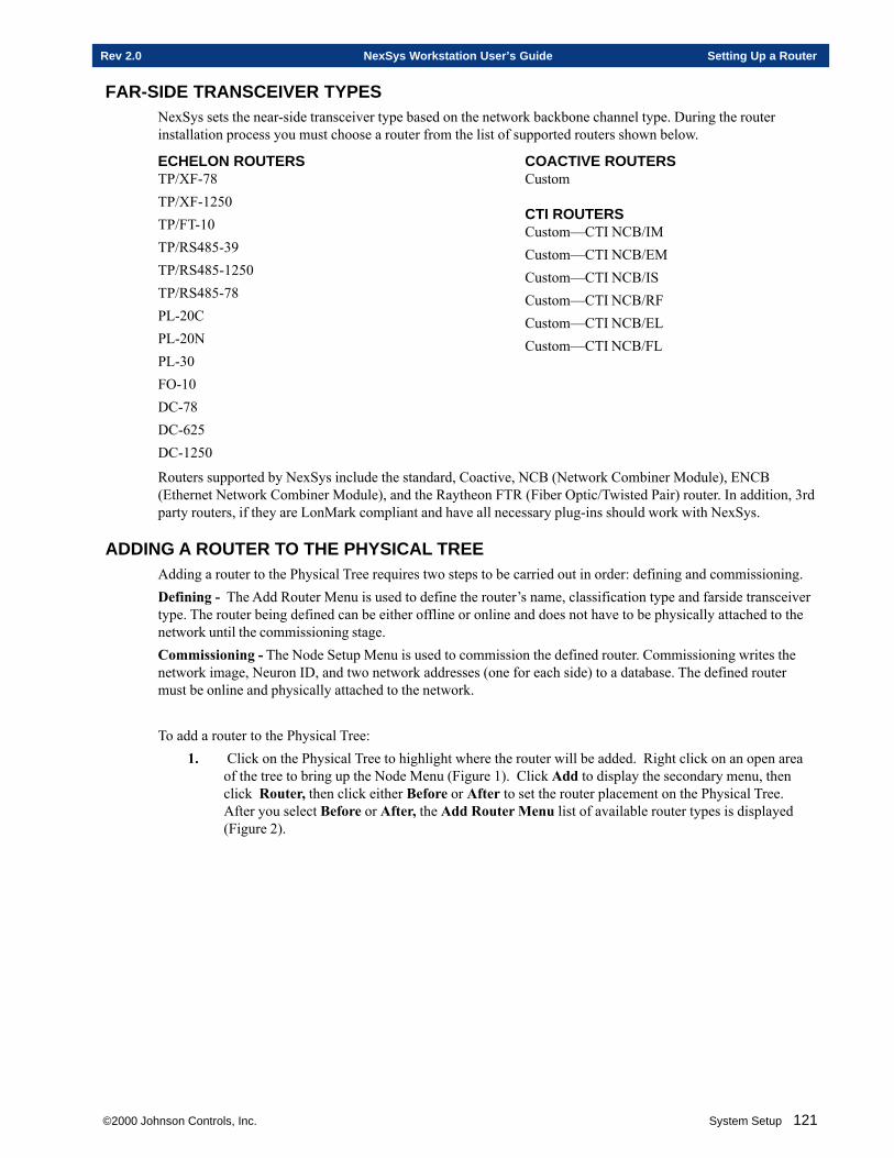
©2000 Johnson Controls, Inc. System Setup 121
Rev 2.0 NexSys Workstation User’s Guide Setting Up a Router
FAR-SIDE TRANSCEIVER TYPESNexSys sets the near-side transceiver type based on the network backbone channel type. During the routerinstallation process you must choose a router from the list of supported routers shown below.
COACTIVE ROUTERSCustom
CTI ROUTERSCustom—CTI NCB/IMCustom—CTI NCB/EMCustom—CTI NCB/ISCustom—CTI NCB/RFCustom—CTI NCB/ELCustom—CTI NCB/FL
Routers supported by NexSys include the standard, Coactive, NCB (Network Combiner Module), ENCB(Ethernet Network Combiner Module), and the Raytheon FTR (Fiber Optic/Twisted Pair) router. In addition, 3rdparty routers, if they are LonMark compliant and have all necessary plug-ins should work with NexSys.
ADDING A ROUTER TO THE PHYSICAL TREEAdding a router to the Physical Tree requires two steps to be carried out in order: defining and commissioning.Defining - The Add Router Menu is used to define the router’s name, classification type and farside transceivertype. The router being defined can be either offline or online and does not have to be physically attached to thenetwork until the commissioning stage.Commissioning - The Node Setup Menu is used to commission the defined router. Commissioning writes thenetwork image, Neuron ID, and two network addresses (one for each side) to a database. The defined routermust be online and physically attached to the network.
To add a router to the Physical Tree:1. Click on the Physical Tree to highlight where the router will be added. Right click on an open area
of the tree to bring up the Node Menu (Figure 1). Click Add to display the secondary menu, thenclick Router, then click either Before or After to set the router placement on the Physical Tree.After you select Before or After, the Add Router Menu list of available router types is displayed(Figure 2).
ECHELON ROUTERSTP/XF-78TP/XF-1250TP/FT-10TP/RS485-39TP/RS485-1250TP/RS485-78PL-20CPL-20NPL-30FO-10DC-78DC-625DC-1250
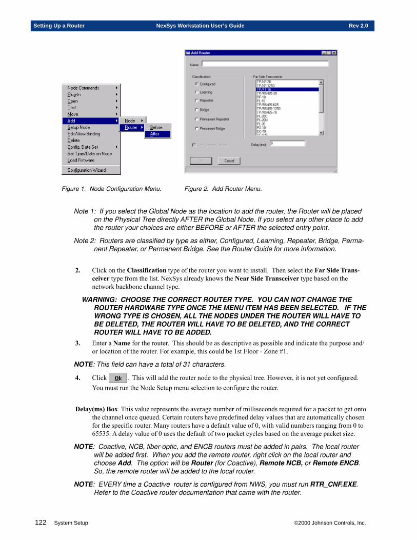
122 System Setup ©2000 Johnson Controls, Inc.
Setting Up a Router NexSys Workstation User’s Guide Rev 2.0
Figure 1. Node Configuration Menu. Figure 2. Add Router Menu.
Note 1: If you select the Global Node as the location to add the router, the Router will be placedon the Physical Tree directly AFTER the Global Node. If you select any other place to addthe router your choices are either BEFORE or AFTER the selected entry point.
Note 2: Routers are classified by type as either, Configured, Learning, Repeater, Bridge, Perma-nent Repeater, or Permanent Bridge. See the Router Guide for more information.
2. Click on the Classification type of the router you want to install. Then select the Far Side Trans-ceiver type from the list. NexSys already knows the Near Side Transceiver type based on thenetwork backbone channel type.
WARNING: CHOOSE THE CORRECT ROUTER TYPE. YOU CAN NOT CHANGE THEROUTER HARDWARE TYPE ONCE THE MENU ITEM HAS BEEN SELECTED. IF THEWRONG TYPE IS CHOSEN, ALL THE NODES UNDER THE ROUTER WILL HAVE TOBE DELETED, THE ROUTER WILL HAVE TO BE DELETED, AND THE CORRECTROUTER WILL HAVE TO BE ADDED.
3. Enter a Name for the router. This should be as descriptive as possible and indicate the purpose and/or location of the router. For example, this could be 1st Floor - Zone #1.
NOTE: This field can have a total of 31 characters.
4. Click . This will add the router node to the physical tree. However, it is not yet configured.You must run the Node Setup menu selection to configure the router.
Delay(ms) Box This value represents the average number of milliseconds required for a packet to get onto the channel once queued. Certain routers have predefined delay values that are automatically chosenfor the specific router. Many routers have a default value of 0, with valid numbers ranging from 0 to65535. A delay value of 0 uses the default of two packet cycles based on the average packet size.
NOTE: Coactive, NCB, fiber-optic, and ENCB routers must be added in pairs. The local routerwill be added first. When you add the remote router, right click on the local router andchoose Add. The option will be Router (for Coactive), Remote NCB, or Remote ENCB.So, the remote router will be added to the local router.
NOTE: EVERY time a Coactive router is configured from NWS, you must run RTR_CNF.EXE.Refer to the Coactive router documentation that came with the router.
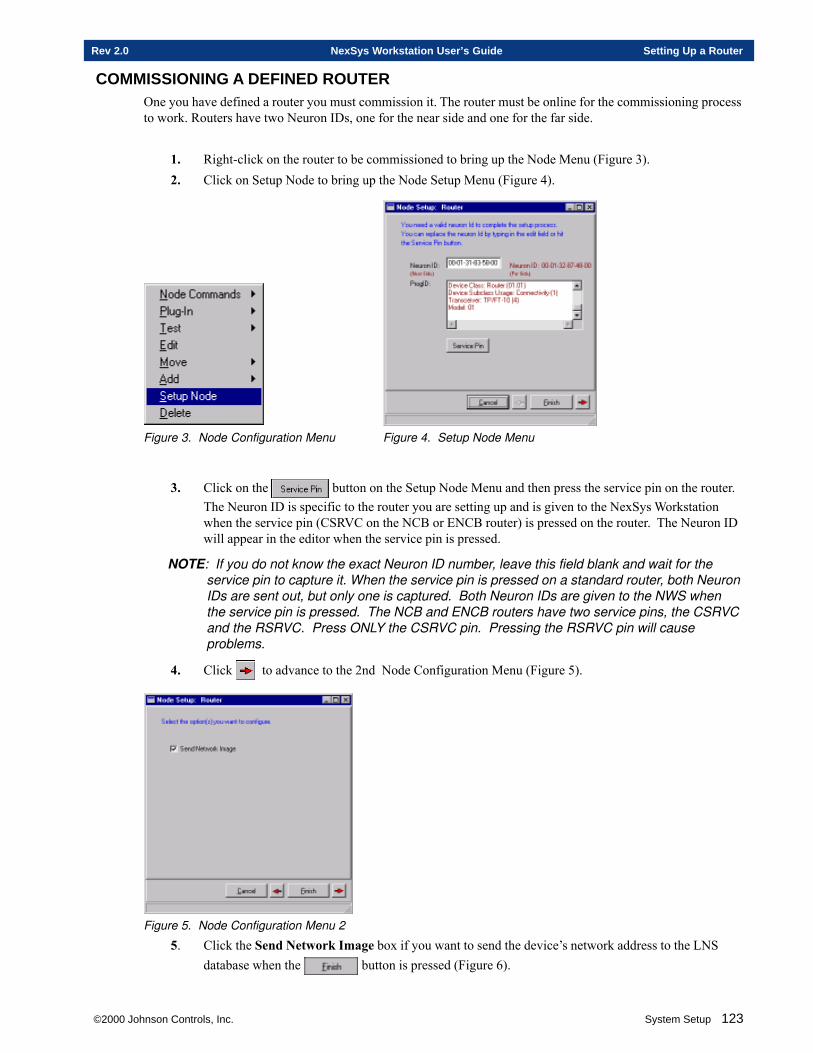
©2000 Johnson Controls, Inc. System Setup 123
Rev 2.0 NexSys Workstation User’s Guide Setting Up a Router
COMMISSIONING A DEFINED ROUTEROne you have defined a router you must commission it. The router must be online for the commissioning processto work. Routers have two Neuron IDs, one for the near side and one for the far side.
1. Right-click on the router to be commissioned to bring up the Node Menu (Figure 3).2. Click on Setup Node to bring up the Node Setup Menu (Figure 4).
Figure 3. Node Configuration Menu Figure 4. Setup Node Menu
3. Click on the button on the Setup Node Menu and then press the service pin on the router.The Neuron ID is specific to the router you are setting up and is given to the NexSys Workstationwhen the service pin (CSRVC on the NCB or ENCB router) is pressed on the router. The Neuron IDwill appear in the editor when the service pin is pressed.
NOTE: If you do not know the exact Neuron ID number, leave this field blank and wait for theservice pin to capture it. When the service pin is pressed on a standard router, both NeuronIDs are sent out, but only one is captured. Both Neuron IDs are given to the NWS whenthe service pin is pressed. The NCB and ENCB routers have two service pins, the CSRVCand the RSRVC. Press ONLY the CSRVC pin. Pressing the RSRVC pin will causeproblems.
4. Click to advance to the 2nd Node Configuration Menu (Figure 5).
Figure 5. Node Configuration Menu 2
5. Click the Send Network Image box if you want to send the device’s network address to the LNSdatabase when the button is pressed (Figure 6).
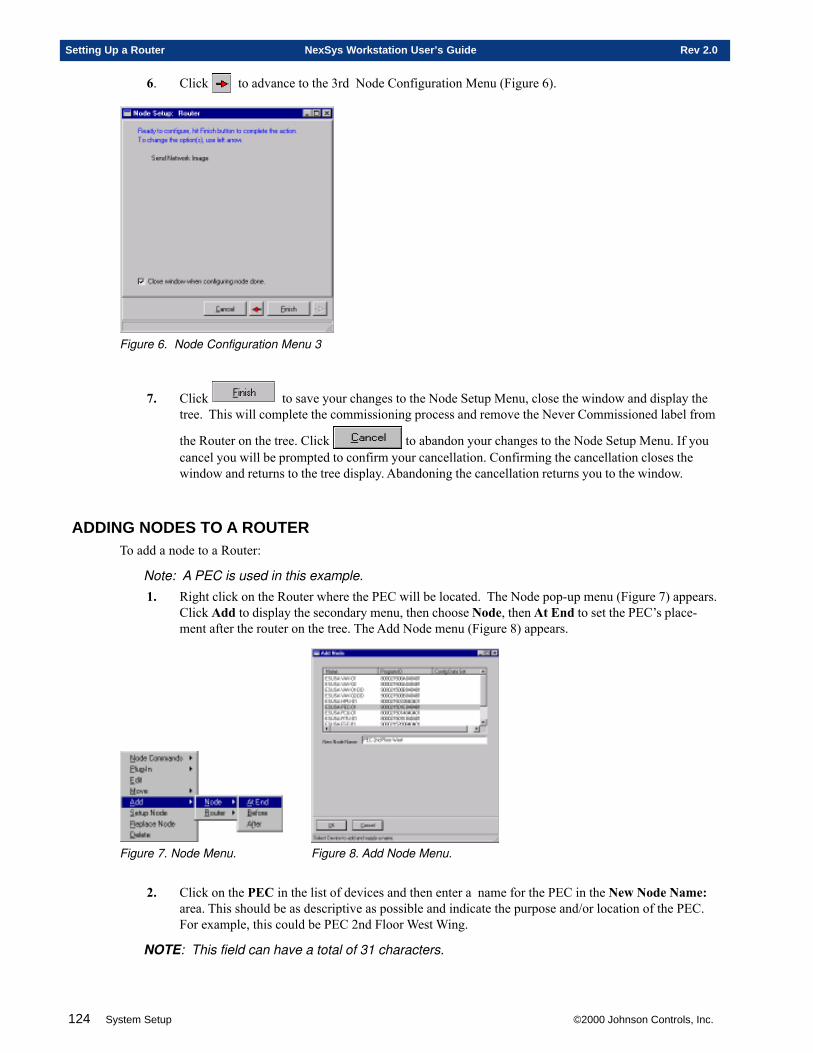
124 System Setup ©2000 Johnson Controls, Inc.
Setting Up a Router NexSys Workstation User’s Guide Rev 2.0
6. Click to advance to the 3rd Node Configuration Menu (Figure 6).
Figure 6. Node Configuration Menu 3
7. Click to save your changes to the Node Setup Menu, close the window and display thetree. This will complete the commissioning process and remove the Never Commissioned label from
the Router on the tree. Click to abandon your changes to the Node Setup Menu. If youcancel you will be prompted to confirm your cancellation. Confirming the cancellation closes thewindow and returns to the tree display. Abandoning the cancellation returns you to the window.
ADDING NODES TO A ROUTERTo add a node to a Router:
Note: A PEC is used in this example.
1. Right click on the Router where the PEC will be located. The Node pop-up menu (Figure 7) appears.Click Add to display the secondary menu, then choose Node, then At End to set the PEC’s place-ment after the router on the tree. The Add Node menu (Figure 8) appears.
Figure 7. Node Menu. Figure 8. Add Node Menu.
2. Click on the PEC in the list of devices and then enter a name for the PEC in the New Node Name:area. This should be as descriptive as possible and indicate the purpose and/or location of the PEC.For example, this could be PEC 2nd Floor West Wing.
NOTE: This field can have a total of 31 characters.
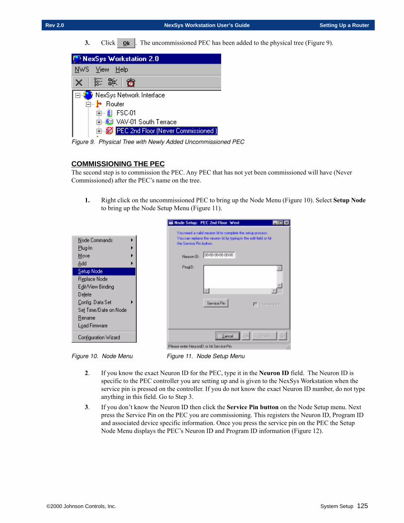
©2000 Johnson Controls, Inc. System Setup 125
Rev 2.0 NexSys Workstation User’s Guide Setting Up a Router
3. Click . The uncommissioned PEC has been added to the physical tree (Figure 9).
Figure 9. Physical Tree with Newly Added Uncommissioned PEC
COMMISSIONING THE PECThe second step is to commission the PEC. Any PEC that has not yet been commissioned will have (NeverCommissioned) after the PEC’s name on the tree.
1. Right click on the uncommissioned PEC to bring up the Node Menu (Figure 10). Select Setup Nodeto bring up the Node Setup Menu (Figure 11).
Figure 10. Node Menu Figure 11. Node Setup Menu
2. If you know the exact Neuron ID for the PEC, type it in the Neuron ID field. The Neuron ID isspecific to the PEC controller you are setting up and is given to the NexSys Workstation when theservice pin is pressed on the controller. If you do not know the exact Neuron ID number, do not typeanything in this field. Go to Step 3.
3. If you don’t know the Neuron ID then click the Service Pin button on the Node Setup menu. Nextpress the Service Pin on the PEC you are commissioning. This registers the Neuron ID, Program IDand associated device specific information. Once you press the service pin on the PEC the SetupNode Menu displays the PEC’s Neuron ID and Program ID information (Figure 12).
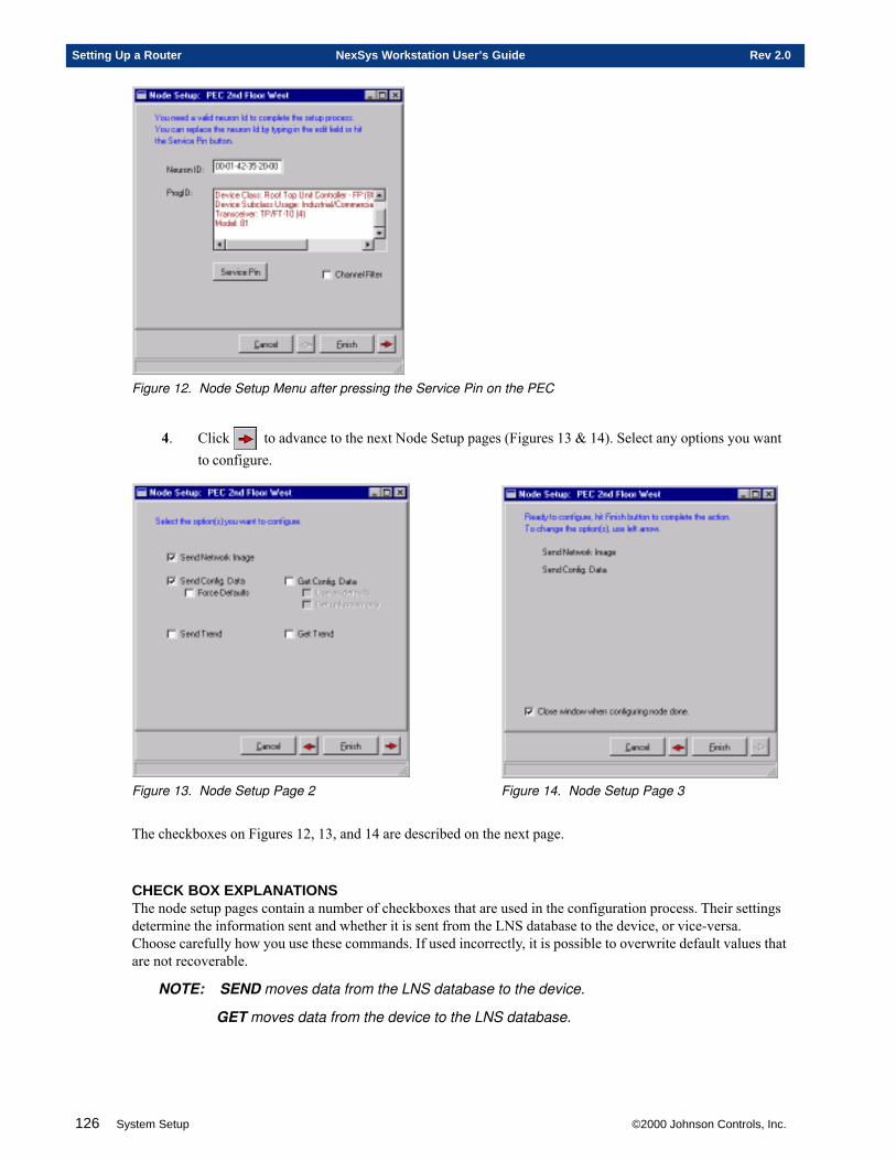
126 System Setup ©2000 Johnson Controls, Inc.
Setting Up a Router NexSys Workstation User’s Guide Rev 2.0
Figure 12. Node Setup Menu after pressing the Service Pin on the PEC
4. Click to advance to the next Node Setup pages (Figures 13 & 14). Select any options you wantto configure.
Figure 13. Node Setup Page 2 Figure 14. Node Setup Page 3
The checkboxes on Figures 12, 13, and 14 are described on the next page.
CHECK BOX EXPLANATIONSThe node setup pages contain a number of checkboxes that are used in the configuration process. Their settingsdetermine the information sent and whether it is sent from the LNS database to the device, or vice-versa.Choose carefully how you use these commands. If used incorrectly, it is possible to overwrite default values thatare not recoverable.
NOTE: SEND moves data from the LNS database to the device.
GET moves data from the device to the LNS database.
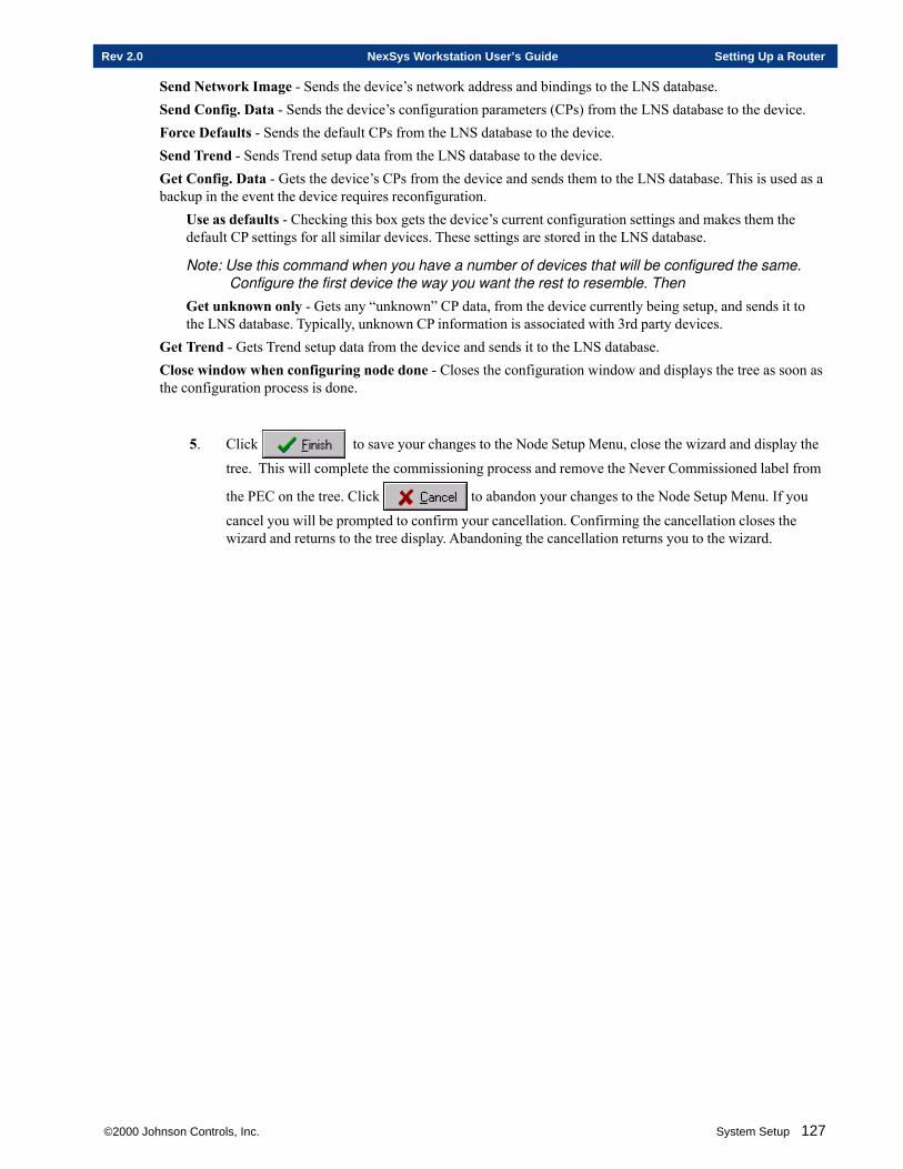
©2000 Johnson Controls, Inc. System Setup 127
Rev 2.0 NexSys Workstation User’s Guide Setting Up a Router
Send Network Image - Sends the device’s network address and bindings to the LNS database.Send Config. Data - Sends the device’s configuration parameters (CPs) from the LNS database to the device.Force Defaults - Sends the default CPs from the LNS database to the device.Send Trend - Sends Trend setup data from the LNS database to the device.Get Config. Data - Gets the device’s CPs from the device and sends them to the LNS database. This is used as abackup in the event the device requires reconfiguration.
Use as defaults - Checking this box gets the device’s current configuration settings and makes them thedefault CP settings for all similar devices. These settings are stored in the LNS database.
Note: Use this command when you have a number of devices that will be configured the same.Configure the first device the way you want the rest to resemble. Then
Get unknown only - Gets any “unknown” CP data, from the device currently being setup, and sends it tothe LNS database. Typically, unknown CP information is associated with 3rd party devices.
Get Trend - Gets Trend setup data from the device and sends it to the LNS database.Close window when configuring node done - Closes the configuration window and displays the tree as soon asthe configuration process is done.
5. Click to save your changes to the Node Setup Menu, close the wizard and display the
tree. This will complete the commissioning process and remove the Never Commissioned label from
the PEC on the tree. Click to abandon your changes to the Node Setup Menu. If you
cancel you will be prompted to confirm your cancellation. Confirming the cancellation closes thewizard and returns to the tree display. Abandoning the cancellation returns you to the wizard.

128 System Setup ©2000 Johnson Controls, Inc.
Setting Up a Router NexSys Workstation User’s Guide Rev 2.0

Chapter Three
Setting Up an FSC/FLC
This chapter contain information on:
� Adding an FSC or FLC
� Setting up an FSC or FLC
� Setting the Time on an FSC
� Adding I/O Modules to an FSC
© 2000 Johnson Controls, Inc.
130 System Setup © 2000 Johnson Controls, Inc.
Setting Up an FSC/FLC NexSys Workstation User’s Guide Rev 2.0
SETTING UP AN FSC/FLC
FSC OVERVIEWThe Flexible System Controllers (FSC) are microprocessor based controllers that work in conjunction with otherFSCs and all Application Specific Controllers (ASCs) in the NexSys family product line. The FSCs providecomplete flexibility and are user defined. The FSCs can be set up for many purposes. For example, they can beused to:· Control an HVAC unit that requires more inputs and outputs than are available on an ASC· Provide the time for an entire system· Run custom programs· To determine occupancy for an ASC
The FSC Editor allows you to add 17 point types to the FSC and then program the FSC for your needs. Theprograming is done through CPL (Control Programing Language) and gives you the flexibility to program theFSC to perform the tasks that are specific to your system.The FSC-01 allows up to eight I/O modules. The FSC-02 allows four I/O modules. The setup of both FSCs willbe discussed in this chapter.
FLC OVERVIEWThe Flexible Lighting Controller (FLC) is a microprocessor based controller that works in conjunction withother FLCs, FSCs, and all Application Specific Controllers (ASCs) in the NexSys family product line. The FLCuses the same CPU and programming as the FSC, but has a specific expansion module designed for lightingcontrol. The Lighting Control Module (LCM), formerly known as the 8 Triac/4 Digital Input expansion module,is designed for use with 4 G.E. RR7 or RR9 lighting relays. The other expansion modules (8 UI, 4 DO/4 AO, and8 DO) can be used in conjunction with the lighting expansion module for additional HVAC and lighting controlsequences. The FLC provides complete flexibility and is user defined. The FLC supports lighting controlapplications such as:· Time of day scheduling· Remote tenant override· Wink notification before lighting turn-off· Zoning of lighting relays· Use of motion detectors or photocells
The FLC is setup through the FSC Editor which allows you to add 17 point types to the FLC and then programthe FLC for your needs. The programing is done through CPL (Control Programing Language) and gives you theflexibility to program the FLC to perform the tasks which are specific to your system.
ADDING AN FSC OR FLC TO THE PHYSICAL TREEAdding an FSC/FLC to the Physical Tree requires three steps to be carried out in order. These three steps areDefining, Commissioning, and Configuring.Defining - The Add Node Menu is used to install the FSC/FLC on the tree, define the FSC/FLC’s name andProgram ID. The FSC/FLC being defined can be either off-line or on-line and does not have to be physicallyattached to the network until the commissioning stage. You can define multiple devices and then commissionthem all at once.Commissioning - The Node Setup Menu is used to commission the defined FSC/FLC. Commissioning writesthe network image, Neuron ID, and Program ID to a database. The defined FSC/FLC must be on-line andphysically attached to the network for the commissioning process to work.Configuring - The FSC/FLC Wizard is the editor used to configure a commissioned FSC/FLC. The wizardworks at the panel level to assign basic configuration settings and customize the FSC/FLC to your requirements.
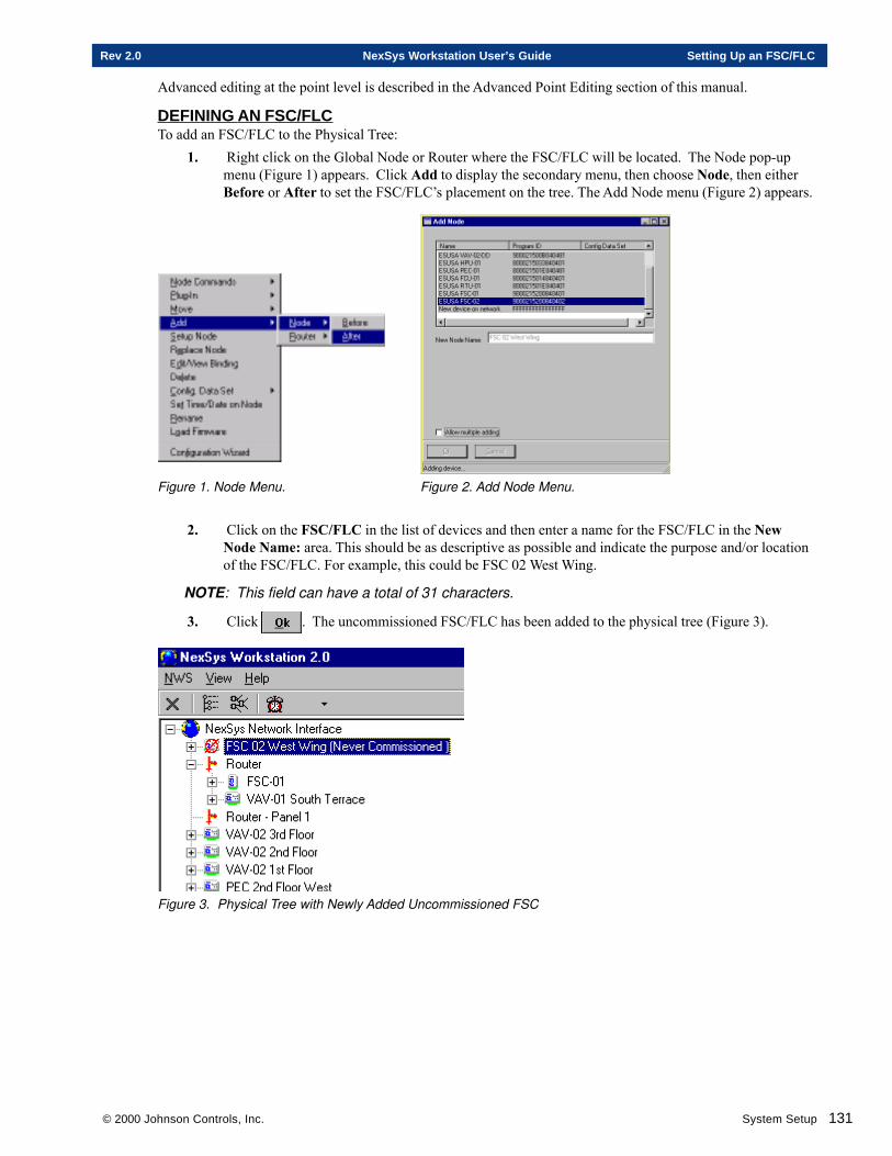
© 2000 Johnson Controls, Inc. System Setup 131
Rev 2.0 NexSys Workstation User’s Guide Setting Up an FSC/FLC
Advanced editing at the point level is described in the Advanced Point Editing section of this manual.
DEFINING AN FSC/FLCTo add an FSC/FLC to the Physical Tree:
1. Right click on the Global Node or Router where the FSC/FLC will be located. The Node pop-upmenu (Figure 1) appears. Click Add to display the secondary menu, then choose Node, then eitherBefore or After to set the FSC/FLC’s placement on the tree. The Add Node menu (Figure 2) appears.
Figure 1. Node Menu. Figure 2. Add Node Menu.
2. Click on the FSC/FLC in the list of devices and then enter a name for the FSC/FLC in the NewNode Name: area. This should be as descriptive as possible and indicate the purpose and/or locationof the FSC/FLC. For example, this could be FSC 02 West Wing.
NOTE: This field can have a total of 31 characters.
3. Click . The uncommissioned FSC/FLC has been added to the physical tree (Figure 3).
Figure 3. Physical Tree with Newly Added Uncommissioned FSC
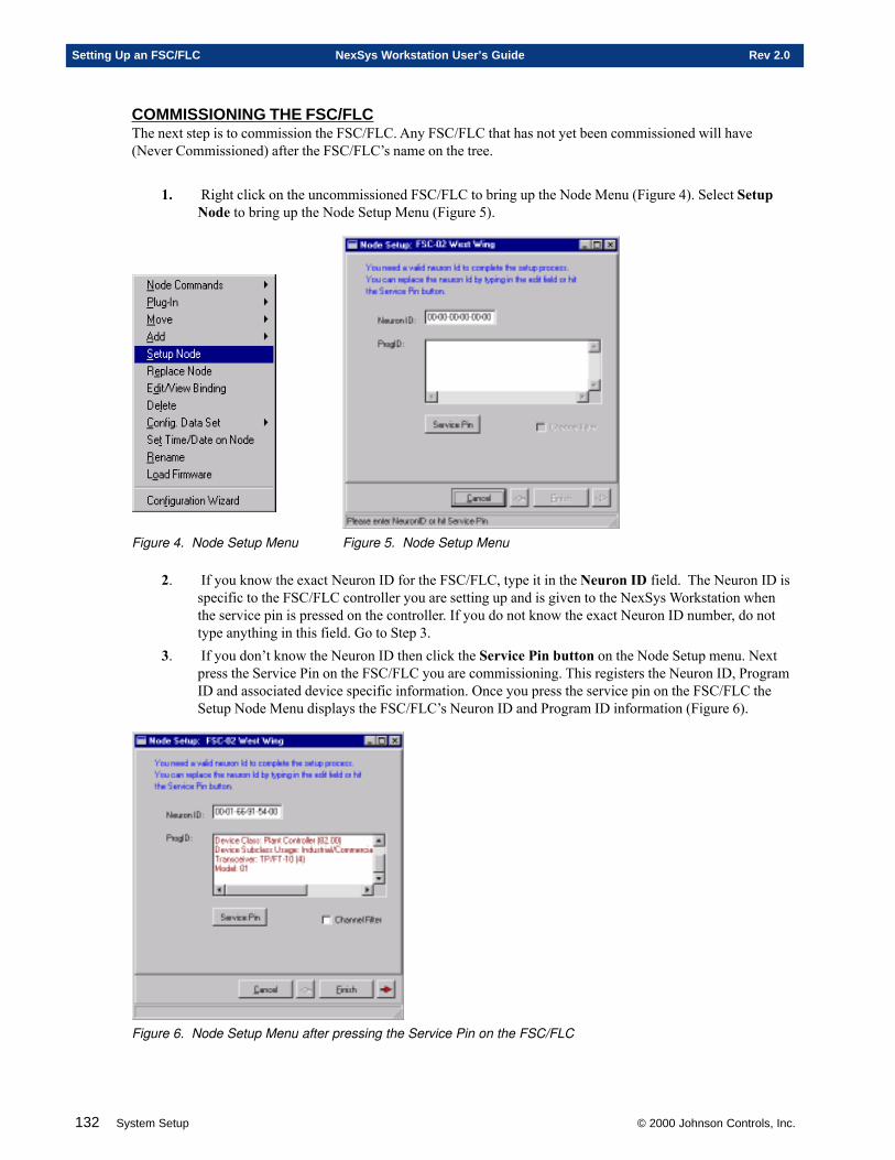
132 System Setup © 2000 Johnson Controls, Inc.
Setting Up an FSC/FLC NexSys Workstation User’s Guide Rev 2.0
COMMISSIONING THE FSC/FLCThe next step is to commission the FSC/FLC. Any FSC/FLC that has not yet been commissioned will have(Never Commissioned) after the FSC/FLC’s name on the tree.
1. Right click on the uncommissioned FSC/FLC to bring up the Node Menu (Figure 4). Select SetupNode to bring up the Node Setup Menu (Figure 5).
Figure 4. Node Setup Menu Figure 5. Node Setup Menu
2. If you know the exact Neuron ID for the FSC/FLC, type it in the Neuron ID field. The Neuron ID isspecific to the FSC/FLC controller you are setting up and is given to the NexSys Workstation whenthe service pin is pressed on the controller. If you do not know the exact Neuron ID number, do nottype anything in this field. Go to Step 3.
3. If you don’t know the Neuron ID then click the Service Pin button on the Node Setup menu. Nextpress the Service Pin on the FSC/FLC you are commissioning. This registers the Neuron ID, ProgramID and associated device specific information. Once you press the service pin on the FSC/FLC theSetup Node Menu displays the FSC/FLC’s Neuron ID and Program ID information (Figure 6).
Figure 6. Node Setup Menu after pressing the Service Pin on the FSC/FLC
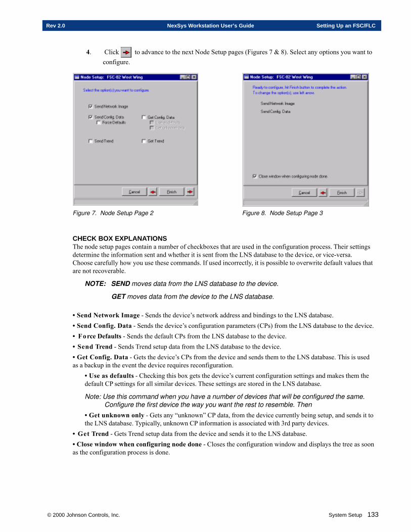
© 2000 Johnson Controls, Inc. System Setup 133
Rev 2.0 NexSys Workstation User’s Guide Setting Up an FSC/FLC
4. Click to advance to the next Node Setup pages (Figures 7 & 8). Select any options you want toconfigure.
Figure 7. Node Setup Page 2 Figure 8. Node Setup Page 3
CHECK BOX EXPLANATIONSThe node setup pages contain a number of checkboxes that are used in the configuration process. Their settingsdetermine the information sent and whether it is sent from the LNS database to the device, or vice-versa.Choose carefully how you use these commands. If used incorrectly, it is possible to overwrite default values thatare not recoverable.
NOTE: SEND moves data from the LNS database to the device.
GET moves data from the device to the LNS database.
• Send Network Image - Sends the device’s network address and bindings to the LNS database.• Send Config. Data - Sends the device’s configuration parameters (CPs) from the LNS database to the device.• Force Defaults - Sends the default CPs from the LNS database to the device.• Send Trend - Sends Trend setup data from the LNS database to the device.• Get Config. Data - Gets the device’s CPs from the device and sends them to the LNS database. This is usedas a backup in the event the device requires reconfiguration.
• Use as defaults - Checking this box gets the device’s current configuration settings and makes them thedefault CP settings for all similar devices. These settings are stored in the LNS database.
Note: Use this command when you have a number of devices that will be configured the same.Configure the first device the way you want the rest to resemble. Then
• Get unknown only - Gets any “unknown” CP data, from the device currently being setup, and sends it tothe LNS database. Typically, unknown CP information is associated with 3rd party devices.
• Get Trend - Gets Trend setup data from the device and sends it to the LNS database.• Close window when configuring node done - Closes the configuration window and displays the tree as soonas the configuration process is done.
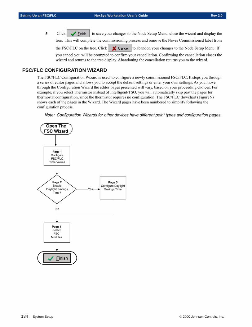
134 System Setup © 2000 Johnson Controls, Inc.
Setting Up an FSC/FLC NexSys Workstation User’s Guide Rev 2.0
5. Click to save your changes to the Node Setup Menu, close the wizard and display the
tree. This will complete the commissioning process and remove the Never Commissioned label from
the FSC/FLC on the tree. Click to abandon your changes to the Node Setup Menu. If
you cancel you will be prompted to confirm your cancellation. Confirming the cancellation closes thewizard and returns to the tree display. Abandoning the cancellation returns you to the wizard.
FSC/FLC CONFIGURATION WIZARDThe FSC/FLC Configuration Wizard is used to configure a newly commissioned FSC/FLC. It steps you througha series of editor pages and allows you to accept the default settings or enter your own settings. As you movethrough the Configuration Wizard the editor pages presented will vary, based on your proceeding choices. Forexample, if you select Thermistor instead of Intelligent/TSO, you will automatically skip past the pages forthermostat configuration, since the thermistor requires no configuration. The FSC/FLC flowchart (Figure 9)shows each of the pages in the Wizard. The Wizard pages have been numbered to simplify following theconfiguration process.
Note: Configuration Wizards for other devices have different point types and configuration pages.
�12��� ���������� ���
�����������
�12��/��� ��
!�"���#$���%��������&
'��
�12��. ���������!�"���#$��%���������
�3� �+4�*����51��
����
�12��#����($��
)�*����
+�
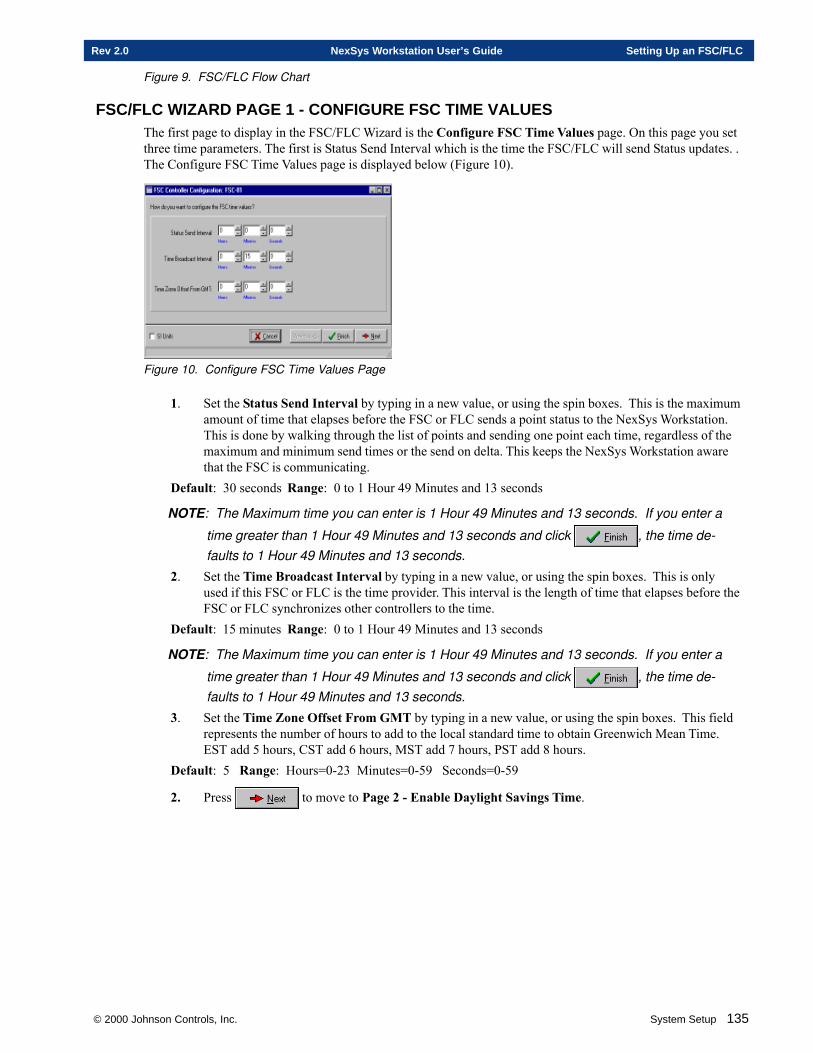
© 2000 Johnson Controls, Inc. System Setup 135
Rev 2.0 NexSys Workstation User’s Guide Setting Up an FSC/FLC
Figure 9. FSC/FLC Flow Chart
FSC/FLC WIZARD PAGE 1 - CONFIGURE FSC TIME VALUESThe first page to display in the FSC/FLC Wizard is the Configure FSC Time Values page. On this page you setthree time parameters. The first is Status Send Interval which is the time the FSC/FLC will send Status updates. .The Configure FSC Time Values page is displayed below (Figure 10).
Figure 10. Configure FSC Time Values Page
1. Set the Status Send Interval by typing in a new value, or using the spin boxes. This is the maximumamount of time that elapses before the FSC or FLC sends a point status to the NexSys Workstation.This is done by walking through the list of points and sending one point each time, regardless of themaximum and minimum send times or the send on delta. This keeps the NexSys Workstation awarethat the FSC is communicating.
Default: 30 seconds Range: 0 to 1 Hour 49 Minutes and 13 seconds
NOTE: The Maximum time you can enter is 1 Hour 49 Minutes and 13 seconds. If you enter a
time greater than 1 Hour 49 Minutes and 13 seconds and click , the time de-faults to 1 Hour 49 Minutes and 13 seconds.
2. Set the Time Broadcast Interval by typing in a new value, or using the spin boxes. This is onlyused if this FSC or FLC is the time provider. This interval is the length of time that elapses before theFSC or FLC synchronizes other controllers to the time.
Default: 15 minutes Range: 0 to 1 Hour 49 Minutes and 13 seconds
NOTE: The Maximum time you can enter is 1 Hour 49 Minutes and 13 seconds. If you enter a
time greater than 1 Hour 49 Minutes and 13 seconds and click , the time de-faults to 1 Hour 49 Minutes and 13 seconds.
3. Set the Time Zone Offset From GMT by typing in a new value, or using the spin boxes. This fieldrepresents the number of hours to add to the local standard time to obtain Greenwich Mean Time.EST add 5 hours, CST add 6 hours, MST add 7 hours, PST add 8 hours.
Default: 5 Range: Hours=0-23 Minutes=0-59 Seconds=0-59
2. Press to move to Page 2 - Enable Daylight Savings Time.
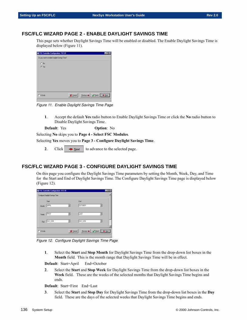
136 System Setup © 2000 Johnson Controls, Inc.
Setting Up an FSC/FLC NexSys Workstation User’s Guide Rev 2.0
FSC/FLC WIZARD PAGE 2 - ENABLE DAYLIGHT SAVINGS TIMEThis page sets whether Daylight Savings Time will be enabled or disabled. The Enable Daylight Savings Time isdisplayed below (Figure 11).
Figure 11. Enable Daylight Savings Time Page
1. Accept the default Yes radio button to Enable Daylight Savings Time or click the No radio button toDisable Daylight Savings Time.
Default: Yes Option: NoSelecting No skips you to Page 4 - Select FSC Modules.Selecting Yes moves you to Page 3 - Configure Daylight Savings Time.
2. Click to advance to the selected page.
FSC/FLC WIZARD PAGE 3 - CONFIGURE DAYLIGHT SAVINGS TIMEOn this page you configure the Daylight Savings Time parameters by setting the Month, Week, Day, and Timefor the Start and End of Daylight Savings Time. The Configure Daylight Savings Time page is displayed below(Figure 12).
Figure 12. Configure Daylight Savings Time Page
1. Select the Start and Stop Month for Daylight Savings Time from the drop-down list boxes in theMonth field. This is the month range that Daylight Savings Time will be in effect.
Default: Start=April End=October2. Select the Start and Stop Week for Daylight Savings Time from the drop-down list boxes in the
Week field. These are the weeks of the selected months that Daylight Savings Time begins andends.
Default: Start=First End=Last3. Select the Start and Stop Day for Daylight Savings Time from the drop-down list boxes in the Day
field. These are the days of the selected weeks that Daylight Savings Time begins and ends.
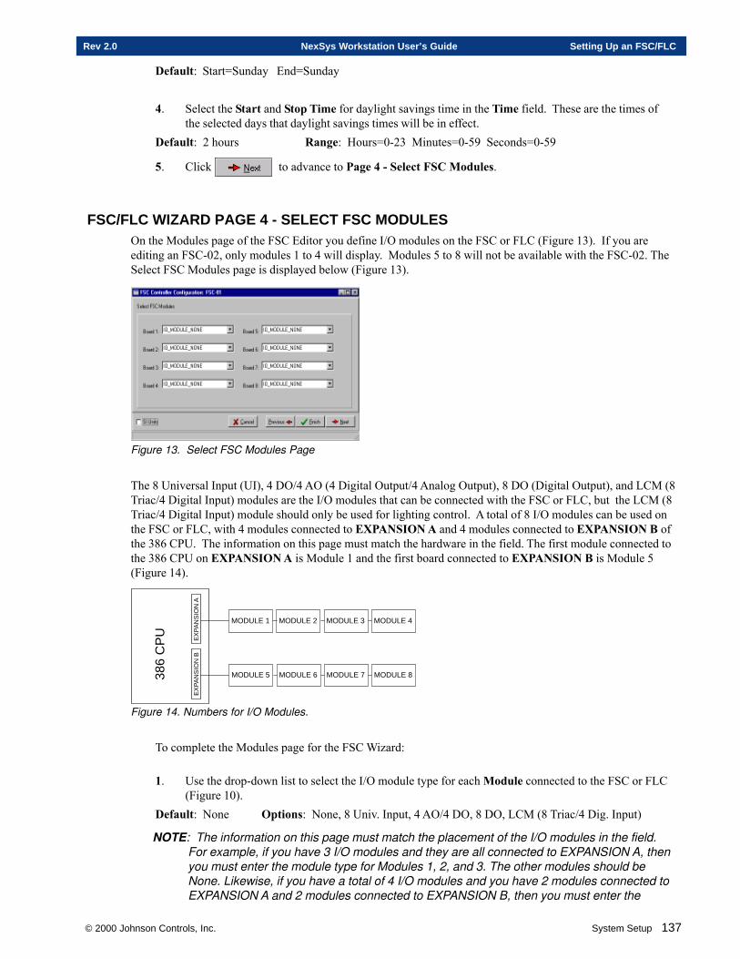
© 2000 Johnson Controls, Inc. System Setup 137
Rev 2.0 NexSys Workstation User’s Guide Setting Up an FSC/FLC
Default: Start=Sunday End=Sunday
4. Select the Start and Stop Time for daylight savings time in the Time field. These are the times ofthe selected days that daylight savings times will be in effect.
Default: 2 hours Range: Hours=0-23 Minutes=0-59 Seconds=0-59
5. Click to advance to Page 4 - Select FSC Modules.
FSC/FLC WIZARD PAGE 4 - SELECT FSC MODULESOn the Modules page of the FSC Editor you define I/O modules on the FSC or FLC (Figure 13). If you areediting an FSC-02, only modules 1 to 4 will display. Modules 5 to 8 will not be available with the FSC-02. TheSelect FSC Modules page is displayed below (Figure 13).
Figure 13. Select FSC Modules Page
The 8 Universal Input (UI), 4 DO/4 AO (4 Digital Output/4 Analog Output), 8 DO (Digital Output), and LCM (8Triac/4 Digital Input) modules are the I/O modules that can be connected with the FSC or FLC, but the LCM (8Triac/4 Digital Input) module should only be used for lighting control. A total of 8 I/O modules can be used onthe FSC or FLC, with 4 modules connected to EXPANSION A and 4 modules connected to EXPANSION B ofthe 386 CPU. The information on this page must match the hardware in the field. The first module connected tothe 386 CPU on EXPANSION A is Module 1 and the first board connected to EXPANSION B is Module 5(Figure 14).
386
CP
U
EX
PA
NS
ION
AE
XP
AN
SIO
N B
MODULE 1 MODULE 2 MODULE 3 MODULE 4
MODULE 5 MODULE 6 MODULE 7 MODULE 8
Figure 14. Numbers for I/O Modules.
To complete the Modules page for the FSC Wizard:
1. Use the drop-down list to select the I/O module type for each Module connected to the FSC or FLC(Figure 10).
Default: None Options: None, 8 Univ. Input, 4 AO/4 DO, 8 DO, LCM (8 Triac/4 Dig. Input)
NOTE: The information on this page must match the placement of the I/O modules in the field.For example, if you have 3 I/O modules and they are all connected to EXPANSION A, thenyou must enter the module type for Modules 1, 2, and 3. The other modules should beNone. Likewise, if you have a total of 4 I/O modules and you have 2 modules connected toEXPANSION A and 2 modules connected to EXPANSION B, then you must enter the

138 System Setup © 2000 Johnson Controls, Inc.
Setting Up an FSC/FLC NexSys Workstation User’s Guide Rev 2.0
module type for Modules 1, 2, 5, and 6. The other modules should be None.
Note: This is the last page in the FSC/FLC Configuration Wizard.
2. Press if you need to make any changes in any of the previous pages.
Click to save your changes and exit the FSC/FLC Wizard.
Click to abandon your changes and exit the FSC/FLC Wizard. You will be prompted toconfirm your desire to cancel.
Chapter Four
Setting Up a VAV
This chapter contains information on:
� Setting Up A VAV
� Defining A VAV
� Commissioning A VAV
� Configuring A VAV
© 2000 Johnson Controls, Inc.
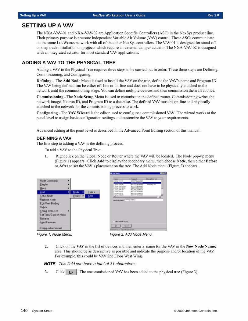
140 System Setup © 2000 Johnson Controls, Inc.
Setting Up a VAV NexSys Workstation User’s Guide Rev 2.0
SETTING UP A VAVThe NXA-VAV-01 and NXA-VAV-02 are Application Specific Controllers (ASC) in the NexSys product line.Their primary purpose is pressure independent Variable Air Volume (VAV) control. These ASCs communicateon the same LONWORKS network with all of the other NexSys controllers. The VAV-01 is designed for stand-offor snap track installation on projects which require an external damper actuator. The NXA-VAV-02 is designedwith an integrated actuator for most standard VAV applications.
ADDING A VAV TO THE PHYSICAL TREEAdding a VAV to the Physical Tree requires three steps to be carried out in order. These three steps are Defining,Commissioning, and Configuring.Defining - The Add Node Menu is used to install the VAV on the tree, define the VAV’s name and Program ID.The VAV being defined can be either off-line or on-line and does not have to be physically attached to thenetwork until the commissioning stage. You can define multiple devices and then commission them all at once.Commissioning - The Node Setup Menu is used to commission the defined router. Commissioning writes thenetwork image, Neuron ID, and Program ID to a database. The defined VAV must be on-line and physicallyattached to the network for the commissioning process to work.Configuring - The VAV Wizard is the editor used to configure a commissioned VAV. The wizard works at thepanel level to assign basic configuration settings and customize the VAV to your requirements.
Advanced editing at the point level is described in the Advanced Point Editing section of this manual.
DEFINING A VAVThe first step to adding a VAV is the defining process.
To add a VAV to the Physical Tree:1. Right click on the Global Node or Router where the VAV will be located. The Node pop-up menu
(Figure 1) appears. Click Add to display the secondary menu, then choose Node, then either Beforeor After to set the VAV’s placement on the tree. The Add Node menu (Figure 2) appears.
Figure 1. Node Menu. Figure 2. Add Node Menu.
2. Click on the VAV in the list of devices and then enter a name for the VAV in the New Node Name:area. This should be as descriptive as possible and indicate the purpose and/or location of the VAV.For example, this could be VAV 2nd Floor West Wing.
NOTE: This field can have a total of 31 characters.
3. Click . The uncommissioned VAV has been added to the physical tree (Figure 3).
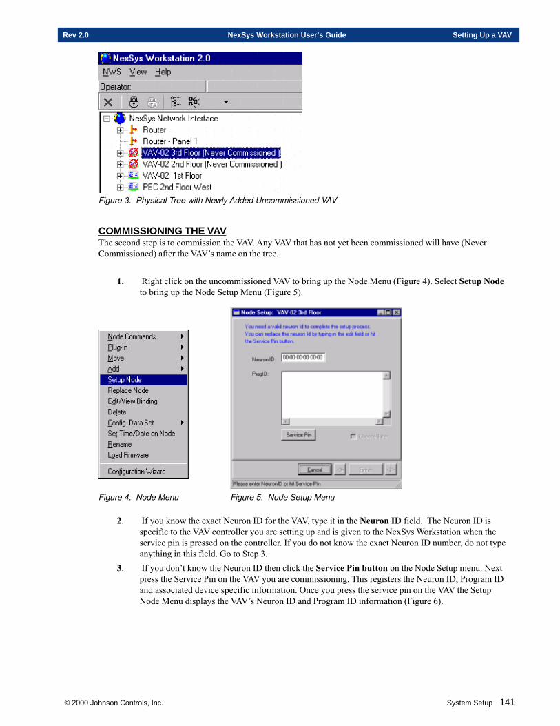
© 2000 Johnson Controls, Inc. System Setup 141
Rev 2.0 NexSys Workstation User’s Guide Setting Up a VAV
Figure 3. Physical Tree with Newly Added Uncommissioned VAV
COMMISSIONING THE VAVThe second step is to commission the VAV. Any VAV that has not yet been commissioned will have (NeverCommissioned) after the VAV’s name on the tree.
1. Right click on the uncommissioned VAV to bring up the Node Menu (Figure 4). Select Setup Nodeto bring up the Node Setup Menu (Figure 5).
Figure 4. Node Menu Figure 5. Node Setup Menu
2. If you know the exact Neuron ID for the VAV, type it in the Neuron ID field. The Neuron ID isspecific to the VAV controller you are setting up and is given to the NexSys Workstation when theservice pin is pressed on the controller. If you do not know the exact Neuron ID number, do not typeanything in this field. Go to Step 3.
3. If you don’t know the Neuron ID then click the Service Pin button on the Node Setup menu. Nextpress the Service Pin on the VAV you are commissioning. This registers the Neuron ID, Program IDand associated device specific information. Once you press the service pin on the VAV the SetupNode Menu displays the VAV’s Neuron ID and Program ID information (Figure 6).
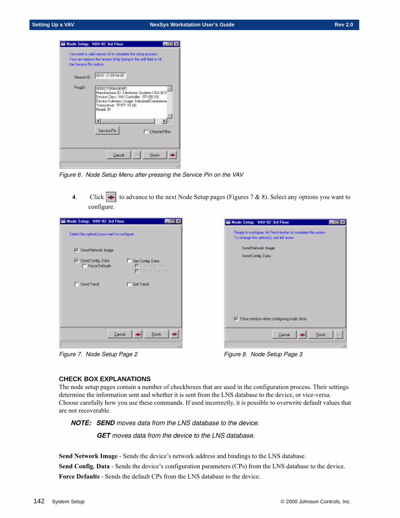
142 System Setup © 2000 Johnson Controls, Inc.
Setting Up a VAV NexSys Workstation User’s Guide Rev 2.0
Figure 6. Node Setup Menu after pressing the Service Pin on the VAV
4. Click to advance to the next Node Setup pages (Figures 7 & 8). Select any options you want toconfigure.
Figure 7. Node Setup Page 2 Figure 8. Node Setup Page 3
CHECK BOX EXPLANATIONSThe node setup pages contain a number of checkboxes that are used in the configuration process. Their settingsdetermine the information sent and whether it is sent from the LNS database to the device, or vice-versa.Choose carefully how you use these commands. If used incorrectly, it is possible to overwrite default values thatare not recoverable.
NOTE: SEND moves data from the LNS database to the device.
GET moves data from the device to the LNS database.
Send Network Image - Sends the device’s network address and bindings to the LNS database.Send Config. Data - Sends the device’s configuration parameters (CPs) from the LNS database to the device.Force Defaults - Sends the default CPs from the LNS database to the device.
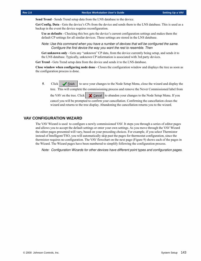
© 2000 Johnson Controls, Inc. System Setup 143
Rev 2.0 NexSys Workstation User’s Guide Setting Up a VAV
Send Trend - Sends Trend setup data from the LNS database to the device.Get Config. Data - Gets the device’s CPs from the device and sends them to the LNS database. This is used as abackup in the event the device requires reconfiguration.
Use as defaults - Checking this box gets the device’s current configuration settings and makes them thedefault CP settings for all similar devices. These settings are stored in the LNS database.
Note: Use this command when you have a number of devices that will be configured the same.Configure the first device the way you want the rest to resemble. Then
Get unknown only - Gets any “unknown” CP data, from the device currently being setup, and sends it tothe LNS database. Typically, unknown CP information is associated with 3rd party devices.
Get Trend - Gets Trend setup data from the device and sends it to the LNS database.Close window when configuring node done - Closes the configuration window and displays the tree as soon asthe configuration process is done.
5. Click to save your changes to the Node Setup Menu, close the wizard and display the
tree. This will complete the commissioning process and remove the Never Commissioned label from
the VAV on the tree. Click to abandon your changes to the Node Setup Menu. If you
cancel you will be prompted to confirm your cancellation. Confirming the cancellation closes thewizard and returns to the tree display. Abandoning the cancellation returns you to the wizard.
VAV CONFIGURATION WIZARDThe VAV Wizard is used to configure a newly commissioned VAV. It steps you through a series of editor pagesand allows you to accept the default settings or enter your own settings. As you move through the VAV Wizardthe editor pages presented will vary, based on your preceding choices. For example, if you select Thermistorinstead of Intelligent/TSO, you will automatically skip past the pages for thermostat configuration, since thethermistor requires no configuration. The VAV flowchart on the next page (Figure 9) shows each of the pages inthe Wizard. The Wizard pages have been numbered to simplify following the configuration process.
Note: Configuration Wizards for other devices have different point types and configuration pages.
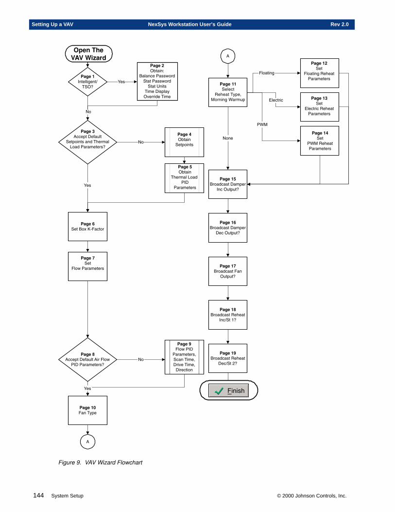
144 System Setup © 2000 Johnson Controls, Inc.
Setting Up a VAV NexSys Workstation User’s Guide Rev 2.0
�12��", $���
�#���������*�-!
������$���'��
�12��'��$�.�/�0���($��
�
�12�����$
���1�������$���
�12��0�((�2$�!�����$��������1
�-!�������$���&+�
'��
�12���%�����"2�
�
�12��������($
3�#��$��"2�4)�������5����2
�12���/��$
����$����3�#��$������$���
+���
����$���
�5)
�12���".���*(��$�!��2��
-�(�,�$2�$&
�12���'.���*(��$�!��2��
!�(�,�$2�$&
�12����.���*(��$����
,�$2�$&
�12���0.���*(��$�3�#��$
-�(��$��&
�12���$.���*(��$�3�#��$
!�(��$�6&
�12��$���1��-!
������$���4�(�������4!��%������4!���($���
�12���.��$
���($��(�3�#��$������$���
�12���#��$
�5)�3�#��$������$���
�12��/, $���7
.����(������1��*�$�$�����1��*�$�$�8��$�
�����!��2��",%����*������
+�
���($��(
'���12���
-�$�������$���,&
�3� �+4�-�-��51��
�12��#, $���
��$2���$�+�
�12��.�((�2$�!�����$
��$2���$����*��#��������*�������$���&
����
Figure 9. VAV Wizard Flowchart
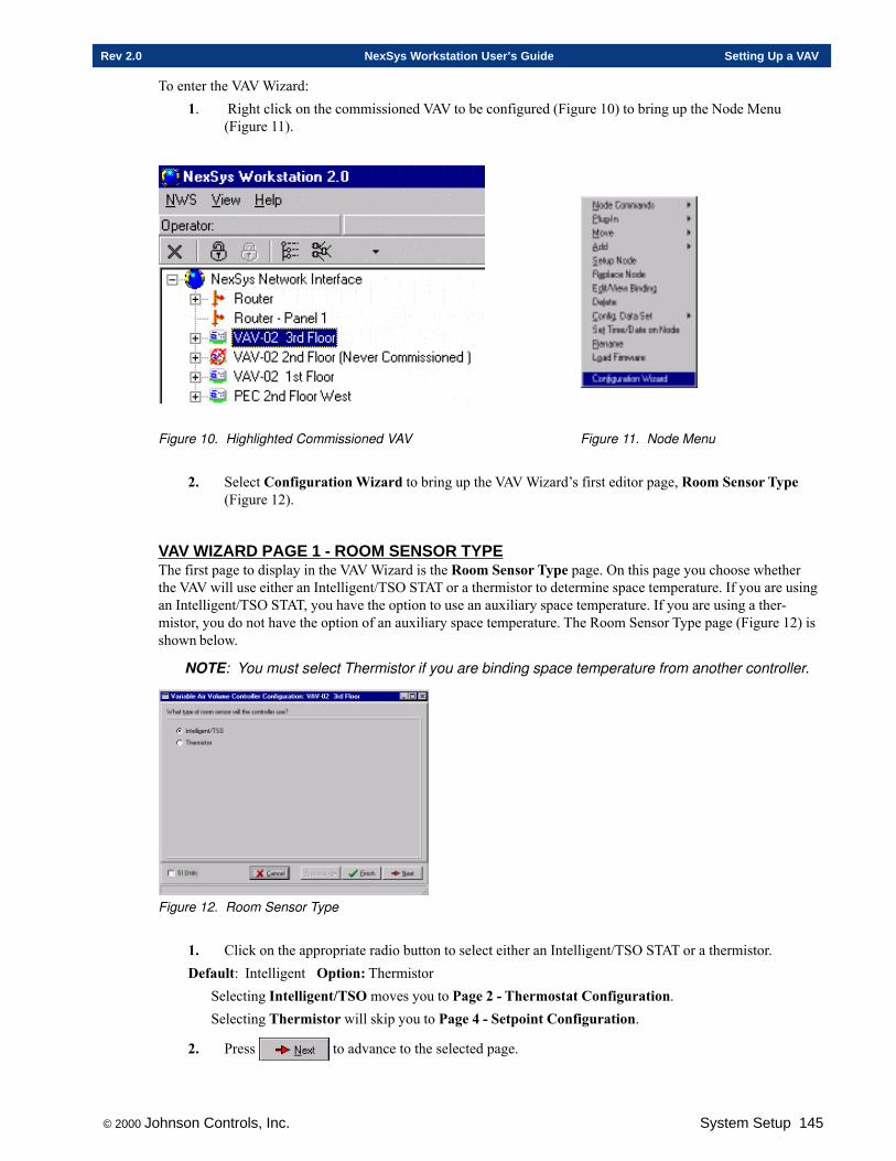
© 2000 Johnson Controls, Inc. System Setup 145
Rev 2.0 NexSys Workstation User’s Guide Setting Up a VAV
To enter the VAV Wizard:1. Right click on the commissioned VAV to be configured (Figure 10) to bring up the Node Menu
(Figure 11).
Figure 10. Highlighted Commissioned VAV Figure 11. Node Menu
2. Select Configuration Wizard to bring up the VAV Wizard’s first editor page, Room Sensor Type(Figure 12).
VAV WIZARD PAGE 1 - ROOM SENSOR TYPEThe first page to display in the VAV Wizard is the Room Sensor Type page. On this page you choose whetherthe VAV will use either an Intelligent/TSO STAT or a thermistor to determine space temperature. If you are usingan Intelligent/TSO STAT, you have the option to use an auxiliary space temperature. If you are using a ther-mistor, you do not have the option of an auxiliary space temperature. The Room Sensor Type page (Figure 12) isshown below.
NOTE: You must select Thermistor if you are binding space temperature from another controller.
Figure 12. Room Sensor Type
1. Click on the appropriate radio button to select either an Intelligent/TSO STAT or a thermistor.Default: Intelligent Option: Thermistor
Selecting Intelligent/TSO moves you to Page 2 - Thermostat Configuration.Selecting Thermistor will skip you to Page 4 - Setpoint Configuration.
2. Press to advance to the selected page.
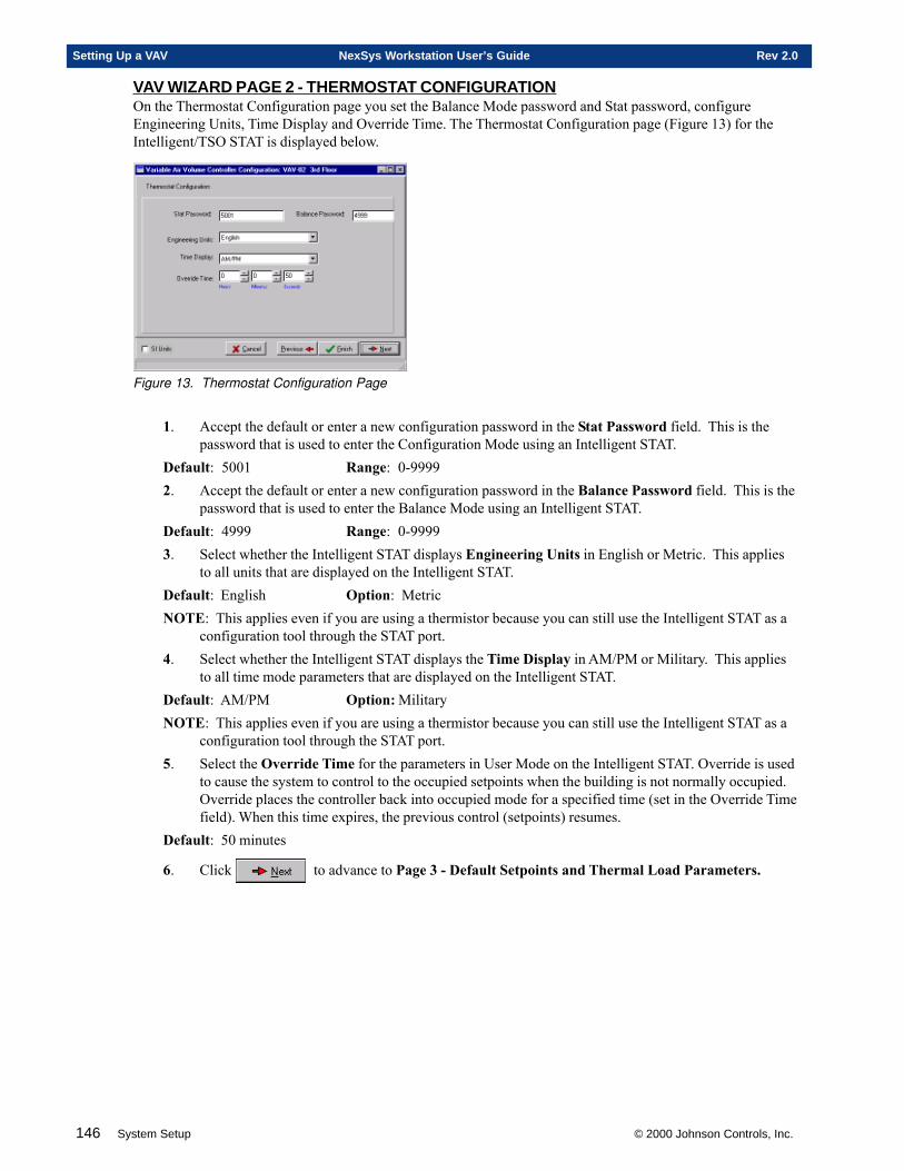
146 System Setup © 2000 Johnson Controls, Inc.
Setting Up a VAV NexSys Workstation User’s Guide Rev 2.0
VAV WIZARD PAGE 2 - THERMOSTAT CONFIGURATIONOn the Thermostat Configuration page you set the Balance Mode password and Stat password, configureEngineering Units, Time Display and Override Time. The Thermostat Configuration page (Figure 13) for theIntelligent/TSO STAT is displayed below.
Figure 13. Thermostat Configuration Page
1. Accept the default or enter a new configuration password in the Stat Password field. This is thepassword that is used to enter the Configuration Mode using an Intelligent STAT.
Default: 5001 Range: 0-99992. Accept the default or enter a new configuration password in the Balance Password field. This is the
password that is used to enter the Balance Mode using an Intelligent STAT.Default: 4999 Range: 0-99993. Select whether the Intelligent STAT displays Engineering Units in English or Metric. This applies
to all units that are displayed on the Intelligent STAT.Default: English Option: MetricNOTE: This applies even if you are using a thermistor because you can still use the Intelligent STAT as a
configuration tool through the STAT port.4. Select whether the Intelligent STAT displays the Time Display in AM/PM or Military. This applies
to all time mode parameters that are displayed on the Intelligent STAT.Default: AM/PM Option: MilitaryNOTE: This applies even if you are using a thermistor because you can still use the Intelligent STAT as a
configuration tool through the STAT port.5. Select the Override Time for the parameters in User Mode on the Intelligent STAT. Override is used
to cause the system to control to the occupied setpoints when the building is not normally occupied.Override places the controller back into occupied mode for a specified time (set in the Override Timefield). When this time expires, the previous control (setpoints) resumes.
Default: 50 minutes
6. Click to advance to Page 3 - Default Setpoints and Thermal Load Parameters.
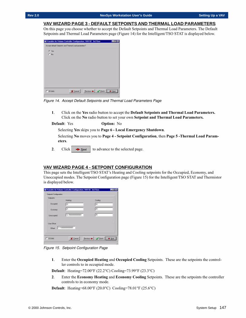
© 2000 Johnson Controls, Inc. System Setup 147
Rev 2.0 NexSys Workstation User’s Guide Setting Up a VAV
VAV WIZARD PAGE 3 - DEFAULT SETPOINTS AND THERMAL LOAD PARAMETERSOn this page you choose whether to accept the Default Setpoints and Thermal Load Parameters. The DefaultSetpoints and Thermal Load Parameters page (Figure 14) for the Intelligent/TSO STAT is displayed below.
Figure 14. Accept Default Setpoints and Thermal Load Parameters Page
1. Click on the Yes radio button to accept the Default Setpoints and Thermal Load Parameters.Click on the No radio button to set your own Setpoint and Thermal Load Parameters.
Default: Yes Option: NoSelecting Yes skips you to Page 6 - Local Emergency Shutdown.Selecting No moves you to Page 4 - Setpoint Configuration, then Page 5 -Thermal Load Param-eters.
2. Click to advance to the selected page.
VAV WIZARD PAGE 4 - SETPOINT CONFIGURATIONThis page sets the Intelligent/TSO STAT’s Heating and Cooling setpoints for the Occupied, Economy, andUnoccupied modes. The Setpoint Configuration page (Figure 15) for the Intelligent/TSO STAT and Thermistoris displayed below.
Figure 15. Setpoint Configuration Page
1. Enter the Occupied Heating and Occupied Cooling Setpoints. These are the setpoints the control-ler controls to in occupied mode.
Default: Heating=72.00°F (22.2°C) Cooling=73.99°F (23.3°C)2. Enter the Economy Heating and Economy Cooling Setpoints. These are the setpoints the controller
controls to in economy mode.Default: Heating=68.00°F (20.0°C) Cooling=78.01°F (25.6°C)
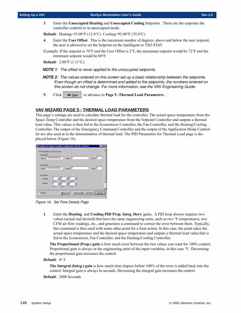
148 System Setup © 2000 Johnson Controls, Inc.
Setting Up a VAV NexSys Workstation User’s Guide Rev 2.0
3. Enter the Unoccupied Heating and Unoccupied Cooling Setpoints. These are the setpoints thecontroller controls to in unoccupied mode.
Default: Heating=55.00°F (12.8°C) Cooling=95.00°F (35.0°C)4. Enter the User Offset. This is the maximum number of degrees, above and below the user setpoint,
the user is allowed to set the Setpoint on the Intelligent or TSO STAT.Example: If the setpoint is 70°F and the User Offset is 2°F, the maximum setpoint would be 72°F and the
minimum setpoint would be 68°F.Default: 2.00°F (1.11°C).
NOTE 1: The offset is never applied to the unoccupied setpoints.
NOTE 2: The values entered on this screen set up a basic relationship between the setpoints.Even though an offset is determined and added to the setpoints, the numbers entered onthis screen do not change. For more information, see the VAV Engineering Guide.
5. Click to advance to Page 5 -Thermal Load Parameters.
VAV WIZARD PAGE 5 - THERMAL LOAD PARAMETERSThis page’s settings are used to calculate thermal load for the controller. The actual space temperature from theSpace Temp Controller and the desired space temperature from the Setpoint Controller and outputs a thermalload value. This values is then fed to the Economizer Controller, the Fan Controller, and the Heating/CoolingController. The output of the Emergency Command Controller and the output of the Application Mode Control-ler are also used at in the determination of thermal load. The PID Parameters for Thermal Load page is dis-played below (Figure 16).
Figure 16. Set Flow Details Page
1. Enter the Heating and Cooling PID Prop. Integ. Derv. gains. A PID loop always requires twovalues (actual and desired) that have the same engineering units, such as two °F temperatures, twoCFM air flow readings, etc., and generates a command to correct the error between them. Typically,this command is then used with some other point for a final action. In this case, the point takes theactual space temperature and the desired space temperature and outputs a thermal load value that isfed to the Economizer, Fan Controller, and the Heating/Cooling Controller.
The Proportional (Prop.) gain is how much error between the two values you want for 100% control.Proportional gain is always in the engineering units of the input variables, in this case °F. Decreasingthe proportional gain increases the control.
Default: 4° FThe Integral (Integ.) gain is how much time elapses before 100% of the error is added back into thecontrol. Integral gain is always in seconds. Decreasing the integral gain increases the control.
Default: 2000 Seconds
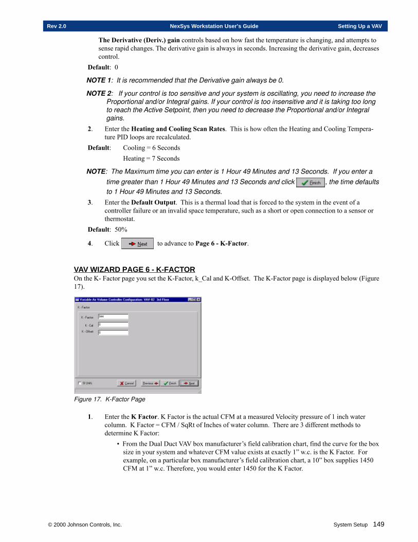
© 2000 Johnson Controls, Inc. System Setup 149
Rev 2.0 NexSys Workstation User’s Guide Setting Up a VAV
The Derivative (Deriv.) gain controls based on how fast the temperature is changing, and attempts tosense rapid changes. The derivative gain is always in seconds. Increasing the derivative gain, decreasescontrol.
Default: 0
NOTE 1: It is recommended that the Derivative gain always be 0.
NOTE 2: If your control is too sensitive and your system is oscillating, you need to increase theProportional and/or Integral gains. If your control is too insensitive and it is taking too longto reach the Active Setpoint, then you need to decrease the Proportional and/or Integralgains.
2. Enter the Heating and Cooling Scan Rates. This is how often the Heating and Cooling Tempera-ture PID loops are recalculated.
Default: Cooling = 6 SecondsHeating = 7 Seconds
NOTE: The Maximum time you can enter is 1 Hour 49 Minutes and 13 Seconds. If you enter atime greater than 1 Hour 49 Minutes and 13 Seconds and click , the time defaultsto 1 Hour 49 Minutes and 13 Seconds.
3. Enter the Default Output. This is a thermal load that is forced to the system in the event of acontroller failure or an invalid space temperature, such as a short or open connection to a sensor orthermostat.
Default: 50%
4. Click to advance to Page 6 - K-Factor.
VAV WIZARD PAGE 6 - K-FACT OROn the K- Factor page you set the K-Factor, k_Cal and K-Offset. The K-Factor page is displayed below (Figure17).
Figure 17. K-Factor Page
1. Enter the K Factor. K Factor is the actual CFM at a measured Velocity pressure of 1 inch watercolumn. K Factor = CFM / SqRt of Inches of water column. There are 3 different methods todetermine K Factor:
• From the Dual Duct VAV box manufacturer’s field calibration chart, find the curve for the boxsize in your system and whatever CFM value exists at exactly 1” w.c. is the K Factor. Forexample, on a particular box manufacturer’s field calibration chart, a 10” box supplies 1450CFM at 1” w.c. Therefore, you would enter 1450 for the K Factor.
150 System Setup © 2000 Johnson Controls, Inc.
Setting Up a VAV NexSys Workstation User’s Guide Rev 2.0
• From the Dual Duct VAV box manufacturer’s field calibration chart, find a point where theinches of water column and a curve intersect with a CFM vertical line. Then to determine KFactor use the following equation: K Factor = CFM / SqRt of Inches of water column. Forexample, on a particular box manufacturer’s field calibration chart, a 10” box supplies 250CFM at .03” w.c. Using the above equation, K Factor = 250 / Ö .03. You would enter 1443 forthe K Factor.
• Obtain an exact CFM reading at 1” w.c. from the box manufacturer.Default: 3002. Enter the K Factor Calibration. K Factor Calibration is calibration, or verification, of K Factor to
actual field conditions. To determine K Factor Calibration:1. Set the VAV box to Maximum CFM position and measure all diffusers for CFM (MeasuredCFM).2. Record the actual CFM reading at the Intelligent Stat or NexSys Workstation at themaximum position (Read CFM).3. Calculate the difference in CFM (Measured CFM - Read CFM).4. Use the following equation to calculate K Factor Calibration:
K Factor Calibration = ( Measured CFM - Read CFM) / SqRt of Inches of water columnFor example, on a particular box manufacturer’s field calibration chart, a 6” box supplies 500
CFM at 1” w.c. When you command the box to maximum, you get a reading of 490 CFM onthe Intelligent Stat. The Balance Commissioner gets a reading of 505 CFM. Using a manom-eter, you determine .98” w.c. at 640 CFM.
Now plugging in the numbers to determine K Factor Calibration:K Factor Calibration = ( Measured CFM - Read CFM) / SqRt of Inches of water columnK Factor Calibration = (505-490)/Ö.98K Factor Calibration = (15)/.9899494K Factor Calibration = 15.15
Default: 0
NOTE: For more information regarding K Factor and K Factor Calibration, see the VAV Engineer-ing Guide.
3. Enter the Flow Offset. Flow Offset is a true offset used to make small adjustments at low CFMreading. The Flow Offset is limited to no more than 5% of the maximum CFM value. This offset canbe used for inadequate laminar air flow entering the VAV box, installation variances, etc.
Default: 0
4. Click to advance to Page 7 - Flow Parameters.
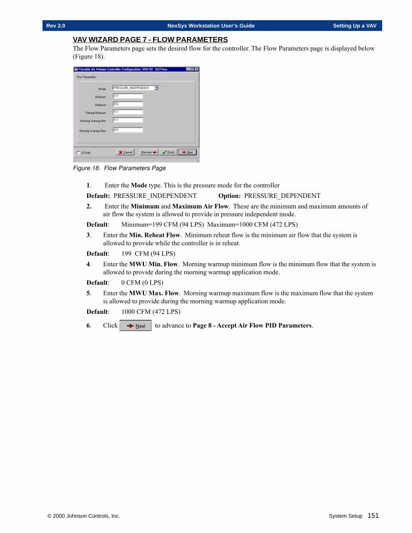
© 2000 Johnson Controls, Inc. System Setup 151
Rev 2.0 NexSys Workstation User’s Guide Setting Up a VAV
VAV WIZARD PAGE 7 - FLOW PARAMETERSThe Flow Parameters page sets the desired flow for the controller. The Flow Parameters page is displayed below(Figure 18).
Figure 18. Flow Parameters Page
1. Enter the Mode type. This is the pressure mode for the controllerDefault: PRESSURE_INDEPENDENT Option: PRESSURE_DEPENDENT2. Enter the Minimum and Maximum Air Flow. These are the minimum and maximum amounts of
air flow the system is allowed to provide in pressure independent mode.Default: Minimum=199 CFM (94 LPS) Maximum=1000 CFM (472 LPS)3. Enter the Min. Reheat Flow. Minimum reheat flow is the minimum air flow that the system is
allowed to provide while the controller is in reheat.Default: 199 CFM (94 LPS)4. Enter the MWU Min. Flow. Morning warmup minimum flow is the minimum flow that the system is
allowed to provide during the morning warmup application mode.Default: 0 CFM (0 LPS)5. Enter the MWU Max. Flow. Morning warmup maximum flow is the maximum flow that the system
is allowed to provide during the morning warmup application mode.Default: 1000 CFM (472 LPS)
6. Click to advance to Page 8 - Accept Air Flow PID Parameters.
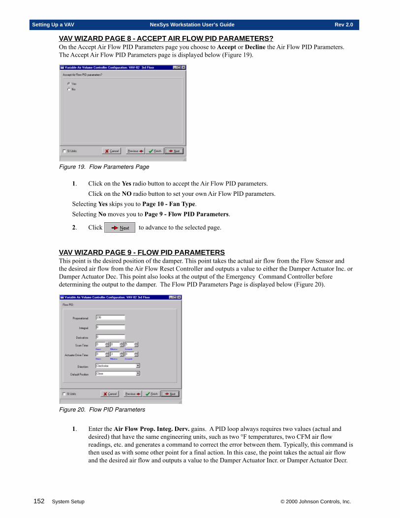
152 System Setup © 2000 Johnson Controls, Inc.
Setting Up a VAV NexSys Workstation User’s Guide Rev 2.0
VAV WIZARD PAGE 8 - ACCEPT AIR FLOW PID PARAMETERS?On the Accept Air Flow PID Parameters page you choose to Accept or Decline the Air Flow PID Parameters.The Accept Air Flow PID Parameters page is displayed below (Figure 19).
Figure 19. Flow Parameters Page
1. Click on the Yes radio button to accept the Air Flow PID parameters.Click on the NO radio button to set your own Air Flow PID parameters.
Selecting Yes skips you to Page 10 - Fan Type.Selecting No moves you to Page 9 - Flow PID Parameters.
2. Click to advance to the selected page.
VAV WIZARD PAGE 9 - FLOW PID PARAMETERSThis point is the desired position of the damper. This point takes the actual air flow from the Flow Sensor andthe desired air flow from the Air Flow Reset Controller and outputs a value to either the Damper Actuator Inc. orDamper Actuator Dec. This point also looks at the output of the Emergency Command Controller beforedetermining the output to the damper. The Flow PID Parameters Page is displayed below (Figure 20).
Figure 20. Flow PID Parameters
1. Enter the Air Flow Prop. Integ. Derv. gains. A PID loop always requires two values (actual anddesired) that have the same engineering units, such as two °F temperatures, two CFM air flowreadings, etc. and generates a command to correct the error between them. Typically, this command isthen used as with some other point for a final action. In this case, the point takes the actual air flowand the desired air flow and outputs a value to the Damper Actuator Incr. or Damper Actuator Decr.
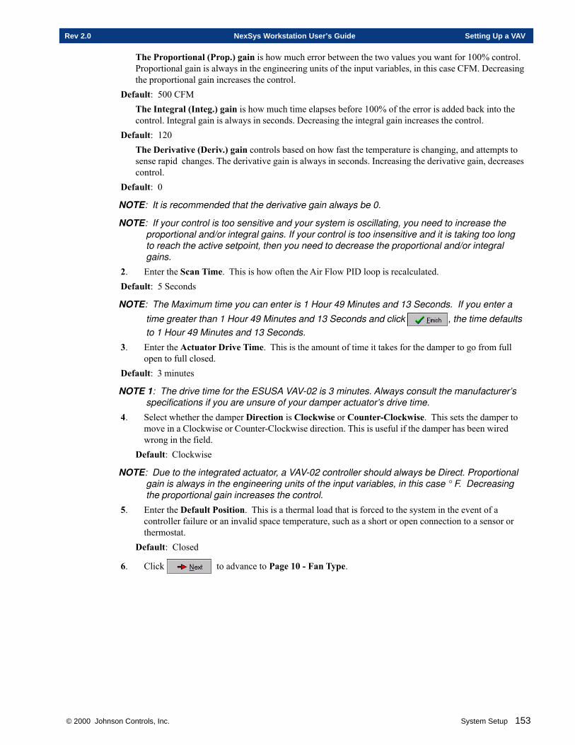
© 2000 Johnson Controls, Inc. System Setup 153
Rev 2.0 NexSys Workstation User’s Guide Setting Up a VAV
The Proportional (Prop.) gain is how much error between the two values you want for 100% control.Proportional gain is always in the engineering units of the input variables, in this case CFM. Decreasingthe proportional gain increases the control.
Default: 500 CFMThe Integral (Integ.) gain is how much time elapses before 100% of the error is added back into thecontrol. Integral gain is always in seconds. Decreasing the integral gain increases the control.
Default: 120The Derivative (Deriv.) gain controls based on how fast the temperature is changing, and attempts tosense rapid changes. The derivative gain is always in seconds. Increasing the derivative gain, decreasescontrol.
Default: 0
NOTE: It is recommended that the derivative gain always be 0.
NOTE: If your control is too sensitive and your system is oscillating, you need to increase theproportional and/or integral gains. If your control is too insensitive and it is taking too longto reach the active setpoint, then you need to decrease the proportional and/or integralgains.
2. Enter the Scan Time. This is how often the Air Flow PID loop is recalculated.Default: 5 Seconds
NOTE: The Maximum time you can enter is 1 Hour 49 Minutes and 13 Seconds. If you enter atime greater than 1 Hour 49 Minutes and 13 Seconds and click , the time defaultsto 1 Hour 49 Minutes and 13 Seconds.
3. Enter the Actuator Drive Time. This is the amount of time it takes for the damper to go from fullopen to full closed.
Default: 3 minutes
NOTE 1: The drive time for the ESUSA VAV-02 is 3 minutes. Always consult the manufacturer’sspecifications if you are unsure of your damper actuator’s drive time.
4. Select whether the damper Direction is Clockwise or Counter-Clockwise. This sets the damper tomove in a Clockwise or Counter-Clockwise direction. This is useful if the damper has been wiredwrong in the field.
Default: Clockwise
NOTE: Due to the integrated actuator, a VAV-02 controller should always be Direct. Proportionalgain is always in the engineering units of the input variables, in this case ° F. Decreasingthe proportional gain increases the control.
5. Enter the Default Position. This is a thermal load that is forced to the system in the event of acontroller failure or an invalid space temperature, such as a short or open connection to a sensor orthermostat.
Default: Closed
6. Click to advance to Page 10 - Fan Type.
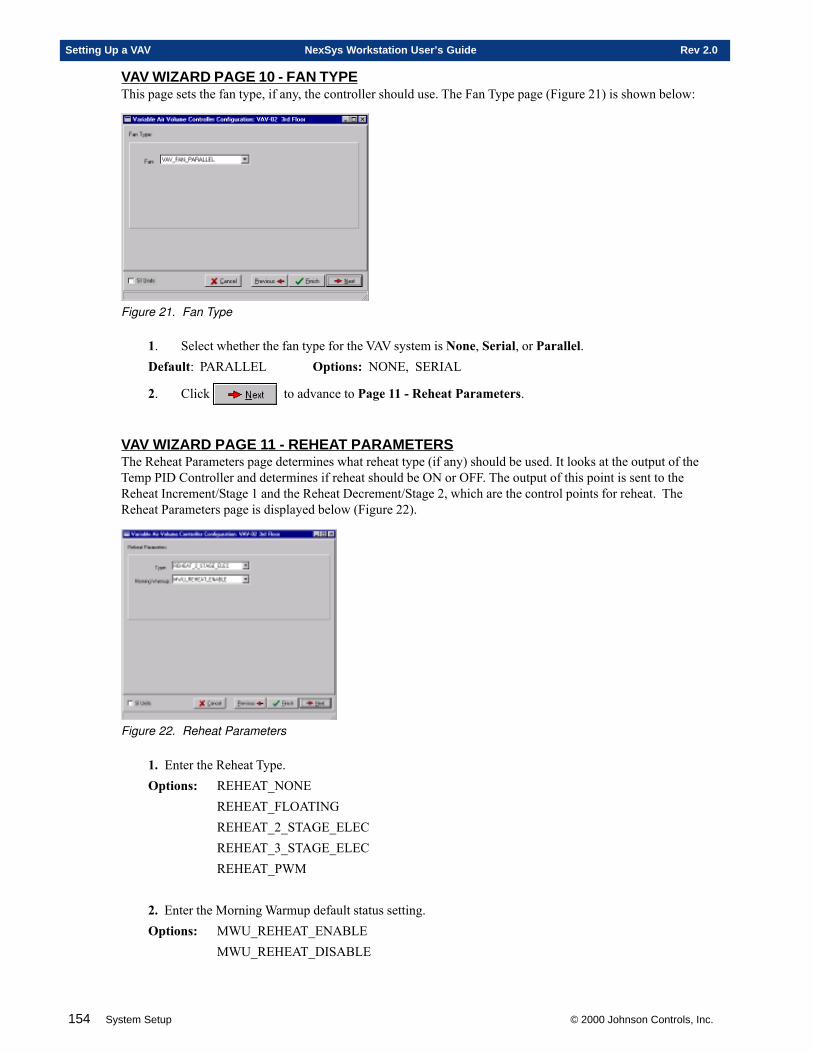
154 System Setup © 2000 Johnson Controls, Inc.
Setting Up a VAV NexSys Workstation User’s Guide Rev 2.0
VAV WIZARD PAGE 10 - FAN TYPEThis page sets the fan type, if any, the controller should use. The Fan Type page (Figure 21) is shown below:
Figure 21. Fan Type
1. Select whether the fan type for the VAV system is None, Serial, or Parallel.Default: PARALLEL Options: NONE, SERIAL
2. Click to advance to Page 11 - Reheat Parameters.
VAV WIZARD PAGE 11 - REHEAT PARAMETERSThe Reheat Parameters page determines what reheat type (if any) should be used. It looks at the output of theTemp PID Controller and determines if reheat should be ON or OFF. The output of this point is sent to theReheat Increment/Stage 1 and the Reheat Decrement/Stage 2, which are the control points for reheat. TheReheat Parameters page is displayed below (Figure 22).
Figure 22. Reheat Parameters
1. Enter the Reheat Type.Options: REHEAT_NONE
REHEAT_FLOATINGREHEAT_2_STAGE_ELECREHEAT_3_STAGE_ELECREHEAT_PWM
2. Enter the Morning Warmup default status setting.Options: MWU_REHEAT_ENABLE
MWU_REHEAT_DISABLE
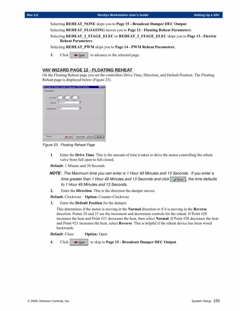
© 2000 Johnson Controls, Inc. System Setup 155
Rev 2.0 NexSys Workstation User’s Guide Setting Up a VAV
Selecting REHEAT_NONE skips you to Page 15 - Broadcast Damper DEC Output.Selecting REHEAT_FLOATING moves you to Page 12 - Floating Reheat Parameters.Selecting REHEAT_2_STAGE_ELEC or REHEAT_3_STAGE_ELEC skips you to Page 13 - Electric
Reheat Parameters.Selecting REHEAT_PWM skips you to Page 14 - PWM Reheat Parameters.
3. Click to advance to the selected page.
VAV WIZARD PAGE 12 - FLOA TING REHEATOn the Floating Reheat page you set the controllers Drive Time, Direction, and Default Position. The FloatingReheat page is displayed below (Figure 23).
Figure 23. Floating Reheat Page
1. Enter the Drive Time. This is the amount of time it takes to drive the motor controlling the reheatvalve from full open to full closed.
Default: 1 Minute and 30 Seconds
NOTE: The Maximum time you can enter is 1 Hour 49 Minutes and 13 Seconds. If you enter atime greater than 1 Hour 49 Minutes and 13 Seconds and click , the time defaultsto 1 Hour 49 Minutes and 13 Seconds.
2. Enter the Direction. This is the direction the damper moves.Default: Clockwise Option: Counter-Clockwise3. Enter the Default Position for the damper.
This determines if the motor is moving in the Normal direction or if it is moving in the Reversedirection. Points 20 and 21 are the increment and decrement controls for the reheat. If Point #20increases the heat and Point #21 decreases the heat, then select Normal. If Point #20 decreases the heatand Point #21 increases the heat, select Reverse. This is helpful if the reheat device has been wiredbackwards.
Default: Close Option: Open
4. Click to skip to Page 15 - Broadcast Damper DEC Output.
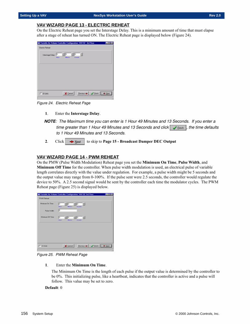
156 System Setup © 2000 Johnson Controls, Inc.
Setting Up a VAV NexSys Workstation User’s Guide Rev 2.0
VAV WIZARD PAGE 13 - ELECTRIC REHEA TOn the Electric Reheat page you set the Interstage Delay. This is a minimum amount of time that must elapseafter a stage of reheat has turned ON. The Electric Reheat page is displayed below (Figure 24).
Figure 24. Electric Reheat Page
1. Enter the Interstage Delay.
NOTE: The Maximum time you can enter is 1 Hour 49 Minutes and 13 Seconds. If you enter atime greater than 1 Hour 49 Minutes and 13 Seconds and click , the time defaultsto 1 Hour 49 Minutes and 13 Seconds.
2. Click to skip to Page 15 - Broadcast Damper DEC Output
VAV WIZARD PAGE 14 - PWM REHEATOn the PMW (Pulse Width Modulation) Reheat page you set the Minimum On Time, Pulse Width, andMinimum Off Time for the controller. When pulse width modulation is used, an electrical pulse of variablelength correlates directly with the value under regulation. For example, a pulse width might be 5 seconds andthe output value may range from 0-100%. If the pulse sent were 2.5 seconds, the controller would regulate thedevice to 50%. A 2.5 second signal would be sent by the controller each time the modulator cycles. The PWMReheat page (Figure 25) is displayed below.
Figure 25. PWM Reheat Page
1. Enter the Minimum On Time.The Minimum On Time is the length of each pulse if the output value is determined by the controller tobe 0%. This initializing pulse, like a heartbeat, indicates that the controller is active and a pulse willfollow. This value may be set to zero.
Default: 0
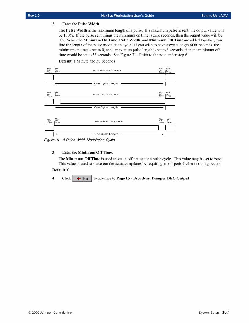
© 2000 Johnson Controls, Inc. System Setup 157
Rev 2.0 NexSys Workstation User’s Guide Setting Up a VAV
2. Enter the Pulse Width.The Pulse Width is the maximum length of a pulse. If a maximum pulse is sent, the output value willbe 100%. If the pulse sent minus the minimum on time is zero seconds, then the output value will be0%. When the Minimum On Time, Pulse Width, and Minimum Off Time are added together, youfind the length of the pulse modulation cycle. If you wish to have a cycle length of 60 seconds, theminimum on time is set to 0, and a maximum pulse length is set to 5 seconds, then the minimum offtime would be set to 55 seconds. See Figure 31. Refer to the note under step 6.Default: 1 Minute and 30 Seconds
���� �����
���� ������
������������������ �����
��������� ��!�
���� �����
���� ������
���� �����
���� ������
������������������� �����
��������� ��!�
���� �����
���� ������
���� �����
���� ������
����������������� �����
��������� ��!�
���� �����
���� ������
Figure 31. A Pulse Width Modulation Cycle.
3. Enter the Minimum Off Time.The Minimum Off Time is used to set an off time after a pulse cycle. This value may be set to zero.This value is used to space out the actuator updates by requiring an off period where nothing occurs.
Default: 0
4. Click to advance to Page 15 - Broadcast Damper DEC Output
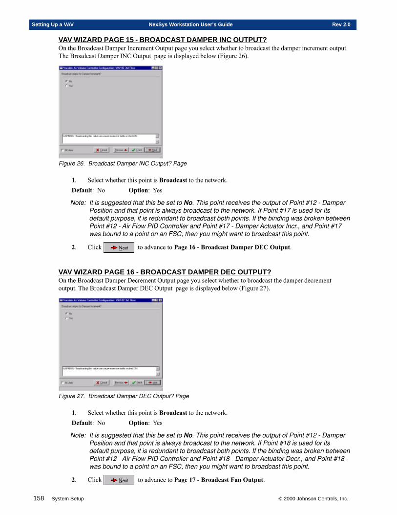
158 System Setup © 2000 Johnson Controls, Inc.
Setting Up a VAV NexSys Workstation User’s Guide Rev 2.0
VAV WIZARD PAGE 15 - BROADCAST DAMPER INC OUTPUT?On the Broadcast Damper Increment Output page you select whether to broadcast the damper increment output.The Broadcast Damper INC Output page is displayed below (Figure 26).
Figure 26. Broadcast Damper INC Output? Page
1. Select whether this point is Broadcast to the network.Default: No Option: Yes
Note: It is suggested that this be set to No. This point receives the output of Point #12 - DamperPosition and that point is always broadcast to the network. If Point #17 is used for itsdefault purpose, it is redundant to broadcast both points. If the binding was broken betweenPoint #12 - Air Flow PID Controller and Point #17 - Damper Actuator Incr., and Point #17was bound to a point on an FSC, then you might want to broadcast this point.
2. Click to advance to Page 16 - Broadcast Damper DEC Output.
VAV WIZARD PAGE 16 - BROADCAST DAMPER DEC OUTPUT?On the Broadcast Damper Decrement Output page you select whether to broadcast the damper decrementoutput. The Broadcast Damper DEC Output page is displayed below (Figure 27).
Figure 27. Broadcast Damper DEC Output? Page
1. Select whether this point is Broadcast to the network.Default: No Option: Yes
Note: It is suggested that this be set to No. This point receives the output of Point #12 - DamperPosition and that point is always broadcast to the network. If Point #18 is used for itsdefault purpose, it is redundant to broadcast both points. If the binding was broken betweenPoint #12 - Air Flow PID Controller and Point #18 - Damper Actuator Decr., and Point #18was bound to a point on an FSC, then you might want to broadcast this point.
2. Click to advance to Page 17 - Broadcast Fan Output.
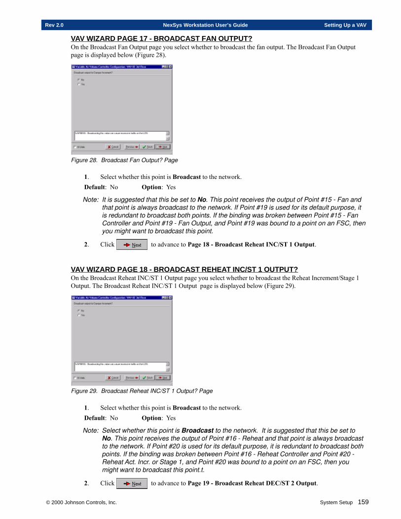
© 2000 Johnson Controls, Inc. System Setup 159
Rev 2.0 NexSys Workstation User’s Guide Setting Up a VAV
VAV WIZARD PAGE 17 - BROADCAST FAN OUTPUT?On the Broadcast Fan Output page you select whether to broadcast the fan output. The Broadcast Fan Outputpage is displayed below (Figure 28).
Figure 28. Broadcast Fan Output? Page
1. Select whether this point is Broadcast to the network.Default: No Option: Yes
Note: It is suggested that this be set to No. This point receives the output of Point #15 - Fan andthat point is always broadcast to the network. If Point #19 is used for its default purpose, itis redundant to broadcast both points. If the binding was broken between Point #15 - FanController and Point #19 - Fan Output, and Point #19 was bound to a point on an FSC, thenyou might want to broadcast this point.
2. Click to advance to Page 18 - Broadcast Reheat INC/ST 1 Output.
VAV WIZARD PAGE 18 - BROADCAST REHEA T INC/ST 1 OUTPUT?On the Broadcast Reheat INC/ST 1 Output page you select whether to broadcast the Reheat Increment/Stage 1Output. The Broadcast Reheat INC/ST 1 Output page is displayed below (Figure 29).
Figure 29. Broadcast Reheat INC/ST 1 Output? Page
1. Select whether this point is Broadcast to the network.Default: No Option: Yes
Note: Select whether this point is Broadcast to the network. It is suggested that this be set toNo. This point receives the output of Point #16 - Reheat and that point is always broadcastto the network. If Point #20 is used for its default purpose, it is redundant to broadcast bothpoints. If the binding was broken between Point #16 - Reheat Controller and Point #20 -Reheat Act. Incr. or Stage 1, and Point #20 was bound to a point on an FSC, then youmight want to broadcast this point.t.
2. Click to advance to Page 19 - Broadcast Reheat DEC/ST 2 Output.
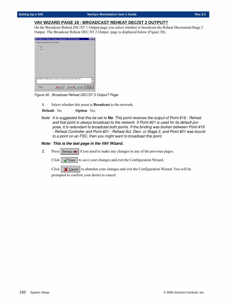
160 System Setup © 2000 Johnson Controls, Inc.
Setting Up a VAV NexSys Workstation User’s Guide Rev 2.0
VAV WIZARD PAGE 19 - BROADCAST REHEA T DEC/ST 2 OUTPUT?On the Broadcast Reheat INC/ST 1 Output page you select whether to broadcast the Reheat Decrement/Stage 2Output. The Broadcast Reheat DEC/ST 2 Output page is displayed below (Figure 30).
Figure 30. Broadcast Reheat DEC/ST 2 Output? Page
1. Select whether this point is Broadcast to the network.Default: No Option: Yes
Note: It is suggested that this be set to No. This point receives the output of Point #16 - Reheatand that point is always broadcast to the network. If Point #21 is used for its default pur-pose, it is redundant to broadcast both points. If the binding was broken between Point #16- Reheat Controller and Point #21 - Reheat Act. Decr. or Stage 2, and Point #21 was boundto a point on an FSC, then you might want to broadcast this point.
Note: This is the last page in the VAV Wizard.
2. Press if you need to make any changes in any of the previous pages.
Click to save your changes and exit the Configuration Wizard.
Click to abandon your changes and exit the Configuration Wizard. You will beprompted to confirm your desire to cancel.
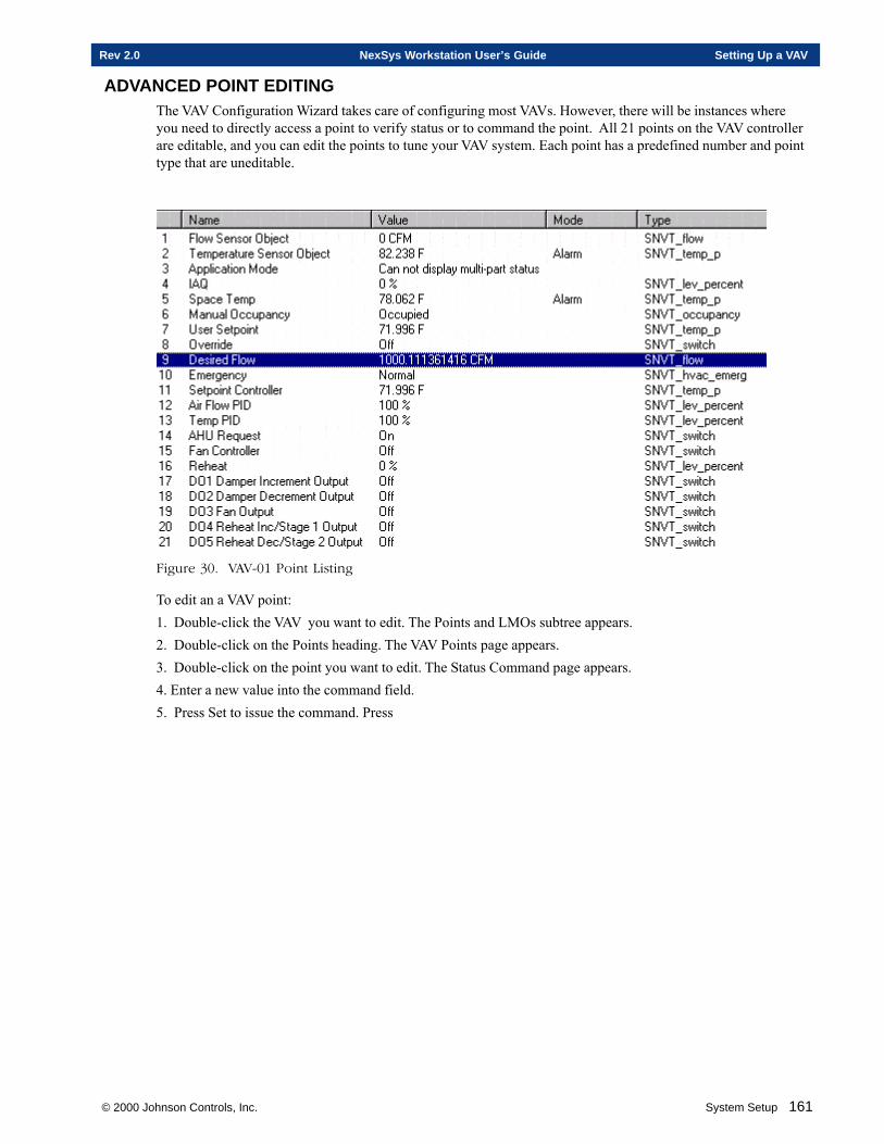
© 2000 Johnson Controls, Inc. System Setup 161
Rev 2.0 NexSys Workstation User’s Guide Setting Up a VAV
ADVANCED POINT EDITINGThe VAV Configuration Wizard takes care of configuring most VAVs. However, there will be instances whereyou need to directly access a point to verify status or to command the point. All 21 points on the VAV controllerare editable, and you can edit the points to tune your VAV system. Each point has a predefined number and pointtype that are uneditable.
Figure 30. VAV-01 Point Listing
To edit an a VAV point:1. Double-click the VAV you want to edit. The Points and LMOs subtree appears.2. Double-click on the Points heading. The VAV Points page appears.3. Double-click on the point you want to edit. The Status Command page appears.4. Enter a new value into the command field.5. Press Set to issue the command. Press

162 System Setup © 2000 Johnson Controls, Inc.
Setting Up a VAV NexSys Workstation User’s Guide Rev 2.0

Chapter Five
Setting Up a Heat Pump
This chapter contains information on:
� Setting Up A Heat Pump
� Defining A Heat Pump
� Commissioning A Heat Pump
� Configuring A Heat Pump
© 2000 Johnson Controls, Inc.
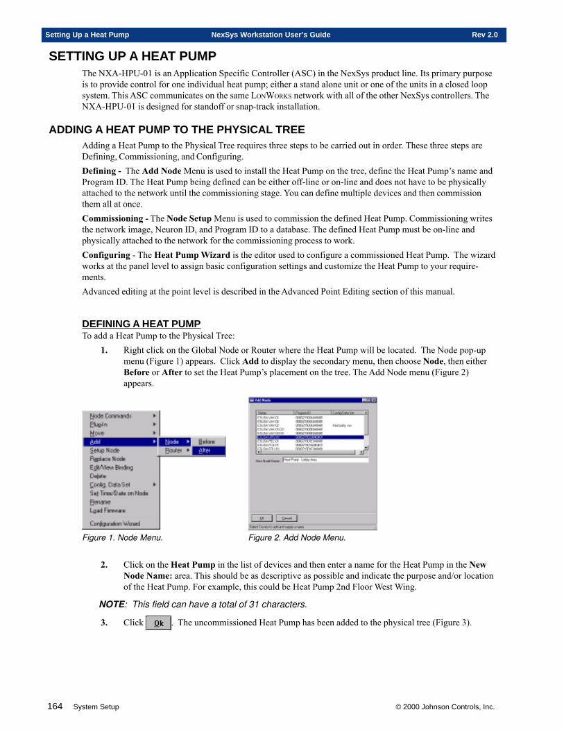
164 System Setup © 2000 Johnson Controls, Inc.
Setting Up a Heat Pump NexSys Workstation User’s Guide Rev 2.0
SETTING UP A HEAT PUMPThe NXA-HPU-01 is an Application Specific Controller (ASC) in the NexSys product line. Its primary purposeis to provide control for one individual heat pump; either a stand alone unit or one of the units in a closed loopsystem. This ASC communicates on the same LONWORKS network with all of the other NexSys controllers. TheNXA-HPU-01 is designed for standoff or snap-track installation.
ADDING A HEAT PUMP TO THE PHYSICAL TREEAdding a Heat Pump to the Physical Tree requires three steps to be carried out in order. These three steps areDefining, Commissioning, and Configuring.Defining - The Add Node Menu is used to install the Heat Pump on the tree, define the Heat Pump’s name andProgram ID. The Heat Pump being defined can be either off-line or on-line and does not have to be physicallyattached to the network until the commissioning stage. You can define multiple devices and then commissionthem all at once.Commissioning - The Node Setup Menu is used to commission the defined Heat Pump. Commissioning writesthe network image, Neuron ID, and Program ID to a database. The defined Heat Pump must be on-line andphysically attached to the network for the commissioning process to work.Configuring - The Heat Pump Wizard is the editor used to configure a commissioned Heat Pump. The wizardworks at the panel level to assign basic configuration settings and customize the Heat Pump to your require-ments.Advanced editing at the point level is described in the Advanced Point Editing section of this manual.
DEFINING A HEAT PUMPTo add a Heat Pump to the Physical Tree:
1. Right click on the Global Node or Router where the Heat Pump will be located. The Node pop-upmenu (Figure 1) appears. Click Add to display the secondary menu, then choose Node, then eitherBefore or After to set the Heat Pump’s placement on the tree. The Add Node menu (Figure 2)appears.
Figure 1. Node Menu. Figure 2. Add Node Menu.
2. Click on the Heat Pump in the list of devices and then enter a name for the Heat Pump in the NewNode Name: area. This should be as descriptive as possible and indicate the purpose and/or locationof the Heat Pump. For example, this could be Heat Pump 2nd Floor West Wing.
NOTE: This field can have a total of 31 characters.
3. Click . The uncommissioned Heat Pump has been added to the physical tree (Figure 3).
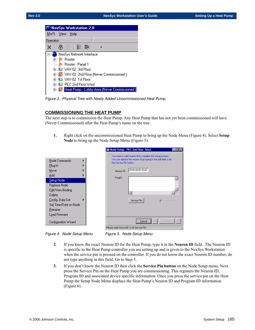
© 2000 Johnson Controls, Inc. System Setup 165
Rev 2.0 NexSys Workstation User’s Guide Setting Up a Heat Pump
Figure 3. Physical Tree with Newly Added Uncommissioned Heat Pump
COMMISSIONING THE HEAT PUMPThe next step is to commission the Heat Pump. Any Heat Pump that has not yet been commissioned will have(Never Commissioned) after the Heat Pump’s name on the tree.
1. Right click on the uncommissioned Heat Pump to bring up the Node Menu (Figure 4). Select SetupNode to bring up the Node Setup Menu (Figure 5).
Figure 4. Node Setup Menu Figure 5. Node Setup Menu
2. If you know the exact Neuron ID for the Heat Pump, type it in the Neuron ID field. The Neuron IDis specific to the Heat Pump controller you are setting up and is given to the NexSys Workstationwhen the service pin is pressed on the controller. If you do not know the exact Neuron ID number, donot type anything in this field. Go to Step 3.
3. If you don’t know the Neuron ID then click the Service Pin button on the Node Setup menu. Nextpress the Service Pin on the Heat Pump you are commissioning. This registers the Neuron ID,Program ID and associated device specific information. Once you press the service pin on the HeatPump the Setup Node Menu displays the Heat Pump’s Neuron ID and Program ID information(Figure 6).
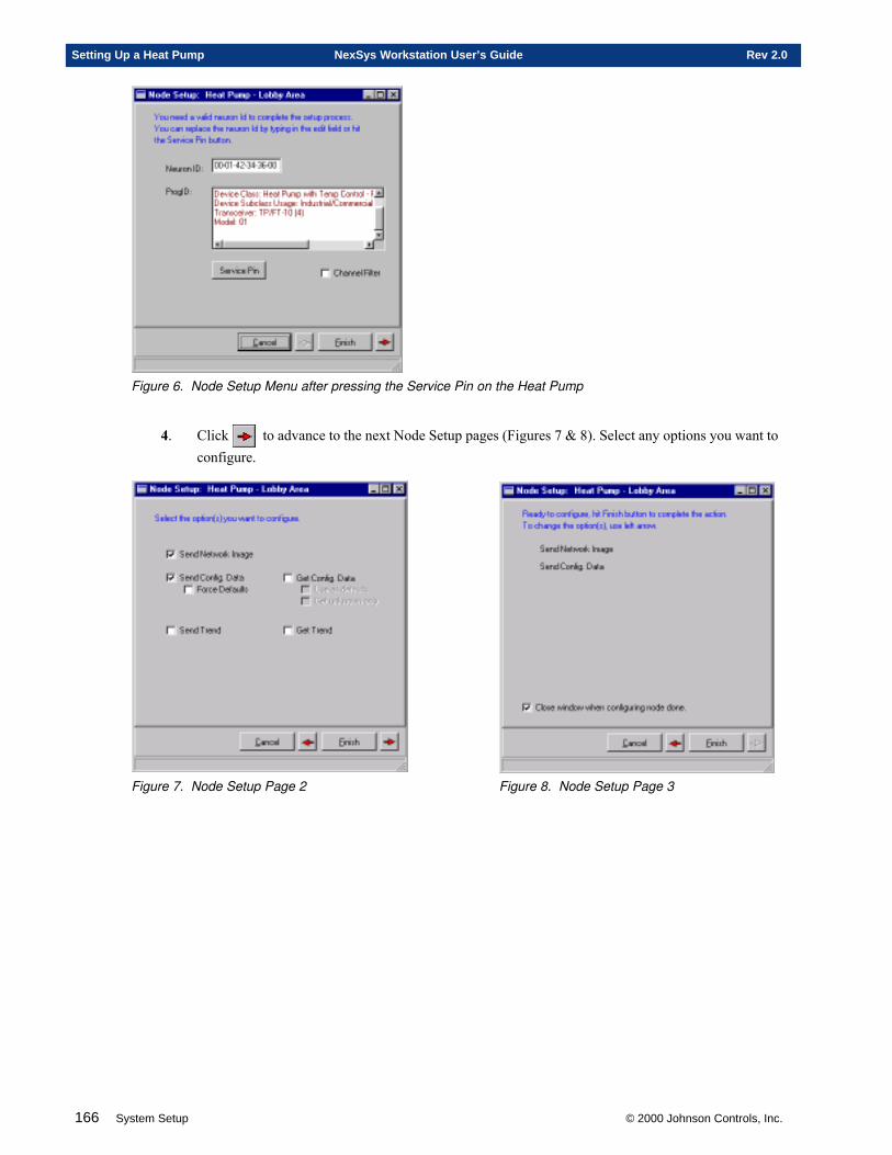
166 System Setup © 2000 Johnson Controls, Inc.
Setting Up a Heat Pump NexSys Workstation User’s Guide Rev 2.0
Figure 6. Node Setup Menu after pressing the Service Pin on the Heat Pump
4. Click to advance to the next Node Setup pages (Figures 7 & 8). Select any options you want toconfigure.
Figure 7. Node Setup Page 2 Figure 8. Node Setup Page 3
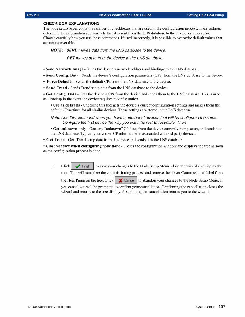
© 2000 Johnson Controls, Inc. System Setup 167
Rev 2.0 NexSys Workstation User’s Guide Setting Up a Heat Pump
CHECK BOX EXPLANATIONSThe node setup pages contain a number of checkboxes that are used in the configuration process. Their settingsdetermine the information sent and whether it is sent from the LNS database to the device, or vice-versa.Choose carefully how you use these commands. If used incorrectly, it is possible to overwrite default values thatare not recoverable.
NOTE: SEND moves data from the LNS database to the device.
GET moves data from the device to the LNS database.
• Send Network Image - Sends the device’s network address and bindings to the LNS database.• Send Config. Data - Sends the device’s configuration parameters (CPs) from the LNS database to the device.• Force Defaults - Sends the default CPs from the LNS database to the device.• Send Trend - Sends Trend setup data from the LNS database to the device.• Get Config. Data - Gets the device’s CPs from the device and sends them to the LNS database. This is usedas a backup in the event the device requires reconfiguration.
• Use as defaults - Checking this box gets the device’s current configuration settings and makes them thedefault CP settings for all similar devices. These settings are stored in the LNS database.
Note: Use this command when you have a number of devices that will be configured the same.Configure the first device the way you want the rest to resemble. Then
• Get unknown only - Gets any “unknown” CP data, from the device currently being setup, and sends it tothe LNS database. Typically, unknown CP information is associated with 3rd party devices.
• Get Trend - Gets Trend setup data from the device and sends it to the LNS database.• Close window when configuring node done - Closes the configuration window and displays the tree as soonas the configuration process is done.
5. Click to save your changes to the Node Setup Menu, close the wizard and display the
tree. This will complete the commissioning process and remove the Never Commissioned label from
the Heat Pump on the tree. Click to abandon your changes to the Node Setup Menu. If
you cancel you will be prompted to confirm your cancellation. Confirming the cancellation closes thewizard and returns to the tree display. Abandoning the cancellation returns you to the wizard.
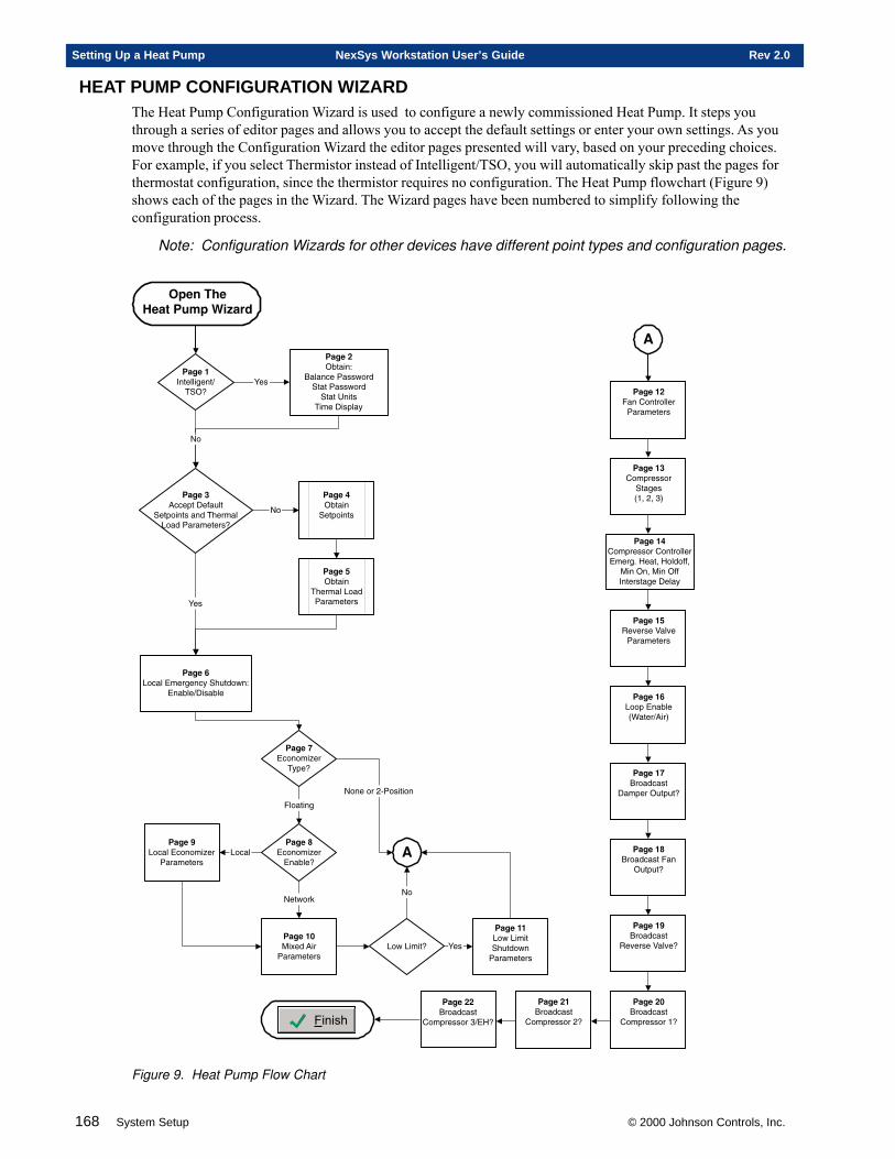
168 System Setup © 2000 Johnson Controls, Inc.
Setting Up a Heat Pump NexSys Workstation User’s Guide Rev 2.0
HEAT PUMP CONFIGURATION WIZARDThe Heat Pump Configuration Wizard is used to configure a newly commissioned Heat Pump. It steps youthrough a series of editor pages and allows you to accept the default settings or enter your own settings. As youmove through the Configuration Wizard the editor pages presented will vary, based on your preceding choices.For example, if you select Thermistor instead of Intelligent/TSO, you will automatically skip past the pages forthermostat configuration, since the thermistor requires no configuration. The Heat Pump flowchart (Figure 9)shows each of the pages in the Wizard. The Wizard pages have been numbered to simplify following theconfiguration process.
Note: Configuration Wizards for other devices have different point types and configuration pages.
�12���-�$�������$���,&
�12��/, $���7
.����(������1��*�$�$�����1��*�$�$�8��$�
�����!��2��"
'��
�12��.�((�2$�!�����$
��$2���$����*��#��������*�������$���&
+�
�12��#, $���
��$2���$�
�12��", $���
�#���������*������$���'��
�12��'��(����������("��#�$*�1�7
��� ���!��� ��
�12����(�����9��
�"2�&
����$���
+�������6�����$���
�12��0�(�����9����� ��&
+�$1��:
��(���12��$
��(����(�����9��������$���
�12���%)�/�*����������$���
�
��1�����$&
+�
�12������1�����$�#�$*�1�������$���
�3� �+4���1���6�3��51��
� �
+�
'��
�12��//.���*(��$
��2�������;��<&
�
�12���/���� ��$������������$���
�12���. ��2������
�$����=�4�64�;>
�12���"3�%��������%�������$���
�12���'���2���� ��=5�$������>
�12����.���*(��$
!��2���,�$2�$&
�12���0.���*(��$����
,�$2�$&
�12���$.���*(��$
3�%��������%�&
�12��/%.���*(��$
��2��������&
�12��/�.���*(��$
��2�������6&
�12���# ��2������� ��$�����������?�<��$4�<��*���4
)���,�4�)���,��-�$���$����!���"
����
Figure 9. Heat Pump Flow Chart
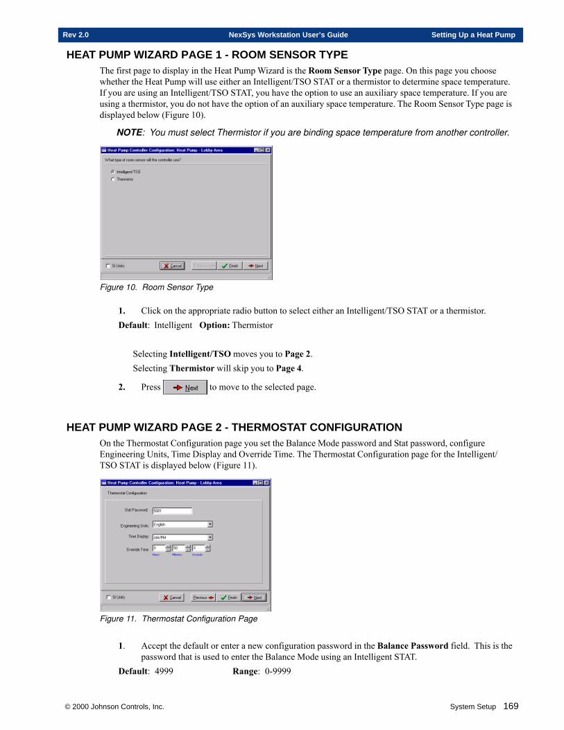
© 2000 Johnson Controls, Inc. System Setup 169
Rev 2.0 NexSys Workstation User’s Guide Setting Up a Heat Pump
HEAT PUMP WIZARD PAGE 1 - ROOM SENSOR TYPEThe first page to display in the Heat Pump Wizard is the Room Sensor Type page. On this page you choosewhether the Heat Pump will use either an Intelligent/TSO STAT or a thermistor to determine space temperature.If you are using an Intelligent/TSO STAT, you have the option to use an auxiliary space temperature. If you areusing a thermistor, you do not have the option of an auxiliary space temperature. The Room Sensor Type page isdisplayed below (Figure 10).
NOTE: You must select Thermistor if you are binding space temperature from another controller.
Figure 10. Room Sensor Type
1. Click on the appropriate radio button to select either an Intelligent/TSO STAT or a thermistor.Default: Intelligent Option: Thermistor
Selecting Intelligent/TSO moves you to Page 2.Selecting Thermistor will skip you to Page 4.
2. Press to move to the selected page.
HEAT PUMP WIZARD PAGE 2 - THERMOSTAT CONFIGURATIONOn the Thermostat Configuration page you set the Balance Mode password and Stat password, configureEngineering Units, Time Display and Override Time. The Thermostat Configuration page for the Intelligent/TSO STAT is displayed below (Figure 11).
Figure 11. Thermostat Configuration Page
1. Accept the default or enter a new configuration password in the Balance Password field. This is thepassword that is used to enter the Balance Mode using an Intelligent STAT.
Default: 4999 Range: 0-9999

170 System Setup © 2000 Johnson Controls, Inc.
Setting Up a Heat Pump NexSys Workstation User’s Guide Rev 2.0
2. Accept the default or enter a new configuration password in the Stat Password field. This is thepassword that is used to enter the Configuration Mode using an Intelligent STAT.
Default: 5001 Range: 0-99993. Select whether the Intelligent STAT displays Engineering Units in English or Metric. This applies
to all units that are displayed on the Intelligent STAT.Default: English Option: Metric
NOTE: This applies even if you are using a thermistor because you can still use the IntelligentSTAT as a configuration tool through the STAT port.
4. Select whether the Intelligent STAT displays the Time Display in AM/PM or Military. This appliesto all time mode parameters that are displayed on the Intelligent STAT.
Default: AM/PM Option: Military
NOTE: This applies even if you are using a thermistor because you can still use the IntelligentSTAT as a configuration tool through the STAT port.
5. Select the Override Time for the parameters in User Mode on the Intelligent STAT. Override is usedto cause the system to control to the occupied setpoints when the building is not normally occupied.Override places the controller back into occupied mode for a specified time (set in the Override Timefield). When this time expires, the previous control (setpoints) resumes.
Default: 50 minutes
6. Click to advance to Page 3 - Default Setpoints and Thermal Load Parameters.
HEAT PUMP WIZARD PAGE 3 - DEFAULT SETPOINTS & THERMAL LOAD PARAM-ETERS
On this page you choose whether to accept the Default Setpoints and Thermal Load Parameters. The DefaultSetpoints and Thermal Load Parameters page for the Intelligent/TSO STAT is displayed below (Figure 12).
Figure 12. Default Setpoints and Thermal Load Parameters Page
2. Accept the Default Setpoints and Thermal Load Parameters by clicking on the appropriate radiobutton. The Default Parameters are found on Page 4 and the Default Thermal Load Parametersare found on Page 5.
Default: Yes Option: NoSelecting Yes skips you to Page 6 - Emergency Shutdown.Selecting No moves you to Page 4 - Setpoint Configuration.
3. Click to advance to the selected page.
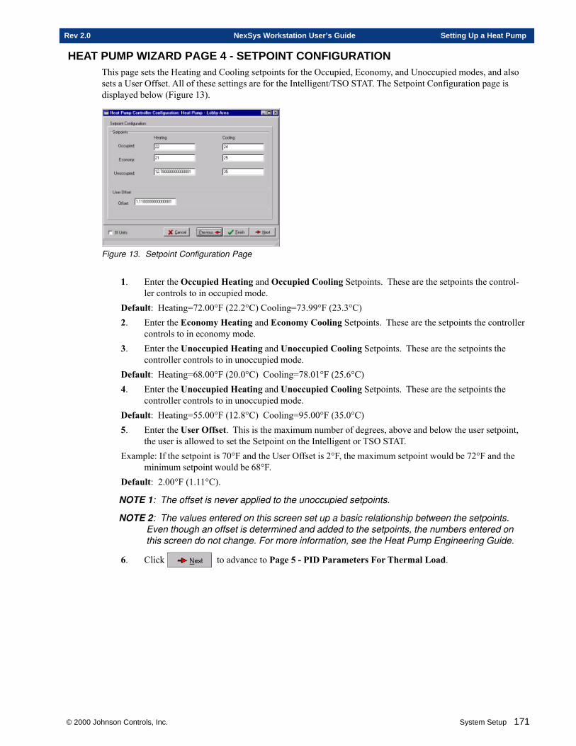
© 2000 Johnson Controls, Inc. System Setup 171
Rev 2.0 NexSys Workstation User’s Guide Setting Up a Heat Pump
HEAT PUMP WIZARD PAGE 4 - SETPOINT CONFIGURATIONThis page sets the Heating and Cooling setpoints for the Occupied, Economy, and Unoccupied modes, and alsosets a User Offset. All of these settings are for the Intelligent/TSO STAT. The Setpoint Configuration page isdisplayed below (Figure 13).
Figure 13. Setpoint Configuration Page
1. Enter the Occupied Heating and Occupied Cooling Setpoints. These are the setpoints the control-ler controls to in occupied mode.
Default: Heating=72.00°F (22.2°C) Cooling=73.99°F (23.3°C)2. Enter the Economy Heating and Economy Cooling Setpoints. These are the setpoints the controller
controls to in economy mode.3. Enter the Unoccupied Heating and Unoccupied Cooling Setpoints. These are the setpoints the
controller controls to in unoccupied mode.Default: Heating=68.00°F (20.0°C) Cooling=78.01°F (25.6°C)4. Enter the Unoccupied Heating and Unoccupied Cooling Setpoints. These are the setpoints the
controller controls to in unoccupied mode.Default: Heating=55.00°F (12.8°C) Cooling=95.00°F (35.0°C)5. Enter the User Offset. This is the maximum number of degrees, above and below the user setpoint,
the user is allowed to set the Setpoint on the Intelligent or TSO STAT.Example: If the setpoint is 70°F and the User Offset is 2°F, the maximum setpoint would be 72°F and the
minimum setpoint would be 68°F.Default: 2.00°F (1.11°C).
NOTE 1: The offset is never applied to the unoccupied setpoints.
NOTE 2: The values entered on this screen set up a basic relationship between the setpoints.Even though an offset is determined and added to the setpoints, the numbers entered onthis screen do not change. For more information, see the Heat Pump Engineering Guide.
6. Click to advance to Page 5 - PID Parameters For Thermal Load.
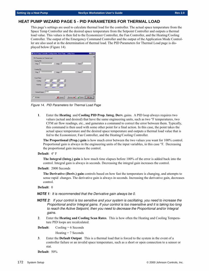
172 System Setup © 2000 Johnson Controls, Inc.
Setting Up a Heat Pump NexSys Workstation User’s Guide Rev 2.0
HEAT PUMP WIZARD PAGE 5 - PID PARAMETERS FOR THERMAL LOADThis page’s settings are used to calculate thermal load for the controller. The actual space temperature from theSpace Temp Controller and the desired space temperature from the Setpoint Controller and outputs a thermalload value. This values is then fed to the Economizer Controller, the Fan Controller, and the Heating/CoolingController. The output of the Emergency Command Controller and the output of the Application Mode Control-ler are also used at in the determination of thermal load. The PID Parameters for Thermal Load page is dis-played below (Figure 14).
Figure 14. PID Parameters for Thermal Load Page
1. Enter the Heating and Cooling PID Prop. Integ. Derv. gains. A PID loop always requires twovalues (actual and desired) that have the same engineering units, such as two °F temperatures, twoCFM air flow readings, etc., and generates a command to correct the error between them. Typically,this command is then used with some other point for a final action. In this case, the point takes theactual space temperature and the desired space temperature and outputs a thermal load value that isfed to the Economizer, Fan Controller, and the Heating/Cooling Controller.
The Proportional (Prop.) gain is how much error between the two values you want for 100% control.Proportional gain is always in the engineering units of the input variables, in this case °F. Decreasingthe proportional gain increases the control.
Default: 4° FThe Integral (Integ.) gain is how much time elapses before 100% of the error is added back into thecontrol. Integral gain is always in seconds. Decreasing the integral gain increases the control.
Default: 2000 SecondsThe Derivative (Deriv.) gain controls based on how fast the temperature is changing, and attempts tosense rapid changes. The derivative gain is always in seconds. Increasing the derivative gain, decreasescontrol.
Default: 0
NOTE 1: It is recommended that the Derivative gain always be 0.
NOTE 2: If your control is too sensitive and your system is oscillating, you need to increase theProportional and/or Integral gains. If your control is too insensitive and it is taking too longto reach the Active Setpoint, then you need to decrease the Proportional and/or Integralgains.
2. Enter the Heating and Cooling Scan Rates. This is how often the Heating and Cooling Tempera-ture PID loops are recalculated.
Default: Cooling = 6 SecondsHeating = 7 Seconds
3. Enter the Default Output. This is a thermal load that is forced to the system in the event of acontroller failure or an invalid space temperature, such as a short or open connection to a sensor orstat.
Default: 50%
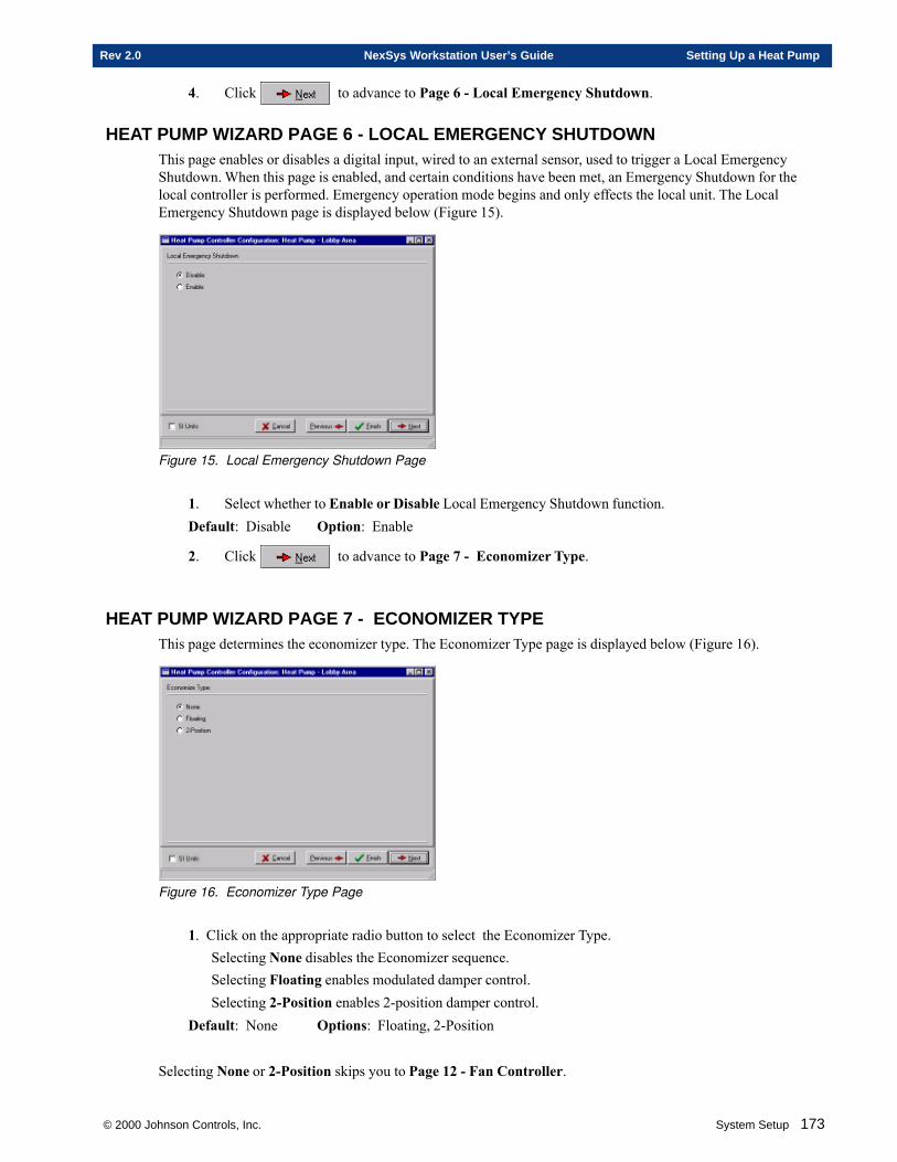
© 2000 Johnson Controls, Inc. System Setup 173
Rev 2.0 NexSys Workstation User’s Guide Setting Up a Heat Pump
4. Click to advance to Page 6 - Local Emergency Shutdown.
HEAT PUMP WIZARD PAGE 6 - LOCAL EMERGENCY SHUTDOWNThis page enables or disables a digital input, wired to an external sensor, used to trigger a Local EmergencyShutdown. When this page is enabled, and certain conditions have been met, an Emergency Shutdown for thelocal controller is performed. Emergency operation mode begins and only effects the local unit. The LocalEmergency Shutdown page is displayed below (Figure 15).
Figure 15. Local Emergency Shutdown Page
1. Select whether to Enable or Disable Local Emergency Shutdown function.Default: Disable Option: Enable
2. Click to advance to Page 7 - Economizer Type.
HEAT PUMP WIZARD PAGE 7 - ECONOMIZER TYPEThis page determines the economizer type. The Economizer Type page is displayed below (Figure 16).
Figure 16. Economizer Type Page
1. Click on the appropriate radio button to select the Economizer Type.Selecting None disables the Economizer sequence.Selecting Floating enables modulated damper control.Selecting 2-Position enables 2-position damper control.
Default: None Options: Floating, 2-Position
Selecting None or 2-Position skips you to Page 12 - Fan Controller.
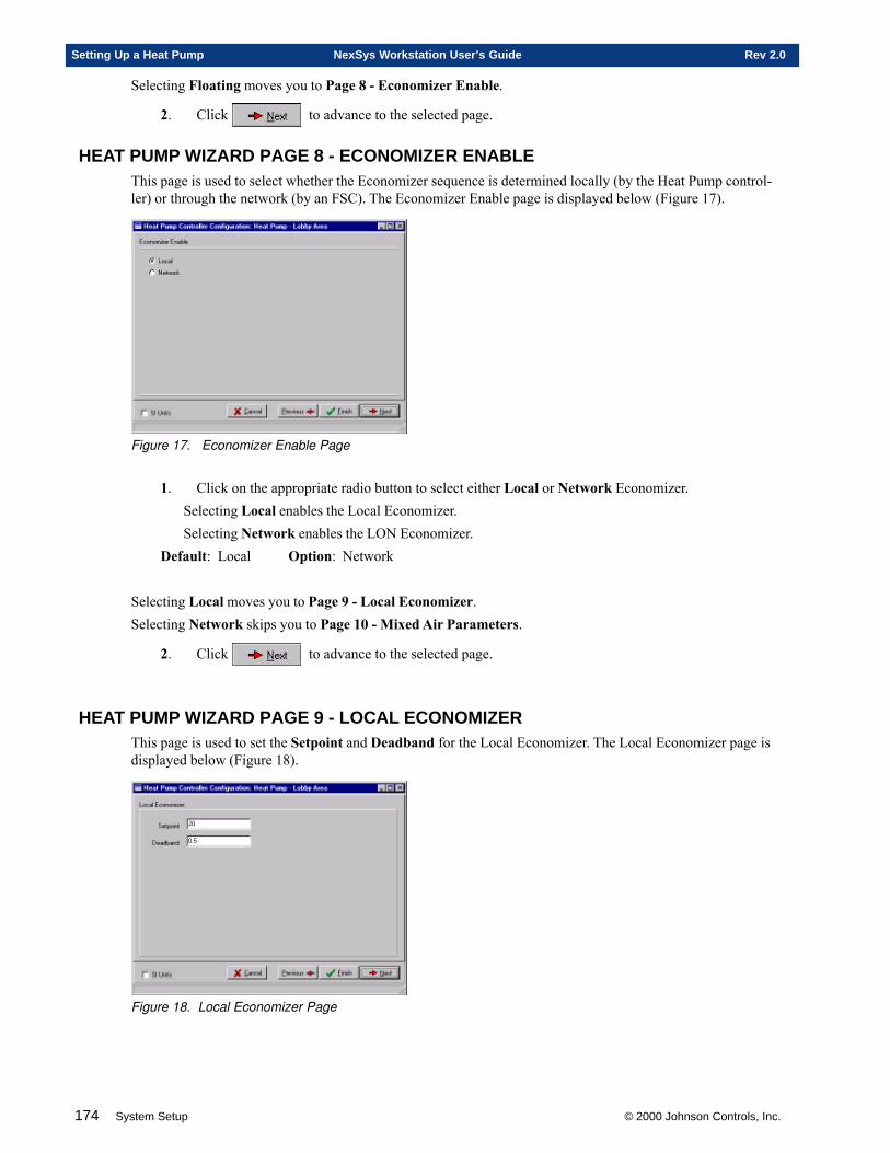
174 System Setup © 2000 Johnson Controls, Inc.
Setting Up a Heat Pump NexSys Workstation User’s Guide Rev 2.0
Selecting Floating moves you to Page 8 - Economizer Enable.
2. Click to advance to the selected page.
HEAT PUMP WIZARD PAGE 8 - ECONOMIZER ENABLEThis page is used to select whether the Economizer sequence is determined locally (by the Heat Pump control-ler) or through the network (by an FSC). The Economizer Enable page is displayed below (Figure 17).
Figure 17. Economizer Enable Page
1. Click on the appropriate radio button to select either Local or Network Economizer.Selecting Local enables the Local Economizer.Selecting Network enables the LON Economizer.
Default: Local Option: Network
Selecting Local moves you to Page 9 - Local Economizer.Selecting Network skips you to Page 10 - Mixed Air Parameters.
2. Click to advance to the selected page.
HEAT PUMP WIZARD PAGE 9 - LOCAL ECONOMIZERThis page is used to set the Setpoint and Deadband for the Local Economizer. The Local Economizer page isdisplayed below (Figure 18).
Figure 18. Local Economizer Page

© 2000 Johnson Controls, Inc. System Setup 175
Rev 2.0 NexSys Workstation User’s Guide Setting Up a Heat Pump
1. Enter the Setpoint. This is the outside air temperature(OAT) and is dependent on your geographicallocation. This is the temperature at which the economizer sequence is enabled.
Default: 55.00°F2. Enter the OAT Deadband. This is the range the OAT must pass in order to enable or disable the
economizer sequence. For example, if the OAT deadband was set at 2°F and the OAT setpoint wasset at 55°, then the economizer sequence would not ENABLED until 53°F and would not be DIS-ABLED until the OAT setpoint had reached 57°F.
Default: 2.50°F
3. Click to advance to Page 10 - Mixed Air Parameters.
HEAT PUMP WIZARD PAGE 10 - MIXED AIR PARAMETERSThis page’s settings are used to calculate a Mixed Air PID damper position in percent. Mixed Air Parameterstakes the Setpoint of either the Mixed Air Temperature or the Discharge Air Temperature and outputs a MixedAir PID damper position in percent. This is not the absolute damper position because this position is based onlyon the Discharge Air Temp and the Mixed Air Setpoint. This output is then fed to the Economizer Controller andthe exact damper position is determined. The Mixed Air Parameters page is displayed below (Figure 19).
Figure 19. Mixed Air Parameters Page
1. Enter the Minimum Damper Percent. This is the minimum percent the damper will close to.Default: 10%2. Accept the Temperature Source default or choose a different one from the drop-down list box. The
Temperature Source determines if the Setpoint for the Mixed Air PID is from the Mixed Air Tem-perature or the Discharge Air Temperature.
Default: Mixed_Air_Temp Options: Discharge_Air_Temp3. Enter the Setpoint, for the Temperature Source selected above, in the Setpoint field. This setpoint
serves as the desired value in the PID loop.Default: 12.794. Enter the Air PID Values: Prop. Integ. Derv. A PID loop always requires two values (actual and
desired) that have the same engineering units, such as two °F temperatures, two CFM air flowreadings, etc., and generates a command to correct the error between them. Typically, this commandis then used with some other point for a final action. In this case, the point takes either the actualMixed Air Temp or the actual Discharge Air Temp, and the desired Setpoint and outputs a value tothe Economizer.
The Proportional (Prop.) gain is how much error between the two values you want for 100% control.Proportional gain is always in the engineering units of the input variables, in this case ° C. Decreasingthe proportional gain increases the control.
Default: 2.2° C
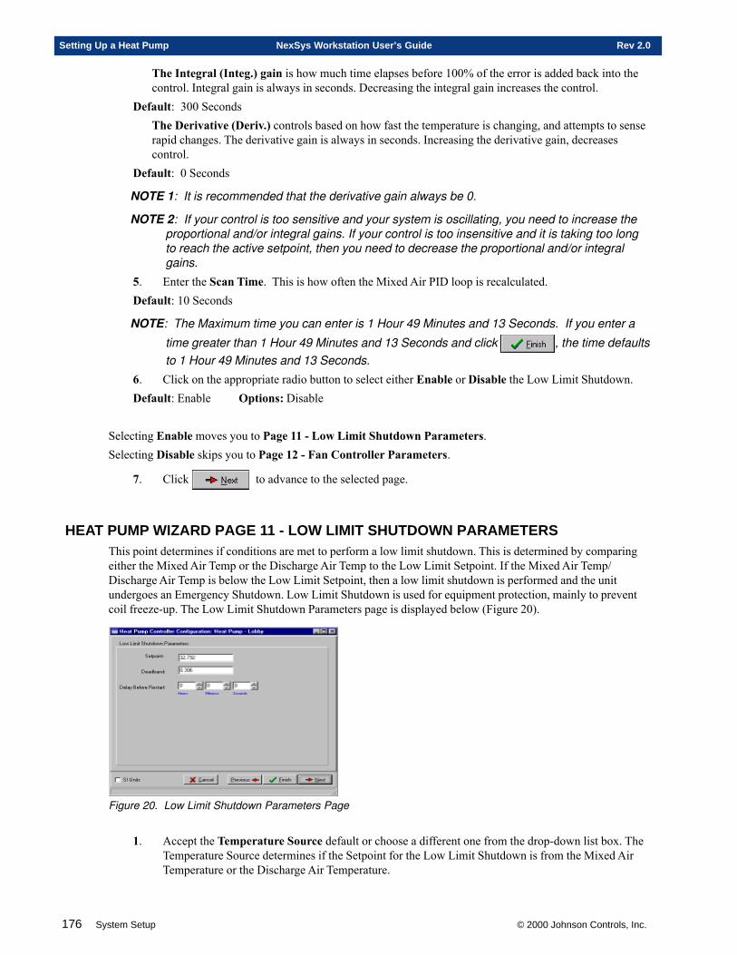
176 System Setup © 2000 Johnson Controls, Inc.
Setting Up a Heat Pump NexSys Workstation User’s Guide Rev 2.0
The Integral (Integ.) gain is how much time elapses before 100% of the error is added back into thecontrol. Integral gain is always in seconds. Decreasing the integral gain increases the control.
Default: 300 SecondsThe Derivative (Deriv.) controls based on how fast the temperature is changing, and attempts to senserapid changes. The derivative gain is always in seconds. Increasing the derivative gain, decreasescontrol.
Default: 0 Seconds
NOTE 1: It is recommended that the derivative gain always be 0.
NOTE 2: If your control is too sensitive and your system is oscillating, you need to increase theproportional and/or integral gains. If your control is too insensitive and it is taking too longto reach the active setpoint, then you need to decrease the proportional and/or integralgains.
5. Enter the Scan Time. This is how often the Mixed Air PID loop is recalculated.Default: 10 Seconds
NOTE: The Maximum time you can enter is 1 Hour 49 Minutes and 13 Seconds. If you enter a
time greater than 1 Hour 49 Minutes and 13 Seconds and click , the time defaultsto 1 Hour 49 Minutes and 13 Seconds.
6. Click on the appropriate radio button to select either Enable or Disable the Low Limit Shutdown.Default: Enable Options: Disable
Selecting Enable moves you to Page 11 - Low Limit Shutdown Parameters.Selecting Disable skips you to Page 12 - Fan Controller Parameters.
7. Click to advance to the selected page.
HEAT PUMP WIZARD PAGE 11 - LOW LIMIT SHUTDOWN PARAMETERSThis point determines if conditions are met to perform a low limit shutdown. This is determined by comparingeither the Mixed Air Temp or the Discharge Air Temp to the Low Limit Setpoint. If the Mixed Air Temp/Discharge Air Temp is below the Low Limit Setpoint, then a low limit shutdown is performed and the unitundergoes an Emergency Shutdown. Low Limit Shutdown is used for equipment protection, mainly to preventcoil freeze-up. The Low Limit Shutdown Parameters page is displayed below (Figure 20).
Figure 20. Low Limit Shutdown Parameters Page
1. Accept the Temperature Source default or choose a different one from the drop-down list box. TheTemperature Source determines if the Setpoint for the Low Limit Shutdown is from the Mixed AirTemperature or the Discharge Air Temperature.
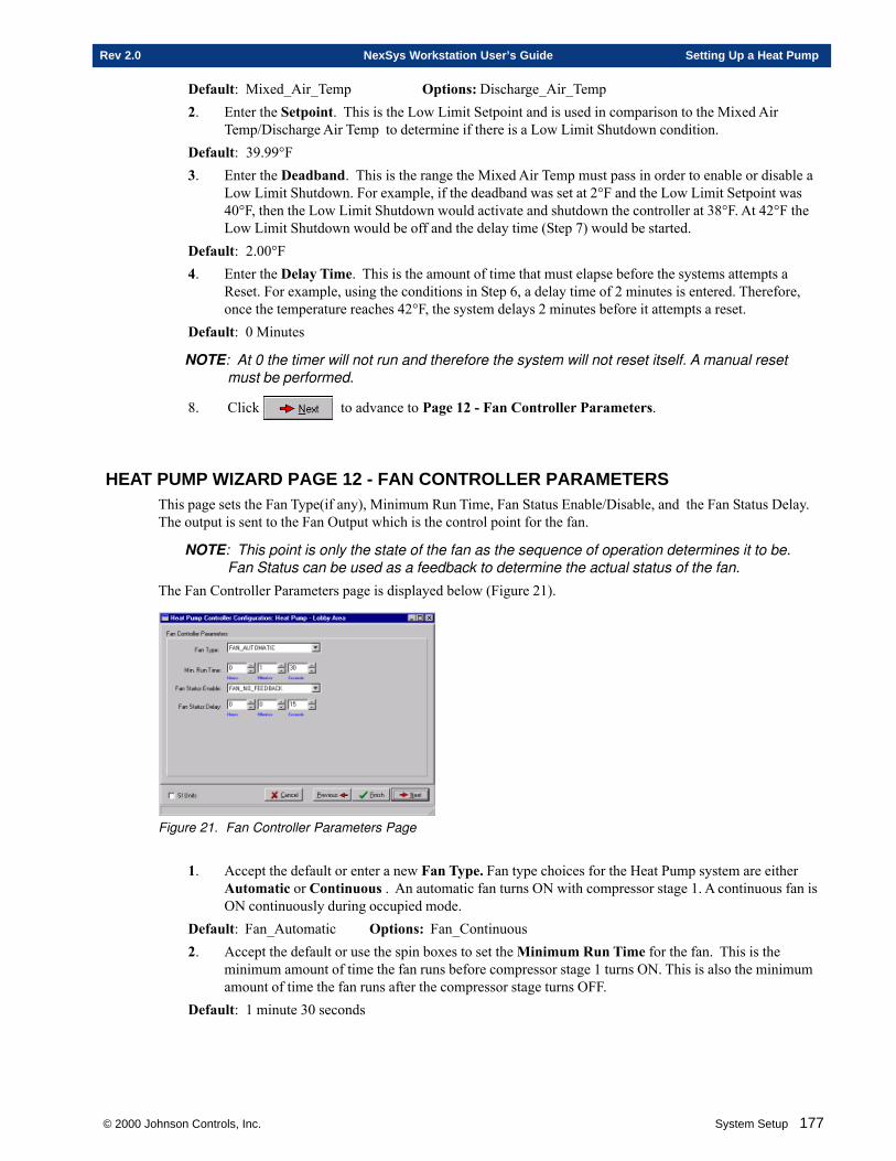
© 2000 Johnson Controls, Inc. System Setup 177
Rev 2.0 NexSys Workstation User’s Guide Setting Up a Heat Pump
Default: Mixed_Air_Temp Options: Discharge_Air_Temp2. Enter the Setpoint. This is the Low Limit Setpoint and is used in comparison to the Mixed Air
Temp/Discharge Air Temp to determine if there is a Low Limit Shutdown condition.Default: 39.99°F3. Enter the Deadband. This is the range the Mixed Air Temp must pass in order to enable or disable a
Low Limit Shutdown. For example, if the deadband was set at 2°F and the Low Limit Setpoint was40°F, then the Low Limit Shutdown would activate and shutdown the controller at 38°F. At 42°F theLow Limit Shutdown would be off and the delay time (Step 7) would be started.
Default: 2.00°F4. Enter the Delay Time. This is the amount of time that must elapse before the systems attempts a
Reset. For example, using the conditions in Step 6, a delay time of 2 minutes is entered. Therefore,once the temperature reaches 42°F, the system delays 2 minutes before it attempts a reset.
Default: 0 Minutes
NOTE: At 0 the timer will not run and therefore the system will not reset itself. A manual resetmust be performed.
8. Click to advance to Page 12 - Fan Controller Parameters.
HEAT PUMP WIZARD PAGE 12 - FAN CONTROLLER PARAMETERSThis page sets the Fan Type(if any), Minimum Run Time, Fan Status Enable/Disable, and the Fan Status Delay.The output is sent to the Fan Output which is the control point for the fan.
NOTE: This point is only the state of the fan as the sequence of operation determines it to be.Fan Status can be used as a feedback to determine the actual status of the fan.
The Fan Controller Parameters page is displayed below (Figure 21).
Figure 21. Fan Controller Parameters Page
1. Accept the default or enter a new Fan Type. Fan type choices for the Heat Pump system are eitherAutomatic or Continuous . An automatic fan turns ON with compressor stage 1. A continuous fan isON continuously during occupied mode.
Default: Fan_Automatic Options: Fan_Continuous2. Accept the default or use the spin boxes to set the Minimum Run Time for the fan. This is the
minimum amount of time the fan runs before compressor stage 1 turns ON. This is also the minimumamount of time the fan runs after the compressor stage turns OFF.
Default: 1 minute 30 seconds

178 System Setup © 2000 Johnson Controls, Inc.
Setting Up a Heat Pump NexSys Workstation User’s Guide Rev 2.0
NOTE: The Maximum time you can enter is 1 Hour 49 Minutes and 13 Seconds. If you enter a
time greater than 1 Hour 49 Minutes and 13 Seconds and click , the time de-faults to 1 Hour 49 Minutes and 13 Seconds.
3. The Fan Status Enable box enables feedback to determine the status of the fan. This requireshardware in the field to verify the status of the fan. Fan Status Enable choices for the Heat Pumpsystem are either Fan_No_Feedback or Fan_Status_Feedback. Fan_No_Feedback orFan_Status_Feedback. An automatic fan turns ON with compressor stage 1. A continuous fan is ONcontinuously during occupied mode.
Default: Fan_No_Feedback Options: Fan_Status_Feedback4. Accept the default or use the spin boxes to set the Fan Status Delay time. The Fan Status Delay is
the minimum amount of time that must elapse after there is a change in the Fan Status. This delayallows for no false readings on the Fan Status.
Default: 15 seconds
5. Click to advance to Page 13 - Number of Stages For Compressor.
HEAT PUMP WIZARD PAGE 13 - NUMBER OF STAGES FOR COMPRESSOR?This page sets whether the Heat Pump compressor is a 1, 2, or 3 stage compressor.The Number of Stages For Compressor page is displayed below (Figure 22).
Figure 22. Number of Compressor Stages
1. Click a radio button to set the Number of Stages for the compressor.Default: 2 Options: 1 or 3
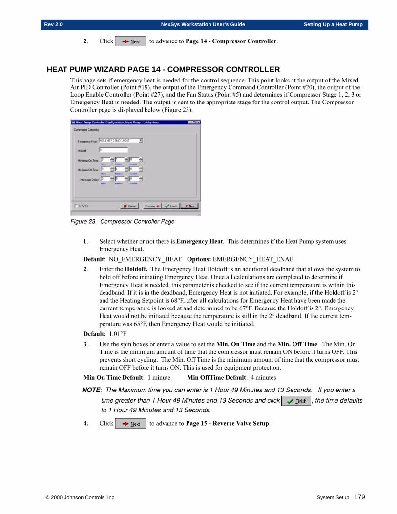
© 2000 Johnson Controls, Inc. System Setup 179
Rev 2.0 NexSys Workstation User’s Guide Setting Up a Heat Pump
2. Click to advance to Page 14 - Compressor Controller.
HEAT PUMP WIZARD PAGE 14 - COMPRESSOR CONTROLLERThis page sets if emergency heat is needed for the control sequence. This point looks at the output of the MixedAir PID Controller (Point #19), the output of the Emergency Command Controller (Point #20), the output of theLoop Enable Controller (Point #27), and the Fan Status (Point #5) and determines if Compressor Stage 1, 2, 3 orEmergency Heat is needed. The output is sent to the appropriate stage for the control output. The CompressorController page is displayed below (Figure 23).
Figure 23. Compressor Controller Page
1. Select whether or not there is Emergency Heat. This determines if the Heat Pump system usesEmergency Heat.
Default: NO_EMERGENCY_HEAT Options: EMERGENCY_HEAT_ENAB2. Enter the Holdoff. The Emergency Heat Holdoff is an additional deadband that allows the system to
hold off before initiating Emergency Heat. Once all calculations are completed to determine ifEmergency Heat is needed, this parameter is checked to see if the current temperature is within thisdeadband. If it is in the deadband, Emergency Heat is not initiated. For example, if the Holdoff is 2°and the Heating Setpoint is 68°F, after all calculations for Emergency Heat have been made thecurrent temperature is looked at and determined to be 67°F. Because the Holdoff is 2°, EmergencyHeat would not be initiated because the temperature is still in the 2° deadband. If the current tem-perature was 65°F, then Emergency Heat would be initiated.
Default: 1.01°F3. Use the spin boxes or enter a value to set the Min. On Time and the Min. Off Time. The Min. On
Time is the minimum amount of time that the compressor must remain ON before it turns OFF. Thisprevents short cycling. The Min. Off Time is the minimum amount of time that the compressor mustremain OFF before it turns ON. This is used for equipment protection.
Min On Time Default: 1 minute Min OffTime Default: 4 minutes
NOTE: The Maximum time you can enter is 1 Hour 49 Minutes and 13 Seconds. If you enter a
time greater than 1 Hour 49 Minutes and 13 Seconds and click , the time defaultsto 1 Hour 49 Minutes and 13 Seconds.
4. Click to advance to Page 15 - Reverse Valve Setup.
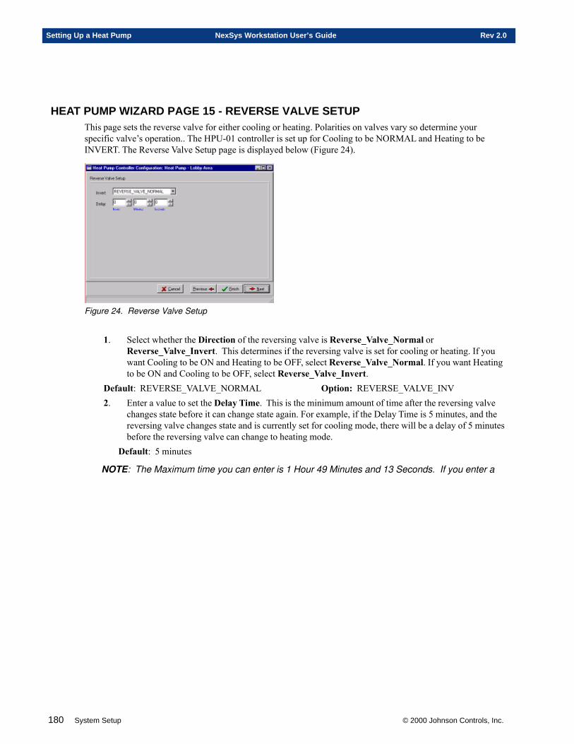
180 System Setup © 2000 Johnson Controls, Inc.
Setting Up a Heat Pump NexSys Workstation User’s Guide Rev 2.0
HEAT PUMP WIZARD PAGE 15 - REVERSE VALVE SETUPThis page sets the reverse valve for either cooling or heating. Polarities on valves vary so determine yourspecific valve’s operation.. The HPU-01 controller is set up for Cooling to be NORMAL and Heating to beINVERT. The Reverse Valve Setup page is displayed below (Figure 24).
Figure 24. Reverse Valve Setup
1. Select whether the Direction of the reversing valve is Reverse_Valve_Normal orReverse_Valve_Invert. This determines if the reversing valve is set for cooling or heating. If youwant Cooling to be ON and Heating to be OFF, select Reverse_Valve_Normal. If you want Heatingto be ON and Cooling to be OFF, select Reverse_Valve_Invert.
Default: REVERSE_VALVE_NORMAL Option: REVERSE_VALVE_INV2. Enter a value to set the Delay Time. This is the minimum amount of time after the reversing valve
changes state before it can change state again. For example, if the Delay Time is 5 minutes, and thereversing valve changes state and is currently set for cooling mode, there will be a delay of 5 minutesbefore the reversing valve can change to heating mode.
Default: 5 minutes
NOTE: The Maximum time you can enter is 1 Hour 49 Minutes and 13 Seconds. If you enter a
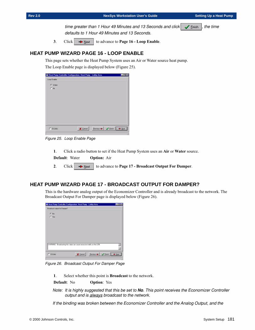
© 2000 Johnson Controls, Inc. System Setup 181
Rev 2.0 NexSys Workstation User’s Guide Setting Up a Heat Pump
time greater than 1 Hour 49 Minutes and 13 Seconds and click , the timedefaults to 1 Hour 49 Minutes and 13 Seconds.
3. Click to advance to Page 16 - Loop Enable.
HEAT PUMP WIZARD PAGE 16 - LOOP ENABLEThis page sets whether the Heat Pump System uses an Air or Water source heat pump.The Loop Enable page is displayed below (Figure 25).
Figure 25. Loop Enable Page
1. Click a radio button to set if the Heat Pump System uses an Air or Water source.Default: Water Option: Air
2. Click to advance to Page 17 - Broadcast Output For Damper.
HEAT PUMP WIZARD PAGE 17 - BROADCAST OUTPUT FOR DAMPER?This is the hardware analog output of the Economizer Controller and is already broadcast to the network. TheBroadcast Output For Damper page is displayed below (Figure 26).
Figure 26. Broadcast Output For Damper Page
1. Select whether this point is Broadcast to the network.Default: No Option: Yes
Note: It is highly suggested that this be set to No. This point receives the Economizer Controlleroutput and is always broadcast to the network.
If the binding was broken between the Economizer Controller and the Analog Output, and the
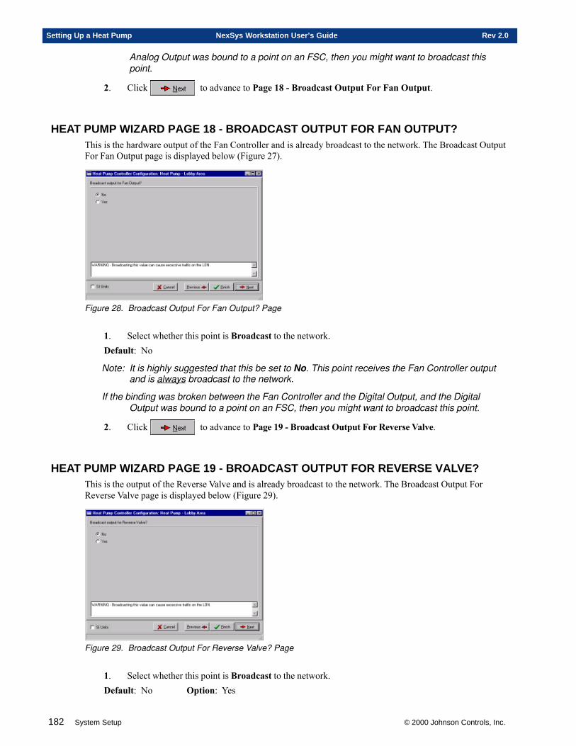
182 System Setup © 2000 Johnson Controls, Inc.
Setting Up a Heat Pump NexSys Workstation User’s Guide Rev 2.0
Analog Output was bound to a point on an FSC, then you might want to broadcast thispoint.
2. Click to advance to Page 18 - Broadcast Output For Fan Output.
HEAT PUMP WIZARD PAGE 18 - BROADCAST OUTPUT FOR FAN OUTPUT?This is the hardware output of the Fan Controller and is already broadcast to the network. The Broadcast OutputFor Fan Output page is displayed below (Figure 27).
Figure 28. Broadcast Output For Fan Output? Page
1. Select whether this point is Broadcast to the network.Default: No
Note: It is highly suggested that this be set to No. This point receives the Fan Controller outputand is always broadcast to the network.
If the binding was broken between the Fan Controller and the Digital Output, and the DigitalOutput was bound to a point on an FSC, then you might want to broadcast this point.
2. Click to advance to Page 19 - Broadcast Output For Reverse Valve.
HEAT PUMP WIZARD PAGE 19 - BROADCAST OUTPUT FOR REVERSE VALVE?This is the output of the Reverse Valve and is already broadcast to the network. The Broadcast Output ForReverse Valve page is displayed below (Figure 29).
Figure 29. Broadcast Output For Reverse Valve? Page
1. Select whether this point is Broadcast to the network.Default: No Option: Yes
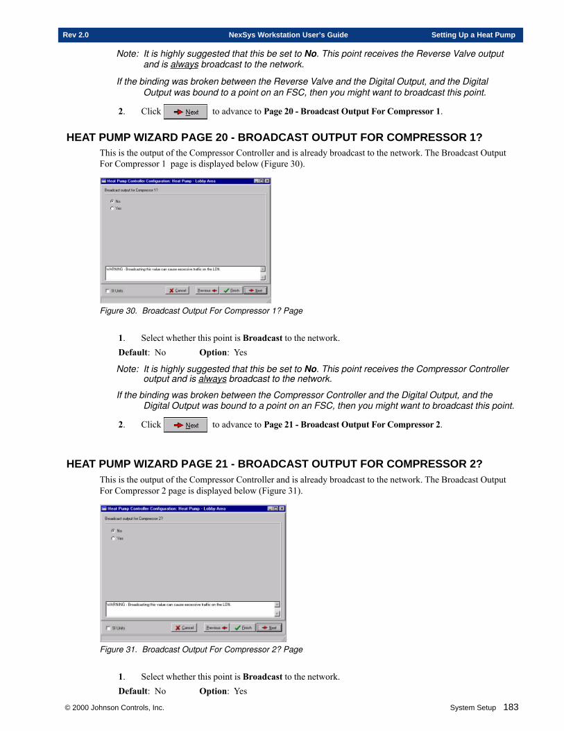
© 2000 Johnson Controls, Inc. System Setup 183
Rev 2.0 NexSys Workstation User’s Guide Setting Up a Heat Pump
Note: It is highly suggested that this be set to No. This point receives the Reverse Valve outputand is always broadcast to the network.
If the binding was broken between the Reverse Valve and the Digital Output, and the DigitalOutput was bound to a point on an FSC, then you might want to broadcast this point.
2. Click to advance to Page 20 - Broadcast Output For Compressor 1.
HEAT PUMP WIZARD PAGE 20 - BROADCAST OUTPUT FOR COMPRESSOR 1?This is the output of the Compressor Controller and is already broadcast to the network. The Broadcast OutputFor Compressor 1 page is displayed below (Figure 30).
Figure 30. Broadcast Output For Compressor 1? Page
1. Select whether this point is Broadcast to the network.Default: No Option: Yes
Note: It is highly suggested that this be set to No. This point receives the Compressor Controlleroutput and is always broadcast to the network.
If the binding was broken between the Compressor Controller and the Digital Output, and theDigital Output was bound to a point on an FSC, then you might want to broadcast this point.
2. Click to advance to Page 21 - Broadcast Output For Compressor 2.
HEAT PUMP WIZARD PAGE 21 - BROADCAST OUTPUT FOR COMPRESSOR 2?This is the output of the Compressor Controller and is already broadcast to the network. The Broadcast OutputFor Compressor 2 page is displayed below (Figure 31).
Figure 31. Broadcast Output For Compressor 2? Page
1. Select whether this point is Broadcast to the network.Default: No Option: Yes
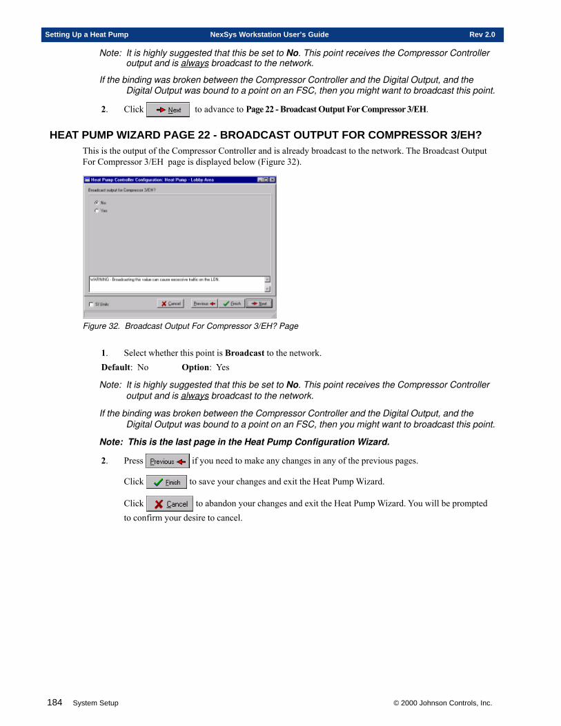
184 System Setup © 2000 Johnson Controls, Inc.
Setting Up a Heat Pump NexSys Workstation User’s Guide Rev 2.0
Note: It is highly suggested that this be set to No. This point receives the Compressor Controlleroutput and is always broadcast to the network.
If the binding was broken between the Compressor Controller and the Digital Output, and theDigital Output was bound to a point on an FSC, then you might want to broadcast this point.
2. Click to advance to Page 22 - Broadcast Output For Compressor 3/EH.
HEAT PUMP WIZARD PAGE 22 - BROADCAST OUTPUT FOR COMPRESSOR 3/EH?This is the output of the Compressor Controller and is already broadcast to the network. The Broadcast OutputFor Compressor 3/EH page is displayed below (Figure 32).
Figure 32. Broadcast Output For Compressor 3/EH? Page
1. Select whether this point is Broadcast to the network.Default: No Option: Yes
Note: It is highly suggested that this be set to No. This point receives the Compressor Controlleroutput and is always broadcast to the network.
If the binding was broken between the Compressor Controller and the Digital Output, and theDigital Output was bound to a point on an FSC, then you might want to broadcast this point.
Note: This is the last page in the Heat Pump Configuration Wizard.
2. Press if you need to make any changes in any of the previous pages.
Click to save your changes and exit the Heat Pump Wizard.
Click to abandon your changes and exit the Heat Pump Wizard. You will be promptedto confirm your desire to cancel.
Chapter Six
Setting Up a PEC
This chapter contains information on:
� Setting Up A PEC
� Defining A PEC
� Commissioning A PEC
� Configuring A PEC
© 2000 Johnson Controls, Inc.
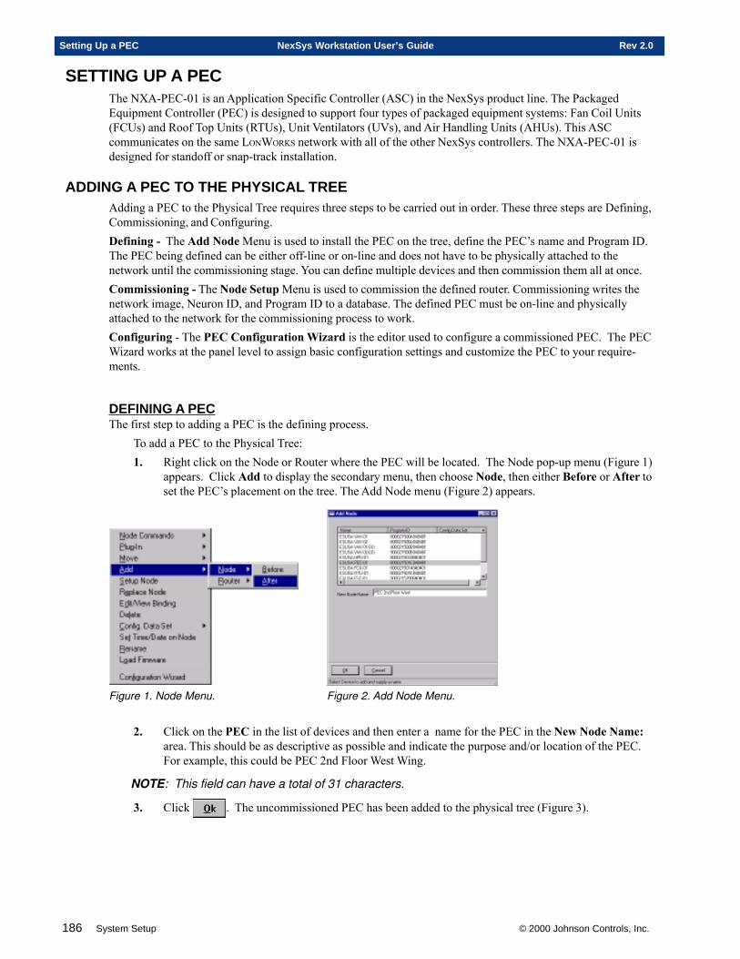
186 System Setup © 2000 Johnson Controls, Inc.
Setting Up a PEC NexSys Workstation User’s Guide Rev 2.0
SETTING UP A PECThe NXA-PEC-01 is an Application Specific Controller (ASC) in the NexSys product line. The PackagedEquipment Controller (PEC) is designed to support four types of packaged equipment systems: Fan Coil Units(FCUs) and Roof Top Units (RTUs), Unit Ventilators (UVs), and Air Handling Units (AHUs). This ASCcommunicates on the same LONWORKS network with all of the other NexSys controllers. The NXA-PEC-01 isdesigned for standoff or snap-track installation.
ADDING A PEC TO THE PHYSICAL TREEAdding a PEC to the Physical Tree requires three steps to be carried out in order. These three steps are Defining,Commissioning, and Configuring.Defining - The Add Node Menu is used to install the PEC on the tree, define the PEC’s name and Program ID.The PEC being defined can be either off-line or on-line and does not have to be physically attached to thenetwork until the commissioning stage. You can define multiple devices and then commission them all at once.Commissioning - The Node Setup Menu is used to commission the defined router. Commissioning writes thenetwork image, Neuron ID, and Program ID to a database. The defined PEC must be on-line and physicallyattached to the network for the commissioning process to work.Configuring - The PEC Configuration Wizard is the editor used to configure a commissioned PEC. The PECWizard works at the panel level to assign basic configuration settings and customize the PEC to your require-ments.
DEFINING A PECThe first step to adding a PEC is the defining process.
To add a PEC to the Physical Tree:1. Right click on the Node or Router where the PEC will be located. The Node pop-up menu (Figure 1)
appears. Click Add to display the secondary menu, then choose Node, then either Before or After toset the PEC’s placement on the tree. The Add Node menu (Figure 2) appears.
Figure 1. Node Menu. Figure 2. Add Node Menu.
2. Click on the PEC in the list of devices and then enter a name for the PEC in the New Node Name:area. This should be as descriptive as possible and indicate the purpose and/or location of the PEC.For example, this could be PEC 2nd Floor West Wing.
NOTE: This field can have a total of 31 characters.
3. Click . The uncommissioned PEC has been added to the physical tree (Figure 3).
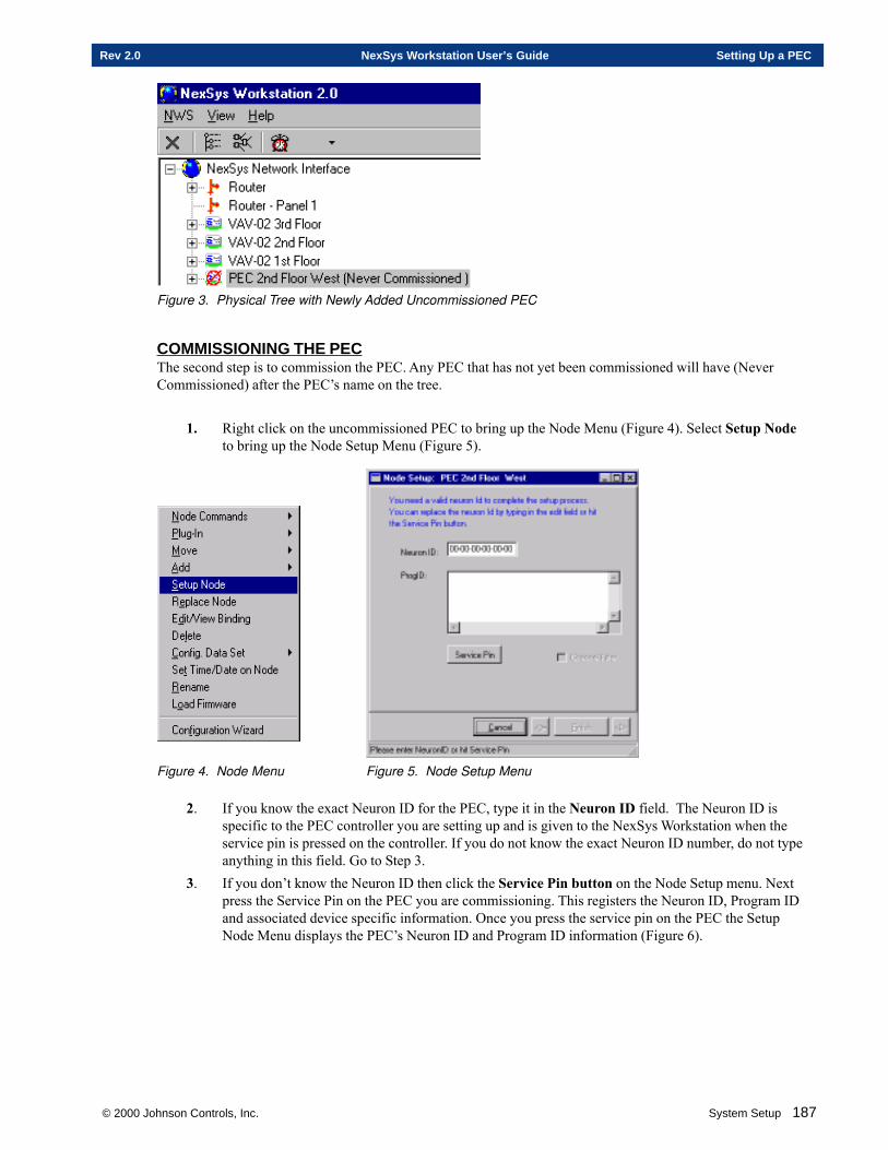
© 2000 Johnson Controls, Inc. System Setup 187
Rev 2.0 NexSys Workstation User’s Guide Setting Up a PEC
Figure 3. Physical Tree with Newly Added Uncommissioned PEC
COMMISSIONING THE PECThe second step is to commission the PEC. Any PEC that has not yet been commissioned will have (NeverCommissioned) after the PEC’s name on the tree.
1. Right click on the uncommissioned PEC to bring up the Node Menu (Figure 4). Select Setup Nodeto bring up the Node Setup Menu (Figure 5).
Figure 4. Node Menu Figure 5. Node Setup Menu
2. If you know the exact Neuron ID for the PEC, type it in the Neuron ID field. The Neuron ID isspecific to the PEC controller you are setting up and is given to the NexSys Workstation when theservice pin is pressed on the controller. If you do not know the exact Neuron ID number, do not typeanything in this field. Go to Step 3.
3. If you don’t know the Neuron ID then click the Service Pin button on the Node Setup menu. Nextpress the Service Pin on the PEC you are commissioning. This registers the Neuron ID, Program IDand associated device specific information. Once you press the service pin on the PEC the SetupNode Menu displays the PEC’s Neuron ID and Program ID information (Figure 6).
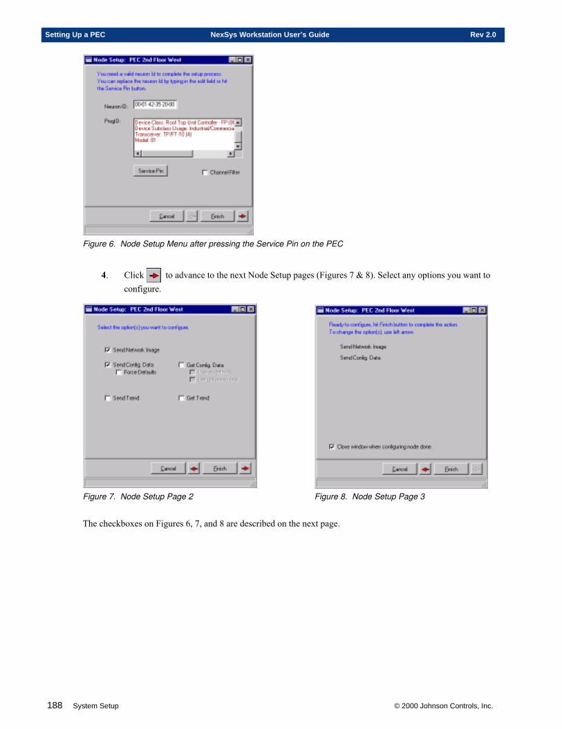
188 System Setup © 2000 Johnson Controls, Inc.
Setting Up a PEC NexSys Workstation User’s Guide Rev 2.0
Figure 6. Node Setup Menu after pressing the Service Pin on the PEC
4. Click to advance to the next Node Setup pages (Figures 7 & 8). Select any options you want toconfigure.
Figure 7. Node Setup Page 2 Figure 8. Node Setup Page 3
The checkboxes on Figures 6, 7, and 8 are described on the next page.
© 2000 Johnson Controls, Inc. System Setup 189
Rev 2.0 NexSys Workstation User’s Guide Setting Up a PEC
CHECK BOX EXPLANATIONSThe node setup pages contain a number of checkboxes that are used in the configuration process. Their settingsdetermine the information sent and whether it is sent from the LNS database to the device, or vice-versa.Choose carefully how you use these commands. If used incorrectly, it is possible to overwrite default valuesthat are not recoverable.
NOTE: SEND moves data from the LNS database to the device.
GET moves data from the device to the LNS database.
Send Network Image - Sends the device’s network address and bindings to the LNS database.Send Config. Data - Sends the device’s configuration parameters (CPs) from the LNS database to the device.Force Defaults - Sends the default CPs from the LNS database to the device.Send Trend - Sends Trend setup data from the LNS database to the device.Get Config. Data - Gets the device’s CPs from the device and sends them to the LNS database. This is used asa backup in the event the device requires reconfiguration.
Use as defaults - Checking this box gets the device’s current configuration settings and makes them thedefault CP settings for all similar devices. These settings are stored in the LNS database.
Note: Use this command when you have a number of devices that will be configured the same.Configure the first device the way you want the rest to resemble. Then
Get unknown only - Gets any “unknown” CP data, from the device currently being setup, and sends it tothe LNS database. Typically, unknown CP information is associated with 3rd party devices.
Get Trend - Gets Trend setup data from the device and sends it to the LNS database.Close window when configuring node done - Closes the configuration window and displays the tree as soonas the configuration process is done.
5. Click to save your changes to the Node Setup Menu, close the wizard and displaythe tree. This will complete the commissioning process and remove the Never Commissioned label
from the PEC on the tree. Click to abandon your changes to the Node Setup Menu.
If you cancel you will be prompted to confirm your cancellation. Confirming the cancellationcloses the wizard and returns to the tree display. Abandoning the cancellation returns you to thewizard.
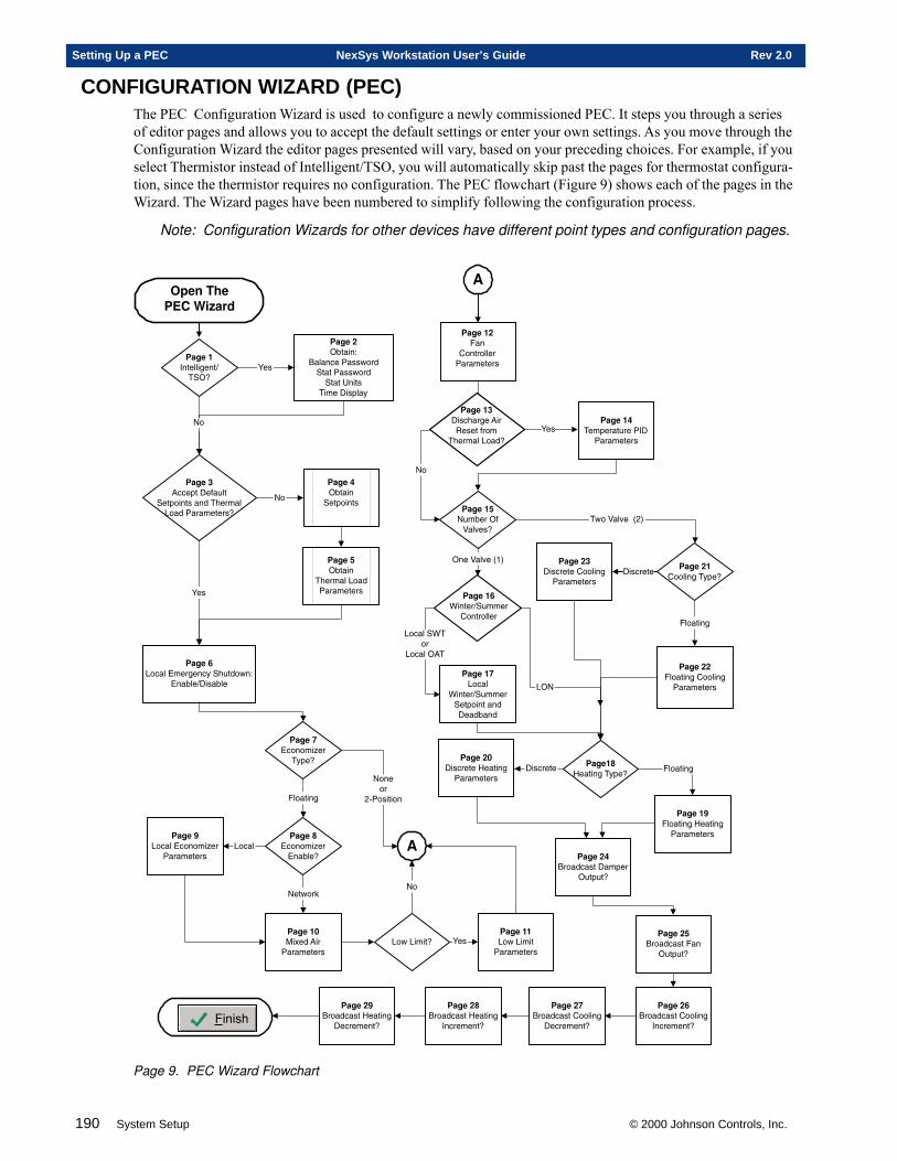
190 System Setup © 2000 Johnson Controls, Inc.
Setting Up a PEC NexSys Workstation User’s Guide Rev 2.0
CONFIGURATION WIZARD (PEC)The PEC Configuration Wizard is used to configure a newly commissioned PEC. It steps you through a seriesof editor pages and allows you to accept the default settings or enter your own settings. As you move through theConfiguration Wizard the editor pages presented will vary, based on your preceding choices. For example, if youselect Thermistor instead of Intelligent/TSO, you will automatically skip past the pages for thermostat configura-tion, since the thermistor requires no configuration. The PEC flowchart (Figure 9) shows each of the pages in theWizard. The Wizard pages have been numbered to simplify following the configuration process.
Note: Configuration Wizards for other devices have different point types and configuration pages.
�12���-�$�������$���,&
�12��/, $���7
.����(������1��*�$�$�����1��*�$�$�8��$�
�����!��2��"
'��
�12��.�((�2$�!�����$
��$2���$����*��#��������*�������$���&
+�
�12��#, $���
��$2���$�
�12��", $���
�#���������*������$���'��
�12��'��(����������("��#�$*�1�7
��� ���!��� ��
�12����(�����9��
�"2�&
����$���
+�����
6�����$���
�12��0�(�����9����� ��&
+�$1��:
��(���12��$
��(����(�����9��������$���
�12���%)�/�*����������$���
�
��1�����$&
+�
�12������1�����$������$���
�
�12���/���
��$������������$���
�12���#���2���$�����-!
������$���
�12���"+�� ���,����%��&
+�
,������%��=�>
�1�����%���=6>
�12���'5��$���������
��$������
�12������(��
5��$�����������$2���$���*!��* ��*
��(����5���
��(���,��
�,+
�12��0<��$�����"2�&
�12���$����$����<��$���������$���
!��(��$� ����$���
�12��/� ��������"2�&
�12��/.!��(��$�� ������������$���
�12��//����$���� ������������$���
!��(��$�
����$���
�12��/#.���*(��$�!��2��
,�$2�$&
�12��/".���*(��$����
,�$2�$&
�12��/'.���*(��$� ������
-�(�����$&
�12��/�.���*(��$� ������
!�(�����$&
�12��/0.���*(��$�<��$���
-�(�����$&
�12��/$.���*(��$�<��$���
!�(�����$&
+��12���.
!��(#��������3���$�����
�#���������*&'��
'��
�3� �+4������51��
�12��/%!��(��$��<��$���������$���
����
Page 9. PEC Wizard Flowchart
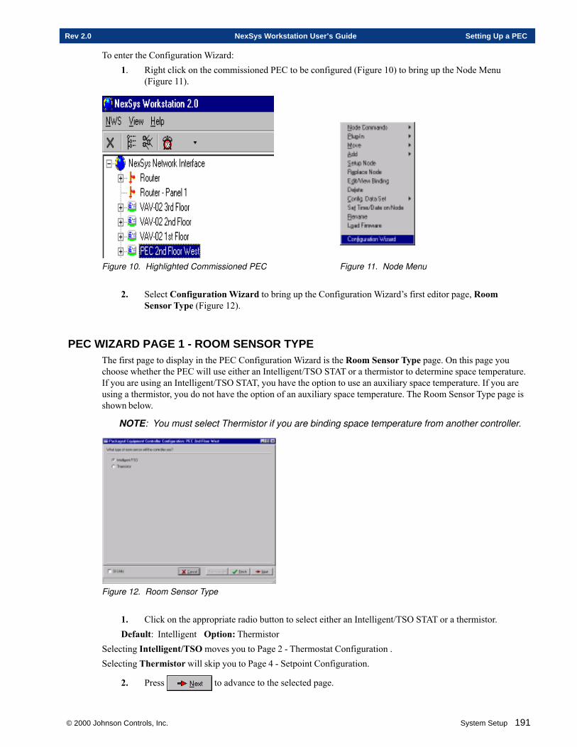
© 2000 Johnson Controls, Inc. System Setup 191
Rev 2.0 NexSys Workstation User’s Guide Setting Up a PEC
To enter the Configuration Wizard:1. Right click on the commissioned PEC to be configured (Figure 10) to bring up the Node Menu
(Figure 11).
Figure 10. Highlighted Commissioned PEC Figure 11. Node Menu
2. Select Configuration Wizard to bring up the Configuration Wizard’s first editor page, RoomSensor Type (Figure 12).
PEC WIZARD PAGE 1 - ROOM SENSOR TYPEThe first page to display in the PEC Configuration Wizard is the Room Sensor Type page. On this page youchoose whether the PEC will use either an Intelligent/TSO STAT or a thermistor to determine space temperature.If you are using an Intelligent/TSO STAT, you have the option to use an auxiliary space temperature. If you areusing a thermistor, you do not have the option of an auxiliary space temperature. The Room Sensor Type page isshown below.
NOTE: You must select Thermistor if you are binding space temperature from another controller.
Figure 12. Room Sensor Type
1. Click on the appropriate radio button to select either an Intelligent/TSO STAT or a thermistor.Default: Intelligent Option: Thermistor
Selecting Intelligent/TSO moves you to Page 2 - Thermostat Configuration .Selecting Thermistor will skip you to Page 4 - Setpoint Configuration.
2. Press to advance to the selected page.
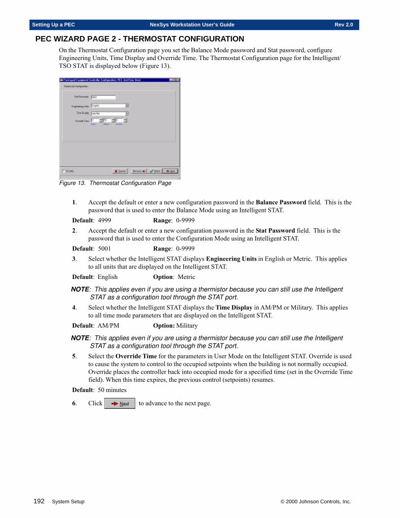
192 System Setup © 2000 Johnson Controls, Inc.
Setting Up a PEC NexSys Workstation User’s Guide Rev 2.0
PEC WIZARD PAGE 2 - THERMOSTAT CONFIGURATIONOn the Thermostat Configuration page you set the Balance Mode password and Stat password, configureEngineering Units, Time Display and Override Time. The Thermostat Configuration page for the Intelligent/TSO STAT is displayed below (Figure 13).
Figure 13. Thermostat Configuration Page
1. Accept the default or enter a new configuration password in the Balance Password field. This is thepassword that is used to enter the Balance Mode using an Intelligent STAT.
Default: 4999 Range: 0-99992. Accept the default or enter a new configuration password in the Stat Password field. This is the
password that is used to enter the Configuration Mode using an Intelligent STAT.Default: 5001 Range: 0-99993. Select whether the Intelligent STAT displays Engineering Units in English or Metric. This applies
to all units that are displayed on the Intelligent STAT.Default: English Option: Metric
NOTE: This applies even if you are using a thermistor because you can still use the IntelligentSTAT as a configuration tool through the STAT port.
4. Select whether the Intelligent STAT displays the Time Display in AM/PM or Military. This appliesto all time mode parameters that are displayed on the Intelligent STAT.
Default: AM/PM Option: Military
NOTE: This applies even if you are using a thermistor because you can still use the IntelligentSTAT as a configuration tool through the STAT port.
5. Select the Override Time for the parameters in User Mode on the Intelligent STAT. Override is usedto cause the system to control to the occupied setpoints when the building is not normally occupied.Override places the controller back into occupied mode for a specified time (set in the Override Timefield). When this time expires, the previous control (setpoints) resumes.
Default: 50 minutes
6. Click to advance to the next page.
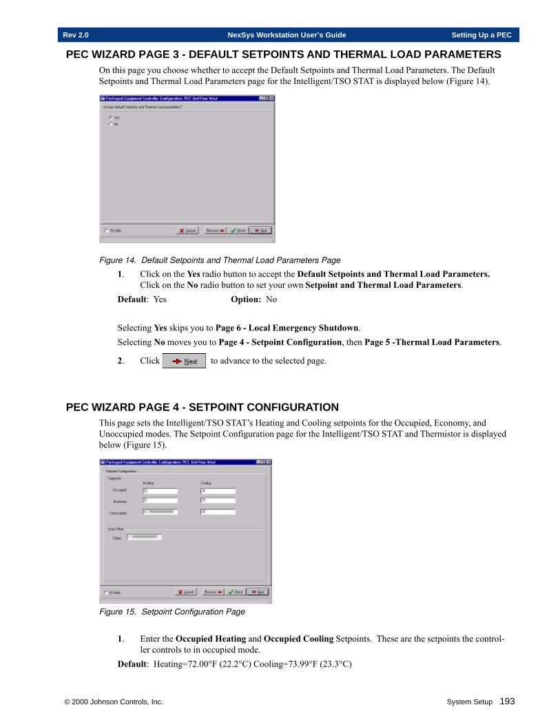
© 2000 Johnson Controls, Inc. System Setup 193
Rev 2.0 NexSys Workstation User’s Guide Setting Up a PEC
PEC WIZARD PAGE 3 - DEFAULT SETPOINTS AND THERMAL LOAD PARAMETERSOn this page you choose whether to accept the Default Setpoints and Thermal Load Parameters. The DefaultSetpoints and Thermal Load Parameters page for the Intelligent/TSO STAT is displayed below (Figure 14).
Figure 14. Default Setpoints and Thermal Load Parameters Page
1. Click on the Yes radio button to accept the Default Setpoints and Thermal Load Parameters.Click on the No radio button to set your own Setpoint and Thermal Load Parameters.
Default: Yes Option: No
Selecting Yes skips you to Page 6 - Local Emergency Shutdown.Selecting No moves you to Page 4 - Setpoint Configuration, then Page 5 -Thermal Load Parameters.
2. Click to advance to the selected page.
PEC WIZARD PAGE 4 - SETPOINT CONFIGURATIONThis page sets the Intelligent/TSO STAT’s Heating and Cooling setpoints for the Occupied, Economy, andUnoccupied modes. The Setpoint Configuration page for the Intelligent/TSO STAT and Thermistor is displayedbelow (Figure 15).
Figure 15. Setpoint Configuration Page
1. Enter the Occupied Heating and Occupied Cooling Setpoints. These are the setpoints the control-ler controls to in occupied mode.
Default: Heating=72.00°F (22.2°C) Cooling=73.99°F (23.3°C)
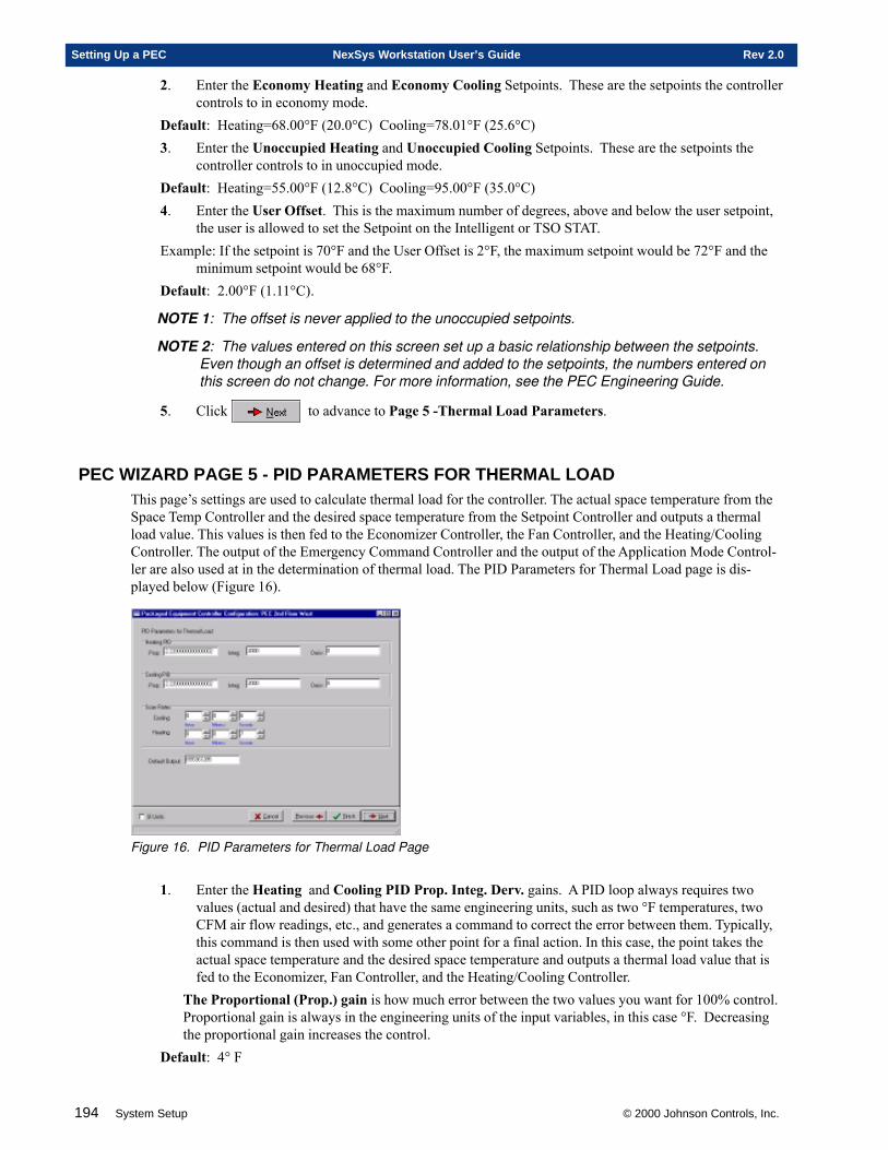
194 System Setup © 2000 Johnson Controls, Inc.
Setting Up a PEC NexSys Workstation User’s Guide Rev 2.0
2. Enter the Economy Heating and Economy Cooling Setpoints. These are the setpoints the controllercontrols to in economy mode.
Default: Heating=68.00°F (20.0°C) Cooling=78.01°F (25.6°C)3. Enter the Unoccupied Heating and Unoccupied Cooling Setpoints. These are the setpoints the
controller controls to in unoccupied mode.Default: Heating=55.00°F (12.8°C) Cooling=95.00°F (35.0°C)4. Enter the User Offset. This is the maximum number of degrees, above and below the user setpoint,
the user is allowed to set the Setpoint on the Intelligent or TSO STAT.Example: If the setpoint is 70°F and the User Offset is 2°F, the maximum setpoint would be 72°F and the
minimum setpoint would be 68°F.Default: 2.00°F (1.11°C).
NOTE 1: The offset is never applied to the unoccupied setpoints.
NOTE 2: The values entered on this screen set up a basic relationship between the setpoints.Even though an offset is determined and added to the setpoints, the numbers entered onthis screen do not change. For more information, see the PEC Engineering Guide.
5. Click to advance to Page 5 -Thermal Load Parameters.
PEC WIZARD PAGE 5 - PID PARAMETERS FOR THERMAL LOADThis page’s settings are used to calculate thermal load for the controller. The actual space temperature from theSpace Temp Controller and the desired space temperature from the Setpoint Controller and outputs a thermalload value. This values is then fed to the Economizer Controller, the Fan Controller, and the Heating/CoolingController. The output of the Emergency Command Controller and the output of the Application Mode Control-ler are also used at in the determination of thermal load. The PID Parameters for Thermal Load page is dis-played below (Figure 16).
Figure 16. PID Parameters for Thermal Load Page
1. Enter the Heating and Cooling PID Prop. Integ. Derv. gains. A PID loop always requires twovalues (actual and desired) that have the same engineering units, such as two °F temperatures, twoCFM air flow readings, etc., and generates a command to correct the error between them. Typically,this command is then used with some other point for a final action. In this case, the point takes theactual space temperature and the desired space temperature and outputs a thermal load value that isfed to the Economizer, Fan Controller, and the Heating/Cooling Controller.
The Proportional (Prop.) gain is how much error between the two values you want for 100% control.Proportional gain is always in the engineering units of the input variables, in this case °F. Decreasingthe proportional gain increases the control.
Default: 4° F

© 2000 Johnson Controls, Inc. System Setup 195
Rev 2.0 NexSys Workstation User’s Guide Setting Up a PEC
The Integral (Integ.) gain is how much time elapses before 100% of the error is added back into thecontrol. Integral gain is always in seconds. Decreasing the integral gain increases the control.
Default: 2000 SecondsThe Derivative (Deriv.) gain controls based on how fast the temperature is changing, and attempts tosense rapid changes. The derivative gain is always in seconds. Increasing the derivative gain, decreasescontrol.
Default: 0
NOTE 1: It is recommended that the Derivative gain always be 0.
NOTE 2: If your control is too sensitive and your system is oscillating, you need to increase theProportional and/or Integral gains. If your control is too insensitive and it is taking too longto reach the Active Setpoint, then you need to decrease the Proportional and/or Integralgains.
2. Enter the Heating and Cooling Scan Rates. This is how often the Heating and Cooling Tempera-ture PID loops are recalculated.
Default: Cooling = 6 SecondsHeating = 7 Seconds
NOTE: The Maximum time you can enter is 1 Hour 49 Minutes and 13 Seconds. If you enter atime greater than 1 Hour 49 Minutes and 13 Seconds and click , the time defaultsto 1 Hour 49 Minutes and 13 Seconds.
3. Enter the Default Output. This is a thermal load that is forced to the system in the event of acontroller failure or an invalid space temperature, such as a short or open connection to a sensor orthermostat.
Default: 50%
4. Click to advance to Page 6 - Local Emergency Shutdown.
PEC WIZARD PAGE 6 - LOCAL EMERGENCY SHUTDOWNThis page enables or disables a digital input, wired to an external sensor, used to trigger a Local EmergencyShutdown. When this page is enabled, and certain conditions have been met, an Emergency Shutdown for thelocal controller is performed. Emergency operation mode begins and only effects the local unit. The LocalEmergency Shutdown page is displayed below (Figure 17).
Figure 17. Local Emergency Shutdown Page
1. Select whether to Enable or Disable Local Emergency Shutdown function.Default: Disable Option: Enable
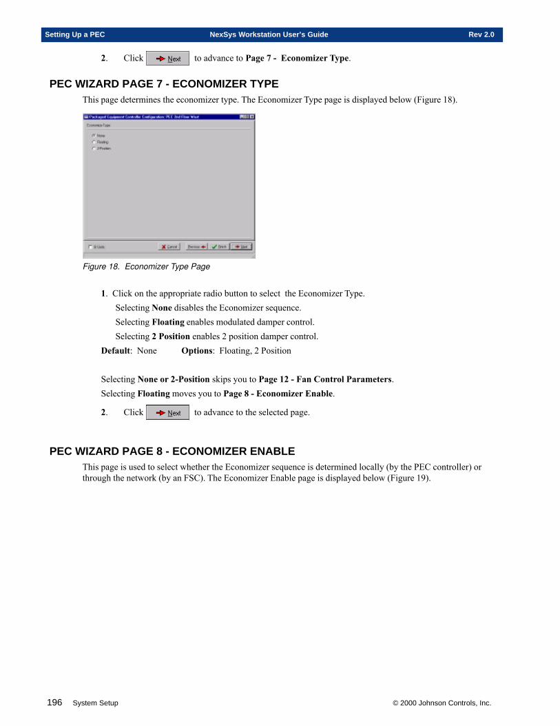
196 System Setup © 2000 Johnson Controls, Inc.
Setting Up a PEC NexSys Workstation User’s Guide Rev 2.0
2. Click to advance to Page 7 - Economizer Type.
PEC WIZARD PAGE 7 - ECONOMIZER TYPEThis page determines the economizer type. The Economizer Type page is displayed below (Figure 18).
Figure 18. Economizer Type Page
1. Click on the appropriate radio button to select the Economizer Type.Selecting None disables the Economizer sequence.Selecting Floating enables modulated damper control.Selecting 2 Position enables 2 position damper control.
Default: None Options: Floating, 2 Position
Selecting None or 2-Position skips you to Page 12 - Fan Control Parameters.Selecting Floating moves you to Page 8 - Economizer Enable.
2. Click to advance to the selected page.
PEC WIZARD PAGE 8 - ECONOMIZER ENABLEThis page is used to select whether the Economizer sequence is determined locally (by the PEC controller) orthrough the network (by an FSC). The Economizer Enable page is displayed below (Figure 19).
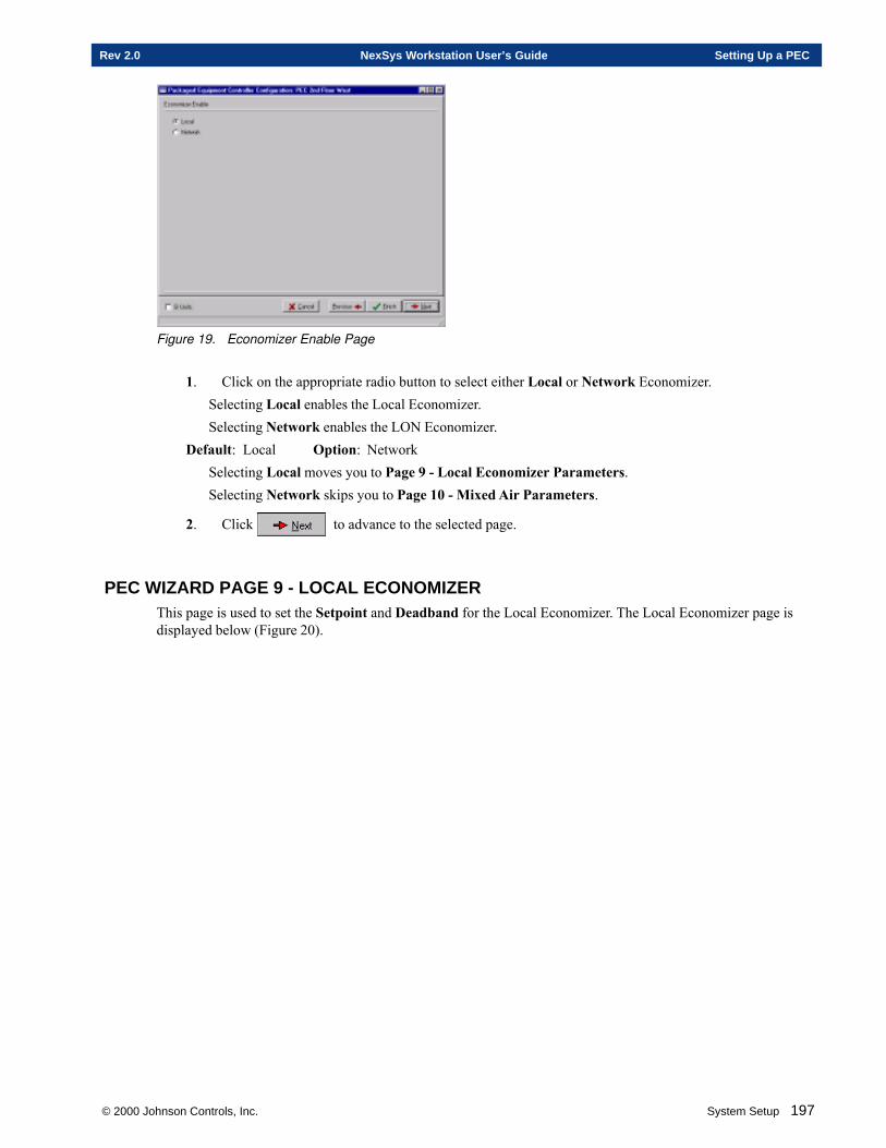
© 2000 Johnson Controls, Inc. System Setup 197
Rev 2.0 NexSys Workstation User’s Guide Setting Up a PEC
Figure 19. Economizer Enable Page
1. Click on the appropriate radio button to select either Local or Network Economizer.Selecting Local enables the Local Economizer.Selecting Network enables the LON Economizer.
Default: Local Option: NetworkSelecting Local moves you to Page 9 - Local Economizer Parameters.Selecting Network skips you to Page 10 - Mixed Air Parameters.
2. Click to advance to the selected page.
PEC WIZARD PAGE 9 - LOCAL ECONOMIZERThis page is used to set the Setpoint and Deadband for the Local Economizer. The Local Economizer page isdisplayed below (Figure 20).
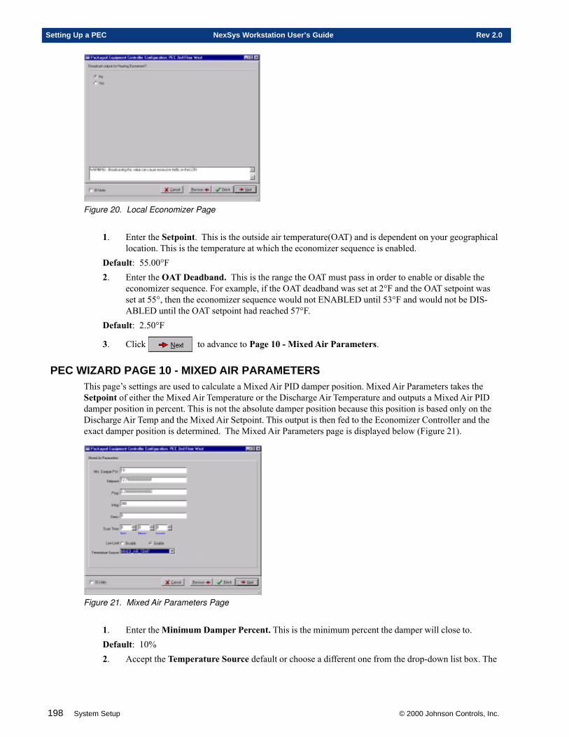
198 System Setup © 2000 Johnson Controls, Inc.
Setting Up a PEC NexSys Workstation User’s Guide Rev 2.0
Figure 20. Local Economizer Page
1. Enter the Setpoint. This is the outside air temperature(OAT) and is dependent on your geographicallocation. This is the temperature at which the economizer sequence is enabled.
Default: 55.00°F2. Enter the OAT Deadband. This is the range the OAT must pass in order to enable or disable the
economizer sequence. For example, if the OAT deadband was set at 2°F and the OAT setpoint wasset at 55°, then the economizer sequence would not ENABLED until 53°F and would not be DIS-ABLED until the OAT setpoint had reached 57°F.
Default: 2.50°F
3. Click to advance to Page 10 - Mixed Air Parameters.
PEC WIZARD PAGE 10 - MIXED AIR PARAMETERSThis page’s settings are used to calculate a Mixed Air PID damper position. Mixed Air Parameters takes theSetpoint of either the Mixed Air Temperature or the Discharge Air Temperature and outputs a Mixed Air PIDdamper position in percent. This is not the absolute damper position because this position is based only on theDischarge Air Temp and the Mixed Air Setpoint. This output is then fed to the Economizer Controller and theexact damper position is determined. The Mixed Air Parameters page is displayed below (Figure 21).
Figure 21. Mixed Air Parameters Page
1. Enter the Minimum Damper Percent. This is the minimum percent the damper will close to.Default: 10%2. Accept the Temperature Source default or choose a different one from the drop-down list box. The
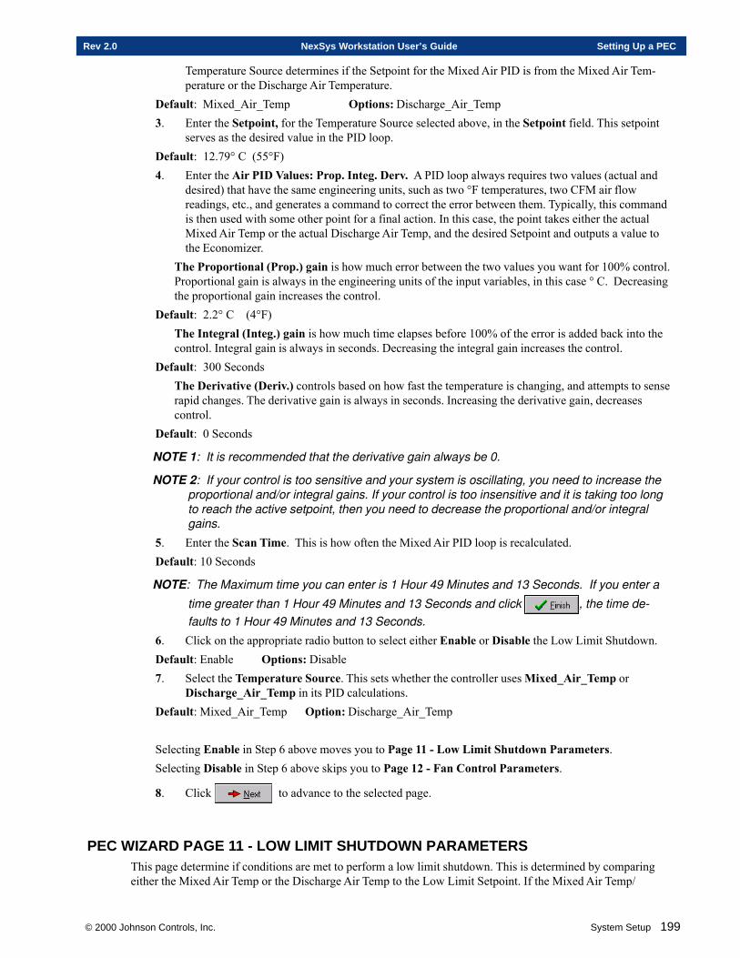
© 2000 Johnson Controls, Inc. System Setup 199
Rev 2.0 NexSys Workstation User’s Guide Setting Up a PEC
Temperature Source determines if the Setpoint for the Mixed Air PID is from the Mixed Air Tem-perature or the Discharge Air Temperature.
Default: Mixed_Air_Temp Options: Discharge_Air_Temp3. Enter the Setpoint, for the Temperature Source selected above, in the Setpoint field. This setpoint
serves as the desired value in the PID loop.Default: 12.79° C (55°F)4. Enter the Air PID Values: Prop. Integ. Derv. A PID loop always requires two values (actual and
desired) that have the same engineering units, such as two °F temperatures, two CFM air flowreadings, etc., and generates a command to correct the error between them. Typically, this commandis then used with some other point for a final action. In this case, the point takes either the actualMixed Air Temp or the actual Discharge Air Temp, and the desired Setpoint and outputs a value tothe Economizer.
The Proportional (Prop.) gain is how much error between the two values you want for 100% control.Proportional gain is always in the engineering units of the input variables, in this case ° C. Decreasingthe proportional gain increases the control.
Default: 2.2° C (4°F)The Integral (Integ.) gain is how much time elapses before 100% of the error is added back into thecontrol. Integral gain is always in seconds. Decreasing the integral gain increases the control.
Default: 300 SecondsThe Derivative (Deriv.) controls based on how fast the temperature is changing, and attempts to senserapid changes. The derivative gain is always in seconds. Increasing the derivative gain, decreasescontrol.
Default: 0 Seconds
NOTE 1: It is recommended that the derivative gain always be 0.
NOTE 2: If your control is too sensitive and your system is oscillating, you need to increase theproportional and/or integral gains. If your control is too insensitive and it is taking too longto reach the active setpoint, then you need to decrease the proportional and/or integralgains.
5. Enter the Scan Time. This is how often the Mixed Air PID loop is recalculated.Default: 10 Seconds
NOTE: The Maximum time you can enter is 1 Hour 49 Minutes and 13 Seconds. If you enter a
time greater than 1 Hour 49 Minutes and 13 Seconds and click , the time de-faults to 1 Hour 49 Minutes and 13 Seconds.
6. Click on the appropriate radio button to select either Enable or Disable the Low Limit Shutdown.Default: Enable Options: Disable7. Select the Temperature Source. This sets whether the controller uses Mixed_Air_Temp or
Discharge_Air_Temp in its PID calculations.Default: Mixed_Air_Temp Option: Discharge_Air_Temp
Selecting Enable in Step 6 above moves you to Page 11 - Low Limit Shutdown Parameters.Selecting Disable in Step 6 above skips you to Page 12 - Fan Control Parameters.
8. Click to advance to the selected page.
PEC WIZARD PAGE 11 - LOW LIMIT SHUTDOWN PARAMETERSThis page determine if conditions are met to perform a low limit shutdown. This is determined by comparingeither the Mixed Air Temp or the Discharge Air Temp to the Low Limit Setpoint. If the Mixed Air Temp/
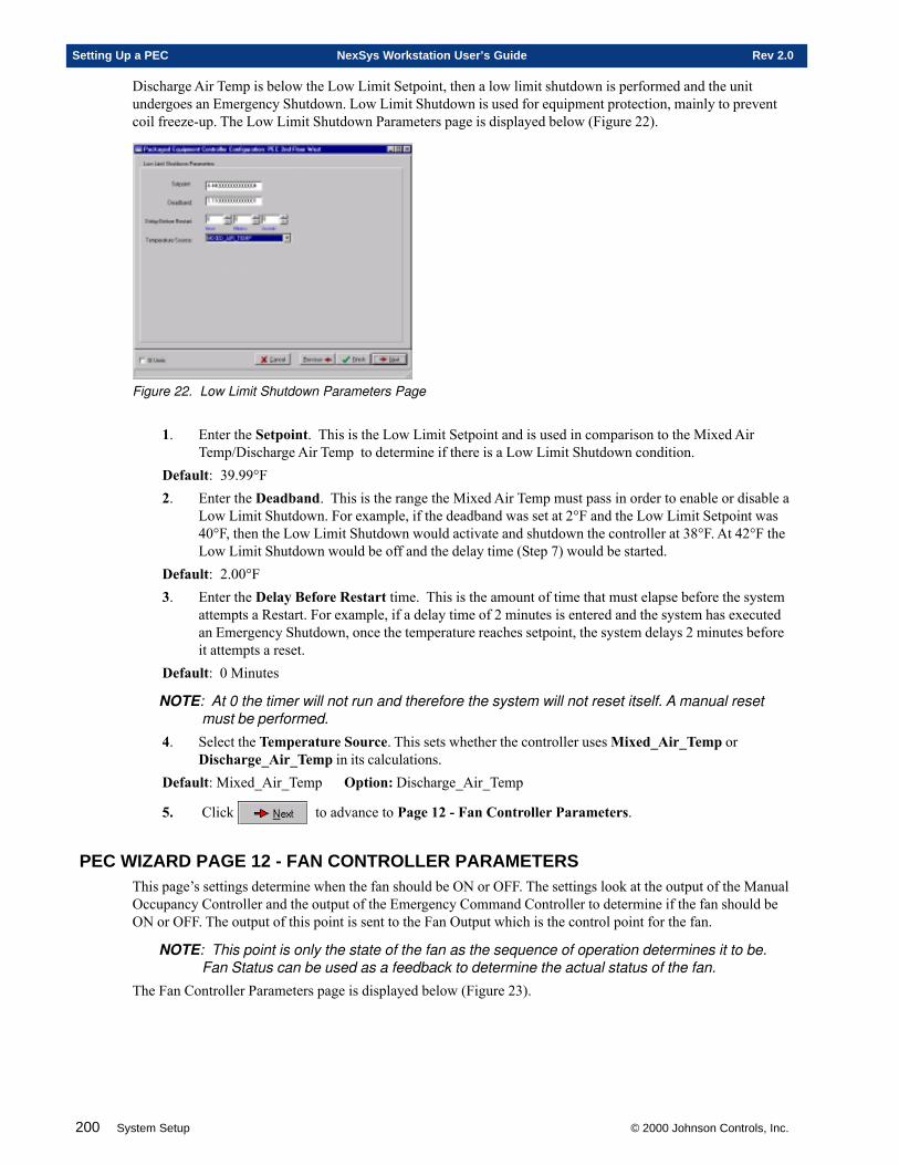
200 System Setup © 2000 Johnson Controls, Inc.
Setting Up a PEC NexSys Workstation User’s Guide Rev 2.0
Discharge Air Temp is below the Low Limit Setpoint, then a low limit shutdown is performed and the unitundergoes an Emergency Shutdown. Low Limit Shutdown is used for equipment protection, mainly to preventcoil freeze-up. The Low Limit Shutdown Parameters page is displayed below (Figure 22).
Figure 22. Low Limit Shutdown Parameters Page
1. Enter the Setpoint. This is the Low Limit Setpoint and is used in comparison to the Mixed AirTemp/Discharge Air Temp to determine if there is a Low Limit Shutdown condition.
Default: 39.99°F2. Enter the Deadband. This is the range the Mixed Air Temp must pass in order to enable or disable a
Low Limit Shutdown. For example, if the deadband was set at 2°F and the Low Limit Setpoint was40°F, then the Low Limit Shutdown would activate and shutdown the controller at 38°F. At 42°F theLow Limit Shutdown would be off and the delay time (Step 7) would be started.
Default: 2.00°F3. Enter the Delay Before Restart time. This is the amount of time that must elapse before the system
attempts a Restart. For example, if a delay time of 2 minutes is entered and the system has executedan Emergency Shutdown, once the temperature reaches setpoint, the system delays 2 minutes beforeit attempts a reset.
Default: 0 Minutes
NOTE: At 0 the timer will not run and therefore the system will not reset itself. A manual resetmust be performed.
4. Select the Temperature Source. This sets whether the controller uses Mixed_Air_Temp orDischarge_Air_Temp in its calculations.
Default: Mixed_Air_Temp Option: Discharge_Air_Temp
5. Click to advance to Page 12 - Fan Controller Parameters.
PEC WIZARD PAGE 12 - FAN CONTROLLER PARAMETERSThis page’s settings determine when the fan should be ON or OFF. The settings look at the output of the ManualOccupancy Controller and the output of the Emergency Command Controller to determine if the fan should beON or OFF. The output of this point is sent to the Fan Output which is the control point for the fan.
NOTE: This point is only the state of the fan as the sequence of operation determines it to be.Fan Status can be used as a feedback to determine the actual status of the fan.
The Fan Controller Parameters page is displayed below (Figure 23).
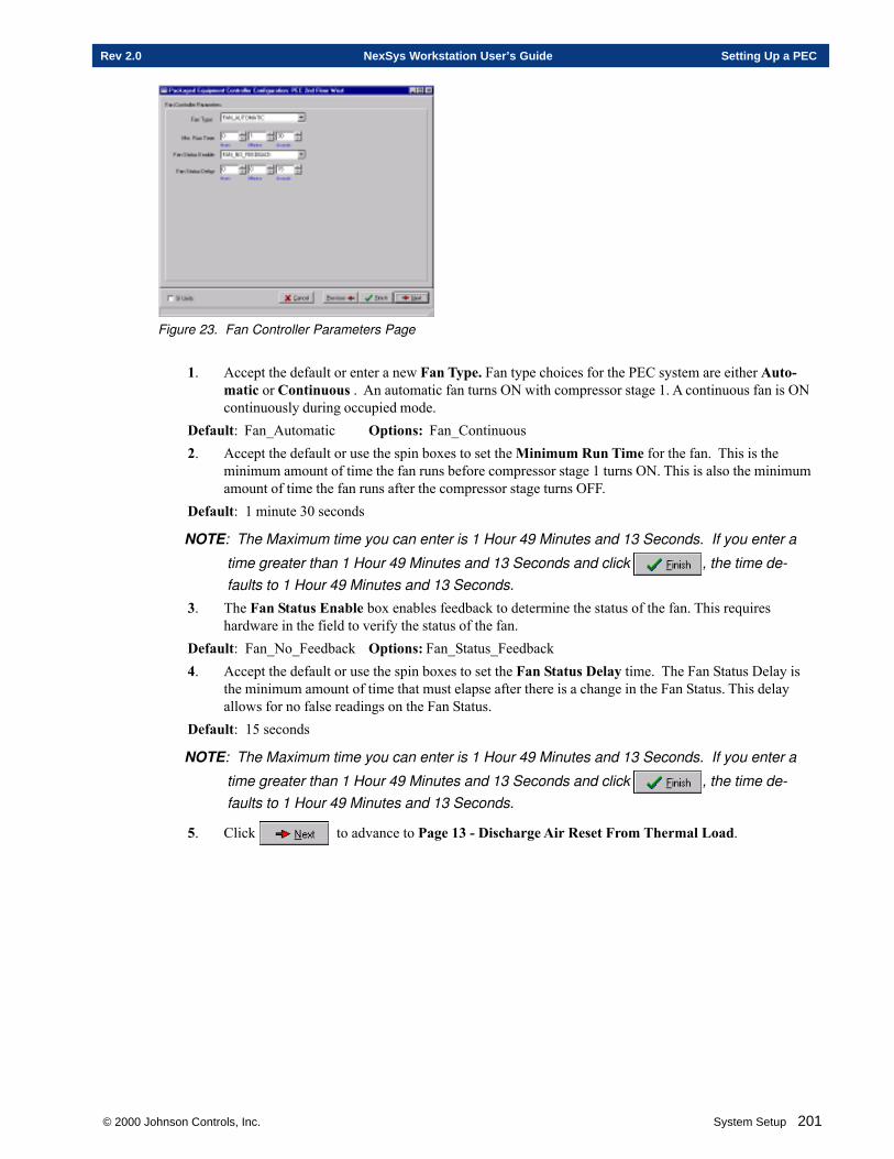
© 2000 Johnson Controls, Inc. System Setup 201
Rev 2.0 NexSys Workstation User’s Guide Setting Up a PEC
Figure 23. Fan Controller Parameters Page
1. Accept the default or enter a new Fan Type. Fan type choices for the PEC system are either Auto-matic or Continuous . An automatic fan turns ON with compressor stage 1. A continuous fan is ONcontinuously during occupied mode.
Default: Fan_Automatic Options: Fan_Continuous2. Accept the default or use the spin boxes to set the Minimum Run Time for the fan. This is the
minimum amount of time the fan runs before compressor stage 1 turns ON. This is also the minimumamount of time the fan runs after the compressor stage turns OFF.
Default: 1 minute 30 seconds
NOTE: The Maximum time you can enter is 1 Hour 49 Minutes and 13 Seconds. If you enter a
time greater than 1 Hour 49 Minutes and 13 Seconds and click , the time de-faults to 1 Hour 49 Minutes and 13 Seconds.
3. The Fan Status Enable box enables feedback to determine the status of the fan. This requireshardware in the field to verify the status of the fan.
Default: Fan_No_Feedback Options: Fan_Status_Feedback4. Accept the default or use the spin boxes to set the Fan Status Delay time. The Fan Status Delay is
the minimum amount of time that must elapse after there is a change in the Fan Status. This delayallows for no false readings on the Fan Status.
Default: 15 seconds
NOTE: The Maximum time you can enter is 1 Hour 49 Minutes and 13 Seconds. If you enter a
time greater than 1 Hour 49 Minutes and 13 Seconds and click , the time de-faults to 1 Hour 49 Minutes and 13 Seconds.
5. Click to advance to Page 13 - Discharge Air Reset From Thermal Load.
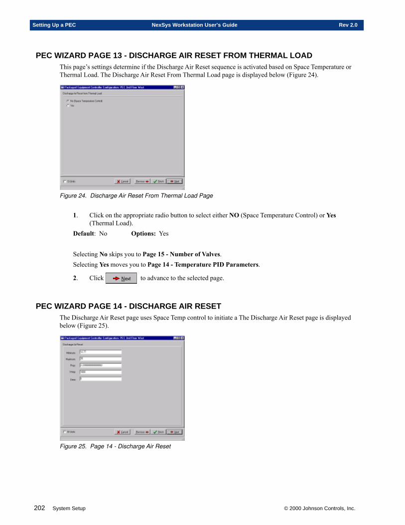
202 System Setup © 2000 Johnson Controls, Inc.
Setting Up a PEC NexSys Workstation User’s Guide Rev 2.0
PEC WIZARD PAGE 13 - DISCHARGE AIR RESET FROM THERMAL LOADThis page’s settings determine if the Discharge Air Reset sequence is activated based on Space Temperature orThermal Load. The Discharge Air Reset From Thermal Load page is displayed below (Figure 24).
Figure 24. Discharge Air Reset From Thermal Load Page
1. Click on the appropriate radio button to select either NO (Space Temperature Control) or Yes(Thermal Load).
Default: No Options: Yes
Selecting No skips you to Page 15 - Number of Valves.Selecting Yes moves you to Page 14 - Temperature PID Parameters.
2. Click to advance to the selected page.
PEC WIZARD PAGE 14 - DISCHARGE AIR RESETThe Discharge Air Reset page uses Space Temp control to initiate a The Discharge Air Reset page is displayedbelow (Figure 25).
Figure 25. Page 14 - Discharge Air Reset

© 2000 Johnson Controls, Inc. System Setup 203
Rev 2.0 NexSys Workstation User’s Guide Setting Up a PEC
1. Enter the Minimum Reset Temperature. This is the minimum temperature .Default: 12.77 °C2. Enter the Maximum Reset Temperature. This is the maximum temperature .Default: 35 °C3. Enter the Air PID Values: Prop. Integ. Derv. A PID loop always requires two values (actual and
desired) that have the same engineering units, such as two °F temperatures, two CFM air flowreadings, etc., and generates a command to correct the error between them. Typically, this commandis then used with some other point for a final action. In this case, the point takes either the actualMixed Air Temp or the actual Discharge Air Temp, and the desired Setpoint and outputs a value tothe Economizer.
The Proportional (Prop.) gain is how much error between the two values you want for 100% control.Proportional gain is always in the engineering units of the input variables, in this case ° C. Decreasingthe proportional gain increases the control.
Default: 2.2° CThe Integral (Integ.) gain is how much time elapses before 100% of the error is added back into thecontrol. Integral gain is always in seconds. Decreasing the integral gain increases the control.
Default: 1000 SecondsThe Derivative (Deriv.) controls based on how fast the temperature is changing, and attempts to senserapid changes. The derivative gain is always in seconds. Increasing the derivative gain, decreasescontrol.
Default: 0 Seconds
NOTE 1: It is recommended that the derivative gain always be 0.
NOTE 2: If your control is too sensitive and your system is oscillating, you need to increase theproportional and/or integral gains. If your control is too insensitive and it is taking too longto reach the active setpoint, then you need to decrease the proportional and/or integralgains.
4. Click to advance to Page 15 - Number of Valves.
PEC WIZARD PAGE 15 - NUMBER OF VALVESThis page is used to select whether the system is a 1 Valve (two-pipe) or 2 Valve (four-pipe) system. A 1 Valve(two-pipe) has only one supply pipe and only one return pipe. This system supplies hot water or chiller waterand it has to be one or the other, never both. A 2 Valve (four-pipe) system has both hot and chilled water at thesame time (supply and return chilled water and supply and return hot water). In order for the PEC-01 to provideproper control, the controller needs to be configured to match the mechanical system you are setting up. TheNumber of Valves page is displayed below (Figure 26).
Figure 26. Number of Valves Page
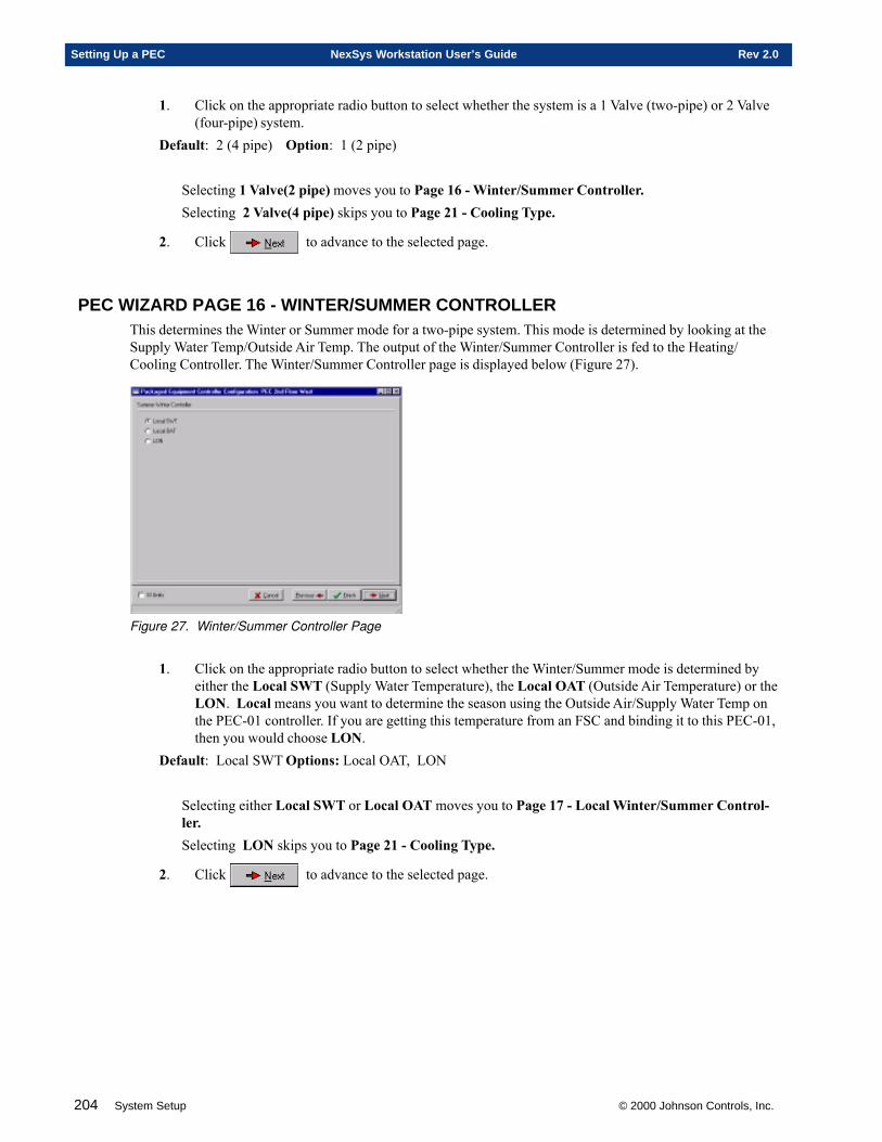
204 System Setup © 2000 Johnson Controls, Inc.
Setting Up a PEC NexSys Workstation User’s Guide Rev 2.0
1. Click on the appropriate radio button to select whether the system is a 1 Valve (two-pipe) or 2 Valve(four-pipe) system.
Default: 2 (4 pipe) Option: 1 (2 pipe)
Selecting 1 Valve(2 pipe) moves you to Page 16 - Winter/Summer Controller.Selecting 2 Valve(4 pipe) skips you to Page 21 - Cooling Type.
2. Click to advance to the selected page.
PEC WIZARD PAGE 16 - WINTER/SUMMER CONTROLLERThis determines the Winter or Summer mode for a two-pipe system. This mode is determined by looking at theSupply Water Temp/Outside Air Temp. The output of the Winter/Summer Controller is fed to the Heating/Cooling Controller. The Winter/Summer Controller page is displayed below (Figure 27).
Figure 27. Winter/Summer Controller Page
1. Click on the appropriate radio button to select whether the Winter/Summer mode is determined byeither the Local SWT (Supply Water Temperature), the Local OAT (Outside Air Temperature) or theLON. Local means you want to determine the season using the Outside Air/Supply Water Temp onthe PEC-01 controller. If you are getting this temperature from an FSC and binding it to this PEC-01,then you would choose LON.
Default: Local SWT Options: Local OAT, LON
Selecting either Local SWT or Local OAT moves you to Page 17 - Local Winter/Summer Control-ler.Selecting LON skips you to Page 21 - Cooling Type.
2. Click to advance to the selected page.
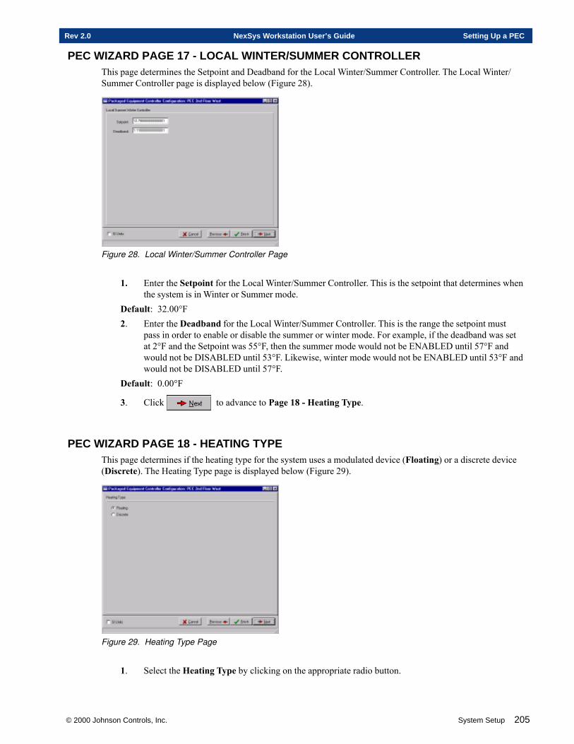
© 2000 Johnson Controls, Inc. System Setup 205
Rev 2.0 NexSys Workstation User’s Guide Setting Up a PEC
PEC WIZARD PAGE 17 - LOCAL WINTER/SUMMER CONTROLLERThis page determines the Setpoint and Deadband for the Local Winter/Summer Controller. The Local Winter/Summer Controller page is displayed below (Figure 28).
Figure 28. Local Winter/Summer Controller Page
1. Enter the Setpoint for the Local Winter/Summer Controller. This is the setpoint that determines whenthe system is in Winter or Summer mode.
Default: 32.00°F2. Enter the Deadband for the Local Winter/Summer Controller. This is the range the setpoint must
pass in order to enable or disable the summer or winter mode. For example, if the deadband was setat 2°F and the Setpoint was 55°F, then the summer mode would not be ENABLED until 57°F andwould not be DISABLED until 53°F. Likewise, winter mode would not be ENABLED until 53°F andwould not be DISABLED until 57°F.
Default: 0.00°F
3. Click to advance to Page 18 - Heating Type.
PEC WIZARD PAGE 18 - HEATING TYPEThis page determines if the heating type for the system uses a modulated device (Floating) or a discrete device(Discrete). The Heating Type page is displayed below (Figure 29).
Figure 29. Heating Type Page
1. Select the Heating Type by clicking on the appropriate radio button.
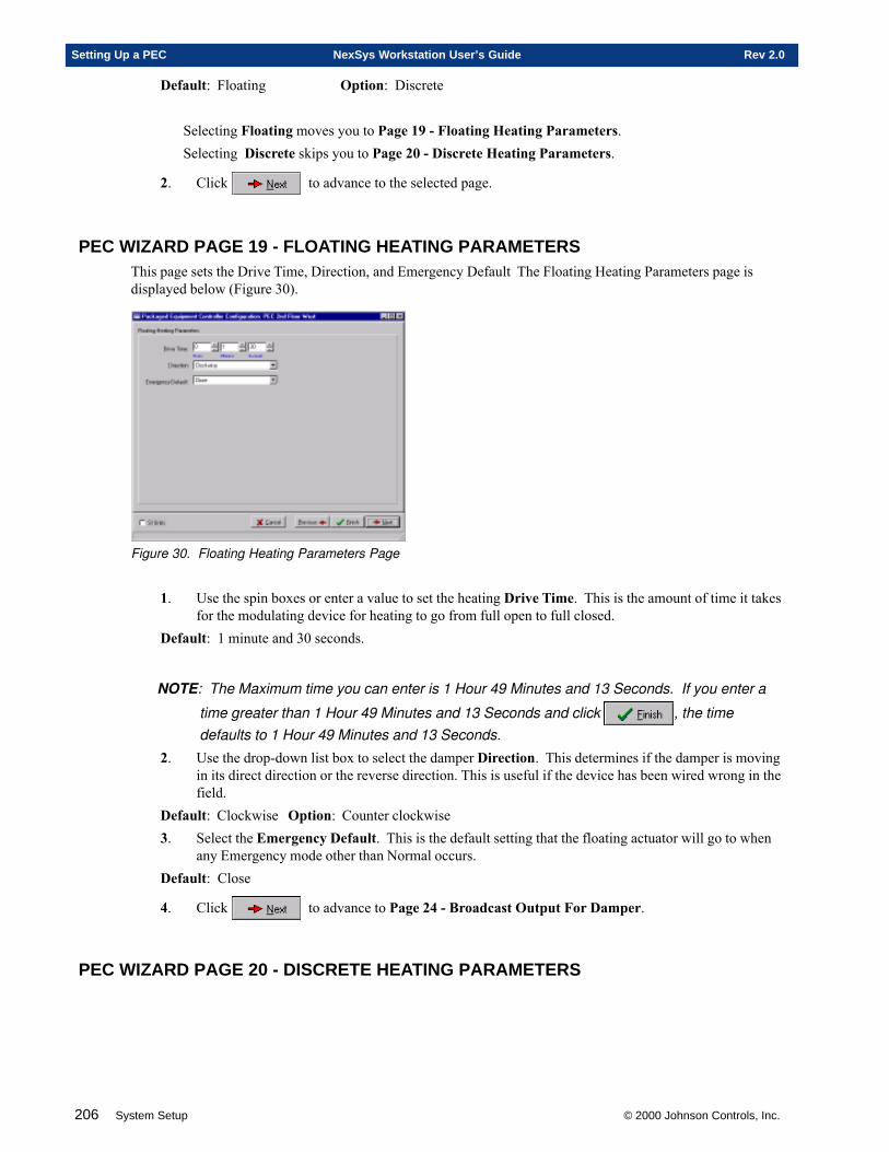
206 System Setup © 2000 Johnson Controls, Inc.
Setting Up a PEC NexSys Workstation User’s Guide Rev 2.0
Default: Floating Option: Discrete
Selecting Floating moves you to Page 19 - Floating Heating Parameters.Selecting Discrete skips you to Page 20 - Discrete Heating Parameters.
2. Click to advance to the selected page.
PEC WIZARD PAGE 19 - FLOATING HEATING PARAMETERSThis page sets the Drive Time, Direction, and Emergency Default The Floating Heating Parameters page isdisplayed below (Figure 30).
Figure 30. Floating Heating Parameters Page
1. Use the spin boxes or enter a value to set the heating Drive Time. This is the amount of time it takesfor the modulating device for heating to go from full open to full closed.
Default: 1 minute and 30 seconds.
NOTE: The Maximum time you can enter is 1 Hour 49 Minutes and 13 Seconds. If you enter a
time greater than 1 Hour 49 Minutes and 13 Seconds and click , the timedefaults to 1 Hour 49 Minutes and 13 Seconds.
2. Use the drop-down list box to select the damper Direction. This determines if the damper is movingin its direct direction or the reverse direction. This is useful if the device has been wired wrong in thefield.
Default: Clockwise Option: Counter clockwise3. Select the Emergency Default. This is the default setting that the floating actuator will go to when
any Emergency mode other than Normal occurs.Default: Close
4. Click to advance to Page 24 - Broadcast Output For Damper.
PEC WIZARD PAGE 20 - DISCRETE HEATING PARAMETERS
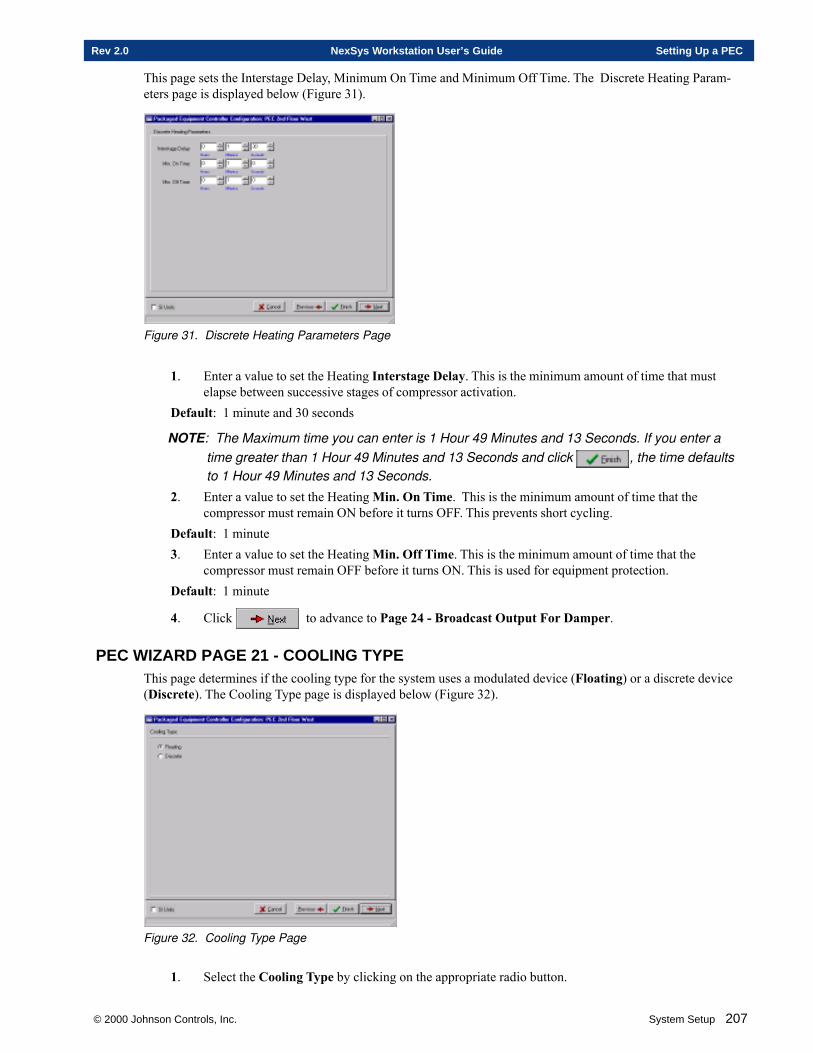
© 2000 Johnson Controls, Inc. System Setup 207
Rev 2.0 NexSys Workstation User’s Guide Setting Up a PEC
This page sets the Interstage Delay, Minimum On Time and Minimum Off Time. The Discrete Heating Param-eters page is displayed below (Figure 31).
Figure 31. Discrete Heating Parameters Page
1. Enter a value to set the Heating Interstage Delay. This is the minimum amount of time that mustelapse between successive stages of compressor activation.
Default: 1 minute and 30 seconds
NOTE: The Maximum time you can enter is 1 Hour 49 Minutes and 13 Seconds. If you enter atime greater than 1 Hour 49 Minutes and 13 Seconds and click , the time defaultsto 1 Hour 49 Minutes and 13 Seconds.
2. Enter a value to set the Heating Min. On Time. This is the minimum amount of time that thecompressor must remain ON before it turns OFF. This prevents short cycling.
Default: 1 minute3. Enter a value to set the Heating Min. Off Time. This is the minimum amount of time that the
compressor must remain OFF before it turns ON. This is used for equipment protection.Default: 1 minute
4. Click to advance to Page 24 - Broadcast Output For Damper.
PEC WIZARD PAGE 21 - COOLING TYPEThis page determines if the cooling type for the system uses a modulated device (Floating) or a discrete device(Discrete). The Cooling Type page is displayed below (Figure 32).
Figure 32. Cooling Type Page
1. Select the Cooling Type by clicking on the appropriate radio button.
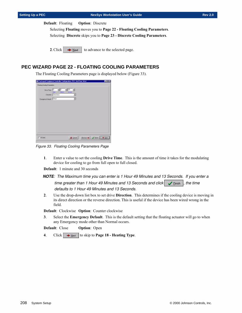
208 System Setup © 2000 Johnson Controls, Inc.
Setting Up a PEC NexSys Workstation User’s Guide Rev 2.0
Default: Floating Option: DiscreteSelecting Floating moves you to Page 22 - Floating Cooling Parameters.Selecting Discrete skips you to Page 23 - Discrete Cooling Parameters.
2. Click to advance to the selected page.
PEC WIZARD PAGE 22 - FLOATING COOLING PARAMETERSThe Floating Cooling Parameters page is displayed below (Figure 33).
Figure 33. Floating Cooling Parameters Page
1. Enter a value to set the cooling Drive Time. This is the amount of time it takes for the modulatingdevice for cooling to go from full open to full closed.
Default: 1 minute and 30 seconds
NOTE: The Maximum time you can enter is 1 Hour 49 Minutes and 13 Seconds. If you enter a
time greater than 1 Hour 49 Minutes and 13 Seconds and click , the timedefaults to 1 Hour 49 Minutes and 13 Seconds.
2. Use the drop-down list box to set drive Direction. This determines if the cooling device is moving inits direct direction or the reverse direction. This is useful if the device has been wired wrong in thefield.
Default: Clockwise Option: Counter clockwise3. Select the Emergency Default. This is the default setting that the floating actuator will go to when
any Emergency mode other than Normal occurs.Default: Close Option: Open
4. Click to skip to Page 18 - Heating Type.

© 2000 Johnson Controls, Inc. System Setup 209
Rev 2.0 NexSys Workstation User’s Guide Setting Up a PEC
PEC WIZARD PAGE 23 - DISCRETE COOLINGThis page sets the Interstage Delay, Minimum On Time, and Minimum Off Time for Discrete Cooling. TheDiscrete Cooling page is displayed below (Figure 34).
Figure 34. Discrete Cooling Page
1. Enter a value to set the Discrete Cooling Interstage Delay. This is the minimum amount of time thatmust elapse between successive stages of compressor activation.
Default: 1 minute 30 seconds
NOTE: The Maximum time you can enter is 1 Hour 49 Minutes and 13 Seconds. If you enter a
time greater than 1 Hour 49 Minutes and 13 Seconds and click , the time defaults to1 Hour 49 Minutes and 13 Seconds.
2. Enter a value to set the Min. On Time and the Min. Off Time. The Min. On Time is the minimumamount of time that the compressor must remain ON before it turns OFF. This prevents short cycling.The Min. Off Time is the minimum amount of time that the compressor must remain OFF before itturns ON. This is used for equipment protection.
Default - Min. On Time: 1 minute Default - Min. Off Time: 5 minutes
3. Click to skip to Page 18 - Heating Type.
PEC WIZARD PAGE 24 - BROADCAST OUTPUT FOR DAMPER?This is the hardware output of the Economizer Controller and is already broadcast. It receives the economizerdamper position as a percent (0% to 100%) from the Economizer Controller and supplies an output signal of 0 to10 VDC to control the economizer damper actuator. The Broadcast Output For Damper? page is displayedbelow (Figure 35).
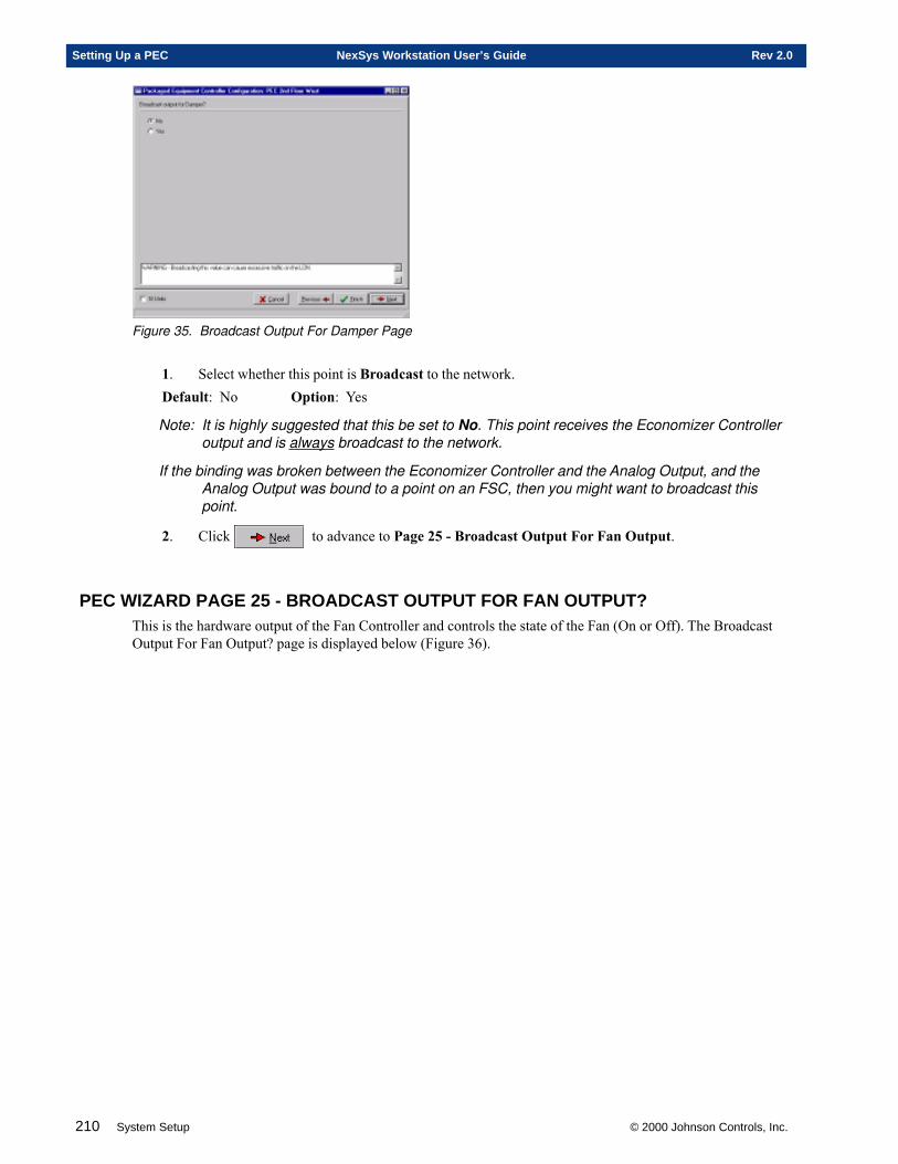
210 System Setup © 2000 Johnson Controls, Inc.
Setting Up a PEC NexSys Workstation User’s Guide Rev 2.0
Figure 35. Broadcast Output For Damper Page
1. Select whether this point is Broadcast to the network.Default: No Option: Yes
Note: It is highly suggested that this be set to No. This point receives the Economizer Controlleroutput and is always broadcast to the network.
If the binding was broken between the Economizer Controller and the Analog Output, and theAnalog Output was bound to a point on an FSC, then you might want to broadcast thispoint.
2. Click to advance to Page 25 - Broadcast Output For Fan Output.
PEC WIZARD PAGE 25 - BROADCAST OUTPUT FOR FAN OUTPUT?This is the hardware output of the Fan Controller and controls the state of the Fan (On or Off). The BroadcastOutput For Fan Output? page is displayed below (Figure 36).
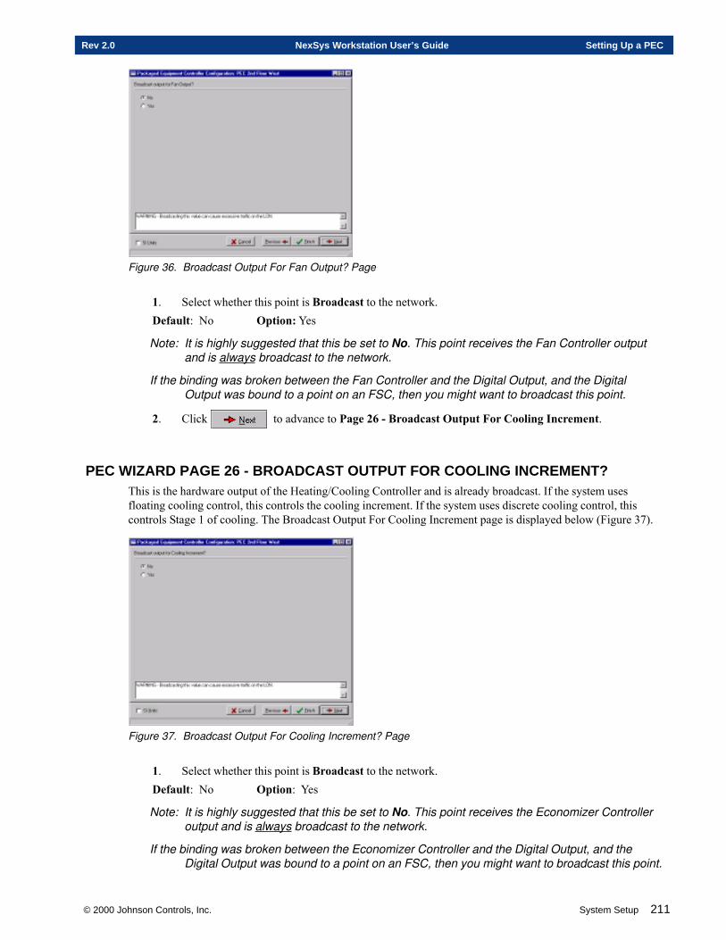
© 2000 Johnson Controls, Inc. System Setup 211
Rev 2.0 NexSys Workstation User’s Guide Setting Up a PEC
Figure 36. Broadcast Output For Fan Output? Page
1. Select whether this point is Broadcast to the network.Default: No Option: Yes
Note: It is highly suggested that this be set to No. This point receives the Fan Controller outputand is always broadcast to the network.
If the binding was broken between the Fan Controller and the Digital Output, and the DigitalOutput was bound to a point on an FSC, then you might want to broadcast this point.
2. Click to advance to Page 26 - Broadcast Output For Cooling Increment.
PEC WIZARD PAGE 26 - BROADCAST OUTPUT FOR COOLING INCREMENT?This is the hardware output of the Heating/Cooling Controller and is already broadcast. If the system usesfloating cooling control, this controls the cooling increment. If the system uses discrete cooling control, thiscontrols Stage 1 of cooling. The Broadcast Output For Cooling Increment page is displayed below (Figure 37).
Figure 37. Broadcast Output For Cooling Increment? Page
1. Select whether this point is Broadcast to the network.Default: No Option: Yes
Note: It is highly suggested that this be set to No. This point receives the Economizer Controlleroutput and is always broadcast to the network.
If the binding was broken between the Economizer Controller and the Digital Output, and theDigital Output was bound to a point on an FSC, then you might want to broadcast this point.
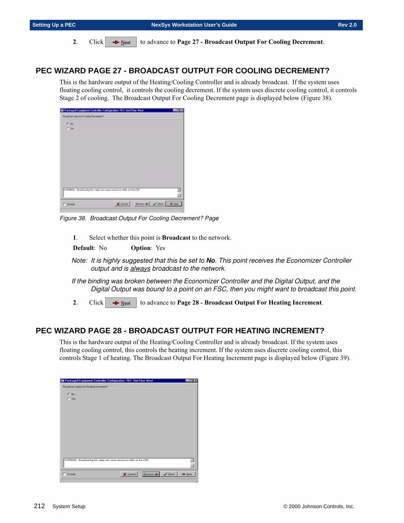
212 System Setup © 2000 Johnson Controls, Inc.
Setting Up a PEC NexSys Workstation User’s Guide Rev 2.0
2. Click to advance to Page 27 - Broadcast Output For Cooling Decrement.
PEC WIZARD PAGE 27 - BROADCAST OUTPUT FOR COOLING DECREMENT?This is the hardware output of the Heating/Cooling Controller and is already broadcast. If the system usesfloating cooling control, it controls the cooling decrement. If the system uses discrete cooling control, it controlsStage 2 of cooling. The Broadcast Output For Cooling Decrement page is displayed below (Figure 38).
Figure 38. Broadcast Output For Cooling Decrement? Page
1. Select whether this point is Broadcast to the network.Default: No Option: Yes
Note: It is highly suggested that this be set to No. This point receives the Economizer Controlleroutput and is always broadcast to the network.
If the binding was broken between the Economizer Controller and the Digital Output, and theDigital Output was bound to a point on an FSC, then you might want to broadcast this point.
2. Click to advance to Page 28 - Broadcast Output For Heating Increment.
PEC WIZARD PAGE 28 - BROADCAST OUTPUT FOR HEATING INCREMENT?This is the hardware output of the Heating/Cooling Controller and is already broadcast. If the system usesfloating cooling control, this controls the heating increment. If the system uses discrete cooling control, thiscontrols Stage 1 of heating. The Broadcast Output For Heating Increment page is displayed below (Figure 39).
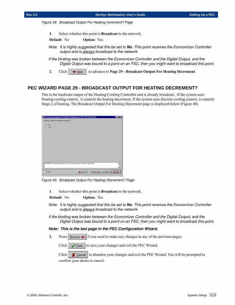
© 2000 Johnson Controls, Inc. System Setup 213
Rev 2.0 NexSys Workstation User’s Guide Setting Up a PEC
Figure 39. Broadcast Output For Heating Increment? Page
1. Select whether this point is Broadcast to the network.Default: No Option: Yes
Note: It is highly suggested that this be set to No. This point receives the Economizer Controlleroutput and is always broadcast to the network.
If the binding was broken between the Economizer Controller and the Digital Output, and theDigital Output was bound to a point on an FSC, then you might want to broadcast this point.
2. Click to advance to Page 29 - Broadcast Output For Heating Decrement.
PEC WIZARD PAGE 29 - BROADCAST OUTPUT FOR HEATING DECREMENT?This is the hardware output of the Heating/Cooling Controller and is already broadcast. If the system usesfloating cooling control, it controls the heating decrement. If the system uses discrete cooling control, it controlsStage 2 of heating. The Broadcast Output For Heating Decrement page is displayed below (Figure 40).
Figure 40. Broadcast Output For Heating Decrement? Page
1. Select whether this point is Broadcast to the network.Default: No Option: Yes
Note: It is highly suggested that this be set to No. This point receives the Economizer Controlleroutput and is always broadcast to the network.
If the binding was broken between the Economizer Controller and the Digital Output, and theDigital Output was bound to a point on an FSC, then you might want to broadcast this point.
Note: This is the last page in the PEC Configuration Wizard.
2. Press if you need to make any changes in any of the previous pages.
Click to save your changes and exit the PEC Wizard.
Click to abandon your changes and exit the PEC Wizard. You will be prompted toconfirm your desire to cancel.
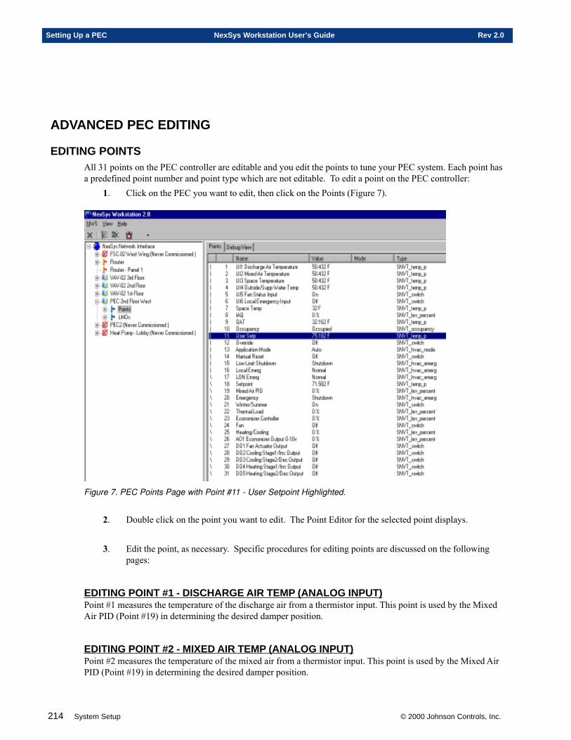
214 System Setup © 2000 Johnson Controls, Inc.
Setting Up a PEC NexSys Workstation User’s Guide Rev 2.0
ADVANCED PEC EDITING
EDITING POINTSAll 31 points on the PEC controller are editable and you edit the points to tune your PEC system. Each point hasa predefined point number and point type which are not editable. To edit a point on the PEC controller:
1. Click on the PEC you want to edit, then click on the Points (Figure 7).
Figure 7. PEC Points Page with Point #11 - User Setpoint Highlighted.
2. Double click on the point you want to edit. The Point Editor for the selected point displays.
3. Edit the point, as necessary. Specific procedures for editing points are discussed on the followingpages:
EDITING POINT #1 - DISCHARGE AIR TEMP (ANALOG INPUT)Point #1 measures the temperature of the discharge air from a thermistor input. This point is used by the MixedAir PID (Point #19) in determining the desired damper position.
EDITING POINT #2 - MIXED AIR TEMP (ANALOG INPUT)Point #2 measures the temperature of the mixed air from a thermistor input. This point is used by the Mixed AirPID (Point #19) in determining the desired damper position.
© 2000 Johnson Controls, Inc. System Setup 215
Rev 2.0 NexSys Workstation User’s Guide Setting Up a PEC
EDITING POINT #3 - SPACE TEMP (ANALOG INPUT)Point #3 is a temperature input. Depending on the exact configuration, this could be either Space Temperature oran auxiliary temperature, Return Air Temperature. If you are using an ESUSA sensor, this point is SpaceTemperature and measures the temperature of the zone under control. If you are using an ESUSA thermostat,then this point can be used as return air temperature.
EDITING POINT #4 - OUTSIDE AIR/SUPPLY WATER TEMP (ANALOG INPUT)Point #4 measures the temperature of the outside air or the supply water from a thermistor input. Depending onthe system configuration, this point could be used by the Winter/Summer Controller (Point 21) in determiningthe summer or winter mode of control for a two pipe system. If this point measures outside air temperature, thispoint provides the OAT for display on the Intelligent STAT.
EDITING POINT #5 - FAN STATUS INPUT (DIGITAL INPUT)Point #5 is a discrete input and is used for fan status feedback. The main purpose of this point is to add safety tothe system by allowing verification of the state of the fan for equipment protection.
EDITING POINT #6 - EMERGENCY SHUTDOWN (DIGITAL INPUT)Point #6 is for the Emergency Shutdown. This input is wired to an external sensor in an area that should be ableto cause an Emergency Shutdown for the local controller.
EDITING POINT #7 - SPACE TEMP CONTROLLERThis point holds the Space Temperature and generates alarms. If you selected Intelligent on the Thermostat Pagefor the PEC, then this value comes from an ESUSA STAT. If Thermistor was selected, then this value comesfrom the Space Temp (Point #3) or an external LON device.
EDITING POINT #8 - INDOOR AIR QUALITY CONTROLLERIndoor Air Quality (IAQ) is the quality of the air expressed in a percentage with 0% being the best and 100%being the worst. This point is used to tell the controller to increase the Minimum Flow Setpoint to compensatefor poor IAQ. The intention is to increase air flow to provide additional fresh air to displace air currently in thecontrolled space.
EDITING POINT #9 - OUTSIDE AIR TEMPThis point receives the outside air temperature from another point or another controller. This point is used by theAnalog Output (Point 26) in determining the desired damper position. This point differs from the Outside Air/Supply Water Temp (Point #4) because Point #4 is an actual hardware point, while Point #9 is a software point.Point #9 allows you to bind an Outside Air Temperature from another controller.
EDITING POINT #10 - MANUAL OCCUPANCY CONTROLLERThis point determines the state of occupancy for the controller (Occupied, Unoccupied, Economy). The state ofoccupancy determines which setpoints are currently in use by the controller. The possible states of occupancythe controller can be placed in are shown on the Point Command window (Figure 13). Although the list contains4 states, the PEC controller only responds to 3 different states. The states are:OCCUPIED - Uses the Occupied Heating and Cooling Setpoints.UNOCCUPIED - Uses the Unoccupied Heating and Cooling Setpoints.BYPASS - Not used in the PEC controller.STANDBY - Uses the Economy Heating and Cooling Setpoints.
216 System Setup © 2000 Johnson Controls, Inc.
Setting Up a PEC NexSys Workstation User’s Guide Rev 2.0
EDITING POINT #11 - USER SETPOINT CONTROLLERThis is the user desired setpoint. This point is given to the controller by the user through the Intelligent or TSOSTAT. This point is used in conjunction with the Setpoint Controller (Point # 18) to determine an offset (bycomparing the Occupied Cooling Setpoint to the User Setpoint) and then apply that offset to the current set-points to determine the Active Setpoint.
EDITING POINT #12 - OVERRIDE CONTROLLERThis point provides the override function and timing for the controller. Override is used to cause the system tocontrol to the occupied setpoints when the building is not normally occupied. Override places the controller backinto occupied mode for a specified time (set in the Override Time field). When this time expires, the previouscontrol (setpoints) resumes.
EDITING POINT #13 - APPLICATION MODE CONTROLLERThis point sets the overall operation mode of the PEC controller. The possible modes the controller can beplaced in are listed below. Although the list contains ten modes, the PEC controller only responds to six differentmodes.The modes are:AUTO - This is the normal mode for the PEC. The controller cools and heats over the whole range of possible
setpoints. Control is provided between -100% to 100% thermal load.HEAT - The controller is in heat mode only. Control is provided between -100% and 0% thermal load.MORNING WARMUP - The economizer damper is fully closed, and then the controller functions as usual.
See the PEC Engineering Guide for more information.COOL - The controller is in cool mode only. Control is provided between 0% and 100% thermal load.NIGHT PURGE - The economizer damper is driven to maximum.PRECOOL - Not used in the PEC controller.OFF - The controller is not providing control and is fixed at 0% thermal load.TEST - Not used in the PEC controller.EMERGENCY HEAT - Not used in the PEC controller.FAN ONLY - Not used in the PEC controller.
EDITING POINT #14 - MANUAL RESETThis point allows the network to send a manual reset command to the Low Limit Shutdown controller in order tofacilitate a reset.
EDITING POINT #15 - LOW LIMIT SHUTDOWNThis point determines if conditions are met to perform a low limit shutdown. This is determined by comparingthe Mixed Air Temp (Point #2) and the Low Limit Setpoint. If the Mixed Air Temp is below the Low LimitSetpoint, then a low limit shutdown is performed and the unit undergoes an Emergency Shutdown. Low LimitShutdown is used for equipment protection mainly to prevent coil freeze-up.
EDITING POINT #16 - LOCAL EMERGENCY SHUTDOWNThis point determines if conditions are met to perform a local emergency shutdown. This is determined by theEmergency Shutdown (Point #6) and is used to tell the controller when to assume emergency operation modeoperations and only effects the local unit.
EDITING POINT #17 - LON EMERGENCY SHUTDOWN
© 2000 Johnson Controls, Inc. System Setup 217
Rev 2.0 NexSys Workstation User’s Guide Setting Up a PEC
This point determines if conditions are met to perform a LON emergency shutdown. This is determined by apoint that is bound from another controller to the PEC-01 controller and is used to tell the controller when toassume emergency operation mode operations. This point is used for smoke control. The possible states ofemergency the controller can be placed in are shown below:
NORMAL - No emergency operations - the controller is controlling to application mode.PRESSURIZE - The controller drives the economizer damper to maximum, the fan is turned ON, and the
thermal load is forced to 0%.DEPRESSURIZE - The controller drives the economizer damper to full closed, the fan is turned OFF, and
the thermal load is forced to 0%.PURGE - The controller drives the economizer damper to maximum, the fan is turned ON, and the thermal
load is forced to 0%.SHUTDOWN - The controller drives the economizer damper to full closed, the fan is turned OFF, and the
thermal load is forced to 0%.
EDITING POINT #18 - SETPOINT CONTROLLERThis point determines the setpoint the controller is currently using. This point takes the User Setpoint Controller(Point #11), compares it to the occupied cooling setpoint entered on this point editor, and determines an offset.This offset is then added to the occupied heating and cooling and economy heating and cooling setpoints and theactive setpoint is determined. The output of the Manual Occupancy Controller (Point #10), the output of theOverride Controller (Point #12), and the output of the Space Temp Controller (Point #7) are also looked at in thedetermination of setpoint.
NOTE 1: The offset is never applied to the unoccupied setpoints.
NOTE 2: The values entered on this screen set up a basic relationship between the setpoints.Even though an offset is determined and added to the setpoints, the numbers entered onthis screen do not change. For more information, see the PEC Engineering Guide.
EDITING POINT #19 - MIXED AIR PID CONTROLLERThis point is used to determine the mixed air PID damper position. This point takes the Discharge Air Temp(Point #1) and the Mixed Air Setpoint (entered in this editor) and outputs a Mixed Air PID damper position inpercent. This is not the absolute damper position because this position is based only on the Discharge Air Tempand the Mixed Air Setpoint. This output is then fed to the Economizer Controller (Point #23) and the exactdamper position is determined.
NOTE 1: It is recommended that the derivative gain always be 0.
NOTE 2: If your control is too sensitive and your system is oscillating, you need to increase theproportional and/or integral gains. If your control is too insensitive and it is taking too longto reach the active setpoint, then you need to decrease the proportional and/or integralgains.
EDITING POINT #20 - EMERGENCY COMMAND CONTROLLERThis point is used to tell the controller when to assume emergency operation mode operations. This point looksat the Low Limit Shutdown (Point #15), the Local Emergency Shutdown (Point #16), and the LON Emergency(Point #17) and determines the emergency mode of operations. The possible states of emergency the controllercan be placed in are shown on the Point Command window (Figure 26). The emergency states are:NORMAL - No emergency operations - the controller is controlling to application mode.PRESSURIZE - The controller drives the economizer damper to maximum, the fan is turned ON, and thethermal load is forced to 0%.
218 System Setup © 2000 Johnson Controls, Inc.
Setting Up a PEC NexSys Workstation User’s Guide Rev 2.0
DEPRESSURIZE - The controller drives the economizer damper to full closed, the fan is turned OFF, and thethermal load is forced to 0%.PURGE - The controller drives the economizer damper to maximum, the fan is turned ON, and the thermal loadis forced to 0%.SHUTDOWN - The controller drives the economizer damper to full closed, the fan is turned OFF, and thethermal load is forced to 0%.
EDITING POINT #21 - WINTER/SUMMER CONTROLLERThis point determines the summer or winter mode for a two-pipe system. This mode is determined by looking atthe Outside Air/Supply Water Temp (Point #4). The output of the Winter/Summer Controller (Point #21) is fedto the Heating/Cooling Controller (Point #25).
EDITING POINT #22 - TEMP PID CONTROLLERThis point calculates thermal load for the controller. It takes the actual space temperature from the Space TempController (Point #7) and the desired space temperature from the Setpoint Controller (Point #18) and outputs athermal load value that is fed to the Economizer Controller (Point #23), the Fan Controller (Point #24), and theHeating/Cooling Controller (Point #25). The output of the Emergency Command Controller (Point #20) and theoutput of the Application Mode Controller (Point #13) are also used at in the determination of thermal load.
EDITING POINT #23 - ECONOMIZER CONTROLLERThis point determines the economizer damper position. The damper position is determined by looking at theIndoor Air Quality Controller (Point #8), the Outside Air/Supply Water Temp (Point #4), the Mixed Air PIDController (Point #19), the Manual Occupancy Controller (Point #10), the Emergency Command Controller(Point #20), and the Temp PID Controller (Point #22).
EDITING POINT #24 - FAN CONTROLLERThis point determines when the fan should be ON or OFF. This point looks at the output the Manual OccupancyController (Point #10) and the output of the Emergency Command Controller (Point #20) to determine if the fanshould be ON or OFF. The output of this point is sent to the Fan Output (Point #27) which is the control pointfor the fan.
NOTE: This point is only the state of the fan as the sequence of operation determines it to be.Fan Status (Point #5) can be used as a feedback to determine the actual status of the fan.
EDITING POINT #25 - HEATING/COOLING CONTROLLERThis point determines whether the system is heating or cooling. Many factors are looked at in this determination.Depending on what is entered in this point editor, this can determine heating or cooling, discrete or floatingcontrol, 2 or 4 pipe system, etc.
NOTE: The fields on this screen change depending on the Cooling Type and Heating Typeselected.
EDITING POINT #26 - ANALOG OUTPUTNOTE: This point is used to control the Economizer Damper.
This point is the hardware output of the Economizer Controller (Point #23). This point receives the economizerdamper position as a percent (0 to 100) from the Economizer Controller and supplies an output signal of 0 to 10VDC to control the economizer damper actuator.
EDITING POINT #27 - DIGITAL OUTPUT #1 FAN ACTUATOR OUTPUTPoint #27 controls the state of the fan (ON or OFF). This point is the hardware output of the Fan Controller(Point #24) and applies the control.
© 2000 Johnson Controls, Inc. System Setup 219
Rev 2.0 NexSys Workstation User’s Guide System Setup Index
System Setup Index
A
Active Setpoint 153Adding a PEC 186Adding a Router to the Physical Tree 121
Commissioning 121Defining 121
Adding Nodes To A Router 124Advanced PEC Editing 214Air Flow 152Application Mode Controller 148,172Application Specific Controller 164ASC 130,140
B
Broadcast 158,159,160,181,182,183,184
C
Coactive Routers 121Commissioning a Defined Router 123Commissioning the PEC 187Config Data Set 107Config Password 146,147,169,170Configuration Mode 146,169Connection Description Template (CDT)
Adding A Connection Description Template(CDT) 115Addressing 116
Deleting An Existing CDT 117Entering Values
Other 116Service Types 116Timing Parameters 116
Modifying An Existing CDT 117Cooling Scan Rate 149,172CPL 130CTI Routers 121
D
Damper 152Deadband 177Default Output 149,153,172
Defining a PEC 186Delay Time 177,180Derivative Gain 149,153,172,176Direct Action 153Display Order 146,170Drive Time 153
E
Echelon Routers 121Economizer
Controller 148,172,175Economy
Cooling Setpoint 147,148,171Heating Setpoint 147,148,171
Edit/View Binding 106Emergency
Command 179Command Controller 148,172Heat 179Heat Holdoff 179Shutdown 215
English Units 146,170
F
FanController 148,172Output 177Status 178,179Status Delay 178
Far-Side Transceiver Types 121Fiber Optic/Twisted Pair Router 121FLC 130Flow Offset 150FSC 183FSC/FLC 130
Add 130FTR 121
G
Global Node 102,131,140,164
H
HeatingScan Rate 149,172
220 System Setup © 2000 Johnson Controls, Inc.
System Setup Index NexSys Workstation User’s Guide Rev 2.0
Heating/Cooling Controller 148,172Holdoff 179
I
I/O Module 137Integral Gain 148,153,172,176Intelligent STAT 145,169Interstage Delay 156
K
K Factor 149,150,152K Factor Calibration 150
L
Load Firmware 110Local 174Local Economizer 174LON Economizer 174Loop Enable 179Low Limit
Setpoint 176
M
Maximum Air Flow 151Metric Units 146,170Min. Off Time 179Min. On Time 179Min. Reheat Flow 151Minimum Air Flow 151Minimum Run Time 177Mixed Air PID 176,179Mixed Air Temperature 176Morning Warmup
Maximum Flow 151Minimum Flow 151
MultiNode Operations 113MWU Max. Flow 151MWU Min. Flow 151
N
Network 174Neuron ID 103,132,141,165No Reverse 180Node
Add 102Configuration Wizard 118Delete 107
Move 101Rename 110
Node Commands 96Offline 97Reset 98Test 98Wink 96
Node Menu 96
O
OAT Deadband 175Occupied Cooling Setpoint 147,171Occupied Heating Setpoint 147,171Occupied Mode 146,170Offset 148,171
P
Parallel Fan 154Password 146,169,170PEC 131,140,164
Editors 132,141,165Global Information 134,143,168,190
Physical Tree 131,140,164NexSys Network Interface Node
Connection Description Template (CDT) 114PID 154PID Loop 152Plug-Ins 99
Registering A Plug-In 99Running A Plug-In 100
Polarity 180Proportional Gain 148,153,172,175
R
Reheat Decrement 154Reheat Increment 154Replace Node 105Reverse 180Reverse Action 153Router
Bridge Router 120Configured Router 120Learning Router 120Permanent Bridge Router 120Permanent Repeater Router 120Repeater Router 120
Router Classification Types 120
© 2000 Johnson Controls, Inc. System Setup 221
Rev 2.0 NexSys Workstation User’s Guide System Setup Index
S
Scan Rate 149,153,172Scan Time 176Serial Fan 154Service Pin 103,132,141,165Set Time/Day On Node 109Setpoint 177Setpoint Controller 148,172Setup Node 103Space Temperature 135,145,169Stages 178Standby State 215Status Send Interval 135
T
Thermal Load 148,172Thermistor 145,169Time Broadcast Interval 135Time Mode 146,170Time Zone Offset 135
U
Units 146,170Unoccupied Cooling Setpoint 148,171Unoccupied Heating Setpoint 148,171User Mode 146,170

222 System Setup © 2000 Johnson Controls, Inc.
System Setup Index NexSys Workstation User’s Guide Rev 2.0
Chapters
1. Binding Network Variables
2. Using CPL
3. CPL Blocks
4. Schedules
© 2000 Johnson Controls, Inc.
PROGRAMMINGSECTION FOUR

224 Programming © 2000 Johnson Controls, Inc.
Programming Introduction NexSys Workstation User’s Guide Rev 2.0
Electronic Systems USA, a wholly owned subsidiary of Johnson Controls, Inc., reserves the right to updatespecifications when Appropriate. Information contained in this document is based on specifications believed tobe correct at the time of publication.
Echelon ©, Coactive©, Windows NT©, and General Electric© are registered trademarks and service marks ofcompanies other than Electronic Systems USA. FSC™, CPL™ and NEXSYS™ are trademarks of ElectronicSystems USA.
Copyright © 2000 Johnson Controls, Inc. All Rights Reserved
© 2000 Johnson Controls, Inc. Programming 225
Rev 2.0 NexSys Workstation User’s Guide Programming Introduction
Programming Table of Contents
Chapter One - Binding Network Variables 251Overview .......................................................................................................................... 252
Editing and Viewing Bindings ................................................................................ 252Refresh ....................................................................................................... 253Adding A Bind ............................................................................................. 254Deleting a Bind ........................................................................................... 255
Chapter Two - Using CPL 257Overview .......................................................................................................................... 258
CPL Pages Subtree ............................................................................................... 258Working With Individual Pages ................................................................... 259CPL Page Menu Commands ...................................................................... 259
CPL Blocks ....................................................................................................................... 261Block Types ................................................................................................ 262
Arithmetic Blocks ............................................................................. 262Comparison Blocks .......................................................................... 262Constant Blocks ............................................................................... 262Function Blocks ................................................................................ 262Global Variable Blocks ..................................................................... 263Logical Blocks .................................................................................. 263Point Blocks ..................................................................................... 263Time Blocks ...................................................................................... 263
Block Colors................................................................................................ 263CPL Editor ........................................................................................................................ 263
CPL Editor Toolbar................................................................................................. 264Selection Mode ........................................................................................... 264Zoom Modes ............................................................................................... 264Best Fit ........................................................................................................ 264Show Grid ................................................................................................... 265Monitor Mode .............................................................................................. 265
Zoom Control Box.................................................................................................. 266CPL Block Menu .................................................................................................... 267
Creating And Editing CPL Pages ..................................................................................... 267To Add A New CPL Page: ...................................................................................... 267
Adding CPL Blocks ..................................................................................... 268Editing CPL Blocks ................................................................................................ 269
Editing Multiple Blocks ................................................................................ 269Direct/Reverse Acting ...................................................................... 270
Deleting A Block .......................................................................................... 270Deleting Multiple Blocks .............................................................................. 271Moving A Block ........................................................................................... 271Moving Multiple Blocks ............................................................................... 272
Block Connections ........................................................................................................... 272Connecting Blocks ................................................................................................. 272
Multiple Inputs............................................................................................. 273
226 Programming © 2000 Johnson Controls, Inc.
Programming Introduction NexSys Workstation User’s Guide Rev 2.0
Deleting A Block Connection....................................................................... 273CPL User Library .............................................................................................................. 274
CPL Library Window .............................................................................................. 274Accessing the CPL Library from NWS ........................................................ 275Closing The CPL Library ............................................................................. 275
Library Pages Window........................................................................................... 275Library Pages Toolbar ................................................................................. 276
CPL Library Block Editor Window .......................................................................... 276Creating A New CPL Library Page .............................................................. 277Importing A CPL Library Page..................................................................... 277Exporting A CPL library page ...................................................................... 277
Summary Of Blocks ............................................................................................... 278
Chapter Three - CPL Blocks 281CPL Blocks ....................................................................................................................... 282
CPL Block Settings ................................................................................................ 282Ignore Error Check Box .............................................................................. 283
Entering Block Information - Constants ................................................................. 283Analog Constant ......................................................................................... 284
Settings ............................................................................................ 284Digital Constant .......................................................................................... 284
Settings ............................................................................................ 284Entering Block Information - Functions .................................................................. 285
2-Position .................................................................................................... 286Settings ............................................................................................ 286
Accumulator ................................................................................................ 287Settings ............................................................................................ 287
Calculation .................................................................................................. 287Settings ............................................................................................ 288
Counter ....................................................................................................... 289Settings ............................................................................................ 289
Dial Provider ............................................................................................... 289Settings ............................................................................................ 289
Enthalpy ...................................................................................................... 290Settings ............................................................................................ 290
Error - Analog (A-error) ............................................................................... 290Settings ............................................................................................ 290
Error - Digital (D-Error) ................................................................................ 291Settings ............................................................................................ 291
Hi/Lo/Average ............................................................................................. 291Settings ............................................................................................ 291
Lead/Lag ..................................................................................................... 292 Settings ........................................................................................... 292
Min/Max ...................................................................................................... 293Settings ............................................................................................ 293
Minimum On/Off .......................................................................................... 294Settings ............................................................................................ 294
One Shot..................................................................................................... 294
© 2000 Johnson Controls, Inc. Programming 227
Rev 2.0 NexSys Workstation User’s Guide Programming Introduction
Settings ............................................................................................ 295PID Loop ..................................................................................................... 296
Settings ............................................................................................ 296Timing .............................................................................................. 296
Psychro ....................................................................................................... 297Settings ............................................................................................ 297
Ramp .......................................................................................................... 297Settings ............................................................................................ 298Timing .............................................................................................. 298
Relay - Analog ........................................................................................... 298Settings ............................................................................................ 298
Relay - digital ............................................................................................. 298Settings ............................................................................................ 299
Reset .......................................................................................................... 299Settings ............................................................................................ 300
Rolling Average........................................................................................... 300Settings ............................................................................................ 300Timing .............................................................................................. 300
Runtime ...................................................................................................... 301Settings ............................................................................................ 301
Schedule ..................................................................................................... 302Settings ............................................................................................ 302Timing .............................................................................................. 303
Sequencer .................................................................................................. 303Settings ............................................................................................ 303Descriptor ......................................................................................... 303
Startup ........................................................................................................ 304Settings ............................................................................................ 304
Start/Stop .................................................................................................... 304Settings ............................................................................................ 304
Time Event .................................................................................................. 304Settings ............................................................................................ 305
Entering Block Information - Global Variables ....................................................... 305Settings ............................................................................................ 306
Global Analog Input .................................................................................... 306Global Digital Input ..................................................................................... 306Global Analog Output.................................................................................. 306Global Digital Output................................................................................... 306
Entering Block Information - Logical ...................................................................... 307AND ............................................................................................................ 307
Settings ............................................................................................ 307OR .............................................................................................................. 308
Settings ............................................................................................ 308NOT ............................................................................................................ 308
Settings ............................................................................................ 308XOR ............................................................................................................ 308
Settings ............................................................................................ 309
228 Programming © 2000 Johnson Controls, Inc.
Programming Introduction NexSys Workstation User’s Guide Rev 2.0
Entering Block Information - Comparison .............................................................. 309A-Equal ....................................................................................................... 310
Settings ............................................................................................ 310A-Not Equal ............................................................................................... 310
Settings ............................................................................................ 310D-Equal ....................................................................................................... 310
Settings ............................................................................................ 310D-Not Equal .................................................................................................311
Settings .............................................................................................311Greater Equal ..............................................................................................311
Settings .............................................................................................311Greater Than ...............................................................................................311
Settings .............................................................................................311Less Equal .................................................................................................. 312
Setting .............................................................................................. 312Less Than ................................................................................................... 312
Settings ............................................................................................ 312Entering Block Information - Arithmetic ................................................................. 312
Add ............................................................................................................. 313Settings ............................................................................................ 313
Divide .......................................................................................................... 313Settings ............................................................................................ 313
Modulus ...................................................................................................... 314Settings ............................................................................................ 314
Multiply........................................................................................................ 314Settings ............................................................................................ 314
Negate ........................................................................................................ 314Settings ............................................................................................ 314
Sq. Root (Square Root) .............................................................................. 315Settings ............................................................................................ 315
Subtract ...................................................................................................... 315Settings ............................................................................................ 315
Entering Block Information - Points ....................................................................... 315AI (Analog Input) ......................................................................................... 316
Settings ............................................................................................ 316DI (Digital Input) .......................................................................................... 316
Settings ............................................................................................ 316AO (Analog Output) .................................................................................... 316
Settings ............................................................................................ 317D0 (Digital Output) ...................................................................................... 317
Settings ............................................................................................ 317MAI (Multiple Analog Input) ......................................................................... 317
Settings ............................................................................................ 318MDI (Multiple Digital Input) ......................................................................... 318
Settings ............................................................................................ 318Point State .................................................................................................. 319
Settings ............................................................................................ 319
© 2000 Johnson Controls, Inc. Programming 229
Rev 2.0 NexSys Workstation User’s Guide Programming Introduction
Entering Block Information - Time ......................................................................... 319Constant Time............................................................................................. 320
Settings ............................................................................................ 320Convert Time .............................................................................................. 320
Settings ............................................................................................ 320Current Time ............................................................................................... 321
Settings ............................................................................................ 321
Chapter Four - Schedules 323SCHEDULING .................................................................................................................. 324
The Schedule Subtree ........................................................................................... 324Viewing Individual Schedules ..................................................................... 324
Creating A New Schedule ...................................................................................... 325Adding A New Schedule: ............................................................................ 325Entering Values For A New Schedule: ........................................................ 326
Editing An Existing Schedule ................................................................................. 328Renaming A Schedule ........................................................................................... 328Deleting A Schedule .............................................................................................. 328Copying Schedules To Another FSC ..................................................................... 329Refresh Schedules ................................................................................................ 329
Programming Index ........................................................................ 331

230 Programming © 2000 Johnson Controls, Inc.
Programming Introduction NexSys Workstation User’s Guide Rev 2.0
Chapter One
Binding Network Variables
This chapter contains information on:
l Editing and Viewing Bindings
l Adding a Bind
l Deleting a Bind
© 2000 Johnson Controls, Inc.
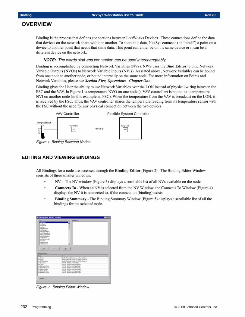
232 Programming © 2000 Johnson Controls, Inc.
Binding NexSys Workstation User’s Guide Rev 2.0
OVERVIEW
Binding is the process that defines connections between LONWORKS Devices . These connections define the datathat devices on the network share with one another. To share this data, NexSys connects (or “binds”) a point on adevice to another point that needs that same data. This point can either be on the same device or it can be adifferent device on the network.
NOTE: The words bind and connection can be used interchangeably.
Binding is accomplished by connecting Network Variables (NVs). NWS uses the Bind Editor to bind NetworkVariable Outputs (NVOs) to Network Variable Inputs (NVIs). As stated above, Network Variables can be boundfrom one node to another node, or bound internally on the same node. For more information on Points andNetwork Variables, please see Section Five, Operations - Chapter One.Binding gives the User the ability to use Network Variables over the LON instead of physical wiring between theFSC and the VAV. In Figure 1, a temperature NVO on one node (a VAV controller) is bound to a temperatureNVI on another node (in this example an FSC). When the temperature from the VAV is broadcast on the LON, itis received by the FSC. Thus, the VAV controller shares the temperature reading from its temperature sensor withthe FSC without the need for any physical connection between the two devices.
VAV Controller Flexible System Controller
55°Temp NVO
55°Temp NVI
Binding
557595
Temp Sensor
Figure 1. Binding Between Nodes.
EDITING AND VIEWING BINDINGS
All Bindings for a node are accessed through the Binding Editor (Figure 2). The Binding Editor Windowconsists of three smaller windows:
• NV - The NV window (Figure 3) displays a scrollable list of all NVs available on the node.• Connects To - When an NV is selected from the NV Window, the Connects To Window (Figure 4)
displays the NV it is connected to, if the connection (binding) exists.• Binding Summary - The Binding Summary Window (Figure 5) displays a scrollable list of all the
bindings for the selected node.
Figure 2. Binding Editor Window
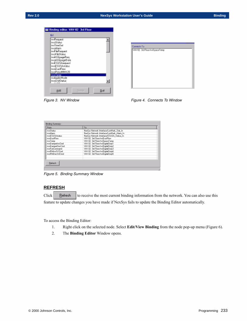
© 2000 Johnson Controls, Inc. Programming 233
Rev 2.0 NexSys Workstation User’s Guide Binding
Figure 3. NV Window Figure 4. Connects To Window
Figure 5. Binding Summary Window
REFRESH
Click to receive the most current binding information from the network. You can also use this
feature to update changes you have made if NexSys fails to update the Binding Editor automatically.
To access the Binding Editor:1. Right click on the selected node. Select Edit/View Binding from the node pop-up menu (Figure 6).2. The Binding Editor Window opens.
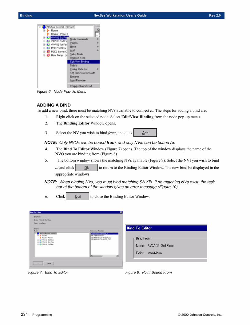
234 Programming © 2000 Johnson Controls, Inc.
Binding NexSys Workstation User’s Guide Rev 2.0
Figure 6. Node Pop-Up Menu
ADDING A BINDTo add a new bind, there must be matching NVs available to connect to. The steps for adding a bind are:
1. Right click on the selected node. Select Edit/View Binding from the node pop-up menu.2. The Binding Editor Window opens.
3. Select the NV you wish to bind from, and click .
NOTE: Only NVOs can be bound from, and only NVIs can be bound to.
4. The Bind To Editor Window (Figure 7) opens. The top of the window displays the name of theNVO you are binding from (Figure 8).
5. The bottom window shows the matching NVs available (Figure 9). Select the NVI you wish to bind
to and click to return to the Binding Editor Window. The new bind be displayed in theappropriate windows
NOTE: When binding NVs, you must bind matching SNVTs. If no matching NVs exist, the taskbar at the bottom of the window gives an error message (Figure 10).
6. Click to close the Binding Editor Window.
Figure 7. Bind To Editor Figure 8. Point Bound From
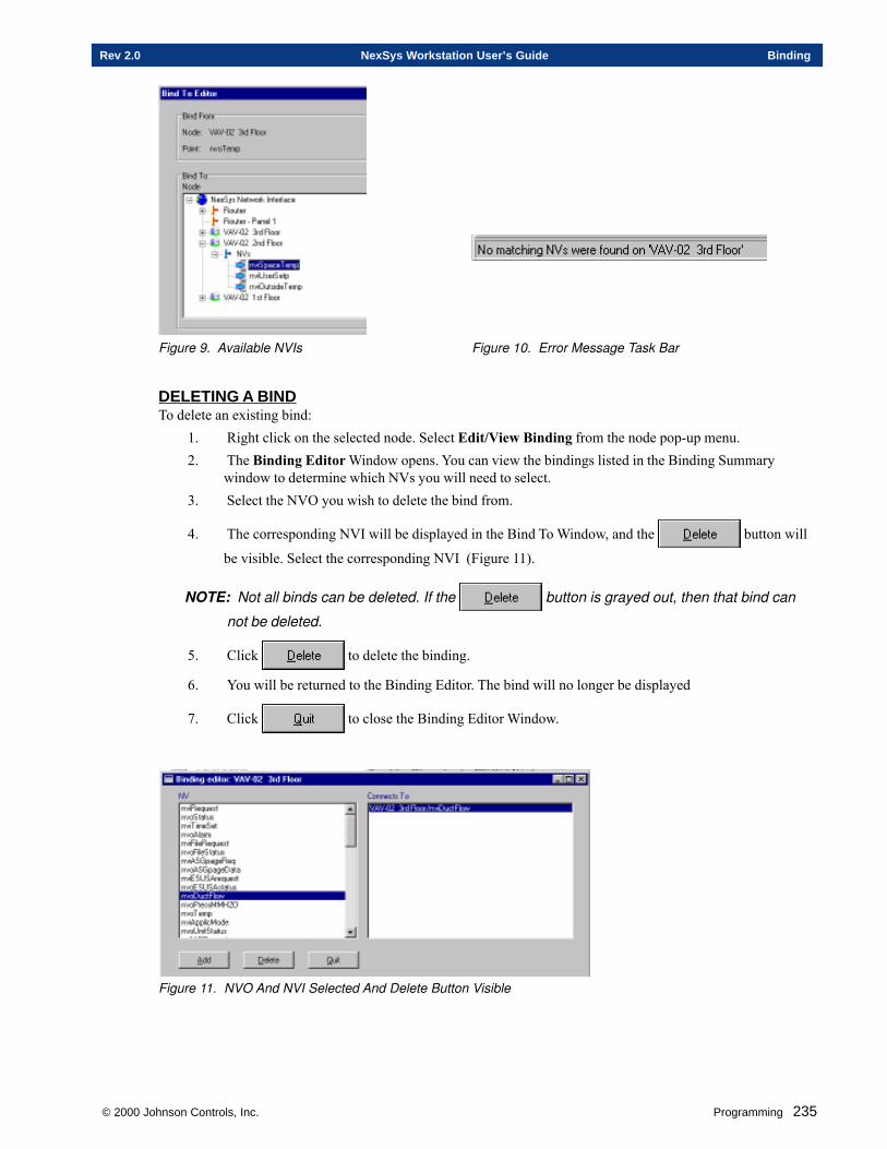
© 2000 Johnson Controls, Inc. Programming 235
Rev 2.0 NexSys Workstation User’s Guide Binding
Figure 9. Available NVIs Figure 10. Error Message Task Bar
DELETING A BINDTo delete an existing bind:
1. Right click on the selected node. Select Edit/View Binding from the node pop-up menu.2. The Binding Editor Window opens. You can view the bindings listed in the Binding Summary
window to determine which NVs you will need to select.3. Select the NVO you wish to delete the bind from.
4. The corresponding NVI will be displayed in the Bind To Window, and the button will
be visible. Select the corresponding NVI (Figure 11).
NOTE: Not all binds can be deleted. If the button is grayed out, then that bind can
not be deleted.
5. Click to delete the binding.
6. You will be returned to the Binding Editor. The bind will no longer be displayed
7. Click to close the Binding Editor Window.
Figure 11. NVO And NVI Selected And Delete Button Visible

236 Programming © 2000 Johnson Controls, Inc.
Binding NexSys Workstation User’s Guide Rev 2.0
This chapter contains information on:
�Creating CPL Blocks
�Creating CPL Pages
�Using the CPL Library
Chapter Two
Using CPL
© 2000 Johnson Controls, Inc.
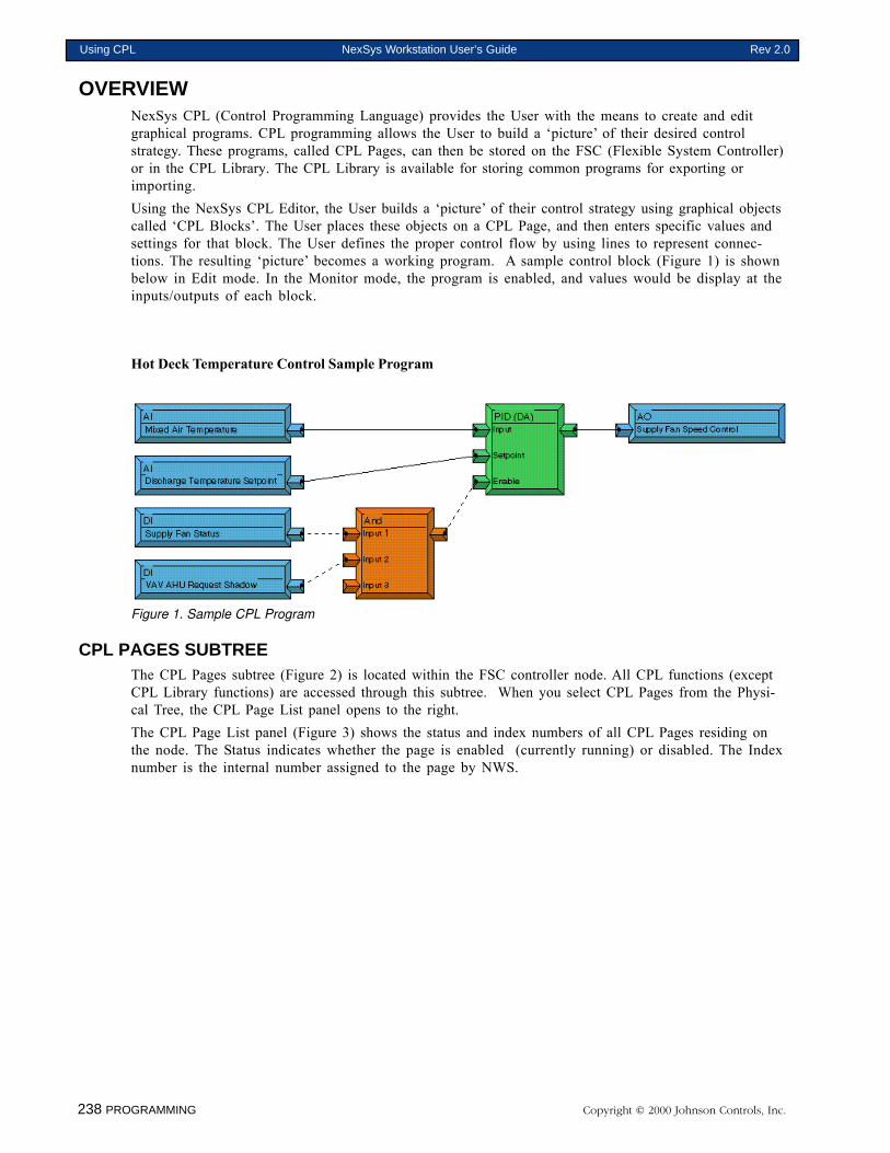
238 PROGRAMMING Copyright © 2000 Johnson Controls, Inc.
Using CPL NexSys Workstation User’s Guide Rev 2.0
OVERVIEWNexSys CPL (Control Programming Language) provides the User with the means to create and editgraphical programs. CPL programming allows the User to build a ‘picture’ of their desired controlstrategy. These programs, called CPL Pages, can then be stored on the FSC (Flexible System Controller)or in the CPL Library. The CPL Library is available for storing common programs for exporting orimporting.Using the NexSys CPL Editor, the User builds a ‘picture’ of their control strategy using graphical objectscalled ‘CPL Blocks’. The User places these objects on a CPL Page, and then enters specific values andsettings for that block. The User defines the proper control flow by using lines to represent connec-tions. The resulting ‘picture’ becomes a working program. A sample control block (Figure 1) is shownbelow in Edit mode. In the Monitor mode, the program is enabled, and values would be display at theinputs/outputs of each block.
Hot Deck Temperature Control Sample Program
Figure 1. Sample CPL Program
CPL PAGES SUBTREEThe CPL Pages subtree (Figure 2) is located within the FSC controller node. All CPL functions (exceptCPL Library functions) are accessed through this subtree. When you select CPL Pages from the Physi-cal Tree, the CPL Page List panel opens to the right.The CPL Page List panel (Figure 3) shows the status and index numbers of all CPL Pages residing onthe node. The Status indicates whether the page is enabled (currently running) or disabled. The Indexnumber is the internal number assigned to the page by NWS.
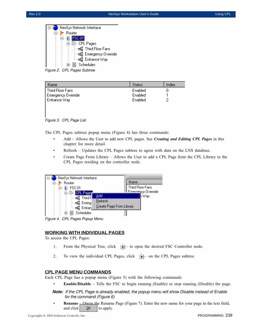
Copyright © 2000 Johnson Controls, Inc. PROGRAMMING 239
Rev 2.0 NexSys Workstation User’s Guide Using CPL
Figure 2. CPL Pages Subtree
Figure 3. CPL Page List
The CPL Pages subtree popup menu (Figure 4) has three commands:• Add – Allows the User to add new CPL pages. See Creating and Editing CPL Pages in this
chapter for more detail.• Refresh – Updates the CPL Pages subtree to agree with data on the LNS database.• Create Page From Library – Allows the User to add a CPL Page from the CPL Library to the
CPL Pages residing on the controller node.
Figure 4. CPL Pages Popup Menu
WORKING WITH INDIVIDUAL PAGESTo access the CPL Pages:
1. From the Physical Tree, click to open the desired FSC Controller node.
2. To view the individual CPL Pages, click on the CPL Pages subtree.
CPL PAGE MENU COMMANDSEach CPL Page has a popup menu (Figure 5) with the following commands:
• Enable/Disable – Tells the FSC to begin running (Enable) or stop running (Disable) the page.
Note: If the CPL Page is already enabled, the popup menu will show Disable instead of Enablefor the command (Figure 6)
• Rename – Opens the Rename Page (Figure 7). Enter the new name for your page in the text field,and click to apply.
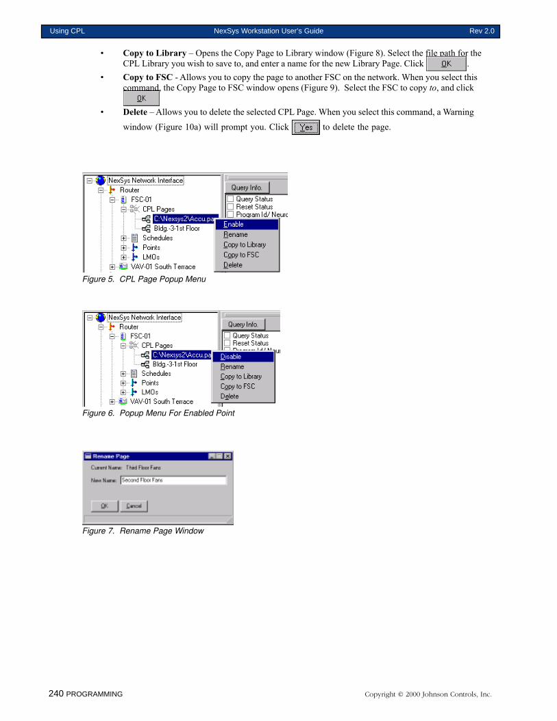
240 PROGRAMMING Copyright © 2000 Johnson Controls, Inc.
Using CPL NexSys Workstation User’s Guide Rev 2.0
• Copy to Library – Opens the Copy Page to Library window (Figure 8). Select the file path for theCPL Library you wish to save to, and enter a name for the new Library Page. Click .
• Copy to FSC - Allows you to copy the page to another FSC on the network. When you select thiscommand, the Copy Page to FSC window opens (Figure 9). Select the FSC to copy to, and click
• Delete – Allows you to delete the selected CPL Page. When you select this command, a Warning
window (Figure 10a) will prompt you. Click to delete the page.
Figure 5. CPL Page Popup Menu
Figure 6. Popup Menu For Enabled Point
Figure 7. Rename Page Window
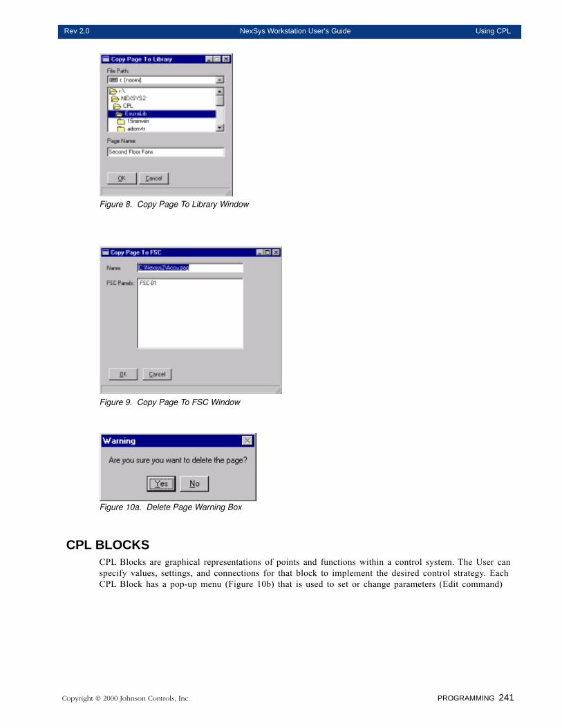
Copyright © 2000 Johnson Controls, Inc. PROGRAMMING 241
Rev 2.0 NexSys Workstation User’s Guide Using CPL
Figure 8. Copy Page To Library Window
Figure 9. Copy Page To FSC Window
Figure 10a. Delete Page Warning Box
CPL BLOCKSCPL Blocks are graphical representations of points and functions within a control system. The User canspecify values, settings, and connections for that block to implement the desired control strategy. EachCPL Block has a pop-up menu (Figure 10b) that is used to set or change parameters (Edit command)
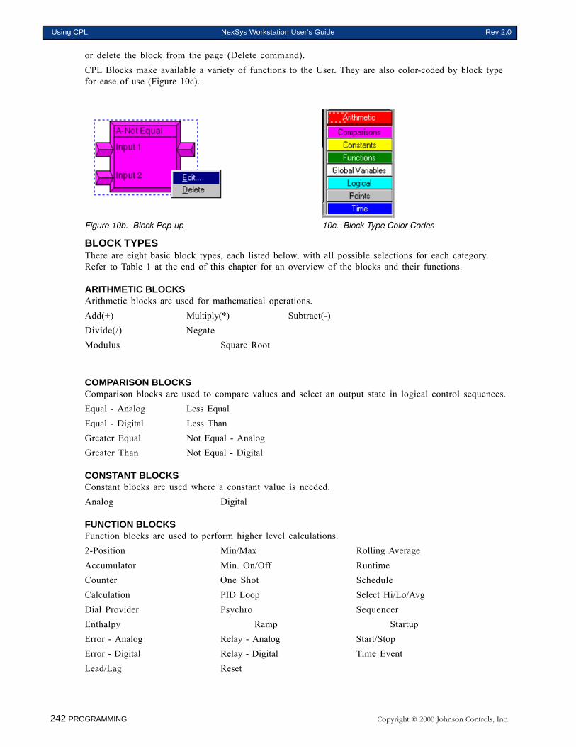
242 PROGRAMMING Copyright © 2000 Johnson Controls, Inc.
Using CPL NexSys Workstation User’s Guide Rev 2.0
or delete the block from the page (Delete command).CPL Blocks make available a variety of functions to the User. They are also color-coded by block typefor ease of use (Figure 10c).
Figure 10b. Block Pop-up 10c. Block Type Color Codes
BLOCK TYPESThere are eight basic block types, each listed below, with all possible selections for each category.Refer to Table 1 at the end of this chapter for an overview of the blocks and their functions.
ARITHMETIC BLOCKSArithmetic blocks are used for mathematical operations.Add(+) Multiply(*) Subtract(-)Divide(/) NegateModulus Square Root
COMPARISON BLOCKSComparison blocks are used to compare values and select an output state in logical control sequences.Equal - Analog Less EqualEqual - Digital Less ThanGreater Equal Not Equal - AnalogGreater Than Not Equal - Digital
CONSTANT BLOCKSConstant blocks are used where a constant value is needed.Analog Digital
FUNCTION BLOCKSFunction blocks are used to perform higher level calculations.2-Position Min/Max Rolling AverageAccumulator Min. On/Off RuntimeCounter One Shot ScheduleCalculation PID Loop Select Hi/Lo/AvgDial Provider Psychro SequencerEnthalpy Ramp StartupError - Analog Relay - Analog Start/StopError - Digital Relay - Digital Time EventLead/Lag Reset
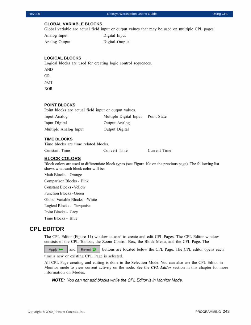
Copyright © 2000 Johnson Controls, Inc. PROGRAMMING 243
Rev 2.0 NexSys Workstation User’s Guide Using CPL
GLOBAL VARIABLE BLOCKSGlobal variable are actual field input or output values that may be used on multiple CPL pages.Analog Input Digital InputAnalog Output Digital Output
LOGICAL BLOCKSLogical blocks are used for creating logic control sequences.ANDORNOTXOR
POINT BLOCKSPoint blocks are actual field input or output values.Input Analog Multiple Digital Input Point StateInput Digital Output AnalogMultiple Analog Input Output Digital
TIME BLOCKSTime blocks are time related blocks.Constant Time Convert Time Current Time
BLOCK COLORSBlock colors are used to differentiate block types (see Figure 10c on the previous page). The following listshows what each block color will be:Math Blocks - OrangeComparison Blocks - PinkConstant Blocks -YellowFunction Blocks -GreenGlobal Variable Blocks - WhiteLogical Blocks - TurquoisePoint Blocks - GreyTime Blocks - Blue
CPL EDITORThe CPL Editor (Figure 11) window is used to create and edit CPL Pages. The CPL Editor windowconsists of the CPL Toolbar, the Zoom Control Box, the Block Menu, and the CPL Page. The
and buttons are located below the CPL Page. The CPL editor opens each
time a new or existing CPL Page is selected.All CPL Page creating and editing is done in the Selection Mode. You can also use the CPL Editor inMonitor mode to view current activity on the node. See the CPL Editor section in this chapter for moreinformation on Modes.
NOTE: You can not add blocks while the CPL Editor is in Monitor Mode.
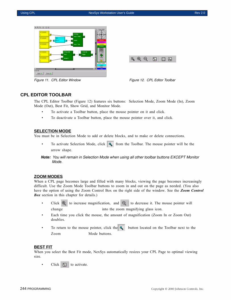
244 PROGRAMMING Copyright © 2000 Johnson Controls, Inc.
Using CPL NexSys Workstation User’s Guide Rev 2.0
Figure 11. CPL Editor Window Figure 12. CPL Editor Toolbar
CPL EDITOR TOOLBARThe CPL Editor Toolbar (Figure 12) features six buttons: Selection Mode, Zoom Mode (In), ZoomMode (Out), Best Fit, Show Grid, and Monitor Mode.
• To activate a Toolbar button, place the mouse pointer on it and click.• To deactivate a Toolbar button, place the mouse pointer over it, and click.
SELECTION MODEYou must be in Selection Mode to add or delete blocks, and to make or delete connections.
• To activate Selection Mode, click from the Toolbar. The mouse pointer will be thearrow shape.
Note: You will remain in Selection Mode when using all other toolbar buttons EXCEPT MonitorMode.
ZOOM MODESWhen a CPL page becomes large and filled with many blocks, viewing the page becomes increasinglydifficult. Use the Zoom Mode Toolbar buttons to zoom in and out on the page as needed. (You alsohave the option of using the Zoom Control Box on the right side of the window. See the Zoom ControlBox section in this chapter for details.)
• Click to increase magnification, and to decrease it. The mouse pointer willchange into the zoom magnifying glass icon.
• Each time you click the mouse, the amount of magnification (Zoom In or Zoom Out)doubles.
• To return to the mouse pointer, click the button located on the Toolbar next to theZoom Mode buttons.
BEST FITWhen you select the Best Fit mode, NexSys automatically resizes your CPL Page to optimal viewingsize.
• Click to activate.
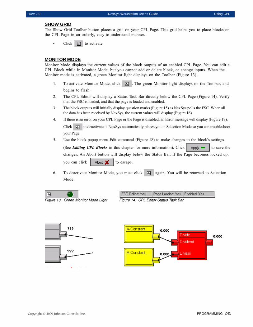
Copyright © 2000 Johnson Controls, Inc. PROGRAMMING 245
Rev 2.0 NexSys Workstation User’s Guide Using CPL
SHOW GRIDThe Show Grid Toolbar button places a grid on your CPL Page. This grid helps you to place blocks onthe CPL Page in an orderly, easy-to-understand manner.
• Click to activate.
MONITOR MODEMonitor Mode displays the current values of the block outputs of an enabled CPL Page. You can edit aCPL Block while in Monitor Mode, but you cannot add or delete block, or change inputs. When theMonitor mode is activated, a green Monitor light displays on the Toolbar (Figure 13).
1. To activate Monitor Mode, click . The green Monitor light displays on the Toolbar, andbegins to flash.
2. The CPL Editor will display a Status Task Bar directly below the CPL Page (Figure 14). Verifythat the FSC is loaded, and that the page is loaded and enabled.
3. The block outputs will initially display question marks (Figure 15) as NexSys polls the FSC. When allthe data has been received by NexSys, the current values will display (Figure 16).
4. If there is an error on your CPL Page or the Page is disabled, an Error message will display (Figure 17).
Click to deactivate it. NexSys automatically places you in Selection Mode so you can troubleshootyour Page.
5. Use the block popup menu Edit command (Figure 18) to make changes to the block’s settings.
(See Editing CPL Blocks in this chapter for more information). Click to save the
changes. An Abort button will display below the Status Bar. If the Page becomes locked up,
you can click to escape.
6. To deactivate Monitor Mode, you must click again. You will be returned to SelectionMode.
Figure 13. Green Monitor Mode Light Figure 14. CPL Editor Status Task Bar
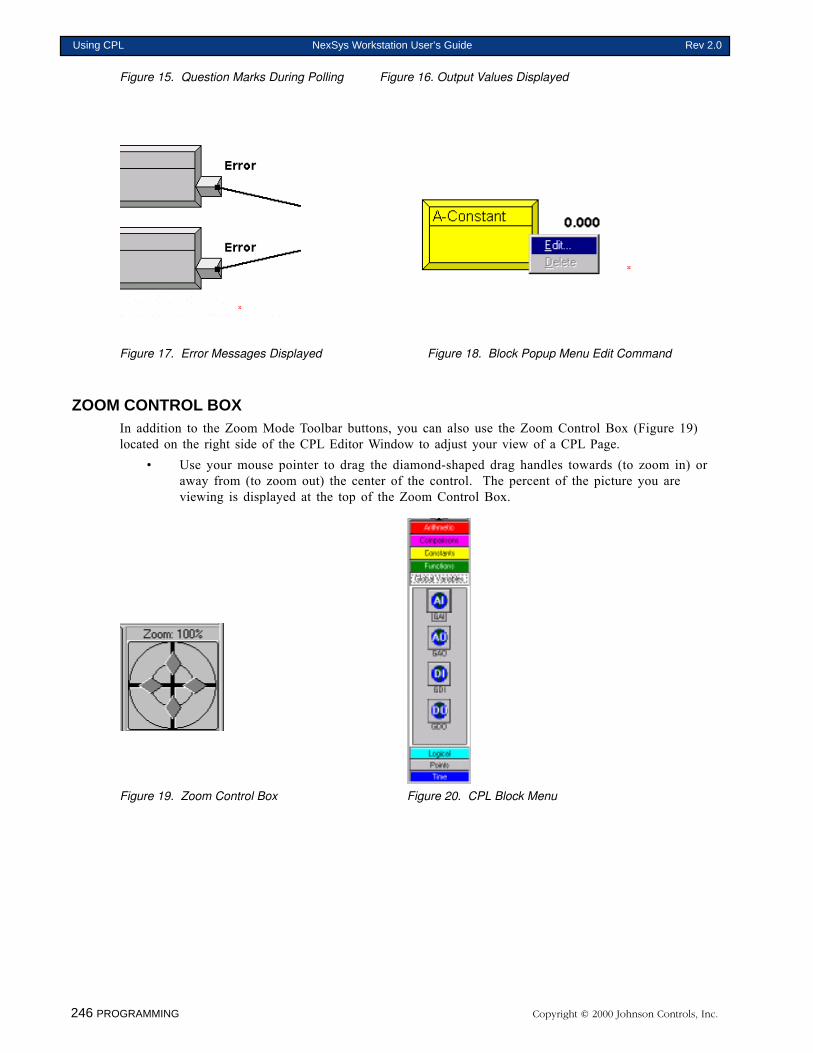
246 PROGRAMMING Copyright © 2000 Johnson Controls, Inc.
Using CPL NexSys Workstation User’s Guide Rev 2.0
Figure 15. Question Marks During Polling Figure 16. Output Values Displayed
Figure 17. Error Messages Displayed Figure 18. Block Popup Menu Edit Command
ZOOM CONTROL BOXIn addition to the Zoom Mode Toolbar buttons, you can also use the Zoom Control Box (Figure 19)located on the right side of the CPL Editor Window to adjust your view of a CPL Page.
• Use your mouse pointer to drag the diamond-shaped drag handles towards (to zoom in) oraway from (to zoom out) the center of the control. The percent of the picture you areviewing is displayed at the top of the Zoom Control Box.
Figure 19. Zoom Control Box Figure 20. CPL Block Menu
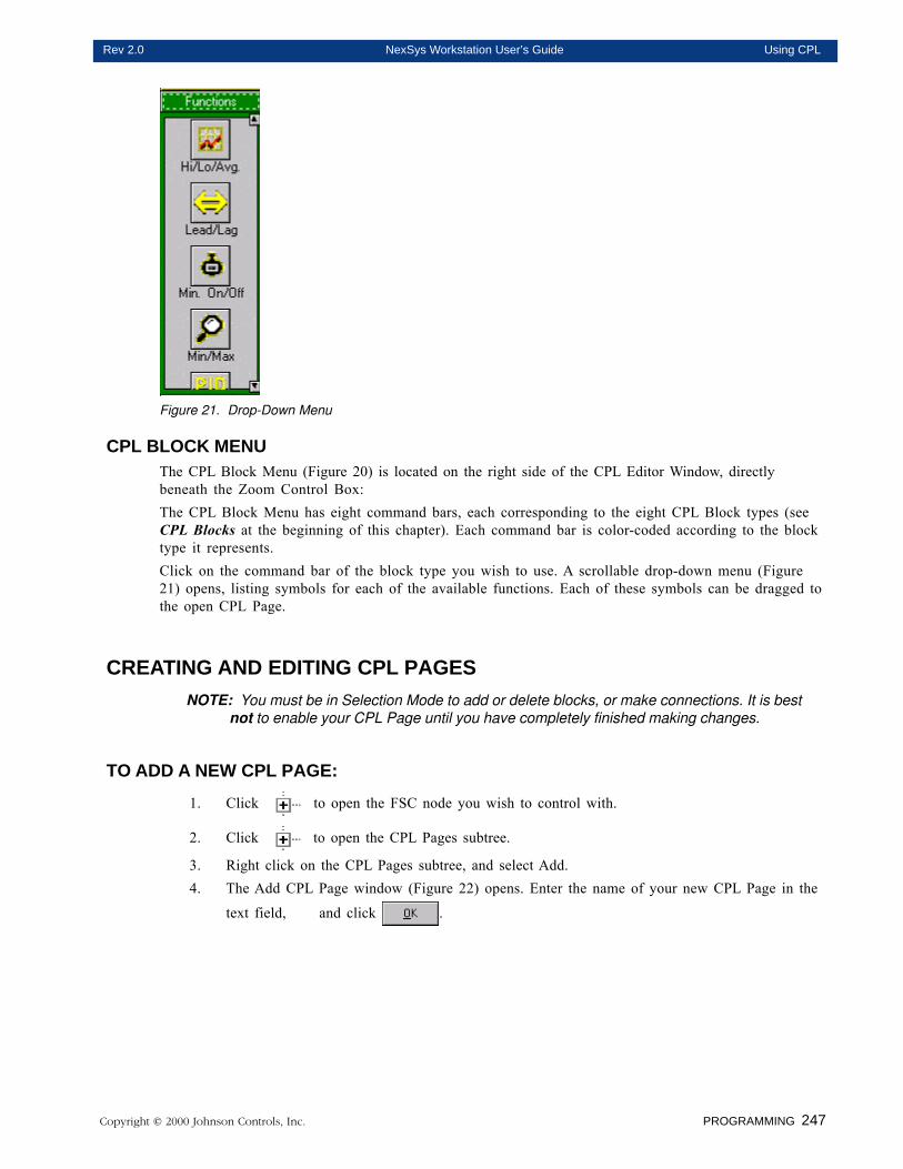
Copyright © 2000 Johnson Controls, Inc. PROGRAMMING 247
Rev 2.0 NexSys Workstation User’s Guide Using CPL
Figure 21. Drop-Down Menu
CPL BLOCK MENUThe CPL Block Menu (Figure 20) is located on the right side of the CPL Editor Window, directlybeneath the Zoom Control Box:The CPL Block Menu has eight command bars, each corresponding to the eight CPL Block types (seeCPL Blocks at the beginning of this chapter). Each command bar is color-coded according to the blocktype it represents.Click on the command bar of the block type you wish to use. A scrollable drop-down menu (Figure21) opens, listing symbols for each of the available functions. Each of these symbols can be dragged tothe open CPL Page.
CREATING AND EDITING CPL PAGESNOTE: You must be in Selection Mode to add or delete blocks, or make connections. It is best
not to enable your CPL Page until you have completely finished making changes.
TO ADD A NEW CPL PAGE:
1. Click to open the FSC node you wish to control with.
2. Click to open the CPL Pages subtree.
3. Right click on the CPL Pages subtree, and select Add.4. The Add CPL Page window (Figure 22) opens. Enter the name of your new CPL Page in the
text field, and click .
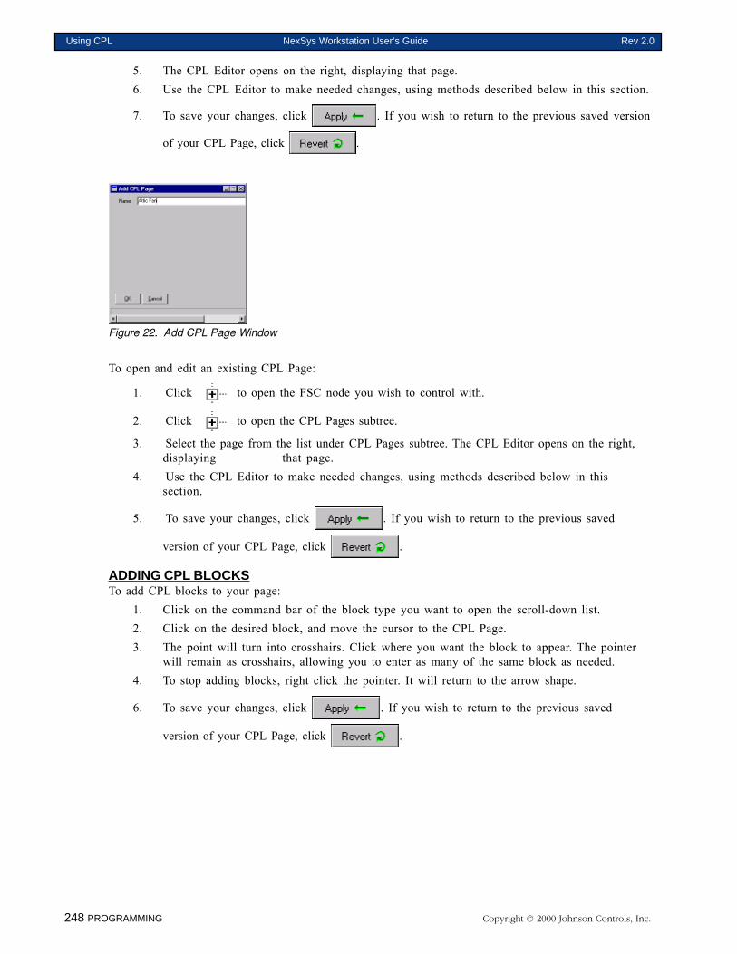
248 PROGRAMMING Copyright © 2000 Johnson Controls, Inc.
Using CPL NexSys Workstation User’s Guide Rev 2.0
5. The CPL Editor opens on the right, displaying that page.6. Use the CPL Editor to make needed changes, using methods described below in this section.
7. To save your changes, click . If you wish to return to the previous saved version
of your CPL Page, click .
Figure 22. Add CPL Page Window
To open and edit an existing CPL Page:
1. Click to open the FSC node you wish to control with.
2. Click to open the CPL Pages subtree.
3. Select the page from the list under CPL Pages subtree. The CPL Editor opens on the right,displaying that page.
4. Use the CPL Editor to make needed changes, using methods described below in thissection.
5. To save your changes, click . If you wish to return to the previous saved
version of your CPL Page, click .
ADDING CPL BLOCKSTo add CPL blocks to your page:
1. Click on the command bar of the block type you want to open the scroll-down list.2. Click on the desired block, and move the cursor to the CPL Page.3. The point will turn into crosshairs. Click where you want the block to appear. The pointer
will remain as crosshairs, allowing you to enter as many of the same block as needed.4. To stop adding blocks, right click the pointer. It will return to the arrow shape.
6. To save your changes, click . If you wish to return to the previous saved
version of your CPL Page, click .
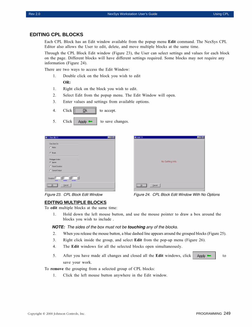
Copyright © 2000 Johnson Controls, Inc. PROGRAMMING 249
Rev 2.0 NexSys Workstation User’s Guide Using CPL
EDITING CPL BLOCKSEach CPL Block has an Edit window available from the popup menu Edit command. The NexSys CPLEditor also allows the User to edit, delete, and move multiple blocks at the same time.Through the CPL Block Edit window (Figure 23), the User can select settings and values for each blockon the page. Different blocks will have different settings required. Some blocks may not require anyinformation (Figure 24).There are two ways to access the Edit Window:
1. Double click on the block you wish to editOR:
1. Right click on the block you wish to edit.2. Select Edit from the popup menu. The Edit Window will open.3. Enter values and settings from available options.
4. Click to accept.
5. Click to save changes.
Figure 23. CPL Block Edit Window Figure 24. CPL Block Edit Window With No Options
EDITING MULTIPLE BLOCKSTo edit multiple blocks at the same time:
1. Hold down the left mouse button, and use the mouse pointer to draw a box around theblocks you wish to include .
NOTE: The sides of the box must not be touching any of the blocks.
2. When you release the mouse button, a blue dashed line appears around the grouped blocks (Figure 25).3. Right click inside the group, and select Edit from the pop-up menu (Figure 26).4. The Edit windows for all the selected blocks open simultaneously.
5. After you have made all changes and closed all the Edit windows, click tosave your work.
To remove the grouping from a selected group of CPL blocks:1. Click the left mouse button anywhere in the Edit window.
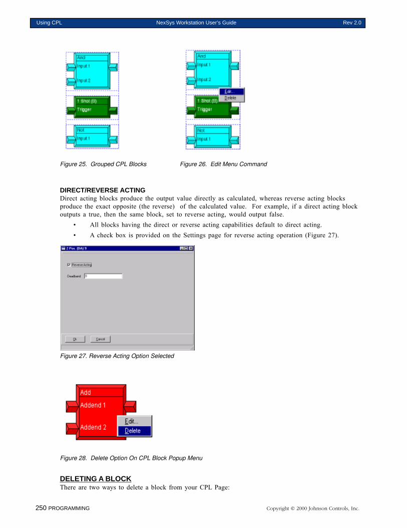
250 PROGRAMMING Copyright © 2000 Johnson Controls, Inc.
Using CPL NexSys Workstation User’s Guide Rev 2.0
Figure 25. Grouped CPL Blocks Figure 26. Edit Menu Command
DIRECT/REVERSE ACTINGDirect acting blocks produce the output value directly as calculated, whereas reverse acting blocksproduce the exact opposite (the reverse) of the calculated value. For example, if a direct acting blockoutputs a true, then the same block, set to reverse acting, would output false.
• All blocks having the direct or reverse acting capabilities default to direct acting.• A check box is provided on the Settings page for reverse acting operation (Figure 27).
Figure 27. Reverse Acting Option Selected
Figure 28. Delete Option On CPL Block Popup Menu
DELETING A BLOCKThere are two ways to delete a block from your CPL Page:
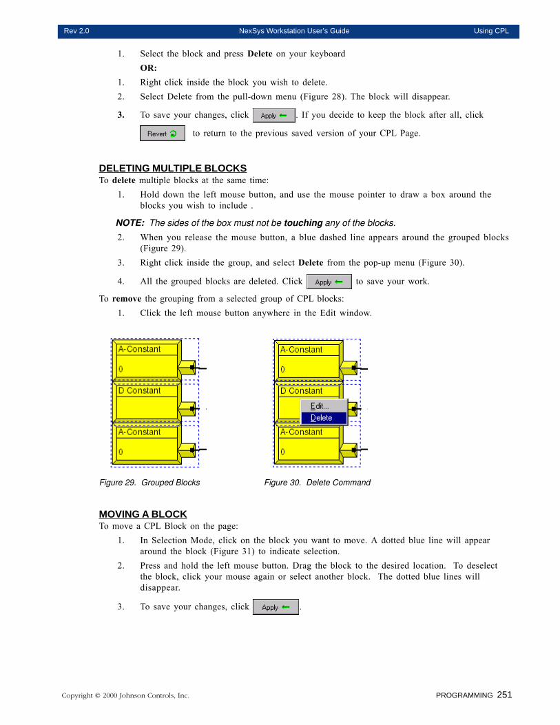
Copyright © 2000 Johnson Controls, Inc. PROGRAMMING 251
Rev 2.0 NexSys Workstation User’s Guide Using CPL
1. Select the block and press Delete on your keyboardOR:
1. Right click inside the block you wish to delete.2. Select Delete from the pull-down menu (Figure 28). The block will disappear.
3. To save your changes, click . If you decide to keep the block after all, click
to return to the previous saved version of your CPL Page.
DELETING MULTIPLE BLOCKSTo delete multiple blocks at the same time:
1. Hold down the left mouse button, and use the mouse pointer to draw a box around theblocks you wish to include .
NOTE: The sides of the box must not be touching any of the blocks.
2. When you release the mouse button, a blue dashed line appears around the grouped blocks(Figure 29).
3. Right click inside the group, and select Delete from the pop-up menu (Figure 30).
4. All the grouped blocks are deleted. Click to save your work.
To remove the grouping from a selected group of CPL blocks:1. Click the left mouse button anywhere in the Edit window.
Figure 29. Grouped Blocks Figure 30. Delete Command
MOVING A BLOCKTo move a CPL Block on the page:
1. In Selection Mode, click on the block you want to move. A dotted blue line will appeararound the block (Figure 31) to indicate selection.
2. Press and hold the left mouse button. Drag the block to the desired location. To deselectthe block, click your mouse again or select another block. The dotted blue lines willdisappear.
3. To save your changes, click .
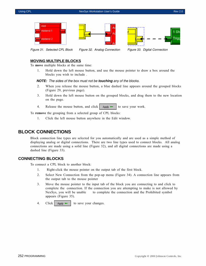
252 PROGRAMMING Copyright © 2000 Johnson Controls, Inc.
Using CPL NexSys Workstation User’s Guide Rev 2.0
Figure 31. Selected CPL Block Figure 32. Analog Connection Figure 33. Digital Connection
MOVING MULTIPLE BLOCKSTo move multiple blocks at the same time:
1. Hold down the left mouse button, and use the mouse pointer to draw a box around theblocks you wish to include .
NOTE: The sides of the box must not be touching any of the blocks.
2. When you release the mouse button, a blue dashed line appears around the grouped blocks(Figure 29, previous page).
3. Hold down the left mouse button on the grouped blocks, and drag them to the new locationon the page.
4. Release the mouse button, and click to save your work.
To remove the grouping from a selected group of CPL blocks:1. Click the left mouse button anywhere in the Edit window.
BLOCK CONNECTIONSBlock connection line types are selected for you automatically and are used as a simple method ofdisplaying analog or digital connections. There are two line types used to connect blocks. All analogconnections are made using a solid line (Figure 32), and all digital connections are made using adashed line (Figure 33).
CONNECTING BLOCKSTo connect a CPL block to another block:
1. Right-click the mouse pointer on the output tab of the first block.2. Select New Connection from the pop-up menu (Figure 34). A connection line appears from
the output tab to the mouse pointer3. Move the mouse pointer to the input tab of the block you are connecting to and click to
complete the connection. If the connection you are attempting to make is not allowed byNexSys, you will be unable to complete the connection and the Prohibited symbolappears (Figure 35).
4. Click to save your changes.
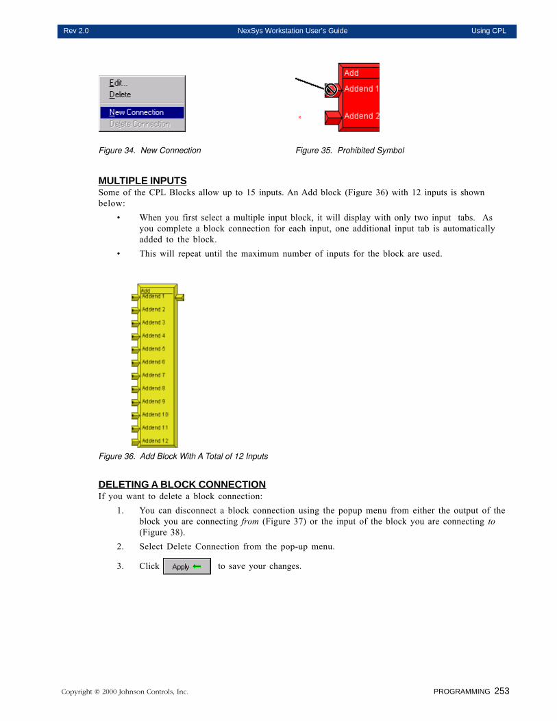
Copyright © 2000 Johnson Controls, Inc. PROGRAMMING 253
Rev 2.0 NexSys Workstation User’s Guide Using CPL
Figure 34. New Connection Figure 35. Prohibited Symbol
MULTIPLE INPUTSSome of the CPL Blocks allow up to 15 inputs. An Add block (Figure 36) with 12 inputs is shownbelow:
• When you first select a multiple input block, it will display with only two input tabs. Asyou complete a block connection for each input, one additional input tab is automaticallyadded to the block.
• This will repeat until the maximum number of inputs for the block are used.
Figure 36. Add Block With A Total of 12 Inputs
DELETING A BLOCK CONNECTIONIf you want to delete a block connection:
1. You can disconnect a block connection using the popup menu from either the output of theblock you are connecting from (Figure 37) or the input of the block you are connecting to(Figure 38).
2. Select Delete Connection from the pop-up menu.
3. Click to save your changes.
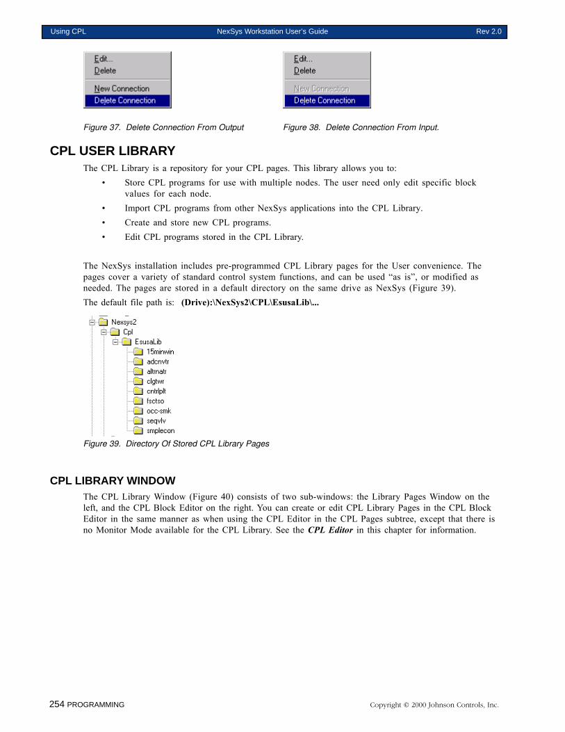
254 PROGRAMMING Copyright © 2000 Johnson Controls, Inc.
Using CPL NexSys Workstation User’s Guide Rev 2.0
Figure 37. Delete Connection From Output Figure 38. Delete Connection From Input.
CPL USER LIBRARYThe CPL Library is a repository for your CPL pages. This library allows you to:
• Store CPL programs for use with multiple nodes. The user need only edit specific blockvalues for each node.
• Import CPL programs from other NexSys applications into the CPL Library.• Create and store new CPL programs.• Edit CPL programs stored in the CPL Library.
The NexSys installation includes pre-programmed CPL Library pages for the User convenience. Thepages cover a variety of standard control system functions, and can be used “as is”, or modified asneeded. The pages are stored in a default directory on the same drive as NexSys (Figure 39).The default file path is: (Drive):\NexSys2\CPL\EsusaLib\...
Figure 39. Directory Of Stored CPL Library Pages
CPL LIBRARY WINDOWThe CPL Library Window (Figure 40) consists of two sub-windows: the Library Pages Window on theleft, and the CPL Block Editor on the right. You can create or edit CPL Library Pages in the CPL BlockEditor in the same manner as when using the CPL Editor in the CPL Pages subtree, except that there isno Monitor Mode available for the CPL Library. See the CPL Editor in this chapter for information.
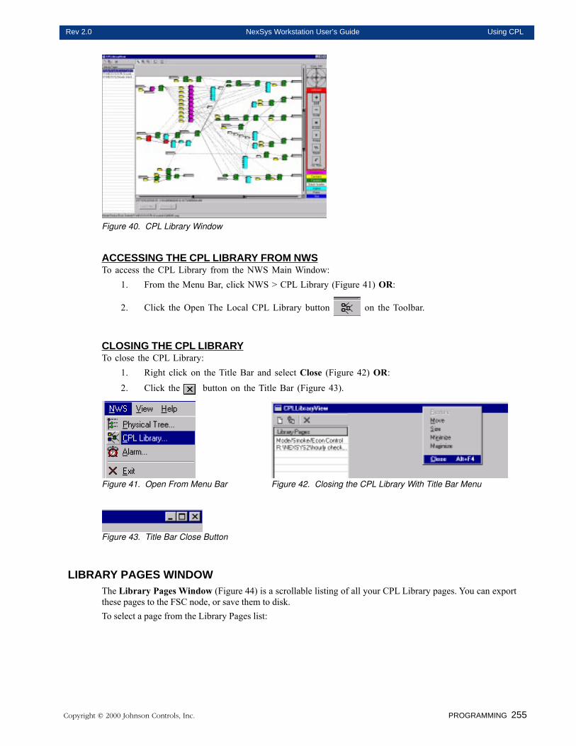
Copyright © 2000 Johnson Controls, Inc. PROGRAMMING 255
Rev 2.0 NexSys Workstation User’s Guide Using CPL
Figure 40. CPL Library Window
ACCESSING THE CPL LIBRARY FROM NWSTo access the CPL Library from the NWS Main Window:
1. From the Menu Bar, click NWS > CPL Library (Figure 41) OR:
2. Click the Open The Local CPL Library button on the Toolbar.
CLOSING THE CPL LIBRARYTo close the CPL Library:
1. Right click on the Title Bar and select Close (Figure 42) OR:2. Click the button on the Title Bar (Figure 43).
Figure 41. Open From Menu Bar Figure 42. Closing the CPL Library With Title Bar Menu
Figure 43. Title Bar Close Button
LIBRARY PAGES WINDOWThe Library Pages Window (Figure 44) is a scrollable listing of all your CPL Library pages. You can exportthese pages to the FSC node, or save them to disk.To select a page from the Library Pages list:
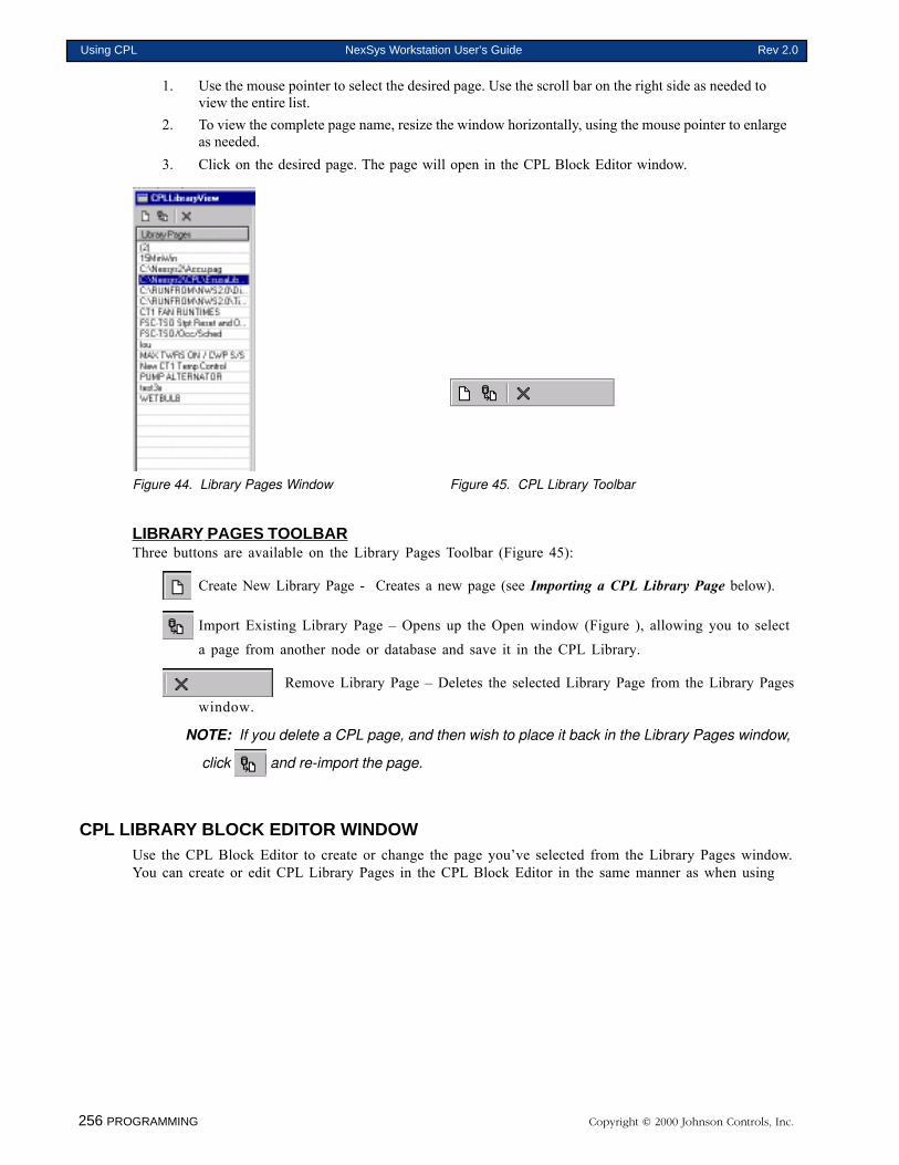
256 PROGRAMMING Copyright © 2000 Johnson Controls, Inc.
Using CPL NexSys Workstation User’s Guide Rev 2.0
1. Use the mouse pointer to select the desired page. Use the scroll bar on the right side as needed toview the entire list.
2. To view the complete page name, resize the window horizontally, using the mouse pointer to enlargeas needed.
3. Click on the desired page. The page will open in the CPL Block Editor window.
Figure 44. Library Pages Window Figure 45. CPL Library Toolbar
LIBRARY PAGES TOOLBARThree buttons are available on the Library Pages Toolbar (Figure 45):
Create New Library Page - Creates a new page (see Importing a CPL Library Page below).
Import Existing Library Page – Opens up the Open window (Figure ), allowing you to select
a page from another node or database and save it in the CPL Library.
Remove Library Page – Deletes the selected Library Page from the Library Pages
window.
NOTE: If you delete a CPL page, and then wish to place it back in the Library Pages window,
click and re-import the page.
CPL LIBRARY BLOCK EDITOR WINDOWUse the CPL Block Editor to create or change the page you’ve selected from the Library Pages window.You can create or edit CPL Library Pages in the CPL Block Editor in the same manner as when using
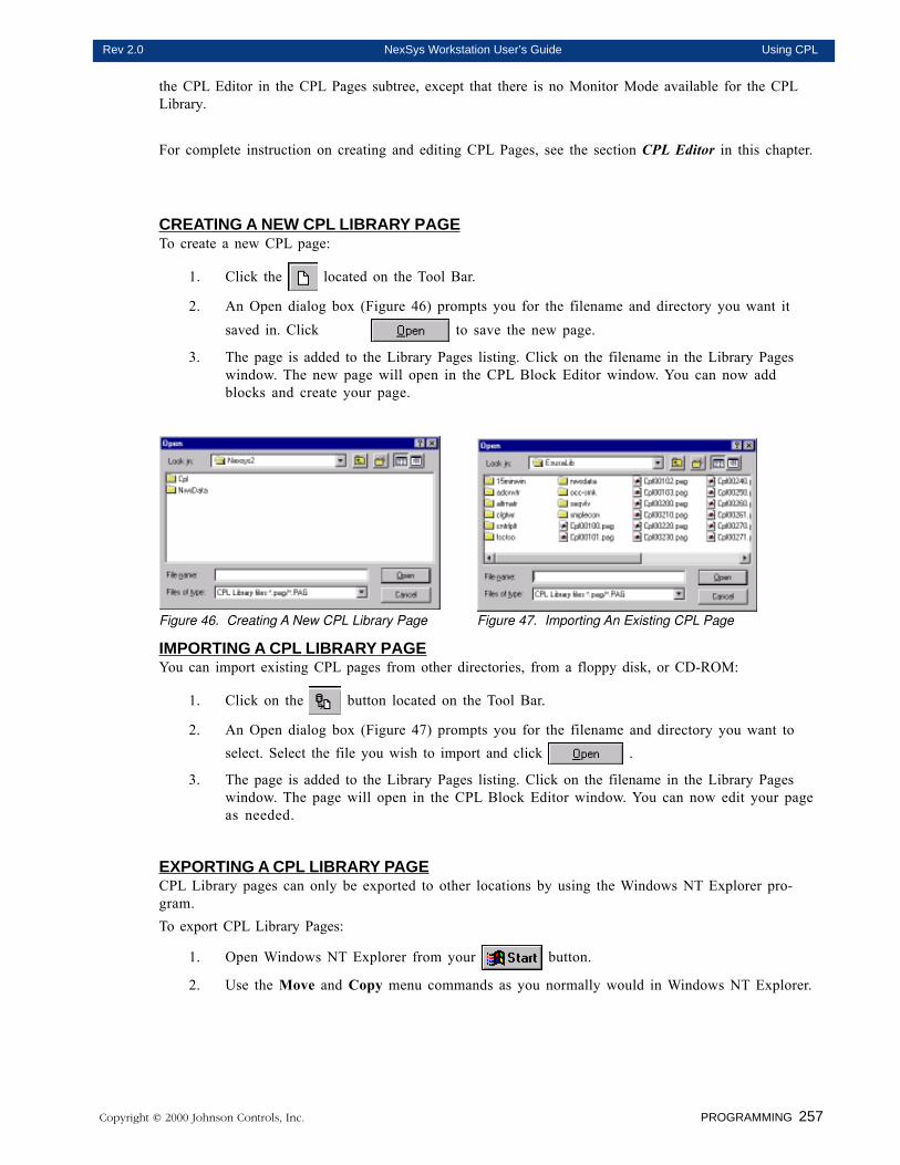
Copyright © 2000 Johnson Controls, Inc. PROGRAMMING 257
Rev 2.0 NexSys Workstation User’s Guide Using CPL
the CPL Editor in the CPL Pages subtree, except that there is no Monitor Mode available for the CPLLibrary.
For complete instruction on creating and editing CPL Pages, see the section CPL Editor in this chapter.
CREATING A NEW CPL LIBRARY PAGETo create a new CPL page:
1. Click the located on the Tool Bar.
2. An Open dialog box (Figure 46) prompts you for the filename and directory you want itsaved in. Click to save the new page.
3. The page is added to the Library Pages listing. Click on the filename in the Library Pageswindow. The new page will open in the CPL Block Editor window. You can now addblocks and create your page.
Figure 46. Creating A New CPL Library Page Figure 47. Importing An Existing CPL Page
IMPORTING A CPL LIBRARY PAGEYou can import existing CPL pages from other directories, from a floppy disk, or CD-ROM:
1. Click on the button located on the Tool Bar.
2. An Open dialog box (Figure 47) prompts you for the filename and directory you want toselect. Select the file you wish to import and click .
3. The page is added to the Library Pages listing. Click on the filename in the Library Pageswindow. The page will open in the CPL Block Editor window. You can now edit your pageas needed.
EXPORTING A CPL LIBRARY PAGECPL Library pages can only be exported to other locations by using the Windows NT Explorer pro-gram.To export CPL Library Pages:
1. Open Windows NT Explorer from your button.
2. Use the Move and Copy menu commands as you normally would in Windows NT Explorer.
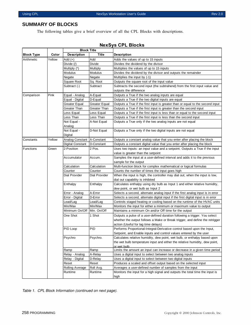
258 PROGRAMMING Copyright © 2000 Johnson Controls, Inc.
Using CPL NexSys Workstation User’s Guide Rev 2.0
SUMMARY OF BLOCKSThe following tables give a brief overview of all the CPL Blocks with descriptions.
NexSys CPL BlocksBlock Title
Block Type Color Description Title DescriptionArithmetic Yellow Add (+) Add Adds the values of up to 15 inputs
Divide (/) Divide Divides the dividend by the divisorMultiply (*) Multiply Multiplies the values of up to 15 inputsModulus Modulus Divides the dividend by the divisor and outputs the remainderNegate Negate Multiplies the input by (-1)Square Root Sq. Root Outputs the square root of the input valueSubtract (-) Subtract Subtracts the second input (the subtrahend) from the first input value and
outputs the difference
Comparison Pink Equal - Analog A-Equal Outputs a True if the two analog inputs are equalEqual - Digital D-Equal Outputs a True if the two digital inputs are equalGreater Equal Greater Equal Outputs a True if the first input is greater than or equal to the second inputGreater Than Greater Than Outputs a True if the first input is greater than the second inputLess Equal Less Equal Outputs a True if the first input is less than or equal to the second inputLess Than Less Than Outputs a True if the first input is less than the second inputNot Equal - Analog
A-Not Equal Outputs a True only if the two analog inputs are not equal
Not Equal - Digital
D-Not Equal Outputs a True only if the two digital inputs are not equal
Constants Yellow Analog Constant A-Constant Outputs a constant analog value that you enter after placing the blockDigital Constant D-Constant Outputs a constant digital value that you enter after placing the block
Functions Green 2-Position 2 Pos. Uses two inputs: an input value and a setpoint. Outputs a True if the input value is greater than the setpoint
Accumulator Accum. Samples the input at a user-defined interval and adds it to the previous sample for the output
Calculation Calculation Multi-function block for complex mathematical or logical formulasCounter Counter Counts the number of times the input goes highDial Provider Dial Provider When the input is high, the controller may dial out; when the input is low,
dial out capability is inhibitedEnthalpy Enthalpy Calculates enthalpy using dry bulb as Input 1 and either relative humidity,
dew point, or wet bulb as Input 2Error - Analog A-Error Selects a second, alternate analog input if the first analog input is in errorError - Digital D-Error Selects a second, alternate digital input if the first digital input is in errorLead/Lag Lead/Lag Controls staged heating or cooling based on the runtime of the HVAC unitsMin/Max Min/Max Monitors the input for either a minimum or maximum value to outputMinimum On/Off Min. On/Off Maintains a minimum On and/or Off time for the output
One Shot 1 Shot Outputs a pulse of a user-defined duration following a trigger. You select whether the output follows a Make or Break trigger, and define the retrigger action (Useful for lag time delays)
PID Loop PID Performs Proportional-Integral-Derivative control based upon the Input, Setpoint, and Enable inputs and control values entered by the user
Psychro Psychro. Calculates relative humidity, dew point, wet bulb, or enthalpy based upon the wet bulb temperature input and either the relative humidity, dew point, or wet bulb
Ramp Ramp Limits the amount an input can increase or decrease in a given time periodRelay - Analog A-Relay Uses a digital input to select between two analog inputsRelay - Digital D-Relay Uses a digital input to select between two digital inputsReset Reset Produces a scaled and offset output based on the selected inputRolling Average Roll Avg. Averages a user-defined number of samples from the inputRuntime Runtime Monitors the input for a high signal and outputs the total time the input is
high
Table 1. CPL Block Information (continued on next page).

Copyright © 2000 Johnson Controls, Inc. PROGRAMMING 259
Rev 2.0 NexSys Workstation User’s Guide Using CPL

260 PROGRAMMING Copyright © 2000 Johnson Controls, Inc.
Using CPL NexSys Workstation User’s Guide Rev 2.0
Chapter Three
CPL Blocks
This chapter contain information on:
� Constant Blocks
� Function Blocks
� Global Variable Blocks
� Logical Blocks
� Math Blocks
� Point Blocks
� Time Blocks
© 2000 Johnson Controls, Inc.
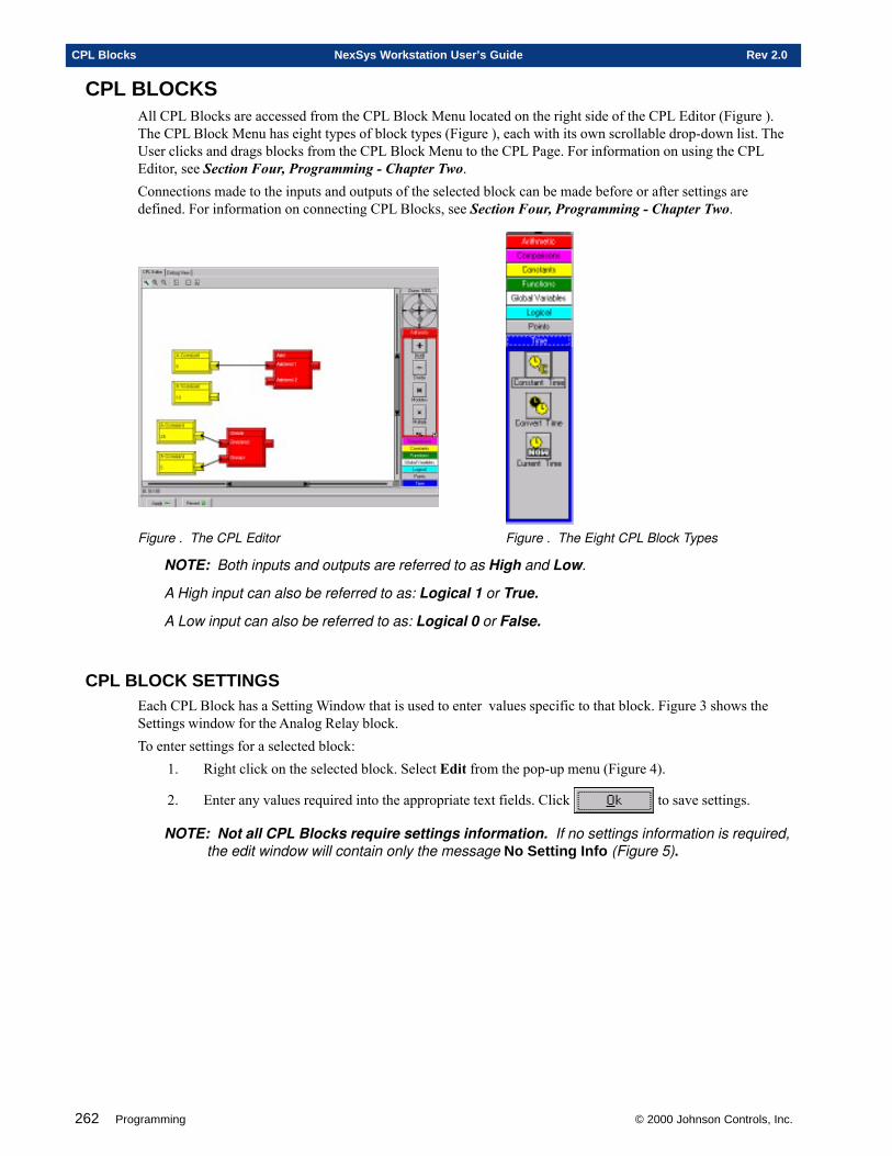
262 Programming © 2000 Johnson Controls, Inc.
CPL Blocks NexSys Workstation User’s Guide Rev 2.0
CPL BLOCKSAll CPL Blocks are accessed from the CPL Block Menu located on the right side of the CPL Editor (Figure ).The CPL Block Menu has eight types of block types (Figure ), each with its own scrollable drop-down list. TheUser clicks and drags blocks from the CPL Block Menu to the CPL Page. For information on using the CPLEditor, see Section Four, Programming - Chapter Two.Connections made to the inputs and outputs of the selected block can be made before or after settings aredefined. For information on connecting CPL Blocks, see Section Four, Programming - Chapter Two.
Figure . The CPL Editor Figure . The Eight CPL Block Types
NOTE: Both inputs and outputs are referred to as High and Low.
A High input can also be referred to as: Logical 1 or True.
A Low input can also be referred to as: Logical 0 or False.
CPL BLOCK SETTINGSEach CPL Block has a Setting Window that is used to enter values specific to that block. Figure 3 shows theSettings window for the Analog Relay block.To enter settings for a selected block:
1. Right click on the selected block. Select Edit from the pop-up menu (Figure 4).
2. Enter any values required into the appropriate text fields. Click to save settings.
NOTE: Not all CPL Blocks require settings information. If no settings information is required,the edit window will contain only the message No Setting Info (Figure 5).
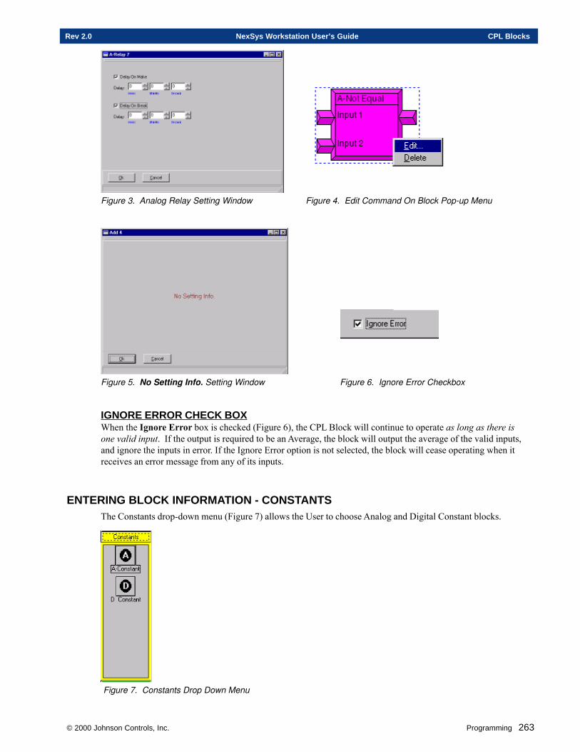
© 2000 Johnson Controls, Inc. Programming 263
Rev 2.0 NexSys Workstation User’s Guide CPL Blocks
Figure 3. Analog Relay Setting Window Figure 4. Edit Command On Block Pop-up Menu
Figure 5. No Setting Info. Setting Window Figure 6. Ignore Error Checkbox
IGNORE ERROR CHECK BOXWhen the Ignore Error box is checked (Figure 6), the CPL Block will continue to operate as long as there isone valid input. If the output is required to be an Average, the block will output the average of the valid inputs,and ignore the inputs in error. If the Ignore Error option is not selected, the block will cease operating when itreceives an error message from any of its inputs.
ENTERING BLOCK INFORMATION - CONSTANTSThe Constants drop-down menu (Figure 7) allows the User to choose Analog and Digital Constant blocks.
Figure 7. Constants Drop Down Menu
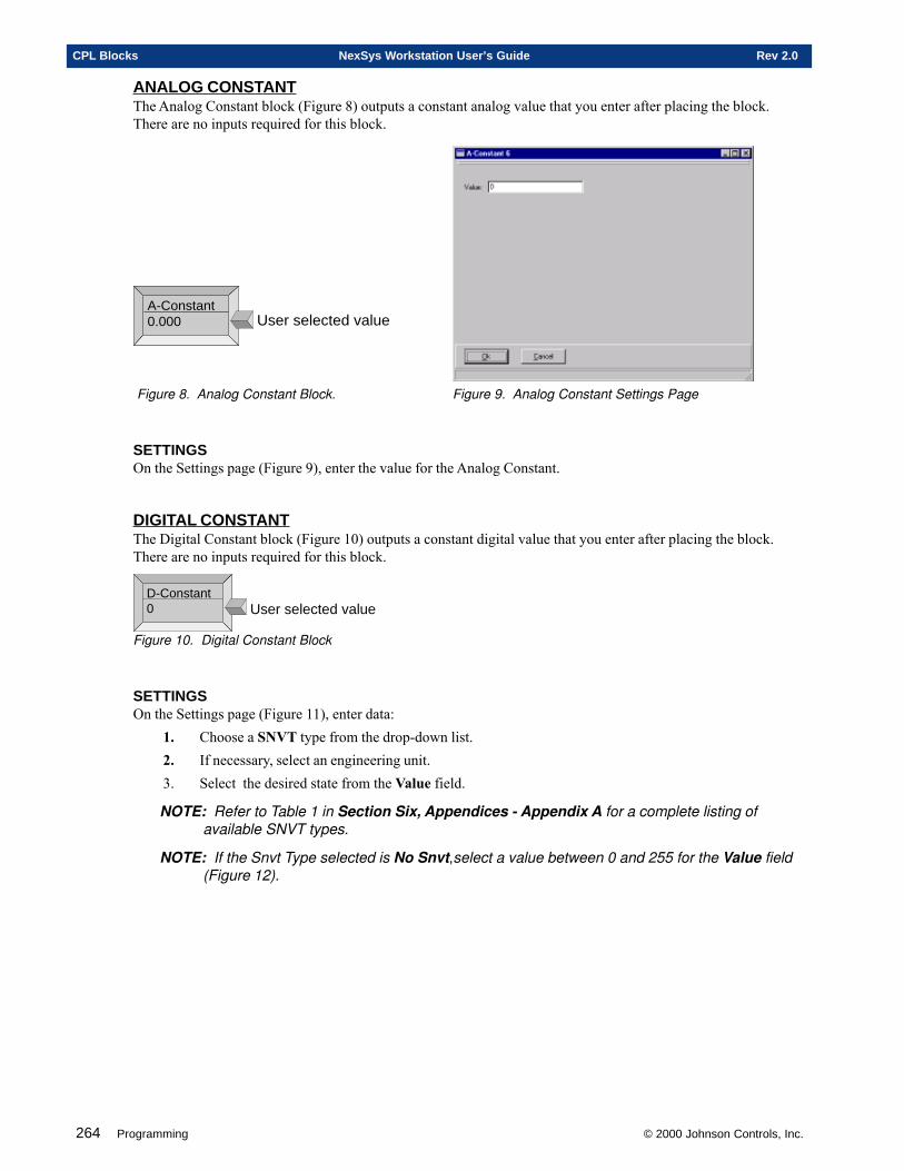
264 Programming © 2000 Johnson Controls, Inc.
CPL Blocks NexSys Workstation User’s Guide Rev 2.0
ANALOG CONSTANTThe Analog Constant block (Figure 8) outputs a constant analog value that you enter after placing the block.There are no inputs required for this block.
A-Constant0.000 User selected value
Figure 8. Analog Constant Block. Figure 9. Analog Constant Settings Page
SETTINGSOn the Settings page (Figure 9), enter the value for the Analog Constant.
DIGITAL CONSTANTThe Digital Constant block (Figure 10) outputs a constant digital value that you enter after placing the block.There are no inputs required for this block.
D-Constant0 User selected value
Figure 10. Digital Constant Block
SETTINGSOn the Settings page (Figure 11), enter data:
1. Choose a SNVT type from the drop-down list.2. If necessary, select an engineering unit.3. Select the desired state from the Value field.
NOTE: Refer to Table 1 in Section Six, Appendices - Appendix A for a complete listing ofavailable SNVT types.
NOTE: If the Snvt Type selected is No Snvt,select a value between 0 and 255 for the Value field(Figure 12).
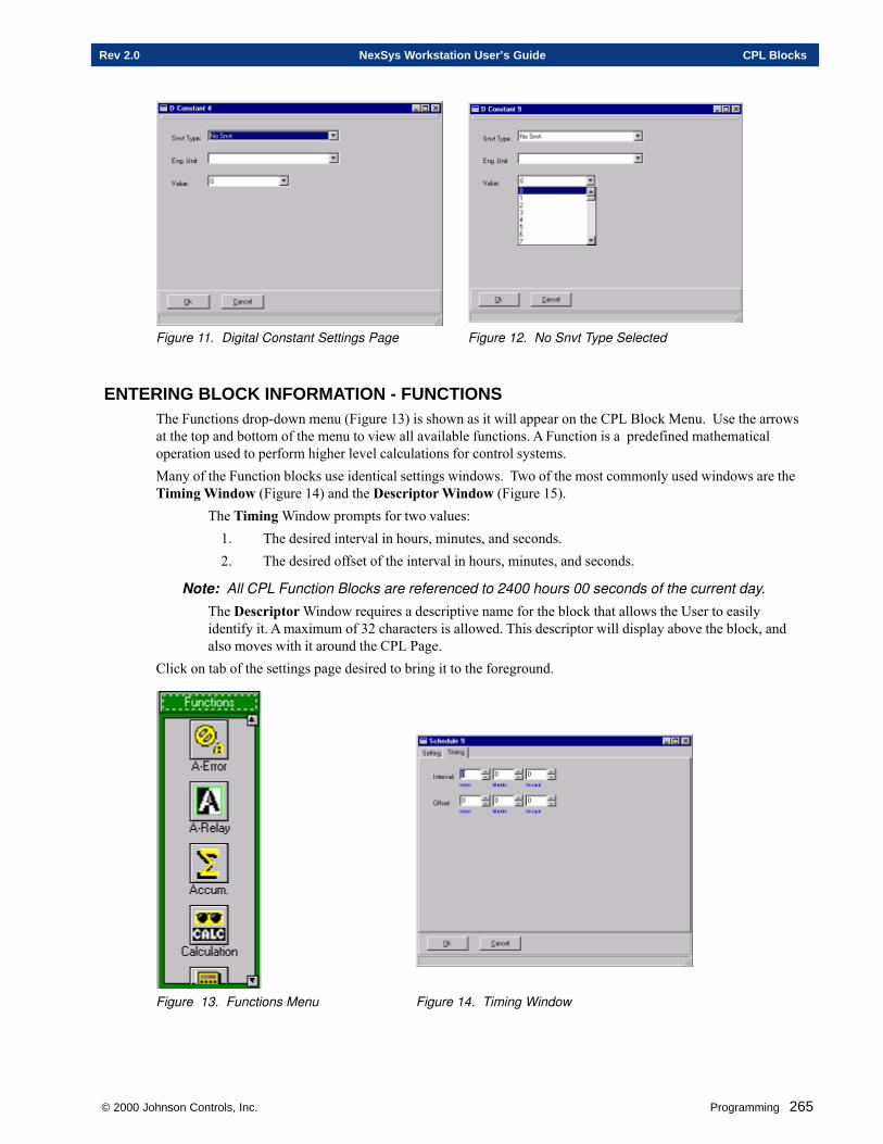
© 2000 Johnson Controls, Inc. Programming 265
Rev 2.0 NexSys Workstation User’s Guide CPL Blocks
Figure 11. Digital Constant Settings Page Figure 12. No Snvt Type Selected
ENTERING BLOCK INFORMATION - FUNCTIONSThe Functions drop-down menu (Figure 13) is shown as it will appear on the CPL Block Menu. Use the arrowsat the top and bottom of the menu to view all available functions. A Function is a predefined mathematicaloperation used to perform higher level calculations for control systems.Many of the Function blocks use identical settings windows. Two of the most commonly used windows are theTiming Window (Figure 14) and the Descriptor Window (Figure 15).
The Timing Window prompts for two values:1. The desired interval in hours, minutes, and seconds.2. The desired offset of the interval in hours, minutes, and seconds.
Note: All CPL Function Blocks are referenced to 2400 hours 00 seconds of the current day.
The Descriptor Window requires a descriptive name for the block that allows the User to easilyidentify it. A maximum of 32 characters is allowed. This descriptor will display above the block, andalso moves with it around the CPL Page.
Click on tab of the settings page desired to bring it to the foreground.
Figure 13. Functions Menu Figure 14. Timing Window
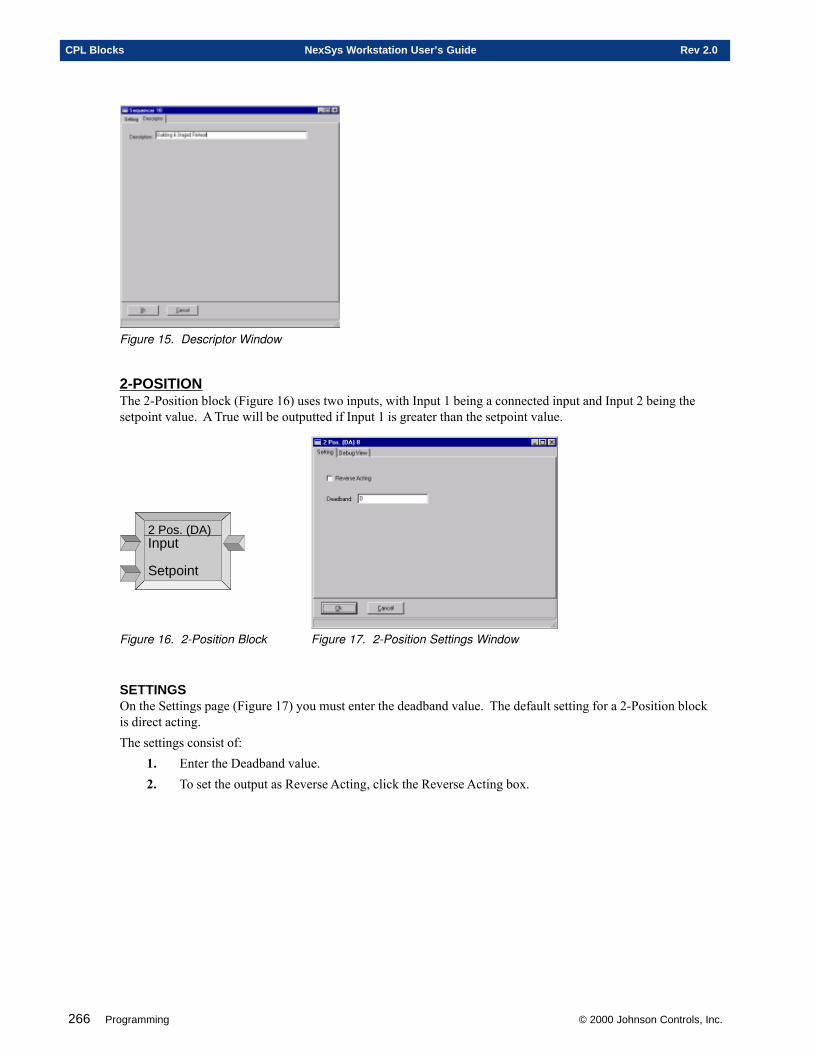
266 Programming © 2000 Johnson Controls, Inc.
CPL Blocks NexSys Workstation User’s Guide Rev 2.0
Figure 15. Descriptor Window
2-POSITIONThe 2-Position block (Figure 16) uses two inputs, with Input 1 being a connected input and Input 2 being thesetpoint value. A True will be outputted if Input 1 is greater than the setpoint value.
2 Pos. (DA)Input
Setpoint
Figure 16. 2-Position Block Figure 17. 2-Position Settings Window
SETTINGSOn the Settings page (Figure 17) you must enter the deadband value. The default setting for a 2-Position blockis direct acting.The settings consist of:
1. Enter the Deadband value.2. To set the output as Reverse Acting, click the Reverse Acting box.
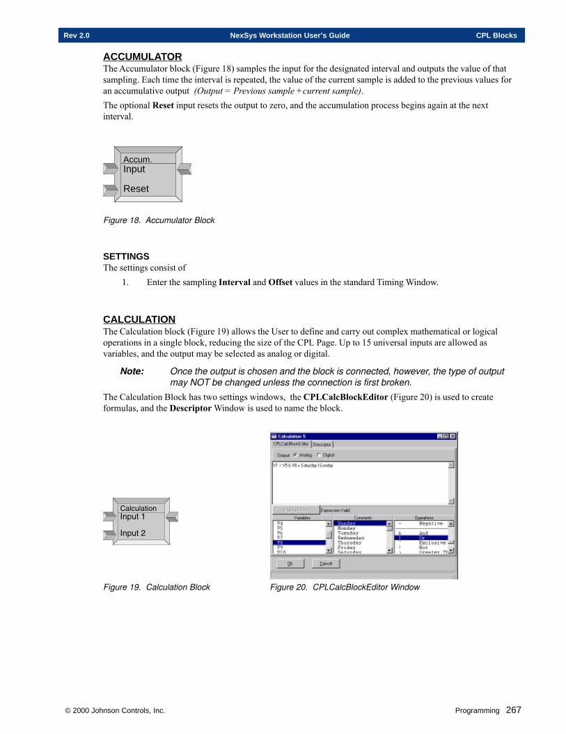
© 2000 Johnson Controls, Inc. Programming 267
Rev 2.0 NexSys Workstation User’s Guide CPL Blocks
ACCUMULATORThe Accumulator block (Figure 18) samples the input for the designated interval and outputs the value of thatsampling. Each time the interval is repeated, the value of the current sample is added to the previous values foran accumulative output (Output = Previous sample +current sample).The optional Reset input resets the output to zero, and the accumulation process begins again at the nextinterval.
Accum.Input
Reset
Figure 18. Accumulator Block
SETTINGSThe settings consist of
1. Enter the sampling Interval and Offset values in the standard Timing Window.
CALCULA TIONThe Calculation block (Figure 19) allows the User to define and carry out complex mathematical or logicaloperations in a single block, reducing the size of the CPL Page. Up to 15 universal inputs are allowed asvariables, and the output may be selected as analog or digital.
Note: Once the output is chosen and the block is connected, however, the type of outputmay NOT be changed unless the connection is first broken.
The Calculation Block has two settings windows, the CPLCalcBlockEditor (Figure 20) is used to createformulas, and the Descriptor Window is used to name the block.
��(���$���-�2�$��
-�2�$�6
Figure 19. Calculation Block Figure 20. CPLCalcBlockEditor Window
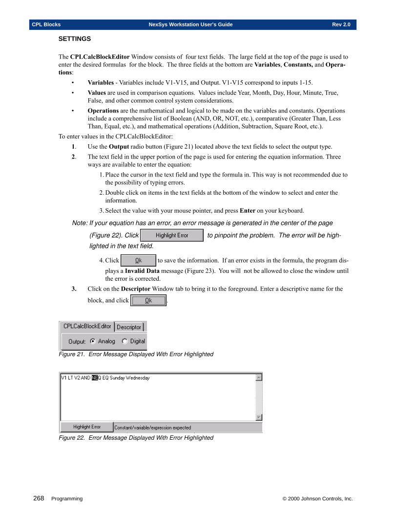
268 Programming © 2000 Johnson Controls, Inc.
CPL Blocks NexSys Workstation User’s Guide Rev 2.0
SETTINGS
The CPLCalcBlockEditor Window consists of four text fields. The large field at the top of the page is used toenter the desired formulas for the block. The three fields at the bottom are Variables, Constants, and Opera-tions:
• Variables - Variables include V1-V15, and Output. V1-V15 correspond to inputs 1-15.• Values are used in comparison equations. Values include Year, Month, Day, Hour, Minute, True,
False, and other common control system considerations.• Operations are the mathematical and logical to be made on the variables and constants. Operations
include a comprehensive list of Boolean (AND, OR, NOT, etc.), comparative (Greater Than, LessThan, Equal, etc.), and mathematical operations (Addition, Subtraction, Square Root, etc.).
To enter values in the CPLCalcBlockEditor:1. Use the Output radio button (Figure 21) located above the text fields to select the output type.2. The text field in the upper portion of the page is used for entering the equation information. Three
ways are available to enter the equation:1. Place the cursor in the text field and type the formula in. This way is not recommended due to
the possibility of typing errors.2. Double click on items in the text fields at the bottom of the window to select and enter the
information.3. Select the value with your mouse pointer, and press Enter on your keyboard.
Note: If your equation has an error, an error message is generated in the center of the page
(Figure 22). Click to pinpoint the problem. The error will be high-
lighted in the text field.
4. Click to save the information. If an error exists in the formula, the program dis-plays a Invalid Data message (Figure 23). You will not be allowed to close the window untilthe error is corrected.
3. Click on the Descriptor Window tab to bring it to the foreground. Enter a descriptive name for the
block, and click .
Figure 21. Error Message Displayed With Error Highlighted
Figure 22. Error Message Displayed With Error Highlighted
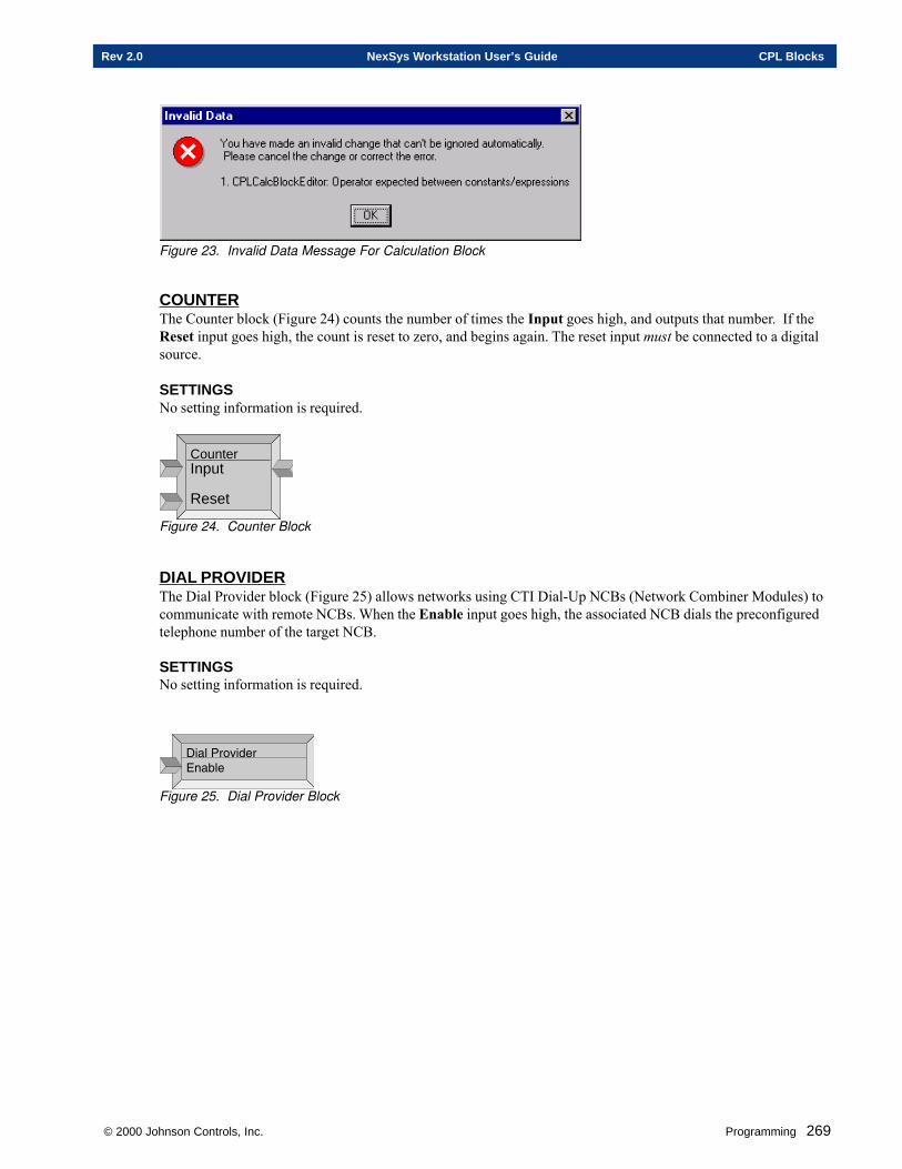
© 2000 Johnson Controls, Inc. Programming 269
Rev 2.0 NexSys Workstation User’s Guide CPL Blocks
Figure 23. Invalid Data Message For Calculation Block
COUNTERThe Counter block (Figure 24) counts the number of times the Input goes high, and outputs that number. If theReset input goes high, the count is reset to zero, and begins again. The reset input must be connected to a digitalsource.
SETTINGSNo setting information is required.
CounterInput
Reset
Figure 24. Counter Block
DIAL PROVIDERThe Dial Provider block (Figure 25) allows networks using CTI Dial-Up NCBs (Network Combiner Modules) tocommunicate with remote NCBs. When the Enable input goes high, the associated NCB dials the preconfiguredtelephone number of the target NCB.
SETTINGSNo setting information is required.
!�������%�*����� ��
Figure 25. Dial Provider Block
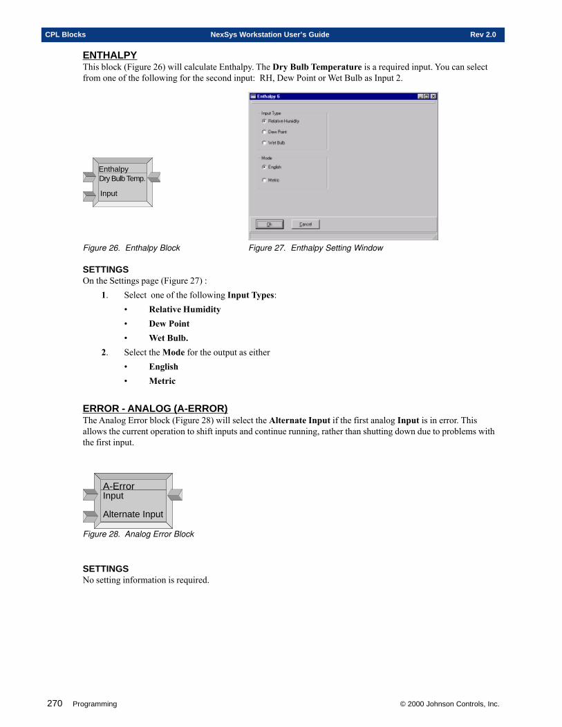
270 Programming © 2000 Johnson Controls, Inc.
CPL Blocks NexSys Workstation User’s Guide Rev 2.0
ENTHALPYThis block (Figure 26) will calculate Enthalpy. The Dry Bulb Temperature is a required input. You can selectfrom one of the following for the second input: RH, Dew Point or Wet Bulb as Input 2.
Enthalpy
Input
Dry Bulb Temp.
Figure 26. Enthalpy Block Figure 27. Enthalpy Setting Window
SETTINGSOn the Settings page (Figure 27) :
1. Select one of the following Input Types:• Relative Humidity• Dew Point• Wet Bulb.
2. Select the Mode for the output as either• English• Metric
ERROR - ANALOG (A-ERROR)The Analog Error block (Figure 28) will select the Alternate Input if the first analog Input is in error. Thisallows the current operation to shift inputs and continue running, rather than shutting down due to problems withthe first input.
A-ErrorInput
Alternate Input
Figure 28. Analog Error Block
SETTINGSNo setting information is required.
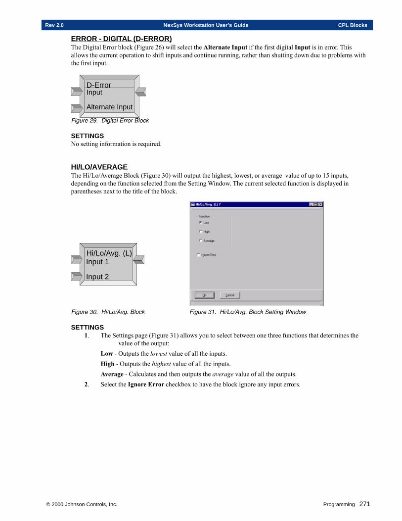
© 2000 Johnson Controls, Inc. Programming 271
Rev 2.0 NexSys Workstation User’s Guide CPL Blocks
ERROR - DIGITAL (D-ERROR)The Digital Error block (Figure 26) will select the Alternate Input if the first digital Input is in error. Thisallows the current operation to shift inputs and continue running, rather than shutting down due to problems withthe first input.
D-ErrorInput
Alternate Input
Figure 29. Digital Error Block
SETTINGSNo setting information is required.
HI/LO/AVERAGEThe Hi/Lo/Average Block (Figure 30) will output the highest, lowest, or average value of up to 15 inputs,depending on the function selected from the Setting Window. The current selected function is displayed inparentheses next to the title of the block.
Hi/Lo/Avg. (L)Input 1
Input 2
Figure 30. Hi/Lo/Avg. Block Figure 31. Hi/Lo/Avg. Block Setting Window
SETTINGS1. The Settings page (Figure 31) allows you to select between one three functions that determines the
value of the output:Low - Outputs the lowest value of all the inputs.High - Outputs the highest value of all the inputs.Average - Calculates and then outputs the average value of all the outputs.
2. Select the Ignore Error checkbox to have the block ignore any input errors.
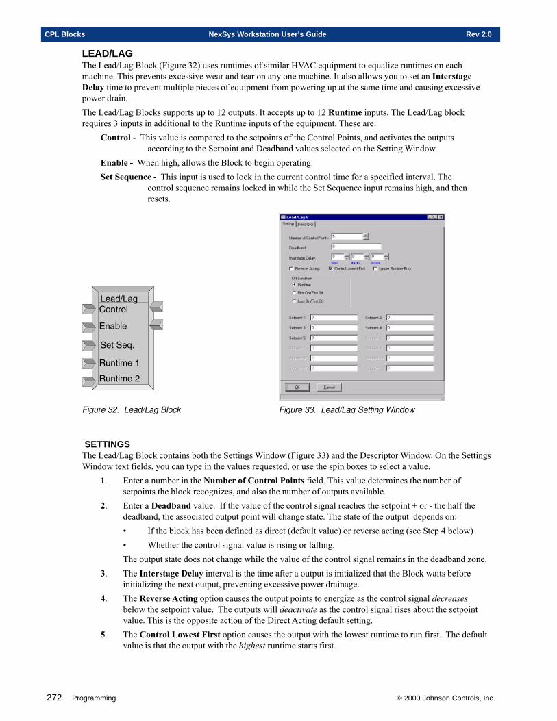
272 Programming © 2000 Johnson Controls, Inc.
CPL Blocks NexSys Workstation User’s Guide Rev 2.0
LEAD/LAGThe Lead/Lag Block (Figure 32) uses runtimes of similar HVAC equipment to equalize runtimes on eachmachine. This prevents excessive wear and tear on any one machine. It also allows you to set an InterstageDelay time to prevent multiple pieces of equipment from powering up at the same time and causing excessivepower drain.The Lead/Lag Blocks supports up to 12 outputs. It accepts up to 12 Runtime inputs. The Lead/Lag blockrequires 3 inputs in additional to the Runtime inputs of the equipment. These are:
Control - This value is compared to the setpoints of the Control Points, and activates the outputsaccording to the Setpoint and Deadband values selected on the Setting Window.
Enable - When high, allows the Block to begin operating.Set Sequence - This input is used to lock in the current control time for a specified interval. The
control sequence remains locked in while the Set Sequence input remains high, and thenresets.
���*���� ��$���
��� ��
��$���@?
3��$�����
3��$����6
Figure 32. Lead/Lag Block Figure 33. Lead/Lag Setting Window
SETTINGSThe Lead/Lag Block contains both the Settings Window (Figure 33) and the Descriptor Window. On the SettingsWindow text fields, you can type in the values requested, or use the spin boxes to select a value.
1. Enter a number in the Number of Control Points field. This value determines the number ofsetpoints the block recognizes, and also the number of outputs available.
2. Enter a Deadband value. If the value of the control signal reaches the setpoint + or - the half thedeadband, the associated output point will change state. The state of the output depends on:• If the block has been defined as direct (default value) or reverse acting (see Step 4 below)• Whether the control signal value is rising or falling.The output state does not change while the value of the control signal remains in the deadband zone.
3. The Interstage Delay interval is the time after a output is initialized that the Block waits beforeinitializing the next output, preventing excessive power drainage.
4. The Reverse Acting option causes the output points to energize as the control signal decreasesbelow the setpoint value. The outputs will deactivate as the control signal rises about the setpointvalue. This is the opposite action of the Direct Acting default setting.
5. The Control Lowest First option causes the output with the lowest runtime to run first. The defaultvalue is that the output with the highest runtime starts first.
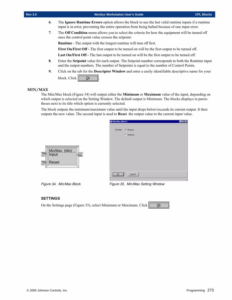
© 2000 Johnson Controls, Inc. Programming 273
Rev 2.0 NexSys Workstation User’s Guide CPL Blocks
6. The Ignore Runtime Errors option allows the block to use the last valid runtime inputs if a runtimeinput is in error, preventing the entire operation from being halted because of one input error.
7. The Off Condition menu allows you to select the criteria for how the equipment will be turned offonce the control point value crosses the setpoint:Runtime - The output with the longest runtime will turn off first.First On/First Off - The first output to be turned on will be the first output to be turned off.Last On/First Off - The last output to be turned on will be the first output to be turned off.
8. Enter the Setpoint value for each output. The Setpoint number corresponds to both the Runtime inputand the output numbers. The number of Setpoints is equal to the number of Control Points.
9. Click on the tab for the Descriptor Window and enter a easily identifiable descriptive name for your
block. Click .
MIN/MAXThe Min/Max block (Figure 34) will output either the Minimum or Maximum value of the input, depending onwhich output is selected on the Setting Window. The default output is Minimum. The blocks displays in paren-theses next to its title which option is currently selected.The block outputs the minimum/maximum value until the input drops below/exceeds its current output. It thenoutputs the new value. The second input is used to Reset the output value to the current input value.
Min/Max (Min)Input
Reset
Figure 34. Min/Max Block Figure 35. Min/Max Setting Window
SETTINGS
On the Settings page (Figure 35), select Minimum or Maximum. Click .
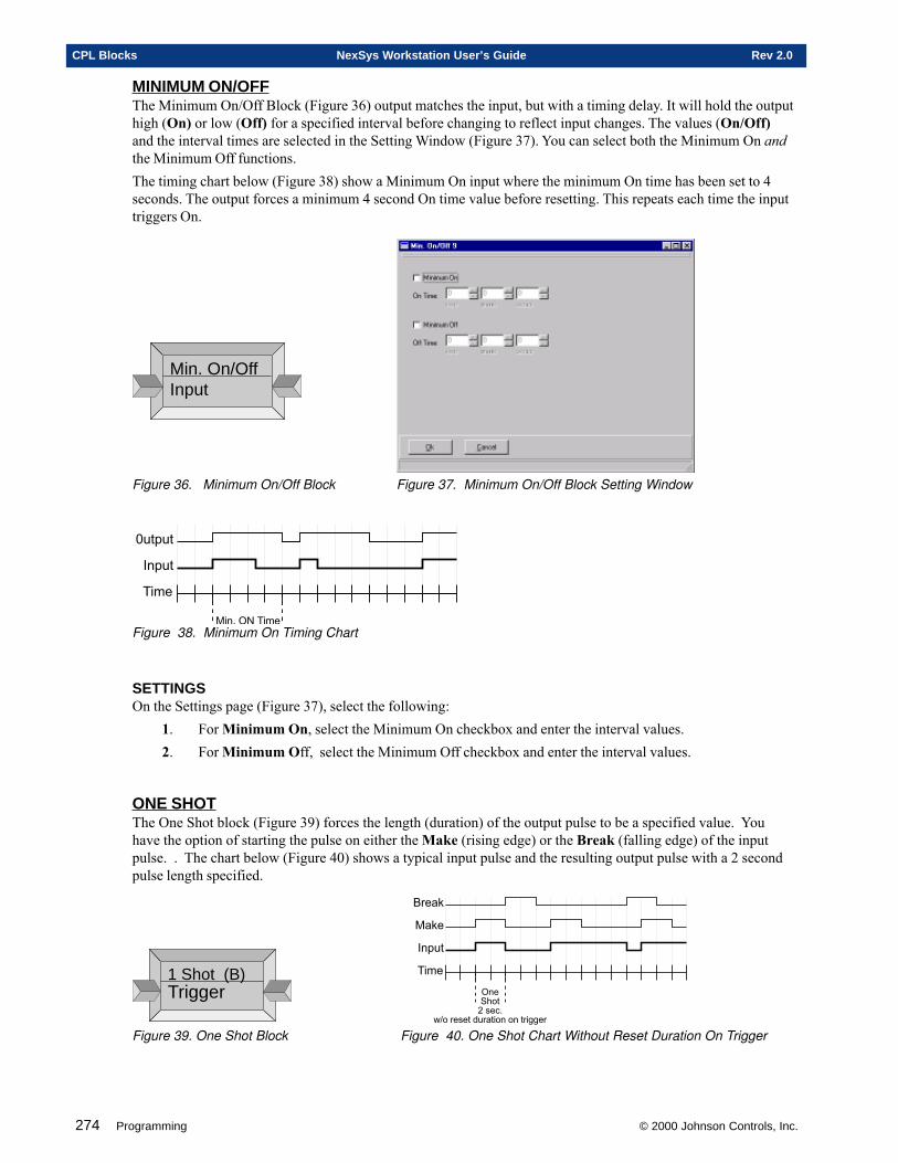
274 Programming © 2000 Johnson Controls, Inc.
CPL Blocks NexSys Workstation User’s Guide Rev 2.0
MINIMUM ON/OFFThe Minimum On/Off Block (Figure 36) output matches the input, but with a timing delay. It will hold the outputhigh (On) or low (Off) for a specified interval before changing to reflect input changes. The values (On/Off)and the interval times are selected in the Setting Window (Figure 37). You can select both the Minimum On andthe Minimum Off functions.The timing chart below (Figure 38) show a Minimum On input where the minimum On time has been set to 4seconds. The output forces a minimum 4 second On time value before resetting. This repeats each time the inputtriggers On.
Min. On/OffInput
Figure 36. Minimum On/Off Block Figure 37. Minimum On/Off Block Setting Window
����
������
"����
���� # ����Figure 38. Minimum On Timing Chart
SETTINGSOn the Settings page (Figure 37), select the following:
1. For Minimum On, select the Minimum On checkbox and enter the interval values.2. For Minimum Off, select the Minimum Off checkbox and enter the interval values.
ONE SHOTThe One Shot block (Figure 39) forces the length (duration) of the output pulse to be a specified value. Youhave the option of starting the pulse on either the Make (rising edge) or the Break (falling edge) of the inputpulse. . The chart below (Figure 40) shows a typical input pulse and the resulting output pulse with a 2 secondpulse length specified.
1 Shot (B)Trigger
����
"����
�$%�
��&��'����
()����������$�����������!!��
*��$%
Figure 39. One Shot Block Figure 40. One Shot Chart Without Reset Duration On Trigger
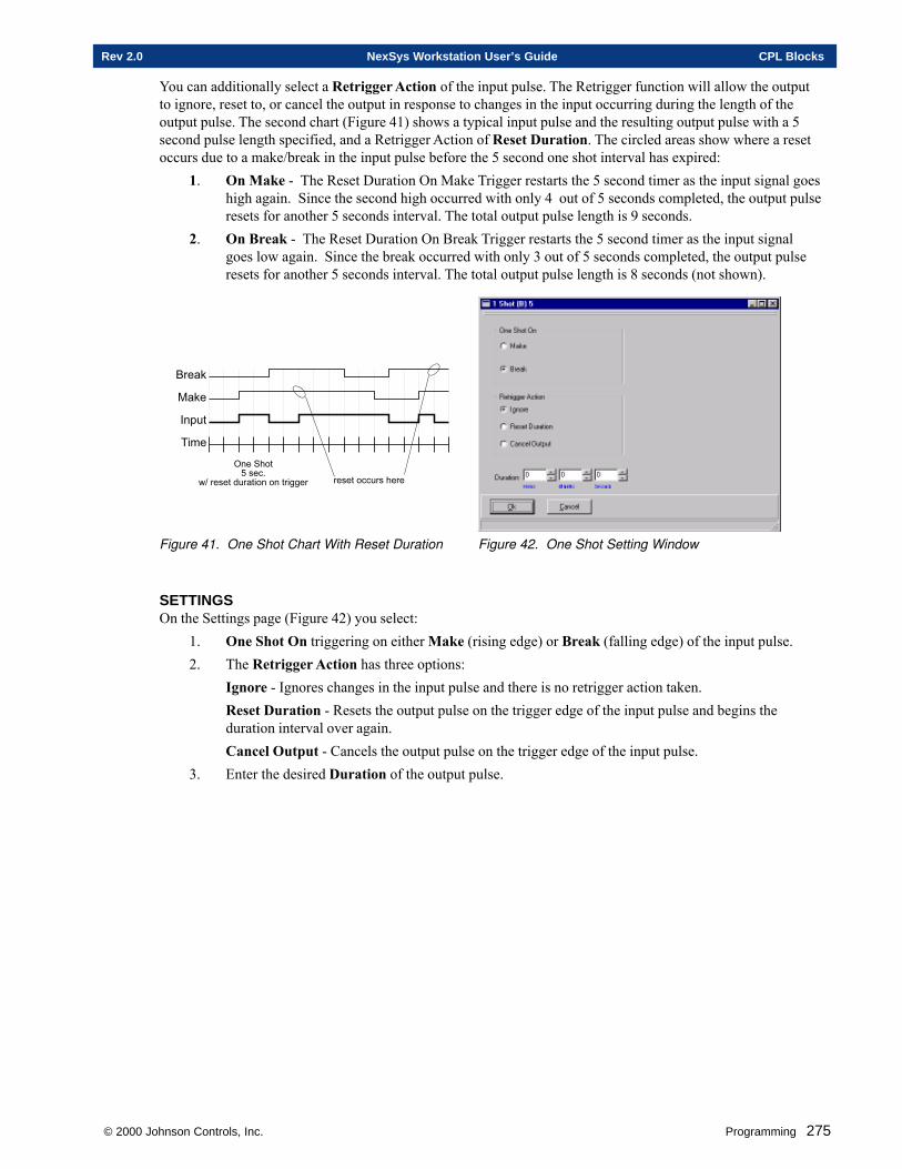
© 2000 Johnson Controls, Inc. Programming 275
Rev 2.0 NexSys Workstation User’s Guide CPL Blocks
You can additionally select a Retrigger Action of the input pulse. The Retrigger function will allow the outputto ignore, reset to, or cancel the output in response to changes in the input occurring during the length of theoutput pulse. The second chart (Figure 41) shows a typical input pulse and the resulting output pulse with a 5second pulse length specified, and a Retrigger Action of Reset Duration. The circled areas show where a resetoccurs due to a make/break in the input pulse before the 5 second one shot interval has expired:
1. On Make - The Reset Duration On Make Trigger restarts the 5 second timer as the input signal goeshigh again. Since the second high occurred with only 4 out of 5 seconds completed, the output pulseresets for another 5 seconds interval. The total output pulse length is 9 seconds.
2. On Break - The Reset Duration On Break Trigger restarts the 5 second timer as the input signalgoes low again. Since the break occurred with only 3 out of 5 seconds completed, the output pulseresets for another 5 seconds interval. The total output pulse length is 8 seconds (not shown).
����
"����
�$%�
���&�������
()���������$�����������!!��
*��$%
��������������
Figure 41. One Shot Chart With Reset Duration Figure 42. One Shot Setting Window
SETTINGSOn the Settings page (Figure 42) you select:
1. One Shot On triggering on either Make (rising edge) or Break (falling edge) of the input pulse.2. The Retrigger Action has three options:
Ignore - Ignores changes in the input pulse and there is no retrigger action taken.Reset Duration - Resets the output pulse on the trigger edge of the input pulse and begins theduration interval over again.Cancel Output - Cancels the output pulse on the trigger edge of the input pulse.
3. Enter the desired Duration of the output pulse.
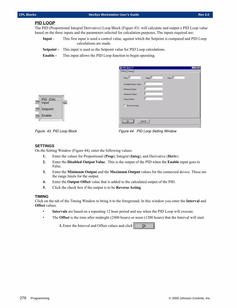
276 Programming © 2000 Johnson Controls, Inc.
CPL Blocks NexSys Workstation User’s Guide Rev 2.0
PID LOOPThe PID (Proportional Integral Derivative) Loop Block (Figure 43) will calculate and output a PID Loop valuebased on the three inputs and the parameters selected for calculation purposes. The inputs required are:
Input - This first input is used a control value, against which the Setpoint is compared and PID Loopcalculations are made.
Setpoint - This input is used as the Setpoint value for PID Loop calculations.Enable - This input allows the PID Loop function to begin operating.
PID (DA)Input
Setpoint
Enable
Figure 43. PID Loop Block Figure 44. PID Loop Setting Window
SETTINGSOn the Setting Window (Figure 44), enter the following values:
1. Enter the values for Proportional (Prop), Integral (Integ), and Derivative (Deriv).2. Enter the Disabled Output Value. This is the output of the PID when the Enable input goes to
False.3. Enter the Minimum Output and the Maximum Output values for the connected device. These are
the range limits for the output.4. Enter the Output Offset value that is added to the calculated output of the PID.5. Click the check box if the output is to be Reverse Acting.
TIMINGClick on the tab of the Timing Window to bring it to the foreground. In this window you enter the Interval andOffset values.
• Intervals are based on a repeating 12 hour period and say when the PID Loop will execute.• The Offset is the time after midnight (2400 hours) or noon (1200 hours) that the Interval will start.
1. Enter the Interval and Offset values and click .
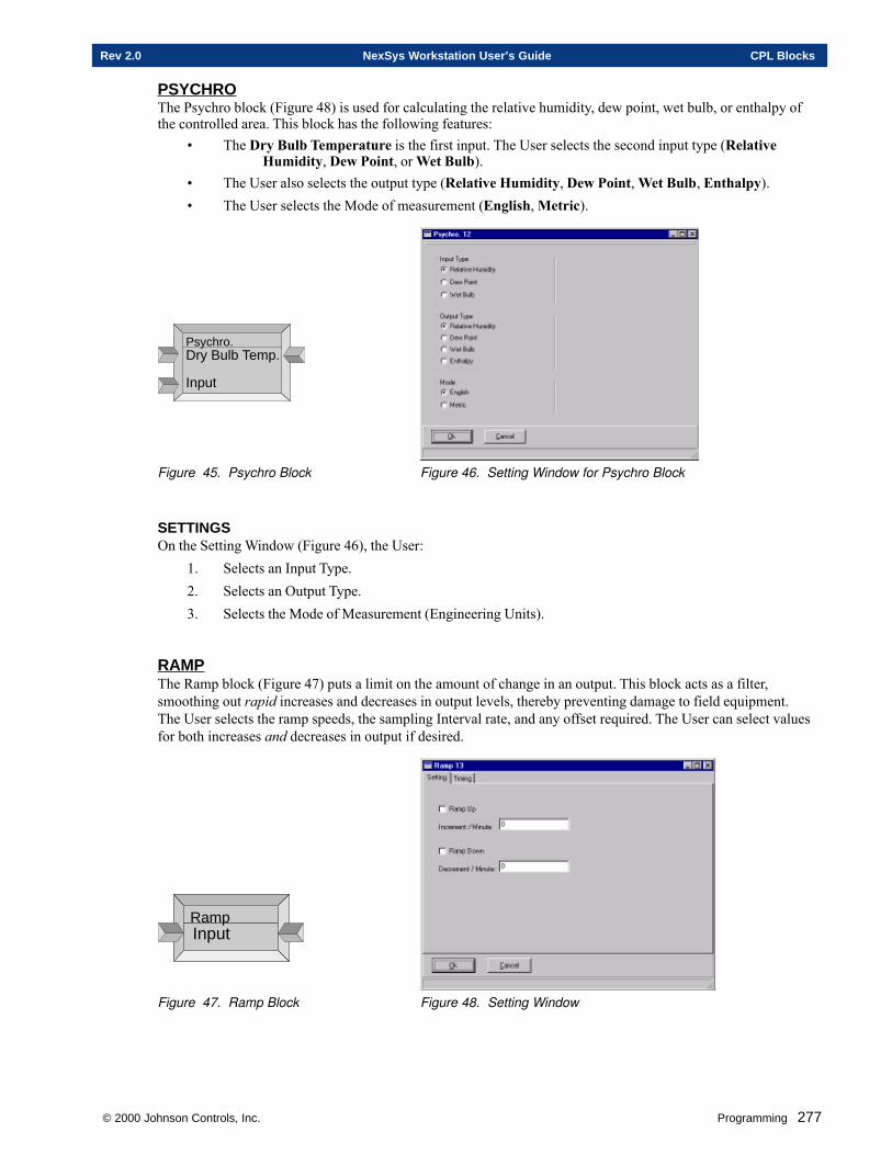
© 2000 Johnson Controls, Inc. Programming 277
Rev 2.0 NexSys Workstation User’s Guide CPL Blocks
PSYCHROThe Psychro block (Figure 48) is used for calculating the relative humidity, dew point, wet bulb, or enthalpy ofthe controlled area. This block has the following features:
• The Dry Bulb Temperature is the first input. The User selects the second input type (RelativeHumidity, Dew Point, or Wet Bulb).
• The User also selects the output type (Relative Humidity, Dew Point, Wet Bulb, Enthalpy).• The User selects the Mode of measurement (English, Metric).
Psychro.Dry Bulb Temp.
Input
Figure 45. Psychro Block Figure 46. Setting Window for Psychro Block
SETTINGSOn the Setting Window (Figure 46), the User:
1. Selects an Input Type.2. Selects an Output Type.3. Selects the Mode of Measurement (Engineering Units).
RAMPThe Ramp block (Figure 47) puts a limit on the amount of change in an output. This block acts as a filter,smoothing out rapid increases and decreases in output levels, thereby preventing damage to field equipment.The User selects the ramp speeds, the sampling Interval rate, and any offset required. The User can select valuesfor both increases and decreases in output if desired.
RampInput
Figure 47. Ramp Block Figure 48. Setting Window
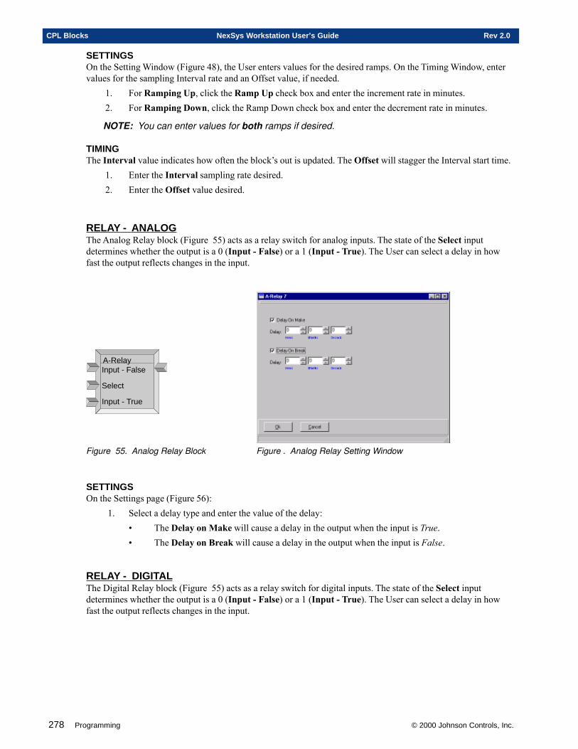
278 Programming © 2000 Johnson Controls, Inc.
CPL Blocks NexSys Workstation User’s Guide Rev 2.0
SETTINGSOn the Setting Window (Figure 48), the User enters values for the desired ramps. On the Timing Window, entervalues for the sampling Interval rate and an Offset value, if needed.
1. For Ramping Up, click the Ramp Up check box and enter the increment rate in minutes.2. For Ramping Down, click the Ramp Down check box and enter the decrement rate in minutes.
NOTE: You can enter values for both ramps if desired.
TIMINGThe Interval value indicates how often the block’s out is updated. The Offset will stagger the Interval start time.
1. Enter the Interval sampling rate desired.2. Enter the Offset value desired.
RELAY - ANALOGThe Analog Relay block (Figure 55) acts as a relay switch for analog inputs. The state of the Select inputdetermines whether the output is a 0 (Input - False) or a 1 (Input - True). The User can select a delay in howfast the output reflects changes in the input.
A-RelayInput - False
Select
Input - True
Figure 55. Analog Relay Block Figure . Analog Relay Setting Window
SETTINGSOn the Settings page (Figure 56):
1. Select a delay type and enter the value of the delay:• The Delay on Make will cause a delay in the output when the input is True.• The Delay on Break will cause a delay in the output when the input is False.
RELAY - DIGITALThe Digital Relay block (Figure 55) acts as a relay switch for digital inputs. The state of the Select inputdetermines whether the output is a 0 (Input - False) or a 1 (Input - True). The User can select a delay in howfast the output reflects changes in the input.
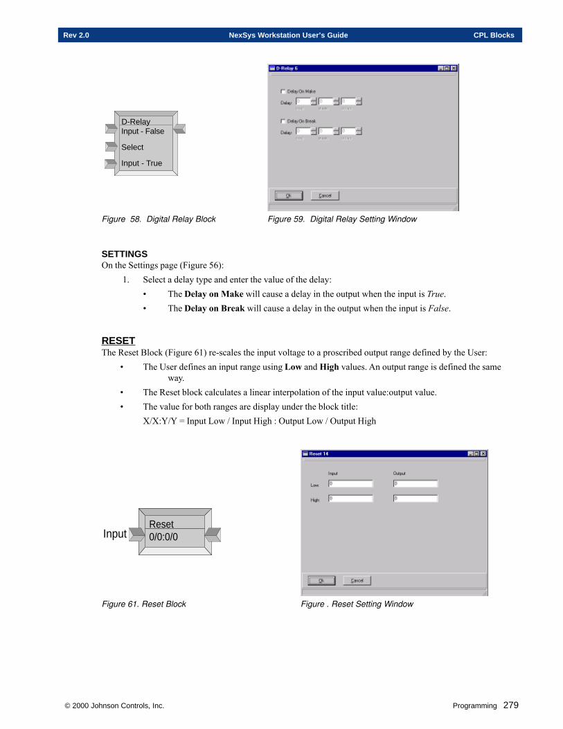
© 2000 Johnson Controls, Inc. Programming 279
Rev 2.0 NexSys Workstation User’s Guide CPL Blocks
D-RelayInput - False
Select
Input - True
Figure 58. Digital Relay Block Figure 59. Digital Relay Setting Window
SETTINGSOn the Settings page (Figure 56):
1. Select a delay type and enter the value of the delay:• The Delay on Make will cause a delay in the output when the input is True.• The Delay on Break will cause a delay in the output when the input is False.
RESETThe Reset Block (Figure 61) re-scales the input voltage to a proscribed output range defined by the User:
• The User defines an input range using Low and High values. An output range is defined the sameway.
• The Reset block calculates a linear interpolation of the input value:output value.• The value for both ranges are display under the block title:
X/X:Y/Y = Input Low / Input High : Output Low / Output High
Reset0/0:0/0Input
Figure 61. Reset Block Figure . Reset Setting Window
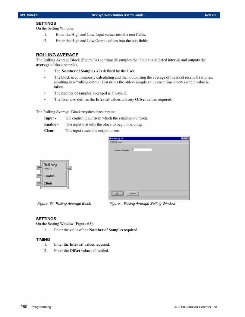
280 Programming © 2000 Johnson Controls, Inc.
CPL Blocks NexSys Workstation User’s Guide Rev 2.0
SETTINGSOn the Setting Window:
1. Enter the High and Low Input values into the text fields.2. Enter the High and Low Output values into the text fields.
ROLLING AVERAGEThe Rolling Average Block (Figure 64) continually samples the input at a selected interval and outputs theaverage of those samples.
• The Number of Samples X is defined by the User.• The block is continuously calculating and then outputting the average of the most recent X samples,
resulting in a “rolling output” that drops the oldest sample value each time a new sample value istaken.
• The number of samples averaged is always X.• The User also defines the Interval values and any Offset values required.
The Rolling Average Block requires three inputs:Input - The control input from which the samples are taken.Enable - The input that tells the block to begin operating.Clear - This input resets the output to zero
Roll Avg.Input
Enable
Clear
Figure 64. Rolling Average Block Figure . Rolling Average Setting Window
SETTINGSOn the Setting Window (Figure 65):
1. Enter the value of the Number of Samples required.
TIMING1. Enter the Interval values required.2. Enter the Offset values, if needed.
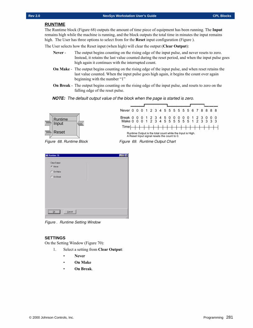
© 2000 Johnson Controls, Inc. Programming 281
Rev 2.0 NexSys Workstation User’s Guide CPL Blocks
RUNTIMEThe Runtime block (Figure 68) outputs the amount of time piece of equipment has been running. The Inputremains high while the machine is running, and the block outputs the total time in minutes the input remainshigh. The User has three options to select from for the Reset input configuration (Figure ).The User selects how the Reset input (when high) will clear the output (Clear Output):
Never - The output begins counting on the rising edge of the input pulse, and never resets to zero.Instead, it retains the last value counted during the reset period, and when the input pulse goeshigh again it continues with the interrupted count.
On Make - The output begins counting on the rising edge of the input pulse, and when reset retains thelast value counted. When the input pulse goes high again, it begins the count over againbeginning with the number “1”
On Break - The output begins counting on the rising edge of the input pulse, and resets to zero on thefalling edge of the reset pulse.
NOTE: The default output value of the block when the page is started is zero.
RuntimeInput
Reset����
�$%�*��$%
+������� ��������������$��������(�������"�������,�!���+����"������!�$���������������������
#�-�� �
��
�
��
�
��
�
��
'
''
.
.
.
/
//
�
��
�
��
�
��
�
��
�
��
�
��
0
��
1
''
2
.
.
2
�.
2
�.
2
�.
Figure 68. Runtime Block Figure 69. Runtime Output Chart
Figure . Runtime Setting Window
SETTINGSOn the Setting Window (Figure 70):
1. Select a setting from Clear Output:• Never• On Make• On Break.
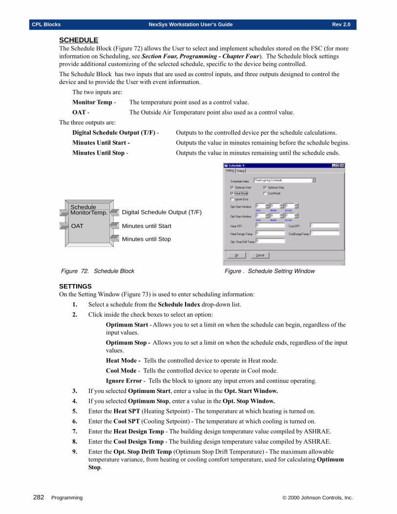
282 Programming © 2000 Johnson Controls, Inc.
CPL Blocks NexSys Workstation User’s Guide Rev 2.0
SCHEDULEThe Schedule Block (Figure 72) allows the User to select and implement schedules stored on the FSC (for moreinformation on Scheduling, see Section Four, Programming - Chapter Four). The Schedule block settingsprovide additional customizing of the selected schedule, specific to the device being controlled.The Schedule Block has two inputs that are used as control inputs, and three outputs designed to control thedevice and to provide the User with event information.
The two inputs are:Monitor Temp - The temperature point used as a control value.OAT - The Outside Air Temperature point also used as a control value.
The three outputs are:Digital Schedule Output (T/F) - Outputs to the controlled device per the schedule calculations.Minutes Until Start - Outputs the value in minutes remaining before the schedule begins.Minutes Until Stop - Outputs the value in minutes remaining until the schedule ends.
Schedule
OAT
Digital Schedule Output (T/F)
Minutes until Start
Minutes until Stop
MonitorTemp.
Figure 72. Schedule Block Figure . Schedule Setting Window
SETTINGSOn the Setting Window (Figure 73) is used to enter scheduling information:
1. Select a schedule from the Schedule Index drop-down list.2. Click inside the check boxes to select an option:
Optimum Start - Allows you to set a limit on when the schedule can begin, regardless of theinput values.Optimum Stop - Allows you to set a limit on when the schedule ends, regardless of the inputvalues.Heat Mode - Tells the controlled device to operate in Heat mode.Cool Mode - Tells the controlled device to operate in Cool mode.Ignore Error - Tells the block to ignore any input errors and continue operating.
3. If you selected Optimum Start, enter a value in the Opt. Start Window.4. If you selected Optimum Stop, enter a value in the Opt. Stop Window.5. Enter the Heat SPT (Heating Setpoint) - The temperature at which heating is turned on.6. Enter the Cool SPT (Cooling Setpoint) - The temperature at which cooling is turned on.7. Enter the Heat Design Temp - The building design temperature value compiled by ASHRAE.8. Enter the Cool Design Temp - The building design temperature value compiled by ASHRAE.9. Enter the Opt. Stop Drift Temp (Optimum Stop Drift Temperature) - The maximum allowable
temperature variance, from heating or cooling comfort temperature, used for calculating OptimumStop.
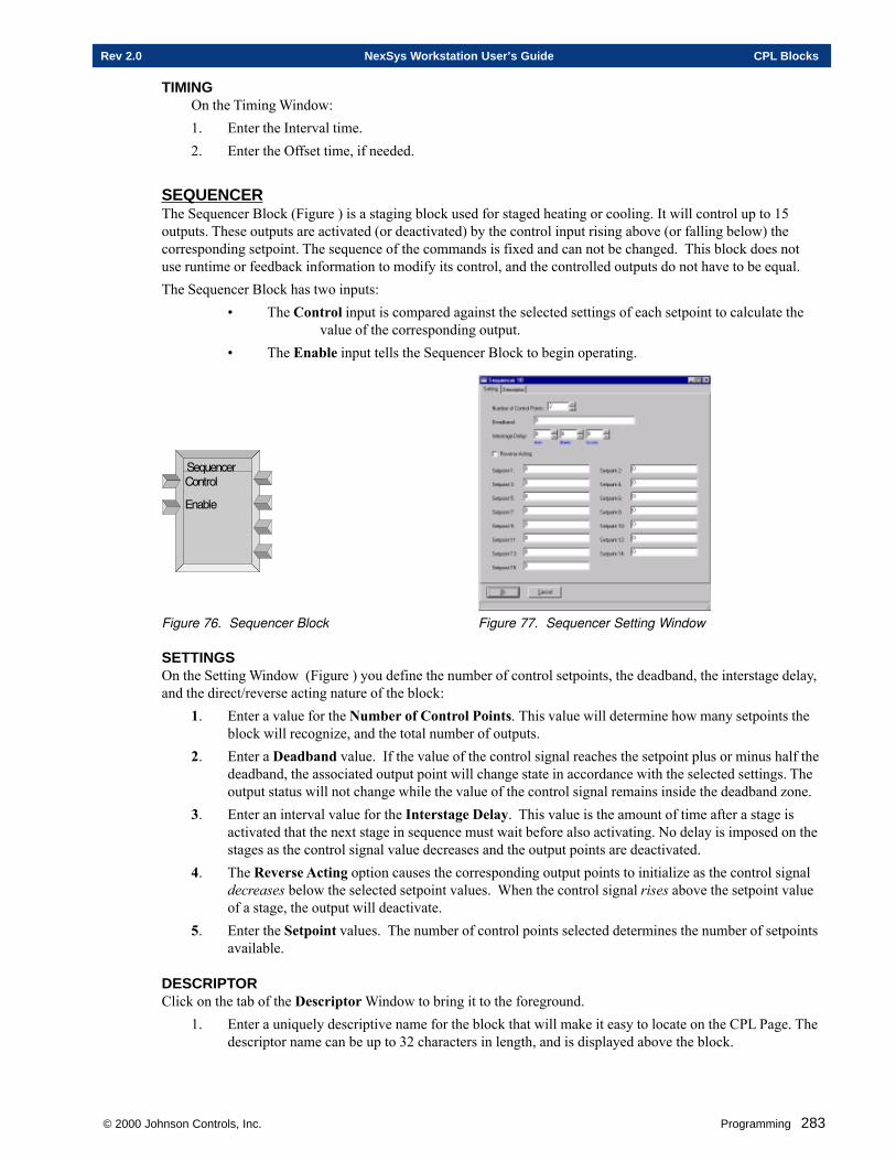
© 2000 Johnson Controls, Inc. Programming 283
Rev 2.0 NexSys Workstation User’s Guide CPL Blocks
TIMINGOn the Timing Window:1. Enter the Interval time.2. Enter the Offset time, if needed.
SEQUENCERThe Sequencer Block (Figure ) is a staging block used for staged heating or cooling. It will control up to 15outputs. These outputs are activated (or deactivated) by the control input rising above (or falling below) thecorresponding setpoint. The sequence of the commands is fixed and can not be changed. This block does notuse runtime or feedback information to modify its control, and the controlled outputs do not have to be equal.The Sequencer Block has two inputs:
• The Control input is compared against the selected settings of each setpoint to calculate thevalue of the corresponding output.
• The Enable input tells the Sequencer Block to begin operating.
��@���(�� ��$���
��� ��
Figure 76. Sequencer Block Figure 77. Sequencer Setting Window
SETTINGSOn the Setting Window (Figure ) you define the number of control setpoints, the deadband, the interstage delay,and the direct/reverse acting nature of the block:
1. Enter a value for the Number of Control Points. This value will determine how many setpoints theblock will recognize, and the total number of outputs.
2. Enter a Deadband value. If the value of the control signal reaches the setpoint plus or minus half thedeadband, the associated output point will change state in accordance with the selected settings. Theoutput status will not change while the value of the control signal remains inside the deadband zone.
3. Enter an interval value for the Interstage Delay. This value is the amount of time after a stage isactivated that the next stage in sequence must wait before also activating. No delay is imposed on thestages as the control signal value decreases and the output points are deactivated.
4. The Reverse Acting option causes the corresponding output points to initialize as the control signaldecreases below the selected setpoint values. When the control signal rises above the setpoint valueof a stage, the output will deactivate.
5. Enter the Setpoint values. The number of control points selected determines the number of setpointsavailable.
DESCRIPTORClick on the tab of the Descriptor Window to bring it to the foreground.
1. Enter a uniquely descriptive name for the block that will make it easy to locate on the CPL Page. Thedescriptor name can be up to 32 characters in length, and is displayed above the block.
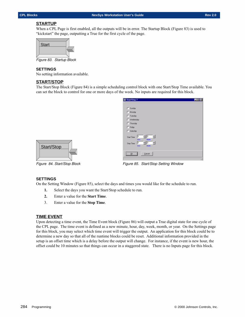
284 Programming © 2000 Johnson Controls, Inc.
CPL Blocks NexSys Workstation User’s Guide Rev 2.0
STARTUPWhen a CPL Page is first enabled, all the outputs will be in error. The Startup Block (Figure 83) is used to“kickstart” the page, outputting a True for the first cycle of the page.
Start
Figure 83. Startup Block
SETTINGSNo setting information available.
START/STOPThe Start/Stop Block (Figure 84) is a simple scheduling control block with one Start/Stop Time available. Youcan set the block to control for one or more days of the week. No inputs are required for this block.
Start/Stop
Figure 84. Start/Stop Block Figure 85. Start/Stop Setting Window
SETTINGSOn the Setting Window (Figure 85), select the days and times you would like for the schedule to run.
1. Select the days you want the Start/Stop schedule to run.2. Enter a value for the Start Time.3. Enter a value for the Stop Time.
TIME EVENTUpon detecting a time event, the Time Event block (Figure 86) will output a True digital state for one cycle ofthe CPL page. The time event is defined as a new minute, hour, day, week, month, or year. On the Settings pagefor this block, you may select which time event will trigger the output. An application for this block could be todetermine a new day so that all of the runtime blocks could be reset. Additional information provided in thesetup is an offset time which is a delay before the output will change. For instance, if the event is new hour, theoffset could be 10 minutes so that things can occur in a staggered state. There is no Inputs page for this block.
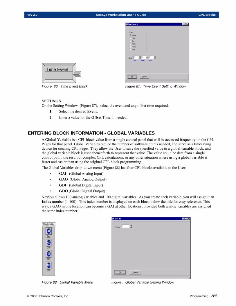
© 2000 Johnson Controls, Inc. Programming 285
Rev 2.0 NexSys Workstation User’s Guide CPL Blocks
Time Event
Figure 86. Time Event Block Figure 87. Time Event Setting Window
SETTINGSOn the Setting Window (Figure 87), select the event and any offset time required.
1. Select the desired Event.2. Enter a value for the Offset Time, if needed.
ENTERING BLOCK INFORMATION - GLOBAL VARIABLESA Global Variable is a CPL block value from a single control panel that will be accessed frequently on the CPLPages for that panel. Global Variables reduce the number of software points needed, and serve as a timesavingdevice for creating CPL Pages. They allow the User to save the specified value to a global variable block, andthe global variable block is used thenceforth to represent that value. The value could be data from a singlecontrol point, the result of complex CPL calculations, or any other situation where using a global variable isfaster and easier than using the original CPL block programming.The Global Variables drop-down menu (Figure 88) has four CPL blocks available to the User:
• GAI (Global Analog Input)• GAO (Global Analog Output)• GDI (Global Digital Input)• GDO (Global Digital Output)
NexSys allows 100 analog variables and 100 digital variables. As you create each variable, you will assign it anIndex number (1-100). This index number is displayed on each block below the title for easy reference. Thisway, a GAO in one location can become a GAI at other locations, provided both analog variables are assignedthe same index number.
Figure 88. Global Variable Menu Figure . Global Variable Setting Window
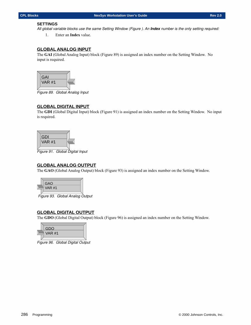
286 Programming © 2000 Johnson Controls, Inc.
CPL Blocks NexSys Workstation User’s Guide Rev 2.0
SETTINGSAll global variable blocks use the same Setting Window (Figure ). An Index number is the only setting required:
1. Enter an Index value.
GLOBAL ANALOG INPUTThe GAI (Global Analog Input) block (Figure 89) is assigned an index number on the Setting Window. Noinput is required.
GAIVAR #1
Figure 89. Global Analog Input
GLOBAL DIGITAL INPUTThe GDI (Global Digital Input) block (Figure 91) is assigned an index number on the Setting Window. No inputis required.
GDIVAR #1
Figure 91. Global Digital Input
GLOBAL ANALOG OUTPUTThe GAO (Global Analog Output) block (Figure 93) is assigned an index number on the Setting Window.
GAOVAR #1
Figure 93. Global Analog Output
GLOBAL DIGITAL OUTPUTThe GDO (Global Digital Output) block (Figure 96) is assigned an index number on the Setting Window.
GDOVAR #1
Figure 96. Global Digital Output
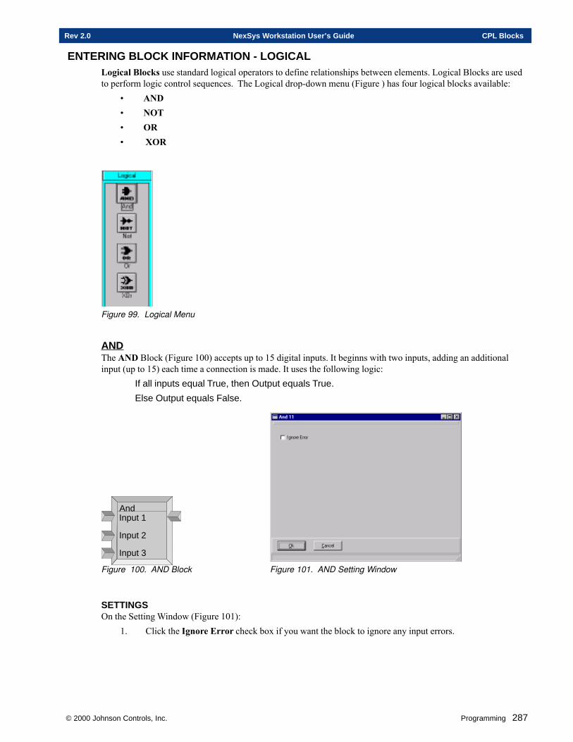
© 2000 Johnson Controls, Inc. Programming 287
Rev 2.0 NexSys Workstation User’s Guide CPL Blocks
ENTERING BLOCK INFORMATION - LOGICALLogical Blocks use standard logical operators to define relationships between elements. Logical Blocks are usedto perform logic control sequences. The Logical drop-down menu (Figure ) has four logical blocks available:
• AND• NOT• OR• XOR
Figure 99. Logical Menu
ANDThe AND Block (Figure 100) accepts up to 15 digital inputs. It beginns with two inputs, adding an additionalinput (up to 15) each time a connection is made. It uses the following logic:
If all inputs equal True, then Output equals True.
Else Output equals False.
AndInput 1
Input 2
Input 3
Figure 100. AND Block Figure 101. AND Setting Window
SETTINGSOn the Setting Window (Figure 101):
1. Click the Ignore Error check box if you want the block to ignore any input errors.
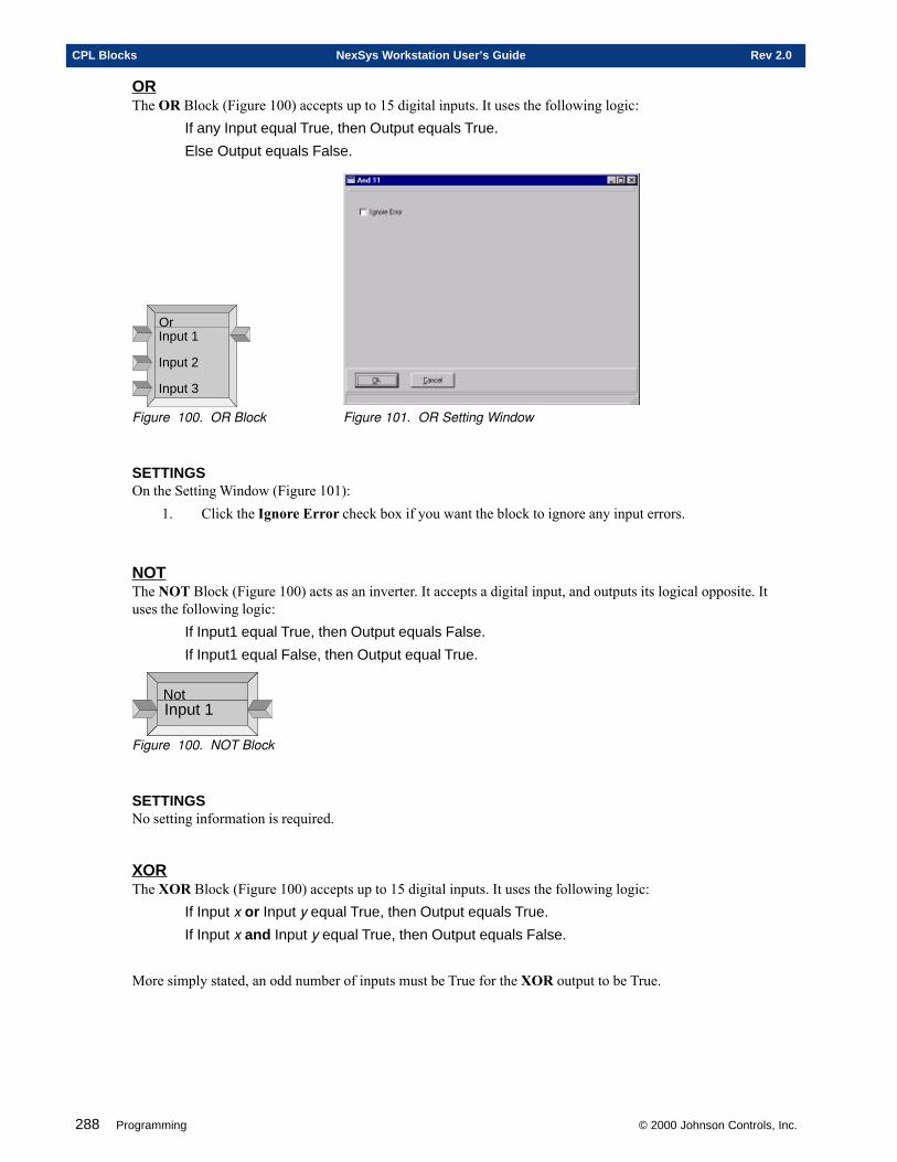
288 Programming © 2000 Johnson Controls, Inc.
CPL Blocks NexSys Workstation User’s Guide Rev 2.0
ORThe OR Block (Figure 100) accepts up to 15 digital inputs. It uses the following logic:
If any Input equal True, then Output equals True.
Else Output equals False.
OrInput 1
Input 2
Input 3
Figure 100. OR Block Figure 101. OR Setting Window
SETTINGSOn the Setting Window (Figure 101):
1. Click the Ignore Error check box if you want the block to ignore any input errors.
NOTThe NOT Block (Figure 100) acts as an inverter. It accepts a digital input, and outputs its logical opposite. Ituses the following logic:
If Input1 equal True, then Output equals False.
If Input1 equal False, then Output equal True.
NotInput 1
Figure 100. NOT Block
SETTINGSNo setting information is required.
XORThe XOR Block (Figure 100) accepts up to 15 digital inputs. It uses the following logic:
If Input x or Input y equal True, then Output equals True.
If Input x and Input y equal True, then Output equals False.
More simply stated, an odd number of inputs must be True for the XOR output to be True.
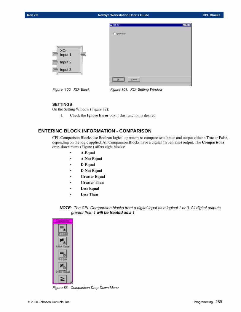
© 2000 Johnson Controls, Inc. Programming 289
Rev 2.0 NexSys Workstation User’s Guide CPL Blocks
XOrInput 1
Input 2
Input 3
Figure 100. XOr Block Figure 101. XOr Setting Window
SETTINGSOn the Setting Window (Figure 82):
1. Check the Ignore Error box if this function is desired.
ENTERING BLOCK INFORMATION - COMPARISONCPL Comparison Blocks use Boolean logical operators to compare two inputs and output either a True or False,depending on the logic applied. All Comparison Blocks have a digital (True/False) output. The Comparisonsdrop-down menu (Figure ) offers eight blocks:
• A-Equal• A-Not Equal• D-Equal• D-Not Equal• Greater Equal• Greater Than• Less Equal• Less Than
NOTE: The CPL Comparison blocks treat a digital input as a logical 1 or 0. All digital outputsgreater than 1 will be treated as a 1.
Figure 83. Comparison Drop-Down Menu
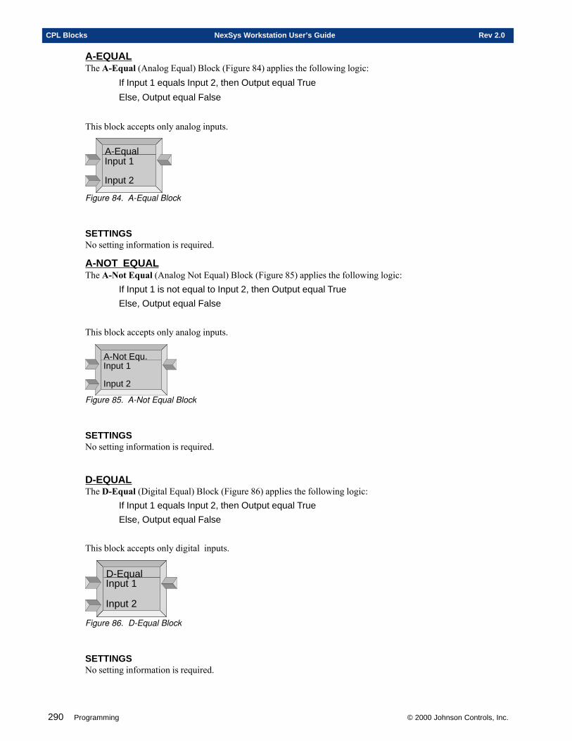
290 Programming © 2000 Johnson Controls, Inc.
CPL Blocks NexSys Workstation User’s Guide Rev 2.0
A-EQUALThe A-Equal (Analog Equal) Block (Figure 84) applies the following logic:
If Input 1 equals Input 2, then Output equal True
Else, Output equal False
This block accepts only analog inputs.
A-EqualInput 1
Input 2
Figure 84. A-Equal Block
SETTINGSNo setting information is required.
A-NOT EQUALThe A-Not Equal (Analog Not Equal) Block (Figure 85) applies the following logic:
If Input 1 is not equal to Input 2, then Output equal True
Else, Output equal False
This block accepts only analog inputs.
A-Not Equ.Input 1
Input 2
Figure 85. A-Not Equal Block
SETTINGSNo setting information is required.
D-EQUALThe D-Equal (Digital Equal) Block (Figure 86) applies the following logic:
If Input 1 equals Input 2, then Output equal True
Else, Output equal False
This block accepts only digital inputs.
D-EqualInput 1
Input 2
Figure 86. D-Equal Block
SETTINGSNo setting information is required.
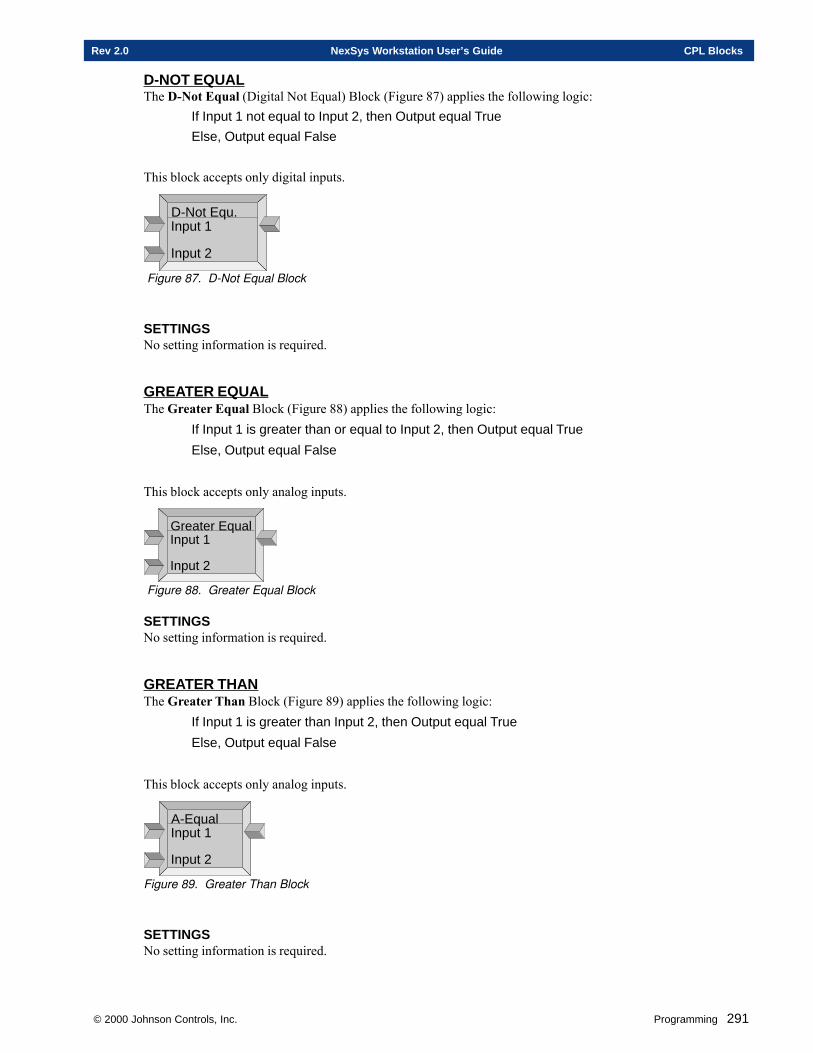
© 2000 Johnson Controls, Inc. Programming 291
Rev 2.0 NexSys Workstation User’s Guide CPL Blocks
D-NOT EQUALThe D-Not Equal (Digital Not Equal) Block (Figure 87) applies the following logic:
If Input 1 not equal to Input 2, then Output equal True
Else, Output equal False
This block accepts only digital inputs.
D-Not Equ.Input 1
Input 2
Figure 87. D-Not Equal Block
SETTINGSNo setting information is required.
GREATER EQUALThe Greater Equal Block (Figure 88) applies the following logic:
If Input 1 is greater than or equal to Input 2, then Output equal True
Else, Output equal False
This block accepts only analog inputs.
Greater EqualInput 1
Input 2
Figure 88. Greater Equal Block
SETTINGSNo setting information is required.
GREATER THANThe Greater Than Block (Figure 89) applies the following logic:
If Input 1 is greater than Input 2, then Output equal True
Else, Output equal False
This block accepts only analog inputs.
A-EqualInput 1
Input 2
Figure 89. Greater Than Block
SETTINGSNo setting information is required.
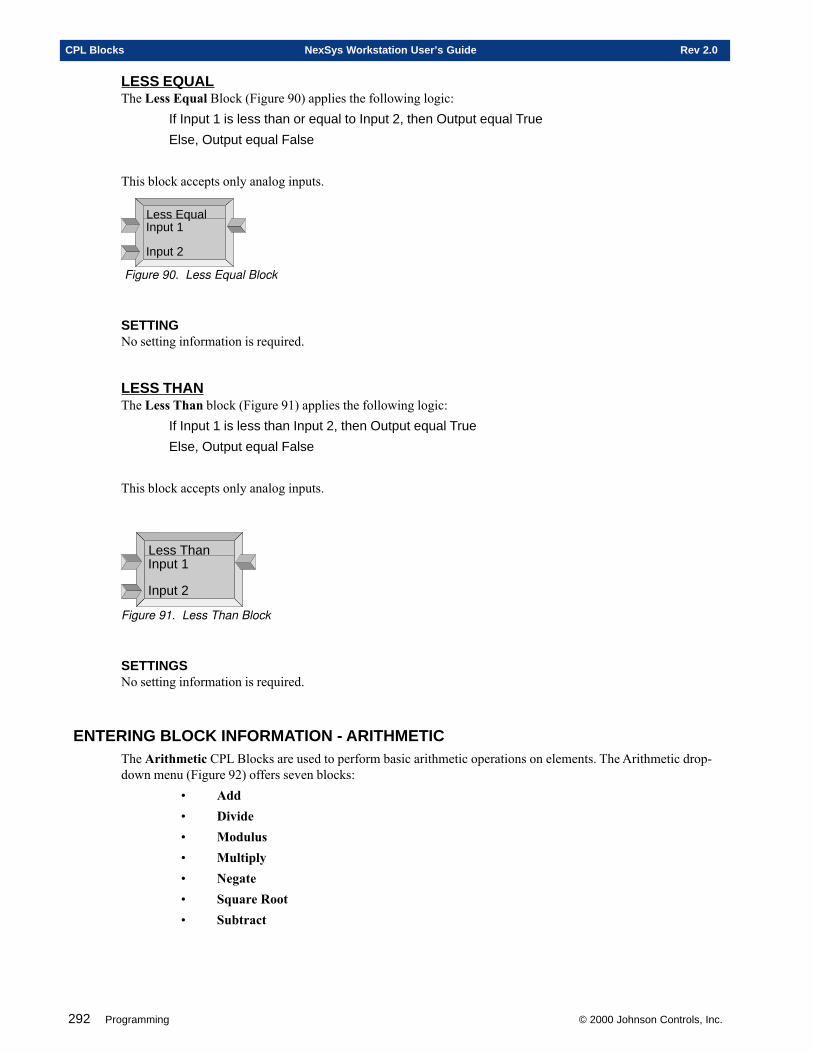
292 Programming © 2000 Johnson Controls, Inc.
CPL Blocks NexSys Workstation User’s Guide Rev 2.0
LESS EQUALThe Less Equal Block (Figure 90) applies the following logic:
If Input 1 is less than or equal to Input 2, then Output equal True
Else, Output equal False
This block accepts only analog inputs.
Less EqualInput 1
Input 2
Figure 90. Less Equal Block
SETTINGNo setting information is required.
LESS THANThe Less Than block (Figure 91) applies the following logic:
If Input 1 is less than Input 2, then Output equal True
Else, Output equal False
This block accepts only analog inputs.
Less ThanInput 1
Input 2
Figure 91. Less Than Block
SETTINGSNo setting information is required.
ENTERING BLOCK INFORMATION - ARITHMETICThe Arithmetic CPL Blocks are used to perform basic arithmetic operations on elements. The Arithmetic drop-down menu (Figure 92) offers seven blocks:
• Add• Divide• Modulus• Multiply• Negate• Square Root• Subtract

© 2000 Johnson Controls, Inc. Programming 293
Rev 2.0 NexSys Workstation User’s Guide CPL Blocks
The Arithmetic Blocks accept analog inputs only. No settings information is required.
Figure 92. Arithmetic Menu
ADDThe Add Block (Figure 93) adds together the values of the inputs and outputs the sum. The Add Block willaccept up to fifteen analog inputs.
AddAddend 1
Addend 2
Addend 3
Figure 93. Add Block
SETTINGSNo setting information required.
DIVIDEThe Divide Block (Figure 94) divides the first input (the Dividend) by the second input (the Divisor) andoutputs the quotient. The block accepts two analog inputs.
DivideDividend
Divisor
Figure 94. D ivide Block
SETTINGSNo setting information required.
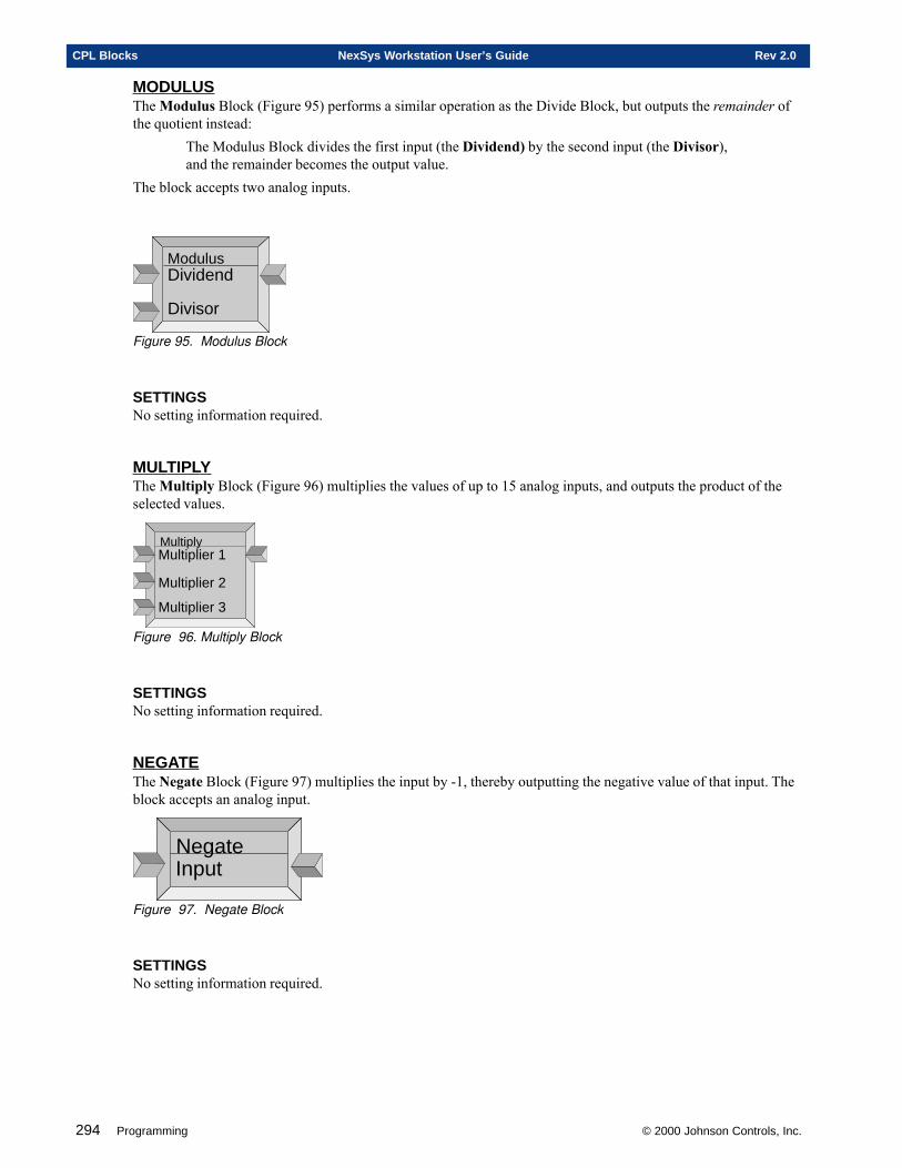
294 Programming © 2000 Johnson Controls, Inc.
CPL Blocks NexSys Workstation User’s Guide Rev 2.0
MODULUSThe Modulus Block (Figure 95) performs a similar operation as the Divide Block, but outputs the remainder ofthe quotient instead:
The Modulus Block divides the first input (the Dividend) by the second input (the Divisor),and the remainder becomes the output value.
The block accepts two analog inputs.
ModulusDividend
Divisor
Figure 95. Modulus Block
SETTINGSNo setting information required.
MULTIPLYThe Multiply Block (Figure 96) multiplies the values of up to 15 analog inputs, and outputs the product of theselected values.
MultiplyMultiplier 1
Multiplier 2
Multiplier 3
Figure 96. Multiply Block
SETTINGSNo setting information required.
NEGATEThe Negate Block (Figure 97) multiplies the input by -1, thereby outputting the negative value of that input. Theblock accepts an analog input.
NegateInput
Figure 97. Negate Block
SETTINGSNo setting information required.
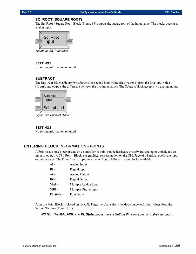
© 2000 Johnson Controls, Inc. Programming 295
Rev 2.0 NexSys Workstation User’s Guide CPL Blocks
SQ. ROOT (SQUARE ROOT)The Sq. Root (Square Root) Block (Figure 98) outputs the square root of the input value. The blocks accepts ananalog input.
Sq. RootInput
Figure 98. Sq. Root Block
SETTINGSNo setting information required.
SUBTRACTThe Subtract Block (Figure 99) subtracts the second input value (Subtrahend) from the first input value(Input), and outputs the difference between the two input values. The Subtract block accepts two analog inputs.
SubtractInput
Subtrahend
Figure 99. Subtract Block
SETTINGSNo setting information required.
ENTERING BLOCK INFORMATION - POINTSA Point is a single piece of data on a controller. A point can be hardware or software, analog or digital, and aninput or output. A CPL Point Block is a graphical representation on the CPL Page of a hardware/software inputor output value. The Point Block drop-down menu (Figure 100) has seven blocks available:
AI - Analog InputDI - Digital InputAO - Analog OutputDO - Digital OutputMAI - Multiple Analog InputMDI - Multiple Digital InputPt. State - Point State
After the Point Block is placed on the CPL Page, the User selects the data source and other values from theSetting Window (Figure 101).
NOTE: The MAI, MDI, and Pt. State blocks have a Setting Window specific to their function.
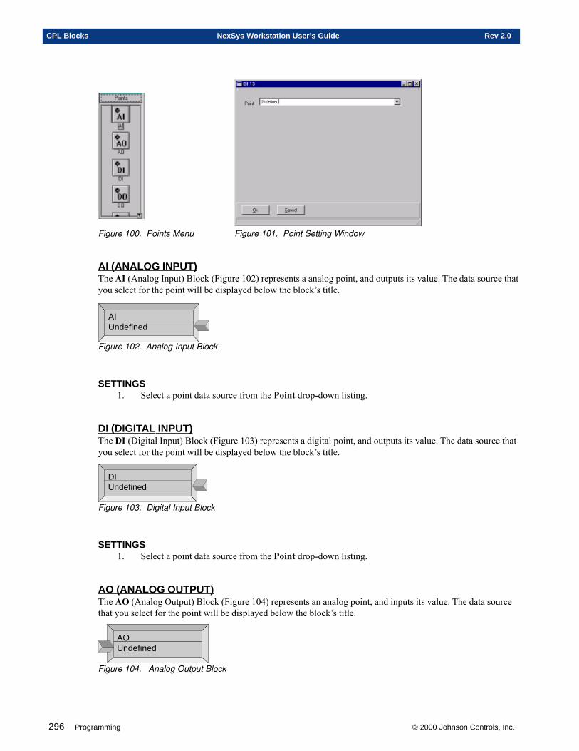
296 Programming © 2000 Johnson Controls, Inc.
CPL Blocks NexSys Workstation User’s Guide Rev 2.0
Figure 100. Points Menu Figure 101. Point Setting Window
AI (ANALOG INPUT)The AI (Analog Input) Block (Figure 102) represents a analog point, and outputs its value. The data source thatyou select for the point will be displayed below the block’s title.
AIUndefined
Figure 102. Analog Input Block
SETTINGS1. Select a point data source from the Point drop-down listing.
DI (DIGITAL INPUT)The DI (Digital Input) Block (Figure 103) represents a digital point, and outputs its value. The data source thatyou select for the point will be displayed below the block’s title.
DIUndefined
Figure 103. Digital Input Block
SETTINGS1. Select a point data source from the Point drop-down listing.
AO (ANALOG OUTPUT)The AO (Analog Output) Block (Figure 104) represents an analog point, and inputs its value. The data sourcethat you select for the point will be displayed below the block’s title.
AOUndefined
Figure 104. Analog Output Block
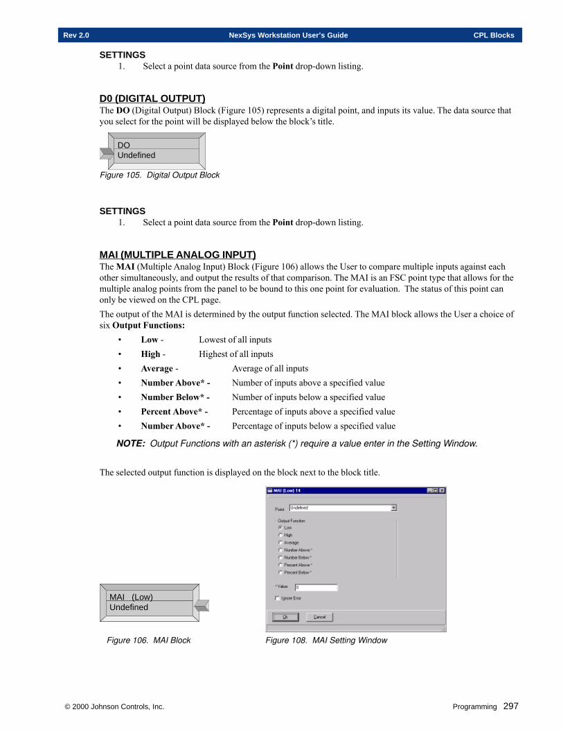
© 2000 Johnson Controls, Inc. Programming 297
Rev 2.0 NexSys Workstation User’s Guide CPL Blocks
SETTINGS1. Select a point data source from the Point drop-down listing.
D0 (DIGITAL OUTPUT)The DO (Digital Output) Block (Figure 105) represents a digital point, and inputs its value. The data source thatyou select for the point will be displayed below the block’s title.
DOUndefined
Figure 105. Digital Output Block
SETTINGS1. Select a point data source from the Point drop-down listing.
MAI (MULTIPLE ANALOG INPUT)The MAI (Multiple Analog Input) Block (Figure 106) allows the User to compare multiple inputs against eachother simultaneously, and output the results of that comparison. The MAI is an FSC point type that allows for themultiple analog points from the panel to be bound to this one point for evaluation. The status of this point canonly be viewed on the CPL page.The output of the MAI is determined by the output function selected. The MAI block allows the User a choice ofsix Output Functions:
• Low - Lowest of all inputs• High - Highest of all inputs• Average - Average of all inputs• Number Above* - Number of inputs above a specified value• Number Below* - Number of inputs below a specified value• Percent Above* - Percentage of inputs above a specified value• Number Above* - Percentage of inputs below a specified value
NOTE: Output Functions with an asterisk (*) require a value enter in the Setting Window.
The selected output function is displayed on the block next to the block title.
MAI (Low)Undefined
Figure 106. MAI Block Figure 108. MAI Setting Window
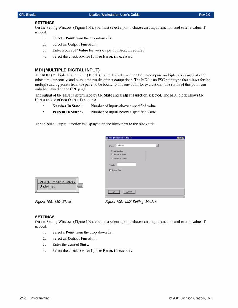
298 Programming © 2000 Johnson Controls, Inc.
CPL Blocks NexSys Workstation User’s Guide Rev 2.0
SETTINGSOn the Setting Window (Figure 107), you must select a point, choose an output function, and enter a value, ifneeded.
1. Select a Point from the drop-down list.2. Select an Output Function.3. Enter a control *Value for your output function, if required.4. Select the check box for Ignore Error, if necessary.
MDI (MULTIPLE DIGITAL INPUT)The MDI (Multiple Digital Input) Block (Figure 108) allows the User to compare multiple inputs against eachother simultaneously, and output the results of that comparison. The MDI is an FSC point type that allows for themultiple analog points from the panel to be bound to this one point for evaluation. The status of this point canonly be viewed on the CPL page.The output of the MDI is determined by the State and Output Function selected. The MDI block allows theUser a choice of two Output Functions:
• Number In State* - Number of inputs above a specified value• Percent In State* - Number of inputs below a specified value
The selected Output Function is displayed on the block next to the block title.
MDI (Number in State)Undefined
Figure 108. MDI Block Figure 109. MDI Setting Window
SETTINGSOn the Setting Window (Figure 109), you must select a point, choose an output function, and enter a value, ifneeded.
1. Select a Point from the drop-down list.2. Select an Output Function.3. Enter the desired State.4. Select the check box for Ignore Error, if necessary.
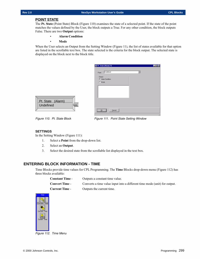
© 2000 Johnson Controls, Inc. Programming 299
Rev 2.0 NexSys Workstation User’s Guide CPL Blocks
POINT STATEThe Pt. State (Point State) Block (Figure 110) examines the state of a selected point. If the state of the pointmatches the values defined by the User, the block outputs a True. For any other condition, the block outputsFalse. There are two Output options:
• Alarm Condition• Mode
When the User selects an Output from the Setting Window (Figure 11), the list of states available for that optionare listed in the scrollable text box. The state selected is the criteria for the block output. The selected state isdisplayed on the block next to the block title.
Pt. State (Alarm)Undefined
Figure 110. Pt. State Block Figure 111. Point State Setting Window
SETTINGSIn the Setting Window (Figure 111):
1. Select a Point from the drop-down list.2. Select an Output.3. Select the desired state from the scrollable list displayed in the text box.
ENTERING BLOCK INFORMATION - TIMETime Blocks provide time values for CPL Programming. The Time Blocks drop-down menu (Figure 112) hasthree blocks available:
Constant Time - Outputs a constant time value.Convert Time - Converts a time value input into a different time mode (unit) for output.Current Time - Outputs the current time.
Figure 112. Time Menu
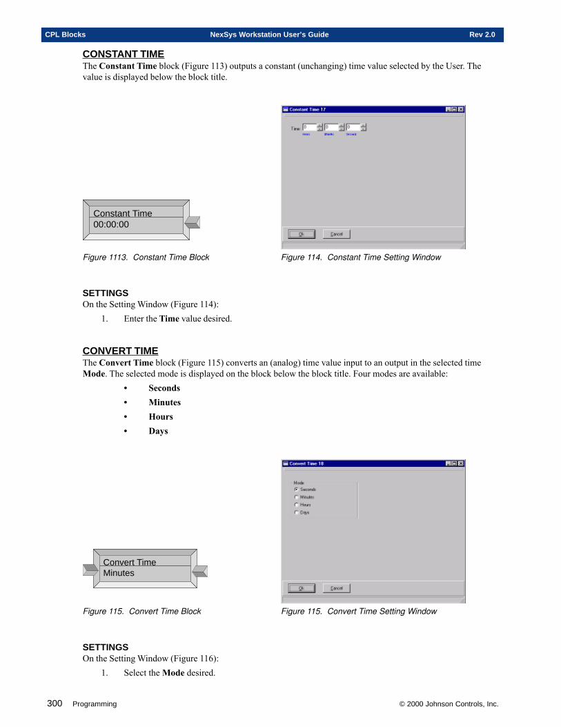
300 Programming © 2000 Johnson Controls, Inc.
CPL Blocks NexSys Workstation User’s Guide Rev 2.0
CONSTANT TIMEThe Constant Time block (Figure 113) outputs a constant (unchanging) time value selected by the User. Thevalue is displayed below the block title.
Constant Time00:00:00
Figure 1113. Constant Time Block Figure 114. Constant Time Setting Window
SETTINGSOn the Setting Window (Figure 114):
1. Enter the Time value desired.
CONVERT TIMEThe Convert Time block (Figure 115) converts an (analog) time value input to an output in the selected timeMode. The selected mode is displayed on the block below the block title. Four modes are available:
• Seconds• Minutes• Hours• Days
Convert TimeMinutes
Figure 115. Convert Time Block Figure 115. Convert Time Setting Window
SETTINGSOn the Setting Window (Figure 116):
1. Select the Mode desired.

© 2000 Johnson Controls, Inc. Programming 301
Rev 2.0 NexSys Workstation User’s Guide CPL Blocks
CURRENT TIMEThe Current Time Block (Figure 117) outputs the current number of minutes that have transpired since mid-night of the current day.
Current Time
Figure 117. Current Time Block
SETTINGSNo setting information is required.

302 Programming © 2000 Johnson Controls, Inc.
CPL Blocks NexSys Workstation User’s Guide Rev 2.0
Chapter Four
Schedules
This chapter contains information on:
� Adding a New Schedule
� Editing Existing Schedules
� Deleting Schedules
© 2000 Johnson Controls, Inc.
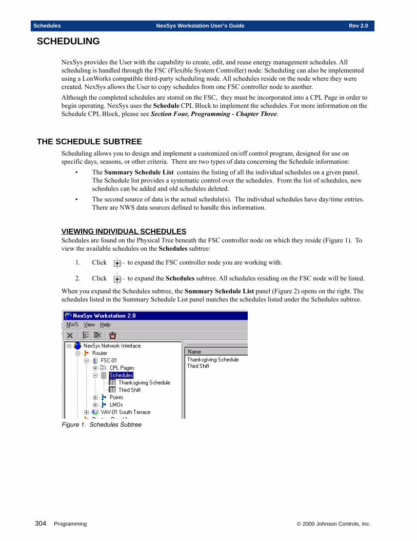
304 Programming © 2000 Johnson Controls, Inc.
Schedules NexSys Workstation User’s Guide Rev 2.0
SCHEDULING
NexSys provides the User with the capability to create, edit, and reuse energy management schedules. Allscheduling is handled through the FSC (Flexible System Controller) node. Scheduling can also be implementedusing a LonWorks compatible third-party scheduling node. All schedules reside on the node where they werecreated. NexSys allows the User to copy schedules from one FSC controller node to another.Although the completed schedules are stored on the FSC, they must be incorporated into a CPL Page in order tobegin operating. NexSys uses the Schedule CPL Block to implement the schedules. For more information on theSchedule CPL Block, please see Section Four, Programming - Chapter Three.
THE SCHEDULE SUBTREEScheduling allows you to design and implement a customized on/off control program, designed for use onspecific days, seasons, or other criteria. There are two types of data concerning the Schedule information:
• The Summary Schedule List contains the listing of all the individual schedules on a given panel.The Schedule list provides a systematic control over the schedules. From the list of schedules, newschedules can be added and old schedules deleted.
• The second source of data is the actual schedule(s). The individual schedules have day/time entries.There are NWS data sources defined to handle this information.
VIEWING INDIVIDUAL SCHEDULESSchedules are found on the Physical Tree beneath the FSC controller node on which they reside (Figure 1). Toview the available schedules on the Schedules subtree:
1. Click to expand the FSC controller node you are working with.
2. Click to expand the Schedules subtree. All schedules residing on the FSC node will be listed.
When you expand the Schedules subtree, the Summary Schedule List panel (Figure 2) opens on the right. Theschedules listed in the Summary Schedule List panel matches the schedules listed under the Schedules subtree.
Figure 1. Schedules Subtree
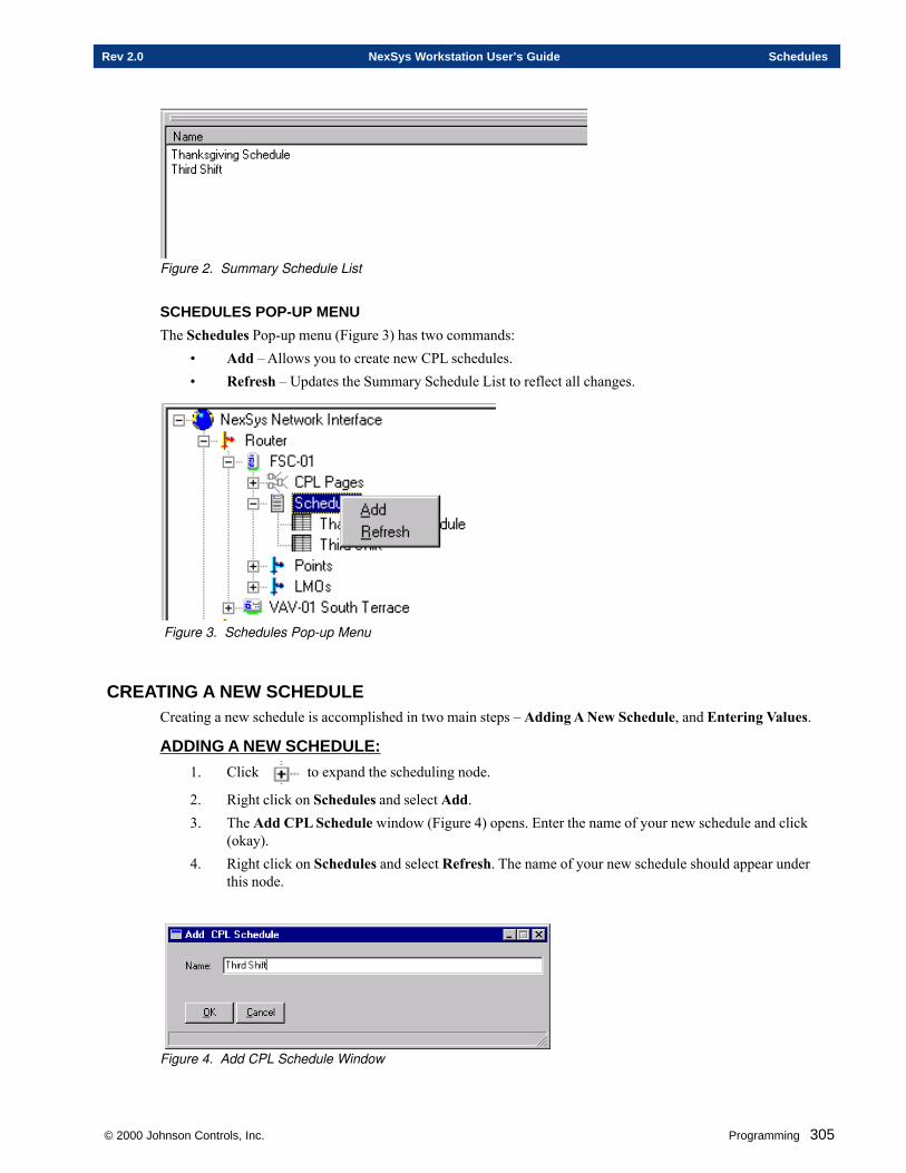
© 2000 Johnson Controls, Inc. Programming 305
Rev 2.0 NexSys Workstation User’s Guide Schedules
Figure 2. Summary Schedule List
SCHEDULES POP-UP MENU
The Schedules Pop-up menu (Figure 3) has two commands:• Add – Allows you to create new CPL schedules.• Refresh – Updates the Summary Schedule List to reflect all changes.
Figure 3. Schedules Pop-up Menu
CREATING A NEW SCHEDULECreating a new schedule is accomplished in two main steps – Adding A New Schedule, and Entering Values.
ADDING A NEW SCHEDULE:
1. Click to expand the scheduling node.
2. Right click on Schedules and select Add.3. The Add CPL Schedule window (Figure 4) opens. Enter the name of your new schedule and click
(okay).4. Right click on Schedules and select Refresh. The name of your new schedule should appear under
this node.
Figure 4. Add CPL Schedule Window
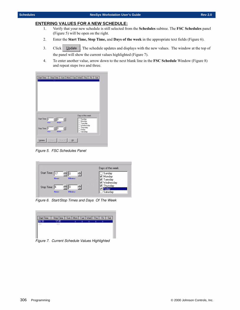
306 Programming © 2000 Johnson Controls, Inc.
Schedules NexSys Workstation User’s Guide Rev 2.0
ENTERING VALUES FOR A NEW SCHEDULE:1. Verify that your new schedule is still selected from the Schedules subtree. The FSC Schedules panel
(Figure 5) will be open on the right.2. Enter the Start Time, Stop Time, and Days of the week in the appropriate text fields (Figure 6).
3. Click . The schedule updates and displays with the new values. The window at the top of
the panel will show the current values highlighted (Figure 7).4. To enter another value, arrow down to the next blank line in the FSC Schedule Window (Figure 8)
and repeat steps two and three.
Figure 5. FSC Schedules Panel
Figure 6. Start/Stop Times and Days Of The Week
Figure 7. Current Schedule Values Highlighted
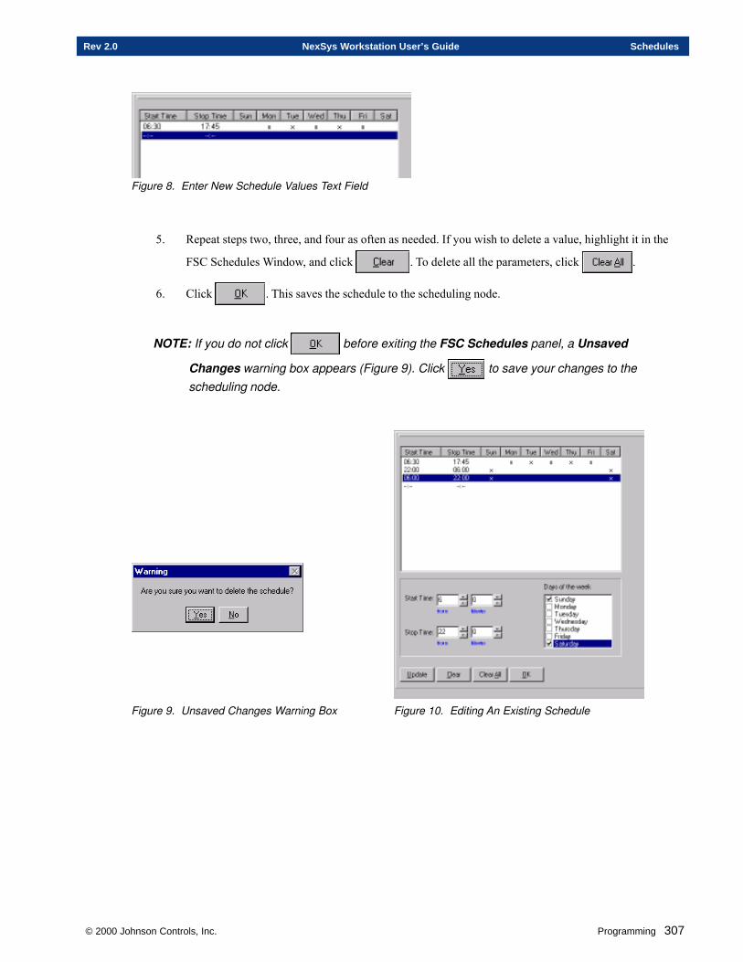
© 2000 Johnson Controls, Inc. Programming 307
Rev 2.0 NexSys Workstation User’s Guide Schedules
Figure 8. Enter New Schedule Values Text Field
5. Repeat steps two, three, and four as often as needed. If you wish to delete a value, highlight it in the
FSC Schedules Window, and click . To delete all the parameters, click .
6. Click . This saves the schedule to the scheduling node.
NOTE: If you do not click before exiting the FSC Schedules panel, a Unsaved
Changes warning box appears (Figure 9). Click to save your changes to thescheduling node.
Figure 9. Unsaved Changes Warning Box Figure 10. Editing An Existing Schedule
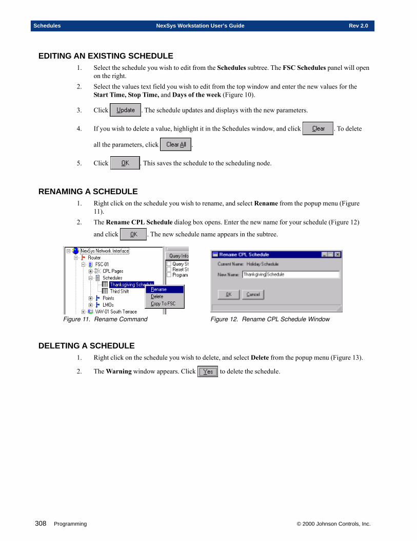
308 Programming © 2000 Johnson Controls, Inc.
Schedules NexSys Workstation User’s Guide Rev 2.0
EDITING AN EXISTING SCHEDULE1. Select the schedule you wish to edit from the Schedules subtree. The FSC Schedules panel will open
on the right.2. Select the values text field you wish to edit from the top window and enter the new values for the
Start Time, Stop Time, and Days of the week (Figure 10).
3. Click . The schedule updates and displays with the new parameters.
4. If you wish to delete a value, highlight it in the Schedules window, and click . To delete
all the parameters, click .
5. Click . This saves the schedule to the scheduling node.
RENAMING A SCHEDULE1. Right click on the schedule you wish to rename, and select Rename from the popup menu (Figure
11).2. The Rename CPL Schedule dialog box opens. Enter the new name for your schedule (Figure 12)
and click . The new schedule name appears in the subtree.
Figure 11. Rename Command Figure 12. Rename CPL Schedule Window
DELETING A SCHEDULE1. Right click on the schedule you wish to delete, and select Delete from the popup menu (Figure 13).
2. The Warning window appears. Click to delete the schedule.
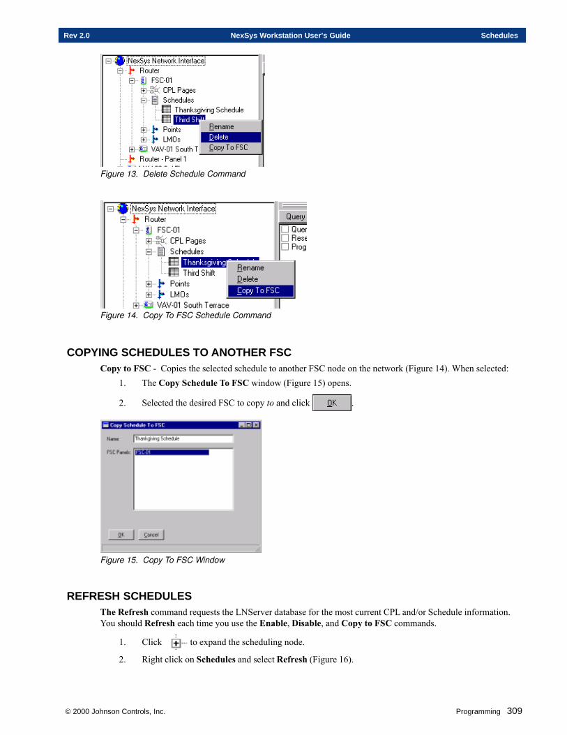
© 2000 Johnson Controls, Inc. Programming 309
Rev 2.0 NexSys Workstation User’s Guide Schedules
Figure 13. Delete Schedule Command
Figure 14. Copy To FSC Schedule Command
COPYING SCHEDULES TO ANOTHER FSCCopy to FSC - Copies the selected schedule to another FSC node on the network (Figure 14). When selected:
1. The Copy Schedule To FSC window (Figure 15) opens.
2. Selected the desired FSC to copy to and click .
Figure 15. Copy To FSC Window
REFRESH SCHEDULESThe Refresh command requests the LNServer database for the most current CPL and/or Schedule information.You should Refresh each time you use the Enable, Disable, and Copy to FSC commands.
1. Click to expand the scheduling node.
2. Right click on Schedules and select Refresh (Figure 16).

310 Programming © 2000 Johnson Controls, Inc.
Schedules NexSys Workstation User’s Guide Rev 2.0
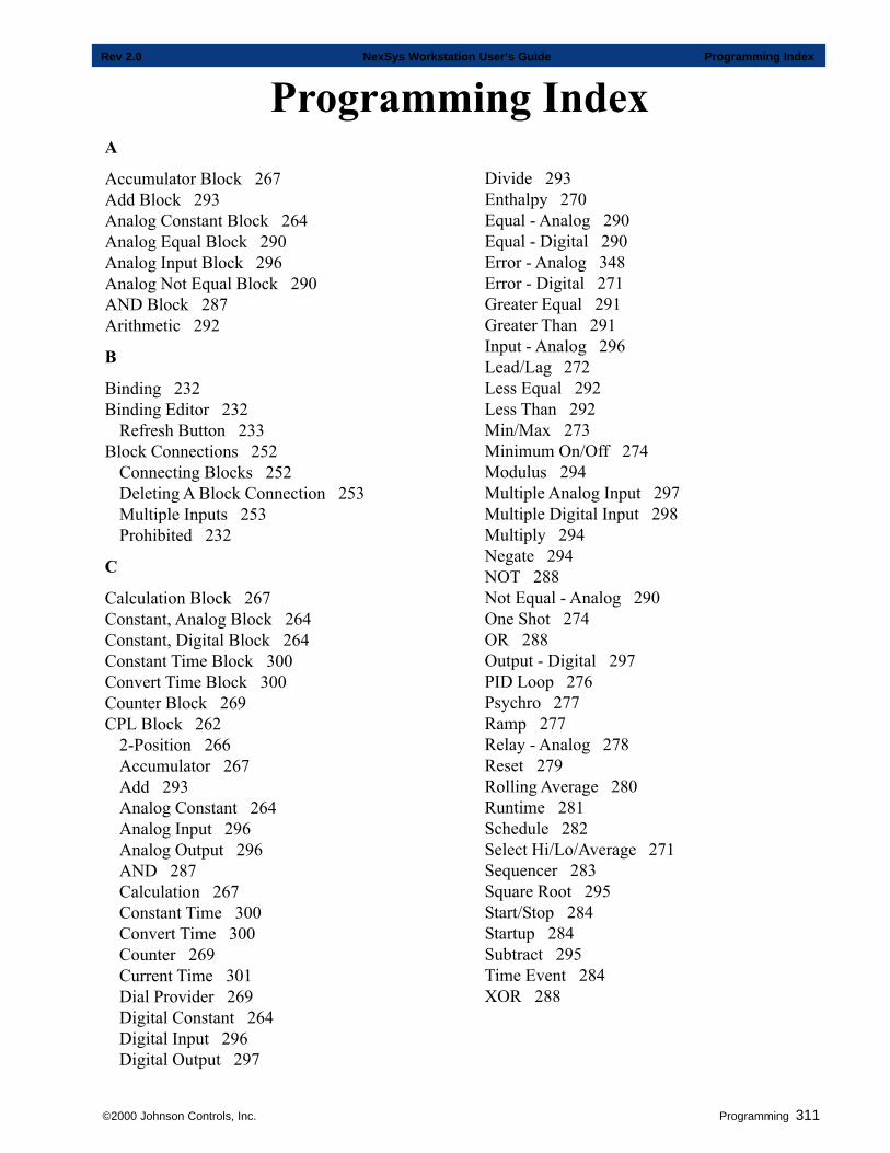
©2000 Johnson Controls, Inc. Programming 311
Rev 2.0 NexSys Workstation User’s Guide Programming Index
Programming IndexDivide 293Enthalpy 270Equal - Analog 290Equal - Digital 290Error - Analog 348Error - Digital 271Greater Equal 291Greater Than 291Input - Analog 296Lead/Lag 272Less Equal 292Less Than 292Min/Max 273Minimum On/Off 274Modulus 294Multiple Analog Input 297Multiple Digital Input 298Multiply 294Negate 294NOT 288Not Equal - Analog 290One Shot 274OR 288Output - Digital 297PID Loop 276Psychro 277Ramp 277Relay - Analog 278Reset 279Rolling Average 280Runtime 281Schedule 282Select Hi/Lo/Average 271Sequencer 283Square Root 295Start/Stop 284Startup 284Subtract 295Time Event 284XOR 288
A
Accumulator Block 267Add Block 293Analog Constant Block 264Analog Equal Block 290Analog Input Block 296Analog Not Equal Block 290AND Block 287Arithmetic 292
B
Binding 232Binding Editor 232
Refresh Button 233Block Connections 252
Connecting Blocks 252Deleting A Block Connection 253Multiple Inputs 253Prohibited 232
C
Calculation Block 267Constant, Analog Block 264Constant, Digital Block 264Constant Time Block 300Convert Time Block 300Counter Block 269CPL Block 262
2-Position 266Accumulator 267Add 293Analog Constant 264Analog Input 296Analog Output 296AND 287Calculation 267Constant Time 300Convert Time 300Counter 269Current Time 301Dial Provider 269Digital Constant 264Digital Input 296Digital Output 297
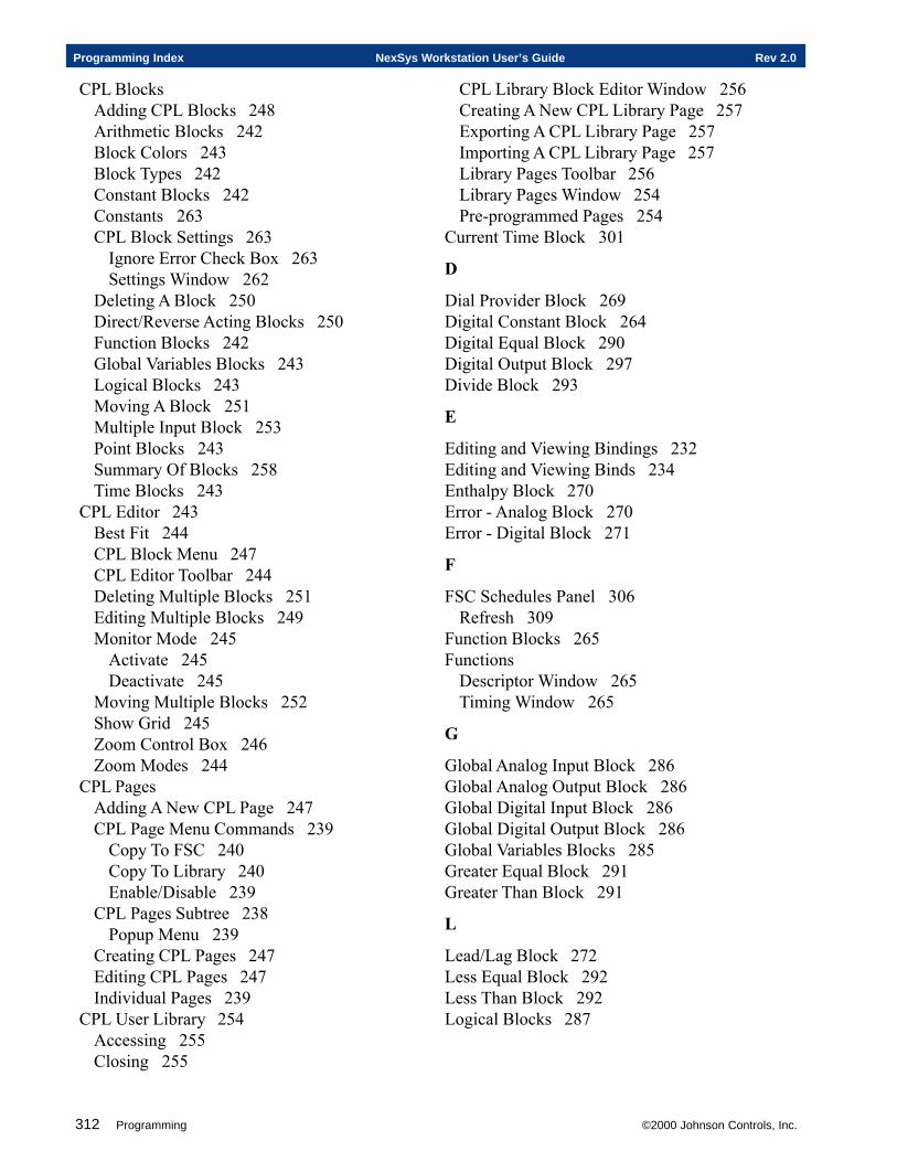
312 Programming ©2000 Johnson Controls, Inc.
Programming Index NexSys Workstation User’s Guide Rev 2.0
CPL BlocksAdding CPL Blocks 248Arithmetic Blocks 242Block Colors 243Block Types 242Constant Blocks 242Constants 263CPL Block Settings 263
Ignore Error Check Box 263Settings Window 262
Deleting A Block 250Direct/Reverse Acting Blocks 250Function Blocks 242Global Variables Blocks 243Logical Blocks 243Moving A Block 251Multiple Input Block 253Point Blocks 243Summary Of Blocks 258Time Blocks 243
CPL Editor 243Best Fit 244CPL Block Menu 247CPL Editor Toolbar 244Deleting Multiple Blocks 251Editing Multiple Blocks 249Monitor Mode 245
Activate 245Deactivate 245
Moving Multiple Blocks 252Show Grid 245Zoom Control Box 246Zoom Modes 244
CPL PagesAdding A New CPL Page 247CPL Page Menu Commands 239
Copy To FSC 240Copy To Library 240Enable/Disable 239
CPL Pages Subtree 238Popup Menu 239
Creating CPL Pages 247Editing CPL Pages 247Individual Pages 239
CPL User Library 254Accessing 255Closing 255
CPL Library Block Editor Window 256Creating A New CPL Library Page 257Exporting A CPL Library Page 257Importing A CPL Library Page 257Library Pages Toolbar 256Library Pages Window 254Pre-programmed Pages 254
Current Time Block 301
D
Dial Provider Block 269Digital Constant Block 264Digital Equal Block 290 Digital Output Block 297Divide Block 293
E
Editing and Viewing Bindings 232Editing and Viewing Binds 234Enthalpy Block 270Error - Analog Block 270Error - Digital Block 271
F
FSC Schedules Panel 306Refresh 309
Function Blocks 265Functions
Descriptor Window 265Timing Window 265
G
Global Analog Input Block 286Global Analog Output Block 286Global Digital Input Block 286Global Digital Output Block 286Global Variables Blocks 285Greater Equal Block 291Greater Than Block 291
L
Lead/Lag Block 272Less Equal Block 292Less Than Block 292Logical Blocks 287
©2000 Johnson Controls, Inc. Programming 313
Rev 2.0 NexSys Workstation User’s Guide Programming Index
M
Min/Max Block 273Minimum On/Off Block 274Modulus Block 294Multiple Analog Input Block 297Multiple Digital Input Block 298Multiply Block 294
N
Negate Block 294Network Variable Inputs 232Network Variable Outputs 232Network Variables 232NOT Block 288
O
One Shot Block 274OR Block 288
P
PID Loop Block 276Point Blocks 295Point State Block 299Psychro Block 277
R
Ramp Block 277Refresh Schedules 309Relay - Analog Block 278Reset Block 279Reverse Acting Block 276Rolling Average Block 280Runtime Block 281
S
ScheduleAdd 305Create 305
Entering Values 306Delete 308Edit 308Pop-up Menu 305Rename 308Viewing 304
Schedule Block 282
Scheduling 304Schedule CPL Block 304Schedule Subtree 304
Summary Schedule List 304Select Hi/Lo/Average Block 271Sequencer Block 283Square Root Block 295Start/Stop Block 284Startup Block 284Subtract Block 295
T
Time Blocks 299Time Event Block 284Two Position Block 264
X
XOR Block 288

314 Programming ©2000 Johnson Controls, Inc.
Programming Index NexSys Workstation User’s Guide Rev 2.0
Chapters
1. Workstation Basics
OPERATIONSSECTION FIVE
© 2000 Johnson Controls, Inc.

316 Operations © 2000 Johnson Controls, Inc.
Operations Introduction NexSys Workstation User’s Guide Rev 2.0
Electronic Systems USA, a wholly owned subsidiary of Johnson Controls, Inc., reserves the right to updatespecifications when appropriate. Information contained in this document is based on specifications believed tobe correct at the time of publication.
Echelon ©, Coactive©, Windows NT©, and General Electric© are registered trademarks and service marks ofcompanies other than Electronic Systems USA. FSC™, CPL™ and NEXSYS™ are trademarks of ElectronicSystems USA.
Copyright © 2000 Johnson Controls, Inc. All Rights Reserved
© 2000 Johnson Controls, Inc. Operations 317
Rev 2.0 NexSys Workstation User’s Guide Operations Introduction
Operations Table of Contents
Chapter One - Workstation Basics 313NexSys Work Station (NWS) Window Overview ......................................................OPS-314
Menu Bar ............................................................................................................... 315Tool Bar ................................................................................................................. 317
Physical Tree .................................................................................................................... 318NexSys Network Interface ..................................................................................... 318
Editing The NexSys Network Interface ....................................................... 319To Access The NexSys Network Interface Editor: ............................ 319NexSys Network Interface Editor Options: ....................................... 319
Connection Description Template (CDT) .................................................... 320Adding A Connection Description Template (CDT) .......................... 321Modifying Connection Description Templates (CDT)........................ 323Deleting Connection Description Templates (CDT) .......................... 323
Multi-Node Operations ................................................................................ 324Selecting the node(s): ...................................................................... 324Selecting the options........................................................................ 325Confirming your selections ............................................................... 325
Routers .................................................................................................................. 325Controller Nodes.................................................................................................... 326Node Pop-up Menu Commands ............................................................................ 326Points .................................................................................................................... 334
Adding FSC/FLC points .............................................................................. 334Editing FSC/FLC Points .............................................................................. 335Deleting FSC/FLC Points ............................................................................ 335
LMOs (LonMark Objects) ...................................................................................... 336Network Variables .................................................................................................. 336
Binding: Connecting NVOs To NVIs .......................................................... 337Configuration Properties ........................................................................................ 337Point, LMO, NV, and CP Working Panels .............................................................. 338Additional FSC Subtrees ....................................................................................... 340
CPL Pages .................................................................................................. 340Schedules ................................................................................................... 342
Node Working Panels....................................................................................................... 344Detail Panel ........................................................................................................... 345
Query Options............................................................................................. 346Trend Setup Panel ................................................................................................. 346
Trend During Occupancy ................................................................. 347Sampling ..................................................................................................... 348
Trend Setup For ASCs ..................................................................... 348 Trend Setup For FSCs .................................................................... 349
Trend Harvest Panel .............................................................................................. 349Trend Channels Window............................................................................ 350 Trend Samples Window ............................................................................ 350Trend Harvest Graph window ..................................................................... 351
318 Operations © 2000 Johnson Controls, Inc.
Operations Introduction NexSys Workstation User’s Guide Rev 2.0
The Harvest Button ..................................................................................... 353To View Trending Data: ............................................................................... 353
ASG (Application Specific Graphics) Panel ........................................................... 353Occupancy Modes ...................................................................................... 354
Occupied .......................................................................................... 354Unoccupied ...................................................................................... 354Economy .......................................................................................... 354
Controller Status Data ................................................................................ 355Line Graph .................................................................................................. 355
Operations Index ............................................................................ 359

© 2000 Johnson Controls, Inc. Operations 319
Rev 2.0 NexSys Workstation User’s Guide Operations Introduction

320 Operations © 2000 Johnson Controls, Inc.
Operations Introduction NexSys Workstation User’s Guide Rev 2.0
Chapter One
Workstation Basics
This chapter contains information on:
� NWS Main Window Overview
� Menu and Tool Bars
� Physical Tree
� Node Working Panels
© 2000 Johnson Controls, Inc.
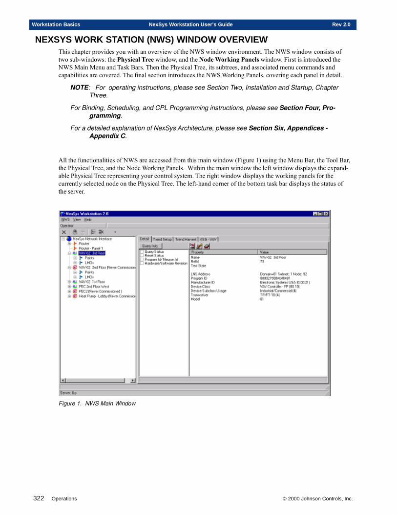
322 Operations © 2000 Johnson Controls, Inc.
Workstation Basics NexSys Workstation User’s Guide Rev 2.0
NEXSYS WORK STATION (NWS) WINDOW OVERVIEWThis chapter provides you with an overview of the NWS window environment. The NWS window consists oftwo sub-windows: the Physical Tree window, and the Node Working Panels window. First is introduced theNWS Main Menu and Task Bars. Then the Physical Tree, its subtrees, and associated menu commands andcapabilities are covered. The final section introduces the NWS Working Panels, covering each panel in detail.
NOTE: For operating instructions, please see Section Two, Installation and Startup, ChapterThree.
For Binding, Scheduling, and CPL Programming instructions, please see Section Four, Pro-gramming.
For a detailed explanation of NexSys Architecture, please see Section Six, Appendices -Appendix C.
All the functionalities of NWS are accessed from this main window (Figure 1) using the Menu Bar, the Tool Bar,the Physical Tree, and the Node Working Panels. Within the main window the left window displays the expand-able Physical Tree representing your control system. The right window displays the working panels for thecurrently selected node on the Physical Tree. The left-hand corner of the bottom task bar displays the status ofthe server.
Figure 1. NWS Main Window
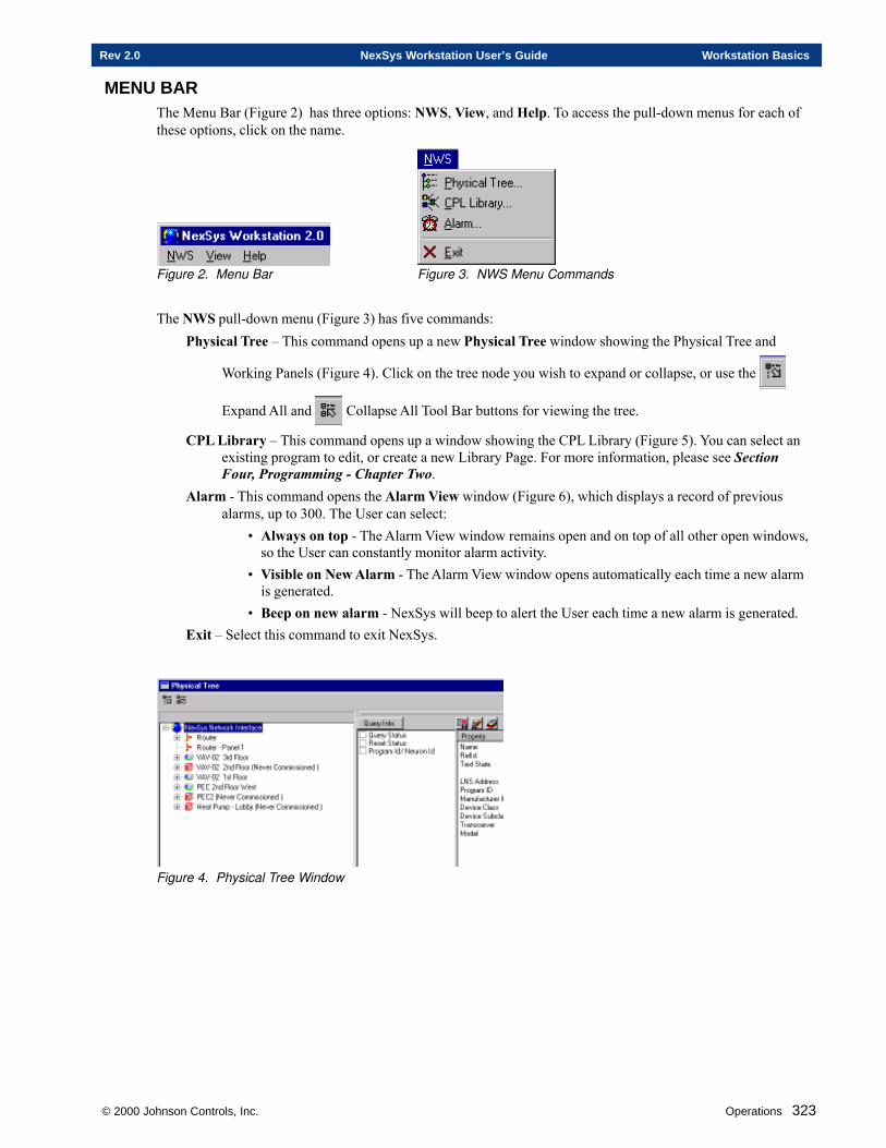
© 2000 Johnson Controls, Inc. Operations 323
Rev 2.0 NexSys Workstation User’s Guide Workstation Basics
MENU BARThe Menu Bar (Figure 2) has three options: NWS, View, and Help. To access the pull-down menus for each ofthese options, click on the name.
Figure 2. Menu Bar Figure 3. NWS Menu Commands
The NWS pull-down menu (Figure 3) has five commands:Physical Tree – This command opens up a new Physical Tree window showing the Physical Tree and
Working Panels (Figure 4). Click on the tree node you wish to expand or collapse, or use the
Expand All and Collapse All Tool Bar buttons for viewing the tree.
CPL Library – This command opens up a window showing the CPL Library (Figure 5). You can select anexisting program to edit, or create a new Library Page. For more information, please see SectionFour, Programming - Chapter Two.
Alarm - This command opens the Alarm View window (Figure 6), which displays a record of previousalarms, up to 300. The User can select:
• Always on top - The Alarm View window remains open and on top of all other open windows,so the User can constantly monitor alarm activity.
• Visible on New Alarm - The Alarm View window opens automatically each time a new alarmis generated.
• Beep on new alarm - NexSys will beep to alert the User each time a new alarm is generated.Exit – Select this command to exit NexSys.
Figure 4. Physical Tree Window
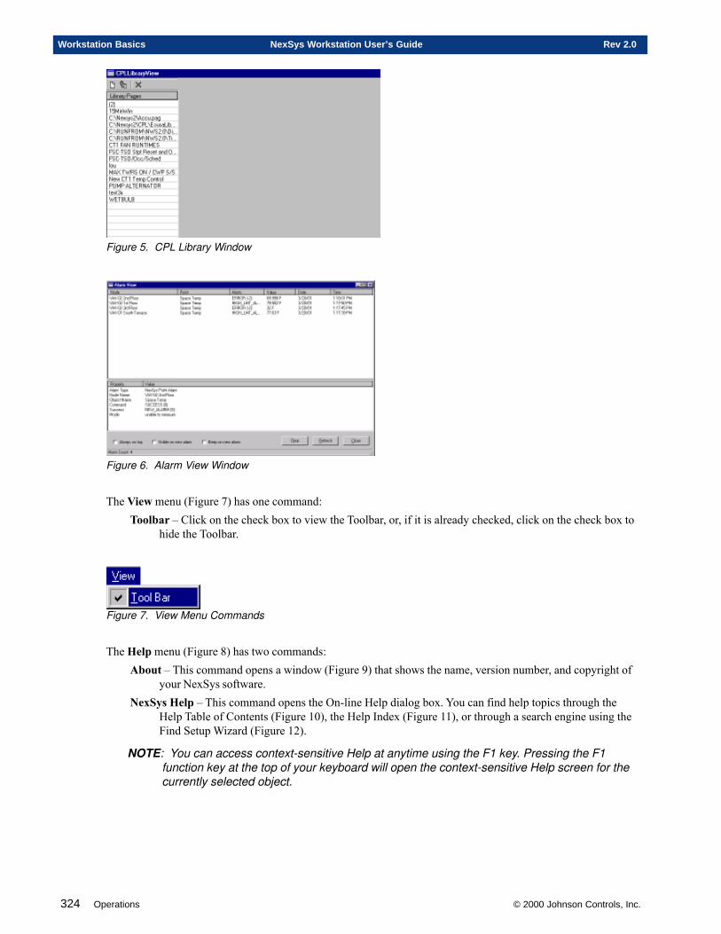
324 Operations © 2000 Johnson Controls, Inc.
Workstation Basics NexSys Workstation User’s Guide Rev 2.0
Figure 5. CPL Library Window
Figure 6. Alarm View Window
The View menu (Figure 7) has one command:Toolbar – Click on the check box to view the Toolbar, or, if it is already checked, click on the check box to
hide the Toolbar.
Figure 7. View Menu Commands
The Help menu (Figure 8) has two commands:About – This command opens a window (Figure 9) that shows the name, version number, and copyright of
your NexSys software.NexSys Help – This command opens the On-line Help dialog box. You can find help topics through the
Help Table of Contents (Figure 10), the Help Index (Figure 11), or through a search engine using theFind Setup Wizard (Figure 12).
NOTE: You can access context-sensitive Help at anytime using the F1 key. Pressing the F1function key at the top of your keyboard will open the context-sensitive Help screen for thecurrently selected object.
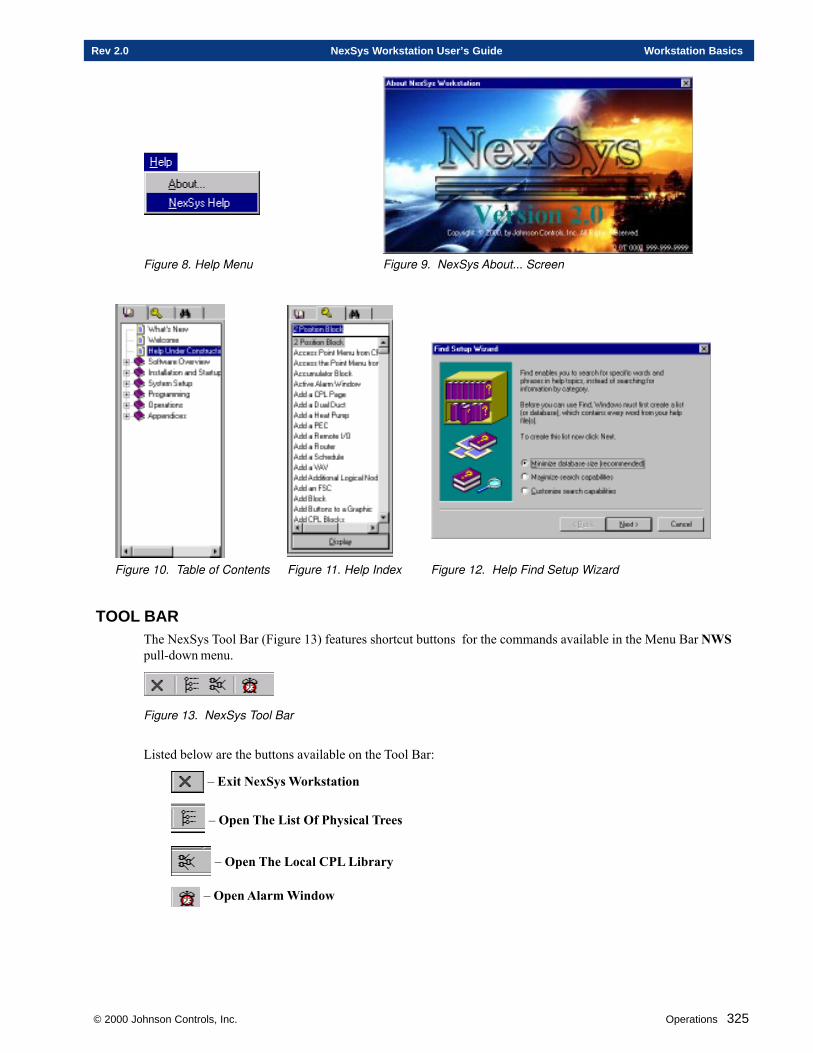
© 2000 Johnson Controls, Inc. Operations 325
Rev 2.0 NexSys Workstation User’s Guide Workstation Basics
Figure 8. Help Menu Figure 9. NexSys About... Screen
Figure 10. Table of Contents Figure 11. Help Index Figure 12. Help Find Setup Wizard
TOOL BARThe NexSys Tool Bar (Figure 13) features shortcut buttons for the commands available in the Menu Bar NWSpull-down menu.
Figure 13. NexSys Tool Bar
Listed below are the buttons available on the Tool Bar:
– Exit NexSys Workstation
– Open The List Of Physical Trees
– Open The Local CPL Library
– Open Alarm Window
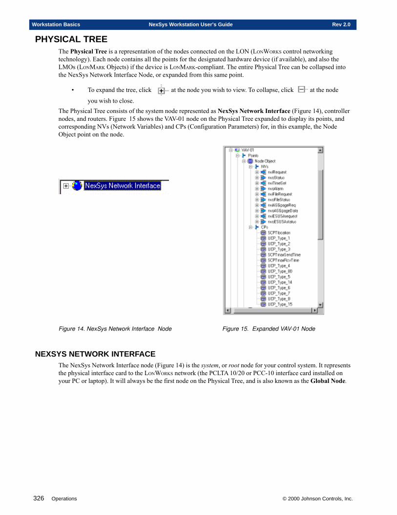
326 Operations © 2000 Johnson Controls, Inc.
Workstation Basics NexSys Workstation User’s Guide Rev 2.0
PHYSICAL TREEThe Physical Tree is a representation of the nodes connected on the LON (LONWORKS control networkingtechnology). Each node contains all the points for the designated hardware device (if available), and also theLMOs (LONMARK Objects) if the device is LONMARK-compliant. The entire Physical Tree can be collapsed intothe NexSys Network Interface Node, or expanded from this same point.
• To expand the tree, click at the node you wish to view. To collapse, click at the node
you wish to close.The Physical Tree consists of the system node represented as NexSys Network Interface (Figure 14), controllernodes, and routers. Figure 15 shows the VAV-01 node on the Physical Tree expanded to display its points, andcorresponding NVs (Network Variables) and CPs (Configuration Parameters) for, in this example, the NodeObject point on the node.
Figure 14. NexSys Network Interface Node Figure 15. Expanded VAV-01 Node
NEXSYS NETWORK INTERFACEThe NexSys Network Interface node (Figure 14) is the system, or root node for your control system. It representsthe physical interface card to the LONWORKS network (the PCLTA 10/20 or PCC-10 interface card installed onyour PC or laptop). It will always be the first node on the Physical Tree, and is also known as the Global Node.
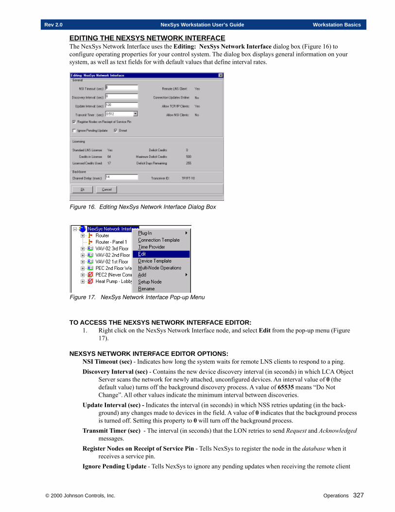
© 2000 Johnson Controls, Inc. Operations 327
Rev 2.0 NexSys Workstation User’s Guide Workstation Basics
EDITING THE NEXSYS NETWORK INTERFACEThe NexSys Network Interface uses the Editing: NexSys Network Interface dialog box (Figure 16) toconfigure operating properties for your control system. The dialog box displays general information on yoursystem, as well as text fields for with default values that define interval rates.
Figure 16. Editing NexSys Network Interface Dialog Box
Figure 17. NexSys Network Interface Pop-up Menu
TO ACCESS THE NEXSYS NETWORK INTERFACE EDITOR:1. Right click on the NexSys Network Interface node, and select Edit from the pop-up menu (Figure
17).
NEXSYS NETWORK INTERFACE EDITOR OPTIONS:NSI Timeout (sec) - Indicates how long the system waits for remote LNS clients to respond to a ping.Discovery Interval (sec) - Contains the new device discovery interval (in seconds) in which LCA Object
Server scans the network for newly attached, unconfigured devices. An interval value of 0 (thedefault value) turns off the background discovery process. A value of 65535 means “Do NotChange”. All other values indicate the minimum interval between discoveries.
Update Interval (sec) - Indicates the interval (in seconds) in which NSS retries updating (in the back-ground) any changes made to devices in the field. A value of 0 indicates that the background processis turned off. Setting this property to 0 will turn off the background process.
Transmit Timer (sec) - The interval (in seconds) that the LON retries to send Request and Acknowledgedmessages.
Register Nodes on Receipt of Service Pin - Tells NexSys to register the node in the database when itreceives a service pin.
Ignore Pending Update - Tells NexSys to ignore any pending updates when receiving the remote client
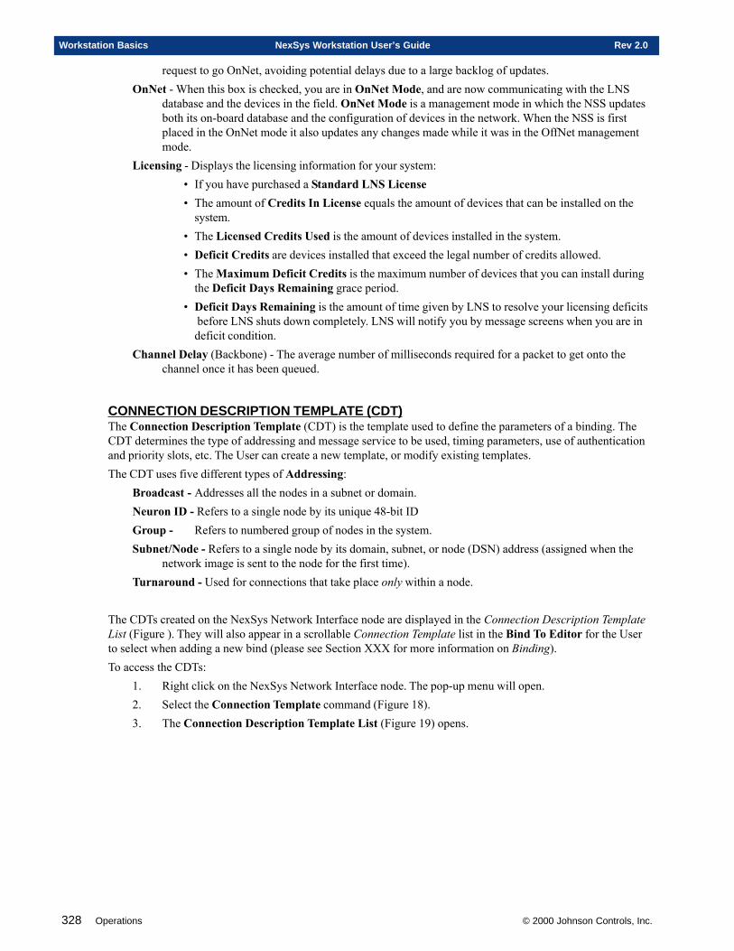
328 Operations © 2000 Johnson Controls, Inc.
Workstation Basics NexSys Workstation User’s Guide Rev 2.0
request to go OnNet, avoiding potential delays due to a large backlog of updates.OnNet - When this box is checked, you are in OnNet Mode, and are now communicating with the LNS
database and the devices in the field. OnNet Mode is a management mode in which the NSS updatesboth its on-board database and the configuration of devices in the network. When the NSS is firstplaced in the OnNet mode it also updates any changes made while it was in the OffNet managementmode.
Licensing - Displays the licensing information for your system:• If you have purchased a Standard LNS License• The amount of Credits In License equals the amount of devices that can be installed on the
system.• The Licensed Credits Used is the amount of devices installed in the system.• Deficit Credits are devices installed that exceed the legal number of credits allowed.• The Maximum Deficit Credits is the maximum number of devices that you can install during
the Deficit Days Remaining grace period.• Deficit Days Remaining is the amount of time given by LNS to resolve your licensing deficits
before LNS shuts down completely. LNS will notify you by message screens when you are indeficit condition.
Channel Delay (Backbone) - The average number of milliseconds required for a packet to get onto thechannel once it has been queued.
CONNECTION DESCRIPTION TEMPLATE (CDT)The Connection Description Template (CDT) is the template used to define the parameters of a binding. TheCDT determines the type of addressing and message service to be used, timing parameters, use of authenticationand priority slots, etc. The User can create a new template, or modify existing templates.The CDT uses five different types of Addressing:
Broadcast - Addresses all the nodes in a subnet or domain.Neuron ID - Refers to a single node by its unique 48-bit IDGroup - Refers to numbered group of nodes in the system.Subnet/Node - Refers to a single node by its domain, subnet, or node (DSN) address (assigned when the
network image is sent to the node for the first time).Turnaround - Used for connections that take place only within a node.
The CDTs created on the NexSys Network Interface node are displayed in the Connection Description TemplateList (Figure ). They will also appear in a scrollable Connection Template list in the Bind To Editor for the Userto select when adding a new bind (please see Section XXX for more information on Binding).To access the CDTs:
1. Right click on the NexSys Network Interface node. The pop-up menu will open.2. Select the Connection Template command (Figure 18).3. The Connection Description Template List (Figure 19) opens.
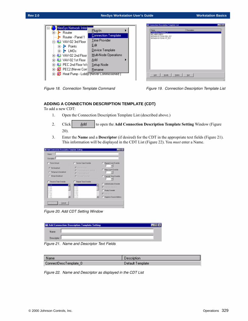
© 2000 Johnson Controls, Inc. Operations 329
Rev 2.0 NexSys Workstation User’s Guide Workstation Basics
Figure 18. Connection Template Command Figure 19. Connection Description Template List
ADDING A CONNECTION DESCRIPTION TEMPLATE (CDT)To add a new CDT:
1. Open the Connection Description Template List (described above.)
2. Click to open the Add Connection Description Template Setting Window (Figure
20).3. Enter the Name and a Descriptor (if desired) for the CDT in the appropriate text fields (Figure 21).
This information will be displayed in the CDT List (Figure 22). You must enter a Name.
Figure 20. Add CDT Setting Window
Figure 21. Name and Descriptor Text Fields
Figure 22. Name and Descriptor as displayed in the CDT List
330 Operations © 2000 Johnson Controls, Inc.
Workstation Basics NexSys Workstation User’s Guide Rev 2.0
4. Enter values for the following parameters:
Addressing:Force Unicast - Forces LNS to use DSN (domain/subnet/node) or NID (Neuron ID) addressing
where it would normally use group (or broadcast) addressing.No broadcast - Tells LNS to fail if there is no other way to address the message besides broadcast.Fail group to broadcast - Tells LNS to use broadcast addressing if it has trouble using group
addressing.Always broadcast - Tells LNS to always use broadcast addressing.
Service TypesService Type Override - Tells LNS that you will choose the service type explicitly rather than
allowing LNS to determine it.Acknowledged - The message is sent out and acknowledged by the receiver (not to be used for large
group bindings causing failure to received Acknowledge messages.Unacknowledged repeated - The message is sent out many times to ensure the probability of it
reaching its destination.Unacknowledged - The message is sent out once.Request Response - Used only for out-and-back messages (e.g.,. NV polls), not used for binds.
Timing ParametersRepeat Count Override - Enter a value for the number of times LNS should repeat an unacknowl-edged-repeated message.Retry Count Override - Enter a value for the number of times LNS should retry an acknowledged
message if it does not receive an acknowledgment in time.Transmit Timer Override - Enter a value for the interval rate LNS waits between retries of
acknowledged and request/response messages.Receive Timer Override - Select a value that tells LNS the time period within which receiving
devices will treat messages from the same source with the same reference ID asduplicate messages. Repeats of messages using the above service types all use thesame reference ID as the original to identify them as duplicates.
Repeat Timer Override - Select a value for the interval LNS waits between repeats for unacknowl-edged-repeated messages.
OtherAuthentication Override - Manually overrides control of the LNS message Authentification option.Use Authentication - Turns the message Authentication option on, telling NexSys to begin sendingand receiving authentification packets for messages on the network.Priority Override - Manually overrides control of the LNS message Priority Override option.Use Priority - Tells LNS that the binding should use a reserved time slot on the network,
helping the message to arrive more quickly to its destination.
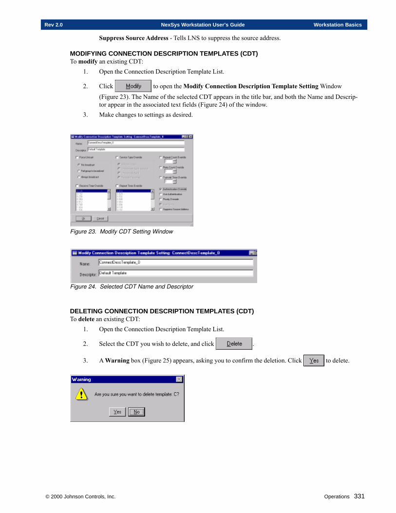
© 2000 Johnson Controls, Inc. Operations 331
Rev 2.0 NexSys Workstation User’s Guide Workstation Basics
Suppress Source Address - Tells LNS to suppress the source address.
MODIFYING CONNECTION DESCRIPTION TEMPLATES (CDT)To modify an existing CDT:
1. Open the Connection Description Template List.
2. Click to open the Modify Connection Description Template Setting Window
(Figure 23). The Name of the selected CDT appears in the title bar, and both the Name and Descrip-tor appear in the associated text fields (Figure 24) of the window.
3. Make changes to settings as desired.
Figure 23. Modify CDT Setting Window
Figure 24. Selected CDT Name and Descriptor
DELETING CONNECTION DESCRIPTION TEMPLATES (CDT)To delete an existing CDT:
1. Open the Connection Description Template List.
2. Select the CDT you wish to delete, and click .
3. A Warning box (Figure 25) appears, asking you to confirm the deletion. Click to delete.
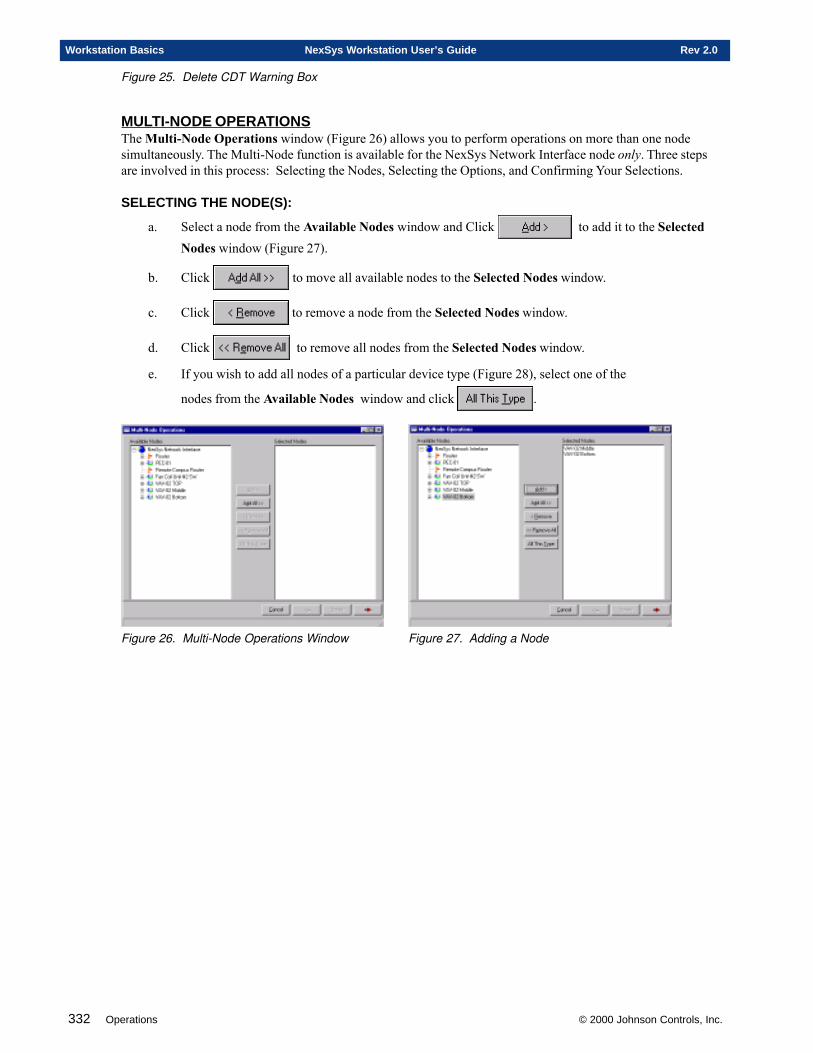
332 Operations © 2000 Johnson Controls, Inc.
Workstation Basics NexSys Workstation User’s Guide Rev 2.0
Figure 25. Delete CDT Warning Box
MULTI-NODE OPERATIONSThe Multi-Node Operations window (Figure 26) allows you to perform operations on more than one nodesimultaneously. The Multi-Node function is available for the NexSys Network Interface node only. Three stepsare involved in this process: Selecting the Nodes, Selecting the Options, and Confirming Your Selections.
SELECTING THE NODE(S):
a. Select a node from the Available Nodes window and Click to add it to the SelectedNodes window (Figure 27).
b. Click to move all available nodes to the Selected Nodes window.
c. Click to remove a node from the Selected Nodes window.
d. Click to remove all nodes from the Selected Nodes window.
e. If you wish to add all nodes of a particular device type (Figure 28), select one of the
nodes from the Available Nodes window and click .
Figure 26. Multi-Node Operations Window Figure 27. Adding a Node
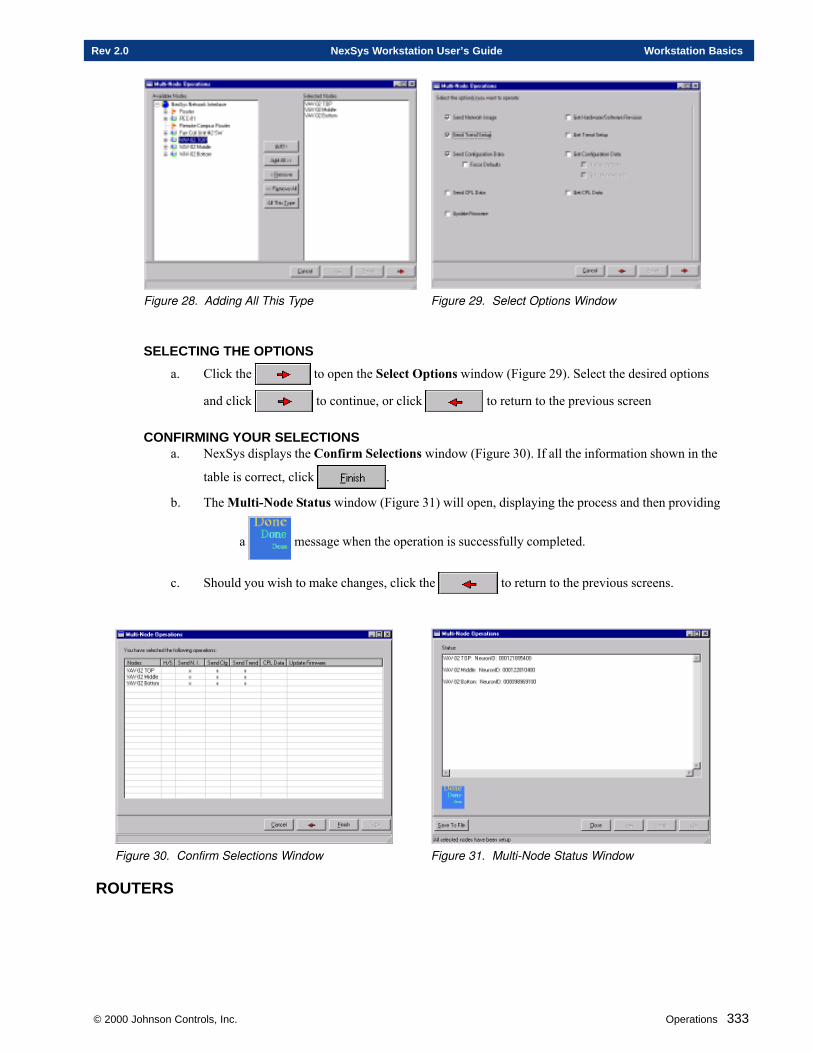
© 2000 Johnson Controls, Inc. Operations 333
Rev 2.0 NexSys Workstation User’s Guide Workstation Basics
Figure 28. Adding All This Type Figure 29. Select Options Window
SELECTING THE OPTIONS
a. Click the to open the Select Options window (Figure 29). Select the desired options
and click to continue, or click to return to the previous screen
CONFIRMING YOUR SELECTIONSa. NexSys displays the Confirm Selections window (Figure 30). If all the information shown in the
table is correct, click .
b. The Multi-Node Status window (Figure 31) will open, displaying the process and then providing
a message when the operation is successfully completed.
c. Should you wish to make changes, click the to return to the previous screens.
Figure 30. Confirm Selections Window Figure 31. Multi-Node Status Window
ROUTERS
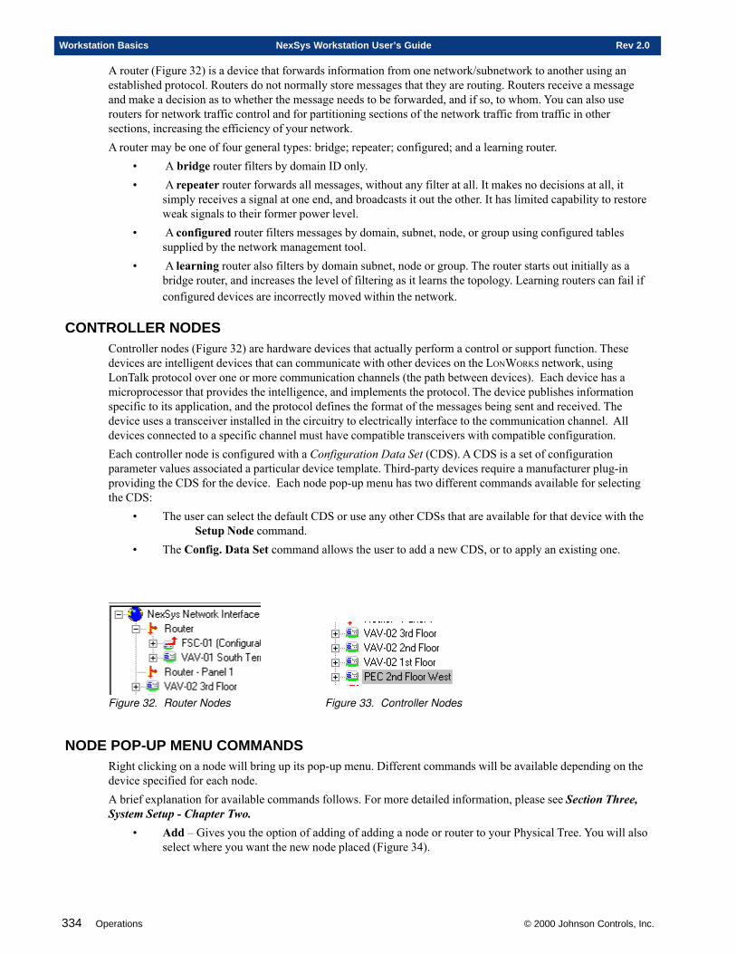
334 Operations © 2000 Johnson Controls, Inc.
Workstation Basics NexSys Workstation User’s Guide Rev 2.0
A router (Figure 32) is a device that forwards information from one network/subnetwork to another using anestablished protocol. Routers do not normally store messages that they are routing. Routers receive a messageand make a decision as to whether the message needs to be forwarded, and if so, to whom. You can also userouters for network traffic control and for partitioning sections of the network traffic from traffic in othersections, increasing the efficiency of your network.A router may be one of four general types: bridge; repeater; configured; and a learning router.
• A bridge router filters by domain ID only.• A repeater router forwards all messages, without any filter at all. It makes no decisions at all, it
simply receives a signal at one end, and broadcasts it out the other. It has limited capability to restoreweak signals to their former power level.
• A configured router filters messages by domain, subnet, node, or group using configured tablessupplied by the network management tool.
• A learning router also filters by domain subnet, node or group. The router starts out initially as abridge router, and increases the level of filtering as it learns the topology. Learning routers can fail ifconfigured devices are incorrectly moved within the network.
CONTROLLER NODESController nodes (Figure 32) are hardware devices that actually perform a control or support function. Thesedevices are intelligent devices that can communicate with other devices on the LONWORKS network, usingLonTalk protocol over one or more communication channels (the path between devices). Each device has amicroprocessor that provides the intelligence, and implements the protocol. The device publishes informationspecific to its application, and the protocol defines the format of the messages being sent and received. Thedevice uses a transceiver installed in the circuitry to electrically interface to the communication channel. Alldevices connected to a specific channel must have compatible transceivers with compatible configuration.Each controller node is configured with a Configuration Data Set (CDS). A CDS is a set of configurationparameter values associated a particular device template. Third-party devices require a manufacturer plug-inproviding the CDS for the device. Each node pop-up menu has two different commands available for selectingthe CDS:
• The user can select the default CDS or use any other CDSs that are available for that device with theSetup Node command.
• The Config. Data Set command allows the user to add a new CDS, or to apply an existing one.
Figure 32. Router Nodes Figure 33. Controller Nodes
NODE POP-UP MENU COMMANDSRight clicking on a node will bring up its pop-up menu. Different commands will be available depending on thedevice specified for each node.A brief explanation for available commands follows. For more detailed information, please see Section Three,System Setup - Chapter Two.
• Add – Gives you the option of adding of adding a node or router to your Physical Tree. You will alsoselect where you want the new node placed (Figure 34).
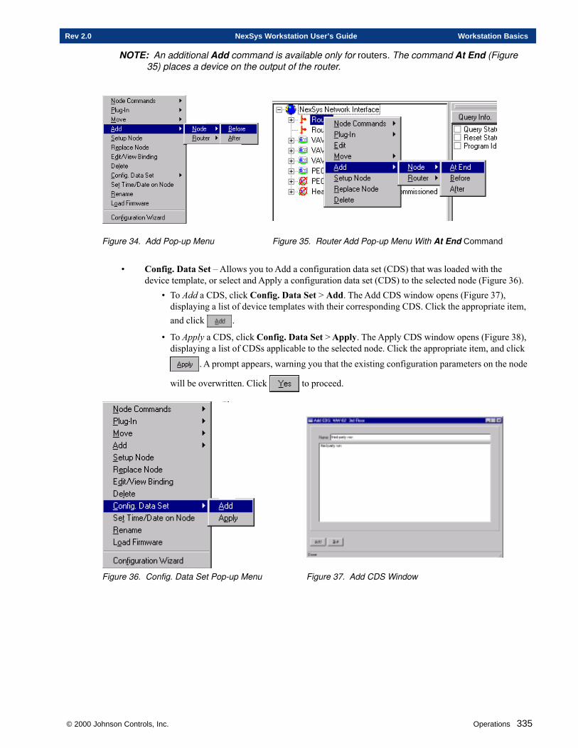
© 2000 Johnson Controls, Inc. Operations 335
Rev 2.0 NexSys Workstation User’s Guide Workstation Basics
NOTE: An additional Add command is available only for routers. The command At End (Figure35) places a device on the output of the router.
Figure 34. Add Pop-up Menu Figure 35. Router Add Pop-up Menu With At End Command
• Config. Data Set – Allows you to Add a configuration data set (CDS) that was loaded with thedevice template, or select and Apply a configuration data set (CDS) to the selected node (Figure 36).
• To Add a CDS, click Config. Data Set > Add. The Add CDS window opens (Figure 37),displaying a list of device templates with their corresponding CDS. Click the appropriate item,and click .
• To Apply a CDS, click Config. Data Set > Apply. The Apply CDS window opens (Figure 38),displaying a list of CDSs applicable to the selected node. Click the appropriate item, and click
. A prompt appears, warning you that the existing configuration parameters on the node
will be overwritten. Click to proceed.
Figure 36. Config. Data Set Pop-up Menu Figure 37. Add CDS Window
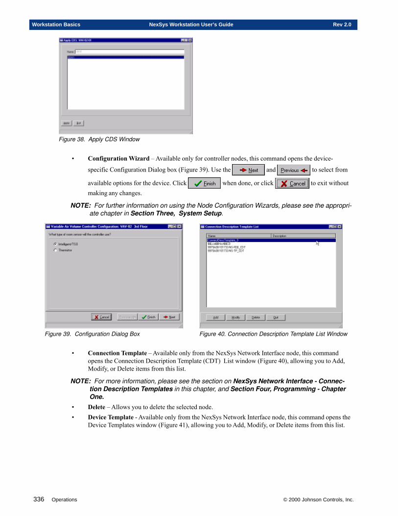
336 Operations © 2000 Johnson Controls, Inc.
Workstation Basics NexSys Workstation User’s Guide Rev 2.0
Figure 38. Apply CDS Window
• Configuration Wizard – Available only for controller nodes, this command opens the device-
specific Configuration Dialog box (Figure 39). Use the and to select from
available options for the device. Click when done, or click to exit withoutmaking any changes.
NOTE: For further information on using the Node Configuration Wizards, please see the appropri-ate chapter in Section Three, System Setup.
Figure 39. Configuration Dialog Box Figure 40. Connection Description Template List Window
• Connection Template – Available only from the NexSys Network Interface node, this commandopens the Connection Description Template (CDT) List window (Figure 40), allowing you to Add,Modify, or Delete items from this list.
NOTE: For more information, please see the section on NexSys Network Interface - Connec-tion Description Templates in this chapter, and Section Four, Programming - ChapterOne.
• Delete – Allows you to delete the selected node.• Device Template - Available only from the NexSys Network Interface node, this command opens the
Device Templates window (Figure 41), allowing you to Add, Modify, or Delete items from this list.
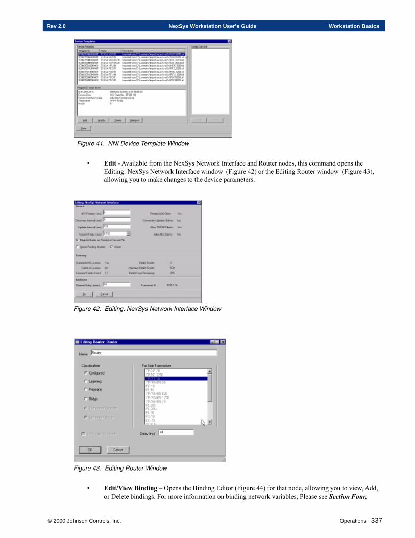
© 2000 Johnson Controls, Inc. Operations 337
Rev 2.0 NexSys Workstation User’s Guide Workstation Basics
Figure 41. NNI Device Template Window
• Edit - Available from the NexSys Network Interface and Router nodes, this command opens theEditing: NexSys Network Interface window (Figure 42) or the Editing Router window (Figure 43),allowing you to make changes to the device parameters.
Figure 42. Editing: NexSys Network Interface Window
Figure 43. Editing Router Window
• Edit/View Binding – Opens the Binding Editor (Figure 44) for that node, allowing you to view, Add,or Delete bindings. For more information on binding network variables, Please see Section Four,
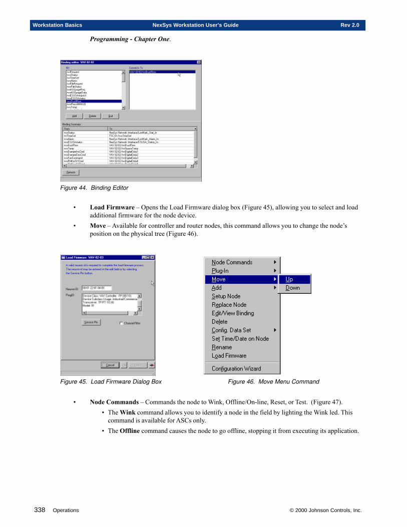
338 Operations © 2000 Johnson Controls, Inc.
Workstation Basics NexSys Workstation User’s Guide Rev 2.0
Programming - Chapter One.
Figure 44. Binding Editor
• Load Firmware – Opens the Load Firmware dialog box (Figure 45), allowing you to select and loadadditional firmware for the node device.
• Move – Available for controller and router nodes, this command allows you to change the node’sposition on the physical tree (Figure 46).
Figure 45. Load Firmware Dialog Box Figure 46. Move Menu Command
• Node Commands – Commands the node to Wink, Offline/On-line, Reset, or Test. (Figure 47).• The Wink command allows you to identify a node in the field by lighting the Wink led. This
command is available for ASCs only.• The Offline command causes the node to go offline, stopping it from executing its application.
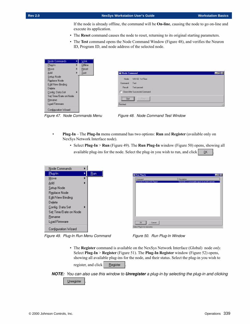
© 2000 Johnson Controls, Inc. Operations 339
Rev 2.0 NexSys Workstation User’s Guide Workstation Basics
If the node is already offline, the command will be On-line, causing the node to go on-line andexecute its application.
• The Reset command causes the node to reset, returning to its original starting parameters.• The Test command opens the Node Command Window (Figure 48), and verifies the Neuron
ID, Program ID, and node address of the selected node.
Figure 47. Node Commands Menu Figure 48. Node Command Test Window
• Plug-In – The Plug-In menu command has two options: Run and Register (available only onNexSys Network Interface node).
• Select Plug-In > Run (Figure 49). The Run Plug-In window (Figure 50) opens, showing allavailable plug-ins for the node. Select the plug-in you wish to run, and click .
Figure 49. Plug-In Run Menu Command Figure 50. Run Plug-In Window
• The Register command is available on the NexSys Network Interface (Global) node only.Select Plug-In > Register (Figure 51). The Plug-In Register window (Figure 52) opens,showing all available plug-ins for the node, and their status. Select the plug-in you wish to
register, and click .
NOTE: You can also use this window to Unregister a plug-in by selecting the plug-in and clicking
.
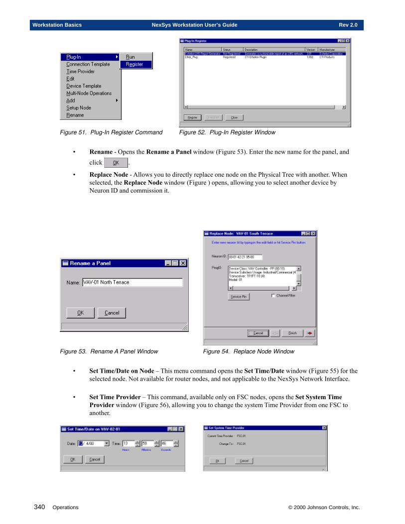
340 Operations © 2000 Johnson Controls, Inc.
Workstation Basics NexSys Workstation User’s Guide Rev 2.0
Figure 51. Plug-In Register Command Figure 52. Plug-In Register Window
• Rename - Opens the Rename a Panel window (Figure 53). Enter the new name for the panel, andclick .
• Replace Node - Allows you to directly replace one node on the Physical Tree with another. Whenselected, the Replace Node window (Figure ) opens, allowing you to select another device byNeuron ID and commission it.
Figure 53. Rename A Panel Window Figure 54. Replace Node Window
• Set Time/Date on Node – This menu command opens the Set Time/Date window (Figure 55) for theselected node. Not available for router nodes, and not applicable to the NexSys Network Interface.
• Set Time Provider – This command, available only on FSC nodes, opens the Set System TimeProvider window (Figure 56), allowing you to change the system Time Provider from one FSC toanother.
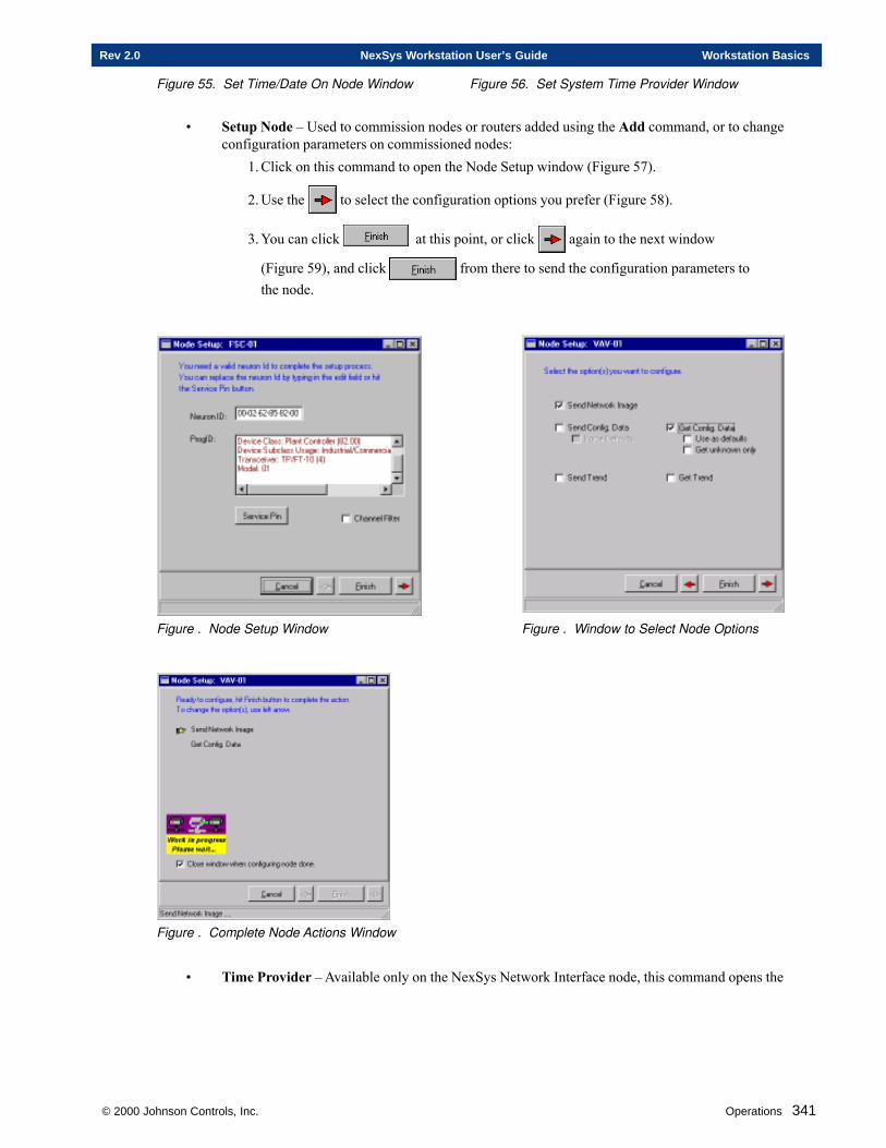
© 2000 Johnson Controls, Inc. Operations 341
Rev 2.0 NexSys Workstation User’s Guide Workstation Basics
Figure 55. Set Time/Date On Node Window Figure 56. Set System Time Provider Window
• Setup Node – Used to commission nodes or routers added using the Add command, or to changeconfiguration parameters on commissioned nodes:
1. Click on this command to open the Node Setup window (Figure 57).
2. Use the to select the configuration options you prefer (Figure 58).
3. You can click at this point, or click again to the next window
(Figure 59), and click from there to send the configuration parameters tothe node.
Figure . Node Setup Window Figure . Window to Select Node Options
Figure . Complete Node Actions Window
• Time Provider – Available only on the NexSys Network Interface node, this command opens the
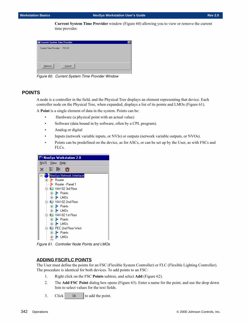
342 Operations © 2000 Johnson Controls, Inc.
Workstation Basics NexSys Workstation User’s Guide Rev 2.0
Current System Time Provider window (Figure 60) allowing you to view or remove the currenttime provider.
Figure 60. Current System Time Provider Window
POINTSA node is a controller in the field, and the Physical Tree displays an element representing that device. Eachcontroller node on the Physical Tree, when expanded, displays a list of its points and LMOs (Figure 61).A Point is a single element of data in the system. Points can be:
• Hardware (a physical point with an actual value)• Software (data bound in by software, often by a CPL program).• Analog or digital• Inputs (network variable inputs, or NVIs) or outputs (network variable outputs, or NVOs).• Points can be predefined on the device, as for ASCs, or can be set up by the User, as with FSCs and
FLCs.
Figure 61. Controller Node Points and LMOs
ADDING FSC/FLC POINTSThe User must define the points for an FSC (Flexible System Controller) or FLC (Flexible Lighting Controller).The procedure is identical for both devices. To add points to an FSC:
1. Right click on the FSC Points subtree, and select Add (Figure 62).2. The Add FSC Point dialog box opens (Figure 63). Enter a name for the point, and use the drop down
lists to select values for the text fields.
3. Click to add the point.
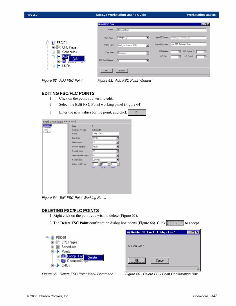
© 2000 Johnson Controls, Inc. Operations 343
Rev 2.0 NexSys Workstation User’s Guide Workstation Basics
Figure 62. Add FSC Point Figure 63. Add FSC Point Window
EDITING FSC/FLC POINTS1. Click on the point you wish to edit.2. Select the Edit FSC Point working panel (Figure 64).
3. Enter the new values for the point, and click .
Figure 64. Edit FSC Point Working Panel
DELETING FSC/FLC POINTS1. Right click on the point you wish to delete (Figure 65).
2. The Delete FSC Point confirmation dialog box opens (Figure 66). Click to accept.
Figure 65. Delete FSC Point Menu Command Figure 66. Delete FSC Point Confirmation Box
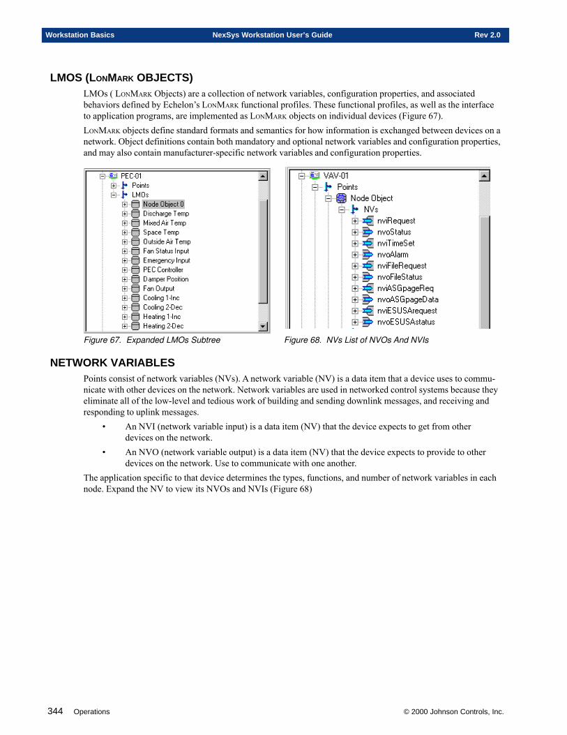
344 Operations © 2000 Johnson Controls, Inc.
Workstation Basics NexSys Workstation User’s Guide Rev 2.0
LMOS (LONMARK OBJECTS)LMOs ( LONMARK Objects) are a collection of network variables, configuration properties, and associatedbehaviors defined by Echelon’s LONMARK functional profiles. These functional profiles, as well as the interfaceto application programs, are implemented as LONMARK objects on individual devices (Figure 67).LONMARK objects define standard formats and semantics for how information is exchanged between devices on anetwork. Object definitions contain both mandatory and optional network variables and configuration properties,and may also contain manufacturer-specific network variables and configuration properties.
Figure 67. Expanded LMOs Subtree Figure 68. NVs List of NVOs And NVIs
NETWORK VARIABLESPoints consist of network variables (NVs). A network variable (NV) is a data item that a device uses to commu-nicate with other devices on the network. Network variables are used in networked control systems because theyeliminate all of the low-level and tedious work of building and sending downlink messages, and receiving andresponding to uplink messages.
• An NVI (network variable input) is a data item (NV) that the device expects to get from otherdevices on the network.
• An NVO (network variable output) is a data item (NV) that the device expects to provide to otherdevices on the network. Use to communicate with one another.
The application specific to that device determines the types, functions, and number of network variables in eachnode. Expand the NV to view its NVOs and NVIs (Figure 68)
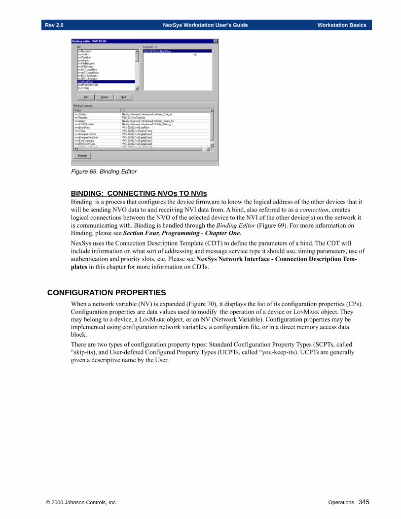
© 2000 Johnson Controls, Inc. Operations 345
Rev 2.0 NexSys Workstation User’s Guide Workstation Basics
Figure 69. Binding Editor
BINDING: CONNECTING NVOs TO NVIsBinding is a process that configures the device firmware to know the logical address of the other devices that itwill be sending NVO data to and receiving NVI data from. A bind, also referred to as a connection, createslogical connections between the NVO of the selected device to the NVI of the other device(s) on the network itis communicating with. Binding is handled through the Binding Editor (Figure 69). For more information onBinding, please see Section Four, Programming - Chapter One.NexSys uses the Connection Description Template (CDT) to define the parameters of a bind. The CDT willinclude information on what sort of addressing and message service type it should use, timing parameters, use ofauthentication and priority slots, etc. Please see NexSys Network Interface - Connection Description Tem-plates in this chapter for more information on CDTs.
CONFIGURATION PROPERTIESWhen a network variable (NV) is expanded (Figure 70), it displays the list of its configuration properties (CPs).Configuration properties are data values used to modify the operation of a device or LONMARK object. Theymay belong to a device, a LONMARK object, or an NV (Network Variable). Configuration properties may beimplemented using configuration network variables, a configuration file, or in a direct memory access datablock.There are two types of configuration property types: Standard Configuration Property Types (SCPTs, called“skip-its), and User-defined Configured Property Types (UCPTs, called “you-keep-its). UCPTs are generallygiven a descriptive name by the User.
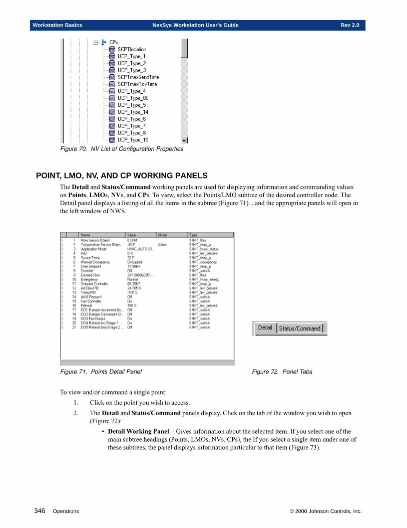
346 Operations © 2000 Johnson Controls, Inc.
Workstation Basics NexSys Workstation User’s Guide Rev 2.0
Figure 70. NV List of Configuration Properties
POINT, LMO, NV, AND CP WORKING PANELSThe Detail and Status/Command working panels are used for displaying information and commanding valueson Points, LMOs, NVs, and CPs. To view, select the Points/LMO subtree of the desired controller node. TheDetail panel displays a listing of all the items in the subtree (Figure 71). , and the appropriate panels will open inthe left window of NWS.
Figure 71. Points Detail Panel Figure 72. Panel Tabs
To view and/or command a single point:1. Click on the point you wish to access.2. The Detail and Status/Command panels display. Click on the tab of the window you wish to open
(Figure 72):• Detail Working Panel - Gives information about the selected item. If you select one of the
main subtree headings (Points, LMOs, NVs, CPs), the If you select a single item under one ofthese subtrees, the panel displays information particular to that item (Figure 73).
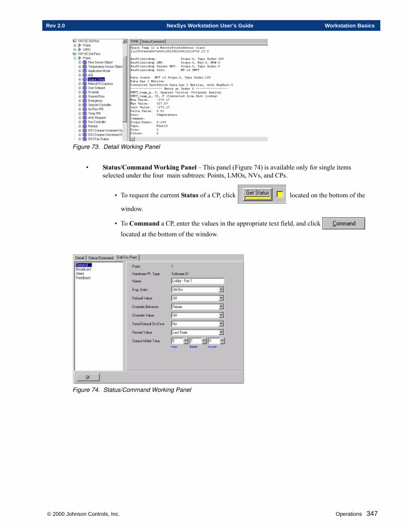
© 2000 Johnson Controls, Inc. Operations 347
Rev 2.0 NexSys Workstation User’s Guide Workstation Basics
Figure 73. Detail Working Panel
• Status/Command Working Panel – This panel (Figure 74) is available only for single itemsselected under the four main subtrees: Points, LMOs, NVs, and CPs.
• To request the current Status of a CP, click located on the bottom of the
window.
• To Command a CP, enter the values in the appropriate text field, and click located at the bottom of the window.
Figure 74. Status/Command Working Panel
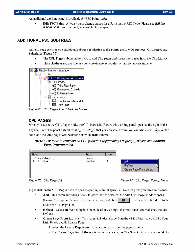
348 Operations © 2000 Johnson Controls, Inc.
Workstation Basics NexSys Workstation User’s Guide Rev 2.0
An additional working panel is available for FSC Points only:• Edit FSC Point - Allows you to change values for a Point on the FSC Node. Please see Editing
FSC/FLC Points previously covered in this chapter.
ADDITIONAL FSC SUBTREES
An FSC node contains two additional subtrees in addition to the Points and LMOs subtrees; CPL Pages andSchedules (Figure 75):
• The CPL Pages subtree allows you to add CPL pages and create new pages from the CPL Library.• The Schedules subtree allows you to create new schedules, or modify an existing one.
Figure 75. CPL Pages And Schedules Nodes
CPL PAGESWhen you select the CPL Pages node, the CPL Page List (Figure 76) working panel opens to the right of the
Physical Tree. The panel lists all existing CPL Pages that you can select from. You can also click on thenode, and the same pages will be listed below the main subtree.
NOTE: For more information on CPL (Control Programming Language), please see SectionFour, Programming.
Figure 76. CPL Page List Figure 77. CPL Pages Pop-up Menu
Right click on the CPL Pages node to open the pop-up menu (Figure 77). NexSys gives you three commands:• Add –This command adds a new CPL page. When selected, the Add CPL Page window opens
(Figure 78). Type in the name of your new page, and click . The page will be added to thenode and CPL Page List.
• Refresh - Select Refresh to update the node of any changes that may have occurred since the lastRefresh.
• Create Page From Library - This command adds a page from the CPL Library to your CPL PageList. To add a CPL Library Page:
1. Select the Create Page from Library command from the pop-up menu.2. The Create Page from Library Window opens (Figure 79). Select the page you would like
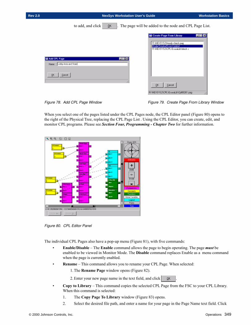
© 2000 Johnson Controls, Inc. Operations 349
Rev 2.0 NexSys Workstation User’s Guide Workstation Basics
to add, and click . The page will be added to the node and CPL Page List.
Figure 78. Add CPL Page Window Figure 79. Create Page From Library Window
When you select one of the pages listed under the CPL Pages node, the CPL Editor panel (Figure 80) opens tothe right of the Physical Tree, replacing the CPL Page List . Using the CPL Editor, you can create, edit, andmonitor CPL programs. Please see Section Four, Programming - Chapter Two for further information.
Figure 80. CPL Editor Panel
The individual CPL Pages also have a pop-up menu (Figure 81), with five commands:• Enable/Disable – The Enable command allows the page to begin operating. The page must be
enabled to be viewed in Monitor Mode. The Disable command replaces Enable as a menu commandwhen the page is currently enabled.
• Rename – This command allows you to rename your CPL Page. When selected:1. The Rename Page window opens (Figure 82).
2. Enter your new page name in the text field, and click .
• Copy to Library – This command copies the selected CPL Page from the FSC to your CPL Library.When this command is selected:1. The Copy Page To Library window (Figure 83) opens.2. Select the desired file path, and enter a name for your page in the Page Name text field. Click
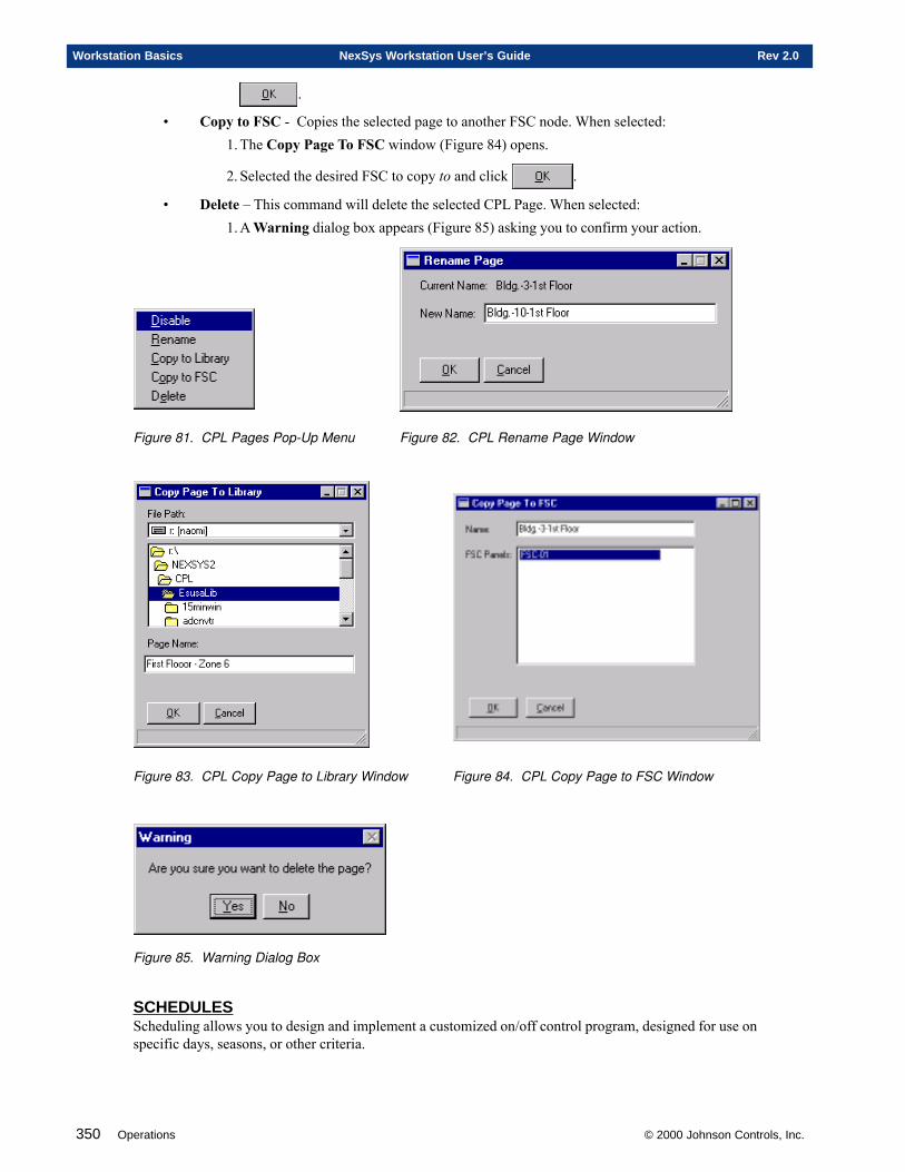
350 Operations © 2000 Johnson Controls, Inc.
Workstation Basics NexSys Workstation User’s Guide Rev 2.0
.
• Copy to FSC - Copies the selected page to another FSC node. When selected:1. The Copy Page To FSC window (Figure 84) opens.
2. Selected the desired FSC to copy to and click .
• Delete – This command will delete the selected CPL Page. When selected:1. A Warning dialog box appears (Figure 85) asking you to confirm your action.
Figure 81. CPL Pages Pop-Up Menu Figure 82. CPL Rename Page Window
Figure 83. CPL Copy Page to Library Window Figure 84. CPL Copy Page to FSC Window
Figure 85. Warning Dialog Box
SCHEDULESScheduling allows you to design and implement a customized on/off control program, designed for use onspecific days, seasons, or other criteria.
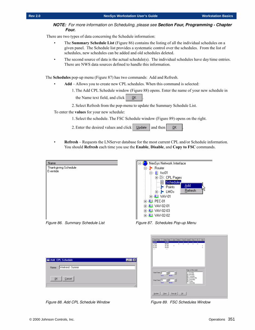
© 2000 Johnson Controls, Inc. Operations 351
Rev 2.0 NexSys Workstation User’s Guide Workstation Basics
NOTE: For more information on Scheduling, please see Section Four, Programming - ChapterFour.
There are two types of data concerning the Schedule information:• The Summary Schedule List (Figure 86) contains the listing of all the individual schedules on a
given panel. The Schedule list provides a systematic control over the schedules. From the list ofschedules, new schedules can be added and old schedules deleted.
• The second source of data is the actual schedule(s). The individual schedules have day/time entries.There are NWS data sources defined to handle this information.
The Schedules pop-up menu (Figure 87) has two commands: Add and Refresh.• Add – Allows you to create new CPL schedules. When this command is selected:
1. The Add CPL Schedule window (Figure 88) opens. Enter the name of your new schedule in
the Name text field, and click .
2. Select Refresh from the pop-menu to update the Summary Schedule List.To enter the values for your new schedule:
1. Select the schedule. The FSC Schedule window (Figure 89) opens on the right.
2. Enter the desired values and click and then .
• Refresh – Requests the LNServer database for the most current CPL and/or Schedule information.You should Refresh each time you use the Enable, Disable, and Copy to FSC commands.
Figure 86. Summary Schedule List Figure 87. Schedules Pop-up Menu
Figure 88. Add CPL Schedule Window Figure 89. FSC Schedules Window
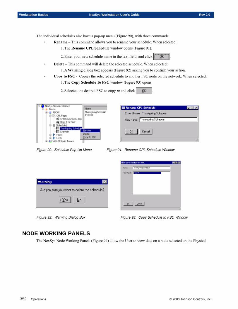
352 Operations © 2000 Johnson Controls, Inc.
Workstation Basics NexSys Workstation User’s Guide Rev 2.0
The individual schedules also have a pop-up menu (Figure 90), with three commands:• Rename – This command allows you to rename your schedule. When selected:
1. The Rename CPL Schedule window opens (Figure 91).
2. Enter your new schedule name in the text field, and click .
• Delete – This command will delete the selected schedule. When selected:1. A Warning dialog box appears (Figure 92) asking you to confirm your action.
• Copy to FSC - Copies the selected schedule to another FSC node on the network. When selected:1. The Copy Schedule To FSC window (Figure 93) opens.
2. Selected the desired FSC to copy to and click .
Figure 90. Schedule Pop-Up Menu Figure 91. Rename CPL Schedule Window
Figure 92. Warning Dialog Box Figure 93. Copy Schedule to FSC Window
NODE WORKING PANELSThe NexSys Node Working Panels (Figure 94) allow the User to view data on a node selected on the Physical
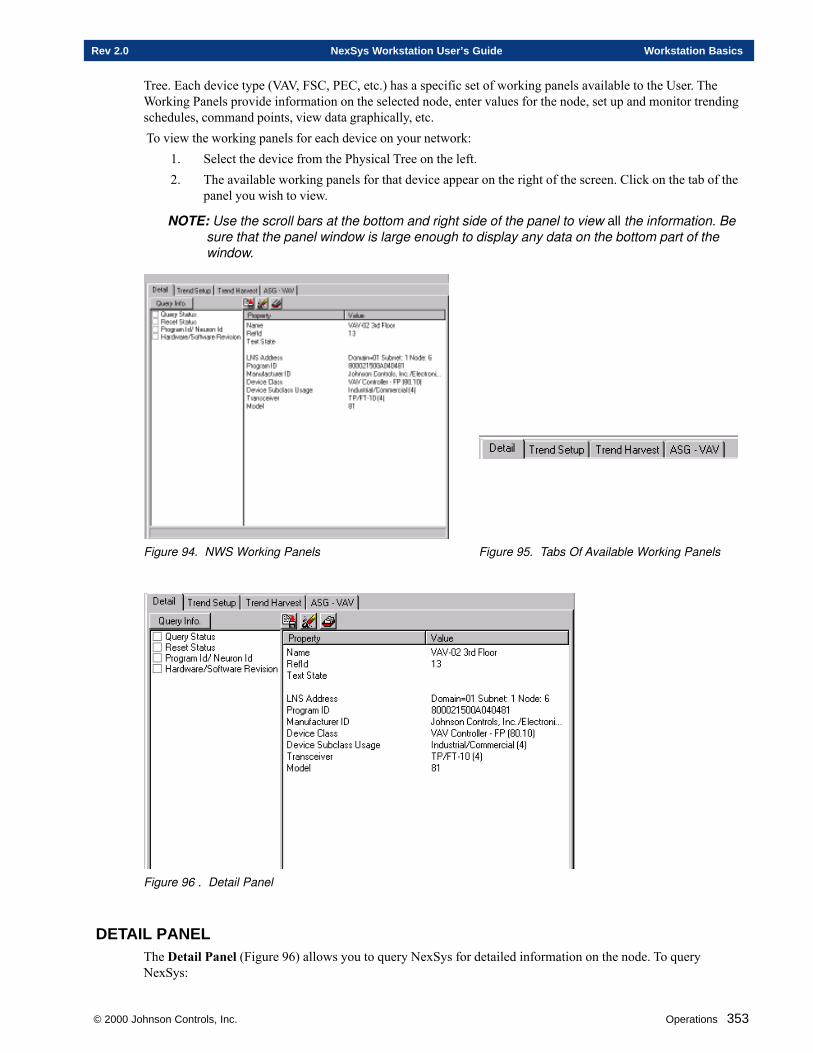
© 2000 Johnson Controls, Inc. Operations 353
Rev 2.0 NexSys Workstation User’s Guide Workstation Basics
Tree. Each device type (VAV, FSC, PEC, etc.) has a specific set of working panels available to the User. TheWorking Panels provide information on the selected node, enter values for the node, set up and monitor trendingschedules, command points, view data graphically, etc. To view the working panels for each device on your network:
1. Select the device from the Physical Tree on the left.2. The available working panels for that device appear on the right of the screen. Click on the tab of the
panel you wish to view.
NOTE: Use the scroll bars at the bottom and right side of the panel to view all the information. Besure that the panel window is large enough to display any data on the bottom part of thewindow.
Figure 94. NWS Working Panels Figure 95. Tabs Of Available Working Panels
Figure 96 . Detail Panel
DETAIL PANELThe Detail Panel (Figure 96) allows you to query NexSys for detailed information on the node. To queryNexSys:
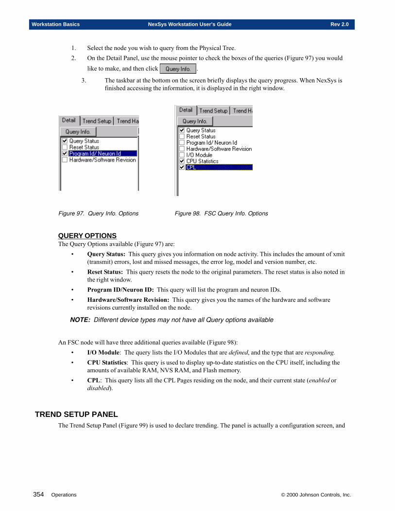
354 Operations © 2000 Johnson Controls, Inc.
Workstation Basics NexSys Workstation User’s Guide Rev 2.0
1. Select the node you wish to query from the Physical Tree.2. On the Detail Panel, use the mouse pointer to check the boxes of the queries (Figure 97) you would
like to make, and then click .
3. The taskbar at the bottom on the screen briefly displays the query progress. When NexSys isfinished accessing the information, it is displayed in the right window.
Figure 97. Query Info. Options Figure 98. FSC Query Info. Options
QUERY OPTIONSThe Query Options available (Figure 97) are:
• Query Status: This query gives you information on node activity. This includes the amount of xmit(transmit) errors, lost and missed messages, the error log, model and version number, etc.
• Reset Status: This query resets the node to the original parameters. The reset status is also noted inthe right window.
• Program ID/Neuron ID: This query will list the program and neuron IDs.• Hardware/Software Revision: This query gives you the names of the hardware and software
revisions currently installed on the node.
NOTE: Different device types may not have all Query options available
An FSC node will have three additional queries available (Figure 98):• I/O Module: The query lists the I/O Modules that are defined, and the type that are responding.• CPU Statistics: This query is used to display up-to-date statistics on the CPU itself, including the
amounts of available RAM, NVS RAM, and Flash memory.• CPL: This query lists all the CPL Pages residing on the node, and their current state (enabled or
disabled).
TREND SETUP PANELThe Trend Setup Panel (Figure 99) is used to declare trending. The panel is actually a configuration screen, and
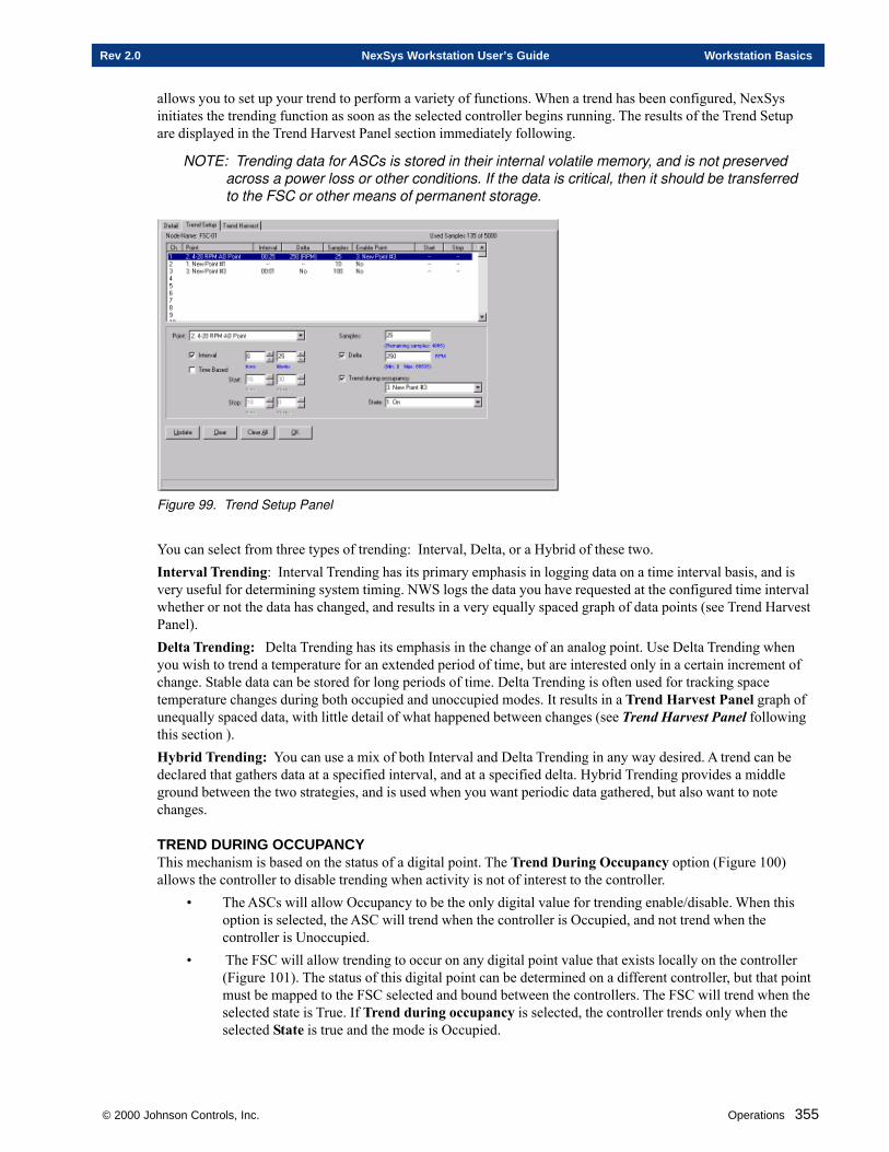
© 2000 Johnson Controls, Inc. Operations 355
Rev 2.0 NexSys Workstation User’s Guide Workstation Basics
allows you to set up your trend to perform a variety of functions. When a trend has been configured, NexSysinitiates the trending function as soon as the selected controller begins running. The results of the Trend Setupare displayed in the Trend Harvest Panel section immediately following.
NOTE: Trending data for ASCs is stored in their internal volatile memory, and is not preservedacross a power loss or other conditions. If the data is critical, then it should be transferredto the FSC or other means of permanent storage.
Figure 99. Trend Setup Panel
You can select from three types of trending: Interval, Delta, or a Hybrid of these two.Interval Trending: Interval Trending has its primary emphasis in logging data on a time interval basis, and isvery useful for determining system timing. NWS logs the data you have requested at the configured time intervalwhether or not the data has changed, and results in a very equally spaced graph of data points (see Trend HarvestPanel).Delta Trending: Delta Trending has its emphasis in the change of an analog point. Use Delta Trending whenyou wish to trend a temperature for an extended period of time, but are interested only in a certain increment ofchange. Stable data can be stored for long periods of time. Delta Trending is often used for tracking spacetemperature changes during both occupied and unoccupied modes. It results in a Trend Harvest Panel graph ofunequally spaced data, with little detail of what happened between changes (see Trend Harvest Panel followingthis section ).Hybrid Trending: You can use a mix of both Interval and Delta Trending in any way desired. A trend can bedeclared that gathers data at a specified interval, and at a specified delta. Hybrid Trending provides a middleground between the two strategies, and is used when you want periodic data gathered, but also want to notechanges.
TREND DURING OCCUPANCYThis mechanism is based on the status of a digital point. The Trend During Occupancy option (Figure 100)allows the controller to disable trending when activity is not of interest to the controller.
• The ASCs will allow Occupancy to be the only digital value for trending enable/disable. When thisoption is selected, the ASC will trend when the controller is Occupied, and not trend when thecontroller is Unoccupied.
• The FSC will allow trending to occur on any digital point value that exists locally on the controller(Figure 101). The status of this digital point can be determined on a different controller, but that pointmust be mapped to the FSC selected and bound between the controllers. The FSC will trend when theselected state is True. If Trend during occupancy is selected, the controller trends only when theselected State is true and the mode is Occupied.
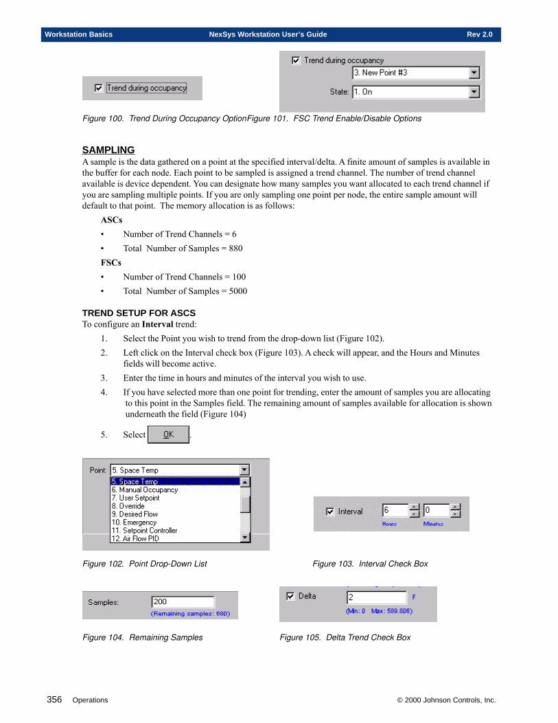
356 Operations © 2000 Johnson Controls, Inc.
Workstation Basics NexSys Workstation User’s Guide Rev 2.0
Figure 100. Trend During Occupancy OptionFigure 101. FSC Trend Enable/Disable Options
SAMPLINGA sample is the data gathered on a point at the specified interval/delta. A finite amount of samples is available inthe buffer for each node. Each point to be sampled is assigned a trend channel. The number of trend channelavailable is device dependent. You can designate how many samples you want allocated to each trend channel ifyou are sampling multiple points. If you are only sampling one point per node, the entire sample amount willdefault to that point. The memory allocation is as follows:
ASCs• Number of Trend Channels = 6• Total Number of Samples = 880FSCs• Number of Trend Channels = 100• Total Number of Samples = 5000
TREND SETUP FOR ASCSTo configure an Interval trend:
1. Select the Point you wish to trend from the drop-down list (Figure 102).2. Left click on the Interval check box (Figure 103). A check will appear, and the Hours and Minutes
fields will become active.3. Enter the time in hours and minutes of the interval you wish to use.4. If you have selected more than one point for trending, enter the amount of samples you are allocating
to this point in the Samples field. The remaining amount of samples available for allocation is shown underneath the field (Figure 104)
5. Select .
Figure 102. Point Drop-Down List Figure 103. Interval Check Box
Figure 104. Remaining Samples Figure 105. Delta Trend Check Box
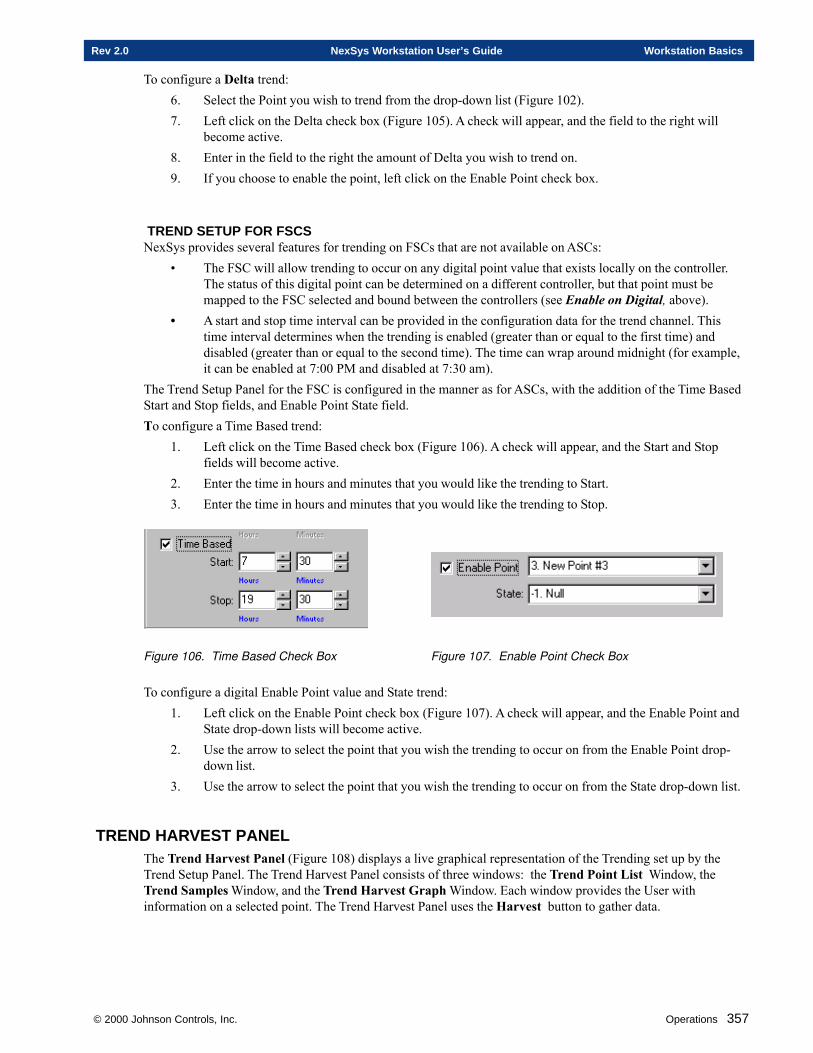
© 2000 Johnson Controls, Inc. Operations 357
Rev 2.0 NexSys Workstation User’s Guide Workstation Basics
To configure a Delta trend:6. Select the Point you wish to trend from the drop-down list (Figure 102).7. Left click on the Delta check box (Figure 105). A check will appear, and the field to the right will
become active.8. Enter in the field to the right the amount of Delta you wish to trend on.9. If you choose to enable the point, left click on the Enable Point check box.
TREND SETUP FOR FSCSNexSys provides several features for trending on FSCs that are not available on ASCs:
• The FSC will allow trending to occur on any digital point value that exists locally on the controller.The status of this digital point can be determined on a different controller, but that point must bemapped to the FSC selected and bound between the controllers (see Enable on Digital, above).
• A start and stop time interval can be provided in the configuration data for the trend channel. Thistime interval determines when the trending is enabled (greater than or equal to the first time) anddisabled (greater than or equal to the second time). The time can wrap around midnight (for example,it can be enabled at 7:00 PM and disabled at 7:30 am).
The Trend Setup Panel for the FSC is configured in the manner as for ASCs, with the addition of the Time BasedStart and Stop fields, and Enable Point State field.To configure a Time Based trend:
1. Left click on the Time Based check box (Figure 106). A check will appear, and the Start and Stopfields will become active.
2. Enter the time in hours and minutes that you would like the trending to Start.3. Enter the time in hours and minutes that you would like the trending to Stop.
Figure 106. Time Based Check Box Figure 107. Enable Point Check Box
To configure a digital Enable Point value and State trend:1. Left click on the Enable Point check box (Figure 107). A check will appear, and the Enable Point and
State drop-down lists will become active.2. Use the arrow to select the point that you wish the trending to occur on from the Enable Point drop-
down list.3. Use the arrow to select the point that you wish the trending to occur on from the State drop-down list.
TREND HARVEST PANELThe Trend Harvest Panel (Figure 108) displays a live graphical representation of the Trending set up by theTrend Setup Panel. The Trend Harvest Panel consists of three windows: the Trend Point List Window, theTrend Samples Window, and the Trend Harvest Graph Window. Each window provides the User withinformation on a selected point. The Trend Harvest Panel uses the Harvest button to gather data.
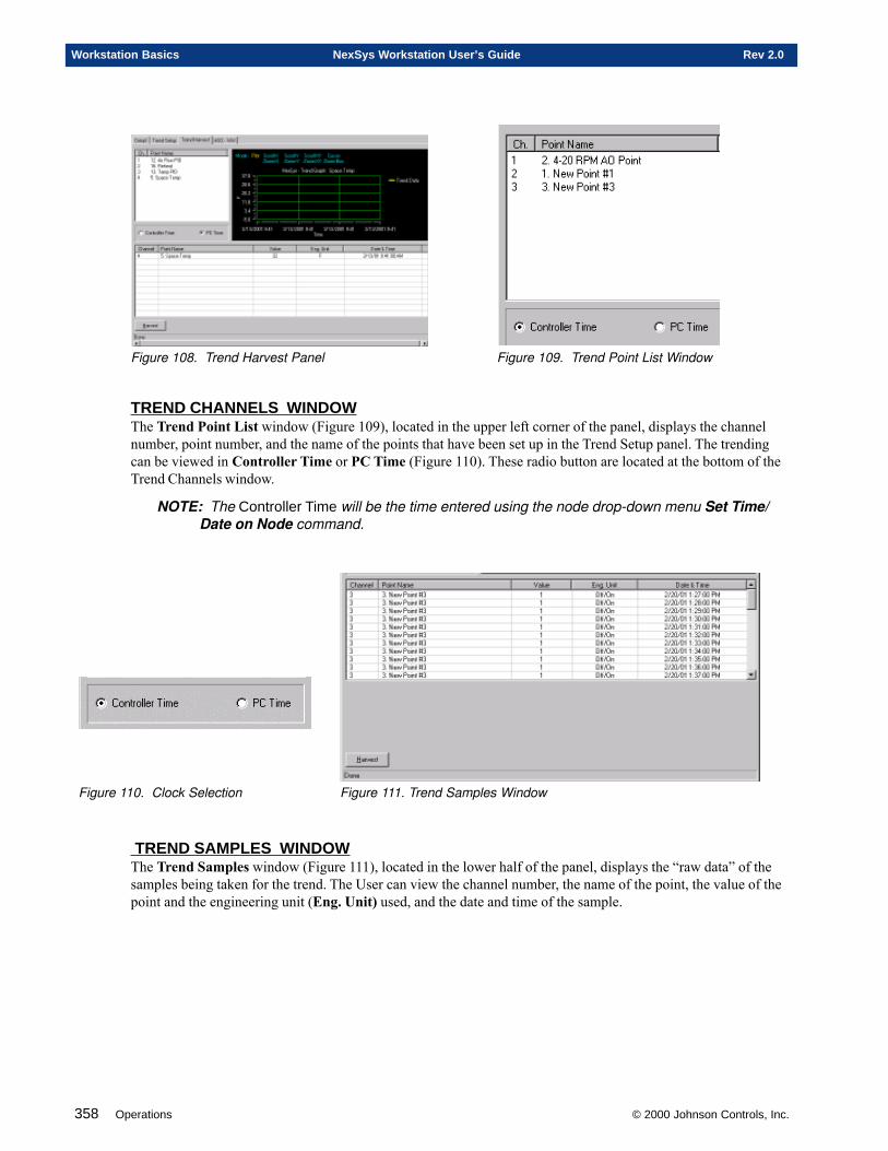
358 Operations © 2000 Johnson Controls, Inc.
Workstation Basics NexSys Workstation User’s Guide Rev 2.0
Figure 108. Trend Harvest Panel Figure 109. Trend Point List Window
TREND CHANNELS WINDOWThe Trend Point List window (Figure 109), located in the upper left corner of the panel, displays the channelnumber, point number, and the name of the points that have been set up in the Trend Setup panel. The trendingcan be viewed in Controller Time or PC Time (Figure 110). These radio button are located at the bottom of theTrend Channels window.
NOTE: The Controller Time will be the time entered using the node drop-down menu Set Time/Date on Node command.
Figure 110. Clock Selection Figure 111. Trend Samples Window
TREND SAMPLES WINDOWThe Trend Samples window (Figure 111), located in the lower half of the panel, displays the “raw data” of thesamples being taken for the trend. The User can view the channel number, the name of the point, the value of thepoint and the engineering unit (Eng. Unit) used, and the date and time of the sample.
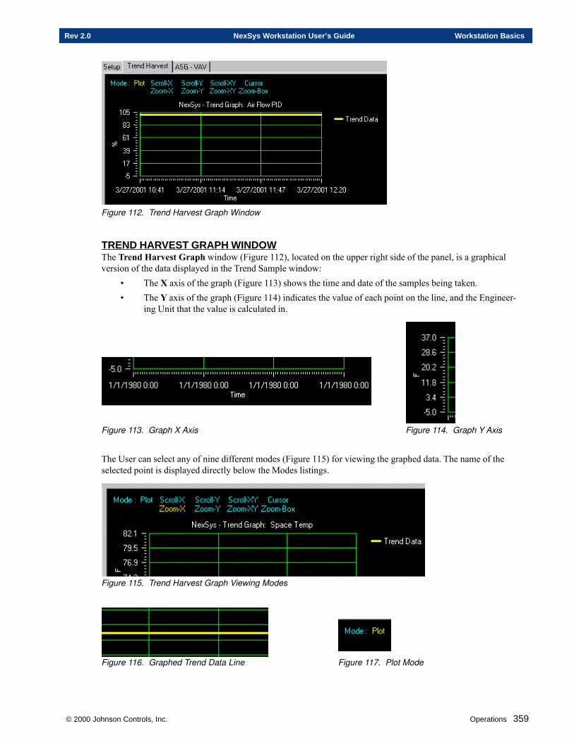
© 2000 Johnson Controls, Inc. Operations 359
Rev 2.0 NexSys Workstation User’s Guide Workstation Basics
Figure 112. Trend Harvest Graph Window
TREND HARVEST GRAPH WINDOWThe Trend Harvest Graph window (Figure 112), located on the upper right side of the panel, is a graphicalversion of the data displayed in the Trend Sample window:
• The X axis of the graph (Figure 113) shows the time and date of the samples being taken.• The Y axis of the graph (Figure 114) indicates the value of each point on the line, and the Engineer-
ing Unit that the value is calculated in.
Figure 113. Graph X Axis Figure 114. Graph Y Axis
The User can select any of nine different modes (Figure 115) for viewing the graphed data. The name of theselected point is displayed directly below the Modes listings.
Figure 115. Trend Harvest Graph Viewing Modes
Figure 116. Graphed Trend Data Line Figure 117. Plot Mode
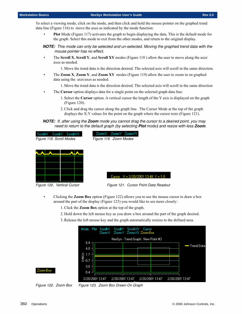
360 Operations © 2000 Johnson Controls, Inc.
Workstation Basics NexSys Workstation User’s Guide Rev 2.0
To select a viewing mode, click on the mode, and then click and hold the mouse pointer on the graphed trenddata line (Figure 116) to move the axes as indicated by the mode function:
• Plot Mode (Figure 117) activates the graph to begin displaying the data. This is the default mode forthe graph. Select this mode to exit from the other modes, and return to the original display.
NOTE: This mode can only be selected and un-selected. Moving the graphed trend data with themouse pointer has no effect.
• The Scroll X, Scroll Y, and Scroll XY modes (Figure 118 ) allow the user to move along the axis/axes as needed.
1. Move the trend data is the direction desired. The selected axis will scroll in the same direction.• The Zoom X, Zoom Y, and Zoom XY modes (Figure 119) allow the user to zoom in on graphed
data using the axis/axes as needed.1. Move the trend data is the direction desired. The selected axis will scroll in the same direction
• The Cursor option displays data for a single point on the selected graph data line:1. Select the Cursor option. A vertical cursor the length of the Y axis is displayed on the graph
(Figure 120).2. Click and drag the cursor along the graph line. The Cursor Mode at the top of the graph
displays the X:Y values for the point on the graph where the cursor rests (Figure 121).
NOTE: If, after using the Zoom mode you cannot drag the cursor to a desired point, you mayneed to return to the default graph (by selecting Plot mode) and resize with less Zoom.
Figure 118. Scroll Modes Figure 119. Zoom Modes
Figure 120. Vertical Cursor Figure 121. Cursor Point Data Readout
• Clicking the Zoom Box option (Figure 122) allows you to use the mouse cursor to draw a boxaround the part of the display (Figure 123) you would like to see more closely:
1. Click the Zoom Box option at the top of the graph.2. Hold down the left mouse key as you draw a box around the part of the graph desired.3. Release the left mouse key and the graph automatically resizes to the defined area.
Figure 122. Zoom Box Figure 123. Zoom Box Drawn On Graph
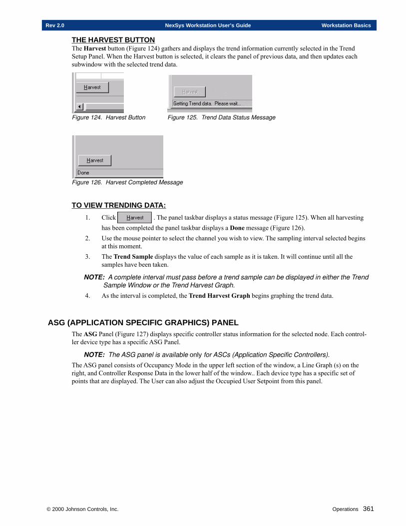
© 2000 Johnson Controls, Inc. Operations 361
Rev 2.0 NexSys Workstation User’s Guide Workstation Basics
THE HARVEST BUTTONThe Harvest button (Figure 124) gathers and displays the trend information currently selected in the TrendSetup Panel. When the Harvest button is selected, it clears the panel of previous data, and then updates eachsubwindow with the selected trend data.
Figure 124. Harvest Button Figure 125. Trend Data Status Message
Figure 126. Harvest Completed Message
TO VIEW TRENDING DATA:
1. Click . The panel taskbar displays a status message (Figure 125). When all harvestinghas been completed the panel taskbar displays a Done message (Figure 126).
2. Use the mouse pointer to select the channel you wish to view. The sampling interval selected beginsat this moment.
3. The Trend Sample displays the value of each sample as it is taken. It will continue until all thesamples have been taken.
NOTE: A complete interval must pass before a trend sample can be displayed in either the TrendSample Window or the Trend Harvest Graph.
4. As the interval is completed, the Trend Harvest Graph begins graphing the trend data.
ASG (APPLICATION SPECIFIC GRAPHICS) PANELThe ASG Panel (Figure 127) displays specific controller status information for the selected node. Each control-ler device type has a specific ASG Panel.
NOTE: The ASG panel is available only for ASCs (Application Specific Controllers).
The ASG panel consists of Occupancy Mode in the upper left section of the window, a Line Graph (s) on theright, and Controller Response Data in the lower half of the window.. Each device type has a specific set ofpoints that are displayed. The User can also adjust the Occupied User Setpoint from this panel.
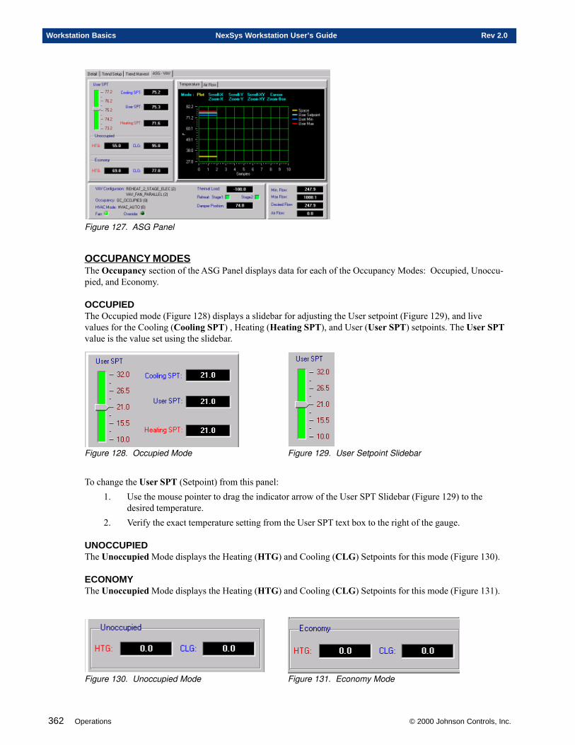
362 Operations © 2000 Johnson Controls, Inc.
Workstation Basics NexSys Workstation User’s Guide Rev 2.0
Figure 127. ASG Panel
OCCUPANCY MODESThe Occupancy section of the ASG Panel displays data for each of the Occupancy Modes: Occupied, Unoccu-pied, and Economy.
OCCUPIEDThe Occupied mode (Figure 128) displays a slidebar for adjusting the User setpoint (Figure 129), and livevalues for the Cooling (Cooling SPT) , Heating (Heating SPT), and User (User SPT) setpoints. The User SPTvalue is the value set using the slidebar.
Figure 128. Occupied Mode Figure 129. User Setpoint Slidebar
To change the User SPT (Setpoint) from this panel:1. Use the mouse pointer to drag the indicator arrow of the User SPT Slidebar (Figure 129) to the
desired temperature.2. Verify the exact temperature setting from the User SPT text box to the right of the gauge.
UNOCCUPIEDThe Unoccupied Mode displays the Heating (HTG) and Cooling (CLG) Setpoints for this mode (Figure 130).
ECONOMYThe Unoccupied Mode displays the Heating (HTG) and Cooling (CLG) Setpoints for this mode (Figure 131).
Figure 130. Unoccupied Mode Figure 131. Economy Mode
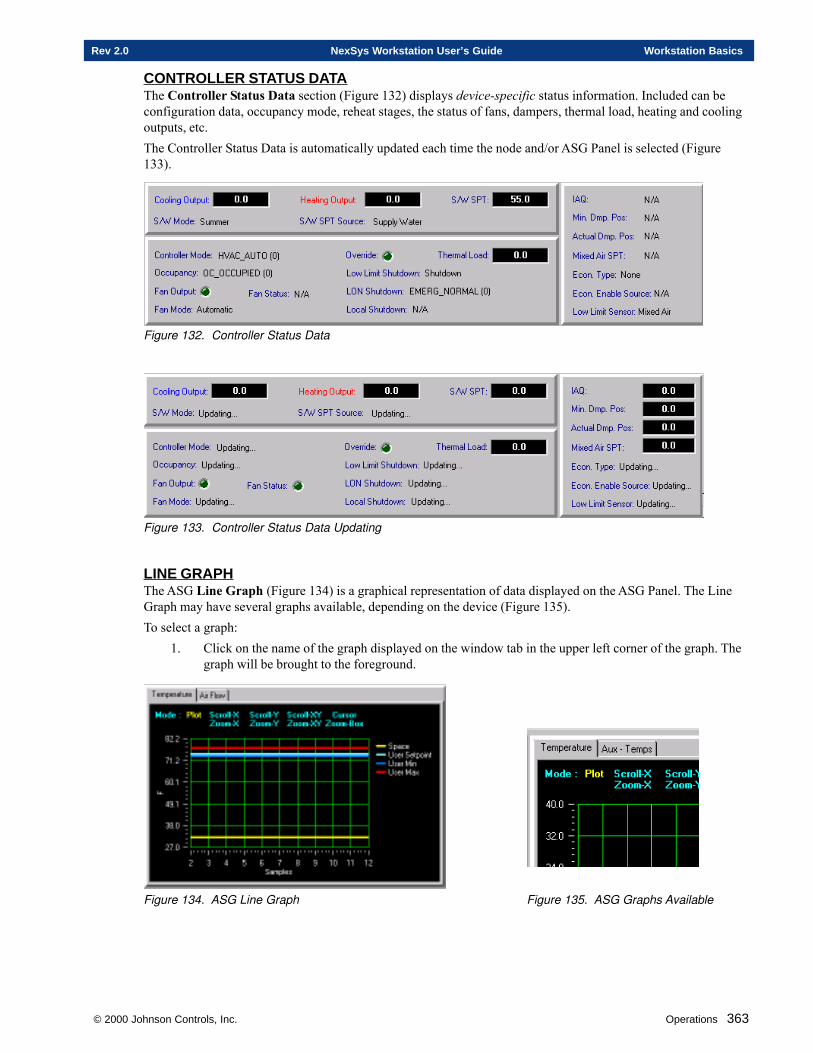
© 2000 Johnson Controls, Inc. Operations 363
Rev 2.0 NexSys Workstation User’s Guide Workstation Basics
CONTROLLER STATUS DATAThe Controller Status Data section (Figure 132) displays device-specific status information. Included can beconfiguration data, occupancy mode, reheat stages, the status of fans, dampers, thermal load, heating and coolingoutputs, etc.The Controller Status Data is automatically updated each time the node and/or ASG Panel is selected (Figure133).
Figure 132. Controller Status Data
Figure 133. Controller Status Data Updating
LINE GRAPHThe ASG Line Graph (Figure 134) is a graphical representation of data displayed on the ASG Panel. The LineGraph may have several graphs available, depending on the device (Figure 135).To select a graph:
1. Click on the name of the graph displayed on the window tab in the upper left corner of the graph. Thegraph will be brought to the foreground.
Figure 134. ASG Line Graph Figure 135. ASG Graphs Available
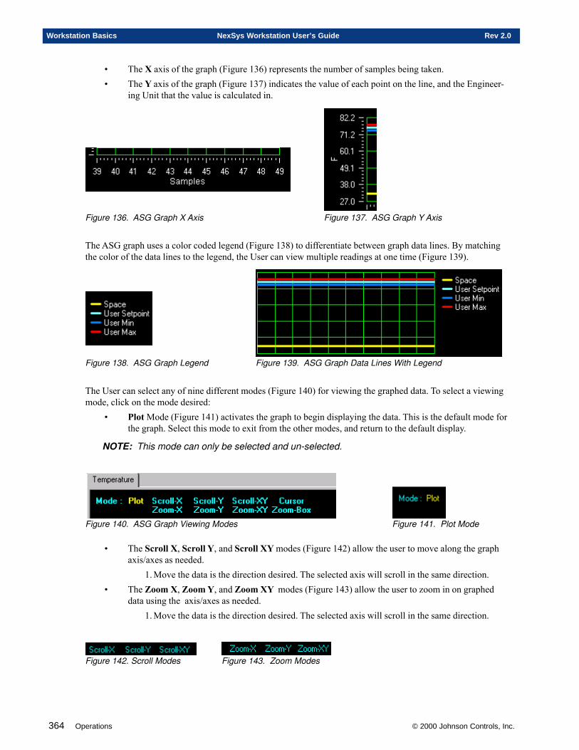
364 Operations © 2000 Johnson Controls, Inc.
Workstation Basics NexSys Workstation User’s Guide Rev 2.0
• The X axis of the graph (Figure 136) represents the number of samples being taken.• The Y axis of the graph (Figure 137) indicates the value of each point on the line, and the Engineer-
ing Unit that the value is calculated in.
Figure 136. ASG Graph X Axis Figure 137. ASG Graph Y Axis
The ASG graph uses a color coded legend (Figure 138) to differentiate between graph data lines. By matchingthe color of the data lines to the legend, the User can view multiple readings at one time (Figure 139).
Figure 138. ASG Graph Legend Figure 139. ASG Graph Data Lines With Legend
The User can select any of nine different modes (Figure 140) for viewing the graphed data. To select a viewingmode, click on the mode desired:
• Plot Mode (Figure 141) activates the graph to begin displaying the data. This is the default mode forthe graph. Select this mode to exit from the other modes, and return to the default display.
NOTE: This mode can only be selected and un-selected.
Figure 140. ASG Graph Viewing Modes Figure 141. Plot Mode
• The Scroll X, Scroll Y, and Scroll XY modes (Figure 142) allow the user to move along the graphaxis/axes as needed.
1. Move the data is the direction desired. The selected axis will scroll in the same direction.• The Zoom X, Zoom Y, and Zoom XY modes (Figure 143) allow the user to zoom in on graphed
data using the axis/axes as needed.1. Move the data is the direction desired. The selected axis will scroll in the same direction.
Figure 142. Scroll Modes Figure 143. Zoom Modes
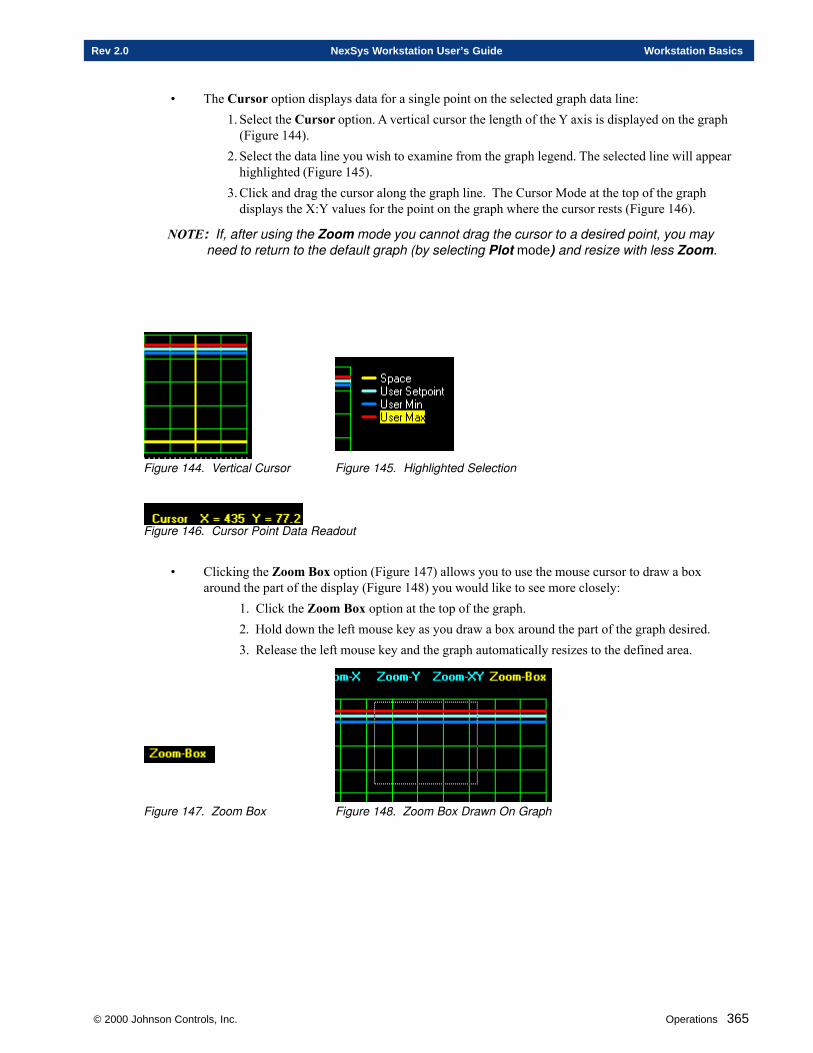
© 2000 Johnson Controls, Inc. Operations 365
Rev 2.0 NexSys Workstation User’s Guide Workstation Basics
• The Cursor option displays data for a single point on the selected graph data line:1. Select the Cursor option. A vertical cursor the length of the Y axis is displayed on the graph
(Figure 144).2. Select the data line you wish to examine from the graph legend. The selected line will appear
highlighted (Figure 145).3. Click and drag the cursor along the graph line. The Cursor Mode at the top of the graph
displays the X:Y values for the point on the graph where the cursor rests (Figure 146).
NOTE: If, after using the Zoom mode you cannot drag the cursor to a desired point, you mayneed to return to the default graph (by selecting Plot mode) and resize with less Zoom.
Figure 144. Vertical Cursor Figure 145. Highlighted Selection
Figure 146. Cursor Point Data Readout
• Clicking the Zoom Box option (Figure 147) allows you to use the mouse cursor to draw a boxaround the part of the display (Figure 148) you would like to see more closely:
1. Click the Zoom Box option at the top of the graph.2. Hold down the left mouse key as you draw a box around the part of the graph desired.3. Release the left mouse key and the graph automatically resizes to the defined area.
Figure 147. Zoom Box Figure 148. Zoom Box Drawn On Graph

366 Operations © 2000 Johnson Controls, Inc.
Workstation Basics NexSys Workstation User’s Guide Rev 2.0
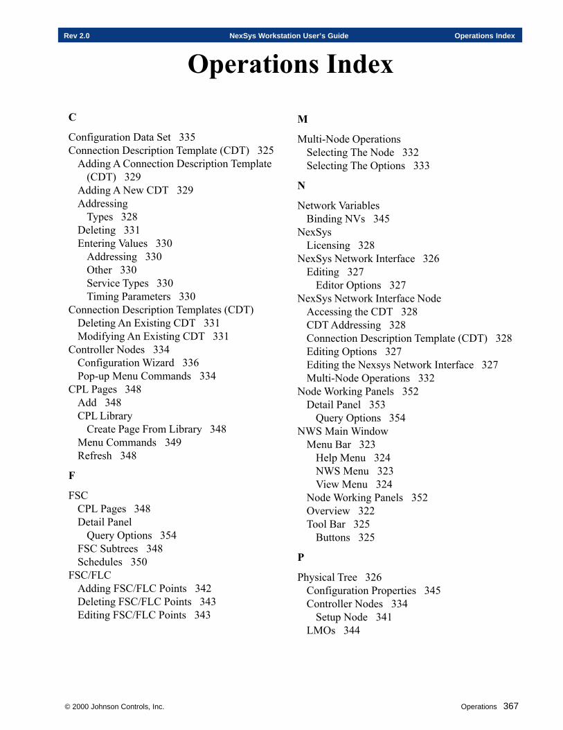
© 2000 Johnson Controls, Inc. Operations 367
Rev 2.0 NexSys Workstation User’s Guide Operations Index
Operations Index
M
Multi-Node OperationsSelecting The Node 332Selecting The Options 333
N
Network VariablesBinding NVs 345
NexSysLicensing 328
NexSys Network Interface 326Editing 327
Editor Options 327NexSys Network Interface Node
Accessing the CDT 328CDT Addressing 328Connection Description Template (CDT) 328Editing Options 327Editing the Nexsys Network Interface 327Multi-Node Operations 332
Node Working Panels 352Detail Panel 353
Query Options 354NWS Main Window
Menu Bar 323Help Menu 324NWS Menu 323View Menu 324
Node Working Panels 352Overview 322Tool Bar 325
Buttons 325
P
Physical Tree 326Configuration Properties 345Controller Nodes 334
Setup Node 341LMOs 344
C
Configuration Data Set 335Connection Description Template (CDT) 325
Adding A Connection Description Template(CDT) 329
Adding A New CDT 329Addressing
Types 328Deleting 331Entering Values 330
Addressing 330Other 330Service Types 330Timing Parameters 330
Connection Description Templates (CDT)Deleting An Existing CDT 331Modifying An Existing CDT 331
Controller Nodes 334Configuration Wizard 336Pop-up Menu Commands 334
CPL Pages 348Add 348CPL Library
Create Page From Library 348Menu Commands 349Refresh 348
F
FSCCPL Pages 348Detail Panel
Query Options 354FSC Subtrees 348Schedules 350
FSC/FLCAdding FSC/FLC Points 342Deleting FSC/FLC Points 343Editing FSC/FLC Points 343
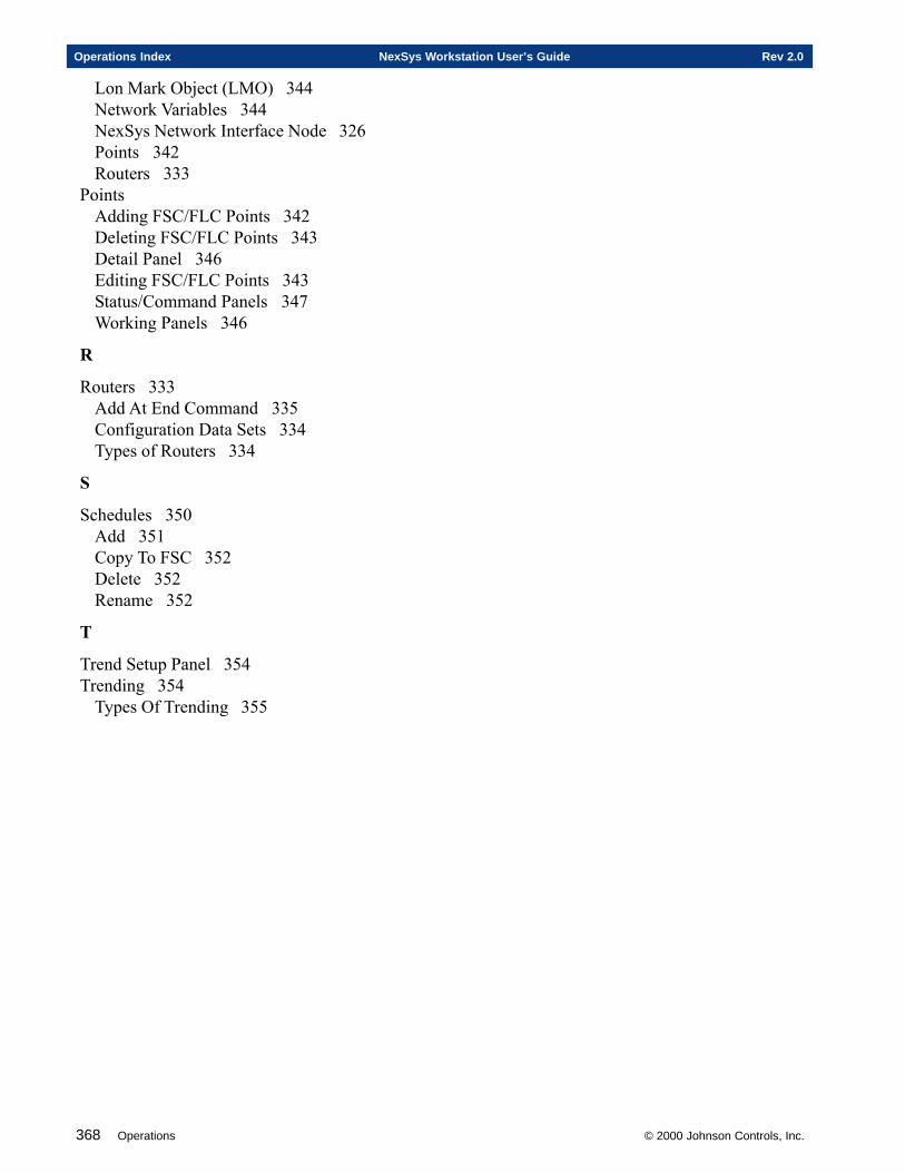
368 Operations © 2000 Johnson Controls, Inc.
Operations Index NexSys Workstation User’s Guide Rev 2.0
Lon Mark Object (LMO) 344Network Variables 344NexSys Network Interface Node 326Points 342Routers 333
PointsAdding FSC/FLC Points 342Deleting FSC/FLC Points 343Detail Panel 346Editing FSC/FLC Points 343Status/Command Panels 347Working Panels 346
R
Routers 333Add At End Command 335Configuration Data Sets 334Types of Routers 334
S
Schedules 350Add 351Copy To FSC 352Delete 352Rename 352
T
Trend Setup Panel 354Trending 354
Types Of Trending 355
Appendices
A. Standard Network Variable Types (SNVTS)
B. Glossary
C. NexSys Architecture
D. LNServer
APPENDICESSECTION SIX
© 2000 Johnson Controls, Inc.

370 Appendices © 2000 Johnson Controls, Inc.
Appendices Introduction NexSys Workstation User’s Guide Rev 2.0
Electronic Systems USA, a wholly owned subsidiary of Johnson Controls, Inc., reserves the right to updatespecifications when appropriate. Information contained in this document is based on specifications believed tobe correct at the time of publication.
Echelon ©, Coactive©, Windows NT©, and General Electric© are registered trademarks and service marks ofcompanies other than Electronic Systems USA. FSC™, CPL™ and NEXSYS™ are trademarks of ElectronicSystems USA.
Copyright © 2000 Electronic Systems USA All Rights Reserved
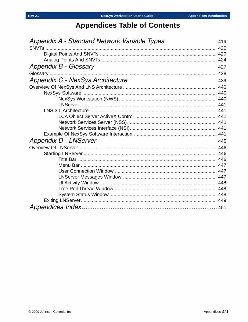
© 2000 Johnson Controls, Inc. Appendices 371
Rev 2.0 NexSys Workstation User’s Guide Appendices Introduction
Appendices Table of Contents
Appendix A - Standard Network Variable Types 419SNVTs .............................................................................................................................. 420
Digital Points And SNVTs ...................................................................................... 420Analog Points And SNVTs ..................................................................................... 424
Appendix B - Glossary 427Glossary ........................................................................................................................... 428
Appendix C - NexSys Architecture 439Overview Of NexSys And LNS Architecture ..................................................................... 440
NexSys Software ................................................................................................... 440NexSys Workstation (NWS) ........................................................................ 440LNServer ..................................................................................................... 441
LNS 3.0 Architecture.............................................................................................. 441LCA Object Server ActiveX Control ............................................................ 441Network Services Server (NSS).................................................................. 441Network Services Interface (NSI)................................................................ 441
Example Of NexSys Software Interaction ............................................................. 441
Appendix D - LNServer 445Overview Of LNServer ..................................................................................................... 446
Starting LNServer .................................................................................................. 446Title Bar ...................................................................................................... 446Menu Bar .................................................................................................... 447User Connection Window ........................................................................... 447LNServer Messages Window ..................................................................... 447UI Activity Window ...................................................................................... 448Tree Poll Thread Window ........................................................................... 448System Status Window ............................................................................... 448
Exiting LNServer.................................................................................................... 449
Appendices Index........................................................................... 451

372 Appendices © 2000 Johnson Controls, Inc.
Appendices Introduction NexSys Workstation User’s Guide Rev 2.0
Appendix A
Standard Network Variable Types
This chapter contains information on:
� Digital SNVTs and Points
� Analog SNVTS and Points
© 2000 Johnson Controls, Inc.
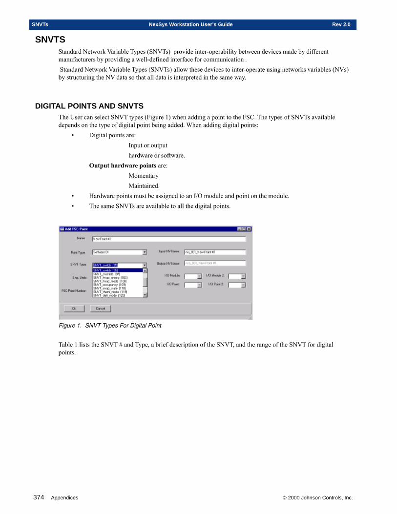
374 Appendices © 2000 Johnson Controls, Inc.
SNVTs NexSys Workstation User’s Guide Rev 2.0
SNVTSStandard Network Variable Types (SNVTs) provide inter-operability between devices made by differentmanufacturers by providing a well-defined interface for communication . Standard Network Variable Types (SNVTs) allow these devices to inter-operate using networks variables (NVs)by structuring the NV data so that all data is interpreted in the same way.
DIGITAL POINTS AND SNVTSThe User can select SNVT types (Figure 1) when adding a point to the FSC. The types of SNVTs availabledepends on the type of digital point being added. When adding digital points:
• Digital points are:Input or outputhardware or software.
Output hardware points are:MomentaryMaintained.
• Hardware points must be assigned to an I/O module and point on the module.• The same SNVTs are available to all the digital points.
Figure 1. SNVT Types For Digital Point
Table 1 lists the SNVT # and Type, a brief description of the SNVT, and the range of the SNVT for digitalpoints.
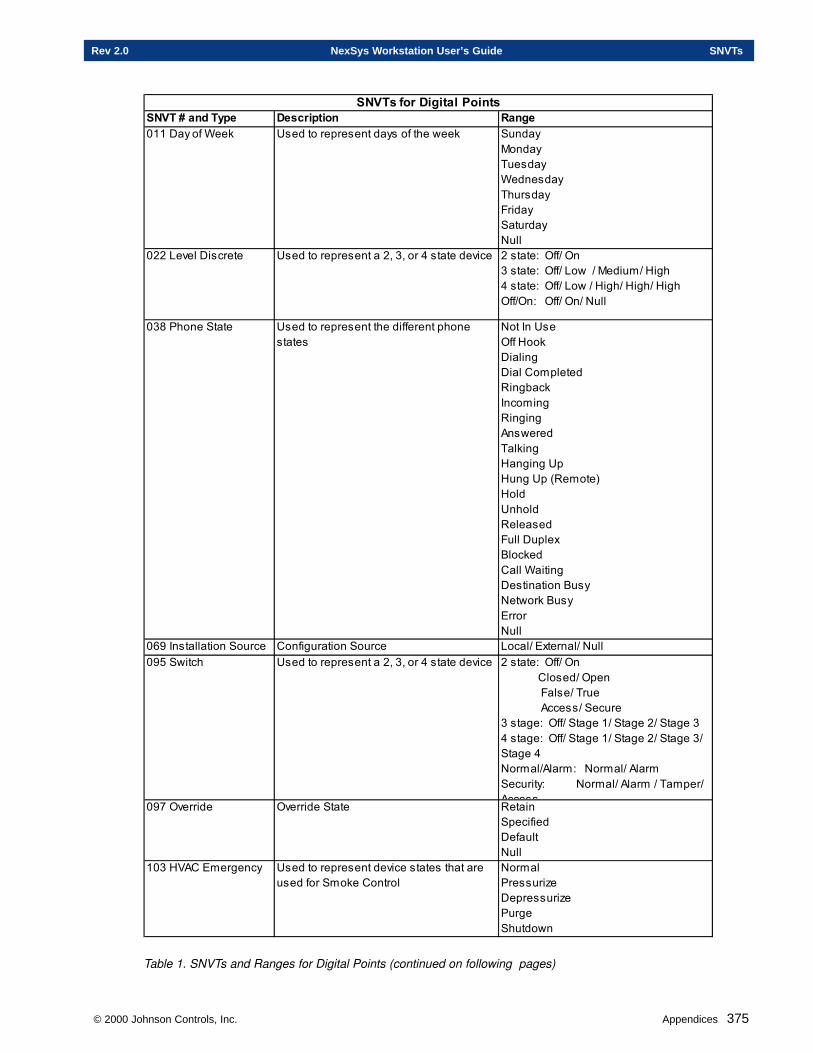
© 2000 Johnson Controls, Inc. Appendices 375
Rev 2.0 NexSys Workstation User’s Guide SNVTs
SNVT # and Type Description Range011 Day of Week Used to represent days of the week Sunday
MondayTuesdayWednesdayThursdayFridaySaturdayNull
022 Level Discrete Used to represent a 2, 3, or 4 state device 2 state: Off/ On3 state: Off/ Low / Medium/ High4 state: Off/ Low / High/ High/ HighOff/On: Off/ On/ Null
038 Phone State Used to represent the different phone states
Not In UseOff HookDialingDial CompletedRingbackIncomingRingingAnsweredTalkingHanging UpHung Up (Remote)HoldUnholdReleasedFull DuplexBlockedCall WaitingDestination BusyNetwork BusyErrorNull
069 Installation Source Configuration Source Local/ External/ Null095 Switch Used to represent a 2, 3, or 4 state device 2 state: Off/ On
Closed/ Open False/ True Access/ Secure3 stage: Off/ Stage 1/ Stage 2/ Stage 34 stage: Off/ Stage 1/ Stage 2/ Stage 3/ Stage 4Normal/Alarm: Normal/ AlarmSecurity: Normal/ Alarm / Tamper/ Access097 Override Override State RetainSpecifiedDefaultNull
103 HVAC Emergency Used to represent device states that are used for Smoke Control
NormalPressurizeDepressurizePurgeShutdown
SNVTs for Digital Points
Table 1. SNVTs and Ranges for Digital Points (continued on following pages)
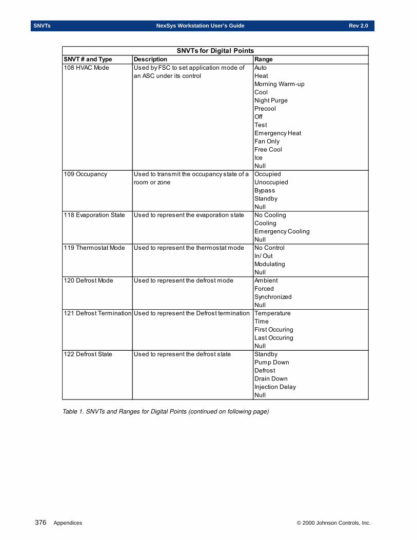
376 Appendices © 2000 Johnson Controls, Inc.
SNVTs NexSys Workstation User’s Guide Rev 2.0
SNVT # and Type Description Range108 HVAC Mode Used by FSC to set application mode of
an ASC under its controlAutoHeatMorning Warm-upCoolNight PurgePrecoolOffTestEmergency HeatFan OnlyFree CoolIceNull
109 Occupancy Used to transmit the occupancy state of a room or zone
OccupiedUnoccupiedBypassStandbyNull
118 Evaporation State Used to represent the evaporation state No CoolingCoolingEmergency CoolingNull
119 Thermostat Mode Used to represent the thermostat mode No ControlIn/ OutModulatingNull
120 Defrost Mode Used to represent the defrost mode AmbientForcedSynchronizedNull
121 Defrost Termination Used to represent the Defrost termination TemperatureTimeFirst OccuringLast OccuringNull
122 Defrost State Used to represent the defrost state StandbyPump DownDefrostDrain DownInjection DelayNull
SNVTs for Digital Points
Table 1. SNVTs and Ranges for Digital Points (continued on following page)
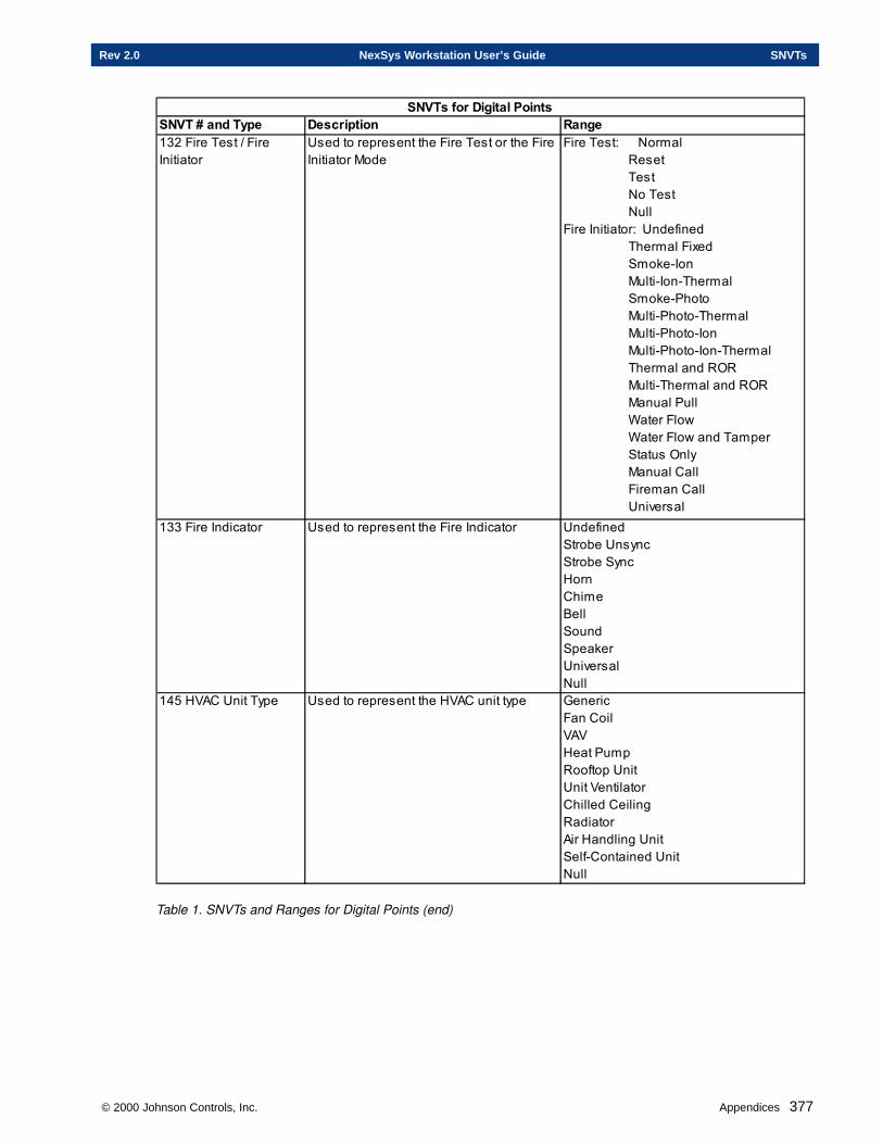
© 2000 Johnson Controls, Inc. Appendices 377
Rev 2.0 NexSys Workstation User’s Guide SNVTs
SNVT # and Type Description Range132 Fire Test / Fire Initiator
Used to represent the Fire Test or the Fire Initiator Mode
Fire Test: Normal Reset Test No Test NullFire Initiator: Undefined Thermal Fixed Smoke-Ion Multi-Ion-Thermal Smoke-Photo Multi-Photo-Thermal Multi-Photo-Ion Multi-Photo-Ion-Thermal Thermal and ROR Multi-Thermal and ROR Manual Pull Water Flow Water Flow and Tamper Status Only Manual Call Fireman Call Universal
133 Fire Indicator Used to represent the Fire Indicator UndefinedStrobe UnsyncStrobe SyncHornChimeBellSoundSpeakerUniversalNull
145 HVAC Unit Type Used to represent the HVAC unit type GenericFan CoilVAVHeat PumpRooftop UnitUnit VentilatorChilled CeilingRadiatorAir Handling UnitSelf-Contained UnitNull
SNVTs for Digital Points
Table 1. SNVTs and Ranges for Digital Points (end)
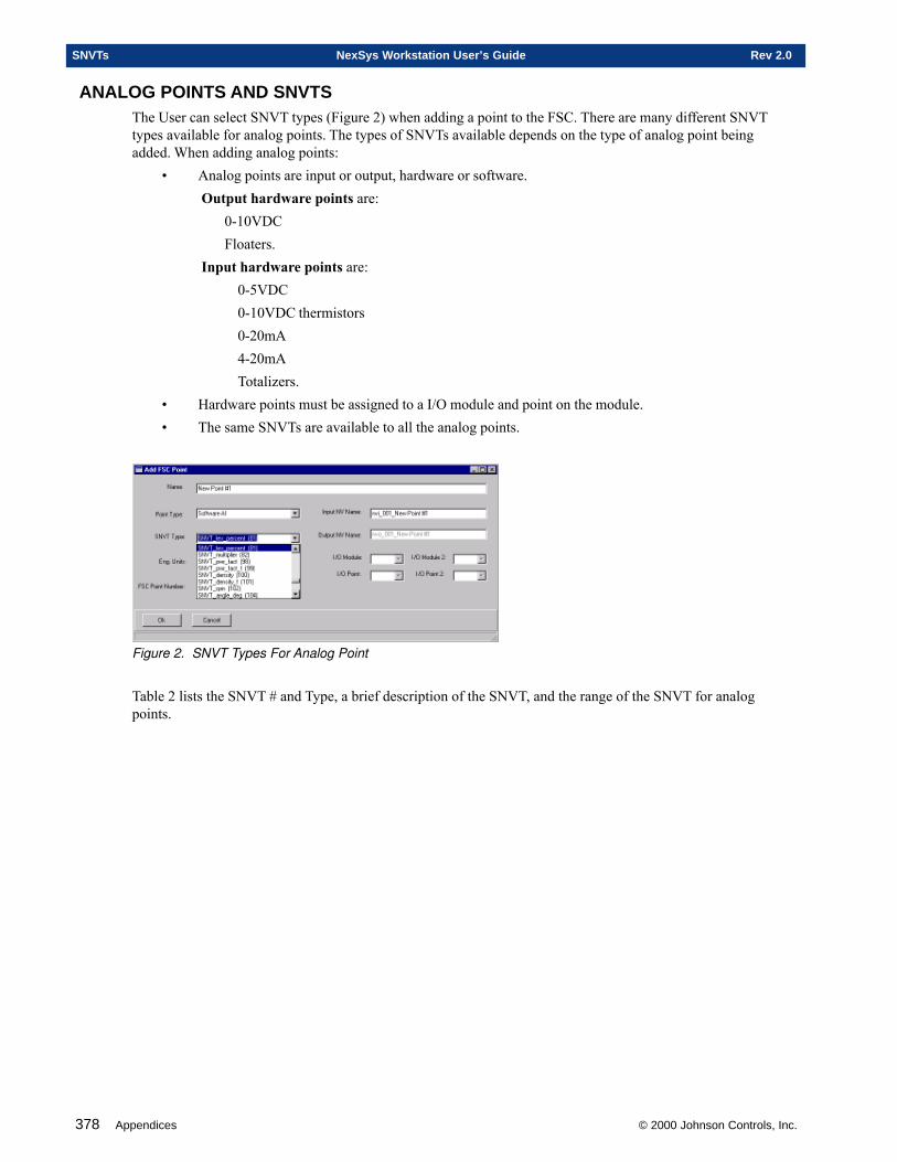
378 Appendices © 2000 Johnson Controls, Inc.
SNVTs NexSys Workstation User’s Guide Rev 2.0
ANALOG POINTS AND SNVTSThe User can select SNVT types (Figure 2) when adding a point to the FSC. There are many different SNVTtypes available for analog points. The types of SNVTs available depends on the type of analog point beingadded. When adding analog points:
• Analog points are input or output, hardware or software.Output hardware points are:
0-10VDCFloaters.
Input hardware points are:0-5VDC0-10VDC thermistors0-20mA4-20mATotalizers.
• Hardware points must be assigned to a I/O module and point on the module.• The same SNVTs are available to all the analog points.
Figure 2. SNVT Types For Analog Point
Table 2 lists the SNVT # and Type, a brief description of the SNVT, and the range of the SNVT for analogpoints.
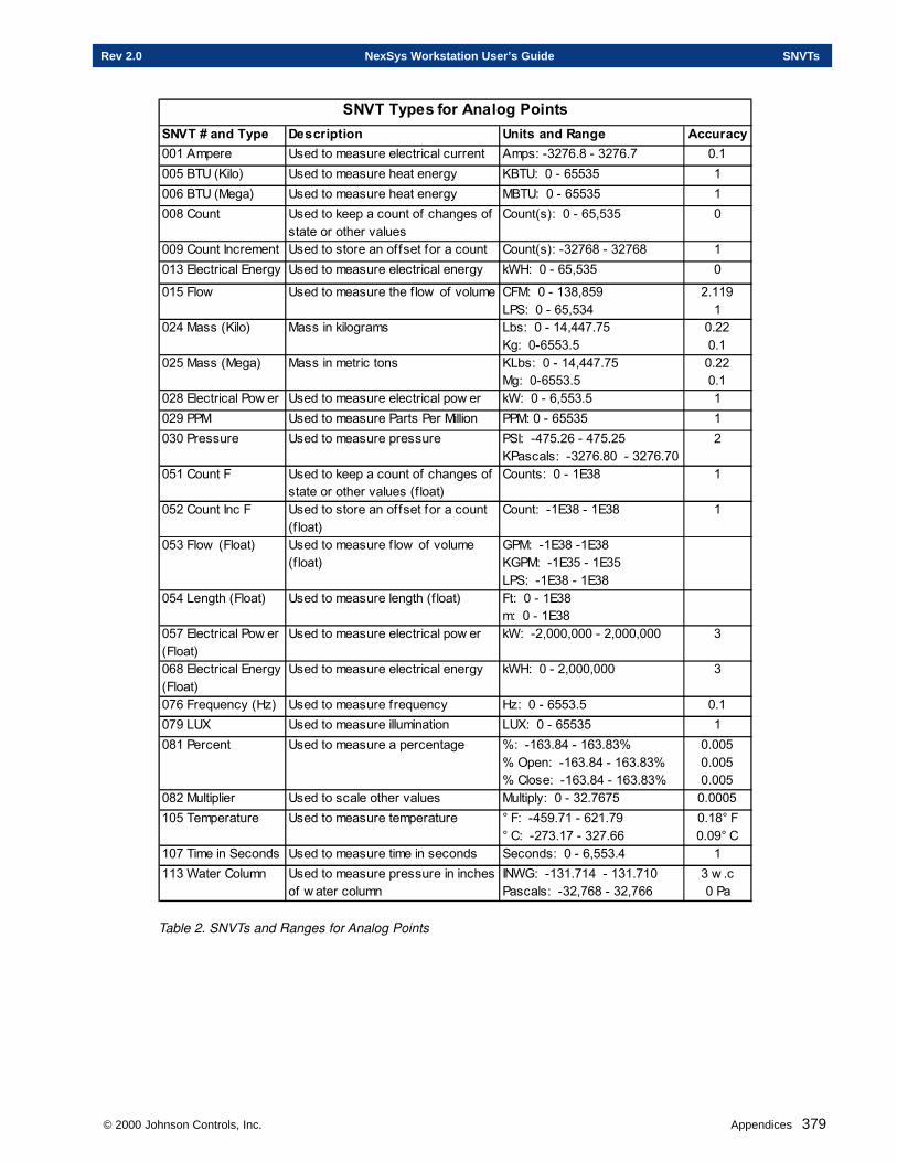
© 2000 Johnson Controls, Inc. Appendices 379
Rev 2.0 NexSys Workstation User’s Guide SNVTs
SNVT # and Type Description Units and Range Accuracy001 Ampere Used to measure electrical current Amps: -3276.8 - 3276.7 0.1005 BTU (Kilo) Used to measure heat energy KBTU: 0 - 65535 1006 BTU (Mega) Used to measure heat energy MBTU: 0 - 65535 1008 Count Used to keep a count of changes of
state or other valuesCount(s): 0 - 65,535 0
009 Count Increment Used to store an offset for a count Count(s): -32768 - 32768 1013 Electrical Energy Used to measure electrical energy kWH: 0 - 65,535 0
015 Flow Used to measure the f low of volume CFM: 0 - 138,859LPS: 0 - 65,534
2.1191
024 Mass (Kilo) Mass in kilograms Lbs: 0 - 14,447.75Kg: 0-6553.5
0.220.1
025 Mass (Mega) Mass in metric tons KLbs: 0 - 14,447.75Mg: 0-6553.5
0.220.1
028 Electrical Pow er Used to measure electrical pow er kW: 0 - 6,553.5 1029 PPM Used to measure Parts Per Million PPM: 0 - 65535 1030 Pressure Used to measure pressure PSI: -475.26 - 475.25
KPascals: -3276.80 - 3276.702
051 Count F Used to keep a count of changes of state or other values (f loat)
Counts: 0 - 1E38 1
052 Count Inc F Used to store an offset for a count (f loat)
Count: -1E38 - 1E38 1
053 Flow (Float) Used to measure f low of volume (f loat)
GPM: -1E38 -1E38KGPM: -1E35 - 1E35LPS: -1E38 - 1E38
054 Length (Float) Used to measure length (f loat) Ft: 0 - 1E38m: 0 - 1E38
057 Electrical Pow er (Float)
Used to measure electrical pow er kW: -2,000,000 - 2,000,000 3
068 Electrical Energy (Float)
Used to measure electrical energy kWH: 0 - 2,000,000 3
076 Frequency (Hz) Used to measure frequency Hz: 0 - 6553.5 0.1079 LUX Used to measure illumination LUX: 0 - 65535 1081 Percent Used to measure a percentage %: -163.84 - 163.83%
% Open: -163.84 - 163.83%% Close: -163.84 - 163.83%
0.0050.0050.005
082 Multiplier Used to scale other values Multiply: 0 - 32.7675 0.0005105 Temperature Used to measure temperature ° F: -459.71 - 621.79
° C: -273.17 - 327.660.18° F0.09° C
107 Time in Seconds Used to measure time in seconds Seconds: 0 - 6,553.4 1113 Water Column Used to measure pressure in inches
of w ater columnINWG: -131.714 - 131.710 Pascals: -32,768 - 32,766
3 w .c 0 Pa
SNVT Types for Analog Points
Table 2. SNVTs and Ranges for Analog Points

380 Appendices © 2000 Johnson Controls, Inc.
SNVTs NexSys Workstation User’s Guide Rev 2.0
Appendix B
Glossary
This chapter contains information on:
� NexSys Terminology
© 2000 Johnson Controls, Inc.
382 Appendices © 2000 Johnson Controls, Inc.
Glossary NexSys Workstation User’s Guide Rev 2.0
GLOSSARY
AAcknowledged Messaging - Provides end-to-end acknowledgment, where a message is sent to each designatedreceiver, and the sender expects to receive an acknowledgment message from each. If the send does not receivean acknowledgment, it times out and retries the transaction at the end of the Transaction Timer interval.Action: Reverse/Direct. - See Direction Reverse.Active Alarm Window - Displays only the current or unacknowledged alarms in the NexSys system.Active X Control - A 32-bit, language-independent programmable objects that can be used in a variety ofsoftware development tools.Address Table Entry - Used with point binding, the address table entry tells the NV sending the data theaddress to send to, and sometimes also telling the receiver where the data is being sent.AI - Analog Input.AHU - Air Handling Unit.Alarm History window - Gives the history of all alarms from all nodes as they are sent to the NWS.Alarm Hysteresis - The range an item in alarm must pass in order to generate a return to normal.Alarm Inhibit Time - The length of time - in hours, minutes, and seconds- that must elapse, after the controlleris activated, before an alarm is generated for a particular point. This prevents unwanted alarms on start-up orwhen the controller is powered up.Alarm Set Time - The length of time - in hours, minutes, and seconds- a point must be in alarm state before it isbroadcast.Alarm Type - You may define an alarm for certain points. Only one alarm type may be defined for each point,but that type may apply to as many of that point’s states as you wish. You also have the option of selecting oneof several Alarm Types to make the alarm more descriptive.Alias - An alternative name for an object, such as a variable, file, or device. The alias increases binding flexibil-ity by allowing an NV (Network Variable) to use more than one selector and/or address table entry.Analog - Point data which has a numerical value. (e.g. 35°F, 10 minutes, 1000 CFM)AO - Analog Output.ASC - Application Specific Controller.Automatic Fan - An HVAC fan which cycles off and on, running only during compressor stage 1.
BBind - The act of connecting NVs on one node with NVs of another node. NVOs are bound to NVIs.Broadcast Addressing - Addressing all nodes in a subnet or domain.BTU - British Thermal Unit. Measurement of heat.
CCalibration Offset - An increment of error set by the factory used to calibrate a particular hardware device, likea thermistor.Channel - The communications medium that is used to connect network devices.Channel Delay - Indicates the average amount of time (in milliseconds), for a message packet to get on thechannel, once it has been queued. This delay allows expected traffic patterns to be input to the system, with timercalculations being affected accordingly.Command Fail Time - See Feedback Time.Configure - (to configure a node) The transfer of all point setup information from the editors to the hardwaredevice, the transfer of binding information to the hardware device, and the assigning of a network address to thehardware device.
© 2000 Johnson Controls, Inc. Appendices 383
Rev 2.0 NexSys Workstation User’s Guide Glossary
Configuration Data Set (CDS) - A set of configuration parameter values associated with a particular devicetemplate. The user can choose to use the default values, or use a different set of values available for the template.CDSs allow a user to save a set of values for a particular setup of a type of device, and apply it to other similardevices of the same type.Configuration Properties (CPs) - Configuration properties are data values used to configure the operation of adevice or LONMARK object. Configuration properties may be implemented using configuration network vari-ables, or they may be implemented as configuration parameters stored in a data block.Connection Description Template (CDT) - Defines the parameters of a bind (also referred to as a connection).The CDT will include information on what sort of addressing and message service type it should use, timingparameters, use of authentication and priority slots, etc.Continuous Fan - An HVAC fan which runs continually during Occupied Mode.CPL - NexSys’s Control Programming Language.
DDA - Discharge Air.DAT - Discharge Air Temperature.Data Server - An engine for system monitoring and control, it interfaces with the LNS Server to automaticallymonitor network data points. It also converts network data in binary data or formatted strings for direct display.Deadband - Range an input variable may pass through without initiating any change in the output variable.Default Gateway - A network card (router) at the end of a local trunk allowing access to a remote host.Default Value - A value in SNVT units of the point used in such specific instances as Send Default on Error andOverride Behavior. This is also used as the initial value at start-up if the point is not fixed.Delta Send - Increment by which an AI must change before sending its status to the LON.DHCP - Dynamic Host Configuration Protocol. A method of assigning IP addresses to client PCs on a networkwhich doesn’t use static IP addresses.DI - Digital Input or Discrete Input.Dial Provider - The FSC at a remote side, connected via NCB, which has the responsibility for monitoring thatsite and dialing the main system if an alarm occurs.Digital - Traditionally, point data which can have one of two states. (e.g. off/on, open/closed, true/false.) Onoccasion, a digital point with a feedback will have three states. (e.g. on/off/auto). In the NWS, however, adigital point can have several “integer” states. For example, the HVAC mode SNVT has eight modes or states.Digital Lockout - Prevents unwanted alarms by locking out alarms from a point. Once you select a DigitalLockout point, you must specify the lockout state and time (if desired). This is commonly done with tempera-ture sensors in conditioned spaces so that they do not generate nuisance alarms when the conditioning equipmentis not active.Digital Lockout Point - DO points whose status dictates whether alarms should be generated for a particular AI.Digital Lockout State - States of DO Lockout Point for which AI alarms are to be locked out.Digital Lockout Time - The time - in hours, minutes, and seconds- that must elapse after a DO switches from adigital lockout state to a non-digital lockout state before alarms can be generated on a particular AI. Thisprevents unwanted alarms from being generated on the AI the first few moments after a DO changes out of aDigital Lockout State.Direction Reverse - If you select YES, this parameter reverses increment/decrement points. (Note: On an I/OModule page, the increment/decrement points are reversed when you select YES. Therefore, instead of usingthis function to correct an error, you may want to switch the increment/decrement I/O Module point prefer-ences.) For DO hardware points and discrete hardware points, this is called Action: Reverse/Direct.Discovery Interval - Indicates the minimum interval rate (in seconds) at which the LCA Object Server scansthe network for newly attached, unconfigured devices.DNS - Domain Name System. A method for resolving host names and IP addresses used in the Internet.
384 Appendices © 2000 Johnson Controls, Inc.
Glossary NexSys Workstation User’s Guide Rev 2.0
DO - Digital Output.DO Momentary - DO point used to control latching devices like motor starters and lighting relays.Double click - Click twice with the left mouse button.Download - The transfer of data from the NWS to the panel.DP - Differential Pressure.Drag - Click and hold the right mouse button, reposition the cursor and let go of the mouse button. This is usedwhen moving items on the computer screen.Drive Time - The time - in hours, minutes, and seconds - for the actuator being controlled to move fromcompletely closed to completely open. This is only used on floating (three state) actuator motors.DST - Daylight Savings Time.Duct Size - Cross sectional area of a duct in square feet.
EEnthalpy - Thermodynamic value for the total heat content (BTU/lb).
FFCU - Fan Coil Unit.Feedback - A DI point is often used to read the status of a device controlled by a DO point. If the DI does nothave the same state as the DO, there may be a problem. If so, an alarm is generated using the Feedback option.Feedback takes precedence over state-based alarming via the “alarm” page.Feedback Point - DO point which the DI point should match or else generate an alarm.Feedback Time - Time - in hours, minutes, and seconds- the FSC will wait before generating an alarm when thestatus of the DI does not match that of its DO feedback point. Feedback Time may also be called “CommandFail Time” in the editors.Field Minimum - Lowest temperature, pressure, GPM, or etc. the sensor can measure. This will typicallycorrespond to the lowest voltage or current value on the sensor. This is FSC specific.Field Maximum - Highest temperature, pressure, GPM, or etc. the sensor can measure. This will typicallycorrespond to the highest voltage or current value on the sensor. This is FSC specific.Floating Actuator - A device which moves a damper, valve, or other similar physical device which is controlledby timed increase and decrease signals. Applying voltage to the “increase” input of the actuator will cause it tomove in the “increase” direction. The same is true for the “decrease” input. The actuator only moves whilevoltage is applied to one of its inputs. These devices are generally slow with no position feedback.Floating Control - Actuator/Valve control signal consisting of pulses from 0.1-10 seconds on “increase” and“decrease” lines that cause the actuator to move the desired direction while the pulse is present. The actuatorwill remain at that point until the next pulse.Front End - Controlling software for the system; NWS.FSC - Flexible System Controller.FTP - File Transfer Protocol. A TCP/IP protocol allowing the transfer of files between computers.FTT 10 - A twisted pair, free or bus topology, with a speed of 78K Baud. Basic length for bus topology is 8500ft. For free topology, length is 1600 ft. This system is polarity insensitive.
GGlobal Node - The primary node on the physical tree. This node defines common information for the LON, andall other nodes attach to this one.Group Addressing - Refers to a numbered group of nodes in the system.GUI - Graphical User Interface.
© 2000 Johnson Controls, Inc. Appendices 385
Rev 2.0 NexSys Workstation User’s Guide Glossary
HHardware Address - A unique alphanumeric code found on the Network Interface Card, also call the MACaddress.High Alarm Limit - A value set on an analog point. When the value of the point, as seen in the point statuswindow, rises above the limit, the point will generate an alarm.Highlight - Used to select text. Place the cursor left of the first character, press and hold down the left mousebutton, and drag the mouse to the end of the text to be selected.Host - An individual PC, server, router, etc. on a network.Host Name - The network name of a particular host. In Windows NT, it can be found by opening the controlpanel and double clicking on the Network icon.Host Table - A file stored on a local PC which maps known IP addresses and network names.HP - Heat Pump.HTML - Hypertext Markup Language. Language used for creating WWW documents enabling hyperlinking toother places in the document or different sites on the web.Hysteresis - See Alarm Hysteresis.
IIAQ - Indoor Air Quality. The quality of air expressed as a percentage.Intelligent STAT - A microcontroller based thermostat which allows an occupant to adjust the setpoint, displayUser Mode parameters, and put the controller in override. The LCD can display the room temperature, time,outside air temperature, and setpoint.Internet - A group of connected networks. The global Internet is referenced with a capital letter. A lower case“i” indicates a group of connected networks.IP - Internet Protocol. A network protocol which the Internet is based on.IP Address - A 32 bit (4 byte) binary code used to identify individual hosts on a network.
KK Factor - Factor of thermal conductivity. The rate that heat flows through a given area of a certain matter,usually air or water.
LLAN - Acronym for a Local Area Network.LCA (LONWORKS Component Architecture) - The LNS application programming interface for Microsoft™Windows NT or Windows 95 operating systems.LCA (LONWORKS Component Architecture) Object Server - An ActiveX control that converts LNS objects(e.g., devices, routers, channels) managed by the NSS into standard OLE objects, and enables sharing ofinformation and objects between multiple tools and components.LNS (LONWORKS Network Services) - Echelon’s network management and monitoring software, LNS allowstools from multiple manufacturers to work together in a single control system by providing a single networkmanagement tool.LNS Server - A software engine consisting of a library and tools that performs network services.LNServer - The software interface that allows NWS to communicate with LNS, and through LNS, devices inthe field.Lockout - Amount of time which must elapse after a point goes active before alarms will no longer be lockedout.
386 Appendices © 2000 Johnson Controls, Inc.
Glossary NexSys Workstation User’s Guide Rev 2.0
Logical Tree - Map of the NexSys system where all points are user defined and may be pulled from any physicalnode in the system. For example, all space temps may be grouped in one logical node.LON (Local Operating Network) - Echelon’s LONWORKS Local Operating System. The LON is designed tomove very brief sensor and control messages containing commands and status information, used to triggeractions.LonMark - An independent organization to establish a higher level of interoperability between nodes.LonMark Object (LMO) - Functional groupings of network variables (NVs) and configuration parameters.LonTalk - A communication protocol for an Echelon system.Low Alarm Limit - A value set on an analog point. When the value of the point, as seen in the point statuswindow, falls below the limit, the point will generate an alarm.
MMA - Mixed Air. The combined outside air and recirculated air.MAC Address - Media Access Control Address. A unique alphanumeric code found on a Network InterfaceCard, also known as the hardware address.MAI - Multiple Analog Input. A point type allowing the user to get information from a number of analog pointsin the system without using a large number of points on the FSC when the user is not concerned about whichspecific controller the value comes from. MAI points have no point status. They are reported in CPL only.MAIs may be used for such things as finding the average space temperature from a group of sensors, or findingthe minimum/maximum thermal load from a group of VAV controllers in order to control an AHU’s output.Maintenance Time - The time - in hours, minutes, and seconds- in which the actuator will be driven an extraamount at its endpoints to ensure that it reaches the endpoint. Since a floating actuator has no feedback, this isthe primary way it can be automatically re-zeroed, whenever it is sent to one extreme or the other. This appliesto the FSC only. Normally, this will be set at 1.5 times the drive time.Max Receive Time - See NV Update Time.Max Send Time - The maximum time - in hours, minutes, and seconds- that will elapse between status broad-casts of a particular point, regardless of whether or not it has changed value. This ensures occasional updates incase the change of state broadcast was missed. NV updates are broadcast to bound connections only, not to thefront end.Max Value - Maximum value the point’s status can be. If the point is commanded above the Max Value, itsstatus will be equal to the Max Value. For hardware analog points, this is the value that matches the field maxvalue in engineering units.MDI - Multiple Discrete Input. A point type allowing the user to get information from a number of discretepoints in the system without using a large number of discrete points on the FSC when the user is not concernedabout which specific controller the value comes from. MDI points have no point status. They are reported inthe CPL only. MDIs may be used for such things as monitoring the number of AHU requests from a set of VAVcontrollers so that the FSC can decide whether to turn on.Min Delta - The minimum change that must occur in a particular analog point for it to be broadcast. Used tolimit network traffic. The Min Delta must be valid for a broadcast to occur.Minimum Move - The time - in hours, minutes, and seconds- that constitutes the minimum move that will beimposed on the floating actuator. This prevents minor back-and-forth hunting or tiny moves which causes wearand tear on an actuator without improving control.Min Send Time - The minimum time - in hours, minutes, and seconds- that must elapse between status broad-casts of a particular point, regardless of how often its value changes. This is used to limit network traffic,especially on a point that may change frequently. The send time must be valid for a broadcast to occur. Analogpoints do not broadcast to the front end for any reason but alarms. Min Value - The minimum value a point’s status can be. If a point is commanded below the minimum value, itsstatus will be equal to the Min Value. For hardware analog points, this is the values that matches the field MinValue. The value is in the engineering units of the appropriate SNVT.MIP - Microprocessor Interface Program.
© 2000 Johnson Controls, Inc. Appendices 387
Rev 2.0 NexSys Workstation User’s Guide Glossary
Momentary (Latching) Relay - A relay that mechanically “latches” into a desired state. These relays have twocoils, an “on” and an “off.” If voltage is applied to one of the coils, the relay moves to that position and remainsthere until voltage is applied to the opposite coil. This is often Magnetic Relay.
NNCB - Network ComBiner. A router manufactured by CTI Products, Inc. which allows the linking of LonWorksnetworks over dial up or leased telephone lines. It is connected to the LON via modem. NCBs come in pairs,the local and remote, on either end of the phone line.NetBEUI - Network BIOS Extended User Interface. In Windows NT, it’s the fastest LAN transport protocol.NetBIOS - An early (1980s) mechanism for client/server communication which can be used across platforms.Network Manager - Allows communication to and from the field, and creates and maintains Echelon specificdatabases.Neuron ID - Unique, 48-bit, factory-assigned identification number associated with every neuron chip.Neuron ID Addressing - The most basic form of addressing, refers to a node by it’s Neuron ID number.NexSys Server - Server for NexSys. Handles communication between NWS and the Network Manager.NIC - Network Interface Card. A hardware card which is installed in the PC’s expansion bus slot and connectsthe PC with the network.Node - The NexSys Network Interface, a router, or a controller in the field, or the Physical Tree elementrepresenting the item.Node History Window - A NexSys window which displays information on the on-line/off-line nature of devicesin the NexSys system, modifications, configuration updates, and firmware updates.NSI (Network Services Interface) - The component in the LNS architecture that provides the physical connec-tion to the LONWORKS network. The NSI is the interface between NWS (through LNServer) and the field devicesnetwork.NSI Timeout - The value ( in seconds) that indicates how long the system will wait for remote LNS clients torespond to a ping.NSS (Network Services Server) - The LNS network management service that processes network services,maintains the network database, and enables and coordinates multiple points of access.Number of Inputs (MAI/MDI) - The number of connections to be made from other panels to this point. Thisvalue cannot be 0. The value must be exactly the number of connection you are going to make to the point. Iftoo few are specified, all values will not be used. If too many are specified, the point will stay in error, since allof its inputs do not have current information.NV - Network Variable. Variable on one node that can be connected to network variables on one or moreadditional nodes. This allows sharing of data in a distributed application.NVI - Network Variable Input.NVO - Network Variable Output.NV Update Time - Maximum time the panel will wait for a status from a point on another panel such as RemoteI/O or VAV before the FSC considers it in error. You may want to set this time slightly higher than the Max SendTime of the output point to which it is bound.NWS (NexSys Workstation) - The graphical user interface (GUI) component of NexSys.
OOA - Outside Air TemperatureOAT - Outside Air Temperature.OEM - Original equipment manufacturer.OffNet Mode - A management mode in which the NSS makes network configuration changes in it’s on-boarddatabase but does not update the nodes in the field. The saved updates are queued for later processing when theNSS is placed in the OnNet management mode.
388 Appendices © 2000 Johnson Controls, Inc.
Glossary NexSys Workstation User’s Guide Rev 2.0
OnNet Mode - A management mode in which the NSS updates both its on-board database and the configurationof devices in the field. When the NSS is first placed in the OnNet mode it also updates any changes that weremade while it was in the OffNet management mode.Operator - Any individual who controls a system using the NWS.
PPCLTA - Personal Computer LonTalk Adaptor. Hardware/PC interface board which converts data to/from thefield.PEC - Package Equipment Controller.Physical Tree - Map of the NexSys system as it is configured on the LON. All points are grouped according tothe hardware device where they reside.PID Loop - Proportional, Integral, Derivative loop. Used to fine tune control of an HVAC system.Ping - Packet Internet Groper. Echo method of determining if a host destination is reachable.Plug-Ins - An ActiveX control for manipulating data within the LNS database. Most commonly used for OEMnode configuration.Point - A single piece of data on a controller (software/hardware, input/output)Points List - Detailed information on points in the system.Program ID - The identification number from Echelon indicating the type of device, manufacturer, etc.Properties - Attributes of the devices in the network that the user can view and modify.Protocol - A defined set of messages between two software applications allowing each application to bothspecify requests, and respond to the other application’s requests.Purge - Remove old data from the system. Data may be stored to disk. Alarm and trend data may be purged.
RResource Catalog Files - Resource files define how node information is displayed in LNServer. LNServer usesthis information to decode and extract information about network variables (NVs) and configuration parameters(CPs).Reheat - A system used to provide local space heating when required by turning on a hot water heat exchangeror electric heater in a duct to warm the air flow.Repeater - A simple router used to increase the network length or switch to a new channel.Reset - (to reset a node) Resets the neuron on the CPU of the hardware device.
Restore - Place previously removed data back in the workstation database. Purged alarm and trend data whichhas been stored to disk may be restored.RH - Relative Humidity.Right click - Click once with the right mouse button.Router - Hardware device allowing communication between different media types, or the Physical Tree elementrepresenting it. It will selectively filter information and can increase the network length.RTU - Roof Top Unit.
SSamples - The number of data points available. It can refer to the total amount of space in the buffer, or theamount of space allocated to a single trend channel.Schedules - A series of start and stop times used in conjunction with a group of days. Schedules are set up inCPL and used for building control.
© 2000 Johnson Controls, Inc. Appendices 389
Rev 2.0 NexSys Workstation User’s Guide Glossary
Security File - Profile set up in NexSys limiting an operator to certain system command options.Selector - Used during point binding, the selector is a 14-bit number that LNS assigns to the bind so that bothends (NVs) what is being updated.Send Default on Error - Determines whether or not to send the defined Default Value - instead of “Error” -when the point is in error.Send Time - Amount of time a point waits prior to broadcasting its data to the LON.Sensor - A device used to measure a variable. Usually, a space temperature.Service Pin - Physical input to an Echelon node which is used when configuring a node. Activating the servicepin broadcasts the neuron ID to the NWS.Setpoint - The desired value of a control point.SNVT (Standard Network Variable Type) - Format of a point using predefined ranges, allowing data to beexchanged between controllers. A standardized engineering unit.Space Temperature - Current temperature recorded in a zone by a thermistor or sensor.SCPT (Standard Configuration Property Type) -A SCPT is a LONMARK-standardized definition type ofconfiguration property (CP) for devices.Status Send Interval - The interval at which the controller broadcasts a status from one of its points to theNexSys server. The NexSys server monitors the traffic to ensure that all controllers are on-line. The default is30 seconds.Subnet Mask - A four byte (32 bit) binary value which defines the network ID portion of an IP address and thehost ID portion.Subnet /Node Addressing - Refers to a single node by its domain/subnet/node (DSN) address assigned whenthe network image is sent to the node during its initial setup.Subtree - The portion of the Physical Tree that is under a node. It can contain points, LONMARK objects, NVs(Network Variables), and CPs (Configuration Parameters).System Node - The Physical Tree element that represents the PC being used to access the LON. It is also used toaccess database-global properties.SWT - Supply Water Temperature.
TTCP/IP - Transmission Control Protocol/Internet Protocol. A suite of protocols controlling Internet communica-tions by allowing for host definition and information routing.
Terminal Unit - An end device on the DDC (Direct Digital Control) system. The VAV box is an example of aterminal unit.Thermal Load - Heating capacity of a system.Thermistor - A thermoelectrical element used to measure temperature.Third Party Node - Any device manufactured by a company other than Johnson Controls, Inc.Time Broadcast Interval - The interval at which the time provider broadcasts the current time to all controllers.This is necessary to coordinate all controllers, since most controllers do not have a real time clock and are thusonly accurate to within a few seconds per day. The default is 15 minutes.Time Provider - The node in the system (designated by the user) which coordinates time for all nodes in thesystem by broadcasting the time at an interval. Currently the time provider must be an FSC.Totalizer (AI) - A point which registers a tally. For example, it could count the number of times a relay opens.TP-1250 - A twisted pair wire with a speed of 1.25 M Baud. TP-1250 can only be used with bus topology, andthe length is limited to 1600 ft. It is polarity insensitive.Transmit Timer - Indicates the interval in seconds that the LON retries to send Request and Acknowledgedmessages.
390 Appendices © 2000 Johnson Controls, Inc.
Glossary NexSys Workstation User’s Guide Rev 2.0
Trend - Set up on an individual point to monitor its status over time. It may be viewed, printed, and graphed.Trend Channel - A collection of data that has been gathered on a single point.Trend Configuration - The relatively small amount of data that configures the controller and determines thepoint(s) for which data to be stored, the interval required, and/or the change (delta) that will be monitored.Trend Data - The entire collection of data gathered on a single point.Trend List - A list of all points in the NexSys system which are currently being trended.Trend Sample - A single piece of data on a single point. The smallest unit of trend data.Triac - Discrete electronic device for switching an AC signal. This cannot be used for DC since it will only turnoff when instantaneous current drops to zero.TSO STAT - Temperature, setpoint, override microcontroller thermostat.Turnaround Addressing - Addressing for connections that take place exclusively within the node.Two-State - Simple “On/Off” or “Open/Closed” signal.
UUCPT (User-defined Configuration Property Type) - Manufacturer defined configuration properties types.UI - User Interface.Update Firmware - To send a new software revision from the PC to the hardware device.Update Interval - Indicates the interval in seconds that NSS retries to update (in the background) any changesmade on a device that NSS was not able to update during the original transaction.Upload - The transfer of data from the panel to the front end.URL - Universal Resource Locator. An alphanumeric name which resolves to the IP address of a site on theInternet.User Defined Graphic - The graphic of a node custom designed by the user to display point status data andaccess other graphics, editors, or CPL pages.UV - Unit Ventilator.
VVAV 01 - Variable Air Volume controller requiring an external damper actuator.VAV 02 - Variable Air Volume controller with an integrated damper actuator.
WWAN - A network comprised of multiple locations, usually a group of interconnected LANs.Wink - To cause the service LED of a hardware device to flash.WINS - Windows Internet Name Service. A Microsoft service provided for Windows PCs containing Internetnumbers for specific NetBIOS names.WWW - World Wide Web. A group of connected computers on the Internet running Hypertext Transfer Proto-col.

© 2000 Johnson Controls, Inc. Appendices 391
Rev 2.0 NexSys Workstation User’s Guide Glossary

392 Appendices © 2000 Johnson Controls, Inc.
Glossary NexSys Workstation User’s Guide Rev 2.0
Appendix C
NexSys Architecture
This chapter contains information on:
� Overview of NexSys and LNS Architecture
� NexSys Workstation (NWS)
� LNServer
� LNS 3.0 Architecture
� Example of NexSys Software Interactions
© 2000 Johnson Controls, Inc.
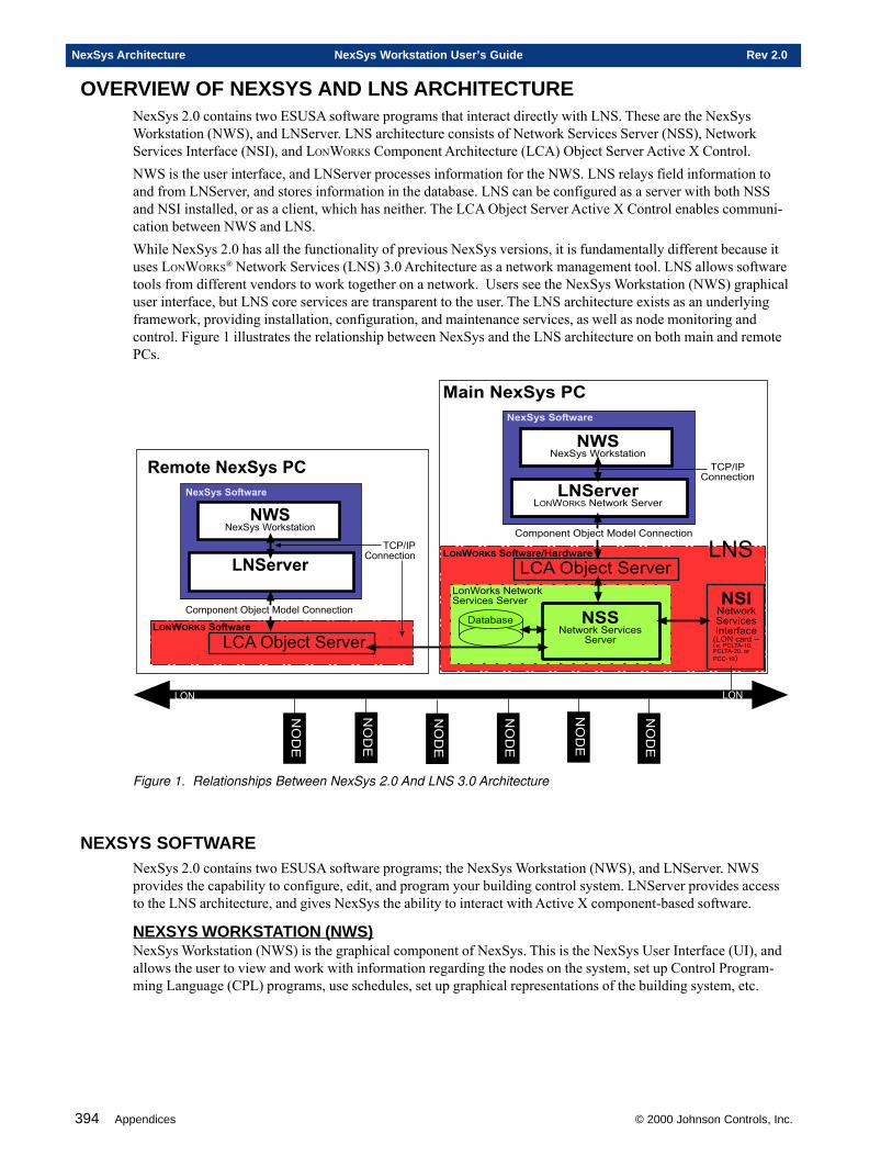
394 Appendices © 2000 Johnson Controls, Inc.
NexSys Architecture NexSys Workstation User’s Guide Rev 2.0
OVERVIEW OF NEXSYS AND LNS ARCHITECTURENexSys 2.0 contains two ESUSA software programs that interact directly with LNS. These are the NexSysWorkstation (NWS), and LNServer. LNS architecture consists of Network Services Server (NSS), NetworkServices Interface (NSI), and LONWORKS Component Architecture (LCA) Object Server Active X Control.NWS is the user interface, and LNServer processes information for the NWS. LNS relays field information toand from LNServer, and stores information in the database. LNS can be configured as a server with both NSSand NSI installed, or as a client, which has neither. The LCA Object Server Active X Control enables communi-cation between NWS and LNS.While NexSys 2.0 has all the functionality of previous NexSys versions, it is fundamentally different because ituses LONWORKS® Network Services (LNS) 3.0 Architecture as a network management tool. LNS allows softwaretools from different vendors to work together on a network. Users see the NexSys Workstation (NWS) graphicaluser interface, but LNS core services are transparent to the user. The LNS architecture exists as an underlyingframework, providing installation, configuration, and maintenance services, as well as node monitoring andcontrol. Figure 1 illustrates the relationship between NexSys and the LNS architecture on both main and remotePCs.
���)"�����������
���� � (�� ��
��� 34����&��-��
�#��(��%�&��-���
&��-��
�)#��(��%&��-���"�����$��5 #��$������������ �����6�� ���'�6���������7
���)"�����������
��#�8&�����%�$����
�� �� � #� +9&�#��(��%�&��-��
�����%�#��(��%&��-����&��-��
������� �*�+�� ,���-+��
� (�� �*�+��
���������� 34��������������������
��#�8&�����%�$����
�� �� �
� .�� � (�� ��
������� �*�+��
� (�� �*�+��
��� 34����&��-��
���������� 34��������������������
# #
:$�$3$�
# :;
# :;
# :;
# :;
# :;
# :;
#&
Figure 1. Relationships Between NexSys 2.0 And LNS 3.0 Architecture
NEXSYS SOFTWARENexSys 2.0 contains two ESUSA software programs; the NexSys Workstation (NWS), and LNServer. NWSprovides the capability to configure, edit, and program your building control system. LNServer provides accessto the LNS architecture, and gives NexSys the ability to interact with Active X component-based software.
NEXSYS WORKSTATION (NWS)NexSys Workstation (NWS) is the graphical component of NexSys. This is the NexSys User Interface (UI), andallows the user to view and work with information regarding the nodes on the system, set up Control Program-ming Language (CPL) programs, use schedules, set up graphical representations of the building system, etc.
© 2000 Johnson Controls, Inc. Appendices 395
Rev 2.0 NexSys Workstation User’s Guide NexSys Architecture
LNSERVERLNServer connects NWS to LNS. When a request is made, the LNServer communicates with the LONWORKS
Component Architecture (LCA) Object Server Active X Control, which in turn passes the request to LNS. TheLNServer runs concurrent with the NexSys Workstation.The LNServer performs the functions of the Echsub and the Netman in previous versions of NexSys, and usesLNS instead of LonManager™ API for DOS. Unlike previous versions of the EchSub and the NetMan, a copyof LNServer must be installed on every PC; both main and remote.
LNS 3.0 ARCHITECTURELNS architecture has two main components: Network Services Server (NSS) and Network Services Interface(NSI). NSS provides network management services. It communicates with the field via the LONWORKS interfacecard (NSI). NSS and NSI operations are transparent to the user. The LONWORKS Component Architecture (LCA)Object Server Active X Control provides a programming language-independent interface to LNS.LNS uses a client/server model. With LNS, the user can setup, configure, or manage the network from any point,using a variety of tools. LNS automatically performs many networking tasks, including detection of new nodesand automatic notification of address changes. LNS continually updates all user interfaces that monitor andcontrol nodes.All Echelon LNS software is automatically installed during the NexSys installation. The main system will havethe Network Services Server (NSS), the network databases, and the LonTalk interface card. Remote systems willonly an LNS client.
LCA OBJECT SERVER ACTIVEX CONTROLThe LONWORKS Component Architecture (LCA) Object Server is an ActiveX control that converts LNS objects(e.g., devices, routers, channels) managed by the NSS for Windows engine into standard OLE objects. Theobject server also provides a network tool kernel that enables sharing of information and objects betweenmultiple tools and components.Echelon’s LONWORKS Component Architecture (LCA) Object Server is installed on each NexSys PC to commu-nicate with the Network Services Server (NSS).
NETWORK SERVICES SERVER (NSS)The Network Services Server (NSS) is the LNS network management service. It processes the data, maintainsthe network database, and executes the services requested by the clients from the various points of systemaccess. Each NexSys system will have ONLY one NSS, and it will be located in the main NexSys PC. All IPremote PCs and network tools communicate with the main PC’s NSS via TCP/IP. Individual clients on thenetwork may monitor the network, but all changes must be made through the single NSS.The NSS communicates with LNServer (and ultimately, NWS) through the LCA Object Server Active XControl. NSS communicates with devices in the field through the NSI ( see below).
NETWORK SERVICES INTERFACE (NSI)Information is passed to the field network from the NSS through the Network Services Interface (NSI) card. TheNetwork Services Interface (NSI) is the hardware interface card in the main NexSys PC. This interface card iseither the PCLTA-10, the PCLTA-20, or the PCC-10. The only NSI is located in the main NexSys PC. RemotePCs communicate via TCP/IP with the NSS on the main NexSys PC.
EXAMPLE OF NEXSYS SOFTWARE INTERACTIONESUSA’s NexSys Workstation (NWS), ESUSA’s LNServer, and the Echelon LNS components work together tomake up NexSys 2.0. The NWS allows the user to visually interface with their environmental control system.
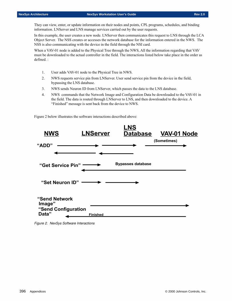
396 Appendices © 2000 Johnson Controls, Inc.
NexSys Architecture NexSys Workstation User’s Guide Rev 2.0
They can view, enter, or update information on their nodes and points, CPL programs, schedules, and bindinginformation. LNServer and LNS manage services carried out by the user requests.In this example, the user creates a new node. LNServer then communicates this request to LNS through the LCAObject Server. The NSS creates or accesses the network database for the information entered in the NWS. TheNSS is also communicating with the device in the field through the NSI card.When a VAV-01 node is added to the Physical Tree through the NWS, All the information regarding that VAVmust be downloaded to the actual controller in the field. The interactions listed below take place in the order asdefined. :
1. User adds VAV-01 node to the Physical Tree in NWS.2. NWS requests service pin from LNServer. User send service pin from the device in the field,
bypassing the LNS database.3. NWS sends Neuron ID from LNServer, which passes the data to the LNS database.4. NWS commands that the Network Image and Configuration Data be downloaded to the VAV-01 in
the field. The data is routed through LNServer to LNS, and then downloaded to the device. A“Finished” message is sent back from the device to NWS.
Figure 2 below illustrates the software interactions described above:
�� �� �� �������/�� �0���% ��-
10��2
1� � ���3 ���2
1 �- � �+��� ).�4 21 �- ���*�45����������2
#�6��� � -���/��
1 � � 5��� )�2
������ -
7�. ��. �8
Figure 2. NexSys Software Interactions

© 2000 Johnson Controls, Inc. Appendices 397
Rev 2.0 NexSys Workstation User’s Guide NexSys Architecture

398 Appendices © 2000 Johnson Controls, Inc.
NexSys Architecture NexSys Workstation User’s Guide Rev 2.0
Appendix D
LNServer
This chapter contains information on:
� LNServer
© 2000 Johnson Controls, Inc.
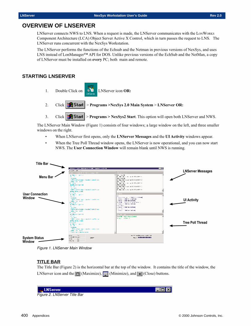
400 Appendices © 2000 Johnson Controls, Inc.
LNServer NexSys Workstation User’s Guide Rev 2.0
OVERVIEW OF LNSERVERLNServer connects NWS to LNS. When a request is made, the LNServer communicates with the LONWORKS
Component Architecture (LCA) Object Server Active X Control, which in turn passes the request to LNS. TheLNServer runs concurrent with the NexSys Workstation.The LNServer performs the functions of the Echsub and the Netman in previous versions of NexSys, and usesLNS instead of LonManager™ API for DOS. Unlike previous versions of the EchSub and the NetMan, a copyof LNServer must be installed on every PC; both main and remote.
STARTING LNSERVER
1. Double Click on LNServer icon OR:
2. Click > Programs >NexSys 2.0 Main System > LNServer OR:
3. Click > Programs > NexSys2 Start. This option will open both LNServer and NWS.
The LNServer Main Window (Figure 1) consists of four windows; a large window on the left, and three smallerwindows on the right.
• When LNServer first opens, only the LNServer Messages and the UI Activity windows appear.• When the Tree Poll Thread window opens, the LNServer is now operational, and you can now start
NWS. The User Connection Window will remain blank until NWS is running.
��������
�������� ����������
���������
��������������
��� ������
����������������
�����������������
Figure 1. LNServer Main Window
TITLE BARThe Title Bar (Figure 2) is the horizontal bar at the top of the window. It contains the title of the window, theLNServer icon and the (Maximize), (Minimize), and (Close) buttons.
Figure 2. LNServer Title Bar
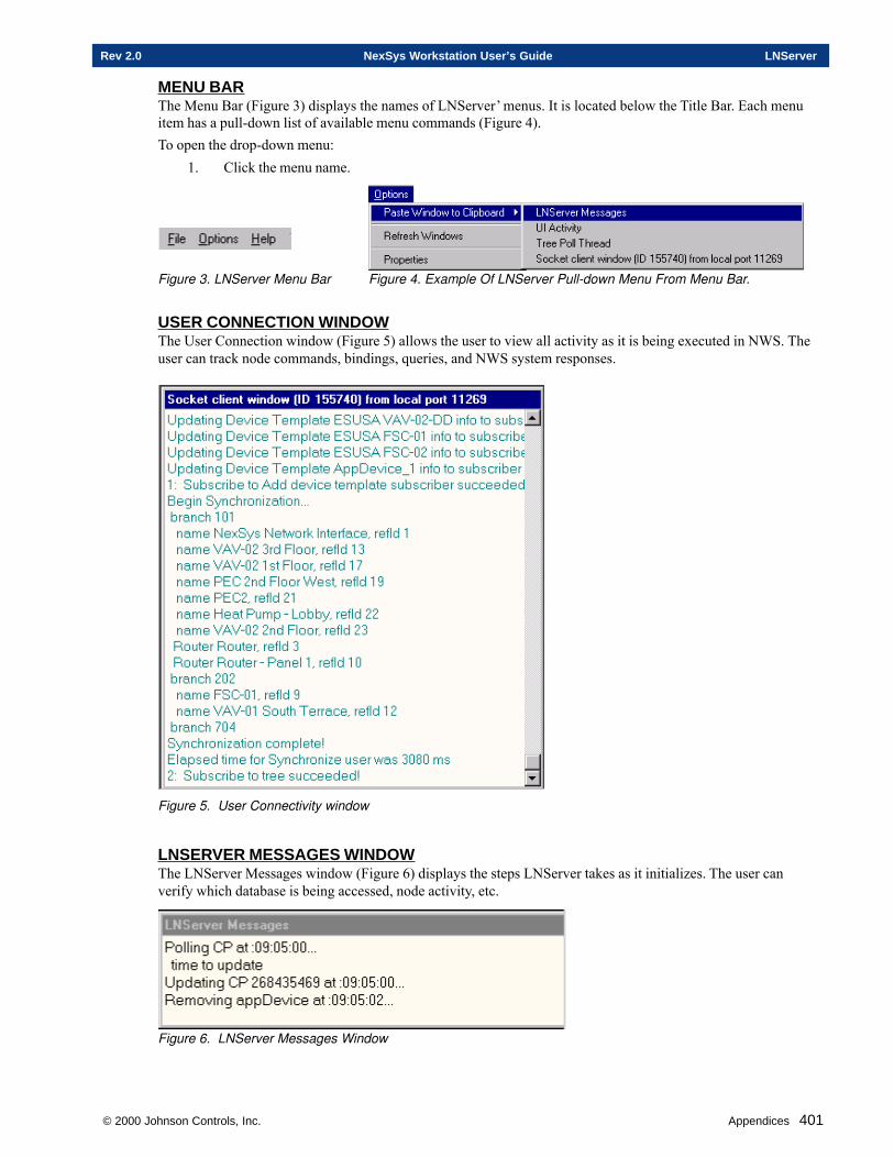
© 2000 Johnson Controls, Inc. Appendices 401
Rev 2.0 NexSys Workstation User’s Guide LNServer
MENU BARThe Menu Bar (Figure 3) displays the names of LNServer’ menus. It is located below the Title Bar. Each menuitem has a pull-down list of available menu commands (Figure 4).To open the drop-down menu:
1. Click the menu name.
Figure 3. LNServer Menu Bar Figure 4. Example Of LNServer Pull-down Menu From Menu Bar.
USER CONNECTION WINDOWThe User Connection window (Figure 5) allows the user to view all activity as it is being executed in NWS. Theuser can track node commands, bindings, queries, and NWS system responses.
Figure 5. User Connectivity window
LNSERVER MESSAGES WINDOWThe LNServer Messages window (Figure 6) displays the steps LNServer takes as it initializes. The user canverify which database is being accessed, node activity, etc.
Figure 6. LNServer Messages Window
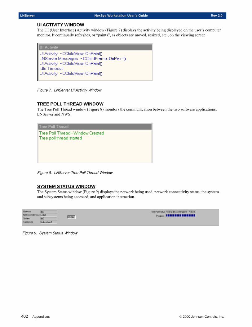
402 Appendices © 2000 Johnson Controls, Inc.
LNServer NexSys Workstation User’s Guide Rev 2.0
UI ACTIVITY WINDOWThe UI (User Interface) Activity window (Figure 7) displays the activity being displayed on the user’s computermonitor. It continually refreshes, or “paints”, as objects are moved, resized, etc., on the viewing screen.
Figure 7. LNServer UI Activity Window
TREE POLL THREAD WINDOWThe Tree Poll Thread window (Figure 8) monitors the communication between the two software applications:LNServer and NWS.
Figure 8. LNServer Tree Poll Thread Window
SYSTEM STATUS WINDOWThe System Status window (Figure 9) displays the network being used, network connectivity status, the systemand subsystems being accessed, and application interaction.
Figure 9. System Status Window
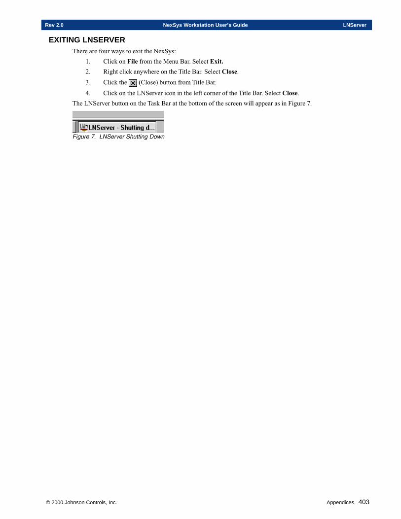
© 2000 Johnson Controls, Inc. Appendices 403
Rev 2.0 NexSys Workstation User’s Guide LNServer
EXITING LNSERVERThere are four ways to exit the NexSys:
1. Click on File from the Menu Bar. Select Exit.2. Right click anywhere on the Title Bar. Select Close.3. Click the (Close) button from Title Bar.
4. Click on the LNServer icon in the left corner of the Title Bar. Select Close.The LNServer button on the Task Bar at the bottom of the screen will appear as in Figure 7.
Figure 7. LNServer Shutting Down

404 Appendices © 2000 Johnson Controls, Inc.
LNServer NexSys Workstation User’s Guide Rev 2.0
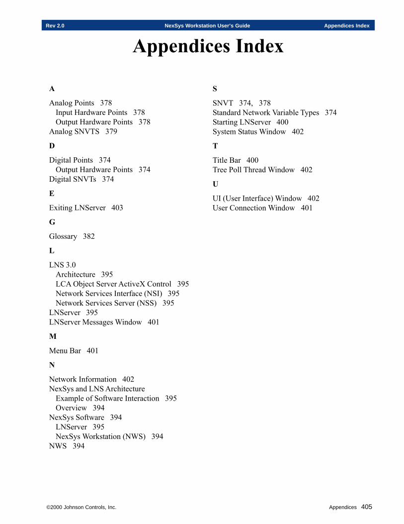
©2000 Johnson Controls, Inc. Appendices 405
Rev 2.0 NexSys Workstation User’s Guide Appendices Index
Appendices Index
A
Analog Points 378Input Hardware Points 378Output Hardware Points 378
Analog SNVTS 379
D
Digital Points 374Output Hardware Points 374
Digital SNVTs 374
E
Exiting LNServer 403
G
Glossary 382
L
LNS 3.0Architecture 395LCA Object Server ActiveX Control 395Network Services Interface (NSI) 395Network Services Server (NSS) 395
LNServer 395LNServer Messages Window 401
M
Menu Bar 401
N
Network Information 402NexSys and LNS Architecture
Example of Software Interaction 395Overview 394
NexSys Software 394LNServer 395NexSys Workstation (NWS) 394
NWS 394
S
SNVT 374, 378Standard Network Variable Types 374Starting LNServer 400System Status Window 402
T
Title Bar 400Tree Poll Thread Window 402
U
UI (User Interface) Window 402User Connection Window 401

406 Appendices ©2000 Johnson Controls, Inc.
Appendices Index NexSys Workstation User’s Guide Rev 2.0
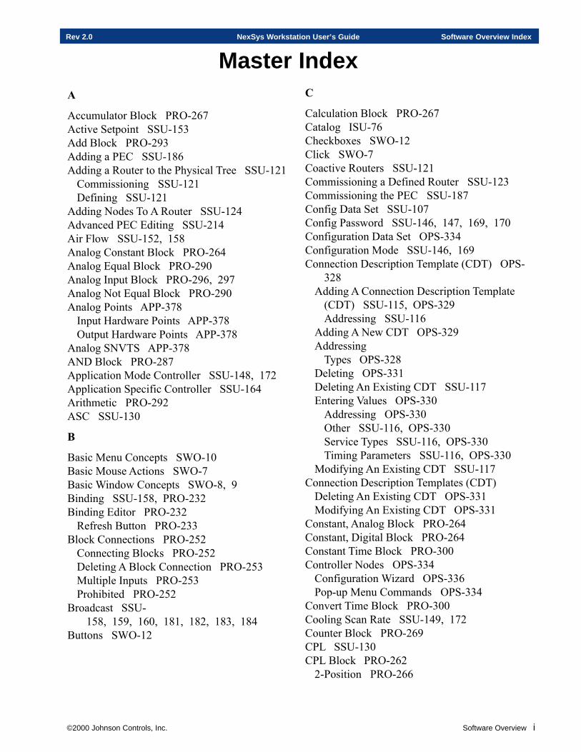
©2000 Johnson Controls, Inc. Software Overview i
Rev 2.0 NexSys Workstation User’s Guide Software Overview Index
Master IndexA
Accumulator Block PRO-267Active Setpoint SSU-153Add Block PRO-293Adding a PEC SSU-186Adding a Router to the Physical Tree SSU-121
Commissioning SSU-121Defining SSU-121
Adding Nodes To A Router SSU-124Advanced PEC Editing SSU-214Air Flow SSU-152, 158Analog Constant Block PRO-264Analog Equal Block PRO-290Analog Input Block PRO-296, 297Analog Not Equal Block PRO-290Analog Points APP-378
Input Hardware Points APP-378Output Hardware Points APP-378
Analog SNVTS APP-378AND Block PRO-287Application Mode Controller SSU-148, 172Application Specific Controller SSU-164Arithmetic PRO-292ASC SSU-130
B
Basic Menu Concepts SWO-10Basic Mouse Actions SWO-7Basic Window Concepts SWO-8, 9Binding SSU-158, PRO-232Binding Editor PRO-232
Refresh Button PRO-233Block Connections PRO-252
Connecting Blocks PRO-252Deleting A Block Connection PRO-253Multiple Inputs PRO-253Prohibited PRO-252
Broadcast SSU-158, 159, 160, 181, 182, 183, 184
Buttons SWO-12
C
Calculation Block PRO-267Catalog ISU-76Checkboxes SWO-12Click SWO-7Coactive Routers SSU-121Commissioning a Defined Router SSU-123Commissioning the PEC SSU-187Config Data Set SSU-107Config Password SSU-146, 147, 169, 170Configuration Data Set OPS-334Configuration Mode SSU-146, 169Connection Description Template (CDT) OPS-
328Adding A Connection Description Template
(CDT) SSU-115, OPS-329Addressing SSU-116
Adding A New CDT OPS-329Addressing
Types OPS-328Deleting OPS-331Deleting An Existing CDT SSU-117Entering Values OPS-330
Addressing OPS-330Other SSU-116, OPS-330Service Types SSU-116, OPS-330Timing Parameters SSU-116, OPS-330
Modifying An Existing CDT SSU-117Connection Description Templates (CDT)
Deleting An Existing CDT OPS-331Modifying An Existing CDT OPS-331
Constant, Analog Block PRO-264Constant, Digital Block PRO-264Constant Time Block PRO-300Controller Nodes OPS-334
Configuration Wizard OPS-336Pop-up Menu Commands OPS-334
Convert Time Block PRO-300Cooling Scan Rate SSU-149, 172Counter Block PRO-269CPL SSU-130CPL Block PRO-262
2-Position PRO-266
ii Software Overview ©2000 Johnson Controls, Inc.
Software Overview Index NexSys Workstation User’s Guide Rev 2.0
Accumulator PRO-267Add PRO-293Analog Constant PRO-264Analog Input PRO-286Analog Output PRO-286AND PRO-287Calculation PRO-267Constant Time PRO-300Convert Time PRO-300Counter PRO-269Current Time PRO-301Dial Provider PRO-269Digital Constant PRO-264Digital Input PRO-286Digital Output PRO-286Divide PRO-293Enthalpy PRO-270Equal - Analog PRO-290Equal - Digital PRO-290Error - Analog PRO-270Error - Digital PRO-271Greater Equal PRO-291Greater Than PRO-291Input - Analog PRO-296, 297Lead/Lag PRO-272Less Equal PRO-292Less Than PRO-292Min/Max PRO-273Minimum On/Off PRO-274Modulus PRO-294Multiple Analog Input PRO-297Multiple Digital Input PRO-298Multiply PRO-294Negate PRO-294NOT PRO-288Not Equal - Analog PRO-290One Shot PRO-274OR PRO-288Output - Digital PRO-297PID Loop PRO-276Psychro PRO-277Ramp PRO-277Relay - Analog PRO-278Reset PRO-279Rolling Average PRO-280Runtime PRO-281Schedule PRO-282
Select Hi/Lo/Average PRO-271Sequencer PRO-283Square Root PRO-295Start/Stop PRO-284Startup PRO-284Subtract PRO-295Time Event PRO-284XOR PRO-288
CPL BlocksAdding CPL Blocks PRO-248, 249Arithmetic Blocks PRO-242Block Colors PRO-243Block Types PRO-241Constant Blocks PRO-242Constants PRO-263CPL Block Settings PRO-262
Ignore Error Check Box PRO-263Settings Window PRO-262
Deleting A Block PRO-250Direct/Reverse Acting Blocks PRO-250Function Blocks PRO-242Global Variables Blocks PRO-243Logical Blocks PRO-243Moving A Block PRO-251Multiple Input Block PRO-253Point Blocks PRO-243Summary Of Blocks PRO-258Time Blocks PRO-243
CPL Editor PRO-243Best Fit PRO-244CPL Block Menu PRO-247CPL Editor Toolbar PRO-244Deleting Multiple Blocks PRO-251Editing Multiple Blocks PRO-249Monitor Mode PRO-245
Activate PRO-245Deactivate PRO-245
Moving Multiple Blocks PRO-252Show Editor PRO-245Zoom Control Box PRO-246Zoom Modes PRO-244
CPL Pages OPS-348Add OPS-348Adding A New CPL Page PRO-247CPL Library
Create Page From Library OPS-348CPL Page Menu Commands PRO-239
©2000 Johnson Controls, Inc. Software Overview iii
Rev 2.0 NexSys Workstation User’s Guide Software Overview Index
Copy To FSC PRO-240Copy To Library PRO-240Enable/Disable PRO-239
CPL Pages Subtree PRO-238Popup Menu PRO-239
Creating CPL Pages PRO-247Editing CPL Pages PRO-247Individual Pages PRO-239Menu Commands OPS-349Refresh OPS-348
CPL User Library PRO-254Accessing PRO-255Closing PRO-255CPL Block Editor Window PRO-256Creating A New CPL Library Page PRO-257Exporting A CPL Library Page PRO-257Importing A CPL Library Page PRO-257Library Pages Toolbar PRO-256Library Pages Window PRO-255Pre-programmed Pages PRO-254
CTI Routers SSU-121Current Time Block PRO-301Cursor SWO-6
D
Damper SSU-152Damper Actuator SSU-158Damper Actuator Increment SSU-158Damper Position SSU-158Deadband SSU-177Default Output SSU-149, 153, 172Defining a PEC SSU-186Delay Time SSU-177, 180Derivative Gain SSU-149, 153, 172, 176DHCP ISU-37Dial Provider Block PRO-269Dial Up Networking ISU-54, 58Dial-Up Monitor ISU-59Dialin Information, RAS ISU-53Dialog Boxes SWO-12, 13Digital Constant Block PRO-264Digital Equal Block PRO-290Digital Output Block PRO-297Digital Points APP-374
Output Hardware Points APP-374Digital SNVTs APP-374Direct Action SSU-153
Display Order SSU-146, 170Divide Block PRO-293Double Click SWO-7Drag SWO-7Drive Time SSU-153Dropdown List Boxes SWO-12
E
Echelon Routers SSU-121Economizer
Controller SSU-148, 172, 175Economy
Cooling Setpoint SSU-147, 148, 171Heating Setpoint SSU-147, 148, 171
Edit/View Binding SSU-106Editing and Viewing Bindings PRO-232Editing and Viewing Binds PRO-234, 235Editing Points. See Heat Pump: Editing
Points; PEC: Editing Points; Remote I/O:Editing Points; Variable Air Volume (VAV):Editing Points
EmergencyCommand SSU-179Command Controller SSU-148, 172Heat SSU-179Heat Holdoff SSU-179Shutdown SSU-215
Emergency Shut Down SWO-19English Units SSU-146, 170Enthalpy Block PRO-270Error - Analog Block PRO-270Error - Digital Block PRO-271Escape Key SWO-6ESUSA Resources ISU-76Exiting LNServer APP-403
F
FanController SSU-148, 159, 172Output SSU-159, 177Status SSU-178, 179Status Delay SSU-178
Far-Side Transceiver Types SSU-121Fiber Optic/Twisted Pair Router SSU-121FLC SSU-130Flow Offset SSU-150FSC SSU-158, 159, 160, 183
iv Software Overview ©2000 Johnson Controls, Inc.
Software Overview Index NexSys Workstation User’s Guide Rev 2.0
CPL Pages OPS-348Detail Panel
Query Options OPS-354FSC Subtrees OPS-348Schedules OPS-350
FSC Schedules Panel PRO-306, 307Refresh PRO-309
FSC/FLC SSU-130Add SSU-130Adding FSC/FLC Points OPS-342Deleting FSC/FLC Points OPS-343Editing FSC/FLC Points OPS-343
FTR SSU-121Function Blocks PRO-265Function Keys SWO-6Functions
Descriptor Window PRO-265Timing Window PRO-265
G
Global Analog Input Block PRO-286Global Analog Output Block PRO-286Global Digital Input Block PRO-286Global Digital Output Block PRO-286Global Node SSU-102, 131, 140, 164Global Variables Blocks PRO-285Glossary APP-382Greater Equal Block PRO-291Greater Than Block PRO-291
H
Hardware Drivers ISU-66Heating
Scan Rate SSU-149, 172Heating/Cooling Controller SSU-148, 172Highlight SWO-7Holdoff SSU-179
I
I/O Module SSU-137Installation Checklist ISU-33Installing
PCC-10 ISU-73PCLTA-10/20 Card ISU-73
Installing a Network Adapter ISU-34Installing NexSys ISU-38Integral Gain SSU-148, 153, 172, 176
Intelligent STAT SSU-145, 169Interrupt Request (IRQ)
Selecting ISU-72Interstage Delay SSU-156IP Address ISU-55IPCONFIG ISU-53
K
K Factor SSU-149, 150, 152K Factor Calibration SSU-150Keyboard SWO-6
L
Lead/Lag Block PRO-272Less Equal Block PRO-292Less Than Block PRO-292List Boxes SWO-12LNS SWO-23LNS 3.0
Architecture APP-395LCA Object Server ActiveX Control APP-
395Network Services Interface (NSI) APP-395Network Services Server (NSS) APP-395
LNServer SWO-23, APP-395Configuration Wizard ISU-39Configure for Local Location ISU-40Configure for Remote Location ISU-43Configuring ISU-39Exiting ISU-82Starting LNServer ISU-78Status Bar ISU-82
LNServer Messages Window APP-401Load Firmware SSU-110Local SSU-174Local Economizer SSU-174Logical Blocks PRO-287, 289LON Economizer SSU-174Loop Enable SSU-179Low Limit
Setpoint SSU-176
M
M3 Workstation SWO-23Maximum Air Flow SSU-151Menu Bar APP-401Menus SWO-10
©2000 Johnson Controls, Inc. Software Overview v
Rev 2.0 NexSys Workstation User’s Guide Software Overview Index
Metric Units SSU-146, 170Min. Off Time SSU-179Min. On Time SSU-179Min. Reheat Flow SSU-151Min/Max Block PRO-273Minimum Air Flow SSU-151Minimum Criteria ISU-34Minimum On/Off Block PRO-274Minimum Run Time SSU-177Mixed Air PID SSU-176, 179Mixed Air Temperature SSU-176Modem ISU-56Modulus Block PRO-294Morning Warmup
Maximum Flow SSU-151Minimum Flow SSU-151
Mouse SWO-6MS Loopback Adapter ISU-35Multi-Node Operations
Selecting The Node OPS-332Selecting The Options OPS-333
Multi-tasking SWO-6MultiNode Operations SSU-113Multiple Analog Input Block PRO-297Multiple Digital Input Block PRO-298Multiply Block PRO-294MWU Max. Flow SSU-151MWU Min. Flow SSU-151My Computer SWO-15
N
Negate Block PRO-294NetBEUI ISU-36, 49Network SSU-174Network Adapter
Installing ISU-34Network Information APP-402Network Neighborhood SWO-15Network Protocols ISU-36, 53Network Variable Inputs PRO-232Network Variable Outputs PRO-232Network Variables PRO-232
Binding NVs OPS-345Neuron ID SSU-103, 132, 141, 165NexSys
Licensing OPS-328NexSys and LNS Architecture
Example of Software Interaction APP-395Overview APP-394
NexSys Network Interface OPS-326Editing OPS-327
Editor Options OPS-327NexSys Network Interface Node
Accessing the CDT OPS-328CDT Addressing OPS-328Connection Description Template (CDT)
OPS-328Editing Options OPS-327Editing the Nexsys Network Interface OPS-
327Multi-Node Operations OPS-332
NexSys Software APP-394LNServer APP-395NexSys Workstation (NWS) APP-394
NexSys Work Station (NWS)Exiting NWS ISU-82Starting NWS ISU-78
Nexsys Workstation (NWS) SWO-23No Reverse SSU-180Node
Add SSU-102Configuration Wizard SSU-118Delete SSU-107Move SSU-101Rename SSU-110
Node Commands SSU-96Offline SSU-97Reset SSU-98Test SSU-98Wink SSU-96
Node Menu SSU-96Node Working Panels OPS-352
Detail Panel OPS-353Query Options OPS-354
NOT Block PRO-288NT Explorer SWO-17NWS APP-394NWS Main Window ISU-79
Menu Bar ISU-81, OPS-323Help Menu OPS-324NWS Menu OPS-323View Menu OPS-324
Node Working Panels OPS-352Overview OPS-322
vi Software Overview ©2000 Johnson Controls, Inc.
Software Overview Index NexSys Workstation User’s Guide Rev 2.0
Physical Tree ISU-81Resizing the NexSys Window ISU-80Title ISU-80Tool Bar OPS-325
Buttons OPS-325Toolbar ISU-81Version Number ISU-80
O
OAT Deadband SSU-175Occupied Cooling Setpoint SSU-147, 171Occupied Heating Setpoint SSU-147, 171Occupied Mode SSU-146, 170Offset SSU-148, SSU-171One Shot Block PRO-274OPC LonWorks® Server SWO-23OR Block PRO-288Overview SWO-6
P
Parallel Fan SSU-154Password SSU-146, 169, 170PC Configurations ISU-32PCC-10 ISU-66PCLTA Card, Full Size
Disabling ISU-65Removing ISU-65
PCLTA-10 ISU-66PCLTA-20 ISU-66PEC SSU-131, 140, 164
Editors SSU-132, 141, 165Global Information SSU-134, 143, 168, 190
Physical Tree SSU-131, 140, 164, OPS-326Configuration Properties OPS-345Controller Nodes OPS-334
Setup Node OPS-341LMOs OPS-344Lon Mark Object (LMO) OPS-344Network Variables OPS-344NexSys Network Interface Node OPS-326
Connection Description Template (CDT)SSU-114
Points OPS-342Routers OPS-333
PID SSU-154PID Loop SSU-152
PID Loop Block PRO-276PING ISU-53Plug-Ins SSU-99
Registering A Plug-In SSU-99Running A Plug-In SSU-100
Point SWO-7Point Blocks PRO-295 to PRO-299Point State Block PRO-298Points
Adding FSC/FLC Points OPS-342Deleting FSC/FLC Points OPS-343Detail Panel OPS-346Editing FSC/FLC Points OPS-343Status/Command Panels OPS-347Working Panels OPS-346
Polarity SSU-180Pop-Up Menus SWO-11
Shortcut Menus SWO-11Printer Setup SWO-18Proportional Gain SSU-148, 153, 172, 175Psychro Block PRO-277Pull-Down Menus SWO-10, 11
R
Radio Buttons SWO-12Ramp Block PRO-277RAS
Client ISU-53Dial the Server ISU-58Dialin Information ISU-53Disconnect a Remote Site ISU-59Installing ISU-46Setting to Automatic Start ISU-50User Login Privileges ISU-51
Refresh Schedules PRO-309Reheat Decrement SSU-154Reheat Increment SSU-154Relay - Analog Block PRO-278Replace Node SSU-105Reset Block PRO-279Resource Files ISU-76
Adding ESUSA Resources to Catalog ISU-76Reverse SSU-180Reverse Acting Block PRO-276Reverse Action SSU-153Right Click SWO-7Rolling Average Block PRO-280
©2000 Johnson Controls, Inc. Software Overview vii
Rev 2.0 NexSys Workstation User’s Guide Software Overview Index
RouterBridge Router SSU-120Configured Router SSU-120Learning Router SSU-120Permanent Bridge Router SSU-120Permanent Repeater Router SSU-120Repeater Router SSU-120
Router Classification Types SSU-120Routers OPS-333
Add At End Command OPS-335Configuration Data Sets OPS-334Types of Routers OPS-334
Runtime Block PRO-281RX ISU-60
S
Scan Rate SSU-149, 153, 172Scan Time SSU-176Schedule
Add PRO-305Create PRO-305
Entering Values PRO-306Delete PRO-308Edit PRO-308Pop-up Menu PRO-305Rename PRO-308Viewing PRO-304
Schedule Block PRO-282Schedules OPS-350
Add OPS-351Copy To FSC OPS-352Delete OPS-352Rename OPS-352
Scheduling PRO-304Schedule CPL Block PRO-304Schedule Subtree PRO-304
Summary Schedule List PRO-304Scroll Bars SWO-8Scroll Box SWO-8Select SWO-7Select Hi/Lo/Average Block PRO-271Sequencer Block PRO-283Serial Fan SSU-154Service Pin SSU-103, 132, 141, 165Set Time/Day On Node SSU-109Setpoint SSU-177Setpoint Controller SSU-148, 172
Setup Node SSU-103Shortcut Menus SWO-16SMX
1250 Transceiver Board ISU-6578K Transceiver Board ISU-65DFOM Transceiver Board ISU-65
SNVT APP-374, APP-378Space Temperature SSU-135, 145, 169Spin Boxes SWO-12Square Root Block PRO-295Stages SSU-178Standard Network Variable Types APP-374Standby State SSU-215Start Menu SWO-17Start-Up Procedure ISU-76
Exiting LNServer ISU-82Exiting NWS ISU-82Starting LNServer ISU-78Starting LNServer And NWS Together ISU-
78Starting NWS ISU-78
Start/Stop Block PRO-284Starting LNServer APP-400Starting NexSys ISU-78, 79Startup Block PRO-284Status Send Interval SSU-135Subtract Block PRO-295Swipe SWO-7System Status Window APP-402
T
Task Bar SWO-16TCP/IP ISU-36, 37, 49, 55Thermal Load SSU-148, 172Thermistor SSU-145, 169Time Blocks PRO-299Time Broadcast Interval SSU-135Time Event Block PRO-284Time Mode SSU-146, 170Time Zone Offset SSU-135Title Bar APP-400Tree Poll Thread Window APP-402Trend Setup Panel OPS-354Trending OPS-354
Types Of Trending OPS-355Two Position Block PRO-266TX ISU-60
viii Software Overview ©2000 Johnson Controls, Inc.
Software Overview Index NexSys Workstation User’s Guide Rev 2.0
U
UI (User Interface) Window APP-402Units SSU-146, 170Unoccupied Cooling Setpoint SSU-148, 171Unoccupied Heating Setpoint SSU-148, 171User Connection Window APP-401User Mode SSU-146, 170
W
WindowMaximize SWO-9Minimize SWO-9Move SWO-9Resize SWO-9Restore SWO-9
Windows NT SWO-19Accessing Information
Pull-Down Menus SWO-10Copy an Object SWO-16Create a Folder SWO-16Delete a Folder SWO-16Desktop SWO-14Find an Object SWO-17Hardware SWO-6Move an Object SWO-16MS DOS Window SWO-18Overview SWO-14Recycle Bin SWO-16Rename an Object SWO-16Screen Breakdown
Cursor SWO-7Scroll Bars SWO-8Windows SWO-9
Windows NT Help SWO-15
X
XOR Block PRO-288


![LMMS v - User Manual, 2011.08.30 - [Digital Audio Workstation - MIDI + Audio]](https://img.pdfslide.net/doc/110x75/552d22464a795963598b4622/lmms-v-user-manual-20110830-digital-audio-workstation-midi-audio.jpg)


![[Nexsys] Helpware - Wearable for industrial safety](https://img.pdfslide.net/doc/110x75/58f32df21a28ab38038b467f/nexsys-helpware-wearable-for-industrial-safety.jpg)