Embed Size (px)
Citation preview

Next Generation Frame (NGF)288 Position Fiber Termination Block (FTB)
User Manual
25818-A
www.commscope.com300100106974 Rev C
TECP-91-002Rev C, March 2018
25818-A

TECP-91-002 • Rev C • March 2018 • Preface
Page ii
COPYRIGHT
© 2018, CommScope Inc.All Rights Reserved
REVISION HISTORY
TRADEMARK INFORMATION
CommScope, CommScope(logo), and Next Generation Frame are registered trademarks of CommScope, Inc.
Telcordia is a registered trademark of Telcordia Technologies, Inc.
GORE is a registered trademark of W. L. Gore & Associates, Inc.
DISCLAIMER OF LIABILITY
Contents herein are current as of the date of publication. CommScope reserves the right to change the contents without prior notice.In no event shall CommScope Inc. be liable for any damages resulting from loss of data, loss of use, or loss of profits andCommScope Inc. further disclaims any and all liability for indirect, incidental, special, consequential or other similardamages. This disclaimer of liability applies to all products, publications and services during and after the warranty period.
This publication may be verified at any time by contacting CommScope’s Technical Assistance Center at:http://www.commscope.com/SupportCenter
PATENTS
http://www.commscope.com/ProductPatent/ProductPatent.aspx
TECHNICAL SUPPORT AND PRODUCT INFORMATION
http://www.commscope.com/SupportCenter
ISSUE DATE REASON FOR CHANGE
1 6/2014 Original.
2 January 2017 Updated to CommScope format.
C March 2018 Corrected part number error on page 1.
TECP-91-002 • Rev C • March 2018 • Preface
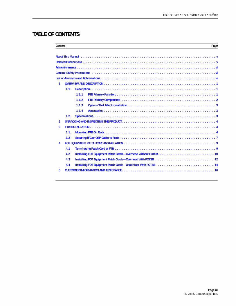
TABLE OF CONTENTS
Content Page
TABLE OF CONTENTS
About This Manual . . . . . . . . . . . . . . . . . . . . . . . . . . . . . . . . . . . . . . . . . . . . . . . . . . . . . . . . . . . . . . . . . . . . . . . . . . . v
Related Publications . . . . . . . . . . . . . . . . . . . . . . . . . . . . . . . . . . . . . . . . . . . . . . . . . . . . . . . . . . . . . . . . . . . . . . . . . . v
Admonishments . . . . . . . . . . . . . . . . . . . . . . . . . . . . . . . . . . . . . . . . . . . . . . . . . . . . . . . . . . . . . . . . . . . . . . . . . . . . .vi
General Safety Precautions . . . . . . . . . . . . . . . . . . . . . . . . . . . . . . . . . . . . . . . . . . . . . . . . . . . . . . . . . . . . . . . . . . . . .vi
List of Acronyms and Abbreviations . . . . . . . . . . . . . . . . . . . . . . . . . . . . . . . . . . . . . . . . . . . . . . . . . . . . . . . . . . . . . . . .vi
1 OVERVIEW AND DESCRIPTION . . . . . . . . . . . . . . . . . . . . . . . . . . . . . . . . . . . . . . . . . . . . . . . . . . . . . . . . . . . . . . 1
1.1 Description. . . . . . . . . . . . . . . . . . . . . . . . . . . . . . . . . . . . . . . . . . . . . . . . . . . . . . . . . . . . . . . . . . . . . . 1
1.1.1 FTB Primary Function. . . . . . . . . . . . . . . . . . . . . . . . . . . . . . . . . . . . . . . . . . . . . . . . . . . . . . . . 1
1.1.2 FTB Primary Components . . . . . . . . . . . . . . . . . . . . . . . . . . . . . . . . . . . . . . . . . . . . . . . . . . . . . 2
1.1.3 Options That Affect Installation . . . . . . . . . . . . . . . . . . . . . . . . . . . . . . . . . . . . . . . . . . . . . . . . . 3
1.1.4 Accessories . . . . . . . . . . . . . . . . . . . . . . . . . . . . . . . . . . . . . . . . . . . . . . . . . . . . . . . . . . . . . . 3
1.2 Specifications . . . . . . . . . . . . . . . . . . . . . . . . . . . . . . . . . . . . . . . . . . . . . . . . . . . . . . . . . . . . . . . . . . . . 3
2 UNPACKING AND INSPECTING THE PRODUCT . . . . . . . . . . . . . . . . . . . . . . . . . . . . . . . . . . . . . . . . . . . . . . . . . . . . 4
3 FTB INSTALLATION . . . . . . . . . . . . . . . . . . . . . . . . . . . . . . . . . . . . . . . . . . . . . . . . . . . . . . . . . . . . . . . . . . . . . . 4
3.1 Mounting FTB On Rack . . . . . . . . . . . . . . . . . . . . . . . . . . . . . . . . . . . . . . . . . . . . . . . . . . . . . . . . . . . . . . 4
3.2 Securing IFC or OSP Cable to Rack . . . . . . . . . . . . . . . . . . . . . . . . . . . . . . . . . . . . . . . . . . . . . . . . . . . . . 7
4 FOT EQUIPMENT PATCH CORD INSTALLATION . . . . . . . . . . . . . . . . . . . . . . . . . . . . . . . . . . . . . . . . . . . . . . . . . . . 9
4.1 Terminating Patch Cord at FTB . . . . . . . . . . . . . . . . . . . . . . . . . . . . . . . . . . . . . . . . . . . . . . . . . . . . . . . . 9
4.2 Installing FOT Equipment Patch Cords—Overhead Without FOTSB . . . . . . . . . . . . . . . . . . . . . . . . . . . . . . . 10
4.3 Installing FOT Equipment Patch Cords—Overhead With FOTSB . . . . . . . . . . . . . . . . . . . . . . . . . . . . . . . . . 12
4.4 Installing FOT Equipment Patch Cords—Underfloor With FOTSB . . . . . . . . . . . . . . . . . . . . . . . . . . . . . . . . 14
5 CUSTOMER INFORMATION AND ASSISTANCE . . . . . . . . . . . . . . . . . . . . . . . . . . . . . . . . . . . . . . . . . . . . . . . . . . . 16
_________________________________________________________________________________________________________
Page iii© 2018, CommScope, Inc.

TECP-91-002 • Rev C • March 2018 • Preface
TABLE OF CONTENTS
Content Page
This page is intentionally blank.
Page iv© 2018, CommScope, Inc.

TECP-91-002 • Rev C • March 2018 • Preface
ABOUT THIS MANUAL
This user manual provides the following information:
• A description of the 288 position Fiber Termination Blocks (FTBs); its components andterminology, typical applications, and typical accessories;
• Procedures for installing an FTB on any of the Next Generation Frame (NGF) racks;
• Procedures for terminating connectorized Outside Plant (OSP) cables, Intra-FacilityCables (IFC), or Fiber Optic Terminal (FOT) equipment patch cords at the FTB.
The procedures for installing the various NGF racks, including the Fiber Main Distribution Frame(FMDF), the Front Facing Fiber Main Distribution Frame (F3MDF), and the Slim Rack FiberDistribution Frame, are provided in other ADC publications (see “Related Publications,” below).
RELATED PUBLICATIONS
Listed below are related manuals and their publication numbers. Copies of these publications canbe ordered by contacting the CommScoope Technical Assistance Center (refer to Section 5 onPage 16).
Next Generation Frame Fiber Main Distributing Frame User Manual 90-273Provides a complete description of the FMDF and procedures for installing the FMDF rack, the FTB, and the FCB.
Next Generation Frame Slim Rack Fiber Distributing Frame User Manual 90-272Provides a complete description of the slim rack frame and procedures for installing the FMDF rack, the FTB, and the FCB.
Next Generation Frame Fiber Combination Block User Manual 90-279Provides instructions for installing the FCB in the NGF rack.
Next Generation Frame 432 Position Fiber Termination Block User Manual 91-003Provides instructions for installing the FCB in the NGF rack.
Next Generation Frame Fiber Optic Terminal Storage Bay User Manual 90-270Provides instructions for installing the FOTSB with the FMDF rack.
Note: The NGF Fiber Termination Blocks (FTBs) are designed to be used with 1.7mm or2.0mm patchcords. 3.0mm patchcords should never be used due to the bulk build-up in theNGF solution.
Title/Description TECP Number
Page v© 2018, CommScope, Inc. All Rights Reserved.

TECP-91-002 • Rev C • March 2018 • Preface
ADMONISHMENTS
Important safety admonishments are used throughout this manual to warn of possible hazards topersons or equipment. An admonishment identifies a possible hazard and then explains whatmay happen if the hazard is not avoided. The admonishments — in the form of Dangers,Warnings, and Cautions — must be followed at all times.
These warnings are flagged by use of the triangular alert icon (seen below), and are listed indescending order of severity of injury or damage and likelihood of occurrence.
GENERAL SAFETY PRECAUTIONS
LIST OF ACRONYMS AND ABBREVIATIONS
The following acronyms are used in this manual:
FCB Fiber Combination BlockFMDF Fiber Main Distributing Frame
FOT Fiber Optic TerminalFOTSB Fiber Optic Terminal Storage Bay
FTB Fiber Termination BlockF3MDF Front Facing Fiber Main Distributing Frame
IFC Intra-Facility Fiber CableNGF Next Generation FrameOSP Outside Plant
VAM Value Added Module
Danger: Danger is used to indicate the presence of a hazard that will cause severe personalinjury, death, or substantial property damage if the hazard is not avoided.
Warning: Warning is used to indicate the presence of a hazard that can cause severe personalinjury, death, or substantial property damage if the hazard is not avoided.
Caution: Caution is used to indicate the presence of a hazard that will or can cause minorpersonal injury or property damage if the hazard is not avoided.
Danger: Infrared radiation is invisible and can seriously damage the retina of the eye. Do notlook into the ends of any optical fiber. Do not look directly into the optical adapters of the adapterpacks. Exposure to invisible laser radiation may result. An optical power meter should be used toverify active fibers. A protective cap or hood MUST be immediately placed over any radiatingadapter or optical fiber connector to avoid the potential of dangerous amounts of radiationexposure. This practice also prevents dirt particles from entering the adapter or connector.
Page vi© 2018, CommScope, Inc. All Rights Reserved.

TECP-91-002 • Rev C • March 2018
1 OVERVIEW AND DESCRIPTION
This section introduces the CommScope 288 position Fiber Termination Blocks (FTBs) andexplains their primary function, primary components, options affecting installation, andavailable accessories. This section also contains product specifications.
1.1 Description
1.1.1 FTB Primary Function
FTBs are used in conjunction with an NGF rack to provide a point for terminatingconnectorized fiber optic cables and for interconnecting or cross-connecting the terminatedcircuits using patch cords. Figure 1 shows an FTB (with stubbed cable) exploded from an NGFrack which also contains a second FTB.
Figure 1. Fiber Termination Blocks and Frame
Connectorized OSP and IFC cables and FOT equipment patch cords terminate at the rear of theFTB. Cross-connect or interconnect patch cords connect to the front of the FTB. The FTBmounts on the NGF rack, which provides physical support and cable management. The FTB hasa left or right orientation for installation on either the left or right side of the frame (as viewedfrom the front).
25812-AFRONT SIDE
SCREW (2X)
WASHER (2X)
FIBER TERMINATION
BLOCK (2X)
NEXTGENERATIONFRAME (NGF)
Page 1© 2018, CommScope, Inc. All Rights Reserved.
TECP-91-002 • Rev C • March 2018
1.1.2 FTB Primary Components
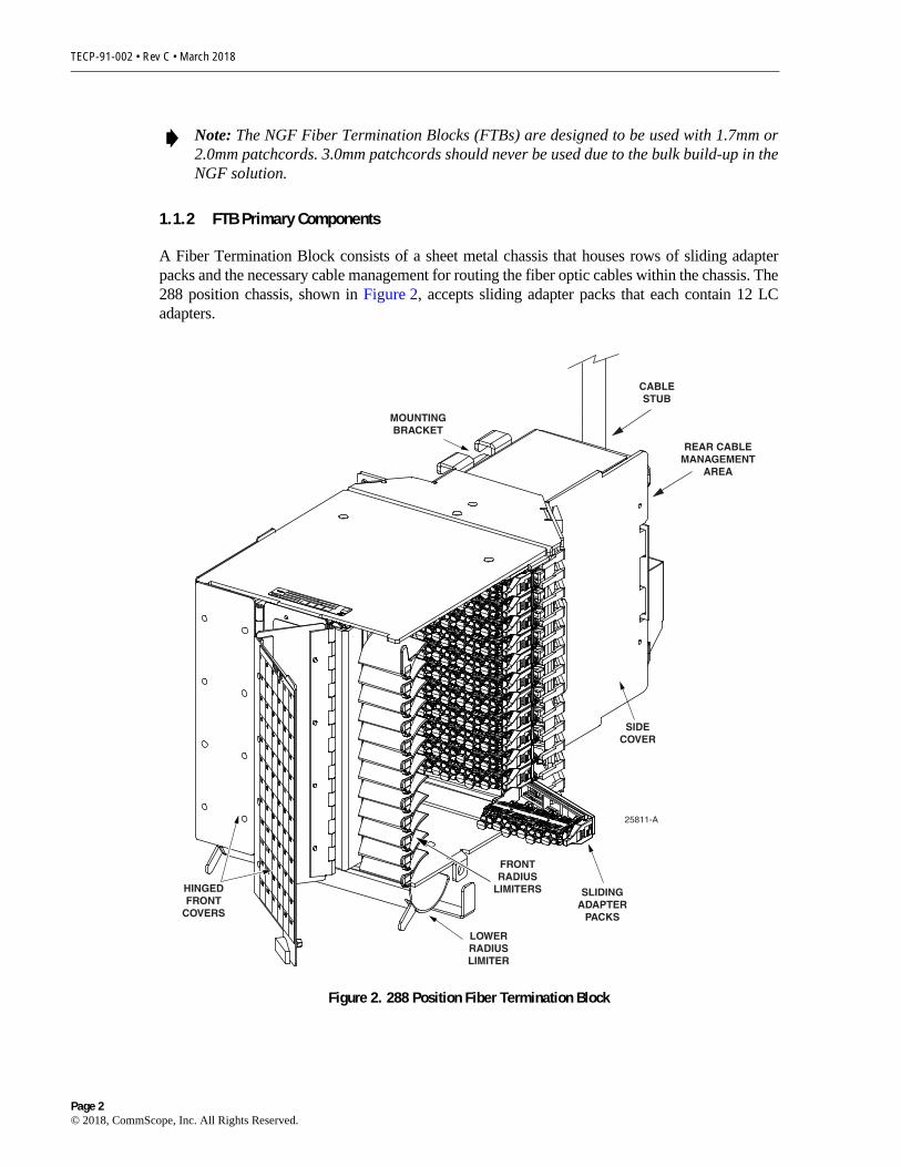
A Fiber Termination Block consists of a sheet metal chassis that houses rows of sliding adapterpacks and the necessary cable management for routing the fiber optic cables within the chassis. The288 position chassis, shown in Figure 2, accepts sliding adapter packs that each contain 12 LCadapters.
Figure 2. 288 Position Fiber Termination Block
Note: The NGF Fiber Termination Blocks (FTBs) are designed to be used with 1.7mm or2.0mm patchcords. 3.0mm patchcords should never be used due to the bulk build-up in theNGF solution.
25811-A
SLIDINGADAPTER
PACKS
SIDECOVER
MOUNTINGBRACKET
LOWERRADIUSLIMITER
FRONTRADIUS
LIMITERS
REAR CABLEMANAGEMENT
AREA
HINGEDFRONT
COVERS
CABLESTUB
Page 2© 2018, CommScope, Inc. All Rights Reserved.

TECP-91-002 • Rev C • March 2018
The FTB chassis includes a removable side cover and two hinged front covers. The back of theFTB has features for clamping and routing OSP/IFC cables and equipment jumpers. Openingthe FTB front covers provides access to the adapter packs (by sliding them out) and to the frontradius limiters which facilitate the routing of interconnect or cross-connect patch cords. Thefront covers also include designation labels to identify the optical circuits.
1.1.3 Options That Affect Installation
The following FTB ordering options may affect the installation process:
• The FTB may be ordered pre-terminated or with MPO adapters on the rear, which allowconnectorization with a high fiber count cable. In the pre-terminated version, the FTB isequipped with an installed OSP or IFC cable. One end of the cable is connected to the rearside of the adapters within the FTB. The other end of the OSP/IFC cable is coiled on a spool.At the job site, the free end of the OSP/IFC cable must be uncoiled from the spool and thenrouted to another location for splicing or connection to the OSP or FOT equipment circuits.The FTB does not include a pre-terminated OSP or IFC cable. This FTB is typically used toterminate FOT patch cords in a cross-connect application.
• The FTB with MPO adapters may be ordered with a left or right orientation. The left-orientation FTB installs on the left side of the frame (when facing the front of the frame);the right-orientation FTB installs on the right side of the frame.
1.1.4 Accessories
The following accessories are available for use with the FTB:
• IFC Cable Assemblies—Are available with singlemode or multimode fiber in specifiedlengths and with specified connectors.
• Patch Cords—Are available with specified connectors in standard lengths.
• Adapter Packs—Are available separately to be used as either as replacements for existingadapter packs.
• In-Line Attenuators—Install between an adapter and connector. They can be mounted oneither the front side or the rear side of an adapter pack.
• Connector Cleaning Kit—Provides all the materials required to correctly clean fiberSpecifications
1.2 Specifications
Table 1 provides specifications for the FTB.
Table 1. FTB Specifications
PARAMETER SPECIFICATION REMARKS
Physical
Number of Fibers 288
Page 3© 2018, CommScope, Inc. All Rights Reserved.

TECP-91-002 • Rev C • March 2018
2 UNPACKING AND INSPECTING THE PRODUCT
Use the following procedure to unpack and inspect the FTB:
1. Inspect the exterior of the shipping container for evidence of rough handling that may havedamaged the contents of the container.
2. Unpack the FTB and inspect for possible damage.
3. If damage is detected or if parts are missing, file a claim with the commercial carrier andthen notify ADC Customer Service. Save damaged carton for inspection by carrier.
4. Refer to Topic 5 on page 16 for CommScope contact information if required.
5. Even if no damage is evident, save the shipping container in case the equipment requiresshipment at a future date.
3 FTB INSTALLATION
3.1 Mounting FTB On Rack
Use the following procedure to mount the FTB on the NGF rack (refer to Figure 4):
1. For an FTB that is not pre-terminated with IFC/OSP cable, remove the shipping bracket.Refer to Figure 3.
2. If the FTB does not have an IFC/OSP cable attached proceed to step 7. If the FTB is pre-terminated by the factory and mounted on a spool assembly, proceed to step 3.
Connector types UPC LC (front)APC 12-fiber MPO (rear)
MPO connectors on MPO version only
Environment
Temperature
Operating –5° C to 50° C (23° F to 122° F)
Storage –40° C to 70° C (–45° F to158° F)
Relative Humidity
Operating Up to 80% No condensation
Storage Up to 95% No condensation
Table 1. FTB Specifications
PARAMETER SPECIFICATION REMARKS
Page 4© 2018, CommScope, Inc. All Rights Reserved.

TECP-91-002 • Rev C • March 2018
Figure 3. Shipping Bracket Removal From FTB
3. Place the cable spool with the enclosed pre-terminated FTB next to the NGF rack.
4. Unwind the free end of the cable from the spool, and then route and install the cable withinthe building as required by the application. Leave sufficient slack at the frame end of thecable for mounting the FTB in the NGF rack.
5. Remove the four wing nuts from the top of the spool, and then remove the lid from thespool (see Figure 4).
6. Remove the foam packing block from the top of the FTB, and then carefully lift the FTBout from the center of the spool with the foam cradle. Separate the FTB from the cradlebefore installing into the rack.
7. Locate the designated mounting position for the FTB. In a new rack installation, the rackmay be populated by starting at the bottom and working toward the top or by starting at thetop and working toward the bottom. Left-oriented FTBs mount only on the left side of therack and right-oriented FTBs mount only on the right side of the rack.
Note: The FTB is mounted inside the cable spool and is designed to rotate as the cable isunwound from the spool.
25826-A
SHIPPINGBRACKET
WASHER ANDSCREW (2x)
Page 5© 2018, CommScope, Inc. All Rights Reserved.

TECP-91-002 • Rev C • March 2018
Figure 4. Pre-Terminated FTB Spool Assembly
8. Slide the FTB onto the appropriate mounting bracket at the front of the rack (Figure 5).
9. Secure the FTB to the rack mounting bracket using the two #12-24 screws provided.
10. Remove the form support block from the radius limiter underneath the block.
25815-A
FOAMPACKINGBLOCK
CRADLE
SPOOL
FTB(SHOWN
WITHOUT CABLEATTACHED)
FOAMPACKINGBLOCKCOVER
WING NUTS(4 PLACES)
FOAMSUPPORT
BLOCK
Page 6© 2018, CommScope, Inc. All Rights Reserved.

TECP-91-002 • Rev C • March 2018
Figure 5. FTB Installation on Rack
11. If an IFC/OSP cable is attached to the FTB, place the cable between the FTB mountingbrackets and the vertical cable brackets.
12. Repeat steps 1–9 for each FTB.
3.2 Securing IFC or OSP Cable to Rack
The method used for securing cables to the frame is determined by the whether the cables enterthe rack at the top or the bottom. Refer to Figure 6 for the recommended method for placing andsecuring cables to the rack based on how the cables enter.
25816-A
SCREW (2X)
WASHER (2X)
Page 7© 2018, CommScope, Inc. All Rights Reserved.

TECP-91-002 • Rev C • March 2018
Figure 6. Securing IFC or OSP Cables to the NGF Rack
FTB 1 FTB 1
FTB 2 FTB 2
FTB 3 FTB 3
FTB 4 FTB 4
FTB 5 FTB 5
FTB 6 FTB 6
6 5 4 3 2 1
1 2 3 4 5 6
BOTTOM ENTRY
TOP ENTRY
17416-A
FOR TOP ENTRY, PLACE AND SECURE CABLES AS SHOWN.FRAME MAY BE POPULATEDFROM THE BOTTOM OR TOP.
FOR BOTTOM ENTRY, PLACEAND SECURE CABLES AS SHOWN.FRAME MAY BE POPULATEDFROM THE BOTTOM OR TOP.
CABLE CLAMP USEDTO SECURE IFC CABLE TO REAR SIDE OF FTB
IFCCABLE
ALTERNATECUT-OUT FOR
CABLE TIE
FTB MOUNTINGBRACKET
CABLE TIEBRACKET
USE WAX STRINGOR CABLE TIES
(PER LOCAL PRACTICE)TO SECURE CABLE TOCABLE TIE BRACKET
Page 8© 2018, CommScope, Inc. All Rights Reserved.

TECP-91-002 • Rev C • March 2018
4 FOT EQUIPMENT PATCH CORD INSTALLATION
For FTBs without an IFC or OSP cable installed, MPO patch cords are used to terminate FOTequipment circuits at the back of the FTB. This section provides procedures for terminating theFOT patch cords at the FTB, routing them to the FOT equipment through either an overhead orunderfloor fiber raceway system, and securing them at the NGF rack. The FTB should beinstalled on the NGF frame (see Section 3) before starting this series of procedures.
4.1 Terminating Patch Cord at FTB
Begin installation by terminating the patch cord at the FTB as described in the followingprocedure. Then refer to the following sub-sections (whichever applies) for routing the patchcord between the NGF frame and the FOT equipment.
1. Locate the FTB within the NGF rack.
2. Route the patch cord around the radius limiter identified in Figure 7.
3. Locate the adapter pack that houses the port for the required termination.
4. Remove the cover from the adapter, and then connect the patch cord connector to theappropriate adapter.
5. Use the basic process outlined in steps 1–4 for routing and terminating each FOTequipment patch cord at the FTB.
Figure 7. FOT Patch Cord Routing
25817-A
RADIUSLIMITER
PATCHCORD
RADIUSLIMITER
Page 9© 2018, CommScope, Inc. All Rights Reserved.

TECP-91-002 • Rev C • March 2018
4.2 Installing FOT Equipment Patch Cords—Overhead Without FOTSB
Use the following procedure to install FOT equipment patch cords when an overhead fiberraceway system will be used for routing and when a Fiber Optic Terminal Storage Bay (FOTSB)is not provided at the frame.
Refer to Figure 8 for a diagram of the routing procedure.
1. Terminate the FOT equipment patch cords at the FTB as described in Section 4.1.
2. Route the patch cord through the vertical channel at the side of the frame and into theoverhead raceway system at the top of the frame.
3. Route the patch cord through the overhead raceway system to the FOT equipment.
4. Connect the patch cord to the FOT equipment.
5. Accumulate and store the excess patch cord length at the FOT equipment.
6. Repeat steps 1–5 as each FTB is terminated.
Note: Start with either the highest or lowest FTB and continue working in order from top-to-bottom or from bottom-to-top as each FTB is terminated.
Page 10© 2018, CommScope, Inc. All Rights Reserved.

TECP-91-002 • Rev C • March 2018
Figure 8. Overhead FOT Equipment Patch Cord Installation (Without FOTSB)
17345-A
FRAME FRAME
1 1
3 3
5
45
4
2 2
NOTE: SEE SUB-SECTION 5.2FOR NUMBERED STEPS
OVERHEAD GUIDEWAY SYSTEM
NOTE: SHOWN WITHOUTDISTRIBUTION TROUGHFOR CLARITY
FOT EQUIPMENTPATCH CORDS
VERTICAL CHANNEL
Page 11© 2018, CommScope, Inc. All Rights Reserved.
TECP-91-002 • Rev C • March 2018
4.3 Installing FOT Equipment Patch Cords—Overhead With FOTSB
Use the following procedure to install FOT equipment patch cords when an overhead fiberraceway system will be used for routing and when a Fiber Optic Terminal Storage Bay (FOTSB)is provided at the frame. Refer to Figure 9 for a diagram of the routing procedure.
1. Connect the patch cord to the FOT equipment.
2. Route the patch cord through the overhead raceway system to the top of the FOTSB.
3. Route the patch cord through the vertical cable guides to the bottom of the FOTSB.
4. Allow the patch cord slack to temporarily rest at the bottom of the FOTSB.
5. Terminate the patch cord at the FTB as described in Section 4.1.
6. Route the patch cord over the adjacent bend radius limiter and through the FOTSB verticalcable guides to the bottom of the FOTSB.
7. Form a storage loop out of the excess patch cord length at the bottom of the FOTSB. Makesure the lower ends of the loop pass under the edge protector spools at the bottom of theFOTSB storage spool panel.
8. Store the excess patch cord slack by hanging the storage loop over the appropriate storagespool.
Note: When using a FOTSB, always use up-configured FTBs.
Page 12© 2018, CommScope, Inc. All Rights Reserved.

TECP-91-002 • Rev C • March 2018
Figure 9. Overhead FOT Equipment Patch Cord Installation (With FOTSB)
7
FOTSTORAGE
BAY
FRAME FRAME FOTSTORAGE
BAY
17343-A
8
8
11
33
55
44
22
7
NOTE: SEE SUB-SECTION 5.3FOR NUMBERED STEPS
FOT EQUIPMENTPATCH CORDS
NOTE: SHOWN WITHOUTDISTRIBUTION TROUGHAND RACK FOR CLARITY
FIBER OPTIC TERMINALEQUIPMENT STORAGE BAY
OVERHEAD GUIDEWAY SYSTEM
66
Page 13© 2018, CommScope, Inc. All Rights Reserved.

TECP-91-002 • Rev C • March 2018
4.4 Installing FOT Equipment Patch Cords—Underfloor With FOTSB
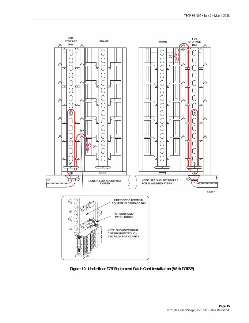
Use the following procedure to install FOT equipment patch cords when an underfloor fiberraceway system will be used for routing and when a Fiber Optic Terminal Storage Bay (FOTSB)is provided at the frame. Refer to Figure 10 for a diagram of the routing procedure.
1. Connect the patch cord to the FOT equipment.
2. Route the patch cord through the underfloor raceway system to the bottom of the FOTSB.
3. Allow the patch cord slack to temporarily rest at the bottom of the FOTSB.
4. Terminate the patch cord at the FTB as described in Section 4.1.
5. Route the patch cord over the adjacent bend radius limiter and through the FOTSB verticalcable guides to the bottom of the FOTSB.
6. Form a storage loop out of the excess patch cord length at the bottom of the FOTSB. Makesure the lower ends of the loop pass under the edge protector spools at the bottom of theFOTSB storage spool panel.
7. Store the excess patch cord slack by hanging the storage loop over the appropriate storagespool.
Note: When using a FOTSB, always use up-configured FTBs.
Page 14© 2018, CommScope, Inc. All Rights Reserved.
TECP-91-002 • Rev C • March 2018
Figure 10. Underfloor FOT Equipment Patch Cord Installation (With FOTSB)
FOTSTORAGE
BAYFRAME
FOTSTORAGE
BAYFRAME
17344-A
NOTE: SEE SUB-SECTION 5.5FOR NUMBERED STEPS
11
3 3
5
5
4
4
2 2
7 7
6 6
UNDERFLOOR GUIDEWAYSYSTEM
FOT EQUIPMENTPATCH CORDS
NOTE: SHOWN WITHOUTDISTRIBUTION TROUGHAND RACK FOR CLARITY
FIBER OPTIC TERMINALEQUIPMENT STORAGE BAY
Page 15© 2018, CommScope, Inc. All Rights Reserved.

TECP-91-002 • Rev C • March 2018
5 CUSTOMER INFORMATION AND ASSISTANCE
http://www.commscope.com/SupportCenter
Page 16