Embed Size (px)
Citation preview

Next Generation Multicast Default MDT:Profile 0 Contents
IntroductionBackground Information PIM as Overlay SignalingConfiguration TasksConfigureVerifyTroubleshoot
Introduction
This document describes how Multicast packet traverses with the use of Multiprotocol LabelSwitching (MPLS) core in Next Generation Multicast.
Background Information
Default MDT - PIM C - mcast signaling
Draft Rosen uses Generic Routing Encapsulation (GRE) as an overlay protocol. That means thatall multicast packets are encapsulated inside GRE. A virtual LAN is emulated with all ProviderEdge (PE) routers in the VPN join a multicast group. This is known as the default MulticastDistribution Tree (MDT). The default MDT is used for Protocol Independent Multicast (PIM) hello’sand other PIM signaling but also for data traffic. If the source sends a lot of traffic it is inefficient touse the default MDT and a data MDT can be created. The data MDT will only include PE’s thathave receivers for the group in use.
Draft Rosen is fairly simple to deploy and works well but it has a few drawbacks. Let’s take a lookat these:
Overhead – GRE adds 24 bytes of overhead to the packet. Compared to MPLS which typicallyadds 8 or 12 bytes there is 100% or more of overhead added to each packet.
PIM in the core – Draft Rosen requires that PIM is enabled in the core because the PE’s must jointhe default and or data MDT which is done through PIM signaling. If PIM ASM is used in the core,an RP is needed as well. If PIM SSM is run in the core, no RP is needed.
Core state – Unnecessary state is created in the core due to the PIM signaling from the PE’s. Thecore should have as little state as possible.
PIM adjacencies – The PE’s will become PIM neighbors with each other. If it’s a large VPN and a

lot of PE’s, a lot of PIM adjacencies will be created. This generates a lot of hello’s and othersignaling which adds to the burden of the router.
Unicast vs multicast – Unicast forwarding uses MPLS, multicast uses GRE. This addscomplexity and means that unicast uses a different forwarding mechanism than multicast, which isnot the optimal solution.
Inefficiency – The default MDT sends traffic to all PE’s in the VPN regardless if the PE has areceiver in the (*,G) or (S,G) for the group in use.
Default MDT will be used to connect multicast to all the PE in one VRF.●
Default means it connects all the PE routers.●
By default, it carries all the traffic.●
All the PIM control traffic and the Data plane traffic. Eg (*,G) Traffic and the (S,G) traffic. ●
This represent multipoint to multipoint.●
Anybody can send and everybody can receive from the tree. ●
PIM as Overlay Signaling
Topology

Configuration Tasks
Enable Multicast Routing on all nodes.1.Enable PIM Sparse Mode in all the interface.2.With existing VRF configure Default MDT.3.Configure the VRF on the interface Ethernet0/x.4.Enable Multicast Routing on VRF.5.Configure PIM SSM Default in all nodes inside the core.6.Configure BSR RP in CE Node.7.Pre-Configured:8.
VRF m-GRE●
mBGP: Address family VPNv4●
VRF Routing Protocol●
Configure
Enable Multicast Routing on all nodes.1.
(config)# ip multicast-routing
2. Enable PIM Sparse Mode in all the interface.

(config)# interface ethernet0/x
(config-if)#ip pim sparse-mode
(config)# interface loopback0
(config-if)#ip pim sparse-mode
3. With VRF that already exists, configure Default MDT.
(config)#ip vrf m-GRE
(config-vrf)# mdt default 232.1.1.1
4. Configure the VRF on the interface Ethernet0/x.
On PE1, PE2 and PE3.
(config)# interface ethernet0/x
(config-if)# ip vrf forwarding m-GRE
(config-if)# ip address 10.x.0.1 255.255.255.0
5. Enable Multicast Routing on VRF.
On PE1, PE2 and PE3.
(config)# ip multicast-routing vrf m-GRE
6. Configure RP for Service Provider core.
On PE1, PE2, PE3 and RR-P Node.
(config)# ip pim rp-address 11.11.11.11
7. Configure BSR RP in CE Node (Receiver).
On Receiver2.
(config)# ip pim bsr-candidate loopback0
(config)# ip pim rp-candidate loopback0
Verify
Use this section in order to confirm that your configuration works properly.
Task 1: Verify Physical Connectivity
Verify all the connected interface are “UP”●

Task 2: Verify Address Family VPNv4 unicast
Verify that BGP is enabled in all the routers for AF VPNv4 unicast and BGP neighbors are“UP”
●
Verify that BGP VPNv4 unicast table has all the Customer prefixes.●
Task 3: Verify Multicast Traffic end to end.
Check PIM neighborship.●
Verify that multicast state is created end to end.●
Verify mRIB entry on PE1, PE2 and PE3●
Verify that (S,G) mFIB entry, packet getting incremented in software forwarding.●
Verify ICMP packets getting reach from CE to CE.●


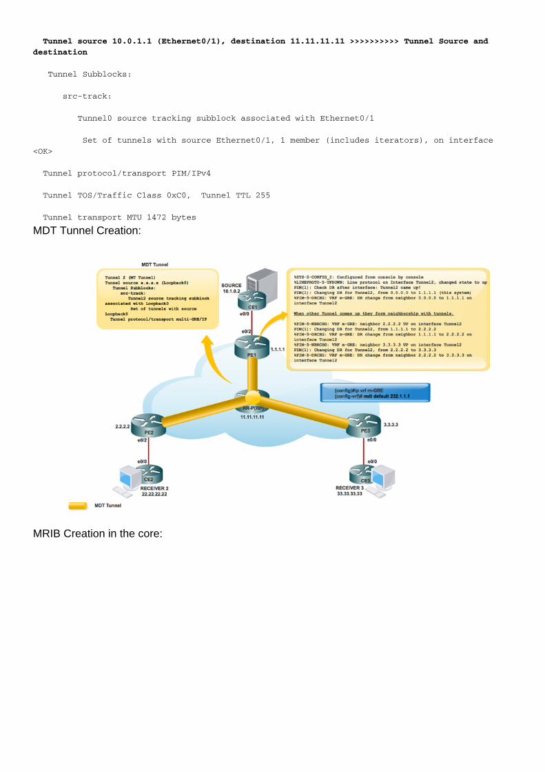
When the Tunnel interfaces are created:
Service Provider RP creation:
Once the RP information flooded in the core. Interface Tunnel 0 is created.

PIM(0): Initiating register encapsulation tunnel creation for RP 11.11.11.11.
PIM(0): Initial register tunnel creation succeeded for RP 11.11.11.11.
PIM(0): Addition of register encap tunnel as forwarding interface of (1.1.1.1, 232.1.1.1) deferreduntil tunnel is created.
*May 9 17:34:56.155: PIM(0): Check RP 11.11.11.11 into the (*, 232.1.1.1).
PIM(0): Adding register encap tunnel (Tunnel0) as forwarding interface of (1.1.1.1, 232.1.1.1).
PE1#sh int tunnel 0
Tunnel0 is up, line protocol is up
Hardware is Tunnel
Description: Pim Register Tunnel (Encap) for RP 11.11.11.11
Interface is unnumbered. Using address of Ethernet0/1 (10.0.1.1)
MTU 17912 bytes, BW 100 Kbit/sec, DLY 50000 usec,
reliability 255/255, txload 1/255, rxload 1/255
Encapsulation TUNNEL, loopback not set
Keepalive not set
Tunnel source 10.0.1.1 (Ethernet0/1), destination 11.11.11.11 >>>>>>>>>> Tunnel Source and
destination
Tunnel Subblocks:
src-track:
Tunnel0 source tracking subblock associated with Ethernet0/1
Set of tunnels with source Ethernet0/1, 1 member (includes iterators), on interface
<OK>
Tunnel protocol/transport PIM/IPv4
Tunnel TOS/Traffic Class 0xC0, Tunnel TTL 255
Tunnel transport MTU 1472 bytes
MDT Tunnel Creation:
MRIB Creation in the core:

PE1#sh ip mroute
IP Multicast Routing Table
Flags: D - Dense, S - Sparse, B - Bidir Group, s - SSM Group, C - Connected,
L - Local, P - Pruned, R - RP-bit set, F - Register flag,
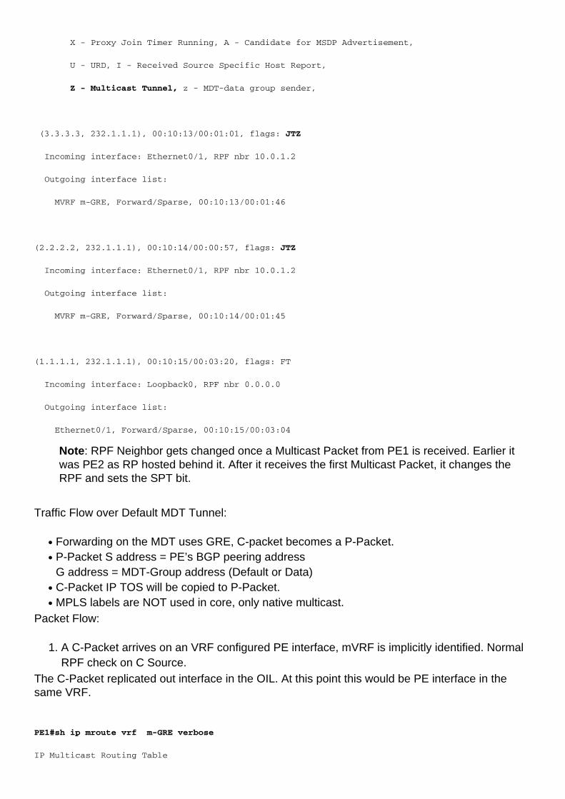
T - SPT-bit set, J - Join SPT, M - MSDP created entry, E - Extranet,
X - Proxy Join Timer Running, A - Candidate for MSDP Advertisement,
U - URD, I - Received Source Specific Host Report,
Z - Multicast Tunnel, z - MDT-data group sender,
(3.3.3.3, 232.1.1.1), 00:10:13/00:01:01, flags: JTZ
Incoming interface: Ethernet0/1, RPF nbr 10.0.1.2
Outgoing interface list:
MVRF m-GRE, Forward/Sparse, 00:10:13/00:01:46
(2.2.2.2, 232.1.1.1), 00:10:14/00:00:57, flags: JTZ
Incoming interface: Ethernet0/1, RPF nbr 10.0.1.2
Outgoing interface list:
MVRF m-GRE, Forward/Sparse, 00:10:14/00:01:45

(1.1.1.1, 232.1.1.1), 00:10:15/00:03:20, flags: FT
Incoming interface: Loopback0, RPF nbr 0.0.0.0
Outgoing interface list:
Ethernet0/1, Forward/Sparse, 00:10:15/00:03:04
Once the RP is created for the customer network:
PE1#sh ip mroute
IP Multicast Routing Table
Flags: D - Dense, S - Sparse, B - Bidir Group, s - SSM Group, C - Connected,
L - Local, P - Pruned, R - RP-bit set, F - Register flag,
T - SPT-bit set, J - Join SPT, M - MSDP created entry, E - Extranet,
X - Proxy Join Timer Running, A - Candidate for MSDP Advertisement,
U - URD, I - Received Source Specific Host Report,
Z - Multicast Tunnel, z - MDT-data group sender,
(3.3.3.3, 232.1.1.1), 00:10:13/00:01:01, flags: JTZ
Incoming interface: Ethernet0/1, RPF nbr 10.0.1.2
Outgoing interface list:
MVRF m-GRE, Forward/Sparse, 00:10:13/00:01:46

(2.2.2.2, 232.1.1.1), 00:10:14/00:00:57, flags: JTZ
Incoming interface: Ethernet0/1, RPF nbr 10.0.1.2
Outgoing interface list:
MVRF m-GRE, Forward/Sparse, 00:10:14/00:01:45
(1.1.1.1, 232.1.1.1), 00:10:15/00:03:20, flags: FT
Incoming interface: Loopback0, RPF nbr 0.0.0.0
Outgoing interface list:
Ethernet0/1, Forward/Sparse, 00:10:15/00:03:04
Tunnel interface is created in order to carry the customer RP information.
PIM(1): Initiating register encapsulation tunnel creation for RP 22.22.22.22.
It is the tunnel created to do Register encapsulation to RP.
For every sparse-mode RP discovered, one Register encapsulation tunnel is created. On thesparse-mode RP itself, there is one de-capsulation tunnel interface created to receive Registerpackets.
PIM Neighborship:
PE1#sh ip mroute
IP Multicast Routing Table
Flags: D - Dense, S - Sparse, B - Bidir Group, s - SSM Group, C - Connected,

L - Local, P - Pruned, R - RP-bit set, F - Register flag,
T - SPT-bit set, J - Join SPT, M - MSDP created entry, E - Extranet,
X - Proxy Join Timer Running, A - Candidate for MSDP Advertisement,
U - URD, I - Received Source Specific Host Report,
Z - Multicast Tunnel, z - MDT-data group sender,
(3.3.3.3, 232.1.1.1), 00:10:13/00:01:01, flags: JTZ
Incoming interface: Ethernet0/1, RPF nbr 10.0.1.2
Outgoing interface list:
MVRF m-GRE, Forward/Sparse, 00:10:13/00:01:46
(2.2.2.2, 232.1.1.1), 00:10:14/00:00:57, flags: JTZ
Incoming interface: Ethernet0/1, RPF nbr 10.0.1.2
Outgoing interface list:
MVRF m-GRE, Forward/Sparse, 00:10:14/00:01:45
(1.1.1.1, 232.1.1.1), 00:10:15/00:03:20, flags: FT
Incoming interface: Loopback0, RPF nbr 0.0.0.0
Outgoing interface list:
Ethernet0/1, Forward/Sparse, 00:10:15/00:03:04
Packet Flow:
Control plane packet flow divides into two parts.
Receiver comes online.1.Source is active.2.
When Receiver is active:

Receiver comes online, sends PIM JOIN (*,G) towards PE3.1.
PE3 encapsulates the PIM JOIN (*,G) in GRE packet and sends through the tunnel 2 (MDTTunnel), which is verified from Incoming Interface of show ip mroute vrf m-GRE.
2.
PE1#sh ip mroute
IP Multicast Routing Table
Flags: D - Dense, S - Sparse, B - Bidir Group, s - SSM Group, C - Connected,
L - Local, P - Pruned, R - RP-bit set, F - Register flag,
T - SPT-bit set, J - Join SPT, M - MSDP created entry, E - Extranet,
X - Proxy Join Timer Running, A - Candidate for MSDP Advertisement,
U - URD, I - Received Source Specific Host Report,

Z - Multicast Tunnel, z - MDT-data group sender,
(3.3.3.3, 232.1.1.1), 00:10:13/00:01:01, flags: JTZ
Incoming interface: Ethernet0/1, RPF nbr 10.0.1.2
Outgoing interface list:
MVRF m-GRE, Forward/Sparse, 00:10:13/00:01:46
(2.2.2.2, 232.1.1.1), 00:10:14/00:00:57, flags: JTZ
Incoming interface: Ethernet0/1, RPF nbr 10.0.1.2
Outgoing interface list:
MVRF m-GRE, Forward/Sparse, 00:10:14/00:01:45
(1.1.1.1, 232.1.1.1), 00:10:15/00:03:20, flags: FT
Incoming interface: Loopback0, RPF nbr 0.0.0.0
Outgoing interface list:
Ethernet0/1, Forward/Sparse, 00:10:15/00:03:04
PE2 received the GRE packet with Source as 3.3.3.3 and Destination 232.1.1.1 and forwardsit to MVRF m-GRE based on the OIL.
1.
PE1#sh ip mroute
IP Multicast Routing Table
Flags: D - Dense, S - Sparse, B - Bidir Group, s - SSM Group, C - Connected,
L - Local, P - Pruned, R - RP-bit set, F - Register flag,
T - SPT-bit set, J - Join SPT, M - MSDP created entry, E - Extranet,
X - Proxy Join Timer Running, A - Candidate for MSDP Advertisement,
U - URD, I - Received Source Specific Host Report,
Z - Multicast Tunnel, z - MDT-data group sender,
(3.3.3.3, 232.1.1.1), 00:10:13/00:01:01, flags: JTZ
Incoming interface: Ethernet0/1, RPF nbr 10.0.1.2
Outgoing interface list:
MVRF m-GRE, Forward/Sparse, 00:10:13/00:01:46

(2.2.2.2, 232.1.1.1), 00:10:14/00:00:57, flags: JTZ
Incoming interface: Ethernet0/1, RPF nbr 10.0.1.2
Outgoing interface list:
MVRF m-GRE, Forward/Sparse, 00:10:14/00:01:45
(1.1.1.1, 232.1.1.1), 00:10:15/00:03:20, flags: FT
Incoming interface: Loopback0, RPF nbr 0.0.0.0
Outgoing interface list:
Ethernet0/1, Forward/Sparse, 00:10:15/00:03:04
The GRE Packet gets decapsulated and PIM JOIN sends towards the RP.
Note: RPF Neighbor is 2.2.2.2 because the PIM Join is destined towards the RP address toform the RPT through the core.
Note: WC Bit and RPT Bit:Triggered by the (*,G) state, the DR creates a Join/Prunemessage with the RP address in its join list and the the wildcard bit (WC-bit) and RP-tree bit(RPT-bit) set to 1. The WC-bit indicates that any source may match and be forwardedaccording to this entry if there is no longer match; the RPT-bit indicates that this join is sentup the shared RP-tree. The prune list is left empty. When the RPT-bit is set to 1 it indicatesthat the join is associated with the shared RP-tree and therefore the Join/Prune message ispropagated along the RP-tree. When the WC-bit is set to 1 it indicates that the address is anRP and the downstream receivers expect to receivepackets from all sources via this (sharedtree) path.
PE1#sh ip mroute
IP Multicast Routing Table
Flags: D - Dense, S - Sparse, B - Bidir Group, s - SSM Group, C - Connected,
L - Local, P - Pruned, R - RP-bit set, F - Register flag,
T - SPT-bit set, J - Join SPT, M - MSDP created entry, E - Extranet,
X - Proxy Join Timer Running, A - Candidate for MSDP Advertisement,
U - URD, I - Received Source Specific Host Report,
Z - Multicast Tunnel, z - MDT-data group sender,
(3.3.3.3, 232.1.1.1), 00:10:13/00:01:01, flags: JTZ
Incoming interface: Ethernet0/1, RPF nbr 10.0.1.2
Outgoing interface list:

MVRF m-GRE, Forward/Sparse, 00:10:13/00:01:46
(2.2.2.2, 232.1.1.1), 00:10:14/00:00:57, flags: JTZ
Incoming interface: Ethernet0/1, RPF nbr 10.0.1.2
Outgoing interface list:
MVRF m-GRE, Forward/Sparse, 00:10:14/00:01:45
(1.1.1.1, 232.1.1.1), 00:10:15/00:03:20, flags: FT
Incoming interface: Loopback0, RPF nbr 0.0.0.0
Outgoing interface list:
Ethernet0/1, Forward/Sparse, 00:10:15/00:03:04
GRE encapsulated packet reach at Source PE PE1.1.
PE1#sh ip mroute
IP Multicast Routing Table
Flags: D - Dense, S - Sparse, B - Bidir Group, s - SSM Group, C - Connected,
L - Local, P - Pruned, R - RP-bit set, F - Register flag,
T - SPT-bit set, J - Join SPT, M - MSDP created entry, E - Extranet,
X - Proxy Join Timer Running, A - Candidate for MSDP Advertisement,
U - URD, I - Received Source Specific Host Report,
Z - Multicast Tunnel, z - MDT-data group sender,
(3.3.3.3, 232.1.1.1), 00:10:13/00:01:01, flags: JTZ
Incoming interface: Ethernet0/1, RPF nbr 10.0.1.2
Outgoing interface list:
MVRF m-GRE, Forward/Sparse, 00:10:13/00:01:46
(2.2.2.2, 232.1.1.1), 00:10:14/00:00:57, flags: JTZ
Incoming interface: Ethernet0/1, RPF nbr 10.0.1.2
Outgoing interface list:
MVRF m-GRE, Forward/Sparse, 00:10:14/00:01:45
(1.1.1.1, 232.1.1.1), 00:10:15/00:03:20, flags: FT

Incoming interface: Loopback0, RPF nbr 0.0.0.0
Outgoing interface list:
Ethernet0/1, Forward/Sparse, 00:10:15/00:03:04
PIM JOIN (S,G) reaches at Source CE.2.
Now the Source got the information of the Interested Receiver and traffic starts send to theSource PE PE1.
3.
At Source PE PE1:4.
PE1#sh ip mroute
IP Multicast Routing Table
Flags: D - Dense, S - Sparse, B - Bidir Group, s - SSM Group, C - Connected,
L - Local, P - Pruned, R - RP-bit set, F - Register flag,
T - SPT-bit set, J - Join SPT, M - MSDP created entry, E - Extranet,
X - Proxy Join Timer Running, A - Candidate for MSDP Advertisement,
U - URD, I - Received Source Specific Host Report,
Z - Multicast Tunnel, z - MDT-data group sender,
(3.3.3.3, 232.1.1.1), 00:10:13/00:01:01, flags: JTZ
Incoming interface: Ethernet0/1, RPF nbr 10.0.1.2
Outgoing interface list:
MVRF m-GRE, Forward/Sparse, 00:10:13/00:01:46
(2.2.2.2, 232.1.1.1), 00:10:14/00:00:57, flags: JTZ
Incoming interface: Ethernet0/1, RPF nbr 10.0.1.2
Outgoing interface list:
MVRF m-GRE, Forward/Sparse, 00:10:14/00:01:45
(1.1.1.1, 232.1.1.1), 00:10:15/00:03:20, flags: FT
Incoming interface: Loopback0, RPF nbr 0.0.0.0
Outgoing interface list:
Ethernet0/1, Forward/Sparse, 00:10:15/00:03:04
At PE2 (RP PE):

PE1#sh ip mroute
IP Multicast Routing Table
Flags: D - Dense, S - Sparse, B - Bidir Group, s - SSM Group, C - Connected,
L - Local, P - Pruned, R - RP-bit set, F - Register flag,
T - SPT-bit set, J - Join SPT, M - MSDP created entry, E - Extranet,
X - Proxy Join Timer Running, A - Candidate for MSDP Advertisement,
U - URD, I - Received Source Specific Host Report,
Z - Multicast Tunnel, z - MDT-data group sender,
(3.3.3.3, 232.1.1.1), 00:10:13/00:01:01, flags: JTZ
Incoming interface: Ethernet0/1, RPF nbr 10.0.1.2
Outgoing interface list:
MVRF m-GRE, Forward/Sparse, 00:10:13/00:01:46
(2.2.2.2, 232.1.1.1), 00:10:14/00:00:57, flags: JTZ
Incoming interface: Ethernet0/1, RPF nbr 10.0.1.2
Outgoing interface list:
MVRF m-GRE, Forward/Sparse, 00:10:14/00:01:45
(1.1.1.1, 232.1.1.1), 00:10:15/00:03:20, flags: FT
Incoming interface: Loopback0, RPF nbr 0.0.0.0
Outgoing interface list:
Ethernet0/1, Forward/Sparse, 00:10:15/00:03:04
PCAP Capture of Multicast Packet from PE1. Tunneled in MDT Default Tunnel. Encapsulated withGRE.
At Receiver PE PE3, packet is received.5.
PE1#sh ip mroute
IP Multicast Routing Table
Flags: D - Dense, S - Sparse, B - Bidir Group, s - SSM Group, C - Connected,
L - Local, P - Pruned, R - RP-bit set, F - Register flag,
T - SPT-bit set, J - Join SPT, M - MSDP created entry, E - Extranet,
X - Proxy Join Timer Running, A - Candidate for MSDP Advertisement,
U - URD, I - Received Source Specific Host Report,
Z - Multicast Tunnel, z - MDT-data group sender,
(3.3.3.3, 232.1.1.1), 00:10:13/00:01:01, flags: JTZ
Incoming interface: Ethernet0/1, RPF nbr 10.0.1.2
Outgoing interface list:
MVRF m-GRE, Forward/Sparse, 00:10:13/00:01:46
(2.2.2.2, 232.1.1.1), 00:10:14/00:00:57, flags: JTZ
Incoming interface: Ethernet0/1, RPF nbr 10.0.1.2
Outgoing interface list:
MVRF m-GRE, Forward/Sparse, 00:10:14/00:01:45
(1.1.1.1, 232.1.1.1), 00:10:15/00:03:20, flags: FT
Incoming interface: Loopback0, RPF nbr 0.0.0.0
Outgoing interface list:
Ethernet0/1, Forward/Sparse, 00:10:15/00:03:04
Note: RPF Neighbor gets changed once a Multicast Packet from PE1 is received. Earlier itwas PE2 as RP hosted behind it. After it receives the first Multicast Packet, it changes theRPF and sets the SPT bit.
Traffic Flow over Default MDT Tunnel:
Forwarding on the MDT uses GRE, C-packet becomes a P-Packet.●
P-Packet S address = PE’s BGP peering addressG address = MDT-Group address (Default or Data)
●
C-Packet IP TOS will be copied to P-Packet.●
MPLS labels are NOT used in core, only native multicast.●
Packet Flow:
A C-Packet arrives on an VRF configured PE interface, mVRF is implicitly identified. NormalRPF check on C Source.
1.
The C-Packet replicated out interface in the OIL. At this point this would be PE interface in thesame VRF.
PE1#sh ip mroute vrf m-GRE verbose
IP Multicast Routing Table

Flags: D - Dense, S - Sparse, B - Bidir Group, s - SSM Group, C - Connected,
L - Local, P - Pruned, R - RP-bit set, F - Register flag,
T - SPT-bit set, v - Vector, p - PIM Joins on route
Outgoing interface flags: H - Hardware switched, A - Assert winner, p - PIM Join
Timers: Uptime/Expires
Interface state: Interface, Next-Hop or VCD, State/Mode
(10.1.0.2, 224.1.1.1), 00:00:03/00:02:56, flags: Tp
Incoming interface: Ethernet0/2, RPF nbr 10.1.0.2
Outgoing interface list:
Tunnel2, GRE MDT: 232.1.1.1 (default), Forward/Sparse, 00:00:03/00:03:26, p (Small “p”
indicates downstream PIM join)
If the OIL contains an MTI, then the C packet encapsulates into a P packet. If “y” flag is set onentry destination used is DATA-MDT group otherwise Default MDT group. Source is the PE BGPpeer address and the destination is the MDT group address.
The P packet is forwarded through the P network as per normal multicast.2.Packet arrives at the global interface. Global (S,G) or (*,G) entry for the MDT group referenced.Normal RPF check on P-Source (PE Peer).
The P packet is replicated out interface in OIL. At this point this is P/PE in the global mroutetable.
3.
If the “Z” flag sets the packet is decapsulated to reveal the C Packet. The target mVRF andincoming interface derived from MDT group is the destination of the encapsulated header.
4.
RPF check of the C-Packet in mVRF done, C Packet replicated out OIL in mVRF.
PE3#sh ip mroute verbose
IP Multicast Routing Table
Flags: D - Dense, S - Sparse, B - Bidir Group, s - SSM Group, C - Connected,
L - Local, P - Pruned, R - RP-bit set, F - Register flag,
T - SPT-bit set, J - Join SPT, M - MSDP created entry, E - Extranet,
Z - Multicast Tunnel, z - MDT-data group sender,
(1.1.1.1, 232.1.1.1), 1d01h/00:02:47, flags: JTZ
Incoming interface: Ethernet0/3, RPF nbr 10.0.3.2

Outgoing interface list: MVRF m-GRE, Forward/Sparse, 1d01h/stopped
Native C Packet reach at the Receiver 3.5.Packet Encapsulation:
Data MDT:
What is Data MDT?
It is optional. It is created in demand, it carries specific (S,G) traffic. In the latest IOS® release, thethreshold configured is as “0” and “infinite”. Whenever a first packet hits the VRF, the Data MDTinitializes, and if infinity then the Data MDT will never be created, and the traffic moves forward inthe default MDT. The Data MDT is always the receiving tree, they never send any traffic. DataMDT is only for the (S,G) traffic.
Selective PMSI:

It’s optional. It is created in demand, it carries specific (S, G) traffic.●
Whenever a first packet hits the VRF, the Data MDT initializes, and if infinity then the DataMDT is never created, and the traffic moves forward in the default MDT.
●
The Data MDT is always be the receiving tree, they never send any traffic. Data MDT is onlyfor the (S, G) traffic.
●
PIM message carries C- (S, G) & P-Group.●
How DATA MDT is created:

When multicast traffic enters in the VRF and when the traffic rate reach the threshold. ItGenerates a MDT Packet.
1.
2. The MDT packet get encapsulated in UDP with Source and Destination 3232. And send it tointerested receiver.
3. After it sends the UDP packet to interested receiver, it sets “y” flag and change the MDTnext_hop to new MDT Group address.
At Source PE PE1:
MRT(1): Set the y-flag for (10.1.0.2,224.1.1.1)
PIM(1): MDT next_hop change from: 232.1.1.1 to 232.2.2.0 for (10.1.0.2, 224.1.1.1) Tunnel2
PE1#sh ip mroute vrf m-GRE verbose
IP Multicast Routing Table
Flags:
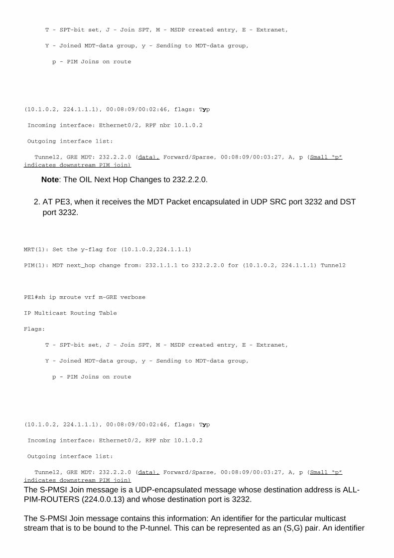
T - SPT-bit set, J - Join SPT, M - MSDP created entry, E - Extranet,
Y - Joined MDT-data group, y - Sending to MDT-data group,
p - PIM Joins on route
(10.1.0.2, 224.1.1.1), 00:08:09/00:02:46, flags: Typ
Incoming interface: Ethernet0/2, RPF nbr 10.1.0.2
Outgoing interface list:
Tunnel2, GRE MDT: 232.2.2.0 (data), Forward/Sparse, 00:08:09/00:03:27, A, p (Small “p”
indicates downstream PIM join)
Note: The OIL Next Hop Changes to 232.2.2.0.
AT PE3, when it receives the MDT Packet encapsulated in UDP SRC port 3232 and DSTport 3232.
2.
MRT(1): Set the y-flag for (10.1.0.2,224.1.1.1)
PIM(1): MDT next_hop change from: 232.1.1.1 to 232.2.2.0 for (10.1.0.2, 224.1.1.1) Tunnel2
PE1#sh ip mroute vrf m-GRE verbose
IP Multicast Routing Table
Flags:
T - SPT-bit set, J - Join SPT, M - MSDP created entry, E - Extranet,
Y - Joined MDT-data group, y - Sending to MDT-data group,
p - PIM Joins on route
(10.1.0.2, 224.1.1.1), 00:08:09/00:02:46, flags: Typ
Incoming interface: Ethernet0/2, RPF nbr 10.1.0.2
Outgoing interface list:
Tunnel2, GRE MDT: 232.2.2.0 (data), Forward/Sparse, 00:08:09/00:03:27, A, p (Small “p”
indicates downstream PIM join)
The S-PMSI Join message is a UDP-encapsulated message whose destination address is ALL-PIM-ROUTERS (224.0.0.13) and whose destination port is 3232.
The S-PMSI Join message contains this information: An identifier for the particular multicaststream that is to be bound to the P-tunnel. This can be represented as an (S,G) pair. An identifier

for the particular P-tunnel to which the stream is to be bound. This identifier is a structured fieldthat includes this information:
Multicast Traffic flow in MDT DATA Tunnel:
MRT(1): Set the y-flag for (10.1.0.2,224.1.1.1)
PIM(1): MDT next_hop change from: 232.1.1.1 to 232.2.2.0 for (10.1.0.2, 224.1.1.1) Tunnel2
PE1#sh ip mroute vrf m-GRE verbose
IP Multicast Routing Table
Flags:
T - SPT-bit set, J - Join SPT, M - MSDP created entry, E - Extranet,
Y - Joined MDT-data group, y - Sending to MDT-data group,
p - PIM Joins on route
(10.1.0.2, 224.1.1.1), 00:08:09/00:02:46, flags: Typ
Incoming interface: Ethernet0/2, RPF nbr 10.1.0.2
Outgoing interface list:
Tunnel2, GRE MDT: 232.2.2.0 (data), Forward/Sparse, 00:08:09/00:03:27, A, p (Small “p”
indicates downstream PIM join)

If the OIL contains a tunnel interface, then the packet is encapsulated with the use of GRE,with the source being the BGP peering address of the local PE router and the destinationbeing the MDT Group address.
●
The decision the Data-MDT group is selected depends on whether the y flag is set on the (S,G) entry in the mVRF.
●
If the (S, G) or (*, G) entry has the Z flag set, then this is a Default- or Data-MDT with anassociated mVRF.
●
The P-packet must be de-encapsulated to reveal the C-packet.●
Because only a single MTI exists in the mVRF per multicast domain, both the Data-MDT andthe Default-MDT use the same tunnel interface for customer traffic.
●
The Y/y flags are necessary to distinguish Default-MDT traffic from Data-MDT traffic andensure that customer multicast routing entries use the correct MDT-Data group and refer to aninternal table that holds the (S, G, Data-MDT) mappings.
●
Troubleshoot
There is currently no specific troubleshooting information available for this configuration.