Embed Size (px)
Citation preview
7/23/2019 NFF Publication 21 LOWRES
http://slidepdf.com/reader/full/nff-publication-21-lowres 1/94
CONTRACTS IN NORWEGIAN TUNNELLING
PUBLICATION NO. 21
NORWEGIAN TUNNELLING SOCIETY
7/23/2019 NFF Publication 21 LOWRES
http://slidepdf.com/reader/full/nff-publication-21-lowres 2/94
NORSK FORENING FOR FJELLSPRENGNINGSTEKNIKK
Norwegian Tunnelling Sosiety
[email protected] - www.tunnel.no - www.nff.no
REPRESENTS EXPERTISE IN
• Hr Rock Tul tchqu • Rock blt tcholoy • Rock mchc r oloy
Used in THe design and
CONSTRUCTION OF• Hyrolctrc powr vlopmt, clu:
- wtr covy tul - ul prur hft
- uburfc powr tto - lk tp - rth rock fll m
• Trportto tul
• Urrou tor fclt• Urrou op for for publc u
NORWEGIAN TUNNELLING SOCIETY
7/23/2019 NFF Publication 21 LOWRES
http://slidepdf.com/reader/full/nff-publication-21-lowres 3/94
CONTRACTS IN
NORWEGIAN TUNNELLINGPublication No. 21
NORWEGIAN TUNNELLING SOCIETY
2012
DESIGN/PRINT BY HELLI - VISUELL KOMMUNIKASJON, OSLO, NORWAY
7/23/2019 NFF Publication 21 LOWRES
http://slidepdf.com/reader/full/nff-publication-21-lowres 4/94
NORWEGIAN T UNNELLING SOCIETY PUBLICATION NO . 21
4
PUBLICATION NO. 21
© Norsk Forening for Fjellsprengningsteknikk NFF
ISBN 978-82-92641-24-8
Front page photo:Olav Nordli, Norwegian Rail Administration
Layout/Print:HELLI - Visuell kommunikasjon [email protected]
DISCLAIMER
«Readers are advised that the publications from the NorwegianTunnelling Society NFF are issued solely for informationalpurpose.The opinions and statements included are basedon reliable sources in good faith. In no event, however, shallNFF or the authors be liable for direct or indirect incidental
or consequential damages resulting from the use of thisinformation.»
7/23/2019 NFF Publication 21 LOWRES
http://slidepdf.com/reader/full/nff-publication-21-lowres 5/94
NORWEGIAN T UNNELLING SOCIETY PUBLICATION NO . 21
5
The publication “Contracts in Norwegian Tunnelling” is part of the English languageseries published by the Norwegian Tunnelling Society NFF.
The aim is to share with colleagues internationally information on aspects of under-ground work. The publications are mainly focusing on technical issues. This timehowever, the publication concentrates on contracts and contract related issues.
The publication starts with an introduction to the Norwegian contract regime fol-lowed by papers relevant for this topic with contributions by important parties in a project implementation stage. Also included are examples of partnering and target price contracts as well as observations from three sub sea tunnelling projects.
Contract disagreements are well known for contract partners in underground con-struction. Most matters are solved through discussions and internal negotiations between the contract parties, for some contracts however, this avenue is difficult.Organised mediation during project implementation is a method to be considered forselected projects. The technique is reviewed.
During the final stage of the project we have received special assistance and supportfrom the NFF Secretary Thor Skjeggedal and member of the international committeeAslak Ravlo.
Sincere thanks to authors, contributors and supporters.
May 2012
Norwegian Tunnelling Society NFF - International Committee
Frode Nilsen Ruth G. Haug Eivind Grøv (Chairman)
FOREWORD
7/23/2019 NFF Publication 21 LOWRES
http://slidepdf.com/reader/full/nff-publication-21-lowres 6/94
NORWEGIAN T UNNELLING SOCIETY PUBLICATION NO . 16
148
YOUR partner in
Underground
Technology
For more information;contact Hilde H. Holmøy;kristinhilde.holmø[email protected]
• Laboratory Testing
• In-situ Rock Stress
iiiMeasurements
• Rock Mechanics
• Engineering Geology
• Numerical Modelling
• Health, Environment
iiiand Safety Aspects
• Construction Method
iiiEvaluation• Value Engineering & Independent Reviews
Rock Engineering
7/23/2019 NFF Publication 21 LOWRES
http://slidepdf.com/reader/full/nff-publication-21-lowres 7/94
7
CONTENTS
FOREWORD................................................................................................................................................................ 5
INTRODUCTION .................................................................................................................................................... 11
History ............................................................................................................................................................... 11
The legal situation today ................................................................................................................................... 11
The market ......................................................................................................................................................... 12
Technology, contract provisions and disagreements ......................................................................................... 12
The future .......................................................................................................................................................... 13
02. CONTRACT PHILOSOPHY IN NORWEGIAN TUNNELLING ................................................................. 15
Risk Sharing ..................................................................................................................................................... 15
Characteristics of Unit Price Contracts ............................................................................................................ 16
Contract clauses to tackle varying quantities and construction time forexploratory drilling and support measures ........................................................................................................ 17
Court Cases ...................................................................................................................................................... 18
Settlement of disputes ....................................................................................................................................... 18
Requirements to the contract ............................................................................................................................ 19
Conclusions ...................................................................................................................................................... 20
References ......................................................................................................................................................... 20
03. NORWEGIAN STANDARD NS 3420 IN CONTRACTS FOR UNDERGROUND WORKS .................... 23
Introduction ....................................................................................................................................................... 23
Preliminaries and General Provisions ............................................................................................................... 23
Tunnel blasting, code FH1.4 ............................................................................................................................. 24
Uploading and transportation, code FM............................................................................................................ 25
Equivalent time accounting ............................................................................................................................... 29
04. SHARING OF RISK IN NORWEGIAN ROAD TUNNELLING CONTRACTS ........................................ 31
Summary............................................................................................................................................................ 31
Contract Philosophy ......................................................................................................................................... 31
Recording geological conditions at the tunnel face .......................................................................................... 31
Sharing the risk on support measures ............................................................................................................... 32
Contract clauses to tackle varying quantities and construction time for exploratory drilling and support measures .... 33
References ......................................................................................................................................................... 33
05. COORDINATION - A WAY TO ENHANCED COOPERATION IN UNDERGROUND PROJECTS ..... 35
The object of coordination ................................................................................................................................ 35
Underlying prerequisites for coordination ........................................................................................................ 35
Basic conditions: ............................................................................................................................................... 35
Coordination and development phase ............................................................................................................... 35
Development of the project after the works have started ................................................................................. 36
Sharing of cost savings resulting from developments ...................................................................................... 36
Experience ......................................................................................................................................................... 36
Challenges ......................................................................................................................................................... 36
Final evaluation ................................................................................................................................................. 36
7/23/2019 NFF Publication 21 LOWRES
http://slidepdf.com/reader/full/nff-publication-21-lowres 8/94
8
06. AN OIL COMPANY’S APPROACH TO UNDERGROUND CONSTRUCTION CONTRACTS ............. 37
Introduction ....................................................................................................................................................... 37
Main projects last decade .................................................................................................................................. 37
Planning ............................................................................................................................................................. 38
HSE .................................................................................................................................................................... 40
RISK .................................................................................................................................................................. 40 TECHNICAL DEFINITION ............................................................................................................................. 41
Competitive tendering ...................................................................................................................................... 42
Compensation .................................................................................................................................................... 42
Contract administration ..................................................................................................................................... 42
Way forward ...................................................................................................................................................... 42
REFERENCES .................................................................................................................................................. 43
07. PARTNERING AGREEMENT FOR SILA ..................................................................................................... 45
Introduction ....................................................................................................................................................... 45
Prior to entering into an agreement ................................................................................................................... 45
Partnering Agreement ....................................................................................................................................... 46
Expansion phase ................................................................................................................................................ 49
08. ALTERNATIVE FORMS OF CONTRACT
- TARGET PRICE CONTRACT ...................................................................................................................... 51
Introduction ....................................................................................................................................................... 51
The parameters of the National Rail Administration ........................................................................................ 52
The Nykirke pilot project .................................................................................................................................. 53
Positive .............................................................................................................................................................. 53
Negative ............................................................................................................................................................. 54
Contract forms further down the line ................................................................................................................ 56
09. THE CONSULTANT’S CONTRIBUTION IN A TUNNEL CONTRACT .................................................... 57
Introduction ....................................................................................................................................................... 57
A “normal “life cycle of a tunneling consulting assignment ............................................................................ 57
Contributions to the tunnel contract .................................................................................................................. 58
General information .......................................................................................................................................... 58
Bid criteria development ................................................................................................................................... 58
Site investigations and geological conditions ................................................................................................... 58
Special procedures and specifications ............................................................................................................... 58
Drawings ............................................................................................................................................................ 58
Bill of Quantities ............................................................................................................................................... 58 Handling of variations and uncertainties........................................................................................................... 58
Finish dates and penalties .................................................................................................................................. 58
Bid evaluation ................................................................................................................................................... 58
Follow up engineering ....................................................................................................................................... 59
Geological mapping and rock support. ............................................................................................................. 59
Other tasks for the consultants .......................................................................................................................... 59
Contract closeout ............................................................................................................................................... 59
Future trends and developments ........................................................................................................................ 59
7/23/2019 NFF Publication 21 LOWRES
http://slidepdf.com/reader/full/nff-publication-21-lowres 9/94
9
10. NORWEGIAN CONTRACT PRACTICE SUITABLE ALSO FOR DEALING WITH
UNEXPECTED GEOLOGICAL CONDITIONS. THREE PROJECT EXAMPLES. ................................ 61
Introduction ....................................................................................................................................................... 61
Unpredictable Work Conditions calls for Flexible Contract Provisions. .......................................................... 61
Particular Risks Elements of Subsea Tunnels .................................................................................................. 62
Case Stories to demonstrate Contract Details ................................................................................................... 62 Godøy Tunnel .................................................................................................................................................... 62
Bjorøy Tunnel ................................................................................................................................................... 64
Oslofjord Tunnel .............................................................................................................................................. 65
Lessons Learned ............................................................................................................................................... 67
Some remarks on the chosen examples ............................................................................................................. 67
References ......................................................................................................................................................... 67
11. PROJECT INTEGRATED MEDIATION (PRIME) ....................................................................................... 69
Project conflicts ................................................................................................................................................. 69
How can project conflicts be handled? ............................................................................................................. 69
Characteristics of arbitration and litigation ....................................................................................................... 70
Mediation ........................................................................................................................................................... 71
A “project twist” to the classical conflict resolution methods. ......................................................................... 71
What is Project Integrated Mediation (PRIME)? .............................................................................................. 72
Variables in the shaping of PRIME .................................................................................................................. 72
International inspiration .................................................................................................................................... 73
What speaks for and against PRIME?............................................................................................................... 74
An illustration: The Norwegian Public Roads Administration’s Bjørvika project. .......................................... 75
Does PRIME work? .......................................................................................................................................... 77
12. TOWARDS FUTURE TUNNELLINGPROSPECTS AND CHALLENGES OF DEVELOPMENT ORIENTED TUNNEL CONTRACTS......... 81
Introduction ............................................................................................................................................................ 81
Where could we improve and what could be gained by what kind of development? ......................................... 81
What are the hindering aspects and mechanisms? ................................................................................................ 82
How to introduce or boost development? .............................................................................................................. 84
Where to implement? ............................................................................................................................................. 84
ACKNOWLEDGEMENTS ...................................................................................................................................... 86
Editorial Committee .......................................................................................................................................... 86
Authors .............................................................................................................................................................. 86
Editorial Work ................................................................................................................................................... 88
NFF INTERNATIONAL SUPPORT GROUP ........................................................................................................ 89
ORDERFORM ........................................................................................................................................................... 92

7/23/2019 NFF Publication 21 LOWRES
http://slidepdf.com/reader/full/nff-publication-21-lowres 10/94
Introducing the E-force
A winning team for superior productivitySince the introduction of mechanized rock drilling, we’ve offered drill rigs with
outstanding productivity. Now we’re adding a new dimension – the E-force! The core
of the E-force, including Boltec EC and the Simba and Boomer E-series, is the heavy-duty
boom. It moves faster and has a longer reach than other booms in the same class. Add the
most powerful rock drills and our intelligent rig control system and you will get precise and
safe rock drilling with superior productivity. Join a winning team – go with the E-force!
www.e-forcefamily.com
7/23/2019 NFF Publication 21 LOWRES
http://slidepdf.com/reader/full/nff-publication-21-lowres 11/94
NORWEGIAN T UNNELLING SOCIETY PUBLICATION NO . 21
11
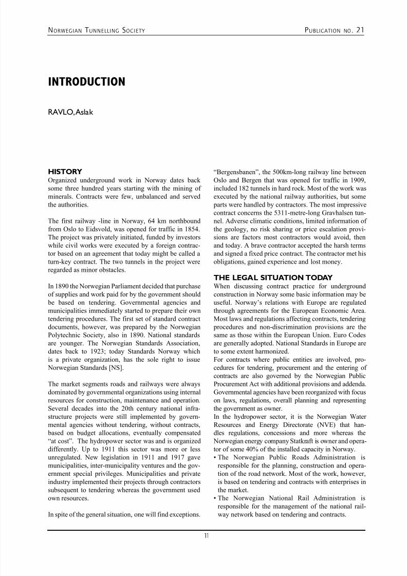
HISTORYOrganized underground work in Norway dates backsome three hundred years starting with the mining ofminerals. Contracts were few, unbalanced and servedthe authorities.
The first railway -line in Norway, 64 km northboundfrom Oslo to Eidsvold, was opened for traffic in 1854.The project was privately initiated, funded by investorswhile civil works were executed by a foreign contrac-tor based on an agreement that today might be called aturn-key contract. The two tunnels in the project wereregarded as minor obstacles. In 1890 the Norwegian Parliament decided that purchaseof supplies and work paid for by the government should
be based on tendering. Governmental agencies andmunicipalities immediately started to prepare their owntendering procedures. The first set of standard contractdocuments, however, was prepared by the NorwegianPolytechnic Society, also in 1890. National standardsare younger. The Norwegian Standards Association,dates back to 1923; today Standards Norway whichis a private organization, has the sole right to issue Norwegian Standards [NS].
The market segments roads and railways were alwaysdominated by governmental organizations using internal
resources for construction, maintenance and operation.Several decades into the 20th century national infra-structure projects were still implemented by govern-mental agencies without tendering, without contracts, based on budget allocations, eventually compensated“at cost”. The hydropower sector was and is organizeddifferently. Up to 1911 this sector was more or lessunregulated. New legislation in 1911 and 1917 gavemunicipalities, inter-municipality ventures and the gov-ernment special privileges. Municipalities and privateindustry implemented their projects through contractorssubsequent to tendering whereas the government usedown resources.
In spite of the general situation, one will find exceptions.
“Bergensbanen”, the 500km-long railway line betweenOslo and Bergen that was opened for traffic in 1909,included 182 tunnels in hard rock. Most of the work wasexecuted by the national railway authorities, but some parts were handled by contractors. The most impressivecontract concerns the 5311-metre-long Gravhalsen tun-nel. Adverse climatic conditions, limited information ofthe geology, no risk sharing or price escalation provi-sions are factors most contractors would avoid, thenand today. A brave contractor accepted the harsh termsand signed a fixed price contract. The contractor met hisobligations, gained experience and lost money.
THE LEGAL SITUATION TODAYWhen discussing contract practice for undergroundconstruction in Norway some basic information may be
useful. Norway’s relations with Europe are regulatedthrough agreements for the European Economic Area.Most laws and regulations affecting contracts, tendering procedures and non-discrimination provisions are thesame as those within the European Union. Euro Codesare generally adopted. National Standards in Europe areto some extent harmonized.For contracts where public entities are involved, pro-cedures for tendering, procurement and the entering ofcontracts are also governed by the Norwegian PublicProcurement Act with additional provisions and addenda.Governmental agencies have been reorganized with focus
on laws, regulations, overall planning and representingthe government as owner.In the hydropower sector, it is the Norwegian WaterResources and Energy Directorate (NVE) that han-dles regulations, concessions and more whereas the Norwegian energy company Statkraft is owner and opera-tor of some 40% of the installed capacity in Norway.• The Norwegian Public Roads Administration is
responsible for the planning, construction and opera-tion of the road network. Most of the work, however,is based on tendering and contracts with enterprises inthe market.
• The Norwegian National Rail Administration is
responsible for the management of the national rail-way network based on tendering and contracts.
INTRODUCTION
RAVLO, Aslak
7/23/2019 NFF Publication 21 LOWRES
http://slidepdf.com/reader/full/nff-publication-21-lowres 12/94
NORWEGIAN T UNNELLING SOCIETY PUBLICATION NO . 21
12
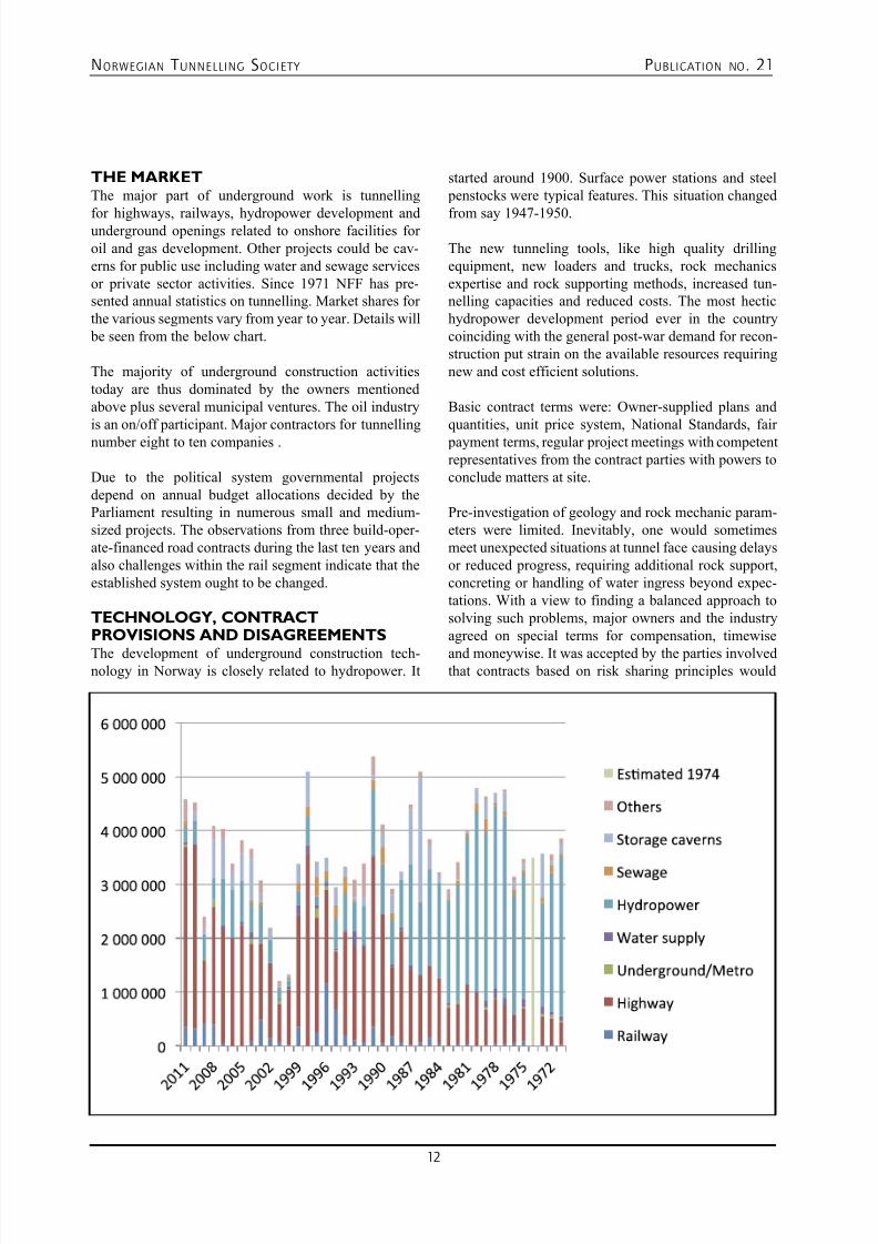
THE MARKETThe major part of underground work is tunnelling
for highways, railways, hydropower development andunderground openings related to onshore facilities foroil and gas development. Other projects could be cav-erns for public use including water and sewage servicesor private sector activities. Since 1971 NFF has pre-sented annual statistics on tunnelling. Market shares forthe various segments vary from year to year. Details will be seen from the below chart. The majority of underground construction activitiestoday are thus dominated by the owners mentionedabove plus several municipal ventures. The oil industryis an on/off participant. Major contractors for tunnellingnumber eight to ten companies .
Due to the political system governmental projectsdepend on annual budget allocations decided by theParliament resulting in numerous small and medium-sized projects. The observations from three build-oper-ate-financed road contracts during the last ten years andalso challenges within the rail segment indicate that theestablished system ought to be changed.
TECHNOLOGY, CONTRACTPROVISIONS AND DISAGREEMENTS
The development of underground construction tech-nology in Norway is closely related to hydropower. It
started around 1900. Surface power stations and steel penstocks were typical features. This situation changed
from say 1947-1950.
The new tunneling tools, like high quality drillingequipment, new loaders and trucks, rock mechanicsexpertise and rock supporting methods, increased tun-nelling capacities and reduced costs. The most hectichydropower development period ever in the countrycoinciding with the general post-war demand for recon-struction put strain on the available resources requiringnew and cost efficient solutions.
Basic contract terms were: Owner-supplied plans andquantities, unit price system, National Standards, fair payment terms, regular project meetings with competentrepresentatives from the contract parties with powers toconclude matters at site.
Pre-investigation of geology and rock mechanic param-eters were limited. Inevitably, one would sometimesmeet unexpected situations at tunnel face causing delaysor reduced progress, requiring additional rock support,concreting or handling of water ingress beyond expec-tations. With a view to finding a balanced approach tosolving such problems, major owners and the industryagreed on special terms for compensation, timewise
and moneywise. It was accepted by the parties involvedthat contracts based on risk sharing principles would
7/23/2019 NFF Publication 21 LOWRES
http://slidepdf.com/reader/full/nff-publication-21-lowres 13/94
NORWEGIAN T UNNELLING SOCIETY PUBLICATION NO . 21
13
improve quality and reduce costs. Several of the paperswill deal with these provisions which we believe are
unique.
Norway is a mountainous country with a rugged coastlineand many outlying islands. Numerous communities withfew people are still waiting for safe road connections.Modestly constructed roads and tunnels will still beneeded. In the cities commuter systems to bring peoplein and out of the centre effectively are needed, calling fortunnels and underground usage. A new era of hydroelec-tric power development will see further application ofunderground solutions. The traditional contracts with theunit price system, flexible quantities and a fair risk shar-ing profile will be needed also in the future.
Disagreements beyond friendly negotiations cannot be avoided. Hydropower companies used to include aclause on arbitration, whereas the governmental agen-cies are bound to litigation.
Organised mediation as a means of solving contract problems during the construction period have been
used internationally for decades. During recent yearsthis approach has also been utilised in Norway. Allsystems include stronger and weaker aspects. In theend, cooperation between the contract partners basedon competence and reason seems to be the advisableavenue to take.
THE FUTUREThe handing over of a completed project to operationmeans the start of a new phase where maintenance costsand depreciation must be covered. The constructionstandard and the quality of the technical installations ina lifetime perspective are in such respect of paramountimportance. Some thoughts on the development ofcontracts for underground projects as well as advice tofuture owners and developers are included.
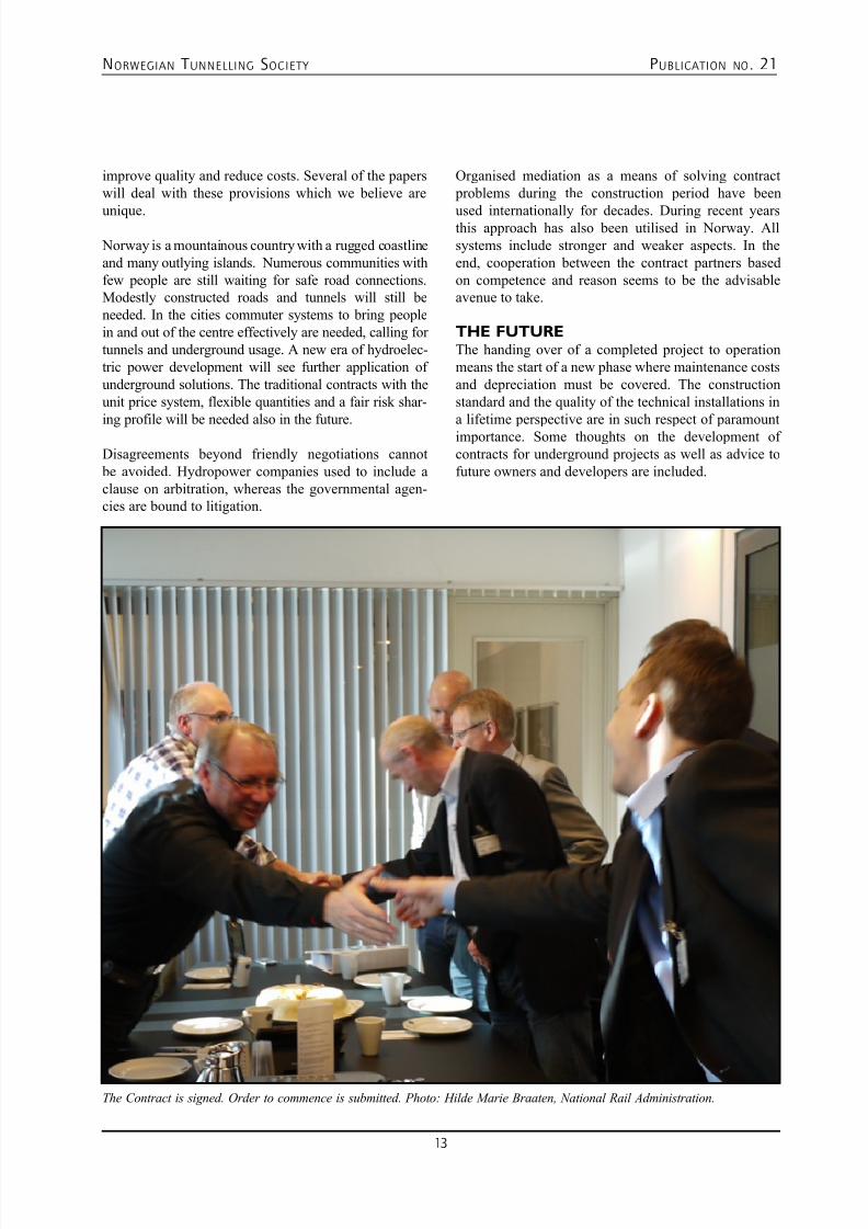
The Contract is signed. Order to commence is submitted. Photo: Hilde Marie Braaten, National Rail Administration.
7/23/2019 NFF Publication 21 LOWRES
http://slidepdf.com/reader/full/nff-publication-21-lowres 14/94
NORWEGIAN T UNNELLING SOCIETY PUBLICATION NO . 21
14www.multiconsult.no
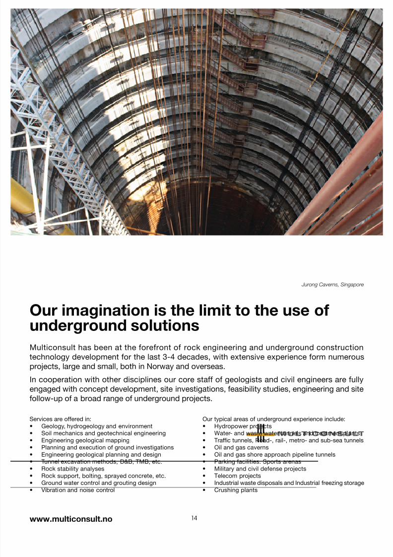
Our imagination is the limit to the use ofunderground solutions
Multiconsult has been at the forefront of rock engineering and underground construction
technology development for the last 3-4 decades, with extensive experience form numerous
projects, large and small, both in Norway and overseas.
In cooperation with other disciplines our core staff of geologists and civil engineers are fully
engaged with concept development, site investigations, feasibility studies, engineering and sitefollow-up of a broad range of underground projects.
Our typical areas of underground experience include:
Hydropower projects•
Water- and waste water tunnels and treatment plants•
Trafc tunnels, Road-, rail-, metro- and sub-sea tunnels•
Oil and gas caverns•
Oil and gas shore approach pipeline tunnels•
Parking facilities. Sports arenas•
Military and civil defense projects•
Telecom projects•
Industrial waste disposals and Industrial freezing storage•
Crushing plants•
Services are offered in:
Geology, hydrogeology and environment•
Soil mechanics and geotechnical engineering•
Engineering geological mapping•
Planning and execution of ground investigations•
Engineering geological planning and design•
Tunnel excavation methods, D&B, TMB, etc.•
Rock stability analyses•
Rock support, bolting, sprayed concrete, etc.•
Ground water control and grouting design•
Vibration and noise control•
Jurong Caverns, Singapore
7/23/2019 NFF Publication 21 LOWRES
http://slidepdf.com/reader/full/nff-publication-21-lowres 15/94
NORWEGIAN T UNNELLING SOCIETY PUBLICATION NO . 21
15
02. CONTRACT PHILOSOPHY IN NORWEGIAN TUNNELLING
GRØV, Eivind
The tunnelling concept regards the rock mass as beinga construction material. Consequently the pre-con-struction assessments of the rock quality form impor-tant input for estimating quantities of the cost itemsincluded in the BoQ. These assessments are also form-ing the basis for the prediction of the construction time.Quantities, also for options, must represent realistic esti-mates to receive well considered prices and schedules.During the construction phase it is important that boththe client and the contractor have competent people atsite to determine the support measures needed and toassess the rock mass conditions at and ahead of the tun-nel face. [1] This latter being especially relevant for theexecution of the grouting works.
The contract parties in underground construction may
have different objectives in some matters. However,in a broader perspective there are probably more com-mon interests at the construction site than interest ofconflicts. Cooperation is important, including aspectssuch as; respect for the different roles and values,experienced professionals participating in the decisionmaking, conflicts being solved at the construction site.
Planning for the construction implies that contingencyand precaution need to be included in the contractto handle expected or unexpected conditions. The Norwegian unit price contracts place the risk for vary-
ing ground conditions on the owner. The contract doesnormally not include different prices for excavationdepending on rock quality encountered, separate unit prices are however included for such measures asreducing the blasting length to half the normal, or divid-ing the tunnel face into various sections. [2]
Before contracting, the ground conditions are mappedand a geological report is compiled which later becomes part of the contract documents. This report is not a geo-logical base line report. The geological report describeswhat have been recorded in terms of factual data andin addition a part that presents a description of the
expected ground conditions, that is an interpretation ofthe factual data. This gives the owner a basis for assess-
ments on measures and quantities to be specified in thecontracts. It also provides the contactor an information basis for his own judgement of the ground conditionsthat he may use for calculations and planning purposes.Predictability is a key issue and it is important thatinformation is provided from one phase of the project tothe next and that nothing is getting lost in the process.
In the bill of quantities, the owner is specifying varioussupport methods and stipulates the quantities, tryingas accurately as possible to stipulate the amounts thathe expects will be carried out, as this gives the leastsurprises, and the truest picture of the scope of work.The contractor is paid according to the actual amountscarried out. [3]
RISK SHARINGBy far, most underground projects in Norway duringthe last 50 years have been contracted as unit pricecontracts. During the hydropower boom in the 1960’sthrough the 1980’s, a contract concept was developedand applied that focused on risk sharing. The risk shar-ing contracts address two main elements of risk:
• Ground conditions. The owner is responsible for the
ground conditions. He ‘provides the ground’, and isalso responsible for the result of the site investigationshe finds necessary to do. If these prove to be insuf-
ficient, it shall remain his problem.
• Performance. The contractor is responsible for the
efficient execution of the works. He shall execute theworks according to the technical specifications. Heis reimbursed according to tendered unit prices forthe work actually completed. The construction timeframe is adjusted based on preset ‘standard capacities’(‘time equivalents’) for the different work activities,if the balance (increases minus decreases) of the workchanges.
By this, the owner keeps the risk of increased cost if
the ground conditions prove to be worse than expected;after all he has chosen the site location. He will also earn
7/23/2019 NFF Publication 21 LOWRES
http://slidepdf.com/reader/full/nff-publication-21-lowres 16/94
NORWEGIAN T UNNELLING SOCIETY PUBLICATION NO . 21
16
the savings if the conditions are better than expected.The contractor keeps the risk of his own performance.
If he is less efficient than the norm set by the ‘standardcapacities’, he may fall behind schedule and will haveto catch up on his own expense to avoid penalties. If heis more efficient, he may finish earlier, saving money bythis and increasing his profit, besides what he is hope-fully earning within his unit prices.
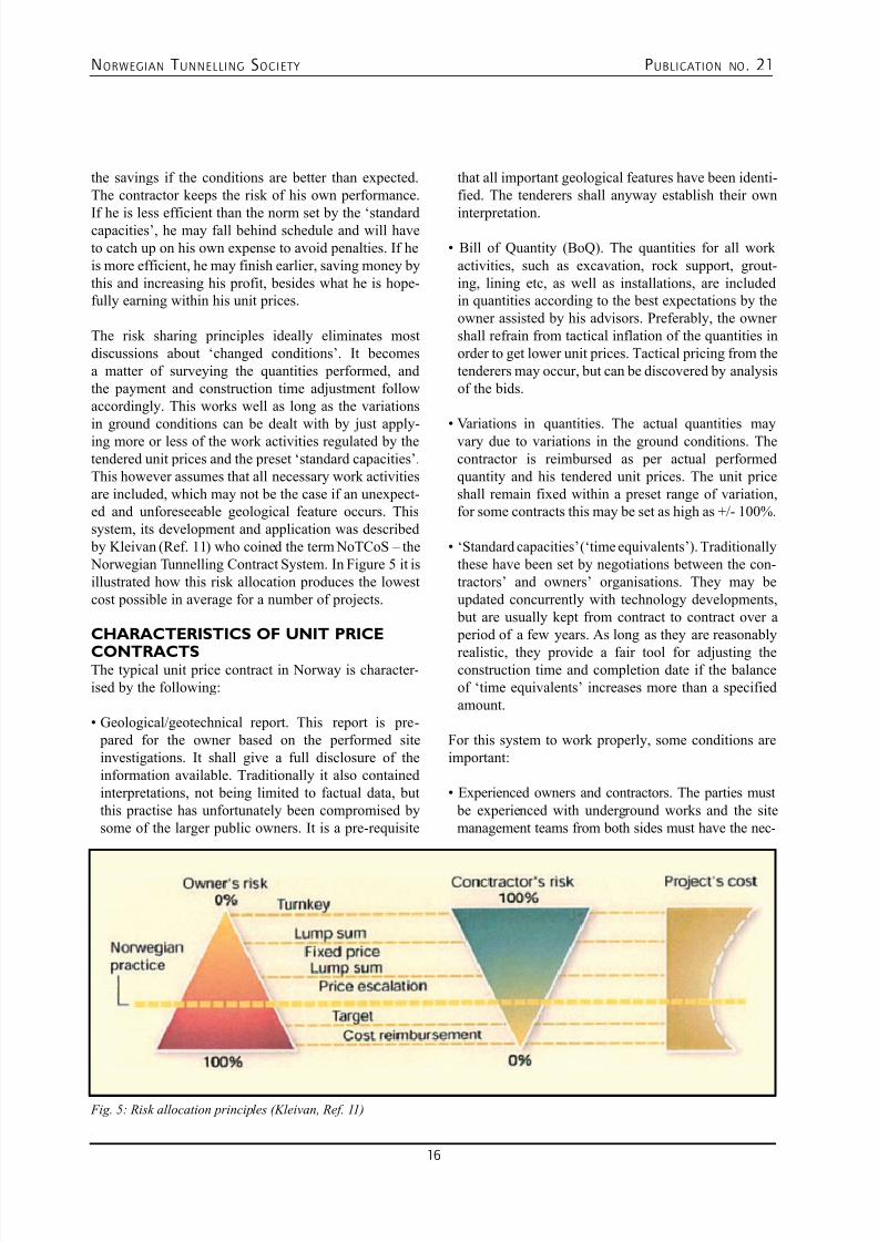
The risk sharing principles ideally eliminates mostdiscussions about ‘changed conditions’. It becomesa matter of surveying the quantities performed, andthe payment and construction time adjustment followaccordingly. This works well as long as the variationsin ground conditions can be dealt with by just apply-ing more or less of the work activities regulated by thetendered unit prices and the preset ‘standard capacities’.This however assumes that all necessary work activitiesare included, which may not be the case if an unexpect-ed and unforeseeable geological feature occurs. Thissystem, its development and application was described by Kleivan (Ref. 11) who coined the term NoTCoS – the Norwegian Tunnelling Contract System. In Figure 5 it isillustrated how this risk allocation produces the lowestcost possible in average for a number of projects.
CHARACTERISTICS OF UNIT PRICE
CONTRACTSThe typical unit price contract in Norway is character-ised by the following:
• Geological/geotechnical report. This report is pre- pared for the owner based on the performed siteinvestigations. It shall give a full disclosure of theinformation available. Traditionally it also containedinterpretations, not being limited to factual data, butthis practise has unfortunately been compromised bysome of the larger public owners. It is a pre-requisite
that all important geological features have been identi-fied. The tenderers shall anyway establish their own
interpretation.
• Bill of Quantity (BoQ). The quantities for all work
activities, such as excavation, rock support, grout-ing, lining etc, as well as installations, are includedin quantities according to the best expectations by theowner assisted by his advisors. Preferably, the ownershall refrain from tactical inflation of the quantities inorder to get lower unit prices. Tactical pricing from thetenderers may occur, but can be discovered by analysisof the bids.
• Variations in quantities. The actual quantities may
vary due to variations in the ground conditions. Thecontractor is reimbursed as per actual performedquantity and his tendered unit prices. The unit priceshall remain fixed within a preset range of variation,for some contracts this may be set as high as +/- 100%.
• ‘Standard capacities’ (‘time equivalents’). Traditionally
these have been set by negotiations between the con-tractors’ and owners’ organisations. They may beupdated concurrently with technology developments, but are usually kept from contract to contract over a period of a few years. As long as they are reasonably
realistic, they provide a fair tool for adjusting theconstruction time and completion date if the balanceof ‘time equivalents’ increases more than a specifiedamount.
For this system to work properly, some conditions areimportant:
• Experienced owners and contractors. The parties must
be experienced with underground works and the sitemanagement teams from both sides must have the nec-
Fig. 5: Risk allocation principles (Kleivan, Ref. 11)
7/23/2019 NFF Publication 21 LOWRES
http://slidepdf.com/reader/full/nff-publication-21-lowres 17/94
NORWEGIAN T UNNELLING SOCIETY PUBLICATION NO . 21
17
essary authority to take decisions, allowing technical
and contractual issues to be solved at site as they occur.This requires respect for each other and their tasks.
• Decision making. Of critical importance is the ability
and authority of the representatives of both partiesto take decisions at the tunnels face, especially withrespect to primary rock support and ground treatmentas pre-grouting etc.
• Acquaintance with the contract. If both parties are
acquainted with the principles and details of the con-tract, discussions and agreements can be made expedi-
ently and with confidence as need arises. This is typi-cally the situation when both parties are experiencedfrom a number of similar projects.
A main advantage with this system is that the con-tractor’s incentive to meet the penalty deadline will be maintained, even if ground conditions get worse.Contractors have recently voiced as a disadvantage thattheir role is limited to performing the specified work forthe owner without incentives to introduce innovativesolutions by which the contractor could better utilisehis special skills. Some owners do not ask for, or evenallow, alternative solutions to be introduced. However,
this is not due to the type of contract, but to how it isapplied.
CONTRACT CLAUSES TO TACKLE
VARYING QUANTITIES ANDCONSTRUCTION TIME FOR EXPLORA-TORY DRILLING AND SUPPORTMEASURESAs a part of Norwegian tunnelling important decisionsare taken at the tunnel face, both related to the need formeasures ahead of the tunnel face and support at theface. A possible consequence is that a considerable dif-ference might occur between the stipulated quantitiesin the contract and the actual quantities as carried out.
To tackle this, the contract has defined “the 100 % rule”
in the specification describing support [3]:
• The unit prices apply even if the sum of actual quanti-ties differs from the bill of quantities by up to ± 100 %.
• If the owner or the contractor wishes unit prices to be
adjusted, prices are set by negotiation.
• The adjusted unit prices shall not differ from the
contract’s unit prices by more than 20 %. Adjusted price shall be determined according to documentedexpenses.
These regulations take care of differing quantities thatmight occur due to changes in the geological condi-
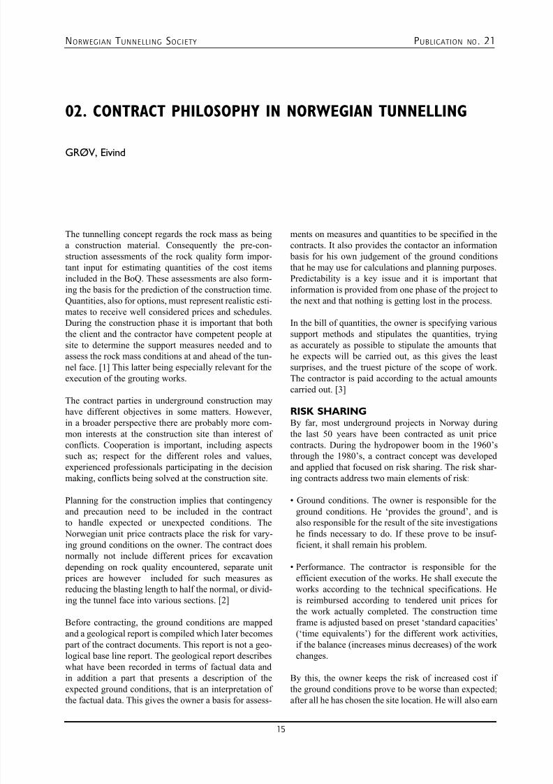
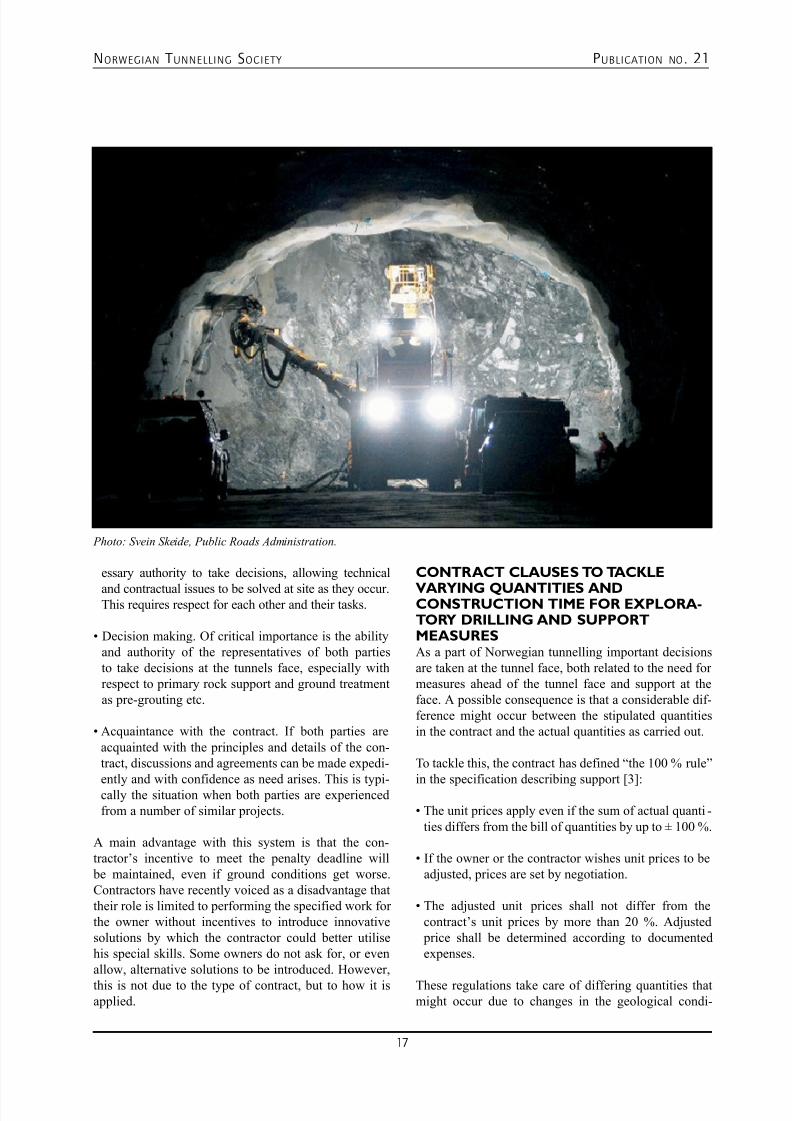
Photo: Svein Skeide, Public Roads Administration.
7/23/2019 NFF Publication 21 LOWRES
http://slidepdf.com/reader/full/nff-publication-21-lowres 18/94
NORWEGIAN T UNNELLING SOCIETY PUBLICATION NO . 21
18
tions, but not the fact that varying quantities also havean impact on the contractor’s available time towards
the date of completion. To handle also the aspect ofconstruction time a contract clause has been introducedthat is called “the equivalent time principle” for adjust-ing the total construction time depending on the actuallyapplied support methods [2]. This is particularly relatedto tunnelling operations that are needed to secure a safetunnelling but are hampering the tunnel advance:
• If the actual quantities for tunnel support vary in com- parison with the contract’s estimated quantities, thecompletion time is adjusted according to predefinedstandard capacities for the different operations, forexample:
– Manual scaling 1 hour/hour – Bolts up to 5 m 12 bolts/hr – Sprayed concrete (shotcrete) 6 m3/hr – Concrete lining 0,1 m/hr – Exploratory drilling and pregrouting 60 m/hr
• The total time for support measures is summed up in
hours, both performed and described amounts from the bill of quantities.
• The difference (between accumulated values) is cal-
culated
• The contractor normally has a tolerance for added sup- port measures (typically a week per year of construc-tion time)
• When this tolerance level is exceeded, the exceeded
time value is calculated as shifts and days, which areadded to the completion time.
These standard capacities resulted from negotiations between the contractor’s organisations and representa-
tives from the owners. The standard capacities reflectthe state-of-the-art in Norway, based on equipment andmethods being standard at a given point in time, andmay not unconditionally be transferred to other coun-tries. However, the equivalent time principle has provedto be a useful tool for sharing the risk for both ownerand contractor.
In combination these two clauses are useful tools toremove some uncertainty regarding risk in tunnellingcontracts, meaning that the risk that the contractor hasto bear is consider as fair. The owner must always bearin mind that risk has a price. In order to reduce the total
construction sum, we must try to reduce the contractor’srisk as well. No matter the type of contract chosen for
a project, if the contractor is forced out of the contract, by termination, bankruptcy or something similar the
ultimate risk taker would be the owner.
In figure 1 below a classical risk principle is shown.In the long run it shows that the Norwegian contract practice based on unit rate contracts would in average produce the lowest construction cost.
COURT CASESDespite the advantages and good track record of thetypical unit price contracts in Norway, some projectsend with disagreements and eventually in court. Thisappears often to be due to:
• Inexperienced owners. The owner may be lacking
experience with underground projects. Deviationsfrom the expectations may put him ‘off his feet’ andthe co-operation with the contractor deteriorates intocontractual confrontations, instead of solving the prob-lems as they arise.
• Insufficient funding for contingencies. The project
may be based on too optimistic cost estimates. Thiscould be by purpose to get approval from the authori-ties or by sheer lack of respect for the potential varia-tions of nature.
• Public scrutiny. Public projects may be subject to criti-cism for any decision made during construction thatdeviates from the expected. The project managementmay prefer to stick to the letter of the contract in ordernot to be criticised, and allow disagreements to accu-mulate and be dealt with in court.
• Tougher profit requirements. The contractors, in order
to survive in an increasingly competitive climate,focus on the economical result of their contracts. Ifa contract does not bring the planned profit by just
performing the contracted work, it may be tempting toseek additional compensation in court.
SETTLEMENT OF DISPUTESDuring the recent years basically all Norwegian con-tracts contain a clause stating that disputes that are notresolved by the contract parties at the project site, areraised to a dispute resolution forum on a higher level.This forum includes representatives from the companymanagement of both the owner and the contractor. Therepresentatives from both owner and contractor mayagree to invite experts who may advise a solution. [2]
There is currently a drive in the tunnelling industry in Norway towards obtaining again solutions at the con-
7/23/2019 NFF Publication 21 LOWRES
http://slidepdf.com/reader/full/nff-publication-21-lowres 19/94
NORWEGIAN T UNNELLING SOCIETY PUBLICATION NO . 21
19
struction site to avoid disputes being brought to arbitra-tion and court. Such solutions may involve technical
as well as commercial and contractual aspects. Forsome large projects, for instance the Bjørvika immersedtunnel in Oslo, dispute review boards were appointed.Feedback so far suggests that the DRB’s are playingan important role in resolving disputes. An additionaleffect is that the DRB’s mere existence seems to haveincreased the willingness to reach a solution at the sitemeetings. If the dispute is not resolved by any of thechosen means, the ultimate solution still remains to for-ward the case to the court.
REQUIREMENTS TO THE CONTRACTThe authors believe that a suitable balance for riskallocation can be found, allowing a combination of theadvantages of both unit price and fixed price contracts.It follows that the risk allocation must be specified inthe tender documents, to the level of describing the geo-logical features or the stabilisation and ground treatmentmethods that are included in the contractor’s risk. Notto forget: the contractor must be able to price the risksallocated to him. In developing such contracts, it may be useful to define success criteria for the project alongthese lines:
Cost: The aim is to get the total cost as low as possible,
including both the price for realistic tenders and the
risks that remain with the owner. Predictability of totalcost may come at a price.
Compliance: The owner has to set the quality standards
considering the life-time costs. Durable solutions are not for
free. This also relates to other aspects such as compliance to
Completion: Both parties have a strong economic inter-est to keep the completion date. The timely completionis probably the success factor that is most easily moni-tored by the public. The construction time can still beadjusted according to preset regulations.
Confidence: The confidence in the outcome of a projectis imperative for financing institutions and for the publicas well, who in many cases are the users. This includessafety during and after construction towards hazardssuch as collapse, water flooding, and loss of the tunnelor of lives. In modern safety regulations the owner hasan overall responsibility for safety, whereas the contrac-tor maintains the executive responsibility.
Control: The contractor needs to control (in the sense ofensuring) his performance. If this is done according tomodern quality management principles, the owner mayrest ‘assured’. The owner may still want to survey the performance of the works, both with respect to quantity
(progress) and quality.
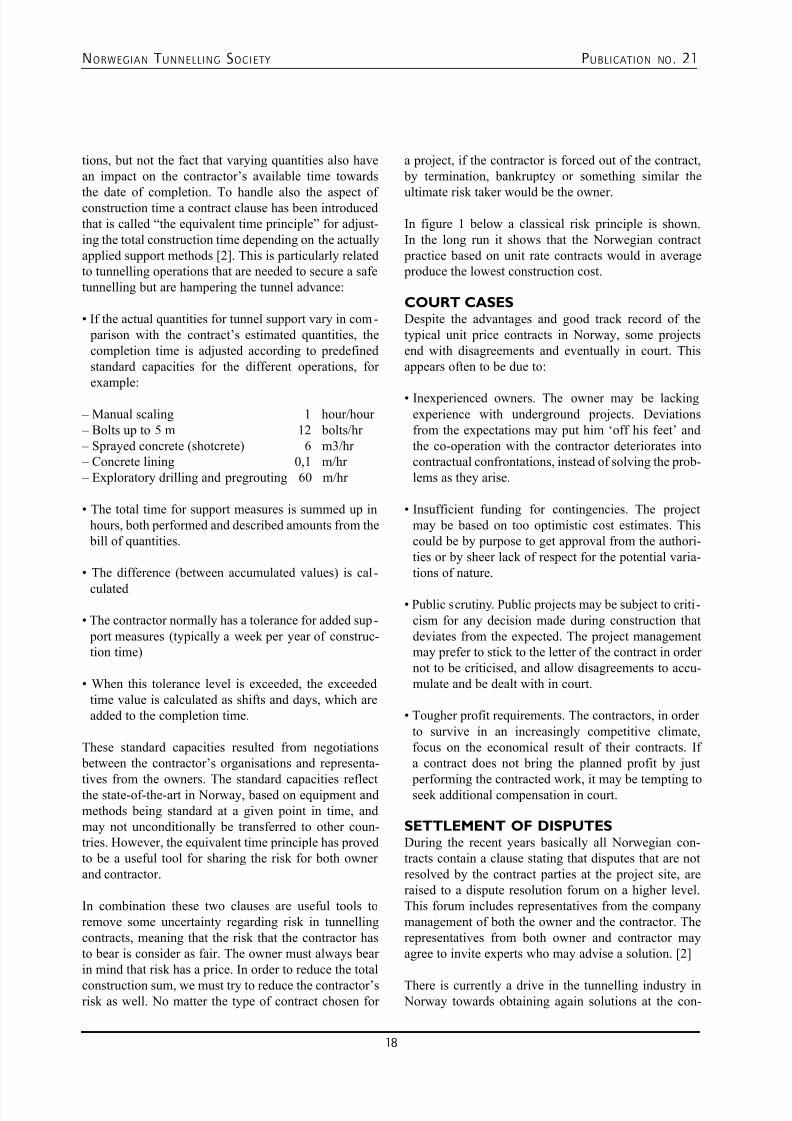
Photo: Svein Skeide, Public Roads Administration.
7/23/2019 NFF Publication 21 LOWRES
http://slidepdf.com/reader/full/nff-publication-21-lowres 20/94
NORWEGIAN T UNNELLING SOCIETY PUBLICATION NO . 21
20
CONCLUSIONSIn order to achieve success according to these criteria,
the following requirements to the contract may apply:
• Incentives. By including incentives for the contractor,
not only penalties, it is possible to stimulate focus on productivity, while maintaining quality and safety.Experience shows that in standard unit price contractsit may be tempting for the contractor to increase his production volume by applying more rock supportthan strictly necessary, especially if particular supportmeasures are tactically priced. If he instead gets a bonus for early completion, and possibly also a com- pensation for saved rock support (‘lost production’),this may turn around. The owner will then have tofollow-up to ensure the sufficiency of the rock sup- port for permanent use. The maintenance of safetyduring construction under such circumstances may bechallenging, and requires experienced personnel forfollow-up.
• Conflict solving. It is important to keep, or get back
to, the problem solving at site instead of in the court-rooms. A tool to achieve this may be the use of adviso-ry ‘reference groups’. A key point is that such groupsmeet on a regular and frequent basis to monitor theworks, before small problems develop into conflicts.
In this respect a ‘reference group’ may have a differentfunction than ‘dispute resolution boards’ dealing withalready materialised disagreements. The responsibilityof such ‘reference groups’ should be defined in thecontract. The personnel should be nominated by the parties and include professionals with practical tun-nelling experience.
• Co-operation. Although it is frequently expressed in
contracts that the parties have a duty to co-operate,as is the case with Norwegian contracts, this may notalways come easy. It may be effective to stimulate this
by focusing on the strong common interest in comple-tion on time. However, other tools may also be used,e.g. ‘geotechnical teams’ to which co-ordination ofgeotechnical issues can be referred and disagreementsabout e.g. choice of rock support measures can besolved.
• Functional requirements. The use of functional require-ments, rather than detailed technical specificationsand work instructions, may stimulate innovation anddevelopment by the contractor. However, functionalrequirements are not easy to apply for rock works,and the result of many of the work processes does not
lend itself to quality checking afterwards (e.g. groutedrock bolts).
• Regulations for ‘changed conditions’. As the inclusion
of all uncertainties in a fixed price may result in a very
high price, it may be beneficial overall to be specificabout the risk allocation. A suitable balance may befound by identifying which features shall be includedin the fixed price and which are kept as a risk of theowner, to be reimbursed by specified regulations.To include risk sharing clauses would be in agree-ment with the recommendations by the InternationalTunnelling Association(Ref. 13).
REFERENCES1. NORWEGIAN PUBLIC ROADSADMINISTRATION: “Road Tunnels”, Handbook No.021, Directorate of Public Roads, 129p, Oslo 1992.
2. O. T. BLINDHEIM & B. NILSEN: “Rock coverrequirements for subsea road tunnels”, 4th Symposiumon Strait Crossings, Bergen, Norway, 10 p, 2001.
3. O. T. BLINDHEIM & A. BEITNES: “Investigationstrategy for sub-sea rock tunnels”, Int. Symp. on StraitCrossings, 18p, Stavanger, 1986. Short version inTunnels & Tunnelling, p 35-39, September, 1986.
4. O. T. BLINDHEIM & E. ØVSTEDAL: “Design principles and construction methods for water control
in subsea road tunnels in rock”, in Water control in Norwegian tunnelling, Publication No. 12, NorwegianSoil and Rock Engineering Association, NorwegianTunnelling Society, NFF, 2002, (can be downloaded atwww.tunnel.no).
5. O. T. BLINDHEIM & A. B. OLSEN: “Prevention is better than cure. Experience with probe drilling, stabil-ity control and pre-grouting in the Ålesund-Giske sub-sea road tunnels”, Tunnels & Tunnelling, March, 1989.
6. O. T. BLINDHEIM, A. B. OLSEN & A. BEITNES:
“The deepest subsea road tunnel in the world –Experiences with the Godøy tunnel”, Presented at: Int.Symp. on Unique Underground Structures, Denver,1990, (copy available on request to: [email protected]).
7. HOLTER, K. G., JOHANSEN, E. D. &HEGRENÆS, A. (1996): Tunnelling through a sand-zone - Ground treatment experiences from the BjorøySubsea Road Tunnel, Proc. North American Tunneling’96, Washington, USA, Ozdemir (ed.), Balkema, pp249-256.
7/23/2019 NFF Publication 21 LOWRES
http://slidepdf.com/reader/full/nff-publication-21-lowres 21/94
NORWEGIAN T UNNELLING SOCIETY PUBLICATION NO . 21
21
8. B. AAGAARD & O. T. BLINDHEIM: “Crossing ofexceptionally poor weakness zones in three subsea tun-
nels, Norway”, in Alten (ed.): Challenges for the 21stCentury, Proc. World Tunnel Congress ’99, Oslo, pp457-466. Balkema, 1999.
9. O. T. BLINDHEIM & H. BERG: “Sprayed con-crete rock support on the Oslofjord Connection”, 3rdInt. Symp. on Sprayed Concrete – Modern Use ofWet Mix Sprayed Concrete for Underground Support, Norwegian Tunnelling Society, Gol, Norway, 1999.
10. L. BACKER & O. T. BLINDHEIM: “TheOslofjord Subsea road tunnel. Crossing of a weaknesszone under high pressure by freezing”, in T. Altenet.al., Challenges for the 21st Century. Proc. WorldTunnel Congress ’99, Oslo: pp 309-316. Balkema,1999. Also published as: “Oslofjord challenge”,Tunnels & Tunnelling International, December, pp39-42, 1999.
11. E. KLEIVAN: “NoTCoS – Norwegian TunnellingContract System”, in Norwegian Tunnelling Today,Publication No. 5, Norwegian Soil and RockEngineering Association, 4p, 1987.
12, E. GRØV & O. T. BLINDHEIM: ”Risk alloca-tion in ’adjustable fixed price contracts”, Tunnels &
Tunnelling International, June 2003.
13. INTERNATIONAL TUNNELLINGASSOCIATION (Working Group on ContractualSharing of Risks): “ITA Recommendations onContractual Sharing of Risks”, Tunnelling andUnderground Space Technology, Vol. 3, No. 2, pp.103-104, 1988.
[1] NPRA handbook 021 Vegtunneler (2006), andEnglish version: handbook 021 E Road Tunnels (2004)
[2] NPRA handbook 066 Konkurransegrunnlag (2008-02)
[3] NPRA handbook 025 Prosesskode 1, Standard beskrivelsestekster for vegkontrakter (2007-11)
Optimal solutionsfor underground structures
Optimal solutionsfor underground structures
NGI (Norwegian Geotechnical Institute) has competence within geotechnics, rock engineering, rockmass classification, underground support design, hydrogeology and environmental geotechnology.
NGI is a leading international centre for research and consulting in the geosciences. We developoptimum solutions for society, and offers expertise on the behaviour of soil, rock and snow and theirinteraction with the natural and built environment. NGI works within the oil, gas and energy, buildingand construction, transportation, natural hazards and environment sectors.
www.ngi.no

7/23/2019 NFF Publication 21 LOWRES
http://slidepdf.com/reader/full/nff-publication-21-lowres 22/94
NORWEGIAN T UNNELLING SOCIETY PUBLICATION NO . 21
22
Orica Norway ASRøykenveien 18 Tel. +47 32 22 91 00P.O.Box 614 Fax. +47 32 22 91 013412 Lierstranda [email protected]
www.oricaminingservices.com
Technology to improve
tunnel advance rates
For your bottom line
Orica Mining Services is the world’s leading supplier of commercial explosives
7/23/2019 NFF Publication 21 LOWRES
http://slidepdf.com/reader/full/nff-publication-21-lowres 23/94
NORWEGIAN T UNNELLING SOCIETY PUBLICATION NO . 21
23
03. NORWEGIAN STANDARD NS 3420 IN CONTRACTS FOR
UNDERGROUND WORKS
LUND, Morten
INTRODUCTIONThe Norwegian Standard NS 3420 is standardizedtechnical specifications for civil engineering works ina coded system based on a unit price system for usein tender documents. The standard can also be used tosystemize and cost estimate components and partiallyworks, calculation and quality control and supervisionduring construction. Contracts with technical specifica-tions based on NS 3420 are mainly Employer managedunit price contracts with NS 8405 as the contractualstandard. Contracts for underground rock works aremainly of this category.
NS 3420 forms the foundation for quantity bearingitems in tender documents to be calculated by theContractors. The items are encoded according to a
system that defines the scope and content of the items.The code defines requirements for materials, execution,tolerances, testing and control for each item. It alsogives rules for measurement and payment. The standardis organized with a hierarchical structure where require-ments on a higher level are valid for lower levels. It hasa superior part, part 1, named General conditions, thatcontains requirements valid for all the technical parts ofthe standard.
NS 3420 is a Norwegian Standard consisting of 25 parts where 5 of them are so called common or general
parts and the others are divided into technical subjects.Parts relevant for underground works are the follow-ing:
• Part 1 - General conditions - with requirements valid
for all other parts;
• Part A - Preliminaries and General Provisions -
contains items for insurance, planning, establishing,management and rigging down the site including re-establishing the area after completed contract;
• Part F - Earthworks - part 1 - contains items such as
blasting, uploading, transportation and rock supportetc.;
• Part G - Earthworks - part 2 - contains items for more
complicated geotechnical and engineering geologicalworks such as drilling of micro tunnels in rock andsoil, TBM-drilling, rock- and soil anchors and grout-ing etc.;
• Part L - Concrete works - contains items for cast in
place concrete rock support and sprayed concrete;
The use of NS 3420 is based on the principal that theEmployer designs what he wants and the Contractordecides how to construct it as specified. The risk forground conditions is normally placed with the Employerin this type of contracts. The Employer normally hiresa consultant to do the design. NS 3420 has standard-ized requirements to help the Employer to achieve an
acceptable level of quality with possibilities to specifyto a higher level of quality if wanted. This way it is pos-sible to adapt to the Employers specific needs for each project.
PRELIMINARIES AND GENERALPROVISIONSPreliminaries and General Provisions includingContractor’s camp facilities can be specified in dif-ferent ways depending on how much interference theEmployer wants to have in the process.
• Basically the Contractor is obligated to take intoaccount all he need to fulfil his contract in a legal mat-ter. If the Employer do not have any special require-ments or no wish to interfere , when it comes to pre-liminaries and General Provisions, the bill of quantitycan consist of as few as 3 - 5 items covering this partof the contract.
• Further it is different ways for the Employer to specify
certain requirements for items of his interest withoutcomplicating the simple principal of few items forcalculation.
• At last it is a set of detailed items for a complete speci-fication of an Employer controlled work site. Mainly
7/23/2019 NFF Publication 21 LOWRES
http://slidepdf.com/reader/full/nff-publication-21-lowres 24/94
NORWEGIAN T UNNELLING SOCIETY PUBLICATION NO . 21
24
these items are meant for one Contractor that are partlyor completely establishing and managing a work site
for another contract than his own. Though in somecases the Employer wants to keep detailed cost controlof certain element of the work site, and it will be suit-able to use these detailed items to highlight the cost.
General conditions, NS 3420, part 1The overall general requirements in NS 3420, part1 - General conditions relevant for underground rockworks, are mainly the following:
• the completed item, a component or partially work, is
to be mounted or executed, connected, tested for func-tion, calibrated and ready for use;
• the prices are to include supply of material, use of
accessory materials, salary, social expenses, toolsand machinery, scaffolding, mobile cranes and lifts inaddition to administration and profit;
• materials chosen by the Contractor is to be adapted to
the base, required mounting, adjacent constructionsand requirements for the finished product. The mate-rials shall in addition be durable or adaptable to theanticipated climate, strain or wear during use.
• the materials shall be undamaged and without errors,they shall be transported handled and stored in such away that the finished product is not deteriorated.
• the Contractor shall hold the competence and equip-ment needed to fulfil the contract.
• products shall fulfil the required function, when it
comes to conditions concerning use, environmentaland maintenance;
• technical solutions or execution methods chosen by the
Contractor, shall be according to the required functionor output and they shall be feasible and durable to theanticipated climate, strain or wear during use.
• mounting is to be done according to producers/suppli-ers descriptions.
We will look further into some items and how they arespecified. The list is far from complete.
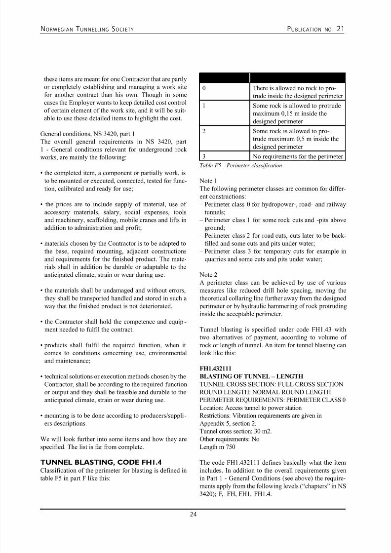
TUNNEL BLASTING, CODE FH1.4Classification of the perimeter for blasting is defined intable F5 in part F like this:
Perimeter class Requirements
0 There is allowed no rock to pro-
trude inside the designed perimeter 1 Some rock is allowed to protrude
maximum 0,15 m inside thedesigned perimeter
2 Some rock is allowed to pro-trude maximum 0,5 m inside thedesigned perimeter
3 No requirements for the perimeter
Table F5 - Perimeter classification
Note 1The following perimeter classes are common for differ-ent constructions: – Perimeter class 0 for hydropower-, road- and railway
tunnels; – Perimeter class 1 for some rock cuts and -pits above
ground; – Perimeter class 2 for road cuts, cuts later to be back-
filled and some cuts and pits under water; – Perimeter class 3 for temporary cuts for example in
quarries and some cuts and pits under water;
Note 2A perimeter class can be achieved by use of various
measures like reduced drill hole spacing, moving thetheoretical collaring line further away from the designed perimeter or by hydraulic hammering of rock protrudinginside the acceptable perimeter.
Tunnel blasting is specified under code FH1.43 withtwo alternatives of payment, according to volume ofrock or length of tunnel. An item for tunnel blasting canlook like this:
FH1.432111
BLASTING OF TUNNEL – LENGTH
TUNNEL CROSS SECTION: FULL CROSS SECTIONROUND LENGTH: NORMAL ROUND LENGTHPERIMETER REQUIREMENTS: PERIMETER CLASS 0
Location: Access tunnel to power stationRestrictions: Vibration requirements are given inAppendix 5, section 2.Tunnel cross section: 30 m2.Other requirements: NoLength m 750
The code FH1.432111 defines basically what the itemincludes. In addition to the overall requirements givenin Part 1 - General Conditions (see above) the require-
ments apply from the following levels (“chapters” in NS3420); F, FH, FH1, FH1.4.
7/23/2019 NFF Publication 21 LOWRES
http://slidepdf.com/reader/full/nff-publication-21-lowres 25/94
NORWEGIAN T UNNELLING SOCIETY PUBLICATION NO . 21
25
The 5 last digits are the results of specificationsgiven directly in the item setup above (explained in
the order they appear); 3 means tunnel, 2 means pay-ment according to length, 1 means the choice FULLCROSS SECTION (in one round), 1 means the choice NORMAL ROUND LENGTH, and the last 1 meansPERIMETER CLASS 0.
Requirements valid for the tunnel blasting from the dif-ferent levels of the code structure will be:
• Level F - Earthworks - part 1 gives no requirements.
• Level FH - Rock excavation requires that rock excava-tion is to be executed in such a way that unnecessaryweakening of the final perimeter shall be avoided andthe perimeter shall be as even as possible.
• Level FH1 - Excavation by blasting requires:
- the price includes necessary drilling, charging, drill-and charging trouble and required perimeter blasting;
- the perimeter holes, and normally also the holes inthe next row shall be charged with reduced chargingadjusted to the hole spacing and rock conditions;
- solid rock is not allowed above designed invert; - collaring of a drill hole is not allowed inside designed
perimeter and deviation of single holes shall not be
larger than 100 mm from the Contractors plannedcollaring.
• Level FH1.4 - Underground excavation by blasting
requires: - the price includes handling of water with up to 500
l/min. per face, and scaling at face with 1 hour perround plus weekly or periodically scaling with up to5 hours per week;
- drill holes in the perimeter shall have a spacing of0,7 m and a burden to the next row of 0,9 m which isto be drilled parallel to the perimeter and not have a
hole spacing exceeding 2 x the spacing in the perim-eter. - the perimeter holes shall be charged with maximum
1,12 MJ/m in the column charge, anfo is not allowed; - for tunnel blasting it is required a deviation in direc-
tion at the collaring point of maximum 6 %;- there shall be separate items for safety measurements
(FH1.1), uploading (FM1.2), transportation (FM2.2),water handling exceeding the included limits, thatis 500 l/min per face (FJ1) and tunnel intersections(FH1.4811).
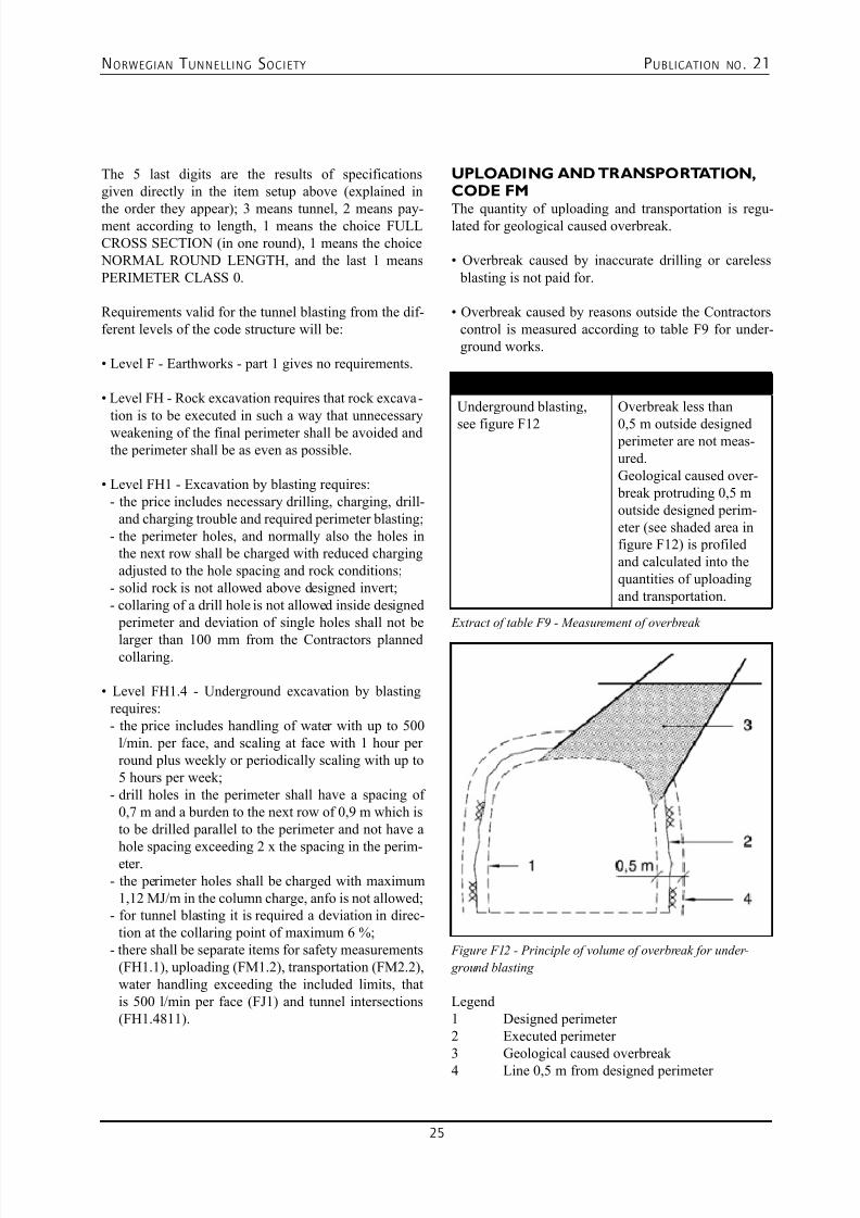
UPLOADING AND TRANSPORTATION,CODE FM
The quantity of uploading and transportation is regu-lated for geological caused overbreak.
• Overbreak caused by inaccurate drilling or careless
blasting is not paid for.
• Overbreak caused by reasons outside the Contractors
control is measured according to table F9 for under-ground works.
Type of work Measurement rules
Underground blasting,
see figure F12
Overbreak less than
0,5 m outside designed perimeter are not meas-ured.Geological caused over- break protruding 0,5 moutside designed perim-eter (see shaded area infigure F12) is profiledand calculated into thequantities of uploadingand transportation.
Extract of table F9 - Measurement of overbreak
Figure F12 - Principle of volume of overbreak for under-
ground blasting
Legend1 Designed perimeter 2 Executed perimeter 3 Geological caused overbreak
4 Line 0,5 m from designed perimeter
7/23/2019 NFF Publication 21 LOWRES
http://slidepdf.com/reader/full/nff-publication-21-lowres 26/94
NORWEGIAN T UNNELLING SOCIETY PUBLICATION NO . 21
26
Items for uploading and transportation may look like this:
FM1.2314UPLOADING – SOLID VOLUME
PLACE OF UPLOADING: PLACE OFUNDERGROUND BLASTINGLocation: Access tunnel to power stationType of masses: Debris from blastingOther requirements: NoDesigned solid volume m3 22500
FM2.21314
TRANSPORTATION WITHIN THE WORK SITE
– SOLID VOLUME
TO PERMANENT DUMP OR TEMPORARY
STORAGE
UPLOADING PLACE: PLACE OFUNDERGROUND BLASTINGPLACE OF UPLOADING: PLACE OFUNDERGROUND BLASTINGLocation: Access tunnel to power stationType of masses: Rubble from blastingDump site: Dump site by the power stationOther requirements: NoDesigned solid volume m³ 20000
FM2.223145
TRANSPORTATION OUT OF THE WORK SITEAREA
UPLOADING PLACE: PLACE OFUNDERGROUND BLASTINGTOTAL LENGTH OF TRANSPORTATION: FROM 4UNTIL AND INCLUDING 6 kmLocation: Access tunnel to power stationPlace of delivery: Dumping in Valley A at the Hillbilly farmType of masses: Rubble from blastingOther requirements: NoDesigned solid volume m³ 2500
Rock support, code FP1
Extra scaling - The price for the blasting operationincludes a minimum of basic scaling. Scaling exceedingthis limit will be paid only when accepted or ordered bythe Employer in advance.
Rock bolting - The following types of rock bolts arethe most common rock bolts in Norway and possible tochoose directly from the standard:
• mechanically end-anchored rock bolts;
• resin end-anchored rock bolts;
• fully grouted rock bolts;• combination bolts.
In addition it is possible to choose• self drilling rock bolts;
• friction bolts;• fibre glass bolts.
Installation of rock bolts includes material, drilling andflushing of the drill hole, specified dished anchor plate,semi-spherical washer and nut, necessary pre tension-ing, post tensioning to obtain the function as temporarysupport and specified testing as seen below.
e1) Rock bolts shall be tested in the following amountseparately for each bolt type in use:
• At least 50 % of the first 100 rock bolts shall be tested.
If more than 5 % of the tested bolts fail, 50 % of thenext 100 bolts shall be tested. This system shall con-tinue until less than 5 % of the tested bolts fail.
• Further 25 bolts of each 1000 installed bolts shall be
tested with the same accept criteria as above. If theaccept criteria is exceeded, the test procedure shall go back to testing 50 % of each 100 bolts until the criteriaagain is obtained.
• If pull test is used it shall be pulled up to 10 % above
work- or design load.
Concrete works, code L
Concrete works are mainly specified with codes from part L.
Cast in place concrete rock support - A set of itemsmay look like this including preparation works:
LB5.511
MOBILIZATION OF PREFABRICATED
FORMWORK
Location: Outside Power stationTunnel cross section: 30 m2Other requirements:a) Scope and price basisTime needed for mobilisation to be given in Appendix X.Lump sum LS
LB5.523
RIGGING OF PREFABRICATED FORMWORK
IN TUNNEL
WORK PLACE: BEHIND FACELocation: Headrace tunnelTunnel cross section: 30 m2
Other requirements: No Number of times no 4
7/23/2019 NFF Publication 21 LOWRES
http://slidepdf.com/reader/full/nff-publication-21-lowres 27/94
NORWEGIAN T UNNELLING SOCIETY PUBLICATION NO . 21
27
LB5.5332
USE OF PREFABRICATED FORMWORK IN
TUNNELWORK PLACE: BEHIND FACEINSPECTION: EXECUTION CLASS 2Location: Headrace tunnelTunnel cross section: 30 m2Other requirements: NoLength m 20
LB8.22402
END CLOSING OF FORMWORK – AREA
TYPE OF CONSTRUCTION: WALLS AND ROOFARCHSURFACE: CONTRACTOR’S CHOICEINSPECTION: EXECUTION CLASS 2Location: Headrace tunnelDimension: Contractor’s choiceOther requirements: NoArea m2 8
LB8.31
ADJUSTING FORMWORK TO ROCK SURFACE
Location: Headrace tunnelOther requirements: NoLength m 15
LC1.1152REINFORCEMENT WITH REBAR
REINFORCEMENT CLASS: B500NADIAMETER: 16 mmINSPECTION: EXECUTION CLASS 2Location: Headrace tunnelOther requirements: NoMass kg 2000
LG1.3123343220
CAST IN PLACE ROCK SUPPORT – LENGTH
WORK PLACE: BEHIND FACE
TYPE OF CONSTRUCTION: WALLS AND ROOFARCHCOMPRESSIVE STRENGTH CLASS: B35DURABILITY CLASS: M45CLORID CLASS: Cl 0,40INSPECTION: EXECUTION CLASS 2CURING MEASUREMENTS: CONTRACTOR’SCHOICEACCORDONG TO NS-EN 13670+NALocation: Headrace tunnelTunnel cross section after casting: 28 m2Other requirements: NoLength m 20
LG1.318334322
EXTRA CONCRETE FOR CAST IN PLACE
ROCK SUPPORTWORK PLACE: BEHIND FACETYPE OF CONSTRUCTION: WALLS AND ROOFARCHCOMPRESSIVE STRENGTH CLASS: B35DURABILITY CLASS: M45CHLORIDE CONTENT CLASS: Cl 0,40INSPECTION: EXECUTION CLASS 2Location: Headrace tunnelOther requirements: NoVolume m3 10
Shotcrete - A set of items may look like this:
LJ2.111
RIGGING FOR SHOTCRETING FOR ROCK
SUPPORT
Location: Headrace tunnelOther requirements: No Number of times no 20
LJ2.122232122
SHOTCRETE FOR ROCK SUPPORT
WORK PLACE: AT FACECOMPRESSIVE STRENGTH CLASS: B35
DURABILITY CLASS: M45CHLORIDE CONTENT CLASS: Cl 0,40FIBRE REINFORCEMENT: ENERGI ABSORPTIONCLASS E700INSPECTION: EXECUTION CLASS 2Location: Headrace tunnelOther requirements: NoVolume m3 150
LJ2.122232132
SHOTCRETE FOR ROCK SUPPORT
WORK PLACE: AT FACE
COMPRESSIVE STRENGTH CLASS: B35DURABILITY CLASS: M45CHLORIDE CONTENT CLASS: Cl 0,40FIBRE REINFORCEMENT: ENERGI ABSORPTIONCLASS E1000INSPECTION: EXECUTION CLASS 2Location: Headrace tunnelOther requirements: NoVolume m3 50
7/23/2019 NFF Publication 21 LOWRES
http://slidepdf.com/reader/full/nff-publication-21-lowres 28/94
NORWEGIAN T UNNELLING SOCIETY PUBLICATION NO . 21
28
LJ2.123233882
SHOTCRETE FOR ROCK SUPPORT
WORK PLACE: BEHIND FACECOMPRESSIVE STRENGTH CLASS: B35DURABILITY CLASS: M45CHLORIDE CONTENT CLASS: Cl 0,40FIBRE REINFORCEMENT: WITHOUT FIBREINSPECTION: EXECUTION CLASS 2Location: Headrace tunnelOther requirements: NoVolume m3 50
LJ2.123232122
SHOTCRETE FOR ROCK SUPPORT
WORK PLACE: BEHIND FACECOMPRESSIVE STRENGTH CLASS: B35DURABILITY CLASS: M45CHLORIDE CONTENT CLASS: Cl 0,40FIBRE REINFORCEMENT: ENERGI ABSORPTIONCLASS E700INSPECTION: EXECUTION CLASS 2Location: Headrace tunnelOther requirements: NoVolume m3 50
LJ8.2
ADDITION FOR ALKALI FREE
ACCELERATOR Location: Headrace tunnelOther requirements: NoVolume of shotcrete m3 200
Grouting, code GE (drilling) and GQ (grouting)
Grouting is normally described on a cost-plus basiswith a split between materials and time consumption.
It may look like this:
GE1.1231113DRILLING OF HOLE IN ROCK
DIAMETRE UNTILL AND INCLUDING 150 mm
UNDER GROUND – LENGTH
PURPOSE: GROUTINGWORK PLACE: UNDER GROUND, AT FACETOTAL HOLE LENGTH: FROM 12 m UNTIL ANDINCLUDING 24 mLocation: Headrace tunnelDrill hole diameter: Maximum 64 mmTolerances: Collaring deviation maximum 100 mm,direction deviation at collaring maximum 2 %Other requirements: No
Summed hole length m 30000
GE1.181211
RIGGING FOR WATER LOSS MEASUREMENTS
PURPOSE: GROUTINGWORK PLACE: UNDER GROUND, AT FACELocation: Headrace tunnelOther requirements: No Number of times no 40
GE1.1813111
WATER LOSS MEASUREMENTS
PURPOSE: GROUTINGWORK PLACE: UNDER GROUND, AT FACEDEPTH OF PACKER: UNTIL AND INCLUDING 3 mLocation: Headrace tunnelDrill hole diameter: Adapted to grout holesPressure: Maximum 100 bar Other requirements: No Number of packers placed no 200
GE1.18331113
CLEANING DRILLHOLE IN ROCK BY FLUSHING
PURPOSE: GROUTINGWORK PLACE: UNDER GROUND, AT FACETOTAL DRILLHOLELENTH: FROM 12 m UNTILAND INCLUDING 24 mLocation: Headrace tunnelExecution: Contractor’s choice
Other requirements: NoSummed hole length m 30000
GQ1.1
RIGGING FOR GROUTING
WORK PLACE: IN ROCK, UNDER GROUND, ATFACELocation: Headrace tunnelCapacity of pump: minimum. 60 l/min at 75 bar work pressureMaximum grouting pressure: 100 bar Number of pump lines: 2
Type of grouting: deep grouting in rock Other requirements: No Number of times no 100
GQ2.11
PLACING OF PACKER FOR GROUTING
WORK PLACE: IN ROCK, UNDER GROUND, ATFACEDEPTH OF PACKER: UNTIL AND INCLUDING 3mLocation: Headrace tunnelFor drill hole diameter: Adapted to the grout holesMaximum pressure: 20 bar
Other requirements: No Number of packers placed no 1500
7/23/2019 NFF Publication 21 LOWRES
http://slidepdf.com/reader/full/nff-publication-21-lowres 29/94
NORWEGIAN T UNNELLING SOCIETY PUBLICATION NO . 21
29
GQ2.12
PLACING OF PACKER FOR GROUTING
WORK PLACE: IN ROCK, UNDER GROUND, ATFACEDEPTH OF PACKER: FROM 3 m UNTIL ANDINCLUDING 5 mLocation: Headrace tunnelFor drill hole diameter: Adapted to the grout holesMaximum pressure: 100 bar Other requirements: No Number of packers placed no 1500
GQ2.13
PLACING OF PACKER FOR GROUTING
WORK PLACE: IN ROCK, UNDER GROUND, ATFACEDEPTH OF PACKER: FROM 5 m UNTIL ANDINCLUDING 10 mLocation: Headrace tunnelFor drill hole diameter: Adapted to the grout holesMaximum pressure: 100 bar Other requirements: No Number of packers placed no 1000
GQ3.11
SUPPLY OF GROUTING MATERIAL
TYPE OF GROUTING MATERIAL: STANDARD
GROUTING CEMENTLocation: For use on the hole siteRequirements for grouting materials: Requirements aregiven in Appendix 5, section 9.Other requirements: NoQuantity kg 300000
GQ3.12
SUPPLY OF GROUTING MATERIAL
TYPE OF GROUTING MATERIAL: MICRO FINECEMENTLocation: For use on the hole site
Requirements for grouting materials: Requirements aregiven in Appendix 5, section 9.Other requirements: NoQuantity kg 100000
GQ3.13
SUPPLY OF GROUTING MATERIAL
TYPE OF GROUTING MATERIAL: ULTRA FINECEMENTLocation: For use on the hole siteRequirements for grouting materials: Requirements aregiven in Appendix 5, section 9.Other requirements: No
Quantity kg 10000
GQ3.21
SUPPLY OF ADDITIVES
TYPE OF ADDITIVE: MICRO SILIKALocation: For use on the whole siteOther requirements: NoQuantity kg 40000
GQ3.22
SUPPLY OF ADDITIVES
TYPE OF ADDITIVE: SUPER PLASTESIZER Location: For use on the whole siteOther requirements: NoQuantity kg 10000
GQ4.111
GROUTING WORKS
WORK PLACE: IN ROCK, UNDERGROUND, ATFACELocation: Headrace tunnelStop criteria: 1000 kg per drill holeOther requirements: NoTime hour 1500
EQUIVALENT TIME ACCOUNTINGThis is a system made in the 70’ies for risk-sharing practice due to variation in ground conditions.Appendix A2 in part F deals with regulation of con-
struction time in case of exceeding rock support quan-tities by use of equivalent time accounting. This sub- ject is dealt with in another article of this publication.
7/23/2019 NFF Publication 21 LOWRES
http://slidepdf.com/reader/full/nff-publication-21-lowres 30/94
NORWEGIAN T UNNELLING SOCIETY PUBLICATION NO . 21
30
www.sweco.no
Nearly 100 years of experience within:
Energy•
Environment and Water Resources•
Industry/Structures•
Transportation•
Underground Works and Engineering Geology•
Soil Mechanics and Foundation Engineering•
For Rock Engineering and Underground Planning please contact:
SWECO Norge AS P.O. Box 400 NO-1327 Lysaker, Norway
Tel: +47 67 12 80 00, Fax: +47 67 12 58 40, E-mail: [email protected]
Sweco - Combined skills in consulting
engineering, environmental management
and architecture.
7/23/2019 NFF Publication 21 LOWRES
http://slidepdf.com/reader/full/nff-publication-21-lowres 31/94
NORWEGIAN T UNNELLING SOCIETY PUBLICATION NO . 21
31
04. SHARING OF RISK IN NORWEGIAN ROAD TUNNELLING
CONTRACTS
FOSSBERG, Gisle Alexander
SUMMARYThis paper addresses contract practice for road tunnelsin the Norwegian Public Roads Administration (NPRA).The specifications are based on the drill and blastmethod and the bid – build contract model and the unit price systems. The NPRA regards the rock that we aretunnelling in as a construction material, and strengthen-ing methods are determined by assessment of rock qual-ity at the tunnel face. This implies that actual quantitiesmay differ from the contract’s bill of quantities. NPRAhas developed a flexible contract for adjusting quanti-ties for both strengthening ahead of the tunnel face andsupport measures, and a clause to adjust constructiontime accordingly.
CONTRACT PHILOSOPHY
The Norwegian Public Roads Administration (NPRA)uses the drill and blast method for the road tunnels.There are some 1000 road tunnels. Most are short, beingless than 1 km, and the longest is 24.5 km. Between 20and 30 km new tunnels are excavated per year.
Typically, road tunnels in Norway are in hard rock. Dueto the quality of rock, one regards rock as a constructionmaterial. Such construction material has weaknessesthat need to be dealt with by reinforcing measures suchas pregrouting, bolts, or sprayed concrete arches. Incases of little or no strength, full reinforced concrete
lining is required.
Since the rock mass is regarded as a construction mate-rial, the assessment of the rock properties is necessary. Itis of vital importance that both client and contractor havecompetent people at the tunnel face to assess the actualsituation ahead and the needed support measures. [1]
We know that there will be surprises, so we normallyuse the unit price contract, which places the risk forvarying ground conditions on the owner. The unit pricecontract gives a fair sharing of risk to the parties by thecontractor bearing the risk for his unit prices covering
his costs and overhead, and the owner bearing the riskfor varying and unforeseen ground conditions.
Though we do not ask for different prices depending onrock quality, we often ask for separate prices for halfthe blasting length or dividing the tunnel face into por-tions. [2]
Before contracting, we register ground conditions andcompile a report that becomes part of the contractdocuments. This report describes test results, in otherwords the facts, but in addition a part that describesground conditions, based on the facts. This gives theowner a fairly good basis for which measures and whichquantities we need to specify in our contracts, and also provides the contactor with information that he may usein calculating.
In our bill of quantities, we specify various support
methods and stipulate quantities, trying as accurately as possible to stipulate the amounts that we expect will becarried out, as this gives the least surprises, and the tru-est picture of the scope of work. The contractor is paidaccording to the actual amounts carried out. [3]
Important objectives of our philosophy are safety underconstruction and safe tunnels, all the time bearing costsin mind. It therefore becomes important that:1. we are clear on how we share risk2. our tunnel contracts are flexible in handling varying
ground conditions
3. owner and contractor interact to achieve the resultswe wish.
RECORDING GEOLOGICALCONDITIONS AT THE TUNNEL FACEWe have had examples proving rock fall accidents canhappen in tunnels opened to traffic. This has led us toreview in detail if our way of tunnelling is good enough,and we have made a few modifications.
After each drill and blast cycle, the rock is inspectedalong with classification of rock quality, in order toensure that appropriate support measures are chosen.
In addition, time is set apart in order to carry out neces-
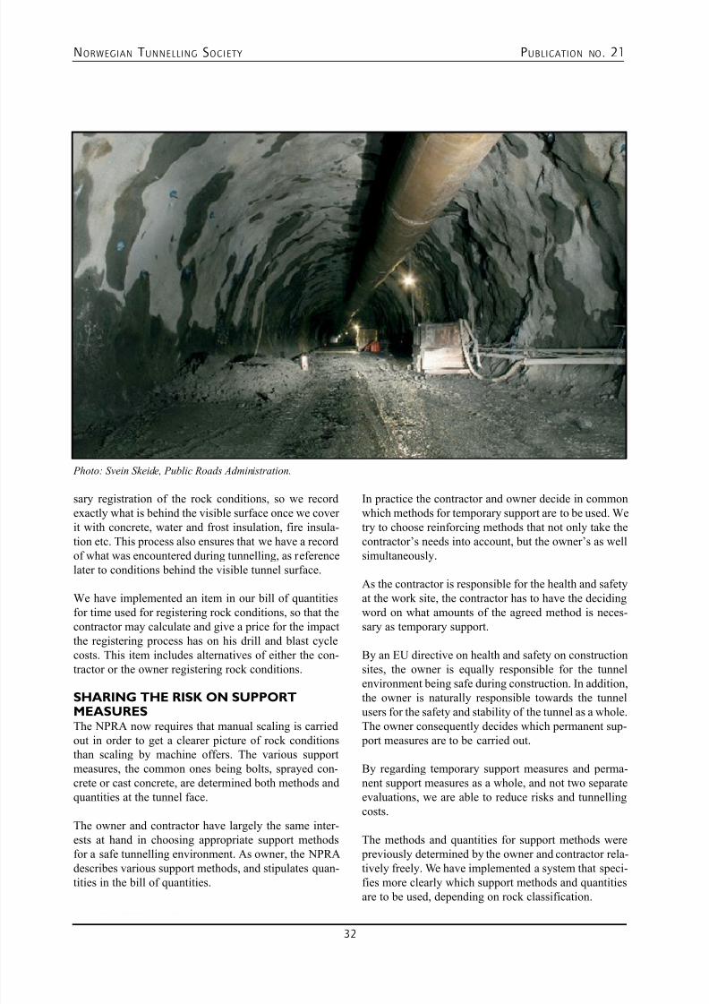
7/23/2019 NFF Publication 21 LOWRES
http://slidepdf.com/reader/full/nff-publication-21-lowres 32/94
NORWEGIAN T UNNELLING SOCIETY PUBLICATION NO . 21
32
sary registration of the rock conditions, so we recordexactly what is behind the visible surface once we cover
it with concrete, water and frost insulation, fire insula-tion etc. This process also ensures that we have a recordof what was encountered during tunnelling, as referencelater to conditions behind the visible tunnel surface.
We have implemented an item in our bill of quantitiesfor time used for registering rock conditions, so that thecontractor may calculate and give a price for the impactthe registering process has on his drill and blast cyclecosts. This item includes alternatives of either the con-tractor or the owner registering rock conditions.
SHARING THE RISK ON SUPPORTMEASURESThe NPRA now requires that manual scaling is carriedout in order to get a clearer picture of rock conditionsthan scaling by machine offers. The various supportmeasures, the common ones being bolts, sprayed con-crete or cast concrete, are determined both methods andquantities at the tunnel face.
The owner and contractor have largely the same inter-ests at hand in choosing appropriate support methodsfor a safe tunnelling environment. As owner, the NPRAdescribes various support methods, and stipulates quan-
tities in the bill of quantities.
In practice the contractor and owner decide in commonwhich methods for temporary support are to be used. We
try to choose reinforcing methods that not only take thecontractor’s needs into account, but the owner’s as wellsimultaneously.
As the contractor is responsible for the health and safetyat the work site, the contractor has to have the decidingword on what amounts of the agreed method is neces-sary as temporary support.
By an EU directive on health and safety on constructionsites, the owner is equally responsible for the tunnelenvironment being safe during construction. In addition,
the owner is naturally responsible towards the tunnelusers for the safety and stability of the tunnel as a whole.The owner consequently decides which permanent sup- port measures are to be carried out.
By regarding temporary support measures and perma-nent support measures as a whole, and not two separateevaluations, we are able to reduce risks and tunnellingcosts.
The methods and quantities for support methods were previously determined by the owner and contractor rela-tively freely. We have implemented a system that speci-
fies more clearly which support methods and quantitiesare to be used, depending on rock classification.
Photo: Svein Skeide, Public Roads Administration.
7/23/2019 NFF Publication 21 LOWRES
http://slidepdf.com/reader/full/nff-publication-21-lowres 33/94
NORWEGIAN T UNNELLING SOCIETY PUBLICATION NO . 21
33
CONTRACT CLAUSES TO TACKLE VARY-ING QUANTITIES AND CONSTRUC-
TION TIME FOR EXPLORATORY DRILL-ING AND SUPPORT MEASURESWe make important decisions at the tunnel face, bothas to the need for measures ahead of the tunnel faceand support at the face. A consequence is that theremay easily occur a considerable difference between thestipulated quantities in the contract and the actual quan-tities as carried out.
To tackle this, the NPRA has defined “the 100 % rule”in our specification describing support [3]:
• The unit prices apply even if the sum of actual quanti-ties as calculated in cost differ from the bill of quanti-ties by up to ± 100 %.
• If this limit is exceeded (more than doubling the quan-tity), unit prices may be adjusted by negotiation.
• The adjusted unit prices may not differ from the con-tract’s unit prices by more than 20 %. Adjusted priceshall be determined according to documented expenses.
This takes care of differing quantities, but not the factthat added quantities also have an impact on the contrac-
tor’s available time towards the date of completion. Tohandle also that aspect, we have introduced a contractclause we call “the equivalent time principle” for adjust-ing the total construction time depending on the appliedsupport methods [2]:
• If the actual quantities for tunnel support vary in com- parison with the contract’s estimated quantities, thecompletion time is adjusted according to values, forexample:
– Manual scaling 1 hour/hour – Bolts up to 5 m 12 bolts/hr
– Sprayed concrete (shotcrete) 6 m3/hr
– Concrete lining 0,1 m/hr – Exploratory drilling and pregrouting 60 m/hr
• The total time for support measures is summed up in
hours, both performed and described amountsfrom the bill of quantities.
• The difference (between accumulated values) is cal-culated.
• The contractor normally has a tolerance for added sup- port measures (typically a week per year of construc-tion time).
• When this tolerance level is exceeded, the exceeded
time value is calculated as shifts and days, which areadded to the completion time.
The method described above also includes a factor totake into account that a tunnel may have more than onetunnel face during construction. The values reflect thestate of the art in Norway, methods and capacities today.The method has proved to be a useful tool useful forsharing the risk for both owner and contractor.
Together, these two clauses in our opinion remove someuncertainty regarding risk in our contracts, meaning that
the risk that the contractor has to bear is fair enough.The owner must always bear in mind that risk has a price. In order to reduce the total construction sum, wemust try to reduce the contractor’s risk as well.
REFERENCES[1] NPRA handbook 021 Vegtunneler (2006), andEnglish version: handbook 021 E Road Tunnels (2004)
[2] NPRA handbook 066 Konkurransegrunnlag (2008-02)
[3] NPRA handbook 025 Prosesskode 1, Standard
beskrivelsestekster for vegkontrakter (2007-11)
Safe storage?
Our products are used
for waterproofing in
tunnels and rock caverns
from Norway to Singapore!
Postboks 78 Laksevaag, N-5847 Bergen/Norway
Tlf.: +47 55 94 30 30 Fax.: +47 55 94 31 15
www.tunnelsealing.com
,
.: .:
.
i t l 11 1 11: 1
l 11 1 11: 1
7/23/2019 NFF Publication 21 LOWRES
http://slidepdf.com/reader/full/nff-publication-21-lowres 34/94
NORWEGIAN T UNNELLING SOCIETY PUBLICATION NO . 21
34
Norconsult is a multidisciplinary
engineering and design consultancy,
providing services to clients in public
and private sectors worldwide. The
company is the leading Norwegian
consultancy, a considerable European
player, and has leveraged its substantial
international presence and experience
in projects on every continent.
www.norconsult.com
Going underground? We know how and why
Our special advisors within underground and tunnelling technology
can offer a complete range of engineering services from concept/
feasibility studies through detailed design and construction, includ-
ing planning and follow up of ground investigations and site super-
vision during construction.
Among our special fields of expertise within rock construction are:
• Hydropower development
• Subsea tunnelling and lake taps
• Oil and gas underground storages
• Groundwater control and grouting technology
• Rock cuts and slope engineering
• Blasting techniques, vibration monitoring
• TBM excavation
• Rock stability assessments and reinforcement techniques
• Analytical and numerical analyses
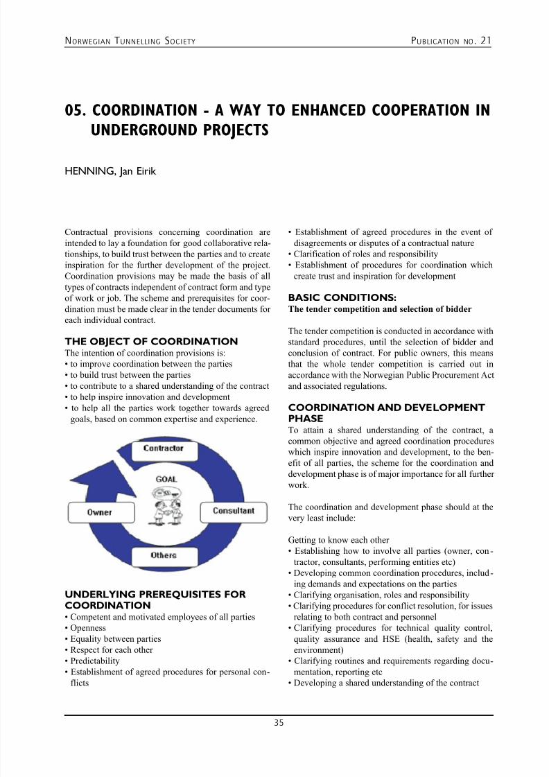
7/23/2019 NFF Publication 21 LOWRES
http://slidepdf.com/reader/full/nff-publication-21-lowres 35/94
NORWEGIAN T UNNELLING SOCIETY PUBLICATION NO . 21
35
05. COORDINATION - A WAY TO ENHANCED COOPERATION IN
UNDERGROUND PROJECTS
HENNING, Jan Eirik
Contractual provisions concerning coordination areintended to lay a foundation for good collaborative rela-tionships, to build trust between the parties and to createinspiration for the further development of the project.Coordination provisions may be made the basis of alltypes of contracts independent of contract form and typeof work or job. The scheme and prerequisites for coor-dination must be made clear in the tender documents foreach individual contract.
THE OBJECT OF COORDINATIONThe intention of coordination provisions is:• to improve coordination between the parties
• to build trust between the parties
• to contribute to a shared understanding of the contract
• to help inspire innovation and development
• to help all the parties work together towards agreedgoals, based on common expertise and experience.
UNDERLYING PREREQUISITES FORCOORDINATION• Competent and motivated employees of all parties
• Openness
• Equality between parties
• Respect for each other
• Predictability
• Establishment of agreed procedures for personal con-
flicts
• Establishment of agreed procedures in the event of
disagreements or disputes of a contractual nature• Clarification of roles and responsibility
• Establishment of procedures for coordination which
create trust and inspiration for development
BASIC CONDITIONS:The tender competition and selection of bidder
The tender competition is conducted in accordance withstandard procedures, until the selection of bidder andconclusion of contract. For public owners, this meansthat the whole tender competition is carried out inaccordance with the Norwegian Public Procurement Actand associated regulations.
COORDINATION AND DEVELOPMENTPHASETo attain a shared understanding of the contract, acommon objective and agreed coordination procedureswhich inspire innovation and development, to the ben-efit of all parties, the scheme for the coordination anddevelopment phase is of major importance for all furtherwork.
The coordination and development phase should at thevery least include:
Getting to know each other • Establishing how to involve all parties (owner, con-tractor, consultants, performing entities etc)
• Developing common coordination procedures, includ-ing demands and expectations on the parties
• Clarifying organisation, roles and responsibility
• Clarifying procedures for conflict resolution, for issues
relating to both contract and personnel• Clarifying procedures for technical quality control,
quality assurance and HSE (health, safety and theenvironment)
• Clarifying routines and requirements regarding docu-mentation, reporting etc
• Developing a shared understanding of the contract
7/23/2019 NFF Publication 21 LOWRES
http://slidepdf.com/reader/full/nff-publication-21-lowres 36/94
NORWEGIAN T UNNELLING SOCIETY PUBLICATION NO . 21
36
• Developing a shared understanding and objective of
the construction job
• Reviewing and optimising progress• Analysing and determining specific development
potential and development targets
The above should be specified and detailed to the extentnecessary, such that all parties find the result of the pro-cess useful, and also helpful for the implementation pro-cess. The coordination and development phase should be carried out without any change to basic conditions,responsibility and risk in relation to the preconditions inthe tender competition.
Sufficient time should therefore be set aside for thecoordination and development phase after the conclu-sion of contract to allow a thorough review of all aspectsof the project and the contract work.
The time necessary for the coordination and develop-ment phase must be determined after an assessmentof each project, taking into account its size, complex-ity and development potential. As a starting point, a period of four weeks may be set aside. However, ifthe parties agree, the coordination and development phase can either be ended and the implementation phase started, or it can be extended. Although the
coordination and development phase should basically be completed before the works are commenced, it willalso carry on as a continuous process after the start ofthe contract work.
The intention behind having a coordination and devel-opment phase laid down in the contract, and settingaside sufficient time before the start of the works, isthat involved parties will, together, be able to establishcoordination procedures and a scheme for further devel-opment of the project by combining good suggestionsfrom the contractor, consultants and owner based on
common expertise and experience.
The coordination and development phase is terminatedafter all relevant factors relating to the contract have been reviewed and the parties have acquired a sharedunderstanding of what is to be achieved by organisingand carrying out the project as described.The expensesthat consultants and contractors incur by participating inthe coordination and development period will be paid inaccordance with rates given in the tender, based on the preconditions in the tender documents.
DEVELOPMENT OF THE PROJECT
AFTER THE WORKS HAVE STARTEDAfter the coordination and development phase has
ended and the works have started, it will still possiblefor the parties to propose new solutions.
SHARING OF COST SAVINGSRESULTING FROM DEVELOPMENTSThe contract provisions must include provisions indicat-ing the parties’ sharing of cost savings. Cost savings areachieved through agreed alternative solutions which are put into practice. Improvements are usually remuner-ated by 50% of the net saving obtained in relation to thecontract sum.
EXPERIENCEExperience of the effects of coordination is gradu-ally accumulating. The Norwegian Public RoadsAdministration has worked with this technique, amongothers, for a number of years and in view of the posi-tive effects it has seen, it has now incorporated standard provisions in its tender documents which state thatcoordination prior to start-up of the contract work is to be implemented. The following may be mentioned asexamples of positive effects: – Collaboration between owner and contractor has been
good from day one. – The coordination phase led to a considerable amount
of time being spent together, which has resulted ingood communication.
– A coordination phase prior to construction start-up hasled to well-functioning collaboration in the implemen-tation phase.
– Strong commitment results in many proposals fordevelopments and new solutions, but many basicconditions have led to proposed solutions not being put into practice.
CHALLENGES – Being open to the process and ideas that crop up – Low threshold for making suggestions – Involvement
– Competent, motivated and suitable people from all parties – Equality between parties – Decision-making authority – Unambiguous and clear framework for the project
such as design guide, zoning plan, handbooks etc. – Completion of the coordination phase prior to con-
struction start-up
FINAL EVALUATIONThe parties should, together, draw up a final report inwhich all aspects of the contract work and coordinationare discussed.
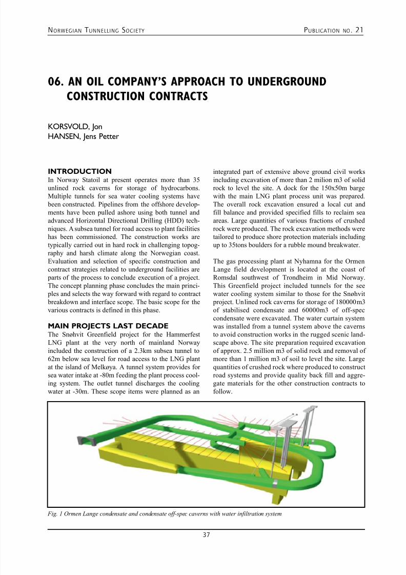
7/23/2019 NFF Publication 21 LOWRES
http://slidepdf.com/reader/full/nff-publication-21-lowres 37/94
NORWEGIAN T UNNELLING SOCIETY PUBLICATION NO . 21
37
06. AN OIL COMPANY’S APPROACH TO UNDERGROUND
CONSTRUCTION CONTRACTS
KORSVOLD, Jon
HANSEN, Jens Petter
INTRODUCTIONIn Norway Statoil at present operates more than 35unlined rock caverns for storage of hydrocarbons.Multiple tunnels for sea water cooling systems have been constructed. Pipelines from the offshore develop-ments have been pulled ashore using both tunnel andadvanced Horizontal Directional Drilling (HDD) tech-niques. A subsea tunnel for road access to plant facilitieshas been commissioned. The construction works aretypically carried out in hard rock in challenging topog-raphy and harsh climate along the Norwegian coast.Evaluation and selection of specific construction andcontract strategies related to underground facilities are parts of the process to conclude execution of a project.The concept planning phase concludes the main princi- ples and selects the way forward with regard to contract
breakdown and interface scope. The basic scope for thevarious contracts is defined in this phase.
MAIN PROJECTS LAST DECADEThe Snøhvit Greenfield project for the HammerfestLNG plant at the very north of mainland Norwayincluded the construction of a 2.3km subsea tunnel to62m below sea level for road access to the LNG plantat the island of Melkøya. A tunnel system provides forsea water intake at -80m feeding the plant process cool-ing system. The outlet tunnel discharges the coolingwater at -30m. These scope items were planned as an
integrated part of extensive above ground civil worksincluding excavation of more than 2 milion m3 of solidrock to level the site. A dock for the 150x50m bargewith the main LNG plant process unit was prepared.The overall rock excavation ensured a local cut andfill balance and provided specified fills to reclaim seaareas. Large quantities of various fractions of crushedrock were produced. The rock excavation methods weretailored to produce shore protection materials includingup to 35tons boulders for a rubble mound breakwater.
The gas processing plant at Nyhamna for the OrmenLange field development is located at the coast ofRomsdal southwest of Trondheim in Mid Norway.This Greenfield project included tunnels for the seewater cooling system similar to those for the Snøhvit
project. Unlined rock caverns for storage of 180000m3of stabilised condensate and 60000m3 of off-speccondensate were excavated. The water curtain systemwas installed from a tunnel system above the cavernsto avoid construction works in the rugged scenic land-scape above. The site preparation required excavationof approx. 2.5 million m3 of solid rock and removal ofmore than 1 million m3 of soil to level the site. Largequantities of crushed rock where produced to constructroad systems and provide quality back fill and aggre-gate materials for the other construction contracts tofollow.
Fig. 1 Ormen Lange condensate and condensate off-spec caverns with water infiltration system
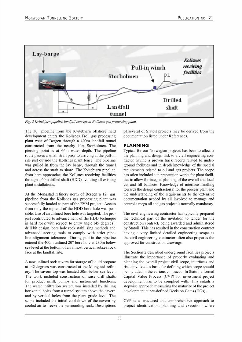
7/23/2019 NFF Publication 21 LOWRES
http://slidepdf.com/reader/full/nff-publication-21-lowres 38/94
NORWEGIAN T UNNELLING SOCIETY PUBLICATION NO . 21
38
The 30” pipeline from the Kvitebjørn offshore fielddevelopment enters the Kollsnes Troll gas processing plant west of Bergen through a 400m landfall tunnelconstructed from the nearby islet Storholmen. The piercing point is at 66m water depth. The pipelineroute passes a small strait prior to arriving at the pull-insite just outside the Kollsnes plant fence. The pipelinewas pulled in from the lay barge, through the tunneland across the strait to shore. The Kvitebjørn pipelinefrom here approaches the Kollsnes receiving facilities
through a 60m drilled shaft (HDD) avoiding all existing plant installations.
At the Mongstad refinery north of Bergen a 12” gas pipeline from the Kollsnes gas processing plant wassuccessfully landed as part of the EVM project. Accessfrom only the top end of the HDD bore hole was pos-sible. Use of an unlined bore hole was targeted. The pro- ject contributed to advancement of the HDD techniquein hard rock with respect to entry angle (45 degrees),drill bit design, bore hole rock stabilising methods andadvanced steering tools to comply with strict pipe-
line alignment tolerances. During pull-in the pipelineentered the 400m unlined 20” bore hole at 230m belowsea level at the bottom of an almost vertical subsea rockface at the landfall site.
A new unlined rock cavern for storage of liquid propaneat -42 degrees was constructed at the Mongstad refin-ery. The cavern top was located 50m below sea level.The work included construction of raise drill shaftsfor product infill, pumps and instrument functions.The water infiltration system was installed by drillinghorizontal holes from a tunnel system above the cavernand by vertical holes from the plant grade level. The
scope included the initial cool down of the cavern bycooled air to freeze the surrounding rock. Descriptions
of several of Statoil projects may be derived from thedocumentation listed under References.
PLANNINGTypical for our Norwegian projects has been to allocatethe planning and design task to a civil engineering con-tractor having a proven track record related to under-ground facilities and in depth knowledge of the specialrequirements related to oil and gas projects. The scopehas often included site preparation works for plant facili-
ties to allow for integral planning of the overall and localcut and fill balances. Knowledge of interface handlingtowards the design contractor(s) for the process plant andthe understanding of the requirements to the extensivedocumentation needed by all involved to manage andcontrol a mega oil and gas project is normally mandatory.
The civil engineering contractor has typically preparedthe technical part of the invitation to tender for theconstruction contract, being awarded and administered by Statoil. This has resulted in the construction contracthaving a very limited detailed engineering scope as
the civil engineering contractor often also prepares theapproved for construction drawings.
The Section 2 described underground facilities projectsillustrate the importance of properly evaluating and planning the overall project civil scope, interfaces andrisks involved as basis for defining which scope should be included in the various contracts. In Statoil a formalCapital Value Process (CVP) for investment projectdevelopment has to be complied with. This entails astepwise approach measuring the maturity of the projectdevelopment at pre-defined Decision Gates (DGs).
CVP is a structured and comprehensive approach to project identification, planning and execution, where
Fig. 2 Kvitebjørn pipeline landfall concept at Kollsnes gas processing plant
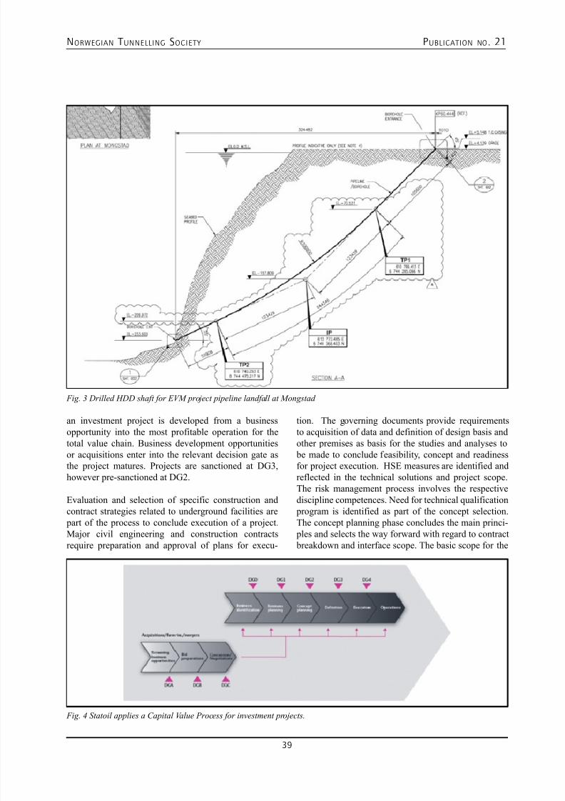
7/23/2019 NFF Publication 21 LOWRES
http://slidepdf.com/reader/full/nff-publication-21-lowres 39/94
NORWEGIAN T UNNELLING SOCIETY PUBLICATION NO . 21
39
an investment project is developed from a businessopportunity into the most profitable operation for thetotal value chain. Business development opportunitiesor acquisitions enter into the relevant decision gate asthe project matures. Projects are sanctioned at DG3,however pre-sanctioned at DG2.
Evaluation and selection of specific construction andcontract strategies related to underground facilities are part of the process to conclude execution of a project.Major civil engineering and construction contractsrequire preparation and approval of plans for execu-
tion. The governing documents provide requirementsto acquisition of data and definition of design basis andother premises as basis for the studies and analyses to be made to conclude feasibility, concept and readinessfor project execution. HSE measures are identified andreflected in the technical solutions and project scope.The risk management process involves the respectivediscipline competences. Need for technical qualification program is identified as part of the concept selection.The concept planning phase concludes the main princi- ples and selects the way forward with regard to contract breakdown and interface scope. The basic scope for the
Fig. 3 Drilled HDD shaft for EVM project pipeline landfall at Mongstad
Fig. 4 Statoil applies a Capital Value Process for investment projects.
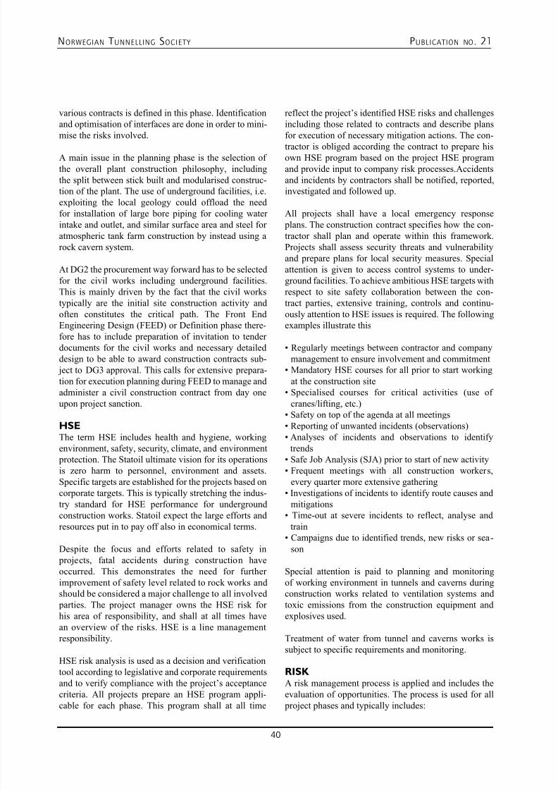
7/23/2019 NFF Publication 21 LOWRES
http://slidepdf.com/reader/full/nff-publication-21-lowres 40/94
NORWEGIAN T UNNELLING SOCIETY PUBLICATION NO . 21
40
various contracts is defined in this phase. Identificationand optimisation of interfaces are done in order to mini-
mise the risks involved.
A main issue in the planning phase is the selection ofthe overall plant construction philosophy, includingthe split between stick built and modularised construc-tion of the plant. The use of underground facilities, i.e.exploiting the local geology could offload the needfor installation of large bore piping for cooling waterintake and outlet, and similar surface area and steel foratmospheric tank farm construction by instead using arock cavern system.
At DG2 the procurement way forward has to be selectedfor the civil works including underground facilities.This is mainly driven by the fact that the civil workstypically are the initial site construction activity andoften constitutes the critical path. The Front EndEngineering Design (FEED) or Definition phase there-fore has to include preparation of invitation to tenderdocuments for the civil works and necessary detaileddesign to be able to award construction contracts sub- ject to DG3 approval. This calls for extensive prepara-tion for execution planning during FEED to manage andadminister a civil construction contract from day oneupon project sanction.
HSEThe term HSE includes health and hygiene, workingenvironment, safety, security, climate, and environment protection. The Statoil ultimate vision for its operationsis zero harm to personnel, environment and assets.Specific targets are established for the projects based oncorporate targets. This is typically stretching the indus-try standard for HSE performance for undergroundconstruction works. Statoil expect the large efforts andresources put in to pay off also in economical terms.
Despite the focus and efforts related to safety in projects, fatal accidents during construction haveoccurred. This demonstrates the need for furtherimprovement of safety level related to rock works andshould be considered a major challenge to all involved parties. The project manager owns the HSE risk forhis area of responsibility, and shall at all times havean overview of the risks. HSE is a line managementresponsibility.
HSE risk analysis is used as a decision and verificationtool according to legislative and corporate requirementsand to verify compliance with the project’s acceptance
criteria. All projects prepare an HSE program appli-cable for each phase. This program shall at all time
reflect the project’s identified HSE risks and challengesincluding those related to contracts and describe plans
for execution of necessary mitigation actions. The con-tractor is obliged according the contract to prepare hisown HSE program based on the project HSE programand provide input to company risk processes.Accidentsand incidents by contractors shall be notified, reported,investigated and followed up.
All projects shall have a local emergency response plans. The construction contract specifies how the con-tractor shall plan and operate within this framework.Projects shall assess security threats and vulnerabilityand prepare plans for local security measures. Specialattention is given to access control systems to under-ground facilities. To achieve ambitious HSE targets withrespect to site safety collaboration between the con-tract parties, extensive training, controls and continu-ously attention to HSE issues is required. The followingexamples illustrate this
• Regularly meetings between contractor and company
management to ensure involvement and commitment• Mandatory HSE courses for all prior to start working
at the construction site• Specialised courses for critical activities (use of
cranes/lifting, etc.)
• Safety on top of the agenda at all meetings• Reporting of unwanted incidents (observations)
• Analyses of incidents and observations to identify
trends• Safe Job Analysis (SJA) prior to start of new activity
• Frequent meetings with all construction workers,
every quarter more extensive gathering• Investigations of incidents to identify route causes and
mitigations• Time-out at severe incidents to reflect, analyse and
train• Campaigns due to identified trends, new risks or sea-
son
Special attention is paid to planning and monitoringof working environment in tunnels and caverns duringconstruction works related to ventilation systems andtoxic emissions from the construction equipment andexplosives used.
Treatment of water from tunnel and caverns works issubject to specific requirements and monitoring.
RISK A risk management process is applied and includes the
evaluation of opportunities. The process is used for all project phases and typically includes:
7/23/2019 NFF Publication 21 LOWRES
http://slidepdf.com/reader/full/nff-publication-21-lowres 41/94
NORWEGIAN T UNNELLING SOCIETY PUBLICATION NO . 21
41
• Establish/define context
• Identify and analyse risks
• Evaluate risks• Decide related actions
• Implement action, monitor, and follow-up risks
• Interaction with cost- and schedule risk analysis
The risk process involves both the company projectteam and applicable contractors to ensure involvementof management and experts for all relevant parties anddisciplines. Specialised IT-tools are used to manage the process and results. Below are some examples of risksthat in spite of the very best intentions, extensive plan-ning and project actions still may materialise:
• Rock and soil conditions turn out different than antici- pated
• Weather downtime is different from what could rea-sonable be expected
• Unsuccessful piercing to sea from a subsea tunnel for
cooling water • Insufficient injection at tunnel face to ensure integrity
of tunnel and compliance with limitations to wateringress
• Severe accident at the construction site
The planning must provide for expertise involvement,
schedule float towards critical path, cost allowance andchange handling systems to avoid jeopardizing the over-all contract and project completion milestones. The sys-tematic approach to risk shall ensure that aspects relatedto HSE, constructability and operability are addressedduring design. The tender documents and proposal forcontract should be evaluated prior to inviting for tendersrelated to risk for disputes related to specific identifiedrisks. The contractor must as part of his tender identifythe major risks he envisage and how he plans to be miti-gate these during execution of his work.
TECHNICAL DEFINITIONThe basis for the technical definition is the projectdesign basis including the functional requirements to thefacilities. To be able to perform a robust concept selec-tion during the Concept planning phase in depth techni-cal studies are normally executed when undergroundfacilities are part of the project scope. The concept andtechnical solution is often subject to verification by3rd parties with respect to technical aspects as well asschedule and risk.
The concept selection has to be based on site specificgeotechnical and geological surveys to establish the
necessary technical design parameters. Supplementarystudies will have to be conducted at latest upon DG2
when commencing the Definition phase to be ableto utilise this information as basis for the Invitation
to Tender documents. Upfront investment in qualitysite surveys usually pays off and is an effective riskreducing measure. Requirements to supplementary siteinvestigations during construction as work progressesare normally specified in the construction contractscope.
The underground facilities design is normally welladvanced as basis for tendering the construction con-tract. This limits the possibility for future surprises andreduces the construction contactors risks and hopefullythe price.
Typically the design prepared by company shall be ten-dered. The contactor may offer alternatives under spe-cific terms and is sometimes invited to offer and pricedifferent technical options for specific items. Concreteworks and outfitting structures are typically part of thecontract scope for underground facilities.
Battery limit for the project scope and interfaces toothers have to be defined. This is in the contract sup- plemented by administrative requirements to ensurethat the battery limits are adhered to and the interfacesare properly handled. The interface towards the con-
tractor installing the process plant equipment requiresspecial attention. For a modification project theinterface relation to plant operation requires special procedures and resources. Requirements to the mini-mum tunnel or cavern profile are specified includingtolerances. Maximum water ingress and other func-tional requirements are defined. The requirements aresupported by references to national standards. Thetechnical requirements are for tasks like applicationof grouting or shotcrete supplemented by referencesto industry standard and acknowledged best practicedocuments as developed by Norwegian Tunnelling
Society (NFF).
Requirements are implemented to ensure properdefinition of rock support to ensure the overall longterm integrity and functionality of the undergroundfacility. The contractor is responsible for the rocksupport measures to ensure safe construction workat all times in the tunnel or cavern. As constructionworks progresses collaboration between the com- pany and contractor engineering geology expertiseis required.
Requirements to documentation of contractor delivera-
bles as well as documentation for the operation phaseare specified.
7/23/2019 NFF Publication 21 LOWRES
http://slidepdf.com/reader/full/nff-publication-21-lowres 42/94
NORWEGIAN T UNNELLING SOCIETY PUBLICATION NO . 21
42
COMPETITIVE TENDERINGStatoil’s procurement process is based on competi-
tive tendering and on the principles of transparency,non-discrimination and equal treatment of tenderers.Statoil develops, integrates and implements procure-ment strategies to achieve the best possible agreementsfor the group. This is achieved through a category-basedapproach to goods and services, based on a coordinatedcontrol of demand, the global market situation androbust analyses in order to minimise risk in the execu-tion phase. The suppliers must be prequalified in orderto compete for tenders.
Based on the defined scope and contract breakdownStatoil prepare tender documents and plans for theindividual procurement packages (contracts). The plantypically includes main activities with estimated dura-tion as:
• Scope definition and preparation of tender documents
• Preparation of bidders list (Statoil uses the pre-
qualification system Achilles to search for qualifiedtenderers)
• Invitation to tender
• Tender phase
• Tenderers submit clarifications to the tender docu-ments
• Evaluation phase• Bid opening, technical and commercial evaluation
• Preparation of evaluation report with recommendation
• Award
Detailed requirement related to HSE issues are incor- porated in the procurement processes. Statoil has strictrequirements for CISR (Corporate Integrity and SocialResponsibility), ethics and HSE. Commitments are based on Statoil standards for contract documents,frame agreements and purchase orders.
COMPENSATIONEngineering contracts are typically reimbursed based ontendered rates with agreed man-hour limit per activitydefined in Cost-Time- Resource sheets (CTRs).
For construction contracts the typical compensation for-mat is developed on the basis of Norwegian standardswith fixed lump sums for preliminaries and unit rates forthe majority of the construction scope.Construction con-tractor is normally compensated as per agreed executedquantities. Unit prices and estimated quantities for rocksupport measures envisaged have typically been includedin the contract. Lump sum elements usually have sepa-
rate payment schedules. Failure to meet progress mile-stones will result in payment of penalties as per contract.
CONTRACT ADMINISTRATIONThe administrative requirements applied in our engi-
neering and construction contracts are more comprehen-sive and detailed compared to contracts typically award-ed to the civil construction industry. This to ensure thatall company and contractor obligations and liabilitiesare properly taken care of and that necessary reportingas basis for aggregation for the overall management ofthe project including handling of deviations, changes,emerging risks, etc. is made.
Handling of changes to the contract is covered in theConditions of Contract for the contract. Communication between the parties is dealt with in the Administrativeappendix in the contract. Detailed requirement to plan-ning of the work and progress reporting are also includ-ed. The same applies for HSE, document handling,quality assurance, documentation of deliverables, etc.
Attention and involvement by both project and cor- porate management from both parties are key successfactors to ensure deliverables according to contract. Thisrequires collaboration and time. HSE performance and progress issues are key items at the agenda.
Usually Statoil applies a Project Completion System todocument that all items are delivered as specified and that
a defined facility items (typically equipment) are ready(mechanical complete) for dynamic testing as part of a process or utility system. The completion system is tai-lored to control readiness for commissioning of complex plant process and utility systems. Selected items of under-ground facilities are included to track completion status.
Construction contractor typically prepares redline mark-up on the construction drawings to reflect actual situa-tion and alterations. This will be the basis the engineer-ing contractor to prepare as built drawings that will be part of the Life Cycle Information (LCI) documentation
to be handed over by the project to operation.
To ensure during construction the necessary quality ofthe day to day decisions with respect to tunnel integrityand rock support measures, engineering geologists haveto be mobilised during construction. Their evaluationwill have to cover the requirement to investigationsof the rock conditions in front of the tunnel face, theimmediate measures for rock support for safe workingconditions until next blast and the permanent rock sup- port for the lifetime of the facilities.
WAY FORWARD
Our past experience will provide the basis with respectto planning and contract strategies for underground
7/23/2019 NFF Publication 21 LOWRES
http://slidepdf.com/reader/full/nff-publication-21-lowres 43/94
NORWEGIAN T UNNELLING SOCIETY PUBLICATION NO . 21
43
facilities in rock for future oil and gas projects. Theexpertise shared in Norway between clients, research
institutes, engineering and construction contractors andothers during decades of systematic experience trans-fer by professionals within the field of rock works isunique.
The combination provides Statoil with a solid base forevaluation of new projects in Norway or internationallyand should be a competitive edge when evaluating con-cepts and applications for new projects abroad. Locationof facilities and functions in rock will provide solutionsthat could result in benefits both with respect to oper-ability, HSE, schedule, risk and value creation.
Compliance with our governing requirements and thesystematic work process to define a robust technicalconcept and project execution are the corner stones forsuccessful hand-over of underground facilities to opera-tion.
REFERENCES1. Norwegian Tunnelling Society (NFF): Publication
No. 16 – Underground Constructions for the NorwegianOil and Gas Industry (2007)
2. Norwegian Tunnelling Society (NFF): Publicationsfrom the annual “Fjellsprengningskonferansen”.
Strength and watertghtness with
ground freezing, a pridictable alternatve.
25 years experience
with design and contractng.GEOFROST AS, Hosletoppen 46, N-1362 HOSLE, Norway.
Tel:. (+47) 67 14 73 50. Fax:. (+47) 67 14 73 53. E-mail: [email protected]
7/23/2019 NFF Publication 21 LOWRES
http://slidepdf.com/reader/full/nff-publication-21-lowres 44/94
NORWEGIAN T UNNELLING SOCIETY PUBLICATION NO . 21
44
NTN is a network of companies and major stake holders within
the Norwegian Tunnelling Society.
NTN encourages and coordinates commercial export of NorwegianTunnelling Technology to the international markets.
NTN communicates knowledge and opportunities from the international tunnelling industry back to the Norwegian industry.
CONTACT US: [email protected]
Norwegian Tunnelling NetworkP.O Box 1313, N- 2406 Elverum, NorwayPhone + 47 48 22 33 95
7/23/2019 NFF Publication 21 LOWRES
http://slidepdf.com/reader/full/nff-publication-21-lowres 45/94
NORWEGIAN T UNNELLING SOCIETY PUBLICATION NO . 21
45
07. PARTNERING AGREEMENT FOR SILA
PEDERSEN, Ann
INTRODUCTIONThe background for the SILA expansion is this: LKAB’sore treatment plant at the time was old, outmoded andhighly resource-demanding to operate.
Upgrading SILA in Narvik by constructing a whole newstorage and discharging structure will boost efficiencyand enhance the environment.
LKAB decided on a new concept, including the con-struction of an approx. 600 m concrete culvert forunloading trains, 13 large underground storage silos forstoring the iron ore from the Kiruna mines, and about2.6 km of underground tunnels for conveyor purposes.
LKAB asked six contractors in northern Europe for a
presentation and settled on Leonhard Nilsen & SønnerAS as partner. In December 2005, a partnering agree-ment to the tune of approximately NOK 800 million wassigned. The contract was designed as a turnkey project, but LNS also has a number of subcontracts designed asturnkey projects.
Construction began in January 2006 and was completedin November 2009.
LNS:
LNS are an attractive collaborative partner, both domes-
tic and international, specializing in road and tunnelconstruction, bulk transport and underground miningoperations. Years of active operations on Svalbard havehelped us acquire unique expertise in polar logistics.
LNS are involved in mining operations several places inmainland Norway, and on Spitsbergen. In the Antarctic,LNS Spitsbergen was hired to construct satellite anten-nas for NASA and the ESA, and intends to build its thirdIndian station, Bharati in Antarctic for National Centrefor Antarctic and Ocean Research (NCAOR), India.
LKAB:
Luossavaara-Kiirunavaara AB (LKAB) is an interna-tional high-tech minerals group, one of the New World’s
leading producers of upgraded iron ore products for thesteel industry and a growing area supplier of industrialminerals products to other sectors. LKAB runs the larg-est underground iron mines in the world.
PRIOR TO ENTERING INTO ANAGREEMENTLKAB’s objective with the ”SILA” project was to carryout a comprehensive rebuilding of the iron ore port in Narvik. Preliminary planning, which considered thefuture structure of the port, was initiated in 2002. Afterthis preliminary planning, a more thoroughgoing col-laboration was established between LKAB and LNSduring the so-called planning phase.
Comprehensive investigative and layout work has been
carried out jointly by the partners. LNS has expendedconsiderable resources and has participated in and played a major role in the planning. LNS have also hadresponsibility for producing the requisite reports, tech-nical solutions, tenders for subcontracts and deliveries,as well as cost estimates.
On account of its extensive participation, LNS hasassumed special responsibility for the success of the project’s implementation.
After a lengthy collaboration, LNS AS entered into a
Partnering Agreement contract with LKAB in December2005, to the tune of approx. NOK 800 million for theconstruction of a completely new storage and discharg-ing facility in Narvik, with silos built into the solid rock.
The Partnering Agreement was drawn up in such a waythat it was in the interests of both parties to achievestated goals. Positive deviations were financially ben-eficial, whereas negative deviations were “punished”financially.
The project was divided into a fixed section, HD 00, anda flexible section. The flexible section was then techni-
cally divided into 15 main parts, called HD 01, 02, 03(A, B and C), HD 04 – HD 15.
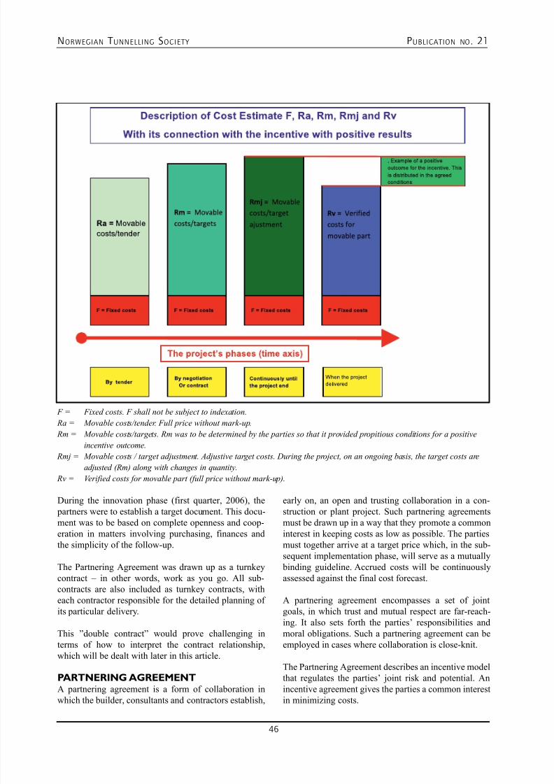
7/23/2019 NFF Publication 21 LOWRES
http://slidepdf.com/reader/full/nff-publication-21-lowres 46/94
NORWEGIAN T UNNELLING SOCIETY PUBLICATION NO . 21
46
During the innovation phase (first quarter, 2006), the partners were to establish a target document. This docu-ment was to be based on complete openness and coop-eration in matters involving purchasing, finances and
the simplicity of the follow-up.
The Partnering Agreement was drawn up as a turnkeycontract – in other words, work as you go. All sub-contracts are also included as turnkey contracts, witheach contractor responsible for the detailed planning ofits particular delivery.
This ”double contract” would prove challenging interms of how to interpret the contract relationship,which will be dealt with later in this article.
PARTNERING AGREEMENT
A partnering agreement is a form of collaboration inwhich the builder, consultants and contractors establish,
F = Fixed costs. F shall not be subject to indexation. Ra = Movable costs/tender. Full price without mark-up.
Rm = Movable costs/targets. Rm was to be determined by the parties so that it provided propitious conditions for a positive
incentive outcome.
Rmj = Movable costs / target adjustment. Adjustive target costs. During the project, on an ongoing basis, the target costs are
adjusted (Rm) along with changes in quantity.
Rv = Verified costs for movable part (full price without mark-up).
early on, an open and trusting collaboration in a con-struction or plant project. Such partnering agreementsmust be drawn up in a way that they promote a commoninterest in keeping costs as low as possible. The parties
must together arrive at a target price which, in the sub-sequent implementation phase, will serve as a mutually binding guideline. Accrued costs will be continuouslyassessed against the final cost forecast.
A partnering agreement encompasses a set of jointgoals, in which trust and mutual respect are far-reach-ing. It also sets forth the parties’ responsibilities andmoral obligations. Such a partnering agreement can beemployed in cases where collaboration is close-knit.
The Partnering Agreement describes an incentive modelthat regulates the parties’ joint risk and potential. An
incentive agreement gives the parties a common interestin minimizing costs.
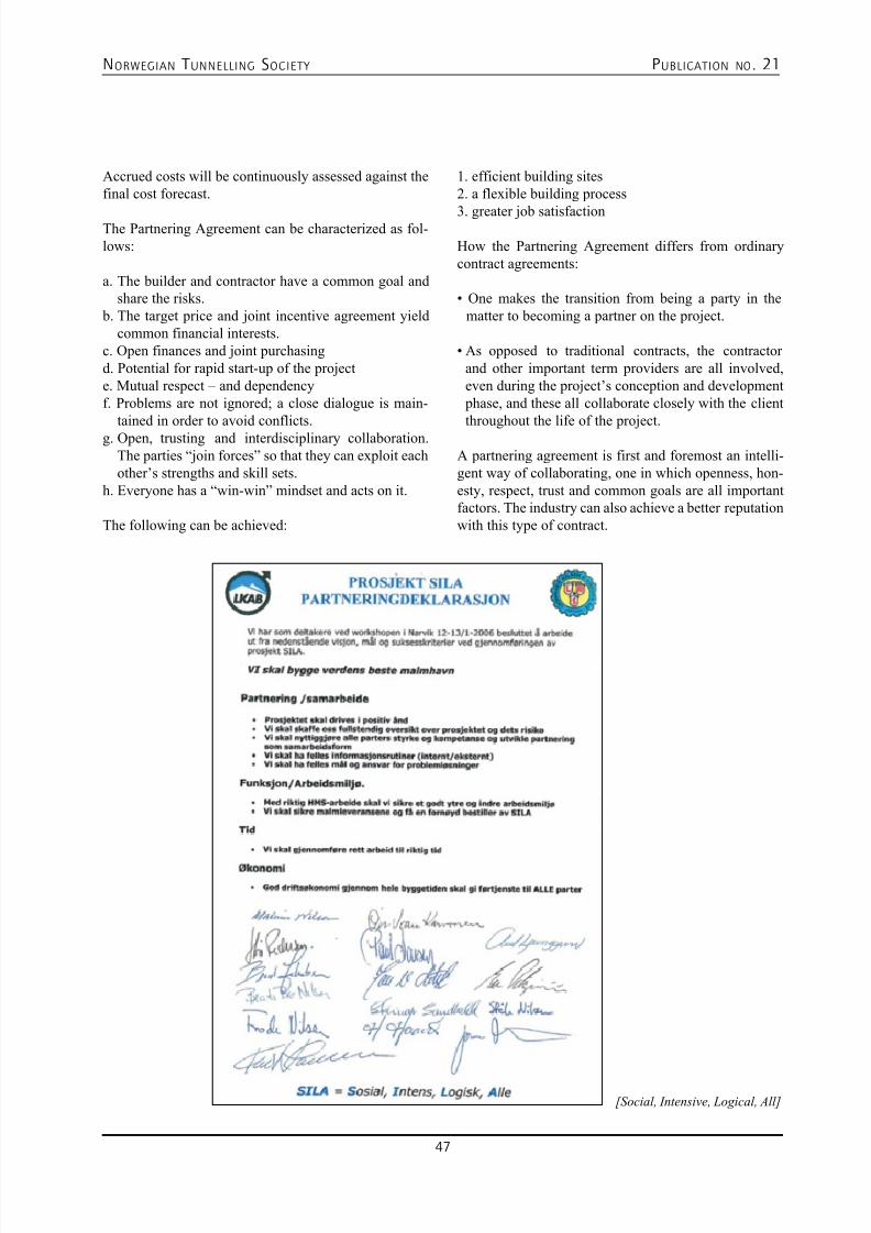
7/23/2019 NFF Publication 21 LOWRES
http://slidepdf.com/reader/full/nff-publication-21-lowres 47/94
NORWEGIAN T UNNELLING SOCIETY PUBLICATION NO . 21
47
Accrued costs will be continuously assessed against thefinal cost forecast.
The Partnering Agreement can be characterized as fol-lows:
a. The builder and contractor have a common goal andshare the risks.
b. The target price and joint incentive agreement yieldcommon financial interests.
c. Open finances and joint purchasingd. Potential for rapid start-up of the projecte. Mutual respect – and dependencyf. Problems are not ignored; a close dialogue is main-
tained in order to avoid conflicts.g. Open, trusting and interdisciplinary collaboration.
The parties “join forces” so that they can exploit eachother’s strengths and skill sets.
h. Everyone has a “win-win” mindset and acts on it.
The following can be achieved:
1. efficient building sites2. a flexible building process
3. greater job satisfaction
How the Partnering Agreement differs from ordinarycontract agreements:
• One makes the transition from being a party in the
matter to becoming a partner on the project.
• As opposed to traditional contracts, the contractor
and other important term providers are all involved,even during the project’s conception and development phase, and these all collaborate closely with the clientthroughout the life of the project.
A partnering agreement is first and foremost an intelli-gent way of collaborating, one in which openness, hon-esty, respect, trust and common goals are all importantfactors. The industry can also achieve a better reputationwith this type of contract.
[Social, Intensive, Logical, All]
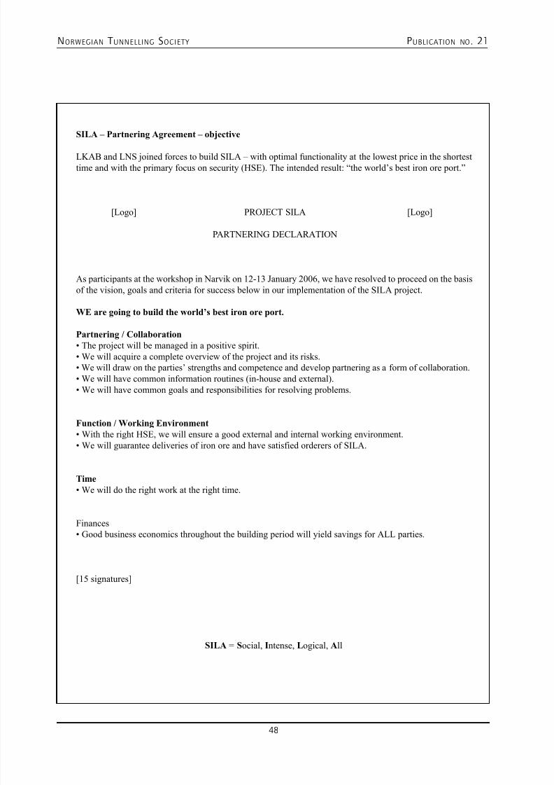
7/23/2019 NFF Publication 21 LOWRES
http://slidepdf.com/reader/full/nff-publication-21-lowres 48/94
NORWEGIAN T UNNELLING SOCIETY PUBLICATION NO . 21
48
SILA – Partnering Agreement – objective
LKAB and LNS joined forces to build SILA – with optimal functionality at the lowest price in the shortesttime and with the primary focus on security (HSE). The intended result: “the world’s best iron ore port.”
[Logo] PROJECT SILA [Logo]
PARTNERING DECLARATION
As participants at the workshop in Narvik on 12-13 January 2006, we have resolved to proceed on the basisof the vision, goals and criteria for success below in our implementation of the SILA project.
WE are going to build the world’s best iron ore port.
Partnering / Collaboration
• The project will be managed in a positive spirit.
• We will acquire a complete overview of the project and its risks.
• We will draw on the parties’ strengths and competence and develop partnering as a form of collaboration.
• We will have common information routines (in-house and external).
• We will have common goals and responsibilities for resolving problems.
Function / Working Environment
• With the right HSE, we will ensure a good external and internal working environment.
• We will guarantee deliveries of iron ore and have satisfied orderers of SILA.
Time
• We will do the right work at the right time.
Finances• Good business economics throughout the building period will yield savings for ALL parties.
[15 signatures]
SILA = Social, Intense, Logical, All
7/23/2019 NFF Publication 21 LOWRES
http://slidepdf.com/reader/full/nff-publication-21-lowres 49/94
NORWEGIAN T UNNELLING SOCIETY PUBLICATION NO . 21
49
EXPANSION PHASEAfter several years in development, the project was
ready to start up in January 2006. LNS began soiland rock work while detailed planning was in itsinfancy. LNS carried out this work itself. All otherwork was sub-contracted out: concrete, steel, VVS,mechanics, electricity, etc. Nine turnkey sub-contrac-tors were signed (with NCC, Sandvik, T. Jespersen,Rørlegger’n, Siemens, NNM, Bamek, Hägglunds andMunck Cranes). The sub-contracts were finalized in thespring and summer of 2006. As each agreement cameinto force, detailed planning for each respective field began. In negotiating and signing all the sub-contractoragreements, LKAB and LNS acted as a joint ordererand contract partner. LKAB/LNS acted in unison withrespect to the sub-contractors. This relationship wasmaintained throughout the entire building process. Inall major negotiations and conflict situations with UE,LKAB/LNS stood united as “the builder.”
Partnering in practice:
The builder LKAB and the contractor LNS had a closecollaboration. LKAB and LNS established a jointorganization plan. This manifested itself in a large num- ber of functions: HSE management, quality assurance,CE labelling, planning management and “technicalconstruction supervisors.” During the first part of the
project, the person in charge of finances was a jointrepresentative. Finances followed the open book princi- ple, in which LKAB had full access to LNS’ costs, timesheets, etc. All UE contracts were entered into jointlyand, of course, LKAB had full access to information onall prices and contract terms.
From the outset, a joint office rig was set up for thefacility, with a common meeting room and mess hall.One positive measure that fostered cooperation anda sense of community was the regular joint lunchesthat were served in the mess hall every Tuesday and
Thursday.
From time to time, workshops were held as well; thesewere intended to “knit us together” and strengthen oursense of community.
• Every fortnight there were partnering meetings where
the focus was on the relationship between LKAB andLSN, and where only LKAB and LNS met together.All outstanding issues involving LKAB and LNS wereresolved in this forum, with the result that at buildingmeetings, planning meetings and progress meetings,LKAB /LNS spoke with one “voice” in the dialogue
with the sub-contractors.
Takeover, final settlement and guarantee period
Also, all take-over proceedings with turnkey sub-con-
tractors were handled jointly by LKAB and LNS. Thus,the final hand-over between LNS and LKAB was a mereformality. All final settlements with the sub-contractorswere also handled jointly. There were some “interface” problems, with some uncertainty as to who the formalcontracting parties were. Such matters were amicablyand satisfactorily resolved because the parties were mag-nanimous and refused to get bogged down in formalities.
LNS can summarize the advantages of the Partnering
Agreement with SILA as follows:
a. Close-knit collaboration – a good dialogue. b. Access to all documents (no secrets).c. Plenty of opportunity for quick decisions.d. A clear-cut willingness to make changes.e. The parties worked together to find solutions.f. The parties had a common goal – at all levels,g. and shared a joint financial result (profit/loss).h. Minimizing the financial risk between the parties.i. Savings that accrued as a result of many joint functions. j. Minimized risk for law suits.
LNS does not envisage many disadvantages with the
Partnering Agreement
k. From the contractor’s viewpoint, one could say that
it was a disadvantage that the benefits of smart solu-tions and successful negotiations had to be sharedwith the builder.
SILA – challenges with the Partnering Agreement
• The biggest challenge of the SILA Partnering
Agreement, I maintain, was the understanding of thecontract that resulted from the turnkey contract beingthe basis for the Partnering Agreement. The settlement principles in these two types of contract are not neces-sarily compatible. It would have been good if this had been made explicit beforehand. The partnering model
that was made the basis of the contract did not takeinto consideration the turnkey contractor model’s set-tlement principles. The contract bore some of the ear-marks of being a copy of other types of contracts andof not being specially adapted to conditions at SILA.
• The fact that the planning and construction work went
hand-in-hand, and that LKAB, a half-year into the building, period chose to make a major layout changein the project, presented a major challenge. The con-sequence of this layout change was a proliferation ofchanges in every technical area, which led to hecticreplanning; this presented a challenge to the progress
of the project and – not least – its financing.
7/23/2019 NFF Publication 21 LOWRES
http://slidepdf.com/reader/full/nff-publication-21-lowres 50/94
NORWEGIAN T UNNELLING SOCIETY PUBLICATION NO . 21
50
• Furthermore, it should be said that it was a challenge
to keep the focus on the collaborative spirit (not to
become a traditional contractor and builder). Thiswas particularly the case in situations where therewas disagreement with UE as to what was included intheir turnkey contract and, in this connection, how thesame situation should be dealt with in the PartneringAgreement between LKAB and LNS.
• In situations where one was ”banging one’s head
against the wall,” so to speak, the focus on the col-laborative spirit was put to a severe test.
• Because detailed planning was taking place while
construction proceeded apace, there arose a continu-ous need to resolve major and minor problems. In suchsituations, the collaboration came under great pres-sure. But for the most part, LNS and LKAB were ableto stand united in these situations.
• The project was huge, and it involved much of the
consultancy environment in Narvik. Consultants werehard pressed for time, and there were occasions whenit was hard for the planners to keep pace with the con-tractors’ construction tempo.
Partnering Agreement – a summary of our experi-
ences with SILA:
• Can be easy to assume the ”old role” (builder/contractor).
• The potential for savings – joint functions.
• The potential for flexible solutions with respect to
clarifications and decisions.• Inherent in the understanding of the contract:
Norwegian and Swedish are two different languages.• The potential for a good result and a climate of coop -
eration depends on: a. a good agreement. b. unambiguous,c. a common understanding,d. a good work-up of financial “incentives (the carrot)”
e. players and an environment that are ripe for such acollaboration.
• Exciting concept – whets the appetite.
• Has given the Narvik area a lot of competence in the
partnering concept, but also invaluable experience incollaborating on a major project.
• SILA – An excellent trial run for the next major pro- ject!
• Could be the key to good project collaboration.
Codan AS Knud Brynsvei 5, N - 0581 Oslo
Phone: +47 22906550 - www.codan-gummi.no
Problems with water?We offer the solutions!
Thorbolt®
GMA AB Rönna väg 2, SE - 686 31 Sunne
Phone: +46 565 12850 / +47 913 00 850 - www.gma.se - [email protected]
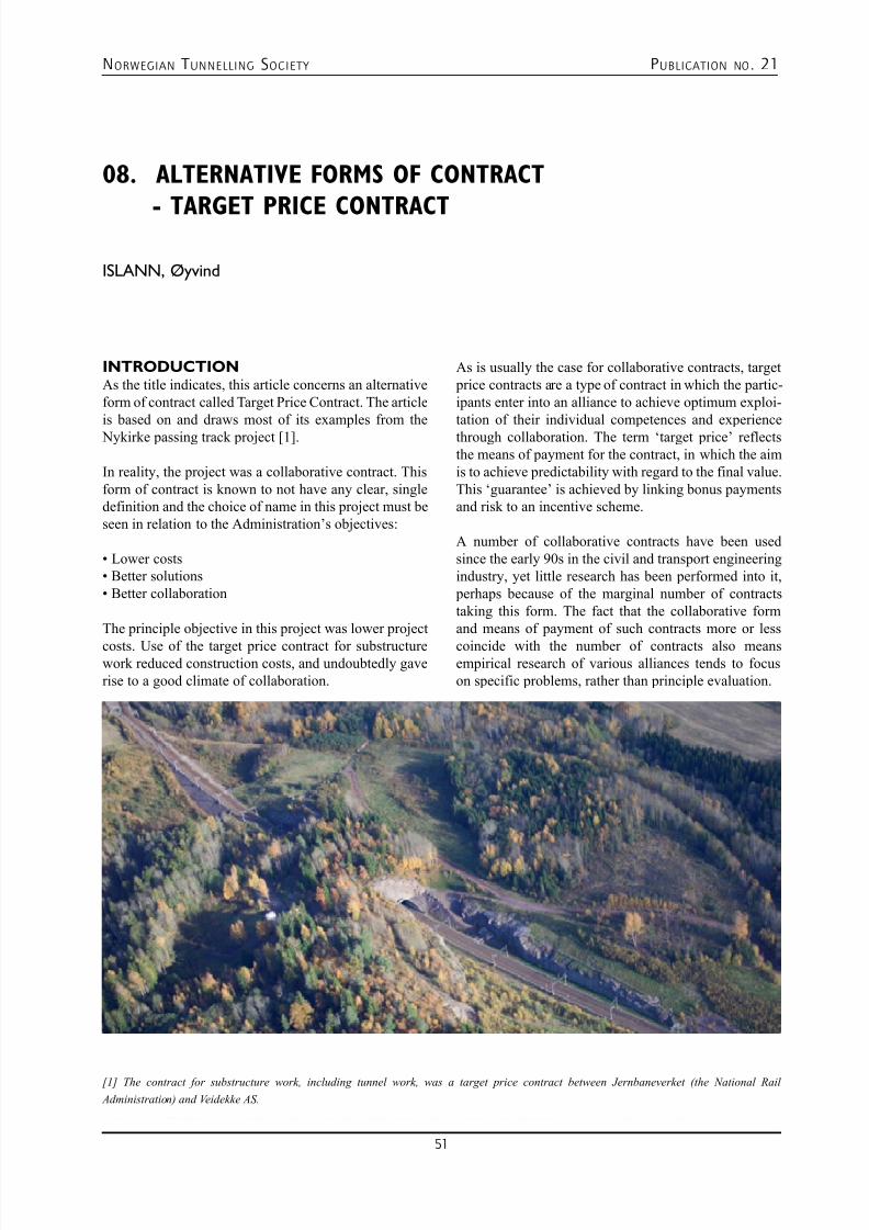
7/23/2019 NFF Publication 21 LOWRES
http://slidepdf.com/reader/full/nff-publication-21-lowres 51/94
NORWEGIAN T UNNELLING SOCIETY PUBLICATION NO . 21
51
08. ALTERNATIVE FORMS OF CONTRACT
- TARGET PRICE CONTRACT
ISLANN, Øyvind
INTRODUCTIONAs the title indicates, this article concerns an alternativeform of contract called Target Price Contract. The articleis based on and draws most of its examples from the Nykirke passing track project [1].
In reality, the project was a collaborative contract. Thisform of contract is known to not have any clear, singledefinition and the choice of name in this project must beseen in relation to the Administration’s objectives:
• Lower costs
• Better solutions
• Better collaboration
The principle objective in this project was lower project
costs. Use of the target price contract for substructurework reduced construction costs, and undoubtedly gaverise to a good climate of collaboration.
As is usually the case for collaborative contracts, target price contracts are a type of contract in which the partic-ipants enter into an alliance to achieve optimum exploi-tation of their individual competences and experiencethrough collaboration. The term ‘target price’ reflectsthe means of payment for the contract, in which the aimis to achieve predictability with regard to the final value.This ‘guarantee’ is achieved by linking bonus paymentsand risk to an incentive scheme.
A number of collaborative contracts have been usedsince the early 90s in the civil and transport engineeringindustry, yet little research has been performed into it, perhaps because of the marginal number of contractstaking this form. The fact that the collaborative formand means of payment of such contracts more or less
coincide with the number of contracts also meansempirical research of various alliances tends to focuson specific problems, rather than principle evaluation.
[1] The contract for substructure work, including tunnel work, was a target price contract between Jernbaneverket (the National Rail
Administration) and Veidekke AS.
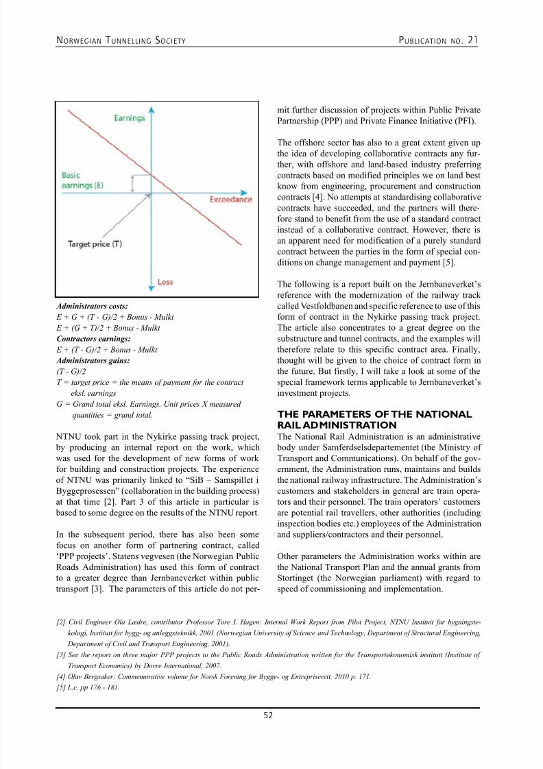
7/23/2019 NFF Publication 21 LOWRES
http://slidepdf.com/reader/full/nff-publication-21-lowres 52/94
NORWEGIAN T UNNELLING SOCIETY PUBLICATION NO . 21
52
Administrators costs:
E + G + (T - G)/2 + Bonus - Mulkt
E + (G + T)/2 + Bonus - Mulkt
Contractors earnings:
E + (T - G)/2 + Bonus - Mulkt
Administrators gains:
(T - G)/2
T = target price = the means of payment for the contract
eksl. earnings
G = Grand total eksl. Earnings. Unit prices X measuredquantities = grand total.
NTNU took part in the Nykirke passing track project, by producing an internal report on the work, whichwas used for the development of new forms of workfor building and construction projects. The experienceof NTNU was primarily linked to “SiB – Samspillet iByggeprosessen” (collaboration in the building process)at that time [2]. Part 3 of this article in particular is based to some degree on the results of the NTNU report.
In the subsequent period, there has also been somefocus on another form of partnering contract, called‘PPP projects’. Statens vegvesen (the Norwegian PublicRoads Administration) has used this form of contractto a greater degree than Jernbaneverket within publictransport [3]. The parameters of this article do not per-
mit further discussion of projects within Public PrivatePartnership (PPP) and Private Finance Initiative (PFI).
The offshore sector has also to a great extent given upthe idea of developing collaborative contracts any fur-ther, with offshore and land-based industry preferringcontracts based on modified principles we on land bestknow from engineering, procurement and constructioncontracts [4]. No attempts at standardising collaborativecontracts have succeeded, and the partners will there-fore stand to benefit from the use of a standard contractinstead of a collaborative contract. However, there isan apparent need for modification of a purely standardcontract between the parties in the form of special con-ditions on change management and payment [5].
The following is a report built on the Jernbaneverket’sreference with the modernization of the railway trackcalled Vestfoldbanen and specific reference to use of thisform of contract in the Nykirke passing track project.The article also concentrates to a great degree on thesubstructure and tunnel contracts, and the examples willtherefore relate to this specific contract area. Finally,thought will be given to the choice of contract form inthe future. But firstly, I will take a look at some of thespecial framework terms applicable to Jernbaneverket’sinvestment projects.
THE PARAMETERS OF THE NATIONALRAIL ADMINISTRATIONThe National Rail Administration is an administrative body under Samferdselsdepartementet (the Ministry ofTransport and Communications). On behalf of the gov-ernment, the Administration runs, maintains and buildsthe national railway infrastructure. The Administration’scustomers and stakeholders in general are train opera-tors and their personnel. The train operators’ customersare potential rail travellers, other authorities (includinginspection bodies etc.) employees of the Administration
and suppliers/contractors and their personnel.
Other parameters the Administration works within arethe National Transport Plan and the annual grants fromStortinget (the Norwegian parliament) with regard tospeed of commissioning and implementation.
[2] Civil Engineer Ola Lædre, contributor Professor Tore I. Hagen: Internal Work Report from Pilot Project, NTNU Institutt for bygningste-
kologi, Institutt for bygg- og anleggsteknikk, 2001 (Norwegian University of Science and Technology, Department of Structural Engineering,
Department of Civil and Transport Engineering, 2001).
[3] See the report on three major PPP projects to the Public Roads Administration written for the Transportøkonomisk institutt (Institute of
Transport Economics) by Dovre International, 2007.
[4] Olav Bergsaker: Commemorative volume for Norsk Forening for Bygge- og Entrepriserett, 2010 p. 171.
[5] L.c. pp 176 - 181.
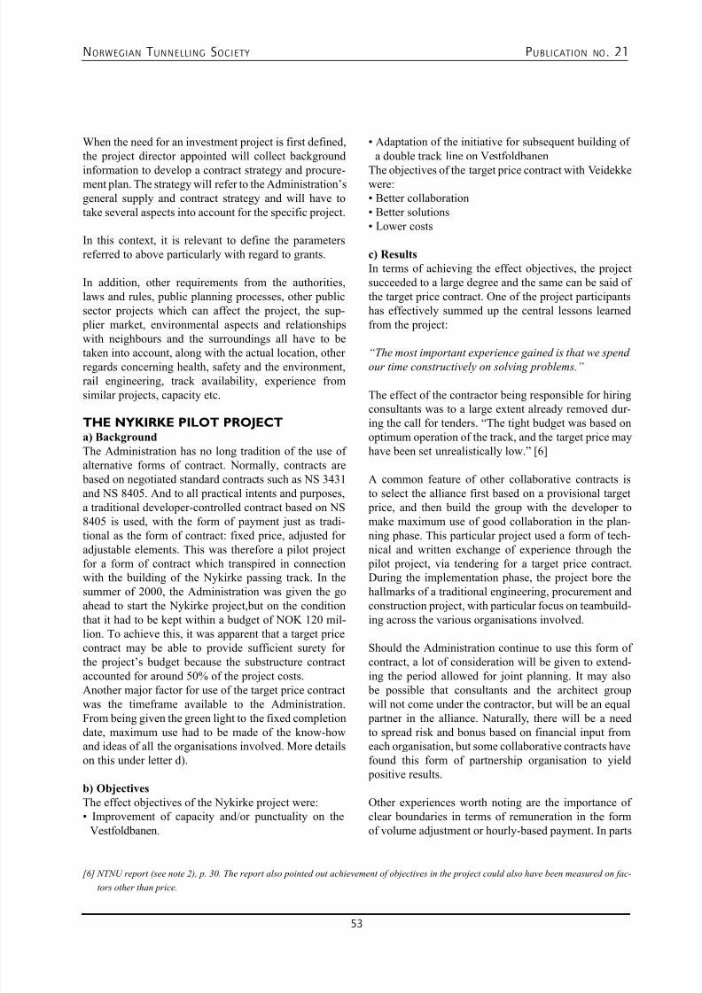
7/23/2019 NFF Publication 21 LOWRES
http://slidepdf.com/reader/full/nff-publication-21-lowres 53/94
NORWEGIAN T UNNELLING SOCIETY PUBLICATION NO . 21
53
When the need for an investment project is first defined,the project director appointed will collect background
information to develop a contract strategy and procure-ment plan. The strategy will refer to the Administration’sgeneral supply and contract strategy and will have totake several aspects into account for the specific project.
In this context, it is relevant to define the parametersreferred to above particularly with regard to grants.
In addition, other requirements from the authorities,laws and rules, public planning processes, other publicsector projects which can affect the project, the sup- plier market, environmental aspects and relationshipswith neighbours and the surroundings all have to betaken into account, along with the actual location, otherregards concerning health, safety and the environment,rail engineering, track availability, experience fromsimilar projects, capacity etc.
THE NYKIRKE PILOT PROJECTa) Background
The Administration has no long tradition of the use ofalternative forms of contract. Normally, contracts are based on negotiated standard contracts such as NS 3431and NS 8405. And to all practical intents and purposes,a traditional developer-controlled contract based on NS
8405 is used, with the form of payment just as tradi-tional as the form of contract: fixed price, adjusted foradjustable elements. This was therefore a pilot projectfor a form of contract which transpired in connectionwith the building of the Nykirke passing track. In thesummer of 2000, the Administration was given the goahead to start the Nykirke project,but on the conditionthat it had to be kept within a budget of NOK 120 mil-lion. To achieve this, it was apparent that a target pricecontract may be able to provide sufficient surety forthe project’s budget because the substructure contractaccounted for around 50% of the project costs.
Another major factor for use of the target price contractwas the timeframe available to the Administration.From being given the green light to the fixed completiondate, maximum use had to be made of the know-howand ideas of all the organisations involved. More detailson this under letter d).
b) Objectives
The effect objectives of the Nykirke project were:• Improvement of capacity and/or punctuality on the
Vestfoldbanen.
• Adaptation of the initiative for subsequent building of
a double track line on Vestfoldbanen
The objectives of the target price contract with Veidekkewere:• Better collaboration
• Better solutions
• Lower costs
c) Results
In terms of achieving the effect objectives, the projectsucceeded to a large degree and the same can be said ofthe target price contract. One of the project participantshas effectively summed up the central lessons learnedfrom the project:
“The most important experience gained is that we spend
our time constructively on solving problems.”
The effect of the contractor being responsible for hiringconsultants was to a large extent already removed dur-ing the call for tenders. “The tight budget was based onoptimum operation of the track, and the target price mayhave been set unrealistically low.” [6]
A common feature of other collaborative contracts isto select the alliance first based on a provisional target price, and then build the group with the developer to
make maximum use of good collaboration in the plan-ning phase. This particular project used a form of tech-nical and written exchange of experience through the pilot project, via tendering for a target price contract.During the implementation phase, the project bore thehallmarks of a traditional engineering, procurement andconstruction project, with particular focus on teambuild-ing across the various organisations involved.
Should the Administration continue to use this form ofcontract, a lot of consideration will be given to extend-ing the period allowed for joint planning. It may also
be possible that consultants and the architect groupwill not come under the contractor, but will be an equal partner in the alliance. Naturally, there will be a needto spread risk and bonus based on financial input fromeach organisation, but some collaborative contracts havefound this form of partnership organisation to yield positive results.
Other experiences worth noting are the importance ofclear boundaries in terms of remuneration in the formof volume adjustment or hourly-based payment. In parts
[6] NTNU report (see note 2), p. 30. The report also pointed out achievement of objectives in the project could also have been measured on fac-
tors other than price.
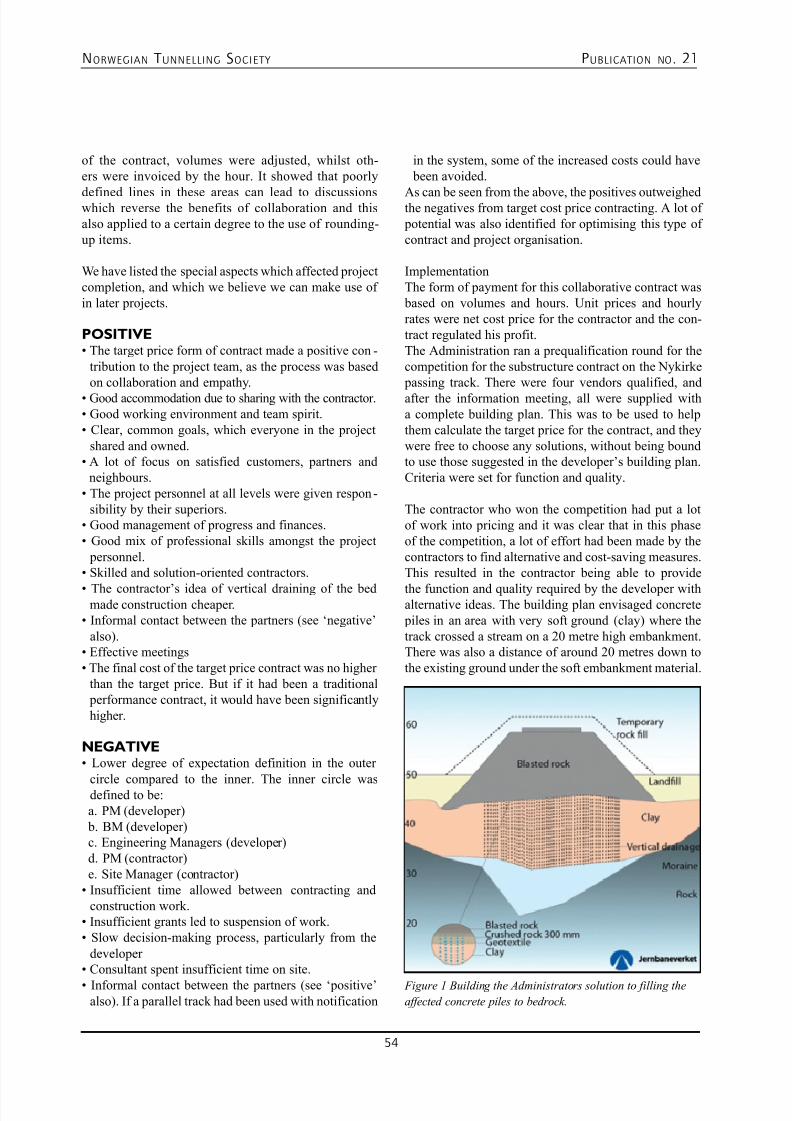
7/23/2019 NFF Publication 21 LOWRES
http://slidepdf.com/reader/full/nff-publication-21-lowres 54/94
NORWEGIAN T UNNELLING SOCIETY PUBLICATION NO . 21
54
of the contract, volumes were adjusted, whilst oth-ers were invoiced by the hour. It showed that poorly
defined lines in these areas can lead to discussionswhich reverse the benefits of collaboration and thisalso applied to a certain degree to the use of rounding-up items.
We have listed the special aspects which affected projectcompletion, and which we believe we can make use ofin later projects.
POSITIVE• The target price form of contract made a positive con -
tribution to the project team, as the process was basedon collaboration and empathy.
• Good accommodation due to sharing with the contractor.
• Good working environment and team spirit.
• Clear, common goals, which everyone in the project
shared and owned.• A lot of focus on satisfied customers, partners and
neighbours.• The project personnel at all levels were given respon-
sibility by their superiors.• Good management of progress and finances.
• Good mix of professional skills amongst the project
personnel.• Skilled and solution-oriented contractors.
• The contractor’s idea of vertical draining of the bedmade construction cheaper.
• Informal contact between the partners (see ‘negative’
also).• Effective meetings
• The final cost of the target price contract was no higher
than the target price. But if it had been a traditional performance contract, it would have been significantlyhigher.
NEGATIVE• Lower degree of expectation definition in the outer
circle compared to the inner. The inner circle wasdefined to be: a. PM (developer) b. BM (developer) c. Engineering Managers (developer) d. PM (contractor) e. Site Manager (contractor)• Insufficient time allowed between contracting and
construction work.• Insufficient grants led to suspension of work.
• Slow decision-making process, particularly from the
developer • Consultant spent insufficient time on site.
• Informal contact between the partners (see ‘positive’also). If a parallel track had been used with notification
Figure 1 Building the Administrators solution to filling the
affected concrete piles to bedrock.
in the system, some of the increased costs could have been avoided.
As can be seen from the above, the positives outweighedthe negatives from target cost price contracting. A lot of potential was also identified for optimising this type ofcontract and project organisation.
ImplementationThe form of payment for this collaborative contract was based on volumes and hours. Unit prices and hourlyrates were net cost price for the contractor and the con-tract regulated his profit.The Administration ran a prequalification round for thecompetition for the substructure contract on the Nykirke passing track. There were four vendors qualified, andafter the information meeting, all were supplied witha complete building plan. This was to be used to helpthem calculate the target price for the contract, and theywere free to choose any solutions, without being boundto use those suggested in the developer’s building plan.Criteria were set for function and quality.
The contractor who won the competition had put a lotof work into pricing and it was clear that in this phaseof the competition, a lot of effort had been made by thecontractors to find alternative and cost-saving measures.This resulted in the contractor being able to provide
the function and quality required by the developer withalternative ideas. The building plan envisaged concrete piles in an area with very soft ground (clay) where thetrack crossed a stream on a 20 metre high embankment.There was also a distance of around 20 metres down tothe existing ground under the soft embankment material.
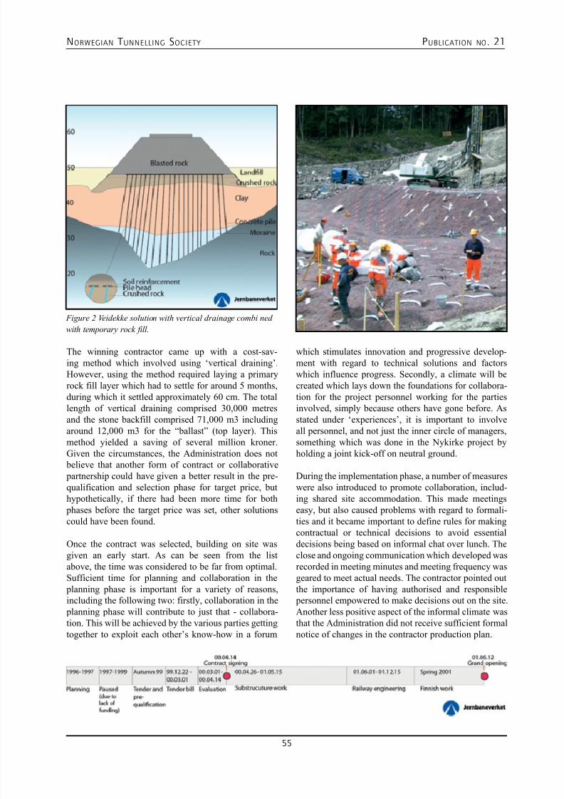
7/23/2019 NFF Publication 21 LOWRES
http://slidepdf.com/reader/full/nff-publication-21-lowres 55/94
NORWEGIAN T UNNELLING SOCIETY PUBLICATION NO . 21
55
Figure 2 Veidekke solution with vertical drainage combi ned
with temporary rock fill.
The winning contractor came up with a cost-sav-ing method which involved using ‘vertical draining’.However, using the method required laying a primaryrock fill layer which had to settle for around 5 months,during which it settled approximately 60 cm. The totallength of vertical draining comprised 30,000 metres
and the stone backfill comprised 71,000 m3 includingaround 12,000 m3 for the “ballast” (top layer). Thismethod yielded a saving of several million kroner.Given the circumstances, the Administration does not believe that another form of contract or collaborative partnership could have given a better result in the pre-qualification and selection phase for target price, buthypothetically, if there had been more time for both phases before the target price was set, other solutionscould have been found.
Once the contract was selected, building on site was
given an early start. As can be seen from the listabove, the time was considered to be far from optimal.Sufficient time for planning and collaboration in the planning phase is important for a variety of reasons,including the following two: firstly, collaboration in the planning phase will contribute to just that - collabora-tion. This will be achieved by the various parties gettingtogether to exploit each other’s know-how in a forum
which stimulates innovation and progressive develop-ment with regard to technical solutions and factorswhich influence progress. Secondly, a climate will becreated which lays down the foundations for collabora-tion for the project personnel working for the partiesinvolved, simply because others have gone before. As
stated under ‘experiences’, it is important to involveall personnel, and not just the inner circle of managers,something which was done in the Nykirke project byholding a joint kick-off on neutral ground.
During the implementation phase, a number of measureswere also introduced to promote collaboration, includ-ing shared site accommodation. This made meetingseasy, but also caused problems with regard to formali-ties and it became important to define rules for makingcontractual or technical decisions to avoid essentialdecisions being based on informal chat over lunch. The
close and ongoing communication which developed wasrecorded in meeting minutes and meeting frequency wasgeared to meet actual needs. The contractor pointed outthe importance of having authorised and responsible personnel empowered to make decisions out on the site.Another less positive aspect of the informal climate wasthat the Administration did not receive sufficient formalnotice of changes in the contractor production plan.
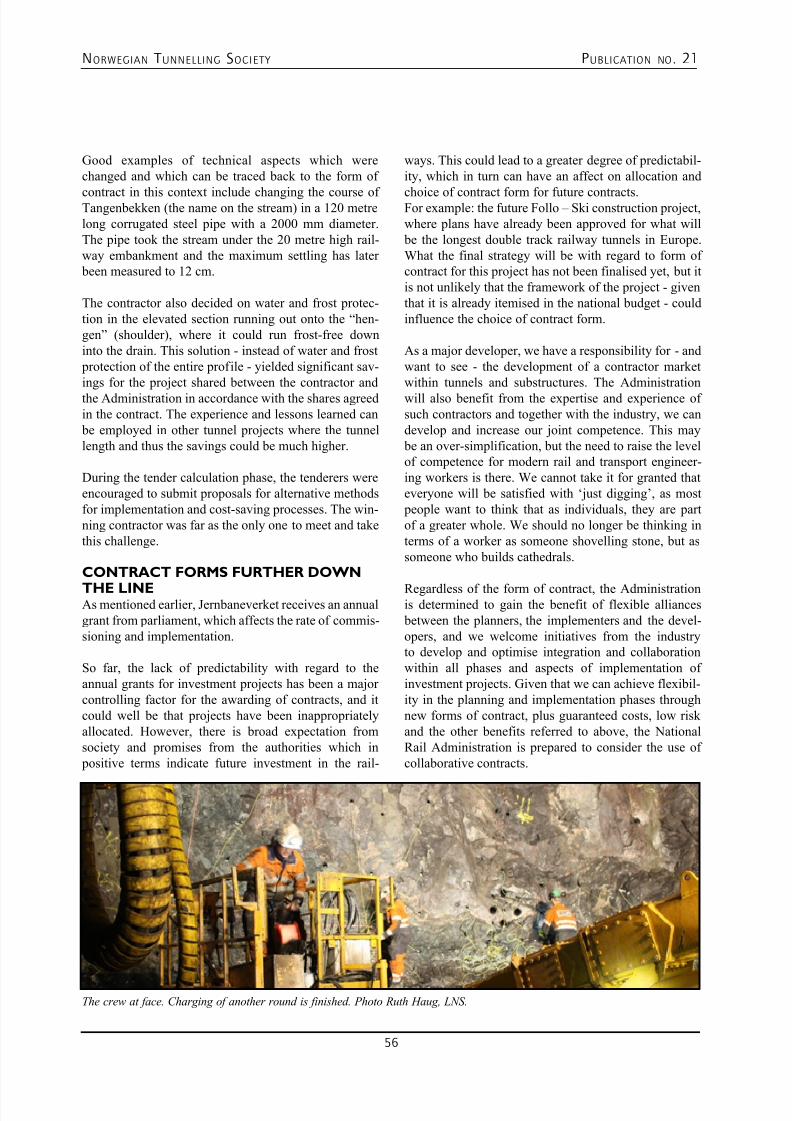
7/23/2019 NFF Publication 21 LOWRES
http://slidepdf.com/reader/full/nff-publication-21-lowres 56/94
NORWEGIAN T UNNELLING SOCIETY PUBLICATION NO . 21
56
Good examples of technical aspects which werechanged and which can be traced back to the form of
contract in this context include changing the course ofTangenbekken (the name on the stream) in a 120 metrelong corrugated steel pipe with a 2000 mm diameter.The pipe took the stream under the 20 metre high rail-way embankment and the maximum settling has later been measured to 12 cm.
The contractor also decided on water and frost protec-tion in the elevated section running out onto the “hen-gen” (shoulder), where it could run frost-free downinto the drain. This solution - instead of water and frost protection of the entire profile - yielded significant sav-ings for the project shared between the contractor andthe Administration in accordance with the shares agreedin the contract. The experience and lessons learned can be employed in other tunnel projects where the tunnellength and thus the savings could be much higher.
During the tender calculation phase, the tenderers wereencouraged to submit proposals for alternative methodsfor implementation and cost-saving processes. The win-ning contractor was far as the only one to meet and takethis challenge.
CONTRACT FORMS FURTHER DOWN
THE LINEAs mentioned earlier, Jernbaneverket receives an annualgrant from parliament, which affects the rate of commis-sioning and implementation.
So far, the lack of predictability with regard to theannual grants for investment projects has been a majorcontrolling factor for the awarding of contracts, and itcould well be that projects have been inappropriatelyallocated. However, there is broad expectation fromsociety and promises from the authorities which in positive terms indicate future investment in the rail-
ways. This could lead to a greater degree of predictabil-ity, which in turn can have an affect on allocation and
choice of contract form for future contracts.For example: the future Follo – Ski construction project,where plans have already been approved for what will be the longest double track railway tunnels in Europe.What the final strategy will be with regard to form ofcontract for this project has not been finalised yet, but itis not unlikely that the framework of the project - giventhat it is already itemised in the national budget - couldinfluence the choice of contract form.
As a major developer, we have a responsibility for - andwant to see - the development of a contractor marketwithin tunnels and substructures. The Administrationwill also benefit from the expertise and experience ofsuch contractors and together with the industry, we candevelop and increase our joint competence. This may be an over-simplification, but the need to raise the levelof competence for modern rail and transport engineer-ing workers is there. We cannot take it for granted thateveryone will be satisfied with ‘just digging’, as most people want to think that as individuals, they are partof a greater whole. We should no longer be thinking interms of a worker as someone shovelling stone, but assomeone who builds cathedrals.
Regardless of the form of contract, the Administrationis determined to gain the benefit of flexible alliances between the planners, the implementers and the devel-opers, and we welcome initiatives from the industryto develop and optimise integration and collaborationwithin all phases and aspects of implementation ofinvestment projects. Given that we can achieve flexibil-ity in the planning and implementation phases throughnew forms of contract, plus guaranteed costs, low riskand the other benefits referred to above, the NationalRail Administration is prepared to consider the use ofcollaborative contracts.
The crew at face. Charging of another round is finished. Photo Ruth Haug, LNS.

7/23/2019 NFF Publication 21 LOWRES
http://slidepdf.com/reader/full/nff-publication-21-lowres 57/94
NORWEGIAN T UNNELLING SOCIETY PUBLICATION NO . 21
57
INTRODUCTIONA consultant can be hired to perform a multitude oftasks. This article focuses on experiences as a consultingand engineering company developing contracts for civiland rock works for construction of tunnels and caverns.The contract for consultancy can be very detailed speci-fying each task and the requirements for drawings anddocuments as well as services before, during and afterconstruction. These contracts are normally developed by clients who have long and repeated experiences from projects, and have considerable experience and capaci-ties within their organization. A variety of contract givesa general responsibility to the consultant to developwhat is necessary for the project.
A “NORMAL “LIFE CYCLE OF A TUN-
NELING CONSULTING ASSIGNMENTTo explain a consultant’s contribution in a tunnel con-tract it is important to understand that a consultingassignment normally covers more than the construction phase. Below it outlined a short description of tasksduring the different stages of a project, and a brief char-acterization of work performed. The assignment mayinclude one, several or all activities.
Phase Typical
Product
Main
Interfaces
1.Concept Meetings,
reports,drawings
Client and other
consultants
2. Basic design Reports ,calculationsand drawings,quantity andcost estimates,schedule
Client and otherconsultants
3. Applicationsand approvals
Impact analysis,descriptions,applications
Client ,authorities,otherconsultants and
experts
09. THE CONSULTANT’S CONTRIBUTION IN A TUNNEL
CONTRACT
ARNESEN, Frode
4. Detail design Input tocontract, billof quantity,calculations,
specifications, procedures,drawings,quantity andcost estimates,schedule,
Client and otherconsultants
5. Bidding andcontracting
Contractorqualification,issuingdocuments,controlling and bid evaluation
reports
Client,contractors
6. Construction phase
Constructiondrawings,follow-upengineering,site queries,drawing andspecification ofchanges. Claimsevaluations andquantity control.
Client,contractor,authorities
7.Completions Quality control
report, As-builtdrawings anddocumentation
Client,
contractor
8. Guarantee period
Quality checks,deformations,leakages,rockfalls,rectificationwork reports.
Client,contractor, users
Plan and execute controls and checks during the guar-antee period as well as check of issues concerning
deformation leakages, rock falls or other issues duringoperation.
7/23/2019 NFF Publication 21 LOWRES
http://slidepdf.com/reader/full/nff-publication-21-lowres 58/94
NORWEGIAN T UNNELLING SOCIETY PUBLICATION NO . 21
58
CONTRIBUTIONS TO THE TUNNELCONTRACT
The Norwegian civil contract code NS3420 and theroad construction code (vegprosesskoden) are com- prehensive documents developed as a key part of a Norwegian construction contract framework. Nationaland European standards for engineering and drawingsare additional directives and tools which shall be used by a consultant.
Below is mentioned some key comments regardingcontract documents normally handled by a tunnelengineering consultant. More detailed information andguidelines are accessible in the English version of NS3420 [1]
GENERAL INFORMATIONThis chapter gives information concerning the worklocations and the rules and regulations concerning the project, often a result of the planning process prior tothe contract. The quality and accuracy of this is vital anderrors can have severe consequences.Critical items can be:• Location and accessibility of work and rigging area,
Battery limits.• Valid authority permits and their content
• Contractors responsibility regarding permits
• Project specific environment rules and regulations
These elements can be critical and must be evaluatedand checked by the consultant and the client. Changesafter contract award can be costly.
BID CRITERIA DEVELOPMENTCriteria for choice of contractors for the bidding roundare important, as well as procedure and award criteriafor the bid award should be decided at an early stage.This policy can have major importance for the contentof the bid document. All information pertaining to this
should be clarified and defined.
SITE INVESTIGATIONS AND GEOLOGI-CAL CONDITIONSReports documenting ground conditions and geologicaldata are essential for a tunnel contract. As unforeseen,or undocumented changes or challenges in ground con-ditions according to Norwegian practice often must becompensated by the client, correct and precise descrip-tions is vital for project cost and schedule control. Thisis a major task for engineering geology consultants.
SPECIAL PROCEDURES AND
SPECIFICATIONSSpecial procedures or processes which are identified as
necessary for the project, but not covered as part of thestandard, must be described and specified. When the
contract code NS3420 is used it is important that cor-rect detail specification and information is added to eachspecific item description.
DRAWINGSDrawing accuracy and coherence is a major responsi- bility. It must be underlined that the constructabilityof what is shown on the drawings also is important.Checking of critical parts by persons with practicalexperiences from same or similar construction methodsand tolerance requirements is essential.
BILL OF QUANTITIES
The contract after Norwegian construction contract practice is a mix of fixed sums and unit prices. Theunit prices are consumables or items compensated aftercompensation verified by the client`s representative.When a contract is edited it is important to note thatthe client and the contractor can have opposing strate-gies when the quantities are set in the bidding process.The consultant`s role in this process is to give his bestassessments of the quantities and work out the bill ofquantities in close cooperation with the client.
HANDLING OF VARIATIONS AND
UNCERTAINTIESIf areas of uncertainties or a high level variance of quan-tities is identified, special rules for ordering additions, regulation formulas for fixed sums or risk shearingrules can be added. This can be a complex area, andadvice from contract specialists, or legal advice can benecessary.
FINISH DATES AND PENALTIESDefinitions regarding finish dates, acceptable delaycauses and penalties are often covered by the contractcodes. However, if the client has critical dependencies
or important milestones which must be met, it is impor-tant to address and work out effective penalty regula-tions and if possible rewards to ensure a successfulresult. This does not replace developing a realistic workschedule at an earlier stage.
BID EVALUATIONWhen the bids are received the consultant might beresponsible for checking of correct pricing , and check-ing the method statement. The bid can have alternativeofferings which need checking and consequence analy-sis. The consultant can also participate if other criteriathan economical value is to be considered for contract
award. A evaluation scheme should be worked out as part of the contract document. To avoid possibilities
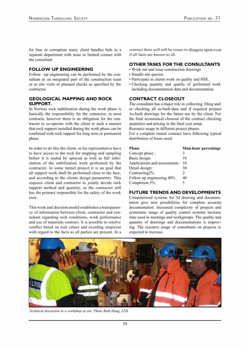
7/23/2019 NFF Publication 21 LOWRES
http://slidepdf.com/reader/full/nff-publication-21-lowres 59/94
NORWEGIAN T UNNELLING SOCIETY PUBLICATION NO . 21
59
for bias or corruption many client handles bids in aseparate department with none or limited contact with
the consultant.
FOLLOW UP ENGINEERINGFollow –up engineering can be performed by the con-sultant as an integrated part of the construction teamor as site visits or planned checks as specified by thecontractor.
GEOLOGICAL MAPPING AND ROCKSUPPORT.In Norway rock stabilization during the work phase is basically the responsibility for the contractor, in mostcontracts, however there is an obligation for the con-tractor to co-operate with the client in such a mannerthat rock support installed during the work phase can becombined with rock support for long term or permanent phase.
In order to do this the client, or his representative haveto have access to the rock for mapping and sampling before it is sealed by sprayed as well as full infor-mation of the stabilization work performed by thecontractor. In some tunnel project it is an goal thatall support work shall be performed close to the face,and according to the clients design parameters. This
requires client and contractor to jointly decide rocksupport method and quantity, as the contractor stillhas the primary responsible for the safety of the workcrew.
This work and decision model establishes a transparen-cy of information between client, contractor and con-sultant regarding rock conditions, work performanceand use of materials contract. It is possible to resolveconflict based on real values and avoiding suspicionwith regard to the facts as all parties are present. In a
contract there will still be issues to disagree upon evenif all facts are known to all.
OTHER TASKS FOR THE CONSULTANTS• Work out and issue construction drawings
• Handle site queries
• Participate in clients work on quality and HSE.
• Checking quantity and quality of performed work
including documentation data and documentation.
CONTRACT CLOSEOUTThe consultant has a major role in collecting, filing and/or checking all as-built-data and if required prepareAs-built drawings for the future use by the client. Forthe final economical closeout of the contract checkingquantities and pricing in the final cost setup.Resource usage in different project phases.For a complete tunnel contract have following typicaldistribution of hours used:
Phase Man-hour percentage
Concept phase : 3Basic design: 10Applications and assessments: 10Detail design: 30Contracting2% 2Follow up engineering 40% 40
Completion 5% 5 FUTURE TRENDS AND DEVELOPMENTSComputerized systems for 3d drawing and documen-tation give new possibilities for complete accuratedocumentation. Increased complexity of projects andsystematic usage of quality control systems increasetime used in meetings and workgroups. The quality andquantity of drawings and documentations is improv-ing. The resource usage of consultants on projects isexpected to increase.
Technical discussion in a workshop at site. Photo Ruth Haug, LNS.
7/23/2019 NFF Publication 21 LOWRES
http://slidepdf.com/reader/full/nff-publication-21-lowres 60/94
NORWEGIAN T UNNELLING SOCIETY PUBLICATION NO . 21
60
Our secret isNorwegianTunnel Technology
We are raised beyond the arctic circle. We are raised to work hard.We are raised to make more of less.
Our secret and success are recognized by strong and competent
teams, advanced equipment, efficiency and quality.
Our homebased reference list are long, several of the longest
tunnels for rail and road, complicated rock structures,
hydro power construction and mining.
LNS are using Norwegian Tunnel Technology world wide:
In Norway, Greenland, Chile, Hong Kong and Antarctic.
v i z u el l i .n o
www.lns.no
7/23/2019 NFF Publication 21 LOWRES
http://slidepdf.com/reader/full/nff-publication-21-lowres 61/94
NORWEGIAN T UNNELLING SOCIETY PUBLICATION NO . 21
61
INTRODUCTIONThis paper presents three cases of subsea road tunnelsthat cast light on the suitability of different types ofcontracts. Firstly, the 3.8km Godøy tunnel (the deep-est subsea road tunnel in the world at the time) wherea grouting effort much larger than planned was neededto prevent unexpected and unacceptable water inflow.The unit price contract proved to be suitable even witha more than 3 times increased quantity of grouting.Secondly, the 2.0km Bjorøy tunnel was expected to be a straightforward project suitable for a fixed pricecontract. An exceptional occurrence of a sand zonecaused serious delays and cost overruns, resulting inlitigation. The contractor had to take the loss. It is dis-cussed whether a unit price contract would have beenmore suitable in this case. Finally, the Oslofjord tunnel
is discussed. During construction an unexpected erosionchannel filled with soil was detected by probe drilling atthe tunnel’s deepest point, i.e. under 120m water pres-sure. The necessary measures were dealt with outsidethe unit price contract regulations.
The experience shows that unit price contracts are suitableto deal with ‘unexpected geological conditions’, as long asthe ‘unexpected’ element results only in variations in thequantities of work activities. This means that all necessarywork activities must have quantities and preferably also‘standard capacities’ for regulation of the construction
time. In fact, variations in quantities must be expected inany underground project, and such variations thereforehardly deserve the term ‘unexpected’. If unexpected con-ditions occur in the form of unforeseen geological featuresnecessitating work activities not included in the Bill ofQuantity, the unit price contract must be supplemented byspecial agreement, usually some form of cost reimburse-ment. Fixed price contracts for underground projects,may not provide the intended predictable cost. Modifiedor ‘adjustable fixed price’ contracts, combining elementsfrom both unit price and fixed price contracts, may proveto be more suitable than fully fixed price contracts.Requirements needed to establish suitable tunnelling con-
tracts and the need for project specific and balanced alloca-tion of risks are outlined.
10. NORWEGIAN CONTRACT PRACTICE SUITABLE ALSO FOR
DEALING WITH UNEXPECTED GEOLOGICAL CONDITIONS.THREE PROJECT EXAMPLES.
GRØV, Eivind
UNPREDICTABLE WORK CONDITIONSCALLS FOR FLEXIBLE CONTRACTPROVISIONS. Norway forms part of a Precambrian shield. Two thirdsof the country is covered by Precambrian rocks (olderthan 600 million years), with different types of gneissdominating. Other rock types from this era are granites,gabbros and quartzite. Approxi¬mately one third of thecountry is covered by rocks of Cambrian - Silurian age.The greater part of these rocks are metamorphosed, butto a varying degree. Rock types such as gneisses, mica-schists and greenstones as well as sand¬stones, shales,lim-estones and other un¬metamorphosed rocks forma mountain range, which runs through the central partsof the country. In the geologically unique Oslo region,the rock mass is partly made up of unmeta¬morphic
Cambro-Silurian shales and limestones and partly ofPermian intrusive and extrusive rocks. These are theyoungest rocks.
The geological setting is dominated by igneous rocktypes together with metamorphic rocks of various typesand origins. The host rock is more or less intersected byweak zones, which may have an intense tectonic joint-ing, hydro-thermal alteration, or be faulted and sheared,constituting significant weaknesses in the rock and mak-ing the rock mass far from homogenous. These condi-tions will frequently call for grouting to reach a desired
low level of rock mass permeability
The zones of weakness can exhibit great variation inquality, their Q-classification ranging from “extremely poor” rock mass at the lower end of the scale, to “good”,with width extending from only a few centimetres totens of metres.
The hydrogeological situation is dominated by highgroundwater level, also in the rock mass. This situationis both favourable and unfavourable for rock tunnelling.One advantage of a groundwater regime surrounding anunderground structure is that it provides a natural gradi-
ent acting towards the opening allowing the utilisationof unlined storage facilities. On the other hand, one
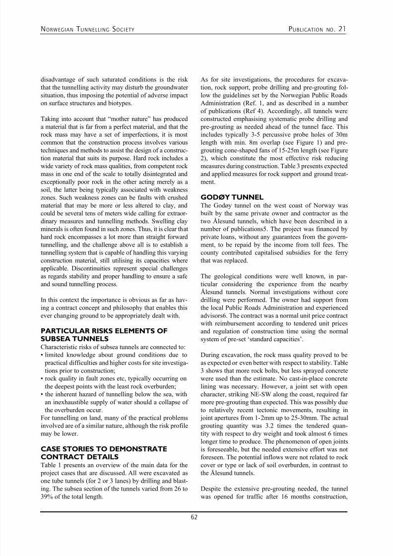
7/23/2019 NFF Publication 21 LOWRES
http://slidepdf.com/reader/full/nff-publication-21-lowres 62/94
NORWEGIAN T UNNELLING SOCIETY PUBLICATION NO . 21
62
disadvantage of such saturated conditions is the riskthat the tunnelling activity may disturb the groundwater
situation, thus imposing the potential of adverse impacton surface structures and biotypes.
Taking into account that “mother nature” has produceda material that is far from a perfect material, and that therock mass may have a set of imperfections, it is mostcommon that the construction process involves varioustechniques and methods to assist the design of a construc-tion material that suits its purpose. Hard rock includes awide variety of rock mass qualities, from competent rockmass in one end of the scale to totally disintegrated andexceptionally poor rock in the other acting merely as asoil, the latter being typically associated with weaknesszones. Such weakness zones can be faults with crushedmaterial that may be more or less altered to clay, andcould be several tens of meters wide calling for extraor-dinary measures and tunnelling methods. Swelling clayminerals is often found in such zones. Thus, it is clear thathard rock encompasses a lot more than straight forwardtunnelling, and the challenge above all is to establish atunnelling system that is capable of handling this varyingconstruction material, still utilising its capacities whereapplicable. Discontinuities represent special challengesas regards stability and proper handling to ensure a safeand sound tunnelling process.
In this context the importance is obvious as far as hav-ing a contract concept and philosophy that enables thisever changing ground to be appropriately dealt with.
PARTICULAR RISKS ELEMENTS OFSUBSEA TUNNELSCharacteristic risks of subsea tunnels are connected to:• limited knowledge about ground conditions due to
practical difficulties and higher costs for site investiga-tions prior to construction;
• rock quality in fault zones etc, typically occurring on
the deepest points with the least rock overburden;• the inherent hazard of tunnelling below the sea, with
an inexhaustible supply of water should a collapse ofthe overburden occur.
For tunnelling on land, many of the practical problemsinvolved are of a similar nature, although the risk profilemay be lower.
CASE STORIES TO DEMONSTRATECONTRACT DETAILSTable 1 presents an overview of the main data for the project cases that are discussed. All were excavated asone tube tunnels (for 2 or 3 lanes) by drilling and blast-
ing. The subsea section of the tunnels varied from 26 to39% of the total length.
As for site investigations, the procedures for excava-tion, rock support, probe drilling and pre-grouting fol-
low the guidelines set by the Norwegian Public RoadsAdministration (Ref. 1, and as described in a numberof publications (Ref 4). Accordingly, all tunnels wereconstructed emphasising systematic probe drilling and pre-grouting as needed ahead of the tunnel face. Thisincludes typically 3-5 percussive probe holes of 30mlength with min. 8m overlap (see Figure 1) and pre-grouting cone-shaped fans of 15-25m length (see Figure2), which constitute the most effective risk reducingmeasures during construction. Table 3 presents expectedand applied measures for rock support and ground treat-ment. GODØY TUNNELThe Godøy tunnel on the west coast of Norway was built by the same private owner and contractor as thetwo Ålesund tunnels, which have been described in anumber of publications5. The project was financed by private loans, without any guarantees from the govern-ment, to be repaid by the income from toll fees. Thecounty contributed capitalised subsidies for the ferrythat was replaced.
The geological conditions were well known, in par-ticular considering the experience from the nearby
Ålesund tunnels. Normal investigations without coredrilling were performed. The owner had support fromthe local Public Roads Administration and experiencedadvisors6. The contract was a normal unit price contractwith reimbursement according to tendered unit pricesand regulation of construction time using the normalsystem of pre-set ‘standard capacities’.
During excavation, the rock mass quality proved to beas expected or even better with respect to stability. Table3 shows that more rock bolts, but less sprayed concretewere used than the estimate. No cast-in-place concrete
lining was necessary. However, a joint set with opencharacter, striking NE-SW along the coast, required farmore pre-grouting than expected. This was possibly dueto relatively recent tectonic movements, resulting in joint apertures from 1-2mm up to 25-30mm. The actualgrouting quantity was 3.2 times the tendered quan-tity with respect to dry weight and took almost 6 timeslonger time to produce. The phenomenon of open jointsis foreseeable, but the needed extensive effort was notforeseen. The potential inflows were not related to rockcover or type or lack of soil overburden, in contrast tothe Ålesund tunnels.
Despite the extensive pre-grouting needed, the tunnelwas opened for traffic after 16 months construction,
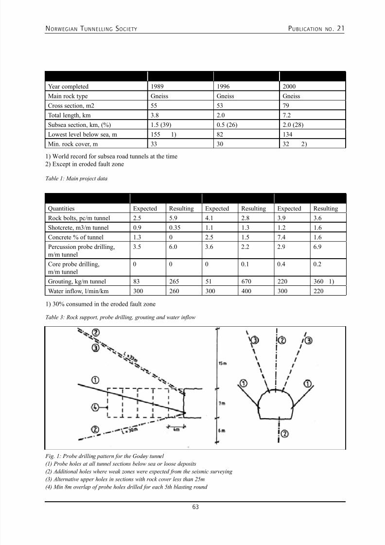
7/23/2019 NFF Publication 21 LOWRES
http://slidepdf.com/reader/full/nff-publication-21-lowres 63/94
NORWEGIAN T UNNELLING SOCIETY PUBLICATION NO . 21
63
Tunnel Godøy Bjorøy Oslofjord
Year completed 1989 1996 2000
Main rock type Gneiss Gneiss GneissCross section, m2 55 53 79
Total length, km 3.8 2.0 7.2
Subsea section, km, (%) 1.5 (39) 0.5 (26) 2.0 (28)
Lowest level below sea, m 155 1) 82 134
Min. rock cover, m 33 30 32 2)
1) World record for subsea road tunnels at the time2) Except in eroded fault zone
Tunnel Godøy Bjorøy Oslofjord
Quantities Expected Resulting Expected Resulting Expected Resulting
Rock bolts, pc/m tunnel 2.5 5.9 4.1 2.8 3.9 3.6
Shotcrete, m3/m tunnel 0.9 0.35 1.1 1.3 1.2 1.6
Concrete % of tunnel 1.3 0 2.5 1.5 7.4 1.6
Percussion probe drilling,m/m tunnel
3.5 6.0 3.6 2.2 2.9 6.9
Core probe drilling,m/m tunnel
0 0 0 0.1 0.4 0.2
Grouting, kg/m tunnel 83 265 51 670 220 360 1)
Water inflow, l/min/km 300 260 300 400 300 220
1) 30% consumed in the eroded fault zone
Table 1: Main project data
Table 3: Rock support, probe drilling, grouting and water inflow
Fig. 1: Probe drilling pattern for the Godøy tunnel
(1) Probe holes at all tunnel sections below sea or loose deposits
(2) Additional holes where weak zones were expected from the seismic surveying
(3) Alternative upper holes in sections with rock cover less than 25m
(4) Min 8m overlap of probe holes drilled for each 5th blasting round
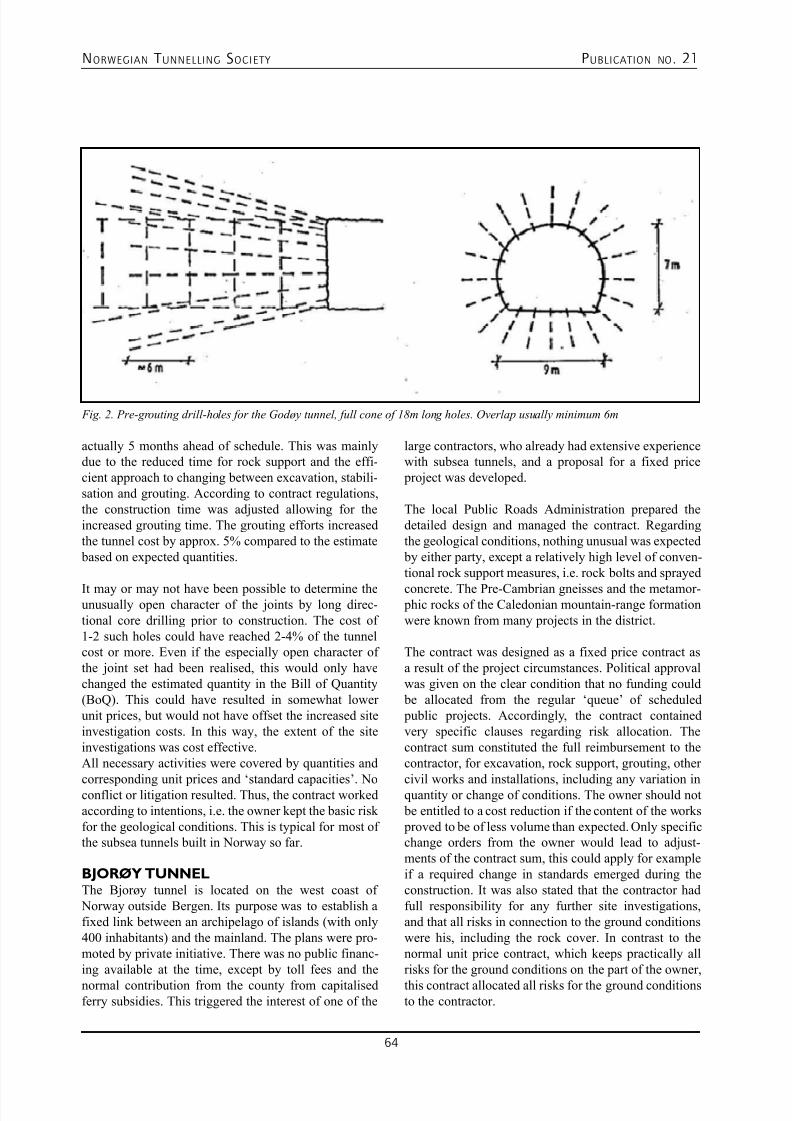
7/23/2019 NFF Publication 21 LOWRES
http://slidepdf.com/reader/full/nff-publication-21-lowres 64/94
NORWEGIAN T UNNELLING SOCIETY PUBLICATION NO . 21
64
actually 5 months ahead of schedule. This was mainlydue to the reduced time for rock support and the effi-cient approach to changing between excavation, stabili-sation and grouting. According to contract regulations,the construction time was adjusted allowing for theincreased grouting time. The grouting efforts increasedthe tunnel cost by approx. 5% compared to the estimate based on expected quantities.
It may or may not have been possible to determine theunusually open character of the joints by long direc-tional core drilling prior to construction. The cost of1-2 such holes could have reached 2-4% of the tunnelcost or more. Even if the especially open character ofthe joint set had been realised, this would only havechanged the estimated quantity in the Bill of Quantity(BoQ). This could have resulted in somewhat lowerunit prices, but would not have offset the increased siteinvestigation costs. In this way, the extent of the siteinvestigations was cost effective.All necessary activities were covered by quantities and
corresponding unit prices and ‘standard capacities’. Noconflict or litigation resulted. Thus, the contract workedaccording to intentions, i.e. the owner kept the basic riskfor the geological conditions. This is typical for most ofthe subsea tunnels built in Norway so far.
BJORØY TUNNELThe Bjorøy tunnel is located on the west coast of Norway outside Bergen. Its purpose was to establish afixed link between an archipelago of islands (with only400 inhabitants) and the mainland. The plans were pro-moted by private initiative. There was no public financ-ing available at the time, except by toll fees and the
normal contribution from the county from capitalisedferry subsidies. This triggered the interest of one of the
Fig. 2. Pre-grouting drill-holes for the Godøy tunnel, full cone of 18m long holes. Overlap usually minimum 6m
large contractors, who already had extensive experiencewith subsea tunnels, and a proposal for a fixed price project was developed. The local Public Roads Administration prepared thedetailed design and managed the contract. Regardingthe geological conditions, nothing unusual was expected by either party, except a relatively high level of conven-tional rock support measures, i.e. rock bolts and sprayed
concrete. The Pre-Cambrian gneisses and the metamor- phic rocks of the Caledonian mountain-range formationwere known from many projects in the district.
The contract was designed as a fixed price contract asa result of the project circumstances. Political approvalwas given on the clear condition that no funding could be allocated from the regular ‘queue’ of scheduled public projects. Accordingly, the contract containedvery specific clauses regarding risk allocation. Thecontract sum constituted the full reimbursement to thecontractor, for excavation, rock support, grouting, other
civil works and installations, including any variation inquantity or change of conditions. The owner should not be entitled to a cost reduction if the content of the works proved to be of less volume than expected. Only specificchange orders from the owner would lead to adjust-ments of the contract sum, this could apply for exampleif a required change in standards emerged during theconstruction. It was also stated that the contractor hadfull responsibility for any further site investigations,and that all risks in connection to the ground conditionswere his, including the rock cover. In contrast to thenormal unit price contract, which keeps practically allrisks for the ground conditions on the part of the owner,
this contract allocated all risks for the ground conditionsto the contractor.
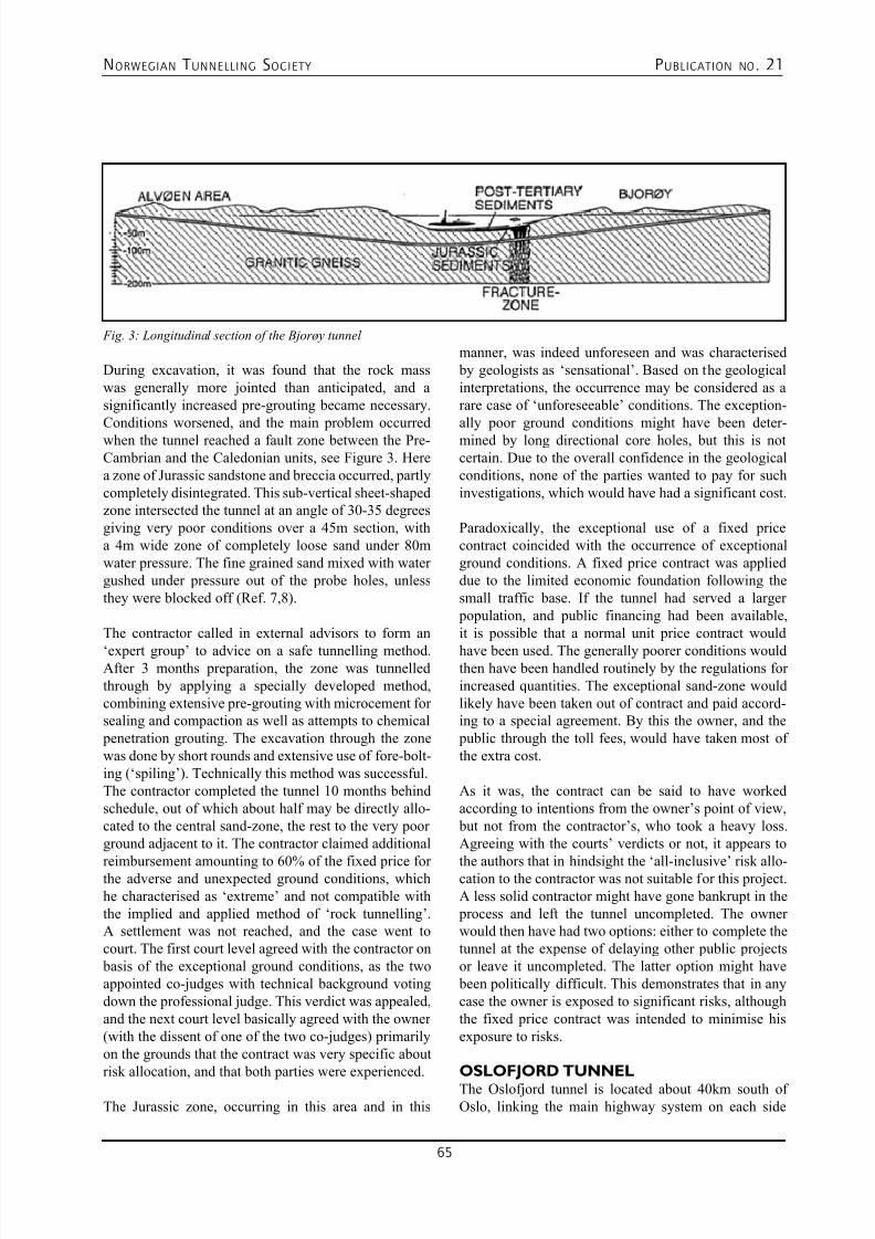
7/23/2019 NFF Publication 21 LOWRES
http://slidepdf.com/reader/full/nff-publication-21-lowres 65/94
NORWEGIAN T UNNELLING SOCIETY PUBLICATION NO . 21
65
During excavation, it was found that the rock masswas generally more jointed than anticipated, and asignificantly increased pre-grouting became necessary.Conditions worsened, and the main problem occurredwhen the tunnel reached a fault zone between the Pre-Cambrian and the Caledonian units, see Figure 3. Herea zone of Jurassic sandstone and breccia occurred, partlycompletely disintegrated. This sub-vertical sheet-shapedzone intersected the tunnel at an angle of 30-35 degreesgiving very poor conditions over a 45m section, witha 4m wide zone of completely loose sand under 80mwater pressure. The fine grained sand mixed with watergushed under pressure out of the probe holes, unlessthey were blocked off (Ref. 7,8).
The contractor called in external advisors to form an
‘expert group’ to advice on a safe tunnelling method.After 3 months preparation, the zone was tunnelledthrough by applying a specially developed method,combining extensive pre-grouting with microcement forsealing and compaction as well as attempts to chemical penetration grouting. The excavation through the zonewas done by short rounds and extensive use of fore-bolt-ing (‘spiling’). Technically this method was successful.The contractor completed the tunnel 10 months behindschedule, out of which about half may be directly allo-cated to the central sand-zone, the rest to the very poorground adjacent to it. The contractor claimed additional
reimbursement amounting to 60% of the fixed price forthe adverse and unexpected ground conditions, whichhe characterised as ‘extreme’ and not compatible withthe implied and applied method of ‘rock tunnelling’.A settlement was not reached, and the case went tocourt. The first court level agreed with the contractor on basis of the exceptional ground conditions, as the twoappointed co-judges with technical background votingdown the professional judge. This verdict was appealed,and the next court level basically agreed with the owner(with the dissent of one of the two co-judges) primarilyon the grounds that the contract was very specific aboutrisk allocation, and that both parties were experienced.
The Jurassic zone, occurring in this area and in this
manner, was indeed unforeseen and was characterised by geologists as ‘sensational’. Based on the geologicalinterpretations, the occurrence may be considered as arare case of ‘unforeseeable’ conditions. The exception-ally poor ground conditions might have been deter-mined by long directional core holes, but this is notcertain. Due to the overall confidence in the geologicalconditions, none of the parties wanted to pay for suchinvestigations, which would have had a significant cost.
Paradoxically, the exceptional use of a fixed pricecontract coincided with the occurrence of exceptionalground conditions. A fixed price contract was applieddue to the limited economic foundation following thesmall traffic base. If the tunnel had served a larger population, and public financing had been available,it is possible that a normal unit price contract would
have been used. The generally poorer conditions wouldthen have been handled routinely by the regulations forincreased quantities. The exceptional sand-zone wouldlikely have been taken out of contract and paid accord-ing to a special agreement. By this the owner, and the public through the toll fees, would have taken most ofthe extra cost.
As it was, the contract can be said to have workedaccording to intentions from the owner’s point of view, but not from the contractor’s, who took a heavy loss.Agreeing with the courts’ verdicts or not, it appears to
the authors that in hindsight the ‘all-inclusive’ risk allo-cation to the contractor was not suitable for this project.A less solid contractor might have gone bankrupt in the process and left the tunnel uncompleted. The ownerwould then have had two options: either to complete thetunnel at the expense of delaying other public projectsor leave it uncompleted. The latter option might have been politically difficult. This demonstrates that in anycase the owner is exposed to significant risks, althoughthe fixed price contract was intended to minimise hisexposure to risks.
OSLOFJORD TUNNEL
The Oslofjord tunnel is located about 40km south ofOslo, linking the main highway system on each side
Fig. 3: Longitudinal section of the Bjorøy tunnel
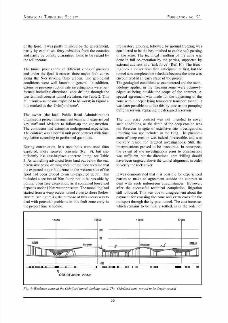
7/23/2019 NFF Publication 21 LOWRES
http://slidepdf.com/reader/full/nff-publication-21-lowres 66/94
NORWEGIAN T UNNELLING SOCIETY PUBLICATION NO . 21
66
of the fjord. It was partly financed by the government, partly by capitalised ferry subsidies from the counties
and partly by county guaranteed loans to be repaid bythe toll income.
The tunnel passes through different kinds of gneissesand under the fjord it crosses three major fault zonesalong the N-S striking Oslo graben. The geologicalconditions were well known in general. In addition,extensive pre-construction site investigations were per-formed including directional core drilling through thewestern fault zone at tunnel elevation, see Table 2. Thisfault zone was the one expected to be worst; in Figure 4it is marked as the ‘Oslofjord zone’.
The owner (the local Public Road Administration)organised a project management team with experiencedkey staff and advisors to follow-up the construction.The contractor had extensive underground experience.The contract was a normal unit price contract with timeregulation according to performed quantities.
During construction, less rock bolts were used thanexpected, more sprayed concrete (Ref. 9), but sig-nificantly less cast-in-place concrete lining, see Table3. As tunnelling advanced from land out below the sea, percussive probe drilling ahead of the face revealed that
the expected major fault zone on the western side of thefjord had been eroded to an un-expected depth. Thisincluded a section of 30m found not to be passable bynormal open face excavation, as it contained loose soildeposits under 120m water pressure. The tunnelling hadstarted from a steep access tunnel close to shore (belowHurum, seeFigure 4); the purpose of this access was todeal with potential problems in this fault zone early inthe project time schedule.
Preparatory grouting followed by ground freezing wasconsidered to be the best method to enable safe passing
of the zone. The technical handling of the zone wasdone in full co-operation by the parties, supported byexternal advisers in a ‘task force’ (Ref. 10). The freez-ing took a longer time than anticipated at first, but thetunnel was completed on schedule because the zone wasencountered at an early stage of the project.The geological conditions as encountered and the meth-odology applied in the ′freezing zone′ were acknowl-edged as being outside the scope of the contract. Aspecial agreement was made for the bypassing of thezone with a deeper lying temporary transport tunnel. Itwas later possible to utilize this by-pass as the pumping buffer reservoir, replacing the designed reservoir.
The unit price contract was not intended to coversuch conditions, as the depth of the deep erosion wasnot foreseen in spite of extensive site investigations.Freezing was not included in the BoQ. The phenom-enon of deep erosion was indeed foreseeable, and wasthe very reason for targeted investigations. Still, theinterpretations proved to be inaccurate. In retrospect,the extent of site investigations prior to constructionwas sufficient, but the directional core drilling shouldhave been targeted above the tunnel alignment in orderto verify the rock cover.
It was demonstrated that it is possible for experienced parties to make an agreement outside the contract todeal with such unforeseen circumstances. However,after the successful technical completion, litigationstill followed. This was due to disagreement about the payment for crossing the zone and extra costs for thetransport through the by-pass tunnel. The cost increase,which remains to be finally settled, is in the order of
Fig. 4: Weakness zones at the Oslofjord tunnel, looking north. The ‘Oslofjord zone’ proved to be deeply eroded
7/23/2019 NFF Publication 21 LOWRES
http://slidepdf.com/reader/full/nff-publication-21-lowres 67/94
NORWEGIAN T UNNELLING SOCIETY PUBLICATION NO . 21
67
10-20% of the expected tunnel cost. The actual costsrelated to the litigation itself were significant. The ver-
dict criticised the parties for not trying harder to settlethe economic aspects out of court.
LESSONS LEARNEDFrom the above case stories, these lessons may apply toother tunnelling as well:• Independent of the type of contract, it is important not
to become too confident about the results or ratherthe interpretations from the site investigations priorto construction. It is necessary to rely on relevantand sufficient site investigations, still maintainingthe respect for the potential variations of nature, bothregarding variations of foreseen features, but alsoregarding the unforeseeable, the features that nobodyexpects. The systematic use of an independent projectreview, by a party not identifying itself with the pro- ject, is advisable.
• In unit price contracts, which normally allocate all or
most of the risk for the ground conditions to the owner,it is easy to deal with large variations of quantities ina fair manner, as regulation mechanisms are built intothe contract. If unforeseen features occur, for whichthere are no methods and quantities available in thecontract, separate agreements need to be established,and cost reimbursement may be suitable.
• Fixed price contracts, with all risk for ground condi-tions allocated to the contractor, may have an apparent predictability of cost, which may be attractive to theowner. However, this type of contract imposes risks onthe contractor that may at best be difficult to quantify,at worst disastrous if the unforeseen or unforeseeableoccurs. Such risks may become the owners problem,no matter the contract text, e.g. if the contractor is notable to bear the loss and complete the project.
SOME REMARKS ON THE CHOSENEXAMPLES
Unfortunate incidents in Norway proving that rock fallaccidents and tunnel collapses may also happen in tun-nels opened to traffic. This has forced the industry toreview the Norwegian tunnelling concept. Some modi-fications have been enforced, but basically the industrysticks to proven tunnelling philosophy. An effect thereview has had, is improving the specification to setapart time in each drill and blast cycle to do the neces-sary geological registrations, so it is known exactly whatis behind the visible surface before it is covered withconcrete, water and frost insulation, fire insulation etc.Another modification is classifying the rock mass inorder to prescribed rock support measures designed and
verified to be sufficient in the actual cases.
The Norwegian Public Roads Administration and othermain tunnel owners have used the drill and blast method
for Norwegian tunnels for many years, and are confidentwith the method. The drill and blast method has proveneffective in the hard rock environment. It is a flexiblemethod, allowing changes in the tunnel shape or diam-eter easily, and giving unrestricted access to the tunnelface which is a useful facility to be able to deal withchanging ground conditions. The use of TBM methodwas typically applied for the hydro power developmentand only in a couple of instances in the 1980’ies forroad tunnels. Conventional drill and blast is likely tocontinue to dominate road tunnelling in Norway, whilstthe Norwegian Railway authorities is currently viewingTBM as an alternative for some of their future tunnel projects.
Keeping in the mind the amount of tunnel projects beingexecuted in Norway every year the number of casesthat requires court decision is few indicates that the risksharing principle work well in Norway. In spite of beinga high cost area tunnel prices are favourably low.
REFERENCES1. NORWEGIAN PUBLIC ROADSADMINISTRATION: “Road Tunnels”, Handbook No.021, Directorate of Public Roads, 129p, Oslo 1992.
2. O. T. BLINDHEIM & B. NILSEN: “Rock coverrequirements for subsea road tunnels”, 4th Symposiumon Strait Crossings, Bergen, Norway, 10 p, 2001.
3. O. T. BLINDHEIM & A. BEITNES: “Investigationstrategy for sub-sea rock tunnels”,Int. Symp. on Strait Crossings, 18p, Stavanger, 1986.Short version in Tunnels & Tunnelling, p 35-39,September, 1986.
4. O. T. BLINDHEIM & E. ØVSTEDAL: “Design
principles and construction methods for water controlin subsea road tunnels in rock”, in Water control in Norwegian tunnelling, Publication No. 12, NorwegianSoil and Rock Engineering Association, NorwegianTunnelling Society, NFF, 2002, (can be downloaded atwww.tunnel.no).
5. O. T. BLINDHEIM & A. B. OLSEN: “Prevention is better than cure. Experience with probe drilling, stabil-ity control and pre-grouting in the Ålesund-Giske sub-sea road tunnels”, Tunnels & Tunnelling, March, 1989.
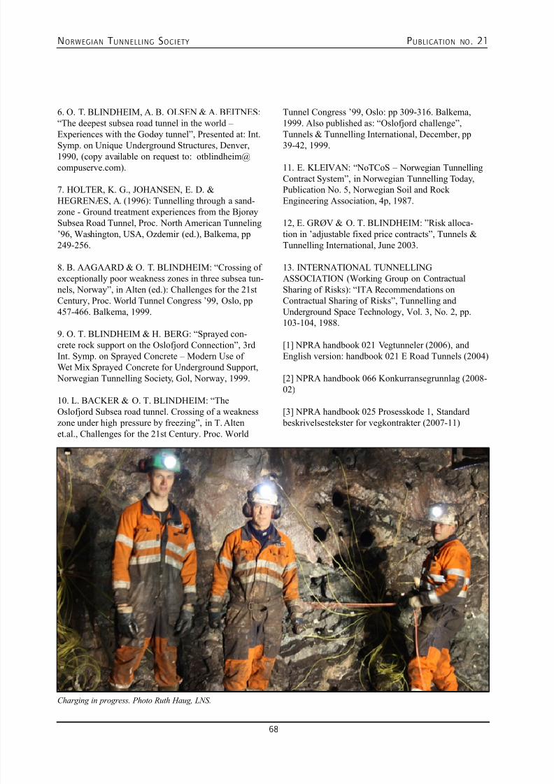
7/23/2019 NFF Publication 21 LOWRES
http://slidepdf.com/reader/full/nff-publication-21-lowres 68/94
NORWEGIAN T UNNELLING SOCIETY PUBLICATION NO . 21
68
6. O. T. BLINDHEIM, A. B. OLSEN & A. BEITNES:“The deepest subsea road tunnel in the world –
Experiences with the Godøy tunnel”, Presented at: Int.Symp. on Unique Underground Structures, Denver,1990, (copy available on request to: [email protected]).
7. HOLTER, K. G., JOHANSEN, E. D. &HEGRENÆS, A. (1996): Tunnelling through a sand-zone - Ground treatment experiences from the BjorøySubsea Road Tunnel, Proc. North American Tunneling’96, Washington, USA, Ozdemir (ed.), Balkema, pp249-256.
8. B. AAGAARD & O. T. BLINDHEIM: “Crossing ofexceptionally poor weakness zones in three subsea tun-nels, Norway”, in Alten (ed.): Challenges for the 21stCentury, Proc. World Tunnel Congress ’99, Oslo, pp457-466. Balkema, 1999.
9. O. T. BLINDHEIM & H. BERG: “Sprayed con-crete rock support on the Oslofjord Connection”, 3rdInt. Symp. on Sprayed Concrete – Modern Use ofWet Mix Sprayed Concrete for Underground Support, Norwegian Tunnelling Society, Gol, Norway, 1999.
10. L. BACKER & O. T. BLINDHEIM: “The
Oslofjord Subsea road tunnel. Crossing of a weaknesszone under high pressure by freezing”, in T. Altenet.al., Challenges for the 21st Century. Proc. World
Tunnel Congress ’99, Oslo: pp 309-316. Balkema,1999. Also published as: “Oslofjord challenge”,
Tunnels & Tunnelling International, December, pp39-42, 1999.
11. E. KLEIVAN: “NoTCoS – Norwegian TunnellingContract System”, in Norwegian Tunnelling Today,Publication No. 5, Norwegian Soil and RockEngineering Association, 4p, 1987.
12, E. GRØV & O. T. BLINDHEIM: ”Risk alloca-tion in ’adjustable fixed price contracts”, Tunnels &Tunnelling International, June 2003.
13. INTERNATIONAL TUNNELLINGASSOCIATION (Working Group on ContractualSharing of Risks): “ITA Recommendations onContractual Sharing of Risks”, Tunnelling andUnderground Space Technology, Vol. 3, No. 2, pp.103-104, 1988.
[1] NPRA handbook 021 Vegtunneler (2006), andEnglish version: handbook 021 E Road Tunnels (2004)
[2] NPRA handbook 066 Konkurransegrunnlag (2008-02)
[3] NPRA handbook 025 Prosesskode 1, Standard beskrivelsestekster for vegkontrakter (2007-11)
Charging in progress. Photo Ruth Haug, LNS.
7/23/2019 NFF Publication 21 LOWRES
http://slidepdf.com/reader/full/nff-publication-21-lowres 69/94
NORWEGIAN T UNNELLING SOCIETY PUBLICATION NO . 21
69
PROJECT CONFLICTSOne will have to search long and hard before findinganyone in the construction industry who has worked ona major project in which the parties, at all stages, were inharmonious agreement on the facts and the law associat-ed with the terms of the contract. This is not surprisingconsidering the many issues of facts and law involvedin such projects – and the importance they have for thecommercial aspects of the project.
But though disagreements and disputes are as old as project life itself, the methods for handling such com-mon occurrences are not as static. The objective of thefollowing is to look at a relatively new variant used in Norway: PRIME – Project Integrated Mediation [7].The key here is not to wait until a dispute has matured
to summon the assistance of a third party, but to involvea third party from the start of the contractual work.
A distinction can be made between conflicts that ariseduring the course of a project, that is to say, prior tocompletion, and those associated with the settling ofthe final account. In both situations, the fundamentallegal question is: Who carries the time and cost risk ofwhat is happening or not happening now, or what shouldalready have happened or not happened? And in bothsituations the parties must deal with a delightful mix oflaw and facts in an ill-fated spiral of a decidedly herme-
neutic nature [8].
However, the final account discussion has in addi-tion some particular characteristics: Claims fromthe entire project period are gathered for collectivereview, during which they are considered in the sharp,
11. PROJECT INTEGRATED MEDIATION (PRIME)
KAASEN, Knut
but at times also quite unrealist ic light of hindsight.The major issues are no longer the isolated conse-quences of delayed drawings, unmanageable groundconditions and mediocre productivity, but the collec-tive consequences of an interaction between factorswhich, even individually, may be difficult to dealwith. The key words are “productivity disturbances”, breach of conditions, exceeded rate limits and otherterms which, for many, conjure up images of numer-ous binders full of documentation, dismal progressreports and thoughtfull graphical presentations ofselected parameters.
Such exercises in “reconstructing the project” to justify or reject claims are risky. It becomes a gameinvolving an unclear evidentiary situation, huge fig-
ures and a strong element of discretionary judgement,in addition to the uncertainty inherent in contract lawitself. Although the parties to an individual disputemay typically have a different tactically based viewof the desirability of embarking on this game, thereis no doubt that usually they would both prefer to bespared the trouble. Project life becomes so miserablewhen it is discovered that this is the way things areheaded. The atmosphere becomes acrimonious, andconstructive cooperation degenerates into distrust andthe one-sided safeguarding of interests. But moreimportant than the mood is the result, which is often
that the project solutions are suboptimal.
HOW CAN PROJECT CONFLICTS BEHANDLED?Put simply, there are three ways of dealing with projectdisputes: prevent them, resolve them or ignore them.
[7] I am not aware of this term having been used before I used it in a commemorative volume for the Norwegian Association for Building and
Construction Law, På rett grunn – festskrift for Norsk Forening for Bygge- og Entrepriserett, Oslo 2010 (see page 286). It is, I hope, fairly
self-explanatory, but it will be discussed in more detail in what follows.
[8] ”The hermeneutic circle means that in order to understand something with meaning (a text, a story, an image, an action) we must, in the inter-
pretation of the individual parts, always start from a certain “pre-understanding” of the whole to which the parts belong. Our understanding
of the parts thus attained is then impacting our understanding of the whole etc.” (Store Norske Leksikon: Den hermeneutiske sirkel: http://
www.snl.no.hermeneutikk, translated from Norwegian).
7/23/2019 NFF Publication 21 LOWRES
http://slidepdf.com/reader/full/nff-publication-21-lowres 70/94
NORWEGIAN T UNNELLING SOCIETY PUBLICATION NO . 21
70
Few would recommend the last-mentioned approach: problems do not disappear by being ignored – they
multiply [9]. On the other hand, both prevention andresolution present many variants.
One of the classical tools for preventing disputes isfirst and foremost to improve the contractual basis. Wewill not look at this tool in any depth here. However precisely the contract is worded, however balanced anddynamic it is and however effective the implementa-tion of the interaction between contractual basis, priceformat and project organisation, it will of course not besufficient to avert all conflicts. It is simply not possibleto regulate and organise away from all disagreement.And even if it were possible, situations might never-theless arise where one party refuses to observe clearcontractual commitments quite simply because he seesthe consequences as unreasonable or unmanageable.
Thus, conflicts will arise, and as there is little to begained by ignoring them, they must be resolved in someway or other. In principle this may be done in fourways: the parties manage to find a solution themselves,“power prevails”, a third party assists or a third partydecides.
We shall not look at the first two solutions, but we will
look briefly at the two solution models that are char-acterised by the bringing in of a third party. As useful background for the discussion of PRIME, let us startwith the most dramatic form: A third party decides.
CHARACTERISTICS OF ARBITRATIONAND LITIGATIONThere are two different ways in which a third partymay be given decisive authority in a parties’ dispute:the parties may turn to the ordinary courts or they mayagree to submit themselves to the decision of a privatelyappointed body. If this decision is to have executory
force, the rules of arbitration must be followed [10].
In both cases, the decision will normally be based on
rules of law, [11] and the process leading up to the deci-sion will follow the basic civil procedural requirements
[12]. However, there are – in our context – importantdifferences between a hearing before the courts and ahearing before an arbitral tribunal.
The basic difference arises from the fact that an arbitralaward normally may not be reviewed [13]. As arbi-tration therefore becomes “the Supreme Court in thefirst instance” the parties are urged to leave no stoneunturned – they cannot run the risk of leaving any argu-ments and submissions unused in anticipation of further proceedings. This may drag the case out, with all theconsequences this has as regards costs and may have asregards judicial risk. On the other hand, arbitration mayopen the way for the flexible planning of proceedingsin collaboration between the parties and the court, andthis may offset the disadvantages of the parties havingonly one go. A hearing in only one instance may savetime and costs compared with a two or, at worst, threeinstance hearing in the ordinary courts [14]. Saved timeoften also means saved costs in a hidden, but quite cen-tral item: the parties’ loss of revenue as a result of tak-ing key personnel away from their regular task in orderinstead to prepare the dispute.
The other differences between the courts and arbitration
hearings are also well known and will not be describedhere beyond a brief outline of the main points. The parties are able to choose their arbitrators, which may be desirable in complex construction cases; they canthrough arbitration obtain confidentiality (provided theyagree to it, cf. section 5 of the Norwegian ArbitrationAct); and they will see more active management ofthe case from the arbitral tribunal than from ordinarycourts – in part because the procedural arrangements provide for this and in part because the arbitrators usu-ally have a better background of experience from theindustry. This may be an advantage in fact-filled cases,
which construction cases often are. On the other hand,the costs of arbitration are without doubt higher than adistrict court hearing because the arbitrators are more
[9] This is the opposite view to that held by the renowned existentialist philosopher Linus van Pelt, who through his ghostwriter Charles Schultz,
maintains that”No problem is so big and complicated that it can’t be run away from”. He does not, however, take a specific stand as regards
projects.
[10] The Norwegian Enforcement Act, section 4-1(2) d). See also the Norwegian Arbitration Act, section 46.
[11] Arbitration is a possible exception here: “The arbitral tribunal shall decide on the basis of fairness only if the parties have expressly author-
ised it to do so” (cf. the Norwegian Arbitration Act, section 31(3)), but only then.
[12] This applies also to arbitration. See the Norwegian Arbitration Act, Chapter 6.
[13] See the Norwegian Arbitration Act, section 42; cf. section 43 concerning grounds for invalidity. Decisions contrary to public policy (ordre
public) excepted, errors in the arbitral tribunal’s procedural application of law will not lead to invalidity.
[14] See the Norwegian Arbitration Act, section 21.
7/23/2019 NFF Publication 21 LOWRES
http://slidepdf.com/reader/full/nff-publication-21-lowres 71/94
NORWEGIAN T UNNELLING SOCIETY PUBLICATION NO . 21
71
expensive than a court fee, and because the case is oftendealt with in a broader manner (although the costs can
be cut by using a sole arbitrator or written proceedingsonly). On a slightly different level is the difference thatarbitration practice is often not made accessible to oth-ers, which means that the contributions which it mighthave made to legal developments are lost. However,it must be acknowledged that this situation only hasspecial significance for parties which are either highly principled or run such large enterprises that a generallegal clarification is important for them.
The possibility of choosing the arbitrators is perhapstempting, but may also open the way for fateful choices.A good illustration here is the classical difference between the parties in typical construction cases, espe-cially where the dispute arises from the final account:the owner demands that the contractor should establishchains of cause from the alleged cost consequences backto matters for which it is maintained the owner bearsthe risk, whilst the constructor invokes global consid-erations where an overall impression of the course ofthe project and the delay and cost factors are central.And whereas the owner demands that the claim be builtfrom the bottom up, the contractor maintains that itmust be justified from above, and never the twain shallmeet. So should one opt for on an arbitrator keen on
formalities who requires documentation or one with afreer approach who assumes that “there must probably be something to this”, and how does one know whicharbitrator will be what in the case in question? [15]
It is difficult to make fateful choices, especially whenone does not have an overview of the alternatives andconsequences. An important aspect of leaving the set-tlement of a dispute to an outsider is that the parties arerelieved of the burden that may be involved in having todefend a solution that they themselves have negotiatedinto existence [16]. But at the same time it is perilous to
place one’s destiny in the hands of outsiders who per-
haps do not reveal how little they have understood of thedispute and the parties’ views and needs until they come
down from on high with a binding decision – which may be a little too late. Indeed, it may well be a burden forthe parties to have control, but it may be even less desir-able not to have control.
MEDIATIONWe may therefore have a situation where the partieswish to have more control than third party decisions –even in the form of arbitration – give them, whilst theyare at the same time unable to sort matters out alonethrough negotiations. In this case, mediation is an alter-native: a third party assists, but does not decide.
This is not the place to go into details about the conceptof mediation in general [17]. However, some character-istic features must be mentioned.
On the one hand, mediation is for most parties stillsomething unfamiliar and therefore unsafe – there isuncertainty as to one’s own role and the role of the other participants, what means that the mediator has at his dis- posal, and the dynamics of the process. This is to someextent the case even when the participants have tried it before, since each mediation process is influenced bythe parties and the circumstances involved. In addition,
there is the uncertainty inherent in the positive aspect ofmediation – that the parties themselves have control ofthe outcome and (to a somewhat varying degree) of the process leading to the outcome. It may be difficult toreturn to one’s parent organisation and say that “this isthe result we have because I accepted it”.
On the other hand, what mediation in principle givesthe parties is precisely unlimited control of the out-come - they can break off mediation without groundsat any time. They also have substantial control of the proceedings, within the wide framework resulting from
the fact that mediation by its very nature is flexible both
[15] The belief that this can be predicted independent of the detailed circumstances of the case may well be the source of some astonishment.
[16] Cf. Vilhelm Aubert’s observation: ”The form of a trial, with two parties confronting one another, each of them with the opportunity to put
forward his case, and with an objective body to make decisions, gives the impression that everything which reasonably can be done to ensure
a fair solution has been done.” (Rettssosiologi, Oslo 1968, page 95, translated from Norwegian).
[17] The USA was in many respects the pioneer in developing mediation as an alternative dispute resolution mechanism, and the literature from
there is abundant. However, in Norway too, we have gradually acquired presentations and discussions of legal and practical aspects of
mediation in legal disputes, both in the form of “judicial mediation” which is conducted within the scope of the Norwegian Dispute Act,
Chapter 8 II (see immediately below), and pure ad hoc mediation. See, for example, Anne Austbø and Geir Engebretsen: Mekling i rettskon-
flikter: rettsmekling, mekling ved advokater og mekling i forliksrådene og konfliktrådene (2nd ed., 2006), Per M. Ristvedt and Ola Ø. Nisja:
Alternativ tvisteløsning (2008), Kristin Kjelland-Mørdre (ed.): Konflikt, mekling og rettsmekling (2008) and Knut Kaasen, “ ‘Gaaer hen og
forliger Eder, I skabhalse’, Noen avveininger ved bruk av alternative tvisteløsningsformer”, Tidsskrift for forretningsjus (Journal of Business
Law), 1998, pp 3-19.
7/23/2019 NFF Publication 21 LOWRES
http://slidepdf.com/reader/full/nff-publication-21-lowres 72/94
NORWEGIAN T UNNELLING SOCIETY PUBLICATION NO . 21
72
as regards form and content. The criteria for resolutionare also flexible; whilst the courts (for the most part) are
bound by what they see as the relevant rules of law [18],there is nothing to stop mediation being based on a freerapproach to the parties’ interests.
In its role as a form regulated by law, judicial mediation[19] is in a class of its own [20]. The solution set forthin the Norwegian Dispute Act is that the court – afterhaving heard the positions of the parties – may, pursuantto section 8-3, decide that judicial mediation is to take place in accordance with the provisions set forth in sec-tions 8-4 to 8-6 of the Act, even if one of the parties tothe dispute disagrees. The mediator may be a judge ofthe court in question or “a person from the court’s panelof judicial mediators (section 8-4(1)). The Act requiresthat a panel of judicial mediators be established for this purpose, often a common panel for several courts. Therequirements made of the selected persons are that they“should together cover the range of expertise requiredfor judicial mediation before the court” and that theyhave “the qualifications necessary to act as judicialmediators” (section 8-4(4)).
A “PROJECT TWIST” TO THECLASSICAL CONFLICT RESOLUTIONMETHODS.
After this summary overview of important features oflitigation, arbitration and mediation, we now have a basis on which to make some observations concerningour point of departure, which was that typical construc-tion disputes have important features in common whichare of significance for how they may most expediently be resolved, regardless of whether the dispute arisesduring the project or not until the settling of the finalaccount.
In this connection it is also useful to distinguish betweenmodels in which a third party decides and those in
which he or she is merely of assistance.
Neither ordinary litigation nor arbitration brings any-thing new to the problems associated with the settling
of the final account. They are methods of classical legaldispute resolution through classical proceedings basedon the principle of audi alteram partem (both partieshave the opportunity to comment on the views of theother before the case is settled). It is different if the dis- pute arises during the project and must be resolved thereand then because the contract’s system forces the partiesto do so (preclusive lawsuit time limits etc.), or becausethe project needs drive (management speed). In suchsituations, there are weaknesses associated with litiga-tion and arbitration as resolution models. They takeup time and attention in a situation where both are inshort supply, and they do not provide solutions that the parties can readily embrace as the basis for their furtherwork. Moreover, the parties must perhaps be more thannormally professional in order to avoid the lawsuit’s for-malisation of the dispute creating an uncooperative andless than solution-oriented atmosphere between them.Such effects are difficult to demonstrate in a measur-able form, but may be far more serious than the strain ofspending many hours dealing with the lawsuit.
The mediation model where a third party assists withoutmaking a decision appears as less disruptive. In gen-eral, this form is not highly resource-demanding, partly
because it is flexible and subject to the parties’ control asthe mediation progresses, but primarily because it doesnot entail “all or nothing” where everything is staked onone card at an early stage of the game. These are goodcharacteristics, in particular in dealing with disputes dur-ing the course of the project. In this phase, full advantagemay also be derived from another important propertyof the mediation process: as a rule, it does not createthe same antagonism that a lawsuit tends to do; there isless disturbance of the focus of the project. And if themediation is successful, what originally was a strain isturned into something positive – the parties, by working
together, found a solution with which they can both live.
[18] As Aubert stresses, “the courts [cannot] deal with the dispute as a pure conflict of interests, in the same way as the parties to a purchas-
ing agreement can. The conflict of interests must couched in a form which at the same time makes it a disagreement about rules of law or
about actual facts. … The court has only a limited opportunity to give weight to the parties’ interests.” (Rettssosiologi, Oslo 1968, pp 92-93,
translated from Norwegian).
[19] “Judicial mediation” follows provisions set forth in the Norwegian Dispute Act, sections 8-4 to 8-6, and the designation should only be used
for this form of mediation. We do not have an established term for mediation of legal disputes outside the courts. “Mediation” is strictly
speaking too imprecise since the word also – and traditionally perhaps most frequently in a Norwegian context (“megling”) – is used to
denominate conflicts of interest as opposed to those of law. However, the context normally makes it clear what is meant, as in “Project
Integrated Mediation”.
[20] Anne Austbø (Tvistelovbrev nr. 8 (2007) points out that “the central role of mediation is emphasised by the name of the Act: ‘Act relating to
mediation and procedure in civil disputes’. The Civil Procedure Reform Committee saw the question of whether it is possible through rules
in the Dispute Act to pave the way for creating a climate and culture for amicable settlements as crucial.” (Translated from Norwegian.)
7/23/2019 NFF Publication 21 LOWRES
http://slidepdf.com/reader/full/nff-publication-21-lowres 73/94
NORWEGIAN T UNNELLING SOCIETY PUBLICATION NO . 21
73
These positive effects can be reinforced if mediation isnot just used ad hoc, but is made a part of the project, in
recognition of the fact that disputes, and hence a needfor mediation, normally are not one-off phenomena in projects, unlike in the case of, for instance, a pure pur-chase agreement.
This model of mediation seems to be gaining groundinternationally. In its Norwegian variant it has beenin use for some years – although not everyone in theconstruction industry seems to be acquainted with it.Phenomena should have a name, and in this instancea fitting name may be Project Integrated Mediation(PRIME).
WHAT IS PROJECT INTEGRATEDMEDIATION (PRIME)?A brief presentation
In essence, PRIME consists of three elements: (a) oneor more mediators (b) are drawn into the project fromday one (c) to maintain continuous contact between the parties, regardless, in principle, of whether there areany conflicts at the time. These simple and straightfor-ward elements provide the basis for a broad spectrumof methods for conflict resolution because a forum isformed which paves the way for a flexible approach tothe dispute.
Project Integrated Mediation does not normally meanthat conflicts are prevented – it is all about handlingconflict [21]. Furthermore, PRIME means that outsidersare drawn in. The model therefore differs from resolu-tion models based on the involvement of levels over the project organisations on both sides, for example in theform of a “bosses’ forum” or a “contract forum” com- posed of personnel other than those who are running the project (see section 2 above).
Lastly, PRIME is in place from the outset. This means
that the mediator becomes acquainted with the contract,the project, the challenges and the personnel before thegoing gets tough, and the parties get to know the media-tor. Two advantages are thus obtained: the threshold for bringing disputes (or signs of disputes) before PRIMEis lower than the threshold for issuing a writ, and themediator already has sufficient understanding of thesituation to be able to provide effective help swiftly. Inthis way, the frictions of project life are dealt with atthe lowest possible level of conflict. Success here willmean that a great deal has been achieved.
In what follows we shall look in more detail at how thePRIME form can be developed, some foreign variants
and some experience of PRIME in Norway, before weconclude with a few evaluations: does PRIME haveanything to offer?
VARIABLES IN THE SHAPING OF PRIMEThe PRIME form per se lays down virtually no bindingguidelines for the basic choices the parties must makewhen establishing the scheme. Certainly, there are somewho hold “orthodox” views and believe that certain pat-terns must be adhered to, but I am not one of them. Asin other mediation, the basic view that “purpose governsform” prevails. The purpose is to help the parties builda sufficiently secure basis on which to make choicesthey can defend – whether it be to settle (which is ofcourse the most agreeable) or not to settle (which insome situations may nevertheless be the best solution).Within the bounds of reason, there are seldom groundsfor imposing special constraints on the choice of formin order to reach this goal.
A fundamental question is whether the mediator should be nothing more than a go-between or whether he orshe should also – possibly under certain conditions – beable to make decisions which are binding on the parties.This question is one of practical importance, but not
for the reasons one would expect (and which result in agreat deal of effort often being put into defining condi-tions for and effects of binding opinions from differenttypes of “dispute resolution boards”). In my view, the point is that binding opinions must be based on neutral proceedings in which both parties are heard, which inmany ways resemble the process leading up to an arbi-tral decision (or for that matter, a district court ruling).This lays down constraints which are not so readilycompatible with effective mediation. For example, itis difficult to hold separate meetings with the parties ifthe aim is to provide a binding opinion, rather than help
the parties agree upon a solution. One must thereforechoose at a relative early stage in the handling of adispute whether to aim at one or other form of contribu-tion from a third party. If the choice entails refrainingfrom using the means that effective mediation calls for,the advantages of this flexible system will be replaced by the disadvantages of a “mini arbitration”, which wehave looked at in brief in section 3 above.
Experience seems moreover to suggest that the ques-tion is more one of principle than practice. Even where
[21] But here it is tempting to speculate: A standing, effective mediation scheme will probably give rise to various types of impulses capable of
neutralising conflicts which under otherwise identical conditions would have come into full bloom.
7/23/2019 NFF Publication 21 LOWRES
http://slidepdf.com/reader/full/nff-publication-21-lowres 74/94
NORWEGIAN T UNNELLING SOCIETY PUBLICATION NO . 21
74
PRIME is required to be able to result in binding deci-sions, it is unlikely that this is what will happen. Instead,
the mediator’s advice and guiding viewpoints on the basis of procedures in which both parties are heard are perceived as such powerful signals that the question offormal binding is not pushed to its logical extreme.
A more important practical question is therefore howmany mediators should there be – one or three [22]. Thecost aspect is of course of some significance here, butmore importantly three mediators will be able to addgreater dynamics and breadth to the mediation than onewould. But the most important aspect is perhaps thatit may be difficult to find one person who covers alltypes of knowledge for which there may be a need insuch a long-term situation. Legal practitioners have, aswe know, good all-round versatility, but engineering or project administrative skills would obviously strengthenthe team. This is not least a question of the mediator’slegitimacy in the project.
With three mediators, such considerations may beaccommodated. However, if the decision is made tohave one, priorities must be established. The distinctivecharacter of the project may suggest otherwise, and ofcourse the individual qualifications of experts vary agreat deal, but I think, as a general rule, that it is never-
theless easier to teach a legal practitioner what he needsto know about technology, finances and project man-agement in order to help with dispute resolution thanto teach an engineer, economist or project administratorwhat he needs to know about the law in order to do so –to the extent that it is felt the process should have sucha foundation. But the best solution will often be to sayyes to “having one’s cake and eating it”.
The approach to the work involved in PRIME is thusgoverned by the purpose. Procedure and means areclarified underway as mediators and parties work
together, and the whole arsenal of mediation weapons isavailable. The method used in the preliminary handlingof a dispute is seldom the same as that used in the con-cluding phase leading up to the moment of truth – andmay range from “a good conversation” to a “hammer-and-tongs” discussion via signals of the strength of
positions and arguments. But some fixed points must be established. Firstly, the conditions for and effects of
formal opinions or decisions from the mediators aboutquestions that might have to be brought before them fordecision should be considered thoroughly and set out inwriting. Secondly, the ground rules for the mediation process should be clear and agreed upon. These includeimpartiality, ensuring both parties are heard, opennessabout the process at every stage (but of course notalways about substance), and the freedom of the partiesat any time to oppose further mediation – including arecommended outcome.
The intensity of meetings between mediators and partieswill of course vary depending on the type and phase ofthe project and the level of conflict. But PRIME pre-supposes that there is no waiting until the conflicts aredefined as such – before that stage is reached, insight,trust and forms of communications should be built up.Moreover, one of the points of PRIME is that the partiesdo not need to initiate dispute handling by defining anoutstanding issue as a dispute. They can “air” the matterearlier and through their relatively regular contact withthe project, the mediators will also acquire a foundationfor intervening in matters at an early and preferablyquite informal stage.
INTERNATIONAL INSPIRATIONPRIME is not a purely Norwegian invention. Althoughan early variant was introduced in some of the petro-leum contracts in 2000 [23], previous traces of the ideacan be found internationally, for example, in the FIDICcontracts. However, developments first truly gathered pace when private organisations marketed dispute reso-lution boards as an option in (particularly) internationalcontracts and at the same time established a milieu fordeveloping clauses, methods and exchange of experi-ence. A couple of examples may be mentioned briefly by way of illustration.
Both the International Chamber of Commerce (ICC)and the Dispute Resolution Board Foundation (DRBF)have developed rules for dispute boards [24]. The mainfeatures of these rules are similar. The parties to acontract appoint a dispute board, usually consisting of
[22] More than three is of course in principle also possible, but will be costly and inefficient. Two may be a better alternative, but problems may
then arise if binding opinions are to be issued. See immediately below.
[23] See the Norwegian Total Contract (Norsk Totalkontrakt - NTK) 2007 Article 37 with regard to the “arbiter” (who, unlike the umpire in the
Norwegian Standards, follows the PRIME pattern, and therefore should have a different title in order to avoid confusion). The scheme has
been used in a couple of major offshore projects.
[24] See respectively http://www.iccwbo.org/uloadedFiles/Court/Arbitration/other/db_rules_2004.pgf (ICC’s rules from 2004) and http://www.
drb.org/manual_access.htm (DRBF’s manual from 2007).
7/23/2019 NFF Publication 21 LOWRES
http://slidepdf.com/reader/full/nff-publication-21-lowres 75/94
NORWEGIAN T UNNELLING SOCIETY PUBLICATION NO . 21
75
three independent persons. The board is not an arbitraltribunal, and its advice or decisions cannot be legally
enforced, but its powers may range from providinginformal assistance to making decisions.
The parties choose the role they would like the board tohave by agreeing on one of the three alternatives defined by the rules (here using the terminology of the ICCrules) [25]. The first alternative is a Dispute ReviewBoard which issues recommendations to the parties.The second option is that the board is established as aDispute Adjudication Board which issues decisions indisputes brought before it, whilst the third alternative isa Combined Dispute Board which does not go beyondmaking recommendations unless one party requests adecision and the other party does not oppose this.
The ICC rules acknowledge the need for more flexibleforms of assistance from a dispute board than wouldnormally fall under one of these three alternatives.When the parties are in agreement, the Dispute Board(DB) can assist the parties in an informal manner by“conversation among the DB and the Parties; separatemeetings between the DB and any Party with the prioragreement of the Parties; informal views given by theDB to the parties; a written note from the DB to theParties; or any other form of assistance which many
help the Parties resolve the disagreement”. In this form,the ground rules are set for the dispute handling methodwhich in practice characterises PRIME in Norway,where neither formal statements nor decisions are usual.
It may be natural to apply the rules pertaining to dis- pute boards in international contractual relationships,and they can also without doubt serve as inspiration.However, for purely Norwegian conditions they are per-haps not so necessary. Moreover, the division betweenthe alternative forms may be rather rigid.
WHAT SPEAKS FOR AND AGAINSTPRIME?As has, I hope, been demonstrated above, PRIME hassome distinct advantages. The approach entails a lowthreshold for a flexible and swift handling of potentialand ongoing disputes in projects. PRIME can therefore be an effective tool in efforts to smooth the way forconcentrating on the essence of the project.
However, objections are conceivable.
One objection may be that the parties, by bringing ina third party, expose their positions, arguments and
priorities in a way that binds them and may thereforeinhibit agreement. However, this will of course also be the case when the parties negotiate directly, withoutassistance from a third party. It is precisely this immedi-ate link between taking a position and exposing oneselfthat often prevents the parties from reaching a solutionthrough direct negotiations. A third party can break thelink – a party does not need to expose itself directlyto the opposing party, just to the mediator. One of the principally most important features of mediation is thatthe mediator is a filter between the party’s concessionand the consequence thereof.
More prosaically, it could be objected that PRIMEimplies the parties using unnecessary resources on dis- pute handling before there is any dispute. However, theresources (costs involved in having mediators and one’sown invested time) are only a waste or disproportionateif it is assumed that there will be no dispute in the courseof the project, or in any case that the benefit of handlingthe dispute using PRIME is not commensurate with theinvestments in the model. Neither of these assumptionsseems particularly convincing. It is beyond questionthat one court or arbitration case saved by far outweighsthe possible costs of the PRIME alternative. In a sense
there is a certain parallel in the catch phrase “If youthink knowledge is dear, try ignorance!”
A more fundamental objection might be that PRIMEleads to unfavourable solutions, either in that the partiesare duped into accepting results they do not want, butfail to resist, or in that the solutions are divorced fromthe dictates of the contract and the law. Here we come back to the intricate issues previously mentioned (sec-tions 3 and 4) which concern the parties’ control of thedispute and the relevant considerations involved in theirdecision. Certainly, cases are imaginable where there
is an imbalance in the relative strengths of the parties(in general or in specific situations, based on, for exam- ple, liquidity requirements or the qualifications of key personnel) that may result in their failing to representtheir own interests in a dispute. However, the sort ofexposure that this will subject a party to during media-tion will also be felt in negotiations without the assis-tance of a third party – and perhaps at least to the sameextent. Admittedly, a mediation scheme may, in givensituations, result in a pressure to which the party wouldnot have been exposed in direct negotiations, but the
[25] See the following ICC Dispute Board Rules (as at 1 September 2004), in particular Articles 4, 5 and 6, respectively.
7/23/2019 NFF Publication 21 LOWRES
http://slidepdf.com/reader/full/nff-publication-21-lowres 76/94
NORWEGIAN T UNNELLING SOCIETY PUBLICATION NO . 21
76
scheme may also help the party consider positions andalternatives more appropriately than it could do alone.
Thus, what must be central is the party’s own choice.As long as PRIME can never force a party to some-thing it does not want, it cannot be a weighty argumentagainst the scheme that in a given situation it will lead tothe party being exposed to pressure and may provide the basis for solutions other than those that would presum-ably have followed from rules of law alone.
Here, there is a practical consideration: Disputes in large projects may of course relate exclusively to the law, but just as often they involve a substantial factual content.The idea that the contract and contract law give preciseanswers may in some cases be quite exaggerated. Thismeans that a considerable risk is involved in pushingissues to their extreme, especially where the settlementthereof tends towards either/or more than a sliding scaleof discretion. A risk-reducing approach to the disputewill therefore often in fact involve gradually identify-ing relevant factual and legal aspects whilst continuallyevaluating the consequences they will have, and on this basis make broader assessments of acceptable outcomes – that is to say, “assisted negotiation” where the media-tor is responsible for the assistance [26].
On a slightly different level is the objection that PRIME
may provoke disputes that would otherwise not have become a problem. The parties are forced into establish-ing and justifying potential differences before they andthe differences are ready for it. In response to this, thereis little one can say other than that if PRIME works inthis way, both the mediators and the parties have failedin their fundamental task – to cooperate on a process. Naturally this may happen, but obviously not as an inevi-table consequence of entering into mediation. Quite thereverse: the very object of PRIME is to find the simplestand most efficient method of handling potential disputes – and then to use this method until a joint decision is
made that it should be changed. If this can be achieved, potential disputes will not become greater than theyshould and must be.
It is perhaps more likely that the threshold for bringing anissue before the mediator becomes too low – the partiesare not subjected to sufficient pressure to reach a solutionat a lowest and earliest level. It may be very helpful tohave to identify and objectify the issues with a view to presenting them to a third party, but at the same time there
is a danger that the higher up in the hierarchy one comes,the greater the ignorance of the facts from which the issue
has arisen. Again, the answer has to be that parties andmediator must cooperate on appropriate forms – includ-ing referring the issues to continued negotiation.
The last objection to PRIME which will be mentionedhere relates to the more indefinable effects of the meth-od: the common “project spirit” is undermined whenthe parties are unable to solve their problems them-selves. And this is an effect that also simply cannot bedismissed. However, all experience suggests that whenthe parties do not manage alone, it is better that they col-laborate on a solution together with one or more media-tors than that they enter a straight confrontation with asubsequent court decision. The dispute that took focusaway from the project and was a strain on the spirit ofcooperation and everything good is turned into some-thing positive, building on the relationship between the parties at the instant they – each with their “hand on thewheel” – succeed in finding a solution they both can livewith. The strain becomes a strengthening.
This requires realism – which may be challenging tocultivate without substantive confrontation: Does thisviewpoint hold? Is my factual understanding adequate?What are the consequences of being wrong, etc? A
major contribution of PRIME is that the process forcesthe parties to adjust their views in the course of the project. – it is not easy to maintain an untenable viewthrough to the settling of the final account.
AN ILLUSTRATION: THE NORWEGIANPUBLIC ROADS ADMINISTRATION’SBJØRVIKA PROJECT.To the best of my knowledge, the Norwegian PublicRoads Administration was the first public owner to putto use the mechanism that in this article I call ProjectIntegrated Mediation. This happened in the Bjørvika
project in the centre of Oslo, a project joining two tun-nels and a main road (the Festning Tunnel, the EkebergTunnel and Mosseveien (E18)), and involving threemain contracts totalling some NOK 3.5 billion [27].In each of the three contracts a “dispute board” – laternamed the Conflict Resolution Board (CRB) – consist-ing of the same three persons appointed jointly by thecontracting parties, was established [28]. From imme-diately after the signing of the individual contracts, theCRB acted as a supplement to the other conflict resolu-
[26] See a description in Kaasen, “Gaaer hen og forliger Eder, I skabhalse” (see Note 11 above), page 14 seq.
[27] See http://www.vegvesen.no/Vegprosjekter/Bjorvika for an overview of the project.
[28] The following description is based on my experience as leader of the Conflict Resolution Board.
7/23/2019 NFF Publication 21 LOWRES
http://slidepdf.com/reader/full/nff-publication-21-lowres 77/94
NORWEGIAN T UNNELLING SOCIETY PUBLICATION NO . 21
77
tion methods in the contracts (which are based on NS(Norwegian Standard) 3430).
According to the contracts, the purpose of the schemeis to “assist the parties in issues where disagreementarises concerning contractual matters (not technical), by a) giving informal advice when both parties agreeto it, and b) implementing a formal process of conflictresolution at the request of at least one of the parties”.As a general rule, the conclusion of the conflict boardshould “have the character of non-mandatory advice”which only becomes binding on the parties if they donot object within a specified time limit. Objection maylead to fresh negotiations between the parties or a courtor arbitral tribunal hearing in accordance with the ordi-nary rules of the contract.
Disputes may be brought before the dispute board within30 days after notice is given of the other contracting par-ty’s rejection or “unsatisfactory standpoint”, otherwise“the claim is lost”, whilst the dispute board should givenotice of its view within 90 days after the parties have put forward their written presentations of the case. Thecontracts say little however about the working methodsof the Conflict Resolution Board, beyond stating that the parties have the right to be heard and the right to hear.But the parties “should agree on a set of rules for the
appointment, mandate, procedures and working methodof the dispute board”. Unless otherwise agreed, this setof rules should “follow internationally published rulesfor dispute boards or dispute review boards with refer-ence rules published by the ICC on 1 September 2004”,that is to say, the rules mentioned in section 6.3 above.
No further agreements as to the dispute handling methodof the CRB have been made. However, each of the threemembers of the CRB has entered into an agreementwith the parties in each of the construction contracts.In these agreements, it is stipulated that the CRB is to
operate in accordance with the said frameworks set forthin the contracts and otherwise as agreed by the parties –implying ad hoc [29]. These ad hoc arrangements havein practice developed into a pattern for the CRB’s work.
The most important elements in this pattern are iden-tification, facilitation and processing of (potential)disputes.
Identification involves establishing mechanisms forcatching the disputes in time. As mentioned, general
project experience indicates that problems do not dis-appear simply by being ignored, they multiply. The
mechanisms for bringing them to the light in the CRBare quite banal: the threshold for identifying them must be made as low as possible by establishing trust so thatopenness is not seen as unprofessional or a loss of face,and furthermore there must be practical ways of doingthis.
Trust can only be built up over time: it is perhaps herethat Project Integrated Mediation shows its greateststrength compared with ad hoc mediation. On the prac-tical side, the “concerns list” tool has proven to be effec-tive. Before each meeting with the CRB, the parties – preferably jointly, but if necessary separately – submita list of aspects of the project which “concern” themat the time, with brief documentation attached whereappropriate. The concern need not mean that there isan established conflict, still less that it is not possibleto resolve the situation through ordinary negotiations.What is decisive for whether a matter belongs on thelist is whether the party or parties think that they see amatter which might prove difficult. This may be quitefundamental matters such as difficulties in establish-ing a revised progress plan after many different typesof interruptions in progress, or limited issues as, forinstance, the criteria for pricing a defined variation job.
Facilitation consists of the parties and the CBR jointlyfinding a suitable way of dealing with the concerns list.Some points on the list are simply noted at the presentstage, but followed up on later lists. Other points may be taken up more or less spontaneously: the parties givean account of their view and what they base it on andthe CRB acts as “agents of reality”, without expressinga view, whereafter the parties find a solution. And stillother points on the list clearly need better preparation before anything meaningful can be done with themin a CRB context. The parties must discuss among
themselves to clarify exactly what the disagreementconsists of, they must find documentation and presentarguments, or external factors such as requirements set by the authorities must be clarified. Facilitation maytake place from one CRB meeting to the next, or it maystretch over a longer period of time. But the object isthe same: the parties and the CRB must acquire a clear-est possible picture of what the issue relates to in orderthen on this basis to cooperate on how it best may bedealt with.
[29] Moreover, it is stipulated that the CRB member cannot be relied on as a witness in later disputes concerning matters dealt with by the CRB,
and that concessions made in the CRB cannot be relied on in later disputes.
7/23/2019 NFF Publication 21 LOWRES
http://slidepdf.com/reader/full/nff-publication-21-lowres 78/94
7/23/2019 NFF Publication 21 LOWRES
http://slidepdf.com/reader/full/nff-publication-21-lowres 79/94
NORWEGIAN T UNNELLING SOCIETY PUBLICATION NO . 21
79
DOES PRIME WORK?We are gradually beginning to have some years’ experi-
ence with Project Integrated Mediation. Contracting – particularly in the public roads sector – seems to date tohave used the scheme the most, but examples are alsofound in data deliveries and offshore fabrication – withthe latter sector being the first to systematically use thesystem [32]. Although it is difficult to have a clear over-view, the trend seems to be that more contracting partiesare now using PRIME.
For obvious reasons, nobody can have a certain opin-ion as to how successful PRIME is in general. Jungletelegraphs are rarely clear and unequivocal. But in thisinstance they can hardly be said to give particularlynegative signals; quite the reverse. Most recorded feed- back from parties and mediators is positive. PRIME is perceived as flexible and swift assistance with a lowthreshold, which is therefore worth considering in rec-ognition of the fact that disagreements occurs in major projects and that it is costly to allow disagreement todrift unresolved.
This feedback is not surprising. A characteristic ofPRIME is that the arrangement is a structured arena forflexible handling of large or small pebbles in the shoeof a project. Those wearing the shoe have the lead in
choosing how the pebbles are to be removed, but theyreceive skilled assistance from persons who know the project and its challenges without being parties, andwho have an insight into the tools available for remov-ing pebbles. The point is this that the contract estab-lishes the arena, the rest is sorted out underway. Theframework is fixed, the content flexible.
If one is successful in establishing good collaborationfor problem resolution without allowing the fact thatone has problems to be a distraction, then much willhave been achieved. PRIME is a suitable means for
reaching this goal.
[32] See Kolrud, Ny standardkontrakt for offshoreleveranser, NTK 2000 - Norwegian Total Contract 2000. Tidsskrift for forretningsjus
(Journal of Business Law), 2000, pp 57-66, on page 66 re “a wise man on site”. For further details, see Kaasen, Petroleumskontrakter
(Universitetsforlaget 2006) pp 877-881.
7/23/2019 NFF Publication 21 LOWRES
http://slidepdf.com/reader/full/nff-publication-21-lowres 80/94
NORWEGIAN T UNNELLING SOCIETY PUBLICATION NO . 21
80
7/23/2019 NFF Publication 21 LOWRES
http://slidepdf.com/reader/full/nff-publication-21-lowres 81/94
NORWEGIAN T UNNELLING SOCIETY PUBLICATION NO . 21
81
INTRODUCTION New generations of tunnels will meet new challengeswithin such aspects as environmental impact, enclosedsites and neighbour concern. Traffic tunnels in particularare subject to enhanced requirements with respect tosafety and serviceability. Cost of operation and mainte-nance has for some owners become a night-mare. At thesame time, there is an inspiring development in materi-als and methods driven by other industrial sectors, suchas telematics, oil recovery, building and kinematics. Onething is for sure, the challenges of tomorrow do call forother solutions than those of yesterday.
Our endeavour should be to make the development hap- pen in an optimized degree and pace. Clients need totone down or leave some of their codes of practice and
to challenge the consultants and research institutes forimproved technology. But lowest possible price in everyaspect and fear of risk are two enemies of technicaldevelopment. The same goes for a bureaucracy wherethe employees find their comfort primarily in sticking tocodebooks. Focus on functional requirements and LCCwould be an improvement, however with limitations.
Could a new practice in contracting also boost thedevelopment? This paper is aiming to bring forward adiscussion of whether and how different requirementspecifications and different tender and contract manage-
ment practice can bring more prosperous business forthe contractors as well as serving the market with moresafe and cost efficient tunnelling, enhanced functional-ity, improved safety and lower maintenance cost.
WHERE COULD WE IMPROVE AND WHAT COULD BE GAINED BY WHATKIND OF DEVELOPMENT?• More safe and cost efficient tunnelling
- Completion of rock support and safety installationsat the tunnel face may provide a safer and morecomfortable working ambience. Working conditionsat the tunnel face are better because of the fresh air
support, good working light and less traffic hazard.
12. TOWARDS FUTURE TUNNELLING
PROSPECTS AND CHALLENGES OF DEVELOPMENTORIENTED TUNNEL CONTRACTS
BEITNES, Anders
- Worksite close to the tunnel advance face mayalso provide conditions for improved quality/ lessmistakes and faults in the permanent structures andinstallations, as this is the section where we have bet-ter survey, more versatile production units and alsothe best experienced and productive crew.
- For a typical highway or rail tunnel, the excavation& rock support do represent less than ½ of the totalvalue of the product. If a major part of the “furnish-ing” could be produced by the same plant and crewwithin the sequence of tunnelling, its productivitywould boost and at the same time give room for arelief on the stress for quickest possible advance.
- Sprayed membrane for water insulation integratedwith shotcrete lining is an example of solution whichis perfect for early completion.
- A relief in advance pace is furthermore an importantfactor for achieving high quality in time-consumingoperations such as leakage control.
- Introduction of non-petrol-fuelled machinery andtransport systems is important both for internal HESand external and global environment.
• Less environmental impact
- As indicated above, high quality in leakage controlnormally does require significant time. And require-ments do typically become more and more strict (tothe safe side). This is due to more restrictive legisla-
tion and a higher awareness among governmentaland political representatives after exposed “scandals”where certain localities experience negative impactsin biotopes and vulnerable groundwater systems. Theresponse from tunnellers must be more consistentand thorough technology, competence and perfec-tion in all leakage control work. Most effective isenhanced ability to choose and perform correct drill-ing pattern, materials and procedures for pre-groutingin actual rock mass conditions. This will gain boththe result and the economy.
- Fumes and exhaust from blasting and diesel engines
may harm the local environment and CO2 emis-sions should be reduced also by the tunnelling
7/23/2019 NFF Publication 21 LOWRES
http://slidepdf.com/reader/full/nff-publication-21-lowres 82/94
NORWEGIAN T UNNELLING SOCIETY PUBLICATION NO . 21
82
industry. Use of emulsion explosives and electrically propelled units (like transport belt) are among the
adequate measures in this aspect.- Emissions of pollutions and suspended mud from atunnel site to a sweet water recipient (or municipal pipe systems) do from time to time cause severe con-cern and very costly clean-up situations. It may clearly be put higher emphasis on the purification systemson released drainage as well as cleaning of the roadconditions inside a tunnel drive and the out-door yard.
- The visual impact of tunnel entrances is often quite brutal. This is not necessary if one could minimiserock cuts by exploiting the possibility to “sneak”tunnels in under a site specific collar of cast-in–placeconcrete, soil backfill and re-vegetation at an earlystage.
• Enhanced or combined functionality
- To-days code of practice is a collection of singlesolutions and improvements for single functionsor problems. Creative focus on the whole range offunctional requirements or expected performance ofa tunnel throughout its prospected service time maylead to more cost effective solutions. Some exam- ples:
- Pre-manufactured wall linings may be developedfurther to contain fixing for light, ducts for cables
and safety installations. Also, they may act as a per-manent formwork and easily maintained coating forcompact cast–in-place rock support with drainingand frost insulation ability!
- Ducts for washing and drainage are normally placed beneath the gutter and require frequent deep sandtrapswhich need to be emptied in the maintenance cam- paigns. Such deep pits often constitute a problemin rock tunnels, as they require extra blasting whichmay damage the pre-grouted zone of the invert. Andthe problem may be larger in tunnels in poor rockconditions, where it creates weak points in a water-
tight concrete invert. A potentially fruitful conceptwould be to introduce a centrally oriented precastduct of such size, shape and alignment that it acts asa longitudinal, self-cleaning sandtrap. Run-out could be in a thoroughly designed stilling basin at the lowerend of the tunnel (or adjacent to the pump basin).
• improved safety
- In single tube tunnels, which still will be a viableconcept for county roads, the hazard rate causes con-cern (even if it is less than on open roads), and thenvery much connected to potential meeting accidents.A concept for lane division could be of interest,
provided it may be retracted or folded for occasionalcrossing in emergency situations.
• lower maintenance cost
- Some of the above suggested technical elements will
contribute substantially to reduction of maintenancecost, e.g. super-smooth wall surface, self-cleaning flushwater systems, improved protection of cable ducts.
- For road base maintenance, it has been experienced both frost heave and reduced bearing capacity due tohigh contents of fines in the sub-base. The clue will bea good, consistent drainage layer and strong enoughor stabilised material in the sub-base. A consistentdrainage layer may come from coarse fractions oflocal tunnel spoil, stabilised by use of cement. Thatwill constitute an excellent road base for the excava-tion phase, provided there is a solid road surface or a provisional dirt surface which is separated by use ofgeotextile.
WHAT ARE THE HINDERING ASPECTSAND MECHANISMS?Given that these and many more examples point out prospects for “better” tunnels and tunnelling, it will be of common interest to the public and to the indus-try to find out what is holding this development back.Probably no single person understands this to its fulldepth. I am quite sure that a lot of the explanation isconnected to comfort in old practice (conservatism) anda lack of procurement, contract and specification codes
that may allow for new ideas. A little closer look tosome of the elements is indicated below:
• Lowest possible price
- In every aspect of procurement and purchase fordesign and construction there is an endeavour to seeklow expense for every service and item, as this mayseem to give improved budget control.
- Even with a view on long term costs and properinvestment analyses, the financial aspect tend to give poor solutions because of too high internal interest inthe models for calculations. (“Do not care about what
happens in 20 years, the present value of costs at thattime is close to zero.”)- Services and items that bring smarter solutions as
well as improved quality and long-life performancenaturally will have a higher up front expense.
• Fear of risk both by bureaucracy designers, checkers
and contractors - It takes courage to stand for new ideas and unproven
technology.- Proper risk evaluation has not become an every
day’s tool in all positions where decisions are taken.Particularly missing is the art of seeking upsides and
possibilities as an addition to the assessment of haz-ards and their probability.
7/23/2019 NFF Publication 21 LOWRES
http://slidepdf.com/reader/full/nff-publication-21-lowres 83/94
NORWEGIAN T UNNELLING SOCIETY PUBLICATION NO . 21
83
- In all organisations, there are people who tend to beor become risk aversive in their attitude. And you’ll
find them more often in those positions where onehas the duty to control or approve, more than in the“invention department”.
- In the business of design and consultancy, it isimpossible to utilise only the progressive, creativeand brilliant people. Young people with a lack ofexperience and/or proper guidance understandablyfind it more convenient to use copy-paste morethan individual and original design. My observa-tion is, regrettably that also well experienced advi-sors tend to stick to that solution, much because ofthe cost and resource aspect, but also because offear of risk.
- Traditional builders (tunnel builders are no excep-tion) are far too afraid of technical and financial risk.Securing a small overhead in a chain of well-known processes and distributed risk is more often the prin-ciples than going for a huge surplus with a certain probability of downside.
• Tender practice
- Traditional procurement regulations (and this isstrengthened by revised national standards strictlyadhering to EU rules) make alternative solutions problematic or even reason for disqualification when
a completed design is the basis.- EPC [33] contracts are the natural answer to this,
as they have a clearer base for utilising functionalrequirements as the specification level in the BoQ[34] and therefor allow or even favour new andsmarter solutions. There are at least four problemsthat prevent such contract practice from becoming asuccess regarding technical development:1. Functional requirements may have only indica-
tive or relative quality parameters, unlike processspecifications where strength and dimension can be controlled exactly. Not without reason, there is
a fear of championship in cheating the system. 2. Contractors who are put to manage the designertend to look upon that as merely an expense inhis budget, forgetting the upside of thorough andsmart design.
3. Professional clients, such as the national roaddepartments, have their thoroughly elaboratedand many times revised codebooks for almost allactual items, processes and solutions. Deliveries
in accordance with those are widely accepted asa guarantee for high quality. Therefor the road
department does not want to omit those codes evenin a EPC or BOT contract.
4. Even if the client opens for relief in that aspect, thecontractor may seek comfort or safety (lees risk) infollowing those codes strictly. Particularly in PPP[35] contracts that include the responsibility for main-tenance costs in a long perspective, there is accordingmy observation, mechanisms that rather lead to con-servatism than innovation. I suspect the financial andlegal decision makers in the private entities do requireadherence to national standards and codes of practice,such that they may have a safer position if there is a break-down or enhanced maintenance need.
• Stressed planning and execution program
- Most infrastructure projects in Norway are at thetime of political and financial “go-ahead”, substan-tially overdue regarding public demand as well as being bound to central yearly budgets.
- The constraint of time does require the project organ-isers to start execution without any further delay. Inthis picture, there is little room for new ideas, ingenu-ity and procurement processes that include a lengthytechnical development.
• Lack of precise and clear functional requirements
- As indicated above, lack of precise specificationswith nominal quality parameters makes one fear acompetition in cheating and poor solutions.
- There has been both research and gathering of experi-ence in a considerable extent throughout the last yearsregarding usefulness and applicability of functionalrequirements. For road tunnels, this has been driven by the fact that a lot of road sections in Norway have been under privatised maintenance contracts. Theexperience does compel the administrative units to
challenge and improve the specifications. Due to theinsufficiency of requirements, there has then been amove towards more activity based contracts insteadof the original concept of maintained standards.
• Too small incentives and risk capital in the supplier
industry.- As long as the suppliers meet mostly scepticism and
defensive attitudes among clients and main contractors,they are not tempted to invest in and promote new ideas.
[33] EPC = Engineering, procurement and construction
[34] BoQ = Bill of quantities
[35] PPP = Public Private Partnership
7/23/2019 NFF Publication 21 LOWRES
http://slidepdf.com/reader/full/nff-publication-21-lowres 84/94
NORWEGIAN T UNNELLING SOCIETY PUBLICATION NO . 21
84
- As long as proven and centrally approved solutionssell in a steady pace, it is not required from a com-
mercial point of view to engage in development ofcompetitors to a blooming product line.- Developing new solutions for such items as e.g.
fire proof water and frost insulation probably willrequire long and expensive product development andapproval processes. Lack of risk willing capital in theindustry and low probability for quick return on suchinvestments understandably are hampering factors.
- Patents may become set-backs as that may limit theimplementation in tenders for open competition.
HOW TO INTRODUCE OR BOOSTDEVELOPMENT?
The first condition is in my opinion a bold, competentand decisive client. He must have a clear vision of what performances should be improved as well as a well-tuned picture of values. Then he should seek advice in amanner that exploits creativity, ingenuity and commonsense to change the vision into realistic goals and guide-lines for a desired development. Value engineering may be one viable and efficient technique in that endeavour.
Second condition is the technology itself. Both pure,sudden ideas from individuals and a logical co-operative process with an element of inspired, creative ingenuity
may act as first step for new solutions. This can happenin all kinds of organisations: clients, R&D entities, con-sultants, contractors and suppliers. In practice, there isno shortage of ideas out there. The limitation is properengagement and instruments for building a value chain,optimisation, refining, production method and approval,often called the innovation phase. It takes time and patience, may run into disappointments, conflicts ofinterest and shortage of funding. Realistic prospect andefficient project management are clues.
The key lies within the client. Leading clients have to
want and to inspire such innovation. Most important is perhaps to convince the industry of predictable strate-gies for implementation. The strategy for implementa-tion may take several courses, all requiring a dedicatedand consistent principle for procurement and contract.
• One rather safe and predictable strategy with low risk
is to introduce a plain development contract where thedelivery is a documented prototype or a completedinstallation i.e. in a section of a tunnel under construc-
tion for the client. Norway has a system called OFU[36] which may be entered into without competition,
but with a rather limited value. Patents are not compro-mised and the outcome has rather limited obligations.
• Probably, a fair competition may be introduced for more
comprehensive development projects on the basis of a setof general goals and by using the procurement methodof competitive dialogue. In that case, tenderers competewith ideas and development resources as well as cost forthe process and industrialised implementation. OriginalIPR [37] and/or patents may be preserved or bought bythe client and the production privileges may be protected, but the outcome must be a technology and a documenta-tion which afterwards is available for all contractors.
• Use of competitive dialogue may in it self open for
development in a broad spectre, as there shall be phasewhere the solutions are elaborated on base of sug-gestions. This happens prior to contract throughout a(typically ½ year) dialogue with the client. One majoradvantage is that this gives time and reason to build acomprehensive value chain and to exploit the problemsolving competence and ingenuity by suppliers andconsultants and to utilise this for competitive strength.This procurement principle has been used for a chal-lenging cut & cover tunnel in Trondheim and it led to
several innovative techniques and solutions as a sideeffect to safe performance.
• Comprehensive tenders for e.g. a specific tunnel may
include an ambition to implement a specific new prod-uct, design or method as a condition. In such case theinnovation phase should have been finished or passedthe stage of verification. The road authority did forexample introduce the industrial use of emulsion typeexplosive as a condition in a large tunnel project forthe Oslofjord crossing (opened in year 2000). This hada major impact and has later improved the working
conditions for all the tunnel industry.
• In an ordinary contract, there may be several openings
for development projects parallel to the construction.One example is utilisation of fly ash to obtain low heatconcrete in the cut and cover tunnel in Trondheim.The first concrete sections were produced with a rangeof recipes and full and extended documentation of both young concrete and long time performance was performed in co-operation with SINTEF [38] and the
[36] OFU = publicly funded development contract
[37] IPR = Intellectual Property Rights
[38] Sintef is a research organisation covering multiple sectors including the COIN Group
7/23/2019 NFF Publication 21 LOWRES
http://slidepdf.com/reader/full/nff-publication-21-lowres 85/94
NORWEGIAN T UNNELLING SOCIETY PUBLICATION NO . 21
85
R&D department of the road authority. The result will be favourably implemented within the project, bring
enhanced competence for those involved and becomea basis for new codes of practice.
Outcome of development contracts may become flops,e.g. because of unforeseen showstoppers or parallelinventions of superior value. Even so, the attempts, if properly documented will act as valuable additions toknowledge and experience.
WHERE TO IMPLEMENT?The record of innovation in public road tunnels is notimpressing as things are today. The central road author-ity is responsible for the TERN [39] road system whichis strictly regulated and this may not be the best placeto change practice. As the result of an administrativereorganisation of the road management in Norway, the19 different counties now have the authority over mostof the secondary road network. These entities do notneed to follow national guidelines strictly and may havea more convenient position as client for introducingchanges and development.
In Trondheim, there is a major traffic and environmentimprovement project comprising a tunnel on the second-ary road system, called the Byåsen tunnel, which will
meet major challenges in the conflict between nationalregulations (grade, number of tubes, safety installa-tions), rational demands and available funding. Faveosuggests designating this tunnel as a “concept tunnel”.There shall be no relief neither in safety for operationand emergency nor for convenience and maintenance,
but design shall be innovative based on prioritised val-ues and safety shall be based on rational risk analysis
in every aspect. Many of those innovative methods andsolutions mentioned earlier may become desired con-cepts e.g. for dialogue in the procurement process.
The key to development still lies with client.
For rail tunnels, there is a paradigm taking place in Norway. Former tunnels did have a minimum of rocksupport and frost and water insulation, no forced ven-tilation and double tracks in the same tube if not singletracks. All rail tunnels in Norway are drill and blast. Fortunnels on the Intercity systems being built today, thereare much higher ambitions for uninterrupted opera-tion, emergency safety and high maximum speed. Evenhigher ambitions must be the standard if high speed railis to be introduced in the years to come.
In the opinion of the author, the challenge must not bemet with just “more of the same” (bigger sections, morerock support, stiffer lining). And just copying alp tun-nels designed for poor rock conditions will not makea rational use of limited funds. There is a potential bythinking differently and to introduce a concept whichtakes maximum benefit from the latest development ofTBM technology, combined rail base and lining slab by
watertight and fire proof cast in place concrete, supersmooth compact wall and ceiling lining and a range ofother innovative solutions.
The key to development still lies with client.
www.ct-bolt.com
● Quickl y ins talled ● Easil y grou ted ● Long las ting
[39] TERN = Trans European Road Network
7/23/2019 NFF Publication 21 LOWRES
http://slidepdf.com/reader/full/nff-publication-21-lowres 86/94
NORWEGIAN T UNNELLING SOCIETY PUBLICATION NO . 21
86
ACKNOWLEDGEMENTS
Editorial Committee
NILSEN, Frode. MSc Civil Engineering. President construction/mining company, director of the NFF Board and theChairman NFF International committee. Nilsen has wide experience within underground mining and civil engineer-ing. Areas of operaion were mainland Norway, Spitsbergen in the Arctics and abroad.Address: LNS AS, NO – 8484 RisøyhavnTel.: +47.76 11 57 00, Fax. +47.76 11 57 01, e-m: [email protected], www.lns.no
HAUG, Ruth Gunlaug. MSc Civil Engineering. Project manager. Tunneling experience from National RoadAuthority and private construction company. Previous president NFF, now active in the NFF International committee.Address: LNS AS, NO – 8484 RisøyhavnTel.: +47.76 11 57 00, Fax. +47.76 11 57 01, e-m: ruth.haug, e-m: [email protected], www.lns.no
GRØV, Eivind. MSc. Prof. II University of Science and Technology in Trondheim (NTNU). Chief Scientist Rockengineering Sintef. Previous Chairman NFF and member of the ITA Exec.Council.Address:SINTEF Building and Infrastructure Geology and Rock Mechanics, NO-7465 TrondheimTel:+47.73 59 31 76; Fax. +47.73 59 71 36, e-m: [email protected] www.sintef.no
Authors
ARNESEN, Frode. MSc.Civil engineering.Address: Stokkamyrveien 13, Inngang Vest, NO - 4313 SandnesTel.: +47.51 22 46 00, Fax: +47.51 22 46 01 [email protected]
BEITNES, Anders. MSc. Faveo Project Management. The author has a life-long experience in civil engineeringcomprising hydropower, road & rail tunnels and certain aspects of project management, both as CM on the clientside, designer, senior advisor and project manager.
FOSSBERG, Gisle. MSc Civil Engineering, Head of Contract management section Norwegian Public Roads
AdministrationAddress:P.O.Box 8142 Dep, NO – 0667 Oslo,Tel.: +47 02030, [email protected] www.vegvesen.no
GRØV, Eivind. (pls. see above)
ISLANN, Øystein. Master of Law. LL.M. Specialized in construction law. Senior contract advisor, public procure-ment. Experience from project management technical projects, supply chain management, industry and constructioncontract, advising and monitoring underground construction projects etc.Address: Jernbaneverket, Eckersbergsgt 4, 3111 Tønsberg, NorwayTel.: +47 40 43 53 49, [email protected]
NFF, Publication no 21
Appendix I.
7/23/2019 NFF Publication 21 LOWRES
http://slidepdf.com/reader/full/nff-publication-21-lowres 87/94
NORWEGIAN T UNNELLING SOCIETY PUBLICATION NO . 21
87
LUND, Morten. MSc. Geologist Rock Engineering. Norconsult AS. Wide experience within consultancy for plan-ning, contract preparation, construction control within rock engineering on surface and underground from projects
within hydropower, road and railways and industry. During the recent ten years substantial work for the standardisa-tion, e.g. NS 3420 and the related texts took place.Address: Vestfjordgt.4, NO 1338 SandvikaTel.: +47.67 57 10 00, [email protected] www.norconsult.com
HANSEN, Jens Petter. M.Sc. Civil and structural Engineering. Starting with 7 years within contract and construc-tion management in bridge, concrete platforms and hydro power plant projects, from 1997 retained as a consultant inStatoil’s Onshore procurement and contract department, joined Statoil 2005 working with contract management inlarger civil onshore construction projects, today Principal Consultant Strategic Procurement within Department forOnshore Cessation and Pipeline projects in Statoil.Address: Statoil ASA, Kårstø, NorwayTel: +47.48223064, e-mail: [email protected] www.statoil.com
HENNING, Jan Eirik . MSc. Civil Engineering. Project implemention, wide experience in tunneling and rock sup- port. Expert advisor Roads AuthorityAddress:P.O.Box 8142 Dep, NO – 0667 Oslo,Tel.: +47 02030, [email protected]
KAASEN, Knut. Professor at the Scandinavian Institute for Maritime Law, University in Oslo. Previously, AssistantDistrict Judge, Dean of The Law Faculty, Oslo, Acting Justice, the Norwegian Supreme Court . Also engaged indispute resolution methods, specifically mediation (including project integrated mediation –PRIME).Moderator innegotiations between construction industry and oil companies / owners to establish agreed standard contracts foroffshore and onshore development projects. Arbitrator and mediator in commercial disputes. Frequently lecturingwithin his field of work.Address: Domus Media Karl Johans gate 47, POB 6706 St. Olavs plass, NO- 0130 OSLO
Tel: +47.22 85 97 73, Fax +47.22 85 96 10 , [email protected] , www.uio.no
KORSVOLD, Jon. M.Sc. Civil and structural Engineering. Starting with 7 years as a consulting engineer joined Norsk Hydro 1984, from 2007 onwards Statoil. Majority of work in major development projects, primarily for theoil and gas industry. Currently Korsvold holds the position as Leading advisor civil and structural within Statoil.Address: Statoil ASA, 0246 OSLO, NorwayTel: +47.91840691, e-mail: [email protected] www.statoil.com
NORDAHL, Neal Alexander. MSc Civil engineering. Degrees from Norway and US. Post training in managementand related topics. Wide experience from construction with emphasis on contracts. Hands-on construction manage-ment within industry, communication, hydropower. Employed by Veidekke ASA (16 years and still) in the capacityof resident manager, regional and pro ject manager. and on-shore oil facilitiesiand.
Address: P.O.Box 504, NO – 0214 OsloTel.:+47.21 05 50 00, Fax.+47.21 05 50 01 [email protected] www.veidekke.no
PEDERSEN, Ann. MSc. Project manager heavy construction underground work, previously manager on behalf ofOwner/Developer and Public Service covering small and large projectsAddress: c/o LNS Spitsbergen AS, POB 534, NO-9171 Longyearbyen.Tel: +47.79 02 49 55 and +47.97 50 12 19, [email protected] www.lns.no
7/23/2019 NFF Publication 21 LOWRES
http://slidepdf.com/reader/full/nff-publication-21-lowres 88/94
NORWEGIAN T UNNELLING SOCIETY PUBLICATION NO . 21
88
Editorial Work
RAVLO, Aslak . MSc. Previous president and secretary of the Society. Member NFF International Committee.Professional background in design, construction and contract management. Experience surface and subsurface heavyconstruction. Assignments within major companies in Norway and abroad.Address: P.O.Box 245, NO -1319 BEKKESTUA,Tel.: +47 67 14 13 34, [email protected]
SKJEGGEDAL, Thor. MSc. Secretary of the Norwegian Tunnelling Society. Owner of Skjeggedal ConstructionServices AS, consultant underground engineering in Norway and abroad. Specialized in tunnelling by TBM andheavy construction in general. Wide contractual and technical experience.Address: Utsiktsveien 18A, NO - 1369 STABEKK, NorwayTel.: +47 67 10 57 66, Mobile: +47 913 44 190, [email protected], www.skjeggedal.com
PicturesPictures and illustrations are provided by the authors where no further information is given.
7/23/2019 NFF Publication 21 LOWRES
http://slidepdf.com/reader/full/nff-publication-21-lowres 89/94
NORWEGIAN T UNNELLING SOCIETY PUBLICATION NO . 21
89
NFF, Publication no 21
Appendix II.NFF INTERNATIONAL SUPPORT GROUP
The Norwegian Tunnelling Society NFF has some 1000 members, among those approximately 60 corporate memberscovering private sector, governmental agencies, research and education. Their representatives are active in the vari-ous permanent committees. One of these - The International Committee responsible for this publication - is speciallysupported by the core group presented below:
Andersens Mek. Verksted A.S
P.O. Box 194, N - 4401 FLEKKEFJORDTEL. +47.38 32 0420FAX. +47.38 32 33 30
Supplier of tunnelling equipment and machineryto the international market. Shotcrete robots andcomputerised drill [email protected]
ATLAS COPCO AS P.O. Box 334, N - 1401 SKITEL. +47.64 86 03 00
FAX. +47.64 86 03 30
Supplier of machinery and equipment for the mining,tunnelling and surface excavation industry.World wide presence.
www.atlascopco.comac.anlegg@ no.atlascopco.com
AVINOR,
The Norwegian Civil Aviation Administration
P.O. Box 150, N - 2061 GARDERMOENTEL. +47.815 30 550FAX. +47.64 81 20 01
Owner and operator of Norwegian airports & supportfacilities.www.avinor.no [email protected]
BASF AS – Admixture Systems
GRANERUD INDUSTRIOMRÅDE,P.O.Box 13, N - 2120 SAGS TUATEL. +47.62 97 00 20FAX. +47.62 97 18 85
Supplier of chemical products and equipment for rocksupport and water control in tunnelling. [email protected]
CODAN AS
Knud Brynsvei 5, 0581 OSLOTEL.: +47.22 90 65 50FAX. :+47.22 32 75 83
Supplier of equipment for grout operations like ducts,couplings and much [email protected]
COWI AS
Grensevn. 88, N-0605 OsloTEL.:+47.02694
Multidiscipline Consulting services covering, [email protected]
GEOMAP AS
Haraldsv.13, N - 1471 LØRENSKOGTEL. +47.67 91 18 70
FAX. +47.67 91 18 80
Consulting Services, specialities: Geophysics,Geotechniques and Rock [email protected]
7/23/2019 NFF Publication 21 LOWRES
http://slidepdf.com/reader/full/nff-publication-21-lowres 90/94
NORWEGIAN T UNNELLING SOCIETY PUBLICATION NO . 21
90
GIERTSEN TUNNEL AS
P.O. Box 78 Laksevåg, N - 5847 BERGEN
TEL. +47.55 94 30 30FAX +47.55 94 31 15
Waterproof lining in rock caverns and tunnels.Membranes for tunnels, shafts and rock galleries.
[email protected] ? [email protected]
INJEKSJON & TUNNEL-SUPPORT AS
Slemmestadvn.30, N-1408 KråkstadTEL.:+47.91 30 08 50
Supplier of equipment for grout operations and rocksupport.frode.andersen@
LEONHARD NILSEN & SØNNER AS
N – 8484 RisøyhamnTEL +47 76 11 57 00FAX +47 76 11 57 01
General Contractors, Heavy construction.Underground [email protected]
MULTICONSULT
P.O.Box 265 Skøyen, N – 0213 OSLO
TEL +47.21 58 00 00Fax +47.21 58 00 01
Complete deliveries of consulting services.Energy, oil & gas, underground engineering.
NCC CONSTRUCTION P.O. Box 93 Sentrum, N - 0663 OSLOTEL + 47.22 98 68 00Fax + 47.22 89 68 01
General Contractors, Heavy construction.Underground [email protected]
NORCONSULT AS
Vestfjordgt. 4, N - 1338 SANDVIKATEL. + 47.67 57 10 00FAX. +47.67 54 45 76
Multi-Discipline Consulting and Engineering services.Underground facilities, geotechnical and [email protected]
NORWEGIAN GEOTECHNICAL INSTITUTENGI
P.O. Box 3930 Ullevål Hageby, N - 0806 OSLOTEL. +47.22 02 30 00FAX. +47.22 23 04 48
Consulting and engineering services.Geotechnical, geology, rock [email protected]
ORICA MINING SERVICES AS
P.O. Box 664 Skøyen, N - 0214 OSLOTEL. +47.22 31 70 00FAX. +47.22 31 78 56
Supplier of explosives and advanced charging [email protected]
PROTAN AS P.O. Box 420, N - 3002 DRAMMEN
TEL. +47.32 22 16 00FAX. +47.32 22 17 00
Intelligent tunnel ventilation, ducts, electronic tunneltagging systems.
www.protan.com [email protected]
MAPEI AS
Vallsetvn.6, N - 2120 SAGSTUATEL. +47.62 97 20 00FAX. +47.62 97 20 99
Supplier of concrete additives for rock support andwater control in tunnelling.www.rescon.no [email protected]
SINTEF
Rock and Soil Mechanics
N - 7465 TRONDHEIMTEL. +47.73 59 30 00Fax. +47.73 59 33 50
Research and consulting [email protected]
7/23/2019 NFF Publication 21 LOWRES
http://slidepdf.com/reader/full/nff-publication-21-lowres 91/94
NORWEGIAN T UNNELLING SOCIETY PUBLICATION NO . 21
91
SKANSKA NORGE AS
P.O. Box 1175 Sentrum, N - 0107 OSLO
TEL. +47.40 00 64 00FAX. +47.23 27 17 30
General contractor.Tunnelling expertise.
STATKRAFT NORFUND POWER INVEST AS
P.O. Box 200 Lilleaker 0216 OsloTel. +47 24 06 86 20FAX. +47 24 06 86 21
International hydropower [email protected]
SWECO NORGE AS
P.O. Box 400, N - 1327 LYSAKER TEL. +47.67 12 80 00FAX. +47.67 12 58 40
Multidiscipline Consulting and engineering services.Hydropower underground facilities, geotechnicaland rock engineering.www.sweco.no [email protected]
VEIDEKKE ENTREPRENØR AS
P.O. Box 504 Skøyen, N - 0214 OSLOTEL. +47.21 05 50 00FAX. +47.21 05 50 01
General contractor. Tunnelling [email protected]
VIK ØRSTA AS
P.O. Box 194, N - 6151 ØRSTATEL. +47.70 04 70 00FAX. +47.70 04 70 04
Supplier of rock support quality steel items e.g. theCT-bolt.www.ct-bolt.comwww.orsta.com [email protected]
WOLDMO CONSULTING AS
P.O Box 1313, N-2406 ELVERUMTEL: + 47 48 22 33 95FAX: + 47 48 22 33 95
Advisory and consulting services. Specialist in the
field of rock mass grouting and sprayed concrete forrock [email protected]
NORWEGIAN TUNNELLING NETWORK
P.O. Box 1313, N - 2406 ELVERUMTEL. + 47 482 23 395
Network of Norwegian Companies for internationaltunnelling. [email protected]
NFF PROSJEKT
P.O. Box 626, N – 1303 SANDVIKATEL. +47 67 57 11 73FAX +47 67 54 45 76
Section of the Norwegian Tunnelling Society NFFProject handling [email protected]
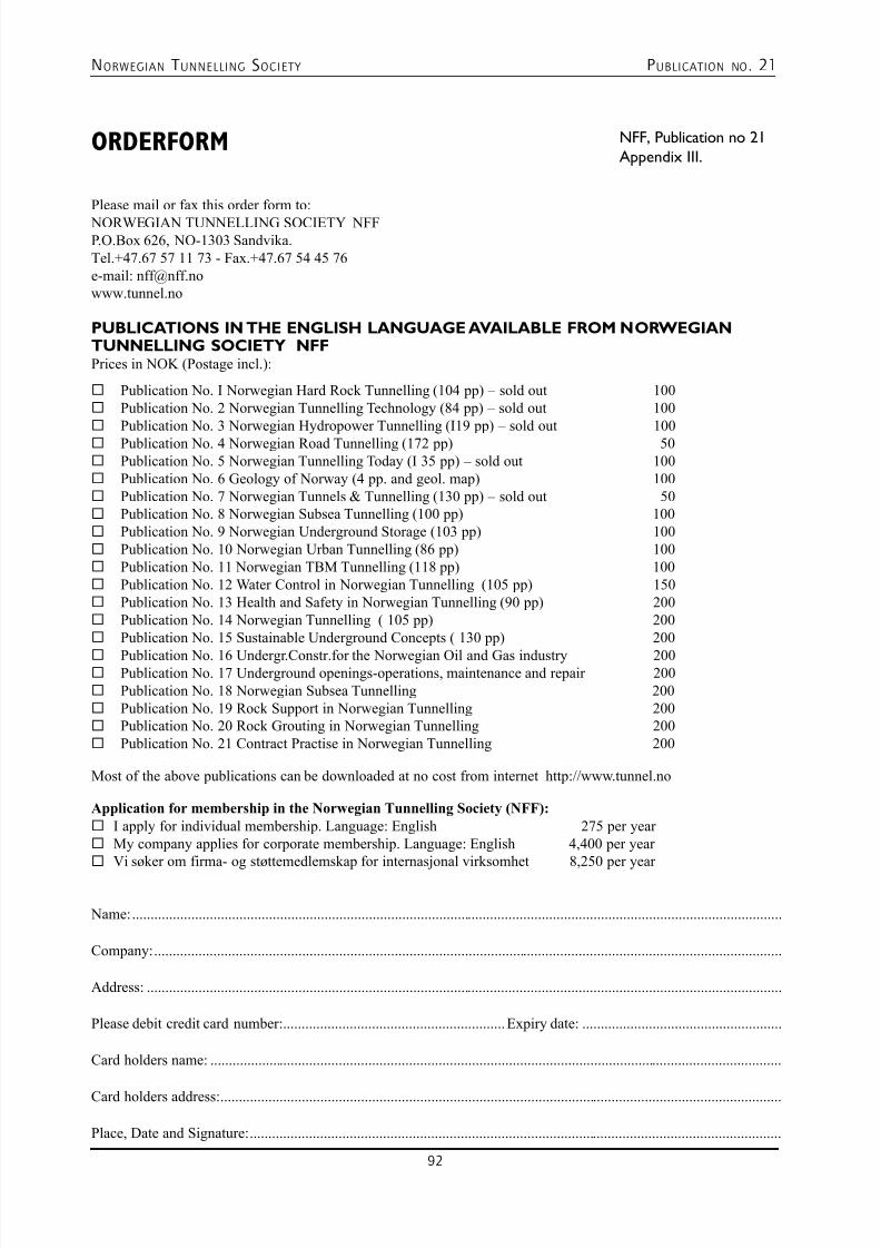
7/23/2019 NFF Publication 21 LOWRES
http://slidepdf.com/reader/full/nff-publication-21-lowres 92/94
NORWEGIAN T UNNELLING SOCIETY PUBLICATION NO . 21
92
ORDERFORM
Please mail or fax this order form to:
NORWEGIAN TUNNELLING SOCIETY NFFP.O.Box 626, NO-1303 Sandvika.Tel.+47.67 57 11 73 - Fax.+47.67 54 45 76e-mail: [email protected]
PUBLICATIONS IN THE ENGLISH LANGUAGE AVAILABLE FROM NORWEGIANTUNNELLING SOCIETY NFFPrices in NOK (Postage incl.):
¨ Publication No. I Norwegian Hard Rock Tunnelling (104 pp) – sold out 100¨ Publication No. 2 Norwegian Tunnelling Technology (84 pp) – sold out 100¨ Publication No. 3 Norwegian Hydropower Tunnelling (I19 pp) – sold out 100¨ Publication No. 4 Norwegian Road Tunnelling (172 pp) 50¨ Publication No. 5 Norwegian Tunnelling Today (I 35 pp) – sold out 100¨ Publication No. 6 Geology of Norway (4 pp. and geol. map) 100¨ Publication No. 7 Norwegian Tunnels & Tunnelling (130 pp) – sold out 50¨ Publication No. 8 Norwegian Subsea Tunnelling (100 pp) 100¨ Publication No. 9 Norwegian Underground Storage (103 pp) 100¨ Publication No. 10 Norwegian Urban Tunnelling (86 pp) 100¨ Publication No. 11 Norwegian TBM Tunnelling (118 pp) 100¨ Publication No. 12 Water Control in Norwegian Tunnelling (105 pp) 150¨ Publication No. 13 Health and Safety in Norwegian Tunnelling (90 pp) 200¨ Publication No. 14 Norwegian Tunnelling ( 105 pp) 200¨ Publication No. 15 Sustainable Underground Concepts ( 130 pp) 200
¨ Publication No. 16 Undergr.Constr.for the Norwegian Oil and Gas industry 200¨ Publication No. 17 Underground openings-operations, maintenance and repair 200¨ Publication No. 18 Norwegian Subsea Tunnelling 200¨ Publication No. 19 Rock Support in Norwegian Tunnelling 200¨ Publication No. 20 Rock Grouting in Norwegian Tunnelling 200¨ Publication No. 21 Contract Practise in Norwegian Tunnelling 200 Most of the above publications can be downloaded at no cost from internet http://www.tunnel.no
Application for membership in the Norwegian Tunnelling Society (NFF):
¨I apply for individual membership. Language: English 275 per year ¨My company applies for corporate membership. Language: English 4,400 per year ¨
Vi søker om firma- og støttemedlemskap for internasjonal virksomhet 8,250 per year
Name: ................................................................................................................................................................................
Company: ..........................................................................................................................................................................
Address: ............................................................................................................................................................................
Please debit credit card number: ............................................................Expiry date: ......................................................
Card holders name: ...........................................................................................................................................................
Card holders address: ........................................................................................................................................................
Place, Date and Signature: ................................................................................................................................................
NFF, Publication no 21
Appendix III.
7/23/2019 NFF Publication 21 LOWRES
http://slidepdf.com/reader/full/nff-publication-21-lowres 93/94

7/23/2019 NFF Publication 21 LOWRES
http://slidepdf.com/reader/full/nff-publication-21-lowres 94/94
Are you looking fortunneling technology and experience?
Check out:
www.tunnel.noThe Tunneling Technology Website