Embed Size (px)
Citation preview
Copyright NFPA
NFPA 414 Standard for
Aircraft Rescue and FireFighting Vehicles
2007 Edition
Copyright © 2006 National Fire Protection Association. All Rights Reserved.
This edition of NFPA 414, Standard for Aircraft Rescue and FireFighting Vehicles, was prepared by the Technical Committee on Aircraft Rescue and Fire Fighting, and acted on by NFPA at its June Association Technical Meeting held June 4–8, 2006, in Orlando, FL. It was issued by the Standards Council on July 28, 2006, with an effective date of August 17, 2006, and supersedes all previous editions.
This edition of NFPA 414 was approved as an American National Standard on August 17, 2006.
Origin and Development of NFPA 414
In 1960, a tentative edition of this standard was adopted by the Association. The original document was further revised in 1962, 1963, 1964, 1965, 1967, 1968, 1969, 1970, 1975, and 1978.
In 1984, the standard was revised completely to identify three types of vehicles and to make the document easier to use. The text also was rewritten to conform with the NFPAManual of Style.
The standard was revised again in 1990, and a chapter was added to provide a test method to verify the design requirements.
Notable revisions to the 1995 edition included the removal of requirements for a separate category of rapid intervention vehicle.
The major change for the 2001 edition was the combination of major firefighting vehicles and combined agent vehicles. Additionally, a table provided many requirements concisely that were previously covered by numerous paragraphs.
The 2007 revision includes minor changes to the document plus the addition of a new chapter on interior access vehicles.
Technical Committee on Aircraft Rescue and Fire Fighting

Copyright NFPA
Lawrence V. Powers, Chair Massport FireRescue, MA [L]
Keith W. Bagot, U.S. Federal Aviation Administration, NJ [RT] Rep. Federal Aviation Administration
Alan Black, Dallas/Fort Worth Airport Board, TX [C] Rep. Airports Council InternationalNorth America
Brian Boucher, Air Canada Pilots Association, NY [L]
Ralph Colet, John Russo Industrial Inc., CA [M]
Robert L. Darwin, Hughes Associates, Inc., MD [SE]
Ross A. Davidson, U.S. Department of the Navy, CA [C]
Roger Davis, BAA plc, United Kingdom [C]
John Demyan, LehighNorthampton Airport Authority, PA [L] Rep. International Association of Fire Fighters
Christopher Farnaby, United Kingdom Civil Aviation Authority, United Kingdom [E]
Kenneth R. Gilliam, U.S. Federal Aviation Administration, FL [E] Rep. Federal Aviation Administration
George F. Hall, U.S. Air Force, FL [C]
Donald E. Hilderbrand, Phoenix Fire Department, AZ [U]
L. M. Krasner, FM Global, MA [I]
Douglas Allen McClish, Akron Brass Company, OH [M]
Thomas J. McGinness, Airservices Australia, Australia [U]
Paul S. Meyer, Hartsfield Atlanta International Airport, GA [C]
Gaétan Morinville, National Defence Department, Canada, Canada [C]
John J. O'Sullivan, British Airways, PLC, United Kingdom [SE]
Pam L. Phillips, Port Authority of New York & New Jersey, NY [C] Rep. American Association of Airport Executives
Thomas J. Phillips, Airline Pilots Association, PA [L]

Copyright NFPA
Rep. Air Line Pilots Association
Richard M. Radford, Dubai International Airport, United Arab Emirates [U]
Michael D. Reagan, Los Angeles City Fire Department, CA [U]
William Savage, Gloucestershire, United Kingdom [L] Rep. International Aviation Fire Protection Association
Gary T. Schott, Omaha Airport Authority, NE [L] Rep. Aircraft Rescue & Fire Fighting Working Group
John M. Schuster, 3M Company, MN [M]
Terry Seaborn, Oshkosh Truck Corporation, WI [M]
Robert L. Shaub, Emergency One, Inc., FL [M]
William D. Stewart, Maryland Aviation Administration, MD [U] Rep. International Association of Fire Chiefs
Bernard Valois, Transport Canada Civil Aviation, Canada [E]
Ronald O. Wikander, Lockheed Martin Aeronautics Company, GA [U]
Joseph A. Wright, ARFF Technical Services, Inc., PA [SE]
Alternates
A. A. J. Cash, Air Safety Support International, United Kingdom [E] (Alt. to C. Farnaby)
Michael P. Crowe, Oshkosh Truck Corporation, WI [M] (Alt. to T. Seaborn)
Robert J. Donahue, Massport FireRescue, MA [L] (Alt. to L. V. Powers)
Eric J. Gogley, U.S. Department of the Navy, CA [C] (Alt. to R. A. Davidson)
Robert G. Lindstrom, ProTec Fire Services Ltd., OK [L] (Alt. to G. T. Schott)
Thomas V. Mai, U.S. Federal Aviation Administration, DC [E] (Alt. to K. R. Gilliam)
Copyright NFPA
Madhu Manikkam, Emergency One, Inc., FL [M] (Alt. to R. L. Shaub)
Harold D. Miller, Atlanta Fire Department, GA [C] (Alt. to P. S. Meyer)
James F. O'Regan, O'Regan Consulting/JRI, Inc., MA [M] (Alt. to R. Colet)
Ron Parry, BAA plc, United Kingdom [C] (Alt. to R. Davis)
Kevin J. Petit, Akron Brass Company, OH [M] (Alt. to D. A. McClish)
Joseph L. Scheffey, Hughes Associates, Inc., MD [SE] (Alt. to R. L. Darwin)
Nicholas M. Subbotin, HiTec Systems, NJ [RT] (Alt. to K. W. Bagot)
Pierre Voisine, National Defence Department, Canada, Canada [C] (Alt. to G. Morinville)
Nonvoting
Francois Villard, Fire Safety Security Crisis Management Training, Switzerland [SE]
B. Victor Hewes, Airport Safety Services, GA [SE] (Member Emeritus)
Thomas J. Lett, Albuquerque Fire & Safety Associates, NM [SE] (Member Emeritus)
Mark T. Conroy, NFPA Staff Liaison
This list represents the membership at the time the Committee was balloted on the final text of this edition. Since that time, changes in the membership may have occurred. A key to classifications is found at the back of the document.
NOTE: Membership on a committee shall not in and of itself constitute an endorsement of the Association or any document developed by the committee on which the member serves.
Committee Scope: This Committee shall have primary responsibility for documents on aircraft rescue and firefighting services and equipment, for procedures for handling aircraft fire emergencies, and for specialized vehicles used to perform these functions at airports, with particular emphasis on saving lives and reducing injuries coincident with aircraft fires following impact or aircraft ground fires. This Committee also shall have responsibility for
Copyright NFPA
documents on aircraft hand fire extinguishers and accident prevention and the saving of lives in future aircraft accidents involving fire.
NFPA 414 Standard for
Aircraft Rescue and FireFighting Vehicles 2007 Edition
IMPORTANT NOTE: This NFPA document is made available for use subject to important notices and legal disclaimers. These notices and disclaimers appear in all publications containing this document and may be found under the heading “Important Notices and Disclaimers Concerning NFPA Documents.” They can also be obtained on request from NFPA or viewed at www.nfpa.org/disclaimers.
NOTICE: An asterisk (*) following the number or letter designating a paragraph indicates that explanatory material on the paragraph can be found in Annex A.
Changes other than editorial are indicated by a vertical rule beside the paragraph, table, or figure in which the change occurred. These rules are included as an aid to the user in identifying changes from the previous edition. Where one or more complete paragraphs have been deleted, the deletion is indicated by a bullet (•) between the paragraphs that remain.
A reference in brackets [ ] following a section or paragraph indicates material that has been extracted from another NFPA document. As an aid to the user, the complete title and edition of the source documents for extracts in mandatory sections of the document are given in Chapter 2 and those for extracts in informational sections are given in Annex F. Editorial changes to extracted material consist of revising references to an appropriate division in this document or the inclusion of the document number with the division number when the reference is to the original document. Requests for interpretations or revisions of extracted text shall be sent to the technical committee responsible for the source document.
Information on referenced publications can be found in Chapter 2 and Annex F.
Chapter 1 Administration
1.1 Scope.
1.1.1* This standard specifies the minimum design, performance, and acceptance criteria for aircraft rescue and firefighting (ARFF) vehicles intended to transport personnel and equipment to the scene of an aircraft emergency for the purpose of rescuing occupants and conducting rescue and firefighting operations.
1.1.2 Vehicles without wheels, such as track, amphibious, or aircushion types, are not covered by this standard.
1.2 Purpose.
1.2.1 The purpose of this standard is to specify features and components that, when assembled, produce an efficient and capable firefighting vehicle for both onpavement and
Copyright NFPA
offpavement performance. Offpavement capability is important to ensure timely and effective response of these vehicles to aircraft accident sites located off paved surfaces. Firefighting capabilities are considered to be the minimum acceptable for proper performance of these vehicles.
1.2.2 It is not the purpose of this standard to serve as a detailed purchase specification. Drafting of complete specifications for bidding purposes is the responsibility of the purchaser.
1.3 Requirements for All Aircraft Rescue and FireFighting Vehicles — Responsibility of Contractors/Suppliers.
1.3.1* Certification. The aircraft rescue and firefighting vehicle manufacturer shall assume responsibility for the design, construction, and performance of all component parts of the complete vehicle, even if major portions are subcontracted, and shall certify that the completed vehicle meets the requirements of this standard.
1.3.2 Manuals. The manufacturer shall supply at the time of delivery the following manuals in electronic format:
(1) Operator's manual
(2) Service manual
(3) Parts manual
These manuals shall cover the entire vehicle and shall be in accordance with 1.3.2.1 through 1.3.2.3.9.
1.3.2.1 Operator's Manual.
1.3.2.1.1 Operating instructions shall include all information required for operation of the vehicle, vehicle components, firefighting systems, and integral vehicular options.
1.3.2.1.2 The location and function of all controls and instruments shall be covered by illustrations and descriptions.
1.3.2.1.3 These instructions, as a minimum, also shall include the following:
(1) Complete description of the vehicle and special equipment
(2) Preparation for use of the vehicle upon receipt
(3) Daily maintenance and mission readiness checks to be performed by the operator
(4) Periodic operator inspection
1.3.2.2 Service Manual. The service manual shall contain the regular maintenance schedule including operating hours, mileage, and cycle time.
1.3.2.2.1 The repair and overhaul instructions shall be factual, specific, concise, and clearly worded.
1.3.2.2.2 The instructions shall cover such typical maintenance and repair operations as troubleshooting, adjustment procedures, minor and major repairs and overhaul, removal and
Copyright NFPA
replacement of units, assemblies and subassemblies, and complete instructions for disassembly and reassembly of components.
1.3.2.2.3 The instructions also shall include data that include tolerances, specifications, and capacities.
1.3.2.2.4 Illustrations, wiring diagrams, and exploded views shall be used to clarify text and shall appear as close to the related text as possible.
1.3.2.2.5 Special tools needed for the repair and overhaul of the equipment shall be specified and illustrated.
1.3.2.2.6 The service manual shall contain a suitable index.
1.3.2.3 Parts Manual.
1.3.2.3.1 The parts list shall include illustrations and exploded views necessary for the proper identification of all parts, assemblies, and subassemblies.
1.3.2.3.2 Assemblies or components shall be shown in illustrations and shall be identified by reference numbers that correspond to the reference numbers in the parts list.
1.3.2.3.3 The size, thread dimensions, and special characteristics shall be given on all nonstandard nuts, bolts, washers, grease fittings, and similar items.
1.3.2.3.4 The parts identification manual shall provide the description and quantity of each item used per vehicle.
1.3.2.3.5 The parts identification manual shall contain a numerical index.
1.3.2.3.6 The vehicle manufacturer shall ensure that parts critical to the mission of the vehicle are shipped to the purchaser within 48 hours.
1.3.2.3.7 The original equipment manufacturers shall be disclosed to the owner if the vendor is unable to supply the necessary parts within 48 hours to allow local purchase of an equivalent part.
1.3.2.3.8 A qualified and responsible representative of the contractor shall instruct personnel specified by the purchaser in the operation, care, and maintenance of the vehicle delivered.
1.3.2.3.9 The purchasers shall specify provisions for training, including the location and duration, and shall agree on suitable training aids such as video tapes and training manuals.
1.3.3 Metal Finish.
1.3.3.1 All exposed ferrous metal surfaces that are not plated or of stainless steel or that are not otherwise treated to resist corrosion shall be cleaned thoroughly and prepared and shall be painted in the color(s) specified by the purchaser.
1.3.3.2 If nonferrous body components are furnished, the purchaser shall specify which surfaces are to be painted.
1.3.3.3 The paint, including the primer, shall be applied in accordance with the paint manufacturer's recommendation.
Copyright NFPA
1.3.3.4 Paint finish shall be selected for maximum visibility and shall be resistant to damage from firefighting agents.
1.3.3.5 Dissimilar metals shall not be in contact with each other.
1.3.3.5.1 Metal plating or metal spraying of metals of dissimilar base to provide electromotively compatible abutting surfaces shall be permitted.
1.3.3.5.2 The use of dissimilar metals separated by suitable insulating material shall be permitted.
1.3.3.5.3 In systems where bridging of insulation materials by an electrically conductive fluid can occur, dissimilar metals shall not be permitted.
1.3.3.6 Materials that deteriorate when exposed to sunlight, weather, or operational conditions normally encountered during service shall not be used or shall have a means of protection against such deterioration that does not prevent compliance with performance requirements.
1.3.3.7 Protective coatings that chip, crack, or scale with age or extremes of climatic conditions or when exposed to heat shall not be used.
1.3.3.8 The use of proven, nonmetallic materials in lieu of metal shall be permitted, provided such use contributes to reduced weight, lower cost, or less maintenance and there is no degradation in performance or increase in longterm operations and maintenance costs.
1.3.4 Lettering, Numbering, and Striping.
1.3.4.1 Vehicle numbering, lettering, and minimum 0.2 m (8 in.) wide reflective striping shall be provided in accordance with ASTM D 4956.
1.3.4.2 Striping shall be placed horizontally on the sides of the vehicle below the body centerline.
1.3.4.3 Vehicles shall display an identification number on each side and roof.
1.3.4.3.1 Side numbers shall be a minimum of 0.4 m (16 in.) in height.
1.3.4.3.2 Primary numbers shall be a minimum of 0.6 m (24 in.) in height and affixed with their base toward the front of the vehicle.
1.3.4.4 Numbering, lettering, and striping shall be in sharp contrast to the vehicle color.
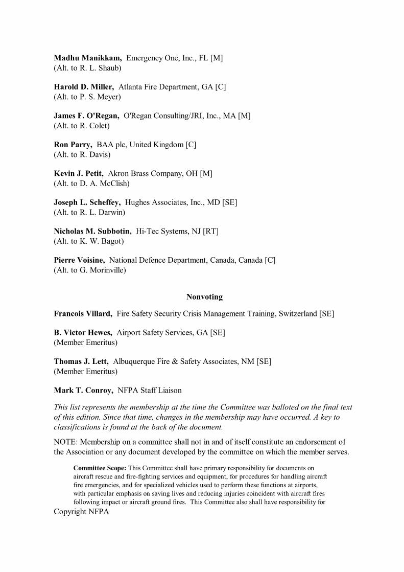
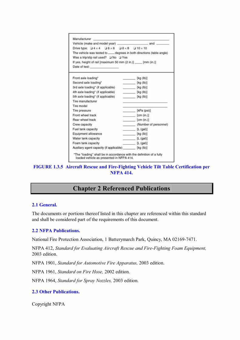
1.3.5 Vehicle Information Data Plate. A data plate that contains all the information presented in Figure 1.3.5, as a minimum, shall be installed in the cab of the vehicle.
Copyright NFPA
FIGURE 1.3.5 Aircraft Rescue and FireFighting Vehicle Tilt Table Certification per NFPA 414.
Chapter 2 Referenced Publications
2.1 General.
The documents or portions thereof listed in this chapter are referenced within this standard and shall be considered part of the requirements of this document.
2.2 NFPA Publications.
National Fire Protection Association, 1 Batterymarch Park, Quincy, MA 021697471.
NFPA 412, Standard for Evaluating Aircraft Rescue and FireFighting Foam Equipment, 2003 edition.
NFPA 1901, Standard for Automotive Fire Apparatus, 2003 edition.
NFPA 1961, Standard on Fire Hose, 2002 edition.
NFPA 1964, Standard for Spray Nozzles, 2003 edition.
2.3 Other Publications.
Copyright NFPA
2.3.1 ANSI Publications.
American National Standards Institute, Inc., 25 West 43rd Street, 4th Floor, New York, NY 10036.
ANSI S1.4, Specification for Sound Level Meters, 1983.
2.3.2 ASME Publications.
American Society of Mechanical Engineers, Three Park Avenue, New York, NY 100165990.
ASME Boiler and Pressure Vessel Code, 1992.
2.3.3 ASTM Publications.
ASTM International, 100 Barr Harbor Drive, P.O. Box C700, West Conshohocken, PA 194282959.
ASTM D 4956, Standard Specification for Retroreflective Sheeting for Traffic Control, 1994.
2.3.4 NATO Publications.
Global Engineering Documents, An IHS Company, 15 Inverness Way East, Englewood, CO 80112.
NATO Document, “Dynamic Stability Report — Allied Vehicle Testing Publication (AVTP),” 0316W.
2.3.5 SAE Publications.
Society of Automotive Engineers, 400 Commonwealth Drive, Warrendale, PA 15096.
SAE J551/2, Test Limits and Methods of Measurement of Radio Disturbance Characteristics of Vehicles, Motorboats, and SparkIgnited EngineDriven Devices, 1994.
SAE J994, Standard on AlarmBackupElectric Laboratory Performance Testing, 1993.
SAE J1908, Electrical Grounding Practice, 1996.
SAE J2180, A Tilt Table Procedure for Measuring the Static Rollover Threshold for Heavy Trucks, 1993.
SAE J2181, Steady State Circular Test Procedures for Trucks and Buses, 1993.
2.3.6 Other Publications.
MerriamWebster’s Collegiate Dictionary, 11th edition, MerriamWebster, Inc., Springfield, MA, 2003.
2.4 References for Extracts in Mandatory Sections. (Reserved)
Chapter 3 Definitions
Copyright NFPA
3.1 General.
The definitions contained in this chapter shall apply to the terms used in this standard. Where terms are not defined in this chapter or within another chapter, they shall be defined using their ordinarily accepted meanings within the context in which they are used. MerriamWebster’s Collegiate Dictionary, 11th edition, shall be the source for the ordinarily accepted meaning.
3.2 NFPA Official Definitions.
3.2.1* Approved. Acceptable to the authority having jurisdiction.
3.2.2* Authority Having Jurisdiction. An organization, office, or individual responsible for enforcing the requirements of a code or standard, or for approving equipment, materials, an installation, or a procedure.
3.2.3* Listed. Equipment, materials, or services included in a list published by an organization that is acceptable to the authority having jurisdiction and concerned with evaluation of products or services, that maintains periodic inspection of production of listed equipment or materials or periodic evaluation of services, and whose listing states that either the equipment, material, or service meets appropriate designated standards or has been tested and found suitable for a specified purpose.
3.2.4 Shall. Indicates a mandatory requirement.
3.2.5 Should. Indicates a recommendation or that which is advised but not required.
3.3 General Definitions.
3.3.1 AFFF. See 3.3.27.1.
3.3.2 Aggressive Tire Tread. See 3.3.63.1.
3.3.3 AirMechanical Brakes. See 3.3.14.1.
3.3.4 AirOverHydraulic Brakes. See 3.3.14.2.
3.3.5 AllWheel Drive. A vehicle with the ability to apply tractive power to all wheels.
3.3.6 Ambient Temperature. The temperature of the surrounding medium; usually used to refer to the temperature of the air in which a structure is situated or a device operates.
3.3.7* Angle of Approach. The measure of the steepest ramp that a fully loaded vehicle can approach.
3.3.8* Angle of Departure. The measure of the steepest ramp from which the fully loaded vehicle can depart.
3.3.9 Aqueous FilmForming Foam (AFFF) Concentrate. See 3.3.27.1.
3.3.10 ARFF Chassis. The assembled frame, engine, drive train, and tires of a vehicle.
3.3.11 Automatic Locking Differential. A type of nonslip differential that operates
Copyright NFPA
automatically.
3.3.12 Axle Tread. See 3.3.63.2.
3.3.13* Bogie. A combination of two axles used to support the end of a vehicle.
3.3.14 Brakes.
3.3.14.1 AirMechanical Brakes. Brakes in which the force from an individual air chamber is applied directly to the friction surfaces through a mechanical linkage.
3.3.14.2 AirOverHydraulic Brakes. Brakes in which the force of a master air cylinder is applied to the friction surfaces through an intervening hydraulic system.
3.3.14.3 Service Brake. A system capable of decelerating the vehicle at a controlled rate to a desired, reduced speed or complete stop.
3.3.15* Center of Gravity. The point within a vehicle at which all of its weight can be considered to be concentrated.
3.3.16* Complementary Agent. Agents that provide unique extinguishing capability beyond the primary chosen agent.
3.3.17 Component Manufacturer's Certification. A signed application approval furnished by the component manufacturer that certifies that the component is approved as being properly installed or applied, or both, in the vehicle for its intended use, or the component complies with the respective construction criteria required by the standard.
3.3.18* Cooling Preheater Device. A device for heating the engine coolant so that the engine is maintained at a constant temperature.
3.3.19* Diagonal Opposite Wheel Motion. The measurement of the vertical movement relationship of the wheel and suspension travel.
3.3.20 Differential Global Positioning System (DGPS). See 3.3.61.3.1.
3.3.21 Driver's Enhanced Vision System (DEVS). See 3.3.61.1.
3.3.22 Dynamic Balance. A physical condition that exists when a vehicle is driven into a turn under high speed and the vehicle displays no tendencies to pitch weight forward on the front steering wheels nor exhibits of understeer or oversteer conditions which could make the vehicle unstable.
3.3.23 Equipment Allowance. Any equipment added to the vehicle that is not directly required for the vehicle to discharge water or other firefighting agent(s) on the initial attack.
3.3.24 Extendable Turret. See 3.3.64.1.
3.3.25 Fluid Coupling. A turbinelike device that transmits power solely through the action of a fluid in a closed circuit without direct mechanical connection between input and output shafts and without producing torque multiplication.
3.3.26 Fluoroprotein Foam Concentrate. See 3.3.27.2.
Copyright NFPA
3.3.27 Foam Concentrate.
3.3.27.1 Aqueous FilmForming Foam (AFFF) Concentrate. A concentrated aqueous solution of fluorinated surfactant(s) and foam stabilizers that is capable of producing an aqueous fluorocarbon film on the surface of hydrocarbon fuels to suppress vaporization.
3.3.27.2 Fluoroprotein Foam Concentrate. A protein foam concentrate incorporating one or more fluorochemical surfactants to enhance its tolerance to fuel contamination.
3.3.27.3 Protein Foam Concentrate. A concentrate consisting primarily of products from a protein hydrolysate, plus stabilizing additives and inhibitors to protect against freezing, to prevent corrosion of equipment and containers, to resist bacterial decomposition, to control viscosity, and otherwise to ensure readiness for use under emergency conditions.
3.3.28 Foam Expansion. The ratio between the volume of foam produced and the volume of solution used in its production.
3.3.29 Foam–Liquid Concentration. The quantity of foam–liquid concentrate in water identified in percentage.
3.3.30* ForwardLooking Infrared (FLIR). The detection of heat energy radiated by objects to produce a “thermal image.” This thermal image is converted by electronics and signal processing into a visual image that can be viewed by the operator.
3.3.31 Fully Loaded Vehicle. See 3.3.71.2.
3.3.32 Global Positioning System (GPS). See 3.3.61.3.
3.3.33 Ground Sweep Nozzle. See 3.3.42.1.
3.3.34 Halogenated Agents. Agents that are complementary agents including halocarbons and halons.
3.3.35 InService Condition. A state or condition of readiness for intended duty; usually an emergency vehicle properly serviced with all equipment properly loaded and ready for immediate response.
3.3.36* Intended Airport Service. All aspects of aircraft rescue and firefighting services as provided by this standard.
3.3.37* Interaxle Clearance Angle (Ramp Angle). The measure of the ability of a fully loaded vehicle to negotiate a ramp without encountering interference between the vehicle and the ramp between any two axles.
3.3.38 Interaxle Differential. A differential in the line of drive between any two axles.
3.3.39 “J” Turn Test. The measure of a vehicle's ability to traverse a 90 degree turn at a prescribed speed.
3.3.40 Lightweight Construction. Lightweight materials or advanced engineering or both practices resulting in a weight saving without sacrifice of strength or efficiency.
3.3.41 NoLoad Condition. The status of an engine with standard accessories operating without an imposed load, with the vehicle drive clutches and any special accessory clutches
Copyright NFPA
in a disengaged or neutral condition.
3.3.42 Nozzle.
3.3.42.1 Ground Sweep Nozzle. A small nozzle(s) mounted in front of the vehicle that disperses foam solution in front to provide protection.
3.3.42.2 Undertruck Nozzle. A small nozzle device that hangs below the vehicle and disperses foam solution in a manner that provides protection for the vehicles from ground or grass proximity fires; these devices spray agent from wheel to wheel and front to back of the underside of the truck.
3.3.43* OffPavement Performance. A vehicle's ability to perform or operate on other than paved surfaces.
3.3.44 Operational Tests. An allvehicle test conducted by the manufacturer to ensure that each vehicle is fully operational when it is delivered and to ensure that the original level of performance of the prototype vehicle has been maintained.
3.3.45* Overall Height, Length, and Width. The dimensions determined with the vehicle fully loaded and equipped, unless otherwise specified.
3.3.46* Percent Grade. The ratio of the change in elevation to the horizontal distance traveled multiplied by 100.
3.3.47 PowerAssist Steering. A system using hydraulic or air power to aid in the steering assist. This system is supplementary to the mechanical system in order to maintain steering ability in the event of power failure.
3.3.48 Primary Turret. See 3.3.64.2.
3.3.49* Propellant Gas. A gas pressurizing an agent container.
3.3.50 Protein Foam Concentrate. See 3.3.27.3.
3.3.51 Prototype Vehicle. See 3.3.71.3.
3.3.52 Radio Suppression. Suppression of the ignition and electrical system noises that normally interfere with radio transmission and reception.
3.3.53 Ramp Angle. See 3.3.37, Interaxle Clearance Angle (Ramp Angle).
3.3.54 Reserve Capacity Rating. The number of minutes a new, fully charged battery at 26.7°C (80°F) can be discharged at 25 amperes while maintaining 1.75 volts per cell or higher.
3.3.55* RubberGasketed Fitting. A device for providing a leakproof connection between two pieces of pipe while allowing moderate movement of one pipe relative to the other.
3.3.56 Seat Belt. A twopoint lap belt, a threepoint lap/shoulder belt, or a fourpoint lap/shoulder harness for vehicle occupants designed to limit their movement in the event of an accident, rapid acceleration, or rapid deceleration by securing individuals safely to a vehicle in a seated position.
Copyright NFPA
3.3.57 Service Brake. See 3.3.14.3.
3.3.58 Side Slope. This angle is measured as either the percent of slope or the tilt angle at which the vehicle would become unstable should the vehicle be placed on the side of a steep, angled hill or sloped surface.
3.3.59* Steering Drive Ends. In the front wheel spindle in a driving–steering axle as used at the front of an allwheel drive vehicle.
3.3.60 Surfaces.
3.3.60.1 Improved Surfaces. Surfaces that are classed as main thoroughfares, paved roadways, runways, taxiways, parking aprons, and secondary routes of vehicle travel including mediums that are normally of paved, asphalted, or concrete construction.
3.3.60.2 Unimproved Surfaces. Surfaces that are not paved or surface coated for heavy automotive travel and include dirt, clay, shale, or crushed rock that is not maintained on a regular basis.
3.3.61 System.
3.3.61.1 Driver's Enhanced Vision System (DEVS). An enhanced vision and navigation system for guiding aircraft rescue and firefighting vehicles at night and during certain lowvisibility conditions. The DEVS is comprised of three systems: (1) Navigation, which displays the ARFF vehicle's position on a moving map display mounted in the cab; (2) Tracking, which provides twoway digital communication between the ARFF vehicle and the Emergency Command Center; (3) Vision, which allows the ARFF vehicle operator to see in 0/0 visibility conditions.
3.3.61.2 Electronic Stability Control System. A closedloop stabilitycontrol system that relies on proven antilock brake system and traction control system components. It incorporates sensors for determining vehicle parameters as well as an electronic control unit to modulate braking and traction forces.
3.3.61.3* Global Positioning System (GPS). A satellitebased radio navigation system comprised of three segments: space, control, and user.
3.3.61.3.1* Differential Global Positioning System (DGPS). A technique applied to a global positioning system (GPS) solution that improves the accuracy of that solution.
3.3.62 Torque Converter. A device that is similar to a fluid coupling but that produces, by means of additional turbine blades, variable torque multiplication.
3.3.63 Tread.
3.3.63.1 Aggressive Tire Tread. Tread designed to provide maximum traction for all types of surfaces, including sand, mud, snow, ice, and hard surfaces, wet or dry.
3.3.63.2* Axle Tread. The distance between the center of two tires or wheels on one axle.
3.3.64 Turret.
Copyright NFPA
3.3.64.1* Extendable Turret. A device, permanently mounted with a poweroperated boom or booms, designed to supply a largecapacity, mobile, elevatable water stream or other fireextinguishing agents, or both.
3.3.64.2* Primary Turret. The largest capacity foam turret used to apply primary extinguishing agent.
3.3.65* TwentyFive Percent Drainage Time. The time in minutes that it takes for 25 percent of the total liquid contained in the foam collected in a specified manner to drain.
3.3.66 Underaxle Clearance. The clearance distance between the ground and the center drive train of the vehicle; generally this measurement is taken at the low point bottom of the drive differentials.
3.3.67* Underbody Clearance Dimensions. The dimensions determined with the vehicle fully loaded and fully equipped, unless otherwise specified.
3.3.68 Undertruck Nozzle. See 3.3.42.2.
3.3.69 Unitized Rigid Body and Frame Structure. A structure in which parts that generally comprise a separate body are integrated with the chassis frame to form a single, rigid, loadcarrying structure.
3.3.70 Unsprung Weight. The total weight of all vehicle components that are not supported completely by the suspension system.
3.3.71 Vehicle.
3.3.71.1 Aircraft Interior Access Vehicle. A vehicle designed with the primary purpose of enabling access to an aircraft interior.
3.3.71.2* Fully Loaded Vehicle. Consists of the fully assembled vehicle, complete with a full complement of crew, fuel, and firefighting agents.
3.3.71.3* Prototype Vehicle. The first vehicle of a unique vehicle configuration built to establish its performance capability and the performance capability of all subsequent vehicles manufactured from its drawings and parts list.
3.3.72* Vehicle Types. Vehicle types are designated as 4 × 4, and so forth, and these designations are used to indicate the number of wheels on the vehicle and the number of wheels that propel or drive the vehicle.
3.3.73* WalltoWall Turning Diameter. A measurement of the space that completely contains a vehicle as it is being turned.
3.3.74* Weather Resistant. Sufficiently protected to prevent the penetration of rain, snow, and winddriven sand, dirt, or dust under all operating conditions.
3.3.75 Weight Scale Measurement. The accurate measurement of vehicle weight by means of a scale to verify or check a stated or estimated weight.
3.3.76 Where Specified. Options selected by the purchaser beyond the minimum requirements of the standard.
Copyright NFPA
Chapter 4 Aircraft Rescue and FireFighting Vehicles
4.1* General.
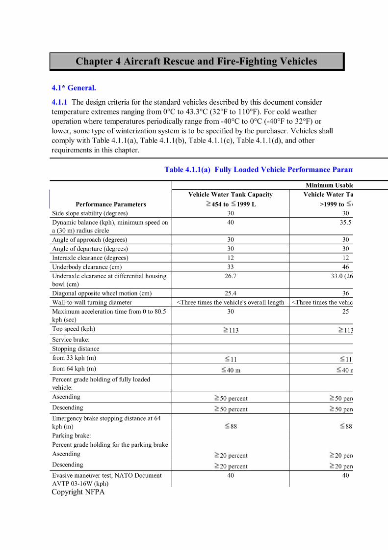
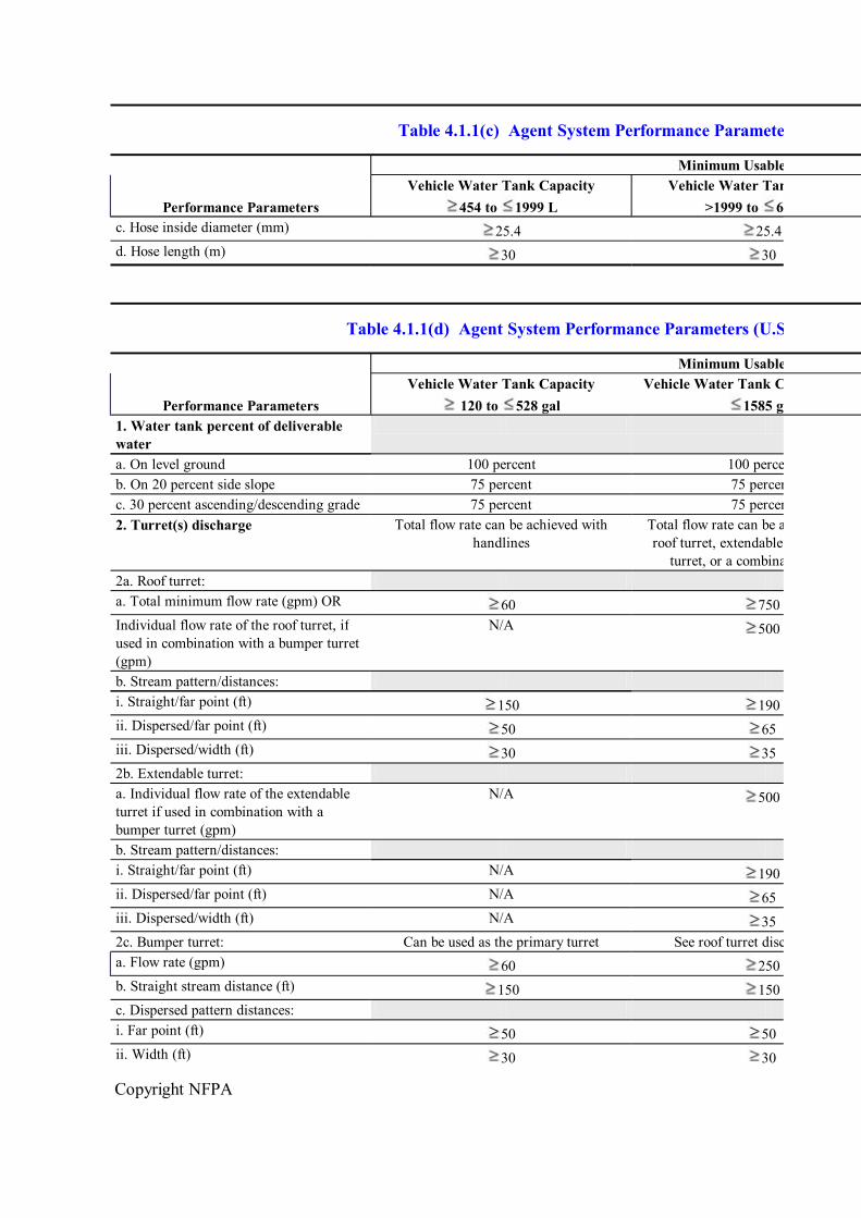
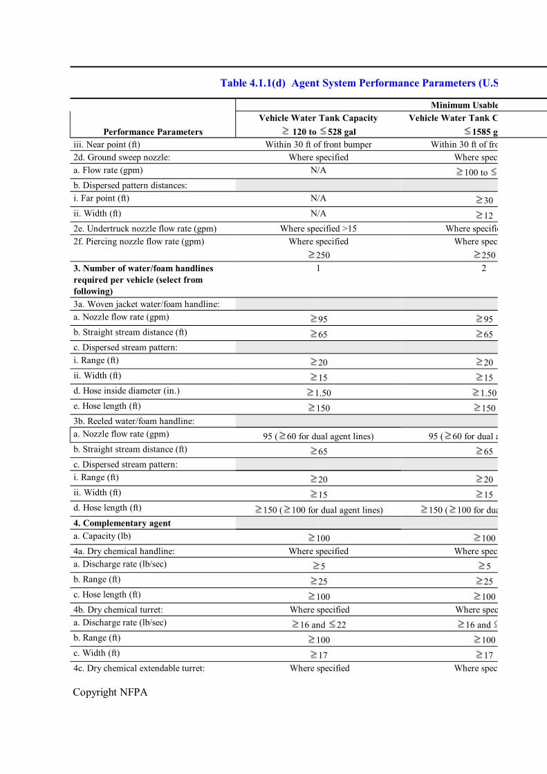
4.1.1 The design criteria for the standard vehicles described by this document consider temperature extremes ranging from 0°C to 43.3°C (32°F to 110°F). For cold weather operation where temperatures periodically range from 40°C to 0°C (40°F to 32°F) or lower, some type of winterization system is to be specified by the purchaser. Vehicles shall comply with Table 4.1.1(a), Table 4.1.1(b), Table 4.1.1(c), Table 4.1.1(d), and other requirements in this chapter.
Table 4.1.1(a) Fully Loaded Vehicle Performance Parameters (SI Units)
Minimum Usable Capacity
Performance Parameters Vehicle Water Tank Capacity
454 to 1999 L Vehicle Water Tank Capacity
>1999 to 6000 L Side slope stability (degrees) 30 30 Dynamic balance (kph), minimum speed on a (30 m) radius circle
40 35.5
Angle of approach (degrees) 30 30 Angle of departure (degrees) 30 30 Interaxle clearance (degrees) 12 12 Underbody clearance (cm) 33 46 Underaxle clearance at differential housing bowl (cm)
26.7 33.0 (26.7)
Diagonal opposite wheel motion (cm) 25.4 36 Walltowall turning diameter <Three times the vehicle's overall length <Three times the vehicle's overall length Maximum acceleration time from 0 to 80.5 kph (sec)
30 25
Top speed (kph) 113 113 Service brake: Stopping distance from 33 kph (m) 11 11 from 64 kph (m) 40 m 40 m Percent grade holding of fully loaded vehicle: Ascending 50 percent 50 percent Descending 50 percent 50 percent Emergency brake stopping distance at 64 kph (m) 88 88 Parking brake: Percent grade holding for the parking brake Ascending 20 percent 20 perce Descending 20 percent 20 percent Evasive maneuver test, NATO Document AVTP 0316W (kph)
40 40
Copyright NFPA
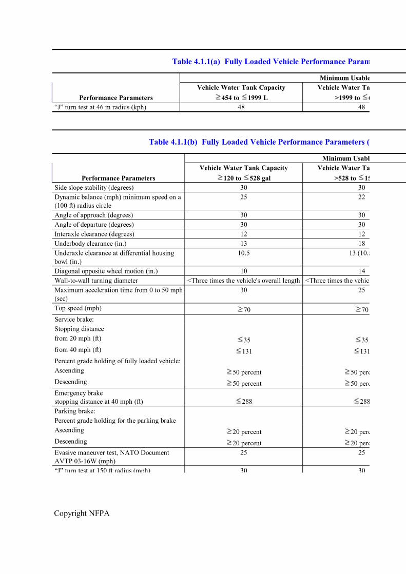
Table 4.1.1(a) Fully Loaded Vehicle Performance Parameters (SI Units)
Minimum Usable Capacity
Performance Parameters Vehicle Water Tank Capacity
454 to 1999 L Vehicle Water Tank Capacity
>1999 to 6000 L “J” turn test at 46 m radius (kph) 48 48
Table 4.1.1(b) Fully Loaded Vehicle Performance Parameters (U.S. Customary Units)
Minimum Usable Capacity
Performance Parameters Vehicle Water Tank Capacity
120 to 528 gal Vehicle Water Tank Capacity
>528 to 1585 gal Side slope stability (degrees) 30 30 Dynamic balance (mph) minimum speed on a (100 ft) radius circle
25 22
Angle of approach (degrees) 30 30 Angle of departure (degrees) 30 30 Interaxle clearance (degrees) 12 12 Underbody clearance (in.) 13 18 Underaxle clearance at differential housing bowl (in.)
10.5 13 (10.5)
Diagonal opposite wheel motion (in.) 10 14 Walltowall turning diameter <Three times the vehicle's overall length <Three times the vehicle's overall length Maximum acceleration time from 0 to 50 mph (sec)
30 25
Top speed (mph) 70 70 Service brake: Stopping distance from 20 mph (ft) 35 35 from 40 mph (ft) 131 131 Percent grade holding of fully loaded vehicle: Ascending 50 percent 50 percent Descending 50 percent 50 percent Emergency brake stopping distance at 40 mph (ft) 288 288 Parking brake: Percent grade holding for the parking brake Ascending 20 percent 20 percent Descending 20 percent 20 percent Evasive maneuver test, NATO Document AVTP 0316W (mph)
25 25
“J” turn test at 150 ft radius (mph) 30 30
Copyright NFPA
Table 4.1.1(b) Fully Loaded Vehicle Performance Parameters (U.S. Customary Units)
Minimum Usable Capacity
Performance Parameters Vehicle Water Tank Capacity
120 to 528 gal Vehicle Water Tank Capacity
>528 to 1585 gal “J” turn test at 150 ft radius (mph) 30 30
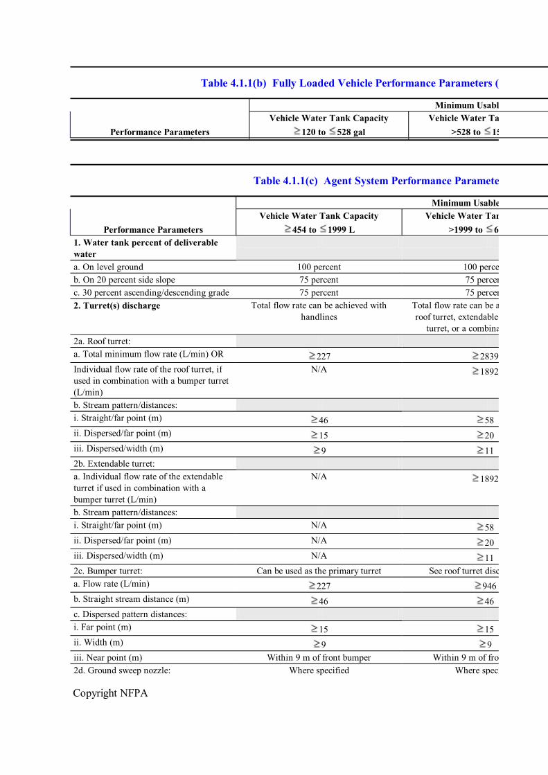
Table 4.1.1(c) Agent System Performance Parameters (SI Units)
Minimum Usable Capacity
Performance Parameters Vehicle Water Tank Capacity
454 to 1999 L Vehicle Water Tank Capacity
>1999 to 6000 L 1. Water tank percent of deliverable water a. On level ground 100 percent 100 percent b. On 20 percent side slope 75 percent 75 percent c. 30 percent ascending/descending grade 75 percent 75 percent 2. Turret(s) discharge Total flow rate can be achieved with
handlines Total flow rate can be achieved using a roof turret, extendable turret, bumper
turret, or a combination thereof 2a. Roof turret: a. Total minimum flow rate (L/min) OR 227 2839 Individual flow rate of the roof turret, if used in combination with a bumper turret (L/min)
N/A 1892
b. Stream pattern/distances: i. Straight/far point (m) 46 58 ii. Dispersed/far point (m) 15 20 iii. Dispersed/width (m) 9 11 2b. Extendable turret: a. Individual flow rate of the extendable turret if used in combination with a bumper turret (L/min)
N/A 1892
b. Stream pattern/distances: i. Straight/far point (m) N/A 58 ii. Dispersed/far point (m) N/A 20 iii. Dispersed/width (m) N/A 11 2c. Bumper turret: Can be used as the primary turret See roof turret discharge rates a. Flow rate (L/min) 227 946 b. Straight stream distance (m) 46 46 c. Dispersed pattern distances: i. Far point (m) 15 15 ii. Width (m) 9 9 iii. Near point (m) Within 9 m of front bumper Within 9 m of front bumper 2d. Ground sweep nozzle: Where specified Where specified
Copyright NFPA
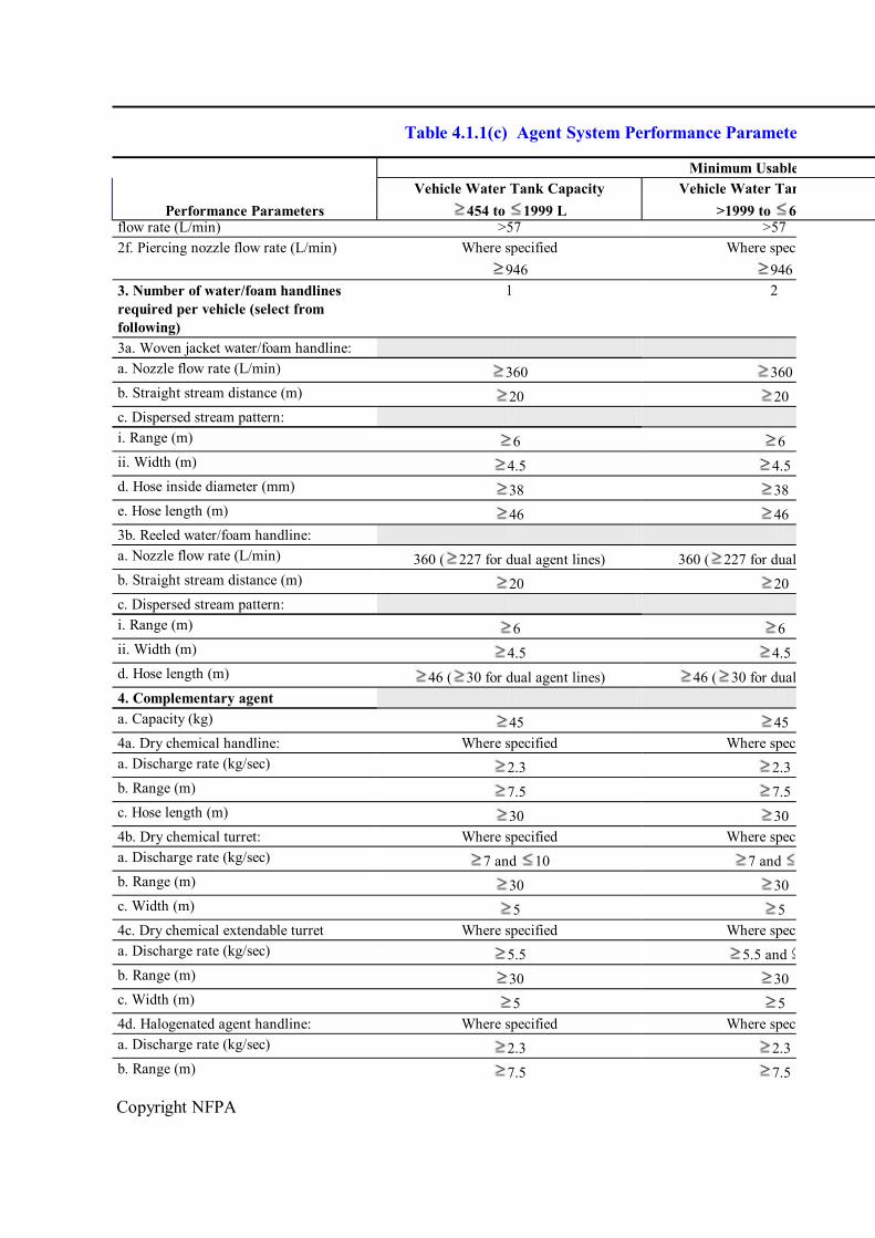
Table 4.1.1(c) Agent System Performance Parameters (SI Units)
Minimum Usable Capacity
Performance Parameters Vehicle Water Tank Capacity
454 to 1999 L Vehicle Water Tank Capacity
>1999 to 6000 L flow rate (L/min) >57 >57 2f. Piercing nozzle flow rate (L/min) Where specified
946 Where specified
946 3. Number of water/foam handlines required per vehicle (select from following)
1 2
3a. Woven jacket water/foam handline: a. Nozzle flow rate (L/min) 360 360 b. Straight stream distance (m) 20 20 c. Dispersed stream pattern: i. Range (m) 6 6 ii. Width (m) 4.5 4.5 d. Hose inside diameter (mm) 38 38 e. Hose length (m) 46 46 3b. Reeled water/foam handline: a. Nozzle flow rate (L/min) 360 ( 227 for dual agent lines) 360 ( 227 for dual agent lines) b. Straight stream distance (m) 20 20 c. Dispersed stream pattern: i. Range (m) 6 6 ii. Width (m) 4.5 4.5 d. Hose length (m) 46 ( 30 for dual agent lines) 46 ( 30 for dual agent lines) 4. Complementary agent a. Capacity (kg) 45 45 4a. Dry chemical handline: Where specified Where specified a. Discharge rate (kg/sec) 2.3 2.3 b. Range (m) 7.5 7.5 c. Hose length (m) 30 30 4b. Dry chemical turret: Where specified Where specified a. Discharge rate (kg/sec) 7 and 10 7 and b. Range (m) 30 30 c. Width (m) 5 5 4c. Dry chemical extendable turret Where specified Where specified a. Discharge rate (kg/sec) 5.5 5.5 and b. Range (m) 30 30 c. Width (m) 5 5 4d. Halogenated agent handline: Where specified Where specified a. Discharge rate (kg/sec) 2.3 2.3 b. Range (m) 7.5 7.5
Copyright NFPA
Table 4.1.1(c) Agent System Performance Parameters (SI Units)
Minimum Usable Capacity
Performance Parameters Vehicle Water Tank Capacity
454 to 1999 L Vehicle Water Tank Capacity
>1999 to 6000 L c. Hose inside diameter (mm) 25.4 25.4 d. Hose length (m) 30 30
Table 4.1.1(d) Agent System Performance Parameters (U.S. Customary Units)
Minimum Usable Capacity
Performance Parameters Vehicle Water Tank Capacity
120 to 528 gal Vehicle Water Tank Capacity >528 to
1585 gal 1. Water tank percent of deliverable water a. On level ground 100 percent 100 percent b. On 20 percent side slope 75 percent 75 percent c. 30 percent ascending/descending grade 75 percent 75 percent 2. Turret(s) discharge Total flow rate can be achieved with
handlines Total flow rate can be achieved using a roof turret, extendable turret, bumper
turret, or a combination thereof 2a. Roof turret: a. Total minimum flow rate (gpm) OR 60 750 Individual flow rate of the roof turret, if used in combination with a bumper turret (gpm)
N/A 500
b. Stream pattern/distances: i. Straight/far point (ft) 150 190 ii. Dispersed/far point (ft) 50 65 iii. Dispersed/width (ft) 30 35 2b. Extendable turret: a. Individual flow rate of the extendable turret if used in combination with a bumper turret (gpm)
N/A 500
b. Stream pattern/distances: i. Straight/far point (ft) N/A 190 ii. Dispersed/far point (ft) N/A 65 iii. Dispersed/width (ft) N/A 35 2c. Bumper turret: Can be used as the primary turret See roof turret discharge rates a. Flow rate (gpm) 60 250 b. Straight stream distance (ft) 150 150 c. Dispersed pattern distances: i. Far point (ft) 50 50 ii. Width (ft) 30 30
Copyright NFPA
Table 4.1.1(d) Agent System Performance Parameters (U.S. Customary Units)
Minimum Usable Capacity
Performance Parameters Vehicle Water Tank Capacity
120 to 528 gal Vehicle Water Tank Capacity >528 to
1585 gal iii. Near point (ft) Within 30 ft of front bumper Within 30 ft of front bumper 2d. Ground sweep nozzle: Where specified Where specified a. Flow rate (gpm) N/A 100 to b. Dispersed pattern distances: i. Far point (ft) N/A 30 ii. Width (ft) N/A 12 2e. Undertruck nozzle flow rate (gpm) Where specified >15 Where specified >15 2f. Piercing nozzle flow rate (gpm) Where specified
250 Where specified
250 3. Number of water/foam handlines required per vehicle (select from following)
1 2
3a. Woven jacket water/foam handline: a. Nozzle flow rate (gpm) 95 95 b. Straight stream distance (ft) 65 65 c. Dispersed stream pattern: i. Range (ft) 20 20 ii. Width (ft) 15 15 d. Hose inside diameter (in.) 1.50 1.50 e. Hose length (ft) 150 150 3b. Reeled water/foam handline: a. Nozzle flow rate (gpm) 95 ( 60 for dual agent lines) 95 ( 60 for dual agent lines) b. Straight stream distance (ft) 65 65 c. Dispersed stream pattern: i. Range (ft) 20 20 ii. Width (ft) 15 15 d. Hose length (ft) 150 ( 100 for dual agent lines) 150 ( 100 for dual agent lines) 4. Complementary agent a. Capacity (lb) 100 100 4a. Dry chemical handline: Where specified Where specified a. Discharge rate (lb/sec) 5 5 b. Range (ft) 25 25 c. Hose length (ft) 100 100 4b. Dry chemical turret: Where specified Where specified a. Discharge rate (lb/sec) 16 and 22 16 and b. Range (ft) 100 100 c. Width (ft) 17 17 4c. Dry chemical extendable turret: Where specified Where specified
Copyright NFPA
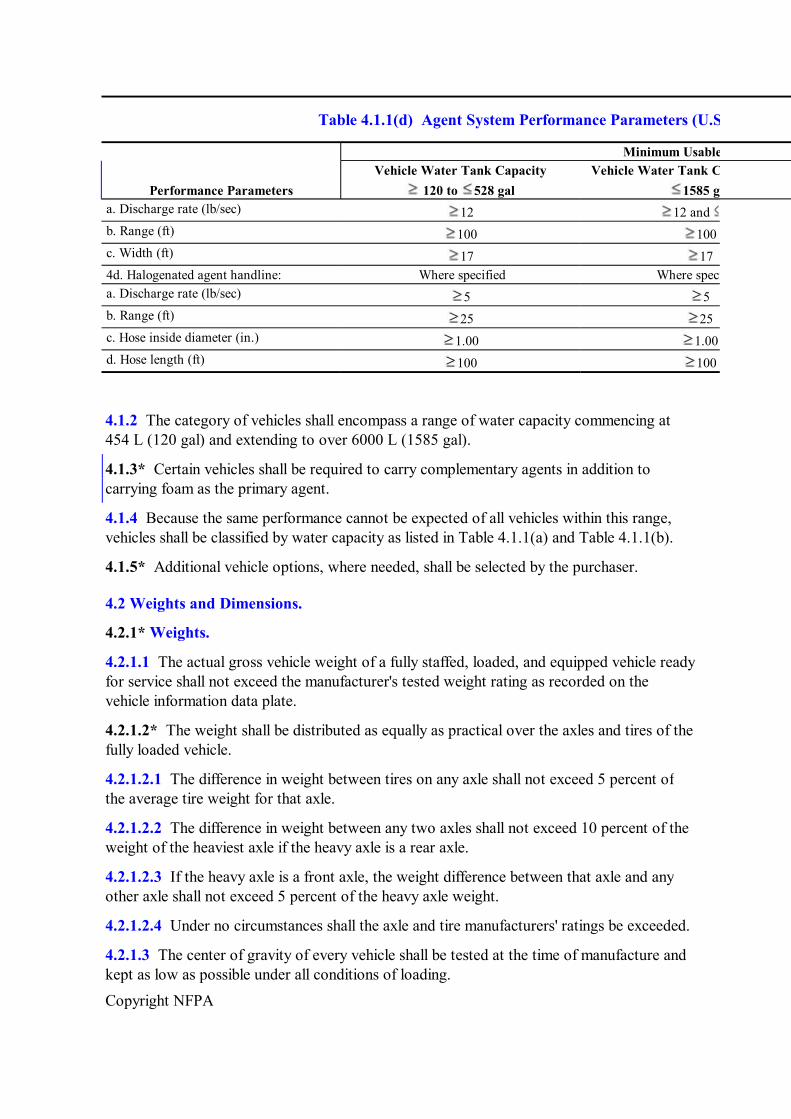
Table 4.1.1(d) Agent System Performance Parameters (U.S. Customary Units)
Minimum Usable Capacity
Performance Parameters Vehicle Water Tank Capacity
120 to 528 gal Vehicle Water Tank Capacity >528 to
1585 gal a. Discharge rate (lb/sec) 12 12 and b. Range (ft) 100 100 c. Width (ft) 17 17 4d. Halogenated agent handline: Where specified Where specified a. Discharge rate (lb/sec) 5 5 b. Range (ft) 25 25 c. Hose inside diameter (in.) 1.00 1.00 d. Hose length (ft) 100 100
4.1.2 The category of vehicles shall encompass a range of water capacity commencing at 454 L (120 gal) and extending to over 6000 L (1585 gal).
4.1.3* Certain vehicles shall be required to carry complementary agents in addition to carrying foam as the primary agent.
4.1.4 Because the same performance cannot be expected of all vehicles within this range, vehicles shall be classified by water capacity as listed in Table 4.1.1(a) and Table 4.1.1(b).
4.1.5* Additional vehicle options, where needed, shall be selected by the purchaser.
4.2 Weights and Dimensions.
4.2.1* Weights.
4.2.1.1 The actual gross vehicle weight of a fully staffed, loaded, and equipped vehicle ready for service shall not exceed the manufacturer's tested weight rating as recorded on the vehicle information data plate.
4.2.1.2* The weight shall be distributed as equally as practical over the axles and tires of the fully loaded vehicle.
4.2.1.2.1 The difference in weight between tires on any axle shall not exceed 5 percent of the average tire weight for that axle.
4.2.1.2.2 The difference in weight between any two axles shall not exceed 10 percent of the weight of the heaviest axle if the heavy axle is a rear axle.
4.2.1.2.3 If the heavy axle is a front axle, the weight difference between that axle and any other axle shall not exceed 5 percent of the heavy axle weight.
4.2.1.2.4 Under no circumstances shall the axle and tire manufacturers' ratings be exceeded.
4.2.1.3 The center of gravity of every vehicle shall be tested at the time of manufacture and kept as low as possible under all conditions of loading.
Copyright NFPA
4.2.1.4 It shall be the end user's responsibility to ensure vehicles modified by the end user comply with performance requirements.
4.2.1.5 The vehicle also shall be driven on a steering pad around a circle and the steering wheel rotation shall increase with acceleration of speed to ensure the vehicle does not exhibit oversteer characteristics. (See 6.3.2.4 for test requirements.)
4.2.2 Dimensions.
4.2.2.1* The axle clearances in Table 4.1.1(a) and Table 4.1.1(b) shall be measured with vehicle tires inflated to highway inflation pressure.
4.2.2.1.1 The dimensions in Table 4.1.1(a) and Table 4.1.1(b) shall be permitted to be reduced to give more stable performance on hard pavement if the suspension is designed to raise the vehicle to these clearances when vehicle is traveling off pavement. Where an active suspension provides vehicle leveling and maintenance of the underbody clearance of the lower underaxle, clearances shown in the parentheses in Table 4.1.1(a) and Table 4.1.1(b) shall be used.
4.2.2.1.2 If this option is used, the vehicle shall be tested in accordance with Table 4.1.1(a) and Table 4.1.1(b).
4.2.2.2* The overall height, length, and width of the vehicle shall be held to a minimum consistent with the best operational performance of the vehicle and the design concepts needed to achieve this performance and to provide optimum maneuverability and facilitate movement on public highways.
4.2.2.3 Field of Vision.
4.2.2.3.1 The vehicle shall be constructed so that a seated driver, having an eye reference point of 80.7 cm (31¾ in.) above the seat cushion and 30.5 cm (12 in.) forward from the seat back, shall be able to see the ground 6.1 m (20 ft) ahead of the vehicle and shall have a field of vision of at least 5 degrees above the horizontal plane.
4.2.2.3.2 The field of vision in the horizontal plane shall be at least 90 degrees on each side from the straight ahead position and shall not create an obstruction of more than 7 degrees per obstruction.
4.2.2.4 Adjustable rearview mirrors with a glass area of not less than 387.1 cm 2 (60 in. 2 ) shall be provided on each side of the vehicle.
4.2.2.4.1 Each side shall be provided with a minimum 45.2 cm 2 (7 in. 2 ) wideangle (convex) mirror.
4.2.2.4.2 Rearview outside mirrors shall be motorized and controlled from the driver's position.
4.2.2.4.3 Convex mirrors shall not be required to be motorized.
4.2.2.4.4 In lieu of mirrors, audiovisual devices that meet or exceed the field of vision provided by the wideangle mirrors shall be permitted.
Copyright NFPA
4.3 Engine.
4.3.1 Performance Requirements.
4.3.1.1 Engine Characteristics.
4.3.1.1.1 The vehicle engines shall have sufficient horsepower, torque, and speed characteristics to meet and maintain all vehicular performance characteristics specified in this standard.
4.3.1.1.2 The engine manufacturer shall certify that the installed engine is approved for this application.
4.3.1.2* The fully loaded vehicle shall be able to accelerate consistently from 0 kph to 80.5 kph (0 mph to 50 mph) on dry, level concrete pavement at the operational airport within the times specified in Table 4.1.1(a) and Table 4.1.1(b).
4.3.1.2.1 The maximum speed shall not be less than 112 kph (70 mph).
4.3.1.2.2 The acceleration times provided in Table 4.1.1(a) and Table 4.1.1(b) shall be achieved with the engine and transmission at their normal operating temperatures at any ambient temperature from 17.8°C to 43.3°C (0°F to 110°F) and at elevations up to 609.6 m (2000 ft) above sea level, unless a higher elevation is specified.
4.3.1.2.3 For airports above 609.6 m (2000 ft), the elevation at which the vehicle shall operate in order to ensure the necessary performance shall be specified.
4.3.1.3 The vehicle also shall be capable of ascending, stopping, starting, and continuing ascent on a 40 percent grade on dry pavement at a speed up to at least 1.6 kph (1 mph) with extinguishing agents being discharged from the primary turret nozzle(s).
4.3.2 Engine Cooling Systems.
4.3.2.1 An engine coolant preheating device shall be provided as an aid to rapid starting and high initial engine performance.
4.3.2.2 This device shall be fitted with an automatic thermostat.
4.3.2.3 If the engine coolant preheating device requires electrical power from an outside source to operate, a grounded ac receptacle shall be provided to allow a pullaway connection from the local electric power supply to the engine coolant preheating device.
4.3.2.3.1 The cooling system shall be designed so that the stabilized engine coolant temperature remains within the engine manufacturer's prescribed limits under all operational conditions and at all ambient temperatures encountered at the operational airport.
4.3.2.3.2 The cooling system shall be provided with an automatic thermostat for rapid engine warming.
4.3.2.3.3 Where specified, radiator shutters, where furnished for cold climates, shall be of the automatic type and shall be designed to open automatically upon failure.
4.3.3 Fuel System.
Copyright NFPA
4.3.3.1 A complete fuel system installed with the engine manufacturer's approval shall include a fuel pump, fuel filtration, and flexible fuel lines, where necessary, that shall be protected from damage, exhaust heat, and exposure to ground fires.
4.3.3.2 Gasoline engines shall have an electric fuel pump located near the fuel tank to prevent vapor lock.
4.3.3.3 Accessible filtration shall be provided for each fuel supply line, and a drain shall be provided at the bottom of the fuel tank.
4.3.3.3.1 A heated fuel/water separator equipped with a manual drain shall be supplied where the vehicle is equipped with a dieselfueled engine.
4.3.3.3.2 The fuel/water separator shall meet the engine manufacturer's requirements.
4.3.3.4 Fuel tanks shall not be installed in a manner that allows gravity feed.
4.3.3.5 Fuel Capacity.
4.3.3.5.1 The fuel tank shall have sufficient capacity to provide for a minimum of 48.3 km (30 mi) of highway travel at 88.5 kph (55 mph) plus 2 hours of pumping at the full rated discharge.
4.3.3.5.2 Additional fuel capacity shall be provided for a minimum of 4 hours of operation of each accessory item (such as a generator or fuelfired heaters) that uses the common fuel tank as a source.
4.3.4 Exhaust System.
4.3.4.1 The exhaust system shall be of a size that avoids undue back pressure and shall be located and constructed in such a manner that entrance of exhaust gases into the cab is minimized under all conditions of operation.
4.3.4.1.1 The exhaust system shall be of highgrade, rustresistant materials.
4.3.4.1.2 The exhaust system shall include a muffler to reduce engine noise.
4.3.4.2 The exhaust system shall be protected from damage that could result from traversing rough terrain.
4.3.4.3 The tail pipe shall be designed to discharge upward or to the rear and shall not be directed toward the ground.
4.4 Vehicle Electrical System.
4.4.1 Electrical Systems and Warning Devices.
4.4.1.1 Lowvoltage electrical systems and warning devices shall comply with NFPA 1901, Chapter 13. (See Annex B.)
4.4.1.2 Line Voltage Electrical Systems. See Annex C.
4.4.2 Battery Chargers.
4.4.2.1 A builtin battery charger shall be provided on the vehicle to maintain full charge on
Copyright NFPA
all batteries.
4.4.2.2 A grounded ac receptacle shall be provided to allow a pullaway connection from the local electric power supply to the battery charger.
4.4.3 The electrical grounding procedures used on the vehicle shall be in accordance with SAE J1908 or an equivalent electrical grounding standard.
4.4.4 The firefighting system shall be on an independent circuit and shall not be jeopardized by the failure of the ancillary systems.
4.4.5 Where specified, an onboard battery charger/conditioner shall be provided on the vehicle and shall have a minimum output rating of onehalf percent of the coldcranking ampere rating at 0°C (32°F) of the enginestarting battery system.
4.4.5.1 The battery charger shall be supplied from an external power source of 115 volts or 220 volts ac.
4.4.5.2 This battery charger/conditioner shall be the type that can be connected to the batteries at all times and yet maintain a charge to the batteries without causing any damage.
4.4.5.3 The unit shall reduce its charging output level to a point where a small amount of charge is allowed to the batteries continuously or it shall shut off completely.
4.4.5.4 The charger/conditioner shall have protection built into it to protect it from damage during high current demands such as those caused by starting the engine.
4.4.5.5 The unit shall be provided with a grounded ac receptacle to allow a pullaway connection from the local electrical power supply to the battery charger/conditioner.
4.4.6 The electrical system and its components shall be weatherproof, insulated, and protected from chafing, damage from road debris, and exposure to ground fires.
4.4.6.1 All wiring shall be coded to correspond with the wiring diagram provided with the vehicle.
4.4.6.2 Circuit protection shall be provided to protect the vehicle in the event of electrical overload.
4.4.7 Radio suppression of the electrical system shall be in accordance with SAE J551/2 or an equivalent radio suppression standard.
4.5 Vehicle Drive.
Transmission of power from the engine to the wheels of the vehicle shall be through an automatic or a semiautomatic gearbox.
4.5.1 The entire drivetrain shall be designed and rated by the component manufacturer as having sufficient capacity to slip the wheels of the staticloaded vehicle on a surface having a coefficient of friction of 0.8.
4.5.2 The transmission shall be matched to the engine properly and shall be approved for the application.
Copyright NFPA
4.5.3 A transmission cooling system shall be provided and designed so that the stabilized transmission oil temperature remains within the transmission manufacturer's prescribed limits under all operational conditions and at all ambient temperatures encountered at the operational airport.
4.5.4 A positive drive shall be provided to each wheel by means of a fully locked driveline in order to maximize traction on lowfriction surfaces.
4.5.4.1 Positive drive either shall be permitted to be achieved by the use of automatic locking and torque proportioning differentials or shall be permitted to be selected manually by the seated driver by use of a single control while the vehicle is in motion.
4.5.4.2 Where a 10 × 8 vehicle is used, only 8 of the 10 wheels shall be required to be powered.
4.5.5 AllWheel Drive.
4.5.5.1 Allwheel drive on these vehicles shall incorporate a drive to the front and rear axles that is engaged at all times during the intended airport service.
4.5.5.2 An interaxle differential shall be installed with automatic means or driverselected means of differential locking.
4.5.6 All tractionincreasing devices shall be operated by a single control for driving simplicity.
4.5.7 Axle Capacity.
4.5.7.1 Front and rear axles shall have adequate capacity to carry the maximum imposed load under all intended operating conditions.
4.5.7.2 The variations in axle track shall not exceed 20 percent of the tire(s) sectional width at rated load.
4.6* Suspension.
The suspension system shall be designed to allow the loaded vehicle to perform as follows:
(1) Travel at the specified speeds over improved surface
(2) Travel at moderate speeds over unimproved surface
(3) Provide diagonally opposite wheel motion above ground obstacles without raising the remaining wheels from the ground, in accordance with Table 4.1.1(a) and Table 4.1.1(b)
(4) Prevent damage to the vehicle caused by wheel movement
4.7 Rims, Tires, and Wheels.
4.7.1 Vehicles shall be required to meet the specified paved surface performance while still providing offpavement performance compatible with the conditions encountered at the operational airport, and tires shall be selected accordingly.
Copyright NFPA
4.7.2* A tire selection shall be made that reflects the offpavement performance requirements necessitated by the soil conditions encountered at the operational airport.
4.7.3 To optimize flotation under soft ground conditions, tires of larger diameter or width, or both, than is needed for bearing weight only shall be specified. Similarly, the lowest tire pressure compatible with the highspeed performance requirements also shall be specified.
4.7.4 Vehicle and tire manufacturers shall be consulted for the tread design most suitable for the specific soil composition at individual airports. Only new tires shall be mounted on the vehicles; retreads shall not be permitted.
4.7.5 All wheels on the vehicle shall be of the singlewheel type, with all rims, tires, and wheels of an identical size and the same tire tread design. This requirement shall not apply to vehicles with a capacity of up to 500 gallons.
4.7.6 Rims, tires, and wheels shall be certified by their respective manufacturers as having sufficient capacity to meet the specified performance and shall be certified for not less than 42.9 km (25 mi) of continuous operation at 96.5 kph (60 mph) when inflated at the normal operational pressure.
4.8* Towing Connections.
At least two large tow eyes or tow hooks (one at the front and one at the rear), capable of towing the vehicle on level ground without damage, shall be mounted on the truck and attached directly to the frame structure or where recommended by the vehicle manufacturer.
4.9 Brakes.
4.9.1* The braking system shall feature service, emergency, and parking brake systems. Service brakes shall be of the poweractuation air, hydraulic, or airoverhydraulic type. Expanding shoe and drum brakes or caliper disc brakes shall be furnished. A brake chamber shall be provided for each wheel and shall be mounted so that no part of the brake chamber projects below the axle bowl. An ABS braking system shall be provided on the vehicle.
4.9.2* Service brakes shall be of the allwheel type with split circuits so that failure of one circuit shall not cause total service brake failure.
4.9.2.1 The service brakes shall be capable of holding the fully loaded vehicle on a 50 percent grade.
4.9.2.2 For vehicles less than 6000 L (1585 gal), the service brakes shall stop the vehicle within 10.7 m (35 ft) at 32.2 kph (20 mph) and within 39.9 m (131 ft) at 64.4 kph (40 mph).
4.9.2.3 For vehicles greater than 6000 L (1585 gal), the service brakes shall stop the vehicle within 12.2 m (40 ft) at 32.2 kph (20 mph) and within 48.8 m (160 ft) at 64.4 kph (40 mph).
4.9.2.4 Stopping distances shall be accomplished on a dry, hard, approximately level roadway that is free from loose material and that has a roadway width equal to the vehicle width plus 1.2 m (4 ft) without any part of the vehicle leaving the roadway.
4.9.2.5 For each vehicle, the service brakes shall provide one powerassisted stop while the
Copyright NFPA
vehicle engine is inoperative for the stopping distances specified in 4.9.2.2 through 4.9.2.4.
4.9.3 An emergency brake system shall be provided that is applied and released by the driver from the cab and is capable of modulation by means of the service brake control. When a single failure in the service brake system of a part designed to contain compressed air or brake fluid occurs, other than failure of a common valve, manifold, brake fluid housing, or brake chamber housing, the vehicle shall stop within no more than 87.8 m (288 ft) at 64.4 kph (40 mph) without any part of the vehicle leaving a dry, hard, approximately level roadway that has a width equal to the vehicle width plus 1.2 m (4 ft).
4.9.4 The parking brake shall be capable of holding the fully loaded vehicle on a 20 percent grade without air or hydraulic assistance.
4.9.5 Brakes — Air System.
4.9.5.1 Where the vehicle is supplied with air brakes, the air compressor shall meet the following criteria:
(1) The compressor shall be engine driven.
(2) The compressor shall have sufficient capacity to increase air pressure in the supply and service reservoirs from 586.1 kPa to 689.5 kPa (85 psi to 100 psi) when the engine is operating at the vehicle manufacturer's maximum recommended revolutions per minute (rpm) in a maximum of 25 seconds.
(3) The compressor shall have the capacity for quick buildup from 0 kPa (0 psi) to release spring brakes, and this buildup in pressure shall be accomplished within 15 seconds.
(4) The compressor shall incorporate an automatic airdrying system immediately downstream from the compressor to prevent condensation buildup in all pneumatic lines.
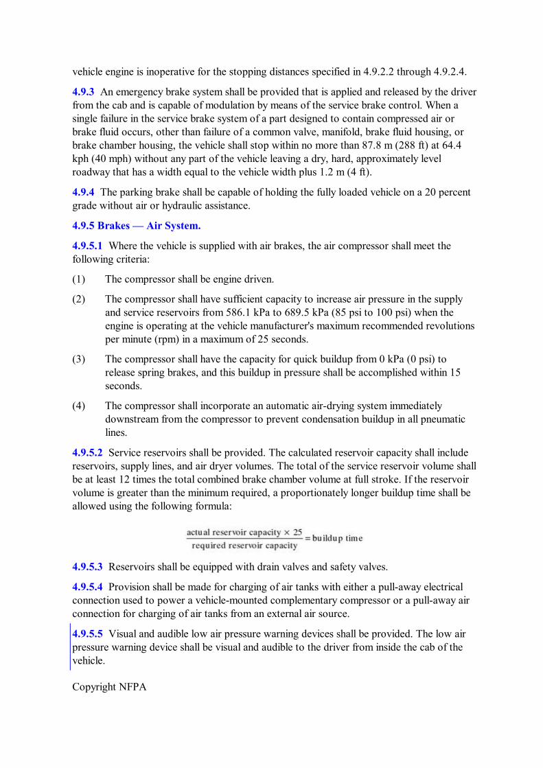
4.9.5.2 Service reservoirs shall be provided. The calculated reservoir capacity shall include reservoirs, supply lines, and air dryer volumes. The total of the service reservoir volume shall be at least 12 times the total combined brake chamber volume at full stroke. If the reservoir volume is greater than the minimum required, a proportionately longer buildup time shall be allowed using the following formula:
4.9.5.3 Reservoirs shall be equipped with drain valves and safety valves.
4.9.5.4 Provision shall be made for charging of air tanks with either a pullaway electrical connection used to power a vehiclemounted complementary compressor or a pullaway air connection for charging of air tanks from an external air source.
4.9.5.5 Visual and audible low air pressure warning devices shall be provided. The low air pressure warning device shall be visual and audible to the driver from inside the cab of the vehicle.
Copyright NFPA
4.10 Steering.
4.10.1 The chassis shall be equipped with powerassisted steering with direct mechanical linkage from the steering wheel to the steered axle(s) to allow manual control in the event of powerassist failure.
4.10.2 The power steering system shall have sufficient capacity so that no more than 66.7 N (15 lbf) pull is needed on the steering wheel rim in order to turn the steering linkage from stop to stop with the fully loaded vehicle stationary on a dry, level, paved surface with the engine at idle.
4.10.3 The walltowall turning diameter of the fully loaded vehicle shall be less than three times the vehicle length.
4.11 Cab.
All interior crew and driving compartment door handles shall be designed and installed to protect against accidental or inadvertent opening.
4.11.1 The cab shall be fully enclosed (i.e., floor, roof, and four sides). Seating for the crew shall be restricted to the cab. The maximum number of crew seat positions provided in the cab shall be designated by the manufacturer and so labeled in the cab. As a minimum, two designated seat positions shall be provided, one for the driver and one for an additional crew member. Threepoint seat belts equipped with a single hand hookup shall be provided for each of the designated seating positions. Space shall be provided for all instrument controls and equipment specified without hindering the crew. Doors that open to as wide a position as possible shall be provided on each side of the cab with the necessary steps and handrails to allow rapid and safe entrance and exit from the cab. Each door shall be equipped with a sufficient restraint device(s) to prevent the door from being sprung by wind or jet blast. The cab design shall take into consideration the provision of ample space for the crew to enter and exit the cab and carry out normal operations while wearing full protective equipment.
4.11.2 The cab shall meet the visibility requirements of 4.2.2.3. Interior cab reflections from exterior and interior lighting shall be minimized. The windshield shall be shatterproof safety glass, and all other windows shall be constructed of approved safety glass. The cab shall be provided with wide gutters to prevent foam and water from dripping on the windshield and side windows. Where equipped with a primary turret having manual controls above the cab roof, the cab shall be designed with a quickaccess passage to the primary turret(s).
4.11.3 The cab shall be weatherproof and shall be fully insulated thermally and acoustically with a fireresistant material. The cab interior noise level at any seated position shall not exceed 85 dBA while traveling at 80.5 kph (50 mph) on a level, hard surface without warning devices operating; and while stationary, discharging water or foam from the highvolume turrets with exterior warning devices operating, the maximum limit shall be 90 dBA. The cab shall be permitted to be of the unitized rigid body and frame structure type, or it shall be permitted to be a separate unit flexibly mounted on the main vehicle frame. The cab shall be constructed from materials of adequate strength to ensure a high degree of safety for the crew under all operating conditions, including excess heat exposure and vehicle
Copyright NFPA
rollover accidents.
4.11.4 Instruments, Warning Lights, and Controls.
4.11.4.1 The minimum number of instruments, warning lights, and controls consistent with the safe and efficient operation of the vehicle, chassis, and firefighting system shall be provided. All chassis instruments and warning lights shall be grouped together on a panel in front of the driver. All firefighting system instruments, warning lights, and controls shall be grouped together by function to provide ready accessibility and high visibility for the driver as well as crew members.
4.11.4.2* All instruments and controls shall be illuminated, and backlighting shall be used where practical.
4.11.4.3 Groupings of both the chassis and firefighting system instruments, warning lights, and controls shall be easily removable as a unit or shall be on a panel hinged for back access by the use of quick disconnect fittings for all electrical, air, and hydraulic circuits.
4.11.4.4 The following instruments or warning lights, or both, shall be provided as a minimum:
(1) Speedometer/odometer
(2) Engine tachometer(s)
(3) Fuel level
(4) Air pressure
(5) Engine(s) temperature
(6) Fire system pressure
(7) Water tank level
(8) Foam–liquid tank level
(9) Low air pressure warning
(10) Headlight beam indicator
(11) Engine(s) oil pressure
(12) Voltmeter(s)
(13) Transmission oil temperature
(14) Inclinometer and a lateral Gforce indicator; or an electronic stability control system; or both
(15) Forward looking infrared (FLIR) monitor
In 4.11.4.4(4), (6), (7), (8), and (9), this component shall not be applicable to small commercial chassis. 4.11.4.5 The cab shall have all the necessary controls within easy reach of the driver for the
Copyright NFPA
full operation of the vehicle and the pumping system. The following cab controls shall be provided:
(1) Accelerator pedal
(2) Brake pedal
(3) Parking brake control
(4) Steering wheel, with directional signal control and horn
(5) Transmission range selector
(6) Pump control or selector
(7) Foam control
(8) Siren switch(es)
(9) Bumper turret controls or ground sweep valve control, where specified
(10) Undertruck valve control, where specified
(11) Remote turret controls, where remote turret is provided
(12) Light switches
(13) Windshield wipers with delayed and multispeed capability and washer controls
(14) Heater/defroster controls
(15) Master electrical switch
(16) Means of starting and stopping engine
(17) Complementary agent pressurization control, where specified
(18) Windshield deluge system switch, where specified
4.11.4.6 Where specified, a windshield deluge system shall be included to cool the windshield and to provide operator visibility during firefighting operations. It shall be designed to flood the windshield with clear water when activated. Clear water shall be discharged under sufficient pressure and in a pattern that ensures the driver/operator's field of vision can be kept clear of foam solution where used in conjunction with the windshield wiper. The windshield wipers shall be energized automatically whenever the deluge system is operated.
4.11.4.7* Where specified, vehicles shall be equipped with the navigation system of a driver's enhanced vision system (DEVS).
4.11.4.7.1 The ARFF vehicle's position shall be displayed on a moving map display that shall be mounted in the cab. The vehicle's position shall be displayed within an accuracy of 2 m (6.56 ft), as well as the direction of travel. The map shall automatically pan and reorient itself to show the area around the vehicle.
4.11.4.8* A lowvisibility enhanced vision system shall be installed in the vehicle. This system shall consist of a FLIR camera, monitor, and controlling devices, and shall provide
Copyright NFPA
the operator with a thermal image to provide assistance in driving under lowvisibility conditions.
4.11.4.8.1 The FLIR shall have automatic gain and level controls and minimum horizontal fields of view (HFOV) of 27 degrees ±4 degrees and vertical fields of view (VFOV) of 18 degrees ±4 degrees, respectively. The FLIR shall be permitted to be a cooled or uncooled camera but shall be able to detect long wave (8 m to 12 m) infrared (IR) energy and have industry standard output.
4.11.5 Equipment.
4.11.5.1 The following equipment shall be provided in or on the cab, as applicable:
(1) Heater/defroster
(2) Driver's suspension seat with vertical, fore and aft adjustment, with seat belt (The use of a nonsuspension driver's seat shall be permitted where recommended by the manufacturer.)
(3) Crew seats with individual retractable seat belts
(4) Windshield washers appropriate for removing foam
(5) Windshield wipers appropriate for removing foam
(6) Siren
(7) Horn
(8) Sun visors, interior transparent
(9) Outside rearview mirrors, as specified in 4.2.2.4
(10) Interior lighting
(11) Provisions for mounting selfcontained breathing apparatus (SCBA) of the type specified by the purchaser at each crew seat position
(12) Lowvisibility forwardlooking infrared device meeting suggested specifications contained in Section E.4 or equivalent
4.11.5.2 Where tools, equipment, or selfcontained breathing apparatus (SCBA) are carried within enclosed seating areas of fire department vehicles, such items shall be secured by either a positive mechanical means of holding the item in its stored position or in a compartment with a positive latching door. The means for holding the item in place or in the compartment shall be designed to minimize injury to persons in the enclosed area of the vehicle caused by loose equipment during travel and, in the event of an accident, a rapid deceleration or a rapid acceleration.
4.11.6 Signs that state “Occupants must be seated and wearing a seat belt when apparatus is in motion” shall be provided. Such signs shall be visible from each seated position. An accident prevention sign shall be located at the rear step area of the vehicle, if it exists. It shall warn personnel that standing on the step while the vehicle is in motion is prohibited.
4.11.7* Where specified, a monitoring and data acquisition system (MADAS) shall be
Copyright NFPA
installed for the collection of various performance measurements to monitor, as a minimum, the following:
(1) Vehicle speed
(2) Vehicle heading
(3) Lateral acceleration
(4) Vertical acceleration
(5) Longitudinal acceleration and deceleration
(6) Engine rpm
(7) Throttle position
(8) Steering input
(9) Vehicle braking input (pedal position and brake pressure)
(10) Date, time, and location for all data collected
4.11.7.1 The data acquisition system shall be capable of storing the measurements and the time intervals, starting at least 120 seconds before and ending at least 15 seconds after any serious incident. The system shall be designed so that the data being recorded will not be lost or overwritten immediately after the incident due to the use of an emergency shutoff or a master electrical disconnect switch.
4.11.8* A lateral acceleration indicator that is adjustable for sensitivity and that provides both visual and audio signals and warnings to the driver shall be provided.
4.12 Body.
4.12.1 The body shall be constructed of materials that are of the lightest weight consistent with the strength necessary for offpavement operation over rough terrain and where exposed to excess heat. The body shall be permitted to be of the unitizedwithchassisrigidstructure type, or it shall be permitted to be flexibly mounted on the vehicle chassis. It also shall include front and rear fenders or wheel wells. Body panels shall be removable where necessary to provide access to the interior of the vehicle.
4.12.2 Access doors shall be provided for those areas of the interior of the vehicle that are inspected frequently. In particular, access doors of sufficient size and number shall be provided for access to the following:
(1) Engine
(2) Pump
(3) Foam proportioning system
(4) Battery storage
(5) Fluid reservoirs
Other areas that need to be accessible for inspection or maintenance shall be open or shall
Copyright NFPA
have removable panels.
4.12.3 Suitable, lighted compartments shall be provided for convenient storage of equipment and tools to be carried on the vehicle. Compartments shall be weather resistant and selfdraining.
4.12.4 A working deck shall be provided and shall be reinforced adequately to allow the crew to perform its duties in the primary turret area, cab hatch area, water tank top fill area and foam–liquid top fill area, and in other areas where access to complementary or installed equipment is necessary. The working deck shall be constructed of, or covered with, a slipresistant material.
4.12.5 Handrails or bulwarks shall be provided where necessary for the safety and convenience of the crew. Rails and stanchions shall be braced strongly and constructed of a material that is durable and resists corrosion. Handrails shall be constructed of, or covered with, a slipresistant material.
4.12.6 Steps or ladders shall be provided for access to the top fill area. The lowermost step(s) shall be permitted to extend below the angle of approach or departure or ground clearance limits if it is designed to swing clear. All other steps shall be rigidly constructed. All steps shall be constructed of, or covered with, a slipresistant material. The lowermost step(s) shall be no more than 558.8 mm (22 in.) above level ground when the vehicle is fully loaded. Adequate lighting shall be provided to illuminate steps and walkways.
4.12.7 A heavyduty front bumper shall be mounted on the vehicle and secured to the frame structure.
4.12.8 Vehicle numbering, lettering, and minimum 20.3 cm (8 in.) wide reflective striping shall be provided in accordance with ASTM D 4956. Striping shall be placed on at least 60 percent of the perimeter length of each side, width, and rear. At least 40 percent of the perimeter width of the front of the vehicle shall have the reflective stripe.
4.12.8.1 A graphic design meeting the reflectivity requirements of this subsection shall be permitted to replace all or part of the required striping, provided the design or combination thereof covers a minimum of the same perimeter length required in 4.12.8.
4.12.9 Attachments shall be provided for all tools, equipment, and other items that the purchaser specifies to be furnished on the vehicle. Equipment holders shall be attached firmly and designed so that equipment remains in place under all operating conditions, but the equipment shall be quickly removable for use.
4.12.10* Each storage compartment identified by the vehicle manufacturer for use by the purchaser shall be labeled with tested weight. Compartment loading shall not be exceeded as identified at the time of vehicle manufacture. Provision shall be made for mounting tools and equipment, as specified by the purchaser, on the truck. Special tools for servicing the vehicle, fire suppression system, and any of the auxiliary equipment shall be furnished as necessary by the vehicle manufacturer. Altering locations of tools and equipment will have an effect on vehicle stability.
4.13 FireFighting Systems and Agents.
Copyright NFPA
4.13.1 For ARFF purposes, vehicles using primary extinguishing agents shall be tested in accordance with NFPA 412.
4.13.2 Vehicles designed to discharge complementary agents shall require the use of complementary agents that are compatible with the primary agent.
4.13.3 All components of the agent systems, including such items as the tanks, piping, fill troughs, and screens, shall be made of materials resistant to corrosion by the primary agent, primary agent/water solution, water, and, where specified, the complementary agent.
4.13.4 Combinations of high pressure lines, valves, and quick disconnect fittings that allow for the inservice refilling of propellents without requiring the removal of the high pressure vessels from the truck shall be permitted.
4.14 Agent Pump(s) and Pump Drive.
4.14.1 Agent Pump(s).
4.14.1.1 The water pump(s) shall be constructed of corrosionresistant metals and shall be of the singlestage or multiplestage centrifugal type and shall be designed for dependable emergency service. Pumps shall be designed carefully and built in accordance with good modern practice. Pumps shall be gravity primed from the vehicle tank. The pump and piping system shall be designed to eliminate the entrapment of air.
4.14.1.2 All proportioning system components shall be made of materials resistant to corrosion by all primary agents.
4.14.1.3 Where discharging foam solution, the pumping system shall be capable of discharging at a rate equal to or exceeding the total requirements of the roof or extendable turret(s), bumper turret or ground sweep nozzles, handline nozzles, and undertruck nozzles, where specified, discharging simultaneously at designed pressures.
4.14.2 Pump Drive.
4.14.2.1 The pump(s) drive shall allow operation of the pump(s) and simultaneous operation of the vehicle. The pump(s) shall not be affected by changes in transmission ratios or the actuation of clutches in the vehicle drive. The design of the drive system and controls shall prevent damage to the drive and shall minimize lurching of the vehicle when the vehicle drive is engaged during pumping operations. The pump(s) drive system shall be capable of absorbing the maximum torque delivered by the engine to the pump(s) and withstanding the engagement of the pump(s) at all engine and vehicle speeds and under all operating conditions. The operation of the pump(s) shall not, under any conditions, cause the engine to stall or cause more than a slight and momentary reduction in engine speed and consequent drop in pump pressure.
4.14.2.2 While pumping at rated capacity, the drive shall allow controlled vehicle operation at speeds from 0 kph to a minimum of 16.1 kph (0 mph to a minimum of 10 mph) in forward direction and 0 kph to a minimum of 8 kph (0 mph to a minimum of 5 mph) in rearward direction. During shifting from forward to rearward drive, the pumping system shall maintain the preset discharge pressure. The pump(s) drive shall have sufficient power capacity to
Copyright NFPA
provide the pump(s) discharge requirements of 4.14.1.3 while the vehicle is being propelled under all operating conditions where a firefighting capability is needed.
4.14.2.3 If an independent engine is used to drive the pump(s), it shall have the same fuel and electrical system as the chassis engine and shall be equipped with an air cleaner, a replaceable element oil filter, a full pressure lubricating system, and an overspeed governing device to prevent engine damage. The engine also shall be provided with a cooling system that meets the requirements of 4.3.2.
4.14.3 TanktoPump Connections.
4.14.3.1 The tanktopump system shall be designed for efficient flow at the pumping rates required by 4.14.1.3. The pump suction line(s) shall be of large diameter and of the shortest length consistent with the most suitable pump location. A drain shall be at the lowest point with a valve for draining all of the liquid from the pumping system where desired. Tanktopump lines and valves shall be constructed of corrosionresistant materials.
4.14.4 Discharge Connections. All couplings shall be specified by the purchaser to the standard for the airport.
4.14.5 Piping, Couplings, and Valves.
4.14.5.1 All piping, couplings, and valves shall be sized for necessary flow with minimum restriction and pressure loss. Material for all piping, couplings, and valves shall be selected to avoid corrosive or galvanic action.
4.14.5.2 Piping shall be mounted securely and provided with flexible couplings to minimize stress. Union or rubbergasketed fittings shall be provided where necessary to facilitate removal of piping.
4.14.5.3 All valves shall be of the quarterturn type and shall be selected for ease of operation and freedom from leakage.
4.14.5.4 All water system piping shall be tested on the tanktopump side of the pump to detect possible leakage. All water and foam solution discharge piping, together with the agent pump(s), shall be tested at 50 percent above the system operating pressure.
4.14.6 Overheat Protection. A system line shall be provided from the water pump discharge and, if applicable, from the foam pump discharge to prevent overheating of the pumps while engaged and operating at zero discharge. The overheat protection system shall be automatic and operate a visual alarm if an overheating situation occurs.
4.14.7 Pressure Relief Valves. A pressure relief system shall be provided to protect and ensure optimum performance of the system.
4.14.8 Drains. A drainage system shall be provided appropriate for the design of the vehicle.
4.15 Water Tank.
4.15.1 Capacity.
4.15.1.1 A water tank shall have a usable capacity as specified in Table 4.1.1(a) and Table
Copyright NFPA
4.1.1(b).
4.15.1.2 The rated capacity of the tank shall be equal to the usable capacity that can be pumped from the tank while the vehicle is parked on level ground. The tank outlets shall be arranged to allow the use of at least 85 percent of the rated capacity with the vehicle positioned as follows:
(1) On a 20 percent side slope
(2) On a 30 percent ascending grade
(3) On a 30 percent descending grade
4.15.2 Construction.
4.15.2.1 The tank shall be constructed to resist all forms of deterioration that could be caused by the water and foam concentrate while affording the structural integrity necessary for offroad operation. The tank shall have longitudinal and transverse baffles. The construction and connections shall be made to prevent the possibility of galvanic corrosion of dissimilar metals.
4.15.2.2 The tank shall be equipped with easily removable manhole covers over the tank discharge. Tanks shall be designed to allow for internal and external inspection and service. A large capacity drain connection shall be installed at the bottom of the sump.
4.15.2.3 Provisions shall be made for necessary overflow and venting. Venting shall be sized to allow agent discharge at the maximum design flow rate without danger of tank collapse and shall be sized to allow rapid and complete filling without exceeding the internal pressure design limit of the tank. Additionally, overflows shall be designed to prevent loss of water from the tank during normal maneuvering and to direct the discharge of overflow water directly to the ground.
4.15.2.4 The water tank shall be mounted in a manner that limits the transfer of the torsional strains from the chassis frame to the tank during offpavement driving. The tank shall be separate and distinct from the crew compartment, engine compartment, and chassis and shall be easily removable as a unit. Water tanks used as an integral part of unitized rigid body construction shall be permitted.
4.15.2.5 The water tank shall be equipped with at least one top fill opening of not less than 20.3 cm (8 in.) internal diameter. The top fill shall be equipped with an easily removable strainer of 6.4 mm (¼ in.) mesh construction. The top fill opening shall be equipped with a cap designed to prevent spillage.
4.15.2.6 For vehicles less than 1998.5 L (528 gal), the water tank shall be equipped with at least one top fill opening of not less than 127 mm (5 in.) internal diameter.
4.15.3 Tank Fill Connection(s).
4.15.3.1 A tank fill connection(s) shall be provided in a position where it can be reached easily from the ground.
4.15.3.2 All couplings shall be specified by the purchaser to the standard for the airport.
Copyright NFPA
4.15.3.3 The connection(s) shall be provided with strainers of 6.4 mm (¼ in.) mesh and shall have check valves or shall be constructed so that water is not lost from the tank when connection or disconnection is made.
4.15.3.4 The tank fill connection(s) shall be sized to allow filling of the water tank in 2 minutes at a pressure of 551.6 kPa (80 psi) at the tank intake connection.
4.16* Foam System.
4.16.1 Foam–Liquid Concentrate Tank(s).
4.16.1.1 The purchaser shall specify the percent concentrate foam system to be provided. The foam–liquid concentrate tank(s) shall have a working capacity sufficient for two tanks of water at the maximum tolerance specified in NFPA 412.
4.16.1.2 Foam–liquid concentrate tanks shall be permitted to be of either the rigid or flexible type. The tank(s) shall be designed for compatibility with the foam concentrate being used and shall resist all forms of deterioration that could be caused by the foam concentrate or water.
4.16.1.3 Tanks shall be designed to allow for internal and external inspection and service. A large capacity drain connection shall be installed at the bottom of the sump.
4.16.1.4 The tank outlets shall be located above the bottom of the sump and shall provide continuous foam–liquid concentrate to the foam proportioning system, with that system operating as specified in 4.16.4 and with the vehicle discharging two tank loads of usable water as specified in 4.15.1.
4.16.1.5 If separate from the water tank, the foam–liquid tank shall be mounted in a manner that limits the transfer of the torsional strains from the chassis frame to the tank during offpavement driving. The tank shall be separate and distinct from the crew compartment, engine compartment, and chassis and shall be easily removable as a unit. Foam–liquid tanks used as an integral part of unitized rigid body construction shall be permitted. A flexible tank shall be structurally supported to resist tearing. The structural support shall not be dependent on the fluid level in either the water or foam tanks.
4.16.1.6 A top fill trough shall be provided and shall be equipped with a mesh screen constructed of noncorrosive materials and container openers to allow emptying 18.9 L (5 gal) foam–liquid concentrate containers into the storage tank(s) at a rapid rate regardless of water tank level. The trough shall be connected to the foam–liquid storage tank(s) with a fill line designed to introduce foam–liquid concentrate near the bottom of the tank(s) to minimize foaming within the storage tank.
4.16.1.7 The tank fill connection(s) shall be provided in a position where it can be reached easily from the ground to allow the pumping of foam–liquid concentrate into the storage tank(s). The connection(s) shall be provided with strainers of 6.4 mm (¼ in.) mesh and shall have check valves or shall be constructed so that foam is not lost from the tank when connection or disconnection is made.
4.16.1.8 Where flexible tanks are used, the supply system shall be designed so that the
Copyright NFPA
flexible tanks are not subject to excess pressure. The supply system shall be capable of delivering foam–liquid at a rate at least equal to or greater than the maximum discharge rate of the foam system.
4.16.1.9 The tank(s) shall be vented adequately to allow rapid and complete filling without the buildup of excessive pressure and to allow emptying of the tank at the maximum design flow rate without danger of collapse. The vent outlets shall be directed to the ground to prevent spillage of foam–liquid concentrate on vehicle components.
4.16.2 Foam Proportioning System Flushing. The foam–liquid concentrate system shall be arranged so that the entire piping system can be flushed readily with clear water.
4.16.3 Foam–Liquid Concentrate Piping.
4.16.3.1* The foam–liquid concentrate piping shall be of material resistant to corrosion by foam–liquid concentrates addressed in this standard. Care shall be taken that combinations of dissimilar metals that produce galvanic corrosion are not selected or that such dissimilar metals are electrically insulated. Where plastic piping is used, it shall be fabricated from unplasticized resins, unless it has been demonstrated that the stipulated plasticizer does not adversely affect the performance characteristics of the foam–liquid concentrates addressed in this standard. The plastic pipe shall be permitted to be reinforced with glass fibers.
4.16.3.2 The foam–liquid concentrate piping shall be adequately sized to allow the maximum required flow rate and shall be arranged to prevent water from entering the foam tank.
4.16.4 Foam Proportioning Systems.
4.16.4.1 The foam concentrate proportioning system shall provide a means of controlling the ratio of foam concentrate to the quantity of water in the foam solution being discharged from all orifices normally used for aircraft firefighting operations.
4.16.4.2 The proportioning system shall be sufficiently accurate to provide for the discharge of finished foam within the range specified in NFPA 412.
4.16.4.3 Each nozzle shall have minimum foam discharge patterns, from a dispersed stream of 4.6 m (15 ft) in width and 6.1 m (20 ft) in range to a straight foam stream with a 19.8 m (65 ft) range.
4.17 Premixed Foam Solutions.
4.17.1 Premixed — Pump System. Where premix solution in the main water tank is selected as the means of proportioning foam to water, the foam solution used shall be aqueous filmforming foam (AFFF) only. Care shall be exercised that the premixed solution is mixed to exact proportions. Where premix solution is used, operation of the vehicle firefighting system shall conform to the requirements of Sections 4.14 and 4.15.
4.17.2 Premixed — Pressurized System.
4.17.2.1 Liquid Agent Container(s).
Copyright NFPA
4.17.2.1.1 The storage container(s) and liquid agent(s) shall be designed for pressurization, shall be constructed in accordance with the ASME Boiler and Pressure Vessel Code, and shall be so marked.
4.17.2.1.2 The material of construction shall be resistant to corrosion by the AFFF agent to be stored, or a suitable lining material shall be provided.
4.17.2.1.3 An American Society of Mechanical Engineers (ASME)approved pressure relief valve of adequate capacity shall be provided on the container and set to prevent pressures in excess of the maximum design working pressure. A pressure gauge shall be provided that indicates the internal pressure of the agent storage container at all times.
4.17.2.1.4 A readily accessible fill opening of sufficient size to allow ease in filling, and stirring if necessary, shall be provided. It shall be in compliance with ASME or local codes and in no case shall be less than 76.2 mm (3 in.) in diameter. Filling shall be accomplished without the removal of any of the extinguisher piping or any major component.
4.17.2.1.5 A means shall be provided to determine the contents of the container as a guide in recharging partial loads.
4.17.2.2 Propellant Gas.
4.17.2.2.1 The propellant gas shall be dry nitrogen or dry compressed air and provided in sufficient quantity to expel the firefighting agent as well as to purge all piping and hose lines after use.
4.17.2.2.2 All propellant gas cylinders and valves shall be in accordance with U.S. Department of Transportation (DOT) requirements or regulations. Cylinders shall bear the DOT marking.
4.17.2.2.3 The design of the propellant source shall provide for quick and easy replacement after each use.
4.17.2.2.4 A pressure gauge shall be provided and shall indicate the pressure of the propellant gas source at all times.
4.17.2.2.5 Cylinder valves, gauges, and piping shall be arranged to preclude accidental mechanical damage.
4.17.2.2.6 The cylinder valve shall be capable of being opened by quickacting control and also shall be suitable for remote operation.
4.17.2.3 Pressure Regulation.
4.17.2.3.1 Pressure regulation shall be designed to reduce the normal cylinder pressure automatically and to hold the propellant gas pressure at the designed operating pressure of the liquid agent container(s).
4.17.2.3.2 All pressureregulating devices shall be sealed or pinned at the designed operating pressures after final adjustment by the system manufacturer.
4.17.2.3.3 Pressureregulating devices shall be equipped with a springloaded relief valve
Copyright NFPA
that relieves any excess pressure that develops in the regulator.
4.17.2.3.4 The pressure regulator shall be permitted to be of a type without pressure indicating gauges.
4.17.2.4 Piping and Valves.
4.17.2.4.1 All propellant piping and fittings shall conform to the appropriate ASME document and shall be designed to withstand the working pressure of the system. The design of the piping and valving shall provide the desired flow of gas into the system and the minimum amount of restriction from the liquid agent container(s) to the hose connection. Where more than one hose line is provided, piping and fittings shall be sized and designed so that there is equal flow to each line, regardless of the number of lines placed in operation.
4.17.2.4.2 Provisions shall be made for purging all piping and hose of the liquid after use without discharging the liquid agent remaining in the container(s). Provisions also shall be made for the depressurization of the liquid agent container(s) without the loss of the remainder of the liquid agent.
4.17.2.4.3 Drains shall be provided to allow complete draining of the system. Drains shall be easily accessible and shall not require the removal of panels, doors, or components for access.
4.17.2.4.4 All valves shall be of the quarterturn, quickopening ball type. A maximum of two operations, exclusive of the nozzle, shall be provided to charge the system. Controls shall be arranged for simultaneous charging of the liquid agent and dry chemical systems. Valves on the gas cylinder specified in 4.17.2.2.2 shall not be required to be of the quarterturn, quickopening ball type.
4.17.2.4.5 A quickacting control to be operated by the driver to pressurize the liquid agent system from the cab of the vehicle shall be provided, with a similar control at the unit.
4.17.2.4.6 All valves and piping shall be resistant to corrosion by the foam–liquid concentrate.
4.17.2.4.7 A check valve shall be provided in the gas piping to prevent the liquid agent from being forced back into the propellant gas line.
4.18 Turret Nozzles.
4.18.1 Aircraft rescue and firefighting vehicles shall have one or two primary turret nozzles.
4.18.2 Turret nozzles with liquid flow rates of 2839 L/min (750 gpm) or more shall be of the dual discharge type and arranged to allow selection of either 50 percent or 100 percent of the turret capacity. The primary turret discharge rates shall have a tolerance of +10 percent/0 percent.
4.18.3 If a turret nozzle is visible from the operator's position in all ranges of motion, an elevation and azimuth indication shall not be required.
4.18.4 The purchaser shall specify whether a manually operated or a powerassisted turret shall be provided. Where a manually operated turret is specified, controls shall be in the cab,
Copyright NFPA
operation force shall be less than 133.4 N (30 lbf), and an indication of turret elevation and azimuth shall be provided. Where a powerassisted turret is specified, controls shall be in the cab, operation force shall be less than 133.4 N (30 lbf), an indicator of turret elevation and azimuth shall be provided, and, where specified, a manual override, or secondary parallel controls powered by an alternate source of all roof turret movement functions shall be provided in the cab. The secondary, parallel controls shall be capable of operating the turret with a failed primary control system. The manual override operation force shall be less than 133.4 N (30 lbf). Where turret control is at the platform, operation forces shall be less than 222.4 N (50 lbf).
4.18.5 Turrets shall be capable of being elevated at least 45 degrees above the horizontal and shall be depressed to discharge agent within 9.1 m (30 ft) in front of the vehicle at full output using a dispersed stream. Where a single turret is used on a vehicle, it shall be capable of being rotated not less than 90 degrees to either side, with total traverse not less than 180 degrees. Where two turrets are used on a vehicle, suitable stops shall be provided so that neither turret can interfere with the other turret. Turret controls for both foam and dry chemical turrets shall be accessible both to the driver and the crew member.
4.18.6* If the primary turret is of the extendable type, it shall meet the following design and functional requirements:
(1) The primary turret shall comply with Chapter 20 of NFPA 1901 and shall meet the requirements of 4.2.1.3 and 4.2.1.4 of this standard while in the stowed position. The vehicle shall achieve a 20 percent side slope, with the extendable turret fully elevated and the nozzle rotated uphill at maximum horizontal rotation while discharging at maximum flow rate. The vehicle shall be provided with an interlock or warning system and placards in full view of the driver/operator to provide the operational limitations during all phases of operation. Flow rates shall be in accordance with Table 4.1.1(c) and Table 4.1.1(d) for major vehicles.
(2) The primary turret shall meet the primary water–foam agent turret discharge requirements of Table 4.1.1(c) and Table 4.1.1(d) for the applicable vehicle class while in the bedded position.
(3) The primary turrret shall meet the foam quality standard of NFPA 412 for the applicable foam applicator and foam type.
(4) The primary turret shall function during ARFF operations without the need for outriggers or other ground contact stabilizers that would render the vehicle immobile or hinder its maneuverability.
(5) The primary turret shall achieve the elevation and reach needed to service the highest engine for the type of aircraft being protected and shall start application within 30 seconds of activation of the deployment cycle. The high rise, telescoping, and/or articulating movement of the boom/tower shall be accomplished with not more than two adjacent lever controls and shall be permitted to be manual or automated for preselected positioning of the elevation and reach. If automated, these functions shall be provided with a manual override positioning capability.
(6) The primary turret shall be capable of applying agent to any interior area of the most
Copyright NFPA
current widebody jet, so as not to impede evacuation and for safety considerations of the vehicle operator. In addition, the device shall be capable of positioning the nozzle within 0.6 m (2 ft) of ground level in front of the vehicle and be capable of applying agent to the interior of the aircraft through cargo bay door openings, passenger doorways, and emergency exits on the type of aircraft being protected while the aircraft is in either the gearup or geardown landing position.
(7) The primary turret shall have a range of motion so as to permit positioning of the nozzle to direct a firefighting agent stream at least 90 degrees to the longitudinal axis of the fuselage for interior fire extinguishment.
(8) The turret/boom mechanism shall be capable of providing for horizontal movement along the aircraft of at least 30 degrees left and right of the vehicle centerline so as not to require repositioning or movement of the ARFF vehicle. This horizontal rotation must be accomplished without the deployment of stabilizers or outriggers that might cause a delay in positioning or emergency movement of the rescue vehicle.
(9) The primary turret shall have sufficient backup systems to allow for override of the single lever boom control and hydraulic system (or other power source) if the primary system becomes disabled.
4.18.6.1 If specified by the purchaser as the primary water–foam and dry chemical turret — that is, to function as a dual agent turret system — the device shall also be capable of meeting the agent discharge performance of Table 4.1.1(c) and Table 4.1.1(d) while in the bedded position.
4.18.6.2 An adjustable or dual flow rate nozzle shall be provided that will allow flow rates and patterns suitable for interior aircraft fire fighting [see Table 4.1.1(c) and Table 4.1.1(d)].
4.18.6.3 Controls for the extendable turret and options shall be as specified. Where specified, the extendable turret shall be fitted with accessories and devices needed for a driver or another operator to remotely perform the interior aircraft and highest engine firefighting functions.
4.18.6.4 Where auxiliary agent lines are specified, they shall be capable of discharging either dry chemical or halocarbon agent or approved equivalent through an appropriate nozzle while the device is extended out and up to its maximum operational reach. Auxiliary agent lines shall meet the minimum auxiliary agent flow rate and pattern requirements of Table 4.1.1(c) and Table 4.1.1(d).
4.18.6.5 Where remote color optics are specified, they shall be capable of sufficient resolution to permit overall fire scene surveillance when fully extended and to provide the driver/operator with the detail needed for placement of the penetration device on the aircraft hull for proper piercing. The camera and associated lighting shall be designed and installed for exterior environmental operating conditions normally encountered by ARFF vehicles. A monitor 178 mm (7 in.) or larger shall be cabmounted in a roadworthy manner and shall be readily accessible to the driver/operator.
4.18.6.6 Where a skin penetrator/agent applicator is specified, it shall be movable in conjunction with the water–foam nozzle to allow proper placement of the nozzle control.
Copyright NFPA
Where a skin penetrator/agent applicator is specified, it shall be capable of the minimum water–foam flow rate and pattern requirements of Table 4.1.1(c) and Table 4.1.1(d).
4.18.6.7* The penetrating nozzle shall be capable of a minimum flow rate of 946 L/min (250 gpm). The nozzle system shall be constructed to direct or spray agent and water on both sides of the aircraft at the same time after the penetration is made. [Conceptdelivery shall be multiple holes causing a spray to cover 7.6 m to 9.1 m (25 ft to 30 ft) on each side of the aircraft interior and in the aircraft aisleway.] From a bedded position, penetration and agent discharge shall take place 20 seconds after positioning the vehicle at the aircraft fuselage and providing water to the floor and ceiling levels beyond the overhead storage bin area.
4.18.7* Lightweight boommounted turrets shall be permitted as primary turrets. These turrets shall meet the following design and functional requirements:
(1) They shall comply with Chapter 20 of NFPA 1901 and shall meet the requirements of 4.2.1.3 and 4.2.1.4 of this standard while in the stowed position.
(2) They shall achieve a 20 percent side slope with the boom turret fully elevated and the nozzle fully rotated uphill at maximum horizontal rotation while discharging at maximum flow rate.
(3) Flow rates shall be in accordance with Table 4.1.1(c) and Table 4.1.1(d) for major vehicles.
(4) They shall meet the primary water–foam agent turret discharge requirements of Table 4.1.1(c) and Table 4.1.1(d) for the applicable vehicle class while in the bedded condition.
(5) They shall meet the foam quality standard of NFPA 412.
(6) They shall function during ARE operations without the need for outriggers or other ground contact stabilizers that could render the vehicle immobile or hinder its maneuverability.
(7) They shall achieve the elevation and reach needed to service the highest engine for the type of aircraft being protected and start application of agent within 30 seconds of activation of the deployment cycle.
(8) They shall be capable of applying agent through passenger doorways, to interior areas of the type of aircraft being protected. In addition, the device must permit the operator to position the nozzle assembly so as to be able to discharge the agent in front of the vehicle at a level that permits the operator to see over the turret discharge.
(9) They shall have a range of motion so as to permit positioning of the nozzle to direct a firefighting agent stream along the longitudinal axis of the fuselage or up to 90 degrees to the longitudinal axis for interior fire extinguishments.
4.19 Preconnected Handlines.
Preconnected handlines shall be those handlines for discharging water or foam, or both, that are specified by the purchaser as intended for use as primary ARFF equipment. All other
Copyright NFPA
handlines that are installed on the vehicle shall not be considered as being preconnected handlines.
4.19.1 Combined agent vehicles shall have at least one preconnected handline and nozzle for each agent. Handlines and nozzles shall be permitted to be separate or twinned together for simultaneous agent discharge. Handlines shall be permitted to be reeled handlines as specified in Table 4.1.1(a), Table 4.1.1(b), Table 4.1.1(c), and Table 4.1.1(d).
4.19.2 Each preconnected handline compartment shall be located so that the distance between the handline nozzle and the ground, step, or surface upon which the operator stands to initiate the pulling of the handline from the reel or top layer of collapsible hose is not more than 1.8 m (6 ft) above the surface.
4.19.3 Preconnected Reeled Handlines and Nozzles.
4.19.3.1 Handlines for reels shall have a minimum burst rating three times the nominal working pressure of the system and shall be able to discharge the flow required in Table 4.1.1(c) and Table 4.1.1(d) without unreeling the hose.
4.19.3.2 Each handline shall be equipped with a pistol grip shutofftype nozzle designed to discharge both foam and water in accordance with the performance criteria in Table 4.1.1(c) and Table 4.1.1(d) and shall meet the requirements of NFPA 1964.
4.19.3.3 Each hose reel shall be designed and positioned to allow hose reel removal by a single person from any position in a 120 degree horizontal sector. Each hose reel shall be designed to prevent the hose from unreeling when not desired. A power rewind with manual override shall be provided. The nozzle holder, friction brake, rewind controls, and manual valve control shall be accessible to the person using the hose reel.
4.19.3.4 The discharge control to each handline shall be adjacent to the handline and accessible to the person using the handline.
4.19.4 Preconnected Collapsible Handlines and Nozzles.
4.19.4.1 Collapsible handlines shall meet the requirements of NFPA 1961 and Table 4.1.1(c) and Table 4.1.1(d).
4.19.4.2 Each handline shall be equipped with a pistol grip shutofftype nozzle designed to discharge foam and water in accordance with the performance criteria in Table 4.1.1(c) and Table 4.1.1(d) and shall meet the requirements of NFPA 1964.
4.19.4.3 Hose storage areas shall be fabricated from noncorrosive material and shall be designed to drain effectively. The storage area shall be smooth and free from all projections that might damage the hose. No other equipment shall be mounted or located where it can obstruct the removal of the hose.
4.19.4.4 The discharge control to each handline shall be adjacent to the handline and accessible to the person using the handline.
4.20 Turret, Ground Sweep, and Undertruck Nozzles.
4.20.1 Where a bumper turret or ground sweep nozzle(s) is provided, the controls shall be
Copyright NFPA
mounted inside the cab within easy reach of the driver and a crew position. Where the extendable, or boom, turret is capable of supplying agent as specified as a primary turret, as a bumper turret, or as a ground sweep nozzle(s), the requirement for a bumper turret or ground sweep nozzle(s) shall be permitted to be omitted at the option of the purchaser.
4.20.2 The turret shall have a horizontal rotation of 180 degrees and vertical travel of +45 degrees/20 degrees.
4.20.3 Where specified, two or more undertruck nozzles shall be mounted under the truck and controlled from the cab. A sufficient number shall be provided to protect the bottom of the vehicle and the inner sides of the wheels and tires with foam solution discharged in a spray pattern.
4.20.4 Turrets, handlines, and ground sweeps shall discharge foam having the quality specified in NFPA 412. Measurement of the expansion ratio and 25 percent drainage times shall be in accordance with the procedures outlined in NFPA 412.
4.21 Complementary Agent System.
Where specified, the vehicle shall be equipped with a complementary agent system.
4.21.1 Dry Chemical Container. The dry chemical container shall be constructed in accordance with the ASME Boiler and Pressure Vessel Code, Section 8, or equivalent, and shall be so stamped.
4.21.1.1 All piping and fittings shall conform to the appropriate ASME, or equivalent, code and shall be designed to withstand the working pressure of the system. The design of the piping and valving shall provide the desired flow of gas into the system and the minimum amount of restriction from the chemical container(s) to the hose connection. Where more than one hose line is provided, piping and fittings shall be sized and designed so that there is equal flow to each line, regardless of the number of lines placed in operation.
4.21.1.2 Provisions shall be made for purging all piping and hose of dry chemical after use without discharging the dry chemical remaining in the dry chemical container(s). Provisions also shall be made for the depressurization of the dry chemical container(s) without the loss of the remainder of the dry chemical. A pressure gauge shall be provided that indicates the internal pressure of the agent storage container(s) at all times.
4.21.1.3 The system shall be designed to ensure fluidization of the dry chemical at the time of operation. Where any design includes the movement of the chemical container(s) to fluidize the contents, such design also shall include a manual operating feature.
4.21.1.4 A check valve shall be provided in the gas piping to prevent the extinguishing agent from being forced back into the propellant gas line.
4.21.1.5 A means of pressure relief conforming to appropriate ASME codes shall be provided for the dry chemical container and piping to prevent overpressurization in the event of a malfunction in the propellant gas regulator system or in the event the container is involved in a severe fire exposure.
4.21.1.6* The fill opening in the dry chemical container shall be located so that it is easily
Copyright NFPA
accessible for recharging and necessitates a minimum amount of time and effort to open and close. Filling shall be accomplished without the removal of any of the extinguisher piping or any major component.
4.21.1.7 A quickacting control to be operated by the driver to pressurize the dry chemical agent system from the cab of the vehicle shall be provided, with a similar control at the handline.
4.21.1.8 The pressure container shall be designed to allow hydrostatic testing.
4.21.2 Dry Chemical Propellant.
4.21.2.1 The propelling agent shall be dry nitrogen, dry air, argon, or carbon dioxide.
4.21.2.2 All propellant gas cylinders and valves shall be in accordance with U.S. DOT, or equivalent, requirements or regulations. Cylinders shall bear the DOT marking or equivalent markings.
4.21.2.3 The method of adequately pressurizing and propelling the dry chemical in the system shall provide a sufficient quantity of gas to expel the agent, as well as allow the complete purging of all piping and hose lines after each use.
4.21.2.4 The design of the propellant source shall provide for quick and easy replacement after each use.
4.21.2.5 A pressure gauge shall be provided and shall indicate the pressure on the propellant gas source at all times.
4.21.2.6 Cylinder valves, gauges, and piping shall be arranged to preclude accidental mechanical damage.
4.21.3 Dry Chemical Pressure Regulation.
4.21.3.1 Pressure regulation shall be designed to reduce the normal cylinder pressure automatically and to hold the propellant gas pressure at the designed operating pressure of the dry chemical container(s).
4.21.3.2 All pressureregulating devices shall be sealed or pinned at the designed operating pressures after final adjustment by the system manufacturer.
4.21.3.3 Pressureregulating devices shall be equipped with a springloaded relief valve that relieves any excess pressure that develops in the regulator.
4.21.3.4 The pressure regulator shall be permitted to be of a type without pressure indicating gauges.
4.22 Halogenated Agent.
4.22.1 Halogenated Agent Container.
4.22.1.1 The storage container shall be designed for pressurization and shall be constructed in accordance with the ASME Boiler and Pressure Vessel Code, or equivalent, and shall be so marked.
Copyright NFPA
4.22.1.1.1 Where specified, a reservice kit shall be provided with the delivery of the truck.
4.22.1.2 The material of construction shall be resistant to corrosion by the halogenated agent to be stored.
4.22.1.3 A readily accessible charge coupling of sufficient size to allow ease in filling shall be provided. Filling shall be accomplished without the removal of any of the extinguisher piping or any major component. A pressure gauge shall be provided that indicates the internal pressure of the agent storage containers at all times.
4.22.1.4 A means shall be provided to determine the contents of the container as a guide in recharging partial loads and to prevent overfilling of the tank.
4.22.2 Halogenated Agent Propellant Gases.
4.22.2.1 The propellant gas shall be provided in sufficient quantity to expel the halogenated agent as well as to purge all piping and hose lines after use.
4.22.2.1.1 Dry air shall have a dew point of 51°C (60°F) or lower.
4.22.2.1.2 Dry nitrogen shall have a dew point of 51°C (60°F) or lower.
4.22.2.2 All propellant gas cylinders and valves shall be in accordance with U.S. DOT, or equivalent, requirements or regulations. Cylinders shall bear the DOT marking or equivalent markings.
4.22.2.3 Pipes and valves connected to the halogenated agent container shall conform to the appropriate ASME, or equivalent, code and shall be designed to withstand the working pressure of the system.
4.22.2.4 The design of the propellant source shall provide for quick and easy replacement after each use.
4.22.2.5 A pressure gauge shall be provided and shall indicate the pressure of the propellant gas source at all times.
4.22.2.6 Cylinder valves, gauges, and piping shall be arranged to preclude accidental mechanical damage.
4.22.2.7 A check valve shall be provided in the gas piping to prevent the liquid agent from being forced back into the propellant gas line.
4.22.3 Halogenated Agent Pressure Regulation.
4.22.3.1 An ASME, or equivalent, approved pressure relief valve of adequate capacity shall be provided on the container and shall be set to prevent pressures in excess of the maximum design working pressure.
4.22.3.2 Pressure regulation shall be designed to reduce the normal cylinder pressure automatically and to hold the propellant gas pressure at the designed operating pressure of the halogenated agent container(s).
4.22.3.3 All pressure regulating devices shall be sealed or pinned at the designed operating
Copyright NFPA
pressures after final adjustment by the system manufacturer.
4.22.3.4 Pressure regulating devices shall be equipped with a springloaded relief valve that relieves any excess pressure that develops in the regulator.
4.22.3.5 The pressure regulator shall be permitted to be of a type without pressure indicating gauges.
4.22.4 Halogenated Agent Delivery Piping and Valves.
4.22.4.1 All piping, couplings, and valves shall be sized for necessary flow with minimum restriction and pressure loss. Material for all piping, couplings, and valves shall be selected to avoid corrosive and galvanic action. Piping shall be mounted securely and provided with flexible couplings to minimize stress.
4.22.4.2 All valves shall be of the quarterturn type and shall be selected for ease of operation and freedom from leakage.
4.22.4.3 All discharge piping shall be tested at 50 percent above the system operating pressure.
4.22.4.4 Where more than one hose line is provided, piping and fittings shall be sized and designed so that there is equal flow to each line, regardless of the number of lines placed in operation.
4.22.4.5 Provisions shall be made for purging all piping and hose of the halogenated agent after use without discharging the halogenated agent remaining in the container(s). Provisions also shall be made for venting of the halogenated agent container without loss of the remainder of the liquid agent.
4.22.4.6 A quickacting control to be operated by the driver to pressurize the halogenated agent system from the cab of the vehicle shall be provided, with a similar control at the handline.
4.22.4.7* All seals within the halogenated agent system and all seals from other systems that can come in contact with the halogenated agent during discharge shall be of a compatible seal material.
4.23 Dry Chemical Turret.
4.23.1 Auxiliary Agent Discharge. Where specified, a turret shall have an auxiliary agent discharge mounted parallel to the foam solution discharge, or entrained within the foam solution discharge stream and controlled the same way and with the same travel requirements as the turret.
4.23.1.1 The dry chemical turret performance shall be in accordance with Table 4.1.1(c) and Table 4.1.1(d).
4.23.1.2 The dry chemical system shall be designed so that the operator can select to discharge both the primary and the complementary agent systems separately or simultaneously.
Copyright NFPA
4.23.2 Complementary Agent Handlines.
4.23.2.1 Handlines for complementary agents shall have a minimum burst pressure rating three times the nominal working pressure of the system and in accordance with the performance criteria in Table 4.1.1(c) and Table 4.1.1(d). The complementary agent handline shall be equipped with a nozzle that allows a fully open to a fully closed position in a single, simple movement. Nozzle construction shall be of nonferrous metal or stainless steel.
4.23.2.2 Multiple agent handlines and nozzles shall be designed so that each agent can be discharged separately or simultaneously, parallel or entrained. The barrels shall be linked together to provide coordinated application by one operator.
4.23.2.2.1 Each reel shall be designed and positioned to allow hose line removal by a single person from any position in a 120 degree horizontal sector. Each reel shall be equipped with a friction brake to prevent the hose from unreeling when not desired. A power rewind with manual override shall be provided. The nozzle holder, friction brake, rewind controls, and manual valve control shall be accessible to the person using the hose reel.
4.23.2.2.2 The discharge control to each handline shall be adjacent to the handline and accessible to the person using the handline.
4.24 Lighting and Electrical Equipment.
4.24.1* Lighting equipment shall be installed in conformity with local road regulations, where practicable, and shall include the following:
(1) Headlights with upper and lower driving beams. A control switch that is readily accessible to the driver shall be provided for beam selection.
(2) In addition to dual taillights and dual stop lights, a minimum of one additional stop light located high up on the rear of the vehicle.
(3) Selfcanceling turn signals, front and rear, with a steering column–mounted control and a visual and audible indicator. A fourway flasher switch shall be provided.
(4) Adequate reflectors and marker and clearance lights furnished to describe the overall length and width of the vehicle.
(5) Engine compartment lights, nonglare type, arranged to illuminate both sides of the engine, with individual switches located in the engine compartment. Service lighting shall be provided for all areas described in 4.12.2(1), (2), and (3), as well as for the engine compartment.
(6) Lighting for all top deck working areas.
(7) At least one backup light and an audible alarm with a minimum of 97 dBA meeting SAE J994 installed in the rear of the body.
4.24.2* A warning siren shall be provided that has a sound output of not less than 95 dBA at 30.5 m (100 ft ) when measured directly ahead of the siren and not less than 90 dBA at 30.5 m (100 ft), measured at 45 degrees on either side. The siren shall be mounted to allow maximum forward sound projection but shall be protected from foam dripping from the
Copyright NFPA
turret or water splashed up by the tires. The siren unit shall consist of the following functions as minimum public address, wail, and yelp. A selector switch shall be mounted within reach of the driver that will allow the operation of the vehicle's horn or the siren from the horn button in the steering wheel.
4.24.3 A horn shall be provided and shall be mounted at the front part of the vehicle with the control positioned so that it is readily accessible to the driver.
4.24.4 Exterior Emergency Warning Lights.
4.24.4.1 A master switch for all exterior emergency warning lights shall be provided in the cab within easy reach of the driver.
4.24.4.2 Emergency warning light(s) shall be mounted on the top of the vehicle and shall be visible for 360 degrees in a horizontal plane. The mounting of the emergency warning light(s) shall also provide good visibility from the air. The purchaser shall provide the vehicle manufacturer with the proper color of the light(s) and indicate whether the emergency warning lights shall be of the rotating beacon type or the strobe type.
4.24.4.3 Two alternating flashing emergency warning lights shall be mounted at the rear of the vehicle as far apart as practical. These lights shall not be mounted any higher than 1828.8 mm (72 in.) above the ground level. The purchaser shall provide the vehicle manufacturer with the proper color of the light and indicate whether the emergency warning lights shall be of the sealed beam type or the strobe type.
4.24.4.4 Two alternating flashing emergency warning lights shall be mounted at the front of the vehicle as far apart as practical. These lights shall not be mounted any higher than 1828.8 mm (72 in.) above the ground level. The purchaser shall provide the vehicle manufacturer with the proper color of the light and indicate whether the emergency warning lights shall be of the sealed beam type or the strobe type.
4.24.4.5 The complete emergency warning light system shall require no more than a combined total of 12 volt 40 amps or equivalent for other voltages.
4.24.5 Radios.
4.24.5.1 Provision shall be made for mounting radios. Operation of the radios shall be from the cab. Radios shall be mounted to allow quick servicing or replacement.
4.24.5.2 The purchaser shall specify all necessary radios and frequencies that are to be provided.
4.24.6 Where furnished, air horns, an electric siren(s), and an electronic siren speaker(s) shall be mounted as low and as far forward on the apparatus as practical. Audible warning equipment shall not be mounted on the roof of the apparatus.
4.25 Application.
Where any part of a line voltage electrical system is provided as a fixed installation, the applicable requirements of this chapter shall apply.
Copyright NFPA
Chapter 5 Interior Access Vehicle
5.1* Vehicle Requirements.
5.1.1 This is a standalone chapter and all other chapters of this standard shall not apply.
5.1.2 This access vehicle shall have allwheel drive and offpavement capabilities.
5.1.3 The vehicle shall provide access to sill heights of between 0.6 m (2 ft) and the upper door sills of aircraft operating at the airport.
5.1.4 The cab shall provide seating for a minimum of two fire fighters in full protective gear and breathing apparatus.
5.1.5* A safety lock shall be provided to prevent a sudden drop of the platform in the event of a system failure.
5.2 Access Stairs.
5.2.1 The access stairs shall not exceed a climbing angle of 45 degrees.
5.2.2* The access stairs shall not be configured as a ladder.
5.3 Docking Platform(s).
5.3.1* The docking platform of the vehicle shall be sized to allow the aircraft door to be fully opened, allowing fire fighters and their equipment to safely access the aircraft.
5.4 Performance Requirements.
5.4.1* The walltowall turning diameter of the fully loaded vehicle shall be less than two times the vehicle length.
5.4.2 The vehicle shall pass a 15 degree tilt test with stairs fully extended and the platform fully loaded to the design weight capacity.
5.5 Safety Requirements.
5.5.1 The vehicle shall be designed so that the platform can be evacuated safely in the event of power failure.
5.5.2 The vehicle shall have a gap control at the leading edge of the platform.
5.5.3 Platform floor material shall be designed to support 1221 kg/m 2 (250 lb/ft 2 ).
5.5.3.1 The entire platform shall be designed for a bearing load of 244 kg/m 2 (50 lb/ft 2 ).
5.5.3.2 To verify the safety of the requirement in 5.5.3.1, a 23 kg (50 lb) weight shall be applied to each square foot area for a period of 4 hours with no platform drift.
Copyright NFPA
Chapter 6 Acceptance Criteria
6.1 General.
6.1.1 Compliance with the requirements of this standard shall be verified by the following methods:
(1) Component manufacturer's certification
(2) Prototype vehicle tests
(3) Operational tests
6.1.2 The component manufacturer's certification shall be provided where specified in Section 6.2. The manufacturer shall certify that the component is approved for use in the ARFF application.
6.1.3 Prototype vehicle tests shall be conducted by the manufacturer in accordance with the standardized procedures found in Section 6.3 to ensure that the performance requirements have been achieved with the design. Calculated performance capability shall not be substituted for an actual prototype test.
6.1.4 Operational tests shall be performed either at the airport or the manufacturer's facility as specified in Section 6.4. The test shall be conducted by the manufacturer on every vehicle built.
6.1.5 The manufacturer of the vehicle shall demonstrate to the purchasing authority or its designee the care and maintenance and operational capability of the vehicle.
6.2 Component Manufacturer's Certification.
6.2.1 A copy of the manufacturer's signed application for approval shall be provided with the vehicle documents for the following components:
(1) Engine
(2) Transmission
(3) Axles
(4) Transfer case
(5) Wheels
(6) Tires
(7) Handline hose with couplings attached
(8) Premixed storage container
(9) Premixed system pressure relief valve
(10) Propellant gas cylinder
Copyright NFPA
(11) Propellant gas cylinder regulating device
(12) Complementary agent storage container
(13) Complementary agent pressure relief device
6.2.2 The cooling system shall be certified by the vehicle manufacturer to satisfy all operational conditions at all ambient temperatures encountered at the operational airport for both the engine and the transmission.
6.2.3 The brake system shall be certified by the vehicle manufacturer to satisfy the service brake, emergency brake, and gradeholding performance requirements for the corresponding class of vehicle.
6.2.4 Where the vehicle is equipped with an air brake system, the vehicle manufacturer shall provide itemized, certified data relative to the air system as follows:
(1) Total reservoir capacity
(2) Total required volume (12 times the total combined brake chamber volume at full stoke)
(3) Quick buildup system capacity
(4) Quick buildup system pressure needed to release the spring brakes
6.3 Prototype Vehicle Tests.
Where the vehicle is fitted with an extendable turret, the test shall be conducted with the extendable turret in the stowed position.
6.3.1 Rated Water and Foam Tank Capacity Test.
6.3.1.1 Test facilities shall consist of an open site suitable for discharging agent that includes both level ground and measured grades of at least 20 percent and 30 percent. Access to a refill water supply shall be required.
6.3.1.2
Test equipment shall consist
of the following:
(1) Calibrated sight gauge
(2) Liquid volume measuring device accurate to within ±1.0 percent
(3) Alternative: A stopwatch and a scale capable of measuring the total vehicle weight accurate to within ±1.0 percent
6.3.1.3 The vehicle shall have had its primary turret(s) discharge rate verified prior to beginning this test to ensure that the turret(s) discharges at or above the minimum rate specified, and the accuracy of the foam metering system shall have been verified.
6.3.1.4 The rated water and foam tank capacity shall be determined as follows:
Copyright NFPA
(1) Park the vehicle on level ground.
(2) If necessary, attach a calibrated site gauge to both the water tank and the foam tank.
(3) Fill the water piping up to a level even with the bottom of the tank. Do not record the water quantity used.
(4) While filling both tanks with a liquid volume measuring device, correlate and record the amount of water added to each tank with the site gauge calibrations. When the tanks are filled to the top, record the total liquid capacity for each tank.
(5) Alternative: After completion of (3), record the weight of the vehicle. Fill the water tank and foam tank and record the weight of the vehicle.
(6) Add dye to the foam tank.
(7) Set the agent system to discharge at the specified foam solution rate, and adjust the system discharge pressure to the recommended pressure.
(8) Starting with tanks that are completely full, discharge at maximum rate through the primary turret(s) until the agent pump(s) shows a drop in discharge pressure, and then stop immediately. Verify that dye is apparent in the discharge stream throughout the test. Record the discharge time if using the weight measurement method.
(9) Alternative: Record the weight of the vehicle after discharging. Calculate the pumpout capacity of the water tank using the weight of the water plus the foam discharged, the foam proportioning rate as verified in 6.3.1.3, and the discharge time.
(10) Measure the amount of liquid remaining in both tanks and convert to liters (gallons) using the conversion established in 6.3.1.4(5). Subtract the amount remaining from the total capacity to determine the amount pumped out. Record the total amount of liquid pumped out of the tanks.
(11) Refill the water tank only (not the foam tank). Discharge the water tank as in 6.3.1.4(8). Verify that dye is apparent throughout the test. Measure and record the additional amount of liquid discharged from the foam tank. Fill the water tank and discharge as many times as necessary to eliminate all usable liquid from the foam tank.
(12) Total and record the amount of liquid discharged from the foam tank from the time of initial fill.
(13) Refill both tanks and repeat 6.3.1.4(6) through (11) with the vehicle parked in the attitudes listed as follows:
(a) 20 percent side slope, left side up
(b) 20 percent side slope, right side up
(c) 30 percent slope, ascending
(d) 30 percent slope, descending After pumping on a slope, with the vehicle in each of the four slope conditions,
Copyright NFPA
return the vehicle to level ground to measure the water volume discharged.
(14) Divide the volume of liquid discharged from each tank on the four slope conditions by 0.75 and record.
6.3.1.5 The rated or usable water tank capacity shall be the lesser of the volumes calculated in 6.3.1.4(10) or 6.3.1.4(14). The rated or usable foam tank capacity shall be the lesser of the volumes calculated in 6.3.1.4(12) or 6.3.1.4(14).
6.3.2 Cornering Stability.
6.3.2.1 Test facilities shall consist of a level site having a dry, paved surface at least 76.2 m (250 ft) in diameter that is free from loose material upon which a circle with a radius of 30.5 m (100 ft) shall be marked in a manner that can be followed easily by a driver.
6.3.2.2 A calibrated speedometer and a means of indicating steering wheel angle shall be required.
6.3.2.3 The vehicle shall be tested in its fully loaded condition.
6.3.2.4 A speed as outlined in Table 4.1.1(a) shall be obtained and maintained for one full revolution of the circle in accordance with SAE J2181, as follows:
(1) Slowly drive the vehicle around the 30.5 m (100 ft) radius circle while keeping the centerline of the front of the vehicle directly over the marked line.
(2) Establish a reference position on the steering wheel position indicator at a slow speed.
(3) Gradually increase the speed until the maximum safe speed, as judged by the driver, is reached.
(4) Record the maximum speed and the corresponding position of the steering wheel.
(5) Repeat (1) through (4) while driving the vehicle in the opposite direction.
6.3.2.5 The speed achieved shall be in accordance with Table 4.1.1(a) and Table 4.1.1(b). The truck shall not have oversteer or understeer characteristics in this test.
6.3.2.6 A double lane change test shall be conducted in accordance with NATO AVTP 03160W. The vehicle shall be driven through the cones at a 40 kph (25 mph) speed without loss of control or vehicle stability in two directions. The vehicle shall not display oversteer or understeer characteristics. This test shall be accomplished for all prototype first article vehicles only. The vehicle shall be fully loaded and equipped for this test.
6.3.2.7 The vehicle shall demonstrate the ability to traverse the “J” turn test on smooth level pavement without the brakes being applied. The “J” turn test shall be completed and then repeated in the opposite direction.
6.3.3 Vehicle Dimensions.
6.3.3.1 Test facilities shall consist of a flat measurement pad that is large enough to accommodate the entire vehicle.
Copyright NFPA
6.3.3.2 Test equipment shall consist of a tape measure and a protractor.
6.3.3.3 The vehicle shall be tested in its fully loaded condition with tires inflated to their recommended operating pressure.
6.3.3.4 The following vehicle dimensions shall be measured in accordance with their definitions with the vehicle positioned on the flat pad:
(1) Angle of approach
(2) Angle of departure
(3) Interaxle clearance angle
(4) Underbody clearance
(5) Underaxle clearance
6.3.3.5 Linear dimensions shall be rounded down to the nearest 12.7 mm (½ in.), and angular dimensions shall be rounded down to the nearest ½ degree and compared against the vehicle specifications.
6.3.4 Driver Vision Measurement.
6.3.4.1 Test facilities shall consist of a level site at least 6.1 m (20 ft) longer than the vehicle.
6.3.4.2 Test equipment shall consist of a plumb bob, a tape measure, and a protractor or an inclinometer.
6.3.4.3 The vehicle shall be tested in its fully loaded condition with tires inflated to their recommended operating pressure.
6.3.4.4 The driver's vision shall be determined as follows:
(1) Adjust the driver's seat to its mid position with respect to height, weight, and fore and aft adjustments.
(2) Place a suitable structure on the seat cushion for locating an eye height of 806.5 mm (31¾ in.) and a position 304.8 mm (12 in.) forward from the seat back. Place the seat back in a vertical position.
(3) Establish the features that limit the upward and downward line of vision that are located directly in front of the driver's seat.
(4) Measure and record the angle above the horizon at which upward vision is obstructed from the eye height point established in (2).
(5) Establish the lowest possible line of vision below the horizon directly in front of the eye height point and project this line forward of the cab until it intersects with the ground. Project this line of vision by using a light beam, or, if the windshield is removed, use a string line. Measure and record the distance from this intersection with the ground and the front face of the bumper at the front of the truck.
(6) Stretch a line from the eye height point laterally across the cab in order to establish and record the 90 degree line of vision to the left and right of the straight ahead
Copyright NFPA
position. Note obstructions within these angles.
6.3.4.5 The recorded values for the distance at which the line of vision meets the ground in front of the truck and the angle of vision above the horizon shall equal or exceed the vehicle's specification. Obstacles within the 90 degree horizontal line of vision to the right or left shall not create an obstruction of more than 5 degrees per obstruction.
6.3.5 Pump and Roll on a 40 Percent Grade.
6.3.5.1 Test facilities shall consist of a site suitable for discharging agent that includes a measured grade of 40 percent that is at least twice the vehicle's length or a level, paved test pad adequate for an extended drawbar pull.
6.3.5.2 Test equipment shall consist of the following:
(1) Calibrated speedometer
(2) Vehicleequipped pump pressure gauge
(3) Load cell accurate to within ±227 kg (±500 lb) (applicable only to the alternate drawbar method)
(4) Variable load dynamometer sled (applicable only to the alternate drawbar method)
6.3.5.3 The vehicle shall have had its primary turret(s) discharge rate and pressure verified prior to beginning this test to ensure that the turret(s) discharges at or above the minimum rate specified. The vehicle shall be tested in its fully loaded condition with tires inflated to their recommended operating pressure.
6.3.5.4 The capability of the vehicle to ascend, stop, start, and continue ascent on a 40 percent grade without interruption in the discharge rate shall be demonstrated either on an actual grade or by means of an equivalent drawbar test as follows:
(1) Fill both the water and foam tanks with water, and add dye to the foam tank.
(2) Set the agent system to discharge in the foam mode, and set the system discharge pressure for optimum performance.
(3) Position the vehicle at the bottom of a 40 percent grade and initiate discharge at full output through the primary turret nozzles. Verify that dye is apparent in the discharge stream throughout the test.
(4) Initiate the vehicle's ascent of the grade and achieve a speed of at least 1.6 kph (1 mph). During the ascent, bring the vehicle to a stop and resume the ascent at a speed of at least 1.6 kph (1 mph) without interruption in the discharge stream. Record the vehicle speed and any variation in discharge pressure.
(5) If an actual 40 percent grade is not available, repeat 6.3.5.4(1) through (4) with the vehicle coupled to a 40 percent grade equivalent drawbar load determined as follows:
(a) A 40 percent grade — 21.8 degree angle.
(b) The loaded vehicle weight × sin 21.8 degrees (0.371) equals the necessary drawbar pull to simulate ascending a 40 percent grade.
Copyright NFPA
(c) The area of the load cell can be determined at the time of the test.
(d) The load cell reading, in kPa (psi), that simulates a 40 percent grade can be calculated by the following:
6.3.5.5 The vehicle shall negotiate the grade or drawbar pull smoothly while maintaining an operating pressure of at least 50 percent of the specified design pressure for the primary turret(s) at speeds of at least 1.6 kph (1 mph).
6.3.6 Electrical Charging System.
6.3.6.1 Test facilities shall consist of an area suitable for running the engine while the electric loads and charging rates are being measured.
6.3.6.2 Test instrumentation shall consist of the following:
(1) A laboratoryquality voltmeter with a scale range compatible with the design voltage of the vehicle's electrical system. The scale on the voltmeter shall be graduated to allow reading voltages with a ±0.1 volt accuracy.
(2) A laboratoryquality ammeter with a scale range compatible with the anticipated electrical load present on the vehicle. The ammeter shall be graduated to allow reading current flow within a ±3 percent accuracy.
(3) The tachometer installed in the vehicle.
6.3.6.3 The test vehicle shall have a fully charged set of batteries, and the vehicle's electric and charging systems shall be fully operational. The test shall be conducted in ambient conditions of 10°C to 32.2°C (50°F to 90°F).
6.3.6.4 The test shall be conducted as follows:
(1) Check each battery cell to verify that voltage and specific gravity are at the battery manufacturer's specifications.
(2) Install a voltmeter to monitor the battery charge continuously during the test.
(3) Install an ammeter/shunt system at the battery to measure the full current demand of the electrical system. Install another ammeter/shunt system at the alternator to measure the total current output of the alternator.
(4) Record voltage and ampere readings under the following conditions:
(a) Battery (engine off, no load).
(b) Engine at idle and all electrical devices shut off. The engine shall be allowed to run long enough after starting to recharge the batteries prior to making these measurements. i. Engine at idle and all electrical loads that normally run simultaneously
turned on.
Copyright NFPA
ii. Engine at 50 percent of governed speed with all electrical loads that normally run simultaneously turned on.
(c) Engine at governed speed with all electrical loads that normally run simultaneously turned on.
6.3.6.5 The electrical system performance shall be compared against the specification at engine idle and at 50 percent of engine rpm. The measured voltage of the batteries shall remain above 13 volts (for a 12volt system) and 26 volts (for a 24volt system) at all times while the alternator is running.
6.3.7 Radio Suppression.
6.3.7.1 Test facilities shall be in accordance with SAE J551/2, or the equivalent standard being used.
6.3.7.2 Test equipment shall be in accordance with SAE J551/2, or the equivalent standard being used.
6.3.7.3 The vehicle shall be configured with all standard electrical features mounted and operational. During the tests, all vehicle engines shall be operated at idle, and all vehiclemounted electrical devices normally functioning at the crash site shall be turned on with the following stipulations:
(1) All vehicle lighting shall be on.
(2) All heating, defrosting, and airconditioning systems shall be on with their respective fans adjusted to the maximum speed setting.
(3) Complementary power generating devices (where applicable) shall be running.
(4) Intermittent warning devices, such as hazard flashers, warning buzzers, and horns, shall be turned off.
6.3.7.4 The vehicle shall be tested in accordance with SAE J551/2, or the equivalent standard being used.
6.3.7.5 The results of the test shall be evaluated in accordance with SAE J551/2, or the equivalent standard being used.
6.3.8 Gradability Test.
6.3.8.1 Test facilities shall consist of a site that includes a measured grade of 50 percent at least equal to the vehicle in length or a level, paved test pad adequate for an extended drawbar pull.
6.3.8.2 Test equipment shall consist of the following:
(1) Load cell accurate to within ±227 kg (±500 lb) (applicable only to the alternate drawbar method)
(2) Variable load dynamometer sled (applicable only to the alternate drawbar method)
6.3.8.3 The vehicle shall be tested in its fully loaded condition with tires inflated to their
Copyright NFPA
recommended operating pressure.
6.3.8.4 The capability of the fully loaded vehicle to ascend a 50 percent grade shall be demonstrated either on an actual grade or by means of an equivalent drawbar pull test. If an actual 50 percent grade is not available, then the vehicle shall be coupled to a 50 percent equivalent drawbar load, determined as follows:
(1) A 50 percent grade, 26.57 degree angle
(2) The loaded vehicle weight × sin 26.57 degrees (0.447) equals the necessary drawbar pull to simulate ascending a 50 percent grade
(3) The area of the load cell determined at the time of the test
(4) The load cell reading, in kPa (psi), that simulates a 50 percent grade, calculated by the following:
6.3.8.5 The vehicle shall negotiate the grade or draw pull smoothly and safely.
6.3.9 Body and Chassis Flexibility Test.
6.3.9.1 Test facilities shall consist of a flat test pad suitable for discharging agent and securing portable ramps under the vehicle.
6.3.9.2 Test equipment shall consist of two to four 355.6 mm (14 in.) ramps with flat tops large enough for the tire footprint and graduated on both sides to allow the vehicle to ascend and descend safely.
6.3.9.3 The vehicle shall be tested in its fully loaded condition with tires inflated to their recommended operating pressure.
6.3.9.4 The vehicle shall be tested as follows:
(1) For a 4 × 4, drive the fully loaded vehicle onto 355.6 mm (14 in.) blocks positioned under the diagonally opposite front and rear wheels. For a 6 × 6, block positions correspond to axle 1 and axle 3. For an 8 × 8, block positions correspond to axle 1 and axle 4.
(2) With the vehicle in the position given in (1), take the following steps:
(a) Inspect the vehicle thoroughly to ensure that there are no sheet metal interferences and that all moving parts are free to function.
(b) Demonstrate all systems to ensure that they function normally, including discharge from all orifices.
(3) For vehicles with bogietype construction, add a block under the second wheel of the bogie axle(s) so that both wheels on one side of the bogie are elevated simultaneously and diagonally opposite front and rear, and then repeat (2)(a) and (2)(b).
(4) Switch the blocks to the opposite sides of the truck and repeat (1) through (3).
Copyright NFPA
6.3.9.5 No moving part shall interfere with another. If component contact should occur, it shall in no way damage the component or detract from the vehicle's ability to carry out its mission. No clearance shall be permitted between any tire and its supporting surface.
6.3.10 Service/Emergency Brake Test.
6.3.10.1 Test facilities shall consist of any dry, smooth, level, paved surface adequate in length to reach the respective test speeds and stop safely. The test area shall be marked so that a lane equivalent in width to that of the vehicle plus 1.2 m (4 ft) is established.
6.3.10.2 Instrumentation shall consist of the following:
(1) Calibrated fifthwheeltype speed measuring device that is accurate to within ±0.8 kph (±0.5 mph) or ±0.5 percent of the actual vehicle speed
(2) Ground speed readout device controlled by the fifth wheel
(3) Trigger device that detects brake pedal movement
(4) Strip chart recorder suitable for recording distance traveled, vehicle speed, and the point at which actuation of the brake system occurs
6.3.10.3 The vehicle shall be tested in its fully loaded condition with the brakes adjusted and the tires inflated to the vehicle manufacturer's recommended specifications. The brakes shall have been adequately burnished to ensure repeatable results.
6.3.10.4 The service and emergency brake stopping distances shall be determined in the following manner:
(1) While traveling down the center of the lane established by the width of the vehicle plus 1.2 m (4 ft), attain a speed slightly above the desired test speed and release the throttle.
(2) With the strip chart recorder running, at the instant that the vehicle reaches the desired test speed, actuate the brake pedal as if in a panic stop and continue applying the brakes until the vehicle comes to a complete stop. While stopped, modulate the brake pedal as necessary to maintain vehicle control. Record the distance traveled from the time that the brake pedal is applied to the time that the vehicle comes to rest.
(3) Observe whether or not the vehicle leaves the established lane during the brake stop.
(4) Repeat (1) through (3) for a total of five stops from each test speed.
(5) Repeat (1) through (4) to obtain results at speeds of 32.2 kph (20 mph) and 64.4 kph (40 mph).
(6) Disable the front service brakes and repeat (1) through (4) at a test speed of 64.4 kph (40 mph).
(7) Reconnect the front service brakes and disable the rear service brakes and repeat (1) through (4) at a test speed of 64.4 kph (40 mph).
6.3.10.5 Each of the recorded stops shall be within the specified distance without any part of
Copyright NFPA
the vehicle leaving the established test lane.
6.3.11 Service/Parking Brake Grade Holding Test.
6.3.11.1 Test facilities shall consist of dry, smooth, measured grades of 20 percent and 50 percent that are at least equal to the vehicle in length or a level, paved test pad adequate for an extended drawbar pull.
6.3.11.2 Test equipment shall consist of the following:
(1) Load cell accurate to within ±227 kg (±500 lb) (applicable only to the alternate drawbar method)
(2) Variable load dynamometer sled (applicable only to the alternate drawbar method)
6.3.11.3 The vehicle shall be tested in its fully loaded condition with the brakes adjusted and the tires inflated to the vehicle manufacturer's recommended specifications. The brakes shall have been adequately burnished to ensure repeatable results.
6.3.11.4 The capability of the vehicle's parking brake to hold the vehicle stationary on a 20 percent grade shall be demonstrated either on an actual grade or by means of an equivalent drawbar pull test. If an actual 20 percent grade is available, the tests shall be conducted as follows:
(1) Drive the vehicle in a forward direction onto the 20 percent grade, stop, and set the parking brake.
(2) Shift the transmission to neutral, and release the service brakes and verify that there is no wheel rotation.
(3) Repeat (1) and (2) with the vehicle facing the opposite direction.
6.3.11.4.1 If an actual 20 percent grade is not available, the tests shall be conducted as follows:
(1) Drive the vehicle in a forward direction onto the 50 percent grade, apply the service brakes, and shift the transmission to neutral.
(2) Verify that there is no wheel rotation.
(3) Repeat (1) and (2) with the vehicle facing the opposite direction.
6.3.11.5 The capability of the vehicle's service brake to hold the vehicle stationary on a 50 percent grade shall be demonstrated either on an actual grade or by means of an equivalent drawbar pull test. If an actual 50 percent grade is available, the tests shall be conducted as follows:
(1) Drive the vehicle in a forward direction onto the 50 percent grade, apply the service brakes, and shift the transmission to neutral.
(2) Verify there is no wheel rotation.
(3) Repeat (1) and (2) with the vehicle facing the opposite direction.
6.3.11.5.1 If an actual 50 percent grade is not available, the tests shall be conducted as
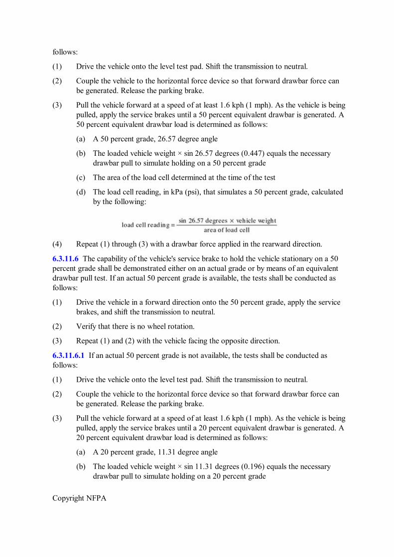
Copyright NFPA
follows:
(1) Drive the vehicle onto the level test pad. Shift the transmission to neutral.
(2) Couple the vehicle to the horizontal force device so that forward drawbar force can be generated. Release the parking brake.
(3) Pull the vehicle forward at a speed of at least 1.6 kph (1 mph). As the vehicle is being pulled, apply the service brakes until a 50 percent equivalent drawbar is generated. A 50 percent equivalent drawbar load is determined as follows:
(a) A 50 percent grade, 26.57 degree angle
(b) The loaded vehicle weight × sin 26.57 degrees (0.447) equals the necessary drawbar pull to simulate holding on a 50 percent grade
(c) The area of the load cell determined at the time of the test
(d) The load cell reading, in kPa (psi), that simulates a 50 percent grade, calculated by the following:
(4) Repeat (1) through (3) with a drawbar force applied in the rearward direction.
6.3.11.6 The capability of the vehicle's service brake to hold the vehicle stationary on a 50 percent grade shall be demonstrated either on an actual grade or by means of an equivalent drawbar pull test. If an actual 50 percent grade is available, the tests shall be conducted as follows:
(1) Drive the vehicle in a forward direction onto the 50 percent grade, apply the service brakes, and shift the transmission to neutral.
(2) Verify that there is no wheel rotation.
(3) Repeat (1) and (2) with the vehicle facing the opposite direction.
6.3.11.6.1 If an actual 50 percent grade is not available, the tests shall be conducted as follows:
(1) Drive the vehicle onto the level test pad. Shift the transmission to neutral.
(2) Couple the vehicle to the horizontal force device so that forward drawbar force can be generated. Release the parking brake.
(3) Pull the vehicle forward at a speed of at least 1.6 kph (1 mph). As the vehicle is being pulled, apply the service brakes until a 20 percent equivalent drawbar is generated. A 20 percent equivalent drawbar load is determined as follows:
(a) A 20 percent grade, 11.31 degree angle
(b) The loaded vehicle weight × sin 11.31 degrees (0.196) equals the necessary drawbar pull to simulate holding on a 20 percent grade
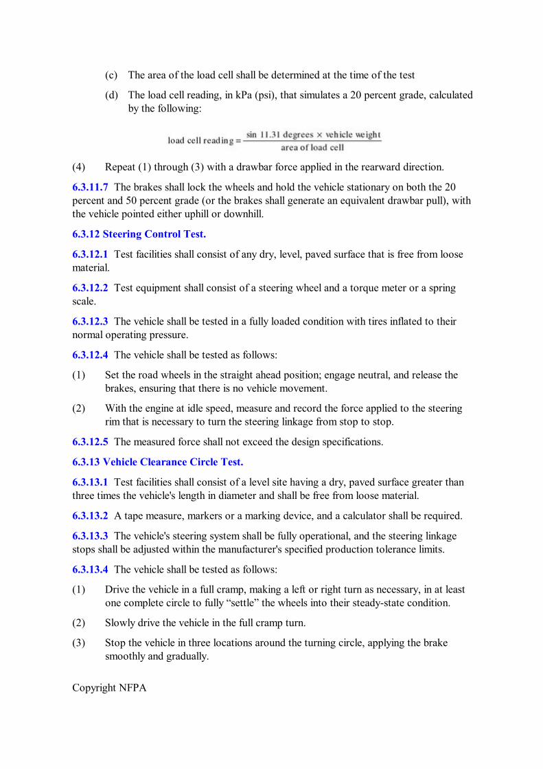
Copyright NFPA
(c) The area of the load cell shall be determined at the time of the test
(d) The load cell reading, in kPa (psi), that simulates a 20 percent grade, calculated by the following:
(4) Repeat (1) through (3) with a drawbar force applied in the rearward direction.
6.3.11.7 The brakes shall lock the wheels and hold the vehicle stationary on both the 20 percent and 50 percent grade (or the brakes shall generate an equivalent drawbar pull), with the vehicle pointed either uphill or downhill.
6.3.12 Steering Control Test.
6.3.12.1 Test facilities shall consist of any dry, level, paved surface that is free from loose material.
6.3.12.2 Test equipment shall consist of a steering wheel and a torque meter or a spring scale.
6.3.12.3 The vehicle shall be tested in a fully loaded condition with tires inflated to their normal operating pressure.
6.3.12.4 The vehicle shall be tested as follows:
(1) Set the road wheels in the straight ahead position; engage neutral, and release the brakes, ensuring that there is no vehicle movement.
(2) With the engine at idle speed, measure and record the force applied to the steering rim that is necessary to turn the steering linkage from stop to stop.
6.3.12.5 The measured force shall not exceed the design specifications.
6.3.13 Vehicle Clearance Circle Test.
6.3.13.1 Test facilities shall consist of a level site having a dry, paved surface greater than three times the vehicle's length in diameter and shall be free from loose material.
6.3.13.2 A tape measure, markers or a marking device, and a calculator shall be required.
6.3.13.3 The vehicle's steering system shall be fully operational, and the steering linkage stops shall be adjusted within the manufacturer's specified production tolerance limits.
6.3.13.4 The vehicle shall be tested as follows:
(1) Drive the vehicle in a full cramp, making a left or right turn as necessary, in at least one complete circle to fully “settle” the wheels into their steadystate condition.
(2) Slowly drive the vehicle in the full cramp turn.
(3) Stop the vehicle in three locations around the turning circle, applying the brake smoothly and gradually.
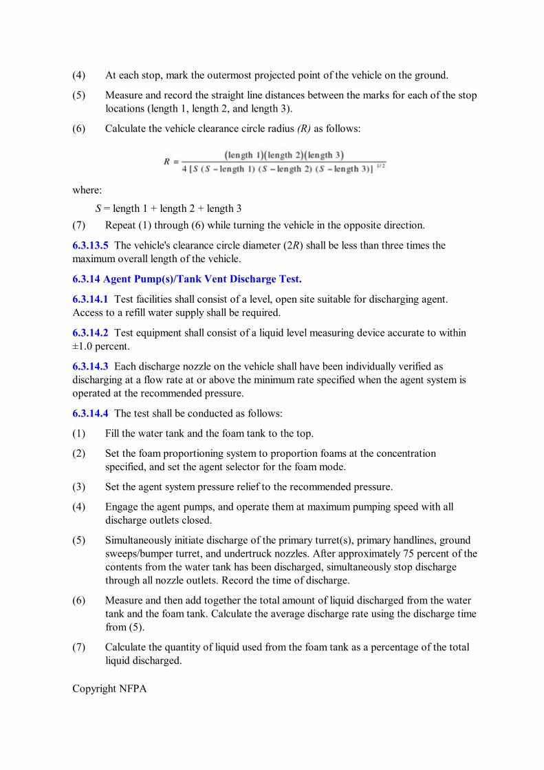
Copyright NFPA
(4) At each stop, mark the outermost projected point of the vehicle on the ground.
(5) Measure and record the straight line distances between the marks for each of the stop locations (length 1, length 2, and length 3).
(6) Calculate the vehicle clearance circle radius (R) as follows:
where:
S = length 1 + length 2 + length 3 (7) Repeat (1) through (6) while turning the vehicle in the opposite direction.
6.3.13.5 The vehicle's clearance circle diameter (2R) shall be less than three times the maximum overall length of the vehicle.
6.3.14 Agent Pump(s)/Tank Vent Discharge Test.
6.3.14.1 Test facilities shall consist of a level, open site suitable for discharging agent. Access to a refill water supply shall be required.
6.3.14.2 Test equipment shall consist of a liquid level measuring device accurate to within ±1.0 percent.
6.3.14.3 Each discharge nozzle on the vehicle shall have been individually verified as discharging at a flow rate at or above the minimum rate specified when the agent system is operated at the recommended pressure.
6.3.14.4 The test shall be conducted as follows:
(1) Fill the water tank and the foam tank to the top.
(2) Set the foam proportioning system to proportion foams at the concentration specified, and set the agent selector for the foam mode.
(3) Set the agent system pressure relief to the recommended pressure.
(4) Engage the agent pumps, and operate them at maximum pumping speed with all discharge outlets closed.
(5) Simultaneously initiate discharge of the primary turret(s), primary handlines, ground sweeps/bumper turret, and undertruck nozzles. After approximately 75 percent of the contents from the water tank has been discharged, simultaneously stop discharge through all nozzle outlets. Record the time of discharge.
(6) Measure and then add together the total amount of liquid discharged from the water tank and the foam tank. Calculate the average discharge rate using the discharge time from (5).
(7) Calculate the quantity of liquid used from the foam tank as a percentage of the total liquid discharged.
Copyright NFPA
6.3.14.5 The measured total discharge rate shall be equal to at least the sum of the minimum specified discharge rates of the nozzles used during the test. A calculated average foam concentration within the tolerance permitted for the respective foam type confirms the adequacy of the foam–liquid concentrate piping to supply foam at a rate compatible with the maximum discharge requirements of the vehicle.
6.3.15 Water Tank Fill and Overflow Test.
6.3.15.1 Test facilities shall consist of a level site with pumping or hydrant capacity, or both, sufficient to provide the water delivery rate needed to fill the water tank in 2 minutes at an inlet pressure of 551.6 kPa (80 psi).
6.3.15.2 Instrumentation shall consist of calibrated mechanical or electronic pressure measuring devices with an accuracy of ±3 percent and a stopwatch.
6.3.15.3 The water tank shall be empty, and the water tank fill and vent system shall be fully operational for this test.
6.3.15.4 The water tank fill and vent system shall be tested as follows to verify that the tank can be filled in 2 minutes or less:
(1) Park the vehicle on level ground.
(2) Attach one pressure measuring device at the inlet to the tank fill piping, and attach the other pressure measuring device to the tank body or an extension of the tank body.
(3) Simultaneously initiate flow to the tank and start the stopwatch. The water supply pressure shall be maintained at 551.6 kPa (80 psi) throughout the test.
(4) At the moment water begins to flow from the overflow piping, stop the watch and record the elapsed time.
(5) While maintaining a 551.6 kPa (80 psi) supply pressure and an overflow condition, record the internal tank pressure. After recording this pressure, shut off the water supply.
6.3.15.5 The results of this test shall be evaluated as follows:
(1) The time to fill the tank to the overflow condition shall be 2 minutes or less.
(2) The internal tank pressure shall not exceed the tank design pressure.
6.3.16 Flushing System Test.
6.3.16.1 Test facilities shall consist of an open site suitable for discharging agent and draining the vehicle. Access to a refill water supply shall be required.
6.3.16.2 No special instrumentation shall be required for this test.
6.3.16.3 The vehicle's agent system and flushing system shall be fully operational for this test.
6.3.16.4 The vehicle's flushing system shall be tested as follows:
Copyright NFPA
(1) Fill the water tank and foam tank with clean water, and add dye to the foam tank.
(2) Discharge agent through each discharge orifice on the vehicle while operating in the foam mode until dye is present in the discharge stream.
(3) Mark the liquid level in the foam tank.
(4) Set the agent system in the flush mode, and discharge through each discharge orifice until clear water is present in the discharge stream.
(5) Shut the agent system down, and drain the piping.
(6) Recheck the foam tank level.
6.3.16.5 Failure to develop a clear water stream through each nozzle shall be considered evidence that the flushing system is inadequate. There shall be no evidence of feedback of clear water into the foam tank.
6.3.17 Primary Turret Flow Rate Test.
6.3.17.1 Test facilities shall consist of a level, open site suitable for discharging agent. Access to a refill water supply shall be required.
6.3.17.2 Test equipment shall consist of the following:
(1) Calibrated sight gauge
(2) Liquid volume measuring device accurate to within ±1.0 percent
(3) Calibrated pressure gauge, if not already provided on the truck
(4) Alternative: A stopwatch and a scale capable of measuring total vehicle weight accurate to within ±1.0 percent of the scale capacity
6.3.17.3 It shall have been verified that the vehicle's pumping system is capable of operating at full rate.
6.3.17.4 The primary turret discharge rate shall be determined as follows:
(1) Set the primary turret pattern for straight stream operation.
(2) Fill the water tank completely.
(3) Engage the pump, and operate it at design speed.
(4) Open the turret flow control valve.
(5) If necessary, at this stage perform the following procedures:
(a) If flow meters are used, read and record the flow rate once the discharge pressure stabilizes.
(b) If a sight gauge is used, read and record the tank volume in gallons while simultaneously starting a stopwatch after the discharge pressure stabilizes. Read and record the tank volume in gallons when the watch is stopped after allowing flow for at least 1 minute. Determine the flow rate in L/min by dividing the
Copyright NFPA
difference in gallons by the time of discharge.
(c) If a scale is used, record the vehicle weight prior to discharge. Start a stopwatch, and discharge water at stabilized pressure for 1 minute. Record the vehicle weight after discharge and calculate the flow rate.
(6) Reset the primary turret pattern to the dispersed setting and repeat (2) through (5).
(7) Reset the primary turret to the half flow rate setting (if applicable) and repeat (1) through (6).
6.3.17.5 The measured turret flow rates shall equal the specified flow rate within a tolerance of +10 percent/0 percent.
6.3.18 Primary Turret Pattern Test. The primary turret pattern test shall be conducted in accordance with the requirements of NFPA 412, and the results shall be evaluated in accordance with the vehicle specifications.
6.3.19 Primary Turret Control Force Measurement.
6.3.19.1 Test facilities shall consist of a level, open site suitable for discharging agent. Access to a refill water supply shall be required.
6.3.19.2 Test equipment shall consist of a spring scale that can be attached to the end of the turret control handle or a torque measuring device that can be attached to the rotational axis of the turret.
6.3.19.3 The water tank shall be filled prior to starting the test, and it shall have been verified that the vehicle pump system is capable of operating at design flow and pressure. The test shall be conducted with the primary turret at the full flow rate setting. The turret powerassist system, if applicable, shall be fully operational.
6.3.19.4 The test shall be conducted as follows:
(1) Set the turret pattern control for straight stream, and, where applicable, engage the power assist.
(2) Engage the pump, and operate it at design speed.
(3) Open the turret flow control valve.
(4) Using a spring scale attached to the end of the turret aiming handle, rotate the turret to the right and to the left, recording the needed force for each direction. Again, using the spring scale attached to the end of the turret aiming handle, elevate and depress the turret, and record the force needed to elevate and depress.
(5) Repeat (2) through (4) with the pattern control set at the maximum dispersed position after refilling the water tank as necessary.
6.3.19.5 The forces recorded shall not exceed the forces specified.
6.3.20 Primary Turret Articulation Test.
6.3.20.1 Test facilities shall consist of a level, open site suitable for discharging agent.
Copyright NFPA
Access to a refill water supply shall be required.
6.3.20.2 The test equipment shall consist of a tape measure, a level, and a protractor.
6.3.20.3 The water tank shall be filled prior to the test, and the turret powerassist system, if applicable, shall be fully operational.
6.3.20.4 The test shall be conducted as follows:
(1) With the turret pointed ahead, raise the turret barrel to the maximum elevated position. With a level held horizontal at the vertical rotation axis, measure the angle between the level and the turret barrel with the protractor and record.
(2) Rotate the primary turret barrel to the right and left to the angle needed.
(3) Place a marker 9.1 m (30 ft) in front of the vehicle. Aim the turret straight ahead with the rate control at full flow, with the pattern control in the maximum dispersed position and with the turret in the maximum depressed position. When water discharges, observe whether water strikes the marker or strikes closer to the vehicle.
6.3.20.5 Turret articulation shall be considered acceptable if the measurements meet or exceed the specifications.
6.3.21 Handline Nozzle Flow Rate Test.
6.3.21.1 Test facilities shall consist of a level, open site suitable for discharging agent. Access to a refill water supply shall be required.
6.3.21.2 Test equipment shall consist of the following:
(1) Calibrated sight gauge
(2) Liquid volume measuring device accurate to within ±1.0 percent
(3) Calibrated pressure gauge, if not already provided on the truck
(4) Alternative: A stopwatch and a scale capable of measuring total vehicle weight accurate to within ±1.0 percent
6.3.21.3 The vehicle's pumping system shall be verified to be capable of operating at full rate.
6.3.21.4 The handline nozzle flow rate shall be determined as follows:
(1) Set the handline nozzle pattern for straight stream operation.
(2) Fill the water tank completely.
(3) Engage the pump and operate it at design speed.
(4) Open the handline nozzle flow control valve.
(5) If necessary, at this stage perform the following procedures:
(a) If flow meters are used, read and record the flow rate once the discharge pressure stabilizes.
Copyright NFPA
(b) If a sight gauge is used, read and record the tank volume in gallons while simultaneously starting a stopwatch after the discharge pressure stabilizes. Read and record the tank volume in liters (gallons) when the watch is stopped after allowing flow for at least 5 minutes. Determine the flow rate in L/min by dividing the difference in gallons by the time of discharge.
(c) If an opentop calibrated tank is used, discharge through the nozzle until the pressure stabilizes, and then simultaneously direct the stream into the tank while starting the stopwatch. Stop the stopwatch when the tank is full, and remove or shut off the nozzle. Determine the flow rate by dividing the tank volume in gallons by the fill time in minutes.
(d) If a scale is used, record the vehicle weight prior to discharge. Start a stopwatch, and discharge water at stabilized pressure for 1 minute. Record the vehicle weight after discharge, and calculate flow rate.
(6) If the nozzle is the nonairaspirated type, repeat (2) through (5) with the nozzle pattern setting in the fully dispersed position.
6.3.21.5 The measured handline nozzle flow rates shall equal the specified flow rate within a tolerance of +10 percent/0 percent.
6.3.22 Handline Nozzle Pattern Test. The handline nozzle pattern test shall be conducted in accordance with the requirements of NFPA 412, and the results shall be evaluated in accordance with the vehicle specifications.
6.3.23 Ground Sweep/Bumper Turret Flow Rate Test.
6.3.23.1 Test facilities shall consist of an open site suitable for discharging agent. Access to a refill water supply shall be required.
6.3.23.2 Test equipment shall consist of the following:
(1) Calibrated sight gauge
(2) Liquid volume measuring device accurate to within ±1.0 percent
(3) Calibrated pressure gauge, if not already provided on the truck
(4) Alternative: A stopwatch and a scale capable of measuring total vehicle weight accurate to within ±1.0 percent
6.3.23.3 The vehicle's pumping system shall be verified to be capable of operating at full rate.
6.3.23.4 The ground sweep/bumper turret discharge rate shall be determined as follows:
(1) Set the ground sweep/bumper turret pattern for straight stream operation.
(2) Fill the water tank completely.
(3) Engage the pump and operate it at design speed.
(4) Open the ground sweep/bumper turret flow control valve.
Copyright NFPA
(5) If necessary, at this stage perform the following procedures:
(a) If flow meters are used, read and record the flow rate once the discharge pressure stabilizes.
(b) If a sight gauge is used, read and record the tank volume in gallons while simultaneously starting a stopwatch after the discharge pressure stabilizes. Read and record the tank volume in liters (gallons) when the watch is stopped after allowing flow for at least 1 minute. Determine the flow rate in L/min by dividing the difference in gallons by the time of discharge.
(c) If a scale is used, record the vehicle weight prior to discharge. Start a stopwatch, and discharge water at stabilized pressure for 1 minute. Record the vehicle weight after discharge, and calculate the flow rate.
(6) If the ground sweep/bumper turret is the nonairaspirated type, repeat (2) through (5) with the nozzle pattern setting in the fully dispersed position.
6.3.23.5 The measured flow rates shall equal the specified flow rate within a tolerance of +10 percent/0 percent.
6.3.24 Ground Sweep/Bumper Turret Pattern Test. The ground sweep/bumper turret pattern test shall be conducted in accordance with the requirements of NFPA 412, and the results shall be evaluated in accordance with the vehicle specifications.
6.3.25 Undertruck Nozzle Test.
6.3.25.1 Test facilities shall consist of an open site suitable for discharging agent.
6.3.25.2 Markers shall be available for use in defining the pattern boundaries.
6.3.25.3 The vehicle's pump system shall be verified to be capable of operating at full rate, and the agent tanks shall be filled with water and foam, respectively.
6.3.25.4 The test shall be conducted as follows:
(1) Set the agent system to operate in the foam mode
(2) Engage the agent pump and operate it at design speed
(3) Open the undertruck nozzles to discharge simultaneously, and continue to discharge until a definite pattern outline is apparent
(4) Close the discharge and mark and record the boundaries of the pattern
6.3.25.5 The pattern shall be considered acceptable if the foam spray covers the outline created by the vehicle on the ground and wets the inside of all tires.
6.3.26 Foam Concentration/Foam Quality Test.
6.3.26.1 Test facilities shall consist of an open site suitable for discharging agent. Access to a refill water supply and a foam concentrate supply shall be required.
6.3.26.2 The test equipment described in NFPA 412 shall be used for this test.
Copyright NFPA
6.3.26.3 Each discharge nozzle on the vehicle shall have been individually verified as discharging at a flow rate within the tolerance specified. The agent system shall have been verified as capable of operating at full rate.
6.3.26.4 The test shall be conducted as follows:
(1) Fill the water tank and the foam tank to the top, and refill as necessary throughout the test.
(2) Set the foam proportioning system to proportion foams at the concentration specified, and set the agent selector for the foam mode.
(3) Set the agent system pressure relief to the recommended pressure.
(4) Engage the agent pumps, and operate them at maximum pumping speed with all discharge outlets closed.
(5) Test each foam delivery system first for the individual nozzle/flow rate specified in the following list and then for a total combined simultaneous discharge in accordance with NFPA 412:
(a) Primary turret(s) full rate
(b) Primary turret(s) half rate
(c) Ground sweep/bumper turret
(d) Handline nozzles
(e) Undertruck nozzles
6.3.26.5 The foam concentrations measured shall fall within the permitted tolerances specified in NFPA 412 for each nozzle and for the combined simultaneous discharge. The foam expansion and drainage time measurements shall equal or exceed those specified in NFPA 412 for each nozzle.
6.3.27 Warning Siren Test.
6.3.27.1 Test facilities shall consist of a flat, open area that is free from any large reflecting surfaces (such as other vehicles, signboards, or hills) within a 61 m (200 ft) radius of the vehicle.
6.3.27.2 Test equipment shall consist of the following:
(1) Sound level meter that meets the requirements of ANSI S1.4 for Type 1 or S1A meters and has been calibrated by a certified testing laboratory within the previous 12 months
(2) Tape measure
6.3.27.3 The vehicle's siren speaker shall be mounted in its proper location and shall be in working order.
6.3.27.4 The capability of the warning siren on the vehicle to project sound forward and to the sides shall be determined as follows:
Copyright NFPA
(1) Set the sound level meter to the Aweighing network, “fast” meter response, and position the meter directly ahead of the vehicle at a distance of 30.5 m (100 ft) from the front bumper, with the microphone at ear level.
(2) Energize the siren and record the meter reading.
(3) Repeat (1) and (2) with the sound level meter 30.5 m (100 ft) from the vehicle, first at a position 45 degrees to the right and then at 45 degrees to the left of the longitudinal centerline of the vehicle.
6.3.27.5 The recorded noise level shall equal or exceed the specifications.
6.3.28 Propellant Gas.
6.3.28.1 Test facilities shall consist of an open site suitable for discharging AFFF concentrate, dry chemical, or halogenated agent.
6.3.28.2 Test equipment shall consist of a calibrated scale or load cell with an accuracy of ±1.0 percent.
6.3.28.3 The vehicle extinguishing agent piping system shall be operational, and the agent tank(s) shall be empty. The propellant gas tank(s) shall be fully charged and within proper pressure. A means of lifting the agent tanks for weighing without loss of agent shall be provided. Alternatively, the extinguishing agent tank(s) shall be permitted to be tested outside of the vehicle. Where this alternative is used, the test shall be conducted with the agent tank(s) and related piping, fittings, valves, hose, and nozzle(s) in the same configurations in which they are installed on the vehicle.
6.3.28.4 The test for each of the extinguishing agents shall be conducted in the following manner:
(1) Weigh the empty tank(s) and record as tare weight.
(2) Using the manufacturer's recommended filling procedure, charge the tank(s) with the manufacturer's recommended extinguishing agent to the upper fill weight/volume tolerance. Reweigh and record this as gross filled weight.
(3) Ensure that all fill caps are tightened securely, all propellant gas lines are connected, the discharge nozzle(s) is in the closed position, and all fittings and connections are tight.
(4) Pressurize the agent tank(s) using the manufacturer's recommended procedure.
(5) Simultaneously, fully open all discharge nozzles, and keep open until only the pressurizing gas is expelled.
(6) Shut down the propellant gas supply.
(7) Reweigh the agent tank(s) and record this as postdischarge weight.
(8) Calculate and record the total agent discharged as follows: Gross filled weight minus postdischarge weight equals total agent discharge.
6.3.28.5 There shall be a sufficient supply of propellant gas to purge all discharge lines as
Copyright NFPA
evidenced by the emission from each nozzle of gas only. The total agent discharged shall equal or exceed the design capacity.
6.3.29 Pressure Regulation.
6.3.29.1 Test facilities shall consist of an open site suitable for discharging the AFFF solution, dry chemical, or halogenated agent.
6.3.29.2 Test equipment shall consist of a calibrated pressure gauge or transducer capable of reading the recommended tank top discharge pressure and possessing an accuracy of ±34.5 kPa (±5.0 psi).
6.3.29.3 The vehicle extinguishing agent system shall be piped to all discharge outlets with the tank(s) empty. The propellant gas tank(s) shall be fully charged and at proper pressure. A means for mounting a pressure gauge or transducer somewhere between the downstream (low pressure) side of the regulator and the agent tank top shall be provided. Alternatively, the extinguishing agent tank(s) shall be permitted to be tested outside of the vehicle. Where this alternative is used, the test shall be conducted with the agent tank(s) and related piping, fittings, valves, hose, and nozzle(s) in the same configuration in which they are installed on the vehicle.
6.3.29.4 The test for each of the extinguishing agents shall be conducted in the following manner:
(1) Using the manufacturer's recommended filling procedure, charge the tank(s) with the manufacturer's recommended extinguishing agent to the upper fill weight/volume tolerance.
(2) Install a pressure gauge or transducer between the downstream (low pressure) side of the regulator and the agent tank top.
(3) Ensure that all fill caps are tightened securely, all propellant gas lines are connected, the discharge nozzle(s) is in the closed position, and all fittings are tight.
(4) Pressurize the agent tank(s) using the manufacturer's recommended procedure. Record the agent tank pressure.
(5) Simultaneously, fully open all discharge nozzles, and keep open until only the pressurizing gas is expelled.
(6) During agent discharge, monitor agent tank pressure and record at 5second or shorter intervals.
(7) Once the gas point has been reached for all discharge nozzles, shut down the gas supply.
6.3.29.5 The pressure regulation system shall be capable of maintaining pressure throughout the discharge. At no time shall pressure fall below or exceed the design range specified by the manufacturer.
6.3.30 AFFF Premix Piping and Valves.
6.3.30.1 Test facilities shall consist of a level, open site suitable for discharging the agent
Copyright NFPA
and measuring ranges.
6.3.30.2 Test equipment shall consist of the following:
(1) Calibrated scale or load cell with an accuracy of ±1.0 percent
(2) Stopwatch
6.3.30.3 All vehicle foam discharge piping shall be operational, and the premix tank shall be empty. The propellant gas tank(s) shall be fully charged and within proper pressure. A means of lifting the agent tank(s) for weighing without loss of agent shall be provided. Alternatively, the system shall be permitted to be tested outside of the vehicle. Where this alternative is used, the test shall be conducted with the premix tank and related piping, fittings, valves, hose, and nozzle(s) in the same configuration in which they are installed on the vehicle.
6.3.30.4 The test shall be conducted in the following manner:
(1) Weigh the empty premix tank and record as tare weight.
(2) Using the manufacturer's recommended filling procedure, charge the tank with water or premix solution. Reweigh and record as gross filled weight.
(3) Ensure that all fill caps are tightened securely, all propellant gas lines are connected, the discharge nozzle(s) is in the closed position, and all fittings and connections are tight.
(4) Pull all handline hose from the reel(s) or hose compartment(s).
(5) Pressurize the system using the manufacturer's recommended procedure.
(6) Simultaneously, start the stopwatch and fully open the turret(s), undertruck nozzles, and handline(s).
(7) After discharging for at least 30 seconds, simultaneously stop the stopwatch and close the turret(s), undertruck nozzles, and handline(s). Record the elapsed time on the stopwatch as discharge time.
(8) Following the manufacturer's instructions, shut off the propellant gas supply, and blow down the system.
(9) Reweigh the premix tank and record this as postdischarge weight.
(10) Add the recommended flow rates from each discharge nozzle and record this sum as the designed total flow rate.
(11) Calculate the actual total flow rate (TFR) as follows:
6.3.30.5 The actual TFR shall equal the specified flow rate designed within a tolerance of +10 percent/0 percent.
Copyright NFPA
6.3.31 Pressurized Agent Purging and Venting.
6.3.31.1 Test facilities shall consist of an open site suitable for discharging AFFF solution, dry chemical, or halogenated agent.
6.3.31.2 No special test equipment or instrumentation shall be required to conduct the test(s).
6.3.31.3 The vehicle extinguishing agent system(s) shall be fully operational, and the agent tank(s) shall be fully charged with the manufacturer's recommended agent. The propellant gas tank(s) shall be fully charged and within proper pressure. Alternatively, the extinguishing agent tank(s) shall be permitted to be tested outside of the vehicle. Where this alternative is used, the test shall be conducted with the fully charged agent tank(s) and related piping, fittings, valves, hose, and nozzle(s) in the same configuration in which they are installed on the vehicle.
6.3.31.4 The test for each of the pressurized extinguishing agent systems shall be conducted in the following manner:
(1) Pressurize the agent tank(s) using the manufacturer's recommended procedure.
(2) Pull all hose from the reel(s) or compartment(s).
(3) Fully open all discharge devices.
(4) After approximately 5 seconds to 20 seconds, close all discharge devices.
(5) Purge all discharge lines, and vent the agent tank(s) using the manufacturer's recommended procedure.
6.3.31.5 Any agent beyond the tank outlet shall be purged from the discharge piping and hose as evidenced by the discharge from each nozzle of gas only. The depressurization or venting of the agent tank shall allow only minimal quantities of agent to escape.
6.3.32 Complementary Agent Handline Flow Rate and Range.
6.3.32.1 Test facilities shall consist of a level, open site suitable for discharging the dry chemical or halogenated agent and measuring ranges. Wind conditions shall be calm [less than 8 kph (5 mph)].
6.3.32.2 Test equipment shall consist of the following:
(1) Calibrated scale or load cell with an accuracy of ±1.0 percent
(2) Stopwatch
(3) Tape measure or other device for measuring distance
(4) Calibrated anemometer
(5) Pan containing at least 0.09 m 2 (1 ft 2 ) of motor or aviation gasoline
6.3.32.3 All vehicle agent piping shall be operational, and the agent tank shall be empty. The propellant gas tank(s) shall be fully charged and within proper pressure. A means of lifting the agent tank(s) for weighing without loss of agent shall be provided. Alternatively, the
Copyright NFPA
system shall be permitted to be tested outside of the vehicle. Where this alternative is used, the test shall be conducted with the agent tank and related piping, fittings, valves, hose, and nozzle(s) in the same configuration in which they are installed on the vehicle.
6.3.32.4 The test shall be conducted in the following manner:
(1) Using the manufacturer's recommended agent and filling procedure, charge the agent tank.
(2) Ensure that all fill caps are tightened securely, all propellant gas lines are connected, the discharge nozzle(s) is in the closed position, and all fittings and connections are tight.
(3) Pull all handline hose from the reel(s).
(4) Pressurize the system using the manufacturer's recommended procedure, and open all handline nozzles until agent flow is observed. Close the nozzles.
(5) Weigh and record the agent tank as the “initial weight.”
(6) Position the handline nozzles at least 6.1 m (20 ft) from the fire pan so that they can be discharged onto a flat grade with no stream obstructions. Ignite the fuel.
(7) Select one of the handline nozzles (nozzle 1). While holding it in a position 0.9 m to 1.2 m (3 ft to 4 ft) above ground level, simultaneously start the stopwatch and fully open the nozzle; then discharge agent onto the fire.
(8) After at least 50 percent of the contents of the tank has been discharged, shut down the nozzle and stop the stopwatch. Record the time as “elapsed discharge time no. 1.”
(9) Reweigh the agent tank, and record as “weight after first discharge.”
(10) If a second nozzle (nozzle 2) is provided, repeat (1) through (8).
(11) While holding the two handline nozzles in a fixed horizontal position 0.9 m to 1.2 m (3 ft to 4 ft) above ground level, simultaneously start the stopwatch and fully open both nozzles.
(12) After at least 50 percent of the contents of the tank has been discharged, simultaneously shut down both nozzles, and stop the stopwatch. Record the time as “elapsed discharge time no. 2.”
(13) Reweigh the agent tank, and record as “weight after second discharge.”
(14) Calculate the flow rate (FR) from nozzle 1 as follows:
(15) Calculate the flow rate (FR) from nozzle 2 as follows:
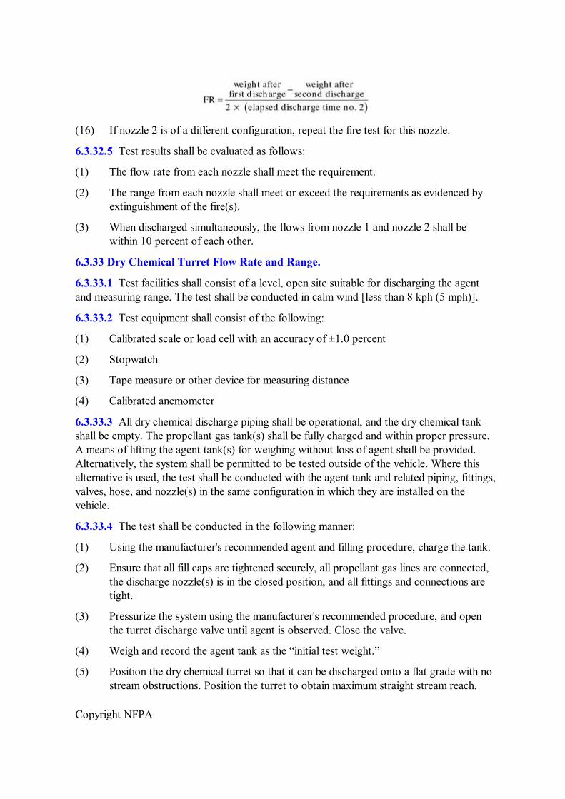
Copyright NFPA
(16) If nozzle 2 is of a different configuration, repeat the fire test for this nozzle.
6.3.32.5 Test results shall be evaluated as follows:
(1) The flow rate from each nozzle shall meet the requirement.
(2) The range from each nozzle shall meet or exceed the requirements as evidenced by extinguishment of the fire(s).
(3) When discharged simultaneously, the flows from nozzle 1 and nozzle 2 shall be within 10 percent of each other.
6.3.33 Dry Chemical Turret Flow Rate and Range.
6.3.33.1 Test facilities shall consist of a level, open site suitable for discharging the agent and measuring range. The test shall be conducted in calm wind [less than 8 kph (5 mph)].
6.3.33.2 Test equipment shall consist of the following:
(1) Calibrated scale or load cell with an accuracy of ±1.0 percent
(2) Stopwatch
(3) Tape measure or other device for measuring distance
(4) Calibrated anemometer
6.3.33.3 All dry chemical discharge piping shall be operational, and the dry chemical tank shall be empty. The propellant gas tank(s) shall be fully charged and within proper pressure. A means of lifting the agent tank(s) for weighing without loss of agent shall be provided. Alternatively, the system shall be permitted to be tested outside of the vehicle. Where this alternative is used, the test shall be conducted with the agent tank and related piping, fittings, valves, hose, and nozzle(s) in the same configuration in which they are installed on the vehicle.
6.3.33.4 The test shall be conducted in the following manner:
(1) Using the manufacturer's recommended agent and filling procedure, charge the tank.
(2) Ensure that all fill caps are tightened securely, all propellant gas lines are connected, the discharge nozzle(s) is in the closed position, and all fittings and connections are tight.
(3) Pressurize the system using the manufacturer's recommended procedure, and open the turret discharge valve until agent is observed. Close the valve.
(4) Weigh and record the agent tank as the “initial test weight.”
(5) Position the dry chemical turret so that it can be discharged onto a flat grade with no stream obstructions. Position the turret to obtain maximum straight stream reach.
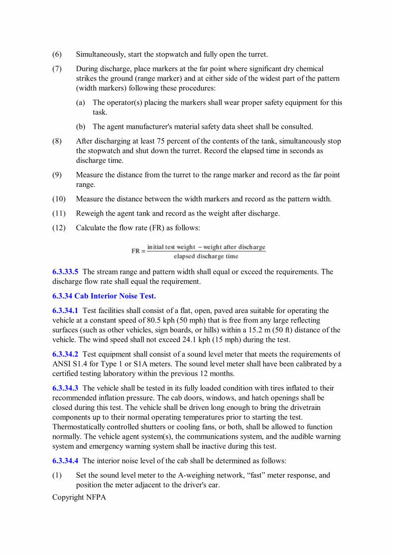
Copyright NFPA
(6) Simultaneously, start the stopwatch and fully open the turret.
(7) During discharge, place markers at the far point where significant dry chemical strikes the ground (range marker) and at either side of the widest part of the pattern (width markers) following these procedures:
(a) The operator(s) placing the markers shall wear proper safety equipment for this task.
(b) The agent manufacturer's material safety data sheet shall be consulted.
(8) After discharging at least 75 percent of the contents of the tank, simultaneously stop the stopwatch and shut down the turret. Record the elapsed time in seconds as discharge time.
(9) Measure the distance from the turret to the range marker and record as the far point range.
(10) Measure the distance between the width markers and record as the pattern width.
(11) Reweigh the agent tank and record as the weight after discharge.
(12) Calculate the flow rate (FR) as follows:
6.3.33.5 The stream range and pattern width shall equal or exceed the requirements. The discharge flow rate shall equal the requirement.
6.3.34 Cab Interior Noise Test.
6.3.34.1 Test facilities shall consist of a flat, open, paved area suitable for operating the vehicle at a constant speed of 80.5 kph (50 mph) that is free from any large reflecting surfaces (such as other vehicles, sign boards, or hills) within a 15.2 m (50 ft) distance of the vehicle. The wind speed shall not exceed 24.1 kph (15 mph) during the test.
6.3.34.2 Test equipment shall consist of a sound level meter that meets the requirements of ANSI S1.4 for Type 1 or S1A meters. The sound level meter shall have been calibrated by a certified testing laboratory within the previous 12 months.
6.3.34.3 The vehicle shall be tested in its fully loaded condition with tires inflated to their recommended inflation pressure. The cab doors, windows, and hatch openings shall be closed during this test. The vehicle shall be driven long enough to bring the drivetrain components up to their normal operating temperatures prior to starting the test. Thermostatically controlled shutters or cooling fans, or both, shall be allowed to function normally. The vehicle agent system(s), the communications system, and the audible warning system and emergency warning system shall be inactive during this test.
6.3.34.4 The interior noise level of the cab shall be determined as follows:
(1) Set the sound level meter to the Aweighing network, “fast” meter response, and position the meter adjacent to the driver's ear.
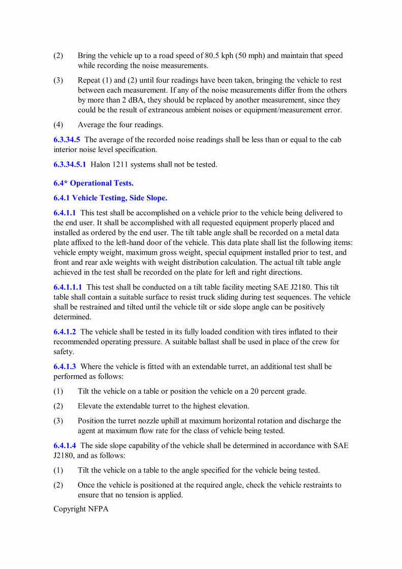
Copyright NFPA
(2) Bring the vehicle up to a road speed of 80.5 kph (50 mph) and maintain that speed while recording the noise measurements.
(3) Repeat (1) and (2) until four readings have been taken, bringing the vehicle to rest between each measurement. If any of the noise measurements differ from the others by more than 2 dBA, they should be replaced by another measurement, since they could be the result of extraneous ambient noises or equipment/measurement error.
(4) Average the four readings.
6.3.34.5 The average of the recorded noise readings shall be less than or equal to the cab interior noise level specification.
6.3.34.5.1 Halon 1211 systems shall not be tested.
6.4* Operational Tests.
6.4.1 Vehicle Testing, Side Slope.
6.4.1.1 This test shall be accomplished on a vehicle prior to the vehicle being delivered to the end user. It shall be accomplished with all requested equipment properly placed and installed as ordered by the end user. The tilt table angle shall be recorded on a metal data plate affixed to the lefthand door of the vehicle. This data plate shall list the following items: vehicle empty weight, maximum gross weight, special equipment installed prior to test, and front and rear axle weights with weight distribution calculation. The actual tilt table angle achieved in the test shall be recorded on the plate for left and right directions.
6.4.1.1.1 This test shall be conducted on a tilt table facility meeting SAE J2180. This tilt table shall contain a suitable surface to resist truck sliding during test sequences. The vehicle shall be restrained and tilted until the vehicle tilt or side slope angle can be positively determined.
6.4.1.2 The vehicle shall be tested in its fully loaded condition with tires inflated to their recommended operating pressure. A suitable ballast shall be used in place of the crew for safety.
6.4.1.3 Where the vehicle is fitted with an extendable turret, an additional test shall be performed as follows:
(1) Tilt the vehicle on a table or position the vehicle on a 20 percent grade.
(2) Elevate the extendable turret to the highest elevation.
(3) Position the turret nozzle uphill at maximum horizontal rotation and discharge the agent at maximum flow rate for the class of vehicle being tested.
6.4.1.4 The side slope capability of the vehicle shall be determined in accordance with SAE J2180, and as follows:
(1) Tilt the vehicle on a table to the angle specified for the vehicle being tested.
(2) Once the vehicle is positioned at the required angle, check the vehicle restraints to ensure that no tension is applied.
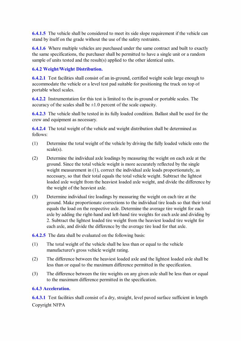
Copyright NFPA
6.4.1.5 The vehicle shall be considered to meet its side slope requirement if the vehicle can stand by itself on the grade without the use of the safety restraints.
6.4.1.6 Where multiple vehicles are purchased under the same contract and built to exactly the same specifications, the purchaser shall be permitted to have a single unit or a random sample of units tested and the result(s) applied to the other identical units.
6.4.2 Weight/Weight Distribution.
6.4.2.1 Test facilities shall consist of an inground, certified weight scale large enough to accommodate the vehicle or a level test pad suitable for positioning the truck on top of portable wheel scales.
6.4.2.2 Instrumentation for this test is limited to the inground or portable scales. The accuracy of the scales shall be ±1.0 percent of the scale capacity.
6.4.2.3 The vehicle shall be tested in its fully loaded condition. Ballast shall be used for the crew and equipment as necessary.
6.4.2.4 The total weight of the vehicle and weight distribution shall be determined as follows:
(1) Determine the total weight of the vehicle by driving the fully loaded vehicle onto the scale(s).
(2) Determine the individual axle loadings by measuring the weight on each axle at the ground. Since the total vehicle weight is more accurately reflected by the single weight measurement in (1), correct the individual axle loads proportionately, as necessary, so that their total equals the total vehicle weight. Subtract the lightest loaded axle weight from the heaviest loaded axle weight, and divide the difference by the weight of the heaviest axle.
(3) Determine individual tire loadings by measuring the weight on each tire at the ground. Make proportionate corrections to the individual tire loads so that their total equals the load on the respective axle. Determine the average tire weight for each axle by adding the righthand and lefthand tire weights for each axle and dividing by 2. Subtract the lightest loaded tire weight from the heaviest loaded tire weight for each axle, and divide the difference by the average tire load for that axle.
6.4.2.5 The data shall be evaluated on the following basis:
(1) The total weight of the vehicle shall be less than or equal to the vehicle manufacturer's gross vehicle weight rating.
(2) The difference between the heaviest loaded axle and the lightest loaded axle shall be less than or equal to the maximum difference permitted in the specification.
(3) The difference between the tire weights on any given axle shall be less than or equal to the maximum difference permitted in the specification.
6.4.3 Acceleration.
6.4.3.1 Test facilities shall consist of a dry, straight, level paved surface sufficient in length
Copyright NFPA
to accelerate the vehicle from rest to 80.5 kph (50 mph) and then bring it to a safe stop.
6.4.3.1.1 Ambient temperatures at the test site shall be –17.8°C to 43.3°C (0°F to 110°F), and elevations shall include heights up to 609.6 m (2000 ft) unless otherwise specified by the purchaser.
6.4.3.2 Instrumentation shall consist of a fifth wheel device, or equivalent, designed to measure and record (at least visibility as a minimum) vehicle speed and time from the time the vehicle begins to move until it reaches a predetermined top speed.
6.4.3.3 The vehicle shall be tested in its fully loaded condition with the engine and the transmission at their normal operating temperatures. The tires shall be inflated to the manufacturer's recommended pressure.
6.4.3.4 The test shall be conducted in the following manner:
(1) Start the test with the vehicle at rest, the engine at idle, and the transmission in gear.
(2) Simultaneously, start the stopwatch and accelerate the vehicle, and continue accelerating to a wideopen throttle condition.
(3) At the moment the vehicle reaches 80.5 kph (50 mph), stop the watch and record the elapsed time.
(4) To compensate for wind conditions and slope, repeat the test in the opposing direction. Record and average a minimum of three readings in each of the two directions.
6.4.3.5 The average acceleration time to 80.5 kph (50 mph) shall be less than or equal to the requirement, as specified.
6.4.4 Top Speed.
6.4.4.1 Test facilities shall consist of a dry, paved, level surface suitable for achieving a vehicle speed of at least 104.6 kph (65 mph) and bringing the vehicle to a safe stop.
6.4.4.2 Instrumentation shall consist of the vehicle's speedometer as installed by the manufacturer at the time of delivery.
6.4.4.3 The vehicle shall be tested in its fully loaded condition with the engine and the transmission at their normal operating temperatures. The tires shall be inflated to the manufacturer's recommended pressure.
6.4.4.4 The test shall be conducted in the following manner:
(1) Accelerate the vehicle to a speed of at least 104.6 kph (65 mph).
(2) To compensate for wind conditions and slope, repeat the test in the opposing direction.
(3) If 104.6 kph (65 mph) cannot be achieved in one of the directions, repeat (1) and (2), accelerating the vehicle to its maximum speed in each direction; record the speeds and average the two numbers.
6.4.4.5 The test shall be considered successful if the average top speed equals or exceeds
Copyright NFPA
104.6 kph (65 mph).
6.4.5 Brake Operational Test.
6.4.5.1 Test facilities shall consist of any dry, smooth, paved surface adequate in length to reach the respective test speeds and stop safely. The test area shall be marked so that a lane that equals the width of the vehicle plus 1.2 m (4 ft) is established. A runway or taxiway with a marked centerline shall be permitted to be used.
6.4.5.2 Instrumentation shall consist of the vehicle's speedometer, as installed by the manufacturer, and a tape measure.
6.4.5.3 The vehicle shall be tested in its fully loaded condition with the brakes adjusted to the manufacturer's recommended tolerances. The tires shall be inflated to the vehicle manufacturer's recommended inflation pressure. The vehicle's stopping distance shall have been certified by the vehicle manufacturer.
6.4.5.4 The test shall be conducted in the following manner:
(1) Maintain a constant speed of 32.2 kph (20 mph) while driving down the centerline of the test site.
(2) Apply the brakes as if in a panic stop until the vehicle comes to rest.
(3) Measure and record the distance from the outer edge of the vehicle to the centerline of the lane.
(4) Repeat (1) through (3) at a constant speed of 64.4 kph (40 mph).
6.4.5.5 The distance measured shall not exceed onehalf the vehicle width plus 0.6 m (2 ft).
6.4.6 Air System/Air Compressor Test.
6.4.6.1 No special test facilities shall be required.
6.4.6.2 Instrumentation shall consist of the vehicle's air system pressure gauge(s), as installed by the manufacturer, and a stopwatch.
6.4.6.3 The vehicle's air system shall be fully operational for this test. The manufacturer previously shall have established the ratio of actual to required reservoir capacity and the spring brake release pressure. The test shall be conducted with the transmission in neutral and the parking brakes set.
6.4.6.4 The test shall be conducted as follows:
(1) Using the brake pedal, bleed off the air reservoir system pressure to a level below 586 kPa (85 psi) as indicated on the cabmounted air gauge(s).
(2) Accelerate the engine to its wideopen throttle condition.
(3) When the air pressure indicator reaches 586 kPa (85 psi), start the stopwatch. If more than one air pressure indicator is installed on the vehicle, start the stopwatch when the first indicator registers 586 kPa (85 psi).
(4) Continue building air pressure with the engine at wideopen throttle until 689.5 kPa
Copyright NFPA
(100 psi) registers on all air pressure indicators, stop the watch, and record the time.
(5) Using the brake pedal, bleed off the air reservoir system pressure to 0 kPa (0 psi), as indicated on the cabmounted air gauge(s).
(6) Accelerate the engine to a wideopen throttle condition.
(7) When the wideopen throttle condition is reached, simultaneously start the stopwatch.
(8) Continue building air pressure with the engine at wideopen throttle until the previously established spring brake release pressure has been reached in the quick buildup system; stop the watch and record the time.
6.4.6.5 The results shall be evaluated as follows:
(1) The time needed for a buildup of 586 kPa to 689.5 kPa (85 psi to 100 psi) shall be within 25 seconds of the permitted time, as calculated for larger reservoir capacities.
(2) The quick buildup time shall be within 15 seconds.
6.4.7 Agent Discharge Pumping Test.
6.4.7.1 Test facilities shall consist of an open site suitable for discharging agent.
6.4.7.2 No test equipment shall be required.
6.4.7.3 The vehicle's agent system shall be fully operational for this test, and all primary handlines shall be deployed.
6.4.7.4 The combined discharge of all nozzles shall be tested as follows:
(1) Fill both the water tank and the foam (or dyed water) tank completely with water and foam, respectively.
(2) Set the agent system to operate in the foam mode, set the system pressure for optimum performance, and engage the agent pumps. Simultaneously operate the pumps of vehicles with multiple pumps during this test.
(3) Initiate discharge first through the primary turret and then through the ground sweeps (or optional bumper turret), primary handlines, and undertruck nozzles until all are discharging simultaneously in a straight stream. As each nozzle is turned on, observe the range along with the system pressure.
(4) Continue to discharge until the system pressure has stabilized with all nozzles discharging.
6.4.7.5 Since measurements of actual flow rates are not practical in the field, the system shall be considered to have met the requirement in accordance with the procedures of 6.4.6.4, provided the nozzle ranges show no signs of deterioration as additional nozzles are engaged and the agent system pressure does not fluctuate by more than 10 percent where comparing the primary turret flowing by itself with the combined discharge pressure. Foam (or dyed water) shall be evident in the discharging stream from all nozzles at all times.
Copyright NFPA
6.4.8 Dual Pumping System Test.
6.4.8.1 Test facilities shall consist of an open site suitable for discharging agent.
6.4.8.2 No special instrumentation shall be required for this test.
6.4.8.3 The vehicle's agent system shall be fully operational for this test.
6.4.8.4 The ability of a vehicle equipped with a dual pumping system to provide foam solution to all nozzles when only one system is active shall be tested as follows:
(1) Fill both the water tank and the foam tank completely with water, and add dye or foam concentrate to the foam tank.
(2) Set the agent system to operate in the foam mode, and set the system pressure for optimum performance.
(3) Set the primary turret(s) discharge rate in the half flow rate setting.
(4) Initiate discharge first through the primary turret(s) (at half rate) and then through the ground sweep nozzles (or alternate bumper turret), the primary handline nozzles, and the undertruck nozzles, first with one pump operating, and then the other.
6.4.8.5 A foam or dye solution discharge stream shall be present at each nozzle tested when either pump is engaged.
6.4.9 Pump and Maneuver Test.
6.4.9.1 Test facilities shall consist of an open site suitable for discharging agent and operating the vehicle up to its maximum speed.
6.4.9.2 No test equipment shall be required.
6.4.9.3 The vehicle's agent system shall be fully operational for this test.
6.4.9.4 The positive pump and maneuver capability, along with the smooth engagement of the pump, shall be tested as follows:
(1) Fill both the water tank and the foam tank completely with water, and add dye or foam concentrate to the foam tank.
(2) With the vehicle being driven at 32.2 kph (20 mph), engage and disengage the pump(s) without damage to the pump or pump drive system.
(3) Bring the vehicle to a stop, and prepare the primary turrets and ground sweeps (or optional bumper turret) for discharging.
(4) Place the agent selector in the foam mode, and set the agent system pressure relief to relieve at the recommended pressure for optimum performance.
(5) Initiate discharge through the primary turrets and ground sweeps/bumper turret nozzles, and drive the vehicle in a forward and reverse direction at speeds ranging up to 8 kph (5 mph). Stop and start the vehicle, and change direction from forward to reverse while operating through this speed range without interrupting the discharge flow rate or range. Engage and disengage the pumps during the test.
Copyright NFPA
(6) Repeat (5) both on and off the road.
6.4.9.5 During the test, there shall be no indication of proportioning, pressure, or flow rate instability. The operation of the pump shall not, under any conditions, cause the engine to stall. Engagement of the pump or vehicle drive shall be accomplished without introducing any unsafe vehicle dynamics such as severe lurching. Dye or foam solution shall be evident while discharging from all nozzles.
6.4.10 Hydrostatic Pressure Test.
6.4.10.1 Test facilities shall consist of an appropriate area in the vehicle manufacturer's plant.
6.4.10.2 Test equipment shall consist of the following:
(1) Hydraulic pressure gauge with a scale adequate for monitoring a pressure equal to 1½ times the normal agent system pressure of the vehicle
(2) Pressure charging device capable of developing a pressure equal to 1½ times the normal agent system pressure of the vehicle and sustaining it for 15 minutes or longer
(3) Miscellaneous plates or caps to isolate the tanktopump side of the agent system, as necessary, from the hydrostatic test pressure
6.4.10.3 The vehicle's agent system shall be fully assembled at the time of the test. As it is sometimes desirable to perform this test before the body is completely assembled and firefighting system controls are in place, the agent system shall not be required to be fully operational during the hydrostatic portion of the test.
6.4.10.4 The water and foam concentrate or foam solution discharge piping shall be tested as follows:
(1) Isolate all tanktopump piping components that cannot tolerate the hydrostatic test pressures from the discharge piping and pump(s) by installing temporary plates or caps between these items and the discharge piping. Include the agent pumps in the test.
(2) Close all discharge nozzles and seal any bypass lines from the pressure piping to the agent tanks.
(3) Connect a pressure charging device (e.g., electric motordriven water pump or hand pump) into the discharge piping.
(4) Activate the pressure charging device, fill the agent pumps and discharge piping with water, and pressurize to at least 1½ times the maximum recommended agent system operating pressure.
(5) Close the supply line from the pressure charging system, thereby sealing the discharge piping in a pressurized condition.
(6) Maintain the test pressure for at least 15 minutes without degradation.
(7) If leaks exist that cause the pressure to drop, repair the leaks and repeat the test.
Copyright NFPA
(8) On completion of the hydrostatic test, disconnect the charging device and reassemble the tanktopump piping.
(9) Fill the agent tanks and piping with water, and inspect the tanktopump piping for leaks after the agent system has been operated in the foam mode.
6.4.10.5 No pressure decay shall be permitted during the 15minute test, and no discharge or tanktopump piping water leaks shall be permitted during or after agent system operation.
6.4.11 Foam Concentration Test.
6.4.11.1 Test facilities shall consist of an open site suitable for discharging agent. Access to a refill water supply and foam concentrate supply shall be required.
6.4.11.2 The test equipment described in NFPA 412 shall be used for this test.
6.4.11.3 Each discharge nozzle on the vehicle shall have been individually verified as discharging at a flow rate within the tolerance specified. The agent system shall have been verified as capable of operating at full rate.
6.4.11.4 The test shall be conducted as follows:
(1) Fill the water and foam tank to the top and refill as necessary throughout the test.
(2) Set the foam proportioning system to proportion foams at the concentration specified, and set the agent selector for the foam mode.
(3) Set the agent system pressure relief to the recommended pressure.
(4) Engage the agent pumps and bring them up to maximum pumping speed with all discharge outlets closed.
(5) Test each foam delivery system in accordance with NFPA 412 for the individual nozzle/flow rate as follows:
(a) Primary turret(s) full rate
(b) Primary turret(s) half rate
(c) Ground sweep/bumper turret
(d) Handline nozzles
(e) Undertruck nozzles
6.4.11.5 The foam concentrations measured shall fall within the permitted tolerances specified in NFPA 412 for each nozzle.
6.4.12 Primary Turret Flow Rate Test.
6.4.12.1 Test facilities shall consist of a level, open site suitable for discharging agent.
6.4.12.2 A stopwatch shall be required for this test.
6.4.12.3 The agent system shall be fully operational, and the agent system pressure shall be
Copyright NFPA
set in accordance with the manufacturer's recommendations. The water tank shall be filled completely.
6.4.12.4 The test shall be conducted as follows:
(1) Simultaneously initiate discharge through the primary turret(s) at the maximum flow rate and start the stopwatch.
(2) Continue discharging until the pump cavitates, as indicated by a significant drop in discharge pressure, and stop the watch when this occurs. Record the elapsed time.
(3) Divide the rated water tank capacity, in liters (gallons), by the elapsed discharge time to determine the average discharge rate.
6.4.12.5 The average measured discharge rate shall be in reasonable agreement with the nominal discharge rate specified, and the total elapsed discharge time shall be no less than 1 minute nor greater than 2 minutes.
6.4.13 Piercing/Penetration Nozzle Testing.
6.4.13.1* The manufacturer shall demonstrate the ability to penetrate a sandwiched metal sample of two pieces of 0.090 5052 grade soft aluminum material with the penetration device in under 3 seconds.
6.4.13.2* The manufacturer shall demonstrate the ability to penetrate a sandwiched metal sample of two pieces of 0.090 2024–T3 grade aircraft aluminum in under 3 seconds.
Annex A Explanatory Material
Annex A is not a part of the requirements of this NFPA document but is included for informational purposes only. This annex contains explanatory material, numbered to correspond with the applicable text paragraphs.
A.1.1.1 The basic NFPA recommendations on the use and provision of this equipment are contained in NFPA 402 and NFPA 403. Field testing procedures for aircraft rescue and firefighting vehicles utilizing foam are provided in NFPA 412. NFPA 422 is designed, in part, to provide technical data useful in evaluating the effectiveness of these vehicles.
A.1.3.1 A minimum 1year warranty should be supplied by the contractor. Purchasers should require that bids be submitted with a detailed description of the vehicles offered and drawings showing general arrangements, weights, and dimensions. Data similar to that provided in Figure D.1 also should be required.
A.3.2.1 Approved. The National Fire Protection Association does not approve, inspect, or certify any installations, procedures, equipment, or materials; nor does it approve or evaluate testing laboratories. In determining the acceptability of installations, procedures, equipment, or materials, the authority having jurisdiction may base acceptance on compliance with NFPA or other appropriate standards. In the absence of such standards, said authority may require evidence of proper installation, procedure, or use. The authority having jurisdiction may also refer to the listings or labeling practices of an organization that is concerned with
Copyright NFPA
product evaluations and is thus in a position to determine compliance with appropriate standards for the current production of listed items.
A.3.2.2 Authority Having Jurisdiction. The phrase “authority having jurisdiction,” or its acronym AHJ, is used in NFPA documents in a broad manner, since jurisdictions and approval agencies vary, as do their responsibilities. Where public safety is primary, the authority having jurisdiction may be a federal, state, local, or other regional department or individual such as a fire chief; fire marshal; chief of a fire prevention bureau, labor department, or health department; building official; electrical inspector; or others having statutory authority. For insurance purposes, an insurance inspection department, rating bureau, or other insurance company representative may be the authority having jurisdiction. In many circumstances, the property owner or his or her designated agent assumes the role of the authority having jurisdiction; at government installations, the commanding officer or departmental official may be the authority having jurisdiction.
A.3.2.3 Listed. The means for identifying listed equipment may vary for each organization concerned with product evaluation; some organizations do not recognize equipment as listed unless it is also labeled. The authority having jurisdiction should utilize the system employed by the listing organization to identify a listed product.
A.3.3.7 Angle of Approach. It is determined by the horizontal ground line and the line tangent to the loaded radius of the front tire extended forward to that fixed point on the vehicle that forms the smallest angle.
A.3.3.8 Angle of Departure. It is determined by the horizontal ground line and the line tangent to the loaded radius of the rear tire extended rearward to that fixed point on the vehicle that forms the smallest angle.
A.3.3.13 Bogie. In a 6 × 6 vehicle, there are two axles at the rear of the vehicle to support the weight on the rear. This twoaxle combination is called a “rear bogie.” With an 8 × 8 vehicle, there are two axles in the front and two axles in the rear; therefore, there is a front bogie and a rear bogie.
A.3.3.15 Center of Gravity. Where a vehicle is tipped to such a degree that a vertical line passing through the center of gravity falls on the ground outside the tire track, it is unstable and can turn over.
A.3.3.16 Complementary Agent. These agents can extinguish by means of chemical reaction, cooling, or removal of oxygen and are applied to special fire situations such as threedimensional running fuel fires.
A.3.3.18 Cooling Preheater Device. It usually consists of a coolant jacket and an electric heating element. The engine coolant flows through the preheater jacket and is heated by the heating element, which obtains its power from an outside source, thereby maintaining the engine coolant at a constant temperature for fast starting.
A.3.3.19 Diagonal Opposite Wheel Motion. This measurement is compared diagonally — from right front to left rear wheels of the vehicles — or opposing corners of the vehicle.
A.3.3.30 ForwardLooking Infrared (FLIR). The FLIR system, which consists of FLIR
Copyright NFPA
camera, monitor, and controlling devices, provides the operator with an image that can be used to drive aircraft rescue and firefighting (ARFF) vehicles under 0/0 visibility conditions.
A.3.3.36 Intended Airport Service. See also NFPA 403 for further information concerning aircraft rescue and firefighting services at airports.
A.3.3.37 Interaxle Clearance Angle (Ramp Angle). It is determined by the horizontal ground line and whichever of the following lines forms the smaller angle:
(1) The line tangent to the loaded radius of the front tire extended rearward to that fixed point on the vehicle, ahead of a vertical line midway between the two axles, that determines the smallest angle
(2) The line tangent to the loaded radius of the rear tire extended forward to that fixed point on the vehicle, behind a vertical line midway between the two axles, that determines the smallest angle
A.3.3.43 OffPavement Performance. “Other than paved surfaces” includes dirt roads and trails and open crosscountry of all kinds. This ability sometimes is referred to as offroad mobility or crosscountry mobility. All of these terms are synonymous.
A.3.3.45 Overall Height, Length, and Width. These dimensions include all fixed protrusions that could in any way hinder the passage of the vehicle. Dimensions that include a movable protrusion are determined with the protrusion in its normally stored position.
A.3.3.46 Percent Grade. A change in elevation of 15.2 m (50 ft) over a horizontal distance of 15.2 m (50 ft) is equivalent to a grade of 100 percent.
A.3.3.49 Propellant Gas. Nitrogen, air, argon, and carbon dioxide are propellant gases that can be used with an agent. The quality of these gases is specified according to guidelines provided by the manufacturer of the agent. The guidelines can include moisture and dew point qualifications. During discharge, the gas provides an energy source, which aids in propelling the agent to meet its performance standards.
A.3.3.55 RubberGasketed Fitting. It incorporates a rubber seal held in place by a twopiece clamp that also engages annular grooves near the end of each pipe to prevent pullout under pressure.
A.3.3.59 Steering Drive Ends. The universal joint that allows steering while transmitting power is supported by the steering drive end at its inner end, and the outer end is connected to the wheel hub through a driving flange. Steering drive ends are also known as stub shafts.
A.3.3.61.3 Global Positioning System (GPS). The user equipment — that is, GPS receiver — provides the user with position, velocity, and time information. Aircraft rescue and firefighting (ARFF) vehicle position provided by the driver's enhanced vision system (DEVS) is derived from the system's GPS receiver and displayed on the moving map display.
A.3.3.61.3.1 Differential Global Positioning System (DGPS). DGPS works on the principle that position errors will be about the same for GPS receivers operating in the same general area. If one of these receivers has an antenna positioned at a precisely known location, the error in that receiver's determined position can be computed. This position error
Copyright NFPA
can then be broadcast to other GPS receivers in the area and used to improve the accuracy of their position solutions. The driver's enhanced vision system (DEVS) utilizes differential GPS.
A.3.3.63.2 Axle Tread. Where dual tires and wheels are used at each end of an axle, the tread is measured as the distance between centers of the pairs of tires or wheels.
A.3.3.64.1 Extendable Turret. The operator, while at the scene of the fire, has the ability to reposition the primary turret and attachments to a location that enhances the visibility of and access to hardtoreach areas, thus providing the opportunity to utilize firefighting agents most effectively.
A.3.3.64.2 Primary Turret. Extinguishing agents are discharged from ARFF vehicles in several ways depending on the firefighting scenarios. In order to establish common terminology in the field, the following information is provided.
A nozzle is the final piece of hardware in the extinguishing agent delivery system that disperses the extinguishing agent in a manner that effectively extinguishes the fire or serves another purpose such as provides cooling to protect a piece of equipment. A “primary turret nozzle” is one that is mounted on a turret and complies with the primary turret nozzle discharge requirements of Table 4.1.1(c) and Table 4.1.1(d). A “single agent nozzle” is one that only discharges one type of extinguishing agent such as foam or dry chemical. “Parallel multiple agent nozzles” are nozzles that are joined in parallel and discharge more than one type of extinguishing agent either together or separately. An “entrained multiple agent nozzle” is a nozzle that is designed to discharge multiple entrained fire extinguishing agents. A “piercing nozzle” is a nozzle with a point that can penetrate through the aircraft fuselage to discharge a fire extinguishing agent(s) into the interior of an aircraft.
A turret is a pivoted and revolvable device that holds the nozzle. Turrets are either primary or auxiliary depending on discharge rate and method of attack. Bumper turrets are mounted on the front bumper and are remotely operated from the cab of the vehicle. Boom turrets are mounted on articulating booms and located on the front end or top deck of the vehicle. Roof turrets are mounted on a vehicle roof and are manually or remotely operated
There are several types of booms. The “single axis boom” is remotely operated on a single axis. A “single axis extendable boom” is remotely operated and is capable of being moved on a single axis that can also be extended. A “multiple axis extendable boom” is capable of being extended and operated on both a horizontal and a vertical axis. Manufacturers of vehicles with booms should provide a diagram to the purchaser depicting the capabilities of the boom showing the side and top views of the vehicle. Figure A.3.3.64.2(a) and Figure A.3.3.64.2(b) are examples of the format that could be used.
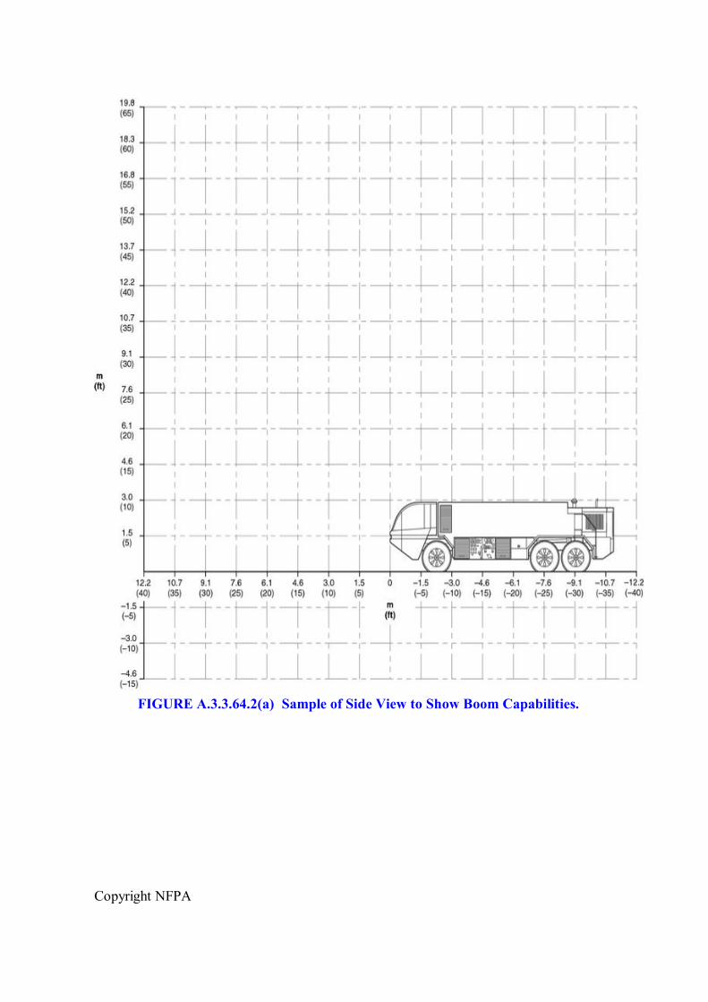
Copyright NFPA
FIGURE A.3.3.64.2(a) Sample of Side View to Show Boom Capabilities.
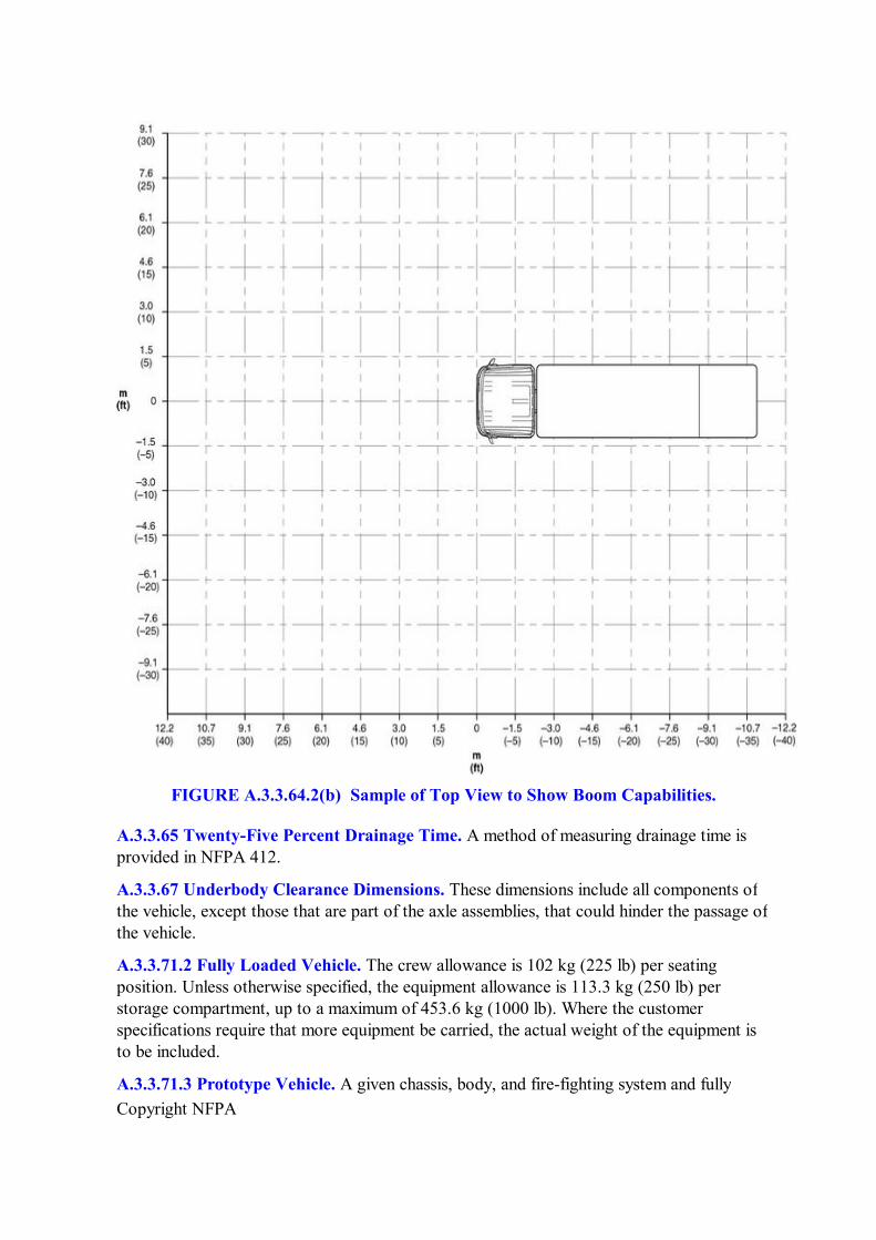
Copyright NFPA
FIGURE A.3.3.64.2(b) Sample of Top View to Show Boom Capabilities.
A.3.3.65 TwentyFive Percent Drainage Time. A method of measuring drainage time is provided in NFPA 412.
A.3.3.67 Underbody Clearance Dimensions. These dimensions include all components of the vehicle, except those that are part of the axle assemblies, that could hinder the passage of the vehicle.
A.3.3.71.2 Fully Loaded Vehicle. The crew allowance is 102 kg (225 lb) per seating position. Unless otherwise specified, the equipment allowance is 113.3 kg (250 lb) per storage compartment, up to a maximum of 453.6 kg (1000 lb). Where the customer specifications require that more equipment be carried, the actual weight of the equipment is to be included.
A.3.3.71.3 Prototype Vehicle. A given chassis, body, and firefighting system and fully
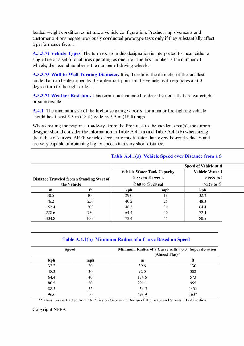
Copyright NFPA
loaded weight condition constitute a vehicle configuration. Product improvements and customer options negate previously conducted prototype tests only if they substantially affect a performance factor.
A.3.3.72 Vehicle Types. The term wheel in this designation is interpreted to mean either a single tire or a set of dual tires operating as one tire. The first number is the number of wheels, the second number is the number of driving wheels.
A.3.3.73 WalltoWall Turning Diameter. It is, therefore, the diameter of the smallest circle that can be described by the outermost point on the vehicle as it negotiates a 360 degree turn to the right or left.
A.3.3.74 Weather Resistant. This term is not intended to describe items that are watertight or submersible.
A.4.1 The minimum size of the firehouse garage door(s) for a major firefighting vehicle should be at least 5.5 m (18 ft) wide by 5.5 m (18 ft) high.
When creating the response roadways from the firehouse to the incident area(s), the airport designer should consider the information in Table A.4.1(a)and Table A.4.1(b) when sizing the radius of curves. ARFF vehicles accelerate much faster than overtheroad vehicles and are very capable of obtaining higher speeds in a very short distance.
Table A.4.1(a) Vehicle Speed over Distance from a Standing Start
Speed of Vehicle at the Given Distance
Distance Traveled from a Standing Start of the Vehicle
Vehicle Water Tank Capacity 227 to 1999 L 60 to 528 gal
Vehicle Water Tank Capacity >1999 to >528 to
m ft kph mph kph 30.5 100 29.0 18 32.2 76.2 250 40.2 25 48.3 152.4 500 48.3 30 64.4 228.6 750 64.4 40 72.4 304.8 1000 72.4 45 80.5
Table A.4.1(b) Minimum Radius of a Curve Based on Speed
Speed Minimum Radius of a Curve with a 0.04 Superelevation (Almost Flat)*
kph mph m ft 32.2 20 39.6 130 48.3 30 92.0 302 64.4 40 174.6 573 80.5 50 291.1 955 88.5 55 436.5 1432 96.6 60 498.9 1637
*Values were extracted from “A Policy on Geometric Design of Highways and Streets,” 1990 edition.
Copyright NFPA
A.4.1.3 New multiagent delivery technology systems are available that deliver multiple agents simultaneously with higher than conventional discharge pressures. These systems can also deliver agents independently at lower flow rates than a typical system. They also deliver the fire extinguishing agents in a form that improves the fire suppression performance of each agent when compared to the agents delivered in a conventional manner (for example, dry chemical suspended dry within the fire envelope, halogenated agent suspended as a vapor within the fire envelope, and foam delivered independently to minimize contamination or wetting of dry chemical to create a vapor barrier and/or further cool the fire environment). These delivery technologies are designed to improve fire suppression capability of all agents.
A.4.1.5 The following is a list of available options that can be ordered from the ARFF vehicle manufacturers:
(1) General ARFF vehicle options as follows:
(a) Winterization system providing sufficient insulation and heating capacity, by means of hot circulating liquids and forced air exchangers, to permit satisfactory operation of the vehicle and firefighting systems for a period of at least 4 hours at ambient temperatures as low as 40°C (40°F) with the vehicle fully operational and the engine running. At the end of the 4hour period, the vehicle shall be capable of successfully discharging its agent(s). The winterization system shall not detract from the performance of the vehicle and firefighting system in ambient temperatures up to 43.5°C (115°F).
(b) Pintlehooktype towing connection rated at 13,607 kg (30,000 lb) gross trailer weight, attached to the vehicle's frame at the rear of the vehicle
(c) Rolluptype compartment doors (other than service doors)
(d) Windshield deluge system (see 4.11.4.6)
(e) Training video tape covering the operation of the vehicle
(f) Navigation system of a driver's enhanced vision system (DEVS) (see 4.11.4.7)
(g) Monitoring and data acquisition system (MADAS) (see 4.11.7)
(2) Dimensional, safety, and stability enhancement options as follows:
(a) Added payload capacity (GVWR) to carry special equipment where the purchaser identifies added equipment
(b) Increased overall width of the vehicle to facilitate increased performance and maneuverability with no concern for movement on public highway(s)
(c) Audiovisual devices that meet or exceed the field of vision provided by wideangle mirrors
(3) Engine(s) with related options as follows:
(a) Engine that operates at necessary performance above 609.6 m (2000 ft)
Copyright NFPA
elevation
(b) Radiator shutters (see 4.3.2.3.3)
(c) Engine coolant filter
(d) Silicone coolant and heater hoses
(e) Heated diesel fuel–water separator
(f) Automatic drain(s) for the diesel fuel–water separator
(g) Auxiliary fuel tank(s) commensurate with need to meet local requirements
(h) Stainless steel exhaust systems and muffler(s)
(4) Vehicle electrical and lighting options as follows:
(a) Automatic ejecttype electrical receptacles
(b) Onboard battery charger/conditioner (see 4.4.5)
(c) Auxiliary generator(s) installed in accordance with NFPA 1901, Chapter 23
(d) Highintensity spotlight(s) on the left and right side of the windshield, hand adjustable type, with controls for beam adjustment inside the truck cab
(e) Highintensity spotlight(s) mounted on the primary turret nozzle(s), with controls located in the cab instrument group
(f) Two highintensity floodlights, mounted on each side of the vehicle
(g) Two highintensity fogtype driving lights mounted on the front bumper
(h) Two highintensity driving lights mounted on the front bumper
(i) Two highintensity floodlights on the rear of the vehicle
(j) Map lights on each side of the dash; a control switch on the instrument group panel in the cab for control of the lights
(k) Rotating beacontype lights on the top roof deck and visible for 360 degrees in the horizontal plane; a control switch on the instrument group panel in the cab for control of the light
(l) Strobetype light(s) on the top roof deck and visible for 360 degrees in the horizontal plane; a control switch on the instrument group panel in the cab for control of the light(s)
(m) Fused radio electrical connection in the cab adjacent to the radio mounting location (Power ratings are to be provided by purchaser.)
(5) Suspension, mobility, and tire options as follows:
(a) Reduced underaxle and underbody clearances to provide a more stable performance on pavement when the vehicle suspension is designed to permit instantaneous adjustment to the required height for offpavement travel
Copyright NFPA
(b) Tag or other nonpowered axle(s) to assist in weight distribution and/or stability requirements
(c) Vehicle stability systems
(d) Passive or active suspension components to increase the stability of the vehicle while decreasing the rollover threshold
(e) Spare tire(s)
(f) Bead locks on tires and rims
(g) Run flat devices in all tires and wheels mounted on the vehicle
(6) Vehicle brake options as follows:
(a) Air brake reservoirs drain valve(s) actuated by the driver from a location or compartment not requiring a creeper to access the actuator
(b) Autoejecttype connectors air connection used to change brake air tanks from an external air source
(7) Vehicle cab operating and driving options as follows:
(a) Tilt and telescoping steering wheel
(b) Supplementary designated seat positions for additional crew members
(c) Quick access passage to the roof
(d) FLIR heads up display located in the cab
(e) Cab airconditioning meeting current automotivetruck and environmental protection standards for vehicle airconditioning (The use of airconditioning does not change the acceptable pass/fail criteria.)
(f) Airsuspensiontype driver [passenger(s)] seat(s), with vertical, fore, and aft adjustment
(g) Crew seat back(s), with storage of selfcontained breathing apparatus (SCBA) with quickreleasetype holders incorporated into the seat cushion
(8) Firefighting systems' options as follows:
(a) Water tank design that allows access with each baffled compartment of the tank for internal and external inspection/service
(b) Automatic foam proportioning system, permitting use of 3 percent and 6 percent foam concentrates automatically when selected (change of proportioning plates not required)
(c) Electronic foam proportioning system
(d) Foam tank drain valve(s), drain line, and hose that facilitate draining the tank into specified container(s) positioned on the ground within 3 m (10 ft) in either horizontal direction of the foam tank drainage system
Copyright NFPA
(e) Manually operated roof turret with controls located in the cab, the operation force of the controls requiring less than 134.4 N (30 ftlb) including incab indicator of turret elevation and azimuth
(f) Manually operated roof turret with controls located on the cab roof platform, the operation force of the controls requiring less than 224 N (50 ftlb)
(g) Turret controls located in the cab or on the roof platform
(h) Manual override of roof turret functions in the cab not exceeding 134.4 N (30 ftlb) operation forces
(i) Turret(s) controls accessible both to the driver and the crew member
(j) Turret(s) equipped with an auxiliary agent discharge (see 4.23.1)
(k) Extendabletype primary turret (see 4.18.6)
(l) Color camera mounted on the extendable turret (see 4.18.6)
(m) Video recorder for color and/or FLIR camera(s)
(n) Aircraft skin penetrator/agent applicator mounted on the extendable turret (see 4.18.6)
(o) Preconnect handlines and nozzles (water/foam/combined/auxiliary agent/mounted parallel entrained streams)
(p) Bumper turret (see Section 4.20)
(q) Highcapacity bumper turret
(r) Two or more undertruck nozzles (see 4.20.1 and 4.20.3)
(s) Fire system pressure gauge/light/warning on the cab instrument panel grouping and/or on the side structural control panel
(t) Foam–liquid tank level gauge/light/warning on the cab instrument panel grouping
(u) Remote foam/water liquid level gauge/light/warning on the side panel and/or supply/service locations
(v) Bumper turret and/or ground sweep valve controls located in the cab
(w) Undertruck nozzle valve control in the cab
(x) Auxiliary agent pressurization control on the cab instrument grouping
(y) Remote mounted instrument and control panel (structural panel)
A.4.2.1 The carrying capacity of a vehicle is one of the least understood features of design and one of the most important. All vehicles are designed for a maximum GVWR or maximum total weight, which should not be exceeded by the apparatus manufacturer or by the purchaser after the vehicle has been placed in service. For tractordrawn vehicles, the inservice weight of the apparatus should not exceed the gross combination weight rating
Copyright NFPA
(GCWR). There are many factors that make up the rated GVWR, including the design of the springs or suspension system, the rated axle capacity, the rated tire and wheel loading, and the distribution of the weight between the front and rear wheels.
Water Tank. One of the most critical factors is the size of the water tank. Water weighs approximately 8.3 lb/gal (1 kg/L). A value of 10 lb/gal (1.2 kg/L) can be used when estimating the weight of the tank and its water, making a 500 gal (2000 L) tank and its water about 2.5 tons (2400 kg).
Miscellaneous Equipment. If the finished apparatus is not to be overloaded, the purchaser should provide the contractor with the weight of equipment to be carried if it is in excess of the allowance shown in Table 12.1 of NFPA 1901. (See Section 4.3 of NFPA 1901.)
Large Compartment Capacity. The manufacturer is only obligated by the standard to provide a miscellaneous equipment allowance in compliance with the minimum allowance listed in Table 12.1 of NFPA 1901. Purchasers who specify vehicles with large compartment capacity should work closely with the vehicle manufacturer to ensure that the GVWR is sufficient to carry the intended equipment. A vehicle with average compartment loading will have a miscellaneous equipment weight of about 8 lb/ft 3 (125 kg/m 3 ) of compartment space available for miscellaneous equipment. A very lightly loaded vehicle could have as little as 4 lb/ft 3 (65 kg/m 3 ). A heavily loaded vehicle can reach 12 lb/ft 3 (200 kg/m 3 ). This volume does not include space occupied by generators, reels, air systems, ladders, hose, and so forth, that are not in the miscellaneous equipment allowance. Total equipment weight varies significantly depending on the density of the equipment and how tightly the fire department chooses to pack it.
Overloading. Overloading of the vehicle by the manufacturer through design or by the purchaser adding a great deal of equipment after the vehicle is in service will materially reduce the life of the vehicle and will undoubtedly result in increased maintenance costs, particularly with respect to the transmissions, clutches, and brakes. Overloading can also seriously affect handling characteristics, making steering particularly difficult.
Underloading. Brake equipment on heavy vehicles can be sensitive to the weight distribution of the vehicle. Specifying a GVWR significantly greater than the intended inservice weight can lead to poor brake performance, chatter, and squeal. Purchasers who specify configurations with limited compartment volume on a high capacity chassis should consult the manufacturer to ensure that a vehicle with an underloaded condition will not result.
Fire apparatus should be able to perform its intended service under adverse conditions that might require operation off paved streets or roads. Chassis components should be selected with the rigors of service in mind. [1901: A.12.1]
It is important to consider the need to conserve weight and space on initial response ARFF vehicles. Rapid response, acceleration, top speed, and vehicle stability are vital to the mission.
It is, therefore, preferable that tools and equipment above what is necessary to perform initial operations be transported by other means, as needed.
The purchaser should specify the particular item required for the following:
Copyright NFPA
(1) One ground ladder that meets the requirements of NFPA 1931
(2) One section of hose of minimum 63.5 mm (2½ in.) diameter for tank fill
(3) Appropriate spanner wrenches for the fittings on the vehicle
(4) One hydrant wrench or other wrench necessary to activate the local water supply
(5) A SCBA meeting the requirements of NFPA 1981 and NFPA 1500 available for each assigned fire fighter
(6) Skin penetrator/agent applicator
(7) Appropriate wheel chocks
(8) 30.5 m (100 ft) of utility rope
(9) Two axes, nonwedge type
(10) Fireresistant blanket
(11) Bolt cutters, minimum 609.6 mm (24 in.)
(12) Multipurpose, forcible entry tool
(13) Intrinsically safe handlight(s)
(14) Two harness cutting tools
(15) Hook, grab, or salvage tool
(16) First aid kit
(17) 1.8 kg (4 lb) hammer
For a detailed discussion of rescue tools, see NFPA 402.
It is important that additional features such as structural firefighting equipment do not interfere with the basic ability of the vehicle to perform its primary aircraft rescue and firefighting function. It is considered preferable to have separate vehicles for structural fire fighting equipped with the needed complement of hose and tools, since the quantity of such equipment carried on an aircraft rescue and firefighting vehicle needs to be limited to conserve weight and space.
A.4.2.1.2 The intent of the weight distribution requirements is to produce the most equally divided weight distribution possible across all axles and wheels. Ideally, the front axle should not be the heaviest loaded axle. It is important to realize, however, that certain customized features not covered in the major firefighting vehicle chapter (such as complementary agent systems) might necessitate that the 5 percent allowance for the front axle be exceeded. Where these situations occur, the vehicle manufacturer needs to be consulted to determine the final weight distribution and to confirm that none of the established component weight ratings is exceeded and that the brake performance of the vehicle still complies with this standard.
A.4.2.2.1 Although the measurement of the axle clearance is with tires inflated to highway
Copyright NFPA
inflation pressure, it is understood that the actual clearance in soft soil and rough terrain could be less as tires could be deflated somewhat in order to achieve better offroad mobility.
A.4.2.2.2 Compromise might be necessary on overall vehicle dimensions, since the dimensions selected for optimum operational performance could be in conflict with other requirements. In order to eliminate unnecessary design restrictions, specification of vehicle dimensions should be undertaken only where a particular requirement exists.
Consideration should be given to the following factors at the time of specification to determine whether vehicle dimensions should be restricted:
(1) Fire station restrictions
(2) Access within the airport boundaries
(3) Access outside the airport boundaries, if necessary
(4) Requirements that affect the dimensions of local construction, if applicable
(5) Use regulations, if applicable
A.4.3.1.2 At higher altitudes, the performance of a vehicle can be affected due to the reduced density of the air drawn into the engine. The resulting reduction in power is more noticeable on a normally aspirated engine (e.g., nonturbo charged).
To assess the difference in performance at higher altitudes, it is important to obtain from the manufacturer the reduced power rating of the engine at the operating altitude. From this rating, the reduced level of acceleration performance or reduced water capacity extinguishing agent can be estimated.
A.4.6 The physical characteristics of an airport can require special suspensions, such as active, passive, or semipassive, to meet required response times.
A.4.7.2 The mobility and handling characteristics of the vehicle greatly depend on tire selection. The offpavement tractive limit of a tire is related to the strength of the soil, power available, load, number of driving wheels, tire diameter, tire deflection, contact area, and tread pattern.
To assist the purchaser in providing a sitespecific tire description, the following guidelines are recommended:
(1) Facilities with hard offpavement conditions and small snow accumulations require a low level of flotation. For these conditions the purchaser can specify tires of a relatively small diameter and narrow sectional width operating at a high inflation pressure. This configuration can be made to maximize highspeed performance and handling while the small contact area and resulting poor offpavement performance will have little if any impact on the effectiveness of the vehicle. A typical example of this configuration is a tire of size 16.00R20 operating within a load range of 4535.9 kg to 5443.1 kg (10,000 lb to 12,000 lb) at an inflation pressure of approximately 586 kPa (85 psi).
(2) Experience has demonstrated that tires with a relatively large diameter and wide sectional width and operating at medium inflation pressure can provide a reasonable
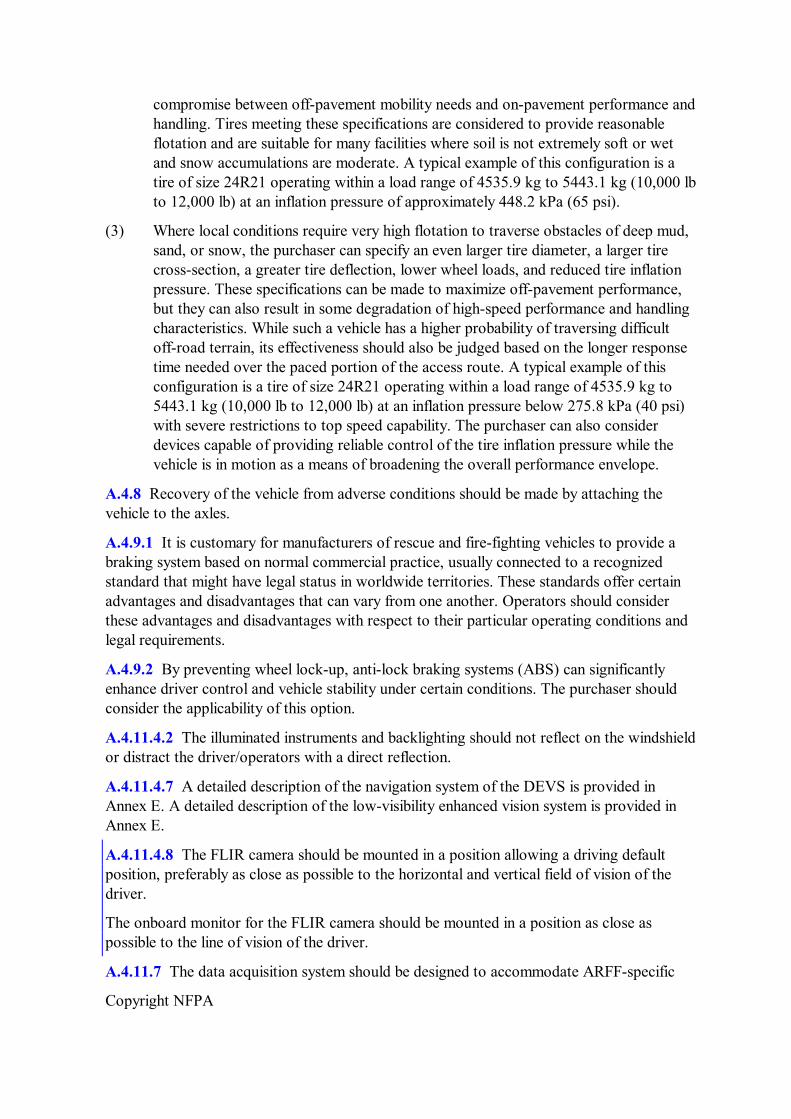
Copyright NFPA
compromise between offpavement mobility needs and onpavement performance and handling. Tires meeting these specifications are considered to provide reasonable flotation and are suitable for many facilities where soil is not extremely soft or wet and snow accumulations are moderate. A typical example of this configuration is a tire of size 24R21 operating within a load range of 4535.9 kg to 5443.1 kg (10,000 lb to 12,000 lb) at an inflation pressure of approximately 448.2 kPa (65 psi).
(3) Where local conditions require very high flotation to traverse obstacles of deep mud, sand, or snow, the purchaser can specify an even larger tire diameter, a larger tire crosssection, a greater tire deflection, lower wheel loads, and reduced tire inflation pressure. These specifications can be made to maximize offpavement performance, but they can also result in some degradation of highspeed performance and handling characteristics. While such a vehicle has a higher probability of traversing difficult offroad terrain, its effectiveness should also be judged based on the longer response time needed over the paced portion of the access route. A typical example of this configuration is a tire of size 24R21 operating within a load range of 4535.9 kg to 5443.1 kg (10,000 lb to 12,000 lb) at an inflation pressure below 275.8 kPa (40 psi) with severe restrictions to top speed capability. The purchaser can also consider devices capable of providing reliable control of the tire inflation pressure while the vehicle is in motion as a means of broadening the overall performance envelope.
A.4.8 Recovery of the vehicle from adverse conditions should be made by attaching the vehicle to the axles.
A.4.9.1 It is customary for manufacturers of rescue and firefighting vehicles to provide a braking system based on normal commercial practice, usually connected to a recognized standard that might have legal status in worldwide territories. These standards offer certain advantages and disadvantages that can vary from one another. Operators should consider these advantages and disadvantages with respect to their particular operating conditions and legal requirements.
A.4.9.2 By preventing wheel lockup, antilock braking systems (ABS) can significantly enhance driver control and vehicle stability under certain conditions. The purchaser should consider the applicability of this option.
A.4.11.4.2 The illuminated instruments and backlighting should not reflect on the windshield or distract the driver/operators with a direct reflection.
A.4.11.4.7 A detailed description of the navigation system of the DEVS is provided in Annex E. A detailed description of the lowvisibility enhanced vision system is provided in Annex E.
A.4.11.4.8 The FLIR camera should be mounted in a position allowing a driving default position, preferably as close as possible to the horizontal and vertical field of vision of the driver.
The onboard monitor for the FLIR camera should be mounted in a position as close as possible to the line of vision of the driver.
A.4.11.7 The data acquisition system should be designed to accommodate ARFFspecific
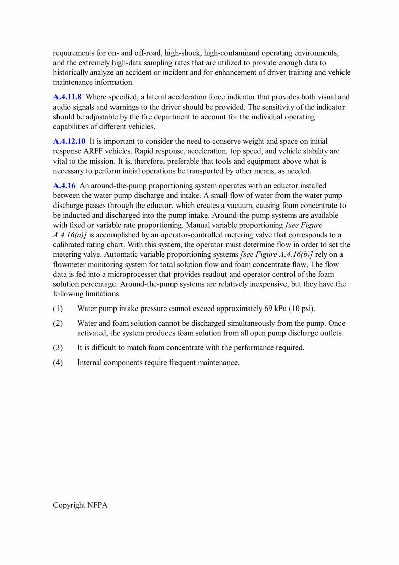
Copyright NFPA
requirements for on and offroad, highshock, highcontaminant operating environments, and the extremely highdata sampling rates that are utilized to provide enough data to historically analyze an accident or incident and for enhancement of driver training and vehicle maintenance information.
A.4.11.8 Where specified, a lateral acceleration force indicator that provides both visual and audio signals and warnings to the driver should be provided. The sensitivity of the indicator should be adjustable by the fire department to account for the individual operating capabilities of different vehicles.
A.4.12.10 It is important to consider the need to conserve weight and space on initial response ARFF vehicles. Rapid response, acceleration, top speed, and vehicle stability are vital to the mission. It is, therefore, preferable that tools and equipment above what is necessary to perform initial operations be transported by other means, as needed.
A.4.16 An aroundthepump proportioning system operates with an eductor installed between the water pump discharge and intake. A small flow of water from the water pump discharge passes through the eductor, which creates a vacuum, causing foam concentrate to be inducted and discharged into the pump intake. Aroundthepump systems are available with fixed or variable rate proportioning. Manual variable proportioning [see Figure A.4.16(a)] is accomplished by an operatorcontrolled metering valve that corresponds to a calibrated rating chart. With this system, the operator must determine flow in order to set the metering valve. Automatic variable proportioning systems [see Figure A.4.16(b)] rely on a flowmeter monitoring system for total solution flow and foam concentrate flow. The flow data is fed into a microprocesser that provides readout and operator control of the foam solution percentage. Aroundthepump systems are relatively inexpensive, but they have the following limitations:
(1) Water pump intake pressure cannot exceed approximately 69 kPa (10 psi).
(2) Water and foam solution cannot be discharged simultaneously from the pump. Once activated, the system produces foam solution from all open pump discharge outlets.
(3) It is difficult to match foam concentrate with the performance required.
(4) Internal components require frequent maintenance.
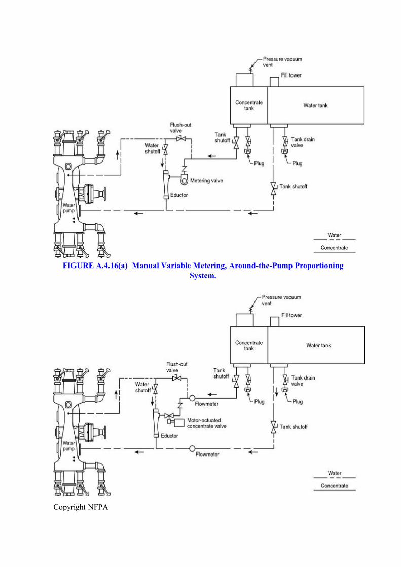
Copyright NFPA
FIGURE A.4.16(a) Manual Variable Metering, AroundthePump Proportioning System.
Copyright NFPA
FIGURE A.4.16(b) Automatic Variable Metering, AroundthePump Proportioning System.
Premixed foam systems utilize a separate tank to contain the foam solution that has been premixed at a specific percentage. There are two types of premix systems.
Pressuretype systems use a pressure vessel for the tank and compressed gas, usually nitrogen, to propel the premixed foam solution from the discharge device. These systems are usually installed on quick attacktype apparatus to take advantage of the instant activation feature of this type of foam system. Pressuretype premix systems [see Figure A.4.16(c)] have the following limitations:
(1) Fixed foam solution percentage, once the foam solution is prepared.
(2) Size and weight of the pressure vessel.
(3) Pressure limitation of the pressure vessel.
(4) System cannot be recharged while the system is in operation.
Suctiontype systems use an atmospheric tank that is connected to the water pump intake. The premixed foam solution is drawn directly into the pump and discharged as required. A suction system can be created by adding the correct amount of foam concentrate to the water tank on the fire apparatus. Suctiontype premix systems have the following limitations:
(1) Fixed foam solution percentage, once foam solution is prepared.
(2) Water and foam solution cannot be discharged simultaneously from the pump. Once activated, the system produces foam solution from all open pump discharge outlets.
(3) System is difficult to recharge when system is in operation.
(4) Foam concentrates must be mechanically mixed with water to create foam solution.
CAUTION: Adding foam directly to the water tank on a piece of apparatus that was not specifically designed for premix usage will cause damage to the tank, plumbing, and pump.
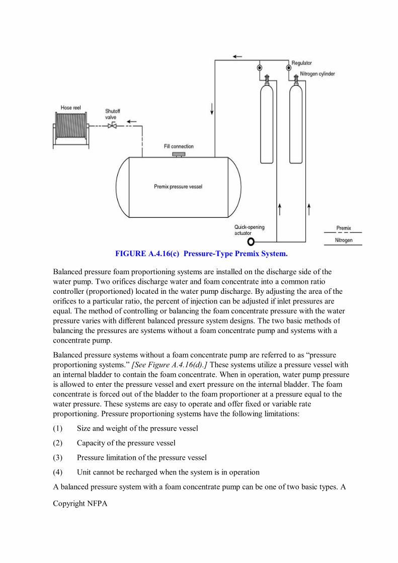
Copyright NFPA
FIGURE A.4.16(c) PressureType Premix System.
Balanced pressure foam proportioning systems are installed on the discharge side of the water pump. Two orifices discharge water and foam concentrate into a common ratio controller (proportioned) located in the water pump discharge. By adjusting the area of the orifices to a particular ratio, the percent of injection can be adjusted if inlet pressures are equal. The method of controlling or balancing the foam concentrate pressure with the water pressure varies with different balanced pressure system designs. The two basic methods of balancing the pressures are systems without a foam concentrate pump and systems with a concentrate pump.
Balanced pressure systems without a foam concentrate pump are referred to as “pressure proportioning systems.” [See Figure A.4.16(d).] These systems utilize a pressure vessel with an internal bladder to contain the foam concentrate. When in operation, water pump pressure is allowed to enter the pressure vessel and exert pressure on the internal bladder. The foam concentrate is forced out of the bladder to the foam proportioner at a pressure equal to the water pressure. These systems are easy to operate and offer fixed or variable rate proportioning. Pressure proportioning systems have the following limitations:
(1) Size and weight of the pressure vessel
(2) Capacity of the pressure vessel
(3) Pressure limitation of the pressure vessel
(4) Unit cannot be recharged when the system is in operation
A balanced pressure system with a foam concentrate pump can be one of two basic types. A
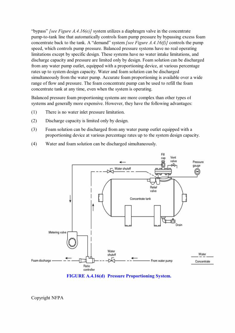
Copyright NFPA
“bypass” [see Figure A.4.16(e)] system utilizes a diaphragm valve in the concentrate pumptotank line that automatically controls foam pump pressure by bypassing excess foam concentrate back to the tank. A “demand” system [see Figure A.4.16(f)] controls the pump speed, which controls pump pressure. Balanced pressure systems have no real operating limitations except by specific design. These systems have no water intake limitations, and discharge capacity and pressure are limited only by design. Foam solution can be discharged from any water pump outlet, equipped with a proportioning device, at various percentage rates up to system design capacity. Water and foam solution can be discharged simultaneously from the water pump. Accurate foam proportioning is available over a wide range of flow and pressure. The foam concentrate pump can be used to refill the foam concentrate tank at any time, even when the system is operating.
Balanced pressure foam proportioning systems are more complex than other types of systems and generally more expensive. However, they have the following advantages:
(1) There is no water inlet pressure limitation.
(2) Discharge capacity is limited only by design.
(3) Foam solution can be discharged from any water pump outlet equipped with a proportioning device at various percentage rates up to the system design capacity.
(4) Water and foam solution can be discharged simultaneously.
FIGURE A.4.16(d) Pressure Proportioning System.
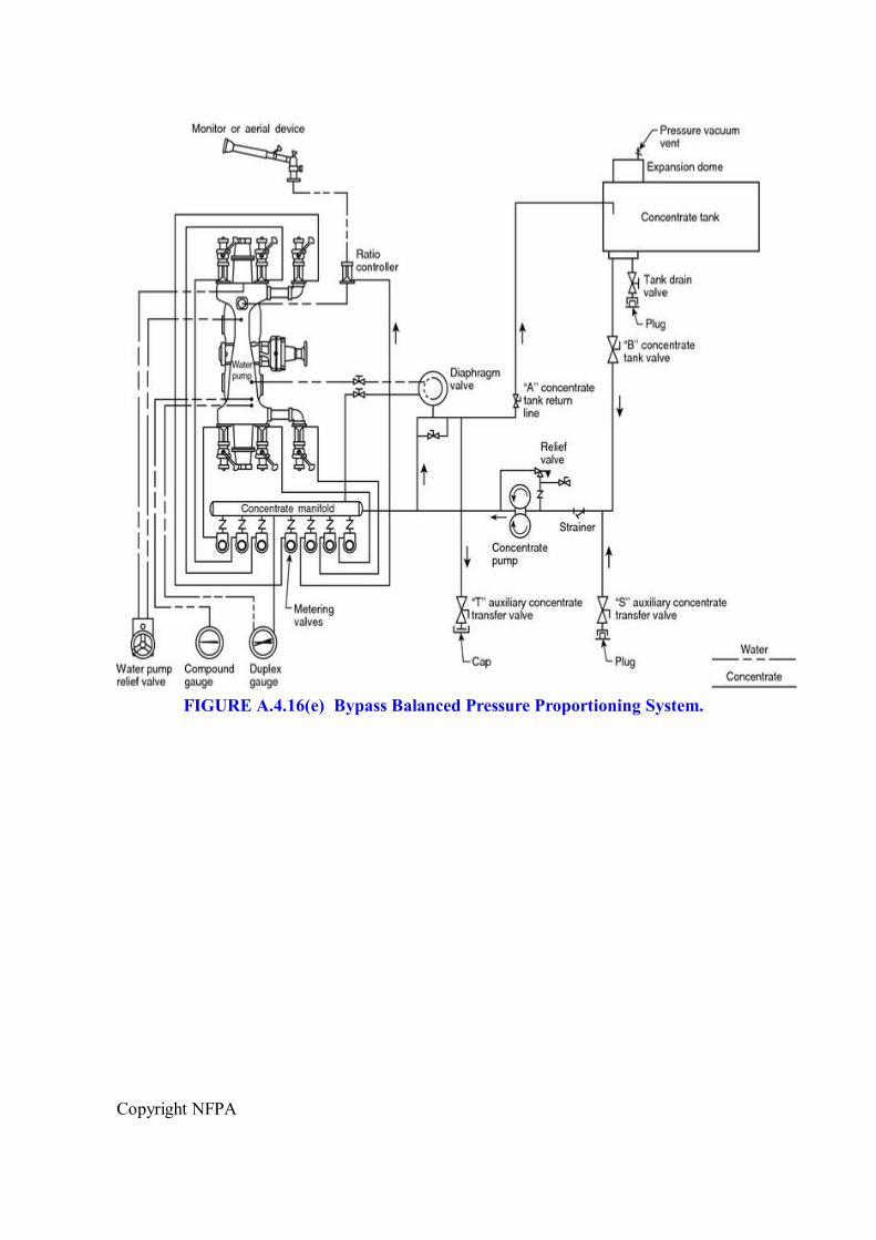
Copyright NFPA
FIGURE A.4.16(e) Bypass Balanced Pressure Proportioning System.
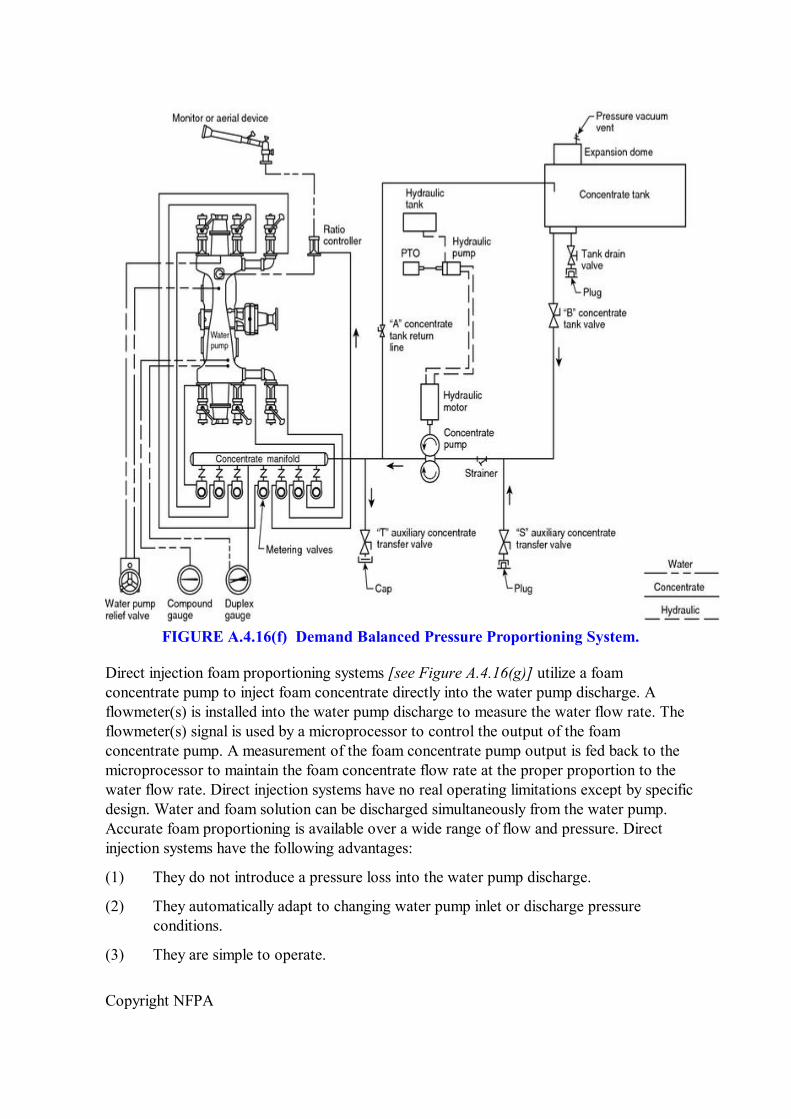
Copyright NFPA
FIGURE A.4.16(f) Demand Balanced Pressure Proportioning System.
Direct injection foam proportioning systems [see Figure A.4.16(g)] utilize a foam concentrate pump to inject foam concentrate directly into the water pump discharge. A flowmeter(s) is installed into the water pump discharge to measure the water flow rate. The flowmeter(s) signal is used by a microprocessor to control the output of the foam concentrate pump. A measurement of the foam concentrate pump output is fed back to the microprocessor to maintain the foam concentrate flow rate at the proper proportion to the water flow rate. Direct injection systems have no real operating limitations except by specific design. Water and foam solution can be discharged simultaneously from the water pump. Accurate foam proportioning is available over a wide range of flow and pressure. Direct injection systems have the following advantages:
(1) They do not introduce a pressure loss into the water pump discharge.
(2) They automatically adapt to changing water pump inlet or discharge pressure conditions.
(3) They are simple to operate.
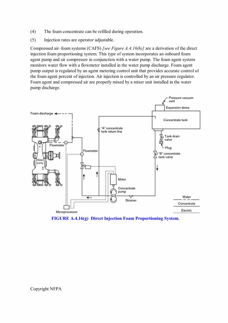
Copyright NFPA
(4) The foam concentrate can be refilled during operation.
(5) Injection rates are operator adjustable.
Compressed air–foam systems (CAFS) [see Figure A.4.16(h)] are a derivation of the direct injection foam proportioning system. This type of system incorporates an onboard foam agent pump and air compressor in conjunction with a water pump. The foam agent system monitors water flow with a flowmeter installed in the water pump discharge. Foam agent pump output is regulated by an agent metering control unit that provides accurate control of the foam agent percent of injection. Air injection is controlled by an air pressure regulator. Foam agent and compressed air are properly mixed by a mixer unit installed in the water pump discharge.
FIGURE A.4.16(g) Direct Injection Foam Proportioning System.
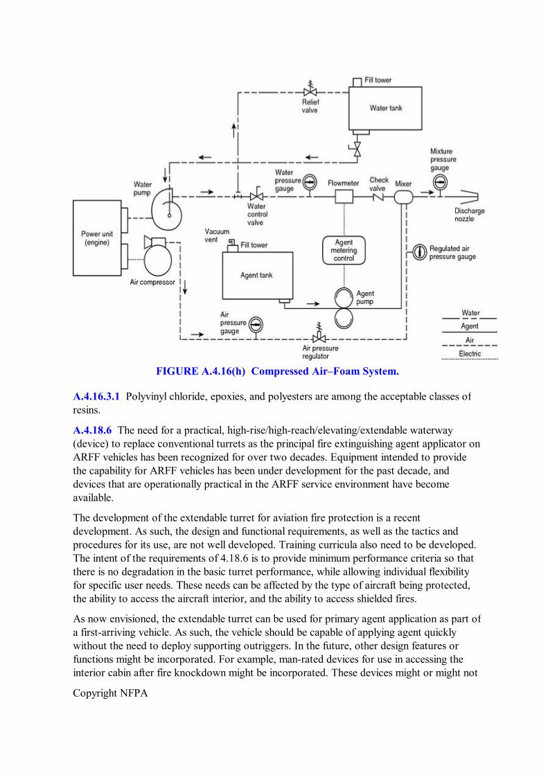
Copyright NFPA
FIGURE A.4.16(h) Compressed Air–Foam System.
A.4.16.3.1 Polyvinyl chloride, epoxies, and polyesters are among the acceptable classes of resins.
A.4.18.6 The need for a practical, highrise/highreach/elevating/extendable waterway (device) to replace conventional turrets as the principal fire extinguishing agent applicator on ARFF vehicles has been recognized for over two decades. Equipment intended to provide the capability for ARFF vehicles has been under development for the past decade, and devices that are operationally practical in the ARFF service environment have become available.
The development of the extendable turret for aviation fire protection is a recent development. As such, the design and functional requirements, as well as the tactics and procedures for its use, are not well developed. Training curricula also need to be developed. The intent of the requirements of 4.18.6 is to provide minimum performance criteria so that there is no degradation in the basic turret performance, while allowing individual flexibility for specific user needs. These needs can be affected by the type of aircraft being protected, the ability to access the aircraft interior, and the ability to access shielded fires.
As now envisioned, the extendable turret can be used for primary agent application as part of a firstarriving vehicle. As such, the vehicle should be capable of applying agent quickly without the need to deploy supporting outriggers. In the future, other design features or functions might be incorporated. For example, manrated devices for use in accessing the interior cabin after fire knockdown might be incorporated. These devices might or might not
Copyright NFPA
require stabilizing devices; depending on the function of the vehicle, the time to deploy such devices might be permitted. In any event, there should be a maximum time for total deployment of the boom/tower device. A maximum of 30 seconds is recommended. The requirements do not prohibit the development of an advanced device or a unit with a different function, recognizing that the primary turret performance should not be compromised.
It is not recommended that agent be applied from a vertically extended position before knockdown of the exterior exposure fire, unless the fire cannot otherwise be accessed. Preliminary data from demonstrations of extendable turrets, plus data from earlier turret testing, suggest that AFFF discharged at a low level is the most effective technique. The extendable turret should be designed to extend below the primary level of the cab to take advantage of lowlevel AFFF application. Extension of the extendable turret below the cab level also should provide advantages in accessing shielded/obstructed areas such as wheelwell incidents and “gear down” scenarios.
To improve operator efficiency, the movement of the boom/tower should be accomplished with a single lever located within the cab. Elevation/azimuth indicators are not needed if the turret is in the line of sight of the operator.
Where specified, the extendable turret should be fitted with the appropriate tools/devices needed for a driver/operator to perform interior aircraft and tailmounted engine firefighting functions remotely. These could include a skin penetrator/agent applicator for penetration of the fuselage to access interior fires from outside the aircraft. Tactics and procedures for these evolutions are not well developed and should be given careful consideration, preplanning, and training, particularly for situations where surviving passengers/crew might still be in the aircraft. Where a penetrator/agent applicator is used, a minimum flow equal to two handlines (as specified in 4.16.4.3) is recommended. Airports planning to use the device for indirect attack with a skin penetrator should preplan appropriate access locations on aircraft served and the conditions under which the device is to be used.
A.4.18.6.7 The proposed concept would be to penetrate above overwing window areas, above interior seat back height, and below baggage storage bins. Providing water extinguishment from ceiling to floor for a distance of 9.1 m to 12.2 m (30 ft to 40 ft) along the fuselage left and right of the centerline of the penetration point would stop fire growth and protect the interior until other vehicles could extinguish the outside exterior fuel fire.
A.4.18.7 A lightweight boommounted turret is a primary turret mounted on a lightweight boom that is capable of being elevated and depressed to apply agent to aircraft engines, doorways, and emergency exits. Lightweight boommounted turrets differ from extendible turrets in that they do not need turntables. Responsive vehicle suspension, steering systems, and drive systems are used to locate the turret more directly and more rapidly.
A.4.21.1.6 Where specified, the vehicle should come with a closed system to aid in reservice of dry chemical.
A.4.22.4.7 Halogenated agents are generally incompatible with some types of seal materials.
A.4.24.1 The following are lighting options:
Copyright NFPA
(1) Where specified, a spotlight on both left and right sides of the windshield, handadjustable type, with controls for adjustment inside the truck cab
(2) Where specified, a spotlight mounted on a turret with a control switch that is readily accessible to the operator
(3) Where specified, two highintensity floodlights mounted one on each side of the vehicle to provide illumination of the work area adjacent to the vehicle
(4) Where specified, two highintensity fogtype drivingtype lights; A protective brush guard should be provided around each lamp. A switch should be mounted on the dash in the cab
(5) Where specified, in addition to the normal vehicle headlight system, two highintensity drivingtype lights; A protective brush guard should be provided around each lamp. A switch should be mounted on the dash in the cab
(6) Where specified, two highintensity floodlights mounted at the rear of the vehicle that are controlled by a switch in the cab
(7) Where specified, map light(s)
A.4.24.2 If desired, the driver's siren control can be wired for selective control on the steering wheel horn button. If a combination public address–type siren is desired, an electronic type having an equivalent sound output should be substituted.
A.5.1 Interior access vehicle information is as follows:
(1) Extinguishing agents criteria is as follows:
(a) The vehicle should be equipped with reeled handlines capable of being supplied from an outside source.
(b) One hose line should be provided for airports intended to service aircraft with one aisle.
(c) Two hose lines should be provided for airports intended to service aircraft with more than one aisle.
(d) The vehicle should be equipped with handheld extinguishers as specified by the purchaser.
(2) Ventilation Capabilities. In order to facilitate interior firefighting and rescue operations, the vehicle should be provided with equipment capable of ventilating the passenger cabins of aircraft at the airport.
(3) Tools and Equipment. The vehicle should be provided with tools and equipment to effectively support initial firefighting and rescue operations as specified by the purchaser.
A.5.1.5 Stabilizers or similar devices can be used where needed.
A.5.2.2 The reason that it is required to be a stairway is that it must be easily traversed by fire fighters in full protective gear.
Copyright NFPA
A.5.3.1 The docking platform should have protective railings that are designed to open on the side intended to face the aircraft. Protective railings should be at least 127 cm (50 in.) high, and rails should be no more than 12.7 cm (5 in.) apart.
A.5.4.1 The required turning radius allows for maneuverability through a crash site debris field, in the vicinity of aircraft passenger gates, and if necessary a quick reposition of the vehicle. The driver of the vehicle should have full view of the contact portion of the docking platform(s). The vehicle control should be possible at speeds less than 1.6 kph (1 mph) without noticeable lurching.
A.6.4 Due to the high tilttable angle that is required in this standard per SAE J 2180, testing to 30 degree tilt angle, vehicle slipping on the table surface can occur. Research has shown that an “open grid deck” product specified as follows resists vehicle traction slippage without impacting the tilttable angle achieved: IKG Greulich 5 in., 4way standard open steel grid with 4183# main bars @ 645 mm (7.5 in.) on center, 6.35 mm × 50.8 mm (¼ in. × 2 in.) crossbars @ 95.3 mm (3.75 in.) on center, on 6.35 mm × 25.4 mm (¼ in. × 1 in.) diagonal and supplemental bars.
This product is available from IKG Industries, Harsco Company, P.O. Box 100930, 860 Visco Drive, Nashville, TN 372240930; (615)7824794; (800)4672346; fax: (615)2567881.
A.6.4.13.1 This demonstration need not have the penetration device mounted to the finished boom system. This demonstration is a laboratory test to show that the manufacturer understands the requirements of the penetration task requirement.
A.6.4.13.2 This demonstration need not have the penetration device mounted to the finished boom system. This demonstration is a laboratory test to show that the manufacturer understands the requirements of the penetration task requirement.
Annex B Requirements for Low Voltage Electrical Systems and Warning Devices
This annex is not a part of the requirements of this NFPA document but is included for informational purposes only.
NOTE: Requirements for low voltage electrical systems and warning devices are covered in NFPA 1901, Standard for Automotive Fire Apparatus. The following material is extracted verbatim from Chapter 13, Low Voltage Electrical Systems and Warning Devices, from the 2003 edition of NFPA 1901, and is included here as a convenience for users of this standard. Any requests for Formal Interpretations (FI) or Tentative Interim Amendments (TIA) on the following material must be directed to the Technical Committee on Fire Department Apparatus.
B.1 General.
Any low voltage electrical systems or warning devices installed on the fire apparatus shall be appropriate for the mounting location and intended electrical load and shall meet the specific
Copyright NFPA
requirements of Annex B.
B.2 Wiring.
All electrical circuit feeder wiring supplied and installed by the fire apparatus manufacturer shall meet the requirements of B.2.1 through B.2.8.
B.2.1 The wire shall be stranded copper or copper alloy conductors of a gauge rated to carry 125 percent of the maximum current for which the circuit is protected.
B.2.1.1 Voltage drops in all wiring from the power source to the using device shall not exceed 10 percent.
B.2.1.2 The use of star washers for circuit ground connections shall not be permitted.
B.2.1.3 All circuits shall otherwise be wired in conformance with SAE J1292, Automobile, Truck, TruckTractor, Trailer, and Motor Coach Wiring.
B.2.2 Wiring and Wire Harness Construction.
B.2.2.1 All insulated wire and cable shall conform to SAE J1127, Battery Cable, or SAE J1128, Low Tension Primary Cable, Type SXL, GXL, or TXL.
B.2.2.1.1 All conductors shall be constructed in accordance with SAE J1127, Battery Cable, or SAE J1128, Low Tension Primary Cable, except where good engineering practice dictates special strand construction.
B.2.2.1.2 Conductor materials and stranding, other than copper, shall be permitted if all applicable requirements for physical, electrical, and environmental conditions are met as dictated by the end application.
B.2.2.1.3 Physical and dimensional values of conductor insulation shall be in conformance with the requirements of SAE J1127, Battery Cable, or SAE J1128, Low Tension Primary Cable, except where good engineering practice dictates special conductor insulation.
B.2.2.2 The overall covering of conductors shall be moistureresistant loom or braid that has a minimum continuous rating of 194°F (90°C) except where good engineering practice dictates special consideration for loom installations exposed to higher temperatures.
B.2.3 The overall covering of jacketed cables shall be moisture resistant and have a minimum continuous temperature rating of 194°F (90°C) except where good engineering practice dictates special consideration for cable installations exposed to higher temperatures.
B.2.4 All wiring connections and terminations shall use a method that provides a positive mechanical and electrical connection.
B.2.4.1 The wiring connections and terminations shall be installed in accordance with the device manufacturer's instructions.
B.2.4.2 All terminal strips shall have protective covers.
B.2.4.3 Wire nut, insulation displacement, and insulation piercing connections shall not be used.
Copyright NFPA
B.2.5 Wiring shall be restrained to prevent damage caused by chafing or ice buildup, and protected against heat, liquid contaminants, or other environmental factors.
B.2.6 Wiring shall be uniquely identified at least every 2 ft (0.6 m) by color coding or permanent marking with a circuit function code. The identification shall reference a wiring diagram. [See 4.19.2.3(6) of NFPA 1901.]
B.2.7 Circuits shall be provided with properly rated low voltage overcurrent protective devices.
B.2.7.1 Such devices shall be readily accessible and protected against heat in excess of the overcurrent device's design range, mechanical damage, and water spray.
B.2.7.2 Circuit protection shall be accomplished by utilizing fuses, circuit breakers, fusible links, or solid state equivalent devices.
B.2.7.3 If a mechanicaltype device is used, it shall conform to one of the following SAE standards:
(1) SAE J156, Fusible Links
(2) SAE J553, Circuit Breakers
(3) SAE J554, Electric Fuses (Cartridge Type)
(4) SAE J1888, High Current Time Lag Electric Fuses
(5) SAE J2077, Miniature Blade Type Electrical Fuses
B.2.8 Switches, relays, terminals, and connectors shall have a direct current (dc) rating of 125 percent of maximum current for which the circuit is protected.
B.3 Power Supply.
B.3.1 A 12 volt or 24 volt electrical alternator shall be provided.
B.3.2 It shall have a minimum output at idle to meet the minimum continuous electrical load of the fire apparatus as defined in B.3.3, at 200°F (93°C) ambient temperature within the engine compartment, and shall be provided with full automatic regulation.
B.3.3 The minimum continuous electrical load shall consist of the total amperage required to simultaneously operate the following in a stationary mode during emergency operations:
(1) The propulsion engine and transmission
(2) All legally required clearance and marker lights, headlights, and other electrical devices except windshield wipers and fourway hazard flashers
(3) The radio(s) at a duty cycle of 10 percent transmit and 90 percent receive (for calculation and testing purposes, a default value of 5 A continuous)
(4) The lighting necessary to produce 1 fc (10 lx) of illumination on all walking surfaces on the apparatus and on the ground at all egress points onto and off the apparatus, 5 fc (50 lx) of illumination on all control and instrument panels, and 50 percent of the
Copyright NFPA
total compartment lighting loads
(5) The minimum optical warning system required in Section B.8, where the apparatus is blocking the rightofway
(6) The continuous electrical current required to simultaneously operate any fire pumps, aerial devices, and hydraulic pumps
(7) Other warning devices and electrical loads defined by the purchaser as critical to the mission of the apparatus.
B.3.4 The condition of the low voltage electrical system shall be monitored by a system that provides an audible and visual warning to persons on, in, or near the apparatus of an impending electrical system failure caused by the excessive discharge of the battery set.
B.3.4.1 The charge status of the battery shall be determined either by direct measurement of the battery charge or indirectly by monitoring the system voltage.
B.3.4.2 If system voltage is monitored, the alarm shall sound if the system voltage at the battery or at the master load disconnect switch drops below 11.8 V for 12 V nominal systems or 23.6 V for 24 V nominal systems for more than 120 seconds.
B.3.5 A voltmeter shall be mounted on the driver's instrument panel to allow direct observation of the system voltage.
B.3.6 Load Management.
B.3.6.1 If the total continuous electrical load exceeds the minimum continuous electrical output rating of the installed alternator(s) operating under the conditions specified in B.3.2, an automatic electrical load management system shall be required.
B.3.6.2 The minimum continuous electrical loads defined in B.3.3 shall not be subject to automatic load management.
B.4 Batteries.
B.4.1 Batteries shall be of the highcycle type.
B.4.2 With the engine off, the battery system shall be able to provide the minimum continuous electrical load for 10 minutes without discharging more than 50 percent of the reserve capacity and then restart the engine.
B.4.3 The battery system cold cranking amps (CCA) rating shall meet or exceed the minimum CCA recommendations of the engine manufacturer.
B.4.4 The batteries shall be mounted to prevent movement during fire apparatus operation and shall be protected against accumulations of road spray, snow, and road debris.
B.4.4.1 The batteries shall be readily accessible for examination, test, and maintenance.
B.4.4.2 A means shall be provided for jumpstarting the engine if the batteries are not accessible without lifting the cab of a tiltcab apparatus.
B.4.4.3 Where an enclosed battery compartment is provided, it shall be ventilated to the
Copyright NFPA
exterior to prevent the buildup of heat and explosive fumes.
B.4.4.4 The batteries shall be protected against vibration and temperatures that exceed the battery manufacturer's recommendation.
B.4.5 An onboard battery conditioner or charger, or a polarized inlet, shall be provided for charging all batteries. Where an onboard conditioner or charger is supplied, the associated line voltage electrical power system shall be installed in accordance with Chapter 23 of NFPA 1901. (See Annex C.)
B.4.6 A master load disconnect switch shall be provided between the starter solenoid(s) and the remainder of the electrical loads on the apparatus.
B.4.6.1 The batteries shall be connected directly to the starter solenoid(s).
B.4.6.2 Electronic control systems and similar devices shall be permitted to be otherwise connected if so specified by their manufacturer.
B.4.6.3 The alternator shall be wired directly to the batteries through the ammeter shunt(s), if one is provided, and not through the master load disconnect switch.
B.4.6.4 A green “battery on” pilot light that is visible from the driver's position shall be provided.
B.4.7 A sequential switching device shall be permitted to energize the optical warning devices required in B.3.3 and other highcurrent devices, provided the switching device energizes the electrical devices required in B.3.3 first and within 5 seconds.
B.5 Starting Device.
B.5.1 An electrical starting device shall be provided for the engine.
B.5.2 Where the electrical starting device is operating under maximum load, the voltage drop of the conductors between the battery and the starting device shall be in accordance with SAE J541, Voltage Drop for Starting Motor Circuits.
B.6 Temperature Exposure.
Any alternator, electrical starting device, ignition wiring, distributor, or ignition coil shall be moisture resistant and protected such that it is not exposed to a temperature that exceeds the component manufacturer's recommendations.
B.7 Electromagnetic Interference.
B.7.1 Electromagnetic interference suppression shall be provided, as required, to satisfy the radiation limits specified in SAE J551/2, Test Limits and Methods of Measurement of Radio Disturbance Characteristics of Vehicles, Motorboats, and SparkIgnited EngineDriven Devices.
B.7.2 The purchaser shall indicate if testing and certification under SAE J551/2, Test Limits and Methods of Measurement of Radio Disturbance Characteristics of Vehicles, Motorboats, and SparkIgnited EngineDriven Devices, are required.
Copyright NFPA
B.8 Optical Warning Devices.
Each apparatus shall have a system of optical warning devices that meets or exceeds the requirements of this section.
B.9 Audible Warning Devices.
B.9.1 Audible warning equipment in the form of at least one automotive traffic horn and one electric or electronic siren shall be provided.
B.9.1.1 The siren manufacturer shall certify the siren as meeting the requirements of SAE J1849, Emergency Vehicle Sirens.
B.9.1.2 A means shall be provided to allow the activation of the siren within convenient reach of the driver.
B.9.2 Where furnished, air horns, electric siren(s), and electronic siren speaker(s) shall be mounted as low and as far forward on the apparatus as practical.
B.9.3 Audible warning equipment shall not be mounted on the roof of the apparatus.
B.10 Work Lighting.
B.10.1 Ground Lighting.
B.10.1.1 The work area immediately behind the vehicle shall be illuminated to a level of at least 3 fc (30 lx) within a 10 ft × 10 ft (3 m × 3 m) square to the rear of the vehicle.
B.10.1.2 The fire apparatus shall be equipped with lighting that is capable of providing illumination at a minimum level of 1 fc (10 lx) on ground areas within 30 in. (800 mm) of the edge of the apparatus in areas designed for personnel to climb onto the apparatus or descend from the apparatus to the ground level.
B.10.1.3 Lighting designed to provide illumination on areas under the driver and crew riding area exits shall be switchable but activated automatically when the exit doors are opened.
B.10.1.4 All other ground area lighting shall be switchable.
B.10.2 Hose Bed Lighting.
B.10.2.1 If a hose bed is provided, lighting on this hose bed shall be at a level of 3 fc (30 lx) or higher.
B.10.2.2 Lateral hose beds (crosslays) that are permanently covered shall not be required to be illuminated.
B.10.3 Surface Lighting. The apparatus shall have sufficient lighting to provide a minimum level of 1 fc (10 lx) on all work surfaces, steps, and walkways.
B.10.4 Interior Lighting. The apparatus shall have sufficient lighting to provide an average level of 2 fc (20 lx) in the driving and crew compartments.
B.10.5 Compartment Lighting.
Copyright NFPA
B.10.5.1 Each engine compartment and pump compartment shall have a light of at least 20 candlepower (250 lumens).
B.10.5.2 The priming lubricant reservoir, if applicable, shall be illuminated.
B.10.5.3 Each enclosed tool and equipment compartment greater than 4 ft 3 (0.1 m 3 ) in volume and having an opening greater than 144 in. 2 (0.9 m 2 ) shall have an average minimum level of lighting of 1 fc (10 lx).
B.10.5.4 Compartments such as ladder tunnels, pikepole storage tubes, or underbody compartments designed around the volumetric requirements of specific equipment that can be removed without the use of article illumination shall not be required to have compartment lighting.
B.10.6 Switching. Switches for all work lighting shall be readily accessible.
B.10.7 Protection. The lights shall be arranged or protected to minimize accidental breakage.
B.10.8 Testing. All work lights mounted in wet locations shall be tested in conformance with SAE J575, Test Methods and Equipment for Lighting Devices and Components for Use on Vehicles Less Than 2032 mm in Overall Width, and shall comply with the following performance requirements of that standard:
(1) Vibration
(2) Moisture
(3) Dust
(4) Corrosion
(5) High temperature
(6) Low temperature
(7) Durability
(8) Warpage
B.11 Hazard Light.
B.11.1 A red flashing or rotating light, located in the driving compartment, shall be illuminated automatically whenever the apparatus's parking brake is not fully engaged and any of the following conditions exist:
(1) Any passenger or equipment compartment door is open.
(2) Any ladder or equipment rack is not in the stowed position.
(3) Stabilizer system is not in its stowed position.
(4) Powered light tower is extended.
(5) Any other device permanently attached to the apparatus is open, extended, or
Copyright NFPA
deployed in a manner that is likely to cause damage to the apparatus if the apparatus is moved.
B.11.2 This section shall not apply to manually raised pole lights with an extension of less than 5 ft (1.5 m).
B.11.3 The hazard light shall be marked with a sign that reads: “Do Not Move Apparatus When Light Is On.”
B.12 Backup Alarm.
An electric or electronic backup alarm shall be provided that meets the Type D (87 dBA) requirements of SAE J994, Alarm — Backup — Electric, Laboratory Performance Testing.
B.13 Stop, Tail, and Directional Lights.
B.13.1 The apparatus shall be equipped with all legally required stop, tail, and directional lights.
B.13.2 Directional lights shall be visible from the front, sides, and rear of the apparatus.
B.13.3 On apparatus 30 ft (10 m) or longer in length, a turn signal shall be mounted approximately midway along the apparatus at approximately running board height.
B.13.4 Equipment shall not be mounted in a manner that obscures the stop, tail, or directional lights.
B.14 Electrical System Performance Tests.
B.14.1 The fire apparatus low voltage electrical system shall be tested as required by this section and the test results certified by the apparatus manufacturer. The certification shall be delivered to the purchaser with the apparatus.
B.14.2 Tests shall be performed when the air temperature is between 0°F and 110°F (–18°C and 43°C).
B.14.3 Test Sequence.
B.14.3.1 The three tests defined in B.14.3.2 through B.14.3.4.4 shall be performed in the order in which they appear.
B.14.3.1.1 Before each test, the batteries shall be fully charged until the voltage stabilizes at the voltage regulator set point and the lowest charge current is maintained for 10 minutes.
B.14.3.1.2 Failure of any of these tests shall require a repeat of the sequence.
B.14.3.2 Reserve Capacity Test.
B.14.3.2.1 The engine shall be started and kept running until the engine and engine compartment temperatures are stabilized at normal operating temperatures and the battery system is fully charged.
B.14.3.2.2 The engine shall be shut off and the minimum continuous electrical load shall be activated for 10 minutes.
Copyright NFPA
B.14.3.2.3 All electrical loads shall be turned off prior to attempting to restart the engine.
B.14.3.2.4 The battery system shall then be capable of restarting the engine.
B.14.3.2.5 Failure to restart the engine shall be considered a test failure.
B.14.3.3 Alternator Performance Test at Idle.
B.14.3.3.1 The minimum continuous electrical load shall be activated with the engine running at idle speed.
B.14.3.3.2 The engine temperature shall be stabilized at normal operating temperature.
B.14.3.3.3 The battery system shall be tested to detect the presence of battery discharge current.
B.14.3.3.4 The detection of battery discharge current shall be considered a test failure.
B.14.3.4 Alternator Performance Test at Full Load.
B.14.3.4.1 The total continuous electrical load shall be activated with the engine running up to the engine manufacturer's governed speed.
B.14.3.4.2 The test duration shall be a minimum of 2 hours.
B.14.3.4.3 Activation of the load management system shall be permitted during this test.
B.14.3.4.4 An alarm sounded by excessive battery discharge, as detected by the system required in B.3.4, or a system voltage of less than 11.8 V dc for a 12 V nominal system or 23.6 V dc for a 24 V nominal system, for more than 120 seconds, shall be considered a test failure.
B.14.4 Low Voltage Alarm Test.
B.14.4.1 Following the completion of the tests described in B.14.3.2 through B.14.3.4.4, the engine shall be shut off.
B.14.4.2 With the engine shut off, the total continuous electrical load shall be activated and shall continue to be applied until the excessive battery discharge alarm activates.
B.14.4.3 The battery voltage shall be measured at the battery terminals.
B.14.4.4 The test shall be considered a failure if the alarm has not yet sounded 140 seconds after the voltage drops to 11.70 V for a 12 V nominal system or 23.4 V for a 24 V nominal system.
B.14.4.5 The battery system shall then be able to restart the engine.
B.14.4.6 Failure to restart the engine shall be considered a test failure.
B.15 Documentation.
At the time of delivery, the manufacturer shall provide the following:
(1) Documentation of the electrical system performance tests
Copyright NFPA
(2) A written electrical load analysis, including the following:
(a) The nameplate rating of the alternator
(b) The alternator rating under the conditions specified in B.3.2
(c) Each of the component loads specified in B.3.3 that make up the minimum continuous electrical load
(d) Additional electrical loads that, when added to the minimum continuous electrical load, determine the total continuous electrical load
(e) Each individual intermittent electrical load
Annex C Line Voltage Electrical Systems
This annex is not a part of the requirements of this NFPA document but is included for informational purposes only.
NOTE: Where specified, auxiliary generators shall be installed in accordance with NFPA 1901, Standard for Automotive Fire Apparatus, Chapter 23. The following material is extracted verbatim from the 2003 edition of NFPA 1901 and is included here as a convenience for users of this standard. The explanatory Annex A material associated with Chapter 23 is included with the text paragraph.
C.1 Application.
Where any part of a line voltage electrical system is provided as a fixed installation, the applicable requirements of this chapter shall apply.
A typical electrical system might consist of a generator system that is bonded to the chassis frame rail. Conductors making up the power supply assembly include the neutral conductor (N), grounding conductor (G), and line voltage conductors (L 1 , L 2 , L 3 ).
The neutral conductor of the power supply assembly is grounded to the generator frame. This is the only location that the neutral conductor is grounded in the entire system. The power supply assembly terminates at the panelboard for distribution to the rest of the system. Figure C.1 shows a typical system on a fire apparatus.
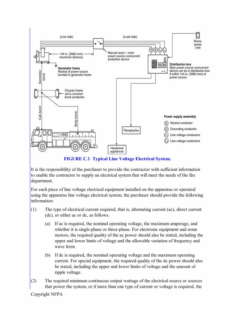
Copyright NFPA
FIGURE C.1 Typical Line Voltage Electrical System.
It is the responsibility of the purchaser to provide the contractor with sufficient information to enable the contractor to supply an electrical system that will meet the needs of the fire department.
For each piece of line voltage electrical equipment installed on the apparatus or operated using the apparatus line voltage electrical system, the purchaser should provide the following information:
(1) The type of electrical current required, that is, alternating current (ac), direct current (dc), or either ac or dc, as follows:
(a) If ac is required, the nominal operating voltage, the maximum amperage, and whether it is singlephase or threephase. For electronic equipment and some motors, the required quality of the ac power should also be stated, including the upper and lower limits of voltage and the allowable variation of frequency and wave form.
(b) If dc is required, the nominal operating voltage and the maximum operating current. For special equipment, the required quality of the dc power should also be stated, including the upper and lower limits of voltage and the amount of ripple voltage.
(2) The required minimum continuous output wattage of the electrical source or sources that power the system, or if more than one type of current or voltage is required, the
Copyright NFPA
maximum output wattage for each type of current or voltage.
(3) If an earth grounded system is required, the details of grounding rods, plates, clamps, or other means to establish bonding of the apparatus and the power source to the earth.
Generally, the line voltage electrical system should be sized based on the total amount of fixed and portable equipment that is likely to be operated at the same time. In view of the increasing use of line voltage devices on apparatus, the provision of a line voltage electrical system of sufficient capacity is strongly recommended. Where line voltage equipment use is extensive, a separately driven generator is recommended.
Where only incandescent lighting is involved, ac or dc power can be used. Where other electrical devices such as motordriven equipment or electronic equipment are involved, singlephase ac power at 60 Hz is normally required. However, because of the substantial reduction of size and cost that results from threephase operation, ac motors larger than 5 hp are usually designed to operate on threephase ac current. Attempting to operate electrical equipment using the wrong type of electrical power will almost always damage the electrical equipment.
If premises wiring or other fixed wiring systems are to be powered by the generator, the installation should be preplanned and in accordance with NFPA 70, National Electrical Code, for that intended purpose. Grounding of the system should comply with Section 250.20, “AlternatingCurrent Circuits and Systems to Be Grounded,” and other applicable sections of NFPA 70.
C.2 General Requirements.
C.2.1 Stability.
C.2.1.1 Any fixed line voltage power source producing alternating current (ac) shall produce electric power at 60 Hz ±3 Hz when producing power at all levels between no load and full rated power.
C.2.1.2 Any fixed line voltage power source shall produce electric power at the rated voltage ±10 percent when producing power at all levels between no load and full rated power.
C.2.2 The maximum voltage supplied to portable equipment shall not exceed 275 volts to ground. Higher voltage shall be permitted only when used to operate fixed wired, permanently mounted equipment on the apparatus.
C.2.3 Conformance with National Electrical Code ® .
C.2.3.1 All components, equipment, and installation procedures shall conform to NFPA 70, National Electrical Code, except where superseded by the requirements of this chapter.
C.2.3.2 Where the requirements of this chapter differ from those in the NFPA 70, National Electrical Code, the requirements in this chapter shall apply.
C.2.4 When available, line voltage electrical system equipment and materials included on the
Copyright NFPA
apparatus shall be listed and used only in the manner for which they have been listed.
Portable line voltage electrical equipment added by the fire department should also be listed and utilized only in accordance with the manufacturer's instructions.
C.2.5 All equipment and materials shall be installed in accordance with the manufacturer's instructions.
C.2.6 Location Ratings.
C.2.6.1 Any equipment used in a dry location shall be listed for dry locations.
C.2.6.2 Any equipment used in a wet location shall be listed for wet locations.
C.2.6.3 Any equipment, except a power takeoff driven generator, used in an underbody or underchassis location that is subject to road spray shall be either listed as Type 4 or mounted in an enclosure that is listed as Type 4.
C.2.6.4 If a power takeoff driven generator is located in an underbody or underchassis location, the installation shall include a shield to prevent road spray from splashing directly on the generator.
While a splash shield will lessen the amount of road spray that reaches the generator, it will not protect the generator if the apparatus is driven through deep water. Care should also be taken if the apparatus is driven offroad, because a splash shield is not a skid pan and will not protect the generator from physical abuse.
C.3 Grounding and Bonding.
C.3.1 Grounding. Grounding shall be in accordance with Section 250.34, “Portable and VehicleMounted Generators,” of NFPA 70, National Electrical Code.
Because of the non–earth grounded nature of apparatusmounted line voltage equipment and the wet environment in which it operates, great care should be taken in the use and maintenance of such line voltage circuits and equipment. Ground fault protection for personnel should be furnished through an assured equipment grounding conductor program in accordance with Section 527.6(B), “Use of Other Outlets,” of NFPA 70. All cord sets, receptacles, and electrical equipment should be maintained in accordance with NFPA 70B, Recommended Practice for Electrical Equipment Maintenance.
This protection can be supplemented by the use of ground fault circuit interrupters (GFCIs). These GFCIs should be attached to the end of distribution cords and located close enough to the equipment being operated that the GFCIs can be conveniently reset in the event they trip. Locating GFCI devices as close as possible to the end of a cord will reduce tripping caused by stray capacitance and leakage associated with long cord lengths and multiple connections.
While this arrangement is desirable for fire service operating conditions and does protect fire fighters who are operating tools and lights downstream of the GFCIs, no ground fault protection is provided between the electrical source and the GFCIs.
C.3.1.1 Ungrounded systems shall not be used.
C.3.1.2 Only stranded or braided copper conductors shall be used for grounding and
Copyright NFPA
bonding.
C.3.1.3 If a supplementary grounding electrode (ground rod) is provided, it shall be provided in accordance with Section 250.62, “Grounding Electrode Conductor Material”; Section 250.118, “Types of Equipment Grounding Conductors”; and Section 250.54, “Supplementary Grounding Electrodes,” of NFPA 70.
C.3.1.4 The grounded currentcarrying conductor (neutral) shall be insulated from the equipmentgrounding conductors and from the equipment enclosures and other grounded parts.
C.3.1.5 The neutral conductor shall be colored white or gray in accordance with Section 200.6, “Means of Identifying Grounded Conductors,” of NFPA 70.
C.3.1.6 Any bonding screws, straps, or buses in the distribution panelboard or in other system components between the neutral and equipmentgrounding conductor shall be removed and discarded.
C.3.2 Bonding.
C.3.2.1 The neutral conductor of the power source shall be bonded to the vehicle frame.
C.3.2.2 The neutral bonding connection shall occur only at the power source.
C.3.2.3 In addition to the bonding required for the low voltage return current, each body and each driving or crew compartment enclosure shall be bonded to the vehicle frame by a copper conductor.
C.3.2.3.1 The conductor shall have a minimum amperage rating, as defined in Section 310.15, “Ampacities for Conductors Rated 0–2000 Volts,” of NFPA 70, of 115 percent of the rated amperage on the power source specification label.
C.3.2.3.2 A single conductor that is sized to meet the low voltage and line voltage requirements shall be permitted to be used.
C.4 Power Source General Requirements.
The following requirements shall apply to all line voltage power sources.
C.4.1 All power source system mechanical and electrical components shall be sized to support the continuous duty nameplate rating of the power source.
C.4.2 The power source shall be shielded from contamination that will prevent the power source from operating within its design specifications.
C.4.3 For power sources of 8 kW or larger, the power source manufacturer shall declare the continuous duty rating that the power source can provide when installed on fire apparatus according to the manufacturer's instructions and run at 120°F (49°C) air intake temperature at 2000 ft (600 m) above sea level.
The following factors could be relevant to power source testing, depending on the type of power source:
(1) Sampling. The selection of test unit(s) should be representative of the construction
Copyright NFPA
and settings for units that will be supplied to the apparatus manufacturer. The standard does not require that all production units be tested; however, the power source manufacturer should test as needed to maintain confidence in his declaration of the continuous duty rating for all production.
(2) Clearances, cooling, and ventilation. Testing should be conducted at the worstcase clearance (usually minimum clearance or minimum compartment size) and worstcase ventilation conditions (minimum inlet/outlet dimensions and maximum inlet/outlet restrictions) specified in the literature. If not in the literature, the power source manufacturer's declaration should indicate the clearances, compartment size, and ventilation that are applicable to the declared continuous duty rating.
(3) Test duration. “Continuous” ratings are usually established by tests run until thermal stabilization is achieved. A minimum test of two hours, matching the inapparatus test duration indicated in C.16.5.3.4, is recommended.
(4) Air inlet temperature. Power sources should be tested in a chamber or room where the air temperature supplied to all inlet ducts (radiators, engine induction, windings, heat sinks, etc.), and the air surrounding the test unit, is maintained at 120°F (49°C).
(5) Barometric pressure. Pressure (air density) varies with changes in altitude and weather. Its effect is generally greatest on engines, where it affects combustion and cooling efficiency. There is a lesser effect on wound machines due to cooling only. To show compliance with the 2000 ft (600 m) requirement, a test in a chamber simulating 2000 ft (600 m) would be ideal, but is not expected. Alternatively, connecting more or less than the rated load can be used to simulate/demonstrate that the engine is capable of the power required for rated output at 2000 ft (600 m). (Several standards organizations, such as SAE and ISO, have standards that describe how to compute load/output correction factors for barometric pressure.)
(6) Fuel temperature. Fuel supply for the test should be stabilized at 120°F (49°C) before testing. Increases in fuel tank temperature that may occur as a result of fuel returned to the tank should be controlled so as to provide a result that is representative of expected fuel temperature conditions for the fire apparatus.
(7) Intake and exhaust restrictions, accessories, hydraulic pumps, and reservoirs. Components and accessories that may reduce engine power available for electrical output or that consume electrical output from the power source should be installed and be of the type used for the model that will be ordered for fire apparatus use, or their effect should be separately determined and reflected in the certified output.
(8) Breakin. Acceptance of a reduced output rating until completion of an inuse breakin period is subject to the prior agreement of the apparatus manufacturer, who may request test evidence. When applicable, the reduced output amount and duration of the breakin period should be indicated in the power supply literature.
(9) Voltage and frequency. Tests should be run while maintaining the ±10 percent voltage and ±3 Hz frequency required by C.2.1. Furthermore, settings for voltage and frequency should be representative of production units.
Copyright NFPA
(10) Engine speed and hydraulic flow/pressure. The engine speed and/or hydraulic flow and pressure ranges indicated in the power source's literature should be used to verify that the declared ratings are achievable.
(11) Hydraulic fluid temperature. The entire hydraulic power supply system, including hydraulic fluid piping and reservoir, should be located within a test chamber where temperature is controlled to maintain 120°F (49°C). Hydraulic fluid reservoirs should be stabilized at the ambient air test temperature [120°F (49°C)] prior to the testing.
(12) Component and material temperatures. Although not specified in the standard, when a power supply designed for lightduty use in open air is proposed for fixed fire apparatus use, the power source manufacturer should evaluate the components to determine whether they will operate within their rated or design temperature limits.
C.4.3.1 The rating on the power source specification label shall not exceed the declared rating from the power source manufacturer.
C.4.4 Access shall be provided to permit both routine maintenance and removal of the power source for major servicing.
C.4.5 The power source shall be located such that neither it nor its mounting brackets interfere with the routine maintenance of the fire apparatus.
C.4.6 Instrumentation.
C.4.6.1 If the power source is rated at less than 3 kW, a “Power On” indicator shall be provided.
C.4.6.2 If the power source is rated at 3 kW or more but less than 8 kW, a voltmeter shall be provided.
C.4.6.3 If the power source is rated at 8 kW or more, the following instrumentation shall be provided at an operator's panel:
(1) Voltmeter
(2) Current meters for each ungrounded leg
(3) Frequency (Hz) meter
(4) Power source hourmeter
The instrumentation should be protected from vibration, which can lead to false readings. Particular attention should be paid to reedtype frequency indicators. Digital electronic instrumentation should be selected that incorporates sample times and intervals that accurately report system performance under varying conditions.
C.4.6.4 The instrumentation shall be permanently mounted at an operator's panel.
C.4.6.4.1 The instruments shall be located in a plane facing the operator.
C.4.6.4.2 Gauges, switches, or other instruments on this panel shall each have a label to indicate their function.
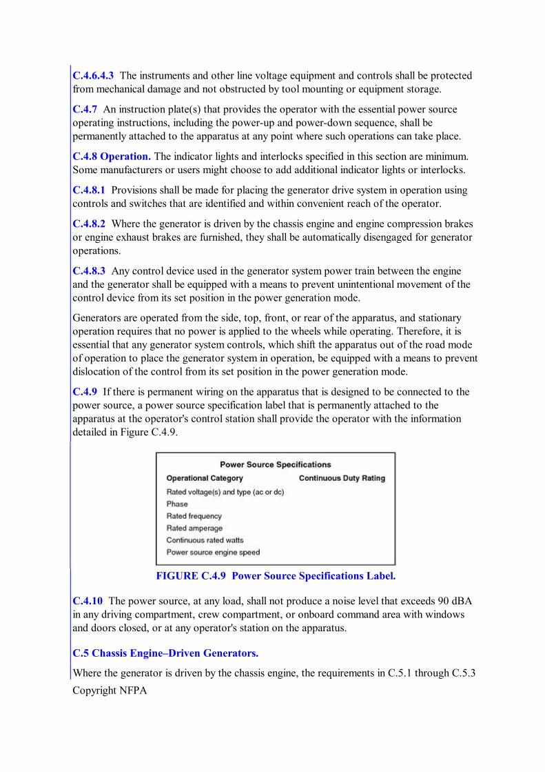
Copyright NFPA
C.4.6.4.3 The instruments and other line voltage equipment and controls shall be protected from mechanical damage and not obstructed by tool mounting or equipment storage.
C.4.7 An instruction plate(s) that provides the operator with the essential power source operating instructions, including the powerup and powerdown sequence, shall be permanently attached to the apparatus at any point where such operations can take place.
C.4.8 Operation. The indicator lights and interlocks specified in this section are minimum. Some manufacturers or users might choose to add additional indicator lights or interlocks.
C.4.8.1 Provisions shall be made for placing the generator drive system in operation using controls and switches that are identified and within convenient reach of the operator.
C.4.8.2 Where the generator is driven by the chassis engine and engine compression brakes or engine exhaust brakes are furnished, they shall be automatically disengaged for generator operations.
C.4.8.3 Any control device used in the generator system power train between the engine and the generator shall be equipped with a means to prevent unintentional movement of the control device from its set position in the power generation mode.
Generators are operated from the side, top, front, or rear of the apparatus, and stationary operation requires that no power is applied to the wheels while operating. Therefore, it is essential that any generator system controls, which shift the apparatus out of the road mode of operation to place the generator system in operation, be equipped with a means to prevent dislocation of the control from its set position in the power generation mode.
C.4.9 If there is permanent wiring on the apparatus that is designed to be connected to the power source, a power source specification label that is permanently attached to the apparatus at the operator's control station shall provide the operator with the information detailed in Figure C.4.9.
FIGURE C.4.9 Power Source Specifications Label.
C.4.10 The power source, at any load, shall not produce a noise level that exceeds 90 dBA in any driving compartment, crew compartment, or onboard command area with windows and doors closed, or at any operator's station on the apparatus.
C.5 Chassis Engine–Driven Generators.
Where the generator is driven by the chassis engine, the requirements in C.5.1 through C.5.3
Copyright NFPA
shall apply.
C.5.1 Unless the generator is always engaged, a “Generator Engaged” indicator shall be provided in the driving compartment to indicate that the generator shift has been successfully completed.
Completion of the generator shift might require that the chassis transmission be shifted into the proper gear (split shaft PTOs only).
C.5.2 Unless the generator is always engaged and operating, an “OK to Operate Generator” indicator shall be provided in the driving compartment to indicate that the generator is engaged, transmission is in the proper gear (automatic transmissions only), and the parking brake is engaged (if applicable).
C.5.3 An interlock system shall be provided to prevent advancement of the engine speed in the driving compartment or at any operator's panel unless the transmission is in neutral and the parking brake is engaged, or the apparatus is in the “OK to Pump” or “OK to Operate Generator” mode.
C.6 Additional Power Source Requirements.
The requirements in C.6.1 through C.6.5.3 are specific to the defined type of line voltage power source.
C.6.1 Direct Drive (PTO) Generators.
C.6.1.1 The generator shall comply with Article 445, “Generators,” of NFPA 70, National Electrical Code.
A PTO generator system typically consists of a propulsion engine, a controller to regulate the propulsion engine's speed, an appropriate PTO arrangement, drivetrain components, a generator, and other miscellaneous parts.
When a generator and fire pump are both direct driven by the same engine and are both operated at the same time, fire pump performance is limited to the generator set speed, and pump pressure is controlled by a pressure relief valve.
Due to variable engine speeds causing uncontrolled voltage and frequency variation, direct drive generators are not acceptable for fire apparatus where “generate and roll” capability is required. Hydraulically driven or separate engine driven generators are suited for these applications.
C.6.1.2 The main propulsion engine shall have a governor capable of maintaining the engine speed within the limits required by the generator to meet the frequency control specifications.
Where possible, the generator PTO system should be prevented from engaging if engine speed is above idle.
PTO gear ratios and engine governor components should be selected and matched to provide an engine speed high enough to maintain rated performance of the alternator and air conditioning system (if provided). Engine speed should be high enough to maintain rated
Copyright NFPA
performance of the low voltage electrical system. Continuous excessive engine speed will result in premature generator drivetrain component failure and unnecessary fuel consumption.
The purchaser should consider the specification of a means to automatically disconnect the generator or reduce engine speed to idle in the event of engine overspeed.
C.6.1.3 An interlock shall prevent engagement of the generator unless the parking brake is engaged.
C.6.1.4 Where the chassis engine drives the generator and electronic engine throttle controls are provided, an interlock shall prevent engine speed control from any other source while the generator is operating.
Operations in conjunction with a fire pump, aerial device, or other component driven off the fire apparatus's engine could require special or alternate interlock systems.
C.6.1.5 The transmission's PTO port and PTO, or the split shaft PTO, and all associated drive shaft components shall be rated to support the continuous duty torque requirements of the generator's continuous duty rating as stated on the power source nameplate.
C.6.1.6 A label indicating the chassis transmission shift selector position to be used for generator operation shall be provided in the driving compartment and located so that it can be read from the driver's position.
C.6.1.7 Where the generator is driven by the chassis engine and transmission through a split shaft PTO, the driving compartment speedometer shall register when the generator drive system is engaged.
C.6.1.8 Where the generator is driven by the chassis engine and transmission through a split shaft PTO and chassis transmission retarders are furnished, they shall be automatically disengaged for generator operations.
C.6.1.9 The direct drive generator shall be mounted so that it does not change the ramp breakover angle, angle of departure, or angle of approach as defined by other components, and shall not extend into the ground clearance area.
C.6.1.10 The direct drive generator shall be mounted away from exhaust and muffler areas or provided with a heat shield to reduce operating temperatures in the generator area.
C.6.2 Hydraulically Driven Generators.
C.6.2.1 The generator shall comply with Article 445, “Generators,” of NFPA 70, National Electrical Code.
A hydraulic generator system generally consists of a variable displacement hydraulic pump deriving its power from the propulsion engine, a controller to regulate the hydraulic fluid flow rate, a hydraulic motor driving the generator, hydraulic fluid cooler, reservoir, and other miscellaneous parts.
All hydraulic generator systems have a window of operation (speed range). When selecting the power output of the hydraulic generator system, its speed range should be compared to
Copyright NFPA
the operating window of the fire apparatus's engine and the PTO ratios available. By selecting the hydraulic generator system and PTO ratio to match the application, electrical power can be provided over a wide operating range.
The selected PTO should have a gear ratio that will allow the widest possible range of engine speeds without overspeeding the hydraulic pump.
Where possible, engagement of the generator PTO system should be prevented if engine speed is above idle.
C.6.2.2 A means shall be provided to activate the hydraulic generator system.
This means can be either a mechanical or hydraulic device.
C.6.2.3 A hydraulic generator system shall operate at all engine speeds, or an automatic engine speed control system shall be provided.
C.6.2.4 If the apparatus is equipped with a fire pump driven by the chassis engine, the generator shall be capable of output at idle as stated on the power source specification label.
C.6.2.5 Hydraulic Components.
C.6.2.5.1 A hydraulic system filter and strainer shall be provided and shall be located in a readily accessible area.
C.6.2.5.2 Hydraulic hose shall meet the hydraulic pump manufacturer's recommendations for pressure, size, vacuum, and abrasion resistance.
C.6.2.5.3 Hydraulic fittings shall meet the hydraulic pump manufacturer's recommendations for pressure, size, and the type of hose used.
The use of 90degree fittings should be avoided.
C.6.2.5.4 Where the hydraulic hose comes into contact with other surfaces, the hose shall be protected from chafing.
Hose runs should not include “S” turns that would allow air to be trapped.
C.6.3 Fixed Auxiliary Engine–Driven Generators. Enginedriven generator systems use an internal combustion engine close coupled to a generator. Some installations are capable of producing power while the apparatus is in motion. Generators used in these applications should be specifically designed for mobile applications. Remote generator controls in the driving compartment should be considered and specified if desired.
C.6.3.1 The generator shall comply with Article 445, “Generators,” of NFPA 70, National Electrical Code.
C.6.3.2 Generators powered by a nonchassis engine shall include the following equipment or shall be installed as follows:
(1) Generators shall be installed so that fumes, vapors, heat, and vibrations do not enter the interior passenger compartment.
(2) Generators shall have the exhaust outlet piped to the exterior and located so that
Copyright NFPA
exhaust is directed away from any operator's position.
(3) Generators 8 kW and over shall be equipped with a high temperature automatic shutdown system and low oil automatic shutdown.
(4) Generators shall be installed in accordance with manufacturer's installation requirements for ventilation and service accessibility.
(5) Generators installed in compartments requiring the compartment doors to be open during operation shall be equipped with a compartment door interlock system, or the compartment shall be equipped with a high temperature alarm.
(6) Generators installed in compartments on slide trays and designed for operation in the “slide out” position shall have interlocks to ensure such operation or the compartment shall be equipped with a high temperature alarm.
(7) Permanently installed generators shall have easily accessible engine oil drain provisions or piping to a remote location for oil changing.
(8) Generators located away from or remote from the main operator's area (top of apparatus, over pump, hidden in body, etc.) shall have a remote operating panel with required instrumentation, start and stop controls, and other controls necessary for safe operation.
The purchaser should consider the following additional remote instruments where a prime mover, other than the propulsion engine, is used to drive a generator:
(1) Oil pressure gauge and low pressure indicator light and audible alarm
(2) Engine temperature gauge and high temperature indicator light and audible alarm
The purchaser might want to specify a high temperature indicator to help troubleshoot automatic shutdowns.
C.6.3.3 Fuel System.
C.6.3.3.1 Fuel lines shall be protected from chafing at all wear points.
C.6.3.3.2 If the fuel source is shared with the apparatus engine, a separate fuel pickup system shall be provided that is arranged to ensure that the generator cannot utilize more than 75 percent of the fuel tank's capacity.
C.6.3.4 Exhaust System.
C.6.3.4.1 The exhaust piping and discharge shall be located or shielded to prevent thermal damage to the apparatus or equipment.
Emissions from exhaust discharge pipes should be directed away from any firefighting tools, because such emissions contain an oily substance that could make the tools difficult to handle and possibly dangerous to use.
C.6.3.4.2 Where parts of the exhaust system are exposed so that they can cause injury to operating personnel, protective guards shall be provided.
C.6.3.4.3 Silencing devices shall be provided and shall not create exhaust backpressure that
Copyright NFPA
exceeds the limits specified by the engine manufacturer.
C.6.4 BeltDriven Generators or Dedicated Alternators Supplying an Inverter. Beltdriven generator systems use a voltage regulator and a generator driven off the propulsion engine. The complexity of modern engine drive belt configurations limits power output to about 6000 watts. This system will generally maintain acceptable voltage, but the frequency will vary with engine speed. Motor loads should not be powered by this type of power supply.
An alternative system uses a separately driven alternator to supply electrical energy to an inverter, which in turn produces line voltage electrical power. These systems are separate from, and do not affect, the performance of the low voltage electrical system. These systems are voltage regulated and provide ample power for scene lighting. Due to the beltdriven configuration, the system is still subject to low voltage at idle conditions, which could damage motors.
C.6.4.1 A means shall be provided to engage and disengage the generator or alternator.
C.6.4.2 A voltmeter shall be provided at the operator's panel for all sizes of systems of this type.
C.6.4.3 The belt drive system shall be rated to drive the generator or alternator at the nameplate rating.
C.6.5 Line Voltage Systems Derived from Apparatus Low Voltage Power Supply Systems.
C.6.5.1 Where a line voltage power source derives its input energy from the apparatus low voltage electrical system, the system shall be installed in strict compliance with the requirements of Annex B.
Brief descriptions of several different types of systems follow. All of these systems can overload the low voltage electrical system and cause the load management system to terminate the generation of line voltage. As a result, the amount of line voltage power that can be supplied at any given time is totally dependent on the other, higher priority demands placed on the low voltage system.
Dynamic Power Inverter. A dynamic power inverter converts alternator output power to 120 volts ac (or 120/240 volts ac). Power is electronically inverted to ac. Usually the largest system of this type is 7500 watts. Voltage and frequency control are typically very good.
Static Power Inverter. A static power inverter converts 12 volt to 14 volt dc power to 120 volt ac (or 120/240 volts ac) power. Power is electronically inverted to ac. Usually the largest system of this type is 2000 watts. Voltage and frequency control are typically very good.
MotorDriven Generators. A motordriven generator system converts 12 volt dc power to 120 volt ac (or 120/240 volts ac) power. The 12 volt dc motor drives an ac generator. Typical power ratings are less than 1600 watts. Voltage and frequency control are less precise than some of the other systems available. These types of systems are suited to providing electric power while the apparatus is in motion.
Copyright NFPA
Transformers. Transformer systems convert energy from the alternator, which is then rectified to 120 volt dc power. Typical installations provide 1000 watts. Output voltage is directly dependent on input voltage. Input voltage is dependent on engine and alternator speed.
C.6.5.2 The alternator and/or battery system shall be adequate to provide power to the power source for continuous operation for a minimum of 2 hours at full output.
C.6.5.3 A means that works in coordination with other engine speed controls and interlocks required by this standard shall be provided to advance engine speed to obtain the continuous duty ratings stated on the power source specification label.
C.7 Portable Generator Installations.
The generator shall comply with Article 445, “Generators,” of NFPA 70, National Electrical Code.
Portable generator systems are generally designed with an integral fuel tank and controls in one modular package. This allows the system to be picked up and transported to a remote location from the apparatus. Generators designed for portable use should be accessible for removal. These generators are generally not suited for “enclosed” compartment operation or should be mounted on a slide out tray for adequate ventilation. Such installations require interlocks or a high temperature alarm to ensure that the generator is operated in “slide out” condition.
The generator performance specifications should be evaluated carefully to ensure that the required level of performance can be met. Article 445, “Generators,” of NFPA 70, National Electrical Code, requires that overcurrent protection be provided on portable generators.
C.7.1 Any portable generator that can be operated while mounted on the apparatus shall be as follows:
(1) Installed so that fumes, vapors, heat, excessive noise, and vibrations do not enter interior driving or crew compartments or damage the generator during operation
(2) Have the exhaust outlet located so that exhaust is directed away from any operator station located on the apparatus and guarded to protect the operator
C.7.2 If the portable generator is remotely mounted, it shall have a remote operator's control station that shall provide a means for starting and stopping the generator and monitoring the same instrumentation as is required for fixed power sources.
C.7.3 Wiring for Portable Generator Installations. Wiring installed for the purpose of facilitating the distribution of power from a portable generator installation to fixed wiring on the apparatus shall conform to the additional requirements of C.7.3.1 through C.7.3.5.
C.7.3.1 Circuit conductors shall be sized in relation to the power source specification label rating and shall be protected by an overcurrent device commensurate with their amperage capacities.
C.7.3.2 There shall be a single output connector cord with all of the conductors in the cord
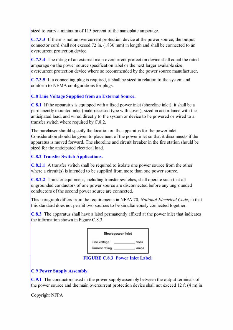
Copyright NFPA
sized to carry a minimum of 115 percent of the nameplate amperage.
C.7.3.3 If there is not an overcurrent protection device at the power source, the output connector cord shall not exceed 72 in. (1830 mm) in length and shall be connected to an overcurrent protection device.
C.7.3.4 The rating of an external main overcurrent protection device shall equal the rated amperage on the power source specification label or the next larger available size overcurrent protection device where so recommended by the power source manufacturer.
C.7.3.5 If a connecting plug is required, it shall be sized in relation to the system and conform to NEMA configurations for plugs.
C.8 Line Voltage Supplied from an External Source.
C.8.1 If the apparatus is equipped with a fixed power inlet (shoreline inlet), it shall be a permanently mounted inlet (malerecessed type with cover), sized in accordance with the anticipated load, and wired directly to the system or device to be powered or wired to a transfer switch where required by C.8.2.
The purchaser should specify the location on the apparatus for the power inlet. Consideration should be given to placement of the power inlet so that it disconnects if the apparatus is moved forward. The shoreline and circuit breaker in the fire station should be sized for the anticipated electrical load.
C.8.2 Transfer Switch Applications.
C.8.2.1 A transfer switch shall be required to isolate one power source from the other where a circuit(s) is intended to be supplied from more than one power source.
C.8.2.2 Transfer equipment, including transfer switches, shall operate such that all ungrounded conductors of one power source are disconnected before any ungrounded conductors of the second power source are connected.
This paragraph differs from the requirements in NFPA 70, National Electrical Code, in that this standard does not permit two sources to be simultaneously connected together.
C.8.3 The apparatus shall have a label permanently affixed at the power inlet that indicates the information shown in Figure C.8.3.
FIGURE C.8.3 Power Inlet Label.
C.9 Power Supply Assembly.
C.9.1 The conductors used in the power supply assembly between the output terminals of the power source and the main overcurrent protection device shall not exceed 12 ft (4 m) in
Copyright NFPA
length.
C.9.2 All power supply assembly conductors, including neutral and grounding conductors, shall have an equivalent amperage rating and shall be sized to carry not less than 115 percent of the amperage of the nameplate current rating of the power source.
C.9.3 If the power supply assembly connects to the vibrating part of a generator (not a connection on the base) the conductors shall be flexible cord or other finestranded conductors enclosed in metallic or nonmetallic liquidtight flexible conduit, rated for wet locations and temperatures not less than 194°F (90°C).
Where the wire could be exposed to temperatures above 194°F (90°C), higher temperature rated wire should be used.
C.10 Overcurrent Protection.
Manually resettable overcurrent devices shall be installed to protect the line voltage electrical system components.
C.10.1 Power Source Protection. A main overcurrent protection device shall be provided that is either incorporated in the power source or connected to the power source by a power supply assembly.
C.10.1.1 The size of the main overcurrent protection device shall not exceed 100 percent of the rated amperage stated on the power source specification label or the rating of the next larger available size overcurrent protection device, where so recommended by the power source manufacturer.
C.10.1.2 If the main overcurrent protection device is subject to road spray, the unit shall be housed in a Type 4 rated enclosure.
C.10.2 Branch Circuit Overcurrent Protection. Overcurrent protection devices shall be provided for each individual circuit and shall be sized at not less than 15 amps in accordance with Section 240.4, “Protection of Conductors,” of NFPA 70, National Electrical Code.
C.10.2.1 Any panelboard shall have a main breaker where the panel has six or more individual branch circuits or the power source is rated 8 kW or larger.
C.10.2.2 Each overcurrent protection device shall be marked with a label to identify the function of the circuit it protects.
C.10.2.3 Dedicated circuits shall be provided for any large appliance or device (air conditioning units, large motors, etc.) that requires 60 percent or more of the rated capacity of the circuit to which it is connected, and that circuit shall serve no other purpose.
C.10.3 Panelboards. All fixed power sources shall be hardwired to a permanently mounted panelboard unless one of the following exist:
(1) All line voltage power connections are made through receptacles on the power source and the receptacles are protected by integrated overcurrent devices
(2) Only one circuit is hardwired to the power source, which is protected by an
Copyright NFPA
integrated overcurrent device
C.10.3.1 The panel shall be visible and located so that there is unimpeded access to the panelboard controls.
C.10.3.2 All panelboards shall be designed for use in their intended location.
C.10.3.3 The panel(s) shall be protected from mechanical damage, tool mounting, and equipment storage.
C.11 Wiring Methods.
Fixed wiring systems shall be limited to the following:
(1) Metallic or nonmetallic liquidtight flexible conduit rated at temperatures not less than 194°F (90°C) with stranded copper wire rated for wet locations and temperatures not less than 194°F (90°C)
(2) Type SOW, SOOW, SEOW, or SEOOW flexible cord, rated at 600 volts and at temperatures not less than 194°F (90°C)
Where the wire could be exposed to temperatures above 194°F (90°C), higher temperature rated wire should be used.
C.11.1 Electrical cord or conduit shall not be attached to chassis suspension components, water or fuel lines, air or air brake lines, fire pump piping, hydraulic lines, exhaust system components, or low voltage wiring and shall be arranged as follows:
(1) Separated by a minimum distance of 12 in. (300 mm) from exhaust piping or shielded from such piping
(2) Separated from fuel lines by a minimum distance of 6 in. (150 mm)
C.11.2 A means shall be provided to allow “flexing” between the driving and crew compartment, the body, and other areas or equipment whose movement would stress the wiring.
C.11.3 Electrical cord or conduit shall be supported within 6 in. (150 mm) of any junction box and at a minimum of every 24 in. (600 mm) of run.
C.11.3.1 Supports shall be made of nonmetallic materials, or corrosionresistant or corrosionprotected metal.
C.11.3.2 All supports shall be of a design that does not cut or abrade the conduit or cord and shall be mechanically fastened to the apparatus.
C.11.4 Only fittings and components listed for the type of cord or conduit being installed shall be used.
C.11.5 Splices shall be made only in a listed junction box.
C.11.6 Additional Requirements for Flexible Cord Installations.
C.11.6.1 Where flexible cord is used in any location where it could be damaged, it shall be

Copyright NFPA
protected by installation in conduit, enclosures, or guards.
Locations in which flexible cord might be damaged include, but are not limited to, compartment walls and floors, exposed outside areas, and exposed interior areas near equipment or walkways.
C.11.6.2 Where flexible cord penetrates a metal surface, rubber or plastic grommets or bushings shall be installed.
C.11.7 Wiring Identification.
C.11.7.1 Each line voltage circuit originating from the main panelboard shall be identified.
C.11.7.2 The wire or circuit identification either shall reference a wiring diagram or wire list or shall indicate the final termination point of the circuit.
C.11.7.3 Where prewiring for future power sources or devices exists, the unterminated ends shall be marked with a label showing their wire size and intended function.
C.12 Wiring System Components.
C.12.1 Only stranded copper conductors with an insulation rated for temperatures of at least 194°F (90°C) and wet locations shall be used.
C.12.1.1 Conductors in flexible cord shall be sized in accordance with Table 400.5(A) of NFPA 70, National Electrical Code.
C.12.1.2 Conductors used in conduit shall be sized in accordance with Section 310.15, “Ampacities for Conductors Rated 02000 Volts,” of NFPA 70.
C.12.1.3 Aluminum or copperclad aluminum conductors shall not be used.
C.12.2 All boxes shall conform to and be mounted in accordance with Article 314, “Outlet, Device, Pull, and Junction Boxes; Conduit Bodies; Fittings; and Manholes,” of NFPA 70.
C.12.2.1 All boxes shall be accessible using ordinary hand tools.
C.12.2.2 Boxes shall not be permitted behind welded or popriveted panels.
C.12.2.3 The maximum number of conductors permitted in any box shall be in accordance with Section 314.16, “Number of Conductors in Outlet, Device, and Junction Boxes, and Conduit Bodies,” of NFPA 70.
C.12.3 All wiring connections and terminations shall provide a positive mechanical and electrical connection.
Common connectors and terminations that comply with these requirements include the following:
(1) Welded or brazed connectors
(2) Crimped connectors
(3) Soldered connections that are mechanically secured before soldering

Copyright NFPA
(4) Screwtype positive pressure connectors
(5) Ring terminals
(6) Hooks
(7) Upturned spade
(8) Crimpedon pins
(9) Other methods providing a positive mechanical and electrical connection that are acceptable to the authority having jurisdiction
C.12.3.1 Connectors shall be installed in accordance with the manufacturer's instructions.
C.12.3.2 Wire nuts or insulation displacement and insulationpiercing connectors shall not be used.
C.12.4 Each switch shall indicate the position of its contact points (i.e., open or closed) and shall be rated for the continuous operation of the load being controlled.
The following switch terminology can be helpful in understanding the different types of switches.
One Pole (1P) or Single Pole (SP). A switch device that opens, closes, or changes connections in a single conductor of an electrical circuit.
Two Pole (2P) or Double Pole (DP). A switch device that opens, closes, or changes connections in both conductors of the same circuit.
Two Circuit (2 CIR). A switch device that opens, closes, or changes connections in a single conductor of two independent circuits.
Single Throw (ST). A switch that opens, closes, or completes a circuit at only one of the extreme positions of its actuator.
Double Throw (DT). A switch that opens, closes, or completes a circuit at both extreme positions of its actuator.
Normally Open (NO). A switch in which one or more circuits are open when the switch actuator is at its normal or rest position.
Normally Closed (NC). A switch in which one or more circuits are closed when the switch actuator is at its normal or rest position.
Switches are rated for the type of load they are designed to control. Switch ratings include the following:
(1) Resistive
(2) Inductive
(3) Horsepower (i.e., motor loads)
(4) Tungsten (i.e., incandescent lamp loads)
Copyright NFPA
(5) Alternating current
(6) Direct current
The ampere rating of a given switch is dependent on the type of load. In particular, switches used to control dc circuits should have the appropriate dc rating.
C.12.4.1 All switches shall be marked with a label indicating the function of the switch.
C.12.4.2 Circuit breakers used as switches shall be “switch rated” (SWD) or better.
In lieu of a switchrated circuit breaker, a standard circuit breaker could be used with a separate switching device.
C.12.4.3 Switches shall simultaneously open all associated line voltage conductors.
C.12.4.4 Switching of the neutral conductor alone shall not be permitted.
C.12.4.5 Line voltage circuits controlled by low voltage circuits shall be wired through properly rated relays in listed enclosures that control all nongrounded currentcarrying conductors.
C.12.5 Receptacles and Inlet Devices.
C.12.5.1 Wet and Dry Locations.
C.12.5.1.1 All wet location receptacle outlets and inlet devices including those on hardwired, remote power distribution boxes, shall be of the grounding type, provided with a wet location cover, and installed in accordance with Section 406.8, “Receptacles in Damp or Wet Locations,” of NFPA 70, National Electrical Code.
The purchaser should specify the number and location of receptacles that are needed to operate the devices to be powered by the system. The purchaser should specify the NEMA number (if applicable), manufacturer, and style of the receptacles desired. For other than NEMAtype receptacles, the purchaser should additionally specify the wiring configuration.
C.12.5.1.2 All receptacles located in a wet location shall be not less than 24 in. (600 mm) from the ground.
C.12.5.1.3 Receptacles on offroad fire apparatus shall be a minimum of 30 in. (750 mm) from the ground.
If the offroad fire apparatus is to ford water, the receptacle distance should be increased above 30 in. (750 mm). The purchaser should review the proposed height for any receptacles on the apparatus and specify a higher mounting height if desired.
C.12.5.2 All receptacles located in a dry location shall be of the grounding type and shall be at least 12 in. (300 mm) above the interior floor height.
C.12.5.3 No receptacle shall be installed in a faceup position.
C.12.5.4 The face of any wet location receptacle shall be installed in a plane from vertical to not more than 45 degrees off vertical.
Copyright NFPA
C.12.5.5 Receptacle Label.
C.12.5.5.1 Each receptacle shall be marked with a label indicating the nominal line voltage (120 volts or 240 volts) and the current rating in amps of the circuit.
C.12.5.5.2 If the receptacle is dc or other than single phase, that information shall also be marked on the label.
C.12.5.6 All receptacles and electrical inlet devices shall be listed to UL 498, Standard for Safety Attachment Plugs and Receptacles, or other recognized performance standards.
While NEMA configurations as defined in NEMA WD 6, Wiring Devices — Dimensional Requirements, are recommended to promote compatibility of equipment during mutual aid operations, other configurations are in use and have been adopted by various fire departments.
Acceptable NEMAtype plug and receptacle configurations for various ac voltage and current ratings are shown in Figure C.12.5.6.
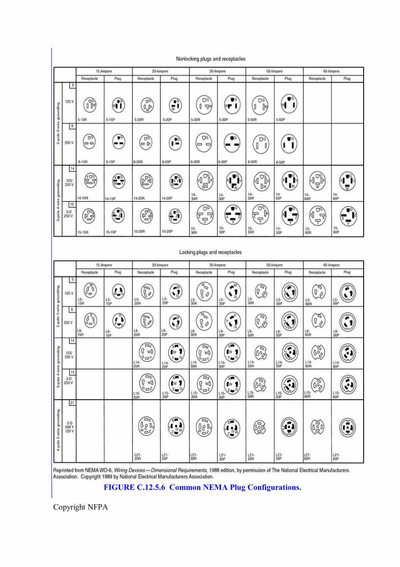
Copyright NFPA
FIGURE C.12.5.6 Common NEMA Plug Configurations.
Copyright NFPA
C.12.5.7 Receptacles used for dc voltages shall be rated for dc service.
C.13 Cord Reels.
All cord reels shall be rated for continuous duty and installed to be accessible for removal, cord access, maintenance, and servicing.
C.13.1 The power rewind cord reel spool area shall be visible to the operator during the rewind operation, or the reel spool shall be encapsulated to prevent cord from spooling off the reel.
C.13.2 Rollers or guides shall be provided, where required, to prevent damage to the cord at reel spools or compartment openings.
C.13.3 Rewind Provision.
C.13.3.1 Manually operated reels shall have a hand crank.
C.13.3.2 Power rewind–type reels shall have the control in a position where the operator can observe the rewinding operation. If a reel is in an enclosure or out of direct view, the cord entry point to the enclosure shall be visible to the operator of the reel control.
C.13.3.3 The rewind control or crank shall not be over 72 in. (1830 mm) above the operator's standing position.
C.13.3.4 The rewind control shall be marked with a label indicating its function and shall be guarded to prevent accidental operation.
C.13.4 The reel shall be designed to hold 110 percent of the capacity needed for the intended cord length.
A suggested minimum capacity of a reel is at least 100 ft (30 m) of cord rated to carry 20 amps at 120 volts ac. When sizing the reel, extra capacity should be provided when multiple receptacles are attached to the cord stored on the reel.
A cord reel to supply a single 120 volt circuit requires three collector rings and three conductors in the cord, for line, neutral, and ground. If the power source has 120/240 volt outputs, as most power sources do, a second equivalent circuit with the same rating requires only one additional conductor, because the neutral and ground can be common to both circuits. Thus, with approximately 25 percent more reel space and cord cost, the cord reel can supply twice the number of lights or other loads.
The letter “R” following the configuration number indicates a receptacle, and the letter “P” denotes a plug. For example, the nonlocking, 15ampere, grounding receptacle found in most homes is configuration 515R and accepts a threeprong plug in the configuration of 515P.
Lockingtype plugs and receptacles are designed to prevent accidental disconnection when subjected to moderate pullapart loads. Neither locking nor nonlocking connectors are designed to withstand the loads that can be created when pulling long cords up buildings and stairs.
C.13.5 The wire size shall be in accordance with NFPA 70, National Electrical Code, Table
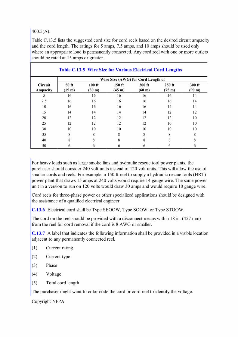
Copyright NFPA
400.5(A).
Table C.13.5 lists the suggested cord size for cord reels based on the desired circuit ampacity and the cord length. The ratings for 5 amps, 7.5 amps, and 10 amps should be used only where an appropriate load is permanently connected. Any cord reel with one or more outlets should be rated at 15 amps or greater.
Table C.13.5 Wire Size for Various Electrical Cord Lengths
Wire Size (AWG) for Cord Length of Circuit Ampacity
50 ft (15 m)
100 ft (30 m)
150 ft (45 m)
200 ft (60 m)
250 ft (75 m)
300 ft (90 m)
5 16 16 16 16 16 14 7.5 16 16 16 16 16 14 10 16 16 16 16 14 14 15 14 14 14 14 12 12 20 12 12 12 12 12 10 25 12 12 12 12 10 10 30 10 10 10 10 10 10 35 8 8 8 8 8 8 40 8 8 8 8 8 8 50 6 6 6 6 6 6
For heavy loads such as large smoke fans and hydraulic rescue tool power plants, the purchaser should consider 240 volt units instead of 120 volt units. This will allow the use of smaller cords and reels. For example, a 150 ft reel to supply a hydraulic rescue tools (HRT) power plant that draws 15 amps at 240 volts would require 14 gauge wire. The same power unit in a version to run on 120 volts would draw 30 amps and would require 10 gauge wire.
Cord reels for threephase power or other specialized applications should be designed with the assistance of a qualified electrical engineer.
C.13.6 Electrical cord shall be Type SEOOW, Type SOOW, or Type STOOW.
The cord on the reel should be provided with a disconnect means within 18 in. (457 mm) from the reel for cord removal if the cord is 8 AWG or smaller.
C.13.7 A label that indicates the following information shall be provided in a visible location adjacent to any permanently connected reel.
(1) Current rating
(2) Current type
(3) Phase
(4) Voltage
(5) Total cord length
The purchaser might want to color code the cord or cord reel to identify the voltage.
Copyright NFPA
C.13.8 Where a power distribution box is hardwired to the end of a cord that is stored on a fixed cord reel or other fixed storage means, the requirements in C.13.8.1 through C.13.8.6 shall apply.
C.13.8.1 The remote power distribution box shall be listed for use in a wet location.
C.13.8.2 The distribution box shall be as follows:
(1) Protected from corrosion
(2) Capable of being carried with a gloved hand
(3) Designed to keep the exterior electrical components above 2 in. (51 mm) of standing water
It might be advantageous to specify a remote power distribution box that has a provision for hanging the unit from a door or ladder.
C.13.8.3 Inlets, receptacles, circuit breakers, or GFCI devices shall not be mounted on the top surface of the horizontal plane.
Consideration should be given to the use of GFCI devices mounted in the remote power distribution box to provide additional protection to personnel using equipment powered through the box.
C.13.8.4 Branch circuit breakers shall be installed in the remote power distribution box if the overcurrent device protecting the feed cord to the box is too large to protect the wiring supplying the devices plugged onto the distribution box.
C.13.8.5 Remote power distribution boxes shall have a light on the box to indicate the power is on.
The lamps used in this application should be roughservice type. Scene lighting around the remote power distribution box can be provided with an integral, mechanically protected light fixture.
C.13.8.5.1 The light shall be visible in a 360 degree plane from a minimum of 200 ft (60 m) in complete darkness.
For increased visibility, reflective tape can be applied to the distribution box.
C.13.8.5.2 The light shall be mechanically protected to prevent damage.
C.13.8.6 The hardwired portable cord connection to the box shall have strain relief and meet the intended usage requirements.
C.14 Scene Lighting Systems.
Where fixed scene lights are supplied, the requirements in C.14.1 through C.14.4 shall apply.
C.14.1 All scene lights shall be provided with a lens or a means for preventing damage from water spray and shall be listed for wet location usage.
C.14.2 Handle on Lights.
Copyright NFPA
C.14.2.1 If the light is adjustable, a handle shall be provided.
C.14.2.2 The design of the light shall not allow the temperature of the handle to exceed 131°F (55°C).
C.14.3 The manufacturer of the device shall type certify that the scene light has been tested and complies with the vibration testing requirements of SAE J575, Test Methods and Equipment for Lighting Devices and Components for Use on Vehicles Less Than 2032 mm in Overall Width.
C.14.4 If manually operated floodlights are not operable from the ground, access steps that meet the requirements of Section 15.7 of NFPA 1901 and handrails that meet the requirements of Section 15.8 of NFPA 1901 shall be provided to allow the user to reach the floodlights.
C.15 PowerOperated Light Mast.
C.15.1 General. The purchaser should specify the type of rotation, telescopic, pan and tilt operations, and other features that are required.
C.15.1.1 The mast shall be designed to sustain the intended tip load with at least a 125 percent safety factor.
C.15.1.2 The mast shall withstand a minimum of a 50 mph (80 kph) wind in a raised, unguyed position.
C.15.2 Installation and Operational Requirements. When the light mast is mounted above the apparatus driving and crew compartment or the body, a brush and tree limb guard should be considered to protect the mast and floodlights.
C.15.2.1 The mast shall be capable of being raised within 2 minutes.
C.15.2.2 Where the installation precludes the operator from seeing the light in its nested position, a means shall be provided to allow the operator to align the light for nesting when the operator is at the operator's position.
C.15.2.3 Appropriate warning labels on the hazards of electrocution shall be installed.
To reduce the electrocution hazards associated with the operation of masts above the apparatus, the purchaser should consider specifying a slideout operator's platform, a wireless remote control, or both.
C.15.2.4 A means shall be provided to prevent operations that could cause damage to the power supply conductors.
C.15.2.5 In the event of a failure of the light tower's raising system while the tower is deployed or being deployed, a means shall be provided to limit the rate of descent in order to prevent injury to equipment or personnel.
C.15.2.6 A secondary means of control shall be provided to allow for emergency lowering of the mast.
C.15.2.7 Where the tower is powered by the chassis air brake system, the air supply shall be
Copyright NFPA
from an auxiliary air circuit that is equipped with a pressure protection valve and an auxiliary air tank(s).
C.15.2.8 An automatic deenergizing means shall be provided so there is no electrical power to the mast or to the light wiring when the mast is in a stowed position.
The lighting assembly should be supported when it is in a transport mode, to prevent damage to lighting assembly from vibration.
C.15.2.9 The hazard warning light required in Section 13.11 of NFPA 1901 shall be illuminated whenever the light tower is not in the stowed position.
C.15.2.10 The operational envelope of the mast shall be automatically illuminated whenever the mast assembly is being raised, lowered, or rotated.
C.15.3 Labeling.
C.15.3.1 An instruction plate showing the operation of the mast and operational warning signs shall be provided at the operator's position.
C.15.3.2 A label shall be provided at the operator's position to indicate the following:
(1) Extended tower height from the ground
(2) Bulb replacement data
C.16 Electrical System Testing.
The purchaser should consider the range of temperatures in which the power source is to be operated. If extreme conditions are anticipated, the purchaser should specify any specific test conditions that are desired.
C.16.1 The wiring and associated equipment shall be tested by the apparatus manufacturer or the installer of the line voltage system.
C.16.2 Dielectric Voltage Withstand Test.
C.16.2.1 The wiring and permanently connected devices and equipment shall be subjected to a dielectric voltage withstand test of 900 volts for 1 minute.
C.16.2.2 The dielectric tester shall have a 500 voltamperes (VA) or larger transformer, with a sinusoidal output voltage that can be verified.
C.16.2.3 The testing shall be performed after all body work has been completed.
C.16.2.4 The test shall be conducted as follows:
(1) Isolate the power source from the panel board and disconnect any solid state low voltage components.
(2) Connect one lead of the dielectric tester to all the hot and neutral busses tied together.
(3) Connect the other lead to the fire apparatus frame or body.
Copyright NFPA
(4) Close any switches and circuit breakers in the circuit(s).
(5) Apply the dielectric voltage for 1 minute in accordance with the testing equipment manufacturer's instructions.
Solid state equipment is generally hipot tested by the manufacturer. It is very important to connect all hot and neutral busses together so that no current flows through connected loads.
C.16.3 The electrical polarity of all permanently wired equipment, cord reels, and receptacles shall be tested to verify that wiring connections have been properly made.
The fire department should check the polarity of the wiring in a building prior to interconnecting the fire apparatus–mounted electrical system to the electrical system in a building.
C.16.4 Electrical light towers, floodlights, motors, fixed appliances, and portable generators shall be operated at their full rating or capacity for 30 minutes to ensure proper operation.
C.16.5 Operational Test of Fixed Power Source. It is important that the power source meet the fire department requirements for output. Power sources of the size and type used on fire apparatus are generally advertised with power ratings for operating conditions that are more favorable than the conditions that may be encountered in fire apparatus use. Some power sources are advertised at peak output or intermittent duty ratings, and not the continuous duty output required for fire apparatus. The power source manufacturer and apparatus manufacturer might need to establish a reduced rating that is appropriate for fire apparatus. The standard calls for two steps. The power source manufacturer provides a declared rating for 120°F (49°C) air inlet temperature and 2000 ft (600 m) altitude for the minimum clearance and ventilation indicated on the declaration (see C.4.3). Then the apparatus manufacturer verifies that the rating printed on the power source specification label can be attained during the apparatus test (see C.16.5).
Generator Set Rating. Auxiliary engine–powered generator sets are the type of power source most likely to require a reduction from advertised ratings, and generator set literature usually provides rating correction factors for altitude and temperature. These factors could be based on standards for engines such as ISO 30461, Reciprocating internal combustion engines — Performance — Part 1: Declarations of power, fuel and lubricating oil consumptions, and test methods — Additional requirements for engines for general use, and SAE J1349, Engine Power Test CodeSpark Ignition and Compression IgnitionNet Power Rating; standards for generators such as NEMA MG 1, Motors and Generators; or manufacturer testing. As an example of how altitude and temperature affect output capability, consider a typical 10 kW generator set with 0.8 generator efficiency and naturally aspirated diesel engine that is rated at 500 ft (150 m) and 85°F (30°C) for continuous operation without overload or reserve capacity. ISO 30461 indicates a factor of 2.1 percent output per 10°F (5.5°C) ambient increase, and a 2.6 percent per 1000 ft (300 m) altitude increase. Generator output is also affected by temperature [about 0.5 percent per 10°F (5.5°C)] and altitude (small and ignored in this example). There is also an effect from combining engine and generator into a generator set due to each heating the other. This may require an additional factor of 1 to 4+ percent per 10°F (5.5°C) depending on effectiveness of the cooling system and temperature (the factor increases with increasing temperature). Altogether, these
Copyright NFPA
factors suggest the 10 kW generator set in this example is capable of about 8.8 kW at the maximum temperature of 110°F (43°C) and altitude 2000 ft (600 m) specified in the standard. Another way to view this result is that an 11.4 kW generator set would be required to provide 10 kW at 110°F (43°C) and 2000 ft (600 m).
Apparatus Test. Where there is concern that installation or operational circumstances could cause power source intake air to heat above 110°F (5.5°C), or where the flow of cooling, induction, or exhaust air is more restricted than what is allowed by the manufacturer's literature, advance consultation with the power source manufacturer(s) could help in the selection of a power source that will pass the apparatus test with an output that meets the fire departments needs. Also, weather, like altitude, can affect air density and so can affect engine and generator set output. The combined effect of altitude and weather is reported as barometric pressure on local weather reports. Low barometric pressure will reduce engine and generator set output capability. High barometric pressure (usually clear cold days) will increase engine and generator set output capacity.
Other Power Source Types. Some output correction factors described in the generator set example apply to other types of power sources, depending on circumstances. For example, PTO and hydraulic driven generators also rely on engine power, but the engine will usually have substantial reserve power, so increased altitude or temperature will not affect their power supply rating. Regardless, best practice for longest life and lowest maintenance is to provide unrestricted air flow at the lowest temperature.
C.16.5.1 If the apparatus is equipped with a fixed power source, the apparatus manufacturer shall perform an operational test on the fixed power sources.
C.16.5.2 The testing of the fixed power source shall be witnessed, and the results of the tests of the fixed power source shall be certified by an independent thirdparty certification organization.
C.16.5.3 Test Procedure.
C.16.5.3.1 The prime mover shall be started from a cold start condition and the unloaded voltage and frequency shall be recorded.
C.16.5.3.2 The line voltage electrical system shall be loaded to at least 100 percent of the continuous rated wattage stated on the power source specification label. Testing with a resistive load bank shall be permitted.
C.16.5.3.3 The power source shall be operated in the manner specified by the apparatus manufacturer as documented on instruction plates or in operation manuals.
C.16.5.3.4 The power source shall be operated at a minimum of 100 percent of the continuous rated wattage as stated on the power source specification label for a minimum of 2 hours.
C.16.5.3.4.1 The load shall be adjusted to maintain the output wattage at or above the continuous rated wattage during the entire 2 hour test.
C.16.5.3.4.2 The following conditions shall be recorded at least every ½ hour during the test.
Copyright NFPA
(1) The power source output voltage, frequency, and amperes
(2) The prime mover's oil pressure, water temperature, and transmission temperature, if applicable
(3) The power source hydraulic fluid temperature, if applicable
(4) The ambient temperature and power source air inlet temperature
C.16.5.3.4.3 The following conditions shall be recorded once during the test for power sources driven by dedicated auxiliary internal combustion engines.
(1) Altitude
(2) Barometric pressure
(3) Relative humidity
C.16.5.3.5 The load shall be removed, and the unloaded voltage and frequency shall be recorded.
C.16.5.3.6 Voltage shall be maintained within ±10 percent of the voltage stated on the power source specification label during the entire test.
C.16.5.3.7 Frequency shall be maintained within ±3 Hz of the frequency stated on the power source specification label during the entire test.
C.16.5.3.8 The total continuous electrical loads excluding those loads associated with the equipment defined in C.16.5.3.10.2 shall be applied during the testing unless an auxiliary engine drives the power source.
C.16.5.3.9 If the apparatus is equipped with a fire pump, the 2 hour operational test of the fixed power source shall be completed with the fire pump pumping at 100 percent capacity at 150 psi (1000 kPa) net pump pressure. The test shall be permitted to be run concurrently with the pump certification test required in 16.13.1 of NFPA 1901.
C.16.5.3.10 Prime Mover–Driven Accessories.
C.16.5.3.10.1 Accessories driven by the power source prime mover shall not be functionally disconnected or otherwise rendered inoperative during the line voltage electrical tests.
C.16.5.3.10.2 The following devices shall be permitted to be turned off or not operating during the fixed power source test.
(1) Aerial hydraulic pump
(2) Foam pump
(3) Hydraulically driven equipment, other than a hydraulically driven line voltage generator
(4) Winch
(5) Windshield wipers
(6) Fourway hazard flashers
Copyright NFPA
(7) Compressed air foam system (CAFS) compressor
C.16.5.3.11 If the line voltage power is derived from the fire apparatus's low voltage system and is the primary source for line voltage, the power source shall not be shed by a load management system during the 2 hour test.
C.16.6 The results of each test shall be recorded on an appropriate form and provided with the delivery documentation.
Annex D Aircraft Rescue and FireFighting Vehicle Questionnaire
This annex is not a part of the requirements of this NFPA document but is included for informational purposes only.
D.1
The questionnaire shown in Figure D.1 can be used to determine information on design features and requirements for aircraft rescue and firefighting (ARFF) vehicles.
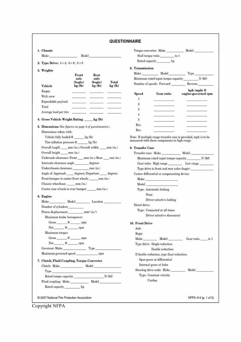
Copyright NFPA

Copyright NFPA
FIGURE D.1 Aircraft Rescue and FireFighting Vehicle Questionnaire.
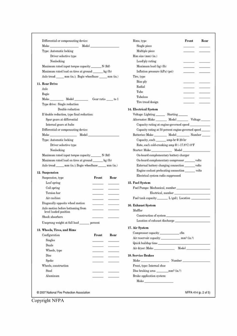
Copyright NFPA

Copyright NFPA
FIGURE D.1 Continued
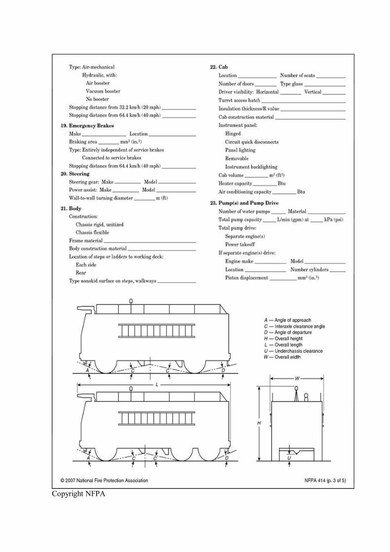
Copyright NFPA

Copyright NFPA
FIGURE D.1 Continued
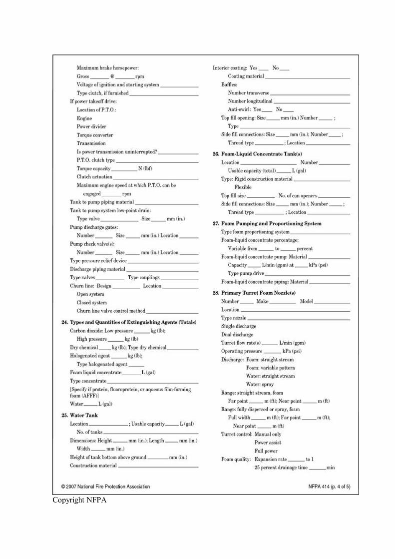
Copyright NFPA

Copyright NFPA
FIGURE D.1 Continued
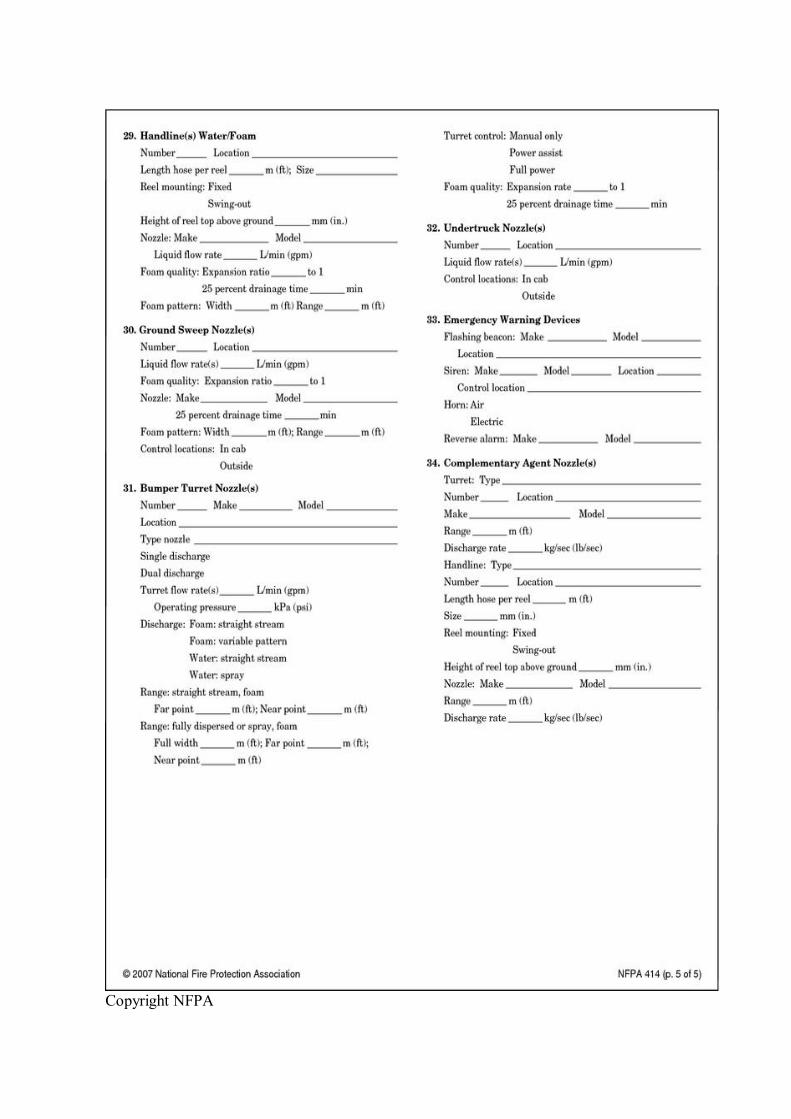
Copyright NFPA
Copyright NFPA
FIGURE D.1 Continued
The vehicle diagram on page 3 of the questionnaire should be used to complete item 5 on page 1 of the questionnaire.
Annex E Driver's Enhanced Vision System
This annex is not a part of the requirements of this NFPA document but is included for informational purposes only.
E.1 General.
The driver's enhanced vision system (DEVS) aids the three difficult aspects of poor visibility response: navigating to the accident site, locating the accident, and negotiating terrain and obstacles on the way to the accident site. DEVS is an integrated system consisting of three systems: navigation, tracking, and lowvisibility enhanced vision. DEVS can be implemented as a standalone system on an ARFF vehicle with no tracking/communication capability or as a fully integrated system with an emergency command center (ECC). The three DEVS system components are as follows:
(1) Navigation. The navigation system provides the ARFF vehicle driver with the vehicle's location and serves as an aid in navigating to the accident site.
(2) Tracking. The tracking system can be tightly integrated with the navigation system through data link. Tracking capability serves as an aid to the ARFF vehicle driver in locating and navigating to the accident site. This capability will reduce driver communications workload and improve the situational awareness of the driver and command or dispatch personnel.
(3) LowVisibility Enhanced Vision. The lowvisibility enhanced vision system uses a forward looking infrared (FLIR) device or other comparable stateoftheart lowvisibility enhanced vision technology. Lowvisibility enhanced vision capability will improve visual awareness in smoky, foggy, or dark environments by sensing thermal radiation instead of visible light.
E.1.1 Installation and Operation. Operation of the DEVS should not increase driver workload or require additional personnel for operation during emergency response. Installation should not obstruct driver view or hamper any other ARFF vehicle system. The system should be installed without extensive vehicle modification and should include sufficient filtering to protect itself from vehicle voltage spikes and surges. Vehiclemounted DEVS equipment should include a dedicated power source that should enable uninterrupted operation of the navigation system for minimally 4 hours without any external power source (i.e., external vehicle shore connection to conditioner/charger or vehicle alternator power). Recommended voltage range for DEVS equipment in ARFF vehicles is 10 to 12 V dc (volts direct current). In addition, exposed equipment should be able to operate within the same conditions (weather, chemical, and otherwise) as that of the ARFF vehicle. All DEVS components should be installed facilitating removal for repair, replacement, and
Copyright NFPA
troubleshooting.
E.1.2 Quality Assurance. The quality and workmanship of an installation should follow normal industry standards and practices. These practices generally include the following: all electrical connections should be by locking–pin type plugs, all wiring should be loomed, all penetrations in the vehicle body should be equipped with grommets or other guards to protect against wire chafing, all penetrations should be sealed from the weather, all firewall penetrations should be sealed, all splices should be soldered and then sealed with heatshrink, wiring should be color coded and identified from end to end, all controls should be labeled and illuminated, and complete “as built” wiring diagrams should be included with each installation.
E.2 Navigation System Performance.
The navigation system should be able to compute a vehicle position solution accurate to 2 m (6.6 ft). Vehicle position updates should be provided once per second and displayed on the moving map display. Vehicle position should be immediately provided upon vehicle startup. The system should be able to withstand vehicle shock and vibration. The system should provide an integrity requirement to insure that it is either working properly or down altogether, allowing no possibility of wrong/misleading information.
E.2.1 Navigation Device. The DEVS global positioning system (GPS) receiver should accept differential correction messages from an always available and reliable source with accuracy within 2 m (6.6 ft) and use these messages to compute a differentially corrected GPS position solution once per second. It also should achieve time to first fix (TTFF) of 30 seconds and should interface with the navigation computer. The antenna should be weatherproof and mounted high and as close to the center of the vehicle as practical with a clear view of the sky.
E.2.2 Navigation Computer. The computer should provide processing power and speed for the DEVS navigation and mapping software while maintaining a 50 percent throughput capacity reserve. It also should carry sufficient, upgradeable volatile and nonvolatile memory (or hard drive) and be able to interface with the navigation display/control, data link (if integrated), and GPS receiver equipment. The computer should be as small and lightweight as possible, as well as shockproof and weatherproof. The computer should be mounted unobtrusively in the cab.
E.2.3 Navigation/Mapping Software. The information displayed on the map should include primary and secondary roadways, all surfaces of the airport movement area, fences, and significant buildings, landmarks, and bodies of water. Other information can be displayed, but consideration should be given so that the map is not too complicated. Software should allow for zooming, panning, and selecting a variablesized area for fullscreen display. Map levels should be as follows:
(1) Level 1. This is the driving area (approximately onehalf mile in front of the vehicle in the headingup orientation). If the map is zoomed in or beyond this level, the vehicle icon should remain fixed and the map should translate and rotate to maintain this position with a headingup orientation.
Copyright NFPA
(2) Level 2. This level corresponds to the airport operational area (AOA). The map should translate and rotate to maintain a headingup orientation.
(3) Level 3. This is the entire airport property, including unimproved access roadways, plus the area surrounding the airport up to the ARFF department's response radius. The map should translate and rotate to maintain a headingup orientation. As an option, the airport's grid map can be integrated at this level.
Visual cues for orientation should be displayed on the screen.
E.2.4 Navigation Display/Control. The display should provide at least 16 colors with front adjustable brightness and contrast controls (contrast ratio of 3:1) and have a 254 mm to 305 mm (10 in. to 12 in.) diagonal viewable image screen with a minimum density of 640 × 480 pixels. A transparent window display system (TWDS), a head up display (HUD), or an industry standard head down display (if mounted near natural line of sight) can be used. It also should be seen easily by the driver while not obstructing the view, require minimal operator intervention to control, use an industry standard digital format, and interface with the navigation computer and operator.
E.3 Tracking System Performance.
The tracking system is accomplished by twoway wireless communication between the DEVS installed in the ARFF vehicle and the DEVS ECC. The tracking system should derive vehicle position data from the navigation system. The tracking system should be able to report the vehicle position to, and exchange messages with, the ECC within 30 seconds and have the capability to do so continuously (24 hours per day, 7 days per week). It should be able to track minimally 10 vehicles simultaneously with 1second updates and be able to track any number of vehicles simultaneously with a maximum update time of 5 seconds. The tracking system should be automatically initialized upon startup, require minimal operator intervention, and be able to withstand vehicle shock and vibration.
E.3.1 Vehicle Computer. The tracking system resident in the vehicle should use the same computer hardware as the navigation system.
E.3.2 Vehicle Tracking Software. The vehicle tracking software should format and transmit vehicle transmission reports to the ECC once per cycle and be able to transmit airport definable asset request messages (police, fire, ambulance), position markers, and special messages to the ECC by touching a single button. The current vehicle location should be indicated by an icon on the vehicle map display, and the marked location should be transmitted to the ECC.
E.3.2.1 Accident Site Location. An icon indicating the accident site or direction and distance of the accident (if site is off map) should be displayed.
E.3.2.2 Text Message. Informational text messages from the ECC should display automatically on screen and be cleared and acknowledged (to the ECC) with the touch of a button.
E.3.3 Vehicle Data Link. The vehicle data link equipment should be capable of receiving accident location and text messages from the ECC; of transmitting vehicle position reports,
Copyright NFPA
vehicle mark reports, and asset request messages to the ECC; and of checking messages through industry standard algorithms. A message transmission handshake should be established between the vehicle and the ECC. The data link should use available communications frequencies, have enough power to transmit messages to the extremes of the normal expected response area (which can vary with the airport), and be able to interface with the vehicle computer.
E.3.4 Vehicle Display/Control. The tracking system resident in the vehicle should use the same display/control hardware as the navigation system.
E.3.5 ECC Computer. The ECC computer should provide sufficient power and speed while maintaining a 50 percent throughput capacity reserve and also provide sufficient, upgradable volatile and nonvolatile memory. A sufficient hard drive should be used, yet the computer should be as small and lightweight (desktop PC size) as possible, with the capability to interface with the ECC data link and control/display equipment.
E.3.6 ECC Tracking Software. The ECC tracking software should display the locations of DEVSequipped ARFF vehicles on a digital map of the airport surrounding area. Information on the map should include primary and secondary roadways, all surfaces of the airport movement area, fences and significant buildings, landmarks, and bodies of water. Other information can be displayed, but consideration should be given so that the map is not too complicated. The mapping software should have the capability of zooming, panning, and also selecting an area for fullscreen display. The map levels are as follows:
(1) Level 1. This is an area approximately onehalf mile around the vehicle.
(2) Level 2. This level corresponds to the AOA.
(3) Level 3. This is the entire airport property, including unimproved access roadways, plus the area surrounding the airport up to the ARFF department's response radius. As an option, the airport's grid map may be integrated at this level.
Icons should indicate vehicle positions and have an identification tag. They also should move to indicate locations or show the last position and direction of the vehicle (if outside the map boundary).
E.3.7 ECC Data Link. The ECC data link should receive position reports, position marks, and asset request messages from vehicles, and it should transmit with sufficient power to reach to the extremes of the normal expected response area that can vary with the airport. It should use available communications frequencies, interface with the ECC computer, and employ industry standard error checking algorithms (check sums, parity checks) to ensure correct message receipt and transmission. It should also employ a message transmission handshake.
E.3.8 ECC Display/Control. The display should have, at minimum, a 356 mm (14 in.) diagonal viewable image screen, provide at least 256 colors, be of an industry standard CRT, and have front adjustable brightness and contrast controls (contrast ratio of 3:1). It also should use industry standard computer control devices, use an industry standard digital format, and be able to interface with the ECC computer and computer operator.
E.3.9 Data Recording and Playback. The ECC should provide recording and playback
Copyright NFPA
functions via which all message traffic between the ECC and equipped vehicles can be recorded and played back at a later time.
E.4 LowVisibility Enhanced Vision System.
The lowvisibility enhanced vision system should be operational within 30 seconds and useful in 0ceiling/0mile visibility. As an option, a standby mode can be incorporated. The lowvisibility enhanced vision system should be able to detect people, debris, wreckage, and equipment for the distances and conditions specified in Table E.4(a) and Table E.4(b).
Table E.4(a) Human Detection Distances
Distance Ambient Temperature m ft °C °F Humidity %
152.4 500 28.9° to 46.1° 20° to 115° 0 to 100 Moving 88.5 152.4 500 28.9° to 46.1° 20° to 115° 0 to 100 Moving 80.5 121.9 400 28.9° to 46.1° 20° to 115° 0 to 100 Moving 64.4 121.9 400 28.9° to 46.1° 20° to 115° 0 to 100 Moving 64.4 91.4 300 28.9° to 46.1° 20° to 115° 0 to 100 Moving 5
Table E.4(b) Aircraft Detection Distances
Distance Ambient Temperature m ft °C °F Humidity % kph
762.0 2500 28.9° to 46.1° 20° to 115° 0 to 100 Moving 88.5 304.8 1000 28.9° to 46.1° 20° to 115° 0 to 100 Moving 80.5 152.4 500 28.9° to 46.1° 20° to 115° 0 to 100 Moving 64.4 152.4 500 28.9° to 46.1° 20° to 115° 0 to 100 Moving 64.4 152.4 500 28.9° to 46.1° 20° to 115° 0 to 100 Moving 56.3
If winterization is necessary, the temperature performance range should extend to at least 40°C (40°F).
E.4.1 FLIR Camera. The FLIR, by function or the mounting platform, should provide remote controlled pan and tilt capabilities. It should be sufficiently tight so that the picture is clear and stable. Line of sight should be aligned with that of the driver. The mounting should not compromise operation of the roof turret in any manner.
The FLIR should be weatherproof (rain, sleet, snow, dust, etc.) for the environment in which it will be used, able to withstand temperature and humidity changes, and have lens clearing capability. The equipment also should be protected from, or able to withstand exposure to, extinguishing foam, water, dry chemicals, and smoke.
E.4.2 FLIR Display. The display should have a viewable image screen with a minimum density of 640 × 480 pixels. It should use an industry standard video format and have front adjustable brightness and contrast controls.
Copyright NFPA
Annex F Informational References
F.1 Referenced Publications.
The documents or portions thereof listed in this annex are referenced within the informational sections of this standard and are not part of the requirements of this document unless also listed in Chapter 2 for other reasons.
F.1.1 NFPA Publications. National Fire Protection Association, 1 Batterymarch Park, Quincy, MA 021697471.
NFPA 70, National Electrical Code ® , 2005 edition.
NFPA 70B, Recommended Practice for Electrical Equipment Maintenance, 2006 edition.
NFPA 402, Guide for Aircraft Rescue and Fire Fighting Operations, 2002 edition.
NFPA 403, Standard for Aircraft Rescue and FireFighting Services at Airports, 2003 edition.
NFPA 412, Standard for Evaluating Aircraft Rescue and FireFighting Foam Equipment, 2003 edition.
NFPA 422, Guide for Aircraft Accident/Incident Response Assessment, 2004 edition.
NFPA 1500, Standard on Fire Department Occupational Safety and Health Program, 2007 edition.
NFPA 1901, Standard for Automotive Fire Apparatus, 2003 edition.
NFPA 1931, Standard for Manufacturer's Design of Fire Department Ground Ladders, 2004 edition.
NFPA 1981, Standard on OpenCircuit SelfContained Breathing Apparatus for Fire and Emergency Services, 2002 edition.
F.1.2 Other Publications.
F.1.2.1 AASHTO Publications. American Association of State Highway and Transportation Officials, 444 N. Capitol Street, NW, Suite 249, Washington, DC 20001.
“A Policy on Geometric Design of Highways and Streets,” 1990.
F.1.2.2 ISO Publications. International Standards Organization, 1 rue de Varembé, Case Postale 56, CH1211 Geneve 20, Switzerland.
ISO 30461, Reciprocating internal combustion engines — Performance — Part 1: Declarations of power, fuel and lubricating oil consumptions, and test methods — Additional requirements for engines for general use, 2002.
F.1.2.3 NEMA Publications. National Electrical Manufacturers Association, 1300 North 17th Street, Suite 1847, Rosslyn, VA 22209.

Copyright NFPA
NEMA MG 1, Motors and Generators, 1998.
MENA WD 6, Wiring Devices — Dimensional Requirements, 1997.
F.1.2.4 SAE Publications. Society of Automotive Engineers, 400 Commonwealth Drive, Warrendale, PA 15096.
SAE J156, Fusible Links, 1997.
SAE J541, Voltage Drop for Starting Motor Circuits, 1996.
SAE J551/2, Test Limits and Methods of Measurement of Radio Disturbance Characteristics of Vehicles, Motorboats, and SparkIgnited EngineDriven Devices, 1996.
SAE J553, Circuit Breakers, 1996.
SAE J554, Electric Fuses (Cartridge Type), 1987.
SAE J575, Test Methods and Equipment for Lighting Devices and Components for Use on Vehicles Less Than 2032 mm in Overall Width, 1992.
SAE J994, Alarm — Backup — Electric, Laboratory Performance Testing, 1993.
SAE J1127, Battery Cable, 1995.
SAE J1128, Low Tension Primary Cable, 1995.
SAE J1292, Automobile, Truck, TruckTractor, Trailer, and Motor Coach Wiring, 1981.
SAE J1349, Engine Power Test CodeSpark Ignition and Compression IgnitionNet Power Rating, 1995.
SAE J1849, Emergency Vehicle Sirens, 1995.
SAE J1888, High Current Time Lag Electric Fuses, 1990.
SAE J2077, Miniature Blade Type Electrical Fuses, 1990.
SAE J2180, A Tilt Table Procedure for Measuring the Static Rollover Threshold for Heavy Trucks, 1998.
F.1.2.5 UL Publications. Underwriters Laboratories Inc., 333 Pfingsten Road, Northbrook, IL 600622096.
UL 498, Standard for Safety Attachment Plugs and Receptacles, 2001.
F.2 Informational References. (Reserved)
F.3 References for Extracts in Informational Sections.
NFPA 1901, Standard for Automotive Fire Apparatus, 2003 edition.

Copyright NFPA


![J. - NFPA€¦ · Robert J. Donahue, Secretary Massport, MA [U] ... amendments to NFPA 403-1993, Standard for Aircraft Rescue and Fire Fighting Services at Airports. NFPA 403-1993](https://img.pdfslide.net/doc/110x75/5e8f9102889b5d4f1a2ad146/j-nfpa-robert-j-donahue-secretary-massport-ma-u-amendments-to-nfpa-403-1993.jpg)