Embed Size (px)
Citation preview

NFPA 52 Vehicular Alternative Fuel Systems
First Draft Meeting (F2015) Agenda
Hilton Atlanta Atlanta, GA
March 11-13, 2014
1.0 Meeting Opening, member and guest welcome – introduction
2.0 Chair remarks
3.0 Review and approve minutes
4.0 Staff Liaison update (new process, committee update)
5.0 Task Group Reports
Organization Task Group
Other Chapter Task Groups (?)
6.0 Task Group Formation
Review of NFPA 56 Standard for Fire and Explosion Prevention During Cleaning and Purging of Flammable Gas Piping Systems
Membership classification review
7.0 Update report on NGV 5.1, the new standard for residential fuelling appliances
8.0 NFPA 52 Public Input
Public Input – review and action
Committee Input – develop and action as required
9.0 Other business
10.0 Review plans and schedule
11.0 Next Meeting - TBD


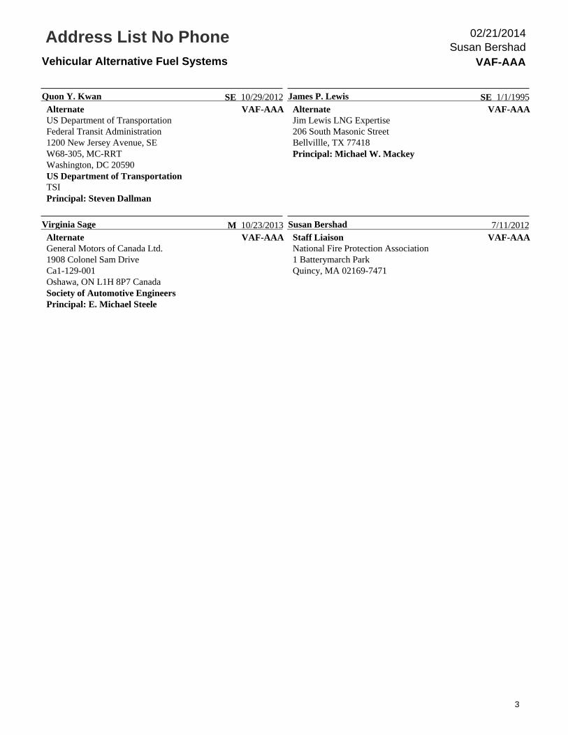
Address List No PhoneVehicular Alternative Fuel Systems VAF-AAA
Susan Bershad02/21/2014
VAF-AAANancy C. PehrsonChairCenterPoint Energy, Inc.700 West Linden AvenuePO Box 1165Minneapolis, MN 55440
U 1/1/1991VAF-AAA
Stephen V. AbernathyPrincipalPiedmont Natural GasPO Box 16087Greenville, SC 29606
IM 10/23/2013
VAF-AAARonald C. AdcockPrincipalMarsh Risk Consulting2325 East Camelback Road, Suite 600Phoenix, AZ 85016
I 1/1/1993VAF-AAA
Dan BowersonPrincipalChrysler800 Chrysler DriveAuburn Hills, MI 48326
M 10/23/2013
VAF-AAASteven DallmanPrincipalUS Department of TransportationTransportation Safety Institute6500 South MacArthur Blvd., DTI-80Oklahoma City, OK 73169US Department of TransportationTSIAlternate: Quon Y. Kwan
SE 1/16/2003VAF-AAA
David J. FaresePrincipalAir Products and Chemicals, Inc.7201 Hamilton BoulevardAllentown, PA 18195Alternate: Steven W. Hoffman
M 7/23/2008
VAF-AAAThomas J. ForsythePrincipalHughes Associates, Inc.2551 San Ramon Valley Blvd., Suite 209San Ramon, CA 94583
SE 10/1/1994VAF-AAA
Tara HenriksenPrincipalCASE Forensics Corporation23109 55th Avenue WestMountlake Terrace, WA 98043
SE 3/4/2009
VAF-AAADouglas B. HornePrincipalDBHorne LLC6011 Fords Lake CourtAcworth, GA 30101Clean Vehicle Education FoundationAlternate: John B. Dimmick
M 1/1/1982VAF-AAA
Michael W. MackeyPrincipalGP Strategies1918 Don Lee PlaceEscondido, CA 92029Alternate: James P. Lewis
SE 9/30/2004
VAF-AAATimothy E. MeyersPrincipalUS Coast GuardOffice of Design & Engineering Standards2100 2nd Street SW, Stop 7126Washington, DC 20593Alternate: Andrew Gibbons
E 8/9/2011VAF-AAA
Gregory A. MilewskiPrincipalShell Oil Company9018 Brook ShadowKingwood, TX 77345American Petroleum Institute
M 7/26/2007
1

Address List No PhoneVehicular Alternative Fuel Systems VAF-AAA
Susan Bershad02/21/2014
VAF-AAARandy MosesPrincipalWayne, A GE Energy Business1000 East Walnut StreetHeritage Campus, Suite 404Perkasie, PA 18944
U 10/23/2013VAF-AAA
Robert E. PetsingerPrincipalCNG Services International Inc.Roosevelt Building, Suite 613609 Penn AvenuePittsburgh, PA 15222
IM 1/1/1982
VAF-AAAGary PopePrincipalUSA PRO & Associates LLC112 11th StreetHuntington Beach, CA 92648
SE 4/17/2002VAF-AAA
Robert N. RenkesPrincipalPetroleum Equipment Institute6514 East 69th StreetTulsa, OK 74133
M 03/07/2013
VAF-AAAJerrold SamethPrincipalCompressed Gas Association, Inc.14501 George Carter WayChantilly, VA 20151Compressed Gas AssociationAlternate: Richard A. Craig
IM 07/29/2013VAF-AAA
Glen E. SmithPrincipalArgus Consulting, Inc.6363 College Boulevard, Suite 600Overland Park, KS 66211-1882American Railway Engineering & Maintenance-of-WayAssn.
SE 10/23/2013
VAF-AAAE. Michael SteelePrincipalSteele Consulting5855 Stratmore AvenueCypress, CA 90630-4623Society of Automotive EngineersAlternate: Virginia Sage
M 03/21/2006VAF-AAA
Steven TuckyPrincipalCSA Group8501 East Pleasant Valley RoadIndependence, OH 44131
RT 07/29/2013
VAF-AAAMihai UrsanPrincipalWestport Power Inc.#101 1750 West 75th AvenueVancouver, BC B6P 6G2 Canada
M 7/23/2008VAF-AAA
Ted WilliamsPrincipalAmerican Gas Assocication400 North Capitol Street, NWWashington, DC 22204
IM 08/09/2012
VAF-AAARichard A. CraigAlternateCompressed Gas Association14501 George Carter Way, Suite 103Chantilly, VA 20151Principal: Jerrold Sameth
IM 8/9/2011VAF-AAA
John B. DimmickAlternateClean Vehicle Education Foundation551W23115 Partridge LaneWaukesha, WI 53189Clean Vehicle Education FoundationPrincipal: Douglas B. Horne
M 10/18/2011
VAF-AAAAndrew GibbonsAlternateUS Coast GuardCommandant (CG-Eng-3)2100 Second Street, SWWashington, DC 20593-7126Principal: Timothy E. Meyers
E 03/07/2013VAF-AAA
Steven W. HoffmanAlternateAir Products and Chemicals, Inc.555 1st Street. Suite 302Benicia, CA 94510Principal: David J. Farese
M 10/27/2009
2
Address List No PhoneVehicular Alternative Fuel Systems VAF-AAA
Susan Bershad02/21/2014
VAF-AAAQuon Y. KwanAlternateUS Department of TransportationFederal Transit Administration1200 New Jersey Avenue, SEW68-305, MC-RRTWashington, DC 20590US Department of TransportationTSIPrincipal: Steven Dallman
SE 10/29/2012VAF-AAA
James P. LewisAlternateJim Lewis LNG Expertise206 South Masonic StreetBellvillle, TX 77418Principal: Michael W. Mackey
SE 1/1/1995
VAF-AAAVirginia SageAlternateGeneral Motors of Canada Ltd.1908 Colonel Sam DriveCa1-129-001Oshawa, ON L1H 8P7 CanadaSociety of Automotive EngineersPrincipal: E. Michael Steele
M 10/23/2013VAF-AAA
Susan BershadStaff LiaisonNational Fire Protection Association1 Batterymarch ParkQuincy, MA 02169-7471
7/11/2012
3

Public Input No. 69-NFPA 52-2013 [ Global Input ]
Type your content here ...
Universally change terminology from “Residential CNG Fueling Facility (RFF-CNG)” to“Residential Fueling Appliance (RFA)” throughout the code.
Statement of Problem and Substantiation for Public Input
This proposal is part of a Series of proposals which will harmonize NFPA 52 with the new NGV 5.1 standard for residential fueling appliances.
The RFA language is similar to the language that is currently used in Z223/NFPA 54 and this will provide additional consistency between the standard and code and will work to harmonize terminology for industry.
Related Public Inputs for This Document
Related Input Relationship
Public Input No. 59-NFPA 52-2013 [Section No.3.3.49]
Changes terminology from "RFF-CNG" to "RFA"
Public Input No. 61-NFPA 52-2013 [Section No.5.3.1 [Excluding any Sub-Sections]]
Changes terminology from "RFF-CNG" to "RFA"
Public Input No. 57-NFPA 52-2013 [Chapter 8[Title Only]]
Changes terminology from "RFF-CNG" to "RFA"
Public Input No. 67-NFPA 52-2013 [Section No.8.1.1]
Changes terminology from "RFF-CNG" to "RFA"
Public Input No. 70-NFPA 52-2013 [Section No.8.1.2]
Changes terminology from "RFF-CNG" to "RFA"
Public Input No. 74-NFPA 52-2013 [Section No.8.3.1]
Changes terminology from "RFF-CNG" to "RFA"
Public Input No. 75-NFPA 52-2013 [Section No.8.3.3]
Changes terminology from "RFF-CNG" to "RFA"
Public Input No. 78-NFPA 52-2013 [Section No.8.4.1.1]
Changes terminology from "RFF-CNG" to "RFA"
Public Input No. 79-NFPA 52-2013 [Section No.8.4.1.2]
Changes terminology from "RFF-CNG" to "RFA".Please note proposal includes additional revision.
Public Input No. 80-NFPA 52-2013 [Section No.8.4.2.2]
Changes terminology from "RFF-CNG" to "RFA"
Public Input No. 81-NFPA 52-2013 [Section No.8.4.3]
Changes terminology from "RFF-CNG" to "RFA"
Public Input No. 82-NFPA 52-2013 [Section No.8.7]
Changes terminology from "RFF-CNG" to "RFA"
Public Input No. 83-NFPA 52-2013 [Section No.8.8.2]
Changes terminology from "RFF-CNG" to "RFA"
Public Input No. 89-NFPA 52-2013 [Section No.8.11.1]
Changes terminology from "RFF-CNG" to "RFA"
Public Input No. 91-NFPA 52-2013 [Section No.8.12.1]
Changes terminology from "RFF-CNG" to "RFA"
Submitter Information Verification
National Fire Protection Association Report http://submittals.nfpa.org/TerraViewWeb/ContentFetcher?commentPara...
1 of 307 1/21/2014 3:31 PM
Submitter Full Name: JULIE CAIRNS
Organization: CSA GROUP
Affilliation: CSA Group NGV 5.1 Residential Fueling Appliance Technical Subcommittee
Street Address:
City:
State:
Zip:
Submittal Date: Fri Dec 20 11:41:08 EST 2013
Copyright Assignment
I, JULIE CAIRNS, hereby irrevocably grant and assign to the National Fire Protection Association (NFPA) all and full rights in copyright inthis Public Input (including both the Proposed Change and the Statement of Problem and Substantiation). I understand and intend that Iacquire no rights, including rights as a joint author, in any publication of the NFPA in which this Public Input in this or another similar orderivative form is used. I hereby warrant that I am the author of this Public Input and that I have full power and authority to enter into thiscopyright assignment.
By checking this box I affirm that I am JULIE CAIRNS, and I agree to be legally bound by the above Copyright Assignment and theterms and conditions contained therein. I understand and intend that, by checking this box, I am creating an electronic signature that will,upon my submission of this form, have the same legal force and effect as a handwritten signature
National Fire Protection Association Report http://submittals.nfpa.org/TerraViewWeb/ContentFetcher?commentPara...
2 of 307 1/21/2014 3:31 PM

Public Input No. 228-NFPA 52-2013 [ New Section after 1.1 ]
TITLE OF NEW CONTENT Revised Title for NFPA 52
Type your content here ... Vehicular Natural Gas Fuel Systems Code
Statement of Problem and Substantiation for Public Input
I was not able to do a revision of the title on Terra so I put it here. The scope was reduced in 2013 with the removal of hydrogen fuel systems. The proposed title better reflects the contents
Submitter Information Verification
Submitter Full Name: John Dimmick
Organization: Clean Vehicle Education Founda
Affilliation: Clean Vehicle Education Foundation
Street Address:
City:
State:
Zip:
Submittal Date: Tue Dec 31 12:47:03 EST 2013
Copyright Assignment
I, John Dimmick, hereby irrevocably grant and assign to the National Fire Protection Association (NFPA) all and full rights in copyright inthis Public Input (including both the Proposed Change and the Statement of Problem and Substantiation). I understand and intend that Iacquire no rights, including rights as a joint author, in any publication of the NFPA in which this Public Input in this or another similar orderivative form is used. I hereby warrant that I am the author of this Public Input and that I have full power and authority to enter into thiscopyright assignment.
By checking this box I affirm that I am John Dimmick, and I agree to be legally bound by the above Copyright Assignment and the termsand conditions contained therein. I understand and intend that, by checking this box, I am creating an electronic signature that will, upon mysubmission of this form, have the same legal force and effect as a handwritten signature
National Fire Protection Association Report http://submittals.nfpa.org/TerraViewWeb/ContentFetcher?commentPara...
3 of 307 1/21/2014 3:31 PM

Public Input No. 125-NFPA 52-2013 [ Section No. 1.1.3 ]
1.1.3
Vehicles and T his Code shall not apply to and fuel supply containers complying with federal motorvehicle safety standards (FMVSSs) covering the installation of CNG fuel systems on vehicles and certifiedby the respective manufacturer as meeting these standards shall not be required to comply with Sections5.4 , 5.8 , 5.9 , and 5.10 and Chapter 6 (except Sections 6.9 , 6.11 , 6.12 , 6.13 , and 6.14 ).standards
Statement of Problem and Substantiation for Public Input
Compliance with FMVSS standards is sufficient for the safety of vehicles. OEM system designers agr generally capable of designing safe systems and adding NFPA 52 requirements without a national AHJ is not helpful. NFPA 52 was originally drafted for an environment of conversion vehicles and attempting to make it apply to OEM vehicles can lead to confusion about requirements. See proposed new definition for Alterer.
Submitter Information Verification
Submitter Full Name: John Dimmick
Organization: Clean Vehicle Education Founda
Affilliation: Clean Vehicle Education Foundation
Street Address:
City:
State:
Zip:
Submittal Date: Mon Dec 30 12:34:43 EST 2013
Copyright Assignment
I, John Dimmick, hereby irrevocably grant and assign to the National Fire Protection Association (NFPA) all and full rights in copyright inthis Public Input (including both the Proposed Change and the Statement of Problem and Substantiation). I understand and intend that Iacquire no rights, including rights as a joint author, in any publication of the NFPA in which this Public Input in this or another similar orderivative form is used. I hereby warrant that I am the author of this Public Input and that I have full power and authority to enter into thiscopyright assignment.
By checking this box I affirm that I am John Dimmick, and I agree to be legally bound by the above Copyright Assignment and the termsand conditions contained therein. I understand and intend that, by checking this box, I am creating an electronic signature that will, upon mysubmission of this form, have the same legal force and effect as a handwritten signature
National Fire Protection Association Report http://submittals.nfpa.org/TerraViewWeb/ContentFetcher?commentPara...
4 of 307 1/21/2014 3:31 PM

Public Input No. 44-NFPA 52-2013 [ Section No. 2.3.6 ]
2.3.6 CGA Publications.
Compressed Gas Association, 4221 Walney Road, 5th Floor, Chantilly, VA 20151-2923.
CGA C-6.4, Methods for External Visual Inspection of Natural Gas Vehicle (NGV) and Hydrogen Vehicle(HV) Fuel Containers and Their Installation. 2007.
CGA S-1.1, Pressure Relief Device Standards — Part 1 — Cylinders for Compressed Gases, 2007.
CGA S-1.3, Pressure Relief Device Standards — Part 3 — Stationary Storage Containers for CompressedGases, 2008.
CGA 341, Standard for Insulated Cargo Tank Specification for Nonflammable Cryogenic Liquids, 2006(reaffirmed 2011).
Statement of Problem and Substantiation for Public Input
This standard is referenced in the suggested revision to 6.13.3
Submitter Information Verification
Submitter Full Name: Quon Kwan
Organization: US Department of Transportation
Street Address:
City:
State:
Zip:
Submittal Date: Tue Dec 17 19:49:27 EST 2013
Copyright Assignment
I, Quon Kwan, hereby irrevocably grant and assign to the National Fire Protection Association (NFPA) all and full rights in copyright in thisPublic Input (including both the Proposed Change and the Statement of Problem and Substantiation). I understand and intend that I acquireno rights, including rights as a joint author, in any publication of the NFPA in which this Public Input in this or another similar or derivativeform is used. I hereby warrant that I am the author of this Public Input and that I have full power and authority to enter into this copyrightassignment.
By checking this box I affirm that I am Quon Kwan, and I agree to be legally bound by the above Copyright Assignment and the termsand conditions contained therein. I understand and intend that, by checking this box, I am creating an electronic signature that will, upon mysubmission of this form, have the same legal force and effect as a handwritten signature
National Fire Protection Association Report http://submittals.nfpa.org/TerraViewWeb/ContentFetcher?commentPara...
5 of 307 1/21/2014 3:31 PM
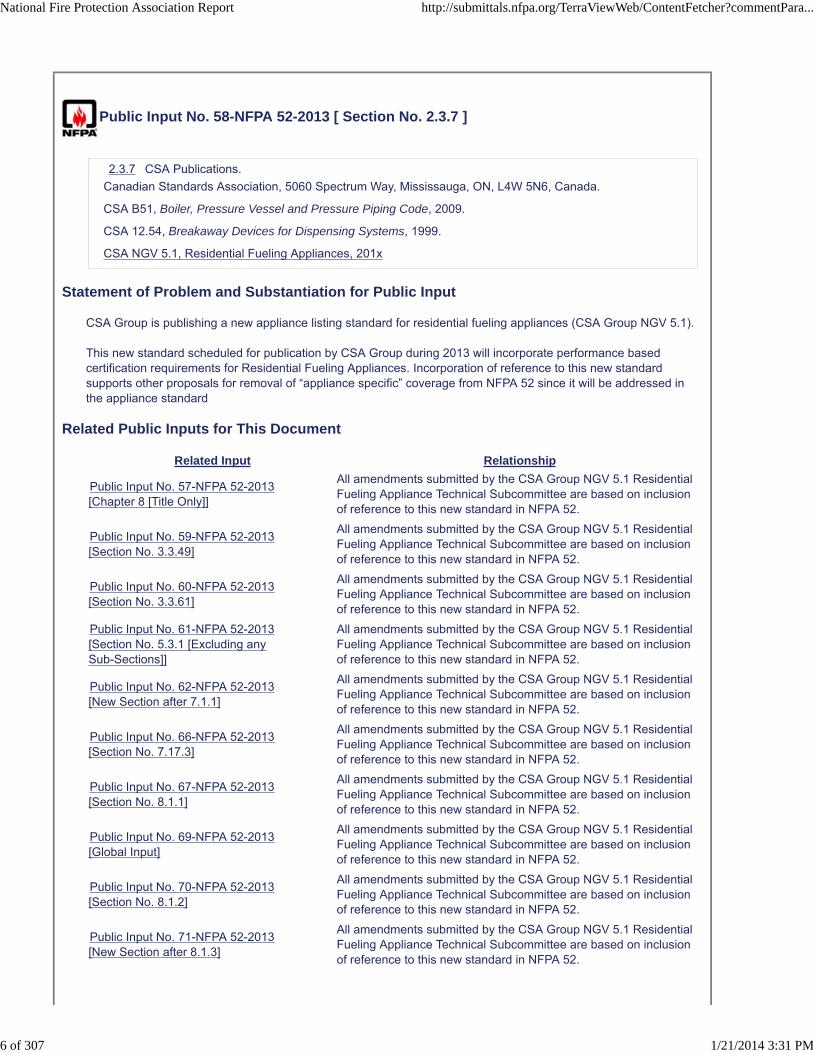
Public Input No. 58-NFPA 52-2013 [ Section No. 2.3.7 ]
2.3.7 CSA Publications.
Canadian Standards Association, 5060 Spectrum Way, Mississauga, ON, L4W 5N6, Canada.
CSA B51, Boiler, Pressure Vessel and Pressure Piping Code, 2009.
CSA 12.54, Breakaway Devices for Dispensing Systems, 1999.
CSA NGV 5.1, Residential Fueling Appliances, 201x
Statement of Problem and Substantiation for Public Input
CSA Group is publishing a new appliance listing standard for residential fueling appliances (CSA Group NGV 5.1).
This new standard scheduled for publication by CSA Group during 2013 will incorporate performance based certification requirements for Residential Fueling Appliances. Incorporation of reference to this new standard supports other proposals for removal of “appliance specific” coverage from NFPA 52 since it will be addressed in the appliance standard
Related Public Inputs for This Document
Related Input Relationship
Public Input No. 57-NFPA 52-2013[Chapter 8 [Title Only]]
All amendments submitted by the CSA Group NGV 5.1 ResidentialFueling Appliance Technical Subcommittee are based on inclusionof reference to this new standard in NFPA 52.
Public Input No. 59-NFPA 52-2013[Section No. 3.3.49]
All amendments submitted by the CSA Group NGV 5.1 ResidentialFueling Appliance Technical Subcommittee are based on inclusionof reference to this new standard in NFPA 52.
Public Input No. 60-NFPA 52-2013[Section No. 3.3.61]
All amendments submitted by the CSA Group NGV 5.1 ResidentialFueling Appliance Technical Subcommittee are based on inclusionof reference to this new standard in NFPA 52.
Public Input No. 61-NFPA 52-2013[Section No. 5.3.1 [Excluding anySub-Sections]]
All amendments submitted by the CSA Group NGV 5.1 ResidentialFueling Appliance Technical Subcommittee are based on inclusionof reference to this new standard in NFPA 52.
Public Input No. 62-NFPA 52-2013[New Section after 7.1.1]
All amendments submitted by the CSA Group NGV 5.1 ResidentialFueling Appliance Technical Subcommittee are based on inclusionof reference to this new standard in NFPA 52.
Public Input No. 66-NFPA 52-2013[Section No. 7.17.3]
All amendments submitted by the CSA Group NGV 5.1 ResidentialFueling Appliance Technical Subcommittee are based on inclusionof reference to this new standard in NFPA 52.
Public Input No. 67-NFPA 52-2013[Section No. 8.1.1]
All amendments submitted by the CSA Group NGV 5.1 ResidentialFueling Appliance Technical Subcommittee are based on inclusionof reference to this new standard in NFPA 52.
Public Input No. 69-NFPA 52-2013[Global Input]
All amendments submitted by the CSA Group NGV 5.1 ResidentialFueling Appliance Technical Subcommittee are based on inclusionof reference to this new standard in NFPA 52.
Public Input No. 70-NFPA 52-2013[Section No. 8.1.2]
All amendments submitted by the CSA Group NGV 5.1 ResidentialFueling Appliance Technical Subcommittee are based on inclusionof reference to this new standard in NFPA 52.
Public Input No. 71-NFPA 52-2013[New Section after 8.1.3]
All amendments submitted by the CSA Group NGV 5.1 ResidentialFueling Appliance Technical Subcommittee are based on inclusionof reference to this new standard in NFPA 52.
National Fire Protection Association Report http://submittals.nfpa.org/TerraViewWeb/ContentFetcher?commentPara...
6 of 307 1/21/2014 3:31 PM

Public Input No. 72-NFPA 52-2013[Section No. 8.2.2]
All amendments submitted by the CSA Group NGV 5.1 ResidentialFueling Appliance Technical Subcommittee are based on inclusionof reference to this new standard in NFPA 52.
Public Input No. 73-NFPA 52-2013[Section No. 8.2.3]
All amendments submitted by the CSA Group NGV 5.1 ResidentialFueling Appliance Technical Subcommittee are based on inclusionof reference to this new standard in NFPA 52.
Public Input No. 74-NFPA 52-2013[Section No. 8.3.1]
All amendments submitted by the CSA Group NGV 5.1 ResidentialFueling Appliance Technical Subcommittee are based on inclusionof reference to this new standard in NFPA 52.
Public Input No. 75-NFPA 52-2013[Section No. 8.3.3]
All amendments submitted by the CSA Group NGV 5.1 ResidentialFueling Appliance Technical Subcommittee are based on inclusionof reference to this new standard in NFPA 52.
Public Input No. 76-NFPA 52-2013[Section No. 8.3.5.1]
All amendments submitted by the CSA Group NGV 5.1 ResidentialFueling Appliance Technical Subcommittee are based on inclusionof reference to this new standard in NFPA 52.
Public Input No. 77-NFPA 52-2013[Section No. 8.3.6]
All amendments submitted by the CSA Group NGV 5.1 ResidentialFueling Appliance Technical Subcommittee are based on inclusionof reference to this new standard in NFPA 52.
Public Input No. 78-NFPA 52-2013[Section No. 8.4.1.1]
All amendments submitted by the CSA Group NGV 5.1 ResidentialFueling Appliance Technical Subcommittee are based on inclusionof reference to this new standard in NFPA 52.
Public Input No. 79-NFPA 52-2013[Section No. 8.4.1.2]
All amendments submitted by the CSA Group NGV 5.1 ResidentialFueling Appliance Technical Subcommittee are based on inclusionof reference to this new standard in NFPA 52.
Public Input No. 80-NFPA 52-2013[Section No. 8.4.2.2]
All amendments submitted by the CSA Group NGV 5.1 ResidentialFueling Appliance Technical Subcommittee are based on inclusionof reference to this new standard in NFPA 52.
Public Input No. 81-NFPA 52-2013[Section No. 8.4.3]
All amendments submitted by the CSA Group NGV 5.1 ResidentialFueling Appliance Technical Subcommittee are based on inclusionof reference to this new standard in NFPA 52.
Public Input No. 82-NFPA 52-2013[Section No. 8.7]
All amendments submitted by the CSA Group NGV 5.1 ResidentialFueling Appliance Technical Subcommittee are based on inclusionof reference to this new standard in NFPA 52.
Public Input No. 83-NFPA 52-2013[Section No. 8.8.2]
All amendments submitted by the CSA Group NGV 5.1 ResidentialFueling Appliance Technical Subcommittee are based on inclusionof reference to this new standard in NFPA 52.
Public Input No. 84-NFPA 52-2013[Section No. 8.8.1]
All amendments submitted by the CSA Group NGV 5.1 ResidentialFueling Appliance Technical Subcommittee are based on inclusionof reference to this new standard in NFPA 52.
Public Input No. 85-NFPA 52-2013[Section No. 8.8.3]
All amendments submitted by the CSA Group NGV 5.1 ResidentialFueling Appliance Technical Subcommittee are based on inclusionof reference to this new standard in NFPA 52.
Public Input No. 86-NFPA 52-2013[Section No. 8.8.4]
All amendments submitted by the CSA Group NGV 5.1 ResidentialFueling Appliance Technical Subcommittee are based on inclusionof reference to this new standard in NFPA 52.
Public Input No. 87-NFPA 52-2013[Section No. 8.8.5]
All amendments submitted by the CSA Group NGV 5.1 ResidentialFueling Appliance Technical Subcommittee are based on inclusionof reference to this new standard in NFPA 52.
Public Input No. 88-NFPA 52-2013[Section No. 8.10]
All amendments submitted by the CSA Group NGV 5.1 ResidentialFueling Appliance Technical Subcommittee are based on inclusionof reference to this new standard in NFPA 52.
Public Input No. 89-NFPA 52-2013[Section No. 8.11.1]
All amendments submitted by the CSA Group NGV 5.1 ResidentialFueling Appliance Technical Subcommittee are based on inclusionof reference to this new standard in NFPA 52.
National Fire Protection Association Report http://submittals.nfpa.org/TerraViewWeb/ContentFetcher?commentPara...
7 of 307 1/21/2014 3:31 PM

Public Input No. 90-NFPA 52-2013[Section No. 8.11.2]
All amendments submitted by the CSA Group NGV 5.1 ResidentialFueling Appliance Technical Subcommittee are based on inclusionof reference to this new standard in NFPA 52.
Public Input No. 91-NFPA 52-2013[Section No. 8.12.1]
All amendments submitted by the CSA Group NGV 5.1 ResidentialFueling Appliance Technical Subcommittee are based on inclusionof reference to this new standard in NFPA 52.
Public Input No. 92-NFPA 52-2013[Section No. A.8.2.2]
All amendments submitted by the CSA Group NGV 5.1 ResidentialFueling Appliance Technical Subcommittee are based on inclusionof reference to this new standard in NFPA 52.
Submitter Information Verification
Submitter Full Name: JULIE CAIRNS
Organization: CSA GROUP
Affilliation: CSA Group NGV 5.1 Home Fueling Appliance Technical Subcommittee
Street Address:
City:
State:
Zip:
Submittal Date: Fri Dec 20 10:13:40 EST 2013
Copyright Assignment
I, JULIE CAIRNS, hereby irrevocably grant and assign to the National Fire Protection Association (NFPA) all and full rights in copyright inthis Public Input (including both the Proposed Change and the Statement of Problem and Substantiation). I understand and intend that Iacquire no rights, including rights as a joint author, in any publication of the NFPA in which this Public Input in this or another similar orderivative form is used. I hereby warrant that I am the author of this Public Input and that I have full power and authority to enter into thiscopyright assignment.
By checking this box I affirm that I am JULIE CAIRNS, and I agree to be legally bound by the above Copyright Assignment and theterms and conditions contained therein. I understand and intend that, by checking this box, I am creating an electronic signature that will,upon my submission of this form, have the same legal force and effect as a handwritten signature
National Fire Protection Association Report http://submittals.nfpa.org/TerraViewWeb/ContentFetcher?commentPara...
8 of 307 1/21/2014 3:31 PM

Public Input No. 41-NFPA 52-2013 [ New Section after 2.3.11 ]
2.3.XX SAE Publications
Society of Automotive Engineers, 400 Commonwealth Drive, Warrendale, PA 15096-0001
SAE 2343 -- Recommended Practices for LNG-Powered Heavy Duty Trucks, July 2008
Statement of Problem and Substantiation for Public Input
This reference will be cited iin new Sections 9.3.3.3 and 9.3.3.4
Submitter Information Verification
Submitter Full Name: Quon Kwan
Organization: US Department of Transportation
Street Address:
City:
State:
Zip:
Submittal Date: Tue Dec 17 11:16:09 EST 2013
Copyright Assignment
I, Quon Kwan, hereby irrevocably grant and assign to the National Fire Protection Association (NFPA) all and full rights in copyright in thisPublic Input (including both the Proposed Change and the Statement of Problem and Substantiation). I understand and intend that I acquireno rights, including rights as a joint author, in any publication of the NFPA in which this Public Input in this or another similar or derivativeform is used. I hereby warrant that I am the author of this Public Input and that I have full power and authority to enter into this copyrightassignment.
By checking this box I affirm that I am Quon Kwan, and I agree to be legally bound by the above Copyright Assignment and the termsand conditions contained therein. I understand and intend that, by checking this box, I am creating an electronic signature that will, upon mysubmission of this form, have the same legal force and effect as a handwritten signature
National Fire Protection Association Report http://submittals.nfpa.org/TerraViewWeb/ContentFetcher?commentPara...
9 of 307 1/21/2014 3:31 PM
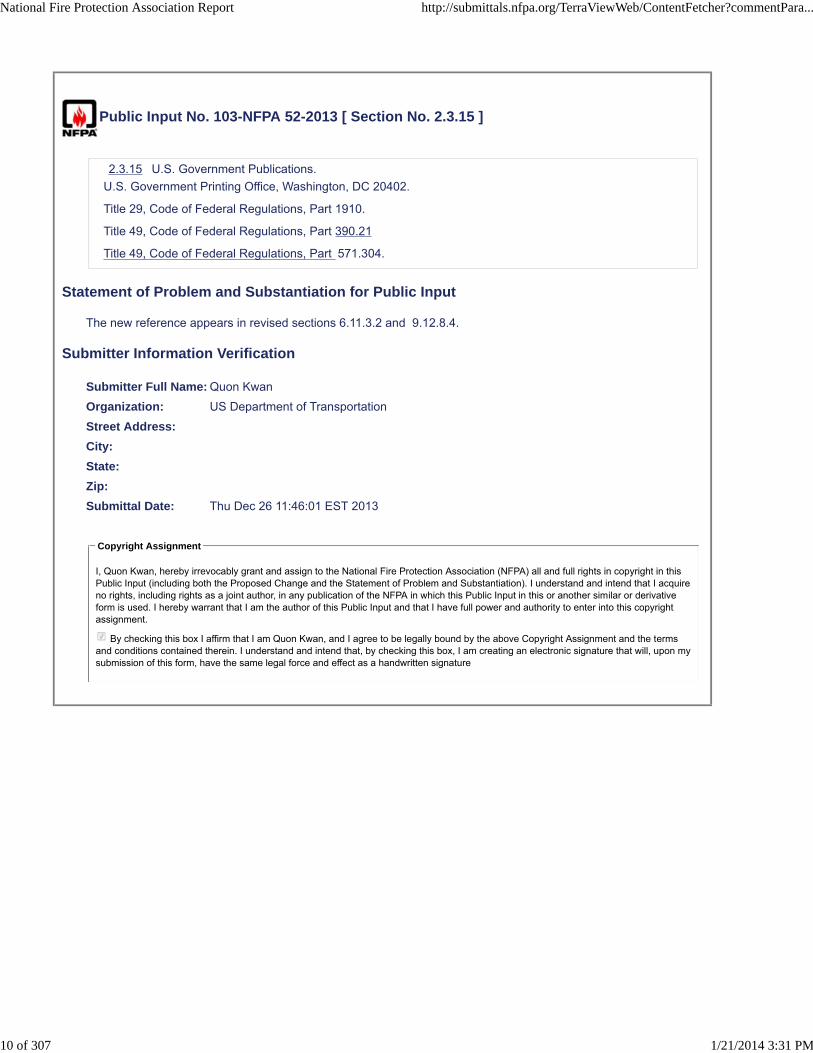
Public Input No. 103-NFPA 52-2013 [ Section No. 2.3.15 ]
2.3.15 U.S. Government Publications.
U.S. Government Printing Office, Washington, DC 20402.
Title 29, Code of Federal Regulations, Part 1910.
Title 49, Code of Federal Regulations, Part 390.21
Title 49, Code of Federal Regulations, Part 571.304.
Statement of Problem and Substantiation for Public Input
The new reference appears in revised sections 6.11.3.2 and 9.12.8.4.
Submitter Information Verification
Submitter Full Name: Quon Kwan
Organization: US Department of Transportation
Street Address:
City:
State:
Zip:
Submittal Date: Thu Dec 26 11:46:01 EST 2013
Copyright Assignment
I, Quon Kwan, hereby irrevocably grant and assign to the National Fire Protection Association (NFPA) all and full rights in copyright in thisPublic Input (including both the Proposed Change and the Statement of Problem and Substantiation). I understand and intend that I acquireno rights, including rights as a joint author, in any publication of the NFPA in which this Public Input in this or another similar or derivativeform is used. I hereby warrant that I am the author of this Public Input and that I have full power and authority to enter into this copyrightassignment.
By checking this box I affirm that I am Quon Kwan, and I agree to be legally bound by the above Copyright Assignment and the termsand conditions contained therein. I understand and intend that, by checking this box, I am creating an electronic signature that will, upon mysubmission of this form, have the same legal force and effect as a handwritten signature
National Fire Protection Association Report http://submittals.nfpa.org/TerraViewWeb/ContentFetcher?commentPara...
10 of 307 1/21/2014 3:31 PM

Public Input No. 126-NFPA 52-2013 [ New Section after 3.3.1 ]
TITLE OF NEW CONTENT
Type your content here ...
Alterer Alterer means a person or business making changes to a certified vehicle. Thesechanges do not include the addition, substitution, or removal of readily attachable components,such as mirrors or tire and rim assemblies. Nor do they include minor finishing operations such aspainting. "Alterer" also means a person or business who alters a certified vehicle in such amanner that its stated weight ratings are no longer valid. All of these changes are made beforethe first purchase of the vehicle in good faith for purposes other than resale.
Statement of Problem and Substantiation for Public Input
This definition is from the NHTSA definition of those who make alterations to vehicles before first sale. From the standpoint of certification, these vehicles are considered to be certified to conform to the FMVSS standards
Submitter Information Verification
Submitter Full Name: John Dimmick
Organization: Clean Vehicle Education Founda
Affilliation: Clean Vehicle Education Foundation
Street Address:
City:
State:
Zip:
Submittal Date: Mon Dec 30 12:42:42 EST 2013
Copyright Assignment
I, John Dimmick, hereby irrevocably grant and assign to the National Fire Protection Association (NFPA) all and full rights in copyright inthis Public Input (including both the Proposed Change and the Statement of Problem and Substantiation). I understand and intend that Iacquire no rights, including rights as a joint author, in any publication of the NFPA in which this Public Input in this or another similar orderivative form is used. I hereby warrant that I am the author of this Public Input and that I have full power and authority to enter into thiscopyright assignment.
By checking this box I affirm that I am John Dimmick, and I agree to be legally bound by the above Copyright Assignment and the termsand conditions contained therein. I understand and intend that, by checking this box, I am creating an electronic signature that will, upon mysubmission of this form, have the same legal force and effect as a handwritten signature
National Fire Protection Association Report http://submittals.nfpa.org/TerraViewWeb/ContentFetcher?commentPara...
11 of 307 1/21/2014 3:31 PM

Public Input No. 127-NFPA 52-2013 [ New Section after 3.3.1 ]
TITLE OF NEW CONTENT
Type your content here .. Converter; an individual or or organization that installs a natural gas fuel systemon a vehicle after first sale and who is not required to certify compliance with federal motor vehicle safetystandards.
Statement of Problem and Substantiation for Public Input
This added definition provides the other half of the definitions as a complement to alterer. It will enable clear communication about the differences.
Submitter Information Verification
Submitter Full Name: John Dimmick
Organization: Clean Vehicle Education Founda
Affilliation: Clean Vehicle Education Foundation
Street Address:
City:
State:
Zip:
Submittal Date: Mon Dec 30 12:45:26 EST 2013
Copyright Assignment
I, John Dimmick, hereby irrevocably grant and assign to the National Fire Protection Association (NFPA) all and full rights in copyright inthis Public Input (including both the Proposed Change and the Statement of Problem and Substantiation). I understand and intend that Iacquire no rights, including rights as a joint author, in any publication of the NFPA in which this Public Input in this or another similar orderivative form is used. I hereby warrant that I am the author of this Public Input and that I have full power and authority to enter into thiscopyright assignment.
By checking this box I affirm that I am John Dimmick, and I agree to be legally bound by the above Copyright Assignment and the termsand conditions contained therein. I understand and intend that, by checking this box, I am creating an electronic signature that will, upon mysubmission of this form, have the same legal force and effect as a handwritten signature
National Fire Protection Association Report http://submittals.nfpa.org/TerraViewWeb/ContentFetcher?commentPara...
12 of 307 1/21/2014 3:31 PM

Public Input No. 101-NFPA 52-2013 [ New Section after 3.3.8 ]
Class 3 or higher vehicle
A Class 3 or higher vehicle is a vehicle with a gross vehicle weight rating of more than 10,000 lbs.
Statement of Problem and Substantiation for Public Input
The terms "Class 3 or higher vehicle" or "less than Class 3 vehicle" are introduced in the revised sections 6.11.3 and 9.12.8 on labeling and need to be defined. Note that the original terms, "Class 6 or higher vehicle" and "less than Class 6 vehicle" were used but never defined.
Submitter Information Verification
Submitter Full Name: Quon Kwan
Organization: US Department of Transportation
Street Address:
City:
State:
Zip:
Submittal Date: Thu Dec 26 11:28:08 EST 2013
Copyright Assignment
I, Quon Kwan, hereby irrevocably grant and assign to the National Fire Protection Association (NFPA) all and full rights in copyright in thisPublic Input (including both the Proposed Change and the Statement of Problem and Substantiation). I understand and intend that I acquireno rights, including rights as a joint author, in any publication of the NFPA in which this Public Input in this or another similar or derivativeform is used. I hereby warrant that I am the author of this Public Input and that I have full power and authority to enter into this copyrightassignment.
By checking this box I affirm that I am Quon Kwan, and I agree to be legally bound by the above Copyright Assignment and the termsand conditions contained therein. I understand and intend that, by checking this box, I am creating an electronic signature that will, upon mysubmission of this form, have the same legal force and effect as a handwritten signature
National Fire Protection Association Report http://submittals.nfpa.org/TerraViewWeb/ContentFetcher?commentPara...
13 of 307 1/21/2014 3:31 PM
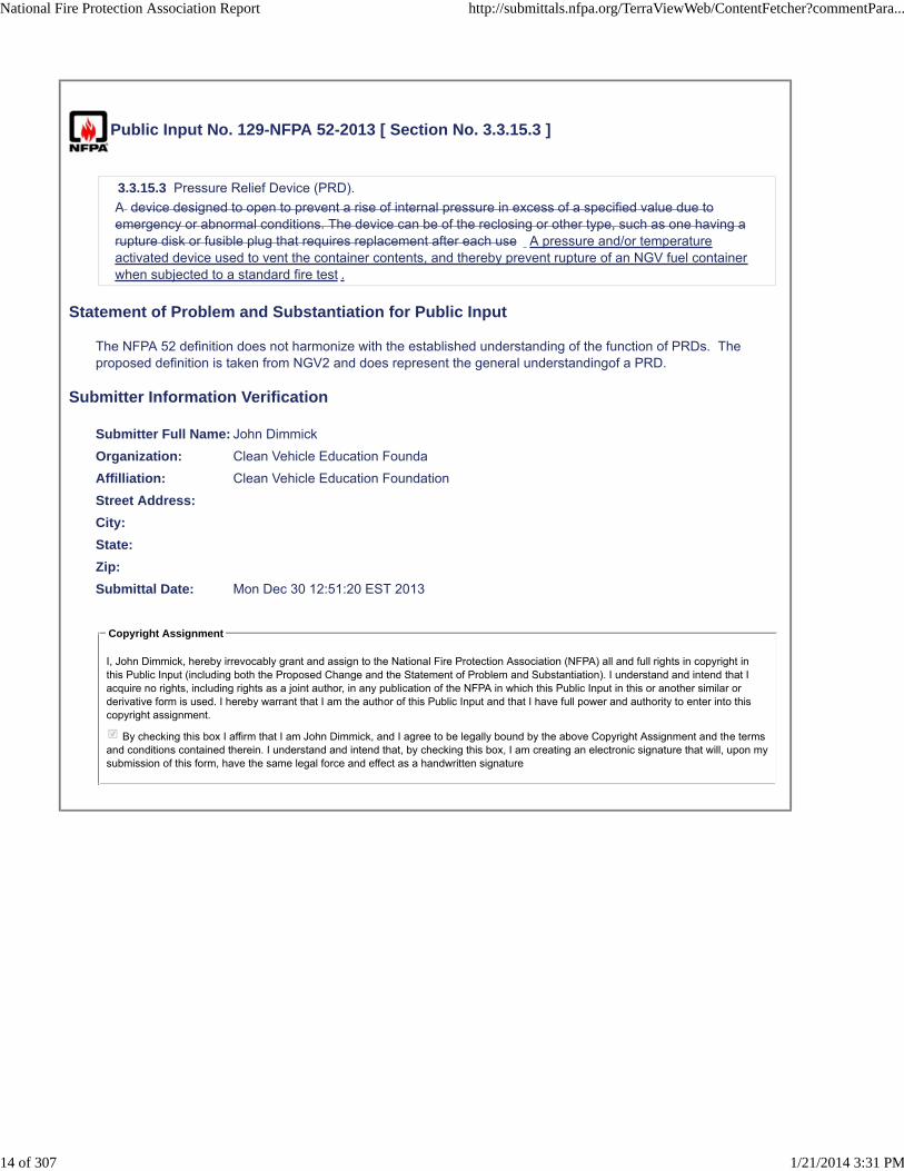
Public Input No. 129-NFPA 52-2013 [ Section No. 3.3.15.3 ]
3.3.15.3 Pressure Relief Device (PRD).
A device designed to open to prevent a rise of internal pressure in excess of a specified value due toemergency or abnormal conditions. The device can be of the reclosing or other type, such as one having arupture disk or fusible plug that requires replacement after each use A pressure and/or temperatureactivated device used to vent the container contents, and thereby prevent rupture of an NGV fuel containerwhen subjected to a standard fire test .
Statement of Problem and Substantiation for Public Input
The NFPA 52 definition does not harmonize with the established understanding of the function of PRDs. The proposed definition is taken from NGV2 and does represent the general understandingof a PRD.
Submitter Information Verification
Submitter Full Name: John Dimmick
Organization: Clean Vehicle Education Founda
Affilliation: Clean Vehicle Education Foundation
Street Address:
City:
State:
Zip:
Submittal Date: Mon Dec 30 12:51:20 EST 2013
Copyright Assignment
I, John Dimmick, hereby irrevocably grant and assign to the National Fire Protection Association (NFPA) all and full rights in copyright inthis Public Input (including both the Proposed Change and the Statement of Problem and Substantiation). I understand and intend that Iacquire no rights, including rights as a joint author, in any publication of the NFPA in which this Public Input in this or another similar orderivative form is used. I hereby warrant that I am the author of this Public Input and that I have full power and authority to enter into thiscopyright assignment.
By checking this box I affirm that I am John Dimmick, and I agree to be legally bound by the above Copyright Assignment and the termsand conditions contained therein. I understand and intend that, by checking this box, I am creating an electronic signature that will, upon mysubmission of this form, have the same legal force and effect as a handwritten signature
National Fire Protection Association Report http://submittals.nfpa.org/TerraViewWeb/ContentFetcher?commentPara...
14 of 307 1/21/2014 3:31 PM

Public Input No. 130-NFPA 52-2013 [ Section No. 3.3.18 ]
3.3.18 Dispensing Station.
A natural gas installation that dispenses CNG or LNG from storage containers or a distribution pipeline intovehicular fuel supply containers or into portable cylinders by cylinders or transportation vehicles bymeans of a compressor, reformer, vaporizer, or pressure booster.
Statement of Problem and Substantiation for Public Input
Stations are often used to fill trailers or trucks, not just individual cylinders, that are used to transport the natural gas.
Submitter Information Verification
Submitter Full Name: John Dimmick
Organization: Clean Vehicle Education Founda
Affilliation: Clean Vehicle Education Foundation
Street Address:
City:
State:
Zip:
Submittal Date: Mon Dec 30 12:55:26 EST 2013
Copyright Assignment
I, John Dimmick, hereby irrevocably grant and assign to the National Fire Protection Association (NFPA) all and full rights in copyright inthis Public Input (including both the Proposed Change and the Statement of Problem and Substantiation). I understand and intend that Iacquire no rights, including rights as a joint author, in any publication of the NFPA in which this Public Input in this or another similar orderivative form is used. I hereby warrant that I am the author of this Public Input and that I have full power and authority to enter into thiscopyright assignment.
By checking this box I affirm that I am John Dimmick, and I agree to be legally bound by the above Copyright Assignment and the termsand conditions contained therein. I understand and intend that, by checking this box, I am creating an electronic signature that will, upon mysubmission of this form, have the same legal force and effect as a handwritten signature
National Fire Protection Association Report http://submittals.nfpa.org/TerraViewWeb/ContentFetcher?commentPara...
15 of 307 1/21/2014 3:31 PM
Public Input No. 119-NFPA 52-2013 [ New Section after 3.3.19 ]
DOT Number
A number assigned by the U.S. DOT to a motor carrier and is required to be marked on all power units ofthe motor carrier in accordance with 49 CFR 390.21.
Statement of Problem and Substantiation for Public Input
The two revised sections on labeling, sections 6.11.3.2 and 9.12.8.4, introduce a new term, "U.S. DOT number", which needs to be defined.
Submitter Information Verification
Submitter Full Name: Quon Kwan
Organization: US Department of Transportation
Street Address:
City:
State:
Zip:
Submittal Date: Thu Dec 26 15:49:27 EST 2013
Copyright Assignment
I, Quon Kwan, hereby irrevocably grant and assign to the National Fire Protection Association (NFPA) all and full rights in copyright in thisPublic Input (including both the Proposed Change and the Statement of Problem and Substantiation). I understand and intend that I acquireno rights, including rights as a joint author, in any publication of the NFPA in which this Public Input in this or another similar or derivativeform is used. I hereby warrant that I am the author of this Public Input and that I have full power and authority to enter into this copyrightassignment.
By checking this box I affirm that I am Quon Kwan, and I agree to be legally bound by the above Copyright Assignment and the termsand conditions contained therein. I understand and intend that, by checking this box, I am creating an electronic signature that will, upon mysubmission of this form, have the same legal force and effect as a handwritten signature
National Fire Protection Association Report http://submittals.nfpa.org/TerraViewWeb/ContentFetcher?commentPara...
16 of 307 1/21/2014 3:31 PM

Public Input No. 128-NFPA 52-2013 [ Section No. 3.3.24 ]
3.3.24 Fuel Line.
The pipe, tubing, or hose on a vehicle, including all related fittings, through which natural gaspasses passes during normal vehicle fueling or operation .
Statement of Problem and Substantiation for Public Input
The additional words are to clarify the distinction that vent lines are not fuel lines and have different functions and requirements within the standard. Fuel passes through both but in much different situations
Submitter Information Verification
Submitter Full Name: John Dimmick
Organization: Clean Vehicle Education Founda
Affilliation: Clean Vehicle Education Foundation
Street Address:
City:
State:
Zip:
Submittal Date: Mon Dec 30 12:48:34 EST 2013
Copyright Assignment
I, John Dimmick, hereby irrevocably grant and assign to the National Fire Protection Association (NFPA) all and full rights in copyright inthis Public Input (including both the Proposed Change and the Statement of Problem and Substantiation). I understand and intend that Iacquire no rights, including rights as a joint author, in any publication of the NFPA in which this Public Input in this or another similar orderivative form is used. I hereby warrant that I am the author of this Public Input and that I have full power and authority to enter into thiscopyright assignment.
By checking this box I affirm that I am John Dimmick, and I agree to be legally bound by the above Copyright Assignment and the termsand conditions contained therein. I understand and intend that, by checking this box, I am creating an electronic signature that will, upon mysubmission of this form, have the same legal force and effect as a handwritten signature
National Fire Protection Association Report http://submittals.nfpa.org/TerraViewWeb/ContentFetcher?commentPara...
17 of 307 1/21/2014 3:31 PM

Public Input No. 131-NFPA 52-2013 [ Section No. 3.3.25 ]
3.3.25 Fueling Nozzle.
A mating device at the refueling station, including shutoff valves, that connects the fueling dispenser hoseto the vehicle fuel filling system receptacle for the transfer of gas, liquid or vapor.
Statement of Problem and Substantiation for Public Input
Liquid and vapor are terms normally associate with LNG but the definition also must apply to CNG which is properly considered a gas.
Submitter Information Verification
Submitter Full Name: John Dimmick
Organization: Clean Vehicle Education Founda
Affilliation: Clean Vehicle Education Foundation
Street Address:
City:
State:
Zip:
Submittal Date: Mon Dec 30 12:58:16 EST 2013
Copyright Assignment
I, John Dimmick, hereby irrevocably grant and assign to the National Fire Protection Association (NFPA) all and full rights in copyright inthis Public Input (including both the Proposed Change and the Statement of Problem and Substantiation). I understand and intend that Iacquire no rights, including rights as a joint author, in any publication of the NFPA in which this Public Input in this or another similar orderivative form is used. I hereby warrant that I am the author of this Public Input and that I have full power and authority to enter into thiscopyright assignment.
By checking this box I affirm that I am John Dimmick, and I agree to be legally bound by the above Copyright Assignment and the termsand conditions contained therein. I understand and intend that, by checking this box, I am creating an electronic signature that will, upon mysubmission of this form, have the same legal force and effect as a handwritten signature
National Fire Protection Association Report http://submittals.nfpa.org/TerraViewWeb/ContentFetcher?commentPara...
18 of 307 1/21/2014 3:31 PM

Public Input No. 132-NFPA 52-2013 [ Section No. 3.3.27 ]
3.3.27 Gaseous Fuels.
All combinations of gaseous natural gas, propane, ethane, and butane commonly used as automotive fuelsas they pertain to refueling sites, onboard fuel systems, safety, dispensing, and vehicle onboard useregardless of the fuel combinations.
Statement of Problem and Substantiation for Public Input
This definition is no longer needed since the scope of NFPA 52 was reduced to natural gas vehicles.
Submitter Information Verification
Submitter Full Name: John Dimmick
Organization: Clean Vehicle Education Founda
Affilliation: Clean Vehicle Education Foundation
Street Address:
City:
State:
Zip:
Submittal Date: Mon Dec 30 13:00:21 EST 2013
Copyright Assignment
I, John Dimmick, hereby irrevocably grant and assign to the National Fire Protection Association (NFPA) all and full rights in copyright inthis Public Input (including both the Proposed Change and the Statement of Problem and Substantiation). I understand and intend that Iacquire no rights, including rights as a joint author, in any publication of the NFPA in which this Public Input in this or another similar orderivative form is used. I hereby warrant that I am the author of this Public Input and that I have full power and authority to enter into thiscopyright assignment.
By checking this box I affirm that I am John Dimmick, and I agree to be legally bound by the above Copyright Assignment and the termsand conditions contained therein. I understand and intend that, by checking this box, I am creating an electronic signature that will, upon mysubmission of this form, have the same legal force and effect as a handwritten signature
National Fire Protection Association Report http://submittals.nfpa.org/TerraViewWeb/ContentFetcher?commentPara...
19 of 307 1/21/2014 3:31 PM

Public Input No. 133-NFPA 52-2013 [ Section No. 3.3.29 ]
3.3.29* Installation.
A system Complete system for preparing and dispensing either CNG or LNG, or complete vehicle fuelsystems for the operation of vehicles on natural gas that includes natural gas containers, pressure booster,compressors, vaporizers, and all attached valves, piping, and appurtenances.
Statement of Problem and Substantiation for Public Input
It should be clear that an installation includes the complete system and not just the listed components. The term is also used in respect to vehicles and must be more inclusive.
Submitter Information Verification
Submitter Full Name: John Dimmick
Organization: Clean Vehicle Education Founda
Affilliation: Clean Vehicle Education Foundation
Street Address:
City:
State:
Zip:
Submittal Date: Mon Dec 30 13:05:46 EST 2013
Copyright Assignment
I, John Dimmick, hereby irrevocably grant and assign to the National Fire Protection Association (NFPA) all and full rights in copyright inthis Public Input (including both the Proposed Change and the Statement of Problem and Substantiation). I understand and intend that Iacquire no rights, including rights as a joint author, in any publication of the NFPA in which this Public Input in this or another similar orderivative form is used. I hereby warrant that I am the author of this Public Input and that I have full power and authority to enter into thiscopyright assignment.
By checking this box I affirm that I am John Dimmick, and I agree to be legally bound by the above Copyright Assignment and the termsand conditions contained therein. I understand and intend that, by checking this box, I am creating an electronic signature that will, upon mysubmission of this form, have the same legal force and effect as a handwritten signature
National Fire Protection Association Report http://submittals.nfpa.org/TerraViewWeb/ContentFetcher?commentPara...
20 of 307 1/21/2014 3:31 PM

Public Input No. 102-NFPA 52-2013 [ New Section after 3.3.30 ]
Less than Class 3 vehicle
A less than Class 3 vehicle is a vehicle with a gross vehicle weight rating of 10,000 lbs. or less.
Statement of Problem and Substantiation for Public Input
The terms "Class 3 or higher vehicle" or "less than Class 3 vehicle" are introduced in the revised sections 6.11.3 and 9.12.8 on labeling and need to be defined. Note that these terms replace "Class 6 or higher vehicle" and "less than Class 6 vehicle" and these original terms were used but never defined.
Submitter Information Verification
Submitter Full Name: Quon Kwan
Organization: US Department of Transportation
Street Address:
City:
State:
Zip:
Submittal Date: Thu Dec 26 11:35:24 EST 2013
Copyright Assignment
I, Quon Kwan, hereby irrevocably grant and assign to the National Fire Protection Association (NFPA) all and full rights in copyright in thisPublic Input (including both the Proposed Change and the Statement of Problem and Substantiation). I understand and intend that I acquireno rights, including rights as a joint author, in any publication of the NFPA in which this Public Input in this or another similar or derivativeform is used. I hereby warrant that I am the author of this Public Input and that I have full power and authority to enter into this copyrightassignment.
By checking this box I affirm that I am Quon Kwan, and I agree to be legally bound by the above Copyright Assignment and the termsand conditions contained therein. I understand and intend that, by checking this box, I am creating an electronic signature that will, upon mysubmission of this form, have the same legal force and effect as a handwritten signature
National Fire Protection Association Report http://submittals.nfpa.org/TerraViewWeb/ContentFetcher?commentPara...
21 of 307 1/21/2014 3:31 PM

Public Input No. 36-NFPA 52-2013 [ New Section after 3.3.30 ]
L/CNGL/CNG is CNG formed by the vaporization of LNG followed by compression of the vapors. Often, manynatural gas fueling stations receive their natural gas via truck delivery of LNG and convert the LNG intoCNG for dispensing. This CNG is often not odorized.
Statement of Problem and Substantiation for Public Input
L/CNG is not defined and needs to be explained.
Submitter Information Verification
Submitter Full Name: Quon Kwan
Organization: US Department of Transportation
Street Address:
City:
State:
Zip:
Submittal Date: Tue Dec 17 08:53:01 EST 2013
Copyright Assignment
I, Quon Kwan, hereby irrevocably grant and assign to the National Fire Protection Association (NFPA) all and full rights in copyright in thisPublic Input (including both the Proposed Change and the Statement of Problem and Substantiation). I understand and intend that I acquireno rights, including rights as a joint author, in any publication of the NFPA in which this Public Input in this or another similar or derivativeform is used. I hereby warrant that I am the author of this Public Input and that I have full power and authority to enter into this copyrightassignment.
By checking this box I affirm that I am Quon Kwan, and I agree to be legally bound by the above Copyright Assignment and the termsand conditions contained therein. I understand and intend that, by checking this box, I am creating an electronic signature that will, upon mysubmission of this form, have the same legal force and effect as a handwritten signature
National Fire Protection Association Report http://submittals.nfpa.org/TerraViewWeb/ContentFetcher?commentPara...
22 of 307 1/21/2014 3:31 PM

Public Input No. 37-NFPA 52-2013 [ New Section after 3.3.30 ]
TITLE OF NEW CONTENT
Definition of L/CNG:
L/CNG is LNG that has been vaporized and compressed to make CNG. There are many natural gasfueling stations that receive their natural gas by truck delivery of LNG, convert the LNG into CNG, anddispense CNG at the pump. CNG made in this way is generally dispensed un-odorized or non-odorized.
Statement of Problem and Substantiation for Public Input
L/CNG has not been defined. A definition was added for clarification.
Submitter Information Verification
Submitter Full Name: Quon Kwan
Organization: US Department of Transportation
Street Address:
City:
State:
Zip:
Submittal Date: Tue Dec 17 09:42:36 EST 2013
Copyright Assignment
I, Quon Kwan, hereby irrevocably grant and assign to the National Fire Protection Association (NFPA) all and full rights in copyright in thisPublic Input (including both the Proposed Change and the Statement of Problem and Substantiation). I understand and intend that I acquireno rights, including rights as a joint author, in any publication of the NFPA in which this Public Input in this or another similar or derivativeform is used. I hereby warrant that I am the author of this Public Input and that I have full power and authority to enter into this copyrightassignment.
By checking this box I affirm that I am Quon Kwan, and I agree to be legally bound by the above Copyright Assignment and the termsand conditions contained therein. I understand and intend that, by checking this box, I am creating an electronic signature that will, upon mysubmission of this form, have the same legal force and effect as a handwritten signature
National Fire Protection Association Report http://submittals.nfpa.org/TerraViewWeb/ContentFetcher?commentPara...
23 of 307 1/21/2014 3:31 PM

Public Input No. 63-NFPA 52-2013 [ Section No. 3.3.32.2 ]
3.3.32.2 * Limited-Combustible Material.
See Section 5 4 .5.
Statement of Problem and Substantiation for Public Input
I believe this call out the wrong Section 5.5 when it should be 4.5 in the current 2013 document
Submitter Information Verification
Submitter Full Name: Ronald Cloyd
Organization: ANGI Energy Systems
Street Address:
City:
State:
Zip:
Submittal Date: Fri Dec 20 10:45:28 EST 2013
Copyright Assignment
I, Ronald Cloyd, hereby irrevocably grant and assign to the National Fire Protection Association (NFPA) all and full rights in copyright in thisPublic Input (including both the Proposed Change and the Statement of Problem and Substantiation). I understand and intend that I acquireno rights, including rights as a joint author, in any publication of the NFPA in which this Public Input in this or another similar or derivativeform is used. I hereby warrant that I am the author of this Public Input and that I have full power and authority to enter into this copyrightassignment.
By checking this box I affirm that I am Ronald Cloyd, and I agree to be legally bound by the above Copyright Assignment and the termsand conditions contained therein. I understand and intend that, by checking this box, I am creating an electronic signature that will, upon mysubmission of this form, have the same legal force and effect as a handwritten signature
National Fire Protection Association Report http://submittals.nfpa.org/TerraViewWeb/ContentFetcher?commentPara...
24 of 307 1/21/2014 3:31 PM

Public Input No. 64-NFPA 52-2013 [ Section No. 3.3.32.3 ]
3.3.32.3 Noncombustible Material.
See Section 5 4 .5.
Statement of Problem and Substantiation for Public Input
This definition calls out to see Section 5.5 when it should be 4.5
Submitter Information Verification
Submitter Full Name: Ronald Cloyd
Organization: ANGI Energy Systems
Street Address:
City:
State:
Zip:
Submittal Date: Fri Dec 20 10:51:41 EST 2013
Copyright Assignment
I, Ronald Cloyd, hereby irrevocably grant and assign to the National Fire Protection Association (NFPA) all and full rights in copyright in thisPublic Input (including both the Proposed Change and the Statement of Problem and Substantiation). I understand and intend that I acquireno rights, including rights as a joint author, in any publication of the NFPA in which this Public Input in this or another similar or derivativeform is used. I hereby warrant that I am the author of this Public Input and that I have full power and authority to enter into this copyrightassignment.
By checking this box I affirm that I am Ronald Cloyd, and I agree to be legally bound by the above Copyright Assignment and the termsand conditions contained therein. I understand and intend that, by checking this box, I am creating an electronic signature that will, upon mysubmission of this form, have the same legal force and effect as a handwritten signature
National Fire Protection Association Report http://submittals.nfpa.org/TerraViewWeb/ContentFetcher?commentPara...
25 of 307 1/21/2014 3:31 PM

Public Input No. 134-NFPA 52-2013 [ Section No. 3.3.33 ]
3.3.33 Maximum Filling Volume.
The maximum volume to which a liquid-containing vessel could shall be filled.
Statement of Problem and Substantiation for Public Input
Conformance with the maximum filling volume limit is fundamental to LNG system safety and should be referred to in mandatory language.
Submitter Information Verification
Submitter Full Name: John Dimmick
Organization: Clean Vehicle Education Founda
Affilliation: Clean Vehicle Education Foundation
Street Address:
City:
State:
Zip:
Submittal Date: Mon Dec 30 13:10:12 EST 2013
Copyright Assignment
I, John Dimmick, hereby irrevocably grant and assign to the National Fire Protection Association (NFPA) all and full rights in copyright inthis Public Input (including both the Proposed Change and the Statement of Problem and Substantiation). I understand and intend that Iacquire no rights, including rights as a joint author, in any publication of the NFPA in which this Public Input in this or another similar orderivative form is used. I hereby warrant that I am the author of this Public Input and that I have full power and authority to enter into thiscopyright assignment.
By checking this box I affirm that I am John Dimmick, and I agree to be legally bound by the above Copyright Assignment and the termsand conditions contained therein. I understand and intend that, by checking this box, I am creating an electronic signature that will, upon mysubmission of this form, have the same legal force and effect as a handwritten signature
National Fire Protection Association Report http://submittals.nfpa.org/TerraViewWeb/ContentFetcher?commentPara...
26 of 307 1/21/2014 3:31 PM

Public Input No. 135-NFPA 52-2013 [ Section No. 3.3.36.1 ]
3.3.36.1 Compressed Natural Gas (CNG).
Mixtures of hydrocarbon gases and vapors consisting principally of methane in gaseous form and meetingthe composition requirements of 6.2 that has been compressed for use as a vehicular fuel.
Statement of Problem and Substantiation for Public Input
It is necessary to define CNG as not just any natural gas but natural gas that has been conditioned to meet the composition requirements. Wherever the term is used it should imply the composition limits.
Submitter Information Verification
Submitter Full Name: John Dimmick
Organization: Clean Vehicle Education Founda
Affilliation: Clean Vehicle Education Foundation
Street Address:
City:
State:
Zip:
Submittal Date: Mon Dec 30 14:27:10 EST 2013
Copyright Assignment
I, John Dimmick, hereby irrevocably grant and assign to the National Fire Protection Association (NFPA) all and full rights in copyright inthis Public Input (including both the Proposed Change and the Statement of Problem and Substantiation). I understand and intend that Iacquire no rights, including rights as a joint author, in any publication of the NFPA in which this Public Input in this or another similar orderivative form is used. I hereby warrant that I am the author of this Public Input and that I have full power and authority to enter into thiscopyright assignment.
By checking this box I affirm that I am John Dimmick, and I agree to be legally bound by the above Copyright Assignment and the termsand conditions contained therein. I understand and intend that, by checking this box, I am creating an electronic signature that will, upon mysubmission of this form, have the same legal force and effect as a handwritten signature
National Fire Protection Association Report http://submittals.nfpa.org/TerraViewWeb/ContentFetcher?commentPara...
27 of 307 1/21/2014 3:31 PM
Public Input No. 136-NFPA 52-2013 [ Section No. 3.3.42 ]
3.3.42 Piping.
A means of transporting natural gas. This term applies to both vehicles and refueling facilities.
Statement of Problem and Substantiation for Public Input
The term piping is also used in Chapter 6 regarding vehicle fuel lines and vent lines.
Submitter Information Verification
Submitter Full Name: John Dimmick
Organization: Clean Vehicle Education Founda
Affilliation: Clean vVehicle Education Foundation
Street Address:
City:
State:
Zip:
Submittal Date: Mon Dec 30 14:30:48 EST 2013
Copyright Assignment
I, John Dimmick, hereby irrevocably grant and assign to the National Fire Protection Association (NFPA) all and full rights in copyright inthis Public Input (including both the Proposed Change and the Statement of Problem and Substantiation). I understand and intend that Iacquire no rights, including rights as a joint author, in any publication of the NFPA in which this Public Input in this or another similar orderivative form is used. I hereby warrant that I am the author of this Public Input and that I have full power and authority to enter into thiscopyright assignment.
By checking this box I affirm that I am John Dimmick, and I agree to be legally bound by the above Copyright Assignment and the termsand conditions contained therein. I understand and intend that, by checking this box, I am creating an electronic signature that will, upon mysubmission of this form, have the same legal force and effect as a handwritten signature
National Fire Protection Association Report http://submittals.nfpa.org/TerraViewWeb/ContentFetcher?commentPara...
28 of 307 1/21/2014 3:31 PM

Public Input No. 118-NFPA 52-2013 [ New Section after 3.3.43 ]
Power Unit
A power unit refers to a vehicle that contains the propulsion system. It can be a single-unit truck (alsocalled a straight truck) or a "bob-tail" tractor. In a combination vehicle, such as a tractor-trailer, the powerunit is the tractor.
.
Statement of Problem and Substantiation for Public Input
The two revised sections on labeling, sections 6.11.3.2 and 9.12.8.4, introduce a new term, "power unit", which needs to be defined.
Submitter Information Verification
Submitter Full Name: Quon Kwan
Organization: US Department of Transportation
Street Address:
City:
State:
Zip:
Submittal Date: Thu Dec 26 15:40:39 EST 2013
Copyright Assignment
I, Quon Kwan, hereby irrevocably grant and assign to the National Fire Protection Association (NFPA) all and full rights in copyright in thisPublic Input (including both the Proposed Change and the Statement of Problem and Substantiation). I understand and intend that I acquireno rights, including rights as a joint author, in any publication of the NFPA in which this Public Input in this or another similar or derivativeform is used. I hereby warrant that I am the author of this Public Input and that I have full power and authority to enter into this copyrightassignment.
By checking this box I affirm that I am Quon Kwan, and I agree to be legally bound by the above Copyright Assignment and the termsand conditions contained therein. I understand and intend that, by checking this box, I am creating an electronic signature that will, upon mysubmission of this form, have the same legal force and effect as a handwritten signature
National Fire Protection Association Report http://submittals.nfpa.org/TerraViewWeb/ContentFetcher?commentPara...
29 of 307 1/21/2014 3:31 PM

Public Input No. 137-NFPA 52-2013 [ Section No. 3.3.44.2 ]
3.3.44.2 Maximum Allowable Working Pressure (MAWP).
The maximum pressure to which any component or portion of the pressure system can be subjected overthe entire range of design temperatures . This value is 1.1 × 1.25 × the service pressure. and normaloperating conditions.
Statement of Problem and Substantiation for Public Input
The formula of 1.25 x Service Pressure was developed by SAE for fault management of fuel cell vehicles and has no relevance to natural gas vehicles. MAWP applies to normal operating conditions and not upset conditions such as fire exposure.
Submitter Information Verification
Submitter Full Name: John Dimmick
Organization: Clean Vehicle Education Founda
Affilliation: Clean Vehicle Education Foundation
Street Address:
City:
State:
Zip:
Submittal Date: Mon Dec 30 14:32:58 EST 2013
Copyright Assignment
I, John Dimmick, hereby irrevocably grant and assign to the National Fire Protection Association (NFPA) all and full rights in copyright inthis Public Input (including both the Proposed Change and the Statement of Problem and Substantiation). I understand and intend that Iacquire no rights, including rights as a joint author, in any publication of the NFPA in which this Public Input in this or another similar orderivative form is used. I hereby warrant that I am the author of this Public Input and that I have full power and authority to enter into thiscopyright assignment.
By checking this box I affirm that I am John Dimmick, and I agree to be legally bound by the above Copyright Assignment and the termsand conditions contained therein. I understand and intend that, by checking this box, I am creating an electronic signature that will, upon mysubmission of this form, have the same legal force and effect as a handwritten signature
National Fire Protection Association Report http://submittals.nfpa.org/TerraViewWeb/ContentFetcher?commentPara...
30 of 307 1/21/2014 3:31 PM

Public Input No. 138-NFPA 52-2013 [ Section No. 3.3.44.3.1 ]
3.3.44.3.1* Maximum Operating Pressure.
The maximum steady-state gauge pressure at which a part or system normally operates. This value is1.25 × the pressure.
Statement of Problem and Substantiation for Public Input
This is a maximum pressure. The incomplete formula of 1.25 time the pressure was relevant only to SAE fuel cell vehicles and their unique mault management provisions.
Submitter Information Verification
Submitter Full Name: John Dimmick
Organization: Clean Vehicle Education Founda
Affilliation: Clean Vehicle Education Foundation
Street Address:
City:
State:
Zip:
Submittal Date: Mon Dec 30 14:35:19 EST 2013
Copyright Assignment
I, John Dimmick, hereby irrevocably grant and assign to the National Fire Protection Association (NFPA) all and full rights in copyright inthis Public Input (including both the Proposed Change and the Statement of Problem and Substantiation). I understand and intend that Iacquire no rights, including rights as a joint author, in any publication of the NFPA in which this Public Input in this or another similar orderivative form is used. I hereby warrant that I am the author of this Public Input and that I have full power and authority to enter into thiscopyright assignment.
By checking this box I affirm that I am John Dimmick, and I agree to be legally bound by the above Copyright Assignment and the termsand conditions contained therein. I understand and intend that, by checking this box, I am creating an electronic signature that will, upon mysubmission of this form, have the same legal force and effect as a handwritten signature
National Fire Protection Association Report http://submittals.nfpa.org/TerraViewWeb/ContentFetcher?commentPara...
31 of 307 1/21/2014 3:31 PM

Public Input No. 139-NFPA 52-2013 [ Section No. 3.3.44.4 ]
3.3.44.4 Service Pressure.
The settled gas pressure at a uniform gas temperature of 70°F (21°C) in CNG systems when theequipment is cylinders are fully charged with gas.
Statement of Problem and Substantiation for Public Input
The definition is relevant only to the charged state of CNG cylinders and no other equipment. Service Pressure can also be used to in reference to DOT 4L LNG containers but these do not fall within the NFPA definition of cylinders.
Submitter Information Verification
Submitter Full Name: John Dimmick
Organization: Clean Vehicle Education Founda
Affilliation: Clean Vehicle Education Foundation
Street Address:
City:
State:
Zip:
Submittal Date: Mon Dec 30 14:37:42 EST 2013
Copyright Assignment
I, John Dimmick, hereby irrevocably grant and assign to the National Fire Protection Association (NFPA) all and full rights in copyright inthis Public Input (including both the Proposed Change and the Statement of Problem and Substantiation). I understand and intend that Iacquire no rights, including rights as a joint author, in any publication of the NFPA in which this Public Input in this or another similar orderivative form is used. I hereby warrant that I am the author of this Public Input and that I have full power and authority to enter into thiscopyright assignment.
By checking this box I affirm that I am John Dimmick, and I agree to be legally bound by the above Copyright Assignment and the termsand conditions contained therein. I understand and intend that, by checking this box, I am creating an electronic signature that will, upon mysubmission of this form, have the same legal force and effect as a handwritten signature
National Fire Protection Association Report http://submittals.nfpa.org/TerraViewWeb/ContentFetcher?commentPara...
32 of 307 1/21/2014 3:31 PM

Public Input No. 140-NFPA 52-2013 [ Section No. 3.3.44.6 ]
3.3.44.6 Settled Pressure.
The pressure in a container after the temperature of the gas reaches equilibrium.
Statement of Problem and Substantiation for Public Input
This definition is not needed. The definition of service pressure is adequate without this additional definition.
Submitter Information Verification
Submitter Full Name: John Dimmick
Organization: Clean Vehicle Education Founda
Affilliation: Clean Vehicle Education Foundation
Street Address:
City:
State:
Zip:
Submittal Date: Mon Dec 30 14:39:38 EST 2013
Copyright Assignment
I, John Dimmick, hereby irrevocably grant and assign to the National Fire Protection Association (NFPA) all and full rights in copyright inthis Public Input (including both the Proposed Change and the Statement of Problem and Substantiation). I understand and intend that Iacquire no rights, including rights as a joint author, in any publication of the NFPA in which this Public Input in this or another similar orderivative form is used. I hereby warrant that I am the author of this Public Input and that I have full power and authority to enter into thiscopyright assignment.
By checking this box I affirm that I am John Dimmick, and I agree to be legally bound by the above Copyright Assignment and the termsand conditions contained therein. I understand and intend that, by checking this box, I am creating an electronic signature that will, upon mysubmission of this form, have the same legal force and effect as a handwritten signature
National Fire Protection Association Report http://submittals.nfpa.org/TerraViewWeb/ContentFetcher?commentPara...
33 of 307 1/21/2014 3:31 PM

Public Input No. 141-NFPA 52-2013 [ Section No. 3.3.47 ]
3.3.47 Pressure Vessel.
A container or other component designed in accordance with the ASME Boiler and Pressure Vessel Codeor CSA B51, Boiler, Pressure Vessel and Pressure Piping Code .
Statement of Problem and Substantiation for Public Input
CSA B51 is appropriate for CSA standards B108 and B109 in Canada but not for NFPA 52 in the US. B108 and B 109 are the Canadian equivalent of NFPA 52.
Submitter Information Verification
Submitter Full Name: John Dimmick
Organization: Clean Vehicle Education Founda
Affilliation: Clean Vehicle Education Foundation
Street Address:
City:
State:
Zip:
Submittal Date: Mon Dec 30 15:05:12 EST 2013
Copyright Assignment
I, John Dimmick, hereby irrevocably grant and assign to the National Fire Protection Association (NFPA) all and full rights in copyright inthis Public Input (including both the Proposed Change and the Statement of Problem and Substantiation). I understand and intend that Iacquire no rights, including rights as a joint author, in any publication of the NFPA in which this Public Input in this or another similar orderivative form is used. I hereby warrant that I am the author of this Public Input and that I have full power and authority to enter into thiscopyright assignment.
By checking this box I affirm that I am John Dimmick, and I agree to be legally bound by the above Copyright Assignment and the termsand conditions contained therein. I understand and intend that, by checking this box, I am creating an electronic signature that will, upon mysubmission of this form, have the same legal force and effect as a handwritten signature
National Fire Protection Association Report http://submittals.nfpa.org/TerraViewWeb/ContentFetcher?commentPara...
34 of 307 1/21/2014 3:31 PM

Public Input No. 59-NFPA 52-2013 [ Section No. 3.3.49 ]
3.3.49 Residential CNG Fueling Facility (RFF-CNG).
An assembly with a capacity not exceeding 5 scf/min (0.14 SCM/min) of natural gas, that can be used forfueling a vehicle at a home or residence. Residential Fueling Appliance (RFA). A type of Vehicle Fueling Appliance (VFA, ref. 3.3.61), designed,listed, delivered and intended to be installed as one system primarily intended for residential (home) use.
Statement of Problem and Substantiation for Public Input
This proposal is part of a series of proposals which will harmonize NFPA 52 with the new NGV 5.1 standard for residential fueling appliances. This term is required to replace the current term "Residential Fueling Facility (RFF-CNG)" because NGV 5.1 will refer to these appliances as “Residential Fueling Appliance (RFA)” and the term RFA is intended as a global change througout NFPA 52 to replace current terminology of "RFF_CNG".
Submitter Information Verification
Submitter Full Name: JULIE CAIRNS
Organization: CSA GROUP
Affilliation: CSA Group NGV 5.1 Home Fueling Appliance Technical Subcommittee
Street Address:
City:
State:
Zip:
Submittal Date: Fri Dec 20 10:16:34 EST 2013
Copyright Assignment
I, JULIE CAIRNS, hereby irrevocably grant and assign to the National Fire Protection Association (NFPA) all and full rights in copyright inthis Public Input (including both the Proposed Change and the Statement of Problem and Substantiation). I understand and intend that Iacquire no rights, including rights as a joint author, in any publication of the NFPA in which this Public Input in this or another similar orderivative form is used. I hereby warrant that I am the author of this Public Input and that I have full power and authority to enter into thiscopyright assignment.
By checking this box I affirm that I am JULIE CAIRNS, and I agree to be legally bound by the above Copyright Assignment and theterms and conditions contained therein. I understand and intend that, by checking this box, I am creating an electronic signature that will,upon my submission of this form, have the same legal force and effect as a handwritten signature
National Fire Protection Association Report http://submittals.nfpa.org/TerraViewWeb/ContentFetcher?commentPara...
35 of 307 1/21/2014 3:31 PM

Public Input No. 142-NFPA 52-2013 [ Section No. 3.3.53.2 ]
3.3.53.2 Fuel Dispenser System.
All the pumps, meters, piping, hose, and The complete system, including controls used for the delivery offuel, either CNG or LNG to, and the removal of vapor from, a vehicle.
Statement of Problem and Substantiation for Public Input
The definition as written is not inclusive of the complete dispenser system and is not inclusive of CNG dispensers
Submitter Information Verification
Submitter Full Name: John Dimmick
Organization: Clean Vehicle Education Founda
Affilliation: Clean Vehicle Education Foundation
Street Address:
City:
State:
Zip:
Submittal Date: Mon Dec 30 15:07:38 EST 2013
Copyright Assignment
I, John Dimmick, hereby irrevocably grant and assign to the National Fire Protection Association (NFPA) all and full rights in copyright inthis Public Input (including both the Proposed Change and the Statement of Problem and Substantiation). I understand and intend that Iacquire no rights, including rights as a joint author, in any publication of the NFPA in which this Public Input in this or another similar orderivative form is used. I hereby warrant that I am the author of this Public Input and that I have full power and authority to enter into thiscopyright assignment.
By checking this box I affirm that I am John Dimmick, and I agree to be legally bound by the above Copyright Assignment and the termsand conditions contained therein. I understand and intend that, by checking this box, I am creating an electronic signature that will, upon mysubmission of this form, have the same legal force and effect as a handwritten signature
National Fire Protection Association Report http://submittals.nfpa.org/TerraViewWeb/ContentFetcher?commentPara...
36 of 307 1/21/2014 3:31 PM
Public Input No. 143-NFPA 52-2013 [ Section No. 3.3.56 ]
3.3.56 Temperature Compensation.
A process that allows the gauge pressure in a container at the actual present gas temperature to becalculated so that the quantity of gas contained is the same as will be in the container at a specified settledservice pressure at a specified uniform temperature of 21C (70F) .
Statement of Problem and Substantiation for Public Input
The existing definition is less clear because the reference temperature for hydrogen was 15C and not the same as CNG at 21C. This clearer definition is possible with the removal of hydrogen from the standard.
Submitter Information Verification
Submitter Full Name: John Dimmick
Organization: Clean Vehicle Education Founda
Affilliation: Clean Vehicle Education Foundation
Street Address:
City:
State:
Zip:
Submittal Date: Mon Dec 30 15:11:00 EST 2013
Copyright Assignment
I, John Dimmick, hereby irrevocably grant and assign to the National Fire Protection Association (NFPA) all and full rights in copyright inthis Public Input (including both the Proposed Change and the Statement of Problem and Substantiation). I understand and intend that Iacquire no rights, including rights as a joint author, in any publication of the NFPA in which this Public Input in this or another similar orderivative form is used. I hereby warrant that I am the author of this Public Input and that I have full power and authority to enter into thiscopyright assignment.
By checking this box I affirm that I am John Dimmick, and I agree to be legally bound by the above Copyright Assignment and the termsand conditions contained therein. I understand and intend that, by checking this box, I am creating an electronic signature that will, upon mysubmission of this form, have the same legal force and effect as a handwritten signature
National Fire Protection Association Report http://submittals.nfpa.org/TerraViewWeb/ContentFetcher?commentPara...
37 of 307 1/21/2014 3:31 PM
Public Input No. 60-NFPA 52-2013 [ Section No. 3.3.61 ]
3.3.61 Vehicle Fueling Appliance (VFA).
A listed, self-contained system that compresses natural gas and dispenses the natural gas to a vehicle'sengine fueling system.
Statement of Problem and Substantiation for Public Input
This proposal is part of a Series of proposals which will harmonize NFPA 52 with the new NGV 5.1 standard for residential fueling appliances.
Removed term “self-contained” to allow for systems to be installed with alternate dispensers. “Self-contained” still applies to RFA, but a VFA used in non-residential installation may be allowed with separate dispensing unit.
Submitter Information Verification
Submitter Full Name: JULIE CAIRNS
Organization: CSA GROUP
Affilliation: CSA Group NGV 5.1 Home Fueling Appliance Technical Subcommittee
Street Address:
City:
State:
Zip:
Submittal Date: Fri Dec 20 10:17:37 EST 2013
Copyright Assignment
I, JULIE CAIRNS, hereby irrevocably grant and assign to the National Fire Protection Association (NFPA) all and full rights in copyright inthis Public Input (including both the Proposed Change and the Statement of Problem and Substantiation). I understand and intend that Iacquire no rights, including rights as a joint author, in any publication of the NFPA in which this Public Input in this or another similar orderivative form is used. I hereby warrant that I am the author of this Public Input and that I have full power and authority to enter into thiscopyright assignment.
By checking this box I affirm that I am JULIE CAIRNS, and I agree to be legally bound by the above Copyright Assignment and theterms and conditions contained therein. I understand and intend that, by checking this box, I am creating an electronic signature that will,upon my submission of this form, have the same legal force and effect as a handwritten signature
National Fire Protection Association Report http://submittals.nfpa.org/TerraViewWeb/ContentFetcher?commentPara...
38 of 307 1/21/2014 3:31 PM

Public Input No. 144-NFPA 52-2013 [ Section No. 3.3.62 ]
3.3.62 Vehicular Fuel.
Fuel stored on board a vehicle , primarily for powering vehicle systems .
Statement of Problem and Substantiation for Public Input
This change is necessary to distinguish vehicular fuel from fuel stored onboard for transportation. The transportation of natural gas is regulated by DOT PHMSA which does not allow many of the practices allowed for vehicle fuels.
Submitter Information Verification
Submitter Full Name: John Dimmick
Organization: Clean Vehicle Education Founda
Affilliation: Clean Vehicle Education Foundation
Street Address:
City:
State:
Zip:
Submittal Date: Mon Dec 30 15:15:27 EST 2013
Copyright Assignment
I, John Dimmick, hereby irrevocably grant and assign to the National Fire Protection Association (NFPA) all and full rights in copyright inthis Public Input (including both the Proposed Change and the Statement of Problem and Substantiation). I understand and intend that Iacquire no rights, including rights as a joint author, in any publication of the NFPA in which this Public Input in this or another similar orderivative form is used. I hereby warrant that I am the author of this Public Input and that I have full power and authority to enter into thiscopyright assignment.
By checking this box I affirm that I am John Dimmick, and I agree to be legally bound by the above Copyright Assignment and the termsand conditions contained therein. I understand and intend that, by checking this box, I am creating an electronic signature that will, upon mysubmission of this form, have the same legal force and effect as a handwritten signature
National Fire Protection Association Report http://submittals.nfpa.org/TerraViewWeb/ContentFetcher?commentPara...
39 of 307 1/21/2014 3:31 PM

Public Input No. 104-NFPA 52-2013 [ Chapter 4 ]
Chapter 4 General Fueling Station Requirements
4.1 Installer Qualifications.
Designers, fabricators, and constructors of LNG fueling facilities shall be competent and have expertise inthe design, fabrication, and construction of LNG containers, cryogenic equipment, loading and unloadingsystems, fire protection equipment, detection, siting, containment, piping systems, and other components ofthe facility.
4.2 Installation Supervision.
The installation of LNG and CNG systems shall be supervised by qualified personnel with reference to theirconstruction and use.
4.3 Alternate Design.
LNG, L/CNG, CNG, and other gaseous/cryogenic installations shall be permitted to use alternate sitedistances, operating requirements, and equipment locations with validation by qualified engineer(s) withproven expertise in mechanical systems, electrical systems, gaseous storage systems, cryogenic storagesystems, fire protection, and gas detection.
4.4 Installation Validation.
The refueling station and associated storage equipment shall be validated per the specifics of 4.4.1 whena change is made to the fundamental design, or not less than every 4 years.
4.4.1
The validation shall at a minimum include the following:
(1) Process safety analysis and hazard and operability studies (HAZOPS)
(2) Mitigating fire protection measures such as suppression systems
(3) Aboveground or belowground systems or vaults for the containers
(4) Fire and gas detection systems designed to interface with an emergency shutdown device (ESD)
(5) Ventilation and other facility features
(6) Drainage and impounding for the individual site as administered by qualified engineer(s) with provenexpertise in these fields
4.4.1.1
Validation shall be kept on site and provided to the AHJ upon request.
4.5 * Building Construction Materials.
4.5.1 * Noncombustible Material.
A material that complies with any of the following shall be considered a noncombustible material:[101:4.6.13.1]
(1)
(2) A material that is reported as passing ASTM E 136, Standard Test Method for Behavior of Materials ina Vertical Tube Furnace at 750° C. [101:4.6.13.1(2)]
(3) A material that is reported as complying with the pass/fail criteria of ASTM E 136 when tested inaccordance with the test method and procedure in ASTM E 2652, Standard Test Method for Behaviorof Materials in a Tube Furnace with a Cone-shaped Airflow Stabilizer, at 750 Degrees C. [101:4.6.13.1(3)]
4.5.2 * Limited-Combustible Material.
A material shall be considered a limited-combustible material where all the conditions of 4.5.2.1 and4.5.2.2, and the conditions of either 4.5.2.3 or 4.5.2.4, are met. [101:4.6.14.2]
4.5.2.1
The material shall not comply with the requirements for noncombustible material, in accordance with 4.5.1.[101:4.6.14.2.1]
* A material that, in the form in which it is used and under the conditions anticipated, will not ignite,burn, support combustion, or release flammable vapors, when subjected to fire or heat.[101:4.6.13.1(1)]
National Fire Protection Association Report http://submittals.nfpa.org/TerraViewWeb/ContentFetcher?commentPara...
40 of 307 1/21/2014 3:31 PM

4.5.2.2
The material, in the form in which it is used, shall exhibit a potential heat value not exceeding 3500 Btu/lb(8141 kJ/kg), where tested in accordance with NFPA 259, Standard Test Method for Potential Heat ofBuilding Materials. [101:4.6.14.2]
4.5.2.3
The material shall have the structural base of a noncombustible material with a surfacing not exceeding athickness of 1⁄8 in. (3.2 mm) where the surfacing exhibits a flame spread index not greater than 50 whentested in accordance with ASTM E 84, Standard Test Method for Surface Burning Characteristics ofBuilding Materials, or ANSI/UL 723, Standard for Test for Surface Burning Characteristics of BuildingMaterials. [101:4.6.14.3]
4.5.2.4
The material shall be composed of materials that, in the form and thickness used, exhibit neither a flamespread index greater than 25 nor evidence of continued progressive combustion when tested in accordancewith ASTM E 84 or ANSI/UL 723, and shall be of such composition that all surfaces that would be exposedby cutting through the material on any plane would exhibit neither a flame spread index greater than 25 norexhibit evidence of continued progressive combustion when tested in accordance with ASTM E 84 orANSI/UL 723. [101:4.6.14.4]
4.5.2.5
Where the term limited-combustible is used in this code, it shall also include the term noncombustible.[101:4.6.14.5]
Replace Chapter 4 with the attached Chapter 4 Facilities developed by a NFPA 52 Task Group
Additional Proposed Changes
File Name Description Approved
NFPA_52_Public_Input_Chapter_4_Facilities.docx NFPA 52 Chapter 4 Facilities
Statement of Problem and Substantiation for Public Input
The NFPA 52 Technical Committee approved the reorganization of NFPA 52 into an organizational layout that restructured requirements into General Requirements, Fuel Specific Requirements and Use Specific Requirements. This Chapter replaces existing Chapter 4 and was developed by a Task Group. For this draft being submitted as a Public Input, existing code sections have only been reorganized. No new or revised language has been included or any requirements deleted.
Submitter Information Verification
Submitter Full Name: Nancy Pehrson
Organization: CenterPoint Energy, Inc.
Street Address:
City:
State:
Zip:
Submittal Date: Thu Dec 26 12:49:05 EST 2013
Copyright Assignment
I, Nancy Pehrson, hereby irrevocably grant and assign to the National Fire Protection Association (NFPA) all and full rights in copyright inthis Public Input (including both the Proposed Change and the Statement of Problem and Substantiation). I understand and intend that Iacquire no rights, including rights as a joint author, in any publication of the NFPA in which this Public Input in this or another similar orderivative form is used. I hereby warrant that I am the author of this Public Input and that I have full power and authority to enter into thiscopyright assignment.
By checking this box I affirm that I am Nancy Pehrson, and I agree to be legally bound by the above Copyright Assignment and theterms and conditions contained therein. I understand and intend that, by checking this box, I am creating an electronic signature that will,upon my submission of this form, have the same legal force and effect as a handwritten signature
National Fire Protection Association Report http://submittals.nfpa.org/TerraViewWeb/ContentFetcher?commentPara...
41 of 307 1/21/2014 3:31 PM

Chapter 4 Facilities
4. Facilities 4.1 General 4.1.1 Application (reserved)
4.1.2 Buildings or structures (7.4.3.1 General.)Compression, dispensing equipment, and storage containers connected for use shall be permitted to be located inside of buildings reserved exclusively for these purposes or in rooms within or attached to buildings used for other purposes in accordance with this section.
4.1.2.1 (7.4.3.4) Rooms Within Buildings.
4.1.2.1.1 (7.4.3.4.1) Rooms within or attached to other buildings shall be constructed of noncombustible or limited-combustible materials.
4.1.2.1.2 (7.4.3.4.1.1) Window glazing shall be permitted to be plastic.
4.1.2.1.3 (7.4.3.4.2) Interior walls or partitions shall be continuous from floor to ceiling, be anchored in accordance with the requirements of the building code, and have a fire resistance rating of at least 2 hours.
4.1.2.1.4 (7.4.3.4.3) At least one wall shall be an exterior wall.
4.1.2.1.5 (7.4.3.4.4) Explosion venting shall be provided in accordance with ( 7.4.3.3. will revise)
4.1.2.1.6 (7.4.3.4.5) Access to the room shall be from outside the primary structure. 4.1.2.1.7 (7.4.3.4.6) If access to the room from outside the primary structure is not possible, access from within the primary structure shall be permitted where such access is made through a barrier space having two vapor-sealing, self-closing fire doors rated for the location where installed.
4.1.2.2 (10.2.4.1 Building Construction.)
4.1.2.2.1 (10.2.4.1.1) Buildings reserved exclusively for an LNG fueling facility shall be of Type I or Type II construction in accordance with NFPA 5000, Building Construction and Safety Code.
4.1.2.2.2 (10.2.4.1.2) Windows and doors shall be located so as to permit ready egress in case of emergency.
4.5* Building Construction Materials.
Commented [BS1]: Add language for new section as PI
Commented [BS2]: Will be renumbered by editorial. Should be in Chapter 4
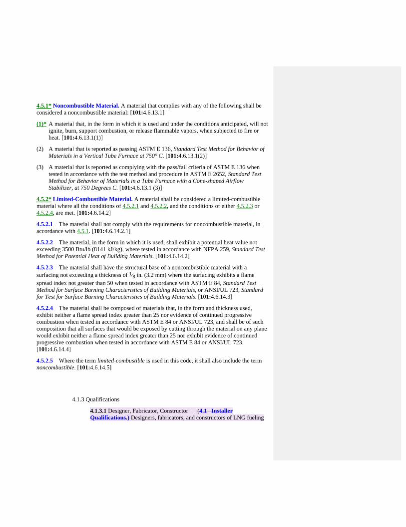
4.5.1* Noncombustible Material. A material that complies with any of the following shall be considered a noncombustible material: [101:4.6.13.1]
(1)* A material that, in the form in which it is used and under the conditions anticipated, will not ignite, burn, support combustion, or release flammable vapors, when subjected to fire or heat. [101:4.6.13.1(1)]
(2) A material that is reported as passing ASTM E 136, Standard Test Method for Behavior of Materials in a Vertical Tube Furnace at 750° C. [101:4.6.13.1(2)]
(3) A material that is reported as complying with the pass/fail criteria of ASTM E 136 when tested in accordance with the test method and procedure in ASTM E 2652, Standard Test Method for Behavior of Materials in a Tube Furnace with a Cone-shaped Airflow Stabilizer, at 750 Degrees C. [101:4.6.13.1 (3)]
4.5.2* Limited-Combustible Material. A material shall be considered a limited-combustible material where all the conditions of 4.5.2.1 and 4.5.2.2, and the conditions of either 4.5.2.3 or 4.5.2.4, are met. [101:4.6.14.2]
4.5.2.1 The material shall not comply with the requirements for noncombustible material, in accordance with 4.5.1. [101:4.6.14.2.1]
4.5.2.2 The material, in the form in which it is used, shall exhibit a potential heat value not exceeding 3500 Btu/lb (8141 kJ/kg), where tested in accordance with NFPA 259, Standard Test Method for Potential Heat of Building Materials. [101:4.6.14.2]
4.5.2.3 The material shall have the structural base of a noncombustible material with a surfacing not exceeding a thickness of 1⁄8 in. (3.2 mm) where the surfacing exhibits a flame spread index not greater than 50 when tested in accordance with ASTM E 84, Standard Test Method for Surface Burning Characteristics of Building Materials, or ANSI/UL 723, Standard for Test for Surface Burning Characteristics of Building Materials. [101:4.6.14.3]
4.5.2.4 The material shall be composed of materials that, in the form and thickness used, exhibit neither a flame spread index greater than 25 nor evidence of continued progressive combustion when tested in accordance with ASTM E 84 or ANSI/UL 723, and shall be of such composition that all surfaces that would be exposed by cutting through the material on any plane would exhibit neither a flame spread index greater than 25 nor exhibit evidence of continued progressive combustion when tested in accordance with ASTM E 84 or ANSI/UL 723. [101:4.6.14.4]
4.5.2.5 Where the term limited-combustible is used in this code, it shall also include the term noncombustible. [101:4.6.14.5]
4.1.3 Qualifications
4.1.3.1 Designer, Fabricator, Constructor (4.1 Installer Qualifications.) Designers, fabricators, and constructors of LNG fueling

facilities shall be competent and have expertise in the design, fabrication, and construction of LNG containers, cryogenic equipment, loading and unloading systems, fire protection equipment, detection, siting, containment, piping systems, and other components of the facility.
4.1.3.2 Construction supervision (4.2 Installation Supervision.) The installation of LNG and CNG systems shall be supervised by qualified personnel with reference to their construction and use.
4.1.4 Plan submittal ( reserved) 4.1.4.1 Plan Requirements
4.1.4.2 Approvals 4.1.5 Permits ( reserved) 4.1.6 Documentation requirement(reserved)
4.1.6.1 General 4.1.6.2 Technical References and Resources 4.1.6.3 Facility Design Specifications 4.1.6.4 Performance Criteria 4.1.6.5 Modeling Features
4.1.6.5.1 Modeler Capability .1.6.5.2 Performance Evaluation
4.1.7 Certification
4.1.7.1 (5.3 System Approvals.)
4.1.7.1.1 (5.3.1*) The following systems and system components shall be listed or approved:
(1) Pressure relief devices, including pressure relief valves
(2) Pressure gauges
(3) Pressure regulators
(4) Valves
(5) Hose and hose connections
(6) Vehicle fueling connections (nozzle and receptacle)
(7) Engine fuel systems
(8) Electrical equipment related to CNG systems
(9) Gas detection equipment and alarms
(10) Fire protection and suppression equipment
(11) Vehicle fueling appliances (VFAs)
Commented [L3]: CNG? Anywhere?
Commented [BS4]: Add language to original section as PI to add CNG here.
Commented [BS5]: This will need to be looked at again with respect to what needs to be included in the general facilities chapter.

4.1.7.1.2 (5.3.1.1) Vehicles certified by the manufacturer to be in compliance with applicable federal motor vehicle safety standards shall not be subject to( 5.3.1.) Now 4.1.7.1.1 4.1.7.2 (5.3.2) Devices not otherwise specifically provided for shall be constructed to provide safety equivalent to that required for other parts of a system.
4.1.8 Equipment Security
4.1.8.1 (7.3.2) Equipment related to a compression, storage, or dispensing installation shall be protected to prevent damage from vehicles and minimize the possibilities of physical damage and vandalism.
4.4.8.2 (10.2.1.2) (LNG) Storage and transfer equipment at unattended facilities shall be secured to prevent tampering.
4.4.8.3 (12.5.1) The LNG fueling facility shall provide protection to minimize unauthorized access and damage to the facility.
4.1.9 Operations and Maintenance 4.1.10.1 Programs and Activities
4.1.10.1.1 (7.16* ) System Maintenance.
4.1.10.1.1.1 (7.16.1) Containers and their appurtenances, piping systems, compression equipment, controls, and detection devices shall be maintained in safe operating condition and according to manufacturers' instructions.
4.1.10.1.1.2 (7.16.2) Written instructions shall be provided for CNG dispensing systems to include the following:
(1) Operating instructions
(2) Emergency shutdown instructions
(3) Maintenance and repair instructions
(4) Instructions for pressure and temperature calibrations and functional checks to assure that the dispenser continues to satisfy the requirements of Section 7.14 New section number
4.1.10.1.1.3 (7.16.3) Dispensing systems shall be maintained in accordance with the instructions required in 7.16.2 4.1.10.1.1.2 to verify pressure control and pressure relief valves.
4.1.10.1.2 (7.16.4) Hose Assemblies. After the original installation, vehicle fueling hoses shall be examined visually according to the manufacturers' recommendations or at least monthly to ensure that they are safe for use.
Commented [L6]: Exclusive to LNG?
Commented [BS7]: Needs to include CNG as well. PI to be submitted.
Commented [L8]: 9 on down
Commented [BS9]: Will be renumber in final draft
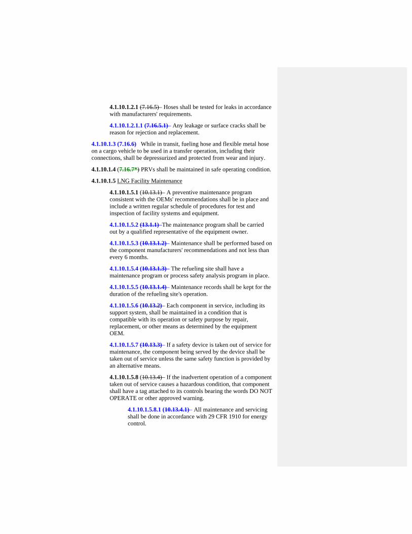
4.1.10.1.2.1 (7.16.5) Hoses shall be tested for leaks in accordance with manufacturers' requirements.
4.1.10.1.2.1.1 (7.16.5.1) Any leakage or surface cracks shall be reason for rejection and replacement.
4.1.10.1.3 (7.16.6) While in transit, fueling hose and flexible metal hose on a cargo vehicle to be used in a transfer operation, including their connections, shall be depressurized and protected from wear and injury.
4.1.10.1.4 (7.16.7*) PRVs shall be maintained in safe operating condition.
4.1.10.1.5 LNG Facility Maintenance
4.1.10.1.5.1 (10.13.1) A preventive maintenance program consistent with the OEMs' recommendations shall be in place and include a written regular schedule of procedures for test and inspection of facility systems and equipment.
4.1.10.1.5.2 (13.1.1) The maintenance program shall be carried out by a qualified representative of the equipment owner.
4.1.10.1.5.3 (10.13.1.2) Maintenance shall be performed based on the component manufacturers' recommendations and not less than every 6 months.
4.1.10.1.5.4 (10.13.1.3) The refueling site shall have a maintenance program or process safety analysis program in place.
4.1.10.1.5.5 (10.13.1.4) Maintenance records shall be kept for the duration of the refueling site's operation.
4.1.10.1.5.6 (10.13.2) Each component in service, including its support system, shall be maintained in a condition that is compatible with its operation or safety purpose by repair, replacement, or other means as determined by the equipment OEM.
4.1.10.1.5.7 (10.13.3) If a safety device is taken out of service for maintenance, the component being served by the device shall be taken out of service unless the same safety function is provided by an alternative means.
4.1.10.1.5.8 (10.13.4) If the inadvertent operation of a component taken out of service causes a hazardous condition, that component shall have a tag attached to its controls bearing the words DO NOT OPERATE or other approved warning.
4.1.10.1.5.8.1 (10.13.4.1) All maintenance and servicing shall be done in accordance with 29 CFR 1910 for energy control.

4.1.10.1.5.9 (10.13.5) LNG fueling facilities shall be free from rubbish, debris, and other material that present a fire hazard to a distance of at least 25 ft (7.6 m).
4.1.10.1.5.10 (10.13.6) Grass areas on the LNG fueling facility grounds shall be maintained in a manner that does not present a fire hazard.
4.1.10.1.5.11 (10.13.7) Safety and fire protection equipment shall be tested or inspected at intervals not to exceed 6 months.
4.1.10.1.5.12 (10.13.8) Maintenance activities on fire control equipment shall be scheduled so that a minimum of equipment is taken out of service at any one time and fire prevention safety is not compromised.
4.1.10.1.5.13 (10.13.9) Access routes for movement of fire control equipment to an LNG fueling facility shall be maintained at all times.
4.1.10.2 Manuals (reserved) 4.1.10.3 Record Requirements
4.1.10.3.1 (7.16.3.1) A written record of maintenance shall be provided. (4.1.10.1.1.3)
4.1.10 Training
4.1.10.1 Qualification of Personnel (12.4.1 Qualification of Personnel.) All persons employed in handling and dispensing LNG shall be trained in handling and operating duties and procedures 4.1.10.2 Protective Clothing (12.4.2) Protective clothing, face shield/goggles, and gloves shall be provided for all operators dispensing and handling LNG.
4.1.10.2.1 (12.4.2.1) Requirements, as specified in 12.4.2 4.1.10.2, shall be permitted to be excluded where equipment is demonstrated to operate without exposing operators to release of LNG or cold gases.
4.1.10.3 Schedule
4.1.10.3.1 (12.4.3*) Training shall be conducted upon employment and every 2 years thereafter.
4.1.10.4 Requirements
4.1.10.4.1 (12.4.4) Training shall include the following:
(1) Information on the nature, properties, and hazards of LNG in both the liquid and gaseous phases
Commented [L10]: So many LNG specifics that seemingly could also apply to CNG…
Commented [BS11]: Should include both CNG and LNG. PI to be submitted to make this change.
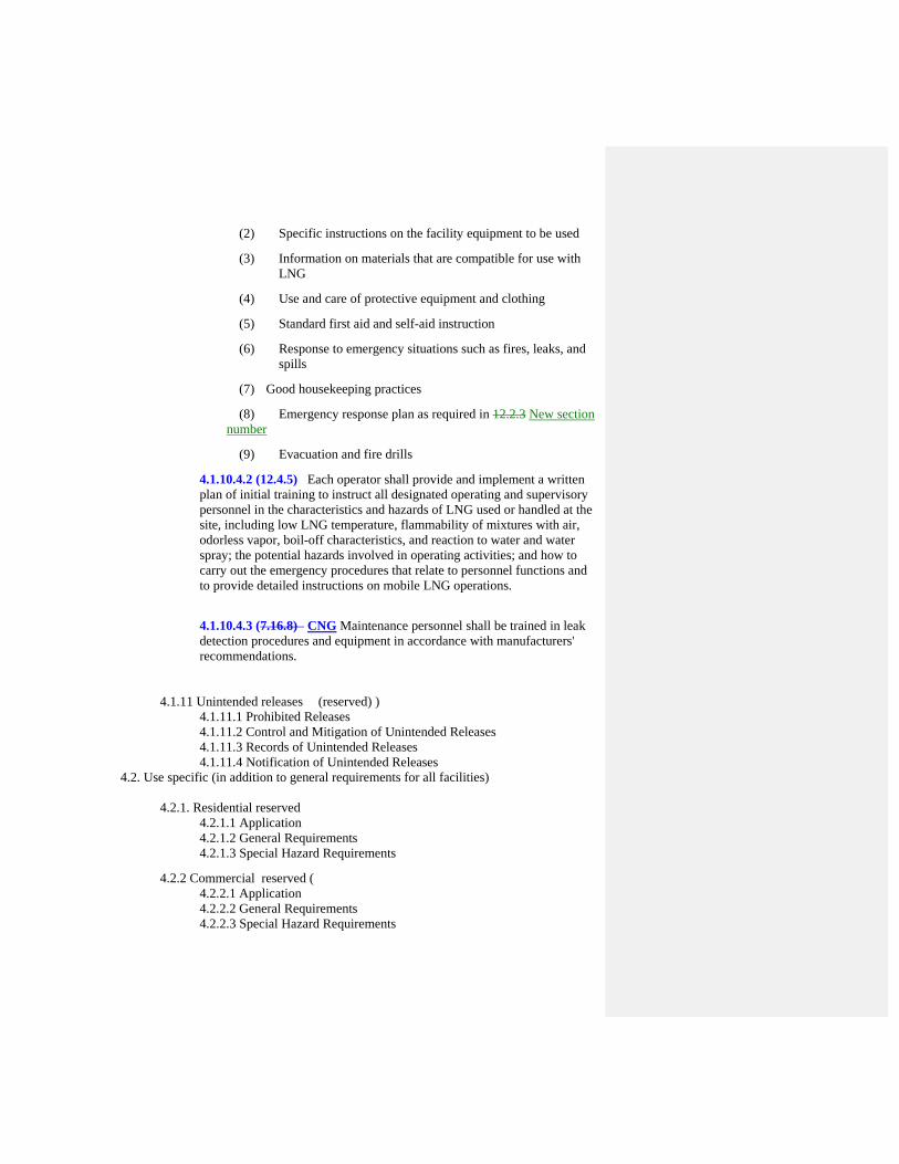
(2) Specific instructions on the facility equipment to be used
(3) Information on materials that are compatible for use with LNG
(4) Use and care of protective equipment and clothing
(5) Standard first aid and self-aid instruction
(6) Response to emergency situations such as fires, leaks, and spills
(7) Good housekeeping practices
(8) Emergency response plan as required in 12.2.3 New section number
(9) Evacuation and fire drills
4.1.10.4.2 (12.4.5) Each operator shall provide and implement a written plan of initial training to instruct all designated operating and supervisory personnel in the characteristics and hazards of LNG used or handled at the site, including low LNG temperature, flammability of mixtures with air, odorless vapor, boil-off characteristics, and reaction to water and water spray; the potential hazards involved in operating activities; and how to carry out the emergency procedures that relate to personnel functions and to provide detailed instructions on mobile LNG operations.
4.1.10.4.3 (7.16.8) CNG Maintenance personnel shall be trained in leak detection procedures and equipment in accordance with manufacturers' recommendations.
4.1.11 Unintended releases (reserved) ) 4.1.11.1 Prohibited Releases
4.1.11.2 Control and Mitigation of Unintended Releases 4.1.11.3 Records of Unintended Releases 4.1.11.4 Notification of Unintended Releases
4.2. Use specific (in addition to general requirements for all facilities) 4.2.1. Residential reserved 4.2.1.1 Application
4.2.1.2 General Requirements 4.2.1.3 Special Hazard Requirements
4.2.2 Commercial reserved ( 4.2.2.1 Application 4.2.2.2 General Requirements 4.2.2.3 Special Hazard Requirements

(Leave in Marine section)
4.2.3 Marine reserved (Note: Formerly 17.10 Marine Service Stations)
4.2.3.1 Application 4.2.3.2 General Requirements
4.2.3.2.1 Signs and Placards (Formerly 17.5.2 Operation) 4.2.4 Parking Garages (Covered by NFPA 88A) 4.2.4.1 Application
4.2.4.2 General Requirements 4.2.4.3 Special Hazard Requirements
4.2.5 Repair Garages (covered by NFPA 30A) 4.2.5.1 Application
4.2.5.2 General Requirements
4.2.5.3 Special Hazard Requirements
7.3.13 Modifications to fuel stations including, but not limited to, increases in working pressure or dispensing pressures shall be subject to a complete review in accordance with that required for a new installation to include a notification of any supplying utility (see 7.3.1).
7.3.13.1 A hazard analysis of the proposed modification and the startup plan shall be required and prepared prior to the modification and operation of the facility.
7.14.10 CNG shall not be used to operate any device or equipment that has not been designed or modified for CNG service.
Commented [L12]: Is the intent of this section to refer the user back to Chapter 17 for all requirements or will there be some general requirements listed here?
Commented [BS13]: Marine section here will be reserved.
Commented [BS14]: Public Input – new section to reference 30A and note duel fuel repair garages. Might be a good place for new annex material.
Public Input No. 65-NFPA 52-2013 [ Section No. 4.1 ]
4.1 Installer Qualifications.
Designers, fabricators, and constructors of LNG, L/CNG and CNG fueling facilities shall be competent andhave expertise in the design, fabrication, and construction of LNG containers , L/CNG andCNG containers, cryogenic equipment, loading and unloading systems, fire protection equipment,detection, siting, containment, piping systems, and other components of the facility.
Statement of Problem and Substantiation for Public Input
With the addition of this section, the reference is to LNG only and should include CNG and L/CNG fill stations
Submitter Information Verification
Submitter Full Name: Ronald Cloyd
Organization: ANGI Energy Systems
Street Address:
City:
State:
Zip:
Submittal Date: Fri Dec 20 10:53:20 EST 2013
Copyright Assignment
I, Ronald Cloyd, hereby irrevocably grant and assign to the National Fire Protection Association (NFPA) all and full rights in copyright in thisPublic Input (including both the Proposed Change and the Statement of Problem and Substantiation). I understand and intend that I acquireno rights, including rights as a joint author, in any publication of the NFPA in which this Public Input in this or another similar or derivativeform is used. I hereby warrant that I am the author of this Public Input and that I have full power and authority to enter into this copyrightassignment.
By checking this box I affirm that I am Ronald Cloyd, and I agree to be legally bound by the above Copyright Assignment and the termsand conditions contained therein. I understand and intend that, by checking this box, I am creating an electronic signature that will, upon mysubmission of this form, have the same legal force and effect as a handwritten signature
National Fire Protection Association Report http://submittals.nfpa.org/TerraViewWeb/ContentFetcher?commentPara...
42 of 307 1/21/2014 3:31 PM

Public Input No. 145-NFPA 52-2013 [ Section No. 4.3 ]
4.3 Alternate Design.
LNG, L/CNG, CNG, and other gaseous/cryogenic installations shall be permitted to use alternate sitedistances, operating requirements, and equipment locations with validation by qualified engineer(s) withproven expertise in mechanical systems, electrical systems, gaseous storage systems, cryogenic storagesystems, fire protection, and gas detection.
Statement of Problem and Substantiation for Public Input
The definition as written makes all of the listed provisions irrelevant if an alternative is validated by an engineer. Only an AHJ can permit an alternate design, not this definition.
Submitter Information Verification
Submitter Full Name: John Dimmick
Organization: Clean Vehicle Education Founda
Affilliation: Clean Vehicle Education Foundation
Street Address:
City:
State:
Zip:
Submittal Date: Mon Dec 30 15:17:28 EST 2013
Copyright Assignment
I, John Dimmick, hereby irrevocably grant and assign to the National Fire Protection Association (NFPA) all and full rights in copyright inthis Public Input (including both the Proposed Change and the Statement of Problem and Substantiation). I understand and intend that Iacquire no rights, including rights as a joint author, in any publication of the NFPA in which this Public Input in this or another similar orderivative form is used. I hereby warrant that I am the author of this Public Input and that I have full power and authority to enter into thiscopyright assignment.
By checking this box I affirm that I am John Dimmick, and I agree to be legally bound by the above Copyright Assignment and the termsand conditions contained therein. I understand and intend that, by checking this box, I am creating an electronic signature that will, upon mysubmission of this form, have the same legal force and effect as a handwritten signature
National Fire Protection Association Report http://submittals.nfpa.org/TerraViewWeb/ContentFetcher?commentPara...
43 of 307 1/21/2014 3:31 PM

Public Input No. 146-NFPA 52-2013 [ Section No. 4.4 ]
4.4 Installation Validation.
The refueling station and associated storage equipment shall be validated per the specifics of 4.4.1 whena change is made to the fundamental design, or not less than every 4 years . The installation validation shall also be reviewed at least every four years to detect any undocumentedchanges .
4.4.1
The validation shall at a minimum include the following:
(1) Process safety analysis and hazard and operability studies (HAZOPS)
(2) Mitigating fire protection measures such as suppression systems
(3) Aboveground or belowground systems or vaults for the containers
(4) Fire and gas detection systems designed to interface with an emergency shutdown device (ESD)
(5) Ventilation and other facility features
(6) Drainage and impounding for the individual site as administered by qualified engineer(s) with provenexpertise in these fields
4.4.1.1
Validation shall be kept on site and provided to the AHJ upon request.
Statement of Problem and Substantiation for Public Input
A full HAZOPS should only be required for a design or changes to a design. The periodic review should be to detect undocumented changes.
Submitter Information Verification
Submitter Full Name: John Dimmick
Organization: Clean Vehicle Education Founda
Affilliation: Clean Vehicle Education Foundation
Street Address:
City:
State:
Zip:
Submittal Date: Mon Dec 30 15:18:59 EST 2013
Copyright Assignment
I, John Dimmick, hereby irrevocably grant and assign to the National Fire Protection Association (NFPA) all and full rights in copyright inthis Public Input (including both the Proposed Change and the Statement of Problem and Substantiation). I understand and intend that Iacquire no rights, including rights as a joint author, in any publication of the NFPA in which this Public Input in this or another similar orderivative form is used. I hereby warrant that I am the author of this Public Input and that I have full power and authority to enter into thiscopyright assignment.
By checking this box I affirm that I am John Dimmick, and I agree to be legally bound by the above Copyright Assignment and the termsand conditions contained therein. I understand and intend that, by checking this box, I am creating an electronic signature that will, upon mysubmission of this form, have the same legal force and effect as a handwritten signature
National Fire Protection Association Report http://submittals.nfpa.org/TerraViewWeb/ContentFetcher?commentPara...
44 of 307 1/21/2014 3:31 PM
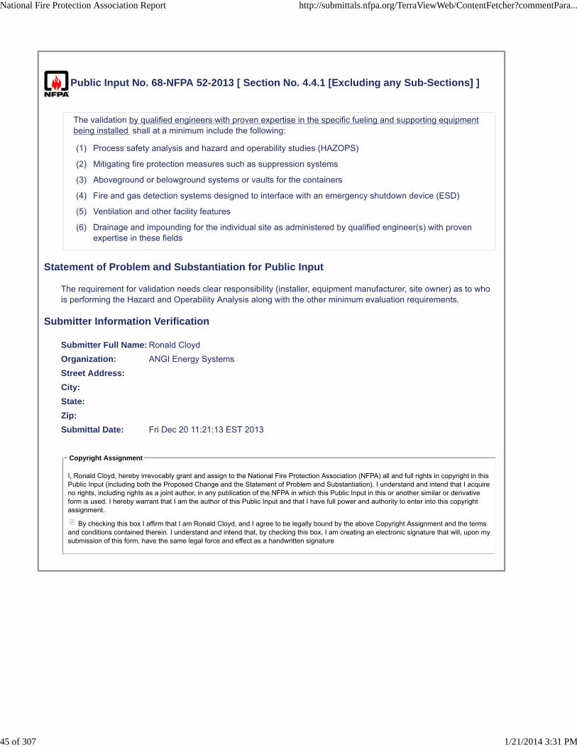
Public Input No. 68-NFPA 52-2013 [ Section No. 4.4.1 [Excluding any Sub-Sections] ]
The validation by qualified engineers with proven expertise in the specific fueling and supporting equipmentbeing installed shall at a minimum include the following:
(1) Process safety analysis and hazard and operability studies (HAZOPS)
(2) Mitigating fire protection measures such as suppression systems
(3) Aboveground or belowground systems or vaults for the containers
(4) Fire and gas detection systems designed to interface with an emergency shutdown device (ESD)
(5) Ventilation and other facility features
(6) Drainage and impounding for the individual site as administered by qualified engineer(s) with provenexpertise in these fields
Statement of Problem and Substantiation for Public Input
The requirement for validation needs clear responsibility (installer, equipment manufacturer, site owner) as to who is performing the Hazard and Operability Analysis along with the other minimum evaluation requirements.
Submitter Information Verification
Submitter Full Name: Ronald Cloyd
Organization: ANGI Energy Systems
Street Address:
City:
State:
Zip:
Submittal Date: Fri Dec 20 11:21:13 EST 2013
Copyright Assignment
I, Ronald Cloyd, hereby irrevocably grant and assign to the National Fire Protection Association (NFPA) all and full rights in copyright in thisPublic Input (including both the Proposed Change and the Statement of Problem and Substantiation). I understand and intend that I acquireno rights, including rights as a joint author, in any publication of the NFPA in which this Public Input in this or another similar or derivativeform is used. I hereby warrant that I am the author of this Public Input and that I have full power and authority to enter into this copyrightassignment.
By checking this box I affirm that I am Ronald Cloyd, and I agree to be legally bound by the above Copyright Assignment and the termsand conditions contained therein. I understand and intend that, by checking this box, I am creating an electronic signature that will, upon mysubmission of this form, have the same legal force and effect as a handwritten signature
National Fire Protection Association Report http://submittals.nfpa.org/TerraViewWeb/ContentFetcher?commentPara...
45 of 307 1/21/2014 3:31 PM

Public Input No. 147-NFPA 52-2013 [ Section No. 4.4.1.1 ]
4.4.1.1
Validation shall be kept on site and provided to the AHJ upon request .
Statement of Problem and Substantiation for Public Input
The HAZOPS validation should always be provided to the AHJ. The AHJ is often the fire marshal who can use the Hazopps for guiding emergency response.
Submitter Information Verification
Submitter Full Name: John Dimmick
Organization: Clean Vehicle Education Founda
Affilliation: Clean Vehicle Education Foundation
Street Address:
City:
State:
Zip:
Submittal Date: Mon Dec 30 15:22:16 EST 2013
Copyright Assignment
I, John Dimmick, hereby irrevocably grant and assign to the National Fire Protection Association (NFPA) all and full rights in copyright inthis Public Input (including both the Proposed Change and the Statement of Problem and Substantiation). I understand and intend that Iacquire no rights, including rights as a joint author, in any publication of the NFPA in which this Public Input in this or another similar orderivative form is used. I hereby warrant that I am the author of this Public Input and that I have full power and authority to enter into thiscopyright assignment.
By checking this box I affirm that I am John Dimmick, and I agree to be legally bound by the above Copyright Assignment and the termsand conditions contained therein. I understand and intend that, by checking this box, I am creating an electronic signature that will, upon mysubmission of this form, have the same legal force and effect as a handwritten signature
National Fire Protection Association Report http://submittals.nfpa.org/TerraViewWeb/ContentFetcher?commentPara...
46 of 307 1/21/2014 3:31 PM

Public Input No. 105-NFPA 52-2013 [ Chapter 5 ]
Chapter 5 General CNG Requirements and Equipment Qualifications
5.1 * Application.
This chapter applies only to pressurized system components handling CNG.
5.2 * Composition.
Natural gas composition in the container shall comply with 5.2.1.
5.2.1
The contained natural gas shall be composed of the following:
(1) Hydrogen sulfide and soluble sulfides, 1 gr/100 scf (23 mg/m3), maximum
(2) Water (GH2O), 7.0 lb/MMScf (110 mg/m3), maximum
(3) Carbon dioxide, 3.0 volume percent, maximum
(4) Oxygen, 0.5 volume percent, maximum
(5) Where the dew point of the natural gas entering the cylinder is below the lowest anticipated containertemperature at the maximum anticipated container pressure, none of the above limits in 5.2.1(1)through 5.2.1(4) shall apply.
5.2.1.1
Natural gas introduced into any system covered by this code shall have a distinctive odor potent enoughfor its presence to be detected down to a concentration in air of not over one-fifth of the lower limit offlammability.
5.2.1.1.1
Natural gas or blends not meeting this definition shall have site and onboard methane detection systemsinstalled and certified by a qualified engineer with expertise in methane detection or fire protection.
5.2.1.2
Methanol and/or glycol shall not be deliberately added to the natural gas at the fueling station.
5.2.1.3
When natural gas is not supplied to the vehicle in accordance with 5.2.1, containers shall be designed totolerate being filled with natural gas meeting both of the following conditions:
(1) Dry gas in which water vapor is limited to less than 2 lb/MMScf (32 mg/m3) and having a pressuredew point of 7°F (-14°C) at 3000 psi (20,700 kPa), with no maximum constituent limits for dry gas,except for the following:
(a) GH2S, 1 gr/100 scf (23 mg/m3)
(b) O2, 1 percent by volume
(2) Wet gas in which gas that contains 2 lb/MMScf (32 mg/m3) of water or more, meeting the maximumconstituent limits, as follows:
(a) GH2S and other soluble sulfides, 1 gr/100 scf (23 mg/m3)
(b) Total sulfur, 5 gr/MMScf (115 mg/m3)
(c) O2, 1 percent by volume
(d) CO2, 3 percent by volume
(e) Hydrogen, 0.1 percent by volume
National Fire Protection Association Report http://submittals.nfpa.org/TerraViewWeb/ContentFetcher?commentPara...
47 of 307 1/21/2014 3:31 PM

5.2.1.4
Under wet gas conditions, a minimum of 0.007 grains of compressor oil per pound of gas (1 mg ofcompressor oil per kilogram of gas) shall be considered necessary to protect metallic containers, liners, andbosses.
5.3 System Approvals.
5.3.1 *
The following systems and system components shall be listed or approved:
(1) Pressure relief devices, including pressure relief valves
(2) Pressure gauges
(3) Pressure regulators
(4) Valves
(5) Hose and hose connections
(6) Vehicle fueling connections (nozzle and receptacle)
(7) Engine fuel systems
(8) Electrical equipment related to CNG systems
(9) Gas detection equipment and alarms
(10) Fire protection and suppression equipment
(11) Vehicle fueling appliances (VFAs)
5.3.1.1
Vehicles certified by the manufacturer to be in compliance with applicable federal motor vehicle safetystandards shall not be subject to 5.3.1.
5.3.2
Devices not otherwise specifically provided for shall be constructed to provide safety equivalent to thatrequired for other parts of a system.
5.4 * Design and Construction of Containers.
5.4.1
Containers shall be fabricated of steel, aluminum, or composite materials.
5.4.2
The container shall be designed for CNG service.
5.4.2.1
The container shall be permanently marked “CNG” by the manufacturer.
5.4.3
Containers manufactured prior to the effective date of this code shall be permitted to be used in CNGservice if recommended for CNG service by the container manufacturer or if approved by the authorityhaving jurisdiction.
5.4.4 *
Cylinders shall be manufactured, inspected, marked, tested, retested, equipped, and used in accordancewith the following:
(1) U.S. Department of Transportation (DOT) or Transport Canada (TC) regulations, exemptions, orspecial permits
(2) ANSI NGV2, Compressed Natural Gas Vehicle (NGV) Fuel Containers, specifically for CNG service
(3) CSA B51, Boiler, Pressure Vessel and Pressure Piping Code
(4) U.S. Federal Motor Vehicle Safety Standard, 49 CFR 571.304, Compressed Natural Gas FuelContainer Integrity
5.4.4.1
Cylinders that have reached the labeled expiration date shall be removed from service.
5.4.4.2 *
Composite reinforced cylinders or other cylinders marked with exemption or special permit numbers shallbe removed from service at the end of the service life designated in the exemption or special permit.
National Fire Protection Association Report http://submittals.nfpa.org/TerraViewWeb/ContentFetcher?commentPara...
48 of 307 1/21/2014 3:31 PM

5.4.5 ASME Compliance.
5.4.5.1
Pressure vessels shall be manufactured, inspected, marked, and tested in accordance with ASME Boilerand Pressure Vessel Code, Section VIII or Section X.
5.4.5.2
Adherence to applicable ASME Boiler and Pressure Vessel Code case interpretations and addenda shallbe considered as compliant with the ASME Boiler and Pressure Vessel Code.
5.4.5.3 *
Pressure vessels manufactured to the requirements of the ASME Boiler and Pressure Vessel Code shall beregistered with the National Board of Boiler and Pressure Vessel Inspectors.
5.4.6
The + (plus) and * (star) markings on DOT and TC cylinders shall not apply in accordance with DOT andTC regulations for cylinders for flammable compressed gases.
5.4.6.1
The star marking shall be removed or obliterated.
5.4.6.2
The removal of the star marking shall be by peening and otherwise be in accordance with DOT or TCregulations.
5.4.6.3
Grinding shall be prohibited.
5.4.7
The repair or alteration of an ASME pressure vessel shall comply with the requirements of the NB-23,National Board Inspection Code.
5.4.7.1
Other welding or brazing shall be permitted only on saddle plates, lugs, or brackets attached to thepressure vessel by the pressure vessel manufacturer.
5.4.7.2
The exchange or interchange of pressure vessel appurtenances intended for the same purpose shall not beconsidered a repair or alteration.
5.5 Pressure Relief Devices (PRDs).
(See Annex C.)
5.5.1
Each cylinder complying with 5.4.4 shall be fitted with one or more pressure relief devices (PRDs) with thenumber, location, and part number as specified by the cylinder manufacturer and OEM for CNG service fora new vehicle, in accordance with the following:
(1) For a retrofitted vehicle, each cylinder complying with 5.4.4 shall be of the number, location, and partnumber as specified by the cylinder manufacturer.
(2) A PRD shall be in accordance with one of the following standards:
(a) CGA S-1.1, Pressure Relief Device Standards — Part 1 — Cylinders for Compressed Gases
(b) ANSI/IAS PRD 1, Pressure Relief Devices for Natural Gas Vehicle (NGV) Fuel Containers
(c) ANSI/IAS PRD 1a, Addenda to ANSI/IAS PRD 1, Pressure Relief Devices for Natural GasVehicle (NGV) Fuel Containers
(d) ANSI/CSA PRD 1b, Addenda to ANSI/IAS PRD 1, Pressure Relief Devices for Natural GasVehicle (NGV) Fuel Containers
(3) The PRD shall be in direct communication with the fuel and vented to the atmosphere by a methodthat withstands the maximum pressure that results.
5.5.1.1
The discharge flow rate of the PRD shall not be reduced below that required for the capacity of thecontainer upon which the device is installed.
5.5.1.2
PRDs shall be located so that the temperature to which they are subjected is representative of thetemperature to which the fuel supply container is subjected.
National Fire Protection Association Report http://submittals.nfpa.org/TerraViewWeb/ContentFetcher?commentPara...
49 of 307 1/21/2014 3:31 PM

5.5.1.3
Where parts of the vehicular fuel container are exposed to higher temperatures than the PRD during alocalized fire, the fuel container shall be protected by any of the following:
(1) Noncombustible heat-insulating shielding to retard localized heating of the container
(2) Installation of a thermally sensitive “fusing” system to trigger the PRD in a fire situation
(3) Other design for venting of the fuel container in a fire situation
5.5.2
Pressure vessels complying with 5.4.5 or cylinders used for stationary storage without temperaturecompensation of the storage pressure shall be protected with one or more spring-loaded pressure reliefvalves in accordance with the ASME Boiler and Pressure Vessel Code.
5.5.2.1
The minimum rate of discharge of PRDs on containers shall be in accordance with CGA S-1.1, PressureRelief Device Standards — Part 1 — Cylinders for Compressed Gases, or the ASME Boiler and PressureVessel Code, whichever is applicable.
5.5.2.2
Pressure relief valves (PRVs) for CNG service shall not be fitted with lifting devices.
5.5.2.2.1
The adjustment, if external, shall be provided with a means for sealing the adjustment to prevent tampering.
5.5.2.2.2
If at any time it is necessary to break such a seal, the valve shall be removed from service until it has beenreset and sealed.
5.5.2.2.3
Adjustments shall be made only by the manufacturer or other companies having competent personnel andfacilities for the repair, adjustment, and testing of such valves.
5.5.2.2.4
The organization making such adjustment shall attach a permanent tag with the setting, capacity, and date.
5.5.2.3
PRVs protecting ASME pressure vessels shall be repaired, adjusted, and tested in accordance with NB-23,National Board Inspection Code.
5.5.3
Containers and pressure vessels not constructed in accordance with 5.4.4 or 5.4.5 shall be provided withPRDs approved by the authority having jurisdiction.
5.6 Pressure Gauges.
A pressure gauge, if provided, shall be capable of reading at least 1.2 times the system design pressure.
5.7 Pressure Regulators.
5.7.1
A pressure regulator inlet and each chamber shall be designed for its service pressure with a pressuresafety factor of at least 4.
5.7.2
Low-pressure chambers shall provide for overpressure relief or be able to withstand the service pressure ofthe upstream pressure chamber.
5.8 Fuel Lines.
5.8.1
Pipe, tubing, fittings, gaskets, and packing material shall be compatible with the fuel under the maximumservice conditions.
5.8.2
Pipe, tubing, fittings, and other components shall be designed with a minimum safety factor of 3.
5.8.3
Natural gas piping shall be fabricated and tested in accordance with ANSI/ASME B31.3, Process Piping.
5.8.4
National Fire Protection Association Report http://submittals.nfpa.org/TerraViewWeb/ContentFetcher?commentPara...
50 of 307 1/21/2014 3:31 PM

The following components shall not be used for CNG service:
(1) Fittings, street els, and other piping components of cast irons other than those complying with ASTMA 47, Standard Specification for Ferritic Malleable Iron Castings (Grade 35018); ASTM A 395,Standard Specification for Ferritic Ductile Iron Pressure-Retaining Castings for Use at ElevatedTemperatures; and ASTM A 536, Standard Specification for Ductile Iron Castings (Grade 60-40-18)
(2) Plastic pipe, tubing, and fittings for high-pressure service
(3) Galvanized pipe and fittings
(4) Aluminum pipe, tubing, and fittings
(5) Pipe nipples for the initial connection to a container
(6) Copper alloy with copper content exceeding 70 percent
5.8.4.1
The refueling connection shall be permitted to be made of nonsparking wrought aluminum alloy designedfor the pressure employed.
5.8.4.2
Aluminum pipe, tubing, and fittings shall be permitted to be used downstream of the first-stage pressureregulator in an engine fuel system.
5.8.5
Piping components such as strainers, snubbers, and expansion joints shall be permanently marked by themanufacturer to indicate the service ratings.
5.9 Valves.
5.9.1
Valves, valve packing, and gaskets shall be designed or selected for the fuel over the full range ofpressures and temperatures to which they are subjected under operating conditions.
5.9.1.1
Shutoff valves shall have a rated service pressure not less than the rated service pressure of the entiresystem and shall be capable of withstanding a hydrostatic test of at least four times the rated servicepressure without rupture.
5.9.1.2
Leakage shall not occur at less than 1 1⁄2 times the rated service pressure.
5.9.2
Valves of cast irons other than those complying with ASTM A 47, Standard Specification for FerriticMalleable Iron Castings (Grade 35018); ASTM A 395, Standard Specification for Ferritic Ductile IronPressure-Retaining Castings for Use at Elevated Temperatures; and ASTM A 536, Standard Specificationfor Ductile Iron Castings (Grade 60-40-18), shall not be used as primary stop valves.
5.9.3
Valves of a design that allows the valve stem to be removed without removal of the complete valve bonnetor without disassembly of the valve body shall not be used.
5.9.4
The manufacturer shall stamp or otherwise permanently mark the valve body to indicate the serviceratings.
5.9.4.1
Container valves incorporating integral PRDs complying with 5.5.1 shall not require additional marking.
5.10 Hose and Hose Connections.
5.10.1
Hose and metallic hose shall be constructed of or lined with materials that are resistant to corrosion andexposure to natural gas.
5.10.2
Hose, metallic hose, flexible metal hose, tubing, and their connections shall be designed or selected for themost severe pressures and temperatures under normal operating conditions with a burst pressure of atleast four times the service pressure.
5.10.3
Prior to use, hose assemblies shall be tested by the OEM or its designated representative at a pressure atleast twice the service pressure.
National Fire Protection Association Report http://submittals.nfpa.org/TerraViewWeb/ContentFetcher?commentPara...
51 of 307 1/21/2014 3:31 PM

5.10.4
Hose and metallic hose shall be distinctly marked by the OEM or component manufacturer, either by themanufacturer's permanently attached tag or by distinct markings indicating the manufacturer's name ortrademark, applicable service identifier, and design pressure.
5.11 Vehicle Fueling Connection.
5.11.1
CNG vehicle fueling connection devices shall be listed in accordance with ANSI/IAS NGV1, Standard forCompressed Natural Gas Vehicle (NGV) Fueling Connection Devices.
5.11.2
The use of adapters shall be prohibited.
Replace Chapter 5 with the attached Chapter 5 Fire Protection developed by a NFPA 52 Task Group
Additional Proposed Changes
File Name Description Approved
NFPA_52_Public_Input_Chapter_5_Fire_Protection.docx NFPA 52 Chapter 5 Fire Protection
Statement of Problem and Substantiation for Public Input
The NFPA 52 Technical Committee approved the reorganization of NFPA 52 into an organizational layout that restructured requirements into General Requirements, Fuel Specific Requirements and Use Specific Requirements. This Chapter replaces existing Chapter 5 and was developed by a Task Group. For this draft being submitted as a Public Input, existing code sections have only been reorganized. No new or revised language has been included or any requirements deleted.
Submitter Information Verification
Submitter Full Name: Nancy Pehrson
Organization: CenterPoint Energy, Inc.
Street Address:
City:
State:
Zip:
Submittal Date: Thu Dec 26 12:55:51 EST 2013
Copyright Assignment
I, Nancy Pehrson, hereby irrevocably grant and assign to the National Fire Protection Association (NFPA) all and full rights in copyright inthis Public Input (including both the Proposed Change and the Statement of Problem and Substantiation). I understand and intend that Iacquire no rights, including rights as a joint author, in any publication of the NFPA in which this Public Input in this or another similar orderivative form is used. I hereby warrant that I am the author of this Public Input and that I have full power and authority to enter into thiscopyright assignment.
By checking this box I affirm that I am Nancy Pehrson, and I agree to be legally bound by the above Copyright Assignment and theterms and conditions contained therein. I understand and intend that, by checking this box, I am creating an electronic signature that will,upon my submission of this form, have the same legal force and effect as a handwritten signature
National Fire Protection Association Report http://submittals.nfpa.org/TerraViewWeb/ContentFetcher?commentPara...
52 of 307 1/21/2014 3:31 PM

Chapter 5 Fire Protection
5.1 General
5.1.1 Siting
1.4.4. LNG, L/CNG, CNG, and other gaseous/cryogenic installations shall be permitted to use alternate site distances, operating requirements, and equipment locations with validation by a qualified engineer(s) with proven expertise in mechanical systems, electrical systems, gaseous storage systems, cryogenic storage systems, fire protection, and gas detection.
1.4.4.1 The validation shall at a minimum include the following:
(1) Process safety analysis and hazard and operability studies (HAZOPS)
(2) Mitigating fire protection measures such as suppression systems
(3) Aboveground or belowground systems or vaults for the containers
(4) Fire and gas detection systems designed to interface with an emergency shutdown device (ESD)
(5) Ventilation and other facility features
(6) Drainage and impounding for the individual site as administered by qualified engineer(s) with proven expertise in these fields
4.3 Alternate Design. LNG, L/CNG, CNG, and other gaseous/cryogenic installations shall be permitted to use alternate site distances, operating requirements, and equipment locations with validation by qualified engineer(s) with proven expertise in mechanical systems, electrical systems, gaseous storage systems, cryogenic storage systems, fire protection, and gas detection.
4.4 Installation Validation. The refueling station and associated storage equipment shall be validated per the specifics of 4.4.1 when a change is made to the fundamental design, or not less than every 4 years.
4.4.1 The validation shall at a minimum include the following:
(1) Process safety analysis and hazard and operability studies (HAZOPS)
(2) Mitigating fire protection measures such as suppression systems
(3) Aboveground or belowground systems or vaults for the containers
(4) Fire and gas detection systems designed to interface with an emergency shutdown device (ESD)
(5) Ventilation and other facility features

(6) Drainage and impounding for the individual site as administered by qualified engineer(s) with proven expertise in these fields
4.4.1.1 Validation shall be kept on site and provided to the AHJ upon request. 5.1.1.1. Setbacks 5.1.1.2 Equipment Protection 5.1.1.3 Fire Extinguishers
7.15 Fire Protection. A portable fire extinguisher having a rating of not less than 20-B:C shall be provided at the dispensing area.
5.1.2 Ignition Source Control
7.14.11 Sources of ignition shall not be permitted within 10 ft (3.0 m) of any filling connection during a transfer operation.
5.3.2.1 Smoking
12.3.1 Smoking and ignition sources shall be prohibited, except in accordance with 12.3.2. 5.3.2.2 Welding, oxygen-acetylene cutting and similar operations
12.3.2 Welding, oxygen–acetylene cutting, and similar operations shall be conducted only when and where specifically authorized and in accordance with the provisions of NFPA 51B, Standard for Fire Prevention During Welding, Cutting, and Other Hot Work.
7.3.4 Vehicles shall not be considered a source of ignition with respect to the provisions of this chapter.
7.3.4.1 Vehicles containing fuel-fired equipment (e.g., recreational vehicles and catering trucks) shall be considered a source of ignition unless this equipment is shut off completely before entering an area in which ignition sources are not permitted.
7.4.3.9 Nonelectrical sources of ignition shall not be permitted.
5.1.3 Signage
7.14.12.2 The location of signs shall be determined by local conditions.
7.14.12.3 The lettering on the sign shall be large enough to be visible and legible from each point of transfer.
7.14.12.1 A warning sign with the words “NO SMOKING, FLAMMABLE GAS” shall be posted in all compressor and storage areas.
7.4.3.11 Warning Signs.
7.4.3.11.1 Access doors shall have warning signs with the words “WARNING — NO SMOKING — FLAMMABLE GAS.”
Commented [BS1]: As a public input, this language should be made more generic to apply to both CNG and LNG installations.

7.4.3.11.2 The wording shall be in plainly legible, bright red letters not less than 1 in. (25 mm) high on a white background.
5.2 CNG(supplemental requirements)
5.2.1 Siting
7.3.4
5.2.1.1. Setbacks
7.4.2.3.2 Compression, storage, and dispensing equipment located outdoors shall be a minimum of 10 ft (3 m) from the nearest important building or line of adjoining property that is able to be built upon or from any source of ignition.
7.4.2.4 Compression, storage, and dispensing equipment located outdoors shall be not less than 10 ft (3 m) from the nearest public street or sidewalk line and at least 50 ft (15 m) from the nearest rail of any railroad main track.
7.4.2.5 A clear space of at least 3 ft (1 m) shall be provided for access to all valves and fittings of multiple groups of containers.
7.4.2.6 Combustible material shall not be permitted within 10 ft (3 m) of any stationary container.
7.4.2.7 The minimum separation between containers and aboveground tanks containing flammable or combustible liquids shall be 20 ft (6 m).
7.4.2.8 During outdoor fueling operations, the point of transfer shall be located at least 10 ft (3 m) from any important building, mobile home, public sidewalk, highway, street, or road and at least 3 ft (1 m) from storage containers.
7.4.2.8.1 The point of transfer shall be permitted to be located at a lesser distance from buildings or walls constructed of concrete or masonry materials or of other material having a fire resistance rating of at least 2 hours, but at least 10 ft (3 m) from any building openings.
7.17 Vehicle Fueling Appliances in Nonresidential Occupancies.
7.17.6 VFAs shall not be installed within 10 ft (3.0 m) of any flammable gas or liquid storage.
7.4.2.9 Areas for compression, storage, and dispensing shall be classified in accordance with Table 7.4.2.9 for installations of electrical equipment.
Formatted: Not Highlight
Commented [BS2]: Need to update reference to where the table winds up.

5.2.3 Signage
7.14.12* A warning sign(s) shall be posted at the dispensing points with the following words: A. STOP MOTOR. B. NO SMOKING.
C. FLAMMABLE GAS. D. NATURAL GAS VEHICLE FUEL CYLINDERS SHALL BE
INSPECTED AT INTERVALS NOT EXCEEDING 3 YEARS TO ENSURE SAFE OPERATION OF THE VEHICLE.
E. NATURAL GAS FUEL CYLINDERS PAST THEIR END-OF-LIFE DATE SHALL NOT BE REFUELED AND SHALL BE REMOVED
FROM SERVICE.
5.3 LNG(supplemental requirements)
12.1 Application. This section applies to LNG fire protection, personnel safety, security, LNG fueling facilities and training for LNG vehicles, and warning signs.
12.2 Fire Protection, Safety, and Security.
12.2.1 Fire protection shall be provided for all LNG fueling facilities.

12.2.1.1 The extent of such protection shall be determined by an evaluation based on sound fire protection and methane detection engineering principles, analysis of local conditions, vehicle operations, hazards within the facility, exposure to or from other property, and the size of the LNG containers.
12.2.1.2 Guidance factors for making such an evaluation shall include the following:
(1) Type, quantity, and location of equipment necessary for the detection and control of fires, leaks, and spills of LNG, flammable refrigerants, and flammable gases or liquids
(2) Methods necessary for the protection of vehicles, equipment, and structures from the effects of fire exposure
(3) Equipment and processes to be incorporated within the ESD system
(4) Type, quantity, and location of sensors necessary to initiate automatic operation of the ESD system
(5) Availability and duties of individual facility personnel and the availability of external response personnel during an emergency
(6) Protective equipment and special training required by personnel for emergency duties
12.2.2 The planning for emergency response measures shall be coordinated with the appropriate local emergency agencies.
12.2.3* An emergency response plan shall be prepared to cover foreseeable emergency conditions.
12.2.4 The fire protection and methane detection equipment shall be maintained in accordance with the manufacturer's instructions and the AHJ. 5.3.1 Siting
5.3.1.1. Setbacks
10.2.2 Siting.
10.2.2.1 LNG tanks and their associated equipment shall not be located where exposed to failure of overhead electric power lines operating over 600 volts.
10.2.2.2 Vaulted or underground installations shall be deemed to provide engineered protection from overhead power lines.
10.2.2.3 If other combustible or hazardous liquids are able to encroach on the LNG fueling facility, means shall be provided to protect the LNG facility.
10.2.2.5 Points of transfer shall be located not less than 25 ft (7.6 m) from the nearest important building not associated with the LNG facility, from the line of adjoining property that is able to be built upon, or from fixed sources of ignition.

10.2.3.4 Flammable liquid storage tanks shall not be located within an LNG container impounding area.
5.3.2 Ignition Source Control
12.3 Ignition Source Control.
10.13.5 LNG fueling facilities shall be free from rubbish, debris, and other material that present a fire hazard to a distance of at least 25 ft (7.6 m).
10.13.6 Grass areas on the LNG fueling facility grounds shall be maintained in a manner that does not present a fire hazard.
12.6 Hazard Detection. Gas leak detection and fire detection shall be installed based on the evaluation required in 12.2.1.1.
12.7 Parking of LNG Vehicles. LNG vehicles shall be permitted to be parked indoors, provided such facilities or vehicles are equipped to prevent an accumulation of gas in a combustible mixture or the onboard fuel storage tank and fuel system are drained of LNG and purged with inert gas or depressurized.
5.3.5 Vehicles
12.3.3 Vehicles and other mobile equipment that constitute a potential ignition source shall be prohibited except where specifically authorized and under constant supervision or when at a transfer point specifically for the purpose of transfer.
12.3.4 Vehicles delivering LNG to the facility or vehicles being fueled from the facility shall not be considered sources of ignition.
12.3.5 Vehicles containing fuel-fired equipment (e.g., recreational vehicles and catering trucks) shall be considered a source of ignition unless all sources of ignition such as pilot lights, electric igniters, burners, electrical appliances, and engines located on the vehicle being refueled are shut off completely before entering an area where ignition sources are prohibited.
5.3.2.3 Electrical Classifications
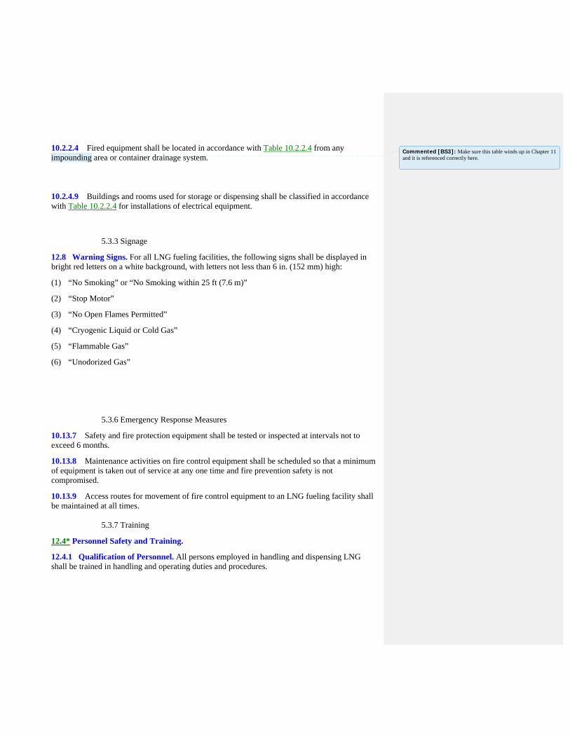
10.2.2.4 Fired equipment shall be located in accordance with Table 10.2.2.4 from any impounding area or container drainage system.
10.2.4.9 Buildings and rooms used for storage or dispensing shall be classified in accordance with Table 10.2.2.4 for installations of electrical equipment.
5.3.3 Signage
12.8 Warning Signs. For all LNG fueling facilities, the following signs shall be displayed in bright red letters on a white background, with letters not less than 6 in. (152 mm) high:
(1) “No Smoking” or “No Smoking within 25 ft (7.6 m)”
(2) “Stop Motor”
(3) “No Open Flames Permitted”
(4) “Cryogenic Liquid or Cold Gas”
(5) “Flammable Gas”
(6) “Unodorized Gas” 5.3.6 Emergency Response Measures
10.13.7 Safety and fire protection equipment shall be tested or inspected at intervals not to exceed 6 months.
10.13.8 Maintenance activities on fire control equipment shall be scheduled so that a minimum of equipment is taken out of service at any one time and fire prevention safety is not compromised.
10.13.9 Access routes for movement of fire control equipment to an LNG fueling facility shall be maintained at all times. 5.3.7 Training
12.4* Personnel Safety and Training.
12.4.1 Qualification of Personnel. All persons employed in handling and dispensing LNG shall be trained in handling and operating duties and procedures.
Commented [BS3]: Make sure this table winds up in Chapter 11 and it is referenced correctly here.

12.4.2 Protective clothing, face shield/goggles, and gloves shall be provided for all operators dispensing and handling LNG.
12.4.2.1 Requirements, as specified in 12.4.2, shall be permitted to be excluded where equipment is demonstrated to operate without exposing operators to release of LNG or cold gases.
12.4.3* Training shall be conducted upon employment and every 2 years thereafter.
12.4.4 Training shall include the following:
(1) Information on the nature, properties, and hazards of LNG in both the liquid and gaseous phases
(2) Specific instructions on the facility equipment to be used
(3) Information on materials that are compatible for use with LNG
(4) Use and care of protective equipment and clothing
(5) Standard first aid and self-aid instruction
(6) Response to emergency situations such as fires, leaks, and spills
(7) Good housekeeping practices
(8) Emergency response plan as required in 12.2.3
(9) Evacuation and fire drills
12.4.5 Each operator shall provide and implement a written plan of initial training to instruct all designated operating and supervisory personnel in the characteristics and hazards of LNG used or handled at the site, including low LNG temperature, flammability of mixtures with air, odorless vapor, boil-off characteristics, and reaction to water and water spray; the potential hazards involved in operating activities; and how to carry out the emergency procedures that relate to personnel functions and to provide detailed instructions on mobile LNG operations. 5.3.8 Security
12.5 Security.
12.5.1 The LNG fueling facility shall provide protection to minimize unauthorized access and damage to the facility.
12.5.2 Security procedures shall be posted in readily visible areas near the fueling facility.

Public Input No. 227-NFPA 52-2013 [ New Section after 5.1 ]
TITLE OF NEW CONTENT Retroactivity of Requirements
Type your content here ...All new requirements for maintenance and operations shall be retroactiveand shall be applied to existing stations and vehicles.
Statement of Problem and Substantiation for Public Input
These changes are necessary to safety and do not require physical changes, only operating changes.
Submitter Information Verification
Submitter Full Name: John Dimmick
Organization: Clean Vehicle Education Founda
Affilliation: Clean Vehicle Education Foundation
Street Address:
City:
State:
Zip:
Submittal Date: Tue Dec 31 12:43:33 EST 2013
Copyright Assignment
I, John Dimmick, hereby irrevocably grant and assign to the National Fire Protection Association (NFPA) all and full rights in copyright inthis Public Input (including both the Proposed Change and the Statement of Problem and Substantiation). I understand and intend that Iacquire no rights, including rights as a joint author, in any publication of the NFPA in which this Public Input in this or another similar orderivative form is used. I hereby warrant that I am the author of this Public Input and that I have full power and authority to enter into thiscopyright assignment.
By checking this box I affirm that I am John Dimmick, and I agree to be legally bound by the above Copyright Assignment and the termsand conditions contained therein. I understand and intend that, by checking this box, I am creating an electronic signature that will, upon mysubmission of this form, have the same legal force and effect as a handwritten signature
National Fire Protection Association Report http://submittals.nfpa.org/TerraViewWeb/ContentFetcher?commentPara...
53 of 307 1/21/2014 3:31 PM

Public Input No. 148-NFPA 52-2013 [ Section No. 5.2 ]
5.2* Composition.
Natural gas composition in the container dispensed to vehicles shall comply with 5.2.1.
5.2.1
The contained dispensed natural gas shall be composed of the following:
(1) Hydrogen sulfide and soluble sulfides, 1 gr/100 scf (23 mg/m3), maximum
(2) Water (GH 2 O), 7.0 lb/MMScf (110 mg/m 3 ), maximum
(3) Carbon dioxide, 3.0 volume percent, maximum
(4) Oxygen, 0.5 volume percent, maximum
Where the
(5) ; the the pressure dew point of the natural
gas entering the cylinder is
(6) shall be at least 20 degrees F below the lowest anticipated
container
(7) temperature in which the vehicle will operate and at the
maximum anticipated container
(8) pressure
, none of the above limits in 5.2.1(1) through 5.2.1(4) shall apply.
(9) of a full container with a uniform gas temperature equal to the lowest anticipated vehicle operatingtemperature.
(10) Carbon dioxide, 3.0 volume percent, maximum
(11) Oxygen, 1.0 volume percent, maximum
5.2.1.1
Natural gas introduced into any system covered by this code shall have a distinctive odor potent enoughfor its presence to be detected down to a concentration in air of not over one-fifth of the lower limit offlammability.
5.2.1.1.1
Natural gas or blends not meeting this definition shall have site and onboard methane detection systemsinstalled and certified by a qualified engineer with expertise in methane detection or fire protection.
5.2.1.2
Methanol and/or glycol shall not be deliberately added to the natural gas at the fueling station.
National Fire Protection Association Report http://submittals.nfpa.org/TerraViewWeb/ContentFetcher?commentPara...
54 of 307 1/21/2014 3:31 PM

5.2.1.3
When natural gas is not supplied to the vehicle in accordance with 5.2.1 , containers shall be designed totolerate being filled with natural gas meeting both of the following conditions:
(1) Dry gas in which water vapor is limited to less than 2 lb/MMScf (32 mg/m 3 ) and having a pressuredew point of 7°F (-14°C) at 3000 psi (20,700 kPa), with no maximum constituent limits for dry gas,except for the following:
(2) GH 2 S, 1 gr/100 scf (23 mg/m 3 )
(3) O 2 , 1 percent by volume
(4) Wet gas in which gas that contains 2 lb/MMScf (32 mg/m 3 ) of water or more, meeting the maximumconstituent limits, as follows:
(5) GH 2 S and other soluble sulfides, 1 gr/100 scf (23 mg/m 3 )
(6) Total sulfur, 5 gr/MMScf (115 mg/m 3 )
(7) O 2 , 1 percent by volume
(8) CO 2 , 3 percent by volume
(9) Hydrogen, 0.1 percent by volume
5.2.1.4
Under wet gas conditions, a minimum of 0.007 grains of compressor oil per pound of gas (1 mg ofcompressor oil per kilogram of gas) shall be considered necessary to protect metallic containers, liners,and bosses.
Statement of Problem and Substantiation for Public Input
Note: The online tool would not accept the proposed change in the correct format. The text in 5.2.1(5,6,7,8&9) all belongs directly after "water".
The critical safety issue in composition is the gas that is actually dispensewd to the vehicle. Stations with cascade vessels are known to accumulate and accentuate the water content of gas withdrawn from them, particularly with large ambient temperature swings such as occur in the sring and fall.Moist natural gas has been implicated as a root cause in a number of serious CNG vehicle incidents in which ice or hydrate formations plugged sensor or safety relief channels. It is also reported as a cause for driveability issues and stalling of NGVs. Stalling in the roadway is a very unsafe occurrence and leads to many very high severity collisions.Hydrate formations as a result of moist gas and the J-T effect at expansion orifices is known to compromise componemt performance, check valves expecially. The safety of NGV fuel systems, particularly in the fill system are dependent of reliable functioning of check valves.A very large portion of all stations include inlet molecular sieve dryers that can easily exceed the performance proposed if properly maintained. If not properly maintained these dryers will admit wet gas that will result in operating safety issues.The requirement for a minimum oil content in the present alternative of wet gas is very undesirable from the standpoint of vehicle operational reliability. Oil fouling results in reliability, emissions and driveability issues since the oil can foul control devices, flow sensors and injectors. Dew point can be readily monitored for compliance at the station but the other constituent limits that are necessary with wet gas cannot.
Submitter Information Verification
Submitter Full Name: John Dimmick
National Fire Protection Association Report http://submittals.nfpa.org/TerraViewWeb/ContentFetcher?commentPara...
55 of 307 1/21/2014 3:31 PM

Organization: Clean Vehicle Education Founda
Affilliation: Clean Vehicle Education Foundation
Street Address:
City:
State:
Zip:
Submittal Date: Mon Dec 30 15:25:27 EST 2013
Copyright Assignment
I, John Dimmick, hereby irrevocably grant and assign to the National Fire Protection Association (NFPA) all and full rights in copyright inthis Public Input (including both the Proposed Change and the Statement of Problem and Substantiation). I understand and intend that Iacquire no rights, including rights as a joint author, in any publication of the NFPA in which this Public Input in this or another similar orderivative form is used. I hereby warrant that I am the author of this Public Input and that I have full power and authority to enter into thiscopyright assignment.
By checking this box I affirm that I am John Dimmick, and I agree to be legally bound by the above Copyright Assignment and the termsand conditions contained therein. I understand and intend that, by checking this box, I am creating an electronic signature that will, upon mysubmission of this form, have the same legal force and effect as a handwritten signature
National Fire Protection Association Report http://submittals.nfpa.org/TerraViewWeb/ContentFetcher?commentPara...
56 of 307 1/21/2014 3:31 PM
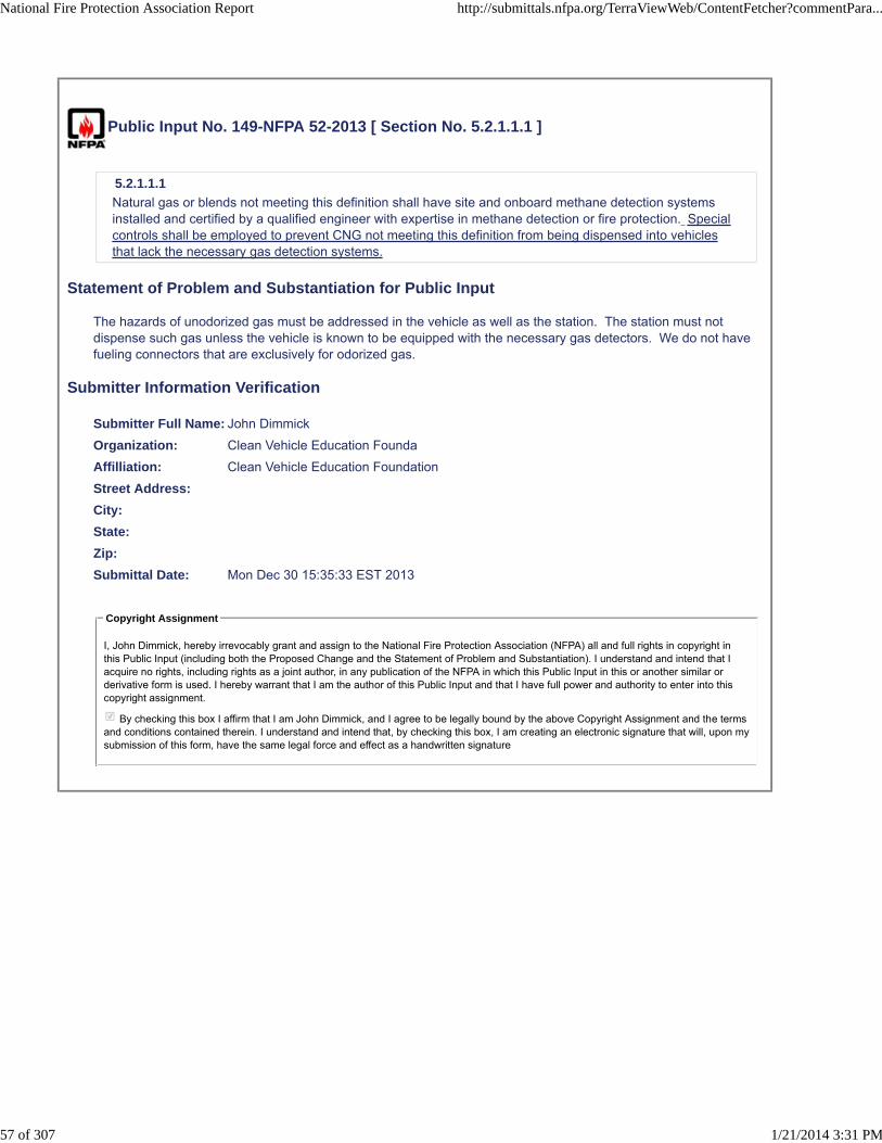
Public Input No. 149-NFPA 52-2013 [ Section No. 5.2.1.1.1 ]
5.2.1.1.1
Natural gas or blends not meeting this definition shall have site and onboard methane detection systemsinstalled and certified by a qualified engineer with expertise in methane detection or fire protection. Specialcontrols shall be employed to prevent CNG not meeting this definition from being dispensed into vehiclesthat lack the necessary gas detection systems.
Statement of Problem and Substantiation for Public Input
The hazards of unodorized gas must be addressed in the vehicle as well as the station. The station must not dispense such gas unless the vehicle is known to be equipped with the necessary gas detectors. We do not have fueling connectors that are exclusively for odorized gas.
Submitter Information Verification
Submitter Full Name: John Dimmick
Organization: Clean Vehicle Education Founda
Affilliation: Clean Vehicle Education Foundation
Street Address:
City:
State:
Zip:
Submittal Date: Mon Dec 30 15:35:33 EST 2013
Copyright Assignment
I, John Dimmick, hereby irrevocably grant and assign to the National Fire Protection Association (NFPA) all and full rights in copyright inthis Public Input (including both the Proposed Change and the Statement of Problem and Substantiation). I understand and intend that Iacquire no rights, including rights as a joint author, in any publication of the NFPA in which this Public Input in this or another similar orderivative form is used. I hereby warrant that I am the author of this Public Input and that I have full power and authority to enter into thiscopyright assignment.
By checking this box I affirm that I am John Dimmick, and I agree to be legally bound by the above Copyright Assignment and the termsand conditions contained therein. I understand and intend that, by checking this box, I am creating an electronic signature that will, upon mysubmission of this form, have the same legal force and effect as a handwritten signature
National Fire Protection Association Report http://submittals.nfpa.org/TerraViewWeb/ContentFetcher?commentPara...
57 of 307 1/21/2014 3:31 PM

Public Input No. 28-NFPA 52-2013 [ Section No. 5.2.1.1.1 ]
5.2.1.1.1
Natural gas or blends not meeting this definition shall have site and onboard methane detection systemsinstalled and certified by a qualified engineer with expertise in methane detection or fireprotection. Additional labels shall be required [see (revised) sections 6.11.3.3 and 6.11.3.4].
Statement of Problem and Substantiation for Public Input
"Unodorized label" should be required to alert emergency responders who are accustomed to odorized natural gas. The recommendation for this label was made on p. 43 of FMCSA's final report, "Natural Gas Systems: Suggested Changes to Truck and Motorcoach Regulations and Inspection Procedures" published Mach 2013.
Submitter Information Verification
Submitter Full Name: Quon Kwan
Organization: US Department of Transportation
Street Address:
City:
State:
Zip:
Submittal Date: Fri Dec 13 16:29:39 EST 2013
Copyright Assignment
I, Quon Kwan, hereby irrevocably grant and assign to the National Fire Protection Association (NFPA) all and full rights in copyright in thisPublic Input (including both the Proposed Change and the Statement of Problem and Substantiation). I understand and intend that I acquireno rights, including rights as a joint author, in any publication of the NFPA in which this Public Input in this or another similar or derivativeform is used. I hereby warrant that I am the author of this Public Input and that I have full power and authority to enter into this copyrightassignment.
By checking this box I affirm that I am Quon Kwan, and I agree to be legally bound by the above Copyright Assignment and the termsand conditions contained therein. I understand and intend that, by checking this box, I am creating an electronic signature that will, upon mysubmission of this form, have the same legal force and effect as a handwritten signature
National Fire Protection Association Report http://submittals.nfpa.org/TerraViewWeb/ContentFetcher?commentPara...
58 of 307 1/21/2014 3:31 PM

Public Input No. 30-NFPA 52-2013 [ Section No. 5.2.1.1.1 ]
5.2.1.1.1
Natural gas or blends not meeting this definition shall have site and onboard methane detection systemsinstalled and certified by a qualified engineer with expertise in methane detection or fire protection. Theonboard methane detection system shall comply with the same requirements as for gas detection for LNGfuel systems described in sections 9.12.10 and 9.13.3.
Statement of Problem and Substantiation for Public Input
The requirement of methane detectors for use of unodorized natural gas is not accompanied by requirements for placement, functionality, and testing of those detectors. Because such requirements are described for LNG and L/CNG fuel systems, they should be the same for CNG fuel systems using unodorized natural gas.
Submitter Information Verification
Submitter Full Name: Quon Kwan
Organization: US Department of Transportation
Street Address:
City:
State:
Zip:
Submittal Date: Mon Dec 16 13:24:51 EST 2013
Copyright Assignment
I, Quon Kwan, hereby irrevocably grant and assign to the National Fire Protection Association (NFPA) all and full rights in copyright in thisPublic Input (including both the Proposed Change and the Statement of Problem and Substantiation). I understand and intend that I acquireno rights, including rights as a joint author, in any publication of the NFPA in which this Public Input in this or another similar or derivativeform is used. I hereby warrant that I am the author of this Public Input and that I have full power and authority to enter into this copyrightassignment.
By checking this box I affirm that I am Quon Kwan, and I agree to be legally bound by the above Copyright Assignment and the termsand conditions contained therein. I understand and intend that, by checking this box, I am creating an electronic signature that will, upon mysubmission of this form, have the same legal force and effect as a handwritten signature
National Fire Protection Association Report http://submittals.nfpa.org/TerraViewWeb/ContentFetcher?commentPara...
59 of 307 1/21/2014 3:31 PM
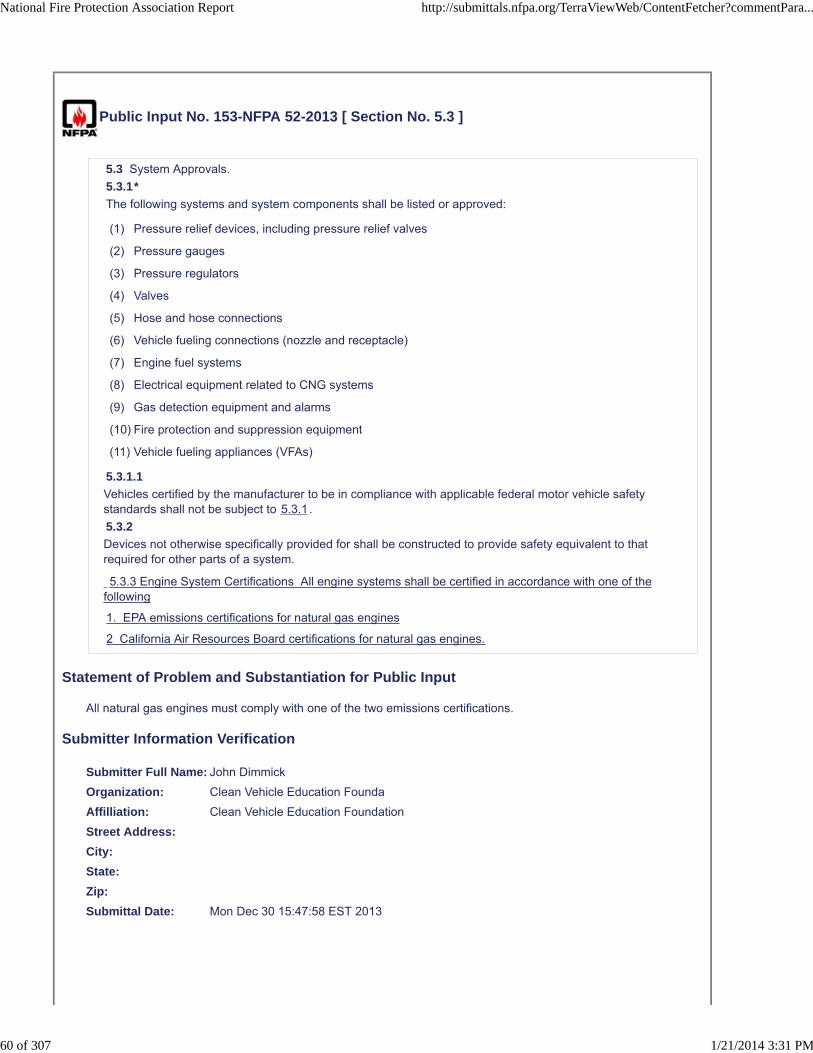
Public Input No. 153-NFPA 52-2013 [ Section No. 5.3 ]
5.3 System Approvals.
5.3.1*
The following systems and system components shall be listed or approved:
(1) Pressure relief devices, including pressure relief valves
(2) Pressure gauges
(3) Pressure regulators
(4) Valves
(5) Hose and hose connections
(6) Vehicle fueling connections (nozzle and receptacle)
(7) Engine fuel systems
(8) Electrical equipment related to CNG systems
(9) Gas detection equipment and alarms
(10) Fire protection and suppression equipment
(11) Vehicle fueling appliances (VFAs)
5.3.1.1
Vehicles certified by the manufacturer to be in compliance with applicable federal motor vehicle safetystandards shall not be subject to 5.3.1.
5.3.2
Devices not otherwise specifically provided for shall be constructed to provide safety equivalent to thatrequired for other parts of a system.
5.3.3 Engine System Certifications All engine systems shall be certified in accordance with one of thefollowing
1. EPA emissions certifications for natural gas engines
2 California Air Resources Board certifications for natural gas engines.
Statement of Problem and Substantiation for Public Input
All natural gas engines must comply with one of the two emissions certifications.
Submitter Information Verification
Submitter Full Name: John Dimmick
Organization: Clean Vehicle Education Founda
Affilliation: Clean Vehicle Education Foundation
Street Address:
City:
State:
Zip:
Submittal Date: Mon Dec 30 15:47:58 EST 2013
National Fire Protection Association Report http://submittals.nfpa.org/TerraViewWeb/ContentFetcher?commentPara...
60 of 307 1/21/2014 3:31 PM

Copyright Assignment
I, John Dimmick, hereby irrevocably grant and assign to the National Fire Protection Association (NFPA) all and full rights in copyright inthis Public Input (including both the Proposed Change and the Statement of Problem and Substantiation). I understand and intend that Iacquire no rights, including rights as a joint author, in any publication of the NFPA in which this Public Input in this or another similar orderivative form is used. I hereby warrant that I am the author of this Public Input and that I have full power and authority to enter into thiscopyright assignment.
By checking this box I affirm that I am John Dimmick, and I agree to be legally bound by the above Copyright Assignment and the termsand conditions contained therein. I understand and intend that, by checking this box, I am creating an electronic signature that will, upon mysubmission of this form, have the same legal force and effect as a handwritten signature
National Fire Protection Association Report http://submittals.nfpa.org/TerraViewWeb/ContentFetcher?commentPara...
61 of 307 1/21/2014 3:31 PM

Public Input No. 150-NFPA 52-2013 [ Section No. 5.3.1 [Excluding any Sub-Sections] ]
The following station systems and station system components shall be listed or approved:
(1) Pressure relief devices, including pressure relief valves
(2) Pressure gauges
(3) Pressure regulators
(4) Valves
(5) Hose and hose connections
(6) Vehicle fueling connections (nozzle and receptacle )
(7) Engine fuel systems
(8) Electrical equipment related to CNG systems
(9) Gas detection equipment and alarms
(10) Fire protection and suppression equipment
(11) Vehicle fueling appliances (VFAs)
Statement of Problem and Substantiation for Public Input
The listing or approval requirements should apply only to stations, not vehicles. Both listing and approval require an AHJ to either approve or to authorize an agency to list systems or components. With very few exceptions there are no AHJs who do this for vehicles and the “shall” cannot therefore be satisfied.
Submitter Information Verification
Submitter Full Name: John Dimmick
Organization: Clean Vehicle Education Founda
Affilliation: Clean Vehicle Education Foundation
Street Address:
City:
State:
Zip:
Submittal Date: Mon Dec 30 15:38:25 EST 2013
Copyright Assignment
I, John Dimmick, hereby irrevocably grant and assign to the National Fire Protection Association (NFPA) all and full rights in copyright inthis Public Input (including both the Proposed Change and the Statement of Problem and Substantiation). I understand and intend that Iacquire no rights, including rights as a joint author, in any publication of the NFPA in which this Public Input in this or another similar orderivative form is used. I hereby warrant that I am the author of this Public Input and that I have full power and authority to enter into thiscopyright assignment.
By checking this box I affirm that I am John Dimmick, and I agree to be legally bound by the above Copyright Assignment and the termsand conditions contained therein. I understand and intend that, by checking this box, I am creating an electronic signature that will, upon mysubmission of this form, have the same legal force and effect as a handwritten signature
National Fire Protection Association Report http://submittals.nfpa.org/TerraViewWeb/ContentFetcher?commentPara...
62 of 307 1/21/2014 3:31 PM

Public Input No. 152-NFPA 52-2013 [ Section No. 5.3.1 [Excluding any Sub-Sections] ]
The following systems and system components shall be listed or approved:
(1) Pressure relief devices, including pressure relief valves
(2) Pressure gauges
(3) Pressure regulators
(4) Valves
(5) Hose and hose connections
(6) Vehicle fueling connections (nozzle and receptacle)
(7) Engine fuel systems
(8) Electrical equipment related to CNG systems
(9) Gas detection equipment and alarms
(10) Fire protection and suppression equipment
(11) Vehicle fueling appliances (VFAs)
(12) CNG dispensing controls including the measuring and regulation system to properly control thequantity and pressure of the CNG dispensed into the vehicle.
Statement of Problem and Substantiation for Public Input
The dispensing control system is critical in assuring the the vehicle containers are not overfilled to an unsafe degree. A number of cylinder failures have occurred when unlisted CNG dispensers failed in this primary function.NFPA 30A already requires listing of CNG dispensers at combined liquid fuel and CNG stations but this has been read as applying only to the electrical safety, not the safe control of dispensed fuel.CSA is presently updating the ANSI NGV4.1 standard to provide a robust basis for listing dispensers.
Submitter Information Verification
Submitter Full Name: John Dimmick
Organization: Clean Vehicle Education Founda
Affilliation: Clean Vehicle Education Foundation
Street Address:
City:
State:
Zip:
Submittal Date: Mon Dec 30 15:45:43 EST 2013
Copyright Assignment
I, John Dimmick, hereby irrevocably grant and assign to the National Fire Protection Association (NFPA) all and full rights in copyright inthis Public Input (including both the Proposed Change and the Statement of Problem and Substantiation). I understand and intend that Iacquire no rights, including rights as a joint author, in any publication of the NFPA in which this Public Input in this or another similar orderivative form is used. I hereby warrant that I am the author of this Public Input and that I have full power and authority to enter into thiscopyright assignment.
By checking this box I affirm that I am John Dimmick, and I agree to be legally bound by the above Copyright Assignment and the termsand conditions contained therein. I understand and intend that, by checking this box, I am creating an electronic signature that will, upon mysubmission of this form, have the same legal force and effect as a handwritten signature
National Fire Protection Association Report http://submittals.nfpa.org/TerraViewWeb/ContentFetcher?commentPara...
63 of 307 1/21/2014 3:31 PM

Public Input No. 61-NFPA 52-2013 [ Section No. 5.3.1 [Excluding any Sub-Sections] ]
The following systems and system components shall be listed or approved:
(1) Pressure relief devices, including pressure relief valves
(2) Pressure gauges
(3) Pressure regulators
(4) Valves
(5) Hose and hose connections
(6) Vehicle fueling connections (nozzle and receptacle)
(7) Engine fuel systems
(8) Electrical equipment related to CNG systems
(9) Gas detection equipment and alarms
(10) Fire protection and suppression equipment
(11) Vehicle fueling appliances (VFAs)
(12) Residential fueling appliances (RFA’s)
Statement of Problem and Substantiation for Public Input
This proposal is part of a Series of proposals which will harmonize NFPA 52 with the new NGV 5.1 standard for residential fueling appliances.
To ensure that residential fueling appliances will be listed to the new CSA Group NGV 5.1, Residential Fueling Appliance standard.
Submitter Information Verification
Submitter Full Name: JULIE CAIRNS
Organization: CSA GROUP
Affilliation: CSA Group NGV 5.1 Home Fueling Appliance Technical Subcommittee
Street Address:
City:
State:
Zip:
Submittal Date: Fri Dec 20 10:20:48 EST 2013
Copyright Assignment
I, JULIE CAIRNS, hereby irrevocably grant and assign to the National Fire Protection Association (NFPA) all and full rights in copyright inthis Public Input (including both the Proposed Change and the Statement of Problem and Substantiation). I understand and intend that Iacquire no rights, including rights as a joint author, in any publication of the NFPA in which this Public Input in this or another similar orderivative form is used. I hereby warrant that I am the author of this Public Input and that I have full power and authority to enter into thiscopyright assignment.
By checking this box I affirm that I am JULIE CAIRNS, and I agree to be legally bound by the above Copyright Assignment and theterms and conditions contained therein. I understand and intend that, by checking this box, I am creating an electronic signature that will,upon my submission of this form, have the same legal force and effect as a handwritten signature
National Fire Protection Association Report http://submittals.nfpa.org/TerraViewWeb/ContentFetcher?commentPara...
64 of 307 1/21/2014 3:31 PM

Public Input No. 151-NFPA 52-2013 [ Section No. 5.3.1.1 ]
5.3.1.1
Vehicles certified by the manufacturer to be in compliance with applicable federal motor vehicle safetystandards shall not be subject to 5.3.1 .
Statement of Problem and Substantiation for Public Input
This change coordinates with the removal of such federally regulated vehicles from the Code.
Submitter Information Verification
Submitter Full Name: John Dimmick
Organization: Clean Vehicle Education Founda
Affilliation: Clean Vehicle Education Foundation
Street Address:
City:
State:
Zip:
Submittal Date: Mon Dec 30 15:43:56 EST 2013
Copyright Assignment
I, John Dimmick, hereby irrevocably grant and assign to the National Fire Protection Association (NFPA) all and full rights in copyright inthis Public Input (including both the Proposed Change and the Statement of Problem and Substantiation). I understand and intend that Iacquire no rights, including rights as a joint author, in any publication of the NFPA in which this Public Input in this or another similar orderivative form is used. I hereby warrant that I am the author of this Public Input and that I have full power and authority to enter into thiscopyright assignment.
By checking this box I affirm that I am John Dimmick, and I agree to be legally bound by the above Copyright Assignment and the termsand conditions contained therein. I understand and intend that, by checking this box, I am creating an electronic signature that will, upon mysubmission of this form, have the same legal force and effect as a handwritten signature
National Fire Protection Association Report http://submittals.nfpa.org/TerraViewWeb/ContentFetcher?commentPara...
65 of 307 1/21/2014 3:31 PM
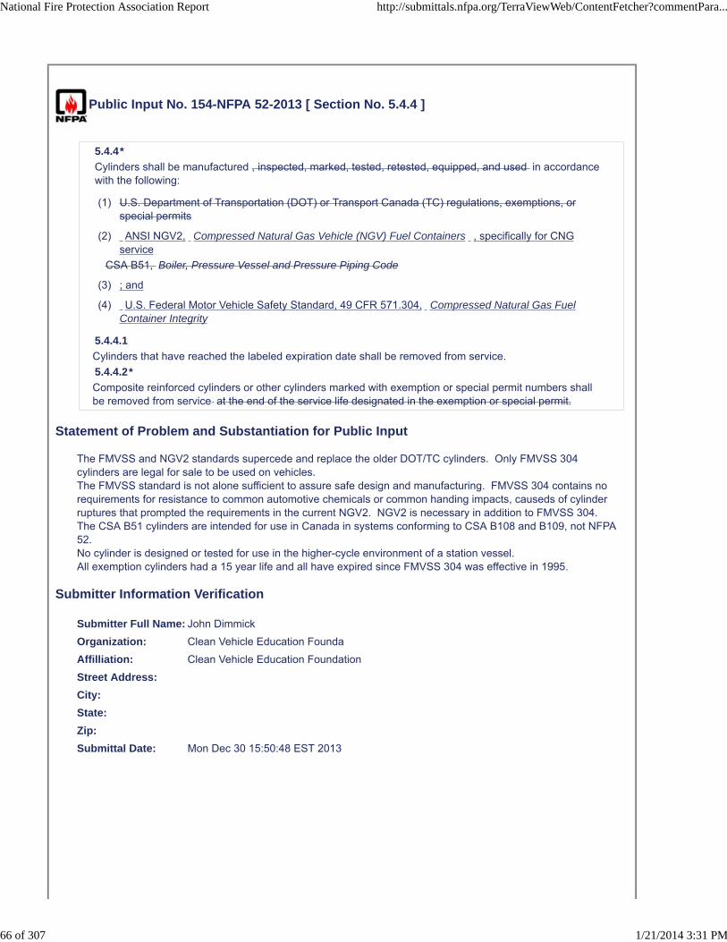
Public Input No. 154-NFPA 52-2013 [ Section No. 5.4.4 ]
5.4.4*
Cylinders shall be manufactured , inspected, marked, tested, retested, equipped, and used in accordancewith the following:
(1) U.S. Department of Transportation (DOT) or Transport Canada (TC) regulations, exemptions, orspecial permits
(2) ANSI NGV2, Compressed Natural Gas Vehicle (NGV) Fuel Containers , specifically for CNGservice
CSA B51, Boiler, Pressure Vessel and Pressure Piping Code
(3) ; and
(4) U.S. Federal Motor Vehicle Safety Standard, 49 CFR 571.304, Compressed Natural Gas FuelContainer Integrity
5.4.4.1
Cylinders that have reached the labeled expiration date shall be removed from service.
5.4.4.2*
Composite reinforced cylinders or other cylinders marked with exemption or special permit numbers shallbe removed from service at the end of the service life designated in the exemption or special permit.
Statement of Problem and Substantiation for Public Input
The FMVSS and NGV2 standards supercede and replace the older DOT/TC cylinders. Only FMVSS 304 cylinders are legal for sale to be used on vehicles.The FMVSS standard is not alone sufficient to assure safe design and manufacturing. FMVSS 304 contains no requirements for resistance to common automotive chemicals or common handing impacts, causeds of cylinder ruptures that prompted the requirements in the current NGV2. NGV2 is necessary in addition to FMVSS 304.The CSA B51 cylinders are intended for use in Canada in systems conforming to CSA B108 and B109, not NFPA 52.No cylinder is designed or tested for use in the higher-cycle environment of a station vessel.All exemption cylinders had a 15 year life and all have expired since FMVSS 304 was effective in 1995.
Submitter Information Verification
Submitter Full Name: John Dimmick
Organization: Clean Vehicle Education Founda
Affilliation: Clean Vehicle Education Foundation
Street Address:
City:
State:
Zip:
Submittal Date: Mon Dec 30 15:50:48 EST 2013
National Fire Protection Association Report http://submittals.nfpa.org/TerraViewWeb/ContentFetcher?commentPara...
66 of 307 1/21/2014 3:31 PM

Copyright Assignment
I, John Dimmick, hereby irrevocably grant and assign to the National Fire Protection Association (NFPA) all and full rights in copyright inthis Public Input (including both the Proposed Change and the Statement of Problem and Substantiation). I understand and intend that Iacquire no rights, including rights as a joint author, in any publication of the NFPA in which this Public Input in this or another similar orderivative form is used. I hereby warrant that I am the author of this Public Input and that I have full power and authority to enter into thiscopyright assignment.
By checking this box I affirm that I am John Dimmick, and I agree to be legally bound by the above Copyright Assignment and the termsand conditions contained therein. I understand and intend that, by checking this box, I am creating an electronic signature that will, upon mysubmission of this form, have the same legal force and effect as a handwritten signature
National Fire Protection Association Report http://submittals.nfpa.org/TerraViewWeb/ContentFetcher?commentPara...
67 of 307 1/21/2014 3:31 PM

Public Input No. 155-NFPA 52-2013 [ Section No. 5.4.4.1 ]
5.4.4.1
Cylinders that have reached the labeled expiration date shall be removed from service. Cylinders that aredisconnected and permanently depressurized may be left in place on the vehicle.
Statement of Problem and Substantiation for Public Input
Many cylinder mounting configurations attach two or more cylinders together and it is impractical to actually remove the decommissioned cylinder and continue yo operate the vehicle. If the vehicle was designed and certified IAW FMVSS 303, removing one cylinder may take it out of conformance with the tested configuration.
Submitter Information Verification
Submitter Full Name: John Dimmick
Organization: Clean Vehicle Education Founda
Affilliation: Clean Vehicle Education Foundation
Street Address:
City:
State:
Zip:
Submittal Date: Mon Dec 30 15:55:39 EST 2013
Copyright Assignment
I, John Dimmick, hereby irrevocably grant and assign to the National Fire Protection Association (NFPA) all and full rights in copyright inthis Public Input (including both the Proposed Change and the Statement of Problem and Substantiation). I understand and intend that Iacquire no rights, including rights as a joint author, in any publication of the NFPA in which this Public Input in this or another similar orderivative form is used. I hereby warrant that I am the author of this Public Input and that I have full power and authority to enter into thiscopyright assignment.
By checking this box I affirm that I am John Dimmick, and I agree to be legally bound by the above Copyright Assignment and the termsand conditions contained therein. I understand and intend that, by checking this box, I am creating an electronic signature that will, upon mysubmission of this form, have the same legal force and effect as a handwritten signature
National Fire Protection Association Report http://submittals.nfpa.org/TerraViewWeb/ContentFetcher?commentPara...
68 of 307 1/21/2014 3:31 PM
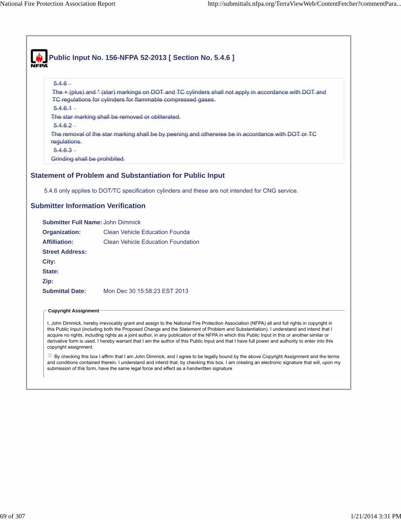
Public Input No. 156-NFPA 52-2013 [ Section No. 5.4.6 ]
5.4.6
The + (plus) and * (star) markings on DOT and TC cylinders shall not apply in accordance with DOT andTC regulations for cylinders for flammable compressed gases.
5.4.6.1
The star marking shall be removed or obliterated.
5.4.6.2
The removal of the star marking shall be by peening and otherwise be in accordance with DOT or TCregulations.
5.4.6.3
Grinding shall be prohibited.
Statement of Problem and Substantiation for Public Input
5.4.6 only applies to DOT/TC specification cylinders and these are not intended for CNG service.
Submitter Information Verification
Submitter Full Name: John Dimmick
Organization: Clean Vehicle Education Founda
Affilliation: Clean Vehicle Education Foundation
Street Address:
City:
State:
Zip:
Submittal Date: Mon Dec 30 15:58:23 EST 2013
Copyright Assignment
I, John Dimmick, hereby irrevocably grant and assign to the National Fire Protection Association (NFPA) all and full rights in copyright inthis Public Input (including both the Proposed Change and the Statement of Problem and Substantiation). I understand and intend that Iacquire no rights, including rights as a joint author, in any publication of the NFPA in which this Public Input in this or another similar orderivative form is used. I hereby warrant that I am the author of this Public Input and that I have full power and authority to enter into thiscopyright assignment.
By checking this box I affirm that I am John Dimmick, and I agree to be legally bound by the above Copyright Assignment and the termsand conditions contained therein. I understand and intend that, by checking this box, I am creating an electronic signature that will, upon mysubmission of this form, have the same legal force and effect as a handwritten signature
National Fire Protection Association Report http://submittals.nfpa.org/TerraViewWeb/ContentFetcher?commentPara...
69 of 307 1/21/2014 3:31 PM
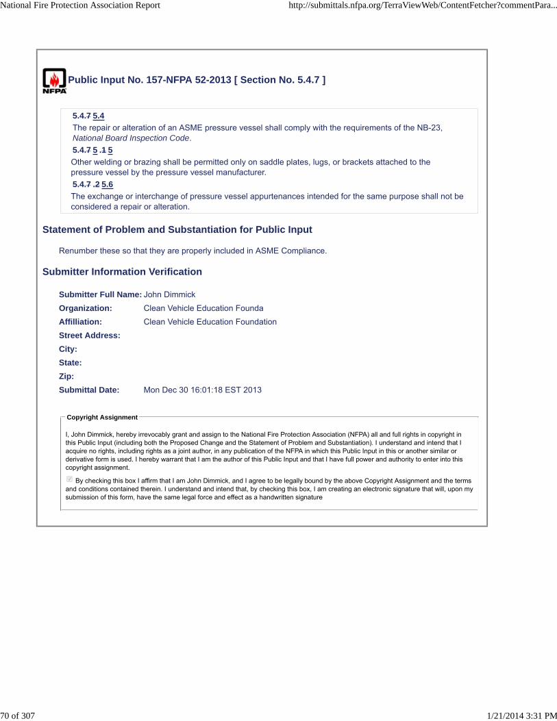
Public Input No. 157-NFPA 52-2013 [ Section No. 5.4.7 ]
5.4.7 5.4
The repair or alteration of an ASME pressure vessel shall comply with the requirements of the NB-23,National Board Inspection Code.
5.4.7 5 .1 5
Other welding or brazing shall be permitted only on saddle plates, lugs, or brackets attached to thepressure vessel by the pressure vessel manufacturer.
5.4.7 .2 5.6
The exchange or interchange of pressure vessel appurtenances intended for the same purpose shall not beconsidered a repair or alteration.
Statement of Problem and Substantiation for Public Input
Renumber these so that they are properly included in ASME Compliance.
Submitter Information Verification
Submitter Full Name: John Dimmick
Organization: Clean Vehicle Education Founda
Affilliation: Clean Vehicle Education Foundation
Street Address:
City:
State:
Zip:
Submittal Date: Mon Dec 30 16:01:18 EST 2013
Copyright Assignment
I, John Dimmick, hereby irrevocably grant and assign to the National Fire Protection Association (NFPA) all and full rights in copyright inthis Public Input (including both the Proposed Change and the Statement of Problem and Substantiation). I understand and intend that Iacquire no rights, including rights as a joint author, in any publication of the NFPA in which this Public Input in this or another similar orderivative form is used. I hereby warrant that I am the author of this Public Input and that I have full power and authority to enter into thiscopyright assignment.
By checking this box I affirm that I am John Dimmick, and I agree to be legally bound by the above Copyright Assignment and the termsand conditions contained therein. I understand and intend that, by checking this box, I am creating an electronic signature that will, upon mysubmission of this form, have the same legal force and effect as a handwritten signature
National Fire Protection Association Report http://submittals.nfpa.org/TerraViewWeb/ContentFetcher?commentPara...
70 of 307 1/21/2014 3:31 PM

Public Input No. 158-NFPA 52-2013 [ Section No. 5.5.1 ]
5.5.1
Each cylinder complying with 5.4.4 shall be fitted with one or more pressure relief devices (PRDs) withthe number, location, and part number as specified by the cylinder manufacturer
and OEM for CNG service for a new vehicle, in accordance with the following: For a retrofitted vehicle,each cylinder complying with 5.4.4 shall be of the number, location, and part number as specified by thecylinder manufacturer; or
(1) For an OEM, FSVIM or altered vehicle certified in accordance fith FMVSS 303, the PRD locationsand number shall be specified by the OEM, FSVIM or alterer .
(2) A PRD shall be marked and certified in accordance
with one of the following standards:
(3) CGA S-1.1, Pressure Relief Device Standards — Part 1 — Cylinders for Compressed Gases
ANSI/IAS PRD 1, Pressure Relief
(4) with ANSI PRD 1, Pressure Relief Devices for Natural Gas Vehicle (NGV) Fuel Containers
(5) ANSI/IAS PRD 1a, Addenda to ANSI/IAS PRD 1, Pressure Relief Devices for Natural Gas Vehicle(NGV) Fuel Containers
(6) ANSI/CSA PRD 1b, Addenda to ANSI/IAS PRD 1, Pressure Relief Devices for Natural Gas Vehicle(NGV) Fuel Containers
(7) The PRD shall be in direct communication with the fuel and vented to the atmosphere by a methodthat withstands the maximum pressure that results.
5.5.1.1
The discharge flow rate of the PRD shall not be reduced below that required for the capacity of thecontainer upon which the device is installed.
5.5.1.2
PRDs shall be located so that the temperature to which they are subjected is representative of thetemperature to which the fuel supply container is subjected.
5.5.1.3
Where parts of the vehicular fuel container are exposed to higher temperatures than the PRD during alocalized fire, the fuel container shall be protected by any of the following:
(1) Noncombustible heat-insulating shielding to retard localized heating of the container
(2) Installation of a thermally sensitive “fusing” system to trigger the PRD in a fire situation
(3) Other design for venting of the fuel container in a fire situation
Statement of Problem and Substantiation for Public Input
All PRDs should be in accordance with the ANSI standard developed specifical for NGV2/FMVSS cylinders and vehicle service conditionsCGA S1.1 PRDs are not intended for vehicle service but only for use on DOT spectfication hazardous material shipping cylinders. S-1.1 does not contain requrements appropriate for CNG vehicle cylinders or the vehicle service environment.The PRD location and number should be specified by FSVIMs and alterers in addition to OEMs.
Submitter Information Verification
Submitter Full Name: John Dimmick
Organization: Clean Vehicle Education Founda
National Fire Protection Association Report http://submittals.nfpa.org/TerraViewWeb/ContentFetcher?commentPara...
71 of 307 1/21/2014 3:31 PM

Affilliation: Clean Vehicle Education Foundation
Street Address:
City:
State:
Zip:
Submittal Date: Mon Dec 30 16:06:02 EST 2013
Copyright Assignment
I, John Dimmick, hereby irrevocably grant and assign to the National Fire Protection Association (NFPA) all and full rights in copyright inthis Public Input (including both the Proposed Change and the Statement of Problem and Substantiation). I understand and intend that Iacquire no rights, including rights as a joint author, in any publication of the NFPA in which this Public Input in this or another similar orderivative form is used. I hereby warrant that I am the author of this Public Input and that I have full power and authority to enter into thiscopyright assignment.
By checking this box I affirm that I am John Dimmick, and I agree to be legally bound by the above Copyright Assignment and the termsand conditions contained therein. I understand and intend that, by checking this box, I am creating an electronic signature that will, upon mysubmission of this form, have the same legal force and effect as a handwritten signature
National Fire Protection Association Report http://submittals.nfpa.org/TerraViewWeb/ContentFetcher?commentPara...
72 of 307 1/21/2014 3:31 PM

Public Input No. 29-NFPA 52-2013 [ Section No. 5.5.1 [Excluding any Sub-Sections] ]
Each cylinder complying with 5.4.4 shall be fitted with one or more pressure relief devices (PRDs) with thenumber, location, and part number as specified by the cylinder manufacturer and OEM for CNG service fora new vehicle, in accordance with the following:
(1) For a retrofitted vehicle, each cylinder complying with 5.4.4 shall be of the number, location, and partnumber as specified by the cylinder manufacturer.
(2) A PRD shall be in accordance with one of the following standards:
(a) CGA S-1.1, Pressure Relief Device Standards — Part 1 — Cylinders for Compressed Gases
(b) ANSI/IAS PRD 1, Pressure Relief Devices for Natural Gas Vehicle (NGV) Fuel Containers
(c) ANSI/IAS PRD 1a, Addenda to ANSI/IAS PRD 1, Pressure Relief Devices for Natural Gas Vehicle(NGV) Fuel Containers
(d) ANSI/CSA PRD 1b, Addenda to ANSI/IAS PRD 1, Pressure Relief Devices for Natural GasVehicle (NGV) Fuel Containers
(3) The PRD shall be in direct communication with the fuel and vented to the atmosphere by a methodthat withstands the maximum pressure that results. See Section 6.4 for venting systems for PRDs.
Statement of Problem and Substantiation for Public Input
The additional sentence provides clarity to the reader on where additional requirements for venting are found.
Submitter Information Verification
Submitter Full Name: Quon Kwan
Organization: US Department of Transportation
Street Address:
City:
State:
Zip:
Submittal Date: Fri Dec 13 16:42:09 EST 2013
Copyright Assignment
I, Quon Kwan, hereby irrevocably grant and assign to the National Fire Protection Association (NFPA) all and full rights in copyright in thisPublic Input (including both the Proposed Change and the Statement of Problem and Substantiation). I understand and intend that I acquireno rights, including rights as a joint author, in any publication of the NFPA in which this Public Input in this or another similar or derivativeform is used. I hereby warrant that I am the author of this Public Input and that I have full power and authority to enter into this copyrightassignment.
By checking this box I affirm that I am Quon Kwan, and I agree to be legally bound by the above Copyright Assignment and the termsand conditions contained therein. I understand and intend that, by checking this box, I am creating an electronic signature that will, upon mysubmission of this form, have the same legal force and effect as a handwritten signature
National Fire Protection Association Report http://submittals.nfpa.org/TerraViewWeb/ContentFetcher?commentPara...
73 of 307 1/21/2014 3:31 PM
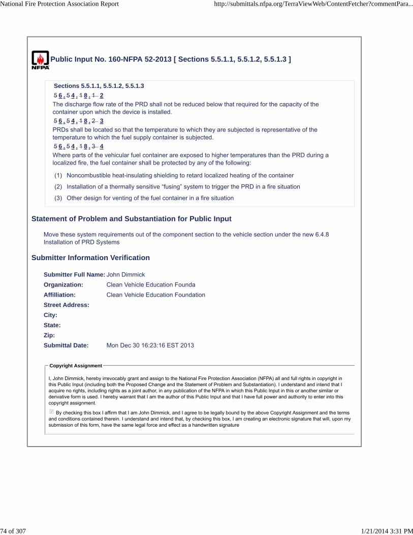
Public Input No. 160-NFPA 52-2013 [ Sections 5.5.1.1, 5.5.1.2, 5.5.1.3 ]
Sections 5.5.1.1, 5.5.1.2, 5.5.1.3
5 6 . 5 4 . 1 8 . 1 2
The discharge flow rate of the PRD shall not be reduced below that required for the capacity of thecontainer upon which the device is installed.
5 6 . 5 4 . 1 8 . 2 3
PRDs shall be located so that the temperature to which they are subjected is representative of thetemperature to which the fuel supply container is subjected.
5 6 . 5 4 . 1 8 . 3 4
Where parts of the vehicular fuel container are exposed to higher temperatures than the PRD during alocalized fire, the fuel container shall be protected by any of the following:
(1) Noncombustible heat-insulating shielding to retard localized heating of the container
(2) Installation of a thermally sensitive “fusing” system to trigger the PRD in a fire situation
(3) Other design for venting of the fuel container in a fire situation
Statement of Problem and Substantiation for Public Input
Move these system requirements out of the component section to the vehicle section under the new 6.4.8 Installation of PRD Systems
Submitter Information Verification
Submitter Full Name: John Dimmick
Organization: Clean Vehicle Education Founda
Affilliation: Clean Vehicle Education Foundation
Street Address:
City:
State:
Zip:
Submittal Date: Mon Dec 30 16:23:16 EST 2013
Copyright Assignment
I, John Dimmick, hereby irrevocably grant and assign to the National Fire Protection Association (NFPA) all and full rights in copyright inthis Public Input (including both the Proposed Change and the Statement of Problem and Substantiation). I understand and intend that Iacquire no rights, including rights as a joint author, in any publication of the NFPA in which this Public Input in this or another similar orderivative form is used. I hereby warrant that I am the author of this Public Input and that I have full power and authority to enter into thiscopyright assignment.
By checking this box I affirm that I am John Dimmick, and I agree to be legally bound by the above Copyright Assignment and the termsand conditions contained therein. I understand and intend that, by checking this box, I am creating an electronic signature that will, upon mysubmission of this form, have the same legal force and effect as a handwritten signature
National Fire Protection Association Report http://submittals.nfpa.org/TerraViewWeb/ContentFetcher?commentPara...
74 of 307 1/21/2014 3:31 PM

Public Input No. 161-NFPA 52-2013 [ Section No. 5.5.2.1 ]
5.5.2.1
The minimum rate of discharge of PRDs on containers shall be in accordance with CGA S-1.1, PressureRelief Device Standards — Part 1 — Cylinders for Compressed Gases , or the with the ASME Boiler andPressure Vessel Code, whichever is applicable.
Statement of Problem and Substantiation for Public Input
CGA S1.1 PRDs are not intended for use on NGV2 or FMVSS 304 cylinders. The rate of discharge tables in S-1.1 are not intended for these cylinders and the adequacy of a PRD must be demonstrated in a bonfire test with the cylinder.
Submitter Information Verification
Submitter Full Name: John Dimmick
Organization: Clean Vehicle Education Founda
Affilliation: Clean Vehicle Education Foundation
Street Address:
City:
State:
Zip:
Submittal Date: Mon Dec 30 16:26:46 EST 2013
Copyright Assignment
I, John Dimmick, hereby irrevocably grant and assign to the National Fire Protection Association (NFPA) all and full rights in copyright inthis Public Input (including both the Proposed Change and the Statement of Problem and Substantiation). I understand and intend that Iacquire no rights, including rights as a joint author, in any publication of the NFPA in which this Public Input in this or another similar orderivative form is used. I hereby warrant that I am the author of this Public Input and that I have full power and authority to enter into thiscopyright assignment.
By checking this box I affirm that I am John Dimmick, and I agree to be legally bound by the above Copyright Assignment and the termsand conditions contained therein. I understand and intend that, by checking this box, I am creating an electronic signature that will, upon mysubmission of this form, have the same legal force and effect as a handwritten signature
National Fire Protection Association Report http://submittals.nfpa.org/TerraViewWeb/ContentFetcher?commentPara...
75 of 307 1/21/2014 3:31 PM

Public Input No. 226-NFPA 52-2013 [ Section No. 5.6 ]
5.6 Pressure Gauges.
A pressure gauge, if provided, shall be capable of reading at least 1.2 times the system design maximumoperating pressure.
Statement of Problem and Substantiation for Public Input
Maximum operating pressure is defined and design pressure is not. Design pressure often applies to piping but MOP can apply to any subsystem.
Submitter Information Verification
Submitter Full Name: John Dimmick
Organization: Clean Vehicle Education Founda
Affilliation: Clean Vehicle Education Foundation
Street Address:
City:
State:
Zip:
Submittal Date: Tue Dec 31 12:40:41 EST 2013
Copyright Assignment
I, John Dimmick, hereby irrevocably grant and assign to the National Fire Protection Association (NFPA) all and full rights in copyright inthis Public Input (including both the Proposed Change and the Statement of Problem and Substantiation). I understand and intend that Iacquire no rights, including rights as a joint author, in any publication of the NFPA in which this Public Input in this or another similar orderivative form is used. I hereby warrant that I am the author of this Public Input and that I have full power and authority to enter into thiscopyright assignment.
By checking this box I affirm that I am John Dimmick, and I agree to be legally bound by the above Copyright Assignment and the termsand conditions contained therein. I understand and intend that, by checking this box, I am creating an electronic signature that will, upon mysubmission of this form, have the same legal force and effect as a handwritten signature
National Fire Protection Association Report http://submittals.nfpa.org/TerraViewWeb/ContentFetcher?commentPara...
76 of 307 1/21/2014 3:31 PM

Public Input No. 162-NFPA 52-2013 [ Section No. 5.7 ]
5.7 Pressure Regulators.
5.7.1
A pressure regulator inlet and each chamber shall be designed for its service maximum operatingpressure with a pressure safety factor of at least 4.
5.7.2
Low-pressure chambers shall provide for overpressure relief or be able to withstand the service maximumoperating pressure of the upstream pressure chamber.
Statement of Problem and Substantiation for Public Input
The term service pressure is relevant only for cylinders and dconnected components. Regulator maximum opwerating pressures may be greater than the cylinder service pressure by 25% or much less in the case of multi-stage regulation.
Submitter Information Verification
Submitter Full Name: John Dimmick
Organization: Clean Vehicle Education Founda
Affilliation: Clean Vehicle Education Foundation
Street Address:
City:
State:
Zip:
Submittal Date: Mon Dec 30 16:29:15 EST 2013
Copyright Assignment
I, John Dimmick, hereby irrevocably grant and assign to the National Fire Protection Association (NFPA) all and full rights in copyright inthis Public Input (including both the Proposed Change and the Statement of Problem and Substantiation). I understand and intend that Iacquire no rights, including rights as a joint author, in any publication of the NFPA in which this Public Input in this or another similar orderivative form is used. I hereby warrant that I am the author of this Public Input and that I have full power and authority to enter into thiscopyright assignment.
By checking this box I affirm that I am John Dimmick, and I agree to be legally bound by the above Copyright Assignment and the termsand conditions contained therein. I understand and intend that, by checking this box, I am creating an electronic signature that will, upon mysubmission of this form, have the same legal force and effect as a handwritten signature
National Fire Protection Association Report http://submittals.nfpa.org/TerraViewWeb/ContentFetcher?commentPara...
77 of 307 1/21/2014 3:31 PM

Public Input No. 12-NFPA 52-2013 [ New Section after 5.8.3 ]
TITLE OF NEW CONTENT - CNG Fuel piping placement/routing.
Type your content here ...
CNG fuel lines shall run the same course as the native fuel lines of the vehicle. If thevehicle native fuel lines of the vehicle are ran in a manner where they are within theframe rails AND away from excessive heat, drive shafts, away from crash crumple zonessuch as in unibody vehicle construction and also traditional truck body, THEN so shouldthe CNG fuel lines run in the like manner as the native fuel lines of the vehicle.
As in case of collision and vehicle damage - CNG fuel lines will remain out of crumplezones and shall be placed between the frame rails (or like unibody structure ridge) onthe high point of the inner frame face and also so that a service mechanic cannot crushthe fuel lines or components of the system when lifting the vehicle on a vehicle lifthoist.
The resilient 316 stainless steel CNG fuel lines shall be mounted with insulated clamps following thenative fuel lines as close a possible without interfering and contacting other components such asbrake lines, exhaust, drive shafts, body members, rotating parts, or pinch points.
Statement of Problem and Substantiation for Public Input
I have found many companies installing high pressure CNG fuel lines between and on the rocker panels and on the outside of the frame rails. These areas are the safety crumple zones of the vehicle occupant. These areas become compromised in a collison and the high pressure fuel lines will come loose, crack, leak, and possibly fly around violently maming or causing death either by contact or affixiation. If the NFPA 52 can address what type of fuel line (resiliant 316 stainless steel is prosumed but not explictated), the insolated mounts, mounting as so away from heat and obvious moving parts THEN it should also address the mounting of the high pressure fuel lines to be mounted on the vehicle in accordance to which the native fuel line were safely designed to be placed.
Submitter Information Verification
Submitter Full Name: Marvin Davis
Organization: MARVINSCNG
Street Address:
City:
State:
Zip:
Submittal Date: Tue Nov 12 11:58:09 EST 2013
Copyright Assignment
I, Marvin Davis, hereby irrevocably grant and assign to the National Fire Protection Association (NFPA) all and full rights in copyright in thisPublic Input (including both the Proposed Change and the Statement of Problem and Substantiation). I understand and intend that I acquireno rights, including rights as a joint author, in any publication of the NFPA in which this Public Input in this or another similar or derivativeform is used. I hereby warrant that I am the author of this Public Input and that I have full power and authority to enter into this copyrightassignment.
By checking this box I affirm that I am Marvin Davis, and I agree to be legally bound by the above Copyright Assignment and the termsand conditions contained therein. I understand and intend that, by checking this box, I am creating an electronic signature that will, upon mysubmission of this form, have the same legal force and effect as a handwritten signature
National Fire Protection Association Report http://submittals.nfpa.org/TerraViewWeb/ContentFetcher?commentPara...
78 of 307 1/21/2014 3:31 PM

Public Input No. 163-NFPA 52-2013 [ Section No. 5.9.1.1 ]
5.9.1.1
Shutoff valves shall have a rated service pressure not less than the rated service maximum operatingpressure of that portion of the entire system and system in which theye are installed and shall becapable of withstanding a hydrostatic test of at least four times the rated service Maximum operatingpressure pressure without rupture.
Statement of Problem and Substantiation for Public Input
Service pressure as defined is relevant only to the high-pressure portion of the system, not for any lower pressure portion. Service pressure is not a useful valve rating and it is never the maximum pressure since it may be exceeded by 25%. The valve design, selection and testing should be based on the maximum operating pressure.
Submitter Information Verification
Submitter Full Name: John Dimmick
Organization: Clean Vehicle Education Founda
Affilliation: Clean Vehicle Education Foundation
Street Address:
City:
State:
Zip:
Submittal Date: Mon Dec 30 16:31:22 EST 2013
Copyright Assignment
I, John Dimmick, hereby irrevocably grant and assign to the National Fire Protection Association (NFPA) all and full rights in copyright inthis Public Input (including both the Proposed Change and the Statement of Problem and Substantiation). I understand and intend that Iacquire no rights, including rights as a joint author, in any publication of the NFPA in which this Public Input in this or another similar orderivative form is used. I hereby warrant that I am the author of this Public Input and that I have full power and authority to enter into thiscopyright assignment.
By checking this box I affirm that I am John Dimmick, and I agree to be legally bound by the above Copyright Assignment and the termsand conditions contained therein. I understand and intend that, by checking this box, I am creating an electronic signature that will, upon mysubmission of this form, have the same legal force and effect as a handwritten signature
National Fire Protection Association Report http://submittals.nfpa.org/TerraViewWeb/ContentFetcher?commentPara...
79 of 307 1/21/2014 3:31 PM

Public Input No. 164-NFPA 52-2013 [ Sections 5.10.2, 5.10.3, 5.10.4 ]
Sections 5.10.2, 5.10.3, 5.10.4
5.10.2
Hose, metallic hose, flexible metal hose, tubing, and their connections shall be designed or selected for themost severe pressures and temperatures under normal operating conditions with a burst pressure of atleast four times the service maximum operating pressure.
5.10.3
Prior to use, hose assemblies shall be tested by the OEM Manufacturer or its designated representative ata pressure at least twice the service maximum operating pressure.
5.10.4
Hose and metallic hose shall be distinctly marked by the OEM or component manufacturer, either by themanufacturer's permanently attached tag or by distinct markings indicating the manufacturer's name ortrademark, applicable service identifier, and design maximum operating pressure.
Statement of Problem and Substantiation for Public Input
Service pressure is relevant only in the vehicle high-pressure system and hoses are often used at lower pressures of on stations where service pressure may have no meaning. Maximum operating pressure should be the basis for design and test.OEM has been defined as a vehicle manufacturer and not a hose manufacturer. Changing to hose manufacturer allows relevance for all vehicle or station hoses.
Submitter Information Verification
Submitter Full Name: John Dimmick
Organization: Clean Vehicle Education Founda
Affilliation: Clean Vehicle Education Foundation
Street Address:
City:
State:
Zip:
Submittal Date: Mon Dec 30 16:35:47 EST 2013
Copyright Assignment
I, John Dimmick, hereby irrevocably grant and assign to the National Fire Protection Association (NFPA) all and full rights in copyright inthis Public Input (including both the Proposed Change and the Statement of Problem and Substantiation). I understand and intend that Iacquire no rights, including rights as a joint author, in any publication of the NFPA in which this Public Input in this or another similar orderivative form is used. I hereby warrant that I am the author of this Public Input and that I have full power and authority to enter into thiscopyright assignment.
By checking this box I affirm that I am John Dimmick, and I agree to be legally bound by the above Copyright Assignment and the termsand conditions contained therein. I understand and intend that, by checking this box, I am creating an electronic signature that will, upon mysubmission of this form, have the same legal force and effect as a handwritten signature
National Fire Protection Association Report http://submittals.nfpa.org/TerraViewWeb/ContentFetcher?commentPara...
80 of 307 1/21/2014 3:31 PM

Public Input No. 165-NFPA 52-2013 [ Section No. 5.11.2 ]
5 7 . 11 14 . 2 x
The use of adapters shall with the dispenser nozzle shall be prohibited.
Statement of Problem and Substantiation for Public Input
This prohibition should be relocated since it is relevant to station operation. The wording also clarifies that it is relevant to the dispenser nozzle that is pressure-specific.
Submitter Information Verification
Submitter Full Name: John Dimmick
Organization: Clean Vehicle Education Founda
Affilliation: Clean Vehicle Education Foundation
Street Address:
City:
State:
Zip:
Submittal Date: Mon Dec 30 16:38:51 EST 2013
Copyright Assignment
I, John Dimmick, hereby irrevocably grant and assign to the National Fire Protection Association (NFPA) all and full rights in copyright inthis Public Input (including both the Proposed Change and the Statement of Problem and Substantiation). I understand and intend that Iacquire no rights, including rights as a joint author, in any publication of the NFPA in which this Public Input in this or another similar orderivative form is used. I hereby warrant that I am the author of this Public Input and that I have full power and authority to enter into thiscopyright assignment.
By checking this box I affirm that I am John Dimmick, and I agree to be legally bound by the above Copyright Assignment and the termsand conditions contained therein. I understand and intend that, by checking this box, I am creating an electronic signature that will, upon mysubmission of this form, have the same legal force and effect as a handwritten signature
National Fire Protection Association Report http://submittals.nfpa.org/TerraViewWeb/ContentFetcher?commentPara...
81 of 307 1/21/2014 3:31 PM

Public Input No. 106-NFPA 52-2013 [ Chapter 6 ]
Chapter 6 CNG Engine Fuel Systems
National Fire Protection Association Report http://submittals.nfpa.org/TerraViewWeb/ContentFetcher?commentPara...
82 of 307 1/21/2014 3:31 PM
6.1 * Application.
6.1.1
This chapter applies to the design, installation, inspection, and testing of CNG fuel supply systems forvehicular internal combustion engines.
6.1.2 * Final-Stage Vehicle Integrator/Manufacturer.
6.1.2.1 *
The FSVIM shall have the responsibility for integration of the engine, fuel system, and gaseous detectionsystem, where required, onto the vehicle chassis and for the operation of the vehicle.
6.1.2.2
The FSVIM shall obtain, when available, documented approval of the chassis original equipment andcomponent manufacturers of the onboard fuel and detection systems components, proper installation, andapplication from each of the following:
(1) Vehicle
(2) Chassis
(3) Engine
(4) Gas detection
(5) Fuel system
6.1.2.3
Modifications of a vehicle gaseous fuel system shall conform with, when available, the engineeringrecommendations of the original specifications of the original chassis vehicle manufacturer.
6.2 System Component Qualifications.
6.2.1
System components shall comply with the applicable provisions of Chapter 5 and this section.
6.2.2 Temperature Range.
6.2.2.1
Components in the engine compartment shall be designed or selected for a minimum temperature range of-40°F to 250°F (-40°C to 121°C).
6.2.2.2
All other components shall be designed or selected for service per the OEM's engineering requirements.
6.2.3
Aluminum or copper pipe, tubing, or fittings shall not be used between the fuel container and the first-stagepressure regulator.
6.2.4
Fuel-carrying components, with the exception of container valves, tubing, and fittings, shall be labeled orstamped with the following:
(1) Manufacturer's name or symbol
(2) Model designation
(3) Design service pressure
(4) Direction of fuel flow where necessary for correct installation
(5) Capacity or electrical rating, as applicable
6.3 Installation of Fuel Supply Containers.
6.3.1
Fuel supply containers shall be installed in accordance with the instructions of the container manufacturerand the requirements in 6.3.2 through 6.3.10.
6.3.2
Fuel supply containers on vehicles shall be permitted to be located within, below, or above the driver orpassenger compartment, provided all connections to the container(s) are external to, or sealed and ventedfrom, these compartments.
National Fire Protection Association Report http://submittals.nfpa.org/TerraViewWeb/ContentFetcher?commentPara...
83 of 307 1/21/2014 3:31 PM

6.3.2.1
Fuel supply containers shall be protected with a means to prevent damage that occurs due to roadhazards, loading, unloading, direct sunlight, exhaust heat, and vehicle use, including accidental cargoleakage.
6.3.2.2
Shields, if present, shall be installed in a manner that prevents damage to the shield or coating in thefollowing occurrences:
(1) Direct contact between the shield and the fuel supply container
(2) Trapping of solid materials or liquids between the shield and fuel supply container
6.3.2.3
The fuel supply container shall be positioned to prevent contact with vehicle components such as, but notlimited to, frame members, body panels, or brake lines that leads to container fretting or abrasion overtime.
6.3.3
Vehicle fuel supply containers shall be mounted in a location to minimize damage from collision.
6.3.3.1
Containers shall be protected by covers from accidental contact with overhead electrical wiring.
6.3.3.2 *
The fuel system, including containers, shall be installed with as much road clearance as practical.
6.3.3.3
This minimum clearance shall be measured from the road to the container, its housing, or its fittings,whichever is lowest, and shall not, with the vehicle loaded to its gross weight rating, allow any componentto touch the road surface in the event of a flat tire or the removal of any tire.
6.3.3.4
No portion of a fuel supply container or container appurtenance mounted on the undercarriage of thevehicle shall be located ahead of the front axle or behind the point of attachment of the rear bumper to thevehicle.
6.3.3.4.1
Container valves shall be protected from physical damage using the vehicle structure, valve protectors, ora metal shield.
6.3.3.5
No part of the fuel supply container or its appurtenances shall protrude beyond the sides or top of anyvehicle to prevent the container from being struck or punctured.
6.3.4
Each fuel supply container rack shall be secured to the vehicle body, bed, or frame to prevent damage fromroad hazards, slippage, loosening, or rotation using a method capable of withstanding a static force in thesix principal directions shown in Figure 6.3.4 of eight times the weight of a fully pressurized container(s).
Figure 6.3.4 The Six Principal Directions.
National Fire Protection Association Report http://submittals.nfpa.org/TerraViewWeb/ContentFetcher?commentPara...
84 of 307 1/21/2014 3:31 PM

6.3.5
Each fuel supply container in the rack shall be secured to its cradle in a manner that it is capable ofwithstanding a static force, applied in the six principal directions (see Figure 6.3.4), of eight times theweight of the fully pressurized container with a maximum displacement of 0.50 in. (13 mm).
6.3.6
The fuel supply container weight shall not be supported by outlet valves, manifolds, or other fuelconnections.
6.3.7
Fuel supply containers located less than 8 in. (200 mm) from the exhaust system shall be shielded againstdirect heat.
6.3.8
The mounting system shall minimize fretting corrosion between the fuel supply container and the mountingsystem.
6.3.9
Fuel supply containers shall not be installed so as to adversely affect the driving characteristics of thevehicle.
6.3.10
Metal clamping bands and their supports shall not be in direct contact with a fuel supply container.
6.3.10.1
A resilient gasket that does not retain water shall be installed between the clamping bands and theirsupports and a container.
6.3.10.2
The resilient gasket shall provide insulation to protect clamping bands from galvanic corrosion in contactwith the containers.
6.4 * Installation of Venting Systems.
6.4.1 *
All pressure relief devices and connections between pressure-carrying components installed within driver,passenger, or a closed compartment (see 6.4.7) shall be vented to the outside of the vehicle.
6.4.1.1
This requirement shall not include plugs in the ends of containers with openings in each end.
6.4.2
The venting system shall be secured at intervals in such a manner as to minimize the possibility ofdamage, corrosion, breakage, or dislocation due to gas flow forces during venting, expansion, contraction,vibration, strains, or wear and to preclude any loosening while in operation.
6.4.3
The vent or vents for the venting system shall not exit into a wheel well.
6.4.4
A vent shall not restrict the operation of a container pressure relief device or pressure relief device channel.
6.4.5
Means shall be provided to prevent water, dirt, insects, and any foreign objects from collecting in the ventlines or pressure relief devices.
6.4.6
Protective devices in 6.4.5 shall not restrict the flow of gas.
6.4.7 Gastight Enclosures.
6.4.7.1
The neck of the container and all CNG fittings within the compartment shall be enclosed in a gastightenclosure made of linear, low-density polyethylene having a minimum thickness of 8 mils (0.20 mm) or anequally gastight alternate enclosure that is vented directly to the outside of the vehicle.
6.4.7.2
The gastight enclosure shall not be constructed of fire-resistant material.
National Fire Protection Association Report http://submittals.nfpa.org/TerraViewWeb/ContentFetcher?commentPara...
85 of 307 1/21/2014 3:31 PM
6.4.8
Where located in a vehicle compartment capable of accumulating natural gas, a container shall be installedso that the following conditions are met:
(1) The pressure relief device (PRD) for the protection of the container is installed in the same vehiclecompartment as the container.
(2) The discharge from the PRD is vented to the outside through an electrically conductive tube or hose,which shall be in accordance with the following:
(a) The tube or hose is secured at intervals in such a manner as to minimize the possibility ofdamage, corrosion, or breakage of either the vent line or the pressure relief device due toexpansion, contraction, vibration, strains, or wear and to preclude any loosening while inoperation.
(b) The tube or hose has a burst pressure of at least 1 1⁄2 times the pressure in the vent that resultsfrom activation of the PRD.
(3) The vent opening is not blocked by debris thrown up from the road, such as snow, ice, mud, and soforth, or otherwise affected by the elements.
6.5 Installation of Piping.
6.5.1
Manifolds connecting fuel containers shall be fabricated to minimize vibration.
6.5.1.1
Manifolds shall be installed in a protected location or shielded to prevent damage from unsecured objects.
6.5.2
Manifolds connecting containers or container pressure relief devices shall be designed to vent gas from theindividual container(s) exposed to a fire so that all containers meet the requirements of Section 5.5.
6.5.3
A pipe thread jointing material impervious to the action of the natural gas used in the system shall beapplied to all male pipe threads prior to assembly.
6.5.4
Piping and fittings shall be clear and free from cutting or threading burrs and scales.
6.5.4.1
The ends of all piping shall be reamed.
6.5.5
Where necessary to prevent abrasion, fuel lines passing through a panel shall be protected by grommetsor other protective devices.
6.5.6
Fuel lines shall have clearance from the engine exhaust system to protect the fuel lines from excessiveheat by durable and effective means.
6.5.7
Fuel lines shall be mounted, braced, and supported to minimize vibration.
6.5.7.1
Fuel lines shall be protected against damage, corrosion, or breakage due to strain or wear.
6.5.8
A bend in piping or tubing shall be prohibited where such a bend weakens the piping or tubing.
6.5.9
Joints or connections on piping systems shall be located in an accessible location.
6.5.10
Where a fuel supply container is located on a trailer, the fuel supply line shall contain an emergencybreakaway device designed to retain CNG on both sides of the breakaway point.
6.6 Installation of Valves.
6.6.1
National Fire Protection Association Report http://submittals.nfpa.org/TerraViewWeb/ContentFetcher?commentPara...
86 of 307 1/21/2014 3:31 PM

Every cylinder shall be equipped with either of the following:
(1) A manual valve
(2) A normally closed, remotely actuated shutoff valve connected directly to the cylinder and equipped tobleed the cylinder manually
6.6.1.1
Vehicles with more than one fuel supply container, where each container is equipped with a normallyclosed remotely actuated shutoff valve, shall have an automatic system to detect the failure of any one ofthe valves.
6.6.2
In addition to the valve required by 6.6.1, a manual shutoff valve or a normally closed, automaticallyactuated shutoff valve shall be installed that allows isolation of the container(s) from the remainder of thefuel system.
6.6.2.1
An additional manual shutoff valve shall not be required on vehicles that are not normally operated onpublic streets, that have a single fuel supply cylinder, and that are equipped with an accessible manualcylinder shutoff valve.
6.6.2.2
The valve shall be mounted and shielded or installed in a protected location to minimize damage fromvibration and unsecured objects.
6.6.2.3
Where a manual shutoff valve is used, it shall be in an accessible location.
6.6.2.3.1
The manual shutoff valve shall have not more than 90 degrees rotation (quarter turn fuel delivery valve)from the open to the closed positions.
6.6.2.4
Access to the manual shutoff valves shall not require the use of any key or tool.
6.6.2.5
Where a manual valve is used, the valve location shall be indicated by means of a decal or label containingthe words “MANUAL SHUTOFF VALVE.”
6.6.2.6
A weather-resistant decal or label with red, blue, or black letters on a white or silver reflective backgroundshall be used.
6.6.2.7
The valve required by 6.6.2 shall not be used to introduce high-pressure gas to downstream componentsof the fuel system that have previously been depressurized.
6.6.3
A valve that automatically prevents the flow of gaseous fuel to the engine when the engine is not running,even if the ignition is switched on, shall be provided in the system.
6.6.4 *
Where multiple fuel systems are installed on the vehicle, automatic valves shall be provided, as necessary,to shut off the fuel not being used.
6.6.5
The fueling system shall be equipped with a backflow check valve that prevents the return flow of gas fromthe container(s) to the filling connection.
6.6.5.1
The backflow check valve shall be mounted to withstand the breakaway force specified in 7.11.6.2.
6.6.5.2
A second check valve shall be located between the fueling receptacle and the fuel supply containers.
6.7 Installation of Pressure Gauges.
6.7.1
Pressure gauges located within a driver or passenger compartment shall be installed in such a manner thatno gas flows into the passenger compartment in the event of failure.
National Fire Protection Association Report http://submittals.nfpa.org/TerraViewWeb/ContentFetcher?commentPara...
87 of 307 1/21/2014 3:31 PM

6.7.2
Pressure gauges installed outside a driver or passenger compartment shall be equipped with a limitingorifice, a shatterproof lens, and a body relief.
6.7.3
Pressure gauges shall be mounted, shielded, and installed in a protected location to prevent damage fromvibration and unsecured objects.
6.8 Installation of Pressure Regulators.
6.8.1
An automatic pressure-reducing regulator(s) shall be installed to reduce the fuel container pressure to alevel consistent with the service pressure required by the gas–air mixer, throttle body, or fuel injectors.
6.8.2
Means shall be provided to prevent regulator malfunctions due to refrigeration effects.
6.8.3
Regulators shall be installed so that their weight is not placed on, or supported by, the attached gas lines.
6.9 Installation of Fueling Connection.
6.9.1
Fueling connections installed on vehicles less than 10,000 lb (4500 kg) gross vehicle weight rating(GVWR) shall be in accordance with Section 5.11.
6.9.1.1
Larger vehicles such as buses and trucks shall be permitted to use fueling connections that are designedto prevent the connection of a lower service pressure vehicle to a higher service pressure source.
6.9.2
The fueling connection receptacle shall be mounted to withstand the breakaway force specified in 7.11.6.2.
6.9.3
The receptacle shall be installed in accordance with the manufacturer's instructions.
6.9.4
The clearance around the fueling connection shall be free of interference that prevents the connection ofthe fueling nozzle.
6.9.5 Service Pressure.
6.9.5.1
The service pressure of the fueling connection receptacle shall not exceed the marked service pressure ofthe fuel supply cylinders.
6.9.5.2
The service pressure of the fueling receptacle shall not exceed 80 percent of the set pressure of any reliefvalves installed on fuel supply containers in the vehicle.
6.10 Wiring Installation.
6.10.1
Wiring shall be secured and protected from abrasion and corrosion to the same standard as the originalwiring on the vehicle.
6.10.2
All wiring shall be sized according to the Society of Automotive Engineers (SAE) and fuse-protected.
6.11 Labeling.
6.11.1
National Fire Protection Association Report http://submittals.nfpa.org/TerraViewWeb/ContentFetcher?commentPara...
88 of 307 1/21/2014 3:31 PM

A vehicle equipped with a CNG fuel system shall bear the following durable labels:
(1) A label readily visible and located in the engine compartment shall include the following:
(a) Identification as a CNG-fueled vehicle
(b) System service pressure
(c) Installer's name or company
(d) Fuel container life expires (insert date for limited-life fuel containers. This label item not requiredfor containers with unlimited life.)
(e) Total container water volume in gallons (liters)
(f) Date by which fuel containers are to be inspected (insert date) and every (insert number)months thereafter
(2) A label located at the fueling connection receptacle shall include the following:
(a) Identification as a CNG-fueled vehicle
(b) System service pressure
(c) Fuel container life expires (insert date for limited-life fuel containers. This label item not requiredfor containers with unlimited life.)
(d) Fuel containers are to be inspected by (insert date) and each (insert number) months thereafter.
6.11.1.1
The fuel container inspection dates shall be changed after each required container inspection to denote thenext required inspection date and shall be permitted on a separate additional label.
6.11.2
If both labels are located in one of the above areas, the labels shall be permitted to be combined into asingle label.
6.11.3
In addition to the label(s) required by 6.11.1, each vehicle shall be identified with a weather-resistant,diamond-shaped label located on the exterior vertical surface or near-vertical surface on the lower rightrear of the vehicle other than on the bumper of the vehicle.
6.11.3.1
The labels for vehicles less than Class 6 shall be a minimum of 4.72 in. long × 3.27 in. high (120 mm × 83mm).
6.11.3.2
The labels for Class 6 vehicles and greater shall be a minimum of 5.7 in. long × 4.2 in. high (145 mm × 107mm).
6.11.3.3
The marking in the label required by 6.11.3.1 shall consist of a border and the letters “CNG” [1 in. (25 mm)minimum height centered in the diamond] of silver or white reflective luminous material on a bluebackground.
6.11.3.4
The marking in the label required by 6.11.3.2 shall consist of a border and the letters “CNG” [1.2 in. (30mm) minimum height centered in the diamond] of silver or white reflective luminous material on a bluebackground.
6.11.4
Each assembly of CNG containers shall be permanently labeled near the container valve as follows:
DANGER. Venting of the pressure from this system requires the use of special instructions or tools thatcan be obtained from the manufacturer [Insert the name, telephone number, and email address of the
vehicle manufacturer or system installer].
6.12 System Testing.
6.12.1 *
The completed fuel system assembly shall be leak tested using natural gas or inert gas.
6.12.2
Before use, every connection shall be verified leak free with a noncorrosive leak detector solution or a leakdetector instrument after the equipment is connected and pressurized to its service pressure.
National Fire Protection Association Report http://submittals.nfpa.org/TerraViewWeb/ContentFetcher?commentPara...
89 of 307 1/21/2014 3:31 PM

6.12.3
If the completed assembly is leak tested with natural gas, the testing shall be done under ventilatedconditions.
6.12.4 *
Where a vehicle is involved in an accident or fire causing damage to the CNG container, or if the containeris subjected to a pressure greater than 125 percent of service pressure, the CNG container shall bereplaced or removed, inspected, and retested in accordance with the document under which it wasoriginally manufactured before being returned to service.
6.12.5
Where a vehicle is involved in an accident or fire causing damage to any part of the CNG fuel system, thesystem shall be repaired and retested (see Section 6.13) before being returned to service.
6.12.6
Where a CNG container is removed from a vehicle in order to be installed within a different vehicle, it shallbe inspected or retested in accordance with the inspection or requalification procedures of the standardunder which it was originally manufactured before it is reinstalled.
6.13 System Maintenance and Repair.
National Fire Protection Association Report http://submittals.nfpa.org/TerraViewWeb/ContentFetcher?commentPara...
90 of 307 1/21/2014 3:31 PM

6.13.1
Damaged fuel lines shall be replaced and not repaired.
6.13.2
All containers, container appurtenances, piping systems, venting systems, and other components shall bemaintained in accordance with the manufacturer's requirements.
6.13.3
Vehicle fuel supply containers shall be inspected in accordance with the vehicle label required in 6.11.1and one of the following:
(1) Vehicle manufacturer’s instructions
(2) Container manufacturer’s instructions
6.13.3.1
Fuel containers whose service life has expired shall be removed from service.
6.13.3.2
After periodic container inspection, a label showing the next required inspection date shall be affixed asrequired in 6.11.1.
6.13.4
Pressure relief devices on fuel containers shall be maintained in accordance with the following:
(1) Pressure relief device channels or other parts that interfere with the functioning of the device shall notbe plugged by paint or accumulation of dirt.
(2) Only qualified personnel shall be permitted to service pressure relief devices.
(3) Only assemblies or original manufacturer's parts shall be used in the repair of pressure relief devicesunless the interchange of parts has been proved by tests.
(4) No pressure relief device that has been in service shall be reinstalled on another fuel cylinder.
6.13.5
The following shall be done during vehicle maintenance:
(1) Ensure the engine is isolated from the fuel supply unless engine operation is required. If a manualisolation valve is used, it shall comply with 6.6.2.
(2) Prohibit torches, welding, or grinding equipment on or near high-pressure fuel lines and containers.
(3) Prevent damage to containers, including actions such as dropping, dragging, or rolling of thecontainer.
(4) Prevent exposure of containers to strong chemicals such as battery acid or metal-cleaning solvents.
(5) Store CNG containers in a manner to avoid damage.
(6) Reinstall containers to their original configuration using approved gaskets, bolts, nuts, washers, andparts in accordance with the recommendations of the container manufacturer.
(7) Prevent hoists or jacks from coming into direct contact with containers.
(8) Prohibit personnel from walking on roof-mounted containers.
6.14 Discharge from Vehicle Containers.
6.14.1
The venting or depressurization of a CNG container shall be performed only by trained personnel usingwritten procedures.
6.14.1.1
The gas to be removed from the container shall be discharged into a closed transfer system or vented byan approved method of atmospheric venting.
6.14.1.2
A valve shall be used to control the discharge of gas from high-pressure systems to a venting system.
National Fire Protection Association Report http://submittals.nfpa.org/TerraViewWeb/ContentFetcher?commentPara...
91 of 307 1/21/2014 3:31 PM

6.14.2
Personnel performing container depressurization shall do the following:
(1) Use grounding to prevent static electrical charge buildup.
(2) Limit the rate of gas release from plastic-lined containers to a value not greater than that specified bythe container manufacturer.
(3) Restrain containers during depressurization to prevent container movement.
6.14.3
Direct gas venting shall be done through a vent tube that diverts the gas flow to atmosphere.
6.14.3.1
The vent tube shall have a gastight connection to the container prior to venting.
6.14.3.1.1
All components of the vent tube shall be grounded.
6.14.3.2
The vent tube shall be constructed of Schedule 80 pipe of at least 2 in. (51 mm) diameter.
6.14.3.3
The vent tube shall not be provided with any feature that limits or obstructs gas flow.
6.14.4 *
All vehicles shall be provided with a venting system to allow the high pressure portion of the CNG fuelsystem to be vented for service.
6.14.4.1
It shall not be required to break any connections while under pressure in order to vent the high pressureportion of the CNG fuel system.
6.14.4.1.1
A connection for an external vent system shall be provided.
6.14.4.2
The venting function shall be manually controlled.
6.14.4.3
All high pressure portions of the CNG fuel system shall be capable of being vented.
6.14.4.4
The vehicle manufacturer or system installer shall provide written venting instructions and specify anyspecial tools needed for venting.
Replace Chapter 6 with the attached Chapter 6 Gas Detection, Alarm, and Emergency ShutdownSystems
Additional Proposed Changes
File Name Description Approved
NFPA_52_Public_Input_Chapter_6_Gas_Detection_Alarm_and_Emergency_Shutdown_Systems.docx
NFPA 52 Chapter 6 Gas Detection, Alarm, and Emergency Shutdown Systems
Statement of Problem and Substantiation for Public Input
The NFPA 52 Technical Committee approved the reorganization of NFPA 52 into an organizational layout that restructured requirements into General Requirements, Fuel Specific Requirements and Use Specific Requirements. This Chapter replaces existing Chapter 6 and was developed by a Task Group. For this draft being submitted as a Public Input, existing code sections have only been reorganized. No new or revised language has been included or any requirements deleted.
National Fire Protection Association Report http://submittals.nfpa.org/TerraViewWeb/ContentFetcher?commentPara...
92 of 307 1/21/2014 3:31 PM

Submitter Information Verification
Submitter Full Name: Nancy Pehrson
Organization: CenterPoint Energy, Inc.
Street Address:
City:
State:
Zip:
Submittal Date: Thu Dec 26 13:00:27 EST 2013
Copyright Assignment
I, Nancy Pehrson, hereby irrevocably grant and assign to the National Fire Protection Association (NFPA) all and full rights in copyright inthis Public Input (including both the Proposed Change and the Statement of Problem and Substantiation). I understand and intend that Iacquire no rights, including rights as a joint author, in any publication of the NFPA in which this Public Input in this or another similar orderivative form is used. I hereby warrant that I am the author of this Public Input and that I have full power and authority to enter into thiscopyright assignment.
By checking this box I affirm that I am Nancy Pehrson, and I agree to be legally bound by the above Copyright Assignment and theterms and conditions contained therein. I understand and intend that, by checking this box, I am creating an electronic signature that will,upon my submission of this form, have the same legal force and effect as a handwritten signature
National Fire Protection Association Report http://submittals.nfpa.org/TerraViewWeb/ContentFetcher?commentPara...
93 of 307 1/21/2014 3:31 PM

Chapter 6 Gas Detection, Alarm, and Emergency Shutdown Systems
6.1General
6.1.1GasDetection 5.3.1* The following systems and system components gas detection equipment and alarms shall be listed or approved (See 4.1.7.1). 7.4.3.6 Where installed, a gas detection system shall be equipped to sound a latched alarm and visually indicate when a maximum of one‐fifth of the lower flammable limit is reached.
6.1.2FlameDetection(reserved)
6.1.3EmergencyShutdown(reserved)
6.2CNGSupplementalRequirements
6.2.1GasDetection 7.4.3.12.1 Where attended fast‐fill fueling is performed indoors, the following shall be installed: (1) An emergency manual shutdown device shall be installed as required by 7.11.5. (2) A gas detection system equipped to sound a latched alarm and visually indicate when a maximum of one‐fifth of the lower flammable limit is reached shall be installed. 7.4.3.12.2 The actuation of the gas detection system shall shut down the compressor and stop the flow of gas into the structure.
Commented [L1]: I’m not sure if this x-ref would add value, but it seemed appropriate enough for consideration.
Commented [BS2]: This change would have to made as a public input.
6.2.1.1OdorizedCNG(reserved)
6.2.1.2Non‐OdorizedCNG(reserved)
6.2.2FlameDetection(reserved)
6.2.3EmergencyShutdown (reserved)
6.3LNGSupplementalRequirements
6.3.1GasDetection10.2.4.4 A gas detection system shall be provided in all buildings containing LNG. 10.2.4.4.3 The gas detection system shall not be shut down during fueling operations.
6.3.2FlameDetection (reserved)
6.3.3EmergencyShutdown (reserved)

Public Input No. 166-NFPA 52-2013 [ Section No. 6.1.2 ]
6.1.2* Responsibilities of OEM, Final-Stage Vehicle Integrator/Manufacturer., vehicle alterer orconverter.
6.1.2.1*
The FSVIM shall Shall have the responsibility for integration of the engine, fuel system, and gaseousdetection system, where required, onto the vehicle chassis and for the operation of the vehicle.
6.1.2.2
The FSVIM shall Shall obtain, when available, documented approval of the chassis original equipment andcomponent manufacturers of the onboard fuel and detection systems components, proper installation, andapplication from each of the following:
(1) Vehicle
(2) Chassis
(3) Engine
(4) Gas detection
(5) Fuel system
6.1.2.3
Modifications of a vehicle gaseous fuel system shall conform with, when available, the engineeringrecommendations of the original specifications of the original chassis vehicle manufacturer.
Statement of Problem and Substantiation for Public Input
The responsibilities in this section are not only those of the FSVIM but of anyone who installs CNG systems on vehicles.
Submitter Information Verification
Submitter Full Name: John Dimmick
Organization: Clean Vehicle Education Founda
Affilliation: CleanVehicle Education Foundation
Street Address:
City:
State:
Zip:
Submittal Date: Mon Dec 30 16:42:20 EST 2013
Copyright Assignment
I, John Dimmick, hereby irrevocably grant and assign to the National Fire Protection Association (NFPA) all and full rights in copyright inthis Public Input (including both the Proposed Change and the Statement of Problem and Substantiation). I understand and intend that Iacquire no rights, including rights as a joint author, in any publication of the NFPA in which this Public Input in this or another similar orderivative form is used. I hereby warrant that I am the author of this Public Input and that I have full power and authority to enter into thiscopyright assignment.
By checking this box I affirm that I am John Dimmick, and I agree to be legally bound by the above Copyright Assignment and the termsand conditions contained therein. I understand and intend that, by checking this box, I am creating an electronic signature that will, upon mysubmission of this form, have the same legal force and effect as a handwritten signature
National Fire Protection Association Report http://submittals.nfpa.org/TerraViewWeb/ContentFetcher?commentPara...
94 of 307 1/21/2014 3:31 PM

Public Input No. 167-NFPA 52-2013 [ Section No. 6.2.2.1 ]
6.2.2.1
Components in the engine compartment shall be designed or selected for a for the service conditionsspecified by the OEM or in the absence of such specifications for a minimum temperature range of -40°Fto 250°F (-40°C to 121°C).
Statement of Problem and Substantiation for Public Input
The OEM service conditins should be used wherever available.
Submitter Information Verification
Submitter Full Name: John Dimmick
Organization: Clean Vehicle Education Founda
Affilliation: Clean Vehicle Education Foundation
Street Address:
City:
State:
Zip:
Submittal Date: Mon Dec 30 16:45:56 EST 2013
Copyright Assignment
I, John Dimmick, hereby irrevocably grant and assign to the National Fire Protection Association (NFPA) all and full rights in copyright inthis Public Input (including both the Proposed Change and the Statement of Problem and Substantiation). I understand and intend that Iacquire no rights, including rights as a joint author, in any publication of the NFPA in which this Public Input in this or another similar orderivative form is used. I hereby warrant that I am the author of this Public Input and that I have full power and authority to enter into thiscopyright assignment.
By checking this box I affirm that I am John Dimmick, and I agree to be legally bound by the above Copyright Assignment and the termsand conditions contained therein. I understand and intend that, by checking this box, I am creating an electronic signature that will, upon mysubmission of this form, have the same legal force and effect as a handwritten signature
National Fire Protection Association Report http://submittals.nfpa.org/TerraViewWeb/ContentFetcher?commentPara...
95 of 307 1/21/2014 3:31 PM

Public Input No. 189-NFPA 52-2013 [ Section No. 6.2.2.2 ]
6.2.2.2
All other components shall be designed or selected for service per the OEM's engineering requirements or if OEM requirements are not available, for a range of -40F to 180F.
Statement of Problem and Substantiation for Public Input
Guidance is necessary if OEM requirements do not exist. The proposed range was used successfully in previous editions of NFPA 52, is used in ANSI NGV standards and is based on actual studies of temperature extremes.
Submitter Information Verification
Submitter Full Name: John Dimmick
Organization: Clean Vehicle Education Founda
Affilliation: Clean Vehicle Education Foundation
Street Address:
City:
State:
Zip:
Submittal Date: Tue Dec 31 10:45:12 EST 2013
Copyright Assignment
I, John Dimmick, hereby irrevocably grant and assign to the National Fire Protection Association (NFPA) all and full rights in copyright inthis Public Input (including both the Proposed Change and the Statement of Problem and Substantiation). I understand and intend that Iacquire no rights, including rights as a joint author, in any publication of the NFPA in which this Public Input in this or another similar orderivative form is used. I hereby warrant that I am the author of this Public Input and that I have full power and authority to enter into thiscopyright assignment.
By checking this box I affirm that I am John Dimmick, and I agree to be legally bound by the above Copyright Assignment and the termsand conditions contained therein. I understand and intend that, by checking this box, I am creating an electronic signature that will, upon mysubmission of this form, have the same legal force and effect as a handwritten signature
National Fire Protection Association Report http://submittals.nfpa.org/TerraViewWeb/ContentFetcher?commentPara...
96 of 307 1/21/2014 3:31 PM

Public Input No. 168-NFPA 52-2013 [ Section No. 6.2.4 ]
6.2.4
Fuel-carrying components, with the exception of container valves, tubing, and fittings, shall be labeled orstamped with the following:
(1) Manufacturer's name or symbol
(2) Model designation
(3) Design service pressure Service Presure or maximum operating pressure
(4) Direction of fuel flow where necessary for correct installation
(5) Capacity or electrical rating, as applicable
Statement of Problem and Substantiation for Public Input
Service pressure only applies to those components in the HP system. Maximum operating pressure should be used elsewhere.
Submitter Information Verification
Submitter Full Name: John Dimmick
Organization: Clean Vehicle Education Founda
Affilliation: Clean Vehicle Education Foundation
Street Address:
City:
State:
Zip:
Submittal Date: Mon Dec 30 16:48:18 EST 2013
Copyright Assignment
I, John Dimmick, hereby irrevocably grant and assign to the National Fire Protection Association (NFPA) all and full rights in copyright inthis Public Input (including both the Proposed Change and the Statement of Problem and Substantiation). I understand and intend that Iacquire no rights, including rights as a joint author, in any publication of the NFPA in which this Public Input in this or another similar orderivative form is used. I hereby warrant that I am the author of this Public Input and that I have full power and authority to enter into thiscopyright assignment.
By checking this box I affirm that I am John Dimmick, and I agree to be legally bound by the above Copyright Assignment and the termsand conditions contained therein. I understand and intend that, by checking this box, I am creating an electronic signature that will, upon mysubmission of this form, have the same legal force and effect as a handwritten signature
National Fire Protection Association Report http://submittals.nfpa.org/TerraViewWeb/ContentFetcher?commentPara...
97 of 307 1/21/2014 3:31 PM

Public Input No. 169-NFPA 52-2013 [ Section No. 6.3.2.2 ]
6.3.2.2
Shields, if present, shall be installed in a manner that prevents damage to the shield container or itscoating in the following occurrences:
(1) Direct contact between the shield and the fuel supply container
(2) Trapping of solid materials or liquids between the shield and fuel supply container
Statement of Problem and Substantiation for Public Input
The function of the shield is to perotect the container, not itself.
Submitter Information Verification
Submitter Full Name: John Dimmick
Organization: Clean Vehicle Education Founda
Affilliation: Clean Vehicle Education Foundation
Street Address:
City:
State:
Zip:
Submittal Date: Mon Dec 30 16:50:56 EST 2013
Copyright Assignment
I, John Dimmick, hereby irrevocably grant and assign to the National Fire Protection Association (NFPA) all and full rights in copyright inthis Public Input (including both the Proposed Change and the Statement of Problem and Substantiation). I understand and intend that Iacquire no rights, including rights as a joint author, in any publication of the NFPA in which this Public Input in this or another similar orderivative form is used. I hereby warrant that I am the author of this Public Input and that I have full power and authority to enter into thiscopyright assignment.
By checking this box I affirm that I am John Dimmick, and I agree to be legally bound by the above Copyright Assignment and the termsand conditions contained therein. I understand and intend that, by checking this box, I am creating an electronic signature that will, upon mysubmission of this form, have the same legal force and effect as a handwritten signature
National Fire Protection Association Report http://submittals.nfpa.org/TerraViewWeb/ContentFetcher?commentPara...
98 of 307 1/21/2014 3:31 PM

Public Input No. 170-NFPA 52-2013 [ Section No. 6.3.3 [Excluding any Sub-Sections] ]
Vehicle fuel supply containers shall be mounted in a location to minimize damageto the container, its valvesand PRDs from collision.
Statement of Problem and Substantiation for Public Input
The container appurtenances are generally even more sensitive to collisions that the container proper. The requirements for valves installations later does not address collisions.
Submitter Information Verification
Submitter Full Name: John Dimmick
Organization: Clean Vehicle Education Founda
Affilliation: Clean Vehicle Education Foundation
Street Address:
City:
State:
Zip:
Submittal Date: Mon Dec 30 16:53:53 EST 2013
Copyright Assignment
I, John Dimmick, hereby irrevocably grant and assign to the National Fire Protection Association (NFPA) all and full rights in copyright inthis Public Input (including both the Proposed Change and the Statement of Problem and Substantiation). I understand and intend that Iacquire no rights, including rights as a joint author, in any publication of the NFPA in which this Public Input in this or another similar orderivative form is used. I hereby warrant that I am the author of this Public Input and that I have full power and authority to enter into thiscopyright assignment.
By checking this box I affirm that I am John Dimmick, and I agree to be legally bound by the above Copyright Assignment and the termsand conditions contained therein. I understand and intend that, by checking this box, I am creating an electronic signature that will, upon mysubmission of this form, have the same legal force and effect as a handwritten signature
National Fire Protection Association Report http://submittals.nfpa.org/TerraViewWeb/ContentFetcher?commentPara...
99 of 307 1/21/2014 3:31 PM
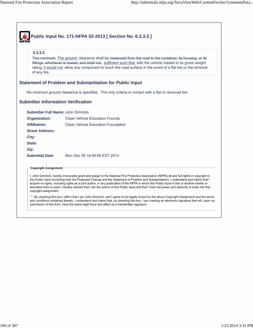
Public Input No. 171-NFPA 52-2013 [ Section No. 6.3.3.3 ]
6.3.3.3
This minimum The ground clearance shall be measured from the road to the container, its housing, or itsfittings, whichever is lowest, and shall not, sufficient such that with the vehicle loaded to its gross weightrating, it would not allow any component to touch the road surface in the event of a flat tire or the removalof any tire.
Statement of Problem and Substantiation for Public Input
No minimum ground clearance is specified. The only criteria is contact with a flat or removed tire.
Submitter Information Verification
Submitter Full Name: John Dimmick
Organization: Clean Vehicle Education Founda
Affilliation: Clean Vehicle Education Foundation
Street Address:
City:
State:
Zip:
Submittal Date: Mon Dec 30 16:56:08 EST 2013
Copyright Assignment
I, John Dimmick, hereby irrevocably grant and assign to the National Fire Protection Association (NFPA) all and full rights in copyright inthis Public Input (including both the Proposed Change and the Statement of Problem and Substantiation). I understand and intend that Iacquire no rights, including rights as a joint author, in any publication of the NFPA in which this Public Input in this or another similar orderivative form is used. I hereby warrant that I am the author of this Public Input and that I have full power and authority to enter into thiscopyright assignment.
By checking this box I affirm that I am John Dimmick, and I agree to be legally bound by the above Copyright Assignment and the termsand conditions contained therein. I understand and intend that, by checking this box, I am creating an electronic signature that will, upon mysubmission of this form, have the same legal force and effect as a handwritten signature
National Fire Protection Association Report http://submittals.nfpa.org/TerraViewWeb/ContentFetcher?commentPara...
100 of 307 1/21/2014 3:31 PM

Public Input No. 172-NFPA 52-2013 [ Section No. 6.3.3.4.1 ]
6.3.3.4.1
Container valves shall be protected from physical damage using the vehicle structure, valve protectors, ora metal shield.
Statement of Problem and Substantiation for Public Input
Container valves often contain temperature activated PRDs and there should be no requirements for a metal shield in particular. A change has been proposed in the container section to require the container location to provide valve protection.
Submitter Information Verification
Submitter Full Name: John Dimmick
Organization: Clean Vehicle Education Founda
Affilliation: Clean Vehicle Education Foundation
Street Address:
City:
State:
Zip:
Submittal Date: Mon Dec 30 16:58:33 EST 2013
Copyright Assignment
I, John Dimmick, hereby irrevocably grant and assign to the National Fire Protection Association (NFPA) all and full rights in copyright inthis Public Input (including both the Proposed Change and the Statement of Problem and Substantiation). I understand and intend that Iacquire no rights, including rights as a joint author, in any publication of the NFPA in which this Public Input in this or another similar orderivative form is used. I hereby warrant that I am the author of this Public Input and that I have full power and authority to enter into thiscopyright assignment.
By checking this box I affirm that I am John Dimmick, and I agree to be legally bound by the above Copyright Assignment and the termsand conditions contained therein. I understand and intend that, by checking this box, I am creating an electronic signature that will, upon mysubmission of this form, have the same legal force and effect as a handwritten signature
National Fire Protection Association Report http://submittals.nfpa.org/TerraViewWeb/ContentFetcher?commentPara...
101 of 307 1/21/2014 3:31 PM

Public Input No. 174-NFPA 52-2013 [ Section No. 6.3.4 ]
6.3.4
Each fuel supply container rack shall be secured to the vehicle body, bed, or frame to prevent damage fromroad hazards, slippage, loosening, or rotation transfer of vehicle chassis loads to the container due toframe flexing rotation using a method capable of withstanding a static force in the six principal directionsshown in Figure 6.3.4 of eight times the weight of a fully pressurized container(s).
Figure 6.3.4 The Six Principal Directions.
Statement of Problem and Substantiation for Public Input
Several occurrences have been reported with issues of containers loosening or rotating when racks were rigidly attached to flexible vehicle frames.
Submitter Information Verification
Submitter Full Name: John Dimmick
Organization: Clean Vehicle Education Founda
Affilliation: Clean Vehicle Education Foundation
Street Address:
City:
State:
Zip:
Submittal Date: Mon Dec 30 17:00:50 EST 2013
Copyright Assignment
I, John Dimmick, hereby irrevocably grant and assign to the National Fire Protection Association (NFPA) all and full rights in copyright inthis Public Input (including both the Proposed Change and the Statement of Problem and Substantiation). I understand and intend that Iacquire no rights, including rights as a joint author, in any publication of the NFPA in which this Public Input in this or another similar orderivative form is used. I hereby warrant that I am the author of this Public Input and that I have full power and authority to enter into thiscopyright assignment.
By checking this box I affirm that I am John Dimmick, and I agree to be legally bound by the above Copyright Assignment and the termsand conditions contained therein. I understand and intend that, by checking this box, I am creating an electronic signature that will, upon mysubmission of this form, have the same legal force and effect as a handwritten signature
National Fire Protection Association Report http://submittals.nfpa.org/TerraViewWeb/ContentFetcher?commentPara...
102 of 307 1/21/2014 3:31 PM

Public Input No. 175-NFPA 52-2013 [ Section No. 6.3.5 ]
6.3.5
Each fuel supply container in the rack shall be secured to its cradle in a manner that it is capable ofwithstanding a static force, applied in the six principal directions (see Figure 6.3.4), of eight times theweight of the fully pressurized container with a maximum displacement of 0.50 in. (13 mm). container
Statement of Problem and Substantiation for Public Input
The 8g requirement is intended to require the bracket to be strong enough to retain the container in a collision. The displacement limit should not be applied in collisions. The ½ “ was originally related to an arbitrary clearance between the cylinder and any other vehicle components but that requirement was deleted several editions back.
Submitter Information Verification
Submitter Full Name: John Dimmick
Organization: Clean Vehicle Education Founda
Affilliation: Clean Vehicle Education Foundation
Street Address:
City:
State:
Zip:
Submittal Date: Mon Dec 30 17:03:25 EST 2013
Copyright Assignment
I, John Dimmick, hereby irrevocably grant and assign to the National Fire Protection Association (NFPA) all and full rights in copyright inthis Public Input (including both the Proposed Change and the Statement of Problem and Substantiation). I understand and intend that Iacquire no rights, including rights as a joint author, in any publication of the NFPA in which this Public Input in this or another similar orderivative form is used. I hereby warrant that I am the author of this Public Input and that I have full power and authority to enter into thiscopyright assignment.
By checking this box I affirm that I am John Dimmick, and I agree to be legally bound by the above Copyright Assignment and the termsand conditions contained therein. I understand and intend that, by checking this box, I am creating an electronic signature that will, upon mysubmission of this form, have the same legal force and effect as a handwritten signature
National Fire Protection Association Report http://submittals.nfpa.org/TerraViewWeb/ContentFetcher?commentPara...
103 of 307 1/21/2014 3:31 PM

Public Input No. 176-NFPA 52-2013 [ Section No. 6.3.7 ]
6.3.7
Fuel supply containers located less than 8 in. (200 mm) from adjacent to the exhaust system shall beshielded against direct heat heat that would result in container or PRD surface temperatures exceeding180F.
Statement of Problem and Substantiation for Public Input
The arbitrary 8” clearance has proven insufficient with the newer large NG engines. 180F is a performance requirement that is based on the maximum temperature in the NGV2 standard for containers.
Submitter Information Verification
Submitter Full Name: John Dimmick
Organization: Clean Vehicle Education Founda
Affilliation: Clean Vehicle Education Foundation
Street Address:
City:
State:
Zip:
Submittal Date: Mon Dec 30 17:06:39 EST 2013
Copyright Assignment
I, John Dimmick, hereby irrevocably grant and assign to the National Fire Protection Association (NFPA) all and full rights in copyright inthis Public Input (including both the Proposed Change and the Statement of Problem and Substantiation). I understand and intend that Iacquire no rights, including rights as a joint author, in any publication of the NFPA in which this Public Input in this or another similar orderivative form is used. I hereby warrant that I am the author of this Public Input and that I have full power and authority to enter into thiscopyright assignment.
By checking this box I affirm that I am John Dimmick, and I agree to be legally bound by the above Copyright Assignment and the termsand conditions contained therein. I understand and intend that, by checking this box, I am creating an electronic signature that will, upon mysubmission of this form, have the same legal force and effect as a handwritten signature
National Fire Protection Association Report http://submittals.nfpa.org/TerraViewWeb/ContentFetcher?commentPara...
104 of 307 1/21/2014 3:31 PM

Public Input No. 177-NFPA 52-2013 [ Section No. 6.3.10.1 ]
6.3.10.1
A resilient gasket that does not retain absorb water shall be installed between the clamping bands andtheir supports and a container.
Statement of Problem and Substantiation for Public Input
It is not practical to prevent water retention but the material should not be absorbent.
Submitter Information Verification
Submitter Full Name: John Dimmick
Organization: Clean Vehicle Education Founda
Affilliation: Clean Vehicle Education Foundation
Street Address:
City:
State:
Zip:
Submittal Date: Mon Dec 30 17:09:39 EST 2013
Copyright Assignment
I, John Dimmick, hereby irrevocably grant and assign to the National Fire Protection Association (NFPA) all and full rights in copyright inthis Public Input (including both the Proposed Change and the Statement of Problem and Substantiation). I understand and intend that Iacquire no rights, including rights as a joint author, in any publication of the NFPA in which this Public Input in this or another similar orderivative form is used. I hereby warrant that I am the author of this Public Input and that I have full power and authority to enter into thiscopyright assignment.
By checking this box I affirm that I am John Dimmick, and I agree to be legally bound by the above Copyright Assignment and the termsand conditions contained therein. I understand and intend that, by checking this box, I am creating an electronic signature that will, upon mysubmission of this form, have the same legal force and effect as a handwritten signature
National Fire Protection Association Report http://submittals.nfpa.org/TerraViewWeb/ContentFetcher?commentPara...
105 of 307 1/21/2014 3:31 PM

Public Input No. 181-NFPA 52-2013 [ New Section after 6.4 ]
TITLE OF NEW CONTENT PRD Manifolds
Type your content here ...PRD manifolds connecting two or more cylinders shall be permitted if inaccordance with the cylinder manufacturer’s instructions.
Statement of Problem and Substantiation for Public Input
Connected PRD systems are are common for large containers and should be permitted only in accordance with manufacturers instructions.
Submitter Information Verification
Submitter Full Name: John Dimmick
Organization: Clean Vehicle Education Founda
Affilliation: Clean Vehicle Education Foundation
Street Address:
City:
State:
Zip:
Submittal Date: Mon Dec 30 17:18:34 EST 2013
Copyright Assignment
I, John Dimmick, hereby irrevocably grant and assign to the National Fire Protection Association (NFPA) all and full rights in copyright inthis Public Input (including both the Proposed Change and the Statement of Problem and Substantiation). I understand and intend that Iacquire no rights, including rights as a joint author, in any publication of the NFPA in which this Public Input in this or another similar orderivative form is used. I hereby warrant that I am the author of this Public Input and that I have full power and authority to enter into thiscopyright assignment.
By checking this box I affirm that I am John Dimmick, and I agree to be legally bound by the above Copyright Assignment and the termsand conditions contained therein. I understand and intend that, by checking this box, I am creating an electronic signature that will, upon mysubmission of this form, have the same legal force and effect as a handwritten signature
National Fire Protection Association Report http://submittals.nfpa.org/TerraViewWeb/ContentFetcher?commentPara...
106 of 307 1/21/2014 3:31 PM

Public Input No. 182-NFPA 52-2013 [ New Section after 6.4 ]
TITLE OF NEW CONTENT PRD Discharge
Type your content here ...
The point of discharge for a PRD shall be configured so as to prevent a high velocity directional dischargeoutside the vehicle. Diverters, diffusers and directing the discharge toward a fire resistant vehiclecomponent or the pavement shall be considered acceptable designs. Diffusers shall not reduce the flowbelow that required for safe venting in a fire.
Statement of Problem and Substantiation for Public Input
There have been many fire incidents involving CNG vehicles with PRD venting systems that directed a high-velocity discharge from the PRD outside of the immediate vehicle fire area, endangering nearby vehicles and structures and first responders. Longstanding industry practice is to vent flammable gas releases into an existing fire whenever possible to avoid accumulating a mixed cloud that can then ignite and cause damage by deflagration. This practice also prevents unnecessarily spreading the fire to new areas.
Submitter Information Verification
Submitter Full Name: John Dimmick
Organization: Clean Vehicle Education Founda
Affilliation: Clean Vehicle Education Foundation
Street Address:
City:
State:
Zip:
Submittal Date: Mon Dec 30 17:20:48 EST 2013
Copyright Assignment
I, John Dimmick, hereby irrevocably grant and assign to the National Fire Protection Association (NFPA) all and full rights in copyright inthis Public Input (including both the Proposed Change and the Statement of Problem and Substantiation). I understand and intend that Iacquire no rights, including rights as a joint author, in any publication of the NFPA in which this Public Input in this or another similar orderivative form is used. I hereby warrant that I am the author of this Public Input and that I have full power and authority to enter into thiscopyright assignment.
By checking this box I affirm that I am John Dimmick, and I agree to be legally bound by the above Copyright Assignment and the termsand conditions contained therein. I understand and intend that, by checking this box, I am creating an electronic signature that will, upon mysubmission of this form, have the same legal force and effect as a handwritten signature
National Fire Protection Association Report http://submittals.nfpa.org/TerraViewWeb/ContentFetcher?commentPara...
107 of 307 1/21/2014 3:31 PM

Public Input No. 179-NFPA 52-2013 [ Section No. 6.4.1 ]
6.4.1*
All pressure relief devices and connections between pressure-carrying components installed within driver,passenger, or a closed compartment (see 6.4.7) shall be vented to the outside of the vehicle.
6.4.1.1
This requirement shall not include plugs in the ends of containers with openings in each end.
Statement of Problem and Substantiation for Public Input
Combining PRD venting systems with the gastight enclosure requirements for closed compartments is confusing. These requirements apply only to PRD vent systems. A second proposal is submitted to make the gastight enclosure requirements independent and clear.
Submitter Information Verification
Submitter Full Name: John Dimmick
Organization: Clean Vehicle Education Founda
Affilliation: Clean Vehicle Education Foundation
Street Address:
City:
State:
Zip:
Submittal Date: Mon Dec 30 17:12:35 EST 2013
Copyright Assignment
I, John Dimmick, hereby irrevocably grant and assign to the National Fire Protection Association (NFPA) all and full rights in copyright inthis Public Input (including both the Proposed Change and the Statement of Problem and Substantiation). I understand and intend that Iacquire no rights, including rights as a joint author, in any publication of the NFPA in which this Public Input in this or another similar orderivative form is used. I hereby warrant that I am the author of this Public Input and that I have full power and authority to enter into thiscopyright assignment.
By checking this box I affirm that I am John Dimmick, and I agree to be legally bound by the above Copyright Assignment and the termsand conditions contained therein. I understand and intend that, by checking this box, I am creating an electronic signature that will, upon mysubmission of this form, have the same legal force and effect as a handwritten signature
National Fire Protection Association Report http://submittals.nfpa.org/TerraViewWeb/ContentFetcher?commentPara...
108 of 307 1/21/2014 3:31 PM

Public Input No. 31-NFPA 52-2013 [ Section No. 6.4.3 ]
6.4.3
The vent or vents for No vent from the venting system shall not exit into a wheel well, passengercompartment, or cargo compartment . No vent from the venting system shall be directed toward the engineexhaust system, components that are normally hot, or any ignition source.
Statement of Problem and Substantiation for Public Input
The proposed changes are in accordance with recommendation on venting systems for PRDs on p. 38 of FMCSA's final report, "Natural Gas Systems: Suggested Changes to Truck and Motorcoach Regulations and Inspection Procedures" published Mach 2013.
Submitter Information Verification
Submitter Full Name: Quon Kwan
Organization: US Department of Transportation
Street Address:
City:
State:
Zip:
Submittal Date: Mon Dec 16 13:35:02 EST 2013
Copyright Assignment
I, Quon Kwan, hereby irrevocably grant and assign to the National Fire Protection Association (NFPA) all and full rights in copyright in thisPublic Input (including both the Proposed Change and the Statement of Problem and Substantiation). I understand and intend that I acquireno rights, including rights as a joint author, in any publication of the NFPA in which this Public Input in this or another similar or derivativeform is used. I hereby warrant that I am the author of this Public Input and that I have full power and authority to enter into this copyrightassignment.
By checking this box I affirm that I am Quon Kwan, and I agree to be legally bound by the above Copyright Assignment and the termsand conditions contained therein. I understand and intend that, by checking this box, I am creating an electronic signature that will, upon mysubmission of this form, have the same legal force and effect as a handwritten signature
National Fire Protection Association Report http://submittals.nfpa.org/TerraViewWeb/ContentFetcher?commentPara...
109 of 307 1/21/2014 3:31 PM

Public Input No. 180-NFPA 52-2013 [ Section No. 6.4.7.1 ]
6.4.7.1
The neck of the container and all CNG fittings within the compartment shall be enclosed in a gastightenclosure made of linear, low-density polyethylene having a minimum thickness of 8 mils (0.20 mm) or anequally gastight alternate enclosure that is vented directly connected to the outside of the vehicle.
Statement of Problem and Substantiation for Public Input
This change harmonizes with the proposed independent PRD Ven Systems proposal and also provides a meaningful definition for other closed compartments. It recognizes that there are often leak-prone pressure joints in valves that are not “fittings”. It also recognizes that a hose or other conduit is usually necessary and “direct” connection may not be feasible.Gastight enclosures of fire resistant materials have isolated ORDs in fires, resulting in container rupture.
Submitter Information Verification
Submitter Full Name: John Dimmick
Organization: Clean Vehicle Education Founda
Affilliation: Clean Vehicle Education Foundation
Street Address:
City:
State:
Zip:
Submittal Date: Mon Dec 30 17:15:54 EST 2013
Copyright Assignment
I, John Dimmick, hereby irrevocably grant and assign to the National Fire Protection Association (NFPA) all and full rights in copyright inthis Public Input (including both the Proposed Change and the Statement of Problem and Substantiation). I understand and intend that Iacquire no rights, including rights as a joint author, in any publication of the NFPA in which this Public Input in this or another similar orderivative form is used. I hereby warrant that I am the author of this Public Input and that I have full power and authority to enter into thiscopyright assignment.
By checking this box I affirm that I am John Dimmick, and I agree to be legally bound by the above Copyright Assignment and the termsand conditions contained therein. I understand and intend that, by checking this box, I am creating an electronic signature that will, upon mysubmission of this form, have the same legal force and effect as a handwritten signature
National Fire Protection Association Report http://submittals.nfpa.org/TerraViewWeb/ContentFetcher?commentPara...
110 of 307 1/21/2014 3:31 PM

Public Input No. 32-NFPA 52-2013 [ New Section after 6.4.8 ]
6.4.9 Vent openings that are obscured
If a vent opening is either located behind a shield or screen or is obscured from the view of a personapproaching the side of the vehicle on which the vent opening is located, the location of the vent openingwill be marked, "CNG Vent", on the exterior of the vehicle near the vent opening in such a way that themarking will be visible to the person approaching the vehicle.
Statement of Problem and Substantiation for Public Input
This is a recommendation made on p. 43 of FMCSA's final report, "Natural Gas Systems: Suggested Changes to Truck and Motorcoach Regulations and Inspection Procedures" published in March 2013. The purpose is to allow a person approaching the vehicle to be aware of the hazard of a location where there may be a possible release of natural gas.
Submitter Information Verification
Submitter Full Name: Quon Kwan
Organization: US Department of Transportation
Street Address:
City:
State:
Zip:
Submittal Date: Mon Dec 16 13:41:24 EST 2013
Copyright Assignment
I, Quon Kwan, hereby irrevocably grant and assign to the National Fire Protection Association (NFPA) all and full rights in copyright in thisPublic Input (including both the Proposed Change and the Statement of Problem and Substantiation). I understand and intend that I acquireno rights, including rights as a joint author, in any publication of the NFPA in which this Public Input in this or another similar or derivativeform is used. I hereby warrant that I am the author of this Public Input and that I have full power and authority to enter into this copyrightassignment.
By checking this box I affirm that I am Quon Kwan, and I agree to be legally bound by the above Copyright Assignment and the termsand conditions contained therein. I understand and intend that, by checking this box, I am creating an electronic signature that will, upon mysubmission of this form, have the same legal force and effect as a handwritten signature
National Fire Protection Association Report http://submittals.nfpa.org/TerraViewWeb/ContentFetcher?commentPara...
111 of 307 1/21/2014 3:31 PM

Public Input No. 159-NFPA 52-2013 [ Section No. 6.4.8 ]
6.4.8 Installation of PRD Systems;
Where located in a vehicle compartment capable of accumulating natural gas, a container shall be installedso that the following conditions are met:
All PRDs shall be in direct communication with the fuel and vented to the atmosphere by a method thatwithstands the maximum pressure that results.
(1) The pressure relief device (PRD) for the protection of the container is installed in the same vehiclecompartment as the container.
(2) The discharge from the PRD is vented to the outside through an electrically conductive tube or hose,which shall be in accordance with the following:
(a) The tube or hose is secured at intervals in such a manner as to minimize the possibility ofdamage, corrosion, or breakage of either the vent line or the pressure relief device due toexpansion, contraction, vibration, strains, or wear and to preclude any loosening while inoperation.
(b) The tube or hose has a burst pressure of at least 1 1⁄2 times the pressure in the vent that resultsfrom activation of the PRD.
(3) The vent opening is not blocked by debris thrown up from the road, such as snow, ice, mud, and soforth, or otherwise affected by the elements.
Statement of Problem and Substantiation for Public Input
These are PRD installation requirements. An associated proposal moves installation requirements that are presently misplaced in CH. 5 to this section.
Submitter Information Verification
Submitter Full Name: John Dimmick
Organization: Clean Vehicle Education Founda
Affilliation: Clean Vehicle Education Foundation
Street Address:
City:
State:
Zip:
Submittal Date: Mon Dec 30 16:16:33 EST 2013
Copyright Assignment
I, John Dimmick, hereby irrevocably grant and assign to the National Fire Protection Association (NFPA) all and full rights in copyright inthis Public Input (including both the Proposed Change and the Statement of Problem and Substantiation). I understand and intend that Iacquire no rights, including rights as a joint author, in any publication of the NFPA in which this Public Input in this or another similar orderivative form is used. I hereby warrant that I am the author of this Public Input and that I have full power and authority to enter into thiscopyright assignment.
By checking this box I affirm that I am John Dimmick, and I agree to be legally bound by the above Copyright Assignment and the termsand conditions contained therein. I understand and intend that, by checking this box, I am creating an electronic signature that will, upon mysubmission of this form, have the same legal force and effect as a handwritten signature
National Fire Protection Association Report http://submittals.nfpa.org/TerraViewWeb/ContentFetcher?commentPara...
112 of 307 1/21/2014 3:31 PM

Public Input No. 183-NFPA 52-2013 [ Section No. 6.4.8 ]
6.4.8 Relocate to the PRD installation section
Where located in a vehicle compartment capable of accumulating natural gas, a container shall be installedso that the following conditions are met:
(1) The pressure relief device (PRD) for the protection of the container is installed in the same vehiclecompartment as the container.
(2) The discharge from the PRD is vented to the outside through an electrically conductive tube or hose,which shall be in accordance with the following:
(a) The tube or hose is secured at intervals in such a manner as to minimize the possibility ofdamage, corrosion, or breakage of either the vent line or the pressure relief device due toexpansion, contraction, vibration, strains, or wear and to preclude any loosening while inoperation.
(b) The tube or hose has a burst pressure of at least 1 1⁄2 times the pressure in the vent that resultsfrom activation of the PRD.
(3) The vent opening is not blocked by debris thrown up from the road, such as snow, ice, mud, and soforth, or otherwise affected by the elements.
Statement of Problem and Substantiation for Public Input
These requirements apply only to PRD vent lines, not to gastight enclosures and moving them to the PRD vent section will clarify their applicability.
Submitter Information Verification
Submitter Full Name: John Dimmick
Organization: Clean Vehicle Education Founda
Affilliation: Clean Vehicle Education Foundation
Street Address:
City:
State:
Zip:
Submittal Date: Mon Dec 30 17:23:28 EST 2013
Copyright Assignment
I, John Dimmick, hereby irrevocably grant and assign to the National Fire Protection Association (NFPA) all and full rights in copyright inthis Public Input (including both the Proposed Change and the Statement of Problem and Substantiation). I understand and intend that Iacquire no rights, including rights as a joint author, in any publication of the NFPA in which this Public Input in this or another similar orderivative form is used. I hereby warrant that I am the author of this Public Input and that I have full power and authority to enter into thiscopyright assignment.
By checking this box I affirm that I am John Dimmick, and I agree to be legally bound by the above Copyright Assignment and the termsand conditions contained therein. I understand and intend that, by checking this box, I am creating an electronic signature that will, upon mysubmission of this form, have the same legal force and effect as a handwritten signature
National Fire Protection Association Report http://submittals.nfpa.org/TerraViewWeb/ContentFetcher?commentPara...
113 of 307 1/21/2014 3:31 PM

Public Input No. 184-NFPA 52-2013 [ Section No. 6.5 ]
6.5 Installation of Piping Fuel Lines .
6.5.1
Manifolds connecting fuel containers shall be fabricated and installed to minimize vibration.
6.5.1.1
Manifolds shall be installed in a protected location or shielded to prevent damage from unsecured objects.
6.5.2
Manifolds connecting containers or container pressure relief devices shall be designed to vent gas from theindividual container(s) exposed to a fire so that all containers to meet the requirements requirements ofSection 5.5 . 6.4 Installation of PRD Vent of 6.4 Installation of PRD Vent Systems.
6.5.3
A pipe thread jointing material impervious to the action of the natural gas used in the system shall beapplied to all male pipe threads prior to assembly.
6.5.4
Piping Metallic tubing and fittings shall be clear and free from cutting or threading burrs and scales.
6.5.4.1
The ends of all piping metallic tubing shall be reamed.
6.5.5
Where necessary to prevent abrasion, fuel lines passing through a panel shall be protected by grommets orother protective devices.
6.5.6
Fuel lines shall have clearance from the engine exhaust system to protect the fuel lines from excessiveheat by durable and effective means.
6.5.7
Fuel lines shall be mounted, braced, and supported to minimize vibration.
6.5.7.1
Fuel lines shall be protected against damage, corrosion, or breakage due to strain or wear.
6.5.8
A bend in piping or metallic tubing shall be prohibited where such a bend weakens the piping or tubing.
6.5.9
Mechanical Joints or connections on piping fuel line systems shall be located in an accessible location.
6.5.10
Where a fuel supply container is located on a trailer, the fuel supply line shall contain an emergencybreakaway device designed to retain CNG on both sides of the breakaway point.
Statement of Problem and Substantiation for Public Input
The definition of piping applies only to stations, not vehicles. Fuel lines and piping were used interchangeably but metallic tubing is a defined term and does not conflict with the definition of piping.The requirements for installation of PRD systems should be in 6.4 per other proiposals.Only mechanical joints in fuel lines must be accessible. Welded or brazed joints need not be accessible.
Submitter Information Verification
Submitter Full Name: John Dimmick
Organization: Clean Vehicle Education Founda
Affilliation: Clean Vehicle Education Foundation
Street Address:
City:
State:
National Fire Protection Association Report http://submittals.nfpa.org/TerraViewWeb/ContentFetcher?commentPara...
114 of 307 1/21/2014 3:31 PM

Zip:
Submittal Date: Mon Dec 30 17:27:49 EST 2013
Copyright Assignment
I, John Dimmick, hereby irrevocably grant and assign to the National Fire Protection Association (NFPA) all and full rights in copyright inthis Public Input (including both the Proposed Change and the Statement of Problem and Substantiation). I understand and intend that Iacquire no rights, including rights as a joint author, in any publication of the NFPA in which this Public Input in this or another similar orderivative form is used. I hereby warrant that I am the author of this Public Input and that I have full power and authority to enter into thiscopyright assignment.
By checking this box I affirm that I am John Dimmick, and I agree to be legally bound by the above Copyright Assignment and the termsand conditions contained therein. I understand and intend that, by checking this box, I am creating an electronic signature that will, upon mysubmission of this form, have the same legal force and effect as a handwritten signature
National Fire Protection Association Report http://submittals.nfpa.org/TerraViewWeb/ContentFetcher?commentPara...
115 of 307 1/21/2014 3:31 PM

Public Input No. 25-NFPA 52-2013 [ Section No. 6.5.4.1 ]
6.5.4.1
The ends of all piping shall be reamed. The ends of all piping shall be deburred or prepared in accordancewith the fitting manufacturer's recommendations.
Statement of Problem and Substantiation for Public Input
Rationale: traditional reaming is opening up the bore. This is not how the double ferrule fitting manufactures recommend tube preparation.
Submitter Information Verification
Submitter Full Name: GARTH RUTTIG
Organization: NEW FLYER INDUSTRIES
Street Address:
City:
State:
Zip:
Submittal Date: Fri Dec 13 11:38:19 EST 2013
Copyright Assignment
I, GARTH RUTTIG, hereby irrevocably grant and assign to the National Fire Protection Association (NFPA) all and full rights in copyright inthis Public Input (including both the Proposed Change and the Statement of Problem and Substantiation). I understand and intend that Iacquire no rights, including rights as a joint author, in any publication of the NFPA in which this Public Input in this or another similar orderivative form is used. I hereby warrant that I am the author of this Public Input and that I have full power and authority to enter into thiscopyright assignment.
By checking this box I affirm that I am GARTH RUTTIG, and I agree to be legally bound by the above Copyright Assignment and theterms and conditions contained therein. I understand and intend that, by checking this box, I am creating an electronic signature that will,upon my submission of this form, have the same legal force and effect as a handwritten signature
National Fire Protection Association Report http://submittals.nfpa.org/TerraViewWeb/ContentFetcher?commentPara...
116 of 307 1/21/2014 3:31 PM

Public Input No. 2-NFPA 52-2013 [ Section No. 6.5.7 [Excluding any Sub-Sections] ]
Fuel lines shall be mounted IN THE SAME MANNER AND LOCATION AS THE O.E.M. FUEL LINES ARE ,AND SUCH AS THE VEHICLE SAFETY FACTOR IS ORIGINALLY DEISNGED (I.E. - ON THE INSIDEAND BETWEEN THE FRAME RAILS OR AS SUCH ON A UNI-BODY CONSTRUCTION), braced, andsupported to minimize vibration.
Statement of Problem and Substantiation for Public Input
THIS WOULD PREVENT FUEL LINES BEING MOUNTED ON THE ROCKER PANELS OF TRUCK BODY WITHIN CRUSH ZONES. IT WOULD PROTECT THE CNG HIGH PRESSURE LINES FROM SIDE IMPACT COLLISIONS.THE O.E.M. FUEL LINE IS MADE TO FOLLOW THE INSIDE OF THE FRAME RAIL FOR BEST POSSIBLE SAFETY FACTORS AND ALSO MOUNTED IN A MOST HIGH LOCATION.ALSO HAVING THE FUEL LINE MOUNTED HIGH AND WITHIN THE FRAME RAILS OR AS LIKE WITHIN UNI-BODY CONSTRUCTION WOULD PREVENT HIGH PRESSURE FUEL LINES FROM MAKING CONTACT WITH ROAD, TRAIL, OFF-ROAD DEBRIS CONDITIONS.THE N.F.P.A. DOES NOT CLEARLY STATE WHERE TO MOUNT THE FUEL LINES AS SUCH AS IN MY RECOMMENDATIONS.
Submitter Information Verification
Submitter Full Name: Marvin Davis
Organization: MARVINSCNG
Affilliation: MARVINSCNG.COM
Street Address:
City:
State:
Zip:
Submittal Date: Mon Apr 29 23:39:33 EDT 2013
Copyright Assignment
I, Marvin Davis, hereby irrevocably grant and assign to the National Fire Protection Association (NFPA) all and full rights in copyright in thisPublic Input (including both the Proposed Change and the Statement of Problem and Substantiation). I understand and intend that I acquireno rights, including rights as a joint author, in any publication of the NFPA in which this Public Input in this or another similar or derivativeform is used. I hereby warrant that I am the author of this Public Input and that I have full power and authority to enter into this copyrightassignment.
By checking this box I affirm that I am Marvin Davis, and I agree to be legally bound by the above Copyright Assignment and the termsand conditions contained therein. I understand and intend that, by checking this box, I am creating an electronic signature that will, upon mysubmission of this form, have the same legal force and effect as a handwritten signature
National Fire Protection Association Report http://submittals.nfpa.org/TerraViewWeb/ContentFetcher?commentPara...
117 of 307 1/21/2014 3:31 PM

Public Input No. 185-NFPA 52-2013 [ Section No. 6.6.1 ]
6.6.1
Every cylinder shall be equipped with either of the following:
(1) A manual valve
(2) A normally closed, remotely actuated shutoff valve connected directly to the cylinder and equipped tobleed the cylinder manually
(3) If an interconnected PRD system is protecting a group of cylinders installed in accordance with theproposed 6. 4.7, a single cylinder valve may be installed to isolate the group of cylinders.
(4) 6. 6. 1.1
Vehicles with more than one fuel supply container, where each container is equipped with a normally closedremotely actuated shutoff valve, shall have an automatic system to detect the failure of any one of thevalves.
Statement of Problem and Substantiation for Public Input
Requiring multiple cylinder valves when the cylinders are permanently interconnected by PRD lines adds no value but does add additional failure and leak points.
Submitter Information Verification
Submitter Full Name: John Dimmick
Organization: Clean Vehicle Education Founda
Affilliation: Clean Vehicle Education Foundation
Street Address:
City:
State:
Zip:
Submittal Date: Mon Dec 30 17:35:07 EST 2013
Copyright Assignment
I, John Dimmick, hereby irrevocably grant and assign to the National Fire Protection Association (NFPA) all and full rights in copyright inthis Public Input (including both the Proposed Change and the Statement of Problem and Substantiation). I understand and intend that Iacquire no rights, including rights as a joint author, in any publication of the NFPA in which this Public Input in this or another similar orderivative form is used. I hereby warrant that I am the author of this Public Input and that I have full power and authority to enter into thiscopyright assignment.
By checking this box I affirm that I am John Dimmick, and I agree to be legally bound by the above Copyright Assignment and the termsand conditions contained therein. I understand and intend that, by checking this box, I am creating an electronic signature that will, upon mysubmission of this form, have the same legal force and effect as a handwritten signature
National Fire Protection Association Report http://submittals.nfpa.org/TerraViewWeb/ContentFetcher?commentPara...
118 of 307 1/21/2014 3:31 PM

Public Input No. 186-NFPA 52-2013 [ Section No. 6.6.1 ]
6.6.1
Every cylinder shall be equipped with either of the following:(3) The connection between the cylinder and valve shall vent a noticeable quantity of gas in the event
that the valve is removed while under pressure. This venting shall start while the connection can stillwithstand a pressure of two times the service pressure
6.6.1.1
(1) A manual valve
(2) A normally closed, remotely actuated shutoff valve connected directly to the cylinder and equipped tobleed the cylinder manually
6.6.1.1
Vehicles with more than one fuel supply container, where each container is equipped with a normally closedremotely actuated shutoff valve, shall have an automatic system to detect the failure of any one of thevalves.
Statement of Problem and Substantiation for Public Input
Incidents continue in which written procedures have been inadequate alone to preveny valve removal from pressurized cylinders. A noticeable gas discharge will be a more reliable design control and will back up the use of procedures.
Submitter Information Verification
Submitter Full Name: John Dimmick
Organization: Clean Vehicle Education Founda
Affilliation: Clean Vehicle Education Foundation
Street Address:
City:
State:
Zip:
Submittal Date: Mon Dec 30 17:38:52 EST 2013
Copyright Assignment
I, John Dimmick, hereby irrevocably grant and assign to the National Fire Protection Association (NFPA) all and full rights in copyright inthis Public Input (including both the Proposed Change and the Statement of Problem and Substantiation). I understand and intend that Iacquire no rights, including rights as a joint author, in any publication of the NFPA in which this Public Input in this or another similar orderivative form is used. I hereby warrant that I am the author of this Public Input and that I have full power and authority to enter into thiscopyright assignment.
By checking this box I affirm that I am John Dimmick, and I agree to be legally bound by the above Copyright Assignment and the termsand conditions contained therein. I understand and intend that, by checking this box, I am creating an electronic signature that will, upon mysubmission of this form, have the same legal force and effect as a handwritten signature
National Fire Protection Association Report http://submittals.nfpa.org/TerraViewWeb/ContentFetcher?commentPara...
119 of 307 1/21/2014 3:31 PM

Public Input No. 187-NFPA 52-2013 [ Section No. 6.6.1 ]
6.6.1
Every cylinder shall be equipped with either of the following:(3) All container valves shall be equipped to blead the cylinder manually even in the event that a remote
actuator fails or a excess flow device should stick closed.
6.6.1.1
(1) A manual valve
(2) A normally closed, remotely actuated shutoff valve connected directly to the cylinder and equipped tobleed the cylinder manually
6.6.1.1
Vehicles with more than one fuel supply container, where each container is equipped with a normally closedremotely actuated shutoff valve, shall have an automatic system to detect the failure of any one of thevalves.
Statement of Problem and Substantiation for Public Input
The manual bleed requirement must also apply when there is a EFD integrated into a manual or solenoid valve. There have been incident reports of stuck EFDs preventing the safe bleeding of gas from containers.
Submitter Information Verification
Submitter Full Name: John Dimmick
Organization: Clean Vehicle Education Founda
Affilliation: Clean Vehicle Education Foundation
Street Address:
City:
State:
Zip:
Submittal Date: Mon Dec 30 17:41:44 EST 2013
Copyright Assignment
I, John Dimmick, hereby irrevocably grant and assign to the National Fire Protection Association (NFPA) all and full rights in copyright inthis Public Input (including both the Proposed Change and the Statement of Problem and Substantiation). I understand and intend that Iacquire no rights, including rights as a joint author, in any publication of the NFPA in which this Public Input in this or another similar orderivative form is used. I hereby warrant that I am the author of this Public Input and that I have full power and authority to enter into thiscopyright assignment.
By checking this box I affirm that I am John Dimmick, and I agree to be legally bound by the above Copyright Assignment and the termsand conditions contained therein. I understand and intend that, by checking this box, I am creating an electronic signature that will, upon mysubmission of this form, have the same legal force and effect as a handwritten signature
National Fire Protection Association Report http://submittals.nfpa.org/TerraViewWeb/ContentFetcher?commentPara...
120 of 307 1/21/2014 3:31 PM

Public Input No. 188-NFPA 52-2013 [ Section No. 6.6.3 ]
6.6.3
A valve or fuel injector that automatically prevents the flow of gaseous fuel to the engine when the engineis not running, even if the ignition is switched on, shall be provided in the system.
Statement of Problem and Substantiation for Public Input
Fuel injectrs can and do provide this function in many systems.
Submitter Information Verification
Submitter Full Name: John Dimmick
Organization: Clean Vehicle Education Founda
Affilliation: Clean Vehicle Education Foundation
Street Address:
City:
State:
Zip:
Submittal Date: Tue Dec 31 10:43:21 EST 2013
Copyright Assignment
I, John Dimmick, hereby irrevocably grant and assign to the National Fire Protection Association (NFPA) all and full rights in copyright inthis Public Input (including both the Proposed Change and the Statement of Problem and Substantiation). I understand and intend that Iacquire no rights, including rights as a joint author, in any publication of the NFPA in which this Public Input in this or another similar orderivative form is used. I hereby warrant that I am the author of this Public Input and that I have full power and authority to enter into thiscopyright assignment.
By checking this box I affirm that I am John Dimmick, and I agree to be legally bound by the above Copyright Assignment and the termsand conditions contained therein. I understand and intend that, by checking this box, I am creating an electronic signature that will, upon mysubmission of this form, have the same legal force and effect as a handwritten signature
National Fire Protection Association Report http://submittals.nfpa.org/TerraViewWeb/ContentFetcher?commentPara...
121 of 307 1/21/2014 3:31 PM

Public Input No. 190-NFPA 52-2013 [ Section No. 6.11.1 ]
6.11.1
A vehicle equipped with a CNG fuel system shall bear the following durable labels:
(1) A label readily visible and located in the engine compartment shall include the following:
(a) Identification Certification as a CNG-fueled vehicle
(b) System service pressure
Installer
(c) system in conformance with NFPA 52-XXXX (denoting the year of the Code)
(d) Service pressure
(e) Certifier 's name or company and contact information (Addfress, Telephone, e-mail)
(f) Fuel container life expires (insert date for limited-life fuel containers. This label item not requiredfor containers with unlimited life.)
(g) Total container water volume in gallons (liters)
(h)
(i) Date by which fuel containers are to be inspected (insert date) and every (insert number) monthsthereafter
(2) A label located at the fueling connection receptacle shall include the following:
(a) Identification as a CNG-fueled vehicle
(b) System service pressure
(c) Fuel container life expires (insert date for limited-life fuel containers. This label item not requiredfor containers with unlimited life.)
(d) Fuel containers are to be inspected by (insert date) and each (insert number) months thereafter.
6.11.1.1
The fuel container inspection dates shall be changed after each required container inspection to denote thenext required inspection date and shall be permitted on a separate additional label.
Statement of Problem and Substantiation for Public Input
The installer should certify the system in accordance with a specific edition of NFPA 52 for the use of any AHJ who may require verification.Service pressure is defined and system is unnecessary.The vehicle label should contain the installer’s (certifier's) contact information.There is no need to label the total container volume. This is not useful.
Submitter Information Verification
Submitter Full Name: John Dimmick
Organization: Clean Vehicle Education Founda
Affilliation: Clean Vehicle Education Foundation
Street Address:
City:
State:
Zip:
Submittal Date: Tue Dec 31 10:48:47 EST 2013
National Fire Protection Association Report http://submittals.nfpa.org/TerraViewWeb/ContentFetcher?commentPara...
122 of 307 1/21/2014 3:31 PM

Copyright Assignment
I, John Dimmick, hereby irrevocably grant and assign to the National Fire Protection Association (NFPA) all and full rights in copyright inthis Public Input (including both the Proposed Change and the Statement of Problem and Substantiation). I understand and intend that Iacquire no rights, including rights as a joint author, in any publication of the NFPA in which this Public Input in this or another similar orderivative form is used. I hereby warrant that I am the author of this Public Input and that I have full power and authority to enter into thiscopyright assignment.
By checking this box I affirm that I am John Dimmick, and I agree to be legally bound by the above Copyright Assignment and the termsand conditions contained therein. I understand and intend that, by checking this box, I am creating an electronic signature that will, upon mysubmission of this form, have the same legal force and effect as a handwritten signature
National Fire Protection Association Report http://submittals.nfpa.org/TerraViewWeb/ContentFetcher?commentPara...
123 of 307 1/21/2014 3:31 PM
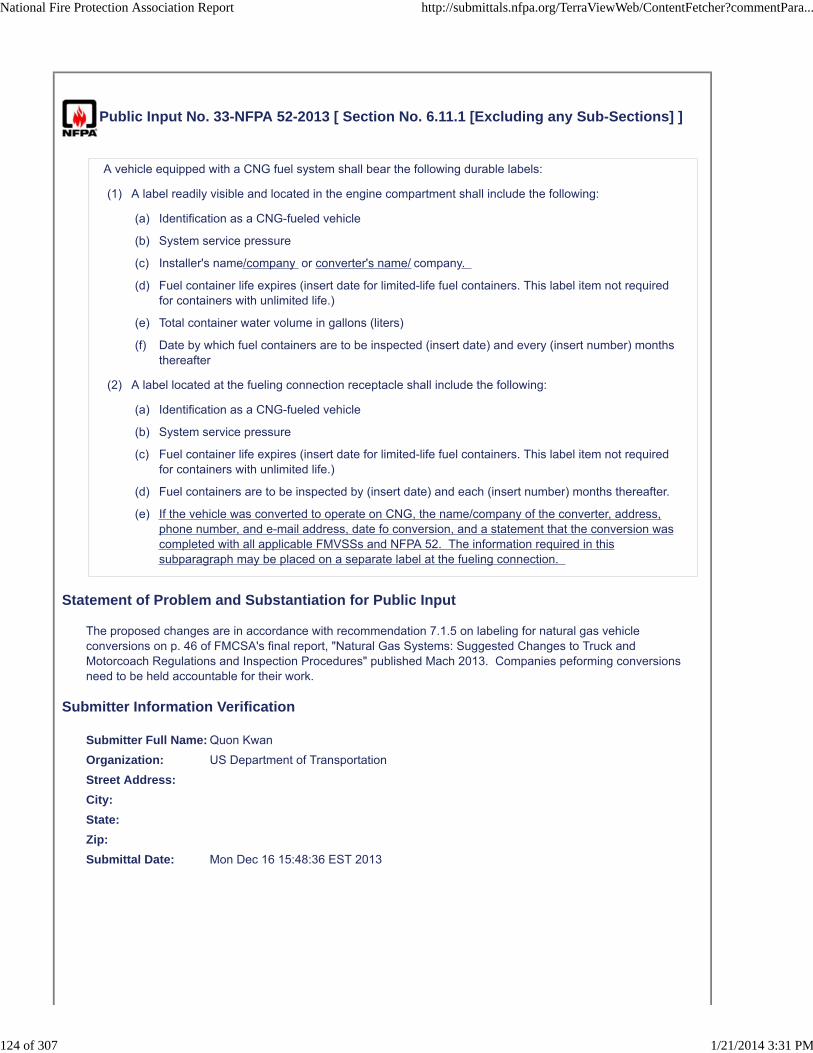
Public Input No. 33-NFPA 52-2013 [ Section No. 6.11.1 [Excluding any Sub-Sections] ]
A vehicle equipped with a CNG fuel system shall bear the following durable labels:
(1) A label readily visible and located in the engine compartment shall include the following:
(a) Identification as a CNG-fueled vehicle
(b) System service pressure
(c) Installer's name/company or converter's name/ company.
(d) Fuel container life expires (insert date for limited-life fuel containers. This label item not requiredfor containers with unlimited life.)
(e) Total container water volume in gallons (liters)
(f) Date by which fuel containers are to be inspected (insert date) and every (insert number) monthsthereafter
(2) A label located at the fueling connection receptacle shall include the following:
(a) Identification as a CNG-fueled vehicle
(b) System service pressure
(c) Fuel container life expires (insert date for limited-life fuel containers. This label item not requiredfor containers with unlimited life.)
(d) Fuel containers are to be inspected by (insert date) and each (insert number) months thereafter.
(e) If the vehicle was converted to operate on CNG, the name/company of the converter, address,phone number, and e-mail address, date fo conversion, and a statement that the conversion wascompleted with all applicable FMVSSs and NFPA 52. The information required in thissubparagraph may be placed on a separate label at the fueling connection.
Statement of Problem and Substantiation for Public Input
The proposed changes are in accordance with recommendation 7.1.5 on labeling for natural gas vehicle conversions on p. 46 of FMCSA's final report, "Natural Gas Systems: Suggested Changes to Truck and Motorcoach Regulations and Inspection Procedures" published Mach 2013. Companies peforming conversions need to be held accountable for their work.
Submitter Information Verification
Submitter Full Name: Quon Kwan
Organization: US Department of Transportation
Street Address:
City:
State:
Zip:
Submittal Date: Mon Dec 16 15:48:36 EST 2013
National Fire Protection Association Report http://submittals.nfpa.org/TerraViewWeb/ContentFetcher?commentPara...
124 of 307 1/21/2014 3:31 PM

Copyright Assignment
I, Quon Kwan, hereby irrevocably grant and assign to the National Fire Protection Association (NFPA) all and full rights in copyright in thisPublic Input (including both the Proposed Change and the Statement of Problem and Substantiation). I understand and intend that I acquireno rights, including rights as a joint author, in any publication of the NFPA in which this Public Input in this or another similar or derivativeform is used. I hereby warrant that I am the author of this Public Input and that I have full power and authority to enter into this copyrightassignment.
By checking this box I affirm that I am Quon Kwan, and I agree to be legally bound by the above Copyright Assignment and the termsand conditions contained therein. I understand and intend that, by checking this box, I am creating an electronic signature that will, upon mysubmission of this form, have the same legal force and effect as a handwritten signature
National Fire Protection Association Report http://submittals.nfpa.org/TerraViewWeb/ContentFetcher?commentPara...
125 of 307 1/21/2014 3:31 PM

Public Input No. 34-NFPA 52-2013 [ Section No. 6.11.1.1 ]
6.11.1.1
The fuel container inspection dates shall be changed after each required container inspection to denote thenext required inspection date and shall be permitted on a separate additional label. See Section 6.13 forinspections.
Statement of Problem and Substantiation for Public Input
There needs to be some guidance point the reader to the appropriate section about inspections.
Submitter Information Verification
Submitter Full Name: Quon Kwan
Organization: US Department of Transportation
Street Address:
City:
State:
Zip:
Submittal Date: Mon Dec 16 16:09:44 EST 2013
Copyright Assignment
I, Quon Kwan, hereby irrevocably grant and assign to the National Fire Protection Association (NFPA) all and full rights in copyright in thisPublic Input (including both the Proposed Change and the Statement of Problem and Substantiation). I understand and intend that I acquireno rights, including rights as a joint author, in any publication of the NFPA in which this Public Input in this or another similar or derivativeform is used. I hereby warrant that I am the author of this Public Input and that I have full power and authority to enter into this copyrightassignment.
By checking this box I affirm that I am Quon Kwan, and I agree to be legally bound by the above Copyright Assignment and the termsand conditions contained therein. I understand and intend that, by checking this box, I am creating an electronic signature that will, upon mysubmission of this form, have the same legal force and effect as a handwritten signature
National Fire Protection Association Report http://submittals.nfpa.org/TerraViewWeb/ContentFetcher?commentPara...
126 of 307 1/21/2014 3:31 PM

Public Input No. 191-NFPA 52-2013 [ Section No. 6.11.2 ]
6.11.2
If all the information of both labels are located in one of the above areas, the labels shall bepermitted to be combined into a single label is included on a label at the fuel receptacle, a second label isnot required .
Statement of Problem and Substantiation for Public Input
There should always be a label at the receptacle for visibility during fueling.
Submitter Information Verification
Submitter Full Name: John Dimmick
Organization: Clean Vehicle Education Founda
Affilliation: Clean Vehicle Education Foundation
Street Address:
City:
State:
Zip:
Submittal Date: Tue Dec 31 10:55:39 EST 2013
Copyright Assignment
I, John Dimmick, hereby irrevocably grant and assign to the National Fire Protection Association (NFPA) all and full rights in copyright inthis Public Input (including both the Proposed Change and the Statement of Problem and Substantiation). I understand and intend that Iacquire no rights, including rights as a joint author, in any publication of the NFPA in which this Public Input in this or another similar orderivative form is used. I hereby warrant that I am the author of this Public Input and that I have full power and authority to enter into thiscopyright assignment.
By checking this box I affirm that I am John Dimmick, and I agree to be legally bound by the above Copyright Assignment and the termsand conditions contained therein. I understand and intend that, by checking this box, I am creating an electronic signature that will, upon mysubmission of this form, have the same legal force and effect as a handwritten signature
National Fire Protection Association Report http://submittals.nfpa.org/TerraViewWeb/ContentFetcher?commentPara...
127 of 307 1/21/2014 3:31 PM
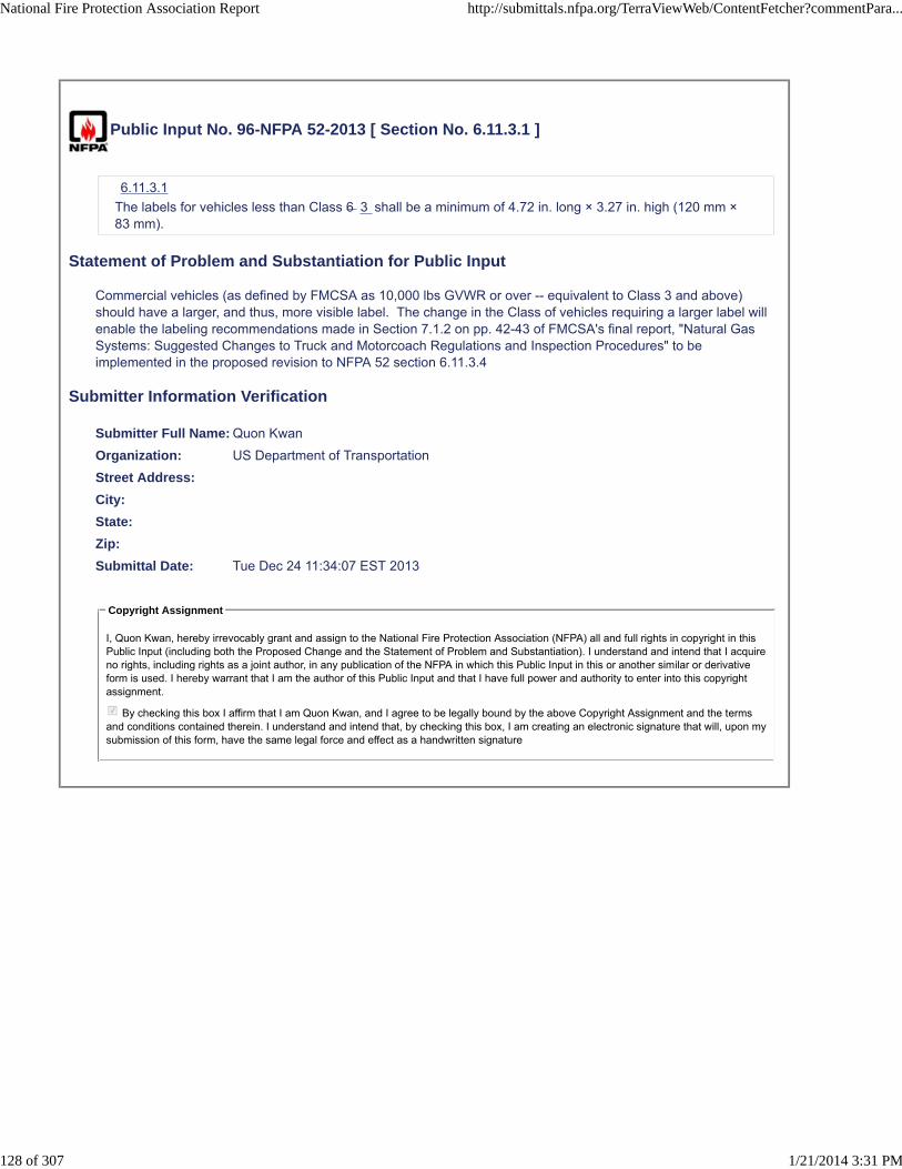
Public Input No. 96-NFPA 52-2013 [ Section No. 6.11.3.1 ]
6.11.3.1
The labels for vehicles less than Class 6 3 shall be a minimum of 4.72 in. long × 3.27 in. high (120 mm ×83 mm).
Statement of Problem and Substantiation for Public Input
Commercial vehicles (as defined by FMCSA as 10,000 lbs GVWR or over -- equivalent to Class 3 and above) should have a larger, and thus, more visible label. The change in the Class of vehicles requiring a larger label will enable the labeling recommendations made in Section 7.1.2 on pp. 42-43 of FMCSA's final report, "Natural Gas Systems: Suggested Changes to Truck and Motorcoach Regulations and Inspection Procedures" to be implemented in the proposed revision to NFPA 52 section 6.11.3.4
Submitter Information Verification
Submitter Full Name: Quon Kwan
Organization: US Department of Transportation
Street Address:
City:
State:
Zip:
Submittal Date: Tue Dec 24 11:34:07 EST 2013
Copyright Assignment
I, Quon Kwan, hereby irrevocably grant and assign to the National Fire Protection Association (NFPA) all and full rights in copyright in thisPublic Input (including both the Proposed Change and the Statement of Problem and Substantiation). I understand and intend that I acquireno rights, including rights as a joint author, in any publication of the NFPA in which this Public Input in this or another similar or derivativeform is used. I hereby warrant that I am the author of this Public Input and that I have full power and authority to enter into this copyrightassignment.
By checking this box I affirm that I am Quon Kwan, and I agree to be legally bound by the above Copyright Assignment and the termsand conditions contained therein. I understand and intend that, by checking this box, I am creating an electronic signature that will, upon mysubmission of this form, have the same legal force and effect as a handwritten signature
National Fire Protection Association Report http://submittals.nfpa.org/TerraViewWeb/ContentFetcher?commentPara...
128 of 307 1/21/2014 3:31 PM
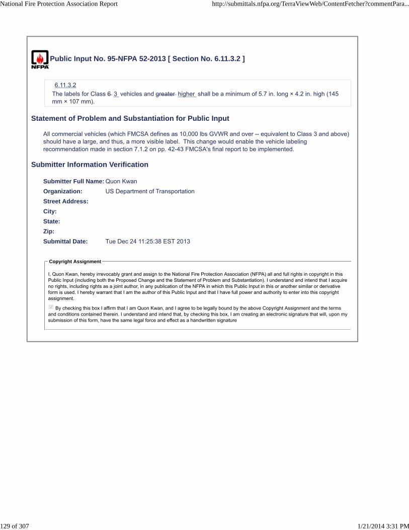
Public Input No. 95-NFPA 52-2013 [ Section No. 6.11.3.2 ]
6.11.3.2
The labels for Class 6 3 vehicles and greater higher shall be a minimum of 5.7 in. long × 4.2 in. high (145mm × 107 mm).
Statement of Problem and Substantiation for Public Input
All commercial vehicles (which FMCSA defines as 10,000 lbs GVWR and over -- equivalent to Class 3 and above) should have a large, and thus, a more visible label. This change would enable the vehicle labeling recommendation made in section 7.1.2 on pp. 42-43 FMCSA's final report to be implemented.
Submitter Information Verification
Submitter Full Name: Quon Kwan
Organization: US Department of Transportation
Street Address:
City:
State:
Zip:
Submittal Date: Tue Dec 24 11:25:38 EST 2013
Copyright Assignment
I, Quon Kwan, hereby irrevocably grant and assign to the National Fire Protection Association (NFPA) all and full rights in copyright in thisPublic Input (including both the Proposed Change and the Statement of Problem and Substantiation). I understand and intend that I acquireno rights, including rights as a joint author, in any publication of the NFPA in which this Public Input in this or another similar or derivativeform is used. I hereby warrant that I am the author of this Public Input and that I have full power and authority to enter into this copyrightassignment.
By checking this box I affirm that I am Quon Kwan, and I agree to be legally bound by the above Copyright Assignment and the termsand conditions contained therein. I understand and intend that, by checking this box, I am creating an electronic signature that will, upon mysubmission of this form, have the same legal force and effect as a handwritten signature
National Fire Protection Association Report http://submittals.nfpa.org/TerraViewWeb/ContentFetcher?commentPara...
129 of 307 1/21/2014 3:31 PM
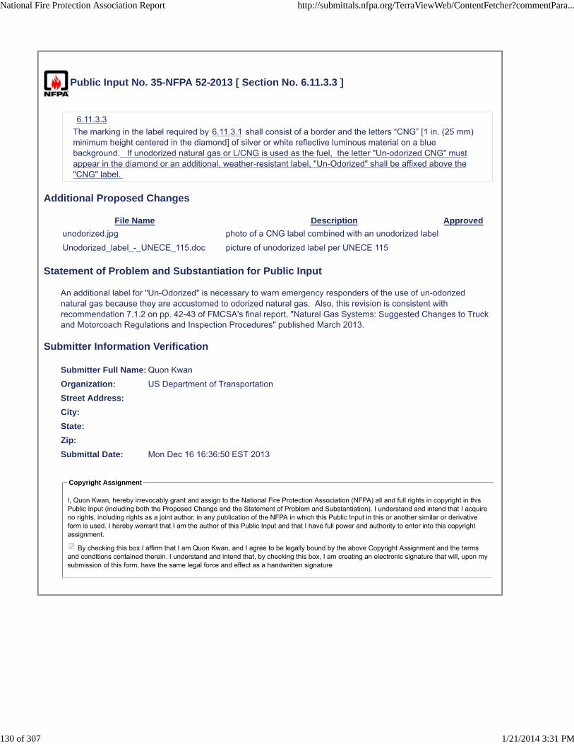
Public Input No. 35-NFPA 52-2013 [ Section No. 6.11.3.3 ]
6.11.3.3
The marking in the label required by 6.11.3.1 shall consist of a border and the letters “CNG” [1 in. (25 mm)minimum height centered in the diamond] of silver or white reflective luminous material on a bluebackground. If unodorized natural gas or L/CNG is used as the fuel, the letter "Un-odorized CNG" mustappear in the diamond or an additional, weather-resistant label, "Un-Odorized" shall be affixed above the"CNG" label.
Additional Proposed Changes
File Name Description Approved
unodorized.jpg photo of a CNG label combined with an unodorized label
Unodorized_label_-_UNECE_115.doc picture of unodorized label per UNECE 115
Statement of Problem and Substantiation for Public Input
An additional label for "Un-Odorized" is necessary to warn emergency responders of the use of un-odorized natural gas because they are accustomed to odorized natural gas. Also, this revision is consistent with recommendation 7.1.2 on pp. 42-43 of FMCSA's final report, "Natural Gas Systems: Suggested Changes to Truck and Motorcoach Regulations and Inspection Procedures" published March 2013.
Submitter Information Verification
Submitter Full Name: Quon Kwan
Organization: US Department of Transportation
Street Address:
City:
State:
Zip:
Submittal Date: Mon Dec 16 16:36:50 EST 2013
Copyright Assignment
I, Quon Kwan, hereby irrevocably grant and assign to the National Fire Protection Association (NFPA) all and full rights in copyright in thisPublic Input (including both the Proposed Change and the Statement of Problem and Substantiation). I understand and intend that I acquireno rights, including rights as a joint author, in any publication of the NFPA in which this Public Input in this or another similar or derivativeform is used. I hereby warrant that I am the author of this Public Input and that I have full power and authority to enter into this copyrightassignment.
By checking this box I affirm that I am Quon Kwan, and I agree to be legally bound by the above Copyright Assignment and the termsand conditions contained therein. I understand and intend that, by checking this box, I am creating an electronic signature that will, upon mysubmission of this form, have the same legal force and effect as a handwritten signature
National Fire Protection Association Report http://submittals.nfpa.org/TerraViewWeb/ContentFetcher?commentPara...
130 of 307 1/21/2014 3:31 PM


Public Input No. 40-NFPA 52-2013 [ New Section after 6.11.3.4 ]
6.11.3.5
Class 3 or higher vehicles with roof-mounted CNG fuel containers shall include a permanent label in thedriver's compartment, clearly visible to a seated operator, which includes the maximum total height of theunladen vehicle.
Statement of Problem and Substantiation for Public Input
There have been too many strikes of tunnels, bridges, or overhead structures by vehicles with roof-mounted CNG fuel tanks (especially transit buses). Requiring a conspicuous label with the vehicle height reminds the driver about overhead clearance. This requirement is consistent with recommendation 7.1.2 on p. 43 of FMCSA's "Natural Gas Systems: Suggested Changes to Truck and MotorCoach Regulations and Inspection Procedures" published March 2013.
Submitter Information Verification
Submitter Full Name: Quon Kwan
Organization: US Department of Transportation
Street Address:
City:
State:
Zip:
Submittal Date: Tue Dec 17 11:05:03 EST 2013
Copyright Assignment
I, Quon Kwan, hereby irrevocably grant and assign to the National Fire Protection Association (NFPA) all and full rights in copyright in thisPublic Input (including both the Proposed Change and the Statement of Problem and Substantiation). I understand and intend that I acquireno rights, including rights as a joint author, in any publication of the NFPA in which this Public Input in this or another similar or derivativeform is used. I hereby warrant that I am the author of this Public Input and that I have full power and authority to enter into this copyrightassignment.
By checking this box I affirm that I am Quon Kwan, and I agree to be legally bound by the above Copyright Assignment and the termsand conditions contained therein. I understand and intend that, by checking this box, I am creating an electronic signature that will, upon mysubmission of this form, have the same legal force and effect as a handwritten signature
National Fire Protection Association Report http://submittals.nfpa.org/TerraViewWeb/ContentFetcher?commentPara...
131 of 307 1/21/2014 3:31 PM

Public Input No. 38-NFPA 52-2013 [ Section No. 6.11.3.4 ]
6.11.3.4
The marking in the label required by 6.11.3.2 shall consist of a border and the letters “CNG” [1.2 in. (30mm) minimum height centered in the diamond] of silver or white reflective luminous material on a bluebackground. If un-odorized CNG or L/CNG is used as fuel, either the letters "un-odorized CNG" shallappear in the diamond or an additional, weather-resistant lable, "Un-odorized" shall be affixed above the"CNG" label.
Statement of Problem and Substantiation for Public Input
The additional labeling requirement is for the benefit of emergency responders who are accustomed to most natural gas being odorized. Also, the requirement is consistent with recommendation 7.1.2 on p. 43 of FMCSA's "Natural Gas Systems: Suggested Changes to Truck and MotorCoach Regulations and Inspection Procedures" published March 2013.
Submitter Information Verification
Submitter Full Name: Quon Kwan
Organization: US Department of Transportation
Street Address:
City:
State:
Zip:
Submittal Date: Tue Dec 17 10:46:08 EST 2013
Copyright Assignment
I, Quon Kwan, hereby irrevocably grant and assign to the National Fire Protection Association (NFPA) all and full rights in copyright in thisPublic Input (including both the Proposed Change and the Statement of Problem and Substantiation). I understand and intend that I acquireno rights, including rights as a joint author, in any publication of the NFPA in which this Public Input in this or another similar or derivativeform is used. I hereby warrant that I am the author of this Public Input and that I have full power and authority to enter into this copyrightassignment.
By checking this box I affirm that I am Quon Kwan, and I agree to be legally bound by the above Copyright Assignment and the termsand conditions contained therein. I understand and intend that, by checking this box, I am creating an electronic signature that will, upon mysubmission of this form, have the same legal force and effect as a handwritten signature
National Fire Protection Association Report http://submittals.nfpa.org/TerraViewWeb/ContentFetcher?commentPara...
132 of 307 1/21/2014 3:31 PM

Public Input No. 39-NFPA 52-2013 [ Section No. 6.11.3.4 ]
6.11.3.4
The marking in the label required by 6.11.3.2 shall consist of a border and the letters “CNG” [1.2 in. (30mm) minimum height centered in the diamond] of silver or white reflective luminous material on a bluebackground. In addition to placement of the "CNG" diamond label on the right rear of the vehicle, the"CNG" diamond label shall also be affixed to both sides of the power unit. If a DOT number is required tobe displayed in accordance with 49 CFR 390.21, then the labels shall be affixed below the DOT numberson each side of the power unit.
Statement of Problem and Substantiation for Public Input
On dump trucks, refuse trucks, and combination vehicles (where a tractor is towing a trailer), there is no bumper to affix the "CNG" label or the "CNG" label is obscured (or could be obscured in event of a rear-end collision). Also, the placement of the two additional labels on the requirement is consistent with recommendation 7.1.2 on p. 43 of FMCSA's "Natural Gas Systems: Suggested Changes to Truck and MotorCoach Regulations and Inspection Procedures" published March 2013. The placement of the "CNG" label on both sides of the power unit allows for more visibility of the presence of the hazard of natural gas to emergency responders. Placement of the "CNG" label next to the USDOT number helps FMCSA and state commercial vehicle enforcement officers/inspectors to identify the vehicle is a natural gas vehicle and different inspection procedures apply to the fuel system, one of the 14 safety-critical components on a commercial vehicle.
Submitter Information Verification
Submitter Full Name: Quon Kwan
Organization: US Department of Transportation
Street Address:
City:
State:
Zip:
Submittal Date: Tue Dec 17 10:54:33 EST 2013
Copyright Assignment
I, Quon Kwan, hereby irrevocably grant and assign to the National Fire Protection Association (NFPA) all and full rights in copyright in thisPublic Input (including both the Proposed Change and the Statement of Problem and Substantiation). I understand and intend that I acquireno rights, including rights as a joint author, in any publication of the NFPA in which this Public Input in this or another similar or derivativeform is used. I hereby warrant that I am the author of this Public Input and that I have full power and authority to enter into this copyrightassignment.
By checking this box I affirm that I am Quon Kwan, and I agree to be legally bound by the above Copyright Assignment and the termsand conditions contained therein. I understand and intend that, by checking this box, I am creating an electronic signature that will, upon mysubmission of this form, have the same legal force and effect as a handwritten signature
National Fire Protection Association Report http://submittals.nfpa.org/TerraViewWeb/ContentFetcher?commentPara...
133 of 307 1/21/2014 3:31 PM

Public Input No. 192-NFPA 52-2013 [ Section No. 6.12.2 ]
6.12.2
Before use, every connection not previously tested in subassemblies shall be verified leak free with anoncorrosive leak detector solution or a leak detector instrument after the equipment is connected andpressurized to its service pressure.
Statement of Problem and Substantiation for Public Input
This makes it explicit that connections may be tested as subassemblies.
Submitter Information Verification
Submitter Full Name: John Dimmick
Organization: Clean Vehicle Education Founda
Affilliation: Clean Vehicle Education Foundation
Street Address:
City:
State:
Zip:
Submittal Date: Tue Dec 31 10:58:00 EST 2013
Copyright Assignment
I, John Dimmick, hereby irrevocably grant and assign to the National Fire Protection Association (NFPA) all and full rights in copyright inthis Public Input (including both the Proposed Change and the Statement of Problem and Substantiation). I understand and intend that Iacquire no rights, including rights as a joint author, in any publication of the NFPA in which this Public Input in this or another similar orderivative form is used. I hereby warrant that I am the author of this Public Input and that I have full power and authority to enter into thiscopyright assignment.
By checking this box I affirm that I am John Dimmick, and I agree to be legally bound by the above Copyright Assignment and the termsand conditions contained therein. I understand and intend that, by checking this box, I am creating an electronic signature that will, upon mysubmission of this form, have the same legal force and effect as a handwritten signature
National Fire Protection Association Report http://submittals.nfpa.org/TerraViewWeb/ContentFetcher?commentPara...
134 of 307 1/21/2014 3:31 PM

Public Input No. 193-NFPA 52-2013 [ Section No. 6.12.4 ]
6.12.4*
Where a vehicle is involved in an accident or fire causing damage to the CNG container, or if the containeris subjected to a pressure greater than 125 percent of service pressure, the CNG container shall bereplaced or removed, inspected , and or retested in accordance with The container manufacturer'sinstructionswith the document under which it was originally manufactured before being returned to service.
Statement of Problem and Substantiation for Public Input
Only the container manufacturer is qualified to establish the inspection or test techniques necessary. Removal should not be required in all cases of inspection but only iof the cylinder manufacturer directs. Disturbing an installation unnecessarily is not beneficial.
Submitter Information Verification
Submitter Full Name: John Dimmick
Organization: Clean Vehicle Education Founda
Affilliation: Clean Vehicle Education Foundation
Street Address:
City:
State:
Zip:
Submittal Date: Tue Dec 31 11:00:25 EST 2013
Copyright Assignment
I, John Dimmick, hereby irrevocably grant and assign to the National Fire Protection Association (NFPA) all and full rights in copyright inthis Public Input (including both the Proposed Change and the Statement of Problem and Substantiation). I understand and intend that Iacquire no rights, including rights as a joint author, in any publication of the NFPA in which this Public Input in this or another similar orderivative form is used. I hereby warrant that I am the author of this Public Input and that I have full power and authority to enter into thiscopyright assignment.
By checking this box I affirm that I am John Dimmick, and I agree to be legally bound by the above Copyright Assignment and the termsand conditions contained therein. I understand and intend that, by checking this box, I am creating an electronic signature that will, upon mysubmission of this form, have the same legal force and effect as a handwritten signature
National Fire Protection Association Report http://submittals.nfpa.org/TerraViewWeb/ContentFetcher?commentPara...
135 of 307 1/21/2014 3:31 PM

Public Input No. 45-NFPA 52-2013 [ Section No. 6.12.4 ]
6.12.4 *
Where a vehicle is involved in an accident or fire causing damage to the CNG container, or if the containeris subjected to a pressure greater than 125 percent of service pressure, the CNG container shall bereplaced or removed, inspected, and retested in accordance with the document under which it wasoriginally manufactured before being returned to service. The mechanic performing the replacement,removal, inspection, and/or retesting shall prepare a document certifying that the cylinder is acceptablefor return to service and present the document to be retained by the vehicle owner/operator and a copy tobe retained by himself. The document shall identify the vehicle (by license number or vehicle identificationnumber) and cylinder (by serial number); describe the work done and the dates of work; and provide themechanic's name and contact information.
Statement of Problem and Substantiation for Public Input
The documentation of the repair, replacement, inspection, and/or testing was recommended in section 7.1.4 on pp. 44-45 of FMCSA's final Report, "Natural Gas Systems: Suggested Changes to Truck and Motorcoach REgulations and Inspection Procedures" published March 2013. The purpose of the requirement for documenttion is to provide a paper trail of accountability.
Submitter Information Verification
Submitter Full Name: Quon Kwan
Organization: US Department of Transportation
Street Address:
City:
State:
Zip:
Submittal Date: Wed Dec 18 09:15:51 EST 2013
Copyright Assignment
I, Quon Kwan, hereby irrevocably grant and assign to the National Fire Protection Association (NFPA) all and full rights in copyright in thisPublic Input (including both the Proposed Change and the Statement of Problem and Substantiation). I understand and intend that I acquireno rights, including rights as a joint author, in any publication of the NFPA in which this Public Input in this or another similar or derivativeform is used. I hereby warrant that I am the author of this Public Input and that I have full power and authority to enter into this copyrightassignment.
By checking this box I affirm that I am Quon Kwan, and I agree to be legally bound by the above Copyright Assignment and the termsand conditions contained therein. I understand and intend that, by checking this box, I am creating an electronic signature that will, upon mysubmission of this form, have the same legal force and effect as a handwritten signature
National Fire Protection Association Report http://submittals.nfpa.org/TerraViewWeb/ContentFetcher?commentPara...
136 of 307 1/21/2014 3:31 PM
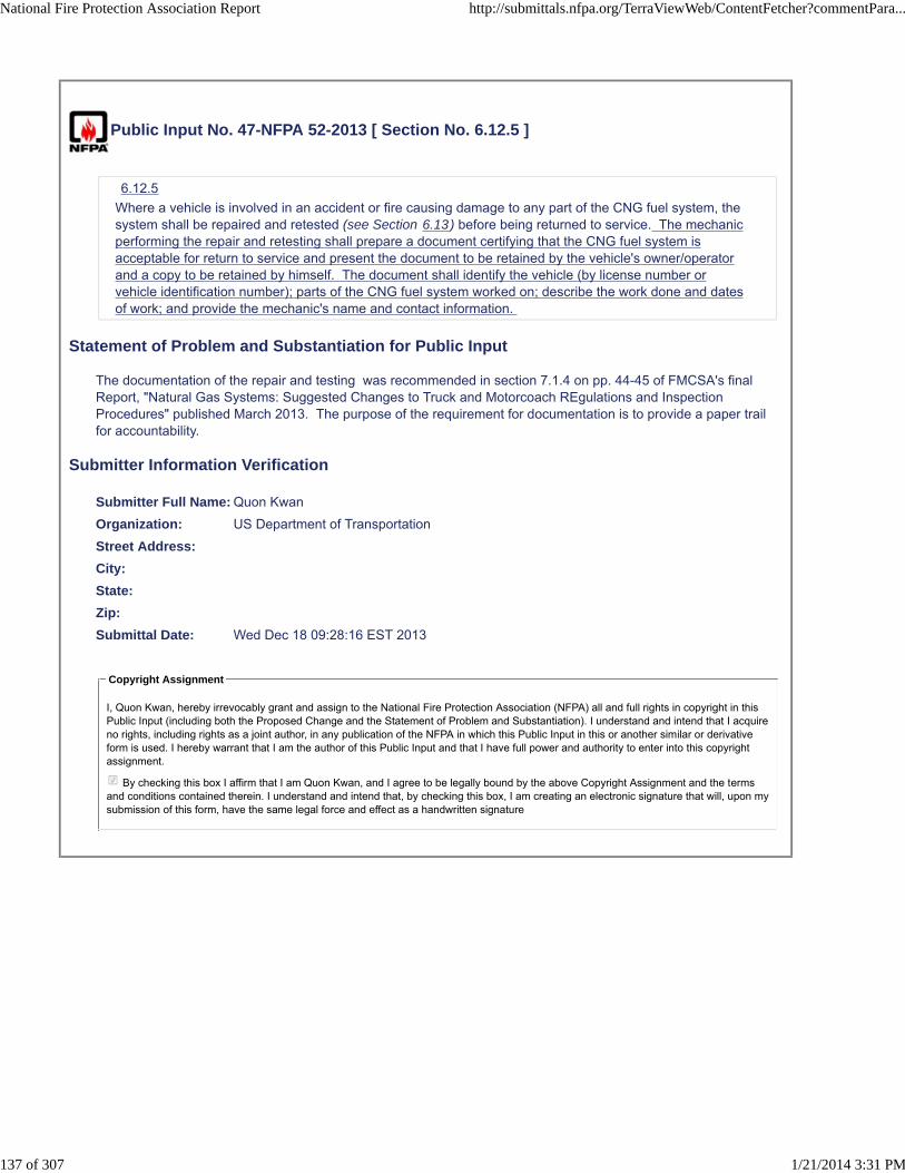
Public Input No. 47-NFPA 52-2013 [ Section No. 6.12.5 ]
6.12.5
Where a vehicle is involved in an accident or fire causing damage to any part of the CNG fuel system, thesystem shall be repaired and retested (see Section 6.13) before being returned to service. The mechanicperforming the repair and retesting shall prepare a document certifying that the CNG fuel system isacceptable for return to service and present the document to be retained by the vehicle's owner/operatorand a copy to be retained by himself. The document shall identify the vehicle (by license number orvehicle identification number); parts of the CNG fuel system worked on; describe the work done and datesof work; and provide the mechanic's name and contact information.
Statement of Problem and Substantiation for Public Input
The documentation of the repair and testing was recommended in section 7.1.4 on pp. 44-45 of FMCSA's final Report, "Natural Gas Systems: Suggested Changes to Truck and Motorcoach REgulations and Inspection Procedures" published March 2013. The purpose of the requirement for documentation is to provide a paper trail for accountability.
Submitter Information Verification
Submitter Full Name: Quon Kwan
Organization: US Department of Transportation
Street Address:
City:
State:
Zip:
Submittal Date: Wed Dec 18 09:28:16 EST 2013
Copyright Assignment
I, Quon Kwan, hereby irrevocably grant and assign to the National Fire Protection Association (NFPA) all and full rights in copyright in thisPublic Input (including both the Proposed Change and the Statement of Problem and Substantiation). I understand and intend that I acquireno rights, including rights as a joint author, in any publication of the NFPA in which this Public Input in this or another similar or derivativeform is used. I hereby warrant that I am the author of this Public Input and that I have full power and authority to enter into this copyrightassignment.
By checking this box I affirm that I am Quon Kwan, and I agree to be legally bound by the above Copyright Assignment and the termsand conditions contained therein. I understand and intend that, by checking this box, I am creating an electronic signature that will, upon mysubmission of this form, have the same legal force and effect as a handwritten signature
National Fire Protection Association Report http://submittals.nfpa.org/TerraViewWeb/ContentFetcher?commentPara...
137 of 307 1/21/2014 3:31 PM

Public Input No. 194-NFPA 52-2013 [ Section No. 6.12.6 ]
6.12.6
Where a CNG container is removed from a vehicle in order to be installed within a different vehicle, it shallbe inspected or retested in accordance with the inspection or requalification procedures of the standardunder which it was originally manufactured the container manufacturer's before it is reinstalled.
Statement of Problem and Substantiation for Public Input
Since only FMVSS 304/NGV2 containers may be sold vor CNG vehicles, the manufacturers instructions should be used in all cases. The old ambiguous requirement was necessary for DOT-TC compresed gas cylinders that are no longer legal for sale for NGVs.
Submitter Information Verification
Submitter Full Name: John Dimmick
Organization: Clean Vehicle Education Founda
Affilliation: Clean Vehicle Education Foundation
Street Address:
City:
State:
Zip:
Submittal Date: Tue Dec 31 11:03:12 EST 2013
Copyright Assignment
I, John Dimmick, hereby irrevocably grant and assign to the National Fire Protection Association (NFPA) all and full rights in copyright inthis Public Input (including both the Proposed Change and the Statement of Problem and Substantiation). I understand and intend that Iacquire no rights, including rights as a joint author, in any publication of the NFPA in which this Public Input in this or another similar orderivative form is used. I hereby warrant that I am the author of this Public Input and that I have full power and authority to enter into thiscopyright assignment.
By checking this box I affirm that I am John Dimmick, and I agree to be legally bound by the above Copyright Assignment and the termsand conditions contained therein. I understand and intend that, by checking this box, I am creating an electronic signature that will, upon mysubmission of this form, have the same legal force and effect as a handwritten signature
National Fire Protection Association Report http://submittals.nfpa.org/TerraViewWeb/ContentFetcher?commentPara...
138 of 307 1/21/2014 3:31 PM

Public Input No. 195-NFPA 52-2013 [ New Section after 6.13 ]
TITLE OF NEW CONTENT Type your content here ... System Instructions
OEMs, FSVIMs, alterers and converters shall make available instructions for system maintenance andrepair including but not limited to the following.
Statement of Problem and Substantiation for Public Input
All CNG installations should be delivered with these essential instructions.
Submitter Information Verification
Submitter Full Name: John Dimmick
Organization: Clean Vehicle Education Founda
Affilliation: Clean Vehicle Education Foundation
Street Address:
City:
State:
Zip:
Submittal Date: Tue Dec 31 11:05:49 EST 2013
Copyright Assignment
I, John Dimmick, hereby irrevocably grant and assign to the National Fire Protection Association (NFPA) all and full rights in copyright inthis Public Input (including both the Proposed Change and the Statement of Problem and Substantiation). I understand and intend that Iacquire no rights, including rights as a joint author, in any publication of the NFPA in which this Public Input in this or another similar orderivative form is used. I hereby warrant that I am the author of this Public Input and that I have full power and authority to enter into thiscopyright assignment.
By checking this box I affirm that I am John Dimmick, and I agree to be legally bound by the above Copyright Assignment and the termsand conditions contained therein. I understand and intend that, by checking this box, I am creating an electronic signature that will, upon mysubmission of this form, have the same legal force and effect as a handwritten signature
National Fire Protection Association Report http://submittals.nfpa.org/TerraViewWeb/ContentFetcher?commentPara...
139 of 307 1/21/2014 3:31 PM

Public Input No. 124-NFPA 52-2013 [ Section No. 6.13 ]
6.13 System Inspection, Maintenance and Repair.
6.13.1
Damaged fuel lines shall be replaced and not repaired.
6.13.2
All containers, container appurtenances, piping systems, venting systems, and other components shall bemaintained in accordance with the manufacturer's requirements.
6.13.3
Vehicle fuel supply containers shall be inspected in accordance with the schedule in the vehicle labelrequired in 6.11.1 and one of the following:
(1) Vehicle manufacturer’s instructions
(2) Container manufacturer’s instructions
with the instructions in the Compressed Gas Association’s (CGA) C-6.4, "Methods for External VisualInspection of Natural Gas Vehicle (NGV) and Hydrogen Vehicle (HV) Fuel Containers and TheirInstallations". Personnel inspecting vehicle fuel supply containers shall be trained on CGA C-6.4 andmaintain current certification with the Canadian Standards Association (CSA) - America.
6.13.3.1
Fuel containers whose service life has expired shall be removed from service.
6.13.3.2
After periodic container inspection, a label showing the next required inspection date shall be noted on theaffixed label as required in 6.11.1.
6.13.4
Pressure relief devices on fuel containers shall be maintained in accordance with the following:
(1) Pressure relief device channels or other parts that interfere with the functioning of the device shall notbe plugged by paint or accumulation of dirt.
(2) Only qualified personnel shall be permitted to service pressure relief devices.
(3) Only assemblies or original manufacturer's parts shall be used in the repair of pressure relief devicesunless the interchange of parts has been proved by tests.
(4) No pressure relief device that has been in service shall be reinstalled on another fuel cylinder.
6.13.5
The following shall be done during vehicle maintenance:
(1) Ensure the engine is isolated from the fuel supply unless engine operation is required. If a manualisolation valve is used, it shall comply with 6.6.2.
(2) Prohibit torches, welding, or grinding equipment on or near high-pressure fuel lines and containers.
(3) Prevent damage to containers, including actions such as dropping, dragging, or rolling of thecontainer.
(4) Prevent exposure of containers to strong chemicals such as battery acid or metal-cleaning solvents.
(5) Store CNG containers in a manner to avoid damage.
(6) Reinstall containers to their original configuration using approved gaskets, bolts, nuts, washers, andparts in accordance with the recommendations of the container manufacturer.
(7) Prevent hoists or jacks from coming into direct contact with containers.
(8) Prohibit personnel from walking on roof-mounted containers.
Statement of Problem and Substantiation for Public Input
National Fire Protection Association Report http://submittals.nfpa.org/TerraViewWeb/ContentFetcher?commentPara...
140 of 307 1/21/2014 3:31 PM

Cylinder inspections must be performed by qualified personnel. The only standards known for performing cylinder inspections are the Compressed Gas Association’s (CGA) C-6.4, "Methods for External Visual Inspection of Natural Gas Vehicle (NGV) and Hydrogen Vehicle (HV) Fuel Containers and Their Installations" and International Standards Organization (ISO) 19078, "Gas Cylinders - Inspection of the Cylinder Installation and Requalification of High Pressure Cylinders for the Onboard Storage of Natural Gas as a Fuel for Automotive Vehicles." The former is more widely used in the U.S. The only certification process known for such qualifying personnel to conduct cylinder inspections is that administered by the Canadian Standards Association (CSA) - America.
Submitter Information Verification
Submitter Full Name: Quon Kwan
Organization: US Department of Transportation
Street Address:
City:
State:
Zip:
Submittal Date: Fri Dec 27 13:20:37 EST 2013
Copyright Assignment
I, Quon Kwan, hereby irrevocably grant and assign to the National Fire Protection Association (NFPA) all and full rights in copyright in thisPublic Input (including both the Proposed Change and the Statement of Problem and Substantiation). I understand and intend that I acquireno rights, including rights as a joint author, in any publication of the NFPA in which this Public Input in this or another similar or derivativeform is used. I hereby warrant that I am the author of this Public Input and that I have full power and authority to enter into this copyrightassignment.
By checking this box I affirm that I am Quon Kwan, and I agree to be legally bound by the above Copyright Assignment and the termsand conditions contained therein. I understand and intend that, by checking this box, I am creating an electronic signature that will, upon mysubmission of this form, have the same legal force and effect as a handwritten signature
National Fire Protection Association Report http://submittals.nfpa.org/TerraViewWeb/ContentFetcher?commentPara...
141 of 307 1/21/2014 3:31 PM

Public Input No. 196-NFPA 52-2013 [ Section No. 6.13.4 ]
6.13.4
Pressure relief devices on fuel containers shall be maintained in accordance with the following:
(1) Pressure relief device channels or other parts that interfere with the functioning of the device shall notbe plugged by paint or accumulation of dirt.
(2) Only qualified personnel shall be permitted to service pressure relief devices.
(3) Only assemblies or original manufacturer's parts shall be used in the repair of pressure relief devicesunless the interchange of parts has been proved by tests .
(4) No pressure relief device that has been in service shall be reinstalled on another fuel cylinder.
Statement of Problem and Substantiation for Public Input
PRD1 makes no provisions for any replacements except by the original manufacturer. The necessary tests are not defined adequately.
Submitter Information Verification
Submitter Full Name: John Dimmick
Organization: Clean Vehicle Education Founda
Affilliation: Clean Vehicle Education Foundation
Street Address:
City:
State:
Zip:
Submittal Date: Tue Dec 31 11:08:33 EST 2013
Copyright Assignment
I, John Dimmick, hereby irrevocably grant and assign to the National Fire Protection Association (NFPA) all and full rights in copyright inthis Public Input (including both the Proposed Change and the Statement of Problem and Substantiation). I understand and intend that Iacquire no rights, including rights as a joint author, in any publication of the NFPA in which this Public Input in this or another similar orderivative form is used. I hereby warrant that I am the author of this Public Input and that I have full power and authority to enter into thiscopyright assignment.
By checking this box I affirm that I am John Dimmick, and I agree to be legally bound by the above Copyright Assignment and the termsand conditions contained therein. I understand and intend that, by checking this box, I am creating an electronic signature that will, upon mysubmission of this form, have the same legal force and effect as a handwritten signature
National Fire Protection Association Report http://submittals.nfpa.org/TerraViewWeb/ContentFetcher?commentPara...
142 of 307 1/21/2014 3:31 PM

Public Input No. 197-NFPA 52-2013 [ Section No. 6.13.5 ]
6.13.5
The following shall be done during vehicle maintenance:
(1) Ensure the engine is isolated from the fuel supply unless engine operation is required. If a manualisolation valve is used, it shall comply with 6.6.2.
(2) Prohibit torches, welding, or grinding equipment on or near high-pressure fuel lines and containers.
(3) Prevent damage to containers, including actions such as dropping, dragging, or rolling of thecontainer.
(4) Prevent exposure of containers to strong chemicals such as battery acid or metal-cleaning solvents.
(5) Store CNG containers in a manner to avoid damage.
(6) Protect stored containers from sunlight. Type 4 cylinders shall be stored with a small pressure inaccordance with manufacturer’s instructions. The openings in all stored cylinders shall be closed toprevent the entry of moisture and other contaminants.
(7) Reinstall containers to their original configuration using approved gaskets, bolts, nuts, washers, andparts in accordance with the recommendations of the container manufacturer.
(8) Prevent hoists or jacks from coming into direct contact with containers.
(9) Prohibit personnel from walking on roof-mounted containers.
Statement of Problem and Substantiation for Public Input
The added storage conditions are necessary to prevent hidden damage to containers. There have been reported incidents cause by the collapse of unpressurized Type 4 liners and internal corrosion due to moisture admitted during storage
Submitter Information Verification
Submitter Full Name: John Dimmick
Organization: Clean Vehicle Education Founda
Affilliation: Clean Vehicle Education Foundation
Street Address:
City:
State:
Zip:
Submittal Date: Tue Dec 31 11:10:48 EST 2013
Copyright Assignment
I, John Dimmick, hereby irrevocably grant and assign to the National Fire Protection Association (NFPA) all and full rights in copyright inthis Public Input (including both the Proposed Change and the Statement of Problem and Substantiation). I understand and intend that Iacquire no rights, including rights as a joint author, in any publication of the NFPA in which this Public Input in this or another similar orderivative form is used. I hereby warrant that I am the author of this Public Input and that I have full power and authority to enter into thiscopyright assignment.
By checking this box I affirm that I am John Dimmick, and I agree to be legally bound by the above Copyright Assignment and the termsand conditions contained therein. I understand and intend that, by checking this box, I am creating an electronic signature that will, upon mysubmission of this form, have the same legal force and effect as a handwritten signature
National Fire Protection Association Report http://submittals.nfpa.org/TerraViewWeb/ContentFetcher?commentPara...
143 of 307 1/21/2014 3:31 PM

Public Input No. 198-NFPA 52-2013 [ Section No. 6.13.5 ]
6.13.5
The following shall be done during vehicle maintenance:
(1) Ensure the engine is isolated from the fuel supply unless engine operation is required. If a manualisolation valve is used, it shall comply with 6.6.2.
(2) Prohibit torches, welding, or grinding equipment on or near high-pressure fuel lines and containers.
(3) Prevent damage to containers, including actions such as dropping, dragging, or rolling of thecontainer.
(4) Prevent exposure of containers to strong chemicals such as battery acid or metal-cleaning solvents.
(5) Store CNG containers in a manner to avoid damage.
(6) Reinstall containers to their original configuration using approved gaskets, bolts, nuts, washers, andparts in accordance with the recommendations of the container manufacturer.
(7) Prevent hoists or jacks from coming into direct contact with containers.
(8) Prohibit personnel from walking on roof-mounted containers.
Statement of Problem and Substantiation for Public Input
Many side mount containers are located where they could be walked on.
Submitter Information Verification
Submitter Full Name: John Dimmick
Organization: Clean Vehicle Education Founda
Affilliation: Clean Vehicle Education Foundation
Street Address:
City:
State:
Zip:
Submittal Date: Tue Dec 31 11:14:42 EST 2013
Copyright Assignment
I, John Dimmick, hereby irrevocably grant and assign to the National Fire Protection Association (NFPA) all and full rights in copyright inthis Public Input (including both the Proposed Change and the Statement of Problem and Substantiation). I understand and intend that Iacquire no rights, including rights as a joint author, in any publication of the NFPA in which this Public Input in this or another similar orderivative form is used. I hereby warrant that I am the author of this Public Input and that I have full power and authority to enter into thiscopyright assignment.
By checking this box I affirm that I am John Dimmick, and I agree to be legally bound by the above Copyright Assignment and the termsand conditions contained therein. I understand and intend that, by checking this box, I am creating an electronic signature that will, upon mysubmission of this form, have the same legal force and effect as a handwritten signature
National Fire Protection Association Report http://submittals.nfpa.org/TerraViewWeb/ContentFetcher?commentPara...
144 of 307 1/21/2014 3:31 PM

Public Input No. 202-NFPA 52-2013 [ Section No. 6.13.5 ]
6.13.5
The following shall be done during vehicle maintenance:
(1) Ensure the engine is isolated from the fuel supply unless engine operation is required. If a manualisolation valve is used, it shall comply with 6.6.2.
(2) Prohibit torches, welding, or grinding equipment on or near high-pressure fuel lines and containers.
(3) Prevent damage to containers, including actions such as dropping, dragging, or rolling of thecontainer.
(4) Prevent exposure of containers to strong chemicals such as battery acid or metal-cleaning solvents.
(5) Store CNG containers in a manner to avoid damage.
(6) Reinstall containers to their original configuration using approved gaskets, bolts, nuts, washers, andparts in accordance with the recommendations of the container manufacturer or system installer .
(7) Prevent hoists or jacks from coming into direct contact with containers.
(8) Prohibit personnel from walking on roof-mounted containers.
Statement of Problem and Substantiation for Public Input
System installer is appropriate since it may be the OEM, FSVIM, altere converter or cylinder manufacturer.
Submitter Information Verification
Submitter Full Name: John Dimmick
Organization: Clean Vehicle Education Founda
Affilliation: Clean Vehicle Education Foundation
Street Address:
City:
State:
Zip:
Submittal Date: Tue Dec 31 11:24:08 EST 2013
Copyright Assignment
I, John Dimmick, hereby irrevocably grant and assign to the National Fire Protection Association (NFPA) all and full rights in copyright inthis Public Input (including both the Proposed Change and the Statement of Problem and Substantiation). I understand and intend that Iacquire no rights, including rights as a joint author, in any publication of the NFPA in which this Public Input in this or another similar orderivative form is used. I hereby warrant that I am the author of this Public Input and that I have full power and authority to enter into thiscopyright assignment.
By checking this box I affirm that I am John Dimmick, and I agree to be legally bound by the above Copyright Assignment and the termsand conditions contained therein. I understand and intend that, by checking this box, I am creating an electronic signature that will, upon mysubmission of this form, have the same legal force and effect as a handwritten signature
National Fire Protection Association Report http://submittals.nfpa.org/TerraViewWeb/ContentFetcher?commentPara...
145 of 307 1/21/2014 3:31 PM

Public Input No. 26-NFPA 52-2013 [ Section No. 6.13.5 ]
6.13.5
The following shall be done during vehicle maintenance:
(1) Ensure the engine is isolated from the fuel supply unless engine operation is required. If a manualisolation valve is used, it shall comply with 6.6.2.
(2) Prohibit torches, welding, or grinding equipment on or near high-pressure fuel lines and containers.
(3) Prevent damage to containers, including actions such as dropping, dragging, or rolling of thecontainer.
(4) Prevent exposure of containers to strong chemicals such as battery acid or metal-cleaning solvents.
(5) Store CNG containers in a manner to avoid damage.
(6) Reinstall containers to their original configuration using approved gaskets, bolts, nuts, washers, andparts in accordance with the recommendations of the container manufacturer.
(7) Prevent hoists or jacks from coming into direct contact with containers.
(8) Prohibit personnel from walking on roof-mounted containers. or follow CNG cylinder manufacturer'srecommendations.
Statement of Problem and Substantiation for Public Input
Some CNG cylinder manufacturer's allow walking on the cylinders as long as you do not have sharp object on your footwear.
Submitter Information Verification
Submitter Full Name: GARTH RUTTIG
Organization: NEW FLYER INDUSTRIES
Street Address:
City:
State:
Zip:
Submittal Date: Fri Dec 13 11:50:07 EST 2013
Copyright Assignment
I, GARTH RUTTIG, hereby irrevocably grant and assign to the National Fire Protection Association (NFPA) all and full rights in copyright inthis Public Input (including both the Proposed Change and the Statement of Problem and Substantiation). I understand and intend that Iacquire no rights, including rights as a joint author, in any publication of the NFPA in which this Public Input in this or another similar orderivative form is used. I hereby warrant that I am the author of this Public Input and that I have full power and authority to enter into thiscopyright assignment.
By checking this box I affirm that I am GARTH RUTTIG, and I agree to be legally bound by the above Copyright Assignment and theterms and conditions contained therein. I understand and intend that, by checking this box, I am creating an electronic signature that will,upon my submission of this form, have the same legal force and effect as a handwritten signature
National Fire Protection Association Report http://submittals.nfpa.org/TerraViewWeb/ContentFetcher?commentPara...
146 of 307 1/21/2014 3:31 PM

Public Input No. 199-NFPA 52-2013 [ Section No. 6.14.1.1 ]
6.14.1.1
The gas to be removed from the container shall be discharged into a closed transfer system or vented byan AHJ approved method of atmospheric venting.
Statement of Problem and Substantiation for Public Input
To reinforce the need for AHJ approval that the venting system is safe and acceptable.
Submitter Information Verification
Submitter Full Name: John Dimmick
Organization: Clean Vehicle Education Founda
Affilliation: Clean Vehicle Education Foundation
Street Address:
City:
State:
Zip:
Submittal Date: Tue Dec 31 11:17:45 EST 2013
Copyright Assignment
I, John Dimmick, hereby irrevocably grant and assign to the National Fire Protection Association (NFPA) all and full rights in copyright inthis Public Input (including both the Proposed Change and the Statement of Problem and Substantiation). I understand and intend that Iacquire no rights, including rights as a joint author, in any publication of the NFPA in which this Public Input in this or another similar orderivative form is used. I hereby warrant that I am the author of this Public Input and that I have full power and authority to enter into thiscopyright assignment.
By checking this box I affirm that I am John Dimmick, and I agree to be legally bound by the above Copyright Assignment and the termsand conditions contained therein. I understand and intend that, by checking this box, I am creating an electronic signature that will, upon mysubmission of this form, have the same legal force and effect as a handwritten signature
National Fire Protection Association Report http://submittals.nfpa.org/TerraViewWeb/ContentFetcher?commentPara...
147 of 307 1/21/2014 3:31 PM

Public Input No. 200-NFPA 52-2013 [ New Section after 6.14.2 ]
TITLE OF NEW CONTENT Instructions
Type your content here ...1 Depressurize containers only in accordance with the manufacturer’sinstructions.
Statement of Problem and Substantiation for Public Input
Assured and safe depressurization of containers is only assured in fanufacturer’s instructions are used.
Submitter Information Verification
Submitter Full Name: John Dimmick
Organization: Clean Vehicle Education Founda
Street Address:
City:
State:
Zip:
Submittal Date: Tue Dec 31 11:20:17 EST 2013
Copyright Assignment
I, John Dimmick, hereby irrevocably grant and assign to the National Fire Protection Association (NFPA) all and full rights in copyright inthis Public Input (including both the Proposed Change and the Statement of Problem and Substantiation). I understand and intend that Iacquire no rights, including rights as a joint author, in any publication of the NFPA in which this Public Input in this or another similar orderivative form is used. I hereby warrant that I am the author of this Public Input and that I have full power and authority to enter into thiscopyright assignment.
By checking this box I affirm that I am John Dimmick, and I agree to be legally bound by the above Copyright Assignment and the termsand conditions contained therein. I understand and intend that, by checking this box, I am creating an electronic signature that will, upon mysubmission of this form, have the same legal force and effect as a handwritten signature
National Fire Protection Association Report http://submittals.nfpa.org/TerraViewWeb/ContentFetcher?commentPara...
148 of 307 1/21/2014 3:31 PM

Public Input No. 201-NFPA 52-2013 [ Section No. 6.14.3.2 ]
6.14.3.2
The vent tube shall be constructed of Schedule 80 pipe of at least 2 in. (51 mm) diameter.
Statement of Problem and Substantiation for Public Input
There is no way to connect such a large pipe to a container or system for depressurization. Both the pipe size and schedule are excessive. The installation must be approved by the AHJ who can verify that the tube is adequate for the flow and pressure.
Submitter Information Verification
Submitter Full Name: John Dimmick
Organization: Clean Vehicle Education Founda
Affilliation: Clean Vehicle Education Foundation
Street Address:
City:
State:
Zip:
Submittal Date: Tue Dec 31 11:22:20 EST 2013
Copyright Assignment
I, John Dimmick, hereby irrevocably grant and assign to the National Fire Protection Association (NFPA) all and full rights in copyright inthis Public Input (including both the Proposed Change and the Statement of Problem and Substantiation). I understand and intend that Iacquire no rights, including rights as a joint author, in any publication of the NFPA in which this Public Input in this or another similar orderivative form is used. I hereby warrant that I am the author of this Public Input and that I have full power and authority to enter into thiscopyright assignment.
By checking this box I affirm that I am John Dimmick, and I agree to be legally bound by the above Copyright Assignment and the termsand conditions contained therein. I understand and intend that, by checking this box, I am creating an electronic signature that will, upon mysubmission of this form, have the same legal force and effect as a handwritten signature
National Fire Protection Association Report http://submittals.nfpa.org/TerraViewWeb/ContentFetcher?commentPara...
149 of 307 1/21/2014 3:31 PM
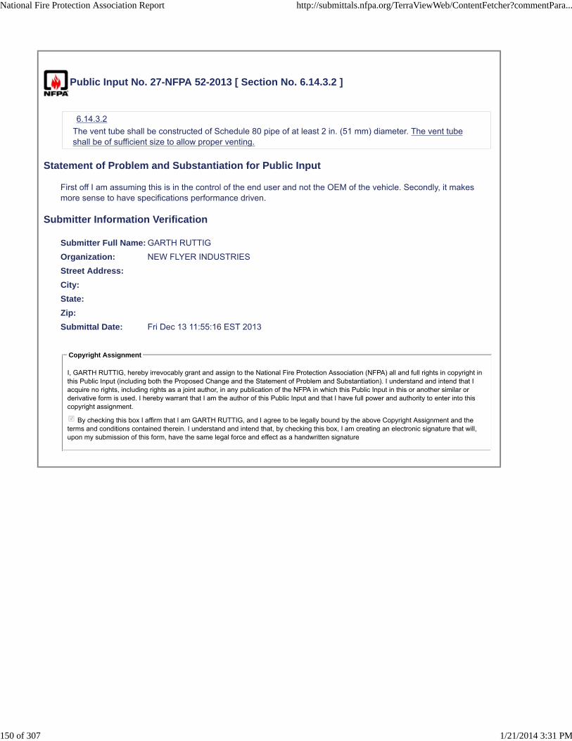
Public Input No. 27-NFPA 52-2013 [ Section No. 6.14.3.2 ]
6.14.3.2
The vent tube shall be constructed of Schedule 80 pipe of at least 2 in. (51 mm) diameter. The vent tubeshall be of sufficient size to allow proper venting.
Statement of Problem and Substantiation for Public Input
First off I am assuming this is in the control of the end user and not the OEM of the vehicle. Secondly, it makes more sense to have specifications performance driven.
Submitter Information Verification
Submitter Full Name: GARTH RUTTIG
Organization: NEW FLYER INDUSTRIES
Street Address:
City:
State:
Zip:
Submittal Date: Fri Dec 13 11:55:16 EST 2013
Copyright Assignment
I, GARTH RUTTIG, hereby irrevocably grant and assign to the National Fire Protection Association (NFPA) all and full rights in copyright inthis Public Input (including both the Proposed Change and the Statement of Problem and Substantiation). I understand and intend that Iacquire no rights, including rights as a joint author, in any publication of the NFPA in which this Public Input in this or another similar orderivative form is used. I hereby warrant that I am the author of this Public Input and that I have full power and authority to enter into thiscopyright assignment.
By checking this box I affirm that I am GARTH RUTTIG, and I agree to be legally bound by the above Copyright Assignment and theterms and conditions contained therein. I understand and intend that, by checking this box, I am creating an electronic signature that will,upon my submission of this form, have the same legal force and effect as a handwritten signature
National Fire Protection Association Report http://submittals.nfpa.org/TerraViewWeb/ContentFetcher?commentPara...
150 of 307 1/21/2014 3:31 PM
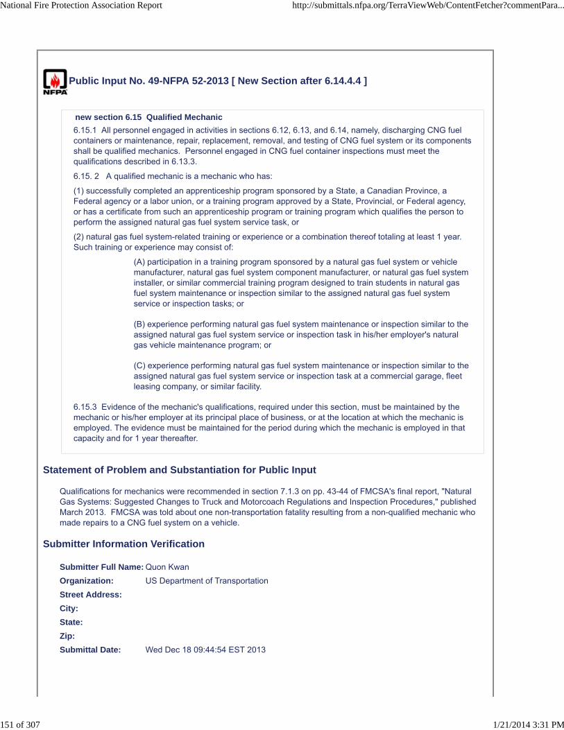
Public Input No. 49-NFPA 52-2013 [ New Section after 6.14.4.4 ]
new section 6.15 Qualified Mechanic
6.15.1 All personnel engaged in activities in sections 6.12, 6.13, and 6.14, namely, discharging CNG fuelcontainers or maintenance, repair, replacement, removal, and testing of CNG fuel system or its componentsshall be qualified mechanics. Personnel engaged in CNG fuel container inspections must meet thequalifications described in 6.13.3.
6.15. 2 A qualified mechanic is a mechanic who has:
(1) successfully completed an apprenticeship program sponsored by a State, a Canadian Province, aFederal agency or a labor union, or a training program approved by a State, Provincial, or Federal agency,or has a certificate from such an apprenticeship program or training program which qualifies the person toperform the assigned natural gas fuel system service task, or
(2) natural gas fuel system-related training or experience or a combination thereof totaling at least 1 year.Such training or experience may consist of:
(A) participation in a training program sponsored by a natural gas fuel system or vehiclemanufacturer, natural gas fuel system component manufacturer, or natural gas fuel systeminstaller, or similar commercial training program designed to train students in natural gasfuel system maintenance or inspection similar to the assigned natural gas fuel systemservice or inspection tasks; or
(B) experience performing natural gas fuel system maintenance or inspection similar to theassigned natural gas fuel system service or inspection task in his/her employer's naturalgas vehicle maintenance program; or
(C) experience performing natural gas fuel system maintenance or inspection similar to theassigned natural gas fuel system service or inspection task at a commercial garage, fleetleasing company, or similar facility.
6.15.3 Evidence of the mechanic's qualifications, required under this section, must be maintained by themechanic or his/her employer at its principal place of business, or at the location at which the mechanic isemployed. The evidence must be maintained for the period during which the mechanic is employed in thatcapacity and for 1 year thereafter.
Statement of Problem and Substantiation for Public Input
Qualifications for mechanics were recommended in section 7.1.3 on pp. 43-44 of FMCSA's final report, "Natural Gas Systems: Suggested Changes to Truck and Motorcoach Regulations and Inspection Procedures," published March 2013. FMCSA was told about one non-transportation fatality resulting from a non-qualified mechanic who made repairs to a CNG fuel system on a vehicle.
Submitter Information Verification
Submitter Full Name: Quon Kwan
Organization: US Department of Transportation
Street Address:
City:
State:
Zip:
Submittal Date: Wed Dec 18 09:44:54 EST 2013
National Fire Protection Association Report http://submittals.nfpa.org/TerraViewWeb/ContentFetcher?commentPara...
151 of 307 1/21/2014 3:31 PM

Copyright Assignment
I, Quon Kwan, hereby irrevocably grant and assign to the National Fire Protection Association (NFPA) all and full rights in copyright in thisPublic Input (including both the Proposed Change and the Statement of Problem and Substantiation). I understand and intend that I acquireno rights, including rights as a joint author, in any publication of the NFPA in which this Public Input in this or another similar or derivativeform is used. I hereby warrant that I am the author of this Public Input and that I have full power and authority to enter into this copyrightassignment.
By checking this box I affirm that I am Quon Kwan, and I agree to be legally bound by the above Copyright Assignment and the termsand conditions contained therein. I understand and intend that, by checking this box, I am creating an electronic signature that will, upon mysubmission of this form, have the same legal force and effect as a handwritten signature
National Fire Protection Association Report http://submittals.nfpa.org/TerraViewWeb/ContentFetcher?commentPara...
152 of 307 1/21/2014 3:31 PM
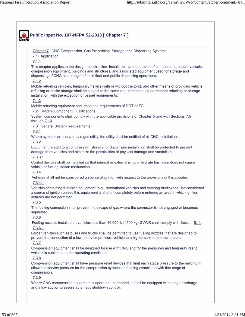
Public Input No. 107-NFPA 52-2013 [ Chapter 7 ]
Chapter 7 CNG Compression, Gas Processing, Storage, and Dispensing Systems
7.1 Application.
7.1.1
This chapter applies to the design, construction, installation, and operation of containers, pressure vessels,compression equipment, buildings and structures, and associated equipment used for storage anddispensing of CNG as an engine fuel in fleet and public dispensing operations.
7.1.2
Mobile refueling vehicles, temporary trailers (with or without tractors), and other means of providing vehiclerefueling or onsite storage shall be subject to the same requirements as a permanent refueling or storageinstallation, with the exception of vessel requirements.
7.1.3
Mobile refueling equipment shall meet the requirements of DOT or TC.
7.2 System Component Qualifications.
System components shall comply with the applicable provisions of Chapter 5 and with Sections 7.5through 7.13.
7.3 General System Requirements.
7.3.1
Where systems are served by a gas utility, the utility shall be notified of all CNG installations.
7.3.2
Equipment related to a compression, storage, or dispensing installation shall be protected to preventdamage from vehicles and minimize the possibilities of physical damage and vandalism.
7.3.3 *
Control devices shall be installed so that internal or external icing or hydrate formation does not causevehicle or fueling station malfunction.
7.3.4
Vehicles shall not be considered a source of ignition with respect to the provisions of this chapter.
7.3.4.1
Vehicles containing fuel-fired equipment (e.g., recreational vehicles and catering trucks) shall be considereda source of ignition unless this equipment is shut off completely before entering an area in which ignitionsources are not permitted.
7.3.5
The fueling connection shall prevent the escape of gas where the connector is not engaged or becomesseparated.
7.3.6
Fueling nozzles installed on vehicles less than 10,000 lb (4500 kg) GVWR shall comply with Section 5.11.
7.3.6.1
Larger vehicles such as buses and trucks shall be permitted to use fueling nozzles that are designed toprevent the connection of a lower service pressure vehicle to a higher service pressure source.
7.3.7
Compression equipment shall be designed for use with CNG and for the pressures and temperatures towhich it is subjected under operating conditions.
7.3.8
Compression equipment shall have pressure relief devices that limit each stage pressure to the maximumallowable service pressure for the compression cylinder and piping associated with that stage ofcompression.
7.3.9
Where CNG compression equipment is operated unattended, it shall be equipped with a high dischargeand a low suction pressure automatic shutdown control.
National Fire Protection Association Report http://submittals.nfpa.org/TerraViewWeb/ContentFetcher?commentPara...
153 of 307 1/21/2014 3:31 PM

7.3.10
Control circuits that shut down shall remain down until manually activated or reset after a safe shutdown isperformed.
7.3.11
Engine-driven compressor installations shall conform, where applicable, to NFPA 37, Standard for theInstallation and Use of Stationary Combustion Engines and Gas Turbines.
7.3.12 *
Compression equipment shall incorporate a means to minimize liquid carryover to the storage system.
7.3.13
Modifications to fuel stations including, but not limited to, increases in working pressure or dispensingpressures shall be subject to a complete review in accordance with that required for a new installation toinclude a notification of any supplying utility (see 7.3.1).
7.3.13.1
A hazard analysis of the proposed modification and the startup plan shall be required and prepared prior tothe modification and operation of the facility.
7.4 System Siting.
7.4.1 General.
7.4.1.1
CNG compression, storage, and dispensing shall be located and conducted outdoors or indoors incompliance with this section.
7.4.1.2
This equipment shall be installed on foundations with anchoring systems designed to meet therequirements of the adopted building code for the applicable seismic and wind conditions.
7.4.2 Outdoors.
7.4.2.1
CNG storage containers charged with CNG not connected for use shall be located outdoors.
7.4.2.2
A facility in which CNG compression, storage, and dispensing equipment are sheltered by weatherprotection constructed in accordance with the requirements of the building code and by a roof designed forventilation and dispersal of escaped gas shall be considered to be located outdoors.
7.4.2.3
Compression, storage, and dispensing equipment located outdoors shall be above ground.
7.4.2.3.1
Compression, storage, and dispensing equipment located outdoors shall not be beneath electric powerlines or where exposed by their failure.
7.4.2.3.2
Compression, storage, and dispensing equipment located outdoors shall be a minimum of 10 ft (3 m) fromthe nearest important building or line of adjoining property that is able to be built upon or from any source ofignition.
7.4.2.4
Compression, storage, and dispensing equipment located outdoors shall be not less than 10 ft (3 m) fromthe nearest public street or sidewalk line and at least 50 ft (15 m) from the nearest rail of any railroad maintrack.
7.4.2.5
A clear space of at least 3 ft (1 m) shall be provided for access to all valves and fittings of multiple groups ofcontainers.
7.4.2.6
Combustible material shall not be permitted within 10 ft (3 m) of any stationary container.
7.4.2.7
The minimum separation between containers and aboveground tanks containing flammable or combustibleliquids shall be 20 ft (6 m).
7.4.2.8
During outdoor fueling operations, the point of transfer shall be located at least 10 ft (3 m) from anyimportant building, mobile home, public sidewalk, highway, street, or road and at least 3 ft (1 m) fromstorage containers.
National Fire Protection Association Report http://submittals.nfpa.org/TerraViewWeb/ContentFetcher?commentPara...
154 of 307 1/21/2014 3:31 PM

7.4.2.8.1
The point of transfer shall be permitted to be located at a lesser distance from buildings or wallsconstructed of concrete or masonry materials or of other material having a fire resistance rating of at least 2hours, but at least 10 ft (3 m) from any building openings.
7.4.2.9
Areas for compression, storage, and dispensing shall be classified in accordance with Table 7.4.2.9 forinstallations of electrical equipment.
Table 7.4.2.9 Electrical Installations
Location
Division
or Zone
Extent of
Classified Area
Containers (other than mounted fuel supplycontainers)
2 Within 10 ft (3 m) of container
Area containing compression and ancillaryequipment
2 Up to 15 ft (4.6 m) from equipment
Dispensing equipment outdoors 1 Inside the dispenser enclosure
Outdoors 2 From 0 to 5 ft (0 to 1.5 m) from the dispenser
Indoors 1 Inside the dispenser enclosure
Indoors 2 Entire room, with adequate ventilation (see 7.4.3)
Discharge from relief valves or vent
Outdoors 1 5 ft (1.5 m) in all directions from the point source
Outdoors 2Beyond 5 ft (1.5 m) but within 15 ft (4.6 m) in alldirections from point of discharge
Valves, flanges of screwed fittings None Unclassified
Discharge from relief valves within 15degrees of the line of discharge
1 15 ft (4.6 m)
7.4.3 Indoors.
7.4.3.1 General.
Compression, dispensing equipment, and storage containers connected for use shall be permitted to belocated inside of buildings reserved exclusively for these purposes or in rooms within or attached tobuildings used for other purposes in accordance with this section.
7.4.3.2 Limits of Storage in Buildings.
Storage shall be limited to not more than 10,000 scf (283 m3) of natural gas in each building or room.
7.4.3.2.1
CNG stored in vehicle-mounted fuel supply containers shall not be subject to 7.4.3.2.
7.4.3.3 * Deflagration Venting.
7.4.3.3.1
Deflagration (explosion) venting shall be provided in exterior walls or roof only.
7.4.3.3.2
Vents shall be permitted to consist of any one or any combination of the following:
(1) Walls of light material
(2) Lightly fastened hatch covers
(3) Lightly fastened, outward opening doors in exterior walls
(4) Lightly fastened walls or roofs
7.4.3.3.3
Where applicable, snow loads shall be considered.
7.4.3.4 Rooms Within Buildings.
7.4.3.4.1
Rooms within or attached to other buildings shall be constructed of noncombustible or limited-combustiblematerials.
National Fire Protection Association Report http://submittals.nfpa.org/TerraViewWeb/ContentFetcher?commentPara...
155 of 307 1/21/2014 3:31 PM

7.4.3.4.1.1
Window glazing shall be permitted to be plastic.
7.4.3.4.2
Interior walls or partitions shall be continuous from floor to ceiling, be anchored in accordance with therequirements of the building code, and have a fire resistance rating of at least 2 hours.
7.4.3.4.3
At least one wall shall be an exterior wall.
7.4.3.4.4
Explosion venting shall be provided in accordance with 7.4.3.3.
7.4.3.4.5
Access to the room shall be from outside the primary structure.
7.4.3.4.6
If access to the room from outside the primary structure is not possible, access from within the primarystructure shall be permitted where such access is made through a barrier space having two vapor-sealing,self-closing fire doors rated for the location where installed.
7.4.3.5 Ventilation Inlets and Outlets.
7.4.3.5.1
Indoor locations shall be ventilated utilizing air supply inlets and exhaust outlets arranged to provideuniform air movement throughout the space.
7.4.3.5.2
Inlets shall be uniformly arranged on exterior walls near floor level.
7.4.3.5.3
Outlets shall be located in exterior walls at the high point of the room or in the roof.
7.4.3.5.4 Ventilation.
7.4.3.5.4.1
Ventilation shall be by a continuous mechanical ventilation system or by a mechanical ventilation systemactivated by a continuously monitoring natural gas detection system where a gas concentration of not morethan one-fifth of the lower flammable limit is present.
7.4.3.5.4.2
In either case in 7.4.3.5.4.1, the system shall immediately shut down the fueling system in the event ofdetection of an alarm condition or failure of the ventilation system, the detection system, or the controls.
7.4.3.5.5 *
The ventilation rate shall be at least 1 ft3/min · 12 ft3 (0.03 m3/min · 0.34 m3) of room volume.
7.4.3.5.6
A ventilation system for a room within or attached to another building shall be separate from any ventilationsystem for the other building.
7.4.3.6
Where installed, a gas detection system shall be equipped to sound a latched alarm and visually indicatewhen a maximum of one-fifth of the lower flammable limit is reached.
7.4.3.7
Reactivation of the fueling system shall be by manual restart that is conducted by trained personnel.
7.4.3.8
Buildings and rooms used for compression, storage, and dispensing shall be classified in accordance withTable 7.4.2.9 for installations of electrical equipment.
7.4.3.9
Nonelectrical sources of ignition shall not be permitted.
7.4.3.10
Pressure relief devices on storage systems shall have pressure relief device channels [see 5.5.1 (3)] toconvey escaping gas to the outdoors and then upward to a safe area to prevent impinging on buildings,other equipment, or areas open to the public (e.g., sidewalks).
7.4.3.11 Warning Signs.
7.4.3.11.1
Access doors shall have warning signs with the words “WARNING — NO SMOKING — FLAMMABLEGAS.”
National Fire Protection Association Report http://submittals.nfpa.org/TerraViewWeb/ContentFetcher?commentPara...
156 of 307 1/21/2014 3:31 PM

7.4.3.11.2
The wording shall be in plainly legible, bright red letters not less than 1 in. (25 mm) high on a whitebackground.
7.4.3.12 Indoor Fast-Fill Fueling, Outdoor Storage, and Compression.
Fast-fill fueling indoors shall be permitted where storage and compression equipment is located outdoorscomplying with 7.4.2.1 through 7.4.2.7 and 7.4.2.9.
7.4.3.12.1
Where attended fast-fill fueling is performed indoors, the following shall be installed:
(1) An emergency manual shutdown device shall be installed as required by 7.11.5.
(2) A gas detection system equipped to sound a latched alarm and visually indicate when a maximum ofone-fifth of the lower flammable limit is reached shall be installed.
7.4.3.12.2
The actuation of the gas detection system shall shut down the compressor and stop the flow of gas into thestructure.
7.5 Installation of Containers and Container Appurtenances (Other than Pressure Relief Devices).
7.5.1 *
Storage containers shall be installed above ground on stable, noncombustible foundations or in vaults withventilation and drainage. (See Section 4.5 for noncombustible.)
7.5.1.1
Horizontal containers shall have no more than two points of support longitudinally.
7.5.1.2
In areas subject to flooding, each container shall be anchored to prevent floating.
7.5.2
Containers shall be protected by painting or other equivalent means where necessary to inhibit corrosion.
7.5.2.1
Composite containers shall not be painted without prior permission from the container manufacturer.
7.5.2.2
Horizontally installed containers shall not be in direct contact with each other.
7.5.2.3
Composite containers shall be protected from UV radiation as required by the manufacturer.
7.5.3
Means shall be provided to prevent the flow or accumulation of flammable or combustible liquids undercontainers, such as by grading, pads, or diversion curbs.
7.6 Installation of Pressure Relief Devices.
7.6.1
Pressure relief valves shall be arranged so that they discharge to a location where escaping gas does notimpinge on buildings, other equipment, or areas that are occupiable by the public (see 7.4.3.10).
7.6.2
Pressure relief valves on pressure vessels shall be installed so that any discharge is in a vertical position.
7.6.2.1
Pressure relief valves shall be fitted with rain caps.
7.6.3
A pressure relief valve other than a rupture disc shall be installed in the fueling transfer system to preventpressures in excess of 125 percent of the vehicle service pressure from being supplied to the vehicle.
7.6.3.1
The pressure relief valve shall be redundant to and independent from any operating control system used tocontrol the supplied fuel pressure during dispenser operation.
7.6.4
The set pressure of the overpressure protection device shall not exceed 125 percent of the servicepressure of the fueling nozzle it supplies.
7.6.5
If approved, full port block valves shall be permitted to be installed between the relief valves and thestorage vessel or fueling transfer system.
National Fire Protection Association Report http://submittals.nfpa.org/TerraViewWeb/ContentFetcher?commentPara...
157 of 307 1/21/2014 3:31 PM

7.6.6
The block valves shall be locked open.
7.7 Installation of Pressure Regulators.
7.7.1
Regulators shall be designed, installed, or protected so that their operation is not affected by freezing rain,sleet, snow, ice, mud, insects, or debris.
7.7.2
Regulator protection of 7.7.1 shall be permitted to be integral with the regulator.
7.8 Installation of Pressure Gauges.
Gauges or other readout devices shall be installed to indicate compression discharge pressure, storagepressure, and dispenser discharge pressure.
7.9 Installation of Piping and Hoses.
7.9.1 *
Piping and hose shall be run directly with provisions for expansion, contraction, jarring, vibration, andsettling.
7.9.1.1
Exterior piping shall be either buried or installed above ground and shall be supported and protectedagainst mechanical damage.
7.9.1.2
Underground piping shall be buried not less than 18 in. (460 mm) below the surface of the ground unlessotherwise protected from damage by movement of the ground.
7.9.1.3
Underground and aboveground piping shall be protected from corrosion in compliance with recognizedpractices.
7.9.1.4
Threaded pipe and fittings shall not be used underground.
7.9.1.5 Piping Connections.
7.9.1.5.1
Manifolds connecting fuel containers shall be fabricated to minimize vibration.
7.9.1.5.1.1
Manifolds shall be installed in a protected location or shielded to prevent damage from unsecured objects.
7.9.1.5.2
A pipe thread jointing material impervious to the action of the natural gas used in system shall be applied toall male pipe threads prior to assembly.
7.9.1.5.3
Threaded piping and fittings shall be clear and free from cutting or threading burrs and scales.
7.9.1.5.3.1
The ends of all piping shall be reamed.
7.9.1.5.4
A bend in piping or tubing shall be prohibited where such a bend weakens the pipe or tubing.
7.9.1.5.5
A joint or connection shall be located in an accessible location.
7.9.1.5.6
The number of joints shall be minimized and placed in a location considering personnel safety.
7.9.2
Natural gas shall be vented only to a safe point of discharge.
7.9.2.1
A vent pipe or stack shall have the open end protected to prevent entrance of rain, snow, and solid material.
7.9.2.2
Vertical vent pipes and stacks shall have provision for drainage.
7.9.3
National Fire Protection Association Report http://submittals.nfpa.org/TerraViewWeb/ContentFetcher?commentPara...
158 of 307 1/21/2014 3:31 PM

The use of hose in an installation shall be limited to the following:
(1) Vehicle fueling hose
(2) Inlet connection to compression equipment
(3) Section of metallic hose not exceeding 36 in. (910 mm) in length in a pipeline to provide flexibilitywhere necessary
7.9.3.1
Each section shall be installed so that it is protected against mechanical damage and is visible forinspection.
7.9.3.2
The manufacturer's identification shall be retained in each section.
7.9.4
At fueling stations, gas used for calibration and testing shall be vented to a safe location.
7.10 System Testing.
7.10.1
Piping, tubing and hose, and hose assemblies shall be leak tested after assembly to prove them free fromleaks at a pressure equal to at least the normal service pressure of that portion of the system.
7.10.2
Pressure relief valves shall be tested at least every 3 years.
7.11 Installation of Emergency Shutdown Equipment.
7.11.1 Manually Operated Container Valve.
7.11.1.1
A manually operated container valve shall be provided for each DOT or TC storage cylinder.
7.11.1.2
Individual groups of manifolded ASME storage vessels without individual storage vessel valves shall be
limited to a maximum of 10,000 scf (283 m3).
7.11.1.2.1
Manifolds serving each group of ASME storage vessels shall be provided with a manually operated shutoffvalve.
7.11.1.3
Individual ASME pressure vessels of any size, not part of a manifold system, shall have a manual shutoffvalve.
7.11.1.4
A manually operated shutoff valve shall be installed at the outlet from the manifold.
7.11.1.5
The valve in 7.11.1.3 shall be located downstream of the backflow check valve specified in 7.11.2.
7.11.2
The fill line on a storage container shall be equipped with a backflow check valve to prevent discharge ofnatural gas from the container in case of the rupture of the line, hose, fittings, or other equipment upstreamof the storage containers.
7.11.3
Where excess-flow check valves are used, the closing flow shall be greater than the maximum systemdesign flow rate and less than the flow rating of the piping system that results from a complete line failurebetween the excess-flow valve and the equipment downstream of the excess-flow check valve.
7.11.4
Gas piping from an outdoor compressor or storage system into a building shall be provided with shutoffvalves located outside the building.
7.11.5
An emergency manual shutdown device shall be provided within 10 ft (3.0 m) of the dispensing area andalso greater than 25 ft (7.6 m) from the dispensing area.
7.11.5.1
This device, when activated, shall shut off the power supply and gas supply to the compressor and thedispenser.
National Fire Protection Association Report http://submittals.nfpa.org/TerraViewWeb/ContentFetcher?commentPara...
159 of 307 1/21/2014 3:31 PM

7.11.5.2
Emergency shutdown devices shall be distinctly marked for easy recognition with a permanently affixedlegible sign.
7.11.6
Breakaway protection shall be provided in a manner that, in the event of a pullaway, natural gas ceases toflow at any separation.
7.11.6.1
A breakaway device shall be installed at every dispensing point.
7.11.6.2
A breakway device shall be arranged to separate using a force not greater than 150 lb (68 kg) when appliedin any direction that the vehicle would move.
7.11.6.3
Breakaway devices shall comply with ANSI/IAS NGV 4.4, Breakaway Devices for Natural Gas DispensingHoses and Systems.
7.11.7
Control circuits shall be arranged so that, when an emergency shutdown device is activated or electricpower is cut off, systems that shut down remain off until manually activated or reset after a safe condition isrestored.
7.11.8 Fast-Fill Station.
7.11.8.1
Each line between a gas storage facility and a dispenser at a fast-fill station shall have a valve that closeswhen one of the following occurs:
(1) The power supply to the dispenser is cut off.
(2) Any emergency shutdown device at the refueling station is activated.
7.11.8.2
A fast-closing, “quarter turn” manual shutoff valve shall be provided at a fast-fill station upstream of thebreakaway device specified in 7.11.6, where it is accessible to the person dispensing natural gas, unlessone of the following occurs:
(1) The self-closing valve referred to in 7.11.8.1 is located immediately upstream of the dispenser.
(2) The dispenser is equipped with a self-closing valve that closes each time the control arm is turned tothe OFF position or when an emergency device is activated.
7.11.9
A self-closing valve shall be provided on the inlet of the compressor that shuts off the gas supply to thecompressor when one of the following occurs:
(1) An emergency shutdown device is activated.
(2) A power failure occurs.
(3) The power to the compressor is switched to the OFF position.
7.12 * Installation of Electrical Equipment.
7.12.1
Fixed electrical equipment and wiring within areas specified in Table 7.4.2.9 shall comply with Table7.4.2.9 and be installed in accordance with NFPA 70, National Electrical Code.
7.12.1.1
Electrical equipment on internal combustion engines installed in accordance with NFPA 37, Standard forthe Installation and Use of Stationary Combustion Engines and Gas Turbines, shall not be subject to7.12.1.
7.12.2
With the approval of the AHJ, classified areas specified in Table 7.4.2.9 shall be permitted to be reduced oreliminated by positive pressure ventilation from a source of clean air or inert gas in conjunction witheffective safeguards against ventilator failure by purging methods recognized in NFPA 496, Standard forPurged and Pressurized Enclosures for Electrical Equipment.
7.12.3
Classified areas shall not extend beyond an unpierced wall, roof, or vaportight partition.
National Fire Protection Association Report http://submittals.nfpa.org/TerraViewWeb/ContentFetcher?commentPara...
160 of 307 1/21/2014 3:31 PM
7.12.3.1
Listed dispensers shall be permitted to be installed using classified areas in accordance with the terms ofthe listing.
7.12.4
Space around welded pipe and equipment without flanges, valves, or fittings shall be a nonhazardouslocation.
7.13 Stray or Impressed Currents and Bonding.
7.13.1 *
Where stray or impressed currents, such as those from cathodic protection, are used or present ondispensing systems, protective measures shall be taken to prevent ignition.
7.13.2 *
Static protection shall not be required where CNG is transferred by conductive or nonconductive hose,flexible metallic tubing, or pipe connections where both halves of the metallic couplings are in continuouscontact.
7.14 System Operation.
7.14.1
A cylinder shall not be charged in excess of the design pressure at the normal temperature for that cylinder.
7.14.1.1
DOT, TC, and ANSI/IAS NGV2 cylinders shall be charged in accordance with DOT, TC, and ANSI/IASNGV2 regulations.
7.14.1.2
DOT, TC, and ANSI/IAS NGV2 cylinders shall not be subjected to pressure in excess of 125 percent of themarked service pressure even if, on cooling, the pressure settles to the marked service pressure.
7.14.2
A fuel supply container shall not have a settled pressure above the service pressure that is stamped on thecontainer and displayed on a label near the filling connection, corrected for the ambient temperature at thetime of filling.
7.14.3
CNG dispensing systems shall be equipped to stop fuel flow automatically when a fuel supply containerreaches the temperature-corrected fill pressure (see 7.6.3).
7.14.4
The dispenser shall be designed to detect any malfunction that fills the vehicle fuel container in excess ofthe limits specified, or causes the relief valve required in 7.6.3 to open.
7.14.4.1
After any such malfunction, the dispenser shall be repaired and calibrated in accordance with Section 7.16before continued operation.
7.14.4.1.1
The excess fuel shall be removed from the vehicle.
7.14.4.2
If the vehicle fuel system has been pressurized in excess of 1.25 times the service pressure of the fuelingconnection, the dispenser shall be shut down until repaired and calibrated, and the vehicle operator shall benotified to contact the container manufacturer for approval before continued operation.
7.14.5
The transfer of CNG into a fuel supply container shall be performed in accordance with instructions postedat the dispensing station.
7.14.6
Where CNG is being transferred to or from a motor vehicle, the engine shall be turned off.
7.14.7
During the transfer of CNG to or from cargo vehicles, the hand or emergency brake of the vehicle shall beset and chock blocks used to prevent rolling of the vehicle.
7.14.8
Transfer systems shall be capable of depressurizing to facilitate disconnection.
7.14.9
Bleed connections shall lead to a safe point of discharge.
National Fire Protection Association Report http://submittals.nfpa.org/TerraViewWeb/ContentFetcher?commentPara...
161 of 307 1/21/2014 3:31 PM

7.14.10
CNG shall not be used to operate any device or equipment that has not been designed or modified for CNGservice.
7.14.11
Sources of ignition shall not be permitted within 10 ft (3.0 m) of any filling connection during a transferoperation.
7.14.12 *
National Fire Protection Association Report http://submittals.nfpa.org/TerraViewWeb/ContentFetcher?commentPara...
162 of 307 1/21/2014 3:31 PM

A warning sign(s) shall be posted at the dispensing points with the following words:
A. STOP MOTOR.
B. NO SMOKING.
C. FLAMMABLE GAS.
D. NATURAL GAS VEHICLE FUEL CYLINDERS SHALL BE INSPECTED AT INTERVALS NOTEXCEEDING 3 YEARS TO ENSURE SAFE OPERATION OF THE VEHICLE.
E. NATURAL GAS FUEL CYLINDERS PAST THEIR END-OF-LIFE DATE SHALL NOT BE REFUELEDAND SHALL BE REMOVED FROM SERVICE.
7.14.12.1
A warning sign with the words “NO SMOKING, FLAMMABLE GAS” shall be posted in all compressor andstorage areas.
7.14.12.2
The location of signs shall be determined by local conditions.
7.14.12.3
The lettering on the sign shall be large enough to be visible and legible from each point of transfer.
7.14.12.4
The service pressure of each dispenser shall be posted in view of the operator.
7.15 Fire Protection.
A portable fire extinguisher having a rating of not less than 20-B:C shall be provided at the dispensingarea.
7.16 * System Maintenance.
7.16.1
Containers and their appurtenances, piping systems, compression equipment, controls, and detectiondevices shall be maintained in safe operating condition and according to manufacturers' instructions.
7.16.2
Written instructions shall be provided for CNG dispensing systems to include the following:
(1) Operating instructions
(2) Emergency shutdown instructions
(3) Maintenance and repair instructions
(4) Instructions for pressure and temperature calibrations and functional checks to assure that thedispenser continues to satisfy the requirements of Section 7.14
7.16.3
Dispensing systems shall be maintained in accordance with the instructions required in 7.16.2 to verifypressure control and pressure relief valves.
7.16.3.1
A written record of maintenance shall be provided.
7.16.4 Hose Assemblies.
After the original installation, vehicle fueling hoses shall be examined visually according to themanufacturers' recommendations or at least monthly to ensure that they are safe for use.
7.16.5
Hoses shall be tested for leaks in accordance with manufacturers' requirements.
7.16.5.1
Any leakage or surface cracks shall be reason for rejection and replacement.
7.16.6
While in transit, fueling hose and flexible metal hose on a cargo vehicle to be used in a transfer operation,including their connections, shall be depressurized and protected from wear and injury.
7.16.7 *
PRVs shall be maintained in safe operating condition.
7.16.8
Maintenance personnel shall be trained in leak detection procedures and equipment in accordance withmanufacturers' recommendations.
7.17 Vehicle Fueling Appliances in Nonresidential Occupancies.
National Fire Protection Association Report http://submittals.nfpa.org/TerraViewWeb/ContentFetcher?commentPara...
163 of 307 1/21/2014 3:31 PM

7.17.1
VFAs shall not exceed a gas flow of 10 scf/min (0.28 SCM/min).
7.17.2
VFAs shall be listed.
7.17.3
The installation of VFAs shall be exempt from the requirements of Sections 5.5 through 5.10, 7.2 through7.4, 7.6, and 7.8 through 7.16.
7.17.4
VFAs shall be permitted to be used to fill stationary containers at vehicle fueling locations.
7.17.4.1
The method of connecting the VFA to such storage shall comply with the provisions of Chapters 5 and 7and shall be approved.
7.17.4.2
The provisions of 7.17.3 shall apply to the VFA where connected to stationary containers at vehicle fuelinglocations.
7.17.5
The installation of VFAs shall comply with the requirements of Chapter 8.
7.17.5.1
The requirements of 8.1.2 and 8.1.3 shall not apply to the installation of VFAs.
7.17.5.2
Gas detectors shall be located in accordance with good engineering practice.
7.17.6
VFAs shall not be installed within 10 ft (3.0 m) of any flammable gas or liquid storage.
7.17.6.1
Storage in the vehicle fuel supply container shall not be subject to 7.17.6.
7.17.7
Where installed indoors in public assembly and educational occupancies, a VFA shall be located in aportion of the occupancy where NFPA 101, Life Safety Code, or the local building code permits theinstallation of hazardous equipment.
7.17.7.1
Where the VFA is located outdoors, the dispensing point shall be permitted to be located indoors withoutthe need for a separate room.
Replace Chapter 7 with the attached Chapter 7 Fuel Quality developed by a NFPA 52 Task Group
Additional Proposed Changes
File Name Description Approved
NFPA_52_Public_Input_Chapter_7_Fuel_Quality.docx NFPA 52 Chapter 7 Fuel Quality
Statement of Problem and Substantiation for Public Input
The NFPA 52 Technical Committee approved the reorganization of NFPA 52 into an organizational layout that restructured requirements into General Requirements, Fuel Specific Requirements and Use Specific Requirements. This Chapter replaces existing Chapter 7 and was developed by a Task Group. For this draft being submitted as a Public Input, existing code sections have only been reorganized. No new or revised language has been included or any requirements deleted.
Submitter Information Verification
Submitter Full Name: Nancy Pehrson
Organization: CenterPoint Energy, Inc.
Street Address:
City:
State:
National Fire Protection Association Report http://submittals.nfpa.org/TerraViewWeb/ContentFetcher?commentPara...
164 of 307 1/21/2014 3:31 PM

Zip:
Submittal Date: Thu Dec 26 13:04:03 EST 2013
Copyright Assignment
I, Nancy Pehrson, hereby irrevocably grant and assign to the National Fire Protection Association (NFPA) all and full rights in copyright inthis Public Input (including both the Proposed Change and the Statement of Problem and Substantiation). I understand and intend that Iacquire no rights, including rights as a joint author, in any publication of the NFPA in which this Public Input in this or another similar orderivative form is used. I hereby warrant that I am the author of this Public Input and that I have full power and authority to enter into thiscopyright assignment.
By checking this box I affirm that I am Nancy Pehrson, and I agree to be legally bound by the above Copyright Assignment and theterms and conditions contained therein. I understand and intend that, by checking this box, I am creating an electronic signature that will,upon my submission of this form, have the same legal force and effect as a handwritten signature
National Fire Protection Association Report http://submittals.nfpa.org/TerraViewWeb/ContentFetcher?commentPara...
165 of 307 1/21/2014 3:31 PM

Chapter 7 Fuel Quality
7.1 General
7.2 CNG
7.2.1 Application 5.2* Composition Natural gas composition in the container shall comply with 7.2.2 through 7.2.4 5.2.1.
7.2.2 5.2.1 The contained natural gas shall be composed of the following:
(1) Hydrogen sulfide and soluble sulfides, 1 gr/100 scf (23 mg/m3), maximum
(2) Water (GH2O), 7.0 lb/MMScf (110 mg/m3), maximum
(3) Carbon dioxide, 3.0 volume percent, maximum
(4) Oxygen, 0.5 volume percent, maximum
(5) Where the dew point of the natural gas entering the cylinder is below the lowest anticipated container temperature at the maximum anticipated container pressure, none of the above limits in 5.2.1(1) through 5.2.1(4) shall apply.
7.2.2.1 5.2.1.3 When natural gas is not supplied to the vehicle in accordance with 7.2.2 5.2.1, containers shall be designed to tolerate being filled with natural gas meeting both of the following conditions:
(1) Dry gas in which water vapor is limited to less than 2 lb/MMScf (32 mg/m3) and having a pressure dew point of 7°F (−14°C) at 3000 psi (20,700 kPa), with no maximum constituent limits for dry gas, except for the following:
(a) GH2S, 1 gr/100 scf (23 mg/m3)
(b) O2, 1 percent by volume
(2) Wet gas in which gas that contains 2 lb/MMScf (32 mg/m3) of water or more, meeting the maximum constituent limits, as follows:
(a) GH2S and other soluble sulfides, 1 gr/100 scf (23 mg/m3)
(b) Total sulfur, 5 gr/MMScf (115 mg/m3)
(c) O2, 1 percent by volume

(d) CO2, 3 percent by volume
(e) Hydrogen, 0.1 percent by volume
7.2.3 5.2.1.1 Natural gas introduced into any system covered by this code shall have a distinctive odor potent enough for its presence to be detected down to a concentration in air of not over one-fifth of the lower limit of flammability.
7.2.3.1 5.2.1.1.1 Natural gas or blends not meeting this definition shall have site and onboard methane detection systems installed and certified by a qualified engineer with expertise in methane detection or fire protection.
7.2.4 Additives
7.2.4.1 5.2.1.2 Methanol and/or glycol shall not be deliberately added to the natural gas at the fueling station.
7.2.4.2 5.2.1.4 Under wet gas conditions, a minimum of 0.007 grains of compressor oil per pound of gas (1 mg of compressor oil per kilogram of gas) shall be considered necessary to protect metallic containers, liners, and bosses
7.3 LNG (Reserved)

Public Input No. 62-NFPA 52-2013 [ New Section after 7.1.1 ]
7.1.1.1 This chapter shall not apply to Residential Fueling Appliances (RFAs) used in nonresidential applications provided that the RFA is installed in accordance to its listing and isnot modified outside the scope of its listing.
Statement of Problem and Substantiation for Public Input
This proposal is part of a Series of proposals will harmonize NFPA 52 with the new NGV 5.1 standard for residential fueling appliances
If someone owns a small private fleet operation they should be allowed to use unmodified RFAs since those devices are just as safe, and possibly have an even better change of further Risk reduction since the RFAs are being managed by a company that internally regulates/monitors their use, maintenance. This is in no way intended to prohibit an RFA being used as a VFA in a non residential application.
Submitter Information Verification
Submitter Full Name: JULIE CAIRNS
Organization: CSA GROUP
Affilliation: CSA Group NGV 5.1 Residential Fueling Appliance Technical Subcommittee
Street Address:
City:
State:
Zip:
Submittal Date: Fri Dec 20 10:21:53 EST 2013
Copyright Assignment
I, JULIE CAIRNS, hereby irrevocably grant and assign to the National Fire Protection Association (NFPA) all and full rights in copyright inthis Public Input (including both the Proposed Change and the Statement of Problem and Substantiation). I understand and intend that Iacquire no rights, including rights as a joint author, in any publication of the NFPA in which this Public Input in this or another similar orderivative form is used. I hereby warrant that I am the author of this Public Input and that I have full power and authority to enter into thiscopyright assignment.
By checking this box I affirm that I am JULIE CAIRNS, and I agree to be legally bound by the above Copyright Assignment and theterms and conditions contained therein. I understand and intend that, by checking this box, I am creating an electronic signature that will,upon my submission of this form, have the same legal force and effect as a handwritten signature
National Fire Protection Association Report http://submittals.nfpa.org/TerraViewWeb/ContentFetcher?commentPara...
166 of 307 1/21/2014 3:31 PM

Public Input No. 203-NFPA 52-2013 [ Section No. 7.1.3 ]
7.1.3
Mobile refueling equipment shall meet the requirements of DOT or TC. shall be in accordance with DOTregulations for transportation of hazardous materials.
1. The mobile refueling equipment shall prevent overfilling of vehicles or storage containers.
2. The connections to and from the refueling equipment shall incorporate a breakaway device inaccordance with 7.11.6.
Statement of Problem and Substantiation for Public Input
TC regulations do not apply in the US and the Canadian codes are CSA B108 & B109, not NFPA 52.Mobile refueling equipment must be equipped to safely fill vehicles or containers.Breakaways are necessary on any mobile connection.
Submitter Information Verification
Submitter Full Name: John Dimmick
Organization: Clean Vehicle Education Founda
Affilliation: Clean Vehicle Education Foundation
Street Address:
City:
State:
Zip:
Submittal Date: Tue Dec 31 11:29:17 EST 2013
Copyright Assignment
I, John Dimmick, hereby irrevocably grant and assign to the National Fire Protection Association (NFPA) all and full rights in copyright inthis Public Input (including both the Proposed Change and the Statement of Problem and Substantiation). I understand and intend that Iacquire no rights, including rights as a joint author, in any publication of the NFPA in which this Public Input in this or another similar orderivative form is used. I hereby warrant that I am the author of this Public Input and that I have full power and authority to enter into thiscopyright assignment.
By checking this box I affirm that I am John Dimmick, and I agree to be legally bound by the above Copyright Assignment and the termsand conditions contained therein. I understand and intend that, by checking this box, I am creating an electronic signature that will, upon mysubmission of this form, have the same legal force and effect as a handwritten signature
National Fire Protection Association Report http://submittals.nfpa.org/TerraViewWeb/ContentFetcher?commentPara...
167 of 307 1/21/2014 3:31 PM

Public Input No. 204-NFPA 52-2013 [ New Section after 7.3 ]
TITLE OF NEW CONTENT Notification By Gas Supplier
Type your content here ...Gas suppliers shall notify station operators of all system maintenance orupsets that may cause temporary delivery of unusually wet gas.
Statement of Problem and Substantiation for Public Input
There have been instances in which the station dryers were overwhelmed by water after a line utility line repair and many vehicles were contaminated with enough moisture to cause severe operating problems. Such notification is common for many industrial gas users.
Submitter Information Verification
Submitter Full Name: John Dimmick
Organization: Clean Vehicle Education Founda
Affilliation: Clean Vehicle Education Foundation
Street Address:
City:
State:
Zip:
Submittal Date: Tue Dec 31 11:32:36 EST 2013
Copyright Assignment
I, John Dimmick, hereby irrevocably grant and assign to the National Fire Protection Association (NFPA) all and full rights in copyright inthis Public Input (including both the Proposed Change and the Statement of Problem and Substantiation). I understand and intend that Iacquire no rights, including rights as a joint author, in any publication of the NFPA in which this Public Input in this or another similar orderivative form is used. I hereby warrant that I am the author of this Public Input and that I have full power and authority to enter into thiscopyright assignment.
By checking this box I affirm that I am John Dimmick, and I agree to be legally bound by the above Copyright Assignment and the termsand conditions contained therein. I understand and intend that, by checking this box, I am creating an electronic signature that will, upon mysubmission of this form, have the same legal force and effect as a handwritten signature
National Fire Protection Association Report http://submittals.nfpa.org/TerraViewWeb/ContentFetcher?commentPara...
168 of 307 1/21/2014 3:31 PM

Public Input No. 205-NFPA 52-2013 [ Section No. 7.3.8 ]
7.3.8
Compression equipment shall have pressure relief devices valves that limit each stage pressure to themaximum allowable service pressure for the compression cylinder and piping associated with that stage ofcompression.
Statement of Problem and Substantiation for Public Input
Service pressure is defined only in relation to fuel storage containers and is not appropriate for compressors.PRD is a special term relating to the devices used on vehicle fuel containers. Overpressure protection for compressors is provided by pressure relief valves.
Submitter Information Verification
Submitter Full Name: John Dimmick
Organization: Clean Vehicle Education Founda
Affilliation: Clean Vehicle Education Foundation
Street Address:
City:
State:
Zip:
Submittal Date: Tue Dec 31 11:35:03 EST 2013
Copyright Assignment
I, John Dimmick, hereby irrevocably grant and assign to the National Fire Protection Association (NFPA) all and full rights in copyright inthis Public Input (including both the Proposed Change and the Statement of Problem and Substantiation). I understand and intend that Iacquire no rights, including rights as a joint author, in any publication of the NFPA in which this Public Input in this or another similar orderivative form is used. I hereby warrant that I am the author of this Public Input and that I have full power and authority to enter into thiscopyright assignment.
By checking this box I affirm that I am John Dimmick, and I agree to be legally bound by the above Copyright Assignment and the termsand conditions contained therein. I understand and intend that, by checking this box, I am creating an electronic signature that will, upon mysubmission of this form, have the same legal force and effect as a handwritten signature
National Fire Protection Association Report http://submittals.nfpa.org/TerraViewWeb/ContentFetcher?commentPara...
169 of 307 1/21/2014 3:31 PM

Public Input No. 206-NFPA 52-2013 [ Section No. 7.3.9 ]
7.3.9
Where CNG CNG compression equipment is operated unattended, it shall shall be equipped with a highdischarge and a low suction pressure automatic shutdown control.
Statement of Problem and Substantiation for Public Input
Only having an attendant on site does not provide adequate protection against these failure modes.
Submitter Information Verification
Submitter Full Name: John Dimmick
Organization: Clean Vehicle Education Founda
Affilliation: Clean Vehicle Education Foundation
Street Address:
City:
State:
Zip:
Submittal Date: Tue Dec 31 11:36:46 EST 2013
Copyright Assignment
I, John Dimmick, hereby irrevocably grant and assign to the National Fire Protection Association (NFPA) all and full rights in copyright inthis Public Input (including both the Proposed Change and the Statement of Problem and Substantiation). I understand and intend that Iacquire no rights, including rights as a joint author, in any publication of the NFPA in which this Public Input in this or another similar orderivative form is used. I hereby warrant that I am the author of this Public Input and that I have full power and authority to enter into thiscopyright assignment.
By checking this box I affirm that I am John Dimmick, and I agree to be legally bound by the above Copyright Assignment and the termsand conditions contained therein. I understand and intend that, by checking this box, I am creating an electronic signature that will, upon mysubmission of this form, have the same legal force and effect as a handwritten signature
National Fire Protection Association Report http://submittals.nfpa.org/TerraViewWeb/ContentFetcher?commentPara...
170 of 307 1/21/2014 3:31 PM

Public Input No. 207-NFPA 52-2013 [ Section No. 7.3.12 ]
7.3.12*
Compression equipment shall incorporate a means to minimize liquid carryover to the storage system.1. An aftercooler to cool the compressor discharge to not more than 20F above ambient air temperatureshall be provided.
2. A coalescing filter after the aftercooler that is rated for the maximum compressor flow at eitherthe maximum operating pressure or 10% of the dispensing service pressure shall be provided.
Statement of Problem and Substantiation for Public Input
The present requirement is excessively vague and liquid carryover poses serious safety and operating issues.The 20F aftercooler is a defacto standard in the industry for good practice. Coalescing filters do not function if the gas is too hot.The maximum flow at low pressure is crfitical to the performance of coalescing filters. Coalescing will not happen id the gas velocity is too high.
Submitter Information Verification
Submitter Full Name: John Dimmick
Organization: Clean Vehicle Education Founda
Affilliation: Clean Vehicle Education Foundation
Street Address:
City:
State:
Zip:
Submittal Date: Tue Dec 31 11:38:28 EST 2013
Copyright Assignment
I, John Dimmick, hereby irrevocably grant and assign to the National Fire Protection Association (NFPA) all and full rights in copyright inthis Public Input (including both the Proposed Change and the Statement of Problem and Substantiation). I understand and intend that Iacquire no rights, including rights as a joint author, in any publication of the NFPA in which this Public Input in this or another similar orderivative form is used. I hereby warrant that I am the author of this Public Input and that I have full power and authority to enter into thiscopyright assignment.
By checking this box I affirm that I am John Dimmick, and I agree to be legally bound by the above Copyright Assignment and the termsand conditions contained therein. I understand and intend that, by checking this box, I am creating an electronic signature that will, upon mysubmission of this form, have the same legal force and effect as a handwritten signature
National Fire Protection Association Report http://submittals.nfpa.org/TerraViewWeb/ContentFetcher?commentPara...
171 of 307 1/21/2014 3:31 PM

Public Input No. 211-NFPA 52-2013 [ Section No. 7.3.13 [Excluding any Sub-Sections] ]
Modifications to fuel stations including, but not limited to, increases in working pressure or dispensingpressures shall be subject to a complete review in accordance with that required for a new installation toinclude a notification of the AHJ and any supplying utility (see 7.3.1).
Statement of Problem and Substantiation for Public Input
These modificxations should not be made without notifying the AHJ.
Submitter Information Verification
Submitter Full Name: John Dimmick
Organization: Clean Vehicle Education Founda
Affilliation: Clean Vehicle Education Foundation
Street Address:
City:
State:
Zip:
Submittal Date: Tue Dec 31 11:49:31 EST 2013
Copyright Assignment
I, John Dimmick, hereby irrevocably grant and assign to the National Fire Protection Association (NFPA) all and full rights in copyright inthis Public Input (including both the Proposed Change and the Statement of Problem and Substantiation). I understand and intend that Iacquire no rights, including rights as a joint author, in any publication of the NFPA in which this Public Input in this or another similar orderivative form is used. I hereby warrant that I am the author of this Public Input and that I have full power and authority to enter into thiscopyright assignment.
By checking this box I affirm that I am John Dimmick, and I agree to be legally bound by the above Copyright Assignment and the termsand conditions contained therein. I understand and intend that, by checking this box, I am creating an electronic signature that will, upon mysubmission of this form, have the same legal force and effect as a handwritten signature
National Fire Protection Association Report http://submittals.nfpa.org/TerraViewWeb/ContentFetcher?commentPara...
172 of 307 1/21/2014 3:31 PM

Public Input No. 213-NFPA 52-2013 [ Section No. 7.4.1.1 ]
7.4.1.1
CNG compression, storage, and dispensing shall be located and conducted outdoors or indoors in incompliance with this section.
Statement of Problem and Substantiation for Public Input
Unnecessary words. Outdoors and indoors is everywhere.
Submitter Information Verification
Submitter Full Name: John Dimmick
Organization: Clean Vehicle Education Founda
Affilliation: Clean Vehicle Education Foundation
Street Address:
City:
State:
Zip:
Submittal Date: Tue Dec 31 11:58:59 EST 2013
Copyright Assignment
I, John Dimmick, hereby irrevocably grant and assign to the National Fire Protection Association (NFPA) all and full rights in copyright inthis Public Input (including both the Proposed Change and the Statement of Problem and Substantiation). I understand and intend that Iacquire no rights, including rights as a joint author, in any publication of the NFPA in which this Public Input in this or another similar orderivative form is used. I hereby warrant that I am the author of this Public Input and that I have full power and authority to enter into thiscopyright assignment.
By checking this box I affirm that I am John Dimmick, and I agree to be legally bound by the above Copyright Assignment and the termsand conditions contained therein. I understand and intend that, by checking this box, I am creating an electronic signature that will, upon mysubmission of this form, have the same legal force and effect as a handwritten signature
National Fire Protection Association Report http://submittals.nfpa.org/TerraViewWeb/ContentFetcher?commentPara...
173 of 307 1/21/2014 3:31 PM

Public Input No. 214-NFPA 52-2013 [ Section No. 7.4.2.5 ]
7.4.2.5
A clear space of at least 3 ft (1 m) shall be provided for access to all Manual valves and fittings of ofmultiple groups of containers.
Statement of Problem and Substantiation for Public Input
The clear space requirement should apply only for manual valve access for the purposes of shutting off the flow.
Submitter Information Verification
Submitter Full Name: John Dimmick
Organization: Clean Vehicle Education Founda
Affilliation: Clean Vehicle Education Foundation
Street Address:
City:
State:
Zip:
Submittal Date: Tue Dec 31 12:00:44 EST 2013
Copyright Assignment
I, John Dimmick, hereby irrevocably grant and assign to the National Fire Protection Association (NFPA) all and full rights in copyright inthis Public Input (including both the Proposed Change and the Statement of Problem and Substantiation). I understand and intend that Iacquire no rights, including rights as a joint author, in any publication of the NFPA in which this Public Input in this or another similar orderivative form is used. I hereby warrant that I am the author of this Public Input and that I have full power and authority to enter into thiscopyright assignment.
By checking this box I affirm that I am John Dimmick, and I agree to be legally bound by the above Copyright Assignment and the termsand conditions contained therein. I understand and intend that, by checking this box, I am creating an electronic signature that will, upon mysubmission of this form, have the same legal force and effect as a handwritten signature
National Fire Protection Association Report http://submittals.nfpa.org/TerraViewWeb/ContentFetcher?commentPara...
174 of 307 1/21/2014 3:31 PM

Public Input No. 6-NFPA 52-2013 [ Section No. 7.4.3.5.5 ]
7.4.3.5.5 *
The ventilation rate shall be at least 1 ft 3 /min · 12 ft 3 (0.03 m least 1CFM/12ft 3 (1m 3 /min · 0 /11 . 34
1 m 3 ) of room volume.
Statement of Problem and Substantiation for Public Input
Uses the standard acronym (CFM)for cubic feet per minute instead of the rate shown.
Submitter Information Verification
Submitter Full Name: John Chartier
Organization: Northeastern Regional Fire Cod
Street Address:
City:
State:
Zip:
Submittal Date: Fri Nov 08 07:35:52 EST 2013
Copyright Assignment
I, John Chartier, hereby irrevocably grant and assign to the National Fire Protection Association (NFPA) all and full rights in copyright in thisPublic Input (including both the Proposed Change and the Statement of Problem and Substantiation). I understand and intend that I acquireno rights, including rights as a joint author, in any publication of the NFPA in which this Public Input in this or another similar or derivativeform is used. I hereby warrant that I am the author of this Public Input and that I have full power and authority to enter into this copyrightassignment.
By checking this box I affirm that I am John Chartier, and I agree to be legally bound by the above Copyright Assignment and the termsand conditions contained therein. I understand and intend that, by checking this box, I am creating an electronic signature that will, upon mysubmission of this form, have the same legal force and effect as a handwritten signature
National Fire Protection Association Report http://submittals.nfpa.org/TerraViewWeb/ContentFetcher?commentPara...
175 of 307 1/21/2014 3:31 PM

Public Input No. 215-NFPA 52-2013 [ Section No. 7.4.3.10 ]
7.4.3.10
Pressure relief devices valves on storage systems shall have pressure relief device channels [see 5.5.1(3)] to valve channels to convey escaping gas to the outdoors and then upward to a safe area to preventimpinging on buildings, other equipment, or areas open to the public (e.g., sidewalks).
Statement of Problem and Substantiation for Public Input
5.5.1 applies only tp pressure relief devices used on cylinders in vehicles, not pressure vessels in stations.All PRVs, not just the ones on storage systems must be connected to a safe discharge point.
Submitter Information Verification
Submitter Full Name: John Dimmick
Organization: Clean Vehicle Education Founda
Affilliation: Clean Vehicle Education Foundation
Street Address:
City:
State:
Zip:
Submittal Date: Tue Dec 31 12:02:32 EST 2013
Copyright Assignment
I, John Dimmick, hereby irrevocably grant and assign to the National Fire Protection Association (NFPA) all and full rights in copyright inthis Public Input (including both the Proposed Change and the Statement of Problem and Substantiation). I understand and intend that Iacquire no rights, including rights as a joint author, in any publication of the NFPA in which this Public Input in this or another similar orderivative form is used. I hereby warrant that I am the author of this Public Input and that I have full power and authority to enter into thiscopyright assignment.
By checking this box I affirm that I am John Dimmick, and I agree to be legally bound by the above Copyright Assignment and the termsand conditions contained therein. I understand and intend that, by checking this box, I am creating an electronic signature that will, upon mysubmission of this form, have the same legal force and effect as a handwritten signature
National Fire Protection Association Report http://submittals.nfpa.org/TerraViewWeb/ContentFetcher?commentPara...
176 of 307 1/21/2014 3:31 PM

Public Input No. 217-NFPA 52-2013 [ Section No. 7.9.4 ]
7. 9 10 . 4 3
At fueling stations, gas used for calibration and testing shall be vented to a safe location.
Statement of Problem and Substantiation for Public Input
Relocate to system testing. This does not belong in piping
Submitter Information Verification
Submitter Full Name: John Dimmick
Organization: Clean Vehicle Education Founda
Affilliation: Clean Vehicle Education Foundation
Street Address:
City:
State:
Zip:
Submittal Date: Tue Dec 31 12:06:52 EST 2013
Copyright Assignment
I, John Dimmick, hereby irrevocably grant and assign to the National Fire Protection Association (NFPA) all and full rights in copyright inthis Public Input (including both the Proposed Change and the Statement of Problem and Substantiation). I understand and intend that Iacquire no rights, including rights as a joint author, in any publication of the NFPA in which this Public Input in this or another similar orderivative form is used. I hereby warrant that I am the author of this Public Input and that I have full power and authority to enter into thiscopyright assignment.
By checking this box I affirm that I am John Dimmick, and I agree to be legally bound by the above Copyright Assignment and the termsand conditions contained therein. I understand and intend that, by checking this box, I am creating an electronic signature that will, upon mysubmission of this form, have the same legal force and effect as a handwritten signature
National Fire Protection Association Report http://submittals.nfpa.org/TerraViewWeb/ContentFetcher?commentPara...
177 of 307 1/21/2014 3:31 PM

Public Input No. 122-NFPA 52-2013 [ Section No. 7.10.1 ]
7.10.1
Piping, tubing and hose, and hose assemblies shall be leak tested after assembly to prove them free fromleaks at a pressure equal to at least the normal service pressure of that portion of the system.Compression equipment which have by design interstage air movement and ventilation through thecrankcase should not be subjectd to this system testing as its inclusion will give an erroroneous reading tothe system test.
Statement of Problem and Substantiation for Public Input
Multi-stage compressors by design have inter-stage leakage and crankcase ventilation which if included as part of the assembly will give a faulty reading, if included in the overall system testing as an assembly.
Submitter Information Verification
Submitter Full Name: Ronald Cloyd
Organization: ANGI Energy Systems
Street Address:
City:
State:
Zip:
Submittal Date: Fri Dec 27 09:37:24 EST 2013
Copyright Assignment
I, Ronald Cloyd, hereby irrevocably grant and assign to the National Fire Protection Association (NFPA) all and full rights in copyright in thisPublic Input (including both the Proposed Change and the Statement of Problem and Substantiation). I understand and intend that I acquireno rights, including rights as a joint author, in any publication of the NFPA in which this Public Input in this or another similar or derivativeform is used. I hereby warrant that I am the author of this Public Input and that I have full power and authority to enter into this copyrightassignment.
By checking this box I affirm that I am Ronald Cloyd, and I agree to be legally bound by the above Copyright Assignment and the termsand conditions contained therein. I understand and intend that, by checking this box, I am creating an electronic signature that will, upon mysubmission of this form, have the same legal force and effect as a handwritten signature
National Fire Protection Association Report http://submittals.nfpa.org/TerraViewWeb/ContentFetcher?commentPara...
178 of 307 1/21/2014 3:31 PM

Public Input No. 216-NFPA 52-2013 [ Section No. 7.10.1 ]
7.10.1
Piping, tubing and hose, and hose assemblies shall be leak tested after assembly to prove them free fromleaks at a pressure equal to at least the normal service maximum operating pressure of that portion of thesystem.
Statement of Problem and Substantiation for Public Input
Service pressure only applies downstream of the dispenser control and is not a maximum operating pressure even there. Maximum operating pressure is a global term.
Submitter Information Verification
Submitter Full Name: John Dimmick
Organization: Clean Vehicle Education Founda
Affilliation: Clean Vehicle Education Foundation
Street Address:
City:
State:
Zip:
Submittal Date: Tue Dec 31 12:04:39 EST 2013
Copyright Assignment
I, John Dimmick, hereby irrevocably grant and assign to the National Fire Protection Association (NFPA) all and full rights in copyright inthis Public Input (including both the Proposed Change and the Statement of Problem and Substantiation). I understand and intend that Iacquire no rights, including rights as a joint author, in any publication of the NFPA in which this Public Input in this or another similar orderivative form is used. I hereby warrant that I am the author of this Public Input and that I have full power and authority to enter into thiscopyright assignment.
By checking this box I affirm that I am John Dimmick, and I agree to be legally bound by the above Copyright Assignment and the termsand conditions contained therein. I understand and intend that, by checking this box, I am creating an electronic signature that will, upon mysubmission of this form, have the same legal force and effect as a handwritten signature
National Fire Protection Association Report http://submittals.nfpa.org/TerraViewWeb/ContentFetcher?commentPara...
179 of 307 1/21/2014 3:31 PM

Public Input No. 225-NFPA 52-2013 [ Section No. 7.10.2 ]
7.10.2
Pressure relief valves shall be tested at least every 3 years. ASME Code pressure relief valves shall betested in accordance with NB-23.
Statement of Problem and Substantiation for Public Input
NB 23 contains the specifics for proper testing of ASME Code PRVs.
Submitter Information Verification
Submitter Full Name: John Dimmick
Organization: Clean Vehicle Education Founda
Affilliation: Clean Vehicle Education Foundation
Street Address:
City:
State:
Zip:
Submittal Date: Tue Dec 31 12:37:49 EST 2013
Copyright Assignment
I, John Dimmick, hereby irrevocably grant and assign to the National Fire Protection Association (NFPA) all and full rights in copyright inthis Public Input (including both the Proposed Change and the Statement of Problem and Substantiation). I understand and intend that Iacquire no rights, including rights as a joint author, in any publication of the NFPA in which this Public Input in this or another similar orderivative form is used. I hereby warrant that I am the author of this Public Input and that I have full power and authority to enter into thiscopyright assignment.
By checking this box I affirm that I am John Dimmick, and I agree to be legally bound by the above Copyright Assignment and the termsand conditions contained therein. I understand and intend that, by checking this box, I am creating an electronic signature that will, upon mysubmission of this form, have the same legal force and effect as a handwritten signature
National Fire Protection Association Report http://submittals.nfpa.org/TerraViewWeb/ContentFetcher?commentPara...
180 of 307 1/21/2014 3:31 PM

Public Input No. 218-NFPA 52-2013 [ Section No. 7.11.1.1 ]
7.11.1.1
A manually operated container valve shall be provided for each DOT or TC storage cylinder.
Statement of Problem and Substantiation for Public Input
DOT and TC gas cylinders are not intended for CNG station use. New stations should be limited to ASME vessels that are intended for such service. If DOT cylinders are used for mobile refueling their valves should be in accordance with DOT regulations.
Submitter Information Verification
Submitter Full Name: John Dimmick
Organization: Clean Vehicle Education Founda
Affilliation: Clean Vehicle Education Foundation
Street Address:
City:
State:
Zip:
Submittal Date: Tue Dec 31 12:15:56 EST 2013
Copyright Assignment
I, John Dimmick, hereby irrevocably grant and assign to the National Fire Protection Association (NFPA) all and full rights in copyright inthis Public Input (including both the Proposed Change and the Statement of Problem and Substantiation). I understand and intend that Iacquire no rights, including rights as a joint author, in any publication of the NFPA in which this Public Input in this or another similar orderivative form is used. I hereby warrant that I am the author of this Public Input and that I have full power and authority to enter into thiscopyright assignment.
By checking this box I affirm that I am John Dimmick, and I agree to be legally bound by the above Copyright Assignment and the termsand conditions contained therein. I understand and intend that, by checking this box, I am creating an electronic signature that will, upon mysubmission of this form, have the same legal force and effect as a handwritten signature
National Fire Protection Association Report http://submittals.nfpa.org/TerraViewWeb/ContentFetcher?commentPara...
181 of 307 1/21/2014 3:31 PM

Public Input No. 219-NFPA 52-2013 [ Section No. 7.11.3 ]
7.11.3
Where excess-flow check valves are used, the closing flow shall be greater than the maximum systemdesign flow rate flow over the full range of operating pressures and less than the flow rating of the pipingsystem that results from a complete line failure between the excess-flow valve and the equipmentdownstream of the excess-flow check valve. . Provision shall be made for safe depressurizationupstream of the device after it closes.
Statement of Problem and Substantiation for Public Input
Excess flow checks must allow maximum flow at all operating pressures. Since they are often triggered by velocity, flow at low pressure is an important consideration. Some devices lack a way to depressurize after closure.
Submitter Information Verification
Submitter Full Name: John Dimmick
Organization: Clean Vehicle Education Founda
Affilliation: Clean Vehicle Education Foundation
Street Address:
City:
State:
Zip:
Submittal Date: Tue Dec 31 12:18:22 EST 2013
Copyright Assignment
I, John Dimmick, hereby irrevocably grant and assign to the National Fire Protection Association (NFPA) all and full rights in copyright inthis Public Input (including both the Proposed Change and the Statement of Problem and Substantiation). I understand and intend that Iacquire no rights, including rights as a joint author, in any publication of the NFPA in which this Public Input in this or another similar orderivative form is used. I hereby warrant that I am the author of this Public Input and that I have full power and authority to enter into thiscopyright assignment.
By checking this box I affirm that I am John Dimmick, and I agree to be legally bound by the above Copyright Assignment and the termsand conditions contained therein. I understand and intend that, by checking this box, I am creating an electronic signature that will, upon mysubmission of this form, have the same legal force and effect as a handwritten signature
National Fire Protection Association Report http://submittals.nfpa.org/TerraViewWeb/ContentFetcher?commentPara...
182 of 307 1/21/2014 3:31 PM

Public Input No. 220-NFPA 52-2013 [ Section No. 7.13.2 ]
7.13.2*
Static protection shall not be required where CNG is transferred by conductive or nonconductive hose,flexible metallic tubing, or pipe connections where both halves of the metallic couplings are in continuouscontact.
Statement of Problem and Substantiation for Public Input
Nonconductive hose will not provide the necessary electrical bonding.
Submitter Information Verification
Submitter Full Name: John Dimmick
Organization: Clean Vehicle Education Founda
Affilliation: Clean Vehicle Education Foundation
Street Address:
City:
State:
Zip:
Submittal Date: Tue Dec 31 12:20:50 EST 2013
Copyright Assignment
I, John Dimmick, hereby irrevocably grant and assign to the National Fire Protection Association (NFPA) all and full rights in copyright inthis Public Input (including both the Proposed Change and the Statement of Problem and Substantiation). I understand and intend that Iacquire no rights, including rights as a joint author, in any publication of the NFPA in which this Public Input in this or another similar orderivative form is used. I hereby warrant that I am the author of this Public Input and that I have full power and authority to enter into thiscopyright assignment.
By checking this box I affirm that I am John Dimmick, and I agree to be legally bound by the above Copyright Assignment and the termsand conditions contained therein. I understand and intend that, by checking this box, I am creating an electronic signature that will, upon mysubmission of this form, have the same legal force and effect as a handwritten signature
National Fire Protection Association Report http://submittals.nfpa.org/TerraViewWeb/ContentFetcher?commentPara...
183 of 307 1/21/2014 3:31 PM

Public Input No. 221-NFPA 52-2013 [ Section No. 7.14.1 ]
7.14.1
7.14.1.2
DOT, TC, and ANSI/IAS NGV2 cylinders shall not be
A A cylinder vehicle fuel storage container shall not be charged in excess of the design pressure atthe normal temperature for that cylinder.
7.14.1.1
DOT, TC, and ANSI/IAS NGV2 cylinders shall be charged in accordance with DOT, TC, and ANSI/IASNGV2 regulations.
the quantity of fuel that would result in a gas pressure equal to service pressure at a uniform temperatureof 70F .
Under no circumstances shall the vehicle fuel storage cylinder be subjected to pressure in excess of
125 percent of the marked service pressure even if, on cooling, the pressure settles to the marked servicepressure
1.25 times the service pressure .
Statement of Problem and Substantiation for Public Input
With the removal of hydrogen from NFPA 52 we can be helpfully specific with regard to CNG filling limits. “design pressure at normal temperature was too vague to be useful.The proposed 7.14.1 is clearer and eliminates the need for 7.14.1.2 and 7.14.2.
Submitter Information Verification
Submitter Full Name: John Dimmick
Organization: Clean Vehicle Education Founda
Street Address:
City:
State:
Zip:
Submittal Date: Tue Dec 31 12:23:48 EST 2013
Copyright Assignment
I, John Dimmick, hereby irrevocably grant and assign to the National Fire Protection Association (NFPA) all and full rights in copyright inthis Public Input (including both the Proposed Change and the Statement of Problem and Substantiation). I understand and intend that Iacquire no rights, including rights as a joint author, in any publication of the NFPA in which this Public Input in this or another similar orderivative form is used. I hereby warrant that I am the author of this Public Input and that I have full power and authority to enter into thiscopyright assignment.
By checking this box I affirm that I am John Dimmick, and I agree to be legally bound by the above Copyright Assignment and the termsand conditions contained therein. I understand and intend that, by checking this box, I am creating an electronic signature that will, upon mysubmission of this form, have the same legal force and effect as a handwritten signature
National Fire Protection Association Report http://submittals.nfpa.org/TerraViewWeb/ContentFetcher?commentPara...
184 of 307 1/21/2014 3:31 PM

Public Input No. 222-NFPA 52-2013 [ Section No. 7.14.3 ]
7.14.3
CNG dispensing systems shall be equipped to stop fuel flow automatically when a fuel supply containerreaches the temperature-corrected fill pressure (see the maximum fill conditions of 7. 6.3). 14.1 -
Statement of Problem and Substantiation for Public Input
Referring to 7.14.1 is a simpler and clearer way of defining fault conditions.
Submitter Information Verification
Submitter Full Name: John Dimmick
Organization: Clean Vehicle Education Founda
Affilliation: Clean Vehicle Education Foundation
Street Address:
City:
State:
Zip:
Submittal Date: Tue Dec 31 12:29:39 EST 2013
Copyright Assignment
I, John Dimmick, hereby irrevocably grant and assign to the National Fire Protection Association (NFPA) all and full rights in copyright inthis Public Input (including both the Proposed Change and the Statement of Problem and Substantiation). I understand and intend that Iacquire no rights, including rights as a joint author, in any publication of the NFPA in which this Public Input in this or another similar orderivative form is used. I hereby warrant that I am the author of this Public Input and that I have full power and authority to enter into thiscopyright assignment.
By checking this box I affirm that I am John Dimmick, and I agree to be legally bound by the above Copyright Assignment and the termsand conditions contained therein. I understand and intend that, by checking this box, I am creating an electronic signature that will, upon mysubmission of this form, have the same legal force and effect as a handwritten signature
National Fire Protection Association Report http://submittals.nfpa.org/TerraViewWeb/ContentFetcher?commentPara...
185 of 307 1/21/2014 3:31 PM
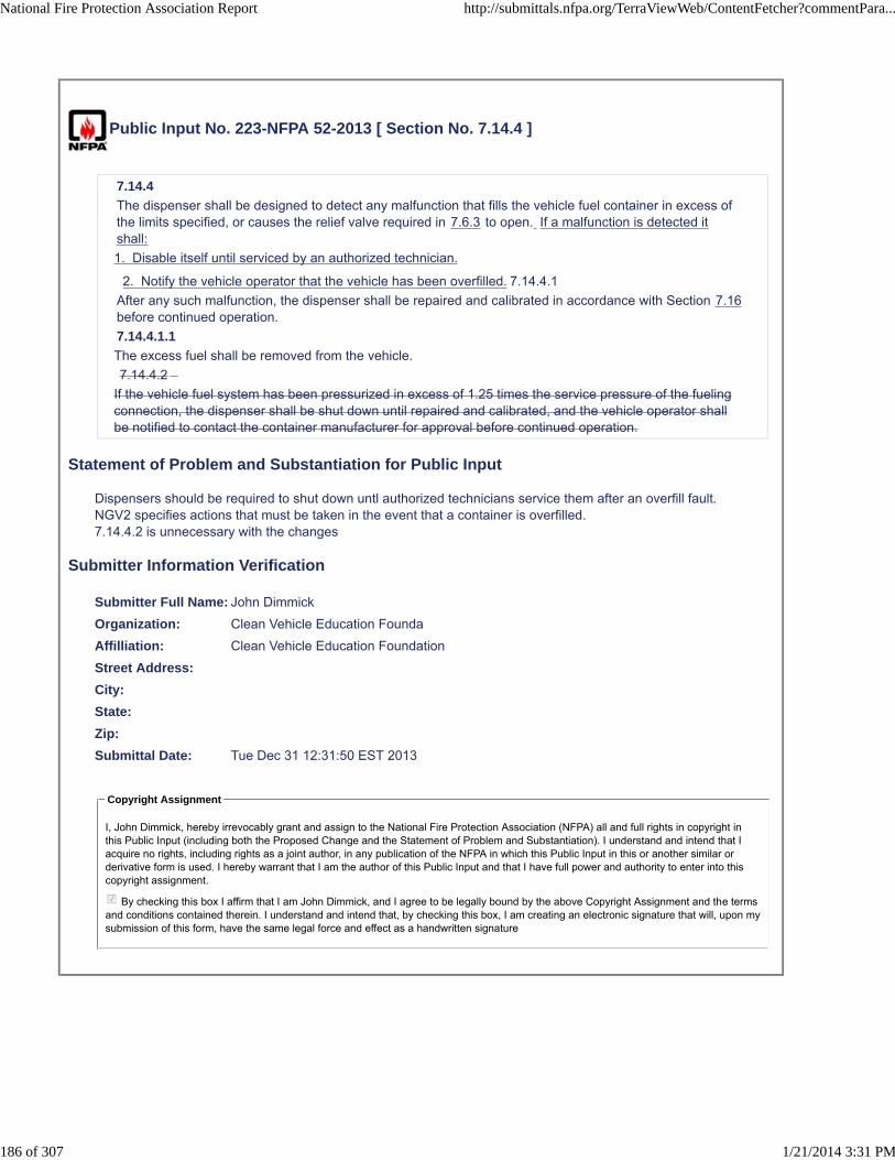
Public Input No. 223-NFPA 52-2013 [ Section No. 7.14.4 ]
7.14.4
The dispenser shall be designed to detect any malfunction that fills the vehicle fuel container in excess ofthe limits specified, or causes the relief valve required in 7.6.3 to open. If a malfunction is detected itshall:
1. Disable itself until serviced by an authorized technician.
2. Notify the vehicle operator that the vehicle has been overfilled. 7.14.4.1
After any such malfunction, the dispenser shall be repaired and calibrated in accordance with Section 7.16before continued operation.
7.14.4.1.1
The excess fuel shall be removed from the vehicle.
7.14.4.2
If the vehicle fuel system has been pressurized in excess of 1.25 times the service pressure of the fuelingconnection, the dispenser shall be shut down until repaired and calibrated, and the vehicle operator shallbe notified to contact the container manufacturer for approval before continued operation.
Statement of Problem and Substantiation for Public Input
Dispensers should be required to shut down untl authorized technicians service them after an overfill fault.NGV2 specifies actions that must be taken in the event that a container is overfilled.7.14.4.2 is unnecessary with the changes
Submitter Information Verification
Submitter Full Name: John Dimmick
Organization: Clean Vehicle Education Founda
Affilliation: Clean Vehicle Education Foundation
Street Address:
City:
State:
Zip:
Submittal Date: Tue Dec 31 12:31:50 EST 2013
Copyright Assignment
I, John Dimmick, hereby irrevocably grant and assign to the National Fire Protection Association (NFPA) all and full rights in copyright inthis Public Input (including both the Proposed Change and the Statement of Problem and Substantiation). I understand and intend that Iacquire no rights, including rights as a joint author, in any publication of the NFPA in which this Public Input in this or another similar orderivative form is used. I hereby warrant that I am the author of this Public Input and that I have full power and authority to enter into thiscopyright assignment.
By checking this box I affirm that I am John Dimmick, and I agree to be legally bound by the above Copyright Assignment and the termsand conditions contained therein. I understand and intend that, by checking this box, I am creating an electronic signature that will, upon mysubmission of this form, have the same legal force and effect as a handwritten signature
National Fire Protection Association Report http://submittals.nfpa.org/TerraViewWeb/ContentFetcher?commentPara...
186 of 307 1/21/2014 3:31 PM

Public Input No. 224-NFPA 52-2013 [ Section No. 7.14.5 ]
7.14.5
The transfer of CNG into a fuel supply container shall be performed in accordance with instructions postedat the dispensing station. Personnel filling transport cylinders or vehicles shall be instructed and trained inaccordance with DOT hazardous materials regulations.
Statement of Problem and Substantiation for Public Input
DOT has specific training requirements, including HAZMAT training for filling personnel. Training for vehicle refueling is not sufficient.
Submitter Information Verification
Submitter Full Name: John Dimmick
Organization: Clean Vehicle Education Founda
Affilliation: Clean Vehicle Education Foundation
Street Address:
City:
State:
Zip:
Submittal Date: Tue Dec 31 12:35:17 EST 2013
Copyright Assignment
I, John Dimmick, hereby irrevocably grant and assign to the National Fire Protection Association (NFPA) all and full rights in copyright inthis Public Input (including both the Proposed Change and the Statement of Problem and Substantiation). I understand and intend that Iacquire no rights, including rights as a joint author, in any publication of the NFPA in which this Public Input in this or another similar orderivative form is used. I hereby warrant that I am the author of this Public Input and that I have full power and authority to enter into thiscopyright assignment.
By checking this box I affirm that I am John Dimmick, and I agree to be legally bound by the above Copyright Assignment and the termsand conditions contained therein. I understand and intend that, by checking this box, I am creating an electronic signature that will, upon mysubmission of this form, have the same legal force and effect as a handwritten signature
National Fire Protection Association Report http://submittals.nfpa.org/TerraViewWeb/ContentFetcher?commentPara...
187 of 307 1/21/2014 3:31 PM

Public Input No. 66-NFPA 52-2013 [ Section No. 7.17.3 ]
7.17.3
The installation of VFAs shall be exempt from the requirements of Sections 4.4, 5.5 through 5.10, 7.2through 7.4, 7.6, and 7.8 through 7.16.
Statement of Problem and Substantiation for Public Input
This proposal is part of a Series of proposals which will harmonize NFPA 52 with the new NGV 5.1 standard for residential fueling appliances.
Added an exemption to Section 4.4 of NFPA 52. CSA NGV 5.1 will be required to have a clause stating that RFA units cannot be changed or modified in any manner without written permission from the manufacturer
Submitter Information Verification
Submitter Full Name: JULIE CAIRNS
Organization: CSA GROUP
Affilliation: CSA Group NGV 5.1 Residential Fueling Appliance Technical Subcommittee
Street Address:
City:
State:
Zip:
Submittal Date: Fri Dec 20 11:10:03 EST 2013
Copyright Assignment
I, JULIE CAIRNS, hereby irrevocably grant and assign to the National Fire Protection Association (NFPA) all and full rights in copyright inthis Public Input (including both the Proposed Change and the Statement of Problem and Substantiation). I understand and intend that Iacquire no rights, including rights as a joint author, in any publication of the NFPA in which this Public Input in this or another similar orderivative form is used. I hereby warrant that I am the author of this Public Input and that I have full power and authority to enter into thiscopyright assignment.
By checking this box I affirm that I am JULIE CAIRNS, and I agree to be legally bound by the above Copyright Assignment and theterms and conditions contained therein. I understand and intend that, by checking this box, I am creating an electronic signature that will,upon my submission of this form, have the same legal force and effect as a handwritten signature
National Fire Protection Association Report http://submittals.nfpa.org/TerraViewWeb/ContentFetcher?commentPara...
188 of 307 1/21/2014 3:31 PM

Public Input No. 108-NFPA 52-2013 [ Chapter 8 ]
Chapter 8 CNG Residential Fueling Facilities (RFF-CNGs)
8.1 Application.
8.1.1
This chapter applies to the design, construction, installation, and operation of a residential fueling facility(RFF-CNG).
8.1.2
The capacity of an RFF-CNG shall not exceed 5 scf/min (0.14 SCM/min) of natural gas.
8.1.3
Storage of CNG shall be prohibited.
8.1.3.1
CNG shall be permitted to be stored in the vehicle fuel supply container.
8.2 System Component Qualifications.
8.2.1
System components not part of a listed VFA shall comply with the appropriate provisions in Chapter 5.
8.2.2 *
VFAs shall be listed.
8.2.3
VFAs shall be exempt from the requirements of Sections 5.5 through 5.9, 7.2 through 7.4, 7.6, and 7.8through 7.16.
8.3 General Safety Requirements.
8.3.1
All equipment related to an RFF-CNG installation shall be protected to minimize the possibility of physicaldamage and vandalism.
8.3.2
The use of an enclosure for the compressor package, similar to that of a central air conditioner, shall bepermitted to satisfy 8.3.1.
8.3.3
All equipment related to RFF-CNG installation shall be designed for the pressure, temperature, and serviceexpected.
8.3.4
Vehicles shall be unclassified electrically with respect to NFPA 70, National Electrical Code, Article 500.
8.3.4.1
Vehicles containing fuel-fired equipment (e.g., recreational vehicles) shall be considered a source of ignitionunless this equipment is shut off completely before entering an area in which ignition sources are notpermitted.
8.3.5
Natural gas shall not be vented to the atmosphere under normal operation.
8.3.5.1
Leakage of 1.0 standard cubic in. (16 cm3) of gas shall be permitted to be released to the atmosphere perfilling during disconnection of the fueling hose.
8.3.6
Unless specifically permitted by the installation instructions, multiple VFAs shall not be manifolded togetheron the discharge side.
8.3.7
Where more than one VFA is located in a common area, spacing between the VFAs shall not be less than 3ft (1 m) unless permitted by the installation instructions.
8.4 Installation.
8.4.1 General.
National Fire Protection Association Report http://submittals.nfpa.org/TerraViewWeb/ContentFetcher?commentPara...
189 of 307 1/21/2014 3:31 PM

8.4.1.1
All RFF-CNG equipment shall be installed in accordance with the equipment manufacturer's instructions.
8.4.1.2
The RFF-CNG shall have a nameplate marked with minimum and maximum gas inlet pressures and flowrates, gas outlet maximum pressure, and electrical requirements.
8.4.2 Indoors.
8.4.2.1
Where it is necessary to install the compression unit and refueling connections indoors, the compressionunit shall be mounted or otherwise located such that the compression unit is vented outdoors.
8.4.2.2 *
Where the RFF-CNG or the vehicle being fueled is located indoors, a gas detector set to operate atone-fifth the (LFL) lower flammable limit of natural gas shall be installed in the room.
8.4.2.2.1
The detector shall be located within 6 in. (150 mm) of the ceiling or the highest point in the room.
8.4.2.2.1.1
An RFF-CNG that is listed shall be permitted to utilize a combination of ventilation or gas detection toensure that the room is maintained at a level below one-fifth of the lower limit of flammability of natural gas.
8.4.2.2.1.2
Meeting the provisions of 8.4.2.2.1 shall be deemed to be equivalent to a gas detector located within 6 in.(150 mm) of the ceiling or the highest point in the room.
8.4.2.2.2
The detector shall stop the compressor and operate an audible or a visual alarm.
8.4.3 Outdoors.
The RFF-CNG shall be installed on a firm, noncombustible support to prevent undue stress on piping andconduit. (See Section 4.5 for noncombustible.)
8.5 Installation of PRVs.
PRVs shall have PRD vents or vent lines to convey escaping gas to the outdoors and then upward toprevent impinging on buildings, other equipment, or areas open to the public (e.g., sidewalks).
8.6 Installation of Pressure Gauges.
For measurement and test purposes, pressure gauges shall be permitted to be installed but shall not berequired.
8.7 Pressure Regulation.
An RFF-CNG shall be equipped to stop fuel flow automatically when the container(s) reaches thetemperature-corrected fill pressure.
8.8 Piping and Hose.
8.8.1
All piping and hose from the outlet of the compressor shall be supplied as part of the RFF-CNG.
8.8.2
All gas piping to the RFF-CNG shall be installed in accordance with NFPA 54, National Fuel Gas Code.
8.8.3
The use of hose in an installation shall be restricted to the following:
(1) A fueling hose limited to a maximum length of 25 ft (7.6 m) and supported above the floor/ground levelor otherwise protected from mechanical damage from abrasion and being driven over by a vehicle
(2) A maximum of 3 ft (1 m) in length where used to prevent abrasion damage resulting from vibration onthe inlet or outlet, or both
8.8.4
Transfer systems shall be capable of depressurizing to facilitate disconnection.
8.8.5
Bleed connections shall lead to a safe point of discharge.
8.9 Testing.
All piping and tubing shall be tested after assembly to be proven free of leaks at a pressure equal to themaximum service pressure of that portion of the system.
8.10 Installation of Emergency Shutdown Equipment.
8.10.1
National Fire Protection Association Report http://submittals.nfpa.org/TerraViewWeb/ContentFetcher?commentPara...
190 of 307 1/21/2014 3:31 PM

An RFF-CNG shall be equipped with emergency manual shutdown of the gas supply and electric power.
8.10.1.1
The emergency electrical switch shall be at least 5 ft (1.5 m) from the RFF-CNG and in view of theRFF-CNG.
8.10.1.2
An RFF-CNG equipped with a flexible cord terminated with a grounding-type attachment plug shall bedeemed to be equivalent to the emergency switch.
8.10.2
Breakaway protection shall be provided in a manner so that, in the event of a pullaway, natural gas ceasesto flow.
8.10.2.1
The breakaway devices shall be compatible with ANSI/IAS NGV 4.4, Breakaway Devices for Natural GasDispensing Hoses and Systems, and CSA 12.54, Breakaway Devices for Dispensing Systems.
8.10.2.2
The breakaway provided as a component of a listed VFA shall be permitted not to comply with ANSI/IASNGV 4.4, Breakaway Devices for Natural Gas Dispensing Hoses and Systems, and CSA 12.54, BreakawayDevices for Dispensing Systems.
8.10.3
A breakaway device shall be installed at every dispensing point.
8.10.4
The breakaway device in 8.10.3 shall be arranged to separate using a force not greater than 150 lb (68 kg)when applied in any horizontal direction.
8.11 Operation.
8.11.1
An RFF-CNG shall be operated in accordance with the manufacturer's instructions.
8.11.2
A fuel supply container shall not be charged in excess of its maximum allowable service pressure at normaltemperature.
8.11.3
DOT and TC containers shall be charged in accordance with DOT and TC regulations.
8.11.4
Where CNG is being transferred to a motor vehicle, the engine shall be turned off.
8.12 Maintenance and Inspection.
8.12.1
All RFF-CNG equipment shall be inspected and maintained in accordance with the manufacturer'sinstructions.
8.12.2
After installation, all hose shall be examined visually as part of this inspection.
8.12.3
Hose that are kinked or worn shall be replaced.
8.12.4
All safety relief valves shall be maintained in operating condition in accordance with themanufacturer's/supplier's recommendation.
Replace Chapter 8 with the attached Chapter 8 Equipment developed by a NFPA 52 Task Group
Additional Proposed Changes
File Name Description Approved
NFPA_52_Public_Input_Chapter_8_Equipment.docx NFPA 52 Chapter 8 Equipment
Statement of Problem and Substantiation for Public Input
The NFPA 52 Technical Committee approved the reorganization of NFPA 52 into an organizational layout that restructured requirements into General Requirements, Fuel Specific Requirements and Use Specific Requirements. This Chapter replaces existing Chapter 8 and was developed by a Task Group. For this draft
National Fire Protection Association Report http://submittals.nfpa.org/TerraViewWeb/ContentFetcher?commentPara...
191 of 307 1/21/2014 3:31 PM

being submitted as a Public Input, existing code sections have only been reorganized. No new or revised language has been included or any requirements deleted.
Submitter Information Verification
Submitter Full Name: Nancy Pehrson
Organization: CenterPoint Energy, Inc.
Street Address:
City:
State:
Zip:
Submittal Date: Thu Dec 26 13:09:24 EST 2013
Copyright Assignment
I, Nancy Pehrson, hereby irrevocably grant and assign to the National Fire Protection Association (NFPA) all and full rights in copyright inthis Public Input (including both the Proposed Change and the Statement of Problem and Substantiation). I understand and intend that Iacquire no rights, including rights as a joint author, in any publication of the NFPA in which this Public Input in this or another similar orderivative form is used. I hereby warrant that I am the author of this Public Input and that I have full power and authority to enter into thiscopyright assignment.
By checking this box I affirm that I am Nancy Pehrson, and I agree to be legally bound by the above Copyright Assignment and theterms and conditions contained therein. I understand and intend that, by checking this box, I am creating an electronic signature that will,upon my submission of this form, have the same legal force and effect as a handwritten signature
National Fire Protection Association Report http://submittals.nfpa.org/TerraViewWeb/ContentFetcher?commentPara...
192 of 307 1/21/2014 3:31 PM
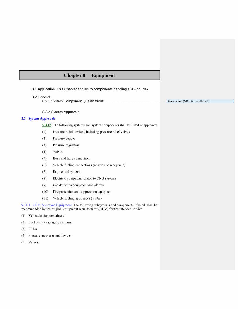
Chapter 8 Equipment
8.1 Application This Chapter applies to components handling CNG or LNG 8.2 General 8.2.1 System Component Qualifications
8.2.2 System Approvals
5.3 System Approvals.
5.3.1* The following systems and system components shall be listed or approved:
(1) Pressure relief devices, including pressure relief valves
(2) Pressure gauges
(3) Pressure regulators
(4) Valves
(5) Hose and hose connections
(6) Vehicle fueling connections (nozzle and receptacle)
(7) Engine fuel systems
(8) Electrical equipment related to CNG systems
(9) Gas detection equipment and alarms
(10) Fire protection and suppression equipment
(11) Vehicle fueling appliances (VFAs)
9.11.1 OEM Approved Equipment. The following subsystems and components, if used, shall be recommended by the original equipment manufacturer (OEM) for the intended service:
(1) Vehicular fuel containers
(2) Fuel quantity gauging systems
(3) PRDs
(4) Pressure measurement devices
(5) Valves
Commented [BS1]: Will be added as PI

(6) Pressure regulators
(7) Vaporizers
(8) Pumps
(9) Engine fuel delivery equipment
(10) Vehicle fueling receptacles
(11) Electrical equipment related to the fuel system
(12) Methane detection, fire protection, and suppression systems
8.2.2.1 Safety Equivalent
5.3.2 Devices not otherwise specifically provided for shall be constructed to provide safety equivalent to that required for other parts of a system.
8.2.3 Equipment installation
8.2.3.1 Pressure Gauges
5.6 Pressure Gauges. A pressure gauge, if provided, shall be capable of reading at least 1.2 times the system design pressure.
8.2.3.2 Pressure Regulators
7.7 Installation of Pressure Regulators.
7.7.1 Regulators shall be designed, installed, or protected so that their operation is not affected by freezing rain, sleet, snow, ice, mud, insects, or debris.
7.7.2 Regulator protection of 7.7.1 shall be permitted to be integral with the regulator. 8.2.3.3 Pressure Relief Devices (reserved)
8.2.3.4 Piping (reserved)
8.2.3.5 Piping Connections (reserved) 8.2.3.6 Hoses and Breakaway Devices (reserved) 8.2.3.7 Valves (reserved) 8.2.3.8 Electrical Equipment (reserved) 8.3 CNG (Supplemental Requirements)

8.3.1 Application 5.1* Application. This chapter applies only to pressurized system components handling CNG.
8.3.4 System Component Qualifications
8.3.4.1 (13.3.2.4) Containers
5.4* Design and Construction of Containers.
5.4.1 Containers shall be fabricated of steel, aluminum, or composite materials.
5.4.2 The container shall be designed for CNG service.
5.4.2.1 The container shall be permanently marked “CNG” by the manufacturer.
5.4.3 Containers manufactured prior to the effective date of this code shall be permitted to be used in CNG service if recommended for CNG service by the container manufacturer or if approved by the authority having jurisdiction.
5.4.4* Cylinders shall be manufactured, inspected, marked, tested, retested, equipped, and used in accordance with the following:
(1) U.S. Department of Transportation (DOT) or Transport Canada (TC) regulations, exemptions, or special permits
(2) ANSI NGV2, Compressed Natural Gas Vehicle (NGV) Fuel Containers, specifically for CNG service
(3) CSA B51, Boiler, Pressure Vessel and Pressure Piping Code
(4) U.S. Federal Motor Vehicle Safety Standard, 49 CFR 571.304, Compressed Natural Gas Fuel Container Integrity
5.4.4.1 Cylinders that have reached the labeled expiration date shall be removed from service.
5.4.4.2* Composite reinforced cylinders or other cylinders marked with exemption or special permit numbers shall be removed from service at the end of the service life designated in the exemption or special permit.
5.4.5 ASME Compliance.
5.4.5.1 Pressure vessels shall be manufactured, inspected, marked, and tested in accordance with ASME Boiler and Pressure Vessel Code, Section VIII or Section X.
5.4.5.2 Adherence to applicable ASME Boiler and Pressure Vessel Code case interpretations and addenda shall be considered as compliant with the ASME Boiler and Pressure Vessel Code.
5.4.5.3* Pressure vessels manufactured to the requirements of the ASME Boiler and Pressure Vessel Code shall be registered with the National Board of Boiler and Pressure Vessel Inspectors.
5.4.6 The + (plus) and * (star) markings on DOT and TC cylinders shall not apply in accordance with DOT and TC regulations for cylinders for flammable compressed gases.

5.4.6.1 The star marking shall be removed or obliterated.
5.4.6.2 The removal of the star marking shall be by peening and otherwise be in accordance with DOT or TC regulations.
5.4.6.3 Grinding shall be prohibited.
5.4.7 The repair or alteration of an ASME pressure vessel shall comply with the requirements of the NB-23, National Board Inspection Code.
5.4.7.1 Other welding or brazing shall be permitted only on saddle plates, lugs, or brackets attached to the pressure vessel by the pressure vessel manufacturer.
5.4.7.2 The exchange or interchange of pressure vessel appurtenances intended for the same purpose shall not be considered a repair or alteration
13.3.2.5 Relief Devices
5.5 Pressure Relief Devices (PRDs). (See Annex C.)
5.5.1 Each cylinder complying with 5.4.4 shall be fitted with one or more pressure relief devices (PRDs) with the number, location, and part number as specified by the cylinder manufacturer and OEM for CNG service for a new vehicle, in accordance with the following:
(1) For a retrofitted vehicle, each cylinder complying with 5.4.4 shall be of the number, location, and part number as specified by the cylinder manufacturer.
(2) A PRD shall be in accordance with one of the following standards:
(a) CGA S-1.1, Pressure Relief Device Standards — Part 1 — Cylinders for Compressed Gases
(b) ANSI/IAS PRD 1, Pressure Relief Devices for Natural Gas Vehicle (NGV) Fuel Containers
(c) ANSI/IAS PRD 1a, Addenda to ANSI/IAS PRD 1, Pressure Relief Devices for Natural Gas Vehicle (NGV) Fuel Containers
(d) ANSI/CSA PRD 1b, Addenda to ANSI/IAS PRD 1, Pressure Relief Devices for Natural Gas Vehicle (NGV) Fuel Containers
(3) The PRD shall be in direct communication with the fuel and vented to the atmosphere by a method that withstands the maximum pressure that results.
5.5.1.1 The discharge flow rate of the PRD shall not be reduced below that required for the capacity of the container upon which the device is installed.
5.5.1.2 PRDs shall be located so that the temperature to which they are subjected is representative of the temperature to which the fuel supply container is subjected.
5.5.2.1 The minimum rate of discharge of PRDs on containers shall be in accordance with CGA S-1.1, Pressure Relief Device Standards — Part 1 — Cylinders for Compressed Gases, or the ASME Boiler and Pressure Vessel Code, whichever is applicable.

5.5.2.2 Pressure relief valves (PRVs) for CNG service shall not be fitted with lifting devices.
5.5.2.2.1 The adjustment, if external, shall be provided with a means for sealing the adjustment to prevent tampering.
5.5.2.2.2 If at any time it is necessary to break such a seal, the valve shall be removed from service until it has been reset and sealed.
5.5.2.2.3 Adjustments shall be made only by the manufacturer or other companies having competent personnel and facilities for the repair, adjustment, and testing of such valves.
5.5.2.2.4 The organization making such adjustment shall attach a permanent tag with the setting, capacity, and date.
8.3.4.2 (13.3.2.6) Pressure Gauges
5.6 Pressure Gauges. A pressure gauge, if provided, shall be capable of reading at least 1.2 times the system design pressure.
8.3.4.3 13.3.2.7 Pressure Regulators
5.7 Pressure Regulators.
5.7.1 A pressure regulator inlet and each chamber shall be designed for its service pressure with a pressure safety factor of at least 4.
5.7.2 Low-pressure chambers shall provide for overpressure relief or be able to withstand the service pressure of the upstream pressure chamber.
8.3.4.4 13.3.2.8 .Piping
5.8 Fuel Lines.
5.8.1 Pipe, tubing, fittings, gaskets, and packing material shall be compatible with the fuel under the maximum service conditions.
5.8.2 Pipe, tubing, fittings, and other components shall be designed with a minimum safety factor of 3.
5.8.3 Natural gas piping shall be fabricated and tested in accordance with ANSI/ASME B31.3, Process Piping.
9.7 Piping, Tubing, and Fittings. Piping, tubing, and fittings shall be designed, installed, inspected, and tested in accordance with ANSI/ASME B31.3, Process Piping.

5.8.4.1 The refueling connection shall be permitted to be made of nonsparking wrought aluminum alloy designed for the pressure employed.
5.8.4.2 Aluminum pipe, tubing, and fittings shall be permitted to be used downstream of the first-stage pressure regulator in an engine fuel system.
5.8.5 Piping components such as strainers, snubbers, and expansion joints shall be permanently marked by the manufacturer to indicate the service ratings.
5.8.4 The following components shall not be used for CNG service:
(1) Fittings, street els, and other piping components of cast irons other than those complying with ASTM A 47, Standard Specification for Ferritic Malleable Iron Castings (Grade 35018); ASTM A 395, Standard Specification for Ferritic Ductile Iron Pressure-Retaining Castings for Use at Elevated Temperatures; and ASTM A 536, Standard Specification for Ductile Iron Castings (Grade 60-40-18)
(2) Plastic pipe, tubing, and fittings for high-pressure service
(3) Galvanized pipe and fittings
(4) Aluminum pipe, tubing, and fittings
(5) Pipe nipples for the initial connection to a container
(6) Copper alloy with copper content exceeding 70 percent
8.3.4.5 13.3.3.9.Valves
5.9 Valves.
5.9.1 Valves, valve packing, and gaskets shall be designed or selected for the fuel over the full range of pressures and temperatures to which they are subjected under operating conditions.
5.9.1.1 Shutoff valves shall have a rated service pressure not less than the rated service pressure of the entire system and shall be capable of withstanding a hydrostatic test of at least four times the rated service pressure without rupture.
5.9.1.2 Leakage shall not occur at less than 1 ½ times the rated service pressure.
5.9.3 Valves of a design that allows the valve stem to be removed without removal of the complete valve bonnet or without disassembly of the valve body shall not be used.
5.9.4 The manufacturer shall stamp or otherwise permanently mark the valve body to indicate the service ratings.
5.9.4.1 Container valves incorporating integral PRDs complying with 5.5.1 shall not require additional marking.
5.9.2 Valves of cast irons other than those complying with ASTM A 47, Standard Specification for Ferritic Malleable Iron Castings (Grade 35018); ASTM A 395, Standard Specification for

Ferritic Ductile Iron Pressure-Retaining Castings for Use at Elevated Temperatures; and ASTM A 536, Standard Specification for Ductile Iron Castings (Grade 60-40-18), shall not be used as primary stop valves.
8.3.4.6 13.3.2.10 Hose and Hose Connections
5.10 Hose and Hose Connections.
5.10.1 Hose and metallic hose shall be constructed of or lined with materials that are resistant to corrosion and exposure to natural gas.
5.10.2 Hose, metallic hose, flexible metal hose, tubing, and their connections shall be designed or selected for the most severe pressures and temperatures under normal operating conditions with a burst pressure of at least four times the service pressure.
5.10.3 Prior to use, hose assemblies shall be tested by the OEM or its designated representative at a pressure at least twice the service pressure.
5.10.4 Hose and metallic hose shall be distinctly marked by the OEM or component manufacturer, either by the manufacturer's permanently attached tag or by distinct markings indicating the manufacturer's name or trademark, applicable service identifier, and design pressure.
8.3.4.7 13.3.2.11 Vehicle Fueling Connection
5.11 Vehicle Fueling Connection.
5.11.1 CNG vehicle fueling connection devices shall be listed in accordance with ANSI/IAS NGV1, Standard for Compressed Natural Gas Vehicle (NGV) Fueling Connection Devices.
5.11.2 The use of adapters shall be prohibited.
6.9.5 Service Pressure.
6.9.5.1 The service pressure of the fueling connection receptacle shall not exceed the marked service pressure of the fuel supply cylinders.
6.9.5.2 The service pressure of the fueling receptacle shall not exceed 80 percent of the set pressure of any relief valves installed on fuel supply containers in the vehicle.
8.3.4.56 Hose and Hose Connections
5.10 Hose and Hose Connections.

5.10.1 Hose and metallic hose shall be constructed of or lined with materials that are resistant to corrosion and exposure to natural gas.
5.10.2 Hose, metallic hose, flexible metal hose, tubing, and their connections shall be designed or selected for the most severe pressures and temperatures under normal operating conditions with a burst pressure of at least four times the service pressure.
5.10.3 Prior to use, hose assemblies shall be tested by the OEM or its designated representative at a pressure at least twice the service pressure.
5.10.4 Hose and metallic hose shall be distinctly marked by the OEM or component manufacturer, either by the manufacturer's permanently attached tag or by distinct markings indicating the manufacturer's name or trademark, applicable service identifier, and design pressure.
7.9.3 The use of hose in an installation shall be limited to the following:
(1) Vehicle fueling hose
(2) Inlet connection to compression equipment
(3) Section of metallic hose not exceeding 36 in. (910 mm) in length in a pipeline to provide flexibility where necessary
7.9.3.1 Each section shall be installed so that it is protected against mechanical damage and is visible for inspection.
7.9.3.2 The manufacturer's identification shall be retained in each section.
7.9.4 At fueling stations, gas used for calibration and testing shall be vented to a safe location. 8.3.4.6 7 Vehicle Fueling Connections
5.8.4.1 The refueling connection shall be permitted to be made of nonsparking wrought aluminum alloy designed for the pressure employed
7.3.5 The fueling connection shall prevent the escape of gas where the connector is not engaged or becomes separated.
8.3.6 Compressor Systems
8.3.6.1 Design Temperature and Pressure
7.3.7 Compression equipment shall be designed for use with CNG and for the pressures and temperatures to which it is subjected under operating conditions.
7.3.12* Compression equipment shall incorporate a means to minimize liquid carryover to the storage system.
8.3.6.2 Pressure Relief Devices

7.3.8 Compression equipment shall have pressure relief devices that limit each stage pressure to the maximum allowable service pressure for the compression cylinder and piping associated with that stage of compression.
8.3.6.3 Shutdown Control
7.3.9 Where CNG compression equipment is operated unattended, it shall be equipped with a high discharge and a low suction pressure automatic shutdown control.
7.3.10 Control circuits that shut down shall remain down until manually activated or reset after a safe shutdown is performed.
8.3.6.4 Engine Drives
7.3.11 Engine-driven compressor installations shall conform, where applicable, to NFPA 37, Standard for the Installation and Use of Stationary Combustion Engines and Gas Turbines. 8.3.7 Dispensing systems and Dispensers
8.3.7.1 Operation
7.13.2* Static protection shall not be required where CNG is transferred by conductive or nonconductive hose, flexible metallic tubing, or pipe connections where both halves of the metallic couplings are in continuous contact.
7.14 System Operation.
7.14.1 A cylinder shall not be charged in excess of the design pressure at the normal temperature for that cylinder.
7.14.1.1 DOT, TC, and ANSI/IAS NGV2 cylinders shall be charged in accordance with DOT, TC, and ANSI/IAS NGV2 regulations.
7.14.1.2 DOT, TC, and ANSI/IAS NGV2 cylinders shall not be subjected to pressure in excess of 125 percent of the marked service pressure even if, on cooling, the pressure settles to the marked service pressure.
7.14.2 A fuel supply container shall not have a settled pressure above the service pressure that is stamped on the container and displayed on a label near the filling connection, corrected for the ambient temperature at the time of filling.
8.3.7.2 Vehicle Fill Pressure Control
7.14.3 CNG dispensing systems shall be equipped to stop fuel flow automatically when a fuel supply container reaches the temperature-corrected fill pressure (see 7.6.3).
7.14.4 The dispenser shall be designed to detect any malfunction that fills the vehicle fuel container in excess of the limits specified, or causes the relief valve required in 7.6.3 to open.
7.14.4.1 After any such malfunction, the dispenser shall be repaired and calibrated in accordance with Section 7.16 before continued operation.
8.3.7.3 Over Pressure Protection
7.14.8 Transfer systems shall be capable of depressurizing to facilitate disconnection.
7.14.9 Bleed connections shall lead to a safe point of discharge.
7.6.3.1 The pressure relief valve shall be redundant to and independent from any operating control system used to control the supplied fuel pressure during dispenser operation.
7.6.4 The set pressure of the overpressure protection device shall not exceed 125 percent of the service pressure of the fueling nozzle it supplies.
8.3.7.4 Breakaway Protection
7.11.6 Breakaway protection shall be provided in a manner that, in the event of a pullaway, natural gas ceases to flow at any separation.
7.11.6.1 A breakaway device shall be installed at every dispensing point.
7.11.6.2 A breakway device shall be arranged to separate using a force not greater than 150 lb (68 kg) when applied in any direction that the vehicle would move.
7.11.6.3 Breakaway devices shall comply with ANSI/IAS NGV 4.4, Breakaway Devices for Natural Gas Dispensing Hoses and Systems.
8.3.7.6 Malfunction Control
7.11.5 An emergency manual shutdown device shall be provided within 10 ft (3.0 m) of the dispensing area and also greater than 25 ft (7.6 m) from the dispensing area.
7.11.5.1 This device, when activated, shall shut off the power supply and gas supply to the compressor and the dispenser.
7.11.7 Control circuits shall be arranged so that, when an emergency shutdown device is activated or electric power is cut off, systems that shut down remain off until manually activated or reset after a safe condition is restored. 8.3.7.7 Electrical Classification 8.3.8 System Testing
8.3.8.1 Leak Testing
Commented [BS2]: These are installation requirements, not equipment move to Chapter 11 under fueling.
Commented [BS3]: Refer to Electrical Classification Table for CNG – Will need to make a PI
7.10 System Testing.
7.10.1 Piping, tubing and hose, and hose assemblies shall be leak tested after assembly to prove them free from leaks at a pressure equal to at least the normal service pressure of that portion of the system.
8.4 LNG Supplemental
13.4.2 Materials of Construction
9.2 Materials.
9.2.1 Metallic materials used in construction of the fuel system, except fusible links, shall have a minimum melting point of 1500°F (816°C).
9.2.2 Metallic material used in construction of the fuel system shall be listed in accordance with ANSI/ASME B31.3, Process Piping, and the ASME Boiler and Pressure Vessel Code, or API 620, Design and Construction of Large, Welded, Low-Pressure Storage Tanks, Appendix Q, and shall not be used below the minimum design temperature established in these codes or standards.
9.2.3 The use of dissimilar metal junctions shall be minimized, but if such a junction cannot be avoided, good corrosion protection practice shall be employed to reduce the effect of such a material combination on the long-term corrosion behavior of the junction.
9.2.4 All materials shall be selected or installed to minimize corrosion or to protect the material from corrosion.
9.2.4.1 Stainless steels that do not resist chloride-induced pitting/corrosion cracking and sensitization-induced corrosion resistance reduction shall not be used.
9.2.4.2 The use of all copper–zinc and copper–tin alloy families shall be restricted to those alloys that are metallurgically inhibited to prevent accelerated metallurgical deterioration from external environmental sources.
9.2.5 Brazing filler material shall have a melting point exceeding 1000°F (538°C).
9.2.6 Oxy–fuel gas welding shall not be permitted.
9.2.7 Furnace butt-welded steel products shall not be used.
9.11.2 Engine Compartment.
9.11.2.1 Onboard fuel system components inside the engine compartment shall be compatible with the liquids and gases throughout the full range of temperatures [−260°F to 250°F (−162°C to 121°C)].

9.11.2.2 Onboard fuel system components that are in contact with LNG shall be designed for service over a temperature range of −260°F to 250°F (−162°C to 121°C).
9.11.3 Outside Engine Compartment.
9.11.3.1 Components outside the engine compartment that are in contact with LNG shall be designed for service over a temperature range of −260°F to 180°F (−162°C to 82°C).
9.11.3.2 Other components that are not in contact with LNG shall be designed for service over a temperature range of −40°F to 180°F (−40°C to 82°C).
9.11.4 Components that are not fuel system components and are located within the operational area of LNG or LNG liquid or gaseous leaks shall also be protected or maintain a service range equal to the onboard fuel system.
8.4.1.1 (13.4.3.1 9.3) Vehicular Fuel Containers.
9.3.1 Design. Containers shall be designed, fabricated, tested, and marked (or stamped) in accordance with the Regulations of DOT Specification 4L or the “Rules for the Construction of Unfired Pressure Vessels,” ASME Boiler and Pressure Vessel Code, applicable at the date of manufacture.
9.3.1.1 LNG containers that are in contact with LNG or cold LNG vapor shall be physically and chemically compatible with LNG and designed for service at −260°F (−162°C).
9.3.1.2 Container appurtenances shall have a rated working pressure not less than the maximum allowable working pressure of the container.
9.3.1.3 For vacuum insulation, the inner tank, outer tank, and internal lines shall be tested for vacuum leaks prior to installation on the vehicle.
9.3.5* Heat Leak. The manufacturer shall identify the maximum operating design pressure of the container.
9.3.5.1 The construction of the container shall be such that the unrelieved pressure inside the container will not exceed the maximum allowable working pressure of the container within a 72-hour period after the container has been filled to its maximum filling volume with LNG stabilized at the designed operating pressure and temperature equilibrium has been established.
9.3.5.2 The ambient temperature during the 72-hour period shall be 70°F (21°C).
5.4* Design and Construction of Containers.
5.4.5 ASME Compliance.
5.4.5.1 Pressure vessels shall be manufactured, inspected, marked, and tested in accordance with ASME Boiler and Pressure Vessel Code, Section VIII or Section X.
5.4.5.2 Adherence to applicable ASME Boiler and Pressure Vessel Code case interpretations and addenda shall be considered as compliant with the ASME Boiler and Pressure Vessel Code.

5.4.5.3* Pressure vessels manufactured to the requirements of the ASME Boiler and Pressure Vessel Code shall be registered with the National Board of Boiler and Pressure Vessel Inspectors.
5.4.6 The + (plus) and * (star) markings on DOT and TC cylinders shall not apply in accordance with DOT and TC regulations for cylinders for flammable compressed gases.
5.4.6.1 The star marking shall be removed or obliterated.
5.4.6.2 The removal of the star marking shall be by peening and otherwise be in accordance with DOT or TC regulations.
5.4.6.3 Grinding shall be prohibited.
5.4.7 The repair or alteration of an ASME pressure vessel shall comply with the requirements of the NB-23, National Board Inspection Code.
5.4.7.1 Other welding or brazing shall be permitted only on saddle plates, lugs, or brackets attached to the pressure vessel by the pressure vessel manufacturer.
5.4.7.2 The exchange or interchange of pressure vessel appurtenances intended for the same purpose shall not be considered a repair or alteration.
5.4.5 ASME Compliance.
5.4.5.1 Pressure vessels shall be manufactured, inspected, marked, and tested in accordance with ASME Boiler and Pressure Vessel Code, Section VIII or Section X.
5.4.5.2 Adherence to applicable ASME Boiler and Pressure Vessel Code case interpretations and addenda shall be considered as compliant with the ASME Boiler and Pressure Vessel Code.
5.4.5.3* Pressure vessels manufactured to the requirements of the ASME Boiler and Pressure Vessel Code shall be registered with the National Board of Boiler and Pressure Vessel Inspectors.
5.4.6 The + (plus) and * (star) markings on DOT and TC cylinders shall not apply in accordance with DOT and TC regulations for cylinders for flammable compressed gases.
5.4.6.1 The star marking shall be removed or obliterated.
5.4.6.2 The removal of the star marking shall be by peening and otherwise be in accordance with DOT or TC regulations.
5.4.6.3 Grinding shall be prohibited.
5.4.7 The repair or alteration of an ASME pressure vessel shall comply with the requirements of the NB-23, National Board Inspection Code.
5.4.7.1 Other welding or brazing shall be permitted only on saddle plates, lugs, or brackets attached to the pressure vessel by the pressure vessel manufacturer.
5.4.7.2 The exchange or interchange of pressure vessel appurtenances intended for the same purpose shall not be considered a repair or alteration.

5.5.1.1 The discharge flow rate of the PRD shall not be reduced below that required for the capacity of the container upon which the device is installed.
5.5.1.2 PRDs shall be located so that the temperature to which they are subjected is representative of the temperature to which the fuel supply container is subjected.
5.5.2.1 The minimum rate of discharge of PRDs on containers shall be in accordance with CGA S-1.1, Pressure Relief Device Standards — Part 1 — Cylinders for Compressed Gases, or the ASME Boiler and Pressure Vessel Code, whichever is applicable.
5.5.2.3 PRVs protecting ASME pressure vessels shall be repaired, adjusted, and tested in accordance with NB-23, National Board Inspection Code.
5.5.3 Containers and pressure vessels not constructed in accordance with 5.4.4 or 5.4.5 shall be provided with PRDs approved by the authority having jurisdiction.
9.3.2 Container Filling.
9.3.2.1 Containers shall be equipped with a device or devices that provide an indication of when the container is filled to the maximum allowable liquid level.
9.3.2.2 The function shall allow for the ullage volume to be determined by the manufacturer to be that which maintains the required hold time as required by 9.3.5.
8.4.1.2 13.4.4 Vehicular Fuel Container Shutoff Valves
9.3.4* Container Shutoff Valves.
9.3.4.1 The container shall be equipped with shutoff valves that allow for its complete isolation from the rest of the vehicular fuel system.
9.3.4.1.1 Container shutoff valves shall be labeled as to their function.
9.3.4.1.2 Decals or stencils shall be acceptable.
9.3.4.2 Normally closed automatic shutoff valves that are held open by electric current, pneumatic or hydraulic pressure, or a combination thereof, or manually operated shutoff valves shall be permitted to be used to meet this requirement.
8.4.1.3 13.4.6 Vehicular Fuel Container Pressure Relief Devices (PRDs) and Pressure Control Valves
9.4 Pressure Relief Devices.
9.4.1 Containers shall be equipped with the PRDs or pressure control valves required by the code under which the containers were designed and fabricated.
9.4.1.1 PRDs shall be sized for simultaneous conditions of fire and loss of vacuum.

9.4.1.2 PRDs shall be sized in accordance with CGA S-1.1, Pressure Relief Device Standards — Part 1 — Cylinders for Compressed Gases, and CGA S-1.3, Pressure Relief Device Standards — Part 3 — Stationary Storage Containers for Compressed Gases.
9.4.2 The PRDs and pressure control valves shall communicate directly with the vapor space of the container in the normal operating position.
9.4.3 The PRDs and pressure control valves shall not come into contact with the liquid within the container during normal operation.
9.4.4 All safety relief devices on vehicular fuel containers that discharge to the atmosphere shall vent outside of the vehicle.
8.4.1.4 13.4.7 Vehicular Fuel Container Pressure Gauges
9.5 Pressure Gauges.
9.5.1 Containers equipped with pressure gauges shall have the gauges connected to the container at a point above the maximum liquid level.
9.5.2 Pressure gauges shall be designed for the maximum pressure and temperature conditions to which they can be subjected, with a minimum burst pressure safety factor of 4.
9.5.3 Dials shall be graduated to indicate at least 1.2 times the pressure at which the pressure relief device incident to the pressure gauge is set to function.
9.5.4 A gauge opening shall not exceed 0.055 in. (1.4 mm) (No. 54 drill size) at the inlet connection. 8.4.1.5 13.4.3.2 Fuel System Pressure Relief Devices 8.4.1.6 13.4.3.3 Fuel System Pressure Gauges
8.4.1.7 13.4.3.4.13.4.8 Fuel system Pressure Regulators
9.6 Pressure Regulators. The engine pressure regulator inlet and each chamber shall have a design operating pressure not less than the maximum pressure of the container.
8.4.1.8 13.4.3.5 13.4.9 Piping, Tubing and Fittings
9.7 Piping, Tubing, and Fittings. Piping, tubing, and fittings shall be designed, installed, inspected, and tested in accordance with ANSI/ASME B31.3, Process Piping.
8.4.1.9 13.4.3.613.4.10 Valves

9.8 Valves.
9.8.1 Valves, valve packing, gaskets, and seats shall be designed for the intended service.
9.8.2 All parts of container shutoff valves shall be designed for temperatures of −260°F (−162°C).
9.8.2.1 All parts of container shutoff valves shall be stainless steel, brass, or copper except gaskets, packing, and seats. 8.4.1.10 13.4.3.7 9.12.9 Fueling Receptacle.
9.12.9.1 The fueling receptacle on the vehicular fuel system shall be supported and meet all the following requirements:
(1) Receive the fueling connector and accommodate the service pressure of the vehicle fuel system
(2) Incorporate a means to minimize the entry of dust, water, and other foreign material
(3) Be designed for any corrosive conditions that are anticipated
8.4.1.11 13.4.3.813.4.11 Onboard Pumps and Compressors
9.9 Pumps and Compressors.
9.9.1 Pumps and compressors shall be provided with a PRD to limit the discharge pressure to the maximum working pressure of the casing and downstream piping and equipment, unless these are designed for the maximum discharge pressure of the pumps or compressors.
9.9.2 Pumps shall be provided with a vent, a relief valve, or both that prevent overpressuring the pump case.
9.9.3 Pumps used for transfer of LNG shall be provided with means for precooling to reduce the effect of thermal shock and overpressure.
8.4.1.12 13.4.3.913.4.12 Onboard Vaporizers
9.10 Vaporizers.
9.10.1 Vaporizers shall have the capacity to vaporize the LNG completely and heat the vapor to the design temperature of the downstream components prior to entry of the vapor into the pressure regulator when the vaporizer is subjected to the maximum vehicular fuel flow rate.
9.10.2 Vaporizers shall be marked permanently at a readily visible point to indicate the maximum allowable working pressure of the fuel-containing portion of the vaporizer.
9.10.3 Vaporizers shall be designed for a working pressure at least equal to the maximum discharge pressure of the pump or the pressurized system that supplies them, whichever is greater.

9.10.4 The discharge valve of each vaporizer, if provided, its piping components, the relief valves installed upstream of the discharge valve, the vaporizer piping, and related components shall be designed for operation at an LNG temperature of −260°F (−162°C).
9.10.5 Engine exhaust gases shall not be used as a direct source of heat to vaporize fuel.
9.10.6 Where engine exhaust is used to vaporize fuel, it shall be used via an indirect heating system.

Public Input No. 57-NFPA 52-2013 [ Chapter 8 [Title Only] ]
CNG Residential Fueling Facilities Appliances (RFF-CNGs RFAs )
Statement of Problem and Substantiation for Public Input
This proposal is part of a series of proposals which will harmonize NFPA 52 with the new NGV 5.1 standard for residential fueling appliances. Update terminology throughout NFPA 52 to be consistent with Definition added for “Residential Fueling Appliance (RFA)” in clause 3.3.28. The Term “RFA” is intended to replace and clarify current terminology of “RFF_CNG”.
Submitter Information Verification
Submitter Full Name: JULIE CAIRNS
Organization: CSA GROUP
Affilliation: CSA Group NGV 5.1 Residential Fueling Appliance Technical Subcommittee
Street Address:
City:
State:
Zip:
Submittal Date: Fri Dec 20 10:06:30 EST 2013
Copyright Assignment
I, JULIE CAIRNS, hereby irrevocably grant and assign to the National Fire Protection Association (NFPA) all and full rights in copyright inthis Public Input (including both the Proposed Change and the Statement of Problem and Substantiation). I understand and intend that Iacquire no rights, including rights as a joint author, in any publication of the NFPA in which this Public Input in this or another similar orderivative form is used. I hereby warrant that I am the author of this Public Input and that I have full power and authority to enter into thiscopyright assignment.
By checking this box I affirm that I am JULIE CAIRNS, and I agree to be legally bound by the above Copyright Assignment and theterms and conditions contained therein. I understand and intend that, by checking this box, I am creating an electronic signature that will,upon my submission of this form, have the same legal force and effect as a handwritten signature
National Fire Protection Association Report http://submittals.nfpa.org/TerraViewWeb/ContentFetcher?commentPara...
193 of 307 1/21/2014 3:31 PM

Public Input No. 67-NFPA 52-2013 [ Section No. 8.1.1 ]
8.1.1
This chapter applies to the design, construction, installation, and operation of a residential fueling facility(RFF-CNG residential fueling appliance (RFA ).
Statement of Problem and Substantiation for Public Input
This proposal is part of a series of proposals which will harmonize NFPA 52 with the new NGV 5.1 standard for residential fueling appliances. Update terminology throughout NFPA 52 to be consistent with Definition added for “Residential Fueling Appliance (RFA)” in clause 3.3.49. The Term “RFA” is intended to replace and clarify current terminology of “RFF_CNG”.
Submitter Information Verification
Submitter Full Name: JULIE CAIRNS
Organization: CSA GROUP
Affilliation: CSA Group NGV 5.1 Residential Fueling Appliance Technical Subcommittee
Street Address:
City:
State:
Zip:
Submittal Date: Fri Dec 20 11:19:55 EST 2013
Copyright Assignment
I, JULIE CAIRNS, hereby irrevocably grant and assign to the National Fire Protection Association (NFPA) all and full rights in copyright inthis Public Input (including both the Proposed Change and the Statement of Problem and Substantiation). I understand and intend that Iacquire no rights, including rights as a joint author, in any publication of the NFPA in which this Public Input in this or another similar orderivative form is used. I hereby warrant that I am the author of this Public Input and that I have full power and authority to enter into thiscopyright assignment.
By checking this box I affirm that I am JULIE CAIRNS, and I agree to be legally bound by the above Copyright Assignment and theterms and conditions contained therein. I understand and intend that, by checking this box, I am creating an electronic signature that will,upon my submission of this form, have the same legal force and effect as a handwritten signature
National Fire Protection Association Report http://submittals.nfpa.org/TerraViewWeb/ContentFetcher?commentPara...
194 of 307 1/21/2014 3:31 PM

Public Input No. 70-NFPA 52-2013 [ Section No. 8.1.2 ]
8.1.2
The capacity of an RFF-CNG RFA listed for indoor refueling shall not exceed 5 scf/min (0.14 SCM/min) ofnatural gas.
Statement of Problem and Substantiation for Public Input
This proposal is part of a series of proposals which will harmonize NFPA 52 with the new NGV 5.1 standard for residential fueling appliances. This maintains the margin of safety that is currently in place for interior mounted devices that could leak into the enclosed room and that would need time before a detection of the gas leak and shutdown could occur.
Submitter Information Verification
Submitter Full Name: JULIE CAIRNS
Organization: CSA GROUP
Affilliation: CSA Group NGV 5.1 Residential Fueling Appliance Technical Subcommittee
Street Address:
City:
State:
Zip:
Submittal Date: Fri Dec 20 11:59:07 EST 2013
Copyright Assignment
I, JULIE CAIRNS, hereby irrevocably grant and assign to the National Fire Protection Association (NFPA) all and full rights in copyright inthis Public Input (including both the Proposed Change and the Statement of Problem and Substantiation). I understand and intend that Iacquire no rights, including rights as a joint author, in any publication of the NFPA in which this Public Input in this or another similar orderivative form is used. I hereby warrant that I am the author of this Public Input and that I have full power and authority to enter into thiscopyright assignment.
By checking this box I affirm that I am JULIE CAIRNS, and I agree to be legally bound by the above Copyright Assignment and theterms and conditions contained therein. I understand and intend that, by checking this box, I am creating an electronic signature that will,upon my submission of this form, have the same legal force and effect as a handwritten signature
National Fire Protection Association Report http://submittals.nfpa.org/TerraViewWeb/ContentFetcher?commentPara...
195 of 307 1/21/2014 3:31 PM

Public Input No. 71-NFPA 52-2013 [ New Section after 8.1.3 ]
8.1.3.2 Storage within RFA’s shall be in accordance with CSA NGV 5.1.
Statement of Problem and Substantiation for Public Input
This proposal is part of a series of proposals which will harmonize NFPA 52 with the new NGV 5.1 standard for residential fueling appliances. Gas containment needed in the performance of a technology should be allowed as long as it can be safely integrated into a listed RFA and located properly at a residential occupancy. Section 7.5 of NFPA 52 already provides guidance on the safe installation of containers. Based on the language in 8.2.3, Section 7.5 already applies to an RFA and should be able to be complied with in an RFA design. An RFA incorporating containers with the potential to store enough gas to reach a certain % of LFL limits in a small garage space should not be allowed indoors, however this should not prevent the compression and/or dispensing components from separately being located indoors, provided safeguards can be put in place to prevent the inadvertent transfer of sufficiently large amounts of gas from the outdoor containers to the indoors and reach a certain % of LFL limits. CSA 5.1 seed document states “The volume of gas contained by the RFA package shall not exceed 0.254 m3 (9 ft3) at standard conditions of 101.3 kPa at 15 ºC (30 in Hg and 60ºF).”
The NGV 5.1 technical subcommittee is proposing to limit the potential amount of gas that could be released into the atmosphere in the event of a catastrophic failure. 0.254/30 cubic meters (small garage size)=0.8% which is less than 1%. 1% is 25% of LFL for natural gas. Storage of natural gas integral to the RFA falls within the jurisdiction of NGV 5.1. If storage is external to the RFA, then it is outside the NGV 5.1 scope of the listing documents and coverage would fall back to NFPA.
Submitter Information Verification
Submitter Full Name: JULIE CAIRNS
Organization: CSA GROUP
Affilliation: CSA Group NGV 5.1 Residential Fueling Appliance Technical Subcommittee
Street Address:
City:
State:
Zip:
Submittal Date: Fri Dec 20 12:03:31 EST 2013
Copyright Assignment
I, JULIE CAIRNS, hereby irrevocably grant and assign to the National Fire Protection Association (NFPA) all and full rights in copyright inthis Public Input (including both the Proposed Change and the Statement of Problem and Substantiation). I understand and intend that Iacquire no rights, including rights as a joint author, in any publication of the NFPA in which this Public Input in this or another similar orderivative form is used. I hereby warrant that I am the author of this Public Input and that I have full power and authority to enter into thiscopyright assignment.
By checking this box I affirm that I am JULIE CAIRNS, and I agree to be legally bound by the above Copyright Assignment and theterms and conditions contained therein. I understand and intend that, by checking this box, I am creating an electronic signature that will,upon my submission of this form, have the same legal force and effect as a handwritten signature
National Fire Protection Association Report http://submittals.nfpa.org/TerraViewWeb/ContentFetcher?commentPara...
196 of 307 1/21/2014 3:31 PM

Public Input No. 72-NFPA 52-2013 [ Section No. 8.2.2 ]
8.2.2 *
VFAs All RFAs shall be listed per CSA NGV 5 .1.
Statement of Problem and Substantiation for Public Input
To include reference within the body of the code to identify the standard for listing the appliance. Change “VFA” to “RFA” to be consistent with terminology change.
Submitter Information Verification
Submitter Full Name: JULIE CAIRNS
Organization: CSA GROUP
Affilliation: CSA Group NGV 5.1 Residential Fueling Appliance Technical Subcommittee
Street Address:
City:
State:
Zip:
Submittal Date: Fri Dec 20 12:12:28 EST 2013
Copyright Assignment
I, JULIE CAIRNS, hereby irrevocably grant and assign to the National Fire Protection Association (NFPA) all and full rights in copyright inthis Public Input (including both the Proposed Change and the Statement of Problem and Substantiation). I understand and intend that Iacquire no rights, including rights as a joint author, in any publication of the NFPA in which this Public Input in this or another similar orderivative form is used. I hereby warrant that I am the author of this Public Input and that I have full power and authority to enter into thiscopyright assignment.
By checking this box I affirm that I am JULIE CAIRNS, and I agree to be legally bound by the above Copyright Assignment and theterms and conditions contained therein. I understand and intend that, by checking this box, I am creating an electronic signature that will,upon my submission of this form, have the same legal force and effect as a handwritten signature
National Fire Protection Association Report http://submittals.nfpa.org/TerraViewWeb/ContentFetcher?commentPara...
197 of 307 1/21/2014 3:31 PM

Public Input No. 73-NFPA 52-2013 [ Section No. 8.2.3 ]
8.2.3
The installation of VFAs and RFAs shall be exempt from the requirements of Sections 4.4, 5.5 through5.9 10 , 7.2 through 7.4, 7.6, and 7.8 through 7.16.
Statement of Problem and Substantiation for Public Input
This proposal is part of a series of proposals which will harmonize NFPA 52 with the new NGV 5.1 standard for residential fueling appliances. Added VFA to ensure that the code directly references both VFA and RFA units. Added an exemption to Section 4.4 of NFPA 52. CSA NGV 5.1 will be required to have a clause stating that RFA units cannot be changed or modified in any manner. Section 4.4 is new to the 2013 edition and is intended to require “inspection” of any modifications to an existing installation to ensure that original design criteria has not been modified. This is not required for Home /residential installations. Section 4.4 does not indicate application to “commercial” applications only. Adding an Section 4.4 to the list of exemptions clarifies that it is not applicable to residential installations.
Submitter Information Verification
Submitter Full Name: JULIE CAIRNS
Organization: CSA GROUP
Affilliation: CSA Group NGV 5.1 Residential Fueling Appliance Technical Subcommittee
Street Address:
City:
State:
Zip:
Submittal Date: Fri Dec 20 12:16:04 EST 2013
Copyright Assignment
I, JULIE CAIRNS, hereby irrevocably grant and assign to the National Fire Protection Association (NFPA) all and full rights in copyright inthis Public Input (including both the Proposed Change and the Statement of Problem and Substantiation). I understand and intend that Iacquire no rights, including rights as a joint author, in any publication of the NFPA in which this Public Input in this or another similar orderivative form is used. I hereby warrant that I am the author of this Public Input and that I have full power and authority to enter into thiscopyright assignment.
By checking this box I affirm that I am JULIE CAIRNS, and I agree to be legally bound by the above Copyright Assignment and theterms and conditions contained therein. I understand and intend that, by checking this box, I am creating an electronic signature that will,upon my submission of this form, have the same legal force and effect as a handwritten signature
National Fire Protection Association Report http://submittals.nfpa.org/TerraViewWeb/ContentFetcher?commentPara...
198 of 307 1/21/2014 3:31 PM

Public Input No. 74-NFPA 52-2013 [ Section No. 8.3.1 ]
8.3.1
All equipment related to an RFA RFF-CNG installation shall be protected to minimize the possibility ofphysical damage and vandalism.
Statement of Problem and Substantiation for Public Input
This proposal is part of a series of proposals which will harmonize NFPA 52 with the new NGV 5.1 standard for residential fueling appliances and update globally terminology within NFPA 52.
Submitter Information Verification
Submitter Full Name: JULIE CAIRNS
Organization: CSA GROUP
Affilliation: CSA Group NGV 5.1 Residential Fueling Appliance Technical Subcommittee
Street Address:
City:
State:
Zip:
Submittal Date: Fri Dec 20 12:23:56 EST 2013
Copyright Assignment
I, JULIE CAIRNS, hereby irrevocably grant and assign to the National Fire Protection Association (NFPA) all and full rights in copyright inthis Public Input (including both the Proposed Change and the Statement of Problem and Substantiation). I understand and intend that Iacquire no rights, including rights as a joint author, in any publication of the NFPA in which this Public Input in this or another similar orderivative form is used. I hereby warrant that I am the author of this Public Input and that I have full power and authority to enter into thiscopyright assignment.
By checking this box I affirm that I am JULIE CAIRNS, and I agree to be legally bound by the above Copyright Assignment and theterms and conditions contained therein. I understand and intend that, by checking this box, I am creating an electronic signature that will,upon my submission of this form, have the same legal force and effect as a handwritten signature
National Fire Protection Association Report http://submittals.nfpa.org/TerraViewWeb/ContentFetcher?commentPara...
199 of 307 1/21/2014 3:31 PM

Public Input No. 75-NFPA 52-2013 [ Section No. 8.3.3 ]
8.3.3
All equipment related to RFA RFF-CNG installation shall be designed for the pressure, temperature, andservice expected.
Statement of Problem and Substantiation for Public Input
This proposal is part of a series of proposals which will harmonize NFPA 52 with the new NGV 5.1 standard for residential fueling appliances.
The RFA language is similar to the language that is currently used in Z223/NFPA 54 and this will provide additional consistency between the standard and code and will work to harmonize terminology for industry.
Submitter Information Verification
Submitter Full Name: JULIE CAIRNS
Organization: CSA GROUP
Affilliation: CSA Group NGV 5.1 Residential Fueling Appliance Technical Subcommittee
Street Address:
City:
State:
Zip:
Submittal Date: Fri Dec 20 12:26:38 EST 2013
Copyright Assignment
I, JULIE CAIRNS, hereby irrevocably grant and assign to the National Fire Protection Association (NFPA) all and full rights in copyright inthis Public Input (including both the Proposed Change and the Statement of Problem and Substantiation). I understand and intend that Iacquire no rights, including rights as a joint author, in any publication of the NFPA in which this Public Input in this or another similar orderivative form is used. I hereby warrant that I am the author of this Public Input and that I have full power and authority to enter into thiscopyright assignment.
By checking this box I affirm that I am JULIE CAIRNS, and I agree to be legally bound by the above Copyright Assignment and theterms and conditions contained therein. I understand and intend that, by checking this box, I am creating an electronic signature that will,upon my submission of this form, have the same legal force and effect as a handwritten signature
National Fire Protection Association Report http://submittals.nfpa.org/TerraViewWeb/ContentFetcher?commentPara...
200 of 307 1/21/2014 3:31 PM
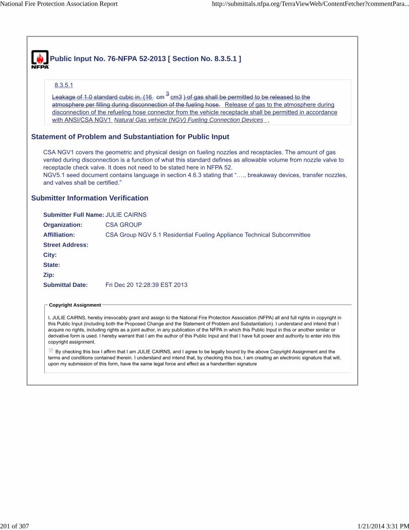
Public Input No. 76-NFPA 52-2013 [ Section No. 8.3.5.1 ]
8.3.5.1
Leakage of 1.0 standard cubic in. (16 cm 3 cm3 ) of gas shall be permitted to be released to theatmosphere per filling during disconnection of the fueling hose. Release of gas to the atmosphere duringdisconnection of the refueling hose connector from the vehicle receptacle shall be permitted in accordancewith ANSI/CSA NGV1 Natural Gas vehicle (NGV) Fueling Connection Devices .
Statement of Problem and Substantiation for Public Input
CSA NGV1 covers the geometric and physical design on fueling nozzles and receptacles. The amount of gas vented during disconnection is a function of what this standard defines as allowable volume from nozzle valve to receptacle check valve. It does not need to be stated here in NFPA 52.NGV5.1 seed document contains language in section 4.6.3 stating that “…., breakaway devices, transfer nozzles, and valves shall be certified.”
Submitter Information Verification
Submitter Full Name: JULIE CAIRNS
Organization: CSA GROUP
Affilliation: CSA Group NGV 5.1 Residential Fueling Appliance Technical Subcommittee
Street Address:
City:
State:
Zip:
Submittal Date: Fri Dec 20 12:28:39 EST 2013
Copyright Assignment
I, JULIE CAIRNS, hereby irrevocably grant and assign to the National Fire Protection Association (NFPA) all and full rights in copyright inthis Public Input (including both the Proposed Change and the Statement of Problem and Substantiation). I understand and intend that Iacquire no rights, including rights as a joint author, in any publication of the NFPA in which this Public Input in this or another similar orderivative form is used. I hereby warrant that I am the author of this Public Input and that I have full power and authority to enter into thiscopyright assignment.
By checking this box I affirm that I am JULIE CAIRNS, and I agree to be legally bound by the above Copyright Assignment and theterms and conditions contained therein. I understand and intend that, by checking this box, I am creating an electronic signature that will,upon my submission of this form, have the same legal force and effect as a handwritten signature
National Fire Protection Association Report http://submittals.nfpa.org/TerraViewWeb/ContentFetcher?commentPara...
201 of 307 1/21/2014 3:31 PM

Public Input No. 77-NFPA 52-2013 [ Section No. 8.3.6 ]
8.3.6
Unless specifically permitted by the installation instructions, multiple VFAs RFA’s shall not be installedin series or manifolded together on the discharge side.
Statement of Problem and Substantiation for Public Input
This proposal is part of a series of proposals which will harmonize NFPA 52 with the new NGV 5.1 standard for residential fueling appliances. To ensure that maximum gas leakages and flow rates are not exceeded especially when the RFA is installed indoors. All listed RFA appliances to be installed in accordance with the manufacturer’s instructions. Any modular or multiple unit RFA designs must be a listed appliance, NGV 5.1. There is no reference to manifolding of RFAs in the NGV 5.1 SEED document at this time.
Submitter Information Verification
Submitter Full Name: JULIE CAIRNS
Organization: CSA GROUP
Affilliation: CSA Group NGV 5.1 Residential Fueling Appliance Technical Subcommittee
Street Address:
City:
State:
Zip:
Submittal Date: Fri Dec 20 12:31:26 EST 2013
Copyright Assignment
I, JULIE CAIRNS, hereby irrevocably grant and assign to the National Fire Protection Association (NFPA) all and full rights in copyright inthis Public Input (including both the Proposed Change and the Statement of Problem and Substantiation). I understand and intend that Iacquire no rights, including rights as a joint author, in any publication of the NFPA in which this Public Input in this or another similar orderivative form is used. I hereby warrant that I am the author of this Public Input and that I have full power and authority to enter into thiscopyright assignment.
By checking this box I affirm that I am JULIE CAIRNS, and I agree to be legally bound by the above Copyright Assignment and theterms and conditions contained therein. I understand and intend that, by checking this box, I am creating an electronic signature that will,upon my submission of this form, have the same legal force and effect as a handwritten signature
National Fire Protection Association Report http://submittals.nfpa.org/TerraViewWeb/ContentFetcher?commentPara...
202 of 307 1/21/2014 3:31 PM

Public Input No. 78-NFPA 52-2013 [ Section No. 8.4.1.1 ]
8.4.1.1
All RFF-CNG RFA equipment shall be installed in accordance with the equipment manufacturer'sinstructions.
Statement of Problem and Substantiation for Public Input
This proposal is part of a series of proposals which will harmonize NFPA 52 with the new NGV 5.1 standard for residential fueling appliances and update globally terminology within NFPA 52.
Submitter Information Verification
Submitter Full Name: JULIE CAIRNS
Organization: CSA GROUP
Affilliation: CSA Group NGV 5.1 Residential Fueling Appliance Technical Subcommittee
Street Address:
City:
State:
Zip:
Submittal Date: Fri Dec 20 12:35:07 EST 2013
Copyright Assignment
I, JULIE CAIRNS, hereby irrevocably grant and assign to the National Fire Protection Association (NFPA) all and full rights in copyright inthis Public Input (including both the Proposed Change and the Statement of Problem and Substantiation). I understand and intend that Iacquire no rights, including rights as a joint author, in any publication of the NFPA in which this Public Input in this or another similar orderivative form is used. I hereby warrant that I am the author of this Public Input and that I have full power and authority to enter into thiscopyright assignment.
By checking this box I affirm that I am JULIE CAIRNS, and I agree to be legally bound by the above Copyright Assignment and theterms and conditions contained therein. I understand and intend that, by checking this box, I am creating an electronic signature that will,upon my submission of this form, have the same legal force and effect as a handwritten signature
National Fire Protection Association Report http://submittals.nfpa.org/TerraViewWeb/ContentFetcher?commentPara...
203 of 307 1/21/2014 3:31 PM

Public Input No. 79-NFPA 52-2013 [ Section No. 8.4.1.2 ]
8.4.1.2
The RFF-CNG RFA shall have a nameplate marked with minimum and maximum gas inlet pressures andflow rates, gas outlet maximum pressure, and electrical requirements.
Statement of Problem and Substantiation for Public Input
This proposal is part of a Series of proposals which will harmonize NFPA 52 with the new NGV 5.1 standard for home fueling appliances.”
Flow rate is not enforceable and as currently defined does not address all “flow rates” (input flow rate, output flow rate and in-process flow rate). Safety vs. flow rate is best defined by the manufacturer and certification and environmental concerns. Flow rate will be addressed in CSA NGV 5.1.
Submitter Information Verification
Submitter Full Name: JULIE CAIRNS
Organization: CSA GROUP
Affilliation: CSA Group NGV 5.1 Residential Fueling Appliance Technical Subcommittee
Street Address:
City:
State:
Zip:
Submittal Date: Fri Dec 20 12:37:13 EST 2013
Copyright Assignment
I, JULIE CAIRNS, hereby irrevocably grant and assign to the National Fire Protection Association (NFPA) all and full rights in copyright inthis Public Input (including both the Proposed Change and the Statement of Problem and Substantiation). I understand and intend that Iacquire no rights, including rights as a joint author, in any publication of the NFPA in which this Public Input in this or another similar orderivative form is used. I hereby warrant that I am the author of this Public Input and that I have full power and authority to enter into thiscopyright assignment.
By checking this box I affirm that I am JULIE CAIRNS, and I agree to be legally bound by the above Copyright Assignment and theterms and conditions contained therein. I understand and intend that, by checking this box, I am creating an electronic signature that will,upon my submission of this form, have the same legal force and effect as a handwritten signature
National Fire Protection Association Report http://submittals.nfpa.org/TerraViewWeb/ContentFetcher?commentPara...
204 of 307 1/21/2014 3:31 PM

Public Input No. 80-NFPA 52-2013 [ Section No. 8.4.2.2 ]
8.4.2.2 *
Where the RFF-CNG RFA or the vehicle being fueled is located indoors, a gas detector set to operate atone-fifth the (LFL) lower flammable limit of natural gas shall be installed in the room.
8.4.2.2.1
The detector shall be located within 6 in. (150 mm) of the ceiling or the highest point in the room.
8.4.2.2.1.1
An RFF-CNG RFA that is listed shall be permitted to utilize a combination of ventilation or gas detection toensure that the room is maintained at a level below one-fifth of the lower limit of flammability of natural gas.
8.4.2.2.1.2
Meeting the provisions of 8.4.2.2.1 shall be deemed to be equivalent to a gas detector located within 6 in.(150 mm) of the ceiling or the highest point in the room.
8.4.2.2.2
The detector shall stop the compressor and operate an audible or and a visual alarm.
Statement of Problem and Substantiation for Public Input
This proposal is part of a series of proposals which will harmonize NFPA 52 with the new NGV 5.1 standard for residential fueling appliances and update globally terminology within NFPA 52.
Changed “or” to “and “ to ensure that if a gas leak is detected both audio and visual alarms are present to ensure detection and that people with hearing and/or visual impairments will be able to detect the alarm.
Submitter Information Verification
Submitter Full Name: JULIE CAIRNS
Organization: CSA GROUP
Affilliation: CSA Group NGV 5.1 Residential Fueling Appliance Technical Subcommittee
Street Address:
City:
State:
Zip:
Submittal Date: Fri Dec 20 12:40:37 EST 2013
Copyright Assignment
I, JULIE CAIRNS, hereby irrevocably grant and assign to the National Fire Protection Association (NFPA) all and full rights in copyright inthis Public Input (including both the Proposed Change and the Statement of Problem and Substantiation). I understand and intend that Iacquire no rights, including rights as a joint author, in any publication of the NFPA in which this Public Input in this or another similar orderivative form is used. I hereby warrant that I am the author of this Public Input and that I have full power and authority to enter into thiscopyright assignment.
By checking this box I affirm that I am JULIE CAIRNS, and I agree to be legally bound by the above Copyright Assignment and theterms and conditions contained therein. I understand and intend that, by checking this box, I am creating an electronic signature that will,upon my submission of this form, have the same legal force and effect as a handwritten signature
National Fire Protection Association Report http://submittals.nfpa.org/TerraViewWeb/ContentFetcher?commentPara...
205 of 307 1/21/2014 3:31 PM

Public Input No. 81-NFPA 52-2013 [ Section No. 8.4.3 ]
8.4.3 Outdoors.
The RFF-CNG RFA shall be installed on a firm, noncombustible support to prevent undue stress onpiping and conduit. (See Section 4.5 for noncombustible.)
Statement of Problem and Substantiation for Public Input
This proposal is part of a series of proposals which will harmonize NFPA 52 with the new NGV 5.1 standard for residential fueling appliances and update globally terminology within NFPA 52.
Submitter Information Verification
Submitter Full Name: JULIE CAIRNS
Organization: CSA GROUP
Affilliation: CSA Group NGV 5.1 Residential Fueling Appliance Technical Subcommittee
Street Address:
City:
State:
Zip:
Submittal Date: Fri Dec 20 12:47:00 EST 2013
Copyright Assignment
I, JULIE CAIRNS, hereby irrevocably grant and assign to the National Fire Protection Association (NFPA) all and full rights in copyright inthis Public Input (including both the Proposed Change and the Statement of Problem and Substantiation). I understand and intend that Iacquire no rights, including rights as a joint author, in any publication of the NFPA in which this Public Input in this or another similar orderivative form is used. I hereby warrant that I am the author of this Public Input and that I have full power and authority to enter into thiscopyright assignment.
By checking this box I affirm that I am JULIE CAIRNS, and I agree to be legally bound by the above Copyright Assignment and theterms and conditions contained therein. I understand and intend that, by checking this box, I am creating an electronic signature that will,upon my submission of this form, have the same legal force and effect as a handwritten signature
National Fire Protection Association Report http://submittals.nfpa.org/TerraViewWeb/ContentFetcher?commentPara...
206 of 307 1/21/2014 3:31 PM

Public Input No. 82-NFPA 52-2013 [ Section No. 8.7 ]
8.7 Pressure Regulation.
An RFF-CNG shall An RFA shall be equipped to stop fuel flow automatically when the container(s)reaches the temperature-corrected fill pressure.
Statement of Problem and Substantiation for Public Input
This proposal is part of a series of proposals which will harmonize NFPA 52 with the new NGV 5.1 standard for residential fueling appliances and update globally terminology within NFPA 52.
Submitter Information Verification
Submitter Full Name: JULIE CAIRNS
Organization: CSA GROUP
Affilliation: CSA Group NGV 5.1 Residential Fueling Appliance Technical Subcommittee
Street Address:
City:
State:
Zip:
Submittal Date: Fri Dec 20 12:49:16 EST 2013
Copyright Assignment
I, JULIE CAIRNS, hereby irrevocably grant and assign to the National Fire Protection Association (NFPA) all and full rights in copyright inthis Public Input (including both the Proposed Change and the Statement of Problem and Substantiation). I understand and intend that Iacquire no rights, including rights as a joint author, in any publication of the NFPA in which this Public Input in this or another similar orderivative form is used. I hereby warrant that I am the author of this Public Input and that I have full power and authority to enter into thiscopyright assignment.
By checking this box I affirm that I am JULIE CAIRNS, and I agree to be legally bound by the above Copyright Assignment and theterms and conditions contained therein. I understand and intend that, by checking this box, I am creating an electronic signature that will,upon my submission of this form, have the same legal force and effect as a handwritten signature
National Fire Protection Association Report http://submittals.nfpa.org/TerraViewWeb/ContentFetcher?commentPara...
207 of 307 1/21/2014 3:31 PM

Public Input No. 84-NFPA 52-2013 [ Section No. 8.8.1 ]
8.8.1
All piping and hose from the outlet of the compressor shall be supplied as part of the RFF-CNG.
Statement of Problem and Substantiation for Public Input
This proposal is part of a series of proposals which will harmonize NFPA 52 with the new NGV 5.1 standard for residential fueling appliances. Details of the piping and hose will be covered in NGV 5.1 as part of the overall certification of the appliance. NGV 5.1 will also require that the installation of piping and hoses must be done to manufacturers written instructions
Submitter Information Verification
Submitter Full Name: JULIE CAIRNS
Organization: CSA GROUP
Affilliation: CSA Group NGV 5.1 Residential Fueling Appliance Technical Subcommittee
Street Address:
City:
State:
Zip:
Submittal Date: Fri Dec 20 12:59:22 EST 2013
Copyright Assignment
I, JULIE CAIRNS, hereby irrevocably grant and assign to the National Fire Protection Association (NFPA) all and full rights in copyright inthis Public Input (including both the Proposed Change and the Statement of Problem and Substantiation). I understand and intend that Iacquire no rights, including rights as a joint author, in any publication of the NFPA in which this Public Input in this or another similar orderivative form is used. I hereby warrant that I am the author of this Public Input and that I have full power and authority to enter into thiscopyright assignment.
By checking this box I affirm that I am JULIE CAIRNS, and I agree to be legally bound by the above Copyright Assignment and theterms and conditions contained therein. I understand and intend that, by checking this box, I am creating an electronic signature that will,upon my submission of this form, have the same legal force and effect as a handwritten signature
National Fire Protection Association Report http://submittals.nfpa.org/TerraViewWeb/ContentFetcher?commentPara...
208 of 307 1/21/2014 3:31 PM

Public Input No. 83-NFPA 52-2013 [ Section No. 8.8.2 ]
8.8.2
All gas piping to the RFF-CNG the RFA shall be installed in accordance with NFPA 54, National Fuel GasCode and manufacturers installation instructions .
Statement of Problem and Substantiation for Public Input
This proposal is part of a series of proposals which will harmonize NFPA 52 with the new NGV 5.1 standard for residential fueling appliances. Details of the piping and hose will be covered in NGV 5.1 as part of the overall certification of the appliance. NGV 5.1 will also require that the installation of piping and hoses must be done to manufacturers written instructions
Related Public Inputs for This Document
Related Input Relationship
Public Input No. 84-NFPA 52-2013[Section No. 8.8.1]
Details of piping and hose will be covered in NGV 5.1 Part ofproposed revision to entire section 8.8.
Public Input No. 85-NFPA 52-2013[Section No. 8.8.3]
Details of piping and hose will be covered in NGV 5.1 Part ofproposed revision to entire section 8.8.
Public Input No. 86-NFPA 52-2013[Section No. 8.8.4]
Details of piping and hose will be covered in NGV 5.1 Part ofproposed revision to entire section 8.8.
Public Input No. 87-NFPA 52-2013[Section No. 8.8.5]
Details of piping and hose will be covered in NGV 5.1 Part ofproposed revision to entire section 8.8.
Submitter Information Verification
Submitter Full Name: JULIE CAIRNS
Organization: CSA GROUP
Affilliation: CSA Group NGV 5.1 Residential Fueling Appliance Technical Subcommittee
Street Address:
City:
State:
Zip:
Submittal Date: Fri Dec 20 12:56:57 EST 2013
Copyright Assignment
I, JULIE CAIRNS, hereby irrevocably grant and assign to the National Fire Protection Association (NFPA) all and full rights in copyright inthis Public Input (including both the Proposed Change and the Statement of Problem and Substantiation). I understand and intend that Iacquire no rights, including rights as a joint author, in any publication of the NFPA in which this Public Input in this or another similar orderivative form is used. I hereby warrant that I am the author of this Public Input and that I have full power and authority to enter into thiscopyright assignment.
By checking this box I affirm that I am JULIE CAIRNS, and I agree to be legally bound by the above Copyright Assignment and theterms and conditions contained therein. I understand and intend that, by checking this box, I am creating an electronic signature that will,upon my submission of this form, have the same legal force and effect as a handwritten signature
National Fire Protection Association Report http://submittals.nfpa.org/TerraViewWeb/ContentFetcher?commentPara...
209 of 307 1/21/2014 3:31 PM

Public Input No. 85-NFPA 52-2013 [ Section No. 8.8.3 ]
8.8.3
The use of hose in an installation shall be restricted to the following:
(1) A fueling hose limited to a maximum length of 25 ft (7.6 m) and supported above the floor/groundlevel or otherwise protected from mechanical damage from abrasion and being driven over by avehicle
(2) A maximum of 3 ft (1 m) in length where used to prevent abrasion damage resulting from vibration onthe inlet or outlet, or both
Statement of Problem and Substantiation for Public Input
This proposal is part of a series of proposals which will harmonize NFPA 52 with the new NGV 5.1 standard for residential fueling appliances. Details of the piping and hose will be covered in NGV 5.1 as part of the overall certification of the appliance. NGV 5.1 will also require that the installation of piping and hoses must be done to manufacturers written instructions
Submitter Information Verification
Submitter Full Name: JULIE CAIRNS
Organization: CSA GROUP
Affilliation: CSA Group NGV 5.1 Residential Fueling Appliance Technical Subcommittee
Street Address:
City:
State:
Zip:
Submittal Date: Fri Dec 20 13:01:58 EST 2013
Copyright Assignment
I, JULIE CAIRNS, hereby irrevocably grant and assign to the National Fire Protection Association (NFPA) all and full rights in copyright inthis Public Input (including both the Proposed Change and the Statement of Problem and Substantiation). I understand and intend that Iacquire no rights, including rights as a joint author, in any publication of the NFPA in which this Public Input in this or another similar orderivative form is used. I hereby warrant that I am the author of this Public Input and that I have full power and authority to enter into thiscopyright assignment.
By checking this box I affirm that I am JULIE CAIRNS, and I agree to be legally bound by the above Copyright Assignment and theterms and conditions contained therein. I understand and intend that, by checking this box, I am creating an electronic signature that will,upon my submission of this form, have the same legal force and effect as a handwritten signature
National Fire Protection Association Report http://submittals.nfpa.org/TerraViewWeb/ContentFetcher?commentPara...
210 of 307 1/21/2014 3:31 PM

Public Input No. 86-NFPA 52-2013 [ Section No. 8.8.4 ]
8.8.4
Transfer systems shall be capable of depressurizing to facilitate disconnection.
Statement of Problem and Substantiation for Public Input
This proposal is part of a series of proposals which will harmonize NFPA 52 with the new NGV 5.1 standard for residential fueling appliances. Details of the piping and hose will be covered in NGV 5.1 as part of the overall certification of the appliance. NGV 5.1 will also require that the installation of piping and hoses must be done to manufacturers written instructions
Submitter Information Verification
Submitter Full Name: JULIE CAIRNS
Organization: CSA GROUP
Affilliation: CSA Group NGV 5.1 Residential Fueling Appliance Technical Subcommittee
Street Address:
City:
State:
Zip:
Submittal Date: Fri Dec 20 13:02:52 EST 2013
Copyright Assignment
I, JULIE CAIRNS, hereby irrevocably grant and assign to the National Fire Protection Association (NFPA) all and full rights in copyright inthis Public Input (including both the Proposed Change and the Statement of Problem and Substantiation). I understand and intend that Iacquire no rights, including rights as a joint author, in any publication of the NFPA in which this Public Input in this or another similar orderivative form is used. I hereby warrant that I am the author of this Public Input and that I have full power and authority to enter into thiscopyright assignment.
By checking this box I affirm that I am JULIE CAIRNS, and I agree to be legally bound by the above Copyright Assignment and theterms and conditions contained therein. I understand and intend that, by checking this box, I am creating an electronic signature that will,upon my submission of this form, have the same legal force and effect as a handwritten signature
National Fire Protection Association Report http://submittals.nfpa.org/TerraViewWeb/ContentFetcher?commentPara...
211 of 307 1/21/2014 3:31 PM

Public Input No. 87-NFPA 52-2013 [ Section No. 8.8.5 ]
8.8.5
Bleed connections shall lead to a safe point of discharge.
Statement of Problem and Substantiation for Public Input
This proposal is part of a series of proposals which will harmonize NFPA 52 with the new NGV 5.1 standard for residential fueling appliances. Details of the piping and hose will be covered in NGV 5.1 as part of the overall certification of the appliance. NGV 5.1 will also require that the installation of piping and hoses must be done to manufacturers written instructions
Submitter Information Verification
Submitter Full Name: JULIE CAIRNS
Organization: CSA GROUP
Affilliation: CSA Group NGV 5.1 Residential Fueling Appliance Technical Subcommittee
Street Address:
City:
State:
Zip:
Submittal Date: Fri Dec 20 13:03:48 EST 2013
Copyright Assignment
I, JULIE CAIRNS, hereby irrevocably grant and assign to the National Fire Protection Association (NFPA) all and full rights in copyright inthis Public Input (including both the Proposed Change and the Statement of Problem and Substantiation). I understand and intend that Iacquire no rights, including rights as a joint author, in any publication of the NFPA in which this Public Input in this or another similar orderivative form is used. I hereby warrant that I am the author of this Public Input and that I have full power and authority to enter into thiscopyright assignment.
By checking this box I affirm that I am JULIE CAIRNS, and I agree to be legally bound by the above Copyright Assignment and theterms and conditions contained therein. I understand and intend that, by checking this box, I am creating an electronic signature that will,upon my submission of this form, have the same legal force and effect as a handwritten signature
National Fire Protection Association Report http://submittals.nfpa.org/TerraViewWeb/ContentFetcher?commentPara...
212 of 307 1/21/2014 3:31 PM
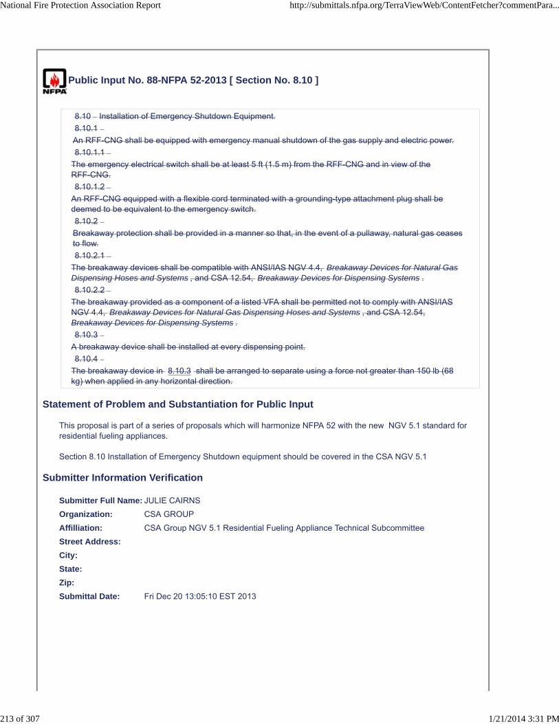
Public Input No. 88-NFPA 52-2013 [ Section No. 8.10 ]
8.10 Installation of Emergency Shutdown Equipment.
8.10.1
An RFF-CNG shall be equipped with emergency manual shutdown of the gas supply and electric power.
8.10.1.1
The emergency electrical switch shall be at least 5 ft (1.5 m) from the RFF-CNG and in view of theRFF-CNG.
8.10.1.2
An RFF-CNG equipped with a flexible cord terminated with a grounding-type attachment plug shall bedeemed to be equivalent to the emergency switch.
8.10.2
Breakaway protection shall be provided in a manner so that, in the event of a pullaway, natural gas ceasesto flow.
8.10.2.1
The breakaway devices shall be compatible with ANSI/IAS NGV 4.4, Breakaway Devices for Natural GasDispensing Hoses and Systems , and CSA 12.54, Breakaway Devices for Dispensing Systems .
8.10.2.2
The breakaway provided as a component of a listed VFA shall be permitted not to comply with ANSI/IASNGV 4.4, Breakaway Devices for Natural Gas Dispensing Hoses and Systems , and CSA 12.54,Breakaway Devices for Dispensing Systems .
8.10.3
A breakaway device shall be installed at every dispensing point.
8.10.4
The breakaway device in 8.10.3 shall be arranged to separate using a force not greater than 150 lb (68kg) when applied in any horizontal direction.
Statement of Problem and Substantiation for Public Input
This proposal is part of a series of proposals which will harmonize NFPA 52 with the new NGV 5.1 standard for residential fueling appliances. Section 8.10 Installation of Emergency Shutdown equipment should be covered in the CSA NGV 5.1
Submitter Information Verification
Submitter Full Name: JULIE CAIRNS
Organization: CSA GROUP
Affilliation: CSA Group NGV 5.1 Residential Fueling Appliance Technical Subcommittee
Street Address:
City:
State:
Zip:
Submittal Date: Fri Dec 20 13:05:10 EST 2013
National Fire Protection Association Report http://submittals.nfpa.org/TerraViewWeb/ContentFetcher?commentPara...
213 of 307 1/21/2014 3:31 PM

Copyright Assignment
I, JULIE CAIRNS, hereby irrevocably grant and assign to the National Fire Protection Association (NFPA) all and full rights in copyright inthis Public Input (including both the Proposed Change and the Statement of Problem and Substantiation). I understand and intend that Iacquire no rights, including rights as a joint author, in any publication of the NFPA in which this Public Input in this or another similar orderivative form is used. I hereby warrant that I am the author of this Public Input and that I have full power and authority to enter into thiscopyright assignment.
By checking this box I affirm that I am JULIE CAIRNS, and I agree to be legally bound by the above Copyright Assignment and theterms and conditions contained therein. I understand and intend that, by checking this box, I am creating an electronic signature that will,upon my submission of this form, have the same legal force and effect as a handwritten signature
National Fire Protection Association Report http://submittals.nfpa.org/TerraViewWeb/ContentFetcher?commentPara...
214 of 307 1/21/2014 3:31 PM

Public Input No. 89-NFPA 52-2013 [ Section No. 8.11.1 ]
8.11.1
An RFF-CNG RFA shall be operated in accordance with the manufacturer's instructions.
Statement of Problem and Substantiation for Public Input
This proposal is part of a series of proposals which will harmonize NFPA 52 with the new NGV 5.1 standard for residential fueling appliances and update globally terminology within NFPA 52.
Submitter Information Verification
Submitter Full Name: JULIE CAIRNS
Organization: CSA GROUP
Affilliation: CSA Group NGV 5.1 Residential Fueling Appliance Technical Subcommittee
Street Address:
City:
State:
Zip:
Submittal Date: Fri Dec 20 13:06:24 EST 2013
Copyright Assignment
I, JULIE CAIRNS, hereby irrevocably grant and assign to the National Fire Protection Association (NFPA) all and full rights in copyright inthis Public Input (including both the Proposed Change and the Statement of Problem and Substantiation). I understand and intend that Iacquire no rights, including rights as a joint author, in any publication of the NFPA in which this Public Input in this or another similar orderivative form is used. I hereby warrant that I am the author of this Public Input and that I have full power and authority to enter into thiscopyright assignment.
By checking this box I affirm that I am JULIE CAIRNS, and I agree to be legally bound by the above Copyright Assignment and theterms and conditions contained therein. I understand and intend that, by checking this box, I am creating an electronic signature that will,upon my submission of this form, have the same legal force and effect as a handwritten signature
National Fire Protection Association Report http://submittals.nfpa.org/TerraViewWeb/ContentFetcher?commentPara...
215 of 307 1/21/2014 3:31 PM

Public Input No. 90-NFPA 52-2013 [ Section No. 8.11.2 ]
8.11.2
A fuel supply container shall not be charged in excess of its maximum operating allowable servicepressure at normal temperature with proper temperature compensation in accordance with NGV 5 . 1 .
Statement of Problem and Substantiation for Public Input
This proposal is part of a series of proposals which will harmonize NFPA 52 with the new NGV 5.1 standard for residential fueling appliances.
Removed “at normal temperature.” The maximum allowable service temperature should never be exceeded for residential fueling. (See SAE J1616 – Pressure Hydrocarbon Dew Point (At Container Pressure))
Submitter Information Verification
Submitter Full Name: JULIE CAIRNS
Organization: CSA GROUP
Affilliation: CSA Group NGV 5.1 Residential Fueling Appliance Technical Subcommittee
Street Address:
City:
State:
Zip:
Submittal Date: Fri Dec 20 13:08:04 EST 2013
Copyright Assignment
I, JULIE CAIRNS, hereby irrevocably grant and assign to the National Fire Protection Association (NFPA) all and full rights in copyright inthis Public Input (including both the Proposed Change and the Statement of Problem and Substantiation). I understand and intend that Iacquire no rights, including rights as a joint author, in any publication of the NFPA in which this Public Input in this or another similar orderivative form is used. I hereby warrant that I am the author of this Public Input and that I have full power and authority to enter into thiscopyright assignment.
By checking this box I affirm that I am JULIE CAIRNS, and I agree to be legally bound by the above Copyright Assignment and theterms and conditions contained therein. I understand and intend that, by checking this box, I am creating an electronic signature that will,upon my submission of this form, have the same legal force and effect as a handwritten signature
National Fire Protection Association Report http://submittals.nfpa.org/TerraViewWeb/ContentFetcher?commentPara...
216 of 307 1/21/2014 3:31 PM

Public Input No. 91-NFPA 52-2013 [ Section No. 8.12.1 ]
8.12.1
All RFF-CNG RFA equipment shall be inspected and maintained in accordance with the manufacturer'sinstructions.
Statement of Problem and Substantiation for Public Input
This proposal is part of a series of proposals which will harmonize NFPA 52 with the new NGV 5.1 standard for residential fueling appliances and update globally terminology within NFPA 52.
Submitter Information Verification
Submitter Full Name: JULIE CAIRNS
Organization: CSA GROUP
Affilliation: CSA Group NGV 5.1 Residential Fueling Appliance Technical Subcommittee
Street Address:
City:
State:
Zip:
Submittal Date: Fri Dec 20 13:13:57 EST 2013
Copyright Assignment
I, JULIE CAIRNS, hereby irrevocably grant and assign to the National Fire Protection Association (NFPA) all and full rights in copyright inthis Public Input (including both the Proposed Change and the Statement of Problem and Substantiation). I understand and intend that Iacquire no rights, including rights as a joint author, in any publication of the NFPA in which this Public Input in this or another similar orderivative form is used. I hereby warrant that I am the author of this Public Input and that I have full power and authority to enter into thiscopyright assignment.
By checking this box I affirm that I am JULIE CAIRNS, and I agree to be legally bound by the above Copyright Assignment and theterms and conditions contained therein. I understand and intend that, by checking this box, I am creating an electronic signature that will,upon my submission of this form, have the same legal force and effect as a handwritten signature
National Fire Protection Association Report http://submittals.nfpa.org/TerraViewWeb/ContentFetcher?commentPara...
217 of 307 1/21/2014 3:31 PM

Public Input No. 109-NFPA 52-2013 [ Chapter 9 ]
Chapter 9 LNG Engine Fuel Systems
9.1 Application.
9.1.1
This chapter applies to the design, installation, inspection, and testing of LNG fuel supply systems forvehicle engines.
9.1.2
This chapter shall not apply to LNG railroad fuel tenders required to comply with applicable DOT (FederalRailroad Administration) regulations.
9.2 Materials.
9.2.1
Metallic materials used in construction of the fuel system, except fusible links, shall have a minimummelting point of 1500°F (816°C).
9.2.2
Metallic material used in construction of the fuel system shall be listed in accordance with ANSI/ASMEB31.3, Process Piping, and the ASME Boiler and Pressure Vessel Code, or API 620, Design andConstruction of Large, Welded, Low-Pressure Storage Tanks, Appendix Q, and shall not be used below theminimum design temperature established in these codes or standards.
9.2.3
The use of dissimilar metal junctions shall be minimized, but if such a junction cannot be avoided, goodcorrosion protection practice shall be employed to reduce the effect of such a material combination on thelong-term corrosion behavior of the junction.
9.2.4
All materials shall be selected or installed to minimize corrosion or to protect the material from corrosion.
9.2.4.1
Stainless steels that do not resist chloride-induced pitting/corrosion cracking and sensitization-inducedcorrosion resistance reduction shall not be used.
9.2.4.2
The use of all copper–zinc and copper–tin alloy families shall be restricted to those alloys that aremetallurgically inhibited to prevent accelerated metallurgical deterioration from external environmentalsources.
9.2.5
Brazing filler material shall have a melting point exceeding 1000°F (538°C).
9.2.6
Oxy–fuel gas welding shall not be permitted.
9.2.7
Furnace butt-welded steel products shall not be used.
9.3 Vehicular Fuel Containers.
National Fire Protection Association Report http://submittals.nfpa.org/TerraViewWeb/ContentFetcher?commentPara...
218 of 307 1/21/2014 3:31 PM

9.3.1 Design.
Containers shall be designed, fabricated, tested, and marked (or stamped) in accordance with theRegulations of DOT Specification 4L or the “Rules for the Construction of Unfired Pressure Vessels,”ASME Boiler and Pressure Vessel Code, applicable at the date of manufacture.
9.3.1.1
LNG containers that are in contact with LNG or cold LNG vapor shall be physically and chemicallycompatible with LNG and designed for service at -260°F (-162°C).
9.3.1.2
Container appurtenances shall have a rated working pressure not less than the maximum allowableworking pressure of the container.
9.3.1.3
For vacuum insulation, the inner tank, outer tank, and internal lines shall be tested for vacuum leaks priorto installation on the vehicle.
9.3.2 Container Filling.
9.3.2.1
Containers shall be equipped with a device or devices that provide an indication of when the container isfilled to the maximum allowable liquid level.
9.3.2.2
The function shall allow for the ullage volume to be determined by the manufacturer to be that whichmaintains the required hold time as required by 9.3.5.
9.3.3 Structural Integrity.
9.3.3.1
The fully pressurized container, when filled to its maximum filling volume with LNG, together with valves,enclosures, and all other items that are mounted and attached, shall be capable of withstanding a staticforce, in the six principal directions, equal to eight times the weight of the container plus its contents,without loss of contents.
9.3.3.2
The container, the plumbing, and the mounting attachments shall withstand the effects of shock, vibration,and acceleration encountered in normal service.
9.3.3.2.1
Marine vessels shall be capable of withstanding forces appropriate for the vessel.
9.3.4 * Container Shutoff Valves.
9.3.4.1
The container shall be equipped with shutoff valves that allow for its complete isolation from the rest of thevehicular fuel system.
9.3.4.1.1
Container shutoff valves shall be labeled as to their function.
9.3.4.1.2
Decals or stencils shall be acceptable.
9.3.4.2
Normally closed automatic shutoff valves that are held open by electric current, pneumatic or hydraulicpressure, or a combination thereof, or manually operated shutoff valves shall be permitted to be used tomeet this requirement.
9.3.5 * Heat Leak.
The manufacturer shall identify the maximum operating design pressure of the container.
9.3.5.1
The construction of the container shall be such that the unrelieved pressure inside the container will notexceed the maximum allowable working pressure of the container within a 72-hour period after thecontainer has been filled to its maximum filling volume with LNG stabilized at the designed operatingpressure and temperature equilibrium has been established.
9.3.5.2
The ambient temperature during the 72-hour period shall be 70°F (21°C).
9.3.6 Reuse.
Containers complying with 9.3.1 shall be permitted to be reused, reinstalled, or continued in use.
National Fire Protection Association Report http://submittals.nfpa.org/TerraViewWeb/ContentFetcher?commentPara...
219 of 307 1/21/2014 3:31 PM

9.3.6.1
A container shall be determined to be suitable for continued service prior to reuse by means of periodicvalidation.
9.3.6.2
Validation shall be performed during normal re-vacuum or repair of the container.
9.3.7 Repair.
Repair or alteration of containers shall comply with the code or original container manufacturer's designunder which the container was fabricated.
9.3.8 Markings.
9.3.8.1
The container shall have the following permanent identification markings:
(1) Total water capacity of the container in gallons (liters)
(2) Label or labels placed in a visible location near the vehicle fill connection identifying it as an LNGconnection, indicating the maximum allowable working pressure of the LNG tank
(3) Markings to designate whether all inlets and outlets, except the relief valves and gauging devices,communicate with vapor or liquid space
9.3.8.2
Decals or stencils shall be acceptable.
9.3.8.3
Penetrations marked with the function of the penetration and identification shall not be obscured by frost.
9.4 Pressure Relief Devices.
9.4.1
Containers shall be equipped with the PRDs or pressure control valves required by the code under whichthe containers were designed and fabricated.
9.4.1.1
PRDs shall be sized for simultaneous conditions of fire and loss of vacuum.
9.4.1.2
PRDs shall be sized in accordance with CGA S-1.1, Pressure Relief Device Standards — Part 1 —Cylinders for Compressed Gases, and CGA S-1.3, Pressure Relief Device Standards — Part 3 —Stationary Storage Containers for Compressed Gases.
9.4.2
The PRDs and pressure control valves shall communicate directly with the vapor space of the container inthe normal operating position.
9.4.3
The PRDs and pressure control valves shall not come into contact with the liquid within the containerduring normal operation.
9.4.4
All safety relief devices on vehicular fuel containers that discharge to the atmosphere shall vent outside ofthe vehicle.
9.4.5
All discharge lines and outlets shall be installed in accordance with 9.4.5.1 through 9.4.5.11.
9.4.5.1
Pressure relief discharge lines shall be designed for the pressure and temperature of the discharged LNG.
9.4.5.2
Components shall be designed for operation at an LNG temperature of -260°F (-162°C).
9.4.5.3
Individual discharge lines and adapters shall be sized, located, and secured so as to permit the maximumrequired relief discharge capacity in order to minimize the possibility of physical damage.
9.4.5.4
The discharge lines shall be able to withstand the pressure of the relief vapor discharge when the PRD isin the full-open position.
National Fire Protection Association Report http://submittals.nfpa.org/TerraViewWeb/ContentFetcher?commentPara...
220 of 307 1/21/2014 3:31 PM

9.4.5.5
A means shall be provided (e.g., loose-fitting caps) to minimize the possibility of the entrance of water ordirt into either the relief device or its discharge line and to drain any water that accumulates in thedischarge line.
9.4.5.6
The means of protection shall remain in place except when the PRD operates.
9.4.5.7
In this event, the means of protection shall permit the relief device to operate at maximum requiredcapacity.
9.4.5.8
The outlet of the discharge line shall be fitted with a device or configured to prevent the formation oraccumulation of any ice or frozen LNG that prevents the relief device from operating at required capacity.
9.4.5.9
The relief valve discharge shall be directed away from the refueling operator and not hinder manuallyshutting off any fuel system devices.
9.4.5.10
The discharge line from PRDs on all vehicles shall be directed upward and extended to a safe location.
9.4.5.11
Secondary relief devices designed to prevent rupture of the container upon failure of the primary reliefdevice shall not be required to be piped away from the tank.
9.4.6
PRDs and pressure control valves shall be so designed that the possibility of tampering is minimized.
9.4.7
Externally set or adjusted valves shall be provided with a means of sealing the adjustment.
9.5 Pressure Gauges.
9.5.1
Containers equipped with pressure gauges shall have the gauges connected to the container at a pointabove the maximum liquid level.
9.5.2
Pressure gauges shall be designed for the maximum pressure and temperature conditions to which theycan be subjected, with a minimum burst pressure safety factor of 4.
9.5.3
Dials shall be graduated to indicate at least 1.2 times the pressure at which the pressure relief deviceincident to the pressure gauge is set to function.
9.5.4
A gauge opening shall not exceed 0.055 in. (1.4 mm) (No. 54 drill size) at the inlet connection.
9.6 Pressure Regulators.
The engine pressure regulator inlet and each chamber shall have a design operating pressure not lessthan the maximum pressure of the container.
9.7 Piping, Tubing, and Fittings.
Piping, tubing, and fittings shall be designed, installed, inspected, and tested in accordance withANSI/ASME B31.3, Process Piping.
9.8 Valves.
9.8.1
Valves, valve packing, gaskets, and seats shall be designed for the intended service.
9.8.2
All parts of container shutoff valves shall be designed for temperatures of -260°F (-162°C).
9.8.2.1
All parts of container shutoff valves shall be stainless steel, brass, or copper except gaskets, packing, andseats.
9.8.3
Extended bonnet valves shall be installed with their stem packing seals in such a position as to preventleakage or malfunction due to freezing.
National Fire Protection Association Report http://submittals.nfpa.org/TerraViewWeb/ContentFetcher?commentPara...
221 of 307 1/21/2014 3:31 PM

9.8.4
Where the extended bonnet in a cryogenic liquid line is installed at an angle greater than 4 degrees fromthe upright vertical position, evidence of satisfactory service in the installed position shall be demonstratedand engineering validation shall be provided by the original equipment (bonnet valve) manufacturer.
9.9 Pumps and Compressors.
9.9.1
Pumps and compressors shall be provided with a PRD to limit the discharge pressure to the maximumworking pressure of the casing and downstream piping and equipment, unless these are designed for themaximum discharge pressure of the pumps or compressors.
9.9.2
Pumps shall be provided with a vent, a relief valve, or both that prevent overpressuring the pump case.
9.9.3
Pumps used for transfer of LNG shall be provided with means for precooling to reduce the effect of thermalshock and overpressure.
9.10 Vaporizers.
9.10.1
Vaporizers shall have the capacity to vaporize the LNG completely and heat the vapor to the designtemperature of the downstream components prior to entry of the vapor into the pressure regulator when thevaporizer is subjected to the maximum vehicular fuel flow rate.
9.10.2
Vaporizers shall be marked permanently at a readily visible point to indicate the maximum allowableworking pressure of the fuel-containing portion of the vaporizer.
9.10.3
Vaporizers shall be designed for a working pressure at least equal to the maximum discharge pressure ofthe pump or the pressurized system that supplies them, whichever is greater.
9.10.4
The discharge valve of each vaporizer, if provided, its piping components, the relief valves installedupstream of the discharge valve, the vaporizer piping, and related components shall be designed foroperation at an LNG temperature of -260°F (-162°C).
9.10.5
Engine exhaust gases shall not be used as a direct source of heat to vaporize fuel.
9.10.6
Where engine exhaust is used to vaporize fuel, it shall be used via an indirect heating system.
9.11 Component Qualification.
9.11.1 OEM Approved Equipment.
The following subsystems and components, if used, shall be recommended by the original equipmentmanufacturer (OEM) for the intended service:
(1) Vehicular fuel containers
(2) Fuel quantity gauging systems
(3) PRDs
(4) Pressure measurement devices
(5) Valves
(6) Pressure regulators
(7) Vaporizers
(8) Pumps
(9) Engine fuel delivery equipment
(10) Vehicle fueling receptacles
(11) Electrical equipment related to the fuel system
(12) Methane detection, fire protection, and suppression systems
9.11.2 Engine Compartment.
National Fire Protection Association Report http://submittals.nfpa.org/TerraViewWeb/ContentFetcher?commentPara...
222 of 307 1/21/2014 3:31 PM

9.11.2.1
Onboard fuel system components inside the engine compartment shall be compatible with the liquids andgases throughout the full range of temperatures [-260°F to 250°F (-162°C to 121°C)].
9.11.2.2
Onboard fuel system components that are in contact with LNG shall be designed for service over atemperature range of -260°F to 250°F (-162°C to 121°C).
9.11.3 Outside Engine Compartment.
9.11.3.1
Components outside the engine compartment that are in contact with LNG shall be designed for serviceover a temperature range of -260°F to 180°F (-162°C to 82°C).
9.11.3.2
Other components that are not in contact with LNG shall be designed for service over a temperature rangeof -40°F to 180°F (-40°C to 82°C).
9.11.4
Components that are not fuel system components and are located within the operational area of LNG orLNG liquid or gaseous leaks shall also be protected or maintain a service range equal to the onboard fuelsystem.
9.12 Installation.
National Fire Protection Association Report http://submittals.nfpa.org/TerraViewWeb/ContentFetcher?commentPara...
223 of 307 1/21/2014 3:31 PM
9.12.1 Vehicular Fuel Containers and Container Appurtenances.
National Fire Protection Association Report http://submittals.nfpa.org/TerraViewWeb/ContentFetcher?commentPara...
224 of 307 1/21/2014 3:31 PM

9.12.1.1
Vehicular components or subsystems that can fail on exposure to LNG temperature shall be protectedfrom exposure to LNG.
9.12.1.2
Containers shall be located in a place and in a manner so as to minimize the possibility of damage to thecontainer and its appurtenances.
9.12.1.2.1
Containers located in the rear of vehicles, where protected by bumpers or vehicular structure, shall beconsidered to be in conformance with 9.12.1.2.
9.12.1.2.2
If fuel or container vent piping containing fuel is installed within 8 in. (200 mm) of engine or exhaustsystem components that exceed 250°F (121°C), it shall be shielded against direct heating.
9.12.1.3 Markings.
9.12.1.3.1
Container markings shall be visible after the container's permanent installation on a vehicle.
9.12.1.3.2
A portable lamp and mirror shall be permitted to be used when reading markings.
9.12.1.4
Container valves, appurtenances, and connections shall be protected to prevent damage due to incidentalcontact with foreign objects.
9.12.1.5 * Position.
9.12.1.5.1
No part of the container or its appurtenances shall protrude beyond the sides or top of any vehicle toprevent the container from being struck or punctured.
9.12.1.5.2
Non-roof-mounted containers shall not be mounted ahead of the front axle or beyond the rear bumper onmotor vehicles.
9.12.1.6
Containers shall be installed to provide as much road clearance as practical.
9.12.1.6.1
The minimum clearance from the road to the container, its housing, or its fittings, whichever is lowest,shall not, with the vehicle loaded to its gross weight rating, be less than that defined by the vehiclemanufacturer's design, or allow any component to touch the surface should the vehicle have a flat tire orrequire the removal of any tire.
9.12.1.6.2
Further requirements for clearances shall be measured as follows:
(1) Containers installed between axles shall comply with 9.12.1.6.2 (3) or shall not be lower than thelowest point on a structural component of the body, frame or subframe, if any, engine, ortransmission, including the clutch housing or torque converter housing, forward of the containermeasured as if the wheel rims were on the ground.
(2) Containers installed behind the rear axle and extending below the frame shall comply with 9.12.1.6.2(3) or shall not be lower than both of the following:
(a) The lowest point of a structural component of the body, engine, or transmission, including clutchhousing or torque converter housing, forward of the container
(b) The lowest point of those lines extending rearward from each wheel at the point where thewheel rims contact the ground directly below the center of the axle to the lowest and mostrearward structural interference (e.g., bumper, frame). Where there are two or more rear axles,the projections shall be made from the rearmost axle.
(3) Where an LNG container is substituted for the fuel container installed by the original chassismanufacturer of the vehicle, the LNG container shall either fit within the space in which the originalfuel container was installed or comply with 9.12.1.6.2 (1) or 9.12.1.6.2 (2) and shall meet, whenavailable, the specifications of the chassis and fuel system OEMs.
9.12.1.7
Containers shall be mounted to prevent their jarring loose, slipping, or rotating.
National Fire Protection Association Report http://submittals.nfpa.org/TerraViewWeb/ContentFetcher?commentPara...
225 of 307 1/21/2014 3:31 PM

9.12.1.8
Containers shall be secured to the vehicle body, bed, or frame by means capable of withstanding theloads defined in 9.3.3.
9.12.1.9
The container weight shall not be supported by outlet valves, manifolds, fuel lines, and other fuel-relatedcomponents or connections.
9.12.1.10
The mounting system shall minimize fretting corrosion between the container and the mounting system.
9.12.1.11
Containers shall not be installed so as to affect adversely the operating characteristics of the vehicle.
9.12.1.12
Vehicular fuel systems shall be equipped with at least one manual or automatic fuel shutoff valve.
9.12.1.13
Manual fuel shutoff valves shall be readily accessible, operable without tools, and labeled as to theirfunction.
9.12.1.14
Where a container is installed above the operator or passenger compartment of a vehicle, the followingrequirements shall apply:
(1) The container and its piping, fittings, and valves shall be protected from damage by the following:
(a) A guard rail or similar device that is designed to absorb the impact of a collision with astationary object when the vehicle is moving either forward or backward at 5 mph/hr (8 km/hr)
(b) A shield designed to absorb impacts that can occur during loading, unloading, or use of thevehicle
(2) The top of the container and any related piping, fitting, valve, housing, guardrail, or shield shall notbe more than 13.5 ft (4.1 m) above the road surface.
(3) The cylinder shall be protected from accidental contact with overhead electrical wiring by metallic ornonmetallic covers.
9.12.1.14.1
The guard rail or similar device shall be free of projections that could damage the container or its valvesand fittings.
9.12.1.14.2
The shield shall be free of projections that subject the container or its valves and fittings to damage.
9.12.2 Containers Mounted in the Interior of Vehicles.
9.12.2.1
Containers shall be installed and fitted so that no gas from fueling operations can be released inside thepassenger compartment, by permanently installing the fueling receptacle outside the passengercompartment of the vehicle in a location protected from physical damage and dislodgment.
9.12.2.2
Enclosures, structures, seals, and conduits used to vent enclosures shall be fabricated of materialsdesigned to resist damage, blockage, or dislodgment caused by the movement of articles carried in thevehicle or by the closing of luggage compartment enclosures or vehicle doors.
9.12.2.2.1
Enclosures shall require the use of tools for removal.
9.12.3 Pipe, Tubing, and Fittings.
9.12.3.1
Manifolds connecting fuel containers shall be fabricated and installed to minimize vibration and shall beinstalled in a protected location or shielded to minimize damage from unsecured objects.
9.12.3.2
Piping and tubing shall be installed, supported, protected, and secured in such a manner as to minimizethe possibility of damage, corrosion, or breakage due to expansion, contraction, vibration, strains, or wearand to preclude any loosening while in transit.
National Fire Protection Association Report http://submittals.nfpa.org/TerraViewWeb/ContentFetcher?commentPara...
226 of 307 1/21/2014 3:31 PM

9.12.3.3
Piping and tubing passing through a panel or structural member shall be protected by grommets or similardevices that shall snugly fit the piping or tubing and the hole in the panel or structural member.
9.12.3.4
Piping or tubing passing through the floor of a vehicle shall be installed to enter the vehicle through thefloor directly beneath, or adjacent to, the container.
9.12.3.4.1
If a branch line is required, the tee connection shall be located in the main fuel line under the floor andoutside the vehicle.
9.12.3.5
A fuel connection between a tractor and trailer or other over-the-road vehicle units shall not be permitted.
9.12.3.6
A PRV shall be installed in each section of piping or tubing in which LNG can be isolated between shutoffvalves so as to relieve the trapped fuel pressure to a safe atmosphere.
9.12.3.7
The PRV shall not have a setting greater than the maximum allowable working pressure of the line itprotects.
9.12.4 Valves.
9.12.4.1
Valves shall be mounted securely and shielded or installed in a protected location to prevent damage fromvibration, shock, and unsecured objects.
9.12.4.2
Valves shall be installed so that their weight is not placed on, or supported by, the attached lines.
9.12.4.3
A positive shutoff valve shall be installed in the fuel supply line.
9.12.4.4
The shutoff valve shall close automatically and prevent the flow of fuel to the engine when the ignitionswitch is off or in the accessory position and when the engine is not running and the ignition switch is on.
9.12.4.5
Where multiple fuel systems or containers are installed on a vehicle, automatic valves shall be provided toshut off the container that is not being utilized.
9.12.4.6
The vehicular fueling system shall be equipped with a backflow check valve to prevent the return flow ofLNG from the container(s) to the filling connection.
9.12.4.7
The check valve in 9.12.4.6 shall be permitted to be integral to another component in the system, such asthe vehicular fueling connector.
9.12.5 Pressure Regulators.
9.12.5.1
On fuel delivery systems that have operating pressures that exceed the engine operating pressurerequirements, automatic pressure regulating equipment shall be installed between the vehicular fuelcontainer and the engine to regulate the pressure of the fuel delivered to the engine.
9.12.5.2
Pressure regulating equipment shall be installed so that its weight is not placed on, or supported by, theattached lines.
9.12.6 Pressure Gauges.
9.12.6.1
A pressure gauge located within a driver or passenger compartment shall be installed in such a mannerthat no gas flows through the gauge in the event of gauge failure.
9.12.6.2
Gauges shall be mounted securely, shielded, and installed in a protected location to prevent damage fromvibration and unsecured objects.
9.12.7 Electrical Wiring.
National Fire Protection Association Report http://submittals.nfpa.org/TerraViewWeb/ContentFetcher?commentPara...
227 of 307 1/21/2014 3:31 PM

9.12.7.1
Wiring shall be installed, supported, and secured in a manner to prevent damage due to vibration, shock,strains, wear, or corrosion.
9.12.7.2
All conductors shall be sized for the maximum anticipated load and shall be protected by overcurrentprotection devices.
9.12.8 Labeling.
9.12.8.1
A vehicle equipped with an LNG fuel system shall bear a durable label located at the fueling connectionreceptacle that shall include the following:
(1) Identification as an LNG-fueled vehicle
(2) Maximum allowable working pressure of the vehicular fuel container
9.12.8.2
Each LNG-fueled vehicle shall be identified with a weather-resistant, diamond-shaped label located on anexterior vertical or near-vertical surface on the lower right rear of the vehicle (or on the trunk lid of avehicle so equipped, but not on the bumper or tailgate of any vehicle), inboard from any other markings.
9.12.8.3
The labels for vehicles less than Class 6 shall be a minimum of 4.72 in. long × 3.27 in. high (120 mm × 83mm).
9.12.8.4
The labels for Class 6 vehicles and greater shall be a minimum of 5.7 in. long × 4.2 in. high (145 mm ×107 mm).
9.12.8.5
The marking in the label required by 9.12.8.2 shall consist of a border and the letters “LNG” [1 in. (25 mm)minimum height centered in the diamond] of silver or white reflective luminous material on a bluebackground.
9.12.8.6
The marking in the label required by 9.12.8.3 shall consist of a border and the letters “LNG” [1.2 in. (30mm) minimum height centered in the diamond] of silver or white reflective luminous material on a bluebackground.
9.12.9 Fueling Receptacle.
9.12.9.1
The fueling receptacle on the vehicular fuel system shall be supported and meet all the followingrequirements:
(1) Receive the fueling connector and accommodate the service pressure of the vehicle fuel system
(2) Incorporate a means to minimize the entry of dust, water, and other foreign material
(3) Be designed for any corrosive conditions that are anticipated
9.12.9.2
The fueling receptacle shall be mounted to withstand a breakaway force such that the breakaway devicespecified in 10.4.5 operates before the receptacle separates from the vehicular fuel system.
9.12.9.3
The receptacle shall be installed in accordance with the original component manufacturer's instructions.
9.12.10 Gas Detection.
A fully engineered LNG onboard application methane detection system shall be validated and installed foreach vehicle configuration and application and shall be certified by a qualified engineer with expertise infire safety and gaseous fuels.
9.12.10.1
Motor vehicles equipped with an LNG fuel system or fueled with an unodorized L/CNG shall be providedwith a methane detection system that will warn of the presence of methane in the engine compartment,driver’s compartment, and any passenger compartment.
9.12.10.2
The methane gas detection system shall provide a warning before the methane gas concentrationexceeds the limits specified by 9.13.3.1.
National Fire Protection Association Report http://submittals.nfpa.org/TerraViewWeb/ContentFetcher?commentPara...
228 of 307 1/21/2014 3:31 PM

9.12.10.3
The gas detection system shall function continuously at all times whether or not the engine is operating orthe vehicle is on roadways.
9.12.10.3.1
Gas detection systems shall be permitted to be disconnected during electrical maintenance whendetection is provided within the service area.
9.12.10.4
Warnings shall be plainly audible and visible to the driver prior to entering the vehicle and while seated inthe normal driving position.
9.13 System Testing.
9.13.1 Cold Test and Pressure Test.
9.13.1.1
After the system has been completely assembled, all fittings and connections shall be tested for leakswhile pressurized to the maximum operating pressure.
9.13.1.2
Liquid nitrogen or LNG shall flow through the system at least as far as LNG flows when the system is inoperation, to validate minimum temperature [-260°F (-162°C)] and maximum tank venting pressure.
9.13.2
When a vehicle is involved in an accident or fire causing damage to the LNG fuel system container, thesystem, container, or both shall be inspected, repaired, or removed and retested before being restored toservice.
9.13.3 Onboard Gas Detection.
9.13.3.1
The detection system shall activate a visual alarm within the driver's compartment of the vehicle at a gasconcentration not exceeding 20 to 30 percent of the LFL and sound an audible and visual alarm at a gasconcentration not greater than 50 to 60 percent of the LFL.
9.13.3.1.1
Sensor locations shall include at a minimum the engine and driver's compartment and any enclosed fuelcontainer or installation within a compartment.
9.13.3.1.2
Motor vehicles equipped with a gas detection system shall provide warnings at two different levels inaccordance with 9.13.3.1 and the following:
(1) At the 50 percent to 60 percent LFL level, a warning that is audible and visible to the driver outsidethe vehicle
(2) An 87 dBA warning that is audible outside the vehicle with windows up and doors closed
(3) A visual warning that is visible in direct sunlight
9.13.3.2
Onboard methane detection, fire suppression, and fire protection systems shall be installed, inspected,validated, and maintained in accordance with the system OEM written recommendations and shall bemaintained as a permanent vehicle record.
9.13.3.2.1
Periodic testing shall be done at a minimum of three times per year.
9.13.3.2.2
The gas detection testing procedure shall simulate the same gas and operating environment in which thevehicle is used for daily use of individual components and systems in accordance with the levels in9.13.3.1.
9.13.3.2.3
Validation shall conform to the specifics of the component OEM recommendations and shall bemaintained as a permanent vehicle record.
9.13.3.2.4
When provided, onboard fire suppression systems shall be operable at all times, whether or not thevehicle is operated or parked.
National Fire Protection Association Report http://submittals.nfpa.org/TerraViewWeb/ContentFetcher?commentPara...
229 of 307 1/21/2014 3:31 PM

9.13.3.2.4.1
The suppression system shall provide a fire sensing system for detection, actuating, and dispensing of theappropriate agent in accordance with the OEM or FSVIM recommendation.
9.13.3.2.4.2
The fire suppression system shall be independent of all other systems and not share commoncomponents for recognition or automatic actuation.
9.13.3.2.4.3
Independent manual actuation shall be included as part of the fire suppression system and accessible tothe driver when seated.
Replace Chapter 9 with the attached Chapter 9 Outdoor Storage developed by a NFPA 52 Task Group
Additional Proposed Changes
File Name Description Approved
NFPA_52_Public_Input_Chapter_9_Outdoor_Storage.docx NFPA 52 Chapter 9 Outdoor Storage
Statement of Problem and Substantiation for Public Input
The NFPA 52 Technical Committee approved the reorganization of NFPA 52 into an organizational layout that restructured requirements into General Requirements, Fuel Specific Requirements and Use Specific Requirements. This Chapter replaces existing Chapter 9 and was developed by the Task Group. For this draft being submitted as a Public Input, existing code sections have only been reorganized. No new or revised language has been included or any requirements deleted.
Submitter Information Verification
Submitter Full Name: Nancy Pehrson
Organization: CenterPoint Energy, Inc.
Street Address:
City:
State:
Zip:
Submittal Date: Thu Dec 26 13:12:15 EST 2013
Copyright Assignment
I, Nancy Pehrson, hereby irrevocably grant and assign to the National Fire Protection Association (NFPA) all and full rights in copyright inthis Public Input (including both the Proposed Change and the Statement of Problem and Substantiation). I understand and intend that Iacquire no rights, including rights as a joint author, in any publication of the NFPA in which this Public Input in this or another similar orderivative form is used. I hereby warrant that I am the author of this Public Input and that I have full power and authority to enter into thiscopyright assignment.
By checking this box I affirm that I am Nancy Pehrson, and I agree to be legally bound by the above Copyright Assignment and theterms and conditions contained therein. I understand and intend that, by checking this box, I am creating an electronic signature that will,upon my submission of this form, have the same legal force and effect as a handwritten signature
National Fire Protection Association Report http://submittals.nfpa.org/TerraViewWeb/ContentFetcher?commentPara...
230 of 307 1/21/2014 3:31 PM
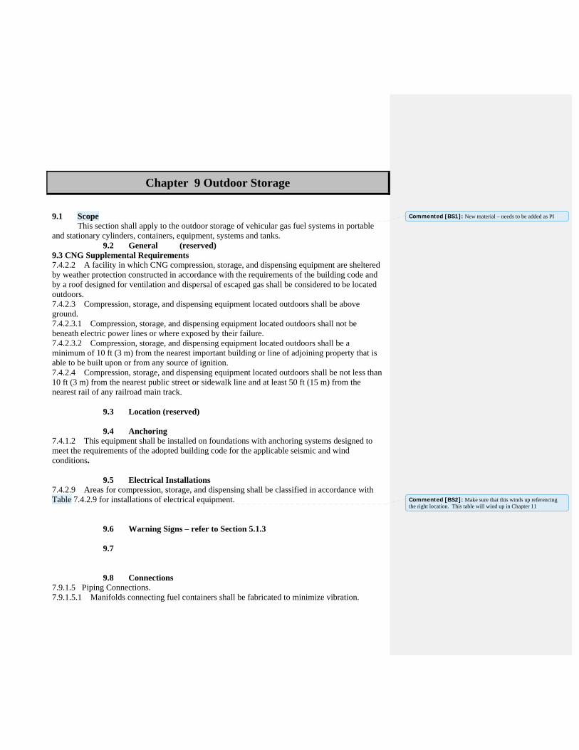
Chapter 9 Outdoor Storage
9.1 Scope This section shall apply to the outdoor storage of vehicular gas fuel systems in portable and stationary cylinders, containers, equipment, systems and tanks. 9.2 General (reserved) 9.3 CNG Supplemental Requirements 7.4.2.2 A facility in which CNG compression, storage, and dispensing equipment are sheltered by weather protection constructed in accordance with the requirements of the building code and by a roof designed for ventilation and dispersal of escaped gas shall be considered to be located outdoors. 7.4.2.3 Compression, storage, and dispensing equipment located outdoors shall be above ground. 7.4.2.3.1 Compression, storage, and dispensing equipment located outdoors shall not be beneath electric power lines or where exposed by their failure. 7.4.2.3.2 Compression, storage, and dispensing equipment located outdoors shall be a minimum of 10 ft (3 m) from the nearest important building or line of adjoining property that is able to be built upon or from any source of ignition. 7.4.2.4 Compression, storage, and dispensing equipment located outdoors shall be not less than 10 ft (3 m) from the nearest public street or sidewalk line and at least 50 ft (15 m) from the nearest rail of any railroad main track. 9.3 Location (reserved) 9.4 Anchoring 7.4.1.2 This equipment shall be installed on foundations with anchoring systems designed to meet the requirements of the adopted building code for the applicable seismic and wind conditions. 9.5 Electrical Installations 7.4.2.9 Areas for compression, storage, and dispensing shall be classified in accordance with Table 7.4.2.9 for installations of electrical equipment. 9.6 Warning Signs – refer to Section 5.1.3 9.7 9.8 Connections 7.9.1.5 Piping Connections. 7.9.1.5.1 Manifolds connecting fuel containers shall be fabricated to minimize vibration.
Commented [BS1]: New material – needs to be added as PI
Commented [BS2]: Make sure that this winds up referencing the right location. This table will wind up in Chapter 11
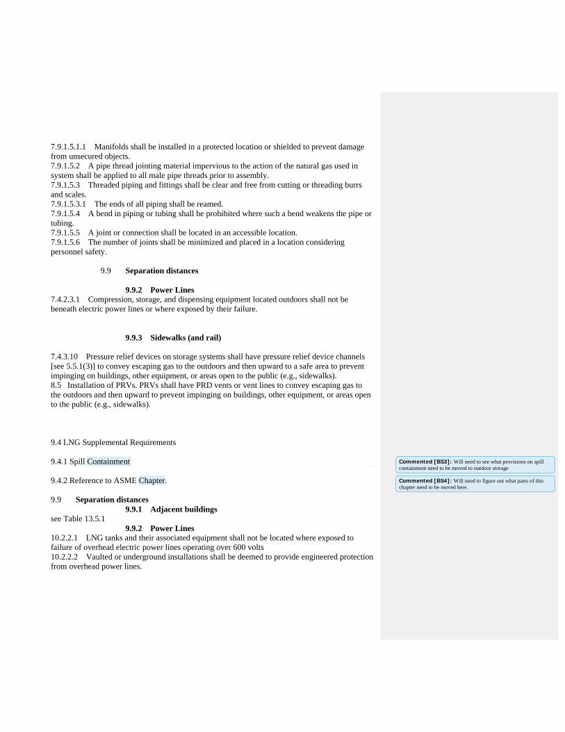
7.9.1.5.1.1 Manifolds shall be installed in a protected location or shielded to prevent damage from unsecured objects. 7.9.1.5.2 A pipe thread jointing material impervious to the action of the natural gas used in system shall be applied to all male pipe threads prior to assembly. 7.9.1.5.3 Threaded piping and fittings shall be clear and free from cutting or threading burrs and scales. 7.9.1.5.3.1 The ends of all piping shall be reamed. 7.9.1.5.4 A bend in piping or tubing shall be prohibited where such a bend weakens the pipe or tubing. 7.9.1.5.5 A joint or connection shall be located in an accessible location. 7.9.1.5.6 The number of joints shall be minimized and placed in a location considering personnel safety. 9.9 Separation distances 9.9.2 Power Lines 7.4.2.3.1 Compression, storage, and dispensing equipment located outdoors shall not be beneath electric power lines or where exposed by their failure. 9.9.3 Sidewalks (and rail) 7.4.3.10 Pressure relief devices on storage systems shall have pressure relief device channels [see 5.5.1(3)] to convey escaping gas to the outdoors and then upward to a safe area to prevent impinging on buildings, other equipment, or areas open to the public (e.g., sidewalks). 8.5 Installation of PRVs. PRVs shall have PRD vents or vent lines to convey escaping gas to the outdoors and then upward to prevent impinging on buildings, other equipment, or areas open to the public (e.g., sidewalks). 9.4 LNG Supplemental Requirements 9.4.1 Spill Containment 9.4.2 Reference to ASME Chapter. 9.9 Separation distances 9.9.1 Adjacent buildings see Table 13.5.1 9.9.2 Power Lines 10.2.2.1 LNG tanks and their associated equipment shall not be located where exposed to failure of overhead electric power lines operating over 600 volts 10.2.2.2 Vaulted or underground installations shall be deemed to provide engineered protection from overhead power lines.
Commented [BS3]: Will need to see what provisions on spill containment need to be moved to outdoor storage
Commented [BS4]: Will need to figure out what parts of this chapter need to be moved here.

9.9.4 Stationary containers See Table 13.5.1 9.9.5 Aboveground/underground storage tanks See Table 13.5.1.2 9.9.6 Buildings, highways, streets and roads See Table 13.5.1 9.9.7 Masonry materials
13.5.1.1 The distance from the edge of an impoundment or container drainage system to buildings or walls of concrete or masonry construction shall be reduced from the distance in Table 13.5.1 with the approval of the authority having jurisdiction with a minimum of 10 ft (3 m). [59A:13.6.2.2]
10.3 Cargo Transport Unloading.
10.3.1 Section 10.3 shall apply to the transfer of LNG between cargo transport containers and fueling facility containers.
10.3.2 When transfers are made into fueling facility containers, the LNG shall be transferred at a pressure that does not overpressurize the receiving tank.
10.3.2.1 Venting of on-site containers shall be done only under emergency conditions and in a manner acceptable to the authority having jurisdiction.
10.3.3 Isolation Valves.
10.3.3.1 The transfer piping shall have isolation valves at both ends.
10.3.3.2 On facility containers with a capacity greater than 2000 gal (7.6 m3), one remotely operated valve, automatic closing valve, or check valve shall be used to prevent backflow.
10.3.4 If the fueling facility tank or transfer equipment is located in a remote area, operating status indicators, such as those that indicate container level, shall be provided in the unloading area.
10.3.5 At least one qualified person shall be in continuous attendance with an unobstructed view of the transfer point while unloading is in progress.
10.3.6 Sources of ignition shall not be permitted in the unloading area while transfer is in progress.
10.3.7 Methane Detection.
10.3.7.1 Offloading site methane detection and fire protection shall be provided.
10.3.7.2 The methane detection system shall be capable of detection at multiple locations beyond the full radius of the transfer hose, measured at each point of transfer and receipt of LNG.
10.3.8 Bleed Connections.

10.3.8.1 Bleed or vent connections shall be provided so that loading arms and hoses can be drained and depressurized prior to disconnection if necessary.
10.3.8.2 The connections shall relieve to a safe area.
10.3.9 Prior to connection, a cargo transport vehicle's wheels shall be rendered immobile.
10.3.10 The cargo transport vehicle's engine shall be shut off while the transfer hose or piping is being connected or disconnected.
10.3.11 If required for LNG transfer, the engine shall be permitted to be started and used during the liquid transfer operations.
10.3.12 The LNG cargo transport unloading connection shall be at least 1.5 ft (0.46 m) from a storage container.

Public Input No. 14-NFPA 52-2013 [ Section No. 9.2.1 ]
9.2.1
Metallic materials used in construction of the fuel system, except fusible links, shall have a minimummelting point of 1500°F (816°C).
There appears to be significant incongruity between the way NFPA 52 defines/deals with CompressedNatural Gas fuel systems and Liquefied Natural Gas fuel systems and that the variances do not appear tobe scientifically rooted.
Several salient facts point to the rationale for reconciling the rules between LNG and CNG
1. Downstream of the high-pressure regulator, CNG and LNG fuel systems function identically, althoughthe LNG regulator outlet pressure (80 to 100 psig) is typically lower than that of the CNG regulator outletpressure (150 to 180 psig). In LNG systems there is only one regulator, stepping pressure down from200-230 psig max/100 psig min to approximately 80 psig. With CNG systems you typically have a secondregulator located near the engine that reduces pressure to ½ psi for analog fuel systems andapproximately 80 psig for digital fuel systems.
2. There are no explicit restrictions in NFPA 52 with regard to the material that must be used in CNGregulators. The only CNG regulator-specific requirements listed are in Chapter 5.7 and deal with burstpressure and pressure relief valve requirements.
3. Section 5.8.4.2 states that aluminum piping may be used downstream of the firststage of pressureregulation in CNG systems. Aluminum has a melting temperature below 1,250°F, whereas 9.2.1 specifiesa minimum melting point of 1500°F for metallic materials used in LNG fuel systems
4. Section 9.2.5 allows for the usage of brazing filler material in LNG systems with a minimum
melting point of 1000 0 F, creating a loss in system seal integrity well below the temperature at which thebase material melts. Thus any rationale for the higher minimum temperature for base material meltingpoints appears negated.
The end result of all this being that we would like to request the NFPA rules committee to review Section9.2.1of NFPA 52 and modify the materials requirement to reconcile it with the rules applied to CNG
systems in Chapter 4 and remove the 1500 0 F minimum melting point requirement.
Statement of Problem and Substantiation for Public Input
There is not a technical problem per se. The issue is a materials requirement for LNG fuel delivery components that does not exist for CNG components even though their operating ranges/conditions are similar. Additionally the allowance for brazing materials within an LNG fuel system that have a minimum melting temperature of 1000 F seem to negate any potential impact of requiring component base material to occur at a higher temperature. Eliminating 9.2.1 would allow the use of aluminum in vaporizers and regulators similar to what has been widely used for decades in CNG and LPG fuel systems.
Submitter Information Verification
Submitter Full Name: Karl Staggemeier
Organization: IMPCO Technologies
Street Address:
City:
State:
Zip:
Submittal Date: Mon Dec 09 18:18:55 EST 2013
National Fire Protection Association Report http://submittals.nfpa.org/TerraViewWeb/ContentFetcher?commentPara...
231 of 307 1/21/2014 3:31 PM

Copyright Assignment
I, Karl Staggemeier, hereby irrevocably grant and assign to the National Fire Protection Association (NFPA) all and full rights in copyright inthis Public Input (including both the Proposed Change and the Statement of Problem and Substantiation). I understand and intend that Iacquire no rights, including rights as a joint author, in any publication of the NFPA in which this Public Input in this or another similar orderivative form is used. I hereby warrant that I am the author of this Public Input and that I have full power and authority to enter into thiscopyright assignment.
By checking this box I affirm that I am Karl Staggemeier, and I agree to be legally bound by the above Copyright Assignment and theterms and conditions contained therein. I understand and intend that, by checking this box, I am creating an electronic signature that will,upon my submission of this form, have the same legal force and effect as a handwritten signature
National Fire Protection Association Report http://submittals.nfpa.org/TerraViewWeb/ContentFetcher?commentPara...
232 of 307 1/21/2014 3:31 PM

Public Input No. 93-NFPA 52-2013 [ New Section after 9.3.3.2.1 ]
9.3.3.3 Drop Tests
All LNG fuel containers shall be certified as passing the drop tests specified in section 4.2.12 and AppendixA of SAE J2343, Recommended Practice for LNG Medium and Heavy-Duty Powered Vehicles.
Statement of Problem and Substantiation for Public Input
No drop tests are specified in the current NFPA standard. The drop tests specified in section 4.2.12 and Appendix A of SAE J2343 are referenced as a recommendation on p. 40 of FMCSA's final report, "Natural Gas Systems: Suggested Changes to Truck and Motorcoach REgulations and Inspection Procedures" published March 2013.
Submitter Information Verification
Submitter Full Name: Quon Kwan
Organization: US Department of Transportation
Street Address:
City:
State:
Zip:
Submittal Date: Tue Dec 24 10:18:32 EST 2013
Copyright Assignment
I, Quon Kwan, hereby irrevocably grant and assign to the National Fire Protection Association (NFPA) all and full rights in copyright in thisPublic Input (including both the Proposed Change and the Statement of Problem and Substantiation). I understand and intend that I acquireno rights, including rights as a joint author, in any publication of the NFPA in which this Public Input in this or another similar or derivativeform is used. I hereby warrant that I am the author of this Public Input and that I have full power and authority to enter into this copyrightassignment.
By checking this box I affirm that I am Quon Kwan, and I agree to be legally bound by the above Copyright Assignment and the termsand conditions contained therein. I understand and intend that, by checking this box, I am creating an electronic signature that will, upon mysubmission of this form, have the same legal force and effect as a handwritten signature
National Fire Protection Association Report http://submittals.nfpa.org/TerraViewWeb/ContentFetcher?commentPara...
233 of 307 1/21/2014 3:31 PM

Public Input No. 94-NFPA 52-2013 [ New Section after 9.3.3.2.1 ]
9.3.3.4 Flame Test
All LNG fuel containers shall be certified as passing the flame test specified in section 4.2.13 of SAE J2343,Recommended Practice for LNG Medium and Heavy-Duty Powered Vehicles.
Statement of Problem and Substantiation for Public Input
No flame tests are specified in the current NFPA Standard. The flame test specified in section 4.2.13 is referenced as a recommendation on p. 40 of FMCSA's final report, "Natural Gas Systems: Suggested Changes to Truck and Motorcoach Regulations and Inspection Procedures" published March 2013.
Submitter Information Verification
Submitter Full Name: Quon Kwan
Organization: US Department of Transportation
Street Address:
City:
State:
Zip:
Submittal Date: Tue Dec 24 10:29:09 EST 2013
Copyright Assignment
I, Quon Kwan, hereby irrevocably grant and assign to the National Fire Protection Association (NFPA) all and full rights in copyright in thisPublic Input (including both the Proposed Change and the Statement of Problem and Substantiation). I understand and intend that I acquireno rights, including rights as a joint author, in any publication of the NFPA in which this Public Input in this or another similar or derivativeform is used. I hereby warrant that I am the author of this Public Input and that I have full power and authority to enter into this copyrightassignment.
By checking this box I affirm that I am Quon Kwan, and I agree to be legally bound by the above Copyright Assignment and the termsand conditions contained therein. I understand and intend that, by checking this box, I am creating an electronic signature that will, upon mysubmission of this form, have the same legal force and effect as a handwritten signature
National Fire Protection Association Report http://submittals.nfpa.org/TerraViewWeb/ContentFetcher?commentPara...
234 of 307 1/21/2014 3:31 PM

Public Input No. 116-NFPA 52-2013 [ New Section after 9.4.5.10 ]
9.4.5.12
If the outlet of a discharge line from a PRD is located behind a shield or screen or is obscured from theview of a person approaching the exterior side of the vehicle on which the outlet is located, a label shall beaffixed to that exterior side of vehicle as close as possible to the outlet to point out the location of theoutlet.
Statement of Problem and Substantiation for Public Input
The new label warns persons approaching the vehicle of a potential hazard. This label was recommended in section 7.1.2 on p. 43 of FMCSA's final report, "Natural Gas Systems: Suggested Changes to Truck and Motorcoach Regulations and Inspection Procedures" published March 2013.
Submitter Information Verification
Submitter Full Name: Quon Kwan
Organization: US Department of Transportation
Street Address:
City:
State:
Zip:
Submittal Date: Thu Dec 26 14:35:06 EST 2013
Copyright Assignment
I, Quon Kwan, hereby irrevocably grant and assign to the National Fire Protection Association (NFPA) all and full rights in copyright in thisPublic Input (including both the Proposed Change and the Statement of Problem and Substantiation). I understand and intend that I acquireno rights, including rights as a joint author, in any publication of the NFPA in which this Public Input in this or another similar or derivativeform is used. I hereby warrant that I am the author of this Public Input and that I have full power and authority to enter into this copyrightassignment.
By checking this box I affirm that I am Quon Kwan, and I agree to be legally bound by the above Copyright Assignment and the termsand conditions contained therein. I understand and intend that, by checking this box, I am creating an electronic signature that will, upon mysubmission of this form, have the same legal force and effect as a handwritten signature
National Fire Protection Association Report http://submittals.nfpa.org/TerraViewWeb/ContentFetcher?commentPara...
235 of 307 1/21/2014 3:31 PM

Public Input No. 98-NFPA 52-2013 [ New Section after 9.4.5.10 ]
9.4.5.11
All discharge lines shall not be loose, crimped, or broken.
Statement of Problem and Substantiation for Public Input
This new requirement is intended to focus on safety of LNG fuel systems during operation and maintenance of the vehicle so as to avoid unsecure, loose, crimped, or broken discharge vent lines. This requirement was recommended on p. 40 of FMCSA's final report: "Natural Gas Systems: Suggested Changes to Truck and Motorcoach REgulations and Inspection Procedures" published March 2013.
Submitter Information Verification
Submitter Full Name: Quon Kwan
Organization: US Department of Transportation
Street Address:
City:
State:
Zip:
Submittal Date: Thu Dec 26 10:37:38 EST 2013
Copyright Assignment
I, Quon Kwan, hereby irrevocably grant and assign to the National Fire Protection Association (NFPA) all and full rights in copyright in thisPublic Input (including both the Proposed Change and the Statement of Problem and Substantiation). I understand and intend that I acquireno rights, including rights as a joint author, in any publication of the NFPA in which this Public Input in this or another similar or derivativeform is used. I hereby warrant that I am the author of this Public Input and that I have full power and authority to enter into this copyrightassignment.
By checking this box I affirm that I am Quon Kwan, and I agree to be legally bound by the above Copyright Assignment and the termsand conditions contained therein. I understand and intend that, by checking this box, I am creating an electronic signature that will, upon mysubmission of this form, have the same legal force and effect as a handwritten signature
National Fire Protection Association Report http://submittals.nfpa.org/TerraViewWeb/ContentFetcher?commentPara...
236 of 307 1/21/2014 3:31 PM

Public Input No. 97-NFPA 52-2013 [ Section No. 9.4.5.10 ]
9.4.5.10
The discharge line from PRDs on all vehicles shall be directed upward and extended to a safe location. . Discharge outlets shall be located such that venting gas will not enter a wheel well, the enginecompartment, the passenger compartment, or the cargo compartment of the vehicle. Dischargeoutlets shall not be directed toward the engine exhaust or components that are normally hot during vehicleuse, or toward any other ignition source.
Statement of Problem and Substantiation for Public Input
"Extended to a safe location" is an ambiguous phrase. Instead, it should be replaced with language specifying unsafe, prohibited locations as recommended (in the provision addressing LNG pressure relief valve discharge outlets) on p. 40 of FMCSA's final report, "Natural Gas Systems: Suggested Changes to Truck and Motorcoach Regulations and Inspection Procedures" published in March 2013.
Submitter Information Verification
Submitter Full Name: Quon Kwan
Organization: US Department of Transportation
Street Address:
City:
State:
Zip:
Submittal Date: Thu Dec 26 10:10:09 EST 2013
Copyright Assignment
I, Quon Kwan, hereby irrevocably grant and assign to the National Fire Protection Association (NFPA) all and full rights in copyright in thisPublic Input (including both the Proposed Change and the Statement of Problem and Substantiation). I understand and intend that I acquireno rights, including rights as a joint author, in any publication of the NFPA in which this Public Input in this or another similar or derivativeform is used. I hereby warrant that I am the author of this Public Input and that I have full power and authority to enter into this copyrightassignment.
By checking this box I affirm that I am Quon Kwan, and I agree to be legally bound by the above Copyright Assignment and the termsand conditions contained therein. I understand and intend that, by checking this box, I am creating an electronic signature that will, upon mysubmission of this form, have the same legal force and effect as a handwritten signature
National Fire Protection Association Report http://submittals.nfpa.org/TerraViewWeb/ContentFetcher?commentPara...
237 of 307 1/21/2014 3:31 PM

Public Input No. 115-NFPA 52-2013 [ Section No. 9.12.8.1 ]
9.12.8.1
A vehicle equipped with an LNG fuel system shall bear a durable label located at the fueling connectionreceptacle that shall include the following:
(1) Identification as an LNG-fueled vehicle
(2) Maximum allowable working pressure of the vehicular fuel container
(3) LNG fuel system installer's name/company or if the vehicle's fuel system was converted to LNG,converter's name/company, contact information, date of the conversion, and an indication that theconversion was made compliant with NFPA 52. (Contact information shall include address, phonenumber, e-mail address).
Statement of Problem and Substantiation for Public Input
The revision implements the recommendation of section 7.1.5 on p. 46 of FMCSA's final report, "Natural Gas Systems: Suggested Changes to the Truck and Motorcoach Regulations and Inspection Procedures" published March 2013. Conversions pose a higher safety risk than originally installed fuel system. Conversion companies should be held accountable.
Submitter Information Verification
Submitter Full Name: Quon Kwan
Organization: US Department of Transportation
Street Address:
City:
State:
Zip:
Submittal Date: Thu Dec 26 14:02:13 EST 2013
Copyright Assignment
I, Quon Kwan, hereby irrevocably grant and assign to the National Fire Protection Association (NFPA) all and full rights in copyright in thisPublic Input (including both the Proposed Change and the Statement of Problem and Substantiation). I understand and intend that I acquireno rights, including rights as a joint author, in any publication of the NFPA in which this Public Input in this or another similar or derivativeform is used. I hereby warrant that I am the author of this Public Input and that I have full power and authority to enter into this copyrightassignment.
By checking this box I affirm that I am Quon Kwan, and I agree to be legally bound by the above Copyright Assignment and the termsand conditions contained therein. I understand and intend that, by checking this box, I am creating an electronic signature that will, upon mysubmission of this form, have the same legal force and effect as a handwritten signature
National Fire Protection Association Report http://submittals.nfpa.org/TerraViewWeb/ContentFetcher?commentPara...
238 of 307 1/21/2014 3:31 PM
Public Input No. 99-NFPA 52-2013 [ Section No. 9.12.8.3 ]
9.12.8.3
The labels for vehicles less than Class 6 3 shall be a minimum of 4.72 in. long × 3.27 in. high (120 mm ×83 mm).
Statement of Problem and Substantiation for Public Input
The change from "less than Class 6 to "less than Class 3" enables implementation of the labeling recommendation made in revised section 9.12.8.4 by FMCSA affecting commercial vehicles (which are defined as more than 10,000 lbs GVWR -- equivalent to Class 3 or higher vehicles). This recommendation is made in Section 7.1.2 on pp. 42-43 of FMCSA's final report, "Natural Gas Systems:Suggested Changes to Truck and Motorcoach Regulations and Inspection Procedures" published March 2013.
Submitter Information Verification
Submitter Full Name: Quon Kwan
Organization: US Department of Transportation
Street Address:
City:
State:
Zip:
Submittal Date: Thu Dec 26 10:49:35 EST 2013
Copyright Assignment
I, Quon Kwan, hereby irrevocably grant and assign to the National Fire Protection Association (NFPA) all and full rights in copyright in thisPublic Input (including both the Proposed Change and the Statement of Problem and Substantiation). I understand and intend that I acquireno rights, including rights as a joint author, in any publication of the NFPA in which this Public Input in this or another similar or derivativeform is used. I hereby warrant that I am the author of this Public Input and that I have full power and authority to enter into this copyrightassignment.
By checking this box I affirm that I am Quon Kwan, and I agree to be legally bound by the above Copyright Assignment and the termsand conditions contained therein. I understand and intend that, by checking this box, I am creating an electronic signature that will, upon mysubmission of this form, have the same legal force and effect as a handwritten signature
National Fire Protection Association Report http://submittals.nfpa.org/TerraViewWeb/ContentFetcher?commentPara...
239 of 307 1/21/2014 3:31 PM
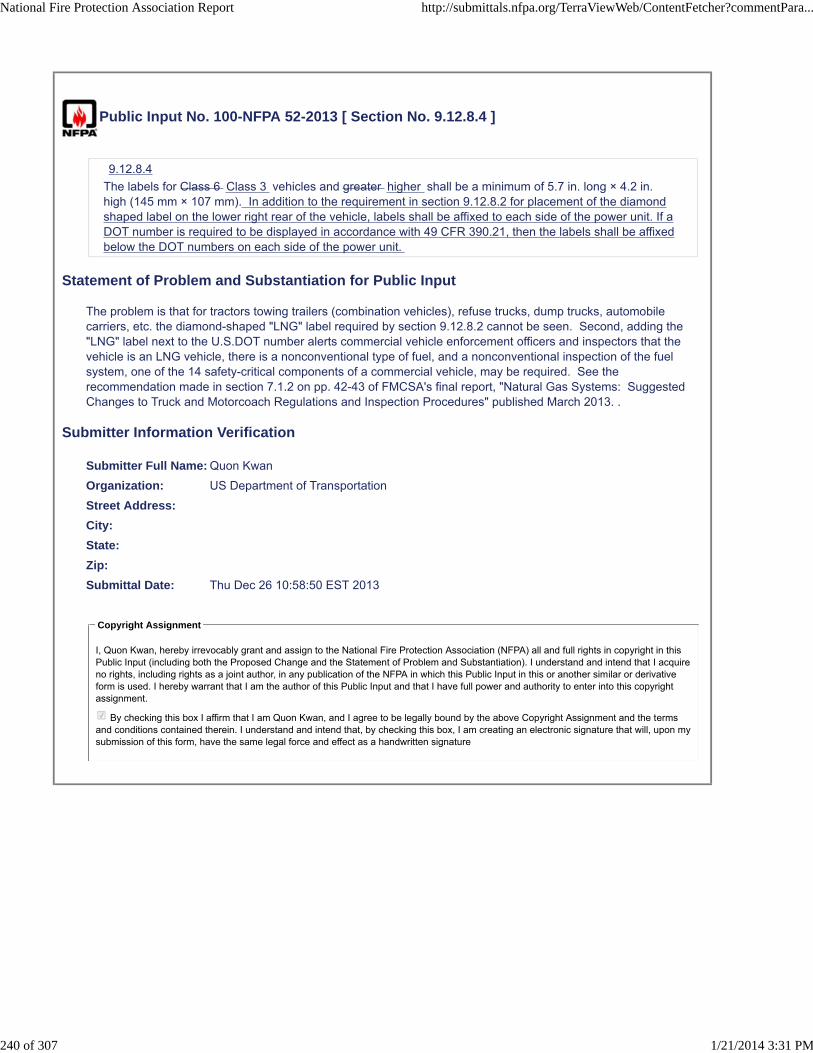
Public Input No. 100-NFPA 52-2013 [ Section No. 9.12.8.4 ]
9.12.8.4
The labels for Class 6 Class 3 vehicles and greater higher shall be a minimum of 5.7 in. long × 4.2 in.high (145 mm × 107 mm). In addition to the requirement in section 9.12.8.2 for placement of the diamondshaped label on the lower right rear of the vehicle, labels shall be affixed to each side of the power unit. If aDOT number is required to be displayed in accordance with 49 CFR 390.21, then the labels shall be affixedbelow the DOT numbers on each side of the power unit.
Statement of Problem and Substantiation for Public Input
The problem is that for tractors towing trailers (combination vehicles), refuse trucks, dump trucks, automobile carriers, etc. the diamond-shaped "LNG" label required by section 9.12.8.2 cannot be seen. Second, adding the "LNG" label next to the U.S.DOT number alerts commercial vehicle enforcement officers and inspectors that the vehicle is an LNG vehicle, there is a nonconventional type of fuel, and a nonconventional inspection of the fuel system, one of the 14 safety-critical components of a commercial vehicle, may be required. See the recommendation made in section 7.1.2 on pp. 42-43 of FMCSA's final report, "Natural Gas Systems: Suggested Changes to Truck and Motorcoach Regulations and Inspection Procedures" published March 2013. .
Submitter Information Verification
Submitter Full Name: Quon Kwan
Organization: US Department of Transportation
Street Address:
City:
State:
Zip:
Submittal Date: Thu Dec 26 10:58:50 EST 2013
Copyright Assignment
I, Quon Kwan, hereby irrevocably grant and assign to the National Fire Protection Association (NFPA) all and full rights in copyright in thisPublic Input (including both the Proposed Change and the Statement of Problem and Substantiation). I understand and intend that I acquireno rights, including rights as a joint author, in any publication of the NFPA in which this Public Input in this or another similar or derivativeform is used. I hereby warrant that I am the author of this Public Input and that I have full power and authority to enter into this copyrightassignment.
By checking this box I affirm that I am Quon Kwan, and I agree to be legally bound by the above Copyright Assignment and the termsand conditions contained therein. I understand and intend that, by checking this box, I am creating an electronic signature that will, upon mysubmission of this form, have the same legal force and effect as a handwritten signature
National Fire Protection Association Report http://submittals.nfpa.org/TerraViewWeb/ContentFetcher?commentPara...
240 of 307 1/21/2014 3:31 PM

Public Input No. 123-NFPA 52-2013 [ Section No. 9.12.10 [Excluding any Sub-Sections] ]
A fully engineered LNG onboard engineered onboard application methane detection system shall bevalidated and installed for each vehicle configuration and application and shall be certified by a qualifiedengineer with expertise in fire safety and gaseous fuels.
Statement of Problem and Substantiation for Public Input
Because of the proposed revision in section 5.2.1.1.1 to make section 9.12.10 applicable to vehicles using L/CNG or un-odorized CNG, the term "LNG" is deleted from section 9.12.10.
Submitter Information Verification
Submitter Full Name: Quon Kwan
Organization: US Department of Transportation
Street Address:
City:
State:
Zip:
Submittal Date: Fri Dec 27 09:39:40 EST 2013
Copyright Assignment
I, Quon Kwan, hereby irrevocably grant and assign to the National Fire Protection Association (NFPA) all and full rights in copyright in thisPublic Input (including both the Proposed Change and the Statement of Problem and Substantiation). I understand and intend that I acquireno rights, including rights as a joint author, in any publication of the NFPA in which this Public Input in this or another similar or derivativeform is used. I hereby warrant that I am the author of this Public Input and that I have full power and authority to enter into this copyrightassignment.
By checking this box I affirm that I am Quon Kwan, and I agree to be legally bound by the above Copyright Assignment and the termsand conditions contained therein. I understand and intend that, by checking this box, I am creating an electronic signature that will, upon mysubmission of this form, have the same legal force and effect as a handwritten signature
National Fire Protection Association Report http://submittals.nfpa.org/TerraViewWeb/ContentFetcher?commentPara...
241 of 307 1/21/2014 3:31 PM

Public Input No. 117-NFPA 52-2013 [ Section No. 9.12.10.3 ]
9.12.10.3
The gas detection system shall function continuously at all times whether or not the engine is operating orthe vehicle is on roadways.
9.12.10.3.1
Gas detection systems shall be permitted to be disconnected during electrical maintenance when detectionis provided within the service area.
Statement of Problem and Substantiation for Public Input
I received a complaint about this section 9.12.10.3.
It is preposterous to require that the gas detection system to function at all times whether or not the engine is running. If the engine is not running, the batteries will die out because the gas detection system will drain all the electric energy over a prolonged period of time (e.g., driver taking a required 8-hour rest due to the hours of service rule or parking the vehicle overnight at a rest area where there are no services for a radius of 50 miles). After all, batteries have a limited discharge life. Moreover, the likelihood of dead batteries is much, much higher than the likelihood of a leak from the LNG fuel system; the batteries will die out far sooner than will a leak ever occur over a prolonged period of time. Mandating a rule resulting in dead batteries makes as much sense as a rule banning LNG vehilces. Parking such a vehicle outdoors without requiring that the gas detectors be turned on should be sufficiently safe. If it is necessary to park such a vehicle indoors, requiring that the indoor facility be compliant with NFPA 12.7 is sufficient.
Submitter Information Verification
Submitter Full Name: Quon Kwan
Organization: US Department of Transportation
Street Address:
City:
State:
Zip:
Submittal Date: Thu Dec 26 14:51:17 EST 2013
Copyright Assignment
I, Quon Kwan, hereby irrevocably grant and assign to the National Fire Protection Association (NFPA) all and full rights in copyright in thisPublic Input (including both the Proposed Change and the Statement of Problem and Substantiation). I understand and intend that I acquireno rights, including rights as a joint author, in any publication of the NFPA in which this Public Input in this or another similar or derivativeform is used. I hereby warrant that I am the author of this Public Input and that I have full power and authority to enter into this copyrightassignment.
By checking this box I affirm that I am Quon Kwan, and I agree to be legally bound by the above Copyright Assignment and the termsand conditions contained therein. I understand and intend that, by checking this box, I am creating an electronic signature that will, upon mysubmission of this form, have the same legal force and effect as a handwritten signature
National Fire Protection Association Report http://submittals.nfpa.org/TerraViewWeb/ContentFetcher?commentPara...
242 of 307 1/21/2014 3:31 PM

Public Input No. 120-NFPA 52-2013 [ Section No. 9.13.2 ]
9.13.2
When a vehicle is involved in an accident or fire causing damage to the LNG fuel system container, thesystem, container, or both shall be inspected, repaired, or removed and retested before being restored toservice. The mechanic performing the inspection, repair, replacement, and/or retesting shall prepare adocument certifying that the LNG fuel system container, the system, container or both are acceptable forreturn to service and present the document to be retained by the vehicle's owner/operator and a copy to beretained by himself. The document shall identify the vehicle (by license number or vehicle identificationnumber); parts of the LNG fuel system worked on; describe the work done and dates of work; and providethe mechanic's name and contact information.
Statement of Problem and Substantiation for Public Input
The documentation of the repair and testing was recommended in section 7.1.4 on pp. 44-45 of FMCSA's final Report, "Natural Gas Systems: Suggested Changes to Truck and Motorcoach REgulations and Inspection Procedures" published March 2013. The purpose of the requirement for documentation is to provide a paper trail for accountability.
Submitter Information Verification
Submitter Full Name: Quon Kwan
Organization: US Department of Transportation
Street Address:
City:
State:
Zip:
Submittal Date: Fri Dec 27 09:19:44 EST 2013
Copyright Assignment
I, Quon Kwan, hereby irrevocably grant and assign to the National Fire Protection Association (NFPA) all and full rights in copyright in thisPublic Input (including both the Proposed Change and the Statement of Problem and Substantiation). I understand and intend that I acquireno rights, including rights as a joint author, in any publication of the NFPA in which this Public Input in this or another similar or derivativeform is used. I hereby warrant that I am the author of this Public Input and that I have full power and authority to enter into this copyrightassignment.
By checking this box I affirm that I am Quon Kwan, and I agree to be legally bound by the above Copyright Assignment and the termsand conditions contained therein. I understand and intend that, by checking this box, I am creating an electronic signature that will, upon mysubmission of this form, have the same legal force and effect as a handwritten signature
National Fire Protection Association Report http://submittals.nfpa.org/TerraViewWeb/ContentFetcher?commentPara...
243 of 307 1/21/2014 3:31 PM

Public Input No. 121-NFPA 52-2013 [ New Section after 9.13.3.2.4.3 ]
9.14 Qualified Mechanics
9.14.1 All personnel engaged in inspection, maintenance, repair, replacement, removal, and testing of LNGfuel system or its components shall be qualified mechanics, as described below.
9.14. 2 A qualified mechanic is a mechanic who has:
(1) successfully completed an apprenticeship program sponsored by a State, a Canadian Province, aFederal agency or a labor union, or a training program approved by a State, Provincial, or Federal agency,or has a certificate from such an apprenticeship program or training program which qualifies the person toperform the assigned natural gas fuel system service task, or
(2) natural gas fuel system-related training or experience or a combination thereof totaling at least 1 year.Such training or experience may consist of:
(A) participation in a training program sponsored by a natural gas fuel system orvehicle manufacturer, natural gas fuel system component manufacturer, or naturalgas fuel system installer, or similar commercial training program designed to trainstudents in natural gas fuel system maintenance or inspection similar to theassigned natural gas fuel system service or inspection tasks; or
(B) experience performing natural gas fuel system maintenance or inspectionsimilar to the assigned natural gas fuel system service or inspection task in his/heremployer's natural gas vehicle maintenance program; or
(C) experience performing natural gas fuel system maintenance or inspectionsimilar to the assigned natural gas fuel system service or inspection task at acommercial garage, fleet leasing company, or similar facility.
9.14.3 Evidence of the mechanic's qualifications, required under this section, must be maintained by themechanic or his/her employer at its principal place of business, or at the location at which the mechanic isemployed. The evidence must be maintained for the period during which the mechanic is employed in thatcapacity and for 1 year thereafter.
Statement of Problem and Substantiation for Public Input
Qualifications for mechanics were recommended in section 7.1.3 on pp. 43-44 of FMCSA's final report, "Natural Gas Systems: Suggested Changes to Truck and Motorcoach Regulations and Inspection Procedures," published March 2013.
Submitter Information Verification
Submitter Full Name: Quon Kwan
Organization: US Department of Transportation
Street Address:
City:
State:
Zip:
Submittal Date: Fri Dec 27 09:30:59 EST 2013
National Fire Protection Association Report http://submittals.nfpa.org/TerraViewWeb/ContentFetcher?commentPara...
244 of 307 1/21/2014 3:31 PM

Copyright Assignment
I, Quon Kwan, hereby irrevocably grant and assign to the National Fire Protection Association (NFPA) all and full rights in copyright in thisPublic Input (including both the Proposed Change and the Statement of Problem and Substantiation). I understand and intend that I acquireno rights, including rights as a joint author, in any publication of the NFPA in which this Public Input in this or another similar or derivativeform is used. I hereby warrant that I am the author of this Public Input and that I have full power and authority to enter into this copyrightassignment.
By checking this box I affirm that I am Quon Kwan, and I agree to be legally bound by the above Copyright Assignment and the termsand conditions contained therein. I understand and intend that, by checking this box, I am creating an electronic signature that will, upon mysubmission of this form, have the same legal force and effect as a handwritten signature
National Fire Protection Association Report http://submittals.nfpa.org/TerraViewWeb/ContentFetcher?commentPara...
245 of 307 1/21/2014 3:31 PM

Public Input No. 110-NFPA 52-2013 [ Chapter 10 ]
Chapter 10 LNG Fueling Facilities
10.1 Application.
10.1.1
This chapter applies to the design, siting, construction, installation, spill containment, and operation ofcontainers, pressure vessels, pumps, vaporization equipment, buildings, structures, and associatedequipment used for the storage and dispensing of LNG and L/CNG as engine fuel for vehicles of all types.
10.1.2
All dispensing of LNG, including mobile refueling, into vehicle onboard fuel systems shall comply with therequirements of a permanent LNG refueling installation at the point of dispensing fuel.
10.2 Facility Design.
National Fire Protection Association Report http://submittals.nfpa.org/TerraViewWeb/ContentFetcher?commentPara...
246 of 307 1/21/2014 3:31 PM

10.2.1 General.
10.2.1.1
LNG fueling facilities that are permitted to be unattended shall be designed to secure all equipment fromtampering.
10.2.1.2
Storage and transfer equipment at unattended facilities shall be secured to prevent tampering.
10.2.1.3
Operating instructions identifying the location and operation of emergency controls shall be postedconspicuously in the facility area.
10.2.1.4
LNG fueling facilities transferring LNG during the night shall have permanent, adequate lighting at points oftransfer and operation.
10.2.1.5
Designers, fabricators, and constructors of LNG fueling facilities shall be competent in the design,fabrication, and construction of LNG containers, cryogenic equipment, loading and unloading systems, fireprotection equipment, methane detection, and other components of the facility.
10.2.1.6
Supervision shall be provided for the fabrication, construction, and acceptance tests of facility componentsto the extent necessary to ensure that facilities are structurally sound, suitable for the service, andotherwise in compliance with this code.
10.2.1.7
LNG refueling sites utilizing or dispensing saturated LNG with personnel in the immediate vicinity shallprovide barrier walls or equal protection in order to protect the refueling operator and vehicle.
10.2.1.8
All facility piping other than the refueling hose to the vehicle shall be behind a barrier, which in the case ofan equipment or device malfunction deflects the saturated LNG upward.
10.2.2 Siting.
10.2.2.1
LNG tanks and their associated equipment shall not be located where exposed to failure of overheadelectric power lines operating over 600 volts.
10.2.2.2
Vaulted or underground installations shall be deemed to provide engineered protection from overheadpower lines.
10.2.2.3
If other combustible or hazardous liquids are able to encroach on the LNG fueling facility, means shall beprovided to protect the LNG facility.
National Fire Protection Association Report http://submittals.nfpa.org/TerraViewWeb/ContentFetcher?commentPara...
247 of 307 1/21/2014 3:31 PM
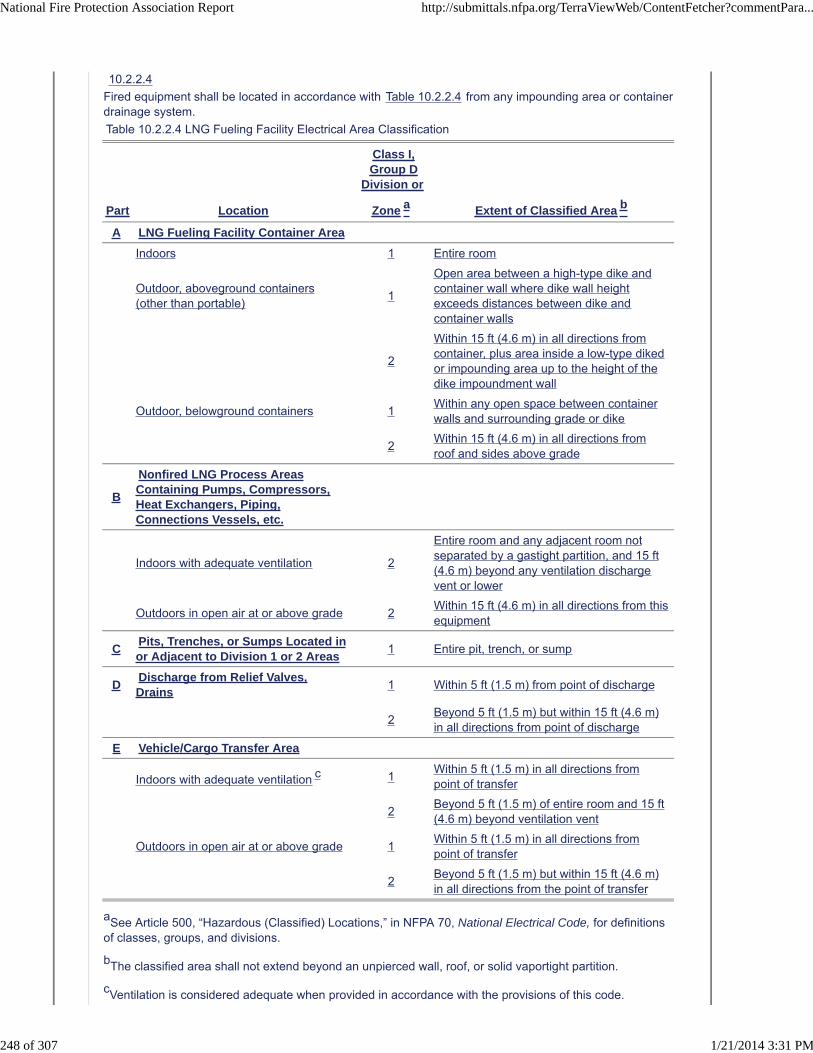
10.2.2.4
Fired equipment shall be located in accordance with Table 10.2.2.4 from any impounding area or containerdrainage system.
Table 10.2.2.4 LNG Fueling Facility Electrical Area Classification
Part Location
Class I,Group D
Division or
Zone a Extent of Classified Area b
A LNG Fueling Facility Container Area
Indoors 1 Entire room
Outdoor, aboveground containers(other than portable)
1
Open area between a high-type dike andcontainer wall where dike wall heightexceeds distances between dike andcontainer walls
2
Within 15 ft (4.6 m) in all directions fromcontainer, plus area inside a low-type dikedor impounding area up to the height of thedike impoundment wall
Outdoor, belowground containers 1Within any open space between containerwalls and surrounding grade or dike
2Within 15 ft (4.6 m) in all directions fromroof and sides above grade
B
Nonfired LNG Process AreasContaining Pumps, Compressors,Heat Exchangers, Piping,Connections Vessels, etc.
Indoors with adequate ventilation 2
Entire room and any adjacent room notseparated by a gastight partition, and 15 ft(4.6 m) beyond any ventilation dischargevent or lower
Outdoors in open air at or above grade 2Within 15 ft (4.6 m) in all directions from thisequipment
CPits, Trenches, or Sumps Located inor Adjacent to Division 1 or 2 Areas
1 Entire pit, trench, or sump
DDischarge from Relief Valves,Drains
1 Within 5 ft (1.5 m) from point of discharge
2Beyond 5 ft (1.5 m) but within 15 ft (4.6 m)in all directions from point of discharge
E Vehicle/Cargo Transfer Area
Indoors with adequate ventilation c 1Within 5 ft (1.5 m) in all directions frompoint of transfer
2Beyond 5 ft (1.5 m) of entire room and 15 ft(4.6 m) beyond ventilation vent
Outdoors in open air at or above grade 1Within 5 ft (1.5 m) in all directions frompoint of transfer
2Beyond 5 ft (1.5 m) but within 15 ft (4.6 m)in all directions from the point of transfer
aSee Article 500, “Hazardous (Classified) Locations,” in NFPA 70, National Electrical Code, for definitionsof classes, groups, and divisions.
bThe classified area shall not extend beyond an unpierced wall, roof, or solid vaportight partition.
cVentilation is considered adequate when provided in accordance with the provisions of this code.
National Fire Protection Association Report http://submittals.nfpa.org/TerraViewWeb/ContentFetcher?commentPara...
248 of 307 1/21/2014 3:31 PM

10.2.2.5
Points of transfer shall be located not less than 25 ft (7.6 m) from the nearest important building notassociated with the LNG facility, from the line of adjoining property that is able to be built upon, or fromfixed sources of ignition.
10.2.3 Spill Containment.
10.2.3.1
Site preparation shall include provisions for retention of spilled LNG within the limits of plant property andfor surface water drainage.
10.2.3.1.1
Saturated LNG in an ASME container [50 psi (345 kPa) and above] shall only have to meet therequirements of 10.2.3.1 with respect to construction of the impounding area.
10.2.3.2
Enclosed drainage channels for LNG shall be prohibited.
10.2.3.3 *
Impounding areas, if provided to serve LNG transfer areas, shall have a minimum volumetric capacityequal to the greatest volume of LNG or flammable liquid that could be discharged into the area during a10-minute period from any single accidental leakage source or a lesser time period based on demonstrablesurveillance and shutdown provisions acceptable to the AHJ.
10.2.3.4
Flammable liquid storage tanks shall not be located within an LNG container impounding area.
10.2.3.5 *
Impounding areas serving LNG containers shall have a minimum volumetric holding capacity, V, includingany useful holding capacity of the drainage area and with allowance made for the displacement of snowaccumulation, other containers, and equipment, in accordance with 10.2.3.5.1 and 10.2.3.5.2.
10.2.3.5.1
For impounding areas serving one or more than one container with provisions made to prevent lowtemperature or fire exposure resulting from the leakage from any one container served from causingsubsequent leakage from any other container served, the volume of the dike shall be the total volume ofliquid in the largest container served, assuming the container is full.
10.2.3.5.2
For impounding areas serving more than one container without provisions made in accordance with10.2.3.5.1, the volume of the dike shall be the total volume of liquid in all containers served, assuming allcontainers are full.
10.2.3.6
The containment design shall include calculations and shall be installed to prevent overflow due to spillwave action.
10.2.3.7
The containment design shall prevent projecting LNG or cold gas beyond the containment area.
10.2.3.8
Provisions shall be made to clear rain or other water from the impounding area.
10.2.3.8.1
Automatically controlled sump pumps shall be permitted if equipped with an automatic cutoff device thatprevents their operation when exposed to LNG temperatures.
10.2.3.8.2
Piping, valves, and fittings whose failure permits liquid to escape from the impounding area shall bedesigned for continuous exposure to LNG temperatures.
10.2.3.8.3
If gravity drainage is employed for water removal, provisions shall be made to prevent the escape of LNGby way of the drainage system.
10.2.4 Indoor Fueling.
10.2.4.1 Building Construction.
10.2.4.1.1
Buildings reserved exclusively for an LNG fueling facility shall be of Type I or Type II construction inaccordance with NFPA 5000, Building Construction and Safety Code.
10.2.4.1.2
Windows and doors shall be located so as to permit ready egress in case of emergency.
National Fire Protection Association Report http://submittals.nfpa.org/TerraViewWeb/ContentFetcher?commentPara...
249 of 307 1/21/2014 3:31 PM

10.2.4.2 * Deflagration Venting.
10.2.4.2.1
Deflagration venting shall be provided only in the exterior walls or the roof.
10.2.4.2.2
Vents shall consist of any one or a combination of the following:
(1) Walls of light material
(2) Lightly fastened hatch covers
(3) Lightly fastened, outward-opening doors in exterior walls
(4) Lightly fastened walls or roof
10.2.4.2.3
Ventilation shall be by a continuous mechanical ventilation system or by a mechanical ventilation systemactivated by a continuously monitoring natural gas detection system when a gas concentration of not morethan one-fifth of the LFL is present.
10.2.4.2.4
In either case, the system shall shut down the fueling system in the event of failure of the ventilationsystem.
10.2.4.2.5
Failures of any controllers used by the system shall result in a safe condition.
10.2.4.2.6 *
The ventilation rate shall be at least 1 ft3/min/12 ft3 (0.03 m3/min/0.34 m3) of room volume.
10.2.4.3
Reactivation of the fueling system shall be by manual restart conducted by trained personnel and inaccordance with a process safety analysis.
10.2.4.4
A gas detection system shall be provided in all buildings containing LNG.
10.2.4.4.1
The gas detection system shall activate a latched alarm when a maximum of 20 percent of the LFL isreached.
10.2.4.4.2
The alarm shall be clearly audible and visible both inside and outside the whole building and potentialaffected area.
10.2.4.4.3
The gas detection system shall not be shut down during fueling operations.
10.2.4.5
Dispensing equipment located inside or attached to buildings used for other purposes shall comply withthe following:
(1) The dispensing room shall have a minimum of one external wall.
(2) Interior walls or partitions shall be continuous from floor to ceiling, be anchored in accordance withthe building code, and have a fire resistance rating of at least 2 hours.
(3) The interior finish of the dispensing room shall be constructed of noncombustible or limited-combustible materials. (See Section 4.5 for noncombustible or limited-combustible.)
(4) In the interior walls of the dispensing room, doors shall be listed as 1-hour self-closing fire doors thatare installed in accordance with NFPA 80, Standard for Fire Doors and Other Opening Protectives.
(5) A ventilation system for a dispensing room within or attached to another building shall be separatedfrom any ventilation system for the other building.
(6) Access to the dispensing room shall be from outside the primary structure only.
10.2.4.5.1
Access from within the primary structure shall be permitted where such access is made through a barrierspace having two vapor-sealing, self-closing fire doors having a fire resistance rating equal to that of thewall.
National Fire Protection Association Report http://submittals.nfpa.org/TerraViewWeb/ContentFetcher?commentPara...
250 of 307 1/21/2014 3:31 PM

10.2.4.6
Access doors or fire doors shall be kept unobstructed at all times.
10.2.4.7
Signs and markings and the words “WARNING — NO SMOKING” shall be in red letters at least 1 in. (25mm) high on a white background.
10.2.4.8
LNG piping entering a building shall be provided with shutoff valves located outside the building.
10.2.4.9
Buildings and rooms used for storage or dispensing shall be classified in accordance with Table 10.2.2.4for installations of electrical equipment.
10.3 Cargo Transport Unloading.
10.3.1
Section 10.3 shall apply to the transfer of LNG between cargo transport containers and fueling facilitycontainers.
10.3.2
When transfers are made into fueling facility containers, the LNG shall be transferred at a pressure thatdoes not overpressurize the receiving tank.
10.3.2.1
Venting of on-site containers shall be done only under emergency conditions and in a manner acceptableto the authority having jurisdiction.
10.3.3 Isolation Valves.
10.3.3.1
The transfer piping shall have isolation valves at both ends.
10.3.3.2
On facility containers with a capacity greater than 2000 gal (7.6 m3), one remotely operated valve,automatic closing valve, or check valve shall be used to prevent backflow.
10.3.4
If the fueling facility tank or transfer equipment is located in a remote area, operating status indicators, suchas those that indicate container level, shall be provided in the unloading area.
10.3.5
At least one qualified person shall be in continuous attendance with an unobstructed view of the transferpoint while unloading is in progress.
10.3.6
Sources of ignition shall not be permitted in the unloading area while transfer is in progress.
10.3.7 Methane Detection.
10.3.7.1
Offloading site methane detection and fire protection shall be provided.
10.3.7.2
The methane detection system shall be capable of detection at multiple locations beyond the full radius ofthe transfer hose, measured at each point of transfer and receipt of LNG.
10.3.8 Bleed Connections.
10.3.8.1
Bleed or vent connections shall be provided so that loading arms and hoses can be drained anddepressurized prior to disconnection if necessary.
10.3.8.2
The connections shall relieve to a safe area.
10.3.9
Prior to connection, a cargo transport vehicle's wheels shall be rendered immobile.
10.3.10
The cargo transport vehicle's engine shall be shut off while the transfer hose or piping is being connectedor disconnected.
10.3.11
If required for LNG transfer, the engine shall be permitted to be started and used during the liquid transferoperations.
National Fire Protection Association Report http://submittals.nfpa.org/TerraViewWeb/ContentFetcher?commentPara...
251 of 307 1/21/2014 3:31 PM

10.3.12
The LNG cargo transport unloading connection shall be at least 1.5 ft (0.46 m) from a storage container.
10.4 Vehicle Fuel Dispensing Systems.
10.4.1
The dispensing device shall be protected from vehicle collision damage.
10.4.2
An ESD shall be provided that includes a shutoff valve for stopping liquid supply and shutting down transferequipment.
10.4.3
An ESD actuator, distinctly marked for easy recognition with a permanently affixed, legible sign, shall beprovided within 10 ft (3.1 m) of the dispenser and also at a safe, remote location.
10.4.4
The maximum delivery pressure at the fueling nozzle shall not exceed the maximum allowable pressure ofthe vehicle fuel tanks.
10.4.5
Hose and arms shall be equipped with a shutoff valve at the fuel end and a breakaway device to minimizerelease of liquid and vapor in the event that a vehicle pulls away while the hose remain connected.
10.4.5.1
Such a device shall be installed and maintained in accordance with the OEM component manufacturer'smaintenance/safety instructions.
10.4.6
When not in use, hose shall be secured to protect it from damage.
10.4.7
Where a hose or arm of nominal 3 in. (76 mm) diameter or larger is used for liquid transfer or where one ofnominal 4 in. (100 mm) diameter or larger is used for vapor transfer, an emergency shutoff valve shall beinstalled in the piping of the transfer system within 10 ft (3.1 m) from the nearest end of the hose or arm.
10.4.7.1
Where the flow is away from the hose, a check valve shall be permitted to be used as the shutoff valve.
10.4.7.2
Where either a liquid or vapor line has two or more legs, an emergency shutoff valve shall be installedeither in each leg or in the feed line before the legs.
10.4.8 Bleed Connections.
10.4.8.1
Bleed or vent connections shall be provided so that loading arms and hose can be drained anddepressurized prior to disconnection if necessary.
10.4.8.2
Bleed or vent connections shall lead to a safe point of discharge.
10.4.9
A fueling connector and mating vehicle receptacle shall be used for reliable, safe, and secure transfer ofLNG or gas vapor to or from the vehicle, with minimal leakage.
10.4.10
The fueling connector either shall be equipped with an interlock device that prevents release while the lineis open or have self-closing ends that automatically close upon disconnection.
10.4.11
The transfer of LNG into vehicular onboard fuel containers shall be performed in accordance with theonboard tank and refueling component OEM manufacturer's instructions.
10.4.11.1
The OEM manufacturer's instructions shall be posted at the dispensing device.
10.4.12
The spacing of LNG dispensing equipment relative to other equipment, activities, nearby property lines,and other exposures in a fuel dispensing forecourt shall be approved by the AHJ.
National Fire Protection Association Report http://submittals.nfpa.org/TerraViewWeb/ContentFetcher?commentPara...
252 of 307 1/21/2014 3:31 PM

10.4.13
The provisions of Section 10.4 shall not apply to dispensing from vehicle-mounted tanks located atcommercial and industrial facilities used in connection with their business where the following conditionsare met:
(1) An inspection of the premises and operations shall have been made and approval granted by theAHJ.
(2) The vehicle-mounted container shall comply with requirements of DOT.
(3) The dispensing hose shall not exceed 50 ft (15 m) in length.
(4) Nighttime deliveries shall be made only in lighted areas.
10.5 Piping Systems and Components.
Piping shall be in accordance with Chapter 13.
10.6 Safety and Relief Valves.
10.6.1
Pressure relieving safety devices shall be so arranged that the possibility of damage to piping orappurtenances is reduced to a minimum.
10.6.2
The means for adjusting relief valve set pressure shall be sealed.
10.6.3
Stationary LNG containers shall be equipped with pressure relief devices in accordance with CGA S-1.3,Pressure Relief Device Standards — Part 3 — Stationary Storage Containers for Compressed Gases.
10.6.4
A thermal expansion relief valve shall be installed as required to prevent overpressure in any section of aliquid or cold vapor pipeline that can be isolated by valves.
10.6.4.1
Thermal expansion relief valves shall be set to discharge above the maximum pressure expected in theline but less than the rated test pressure of the line it protects.
10.6.4.2
Discharge from thermal expansion relief valves shall be directed so as to minimize hazard to personnel andother equipment.
10.7 Corrosion Control.
10.7.1
Underground and submerged piping shall be protected and maintained in accordance with the principles ofNACE RP0169, Control of External Corrosion of Underground or Submerged Metallic Piping Systems.
10.7.2
Austenitic stainless steels and aluminum alloys shall be protected to minimize corrosion and pitting fromcorrosive atmospheric and industrial substances during storage, construction, fabrication, testing, andservice.
10.7.2.1
These substances shall include, but not be limited to, chlorides and compounds of sulfur or nitrogen.
10.7.2.2
Tapes or other packaging materials that are corrosive to the pipe or piping components shall not be used.
10.7.2.3
Where insulation materials cause corrosion of aluminum or stainless steels, inhibitors or waterproofbarriers shall be utilized.
10.7.3
Corrosion protection of all other materials shall be in accordance with the requirements of SSPC-PA 1,Shop, Field and Maintenance Painting; SSPC-PA 2, Measurement of Dry Paint Thickness with MagneticGages; and SSPC-SP 6, Commercial Blast Cleaning.
10.8 Stationary Pumps and Compressors.
10.8.1
Valves shall be installed such that each pump or compressor can be isolated for maintenance.
National Fire Protection Association Report http://submittals.nfpa.org/TerraViewWeb/ContentFetcher?commentPara...
253 of 307 1/21/2014 3:31 PM

10.8.2
Where pumps or centrifugal compressors are installed for operation in parallel, each discharge line shall beequipped with a check valve.
10.8.3
Foundations and sumps for cryogenic pumps shall be designed and constructed to prevent frost heaving.
10.8.4
Operation of all pumps and compressors shall cease when the facility's ESD system is initiated.
10.8.5
Each pump shall be provided with a vent or relief valve that prevents overpressurizing of the pump caseunder all conditions, including the maximum possible rate of cool down.
10.8.6
Compression equipment handling flammable gases shall be provided with vent line connections from allpoints, including distance pieces of packing for piston rods, where gases escape.
10.8.7
Vents shall be piped outside of buildings to a point of safe disposal.
10.9 Vaporizers.
10.9.1
Multiple vaporizers shall be manifolded such that both inlet and discharge block valves are installed oneach vaporizer.
10.9.2
If the intermediate fluid used with a remote heated vaporizer is flammable, shutoff valves shall be providedon both the hot and cold lines of the intermediate fluid system.
10.9.3
A low temperature switch or other accepted means shall be installed on the vaporizer discharge toeliminate the possibility of LNG or cold natural gas entering CNG containers and other equipment notdesigned for LNG temperatures.
10.9.4
Relief valves on heated vaporizers shall be located so that they are not subjected to temperaturesexceeding 140°F (60°C) during normal operation unless they are designed to withstand highertemperatures.
10.9.5
The combustion air required for the operation of integral heated vaporizers or the primary heat source forremote heated vaporizers shall be taken from outside an enclosed structure or building.
10.9.6
Vaporizers for purposes other than pressure building coils or LNG-to-CNG (L/CNG) systems shall be inaccordance with NFPA 59A, Standard for the Production, Storage, and Handling of Liquefied Natural Gas(LNG).
10.9.7
Installation of internal combustion engines or gas turbines shall conform to NFPA 37, Standard for theInstallation and Use of Stationary Combustion Engines and Gas Turbines.
10.9.8
The vaporizer shall be anchored and its connecting piping shall be sufficiently flexible to provide for theeffect of expansion and contraction due to temperature change.
10.10 LNG-to-CNG (L/CNG) Systems.
National Fire Protection Association Report http://submittals.nfpa.org/TerraViewWeb/ContentFetcher?commentPara...
254 of 307 1/21/2014 3:31 PM

10.10.1
Section 10.10 shall apply to the design, construction, installation, and operation of equipment used toproduce CNG from LNG.
10.10.2
The process shall be permitted to be accomplished by pumping LNG to high pressure and vaporizing it orby compressing vapor from an LNG tank.
10.10.3
In addition to the emergency shutdown systems described in Section 10.4, the emergency shutdownsystem also shall shut off the liquid supply and power to the LNG transfer equipment necessary forproducing CNG from LNG.
10.10.4
Compressors, vaporizers, and CNG storage cylinders shall not be located inside the facility impoundingarea.
10.10.4.1
Ambient and remotely heated vaporizers shall be permitted to be located inside the facility impoundingarea.
10.10.5
Transfer piping, pumps, and compressors shall be protected from vehicle collision damage.
10.10.6
L/CNG natural gas refueling site and automotive applications shall not be required to utilize an odorant ifan engineered and validated methane detection system is in place.
10.10.7
Unodorized L/CNG natural gas shall not be dispensed at public refueling stations.
10.10.8
Refueling stations dispensing odorant shall have safety measures in place to automatically and completelyshut down all dispensing of L/CNG if the odorant supply is inadequate.
10.10.9
Refueling station odorant dispensing equipment shall be certified by the dispenser OEM for automotiverefueling station applications.
10.10.10
Dispensing of odorant for automotive natural gas applications shall conform to the federal standards fornatural gas pipeline percentages of odorant within the gaseous mixture.
10.10.11
Onboard methane detection shall be required for vehicles that utilize unodorized natural gas or that do notmeet the federal standards for pipeline gas odorization.
10.11 Instrumentation.
10.11.1 Pressure Gauging.
Pressure gauges shall be installed on each pump and compressor discharge.
10.11.2 Temperature Instruments.
10.11.2.1
Vaporizers and heaters shall be provided with instrumentation to monitor outlet temperatures.
10.11.2.1.1
Ambient pressure–building coil vaporizers that are fed with liquid from, and return vapor to, a containershall not be subject to 10.11.2.1.
10.11.2.2
Temperature monitoring systems shall be provided where the foundations supporting cryogenic containersand equipment are subject to adverse effects by freezing or frost heaving of the ground.
10.11.3 Emergency Shutdown Device (ESD).
10.11.3.1
Instrumentation for LNG fueling facilities shall be designed so that, in the event of a power orinstrumentation failure, the system goes into a fail-safe condition until the operators either reactivate orshut down the system.
10.11.3.2
All ESDs shall be manually reset.
10.12 Electrical Equipment.
National Fire Protection Association Report http://submittals.nfpa.org/TerraViewWeb/ContentFetcher?commentPara...
255 of 307 1/21/2014 3:31 PM
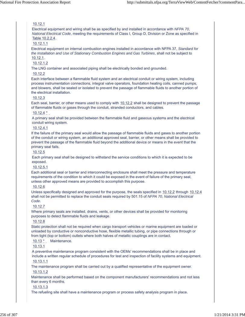
10.12.1
Electrical equipment and wiring shall be as specified by and installed in accordance with NFPA 70,National Electrical Code, meeting the requirements of Class I, Group D, Division or Zone as specified inTable 10.2.2.4.
10.12.1.1
Electrical equipment on internal combustion engines installed in accordance with NFPA 37, Standard forthe Installation and Use of Stationary Combustion Engines and Gas Turbines, shall not be subject to10.12.1.
10.12.1.2
The LNG container and associated piping shall be electrically bonded and grounded.
10.12.2
Each interface between a flammable fluid system and an electrical conduit or wiring system, includingprocess instrumentation connections, integral valve operators, foundation heating coils, canned pumps,and blowers, shall be sealed or isolated to prevent the passage of flammable fluids to another portion ofthe electrical installation.
10.12.3
Each seal, barrier, or other means used to comply with 10.12.2 shall be designed to prevent the passageof flammable fluids or gases through the conduit, stranded conductors, and cables.
10.12.4 *
A primary seal shall be provided between the flammable fluid and gaseous systems and the electricalconduit wiring system.
10.12.4.1
If the failure of the primary seal would allow the passage of flammable fluids and gases to another portionof the conduit or wiring system, an additional approved seal, barrier, or other means shall be provided toprevent the passage of the flammable fluid beyond the additional device or means in the event that theprimary seal fails.
10.12.5
Each primary seal shall be designed to withstand the service conditions to which it is expected to beexposed.
10.12.5.1
Each additional seal or barrier and interconnecting enclosure shall meet the pressure and temperaturerequirements of the condition to which it could be exposed in the event of failure of the primary seal,unless other approved means are provided to accomplish this purpose.
10.12.6
Unless specifically designed and approved for the purpose, the seals specified in 10.12.2 through 10.12.4shall not be permitted to replace the conduit seals required by 501.15 of NFPA 70, National ElectricalCode.
10.12.7
Where primary seals are installed, drains, vents, or other devices shall be provided for monitoringpurposes to detect flammable fluids and leakage.
10.12.8
Static protection shall not be required when cargo transport vehicles or marine equipment are loaded orunloaded by conductive or nonconductive hose, flexible metallic tubing, or pipe connections through orfrom tight (top or bottom) outlets where both halves of metallic couplings are in contact.
10.13 * Maintenance.
10.13.1
A preventive maintenance program consistent with the OEMs' recommendations shall be in place andinclude a written regular schedule of procedures for test and inspection of facility systems and equipment.
10.13.1.1
The maintenance program shall be carried out by a qualified representative of the equipment owner.
10.13.1.2
Maintenance shall be performed based on the component manufacturers' recommendations and not lessthan every 6 months.
10.13.1.3
The refueling site shall have a maintenance program or process safety analysis program in place.
National Fire Protection Association Report http://submittals.nfpa.org/TerraViewWeb/ContentFetcher?commentPara...
256 of 307 1/21/2014 3:31 PM

10.13.1.4
Maintenance records shall be kept for the duration of the refueling site's operation.
10.13.2
Each component in service, including its support system, shall be maintained in a condition that iscompatible with its operation or safety purpose by repair, replacement, or other means as determined bythe equipment OEM.
10.13.3
If a safety device is taken out of service for maintenance, the component being served by the device shallbe taken out of service unless the same safety function is provided by an alternative means.
10.13.4
If the inadvertent operation of a component taken out of service causes a hazardous condition, thatcomponent shall have a tag attached to its controls bearing the words DO NOT OPERATE or otherapproved warning.
10.13.4.1
All maintenance and servicing shall be done in accordance with 29 CFR 1910 for energy control.
10.13.5
LNG fueling facilities shall be free from rubbish, debris, and other material that present a fire hazard to adistance of at least 25 ft (7.6 m).
10.13.6
Grass areas on the LNG fueling facility grounds shall be maintained in a manner that does not present afire hazard.
10.13.7
Safety and fire protection equipment shall be tested or inspected at intervals not to exceed 6 months.
10.13.8
Maintenance activities on fire control equipment shall be scheduled so that a minimum of equipment istaken out of service at any one time and fire prevention safety is not compromised.
10.13.9
Access routes for movement of fire control equipment to an LNG fueling facility shall be maintained at alltimes.
Replace Chapter 10 with the attached Chapter 10 Indoor Storage developed by a NFPA 52 Task Group
Additional Proposed Changes
File Name Description Approved
NFPA_52_Public_Input_Chapter_10_Indoor_Storage.docx NFPA 52 Chapter 10 Indoor Storage
Statement of Problem and Substantiation for Public Input
The NFPA 52 Technical Committee approved the reorganization of NFPA 52 into an organizational layout that restructured requirements into General Requirements, Fuel Specific Requirements and Use Specific Requirements. This Chapter replaces existing Chapter 10 and was developed by a Task Group. For this draft being submitted as a Public Input, existing code sections have only been reorganized. No new or revised language has been included or any requirements deleted.
Submitter Information Verification
Submitter Full Name: Nancy Pehrson
Organization: CenterPoint Energy, Inc.
Street Address:
City:
State:
Zip:
Submittal Date: Thu Dec 26 13:15:34 EST 2013
National Fire Protection Association Report http://submittals.nfpa.org/TerraViewWeb/ContentFetcher?commentPara...
257 of 307 1/21/2014 3:31 PM

Copyright Assignment
I, Nancy Pehrson, hereby irrevocably grant and assign to the National Fire Protection Association (NFPA) all and full rights in copyright inthis Public Input (including both the Proposed Change and the Statement of Problem and Substantiation). I understand and intend that Iacquire no rights, including rights as a joint author, in any publication of the NFPA in which this Public Input in this or another similar orderivative form is used. I hereby warrant that I am the author of this Public Input and that I have full power and authority to enter into thiscopyright assignment.
By checking this box I affirm that I am Nancy Pehrson, and I agree to be legally bound by the above Copyright Assignment and theterms and conditions contained therein. I understand and intend that, by checking this box, I am creating an electronic signature that will,upon my submission of this form, have the same legal force and effect as a handwritten signature
National Fire Protection Association Report http://submittals.nfpa.org/TerraViewWeb/ContentFetcher?commentPara...
258 of 307 1/21/2014 3:31 PM

Chapter 10 Indoor Storage
10.1 Scope This section shall apply to the indoor storage of vehicular gas fuel systems in portable and stationary cylinders, containers, equipment, systems and tanks. 10.2 General (reserved) 10.3 CNG Supplemental 7.4.3 Indoors. 7.4.3.1 General. Compression, dispensing equipment, and storage containers connected for use shall be permitted to be located inside of buildings reserved exclusively for these purposes or in rooms within or attached to buildings used for other purposes in accordance with this section. 10.3 Limits of Storage in Buildings 7.4.3.2 Limits of Storage in Buildings. Storage shall be limited to not more than 10,000 scf (283 m3) of natural gas in each building or room. 7.4.3.2.1 CNG stored in vehicle-mounted fuel supply containers shall not be subject to 7.4.3.2. 10.4 Rooms within buildings 7.4.3.4 Rooms Within Buildings. 7.4.3.4.1 Rooms within or attached to other buildings shall be constructed of noncombustible or limited-combustible materials. 7.4.3.4.1.1 Window glazing shall be permitted to be plastic. 7.4.3.4.2 Interior walls or partitions shall be continuous from floor to ceiling, be anchored in accordance with the requirements of the building code, and have a fire resistance rating of at least 2 hours. 7.4.3.4.3 At least one wall shall be an exterior wall. 7.4.3.4.4 Explosion venting shall be provided in accordance with 7.4.3.3. 7.4.3.4.5 Access to the room shall be from outside the primary structure. 7.4.3.4.6 If access to the room from outside the primary structure is not possible, access from within the primary structure shall be permitted where such access is made through a barrier space having two vapor-sealing, self-closing fire doors rated for the location where installed. 10.5 Ventilation 7.4.3.5.4 Ventilation. 7.4.3.5.4.1 Ventilation shall be by a continuous mechanical ventilation system or by a mechanical ventilation system activated by a continuously monitoring natural gas detection system where a gas concentration of not more than one-fifth of the lower flammable limit is present. 7.4.3.5.4.2 In either case in 7.4.3.5.4.1, the system shall immediately shut down the fueling system in the event of detection of an alarm condition or failure of the ventilation system, the detection system, or the controls. 7.4.3.5.5* The ventilation rate shall be at least 1 ft3/min • 12 ft3 (0.03 m3/min • 0.34 m3) of room volume.
Commented [BS1]: This is a new section. This needs to be added as a PI

7.4.3.5.6 A ventilation system for a room within or attached to another building shall be separate from any ventilation system for the other building. 7.4.3.6 Where installed, a gas detection system shall be equipped to sound a latched alarm and visually indicate when a maximum of one-fifth of the lower flammable limit is reached. 7.4.3.7 Reactivation of the fueling system shall be by manual restart that is conducted by trained personnel. 7.4.3.8 Buildings and rooms used for compression, storage, and dispensing shall be classified in accordance with Table 7.4.2.9 for installations of electrical equipment. 7.4.3.9 Nonelectrical sources of ignition shall not be permitted. 7.4.3.10 Pressure relief devices on storage systems shall have pressure relief device channels [see 5.5.1(3)] to convey escaping gas to the outdoors and then upward to a safe area to prevent impinging on buildings, other equipment, or areas open to the public (e.g., sidewalks). 10.6 Ventilation inlets and outlets 7.4.3.5 Ventilation Inlets and Outlets. 7.4.3.5.1 Indoor locations shall be ventilated utilizing air supply inlets and exhaust outlets arranged to provide uniform air movement throughout the space. 7.4.3.5.2 Inlets shall be uniformly arranged on exterior walls near floor level. 7.4.3.5.3 Outlets shall be located in exterior walls at the high point of the room or in the roof. 10.8 PRVs 5.5.2.2 Pressure relief valves (PRVs) for CNG service shall not be fitted with lifting devices. 5.5.2.3 PRVs protecting ASME pressure vessels shall be repaired, adjusted, and tested in accordance with NB-23, National Board Inspection Code. 7.16.7* PRVs shall be maintained in safe operating condition 8.5 Installation of PRVs. PRVs shall have PRD vents or vent lines to convey escaping gas to the outdoors and then upward to prevent impinging on buildings, other equipment, or areas open to the public (e.g., sidewalks). 9.12.3.6 A PRV shall be installed in each section of piping or tubing in which LNG can be isolated between shutoff valves so as to relieve the trapped fuel pressure to a safe atmosphere. 9.12.3.7 The PRV shall not have a setting greater than the maximum allowable working pressure of the line it protects. 10.9 Shutoff valves 5.9.1.1 Shutoff valves shall have a rated service pressure not less than the rated service pressure of the entire system and shall be capable of withstanding a hydrostatic test of at least four times the rated service pressure without rupture. 6.6.2.4 Access to the manual shutoff valves shall not require the use of any key or tool. 7.11.4 Gas piping from an outdoor compressor or storage system into a building shall be provided with shutoff valves located outside the building. 10.11' Interior Walls

7.4.3.4.2 Interior walls or partitions shall be continuous from floor to ceiling, be anchored in accordance with the requirements of the building code, and have a fire resistance rating of at least 2 hours. 10.12 Exterior Walls 7.4.3.3.1 Deflagration (explosion) venting shall be provided in exterior walls or roof only. 7.4.3.3.2 Vents shall be permitted to consist of any one or any combination of the following: (1) Walls of light material (2) Lightly fastened hatch covers (3) Lightly fastened, outward opening doors in exterior walls 7.4.3.5.2 Inlets shall be uniformly arranged on exterior walls near floor level. 7.4.3.5.3 Outlets shall be located in exterior walls at the high point of the room or in the roof. 10.13Ventilation 4.4.1 7.4.3.5.4.1 Ventilation shall be by a continuous mechanical ventilation system or by a mechanical ventilation system activated by a continuously monitoring natural gas detection system where a gas concentration of not more than one-fifth of the lower flammable limit is present. 7.4.3.6 Where installed, a gas detection system shall be equipped to sound a latched alarm and visually indicate when a maximum of one-fifth of the lower flammable limit is reached. 7.4.3.12.2 The actuation of the gas detection system shall shut down the compressor and stop the flow of gas into the structure. . 10.2.4.2.3 10.14 Reactivation 7.4.3.7 Reactivation of the fueling system shall be by manual restart that is conducted by trained 10.16 Residential Storage (reserved) 10.17 Maintenance 7.16* System Maintenance. 7.16.1 Containers and their appurtenances, piping systems, compression equipment, controls, and detection devices shall be maintained in safe operating condition and according to manufacturers' instructions. 7.16.7* PRVs shall be maintained in safe operating condition. 7.16.8 Maintenance personnel shall be trained in leak detection procedures and equipment in accordance with manufacturers' recommendations. 10.4 LNG Supplemental Requirements See old 13.5.6

Public Input No. 20-NFPA 52-2013 [ Section No. 10.2.3.5 [Excluding any Sub-Sections] ]
Impounding areas serving aboveground and mounded LNG containers shall have a minimum volumetricholding capacity, V, including any useful holding capacity of the drainage area and with allowance made forthe displacement of snow accumulation, other containers, and equipment, in accordance with 10.2.3.5.1and 10.2.3.5.2.
Statement of Problem and Substantiation for Public Input
Impounding area capacity requirements to match extracted requirements from section 13.8.3 of NFPA 59A Production, Storage, and Handling of Liquefied Natural Gas (LNG) for above ground and mounded LNG containers.
Submitter Information Verification
Submitter Full Name: Nancy Pehrson
Organization: CenterPoint Energy, Inc.
Street Address:
City:
State:
Zip:
Submittal Date: Wed Dec 11 11:52:46 EST 2013
Copyright Assignment
I, Nancy Pehrson, hereby irrevocably grant and assign to the National Fire Protection Association (NFPA) all and full rights in copyright inthis Public Input (including both the Proposed Change and the Statement of Problem and Substantiation). I understand and intend that Iacquire no rights, including rights as a joint author, in any publication of the NFPA in which this Public Input in this or another similar orderivative form is used. I hereby warrant that I am the author of this Public Input and that I have full power and authority to enter into thiscopyright assignment.
By checking this box I affirm that I am Nancy Pehrson, and I agree to be legally bound by the above Copyright Assignment and theterms and conditions contained therein. I understand and intend that, by checking this box, I am creating an electronic signature that will,upon my submission of this form, have the same legal force and effect as a handwritten signature
National Fire Protection Association Report http://submittals.nfpa.org/TerraViewWeb/ContentFetcher?commentPara...
259 of 307 1/21/2014 3:31 PM

Public Input No. 21-NFPA 52-2013 [ Section No. 10.2.3.5.1 ]
10.2.3.5.1
For impounding areas serving one or more than one container with provisions made to prevent lowtemperature or fire exposure resulting from the leakage from any one container served from causingsubsequent leakage from any other container served, the volume of the dike shall be the total volume ofliquid in the largest container served, assuming the container is full.
Replce 10.2.3.5.1 with the following
Where containers in the dike area are constructed or protected to prevent failure from spilled LNG and firein the dike, the minimum holding of the dike shall be the volume of the largest container in the dike.
Statement of Problem and Substantiation for Public Input
Consistency with holding requirements of NFPA 59A Production, Storage, and Handling of Liquefied Natural Gas (LNG) extract language from 13.8.3 (1)
Submitter Information Verification
Submitter Full Name: Nancy Pehrson
Organization: CenterPoint Energy, Inc.
Street Address:
City:
State:
Zip:
Submittal Date: Wed Dec 11 12:00:30 EST 2013
Copyright Assignment
I, Nancy Pehrson, hereby irrevocably grant and assign to the National Fire Protection Association (NFPA) all and full rights in copyright inthis Public Input (including both the Proposed Change and the Statement of Problem and Substantiation). I understand and intend that Iacquire no rights, including rights as a joint author, in any publication of the NFPA in which this Public Input in this or another similar orderivative form is used. I hereby warrant that I am the author of this Public Input and that I have full power and authority to enter into thiscopyright assignment.
By checking this box I affirm that I am Nancy Pehrson, and I agree to be legally bound by the above Copyright Assignment and theterms and conditions contained therein. I understand and intend that, by checking this box, I am creating an electronic signature that will,upon my submission of this form, have the same legal force and effect as a handwritten signature
National Fire Protection Association Report http://submittals.nfpa.org/TerraViewWeb/ContentFetcher?commentPara...
260 of 307 1/21/2014 3:31 PM

Public Input No. 22-NFPA 52-2013 [ Section No. 10.2.3.5.2 ]
10.2.3.5.2
For impounding areas serving more than one container without provisions made in accordance with10.2.3.5.1, the volume of the dike shall be the total volume of liquid in all containers served, assuming allcontainers are full.
Replace with
Where containers in the dike area are not constructed or protected to prevent failure from spilled LNG andfire in the dike, the minimum holding of the dike shall be equal to the total volume of the containers in thedike area.
Statement of Problem and Substantiation for Public Input
Consistency with NFPA 59A Production, Storage, and Handling of Liquefied Natural Gas (LNG) regarding holding capacity of the dike extract langauge from 13.8.3 (2).
Submitter Information Verification
Submitter Full Name: Nancy Pehrson
Organization: CenterPoint Energy, Inc.
Street Address:
City:
State:
Zip:
Submittal Date: Wed Dec 11 12:10:49 EST 2013
Copyright Assignment
I, Nancy Pehrson, hereby irrevocably grant and assign to the National Fire Protection Association (NFPA) all and full rights in copyright inthis Public Input (including both the Proposed Change and the Statement of Problem and Substantiation). I understand and intend that Iacquire no rights, including rights as a joint author, in any publication of the NFPA in which this Public Input in this or another similar orderivative form is used. I hereby warrant that I am the author of this Public Input and that I have full power and authority to enter into thiscopyright assignment.
By checking this box I affirm that I am Nancy Pehrson, and I agree to be legally bound by the above Copyright Assignment and theterms and conditions contained therein. I understand and intend that, by checking this box, I am creating an electronic signature that will,upon my submission of this form, have the same legal force and effect as a handwritten signature
National Fire Protection Association Report http://submittals.nfpa.org/TerraViewWeb/ContentFetcher?commentPara...
261 of 307 1/21/2014 3:31 PM

Public Input No. 7-NFPA 52-2013 [ Section No. 10.2.4.2.6 ]
10.2.4.2.6 *
The ventilation rate shall be at least 1 ft 3 /min/12 ft 3 (0.03 m least 1CFM/12ft 3 (1m 3 /min/ 0 11 . 34 1
m 3 ) of room volume.
Statement of Problem and Substantiation for Public Input
Uses the standard acronym (CFM)for cubic feet per minute instead of the rate shown.
Submitter Information Verification
Submitter Full Name: John Chartier
Organization: Northeastern Regional Fire Cod
Street Address:
City:
State:
Zip:
Submittal Date: Fri Nov 08 07:39:26 EST 2013
Copyright Assignment
I, John Chartier, hereby irrevocably grant and assign to the National Fire Protection Association (NFPA) all and full rights in copyright in thisPublic Input (including both the Proposed Change and the Statement of Problem and Substantiation). I understand and intend that I acquireno rights, including rights as a joint author, in any publication of the NFPA in which this Public Input in this or another similar or derivativeform is used. I hereby warrant that I am the author of this Public Input and that I have full power and authority to enter into this copyrightassignment.
By checking this box I affirm that I am John Chartier, and I agree to be legally bound by the above Copyright Assignment and the termsand conditions contained therein. I understand and intend that, by checking this box, I am creating an electronic signature that will, upon mysubmission of this form, have the same legal force and effect as a handwritten signature
National Fire Protection Association Report http://submittals.nfpa.org/TerraViewWeb/ContentFetcher?commentPara...
262 of 307 1/21/2014 3:31 PM

Public Input No. 13-NFPA 52-2013 [ New Section after 10.4.5.1 ]
10.4.5.2 A breakaway device shall be arranged to separate using a force not less than 225 lb and notgreater than 275 lb when applied in any direction that the vehicle would move.
Statement of Problem and Substantiation for Public Input
This change is proposed to make this section consist with CNG section 7.11.6.2.
Submitter Information Verification
Submitter Full Name: KAREN KOENIG
Organization: Compressed Gas Association, Inc.
Street Address:
City:
State:
Zip:
Submittal Date: Tue Nov 19 13:10:36 EST 2013
Copyright Assignment
I, KAREN KOENIG, hereby irrevocably grant and assign to the National Fire Protection Association (NFPA) all and full rights in copyright inthis Public Input (including both the Proposed Change and the Statement of Problem and Substantiation). I understand and intend that Iacquire no rights, including rights as a joint author, in any publication of the NFPA in which this Public Input in this or another similar orderivative form is used. I hereby warrant that I am the author of this Public Input and that I have full power and authority to enter into thiscopyright assignment.
By checking this box I affirm that I am KAREN KOENIG, and I agree to be legally bound by the above Copyright Assignment and theterms and conditions contained therein. I understand and intend that, by checking this box, I am creating an electronic signature that will,upon my submission of this form, have the same legal force and effect as a handwritten signature
National Fire Protection Association Report http://submittals.nfpa.org/TerraViewWeb/ContentFetcher?commentPara...
263 of 307 1/21/2014 3:31 PM

Public Input No. 24-NFPA 52-2013 [ New Section after 10.12.8 ]
TITLE OF NEW CONTENT
Type your content here ...
Operations and Maintenance (see File)
Additional Proposed Changes
File Name Description Approved
NFPA_52_Public_Input_Operations_and_Maintenance.docx
Statement of Problem and Substantiation for Public Input
Operating procedures and manual requirements should be included in the code. Proposed public input extracts appropriate material from sections 13.18 - 13.18.7 of NFPA 59A Production, Storage, and Handling of Liqufied Natural Gas (LNG) (Sections 14.2. Reference is made to NFPA 56 Standard for Fire and Explosion PRevention During Cleaning and Purging of Flammable Gas Piping Systems
Submitter Information Verification
Submitter Full Name: Nancy Pehrson
Organization: CenterPoint Energy, Inc.
Street Address:
City:
State:
Zip:
Submittal Date: Wed Dec 11 12:41:51 EST 2013
Copyright Assignment
I, Nancy Pehrson, hereby irrevocably grant and assign to the National Fire Protection Association (NFPA) all and full rights in copyright inthis Public Input (including both the Proposed Change and the Statement of Problem and Substantiation). I understand and intend that Iacquire no rights, including rights as a joint author, in any publication of the NFPA in which this Public Input in this or another similar orderivative form is used. I hereby warrant that I am the author of this Public Input and that I have full power and authority to enter into thiscopyright assignment.
By checking this box I affirm that I am Nancy Pehrson, and I agree to be legally bound by the above Copyright Assignment and theterms and conditions contained therein. I understand and intend that, by checking this box, I am creating an electronic signature that will,upon my submission of this form, have the same legal force and effect as a handwritten signature
National Fire Protection Association Report http://submittals.nfpa.org/TerraViewWeb/ContentFetcher?commentPara...
264 of 307 1/21/2014 3:31 PM

Operations and Maintenance. Each facility shall have written operating, maintenance and training procedures based on experience, knowledge of similar facilities, and conditions under which the facility will be operated.
Basic Operations Requirements. Each facility shall meet the following requirements.
(1) Have written procedures covering operation, maintenance and training (2) Keep up‐to‐date drawings of plant equipment, showing all revisions made after installation (3) Revised the plans and procedures as operating conditions or facility equipment require (4) Establish a written emergency plan (5) Establish liaison with appropriate local authorities such as police, fire department, or municipal
works and inform them of the emergency plans and their role in emergency situation. (6) Analyze and document all safety=related malfunctions and incidents for the purpose of
determining their causes and preventing the possibility of recurrence.
Operating Procedures Manual Each facility shall have a written manual of operating procedures, including the following
(1) Conducting a proper startup and shutdown of all components of the facility, including those for an initial startup of the LNG facility that will ensure that all components will operate satisfactorily.
(2) Purging and inerting components. (3) Cooling down components (4) Ensuring that each control system is properly adjusted to operate within its design limits (5) Maintaining the vaporization rate, temperature, and pressure so that the resultant gas is within
the design tolerance of a vaporizer and the downstream piping. (6) Determining the existence of any abnormal conditions and indicating the response to those
conditions (7) Ensuring the safety of personnel and property while repairs are carried out, whether or not
equipment is in operation (8) Ensuring the safe transfer of hazardous fluids (9) Ensuring the security at the LNG plant (10) Monitoring operation by watching or listening for warning alarms from an attended control
center and by conducting inspections on a planned, periodic basis (11) Monitoring the foundation heating system weekly
The manual shall be accessible to operating and maintenance personnel
The manual shall be updated when changes in equipment or procedures are made.
The operations manual shall contain procedures to ensure the following;
(1) That the cooldown of each system under its control and subjected to cryogenic temperatures is limited to a rate and a distribution pattern that maintains the thermal stresses within the desing

limits of the system during the cooldown period having regard for the performance of expansion and contraction devices.
(2) That each facility has procedures to check each cryogenic piping system under its control during and after cooldown stabilization for leaks in areas where there are flanges, valves, and seals.
Each operations manual shall include purging procedure in accordance with NFPA 56, Standard for Fire and Explosion Prevention During Cleaning and Purging of Flammable Gas Piping Systems that when implemented, minimize the presence of a combustible mixture in plant piping or equipment when a system is being placed into or taken out of operation.
The Operations manual shall contain procedures for loading or unloading operations applicable to all bulk storage transfers including the following:
(1) Written procedures shall cover all transfer operations and shall cover emergency as well as normal operating procedures.
(2) Written procedures shall be kept up‐to date and available to all personnel engaged in transfer operations.
(3) Prior to transfer, gauge reading shall be obtained or inventory established to ensure that the receiving container cannot be overfilled.
(4) Levels of the receiving container shall be checked during transfer operations. (5) The transfer system shall be checked prior to use to ensure that the valves are in the correct
position. (6) Pressure and temperature conditions shall be observed during the transfer operation.
Each operations manual for a facility that transfers LNG from a cargo tank vehicle or a tank car into a storage container shall contain procedures for unloading tank cars or tank vehicles including the following.
(1) While tank car or tank vehicle unloading operations are in progress, rail and vehicle traffic shall be prohibited within 25 ft (7.6 m) of LNG facilities or within 50 ft (15 m) of refrigerants whose vapors are heavier than air.
(2) Prior to connecting a tank car, the car shall be checked and the brakes set, the derailer or switch properly positioned and warning signs or lights placed as required.
(3) The warning signs or lights shall not be removed or reset until the transfer is completed and the car disconnected.
(4) Unless required for transfer operations truck vehicle engines shall be shut off. (5) Brakes shall be set and wheels checked prior to connecting for unloading. (6) The engine shall not be started until the truck vehicle has been disconnected and any released
vapors have dissipated.

Public Input No. 50-NFPA 52-2013 [ Sections 10.13.1, 10.13.2, 10.13.3, 10.13.4 ]
Sections 10.13.1, 10.13.2, 10.13.3, 10.13.4
10.13.1
A preventive maintenance program consistent with the OEMs' recommendations shall be in place andinclude a written regular schedule of procedures for test and inspection of facility systems and equipment.
Delete and replace with the following
Each facility shall have written maintenance procedures based on experience, knowledge of similarfacilities and conditions under which the facilities will be maintained (NFPA 59A 13.8.4)
10.13.1.1
The maintenance program shall be carried out by a qualified representative of the equipment owner.
10.13.1.2
Maintenance shall be performed based on the component manufacturers' recommendations and not lessthan every 6 months.
10.13.1.3
The refueling site shall have a maintenance program or process safety analysis program in place.
10.13.1.4
Maintenance records shall be kept for the duration of the refueling site's operation.
10.13.2
Each component in service, including its support system, shall be maintained in a condition that iscompatible with its operation or safety purpose by repair, replacement, or other means as determined bythe equipment OEM.
Delete and replace with the following
Each facility operators shall carry out periodic inspection, test, or both on a schedule that is included in themaintenance plan on identified components and its support system in service in the facility to verify that thecomponents are maintained in accordance with the equipment manufacturer's recommendations and thefollowing: (NFPA 59A 13.18.4.1)
(1) The support system or foundation of each component shall be inspected at least annually to ensurethat the support system or foundation is sound (NFPA 59A 13.18.4.1.(1))
(2) Each emergency power source at the facility shall be tested monthly to ensure that it is operational andtested annually to ensure that it is capable of performing at its intended operating capacity (NFPA 59A13.18.4.1.(2))
10.13.3
If a safety device is taken out of service for maintenance, the component being served by the device shallbe taken out of service unless the same safety function is provided by an alternative means.
Delete and replace with the following
(3) When a safety device serving a single component is taken out of service for maintenance or repair, thecomponent shall also be taken out of service, except where the safety function is provided by an alternativemeans (NFPA 59A 13.18.4.1 (3))
10.13.4
National Fire Protection Association Report http://submittals.nfpa.org/TerraViewWeb/ContentFetcher?commentPara...
265 of 307 1/21/2014 3:31 PM

If the inadvertent operation of a component taken out of service causes a hazardous condition, thatcomponent shall have a tag attached to its controls bearing the words DO NOT OPERATE or otherapproved warning.
Delete and replace with the following
(4) Where the operation of a component that is taken out of service could cause a hazardous condition, atag bearing the words "Do No Operate" or equivalent shall be attached to the controls of the component orthe component shall be locked out (NFPA 59A 13.18.4.1.(4))
(5) Stop valves for isolating pressure or vacuum-relief valves shall be locked or sealed open and shall beoperated only by an authorized person. (NFPA 59A 13.18.4.1 (5)
(6) No more that one pressure or vacuum relief valve stop valve shall be closed at one time on an LNGcontainer (NFPA 59A 13.18.4.1 (6))
10.13.4.1
All maintenance and servicing shall be done in accordance with 29 CFR 1910 for energy control.
Statement of Problem and Substantiation for Public Input
Existing language appears to be based on NFPA 59A requirements. Recommend extract of NFPA 59A 13.18.4.1 languange with inclusion of support system, emergencypower and stop valve maintenance requirements
Submitter Information Verification
Submitter Full Name: Nancy Pehrson
Organization: CenterPoint Energy, Inc.
Street Address:
City:
State:
Zip:
Submittal Date: Wed Dec 18 09:49:58 EST 2013
Copyright Assignment
I, Nancy Pehrson, hereby irrevocably grant and assign to the National Fire Protection Association (NFPA) all and full rights in copyright inthis Public Input (including both the Proposed Change and the Statement of Problem and Substantiation). I understand and intend that Iacquire no rights, including rights as a joint author, in any publication of the NFPA in which this Public Input in this or another similar orderivative form is used. I hereby warrant that I am the author of this Public Input and that I have full power and authority to enter into thiscopyright assignment.
By checking this box I affirm that I am Nancy Pehrson, and I agree to be legally bound by the above Copyright Assignment and theterms and conditions contained therein. I understand and intend that, by checking this box, I am creating an electronic signature that will,upon my submission of this form, have the same legal force and effect as a handwritten signature
National Fire Protection Association Report http://submittals.nfpa.org/TerraViewWeb/ContentFetcher?commentPara...
266 of 307 1/21/2014 3:31 PM

Public Input No. 51-NFPA 52-2013 [ New Section after 10.13.1.1 ]
TITLE OF NEW CONTENT
Type your content here ...
Maintenance Manual
(1) Each facility operator shall prepare a written manual that sets out an inspection andmaintenance program for identified components that are used in the facility
(2) The maintenance manual for facility components shall include the following:
(1) The manner of carrying out and the frequency of the inspections and tests referred to in13.18.4.1
(2) A description of any other action in addition to those referred to in 13.18.4.2 (B)(1) that isnecessary to maintain the facility in accordance with this standard.
(3) All procedures to be followed during repairs on a component that is operating while it is beingrepaired, to ensure the safety of persons and property at the facility
(1) Each facility operator shall conduct the facility’s maintenance program in accordance with thewritten manual for facility components.
NFPA 59A 13.18.4.2
Statement of Problem and Substantiation for Public Input
Requires a maintenance manual with the following requirements for the facility. Propose extract of language from NFPA 59A 13.18.4.2
Submitter Information Verification
Submitter Full Name: Nancy Pehrson
Organization: CenterPoint Energy, Inc.
Street Address:
City:
State:
Zip:
Submittal Date: Wed Dec 18 10:12:56 EST 2013
Copyright Assignment
I, Nancy Pehrson, hereby irrevocably grant and assign to the National Fire Protection Association (NFPA) all and full rights in copyright inthis Public Input (including both the Proposed Change and the Statement of Problem and Substantiation). I understand and intend that Iacquire no rights, including rights as a joint author, in any publication of the NFPA in which this Public Input in this or another similar orderivative form is used. I hereby warrant that I am the author of this Public Input and that I have full power and authority to enter into thiscopyright assignment.
By checking this box I affirm that I am Nancy Pehrson, and I agree to be legally bound by the above Copyright Assignment and theterms and conditions contained therein. I understand and intend that, by checking this box, I am creating an electronic signature that will,upon my submission of this form, have the same legal force and effect as a handwritten signature
National Fire Protection Association Report http://submittals.nfpa.org/TerraViewWeb/ContentFetcher?commentPara...
267 of 307 1/21/2014 3:31 PM

Public Input No. 52-NFPA 52-2013 [ New Section after 10.13.1.2 ]
TITLE OF NEW CONTENT
Type your content here ...
Relief valves shall be inspected and set-point tested at least once every 2 calendar years, with intervals noexceeding 30 months to ensure that each valve relieves at the proper setting.
Statement of Problem and Substantiation for Public Input
Relief valve testing requirement that specified in NFPA 59A. Extract language from NFPA 59A 13.18.4.5 (D)
Submitter Information Verification
Submitter Full Name: Nancy Pehrson
Organization: CenterPoint Energy, Inc.
Street Address:
City:
State:
Zip:
Submittal Date: Wed Dec 18 10:22:30 EST 2013
Copyright Assignment
I, Nancy Pehrson, hereby irrevocably grant and assign to the National Fire Protection Association (NFPA) all and full rights in copyright inthis Public Input (including both the Proposed Change and the Statement of Problem and Substantiation). I understand and intend that Iacquire no rights, including rights as a joint author, in any publication of the NFPA in which this Public Input in this or another similar orderivative form is used. I hereby warrant that I am the author of this Public Input and that I have full power and authority to enter into thiscopyright assignment.
By checking this box I affirm that I am Nancy Pehrson, and I agree to be legally bound by the above Copyright Assignment and theterms and conditions contained therein. I understand and intend that, by checking this box, I am creating an electronic signature that will,upon my submission of this form, have the same legal force and effect as a handwritten signature
National Fire Protection Association Report http://submittals.nfpa.org/TerraViewWeb/ContentFetcher?commentPara...
268 of 307 1/21/2014 3:31 PM
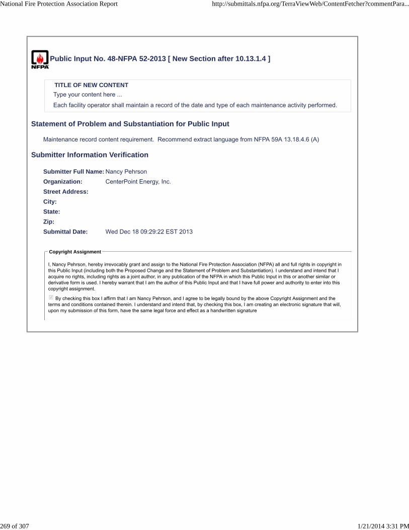
Public Input No. 48-NFPA 52-2013 [ New Section after 10.13.1.4 ]
TITLE OF NEW CONTENT
Type your content here ...
Each facility operator shall maintain a record of the date and type of each maintenance activity performed.
Statement of Problem and Substantiation for Public Input
Maintenance record content requirement. Recommend extract language from NFPA 59A 13.18.4.6 (A)
Submitter Information Verification
Submitter Full Name: Nancy Pehrson
Organization: CenterPoint Energy, Inc.
Street Address:
City:
State:
Zip:
Submittal Date: Wed Dec 18 09:29:22 EST 2013
Copyright Assignment
I, Nancy Pehrson, hereby irrevocably grant and assign to the National Fire Protection Association (NFPA) all and full rights in copyright inthis Public Input (including both the Proposed Change and the Statement of Problem and Substantiation). I understand and intend that Iacquire no rights, including rights as a joint author, in any publication of the NFPA in which this Public Input in this or another similar orderivative form is used. I hereby warrant that I am the author of this Public Input and that I have full power and authority to enter into thiscopyright assignment.
By checking this box I affirm that I am Nancy Pehrson, and I agree to be legally bound by the above Copyright Assignment and theterms and conditions contained therein. I understand and intend that, by checking this box, I am creating an electronic signature that will,upon my submission of this form, have the same legal force and effect as a handwritten signature
National Fire Protection Association Report http://submittals.nfpa.org/TerraViewWeb/ContentFetcher?commentPara...
269 of 307 1/21/2014 3:31 PM

Public Input No. 53-NFPA 52-2013 [ New Section after 10.13.8 ]
TITLE OF NEW CONTENT
Type your content here ...
Control systems that are used as part of the fire protection system at the facility shall be inspected andtested in accordance with the applicable fire codes and standards and conform to the following criteria:
(1) Monitoring equipment shall be maintained in accordance with NFPA 72, National Fire Alarm andSignaling Codes, and NFPA 1221, Standard for the Installation, Maintenance, and Use of EmergencyServices Communications Systems.
(2) Fire protection water systems, if required shall be maintained in accordance with NFPA 13 Standard forthe Installation of Sprinkler Systems, NFPA 14, Standard for the Installation of Standpipe and HoseSystems, NFPA 15, Standard for Water Spray Fixed Systems for Fire Protection, NFPA 20, Standard for theInstallation of Stationary Pumps for Fire Protection, NFPA 22 Standard for Water Tanks for Private FireProtection, NFPA 24, Standard for the Installation of Private Fire Service Mains and Their Appurtenances,and NFPA 25, Standard for the Inspection, Testing, and Maintenance of Water-Based Fire ProtectionSystems.
(3) Portable or wheeled fire extinguishers suitable for gas fires, preferable of the dry-chemical type, shall beavailable at strategic locations as determined in accordance of Chapter 12, within an LNG facility and shallbe maintained in accordance with NFPA 10 Standard for Portable Fire Extinguishers.
(4) Fixed fire extinguishers and other fire-control systems that are installed shall be maintained inaccordance with NFPA 11, Standard for Low-, Medium-, and High Expansion foam, NFPA12, Standard onCarbon Dioxide Extinguishing Systems, NFPA 12A, Standard on Halon, NFPA 1301 Fire ExtinguishingSystems, NFPA 16, Standard for the Installation of Foam-Water Sprinkler and Foam-Water Spray Systemsand NFPA 17, Standard for Dry Chemical Extinguishing Systems,
NFPA 59A 18.4.5 (C)
Statement of Problem and Substantiation for Public Input
Requirements for filre protection control system maintenance. Recommend extracted language from NFPA 59A 13.18.4.5 (C)
Submitter Information Verification
Submitter Full Name: Nancy Pehrson
Organization: CenterPoint Energy, Inc.
Street Address:
City:
State:
Zip:
Submittal Date: Wed Dec 18 10:28:59 EST 2013
Copyright Assignment
I, Nancy Pehrson, hereby irrevocably grant and assign to the National Fire Protection Association (NFPA) all and full rights in copyright inthis Public Input (including both the Proposed Change and the Statement of Problem and Substantiation). I understand and intend that Iacquire no rights, including rights as a joint author, in any publication of the NFPA in which this Public Input in this or another similar orderivative form is used. I hereby warrant that I am the author of this Public Input and that I have full power and authority to enter into thiscopyright assignment.
By checking this box I affirm that I am Nancy Pehrson, and I agree to be legally bound by the above Copyright Assignment and theterms and conditions contained therein. I understand and intend that, by checking this box, I am creating an electronic signature that will,upon my submission of this form, have the same legal force and effect as a handwritten signature
National Fire Protection Association Report http://submittals.nfpa.org/TerraViewWeb/ContentFetcher?commentPara...
270 of 307 1/21/2014 3:31 PM

National Fire Protection Association Report http://submittals.nfpa.org/TerraViewWeb/ContentFetcher?commentPara...
271 of 307 1/21/2014 3:31 PM

Public Input No. 54-NFPA 52-2013 [ New Section after 10.13.9 ]
TITLE OF NEW CONTENT
Type your content here ...
The external surfaces of LNG storage tanks shall be inspected and tested as set out in the maintenancemanual for the following:
(1) Inner tank leakage
(2) Soundness of insulation
(3) Tank foundation heating to ensure that the structural integrity of safety of the tanks in not affected.
NFPA 59A 13.18.4.5 (E)
LNG storage containers and their foundation shall be externally impacted after each major meteorological disturbanceto ensure that the structural integrity of the facility if intact.
NFPA 59A 13.18.4.5 (F)
Statement of Problem and Substantiation for Public Input
LNG tank maintenance requirement. Recommend extract language from NFPA 59A 13.18.4.5 (E and F)
Submitter Information Verification
Submitter Full Name: Nancy Pehrson
Organization: CenterPoint Energy, Inc.
Street Address:
City:
State:
Zip:
Submittal Date: Wed Dec 18 10:33:57 EST 2013
Copyright Assignment
I, Nancy Pehrson, hereby irrevocably grant and assign to the National Fire Protection Association (NFPA) all and full rights in copyright inthis Public Input (including both the Proposed Change and the Statement of Problem and Substantiation). I understand and intend that Iacquire no rights, including rights as a joint author, in any publication of the NFPA in which this Public Input in this or another similar orderivative form is used. I hereby warrant that I am the author of this Public Input and that I have full power and authority to enter into thiscopyright assignment.
By checking this box I affirm that I am Nancy Pehrson, and I agree to be legally bound by the above Copyright Assignment and theterms and conditions contained therein. I understand and intend that, by checking this box, I am creating an electronic signature that will,upon my submission of this form, have the same legal force and effect as a handwritten signature
National Fire Protection Association Report http://submittals.nfpa.org/TerraViewWeb/ContentFetcher?commentPara...
272 of 307 1/21/2014 3:31 PM

Public Input No. 111-NFPA 52-2013 [ Chapter 11 ]
Chapter 11 Reserved
Reserved Replace reserved chapter 11 with the attached Chapter 11 Fueling developed by a NFPA 52Task Group
Additional Proposed Changes
File Name Description Approved
NFPA_52_Public_Input_Chapter_11_Fueling.docx NFPA 52 Chapter 11 Fueling
Statement of Problem and Substantiation for Public Input
The NFPA 52 Technical Committee approved the reorganization of NFPA 52 into an organizational layout that restructured requirements into General Requirements, Fuel Specific Requirements and Use Specific Requirements. This Chapter replaces existing Chapter 11 and was developed by a Task Group. For this draft being submitted as a Public Input, existing code sections have only been reorganized. No new or revised language has been included or any requirements deleted.
Submitter Information Verification
Submitter Full Name: Nancy Pehrson
Organization: CenterPoint Energy, Inc.
Street Address:
City:
State:
Zip:
Submittal Date: Thu Dec 26 13:20:25 EST 2013
Copyright Assignment
I, Nancy Pehrson, hereby irrevocably grant and assign to the National Fire Protection Association (NFPA) all and full rights in copyright inthis Public Input (including both the Proposed Change and the Statement of Problem and Substantiation). I understand and intend that Iacquire no rights, including rights as a joint author, in any publication of the NFPA in which this Public Input in this or another similar orderivative form is used. I hereby warrant that I am the author of this Public Input and that I have full power and authority to enter into thiscopyright assignment.
By checking this box I affirm that I am Nancy Pehrson, and I agree to be legally bound by the above Copyright Assignment and theterms and conditions contained therein. I understand and intend that, by checking this box, I am creating an electronic signature that will,upon my submission of this form, have the same legal force and effect as a handwritten signature
National Fire Protection Association Report http://submittals.nfpa.org/TerraViewWeb/ContentFetcher?commentPara...
273 of 307 1/21/2014 3:31 PM

Chapter 11 Fueling
11.1 Scope
7.1 Application.
7.1.1 This chapter applies to the design, construction, installation, and operation of containers, pressure vessels, compression equipment, buildings and structures, and associated equipment used for storage and dispensing of CNG as an engine fuel in fleet and public dispensing operations.
11.2 General
1.4.3 The installation of LNG and CNG systems shall be supervised by personnel familiar with proper practices with reference to their construction and use.
7.14.10 CNG shall not be used to operate any device or equipment that has not been designed or modified for CNG service.
11.3 CNG Dispensing 11.3.1 General 7.3 General System Requirements.
7.3.1 Where systems are served by a gas utility, the utility shall be notified of all CNG installations.
7.3.2 Equipment related to a compression, storage, or dispensing installation shall be protected to prevent damage from vehicles and minimize the possibilities of physical damage and vandalism.
7.3.3* Control devices shall be installed so that internal or external icing or hydrate formation does not cause vehicle or fueling station malfunction.
7.3.4 Vehicles shall not be considered a source of ignition with respect to the p.2 – 9.5rovisions of this chapter.
7.3.4.1 Vehicles containing fuel-fired equipment (e.g., recreational vehicles and catering trucks) shall be considered a source of ignition unless this equipment is shut off completely before entering an area in which ignition sources are not permitted.
7.3.13 Modifications to fuel stations including, but not limited to, increases in working pressure or dispensing pressures shall be subject to a complete review in accordance with that required for a new installation to include a notification of any supplying utility (see 7.3.1).
Commented [BS1]: Need to change scope section to include both CNG and LNG

7.3.13.1 A hazard analysis of the proposed modification and the startup plan shall be required and prepared prior to the modification and operation of the facility.
11.3.1.1 System Component Qualification 7.2 System Component Qualifications. System components shall comply with the applicable provisions of Chapter 5 and with Sections 7.5 through 7.13. 11.3.1.2 Installation of Containers, Cylinders and Tanks 11.3.1.2.1 Installation of Indoor tanks shall meet the requirements of 9.2-9.6 11.3.2.1.2 Installation of outdoor tanks shall meet the requirements of Chapter 10.
11.3.1.4 Pressure Relief Devices 7.6 Installation of Pressure Relief Devices.
7.6.1 Pressure relief valves shall be arranged so that they discharge to a location where escaping gas does not impinge on buildings, other equipment, or areas that are occupiable by the public (see 7.4.3.10).
7.6.2 Pressure relief valves on pressure vessels shall be installed so that any discharge is in a vertical position.
7.6.2.1 Pressure relief valves shall be fitted with rain caps.
7.6.5 If approved, full port block valves shall be permitted to be installed between the relief valves and the storage vessel or fueling transfer system.
7.6.6 The block valves shall be locked open.
11.3.1.4.X Installation of Pressure Relief Devices On Dispensing Systems
7.6.3 A pressure relief valve other than a rupture disc shall be installed in the fueling transfer system to prevent pressures in excess of 125 percent of the vehicle service pressure from being supplied to the vehicle.
7.6.3.1 The pressure relief valve shall be redundant to and independent from any operating control system used
Commented [BS2]: Will need to modify this as a public input.

to control the supplied fuel pressure during dispenser operation.
7.6.4 The set pressure of the overpressure protection device shall not exceed 125 percent of the service pressure of the fueling nozzle it supplies.
11.3.1.5 7.8 Installation of Pressure Gauges. Gauges or other readout devices shall be installed to indicate compression discharge pressure, storage pressure, and dispenser discharge pressure.
11.3.1. 7.7 Installation of Pressure Regulators.
7.7.1 Regulators shall be designed, installed, or protected so that their operation is not affected by freezing rain, sleet, snow, ice, mud, insects, or debris.
7.7.2 Regulator protection of 7.7.1 shall be permitted to be integral with the regulator.
11.3.1.7 7.9 Installation of Piping and Hoses.
7.9.1* Piping and hose shall be run directly with provisions for expansion, contraction, jarring, vibration, and settling.
7.9.1.1 Exterior piping shall be either buried or installed above ground and shall be supported and protected against mechanical damage.
7.9.1.2 Underground piping shall be buried not less than 18 in. (460 mm) below the surface of the ground unless otherwise protected from damage by movement of the ground.
7.9.1.3 Underground and aboveground piping shall be protected from corrosion in compliance with recognized practices.
7.9.1.4 Threaded pipe and fittings shall not be used underground.
11.3.1.7.X Piping Connections7.9.1.5 Installation of Piping Connections.
7.9.1.5.1 Manifolds connecting fuel containers shall be fabricated to minimize vibration.
7.9.1.5.1.1 Manifolds shall be installed in a protected location or shielded to prevent damage from unsecured objects.
7.9.1.5.2 A pipe thread jointing material impervious to the action of the natural gas used in system shall be applied to all male pipe threads prior to assembly.

7.9.1.5.3 Threaded piping and fittings shall be clear and free from cutting or threading burrs and scales.
7.9.1.5.3.1 The ends of all piping shall be reamed.
7.9.1.5.4 A bend in piping or tubing shall be prohibited where such a bend weakens the pipe or tubing.
7.9.1.5.5 A joint or connection shall be located in an accessible location.
7.9.1.5.6 The number of joints shall be minimized and placed in a location considering personnel safety.
7.9.2 Natural gas shall be vented only to a safe point of discharge.
7.9.2.1 A vent pipe or stack shall have the open end protected to prevent entrance of rain, snow, and solid material.
7.9.2.2 Vertical vent pipes and stacks shall have provision for drainage.
11.3.1.8 Installation of Hose and Hose Connections
7.9.3 The use of hose in an installation shall be limited to the following:
(1) Vehicle fueling hose
(2) Inlet connection to compression equipment
(3) Section of metallic hose not exceeding 36 in. (910 mm) in length in a pipeline to provide flexibility where necessary
7.9.3.1 Each section shall be installed so that it is protected against mechanical damage and is visible for inspection.
7.9.3.2 The manufacturer's identification shall be retained in each section.
11.3.1.9 Installation of Valves
7.11.1 Manually Operated Container Valve.
7.11.1.1 A manually operated container valve shall be provided for each DOT or TC storage cylinder.
7.11.1.2 Individual groups of manifolded ASME storage vessels without individual storage vessel valves shall be limited to a
maximum of 10,000 scf (283 m3).
7.11.1.2.1 Manifolds serving each group of ASME storage vessels shall be provided with a manually operated shutoff valve.

7.11.1.3 Individual ASME pressure vessels of any size, not part of a manifold system, shall have a manual shutoff valve.
7.11.1.4 A manually operated shutoff valve shall be installed at the outlet from the manifold.
7.11.1.5 The valve in 7.11.1.3 shall be located downstream of the backflow check valve specified in 7.11.2.
7.11.2 The fill line on a storage container shall be equipped with a backflow check valve to prevent discharge of natural gas from the container in case of the rupture of the line, hose, fittings, or other equipment upstream of the storage containers.
7.11.3 Where excess-flow check valves are used, the closing flow shall be greater than the maximum system design flow rate and less than the flow rating of the piping system that results from a complete line failure between the excess-flow valve and the equipment downstream of the excess-flow check valve.
7.11.4 Gas piping from an outdoor compressor or storage system into a building shall be provided with shutoff valves located outside the building.
11.3.1.10 System Testing 7.10 System Testing.
7.10.1 Piping, tubing and hose, and hose assemblies shall be leak tested after assembly to prove them free from leaks at a pressure equal to at least the normal service pressure of that portion of the system.
7.10.2 Pressure relief valves shall be tested at least every 3 years.
11.3.1.11 System Maintenance
7.16.1 Containers and their appurtenances, piping systems, compression equipment, controls, and detection devices shall be maintained in safe operating condition and according to manufacturers' instructions.
7.16.2 Written instructions shall be provided for CNG dispensing systems to include the following:
(1) Operating instructions
(2) Emergency shutdown instructions
(3) Maintenance and repair instructions

(4) Instructions for pressure and temperature calibrations and functional checks to assure that the dispenser continues to satisfy the requirements of Section 7.14
7.16.3 Dispensing systems shall be maintained in accordance with the instructions required in 7.16.2 to verify pressure control and pressure relief valves.
7.16.3.1 A written record of maintenance shall be provided.
7.16.4 Hose Assemblies. After the original installation, vehicle fueling hoses shall be examined visually according to the manufacturers' recommendations or at least monthly to ensure that they are safe for use.
7.16.5 Hoses shall be tested for leaks in accordance with manufacturers' requirements.
7.16.5.1 Any leakage or surface cracks shall be reason for rejection and replacement.
7.16.6 While in transit, fueling hose and flexible metal hose on a cargo vehicle to be used in a transfer operation, including their connections, shall be depressurized and protected from wear and injury.
7.16.7* PRVs shall be maintained in safe operating condition.
7.16.8 Maintenance personnel shall be trained in leak detection procedures and equipment in accordance with manufacturers' recommendations.
11.3.1.12 Installation of Compression and Gas Processing Equipment
7.3.7 Compression equipment shall be designed for use with CNG and for the pressures and temperatures to which it is subjected under operating conditions.
7.3.8 Compression equipment shall have pressure relief devices that limit each stage pressure to the maximum allowable service pressure for the compression cylinder and piping associated with that stage of compression.
7.3.9 Where CNG compression equipment is operated unattended, it shall be equipped with a high discharge and a low suction pressure automatic shutdown control.
7.3.10 Control circuits that shut down shall remain down until manually activated or reset after a safe shutdown is performed.

7.3.11 Engine-driven compressor installations shall conform, where applicable, to NFPA 37, Standard for the Installation and Use of Stationary Combustion Engines and Gas Turbines.
7.3.12* Compression equipment shall incorporate a means to minimize liquid carryover to the storage system.
7.4.2.2 A facility in which CNG compression, storage, and dispensing equipment are sheltered by weather protection constructed in accordance with the requirements of the building code and by a roof designed for ventilation and dispersal of escaped gas shall be considered to be located outdoors.
7.4.2.3 Compression, storage, and dispensing equipment located outdoors shall be above ground.
7.4.2.3.1 Compression, storage, and dispensing equipment located outdoors shall not be beneath electric power lines or where exposed by their failure.
7.4.2.3.2 Compression, storage, and dispensing equipment located outdoors shall be a minimum of 10 ft (3 m) from the nearest important building or line of adjoining property that is able to be built upon or from any source of ignition.
7.4.2.4 Compression, storage, and dispensing equipment located outdoors shall be not less than 10 ft (3 m) from the nearest public street or sidewalk line and at least 50 ft (15 m) from the nearest rail of any railroad main track.
7.4.2.9 Areas for compression, storage, and dispensing shall be classified in accordance with Table 7.4.2.9 for installations of electrical equipment.
7.11.4 Gas piping from an outdoor compressor or storage system into a building shall be provided with shutoff valves located outside the building.
7.11.5 An emergency manual shutdown device shall be provided within 10 ft (3.0 m) of the dispensing area and also greater than 25 ft (7.6 m) from the dispensing area.
7.11.5.1 This device, when activated, shall shut off the power supply and gas supply to the compressor and the dispenser.
7.11.5.2 Emergency shutdown devices shall be distinctly marked for easy recognition with a permanently affixed legible sign
7.11.7 Control circuits shall be arranged so that, when an emergency shutdown device is activated or electric power is cut

off, systems that shut down remain off until manually activated or reset after a safe condition is restored..
11.3.1.13 Vehicle Fueling Dispensing Operation 7.14 System Operation.
7.14.1 A cylinder shall not be charged in excess of the design pressure at the normal temperature for that cylinder.
7.14.1.1 DOT, TC, and ANSI/IAS NGV2 cylinders shall be charged in accordance with DOT, TC, and ANSI/IAS NGV2 regulations.
7.14.1.2 DOT, TC, and ANSI/IAS NGV2 cylinders shall not be subjected to pressure in excess of 125 percent of the marked service pressure even if, on cooling, the pressure settles to the marked service pressure.
7.14.2 A fuel supply container shall not have a settled pressure above the service pressure that is stamped on the container and displayed on a label near the filling connection, corrected for the ambient temperature at the time of filling.
7.14.3 CNG dispensing systems shall be equipped to stop fuel flow automatically when a fuel supply container reaches the temperature-corrected fill pressure (see 7.6.3).
7.14.4 The dispenser shall be designed to detect any malfunction that fills the vehicle fuel container in excess of the limits specified, or causes the relief valve required in 7.6.3 to open.
7.14.4.1 After any such malfunction, the dispenser shall be repaired and calibrated in accordance with Section 7.16 before continued operation.
7.14.4.1.1 The excess fuel shall be removed from the vehicle.
7.14.4.2 If the vehicle fuel system has been pressurized in excess of 1.25 times the service pressure of the fueling connection, the dispenser shall be shut down until repaired and calibrated, and the vehicle operator shall be notified to contact the container manufacturer for approval before continued operation.
7.14.5 The transfer of CNG into a fuel supply container shall be performed in accordance with instructions posted at the dispensing station.
7.14.6 Where CNG is being transferred to or from a motor vehicle, the engine shall be turned off.

7.14.7 During the transfer of CNG to or from cargo vehicles, the hand or emergency brake of the vehicle shall be set and chock blocks used to prevent rolling of the vehicle.
7.14.8 Transfer systems shall be capable of depressurizing to facilitate disconnection.
7.14.9 Bleed connections shall lead to a safe point of discharge.
7.14.11 Sources of ignition shall not be permitted within 10 ft (3.0 m) of any filling connection during a transfer operation.
7.14.12* A warning sign(s) shall be posted at the dispensing points with the following words:
A. STOP MOTOR. B. NO SMOKING. C. FLAMMABLE GAS. D. NATURAL GAS VEHICLE FUEL CYLINDERS SHALL BE INSPECTED AT INTERVALS NOT EXCEEDING 3 YEARS TO ENSURE SAFE OPERATION OF THE VEHICLE.
E. NATURAL GAS FUEL CYLINDERS PAST THEIR END-OF-LIFE DATE SHALL NOT BE REFUELED AND SHALL BE REMOVED
FROM SERVICE.
7.14.12.4 The service pressure of each dispenser shall be posted in view of the operator.
11.3.1.15 Installation of Electrical Equipment 7.12* Installation of Electrical Equipment.
7.12.1 Fixed electrical equipment and wiring within areas specified in Table 7.4.2.9 shall comply with Table 7.4.2.9 and be installed in accordance with NFPA 70, National Electrical Code.
7.12.1.1 Electrical equipment on internal combustion engines installed in accordance with NFPA 37, Standard for the Installation and Use of Stationary Combustion Engines and Gas Turbines, shall not be subject to 7.12.1.
7.12.2 With the approval of the AHJ, classified areas specified in Table 7.4.2.9 shall be permitted to be reduced or eliminated by positive pressure ventilation from a source of clean air or inert gas in conjunction with effective safeguards against ventilator failure by purging methods recognized in NFPA 496, Standard for Purged and Pressurized Enclosures for Electrical Equipment.
7.12.3 Classified areas shall not extend beyond an unpierced wall, roof, or vaportight partition.
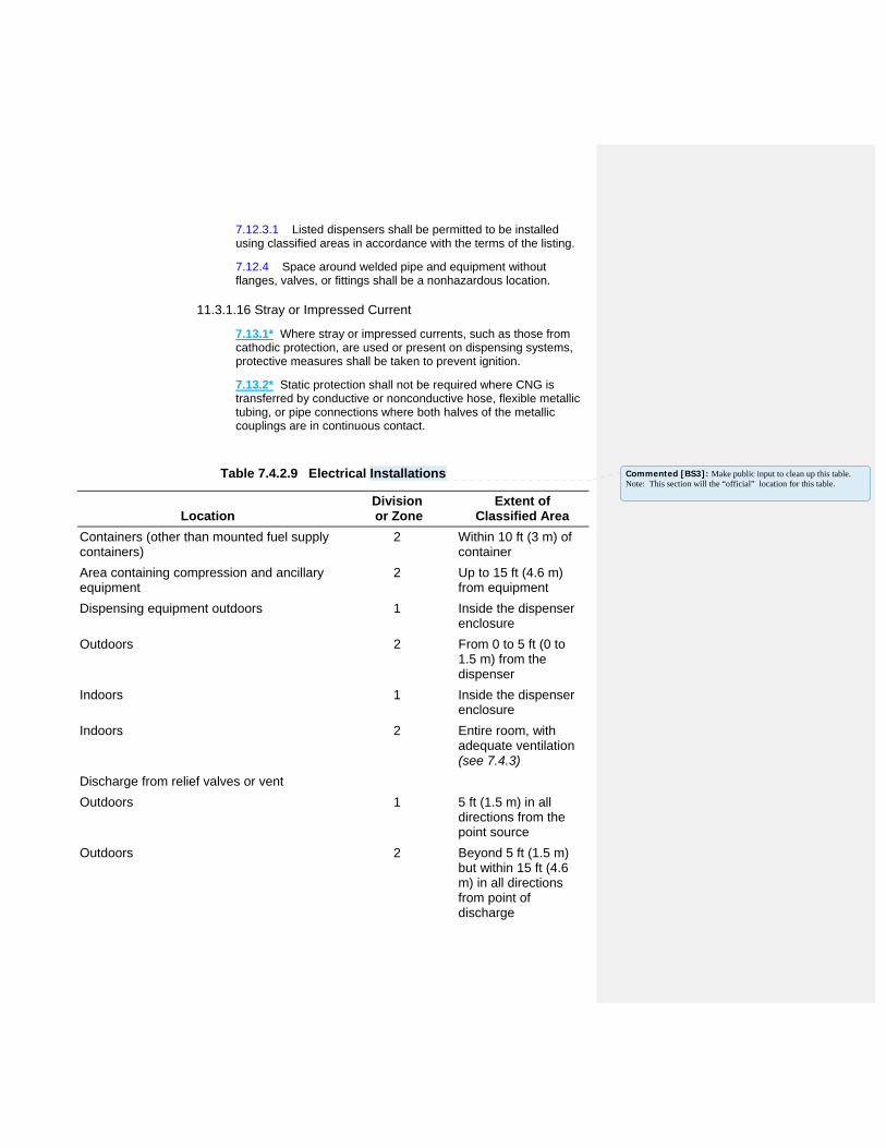
7.12.3.1 Listed dispensers shall be permitted to be installed using classified areas in accordance with the terms of the listing.
7.12.4 Space around welded pipe and equipment without flanges, valves, or fittings shall be a nonhazardous location.
11.3.1.16 Stray or Impressed Current
7.13.1* Where stray or impressed currents, such as those from cathodic protection, are used or present on dispensing systems, protective measures shall be taken to prevent ignition.
7.13.2* Static protection shall not be required where CNG is transferred by conductive or nonconductive hose, flexible metallic tubing, or pipe connections where both halves of the metallic couplings are in continuous contact.
Table 7.4.2.9 Electrical Installations
Location Division or Zone
Extent of Classified Area
Containers (other than mounted fuel supply containers)
2 Within 10 ft (3 m) of container
Area containing compression and ancillary equipment
2 Up to 15 ft (4.6 m) from equipment
Dispensing equipment outdoors 1 Inside the dispenser enclosure
Outdoors 2 From 0 to 5 ft (0 to 1.5 m) from the dispenser
Indoors 1 Inside the dispenser enclosure
Indoors 2 Entire room, with adequate ventilation (see 7.4.3)
Discharge from relief valves or vent
Outdoors 1 5 ft (1.5 m) in all directions from the point source
Outdoors 2 Beyond 5 ft (1.5 m) but within 15 ft (4.6 m) in all directions from point of discharge
Commented [BS3]: Make public input to clean up this table. Note: This section will the “official” location for this table.

Valves, flanges of screwed fittings None Unclassified
Discharge from relief valves within 15 degrees of the line of discharge
1 15 ft (4.6 m)
11.3.1.18 Installation of Emergency Shutdown Equipment
7.11.1 Manually Operated Container Valve.
7.11.1.1 A manually operated container valve shall be provided for each DOT or TC storage cylinder.
7.11.1.2 Individual groups of manifolded ASME storage vessels without individual storage vessel valves shall be limited to a
maximum of 10,000 scf (283 m3).
7.11.1.2.1 Manifolds serving each group of ASME storage vessels shall be provided with a manually operated shutoff valve.
7.11.1.3 Individual ASME pressure vessels of any size, not part of a manifold system, shall have a manual shutoff valve.
7.11.1.4 A manually operated shutoff valve shall be installed at the outlet from the manifold.
7.11.1.5 The valve in 7.11.1.3 shall be located downstream of the backflow check valve specified in 7.11.2.
7.11.2 The fill line on a storage container shall be equipped with a backflow check valve to prevent discharge of natural gas from the container in case of the rupture of the line, hose, fittings, or other equipment upstream of the storage containers.
7.11.3 Where excess-flow check valves are used, the closing flow shall be greater than the maximum system design flow rate and less than the flow rating of the piping system that results from a complete line failure between the excess-flow valve and the equipment downstream of the excess-flow check valve.
7.11.4 Gas piping from an outdoor compressor or storage system into a building shall be provided with shutoff valves located outside the building.
7.11.5 An emergency manual shutdown device shall be provided within 10 ft (3.0 m) of the dispensing area and also greater than 25 ft (7.6 m) from the dispensing area.
7.11.5.1 This device, when activated, shall shut off the power supply and gas supply to the compressor and the dispenser.
7.11.5.2 Emergency shutdown devices shall be distinctly marked for easy recognition with a permanently affixed legible sign.

7.11.6 Breakaway protection shall be provided in a manner that, in the event of a pullaway, natural gas ceases to flow at any separation.
7.11.6.1 A breakaway device shall be installed at every dispensing point.
7.11.6.2 A breakaway device shall be arranged to separate using a force not greater than 150 lb (68 kg) when applied in any direction that the vehicle would move.
7.11.6.3 Breakaway devices shall comply with ANSI/IAS NGV 4.4, Breakaway Devices for Natural Gas Dispensing Hoses and Systems.
7.11.7 Control circuits shall be arranged so that, when an emergency shutdown device is activated or electric power is cut off, systems that shut down remain off until manually activated or reset after a safe condition is restored.
7.11.8 Fast-Fill Station.
7.11.8.1 Each line between a gas storage facility and a dispenser at a fast-fill station shall have a valve that closes when one of the following occurs:
(1) The power supply to the dispenser is cut off.
(2) Any emergency shutdown device at the refueling station is activated.
7.11.8.2 A fast-closing, “quarter turn” manual shutoff valve shall be provided at a fast-fill station upstream of the breakaway device specified in 7.11.6, where it is accessible to the person dispensing natural gas, unless one of the following occurs:
(1) The self-closing valve referred to in 7.11.8.1 is located immediately upstream of the dispenser.
(2) The dispenser is equipped with a self-closing valve that closes each time the control arm is turned to the OFF position or when an emergency device is activated.
7.11.9 A self-closing valve shall be provided on the inlet of the compressor that shuts off the gas supply to the compressor when one of the following occurs:
(1) An emergency shutdown device is activated.
(2) A power failure occurs.
(3) The power to the compressor is switched to the OFF position.

11.3.1.19 Fire Protection 7.15 Fire Protection. A portable fire extinguisher having a rating of not less than 20-B:C shall be provided at the dispensing area.
11.3.2 Dispensing to Non-Public Users 11.3.3.1 General 11.3.3.2 Indoor Non-Public Fueling 11.3.3.2.1 General
11.3.3.2.1.1 Vehicle Refueling Appliance in Non-residential Occupancies7.17 Vehicle Fueling Appliances in Nonresidential Occupancies.
7.17.1 VFAs shall not exceed a gas flow of 10 scf/min (0.28 SCM/min).
7.17.2 VFAs shall be listed.
7.17.3 The installation of VFAs shall be exempt from the requirements of Sections 5.5 through 5.10, 7.2 through 7.4, 7.6, and 7.8 through 7.16.
7.17.4 VFAs shall be permitted to be used to fill stationary containers at vehicle fueling locations.
7.17.4.1 The method of connecting the VFA to such storage shall comply with the provisions of Chapters 5 and 7 and shall be approved.
7.17.4.2 The provisions of 7.17.3 shall apply to the VFA where connected to stationary containers at vehicle fueling locations.
7.17.5 The installation of VFAs shall comply with the requirements of Chapter 8.
7.17.5.1 The requirements of 8.1.2 and 8.1.3 shall not apply to the installation of VFAs.
7.17.5.2 Gas detectors shall be located in accordance with good engineering practice.
7.17.6 VFAs shall not be installed within 10 ft (3.0 m) of any flammable gas or liquid storage.
7.17.6.1 Storage in the vehicle fuel supply container shall not be subject to 7.17.6.
7.17.7 Where installed indoors in public assembly and educational occupancies, a VFA shall be located in a portion of the occupancy where NFPA 101, Life Safety Code, or the local building code permits the installation of hazardous equipment.
Commented [BS4]: Public comment to add annex note as to what you should use the fire ext for in a CNG fire.
Commented [BS5]: Non- public fueling will be first, public fueling second. Numbering will be changed later.

7.17.7.1 Where the VFA is located outdoors, the dispensing point shall be permitted to be located indoors without the need for a separate room.
11.3.3.2.2 Indoor Non-Public Fast Fill Fueling
7.4.3.12 Indoor Fast-Fill Fueling, Outdoor Storage, and Compression. Fast-fill fueling indoors shall be permitted where storage and compression equipment is located outdoors complying with 7.4.2.1 through 7.4.2.7 and 7.4.2.9.
7.4.3.12.1 Where attended fast-fill fueling is performed indoors, the following shall be installed:
(1) An emergency manual shutdown device shall be installed as required by 7.11.5.
(2) A gas detection system equipped to sound a latched alarm and visually indicate when a maximum of one-fifth of the lower flammable limit is reached shall be installed.
7.4.3.12.2 The actuation of the gas detection system shall shut down the compressor and stop the flow of gas into the structure.
11.3.3.2.2.1 Equipment location (reserved 11.3.3.2.2.2 Ventilation (reserved) 11.3.3.2.2.3 Electrical Classification(reserved) 11.3.3.2.2 4 Fire Detection(reserved) 11.3.3.2.2.5 Fire Alarm System(reserved) 11.3.3.2.2.6 Emergency Shutdown System 11.3.3.2.2.7 Dispensing equipment (reserved) 11.3.3.2.3 Indoor Non-Public Slow Fill Fueling(reserved) 11.3.3.2.4 Indoor Residential Slow Fill Fueling 11.3.3.3.Outdoor Non-Public Fueling 11.3.3.3.1 General 7.4.2 Outdoors.
7.4.2.2 A facility in which CNG compression, storage, and dispensing equipment are sheltered by weather protection constructed in accordance with the requirements of the building code and by a roof designed for ventilation and dispersal of escaped gas shall be considered to be located outdoors.
7.4.2.3 Compression, storage, and dispensing equipment located outdoors shall be above ground.
7.4.2.3.1 Compression, storage, and dispensing equipment located outdoors shall not be beneath electric power lines or where exposed by their failure.
7.4.2.3.2 Compression, storage, and dispensing equipment located outdoors shall be a minimum of 10 ft (3 m) from the nearest important building or line of adjoining property that is able to be built upon or from any source of ignition.
7.4.2.4 Compression, storage, and dispensing equipment located outdoors shall be not less than 10 ft (3 m) from the nearest public street or sidewalk line and at least 50 ft (15 m) from the nearest rail of any railroad main track.
7.4.2.5 A clear space of at least 3 ft (1 m) shall be provided for access to all valves and fittings of multiple groups of containers.
7.4.2.6 Combustible material shall not be permitted within 10 ft (3 m) of any stationary container.
7.4.2.7 The minimum separation between containers and aboveground tanks containing flammable or combustible liquids shall be 20 ft (6 m).
7.4.2.8 During outdoor fueling operations, the point of transfer shall be located at least 10 ft (3 m) from any important building, mobile home, public sidewalk, highway, street, or road and at least 3 ft (1 m) from storage containers.
7.4.2.8.1 The point of transfer shall be permitted to be located at a lesser distance from buildings or walls constructed of concrete or masonry materials or of other material having a fire resistance rating of at least 2 hours, but at least 10 ft (3 m) from any building openings.
7.4.2.9 Areas for compression, storage, and dispensing shall be classified in accordance with Table 7.4.2.9 for installations of electrical equipment.
11.3.3.3.2 Outdoor Non-Public Fast Fill Fueling 11.3.3.3.3 Outdoor Non-Public Slow Fill Fueling (reserved)
11.3.3.3.4 Outdoor Residential Fueling 8.1.1 This chapter applies to the design, construction, installation, and operation of a residential fueling facility (RFF-CNG).
11.3.3.3.4.1 Slow Fill Residential Fueling
Commented [BS6]: Reference table in new location
Commented [BS7]: Outdoor non-public fueling is fast fill.

8.1 Application.
8.1.1 This chapter applies to the design, construction, installation, and operation of a residential fueling facility (RFF-CNG).
8.1.2 The capacity of an RFF-CNG shall not exceed 5 scf/min (0.14 SCM/min) of natural gas.
8.1.3 Storage of CNG shall be prohibited.
8.1.3.1 CNG shall be permitted to be stored in the vehicle fuel supply container.
8.2 System Component Qualifications.
8.2.1 System components not part of a listed VFA shall comply with the appropriate provisions in Chapter 5.
8.2.2* VFAs shall be listed.
8.2.3 VFAs shall be exempt from the requirements of Sections 5.5 through 5.9, 7.2 through 7.4, 7.6, and 7.8 through 7.16.
8.3 General Safety Requirements.
8.3.1 All equipment related to an RFF-CNG installation shall be protected to minimize the possibility of physical damage and vandalism.
8.3.2 The use of an enclosure for the compressor package, similar to that of a central air conditioner, shall be permitted to satisfy 8.3.1.
8.3.3 All equipment related to RFF-CNG installation shall be designed for the pressure, temperature, and service expected.
8.3.4 Vehicles shall be unclassified electrically with respect to NFPA 70, National Electrical Code, Article 500.
8.3.4.1 Vehicles containing fuel-fired equipment (e.g., recreational vehicles) shall be considered a source of ignition unless this equipment is shut off completely before entering an area in which ignition sources are not permitted.
8.3.5 Natural gas shall not be vented to the atmosphere under normal operation.
8.3.5.1 Leakage of 1.0 standard cubic in. (16
cm3) of gas shall be permitted to be released to the
atmosphere per filling during disconnection of the fueling hose.
8.3.6 Unless specifically permitted by the installation instructions, multiple VFAs shall not be manifolded together on the discharge side.
8.3.7 Where more than one VFA is located in a common area, spacing between the VFAs shall not be less than 3 ft (1 m) unless permitted by the installation instructions.
8.4 Installation.
8.4.1 General.
8.4.1.1 All RFF-CNG equipment shall be installed in accordance with the equipment manufacturer's instructions.
8.4.1.2 The RFF-CNG shall have a nameplate marked with minimum and maximum gas inlet pressures and flow rates, gas outlet maximum pressure, and electrical requirements.
8.4.2 Indoors.
8.4.2.1 Where it is necessary to install the compression unit and refueling connections indoors, the compression unit shall be mounted or otherwise located such that the compression unit is vented outdoors.
8.4.2.2* Where the RFF-CNG or the vehicle being fueled is located indoors, a gas detector set to operate at one-fifth the (LFL) lower flammable limit of natural gas shall be installed in the room.
8.4.2.2.1 The detector shall be located within 6 in. (150 mm) of the ceiling or the highest point in the room.
8.4.2.2.1.1 An RFF-CNG that is listed shall be permitted to utilize a combination of ventilation or gas detection to ensure that the room is maintained at a level below one-fifth of the lower limit of flammability of natural gas.
8.4.2.2.1.2 Meeting the provisions of 8.4.2.2.1 shall be deemed to be equivalent to a gas detector located within 6 in. (150 mm) of the ceiling or the highest point in the room.

8.4.2.2.2 The detector shall stop the compressor and operate an audible or a visual alarm.
8.4.3 Outdoors. The RFF-CNG shall be installed on a firm, noncombustible support to prevent undue stress on piping and conduit. (See Section 4.5 for noncombustible.)
8.5 Installation of PRVs. PRVs shall have PRD vents or vent lines to convey escaping gas to the outdoors and then upward to prevent impinging on buildings, other equipment, or areas open to the public (e.g., sidewalks).
8.6 Installation of Pressure Gauges. For measurement and test purposes, pressure gauges shall be permitted to be installed but shall not be required.
8.7 Pressure Regulation. An RFF-CNG shall be equipped to stop fuel flow automatically when the container(s) reaches the temperature-corrected fill pressure.
8.8 Piping and Hose.
8.8.1 All piping and hose from the outlet of the compressor shall be supplied as part of the RFF-CNG.
8.8.2 All gas piping to the RFF-CNG shall be installed in accordance with NFPA 54, National Fuel Gas Code.
8.8.3 The use of hose in an installation shall be restricted to the following:
(1) A fueling hose limited to a maximum length of 25 ft (7.6 m) and supported above the floor/ground level or otherwise protected from mechanical damage from abrasion and being driven over by a vehicle
(2) A maximum of 3 ft (1 m) in length where used to prevent abrasion damage resulting from vibration on the inlet or outlet, or both
8.8.4 Transfer systems shall be capable of depressurizing to facilitate disconnection.
8.8.5 Bleed connections shall lead to a safe point of discharge.

8.9 Testing. All piping and tubing shall be tested after assembly to be proven free of leaks at a pressure equal to the maximum service pressure of that portion of the system.
8.10 Installation of Emergency Shutdown Equipment.
8.10.1 An RFF-CNG shall be equipped with emergency manual shutdown of the gas supply and electric power.
8.10.1.1 The emergency electrical switch shall be at least 5 ft (1.5 m) from the RFF -CNG and in view of the RFF-CNG.
8.10.1.2 An RFF-CNG equipped with a flexible cord terminated with a grounding-type attachment plug shall be deemed to be equivalent to the emergency switch.
8.10.2 Breakaway protection shall be provided in a manner so that, in the event of a pullaway, natural gas ceases to flow.
8.10.2.1 The breakaway devices shall be compatible with ANSI/IAS NGV 4.4, Breakaway Devices for Natural Gas Dispensing Hoses and Systems, and CSA 12.54, Breakaway Devices for Dispensing Systems.
8.10.2.2 The breakaway provided as a component of a listed VFA shall be permitted not to comply with ANSI/IAS NGV 4.4, Breakaway Devices for Natural Gas Dispensing Hoses and Systems, and CSA 12.54, Breakaway Devices for Dispensing Systems.
8.10.3 A breakaway device shall be installed at every dispensing point.
8.10.4 The breakaway device in 8.10.3 shall be arranged to separate using a force not greater than 150 lb (68 kg) when applied in any horizontal direction.
8.11 Operation.
8.11.1 An RFF-CNG shall be operated in accordance with the manufacturer's instructions.
8.11.2 A fuel supply container shall not be charged in excess of its maximum allowable service pressure at normal temperature.

8.11.3 DOT and TC containers shall be charged in accordance with DOT and TC regulations.
8.11.4 Where CNG is being transferred to a motor vehicle, the engine shall be turned off.
8.12 Maintenance and Inspection.
8.12.1 All RFF-CNG equipment shall be inspected and maintained in accordance with the manufacturer's instructions.
8.12.2 After installation, all hose shall be examined visually as part of this inspection.
8.12.3 Hose that are kinked or worn shall be replaced.
8.12.4 All safety relief valves shall be maintained in operating condition in accordance with the manufacturer's/supplier's recommendation.
11.3.3.3.4.2 FastFill Residential Fueling (Reserved) 11.3.3.3.5 Outdoor Non-Public Fueling from Transport Vehicles Including Marine Vessels 11.3.3.3.5.1 Mobile Refueling Stations
7.1.2 Mobile refueling vehicles, temporary trailers (with or without tractors), and other means of providing vehicle refueling or onsite storage shall be subject to the same requirements as a permanent refueling or storage installation, with the exception of vessel requirements.
7.1.3 Mobile refueling equipment shall meet the requirements of DOT or TC.
11.3.3.3.5.1.1 Mobile Refueling Vehicles (reserved and all below) 11.3.3.3.5.1.2 AHJ Approval 11.3.3.3.5.1.3 Dispensing Area 11.3.3.3.5.1.4 Dispensing Operation 11.3.3.3.5.1.5 Transfer Area 11.3.3.3.5.1.6 Refueling from Vehicle Mounted Tank at Commercial and Industrial Facilities 11.3.3.3.5.1.7 Ignition Sources 11.3.3.3.5.1.8 Fire Extinguishers 11.3.3.3.5.2 Marine Vessel Transfer 11.4 Storage See Chapters 9, 10 or 14

11.3.3 Dispensing to the Public 11.3.2.1 General
7.4.1.1 CNG compression, storage, and dispensing shall be located and conducted outdoors or indoors in compliance with this section.
7.4.3.1 General. Compression, dispensing equipment, and storage containers connected for use shall be permitted to be located inside of buildings reserved exclusively for these purposes or in rooms within or attached to buildings used for other purposes in accordance with this section.
11.3.2.2 Indoor Public Fueling
11.3.2.2.1 General 7.4.3.1 General. Compression, dispensing equipment, and storage containers connected for use shall be permitted to be located inside of buildings reserved exclusively for these purposes or in rooms within or attached to buildings used for other purposes in accordance with this section.
7.4.3.9 Nonelectrical sources of ignition shall not be permitted.
7.4.3.10 Pressure relief devices on storage systems shall have pressure relief device channels [see 5.5.1(3)] to convey escaping gas to the outdoors and then upward to a safe area to prevent impinging on buildings, other equipment, or areas open to the public (e.g., sidewalks).
11.3.2.2.1.1 Dispensing
11.3.2.2.1.2 Deflagation Venting 7.4.3.3* Deflagration Venting.
7.4.3.3.1 Deflagration (explosion) venting shall be provided in exterior walls or roof only.
11.3.2.2.1.3 Vents
7.4.3.3.2 Vents shall be permitted to consist of any one or any combination of the following:
(1) Walls of light material
(2) Lightly fastened hatch covers
(3) Lightly fastened, outward opening doors in exterior walls
Commented [BS8]: Non-public fueling is first, public second. Sections will be renumbered in final draft.

(4) Lightly fastened walls or roofs
11.3.2.2.1.4 Snow Loads 7.4.3.3.3 Where applicable, snow loads shall be considered. 11.3.2.2.1.5 Rooms within Buildings 7.4.3.4 Rooms Within Buildings.
7.4.3.4.1 Rooms within or attached to other buildings shall be constructed of noncombustible or limited-combustible materials.
7.4.3.4.1.1 Window glazing shall be permitted to be plastic.
7.4.3.4.2 Interior walls or partitions shall be continuous from floor to ceiling, be anchored in accordance with the requirements of the building code, and have a fire resistance rating of at least 2 hours.
7.4.3.4.3 At least one wall shall be an exterior wall.
7.4.3.4.4 Explosion venting shall be provided in accordance with 7.4.3.3.
7.4.3.4.5 Access to the room shall be from outside the primary structure.
7.4.3.4.6 If access to the room from outside the primary structure is not possible, access from within the primary structure shall be permitted where such access is made through a barrier space having two vapor-sealing, self-closing fire doors rated for the location where installed.
11.3.2.2.1.6 Ventilation 7.4.3.5 Ventilation Inlets and Outlets.
7.4.3.5.1 Indoor locations shall be ventilated utilizing air supply inlets and exhaust outlets arranged to provide uniform air movement throughout the space.
7.4.3.5.2 Inlets shall be uniformly arranged on exterior walls near floor level.
7.4.3.5.3 Outlets shall be located in exterior walls at the high point of the room or in the roof.
7.4.3.5.4 Ventilation.

7.4.3.5.4.1 Ventilation shall be by a continuous mechanical ventilation system or by a mechanical ventilation system activated by a continuously monitoring natural gas detection system where a gas concentration of not more than one-fifth of the lower flammable limit is present.
7.4.3.5.4.2 In either case in 7.4.3.5.4.1, the system shall immediately shut down the fueling system in the event of detection of an alarm condition or failure of the ventilation system, the detection system, or the controls.
7.4.3.5.5* The ventilation rate shall be at least 1
ft3/min · 12 ft3 (0.03 m3/min · 0.34 m3) of room volume.
7.4.3.5.6 A ventilation system for a room within or attached to another building shall be separate from any ventilation system for the other building.
7.4.3.8 Buildings and rooms used for compression, storage, and dispensing shall be classified in accordance with Table 7.4.2.9 for installations of electrical equipment.
11.3.2.2.1.7 Gas Detection 7.4.3.6 Where installed, a gas detection system shall be equipped to sound a latched alarm and visually indicate when a maximum of one-fifth of the lower flammable limit is reached.
11.3.2.2.1.8 Gas Detection During System Maintenance Operations
11.3.2.2.1.9 Reactivation 7.4.3.7 Reactivation of the fueling system shall be by manual restart that is conducted by trained personnel.
11.3.2.2.1.10 Warning Signs 7.4.3.11 Warning Signs.
7.4.3.11.1 Access doors shall have warning signs with the words “WARNING — NO SMOKING — FLAMMABLE GAS.”
7.4.3.11.2 The wording shall be in plainly legible, bright red letters not less than 1 in. (25 mm) high on a white background.

11.3.2.2.1.11 Indoor Fast-Fill, Outdoor Storage and Compression7.4.3.12 Indoor Fast-Fill Fueling, Outdoor Storage, and Compression. Fast-fill fueling indoors shall be permitted where storage and compression equipment is located outdoors complying with 7.4.2.1 through 7.4.2.7 and 7.4.2.9.
7.4.3.12.1 Where attended fast-fill fueling is performed indoors, the following shall be installed:
(1) An emergency manual shutdown device shall be installed as required by 7.11.5.
(2) A gas detection system equipped to sound a latched alarm and visually indicate when a maximum of one-fifth of the lower flammable limit is reached shall be installed.
7.4.3.12.2 The actuation of the gas detection system shall shut down the compressor and stop the flow of gas into the structure.
11.3.2.2.2 Indoor Public Full Service Fueling (reserved) 11.3.2.2.3 Indoor Public Attended Self Service (reserved) 11.3.2.2.4 Indoor Public Unattended Self Service (reserved) 11.3.2.3 Outdoor Public Fueling
11.3.2.3.1 General
7.4.2.2 A facility in which CNG compression, storage, and dispensing equipment are sheltered by weather protection constructed in accordance with the requirements of the building code and by a roof designed for ventilation and dispersal of escaped gas shall be considered to be located outdoors.
7.4.2.3 Compression, storage, and dispensing equipment located outdoors shall be above ground.
11.3.2.3.1.X Dispensing Equipment Location
7.4.2.3.1 Compression, storage, and dispensing equipment located outdoors shall not be beneath electric power lines or where exposed by their failure.
7.4.2.3.2 Compression, storage, and dispensing equipment located outdoors shall be a minimum of 10 ft (3 m) from the nearest important building or line of adjoining property that is able to be built upon or from any source of ignition.

7.4.2.4 Compression, storage, and dispensing equipment located outdoors shall be not less than 10 ft (3 m) from the nearest public street or sidewalk line and at least 50 ft (15 m) from the nearest rail of any railroad main track.
11.3.2.3.2.X Point of Transfer 7.4.2.8 During outdoor fueling operations, the point of transfer shall be located at least 10 ft (3 m) from any important building, mobile home, public sidewalk, highway, street, or road and at least 3 ft (1 m) from storage containers.
7.4.2.8.1 The point of transfer shall be permitted to be located at a lesser distance from buildings or walls constructed of concrete or masonry materials or of other material having a fire resistance rating of at least 2 hours, but at least 10 ft (3 m) from any building openings.
11.3.2.3.2 Outdoor Public Full Service Fueling (Reserved) 11.3.2.3.3 Outdoor Public Attended Self Service Fueling (Reserved) 11.3.2.3.4 Outdoor Public Unattended Self Service Fueling (Reserved) 11 LNG Fueling 11.1 Scope
10.1 Application.
10.1.1 This chapter applies to the design, siting, construction, installation, spill containment, and operation of containers, pressure vessels, pumps, vaporization equipment, buildings, structures, and associated equipment used for the storage and dispensing of LNG and L/CNG as engine fuel for vehicles of all types.
11.2 General
10.2.1.5 Designers, fabricators, and constructors of LNG fueling facilities shall be competent in the design, fabrication, and construction of LNG containers, cryogenic equipment, loading and unloading systems, fire protection equipment, methane detection, and other components of the facility.
1.4.2 Designers, fabricators, and constructors of LNG fueling facilities shall be competent and have expertise in the design, fabrication, and construction of LNG containers, cryogenic equipment, loading and

unloading systems, fire protection equipment, detection, siting, containment, piping systems, and other components of the facility.
1.4.3 The installation of LNG and CNG systems shall be supervised by personnel familiar with proper practices with reference to their construction and use.
10.2.1.6 Supervision shall be provided for the fabrication, construction, and acceptance tests of facility components to the extent necessary to ensure that facilities are structurally sound, suitable for the service, and otherwise in compliance with this code.
11.3 LNG Dispensing 11.3.1 General
10.2.1.7 LNG refueling sites utilizing or dispensing saturated LNG with personnel in the immediate vicinity shall provide barrier walls or equal protection in order to protect the refueling operator and vehicle.
10.2.1.8 All facility piping other than the refueling hose to the vehicle shall be behind a barrier, which in the case of an equipment or device malfunction deflects the saturated LNG upward.
11.3.1.1 System Component Qualification
11.3.1.2 Devices 11.3.1.3 Design and Construction of Containers, Cylinders and Tanks (Reference Chapter 14)
11.3.1.4 Pressure Relief Devices 10.6 Safety and Relief Valves.
10.6.1 Pressure relieving safety devices shall be so arranged that the possibility of damage to piping or appurtenances is reduced to a minimum.
10.6.2 The means for adjusting relief valve set pressure shall be sealed.
10.6.3 Stationary LNG containers shall be equipped with pressure relief devices in accordance with CGA S-1.3, Pressure Relief Device Standards — Part 3 — Stationary Storage Containers for Compressed Gases.
10.6.4 A thermal expansion relief valve shall be installed as required to prevent overpressure in any section of a liquid or cold vapor pipeline that can be isolated by valves.
10.6.4.1 Thermal expansion relief valves shall be set to discharge above the maximum pressure expected in the line but less than the rated test pressure of the line it protects.

10.6.4.2 Discharge from thermal expansion relief valves shall be directed so as to minimize hazard to personnel and other equipment.
11.3.1.4.X Installation of Pressure Relief Devices On Dispensing Systems
11.3.1.5 Pressure Gauges 10.11 Instrumentation.
10.11.1 Pressure Gauging. Pressure gauges shall be installed on each pump and compressor discharge.
11.3.1.6 Pressure Regulators
10.11.2 Temperature Instruments.
10.11.2.1 Vaporizers and heaters shall be provided with instrumentation to monitor outlet temperatures.
10.11.2.1.1 Ambient pressure–building coil vaporizers that are fed with liquid from, and return vapor to, a container shall not be subject to 10.11.2.1.
10.11.2.2 Temperature monitoring systems shall be provided where the foundations supporting cryogenic containers and equipment are subject to adverse effects by freezing or frost heaving of the ground.
11.3.1.7 Fuel Lines and Piping Systems 10.5 Piping Systems and Components. Piping shall be in accordance with Chapter 13.
11.3.1.7.X Piping Connections 10.4.8 Bleed Connections.
10.4.8.1 Bleed or vent connections shall be provided so that loading arms and hose can be drained and depressurized prior to disconnection if necessary.
10.4.8.2 Bleed or vent connections shall lead to a safe point of discharge.
10.7 Corrosion Control.
10.7.1 Underground and submerged piping shall be protected and maintained in accordance with the principles of NACE RP0169, Control of External Corrosion of Underground or Submerged Metallic Piping Systems.

10.7.2 Austenitic stainless steels and aluminum alloys shall be protected to minimize corrosion and pitting from corrosive atmospheric and industrial substances during storage, construction, fabrication, testing, and service.
10.7.2.1 These substances shall include, but not be limited to, chlorides and compounds of sulfur or nitrogen.
10.7.2.2 Tapes or other packaging materials that are corrosive to the pipe or piping components shall not be used.
10.7.2.3 Where insulation materials cause corrosion of aluminum or stainless steels, inhibitors or waterproof barriers shall be utilized.
10.7.3 Corrosion protection of all other materials shall be in accordance with the requirements of SSPC-PA 1, Shop, Field and Maintenance Painting; SSPC-PA 2, Measurement of Dry Paint Thickness with Magnetic Gages; and SSPC-SP 6, Commercial Blast Cleaning.
11.3.1.8 Hose and Hose Connections 11.3.1.9 Valves 11.3.1.10 System Testing 11.3.1.11 System Maintenance 10.13* Maintenance.
10.13.1 A preventive maintenance program consistent with the OEMs' recommendations shall be in place and include a written regular schedule of procedures for test and inspection of facility systems and equipment.
10.13.1.1 The maintenance program shall be carried out by a qualified representative of the equipment owner.
10.13.1.2 Maintenance shall be performed based on the component manufacturers' recommendations and not less than every 6 months.
10.13.1.3 The refueling site shall have a maintenance program or process safety analysis program in place.
10.13.1.4 Maintenance records shall be kept for the duration of the refueling site's operation.
10.13.2 Each component in service, including its support system, shall be maintained in a condition that is compatible with its operation or safety purpose by repair, replacement, or other means as determined by the equipment OEM.

10.13.3 If a safety device is taken out of service for maintenance, the component being served by the device shall be taken out of service unless the same safety function is provided by an alternative means.
10.13.4 If the inadvertent operation of a component taken out of service causes a hazardous condition, that component shall have a tag attached to its controls bearing the words DO NOT OPERATE or other approved warning.
10.13.4.1 All maintenance and servicing shall be done in accordance with 29 CFR 1910 for energy control.
10.13.5 LNG fueling facilities shall be free from rubbish, debris, and other material that present a fire hazard to a distance of at least 25 ft (7.6 m).
10.13.6 Grass areas on the LNG fueling facility grounds shall be maintained in a manner that does not present a fire hazard.
10.13.7 Safety and fire protection equipment shall be tested or inspected at intervals not to exceed 6 months.
10.13.8 Maintenance activities on fire control equipment shall be scheduled so that a minimum of equipment is taken out of service at any one time and fire prevention safety is not compromised.
10.13.9 Access routes for movement of fire control equipment to an LNG fueling facility shall be maintained at all times.
11.3.1.12 Compression and Gas Processing 10.2.2 Siting.
10.2.2.1 LNG tanks and their associated equipment shall not be located where exposed to failure of overhead lines operating over 600 volts.
10.2.2.2 Vaulted or underground installations shall be deemed to provide engineered protection from overhead power lines.
10.2.2.3 If other combustible or hazardous liquids are able to encroach on the LNG fueling facility, means shall be provided to protect the LNG facility.
10.2.2.4 Fired equipment shall be located in accordance with Table 10.2.2.4 from any impounding area or container drainage system.
10.2.2.5 Points of transfer shall be located not less than 25 ft (7.6 m) from the nearest important building not associated with the LNG facility, from the line of adjoining property that is able to be built upon, or from fixed sources of ignition.
10.2.3 Spill Containment.
10.2.3.1 Site preparation shall include provisions for retention of spilled LNG within the limits of plant property and for surface water drainage.
10.2.3.1.1 Saturated LNG in an ASME container [50 psi (345 kPa) and above] shall only have to meet the requirements of 10.2.3.1 with respect to construction of the impounding area.
10.2.3.2 Enclosed drainage channels for LNG shall be prohibited.
10.2.3.3* Impounding areas, if provided to serve LNG transfer areas, shall have a minimum volumetric capacity equal to the greatest volume of LNG or flammable liquid that could be discharged into the area during a 10-minute period from any single accidental leakage source or a lesser time period based on demonstrable surveillance and shutdown provisions acceptable to the AHJ.
10.2.3.4 Flammable liquid storage tanks shall not be located within an LNG container impounding area.
10.2.3.5* Impounding areas serving LNG containers shall have a minimum volumetric holding capacity, V, including any useful holding capacity of the drainage area and with allowance made for the displacement of snow accumulation, other containers, and equipment, in accordance with 10.2.3.5.1 and 10.2.3.5.2.
10.2.3.5.1 For impounding areas serving one or more than one container with provisions made to prevent low temperature or fire exposure resulting from the leakage from any one container served from

causing subsequent leakage from any other container served, the volume of the dike shall be the total volume of liquid in the largest container served, assuming the container is full.
10.2.3.5.2 For impounding areas serving more than one container without provisions made in accordance with 10.2.3.5.1, the volume of the dike shall be the total volume of liquid in all containers served, assuming all containers are full.
10.2.3.6 The containment design shall include calculations and shall be installed to prevent overflow due to spill wave action.
10.2.3.7 The containment design shall prevent projecting LNG or cold gas beyond the containment area.
10.2.3.8 Provisions shall be made to clear rain or other water from the impounding area.
10.2.3.8.1 Automatically controlled sump pumps shall be permitted if equipped with an automatic cutoff device that prevents their operation when exposed to LNG temperatures.
10.2.3.8.2 Piping, valves, and fittings whose failure permits liquid to escape from the impounding area shall be designed for continuous exposure to LNG temperatures.
10.2.3.8.3 If gravity drainage is employed for water removal, provisions shall be made to prevent the escape of LNG by way of the drainage system.
10.4.12 The spacing of LNG dispensing equipment relative to other equipment, activities, nearby property lines, and other exposures in a fuel dispensing forecourt shall be approved by the AHJ.
10.8 Stationary Pumps and Compressors.
10.8.1 Valves shall be installed such that each pump or compressor can be isolated for maintenance.
10.8.2 Where pumps or centrifugal compressors are installed for operation in parallel, each discharge line shall be equipped with a check valve.

10.8.3 Foundations and sumps for cryogenic pumps shall be designed and constructed to prevent frost heaving.
10.8.4 Operation of all pumps and compressors shall cease when the facility's ESD system is initiated.
10.8.5 Each pump shall be provided with a vent or relief valve that prevents overpressurizing of the pump case under all conditions, including the maximum possible rate of cool down.
10.8.6 Compression equipment handling flammable gases shall be provided with vent line connections from all points, including distance pieces of packing for piston rods, where gases escape.
10.8.7 Vents shall be piped outside of buildings to a point of safe disposal.
10.9 Vaporizers.
10.9.1 Multiple vaporizers shall be manifolded such that both inlet and discharge block valves are installed on each vaporizer.
10.9.2 If the intermediate fluid used with a remote heated vaporizer is flammable, shutoff valves shall be provided on both the hot and cold lines of the intermediate fluid system.
10.9.3 A low temperature switch or other accepted means shall be installed on the vaporizer discharge to eliminate the possibility of LNG or cold natural gas entering CNG containers and other equipment not designed for LNG temperatures.
10.9.4 Relief valves on heated vaporizers shall be located so that they are not subjected to temperatures exceeding 140°F (60°C) during normal operation unless they are designed to withstand higher temperatures.
10.9.5 The combustion air required for the operation of integral heated vaporizers or the primary heat source for remote heated vaporizers shall be taken from outside an enclosed structure or building.

10.9.6 Vaporizers for purposes other than pressure building coils or LNG-to-CNG (L/CNG) systems shall be in accordance with NFPA 59A, Standard for the Production, Storage, and Handling of Liquefied Natural Gas (LNG).
10.9.7 Installation of internal combustion engines or gas turbines shall conform to NFPA 37, Standard for the Installation and Use of Stationary Combustion Engines and Gas Turbines.
10.9.8 The vaporizer shall be anchored and its connecting piping shall be sufficiently flexible to provide for the effect of expansion and contraction due to temperature change.
10.10 LNG-to-CNG (L/CNG) Systems.
10.10.1 Section 10.10 shall apply to the design, construction, installation, and operation of equipment used to produce CNG from LNG.
10.10.2 The process shall be permitted to be accomplished by pumping LNG to high pressure and vaporizing it or by compressing vapor from an LNG tank.
10.10.3 In addition to the emergency shutdown systems described in Section 10.4, the emergency shutdown system also shall shut off the liquid supply and power to the LNG transfer equipment necessary for producing CNG from LNG.
10.10.4 Compressors, vaporizers, and CNG storage cylinders shall not be located inside the facility impounding area.
10.10.4.1 Ambient and remotely heated vaporizers shall be permitted to be located inside the facility impounding area.
10.10.5 Transfer piping, pumps, and compressors shall be protected from vehicle collision damage.
10.10.6 L/CNG natural gas refueling site and automotive applications shall not be required to utilize an odorant if an engineered and validated methane detection system is in place.
10.10.7 Unodorized L/CNG natural gas shall not be dispensed at public refueling stations.
10.10.8 Refueling stations dispensing odorant shall have safety measures in place to automatically and completely shut down all dispensing of L/CNG if the odorant supply is inadequate.
10.10.9 Refueling station odorant dispensing equipment shall be certified by the dispenser OEM for automotive refueling station applications.
10.10.10 Dispensing of odorant for automotive natural gas applications shall conform to the federal standards for natural gas pipeline percentages of odorant within the gaseous mixture.
10.10.11 Onboard methane detection shall be required for vehicles that utilize unodorized natural gas or that do not meet the federal standards for pipeline gas odorization.
11.3.1.13 Vehicle Fueling Dispensing 10.4 Vehicle Fuel
Dispensing Systems.
10.4.1 The dispensing device shall be protected from vehicle collision damage.
10.4.2 An ESD shall be provided that includes a shutoff valve for stopping liquid supply and shutting down transfer equipment.
10.4.3 An ESD actuator, distinctly marked for easy recognition with a permanently affixed, legible sign, shall be provided within 10 ft (3.1 m) of the dispenser and also at a safe, remote location.
10.4.4 The maximum delivery pressure at the fueling nozzle shall not exceed the maximum allowable pressure of the vehicle fuel tanks.
10.4.5 Hose and arms shall be equipped with a shutoff valve at the fuel end and a breakaway device to minimize release of liquid and vapor in the event that a vehicle pulls away while the hose remain connected.
10.4.5.1 Such a device shall be installed and maintained in accordance with the OEM component manufacturer's maintenance/safety instructions.
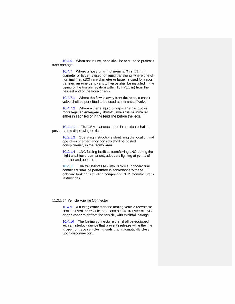
10.4.6 When not in use, hose shall be secured to protect it from damage.
10.4.7 Where a hose or arm of nominal 3 in. (76 mm) diameter or larger is used for liquid transfer or where one of nominal 4 in. (100 mm) diameter or larger is used for vapor transfer, an emergency shutoff valve shall be installed in the piping of the transfer system within 10 ft (3.1 m) from the nearest end of the hose or arm.
10.4.7.1 Where the flow is away from the hose, a check valve shall be permitted to be used as the shutoff valve.
10.4.7.2 Where either a liquid or vapor line has two or more legs, an emergency shutoff valve shall be installed either in each leg or in the feed line before the legs.
10.4.11.1 The OEM manufacturer's instructions shall be
posted at the dispensing device
10.2.1.3 Operating instructions identifying the location and operation of emergency controls shall be posted conspicuously in the facility area.
10.2.1.4 LNG fueling facilities transferring LNG during the night shall have permanent, adequate lighting at points of transfer and operation.
10.4.11 The transfer of LNG into vehicular onboard fuel containers shall be performed in accordance with the onboard tank and refueling component OEM manufacturer's instructions.
11.3.1.14 Vehicle Fueling Connector
10.4.9 A fueling connector and mating vehicle receptacle shall be used for reliable, safe, and secure transfer of LNG or gas vapor to or from the vehicle, with minimal leakage.
10.4.10 The fueling connector either shall be equipped with an interlock device that prevents release while the line is open or have self-closing ends that automatically close upon disconnection.

11.3.1.15 Installation of Electrical Equipment 10.12 Electrical Equipment
10.2.4.9 Buildings and rooms used for storage or dispensing shall be classified in accordance with Table 10.2.2.4 for installations of electrical equipment.
10.12.1 Electrical equipment and wiring shall be as specified by and installed in accordance with NFPA 70, National Electrical Code, meeting the requirements of Class I, Group D, Division or Zone as specified in Table 10.2.2.4.
10.12.1.1 Electrical equipment on internal combustion engines installed in accordance with NFPA 37, Standard for the Installation and Use of Stationary Combustion Engines and Gas Turbines, shall not be subject to 10.12.1.
10.12.1.2 The LNG container and associated piping shall be electrically bonded and grounded.
10.12.2 Each interface between a flammable fluid system and an electrical conduit or wiring system, including process instrumentation connections, integral valve operators, foundation heating coils, canned pumps, and blowers, shall be sealed or isolated to prevent the passage of flammable fluids to another portion of the electrical installation.
10.12.3 Each seal, barrier, or other means used to comply with 10.12.2 shall be designed to prevent the passage of flammable fluids or gases through the conduit, stranded conductors, and cables.
10.12.4* A primary seal shall be provided between the flammable fluid and gaseous systems and the electrical conduit wiring system.
10.12.4.1 If the failure of the primary seal would allow the passage of flammable fluids and gases to another portion of the conduit or wiring system, an additional approved seal, barrier, or other means shall be provided to prevent the passage of the flammable fluid beyond the additional device or means in the event that the primary seal fails.
10.12.5 Each primary seal shall be designed to withstand the service conditions to which it is expected to be exposed.
10.12.5.1 Each additional seal or barrier and interconnecting enclosure shall meet the pressure and temperature requirements of the condition to which it could

be exposed in the event of failure of the primary seal, unless other approved means are provided to accomplish this purpose.
10.12.6 Unless specifically designed and approved for the purpose, the seals specified in 10.12.2 through 10.12.4 shall not be permitted to replace the conduit seals required by 501.15 of NFPA 70, National Electrical Code.
10.12.7 Where primary seals are installed, drains, vents, or other devices shall be provided for monitoring purposes to detect flammable fluids and leakage.
10.12.8 Static protection shall not be required when cargo transport vehicles or marine equipment are loaded or unloaded by conductive or nonconductive hose, flexible metallic tubing, or pipe connections through or from tight (top or bottom) outlets where both halves of metallic couplings are in contact.
Table 10.2.2.4 LNG Fueling Facility Electrical Area Classification
Part Location
Class I, Group D Division
or
Zonea Extent of Classified Areab
A LNG Fueling Facility Container Area
Indoors 1 Entire room
Outdoor, aboveground containers (other than portable)
1 Open area between a high-type dike and container wall where dike wall height exceeds distances between dike and container walls
2 Within 15 ft (4.6 m) in all directions from container, plus area inside a low-type diked or impounding area up to the height of the dike impoundment wall
Outdoor, belowground containers 1 Within any open space

between container walls and surrounding grade or dike
2 Within 15 ft (4.6 m) in all directions from roof and sides above grade
B Nonfired LNG Process Areas Containing Pumps, Compressors, Heat Exchangers, Piping, Connections Vessels, etc.
Indoors with adequate ventilation 2 Entire room and any adjacent room not separated by a gastight partition, and 15 ft (4.6 m) beyond any ventilation discharge vent or lower
Outdoors in open air at or above grade
2 Within 15 ft (4.6 m) in all directions from this equipment
C Pits, Trenches, or Sumps Located in or Adjacent to Division 1 or 2 Areas
1 Entire pit, trench, or sump
D Discharge from Relief Valves, Drains
1 Within 5 ft (1.5 m) from point of discharge
2 Beyond 5 ft (1.5 m) but within 15 ft (4.6 m) in all directions from point of discharge
E Vehicle/Cargo Transfer Area
Indoors with adequate ventilationc 1 Within 5 ft (1.5 m) in all directions from point of transfer
2 Beyond 5 ft (1.5 m) of entire room and 15 ft (4.6 m) beyond ventilation vent
Outdoors in open air at or above grade
1 Within 5 ft (1.5 m) in all directions from point of transfer
2 Beyond 5 ft (1.5 m) but within 15 ft (4.6 m) in all directions from the point of transfer
aSee Article 500, “Hazardous (Classified) Locations,” in NFPA 70, National Electrical Code, for definitions of classes, groups, and divisions.

bThe classified area shall not extend beyond an unpierced wall, roof, or solid vaportight partition.
cVentilation is considered adequate when provided in accordance with the provisions of this code.
11.3.1.16 Stray or Impressed Current 11.3.1.18 Installation of Emergency Shutdown Equipment 10.11.3 Emergency Shutdown Device (ESD).
10.11.3.1 Instrumentation for LNG fueling facilities shall be designed so that, in the event of a power or instrumentation failure, the system goes into a fail-safe condition until the operators either reactivate or shut down the system.
10.11.3.2 All ESDs shall be manually reset.
11.3.3 Dispensing to Non-Public Users 11.3.3.1 General 11.3.3.2 Indoor Non-Public Fueling (reserved) 11.3.3.2.1 General
11.3.3.2.1.1 Vehicle Refueling Appliance in Non-residential Occupancies (Reserved)
11.3.3.2.2 Indoor Non-Public Fast Fill Fueling (reserved) 11.3.3.2.2.1 Equipment location 11.3.3.2.2.2 Ventilation 11.3.3.2.2.3 Electrical Classification 11.3.3.2.2 4 Fire Detection 11.3.3.2.2.5 Fire Alarm System 11.3.3.2.2.6 Emergency Shutdown System 11.3.3.2.2.7 Dispensing equipment 11.3.3.2.3 Indoor Non-Public Slow Fill Fueling (reserved) 11.3.3.2.4 Indoor Residential Slow Fill Fueling (reserved) 11.3.3.3.Outdoor Non-Public Fueling 11.3.3.3.1 General 11.3.3.3.2 Outdoor Non-Public Fast Fill Fueling 11.3.3.3.5 Outdoor Non-Public Fueling from Transport Vehicles Including Marine Vessels
11.3.3.3.5.1 Mobile Refueling Stations 10.1.2 All dispensing of LNG, including mobile refueling, into vehicle onboard fuel systems shall comply with the
Commented [BS9]: Non-public fueling will be first, followed by public fueling requirements. Will be renumbered in final draft.

requirements of a permanent LNG refueling installation at the point of dispensing fuel. (all sections below are reserved)
11.3.3.3.5.1.1 Mobile Refueling Vehicles 11.3.3.3.5.1.2 AHJ Approval 11.3.3.3.5.1.3 Dispensing Area 11.3.3.3.5.1.4 Dispensing Operation 11.3.3.3.5.1.5 Transfer Area 11.3.3.3.5.1.6 Refueling from Vehicle Mounted Tank At Commercial and Industrial Facilities
10.4.13 The provisions of Section 10.4 shall not apply to dispensing from vehicle-mounted tanks located at commercial and industrial facilities used in connection with their business where the following conditions are met:
(1) An inspection of the premises and operations shall have been made and approval granted by the AHJ.
(2) The vehicle-mounted container shall comply with requirements of DOT.
(3) The dispensing hose shall not exceed 50 ft (15 m) in length.
(4) Nighttime deliveries shall be made only in lighted areas.
11.3.3.3.5.2 Marine Vessel Transfer (reserved) 11.4 Storage 11.4.1 General Applicable requirements of Chapter 9,10,1414 11.4.2 Indoor Storage Applicable requirements of Chapters 11.4.3 Outdoor Storage 11.4.4 Vaults for Above Ground Storage 11.4.5 Underground Storage System 11.5 CNG 11.6 LNG 11.3.2 Dispensing to the Public Commented [BS10]: Flip this section as well. Non-public
fueling will be first and public second.

11.3.2.1 General 10.2.1.1 LNG fueling facilities that are permitted to be unattended shall be designed to secure all equipment from tampering.
10.2.1.2 Storage and transfer equipment at unattended facilities shall be secured to prevent tampering.
11.3.2.2 Indoor Public Fueling section.10.2.4 Indoor Fueling.
10.2.4.1 Building Construction.
10.2.4.1.1 Buildings reserved exclusively for an LNG fueling facility shall be of Type I or Type II construction in accordance with NFPA 5000, Building Construction and Safety Code.
10.2.4.1.2 Windows and doors shall be located so as to permit ready egress in case of emergency.
10.2.4.8 LNG piping entering a building shall be provided with shutoff valves located outside the building.
11.3.2.2.1.1 Dispensing
11.3.2.2.1.2 Deflagation Venting10.2.4.2* Deflagration Venting.
10.2.4.2.1 Deflagration venting shall be provided only in the exterior walls or the roof.
11.3.2.2.1.3 Vents
10.2.4.2.2 Vents shall consist of any one or a combination of the following:
(1) Walls of light material
(2) Lightly fastened hatch covers
(3) Lightly fastened, outward-opening doors in exterior walls
(4) Lightly fastened walls or roof 11.3.2.2.1.4 Snow Loads 11.3.2.2.1.5 Rooms within Buildings

10.2.4.5 Dispensing equipment located inside or attached to buildings used for other purposes shall comply with the following:
(1) The dispensing room shall have a minimum of one external wall.
(2) Interior walls or partitions shall be continuous from floor to ceiling, be anchored in accordance with the building code, and have a fire resistance rating of at least 2 hours.
(3) The interior finish of the dispensing room shall be constructed of noncombustible or limited-combustible materials. (See Section 4.5 for noncombustible or limited-combustible.)
(4) In the interior walls of the dispensing room, doors shall be listed as 1-hour fire doors that are installed in accordance with NFPA 80, Standard for Fire Doors and Other Opening Protectives.
(5) A ventilation system for a dispensing room within or attached to another building shall be separated from any ventilation system for the other building.
(6) Access to the dispensing room shall be from outside the primary structure only.
10.2.4.5.1 Access from within the primary structure shall be permitted where such access is made through a barrier space having two vapor-sealing, self-closing fire doors having a fire resistance rating equal to that of the wall.
10.2.4.6 Access doors or fire doors shall be kept unobstructed at all times.
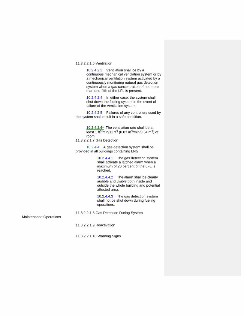
11.3.2.2.1.6 Ventilation
10.2.4.2.3 Ventilation shall be by a continuous mechanical ventilation system or by a mechanical ventilation system activated by a continuously monitoring natural gas detection system when a gas concentration of not more than one-fifth of the LFL is present.
10.2.4.2.4 In either case, the system shall shut down the fueling system in the event of failure of the ventilation system.
10.2.4.2.5 Failures of any controllers used by the system shall result in a safe condition.
10.2.4.2.6* The ventilation rate shall be at least 1 ft3/min/12 ft3 (0.03 m3/min/0.34 m3) of room
11.3.2.2.1.7 Gas Detection
10.2.4.4 A gas detection system shall be provided in all buildings containing LNG.
10.2.4.4.1 The gas detection system shall activate a latched alarm when a maximum of 20 percent of the LFL is reached.
10.2.4.4.2 The alarm shall be clearly audible and visible both inside and outside the whole building and potential affected area.
10.2.4.4.3 The gas detection system shall not be shut down during fueling operations.
11.3.2.2.1.8 Gas Detection During System Maintenance Operations
11.3.2.2.1.9 Reactivation
11.3.2.2.1.10 Warning Signs

10.2.4.7 Signs and markings and the words “WARNING — NO SMOKING” shall be in red letters at least 1 in. (25 mm) high on a white background.
11.3.2.2.2 Indoor Public Full Service Fueling (reserved for all indoor public fueling) 11.3.2.2.3 Indoor Public Attended Self Service 11.3.2.2.4 Indoor Public Unattended Self Service 11.3.2.3 Outdoor Public Fueling
11.3.2.3.1 General
11.3.2.3.1.X Dispensing Equipment Location
10.4.12 The spacing of LNG dispensing equipment relative to other equipment, activities, nearby property lines, and other exposures in a fuel dispensing forecourt shall be approved by the AHJ.
11.3.2.3.2.X Point of Transfer 11.3.2.3.2 Outdoor Public Full Service Fueling 11.3.2.3.3 Outdoor Public Attended Self Service Fueling 11.3.2.3.4 Outdoor Public Unattended Self Service Fueling
11.X.1 Mobile Fueling Stations (Reserved)
11.X.2 Marine Vessel Transfer
14.10 Marine Service Stations.
14.10.1 11.X.2.1 Marine service stations for fueling natural gas–powered marine vessels shall be in accordance with NFPA 30A, Code for Motor Fuel Dispensing Facilities and Repair Garages.
14.8 11.X.2.2 Fueling Systems.
14.8.1 11.X.2.2.3 LNG fueling systems shall be in accordance with NFPA 303, Fire Protection Standard for Marinas and Boatyards.
14.8.2 11.X.2.2.4 The following paragraphs of NFPA 303, Fire Protection Standard for Marinas and Boatyards, shall be revised as follows when using LNG as a fuel:
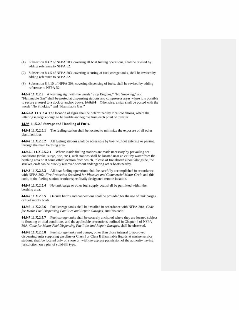
(1) Subsection 8.4.2 of NFPA 303, covering all boat fueling operations, shall be revised by adding reference to NFPA 52.
(2) Subsection 8.4.5 of NFPA 303, covering securing of fuel storage tanks, shall be revised by adding reference to NFPA 52.
(3) Subsection 8.4.10 of NFPA 303, covering dispensing of fuels, shall be revised by adding reference to NFPA 52.
14.5.2 11.X.2.3 A warning sign with the words “Stop Engines,” “No Smoking,” and “Flammable Gas” shall be posted at dispensing stations and compressor areas where it is possible to secure a vessel to a dock or anchor buoys. 14.5.2.1 Otherwise, a sign shall be posted with the words “No Smoking” and “Flammable Gas.”
14.5.2.2 11.X.2.4 The location of signs shall be determined by local conditions, where the lettering is large enough to be visible and legible from each point of transfer.
14.9* 11.X.2.5 Storage and Handling of Fuels.
14.9.1 11.X.2.5.1 The fueling station shall be located to minimize the exposure of all other plant facilities.
14.9.2 11.X.2.5.2 All fueling stations shall be accessible by boat without entering or passing through the main berthing area.
14.9.2.1 11.X.2.5.2.1 Where inside fueling stations are made necessary by prevailing sea conditions (wake, surge, tide, etc.), such stations shall be located near an exit by water from the berthing area or at some other location from which, in case of fire aboard a boat alongside, the stricken craft can be quickly removed without endangering other boats nearby.
14.9.3 11.X.2.5.3 All boat fueling operations shall be carefully accomplished in accordance with NFPA 302, Fire Protection Standard for Pleasure and Commercial Motor Craft, and this code, at the fueling station or other specifically designated remote location.
14.9.4 11.X.2.5.4 No tank barge or other fuel supply boat shall be permitted within the berthing area.
14.9.5 11.X.2.5.5 Outside berths and connections shall be provided for the use of tank barges or fuel supply boats.
14.9.6 11.X.2.5.6 Fuel storage tanks shall be installed in accordance with NFPA 30A, Code for Motor Fuel Dispensing Facilities and Repair Garages, and this code.
14.9.7 11.X.2.5.7 Fuel storage tanks shall be securely anchored where they are located subject to flooding or tidal conditions, and the applicable precautions outlined in Chapter 4 of NFPA 30A, Code for Motor Fuel Dispensing Facilities and Repair Garages, shall be observed.
14.9.8 11.X.2.5.8 Fuel storage tanks and pumps, other than those integral to approved dispensing units supplying gasoline or Class I or Class II flammable liquids at marine service stations, shall be located only on shore or, with the express permission of the authority having jurisdiction, on a pier of solid-fill type.

14.9.9 11.X.2.5.9 Approved dispensing units with or without integral pumps shall be permitted to be located on shore, on piers of solid-fill type, or on open piers, wharves, or floating piers.
14.9.10 11.X.2.5.10 Pumps that are not a part of the dispensing unit shall be located adjacent to the tanks.
14.9.11 11.X.2.5.11 Fuel pipelines shall be installed in accordance with the provisions of NFPA 30A, Code for Motor Fuel Dispensing Facilities and Repair Garages.
14.9.12 11.X.2.5.12 Dispensing units for transferring fuels from storage tanks shall be in accordance with the provisions of NFPA 30A, Code for Motor Fuel Dispensing Facilities and Repair Garages, and this code.
14.9.12.1 11.X.2.5.12.1 In the construction of the fuel hose assembly, provision shall be made so the fuel delivery nozzle is properly bonded to the shore electric grounding facilities.
14.9.13 11.X.2.5.13 Gasoline and other flammable liquids stored in drums or cans shall be kept separate from other plant facilities and stored and dispensed in accordance with applicable requirements of NFPA 30A, Code for Motor Fuel Dispensing Facilities and Repair Garages.


Public Input No. 112-NFPA 52-2013 [ Chapter 12 ]
Chapter 12 LNG Fire Protection
12.1 Application.
This chapter applies to LNG fire protection, personnel safety, security, LNG fueling facilities and training forLNG vehicles, and warning signs.
12.2 Fire Protection, Safety, and Security.
12.2.1
Fire protection shall be provided for all LNG fueling facilities.
12.2.1.1
The extent of such protection shall be determined by an evaluation based on sound fire protection andmethane detection engineering principles, analysis of local conditions, vehicle operations, hazards withinthe facility, exposure to or from other property, and the size of the LNG containers.
12.2.1.2
Guidance factors for making such an evaluation shall include the following:
(1) Type, quantity, and location of equipment necessary for the detection and control of fires, leaks, andspills of LNG, flammable refrigerants, and flammable gases or liquids
(2) Methods necessary for the protection of vehicles, equipment, and structures from the effects of fireexposure
(3) Equipment and processes to be incorporated within the ESD system
(4) Type, quantity, and location of sensors necessary to initiate automatic operation of the ESD system
(5) Availability and duties of individual facility personnel and the availability of external responsepersonnel during an emergency
(6) Protective equipment and special training required by personnel for emergency duties
12.2.2
The planning for emergency response measures shall be coordinated with the appropriate local emergencyagencies.
12.2.3 *
An emergency response plan shall be prepared to cover foreseeable emergency conditions.
12.2.4
The fire protection and methane detection equipment shall be maintained in accordance with themanufacturer's instructions and the AHJ.
12.3 Ignition Source Control.
12.3.1
Smoking and ignition sources shall be prohibited, except in accordance with 12.3.2.
12.3.2
Welding, oxygen–acetylene cutting, and similar operations shall be conducted only when and wherespecifically authorized and in accordance with the provisions of NFPA 51B, Standard for Fire PreventionDuring Welding, Cutting, and Other Hot Work.
12.3.3
Vehicles and other mobile equipment that constitute a potential ignition source shall be prohibited exceptwhere specifically authorized and under constant supervision or when at a transfer point specifically for thepurpose of transfer.
12.3.4
Vehicles delivering LNG to the facility or vehicles being fueled from the facility shall not be consideredsources of ignition.
National Fire Protection Association Report http://submittals.nfpa.org/TerraViewWeb/ContentFetcher?commentPara...
274 of 307 1/21/2014 3:31 PM

12.3.5
Vehicles containing fuel-fired equipment (e.g., recreational vehicles and catering trucks) shall be considereda source of ignition unless all sources of ignition such as pilot lights, electric igniters, burners, electricalappliances, and engines located on the vehicle being refueled are shut off completely before entering anarea where ignition sources are prohibited.
12.4 * Personnel Safety and Training.
12.4.1 Qualification of Personnel.
All persons employed in handling and dispensing LNG shall be trained in handling and operating duties andprocedures.
12.4.2
Protective clothing, face shield/goggles, and gloves shall be provided for all operators dispensing andhandling LNG.
12.4.2.1
Requirements, as specified in 12.4.2, shall be permitted to be excluded where equipment is demonstratedto operate without exposing operators to release of LNG or cold gases.
12.4.3 *
Training shall be conducted upon employment and every 2 years thereafter.
12.4.4
Training shall include the following:
(1) Information on the nature, properties, and hazards of LNG in both the liquid and gaseous phases
(2) Specific instructions on the facility equipment to be used
(3) Information on materials that are compatible for use with LNG
(4) Use and care of protective equipment and clothing
(5) Standard first aid and self-aid instruction
(6) Response to emergency situations such as fires, leaks, and spills
(7) Good housekeeping practices
(8) Emergency response plan as required in 12.2.3
(9) Evacuation and fire drills
12.4.5
Each operator shall provide and implement a written plan of initial training to instruct all designatedoperating and supervisory personnel in the characteristics and hazards of LNG used or handled at the site,including low LNG temperature, flammability of mixtures with air, odorless vapor, boil-off characteristics, andreaction to water and water spray; the potential hazards involved in operating activities; and how to carryout the emergency procedures that relate to personnel functions and to provide detailed instructions onmobile LNG operations.
12.5 Security.
12.5.1
The LNG fueling facility shall provide protection to minimize unauthorized access and damage to the facility.
12.5.2
Security procedures shall be posted in readily visible areas near the fueling facility.
12.6 Hazard Detection.
Gas leak detection and fire detection shall be installed based on the evaluation required in 12.2.1.1.
12.7 Parking of LNG Vehicles.
LNG vehicles shall be permitted to be parked indoors, provided such facilities or vehicles are equipped toprevent an accumulation of gas in a combustible mixture or the onboard fuel storage tank and fuel systemare drained of LNG and purged with inert gas or depressurized.
National Fire Protection Association Report http://submittals.nfpa.org/TerraViewWeb/ContentFetcher?commentPara...
275 of 307 1/21/2014 3:31 PM

12.8 Warning Signs.
For all LNG fueling facilities, the following signs shall be displayed in bright red letters on a whitebackground, with letters not less than 6 in. (152 mm) high:
(1) “No Smoking” or “No Smoking within 25 ft (7.6 m)”
(2) “Stop Motor”
(3) “No Open Flames Permitted”
(4) “Cryogenic Liquid or Cold Gas”
(5) “Flammable Gas”
(6) “Unodorized Gas”
Replace existing Chapter 12 with the attached Chapter 12 Marine Vessel Fuel and Safety Systems(Onboard) developed by a NFPA 52 Task Group
Additional Proposed Changes
File Name Description Approved
NFPA_52_Public_Input_Chapter_12_Marine_Vessel_Fuel_and_Safety_Systems.docx
NFPA 52 Chapter 12 Marine Vessel Fuel and Safety Systems (Onboard)
Statement of Problem and Substantiation for Public Input
The NFPA 52 Technical Committee approved the reorganization of NFPA 52 into an organizational layout that restructured requirements into General Requirements, Fuel Specific Requirements and Use Specific Requirements. This Chapter replaces existing Chapter 12 and was developed by a Task Group. For this draft being submitted as a Public Input, existing code sections have only been reorganized. No new or revised language has been included or any requirements deleted.
Submitter Information Verification
Submitter Full Name: Nancy Pehrson
Organization: CenterPoint Energy, Inc.
Street Address:
City:
State:
Zip:
Submittal Date: Thu Dec 26 13:23:32 EST 2013
Copyright Assignment
I, Nancy Pehrson, hereby irrevocably grant and assign to the National Fire Protection Association (NFPA) all and full rights in copyright inthis Public Input (including both the Proposed Change and the Statement of Problem and Substantiation). I understand and intend that Iacquire no rights, including rights as a joint author, in any publication of the NFPA in which this Public Input in this or another similar orderivative form is used. I hereby warrant that I am the author of this Public Input and that I have full power and authority to enter into thiscopyright assignment.
By checking this box I affirm that I am Nancy Pehrson, and I agree to be legally bound by the above Copyright Assignment and theterms and conditions contained therein. I understand and intend that, by checking this box, I am creating an electronic signature that will,upon my submission of this form, have the same legal force and effect as a handwritten signature
National Fire Protection Association Report http://submittals.nfpa.org/TerraViewWeb/ContentFetcher?commentPara...
276 of 307 1/21/2014 3:31 PM

Chapter 12 Marine Vessel Fuel and Safety Systems (Onboard)
12.1 General
12.1.1 14.1 Application.
14 12.1.1 This chapter applies to all commercial marine vessels and pleasure craft operating on LNG or CNG, including new and retrofit construction.
9.3.3.2.1 Marine vessels shall be capable of withstanding forces appropriate for the vessel.
14 12.1.2 Chapters 9, 10, and 12 of this code apply to commercial marine vessels and pleasure craft operating on LNG.
14 12.1.3 The requirements in 9.12.1.2, 9.12.1.3, 9.12.1.3.1, 9.12.1.6, 9.12.1.7, 9.12.2, 9.12.3.4, 9.12.3.5, and 9.12.8 and all subparts are not applicable to commercial marine vessels and pleasure craft operating on LNG.
12.1.2 Material Requirements. (Reserved)
14.4 12.1.3 Labeling.
14.4.1 12.1.3.1 Each marine vessel or pleasure craft shall be identified with weather-resistant, diamond-shaped labels located on an exterior vertical surface or near-vertical surface, at a location, as near to eye level as possible, where the vessel is routinely boarded, both port and starboard.
14.4.2 12.1.3.2 Depending on the size of the vessel, other labels shall be placed at logical locations to alert persons not familiar with the vessel, such as fire fighters or service personnel, as to the nature of the vessel.
14.4.3 12.1.3.3 The label shall be a minimum of 4.72 in. (120 mm) long by 3.27 in. (83 mm) high.
14.4.4 12.1.3.4 The marking shall consist of a border and the letters “CNG” or “LNG” as appropriate [1 in. (25 mm) minimum height centered in the diamond] of silver or white reflective luminous material on a blue background.
14.6 Fire Protection for Vessels. 12.1.4 Fire Protection and Fire-Fighting Equipment
12.1.4.1 General
14.6.1 12.1.4.1.1 Fire protection for vessels shall be in accordance with NFPA 302, Fire Protection Standard for Pleasure and Commercial Motor Craft.
Commented [BS1]: Update references in final draft
Commented [BS2]: Will need to update references in final draft

14.6.2 12.1.4.1.2 The following paragraphs of NFPA 302, Fire Protection Standard for Pleasure and Commercial Motor Craft, shall be revised as follows when used for LNG fuel systems:
(1) Paragraph 4.5.3.5(2) of NFPA 302, Fire Protection Standard for Pleasure and Commercial Motor Craft, covering blower intake duct openings, shall be revised to change the blower inlet duct opening location from the lower one-third of the compartment to the upper one-third of the compartment.
(2) Subsection 6.1.1 of NFPA 302, Fire Protection Standard for Pleasure and Commercial Motor Craft, general requirements for engine exhaust systems, shall be revised by expanding the exception to make the paragraph not applicable to exhaust cooling water in addition to engine-cooling water.
14.15.6 12.1.4.1.3 Gas-safe spaces adjacent to gas-dangerous spaces such as engine rooms and tank compartments shall have positive pressure ventilation systems capable of 30 volumetric exchanges an hour. 14.15.6.1 Their ventilation shall activate whenever an alarm is activated.
14.12.10 12.1.4.2 Fire-Fighting Equipment and Systems.
14.11.8 12.1.4.2.1 Machinery Spaces. LNG/CNG-powered marine vessels of all sizes shall carry fire equipment and systems normally required by U.S. Coast Guard, and meet all of the criteria in 14.11.8.1 12.1.4.2.2 through 14.11.8.4 12.4.4.2.7
14.11.8.1 12.1.4.2.2 In addition, engine rooms and engine compartments shall have a 150°F (66°C) thermal switch that activates fire-fighting equipment.
14.11.8.1.1 12.1.4.2.3 When the thermal switch is activated, a flashing red light and an audible alarm in the engine room wheelhouse (bridge) and other accommodation space or service space where crew are likely to congregate, such as a galley, activates, signaling the possible presence of a fire.
14.11.8.2 12.1.4.2.4 There shall be a 1-minute time delay, after which the engine room or the compartment is flooded with CO2 (or other USCG-approved inert gas) for 2 minutes.
14.11.8.2.1 12.1.4.2.5 Simultaneously, the ventilation fans shall be cut off for 2 minutes and then reactivated. Sufficient CO2 (or other USCG-approved inert gas) should be provided for two cycles.
14.11.8.3 12.1.4.2.6 A manual override switch shall be provided in the engine room or near the engine compartment to allow the response to be terminated in the event of false alarm or other contingency.
14.11.8.4 12.1.4.2.7 Controls shall be provided to allow manual activation of the CO2 (or other USCG-approved inert gas) system without a delay.
14.12.10.1 12.1.4.2.8 Tank Rooms. Tank rooms and compartments shall have a 150°F (66°C) thermal switch, which will activate automatic fire-fighting equipment.
14.12.2 The tank rooms shall be provided with positive pressure and passive ventilation.
Commented [BS3]: (Note: These sections include the original wording which does not read all that well because 14.11.8 was a separate section; for future editions of 12.1.4.2.2-12.1.4.2.7 (Machinery Spaces) and 12.1.4.2.8-12.1.4.2.15 (Tank Rooms) the wording should be edited for consistency, these sections may also be combined to avoid unnecessary duplication of standards.)

14.12.3 Ventilation of the tank rooms (compartments) shall be provided at 30 volumetric exchanges per hour minimum.
14.12.4 Air shall be taken from the weather deck and discharged to the weather deck through ducts that have a maximum separation from the fans.
14.12.5 The fans shall be capable of handling a combustible mixture, if necessary.
14.12.6 Multiple discharge ducts shall be used, if practical, to enhance ventilation.
14.12.10.2 12.1.4.2.9 When the switch is activated, a red flashing light and an audible alarm shall activate on a fire alarm panel in the wheelhouse (bridge) and in an accommodation or service space (such as a galley) where crew are likely to congregate.
14.12.10.3 12.1.4.2.10 Since the tank rooms or compartments are unmanned spaces, alarms shall not be required in those spaces.
14.12.10.4 12.1.4.2.11 Ventilation in the tank rooms or compartments shall be terminated simultaneously with the activation of the fire alarm.
14.12.10.4.1 12.1.4.2.12 One minute after the fire alarm is activated, the tank room or compartment shall be flooded with CO2 (or other USCG-approved inert gas).
14.12.10.4.2 12.1.4.2.13 A deluge system shall activate to keep the tanks cool and to assist in terminating fire.
14.12.10.5 12.1.4.2.14 The tank room or compartment shall be provided with a readily accessible override switch that will allow the crew to terminate the fire-fighting system in the event of a false alarm or other contingency.
14.12.10.6 12.1.4.2.15 A deluge system shall be permitted to be omitted from tank compartments on vessels too small to accommodate them. 14.12.10.6.1This determination shall be made by the AHJ.
14.11.8 Fire Equipment and Systems.
14.14 12.1.4.3 Deluge Systems.
14.14.1 12.1.4.3.1 Each deluge system that protects more than one area shall have at least one isolation valve at each branch connection and at least one isolation valve downstream from each branch connection to isolate damaged sections.
14.14.2 12.1.4.3.2 Each valved cross connection from the deluge system to the fire main shall be outside of the tank room or compartment.
14.14.3 12.1.4.3.3 Each pipe, fitting, and valve for the deluge system shall be made of fire-resistant and corrosion-resistant materials such as galvanized steel or galvanized iron pipe.
14.14.4 12.1.4.3.4 Each deluge system shall have a means of drainage to prevent corrosion of the system and freezing of the accumulated water in subfreezing temperatures.

14.14.5 12.1.4.3.5 Each deluge system shall have a dirt strainer that is located at the deluge system manifold or pump.
14.14.6 12.1.4.3.6 Water to the deluge system shall be supplied by a pump that is reserved for the use of the system.
14.15 12.1.4.4 Alarm Systems.
14.15.1 12.1.4.4.1 Alarm systems shall have a means of indicating which natural gas sensor has been activated.
14.15.2 12.1.4.4.2 The fire alarm systems shall have a means of indicating which thermal switch has been activated.
14.15.3 12.1.4.4.3 Audible alarms shall have an arrangement that allows the alarm to be turned off after sounding.
14.15.3.1 12.1.4.4.4 For remote group alarms, this arrangement shall not interrupt the alarm's actuation by other faults.
14.15.4 12.1.4.4.5 Each visual alarm shall be of the type that can be turned off only after the actuating is corrected.
14.15.5 12.1.4.4.6 Each vessel shall have means for testing each alarm.
12.1.5 Electrical Systems
14.12.11.2 Switches and overcurrent protective devices for lighting in the tank room(s) shall be in a gas-safe space.
14.11 Engine Rooms or Compartments. 12.1.6 Machinery Spaces
14.11.1 12.1.6.1 In engine rooms and engine compartments, all fuel lines shall be mounted in the overhead to provide the shortest route for leaking gas to flow to the exterior.
14.11.2 12.1.6.2 The pressure in the fuel lines passing through the engine room or engine compartment shall not exceed the pressure required to operate the engines.
14.11.3 12.1.6.3 All pressure regulators, except those mounted on the engine(s), shall be located in a tank room or tank compartment.
14.3.2 12.1.6.4 A pressure gauge installed in the engine room/compartment, fuel tank room/compartment, or other gas-dangerous space shall be equipped with a limiting orifice, a shatterproof dial lens, and a body relief.
14.11.5 Engines.
14.11.5.1 Blowout Plugs.
14.11.5.1.1 12.1.6.5 Since LNG/CNG engines have a natural gas atmosphere in the crankcase, they shall be provided with blowout plugs to relieve pressure in the event of a crankcase explosion.

14.11.5.1.2 12.1.6.6 Blowout plugs shall be located so as to limit risk to the crew.
14.11.5.2 Vessels having the capability shall be permitted to switch to another fuel to maintain power. (Note: Duplicate for current 12.1.8.2)
14.11.5.3 12.1.6.7 Engines shall be permitted to be located on the weather deck.
14.11.5.4 12.1.6.8 Engines on the weather deck shall be protected with a housing to prevent damage that can occur due to loading, unloading, or the general use of the vessel.
14.11.5.5 12.1.6.9 Shelters for engines installed on the weather deck shall be enclosures constructed of noncombustible or limited-combustible materials that have at least one side predominantly open, facing outboard, and roofs designed for dispersal of escaped gas. (See Section 4.5 for noncombustible or limited-combustible.)
14.11.5.6 12.1.6.10 An engine or engines on the weather deck shall be mounted in a location to minimize damage from collision.
14.11.5.7 12.1.6.11 No part of an engine or its appurtenances shall protrude beyond the sides or top of the vessel at the point where it is installed.
14.11.5.8 12.1.6.12 No portion of an engine on the weather deck shall protrude beyond the bow or stern of the vessel.
14.11.6 12.1.6.13 Natural Gas Monitoring.
14.11.6.1 12.1.6.13.1 Engine Rooms. Engine rooms shall have at least two natural gas detectors placed in the overhead at the fore and aft locations.
14.11.6.2 12.1.6.13.1.2 Monitoring stations shall be located in the engine room, in the wheelhouse (bridge), and in an accommodation or service space, such as a galley, where crew are likely to congregate.
14.11.6.3 12.1.6.13.1.3 When no gas is detected, the monitoring stations shall show a green light.
14.11.6.4 12.1.6.13.1.4 At a concentration of one-tenth of the LFL, power ventilation shall activate simultaneously along with a flashing yellow light at each monitoring station, accompanied by a klaxon.
14.11.6.5 12.1.6.13.1.5 Should the monitoring system detect a concentration of one-fifth of the LFL, a flashing red light shall activate at each monitoring station, accompanied by a siren.
14.11.6.5.1 12.1.6.13.1.6 When the one-fifth LFL is detected and the alarm system activated, an emergency fuel shutoff shall be activated simultaneously, terminating the flow of natural gas to the engine room.
14.11.6.6 12.1.6.13.1.7 A manual override switch shall be mounted in the engine room so that the crew can turn off the alarm and restore natural gas to the engines in the event of a false alarm or other contingency.

14.11.6.7 12.1.6.13.1.8 When the natural gas fuel supply is shut down due to loss of ventilation or detection of gas, the master shall ensure that the natural gas fuel supply is not used until the leak or other cause of the shutdown is found and corrected.
14.11.7 12.1.6.13.2 Engine Compartments.
14.11.7.1 12.1.6.13.2.1 Engine compartments shall be equipped with natural gas detection and intervention equipment in a fashion similar to engine rooms, except that a monitoring station shall be placed only at the wheelhouse (bridge).
14.11.7.2 12.1.6.13.2.2 If the vessel is large enough to make a fuel alarm inaudible if no one is manning the wheelhouse (bridge), then a monitoring station shall also be placed in the accommodation or service space.
14.13 12.1.6.14 Vent Masts.
14.13.1 12.1.6.14.1 All crankcases on natural gas–powered engines shall have a closed crankcase ventilation system or be vented to a vent mast.
14.13.2 12.1.6.14.2 Vessels having more than one engine shall be permitted to utilize a manifold.
14.13.3 12.1.6.14.3 Relief valves or common vent headers from relief valves shall discharge to a vent mast.
14.13.4 12.1.6.14.4 Vent masts shall have the following features:
(1) Vertically upward discharge
(2) Rain cap or other means of preventing the entrance of rain or snow
(3) Height of at least 10 ft (3 m) above the highest working level on the vessel
14.13.5 12.1.6.14.5 Relief valve vent masts and engine ventilation vent masts shall not be connected but be permitted to terminate at the same location.
14.11.4 12.1.6.15 Ventilation. Engine rooms or compartments shall be provided with positive pressure and passive ventilation.
14.11.4.1 12.1.6.15.1 Positive pressure ventilation shall provide a minimum of 30 volumetric exchanges per hour.
14.11.4.2 12.1.6.15.2 The ventilation system shall be capable of handling a combustible mixture, if necessary.
14.11.4.2.1 12.1.6.15.3 The ventilation fans shall take air from the weather deck and discharge it to the weather deck through ducts having a maximum separation from the fans.
14.11.4.2.2 12.1.6.15.4 Multiple discharge ducts shall be used, if practical, to enhance ventilation.

14.11.4.3 12.1.6.15.5 If engine combustion air is taken from the engine room (compartment), the 30 volumetric exchanges per hour shall be in excess of the maximum air volume per hour required by the engines.
14.7* Installation of Powered Ventilation.
14.7.1 12.1.6.15.6 Blower(s) capacity shall be selected in accordance with the blower capacity curve in Figure 4.5.3.1 of NFPA 302, Fire Protection Standard for Pleasure and Commercial Motor Craft.
14.7.1.1 12.1.6.15.7 Multiple blowers shall be permitted.
14.7.2 12.1.6.15.8 As installed, the blower system(s) shall exhaust air from the boat at a rate in accordance with the system performance curve in Figure 4.5.3.1 of NFPA 302, Fire Protection Standard for Pleasure and Commercial Motor Craft, when the engine is not operating and the blower is operating at the electrical system's nominal voltage.
14.7.3 12.1.6.15.9 Blowers shall be mounted above the normal level of accumulated bilge water.
Exception: Submersible blower motors.
14.7.4 12.1.6.15.10 Blowers shall be installed with ducts having intake openings that are as follows:
(1) Permanently secured
(2) Located in the upper one-third of the compartment
(3) Located above the normal level of accumulated bilge water
(4) Located as near below the engine(s) that they serve as practicable
14.7.5 12.1.6.15.11 Electrical wiring shall be installed in accordance with Chapter 9 or Chapter 10 of NFPA 302, Fire Protection Standard for Pleasure and Commercial Motor Craft.
14.7.6 12.1.6.15.12 Each boat that requires a powered ventilation system shall display a warning label that provides the information that follows, located in plain view of the operator, and located as close as practicable to each ignition switch (including auxiliary equipment).
14.7.7 12.1.6.15.13 The powered ventilation label shall read as follows:
WARNING:
Gas Can Explode Before Starting Engine: 1. Check Engine Compartment for Gasoline, Gas, or Vapors 2. Operate Blower for 4 Minutes
14.7.8* 12.1.6.15.14 Exhaust systems shall conform to the following:
(1) Be gastight to hull interiors

(2) Have all connections accessible
(3) Be supported to minimize failure from vibration, shock, expansion, and contraction
(4) Have no threaded fittings into nonmetallic exhaust system components
(5) Have no discharge from other devices into the exhaust
Exception: Engine-cooling water or exhaust-cooling water.
14.7.9 12.1.6.15.15 In case of conflict, this code shall have precedence over the requirements of NFPA 302, Fire Protection Standard for Pleasure and Commercial Motor Craft.
14.12 Tank Rooms or Compartments. 12.1.7 Fuel Tanks
14.12.1 12.1.7.1 Tank rooms and tank compartments shall be airtight as well as watertight, with appropriate fittings used to seal penetrations through the bulkheads for wire or pipes passing through the tank rooms.
14.12.11 Lighting.
14.12.11.1 12.1.7.2 Tank rooms shall have at least two explosionproof lighting fixtures.
14.3.2 12.1.7.3 A pressure gauge installed in the engine room/compartment, fuel tank room/compartment, or other gas-dangerous space shall be equipped with a limiting orifice, a shatterproof dial lens, and a body relief.
14.12.7.1 12.1.7.4 Tank rooms or compartments shall have at least two natural gas sensors placed at or near the ceiling at fore and aft locations.
14.12.2 12.1.7.5 The tank rooms shall be provided with positive pressure and passive ventilation.
14.12.3 12.1.7.6 Ventilation of the tank rooms (compartments) shall be provided at 30 volumetric exchanges per hour minimum.
14.12.4 12.1.7.7 Air shall be taken from the weather deck and discharged to the weather deck through ducts that have a maximum separation from the fans.
14.12.5 12.1.7.8 The fans shall be capable of handling a combustible mixture, if necessary.
14.12.6 12.1.7.9 Multiple discharge ducts shall be used, if practical, to enhance ventilation.
14.2 12.1.7.10 Installation of Fuel Supply Containers.
14.2.1 12.1.7.10.1 Fuel supply containers on marine vessels shall be permitted to be located on the weather deck, above accommodation and service space, or below deck adjacent to accommodation and service space, provided all connections to the containers are external to or sealed and vented from these spaces.

14.2.1.1 12.1.7.10.2 Containers on the weather deck shall be protected with a housing to prevent damage that can occur due to loading, unloading, direct sunlight, and the general use of the vessel.
14.2.1.2 12.1.7.10.3 The housing shall be installed to prevent contact of the housing with the container(s) and to prevent entrapment of materials that could damage the container(s) or its coating.
14.2.1.3 12.1.7.10.4 The shelter(s) for storing the containers on the weather deck shall be an enclosure that is constructed of noncombustible or limited-combustible materials and has at least one side predominantly open, facing outboard, and a roof designed for ventilation and dispersal of escaped gas. (See Section 4.5 for noncombustible or limited-combustible.)
14.2.2 Position.
14.2.2.1 12.1.7.10.5 Each fuel supply container shall be mounted in a location that minimizes damage from collision.
14.2.2.2 12.1.7.10.6 No part of a container or its appurtenances on the weather deck shall protrude beyond the sides or top of the vessel at the point where it is installed.
14.2.2.3 12.1.7.10.7 No portion of a fuel supply container or container appurtenances shall protrude beyond the bow or the stern of the vessel.
14.2.2.4 12.1.7.10.8 Container valves shall be protected from physical damage using the vessel structure, valve protectors, or a suitable metal shield.
14.2.3 12.1.7.10.9 Each container cradle shall be secured to the vessel frame, either above or below or both, to prevent damage from slippage, loosening, or rotation using a method capable of withstanding a static force in the six principal directions of at least four times the weight of the fully pressurized container(s) or greater as is appropriate for the vessel.
14.2.4 12.1.7.10.10 Each fuel supply container in the rack shall be secured to its cradle in such a manner that it is capable of withstanding a static force applied in the six principal directions of four times the weight of the fully pressurized container with a maximum displacement of 0.5 in. (13 mm).
14.2.4.1 12.1.7.10.11 Metal clamping bands and their supports shall not be in direct contact with a container.
14.2.4.2 12.1.7.10.12 A resilient gasket that does not retain water shall be installed between the clamping bands and their supports and the container.
14.2.5 12.1.7.10.13 The container weight shall not be supported by outlet valves, manifolds, or other fuel connections.
14.2.6 12.1.7.10.14 Fuel supply containers located less than 18 in. (460 mm) from the exhaust system shall be shielded against direct heat.
14.2.7 12.1.7.10.15 The mounting system shall minimize fretting corrosion between the container and the mounting system.

14.2.8 12.1.7.10.16 Fuel supply containers shall not be installed so as to adversely affect the balance of the marine vessel.
14.2.9 12.1.7.10.17 A container, where located in a below-deck tank room or tank compartment that is capable of accumulating natural gas, shall be installed so that the pressure relief device for the protection of the container is installed in the same space as the container and the discharge from the pressure relief device is as follows:
(1) Vented to the outside through a metallic tube (vent mast) or hose no smaller than the outlet diameter of the relief device, secured at 12 in. (305 mm) intervals where the tube exceeds 24 in. (610 mm) in length and having a minimum burst pressure of at least one and one-half times the service pressure of the container at 400°F (204°C)
(2) Located so that the vent opening is not blocked by debris or otherwise affected by the elements
14.2.10 12.1.7.10.18 An LNG container located in a below-deck tank room or compartment shall be enclosed in a space constructed of materials approved for cryogenic service.
14.2.11 12.1.7.10.19 The enclosure shall be capable of containing leakage from the fuel tank.
14.5 Operation. 12.1.8 Operations.
14.3.1 12.1.8.1 A pressure gauge located within the wheelhouse (bridge) or accommodation or service space shall be installed in such a manner that no gas flows through the gauge in the event of failure.
14.12.7.5.3 12.1.8.2 Vessels having the capability shall be permitted to switch to another fuel.
12.1.8.3 Fuel Transfers
14.5.1 12.1.8.3.1 Where natural gas is being transferred to or from a marine vessel, the engines shall be turned off.
14.5.1.1 12.1.8.3.2 Engine operation shall be permitted to hold the vessel in position while refueling or when, in the opinion of the master, the safety of the vessel is at issue.
14.5.1.2 12.1.8.3.3 The master shall be permitted to elect to operate generators during refueling.
14.12.7 12.1.8.4 Natural Gas Monitoring.
14.12.7.2 12.1.8.4.1 When no gas is detected, the monitoring stations shall show a green light.
14.12.7.3 12.1.8.4.2 Two levels of alarm shall be used for signaling the need for intervention.
14.12.7.4 12.1.8.4.3 An alarm shall activate when one-tenth of the LFL is detected by a monitor.

14.12.7.4.1 12.1.8.4.4 A flashing yellow light and a klaxon shall be activated in the engine room and in the wheelhouse (bridge), as well as in an accommodation or service space, such as a galley, where crew are likely to congregate. 14.12.7.4.2 Simultaneously, power ventilation shall activate.
14.12.7.4.3 12.1.8.4.5 On vessels with a tank compartment, a flashing yellow light and an audible signal shall activate in the wheelhouse (bridge).
14.12.7.4.4 12.1.8.4.6 If the vessel is large enough to cause the alarm to be inaudible if no one is manning the wheelhouse (bridge), a second warning station shall activate in an accommodation or service space where crew are likely to congregate.
14.12.7.5 12.1.8.4.7 At one-fifth of LFL, a second alarm shall activate, utilizing a flashing red light and a siren.
14.12.7.5.1 12.1.8.4.8 These monitoring stations shall be located as are the monitoring stations for the one-tenth LFL.
14.12.7.5.2 12.1.8.4.9 When the one-fifth LFL warning is activated, an automatic fuel shutoff valve will terminate flow of natural gas from the tank room or compartment, ventilation shall terminate, CO2 (or other USCG-approved inert gas) shall flood the tank room, and a water deluge system shall be activated.
14.12.7.7 12.1.8.4.10 When the LNG fuel supply is shut down due to loss of ventilation or detection of gas, the master shall ensure that the LNG fuel supply is not used until the leak or other cause of the shutdown is found and corrected.
14.12.9 12.1.8.4.11 A labeled override switch shall be available in a readily accessible location to turn off the tank room or compartment warning system in the event of a false alarm or other contingency and to shut down the CO2 (or other USCG-approved inert gas) and deluge.
14.16 12.1.8.5 Safety Equipment and Training.
14.16.1 12.1.8.5.1 Marine vessels with tank rooms and engine rooms shall have the following:
(1) Three self-contained, pressure demand–type, air-breathing apparatus approved by the Mine Safety and Health Administration (MSHA) or the National Institute for Occupational Safety and Health (NIOSH), each having at least a 30-minute capacity
(2) Three spare bottles of air for the self-contained air-breathing apparatus, each having at least a 30-minute capacity
(3) Three explosion-proof flashlights
(4) Three helmets that meet ANSI Z89.1, Personal Protection — Protective Headwear for Industrial Workers — Requirements
(5) Three sets of goggles that meet the specification ANSI Z87.1, Practice for Occupational and Educational Eye and Face Protection
(6) An air compressor to recharge the bottles for the air-breathing apparatus

(7)* Portable handheld natural gas detectors provided to aid in evaluating alarms and for making a survey of the vessel
14.16.1.1 12.1.8.5.2 Portable handheld natural gas detectors shall be carried by personnel working in a compartment containing gas storage or transmission equipment.
14.16.1.2 12.1.8.5.3 Portable handheld natural gas detectors shall allow locating specific leaks at very low levels of detection.
14.16.1.3 12.1.8.5.4 A vessel with a tank room shall have at least two of the sensors described in 14.16.1.1 12.1.8.5.2.
14.16.2 12.1.8.5.5 Vessels having engine rooms and tank rooms shall have a portable analyzer that measures oxygen levels in an inert atmosphere.
14.16.3 12.1.8.5.6 Before allowing anyone to enter a space that has had a gas leak and repair, the master shall ensure that the space has an oxygen concentration of at least 19.5 percent oxygen by volume and is free of natural gas.
14.16.4 12.1.8.5.7 The master shall ensure that the compressed air-breathing equipment is inspected at least once a month by a licensed officer and that the date of inspection and condition of the equipment is placed in the vessel's log.
14.17 Safety Training.
14.17.1 12.1.8.5.8 A written safety guide for the vessel and for the safety equipment and procedures shall be provided.
14.17.2 12.1.8.5.9 The safety guide shall outline all safety systems and equipment and their operation.
14.17.3 12.1.8.5.10 Crews shall be trained to operate the LNG/CNG-powered vessel and perform repairs. 14.17.4 12.1.8.5.11 Training

Public Input No. 16-NFPA 52-2013 [ New Section after 12.2.2 ]
TITLE OF NEW CONTENT
Type your content here ...
All-weather accessibility to the site for emergency services equipment shall be provided.
Statement of Problem and Substantiation for Public Input
Emergency service vehicles need access to the site under all weather coniditons.
Submitter Information Verification
Submitter Full Name: Nancy Pehrson
Organization: CenterPoint Energy, Inc.
Street Address:
City:
State:
Zip:
Submittal Date: Tue Dec 10 13:45:45 EST 2013
Copyright Assignment
I, Nancy Pehrson, hereby irrevocably grant and assign to the National Fire Protection Association (NFPA) all and full rights in copyright inthis Public Input (including both the Proposed Change and the Statement of Problem and Substantiation). I understand and intend that Iacquire no rights, including rights as a joint author, in any publication of the NFPA in which this Public Input in this or another similar orderivative form is used. I hereby warrant that I am the author of this Public Input and that I have full power and authority to enter into thiscopyright assignment.
By checking this box I affirm that I am Nancy Pehrson, and I agree to be legally bound by the above Copyright Assignment and theterms and conditions contained therein. I understand and intend that, by checking this box, I am creating an electronic signature that will,upon my submission of this form, have the same legal force and effect as a handwritten signature
National Fire Protection Association Report http://submittals.nfpa.org/TerraViewWeb/ContentFetcher?commentPara...
277 of 307 1/21/2014 3:31 PM

Public Input No. 23-NFPA 52-2013 [ New Section after 12.2.4 ]
TITLE OF NEW CONTENT
Type your content here ...
An operating portable flammable gas indicator shall be readily available.
Statement of Problem and Substantiation for Public Input
Evaluating problems with the gas detection system and its unavailablity during repairsmay require monitoring with a portable unit.
Submitter Information Verification
Submitter Full Name: Nancy Pehrson
Organization: CenterPoint Energy, Inc.
Street Address:
City:
State:
Zip:
Submittal Date: Wed Dec 11 12:33:31 EST 2013
Copyright Assignment
I, Nancy Pehrson, hereby irrevocably grant and assign to the National Fire Protection Association (NFPA) all and full rights in copyright inthis Public Input (including both the Proposed Change and the Statement of Problem and Substantiation). I understand and intend that Iacquire no rights, including rights as a joint author, in any publication of the NFPA in which this Public Input in this or another similar orderivative form is used. I hereby warrant that I am the author of this Public Input and that I have full power and authority to enter into thiscopyright assignment.
By checking this box I affirm that I am Nancy Pehrson, and I agree to be legally bound by the above Copyright Assignment and theterms and conditions contained therein. I understand and intend that, by checking this box, I am creating an electronic signature that will,upon my submission of this form, have the same legal force and effect as a handwritten signature
National Fire Protection Association Report http://submittals.nfpa.org/TerraViewWeb/ContentFetcher?commentPara...
278 of 307 1/21/2014 3:31 PM

Public Input No. 55-NFPA 52-2013 [ Section No. 12.4.4 ]
12.4.4
Training shall include the following:
(1) Information on the nature, properties, and hazards of LNG in both the liquid and gaseous phasesincluding low LNG temperature, flammability of mixtures with air, odorless vapor, boil-offcharacteristics and reactions to water and water spray.
(2) The potential hazards involved in operating activities
(3) Delete Specific instructions on the facility equipment to be used and replace with
Operating and maintaining facility equipment per the operation and maintenance manuals
Add
LNG transfer procedures and d etailed instructions on mobile LNG operations
(1) Information on materials that are compatible for use with LNG
(2) Use and care of protective equipment and clothing
(3) Standard first aid and self-aid instruction
(4) Response to emergency situations such as fires, leaks, and spills and other personnel functions
(5) Good housekeeping practices
(6) Emergency response plan as required in 12.2.3
(7) Evacuation and fire drills
Statement of Problem and Substantiation for Public Input
Adds training requirements for requirements for bulk LNG transfer and operation and maintenanceprocedures defined in manuals and incorporates training requirements from 12.4.5 current stated as being initial training requirements.
Submitter Information Verification
Submitter Full Name: Nancy Pehrson
Organization: CenterPoint Energy, Inc.
Street Address:
City:
State:
Zip:
Submittal Date: Wed Dec 18 10:41:45 EST 2013
Copyright Assignment
I, Nancy Pehrson, hereby irrevocably grant and assign to the National Fire Protection Association (NFPA) all and full rights in copyright inthis Public Input (including both the Proposed Change and the Statement of Problem and Substantiation). I understand and intend that Iacquire no rights, including rights as a joint author, in any publication of the NFPA in which this Public Input in this or another similar orderivative form is used. I hereby warrant that I am the author of this Public Input and that I have full power and authority to enter into thiscopyright assignment.
By checking this box I affirm that I am Nancy Pehrson, and I agree to be legally bound by the above Copyright Assignment and theterms and conditions contained therein. I understand and intend that, by checking this box, I am creating an electronic signature that will,upon my submission of this form, have the same legal force and effect as a handwritten signature
National Fire Protection Association Report http://submittals.nfpa.org/TerraViewWeb/ContentFetcher?commentPara...
279 of 307 1/21/2014 3:31 PM

National Fire Protection Association Report http://submittals.nfpa.org/TerraViewWeb/ContentFetcher?commentPara...
280 of 307 1/21/2014 3:31 PM

Public Input No. 56-NFPA 52-2013 [ Section No. 12.4.5 ]
12.4.5
Each operator shall provide and implement a written plan of initial training to instruct all designatedoperating and supervisory personnel in the characteristics and hazards of LNG used or handled at the site,including low LNG temperature, flammability of mixtures with air, odorless vapor, boil-off characteristics, andreaction to water and water spray; the potential hazards involved in operating activities; and how to carryout the emergency procedures that relate to personnel functions and to provide detailed instructions onmobile LNG operations.
Delete due to inclusion in 12.4.4 in Public Input 55
Statement of Problem and Substantiation for Public Input
Delete due to inclusion in Public Input 55
Submitter Information Verification
Submitter Full Name: Nancy Pehrson
Organization: CenterPoint Energy, Inc.
Street Address:
City:
State:
Zip:
Submittal Date: Wed Dec 18 10:57:57 EST 2013
Copyright Assignment
I, Nancy Pehrson, hereby irrevocably grant and assign to the National Fire Protection Association (NFPA) all and full rights in copyright inthis Public Input (including both the Proposed Change and the Statement of Problem and Substantiation). I understand and intend that Iacquire no rights, including rights as a joint author, in any publication of the NFPA in which this Public Input in this or another similar orderivative form is used. I hereby warrant that I am the author of this Public Input and that I have full power and authority to enter into thiscopyright assignment.
By checking this box I affirm that I am Nancy Pehrson, and I agree to be legally bound by the above Copyright Assignment and theterms and conditions contained therein. I understand and intend that, by checking this box, I am creating an electronic signature that will,upon my submission of this form, have the same legal force and effect as a handwritten signature
National Fire Protection Association Report http://submittals.nfpa.org/TerraViewWeb/ContentFetcher?commentPara...
281 of 307 1/21/2014 3:31 PM

Public Input No. 113-NFPA 52-2013 [ Chapter 13 ]
Chapter 13 Installation Requirements for ASME Tanks for LNG
13.1 * Application.
This chapter provides requirements for the installation, design, fabrication, and siting of LNG containers of100,000 gal (378,000 L) capacities and less and their associated equipment for use in applications such asvehicle refueling facilities that are designed and constructed in accordance with ASME Boiler and PressureVessel Code.
13.1.1
The maximum aggregate storage capacity at a single fueling facility shall be 280,000 U.S. gal (1060 m3).
13.2 General.
Storage and transfer equipment at unattended facilities shall be secured to prevent tampering. [59A:13.2.3]
13.3 Containers.
13.3.1
All piping that is part of an LNG container, including piping between the inner and outer containers, shall bein accordance with either the ASME Boiler and Pressure Vessel Code, Section VIII, or ANSI/ASME B31.3,Process Piping. [59A:13.3.1]
13.3.2
Compliance with 13.3.1 shall be stated on or appended to the ASME Boiler and Pressure Vessel Code,Appendix W, Form U-1, “Manufacturer's Data Report for Pressure Vessels.” [59A:13.3.2]
13.3.3
Internal piping between the inner tank and the outer tank within the insulation space shall be designed forthe maximum allowable working pressure of the inner tank, with allowance for the thermal stresses.[59A:13.3.3]
13.3.4
Bellows shall not be permitted within the insulation space. [59A:13.3.4]
13.3.5
Containers shall be double-walled, with the inner tank holding LNG surrounded by insulation containedwithin the outer tank. [59A:13.3.5]
13.3.6
The inner tank shall be of welded construction and in accordance with the ASME Boiler and PressureVessel Code, Section VIII, and shall be ASME-stamped and registered with the National Board of Boilerand Pressure Vessel Inspectors or other agency that registers pressure vessels. [59A:13.3.6]
13.3.7
The inner tank supports shall be designed for shipping, seismic, and operating loads. [59A:13.3.7]
13.3.8
The support system to accommodate the expansion and contraction of the inner tank shall be designed sothat the resulting stresses imparted to the inner and outer tanks are within allowable limits. [59A:13.3.8]
13.3.9
The outer tank shall be of welded construction using any of the following materials:
(1) Any of the carbon steels in Section VIII, Part UCS of the ASME Boiler and Pressure Vessel Code attemperatures at or above the minimum allowable use temperature in Table 1A of the ASME Boiler andPressure Vessel Code, Section II, Part D
(2) Materials with a melting point below 2000°F (1093°C) where the container is buried or mounded
[59A:13.3.9]
National Fire Protection Association Report http://submittals.nfpa.org/TerraViewWeb/ContentFetcher?commentPara...
282 of 307 1/21/2014 3:31 PM

13.3.10
Where vacuum insulation is used, the outer tank shall be designed by either of the following:
(1) The ASME Boiler and Pressure Vessel Code, Section VIII, Parts UG-28, UG-29, UG-30, and UG-33,using an external pressure of not less than 15 psi (100 kPa)
(2) Paragraph 3.6.2 of CGA 341, Standard for Insulated Cargo Tank Specification for NonflammableCryogenic Liquids [59A:13.3.10]
13.3.11
Heads and spherical outer tanks that are formed in segments and assembled by welding shall be designedin accordance with the ASME Boiler and Pressure Vessel Code, Section VIII, Parts UG-28, UG-29, UG-30,and UG-33, using an external pressure of 15 psi (100 kPa). [59A:13.3.11]
13.3.12
Any portion of the outer tank surface exposed to LNG temperatures shall be designed for suchtemperatures or protected from the effects of such exposure.
13.3.13
The outer tank shall be equipped with a relief device or other device to release internal pressure.[59A:13.3.12]
13.3.13.1
The discharge area shall be at least 0.00024 in.2/lb (0.34 mm2/kg) of the water capacity of the inner tank,
but the area shall not exceed 300 in.2 (0.2 m2). [59A:13.3.12.1]
13.3.13.2
The relief device shall function at a pressure not exceeding the internal design pressure of the outer tank,the external design pressure of the inner tank, or 25 psi (172 kPa), whichever is least. [59A:13.3.12.2]
13.3.14
Thermal barriers shall be provided to prevent the outer tank from going below its design temperature.[59A:13.3.13]
13.3.15 Seismic Design.
National Fire Protection Association Report http://submittals.nfpa.org/TerraViewWeb/ContentFetcher?commentPara...
283 of 307 1/21/2014 3:31 PM

13.3.15.1
Shop-built containers designed and constructed in accordance with the ASME Boiler and Pressure VesselCode and their support systems shall be designed for the dynamic forces associated with horizontal andvertical accelerations as follows:
(1) For horizontal force:
(2) For vertical force:
where:
Zc = seismic coefficient equal to 0.60 SDS where SDS is the maximum design spectral acceleration
determined in accordance with the provisions of ASCE 7, Minimum Design Loads for Buildingsand Other Structures, using an importance factor, I, of 1.0 for the site class most representativeof the subsurface conditions where the LNG facility is located
W = total weight of the container and its contents
[59A:13.3.14.1]
13.3.15.2 Usage.
13.3.15.2.1
The method of design described in 13.3.15.1 shall be used only where the natural period, T, of theshop-built container and its supporting system is less than 0.06 second. [59A:13.3.14.2(A)]
13.3.15.2.2
If the natural period T is 0.06 or greater, 7.4.4.1 and 7.4.4.2 of NFPA 59A, Standard for the Production,Storage, and Handling of Liquefied Natural Gas (LNG), shall apply. [59A:13.3.14.2(B)]
13.3.15.3
The container and its supports shall be designed for the resultant seismic forces in combination with theoperating loads, using the allowable stresses increase shown in the code or standard used to design thecontainer or its supports. [59A:13.3.14.3]
13.3.15.4
The requirements of Section 13.3 shall apply to ASME containers built prior to July 1, 1996, whenreinstalled. [59A:13.3.14.4]
13.3.16
Each container shall be identified by the attachment of a nameplate(s) in an accessible location markedwith the information required by the ASME Boiler and Pressure Vessel Code and the following:
(1) Builder's name and date container was built
(2) Nominal liquid capacity
(3) Design pressure at the top of the container
(4) Maximum permitted liquid density
(5) Maximum filling level
(6) Minimum design temperature
[59A:13.3.15]
13.3.17
All penetrations of storage containers shall be marked with the function of the penetration. [59A:13.3.16]
13.3.18
Markings shall be legible under all conditions.
13.3.19 Container Filling.
Containers designed to operate at a pressure in excess of 15 psi (100 kPa) shall be equipped with adevice(s) that prevents the container from becoming liquid-full or the inlet of the relief device(s) frombecoming covered with liquid when the pressure in the container reaches the set pressure of the relievingdevice(s) under all conditions. [59A:13.4]
13.4 Container Foundations and Supports.
National Fire Protection Association Report http://submittals.nfpa.org/TerraViewWeb/ContentFetcher?commentPara...
284 of 307 1/21/2014 3:31 PM

13.4.1
LNG container foundations shall be designed and constructed in accordance with NFPA 5000, BuildingConstruction and Safety Code. [59A:13.5.1].
13.4.1.1
The design of saddles and legs shall include shipping loads, erection loads, wind loads, and thermal loads.[59A:13.5.2]
13.4.1.2
Foundations and supports shall have a fire resistance rating of not less than 2 hours and shall be resistantto dislodgment by hose streams. [59A:13.5.3]
13.4.2
LNG storage containers installed in an area subject to flooding shall be secured to prevent the release ofLNG or flotation of the container in the event of a flood. [59A:13.5.4]
13.5 Container Installation.
LNG containers of 1000 gal (3.8 m3) and smaller shall be located as follows:
(1) 125 gal (0.47 m3) or less, 0 ft (0 m) from property lines that can be built upon
(2) Larger than 125 gal (0.47 m3) to 1000 gal (3.8 m3), 10 ft (3.0 m) from property lines that can be builtupon
[59A:13.6.1]
13.5.1
The minimum distance from the edge of an impoundment or container drainage system serving
aboveground and mounded containers larger than 1000 gal (3.8 m3) shall be in accordance with Table13.5.1 for each of the following:
(1) Nearest offsite building
(2) The property line that can be built upon
(3) Spacing between containers
[59A:13.6.2.1]
Table 13.5.1 Distances from Containers and Exposuures
Container WaterCapacity
Minimum Distance from Edge ofImpoundment or Container Drainage
System to Offsite Buildings and PropertyLines That Can Be Built Upon
Minimum DistanceBetween Storage
Containers
gal m 3 ft m ft m
1000–2000 3.8–7.6 15 4.6 5 1.5
2001–18,000 ≥7.6–56.8 25 7.6 5 1.5
18,001–30,000 ≥56.8–114 50 15 5 1.5
30,001–70,000 ≥114–265 75 23
¼ of the sum of thediameters of adjacentcontainers [5 ft (1.5 m)
minimum]
>70,000 >2650.7 times the container diameter
[100 ft (30 m) minimum]
[59A: Table 13.6.2.1]
13.5.1.1
The distance from the edge of an impoundment or container drainage system to buildings or walls ofconcrete or masonry construction shall be reduced from the distance in Table 13.5.1 with the approval ofthe authority having jurisdiction with a minimum of 10 ft (3 m). [59A:13.6.2.2]
National Fire Protection Association Report http://submittals.nfpa.org/TerraViewWeb/ContentFetcher?commentPara...
285 of 307 1/21/2014 3:31 PM

13.5.1.2
Underground LNG tanks shall be installed in accordance with Table 13.5.1.2. [59A:13.6.3]
Table 13.5.1.2 Distances from Underground Containers and Exposures
Container WaterCapacity
Minimum Distance from Buildings and theAdjoining Property Line That Can Be Built
Upon
Distance BetweenContainers
gal m 3 ft m ft m
<18,000 <15.8 15 4.6 15 4.6
18,000–30,000 15.8–114 25 7.6 15 4.6
30,001–100,000 >114 40 12.2 15 4.6
[59A: Table 13.6.3]
13.5.2
Buried and underground containers shall be provided with means to prevent the 32°F (0°C) isotherm frompenetrating the soil. [59A:13.6.4]
13.5.3
Where heating systems are used, they shall be installed such that any heating element or temperaturesensor used for control can be replaced. [59A:13.6.5]
13.5.4
All buried or mounded components in contact with the soil shall be constructed from material resistant tosoil corrosion or protected to minimize corrosion. [59A:13.6.6]
13.5.5
A clear space of at least 3 ft (0.9 m) shall be provided for access to all isolation valves serving multiplecontainers. [59A:13.6.7]
13.5.6
LNG containers of greater than 125 gal (0.5 m3) capacity shall not be located in buildings. [59A:13.6.8]
13.5.7
LNG vehicles shall be permitted to be located in buildings.
13.6 Automatic Product Retention Valves.
13.6.1
All liquid and vapor connections, except relief valve and instrument connections, shall be equipped withautomatic failsafe product retention valves. [59A:13.7.1]
13.6.2
Automatic failsafe product retention valves shall be designed to close on the occurrence of any of thefollowing conditions:
(1) Fire detection or exposure
(2) Uncontrolled flow of LNG from the container
(3) Manual operation from a local and remote location
[59A:13.7.2]
13.6.3
Connections used only for flow into the container shall be equipped with either two backflow valves, inseries, or an automatic failsafe product retention valve. [59A:13.7.3]
13.6.4
Appurtenances shall be installed as close to the container as practical so that a break resulting fromexternal strain shall occur on the piping side of the appurtenance while maintaining intact the valve andpiping on the container side of the appurtenance. [59A:13.7.4]
13.7 Inspection.
13.7.1
Prior to initial operation, containers shall be inspected to ensure compliance with the engineering designand material, fabrication, assembly, and test provisions of this chapter. [59A:13.9.1]
National Fire Protection Association Report http://submittals.nfpa.org/TerraViewWeb/ContentFetcher?commentPara...
286 of 307 1/21/2014 3:31 PM

13.7.2
Inspectors shall be qualified in accordance with the code or standard applicable to the container and asspecified in NFPA 59A, Standard for the Production, Storage, and Handling of Liquefied Natural Gas(LNG). [59A:13.9.2]
13.7.3
Performance of any part of the inspection shall be permitted to be delegated to inspectors who areemployees of the operator's own organization, an engineering or scientific organization, or a recognizedinsurance or inspection company.
13.8 Testing and Purging of LNG Containers.
13.8.1 Shop Testing of LNG Containers.
13.8.1.1
The outer tank shall be leak tested. [59A:13.10.1]
13.8.1.2
Piping between the inner container and the first connection outside the outer container shall be tested inaccordance with ASME B 31.3, Process Piping. [59A:13.10.2]
13.8.1.3 Shipment of LNG Containers.
Containers shall be shipped under a minimum internal pressure of 10 psi (69 kPa) inert gas. [59A:13.11]
13.8.2 Field Testing of LNG Containers.
13.8.2.1
Containers and associated piping shall be leak tested prior to filling with LNG. [59A:13.12.1]
13.8.2.2
After acceptance tests are completed, there shall be no field welding on the LNG containers. [59A:13.12.2]
13.8.3 Welding on Containers.
13.8.3.1
Field welding shall be done only on saddle plates or brackets provided for the purpose. [59A:13.13.1]
13.8.3.2
Where repairs or modifications incorporating welding are required, they shall comply with the code orstandard under which the container was fabricated. [59A:13.13.2]
13.8.3.3
Retesting by a method appropriate to the repair or modification shall be required only where the repair ormodification is of such a nature that a retest actually tests the element affected and is necessary todemonstrate the adequacy of the repair or modification. [59A:13.13.3]
13.8.4 Container Purging Procedures.
Prior to placing an LNG container into or out of service, the container shall be inerted by an approvedinerting procedure.
13.9 Piping.
National Fire Protection Association Report http://submittals.nfpa.org/TerraViewWeb/ContentFetcher?commentPara...
287 of 307 1/21/2014 3:31 PM

13.9.1
All piping that is part of an LNG container and the facility associated with the container for handlingcryogenic liquid or flammable fluid shall be in accordance with ASME B 31.3, Process Piping, and thefollowing:
(1) Type F piping, spiral welded piping, and furnace buttwelded steel products shall not be permitted.
(2) All welding or brazing shall be performed by personnel qualified to the requirements of ASME B 31.3,Subsection 328.2, Welding Qualifications, and ASME Boiler and Pressure Vessel Code, Section IX,as applicable.
(3) Oxygen–fuel gas welding shall not be permitted.
(4) Brazing filler metal shall have a melting point exceeding 1000°F (538°C).
(5) All piping and tubing shall be austenitic stainless steel for all services below -20°F (-29°C).
(6) All piping and piping components, except gaskets, seals, and packing, shall have a minimum meltingpoint of 1500°F (816°C).
(7) Aluminum shall be used only downstream of a product retention valve in vaporizer service.
(8) Compression-type couplings used where they can be subjected to temperatures below -20°F (-29°C)shall meet the requirements of ASME B 31.3, Process Piping, Section 315.
(9) Stab-in branch connections shall not be permitted.
(10) Extended bonnet valves shall be used for all cryogenic liquid service, and they shall be installed sothat the bonnet is at an angle of not more than 45 degrees from the upright vertical position.
[59A:13.14.1]
13.9.2
The level of examination of piping shall be specified. [59A:13.14.2]
13.10 Container Instrumentation.
13.10.1 General.
Instrumentation for LNG facilities shall be designed so that, in the event of power or instrument air failure,the system will go into a failsafe condition that can be maintained until the operators can take action toreactivate or secure the system. [59A:13.15.1]
13.10.2 Level Gauging.
LNG containers shall be equipped with liquid level devices as follows:
(1) Containers of 1000 gal (3.8 m3) or larger shall be equipped with two independent liquid level devices.
(2) Containers smaller than 1000 gal (3.8 m3) shall be equipped with either a fixed length dip tube orother level devices.
(3) Containers of 1000 gal (3.8 m3) or larger shall have one liquid level device that provides a continuouslevel indication ranging from full to empty and that is maintainable or replaceable without taking thecontainer out of service.
[59A:13.15.2]
13.11 Pressure Gauging and Control.
National Fire Protection Association Report http://submittals.nfpa.org/TerraViewWeb/ContentFetcher?commentPara...
288 of 307 1/21/2014 3:31 PM
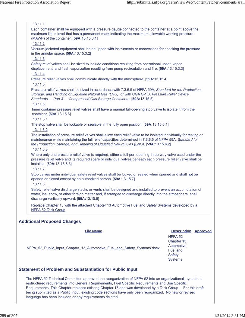
13.11.1
Each container shall be equipped with a pressure gauge connected to the container at a point above themaximum liquid level that has a permanent mark indicating the maximum allowable working pressure(MAWP) of the container. [59A:13.15.3.1]
13.11.2
Vacuum-jacketed equipment shall be equipped with instruments or connections for checking the pressurein the annular space. [59A:13.15.3.2]
13.11.3
Safety relief valves shall be sized to include conditions resulting from operational upset, vapordisplacement, and flash vaporization resulting from pump recirculation and fire. [59A:13.15.3.3]
13.11.4
Pressure relief valves shall communicate directly with the atmosphere. [59A:13.15.4]
13.11.5
Pressure relief valves shall be sized in accordance with 7.3.6.5 of NFPA 59A, Standard for the Production,Storage, and Handling of Liquefied Natural Gas (LNG), or with CGA S-1.3, Pressure Relief DeviceStandards — Part 3 — Compressed Gas Storage Containers. [59A:13.15.5]
13.11.6
Inner container pressure relief valves shall have a manual full-opening stop valve to isolate it from thecontainer. [59A:13.15.6]
13.11.6.1
The stop valve shall be lockable or sealable in the fully open position. [59A:13.15.6.1]
13.11.6.2
The installation of pressure relief valves shall allow each relief valve to be isolated individually for testing ormaintenance while maintaining the full relief capacities determined in 7.3.6.5 of NFPA 59A, Standard forthe Production, Storage, and Handling of Liquefied Natural Gas (LNG). [59A:13.15.6.2]
13.11.6.3
Where only one pressure relief valve is required, either a full-port opening three-way valve used under thepressure relief valve and its required spare or individual valves beneath each pressure relief valve shall beinstalled. [59A:13.15.6.3]
13.11.7
Stop valves under individual safety relief valves shall be locked or sealed when opened and shall not beopened or closed except by an authorized person. [59A:13.15.7]
13.11.8
Safety relief valve discharge stacks or vents shall be designed and installed to prevent an accumulation ofwater, ice, snow, or other foreign matter and, if arranged to discharge directly into the atmosphere, shalldischarge vertically upward. [59A:13.15.8]
Replace Chapter 13 with the attached Chapter 13 Automotive Fuel and Safety Systems developed by aNFPA 52 Task Group
Additional Proposed Changes
File Name Description Approved
NFPA_52_Public_Input_Chapter_13_Automotive_Fuel_and_Safety_Systems.docx
NFPA 52 Chapter 13 Automotive Fuel and Safety Systems
Statement of Problem and Substantiation for Public Input
The NFPA 52 Technical Committee approved the reorganization of NFPA 52 into an organizational layout that restructured requirements into General Requirements, Fuel Specific Requirements and Use Specific Requirements. This Chapter replaces existing Chapter 13 and was developed by a Task Group. For this draft being submitted as a Public Input, existing code sections have only been reorganized. No new or revised language has been included or any requirements deleted.
National Fire Protection Association Report http://submittals.nfpa.org/TerraViewWeb/ContentFetcher?commentPara...
289 of 307 1/21/2014 3:31 PM

Submitter Information Verification
Submitter Full Name: Nancy Pehrson
Organization: CenterPoint Energy, Inc.
Street Address:
City:
State:
Zip:
Submittal Date: Thu Dec 26 13:27:09 EST 2013
Copyright Assignment
I, Nancy Pehrson, hereby irrevocably grant and assign to the National Fire Protection Association (NFPA) all and full rights in copyright inthis Public Input (including both the Proposed Change and the Statement of Problem and Substantiation). I understand and intend that Iacquire no rights, including rights as a joint author, in any publication of the NFPA in which this Public Input in this or another similar orderivative form is used. I hereby warrant that I am the author of this Public Input and that I have full power and authority to enter into thiscopyright assignment.
By checking this box I affirm that I am Nancy Pehrson, and I agree to be legally bound by the above Copyright Assignment and theterms and conditions contained therein. I understand and intend that, by checking this box, I am creating an electronic signature that will,upon my submission of this form, have the same legal force and effect as a handwritten signature
National Fire Protection Association Report http://submittals.nfpa.org/TerraViewWeb/ContentFetcher?commentPara...
290 of 307 1/21/2014 3:31 PM

Chapter 13 Automotive Fuel and Safety Systems
13.2.1 Modifications 6.1.2.3 Modifications of a vehicle gaseous fuel system shall conform with, when available, the engineering recommendations of the original specifications of the original chassis vehicle manufacturer.
13.2.2 OEM Approved Equipment 9.11.1 OEM Approved Equipment. The following subsystems and components, if used, shall be recommended by the original equipment manufacturer (OEM) for the intended service.
(1) Vehicular fuel containers
(2) Fuel quantity gauging systems
(3) PRDs
(4) Pressure measurement devices
(5) Valves
(6) Pressure regulators
(7) Vaporizers
(8) Pumps
(9) Engine fuel delivery equipment
(10) Vehicle fueling receptacles
(11) Electrical equipment related to the fuel system
(12) Methane detection, fire protection, and suppression systems
5.3 System Approvals.
5.3.1* The following systems and system components shall be listed or approved:
(1) Pressure relief devices, including pressure relief valves
(2) Pressure gauges
(3) Pressure regulators
(4) Valves

(5) Hose and hose connections
(6) Vehicle fueling connections (nozzle and receptacle)
(7) Engine fuel systems
(8) Electrical equipment related to CNG systems
(9) Gas detection equipment and alarms
(10) Fire protection and suppression equipment
(11) Vehicle fueling appliances (VFAs)
5.3.1.1 Vehicles certified by the manufacturer to be in compliance with applicable federal motor vehicle safety standards shall not be subject to 5.3.1. (13.3.2)
13.2.3 FSVIM documentation
6.1.2* Final-Stage Vehicle Integrator/Manufacturer.
6.1.2.2 The FSVIM shall obtain, when available, documented approval of the chassis original equipment and component manufacturers of the onboard fuel and detection systems components, proper installation, and application from each of the following:
(1) Vehicle
(2) Chassis
(3) Engine
(4) Gas detection
(5) Fuel system
13.2.4 Integration
6.1.2.1* The FSVIM shall have the responsibility for integration of the engine, fuel system, and gaseous detection system, where required, onto the vehicle chassis and for the operation of the vehicle.
6.2.4 Fuel-carrying components, with the exception of container valves, tubing, and fittings, shall be labeled or stamped with the following:
(1) Manufacturer's name or symbol
(2) Model designation
(3) Design service pressure

(4) Direction of fuel flow where necessary for correct installation
(5) Capacity or electrical rating, as applicable
6.2.2.2 All other components shall be designed or selected for service per the OEM's engineering requirements. 13.2.6 Installation of Fuel Supply containers
13.2.6.1 Locations of Fuel Supply Containers
6.3.2 Fuel supply containers on vehicles shall be permitted to be located within, below, or above the driver or passenger compartment, provided all connections to the container(s) are external to, or sealed and vented from, these compartments.
13.2.6.2 Containers Mounted in the Interior of Vehicles
9.12.2 Containers Mounted in the Interior of Vehicles.
9.12.2.1 Containers shall be installed and fitted so that no gas from fueling operations can be released inside the passenger compartment, by permanently installing the fueling receptacle outside the passenger compartment of the vehicle in a location protected from physical damage and dislodgment.
13.2.6.3 Installation of Containers6.3.1 Fuel supply containers shall be installed in accordance with the instructions of the container manufacturer and the requirements in 6.3.2 through 6.3.10. 13.2.6.4 Securing Containers
9.12.1.7 Containers shall be mounted to prevent their jarring loose, slipping, or rotating.
9.12.1.8 Containers shall be secured to the vehicle body, bed, or frame by means capable of withstanding the loads defined in 9.3.3. 13.2.6.5 Container Support(Reserved) 13.2.7 Installation of Venting Systems
13.2.89.12.2.2 Enclosures, structures, seals, and conduits used to vent enclosures shall be fabricated of materials designed to resist damage, blockage, or dislodgment caused by the movement of articles carried in the vehicle or by the closing of luggage compartment enclosures or vehicle doors.

9.12.2.2.1 Enclosures shall require the use of tools for removal.
Installation of Piping
6.5 Installation of Piping.
6.5.1 Manifolds connecting fuel containers shall be fabricated to minimize vibration.
6.5.1.1 Manifolds shall be installed in a protected location or shielded to prevent damage from unsecured objects.
6.5.2 Manifolds connecting containers or container pressure relief devices shall be designed to vent gas from the individual container(s) exposed to a fire so that all containers meet the requirements of Section 5.5.
13.2.9 Installation of Valves
9.12.4.1 Valves shall be mounted securely and shielded or installed in a protected location to prevent damage from vibration, shock, and unsecured objects.
9.12.4.2 Valves shall be installed so that their weight is not placed on, or supported by, the attached lines.
13.2.10 Installation of Pressure Gauges (Reserved)
13.2.11 Installation of Pressure Regulators
13.2.12 Installation of Wiring
9.12.7 Electrical Wiring.
9.12.7.1 Wiring shall be installed, supported, and secured in a manner to prevent damage due to vibration, shock, strains, wear, or corrosion.
9.12.7.2 All conductors shall be sized for the maximum anticipated load and shall be protected by overcurrent protection devices.
6.10 Wiring Installation.
6.10.1 Wiring shall be secured and protected from abrasion and corrosion to the same standard as the original wiring on the vehicle.
6.10.2 All wiring shall be sized according to the Society of Automotive Engineers (SAE) and fuse-protected. 13.2.13 Markings

6.11.3 In addition to the label(s) required by 6.11.1, Each CNG vehicle shall be identified with a weather-resistant, diamond-shaped label located on the exterior vertical surface or near-vertical surface on the lower right rear of the vehicle other than on the bumper of the vehicle. (or on the trunk lid of a vehicle so equipped, but not on the bumper or tailgate of any vehicle), inboard from any other markings
6.11.3.1 The labels for vehicles less than Class 6 shall be a minimum of 4.72 in. long × 3.27 in. high (120 mm × 83 mm).
6.11.3.2 The labels for Class 6 vehicles and greater shall be a minimum of 5.7 in. long × 4.2 in. high (145 mm × 107 mm).
6.11.3.3 The marking in the label required by 6.11.3.1 shall consist of a border and the letters “CNG” [1 in. (25 mm) minimum height centered in the diamond] of silver or white reflective luminous material on a blue background.
6.11.3.4 The marking in the label required by 6.11.3.2 shall consist of a border and the letters “CNG” or [1.2 in. (30 mm) minimum height centered in the diamond] of silver or white reflective luminous material on a blue background.
9.12.8.2 Each LNG-fueled vehicle shall be identified with a weather-resistant, diamond-shaped label located on an exterior vertical or near-vertical surface on the lower right rear of the vehicle (or on the trunk lid of a vehicle so equipped, but not on the bumper or tailgate of any vehicle), inboard from any other markings.
9.12.8.3 The labels for vehicles less than Class 6 shall be a minimum of 4.72 in. long × 3.27 in. high (120 mm × 83 mm).
9.12.8.4 The labels for Class 6 vehicles and greater shall be a minimum of 5.7 in. long × 4.2 in. high (145 mm × 107 mm).
9.12.8.5 The marking in the label required by 9.12.8.2 shall consist of a border and the letters “LNG” [1 in. (25 mm) minimum height centered in the diamond] of silver or white reflective luminous material on a blue background.
9.12.8.6 The marking in the label required by 9.12.8.3 shall consist of a border and the letters “LNG” [1.2 in. (30 mm) minimum height centered in the diamond] of silver or white reflective luminous material on a blue background.
13.2.14 System Testing (Reserved)
13.2.15 System Maintenance and Repair(Reserved) 13.2.16 Discharge from Vehicle Containers (Reserved) 13.3 CNG Engine Fuel Systems
13.3.2 System Component Qualifications (6.2)

13.3.2.1 5.3.2 Devices not otherwise specifically provided for shall be constructed to provide safety equivalent to that required for other parts of a system.
13.3.2.2 6.2.2 Temperature Range.
13.3.2.2.16.2.2.1 Components in the engine compartment shall be designed or selected for a minimum temperature range of −40°F to 250°F (−40°C to 121°C).
13.3.2.X 6.2.1 System Components shall comply with the applicable provision of CHaper 8 and this section.
13.3.3 Fuel Supply Container Racks Installation of Fuel System Equipment
6.3.2.1 Fuel supply containers shall be protected with a means to prevent damage that occurs due to road hazards, loading, unloading, direct sunlight, exhaust heat, and vehicle use, including accidental cargo leakage.
6.3.2.2 Shields, if present, shall be installed in a manner that prevents damage to the shield or coating in the following occurrences:
(1) Direct contact between the shield and the fuel supply container
(2) Trapping of solid materials or liquids between the shield and fuel supply container
6.3.2.3 The fuel supply container shall be positioned to prevent contact with vehicle components such as, but not limited to, frame members, body panels, or brake lines that leads to container fretting or abrasion over time.
6.3.3 Vehicle fuel supply containers shall be mounted in a location to minimize damage from collision.
6.3.3.1 Containers shall be protected by covers from accidental contact with overhead electrical wiring.
6.3.3.2* The fuel system, including containers, shall be installed with as much road clearance as practical.
6.3.3.3 This minimum clearance shall be measured from the road to the container, its housing, or its fittings, whichever is lowest, and shall not, with the vehicle loaded to its gross weight rating, allow any component to touch the road surface in the event of a flat tire or the removal of any tire.
6.3.3.4 No portion of a fuel supply container or container appurtenance mounted on the undercarriage of the vehicle shall be located ahead of the front axle or behind the point of attachment of the rear bumper to the vehicle.
6.3.3.4.1 Container valves shall be protected from physical damage using the vehicle structure, valve protectors, or a metal shield.
6.3.3.5 No part of the fuel supply container or its appurtenances shall protrude beyond the sides or top of any vehicle to prevent the container from being struck or punctured.

6.3.4 Each fuel supply container rack shall be secured to the vehicle body, bed, or frame to prevent damage from road hazards, slippage, loosening, or rotation using a method capable of withstanding a static force in the six principal directions shown in Figure 6.3.4 of eight times the weight of a fully pressurized container(s).
****INSERT FIGURE HERE****
FIGURE 6.3.4 The Six Principal Directions.
6.3.5 Each fuel supply container in the rack shall be secured to its cradle in a manner that it is capable of withstanding a static force, applied in the six principal directions (see Figure 6.3.4), of eight times the weight of the fully pressurized container with a maximum displacement of 0.50 in. (13 mm).
6.3.6 The fuel supply container weight shall not be supported by outlet valves, manifolds, or other fuel connections.
6.3.7 Fuel supply containers located less than 8 in. (200 mm) from the exhaust system shall be shielded against direct heat.
6.3.8 The mounting system shall minimize fretting corrosion between the fuel supply container and the mounting system.
6.3.9 Fuel supply containers shall not be installed so as to adversely affect the driving characteristics of the vehicle.
6.3.10 Metal clamping bands and their supports shall not be in direct contact with a fuel supply container.
6.3.10.1 A resilient gasket that does not retain water shall be installed between the clamping bands and their supports and a container.
6.3.10.2 The resilient gasket shall provide insulation to protect clamping bands from galvanic corrosion in contact with the containers.
6.5.10 Where a fuel supply container is located on a trailer, the fuel supply line shall contain an emergency breakaway device designed to retain CNG on both sides of the breakaway point.
5.5.1.3 Where parts of the vehicular fuel container are exposed to higher temperatures than the PRD during a localized fire, the fuel container shall be protected by any of the following:
(1) Noncombustible heat-insulating shielding to retard localized heating of the container
(2) Installation of a thermally sensitive “fusing” system to trigger the PRD in a fire situation
(3) Other design for venting of the fuel container in a fire situation
13.3.3.2 Installation of Relief Devices (Reserved) 13.3.3.3Installation of Pressure Gauges (Reserved)

13.3.3.4.Installation of Pressure Regulators( Reserved) 13.3.3.5.Installation of Fuel Lines
6.5.3 A pipe thread jointing material impervious to the action of the natural gas used in the system shall be applied to all male pipe threads prior to assembly.
6.5.4 Piping and fittings shall be clear and free from cutting or threading burrs and scales.
6.5.4.1 The ends of all piping shall be reamed.
6.5.5 Where necessary to prevent abrasion, fuel lines passing through a panel shall be protected by grommets or other protective devices.
6.5.6 Fuel lines shall have clearance from the engine exhaust system to protect the fuel lines from excessive heat by durable and effective means.
6.5.7 Fuel lines shall be mounted, braced, and supported to minimize vibration.
6.5.7.1 Fuel lines shall be protected against damage, corrosion, or breakage due to strain or wear.
6.5.8 A bend in piping or tubing shall be prohibited where such a bend weakens the piping or tubing.
6.5.9 Joints or connections on piping systems shall be located in an accessible location.
13.3.2.36.2.3 Aluminum or copper pipe, tubing, or fittings shall not be used between the fuel container and the first-stage pressure regulator.
13.3.3.6 Installation of Valve 6.6 Installation of Valves.
13.3.3.6.1 Container Shutoff Valves
6.6.1 Every cylinder shall be equipped with either of the following:
(1) A manual valve
(2) A normally closed, remotely actuated shutoff valve connected directly to the cylinder and equipped to bleed the cylinder manually
6.6.1.1 Vehicles with more than one fuel supply container, where each container is equipped with a normally closed remotely actuated shutoff valve, shall have an automatic system to detect the failure of any one of the valves.
13.3.4.6.2 Other Fuel System Valves

6.6.2 In addition to the valve required by 6.6.1, a manual shutoff valve or a normally closed, automatically actuated shutoff valve shall be installed that allows isolation of the container(s) from the remainder of the fuel system.
6.6.2.1 An additional manual shutoff valve shall not be required on vehicles that are not normally operated on public streets, that have a single fuel supply cylinder, and that are equipped with an accessible manual cylinder shutoff valve.
6.6.2.2 The valve shall be mounted and shielded or installed in a protected location to minimize damage from vibration and unsecured objects.
6.6.2.3 Where a manual shutoff valve is used, it shall be in an accessible location.
6.6.2.3.1 The manual shutoff valve shall have not more than 90 degrees rotation (quarter turn fuel delivery valve) from the open to the closed positions.
6.6.2.4 Access to the manual shutoff valves shall not require the use of any key or tool.
6.6.2.5 Where a manual valve is used, the valve location shall be indicated by means of a decal or label containing the words “MANUAL SHUTOFF VALVE.”
6.6.2.6 A weather-resistant decal or label with red, blue, or black letters on a white or silver reflective background shall be used.
6.6.2.7 The valve required by 6.6.2 shall not be used to introduce high-pressure gas to downstream components of the fuel system that have previously been depressurized.
6.6.3 A valve that automatically prevents the flow of gaseous fuel to the engine when the engine is not running, even if the ignition is switched on, shall be provided in the system.
6.6.4* Where multiple fuel systems are installed on the vehicle, automatic valves shall be provided, as necessary, to shut off the fuel not being used.
6.6.5 The fueling system shall be equipped with a backflow check valve that prevents the return flow of gas from the container(s) to the filling connection.
6.6.5.1 The backflow check valve shall be mounted to withstand the breakaway force specified in 7.11.6.2.
6.6.5.2 A second check valve shall be located between the fueling receptacle and the fuel supply containers.
13.3.3.7 Installation of Fueling Connectors 6.9 Installation of Fueling Connection.
6.9.1 Fueling connections installed on vehicles less than 10,000 lb (4500 kg) gross vehicle weight rating (GVWR) shall be in accordance with Section 5.11.
6.9.1.1 Larger vehicles such as buses and trucks shall be permitted to use fueling connections that are designed to prevent the connection of a lower service pressure vehicle to a higher service pressure source.

6.9.2 The fueling connection receptacle shall be mounted to withstand the breakaway force specified in 7.11.6.2.
6.9.3 The receptacle shall be installed in accordance with the manufacturer's instructions.
6.9.4 The clearance around the fueling connection shall be free of interference that prevents the connection of the fueling nozzle.
13.3.4 Installation of Venting Systems
6.14 Discharge from Vehicle Containers.
6.14.1 The venting or depressurization of a CNG container shall be performed only by trained personnel using written procedures.
6.14.1.1 The gas to be removed from the container shall be discharged into a closed transfer system or vented by an approved method of atmospheric venting.
6.14.1.2 A valve shall be used to control the discharge of gas from high-pressure systems to a venting system.
6.14.2 Personnel performing container depressurization shall do the following:
(1) Use grounding to prevent static electrical charge buildup.
(2) Limit the rate of gas release from plastic-lined containers to a value not greater than that specified by the container manufacturer.
(3) Restrain containers during depressurization to prevent container movement.
6.14.3 Direct gas venting shall be done through a vent tube that diverts the gas flow to atmosphere.
6.14.3.1 The vent tube shall have a gastight connection to the container prior to venting.
6.14.3.1.1 All components of the vent tube shall be grounded.
6.14.3.2 The vent tube shall be constructed of Schedule 80 pipe of at least 2 in. (51 mm) diameter.
6.14.3.3 The vent tube shall not be provided with any feature that limits or obstructs gas flow.
6.14.4* All vehicles shall be provided with a venting system to allow the high pressure portion of the CNG fuel system to be vented for service.
6.14.4.1 It shall not be required to break any connections while under pressure in order to vent the high pressure portion of the CNG fuel system.
6.14.4.1.1 A connection for an external vent system shall be provided.
6.14.4.2 The venting function shall be manually controlled.

6.14.4.3 All high pressure portions of the CNG fuel system shall be capable of being vented.
6.14.4.4 The vehicle manufacturer or system installer shall provide written venting instructions and specify any special tools needed for venting. 13.3.5 Container Inspections
6.12.4* Where a vehicle is involved in an accident or fire causing damage to the CNG container, or if the container is subjected to a pressure greater than 125 percent of service pressure, the CNG container shall be replaced or removed, inspected, and retested in accordance with the document under which it was originally manufactured before being returned to service.
6.12.5 Where a vehicle is involved in an accident or fire causing damage to any part of the CNG fuel system, the system shall be repaired and retested (see Section 6.13) before being returned to service.
6.12.6 Where a CNG container is removed from a vehicle in order to be installed within a different vehicle, it shall be inspected or retested in accordance with the inspection or requalification procedures of the standard under which it was originally manufactured before it is reinstalled.
13.3.6 Labeling
6.11 Labeling.
6.11.1 A vehicle equipped with a CNG fuel system shall bear the following durable labels:
(1) A label readily visible and located in the engine compartment shall include the following:
(a) Identification as a CNG-fueled vehicle
(b) System service pressure
(c) Installer's name or company
(d) Fuel container life expires (insert date for limited-life fuel containers. This label item not required for containers with unlimited life.)
(e) Total container water volume in gallons (liters)
(f) Date by which fuel containers are to be inspected (insert date) and every (insert number) months thereafter
(2) A label located at the fueling connection receptacle shall include the following:

(a) Identification as a CNG-fueled vehicle
(b) System service pressure
(c) Fuel container life expires (insert date for limited-life fuel containers. This label item not required for containers with unlimited life.)
(d) Fuel containers are to be inspected by (insert date) and each (insert number) months thereafter.
6.11.1.1 The fuel container inspection dates shall be changed after each required container inspection to denote the next required inspection date and shall be permitted on a separate additional label.
6.11.2 If both labels are located in one of the above areas, the labels shall be permitted to be combined into a single label.
6.11.4 Each assembly of CNG containers shall be permanently labeled near the container valve as follows:
DANGER. Venting of the pressure from this system requires the use of special instructions or tools that can be obtained from the manufacturer [Insert the name, telephone number, and email
address of the vehicle manufacturer or system installer]. 13.3.7 System Testing 6.12 System Testing.
6.12.1* The completed fuel system assembly shall be leak tested using natural gas or inert gas.
6.12.2 Before use, every connection shall be verified leak free with a noncorrosive leak detector solution or a leak detector instrument after the equipment is connected and pressurized to its service pressure.
6.12.3 If the completed assembly is leak tested with natural gas, the testing shall be done under ventilated conditions.
13.3.8 System Maintenance and Repair 6.13 System Maintenance and Repair.
6.13.1 Damaged fuel lines shall be replaced and not repaired.
6.13.2 All containers, container appurtenances, piping systems, venting systems, and other components shall be maintained in accordance with the manufacturer's requirements.
6.13.3 Vehicle fuel supply containers shall be inspected in accordance with the vehicle label required in 6.11.1 and one of the following:
(1) Vehicle manufacturer’s instructions
(2) Container manufacturer’s instructions
6.13.3.1 Fuel containers whose service life has expired shall be removed from service.

6.13.3.2 After periodic container inspection, a label showing the next required inspection date shall be affixed as required in 6.11.1.
6.13.4 Pressure relief devices on fuel containers shall be maintained in accordance with the following:
(1) Pressure relief device channels or other parts that interfere with the functioning of the device shall not be plugged by paint or accumulation of dirt.
(2) Only qualified personnel shall be permitted to service pressure relief devices.
(3) Only assemblies or original manufacturer's parts shall be used in the repair of pressure relief devices unless the interchange of parts has been proved by tests.
(4) No pressure relief device that has been in service shall be reinstalled on another fuel cylinder.
6.13.5 The following shall be done during vehicle maintenance:
(1) Ensure the engine is isolated from the fuel supply unless engine operation is required. If a manual isolation valve is used, it shall comply with 6.6.2.
(2) Prohibit torches, welding, or grinding equipment on or near high-pressure fuel lines and containers.
(3) Prevent damage to containers, including actions such as dropping, dragging, or rolling of the container.
(4) Prevent exposure of containers to strong chemicals such as battery acid or metal-cleaning solvents.
(5) Store CNG containers in a manner to avoid damage.
(6) Reinstall containers to their original configuration using approved gaskets, bolts, nuts, washers, and parts in accordance with the recommendations of the container manufacturer.
(7) Prevent hoists or jacks from coming into direct contact with containers.
(8) Prohibit personnel from walking on roof-mounted containers. 13.4 LNG Engine Fuel Systems
13.4.1 Application
9.1 Application.
9.1.1 In addition to the general requirements of 13.2, the fuel specific requirements of section 13.4 shall apply to fuel systems service LNG fueled vehicles.
9.1.2 This chapter shall not apply to LNG railroad fuel tenders required to comply with applicable DOT (Federal Railroad Administration) regulations.

13.4.2 Materials of Construction
9.2 Materials.
9.2.1 Metallic materials used in construction of the fuel system, except fusible links, shall have a minimum melting point of 1500°F (816°C).
9.2.2 Metallic material used in construction of the fuel system shall be listed in accordance with ANSI/ASME B31.3, Process Piping, and the ASME Boiler and Pressure Vessel Code, or API 620, Design and Construction of Large, Welded, Low-Pressure Storage Tanks, Appendix Q, and shall not be used below the minimum design temperature established in these codes or standards.
9.2.3 The use of dissimilar metal junctions shall be minimized, but if such a junction cannot be avoided, good corrosion protection practice shall be employed to reduce the effect of such a material combination on the long-term corrosion behavior of the junction.
9.2.4 All materials shall be selected or installed to minimize corrosion or to protect the material from corrosion.
9.2.4.1 Stainless steels that do not resist chloride-induced pitting/corrosion cracking and sensitization-induced corrosion resistance reduction shall not be used.
9.2.4.2 The use of all copper–zinc and copper–tin alloy families shall be restricted to those alloys that are metallurgically inhibited to prevent accelerated metallurgical deterioration from external environmental sources.
9.2.5 Brazing filler material shall have a melting point exceeding 1000°F (538°C).
9.2.6 Oxy–fuel gas welding shall not be permitted.
9.2.7 Furnace butt-welded steel products shall not be used.
9.11.2 Engine Compartment.
9.11.2.1 Onboard fuel system components inside the engine compartment shall be compatible with the liquids and gases throughout the full range of temperatures [−260°F to 250°F (−162°C to 121°C)].
9.11.2.2 Onboard fuel system components that are in contact with LNG shall be designed for service over a temperature range of −260°F to 250°F (−162°C to 121°C).
9.11.3 Outside Engine Compartment.
9.11.3.1 Components outside the engine compartment that are in contact with LNG shall be designed for service over a temperature range of −260°F to 180°F (−162°C to 82°C).
9.11.3.2 Other components that are not in contact with LNG shall be designed for service over a temperature range of −40°F to 180°F (−40°C to 82°C).

9.11.4 Components that are not fuel system components and are located within the operational area of LNG or LNG liquid or gaseous leaks shall also be protected or maintain a service range equal to the onboard fuel system.
13.4.4 13.4.13 Installation of Vehicular Fuel Containers and Container Appurtenances
9.12 Installation.
9.12.1 Vehicular Fuel Containers and Container Appurtenances.
9.12.1.1 Vehicular components or subsystems that can fail on exposure to LNG temperature shall be protected from exposure to LNG.
9.12.1.2 Containers shall be located in a place and in a manner so as to minimize the possibility of damage to the container and its appurtenances.
9.12.1.2.1 Containers located in the rear of vehicles, where protected by bumpers or vehicular structure, shall be considered to be in conformance with 9.12.1.2.
9.12.1.2.2 If fuel or container vent piping containing fuel is installed within 8 in. (200 mm) of engine or exhaust system components that exceed 250°F (121°C), it shall be shielded against direct heating.
9.12.1.4 Container valves, appurtenances, and connections shall be protected to prevent damage due to incidental contact with foreign objects.
9.3.3 Structural Integrity.
9.3.3.1 The fully pressurized container, when filled to its maximum filling volume with LNG, together with valves, enclosures, and all other items that are mounted and attached, shall be capable of withstanding a static force, in the six principal directions, equal to eight times the weight of the container plus its contents, without loss of contents.
9.3.3.2 The container, the plumbing, and the mounting attachments shall withstand the effects of shock, vibration, and acceleration encountered in normal service.
9.3.6 Reuse. Containers complying with 9.3.1 shall be permitted to be reused, reinstalled, or continued in use.
9.3.6.1 A container shall be determined to be suitable for continued service prior to reuse by means of periodic validation.
9.3.6.2 Validation shall be performed during normal re-vacuum or repair of the container.
9.3.7 Repair. Repair or alteration of containers shall comply with the code or original container manufacturer's design under which the container was fabricated.

9.12.1.5* Position.
9.12.1.5.1 No part of the container or its appurtenances shall protrude beyond the sides or top of any vehicle to prevent the container from being struck or punctured.
9.12.1.5.2 Non-roof-mounted containers shall not be mounted ahead of the front axle or beyond the rear bumper on motor vehicles.
9.12.1.6 Containers shall be installed to provide as much road clearance as practical.
9.12.1.6.1 The minimum clearance from the road to the container, its housing, or its fittings, whichever is lowest, shall not, with the vehicle loaded to its gross weight rating, be less than that defined by the vehicle manufacturer's design, or allow any component to touch the surface should the vehicle have a flat tire or require the removal of any tire.
9.12.1.6.2 Further requirements for clearances shall be measured as follows:
(1) Containers installed between axles shall comply with 9.12.1.6.2(3) or shall not be lower than the lowest point on a structural component of the body, frame or subframe, if any, engine, or transmission, including the clutch housing or torque converter housing, forward of the container measured as if the wheel rims were on the ground.
(2) Containers installed behind the rear axle and extending below the frame shall comply with 9.12.1.6.2(3) or shall not be lower than both of the following:
(a) The lowest point of a structural component of the body, engine, or transmission, including clutch housing or torque converter housing, forward of the container
(b) The lowest point of those lines extending rearward from each wheel at the point where the wheel rims contact the ground directly below the center of the axle to the lowest and most rearward structural interference (e.g., bumper, frame). Where there are two or more rear axles, the projections shall be made from the rearmost axle.
(3) Where an LNG container is substituted for the fuel container installed by the original chassis manufacturer of the vehicle, the LNG container shall either fit within the space in which the original fuel container was installed or comply with 9.12.1.6.2(1) or 9.12.1.6.2(2) and shall meet, when available, the specifications of the chassis and fuel system OEMs.
9.12.1.9 The container weight shall not be supported by outlet valves, manifolds, fuel lines, and other fuel-related components or connections.
9.12.1.10 The mounting system shall minimize fretting corrosion between the container and the mounting system.
9.12.1.11 Containers shall not be installed so as to affect adversely the operating characteristics of the vehicle.
9.12.1.12 Vehicular fuel systems shall be equipped with at least one manual or automatic fuel shutoff valve.

9.12.1.13 Manual fuel shutoff valves shall be readily accessible, operable without tools, and labeled as to their function.
9.12.1.14 Where a container is installed above the operator or passenger compartment of a vehicle, the following requirements shall apply:
(1) The container and its piping, fittings, and valves shall be protected from damage by the following:
(a) A guard rail or similar device that is designed to absorb the impact of a collision with a stationary object when the vehicle is moving either forward or backward at 5 mph/hr (8 km/hr)
(b) A shield designed to absorb impacts that can occur during loading, unloading, or use of the vehicle
(2) The top of the container and any related piping, fitting, valve, housing, guardrail, or shield shall not be more than 13.5 ft (4.1 m) above the road surface.
(3) The cylinder shall be protected from accidental contact with overhead electrical wiring by metallic or nonmetallic covers.
9.12.1.14.1 The guard rail or similar device shall be free of projections that could damage the container or its valves and fittings.
9.12.1.14.2 The shield shall be free of projections that subject the container or its valves and fittings to damage.
9.12.2 Containers Mounted in the Interior of Vehicles.
9.12.2.2 Enclosures, structures, seals, and conduits used to vent enclosures shall be fabricated of materials designed to resist damage, blockage, or dislodgment caused by the movement of articles carried in the vehicle or by the closing of luggage compartment enclosures or vehicle doors.
9.12.2.2.1 Enclosures shall require the use of tools for removal.
9.12.1.4 Container valves, appurtenances, and connections shall be protected to prevent damage due to incidental contact with foreign objects.
13.4.5 Installation of Fuel System Equipment
13.4.5.1 Installation of Pressure Relief Device
9.4.5 All discharge lines and outlets shall be installed in accordance with 9.4.5.1 through 9.4.5.11.
9.4.5.1 Pressure relief discharge lines shall be designed for the pressure and temperature of the discharged LNG.
9.4.5.2 Components shall be designed for operation at an LNG temperature of −260°F (−162°C).

9.4.5.3 Individual discharge lines and adapters shall be sized, located, and secured so as to permit the maximum required relief discharge capacity in order to minimize the possibility of physical damage.
9.4.5.4 The discharge lines shall be able to withstand the pressure of the relief vapor discharge when the PRD is in the full-open position.
9.4.5.5 A means shall be provided (e.g., loose-fitting caps) to minimize the possibility of the entrance of water or dirt into either the relief device or its discharge line and to drain any water that accumulates in the discharge line.
9.4.5.6 The means of protection shall remain in place except when the PRD operates.
9.4.5.7 In this event, the means of protection shall permit the relief device to operate at maximum required capacity.
9.4.5.8 The outlet of the discharge line shall be fitted with a device or configured to prevent the formation or accumulation of any ice or frozen LNG that prevents the relief device from operating at required capacity.
9.4.5.9 The relief valve discharge shall be directed away from the refueling operator and not hinder manually shutting off any fuel system devices.
9.4.5.10 The discharge line from PRDs on all vehicles shall be directed upward and extended to a safe location.
9.4.5.11 Secondary relief devices designed to prevent rupture of the container upon failure of the primary relief device shall not be required to be piped away from the tank.
9.4.6 PRDs and pressure control valves shall be so designed that the possibility of tampering is minimized.
9.4.7 Externally set or adjusted valves shall be provided with a means of sealing the adjustment. 13.4.5.2 Installation of Pressure Gauges 9.12.6 Pressure Gauges.
9.12.6.1 A pressure gauge located within a driver or passenger compartment shall be installed in such a manner that no gas flows through the gauge in the event of gauge failure.
9.12.6.2 Gauges shall be mounted securely, shielded, and installed in a protected location to prevent damage from vibration and unsecured objects. 13.4.5.4 Installation of Pressure Regulators 9.12.5 Pressure Regulators.
9.12.5.1 On fuel delivery systems that have operating pressures that exceed the engine operating pressure requirements, automatic pressure regulating equipment shall be installed between the vehicular fuel container and the engine to regulate the pressure of the fuel delivered to the engine.

9.12.5.2 Pressure regulating equipment shall be installed so that its weight is not placed on, or supported by, the attached lines.
13.4.5.5 Piping Tubing and Fittings 9.12.3 Pipe, Tubing, and Fittings.
9.12.3.1 Manifolds connecting fuel containers shall be fabricated and installed to minimize vibration and shall be installed in a protected location or shielded to minimize damage from unsecured objects.
9.12.3.2 Piping and tubing shall be installed, supported, protected, and secured in such a manner as to minimize the possibility of damage, corrosion, or breakage due to expansion, contraction, vibration, strains, or wear and to preclude any loosening while in transit.
9.12.3.3 Piping and tubing passing through a panel or structural member shall be protected by grommets or similar devices that shall snugly fit the piping or tubing and the hole in the panel or structural member.
9.12.3.4 Piping or tubing passing through the floor of a vehicle shall be installed to enter the vehicle through the floor directly beneath, or adjacent to, the container.
9.12.3.4.1 If a branch line is required, the tee connection shall be located in the main fuel line under the floor and outside the vehicle.
9.12.3.5 A fuel connection between a tractor and trailer or other over-the-road vehicle units shall not be permitted.
9.12.3.6 A PRV shall be installed in each section of piping or tubing in which LNG can be isolated between shutoff valves so as to relieve the trapped fuel pressure to a safe atmosphere. 9.12.3.7 The PRV shall not have a setting greater than the maximum allowable working pressure of the line it protects 13.4.5.6 Installation of Valves
9.8.3 Extended bonnet valves shall be installed with their stem packing seals in such a position as to prevent leakage or malfunction due to freezing.
9.8.4 Where the extended bonnet in a cryogenic liquid line is installed at an angle greater than 4 degrees from the upright vertical position, evidence of satisfactory service in the installed position shall be demonstrated and engineering validation shall be provided by the original equipment (bonnet valve) manufacturer.
9.12.4 Valves.
9.12.4.3 A positive shutoff valve shall be installed in the fuel supply line.
9.12.4.4 The shutoff valve shall close automatically and prevent the flow of fuel to the engine when the ignition switch is off or in the accessory position and when the engine is not running and the ignition switch is on.
9.12.4.5 Where multiple fuel systems or containers are installed on a vehicle, automatic valves shall be provided to shut off the container that is not being utilized.

9.12.4.6 The vehicular fueling system shall be equipped with a backflow check valve to prevent the return flow of LNG from the container(s) to the filling connection.
9.12.4.7 The check valve in 9.12.4.6 shall be permitted to be integral to another component in the system, such as the vehicular fueling connector.
13.4.5.7 Fueling Receptacle
9.12.9.2 The fueling receptacle shall be mounted to withstand a breakaway force such that the breakaway device specified in 10.4.5 operates before the receptacle separates from the vehicular fuel system.
9.12.9.3 The receptacle shall be installed in accordance with the original component manufacturer's instructions.
13.4.146Labeling
9.12.1.3 Markings.
13.4.5 Vehicular Fuel Container Markings
9.3.8 Markings.
9.3.8.1 The container shall have the following permanent identification markings:
(1) Total water capacity of the container in gallons (liters)
(2) Label or labels placed in a visible location near the vehicle fill connection identifying it as an LNG connection, indicating the maximum allowable working pressure of the LNG tank
(3) Markings to designate whether all inlets and outlets, except the relief valves and gauging devices, communicate with vapor or liquid space
9.3.8.2 Decals or stencils shall be acceptable.
9.3.8.3 Penetrations marked with the function of the penetration and identification shall not be obscured by frost.
9.12.1.3.1 Container markings shall be visible after the container's permanent installation on a vehicle.
9.12.1.3.2 A portable lamp and mirror shall be permitted to be used when reading markings.
9.12.8 Labeling.

9.12.8.1 A vehicle equipped with an LNG fuel system shall bear a durable label located at the fueling connection receptacle that shall include the following:
(1) Identification as an LNG-fueled vehicle
(2) Maximum allowable working pressure of the vehicular fuel container 13.4.7 Wiring
9.12.7 Electrical Wiring.
9.12.7.1 Wiring shall be installed, supported, and secured in a manner to prevent damage due to vibration, shock, strains, wear, or corrosion. 9.12.7.2 All conductors shall be sized for the maximum anticipated load and shall be protected by overcurrent protection devices
13.4.168 Fuel System Testing
9.13 System Testing.
9.13.1 Cold Test and Pressure Test.
9.13.1.1 After the system has been completely assembled, all fittings and connections shall be tested for leaks while pressurized to the maximum operating pressure.
9.13.1.2 Liquid nitrogen or LNG shall flow through the system at least as far as LNG flows when the system is in operation, to validate minimum temperature [−260°F (−162°C)] and maximum tank venting pressure.
9.13.2 When a vehicle is involved in an accident or fire causing damage to the LNG fuel system container, the system, container, or both shall be inspected, repaired, or removed and retested before being restored to service.
13.4.179 Onboard Gas Detection
9.12.10 Gas Detection. A fully engineered LNG onboard application methane detection system shall be validated and installed for each vehicle configuration and application and shall be certified by a qualified engineer with expertise in fire safety and gaseous fuels.
9.12.10.1 Motor vehicles equipped with an LNG fuel system or fueled with an unodorized L/CNG shall be provided with a methane detection system that will warn of the presence of methane in the engine compartment, driver’s compartment, and any passenger compartment.
9.12.10.2 The methane gas detection system shall provide a warning before the methane gas concentration exceeds the limits specified by 9.13.3.1.
9.12.10.3 The gas detection system shall function continuously at all times whether or not the engine is operating or the vehicle is on roadways.

9.12.10.3.1 Gas detection systems shall be permitted to be disconnected during electrical maintenance when detection is provided within the service area.
9.12.10.4 Warnings shall be plainly audible and visible to the driver prior to entering the vehicle and while seated in the normal driving position.
9.13.3 Onboard Gas Detection.
9.13.3.1 The detection system shall activate a visual alarm within the driver's compartment of the vehicle at a gas concentration not exceeding 20 to 30 percent of the LFL and sound an audible and visual alarm at a gas concentration not greater than 50 to 60 percent of the LFL.
9.13.3.1.1 Sensor locations shall include at a minimum the engine and driver's compartment and any enclosed fuel container or installation within a compartment.
9.13.3.1.2 Motor vehicles equipped with a gas detection system shall provide warnings at two different levels in accordance with 9.13.3.1 and the following:
(1) At the 50 percent to 60 percent LFL level, a warning that is audible and visible to the driver outside the vehicle
(2) An 87 dBA warning that is audible outside the vehicle with windows up and doors closed
(3) A visual warning that is visible in direct sunlight
9.13.3.2 Onboard methane detection, fire suppression, and fire protection systems shall be installed, inspected, validated, and maintained in accordance with the system OEM written recommendations and shall be maintained as a permanent vehicle record.
9.13.3.2.1 Periodic testing shall be done at a minimum of three times per year.
9.13.3.2.2 The gas detection testing procedure shall simulate the same gas and operating environment in which the vehicle is used for daily use of individual components and systems in accordance with the levels in 9.13.3.1.
9.13.3.2.3 Validation shall conform to the specifics of the component OEM recommendations and shall be maintained as a permanent vehicle record.
13.4.1810 Fire Suppression Systems
9.13.3.2.4 When provided, onboard fire suppression systems shall be operable at all times, whether or not the vehicle is operated or parked.
9.13.3.2.4.1 The suppression system shall provide a fire sensing system for detection, actuating, and dispensing of the appropriate agent in accordance with the OEM or FSVIM recommendation.
9.13.3.2.4.2 The fire suppression system shall be independent of all other systems and not share common components for recognition or automatic actuation.
9.13.3.2.4.3 Independent manual actuation shall be included as part of the fire suppression system and accessible to the driver when seated.

Public Input No. 15-NFPA 52-2013 [ New Section after 13.2 ]
TITLE OF NEW CONTENT
Type your content here ...
Site Preparation shall include provisions for retention of spill LNG within the limits of plant property and forsurface water drainage.
Statement of Problem and Substantiation for Public Input
Requirement for spill containment for ASME pressure should be part of requirements for installation. Extract from NFPA 59 Chapter 13 Requirements for Stationary Applications uUsing ASME Containers 13.2.1
Submitter Information Verification
Submitter Full Name: Nancy Pehrson
Organization: CenterPoint Energy, Inc.
Street Address:
City:
State:
Zip:
Submittal Date: Tue Dec 10 13:37:47 EST 2013
Copyright Assignment
I, Nancy Pehrson, hereby irrevocably grant and assign to the National Fire Protection Association (NFPA) all and full rights in copyright inthis Public Input (including both the Proposed Change and the Statement of Problem and Substantiation). I understand and intend that Iacquire no rights, including rights as a joint author, in any publication of the NFPA in which this Public Input in this or another similar orderivative form is used. I hereby warrant that I am the author of this Public Input and that I have full power and authority to enter into thiscopyright assignment.
By checking this box I affirm that I am Nancy Pehrson, and I agree to be legally bound by the above Copyright Assignment and theterms and conditions contained therein. I understand and intend that, by checking this box, I am creating an electronic signature that will,upon my submission of this form, have the same legal force and effect as a handwritten signature
National Fire Protection Association Report http://submittals.nfpa.org/TerraViewWeb/ContentFetcher?commentPara...
291 of 307 1/21/2014 3:31 PM

Public Input No. 19-NFPA 52-2013 [ New Section after 13.2 ]
TITLE OF NEW CONTENT
Type your content here ...
The maximum allowable working presure shall be specified for all pressure-containing components.
Statement of Problem and Substantiation for Public Input
Design requirement extracted from NFPA 59 Production, Storage, and Handling of Liquefied Natural Gas (LNG) 13.2.8
Submitter Information Verification
Submitter Full Name: Nancy Pehrson
Organization: CenterPoint Energy, Inc.
Street Address:
City:
State:
Zip:
Submittal Date: Wed Dec 11 11:48:46 EST 2013
Copyright Assignment
I, Nancy Pehrson, hereby irrevocably grant and assign to the National Fire Protection Association (NFPA) all and full rights in copyright inthis Public Input (including both the Proposed Change and the Statement of Problem and Substantiation). I understand and intend that Iacquire no rights, including rights as a joint author, in any publication of the NFPA in which this Public Input in this or another similar orderivative form is used. I hereby warrant that I am the author of this Public Input and that I have full power and authority to enter into thiscopyright assignment.
By checking this box I affirm that I am Nancy Pehrson, and I agree to be legally bound by the above Copyright Assignment and theterms and conditions contained therein. I understand and intend that, by checking this box, I am creating an electronic signature that will,upon my submission of this form, have the same legal force and effect as a handwritten signature
National Fire Protection Association Report http://submittals.nfpa.org/TerraViewWeb/ContentFetcher?commentPara...
292 of 307 1/21/2014 3:31 PM

Public Input No. 114-NFPA 52-2013 [ Chapter 14 ]
Chapter 14 LNG and CNG on Commercial Marine Vessels and Pleasure Craft
14.1 Application.
14.1.1
This chapter applies to all commercial marine vessels and pleasure craft operating on LNG or CNG,including new and retrofit construction.
14.1.2
Chapters 9, 10, and 12 of this code apply to commercial marine vessels and pleasure craft operating onLNG.
14.1.3
The requirements in 9.12.1.2, 9.12.1.3, 9.12.1.3.1, 9.12.1.6, 9.12.1.7, 9.12.2, 9.12.3.4, 9.12.3.5, and9.12.8 and all subparts are not applicable to commercial marine vessels and pleasure craft operating onLNG.
14.2 Installation of Fuel Supply Containers.
14.2.1
Fuel supply containers on marine vessels shall be permitted to be located on the weather deck, aboveaccommodation and service space, or below deck adjacent to accommodation and service space, providedall connections to the containers are external to or sealed and vented from these spaces.
14.2.1.1
Containers on the weather deck shall be protected with a housing to prevent damage that can occur due toloading, unloading, direct sunlight, and the general use of the vessel.
14.2.1.2
The housing shall be installed to prevent contact of the housing with the container(s) and to prevententrapment of materials that could damage the container(s) or its coating.
14.2.1.3
The shelter(s) for storing the containers on the weather deck shall be an enclosure that is constructed ofnoncombustible or limited-combustible materials and has at least one side predominantly open, facingoutboard, and a roof designed for ventilation and dispersal of escaped gas. (See Section 4.5 fornoncombustible or limited-combustible.)
14.2.2 Position.
14.2.2.1
Each fuel supply container shall be mounted in a location that minimizes damage from collision.
14.2.2.2
No part of a container or its appurtenances on the weather deck shall protrude beyond the sides or top ofthe vessel at the point where it is installed.
14.2.2.3
No portion of a fuel supply container or container appurtenances shall protrude beyond the bow or the sternof the vessel.
14.2.2.4
Container valves shall be protected from physical damage using the vessel structure, valve protectors, or asuitable metal shield.
14.2.3
Each container cradle shall be secured to the vessel frame, either above or below or both, to preventdamage from slippage, loosening, or rotation using a method capable of withstanding a static force in thesix principal directions of at least four times the weight of the fully pressurized container(s) or greater as isappropriate for the vessel.
14.2.4
Each fuel supply container in the rack shall be secured to its cradle in such a manner that it is capable ofwithstanding a static force applied in the six principal directions of four times the weight of the fullypressurized container with a maximum displacement of 0.5 in. (13 mm).
14.2.4.1
Metal clamping bands and their supports shall not be in direct contact with a container.
National Fire Protection Association Report http://submittals.nfpa.org/TerraViewWeb/ContentFetcher?commentPara...
293 of 307 1/21/2014 3:31 PM
14.2.4.2
A resilient gasket that does not retain water shall be installed between the clamping bands and theirsupports and the container.
14.2.5
The container weight shall not be supported by outlet valves, manifolds, or other fuel connections.
14.2.6
Fuel supply containers located less than 18 in. (460 mm) from the exhaust system shall be shielded againstdirect heat.
14.2.7
The mounting system shall minimize fretting corrosion between the container and the mounting system.
14.2.8
Fuel supply containers shall not be installed so as to adversely affect the balance of the marine vessel.
14.2.9
A container, where located in a below-deck tank room or tank compartment that is capable of accumulatingnatural gas, shall be installed so that the pressure relief device for the protection of the container is installedin the same space as the container and the discharge from the pressure relief device is as follows:
(1) Vented to the outside through a metallic tube (vent mast) or hose no smaller than the outlet diameterof the relief device, secured at 12 in. (305 mm) intervals where the tube exceeds 24 in. (610 mm) inlength and having a minimum burst pressure of at least one and one-half times the service pressure ofthe container at 400°F (204°C)
(2) Located so that the vent opening is not blocked by debris or otherwise affected by the elements
14.2.10
An LNG container located in a below-deck tank room or compartment shall be enclosed in a spaceconstructed of materials approved for cryogenic service.
14.2.11
The enclosure shall be capable of containing leakage from the fuel tank.
14.3 Installation of Pressure Gauges.
14.3.1
A pressure gauge located within the wheelhouse (bridge) or accommodation or service space shall beinstalled in such a manner that no gas flows through the gauge in the event of failure.
14.3.2
A pressure gauge installed in the engine room/compartment, fuel tank room/compartment, or othergas-dangerous space shall be equipped with a limiting orifice, a shatterproof dial lens, and a body relief.
14.4 Labeling.
14.4.1
Each marine vessel or pleasure craft shall be identified with weather-resistant, diamond-shaped labelslocated on an exterior vertical surface or near-vertical surface, at a location, as near to eye level aspossible, where the vessel is routinely boarded, both port and starboard.
14.4.2
Depending on the size of the vessel, other labels shall be placed at logical locations to alert persons notfamiliar with the vessel, such as fire fighters or service personnel, as to the nature of the vessel.
14.4.3
The label shall be a minimum of 4.72 in. (120 mm) long by 3.27 in. (83 mm) high.
14.4.4
The marking shall consist of a border and the letters “CNG” or “LNG” as appropriate [1 in. (25 mm)minimum height centered in the diamond] of silver or white reflective luminous material on a bluebackground.
14.5 Operation.
14.5.1
Where natural gas is being transferred to or from a marine vessel, the engines shall be turned off.
14.5.1.1
Engine operation shall be permitted to hold the vessel in position while refueling or when, in the opinion ofthe master, the safety of the vessel is at issue.
National Fire Protection Association Report http://submittals.nfpa.org/TerraViewWeb/ContentFetcher?commentPara...
294 of 307 1/21/2014 3:31 PM

14.5.1.2
The master shall be permitted to elect to operate generators during refueling.
14.5.2
A warning sign with the words “Stop Engines,” “No Smoking,” and “Flammable Gas” shall be posted atdispensing stations and compressor areas where it is possible to secure a vessel to a dock or anchorbuoys.
14.5.2.1
Otherwise, a sign shall be posted with the words “No Smoking” and “Flammable Gas.”
14.5.2.2
The location of signs shall be determined by local conditions, where the lettering is large enough to bevisible and legible from each point of transfer.
14.6 Fire Protection for Vessels.
14.6.1
Fire protection for vessels shall be in accordance with NFPA 302, Fire Protection Standard for Pleasure andCommercial Motor Craft.
14.6.2
The following paragraphs of NFPA 302, Fire Protection Standard for Pleasure and Commercial Motor Craft,shall be revised as follows when used for LNG fuel systems:
(1) Paragraph 4.5.3.5(2) of NFPA 302, Fire Protection Standard for Pleasure and Commercial MotorCraft, covering blower intake duct openings, shall be revised to change the blower inlet duct openinglocation from the lower one-third of the compartment to the upper one-third of the compartment.
(2) Subsection 6.1.1 of NFPA 302, Fire Protection Standard for Pleasure and Commercial Motor Craft,general requirements for engine exhaust systems, shall be revised by expanding the exception tomake the paragraph not applicable to exhaust cooling water in addition to engine-cooling water.
14.7 * Installation of Powered Ventilation.
14.7.1
Blower(s) capacity shall be selected in accordance with the blower capacity curve in Figure 4.5.3.1 ofNFPA 302, Fire Protection Standard for Pleasure and Commercial Motor Craft.
14.7.1.1
Multiple blowers shall be permitted.
14.7.2
As installed, the blower system(s) shall exhaust air from the boat at a rate in accordance with the systemperformance curve in Figure 4.5.3.1 of NFPA 302, Fire Protection Standard for Pleasure and CommercialMotor Craft, when the engine is not operating and the blower is operating at the electrical system's nominalvoltage.
14.7.3
Blowers shall be mounted above the normal level of accumulated bilge water.
Exception: Submersible blower motors.
14.7.4
Blowers shall be installed with ducts having intake openings that are as follows:
(1) Permanently secured
(2) Located in the upper one-third of the compartment
(3) Located above the normal level of accumulated bilge water
(4) Located as near below the engine(s) that they serve as practicable
14.7.5
Electrical wiring shall be installed in accordance with Chapter 9 or Chapter 10 of NFPA 302, Fire ProtectionStandard for Pleasure and Commercial Motor Craft.
14.7.6
Each boat that requires a powered ventilation system shall display a warning label that provides theinformation that follows, located in plain view of the operator, and located as close as practicable to eachignition switch (including auxiliary equipment).
National Fire Protection Association Report http://submittals.nfpa.org/TerraViewWeb/ContentFetcher?commentPara...
295 of 307 1/21/2014 3:31 PM

14.7.7
The powered ventilation label shall read as follows:
WARNING: Gas Can Explode
Before Starting Engine:
1. Check Engine Compartment for Gasoline, Gas, or Vapors
2. Operate Blower for 4 Minutes
14.7.8 *
Exhaust systems shall conform to the following:
(1) Be gastight to hull interiors
(2) Have all connections accessible
(3) Be supported to minimize failure from vibration, shock, expansion, and contraction
(4) Have no threaded fittings into nonmetallic exhaust system components
(5) Have no discharge from other devices into the exhaust
Exception: Engine-cooling water or exhaust-cooling water.
14.7.9
In case of conflict, this code shall have precedence over the requirements of NFPA 302, Fire ProtectionStandard for Pleasure and Commercial Motor Craft.
14.8 Fueling Systems.
14.8.1
LNG fueling systems shall be in accordance with NFPA 303, Fire Protection Standard for Marinas andBoatyards.
14.8.2
The following paragraphs of NFPA 303, Fire Protection Standard for Marinas and Boatyards, shall berevised as follows when using LNG as a fuel:
(1) Subsection 8.4.2 of NFPA 303, covering all boat fueling operations, shall be revised by addingreference to NFPA 52.
(2) Subsection 8.4.5 of NFPA 303, covering securing of fuel storage tanks, shall be revised by addingreference to NFPA 52.
(3) Subsection 8.4.10 of NFPA 303, covering dispensing of fuels, shall be revised by adding reference toNFPA 52.
14.9 * Storage and Handling of Fuels.
14.9.1
The fueling station shall be located to minimize the exposure of all other plant facilities.
14.9.2
All fueling stations shall be accessible by boat without entering or passing through the main berthing area.
14.9.2.1
Where inside fueling stations are made necessary by prevailing sea conditions (wake, surge, tide, etc.),such stations shall be located near an exit by water from the berthing area or at some other location fromwhich, in case of fire aboard a boat alongside, the stricken craft can be quickly removed withoutendangering other boats nearby.
14.9.3
All boat fueling operations shall be carefully accomplished in accordance with NFPA 302, Fire ProtectionStandard for Pleasure and Commercial Motor Craft, and this code, at the fueling station or other specificallydesignated remote location.
14.9.4
No tank barge or other fuel supply boat shall be permitted within the berthing area.
14.9.5
Outside berths and connections shall be provided for the use of tank barges or fuel supply boats.
National Fire Protection Association Report http://submittals.nfpa.org/TerraViewWeb/ContentFetcher?commentPara...
296 of 307 1/21/2014 3:31 PM

14.9.6
Fuel storage tanks shall be installed in accordance with NFPA 30A, Code for Motor Fuel DispensingFacilities and Repair Garages, and this code.
14.9.7
Fuel storage tanks shall be securely anchored where they are located subject to flooding or tidal conditions,and the applicable precautions outlined in Chapter 4 of NFPA 30A, Code for Motor Fuel DispensingFacilities and Repair Garages, shall be observed.
14.9.8
Fuel storage tanks and pumps, other than those integral to approved dispensing units supplying gasoline orClass I or Class II flammable liquids at marine service stations, shall be located only on shore or, with theexpress permission of the authority having jurisdiction, on a pier of solid-fill type.
14.9.9
Approved dispensing units with or without integral pumps shall be permitted to be located on shore, onpiers of solid-fill type, or on open piers, wharves, or floating piers.
14.9.10
Pumps that are not a part of the dispensing unit shall be located adjacent to the tanks.
14.9.11
Fuel pipelines shall be installed in accordance with the provisions of NFPA 30A, Code for Motor FuelDispensing Facilities and Repair Garages.
14.9.12
Dispensing units for transferring fuels from storage tanks shall be in accordance with the provisions ofNFPA 30A, Code for Motor Fuel Dispensing Facilities and Repair Garages, and this code.
14.9.12.1
In the construction of the fuel hose assembly, provision shall be made so the fuel delivery nozzle is properlybonded to the shore electric grounding facilities.
14.9.13
Gasoline and other flammable liquids stored in drums or cans shall be kept separate from other plantfacilities and stored and dispensed in accordance with applicable requirements of NFPA 30A, Code forMotor Fuel Dispensing Facilities and Repair Garages.
14.10 Marine Service Stations.
14.10.1
Marine service stations for fueling natural gas–powered marine vessels shall be in accordance with NFPA30A, Code for Motor Fuel Dispensing Facilities and Repair Garages.
14.11 Engine Rooms or Compartments.
14.11.1
In engine rooms and engine compartments, all fuel lines shall be mounted in the overhead to provide theshortest route for leaking gas to flow to the exterior.
14.11.2
The pressure in the fuel lines passing through the engine room or engine compartment shall not exceed thepressure required to operate the engines.
14.11.3
All pressure regulators, except those mounted on the engine(s), shall be located in a tank room or tankcompartment.
14.11.4 Ventilation.
Engine rooms or compartments shall be provided with positive pressure and passive ventilation.
14.11.4.1
Positive pressure ventilation shall provide a minimum of 30 volumetric exchanges per hour.
14.11.4.2
The ventilation system shall be capable of handling a combustible mixture, if necessary.
14.11.4.2.1
The ventilation fans shall take air from the weather deck and discharge it to the weather deck through ductshaving a maximum separation from the fans.
14.11.4.2.2
Multiple discharge ducts shall be used, if practical, to enhance ventilation.
National Fire Protection Association Report http://submittals.nfpa.org/TerraViewWeb/ContentFetcher?commentPara...
297 of 307 1/21/2014 3:31 PM
14.11.4.3
If engine combustion air is taken from the engine room (compartment), the 30 volumetric exchanges perhour shall be in excess of the maximum air volume per hour required by the engines.
14.11.5 Engines.
14.11.5.1 Blowout Plugs.
14.11.5.1.1
Since LNG/CNG engines have a natural gas atmosphere in the crankcase, they shall be provided withblowout plugs to relieve pressure in the event of a crankcase explosion.
14.11.5.1.2
Blowout plugs shall be located so as to limit risk to the crew.
14.11.5.2
Vessels having the capability shall be permitted to switch to another fuel to maintain power.
14.11.5.3
Engines shall be permitted to be located on the weather deck.
14.11.5.4
Engines on the weather deck shall be protected with a housing to prevent damage that can occur due toloading, unloading, or the general use of the vessel.
14.11.5.5
Shelters for engines installed on the weather deck shall be enclosures constructed of noncombustible orlimited-combustible materials that have at least one side predominantly open, facing outboard, and roofsdesigned for dispersal of escaped gas. (See Section 4.5 for noncombustible or limited-combustible.)
14.11.5.6
An engine or engines on the weather deck shall be mounted in a location to minimize damage fromcollision.
14.11.5.7
No part of an engine or its appurtenances shall protrude beyond the sides or top of the vessel at the pointwhere it is installed.
14.11.5.8
No portion of an engine on the weather deck shall protrude beyond the bow or stern of the vessel.
14.11.6 Natural Gas Monitoring.
14.11.6.1 Engine Rooms.
Engine rooms shall have at least two natural gas detectors placed in the overhead at the fore and aftlocations.
14.11.6.2
Monitoring stations shall be located in the engine room, in the wheelhouse (bridge), and in anaccommodation or service space, such as a galley, where crew are likely to congregate.
14.11.6.3
When no gas is detected, the monitoring stations shall show a green light.
14.11.6.4
At a concentration of one-tenth of the LFL, power ventilation shall activate simultaneously along with aflashing yellow light at each monitoring station, accompanied by a klaxon.
14.11.6.5
Should the monitoring system detect a concentration of one-fifth of the LFL, a flashing red light shallactivate at each monitoring station, accompanied by a siren.
14.11.6.5.1
When the one-fifth LFL is detected and the alarm system activated, an emergency fuel shutoff shall beactivated simultaneously, terminating the flow of natural gas to the engine room.
14.11.6.5.2
Vessels having the capability shall be permitted to switch to another fuel.
14.11.6.6
A manual override switch shall be mounted in the engine room so that the crew can turn off the alarm andrestore natural gas to the engines in the event of a false alarm or other contingency.
National Fire Protection Association Report http://submittals.nfpa.org/TerraViewWeb/ContentFetcher?commentPara...
298 of 307 1/21/2014 3:31 PM
14.11.6.7
When the natural gas fuel supply is shut down due to loss of ventilation or detection of gas, the master shallensure that the natural gas fuel supply is not used until the leak or other cause of the shutdown is foundand corrected.
14.11.7 Engine Compartments.
14.11.7.1
Engine compartments shall be equipped with natural gas detection and intervention equipment in a fashionsimilar to engine rooms, except that a monitoring station shall be placed only at the wheelhouse (bridge).
14.11.7.2
If the vessel is large enough to make a fuel alarm inaudible if no one is manning the wheelhouse (bridge),then a monitoring station shall also be placed in the accommodation or service space.
14.11.8 Fire Equipment and Systems.
LNG/CNG-powered marine vessels of all sizes shall carry fire equipment and systems normally required byU.S. Coast Guard, and meet all of the criteria in 14.11.8.1 through 14.11.8.4.
14.11.8.1
In addition, engine rooms and engine compartments shall have a 150°F (66°C) thermal switch thatactivates fire-fighting equipment.
14.11.8.1.1
When the thermal switch is activated, a flashing red light and an audible alarm in the engine roomwheelhouse (bridge) and other accommodation space or service space where crew are likely tocongregate, such as a galley, activates, signaling the possible presence of a fire.
14.11.8.2
There shall be a 1-minute time delay, after which the engine room or the compartment is flooded with CO2(or other USCG-approved inert gas) for 2 minutes.
14.11.8.2.1
Simultaneously, the ventilation fans shall be cut off for 2 minutes and then reactivated. Sufficient CO2 (or
other USCG-approved inert gas) should be provided for two cycles.
14.11.8.3
A manual override switch shall be provided in the engine room or near the engine compartment to allow theresponse to be terminated in the event of false alarm or other contingency.
14.11.8.4
Controls shall be provided to allow manual activation of the CO2 (or other USCG-approved inert gas)
system without a delay.
14.12 Tank Rooms or Compartments.
14.12.1
Tank rooms and tank compartments shall be airtight as well as watertight, with appropriate fittings used toseal penetrations through the bulkheads for wire or pipes passing through the tank rooms.
14.12.2
The tank rooms shall be provided with positive pressure and passive ventilation.
14.12.3
Ventilation of the tank rooms (compartments) shall be provided at 30 volumetric exchanges per hourminimum.
14.12.4
Air shall be taken from the weather deck and discharged to the weather deck through ducts that have amaximum separation from the fans.
14.12.5
The fans shall be capable of handling a combustible mixture, if necessary.
14.12.6
Multiple discharge ducts shall be used, if practical, to enhance ventilation.
14.12.7 Natural Gas Monitoring.
14.12.7.1
Tank rooms or compartments shall have at least two natural gas sensors placed at or near the ceiling atfore and aft locations.
National Fire Protection Association Report http://submittals.nfpa.org/TerraViewWeb/ContentFetcher?commentPara...
299 of 307 1/21/2014 3:31 PM

14.12.7.2
When no gas is detected, the monitoring stations shall show a green light.
14.12.7.3
Two levels of alarm shall be used for signaling the need for intervention.
14.12.7.4
An alarm shall activate when one-tenth of the LFL is detected by a monitor.
14.12.7.4.1
A flashing yellow light and a klaxon shall be activated in the engine room and in the wheelhouse (bridge),as well as in an accommodation or service space, such as a galley, where crew are likely to congregate.
14.12.7.4.2
Simultaneously, power ventilation shall activate.
14.12.7.4.3
On vessels with a tank compartment, a flashing yellow light and an audible signal shall activate in thewheelhouse (bridge).
14.12.7.4.4
If the vessel is large enough to cause the alarm to be inaudible if no one is manning the wheelhouse(bridge), a second warning station shall activate in an accommodation or service space where crew arelikely to congregate.
14.12.7.5
At one-fifth of LFL, a second alarm shall activate, utilizing a flashing red light and a siren.
14.12.7.5.1
These monitoring stations shall be located as are the monitoring stations for the one-tenth LFL.
14.12.7.5.2
When the one-fifth LFL warning is activated, an automatic fuel shutoff valve will terminate flow of naturalgas from the tank room or compartment, ventilation shall terminate, CO2 (or other USCG-approved inert
gas) shall flood the tank room, and a water deluge system shall be activated.
14.12.7.5.3
Vessels having the capability shall be permitted to switch to another fuel.
14.12.7.6
A tank compartment shall be permitted to omit a deluge system if a vessel is too small to accommodate theequipment. The judgment shall be made by the AHJ.
14.12.7.7
When the LNG fuel supply is shut down due to loss of ventilation or detection of gas, the master shallensure that the LNG fuel supply is not used until the leak or other cause of the shutdown is found andcorrected.
14.12.8
Tank rooms and compartments shall have manual drains to remove the water produced by the delugesystem.
14.12.9
A labeled override switch shall be available in a readily accessible location to turn off the tank room orcompartment warning system in the event of a false alarm or other contingency and to shut down the CO2(or other USCG-approved inert gas) and deluge.
14.12.10 Fire-Fighting Equipment.
14.12.10.1
Tank rooms and compartments shall have a 150°F (66°C) thermal switch, which will activate automaticfire-fighting equipment.
14.12.10.2
When the switch is activated, a red flashing light and an audible alarm shall activate on a fire alarm panel inthe wheelhouse (bridge) and in an accommodation or service space (such as a galley) where crew arelikely to congregate.
14.12.10.3
Since the tank rooms or compartments are unmanned spaces, alarms shall not be required in thosespaces.
14.12.10.4
National Fire Protection Association Report http://submittals.nfpa.org/TerraViewWeb/ContentFetcher?commentPara...
300 of 307 1/21/2014 3:31 PM

Ventilation in the tank rooms or compartments shall be terminated simultaneously with the activation of thefire alarm.
14.12.10.4.1
One minute after the fire alarm is activated, the tank room or compartment shall be flooded with CO2 (or
other USCG-approved inert gas).
14.12.10.4.2
A deluge system shall activate to keep the tanks cool and to assist in terminating fire.
14.12.10.5
The tank room or compartment shall be provided with a readily accessible override switch that will allow thecrew to terminate the fire-fighting system in the event of a false alarm or other contingency.
14.12.10.6
A deluge system shall be permitted to be omitted from tank compartments on vessels too small toaccommodate them.
14.12.10.6.1
This determination shall be made by the AHJ.
14.12.11 Lighting.
14.12.11.1
Tank rooms shall have at least two explosionproof lighting fixtures.
14.12.11.2
Switches and overcurrent protective devices for lighting in the tank room(s) shall be in a gas-safe space.
14.13 Vent Masts.
14.13.1
All crankcases on natural gas–powered engines shall have a closed crankcase ventilation system or bevented to a vent mast.
14.13.2
Vessels having more than one engine shall be permitted to utilize a manifold.
14.13.3
Relief valves or common vent headers from relief valves shall discharge to a vent mast.
14.13.4
Vent masts shall have the following features:
(1) Vertically upward discharge
(2) Rain cap or other means of preventing the entrance of rain or snow
(3) Height of at least 10 ft (3 m) above the highest working level on the vessel
14.13.5
Relief valve vent masts and engine ventilation vent masts shall not be connected but be permitted toterminate at the same location.
14.14 Deluge Systems.
14.14.1
Each deluge system that protects more than one area shall have at least one isolation valve at each branchconnection and at least one isolation valve downstream from each branch connection to isolate damagedsections.
14.14.2
Each valved cross connection from the deluge system to the fire main shall be outside of the tank room orcompartment.
14.14.3
Each pipe, fitting, and valve for the deluge system shall be made of fire-resistant and corrosion-resistantmaterials such as galvanized steel or galvanized iron pipe.
14.14.4
Each deluge system shall have a means of drainage to prevent corrosion of the system and freezing of theaccumulated water in subfreezing temperatures.
14.14.5
Each deluge system shall have a dirt strainer that is located at the deluge system manifold or pump.
National Fire Protection Association Report http://submittals.nfpa.org/TerraViewWeb/ContentFetcher?commentPara...
301 of 307 1/21/2014 3:31 PM

14.14.6
Water to the deluge system shall be supplied by a pump that is reserved for the use of the system.
14.15 Alarm Systems.
14.15.1
Alarm systems shall have a means of indicating which natural gas sensor has been activated.
14.15.2
The fire alarm systems shall have a means of indicating which thermal switch has been activated.
14.15.3
Audible alarms shall have an arrangement that allows the alarm to be turned off after sounding.
14.15.3.1
For remote group alarms, this arrangement shall not interrupt the alarm's actuation by other faults.
14.15.4
Each visual alarm shall be of the type that can be turned off only after the actuating is corrected.
14.15.5
Each vessel shall have means for testing each alarm.
14.15.6
Gas-safe spaces adjacent to gas-dangerous spaces such as engine rooms and tank compartments shallhave positive pressure ventilation systems capable of 30 volumetric exchanges an hour.
14.15.6.1
Their ventilation shall activate whenever an alarm is activated.
14.16 Safety Equipment.
14.16.1
Marine vessels with tank rooms and engine rooms shall have the following:
(1) Three self-contained, pressure demand–type, air-breathing apparatus approved by the Mine Safetyand Health Administration (MSHA) or the National Institute for Occupational Safety and Health(NIOSH), each having at least a 30-minute capacity
(2) Three spare bottles of air for the self-contained air-breathing apparatus, each having at least a30-minute capacity
(3) Three explosionproof flashlights
(4) Three helmets that meet ANSI Z89.1, Personal Protection — Protective Headwear for IndustrialWorkers — Requirements
(5) Three sets of goggles that meet the specification ANSI Z87.1, Practice for Occupational andEducational Eye and Face Protection
(6) An air compressor to recharge the bottles for the air-breathing apparatus
(7)
14.16.1.1
Portable handheld natural gas detectors shall be carried by personnel working in a compartment containinggas storage or transmission equipment.
14.16.1.2
Portable handheld natural gas detectors shall allow locating specific leaks at very low levels of detection.
14.16.1.3
A vessel with a tank room shall have at least two of the sensors described in 14.16.1.1.
14.16.2
Vessels having engine rooms and tank rooms shall have a portable analyzer that measures oxygen levelsin an inert atmosphere.
14.16.3
Before allowing anyone to enter a space that has had a gas leak and repair, the master shall ensure thatthe space has an oxygen concentration of at least 19.5 percent oxygen by volume and is free of naturalgas.
* Portable handheld natural gas detectors provided to aid in evaluating alarms and for making asurvey of the vessel
National Fire Protection Association Report http://submittals.nfpa.org/TerraViewWeb/ContentFetcher?commentPara...
302 of 307 1/21/2014 3:31 PM

14.16.4
The master shall ensure that the compressed air-breathing equipment is inspected at least once a monthby a licensed officer and that the date of inspection and condition of the equipment is placed in the vessel'slog.
14.17 Safety Training.
14.17.1
A written safety guide for the vessel and for the safety equipment and procedures shall be provided.
14.17.2
The safety guide shall outline all safety systems and equipment and their operation.
14.17.3
Crews shall be trained to operate the LNG/CNG-powered vessel and perform repairs.
14.17.4
Training drills shall be conducted monthly.
Repalce existing Chapter 14 with Existing Chapter 13 Installation Requirements for ASME Tanks for LNG
Statement of Problem and Substantiation for Public Input
The NFPA 52 Technical Committee approved the reorganization of NFPA 52 into an organizational layout that restructured requirements into General Requirements, Fuel Specific Requirements and Use Specific Requirements. Chapter 13 is being renumbered only and replaces existing Chapter 14.
Submitter Information Verification
Submitter Full Name: Nancy Pehrson
Organization: CenterPoint Energy, Inc.
Street Address:
City:
State:
Zip:
Submittal Date: Thu Dec 26 13:37:50 EST 2013
Copyright Assignment
I, Nancy Pehrson, hereby irrevocably grant and assign to the National Fire Protection Association (NFPA) all and full rights in copyright inthis Public Input (including both the Proposed Change and the Statement of Problem and Substantiation). I understand and intend that Iacquire no rights, including rights as a joint author, in any publication of the NFPA in which this Public Input in this or another similar orderivative form is used. I hereby warrant that I am the author of this Public Input and that I have full power and authority to enter into thiscopyright assignment.
By checking this box I affirm that I am Nancy Pehrson, and I agree to be legally bound by the above Copyright Assignment and theterms and conditions contained therein. I understand and intend that, by checking this box, I am creating an electronic signature that will,upon my submission of this form, have the same legal force and effect as a handwritten signature
National Fire Protection Association Report http://submittals.nfpa.org/TerraViewWeb/ContentFetcher?commentPara...
303 of 307 1/21/2014 3:31 PM

Public Input No. 8-NFPA 52-2013 [ Section No. 14.15.3 [Excluding any Sub-Sections] ]
Audible alarms shall be permitted to have an arrangement that allows the alarm to be turned off aftersounding.
Statement of Problem and Substantiation for Public Input
As written, the audible alarms are required to have a “silence: feature. The intent was probably to allow such an arrangement; not require it.
Submitter Information Verification
Submitter Full Name: John Chartier
Organization: Northeastern Regional Fire Cod
Street Address:
City:
State:
Zip:
Submittal Date: Fri Nov 08 07:41:06 EST 2013
Copyright Assignment
I, John Chartier, hereby irrevocably grant and assign to the National Fire Protection Association (NFPA) all and full rights in copyright in thisPublic Input (including both the Proposed Change and the Statement of Problem and Substantiation). I understand and intend that I acquireno rights, including rights as a joint author, in any publication of the NFPA in which this Public Input in this or another similar or derivativeform is used. I hereby warrant that I am the author of this Public Input and that I have full power and authority to enter into this copyrightassignment.
By checking this box I affirm that I am John Chartier, and I agree to be legally bound by the above Copyright Assignment and the termsand conditions contained therein. I understand and intend that, by checking this box, I am creating an electronic signature that will, upon mysubmission of this form, have the same legal force and effect as a handwritten signature
National Fire Protection Association Report http://submittals.nfpa.org/TerraViewWeb/ContentFetcher?commentPara...
304 of 307 1/21/2014 3:31 PM

Public Input No. 9-NFPA 52-2013 [ Section No. 14.15.6.1 ]
14.15.6.1
Their ventilation shall The positive pressure ventilation for the gas-safe spaces adjacent to gas-dangerousspaces shall activate whenever an alarm is activated.
Statement of Problem and Substantiation for Public Input
If a pronoun is to be used, it should be “Its ventilation shall activate”. The additional language clarifies exactly what ventilation needs to be activated.
Submitter Information Verification
Submitter Full Name: John Chartier
Organization: Northeastern Regional Fire Cod
Street Address:
City:
State:
Zip:
Submittal Date: Fri Nov 08 07:42:19 EST 2013
Copyright Assignment
I, John Chartier, hereby irrevocably grant and assign to the National Fire Protection Association (NFPA) all and full rights in copyright in thisPublic Input (including both the Proposed Change and the Statement of Problem and Substantiation). I understand and intend that I acquireno rights, including rights as a joint author, in any publication of the NFPA in which this Public Input in this or another similar or derivativeform is used. I hereby warrant that I am the author of this Public Input and that I have full power and authority to enter into this copyrightassignment.
By checking this box I affirm that I am John Chartier, and I agree to be legally bound by the above Copyright Assignment and the termsand conditions contained therein. I understand and intend that, by checking this box, I am creating an electronic signature that will, upon mysubmission of this form, have the same legal force and effect as a handwritten signature
National Fire Protection Association Report http://submittals.nfpa.org/TerraViewWeb/ContentFetcher?commentPara...
305 of 307 1/21/2014 3:31 PM

Public Input No. 10-NFPA 52-2013 [ Section No. 14.17.4 ]
14.17.4
Training drills shall be conducted monthly and documentation of the drills shall be maintained in a file forfuture review .
Statement of Problem and Substantiation for Public Input
It is important to be able to document that drills are being conducted.
Submitter Information Verification
Submitter Full Name: John Chartier
Organization: Northeastern Regional Fire Cod
Street Address:
City:
State:
Zip:
Submittal Date: Fri Nov 08 07:44:31 EST 2013
Copyright Assignment
I, John Chartier, hereby irrevocably grant and assign to the National Fire Protection Association (NFPA) all and full rights in copyright in thisPublic Input (including both the Proposed Change and the Statement of Problem and Substantiation). I understand and intend that I acquireno rights, including rights as a joint author, in any publication of the NFPA in which this Public Input in this or another similar or derivativeform is used. I hereby warrant that I am the author of this Public Input and that I have full power and authority to enter into this copyrightassignment.
By checking this box I affirm that I am John Chartier, and I agree to be legally bound by the above Copyright Assignment and the termsand conditions contained therein. I understand and intend that, by checking this box, I am creating an electronic signature that will, upon mysubmission of this form, have the same legal force and effect as a handwritten signature
National Fire Protection Association Report http://submittals.nfpa.org/TerraViewWeb/ContentFetcher?commentPara...
306 of 307 1/21/2014 3:31 PM

Public Input No. 92-NFPA 52-2013 [ Section No. A.8.2.2 ]
A.8.2.2
For information on standards for listing fueling appliances, see AGA publication, Requirements for NaturalGas Vehicle (NGV) Fueling Appliances and CSA Group NGV 5 .1, S tandard for Residential FuelingAppliances.
Statement of Problem and Substantiation for Public Input
This proposal is part of a series of proposals which will harmonize NFPA 52 with the new NGV 5.1 standard for residential fueling appliances.
Submitter Information Verification
Submitter Full Name: JULIE CAIRNS
Organization: CSA GROUP
Affilliation: CSA Group NGV 5.1 Residential Fueling Appliance Technical Subcommittee
Street Address:
City:
State:
Zip:
Submittal Date: Fri Dec 20 13:16:14 EST 2013
Copyright Assignment
I, JULIE CAIRNS, hereby irrevocably grant and assign to the National Fire Protection Association (NFPA) all and full rights in copyright inthis Public Input (including both the Proposed Change and the Statement of Problem and Substantiation). I understand and intend that Iacquire no rights, including rights as a joint author, in any publication of the NFPA in which this Public Input in this or another similar orderivative form is used. I hereby warrant that I am the author of this Public Input and that I have full power and authority to enter into thiscopyright assignment.
By checking this box I affirm that I am JULIE CAIRNS, and I agree to be legally bound by the above Copyright Assignment and theterms and conditions contained therein. I understand and intend that, by checking this box, I am creating an electronic signature that will,upon my submission of this form, have the same legal force and effect as a handwritten signature
National Fire Protection Association Report http://submittals.nfpa.org/TerraViewWeb/ContentFetcher?commentPara...
307 of 307 1/21/2014 3:31 PM