Embed Size (px)
Citation preview
NG Series RFID safety switches with block
NG 2D1D411A-F31 NG 2D1D411A-F31 NG 2D1D411A-F31
ST DD310MK-D1TNG 2D1D411A-F31 ST DD310MK-D1TNG 2D1D411A-F31
HX BEE1
HX BEE1
8
NG series switches1
NG Series RFID safety switches with block
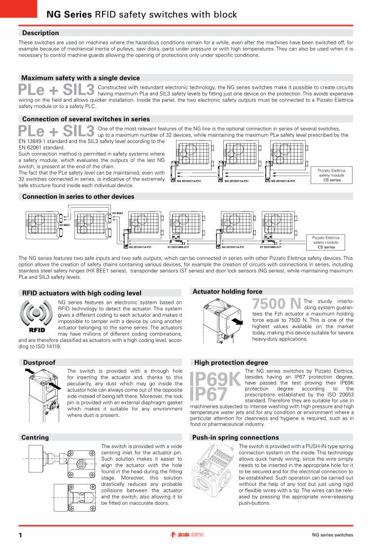
These switches are used on machines where the hazardous conditions remain for a while, even after the machines have been switched off, for example because of mechanical inertia of pulleys, saw disks, parts under pressure or with high temperatures. They can also be used when it is necessary to control machine guards allowing the opening of protections only under specific conditions.
Description
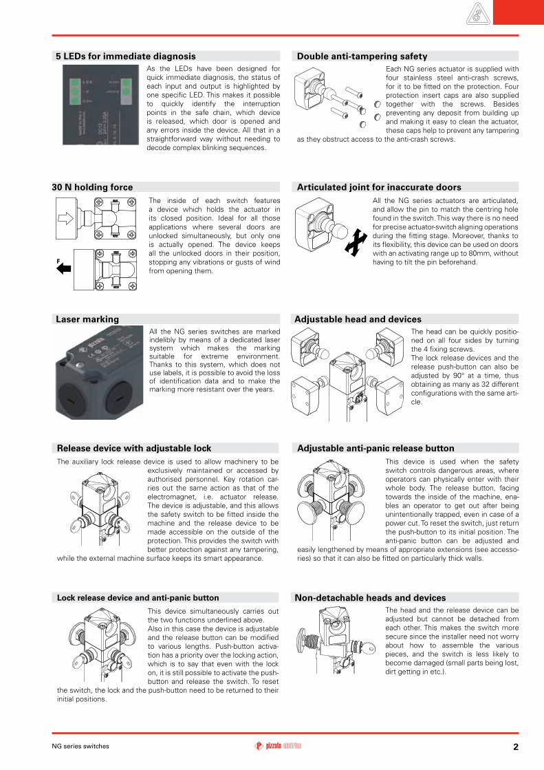
Actuator holding forceThe sturdy interlo-cking system guaran-
tees the Fzh actuator a maximum holding force equal to 7500 N. This is one of the highest values available on the market today, making this device suitable for severe heavy-duty applications.
One of the most relevant features of the NG line is the optional connection in series of several switches,up to a maximum number of 32 devices, while maintaining the maximum PLe safety level prescribed by the
EN 13849-1 standard and the SIL3 safety level according to the EN 62061 standard.Such connection method is permitted in safety systems where a safety module, which evaluates the outputs of the last NG switch, is present at the end of the chain.The fact that the PLe safety level can be maintained, even with 32 switches connected in series, is indicative of the extremely safe structure found inside each individual device.
Connection in series to other devices
Pizzato Elettrica safety module
CS series
The NG series features two safe inputs and two safe outputs, which can be connected in series with other Pizzato Elettrica safety devices. This option allows the creation of safety chains containing various devices, for example the creation of circuits with connections in series, including stainless steel safety hinges (HX BEE1 series), transponder sensors (ST series) and door lock sensors (NG series), while maintaining maximum PLe and SIL3 safety levels.
DustproofThe switch is provided with a through hole for inserting the actuator and, thanks to this peculiarity, any dust which may go inside the actuator hole can always come out of the opposite side instead of being left there. Moreover, the lock pin is provided with an external diaphragm gasket which makes it suitable for any environment where dust is present.
Maximum safety with a single deviceConstructed with redundant electronic technology, the NG series switches make it possible to create circuits having maximum PLe and SIL3 safety levels by fitting just one device on the protection. This avoids expensive
wiring on the field and allows quicker installation. Inside the panel, the two electronic safety outputs must be connected to a Pizzato Elettrica safety module or to a safety PLC.
The NG series switches by Pizzato Elettrica, besides having an IP67 protection degree, have passed the test proving their IP69K protection degree according to the prescriptions established by the ISO 20653 standard. Therefore they are suitable for use in
machineries subjected to intense washing with high pressure and high temperature water jets and for any condition or environment where a particular attention for cleanness and hygiene is required, such as in food or pharmaceutical industry.
Pizzato Elettrica safety module
CS series
Connection of several switches in series
NG series features an electronic system based on RFID technology to detect the actuator. This system gives a different coding to each actuator and makes it impossible to tamper with a device by using another actuator belonging to the same series. The actuators may have millions of different coding combinations,
and are therefore classified as actuators with a high coding level, accor-ding to ISO 14119.
RFID actuators with high coding level
High protection degree
CentringThe switch is provided with a wide centring inlet for the actuator pin. Such solution makes it easier to align the actuator with the hole found in the head during the fitting stage. Moreover, this solution drastically reduces any probable collisions between the actuator and the switch, also allowing it to be fitted on inaccurate doors.
Push-in spring connectionsThe switch is provided with a PUSH-IN type spring connection system on the inside. This technology allows quick handy wiring, since the wire simply needs to be inserted in the appropriate hole for it to be secured and for the electrical connection to be established. Such operation can be carried out without the help of any tool but just using rigid or flexible wires with a tip. The wires can be rele-ased by pressing the appropriate wire-releasing push-buttons.
F
2NG series switches
Adjustable head and devices The head can be quickly positio-
ned on all four sides by turning the 4 fixing screws.The lock release devices and the release push-button can also be adjusted by 90° at a time, thus obtaining as many as 32 different configurations with the same arti-cle.
The auxiliary lock release device is used to allow machinery to be exclusively maintained or accessed by authorised personnel. Key rotation car-ries out the same action as that of the electromagnet, i.e. actuator release. The device is adjustable, and this allows the safety switch to be fitted inside the machine and the release device to be made accessible on the outside of the protection. This provides the switch with better protection against any tampering,
while the external machine surface keeps its smart appearance.
Release device with adjustable lock Adjustable anti-panic release buttonThis device is used when the safety switch controls dangerous areas, where operators can physically enter with their whole body. The release button, facing towards the inside of the machine, ena-bles an operator to get out after being unintentionally trapped, even in case of a power cut. To reset the switch, just return the push-button to its initial position. The anti-panic button can be adjusted and
easily lengthened by means of appropriate extensions (see accesso-ries) so that it can also be fitted on particularly thick walls.
Each NG series actuator is supplied with four stainless steel anti-crash screws, for it to be fitted on the protection. Four protection insert caps are also supplied together with the screws. Besides preventing any deposit from building up and making it easy to clean the actuator, these caps help to prevent any tampering
as they obstruct access to the anti-crash screws.
Double anti-tampering safety
Articulated joint for inaccurate doorsAll the NG series actuators are articulated, and allow the pin to match the centring hole found in the switch. This way there is no need for precise actuator-switch aligning operations during the fitting stage. Moreover, thanks to its flexibility, this device can be used on doors with an activating range up to 80mm, without having to tilt the pin beforehand.
30 N holding forceThe inside of each switch features a device which holds the actuator in its closed position. Ideal for all those applications where several doors are unlocked simultaneously, but only one is actually opened. The device keeps all the unlocked doors in their position, stopping any vibrations or gusts of wind from opening them.
Laser markingAll the NG series switches are marked indelibly by means of a dedicated laser system which makes the marking suitable for extreme environment. Thanks to this system, which does not use labels, it is possible to avoid the loss of identification data and to make the marking more resistant over the years.
5 LEDs for immediate diagnosisAs the LEDs have been designed for quick immediate diagnosis, the status of each input and output is highlighted by one specific LED. This makes it possible to quickly identify the interruption points in the safe chain, which device is released, which door is opened and any errors inside the device. All that in a straightforward way without needing to decode complex blinking sequences.
Non-detachable heads and devicesThe head and the release device can be adjusted but cannot be detached from each other. This makes the switch more secure since the installer need not worry about how to assemble the various pieces, and the switch is less likely to become damaged (small parts being lost, dirt getting in etc.).
This device simultaneously carries out the two functions underlined above.Also in this case the device is adjustable and the release button can be modified to various lengths. Push-button activa-tion has a priority over the locking action, which is to say that even with the lock on, it is still possible to activate the push-button and release the switch. To reset
the switch, the lock and the push-button need to be returned to their initial positions.
Lock release device and anti-panic button
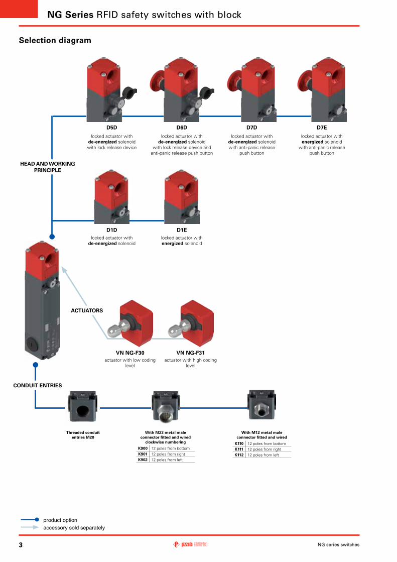
VN NG-F30 VN NG-F31
D1D D1E
D5D D6D D7D D7E
NG series switches3
product optionaccessory sold separately
Threaded conduit entries M20
ACTUATORS
CONDUIT ENTRIES
HEAD AND WORKING PRINCIPLE
locked actuator with de-energized solenoid
locked actuator with energized solenoid
Selection diagram
With M23 metal male connector fitted and wired
clockwise numbering
K900 12 poles from bottomK901 12 poles from rightK902 12 poles from left
NG Series RFID safety switches with block
locked actuator with de-energized solenoidwith lock release device
locked actuator with de-energized solenoid
with lock release device and anti-panic release push button
locked actuator with de-energized solenoidwith anti-panic release
push button
locked actuator with energized solenoid
with anti-panic release push button
actuator with low coding level
actuator with high coding level
With M12 metal male connector fitted and wired
K110 12 poles from bottomK111 12 poles from rightK112 12 poles from left

NG 2D1D411A-F31K900LP30
VN NG-F30
4NG series switches
article options
Code structure Attention! The feasibility of a code number does not mean the effective availability of a product. Please contact our sales office.
Preinstalled connectors
no connectors (standard)
K110 with M12 metal connector assembled and wired, 12 poles from bottom
K900 with M23 metal connector assembled and wired, 12 poles from bottom
... Other connectors on request
Working principle
D1D locked actuator with de-energized solenoid
D1E locked actuator with energized solenoid
D5D locked actuator with de-energized solenoid.With lock release device
D6Dlocked actuator with de-energized solenoid.With lock release device and anti-panic release push button
D7D locked actuator with de-energized solenoid.With anti-panic release push button
D7E locked actuator with energized solenoid.With anti-panic release push button
Release button length
wall thickness length max 15 mm (standard)
LP30 wall thickness length max 30 mm
LP40 wall thickness length max 40 mm
LP50 wall thickness length max 50 mm
LP60 wall thickness length max 60 mm
... Other wall thickness on request
Inputs, outputs and programming
safety outputs
OS
auxiliary outputs
O
safety inputs
IS
programming inputs
I3
electromagnet activation
inputsI4
4 2 2 2 1 1Actuator
F30provided with VN NG-F30 actuator with low coding level the switch recognises any type F30 actuator
F31provided with VN NG-F31 actuator with high coding level the switch recognises one single actuator
Actuator code structure
Actuator
F30 actuator with low coding level the switch recognises any type F30 actuator
F31 actuator with high coding level the switch recognises one single actuator
x
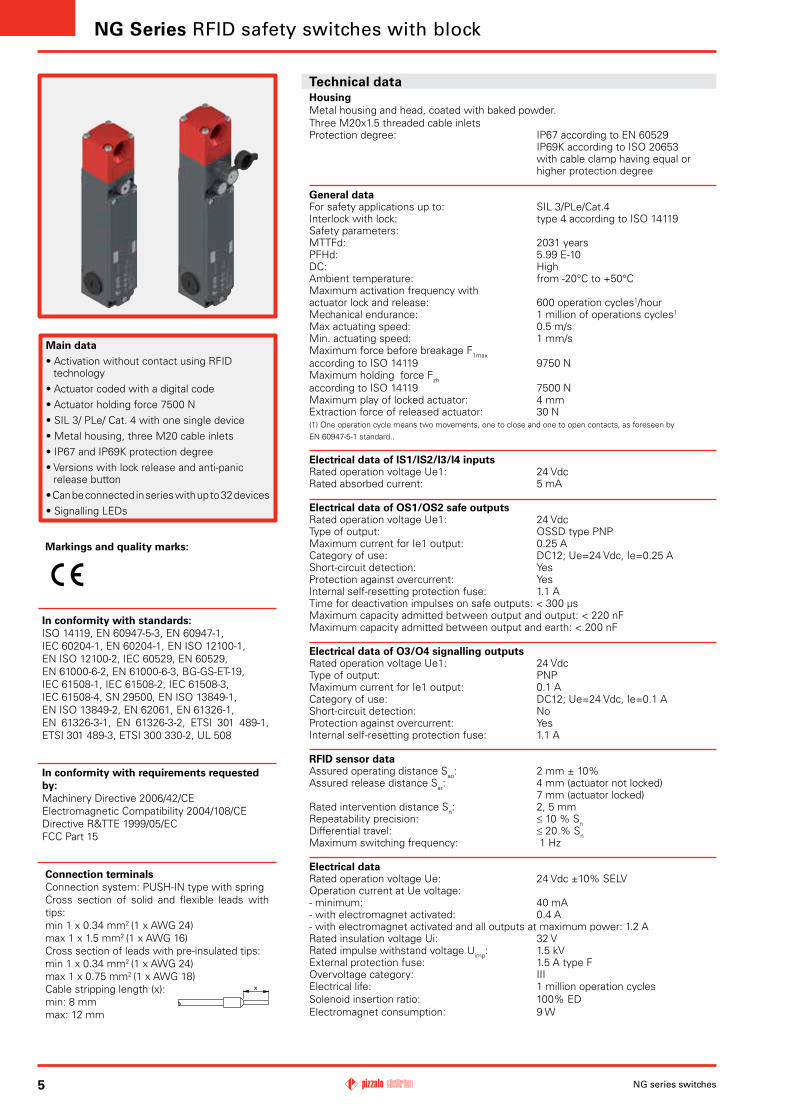
Technical data
NG series switches5
HousingMetal housing and head, coated with baked powder. Three M20x1.5 threaded cable inlets Protection degree: IP67 according to EN 60529 IP69K according to ISO 20653 with cable clamp having equal or higher protection degree
General dataFor safety applications up to: SIL 3/PLe/Cat.4Interlock with lock: type 4 according to ISO 14119Safety parameters: MTTFd: 2031 yearsPFHd: 5.99 E-10DC: HighAmbient temperature: from -20°C to +50°CMaximum activation frequency with actuator lock and release: 600 operation cycles1/hourMechanical endurance: 1 million of operations cycles1
Max actuating speed: 0.5 m/sMin. actuating speed: 1 mm/sMaximum force before breakage F1maxaccording to ISO 14119 9750 NMaximum holding force Fzhaccording to ISO 14119 7500 NMaximum play of locked actuator: 4 mmExtraction force of released actuator: 30 N(1) One operation cycle means two movements, one to close and one to open contacts, as foreseen by EN 60947-5-1 standard..
Electrical data of IS1/IS2/I3/I4 inputsRated operation voltage Ue1: 24 VdcRated absorbed current: 5 mA
Electrical data of OS1/OS2 safe outputsRated operation voltage Ue1: 24 VdcType of output: OSSD type PNPMaximum current for Ie1 output: 0.25 ACategory of use: DC12; Ue=24 Vdc, Ie=0.25 A Short-circuit detection: YesProtection against overcurrent: YesInternal self-resetting protection fuse: 1.1 ATime for deactivation impulses on safe outputs: < 300 µsMaximum capacity admitted between output and output: < 220 nFMaximum capacity admitted between output and earth: < 200 nF
Electrical data of O3/O4 signalling outputsRated operation voltage Ue1: 24 VdcType of output: PNPMaximum current for Ie1 output: 0.1 ACategory of use: DC12; Ue=24 Vdc, Ie=0.1 AShort-circuit detection: No Protection against overcurrent: YesInternal self-resetting protection fuse: 1.1 A
RFID sensor dataAssured operating distance Sao: 2 mm ± 10%Assured release distance Sar: 4 mm (actuator not locked) 7 mm (actuator locked)Rated intervention distance Sn: 2, 5 mm Repeatability precision: ≤ 10 % Sn Differential travel: ≤ 20 % SnMaximum switching frequency: 1 Hz
Electrical dataRated operation voltage Ue: 24 Vdc ±10% SELVOperation current at Ue voltage:- minimum: 40 mA- with electromagnet activated: 0.4 A- with electromagnet activated and all outputs at maximum power: 1.2 ARated insulation voltage Ui: 32 VRated impulse withstand voltage Uimp: 1.5 kVExternal protection fuse: 1.5 A type FOvervoltage category: IIIElectrical life: 1 million operation cyclesSolenoid insertion ratio: 100% EDElectromagnet consumption: 9 W
Main data• Activation without contact using RFID
technology • Actuator coded with a digital code• Actuator holding force 7500 N• SIL 3/ PLe/ Cat. 4 with one single device • Metal housing, three M20 cable inlets• IP67 and IP69K protection degree• Versions with lock release and anti-panic
release button • Can be connected in series with up to 32 devices• Signalling LEDs
In conformity with requirements requested by: Machinery Directive 2006/42/CEElectromagnetic Compatibility 2004/108/CEDirective R&TTE 1999/05/ECFCC Part 15
In conformity with standards:ISO 14119, EN 60947-5-3, EN 60947-1, IEC 60204-1, EN 60204-1, EN ISO 12100-1, EN ISO 12100-2, IEC 60529, EN 60529, EN 61000-6-2, EN 61000-6-3, BG-GS-ET-19, IEC 61508-1, IEC 61508-2, IEC 61508-3, IEC 61508-4, SN 29500, EN ISO 13849-1, EN ISO 13849-2, EN 62061, EN 61326-1, EN 61326-3-1, EN 61326-3-2, ETSI 301 489-1, ETSI 301 489-3, ETSI 300 330-2, UL 508
Markings and quality marks:
NG Series RFID safety switches with block
Connection terminalsConnection system: PUSH-IN type with springCross section of solid and flexible leads with tips:min 1 x 0.34 mm2 (1 x AWG 24)max 1 x 1.5 mm2 (1 x AWG 16)Cross section of leads with pre-insulated tips:min 1 x 0.34 mm2 (1 x AWG 24)max 1 x 0.75 mm2 (1 x AWG 18)Cable stripping length (x): min: 8 mmmax: 12 mm
6NG series switches
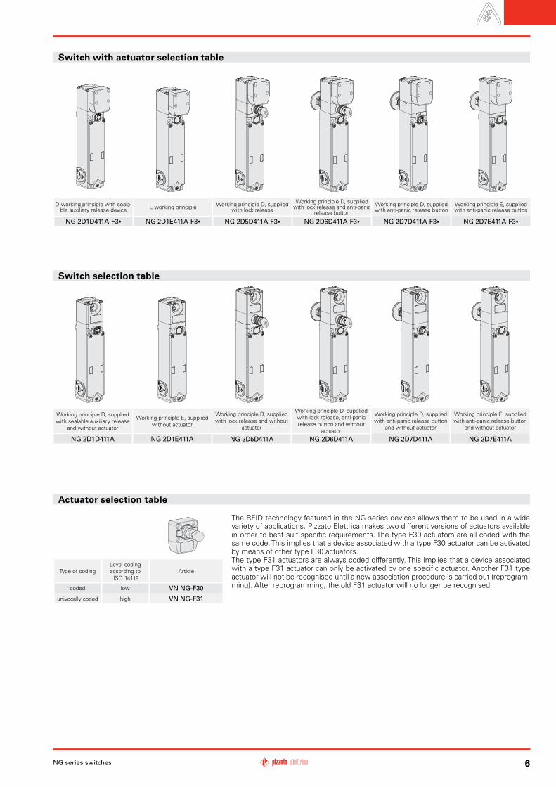
D working principle with seala-ble auxiliary release device E working principle Working principle D, supplied
with lock release Working principle D, supplied
with lock release and anti-panic release button
Working principle D, supplied with anti-panic release button
Working principle E, supplied with anti-panic release button
NG 2D1D411A-F3• NG 2D1E411A-F3• NG 2D5D411A-F3• NG 2D6D411A-F3• NG 2D7D411A-F3• NG 2D7E411A-F3•
Switch selection table
Type of codingLevel coding according to ISO 14119
Article
coded low VN NG-F30
univocally coded high VN NG-F31
Actuator selection table
The RFID technology featured in the NG series devices allows them to be used in a wide variety of applications. Pizzato Elettrica makes two different versions of actuators available in order to best suit specific requirements. The type F30 actuators are all coded with the same code. This implies that a device associated with a type F30 actuator can be activated by means of other type F30 actuators.The type F31 actuators are always coded differently. This implies that a device associated with a type F31 actuator can only be activated by one specific actuator. Another F31 type actuator will not be recognised until a new association procedure is carried out (reprogram-ming). After reprogramming, the old F31 actuator will no longer be recognised.
Working principle D, supplied with sealable auxiliary release
and without actuator
Working principle E, supplied without actuator
Working principle D, supplied with lock release and without
actuator
Working principle D, supplied with lock release, anti-panic release button and without
actuator
Working principle D, supplied with anti-panic release button
and without actuator
Working principle E, supplied with anti-panic release button
and without actuator
NG 2D1D411A NG 2D1E411A NG 2D5D411A NG 2D6D411A NG 2D7D411A NG 2D7E411A
Switch with actuator selection table
NG
OS1 OS2
VN NG-F3•IS1 IS2
O3
O4
+ Vcc
NG
NG
NG
PLC
OS1 OS2
IS1 IS2
IS1 IS2
OS1 OS2
IS1 IS2
OS1 OS2
O3
O4
O3
O4
O3
O4
VN NG-F3•
VN NG-F3•
VN NG-F3•
+ Vcc
NG
NG
NG
OS1 OS2
IS1 IS2
IS1 IS2
OS1 OS2
IS1 IS2
OS1 OS2
O3
O4
O3
O4
O3
O4
VN NG-F3•
VN NG-F3•
VN NG-F3•
+ Vcc
f4
f1
f2
f3
f0
OS1
OS2
IS2
IS1
IN
O4
PWRA2A1
03
OUT
CODE
ACT
LOCK
NG series switches7
NG Series RFID safety switches with block
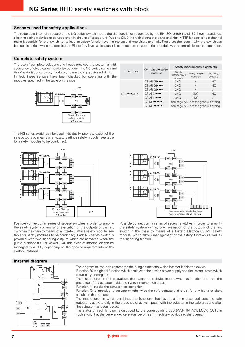
Complete safety systemThe use of complete solutions and heads provides the customer with assurance of electrical compatibility between the NG series switch and the Pizzato Elettrica safety modules, guaranteeing greater reliability.In fact, these sensors have been checked for operating with the modules specified in the table on the side.
SwitchesCompatible safety
modules
Safety module output contacts
Safety instantaneous
contacts
Safety delayed contacts
Signaling contacts
NG 2•••411A
CS AR-05•••• 3NO / 1NCCS AR-06•••• 3NO / 1NCCS AR-08•••• 2NO / /CS AT-0••••• 2NO 2NO 1NCCS AT-1••••• 3NO 2NO /CS MP•••••• see page 5/63 / of the general CatalogCS MF•••••• see page 5/69 / of the general Catalog
Sensors used for safety applications The redundant internal structure of the NG series switch meets the characteristics requested by the EN ISO 13489-1 and IEC 62061 standards, allowing a single device to be used even in circuits of category 4, PLe and SIL 3. Its high diagnostic cover and high MTTF for each single channel make it possible for the switch not to lose its safety function even in the case of one single anomaly. These are the reason why the switch can be used in series, while maintaining the PLe safety level, as long as it is connected to an appropriate module which controls its correct operation.
The NG series switch can be used individually, prior evaluation of the safe outputs by means of a Pizzato Elettrica safety module (see table for safety modules to be combined).
Possible connection in series of several switches in order to simplify the safety system wiring, prior evaluation of the outputs of the last switch in the chain by means of a Pizzato Elettrica safety module (see table for safety modules to be combined). Each NG series switch is provided with two signalling outputs which are activated when the guard is closed (O3) or locked (O4). This piece of information can be managed by a PLC, depending on the specific requirements of the system installed.
Possible connection in series of several switches in order to simplify the safety system wiring, prior evaluation of the outputs of the last switch in the chain by means of a Pizzato Elettrica CS MP safety module, which allows management of the safety function as well as the signalling function.
Pizzato Elettrica safety module
CS series
Pizzato Elettrica safety module
CS series
Programmable Pizzato Elettrica safety module CS MP series
Internal diagramThe diagram on the side represents the 5 logic functions which interact inside the device.Function F0 is a global function which deals with the device power supply and the internal tests which it cyclically undergoes.The task of function f1 is to evaluate the status of the device inputs, whereas function f2 checks the presence of the actuator inside the switch intervention areas.Function f4 checks the actuator lock condition.Function f3 is intended to activate or otherwise the safe outputs and check for any faults or short circuits in the outputs.The macro-function which combines the functions that have just been described gets the safe outputs to activate only in the presence of active inputs, with the actuator in the safe area and after the actuator has been locked.The status of each function is displayed by the corresponding LED (PWR, IN, ACT, LOCK, OUT), in such a way that the general device status becomes immediately obvious to the operator.
PWR
IN
OUT
ACT
LOCK
PWR
IN
OUT
ACT
LOCK
PWR
IN
OUT
ACT
LOCK
PWR
IN
OUT
ACT
LOCK
PWR
IN
OUT
ACT
LOCK
8NG series switches
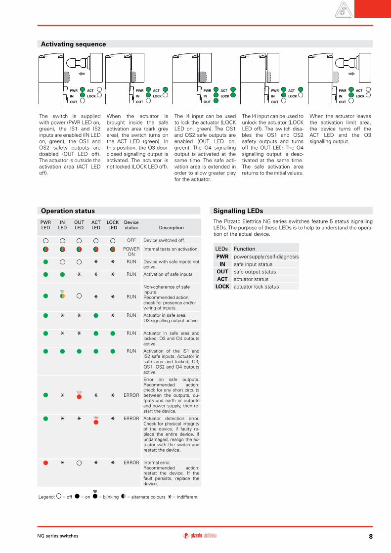
The Pizzato Elettrica NG series switches feature 5 status signalling LEDs. The purpose of these LEDs is to help to understand the opera-tion of the actual device.
LEDs FunctionPWR power supply / self-diagnosis
IN safe input status OUT safe output statusACT actuator status
LOCK actuator lock status
Signalling LEDs Operation status
PWR LED
INLED
OUT LED
ACTLED
LOCKLED
Devicestatus Description
OFF Device switched off.
POWER ON
Internal tests on activation.
RUN Device with safe inputs not active.
RUN Activation of safe inputs.
RUN
Non-coherence of safe inputs.Recommended action: check for presence and/or wiring of inputs.
RUN Actuator in safe area.O3 signalling output active.
RUN Actuator in safe area and locked; O3 and O4 outputs active.
RUN Activation of the IS1 and IS2 safe inputs. Actuator in safe area and locked; O3, OS1, OS2 and O4 outputs active.
ERROR
Error on safe outputs. Recommended action: check for any short circuits between the outputs, ou-tputs and earth or outputs and power supply, then re-start the device.
ERROR Actuator detection error. Check for physical integrity of the device, if faulty re-place the entire device. If undamaged, realign the ac-tuator with the switch and restart the device.
ERROR Internal error.Recommended action: restart the device. If the fault persists, replace the device.
Legend: = off = on = blinking = alternate colours = indifferent
The switch is supplied with power (PWR LED on, green), the IS1 and IS2 inputs are enabled (IN LED on, green), the OS1 and OS2 safety outputs are disabled (OUT LED off). The actuator is outside the activation area (ACT LED off).
Activating sequence
When the actuator is brought inside the safe activation area (dark grey area), the switch turns on the ACT LED (green). In this position, the O3 door-closed signalling output is activated. The actuator is not locked (LOCK LED off).
The I4 input can be used to lock the actuator (LOCK LED on, green). The OS1 and OS2 safe outputs are enabled (OUT LED on, green). The O4 signalling output is activated at the same time. The safe acti-vation area is extended in order to allow greater play for the actuator.
When the actuator leaves the activation limit area, the device turns off the ACT LED and the O3 signalling output.
The I4 input can be used to unlock the actuator (LOCK LED off). The switch disa-bles the OS1 and OS2 safety outputs and turns off the OUT LED. The O4 signalling output is deac-tivated at the same time. The safe activation area returns to the initial values.
46
5.6
144
61.9
211.
5
40.4
30
2.4
5.4
4024
.1
18.3
46
40
38.8
46
40.4
30
2.4
5.4
40
24.1
18.3
46
40
38.8
5.6
144
61.9
211.
5
68
40.4
30
2.4
5.4
40
24.1
18.3
46
40
38.8
38.1
22.8
5.6
144
83.9
233.
5
68
5.6
144
83.9
233.
5
40.4
30
2.4
5.4
40
5
24.1
18.3
46
40
38.8
38.1
22.8
Ø38
30
39.3
Ø21
.4
68
40.4
30
2.4
5.4
40
24.1
18.3
46
40
38.8
39.3
5.6
144
83.9
233.
5
5
Ø38
30
Ø21
.4
68
40.4
30
2.4
5.4
40
24.1
18.3
46
40
38.8
39.3
5.6
144
83.9
233.
5
5
Ø38
30
Ø21
.4
16
Ø15
32.1
29
215.
521
.6
5.5
40
R >80
59.4
21 38.4
48.1
5.25.4
NG series switches9All measures in the drawings are in mm
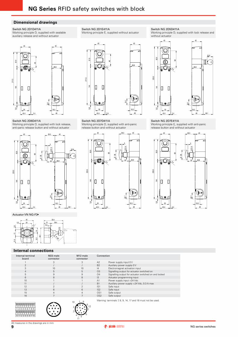
Dimensional drawings
Switch NG 2D1D411AWorking principle D, supplied with sealable auxiliary release and without actuator
Switch NG 2D5D411AWorking principle D, supplied with lock release and without actuator
Switch NG 2D1E411AWorking principle E, supplied without actuator
Switch NG 2D6D411AWorking principle D, supplied with lock release, anti-panic release button and without actuator
Switch NG 2D7E411AWorking principle E, supplied with anti-panic release button and without actuator
Switch NG 2D7D411AWorking principle D, supplied with anti-panic release button and without actuator
Actuator VN NG-F3•
NG Series RFID safety switches with block
Internal connectionsInternal terminal
boardM23 male connector
M12 male connector
Connection
1 3 3 A2 Power supply input 0 V2 / / B2 Auxiliary power supply 0 V3 10 10 I4 Electromagnet activation input 4 5 5 O3 Signalling output for actuator switched on 5 9 9 O4 Signalling output for actuator switched on and locked 6 8 8 I3 Actuator programming input10 1 1 A1 Power supply input +24 Vdc11 / / B1 Auxiliary power supply +24 Vdc, 0.3 A max12 2 2 IS1 Safe input13 6 6 IS2 Safe input15 4 4 OS1 Safe output16 7 7 OS2 Safe output
10 11 12 13 14 15 16 17 18
1 2 3 4 5 6 7 8 9
1
2
3
4 56
7
8910
11
12
Warning: terminals 7, 8, 9, 14, 17 and 18 must not be used.
S33
S21 S22 S35 S34 A2
S52S12A1
-
+OS2OS1
IS2IS1A1
+
A2
-
NG 2•••411A
IxxIxx
OS2OS1
IS2IS1A1
+
OS2OS1
IS2IS1A1
+
IxxIxx
A2
-
A2
-
NG 2•••411A NG 2•••411A
S33
S21 S22 S35 S34 A2
A1
-
+
S31S12
OS2OS1
IS2IS1A1
+
A2
-
NG 2•••411A
S21 S22 S34 A2
A1
-
+
S52S12
OS2OS1
IS2IS1A1
+
A2
-
NG 2•••411A
10NG series switches
Items with code on the green background are available in stock
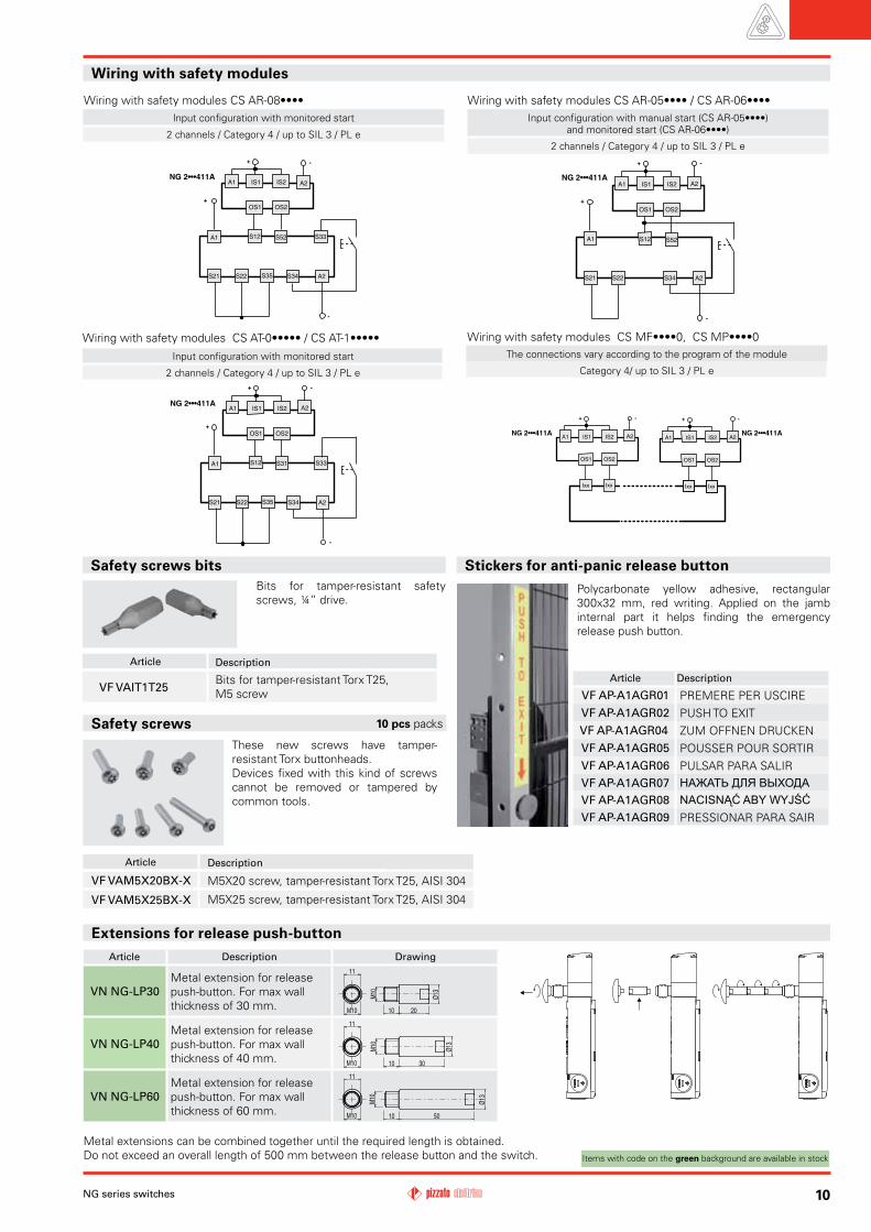
Extensions for release push-button
Article Description Drawing
VN NG-LP30Metal extension for release push-button. For max wall thickness of 30 mm. 20
Ø13
M10
10
11
M10
VN NG-LP40Metal extension for release push-button. For max wall thickness of 40 mm. 30
Ø13
M10
11
10M10
VN NG-LP60Metal extension for release push-button. For max wall thickness of 60 mm.
Ø13
50
11
M10
10M10
These new screws have tamper-resistant Torx buttonheads.Devices fixed with this kind of screws cannot be removed or tampered by common tools.
Safety screws
Article Description
VF VAM5X20BX-X M5X20 screw, tamper-resistant Torx T25, AISI 304
VF VAM5X25BX-X M5X25 screw, tamper-resistant Torx T25, AISI 304
10 pcs packs
Bits for tamper-resistant safety screws, ¼” drive.
Article Description
VF VAIT1T25Bits for tamper-resistant Torx T25, M5 screw
Wiring with safety modules
Wiring with safety modules CS AR-08••••Input configuration with monitored start
2 channels / Category 4 / up to SIL 3 / PL e
Input configuration with monitored start
2 channels / Category 4 / up to SIL 3 / PL e
Wiring with safety modules CS AT-0••••• / CS AT-1•••••The connections vary according to the program of the module
Category 4/ up to SIL 3 / PL e
Wiring with safety modules CS MF••••0, CS MP••••0
Metal extensions can be combined together until the required length is obtained.Do not exceed an overall length of 500 mm between the release button and the switch.
Stickers for anti-panic release button
Article Description
VF AP-A1AGR01 PREMERE PER USCIREVF AP-A1AGR02 PUSH TO EXITVF AP-A1AGR04 ZUM OFFNEN DRUCKENVF AP-A1AGR05 POUSSER POUR SORTIRVF AP-A1AGR06 PULSAR PARA SALIRVF AP-A1AGR07 НАЖАТЬ ДЛЯ ВЫХОДАVF AP-A1AGR08 NACISNĄĆ ABY WYJŚĆVF AP-A1AGR09 PRESSIONAR PARA SAIR
Polycarbonate yellow adhesive, rectangular 300x32 mm, red writing. Applied on the jamb internal part it helps finding the emergency release push button.
Input configuration with manual start (CS AR-05••••) and monitored start (CS AR-06••••)
2 channels / Category 4 / up to SIL 3 / PL e
Wiring with safety modules CS AR-05•••• / CS AR-06••••
Safety screws bits
© 2014 Copyright Pizzato Elettrica
Passion for Quality
DVD
Pizzato Elettrica s.r.l. Via Torino, 1 - 36063 Marostica (VI) ItalyPhone +39.0424.470.930 - Fax +39.0424.470.955
E-mail: [email protected] - Web site: www.pizzato.com
General Catalog Production program EROUND brochure
LIFT General Catalog
Web sitewww.pizzato.com
ZE FGL16A14-ENG