Embed Size (px)
Citation preview
8/7/2019 NG112-06_Tech_Info
http://slidepdf.com/reader/full/ng112-06techinfo 1/20
T ECHNICAL I NFORMATION
4750 Olympic Blvd.Erlanger, KY 41018 USA
Phone: 859-283-0778
Toll-Free: 800-537-6144
FAX: 859-283-2978
Web: www.postglover.com
NEUTRAL GROUNDING RESISTORS

8/7/2019 NG112-06_Tech_Info
http://slidepdf.com/reader/full/ng112-06techinfo 2/20
8/7/2019 NG112-06_Tech_Info
http://slidepdf.com/reader/full/ng112-06techinfo 3/20
3 PGR Document #NG112-06
Table of Contents
Grounding of Industrial Power Systems ................................................... 4 Denition of Grounding ................................................................................4
Characteristics of Ungrounded Systems .....................................................4
System Neutral Grounding ................................................................................ 5
Importance ...................................................................................................5
Solid Grounding ...........................................................................................5
Resistance Grounding .................................................................................6
• Low Resistance ...................................................................................6
• High Resistance ...................................................................................6
Grounding Recap ..................................................................................................... 7 Comparative Performance Rating Table......................................................7
Rating & Testing Neutral Grounding Resistors .................................... 8 IEEE-32 Standards ......................................................................................8
Time Rating .................................................................................................8
Tests ............................................................................................................8
CSA Standards ............................................................................................9
Selection of Neutral Grounding Resistors............................................ 10Factors to Consider ................................................................................... 10
The Selection Process ...............................................................................10
Other Methods of Grounding ........................................................................ 12
Single Phase Transformer & Loading Resistor .......................................... 12
Grounding Transformers ............................................................................ 12
• Zigzag ................................................................................................ 13
• Wye-Delta ..........................................................................................14
• Alternate Wye-Delta .......................................................................... 14
Specications ......................................................................................................... 15Neutral Grounding Resistors .....................................................................15
• High Voltage, Low Resistance ...........................................................15
• Low or Medium Voltage, High Resistance .........................................16
Zigzag Grounding Transformers ................................................................17
Glossary of Terms ................................................................................................... 18
8/7/2019 NG112-06_Tech_Info
http://slidepdf.com/reader/full/ng112-06techinfo 4/20
4 PGR Document #NG112-06
Grounding of Industrial
Power Systems
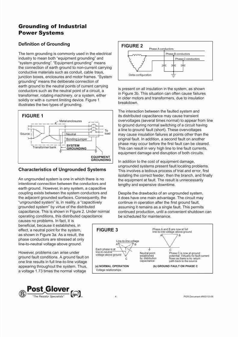
Denition of Grounding
The term grounding is commonly used in the electrical
industry to mean both “equipment grounding” and“system grounding”. “Equipment grounding” means
the connection of earth ground to non-current carrying
conductive materials such as conduit, cable trays,
junction boxes, enclosures and motor frames. “System
grounding” means the deliberate connection of
earth ground to the neutral points of current carrying
conductors such as the neutral point of a circuit, a
transformer, rotating machinery, or a system, either
solidly or with a current limiting device. Figure 1
illustrates the two types of grounding.
Characteristics of Ungrounded Systems
An ungrounded system is one in which there is no
intentional connection between the conductors and
earth ground. However, in any system, a capacitive
coupling exists between the system conductors and
the adjacent grounded surfaces. Consequently, the
“ungrounded system” is, in reality, a “capacitively
grounded system” by virtue of the distributed
capacitance. This is shown in Figure 2. Under normal
operating conditions, this distributed capacitance
causes no problems. In fact, it is
benecial, because it establishes, ineffect, a neutral point for the system,
as shown in Figure 3a. As a result, thephase conductors are stressed at only
line-to-neutral voltage above ground.
However, problems can arise under
ground fault conditions. A ground fault on
one line results in full line-to-line voltage
appearing throughout the system. Thus,
a voltage 1.73 times the normal voltage
is present on all insulation in the system, as shown
in Figure 3b. This situation can often cause failures
in older motors and transformers, due to insulation
breakdown.
The interaction between the faulted system and
its distributed capacitance may cause transient
overvoltages (several times normal) to appear from line
to ground during normal switching of a circuit having
a line to ground fault (short). These overvoltages
may cause insulation failures at points other than the
original fault. In addition, a second fault on another
phase may occur before the rst fault can be cleared.This can result in very high line to line fault currents,
equipment damage and disruption of both circuits.
In addition to the cost of equipment damage,
ungrounded systems present fault locating problems.
This involves a tedious process of trial and error, rst
isolating the correct feeder, then the branch, and nallythe equipment at fault. The result is unnecessarily
lengthy and expensive downtime.
Despite the drawbacks of an ungrounded system,
it does have one main advantage. The circuit may
continue in operation after the rst ground fault,assuming it remains as a single fault. This permits
continued production, until a convenient shutdown can
be scheduled for maintenance.
Line-to-line voltage
Phase A and B are now at fullline-to-line voltage above ground
Each phase is atline-to-neutralvoltage above ground
Neutral pointestablishedby distributioncapacitance
Phase C is now at groundpotential. Virtually no fault currentflows as there is no returnpath back to the source
A B
C
C
BA
(a) NORMAL OPERATION (b) GROUND FAULT ON PHASE C
Voltage relationships
FIGURE 3
Phase A conductors
Phase B conductors
Phase C conductors
Delta configuration
FIGURE 2
Transformer bank
Metal enclosures
Neutral
Bonding jumper
SourceToload
SYSTEMGROUNDING
EQUIPMENTGROUNDING
FIGURE 1
8/7/2019 NG112-06_Tech_Info
http://slidepdf.com/reader/full/ng112-06techinfo 5/20
5 PGR Document #NG112-06
System Neutral Grounding
Importance
This section is devoted to the proven benets of
proper system grounding, and in par ticular, the added
advantages of resistance (current limited) grounding.
The intentional connection of the neutral points of
transformers, generators and rotating machinery to
the earth ground network provides a reference point
of zero volts. This protective measure offers many
advantages over an ungrounded system, including:
• Reduced magnitude of transient overvoltages
• Simplied ground fault location
• Improved system and equipment fault
protection
• Reduced maintenance time and expense
• Greater safety for personnel
• Improved lightning protection
• Reduction in frequency of faults
Solidly Neutral Grounded Systems
Offer Partial Protection
A solidly grounded system is one in which the
neutral points have been intentionally connected to
earth ground with a conductor having no intentional
impedance, as shown in Figure 4. This partially
reduces the problem of transient overvoltages found
on the ungrounded system, provided the ground fault
current is in the range of 25 to 100% of the systemthree phase fault current. However, if the reactance of
the generator or transformer is too great, the problem
of transient overvoltages will not be solved.
While solidly grounded systems are an improvement
over ungrounded systems, and speed up the location of
faults, they lack the current limiting ability of resistance
grounding and the extra protection this provides.
Solidly grounded systems are usually limited to older,
low voltage applications at 600 volts or less.
Solidly
Grounded
Neutral
System
FIGURE 4
Advantages of Grounded Neutral Systems
Resistance grounding is by far the most effective and
preferred method. It solves the problem of transient
overvoltages, thereby reducing equipment damage.
It accomplishes this by allowing the magnitude of thefault current to be predetermined by a simple ohms law
calculation (see Table 1). Thus the fault current can be
limited, in order to prevent equipment damage.
In addition, limiting fault currents to predeterminedmaximum values permits the designer to selectively
coordinate the operation of protective devices, which
minimizes system disruption and allows for quick
location of the fault. There are two broad categories
of resistance grounding: low resistance and high
resistance.
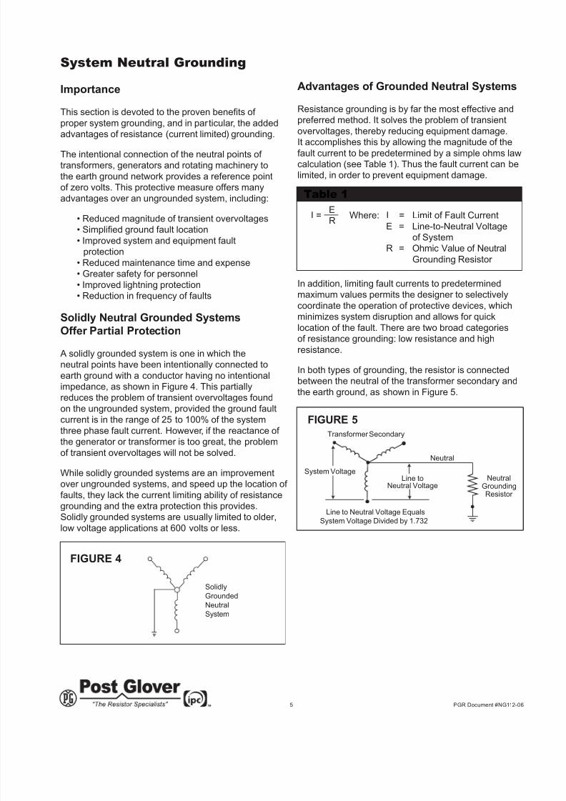
In both types of grounding, the resistor is connected
between the neutral of the transformer secondary and
the earth ground, as shown in Figure 5.
Transformer Secondary
Line to Neutral Voltage Equals
System Voltage Divided by 1.732
Neutral
Line toNeutral Voltage
System VoltageNeutral
GroundingResistor
FIGURE 5
Where: I = Limit of Fault Current
E = Line-to-Neutral Voltage
of System
R = Ohmic Value of Neutral
Grounding Resistor
E
RI =
Table 1
8/7/2019 NG112-06_Tech_Info
http://slidepdf.com/reader/full/ng112-06techinfo 6/20
6 PGR Document #NG112-06
Low Resistance Grounded Neutral
Low resistance grounding of the neutral limits the
ground fault current to a high level (typically 50 amps or
more) in order to operate protective fault clearing relays
and current transformers. These devices are then able
to quickly clear the fault, usually within a few seconds.
The importance of this fast response time is that it:
• Limits damage to equipment
• Prevents additional faults from occurring
• Provides safety for personnel
• Localizes the fault
The limited fault current and fast response time
also prevent over-heating and mechanical stress on
conductors. Please note that, like the solidly grounded
neutral system, the circuit must be shut down after the
rst ground fault.
Low resistance grounding resistors are typically rated400 amps for 10 seconds, and are commonly found on
medium and high voltage systems.
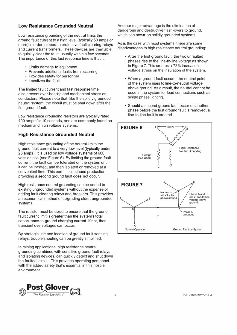
High Resistance Grounded Neutral
High resistance grounding of the neutral limits the
ground fault current to a very low level (typically under
25 amps). It is used on low voltage systems of 600
volts or less (see Figure 6). By limiting the ground fault
current, the fault can be tolerated on the system until
it can be located, and then isolated or removed at a
convenient time. This permits continued production,
providing a second ground fault does not occur.
High resistance neutral grounding can be added to
existing ungrounded systems without the expense of
adding fault clearing relays and breakers. This provides
an economical method of upgrading older, ungrounded
systems.
The resistor must be sized to ensure that the ground
fault current limit is greater than the system’s total
capacitance-to-ground charging current. If not, then
transient overvoltages can occur.
By strategic use and location of ground fault sensingrelays, trouble shooting can be greatly simplied.
In mining applications, high resistance neutral
grounding combined with sensitive ground fault relays
and isolating devices, can quickly detect and shut down
the faulted circuit. This provides operating personnel
with the added safety that’s essential in this hostile
environment.
Another major advantage is the elimination of
dangerous and destructive ash-overs to ground,
which can occur on solidly grounded systems.
As is the case with most systems, there are some
disadvantages to high resistance neutral grounding:
• After the rst ground fault, the two unfaulted
phases rise to the line-to-line voltage as shown
in Figure 7. This creates a 73% increase in
voltage stress on the insulation of the system.
• When a ground fault occurs, the neutral point
of the system rises to line-to-neutral voltage
above ground. As a result, the neutral cannot be
used in the system for load connections such as
single phase lighting.
• Should a second ground fault occur on another
phase before the rst ground fault is removed, aline-to-line fault is created.
High ResistanceNeutral Grounding
5 Amps69.4 Ohms
600 V
347 V
FIGURE 6
Phase A and Bare at line-to-linevoltage aboveground
Neutral isat L-N voltsabove ground
A B
C
Normal Operation
A B
Ground Fault on System
Phase Cgrounded
N
FIGURE 7
8/7/2019 NG112-06_Tech_Info
http://slidepdf.com/reader/full/ng112-06techinfo 7/20
7 PGR Document #NG112-06
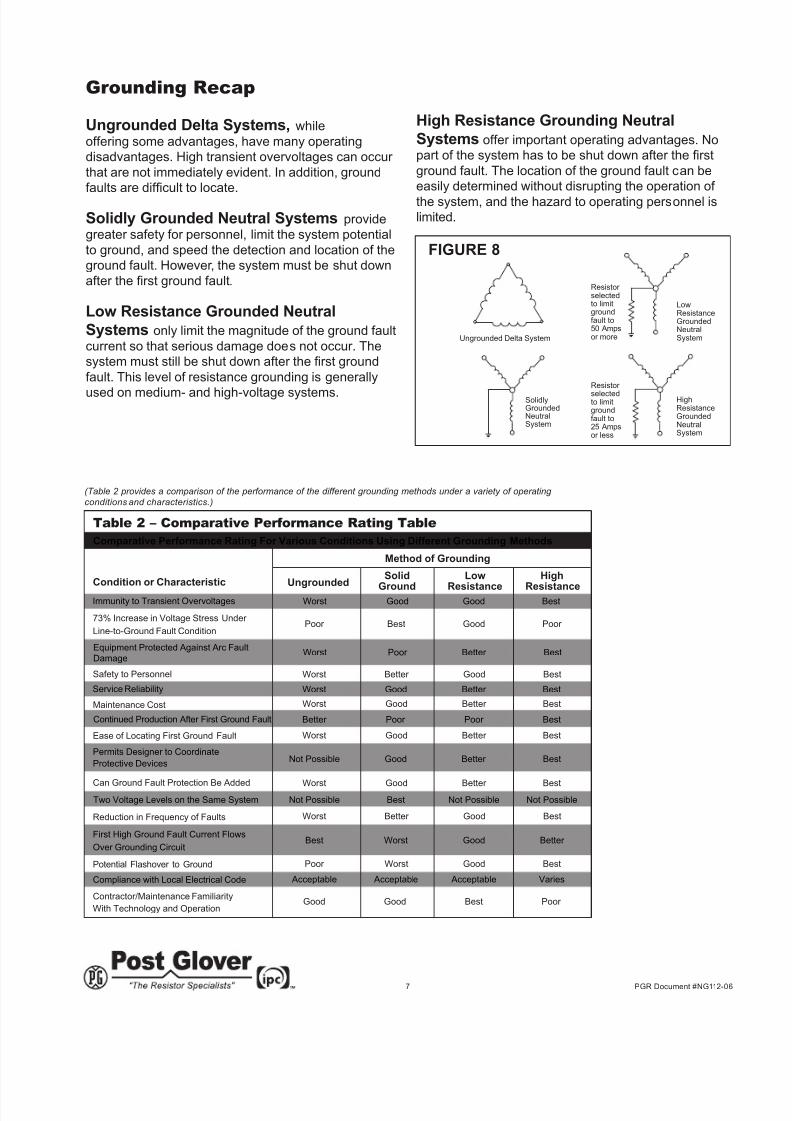
Table 2 – Comparative Performance Rating Table
Comparative Performance Rating For Various Conditions Using Different Grounding Methods
Method of Grounding
Condition or Characteristic
73% Increase in Voltage Stress Under
Line-to-Ground Fault Condition
Safety to Personnel
Maintenance Cost
Ease of Locating First Ground Fault
Permits Designer to Coordinate
Protective Devices
Can Ground Fault Protection Be Added
Reduction in Frequency of Faults
First High Ground Fault Current Flows
Over Grounding Circuit
Potential Flashover to Ground
Compliance with Local Electrical Code
Contractor/Maintenance Familiarity
With Technology and Operation
Poor Best Good Poor
Solid Low High
Ground Resistance Resistance
Worst Good Better Best
Worst Better Good Best
Worst Poor Better Best
Worst Good Good Best
Better Poor Poor Best
Good Good Best Poor
Poor Worst Good Best
Worst Better Good Best
Worst Good Better Best
Worst Good Better Best
Acceptable Acceptable Acceptable Varies
Best Worst Good Better
Not Possible Best Not Possible Not Possible
Not Possible Good Better Best
Worst Good Better Best
Ungrounded
Service Reliability
Immunity to Transient Overvoltages
Continued Production After First Ground Fault
Two Voltage Levels on the Same System
Equipment Protected Against Arc Fault
Damage
Grounding Recap
Ungrounded Delta Systems, while
offering some advantages, have many operating
disadvantages. High transient overvoltages can occur
that are not immediately evident. In addition, ground
faults are difcult to locate.
Solidly Grounded Neutral Systems provide
greater safety for personnel, limit the system potential
to ground, and speed the detection and location of the
ground fault. However, the system must be shut down
after the rst ground fault.
Low Resistance Grounded Neutral
Systems only limit the magnitude of the ground fault
current so that serious damage does not occur. The
system must still be shut down after the rst ground
fault. This level of resistance grounding is generally
used on medium- and high-voltage systems. SolidlyGroundedNeutralSystem
HighResistanceGroundedNeutralSystem
LowResistanceGroundedNeutralSystem
Resistor selectedto limitgroundfault to50 Ampsor more
Resistor
selectedto limitgroundfault to25 Ampsor less
Ungrounded Delta System
FIGURE 8
(Table 2 provides a comparison of the performance of the different grounding methods under a variety of operating
conditions and characteristics.)
High Resistance Grounding Neutral
Systems offer important operating advantages. No
part of the system has to be shut down after the rst
ground fault. The location of the ground fault can be
easily determined without disrupting the operation of
the system, and the hazard to operating personnel is
limited.
8/7/2019 NG112-06_Tech_Info
http://slidepdf.com/reader/full/ng112-06techinfo 8/20
8 PGR Document #NG112-06
Rating and Testing Neutral
Grounding Resistors
IEEE-32-1972 Standards
IEEE-32 is the standard used for rating and testing
neutral grounding resistors. The most importantparameters to consider from the IEEE-32 are: the
allowable temperature rises of the element for different
“on” times; the applied potential tests; the dielectric
tests, and the resistance tolerance tests that are
required. Post Glover Neutral Grounding Resistors are
designated and built to pass all these rigorous tests.
• Time Rating
IEEE Standard 32 species standing timeratings for Neutral Grounding Resistors (NGRs)
with permissible temperature rises above 30˚C
ambient as shown in Table 3.
Time ratings indicate the time the grounding
resistor can operate under fault conditions
without exceeding the temperature rises.
• 10-Second Rating
This rating is applied on NGRs that are used
with a protective relay to prevent damage to both
the NGR and the protected equipment. The
relay must clear the fault within 10 seconds.
• One-Minute Rating
One NGR is often used to limit ground current
on several outgoing feeders. This reducesequipment damage, limits voltage rise and
improves voltage regulation. Since simultaneous
grounds could occur in rapid succession on
different feeders, a 10-second rating is not
satisfactory. The one-minute rating is applied.
• Ten-Minute Rating
This rating is used infrequently. Some engineers
specify a 10-minute rating to provide an added
margin of safety. There is, however, acorresponding increase in cost.
• Extended-Time Rating
This is applied where a ground fault is permitted
to persist for longer than 10 minutes, and where
the NGR will not operate at its temperature rise
for more than an average of 90 days per year.
• Steady-State Rating
This rating applies where the NGR is expected
to be operating under ground fault conditions for
more than an average of 90 days per year and/
or it is desirable to keep the temperature rise
below 385˚C.
Tests
An applied potential test (HI-POT) is required to test
the insulation of the complete assembly (or sections
thereof). For 600 volts or less, the applied potential test
is equal to twice the rated voltage of the assembly (or
section) plus 1,000 volts. For ratings above 600 volts,
the applied potential test is equal to 2.25 times the
rated voltage, plus 2,000 volts.
The resistance tolerance test allows plus or minus 10percent of the rated resistance value.
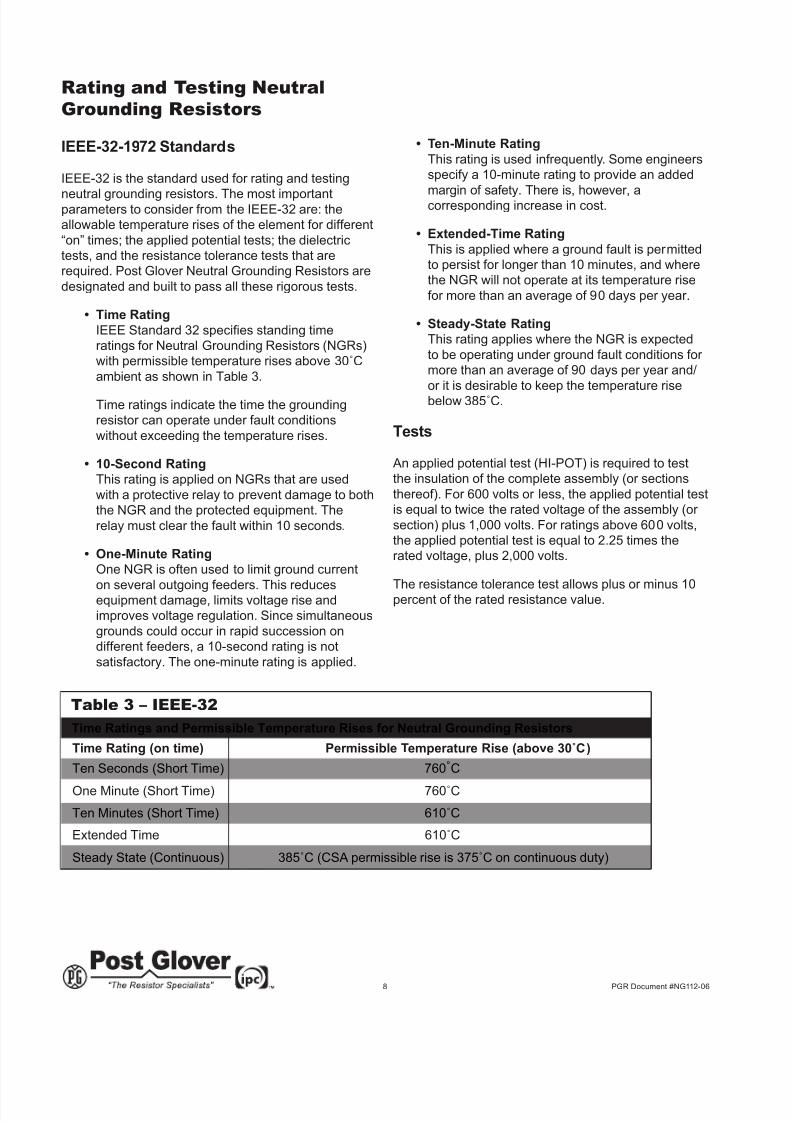
Table 3 – IEEE-32
Time Ratings and Permissible Temperature Rises for Neutral Grounding Resistors
Time Rating (on time) Permissible Temperature Rise (above 30˚C)
Ten Minutes (Short Time) 610˚C
Steady State (Continuous) 385˚C (CSA permissible rise is 375˚C on continuous duty)
Ten Seconds (Short Time) 760˚C
Extended Time 610˚C
One Minute (Short Time) 760˚C
8/7/2019 NG112-06_Tech_Info
http://slidepdf.com/reader/full/ng112-06techinfo 9/20
9 PGR Document #NG112-06
CSA Standards and Certication
CSA provides certication services for manufacturers
who, under license from CSA, wish to use theappropriate registered CSA marks on products of
their manufacture to indicate conformity with CSA
standards.
The Canadian Electrical Code is a publication issued
by CSA. Part 1 establishes safety standards for the
installation and maintenance of electrical equipment.
Part 11 consists of safety standards governing
the construction, testing, and marking of electrical
equipment.
For resistors to be certied by CSA, they must meet
the following sections of the Canadian Electrical Code:
a.) CAN/CSA-C22.2 No. 0-M91 - General
Requirements - Canadian Electrical Code,
Part 11.
b.) C22.2 No. 0.4-M1982 - Bonding and
Grounding of Electrical Equipment (Protective
Grounding).
c.) CAN/CSA-C22.2 No. 14-M91 - Industrial
Control Equipment.
d.) CAN/CSA-C22.2 No. 94-M91 - Special
Purpose Enclosures.
In addition, factory test must be conducted at the
conclusion of manufacture and before shipment of
each resistor assembly.
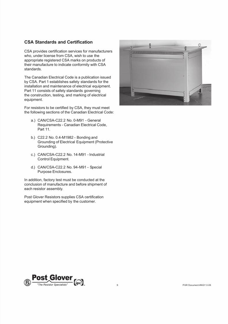
Post Glover Resistors supplies CSA certicationequipment when specied by the customer.
8/7/2019 NG112-06_Tech_Info
http://slidepdf.com/reader/full/ng112-06techinfo 10/20
10 PGR Document #NG112-06
Selection of Neutral Grounding
Resistors for Industrial Systems
Factors to Consider
Over the years, the standard practice for neutral
grounding in industrial plants has been:
a.) 600 volt and lower systems - solid grounding
b.) 2.4 to 13.8 kv - low resistance grounding
c.) above 13.8 kv- solid grounding
Recently the trend on 600 volt and lower systems has
been to use high resistance grounding, with all the
inherent advantages it offers the user.
The following factors should be considered when rating
neutral grounding resistors:
a.) The capacitance-to-ground charging current of
the circuit being protected. Rule of thumb is:
- On systems of 600 volts or lower, .5 amp per
1000 kVA of transformer capacity. - On
medium and high voltage systems (above 600
volts), 1.0 amp per 1000 kVA of transformer
capacity.
b.) The maximum ground fault current to be
permitted on the system, after taking into
consideration points a.) and b.) above. This
determines the amount of fault damage
considered acceptable under ground faultconditions.
c.) The importance of maintaining production in
the presence of a single ground fault. Do you
chose to shut down, or continue to run?
d.) The type and characteristics of the sensing
relays, fault clearing relays, and circuit isolating
devices. Ground fault relays are generally
selected to operate from 5% to 20% of the
maximum current allowed by the grounding
resistor. To provide maximum system
protection with minimum system damage, thetrend is to select lower current ratings.
e.) Safety to operating personnel.
The Selection Process
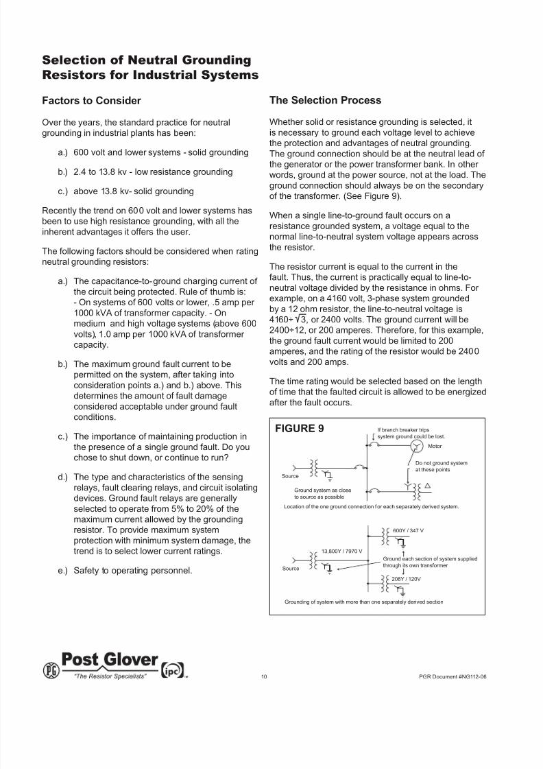
Whether solid or resistance grounding is selected, it
is necessary to ground each voltage level to achievethe protection and advantages of neutral grounding.
The ground connection should be at the neutral lead of
the generator or the power transformer bank. In other
words, ground at the power source, not at the load. The
ground connection should always be on the secondary
of the transformer. (See Figure 9).
When a single line-to-ground fault occurs on a
resistance grounded system, a voltage equal to the
normal line-to-neutral system voltage appears across
the resistor.
The resistor current is equal to the current in thefault. Thus, the current is practically equal to line-to-
neutral voltage divided by the resistance in ohms. For
example, on a 4160 volt, 3-phase system grounded
by a 12 ohm resistor, the line-to-neutral voltage is
4160÷ 3, or 2400 volts. The ground current will be
2400÷12, or 200 amperes. Therefore, for this example,
the ground fault current would be limited to 200
amperes, and the rating of the resistor would be 2400
volts and 200 amps.
The time rating would be selected based on the length
of time that the faulted circuit is allowed to be energized
after the fault occurs.
Do not ground system
at these points
Motor
Source
Ground system as close
to source as possible
Location of the one ground connection for each separately derived system.
If branch breaker trips
system ground could be lost.
600Y / 347 V
Ground each section of system supplied
through its own transformer
208Y / 120V
13,800Y / 7970 V
Source
Grounding of system with more than one separately derived section
FIGURE 9
8/7/2019 NG112-06_Tech_Info
http://slidepdf.com/reader/full/ng112-06techinfo 11/20
8/7/2019 NG112-06_Tech_Info
http://slidepdf.com/reader/full/ng112-06techinfo 12/20
12 PGR Document #NG112-06
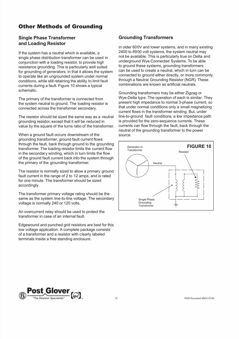
Other Methods of Grounding
Single Phase Transformer
and Loading Resistor
If the system has a neutral which is available, a
single phase distribution transformer can be used inconjunction with a loading resistor, to provide high
resistance grounding. This is particularly well suited
for grounding of generators, in that it allows the system
to operate like an ungrounded system under normal
conditions, while still retaining the ability to limit fault
currents during a fault. Figure 10 shows a typical
schematic.
The primary of the transformer is connected from
the system neutral to ground. The loading resistor is
connected across the transformer secondary.
The resistor should be sized the same way as a neutralgrounding resistor, except that it will be reduced in
value by the square of the turns ratio of the transformer.
When a ground fault occurs downstream of the
grounding transformer, ground fault current ows
through the fault, back through ground to the grounding
transformer. The loading resistor limits the current ow
in the secondary winding, which in turn limits the owof the ground fault current back into the system through
the primary of the grounding transformer.
The resistor is normally sized to allow a primary ground
fault current in the range of 2 to 12 amps, and is rated
for one minute. The transformer should be sized
accordingly.
The transformer primary voltage rating should be the
same as the system line-to-line voltage. The secondary
voltage is normally 240 or 120 volts.
An overcurrent relay should be used to protect the
transformer in case of an internal fault.
Edgewound and punched grid resistors are best for this
low voltage application. A complete package consists
of a transformer and a resistor with clearly labeled
terminals inside a free standing enclosure.
Grounding Transformers
In older 600V and lower systems, and in many existing
2400 to 6900 volt systems, the system neutral may
not be available. This is particularly true on Delta and
underground Wye Connected Systems. To be able
to ground these systems, grounding transformers
can be used to create a neutral, which in turn can be
connected to ground either directly, or more commonly,
through a Neutral Grounding Resistor (NGR). These
combinations are known as articial neutrals.
Grounding transformers may be either Zigzag or
Wye-Delta type. The operation of each is similar. They
present high impedance to normal 3-phase current, so
that under normal conditions only a small magnetizing
current ows in the transformer winding. But, under line-to-ground fault conditions, a low impedance path
is provided for the zero-sequence currents. These
currents can ow through the fault, back through the
neutral of the grounding transformer to the power
source.
Generator or Transformer
Neutral
Single PhaseGroundingTransformer
Resistor
FIGURE 10
8/7/2019 NG112-06_Tech_Info
http://slidepdf.com/reader/full/ng112-06techinfo 13/20
13 PGR Document #NG112-06
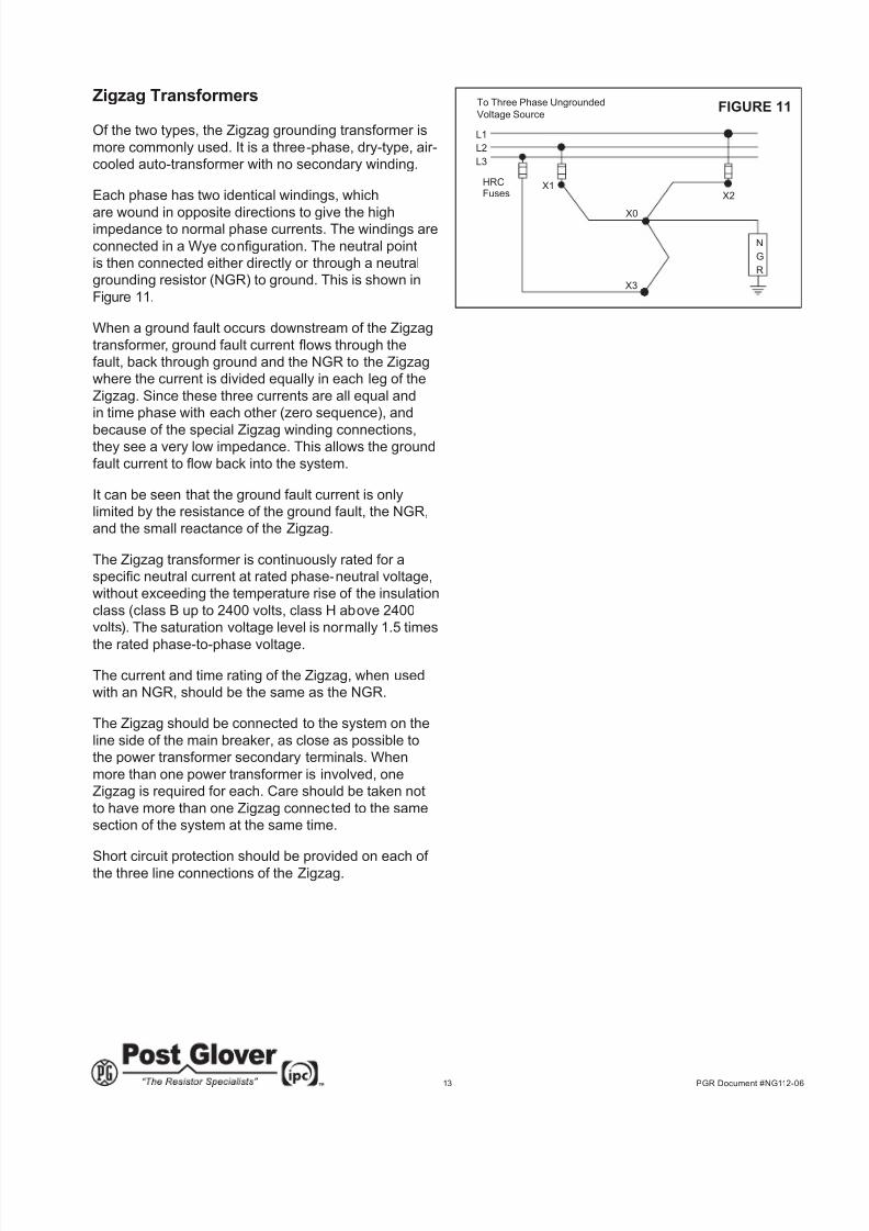
Zigzag Transformers
Of the two types, the Zigzag grounding transformer is
more commonly used. It is a three-phase, dry-type, air-
cooled auto-transformer with no secondary winding.
Each phase has two identical windings, which
are wound in opposite directions to give the highimpedance to normal phase currents. The windings are
connected in a Wye conguration. The neutral pointis then connected either directly or through a neutral
grounding resistor (NGR) to ground. This is shown in
Figure 11.
When a ground fault occurs downstream of the Zigzag
transformer, ground fault current ows through thefault, back through ground and the NGR to the Zigzag
where the current is divided equally in each leg of the
Zigzag. Since these three currents are all equal and
in time phase with each other (zero sequence), and
because of the special Zigzag winding connections,they see a very low impedance. This allows the ground
fault current to ow back into the system.
It can be seen that the ground fault current is only
limited by the resistance of the ground fault, the NGR,
and the small reactance of the Zigzag.
The Zigzag transformer is continuously rated for a
specic neutral current at rated phase-neutral voltage,without exceeding the temperature rise of the insulation
class (class B up to 2400 volts, class H above 2400
volts). The saturation voltage level is normally 1.5 times
the rated phase-to-phase voltage.
The current and time rating of the Zigzag, when used
with an NGR, should be the same as the NGR.
The Zigzag should be connected to the system on the
line side of the main breaker, as close as possible to
the power transformer secondary terminals. When
more than one power transformer is involved, one
Zigzag is required for each. Care should be taken not
to have more than one Zigzag connected to the same
section of the system at the same time.
Short circuit protection should be provided on each of the three line connections of the Zigzag.
To Three Phase Ungrounded
Voltage Source
L1
L2
L3
HRCFuses
X1
X0
X3
X2
N
G
R
FIGURE 11
8/7/2019 NG112-06_Tech_Info
http://slidepdf.com/reader/full/ng112-06techinfo 14/20
14 PGR Document #NG112-06
Wye-Delta Transformers
These grounding transformers have a Wye-connected
primary and Delta-connected secondary. The three
primary line terminals are connected to the 3-phase
ungrounded power source. The neutral terminal is
connected either directly or through a neutral grounding
resistor NGR to ground. The Delta secondary is notconnected to any external circuit. This is shown in
Figure 12.
During normal system conditions, the Wye-Delta
grounding transformer operates unloaded, therefore
providing high impedance to the three phase system
current. Only a small magnetizing current ows.
When a ground fault occurs downstream of the
grounding transformer, ground fault current ows
through the fault, back through ground and the NGR
to the Wye-Delta grounding transformer. The current
is divided equally in each leg of the Wye transformer.Since these three currents are all equal and in time
phase with each other (zero sequence), and since
the Delta secondary is a closed series circuit, the
ground fault current only sees the transformer leakage
reactance.
This allows the ground fault current to ow back intothe system. The ground fault current is only limited by
the resistance of the ground fault, the NGR, and the
small transformer leakage reactance.
The Wye-Delta grounding transformer is continuously
rated for a specic neutral current at rated phase-to-neutral voltage, without exceeding the temperature rise
of the insulation class.
The current and time rating of the transformer, when
used with an NGR, should be the same as the NGR.
To Three Phase UngroundedVoltage Source
L1
L2
L3
HRC
Fuses X1
X0
X3
X2G
R
FIGURE 13
The transformer primary voltage rating should be equal
to or greater than the line-to-line voltage of the system
to which it is being connected.
The Wye-Delta grounding transformer should be
connected to the system on the line side of the main
breaker, as close as possible to the power transformer
secondary terminals. When more than one power transformer is involved, one grounding transformer is
required for each. Care should be taken not to have
more than one grounding transformer connected to the
same section of the system at the same time.
Short circuit protection should be provided on each
of the primary line connections of the Wye-Delta
transformer.
Alternate Wye-Delta Grounding
Transformer Conguration
In this conguration, the neutral of the Wye-connectedprimary is connected directly to ground. A loading
resistor is connected across the broken Delta-
connected secondary. This is shown in Figure 13.
The loading resistor is selected the same way as
a high resistance NGR, except it will be reduced in
value by the square of the turns ratio of the grounding
transformer.
This resistor limits the current ow in the closed Delta
secondary windings, which in turn limits the ground
fault current ow in each of windings of the Wye
primary of the grounding transformer.
The same precautions must be followed as for the
Wye-Delta grounding transformer described in the
Wye-Delta Transformers section.
To Three Phase Ungrounded
Voltage Source
L1
L2
L3
HRC
Fuses X1
X0
X3
X2
N
G
R
FIGURE 12
8/7/2019 NG112-06_Tech_Info
http://slidepdf.com/reader/full/ng112-06techinfo 15/20
15 PGR Document #NG112-06
Specication for High Voltage,
Low Resistance Type
Scope
This specication covers the design, manufacture and
testing of high-voltage, low-resistance type NeutralGrounding Resistors (NGR) for installation outdoors
onto a concrete pad or power transformer.
Applicable Standards
The NGR shall be designed, manufactured and tested
as per the latest revisions of IEEE-32.
Resistors
The resistive elements shall be low temperature
coefcient, resistor grade stainless steel of sufcient
mass to withstand the rated current and prescribedduty.
The resistors shall be mounted in corrosion resistant
support frames, using stainless-steel hardware.
The entire resistor assembly shall be mounted on
insulators rated for the system voltage.
All resistor terminals and interconnections between
resistor units shall be stainless-steel using stainless-
steel hardware including lock washers. High
current connections shall be spot or TIG welded as
appropriate.
Connections between resistors and bushings or current
transformers shall be solid copper or stainless steel
bus or copper cables.
Enclosures
The frame of the enclosure shall be made from
structural steel angles welded together, or boltedtogether with stainless-steel hardware. The top of the
enclosure shall be solid, slightly overhung and sloped.
It shall be embossed with stif fening ribs. The enclosure
shall have forged eyebolts in each corner for lif ting
purposes.
The bottom of the enclosure shall be screened with
expanded or perforated metal with openings of 1/2" or
less. This screening shall be welded or bolted in and is
not removable. It shall be elevated 4 to 6 inches above
the base of the unit.
Bolt-on side covers on all four sides shall be used.Screened covers may be furnished for certain
applications. Stainless-steel hardware shall be used.
Louvered or screened openings shall not exceed 1/2".
A durable nameplate, permanently attached to one
side cover shall show the manufacturer and the
complete rating. Painted enclosures shall be suitably
cleaned, primed and painted. Stainless-steel and
aluminum enclosures (in particular) shall be protected
from scratching during manufacture, assembly and
shipment.
CSA Approved Enclosure
To meet CSA outdoor requirements, solid side covers
and elevated, hooded roof shall be supplied. All of the
other requirements outlined above shall be met.
8/7/2019 NG112-06_Tech_Info
http://slidepdf.com/reader/full/ng112-06techinfo 16/20
16 PGR Document #NG112-06
Specication for Low or
Medium Voltage, High
Resistance Type
Scope
This specication covers design, manufacture andtesting of low- or medium-voltage, high-resistance type
Neutral Grounding Resistors (NGR) for installation
indoors and outdoors onto a concrete pad or power
transformer.
Applicable Standards
The NGR shall be designed, manufactured and tested
as per the latest revisions of IEEE-32.
Resistors
The resistive elements shall be low temperature
coefcient, resistor grade stainless steel or nickelchromium rigidly supported at each end to allow for
expansion due to heating.
The resistors shall be mounted in corrosion resistant
support frames, using stainless-steel hardware.
For low voltage, continuous rated above 10 amp, and
all medium voltage applications, the entire resistor
frame shall be mounted on insulators rated for the
system voltage.
All resistor terminals and interconnections between
units shall be stainless-steel, using stainless-steel
hardware including lock washers. High current
connections shall be spot or TIG welded as
appropriate.
Connections between resistors and bushings or current
transformers shall be solid copper or stainless steel
bus or copper cables.
Enclosures
Low Voltage (600 volts or less) Enclosure shall be of heavy gauge Galvanneal cold
rolled steel with baked enamel nish. All mountinghardware shall be stainless steel.
Indoor enclosure shall have a screened cover with
maximum openings of 1/2".
Outdoor enclosure shall have a solid heavy gauge top
cover, slightly overhung to prevent ingress of rain or
sleet.
CSA Approved Low Voltage
Separate external terminal junction boxes shall beprovided for termination of the neutral conductor and
the ground conductor. All of the other requirements
outlined above shall be met.
Medium Voltage (above 600 volts to 5,000 volts)
The frame of the enclosure shall be made from
structural steel angles made from heavy gauge steel,
welded together, or bolted together with stainless-steel
hardware. The top of the enclosure shall be solid,
slightly overhung and sloped. It shall be embossed
with stiffening ribs. The enclosure shall have forged
eyebolts in each corner for lifting purposes.
The bottom of the enclosure shall be screened with
expanded or perforated metal with openings of 1/2" or
less. This screening shall be welded or bolted in and is
not removable. It shall be elevated 4 to 6 inches above
the base of the unit.
Bolt-on side covers on all four sides shall be used.
Screened covers may be furnished for certain
applications. Stainless-steel hardware shall be used.
Louvered or screened openings shall not exceed 1/2".
A durable nameplate, permanently attached to one side
cover shall show the manufacturer and the completerating.
Painted enclosures shall be suitably sanded, cleaned,
primed and painted. Stainless-steel and aluminum
enclosures (in particular) shall be protected from
scratching during manufacture, assembly and
shipment.
8/7/2019 NG112-06_Tech_Info
http://slidepdf.com/reader/full/ng112-06techinfo 17/20
17 PGR Document #NG112-06
Specication for Zigzag
Grounding Transformers
Scope
This specication covers design, manufacture and
testing of low- or medium-voltage Zigzag groundingtransformers for use with Neutral Grounding Resistors
(NGR) for installation indoors or outdoors onto a
concrete pad or power transformer.
Applicable Standards
The transformer shall be designed, manufactured and
tested as per the latest revisions of IEEE-32.
Transformer
The transformer shall be a three-phase, dry-type, air-
cooled auto-transformer with each phase having two
windings connected in a Zigzag conguration. It shallhave class “B” insulation up to 2400 volts or class “H”
insulation above 2400 volts.
The transformer shall be continuously rated for the
charging current of the system on which it is being
applied; it shall also have the same current and “on”
time rating as that of the NGR with which it is being
applied.
Insulation class maximum temperature rise shall not be
exceeded at these currents and “on” times.
It shall be rated at the system voltage.
Enclosures
Low Voltage (600 volts or less)
The Zigzag transformer may be combined withthe NGR and mounted in one enclosure where the
continuous rating does not exceed 5 amps.
The enclosure shall be of heavy gauge Galvanneal
cold rolled steel with baked enamel nish. All mounting
hardware shall be stainless-steel.
Indoor enclosure shall have a screened cover with
maximum openings of 1/2".
Outdoor enclosure shall have a solid heavy gauge top
cover, slightly overhung.
CSA Approved Low Voltage
Separate external terminal junction boxes shall be
provided for termination of all three line conductors and
the ground conductor.
Medium Voltage (above 600 volts to 5,000 volts)
The frame of the enclosure shall be made from
structural steel angles made from heavy gauge steel,
welded together, or bolted together with stainless-steel
hardware. The top of the enclosure shall be solid,
slightly overhung and sloped. It shall be embossed
with stiffening ribs. The enclosure shall have forged
eyebolts in each corner for lifting purposes.
The bottom of the enclosure shall be screened with
expanded or perforated metal with openings of 1/2" or
less. This screening shall be welded or bolted in and is
not removable. It shall be elevated 4 to 6 inches above
the base of the unit.
Bolt-on side covers on all four sides shall be used.
Screened covers may be furnished for certain
applications. Stainless-steel hardware shall be used.
Louvered or screened openings shall not exceed 1/2".
A durable nameplate, permanently attached to one side
cover shall show the manufacturer and the completerating.
Painted enclosures shall be suitably sanded, cleaned,
primed and painted. Stainless-steel and aluminum
enclosures (in particular) shall be protected from
scratching during manufacture, assembly and
shipment.
8/7/2019 NG112-06_Tech_Info
http://slidepdf.com/reader/full/ng112-06techinfo 18/20
18 PGR Document #NG112-06
Glossary of Terms
BushingA high voltage terminal connection which isolates the
conductor from the grounded sheet metal surface
through which the bushing passes. Sometimes called
“entrance” and “exit” bushings.
Cap and Pin Type Insulator Also called Petticoat insulators because of the
porcelain “skirt” around the “pin” base. The bottom
ange has four mounting holes while the top has four threaded inserts. The units can be bolted together in a
stack.
Current Transformer Usually a high-voltage bar-type with the primary
connected in series with the grounding resistor, and the
secondary connected to external fault clearing relays.
Extended Time Rating
A rated time in which the time period Is greater than
the time required for the temperature rise to become
constant but is limited to a specied average number of
days operation per year.
Ground Pad
A surface for terminating a ground lug to make a
reliable connection to the system or equipment ground.
May have one, two or four holes and is usually drilled
for NEMA connectors.
Grounded Safety EnclosureA grounded enclosure which provides protection of
the resistors from birds and rodents while preventing
accidental contact of live or high temperature parts by
personnel. May have side or top mounted entrance
bushing.
Grounding Transformer A transformer that is used to provide a neutral point
for grounding purposes. It may be a single-phase
transformer such as used to reect high resistance
grounding for a generator, or it may be a special Wye
- Delta or Zigzag transformer used to articially createa neutral point on a Delta or 3 wire Wye system which
has no neutral.
Insulating Bushing
A Phenolic strain relief grommet to prevent chafng of apower cable as it passes through a sheet metal panel.
Held in place with a conduit lock ring.
Neutral Grounding Resistor A suitably rated power resistor that is connected
between the neutral of a transformer (or generator) and
the system ground. It serves to limit fault currents and
prevent damage to the equipment.
Rated Continuous Current
The current expressed in amperes (RMS), that the
device can carry continuously under specied serviceconditions without exceeding the allowable temperature
rise.
Rated Time
The time during which the device will carry its rated
thermal current under standard operating conditions
without exceeding the limitations established by
the applicable standards. The various “on” times
established by IEEE-32 are shown in Table 3 onpage 8.
Rated Time Temperature Rise
The maximum temperature rise above ambient
attained by the winding of a device as the result of
the ow of rated thermal current under standard
operating conditions, for rated time and with a star ting
temperature equal to the steady-state temperature. It
may be expressed as an average or a hot winding rise.
The allowable temperature rises for various “on” times,
as established by IEEE-32 are shown in Table 3 on
page 8.
Rated Voltage
The rms voltage, at rated frequency, which may be
impressed between the terminals of the device under
standard operating conditions for rated time without
exceeding the limitations established by the applicable
standards. For the Neutral Grounding Resistor, this is
equal to the line-to-neutral voltage. The line-to-neutral
voltage is simply the line-to-line (system) voltage
divided by 1.732.
Resistor Element
A resistor element is the conducting unit whichfunctions to limit the current ow to a predetermined
value. Usually a helical coiled, edgewound, or
serpentine folded ribbon of stainless steel alloy.
Short Time Rating
(Of a grounding device) A rated time of ten minutes or
less.
8/7/2019 NG112-06_Tech_Info
http://slidepdf.com/reader/full/ng112-06techinfo 19/20
19 PGR Document #NG112-06
Standoff Insulator A glazed porcelain or epoxy body with threaded
inserts in the top and bottom. The insulators serve to
mechanically connect mounting frames to enclosures,
or one mounting frame to the next, while still providing
electrical isolation. The body of the insulator is typically
corrugated to provide a longer creepage distance to
prevent tracking.
Station Post Insulator Similar to the standoff type insulator, but usually has
two threaded studs on top and bottom and is rated for
higher voltages than the standoff type.
Support or Elevating Stand
An angle frame stand used to elevate the entire
grounding resistor and enclosure. This may be for
safety purposes to prevent personnel from reachinglive parts, or may be to facilitate connection to a
transformer.

8/7/2019 NG112-06_Tech_Info
http://slidepdf.com/reader/full/ng112-06techinfo 20/20
4750 Olympic Blvd. • Erlanger, KY 41018 • USA
Phone: 800-537-6144 / 859-283-0778 • Fax: 859-283-2978
www.postglover.com
Serving the Electrical Industry Since 1892