Embed Size (px)
Citation preview
DATASHEET
NI 9242 Datasheet3 AI/1 Neutral, 250 Vrms L-N/400 Vrms L-L, 24 Bit, 50 kS/s/chSimultaneous
• Screw-terminal connectivity for up to 12 AWG cables• Protective backshell• 250 Vrms, CAT III, channel-to-earth working voltage
The NI 9242 is a C series analog input module that offers three channels for measurementsbetween the signal and the neutral channel, and the neutral channel provides measurementsbetween the neutral terminal and the chassis ground. With this configuration, you can connectsingle- or three-phase measurement configurations such as WYE and delta. If you aredeveloping power monitoring, metering, or quality analysis applications, consider the NILabVIEW Electrical Power Suite, which is compatible with both NI CompactRIO andCompactDAQ systems.
• NI 9242• NI 9242 Getting Started Guide• NI 9968 4-Position Screw-Terminal Connector• NI 9967 Strain Relief and Operator Protection
Kit Contents
± 60 VDC,CAT I (DSUB)
±60 VDC, CAT I(BNC)
ConnectivitySimultaneous
DSUBScrew-TerminalSpring-Terminal
No
Screw-Terminal
Yes
Screw-TerminalBNC
Yes
Screw-TerminalYes
SignalLevels
± 60 V
300 Vrms
± 60 V
400 Vrms L-N690 Vrms L-L
250 Vrms L-N400 Vrms L-L
Screw-TerminalYes
Isolation/Safety Voltages
Ch-Earth ground 250 Vrms,CAT II (Screw/
Spring Terminal)
Ch-Ch 600 Vrms,CAT II
Ch-Earth ground 250 Vrms, CAT II (Screw-Terminal)
Ch-Earth ground250 Vrms, CAT III
SampleRate
800 kS/s
50 kS/s/ch
50 kS/s/ch
50 kS/s/ch
50 kS/s/ch
InputNoise
0.7 LSBRMS
2 mVrms
320 µVrms
3 mVrms
6 mVrms
Channels
8
3
4
3 AI 1 Neutral
3 AI 1 Neutral
C SERIES HIGH VOLTAGE ANALOG INPUT MODULE COMPARISON
ProductName
NI 9221
NI 9225
NI 9229
NI 9242
NI 9244 Ch-Earth ground 400 Vrms,CAT II, or 300 Vrms CATIII
at 5,000 m altitude
NI C Series Overview
NI provides more than 100 C Series modules for measurement, control, and communicationapplications. C Series modules can connect to any sensor or bus and allow for high-accuracymeasurements that meet the demands of advanced data acquisition and control applications.• Measurement-specific signal conditioning that connects to an array of sensors and signals• Isolation options such as bank-to-bank, channel-to-channel, and channel-to-earth ground• -40 °C to 70 °C temperature range to meet a variety of application and environmental
needs• Hot-swappable
The majority of C Series modules are supported in both CompactRIO and CompactDAQplatforms and you can move modules from one platform to the other with no modification.
2 | ni.com | NI 9242 Datasheet
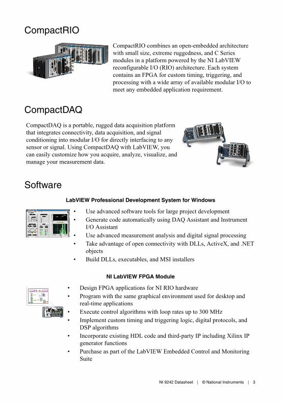
CompactRIO
CompactRIO combines an open-embedded architecturewith small size, extreme ruggedness, and C Seriesmodules in a platform powered by the NI LabVIEWreconfigurable I/O (RIO) architecture. Each systemcontains an FPGA for custom timing, triggering, andprocessing with a wide array of available modular I/O tomeet any embedded application requirement.
CompactDAQ
CompactDAQ is a portable, rugged data acquisition platformthat integrates connectivity, data acquisition, and signalconditioning into modular I/O for directly interfacing to anysensor or signal. Using CompactDAQ with LabVIEW, youcan easily customize how you acquire, analyze, visualize, andmanage your measurement data.
Software
LabVIEW Professional Development System for Windows
• Use advanced software tools for large project development• Generate code automatically using DAQ Assistant and Instrument
I/O Assistant• Use advanced measurement analysis and digital signal processing• Take advantage of open connectivity with DLLs, ActiveX, and .NET
objects• Build DLLs, executables, and MSI installers
NI LabVIEW FPGA Module
• Design FPGA applications for NI RIO hardware• Program with the same graphical environment used for desktop and
real-time applications• Execute control algorithms with loop rates up to 300 MHz• Implement custom timing and triggering logic, digital protocols, and
DSP algorithms• Incorporate existing HDL code and third-party IP including Xilinx IP
generator functions• Purchase as part of the LabVIEW Embedded Control and Monitoring
Suite
NI 9242 Datasheet | © National Instruments | 3
NI LabVIEW Real-Time Module
• Design deterministic real-time applications with LabVIEWgraphical programming
• Download to dedicated NI or third-party hardware for reliableexecution and a wide selection of I/O
• Take advantage of built-in PID control, signal processing, andanalysis functions
• Automatically take advantage of multicore CPUs or setprocessor affinity manually
• Take advantage of real-time OS, development and debuggingsupport, and board support
• Purchase individually or as part of a LabVIEW suite
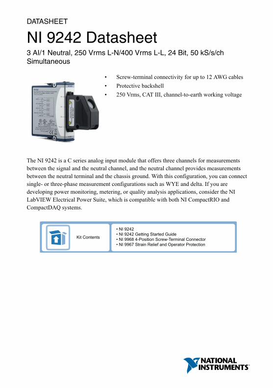
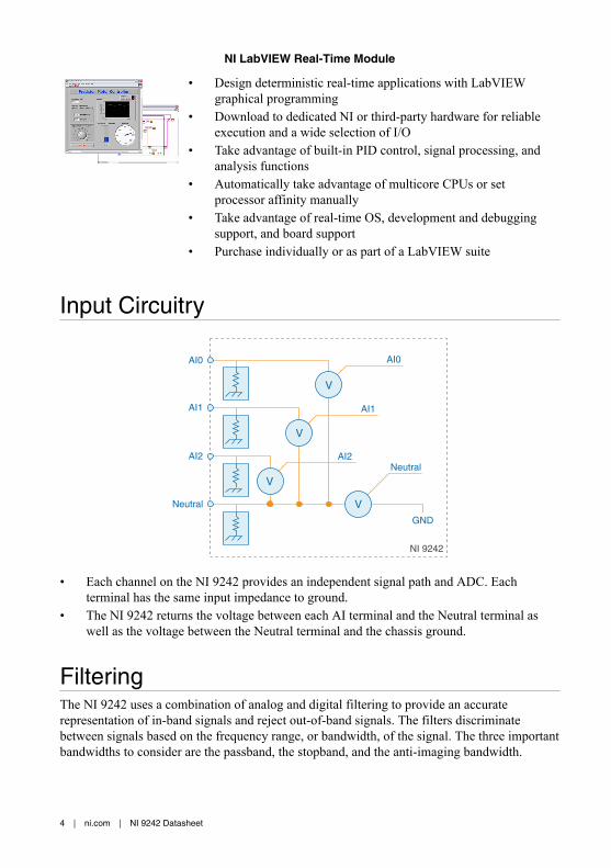
Input Circuitry
NI 9242
AI1
AI2
Neutral
GND
Neutral
AI0
AI1
AI2
AI0
V
V
V
V
• Each channel on the NI 9242 provides an independent signal path and ADC. Eachterminal has the same input impedance to ground.
• The NI 9242 returns the voltage between each AI terminal and the Neutral terminal aswell as the voltage between the Neutral terminal and the chassis ground.
FilteringThe NI 9242 uses a combination of analog and digital filtering to provide an accuraterepresentation of in-band signals and reject out-of-band signals. The filters discriminatebetween signals based on the frequency range, or bandwidth, of the signal. The three importantbandwidths to consider are the passband, the stopband, and the anti-imaging bandwidth.
4 | ni.com | NI 9242 Datasheet
The NI 9242 represents signals within the passband, as quantified primarily by passband rippleand phase nonlinearity. All signals that appear in the alias-free bandwidth are either unaliasedsignals or signals that have been filtered by at least the amount of the stopband rejection.
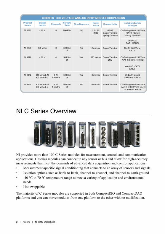
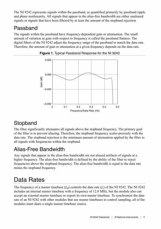
PassbandThe signals within the passband have frequency-dependent gain or attenuation. The smallamount of variation in gain with respect to frequency is called the passband flatness. Thedigital filters of the NI 9242 adjust the frequency range of the passband to match the data rate.Therefore, the amount of gain or attenuation at a given frequency depends on the data rate.
Figure 1. Typical Passband Response for the NI 9242
Frequency/Data Rate (Hz)
0.50.4
0.025
0.000
–0.025
–0.0500.30.20.10
Gai
n (d
B)
StopbandThe filter significantly attenuates all signals above the stopband frequency. The primary goalof the filter is to prevent aliasing. Therefore, the stopband frequency scales precisely with thedata rate. The stopband rejection is the minimum amount of attenuation applied by the filter toall signals with frequencies within the stopband.
Alias-Free BandwidthAny signals that appear in the alias-free bandwidth are not aliased artifacts of signals at ahigher frequency. The alias-free bandwidth is defined by the ability of the filter to rejectfrequencies above the stopband frequency. The alias-free bandwidth is equal to the data rateminus the stopband frequency.
Data RatesThe frequency of a master timebase (fM) controls the data rate (fs) of the NI 9242. The NI 9242includes an internal master timebase with a frequency of 12.8 MHz, but the module also canaccept an external master timebase or export its own master timebase. To synchronize the datarate of an NI 9242 with other modules that use master timebases to control sampling, all of themodules must share a single master timebase source.
NI 9242 Datasheet | © National Instruments | 5

The following equation provides the available data rates of the NI 9242:
�� = ��÷ 256�where n is any integer from 1 to 31.
However, the data rate must remain within the appropriate data rate range. When using theinternal master timebase of 12.8 MHz, the result is data rates of 50 kS/s, 25 kS/s, 16.667 kS/s,and so on down to 1.613 kS/s depending on the value of n. When using an external timebasewith a frequency other than 12.8 MHz, the NI 9242 has a different set of data rates.
Note The NI 9151 R Series Expansion chassis does not support sharing timebasesbetween modules.
NI 9242 SpecificationsThe following specifications are typical for the range -40 °C to 70 °C unless otherwise noted.
Caution Do not operate the NI 9242 in a manner not specified in this document.Product misuse can result in a hazard. You can compromise the safety protectionbuilt into the product if the product is damaged in any way. If the product isdamaged, return it to NI for repair.
Input CharacteristicsScaling coefficient 59,605 nV/LSB
Number of channels 4 analog input channels
ADC resolution 24 bits
Type of ADC Delta-Sigma (with analog prefiltering)
Sampling mode Simultaneous
Internal master timebase (fM)
Frequency 12.8 MHz
Accuracy ±100 ppm maximum
Data rate range (fs) using internal master timebase
Minimum 1.613 kS/s
Maximum 50 kS/s
Data rate range (fs) using external master timebase
Minimum 390.625 S/s
Maximum 51.2 kS/s
6 | ni.com | NI 9242 Datasheet
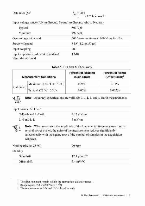
Data rates (fs)1 ��÷ 256� , n = 1, 2, …, 31
Input voltage range (AIx-to-Ground, Neutral-to-Ground, AIx-to-Neutral)
Typical 500 Vpk
Minimum 497 Vpk
Overvoltage withstand 500 Vrms continuous, 600 Vrms for 10 s
Surge withstand 8 kV (1.2 µs/50 µs)
Input coupling DC
Input impedance, AIx-to-Ground andNeutral-to-Ground
1 MΩ
Table 1. DC and AC Accuracy
Measurement ConditionsPercent of Reading
(Gain Error)Percent of Range
(Offset Error)2
Calibrated
Maximum, (-40 °C to 70 °C) 0.26% 0.14%
Typical, (23 °C ±5 °C) 0.05% 0.022%
Note Accuracy specifications are valid for L-L, L-N and L-Earth measurements.
Input noise at 50 kS/s3
N-Earth and L-Earth 2.12 mVrms
L-N and L-L 3 mVrms
Note When measuring the amplitude of the fundamental frequency over one orseveral power cycles, the noise of the measurement reduces significantly(theoretically with the square root of the number of samples in the acquisitionwindow).
Nonlinearity (at 25 °C) 20 ppm
Stability
Gain drift 12.1 ppm/°C
Offset drift 3.4 mV/°C
1 The data rate must remain within the appropriate data rate range.2 Range equals 354 V (250 Vrms × √2)3 The module returns L-N and N-Earth values only.
NI 9242 Datasheet | © National Instruments | 7
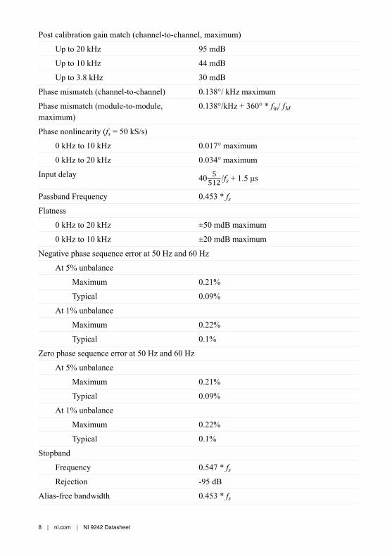
Post calibration gain match (channel-to-channel, maximum)
Up to 20 kHz 95 mdB
Up to 10 kHz 44 mdB
Up to 3.8 kHz 30 mdB
Phase mismatch (channel-to-channel) 0.138°/ kHz maximum
Phase mismatch (module-to-module,maximum)
0.138°/kHz + 360° * fin/ fM
Phase nonlinearity (fs = 50 kS/s)
0 kHz to 10 kHz 0.017° maximum
0 kHz to 20 kHz 0.034° maximum
Input delay 40 5512 /fs + 1.5 μs
Passband Frequency 0.453 * fsFlatness
0 kHz to 20 kHz ±50 mdB maximum
0 kHz to 10 kHz ±20 mdB maximum
Negative phase sequence error at 50 Hz and 60 Hz
At 5% unbalance
Maximum 0.21%
Typical 0.09%
At 1% unbalance
Maximum 0.22%
Typical 0.1%
Zero phase sequence error at 50 Hz and 60 Hz
At 5% unbalance
Maximum 0.21%
Typical 0.09%
At 1% unbalance
Maximum 0.22%
Typical 0.1%
Stopband
Frequency 0.547 * fsRejection -95 dB
Alias-free bandwidth 0.453 * fs
8 | ni.com | NI 9242 Datasheet
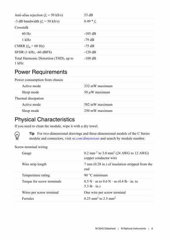
Anti-alias rejection (fs = 50 kS/s) 53 dB
-3 dB bandwidth (fs = 50 kS/s) 0.49 * fsCrosstalk
60 Hz -105 dB
1 kHz -79 dB
CMRR (fin = 60 Hz) -75 dB
SFDR (1 kHz, -60 dBFS) -120 dB
Total Harmonic Distortion (THD), up to1 kHz
-100 dB
Power RequirementsPower consumption from chassis
Active mode 332 mW maximum
Sleep mode 50 µW maximum
Thermal dissipation
Active mode 582 mW maximum
Sleep mode 250 mW maximum
Physical CharacteristicsIf you need to clean the module, wipe it with a dry towel.
Tip For two-dimensional drawings and three-dimensional models of the C Seriesmodule and connectors, visit ni.com/dimensions and search by module number.
Screw-terminal wiring
Gauge 0.2 mm 2 to 3.0 mm2 (24 AWG to 12 AWG)copper conductor wire
Wire strip length 7 mm (0.28 in.) of insulation stripped from theend
Temperature rating 90 °C minimum
Torque for screw terminals 0.5 N · m to 0.6 N · m (4.4 lb · in. to5.3 lb · in.)
Wires per screw terminal One wire per screw terminal
Ferrules 0.25 mm2 to 2.5 mm2
NI 9242 Datasheet | © National Instruments | 9
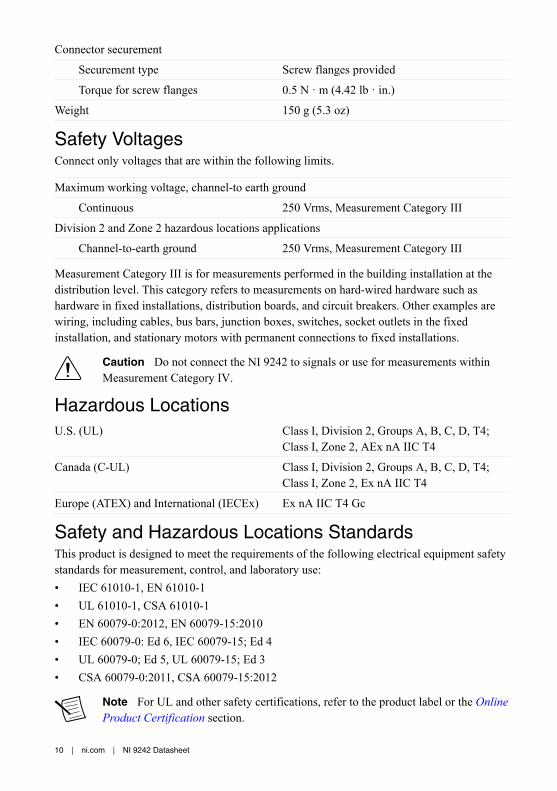
Connector securement
Securement type Screw flanges provided
Torque for screw flanges 0.5 N · m (4.42 lb · in.)
Weight 150 g (5.3 oz)
Safety VoltagesConnect only voltages that are within the following limits.
Maximum working voltage, channel-to earth ground
Continuous 250 Vrms, Measurement Category III
Division 2 and Zone 2 hazardous locations applications
Channel-to-earth ground 250 Vrms, Measurement Category III
Measurement Category III is for measurements performed in the building installation at thedistribution level. This category refers to measurements on hard-wired hardware such ashardware in fixed installations, distribution boards, and circuit breakers. Other examples arewiring, including cables, bus bars, junction boxes, switches, socket outlets in the fixedinstallation, and stationary motors with permanent connections to fixed installations.
Caution Do not connect the NI 9242 to signals or use for measurements withinMeasurement Category IV.
Hazardous LocationsU.S. (UL) Class I, Division 2, Groups A, B, C, D, T4;
Class I, Zone 2, AEx nA IIC T4
Canada (C-UL) Class I, Division 2, Groups A, B, C, D, T4;Class I, Zone 2, Ex nA IIC T4
Europe (ATEX) and International (IECEx) Ex nA IIC T4 Gc
Safety and Hazardous Locations StandardsThis product is designed to meet the requirements of the following electrical equipment safetystandards for measurement, control, and laboratory use:• IEC 61010-1, EN 61010-1• UL 61010-1, CSA 61010-1• EN 60079-0:2012, EN 60079-15:2010• IEC 60079-0: Ed 6, IEC 60079-15; Ed 4• UL 60079-0; Ed 5, UL 60079-15; Ed 3• CSA 60079-0:2011, CSA 60079-15:2012
Note For UL and other safety certifications, refer to the product label or the OnlineProduct Certification section.
10 | ni.com | NI 9242 Datasheet

Electromagnetic CompatibilityThis product meets the requirements of the following EMC standards for electrical equipmentfor measurement, control, and laboratory use:• EN 61326-1 (IEC 61326-1): Class A emissions; Industrial immunity• EN 55011 (CISPR 11): Group 1, Class A emissions• EN 55022 (CISPR 22): Class A emissions• EN 55024 (CISPR 24): Immunity• AS/NZS CISPR 11: Group 1, Class A emissions• AS/NZS CISPR 22: Class A emissions• FCC 47 CFR Part 15B: Class A emissions• ICES-001: Class A emissions
Note In the United States (per FCC 47 CFR), Class A equipment is intended foruse in commercial, light-industrial, and heavy-industrial locations. In Europe,Canada, Australia and New Zealand (per CISPR 11) Class A equipment is intendedfor use only in heavy-industrial locations.
Note Group 1 equipment (per CISPR 11) is any industrial, scientific, or medicalequipment that does not intentionally generate radio frequency energy for thetreatment of material or inspection/analysis purposes.
Note For EMC declarations and certifications, and additional information, refer tothe Online Product Certification section.
CE Compliance This product meets the essential requirements of applicable European Directives, as follows:• 2014/35/EU; Low-Voltage Directive (safety)• 2014/30/EU; Electromagnetic Compatibility Directive (EMC)• 94/9/EC; Potentially Explosive Atmospheres (ATEX)
Online Product CertificationRefer to the product Declaration of Conformity (DoC) for additional regulatory complianceinformation. To obtain product certifications and the DoC for this product, visit ni.com/certification, search by model number or product line, and click the appropriate link in theCertification column.
NI 9242 Datasheet | © National Instruments | 11
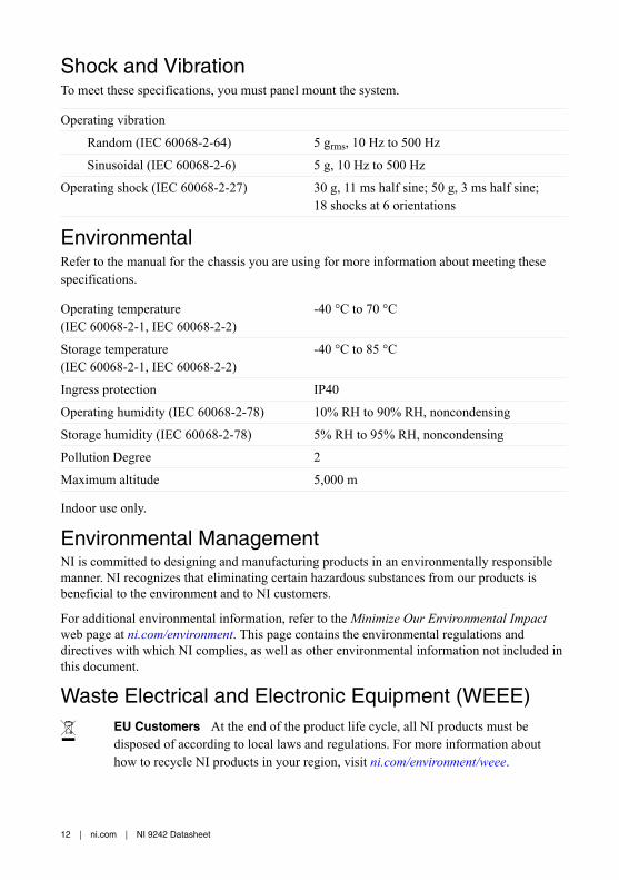
Shock and VibrationTo meet these specifications, you must panel mount the system.
Operating vibration
Random (IEC 60068-2-64) 5 grms, 10 Hz to 500 Hz
Sinusoidal (IEC 60068-2-6) 5 g, 10 Hz to 500 Hz
Operating shock (IEC 60068-2-27) 30 g, 11 ms half sine; 50 g, 3 ms half sine;18 shocks at 6 orientations
EnvironmentalRefer to the manual for the chassis you are using for more information about meeting thesespecifications.
Operating temperature(IEC 60068-2-1, IEC 60068-2-2)
-40 °C to 70 °C
Storage temperature(IEC 60068-2-1, IEC 60068-2-2)
-40 °C to 85 °C
Ingress protection IP40
Operating humidity (IEC 60068-2-78) 10% RH to 90% RH, noncondensing
Storage humidity (IEC 60068-2-78) 5% RH to 95% RH, noncondensing
Pollution Degree 2
Maximum altitude 5,000 m
Indoor use only.
Environmental ManagementNI is committed to designing and manufacturing products in an environmentally responsiblemanner. NI recognizes that eliminating certain hazardous substances from our products isbeneficial to the environment and to NI customers.
For additional environmental information, refer to the Minimize Our Environmental Impactweb page at ni.com/environment. This page contains the environmental regulations anddirectives with which NI complies, as well as other environmental information not included inthis document.
Waste Electrical and Electronic Equipment (WEEE)EU Customers At the end of the product life cycle, all NI products must bedisposed of according to local laws and regulations. For more information abouthow to recycle NI products in your region, visit ni.com/environment/weee.
12 | ni.com | NI 9242 Datasheet
电子信息产品污染控制管理办法(中国 RoHS)中国客户 National Instruments 符合中国电子信息产品中限制使用某些有害物
质指令(RoHS)。关于 National Instruments 中国 RoHS 合规性信息,请登录
ni.com/environment/rohs_china。(For information about China RoHScompliance, go to ni.com/environment/rohs_china.)
CalibrationYou can obtain the calibration certificate and information about calibration services for theNI 9242 at ni.com/calibration.
Calibration interval 1 year
NI 9242 Datasheet | © National Instruments | 13

Refer to the NI Trademarks and Logo Guidelines at ni.com/trademarks for information on NI trademarks. Other product andcompany names mentioned herein are trademarks or trade names of their respective companies. For patents covering NIproducts/technology, refer to the appropriate location: Help»Patents in your software, the patents.txt file on your media, or theNational Instruments Patent Notice at ni.com/patents. You can find information about end-user license agreements (EULAs)and third-party legal notices in the readme file for your NI product. Refer to the Export Compliance Information at ni.com/legal/export-compliance for the NI global trade compliance policy and how to obtain relevant HTS codes, ECCNs, and otherimport/export data. NI MAKES NO EXPRESS OR IMPLIED WARRANTIES AS TO THE ACCURACY OF THE INFORMATIONCONTAINED HEREIN AND SHALL NOT BE LIABLE FOR ANY ERRORS. U.S. Government Customers: The data contained inthis manual was developed at private expense and is subject to the applicable limited rights and restricted data rights as set forthin FAR 52.227-14, DFAR 252.227-7014, and DFAR 252.227-7015.
© 2016 National Instruments. All rights reserved.
376130B-02 Sep16