Embed Size (px)
Citation preview
Last Update: September 2014
Front cover
NIC Virtualization in Lenovo Flex System Fabric Solutions
Introduces NIC virtualization concepts and technologies
Describes UFP and vNIC deployment scenarios
Provides UFP and vNIC configuration examples
Useful knowledge for networking professionals
Scott Irwin
Scott Lorditch
Matt Slavin
Ilya Krutov


NIC Virtualization in Lenovo Flex System Fabric Solutions
September 2014
SG24-8223-00
© Copyright Lenovo 2016. All rights reserved.Note to U.S. Government Users Restricted Rights -- Use, duplication or disclosure restricted by GSA ADP Schedule Contract
Last update on September 2014
This edition applies to:
� Networking Operating System 7.8� Flex System Fabric CN4093 10Gb Converged Scalable Switch� Flex System Fabric EN4093R 10Gb Scalable Switch� Flex System Embedded 10Gb Virtual Fabric Adapter� Flex System CN4054 10Gb Virtual Fabric Adapter� Flex System CN4054R 10Gb Virtual Fabric Adapter
Note: Before using this information and the product it supports, read the information in “Notices” on page v.
Contents
Notices . . . . . . . . . . . . . . . . . . . . . . . . . . . . . . . . . . . . . . . . . . . . . . . . . . . . . . . . . . . . . . . . . .vTrademarks . . . . . . . . . . . . . . . . . . . . . . . . . . . . . . . . . . . . . . . . . . . . . . . . . . . . . . . . . . . . . . vi
Preface . . . . . . . . . . . . . . . . . . . . . . . . . . . . . . . . . . . . . . . . . . . . . . . . . . . . . . . . . . . . . . . . . viiThe team who wrote this book . . . . . . . . . . . . . . . . . . . . . . . . . . . . . . . . . . . . . . . . . . . . . . . . viiComments welcome. . . . . . . . . . . . . . . . . . . . . . . . . . . . . . . . . . . . . . . . . . . . . . . . . . . . . . . viiiDo you have the latest version?. . . . . . . . . . . . . . . . . . . . . . . . . . . . . . . . . . . . . . . . . . . . . . . ix
Chapter 1. I/O module and NIC virtualization features in the Flex System environment1
1.1 Overview of Flex System network virtualization . . . . . . . . . . . . . . . . . . . . . . . . . . . . . . . 21.2 Introduction to NIC virtualization . . . . . . . . . . . . . . . . . . . . . . . . . . . . . . . . . . . . . . . . . . . 3
1.2.1 vNIC based NIC virtualization . . . . . . . . . . . . . . . . . . . . . . . . . . . . . . . . . . . . . . . . . 31.2.2 Unified Fabric Port-based NIC virtualization . . . . . . . . . . . . . . . . . . . . . . . . . . . . . . 51.2.3 Comparing vNIC modes and UFP modes. . . . . . . . . . . . . . . . . . . . . . . . . . . . . . . . 5
1.3 Introduction to I/O module virtualization . . . . . . . . . . . . . . . . . . . . . . . . . . . . . . . . . . . . . 61.3.1 Introduction to vLAG . . . . . . . . . . . . . . . . . . . . . . . . . . . . . . . . . . . . . . . . . . . . . . . . 61.3.2 Introduction to stacking . . . . . . . . . . . . . . . . . . . . . . . . . . . . . . . . . . . . . . . . . . . . . . 81.3.3 Introduction to SPAR . . . . . . . . . . . . . . . . . . . . . . . . . . . . . . . . . . . . . . . . . . . . . . 101.3.4 Easy Connect Q-in-Q solutions. . . . . . . . . . . . . . . . . . . . . . . . . . . . . . . . . . . . . . . 111.3.5 Introduction to the Failover feature . . . . . . . . . . . . . . . . . . . . . . . . . . . . . . . . . . . . 13
1.4 Introduction to converged fabrics . . . . . . . . . . . . . . . . . . . . . . . . . . . . . . . . . . . . . . . . . 151.4.1 FCoE. . . . . . . . . . . . . . . . . . . . . . . . . . . . . . . . . . . . . . . . . . . . . . . . . . . . . . . . . . . 151.4.2 iSCSI . . . . . . . . . . . . . . . . . . . . . . . . . . . . . . . . . . . . . . . . . . . . . . . . . . . . . . . . . . . 161.4.3 iSCSI versus FCoE . . . . . . . . . . . . . . . . . . . . . . . . . . . . . . . . . . . . . . . . . . . . . . . . 17
Chapter 2. Flex System networking architecture and Fabric portfolio . . . . . . . . . . . . 192.1 Enterprise Chassis I/O architecture . . . . . . . . . . . . . . . . . . . . . . . . . . . . . . . . . . . . . . . 202.2 Flex System Fabric I/O modules . . . . . . . . . . . . . . . . . . . . . . . . . . . . . . . . . . . . . . . . . . 23
2.2.1 Flex System Fabric EN4093R 10Gb Scalable Switch. . . . . . . . . . . . . . . . . . . . . . 242.2.2 Flex System Fabric CN4093 10Gb Converged Scalable Switch . . . . . . . . . . . . . 302.2.3 Flex System Fabric SI4093 System Interconnect Module . . . . . . . . . . . . . . . . . . 362.2.4 I/O modules and cables . . . . . . . . . . . . . . . . . . . . . . . . . . . . . . . . . . . . . . . . . . . . 42
2.3 Flex System Virtual Fabric adapters . . . . . . . . . . . . . . . . . . . . . . . . . . . . . . . . . . . . . . . 432.3.1 Embedded 10Gb Virtual Fabric Adapter . . . . . . . . . . . . . . . . . . . . . . . . . . . . . . . . 432.3.2 Flex System CN4054/CN4054R 10Gb Virtual Fabric Adapters . . . . . . . . . . . . . . 44
Chapter 3. NIC virtualization considerations on the switch side . . . . . . . . . . . . . . . . . 473.1 Virtual Fabric vNIC solution capabilities . . . . . . . . . . . . . . . . . . . . . . . . . . . . . . . . . . . . 48
3.1.1 Virtual Fabric mode vNIC . . . . . . . . . . . . . . . . . . . . . . . . . . . . . . . . . . . . . . . . . . . 493.1.2 Switch Independent mode vNIC . . . . . . . . . . . . . . . . . . . . . . . . . . . . . . . . . . . . . . 53
3.2 Unified Fabric Port feature . . . . . . . . . . . . . . . . . . . . . . . . . . . . . . . . . . . . . . . . . . . . . . 553.2.1 UFP Access and Trunk modes . . . . . . . . . . . . . . . . . . . . . . . . . . . . . . . . . . . . . . . 563.2.2 UFP Tunnel mode. . . . . . . . . . . . . . . . . . . . . . . . . . . . . . . . . . . . . . . . . . . . . . . . . 583.2.3 UFP FCoE mode. . . . . . . . . . . . . . . . . . . . . . . . . . . . . . . . . . . . . . . . . . . . . . . . . . 593.2.4 UFP Auto mode . . . . . . . . . . . . . . . . . . . . . . . . . . . . . . . . . . . . . . . . . . . . . . . . . . 603.2.5 UFP vPort considerations . . . . . . . . . . . . . . . . . . . . . . . . . . . . . . . . . . . . . . . . . . . 60
3.3 Compute node NIC to I/O module connectivity mapping . . . . . . . . . . . . . . . . . . . . . . . 623.3.1 Embedded 10 Gb VFA (LOM): Mezzanine 1 . . . . . . . . . . . . . . . . . . . . . . . . . . . . 62
© Copyright Lenovo 2016. All rights reserved. iii
3.3.2 Flex System CN4054/CN4054R 10Gb VFA: Mezzanine 1 . . . . . . . . . . . . . . . . . . 623.3.3 Flex System CN4054/CN4054R 10Gb VFA: Mezzanine 1 and 2 . . . . . . . . . . . . . 633.3.4 Flex System x222 Compute Node . . . . . . . . . . . . . . . . . . . . . . . . . . . . . . . . . . . . 64
Chapter 4. NIC virtualization considerations on the server side . . . . . . . . . . . . . . . . . 674.1 Enabling virtual NICs on the server via UEFI . . . . . . . . . . . . . . . . . . . . . . . . . . . . . . . . 68
4.1.1 Getting in to the virtual NIC configuration section of UEFI . . . . . . . . . . . . . . . . . . 684.1.2 Initially enabling virtual NIC functionality via UEFI . . . . . . . . . . . . . . . . . . . . . . . . 774.1.3 Special settings for the different modes of virtual NIC via UEFI . . . . . . . . . . . . . . 784.1.4 Setting the Emulex virtual NIC settings back to factory default. . . . . . . . . . . . . . . 83
4.2 Enabling virtual NICs via Configuration Patterns . . . . . . . . . . . . . . . . . . . . . . . . . . . . . 844.3 Using physical and virtual NICs in the operating systems. . . . . . . . . . . . . . . . . . . . . . 107
4.3.1 Introduction to teaming/bonding on the server . . . . . . . . . . . . . . . . . . . . . . . . . . 1084.3.2 Operating system side teaming/bonding and upstream network requirements . 1154.3.3 Physical NIC connections and logical enumeration . . . . . . . . . . . . . . . . . . . . . . 122
Chapter 5. Flex System NIC virtualization deployment scenarios . . . . . . . . . . . . . . . 1275.1 Introduction to deployment examples . . . . . . . . . . . . . . . . . . . . . . . . . . . . . . . . . . . . . 1285.2 UFP mode virtual NIC and Layer 2 Failover . . . . . . . . . . . . . . . . . . . . . . . . . . . . . . . . 129
5.2.1 Components . . . . . . . . . . . . . . . . . . . . . . . . . . . . . . . . . . . . . . . . . . . . . . . . . . . . 1295.2.2 Topology . . . . . . . . . . . . . . . . . . . . . . . . . . . . . . . . . . . . . . . . . . . . . . . . . . . . . . . 1295.2.3 Use Cases . . . . . . . . . . . . . . . . . . . . . . . . . . . . . . . . . . . . . . . . . . . . . . . . . . . . . 1315.2.4 Configuration. . . . . . . . . . . . . . . . . . . . . . . . . . . . . . . . . . . . . . . . . . . . . . . . . . . . 1315.2.5 Confirming operation of the environment . . . . . . . . . . . . . . . . . . . . . . . . . . . . . . 136
5.3 UFP mode virtual NIC with vLAG and FCoE. . . . . . . . . . . . . . . . . . . . . . . . . . . . . . . . 1405.3.1 Components . . . . . . . . . . . . . . . . . . . . . . . . . . . . . . . . . . . . . . . . . . . . . . . . . . . . 1405.3.2 Topology . . . . . . . . . . . . . . . . . . . . . . . . . . . . . . . . . . . . . . . . . . . . . . . . . . . . . . . 1405.3.3 Use cases . . . . . . . . . . . . . . . . . . . . . . . . . . . . . . . . . . . . . . . . . . . . . . . . . . . . . . 1415.3.4 Configuration. . . . . . . . . . . . . . . . . . . . . . . . . . . . . . . . . . . . . . . . . . . . . . . . . . . . 1425.3.5 Confirming operation of the environment . . . . . . . . . . . . . . . . . . . . . . . . . . . . . . 149
5.4 pNIC and vNIC Virtual Fabric modes with Layer 2 Failover . . . . . . . . . . . . . . . . . . . . 1535.4.1 Components . . . . . . . . . . . . . . . . . . . . . . . . . . . . . . . . . . . . . . . . . . . . . . . . . . . . 1555.4.2 Topologies . . . . . . . . . . . . . . . . . . . . . . . . . . . . . . . . . . . . . . . . . . . . . . . . . . . . . 1555.4.3 Use cases . . . . . . . . . . . . . . . . . . . . . . . . . . . . . . . . . . . . . . . . . . . . . . . . . . . . . . 1565.4.4 Configurations. . . . . . . . . . . . . . . . . . . . . . . . . . . . . . . . . . . . . . . . . . . . . . . . . . . 1565.4.5 Verifying operation . . . . . . . . . . . . . . . . . . . . . . . . . . . . . . . . . . . . . . . . . . . . . . . 171
5.5 Switch Independent mode with SPAR . . . . . . . . . . . . . . . . . . . . . . . . . . . . . . . . . . . . 1795.5.1 Components . . . . . . . . . . . . . . . . . . . . . . . . . . . . . . . . . . . . . . . . . . . . . . . . . . . . 1795.5.2 Topology . . . . . . . . . . . . . . . . . . . . . . . . . . . . . . . . . . . . . . . . . . . . . . . . . . . . . . . 1795.5.3 Use cases . . . . . . . . . . . . . . . . . . . . . . . . . . . . . . . . . . . . . . . . . . . . . . . . . . . . . . 1815.5.4 Configuration. . . . . . . . . . . . . . . . . . . . . . . . . . . . . . . . . . . . . . . . . . . . . . . . . . . . 1835.5.5 Verifying operation . . . . . . . . . . . . . . . . . . . . . . . . . . . . . . . . . . . . . . . . . . . . . . . 188
Abbreviations and acronyms . . . . . . . . . . . . . . . . . . . . . . . . . . . . . . . . . . . . . . . . . . . . . 195
Related publications . . . . . . . . . . . . . . . . . . . . . . . . . . . . . . . . . . . . . . . . . . . . . . . . . . . . 197Lenovo Press . . . . . . . . . . . . . . . . . . . . . . . . . . . . . . . . . . . . . . . . . . . . . . . . . . . . . . . . . . . 197
iv NIC Virtualization in Lenovo Flex System Fabric Solutions
Notices
Lenovo may not offer the products, services, or features discussed in this document in all countries. Consult your local Lenovo representative for information on the products and services currently available in your area. Any reference to a Lenovo product, program, or service is not intended to state or imply that only that Lenovo product, program, or service may be used. Any functionally equivalent product, program, or service that does not infringe any Lenovo intellectual property right may be used instead. However, it is the user's responsibility to evaluate and verify the operation of any other product, program, or service.
Lenovo may have patents or pending patent applications covering subject matter described in this document. The furnishing of this document does not give you any license to these patents. You can send license inquiries, in writing, to:
Lenovo (United States), Inc.1009 Think Place - Building OneMorrisville, NC 27560U.S.A.Attention: Lenovo Director of Licensing
LENOVO PROVIDES THIS PUBLICATION “AS IS” WITHOUT WARRANTY OF ANY KIND, EITHER EXPRESS OR IMPLIED, INCLUDING, BUT NOT LIMITED TO, THE IMPLIED WARRANTIES OF NON-INFRINGEMENT, MERCHANTABILITY OR FITNESS FOR A PARTICULAR PURPOSE. Some jurisdictions do not allow disclaimer of express or implied warranties in certain transactions, therefore, this statement may not apply to you.
This information could include technical inaccuracies or typographical errors. Changes are periodically made to the information herein; these changes will be incorporated in new editions of the publication. Lenovo may make improvements and/or changes in the product(s) and/or the program(s) described in this publication at any time without notice.
The products described in this document are not intended for use in implantation or other life support applications where malfunction may result in injury or death to persons. The information contained in this document does not affect or change Lenovo product specifications or warranties. Nothing in this document shall operate as an express or implied license or indemnity under the intellectual property rights of Lenovo or third parties. All information contained in this document was obtained in specific environments and is presented as an illustration. The result obtained in other operating environments may vary.
Lenovo may use or distribute any of the information you supply in any way it believes appropriate without incurring any obligation to you.
Any references in this publication to non-Lenovo Web sites are provided for convenience only and do not in any manner serve as an endorsement of those Web sites. The materials at those Web sites are not part of the materials for this Lenovo product, and use of those Web sites is at your own risk.
Any performance data contained herein was determined in a controlled environment. Therefore, the result obtained in other operating environments may vary significantly. Some measurements may have been made on development-level systems and there is no guarantee that these measurements will be the same on generally available systems. Furthermore, some measurements may have been estimated through extrapolation. Actual results may vary. Users of this document should verify the applicable data for their specific environment.
© Copyright Lenovo 2016. All rights reserved. v
Trademarks
Lenovo, the Lenovo logo, and For Those Who Do are trademarks or registered trademarks of Lenovo in the United States, other countries, or both. These and other Lenovo trademarked terms are marked on their first occurrence in this information with the appropriate symbol (® or ™), indicating US registered or common law trademarks owned by Lenovo at the time this information was published. Such trademarks may also be registered or common law trademarks in other countries. A current list of Lenovo trademarks is available on the Web at http://www.lenovo.com/legal/copytrade.html.
The following terms are trademarks of Lenovo in the United States, other countries, or both:
Blade Network Technologies®BladeCenter®BNT®Flex System™
Lenovo®Omni Ports™Lenovo(logo)®System x®
VMready®vNIC™
The following terms are trademarks of other companies:
Intel, Xeon, and the Intel logo are trademarks or registered trademarks of Intel Corporation or its subsidiaries in the United States and other countries.
Linux is a trademark of Linus Torvalds in the United States, other countries, or both.
Hyper-V, Microsoft, Windows, Windows Server, and the Windows logo are trademarks of Microsoft Corporation in the United States, other countries, or both.
Other company, product, or service names may be trademarks or service marks of others.
vi NIC Virtualization in Lenovo Flex System Fabric Solutions
Preface
The deployment of server virtualization technologies in data centers requires significant efforts in providing sufficient network I/O bandwidth to satisfy the demand of virtualized applications and services. For example, every virtualized system can host several dozen applications and services. Each of these services requires certain bandwidth (or speed) to function properly.
Furthermore, because of different network traffic patterns that are relevant to different service types, these traffic flows can interfere with each other. They can lead to serious network problems, including the inability of the service to perform its functions.
The NIC virtualization in Lenovo® Flex System™ Fabric solutions addresses these issues. The solutions are based on the Flex System Enterprise Chassis with a 10 Gbps Converged Enhanced Ethernet infrastructure. This infrastructure is built on Flex System Fabric CN4093 and EN4093R 10 Gbps Ethernet switch modules, and Flex System Fabric SI4093 Switch Interconnect modules in the chassis and the Emulex Virtual Fabric Adapters in each compute node.
This book introduces NIC virtualization concepts and technologies, describes their deployment scenarios, and provides configuration examples that use Lenovo Networking OS technologies that are combined with the Emulex Virtual Fabric adapters.
This book is for networking professionals who want to learn how to implement NIC virtualization solutions and switch interconnect technologies on Flex System by using the Unified Fabric Port (UFP) mode, Switch Independent mode, and Virtual Fabric mode.
This book assumes that the reader has basic knowledge of the networking concepts and technologies, including OSI model, Ethernet LANs, Spanning Tree protocol, VLANs, VLAN tagging, uplinks, trunks, and static and dynamic (LACP) link aggregation.
The team who wrote this book
This document is produced by the following subject matter experts working in the Lenovo offices in Morrisville, NC, USA.
Ilya Krutov is a Project Leader at Lenovo Press. He manages and produces pre-sale and post-sale technical publications on various IT topics, including x86 rack and blade servers, server operating systems, virtualization and cloud, networking, storage, and systems management. Ilya has more than 15 years of experience in the IT industry, backed by professional certifications from Cisco Systems, IBM, and Microsoft. During his career, Ilya has held a variety of technical and leadership positions in education, consulting, services, technical sales, marketing, channel business, and programming. He has written more than 200 books, papers, and other technical documents. Ilya has a Specialist's degree with honors in Computer Engineering from the Moscow State Engineering and Physics Institute (Technical University).
© Copyright Lenovo 2016. All rights reserved. vii

Comments welcome
Your comments are important to us!
We want our books to be as helpful as possible. Send us your comments about this book or in one of the following ways:
� Use the online feedback form found at the web page for this document:
http://lenovopress.com/sg248223
� Send your comments in an email to:
Scott Irwin is a Consulting Systems Engineer (CSE) with Lenovo Networking, formerly from IBM and Blade Network Technologies® (BNT®). His networking background spans well over 16 years as a Customer Support Escalation Engineer and a Customer-facing Field Systems Engineer. His focus is on deep customer troubleshooting and his responsibilities include supporting customer proof of concepts, assistance with paid installations and training, and supporting pre- and post-sales activities with customers in the Public Sector, High Frequency Trading, Service Provider, Midmarket, and Enterprise markets.
Scott Lorditch is a Consulting System Engineer for Lenovo. He performs network architecture assessments and develops designs and proposals for solutions that involve Lenovo Networking products. He also developed several training and lab sessions for technical and sales personnel. Scott joined IBM as part of the acquisition of Blade Network Technologies and joined Lenovo as part of the System x® acquisition from IBM. Scott spent almost 20 years working on networking in various industries, as a senior network architect, a product manager for managed hosting services, and manager of electronic securities transfer projects. Scott holds a BS degree in Operations Research with a specialization in computer science from Cornell University.
Matt Slavin is a Consulting Systems Engineer for Lenovo Networking, based out of Tulsa, Oklahoma. He provides network consulting skills to the Americas. He has over 30 years of hands-on systems and network design, installation, and troubleshooting experience. Most recently, he has focused on data center networking, where he is leading client efforts to adopt new technologies into day-to-day operations. Matt joined Lenovo through the acquisition of the IBM System x team. Before that acquisition, he worked at some of the top systems and networking companies in the world.
viii NIC Virtualization in Lenovo Flex System Fabric Solutions

Do you have the latest version?
We update our books and papers from time to time, so check whether you have the latest version of this document by clicking the Check for Updates button on the front page of the PDF. Pressing this button will take you to a web page that will tell you if you are reading the latest version of the document and give you a link to the latest if needed. While you’re there, you can also sign up to get notified via email whenever we make an update.
Preface ix

x NIC Virtualization in Lenovo Flex System Fabric Solutions
Chapter 1. I/O module and NIC virtualization features in the Flex System environment
This chapter introduces the various virtualization features that are available with certain I/O Modules and converged network adapters (CNAs) in the Flex System environment. The primary focus of this publication is the EN4093R, CN4093, and the SI4093, with related server-side converged network adapter (CNA) or Virtual Fabric Adapter (VFA) virtualization features.
Although other I/O modules are available for the Flex System Enterprise Chassis environment, those other I/O modules do not support the virtualization features discussed in this document and are not covered here (unless otherwise noted).
This chapter includes the following topics:
� Overview of Flex System network virtualization� Introduction to NIC virtualization� Introduction to I/O module virtualization� Introduction to converged fabrics
1
© Copyright Lenovo 2016. All rights reserved. 1
1.1 Overview of Flex System network virtualization
The term virtualization can mean many different things to different people, and in different contexts.
For example, in the server world, the term is often associated with taking bare metal platforms and adding a layer of software (referred to as a hypervisor) that permits multiple virtual machines (VMs) to run on that single physical platform, with each VM thinking it owns the entire hardware platform.
In the network world, there are many different concepts of virtualization. Such things as overlay technologies, with which a user can run one network on top of another network, usually with the goal of hiding the complexities of the underlying network (often referred to as overlay networking). Another form of network virtualization is Openflow technology, which de-couples a switches control plane from the switch, and allows the switching path decisions to be made from a central control point.
There are other forms of virtualization, such as cross chassis aggregation (also known as cross-switch aggregation), virtualized NIC technologies, and converged fabrics.
This publication is focused on the latter set of cross chassis aggregation, virtualized NIC technologies, and converged fabrics, specifically, the following set of features:
� Converged fabrics: Fibre Channel over Ethernet (FCoE) and Internet Small Computer Systems Interconnect (iSCSI)
� Virtual Link Aggregation (vLAG): A form of cross switch aggregation
� Stacking: Virtualizing the management plane and the switching fabric
� Switch Partitioning (SPAR): Masking the I/O Module from the host and upstream network
� Easy Connect Q-in-Q solutions: More ways to mask the I/O Modules from connecting devices
� NIC virtualization - Allowing a single physical 10 GbE NIC to represent multiple NICs to the host OS
Although we introduce all of these topics in this chapter, the primary focus of this publication is regarding how NIC virtualization integrates into the various other features and the surrounding customer environment. The following specific NIC virtualization features are described:
� Virtual Fabric mode: Also known as vNIC™ Virtual Fabric mode, which includes Dedicated Uplink Mode (default) and Shared Uplink Mode (optional) operations.
� Switch Independent Mode: Also known as vNIC Switch Independent mode.
� Unified Fabric Port: Also known as Unified Fabric Protocol (UFP) - All modes.
Important: The term vNIC can be used generically for all virtual NIC technologies, or as a vendor-specific term. For example, VMware calls the virtual NIC that is inside a VM a vNIC. Unless otherwise noted, the use of the term vNIC in this publication is referring to a specific feature that is available on the Flex System I/O modules and Emulex CNAs inside physical hosts.
In a related fashion, the term vPort has multiple connotations; for example, used by Microsoft for their Hyper-V environment. Unless otherwise noted, the use of the term vPort in this publication refers to the UFP feature on the Flex System I/O modules and Emulex CNAs inside physical hosts.
2 NIC Virtualization in Lenovo Flex System Fabric Solutions
1.2 Introduction to NIC virtualization
This section introduces the two primary types of NIC virtualization (vNIC and UFP) that are available on the Flex System I/O modules and adapters and the various subelements of these virtual NIC technologies.
The deployment of server virtualization technologies in data centers requires significant efforts to provide sufficient network I/O bandwidth (or speed) to satisfy the demand of virtualized applications and services. For example, every virtualized system can host several dozen network applications and services, and each of these services requires a certain bandwidth to function properly. Also, because of different network traffic patterns that are relevant to different service types, these traffic flows might interfere with each other. This interference can lead to serious network problems, including the inability of the service to perform its functions.
Providing sufficient bandwidth and isolation to virtualized applications in a 1 Gbps network infrastructure might be challenging for blade-based deployments where the number of physical I/O ports per compute node is limited. For example, a maximum of 12 physical ports per single-wide compute node (up to six Ethernet ports per adapter) can be used for network connectivity. With 1 GbE, a total network bandwidth of 12 Gb per compute node is available for Gigabit Ethernet infrastructures, which leaves no room for future growth.
In addition, traffic flows are isolated on a physical port basis. Also, the bandwidth per interface is static with a maximum bandwidth of 1 Gb per flow, which limits the flexibility of bandwidth usage. Flex System Fabric solutions address these issues by increasing the number of available Ethernet ports and providing more flexibility in allocating the available bandwidth to meet specific application requirements.
By virtualizing a 10 Gbps NIC, its resources can be divided into multiple logical instances or virtual NICs. Each virtual NIC appears as a regular, independent NIC to the server operating system or hypervisor, and each virtual NIC uses a portion of the overall bandwidth of the physical NIC. For example, a NIC partition with a maximum bandwidth of 4 Gbps appears to the host applications as a physically distinct 4 Gbps Ethernet adapter. Also, the NIC partitions provide traffic forwarding and port isolation.
The virtual NIC technologies that are described for the I/O module here are all directly tied to the Emulex CNA offerings for the Flex System environment, and documented in 2.3, “Flex System Virtual Fabric adapters” on page 43.
1.2.1 vNIC based NIC virtualization
vNIC is the original virtual NIC technology that is used in the BladeCenter® 10 Gb Virtual Fabric Switch Module. It was brought forward into the PureFlex System environment to allow customers that have standardized on vNIC to still use it with the PureFlex System solutions.
Important: All I/O module features that are described in this paper are based on the latest available firmware at the time of this writing (Networking OS 7.8 for the EN4093R, CN4093, and SI4093 modules).
Chapter 1. I/O module and NIC virtualization features in the Flex System environment 3
vNIC has the following primary modes:
� Virtual Fabric mode
Virtual Fabric mode offer advanced virtual NICs to servers and it requires support on the switch side. In Virtual Fabric mode, the Virtual Fabric Adapter (VFA) in the compute node communicates with the Flex System switch to obtain vNIC parameters (by using DCBX). A special tag is added within each data packet and is later removed by the NIC and switch for each vNIC group to maintain separation of the virtual data paths.
In Virtual Fabric Mode, you can change the bandwidth allocations through the switch user interfaces without requiring a reboot of the server.
vNIC bandwidth allocation and metering are performed by both the switch and the VFA. In such a case, a bidirectional virtual channel of an assigned bandwidth is established between them for every defined vNIC.
� Switch Independent mode
Switch Independent Mode offers virtual NICs to server with no special I/O module side configuration. It extends the existing customer VLANs to the virtual NIC interfaces. The IEEE 802.1Q VLAN tag is essential to the separation of the vNIC groups by the NIC adapter or driver and the switch. The VLAN tags are added to the packet by the applications or drivers at each endstation rather than by the switch.
vNIC bandwidth allocation and metering are performed only by VFA. The switch is unaware that the 10 GbE NIC is seen as multiple logical NICs in the OS. In such a case, a unidirectional virtual channel is established where the bandwidth management is only performed for the outgoing traffic on a VFA side (server-to-switch). The incoming traffic (switch-to-server) uses the all available physical port bandwidth because there is no metering that is performed on either the VFA or a switch side.
Virtual Fabric mode vNIC has the following submodes:
� vNIC Virtual Fabric - Dedicated Uplink Mode:
– Provides a Q-in-Q tunneling action for each vNIC group
– Each vNIC group must have its own dedicated uplink path out
– Any vNICs in one vNIC group cannot communicate with vNICs in any other vNIC group without first exiting to the upstream network with Layer 3 routing
� vNIC Virtual Fabric - Shared Uplink Mode:
– Each vNIC group provides a single VLAN for all vNICs in that group
– Each vNIC group must be a unique VLAN (cannot use same VLAN on more than a single vNIC group)
– Servers cannot use tagging when Shared Uplink Mode is enabled
– As with vNICs in Dedicate Uplink Mode, any vNICs in one vNIC group cannot talk with vNICs in any other vNIC group without first exiting to the upstream network with Layer 3 routing
For more information about enabling and configuring these modes, see Chapter 4, “NIC virtualization considerations on the server side” on page 67, and Chapter 5, “Flex System NIC virtualization deployment scenarios” on page 127.
4 NIC Virtualization in Lenovo Flex System Fabric Solutions
1.2.2 Unified Fabric Port-based NIC virtualization
Unified Fabric Port (UFP) is the current direction of Lenovo NIC virtualization and provides a more feature-rich solution compared to the original vNIC Virtual Fabric mode. As with Virtual Fabric mode vNIC, UFP allows carving up a single 10 Gb port into four virtual NICs (called vPorts in UFP). UFP also has the following modes that are associated with it:
� Tunnel mode
Provides Q-in-Q mode, where the vPort is customer VLAN-independent (which is similar to vNIC Virtual Fabric Dedicated Uplink Mode).
� Trunk mode
Provides a traditional 802.1Q trunk mode (multi-VLAN trunk link) to the virtual NIC (vPort) interface; that is, permits host side tagging.
� Access mode
Provides a traditional access mode (single untagged VLAN) to the virtual NIC (vPort) interface, which is similar to a physical port in access mode.
� FCoE mode
Provides FCoE functionality to the vPort.
� Auto-VLAN mode
Auto VLAN creation for Qbg and VMready® environments.
Only one vPort (vPort 2) per physical port can be bound to FCoE. If FCoE is not wanted, vPort 2 can be configured for one of the other modes.
For more information about enabling and configuring these modes, see Chapter 4, “NIC virtualization considerations on the server side” on page 67, and Chapter 5, “Flex System NIC virtualization deployment scenarios” on page 127.
1.2.3 Comparing vNIC modes and UFP modes
As a rule, if a customer wants virtualized NICs in the PureFlex System environment, UFP is usually the preferred solution because all of the new feature development is going into UFP.
If a customer has standardized the original vNIC Virtual Fabric mode, they can still continue to use that mode in a fully supported fashion.
If a customer does not want any of the virtual NIC functionality that is controlled by the I/O module (controlled and configured only on the server side), Switch Independent mode vNIC is the solution of choice. This mode has the advantage of being I/O module-independent, such that any upstream I/O module can be used. Some of the disadvantages to this mode are that bandwidth restrictions can be enforced only from the server side (not the I/O module side) and to change bandwidth requires a reboot of the server (bandwidth control for the other virtual NIC modes that are described here are changed from the switch side, enforce bandwidth restrictions bidirectionally, and can be changed dynamically, with no reboot required).
Chapter 1. I/O module and NIC virtualization features in the Flex System environment 5
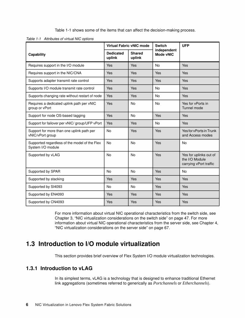
Table 1-1 shows some of the items that can affect the decision-making process.
Table 1-1 Attributes of virtual NIC options
For more information about virtual NIC operational characteristics from the switch side, see Chapter 3, “NIC virtualization considerations on the switch side” on page 47. For more information about virtual NIC operational characteristics from the server side, see Chapter 4, “NIC virtualization considerations on the server side” on page 67.
1.3 Introduction to I/O module virtualization
This section provides brief overview of Flex System I/O module virtualization technologies.
1.3.1 Introduction to vLAG
In its simplest terms, vLAG is a technology that is designed to enhance traditional Ethernet link aggregations (sometimes referred to generically as Portchannels or Etherchannels).
Capability
Virtual Fabric vNIC mode Switch independent Mode vNIC
UFP
Dedicated uplink
Shared uplink
Requires support in the I/O module Yes Yes No Yes
Requires support in the NIC/CNA Yes Yes Yes Yes
Supports adapter transmit rate control Yes Yes Yes Yes
Supports I/O module transmit rate control Yes Yes No Yes
Supports changing rate without restart of node Yes Yes No Yes
Requires a dedicated uplink path per vNIC group or vPort
Yes No No Yes for vPorts in Tunnel mode
Support for node OS-based tagging Yes No Yes Yes
Support for failover per vNIC/ group/UFP vPort Yes Yes No Yes
Support for more than one uplink path per vNIC/vPort group
No Yes Yes Yes for vPorts in Trunk and Access modes
Supported regardless of the model of the Flex System I/O module
No No Yes No
Supported by vLAG No No Yes Yes for uplinks out of the I/O Module carrying vPort traffic
Supported by SPAR No No Yes No
Supported by stacking Yes Yes Yes Yes
Supported by SI4093 No No Yes Yes
Supported by EN4093 Yes Yes Yes Yes
Supported by CN4093 Yes Yes Yes Yes
6 NIC Virtualization in Lenovo Flex System Fabric Solutions
Under current IEEE specifications, an aggregation is still defined as a bundle of similar links between two (and only two devices) bound together to operate as a single logical link. By today’s standards-based definitions, you cannot create an aggregation on one device and have these links of that aggregation connect to more than a single device on the other side of the aggregation. The use of only two devices in this fashion limits the ability to offer certain robust designs.
Although the standards bodies are working on a solution that provides split aggregations across devices, most vendors developed their own versions of this multi-chassis aggregation. For example, Cisco has virtual Port Channel (vPC) on NX OS products and Virtual Switch System (VSS) on the 6500 IOS products. Lenovo offers virtual Link Aggregation (vLAG) on many of the Lenovo Top of Rack (ToR) solutions and on the EN4093R and CN4093 Flex System I/O modules.
The primary goal of virtual link aggregation is to overcome the limit that is imposed by the current standards-based aggregation, and provide a distributed aggregation across a pair of switches instead of a single switch. Doing so results in a reduction of single points of failure, while still maintaining a loop-free, non-blocking environment.
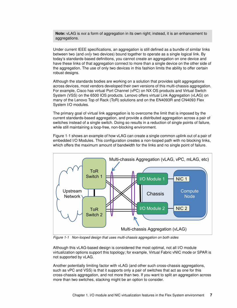
Figure 1-1 shows an example of how vLAG can create a single common uplink out of a pair of embedded I/O Modules. This configuration creates a non-looped path with no blocking links, which offers the maximum amount of bandwidth for the links and no single point of failure.
Figure 1-1 Non-looped design that uses multi-chassis aggregation on both sides
Although this vLAG-based design is considered the most optimal, not all I/O module virtualization options support this topology; for example, Virtual Fabric vNIC mode or SPAR is not supported by vLAG.
Another potentially limiting factor with vLAG (and other such cross-chassis aggregations, such as vPC and VSS) is that it supports only a pair of switches that act as one for this cross-chassis aggregation, and not more than two. If you want to split an aggregation across more than two switches, stacking might be an option to consider.
Note: vLAG is not a form of aggregation in its own right; instead, it is an enhancement to aggregations.
Chassis ComputeNode
NIC 1
NIC 2
UpstreamNetwork
ToRSwitch 2
ToRSwitch 1
Multi-chassis Aggregation (vLAG, vPC, mLAG, etc)
I/O Module 1
I/O Module 2
Multi-chassis Aggregation (vLAG)
Chapter 1. I/O module and NIC virtualization features in the Flex System environment 7
1.3.2 Introduction to stacking
By using stacking, you can take up to eight physical I/O modules and treat them as a single logical switch from a port usage and management perspective. Ports on different I/O modules in the stack can be part of a common aggregation and you log in to only a single IP address to manage all I/O modules in the stack. For devices that are attaching to the stack, the stack looks and acts like a single large switch.
Stacking is supported on the EN4093R and CN4093 I/O modules. It is provided by reserving a group of uplinks into stacking links and creating a ring of I/O modules with these links. The ring design ensures that the loss of a single link or single I/O module in the stack does not lead to a disruption of the stack.
Before v7.7 releases of code, it was possible to stack the EN4093R only into a common stack of like model I/O modules. However, in v7.7 and later code, support was added to add a pair CN4093s into a hybrid stack of EN4093s to add Fibre Channel Forwarder (FCF) capability into the stack. The limit for this hybrid stacking is a maximum of 6x EN4093Rs and 2x CN4093s in a common stack.
Stacking the Flex System chassis I/O modules with Lenovo Top of Rack switches that also support stacking is not allowed. Connections from a stack of Flex System chassis I/O modules to upstream switches can be made with normal single or aggregated connections, including the use of vLAG/vPC on the upstream switches to connect links across stack members into a common non-blocking fabric between the stack and the Top of Rack switches.
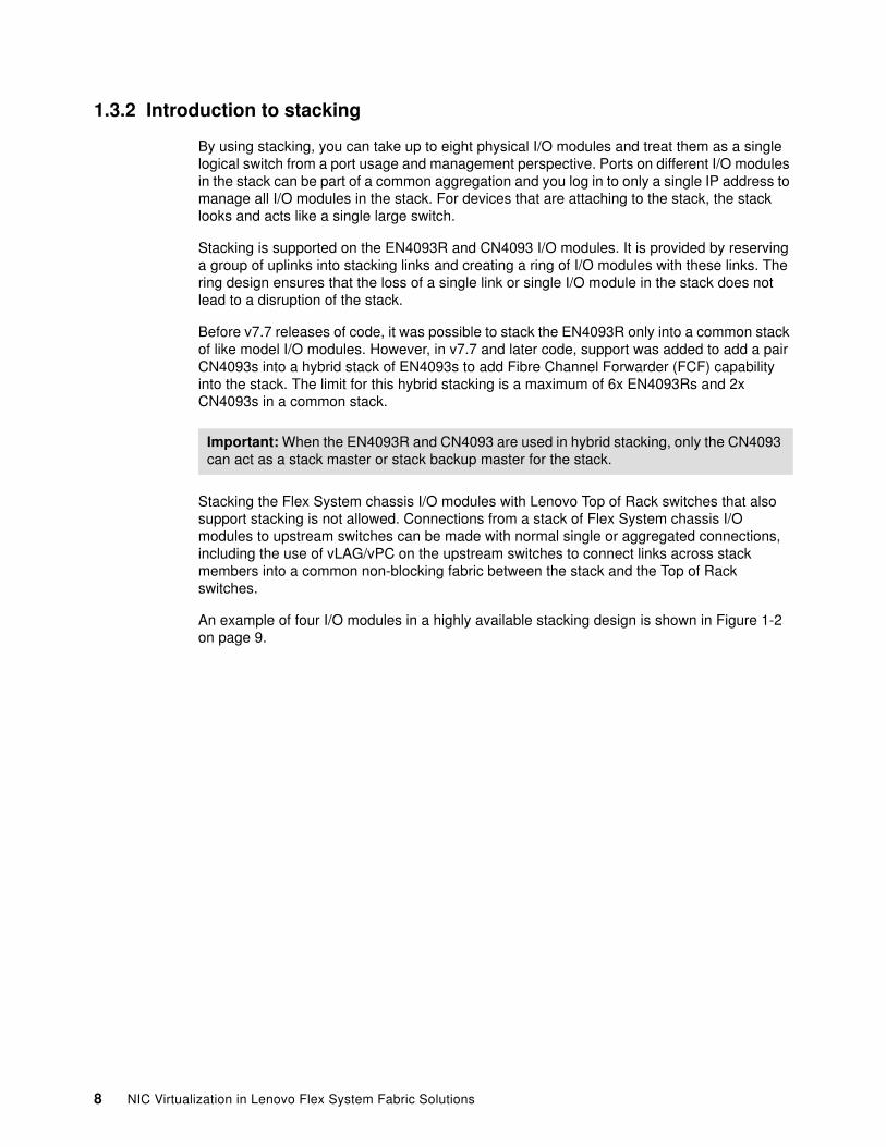
An example of four I/O modules in a highly available stacking design is shown in Figure 1-2 on page 9.
Important: When the EN4093R and CN4093 are used in hybrid stacking, only the CN4093 can act as a stack master or stack backup master for the stack.
8 NIC Virtualization in Lenovo Flex System Fabric Solutions
Figure 1-2 Example of stacking in the Flex System environment
This example shows a design with no single points of failures (via a stack of four I/O modules in a single stack) and a pair of upstream vLAG/vPC connected switches.
One of the potential limitations of the current implementation of stacking is that if an upgrade of code is needed, a reload of the entire stack must occur. Because upgrades are uncommon and should be scheduled for non-production hours anyway, a single stack design is efficient and acceptable. However, some customers do not want to have any downtime (scheduled or otherwise); therefore, a single stack design is not an acceptable solution. For these users that still want to make the most use of stacking, a two-stack design might be an option. This design features stacking a set of I/O modules in bay 1 into one stack, and a set of I/O modules in bay 2 in a second stack.
The primary advantage to a two-stack design is that each stack can be upgraded one at a time, with the running stack maintaining connectivity for the compute nodes during the upgrade and reload of the other stack. The downside of the two-stack design is that traffic that is flowing from one stack to another stack must go through the upstream network to reach the other stack.
Stacking might not be suitable for all customers. However, if it is wanted, it is another tool that is available for building a robust infrastructure by using the Flex System I/O modules.
Multi-chassis Aggregation (vLAG, vPC, mLAG, etc)
Chassis 1 ComputeNode
NIC 1
NIC 2
UpstreamNetwork
ToRSwitch 2
ToRSwitch 1
I/O Module 1
I/O Module 2
Stacking
Chassis 2 ComputeNode
NIC 1
NIC 2
I/O Module 1
I/O Module 2
Chapter 1. I/O module and NIC virtualization features in the Flex System environment 9
1.3.3 Introduction to SPAR
Switch partitioning (SPAR) is a feature that, among other things, allows a physical I/O module to be divided into multiple logical switches. After SPAR is configured, ports within a specific SPAR group can communicate only with each other. Ports that are members of different SPAR groups on the same I/O module cannot communicate directly with each other, without going outside the I/O module.
The EN4093R, CN4093, and the SI4093 I/O Modules support SPAR.
SPAR features the following modes of operation:
� Pass-through domain mode (also known as transparent mode)
This mode of SPAR uses a Q-in-Q function to encapsulate all traffic that is passing through the switch in a second layer of VLAN tagging. This mode is the default mode when SPAR is enabled and is VLAN independent owing to this Q-in-Q operation. It passes tagged and untagged packets through the SPAR session without looking at or interfering with any customer assigned tag.
SPAR pass-through mode supports passing FCoE packets to an upstream FCF, but without FIP Snooping within the SPAR group in pass-through domain mode.
� Local domain mode
This mode is not VLAN independent and requires a user to create any required VLANs in the SPAR group. Currently, there is a limit of 256 VLANs in Local domain mode.
Support is available for FIP Snooping on FCoE sessions in Local Domain mode. Unlike pass-through domain mode, Local Domain mode provides strict control of end host VLAN isolation.
Consider the following points regarding SPAR:
� SPAR is disabled by default on the EN4093R and CN4093. SPAR is enabled by default on SI4093, with all base licensed internal and external ports defaulting to a single pass-through SPAR group. This default SI4093 configuration can be changed, if wanted.
� Any port can be a member of only a single SPAR group at one time.
� Only a single uplink path is permissible per SPAR group (can be a single link, a single static aggregation, or a single LACP aggregation). This SPAR enforced restriction ensures that no network loops are possible with ports in a SPAR group.
� SPAR cannot be used with UFP or Virtual Fabric vNIC as of this writing. Switch Independent Mode vNIC is supported by SPAR. UFP support is slated for a future release.
� Up to eight SPAR groups per I/O module are supported. This number might be increased in a future release.
� SPAR is not supported by vLAG, stacking, or tagpvid-ingress features.
SPAR can be a useful solution in environments where simplicity is paramount.
10 NIC Virtualization in Lenovo Flex System Fabric Solutions
1.3.4 Easy Connect Q-in-Q solutions
The Easy Connect concept (which is often referred to as Easy Connect mode or Transparent mode) is not a specific feature. Instead, it is a way of using one of four different existing features to attempt to minimize ongoing I/O module management requirements. The primary goal of Easy Connect is to make an I/O module transparent to the hosts and the upstream network they must access, which reduces the management requirements for I/O Modules in an Easy Connect mode.
There are several features that can be used to accomplish an Easy Connect solution. The following common aspects of Easy Connect solutions are available:
� At the heart of Easy Connect is some form of Q-in-Q tagging to mask packets that are traveling through the I/O module. This tagging is a fundamental requirement of any Easy Connect solution with which the attached hosts and upstream network can communicate by using any VLAN (tagged or untagged) and the I/O module passes those packets through to the other side of the I/O module by wrapping them in an outer VLAN tag. It then removes that outer VLAN tag as the packet exits the I/O module, which makes the I/O module VLAN independent. This Q-in-Q operation is what removes the need to manage VLANs on the I/O module, which is usually one of the larger ongoing management requirements of a deployed I/O module.
� Pre-creating an aggregation of the uplinks (in some cases, all of the uplinks) to remove the possibility of loops (if all uplinks are not used, any unused uplinks/ports should be disabled to ensure that loops are not possible).
� Optionally disabling spanning-tree so the upstream network does not receive any spanning-tree BPDUs. This function is especially important in the case of upstream devices that shut down a port if BPDUs are received, such as a Cisco FEX device, or an upstream switch that is running some form of BPDU guard.
After it is configured, an I/O module in Easy Connect mode does not require on-going configuration changes as a customer adds and removes VLANs to the hosts and upstream network. In essence, Easy Connect turns the I/O module into a VLAN independent port aggregator, with support for growing up to the maximum bandwidth of the product (for example, add upgrade Feature on Demand [FoD] keys to the I/O module to increase the 10 Gb links to Compute Nodes and 10 Gb and 40 Gb links to the upstream networks).
The following primary methods are used for deploying an Easy Connect solution:
� Use an I/O module that defaults to a form of Easy Connect:
For customers that want an Easy Connect type of solution that is immediately ready for use (zero touch I/O module deployment), the SI4093 provides this function by default. The SI4093 accomplishes this function by having the following factory default configuration:
– All base licensed internal and external ports are put into a single SPAR group.
– All uplinks are put into a single common LACP aggregation and the LACP suspend-port feature is enabled.
– The failover feature is enabled on the common LACP key.
– No spanning-tree support (the SI4093 is designed to never permit more than a single uplink path per SPAR, so it cannot create a loop and does not support spanning-tree).
� For customers that want the option to use advanced features but also want an Easy Connect mode solution, the EN4093R and CN4093 offer configurable options. These options can make them transparent to the attaching Compute Nodes and upstream network switches while maintaining the option of changing to more advanced modes of configuration, when needed.
Chapter 1. I/O module and NIC virtualization features in the Flex System environment 11
The SI4093 accomplishes this task by defaulting to the SPAR feature in pass-through mode, which puts all compute node ports and all uplinks into a common Q-in-Q group.
For the EN4093R and CN4093, there are several features that can be implemented to accomplish this Easy Connect support. The primary difference between these I/O modules and the SI4093 is that you must first perform a small set of configuration steps to set up the EN4093R and CN4093 into an Easy Connect mode after which minimal management of the I/O module is required.
For these I/O modules, this Easy Connect mode can be configured by using one of the following features:
� SPAR feature that is default on the SI4093 and can be configured on the EN4093R and CN4093
� Tagpvid-ingress� Configure vNIC Virtual Fabric Dedicated Uplink Mode� Configure UFP vPort tunnel mode
In general, all of these features provide this Easy Connect functionality, with each having some pros and cons. For example, if you want to use Easy Connect with vLAG, you should use the tagpvid-ingress mode or the UFP vPort tunnel mode (SPAR and Virtual Fabric vNIC do not permit the vLAG ISL). However, if you want to use Easy Connect with FCoE today, you cannot use tagpvid-ingress and must use a different form of Easy connect, such as the vNIC Virtual Fabric Dedicated Uplink Mode or UFP tunnel mode (SPAR pass-through mode allows FCoE but does not support FIP snooping, which might or might not be a concern for some customers).
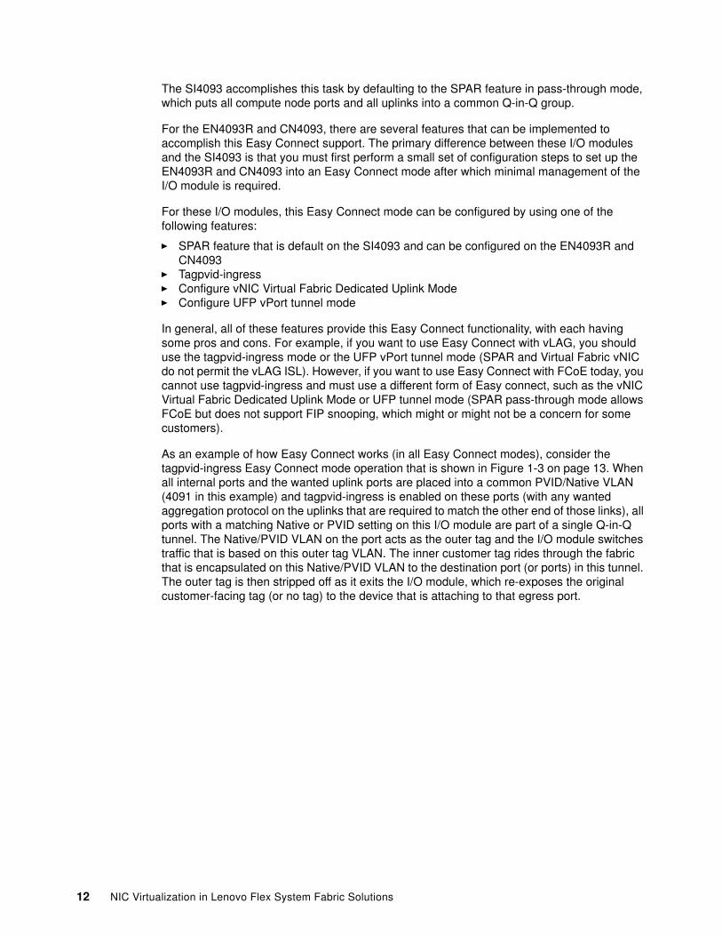
As an example of how Easy Connect works (in all Easy Connect modes), consider the tagpvid-ingress Easy Connect mode operation that is shown in Figure 1-3 on page 13. When all internal ports and the wanted uplink ports are placed into a common PVID/Native VLAN (4091 in this example) and tagpvid-ingress is enabled on these ports (with any wanted aggregation protocol on the uplinks that are required to match the other end of those links), all ports with a matching Native or PVID setting on this I/O module are part of a single Q-in-Q tunnel. The Native/PVID VLAN on the port acts as the outer tag and the I/O module switches traffic that is based on this outer tag VLAN. The inner customer tag rides through the fabric that is encapsulated on this Native/PVID VLAN to the destination port (or ports) in this tunnel. The outer tag is then stripped off as it exits the I/O module, which re-exposes the original customer-facing tag (or no tag) to the device that is attaching to that egress port.
12 NIC Virtualization in Lenovo Flex System Fabric Solutions
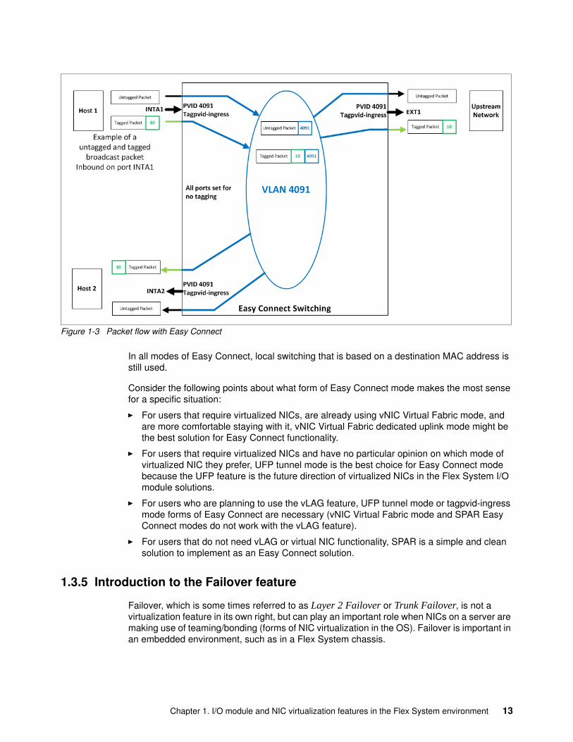
Figure 1-3 Packet flow with Easy Connect
In all modes of Easy Connect, local switching that is based on a destination MAC address is still used.
Consider the following points about what form of Easy Connect mode makes the most sense for a specific situation:
� For users that require virtualized NICs, are already using vNIC Virtual Fabric mode, and are more comfortable staying with it, vNIC Virtual Fabric dedicated uplink mode might be the best solution for Easy Connect functionality.
� For users that require virtualized NICs and have no particular opinion on which mode of virtualized NIC they prefer, UFP tunnel mode is the best choice for Easy Connect mode because the UFP feature is the future direction of virtualized NICs in the Flex System I/O module solutions.
� For users who are planning to use the vLAG feature, UFP tunnel mode or tagpvid-ingress mode forms of Easy Connect are necessary (vNIC Virtual Fabric mode and SPAR Easy Connect modes do not work with the vLAG feature).
� For users that do not need vLAG or virtual NIC functionality, SPAR is a simple and clean solution to implement as an Easy Connect solution.
1.3.5 Introduction to the Failover feature
Failover, which is some times referred to as Layer 2 Failover or Trunk Failover, is not a virtualization feature in its own right, but can play an important role when NICs on a server are making use of teaming/bonding (forms of NIC virtualization in the OS). Failover is important in an embedded environment, such as in a Flex System chassis.
Chapter 1. I/O module and NIC virtualization features in the Flex System environment 13
When NICs are teamed or bonded in an operating system, they must know when a NIC cannot reach the upstream network so they can decide to use or not use a NIC in the team. Most commonly, this link is a simple link up or link down check in the server. If the link is reporting up, use the NIC; if a link is reporting down, do not use the NIC.
In an embedded environment, this behavior can be a problem if the uplinks out of the embedded I/O module go down, but the internal link to the server is still up. In that case, the server is still reporting the NIC link as up, even though there is no path to the upstream network. This issue leads to the server sending traffic out a NIC that has no path out of the embedded I/O module and disrupts server communications.
The Failover feature can be implemented in these environments. When the set of uplinks that the Failover feature is tracking go down, configurable internal ports also are taken down, which alerts the embedded server to a path fault in this direction. The server then can use the team or bond to select a different NIC and maintain network connectivity.
An example of how failover can protect Compute Nodes in a PureFlex chassis when there is an uplink fault out of one of the I/O modules can be seen in Figure 1-4.
Figure 1-4 Example of Failover in action
Without failover or some other form of remote link failure detection, embedded servers can be exposed to loss of connectivity if the uplink path on one of the embedded I/O modules fails.
Designs that use vLAG or some sort of cross chassis aggregation (such as stacking) are not exposed to this issue (and therefore, do not need the Failover feature) because they have a different coping method for dealing with uplinks out of an I/O module going down. For example, with vLAG, the packets that must get upstream can cross the vLAG ISL and use the other I/O modules uplinks to get to the upstream network.
How�Failover�Works�� ���������� ��� ����������� ����������� ��� ���� ������������������� ��������� ��� ��!����� �� ���"�
#� �������� ����������� ���������� �$�%���� � ��&������ ������ ������������ ��� ������� ���������� ��
'�$�%������� ������ ������ ��������� ������������������ ��$�%�#�� ������� ������ ��
Chassis
$ ��
NIC�1
NIC�2ToR�Switch�2
ToR�Switch�1 ����( ������
)�� ����������
����( �����#)�� ����������
X* �����
�������$�%
#
'
�
14 NIC Virtualization in Lenovo Flex System Fabric Solutions
1.4 Introduction to converged fabrics
As the name implies, converged fabrics are all about taking a set of protocols and data that is designed to run on top of one type of physical medium and allowing them to be carried on top of a different physical medium. This function provides several cost benefits, such as reducing the number of physical cabling plants that are required, removing the need for separate physical NICs and HBAs, and including a potential reduction in power and cooling. From an OpEx perspective, it can reduce the cost that is associated with the management of separate physical infrastructures. In the data center world, two of the most common forms of converged fabrics are Fibre Channel over Ethernet (FCoE) and iSCSI.
FCoE allows a host to use its 10 Gb Ethernet connections to access Fibre Channel attached storage (as though it were physically attached via Fibre Channel to the host) when, in fact, the Fibre Channel traffic is encapsulated into FCoE frames and carried to the remote storage via an Ethernet network.
iSCSI takes a protocol that was originally designed for hosts to talk to relatively close physical storage over physical SCSI cables. iSCSi then converts it to use IP and run over an Ethernet network with which they can access storage beyond the limitations of a physical SCSI-based solution.
iSCSI can be used in existing (lossy) and new (lossless) Ethernet infrastructure, with different performance characteristics. However, FCoE requires a lossless converged enhanced Ethernet network and it relies on other functionality that is known from Fibre Channel (for example, name server and zoning).
1.4.1 FCoE
FCoE assumes the existence of a lossless Ethernet, such as one that implements the Data Center Bridging (DCB) extensions to Ethernet. The EN4093R, CN4093, G8264, and G8264CS switches support FCoE. The G8264 and EN4093R functions as an FCoE transit switch while the CN4093 and G8264CS have Omni Ports™ that can be set to function as Fibre Channel ports or Ethernet ports as specified in the switch configuration.
The basic notion of FCoE is that the upper layers of Fibre Channel are mapped onto Ethernet. The upper layer protocols and services of Fibre Channel remain the same in an FCoE deployment. Zoning, fabric services, and similar services still exist with FCoE.
The difference is that the lower layers of Fibre Channel are replaced by lossless Ethernet, which also implies that Fibre Channel concepts, such as port types and lower-layer initialization protocols, must be replaced by new constructs in FCoE. Such mappings are defined by the FC-BB-5 standard and are briefly described here.
Figure 1-5 on page 16 shows the perspective on FCoE layering that is compared to other storage networking technologies. In Figure 1-5 on page 16, Fibre Channel and FCoE layers are shown with other storage networking protocols, including iSCSI.
Chapter 1. I/O module and NIC virtualization features in the Flex System environment 15
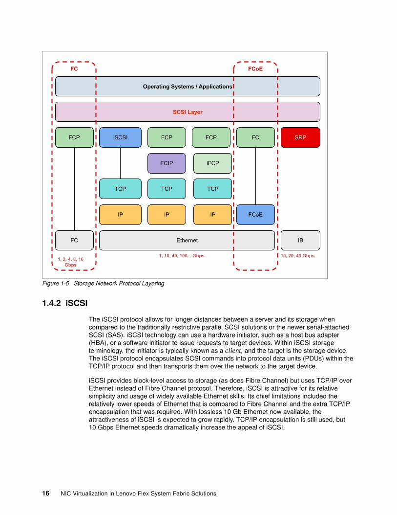
Figure 1-5 Storage Network Protocol Layering
1.4.2 iSCSI
The iSCSI protocol allows for longer distances between a server and its storage when compared to the traditionally restrictive parallel SCSI solutions or the newer serial-attached SCSI (SAS). iSCSI technology can use a hardware initiator, such as a host bus adapter (HBA), or a software initiator to issue requests to target devices. Within iSCSI storage terminology, the initiator is typically known as a client, and the target is the storage device. The iSCSI protocol encapsulates SCSI commands into protocol data units (PDUs) within the TCP/IP protocol and then transports them over the network to the target device.
iSCSI provides block-level access to storage (as does Fibre Channel) but uses TCP/IP over Ethernet instead of Fibre Channel protocol. Therefore, iSCSI is attractive for its relative simplicity and usage of widely available Ethernet skills. Its chief limitations included the relatively lower speeds of Ethernet that is compared to Fibre Channel and the extra TCP/IP encapsulation that was required. With lossless 10 Gb Ethernet now available, the attractiveness of iSCSI is expected to grow rapidly. TCP/IP encapsulation is still used, but 10 Gbps Ethernet speeds dramatically increase the appeal of iSCSI.
Operating Systems / Applications
SCSI Layer
1, 2, 4, 8, 16Gbps
FCP FCP FCP FCiSCSI SRP
TCP TCP TCP
IP IP IP FCoE
FC IB
iFCPFCIP
Ethernet
1, 10, 40, 100... Gbps 10, 20, 40 Gbps
FC FCoE
16 NIC Virtualization in Lenovo Flex System Fabric Solutions
1.4.3 iSCSI versus FCoE
This section describes the similarities and differences between iSCSI and FCoE. However, in most cases, considerations other than purely technical ones often influence your decision when you are choosing one over the other.
iSCSI and FCoE have the following similarities:
� Both protocols are block-oriented storage protocols. That is, the file system logic for accessing storage with either of them is on the computer where the initiator is, not on the storage hardware. Therefore, they are both different from typical network-attached storage (NAS) technologies, which are file-oriented.
� Both protocols implement Ethernet-attached storage.
� Both protocols can be implemented in hardware, which is detected by the operating system of the host as an HBA.
� Both protocols can also be implemented by using software initiators, which are available in various server operating systems. However, this approach uses resources of the main processor to perform tasks that otherwise are performed by the hardware of an HBA.
� Both protocols can use the Converged Enhanced Ethernet (CEE) (which is also referred to as Data Center Bridging) standards to deliver “lossless” traffic over Ethernet.
� Both protocols are alternatives to traditional Fibre Channel storage and Fibre Channel SANs.
iSCSI and FCoE have the following differences:
� iSCSI uses TCP/IP as its transport, and FCoE uses Ethernet. iSCSI can use media other than Ethernet, such as InfiniBand, and iSCSI can use Layer 3 routing in an IP network.
� Numerous vendors provide local iSCSI storage targets, some of which also support Fibre Channel and other storage technologies. Relatively few native FCoE targets are available at the time of this writing, which might allow iSCSI to be implemented at a lower overall capital cost.
� FCoE requires a gateway function (often referred to a Fibre Channel Forwarder [FCF]), which allows FCoE access to traditional Fibre Channel-attached storage. This approach allows FCoE and traditional Fibre Channel storage access to coexist as a long-term approach or as part of a migration. The G8264CS and CN4093 switches can be used to provide FCF functionality.
� iSCSI-to-Fibre Channel gateways exist but are not required when a storage device is used that can accept iSCSI traffic directly.
� Except in the case of a local FCoE storage target, the last leg of the connection uses Fibre Channel to reach the storage. Fibre Channel uses 8b/10b encoding, which means that sending 8 bits of data requires a transmission of 10 bits over the wire or 25% overhead that is transmitted over the network to prevent corruption of the data. The 10 Gbps Ethernet uses 64b/66b encoding, which has a far smaller overhead.
� iSCSI includes IP headers and Ethernet (or other media) headers with every frame, which adds overhead.
� The largest payload that can be sent in an FCoE frame is 2112. iSCSI can use jumbo frame support on Ethernet and send 9 K or more in a single frame.
� iSCSI was on the market for several years longer than FCoE. Therefore, the iSCSI standards are more mature than FCoE.
� Troubleshooting FCoE end-to-end requires Ethernet networking skills and Fibre Channel SAN skills.
Chapter 1. I/O module and NIC virtualization features in the Flex System environment 17

18 NIC Virtualization in Lenovo Flex System Fabric Solutions
Chapter 2. Flex System networking architecture and Fabric portfolio
The Flex System chassis delivers high-speed performance complete with integrated servers, storage, and networking for multi-chassis management in data center compute environments. Its flexible design can meet the needs of varying workloads with independently scalable IT resource pools for higher usage and lower cost per workload.
Although increased security and resiliency protect vital information and promote maximum uptime, the integrated, easy-to-use management system reduces setup time and complexity, which provides a quicker path to return on investment (ROI).
This chapter includes the following topics:
� Enterprise Chassis I/O architecture� Flex System Fabric I/O modules� Flex System Virtual Fabric adapters
2
© Copyright Lenovo 2016. All rights reserved. 19
2.1 Enterprise Chassis I/O architecture
The Fabric networking I/O architecture for the Flex System Enterprise Chassis includes an array of connectivity options for server nodes that are installed in the enclosure. Flex System Fabric I/O modules offer a local switching model that provides superior performance, cable reduction, and a rich feature set that is fully integrated into the operation and management of the Enterprise Chassis.
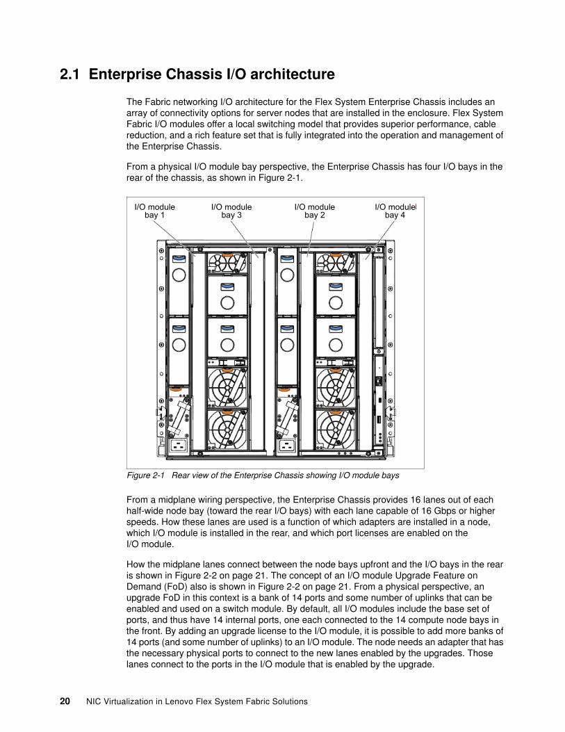
From a physical I/O module bay perspective, the Enterprise Chassis has four I/O bays in the rear of the chassis, as shown in Figure 2-1.
Figure 2-1 Rear view of the Enterprise Chassis showing I/O module bays
From a midplane wiring perspective, the Enterprise Chassis provides 16 lanes out of each half-wide node bay (toward the rear I/O bays) with each lane capable of 16 Gbps or higher speeds. How these lanes are used is a function of which adapters are installed in a node, which I/O module is installed in the rear, and which port licenses are enabled on the I/O module.
How the midplane lanes connect between the node bays upfront and the I/O bays in the rear is shown in Figure 2-2 on page 21. The concept of an I/O module Upgrade Feature on Demand (FoD) also is shown in Figure 2-2 on page 21. From a physical perspective, an upgrade FoD in this context is a bank of 14 ports and some number of uplinks that can be enabled and used on a switch module. By default, all I/O modules include the base set of ports, and thus have 14 internal ports, one each connected to the 14 compute node bays in the front. By adding an upgrade license to the I/O module, it is possible to add more banks of 14 ports (and some number of uplinks) to an I/O module. The node needs an adapter that has the necessary physical ports to connect to the new lanes enabled by the upgrades. Those lanes connect to the ports in the I/O module that is enabled by the upgrade.
I/O modulebay 1
I/O modulebay 3
I/O modulebay 2
I/O modulebay 4
20 NIC Virtualization in Lenovo Flex System Fabric Solutions
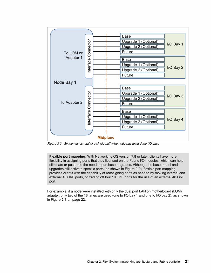
Figure 2-2 Sixteen lanes total of a single half-wide node bay toward the I/O bays
For example, if a node were installed with only the dual port LAN on motherboard (LOM) adapter, only two of the 16 lanes are used (one to I/O bay 1 and one to I/O bay 2), as shown in Figure 2-3 on page 22.
Flexible port mapping: With Networking OS version 7.8 or later, clients have more flexibility in assigning ports that they licensed on the Fabric I/O modules, which can help eliminate or postpone the need to purchase upgrades. Although the base model and upgrades still activate specific ports (as shown in Figure 2-2), flexible port mapping provides clients with the capability of reassigning ports as needed by moving internal and external 10 GbE ports, or trading off four 10 GbE ports for the use of an external 40 GbE port.
Node Bay 1In
terfa
ce C
onne
ctor
To Adapter 2
To LOM or Adapter 1
Inte
rface
Con
nect
or
Midplane
I/O Bay 1
BaseUpgrade 1 (Optional)Upgrade 2 (Optional)Future
I/O Bay 2
BaseUpgrade 1 (Optional)Upgrade 2 (Optional)Future
I/O Bay 3
BaseUpgrade 1 (Optional)Upgrade 2 (Optional)Future
I/O Bay 4
BaseUpgrade 1 (Optional)Upgrade 2 (Optional)Future
Chapter 2. Flex System networking architecture and Fabric portfolio 21
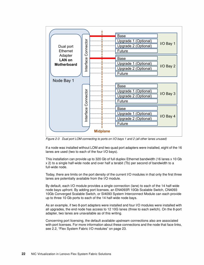
Figure 2-3 Dual port LOM connecting to ports on I/O bays 1 and 2 (all other lanes unused)
If a node was installed without LOM and two quad port adapters were installed, eight of the 16 lanes are used (two to each of the four I/O bays).
This installation can provide up to 320 Gb of full duplex Ethernet bandwidth (16 lanes x 10 Gb x 2) to a single half-wide node and over half a terabit (Tb) per second of bandwidth to a full-wide node.
Today, there are limits on the port density of the current I/O modules in that only the first three lanes are potentially available from the I/O module.
By default, each I/O module provides a single connection (lane) to each of the 14 half-wide node bays upfront. By adding port licenses, an EN4093R 10Gb Scalable Switch, CN4093 10Gb Converged Scalable Switch, or SI4093 System Interconnect Module can each provide up to three 10 Gb ports to each of the 14 half-wide node bays.
As an example, if two 8-port adapters were installed and four I/O modules were installed with all upgrades, the end node has access to 12 10G lanes (three to each switch). On the 8-port adapter, two lanes are unavailable as of this writing.
Concerning port licensing, the default available upstream connections also are associated with port licenses. For more information about these connections and the node that face links, see 2.2, “Flex System Fabric I/O modules” on page 23.
Node Bay 1In
terfa
ce C
onne
ctor
Inte
rface
Con
nect
or
Midplane
Dual portEthernetAdapterLAN on
Motherboard
I/O Bay 1
BaseUpgrade 1 (Optional)Upgrade 2 (Optional)Future
I/O Bay 2
BaseUpgrade 1 (Optional)Upgrade 2 (Optional)Future
I/O Bay 3
BaseUpgrade 1 (Optional)Upgrade 2 (Optional)Future
I/O Bay 4
BaseUpgrade 1 (Optional)Upgrade 2 (Optional)Future
22 NIC Virtualization in Lenovo Flex System Fabric Solutions
All I/O modules include a base set of 14 downstream ports. The Ethernet switching and interconnect I/O modules support more than the base set of ports, and the ports are enabled by the upgrades. For more information, see 2.2, “Flex System Fabric I/O modules” on page 23.
Although no I/O modules and node adapter combinations can use all 16 lanes between a compute node bay and the I/O bays as of this writing, the lanes exist to ensure that the Enterprise Chassis can use future available capacity.
Beyond the physical aspects of the hardware, certain logical aspects ensure that the Enterprise Chassis can integrate seamlessly into any modern data centers infrastructure.
Many of these enhancements, such as vNIC, VMready, and 802.1Qbg, revolve around integrating virtualized servers into the environment. By using Fibre Channel over Ethernet (FCoE), users can converge their Fibre Channel traffic onto their 10 Gb Ethernet network, which reduces the number of cables and points of management that is necessary to connect the Enterprise Chassis to the upstream infrastructures.
The wide range of physical and logical Ethernet networking options that are available today and in development ensure that the Enterprise Chassis can meet the most demanding I/O connectivity challenges now and as the data center evolves.
2.2 Flex System Fabric I/O modules
The Flex System Enterprise Chassis features a number of Fabric I/O module solutions that provide a combination of 1 Gb and 10 Gb ports to the servers and 1 Gb, 10 Gb, and 40 Gb for uplink connectivity to the outside upstream infrastructure. The Flex System Enterprise Chassis ensures that a suitable selection is available to meet the needs of the server nodes.
The following Flex System Fabric modules are available for deployment within the Enterprise Chassis:
� Flex System Fabric EN4093R 10Gb Scalable Switch� Flex System Fabric CN4093 10Gb Converged Scalable Switch� Flex System Fabric SI4093 System Interconnect Module
Some of the Fabric I/O module selection criteria are summarized in Table 2-1 on page 24.
External cabling: SFP, SFP+, and QSFP+ transceivers or DAC cables are required for external fabric module connectivity. For more information about compatible transceivers and cables, see 2.2.4, “I/O modules and cables” on page 42.
Chapter 2. Flex System networking architecture and Fabric portfolio 23
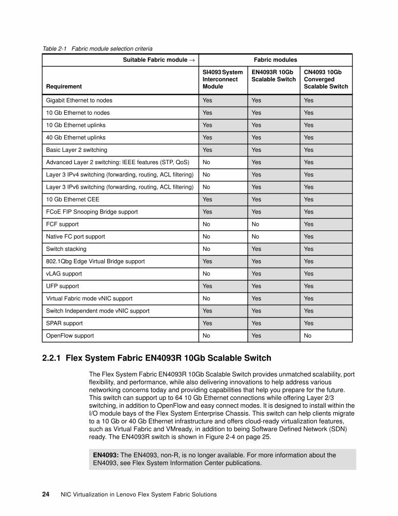
Table 2-1 Fabric module selection criteria
2.2.1 Flex System Fabric EN4093R 10Gb Scalable Switch
The Flex System Fabric EN4093R 10Gb Scalable Switch provides unmatched scalability, port flexibility, and performance, while also delivering innovations to help address various networking concerns today and providing capabilities that help you prepare for the future. This switch can support up to 64 10 Gb Ethernet connections while offering Layer 2/3 switching, in addition to OpenFlow and easy connect modes. It is designed to install within the I/O module bays of the Flex System Enterprise Chassis. This switch can help clients migrate to a 10 Gb or 40 Gb Ethernet infrastructure and offers cloud-ready virtualization features, such as Virtual Fabric and VMready, in addition to being Software Defined Network (SDN) ready. The EN4093R switch is shown in Figure 2-4 on page 25.
Suitable Fabric module → Fabric modules
Requirement
SI4093 System Interconnect Module
EN4093R 10Gb Scalable Switch
CN4093 10Gb Converged Scalable Switch
Gigabit Ethernet to nodes Yes Yes Yes
10 Gb Ethernet to nodes Yes Yes Yes
10 Gb Ethernet uplinks Yes Yes Yes
40 Gb Ethernet uplinks Yes Yes Yes
Basic Layer 2 switching Yes Yes Yes
Advanced Layer 2 switching: IEEE features (STP, QoS) No Yes Yes
Layer 3 IPv4 switching (forwarding, routing, ACL filtering) No Yes Yes
Layer 3 IPv6 switching (forwarding, routing, ACL filtering) No Yes Yes
10 Gb Ethernet CEE Yes Yes Yes
FCoE FIP Snooping Bridge support Yes Yes Yes
FCF support No No Yes
Native FC port support No No Yes
Switch stacking No Yes Yes
802.1Qbg Edge Virtual Bridge support Yes Yes Yes
vLAG support No Yes Yes
UFP support Yes Yes Yes
Virtual Fabric mode vNIC support No Yes Yes
Switch Independent mode vNIC support Yes Yes Yes
SPAR support Yes Yes Yes
OpenFlow support No Yes No
EN4093: The EN4093, non-R, is no longer available. For more information about the EN4093, see Flex System Information Center publications.
24 NIC Virtualization in Lenovo Flex System Fabric Solutions
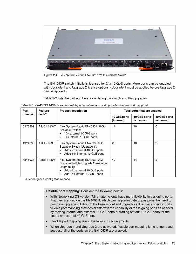
Figure 2-4 Flex System Fabric EN4093R 10Gb Scalable Switch
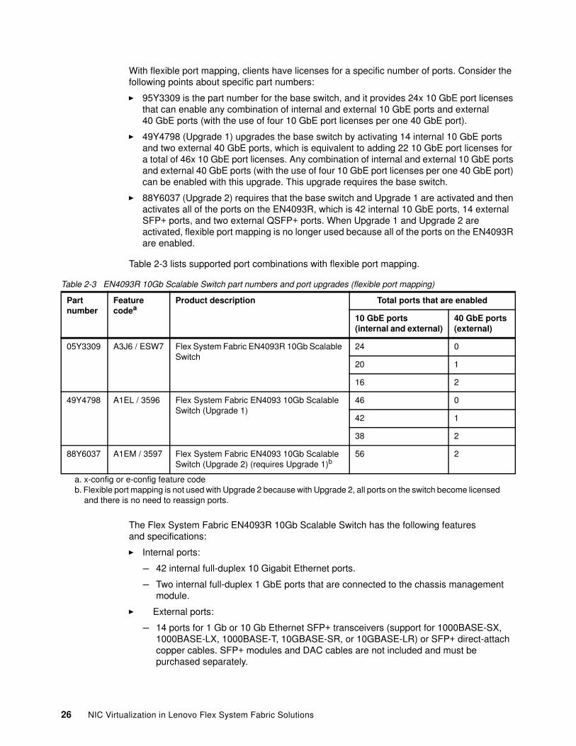
The EN4093R switch initially is licensed for 24x 10 GbE ports. More ports can be enabled with Upgrade 1 and Upgrade 2 license options. (Upgrade 1 must be applied before Upgrade 2 can be applied.)
Table 2-2 lists the part numbers for ordering the switch and the upgrades.
Table 2-2 EN4093R 10Gb Scalable Switch part numbers and port upgrades (default port mapping)
Partnumber
Featurecodea
a. x-config or e-config feature code
Product description Total ports that are enabled
10 GbE ports (internal)
10 GbE ports (external)
40 GbE ports (external)
05Y3309 A3J6 / ESW7 Flex System Fabric EN4093R 10Gb Scalable Switch:� 10x external 10 GbE ports� 14x internal 10 GbE ports
14 10 0
49Y4798 A1EL / 3596 Flex System Fabric EN4093 10Gb Scalable Switch (Upgrade 1):� Adds 2x external 40 GbE ports� Adds 14x internal 10 GbE ports
28 10 2
88Y6037 A1EM / 3597 Flex System Fabric EN4093 10Gb Scalable Switch (Upgrade 2) (requires Upgrade 1):� Adds 4x external 10 GbE ports � Add 14x internal 10 GbE ports
42 14 2
Flexible port mapping: Consider the following points:
� With Networking OS version 7.8 or later, clients have more flexibility in assigning ports that they licensed on the EN4093R, which can help eliminate or postpone the need to purchase upgrades. Although the base model and upgrades still activate specific ports, flexible port mapping provides clients with the capability of reassigning ports as needed by moving internal and external 10 GbE ports or trading off four 10 GbE ports for the use of an external 40 GbE port.
� Flexible port mapping is not available in Stacking mode.
� When Upgrade 1 and Upgrade 2 are activated, flexible port mapping is no longer used because all of the ports on the EN4093R are enabled.
Chapter 2. Flex System networking architecture and Fabric portfolio 25
With flexible port mapping, clients have licenses for a specific number of ports. Consider the following points about specific part numbers:
� 95Y3309 is the part number for the base switch, and it provides 24x 10 GbE port licenses that can enable any combination of internal and external 10 GbE ports and external 40 GbE ports (with the use of four 10 GbE port licenses per one 40 GbE port).
� 49Y4798 (Upgrade 1) upgrades the base switch by activating 14 internal 10 GbE ports and two external 40 GbE ports, which is equivalent to adding 22 10 GbE port licenses for a total of 46x 10 GbE port licenses. Any combination of internal and external 10 GbE ports and external 40 GbE ports (with the use of four 10 GbE port licenses per one 40 GbE port) can be enabled with this upgrade. This upgrade requires the base switch.
� 88Y6037 (Upgrade 2) requires that the base switch and Upgrade 1 are activated and then activates all of the ports on the EN4093R, which is 42 internal 10 GbE ports, 14 external SFP+ ports, and two external QSFP+ ports. When Upgrade 1 and Upgrade 2 are activated, flexible port mapping is no longer used because all of the ports on the EN4093R are enabled.
Table 2-3 lists supported port combinations with flexible port mapping.
Table 2-3 EN4093R 10Gb Scalable Switch part numbers and port upgrades (flexible port mapping)
The Flex System Fabric EN4093R 10Gb Scalable Switch has the following features and specifications:
� Internal ports:
– 42 internal full-duplex 10 Gigabit Ethernet ports.
– Two internal full-duplex 1 GbE ports that are connected to the chassis management module.
� External ports:
– 14 ports for 1 Gb or 10 Gb Ethernet SFP+ transceivers (support for 1000BASE-SX, 1000BASE-LX, 1000BASE-T, 10GBASE-SR, or 10GBASE-LR) or SFP+ direct-attach copper cables. SFP+ modules and DAC cables are not included and must be purchased separately.
Partnumber
Featurecodea
a. x-config or e-config feature code
Product description Total ports that are enabled
10 GbE ports (internal and external)
40 GbE ports (external)
05Y3309 A3J6 / ESW7 Flex System Fabric EN4093R 10Gb Scalable Switch
24 0
20 1
16 2
49Y4798 A1EL / 3596 Flex System Fabric EN4093 10Gb Scalable Switch (Upgrade 1)
46 0
42 1
38 2
88Y6037 A1EM / 3597 Flex System Fabric EN4093 10Gb Scalable Switch (Upgrade 2) (requires Upgrade 1)b
b. Flexible port mapping is not used with Upgrade 2 because with Upgrade 2, all ports on the switch become licensed and there is no need to reassign ports.
56 2
26 NIC Virtualization in Lenovo Flex System Fabric Solutions
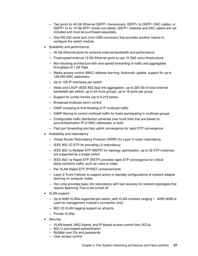
– Two ports for 40 Gb Ethernet QSFP+ transceivers, QSFP+ to QSFP+ DAC cables, or QSFP+ to 4x 10 Gb SFP+ break-out cables. QSFP+ modules and DAC cables are not included and must be purchased separately.
– One RS-232 serial port (mini-USB connector) that provides another means to configure the switch module.
� Scalability and performance:
– 40 Gb Ethernet ports for extreme external bandwidth and performance
– Fixed-speed external 10 Gb Ethernet ports to use 10 GbE core infrastructure
– Non-blocking architecture with wire-speed forwarding of traffic and aggregated throughput of 1.28 Tbps
– Media access control (MAC) address learning: Automatic update, support for up to 128,000 MAC addresses
– Up to 128 IP interfaces per switch
– Static and LACP (IEEE 802.3ad) link aggregation, up to 220 Gb of total external bandwidth per switch, up to 64 trunk groups, up to 16 ports per group
– Support for jumbo frames (up to 9,216 bytes)
– Broadcast/multicast storm control
– IGMP snooping to limit flooding of IP multicast traffic
– IGMP filtering to control multicast traffic for hosts participating in multicast groups
– Configurable traffic distribution schemes over trunk links that are based on source/destination IP or MAC addresses, or both
– Fast port forwarding and fast uplink convergence for rapid STP convergence
� Availability and redundancy
– Virtual Router Redundancy Protocol (VRRP) for Layer 3 router redundancy
– IEEE 802.1D STP for providing L2 redundancy
– IEEE 802.1s Multiple STP (MSTP) for topology optimization, up to 32 STP instances are supported by a single switch
– IEEE 802.1w Rapid STP (RSTP) provides rapid STP convergence for critical delay-sensitive traffic, such as voice or video
– Per-VLAN Rapid STP (PVRST) enhancements
– Layer 2 Trunk Failover to support active or standby configurations of network adapter teaming on compute nodes
– Hot Links provides basic link redundancy with fast recovery for network topologies that require Spanning Tree to be turned off
� VLAN support:
– Up to 4095 VLANs supported per switch, with VLAN numbers ranging 1 - 4095 (4095 is used for management module’s connection only)
– 802.1Q VLAN tagging support on all ports
– Private VLANs
� Security:
– VLAN-based, MAC-based, and IP-based access control lists (ACLs)– 802.1x port-based authentication– Multiple user IDs and passwords– User access control
Chapter 2. Flex System networking architecture and Fabric portfolio 27
– Radius, TACACS+ and LDAP authentication and authorization– NIST 800-131A Encryption– Selectable encryption protocol; SHA 256 enabled as default– IPv6 ACL metering
� Quality of service (QoS):
– Support for IEEE 802.1p, IP ToS/DSCP, and ACL-based (MAC/IP source and destination addresses, VLANs) traffic classification and processing
– Traffic shaping and remarking based on defined policies
– Eight Weighted Round Robin (WRR) priority queues per port for processing qualified traffic
� IP v4 Layer 3 functions:
– Host management
– IP forwarding
– IP filtering with ACLs, up to 896 ACLs supported
– VRRP for router redundancy
– Support for up to 128 static routes
– Routing protocol support (RIP v1, RIP v2, OSPF v2, and BGP-4); up to 2048 entries in a routing table
– Support for DHCP Relay
– Support for IGMP snooping and IGMP relay
– Support for Protocol Independent Multicast (PIM) in Sparse Mode (PIM-SM) and Dense Mode (PIM-DM).
� IPv6 Layer 3 functions:
– IPv6 host management (except default switch management IP address)– IPv6 forwarding– Up to 128 static routes– Support for OSPF v3 routing protocol– IPv6 filtering with ACLs– Virtual Station Interface Data Base (VSIDB) support
� OpenFlow support:
– OpenFlow 1.0 and 1.3.1– OpenFlow hybrid mode
� Virtualization:
– Virtual NICs (vNICs)
Ethernet, iSCSI, or FCoE traffic is supported on vNICs
– Unified fabric ports (UFPs):
• Ethernet or FCoE traffic is supported on UFPs• Supports up to 256 VLAN for the virtual ports• Integration with L2 failover
– Virtual link aggregation groups (vLAGs)
– 802.1Qbg Edge Virtual Bridging (EVB) is an emerging IEEE standard for allowing networks to become virtual machine (VM)-aware:
• Virtual Ethernet Bridging (VEB) and Virtual Ethernet Port Aggregator (VEPA) are mechanisms for switching between VMs on the same hypervisor.
28 NIC Virtualization in Lenovo Flex System Fabric Solutions
• Edge Control Protocol (ECP) is a transport protocol that operates between two peers over an IEEE 802 LAN providing reliable, in-order delivery of upper layer protocol data units.
• Virtual Station Interface (VSI) Discovery and Configuration Protocol (VDP) allows centralized configuration of network policies that persist with the VM, independent of its location.
• EVB Type-Length-Value (TLV) is used to discover and configure VEPA, ECP, VDP.
– VMready
– Switch partitioning (SPAR):
• SPAR forms separate virtual switching contexts by segmenting the data plane of the module. Data plane traffic is not shared between SPARs on the same switch.
• SPAR operates as a Layer 2 broadcast network. Hosts on the same VLAN that are attached to a SPAR can communicate with each other and with the upstream switch. Hosts on the same VLAN but attached to different SPARs communicate through the upstream switch.
• SPAR is implemented as a dedicated VLAN with a set of internal compute node ports and a single external port or link aggregation (LAG). Multiple external ports or LAGs are not allowed in SPAR. A port can be a member of only one SPAR.
� Converged Enhanced Ethernet:
– Priority-Based Flow Control (PFC) (IEEE 802.1Qbb) extends 802.3x standard flow control to allow the switch to pause traffic that is based on the 802.1p priority value in each packet’s VLAN tag.
– Enhanced Transmission Selection (ETS) (IEEE 802.1Qaz) provides a method for allocating link bandwidth that is based on the 802.1p priority value in each packet’s VLAN tag.
– Data Center Bridging Capability Exchange Protocol (DCBX) (IEEE 802.1AB) allows neighboring network devices to exchange information about their capabilities.
– Support for SPAR and FCoE
� FCoE:
– FC-BB5 FCoE specification compliant– FCoE transit switch operations– FCoE Initialization Protocol (FIP) support for automatic ACL configuration– FCoE Link Aggregation Group (LAG) support– Multi-hop RDMA over Converged Ethernet (RoCE) with LAG support– Supports 2,000 secure FCoE sessions with FIP Snooping by using Class ID ACLs
� Stacking:
– Up to eight switches in a stack - single IP management– Hybrid stacking support (from two to six EN4093R switches with two CN4093 switches)– FCoE support: FCoE LAG on external ports– 802.1Qbg support– vNIC and UFP support: Support for UFP with 802.1Qbg
� Manageability:
– Simple Network Management Protocol (SNMP V1, V2, and V3)– HTTP browser GUI– Telnet interface for CLI– SSH– Secure FTP (sFTP)– Service Location Protocol (SLP)
Chapter 2. Flex System networking architecture and Fabric portfolio 29
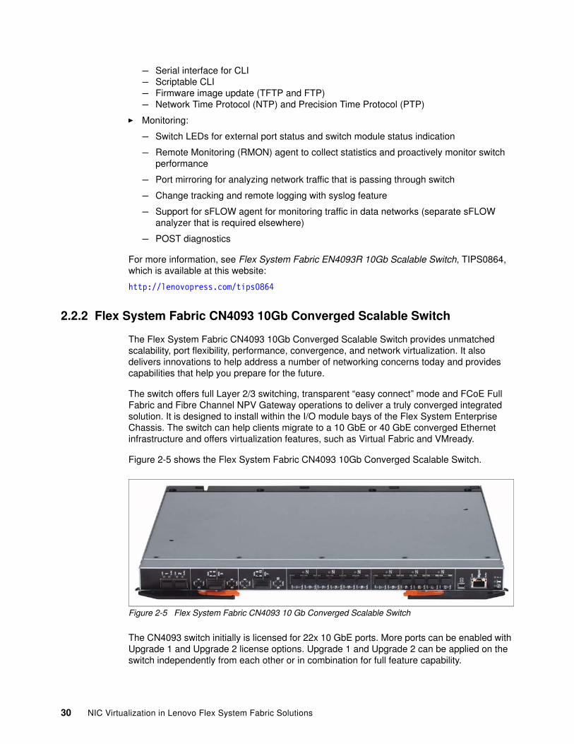
– Serial interface for CLI– Scriptable CLI– Firmware image update (TFTP and FTP)– Network Time Protocol (NTP) and Precision Time Protocol (PTP)
� Monitoring:
– Switch LEDs for external port status and switch module status indication
– Remote Monitoring (RMON) agent to collect statistics and proactively monitor switch performance
– Port mirroring for analyzing network traffic that is passing through switch
– Change tracking and remote logging with syslog feature
– Support for sFLOW agent for monitoring traffic in data networks (separate sFLOW analyzer that is required elsewhere)
– POST diagnostics
For more information, see Flex System Fabric EN4093R 10Gb Scalable Switch, TIPS0864, which is available at this website:
http://lenovopress.com/tips0864
2.2.2 Flex System Fabric CN4093 10Gb Converged Scalable Switch
The Flex System Fabric CN4093 10Gb Converged Scalable Switch provides unmatched scalability, port flexibility, performance, convergence, and network virtualization. It also delivers innovations to help address a number of networking concerns today and provides capabilities that help you prepare for the future.
The switch offers full Layer 2/3 switching, transparent “easy connect” mode and FCoE Full Fabric and Fibre Channel NPV Gateway operations to deliver a truly converged integrated solution. It is designed to install within the I/O module bays of the Flex System Enterprise Chassis. The switch can help clients migrate to a 10 GbE or 40 GbE converged Ethernet infrastructure and offers virtualization features, such as Virtual Fabric and VMready.
Figure 2-5 shows the Flex System Fabric CN4093 10Gb Converged Scalable Switch.
Figure 2-5 Flex System Fabric CN4093 10 Gb Converged Scalable Switch
The CN4093 switch initially is licensed for 22x 10 GbE ports. More ports can be enabled with Upgrade 1 and Upgrade 2 license options. Upgrade 1 and Upgrade 2 can be applied on the switch independently from each other or in combination for full feature capability.
30 NIC Virtualization in Lenovo Flex System Fabric Solutions
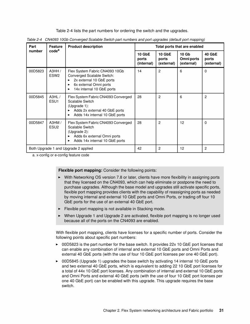
Table 2-4 lists the part numbers for ordering the switch and the upgrades.
Table 2-4 CN4093 10Gb Converged Scalable Switch part numbers and port upgrades (default port mapping)
With flexible port mapping, clients have licenses for a specific number of ports. Consider the following points about specific part numbers:
� 00D5823 is the part number for the base switch. It provides 22x 10 GbE port licenses that can enable any combination of internal and external 10 GbE ports and Omni Ports and external 40 GbE ports (with the use of four 10 GbE port licenses per one 40 GbE port).
� 00D5845 (Upgrade 1) upgrades the base switch by activating 14 internal 10 GbE ports and two external 40 GbE ports, which is equivalent to adding 22 10 GbE port licenses for a total of 44x 10 GbE port licenses. Any combination of internal and external 10 GbE ports and Omni Ports and external 40 GbE ports (with the use of four 10 GbE port licenses per one 40 GbE port) can be enabled with this upgrade. This upgrade requires the base switch.
Partnumber
Featurecodea
a. x-config or e-config feature code
Product description Total ports that are enabled
10 GbE ports (internal)
10 GbE ports (external)
10 Gb Omni ports (external)
40 GbE ports (external)
00D5823 A3HH / ESW2
Flex System Fabric CN4093 10Gb Converged Scalable Switch:� 2x external 10 GbE ports� 6x external Omni ports� 14x internal 10 GbE ports
14 2 6 0
00D5845 A3HL / ESU1
Flex System Fabric CN4093 Converged Scalable Switch(Upgrade 1):� Adds 2x external 40 GbE ports� Adds 14x internal 10 GbE ports
28 2 6 2
00D5847 A3HM / ESU2
Flex System Fabric CN4093 Converged Scalable Switch (Upgrade 2):� Adds 6x external Omni ports � Adds 14x internal 10 GbE ports
28 2 12 0
Both Upgrade 1 and Upgrade 2 applied 42 2 12 2
Flexible port mapping: Consider the following points:
� With Networking OS version 7.8 or later, clients have more flexibility in assigning ports that they licensed on the CN4093, which can help eliminate or postpone the need to purchase upgrades. Although the base model and upgrades still activate specific ports, flexible port mapping provides clients with the capability of reassigning ports as needed by moving internal and external 10 GbE ports and Omni Ports, or trading off four 10 GbE ports for the use of an external 40 GbE port.
� Flexible port mapping is not available in Stacking mode.
� When Upgrade 1 and Upgrade 2 are activated, flexible port mapping is no longer used because all of the ports on the CN4093 are enabled.
Chapter 2. Flex System networking architecture and Fabric portfolio 31
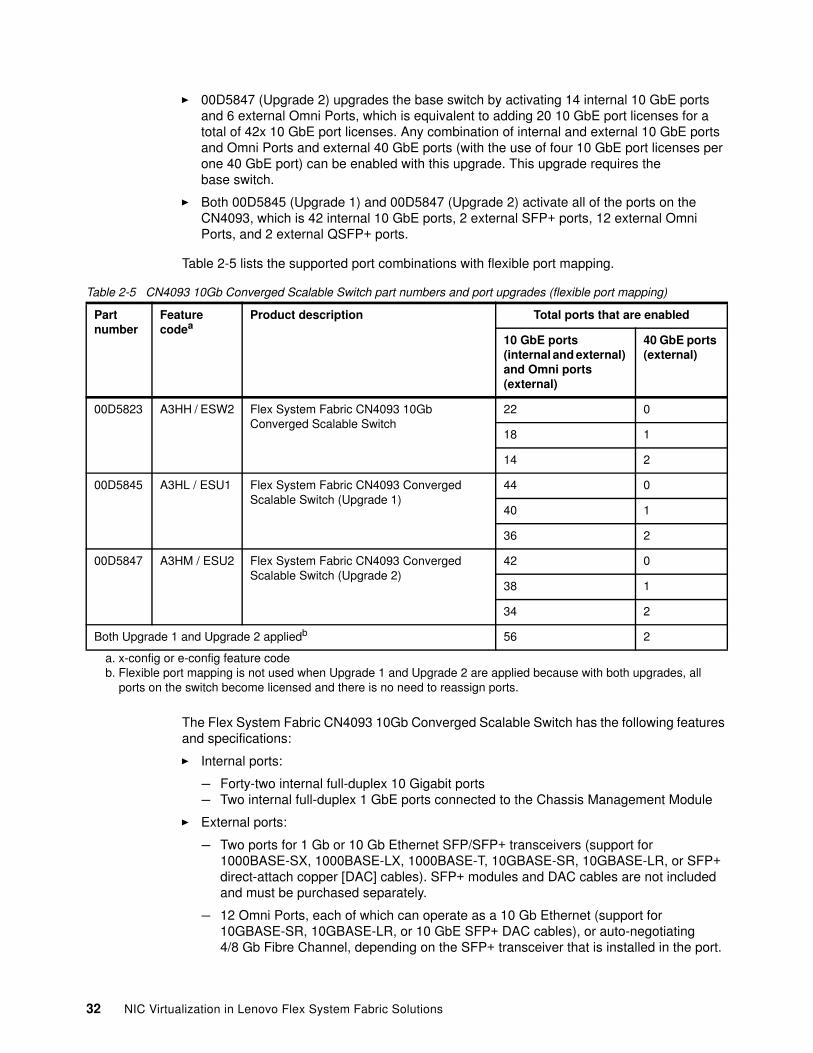
� 00D5847 (Upgrade 2) upgrades the base switch by activating 14 internal 10 GbE ports and 6 external Omni Ports, which is equivalent to adding 20 10 GbE port licenses for a total of 42x 10 GbE port licenses. Any combination of internal and external 10 GbE ports and Omni Ports and external 40 GbE ports (with the use of four 10 GbE port licenses per one 40 GbE port) can be enabled with this upgrade. This upgrade requires the base switch.
� Both 00D5845 (Upgrade 1) and 00D5847 (Upgrade 2) activate all of the ports on the CN4093, which is 42 internal 10 GbE ports, 2 external SFP+ ports, 12 external Omni Ports, and 2 external QSFP+ ports.
Table 2-5 lists the supported port combinations with flexible port mapping.
Table 2-5 CN4093 10Gb Converged Scalable Switch part numbers and port upgrades (flexible port mapping)
The Flex System Fabric CN4093 10Gb Converged Scalable Switch has the following features and specifications:
� Internal ports:
– Forty-two internal full-duplex 10 Gigabit ports– Two internal full-duplex 1 GbE ports connected to the Chassis Management Module
� External ports:
– Two ports for 1 Gb or 10 Gb Ethernet SFP/SFP+ transceivers (support for 1000BASE-SX, 1000BASE-LX, 1000BASE-T, 10GBASE-SR, 10GBASE-LR, or SFP+ direct-attach copper [DAC] cables). SFP+ modules and DAC cables are not included and must be purchased separately.
– 12 Omni Ports, each of which can operate as a 10 Gb Ethernet (support for 10GBASE-SR, 10GBASE-LR, or 10 GbE SFP+ DAC cables), or auto-negotiating 4/8 Gb Fibre Channel, depending on the SFP+ transceiver that is installed in the port.
Partnumber
Featurecodea
a. x-config or e-config feature code
Product description Total ports that are enabled
10 GbE ports (internal and external) and Omni ports (external)
40 GbE ports (external)
00D5823 A3HH / ESW2 Flex System Fabric CN4093 10Gb Converged Scalable Switch
22 0
18 1
14 2
00D5845 A3HL / ESU1 Flex System Fabric CN4093 Converged Scalable Switch (Upgrade 1)
44 0
40 1
36 2
00D5847 A3HM / ESU2 Flex System Fabric CN4093 Converged Scalable Switch (Upgrade 2)
42 0
38 1
34 2
Both Upgrade 1 and Upgrade 2 appliedb
b. Flexible port mapping is not used when Upgrade 1 and Upgrade 2 are applied because with both upgrades, all ports on the switch become licensed and there is no need to reassign ports.
56 2
32 NIC Virtualization in Lenovo Flex System Fabric Solutions
SFP+ modules and DAC cables are not included and must be purchased separately. (Omni Ports do not support 1 Gb SFP Ethernet transceivers.)
– Two ports for 40 Gb Ethernet QSFP+ transceivers or QSFP+ DAC cables. In addition, you can use break-out cables to break out each 40 GbE port into four 10 GbE SFP+ connections. QSFP+ modules and DAC cables are not included and must be purchased separately.
– One RS-232 serial port (mini-USB connector) that provides another means to configure the switch module.
� Scalability and performance:
– 40 Gb Ethernet ports for more external bandwidth and performance
– Fixed-speed external 10 Gb Ethernet ports to use 10 GbE upstream infrastructure
– Non-blocking architecture with wire-speed forwarding of traffic and aggregated throughput of 1.28 Tbps on Ethernet ports
– Media access control (MAC) address learning: Automatic update, support for up to 128,000 MAC addresses
– Up to 128 IP interfaces per switch
– Static and LACP (IEEE 802.3ad) link aggregation, up to 220 Gb of total external bandwidth per switch, up to 64 trunk groups, up to 16 ports per group
– Support for jumbo frames (up to 9,216 bytes)
– Broadcast and multicast storm control
– IGMP snooping to limit flooding of IP multicast traffic
– IGMP filtering to control multicast traffic for hosts that are participating in multicast groups
– Configurable traffic distribution schemes over trunk links that are based on source/destination IP or MAC addresses, or both
– Fast port forwarding and fast uplink convergence for rapid STP convergence
� Availability and redundancy:
– Virtual Router Redundancy Protocol (VRRP) for Layer 3 router redundancy
– IEEE 802.1D STP for providing L2 redundancy
– IEEE 802.1s Multiple STP (MSTP) for topology optimization; up to 32 STP instances are supported by a single switch
– IEEE 802.1w Rapid STP (RSTP) provides rapid STP convergence for critical delay-sensitive traffic, such as voice or video
– Per-VLAN Rapid STP (PVRST) enhancements
– Layer 2 Trunk Failover to support active or standby configurations of network adapter teaming on compute nodes
– Hot Links provides basic link redundancy with fast recovery for network topologies that require Spanning Tree to be turned off
� VLAN support:
– Up to 4095 VLANs supported per switch, with VLAN numbers ranging 1 - 4095 (4095 is used for management module’s connection only.)
– 802.1Q VLAN tagging support on all ports
– Private VLANs
Chapter 2. Flex System networking architecture and Fabric portfolio 33
� Security:
– VLAN-based, MAC-based, and IP-based access control lists (ACLs)– 802.1x port-based authentication– Multiple user IDs and passwords– User access control– Radius, TACACS+, and LDAP authentication and authorization– NIST 800-131A Encryption– Selectable encryption protocol; SHA 256 enabled as default– IPv6 ACL metering
� Quality of service (QoS):
– Support for IEEE 802.1p, IP ToS/DSCP, and ACL-based (MAC/IP source and destination addresses, VLANs) traffic classification and processing
– Traffic shaping and remarking based on defined policies
– Eight Weighted Round Robin (WRR) priority queues per port for processing qualified traffic
� IP v4 Layer 3 functions:
– Host management
– IP forwarding
– IP filtering with ACLs; up to 896 ACLs supported
– VRRP for router redundancy
– Support for up to 128 static routes
– Routing protocol support (RIP v1, RIP v2, OSPF v2, BGP-4); up to 2048 entries in a routing table
– Support for DHCP Relay
– Support for IGMP snooping and IGMP relay
– Support for Protocol Independent Multicast (PIM) in Sparse Mode (PIM-SM) and Dense Mode (PIM-DM)
� IP v6 Layer 3 functions:
– IPv6 host management (except default switch management IP address)– IPv6 forwarding– Up to 128 static routes– Support for OSPF v3 routing protocol– IPv6 filtering with ACLs– Virtual Station Interface Data Base (VSIDB) support
� Virtualization:
– Virtual NIC (vNIC): Ethernet, iSCSI, or FCoE traffic is supported on vNICs
– Unified fabric port (UFP):
• Ethernet or FCoE traffic is supported on UFPs• Supports up to 256 VLAN for the virtual ports (vPorts)• Integration with L2 failover
– Virtual link aggregation groups (vLAGs)
– 802.1Qbg Edge Virtual Bridging (EVB) is an emerging IEEE standard for allowing networks to become virtual machine (VM)-aware:
• Virtual Ethernet Bridging (VEB) and Virtual Ethernet Port Aggregator (VEPA) are mechanisms for switching between VMs on the same hypervisor.
34 NIC Virtualization in Lenovo Flex System Fabric Solutions
• Edge Control Protocol (ECP) is a transport protocol that operates between two peers over an IEEE 802 LAN providing reliable, in-order delivery of upper layer protocol data units.
• Virtual Station Interface (VSI) Discovery and Configuration Protocol (VDP) allows centralized configuration of network policies that persist with the VM, independent of its location.
• EVB Type-Length-Value (TLV) is used to discover and configure VEPA, ECP, VDP.
– VMready:
– Switch partitioning (SPAR):
• SPAR forms separate virtual switching contexts by segmenting the data plane of the switch. Data plane traffic is not shared between SPARs on the same switch.
• SPAR operates as a Layer 2 broadcast network. Hosts on the same VLAN that are attached to a SPAR can communicate with each other and with the upstream switch. Hosts on the same VLAN but attached to different SPARs communicate through the upstream switch.
• SPAR is implemented as a dedicated VLAN with a set of internal compute node ports and a single external port or link aggregation (LAG). Multiple external ports or LAGs are not allowed in SPAR. A port can be a member of only one SPAR.
� Converged Enhanced Ethernet:
– Priority-Based Flow Control (PFC) (IEEE 802.1Qbb) extends 802.3x standard flow control to allow the switch to pause traffic that is based on the 802.1p priority value in each packet’s VLAN tag.
– Enhanced Transmission Selection (ETS) (IEEE 802.1Qaz) provides a method for allocating link bandwidth that is based on the 802.1p priority value in each packet’s VLAN tag.
– Data Center Bridging Capability Exchange Protocol (DCBX) (IEEE 802.1AB) allows neighboring network devices to exchange information about their capabilities.
– Multi-hop RDMA over Converged Ethernet (RoCE) with LAG support.
� Fibre Channel and Fibre Channel over Ethernet (FCoE):
– FC-BB-5 FCoE specification compliant
– Native FC Forwarder (FCF) switch operations
– End-to-end FCoE support (initiator to target)
– FCoE Initialization Protocol (FIP) support
– FCoE Link Aggregation Group (LAG) support
– Optimized FCoE to FCoE forwarding
– Omni Ports support 4/8 Gb FC when FC SFPs+ are installed in these ports
– Support for F_port, E_Port ISL, NP_port, and VF_port FC port types
– Full Fabric mode for end-to-end FCoE or FCoE gateway; NPV Gateway mode for external FC SAN attachments (support for Lenovo B-type, IBM B-type, Brocade, and Cisco MDS external SANs)
– 16 buffer credits supported
– Fabric Device Management Interface (FDMI)
– NPIV support
– Fabric Shortest Path First (FSPF)
Chapter 2. Flex System networking architecture and Fabric portfolio 35
– Port security
– Fibre Channel ping, debugging
– Supports 2,000 secure FCoE sessions with FIP Snooping by using Class ID ACLs
– Fabric services in Full Fabric mode:
• Name Server• Registered State Change Notification (RSCN)• Login services• Zoning
� Stacking:
– Hybrid stacking support (from two to six EN4093/EN4093R switches with two CN4093 switches) - single IP management
– FCoE support: FCoE LAG on external ports
– 802.1Qbg support
– vNIC and UFP support: Support for UFP with 802.1Qbg
� Manageability:
– Simple Network Management Protocol (SNMP V1, V2, and V3)– HTTP browser GUI– Telnet interface for CLI– SSH– Secure FTP (sFTP)– Service Location Protocol (SLP)– Serial interface for CLI– Scriptable CLI– Firmware image update (TFTP and FTP)– Network Time Protocol (NTP) for switch clock synchronization
� Monitoring:
– Switch LEDs for external port status and switch module status indication
– Remote Monitoring (RMON) agent to collect statistics and proactively monitor switch performance
– Port mirroring for analyzing network traffic passing through the switch
– Change tracking and remote logging with syslog feature
– Support for sFLOW agent for monitoring traffic in data networks (separate sFLOW analyzer that is required elsewhere)
– POST diagnostics
For more information, see Flex System Fabric CN4093 10Gb Converged Scalable Switch, TIPS0910, which is available at this website:
http://lenovopress.com/tips0910
2.2.3 Flex System Fabric SI4093 System Interconnect Module
The Flex System Fabric SI4093 System Interconnect Module enables simplified integration of Flex System into your existing networking infrastructure. It also can be used to build simple connectivity for points of delivery (PODs) or clusters up to 252 nodes.
36 NIC Virtualization in Lenovo Flex System Fabric Solutions
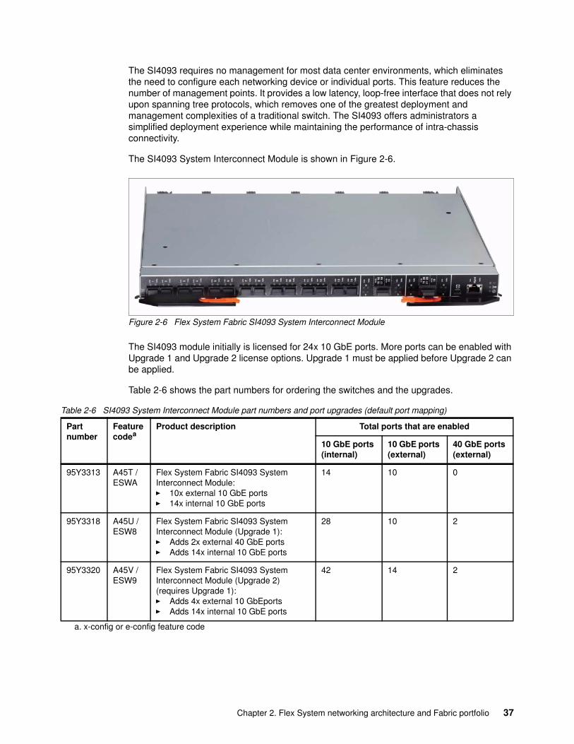
The SI4093 requires no management for most data center environments, which eliminates the need to configure each networking device or individual ports. This feature reduces the number of management points. It provides a low latency, loop-free interface that does not rely upon spanning tree protocols, which removes one of the greatest deployment and management complexities of a traditional switch. The SI4093 offers administrators a simplified deployment experience while maintaining the performance of intra-chassis connectivity.
The SI4093 System Interconnect Module is shown in Figure 2-6.
Figure 2-6 Flex System Fabric SI4093 System Interconnect Module
The SI4093 module initially is licensed for 24x 10 GbE ports. More ports can be enabled with Upgrade 1 and Upgrade 2 license options. Upgrade 1 must be applied before Upgrade 2 can be applied.
Table 2-6 shows the part numbers for ordering the switches and the upgrades.
Table 2-6 SI4093 System Interconnect Module part numbers and port upgrades (default port mapping)
Partnumber
Featurecodea
a. x-config or e-config feature code
Product description Total ports that are enabled
10 GbE ports (internal)
10 GbE ports (external)
40 GbE ports (external)
95Y3313 A45T / ESWA
Flex System Fabric SI4093 System Interconnect Module:� 10x external 10 GbE ports� 14x internal 10 GbE ports
14 10 0
95Y3318 A45U / ESW8
Flex System Fabric SI4093 System Interconnect Module (Upgrade 1):� Adds 2x external 40 GbE ports� Adds 14x internal 10 GbE ports
28 10 2
95Y3320 A45V / ESW9
Flex System Fabric SI4093 System Interconnect Module (Upgrade 2) (requires Upgrade 1):� Adds 4x external 10 GbEports � Adds 14x internal 10 GbE ports
42 14 2
Chapter 2. Flex System networking architecture and Fabric portfolio 37
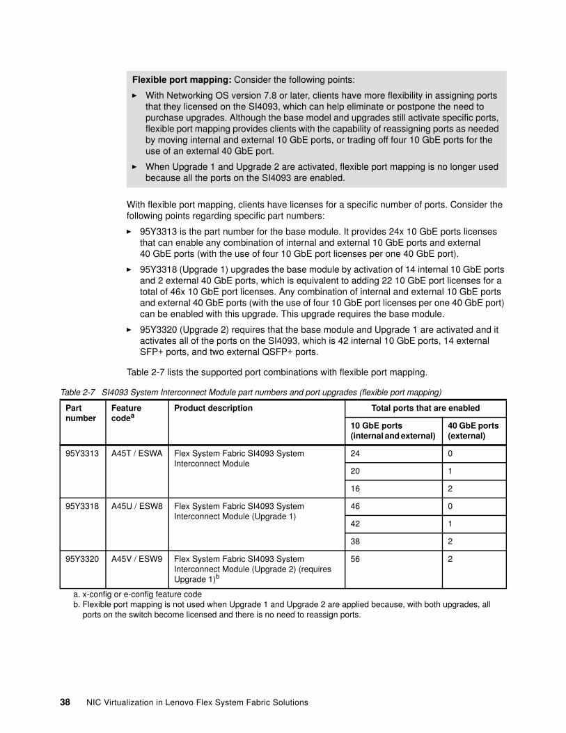
With flexible port mapping, clients have licenses for a specific number of ports. Consider the following points regarding specific part numbers:
� 95Y3313 is the part number for the base module. It provides 24x 10 GbE ports licenses that can enable any combination of internal and external 10 GbE ports and external 40 GbE ports (with the use of four 10 GbE port licenses per one 40 GbE port).
� 95Y3318 (Upgrade 1) upgrades the base module by activation of 14 internal 10 GbE ports and 2 external 40 GbE ports, which is equivalent to adding 22 10 GbE port licenses for a total of 46x 10 GbE port licenses. Any combination of internal and external 10 GbE ports and external 40 GbE ports (with the use of four 10 GbE port licenses per one 40 GbE port) can be enabled with this upgrade. This upgrade requires the base module.
� 95Y3320 (Upgrade 2) requires that the base module and Upgrade 1 are activated and it activates all of the ports on the SI4093, which is 42 internal 10 GbE ports, 14 external SFP+ ports, and two external QSFP+ ports.
Table 2-7 lists the supported port combinations with flexible port mapping.
Table 2-7 SI4093 System Interconnect Module part numbers and port upgrades (flexible port mapping)
Flexible port mapping: Consider the following points:
� With Networking OS version 7.8 or later, clients have more flexibility in assigning ports that they licensed on the SI4093, which can help eliminate or postpone the need to purchase upgrades. Although the base model and upgrades still activate specific ports, flexible port mapping provides clients with the capability of reassigning ports as needed by moving internal and external 10 GbE ports, or trading off four 10 GbE ports for the use of an external 40 GbE port.
� When Upgrade 1 and Upgrade 2 are activated, flexible port mapping is no longer used because all the ports on the SI4093 are enabled.
Partnumber
Featurecodea
a. x-config or e-config feature code
Product description Total ports that are enabled
10 GbE ports (internal and external)
40 GbE ports (external)
95Y3313 A45T / ESWA Flex System Fabric SI4093 System Interconnect Module
24 0
20 1
16 2
95Y3318 A45U / ESW8 Flex System Fabric SI4093 System Interconnect Module (Upgrade 1)
46 0
42 1
38 2
95Y3320 A45V / ESW9 Flex System Fabric SI4093 System Interconnect Module (Upgrade 2) (requires Upgrade 1)b
b. Flexible port mapping is not used when Upgrade 1 and Upgrade 2 are applied because, with both upgrades, all ports on the switch become licensed and there is no need to reassign ports.
56 2
38 NIC Virtualization in Lenovo Flex System Fabric Solutions
The SI4093 System Interconnect Module has the following features and specifications:
� Modes of operations:
– Transparent (or VLAN-independent) mode
In VLAN-independent mode (default configuration), the SI4093 transparently forwards VLAN tagged frames without filtering on the customer VLAN tag. This feature provides an end host view to the upstream network. The interconnect module provides traffic consolidation in the chassis to minimize TOR port usage. It also enables compute node-to-compute node communication for optimum performance (for example, vMotion). It can be connected to the FCoE transit switch or FCoE gateway (FC Forwarder) device.
– Local Domain (or VLAN-aware) mode
In VLAN-aware mode (optional configuration), the SI4093 provides more security for multi-tenant environments by extending client VLAN traffic isolation to the interconnect module and its external ports. VLAN-based access control lists (ACLs) can be configured on the SI4093. When FCoE is used, the SI4093 operates as an FCoE transit switch, and it should be connected to the FCF device.
– Flex System Interconnect Fabric mode
In Flex System Interconnect Fabric mode, the SI4093 module is running optional Interconnect Fabric software image and operates as a leaf switch in the leaf-spine fabric. Flex System Interconnect Fabric integrates the entire point of delivery (POD) into a seamless network fabric for compute node and storage under single IP management. It also attaches to the upstream data center network as a loop-free Layer 2 network fabric with a single Ethernet external connection or aggregation group to each Layer 2 upstream network.
� Internal ports:
– 42 internal full-duplex 10 Gigabit ports– Two internal full-duplex 1 GbE ports that are connected to the chassis management
module
� External ports:
– 14 ports for 1 Gb or 10 Gb Ethernet SFP+ transceivers (support for 1000BASE-SX, 1000BASE-LX, 1000BASE-T, 10GBASE-SR, or 10GBASE-LR) or SFP+ direct-attach copper (DAC) cables. SFP+ modules and DAC cables are not included and must be purchased separately.
– Two ports for 40 Gb Ethernet QSFP+ transceivers or QSFP+ DAC cables. QSFP+ modules and DAC cables are not included and must be purchased separately.
– One RS-232 serial port (mini-USB connector) that provides another means to configure the interconnect module.
� Scalability and performance:
– 40 Gb Ethernet ports for extreme external bandwidth and performance.
– External 10 Gb Ethernet ports to use 10 GbE upstream infrastructure.
– Non-blocking architecture with wire-speed forwarding of traffic and aggregated throughput of 1.28 Tbps.
Note: Flexible port mapping is not available in Flex System Interconnect Fabric mode.
Chapter 2. Flex System networking architecture and Fabric portfolio 39

– Media access control (MAC) address learning: Automatic update, support for up to 128,000 MAC addresses.
– Static and LACP (IEEE 802.3ad) link aggregation, up to 220 Gb of total external bandwidth per interconnect module.
– Support for jumbo frames (up to 9,216 bytes).
� Availability and redundancy:
– Layer 2 Trunk Failover to support active or standby configurations of network adapter teaming on compute nodes.
– Built-in link redundancy with loop prevention without a need for Spanning Tree protocol.
� VLAN support:
– Up to 32 VLANs supported per interconnect module SPAR partition, with VLAN numbers 1 - 4095 (4095 is used for management module’s connection only).
– 802.1Q VLAN tagging support on all ports.
– Private VLANs.
� Security
– VLAN-based access control lists (ACLs) (VLAN-aware mode).– Multiple user IDs and passwords.– User access control.– Radius, TACACS+, and LDAP authentication and authorization.– NIST 800-131A Encryption.– Selectable encryption protocol; SHA 256 enabled as default.
� Quality of service (QoS)
Support for IEEE 802.1p traffic classification and processing.
� Virtualization:
– Switch Independent Virtual NIC (vNIC2)
Ethernet, iSCSI, or FCoE traffic is supported on vNICs.
– Unified fabric port (UFP):
• Ethernet or FCoE traffic is supported on UFPs.• Supports up to 256 VLAN for the virtual ports.• Integration with L2 failover.
– 802.1Qbg Edge Virtual Bridging (EVB) is an emerging IEEE standard for allowing networks to become virtual machine (VM)-aware.
• Virtual Ethernet Bridging (VEB) and Virtual Ethernet Port Aggregator (VEPA) are mechanisms for switching between VMs on the same hypervisor.
• Edge Control Protocol (ECP) is a transport protocol that operates between two peers over an IEEE 802 LAN providing reliable, in-order delivery of upper layer protocol data units.
• Virtual Station Interface (VSI) Discovery and Configuration Protocol (VDP) allows centralized configuration of network policies that persist with the VM, independent of its location.
• EVB Type-Length-Value (TLV) is used to discover and configure VEPA, ECP, VDP.
– VMready
40 NIC Virtualization in Lenovo Flex System Fabric Solutions
– Switch partitioning (SPAR):
• SPAR forms separate virtual switching contexts by segmenting the data plane of the module. Data plane traffic is not shared between SPARs on the same module.
• SPAR operates as a Layer 2 broadcast network. Hosts on the same VLAN attached to a SPAR can communicate with each other and with the upstream switch. Hosts on the same VLAN but attached to different SPARs communicate through the upstream switch.
• SPAR is implemented as a dedicated VLAN with a set of internal compute node ports and a single external port or link aggregation (LAG). Multiple external ports or LAGs are not allowed in SPAR. A port can be a member of only one SPAR.
� Converged Enhanced Ethernet:
– Priority-Based Flow Control (PFC) (IEEE 802.1Qbb) extends 802.3x standard flow control to allow the module to pause traffic that is based on the 802.1p priority value in each packet’s VLAN tag.
– Enhanced Transmission Selection (ETS) (IEEE 802.1Qaz) provides a method for allocating link bandwidth that is based on the 802.1p priority value in each packet’s VLAN tag.
– Data Center Bridging Capability Exchange Protocol (DCBX) (IEEE 802.1AB) allows neighboring network devices to exchange information about their capabilities.
� Fibre Channel over Ethernet (FCoE):
– FC-BB5 FCoE specification compliant.– FCoE transit switch operations.– FCoE Initialization Protocol (FIP) support.
� Manageability:
– IPv4 and IPv6 host management.
– Simple Network Management Protocol (SNMP V1, V2, and V3).
– Industry standard command-line interface (IS-CLI) through Telnet, SSH, and serial port.
– Secure FTP (sFTP).
– Service Location Protocol (SLP).
– Firmware image update (TFTP and FTP/sFTP).
– Network Time Protocol (NTP) for clock synchronization.
– IBM System Networking Switch Center (SNSC) support.
� Monitoring:
– LEDs for external port status and module status indication.– Change tracking and remote logging with syslog feature.– POST diagnostic tests.
For more information, see Flex System Fabric EN4093 and EN4093R 10Gb Scalable Switches, TIPS0864, which is available at this website:
http://lenovopress.com/tips0864
Chapter 2. Flex System networking architecture and Fabric portfolio 41
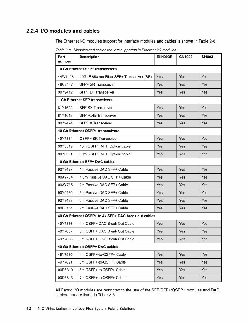
2.2.4 I/O modules and cables
The Ethernet I/O modules support for interface modules and cables is shown in Table 2-8.
Table 2-8 Modules and cables that are supported in Ethernet I/O modules
All Fabric I/O modules are restricted to the use of the SFP/SFP+/QSFP+ modules and DAC cables that are listed in Table 2-8.
Part number
Description EN4093R CN4093 SI4093
10 Gb Ethernet SFP+ transceivers
44W4408 10GbE 850 nm Fiber SFP+ Transceiver (SR) Yes Yes Yes
46C3447 SFP+ SR Transceiver Yes Yes Yes
90Y9412 SFP+ LR Transceiver Yes Yes Yes
1 Gb Ethernet SFP transceivers
81Y1622 SFP SX Transceiver Yes Yes Yes
81Y1618 SFP RJ45 Transceiver Yes Yes Yes
90Y9424 SFP LX Transceiver Yes Yes Yes
40 Gb Ethernet QSFP+ transceivers
49Y7884 QSFP+ SR Transceiver Yes Yes Yes
90Y3519 10m QSFP+ MTP Optical cable Yes Yes Yes
90Y3521 30m QSFP+ MTP Optical cable Yes Yes Yes
10 Gb Ethernet SFP+ DAC cables
90Y9427 1m Passive DAC SFP+ Cable Yes Yes Yes
00AY764 1.5m Passive DAC SFP+ Cable Yes Yes Yes
00AY765 2m Passive DAC SFP+ Cable Yes Yes Yes
90Y9430 3m Passive DAC SFP+ Cable Yes Yes Yes
90Y9433 5m Passive DAC SFP+ Cable Yes Yes Yes
00D6151 7m Passive DAC SFP+ Cable Yes Yes Yes
40 Gb Ethernet QSFP+ to 4x SFP+ DAC break out cables
49Y7886 1m QSFP+ DAC Break Out Cable Yes Yes Yes
49Y7887 3m QSFP+ DAC Break Out Cable Yes Yes Yes
49Y7888 5m QSFP+ DAC Break Out Cable Yes Yes Yes
40 Gb Ethernet QSFP+ DAC cables
49Y7890 1m QSFP+-to-QSFP+ Cable Yes Yes Yes
49Y7891 3m QSFP+-to-QSFP+ Cable Yes Yes Yes
00D5810 5m QSFP+ to QSFP+ Cable Yes Yes Yes
00D5813 7m QSFP+ to QSFP+ Cable Yes Yes Yes
42 NIC Virtualization in Lenovo Flex System Fabric Solutions
2.3 Flex System Virtual Fabric adapters
The Flex System portfolio contains several Virtual Fabric I/O adapters. The cards are a combination of 10 Gb ports and advanced function support that includes converged networks and virtual NICs.
The following Virtual Fabric I/O adapters are described:
� Embedded 10Gb Virtual Fabric Adapter� Flex System CN4054/CN4054R 10Gb Virtual Fabric Adapters
2.3.1 Embedded 10Gb Virtual Fabric Adapter
Some models of the Flex System x240 and x440 Compute Nodes include an Embedded 10Gb Virtual Fabric Adapter (VFA) or LOM that is built into the system board.
Each x240 model that includes the embedded 10 Gb VFA also has the Compute Node Fabric Connector that is installed in I/O connector 1 (and physically screwed onto the system board) to provide connectivity to the Enterprise Chassis midplane. Each x440 model that includes two embedded 10 Gb VFAs also has the Compute Node Fabric Connectors that are installed in each of I/O connectors 1 and 3 (and physically screwed onto the system board) to provide connectivity to the Enterprise Chassis midplane. The Fabric Connector enables port 1 on the embedded 10 Gb VFA to be routed to I/O module bay 1 and port 2 to be routed to I/O bay 2.
Each server in the x222 compute node includes an Embedded two-port 10Gb Virtual Fabric Adapter that is built in to the system board. The x222 has one Fabric Connector (which is physically on the lower server) and the Ethernet connections from both Embedded 10 Gb VFAs are routed through it to I/O module bays 1 and 2.
Table 2-9 lists the ordering information for the Virtual Fabric Advanced Software Upgrade (LOM), which enables the iSCSI and FCoE support on the Embedded 10Gb Virtual Fabric Adapter.
Table 2-9 Feature on-Demand upgrade for FCoE and iSCSI support
The Flex System Embedded 10 Gb VFA has the following features and specifications:
� Models with Intel Xeon E5-2400, E5-2600, and 4600 processors: Emulex BladeEngine 3 (BE3) ASIC
� Models with Intel Xeon E5-2600 v2 processors: Emulex BladeEngine 3R (BE3R) ASIC
� Operates as a 2-port 1/10 Gb Ethernet adapter or supports up to eight Virtual Network Interface Controllers (virtual NICs)
� Supports NIC virtualization:
– Modes of operation:
• Unified Fabric Port (UFP)• Virtual Fabric mode vNIC• Switch Independent mode vNIC
– Virtual port bandwidth allocation in 100 Mbps increments
– Up to eight virtual ports per adapter (four per port)
Part number Feature code Description
90Y9310 A2TD Virtual Fabric Advanced Software Upgrade (LOM)
Chapter 2. Flex System networking architecture and Fabric portfolio 43
– With the optional Advanced Upgrade, two of the eight virtual NICs (one per port) are transformed into iSCSI or FCoE HBAs
� Wake On LAN support
� FCoE and iSCSI HBA function support with the optional Advanced Upgrade
� PCI Express 2.0 x8 host interface
� Full-duplex capability
� DMA support
� PXE support
� IPv4/IPv6 TCP, UDP checksum offload:
– Large send offload– Large receive offload – RSS – IPv4 TCP Chimney offload – TCP Segmentation offload
� VLAN insertion and extraction
� Jumbo frames up to 9000 bytes
� Load balancing and failover support, including AFT, SFT, ALB, and LACP
� Converged Enhanced Ethernet (draft):
– Enhanced Transmission Selection (ETS) (P802.1Qaz)– Priority-based Flow Control (PFC) (P802.1Qbb)– Data Center Bridging eXchange protocol (DCBX) (P802.1Qaz)
� Support Serial over LAN (SoL)
2.3.2 Flex System CN4054/CN4054R 10Gb Virtual Fabric Adapters
The Flex System CN4054 and CN4054R 10Gb Virtual Fabric Adapters from Emulex are 4-port 10 Gb converged network adapters. They can scale to up to 16 virtual ports and support multiple protocols, such as Ethernet, iSCSI, and FCoE. The CN4054R adds support for compute nodes with the Intel Xeon E5-2600 v2 processors.
Figure 2-7 on page 45 shows the Flex System CN4054/CN4054R 10Gb Virtual Fabric Adapters.
44 NIC Virtualization in Lenovo Flex System Fabric Solutions
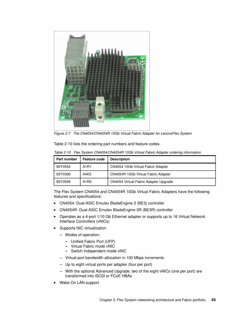
Figure 2-7 The CN4054/CN4054R 10Gb Virtual Fabric Adapter for LenovoFlex System
Table 2-10 lists the ordering part numbers and feature codes.
Table 2-10 Flex System CN4054/CN4054R 10Gb Virtual Fabric Adapter ordering information
The Flex System CN4054 and CN4054R 10Gb Virtual Fabric Adapters have the following features and specifications:
� CN4054: Dual-ASIC Emulex BladeEngine 3 (BE3) controller
� CN4054R: Dual-ASIC Emulex BladeEngine 3R (BE3R) controller
� Operates as a 4-port 1/10 Gb Ethernet adapter or supports up to 16 Virtual Network Interface Controllers (vNICs)
� Supports NIC virtualization
– Modes of operation:
• Unified Fabric Port (UFP)• Virtual Fabric mode vNIC• Switch Independent mode vNIC
– Virtual port bandwidth allocation in 100 Mbps increments
– Up to eight virtual ports per adapter (four per port)
– With the optional Advanced Upgrade, two of the eight vNICs (one per port) are transformed into iSCSI or FCoE HBAs
� Wake On LAN support
Part number Feature code Description
90Y3554 A1R1 CN4054 10Gb Virtual Fabric Adapter
00Y3306 A4K2 CN4054R 10Gb Virtual Fabric Adapter
90Y3558 A1R0 CN4054 Virtual Fabric Adapter Upgrade
Chapter 2. Flex System networking architecture and Fabric portfolio 45
� FCoE and iSCSI HBA function support with the optional Advanced Upgrade
� PCI Express 3.0 x8 host interface
� Full-duplex capability
� DMA support
� PXE support
� IPv4/IPv6 TCP, UDP checksum offload:
– Large send offload– Large receive offload – RSS – IPv4 TCP Chimney offload – TCP Segmentation offload
� VLAN insertion and extraction
� Jumbo frames up to 9000 bytes
� Load balancing and failover support, including AFT, SFT, ALB, and LACP
� Converged Enhanced Ethernet (draft):
– Enhanced Transmission Selection (ETS) (P802.1Qaz)– Priority-based Flow Control (PFC) (P802.1Qbb)– Data Center Bridging eXchange protocol (DCBX) (P802.1Qaz)
� Support Serial over LAN (SoL)
For more information, see Flex System CN4054/CN4054R 10Gb Virtual Fabric Adapter and EN4054 4-port 10Gb Ethernet Adapter, TIPS0868, which can be found at this website:
http://lenovopress.com/tips0868
46 NIC Virtualization in Lenovo Flex System Fabric Solutions
Chapter 3. NIC virtualization considerations on the switch side
This publication is primarily focused on the various options to virtualize NIC technology. This chapter introduces the two primary types of NIC virtualization (vNIC and UFP) that are available on the Flex System switches. Also introduced and described are the considerations of the various subelements of these virtual NIC technologies.
At the core of all virtual NICs that are described in this chapter is the ability to take a single physical 10 GbE NIC and carve it up into up to four virtual NICs for use in the attaching host.
This chapter focuses on various deployment considerations when you are considering the right choice in NIC virtualization within a PureFlex System environment.
This chapter includes the following topics:
� Virtual Fabric vNIC solution capabilities� Unified Fabric Port feature� Compute node NIC to I/O module connectivity mapping
3
© Copyright Lenovo 2016. All rights reserved. 47
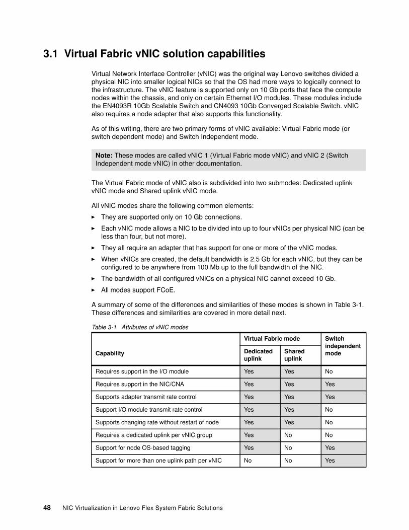
3.1 Virtual Fabric vNIC solution capabilities
Virtual Network Interface Controller (vNIC) was the original way Lenovo switches divided a physical NIC into smaller logical NICs so that the OS had more ways to logically connect to the infrastructure. The vNIC feature is supported only on 10 Gb ports that face the compute nodes within the chassis, and only on certain Ethernet I/O modules. These modules include the EN4093R 10Gb Scalable Switch and CN4093 10Gb Converged Scalable Switch. vNIC also requires a node adapter that also supports this functionality.
As of this writing, there are two primary forms of vNIC available: Virtual Fabric mode (or switch dependent mode) and Switch Independent mode.
The Virtual Fabric mode of vNIC also is subdivided into two submodes: Dedicated uplink vNIC mode and Shared uplink vNIC mode.
All vNIC modes share the following common elements:
� They are supported only on 10 Gb connections.
� Each vNIC mode allows a NIC to be divided into up to four vNICs per physical NIC (can be less than four, but not more).
� They all require an adapter that has support for one or more of the vNIC modes.
� When vNICs are created, the default bandwidth is 2.5 Gb for each vNIC, but they can be configured to be anywhere from 100 Mb up to the full bandwidth of the NIC.
� The bandwidth of all configured vNICs on a physical NIC cannot exceed 10 Gb.
� All modes support FCoE.
A summary of some of the differences and similarities of these modes is shown in Table 3-1. These differences and similarities are covered in more detail next.
Table 3-1 Attributes of vNIC modes
Note: These modes are called vNIC 1 (Virtual Fabric mode vNIC) and vNIC 2 (Switch Independent mode vNIC) in other documentation.
Capability
Virtual Fabric mode Switch independent modeDedicated
uplinkShared uplink
Requires support in the I/O module Yes Yes No
Requires support in the NIC/CNA Yes Yes Yes
Supports adapter transmit rate control Yes Yes Yes
Support I/O module transmit rate control Yes Yes No
Supports changing rate without restart of node Yes Yes No
Requires a dedicated uplink per vNIC group Yes No No
Support for node OS-based tagging Yes No Yes
Support for more than one uplink path per vNIC No No Yes
48 NIC Virtualization in Lenovo Flex System Fabric Solutions
3.1.1 Virtual Fabric mode vNIC
Virtual Fabric mode vNIC depends on the switch in the I/O module bay to participate in the vNIC process. Specifically, the Flex System Fabric EN4093R 10Gb Scalable Switch and the CN4093 10Gb Converged Scalable Switch support this mode. It also requires an adapter on the compute node that supports the vNIC Virtual Fabric mode feature.
In Virtual Fabric mode vNIC, configuration is performed on the switch and the configuration information is communicated between the switch and the adapter so that both sides agree on and enforce bandwidth controls. The mode can be changed to different speeds at any time without rebooting the OS or the I/O module.
There are two types of Virtual Fabric vNIC modes: Dedicated uplink mode and Shared uplink mode. Both modes incorporate the concept of a vNIC group on the switch that is used to associate vNICs and physical ports into virtual switches within the chassis. How these vNIC groups are used is the primary difference between dedicated uplink mode and shared uplink mode.
Virtual Fabric vNIC modes share the following common attributes:
� They conceptually are a vNIC group that must be created on the I/O module.
� Similar vNICs are bundled together into common vNIC groups.
� Each vNIC group is treated as a virtual switch within the I/O module. Packets in one vNIC group can get only to a different vNIC group by going to an external switch or router.
� For the purposes of Spanning tree and packet flow, each vNIC group is treated as a unique switch by upstream connecting switches or routers.
� Both modes support the addition of physical NICs (pNIC) (the NICs from nodes that are not using vNIC) to vNIC groups for internal communication to other pNICs and vNICs in that vNIC group, and share any uplink that is associated with that vNIC group.
Dedicated uplink modeDedicated uplink mode is the default mode when vNIC is enabled on the I/O module. In dedicated uplink mode, each vNIC group must have its own dedicated physical or logical (aggregation) uplink. In this mode, no more than one physical or logical uplink to a vNIC group can be assigned and it assumed that high availability is achieved by some combination of aggregation on the uplink or NIC teaming on the server.
In dedicated uplink mode, vNIC groups are VLAN-independent to the nodes and the rest of the network, which means that you do not need to create VLANs for each VLAN that is used by the nodes. The vNIC group takes each packet (tagged or untagged) and moves it through the switch. This mode is accomplished by the use of a form of Q-in-Q tagging. Each vNIC group is assigned some VLAN that is unique to each vNIC group. Any packet (tagged or untagged) that comes in on a downstream or upstream port in that vNIC group has a tag that is placed on it equal to the vNIC group VLAN. As that packet leaves the vNIC into the node or out an uplink, that tag is removed and the original tag (or no tag, depending on the original packet) is revealed.
Example 3-1 on page 50 shows an example Virtual Fabric vNIC - Dedicated Uplink mode configuration. The example enables VLAN 4091 as the Outer Q-n-Q VLAN ID on vNIC port 1 the first Index ID. By default, the bandwidth configuration is set to 25% on all four index numbers equating to 100%. These values can be adjusted as needed but not to exceed 100% on all four indexes.
Chapter 3. NIC virtualization considerations on the switch side 49
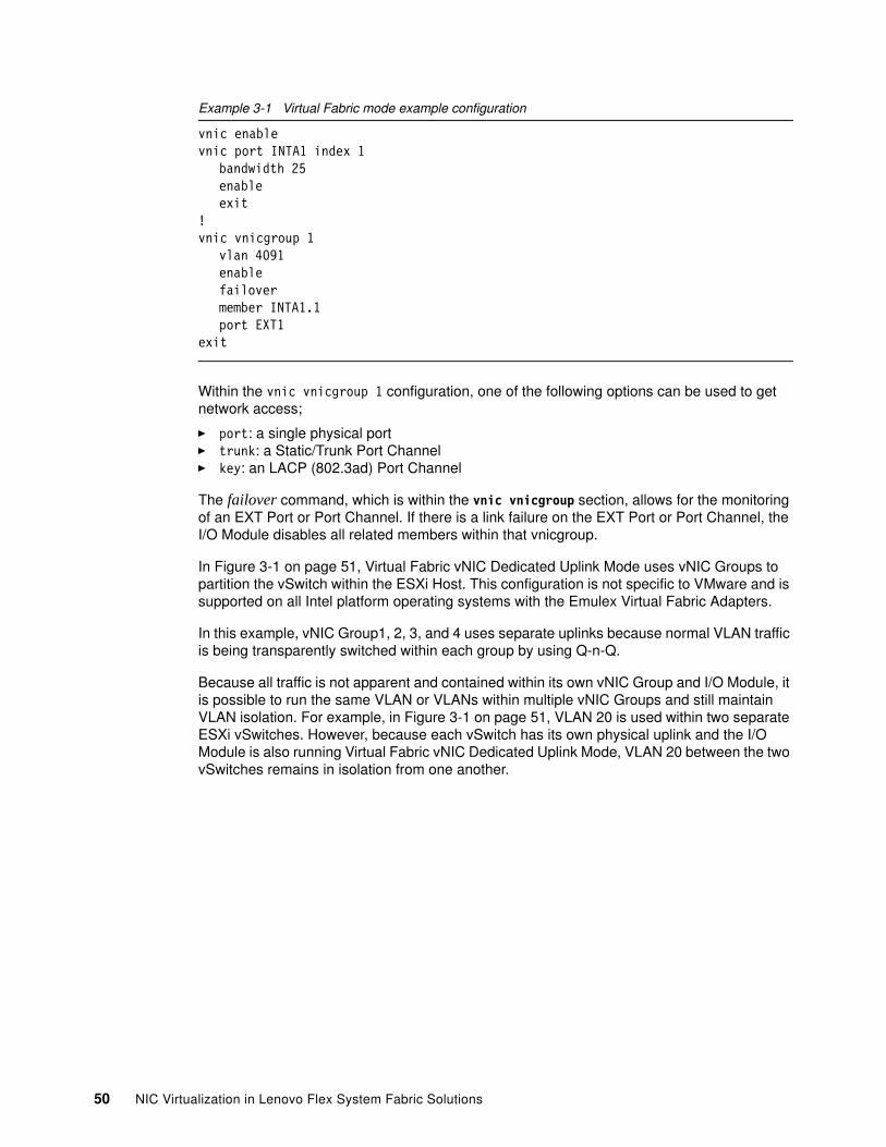
Example 3-1 Virtual Fabric mode example configuration
vnic enablevnic port INTA1 index 1
bandwidth 25enableexit
!vnic vnicgroup 1
vlan 4091enablefailovermember INTA1.1port EXT1
exit
Within the vnic vnicgroup 1 configuration, one of the following options can be used to get network access;
� port: a single physical port� trunk: a Static/Trunk Port Channel� key: an LACP (802.3ad) Port Channel
The failover command, which is within the vnic vnicgroup section, allows for the monitoring of an EXT Port or Port Channel. If there is a link failure on the EXT Port or Port Channel, the I/O Module disables all related members within that vnicgroup.
In Figure 3-1 on page 51, Virtual Fabric vNIC Dedicated Uplink Mode uses vNIC Groups to partition the vSwitch within the ESXi Host. This configuration is not specific to VMware and is supported on all Intel platform operating systems with the Emulex Virtual Fabric Adapters.
In this example, vNIC Group1, 2, 3, and 4 uses separate uplinks because normal VLAN traffic is being transparently switched within each group by using Q-n-Q.
Because all traffic is not apparent and contained within its own vNIC Group and I/O Module, it is possible to run the same VLAN or VLANs within multiple vNIC Groups and still maintain VLAN isolation. For example, in Figure 3-1 on page 51, VLAN 20 is used within two separate ESXi vSwitches. However, because each vSwitch has its own physical uplink and the I/O Module is also running Virtual Fabric vNIC Dedicated Uplink Mode, VLAN 20 between the two vSwitches remains in isolation from one another.
50 NIC Virtualization in Lenovo Flex System Fabric Solutions
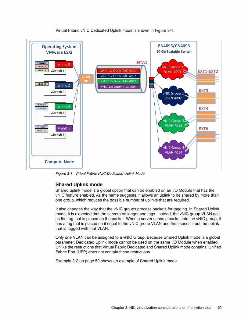
Virtual Fabric vNIC Dedicated Uplink mode is shown in Figure 3-1.
Figure 3-1 Virtual Fabric vNIC Dedicated Uplink Mode
Shared Uplink modeShared uplink mode is a global option that can be enabled on an I/O Module that has the vNIC feature enabled. As the name suggests, it allows an uplink to be shared by more than one group, which reduces the possible number of uplinks that are required.
It also changes the way that the vNIC groups process packets for tagging. In Shared Uplink mode, it is expected that the servers no longer use tags. Instead, the vNIC group VLAN acts as the tag that is placed on the packet. When a server sends a packet into the vNIC group, it has a tag that is placed on it equal to the vNIC group VLAN and then sends it out the uplink that is tagged with that VLAN.
Only one VLAN can be assigned to a vNIC Group. Because Shared Uplink mode is a global parameter, Dedicated Uplink mode cannot be used on the same I/O Module when enabled. Unlike the restrictions that Virtual Fabric Dedicated and Shared Uplink mode contains, Unified Fabric Port (UFP) does not contain these restrictions.
Example 3-2 on page 52 shows an example of Shared Uplink mode.
Chapter 3. NIC virtualization considerations on the switch side 51
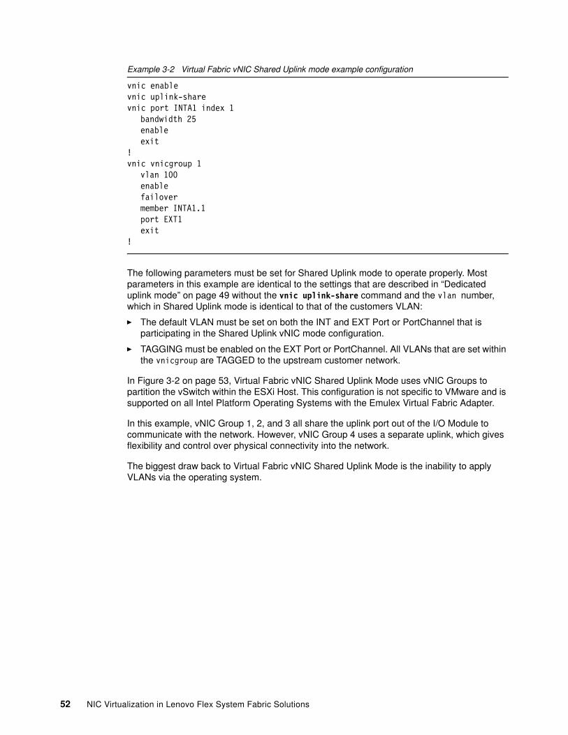
Example 3-2 Virtual Fabric vNIC Shared Uplink mode example configuration
vnic enablevnic uplink-sharevnic port INTA1 index 1
bandwidth 25enableexit
!vnic vnicgroup 1
vlan 100enablefailovermember INTA1.1port EXT1exit
!
The following parameters must be set for Shared Uplink mode to operate properly. Most parameters in this example are identical to the settings that are described in “Dedicated uplink mode” on page 49 without the vnic uplink-share command and the vlan number, which in Shared Uplink mode is identical to that of the customers VLAN:
� The default VLAN must be set on both the INT and EXT Port or PortChannel that is participating in the Shared Uplink vNIC mode configuration.
� TAGGING must be enabled on the EXT Port or PortChannel. All VLANs that are set within the vnicgroup are TAGGED to the upstream customer network.
In Figure 3-2 on page 53, Virtual Fabric vNIC Shared Uplink Mode uses vNIC Groups to partition the vSwitch within the ESXi Host. This configuration is not specific to VMware and is supported on all Intel Platform Operating Systems with the Emulex Virtual Fabric Adapter.
In this example, vNIC Group 1, 2, and 3 all share the uplink port out of the I/O Module to communicate with the network. However, vNIC Group 4 uses a separate uplink, which gives flexibility and control over physical connectivity into the network.
The biggest draw back to Virtual Fabric vNIC Shared Uplink Mode is the inability to apply VLANs via the operating system.
52 NIC Virtualization in Lenovo Flex System Fabric Solutions
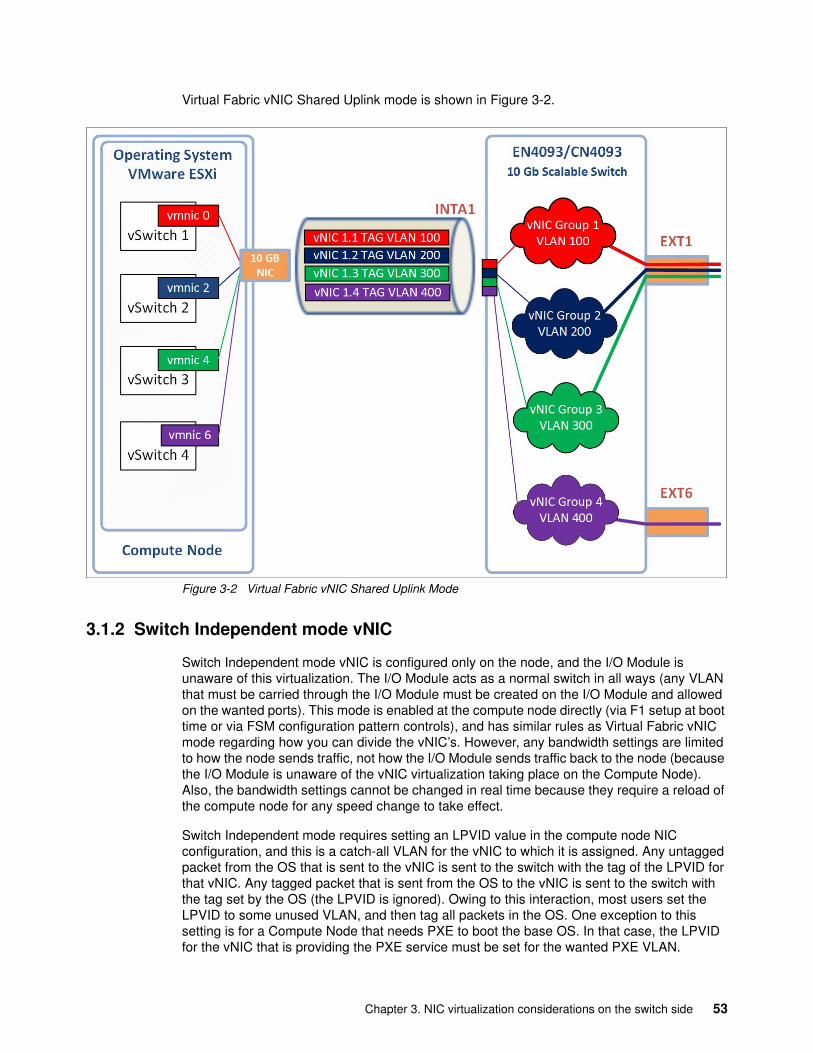
Virtual Fabric vNIC Shared Uplink mode is shown in Figure 3-2.
Figure 3-2 Virtual Fabric vNIC Shared Uplink Mode
3.1.2 Switch Independent mode vNIC
Switch Independent mode vNIC is configured only on the node, and the I/O Module is unaware of this virtualization. The I/O Module acts as a normal switch in all ways (any VLAN that must be carried through the I/O Module must be created on the I/O Module and allowed on the wanted ports). This mode is enabled at the compute node directly (via F1 setup at boot time or via FSM configuration pattern controls), and has similar rules as Virtual Fabric vNIC mode regarding how you can divide the vNIC’s. However, any bandwidth settings are limited to how the node sends traffic, not how the I/O Module sends traffic back to the node (because the I/O Module is unaware of the vNIC virtualization taking place on the Compute Node). Also, the bandwidth settings cannot be changed in real time because they require a reload of the compute node for any speed change to take effect.
Switch Independent mode requires setting an LPVID value in the compute node NIC configuration, and this is a catch-all VLAN for the vNIC to which it is assigned. Any untagged packet from the OS that is sent to the vNIC is sent to the switch with the tag of the LPVID for that vNIC. Any tagged packet that is sent from the OS to the vNIC is sent to the switch with the tag set by the OS (the LPVID is ignored). Owing to this interaction, most users set the LPVID to some unused VLAN, and then tag all packets in the OS. One exception to this setting is for a Compute Node that needs PXE to boot the base OS. In that case, the LPVID for the vNIC that is providing the PXE service must be set for the wanted PXE VLAN.
Chapter 3. NIC virtualization considerations on the switch side 53
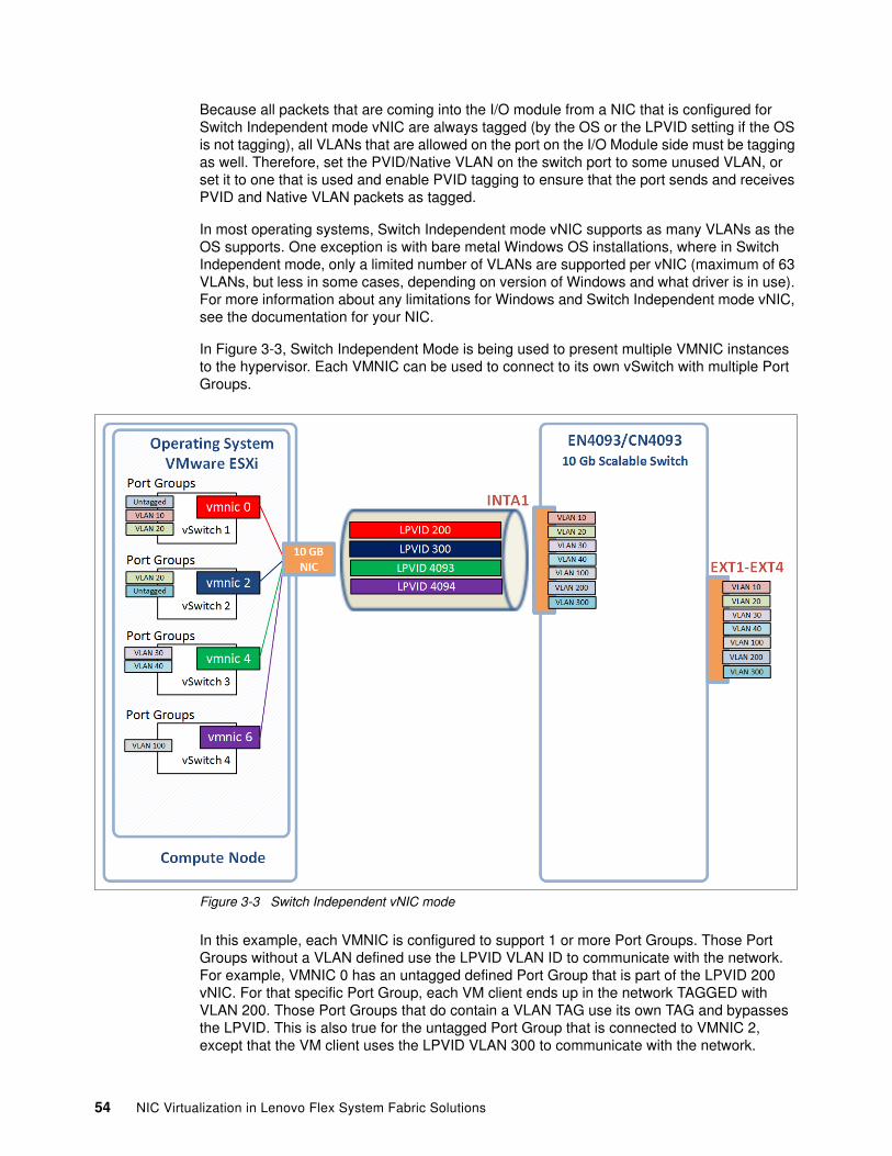
Because all packets that are coming into the I/O module from a NIC that is configured for Switch Independent mode vNIC are always tagged (by the OS or the LPVID setting if the OS is not tagging), all VLANs that are allowed on the port on the I/O Module side must be tagging as well. Therefore, set the PVID/Native VLAN on the switch port to some unused VLAN, or set it to one that is used and enable PVID tagging to ensure that the port sends and receives PVID and Native VLAN packets as tagged.
In most operating systems, Switch Independent mode vNIC supports as many VLANs as the OS supports. One exception is with bare metal Windows OS installations, where in Switch Independent mode, only a limited number of VLANs are supported per vNIC (maximum of 63 VLANs, but less in some cases, depending on version of Windows and what driver is in use). For more information about any limitations for Windows and Switch Independent mode vNIC, see the documentation for your NIC.
In Figure 3-3, Switch Independent Mode is being used to present multiple VMNIC instances to the hypervisor. Each VMNIC can be used to connect to its own vSwitch with multiple Port Groups.
Figure 3-3 Switch Independent vNIC mode
In this example, each VMNIC is configured to support 1 or more Port Groups. Those Port Groups without a VLAN defined use the LPVID VLAN ID to communicate with the network. For example, VMNIC 0 has an untagged defined Port Group that is part of the LPVID 200 vNIC. For that specific Port Group, each VM client ends up in the network TAGGED with VLAN 200. Those Port Groups that do contain a VLAN TAG use its own TAG and bypasses the LPVID. This is also true for the untagged Port Group that is connected to VMNIC 2, except that the VM client uses the LPVID VLAN 300 to communicate with the network.
54 NIC Virtualization in Lenovo Flex System Fabric Solutions
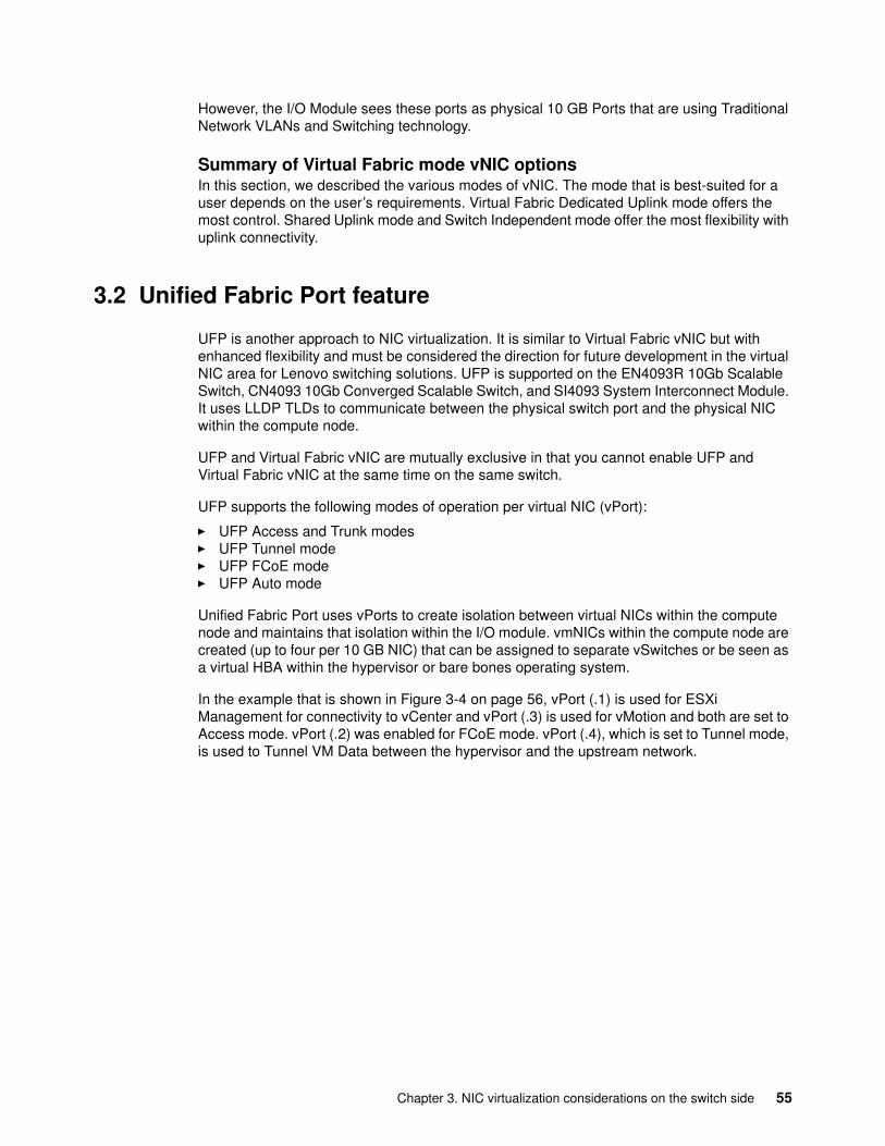
However, the I/O Module sees these ports as physical 10 GB Ports that are using Traditional Network VLANs and Switching technology.
Summary of Virtual Fabric mode vNIC optionsIn this section, we described the various modes of vNIC. The mode that is best-suited for a user depends on the user’s requirements. Virtual Fabric Dedicated Uplink mode offers the most control. Shared Uplink mode and Switch Independent mode offer the most flexibility with uplink connectivity.
3.2 Unified Fabric Port feature
UFP is another approach to NIC virtualization. It is similar to Virtual Fabric vNIC but with enhanced flexibility and must be considered the direction for future development in the virtual NIC area for Lenovo switching solutions. UFP is supported on the EN4093R 10Gb Scalable Switch, CN4093 10Gb Converged Scalable Switch, and SI4093 System Interconnect Module. It uses LLDP TLDs to communicate between the physical switch port and the physical NIC within the compute node.
UFP and Virtual Fabric vNIC are mutually exclusive in that you cannot enable UFP and Virtual Fabric vNIC at the same time on the same switch.
UFP supports the following modes of operation per virtual NIC (vPort):
� UFP Access and Trunk modes� UFP Tunnel mode� UFP FCoE mode� UFP Auto mode
Unified Fabric Port uses vPorts to create isolation between virtual NICs within the compute node and maintains that isolation within the I/O module. vmNICs within the compute node are created (up to four per 10 GB NIC) that can be assigned to separate vSwitches or be seen as a virtual HBA within the hypervisor or bare bones operating system.
In the example that is shown in Figure 3-4 on page 56, vPort (.1) is used for ESXi Management for connectivity to vCenter and vPort (.3) is used for vMotion and both are set to Access mode. vPort (.2) was enabled for FCoE mode. vPort (.4), which is set to Tunnel mode, is used to Tunnel VM Data between the hypervisor and the upstream network.
Chapter 3. NIC virtualization considerations on the switch side 55
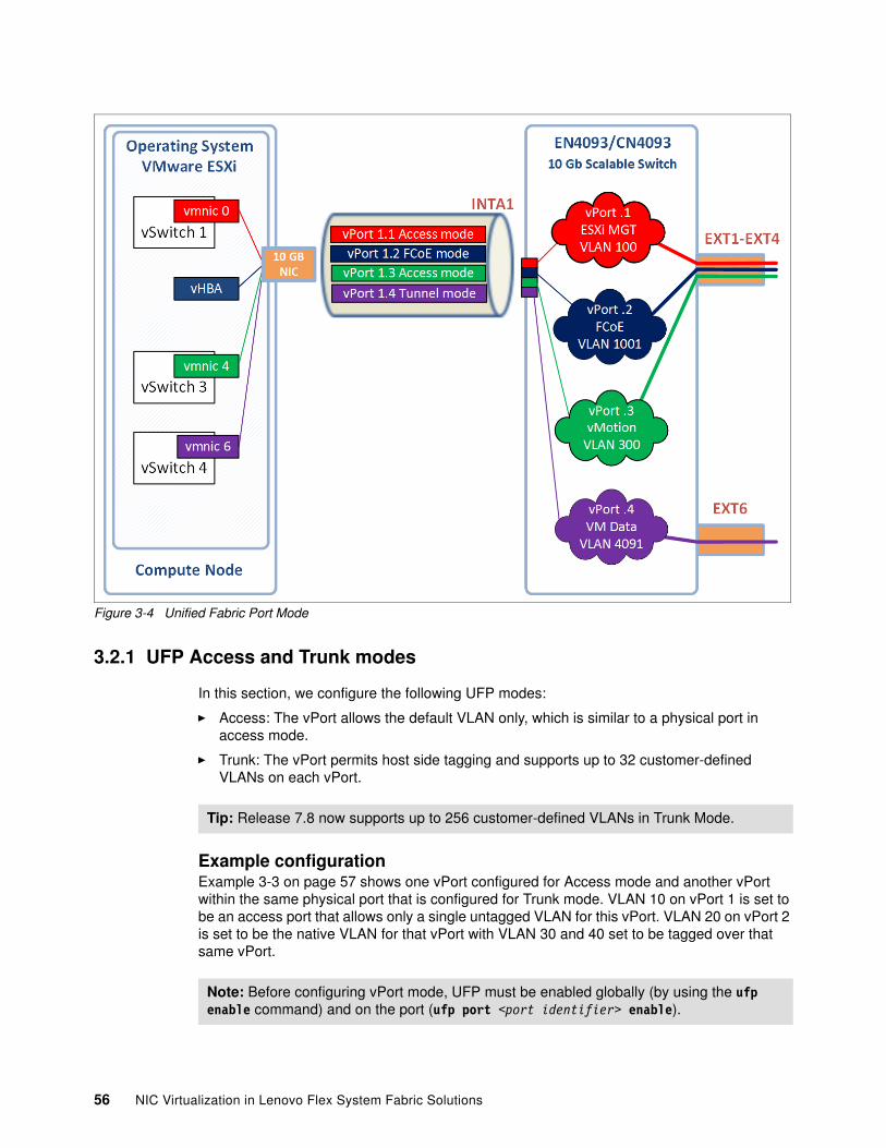
Figure 3-4 Unified Fabric Port Mode
3.2.1 UFP Access and Trunk modes
In this section, we configure the following UFP modes:
� Access: The vPort allows the default VLAN only, which is similar to a physical port in access mode.
� Trunk: The vPort permits host side tagging and supports up to 32 customer-defined VLANs on each vPort.
Example configurationExample 3-3 on page 57 shows one vPort configured for Access mode and another vPort within the same physical port that is configured for Trunk mode. VLAN 10 on vPort 1 is set to be an access port that allows only a single untagged VLAN for this vPort. VLAN 20 on vPort 2 is set to be the native VLAN for that vPort with VLAN 30 and 40 set to be tagged over that same vPort.
Tip: Release 7.8 now supports up to 256 customer-defined VLANs in Trunk Mode.
Note: Before configuring vPort mode, UFP must be enabled globally (by using the ufp enable command) and on the port (ufp port <port identifier> enable).
56 NIC Virtualization in Lenovo Flex System Fabric Solutions
Example 3-3 vPort Access and Trunk mode example configuration
ufp port INTA1 vport 1network mode accessnetwork default-vlan 10enableexit
!ufp port INTA1 vport 2
network mode trunknetwork default-vlan 20enableexit
!vlan 30,40
enablevmember INTA1.2
Optionally, Example 3-4 shows adding the ability to detect uplink failures, which is referred to as failover. Failover is a feature that is used to monitor an up uplink port or port channel. Upon detection of a failed link or port channel, the I/O Module disables any associated members (INT Ports) or vmembers (UFP vPorts).
Example 3-4 UFP Failover of a vmembers
failover trigger 1 mmon monitor member EXT1failover trigger 1 mmon control vmember INTA1.1failover trigger 1 enable
Configuration validation and state of a UFP vPortThere are several troubleshooting commands that can be used to validate the configuration and the state of a vPort.
Example 3-5 shows the results of a successfully configured vPort with UFP selected and running on the Compute Node.
Example 3-5 Displays individual ufp vPort configuration and status
PF_CN4093a#show ufp information vport port 3 vport 1-------------------------------------------------------------------vPort state evbprof mode svid defvlan deftag VLANs--------- ----- ------- ---- ---- ------- ------ ---------INTA3.1 up dis trunk 4002 10 dis 10 20 30
The following states are shown in Example 3-5:
� vPort: The Virtual Port ID [port.vport].� state: The state of the vPort (up, down, or disabled).� evbprof: Used only when Edge Virtual Bridge Profile is used (that is, 5000v).� mode: vPort mode type (for example, access, trunk, tunnel, fcoe, and auto).� svid: Reserved VLAN 4001 - 4004 for UFP vPort communication with Emulex NIC.� defvlan: Default VLAN that is the PVID/Native VLAN for that vPort (untagged).� deftag: Default TAG (disabled by default) that allows for option to tag the defvlan.� VLANs: A list of VLANs assigned to that vPort.
Chapter 3. NIC virtualization considerations on the switch side 57
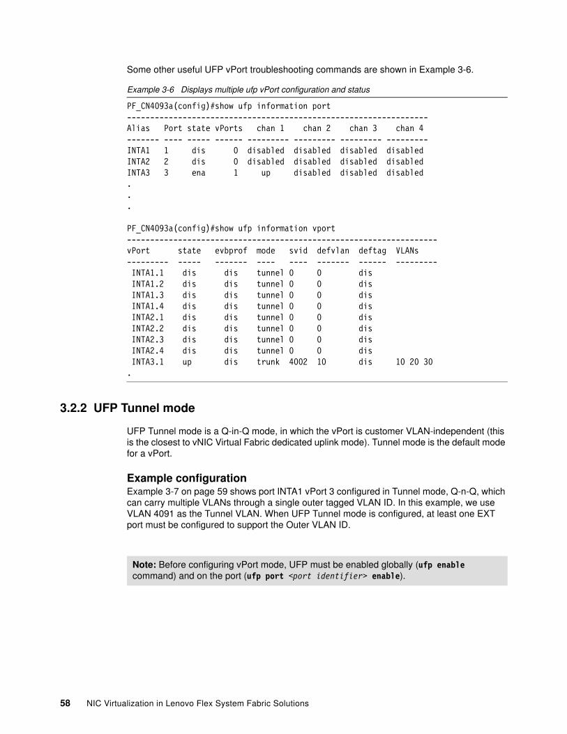
Some other useful UFP vPort troubleshooting commands are shown in Example 3-6.
Example 3-6 Displays multiple ufp vPort configuration and status
PF_CN4093a(config)#show ufp information port-----------------------------------------------------------------Alias Port state vPorts chan 1 chan 2 chan 3 chan 4------- ---- ----- ------ --------- --------- --------- ---------INTA1 1 dis 0 disabled disabled disabled disabledINTA2 2 dis 0 disabled disabled disabled disabledINTA3 3 ena 1 up disabled disabled disabled...
PF_CN4093a(config)#show ufp information vport-------------------------------------------------------------------vPort state evbprof mode svid defvlan deftag VLANs--------- ----- ------- ---- ---- ------- ------ --------- INTA1.1 dis dis tunnel 0 0 dis INTA1.2 dis dis tunnel 0 0 dis INTA1.3 dis dis tunnel 0 0 dis INTA1.4 dis dis tunnel 0 0 dis INTA2.1 dis dis tunnel 0 0 dis INTA2.2 dis dis tunnel 0 0 dis INTA2.3 dis dis tunnel 0 0 dis INTA2.4 dis dis tunnel 0 0 dis INTA3.1 up dis trunk 4002 10 dis 10 20 30.
3.2.2 UFP Tunnel mode
UFP Tunnel mode is a Q-in-Q mode, in which the vPort is customer VLAN-independent (this is the closest to vNIC Virtual Fabric dedicated uplink mode). Tunnel mode is the default mode for a vPort.
Example configurationExample 3-7 on page 59 shows port INTA1 vPort 3 configured in Tunnel mode, Q-n-Q, which can carry multiple VLANs through a single outer tagged VLAN ID. In this example, we use VLAN 4091 as the Tunnel VLAN. When UFP Tunnel mode is configured, at least one EXT port must be configured to support the Outer VLAN ID.
Note: Before configuring vPort mode, UFP must be enabled globally (ufp enable command) and on the port (ufp port <port identifier> enable).
58 NIC Virtualization in Lenovo Flex System Fabric Solutions
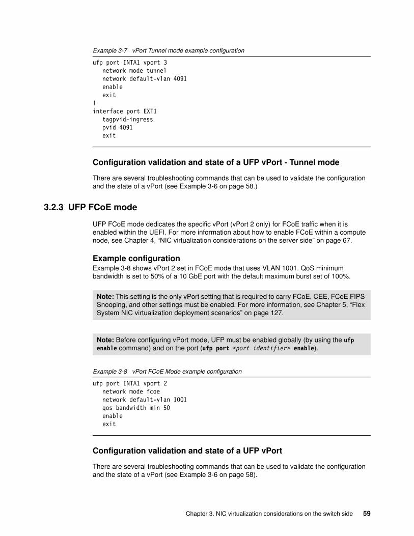
Example 3-7 vPort Tunnel mode example configuration
ufp port INTA1 vport 3network mode tunnelnetwork default-vlan 4091enableexit
!interface port EXT1
tagpvid-ingresspvid 4091exit
Configuration validation and state of a UFP vPort - Tunnel mode
There are several troubleshooting commands that can be used to validate the configuration and the state of a vPort (see Example 3-6 on page 58.)
3.2.3 UFP FCoE mode
UFP FCoE mode dedicates the specific vPort (vPort 2 only) for FCoE traffic when it is enabled within the UEFI. For more information about how to enable FCoE within a compute node, see Chapter 4, “NIC virtualization considerations on the server side” on page 67.
Example configurationExample 3-8 shows vPort 2 set in FCoE mode that uses VLAN 1001. QoS minimum bandwidth is set to 50% of a 10 GbE port with the default maximum burst set of 100%.
Example 3-8 vPort FCoE Mode example configuration
ufp port INTA1 vport 2network mode fcoenetwork default-vlan 1001qos bandwidth min 50enableexit
Configuration validation and state of a UFP vPort
There are several troubleshooting commands that can be used to validate the configuration and the state of a vPort (see Example 3-6 on page 58).
Note: This setting is the only vPort setting that is required to carry FCoE. CEE, FCoE FIPS Snooping, and other settings must be enabled. For more information, see Chapter 5, “Flex System NIC virtualization deployment scenarios” on page 127.
Note: Before configuring vPort mode, UFP must be enabled globally (by using the ufp enable command) and on the port (ufp port <port identifier> enable).
Chapter 3. NIC virtualization considerations on the switch side 59
3.2.4 UFP Auto mode
The UFP vPort Auto mode feature is based on VMready and IEEE 802.1Qbg implementations.
VMready and IEEE 802.1Qbg Edge Virtual Bridging are software solutions that support open standards virtualization. By using these solutions, administrators can create groups of virtual machine port groups to administer and migrate them from a central location.
VMready works with all major hypervisor software, including VMware, Microsoft Hyper-V, Linux kernel-based virtual machine (KVM), or Citrix XenServer. Although IBM PowerVM is supported by VMready, UFP is specific to x86-based compute nodes. It requires no proprietary tagging or changes to the hypervisor software.
UFP vPort Auto Mode works to dynamically create and remove VLANs that are learned from the vPort. When a VLAN is created and added to a vPort, that same VLAN ID is also added to the uplink that is associated with that vPort. However, this configuration can be intrusive to a network if having more than one uplink path out of a Switch (not a PortChannel) to a single destination that is running the same VLAN. Caution must be taken when you are implementing VMready.
For more information about implementing VMready, see Implementing a VM-Aware Network Using VMready, SG24-7985, which is available at this website:
http://lenovopress.com/sg247985
3.2.5 UFP vPort considerations
The following rules and attributes are associated with UFP vPorts:
� They are supported only on 10 Gb internal interfaces.
� UFP allows an NIC to be divided into up to four virtual NICs called vPorts per physical NIC (can be less than four, but no more than four).
� Each vPort can be set for a different mode or same mode (except for the FCoE mode, which is limited only to a single vPort on a UFP port, and specifically only vPort 2).
� UFP requires the proper support in the Compute Node for any port that is using UFP.
� By default, each vPort is ensured 2.5 Gb and can burst up to the full 10G if other vPorts do not need the bandwidth. The ensured minimum bandwidth and maximum bandwidth for each vPort are configurable.
� The minimum bandwidth settings of all configured vPorts on a physical NIC cannot exceed 10 Gb.
� Each vPort must have a default VLAN assigned. This default VLAN is used for different purposes in different modes.
� This default VLAN must be unique across the other three vPorts for this physical port, which means that vPort 1.1 must have a different default VLAN assigned than vPort 1.2, 1.3, or 1.4.
� When in trunk or access mode, this default VLAN is untagged by default; however, it can be configured for tagging, if wanted. This configuration is similar to tagging the native or PVID VLAN on a physical port. In tunnel mode, the default VLAN is the outer tag for the Q-in-Q tunnel through the switch and is not seen by the end hosts and upstream network.
60 NIC Virtualization in Lenovo Flex System Fabric Solutions
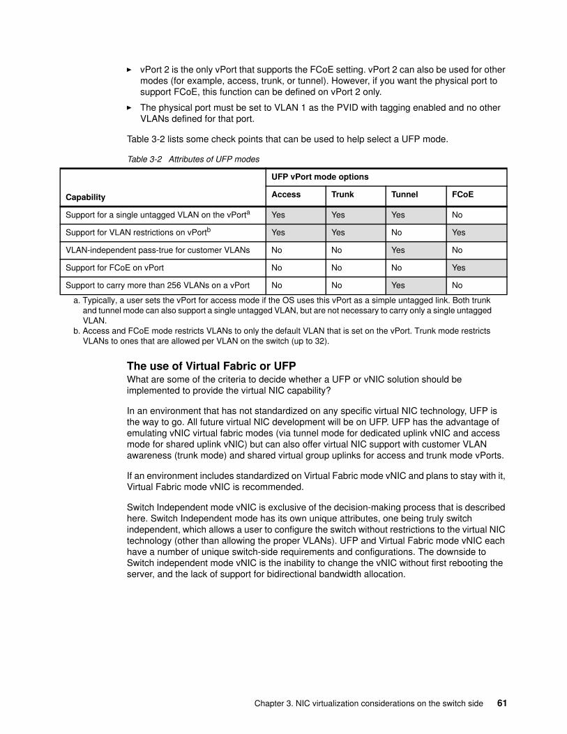
� vPort 2 is the only vPort that supports the FCoE setting. vPort 2 can also be used for other modes (for example, access, trunk, or tunnel). However, if you want the physical port to support FCoE, this function can be defined on vPort 2 only.
� The physical port must be set to VLAN 1 as the PVID with tagging enabled and no other VLANs defined for that port.
Table 3-2 lists some check points that can be used to help select a UFP mode.
Table 3-2 Attributes of UFP modes
The use of Virtual Fabric or UFPWhat are some of the criteria to decide whether a UFP or vNIC solution should be implemented to provide the virtual NIC capability?
In an environment that has not standardized on any specific virtual NIC technology, UFP is the way to go. All future virtual NIC development will be on UFP. UFP has the advantage of emulating vNIC virtual fabric modes (via tunnel mode for dedicated uplink vNIC and access mode for shared uplink vNIC) but can also offer virtual NIC support with customer VLAN awareness (trunk mode) and shared virtual group uplinks for access and trunk mode vPorts.
If an environment includes standardized on Virtual Fabric mode vNIC and plans to stay with it, Virtual Fabric mode vNIC is recommended.
Switch Independent mode vNIC is exclusive of the decision-making process that is described here. Switch Independent mode has its own unique attributes, one being truly switch independent, which allows a user to configure the switch without restrictions to the virtual NIC technology (other than allowing the proper VLANs). UFP and Virtual Fabric mode vNIC each have a number of unique switch-side requirements and configurations. The downside to Switch independent mode vNIC is the inability to change the vNIC without first rebooting the server, and the lack of support for bidirectional bandwidth allocation.
Capability
UFP vPort mode options
Access Trunk Tunnel FCoE
Support for a single untagged VLAN on the vPorta Yes Yes Yes No
Support for VLAN restrictions on vPortb Yes Yes No Yes
VLAN-independent pass-true for customer VLANs No No Yes No
Support for FCoE on vPort No No No Yes
Support to carry more than 256 VLANs on a vPort No No Yes No
a. Typically, a user sets the vPort for access mode if the OS uses this vPort as a simple untagged link. Both trunk and tunnel mode can also support a single untagged VLAN, but are not necessary to carry only a single untagged VLAN.
b. Access and FCoE mode restricts VLANs to only the default VLAN that is set on the vPort. Trunk mode restricts VLANs to ones that are allowed per VLAN on the switch (up to 32).
Chapter 3. NIC virtualization considerations on the switch side 61
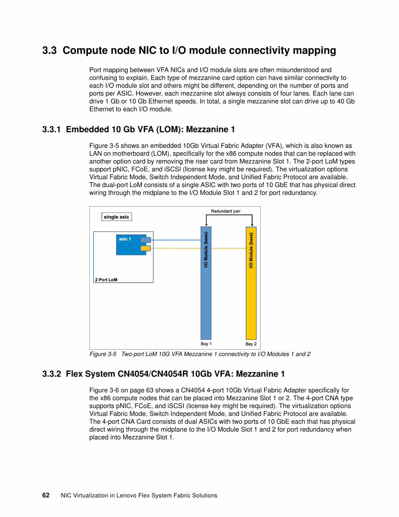
3.3 Compute node NIC to I/O module connectivity mapping
Port mapping between VFA NICs and I/O module slots are often misunderstood and confusing to explain. Each type of mezzanine card option can have similar connectivity to each I/O module slot and others might be different, depending on the number of ports and ports per ASIC. However, each mezzanine slot always consists of four lanes. Each lane can drive 1 Gb or 10 Gb Ethernet speeds. In total, a single mezzanine slot can drive up to 40 Gb Ethernet to each I/O module.
3.3.1 Embedded 10 Gb VFA (LOM): Mezzanine 1
Figure 3-5 shows an embedded 10Gb Virtual Fabric Adapter (VFA), which is also known as LAN on motherboard (LOM), specifically for the x86 compute nodes that can be replaced with another option card by removing the riser card from Mezzanine Slot 1. The 2-port LoM types support pNIC, FCoE, and iSCSI (license key might be required). The virtualization options Virtual Fabric Mode, Switch Independent Mode, and Unified Fabric Protocol are available. The dual-port LoM consists of a single ASIC with two ports of 10 GbE that has physical direct wiring through the midplane to the I/O Module Slot 1 and 2 for port redundancy.
Figure 3-5 Two-port LoM 10G VFA Mezzanine 1 connectivity to I/O Modules 1 and 2
3.3.2 Flex System CN4054/CN4054R 10Gb VFA: Mezzanine 1
Figure 3-6 on page 63 shows a CN4054 4-port 10Gb Virtual Fabric Adapter specifically for the x86 compute nodes that can be placed into Mezzanine Slot 1 or 2. The 4-port CNA type supports pNIC, FCoE, and iSCSI (license key might be required). The virtualization options Virtual Fabric Mode, Switch Independent Mode, and Unified Fabric Protocol are available. The 4-port CNA Card consists of dual ASICs with two ports of 10 GbE each that has physical direct wiring through the midplane to the I/O Module Slot 1 and 2 for port redundancy when placed into Mezzanine Slot 1.
62 NIC Virtualization in Lenovo Flex System Fabric Solutions
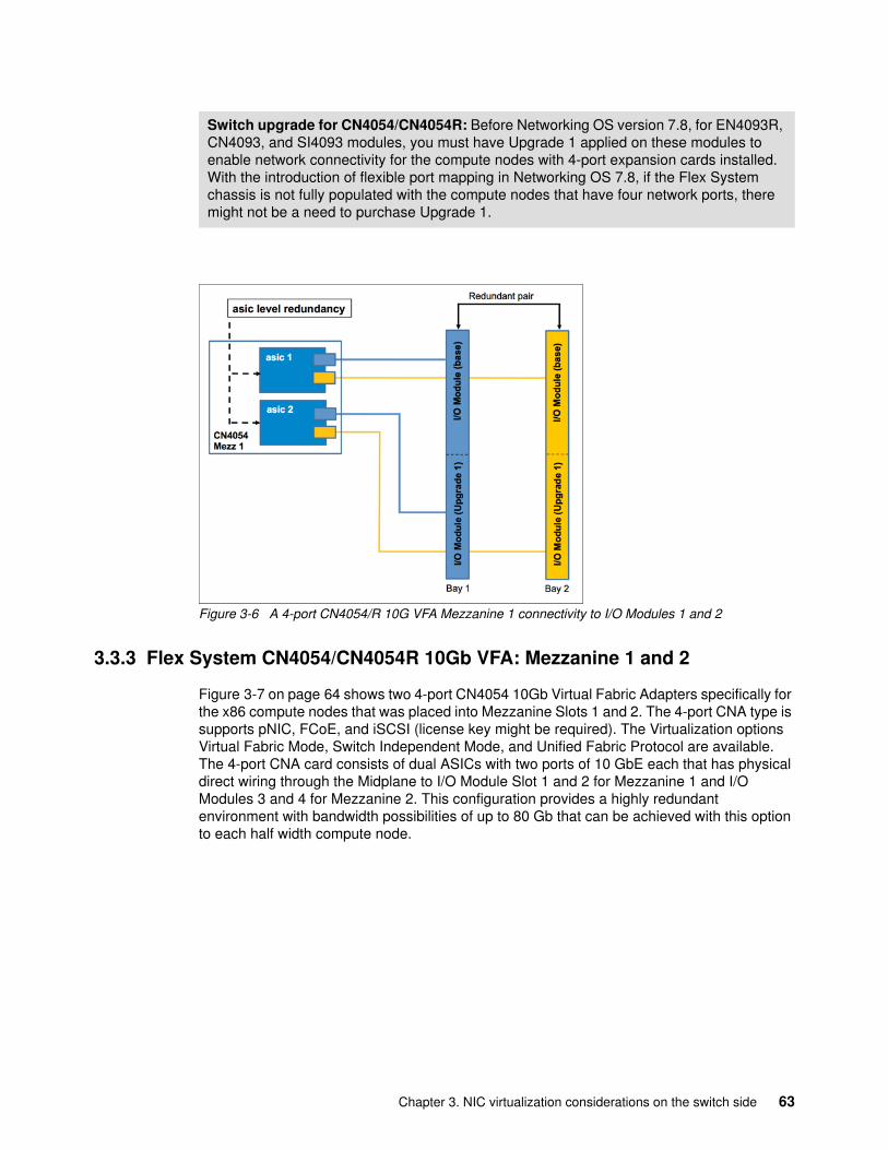
Figure 3-6 A 4-port CN4054/R 10G VFA Mezzanine 1 connectivity to I/O Modules 1 and 2
3.3.3 Flex System CN4054/CN4054R 10Gb VFA: Mezzanine 1 and 2
Figure 3-7 on page 64 shows two 4-port CN4054 10Gb Virtual Fabric Adapters specifically for the x86 compute nodes that was placed into Mezzanine Slots 1 and 2. The 4-port CNA type is supports pNIC, FCoE, and iSCSI (license key might be required). The Virtualization options Virtual Fabric Mode, Switch Independent Mode, and Unified Fabric Protocol are available. The 4-port CNA card consists of dual ASICs with two ports of 10 GbE each that has physical direct wiring through the Midplane to I/O Module Slot 1 and 2 for Mezzanine 1 and I/O Modules 3 and 4 for Mezzanine 2. This configuration provides a highly redundant environment with bandwidth possibilities of up to 80 Gb that can be achieved with this option to each half width compute node.
Switch upgrade for CN4054/CN4054R: Before Networking OS version 7.8, for EN4093R, CN4093, and SI4093 modules, you must have Upgrade 1 applied on these modules to enable network connectivity for the compute nodes with 4-port expansion cards installed. With the introduction of flexible port mapping in Networking OS 7.8, if the Flex System chassis is not fully populated with the compute nodes that have four network ports, there might not be a need to purchase Upgrade 1.
Chapter 3. NIC virtualization considerations on the switch side 63
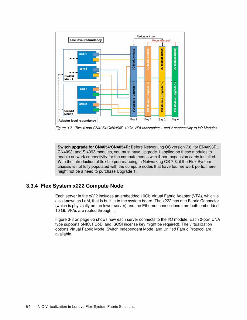
Figure 3-7 Two 4-port CN4054/CN4054R 10Gb VFA Mezzanine 1 and 2 connectivity to I/O Modules
3.3.4 Flex System x222 Compute Node
Each server in the x222 includes an embedded 10Gb Virtual Fabric Adapter (VFA), which is also known as LoM, that is built in to the system board. The x222 has one Fabric Connector (which is physically on the lower server) and the Ethernet connections from both embedded 10 Gb VFAs are routed through it.
Figure 3-8 on page 65 shows how each server connects to the I/O module. Each 2-port CNA type supports pNIC, FCoE, and iSCSI (license key might be required). The virtualization options Virtual Fabric Mode, Switch Independent Mode, and Unified Fabric Protocol are available.
Switch upgrade for CN4054/CN4054R: Before Networking OS version 7.8, for EN4093R, CN4093, and SI4093 modules, you must have Upgrade 1 applied on these modules to enable network connectivity for the compute nodes with 4-port expansion cards installed. With the introduction of flexible port mapping in Networking OS 7.8, if the Flex System chassis is not fully populated with the compute nodes that have four network ports, there might not be a need to purchase Upgrade 1.
64 NIC Virtualization in Lenovo Flex System Fabric Solutions
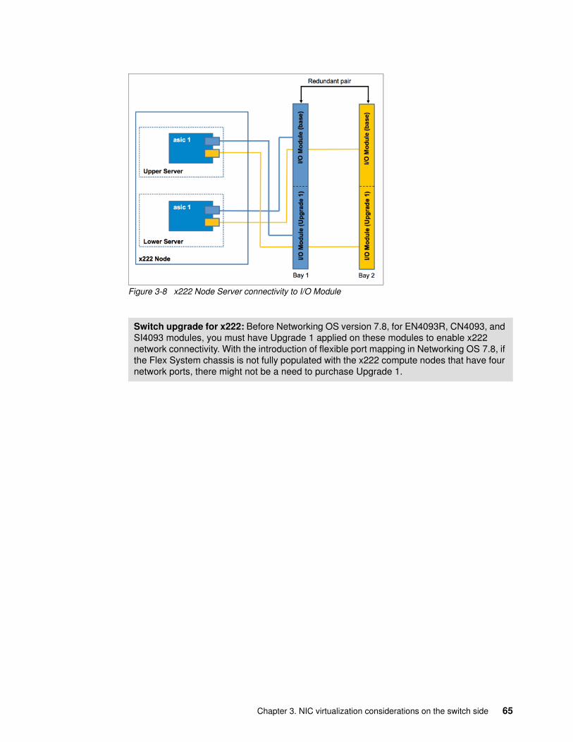
Figure 3-8 x222 Node Server connectivity to I/O Module
Switch upgrade for x222: Before Networking OS version 7.8, for EN4093R, CN4093, and SI4093 modules, you must have Upgrade 1 applied on these modules to enable x222 network connectivity. With the introduction of flexible port mapping in Networking OS 7.8, if the Flex System chassis is not fully populated with the x222 compute nodes that have four network ports, there might not be a need to purchase Upgrade 1.
Chapter 3. NIC virtualization considerations on the switch side 65

66 NIC Virtualization in Lenovo Flex System Fabric Solutions
Chapter 4. NIC virtualization considerations on the server side
In 2.3, “Flex System Virtual Fabric adapters” on page 43, we introduced the physical Emulex NICs that support virtual NIC functionality in the PureFlex System environment. In Chapter 3, “NIC virtualization considerations on the switch side” on page 47, we described the I/O module virtualization features.
In this chapter, we describe how to enable the NIC virtualization from the server side, and some design considerations for using these NICs within various operating systems.
This chapter includes the following topics:
� Enabling virtual NICs on the server via UEFI� Enabling virtual NICs via Configuration Patterns� Using physical and virtual NICs in the operating systems
4
© Copyright Lenovo 2016. All rights reserved. 67
4.1 Enabling virtual NICs on the server via UEFI
Regardless of what mode of virtual NIC is wanted, all modes have at least some small element of low-level configuration that must be performed on the server side. Some Emulex NICs might include pre-configured for vNIC Virtual Fabric mode enabled. However, even those NICs can be changed to a different mode, or have vNIC disabled, if wanted.
Exactly how to enable or change the virtual NIC function on the Emulex NICs varied in the past; however, usually, the change can always be done via the UEFI configuration from the F1 setup on the server.
It is also possible to control and automate setting virtual NIC options via certain tools, such as the use of Configuration Patterns in the Flex System Manager (FSM), (which is described in this section. However, we focus primarily on the use of the F1 setup method for configuring the virtual NIC on the server side.
4.1.1 Getting in to the virtual NIC configuration section of UEFI
When you are manually performing the virtual NIC configuration on the server, you must enter UEFI via the F1 setup option during server boot. After you are in the F1 setup, you must drill into the section that permits enabling and changing the wanted virtual NIC mode, perform any changes, and then save those changes.
Important: The steps to enter UEFI that are described in this section assume that the reader knows how to get to the console of a compute node. For reference, this process is commonly done by connecting via a web browser to the IMM IP address of that host, clicking Remote Control, and the clicking the option to start remote control in single-user or multi-user mode.
68 NIC Virtualization in Lenovo Flex System Fabric Solutions
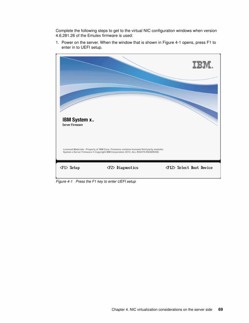
Complete the following steps to get to the virtual NIC configuration windows when version 4.6.281.26 of the Emulex firmware is used:
1. Power on the server. When the window that is shown in Figure 4-1 opens, press F1 to enter in to UEFI setup.
Figure 4-1 Press the F1 key to enter UEFI setup
Chapter 4. NIC virtualization considerations on the server side 69
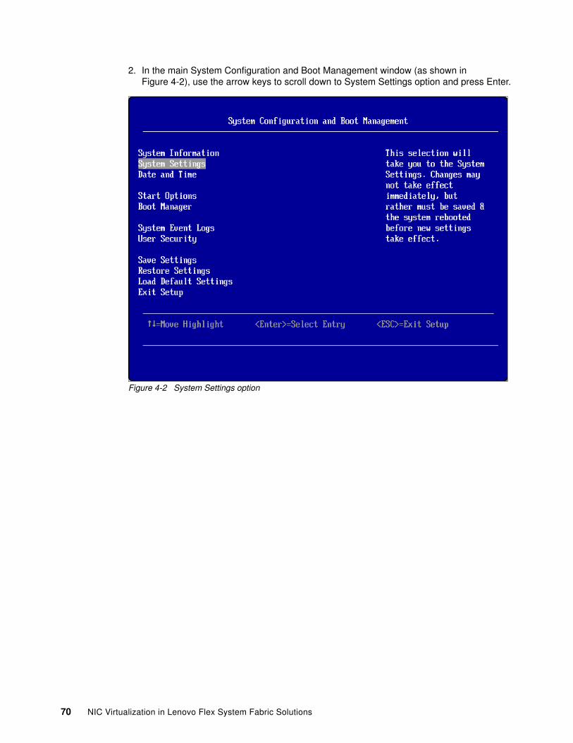
2. In the main System Configuration and Boot Management window (as shown in Figure 4-2), use the arrow keys to scroll down to System Settings option and press Enter.
Figure 4-2 System Settings option
70 NIC Virtualization in Lenovo Flex System Fabric Solutions
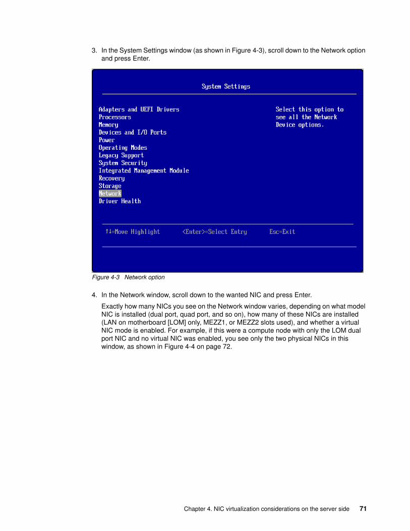
3. In the System Settings window (as shown in Figure 4-3), scroll down to the Network option and press Enter.
Figure 4-3 Network option
4. In the Network window, scroll down to the wanted NIC and press Enter.
Exactly how many NICs you see on the Network window varies, depending on what model NIC is installed (dual port, quad port, and so on), how many of these NICs are installed (LAN on motherboard [LOM] only, MEZZ1, or MEZZ2 slots used), and whether a virtual NIC mode is enabled. For example, if this were a compute node with only the LOM dual port NIC and no virtual NIC was enabled, you see only the two physical NICs in this window, as shown in Figure 4-4 on page 72.
Chapter 4. NIC virtualization considerations on the server side 71
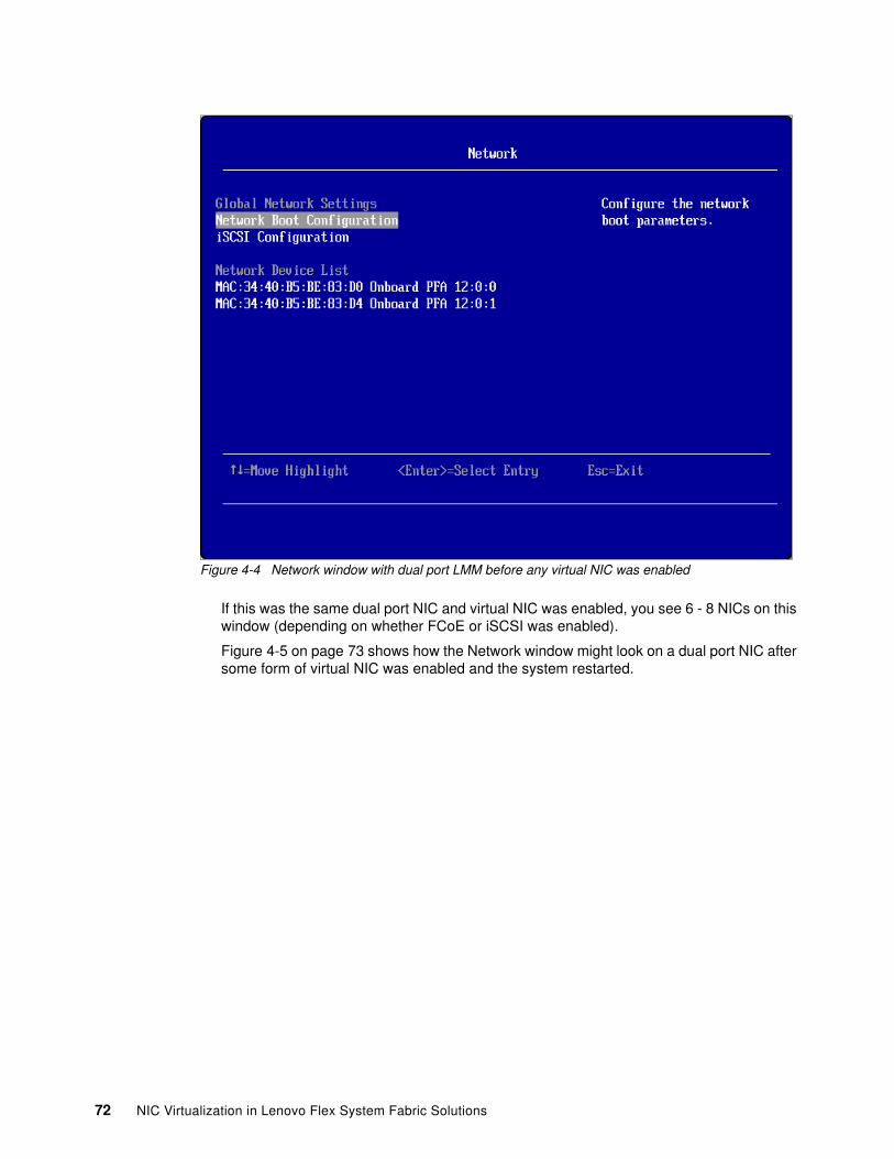
Figure 4-4 Network window with dual port LMM before any virtual NIC was enabled
If this was the same dual port NIC and virtual NIC was enabled, you see 6 - 8 NICs on this window (depending on whether FCoE or iSCSI was enabled).
Figure 4-5 on page 73 shows how the Network window might look on a dual port NIC after some form of virtual NIC was enabled and the system restarted.
72 NIC Virtualization in Lenovo Flex System Fabric Solutions
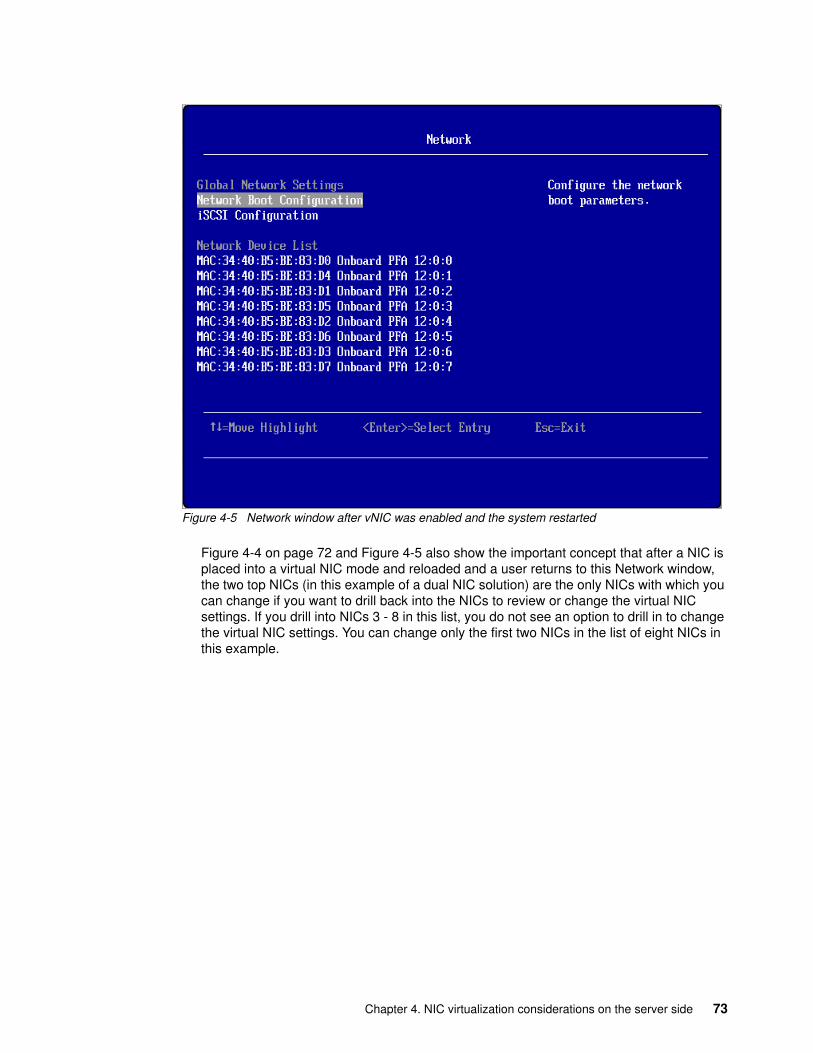
Figure 4-5 Network window after vNIC was enabled and the system restarted
Figure 4-4 on page 72 and Figure 4-5 also show the important concept that after a NIC is placed into a virtual NIC mode and reloaded and a user returns to this Network window, the two top NICs (in this example of a dual NIC solution) are the only NICs with which you can change if you want to drill back into the NICs to review or change the virtual NIC settings. If you drill into NICs 3 - 8 in this list, you do not see an option to drill in to change the virtual NIC settings. You can change only the first two NICs in the list of eight NICs in this example.
Chapter 4. NIC virtualization considerations on the server side 73
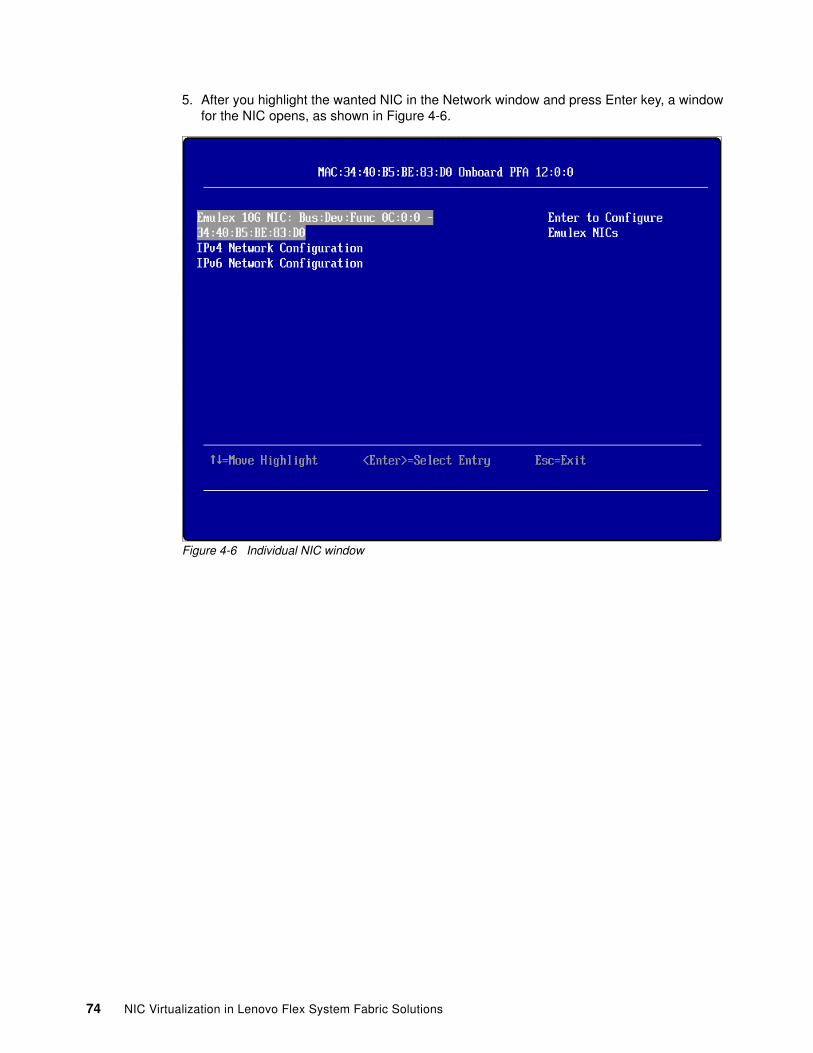
5. After you highlight the wanted NIC in the Network window and press Enter key, a window for the NIC opens, as shown in Figure 4-6.
Figure 4-6 Individual NIC window
74 NIC Virtualization in Lenovo Flex System Fabric Solutions
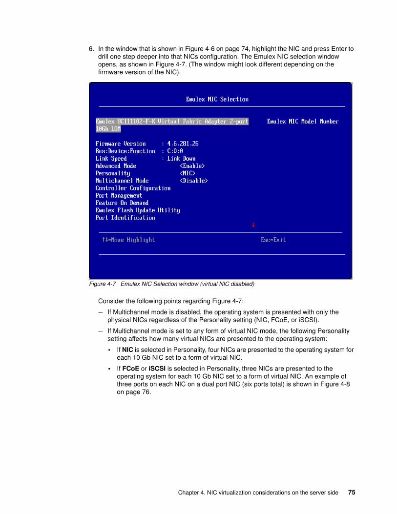
6. In the window that is shown in Figure 4-6 on page 74, highlight the NIC and press Enter to drill one step deeper into that NICs configuration. The Emulex NIC selection window opens, as shown in Figure 4-7. (The window might look different depending on the firmware version of the NIC).
Figure 4-7 Emulex NIC Selection window (virtual NIC disabled)
Consider the following points regarding Figure 4-7:
– If Multichannel mode is disabled, the operating system is presented with only the physical NICs regardless of the Personality setting (NIC, FCoE, or iSCSI).
– If Multichannel mode is set to any form of virtual NIC mode, the following Personality setting affects how many virtual NICs are presented to the operating system:
• If NIC is selected in Personality, four NICs are presented to the operating system for each 10 Gb NIC set to a form of virtual NIC.
• If FCoE or iSCSI is selected in Personality, three NICs are presented to the operating system for each 10 Gb NIC set to a form of virtual NIC. An example of three ports on each NIC on a dual port NIC (six ports total) is shown in Figure 4-8 on page 76.
Chapter 4. NIC virtualization considerations on the server side 75
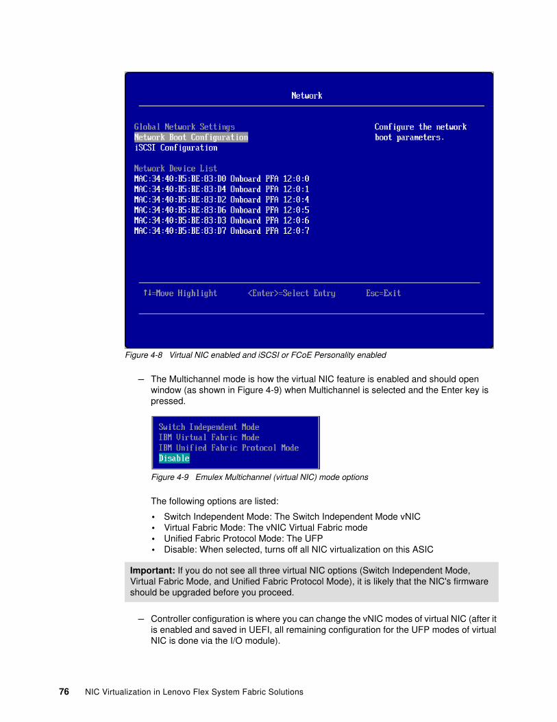
Figure 4-8 Virtual NIC enabled and iSCSI or FCoE Personality enabled
– The Multichannel mode is how the virtual NIC feature is enabled and should open window (as shown in Figure 4-9) when Multichannel is selected and the Enter key is pressed.
Figure 4-9 Emulex Multichannel (virtual NIC) mode options
The following options are listed:
• Switch Independent Mode: The Switch Independent Mode vNIC• Virtual Fabric Mode: The vNIC Virtual Fabric mode• Unified Fabric Protocol Mode: The UFP• Disable: When selected, turns off all NIC virtualization on this ASIC
– Controller configuration is where you can change the vNIC modes of virtual NIC (after it is enabled and saved in UEFI, all remaining configuration for the UFP modes of virtual NIC is done via the I/O module).
Important: If you do not see all three virtual NIC options (Switch Independent Mode, Virtual Fabric Mode, and Unified Fabric Protocol Mode), it is likely that the NIC's firmware should be upgraded before you proceed.
76 NIC Virtualization in Lenovo Flex System Fabric Solutions
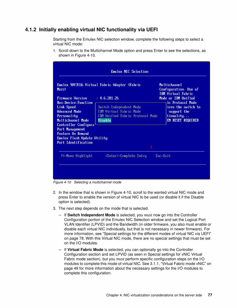
4.1.2 Initially enabling virtual NIC functionality via UEFI
Starting from the Emulex NIC selection window, complete the following steps to select a virtual NIC mode:
1. Scroll down to the Multichannel Mode option and press Enter to see the selections, as shown in Figure 4-10.
Figure 4-10 Selecting a multichannel mode
2. In the window that is shown in Figure 4-10, scroll to the wanted virtual NIC mode and press Enter to enable the version of virtual NIC to be used (or disable it if the Disable option is selected).
3. The next step depends on the mode that is selected.
– If Switch Independent Mode is selected, you must now go into the Controller Configuration portion of the Emulex NIC Selection window and set the Logical Port VLAN Identifier (LPVID) and the Bandwidth (in older firmware, you also must enable or disable each virtual NIC individually, but that is not necessary in newer firmware). For more information, see “Special settings for the different modes of virtual NIC via UEFI” on page 78. With this Virtual NIC mode, there are no special settings that must be set on the I/O modules.
– If Virtual Fabric Mode is selected, you can optionally go into the Controller Configuration section and set LPVID (as seen in Special settings for vNIC Virtual Fabric mode section), but you must perform specific configuration steps on the I/O modules to complete this mode of virtual NIC. See 3.1.1, “Virtual Fabric mode vNIC” on page 49 for more information about the necessary settings for the I/O modules to complete this configuration.
Chapter 4. NIC virtualization considerations on the server side 77
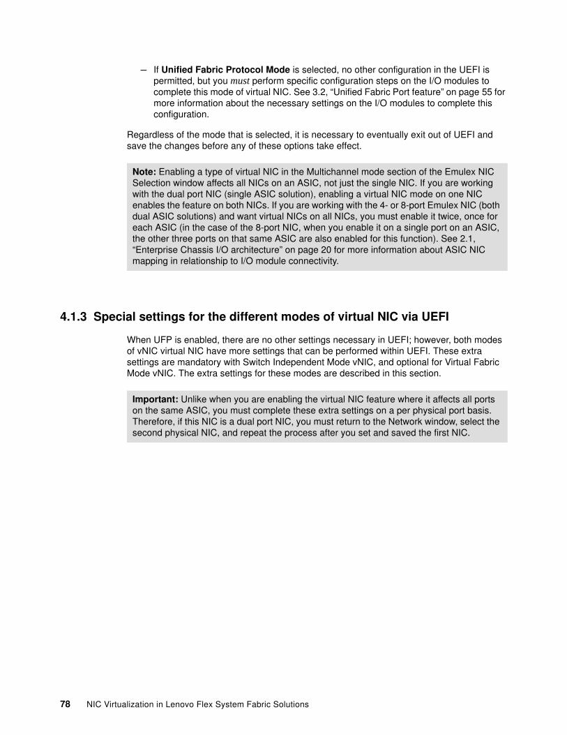
– If Unified Fabric Protocol Mode is selected, no other configuration in the UEFI is permitted, but you must perform specific configuration steps on the I/O modules to complete this mode of virtual NIC. See 3.2, “Unified Fabric Port feature” on page 55 for more information about the necessary settings on the I/O modules to complete this configuration.
Regardless of the mode that is selected, it is necessary to eventually exit out of UEFI and save the changes before any of these options take effect.
4.1.3 Special settings for the different modes of virtual NIC via UEFI
When UFP is enabled, there are no other settings necessary in UEFI; however, both modes of vNIC virtual NIC have more settings that can be performed within UEFI. These extra settings are mandatory with Switch Independent Mode vNIC, and optional for Virtual Fabric Mode vNIC. The extra settings for these modes are described in this section.
Note: Enabling a type of virtual NIC in the Multichannel mode section of the Emulex NIC Selection window affects all NICs on an ASIC, not just the single NIC. If you are working with the dual port NIC (single ASIC solution), enabling a virtual NIC mode on one NIC enables the feature on both NICs. If you are working with the 4- or 8-port Emulex NIC (both dual ASIC solutions) and want virtual NICs on all NICs, you must enable it twice, once for each ASIC (in the case of the 8-port NIC, when you enable it on a single port on an ASIC, the other three ports on that same ASIC are also enabled for this function). See 2.1, “Enterprise Chassis I/O architecture” on page 20 for more information about ASIC NIC mapping in relationship to I/O module connectivity.
Important: Unlike when you are enabling the virtual NIC feature where it affects all ports on the same ASIC, you must complete these extra settings on a per physical port basis. Therefore, if this NIC is a dual port NIC, you must return to the Network window, select the second physical NIC, and repeat the process after you set and saved the first NIC.
78 NIC Virtualization in Lenovo Flex System Fabric Solutions
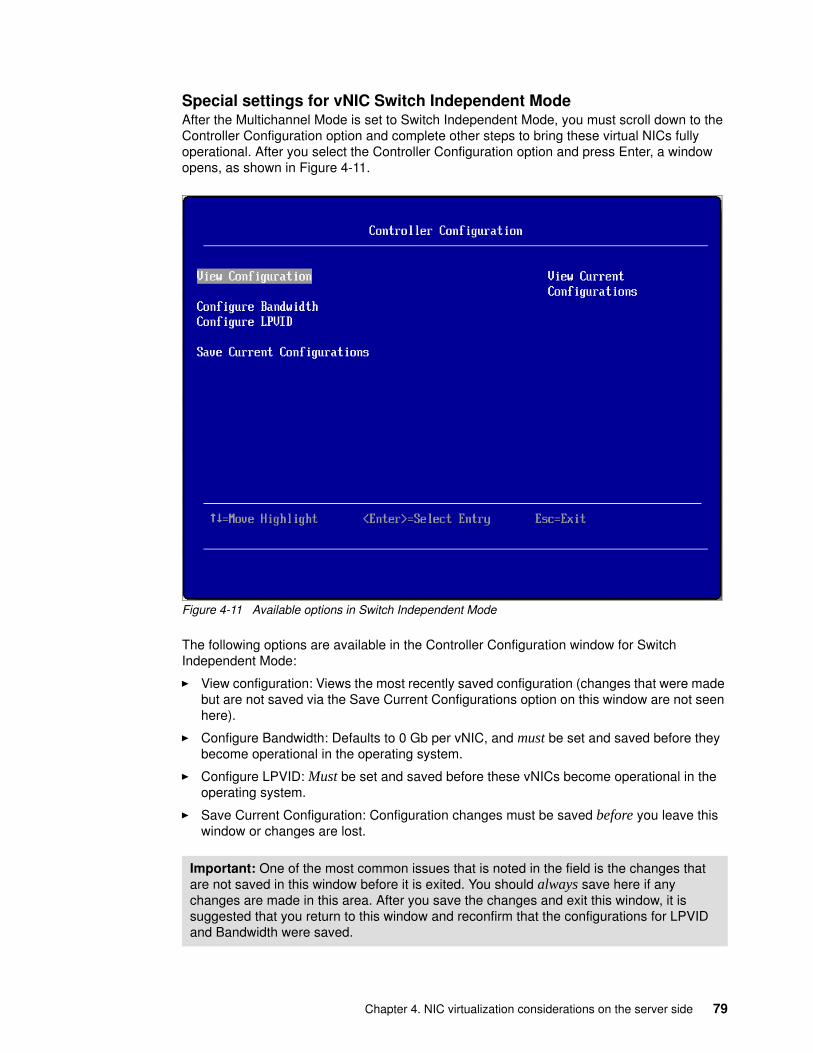
Special settings for vNIC Switch Independent ModeAfter the Multichannel Mode is set to Switch Independent Mode, you must scroll down to the Controller Configuration option and complete other steps to bring these virtual NICs fully operational. After you select the Controller Configuration option and press Enter, a window opens, as shown in Figure 4-11.
Figure 4-11 Available options in Switch Independent Mode
The following options are available in the Controller Configuration window for Switch Independent Mode:
� View configuration: Views the most recently saved configuration (changes that were made but are not saved via the Save Current Configurations option on this window are not seen here).
� Configure Bandwidth: Defaults to 0 Gb per vNIC, and must be set and saved before they become operational in the operating system.
� Configure LPVID: Must be set and saved before these vNICs become operational in the operating system.
� Save Current Configuration: Configuration changes must be saved before you leave this window or changes are lost.
Important: One of the most common issues that is noted in the field is the changes that are not saved in this window before it is exited. You should always save here if any changes are made in this area. After you save the changes and exit this window, it is suggested that you return to this window and reconfirm that the configurations for LPVID and Bandwidth were saved.
Chapter 4. NIC virtualization considerations on the server side 79
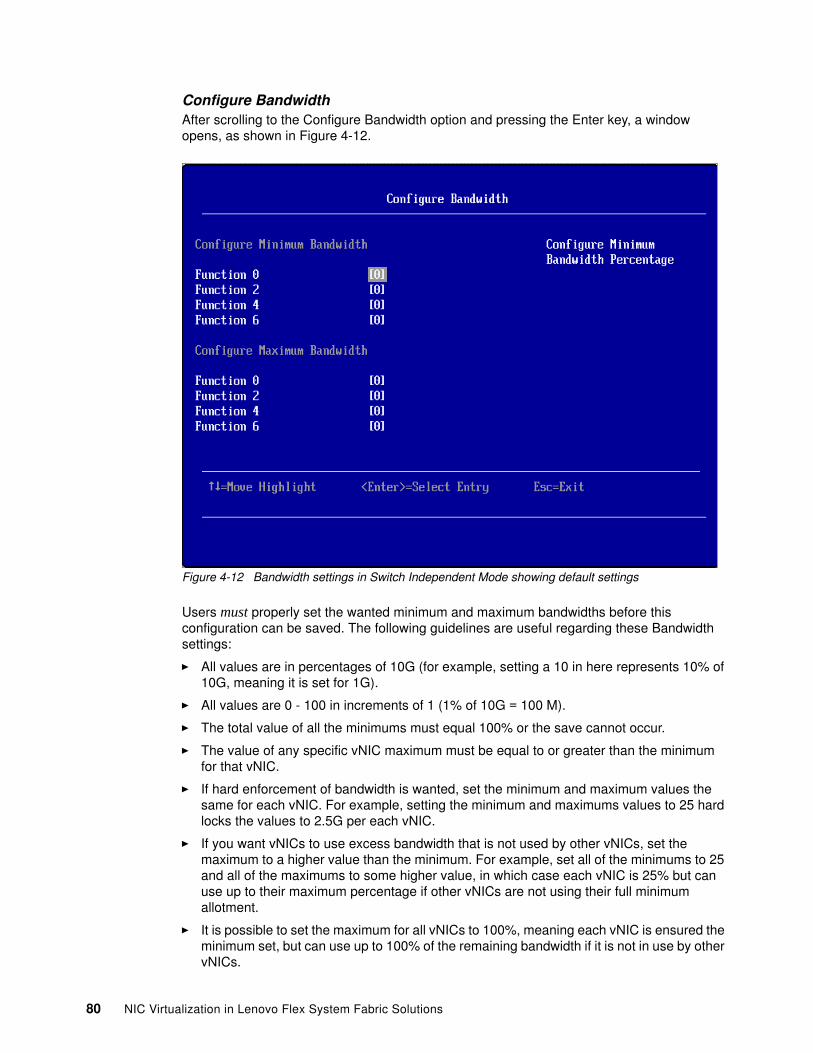
Configure BandwidthAfter scrolling to the Configure Bandwidth option and pressing the Enter key, a window opens, as shown in Figure 4-12.
Figure 4-12 Bandwidth settings in Switch Independent Mode showing default settings
Users must properly set the wanted minimum and maximum bandwidths before this configuration can be saved. The following guidelines are useful regarding these Bandwidth settings:
� All values are in percentages of 10G (for example, setting a 10 in here represents 10% of 10G, meaning it is set for 1G).
� All values are 0 - 100 in increments of 1 (1% of 10G = 100 M).
� The total value of all the minimums must equal 100% or the save cannot occur.
� The value of any specific vNIC maximum must be equal to or greater than the minimum for that vNIC.
� If hard enforcement of bandwidth is wanted, set the minimum and maximum values the same for each vNIC. For example, setting the minimum and maximums values to 25 hard locks the values to 2.5G per each vNIC.
� If you want vNICs to use excess bandwidth that is not used by other vNICs, set the maximum to a higher value than the minimum. For example, set all of the minimums to 25 and all of the maximums to some higher value, in which case each vNIC is 25% but can use up to their maximum percentage if other vNICs are not using their full minimum allotment.
� It is possible to set the maximum for all vNICs to 100%, meaning each vNIC is ensured the minimum set, but can use up to 100% of the remaining bandwidth if it is not in use by other vNICs.
80 NIC Virtualization in Lenovo Flex System Fabric Solutions
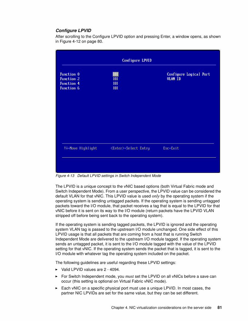
Configure LPVIDAfter scrolling to the Configure LPVID option and pressing Enter, a window opens, as shown in Figure 4-12 on page 80.
Figure 4-13 Default LPVID settings in Switch Independent Mode
The LPVID is a unique concept to the vNIC based options (both Virtual Fabric mode and Switch Independent Mode). From a user perspective, the LPVID value can be considered the default VLAN for that vNIC. This LPVID value is used only by the operating system if the operating system is sending untagged packets. If the operating system is sending untagged packets toward the I/O module, that packet receives a tag that is equal to the LPVID for that vNIC before it is sent on its way to the I/O module (return packets have the LPVID VLAN stripped off before being sent back to the operating system).
If the operating system is sending tagged packets, the LPVID is ignored and the operating system VLAN tag is passed to the upstream I/O module unchanged. One side effect of this LPVID usage is that all packets that are coming from a host that is running Switch Independent Mode are delivered to the upstream I/O module tagged. If the operating system sends an untagged packet, it is sent to the I/O module tagged with the value of the LPVID setting for that vNIC. If the operating system sends the packet that is tagged, it is sent to the I/O module with whatever tag the operating system included on the packet.
The following guidelines are useful regarding these LPVID settings:
� Valid LPVID values are 2 - 4094.
� For Switch Independent mode, you must set the LPVID on all vNICs before a save can occur (this setting is optional on Virtual Fabric vNIC mode).
� Each vNIC on a specific physical port must use a unique LPVID. In most cases, the partner NIC LPVIDs are set for the same value, but they can be set different.
Chapter 4. NIC virtualization considerations on the server side 81
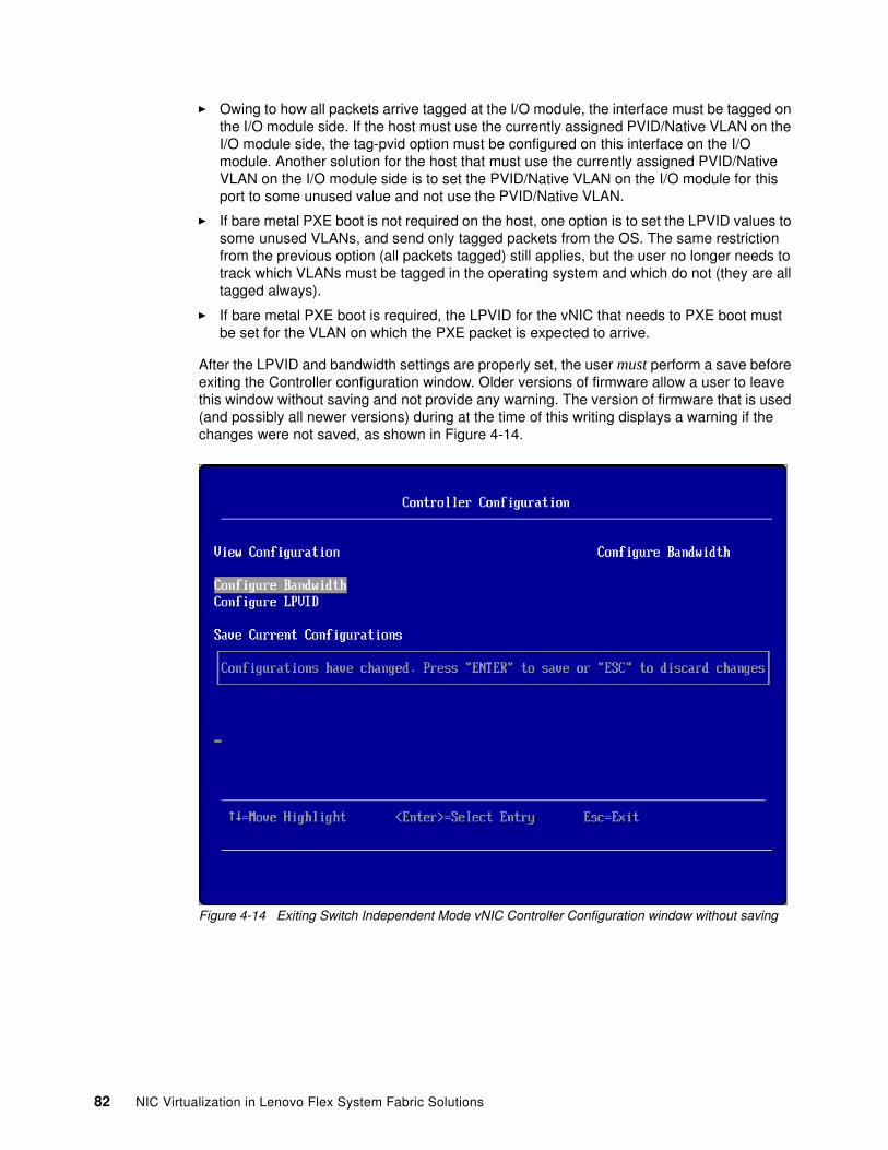
� Owing to how all packets arrive tagged at the I/O module, the interface must be tagged on the I/O module side. If the host must use the currently assigned PVID/Native VLAN on the I/O module side, the tag-pvid option must be configured on this interface on the I/O module. Another solution for the host that must use the currently assigned PVID/Native VLAN on the I/O module side is to set the PVID/Native VLAN on the I/O module for this port to some unused value and not use the PVID/Native VLAN.
� If bare metal PXE boot is not required on the host, one option is to set the LPVID values to some unused VLANs, and send only tagged packets from the OS. The same restriction from the previous option (all packets tagged) still applies, but the user no longer needs to track which VLANs must be tagged in the operating system and which do not (they are all tagged always).
� If bare metal PXE boot is required, the LPVID for the vNIC that needs to PXE boot must be set for the VLAN on which the PXE packet is expected to arrive.
After the LPVID and bandwidth settings are properly set, the user must perform a save before exiting the Controller configuration window. Older versions of firmware allow a user to leave this window without saving and not provide any warning. The version of firmware that is used (and possibly all newer versions) during at the time of this writing displays a warning if the changes were not saved, as shown in Figure 4-14.
Figure 4-14 Exiting Switch Independent Mode vNIC Controller Configuration window without saving
82 NIC Virtualization in Lenovo Flex System Fabric Solutions
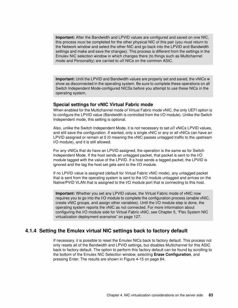
Special settings for vNIC Virtual Fabric modeWhen enabled for the Multichannel mode of Virtual Fabric mode vNIC, the only UEFI option is to configure the LPVID value (Bandwidth is controlled from the I/O module). Unlike the Switch Independent mode, this setting is optional.
Also, unlike the Switch Independent Mode, it is not necessary to set all vNICs LPVID values, and still save the configuration. If wanted, only a single vNIC or any or all vNICs can have an LPVID assigned or remain at 0 (0 meaning the vNIC passes untagged traffic to the upstream I/O module), and it is still allowed.
For any vNICs that do have an LPVID assigned, the operation is the same as for Switch Independent Mode. If the host sends an untagged packet, that packet is sent to the I/O module tagged with the value of the LPVID. If a host sends a tagged packet, the LPVID is ignored and the tag the host set gets sent to the I/O module.
If no LPVID value is assigned (default for Virtual Fabric vNIC mode), any untagged packet that is sent from the operating system is sent to the I/O module untagged and arrives on the Native/PVID VLAN that is assigned to the I/O module port that is connecting to this host.
4.1.4 Setting the Emulex virtual NIC settings back to factory default
If necessary, it is possible to reset the Emulex NICs back to factory default. This process not only resets all of the Bandwidth and LPVID settings, but disables Multichannel for this ASIC back to factory default. The option to perform this factory default can be found by scrolling to the bottom of the Emulex NIC Selection window, selecting Erase Configuration, and pressing Enter. The results are shown in Figure 4-15 on page 84.
Important: After the Bandwidth and LPVID values are configured and saved on one NIC, this process must be completed for the other physical NIC of this pair (you must return to the Network window and select the other NIC and go back into the LPVID and Bandwidth settings and make and save the changes). This process is different from the settings in the Emulex NIC selection window in which changes there (to things such as Multichannel mode and Personality) are carried to all NICs on the common ASIC.
Important: Until the LPVID and Bandwidth values are properly set and saved, the vNICs w show as disconnected in the operating system. Be sure to complete these operations on all Switch Independent Mode-configured NICSs before you attempt to use these NICs in the operating system.
Important: Whether you set any LPVID values, the Virtual Fabric mode of vNIC now requires you to go into the I/O module to complete the configuration process (enable vNIC, create vNIC groups, and assign other variables). Until the I/O module step is done, the operating system reports the vNIC as not connected. For more information about configuring the I/O module side for Virtual Fabric vNIC, see Chapter 5, “Flex System NIC virtualization deployment scenarios” on page 127.
Chapter 4. NIC virtualization considerations on the server side 83
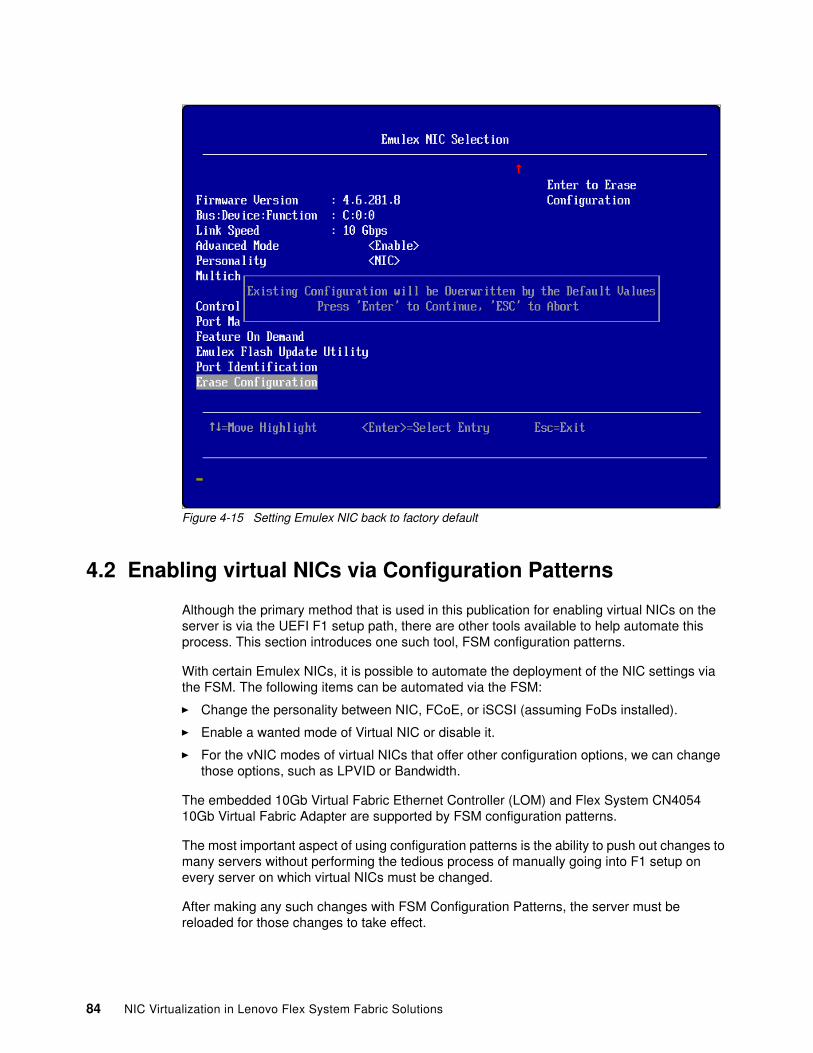
Figure 4-15 Setting Emulex NIC back to factory default
4.2 Enabling virtual NICs via Configuration Patterns
Although the primary method that is used in this publication for enabling virtual NICs on the server is via the UEFI F1 setup path, there are other tools available to help automate this process. This section introduces one such tool, FSM configuration patterns.
With certain Emulex NICs, it is possible to automate the deployment of the NIC settings via the FSM. The following items can be automated via the FSM:
� Change the personality between NIC, FCoE, or iSCSI (assuming FoDs installed).
� Enable a wanted mode of Virtual NIC or disable it.
� For the vNIC modes of virtual NICs that offer other configuration options, we can change those options, such as LPVID or Bandwidth.
The embedded 10Gb Virtual Fabric Ethernet Controller (LOM) and Flex System CN4054 10Gb Virtual Fabric Adapter are supported by FSM configuration patterns.
The most important aspect of using configuration patterns is the ability to push out changes to many servers without performing the tedious process of manually going into F1 setup on every server on which virtual NICs must be changed.
After making any such changes with FSM Configuration Patterns, the server must be reloaded for those changes to take effect.
84 NIC Virtualization in Lenovo Flex System Fabric Solutions
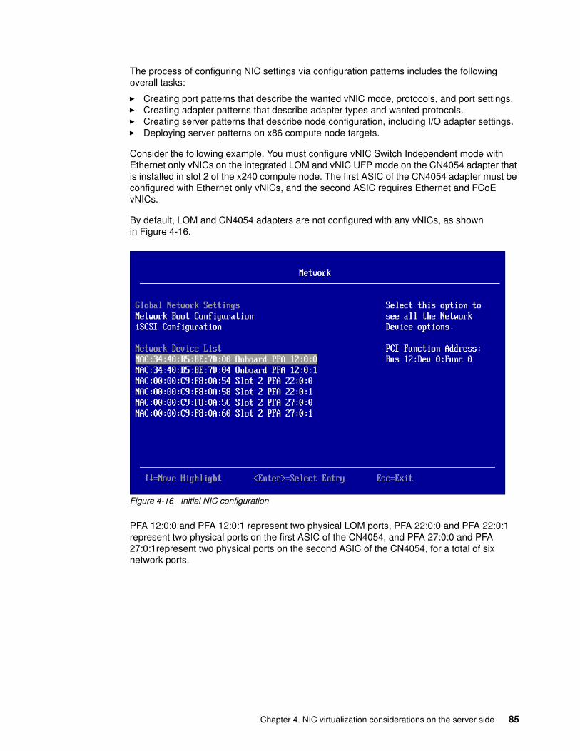
The process of configuring NIC settings via configuration patterns includes the following overall tasks:
� Creating port patterns that describe the wanted vNIC mode, protocols, and port settings.� Creating adapter patterns that describe adapter types and wanted protocols.� Creating server patterns that describe node configuration, including I/O adapter settings.� Deploying server patterns on x86 compute node targets.
Consider the following example. You must configure vNIC Switch Independent mode with Ethernet only vNICs on the integrated LOM and vNIC UFP mode on the CN4054 adapter that is installed in slot 2 of the x240 compute node. The first ASIC of the CN4054 adapter must be configured with Ethernet only vNICs, and the second ASIC requires Ethernet and FCoE vNICs.
By default, LOM and CN4054 adapters are not configured with any vNICs, as shown in Figure 4-16.
Figure 4-16 Initial NIC configuration
PFA 12:0:0 and PFA 12:0:1 represent two physical LOM ports, PFA 22:0:0 and PFA 22:0:1 represent two physical ports on the first ASIC of the CN4054, and PFA 27:0:0 and PFA 27:0:1represent two physical ports on the second ASIC of the CN4054, for a total of six network ports.
Chapter 4. NIC virtualization considerations on the server side 85
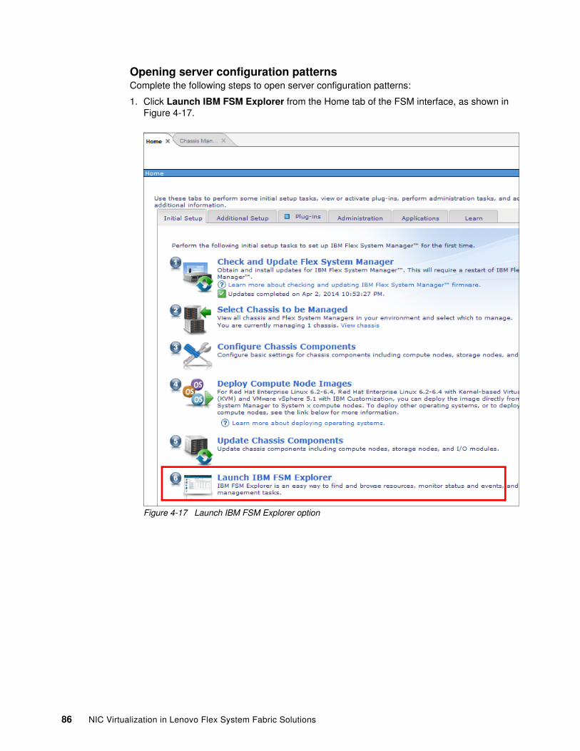
Opening server configuration patternsComplete the following steps to open server configuration patterns:
1. Click Launch IBM FSM Explorer from the Home tab of the FSM interface, as shown in Figure 4-17.
Figure 4-17 Launch IBM FSM Explorer option
86 NIC Virtualization in Lenovo Flex System Fabric Solutions
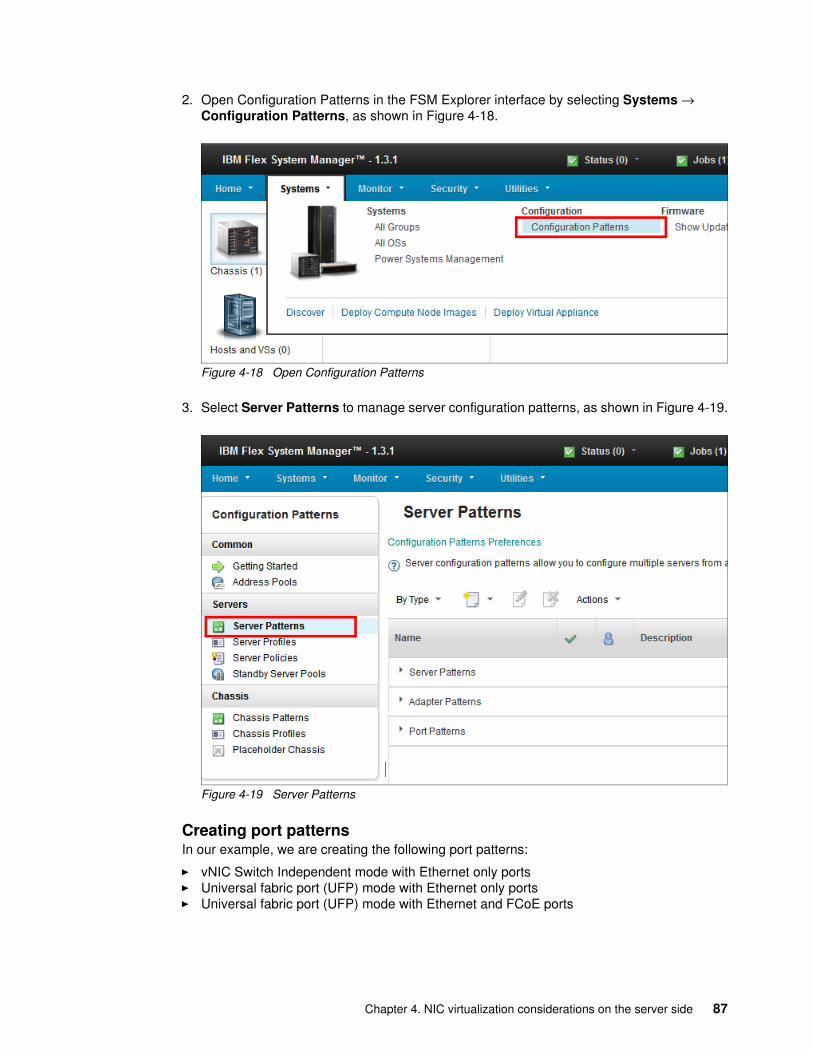
2. Open Configuration Patterns in the FSM Explorer interface by selecting Systems → Configuration Patterns, as shown in Figure 4-18.
Figure 4-18 Open Configuration Patterns
3. Select Server Patterns to manage server configuration patterns, as shown in Figure 4-19.
Figure 4-19 Server Patterns
Creating port patternsIn our example, we are creating the following port patterns:
� vNIC Switch Independent mode with Ethernet only ports� Universal fabric port (UFP) mode with Ethernet only ports� Universal fabric port (UFP) mode with Ethernet and FCoE ports
Chapter 4. NIC virtualization considerations on the server side 87
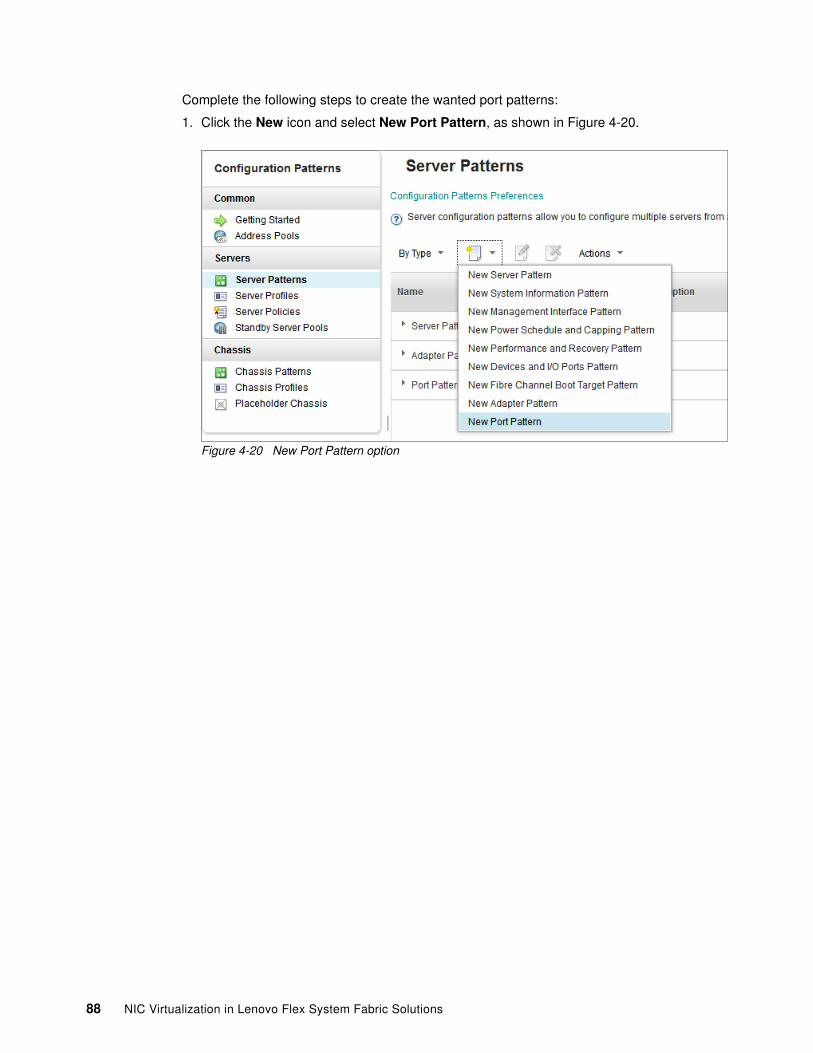
Complete the following steps to create the wanted port patterns:
1. Click the New icon and select New Port Pattern, as shown in Figure 4-20.
Figure 4-20 New Port Pattern option
88 NIC Virtualization in Lenovo Flex System Fabric Solutions
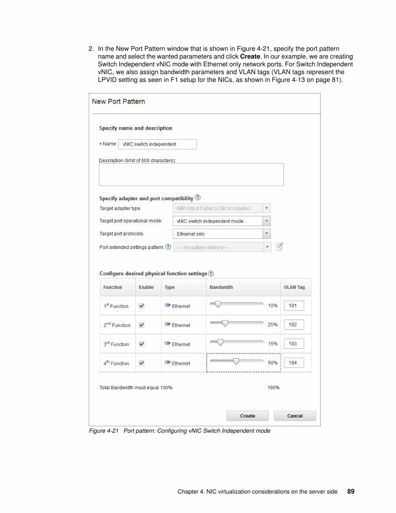
2. In the New Port Pattern window that is shown in Figure 4-21, specify the port pattern name and select the wanted parameters and click Create. In our example, we are creating Switch Independent vNIC mode with Ethernet only network ports. For Switch Independent vNIC, we also assign bandwidth parameters and VLAN tags (VLAN tags represent the LPVID setting as seen in F1 setup for the NICs, as shown in Figure 4-13 on page 81).
Figure 4-21 Port pattern: Configuring vNIC Switch Independent mode
Chapter 4. NIC virtualization considerations on the server side 89
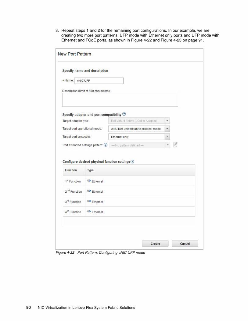
3. Repeat steps 1 and 2 for the remaining port configurations. In our example, we are creating two more port patterns: UFP mode with Ethernet only ports and UFP mode with Ethernet and FCoE ports, as shown in Figure 4-22 and Figure 4-23 on page 91.
Figure 4-22 Port Pattern: Configuring vNIC UFP mode
90 NIC Virtualization in Lenovo Flex System Fabric Solutions
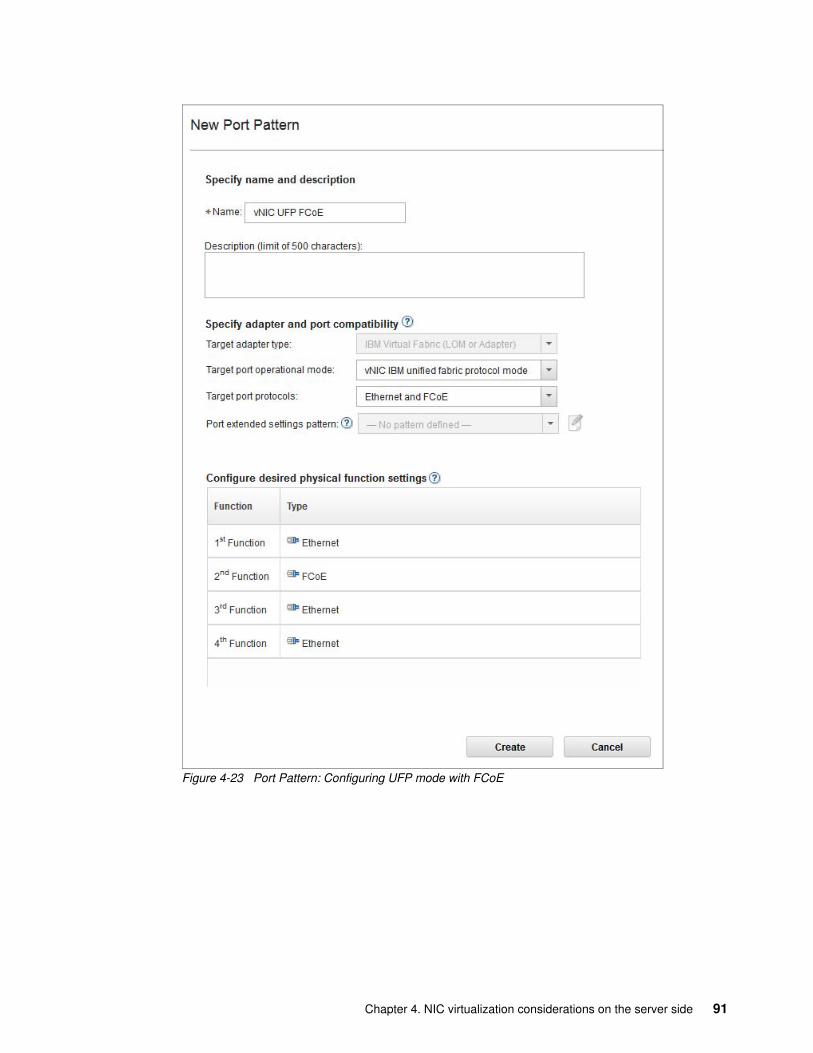
Figure 4-23 Port Pattern: Configuring UFP mode with FCoE
Chapter 4. NIC virtualization considerations on the server side 91
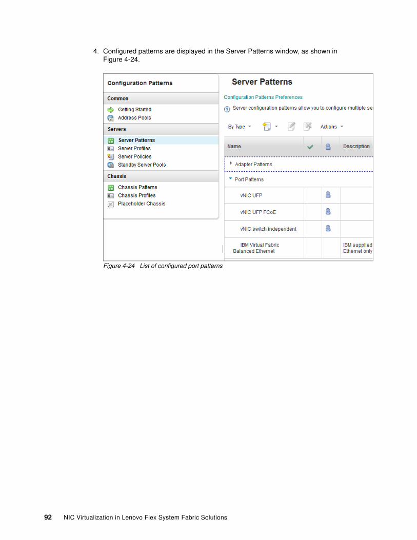
4. Configured patterns are displayed in the Server Patterns window, as shown in Figure 4-24.
Figure 4-24 List of configured port patterns
92 NIC Virtualization in Lenovo Flex System Fabric Solutions
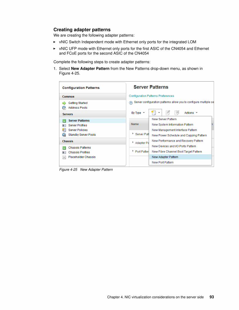
Creating adapter patternsWe are creating the following adapter patterns:
� vNIC Switch Independent mode with Ethernet only ports for the integrated LOM
� vNIC UFP mode with Ethernet only ports for the first ASIC of the CN4054 and Ethernet and FCoE ports for the second ASIC of the CN4054
Complete the following steps to create adapter patterns:
1. Select New Adapter Pattern from the New Patterns drop-down menu, as shown in Figure 4-25.
Figure 4-25 New Adapter Pattern
Chapter 4. NIC virtualization considerations on the server side 93
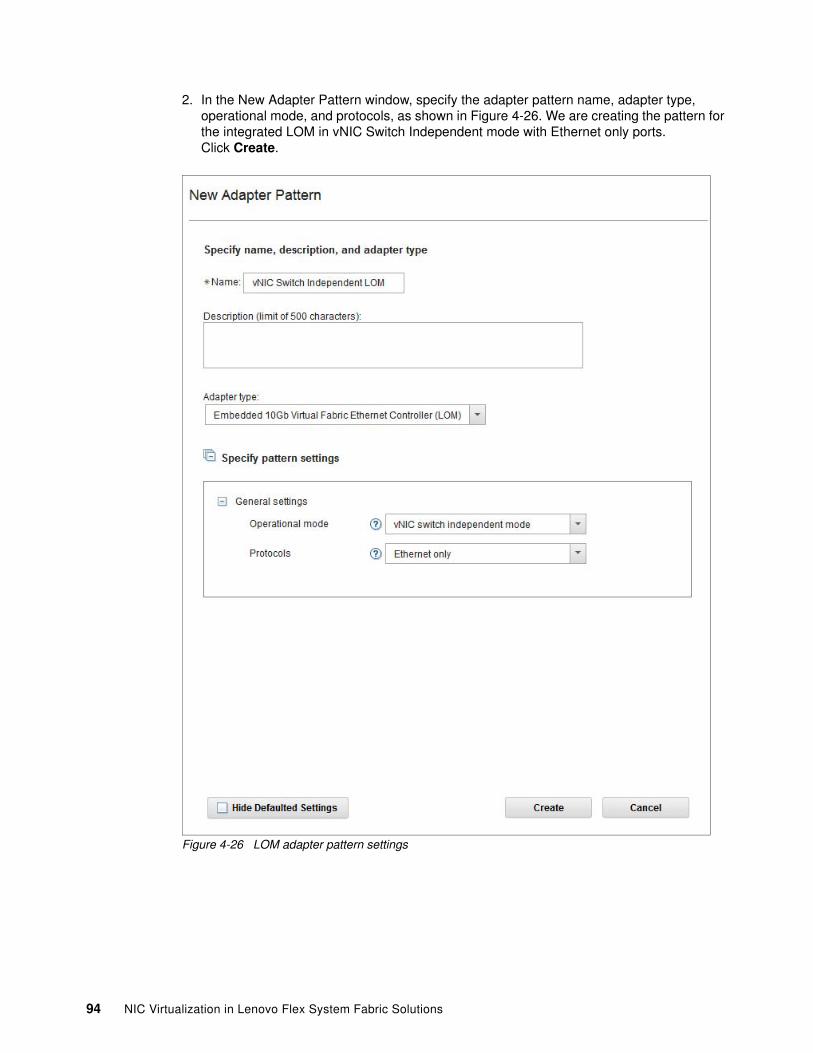
2. In the New Adapter Pattern window, specify the adapter pattern name, adapter type, operational mode, and protocols, as shown in Figure 4-26. We are creating the pattern for the integrated LOM in vNIC Switch Independent mode with Ethernet only ports. Click Create.
Figure 4-26 LOM adapter pattern settings
94 NIC Virtualization in Lenovo Flex System Fabric Solutions
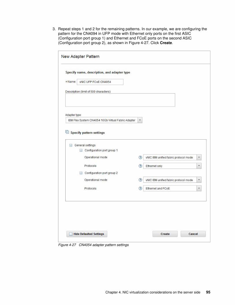
3. Repeat steps 1 and 2 for the remaining patterns. In our example, we are configuring the pattern for the CN4094 in UFP mode with Ethernet only ports on the first ASIC (Configuration port group 1) and Ethernet and FCoE ports on the second ASIC (Configuration port group 2), as shown in Figure 4-27. Click Create.
Figure 4-27 CN4054 adapter pattern settings
Chapter 4. NIC virtualization considerations on the server side 95
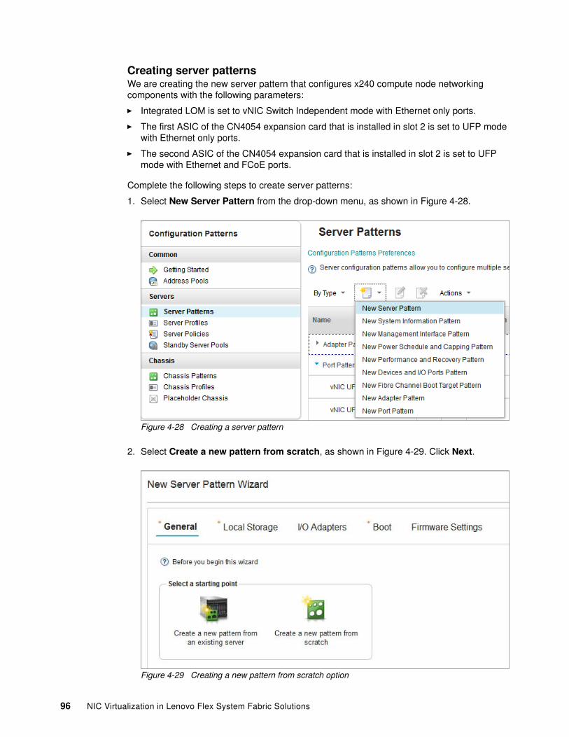
Creating server patternsWe are creating the new server pattern that configures x240 compute node networking components with the following parameters:
� Integrated LOM is set to vNIC Switch Independent mode with Ethernet only ports.
� The first ASIC of the CN4054 expansion card that is installed in slot 2 is set to UFP mode with Ethernet only ports.
� The second ASIC of the CN4054 expansion card that is installed in slot 2 is set to UFP mode with Ethernet and FCoE ports.
Complete the following steps to create server patterns:
1. Select New Server Pattern from the drop-down menu, as shown in Figure 4-28.
Figure 4-28 Creating a server pattern
2. Select Create a new pattern from scratch, as shown in Figure 4-29. Click Next.
Figure 4-29 Creating a new pattern from scratch option
96 NIC Virtualization in Lenovo Flex System Fabric Solutions
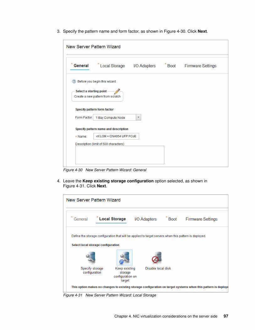
3. Specify the pattern name and form factor, as shown in Figure 4-30. Click Next.
Figure 4-30 New Server Pattern Wizard: General
4. Leave the Keep existing storage configuration option selected, as shown in Figure 4-31. Click Next.
Figure 4-31 New Server Pattern Wizard: Local Storage
Chapter 4. NIC virtualization considerations on the server side 97
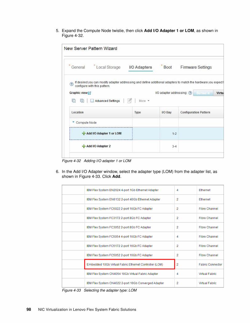
5. Expand the Compute Node twistie, then click Add I/O Adapter 1 or LOM, as shown in Figure 4-32.
Figure 4-32 Adding I/O adapter 1 or LOM
6. In the Add I/O Adapter window, select the adapter type (LOM) from the adapter list, as shown in Figure 4-33. Click Add.
Figure 4-33 Selecting the adapter type: LOM
98 NIC Virtualization in Lenovo Flex System Fabric Solutions
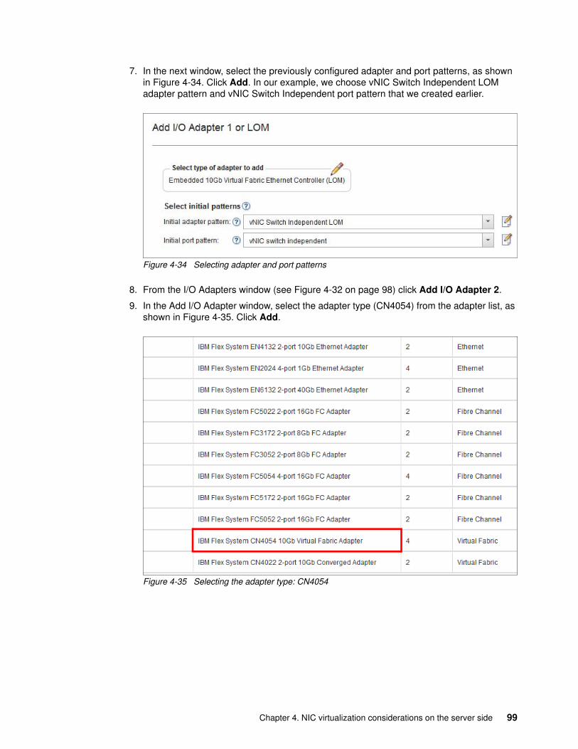
7. In the next window, select the previously configured adapter and port patterns, as shown in Figure 4-34. Click Add. In our example, we choose vNIC Switch Independent LOM adapter pattern and vNIC Switch Independent port pattern that we created earlier.
Figure 4-34 Selecting adapter and port patterns
8. From the I/O Adapters window (see Figure 4-32 on page 98) click Add I/O Adapter 2.
9. In the Add I/O Adapter window, select the adapter type (CN4054) from the adapter list, as shown in Figure 4-35. Click Add.
Figure 4-35 Selecting the adapter type: CN4054
Chapter 4. NIC virtualization considerations on the server side 99
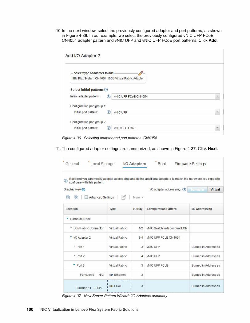
10.In the next window, select the previously configured adapter and port patterns, as shown in Figure 4-36. In our example, we select the previously configured vNIC UFP FCoE CN4054 adapter pattern and vNIC UFP and vNIC UFP FCoE port patterns. Click Add.
Figure 4-36 Selecting adapter and port patterns: CN4054
11.The configured adapter settings are summarized, as shown in Figure 4-37. Click Next.
Figure 4-37 New Server Pattern Wizard: I/O Adapters summary
100 NIC Virtualization in Lenovo Flex System Fabric Solutions
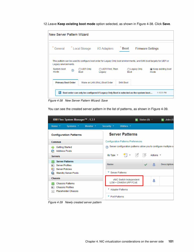
12.Leave Keep existing boot mode option selected, as shown in Figure 4-38. Click Save.
Figure 4-38 New Server Pattern Wizard: Save
You can see the created server pattern in the list of patterns, as shown in Figure 4-39.
Figure 4-39 Newly created server pattern
Chapter 4. NIC virtualization considerations on the server side 101
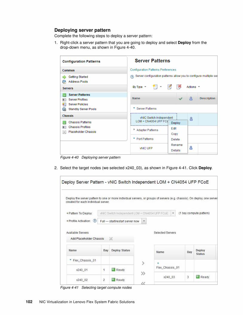
Deploying server patternComplete the following steps to deploy a server pattern:
1. Right-click a server pattern that you are going to deploy and select Deploy from the drop-down menu, as shown in Figure 4-40.
Figure 4-40 Deploying server pattern
2. Select the target nodes (we selected x240_03), as shown in Figure 4-41. Click Deploy.
Figure 4-41 Selecting target compute nodes
102 NIC Virtualization in Lenovo Flex System Fabric Solutions
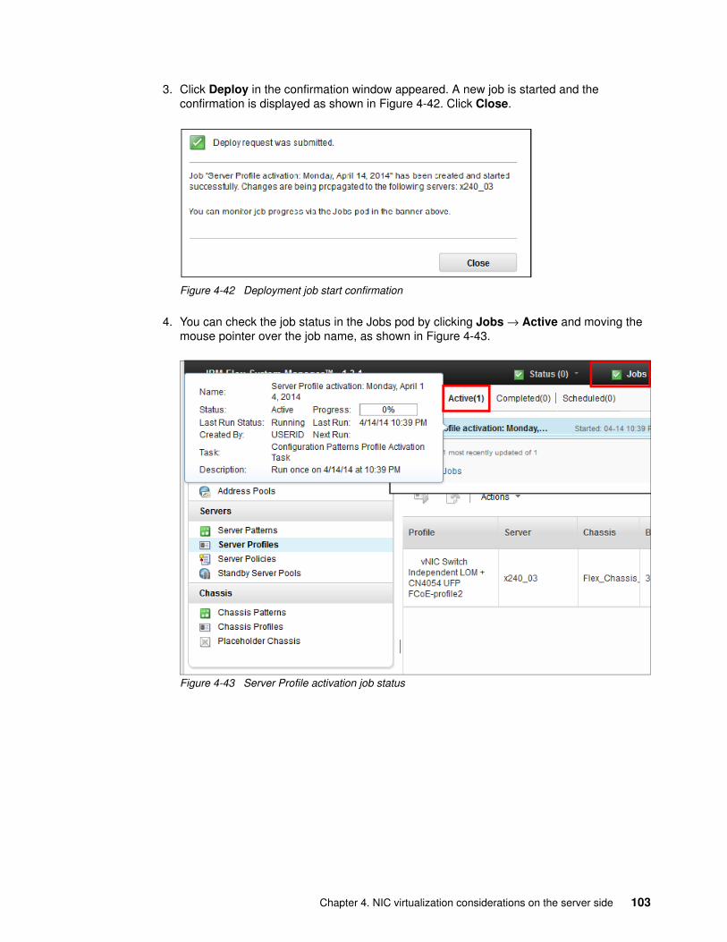
3. Click Deploy in the confirmation window appeared. A new job is started and the confirmation is displayed as shown in Figure 4-42. Click Close.
Figure 4-42 Deployment job start confirmation
4. You can check the job status in the Jobs pod by clicking Jobs → Active and moving the mouse pointer over the job name, as shown in Figure 4-43.
Figure 4-43 Server Profile activation job status
Chapter 4. NIC virtualization considerations on the server side 103
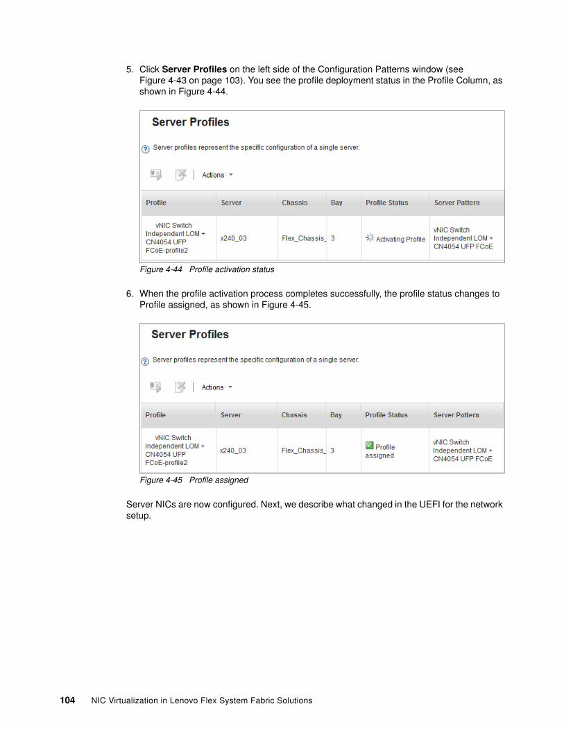
5. Click Server Profiles on the left side of the Configuration Patterns window (see Figure 4-43 on page 103). You see the profile deployment status in the Profile Column, as shown in Figure 4-44.
Figure 4-44 Profile activation status
6. When the profile activation process completes successfully, the profile status changes to Profile assigned, as shown in Figure 4-45.
Figure 4-45 Profile assigned
Server NICs are now configured. Next, we describe what changed in the UEFI for the network setup.
104 NIC Virtualization in Lenovo Flex System Fabric Solutions
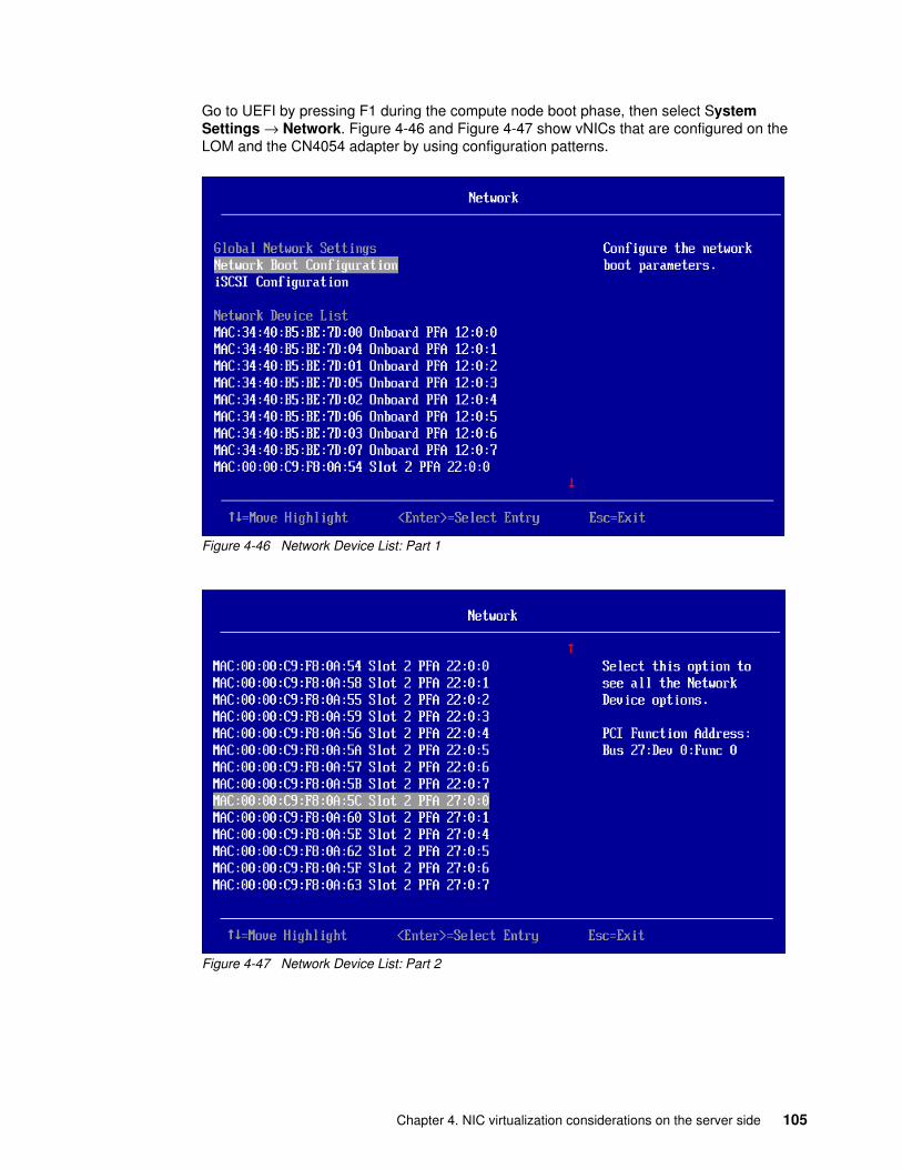
Go to UEFI by pressing F1 during the compute node boot phase, then select System Settings → Network. Figure 4-46 and Figure 4-47 show vNICs that are configured on the LOM and the CN4054 adapter by using configuration patterns.
Figure 4-46 Network Device List: Part 1
Figure 4-47 Network Device List: Part 2
Chapter 4. NIC virtualization considerations on the server side 105
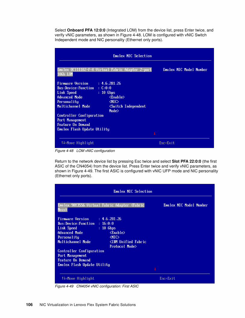
Select Onboard PFA 12:0:0 (Integrated LOM) from the device list, press Enter twice, and verify vNIC parameters, as shown in Figure 4-48. LOM is configured with vNIC Switch Independent mode and NIC personality (Ethernet only ports).
Figure 4-48 LOM vNIC configuration
Return to the network device list by pressing Esc twice and select Slot PFA 22:0:0 (the first ASIC of the CN4054) from the device list. Press Enter twice and verify vNIC parameters, as shown in Figure 4-49. The first ASIC is configured with vNIC UFP mode and NIC personality (Ethernet only ports).
Figure 4-49 CN4054 vNIC configuration: First ASIC
106 NIC Virtualization in Lenovo Flex System Fabric Solutions
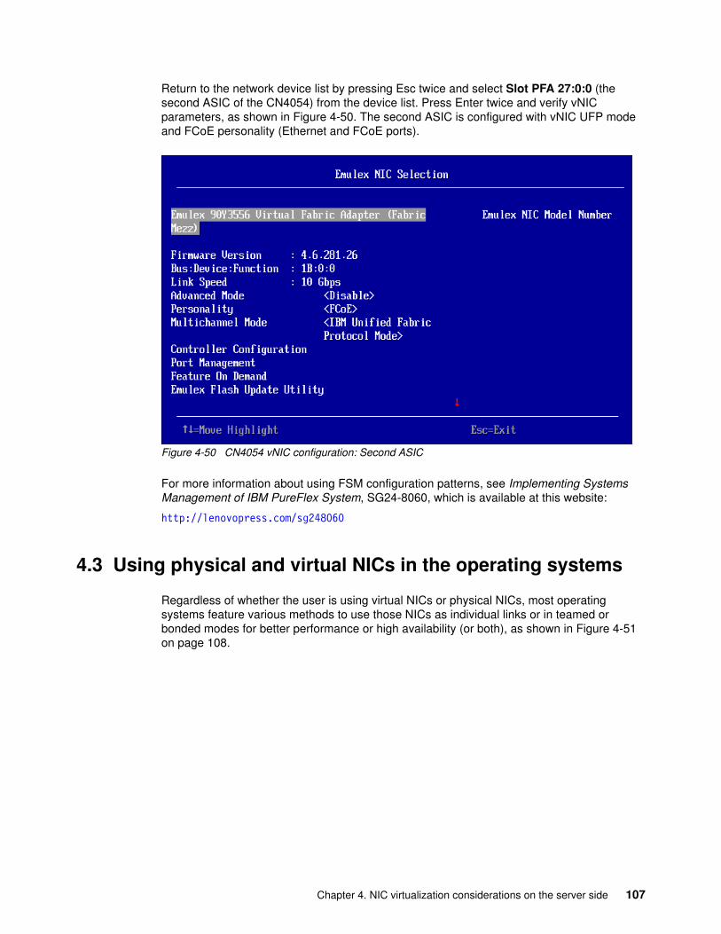
Return to the network device list by pressing Esc twice and select Slot PFA 27:0:0 (the second ASIC of the CN4054) from the device list. Press Enter twice and verify vNIC parameters, as shown in Figure 4-50. The second ASIC is configured with vNIC UFP mode and FCoE personality (Ethernet and FCoE ports).
Figure 4-50 CN4054 vNIC configuration: Second ASIC
For more information about using FSM configuration patterns, see Implementing Systems Management of IBM PureFlex System, SG24-8060, which is available at this website:
http://lenovopress.com/sg248060
4.3 Using physical and virtual NICs in the operating systems
Regardless of whether the user is using virtual NICs or physical NICs, most operating systems feature various methods to use those NICs as individual links or in teamed or bonded modes for better performance or high availability (or both), as shown in Figure 4-51 on page 108.
Chapter 4. NIC virtualization considerations on the server side 107
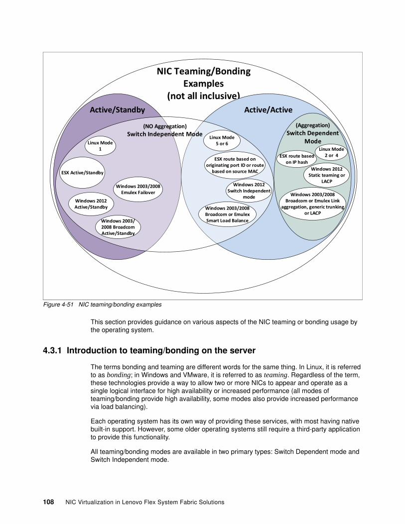
Figure 4-51 NIC teaming/bonding examples
This section provides guidance on various aspects of the NIC teaming or bonding usage by the operating system.
4.3.1 Introduction to teaming/bonding on the server
The terms bonding and teaming are different words for the same thing. In Linux, it is referred to as bonding; in Windows and VMware, it is referred to as teaming. Regardless of the term, these technologies provide a way to allow two or more NICs to appear and operate as a single logical interface for high availability or increased performance (all modes of teaming/bonding provide high availability, some modes also provide increased performance via load balancing).
Each operating system has its own way of providing these services, with most having native built-in support. However, some older operating systems still require a third-party application to provide this functionality.
All teaming/bonding modes are available in two primary types: Switch Dependent mode and Switch Independent mode.
NIC Teaming/BondingExamples
(not all inclusive)Active/Standby Active/Active
(Aggregation)Switch Dependent
Mode
(NO Aggregation)Switch Independent Mode Linux Mode
5 or 6Linux Mode
2 or 4
Linux Mode1
ESX route based on originating port ID or route
based on source MACESX Active/Standby
ESX route based on IP hash
Windows 2012 Static teaming or
LACPWindows 2012
Switch Independent mode
Windows 2012 Active/Standby Windows 2003/2008
Broadcom or Emulex Smart Load Balance
Windows 2003/2008 Broadcom or Emulex Link
aggregation, generic trunking or LACP
Windows 2003/2008 Broadcom Active/Standby
Windows 2003/2008 Emulex Failover
108 NIC Virtualization in Lenovo Flex System Fabric Solutions
Switch Dependent modes of teaming/bondingThese Switch-Dependent modes are any teaming/bonding modes in the operating system that also require a specific architecture in the connecting switches, and special configurations in these upstream switches (that is, they depend on the upstream switch design and configuration to operate correctly).
Consider the following points regarding these modes:
� All of these modes are some form of link aggregation, either static aggregation or dynamic aggregation; that is, Link Aggregation Control Protocol (LACP).
� Most operating systems support an LACP and a static form of teaming/bonding. These are all forms of Active/Active teaming/bonding, usually load balancing traffic on a per-session basis (what constitutes a session is controlled by settings on each side of the device supporting this mode of teaming/bonding and is beyond the scope of this book).
� Any teaming/bonding mode that uses static or LACP aggregation requires that all ports in that team/bond go to a single upstream switch or a group of switches that can appear as a single switch to the NIC teaming (for example, switches that are running Cisco vPC or Lenovo vLAG, or stacked switches).
� Any of these modes also must have a corresponding mode of aggregation that is configured on the upstream I/O modules to work properly (this is what makes them Switch Dependent).
Important: The use of any aggregation-based mode of teaming/bonding is not supported on a server if any of the virtual NIC options (Switch Independent mode, Virtual Fabric vNIC mode, or UFP) were implemented. This rule is based on the current limitation that aggregation on Lenovo switches is on the physical port, not the logical port. A future release of code might permit aggregations on UFP vPorts.
Chapter 4. NIC virtualization considerations on the server side 109
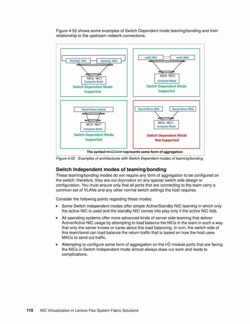
Figure 4-52 shows some examples of Switch Dependent mode teaming/bonding and their relationship to the upstream network connections.
Figure 4-52 Examples of architectures with Switch Dependent modes of teaming/bonding
Switch Independent modes of teaming/bondingThese teaming/bonding modes do not require any form of aggregation to be configured on the switch; therefore, they are not dependent on any special switch side design or configuration. You must ensure only that all ports that are connecting to the team carry a common set of VLANs and any other normal switch settings the host requires.
Consider the following points regarding these modes:
� Some Switch independent modes offer simple Active/Standby NIC teaming in which only the active NIC is used and the standby NIC comes into play only if the active NIC fails.
� All operating systems offer more advanced kinds of server side teaming that deliver Active/Active NIC usage by attempting to load balance the NICs in the team in such a way that only the server knows or cares about this load balancing. In turn, the switch side of this team/bond can load balance the return traffic that is based on how the host uses MACs to send out traffic.
� Attempting to configure some form of aggregation on the I/O module ports that are facing the NICs in Switch Independent mode almost always does not work and leads to complications.
Stand�Alone�SW1 Stand�Alone�SW2
Compute�NodeNIC0 NIC1
vLAG�SW1 vLAG�SW2
Compute�Node
NIC0 NIC1
Stacked��SW1 Stacked��SW2
Compute�NodeNIC0 NIC1
Stand�Alone�Switch�
Compute�NodeNIC0 NIC1
The�symbol�� represents�some�form�of�aggregation
Switch�Dependent�Mode�Supported
Switch�Dependent�Mode�Supported
Switch�Dependent�Mode�Supported
Switch�Dependent�Mode�Not�Supported
110 NIC Virtualization in Lenovo Flex System Fabric Solutions
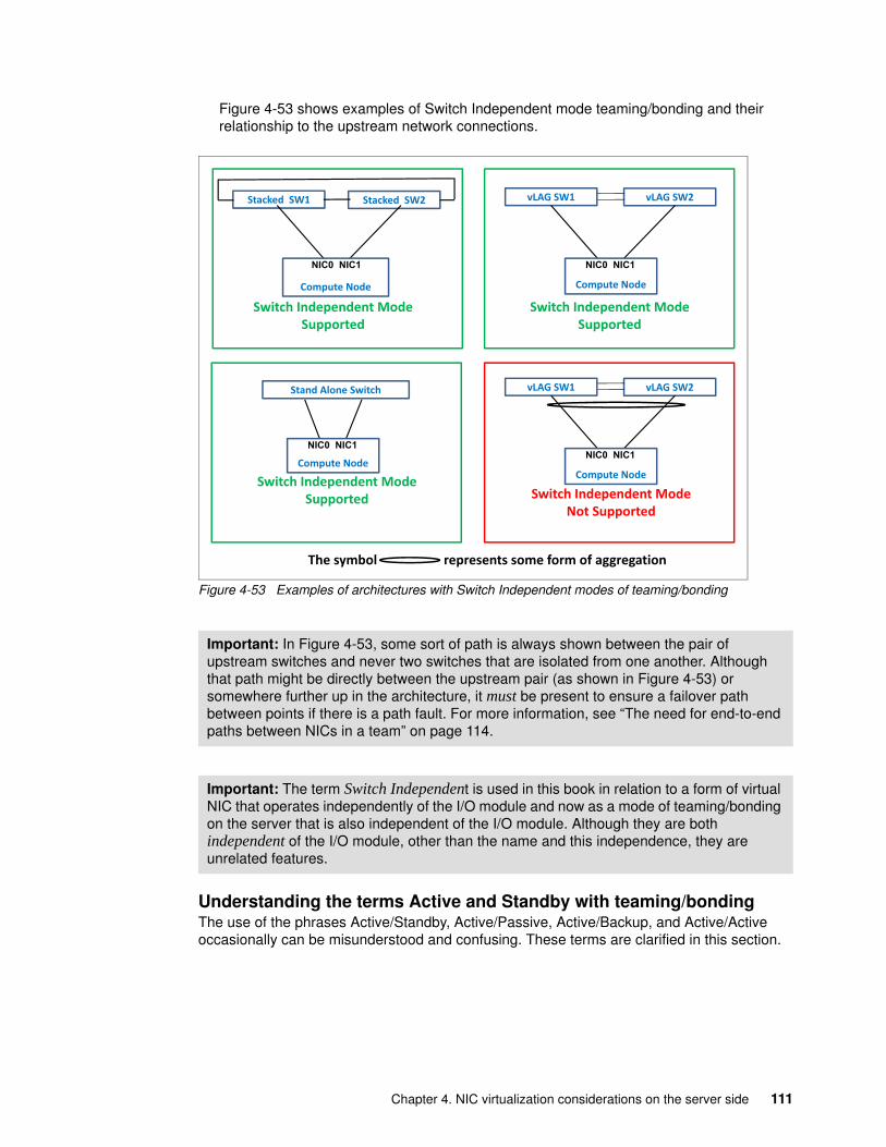
Figure 4-53 shows examples of Switch Independent mode teaming/bonding and their relationship to the upstream network connections.
Figure 4-53 Examples of architectures with Switch Independent modes of teaming/bonding
Understanding the terms Active and Standby with teaming/bondingThe use of the phrases Active/Standby, Active/Passive, Active/Backup, and Active/Active occasionally can be misunderstood and confusing. These terms are clarified in this section.
Important: In Figure 4-53, some sort of path is always shown between the pair of upstream switches and never two switches that are isolated from one another. Although that path might be directly between the upstream pair (as shown in Figure 4-53) or somewhere further up in the architecture, it must be present to ensure a failover path between points if there is a path fault. For more information, see “The need for end-to-end paths between NICs in a team” on page 114.
Important: The term Switch Independent is used in this book in relation to a form of virtual NIC that operates independently of the I/O module and now as a mode of teaming/bonding on the server that is also independent of the I/O module. Although they are both independent of the I/O module, other than the name and this independence, they are unrelated features.
Stacked��SW1 Stacked��SW2
Compute�Node
NIC0 NIC1
Stand�Alone�Switch�
Compute�Node
NIC0 NIC1
vLAG�SW1 vLAG�SW2
Compute�Node
NIC0 NIC1
vLAG�SW1 vLAG�SW2
Compute�Node
NIC0 NIC1
Switch�Independent�Mode�Supported
Switch�Independent�Mode�Supported
Switch�Independent�Mode�Supported
Switch�Independent�Mode�Not�Supported
The�symbol�� represents�some�form�of�aggregation
Chapter 4. NIC virtualization considerations on the server side 111
Active/Standby, Active/Passive, and Active/BackupThese terms are all different names for the same thing, an NIC in a team/bond that is selected to be active (passing traffic), and the other NIC is put into a standby state (not passing traffic), and used only if the active NIC goes down. In some cases, the team/bond might have multiple active NICs and only a single standby NIC, or the reverse (one active NIC and multiple standby NICs). One or more NICs in this mode are unused for any traffic until needed.
Most users understand the operation of these modes of teaming, but there can be some confusion in the context of how the connecting I/O modules are used. The I/O modules are not in any type of special Active/Standby configuration. I/O modules that support servers that are running Active/Standby are active and forward traffic as it is received from the server while following the rules of that I/O module (usually Layer 2 switching that is based on MAC addresses). Therefore, the I/O modules are not in any sort of Active/Standby mode and depend on the servers to decide which I/O module to use (based on the NIC that is selected as active in the OS team/bond).
Because the server administrator can control what NICs are active or standby, some servers can be configured by using an NIC that is going to I/O module bay 1 as the active NIC, and other servers in the same Flex System chassis by using an NIC that is pointing to the other I/O module in bay 2. In doing so, you can achieve some form of load balancing (albeit a chassis-based form of load balance). For example, the server administrator can configure half of the servers to use the NIC that is going to I/O module bay 1 for the active NIC, and the other servers by using the I/O module that is going to bay 2 for the active NIC.
One possible downside to this type of Active/Standby per-chassis load balance is that any server within this Flex System chassis that is using I/O module bay 1 and must talk to another server in the same chassis by using bay 2 as the active path often must have that traffic travel to the upstream network and back down to get between the two I/O bays and their associated active server NICs.
Overall, these Active/Standby modes tend to be the simplest to implement and require no special switch side configuration. However, they provide only high availability (no load balancing for a single server), and therefore, they are wasteful of over all bandwidth that is available to a specific server.
Active/ActiveAlthough most users agree on the meaning of the phrase Active/Standby, the phrase Active/Active is frequently a point of contention when users do not define what the term active means.
In this book, the term active means that the operating system is free to actively use the NIC in any way that agrees with the teaming/bonding mode that is selected in the operating system and does not leave that NIC in some sort of standby mode. Within the term Active/Active, there are Switch Dependent modes and Switch Independent modes of teaming/bonding.
Consider the following points regarding Switch Dependent modes of Active/Active and some examples of these modes:
� As with all Switch Dependent modes of teaming/bonding, any of these Active/Active modes use some form of aggregation and require an accompanying upstream network architecture and I/O module configuration to support this aggregation on the server-side NICs. These aggregation modes are LACP or static aggregation exclusively.
� These modes use the aggregation hash algorithm to determine what NIC is used for a session of traffic. A session of traffic can be based on MAC address, IP address, or other components of the packets that are being transferred.
112 NIC Virtualization in Lenovo Flex System Fabric Solutions
� The outbound path that is used for this mode of teaming/bonding is decoupled from the return traffic. Each side of the aggregation decides on their own hash which NIC to use for a specific session.
� These modes provide a higher chance of better overall load balance but do not ensure any load balancing. For example, if all traffic is between only two hosts (such as, a large file copy from one host to another) for a specific session, that traffic uses only a single NIC in the team. The return traffic uses whatever link it hashed to by the switch side hash, but also picks only a single link for this single session for that return traffic. That is, for a specific session, a sending device can use only the bandwidth of a single NIC in the team.
� These aggregation-based modes of teaming/bonding are not supported when any of the virtual NIC features are used that are available from the Emulex NIC. Therefore, if the server was configured for UFP, VF mode vNIC, or Switch Independent mode vNIC, these teaming/bonding modes should not be implemented.
� Active/Active teaming modes in this category for various operating systems include the following examples:
– Linux:
• Bonding mode 2: Static aggregation• Linux: Bonding mode 4:LACP aggregation
– ESX vSwitch teaming mode Route based on IP hash: Static aggregation
– ESX dvSwitch teaming mode Route based on IP hash: Static or LACP, depending on LACP setting enabled or disabled in the dvSwitch
Consider the following points regarding Switch Independent modes of Active/Active with some examples:
� As with all Switch Independent modes of teaming/bonding, there are no special switch side architectures or configurations. The switch should not be configured for any form of aggregation.
� These modes use some server-side decision-making process to select which NIC to use for what session. In this case, a session is often all traffic from a specific VM or process in a bare metal operating system, destination IP, or MAC, and so on. The server decides how it load balances the traffic over the NICs.
� The outbound path that is used for this mode of teaming/bonding is usually not decoupled from the inbound traffic. In most cases, whatever NIC is used to send outgoing traffic from the host, the switch side uses the same NIC/link for any return traffic (the switch bases its decision on the MAC that is learned when the host sent a packet by using that MAC to return the traffic on the link learned).
� These modes can provide satisfactory load balancing and are not dependent on having a specific switch architecture or configuration above the host (as the Switch Dependent modes do) and are available in all major operating systems.
� Unlike the aggregation-based modes of Active/Active teaming/bonding, these Switch Independent modes of Active/Active teaming/bonding work well with any of the virtual NIC functions that are available in the Emulex adapters.
� Active/Active Switch Independent modes of teaming/bonding in various operating systems include the following examples:
– Linux:
• Bonding mode 5: Adaptive Transmit load balance• Linux: Bonding mode 6: Adaptive load balance
Chapter 4. NIC virtualization considerations on the server side 113
– ESX vSwitch teaming mode Route based on originating virtual port ID
– ESX dvSwitch teaming mode Route based on source MAC hash
The Switch Dependent modes of Active/Active bonding/teaming have a greater potential of (but no guarantee that they do have) overall better load balance in the team/bond. However, they include added complexity and support only certain upstream network architectures and require the server team to coordinate with the network team to match the aggregation configurations correctly. Whereas Switch Independent modes of Active/Active do not require any special upstream architecture/switch configuration. They also can be controlled and configured from the server side of the equation with no need for the server team to coordinate with the network team, except for what VLANs to use and how (tagged or untagged), which is always necessary with or without any sort of teaming/bonding modes.
Link and path fault detection in teaming/bondingAll teaming/bonding solutions need a way to know whether an NIC in the team/bond is available for use. Most use simple link up/down as the primary method. Some add a layer beyond simple link up/down to attempt to detect remote failures beyond the direct link (upstream path failures). In general, most of these remote fault methods use some sort of AdDress Resolution Protocol (ARP) or ping or probe packet to determine whether the path to the other NIC or some upstream device is available, and if not, take that NIC out of service.
Non-link fault failure detection technologies include the following examples:
� Linux ARP monitoring� VMware Beacon probing� Broadcom Livelink (third-party teaming tool)
All of these remote fault methods have their limitations and can be prone to false positives (reporting a NIC unavailable when it can still service packets). Issues with these remote fault detection methods include the following examples:
� In a large datacenter with potentially thousands of hosts that are using Linux ARP monitoring and constantly mapping the default gateway can eventually become (or at least be perceived as) a Denial of Service attack on the default gateway.
� If Beacon probing in ESX is used on a two-NIC team and it fails with both NICs still in an up state (for example, a path fault not directly at the host, but somewhere in the upstream L2 network), it does not know which NIC is having a path issue and begins to blast all packets out both ports. This situation can overload the network and create issues. Because of this issue, VMware does not recommend the use of Beacon probing with two NIC teams; however, you can configure it on a two NIC team).
Rather than using any of these OS-based remote fault detection methods, it is often preferred to use the Failover feature of Lenovo switches. Other vendors often also support a similar failover feature, such as Cisco’s Link State Tracking.
For more information about failover configurations in a PureFlex System environment, see Chapter 5, “Flex System NIC virtualization deployment scenarios” on page 127.
The need for end-to-end paths between NICs in a teamFor teaming to work properly, there must be an end-to-end layer 2 path between the two (or more) NICs in the team. If you have a pair of teamed NICs and a host must use VLAN 10, VLAN 10 must be carried to both NICs. Also, that VLAN 10 must have an external path in the upstream network to connect these two NICs.
114 NIC Virtualization in Lenovo Flex System Fabric Solutions
This configuration is required for failover and in some configurations, load balancing, and normal traffic and is true regardless of teaming type (switch dependent or Switch Independent modes). This configuration also has implications when multi-switch aggregations are used (that is, vPC or vLAG)
In a typical vLAG/vPC environment, a user might have a pair of enclosure switches that are running a vLAG aggregation toward the upstream network. Because the upstream switch thinks this pair of enclosure-based switches are one switch, a host on the enclosure might send a packet that goes up on a port on one enclosure switch. However, the response comes down on a port on the other enclosure switch (based on the other sides load balancing transmit of packets).
Because of this process, you must ensure that not only is that VLAN carried on all ports to the server team and all ports to the upstream aggregation, but it must be carried on the ISL links of the vLAG/vPC. If this was a switch-dependent mode of teaming (that is, aggregation), this VLAN on the ISL is needed if there is failover. If this is a switch-independent mode of teaming, this VLAN on the ISL is required for failover and normal communications.
4.3.2 Operating system side teaming/bonding and upstream network requirements
This section describes the most common NIC teaming and bonding modes for various operating systems and relates them to requirements for the upstream connecting network.
Linux bondingLinux bonding evolved over the years to become easier to deploy and more robust. This section describes the various modes of bonding that are available on most Linux implementations. Most versions of Linux include the bonding module, but some versions still need it installed before bonding can be implemented.
Linux offers many different modes of bonding, and not all modes of bonding exist in all versions of Linux. However, most implementations of Linux support bonding modes 0 - 6, which are described here.
Linux bonding offers the following primary ways to determine whether a link is available for server use:
� Mii-mon: This method is simple link status up/down and is the default for bonding.� ARP monitor: Sends an ARP packet to a specified device and expects a response.
There are some helpful documents available that explain bonding, but much of the Linux bonding documentation was written by server administrators, not network administrators. Therefore, some of the terms that are used in these documents and help files can be confusing to a network administrator.
For more information about Linux bonding, see this website:
https://www.kernel.org/doc/Documentation/networking/bonding.txt
Chapter 4. NIC virtualization considerations on the server side 115
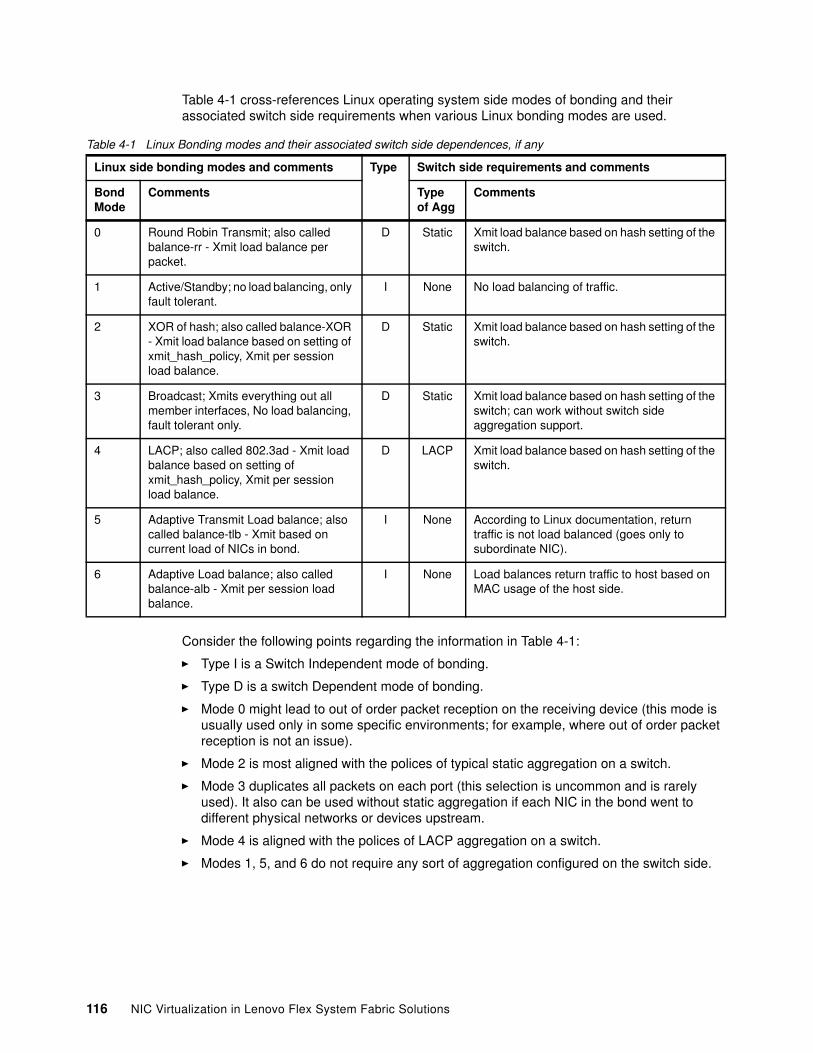
Table 4-1 cross-references Linux operating system side modes of bonding and their associated switch side requirements when various Linux bonding modes are used.
Table 4-1 Linux Bonding modes and their associated switch side dependences, if any
Consider the following points regarding the information in Table 4-1:
� Type I is a Switch Independent mode of bonding.
� Type D is a switch Dependent mode of bonding.
� Mode 0 might lead to out of order packet reception on the receiving device (this mode is usually used only in some specific environments; for example, where out of order packet reception is not an issue).
� Mode 2 is most aligned with the polices of typical static aggregation on a switch.
� Mode 3 duplicates all packets on each port (this selection is uncommon and is rarely used). It also can be used without static aggregation if each NIC in the bond went to different physical networks or devices upstream.
� Mode 4 is aligned with the polices of LACP aggregation on a switch.
� Modes 1, 5, and 6 do not require any sort of aggregation configured on the switch side.
Linux side bonding modes and comments Type Switch side requirements and comments
Bond Mode
Comments Type of Agg
Comments
0 Round Robin Transmit; also called balance-rr - Xmit load balance per packet.
D Static Xmit load balance based on hash setting of the switch.
1 Active/Standby; no load balancing, only fault tolerant.
I None No load balancing of traffic.
2 XOR of hash; also called balance-XOR - Xmit load balance based on setting of xmit_hash_policy, Xmit per session load balance.
D Static Xmit load balance based on hash setting of the switch.
3 Broadcast; Xmits everything out all member interfaces, No load balancing, fault tolerant only.
D Static Xmit load balance based on hash setting of the switch; can work without switch side aggregation support.
4 LACP; also called 802.3ad - Xmit load balance based on setting of xmit_hash_policy, Xmit per session load balance.
D LACP Xmit load balance based on hash setting of the switch.
5 Adaptive Transmit Load balance; also called balance-tlb - Xmit based on current load of NICs in bond.
I None According to Linux documentation, return traffic is not load balanced (goes only to subordinate NIC).
6 Adaptive Load balance; also called balance-alb - Xmit per session load balance.
I None Load balances return traffic to host based on MAC usage of the host side.
116 NIC Virtualization in Lenovo Flex System Fabric Solutions
VMware ESX teamingVMware ESX offers teaming on its virtual switches, including the stand-alone vSwitch and the distributed vSwitch (dvSwitch).
The forms of teaming that are available vary slightly between an ESX stand-alone vSwitch and the distributed dvSwitch, with the stand-alone vSwitch offering the following options:
� Route-based on originating virtual Port ID (this option is the default; load balances on a per-VM basis).
� Route-based on IP hash (this is a static aggregation).
� Route-based on source MAC hash (similar to the default).
� Use Explicit failover order (high availability only, no load balancing).
The dvSwitch offers some of the same modes, but with more options. The following teaming options are available on the dvSwitch:
� Route-based on originating virtual port (same as stand-alone vSwitch).
� Route-based on IP hash (defaults to static aggregation; same as stand-alone vSwitch).
� Route-based on IP hash (optionally configured for LACP).
� Route-based on source MAC hash (same as stand-alone vSwitch).
� Route-based on physical NIC load (attempts to consider the load on a NIC as they are allocated to the VMs).
� Use Explicit failover order (same as stand-alone vSwitch).
VMware offers the following modes of detecting when a path is down:
� Link Status: This mode is simple link up/link down and is the default.
� Beacon Probing: Useful only in vSwitches/dvSwitches with more than two NICs.
Do not use beacon probing on vSwitches/dvSwitches with only two NICs. Also, if the upstream switch offers a failover option (as all of the 4093 models do), it is suggested that you use that option over Beacon Probing.
For more information about VMware ESX networking and the kinds of teams that are supported (does not include the modes available in the dvSwitch), see this website:
http://www.vmware.com/files/pdf/virtual_networking_concepts.pdf
For more information about the dvSwitch, see this website:
http://www.vmware.com/files/pdf/vsphere-vnetwork-ds-migration-configuration-wp.pdf
Chapter 4. NIC virtualization considerations on the server side 117
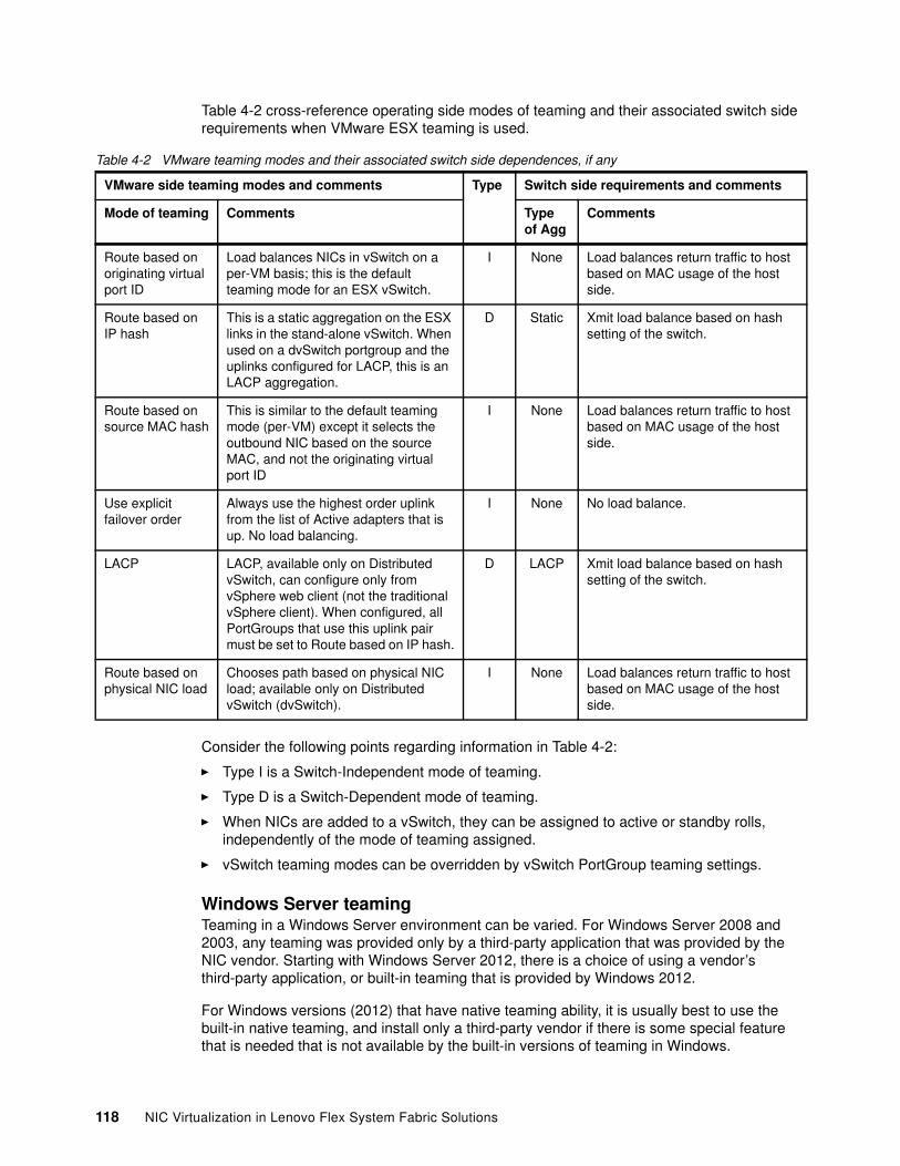
Table 4-2 cross-reference operating side modes of teaming and their associated switch side requirements when VMware ESX teaming is used.
Table 4-2 VMware teaming modes and their associated switch side dependences, if any
Consider the following points regarding information in Table 4-2:
� Type I is a Switch-Independent mode of teaming.
� Type D is a Switch-Dependent mode of teaming.
� When NICs are added to a vSwitch, they can be assigned to active or standby rolls, independently of the mode of teaming assigned.
� vSwitch teaming modes can be overridden by vSwitch PortGroup teaming settings.
Windows Server teamingTeaming in a Windows Server environment can be varied. For Windows Server 2008 and 2003, any teaming was provided only by a third-party application that was provided by the NIC vendor. Starting with Windows Server 2012, there is a choice of using a vendor’s third-party application, or built-in teaming that is provided by Windows 2012.
For Windows versions (2012) that have native teaming ability, it is usually best to use the built-in native teaming, and install only a third-party vendor if there is some special feature that is needed that is not available by the built-in versions of teaming in Windows.
VMware side teaming modes and comments Type Switch side requirements and comments
Mode of teaming Comments Type of Agg
Comments
Route based on originating virtual port ID
Load balances NICs in vSwitch on a per-VM basis; this is the default teaming mode for an ESX vSwitch.
I None Load balances return traffic to host based on MAC usage of the host side.
Route based on IP hash
This is a static aggregation on the ESX links in the stand-alone vSwitch. When used on a dvSwitch portgroup and the uplinks configured for LACP, this is an LACP aggregation.
D Static Xmit load balance based on hash setting of the switch.
Route based on source MAC hash
This is similar to the default teaming mode (per-VM) except it selects the outbound NIC based on the source MAC, and not the originating virtual port ID
I None Load balances return traffic to host based on MAC usage of the host side.
Use explicit failover order
Always use the highest order uplink from the list of Active adapters that is up. No load balancing.
I None No load balance.
LACP LACP, available only on Distributed vSwitch, can configure only from vSphere web client (not the traditional vSphere client). When configured, all PortGroups that use this uplink pair must be set to Route based on IP hash.
D LACP Xmit load balance based on hash setting of the switch.
Route based on physical NIC load
Chooses path based on physical NIC load; available only on Distributed vSwitch (dvSwitch).
I None Load balances return traffic to host based on MAC usage of the host side.
118 NIC Virtualization in Lenovo Flex System Fabric Solutions
Teaming that uses the native modes available in Windows Server 2012Windows Server 2012 offers built-in NIC teaming, which is also referred to as Load Balance/Failover (LBFO) in some of their documentation.
Microsoft refers to their teaming options as Switch Independent mode, or switch dependent mode, with the same meaning we are applying in this chapter.
When you are selecting the teaming mode in Windows 2012, the following options are available:
� Static Teaming
Also referred to as generic aggregation in some Microsoft documentation, this option represents a static aggregation and is switch-dependent, which requires a static aggregation to be configured on the switch.
� Switch Independent
As the name implies, this option represents a Switch Independent mode of teaming (no aggregation configuration needed on the switch). How it uses the NICs for load balance is a separate setting.
� LACP
Also referred to as 802.1AX in some Microsoft documentation (AX being the latest IEEE standard for LACP, replacing the older 802.3ad LACP standard), this option is a switch-dependent mode of teaming that requires LACP be configured on the upstream switch.
Separate from the teaming mode, a user can select load balance method. In the initial versions of Windows Server 2012, the following types of load balance options were available:
� Address hash: Address hash uses information from the IP addresses in the packets to determine load balance.
� Hyper-V Port: Attempts to load balance on a per vPort basis (not related to the term vPort as configured in UFP virtual NIC settings).
As of Windows Server 2012 R2, Microsoft added a third load balance option, dynamic load balance, that attempts to also factor in NIC utilization to distribute the loads. For more information about this and other aspects of teaming load balancing for Windows Server 2012, see this website:
http://www.microsoft.com/en-us/download/confirmation.aspx?id=40319
Windows Server 2012 also still allows third-party NIC vendors teaming applications, but states that it is recommended that no system administrator ever run two teaming solutions (built-in Windows teaming and third-party vendor teaming) at the same time on the same server.
For more information about Windows Server 2012 NIC teaming, see this website:
http://www.microsoft.com/en-us/download/details.aspx?id=30160
Chapter 4. NIC virtualization considerations on the server side 119
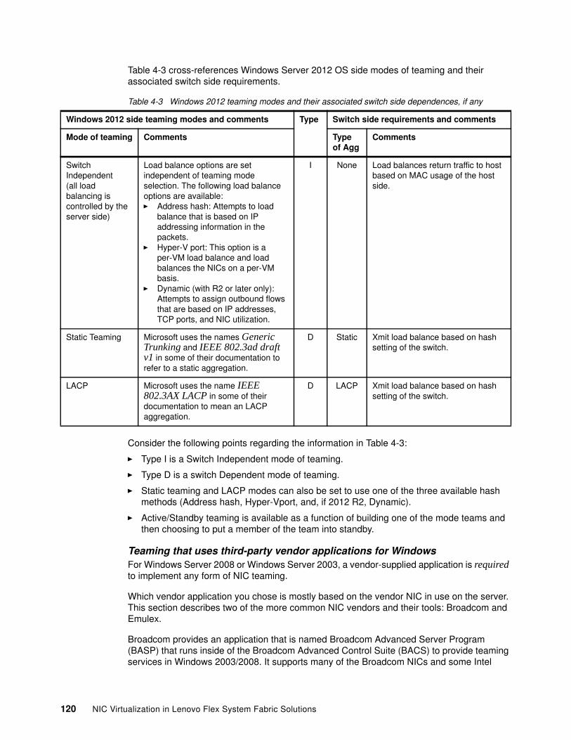
Table 4-3 cross-references Windows Server 2012 OS side modes of teaming and their associated switch side requirements.
Table 4-3 Windows 2012 teaming modes and their associated switch side dependences, if any
Consider the following points regarding the information in Table 4-3:
� Type I is a Switch Independent mode of teaming.
� Type D is a switch Dependent mode of teaming.
� Static teaming and LACP modes can also be set to use one of the three available hash methods (Address hash, Hyper-Vport, and, if 2012 R2, Dynamic).
� Active/Standby teaming is available as a function of building one of the mode teams and then choosing to put a member of the team into standby.
Teaming that uses third-party vendor applications for WindowsFor Windows Server 2008 or Windows Server 2003, a vendor-supplied application is required to implement any form of NIC teaming.
Which vendor application you chose is mostly based on the vendor NIC in use on the server. This section describes two of the more common NIC vendors and their tools: Broadcom and Emulex.
Broadcom provides an application that is named Broadcom Advanced Server Program (BASP) that runs inside of the Broadcom Advanced Control Suite (BACS) to provide teaming services in Windows 2003/2008. It supports many of the Broadcom NICs and some Intel
Windows 2012 side teaming modes and comments Type Switch side requirements and comments
Mode of teaming Comments Type of Agg
Comments
Switch Independent(all load balancing is controlled by the server side)
Load balance options are set independent of teaming mode selection. The following load balance options are available:� Address hash: Attempts to load
balance that is based on IP addressing information in the packets.
� Hyper-V port: This option is a per-VM load balance and load balances the NICs on a per-VM basis.
� Dynamic (with R2 or later only): Attempts to assign outbound flows that are based on IP addresses, TCP ports, and NIC utilization.
I None Load balances return traffic to host based on MAC usage of the host side.
Static Teaming Microsoft uses the names Generic Trunking and IEEE 802.3ad draft v1 in some of their documentation to refer to a static aggregation.
D Static Xmit load balance based on hash setting of the switch.
LACP Microsoft uses the name IEEE 802.3AX LACP in some of their documentation to mean an LACP aggregation.
D LACP Xmit load balance based on hash setting of the switch.
120 NIC Virtualization in Lenovo Flex System Fabric Solutions
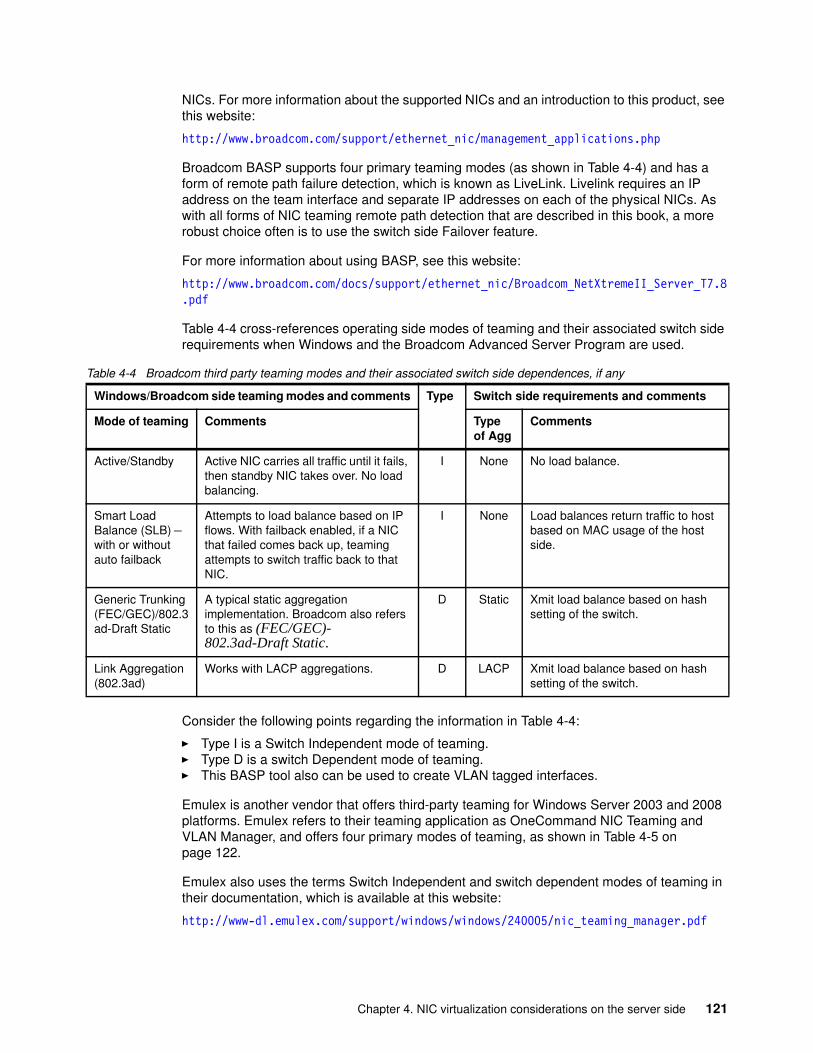
NICs. For more information about the supported NICs and an introduction to this product, see this website:
http://www.broadcom.com/support/ethernet_nic/management_applications.php
Broadcom BASP supports four primary teaming modes (as shown in Table 4-4) and has a form of remote path failure detection, which is known as LiveLink. Livelink requires an IP address on the team interface and separate IP addresses on each of the physical NICs. As with all forms of NIC teaming remote path detection that are described in this book, a more robust choice often is to use the switch side Failover feature.
For more information about using BASP, see this website:
http://www.broadcom.com/docs/support/ethernet_nic/Broadcom_NetXtremeII_Server_T7.8.pdf
Table 4-4 cross-references operating side modes of teaming and their associated switch side requirements when Windows and the Broadcom Advanced Server Program are used.
Table 4-4 Broadcom third party teaming modes and their associated switch side dependences, if any
Consider the following points regarding the information in Table 4-4:
� Type I is a Switch Independent mode of teaming.� Type D is a switch Dependent mode of teaming.� This BASP tool also can be used to create VLAN tagged interfaces.
Emulex is another vendor that offers third-party teaming for Windows Server 2003 and 2008 platforms. Emulex refers to their teaming application as OneCommand NIC Teaming and VLAN Manager, and offers four primary modes of teaming, as shown in Table 4-5 on page 122.
Emulex also uses the terms Switch Independent and switch dependent modes of teaming in their documentation, which is available at this website:
http://www-dl.emulex.com/support/windows/windows/240005/nic_teaming_manager.pdf
Windows/Broadcom side teaming modes and comments Type Switch side requirements and comments
Mode of teaming Comments Type of Agg
Comments
Active/Standby Active NIC carries all traffic until it fails, then standby NIC takes over. No load balancing.
I None No load balance.
Smart Load Balance (SLB) – with or without auto failback
Attempts to load balance based on IP flows. With failback enabled, if a NIC that failed comes back up, teaming attempts to switch traffic back to that NIC.
I None Load balances return traffic to host based on MAC usage of the host side.
Generic Trunking (FEC/GEC)/802.3ad-Draft Static
A typical static aggregation implementation. Broadcom also refers to this as (FEC/GEC)- 802.3ad-Draft Static.
D Static Xmit load balance based on hash setting of the switch.
Link Aggregation (802.3ad)
Works with LACP aggregations. D LACP Xmit load balance based on hash setting of the switch.
Chapter 4. NIC virtualization considerations on the server side 121
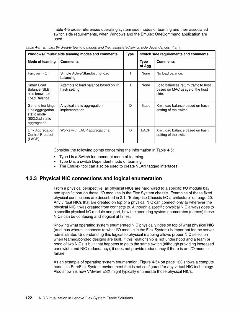
Table 4-5 cross-references operating system side modes of teaming and their associated switch side requirements, when Windows and the Emulex OneCommand application are used.
Table 4-5 Emulex third-party teaming modes and their associated switch side dependences, if any
Consider the following points concerning the information in Table 4-5:
� Type I is a Switch Independent mode of teaming.� Type D is a switch Dependent mode of teaming.� The Emulex tool can also be used to create VLAN tagged interfaces.
4.3.3 Physical NIC connections and logical enumeration
From a physical perspective, all physical NICs are hard wired to a specific I/O module bay and specific port on those I/O modules in the Flex System chassis. Examples of these fixed physical connections are described in 2.1, “Enterprise Chassis I/O architecture” on page 20. Any virtual NICs that are created on top of a physical NIC can connect only to wherever the physical NIC it was created from connects to. Although a specific physical NIC always goes to a specific physical I/O module and port, how the operating system enumerates (names) these NICs can be confusing and illogical at times.
Knowing what operating system enumerated NIC physically rides on top of what physical NIC (and thus where it connects to what I/O module in the Flex System) is important for the server administrator. Understanding this logical to physical mapping allows proper NIC selection when teamed/bonded designs are built. If this relationship is not understood and a team or bond of two NICs is built that happens to go to the same switch (although providing increased bandwidth and NIC redundancy), it does not provide redundancy if there is an I/O module failure.
As an example of operating system enumeration, Figure 4-54 on page 123 shows a compute node in a PureFlex System environment that is not configured for any virtual NIC technology. Also shown is how VMware ESX might typically enumerate those physical NICs.
Windows/Emulex side teaming modes and comments Type Switch side requirements and comments
Mode of teaming Comments Type of Agg
Comments
Failover (FO) Simple Active/Standby; no load balancing.
I None No load balance.
Smart Load Balance (SLB), also known as Load Balance
Attempts to load balance based on IP hash setting.
I None Load balances return traffic to host based on MAC usage of the host side.
Generic trunking: Link aggregation static mode (802.3ad static aggregation)
A typical static aggregation implementation.
D Static Xmit load balance based on hash setting of the switch.
Link Aggregation Control Protocol (LACP)
Works with LACP aggregations. D LACP Xmit load balance based on hash setting of the switch.
122 NIC Virtualization in Lenovo Flex System Fabric Solutions
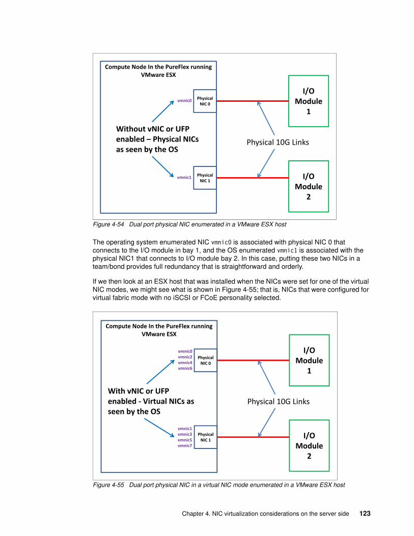
Figure 4-54 Dual port physical NIC enumerated in a VMware ESX host
The operating system enumerated NIC vmnic0 is associated with physical NIC 0 that connects to the I/O module in bay 1, and the OS enumerated vmnic1 is associated with the physical NIC1 that connects to I/O module bay 2. In this case, putting these two NICs in a team/bond provides full redundancy that is straightforward and orderly.
If we then look at an ESX host that was installed when the NICs were set for one of the virtual NIC modes, we might see what is shown in Figure 4-55; that is, NICs that were configured for virtual fabric mode with no iSCSI or FCoE personality selected.
Figure 4-55 Dual port physical NIC in a virtual NIC mode enumerated in a VMware ESX host
I/O�Module�
1
I/O�Module�
2
Compute�Node�In�the�PureFlex�running�VMware�ESX
Physical�10G�Links
vmnic0 Physical�NIC�0
Physical�NIC�1
vmnic1
Without�vNIC�or�UFP�enabled�� Physical�NICs�as�seen�by�the�OS
I/O�Module�
1
I/O�Module�
2
Compute�Node�In�the�PureFlex�running�VMware�ESX
Physical�10G�Links
vmnic0vmnic2vmnic4vmnic6
Physical�NIC�0
Physical�NIC�1
vmnic1vmnic3vmnic5vmnic7
With�vNIC�or�UFP�enabled�� Virtual�NICs�as�seen�by�the�OS
Chapter 4. NIC virtualization considerations on the server side 123
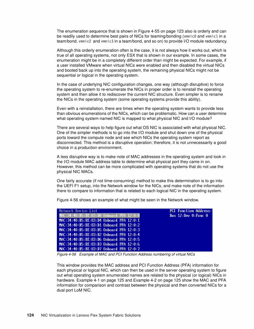
The enumeration sequence that is shown in Figure 4-55 on page 123 also is orderly and can be readily used to determine best pairs of NICs for teaming/bonding (vmnic0 and vmnic1 in a team/bond, vmnic2 and vmnic3 in a team/bond, and so on) to provide I/O module redundancy.
Although this orderly enumeration often is the case, it is not always how it works out, which is true of all operating systems, not only ESX that is shown in our example. In some cases, the enumeration might be in a completely different order than might be expected. For example, if a user installed VMware when virtual NICs were enabled and then disabled the virtual NICs and booted back up into the operating system, the remaining physical NICs might not be sequential or logical in the operating system.
In the case of underlying NIC configuration changes, one way (although disruptive) to force the operating system to re-enumerate the NICs in proper order is to reinstall the operating system and then allow it to rediscover the current NIC structure. Even simpler is to rename the NICs in the operating system (some operating systems provide this ability).
Even with a reinstallation, there are times when the operating system wants to provide less than obvious enumerations of the NICs, which can be problematic. How can a user determine what operating system-named NIC is mapped to what physical NIC and I/O module?
There are several ways to help figure out what OS NIC is associated with what physical NIC. One of the simpler methods is to go into the I/O module and shut down one of the physical ports toward the compute node and see which NICs the operating system report as disconnected. This method is a disruptive operation; therefore, it is not unnecessarily a good choice in a production environment.
A less disruptive way is to make note of MAC addresses in the operating system and look in the I/O module MAC address table to determine what physical port they came in on. However, this method can be more complicated with operating systems that do not use the physical NIC MACs.
One fairly accurate (if not time-consuming) method to make this determination is to go into the UEFI F1 setup, into the Network window for the NICs, and make note of the information there to compare to information that is related to each logical NIC in the operating system.
Figure 4-56 shows an example of what might be seen in the Network window.
Figure 4-56 Example of MAC and PCI Function Address numbering of virtual NICs
This window provides the MAC address and PCI Function Address (PFA) information for each physical or logical NIC, which can then be used in the server operating system to figure out what operating system enumerated names are related to the physical (or logical) NICs in hardware. Example 4-1 on page 125 and Example 4-2 on page 125 show the MAC and PFA information for comparison and contrast between the physical and then converted NICs for a dual port LoM NIC.
124 NIC Virtualization in Lenovo Flex System Fabric Solutions
Example 4-1 shows the values as seen for onboard NICs that are not in any virtual NIC mode, along with the physical I/O module bays to which those physical NICs connect. Example 4-2 shows that same onboard NIC after conversion to some form of virtual NIC mode.
Example 4-1 Example of onboard dual port NIC not in any virtual NIC mode
MAC: 34:40:B5:BE:83:D0 Onboard PFA 12:0:0 <<< physical NIC-0 to I/O Module bay 1MAC: 34:40:B5:BE:83:D4 Onboard PFA 12:0:1 <<< physical NIC-1 to I/O Module bay 2
As can be seen in Example 4-2, the original physical NIC and PFA information was inherited by the first two virtual NICs, followed by the other six virtual NICs and their associated MAC, PFA information, and which I/O module to which they connect (based on the under lying physical connections of the physical NIC).
Example 4-2 Example of onboard dual port NIC after converting in to virtual NIC mode
MAC: 34:40:B5:BE:83:D0 Onboard PFA 12:0:0 <<< physical NIC-0 to I/O Module bay 1MAC: 34:40:B5:BE:83:D4 Onboard PFA 12:0:1 <<< physical NIC-1 to I/O Module bay 2MAC: 34:40:B5:BE:83:D1 Onboard PFA 12:0:2 <<< physical NIC-0 to I/O Module bay 1MAC: 34:40:B5:BE:83:D5 Onboard PFA 12:0:3 <<< physical NIC-1 to I/O Module bay 2MAC: 34:40:B5:BE:83:D2 Onboard PFA 12:0:4 <<< physical NIC-0 to I/O Module bay 1MAC: 34:40:B5:BE:83:D6 Onboard PFA 12:0:5 <<< physical NIC-1 to I/O Module bay 2MAC: 34:40:B5:BE:83:D3 Onboard PFA 12:0:6 <<< physical NIC-0 to I/O Module bay 1MAC: 34:40:B5:BE:83:D7 Onboard PFA 12:0:7 <<< physical NIC-1 to I/O Module bay 2
Now that we know this MAC and PFA information (and their relationship to the underlying physical NIC and where it connects to), it is often possible to go into the operating system and locate the MAC or PFA information that is associated with the operating system enumerated name (for example, in the Device Manager in Windows Server 2012); therefore, regardless of the enumerated name, we know where each vNIC connects.
Regardless of how it is determined, getting the proper pair of NICs into a team/bond is always important to ensure that the wanted high availability is achieved.
Chapter 4. NIC virtualization considerations on the server side 125

126 NIC Virtualization in Lenovo Flex System Fabric Solutions
Chapter 5. Flex System NIC virtualization deployment scenarios
This chapter provides details about various aspects of NIC virtualization and their interactions with various I/O module features.
This chapter includes following topics:
� Introduction to deployment examples� UFP mode virtual NIC and Layer 2 Failover� UFP mode virtual NIC with vLAG and FCoE� pNIC and vNIC Virtual Fabric modes with Layer 2 Failover� Switch Independent mode with SPAR
5
© Copyright Lenovo 2016. All rights reserved. 127
5.1 Introduction to deployment examples
This chapter provides examples for deploying the Flex System I/O modules and NIC virtualization functionality in various scenarios. Also provided are helpful commands to confirm that the environment is operating as designed.
The provided examples might not reflect an exact combination of features that an average environment might include. They were more chosen to demonstrate the interoperation of features and their associated configurations. The following combinations of features are described in this chapter:
� UFP mode virtual NIC and Layer 2 Failover� UFP mode virtual NIC with FCoE and vLAG� Virtual Fabric mode vNIC and Physical NIC with Layer 2 Failover� Switch Independent mode vNIC with SPAR
These combinations are not necessarily indicative of any specific restriction as to what works with what or on what model I/O module; however, the following features and combinations of features do not interoperate with others, or on all I/O modules:
� NIC virtualization features
All forms of vNIC are mutually exclusive of each other on the server side. A specific server can be set for UFP or Virtual Fabric mode vNIC, or Switch Independent mode (or disabled for virtual NIC), but not more than one of these can be set at one time on that server.
On the switch side that is related to virtual NICs, UFP and Virtual Fabric mode vNIC are also mutual exclusive of each other in that you can enable one or the other, but not both at the same time. Switch Independent mode vNIC can be enabled on a host that is connected to an I/O module that is configured for UFP or Virtual Fabric mode vNIC, but only if the I/O module ports that are facing this host are in physical mode (not configured for UFP or Virtual Fabric mode vNIC).
� Switch virtualization features
SPAR, vLAG, and Stacking are all mutually exclusive on a specific I/O module.
SI4093 does not support vLAG or Stacking, but it does support SPAR. The SI4093 also does not support Virtual Fabric vNIC, but supports UFP starting from Networking Operating System version 7.8. It also supports Switch Independent mode vNIC that is running on the host.
The I/O module-based Failover feature is supported by all modes of virtual NIC, but implemented differently depending on the mode (Virtual Fabric vNIC is configured on a per vNIC group basis, Switch Independent vNIC is configured by using global failover per physical port, and UFP is configured by using global failover on a per vPort basis).
Important: Unless otherwise noted, all configuration examples and commands in this chapter are based on the use of the industry standard CLI (isCLI) of the Flex System I/O modules that are running Networking Operating System. By default, the EN4093R and CN4093 use the menu-driven CLI (which might change in the future). It is necessary to change the I/O module to isCLI mode to uses these examples. The simplest way to get into the isCLI from the menu CLI is to issue the menu CLI command /boot/prompt ena and then exit out and log back in. Upon logging back in, the option to select the wanted CLI is available.
128 NIC Virtualization in Lenovo Flex System Fabric Solutions
Other restrictions can apply. For more information, see Chapter 3, “NIC virtualization considerations on the switch side” on page 47 and Chapter 4, “NIC virtualization considerations on the server side” on page 67.
5.2 UFP mode virtual NIC and Layer 2 Failover
By using Unified Fabric Port, you can divide 10 Gb ports into virtual NICs, as described in Chapter 4, “NIC virtualization considerations on the server side” on page 67. By using Layer 2 Failover, you can detect uplink failures and systematically disable all INT ports. Layer 2 Failover with UFP takes that process to the next level and automates the shutdown not only to a physical NIC, but a UFP vPort virtual NIC.
This section provides diagrams and configuration examples for setting up UFP and Layer 2 Failover.
5.2.1 Components
This deployment scenario uses the following equipment:
� Flex System Enterprise Chassis
� x240 Compute Node (in bay 3):
– ESXi 5.5 embedded hypervisor
– Quad port CN4054 NIC in Mezzanine slot 2:
• First two physical NICs have UFP configured and FCoE personality enabled• Second two NICs have Virtual NIC disabled (in physical NIC mode)
� Two CN4093s in switch bays 3 and 4
� Two G8264s to act as upstream Ethernet connectivity that is running vLAG
5.2.2 Topology
The x240 Compute Node operating system that is running ESXi uses vSwitch0 by using its default NIC team “route based on originating virtual port” setting to the pair of CN4093s. The first two ports within the UEFI of the CN4054R Emulex Quad Port NIC are running in UFP mode. The CN4093s are running as independent I/O modules with UFP enabled on vPort (.1) in Tunnel mode and vPort (.2) in FCoE mode.
Tunnel mode is using EXT1 and EXT2, which are in an IEEE 802.3ad LACP port channel with adminkey 4344. The port channel, along with INT port 4 UFP vPort (.1), are members of a failover trigger.
Chapter 5. Flex System NIC virtualization deployment scenarios 129
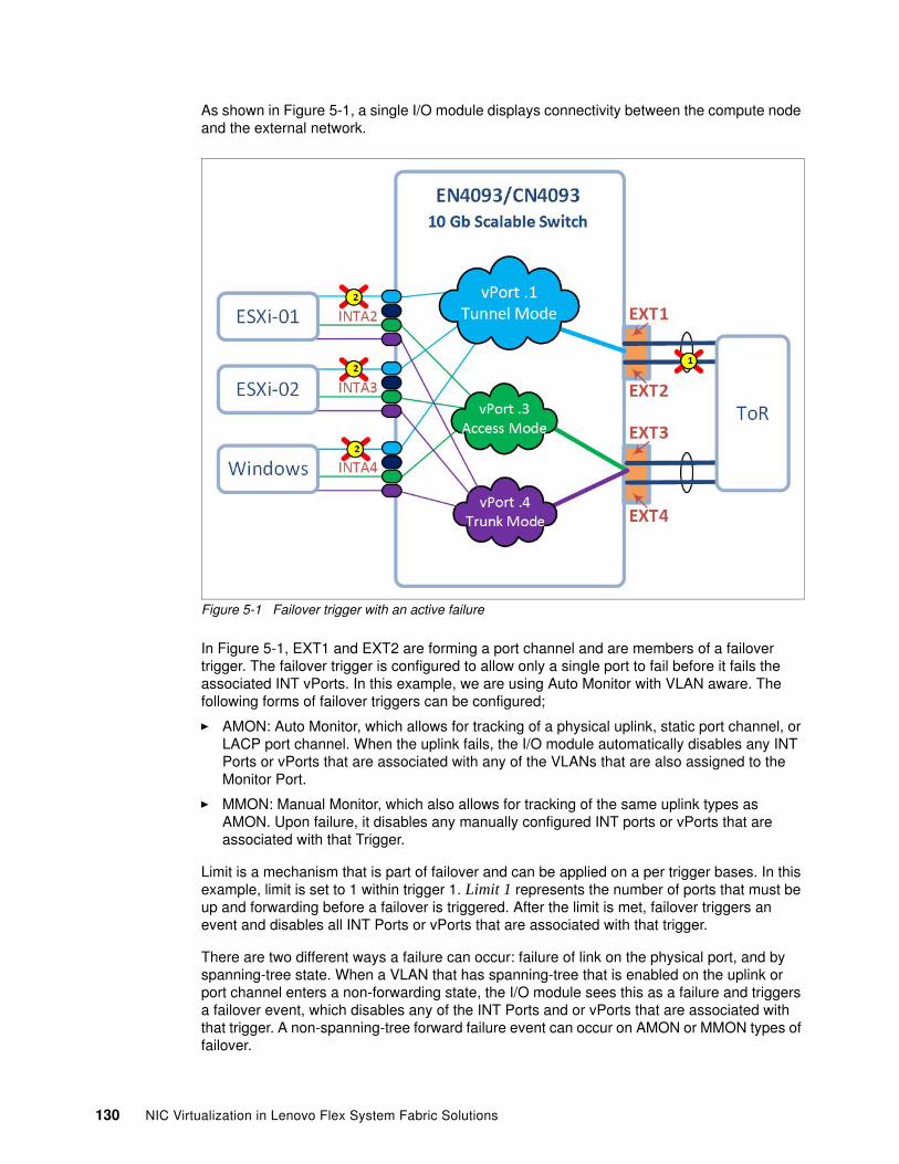
As shown in Figure 5-1, a single I/O module displays connectivity between the compute node and the external network.
Figure 5-1 Failover trigger with an active failure
In Figure 5-1, EXT1 and EXT2 are forming a port channel and are members of a failover trigger. The failover trigger is configured to allow only a single port to fail before it fails the associated INT vPorts. In this example, we are using Auto Monitor with VLAN aware. The following forms of failover triggers can be configured;
� AMON: Auto Monitor, which allows for tracking of a physical uplink, static port channel, or LACP port channel. When the uplink fails, the I/O module automatically disables any INT Ports or vPorts that are associated with any of the VLANs that are also assigned to the Monitor Port.
� MMON: Manual Monitor, which also allows for tracking of the same uplink types as AMON. Upon failure, it disables any manually configured INT ports or vPorts that are associated with that Trigger.
Limit is a mechanism that is part of failover and can be applied on a per trigger bases. In this example, limit is set to 1 within trigger 1. Limit 1 represents the number of ports that must be up and forwarding before a failover is triggered. After the limit is met, failover triggers an event and disables all INT Ports or vPorts that are associated with that trigger.
There are two different ways a failure can occur: failure of link on the physical port, and by spanning-tree state. When a VLAN that has spanning-tree that is enabled on the uplink or port channel enters a non-forwarding state, the I/O module sees this as a failure and triggers a failover event, which disables any of the INT Ports and or vPorts that are associated with that trigger. A non-spanning-tree forward failure event can occur on AMON or MMON types of failover.
130 NIC Virtualization in Lenovo Flex System Fabric Solutions
5.2.3 Use Cases
Failover can be useful when NIC teaming/bonding is used on the compute nodes. Because the I/O module is between the compute node and the upstream network, a compute node has no way of detecting an outage further than its physical connection and can end up sending traffic to a black holed I/O module. For this reason, failover is a significant feature with which customers can implement an HA environment with peace of mind that if a failure does occur, their applications can survive with full access through its redundant connection to the network.
5.2.4 Configuration
This section describes the configurations and steps that are necessary to configure the various components. This information does not include the upstream G8264s because that is not the focus of this section. However, this section does include the configuration for the uplinks in the CN4093’s toward the G8264.
Host side configuring (OS/UEFI)The process of configuring the UEFI is the same for any operating system that is on an Intel based compute node.
As shown in Figure 5-2 on page 132, the UEFI Emulex NIC Selection window is found within the System Settings → Network → Network Device List {NIC wanting to enable UFP on}. Then, select Multichannel Mode → Unified Fabric Protocol Mode. After making the change, return to System Configuration and Boot Management by pressing ESC and selecting Save Settings. After it is enabled on one port of a two-port ASIC, the settings are automatically applied to the other port (or ports).
Chapter 5. Flex System NIC virtualization deployment scenarios 131
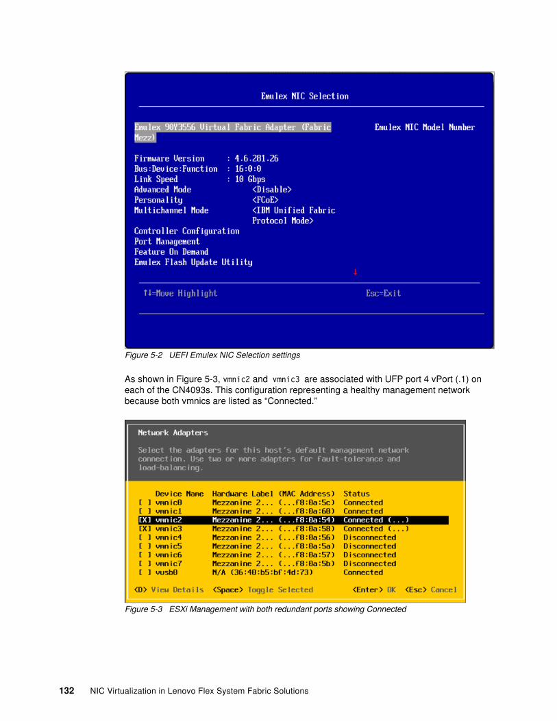
Figure 5-2 UEFI Emulex NIC Selection settings
As shown in Figure 5-3, vmnic2 and vmnic3 are associated with UFP port 4 vPort (.1) on each of the CN4093s. This configuration representing a healthy management network because both vmnics are listed as “Connected.”
Figure 5-3 ESXi Management with both redundant ports showing Connected
132 NIC Virtualization in Lenovo Flex System Fabric Solutions
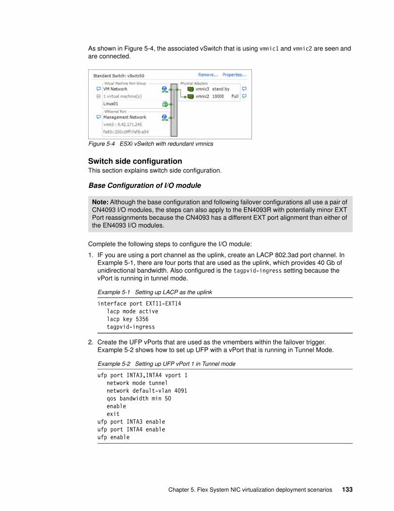
As shown in Figure 5-4, the associated vSwitch that is using vmnic1 and vmnic2 are seen and are connected.
Figure 5-4 ESXi vSwitch with redundant vmnics
Switch side configurationThis section explains switch side configuration.
Base Configuration of I/O module
Complete the following steps to configure the I/O module:
1. IF you are using a port channel as the uplink, create an LACP 802.3ad port channel. In Example 5-1, there are four ports that are used as the uplink, which provides 40 Gb of unidirectional bandwidth. Also configured is the tagpvid-ingress setting because the vPort is running in tunnel mode.
Example 5-1 Setting up LACP as the uplink
interface port EXT11-EXT14lacp mode activelacp key 5356tagpvid-ingress
2. Create the UFP vPorts that are used as the vmembers within the failover trigger. Example 5-2 shows how to set up UFP with a vPort that is running in Tunnel Mode.
Example 5-2 Setting up UFP vPort 1 in Tunnel mode
ufp port INTA3,INTA4 vport 1network mode tunnelnetwork default-vlan 4091qos bandwidth min 50enableexit
ufp port INTA3 enableufp port INTA4 enableufp enable
Note: Although the base configuration and following failover configurations all use a pair of CN4093 I/O modules, the steps can also apply to the EN4093R with potentially minor EXT Port reassignments because the CN4093 has a different EXT port alignment than either of the EN4093 I/O modules.
Chapter 5. Flex System NIC virtualization deployment scenarios 133
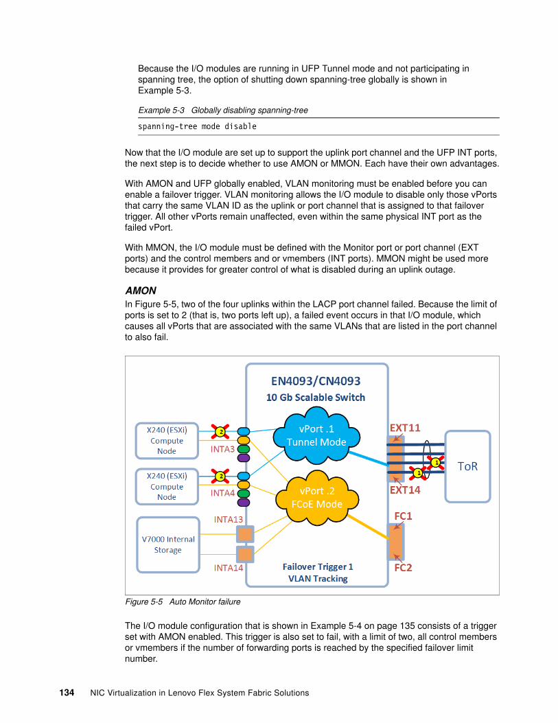
Because the I/O modules are running in UFP Tunnel mode and not participating in spanning tree, the option of shutting down spanning-tree globally is shown in Example 5-3.
Example 5-3 Globally disabling spanning-tree
spanning-tree mode disable
Now that the I/O module are set up to support the uplink port channel and the UFP INT ports, the next step is to decide whether to use AMON or MMON. Each have their own advantages.
With AMON and UFP globally enabled, VLAN monitoring must be enabled before you can enable a failover trigger. VLAN monitoring allows the I/O module to disable only those vPorts that carry the same VLAN ID as the uplink or port channel that is assigned to that failover trigger. All other vPorts remain unaffected, even within the same physical INT port as the failed vPort.
With MMON, the I/O module must be defined with the Monitor port or port channel (EXT ports) and the control members and or vmembers (INT ports). MMON might be used more because it provides for greater control of what is disabled during an uplink outage.
AMONIn Figure 5-5, two of the four uplinks within the LACP port channel failed. Because the limit of ports is set to 2 (that is, two ports left up), a failed event occurs in that I/O module, which causes all vPorts that are associated with the same VLANs that are listed in the port channel to also fail.
Figure 5-5 Auto Monitor failure
The I/O module configuration that is shown in Example 5-4 on page 135 consists of a trigger set with AMON enabled. This trigger is also set to fail, with a limit of two, all control members or vmembers if the number of forwarding ports is reached by the specified failover limit number.
134 NIC Virtualization in Lenovo Flex System Fabric Solutions
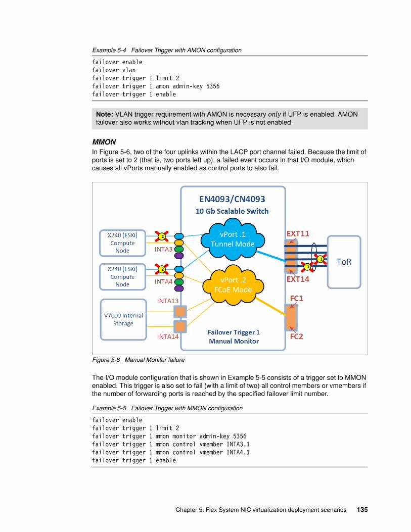
Example 5-4 Failover Trigger with AMON configuration
failover enablefailover vlanfailover trigger 1 limit 2failover trigger 1 amon admin-key 5356failover trigger 1 enable
MMONIn Figure 5-6, two of the four uplinks within the LACP port channel failed. Because the limit of ports is set to 2 (that is, two ports left up), a failed event occurs in that I/O module, which causes all vPorts manually enabled as control ports to also fail.
Figure 5-6 Manual Monitor failure
The I/O module configuration that is shown in Example 5-5 consists of a trigger set to MMON enabled. This trigger is also set to fail (with a limit of two) all control members or vmembers if the number of forwarding ports is reached by the specified failover limit number.
Example 5-5 Failover Trigger with MMON configuration
failover enablefailover trigger 1 limit 2failover trigger 1 mmon monitor admin-key 5356failover trigger 1 mmon control vmember INTA3.1failover trigger 1 mmon control vmember INTA4.1failover trigger 1 enable
Note: VLAN trigger requirement with AMON is necessary only if UFP is enabled. AMON failover also works without vlan tracking when UFP is not enabled.
Chapter 5. Flex System NIC virtualization deployment scenarios 135
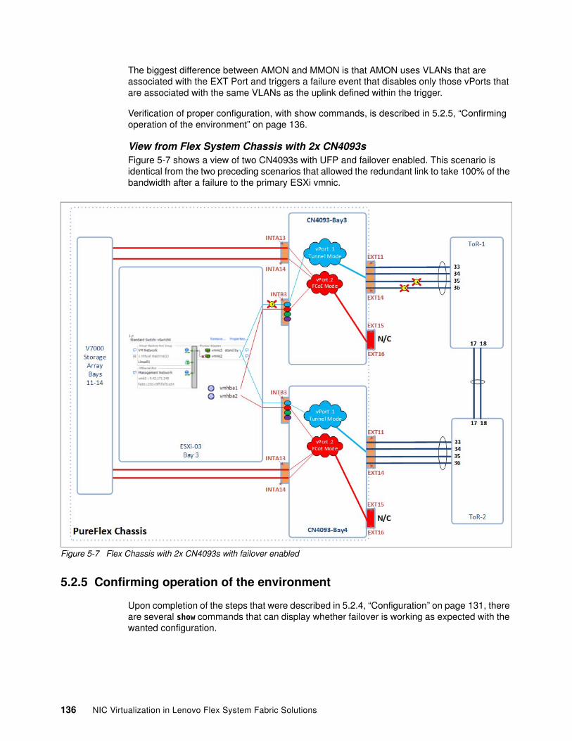
The biggest difference between AMON and MMON is that AMON uses VLANs that are associated with the EXT Port and triggers a failure event that disables only those vPorts that are associated with the same VLANs as the uplink defined within the trigger.
Verification of proper configuration, with show commands, is described in 5.2.5, “Confirming operation of the environment” on page 136.
View from Flex System Chassis with 2x CN4093sFigure 5-7 shows a view of two CN4093s with UFP and failover enabled. This scenario is identical from the two preceding scenarios that allowed the redundant link to take 100% of the bandwidth after a failure to the primary ESXi vmnic.
Figure 5-7 Flex Chassis with 2x CN4093s with failover enabled
5.2.5 Confirming operation of the environment
Upon completion of the steps that were described in 5.2.4, “Configuration” on page 131, there are several show commands that can display whether failover is working as expected with the wanted configuration.
136 NIC Virtualization in Lenovo Flex System Fabric Solutions
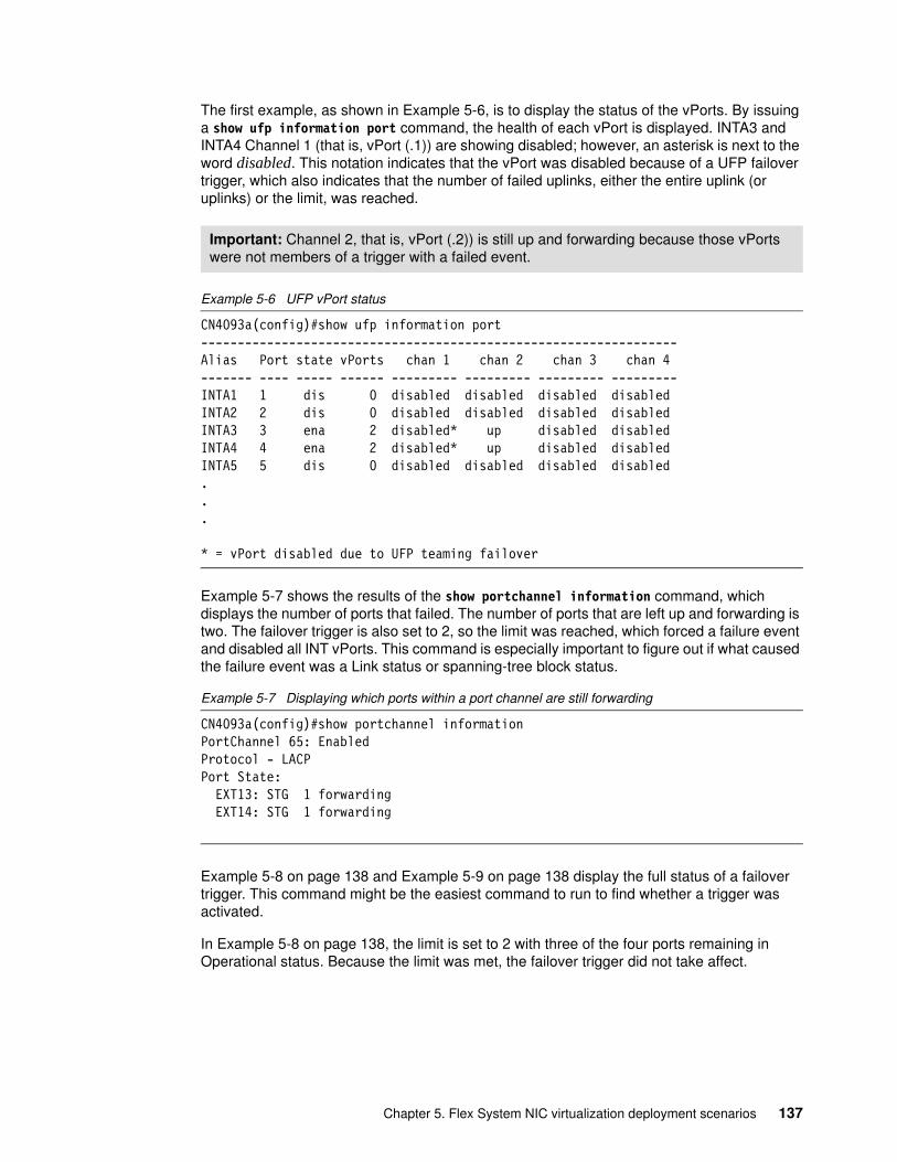
The first example, as shown in Example 5-6, is to display the status of the vPorts. By issuing a show ufp information port command, the health of each vPort is displayed. INTA3 and INTA4 Channel 1 (that is, vPort (.1)) are showing disabled; however, an asterisk is next to the word disabled. This notation indicates that the vPort was disabled because of a UFP failover trigger, which also indicates that the number of failed uplinks, either the entire uplink (or uplinks) or the limit, was reached.
Example 5-6 UFP vPort status
CN4093a(config)#show ufp information port-----------------------------------------------------------------Alias Port state vPorts chan 1 chan 2 chan 3 chan 4------- ---- ----- ------ --------- --------- --------- ---------INTA1 1 dis 0 disabled disabled disabled disabledINTA2 2 dis 0 disabled disabled disabled disabledINTA3 3 ena 2 disabled* up disabled disabledINTA4 4 ena 2 disabled* up disabled disabledINTA5 5 dis 0 disabled disabled disabled disabled...
* = vPort disabled due to UFP teaming failover
Example 5-7 shows the results of the show portchannel information command, which displays the number of ports that failed. The number of ports that are left up and forwarding is two. The failover trigger is also set to 2, so the limit was reached, which forced a failure event and disabled all INT vPorts. This command is especially important to figure out if what caused the failure event was a Link status or spanning-tree block status.
Example 5-7 Displaying which ports within a port channel are still forwarding
CN4093a(config)#show portchannel informationPortChannel 65: EnabledProtocol - LACPPort State: EXT13: STG 1 forwarding EXT14: STG 1 forwarding
Example 5-8 on page 138 and Example 5-9 on page 138 display the full status of a failover trigger. This command might be the easiest command to run to find whether a trigger was activated.
In Example 5-8 on page 138, the limit is set to 2 with three of the four ports remaining in Operational status. Because the limit was met, the failover trigger did not take affect.
Important: Channel 2, that is, vPort (.2)) is still up and forwarding because those vPorts were not members of a trigger with a failed event.
Chapter 5. Flex System NIC virtualization deployment scenarios 137

Example 5-8 Healthy Trigger state
CN4093a(config)#show failover trigger 1 information
Trigger 1 Manual Monitor: EnabledTrigger 1 limit: 2Monitor State: UpMember Status--------- -----------adminkey 5356 EXT11 Operational EXT12 Failed EXT13 Operational EXT14 OperationalControl State: Auto ControlledMember Status--------- -----------Virtual ports INTA3.1 Operational INTA4.1 Operational
In Example 5-9, the limit is set to 2 and there are only two ports remaining in Operational status. Because the limit was met, the failover trigger took affect and put the associated vPorts into a Failed state.
Example 5-9 Failed Trigger state
CN4093a(config)#show failover trigger 1 information
Trigger 1 Manual Monitor: EnabledTrigger 1 limit: 2Monitor State: DownMember Status--------- -----------adminkey 5356 EXT11 Failed EXT12 Failed EXT13 Operational EXT14 OperationalControl State: Auto DisabledMember Status--------- -----------Virtual ports INTA3.1 Failed INTA4.1 Failed
We can also see disconnects from the host side, which indicates that a physical or logical connection was ended.
138 NIC Virtualization in Lenovo Flex System Fabric Solutions
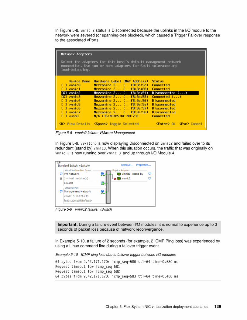
In Figure 5-8, vmnic 2 status is Disconnected because the uplinks in the I/O module to the network were severed (or spanning-tree blocked), which caused a Trigger Failover response to the associated vPorts.
Figure 5-8 vmnic2 failure: VMware Management
In Figure 5-9, vSwitch0 is now displaying Disconnected on vmnic2 and failed over to its redundant (stand by) vmnic3. When this situation occurs, the traffic that was originally on vmnic 2 is now running over vmnic 3 and up through I/O Module 4.
Figure 5-9 vmnic2 failure: vSwitch
In Example 5-10, a failure of 2 seconds (for example, 2 ICMP Ping loss) was experienced by using a Linux command line during a failover trigger event.
Example 5-10 ICMP ping loss due to failover trigger between I/O modules
64 bytes from 9.42.171.170: icmp_seq=580 ttl=64 time=0.580 msRequest timeout for icmp_seq 581Request timeout for icmp_seq 58264 bytes from 9.42.171.170: icmp_seq=583 ttl=64 time=0.468 ms
Important: During a failure event between I/O modules, it is normal to experience up to 3 seconds of packet loss because of network reconvergence.
Chapter 5. Flex System NIC virtualization deployment scenarios 139
5.3 UFP mode virtual NIC with vLAG and FCoE
This section describes the implementation of UFP virtual NIC with FCoE and vLAG aggregations on the uplinks of a pair of CN4093s.
5.3.1 Components
This deployment scenario uses the following equipment:
� Flex System Enterprise Chassis
� x240 Compute Node in bay 3:
– Running ESX 5.5
– Quad port CN4054 CNA in Mezzanine slot 2:
• First two physical CNA ports have UFP configured and FCoE personality enabled• Second two CNA ports have Virtual NIC disabled (not used in this scenario)
� v7000 Storage Node in bays 11 - 14 of the Flex System chassis
Provides remote storage for compute node in bay 3
� Two CN4093 I/O modules:
– Installed in I/O module bays 3 and 4 for this scenario
– Provide the FCF function between the compute node in bay 3, and the storage array in bays 11 - 14
� Two G8264 switches to act as upstream Ethernet connectivity out of the vLAG pair of CN4093s
5.3.2 Topology
This scenario uses the vLAG feature that is available on the CN4093 to virtualize the data plane to support cross switch aggregation. It also uses UFP to provide virtual NIC support to the compute node, and FCoE within UFP to offer FCoE attached storage to the compute node in bay 3.
Consider the following points regarding our demonstration scenario:
� We are using vLAG to provide cross-switch aggregation out of the CN4093s toward the upstream direction to the Top of Rack switches. This configuration provides HA and improved performance for these connections to the upstream network
We are not performing any vLAG aggregations from the CN4093s toward the compute node in bay 3 (aggregations toward servers that are running any form of virtual NIC is not supported at the time of this writing).
� For UFP, we demonstrate the following vPorts:
– vPort1 in tunnel mode
The use of the vLAG aggregation of EXT11 on both CN4093s for the tunnel uplinks out of the I/O modules
Uplink for vPorts by using tunnel mode should use the tagpvid-ingress command to break out tunnel packets toward upstream and add again outer tag on inbound packets back into the tunnel.
140 NIC Virtualization in Lenovo Flex System Fabric Solutions
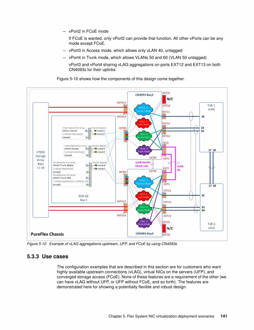
– vPort2 in FCoE mode
If FCoE is wanted, only vPort2 can provide that function. All other vPorts can be any mode except FCoE.
– vPort3 in Access mode, which allows only vLAN 40, untagged
– vPort4 in Trunk mode, which allows VLANs 50 and 60 (VLAN 50 untagged)
vPort3 and vPort4 sharing vLAG aggregations on ports EXT12 and EXT13 on both CN4093s for their uplinks
Figure 5-10 shows how the components of this design come together.
Figure 5-10 Example of vLAG aggregations upstream, UFP, and FCoE by using CN4093s
5.3.3 Use cases
The configuration examples that are described in this section are for customers who want highly available upstream connections (vLAG), virtual NICs on the servers (UFP), and converged storage access (FCoE). None of these features are a requirement of the other (we can have vLAG without UFP, or UFP without FCoE, and so forth). The features are demonstrated here for showing a potentially flexible and robust design.
Chapter 5. Flex System NIC virtualization deployment scenarios 141
5.3.4 Configuration
This section includes the configurations and steps that are necessary to configure the various components. The examples here do not include the upstream G8264 configurations because that is not the focus of this paper (but it does include the configuration for the uplinks in the CN4093s toward the G8264s). Also not included here is the act of creating the LUNs that are used for this process. It is assumed they exist at the time this scenario is built.
The following overall steps that are required to complete this scenario are described next:
� Host side enablement (UEFI Setup)� Miscellaneous I/O module settings� vLAG and aggregation configurations� UFP configuration� FCoE configuration
Host side enablement (UEFI Setup)For this example, we must go into UEFI and configure the wanted virtual NIC type (UFP) and set the personality to FCoE. The installation of ESX and the configuration of the vSwitches and a test VM (images in Figure 5-10 on page 141 represent the final vSwitch vmnic usage) are not shown.
To configure the host to support UFP and FCoE, reboot the server and when you are prompted, press F1 to enter the setup. In setup, click System Settings → Network, then highlight the wanted NIC and press Enter twice. The Emulex NIC Selection menu opens. Change Personality to FCoE (assumes FCoE FoD key already installed) and change Multichannel Mode to Unified Fabric Port (UFP).
After setting the FCoE and UFP Virtual NIC in UEFI, exit the UEFI setup, save the configuration when prompted, and reboot the compute node.
For more information about this process, see Chapter 4, “NIC virtualization considerations on the server side” on page 67.
Miscellaneous I/O module settingsThe following preparatory steps are necessary before you configure the main features of this scenario.
Important: Changing the Personality and MultiChannel modes affects all CNA ports on the ASIC associated with the one being changed. Therefore, it is only necessary to make this change in one place to enable two CNA ports if this is the onboard Emulex or in two places for Quad port CN4054 NIC (CN4054 and Cn4054R have two ASICs).
Important: While you are configuring the I/O modules, all uplinks should be disconnected or disabled until you are instructed to bring up the links. Making certain configuration changes on an I/O module with live connections to an upstream network can cause instability in the network.
Important: All switch configuration instructions assume that we are starting from a factory default configuration on the I/O modules. All configuration commands that are shown are run from the conf t mode of the isCLI interface of the I/O module.
142 NIC Virtualization in Lenovo Flex System Fabric Solutions
Consider the following points regarding these commands:
� In this example, we are using only a limited subset of ports (INTA3, INTA13-INTA14, and so on). However, in most cases many ports are performing the same roles; therefore, some of the commands that are shown here affect both the ports that we are using to demonstrate this scenario and the ports that we are not using in this specific scenario.
� Tagging must be enabled on all ports that are carrying FCoE VLANs and on any ports that are carrying more than a single VLAN.
� A host name is configured (for clarity).
� An idle logout timer is configured (for reference).
� Apply name to ports that are going to internal v7000 (for clarity).
The commands that are used to perform these miscellaneous tasks are shown in Example 5-11.
Example 5-11 Example of preparing switch with base commands
! Enable tagging on all desired ports! 1-28 = INTA1-INTB14, 43-44 = EXT1-EXT2 (vLAG ISL)! 54-55 = EXT11-EXT12 (uplink)int port 1-28,43-44,54-55tagging! ! Add host name and set idle time out to 60 minuteshostname "PF_CN4093a"system idle 60!! Add port names on INTA13 and INTA14int port 13-14name "v7000_Storage"
Repeat the steps that are shown in Example 5-11 for the second switch, changing the hostname to PF_CN4093b. After these base commands are applied, the vLAG and aggregations can be created.
vLAG and aggregation configurationsComplete the following steps to configure the vLAG and aggregation:
1. Create the aggregation for the vLAG ISL and set PVID to an unused VLAN (the use of an unused VLAN for the PVID on the vLAG ISL helps to increase stability of the ISL). We use LACP for all aggregations, but static aggregations also can be used. All LACP keys are chosen to be unique for each aggregation and do not denote anything else special by the use of these specific LACP key numbers.
2. Disable spanning-tree on the PVID VLAN of the ISL, which also helps ensure stability of the ISL.
3. Create the local aggregations on the uplinks.
4. Configure the health check (in this example, we use the EXTM ports back-to-back to provide the vLAG health check). Use some unused IP subnet (1.1.1.X/30) for this health check connection.
Important: All of the examples that are provided here can be directly pasted into the I/O module.
Chapter 5. Flex System NIC virtualization deployment scenarios 143
5. Configure and enable vLAG.
6. vLAG Tier ID must be unique from any upstream that is connecting vLAG pair and must be same for both CN4093 I/O modules in the same vLAG pair.
7. After all configurations are complete, plug in the back-to-back health check cable between EXTM ports. Plug in ISL links.
8. After the ISL is up, plug in uplinks to upstream networks.
The commands that are used to perform these tasks are shown in Example 5-12.
Example 5-12 Example of configuring vLAG and aggregations
! Create the ISL aggregation and set the PVID to an unused VLAN int port 43-44lacp mode activelacp key 4344pvid 4090!! Exit from interface config mode and then globally disable instance of STP ! for ISL PVID VLANexitno spanning-tree stp 26 enablespanning-tree stp 26 vlan 4090
! Configure upstream aggregations (using EXT11 (53) for UFP tunnel uplink! Using EXT12-EXT13 (54-55) for UFP trunk and access uplinksint port 53lacp mode activelacp key 1111!int port 54-55lacp mode activelacp key 1213!! Configure EXTM ports for use as vLAG healthcheck! Interface IP 127 is tied to EXTMint ip 127ip address 1.1.1.1 255.255.255.252 enable
! Configure VLAG! Hlthck points to IP of other CN4093 in this vLAG pair! ISL adminkey is the admin keys on ports EXT1-EXT2! Other adminkeys are for uplink aggregations previously configuredvlag enablevlag tier-id 11vlag hlthchk peer-ip 1.1.1.2vlag isl adminkey 4344vlag adminkey 1111 enablevlag adminkey 1213 enable!
After the process is complete, repeat these steps for the second I/O module, changing the following lines in the configuration that is shown in Example 5-12:
� Change ip address 1.1.1.1 255.255.255.252 enable to ip address 1.1.1.2 255.255.255.252 enable.
144 NIC Virtualization in Lenovo Flex System Fabric Solutions
� Change vlag hlthchk peer-ip 1.1.1.2 to vlag hlthchk peer-ip 1.1.1.1.
After both switches are configured according to these changes, complete the following steps:
1. Bring up the ISL links between the pair of CN4093’s (no shut EXT1-EXT2 or plug in the cables as necessary).
2. Bring up the management ports on both CN4093’s (no shut EXTM or plug in the cable as necessary.
3. Confirm links on EXT1, EXT2, and EXTM ports on both CN4093’s are up (show int status).
4. Confirm that aggregation on EXT1-EXT2 is Up (show lacp info).
5. Confirm vLAG ISL and health check are up by using the show vlag info command and confirm that health check is Up and ISL state is Up.
6. After the vLAG and health checks are confirmed operational, bring up uplink aggregations on EXT11-EXT13 on both I/O modules (no shut EXT11-EXT13 or plug in the cables as necessary).
7. Confirm that links are up (show int status), aggregations are up (show lacp info), and vLAG shows state formed (show vlag info) for both upstream aggregations.
For more information about the commands that are used for correctly functioning I/O modules, see 5.3.5, “Confirming operation of the environment” on page 149.
UFP configurationIn this process, we enable and configure UFP on the INTA3 interface and add the wanted VLANs to uplink ports to complete the path out for the UFP vPorts.
Consider the following points about this process:
� Before we start configuring vPorts, we enabled CEE:
– If a vPort is configured for FCoE, UFP cannot be enabled until CEE is enabled.
– Enabling CEE automatically turns off flow control on all internal ports. This step is done to switch to Per Priority Flow control that is used by CEE.
– When flowcontrol states are changed, the ports are shut or not shut automatically to force the new flowcontrol state.
� In this example, we are configuring the following vPorts:
– vPort 1 is in UFP tunnel mode and uses a tunnel VLAN 4091. VLAN 4091 is the outer tag that is used on packets that are flowing on this tunnel and are stripped off on the uplink EXT11 interface by using the tagpvid-ingress command.
– vPort 2 is used for FCoE traffic and set for VLAN 1001 or 1002, depending on the switch. FCoE VLANs must be different for the separate switches to reduce the likely hood of a fabric merge.
– vPort 3 is configured as a simple access vPort, using an access/untagged VLAN 40.
– vPort 4 is configured as an 802.1Q trunk vPort, by using an untagged VLAN 50, and allowing a tagged VLAN 60.
Important: It is assumed that the upstream connecting switches are properly configured for any necessary aggregations and vLAG/vPC before the links to the upstream network are brought up. Failure to ensure that upstream configuration is complete before plugging in cables can lead to a network down situation.
Chapter 5. Flex System NIC virtualization deployment scenarios 145
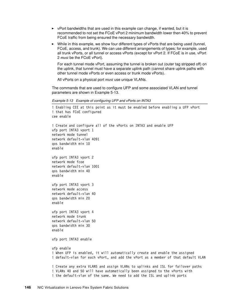
� vPort bandwidths that are used in this example can change, if wanted, but it is recommended to not set the FCoE vPort 2 minimum bandwidth lower then 40% to prevent FCoE traffic from being ensured the necessary bandwidth.
� While in this example, we show four different types of vPorts that are being used (tunnel, FCoE, access, and trunk). We can use different arrangements of types; for example, used all trunk vPorts, or all tunnel or access vPorts (except for vPort 2. If FCoE is in use, vPort 2 must be the FCoE vPort).
For each tunnel mode vPort, assuming the tunnel is broken out (outer tag stripped off) on the uplink, that tunnel must have a separate uplink path (cannot share uplink paths with other tunnel mode vPorts or even access or trunk mode vPorts).
All vPorts on a physical port must use unique VLANs.
The commands that are used to configure UFP and some associated VLAN and tunnel parameters are shown in Example 5-13.
Example 5-13 Example of configuring UFP and vPorts on INTA3
! Enabling CEE at this point as it must be enabled before enabling a UFP vPort ! that has FCoE configuredcee enable
! Create and configure all of the vPorts on INTA3 and enable UFPufp port INTA3 vport 1network mode tunnelnetwork default-vlan 4091qos bandwidth min 10enable
ufp port INTA3 vport 2network mode fcoenetwork default-vlan 1001qos bandwidth min 40enable
ufp port INTA3 vport 3network mode accessnetwork default-vlan 40qos bandwidth min 20enable
ufp port INTA3 vport 4network mode trunknetwork default-vlan 50qos bandwidth min 30enable
ufp port INTA3 enable
ufp enable! When UFP is enabled, it will automatically create and enable the assigned ! default-vlan for each vPort, and add the vPort as a member of that default VLAN
! Create any extra VLANS and assign VLANs to uplinks and ISL for failover paths! VLANs 40 and 50 will have automatically been assigned to the vPorts with ! the default-vlan of the same. We need to add the ISL and uplink ports
146 NIC Virtualization in Lenovo Flex System Fabric Solutions
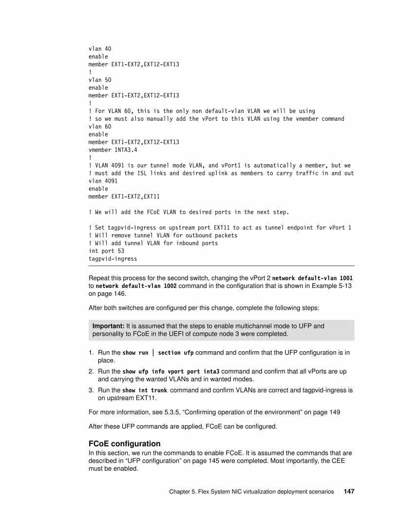
vlan 40enablemember EXT1-EXT2,EXT12-EXT13!vlan 50enablemember EXT1-EXT2,EXT12-EXT13!! For VLAN 60, this is the only non default-vlan VLAN we will be using! so we must also manually add the vPort to this VLAN using the vmember commandvlan 60enablemember EXT1-EXT2,EXT12-EXT13vmember INTA3.4!! VLAN 4091 is our tunnel mode VLAN, and vPort1 is automatically a member, but we ! must add the ISL links and desired uplink as members to carry traffic in and outvlan 4091enablemember EXT1-EXT2,EXT11
! We will add the FCoE VLAN to desired ports in the next step.
! Set tagpvid-ingress on upstream port EXT11 to act as tunnel endpoint for vPort 1 ! Will remove tunnel VLAN for outbound packets! Will add tunnel VLAN for inbound portsint port 53tagpvid-ingress
Repeat this process for the second switch, changing the vPort 2 network default-vlan 1001 to network default-vlan 1002 command in the configuration that is shown in Example 5-13 on page 146.
After both switches are configured per this change, complete the following steps:
1. Run the show run | section ufp command and confirm that the UFP configuration is in place.
2. Run the show ufp info vport port inta3 command and confirm that all vPorts are up and carrying the wanted VLANs and in wanted modes.
3. Run the show int trunk command and confirm VLANs are correct and tagpvid-ingress is on upstream EXT11.
For more information, see 5.3.5, “Confirming operation of the environment” on page 149
After these UFP commands are applied, FCoE can be configured.
FCoE configurationIn this section, we run the commands to enable FCoE. It is assumed the commands that are described in “UFP configuration” on page 145 were completed. Most importantly, the CEE must be enabled.
Important: It is assumed that the steps to enable multichannel mode to UFP and personality to FCoE in the UEFI of compute node 3 were completed.
Chapter 5. Flex System NIC virtualization deployment scenarios 147
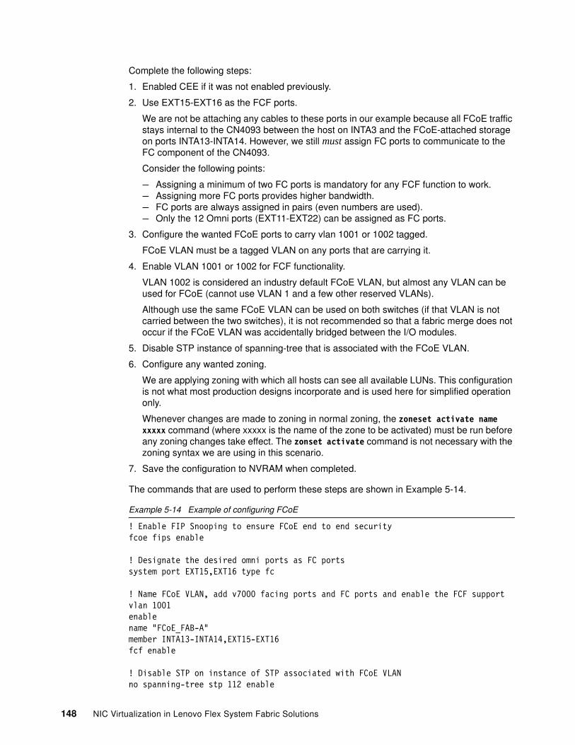
Complete the following steps:
1. Enabled CEE if it was not enabled previously.
2. Use EXT15-EXT16 as the FCF ports.
We are not be attaching any cables to these ports in our example because all FCoE traffic stays internal to the CN4093 between the host on INTA3 and the FCoE-attached storage on ports INTA13-INTA14. However, we still must assign FC ports to communicate to the FC component of the CN4093.
Consider the following points:
– Assigning a minimum of two FC ports is mandatory for any FCF function to work.– Assigning more FC ports provides higher bandwidth.– FC ports are always assigned in pairs (even numbers are used).– Only the 12 Omni ports (EXT11-EXT22) can be assigned as FC ports.
3. Configure the wanted FCoE ports to carry vlan 1001 or 1002 tagged.
FCoE VLAN must be a tagged VLAN on any ports that are carrying it.
4. Enable VLAN 1001 or 1002 for FCF functionality.
VLAN 1002 is considered an industry default FCoE VLAN, but almost any VLAN can be used for FCoE (cannot use VLAN 1 and a few other reserved VLANs).
Although use the same FCoE VLAN can be used on both switches (if that VLAN is not carried between the two switches), it is not recommended so that a fabric merge does not occur if the FCoE VLAN was accidentally bridged between the I/O modules.
5. Disable STP instance of spanning-tree that is associated with the FCoE VLAN.
6. Configure any wanted zoning.
We are applying zoning with which all hosts can see all available LUNs. This configuration is not what most production designs incorporate and is used here for simplified operation only.
Whenever changes are made to zoning in normal zoning, the zoneset activate name xxxxx command (where xxxxx is the name of the zone to be activated) must be run before any zoning changes take effect. The zonset activate command is not necessary with the zoning syntax we are using in this scenario.
7. Save the configuration to NVRAM when completed.
The commands that are used to perform these steps are shown in Example 5-14.
Example 5-14 Example of configuring FCoE
! Enable FIP Snooping to ensure FCoE end to end securityfcoe fips enable
! Designate the desired omni ports as FC portssystem port EXT15,EXT16 type fc
! Name FCoE VLAN, add v7000 facing ports and FC ports and enable the FCF supportvlan 1001enablename "FCoE_FAB-A"member INTA13-INTA14,EXT15-EXT16fcf enable
! Disable STP on instance of STP associated with FCoE VLANno spanning-tree stp 112 enable
148 NIC Virtualization in Lenovo Flex System Fabric Solutions
spanning-tree stp 112 vlan 1001
! Add catch-all zoning (not suitable for most production environments)zone default-zone permitzone name allow-allzoneset name default
! Save the configuration changes made to NVRAMcopy running startup! If prompted to save to flash press the y key! If prompted to change to active config block, press the y key
Repeat these steps for the second switch, changing the following lines:
� Change vlan 1001 to vlan 1002.� Change name "FCoE_FAB-A" to name "FCoE_FAB-B".� Change no spanning-tree stp 112 enable to no spanning-tree stp 113 enable.� Change spanning-tree stp 112 vlan 1001 to spanning-tree stp 113 vlan 1002.
After both switches are configured per these changes, complete the following steps:
1. Run the show fcoe fips fcf command and confirm that an FCF entry is seen for each FC port that was configured. The FCF function should come up, regardless of the FCoE sessions.
2. Run the show fcoe fips fcoe command and confirm that an FCoE session is seen for each V7000 port on INTA13 and INTA14 and one for the server on INTA3.
3. Run the show fcoe fips vlan command and confirm that the wanted interfaces are present for the FCoE VLAN.
For more information about these commands and other helpful troubleshooting commands for this environment, see 5.3.5, “Confirming operation of the environment” on page 149.
5.3.5 Confirming operation of the environment
This section contains helpful commands and their associated output to ensure that the demonstrated scenario is healthy and operating as expected. There are many helpful commands for many tasks, but this section is focused on the specific commands for this environment. Also, the output for most of this information can also be obtained by using a show tech command.
Confirming the health of vLAG and aggregationsThe examples that are shown in Example 5-15 on page 150 represent truncated output and added embedded comments about that command output.
Important: It is assumed that the operating system was installed on the compute node and proper FCoE drivers are operational within the operating system. It is also assumed that the V7000 storage was configured and is presenting storage to the host.
Important: To reduce extraneous output, many non-essential lines were removed from the output of the commands that are shown in this section. Where removed, the lines are replaced by an ellipsis (...).
Chapter 5. Flex System NIC virtualization deployment scenarios 149
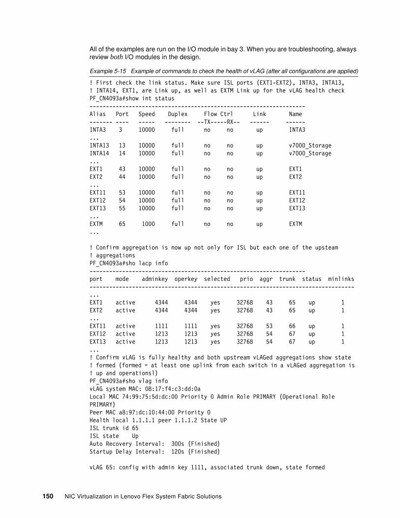
All of the examples are run on the I/O module in bay 3. When you are troubleshooting, always review both I/O modules in the design.
Example 5-15 Example of commands to check the health of vLAG (after all configurations are applied)
! First check the link status. Make sure ISL ports (EXT1-EXT2), INTA3, INTA13,! INTA14, EXT1, are Link up, as well as EXTM Link up for the vLAG health checkPF_CN4093a#show int status------------------------------------------------------------------Alias Port Speed Duplex Flow Ctrl Link Name------- ---- ----- -------- --TX-----RX-- ------ ------INTA3 3 10000 full no no up INTA3...INTA13 13 10000 full no no up v7000_StorageINTA14 14 10000 full no no up v7000_Storage...EXT1 43 10000 full no no up EXT1EXT2 44 10000 full no no up EXT2...EXT11 53 10000 full no no up EXT11EXT12 54 10000 full no no up EXT12EXT13 55 10000 full no no up EXT13...EXTM 65 1000 full no no up EXTM...
! Confirm aggregation is now up not only for ISL but each one of the upsteam ! aggregationsPF_CN4093a#sho lacp info------------------------------------------------------------------port mode adminkey operkey selected prio aggr trunk status minlinks---------------------------------------------------------------------------------...EXT1 active 4344 4344 yes 32768 43 65 up 1EXT2 active 4344 4344 yes 32768 43 65 up 1...EXT11 active 1111 1111 yes 32768 53 66 up 1EXT12 active 1213 1213 yes 32768 54 67 up 1EXT13 active 1213 1213 yes 32768 54 67 up 1...! Confirm vLAG is fully healthy and both upstream vLAGed aggregations show state ! formed (formed = at least one uplink from each switch in a vLAGed aggregation is ! up and operationsl)PF_CN4093a#sho vlag infovLAG system MAC: 08:17:f4:c3:dd:0aLocal MAC 74:99:75:5d:dc:00 Priority 0 Admin Role PRIMARY (Operational Role PRIMARY)Peer MAC a8:97:dc:10:44:00 Priority 0 Health local 1.1.1.1 peer 1.1.1.2 State UPISL trunk id 65ISL state UpAuto Recovery Interval: 300s (Finished)Startup Delay Interval: 120s (Finished)
vLAG 65: config with admin key 1111, associated trunk down, state formed
150 NIC Virtualization in Lenovo Flex System Fabric Solutions
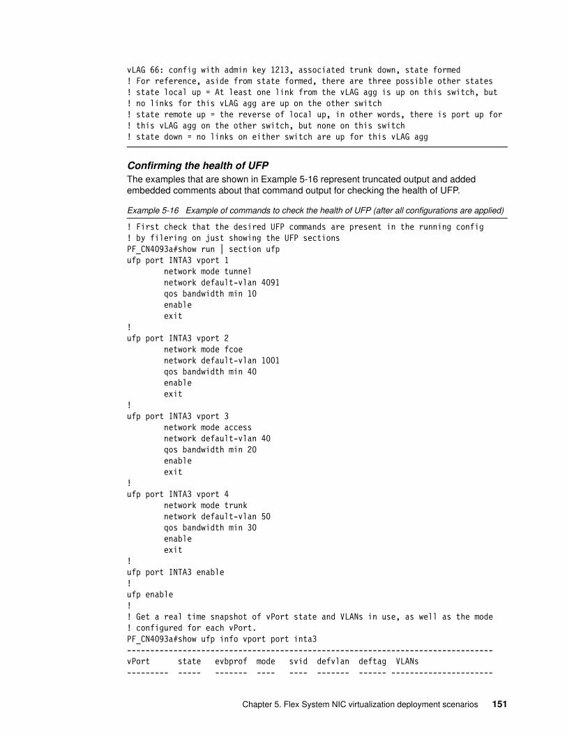
vLAG 66: config with admin key 1213, associated trunk down, state formed! For reference, aside from state formed, there are three possible other states! state local up = At least one link from the vLAG agg is up on this switch, but ! no links for this vLAG agg are up on the other switch! state remote up = the reverse of local up, in other words, there is port up for ! this vLAG agg on the other switch, but none on this switch! state down = no links on either switch are up for this vLAG agg
Confirming the health of UFPThe examples that are shown in Example 5-16 represent truncated output and added embedded comments about that command output for checking the health of UFP.
Example 5-16 Example of commands to check the health of UFP (after all configurations are applied)
! First check that the desired UFP commands are present in the running config! by filering on just showing the UFP sectionsPF_CN4093a#show run | section ufpufp port INTA3 vport 1 network mode tunnel network default-vlan 4091 qos bandwidth min 10 enable exit!ufp port INTA3 vport 2 network mode fcoe network default-vlan 1001 qos bandwidth min 40 enable exit!ufp port INTA3 vport 3 network mode access network default-vlan 40 qos bandwidth min 20 enable exit!ufp port INTA3 vport 4 network mode trunk network default-vlan 50 qos bandwidth min 30 enable exit!ufp port INTA3 enable!ufp enable!! Get a real time snapshot of vPort state and VLANs in use, as well as the mode ! configured for each vPort.PF_CN4093a#show ufp info vport port inta3-------------------------------------------------------------------------------vPort state evbprof mode svid defvlan deftag VLANs--------- ----- ------- ---- ---- ------- ------ ----------------------
Chapter 5. Flex System NIC virtualization deployment scenarios 151
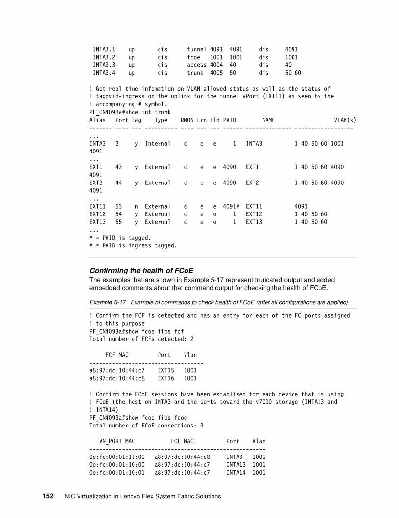
INTA3.1 up dis tunnel 4091 4091 dis 4091 INTA3.2 up dis fcoe 1001 1001 dis 1001 INTA3.3 up dis access 4004 40 dis 40 INTA3.4 up dis trunk 4005 50 dis 50 60
! Get real time infomation on VLAN allowed status as well as the status of! tagpvid-ingress on the uplink for the tunnel vPort (EXT11) as seen by the ! accompanying # symbol.PF_CN4093a#show int trunkAlias Port Tag Type RMON Lrn Fld PVID NAME VLAN(s)------- ---- --- ---------- ---- --- --- ------ -------------- ------------------...INTA3 3 y Internal d e e 1 INTA3 1 40 50 60 1001 4091...EXT1 43 y External d e e 4090 EXT1 1 40 50 60 4090 4091EXT2 44 y External d e e 4090 EXT2 1 40 50 60 4090 4091...EXT11 53 n External d e e 4091# EXT11 4091EXT12 54 y External d e e 1 EXT12 1 40 50 60EXT13 55 y External d e e 1 EXT13 1 40 50 60...* = PVID is tagged.# = PVID is ingress tagged.
Confirming the health of FCoEThe examples that are shown in Example 5-17 represent truncated output and added embedded comments about that command output for checking the health of FCoE.
Example 5-17 Example of commands to check health of FCoE (after all configurations are applied)
! Confirm the FCF is detected and has an entry for each of the FC ports assigned ! to this purposePF_CN4093a#show fcoe fips fcfTotal number of FCFs detected: 2
FCF MAC Port Vlan-----------------------------------a8:97:dc:10:44:c7 EXT15 1001a8:97:dc:10:44:c8 EXT16 1001
! Confirm the FCoE sessions have been establised for each device that is using ! FCoE (the host on INTA3 and the ports toward the v7000 storage (INTA13 and! INTA14)PF_CN4093a#show fcoe fips fcoeTotal number of FCoE connections: 3
VN_PORT MAC FCF MAC Port Vlan------------------------------------------------------0e:fc:00:01:11:00 a8:97:dc:10:44:c8 INTA3 10010e:fc:00:01:10:00 a8:97:dc:10:44:c7 INTA13 10010e:fc:00:01:10:01 a8:97:dc:10:44:c7 INTA14 1001
152 NIC Virtualization in Lenovo Flex System Fabric Solutions
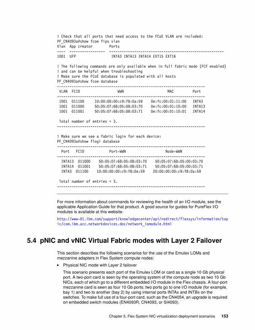
! Check that all ports that need access to the FCoE VLAN are included:PF_CN4093a#show fcoe fips vlanVlan App creator Ports---- ----------------- -------------------------------------------------------1001 UFP INTA3 INTA13 INTA14 EXT15 EXT16
! The following commands are only available when in full fabric mode (FCF enabled) ! and can be helpful when troubleshooting! Make sure the FCoE database is populated with all hostsPF_CN4093a#show fcoe database----------------------------------------------------------------------- VLAN FCID WWN MAC Port----------------------------------------------------------------------- 1001 011100 10:00:00:00:c9:f8:0a:59 0e:fc:00:01:11:00 INTA3 1001 011000 50:05:07:68:05:08:03:70 0e:fc:00:01:10:00 INTA13 1001 011001 50:05:07:68:05:08:03:71 0e:fc:00:01:10:01 INTA14
Total number of entries = 3.-----------------------------------------------------------------------
! Make sure we see a fabric login for each device:PF_CN4093a#show flogi database----------------------------------------------------------------------- Port FCID Port-WWN Node-WWN----------------------------------------------------------------------- INTA13 011000 50:05:07:68:05:08:03:70 50:05:07:68:05:00:03:70 INTA14 011001 50:05:07:68:05:08:03:71 50:05:07:68:05:00:03:71 INTA3 011100 10:00:00:00:c9:f8:0a:59 20:00:00:00:c9:f8:0a:59
Total number of entries = 3.-----------------------------------------------------------------------
For more information about commands for reviewing the health of an I/O module, see the applicable Application Guide for that product. A good source for guides for PureFlex I/O modules is available at this website:
http://www-01.ibm.com/support/knowledgecenter/api/redirect/flexsys/information/topic/com.ibm.acc.networkdevices.doc/network_iomodule.html
5.4 pNIC and vNIC Virtual Fabric modes with Layer 2 Failover
This section describes the following scenarios for the use of the Emulex LOMs and mezzanine adapters in Flex System compute nodes:
� Physical NIC mode with Layer 2 failover
This scenario presents each port of the Emulex LOM or card as a single 10 Gb physical port. A two-port card is seen by the operating system of the compute node as two 10 Gb NICs, each of which go to a different embedded I/O module in the Flex chassis. A four-port mezzanine card is seen as four 10 Gb ports; two ports go to one I/O module (for example, bay 1) and two to another (bay 2) by using internal ports INTAx and INTBx on the switches. To make full use of a four-port card, such as the CN4054, an upgrade is required on embedded switch modules (EN4093R, CN4093, or SI4093).
Chapter 5. Flex System NIC virtualization deployment scenarios 153
� Physical NIC mode with Layer 2 failover and FCoE storage
This scenario changes the presentation of the card so that each physical port is seen as an NIC and a corresponding FCoE HBA. (It is also possible to select the iSCSI personality on the card, and the storage side is seen as an iSCSI HBA. This scenario is not tested here.)
� Virtual Fabric vNIC mode with failover
Also known as Virtual Fabric mode, this scenario presents each port of an Emulex LOM or card as up to four virtualized ports. The bandwidth of these ports is configurable with a minimum guaranteed bandwidth allocation and a maximum limit on bandwidth usage. The operating system of the compute node sees up to eight NICs, with bandwidth equal to the maximum limit that is configured on the Emulex hardware. Although the operating system might see eight NICs (each with a bandwidth of 10 Gb), there are still only two 10 Gb physical ports behind them. Four of the vNICs share the 10 Gb bandwidth of each physical port. (If a four-port card is used, such as the EN4054, vNIC presents up to 16 virtualized NICs to the operating system from each EN4054. However, there are still only four 10 Gb physical ports and the total available bandwidth is 40 Gb.)
� Virtual Fabric vNIC mode with failover and FCoE storage
This scenario reserves one of the four vNIC instances for each physical port for storage networking. In this case, the operating system sees fewer virtualized NIC instances but sees the storage functionality reflected as an HBA. For example, a two-port LOM that is configured in this way is seen by the operating system as six virtualized NIC instances and a two-port HBA. The two-port LOM still has only two physical 10 Gb ports, and each one is shared by three vNIC instances and one HBA. As in Physical NIC mode, an iSCSI personality also is available.
Layer 2 Failover is a configurable function of most of the embedded switch I/O modules on the Flex System chassis. It allows the state of a set of ports (typically, external ports that connect to an upstream network) to control the state of other ports (often internal facing ports that connect across the chassis backplane to compute nodes). This feature often is used to protect against a specific type of network failure that can occur in chassis-based systems, where an embedded switch is operational but disconnected from the remainder of the network. Layer 2 failover can administratively disable server-facing ports when such a failure occurs, which triggers the servers’ NIC teaming (or bonding) capability to use a surviving port that still has a viable connection to the network.
Notes: Consider the following important points:
� There are two distinct ways to configure L2 failover on the EN4093R and CN4093 switches. The failover command and associated subcommands and operands operates on full physical ports and was enhanced to function for UFP vports.
� There is also a failover option within the configuration of a vnic group. This option allows a failure in the uplink that is associated with a vnic group to cause the vnic members of that group to be administratively disabled.
� The vmember option of the failover command, which is intended for UFP vports, allows a vNIC instance to be specified, but it does not provide the wanted failover function.
154 NIC Virtualization in Lenovo Flex System Fabric Solutions
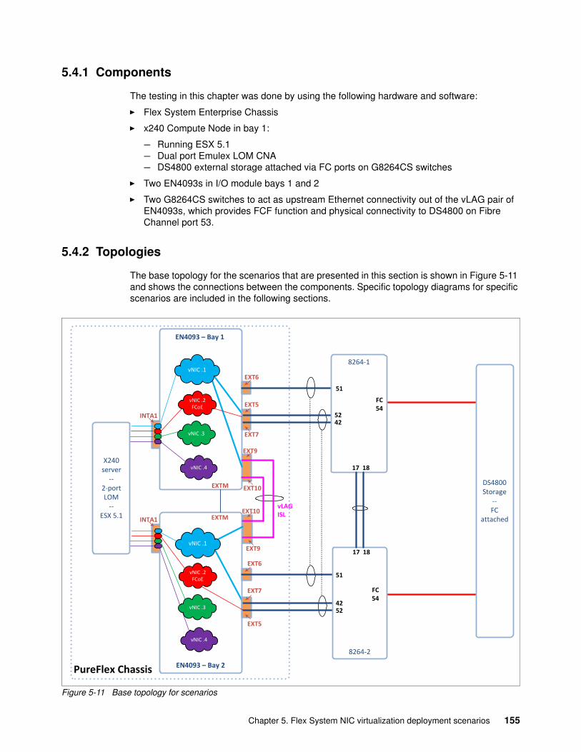
5.4.1 Components
The testing in this chapter was done by using the following hardware and software:
� Flex System Enterprise Chassis
� x240 Compute Node in bay 1:
– Running ESX 5.1– Dual port Emulex LOM CNA – DS4800 external storage attached via FC ports on G8264CS switches
� Two EN4093s in I/O module bays 1 and 2
� Two G8264CS switches to act as upstream Ethernet connectivity out of the vLAG pair of EN4093s, which provides FCF function and physical connectivity to DS4800 on Fibre Channel port 53.
5.4.2 Topologies
The base topology for the scenarios that are presented in this section is shown in Figure 5-11 and shows the connections between the components. Specific topology diagrams for specific scenarios are included in the following sections.
Figure 5-11 Base topology for scenarios
PureFlex Chassis
DS4800 Storage
--FC
attached
EN4093 – Bay 1
EXT6
vNIC .4
8264-1
EXT5
EXT7
vNIC .2FCoE
EN4093 – Bay 2
vNIC .4
8264-2
vNIC .2FCoE
INTA1
INTA1
EXT6
EXT7
EXT5
EXT10
EXT9
EXT9
EXT10vLAGISL
5242
4252
51
51
17 18
17 18
EXTM
EXTM
FC54
FC54
vNIC .3
vNIC .3
vNIC .1
vNIC .1
X240 server
--2-port LOM
-- ESX 5.1
Chapter 5. Flex System NIC virtualization deployment scenarios 155
5.4.3 Use cases
Physical NIC mode (pNIC) is the default mode for the Flex environment. It presents the LOM and NIC mezzanine cards to the server’s operating system with the same number of ports that the card features (2-port or 4-port). In this mode, converged networking can be enabled so that these cards present two or four NIC ports and two or four HBA ports for storage (FCoE or iSCSI).
Redundancy can be achieved in pNIC mode for data networking by using NIC teaming options on the various operating systems. The storage protocols each have their own multi-pathing options, which provide a similar capability if both HBA ports can access the storage LUNs.
The embedded and Top-of-Rack switches can be configured by using the failover command, which works with NIC teaming. This scenario uses active-standby teaming on Windows and Linux; it can use a form of active-active teaming with VMware. (For more information about these options, see 4.3, “Using physical and virtual NICs in the operating systems” on page 107). In addition, active-active NIC teaming modes can be supported by Virtual Link-aggregation (vLAG) on the switches. This configuration often provides a more rapid failover and fail-back.
Virtual Fabric vNIC mode was the first virtualization option that was available from Emulex and Lenovo. It allows the Emulex converged NIC to be seen by operating systems as four NIC ports per physical port, or three NIC ports and one HBA per physical port. There are topology constraints in Virtual Fabric vNIC mode that are largely relaxed in the newer UFP virtualization mode, which is recommended for new implementations. For more information about UFP, see 5.3, “UFP mode virtual NIC with vLAG and FCoE” on page 140.
5.4.4 Configurations
The following configuration options are described in this section:
� Physical NIC mode� Use of vLAG with failover� Physical NIC mode with FCoE storage� Virtual Fabric vNIC mode� Virtual Fabric vNIC mode with FCoE
Physical NIC mode The failover function on the EN4093R switches can be configured on static or dynamic (LACP) aggregations. If you want to use auto monitoring (AMON), then a single port can be configured as an aggregation and then configured into a failover trigger. The following configuration is used: assuming that the uplink ports to be monitored are EXT5 and EXT7, the upstream switch must configure LACP on the corresponding ports.
With this configuration, when both EXT5 and EXT7 fail, internally facing ports with the same VLANs are administratively brought down. The limit option that is shown in Example 5-18 on page 157 can be used to cause the internal ports to be brought down when EXT5 or EXT7 fails; that is, when there are one or fewer ports active. The commands are shown in Example 5-18 on page 157.
156 NIC Virtualization in Lenovo Flex System Fabric Solutions
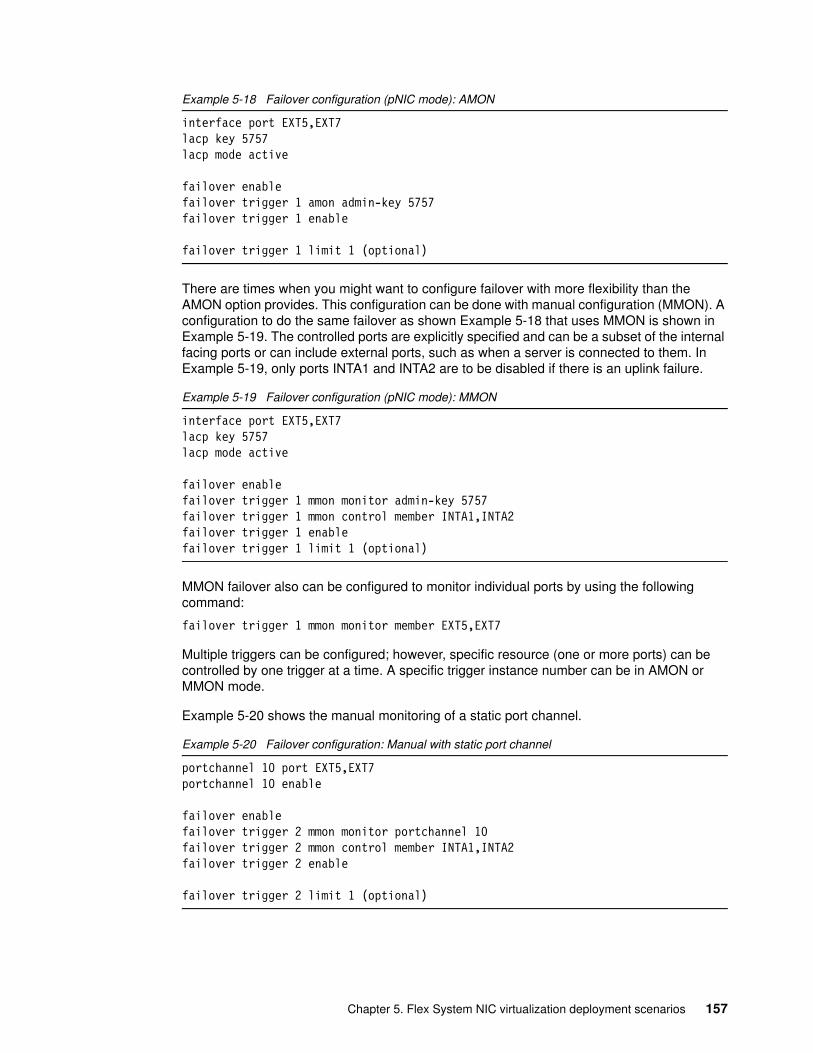
Example 5-18 Failover configuration (pNIC mode): AMON
interface port EXT5,EXT7lacp key 5757lacp mode active
failover enablefailover trigger 1 amon admin-key 5757failover trigger 1 enable
failover trigger 1 limit 1 (optional)
There are times when you might want to configure failover with more flexibility than the AMON option provides. This configuration can be done with manual configuration (MMON). A configuration to do the same failover as shown Example 5-18 that uses MMON is shown in Example 5-19. The controlled ports are explicitly specified and can be a subset of the internal facing ports or can include external ports, such as when a server is connected to them. In Example 5-19, only ports INTA1 and INTA2 are to be disabled if there is an uplink failure.
Example 5-19 Failover configuration (pNIC mode): MMON
interface port EXT5,EXT7lacp key 5757lacp mode active
failover enablefailover trigger 1 mmon monitor admin-key 5757failover trigger 1 mmon control member INTA1,INTA2failover trigger 1 enablefailover trigger 1 limit 1 (optional)
MMON failover also can be configured to monitor individual ports by using the following command:
failover trigger 1 mmon monitor member EXT5,EXT7
Multiple triggers can be configured; however, specific resource (one or more ports) can be controlled by one trigger at a time. A specific trigger instance number can be in AMON or MMON mode.
Example 5-20 shows the manual monitoring of a static port channel.
Example 5-20 Failover configuration: Manual with static port channel
portchannel 10 port EXT5,EXT7portchannel 10 enable
failover enablefailover trigger 2 mmon monitor portchannel 10failover trigger 2 mmon control member INTA1,INTA2failover trigger 2 enable
failover trigger 2 limit 1 (optional)
Chapter 5. Flex System NIC virtualization deployment scenarios 157
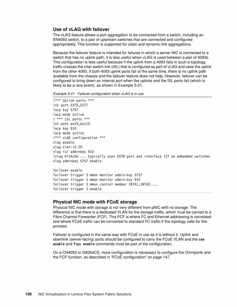
Use of vLAG with failoverThe vLAG feature allows a port aggregation to be connected from a switch, including an EN4093 switch, to a pair of upstream switches that are connected and configured appropriately. This function is supported for static and dynamic link aggregations.
Because the failover feature is intended for failures in which a server NIC is connected to a switch that has no uplink path, it is less useful when vLAG is used between a pair of 4093s. This configuration is less useful because if the uplink from a 4093 fails in such a topology, traffic crosses the inter-switch link (ISL) that is configured as part of vLAG and uses the uplink from the other 4093. If both 4093 uplink ports fail at the same time, there is no uplink path available from the chassis and the failover feature does not help. However, failover can be configured to bring down an internal port when the uplinks and the ISL ports fail (which is likely to be a rare event), as shown in Example 5-21.
Example 5-21 Failover configuration when vLAG is in use
!*** Uplink ports ***int port EXT5,EXT7lacp key 5757lacp mode active! *** ISL ports ***int port ext9,ext10lacp key 910lacp mode active!*** vLAG configuration ***vlag enablevlag tier-id 20vlag isl adminkey 910!vlag hlthchk ... typically uses EXTM port and interface 127 on embedded switchesvlag adminkey 5757 enable
failover enablefailover trigger 3 mmon monitor admin-key 5757failover trigger 3 mmon monitor admin-key 910failover trigger 3 mmon control member INTA1,INTA2....failover trigger 3 enable
Physical NIC mode with FCoE storagePhysical NIC mode with storage is not very different from pNIC with no storage. The difference is that there is a dedicated VLAN for the storage traffic, which must be carried to a Fibre Channel Forwarder (FCF). This FCF is where FC and Ethernet addressing is correlated and where FCoE traffic can be converted to standard FC traffic if the topology calls for this process.
Failover is configured in the same way with FCoE in use as it is without it. Uplink and downlink (server-facing) ports should be configured to carry the FCoE VLAN and the cee enable and fips enable commands must be part of the configuration.
On a CN4093 or G8264CS, more configuration is necessary to configure the Omniports and the FCF function, as described in “FCoE configuration” on page 147.
158 NIC Virtualization in Lenovo Flex System Fabric Solutions
Design choicesFor pNIC mode (or vNIC) with storage, it is often suggested that the two HBA ports and the associated switches use different FCoE VLANs. If vLAG is in use in such a topology, the FCoE VLANs should not cross the ISL between the vLAG partner switches. This configuration works well with the typical SAN design in which redundancy is provided by having two distinct SAN networks (SAN-A and SAN-B), which can reach the physical storage but share few or no components between the servers and the storage.
FCoE traffic can be sent on the same uplinks as data traffic or separate uplinks can be used for the different types of traffic. In the tested scenario, storage and data traffic were forwarded to the same upstream switches, but this process is not required. Even when the traffic is sent to the same upstream switches, the option to segregate the two types of traffic is available.
Topologies that show this and relevant parts of the switch configurations are shown in Figure 5-12 on page 160 and Figure 5-13 on page 161. In the configuration examples that are shown in Example 5-22 on page 161 and Example 5-23 on page 163, VLANs 1001 and 1002 (on the second EN4093) are used to carry FCoE traffic and VLANs 1 and 2 are carrying data traffic. The traffic can be segregated by changing the configuration in the following ways:
� On the EN4093 switches:
– Breaking the aggregation between links EXT5 and EXT7, which uses LACP key 5757– Assigning VLAN 1001 (or 1002) to EXT5 and VLAN 1 and 2 to EXT7 (or vice versa)
� On the G8264CS switches:
– Breaking the aggregation between links 42 and 52, which uses LACP key 4252– Assigning the VLANs to the links to match what was done on the EN4093s
Chapter 5. Flex System NIC virtualization deployment scenarios 159
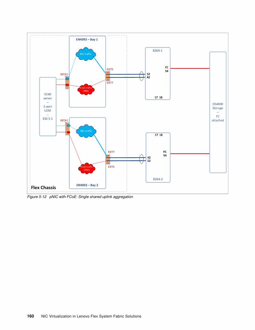
Figure 5-12 pNIC with FCoE: Single shared uplink aggregation
160 NIC Virtualization in Lenovo Flex System Fabric Solutions
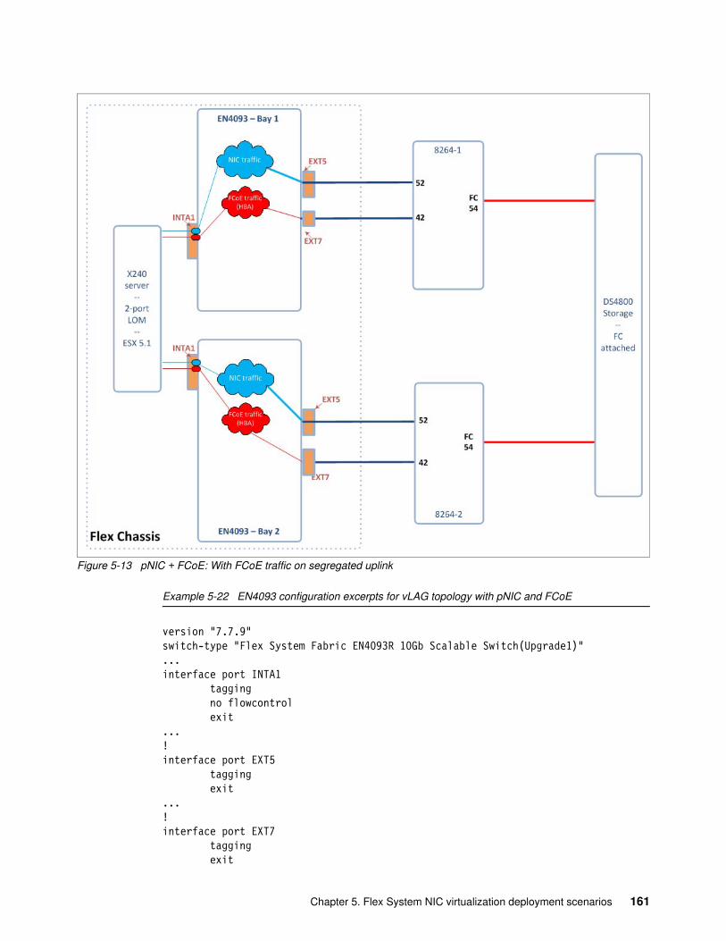
Figure 5-13 pNIC + FCoE: With FCoE traffic on segregated uplink
Example 5-22 EN4093 configuration excerpts for vLAG topology with pNIC and FCoE
version "7.7.9"switch-type "Flex System Fabric EN4093R 10Gb Scalable Switch(Upgrade1)"...interface port INTA1 tagging no flowcontrol exit...!interface port EXT5 tagging exit...!interface port EXT7 tagging exit
Chapter 5. Flex System NIC virtualization deployment scenarios 161
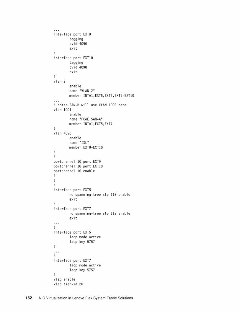
...interface port EXT9 tagging pvid 4090 exit!interface port EXT10 tagging pvid 4090 exit!vlan 2 enable name "VLAN 2" member INTA1,EXT5,EXT7,EXT9-EXT10...! Note: SAN-B will use VLAN 1002 herevlan 1001 enable name "FCoE SAN-A" member INTA1,EXT5,EXT7!vlan 4090 enable name "ISL" member EXT9-EXT10!!portchannel 10 port EXT9portchannel 10 port EXT10portchannel 10 enable!!!interface port EXT5 no spanning-tree stp 112 enable exit!interface port EXT7 no spanning-tree stp 112 enable exit...!interface port EXT5 lacp mode active lacp key 5757!...!interface port EXT7 lacp mode active lacp key 5757!vlag enablevlag tier-id 20
162 NIC Virtualization in Lenovo Flex System Fabric Solutions
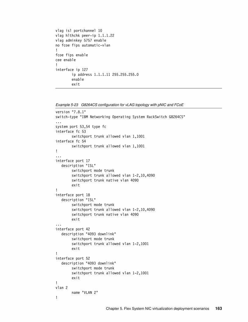
vlag isl portchannel 10vlag hlthchk peer-ip 1.1.1.22vlag adminkey 5757 enableno fcoe fips automatic-vlan!fcoe fips enablecee enable!interface ip 127 ip address 1.1.1.11 255.255.255.0 enable exit
Example 5-23 G8264CS configuration for vLAG topology with pNIC and FCoE
version "7.8.1"switch-type "IBM Networking Operating System RackSwitch G8264CS"...system port 53,54 type fcinterface fc 53 switchport trunk allowed vlan 1,1001interface fc 54 switchport trunk allowed vlan 1,1001!...interface port 17
description "ISL" switchport mode trunk switchport trunk allowed vlan 1-2,10,4090 switchport trunk native vlan 4090 exit!interface port 18
description "ISL" switchport mode trunk switchport trunk allowed vlan 1-2,10,4090 switchport trunk native vlan 4090 exit...interface port 42
description "4093 downlink" switchport mode trunk switchport trunk allowed vlan 1-2,1001 exit!interface port 52
description "4093 downlink" switchport mode trunk switchport trunk allowed vlan 1-2,1001 exit!vlan 2 name "VLAN 2"!
Chapter 5. Flex System NIC virtualization deployment scenarios 163
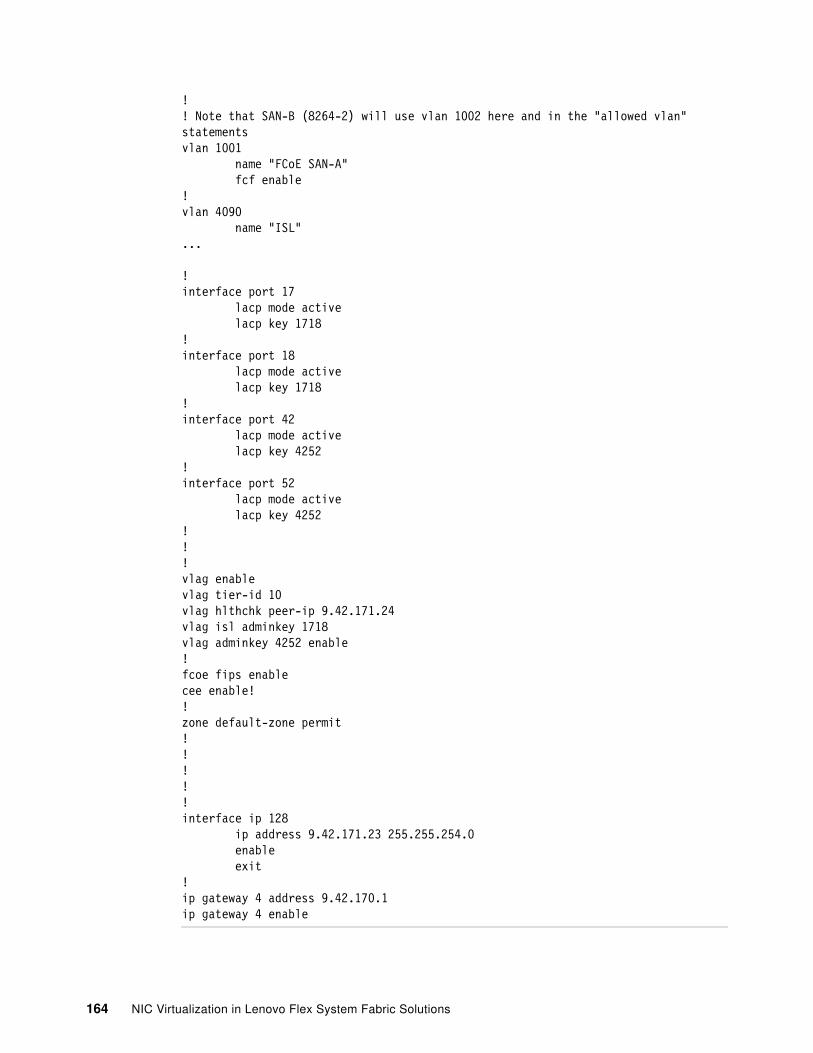
!! Note that SAN-B (8264-2) will use vlan 1002 here and in the "allowed vlan" statementsvlan 1001 name "FCoE SAN-A" fcf enable!vlan 4090 name "ISL"...
!interface port 17 lacp mode active lacp key 1718!interface port 18 lacp mode active lacp key 1718!interface port 42 lacp mode active lacp key 4252!interface port 52 lacp mode active lacp key 4252!!!vlag enablevlag tier-id 10vlag hlthchk peer-ip 9.42.171.24vlag isl adminkey 1718vlag adminkey 4252 enable!fcoe fips enablecee enable!!zone default-zone permit!!!!!interface ip 128 ip address 9.42.171.23 255.255.254.0 enable exit!ip gateway 4 address 9.42.170.1ip gateway 4 enable
164 NIC Virtualization in Lenovo Flex System Fabric Solutions
Virtual Fabric vNIC modeVirtual Fabric vNIC (or vNIC1) mode is the first NIC virtualization mode that was developed for use with Emulex adapters on Lenovo servers. It was supplanted mostly by UFP mode, which is more versatile. However, Virtual Fabric vNIC has its own failover configuration commands that are part of the vNIC group configuration.
vNICs, vNIC groups, and uplinksFor more information about the available options for vNIC and their initial configuration, see 4.1, “Enabling virtual NICs on the server via UEFI” on page 68.
Virtual Fabric vNIC mode introduces the following concepts:
� vNIC: An instance of a virtualized NIC that is associated with a specific physical port and appears as an NIC or as an HBA, as seen by a server’s operating system or hypervisor.
� vNIC group: A set of vNICs that are used together and are each associated with a different physical port.
� vNIC group uplink: A single port or a static or LACP port aggregation that is associated with a vNIC group.
� vNIC group VLAN: A VLAN that is used for tunneling traffic from the vNICs and any non-virtualized internal ports that are associated the group through the group’s uplink to the wider network.
Configuration of the Virtual Fabric vNIC feature is done according to the following requirements:
� A physical port can have up to four vNICs activated. No more than one can be for FCoE traffic and it always is vNIC instance 2.
� Bandwidth of vNIC’s is specified in 100 Mb increments; each increment is also 1% of the bandwidth of a 10 Gb port. Minimum bandwidth is 1 Gb, which is specified as 10 in the configuration.
� Each data vNIC must be associated with a vNIC group. FCoE vNIC instances cannot be associated with a vNIC group.
� A vNIC group can have a single logical uplink. If there is no requirement for traffic from the group to be forwarded outside of the chassis, an uplink is not needed.
� Each vNIC group must be configured with a vNIC VLAN. This VLAN is never seen outside of the embedded switch in the chassis. It is used as an outer tag for 802-1q double-tagging by the switching ASIC.
� vNIC group VLAN numbers are not strictly required to be unique within the network; however, making them unique can avoid confusion when troubleshooting.
Note: By using the zone default-zone permit command, any server can access any storage where the LUN is made accessible. However, the default zoning configuration when FCF mode is used on a G8264CS or a CN4093 is to deny all access. Therefore, explicit zoning or the default-zone option is necessary. The status of zoning can be seen by using the show zone command on converged switches.
This configuration does not apply when NPV mode is used; in that case, zoning is configured on an upstream SAN switch.
Chapter 5. Flex System NIC virtualization deployment scenarios 165
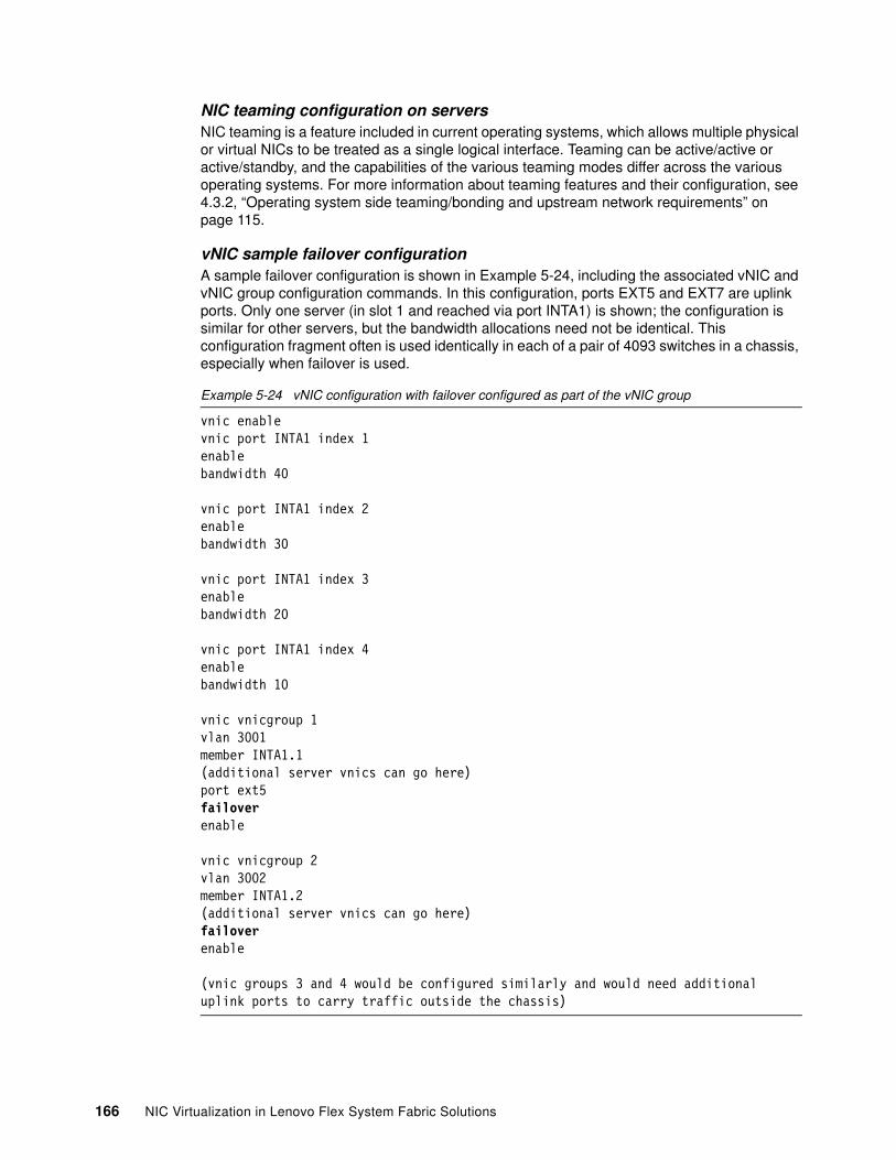
NIC teaming configuration on serversNIC teaming is a feature included in current operating systems, which allows multiple physical or virtual NICs to be treated as a single logical interface. Teaming can be active/active or active/standby, and the capabilities of the various teaming modes differ across the various operating systems. For more information about teaming features and their configuration, see 4.3.2, “Operating system side teaming/bonding and upstream network requirements” on page 115.
vNIC sample failover configurationA sample failover configuration is shown in Example 5-24, including the associated vNIC and vNIC group configuration commands. In this configuration, ports EXT5 and EXT7 are uplink ports. Only one server (in slot 1 and reached via port INTA1) is shown; the configuration is similar for other servers, but the bandwidth allocations need not be identical. This configuration fragment often is used identically in each of a pair of 4093 switches in a chassis, especially when failover is used.
Example 5-24 vNIC configuration with failover configured as part of the vNIC group
vnic enablevnic port INTA1 index 1enablebandwidth 40
vnic port INTA1 index 2enablebandwidth 30
vnic port INTA1 index 3enablebandwidth 20
vnic port INTA1 index 4enablebandwidth 10
vnic vnicgroup 1vlan 3001member INTA1.1(additional server vnics can go here)port ext5failoverenable
vnic vnicgroup 2vlan 3002member INTA1.2(additional server vnics can go here)failoverenable
(vnic groups 3 and 4 would be configured similarly and would need additional uplink ports to carry traffic outside the chassis)
166 NIC Virtualization in Lenovo Flex System Fabric Solutions
The following vNIC failover functions occur for vNIC groups where it is configured:
� The uplink port, which also can be a static port channel or LACP port channel that is specified by an adminkey, is monitored.
� If the uplink for a vnic group fails or is blocked because of spanning tree, the vnic members of the group are administratively brought down.
� If the other switch in the chassis is configured with the same vnic and vnic group configuration, if the corresponding uplink in that switch is up, and if NIC teaming is configured appropriately on the servers, traffic uses the path through the other switch.
� Options that are available in the standard failover trigger configuration, such as the limit option, VLAN sensitivity, and the manual monitoring options, are not available in the vNIC failover feature. However, UFP uses standard failover triggers.
� vLAG cannot be used with Virtual Fabric vNIC mode.
vNIC failover and shared uplink modeShared uplink mode with Virtual Fabric vNIC allows multiple vnic groups to share an uplink port. This mode is enabled by using the vnic uplink-share command and by specifying the uplink port (or aggregation) in those vNIC groups where it is wanted. The vnic failover command is specified in the same way when shared uplink mode is used. As with dedicated uplink mode, shared uplink mode does not allow multiple uplinks to be specified in a specific vnic group. For more information about shared uplink mode and a comparison with the default dedicated uplink mode, see 3.1.1, “Virtual Fabric mode vNIC” on page 49.
vLAG considerationsvLAG cannot be used on ports or vNIC instances that are members of a vNIC group. A vNIC group can have only one uplink, and so it is not be possible to configure both an uplink and an ISL to connect to a vLAG peer switch.
A pair of upstream switches, such as the G8264s that are used in our testing, can run vLAG between them and connect to the uplink port channel of a pair of vNIC groups on different switches, such as EN4093s. The EN4093s cannot detect that vLAG is in use at the other end of their uplinks. For this configuration to work, the servers that are supported by the vNIC groups must configure the same VLANS on corresponding vNICs that are connecting to each physical port.
Virtual Fabric vNIC mode with FCoEThe following configuration is used for FCoE traffic in Virtual Fabric vNIC mode:
� If enabled, FCoE traffic is always on vNIC instance 2.
� When instance 2 is used for FCoE, it is not included in any vNIC group.
� Because the FCoE instance is not configured in a vNIC group, failover for FCoE traffic is not configured with the vnic group failover option.
� FCoE traffic does not flow over an uplink that is configured for a vnic group. It can flow over an uplink in shared uplink mode.
� The standard failover trigger commands can be used to implement failover for FCoE traffic if wanted; however, if this configuration is done, the entire server-facing port is brought down, not only the FCoE vNIC.
Chapter 5. Flex System NIC virtualization deployment scenarios 167
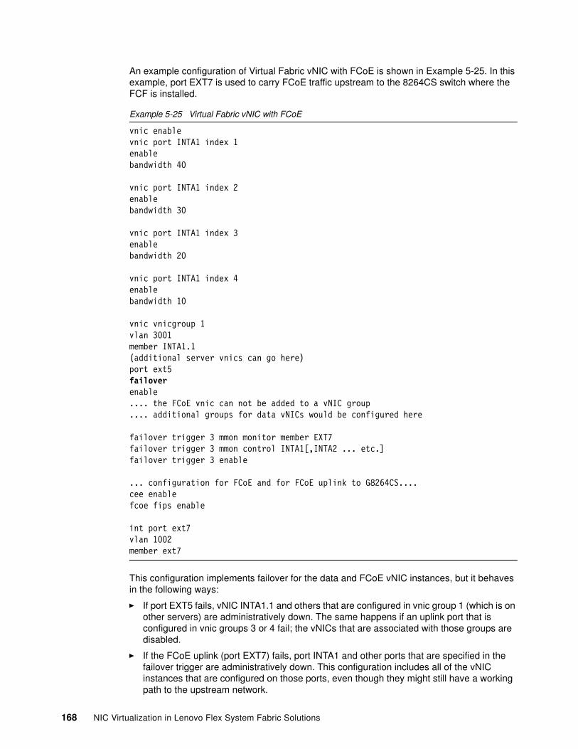
An example configuration of Virtual Fabric vNIC with FCoE is shown in Example 5-25. In this example, port EXT7 is used to carry FCoE traffic upstream to the 8264CS switch where the FCF is installed.
Example 5-25 Virtual Fabric vNIC with FCoE
vnic enablevnic port INTA1 index 1enablebandwidth 40
vnic port INTA1 index 2enablebandwidth 30
vnic port INTA1 index 3enablebandwidth 20
vnic port INTA1 index 4enablebandwidth 10
vnic vnicgroup 1vlan 3001member INTA1.1(additional server vnics can go here)port ext5failoverenable.... the FCoE vnic can not be added to a vNIC group.... additional groups for data vNICs would be configured here
failover trigger 3 mmon monitor member EXT7failover trigger 3 mmon control INTA1[,INTA2 ... etc.]failover trigger 3 enable
... configuration for FCoE and for FCoE uplink to G8264CS....cee enablefcoe fips enable
int port ext7vlan 1002member ext7
This configuration implements failover for the data and FCoE vNIC instances, but it behaves in the following ways:
� If port EXT5 fails, vNIC INTA1.1 and others that are configured in vnic group 1 (which is on other servers) are administratively down. The same happens if an uplink port that is configured in vnic groups 3 or 4 fail; the vNICs that are associated with those groups are disabled.
� If the FCoE uplink (port EXT7) fails, port INTA1 and other ports that are specified in the failover trigger are administratively down. This configuration includes all of the vNIC instances that are configured on those ports, even though they might still have a working path to the upstream network.
168 NIC Virtualization in Lenovo Flex System Fabric Solutions
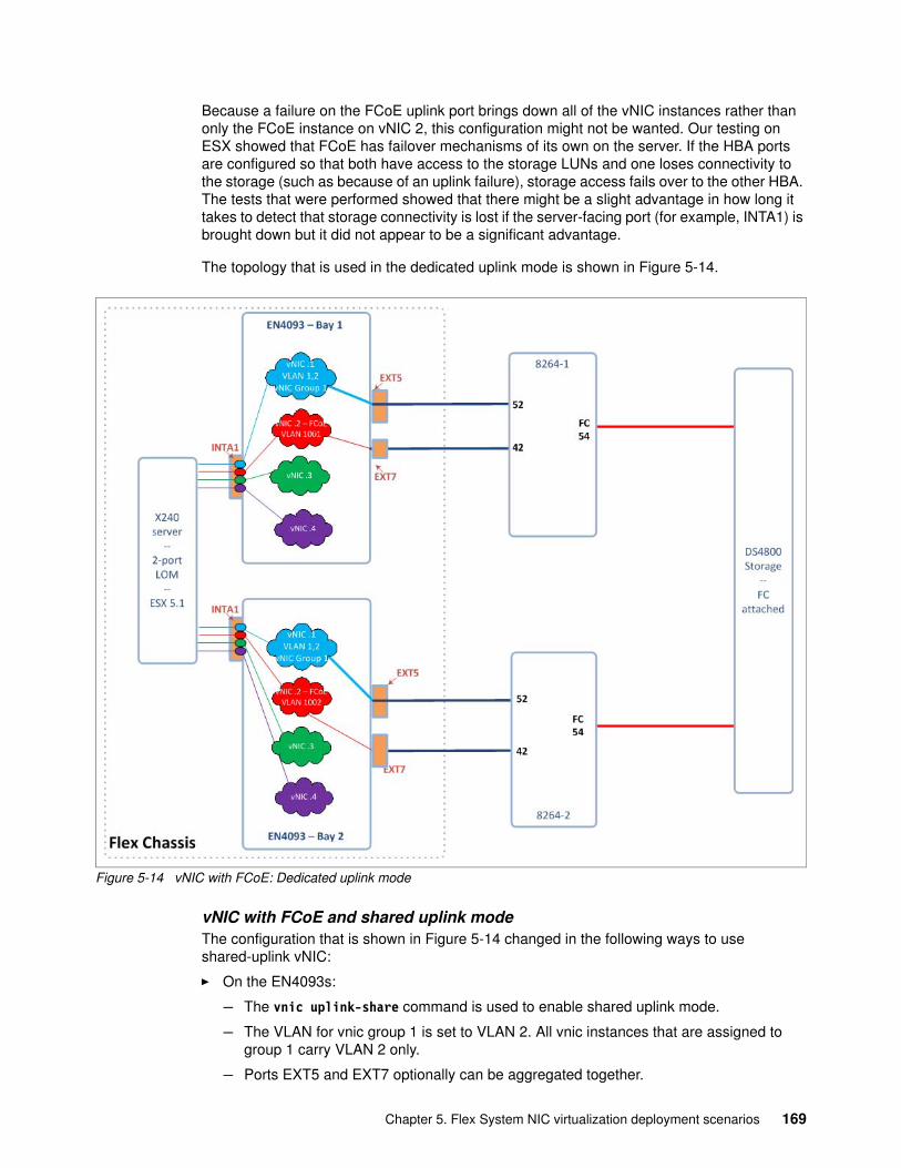
Because a failure on the FCoE uplink port brings down all of the vNIC instances rather than only the FCoE instance on vNIC 2, this configuration might not be wanted. Our testing on ESX showed that FCoE has failover mechanisms of its own on the server. If the HBA ports are configured so that both have access to the storage LUNs and one loses connectivity to the storage (such as because of an uplink failure), storage access fails over to the other HBA. The tests that were performed showed that there might be a slight advantage in how long it takes to detect that storage connectivity is lost if the server-facing port (for example, INTA1) is brought down but it did not appear to be a significant advantage.
The topology that is used in the dedicated uplink mode is shown in Figure 5-14.
Figure 5-14 vNIC with FCoE: Dedicated uplink mode
vNIC with FCoE and shared uplink modeThe configuration that is shown in Figure 5-14 changed in the following ways to use shared-uplink vNIC:
� On the EN4093s:
– The vnic uplink-share command is used to enable shared uplink mode.
– The VLAN for vnic group 1 is set to VLAN 2. All vnic instances that are assigned to group 1 carry VLAN 2 only.
– Ports EXT5 and EXT7 optionally can be aggregated together.
Chapter 5. Flex System NIC virtualization deployment scenarios 169
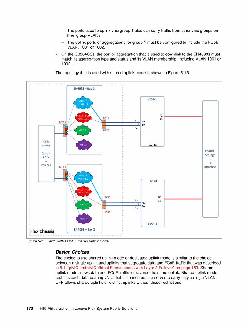
– The ports used to uplink vnic group 1 also can carry traffic from other vnic groups on their group VLANs.
– The uplink ports or aggregations for group 1 must be configured to include the FCoE VLAN, 1001 or 1002.
� On the G8264CSs, the port or aggregation that is used to downlink to the EN4093s must match its aggregation type and status and its VLAN membership, including VLAN 1001 or 1002.
The topology that is used with shared uplink mode is shown in Figure 5-15.
Figure 5-15 vNIC with FCoE: Shared uplink mode
Design ChoicesThe choice to use shared uplink mode or dedicated uplink mode is similar to the choice between a single uplink and uplinks that segregate data and FCoE traffic that was described in 5.4, “pNIC and vNIC Virtual Fabric modes with Layer 2 Failover” on page 153. Shared uplink mode allows data and FCoE traffic to traverse the same uplink. Shared uplink mode restricts each data bearing vNIC that is connected to a server to carry only a single VLAN. UFP allows shared uplinks or distinct uplinks without these restrictions.
170 NIC Virtualization in Lenovo Flex System Fabric Solutions
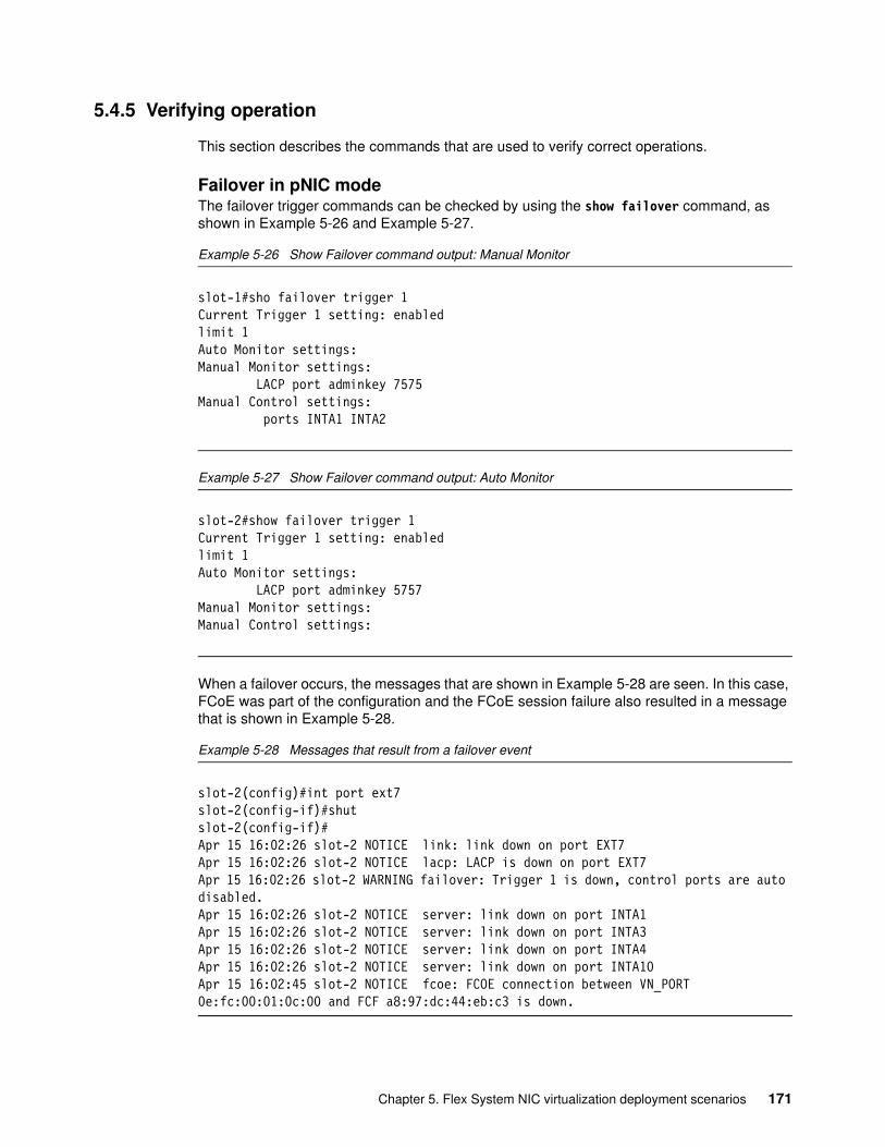
5.4.5 Verifying operation
This section describes the commands that are used to verify correct operations.
Failover in pNIC modeThe failover trigger commands can be checked by using the show failover command, as shown in Example 5-26 and Example 5-27.
Example 5-26 Show Failover command output: Manual Monitor
slot-1#sho failover trigger 1Current Trigger 1 setting: enabledlimit 1Auto Monitor settings:Manual Monitor settings: LACP port adminkey 7575Manual Control settings: ports INTA1 INTA2
Example 5-27 Show Failover command output: Auto Monitor
slot-2#show failover trigger 1Current Trigger 1 setting: enabledlimit 1Auto Monitor settings: LACP port adminkey 5757Manual Monitor settings:Manual Control settings:
When a failover occurs, the messages that are shown in Example 5-28 are seen. In this case, FCoE was part of the configuration and the FCoE session failure also resulted in a message that is shown in Example 5-28.
Example 5-28 Messages that result from a failover event
slot-2(config)#int port ext7slot-2(config-if)#shutslot-2(config-if)#Apr 15 16:02:26 slot-2 NOTICE link: link down on port EXT7Apr 15 16:02:26 slot-2 NOTICE lacp: LACP is down on port EXT7Apr 15 16:02:26 slot-2 WARNING failover: Trigger 1 is down, control ports are auto disabled.Apr 15 16:02:26 slot-2 NOTICE server: link down on port INTA1Apr 15 16:02:26 slot-2 NOTICE server: link down on port INTA3Apr 15 16:02:26 slot-2 NOTICE server: link down on port INTA4Apr 15 16:02:26 slot-2 NOTICE server: link down on port INTA10Apr 15 16:02:45 slot-2 NOTICE fcoe: FCOE connection between VN_PORT 0e:fc:00:01:0c:00 and FCF a8:97:dc:44:eb:c3 is down.
Chapter 5. Flex System NIC virtualization deployment scenarios 171
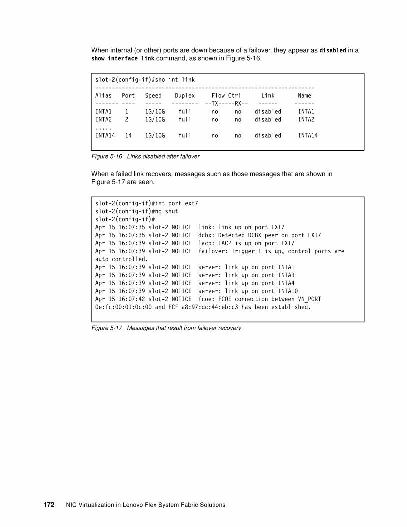
When internal (or other) ports are down because of a failover, they appear as disabled in a show interface link command, as shown in Figure 5-16.
Figure 5-16 Links disabled after failover
When a failed link recovers, messages such as those messages that are shown in Figure 5-17 are seen.
Figure 5-17 Messages that result from failover recovery
slot-2(config-if)#sho int link------------------------------------------------------------------Alias Port Speed Duplex Flow Ctrl Link Name------- ---- ----- -------- --TX-----RX-- ------ ------INTA1 1 1G/10G full no no disabled INTA1INTA2 2 1G/10G full no no disabled INTA2.....INTA14 14 1G/10G full no no disabled INTA14
slot-2(config-if)#int port ext7slot-2(config-if)#no shutslot-2(config-if)#Apr 15 16:07:35 slot-2 NOTICE link: link up on port EXT7Apr 15 16:07:35 slot-2 NOTICE dcbx: Detected DCBX peer on port EXT7Apr 15 16:07:39 slot-2 NOTICE lacp: LACP is up on port EXT7Apr 15 16:07:39 slot-2 NOTICE failover: Trigger 1 is up, control ports are auto controlled.Apr 15 16:07:39 slot-2 NOTICE server: link up on port INTA1Apr 15 16:07:39 slot-2 NOTICE server: link up on port INTA3Apr 15 16:07:39 slot-2 NOTICE server: link up on port INTA4Apr 15 16:07:39 slot-2 NOTICE server: link up on port INTA10Apr 15 16:07:42 slot-2 NOTICE fcoe: FCOE connection between VN_PORT 0e:fc:00:01:0c:00 and FCF a8:97:dc:44:eb:c3 has been established.
172 NIC Virtualization in Lenovo Flex System Fabric Solutions
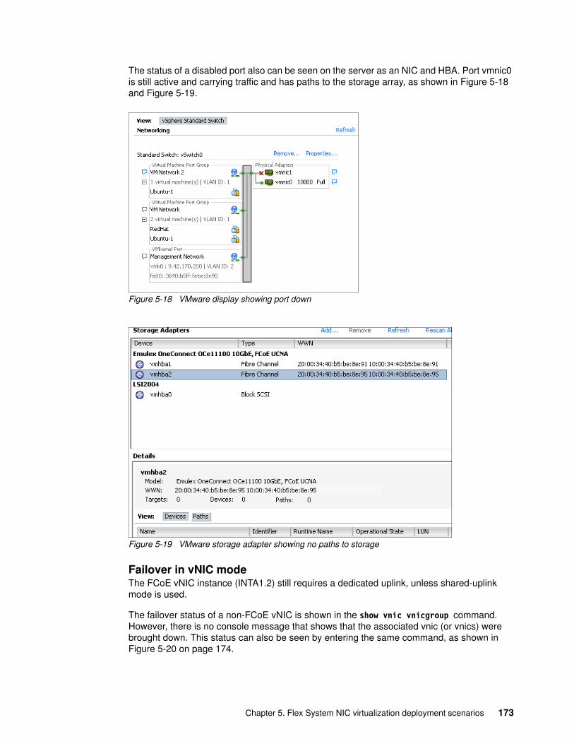
The status of a disabled port also can be seen on the server as an NIC and HBA. Port vmnic0 is still active and carrying traffic and has paths to the storage array, as shown in Figure 5-18 and Figure 5-19.
Figure 5-18 VMware display showing port down
Figure 5-19 VMware storage adapter showing no paths to storage
Failover in vNIC modeThe FCoE vNIC instance (INTA1.2) still requires a dedicated uplink, unless shared-uplink mode is used.
The failover status of a non-FCoE vNIC is shown in the show vnic vnicgroup command. However, there is no console message that shows that the associated vnic (or vnics) were brought down. This status can also be seen by entering the same command, as shown in Figure 5-20 on page 174.
Chapter 5. Flex System NIC virtualization deployment scenarios 173
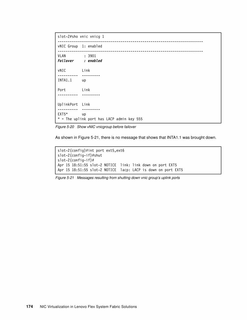
Figure 5-20 Show vNIC vnicgroup before failover
As shown in Figure 5-21, there is no message that shows that INTA1.1 was brought down.
Figure 5-21 Messages resulting from shutting down vnic group’s uplink ports
slot-2#sho vnic vnicg 1------------------------------------------------------------------------vNIC Group 1: enabled------------------------------------------------------------------------VLAN : 3901Failover : enabled
vNIC Link---------- ---------INTA1.1 up
Port Link---------- ---------
UplinkPort Link---------- ---------EXT5* up* = The uplink port has LACP admin key 555
slot-2(config)#int port ext5,ext6slot-2(config-if)#shutslot-2(config-if)#Apr 15 18:51:55 slot-2 NOTICE link: link down on port EXT5Apr 15 18:51:55 slot-2 NOTICE lacp: LACP is down on port EXT5
174 NIC Virtualization in Lenovo Flex System Fabric Solutions

However, the command output does show that the uplink port (EXT5) is down and that the associated vNIC members of the group were disabled, as shown in Figure 5-22.
Figure 5-22 Show vnic vnicgroup after failover
slot-1(config-if)#sho vnic vnicg 1------------------------------------------------------------------------vNIC Group 1: enabled------------------------------------------------------------------------VLAN : 3901Failover : enabled
vNIC Link---------- ---------INTA1.1 disabled
Port Link---------- ---------
UplinkPort Link---------- ---------EXT5* down* = The uplink port has LACP admin key 555
Chapter 5. Flex System NIC virtualization deployment scenarios 175
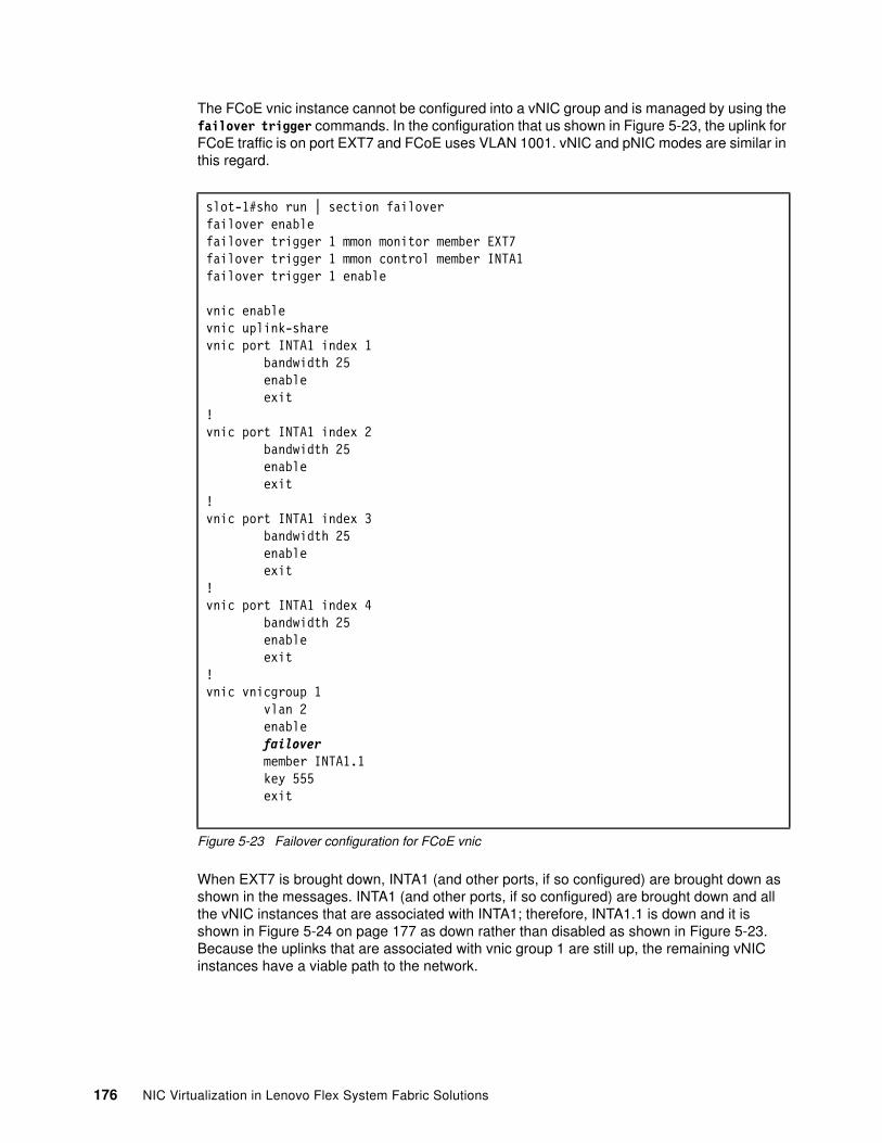
The FCoE vnic instance cannot be configured into a vNIC group and is managed by using the failover trigger commands. In the configuration that us shown in Figure 5-23, the uplink for FCoE traffic is on port EXT7 and FCoE uses VLAN 1001. vNIC and pNIC modes are similar in this regard.
Figure 5-23 Failover configuration for FCoE vnic
When EXT7 is brought down, INTA1 (and other ports, if so configured) are brought down as shown in the messages. INTA1 (and other ports, if so configured) are brought down and all the vNIC instances that are associated with INTA1; therefore, INTA1.1 is down and it is shown in Figure 5-24 on page 177 as down rather than disabled as shown in Figure 5-23. Because the uplinks that are associated with vnic group 1 are still up, the remaining vNIC instances have a viable path to the network.
slot-1#sho run | section failoverfailover enablefailover trigger 1 mmon monitor member EXT7failover trigger 1 mmon control member INTA1failover trigger 1 enable
vnic enablevnic uplink-sharevnic port INTA1 index 1 bandwidth 25 enable exit!vnic port INTA1 index 2 bandwidth 25 enable exit!vnic port INTA1 index 3 bandwidth 25 enable exit!vnic port INTA1 index 4 bandwidth 25 enable exit!vnic vnicgroup 1 vlan 2 enable failover member INTA1.1 key 555 exit
176 NIC Virtualization in Lenovo Flex System Fabric Solutions
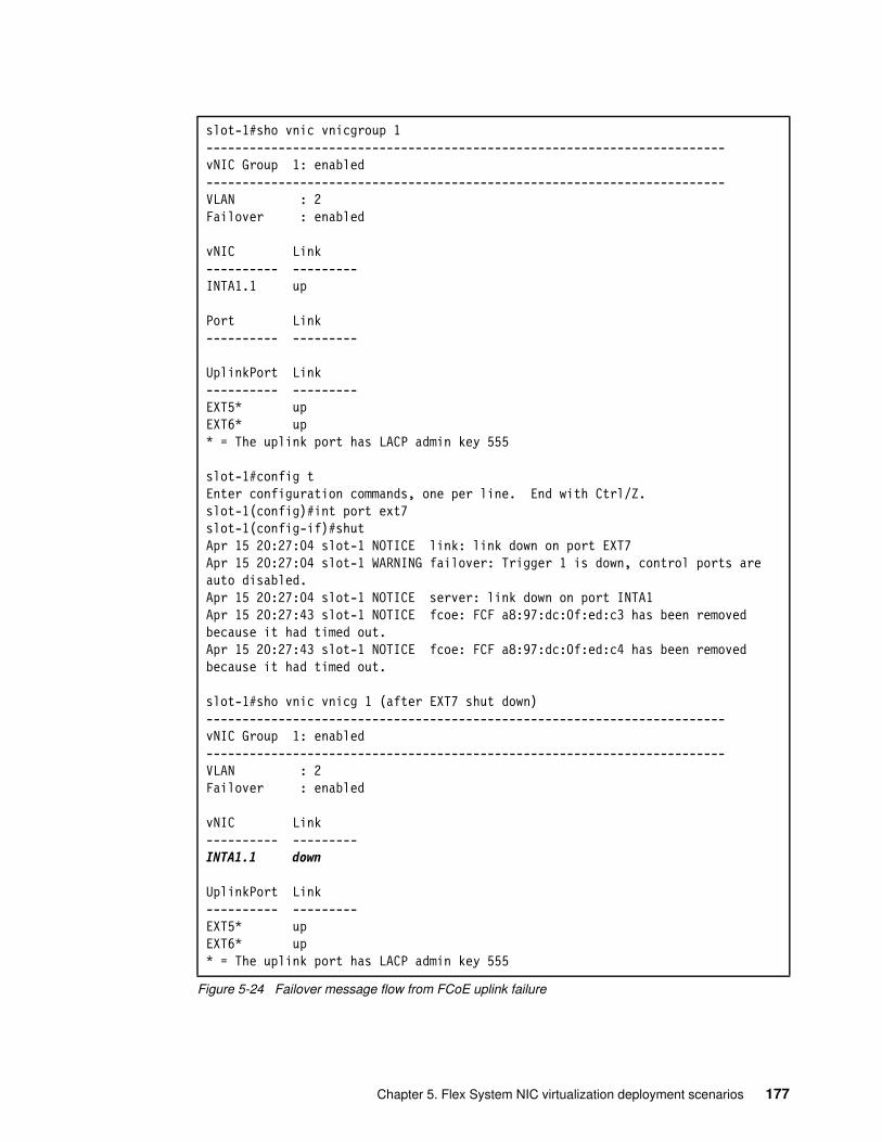
Figure 5-24 Failover message flow from FCoE uplink failure
slot-1#sho vnic vnicgroup 1------------------------------------------------------------------------vNIC Group 1: enabled------------------------------------------------------------------------VLAN : 2Failover : enabled
vNIC Link---------- ---------INTA1.1 up
Port Link---------- ---------
UplinkPort Link---------- ---------EXT5* upEXT6* up* = The uplink port has LACP admin key 555
slot-1#config tEnter configuration commands, one per line. End with Ctrl/Z.slot-1(config)#int port ext7slot-1(config-if)#shutApr 15 20:27:04 slot-1 NOTICE link: link down on port EXT7Apr 15 20:27:04 slot-1 WARNING failover: Trigger 1 is down, control ports are auto disabled.Apr 15 20:27:04 slot-1 NOTICE server: link down on port INTA1Apr 15 20:27:43 slot-1 NOTICE fcoe: FCF a8:97:dc:0f:ed:c3 has been removed because it had timed out.Apr 15 20:27:43 slot-1 NOTICE fcoe: FCF a8:97:dc:0f:ed:c4 has been removed because it had timed out.
slot-1#sho vnic vnicg 1 (after EXT7 shut down)------------------------------------------------------------------------vNIC Group 1: enabled------------------------------------------------------------------------VLAN : 2Failover : enabled
vNIC Link---------- ---------INTA1.1 down
UplinkPort Link---------- ---------EXT5* upEXT6* up* = The uplink port has LACP admin key 555
Chapter 5. Flex System NIC virtualization deployment scenarios 177
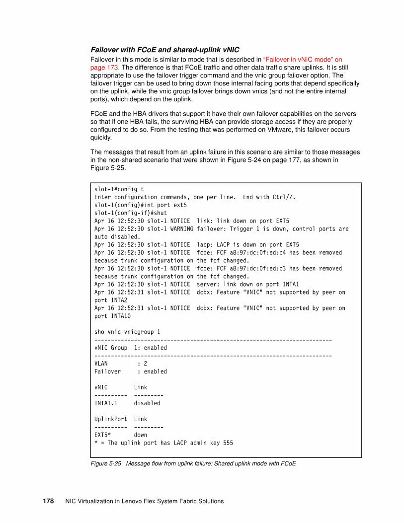
Failover with FCoE and shared-uplink vNICFailover in this mode is similar to mode that is described in “Failover in vNIC mode” on page 173. The difference is that FCoE traffic and other data traffic share uplinks. It is still appropriate to use the failover trigger command and the vnic group failover option. The failover trigger can be used to bring down those internal facing ports that depend specifically on the uplink, while the vnic group failover brings down vnics (and not the entire internal ports), which depend on the uplink.
FCoE and the HBA drivers that support it have their own failover capabilities on the servers so that if one HBA fails, the surviving HBA can provide storage access if they are properly configured to do so. From the testing that was performed on VMware, this failover occurs quickly.
The messages that result from an uplink failure in this scenario are similar to those messages in the non-shared scenario that were shown in Figure 5-24 on page 177, as shown in Figure 5-25.
Figure 5-25 Message flow from uplink failure: Shared uplink mode with FCoE
slot-1#config tEnter configuration commands, one per line. End with Ctrl/Z.slot-1(config)#int port ext5slot-1(config-if)#shutApr 16 12:52:30 slot-1 NOTICE link: link down on port EXT5Apr 16 12:52:30 slot-1 WARNING failover: Trigger 1 is down, control ports are auto disabled.Apr 16 12:52:30 slot-1 NOTICE lacp: LACP is down on port EXT5Apr 16 12:52:30 slot-1 NOTICE fcoe: FCF a8:97:dc:0f:ed:c4 has been removed because trunk configuration on the fcf changed.Apr 16 12:52:30 slot-1 NOTICE fcoe: FCF a8:97:dc:0f:ed:c3 has been removed because trunk configuration on the fcf changed.Apr 16 12:52:30 slot-1 NOTICE server: link down on port INTA1Apr 16 12:52:31 slot-1 NOTICE dcbx: Feature "VNIC" not supported by peer on port INTA2Apr 16 12:52:31 slot-1 NOTICE dcbx: Feature "VNIC" not supported by peer on port INTA10
sho vnic vnicgroup 1------------------------------------------------------------------------vNIC Group 1: enabled------------------------------------------------------------------------VLAN : 2Failover : enabled
vNIC Link---------- ---------INTA1.1 disabled
UplinkPort Link---------- ---------EXT5* down* = The uplink port has LACP admin key 555
178 NIC Virtualization in Lenovo Flex System Fabric Solutions
5.5 Switch Independent mode with SPAR
This section describes deployment examples that use vNIC Switch Independent mode with SPAR pass-through mode. The combination of these features, Switch Independent mode on the Emulex adapter and SPAR pass-through mode on the embedded switches (EN4093R, CN4093, SI4093), allows for a minimum configuration effort on the embedded switches. Little to no embedded switch configuration effort is required when a new VLAN or new compute node is added to a Flex chassis in this scenario,
5.5.1 Components
The following hardware and software was used in the examples in this chapter:
� Flex System Enterprise Chassis
� x240 Compute Node in bay 1:
– Running ESX 5.1– Dual port Emulex LOM CNA – DS4800 external storage attached via FC ports on G8264CS switches
� Two EN4093s in I/O module bays 1 and 2
� Two G8264 switches to act as upstream Ethernet connectivity out of the vLAG pair of EN4093s, which provides FCF function and physical connectivity to DS4800 on Fibre Channel port 53.
5.5.2 Topology
Figure 5-26 on page 180 and Figure 5-27 on page 181 describe the topologies that are used with SPAR.
Chapter 5. Flex System NIC virtualization deployment scenarios 179
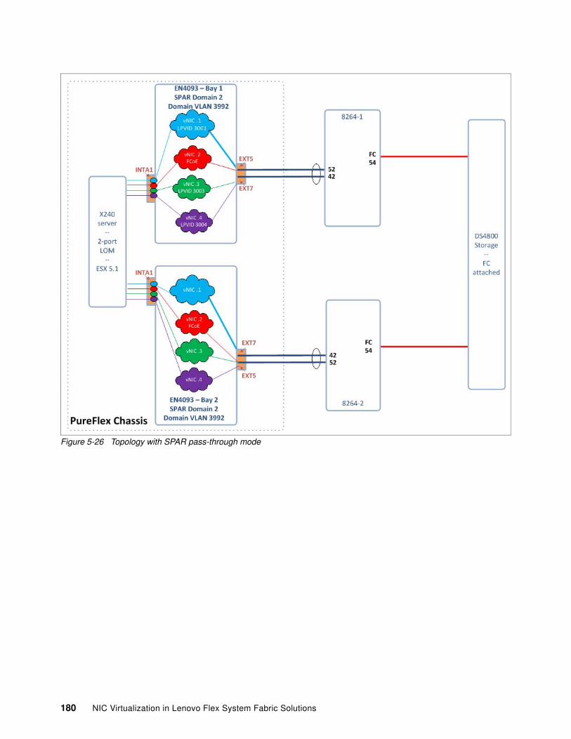
Figure 5-26 Topology with SPAR pass-through mode
180 NIC Virtualization in Lenovo Flex System Fabric Solutions
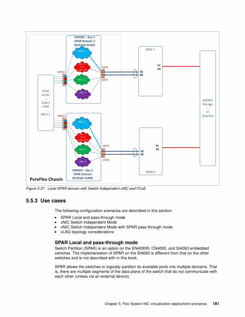
Figure 5-27 Local SPAR domain with Switch Independent vNIC and FCoE
5.5.3 Use cases
The following configuration scenarios are described in this section:
� SPAR Local and pass-through mode� vNIC Switch Independent Mode� vNIC Switch Independent Mode with SPAR pass-through mode� vLAG topology considerations
SPAR Local and pass-through modeSwitch Partition (SPAR) is an option on the EN4093R, CN4093, and SI4093 embedded switches. The implementation of SPAR on the SI4093 is different from that on the other switches and is not described with in this book.
SPAR allows the switches to logically partition its available ports into multiple domains. That is, there are multiple segments of the data plane of the switch that do not communicate with each other (unless via an external device).
Chapter 5. Flex System NIC virtualization deployment scenarios 181
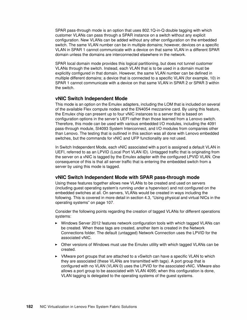
SPAR pass-through mode is an option that uses 802.1Q-in-Q double tagging with which customer VLANs can pass through a SPAR instance on a switch without any explicit configuration. New VLANs can be added without any other configuration on the embedded switch. The same VLAN number can be in multiple domains; however, devices on a specific VLAN in SPAR 1 cannot communicate with a device on that same VLAN in a different SPAR domain unless the domains are interconnected elsewhere in the network.
SPAR local domain mode provides this logical partitioning, but does not tunnel customer VLANs through the switch. Instead, each VLAN that is to be used in a domain must be explicitly configured in that domain. However, the same VLAN number can be defined in multiple different domains; a device that is connected to a specific VLAN (for example, 10) in SPAR 1 cannot communicate with a device on that same VLAN in SPAR 2 or SPAR 3 within the switch.
vNIC Switch Independent ModeThis mode is an option on the Emulex adapters, including the LOM that is included on several of the available Flex compute nodes and the EN4054 mezzanine card. By using this feature, the Emulex chip can present up to four vNIC instances to a server that is based on configuration options in the server’s UEFI rather than those learned from a Lenovo switch. Therefore, this mode can be used with various embedded I/O modules, including the 4091 pass-through module, SI4093 System Interconnect, and I/O modules from companies other than Lenovo. The testing that is outlined in this section was all done with Lenovo embedded switches, but the commands for vNIC and UFP functionality are not used.
In Switch Independent Mode, each vNIC associated with a port is assigned a default VLAN in UEFI, referred to as an LPVID (Local Port VLAN ID). Untagged traffic that is originating from the server on a vNIC is tagged by the Emulex adapter with the configured LPVID VLAN. One consequence of this is that all server traffic that is entering the embedded switch from a server by using this mode is tagged.
vNIC Switch Independent Mode with SPAR pass-through modeUsing these features together allows new VLANs to be created and used on servers (including guest operating system’s running under a hypervisor) and not configured on the embedded switches at all. On servers, VLANs would be created in ways including the following. This is covered in more detail in section 4.3, “Using physical and virtual NICs in the operating systems” on page 107.
Consider the following points regarding the creation of tagged VLANs for different operations systems:
� Windows Server 2012 features network configuration tools with which tagged VLANs can be created. When these tags are created, another item is created in the Network Connections folder. The default (untagged) Network Connection uses the LPVID for the associated vNIC.
� Other versions of Windows must use the Emulex utility with which tagged VLANs can be created.
� VMware port groups that are attached to a vSwitch can have a specific VLAN to which they are associated (these VLANs are transmitted with tags). A port group that is configured with no VLAN (VLAN 0) uses the LPVID for the associated vNIC. VMware also allows a port group to be associated with VLAN 4095; when this configuration is done, VLAN tagging is delegated to the operating systems of the guest systems.
182 NIC Virtualization in Lenovo Flex System Fabric Solutions
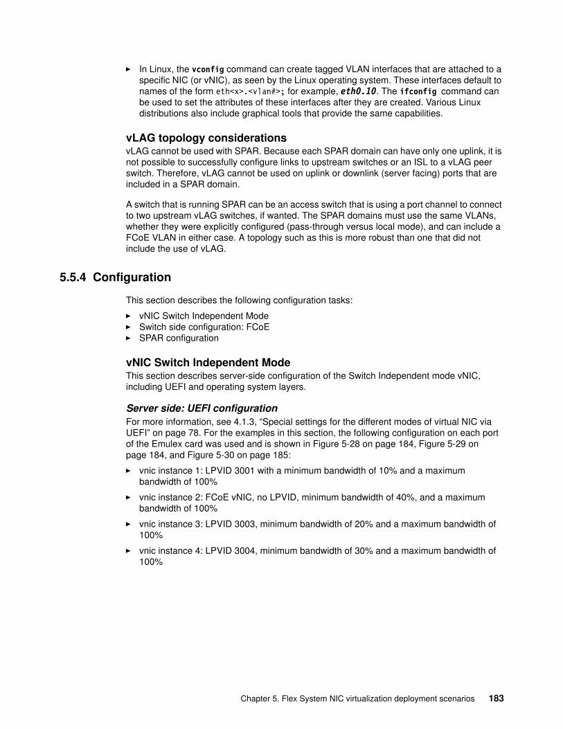
� In Linux, the vconfig command can create tagged VLAN interfaces that are attached to a specific NIC (or vNIC), as seen by the Linux operating system. These interfaces default to names of the form eth<x>.<vlan#>; for example, eth0.10. The ifconfig command can be used to set the attributes of these interfaces after they are created. Various Linux distributions also include graphical tools that provide the same capabilities.
vLAG topology considerationsvLAG cannot be used with SPAR. Because each SPAR domain can have only one uplink, it is not possible to successfully configure links to upstream switches or an ISL to a vLAG peer switch. Therefore, vLAG cannot be used on uplink or downlink (server facing) ports that are included in a SPAR domain.
A switch that is running SPAR can be an access switch that is using a port channel to connect to two upstream vLAG switches, if wanted. The SPAR domains must use the same VLANs, whether they were explicitly configured (pass-through versus local mode), and can include a FCoE VLAN in either case. A topology such as this is more robust than one that did not include the use of vLAG.
5.5.4 Configuration
This section describes the following configuration tasks:
� vNIC Switch Independent Mode� Switch side configuration: FCoE� SPAR configuration
vNIC Switch Independent ModeThis section describes server-side configuration of the Switch Independent mode vNIC, including UEFI and operating system layers.
Server side: UEFI configurationFor more information, see 4.1.3, “Special settings for the different modes of virtual NIC via UEFI” on page 78. For the examples in this section, the following configuration on each port of the Emulex card was used and is shown in Figure 5-28 on page 184, Figure 5-29 on page 184, and Figure 5-30 on page 185:
� vnic instance 1: LPVID 3001 with a minimum bandwidth of 10% and a maximum bandwidth of 100%
� vnic instance 2: FCoE vNIC, no LPVID, minimum bandwidth of 40%, and a maximum bandwidth of 100%
� vnic instance 3: LPVID 3003, minimum bandwidth of 20% and a maximum bandwidth of 100%
� vnic instance 4: LPVID 3004, minimum bandwidth of 30% and a maximum bandwidth of 100%
Chapter 5. Flex System NIC virtualization deployment scenarios 183
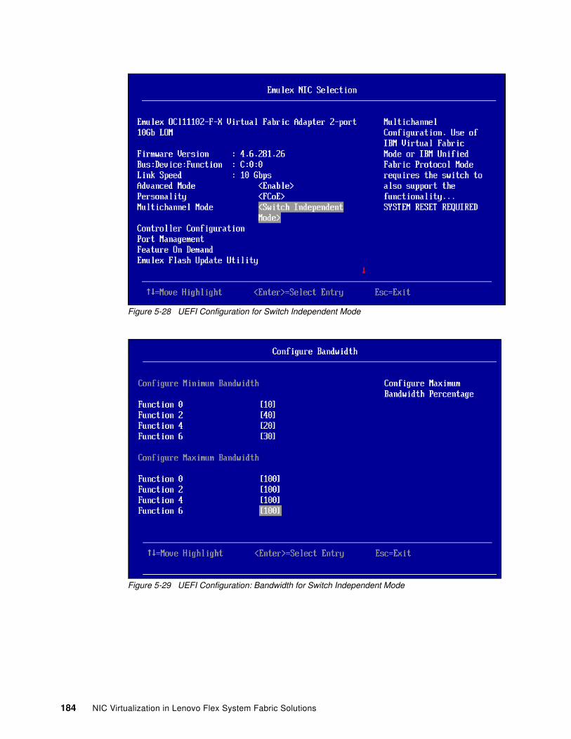
Figure 5-28 UEFI Configuration for Switch Independent Mode
Figure 5-29 UEFI Configuration: Bandwidth for Switch Independent Mode
184 NIC Virtualization in Lenovo Flex System Fabric Solutions
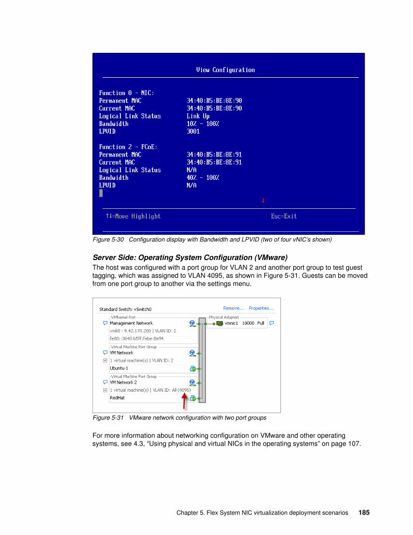
Figure 5-30 Configuration display with Bandwidth and LPVID (two of four vNIC’s shown)
Server Side: Operating System Configuration (VMware)The host was configured with a port group for VLAN 2 and another port group to test guest tagging, which was assigned to VLAN 4095, as shown in Figure 5-31. Guests can be moved from one port group to another via the settings menu.
Figure 5-31 VMware network configuration with two port groups
For more information about networking configuration on VMware and other operating systems, see 4.3, “Using physical and virtual NICs in the operating systems” on page 107.
Chapter 5. Flex System NIC virtualization deployment scenarios 185
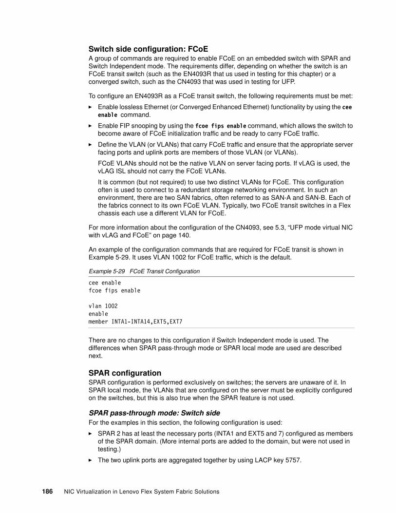
Switch side configuration: FCoEA group of commands are required to enable FCoE on an embedded switch with SPAR and Switch Independent mode. The requirements differ, depending on whether the switch is an FCoE transit switch (such as the EN4093R that us used in testing for this chapter) or a converged switch, such as the CN4093 that was used in testing for UFP.
To configure an EN4093R as a FCoE transit switch, the following requirements must be met:
� Enable lossless Ethernet (or Converged Enhanced Ethernet) functionality by using the cee enable command.
� Enable FIP snooping by using the fcoe fips enable command, which allows the switch to become aware of FCoE initialization traffic and be ready to carry FCoE traffic.
� Define the VLAN (or VLANs) that carry FCoE traffic and ensure that the appropriate server facing ports and uplink ports are members of those VLAN (or VLANs).
FCoE VLANs should not be the native VLAN on server facing ports. If vLAG is used, the vLAG ISL should not carry the FCoE VLANs.
It is common (but not required) to use two distinct VLANs for FCoE. This configuration often is used to connect to a redundant storage networking environment. In such an environment, there are two SAN fabrics, often referred to as SAN-A and SAN-B. Each of the fabrics connect to its own FCoE VLAN. Typically, two FCoE transit switches in a Flex chassis each use a different VLAN for FCoE.
For more information about the configuration of the CN4093, see 5.3, “UFP mode virtual NIC with vLAG and FCoE” on page 140.
An example of the configuration commands that are required for FCoE transit is shown in Example 5-29. It uses VLAN 1002 for FCoE traffic, which is the default.
Example 5-29 FCoE Transit Configuration
cee enablefcoe fips enable
vlan 1002enablemember INTA1-INTA14,EXT5,EXT7
There are no changes to this configuration if Switch Independent mode is used. The differences when SPAR pass-through mode or SPAR local mode are used are described next.
SPAR configurationSPAR configuration is performed exclusively on switches; the servers are unaware of it. In SPAR local mode, the VLANs that are configured on the server must be explicitly configured on the switches, but this is also true when the SPAR feature is not used.
SPAR pass-through mode: Switch sideFor the examples in this section, the following configuration is used:
� SPAR 2 has at least the necessary ports (INTA1 and EXT5 and 7) configured as members of the SPAR domain. (More internal ports are added to the domain, but were not used in testing.)
� The two uplink ports are aggregated together by using LACP key 5757.
186 NIC Virtualization in Lenovo Flex System Fabric Solutions
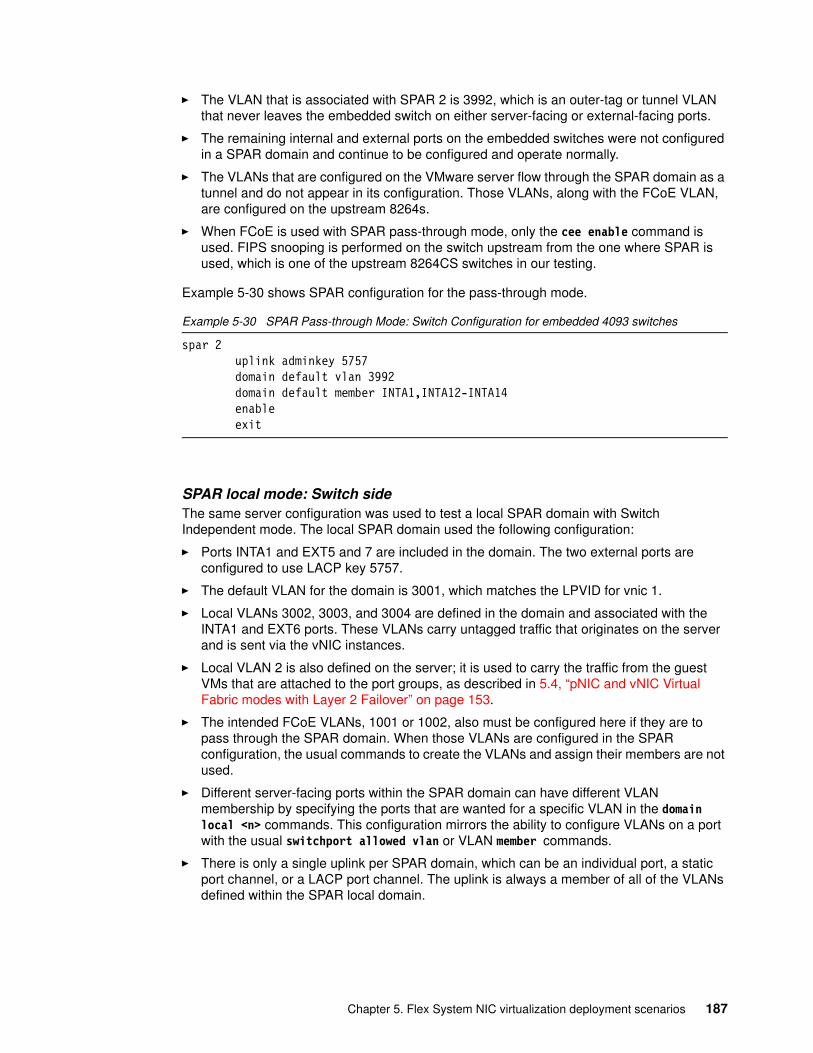
� The VLAN that is associated with SPAR 2 is 3992, which is an outer-tag or tunnel VLAN that never leaves the embedded switch on either server-facing or external-facing ports.
� The remaining internal and external ports on the embedded switches were not configured in a SPAR domain and continue to be configured and operate normally.
� The VLANs that are configured on the VMware server flow through the SPAR domain as a tunnel and do not appear in its configuration. Those VLANs, along with the FCoE VLAN, are configured on the upstream 8264s.
� When FCoE is used with SPAR pass-through mode, only the cee enable command is used. FIPS snooping is performed on the switch upstream from the one where SPAR is used, which is one of the upstream 8264CS switches in our testing.
Example 5-30 shows SPAR configuration for the pass-through mode.
Example 5-30 SPAR Pass-through Mode: Switch Configuration for embedded 4093 switches
spar 2 uplink adminkey 5757 domain default vlan 3992 domain default member INTA1,INTA12-INTA14 enable exit
SPAR local mode: Switch sideThe same server configuration was used to test a local SPAR domain with Switch Independent mode. The local SPAR domain used the following configuration:
� Ports INTA1 and EXT5 and 7 are included in the domain. The two external ports are configured to use LACP key 5757.
� The default VLAN for the domain is 3001, which matches the LPVID for vnic 1.
� Local VLANs 3002, 3003, and 3004 are defined in the domain and associated with the INTA1 and EXT6 ports. These VLANs carry untagged traffic that originates on the server and is sent via the vNIC instances.
� Local VLAN 2 is also defined on the server; it is used to carry the traffic from the guest VMs that are attached to the port groups, as described in 5.4, “pNIC and vNIC Virtual Fabric modes with Layer 2 Failover” on page 153.
� The intended FCoE VLANs, 1001 or 1002, also must be configured here if they are to pass through the SPAR domain. When those VLANs are configured in the SPAR configuration, the usual commands to create the VLANs and assign their members are not used.
� Different server-facing ports within the SPAR domain can have different VLAN membership by specifying the ports that are wanted for a specific VLAN in the domain local <n> commands. This configuration mirrors the ability to configure VLANs on a port with the usual switchport allowed vlan or VLAN member commands.
� There is only a single uplink per SPAR domain, which can be an individual port, a static port channel, or a LACP port channel. The uplink is always a member of all of the VLANs defined within the SPAR local domain.
Chapter 5. Flex System NIC virtualization deployment scenarios 187
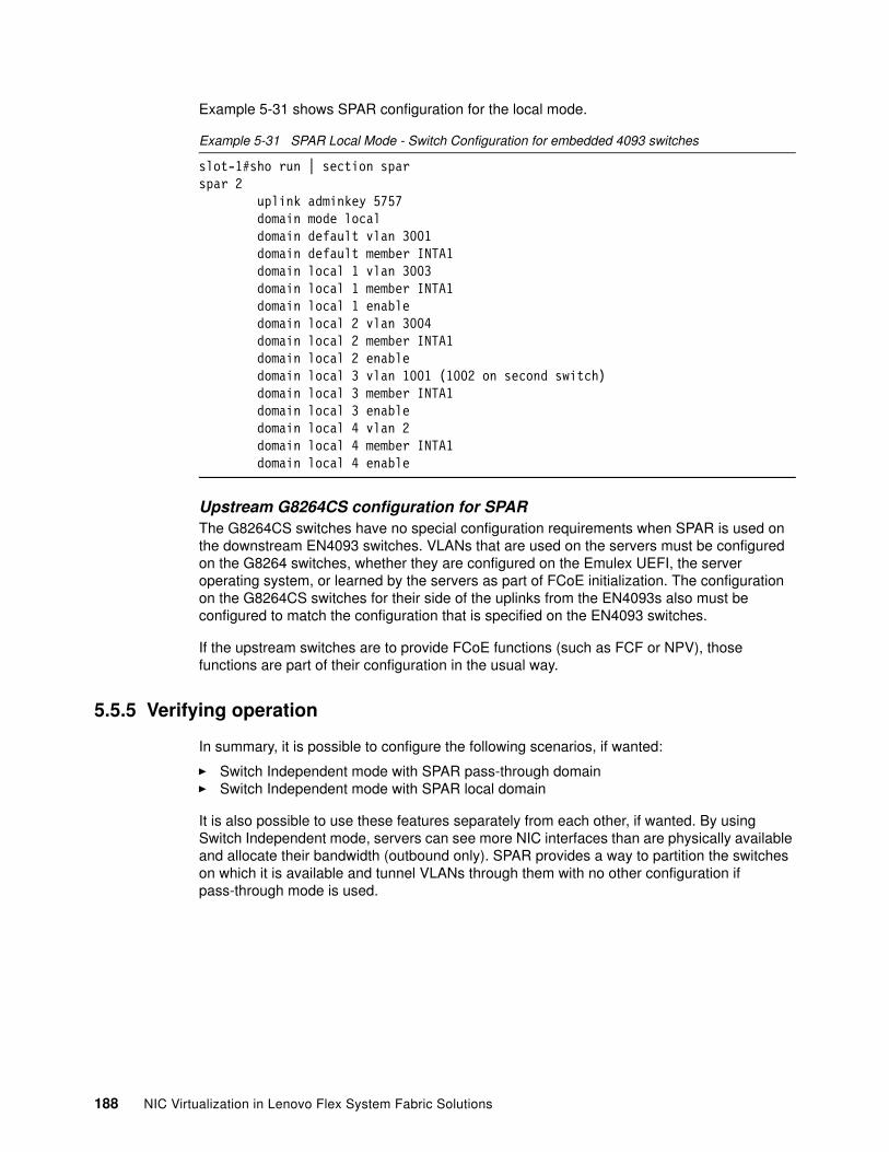
Example 5-31 shows SPAR configuration for the local mode.
Example 5-31 SPAR Local Mode - Switch Configuration for embedded 4093 switches
slot-1#sho run | section sparspar 2 uplink adminkey 5757 domain mode local domain default vlan 3001 domain default member INTA1 domain local 1 vlan 3003 domain local 1 member INTA1 domain local 1 enable domain local 2 vlan 3004 domain local 2 member INTA1 domain local 2 enable domain local 3 vlan 1001 (1002 on second switch) domain local 3 member INTA1 domain local 3 enable domain local 4 vlan 2 domain local 4 member INTA1 domain local 4 enable
Upstream G8264CS configuration for SPARThe G8264CS switches have no special configuration requirements when SPAR is used on the downstream EN4093 switches. VLANs that are used on the servers must be configured on the G8264 switches, whether they are configured on the Emulex UEFI, the server operating system, or learned by the servers as part of FCoE initialization. The configuration on the G8264CS switches for their side of the uplinks from the EN4093s also must be configured to match the configuration that is specified on the EN4093 switches.
If the upstream switches are to provide FCoE functions (such as FCF or NPV), those functions are part of their configuration in the usual way.
5.5.5 Verifying operation
In summary, it is possible to configure the following scenarios, if wanted:
� Switch Independent mode with SPAR pass-through domain� Switch Independent mode with SPAR local domain
It is also possible to use these features separately from each other, if wanted. By using Switch Independent mode, servers can see more NIC interfaces than are physically available and allocate their bandwidth (outbound only). SPAR provides a way to partition the switches on which it is available and tunnel VLANs through them with no other configuration if pass-through mode is used.
188 NIC Virtualization in Lenovo Flex System Fabric Solutions
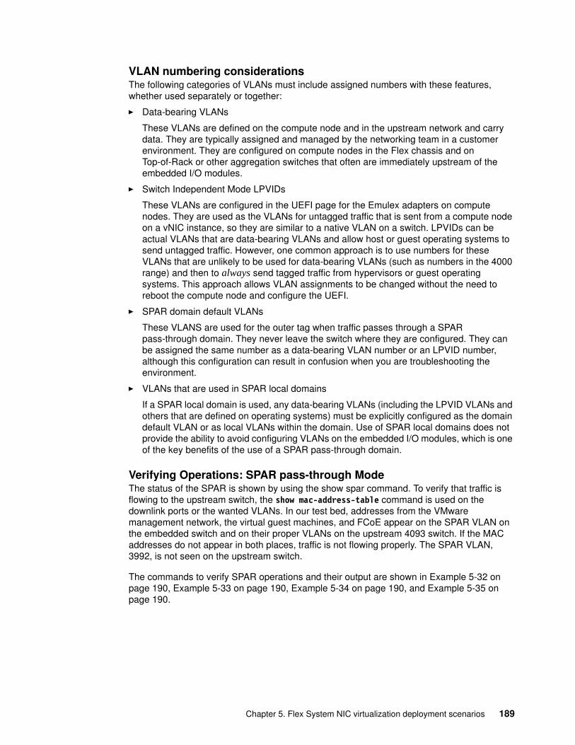
VLAN numbering considerationsThe following categories of VLANs must include assigned numbers with these features, whether used separately or together:
� Data-bearing VLANs
These VLANs are defined on the compute node and in the upstream network and carry data. They are typically assigned and managed by the networking team in a customer environment. They are configured on compute nodes in the Flex chassis and on Top-of-Rack or other aggregation switches that often are immediately upstream of the embedded I/O modules.
� Switch Independent Mode LPVIDs
These VLANs are configured in the UEFI page for the Emulex adapters on compute nodes. They are used as the VLANs for untagged traffic that is sent from a compute node on a vNIC instance, so they are similar to a native VLAN on a switch. LPVIDs can be actual VLANs that are data-bearing VLANs and allow host or guest operating systems to send untagged traffic. However, one common approach is to use numbers for these VLANs that are unlikely to be used for data-bearing VLANs (such as numbers in the 4000 range) and then to always send tagged traffic from hypervisors or guest operating systems. This approach allows VLAN assignments to be changed without the need to reboot the compute node and configure the UEFI.
� SPAR domain default VLANs
These VLANS are used for the outer tag when traffic passes through a SPAR pass-through domain. They never leave the switch where they are configured. They can be assigned the same number as a data-bearing VLAN number or an LPVID number, although this configuration can result in confusion when you are troubleshooting the environment.
� VLANs that are used in SPAR local domains
If a SPAR local domain is used, any data-bearing VLANs (including the LPVID VLANs and others that are defined on operating systems) must be explicitly configured as the domain default VLAN or as local VLANs within the domain. Use of SPAR local domains does not provide the ability to avoid configuring VLANs on the embedded I/O modules, which is one of the key benefits of the use of a SPAR pass-through domain.
Verifying Operations: SPAR pass-through ModeThe status of the SPAR is shown by using the show spar command. To verify that traffic is flowing to the upstream switch, the show mac-address-table command is used on the downlink ports or the wanted VLANs. In our test bed, addresses from the VMware management network, the virtual guest machines, and FCoE appear on the SPAR VLAN on the embedded switch and on their proper VLANs on the upstream 4093 switch. If the MAC addresses do not appear in both places, traffic is not flowing properly. The SPAR VLAN, 3992, is not seen on the upstream switch.
The commands to verify SPAR operations and their output are shown in Example 5-32 on page 190, Example 5-33 on page 190, Example 5-34 on page 190, and Example 5-35 on page 190.
Chapter 5. Flex System NIC virtualization deployment scenarios 189
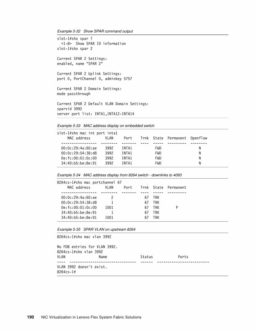
Example 5-32 Show SPAR command output
slot-1#sho spar ? <1-8> Show SPAR ID informationslot-1#sho spar 2
Current SPAR 2 Settings:enabled, name "SPAR 2"
Current SPAR 2 Uplink Settings:port 0, PortChannel 0, adminkey 5757
Current SPAR 2 Domain Settings:mode passthrough
Current SPAR 2 Default VLAN Domain Settings:sparvid 3992server port list: INTA1,INTA12-INTA14
Example 5-33 MAC address display on embedded switch
slot-1#sho mac int port inta1 MAC address VLAN Port Trnk State Permanent Openflow ----------------- -------- ------- ---- ----- --------- -------- 00:0c:29:4a:60:ae 3992 INTA1 FWD N 00:0c:29:54:38:d8 3992 INTA1 FWD N 0e:fc:00:01:0c:00 3992 INTA1 FWD N 34:40:b5:be:8e:91 3992 INTA1 FWD N
Example 5-34 MAC address display from 8264 switch - downlinks to 4093
8264cs-1#sho mac portchannel 67 MAC address VLAN Port Trnk State Permanent ----------------- -------- ------- ---- ----- --------- 00:0c:29:4a:60:ae 2 67 TRK 00:0c:29:54:38:d8 1 67 TRK 0e:fc:00:01:0c:00 1001 67 TRK P 34:40:b5:be:8e:91 1 67 TRK 34:40:b5:be:8e:91 1001 67 TRK
Example 5-35 SPAR VLAN on upstream 8264
8264cs-1#sho mac vlan 3992
No FDB entries for VLAN 3992.8264cs-1#sho vlan 3992VLAN Name Status Ports---- -------------------------------- ------ -------------------------VLAN 3992 doesn't exist.8264cs-1#
190 NIC Virtualization in Lenovo Flex System Fabric Solutions
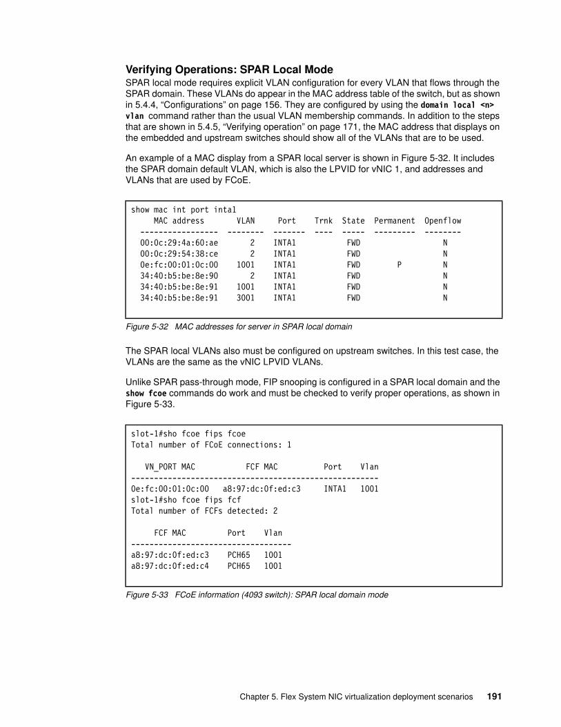
Verifying Operations: SPAR Local ModeSPAR local mode requires explicit VLAN configuration for every VLAN that flows through the SPAR domain. These VLANs do appear in the MAC address table of the switch, but as shown in 5.4.4, “Configurations” on page 156. They are configured by using the domain local <n> vlan command rather than the usual VLAN membership commands. In addition to the steps that are shown in 5.4.5, “Verifying operation” on page 171, the MAC address that displays on the embedded and upstream switches should show all of the VLANs that are to be used.
An example of a MAC display from a SPAR local server is shown in Figure 5-32. It includes the SPAR domain default VLAN, which is also the LPVID for vNIC 1, and addresses and VLANs that are used by FCoE.
Figure 5-32 MAC addresses for server in SPAR local domain
The SPAR local VLANs also must be configured on upstream switches. In this test case, the VLANs are the same as the vNIC LPVID VLANs.
Unlike SPAR pass-through mode, FIP snooping is configured in a SPAR local domain and the show fcoe commands do work and must be checked to verify proper operations, as shown in Figure 5-33.
Figure 5-33 FCoE information (4093 switch): SPAR local domain mode
show mac int port inta1 MAC address VLAN Port Trnk State Permanent Openflow ----------------- -------- ------- ---- ----- --------- -------- 00:0c:29:4a:60:ae 2 INTA1 FWD N 00:0c:29:54:38:ce 2 INTA1 FWD N 0e:fc:00:01:0c:00 1001 INTA1 FWD P N 34:40:b5:be:8e:90 2 INTA1 FWD N 34:40:b5:be:8e:91 1001 INTA1 FWD N 34:40:b5:be:8e:91 3001 INTA1 FWD N
slot-1#sho fcoe fips fcoeTotal number of FCoE connections: 1
VN_PORT MAC FCF MAC Port Vlan------------------------------------------------------0e:fc:00:01:0c:00 a8:97:dc:0f:ed:c3 INTA1 1001slot-1#sho fcoe fips fcfTotal number of FCFs detected: 2
FCF MAC Port Vlan-----------------------------------a8:97:dc:0f:ed:c3 PCH65 1001a8:97:dc:0f:ed:c4 PCH65 1001
Chapter 5. Flex System NIC virtualization deployment scenarios 191
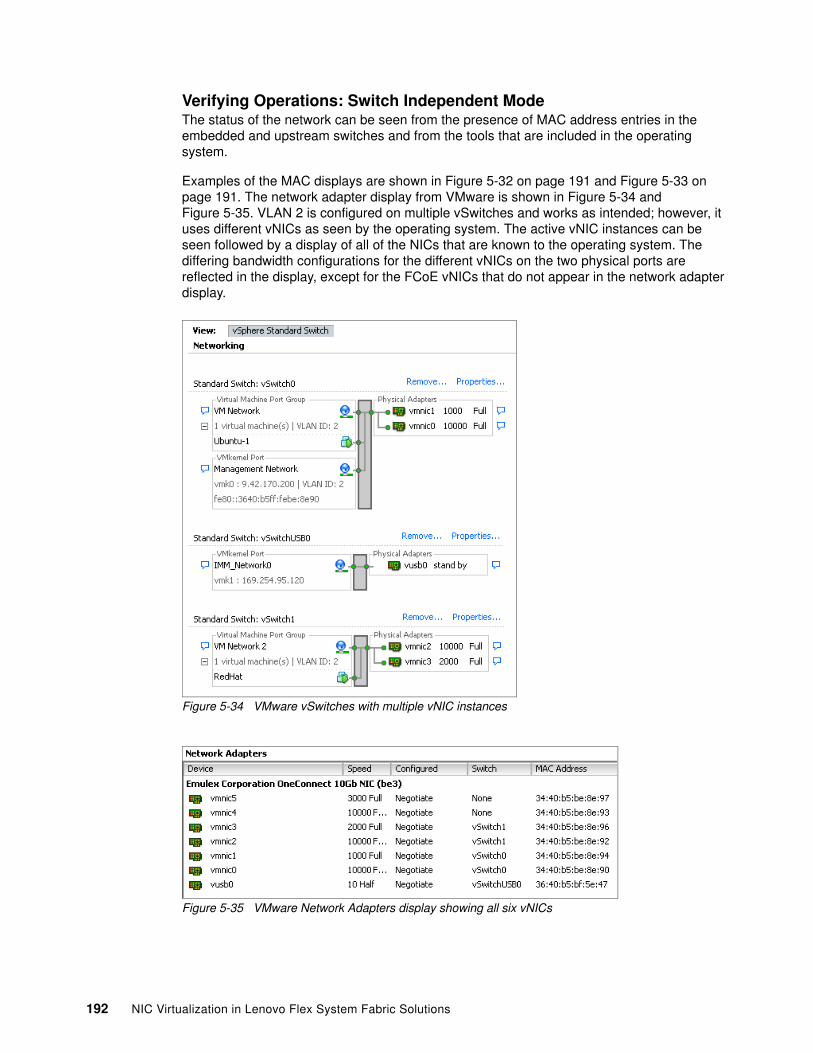
Verifying Operations: Switch Independent Mode The status of the network can be seen from the presence of MAC address entries in the embedded and upstream switches and from the tools that are included in the operating system.
Examples of the MAC displays are shown in Figure 5-32 on page 191 and Figure 5-33 on page 191. The network adapter display from VMware is shown in Figure 5-34 and Figure 5-35. VLAN 2 is configured on multiple vSwitches and works as intended; however, it uses different vNICs as seen by the operating system. The active vNIC instances can be seen followed by a display of all of the NICs that are known to the operating system. The differing bandwidth configurations for the different vNICs on the two physical ports are reflected in the display, except for the FCoE vNICs that do not appear in the network adapter display.
Figure 5-34 VMware vSwitches with multiple vNIC instances
Figure 5-35 VMware Network Adapters display showing all six vNICs
192 NIC Virtualization in Lenovo Flex System Fabric Solutions
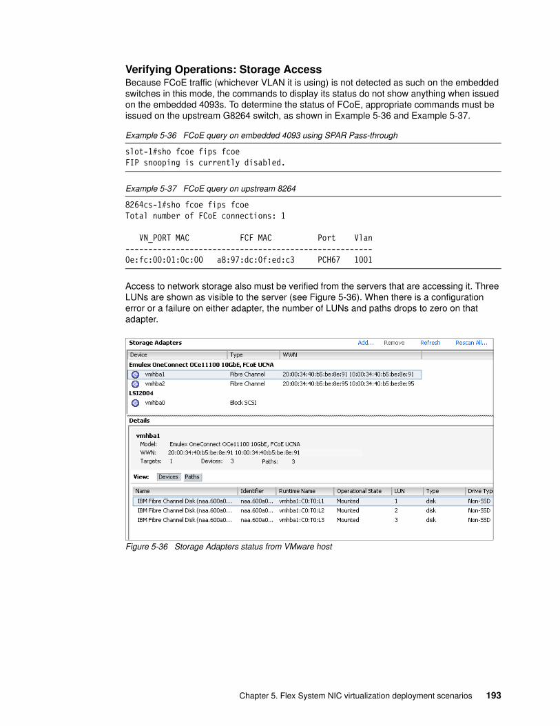
Verifying Operations: Storage AccessBecause FCoE traffic (whichever VLAN it is using) is not detected as such on the embedded switches in this mode, the commands to display its status do not show anything when issued on the embedded 4093s. To determine the status of FCoE, appropriate commands must be issued on the upstream G8264 switch, as shown in Example 5-36 and Example 5-37.
Example 5-36 FCoE query on embedded 4093 using SPAR Pass-through
slot-1#sho fcoe fips fcoeFIP snooping is currently disabled.
Example 5-37 FCoE query on upstream 8264
8264cs-1#sho fcoe fips fcoeTotal number of FCoE connections: 1
VN_PORT MAC FCF MAC Port Vlan------------------------------------------------------0e:fc:00:01:0c:00 a8:97:dc:0f:ed:c3 PCH67 1001
Access to network storage also must be verified from the servers that are accessing it. Three LUNs are shown as visible to the server (see Figure 5-36). When there is a configuration error or a failure on either adapter, the number of LUNs and paths drops to zero on that adapter.
Figure 5-36 Storage Adapters status from VMware host
Chapter 5. Flex System NIC virtualization deployment scenarios 193

194 NIC Virtualization in Lenovo Flex System Fabric Solutions
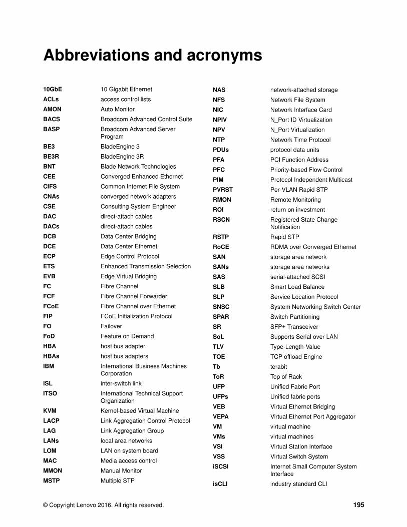
ronyms
10GbE 10 Gigabit Ethernet
ACLs access control lists
AMON Auto Monitor
BACS Broadcom Advanced Control Suite
BASP Broadcom Advanced Server Program
BE3 BladeEngine 3
BE3R BladeEngine 3R
BNT Blade Network Technologies
CEE Converged Enhanced Ethernet
CIFS Common Internet File System
CNAs converged network adapters
CSE Consulting System Engineer
DAC direct-attach cables
DACs direct-attach cables
DCB Data Center Bridging
DCE Data Center Ethernet
ECP Edge Control Protocol
ETS Enhanced Transmission Selection
EVB Edge Virtual Bridging
FC Fibre Channel
FCF Fibre Channel Forwarder
FCoE Fibre Channel over Ethernet
FIP FCoE Initialization Protocol
FO Failover
FoD Feature on Demand
HBA host bus adapter
HBAs host bus adapters
IBM International Business Machines Corporation
ISL inter-switch link
ITSO International Technical Support Organization
KVM Kernel-based Virtual Machine
LACP Link Aggregation Control Protocol
LAG Link Aggregation Group
LANs local area networks
LOM LAN on system board
MAC Media access control
MMON Manual Monitor
MSTP Multiple STP
Abbreviations and ac
© Copyright Lenovo 2016. All rights reserved.
NAS network-attached storage
NFS Network File System
NIC Network Interface Card
NPIV N_Port ID Virtualization
NPV N_Port Virtualization
NTP Network Time Protocol
PDUs protocol data units
PFA PCI Function Address
PFC Priority-based Flow Control
PIM Protocol Independent Multicast
PVRST Per-VLAN Rapid STP
RMON Remote Monitoring
ROI return on investment
RSCN Registered State Change Notification
RSTP Rapid STP
RoCE RDMA over Converged Ethernet
SAN storage area network
SANs storage area networks
SAS serial-attached SCSI
SLB Smart Load Balance
SLP Service Location Protocol
SNSC System Networking Switch Center
SPAR Switch Partitioning
SR SFP+ Transceiver
SoL Supports Serial over LAN
TLV Type-Length-Value
TOE TCP offload Engine
Tb terabit
ToR Top of Rack
UFP Unified Fabric Port
UFPs Unified fabric ports
VEB Virtual Ethernet Bridging
VEPA Virtual Ethernet Port Aggregator
VM virtual machine
VMs virtual machines
VSI Virtual Station Interface
VSS Virtual Switch System
iSCSI Internet Small Computer System Interface
isCLI industry standard CLI
195
pNIC Physical NIC mode
sFTP Secure FTP
vLAG virtual Link Aggregation
vLAGs Virtual link aggregation groups
vNIC virtual Network Interface Card
vNICs Virtual NICs
vPC virtual Port Channel
vPort virtual port
196 NIC Virtualization in Lenovo Flex System Fabric Solutions
Related publications
The publications listed in this section are considered particularly suitable for a more detailed discussion of the topics covered in this book.
Lenovo Press
The following Lenovo Press publications provide more information about the topic in this document:
� Flex System Networking in an Enterprise Data Center, REDP-4834
� Flex System and PureFlex System Network Implementation, SG24-8089
� Storage and Network Convergence Using FCoE and iSCSI, SG24-7986
� Implementing Systems Management of IBM PureFlex System, SG24-8060
� Lenovo Flex System Products and Technology, SG24-8255
� Flex System Interconnect Fabric Technical Overview and Planning Considerations, REDP-5106
Download these documents from the following website:
http://lenovopress.com
© Copyright Lenovo 2016. All rights reserved. 197

198 NIC Virtualization in Lenovo Flex System Fabric Solutions

(0.2”spine)0.17”<
->0.473”
90<->
249 pages
NIC Virtualization in Lenovo Flex System Fabric Solutions
NIC Virtualization in Lenovo Flex System Fabric Solutions
NIC Virtualization in Lenovo Flex System
NIC Virtualization in Lenovo Flex System Fabric Solutions

NIC Virtualization in Lenovo Flex System
NIC Virtualization in Lenovo Flex System

BUILDING TECHNICAL INFORMATION BASED ON PRACTICAL EXPERIENCE
At Lenovo Press, we
bring together experts
to produce technical
publications around
topics of importance to
you, providing
information and best
practices for using
Lenovo products and
solutions to solve IT
challenges.
lenovopress.com SG24-8223-00
NIC Virtualization in Lenovo Flex System Fabric Solutions
Introduces NIC virtualization concepts and technologies
Describes UFP and vNIC deployment scenarios
Provides UFP and vNIC configuration examples
Useful knowledge for networking professionals
The deployment of server virtualization technologies in data centers requires significant efforts in providing sufficient network I/O bandwidth to satisfy the demand of virtualized applications and services. For example, every virtualized system can host several dozen applications and services. Each of these services requires certain bandwidth (or speed) to function properly.
Furthermore, because of different network traffic patterns that are relevant to different service types, these traffic flows can interfere with each other. They can lead to serious network problems, including the inability of the service to perform its functions.
The NIC virtualization in Lenovo Flex System Fabric solutions addresses these issues. The solutions are based on the Flex System Enterprise Chassis with a 10 Gbps Converged Enhanced Ethernet infrastructure. This infrastructure is built on Flex System Fabric CN4093 and EN4093R 10 Gbps Ethernet switch modules, and Flex System Fabric SI4093 Switch Interconnect modules in the chassis and the Emulex Virtual Fabric Adapters in each compute node.
This book introduces NIC virtualization concepts and technologies, describes their deployment scenarios, and provides configuration examples that use Lenovo Networking OS technologies that are combined with the Emulex Virtual Fabric adapters.
This book is for networking professionals who want to learn how to implement NIC virtualization solutions and switch interconnect technologies on Flex System by using the Unified Fabric Port (UFP) mode, Switch Independent mode, and Virtual Fabric mode.
Back cover