Embed Size (px)
Citation preview

Sagara 1
R&D activities on flibe blanketin Japan
Akio SAGARANIFS
ITER TBM Project Meeting at UCLAFebruary 23-25, 2004

Sagara 2
�FFHR design �with R&D
�JUPITER-II
R&D/LHD�TNT loop�Ultrahigh HT
FY1993 1997 2001 2004 2007
Molten salt R & D activities in Japan Molten salt R & D activities in Japan
2015
$
$
$

Sagara 3
Advantages in LHD• current-less • Steady state• no CD power• Intrinsic divertor
Force Free Helical ReactorPhase I ----- Concept definition 1993 Design of FFHR-1 (l=3) 1994 ---> NIFS Collaboration 1995 Design of FFHR-2 (l=2) 1998 ---> Fusion Eng. Network 2001 ---> Liq. Blanket in JUPITER-II 2002 ---> Concept improvements
Sagara 4
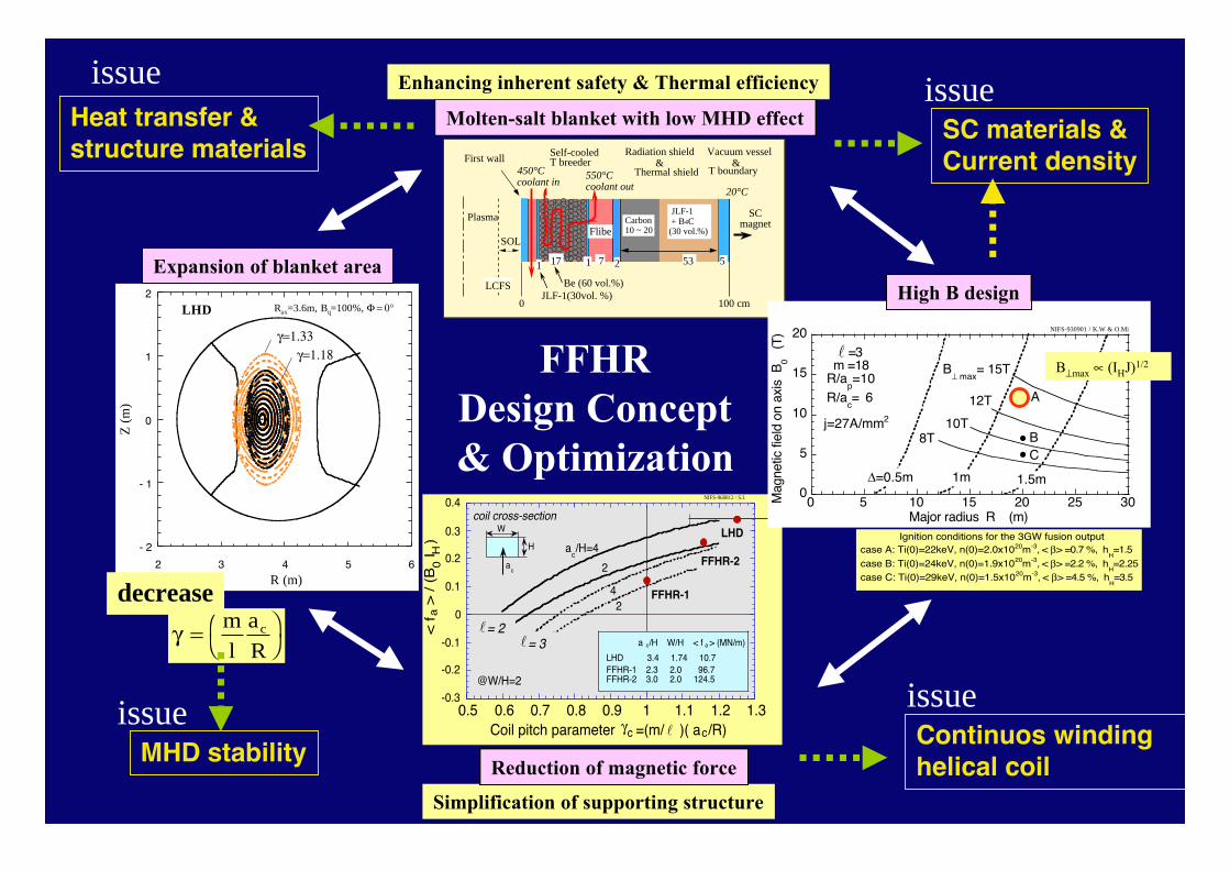
FFHRDesign Concept& Optimization
Molten-salt blanket with low MHD effect
Enhancing inherent safety & Thermal efficiency
Plasma
100 cm0
Self-cooled T breeder
Radiation shield Vacuum vessel
SCmagnet
LCFS
First wall
550°Ccoolant out
SOL
Thermal shield 450°Ccoolant in
20°C
7 53
T boundary&
Flibe
217 5
JLF-1(30vol. %)
1 1
&
Carbon10 ~ 20
JLF-1 + B4C(30 vol.%)
Be (60 vol.%)
Simplification of supporting structure
-0.3
-0.2
-0.1
0
0.1
0.2
0.3
0.4
0.5 0.6 0.7 0.8 0.9 1 1.1 1.2 1.3
< f
a >
/ (
B0
I H)
ac/H=4
2
LHD
FFHR-142
W
H
ac
= 3
@W/H=2
= 2 l
coil cross-section
NIFS-960812 / S.I.
l
Coil pitch parameter c =(m/ )( acg /R) l
FFHR-2
a c/H W/H < f a > (MN/m)
LHD 3.4 1.74 10.7FFHR-1 2.3 2.0 96.7FFHR-2 3.0 2.0 124.5
Reduction of magnetic force
case C: Ti(0)=29keV, n(0)=1.5x10²⁰m-3, < b> =4.5 %, hH=3.5
case B: Ti(0)=24keV, n(0)=1.9x10²⁰m-3, < b> =2.2 %, hH=2.25
Ignition conditions for the 3GW fusion outputcase A: Ti(0)=22keV, n(0)=2.0x10²⁰m-3, < b> =0.7 %, h
H=1.5
0
5
10
15
20
0 5 10 15 20 25 30Mag
netic
fiel
d on
axi
s B
0
(T)
C
10T
Major radius R (m)
B
12T
8T
D=0.5m 1m 1.5m
=3 m =18R/a
p=10
R/ac= 6
NIFS-930901 / K.W & O.Mi
j=27A/mm2
A
B^ max
= 15T l
B^max µ (IHJ)1/2
High B design
- 2
- 1
0
1
2
2 3 4 5 6
Z (
m)
R (m)
g=1.18g=1.33
LHD Rax=3.6m, Bq=100%, F = 0∞
Expansion of blanket area
g = ÊË
ˆ¯
ml
aR
c
decrease
Continuos windinghelical coil
issue
SC materials &Current density
issue
MHD stabilityissue
Heat transfer & structure materials
issue

Sagara 5
SCmagnet
Self-cooled T breeder TBRlocal > 1.2
Radiation shield reduction > 5 orders Thermal shield
20°C
Vacuum vessel
T boundary&
Protection wall Ph =0.2 MW/mPn =1.5 MW/m Nd =450 dpa/30y
22
Be
T storage
Pump
Pump
Tank
HXPurifier
T-disengager
14MeV neutron
Turbine
Liquid / Gas
Structural Materials
In-vesselComponents
Blanket
Thermo-fluid
Tritium
June 6. 2003, A.Sagara
Safety& Cost
Chemistry
shielding materials.
high temp.surface heat flux
CorePlasma
Ignition access & heat fluxO.Mitarai(Kyusyu Tokai Univ.)
Helical core plasmaK.Yamazaki(NIFS)
Blanket systemS,Tanaka(Univ. of Tokyo)
Thermo-mechanical analysisH.Matsui(Tohoku Univ.)
Helical reactor design / Sytem IntegrationA.Sagara(NIFS)
Thermofluid systemK.Yuki(Tohoku Univ.)
Advanced thermofluid T.Kunugi(Kyoto Univ.)
Heat exchanger & gas turbine systemA.Shimizu(Kyusyu Univ.)
T-disengager systemS.Fukada, M.Nishikawa(Kyusyu Univ.)
Device system codeH.Hashizume(Tohoku Univ.)
Thermofluid MHD S.Satake(Tokyo Univ. Sci.)
Advanced first wallT.Norimatsu(Osaka Univ.)
Reactor design activity in NIFS collaborationReactor design activity in NIFS collaboration
• on goingcf. NIFS annual repo.
Flibe related

Sagara 6
Evaluation of tritium leak and permeation barrierEvaluation of tritium leak and permeation barrier( by S. ( by S. FukadaFukada ) )
He purge gas flow
W=2.2x10⁻⁴m3/s, Re=100, Sh=10
Flibe flow, W=2.1m3/s,Re=9x105, Sh=2x10⁴
• With barrier of He sweep gas(W=220cc/s) and/or Flibe stagnant(t=0.5m) in double wall (100m2), theleak level is 1.6Ci/day < 10Ci/day.
Heat exchanger
pump
TritiumrecoveryFlibe blanket
Tritiumstorage
Flow rate2.3m3/s
Tritium generation rate (1 GWt)190 g-T/day = 1.8 MCi/day
Permeationbarrier
Double tube
Flibe/He gasPlasma
100 cm0
Self-cooled T breeder
Radiation shield Vacuum vessel
SCmagnet
LCFS
First wall
550°Ccoolant out
SOL
Thermal shield 450°Ccoolant in
20°C
7 53
T boundary&
Flibe
217 5
JLF-1(30vol. %)
1 1
&
Carbon10 ~ 20
JLF-1 + B4C(30 vol.%)
Be (60 vol.%)
• W/O barrier, 200Ci/m/day from ss316 tube ( t=5mm, f=0.7m)
100
101
102
103
104
105
106
Tri
tium
per
mea
tion
rate
per
leng
th [
Ci/m
day]
10-12
10-11
10-10
10-9
10-8
10-7
10-6
Tritium concentration in Flibe [weight fraction]
101
102
103
104
105
106
Tritium partial pressure in Flibe [Pa]
j/z=pdrFlibekM(xT-xoutside)
j/z=pdKp(xT0.5-xoutside
0.5)/tKH0.5
diffusion-in-Flibe controlling
permeation-through-wall controlling
Flibe, 600C, sus316tube
W=2.1m3/s, Re=8.5x10
5, Sc=870, Sh=1.9x10
4
corresponding to 190g/day
However, leakageinto the secondaryflow ~ 34kCi/day

Sagara 7
Permeation window system for Tritium RecoveryPermeation window system for Tritium Recovery
10-8
10-7
10-6
10-5
10-4
Tri
tiu
m m
ola
r fr
acti
on
in
Fli
be
[-]
101
102
103
104
105
Permeation area [m2]
103
104
105
106
Tri
tiu
m p
arti
al p
ress
ure
[P
a]
Fluid-film diffusion + permeation
ferrite-steel permeation window
T=843K, QT=190g-T/day, WFlibe=2.3m3/s
Permeation controlling
Fluid film diffusion controlling
Permeation window area [m2] (a=1, t=1mm)
Tritium leak
Large apparatus
By S. Fukada et al., Fusion Sci. Tech.41 (2002) 1054.
With the barrier for T leakage,operation at CT > 0.3ppm(PT2~ 20 kPa) is optimum
Diffusion of T2 in Flibe is therate-limiting process.
Recovery systems ofa realistic-scale ( the total <a few 100 m2) are possiblefor permeation windowdisengager systems.

Sagara 8A.Sagara
Japan-US joint project JUPITER-IIFrom FY2001 to 2006
����������������������������
����������������
1-1-B: FLiBe Thermofluid Flow Simulation2-2 : SiC System Thermomechanics
1-2-A: Coatings for MHD Reduction
1-2-B: V Alloy Capsule Irradiation2-1 : SiC Fundamental Issues, Fabrication, and Materials Supply2-3 : SiC Capsule Irradiation
1-1-A: FLiBe Handling/Tritium.Chemistry������������
��� ��� ��� ���
3-1: Design-based Integration Modeling3-2: Materials Systems Modeling

Sagara 9
R & D collaboration program in LHD project R & D collaboration program in LHD project1. Development of the Molten Salt Forced
Circulation Loop Unit and Investigationon the High Heat Flux Removal Devicefor Divertor and Blanket Technologies
Tohoku Univ., Prof.S.Toda / A.Sagara(NIFS)
(FY1997 - 2000 - )
TNT loop
2. Ultrahigh Heat Transfer Enhancementusing Nano-Particle Porous Surface forDivertor and Blanket Technologies
Kyoto Univ., Prof.T.Kunugi / A.Sagara(NIFS)
(FY2004 - 2006 - )
Ultrahigh HT
July 4, ‘03
“2 timesenhancedby Kunugi”
High Pr fluid

Sagara 10
TTTTTTTToooohhhhooookkkkuuuuoooohhhhooookkkkuuuu----NNNN----NNNNIIIIFFFFSSSSIIIIFFFFSSSS TTTTTTTThhhheeeerrrrmmmmoooofffflllluuuuiiiiddddhhhheeeerrrrmmmmoooofffflllluuuuiiiidddd lllloooooooopppp lllloooooooopppp ffffoooorrrr mmmmoooolllltttteeeennnn ssssaaaallllttttffffoooorrrr mmmmoooolllltttteeeennnn ssssaaaalllltttt
TNT loopTNT loop�� u ~ Max.20 L/minu ~ Max.20 L/min
�� T ~ 600 T ~ 600°°CC
�� V ~ 0.1m V ~ 0.1m33
�� P ~ 0.7 P ~ 0.7 MPa MPa..
40 kW
Now HTS (simulant for Flibe) is used.

Sagara 11System diagram of TNT loop
• S.Toda, S.Chiba, K.Yuki, A. Sagara, “Experimental research on molten salt thermofluid technologyusing a high-temperature molten salt loop applied for a fusion reactor Flibe blanket”, Fusion. Eng.Des., 63-64, 405 (2002)
• M.Omae, “Experimental study about heat transfer enhancement for high temperature molten salt”,Master thesis of Tohoku Univ. (2003) [In Japanese]
• S.Chiba, “Study on improvement of thermofluid characteristics with optimization of flow field forhigh Prandtle-number fluid”, Doctoral thesis of Tohoku Univ. (2003) [In Japanese]

Sagara 12
Bird’s eye view of TNT loop
(Fabricated by IHI Co., Ltd.)
Upper Tank
Main Pump
Dump Tank
Air CoolerTestSection
ControlRoom

Sagara 13
Side view of TNT loop
Upper TankMain Pump
Dump Tank
Air Cooler

Sagara 14Elapsed time vs Temperature at each point of TNT loop (Heater Test)
0
100
200
300
400
500
600
700
0 5 10 15 20 25 30
Elapsed time (hr)
Te
mp
era
ture
(�
)TE11 Bottom of Dump Tank
TE12 Lateral of Dump Tank
TE27 Pipe connected at inlet of Upper Tank
TE22 Pipe to supply gas for flow meter
TE32 Inlet of Air Cooler
TE29 Heat transfer pipe (Upper row at Air Cooler)
TE14 Heat transfer pipe (Upper row at Air Cooler)
TE15 Heat transfer pipe (Upper row at Air Cooler)
TE16 Heat transfer pipe (Middle row at Air Cooler)
TE17 Heat transfer pipe (Middle row at Air Cooler)
TE18 Heat transfer pipe (Lower row at Air Cooler)
TE30 Heat transfer pipe (Lower row at Air Cooler)
TE19 Bottom of Upper Tank
TE02 Outlet of Air Cooler
TE13 Orifice flange
TE24 Pipe (Between Dump Tank and Main Pump)
TE23 Pipe (Between Dump Tank and flow meter)
TE31 Pipe (Betwenn Main Pump and Test Section)
TE25 Flange at outlet of Main Pump
TE03 Pipe connected at inlet of Test Section
TE21 Pipe (Between Test Section and Upper Tank)
TE01 Pipe connected at outlet of Test Section
TE20 Flange at outlet of Test Section
TE26 Test Section (dummy)
TE28 Main Pump

Sagara 15
pipe Insulatort=25 mm
Insulatort= 6 mm
Coppert= 0.5 mm
Insulatort= 25mm
Thermal insulator at Test Section and Schematic view of cross section
g

Sagara 16
Heat transfer enhancer at Heat transfer enhancer at low flow ratelow flow rate…… Packed-bed tube in TNT loop Packed-bed tube in TNT loop
Fig.Re vs heat transfer characteristics (at 300 mm)
Fig.Pump frequency vs heat transfer coefficient (at 300 mm)
About About 33 times higher than times higher thanturbulent heat transferturbulent heat transfer
300 mm
HERE
Flow
Fig. Flow structure near wall(Result of 2D numerical simulation)
19.5mm
5mm

Sagara 18
�FFHR design �with R&D
�JUPITER-II
R&D/LHD�TNT loop�Ultrahigh HT
FY1993 1997 2001 2004 2007
Molten salt R & D activities in Japan Molten salt R & D activities in Japan
2015
�ITER-TBM
$
$
$
Presented by A.Sagara(NIFS), Feb.’04