Embed Size (px)
Citation preview

1
UNITED STATES MARINE CORPS THE BASIC SCHOOL
MARINE CORPS TRAINING COMMAND CAMP BARRETT, VIRGINIA 22134-5019
NIGHT OPTICS AND OBSERVATION THEORY
B2E2677 STUDENT HANDOUT

2
NIGHT OPTICS AND OBS THEORY
Introduction The Marine Corps utilizes Night Vision Devices on a daily basis. We conduct many successful operations in the night environment in order to take advantage of our superior night capabilities. We have sights for every Marine that will help them employ their weapons systems more effectively in the night environment.
Importance In order for the Marine Corps to effectively fight during the
night we need to understand the capabilities, limitations, and proper use of the Night Vision Devices in our inventory. If our devices are not employed properly it will lead to ineffective use on the battlefield. As leaders of Marines we will need to ensure our Marines know how to properly and effective utilize Night Vision Devices on the battlefield.
In this Lesson We will cover the history of Night Vision Devices, how they
work, and discuss some of the devices you will find in an infantry company. Both during and after the lecture there will be a hands-on application to prepare you for utilizing these devices.
This lesson discusses the follow topics:
Topic History of NVDs 3
NVD Overview 6
How NVDs Work 9
Planning Considerations 15
Ambient Light Optic (AN/PVS-14) 18
Thermals • AN/PAS-13B 24
• AN/PAS-13D 25
• AN/PAS-22 26
Target Pointer Illuminator (AN/PEQ-15) 28
References 31
Notes Page 31

3
Learning Objectives TERMINAL LEARNING OBJECTIVE:
Given observation aiding equipment, and an area to observe during daylight and limited visibility, perform aided observation to identify objects and/or sounds. (0300-CMBH-1203)
ENABLING LEARNING OBJECTIVES:
Without the aid of references, describe how to employ night vision devices without omission. (0300-CMBH- 1203b)
Without the aid of references and considering use during daylight and limited visibility, describe how to employ thermal devices without omission. (0300- CMBH-1203c)
History of Night Vision Devices History
Military tacticians throughout history have seen the advantages of being able to maneuver effectively under cover of darkness. In the Battle of Trenton, in 1776, for example, George Washington led Continental troops across the Delaware River in darkness, though a snowstorm delayed their attack until morning. In the War of 1812 and the Civil War, troops would sometimes surround the enemy at night and then attack the next day. With no means of effectively seeing at night, such strategy often ended in disaster. Knowing this, commanders traditionally elected to take their chances on being annihilated by day rather than risk nocturnal miscalculations.
The earliest effort at technology-assisted night fighting was with the Union navy's use of calcium lights to bombard Charleston Harbor in 1864; however, casting a powerful light on a target has the unwanted effect of revealing the attacker's location. The first true night-vision systems would have to wait for the development of devices that could detect invisible wavelengths of light and amplify weak signals.
Late in World War II, German, American, and British forces introduced crude infrared riflescopes that allowed snipers to operate at night. These "active" systems—meaning that they provided light rather than just rely on

4
existing light —had a near-infrared (NIR) light source mounted on the scope. (NIR is next up in wavelength from visible light on the electromagnetic radiation spectrum.) The NIR light would shine on the object to be seen and reflect back to the scope, which converted the reflection into a visual image and made it brighter with a device called an image tube.
The infrared sniper scope showed that night vision technology was on the horizon. Military leaders immediately saw many uses for this technology beyond sniping at the enemy under cover of darkness. A unit equipped with night vision goggles, helmets, and weapons sights would be able to operate 24 hours a day.
Interest in night-vision equipment declined after its experimental use in World War II, and development proceeded slowly for the remainder of the 1940s. But in 1950, the overwhelming success of the Chinese Communist attack in Korea, much of it effectively pressed after dark, dramatically demonstrated that the ability to fight at night was essential in modern warfare. Our experiences in the Korean War fueled a movement to expand our night fighting capabilities.
In 1954, the Army decided to upgrade components of the rudimentary NIR sniper scopes they had developed. In using these scopes, each sniper had to wear a heavy battery-backpack with a wire reaching over the shoulder due to the hefty 16,000 volts needed to power the system. This type of active NIR technology became known as Generation 0. The first enhancement would be to reduce the apparatus's power usage at both ends by developing a more efficient NIR source and a more sensitive image tube. This would make a smaller, more-practical, and lighter battery pack. A program was started to couple two image tubes end to end to create a cascading effect, greatly multiplying the gain. The image tube now took on the name of image intensifier.
5
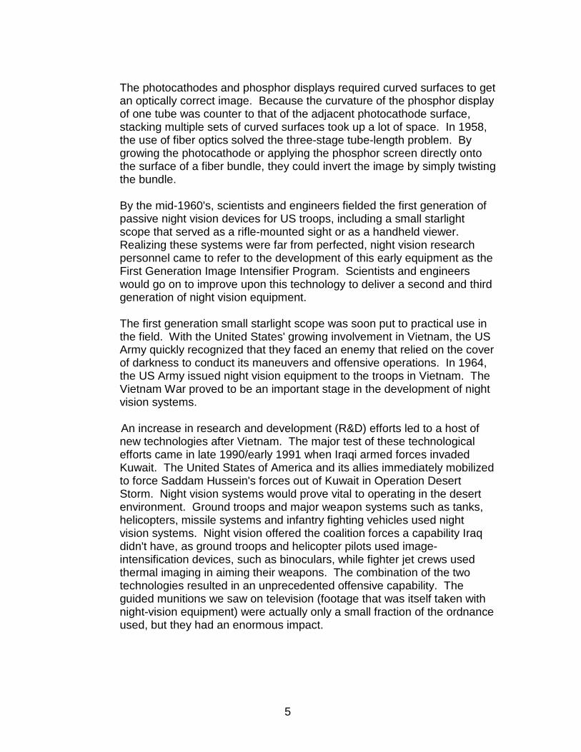
The photocathodes and phosphor displays required curved surfaces to get an optically correct image. Because the curvature of the phosphor display of one tube was counter to that of the adjacent photocathode surface, stacking multiple sets of curved surfaces took up a lot of space. In 1958, the use of fiber optics solved the three-stage tube-length problem. By growing the photocathode or applying the phosphor screen directly onto the surface of a fiber bundle, they could invert the image by simply twisting the bundle.
By the mid-1960's, scientists and engineers fielded the first generation of passive night vision devices for US troops, including a small starlight scope that served as a rifle-mounted sight or as a handheld viewer. Realizing these systems were far from perfected, night vision research personnel came to refer to the development of this early equipment as the First Generation Image Intensifier Program. Scientists and engineers would go on to improve upon this technology to deliver a second and third generation of night vision equipment.
The first generation small starlight scope was soon put to practical use in the field. With the United States' growing involvement in Vietnam, the US Army quickly recognized that they faced an enemy that relied on the cover of darkness to conduct its maneuvers and offensive operations. In 1964, the US Army issued night vision equipment to the troops in Vietnam. The Vietnam War proved to be an important stage in the development of night vision systems.
An increase in research and development (R&D) efforts led to a host of new technologies after Vietnam. The major test of these technological efforts came in late 1990/early 1991 when Iraqi armed forces invaded Kuwait. The United States of America and its allies immediately mobilized to force Saddam Hussein's forces out of Kuwait in Operation Desert Storm. Night vision systems would prove vital to operating in the desert environment. Ground troops and major weapon systems such as tanks, helicopters, missile systems and infantry fighting vehicles used night vision systems. Night vision offered the coalition forces a capability Iraq didn't have, as ground troops and helicopter pilots used image- intensification devices, such as binoculars, while fighter jet crews used thermal imaging in aiming their weapons. The combination of the two technologies resulted in an unprecedented offensive capability. The guided munitions we saw on television (footage that was itself taken with night-vision equipment) were actually only a small fraction of the ordnance used, but they had an enormous impact.

6
NVD Overview Passive Night Sights
Type Description Thermals Thermal Weapon Systems (TWS)
• Completely passive • Primarily designed for target detection and engagement with
Marine Corps crew served weapons • May also be used for all weather surveillance • A family of sights which will include a
o Medium weapons sight (MWTS) o Heavy weapons sight (HWTS)
• Will be mounted to the o M249 squad automatic weapon (SAW) o M240G machine gun o M2 .50 cal machine gun o MK 19 40mm grenade machine gun.
Type Description Ambient light NVDs
• Have been around for more than 40 years beginning with sniper scopes of World War II, which
o Were cumbersome devices o Had short battery lives and indifferent performance o Required the use of infrared lighting o Were not much more sensitive to light than the human eye
• NVDs are categorized by generation; each substantial change in NVD technology establishes a new generation:
o Generation I, developed in 1960s o Generation II, developed in 1970s o Generation III, developed in 1990s o Generation IV developed in 2000
Generation I
• Beginning of passive night vision • Included
o Vacuum tight fused fiber optics for good center resolution and improved gain
o Multi-alkali photo cathodes o Fiber optic input and output windows
• Lacked the sensitivity and light amplification necessary to see below full moonlight
• Were o Often staged or cascaded to improve gain o Large and cumbersome

7
o Less reliable
o Relatively poor low light imagers o Characterized by streaking and distortion
• Characteristics: o Vacuum tube technology o Full moon operation o Amplification: 1,000 - 2,000 o Operating life: 2,000 hours
Generation II
• Born out of the development of the micro channel plate (MCP): o Higher electron gains were now possible through smaller
packaging o Performance improvements made observation possible down
to 1/4 moonlight • First proximity focused MCP image intensifier tube was an 18mm
tube used in the original AN/TVS-5 NVG • Generation II+ improved performance by providing increased gain at
high and low levels • Generation II+ equipment
o Will provide the best image under full moonlight conditions o Is recommended for urban environments.
• First MCP application • Characteristics
o One-quarter moon operation o Amplification: 20,000 - 40,000 o Operating life: 2,500 hours
Generation III
• Intensifier o Multiplies the light gathering power of the eye or video receptor
up to 30,000 times o Is typically characterized by a gallium arsenide (GaAs)
photocathode • Photocathode
o Is grown using a metal organic vapor-phase epitaxy (MOVPE) process
o Has photon sensitivity that extends into the near-infrared region, where night sky illuminance and contrast ratios are highest
o Sealed to an input window which minimizes veiling glare, generates an electron current which is proximity focused onto a phosphor screen, where the electron energy is converted into green light which can then be relayed to the eye or sensor through an output window
• Characteristics: o Improved MCP and photocathode o Starlight operation

8
o Amplification: 35,000 - 60,000
o Operating life: 10,000 hours Generation IV
• Gated filmless technology • Represents biggest technological breakthrough in image
intensification of past 10 years • Removing the ion barrier film and “gating” the system
demonstrates substantial increases in target detection range and resolution, particularly at extremely low light levels
NOTE: The term 4th generation is used/accepted among night vision manufacturers to describe gated filmless tubes; however, this designation is widely debated. Currently US military referred to it as “filmless and gated image intensifiers.” NOTE: The sensitivity of a first generation scope is far behind that of the second generation; in the areas of resolution and distortion, the performance of the first generation lags far behind that of the second, third, and fourth generation.
Night Aiming Devices
Type Description Advanced Target Pointer Illuminator Aiming Light
The Advanced Target Pointer Illuminator Aiming Light (ATPIAL), PEQ-15, provides a highly collimated beam of infrared energy for weapon aiming and an adjustable focus infrared beam for target illumination. This Class 3b laser device also provides a highly collimated beam of visible energy for weapon aiming. The ATPIAL has low profile aiming and illumination boresight adjusters. This device is 50% smaller and lighter than the TPIAL. The system comes with a MIL-STD-1913 rail grabber interface using the integral rail grabber bracket. The ATPIAL is the successor to the AN/PEQ-2A.
Weapon Platforms: The ATPIAL has an Integral Rail Grabber Bracket that mounts to any weapon using the standard MIL-STD-1913 Rail, which includes the M4/M16-A4 rifles, M249, M240, M2, and Mk 19. The ATPIAL can also be used as a handheld illuminator/pointer.
The AN/PEQ-15 has replaced both the AN/PEQ-2 and the AN/PAQ-4C

9
How Night Vision Devices Work Spectrum
Electromagnetic waves are waves that are capable of traveling through a vacuum. Unlike mechanical waves, which require a medium in order to transport their energy, electromagnetic waves are capable of transporting energy through the vacuum of outer space. Electromagnetic waves are produced by a vibrating electric charge, and as such, they consist of both an electric and a magnetic component.
Electromagnetic waves exist with an enormous range of frequencies. This continuous range of frequencies is known as the electromagnetic spectrum. The entire range of the spectrum is often broken into specific regions. The subdividing of the entire spectrum into smaller spectra is done mostly on the basis of how each region of electromagnetic waves interacts with matter.
The diagram below depicts the electromagnetic spectrum and its various regions:
• The longer wavelength, lower frequency regions are located on the
far left of the spectrum • The shorter wavelength, higher frequency regions are on the far
right • Two very narrow regions within the spectrum are the visible light
region and the X-ray region
You are undoubtedly familiar with some of the other regions of the electromagnetic spectrum.
THERMAL
Electromagnetic Spectrum

10
Though electromagnetic waves exist in a vast range of wavelengths, our eyes are sensitive to only a very narrow band. Since this narrow band of wavelengths is the means by which humans see, we refer to it as the visible light spectrum. Normally when we use the term "light," we are referring to a type of electromagnetic wave, which stimulates the retina of our eyes. In this sense, we are referring to visible light, a small spectrum of the enormous range of frequencies of electromagnetic radiation. This visible light region consists of a spectrum of wavelengths, which range from approximately 700 nanometers (abbreviated nm) to approximately 400 nm; that would be 7 x 10⁻⁷ meters to 4 x 10⁻⁷ meters.
Each individual wavelength within the spectrum of visible light wavelengths is representative of a particular color. That is, when light of that particular wavelength strikes the retina of our eye, we perceive that specific color sensation. Isaac Newton showed that light shining through a prism will be separated into its different wavelengths and will thus show the various colors of which visible light is comprised.
The separation of visible light into its different colors is known as dispersion. Each color is characteristic of a distinct wavelength; and different wavelengths of light waves will bend varying amounts upon passage through a prism; for these reasons, visible light is dispersed upon passage through a prism.
Dispersion of visible light produces these colors (see electromagnetic spectrum above); thus, visible light is sometimes referred to as ROY G. BIV:
• Red (R) Longer wavelengths • Orange (O) • Yellow (Y) • Green (G) • Blue (B) • Indigo (I)
• Violet (V)
Continuous
range of
spectrum of wavelengths
Shorter wavelengths

11
When all the wavelengths of the visible light spectrum strike your eye at the same time, white is perceived. Thus, visible light is sometimes referred to as white light. Technically speaking, white is not a color at all, but rather the combination of all the colors of the visible light spectrum.
If all the wavelengths of the visible light spectrum give the appearance of white, then none of the wavelengths would lead to the appearance of black. Once more, black is not actually a color. Technically speaking,

12
black is merely the absence of the wavelengths of the visible light spectrum. So when you are in a room with no lights and everything around you appears black, it means that no wavelengths of visible light are striking your eye as you sight at the surroundings.
How Night Vision Technology Works
NVGs are electro-optical devices that intensify (or amplify) existing light instead of relying on a light source of their own. Image intensifiers capture ambient light (which comes from the stars, moon, or sky glow from distant manmade sources, such as cities) and amplify it thousands of times by electronic means to display the battlefield to a Marine via a phosphor display such as night vision goggles. The devices are sensitive to a broad spectrum of light, from visible to infrared (invisible). Users do not look through NVGs; they look at the amplified electronic image on a phosphor screen. Light enters the NVG through an objective lens and strikes a photo cathode powered by a high energy charge from the power supply. The energy charge accelerates across a vacuum inside the intensifier and strikes a phosphor screen (like a TV screen) where the image is focused. The eyepiece magnifies the image.
An NVG phosphor screen is purposefully colored green because the human eye can differentiate more shades of green than other phosphor colors. Like cameras, NVGs have various image magnifications. The distance at which a human-sized figure can be clearly recognized under normal conditions (moon and star light with no haze or fog) depends on the
• Magnifying power of the objective lens • Strength of the image intensifier
A Marine can conduct his combat missions without any active illumination sources using only image intensifiers. The main advantages of image intensifiers as night vision devices are their
• Small size • Light weight • Low power requirements • Low cost
These attributes have enabled image intensifier goggles for head-worn, individual Marine applications and resulted in hundreds of thousands of night vision goggles to be procured by the Marine Corps. Research and development continues today on image intensifiers in the areas of longer wavelength spectral response, higher sensitivity, larger fields of view and increased resolution.

13
The view through NVGs can be a lot like looking down a tunnel. Your normal field of view is almost 190 degrees. NVGs cut that down to 40 degrees; side or “peripheral” vision you’re accustomed to and from which you often see dangers is just not there. To adjust for the narrow field of view, you must constantly turn your head to scan for the dangers on either side of you.
NVGs cannot provide the same level of clarity you are accustomed to during the day. While normal vision is 20/20, NVGs can, at best, provide only 20/25 to 20/40 and even this is possible only during optimal illumination and when you have a high-contrast target or scene. As either illumination or contrast decreases, the NVGs visual acuity drops, giving you an even more “fuzzy” image.
Normally you use both eyes (binocular vision) to pick up cues to help estimate the distance and depth of an object. However, with NVGs you are essentially using one eye (monocular) vision, which can pose real problems. For example, when you are wearing NVGs and view two objects of different sizes that are side-by-side, the larger object appears to be nearer. When you view overlapping objects through an NVG, the one that is in front “appears” to be nearer – maybe much more so than is true. In addition, some objects viewed through NVGs may appear to be farther away than they actually are. The reason for these optical illusions is that we tend to associate the loss of detail sharpness with distance. On the other hand, a light source that is not part of a terrain feature—for example, a light atop a tower—may look closer than it actually is. Be aware of these potential problems and that NVG users tend to overestimate distance and underestimate depth (how tall an object is).
Originated in the 1920s to increase the sensitivity of television cameras, image tubes work by converting light into electricity. Certain substances, such as selenium, had been known since the 1870s to be photoemissive—that is, to emit electrons when a light shone on them. With the proper use of lenses, a pattern of light—visible or invisible—upon a photoemissive surface can be converted into electrical impulses. In an image tube, a voltage is applied across the photoemissive surface, which is called a photocathode. This voltage accelerates the emitted electrons and causes them to multiply.
To create a visible image, the emitted electrons are directed against a phosphor surface. This type of surface is the opposite of photoemissive; it emits light when electrons strike it. The phosphor is in the form of a coating on an optic lens, which focuses the resulting visible image. The phosphor screen looks much like a black-and-white television with a greenish tint (green is used because the eye is most sensitive to that

14
color). In essence, then, the earliest NVGs converted NIR light to electricity, amplified it, and then converted it to visible light. A microchannel plate (MCP) is a form of glass plate with millions of microscopic holes, or channels, running through it (this replaces the bundle of optical fibers). When a voltage is applied to accelerate electrons through it, the electrons repeatedly bounce off the channel walls, which are coated with the residue from etching the holes. As they do so, they dislodge additional electrons. The gain is proportional to the voltage applied. Each channel in the MCP corresponds to a pixel in the final image.
In Generation 2, the photocathode, microchannel plate, and phosphor screen—detector, amplifier, and display—are sealed together in a module less than an inch thick (see diagram below):
• The photocathode converts light to an electric current • The microchannel plate amplifies it • The phosphor screen converts it back to light
Generation 2 Module
Night vision systems are electro-optical devices which allow you to see at night. The objective lens of the night vision device collects small particles of light called photons, such as moonlight and starlight, and focuses them on the image tube. The photocathode converts this light energy into electrons. The electrons pass through a thin wafer disk, the microchannel plate, which contains millions of channels. As the electrons pass through the channels, they are amplified thousands of times. These multiplied

15
electrons then strike a phosphor screen which converts them back into photons and provides you with the nighttime image of the scene in which you are viewing.

16
PLANNING CONSIDERATIONS
Planning Considerations
When using NVDs that require ambient light, illumination will be a major factor in planning operations. Some type of illumination must exist in order for the NVDs to be effective; too much illumination can severely degrade them or make them completely ineffective. Lunar and solar cycles (see diagram and table below) play an important part of determining natural illumination at various times:
Solar Illumination
Solar Illumination Definition Moonrise The instant when,
• In the eastern sky • Under ideal meteorological conditions • With standard refraction of the moon's rays, the upper
edge of the moon's disk is coincident with an ideal horizon Moonset The instant when,
• In the western sky • Under ideal meteorological conditions • With standard refraction of the moon's rays, the upper
edge of the moon's disk is coincident with an ideal horizon Twilight • Before sunrise and again after sunset, intervals of time during
which

17
o The upper atmosphere receives direct sunlight and reflects
part of it toward the Earth’s surface to provide natural light o Some outdoor activities may be conducted without artificial
illumination • Major determinants of the amount of natural light during twilight
are the o State of the atmosphere generally o Local weather conditions in particular
• Atmospheric conditions are best determined at the actual time and place of events; however, it is possible to establish useful, though necessarily approximate, limits applicable to large classes of activities by considering only the position of the Sun below the local horizon.
• Reasonable and convenient definitions have evolved for three kinds of twilight:
o Civil twilight o Nautical twilight o Astronomical twilight
Civil Twilight • Begins in the morning and ends in the evening when the center of the Sun is geometrically 6 degrees below the horizon
• Is the limit at which twilight illumination is sufficient, under good weather conditions, for terrestrial objects to be clearly distinguished
• At the beginning of morning civil twilight or end of evening civil twilight (ECT), the horizon is clearly defined and the brightest stars are visible under good atmospheric conditions in the absence of moonlight or other illumination
• In the morning before the beginning of civil twilight and in the evening after the end of civil twilight, artificial illumination is normally required to carry on ordinary outdoor activities
• Beginning of morning civil twilight (BMCT) is the period of time at which the sun is halfway between beginning morning and nautical twilight and sunrise, when there is enough light to see objects clearly with the unaided eye. At this time, light intensification devices are no longer effective, and the sun is six degrees below the eastern horizon
• End of evening civil twilight (EECT) is the instant in the evening, when the centre of the sun is at a depression angle of six degrees below an ideal horizon. At this time in the absence of moonlight, artificial lighting or adverse atmospheric conditions, the illumination is such that large objects may be seen, but no detail is discernible. The brightest stars and planets can be seen and for navigation purposes at sea, the sea horizon is clearly defined.
• Complete darkness, however, ends sometime prior to BMCT and begins sometime after EECT

18
Nautical Twilight • Begins in the morning and ends in the evening, when the center of the sun is geometrically 12 degrees below the horizon.
• At the dark limit of nautical twilight, the center of the Sun is geometrically 12 degrees below a horizontal plane. At the beginning or end of nautical twilight, under good atmospheric conditions and in the absence of other illumination, general outlines of ground objects may be distinguishable, but detailed outdoor operations are not possible, and the horizon is indistinct.
• Beginning of morning nautical twilight (BMNT) is the start of that period where, in good conditions and in the absence of other illumination, enough light is available to identify the general outlines of ground objects and conduct limited military operations. Light intensification devices are still effective and may have enhanced capabilities. At this time, the sun is 12 degrees below the eastern horizon.
• End of evening nautical twilight (EENT) is the instant in the evening, when the centre of the sun is at a depression angle of 12 degrees below an ideal horizon. At this time in the absence of moonlight, artificial lighting or adverse atmospheric conditions, it is dark for normal practical purposes. For navigation purposes at sea, the sea horizon is not normally visible.
Astronomical Twilight
• Begins in the morning and ends in the evening when the center of the Sun is geometrically 18 degrees below the horizon.
• At the dark limit of astronomical twilight, the center of the Sun is geometrically 18 degrees below a horizontal plane. Before the beginning of astronomical twilight in the morning and after the end of astronomical twilight in the evening the Sun does not contribute to sky illumination; for a considerable interval after the beginning of morning twilight and before the end of evening twilight, sky illumination is so faint that it is practically imperceptible.

19
AN/PVS - 14
The PVS-14 (see diagram below) allows the user to see at night using moonlight or starlight. The PVS-14 is a GEN III image intensification device similar in performance to the previously-used PVS-7 NVGs, yet smaller, lighter, and more versatile. PVS-14s can be
• Hand-held • Carried in the utility uniform pocket • Head-mounted • Helmet-mounted • Mounted to a weapon
PVS-14
The table below provides more information on the PVS-14. Nomenclature NSN Manual AN/PVS-14 monocular night vision device
5855-01-432- 0524
TM 10271A-10/1 TM 11-5855-306-10 Operator’s Manual, Monocular NVD, AN/PVS-14, 30 Dec 97
Characteristics
• Weight: 14 oz • Focus range: 25 cm to infinity • Range:
o 150 m (starlight) o 300 m (moonlight)
• Battery: 2 AA
o Alkaline o Lithium
• Battery life: 12 hours • Magnification: 1X • Field of view: 40 degrees

20
Accessories
• Monocular with lens cap to protect lens • Demist shield for high humidity and rain. Degrades visual acuity. • Light interference filter (LIF) to protect eyes from lasers • Sacrificial window to protect monocular lens from dust and sand
scratches • Compass to orient at night • Tether cord is a dummy cord for
o Compass o 3X magnifier
• Head mount and 3 browpads to mount monocular on head • Helmet mount to mount monocular on helmet • Head/helmet mount adapter to attach monocular to mounts • Small arms mount to mount monocular to weapon • 3X magnifier lens is available as an optional accessory • Carrying case and strap to carry monocular • Storage case to store monocular and all accessories • Operator’s manual
Limitations
In complete darkness, such as inside buildings, PVS-14s are ineffective unless additional IR illumination is present.
Indicator Lights
• Low battery: Blinking red dot in eyepiece means less than 30
minutes of battery life. • IR beacon is on: Steady red dot in eyepiece.
Switch
• OFF/RESET turns monocular off. Resets monocular after
automatic shutoff. • ON turns monocular on. • IR turns IR beacon on. Pull and turn. A steady red dot appears.
Automatic Shutoff
The monocular shuts off automatically

21
• In excessive light • When monocular is removed from head mount • When monocular is flipped up from the helmet mount
To turn monocular back on, turn switch to OFF/RESET, then back to ON.
Monocular Adjustment
The PVS-14 has four adjustments:
• Variable gain: Adjusts the brightness of the image to reduce
eyestrain, especially in changing light. • Objective lens focus: Adjusts for sharpest image of viewed object. • Diopter adjustment ring: Focuses eyepiece for sharpest image of
intensifier screen. To adjust,
o Rotate diopter adjustment ring (see diagram below) for the clearest view of the image.
o If done in a lighted condition, line up the image through the goggle and the image in your naked eye.
• Eye relief: On helmet and head mounts, the distance between the
user’s eye and the monocular needs to be adjusted as close to the eye as is comfortable.
PVS-14 Maintenance
To maintain the PVS-14, clean lens with lens paper. Turn in for maintenance if monocular operates intermittently or has

22
• Shading • Edge flow • Flashing • Flickering
Some blemishes or spots on screen are not deadline issues. Only higher echelon maintenance can adjust goggle resolution.
Mounts
• Head mount:
o Don head mount. o Adjust straps. o Attach head/helmet mount adapter to monocular. o Attach monocular to mount. o Adjust eye relief by sliding mounting bracket toward or away
from eyes.
• Helmet mount:
o Strap helmet mount to helmet. o Attach head/helmet mount adapter to monocular. o Attach monocular to mount. o Slide monocular up and down by loosening bracket knob. o Adjust eye relief by sliding mounting bracket toward or away from
eyes. o Monocular can be

23
9 Flipped up when not in use 9 Removed from the helmet by depressing the lever on the
right side of the helmet mount and removing the entire bracket
9 Worn on either eye. Loosen the knob on the end of the mount adapter, rotate the monocular to the desired eye, and once the monocular is positioned, tighten the knob
• Small arms weapons mount:
o Attach to weapon. o Mount PVS-14 to mount. o Can be used with 3X magnifier.
Pre-Combat Checks
• Install batteries. • Remove lens cap. • Install
o Sacrificial window o Compass o 3X magnifier
• Don and adjust head or helmet mount. • Make the four monocular adjustments.
IR Beacon
IR beacon illuminates near objects in very dark conditions or for signaling. An enemy equipped with NVGs can detect the IR beacon. Turn beacon on by pulling switch out and forward.
PVS-14 Training
Most of the tactics, techniques, and procedures for the PVS-7 are the same as for PVS-14. The TTPs specific to PVS-14 are as follows:
• Fire the M-16A2 with PVS-14 mounted:
o Mount the PVS-14 to the weapon using the small arms
mount. o Adjust PVS-14 far enough away from eye to prevent injury
from weapon recoil.

24
o Op-check PAQ-4C / PEQ-2A beam by observing through PVS-14 monocular.
• Mounting PVS-14 to the M-16A4 is best done in stationary or
defensive operations where the Marine is covering a sector from behind his weapon.
• Common error: Using a mounted PVS-14 during offensive actions.
It is nearly impossible to use a mounted PVS-14 while moving with the weapon.

25
AN / PAS – 13B THERMAL SIGHT

26
AN / PAS – 13D THERMAL SIGHT

27
AN / PAS – 22 THERMAL SIGHT

28

29
AN / PEQ-15 ATPIAL
Weight and Dimensions Weight (with battery) 7.5 ounces Length 4.6 inches 4.6 inches Width 2.8 inches 2.8 inches Height 1.6 inches 1.6 inches
Power Performance Batteries (1) 3-Volt DL 123 Battery Life (6) Hours in DH (DUAL HIGH) Waterproof (6) Meters for one hour
Laser Visible Aim Laser
Output Power 4.0 mW (± 1.0 mW) Beam Divergence 0.5 mrad (+ 0.3 / -0.35
mrad) Wavelength 605 – 665 nm
Range 25m IR Aim Laser
Output Power LOW 600 μW (± 100 μW) Output Power HIGH 25 mW (+ 10%) Beam Divergence 0.5 mrad (± 0.3 mrad)

30
Wavelength 820 – 850 nm Range >600m (LOW), >2000m (HIGH)
IR Illuminator Output Power LOW < 3.5 mW Output Power HIGH 30 mW (+ 50 / -20%) Beam Divergence No less than 1 mrad to
greater than 105 mrad
Wavelength 820 – 850 nm Range >2000m
SAFETY: The ATPIAL is a Class 3b Laser. Ensuring that the safety block and safety filters are in place (see figures below) will keep the Laser in an eye safe (training) mode which prevents possible eye injury. DO NOT remove the safety block. When firing the Laser in conditions where possible specular reflection is present, the use of approved Laser safety goggles will be used. The following general safety precautions apply at all times: DO NOT stare into the Laser beams. DO NOT look into the Laser beams through binoculars or telescopes. DO NOT point the Laser beams at mirror-like surfaces. DO NOT shine the Laser beams into other individual’s eyes.
Removable Safety Screw. A removable safety screw installed in the lockout position prevents the mode selector from being turned to the high power laser settings (i.e., AH, IH, DH). This configuration is appropriate for a training environment or when the ATPIAL is being stored. A hex head wrench is used to remove the safety screw when, for tactical reasons, access to the high power laser settings is desired. The safety screw storage location allows for secure storage of the safety screw after it has been removed from the Lockout Position
Visible Laser Blocking Cap (lower laser)
Illuminator Diffuser

31
Position Mode Remarks
VIS AL
VISIBLE AIM Class 3a
Visible Aim Laser is selected. Visible without the use of night vision devices.
O
OFF
The ATPIAL will not operate. Prevents inadvertent emission of laser energy.
P
PROGRAM
Programming Mode is selected to set the desired Infrared (IR) Illuminator pulse rate.
AL
AIM LOW Class 1
IR Aim Laser is selected at low power. Visible with the use of night vision devices.
DL
DUAL LOW Class 1/3b
IR Aim Laser and IR Illuminator are both selected at low power. Visible with the use of night vision devices.
AH
AIM HIGH Class 3b
IR Aim Laser is selected at high power. Visible with the use of night vision devices.
IH
ILLUMINATOR HIGH Class 3b
IR Illuminator is selected at high power. Visible with the use of night vision devices.
DH
DUAL HIGH Class 3b
IR Aim Laser and IR Illuminator are both selected at high power. Visible with the use of night vision devices.
Table 2-9 Mode Selector Positions
Note:
NOHD - Nominal Ocular Hazard Distance NSHD - Nominal Skin Hazard Distance OD - Optical Density (Applies to a safety
lens’s ability to block light transmissions)
Table i-1 Nominal Ocular Hazard Distances for Safe Operation (NOHD)
Visible Infrared AL AL AH AH w/
Filter IH DL DH DL w/
Filters DH w/ Filters
Class 3R 1 3B 1 3B 3B 3B 1 1 NOHD (unaided)
101 m 0 m 234 m 0 m 57.1 m
32.6 m 240 m 0 m 0 m
NOHD (5-cm aided)
654 m 0 m 1.34 km
0 m 338 m
161 m 1.38 km
0 m 0 m
NOHD (8-cm aided)
1.03 km
0 m 2.11 km
0 m 539 m
255 m 2.16 km
0 m 0 m
NOHD (12- cm aided)
1.52 km
0 m 3.09 km
0 m 803 m
378 m 3.16 km
0 m 0 m
NSHD 0 m 0 m 0 m 0 m 0 m 0 m 0 m 0 m 0 m OD (unaided) 0.7 - 1.7 - 1.9 0.8 2.1 - - OD (aided) 0.7 - 1.6 - 1.9 0.8 2.1 - -

32
____
References MCIP 3-15.01 – M16A4 Rifleman’s Suite
TM 10271A-10/1 - Operator’s Manual AN/PVS-14
TM 0470B-OI/1 - Operator’s Manual AN/PEQ-15 ATPIHL
TM 11-5855-312-10 - Operator’s Manual AN/PAS-13B
TM 11-5855-317-10 – Operator’s Manual AN/PAS-13D
TM 10988B-OR/1 – Operator’s Manual PAS-22
Notes