Embed Size (px)
Citation preview

NIMPKISH RIVER
2003 Yookwa Creek Construction Report
submitted to
CANADIAN FOREST PRODUCTS LTD Englewood Logging Division
Woss, B.C. V0N 3P0
and
‘Namgis First Nation P.O. Box 210
Alert Bay, B.C. V0N 1A0
submitted by
northwest hydraulic consultants ltd. 30 Gostick Place
North Vancouver, B.C. V7M 3G2 Phone: (604) 980-6011, Fax (604) 980-9264
and
Alby Systems Ltd.
P.O. Box 71 Alert Bay, B.C. V0N 1A0
Phone: (250) 974-5855, Fax (250) 974-5855*51
February 2004
File: 3871\as-built\report-final.doc

nhc / ALBY
NIMPKISH RIVER RESTORATION 2003 Yookwa Creek Construction Report Page i
TABLE OF CONTENTS Page
List of Tables ........................................................................................................................................ i List of Figures....................................................................................................................................... i List of Photographs ............................................................................................................................... i List of Appendices ................................................................................................................................ i
1. INTRODUCTION............................................................................................................................... 1
1.1 Project Scope............................................................................................................................... 1 1.2 Project Team................................................................................................................................ 2 1.3 Project Documentation ................................................................................................................. 3
2. CONSTRUCTION SITES .................................................................................................................. 3
2.1 Site YK1DC1 (600m Channel): Type 3 ........................................................................................ 3 2.2 Site YK1DC2 (900m Channel): Type 3 ........................................................................................ 5
3. ENVIRONMENTAL MONITORING ............................................................................................... 7
3.1 Fish Salvage ................................................................................................................................ 7 3.2 Bank and Riparian Protection ....................................................................................................... 7 3.3 Sediment Control and Water Quality ............................................................................................ 7 3.4 Equipment and Machinery ........................................................................................................... 8
4. PROJECT COSTS.............................................................................................................................. 8
5. RECOMMENDATIONS .................................................................................................................... 8
5.1 Monitoring................................................................................................................................... 8 5.2 Other Recommendations and Future Trends ................................................................................. 8
6. REFERENCES ................................................................................................................................. 10
LIST OF TABLES Table 1 Summary of Constructed Works for Site YK1DC1 Table 2 Summary of Constructed Works for Site YK1DC2
LIST OF FIGURES Figure 1 Nimpkish River Restoration, Yookwa Creek Fan Project Sites Figure 2 Yookwa Creek Fan, Overview of Project Site Figure 3 Yookwa Creek Fan, YK1DC1 – 600m Distributary Channel, As-Built Plan,
Profile and Sections Figure 4 Yookwa Creek Fan, YK1DC2 – 900m Distributary Channel, As-Built Plan,
Profile and Sections
LIST OF PHOTOGRAPHS Photo pages 1 to 3 Site YK1DC1 Photo pages 3 to 8 Site YK1DC2
LIST OF APPENDICES Appendix A Routine Effectiveness Evaluation Summary Forms

nhc / ALBY
NIMPKISH RIVER RESTORATION 2003 Stream Habitat Restoration Construction Report Page 1
1. INTRODUCTION
1.1 PROJECT SCOPE A partnership of Canadian Forest Products Limited (Canfor), 'Namgis First Nation and the International Woodworkers of America (IWA) are restoring the Nimpkish River Watershed (TFL 37) as directed by the Nimpkish Resource Management Boards’ (NRMB) fish sustainability plan. The Forest Investment Account (FIA), administered by Price Waterhouse Coopers, funds the program that was started under the Watershed Restoration Program (WRP). This program includes road and slope stabilisation and rehabilitation, road deactivation, stream fertilisation, and stream channel and fish habitat restoration. This report describes the Yookwa Creek portion of the restoration work completed in Nimpkish River watershed during the 2003 instream construction window after several years of study. The Nimpkish Watershed Restoration Plan, 2002-2006 developed by ALBY Systems Ltd. (2001) ranked Reach Y1 of Yookwa Creek the highest priority reach for restoration in the Nimpkish Watershed. This ranking was based on:
• Damage to fish habitats from channel widening as the result of fan and watershed harvesting,
• Low present fish use when compared to historic use, • Prevention of future damage to high quality downstream fish habitat in the Sebalhall
River and Nimpkish River as well as damage to the Nimpkish Island Ecological Reserve, • The potential for successful completion of instream works,
During the winter of 2002 and spring of 2003 the Yookwa Technical Working Committee, as appointed by the NRMB, approved the restoration concept of working with the current channel configuration of Yookwa Creek on its fan while attempting to restore a more natural stream system of distributary channels1. These occasionally wetted channels allow floods flow to travel to Vernon Lake along alternate paths to the main channel, reducing flow in the main channel. This condition encourages coarse sediment deposition on the fan surface, decreasing throughput to Sebalhall River, thus reducing impacts to downstream reaches. Five separate tasks or sites were prescribed for the Yookwa Creek Fan project. These are:
• Site YK1BT1 – Bar Top Stabilisation Structures (Type 1) • Site YK1LWD1 – Bank Protection at 800m on the Left Bank (Type 1) • Site YK1LWD2 – Bank Protection at 800m on the Right Bank (Type 1) • Site YK1DC1 – Distributary Channel at 600m on the Right Bank (Type 3) • Site YK1DC2 – Distributary Channel at 900m on the Right Bank (Type 3)
1 A distributary channel is a river branch that flows away from the main stream and does not rejoin it, common on alluvial fans. On Yookwa Creek fan, distributary channels flow across the fan into Vernon Lake or lower Sebalhall River without rejoining the main stream.

nhc / ALBY
NIMPKISH RIVER RESTORATION 2003 Stream Habitat Restoration Construction Report Page 2
The sites were identified as Type 1, Type 2, or Type 3 following the definitions outlined in the Habitat Restoration Prescription Guidebook (1998).
• Type 1 projects are defined as structures that alter the channel plan and profile for less than five bankfull widths, produce a local effect on the streambed and banks.
• Type 2 projects are defined as structures that alter the channel plan and profile over a reach length greater than five bankfull widths. These include structures that encroach into the channel more than 30% of the bankfull width or more than 50% of the bankfull depth.
• Type 3 projects are defined as side or off-channel development. Prescriptions were completed in the summer and submitted for Section 9 Approval by the ‘Namgis First Nation in June 2003 in the 2003 Level 2 Prescriptions for Yookwa Creek report (nhc and ALBY 2003). Construction was undertaken at two of the approved five sites in 2003. They are:
• Site YK1DC1 – Distributary Channel at 600m on the Right Bank (Type 3) • Site YK1DC2 – Distributary Channel at 900m on the Right Bank (Type 3)
The sites are named following a naming scheme developed by ALBY Systems Ltd. in 1996 where the first three alphanumeric characters denote the stream and reach (i.e. YK1 for Yookwa Creek reach 1). The last three alphanumeric characters denote the type of site and site number. The following abbreviations are used to denote the type of site:
• DJ – LWD accumulations and log jams • SC – Side channels • SD – Excess sediment and associated problems • OC – Off-channel • BD – Beaver Dam • DC – Distributary channel • OT – Other
This report provides details of the construction techniques, timing and equipment used during construction as well as recommendations for monitoring and for future work at the sites, where required. The sites are arranged within the sections from downstream to upstream.
1.2 PROJECT TEAM A partnership of Canadian Forest Products Limited, 'Namgis First Nation and International Woodworkers of America completed the recommended works in Nimpkish Watershed. Project support, crew supervision, environmental monitoring and ongoing project monitoring was provided by Mr. Ray Lutz, on behalf of Canfor. Mr. Charlie Jancsik of C. J. Forest Engineering, representing Canfor, provided project co-ordination and liaison. Mr. Bruce Walsh of Northwest Hydraulic Consultants Ltd (nhc) provided technical advice and review. Mr. Don Reid and Mr. Derek Ray of nhc designed and supervised the projects. Mr. Michael Berry of ALBY Systems Ltd provided biological input to the designs for restoration, supervised construction and provided environmental monitoring. All crew members belong to the International Woodworkers of America (IWA). In addition to membership in the IWA, 50% of the crew are 'Namgis First Nation members.

nhc / ALBY
NIMPKISH RIVER RESTORATION 2003 Stream Habitat Restoration Construction Report Page 3
1.3 PROJECT DOCUMENTATION Figures 2 through 4 show the project sites as they were constructed and Tables 1 and 2 list the materials used in each structure. For monitoring, all structures were photographed as they were built. These photographs are included in the photograph section following the main body of this report. The photo captions identify the structures by number and distance as well as by orientation of view.
2. CONSTRUCTION SITES
2.1 SITE YK1DC1 (600M CHANNEL): TYPE 3
Site Objectives Reach 1 of Yookwa Creek is an alluvial fan built by material depositing between the upstream canyon reach and the downstream Vernon Lake/Sebalhall River. Forest harvesting on the fan has weakened the channel banks and resulted in an over-widened channel with a very high coarse sediment load that is delivered downstream. This coarse sediment is impacting valuable fish habitat in Sebalhall River and Vernon Lake. Strategies to stabilize the channel on the fan include 1) encouraging revegetation of extensive coarse sediment deposits, 2) creation of high-flow distributary channels such as are found on undisturbed fans, and 3) protect existing banks against erosion where possible. The objective of work at this site is to promote the distribution of flood flows over the fan and reduce the capacity of the main channel to transport coarse sediment. Reduced transport capacity should result in increased deposition of coarse sediment on bar tops and eventual stabilisation of the fan channels. Reducing the coarse sediment delivery to the downstream reaches of Sebalhall River should reduce bank erosion and create increased pool depths in this highly valuable habitat. Diversion of normal, or average, flows is not expected. However, because most of the transport of sediment downstream in fluvial channels is thought to occur at, or near, bankfull stage, the distributary channels should be functioning on a yearly or bi-yearly basis.
Materials, Access and Equipment A Cat 330B excavator supported by an articulated dump truck completed the majority of the work at this site. A second excavator developed riprap and loaded up to four rock trucks from a remote site while a third, smaller excavator (Cat 315C L) cleared the lower end of the channel centreline to ensure connectivity between the upper, excavated channel and Vernon Lake. The trucks delivered 12 loads of riprap and a self-loading logging truck delivered 1 load of logs to the site. The channel was constructed between August 11 and 30, 2003. The weather was mostly dry allowing construction to proceed in the dry or shallow, flowing water. Rain towards the end of the project added shallow, flowing water to the upper 50m of the 600m Channel and ponded water at the base of the riprap apron in the 900m Channel.

nhc / ALBY
NIMPKISH RIVER RESTORATION 2003 Stream Habitat Restoration Construction Report Page 4
Access to the site is via the east branch of the Yookwa Creek logging road located on the south side of Yookwa Creek. A series of partially overgrown spur roads lead from the branch, north across the fan to the project site (Figure 2). Table 1 lists the materials used to construct each structure.
Constructed Works The following tasks were completed at the site in 2003:
• Excavated 120m length of channel through the Yookwa Creek bank to encourage flood flows in Yookwa Creek to leave the main channel and flow along an alternate route to Vernon Lake.
• Lined the excavated section of the grade with local gravel and cobbles to a depth of about 0.3m to add some resistance to the bed of the new channel.
• Cleared trees and shrubs from the centreline of the channel alignment for a 450m length below the excavated channel to ensure the connectivity of the channel to Vernon Lake to avoid stranding fish that enter the channel.
• Constructed a 25m long, 2m high, and 1.0m deep riprap apron at the head of the channel to prevent flood flows from eroding the opening and expanding the channel.
Figure 3 shows the location of the constructed works, typical riprap apron detail, and excavated section. The Restoration Works Summary table, Table A1 in Appendix A, lists the structures by distance downstream of the 0+000m mark located at the inlet to the channel. In general the excavated channel portion of the project proceeded from downstream to upstream. Most of the material removed from the channel was side cast to the right bank as the excavator moved upstream. However, from 50m to the head of the channel the volume of sediment to spoil became too great to side cast and the articulated dump truck hauled the material out of the channel to be spoiled on the nearby road surface. Once the channel had been dug to its new grade, the articulated dump truck, loaded with gravel and cobbles from Yookwa Creek at the head of the channel, backed and dumped this material along the new channel. Loads were dumped every 10m along the grade from 120m to 40m. In a final pass through the channel the excavator smoothed the gravel mounds along the grade. At the head of the channel the excavator placed about 120m3 of riprap in a 25m long apron. The apron has a thickness of about 1m and extends up to 2.5m up the banks. Larger stones were placed at the base of the banks to prevent the channel from widening during a large event. While the upper channel was being built, a second, smaller excavator moved downstream into the clearing portion of the channel. The excavator removed trees and brush from the flagged centreline as it moved downstream and then “swept” the new channel clear on the way out of the site. Two higher areas of ground were encountered during the clearing; these areas were dug to about 0.5m depth as the machine worked its way back out of the site. Clearing 420m of channel took about 2 days of excavator time. A team consisting of ALBY Systems Ltd. and nhc supervised the work at the site. nhc and ALBY inspected the project upon completion of the work.

nhc / ALBY
NIMPKISH RIVER RESTORATION 2003 Stream Habitat Restoration Construction Report Page 5
Modifications to the Prescriptions Three deviations from the prescriptions were incorporated into the constructed channel during the August work. The design anticipated that coarse alluvial sediments would be found along the channel alignment. Instead, the alluvial fan in the vicinity of the 600m Channel seems to have been built with overbank silts and sands with very small pockets of gravel. These finely textured sediments would be susceptible to erosion during flood events, requiring a change to the prescription. The invert at the head of the channel was raised to 215.7m from a design elevation of 215.0m during construction to reduce the degree of disturbance to the finely textured material in this area of the alluvial fan. Correspondingly, the downstream grade was raised and the bed of the new channel lined with local cobbles to add armour to the bed. To provide stability to the opening of the channel a riprap apron extending 25m down the channel was added. Following construction a moderately large storm in October 2003 caused some degradation in the bed of the 600m Channel. This damage, when combined with changed conditions in the Yookwa mainstem, prompted the addition of about 10m3 of large riprap, stockpiled by the channel as ballast for 2004 works, to be placed in the head of the channel to reduce flow entering the site. In addition to constricting the opening, a gravel/cobble berm was built across the small connecting channel to further reduce moderate flows from entering the site. Details of the storm, the damage to the 600m Channel, and recommendations for future work can be found in the “November 2003 Inspection of Yookwa Creek Distributary Channels” report.
2.2 SITE YK1DC2 (900M CHANNEL): TYPE 3
Site Objectives Reach 1 of Yookwa Creek is an alluvial fan built by material depositing between the upstream canyon reach and the downstream Vernon Lake. Forest harvesting on the fan has weakened the channel banks and resulted in an over-widened channel with a very high coarse sediment load that is delivered downstream. This coarse sediment is impacting valuable fish habitat in Sebalhall River and Vernon Lake. Strategies to stabilize the channel on the fan include 1) encouraging revegetation of extensive coarse sediment deposits, 2) creation of high-flow distributary channels such as are found on undisturbed fans, and 3) protect existing banks against erosion where possible. The objective of work at this site is to promote the distribution of flood flows over the fan and reduce the capacity of the main channel to transport coarse sediment. Reduced transport capacity should result in increased deposition of coarse sediment on bar tops and eventual stabilisation of the fan channels. Reducing the coarse sediment delivery to the downstream reaches of Sebalhall River should reduce bank erosion and create increased pool depths in this highly valuable habitat. Diversion of normal, or average, flows is not expected. However, because most of the transport of sediment downstream in fluvial channels is thought to occur at, or near, bankfull stage, the distributary channels should be functioning on a yearly or bi-yearly basis.

nhc / ALBY
NIMPKISH RIVER RESTORATION 2003 Stream Habitat Restoration Construction Report Page 6
Materials, Access and Equipment A Cat 330B excavator supported by an articulated dump truck completed the majority of the work at this site. A second excavator developed riprap and loaded up to four rock trucks from a remote site while a third, smaller excavator (Cat 315C L) cleared the lower end of the channel centreline to ensure connectivity between the upper, excavated channel and Vernon Lake. The trucks delivered 19 loads of riprap and a self-loading logging truck delivered 2 loads of logs to the site. The channel was constructed between August 15 and 30, 2003. The weather was mostly dry allowing construction to proceed in the dry. Rain towards the end of the project added shallow, ponded water at the base of the riprap apron. Access to the site is via the east branch of the Yookwa Creek logging road located on the south side of Yookwa Creek. A series of partially overgrown spur roads lead from the branch, north across the fan to the project site (Figure 2). Table 2 lists the materials used in each structure.
Constructed Works The following tasks were completed at the site in 2003:
• Excavated 130m length of channel to a depth of 0.5-2.0m through the Yookwa Creek bank to encourage flood flows in Yookwa Creek to leave the main channel and flow along an alternate route to Vernon Lake. Material removed from the channel was spoiled on the access roads using the dump truck. The volume was too great to side cast.
• Cleared small log jams and sediment wedges for a distance of about 225m between the upper excavation and the access road. This section of the channel contained flowing water in the past and only required minimal clearing to allow flood flows to pass along the channel.
• Excavated 90m length of channel to a depth of about 1.1m through the access road to connect the upper and lower channels. All material removed from the channel was side cast.
• Cleared trees and shrubs from the centreline of the channel alignment for a 425m length below the excavated channel to ensure the connectivity of the channel to Vernon Lake to avoid stranding fish that enter the channel.
• Constructed a 25m long, 2.5m high, and 1.0m deep riprap apron at the head of the channel to prevent flood flows from eroding the opening and expanding the channel.
• Constructed an upstream debris catcher out of logs and rock anchors to prevent debris that is carried along the upstream bank from blocking the entrance to the channel.
• Constructed a logjam downstream of the channel to pond water at the mouth of the distributary channel allowing a greater portion of the flow to enter the channel.
Figure 4 shows the location of the constructed works. The Restoration Works Summary table, Table A2 in Appendix A, lists the structures by distance downstream of the arbitrary 0+000 m mark located at the inlet to the channel.

nhc / ALBY
NIMPKISH RIVER RESTORATION 2003 Stream Habitat Restoration Construction Report Page 7
A team consisting of nhc, and ALBY Systems Ltd. supervised the work at the site. nhc and ALBY inspected the project upon completion of the work.
Modifications to the Prescriptions The design recommended a riprap apron for the 900m Channel with a volume of 270m3. However, due to the long hauling distances and the addition of a riprap apron to the 600m Channel only 190m3 of riprap were incorporated in the apron at this site. All other works were built as prescribed.
3. ENVIRONMENTAL MONITORING All phases of the 2003 instream construction were closely monitored to ensure environmental and regulatory compliance. Consequently, the 2003 construction was completed without only minor environmental impacts. When heavy equipment was within the channel perimeter an environmental monitor was on-site at all times. ALBY Systems Ltd., or Mr. Ray Lutz provided environmental monitoring.
3.1 FISH SALVAGE No fish were salvaged from the work sites. Both sites as well as the nearby Yookwa Creek were dry prior to construction and therefore uninhabited by fish. However, during a brief rainstorm on August 25th and 26th a small amount of water flowed into the 600m Channel. A close inspection of the wetted portions of the channel failed to reveal the presence of juveniles and therefore no salvage was required.
3.2 BANK AND RIPARIAN PROTECTION The instream restoration was designed and conducted in a manner that minimised site disturbance and maintained bank stability. Removal and disturbance of topsoil, forest cover and vegetation adjacent to the creek was kept to a minimum and where necessary the impacted areas were grass seeded with appropriate species. LWD, rootwads, stumps and rock ballast and other materials were moved to the project sites through well-defined access points laid out to avoid large conifers and minimise the impact to riparian areas. Existing and abandoned roads were used where available. The largest impact to the riparian area occurred along the downstream cleared portion of the sites where the new channels were created in an otherwise forested area. Care was taken to avoid large trees where possible.
3.3 SEDIMENT CONTROL AND WATER QUALITY Both sites were dry prior to construction and therefore no sediment control measures were required. After the brief rainstorm of August 25th and 26th the shallow flowing water at the upstream end of the 600m Channel was unconnected to downstream, fish inhabited waters and as a result no measures were taken to avoid downstream sediment transport.
nhc / ALBY
NIMPKISH RIVER RESTORATION 2003 Stream Habitat Restoration Construction Report Page 8
3.4 EQUIPMENT AND MACHINERY As a safety precaution, spill kits, first aid kits and fire equipment were on-site at all times. Refuelling of the heavy equipment was carried out away from the active channel at all times. Fuel was stored properly, with no refuelling containers left unattended or unsecured at night. All equipment was moved well away from the active channel while undergoing maintenance or at night. All heavy equipment was steam cleaned before entering the channel and monitored for leaks throughout construction. No environmental spills of any type occurred during construction.
4. PROJECT COSTS Project costs were not available during the drafting of this report. A complete accounting is available through Canfor- Woss.
5. RECOMMENDATIONS
5.1 MONITORING Regular monitoring is essential to assess fish use of the completed structures and to ensure that they remain stable and function as designed. As part of the operational monitoring program, a Routine Effectiveness Evaluation Restoration Works Summary Form developed by Andrew Wilson after Gaboury and Feduk (1996) and Koning et al (1998) has been completed for the work sites. It is included in Appendix A. In our opinion repeated photographs provide the best evidence for change at the construction sites. Initial photos taken during the as-built surveys provide a base for assessing performance and stability. We recommend monitoring the bed elevation of the main Yookwa Creek and downstream Sebalhall River. A periodically repeated longitudinal survey of Sebalhall River and Yookwa Creek should document the changes in bed levels and benefits to Sebalhall River. In tandem with the longitudinal surveys, we recommend periodically flying air photos of the area so that the contour maps of the Yookwa Creek fan can be updated and comparisons made using the established GIS model.
5.2 OTHER RECOMMENDATIONS AND FUTURE TRENDS 1. We recommend that the monitoring follow the guidelines outlined in the WRP Fish Habitat
Restoration Project Monitoring Protocol (Interim). These guidelines suggest that the monitoring frequency be once a year for the first three years and then every five years or after a major flood with a return period in excess of 20 years.
2. We recommend that a new set of photos be taken of structures that require maintenance,
preferably during low flow conditions (or after major run-off events) and be used as the primary indicator of structure stability.

nhc / ALBY
NIMPKISH RIVER RESTORATION 2003 Stream Habitat Restoration Construction Report Page 9
3. We recommend raising and narrowing the opening to the 600m Channel during the summer
of 2004 fisheries construction window with additional riprap appropriately sized for the site. 4. We recommend reviewing the short gravel berm between the vegetated bar that separates the
main channel from the 600m Channel and the downstream bank during the 2004 construction window. We recommend that the berm be constructed to an elevation higher than the upstream vegetated bar so that flow will overtop the natural and vegetated surface before the berm. The berm will have a long and tapered cross section so that when it is overtopped it will reduce the likelihood catastrophic failure into the channel.
5. We recommend removing some of the aggraded boulders and cobbles in the main stream
adjacent to the 600m Channel during the 2004 construction window when the main channel is dry. The boulders and cobbles can be used to fill the scoured section of the 600m Channel and build the gravel berm.
Constructing works on a disturbed alluvial fan such as Yookwa Creek is inherently risky. Despite this acknowledged risk, the Yookwa Creek Technical Working Group of the Nimpkish Resource Management Board deemed that the ongoing impacts of Yookwa Creek on the highly productive Sebalhall River warranted an attempt to mitigate these impacts by the construction of distributary channels on the Yookwa fan. These channels are intended to restore a more natural connectivity between the main channel and the fan surface thereby reducing coarse sediment transport to the more highly productive downstream habitat. However, as the distributary channels function as intended, the main channel of Yookwa Creek will continue to aggrade. An aggrading main channel will leave the surrounding floodplain low, subjecting it, and the constructed channels, to more frequent flow. We suggest that this situation, despite some unavoidable loss of fish when fry leave the main channel and follow ephemeral flow paths, is desirable and essential to the restoration of a naturally functioning alluvial fan. We suggest that the model of a narrow, single-thread main channel that spills water intermittently into the constructed distributary channels once or twice a year is unachievable in the longer-term. The Yookwa Creek Fan – Assessment of Treatment Options (nhc, 2003) estimated the coarse sediment input from the upper watershed as 16,000 m3/year from 1995 to 2001. This volume, if stored in the active channel and not transferred downstream, is estimated to have added an additional 0.4m over the entire active channel area from 1995 to 2001. If this channel aggradation continues in the future, it will increase the amount and frequency of low and moderate flows in the distributary channels. If future flood events entering the distributary channels fail to carry bed material, we anticipate that continued bed erosion will occur that would ultimately cause the riprap aprons to fail. The bed degradation in the channels will migrate upstream to the aprons, causing them to ravel into the scour hole. Therefore it is essential for the long-term stability of these structures that material eroded from the beds of the distributary channels be replaced by bed material moving into the channels from Yookwa Creek - a situation that will become more and more likely as the bed of the main channel continues to aggrade. An expected consequence of coarse material transport in the channels is sediment wedges and flow spreading where the channels join Vernon Lake/lower Sebalhall River.
nhc / ALBY
NIMPKISH RIVER RESTORATION 2003 Stream Habitat Restoration Construction Report Page 10
6. REFERENCES Additional information on the overall assessment of the Nimpkish Watershed and the prescriptions prepared for the site can be found in the following reports: ALBY Systems Ltd. 1998. Nimpkish River Watershed Restoration Project - Stream Overview
Reconnaissance Report - Fall 1998. For Canadian Forest Products Ltd.
Gaboury M. and M. Feduk. 1996. Watershed Restoration Project Monitoring Protocol (Draft). Watershed Restoration Program. B.C. Ministry of Environment, Lands and Parks. Nanaimo, B.C.
Koning C.W. et al. 1998. Techniques to Evaluate the Effectiveness of Fish Habitat Restoration
Works in Streams Impacted by Logging Activities. Canadian Water Resources Journal. Vol. 23, No. 2.
Ministry of Environment, Lands and Parks. 1998. Habitat Restoration Prescription Guidebook, Vancouver Island Region 1. For the Watershed Restoration Program. Northwest Hydraulic Consultants Ltd. and ALBY Systems Ltd. 2003a. Nimpkish
River Restoration - 2003. 2003 Level 2 Prescriptions for Yookwa Creek. Canadian Forest Products Ltd.
Northwest Hydraulic Consultants Ltd. 2003b. Yookwa Creek Fan. Assessment of Treatment Options. Canadian Forest Products Ltd.
Northwest Hydraulic Consultants Ltd. 2003c. Yookwa Creek Fan. November 2003 Inspection
of Yookwa Creek Distributary Channels. Canadian Forest Products Ltd.

TABLE 1: Summary of Constructed Works for Site YK1DC1 (600m Channel)
Distance Id. Bank Excavation Comments
Number Type Comment Type 1 No. Diameter 2 Length No. b-axis Size Volume Length Volume Spoil
(m) (m) (m) (mm) (m3) (m) (m3) Site600m Channel0+000-0+025 1 Riprap Apron Riprap Apron
- - - - - - - 400 120 - - - Protects Inlet
0+000-0+120 2 Distributary Channel
Upstream Excavated Channel
- - - - - - - - - 120 360 End Haul or predominantly
right bank
Conveys water through bank to lower channel
0+120-0+570 3 Distributary Channel
Downstream Cleared Channel
- - - - - - - - - 460 minor, mostly clearing
Right Bank Creates continuity between the excavated channel and Vernon Lake
Total 120 580 360
Structural LWD RiprapBoulder AnchorsStructure
1 - Rootwad = rootplate with stem Log = stem only, no roots Stump = rootplate with short stem2 - Diameter of rootwads is width of rootplate3 - Rock anchors weighed by helicopter tab_1.XLS

TABLE 2: Summary of Constructed Works for Site YK1DC2 (900m Channel)
Distance Id. Bank Excavation Comments
Number Type Comment Type 1 No. Diameter 2 Length No. b-axis Size Volume Length Volume Spoil
(m) (m) (m) (mm) (m3) (m) (m3) Site900m Channel0+000-0+025 1 Riprap Apron Riprap Apron - - - - - - - 600 190 - - - Protects Inlet
0+000-0+130 2Distributary Channel
Upstream Excavated Channel
- - - - - - - - - 125 1250 End Haul Conveys water through bank to lower channel
0+130-0+355 3Distributary Channel
Upstream Cleared Channel
- - - - - - - - - 230 minor, mostly clearing
Right Bank Most of channel previously constructed in 1970's, required minor excavation and clearing
0+355-0+445 4Distributary Channel
Downstream Excavated Channel
- - - - - - - - - 85 510 Right Bank Excavation through access road
0+445-0+870 5Distributary Channel
Downstream Cleared Channel
- - - - - - - - - 530 minor, mostly clearing
Right Bank Creates continuity between the excavated channel and Vernon Lake
-0+025 6 LWD-M,A Debris Catcher
right Log 7 0.4-0.7 4-7 6 0.75-1.3 - - - - - Prevents wood moving along the right bank from entering the channel
-0+025 7 LWD-M Logjam rightLog
Rootwad6 3
0.4-0.7 0.4-0.7
4-7 4-7
20 1.0-1.9 - - - - - Ponds water below the channel to allow more water to enter the channel
Total 190 970 1760
Structure Structural LWD RiprapBoulder Anchors
1 - Rootwad = rootplate with stem Log = stem only, no roots Stump = rootplate with short stem2 - Diameter of rootwads is width of rootplate3 - Rock anchors weighed by helicopter tab_2.XLS

XS 2-600
XS 1-600
XS 1-YK
XS 2-YK
XS 3-YK Eroding 800m Left Bank
Access Road
Yookw
a Cre
ek
YK1D
C2 (9
00m
Cha
nnel
)
Vernon Lake/Sebalhall River
Abandoned Road
YK
1DC
1 (6
00m
Cha
nnel
)
XS 3-900
XS
1-900XS 2-900
Acc
ess
Roa
d
Access R
oad
Acces
s Roa
d
1
2 3
4
5
Eroding 800m Right Bank
NHCV Overall Plan
Yookwa Creek As-Built
Work Site Location
Plan
Figure 2
2

Distance Upstream (m)
Ele
vatio
n (m
)
XS 1 - 600
XS 2 - 600Channel moves
off the abandoned road
Bar portion of Yookwa
CreekHigh flow channel
on back side of Yookwa Creek bar
Riprap apron at channel opening
Junction of 2 lower channels
Swamp deposits and
standing water
Excavation
Centreline Clearing and Debris Removal
End of Scour, Start of Fill
Maximum Scour 1.8m
Original Ground ElevationAs-Built ProfileNov. 2003 Profile
Legend:
Ele
vatio
n (m
)E
leva
tion
(m)
Distance (m)
Distance (m)
Cross Section 2 - 600
Cross Section 1 - 600
XS 1
Raised existing road with spoil
from the channel
Removed existing berm and excavated channel to grade
Main Channel Flow
Exi
stin
g B
ank
Line1 cms
Excavated channel for about 130m.
Flow
Removed material from end of high bar to prevent migration of sediment into the channel
600mm rock
Riprap Apron Detail
Lined channel bed and banks for about 25m with riprap apron (see detail).
Most of Flow Entered Channel Along the Base of the Downstream Bank
Excavation alignment
Legend
Clearing alignment
YK
1DC
1 (6
00m
Cha
nnel
)
XS 2-600
XS 1-600
Access Road
Excavated portion of
distributary channel
Abandoned Road
Cleared portion of
distributary channel
Vernon Lake/Sebalhall River
Vernon Lake/Sebalhall River
Yookw
a C
reek
YK1DC2 (900m Channel)
fig 3 - 600m Channel
YK1DC1 - 600m Distributary ChannelYookwa Creek November Inspection
Plan, Profile and Sections
Plan Layout Channel Head Detail
Longitudinal Profile
Sections
Figure 3
Scale 1:2,000
Scale 1:600

Clearing alignment
Excavation alignment
Legend
Distance (m)
Typical Section Through Road
Ele
vatio
n (m
)
Maximum 2:1 side slope
4.5m bottom width
Excavated channel for total length of 150m with a bottom width of about 4m (see profile).
Flow
About 8m
Constructed debris catcher to prevent debris from obstructing the distributary channel
Constructed LWD jam to
backwater flow at mouth of distributary
channel
Main Channel Flow
Existing Bank Line
Armoured first 22m of opening with a riprap apron (see detail).
(on bar)
Main Channel Flow
600mm rock
Riprap Apron Detail
Built Logjam as 3 overlapping
triangles then filled centre with rock
and smaller debris
XS
1-900
XS 2-900
XS 3-900
Excavated through road
crossing
Abandoned Road
Cleared portion of
distributary channel
Vernon Lake/Sebalhall River
Yookw
a C
reek
YK
1DC
1 (6
00 C
hann
el)
YK1D
C2 (9
00 C
hann
el)
Access Road
Excavated portion of
distributary channel
Ele
vatio
n (m
)
Distance (m)
Cross Section 1 - 900
Maximum 1.5:1 side slope
Excavate to grade shown
on profile
4.5m bottom width
Distance Upstream (m)
Ele
vatio
n (m
)XS 1 - 900
XS 2 - 900
XS 3 - 900
Road CrossingHigh flow channel on back side of Yookwa
Creek bar
Riprap apron at channel opening
Legend
Excavation
Excavation
Centreline Clearing and Debris Removal
Centreline Clearing and Debris Removal
NHCV fig-4-900m Channel
YK1DC2 - 900m Distributary ChannelYookwa Creek As-Built
Plan, Profile and Sections
Channel Head Detail
SectionsPlan Layout
Longitudinal Profile
Figure 4

Page 1 of 8
Photo 1: Looking downstream at the inlet to the 600m Channel after the October 2003
storm. There has been some erosion of the bed of the riprap apron during the storm but no widening towards the banks.
Photo 2: Looking upstream from 0+125m at the first bend in the 600m Channel. The
channel was excavated about 0.5m into the floodplain at this point. Note the gravel cobbles that have been hauled down the channel to line the bed and banks.
Page 2 of 8
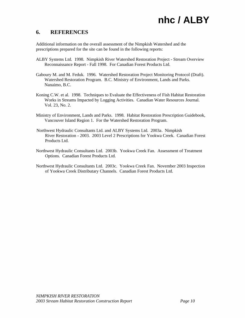
Photo 3: Looking downstream from 0+175 shortly after construction. This area of the
channel had very minor excavation, just clearing of the centerline and piling material along the banks to encourage flow in one main channel.
Photo 4: Looking upstream from 0+350m at the newly constructed channel in August 2003.
The old road surface was very slightly excavated to encourage flow to remain in one main channel.

Page 3 of 8
Photo 5: Looking upstream from 0+525m at the newly constructed channel in August 2003.
This area had minor excavation and centerline clearing to ensure continuity of flow to Vernon Lake.
Photo 6: Looking downstream at the entrance to the 900m Channel and the riprap apron
that protects the opening.

Page 4 of 8
Photo 7: Looking upstream at the 900m Channel’s inlet apron.
Photo 8: Looking downstream from 0+050m shortly after construction. This area of the
channel was slightly excavated during the 2003 construction.

Page 5 of 8
Photo 9: Looking upstream at the head of the channel from 0+075m. This area had the
deepest excavation of the whole project.
Photo 10: Looking upstream at the access road and downstream excavation from 0+475m.
This area had up to 1.0m of excavation completed.

Page 6 of 8
Photo 11: Looking upstream from 0+500m in the 900m Channel shortly after completion in
August. There was no excavation of a channel here, just clearing the centerline to encourage flow in one main channel.
Photo 12: Looking downstream at the end of the channel clearing near Vernon Lake.

Page 7 of 8
Photo 13: Looking downstream at the logjam at the head of the 900m Channel. This jam is
intended to pond water upstream so that flow enters the channel.
Photo 14: Looking downstream at the right side of the downstream logjam at the 900m
Channel. Note the very large boulder anchors.
Page 8 of 8
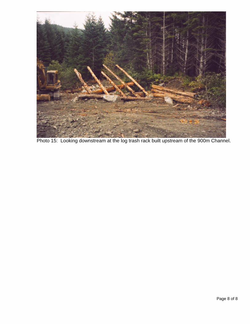
Photo 15: Looking downstream at the log trash rack built upstream of the 900m Channel.

nhc / ALBY
NIMPKISH RIVER RESTORATION 2003 Stream Habitat Restoration Construction Report Page A
APPENDIX A ROUTINE EFFECTIVENESS EVALUATION SUMMARY FORMS Legend: Structure Type LWD-M,A – Multiple LWD Structure or a Jam LWD-1 – Single LWD Structure GF – Groundwater Fed Channel BLD-M – Boulder Multiple LWD-M – Multiple LWD Structure Species AO – all anadromous salmonid species DV – Dolly Varden Char Life Stage Ju - Juvenile Ad – Adult


![updated July 2017Blackwater River Blackwater River Bull Run Bull begger Creek Calfpaqture River Cat Point Creek Catoctin Cree k r reek Chickahom River SIATUS QUa]ifiecl (Qualified](https://img.pdfslide.net/doc/110x75/5ec83fe57981d11a20368bf0/updated-july-2017-blackwater-river-blackwater-river-bull-run-bull-begger-creek-calfpaqture.jpg)