Embed Size (px)
Citation preview

NISS4HT
INSTALLATION GUIDE
This product is intended for installation by a professional installer only! Attempts to install this product by a person other than a trained professional may result in severe damage to a vehicle’s electrical system and components.
2017-12-05
© 2017 Directed, Vista CA
DS4+
Designed by Installers for Installers

ContentsWarning! Safety first ....................................................................................................................... 3Introduction .................................................................................................................................... 4
Pre-installation and application warnings ..................................................................................... 4Vehicle application guide ........................................................................................................... 5
Wiring connections ......................................................................................................................... 6Main harness (H1), 12-pin black connector .................................................................................. 6Relay harness (H2), 10-pin white connector .................................................................................. 6Data harness (H3), 8-pin white connector ..................................................................................... 6Analog input/output harness (H4), 22-pin white connector ............................................................. 7RF Port harness (H5), 2-pin white connector .................................................................................. 7D2D harness (H6), 4-pin white (1) and black (2) connectors ........................................................... 7Temperature sensor harness (H7), 2-pin black connector (optional, 8556T) ....................................... 7
Installation (wiring diagrams, fuse selection & vehicle wiring reference charts) ........................................ 8Type 1 ..................................................................................................................................... 8Type 2 ................................................................................................................................... 12Type 3 ................................................................................................................................... 14Type 4 ................................................................................................................................... 16Type 5 ................................................................................................................................... 18Type 6 ................................................................................................................................... 20Type 7 ................................................................................................................................... 22Type 8 ................................................................................................................................... 24Type 9 ................................................................................................................................... 26
Configuring the system................................................................................................................... 28Important! .............................................................................................................................. 28Vehicles equipped with a manual transmission ............................................................................ 28RF Systems ............................................................................................................................. 288504D Combo Sensor ............................................................................................................. 28When used in conjunction with SmartStart .................................................................................. 28D2D port configuration ............................................................................................................ 29Module programming .............................................................................................................. 29LED diagnostics and troubleshooting .......................................................................................... 30Soft reset ................................................................................................................................ 32Hard reset .............................................................................................................................. 32
Learning the Tach (not needed with Virtual Tach) ............................................................................... 33Initializing Virtual Tach (not needed with hardwired or data tach applications) ..................................... 33Limited lifetime consumer warranty .................................................................................................. 34Quick Reference Guide .................................................................................................................. 35

Warning! Safety firstThe following safety warnings must be observed at all times:
• Due to the complexity of this system, installation of this product must only be performed by an authorized Directed dealer.• When properly installed, this system can start the vehicle via a command signal from the remote control. Therefore, never
operate the system in an area that does not have adequate ventilation.
The following precautions are the sole responsibility of the user; however, authorized Directed dealers should:• Never use a test light or logic probe when installing this unit. Always use a multimeter. • Never operate the system in an enclosed or partially enclosed area without ventilation (such as a garage). • USER MUST INSTALL A CARBON MONOXIDE DETECTOR IN OR ABOUT THE LIVING AREA ADJACENT TO THE VEHICLE.
ALL DOORS LEADING FROM ADJACENT LIVING AREAS TO THE ENCLOSED OR PARTIALLY ENCLOSED VEHICLE STORAGE AREA MUST REMAIN CLOSED AT ALL TIMES.
Use of this product in a manner contrary to its intended mode of operation may result in property damage, personal injury, or death. Except when performing the Safety Check outlined in this installation guide, (1) Never remotely start the vehicle with the vehicle in gear, and (2) Never remotely start the vehicle with the keys in the ignition. The user is responsible for having the neutral safety feature of the vehicle periodically checked, wherein the vehicle must not remotely start while the car is in gear. This testing should be performed by an authorized Directed dealer in accordance with the Safety Check outlined in this product installation guide. If the vehicle starts in gear, cease remote start operation immediately and consult with the user to fix the problem immediately.
OPERATION OF THE REMOTE START MODULE IF THE VEHICLE STARTS IN GEAR IS CONTRARY TO ITS INTENDED MODE OF OPERATION. OPERATING THE REMOTE START SYSTEM UNDER THESE CONDITIONS MAY RESULT IN PROPERTY DAMAGE OR PERSONAL INJURY. IMMEDIATELY CEASE THE USE OF THE UNIT AND REPAIR OR DISCONNECT THE INSTALLED REMOTE START MODULE. DIRECTED WILL NOT BE HELD RESPONSIBLE OR PAY FOR INSTALLATION OR REINSTALLATION COSTS.
Remote starters for manual transmission pose significant risks if not properly installed and operated. When testing to ensure the installation is working properly, only remote start the vehicle in neutral gear, on a flat surface and with a functional, fully engaged parking brake. Do not allow anyone to stand in front of or behind the vehicle.
This product should not be installed in any convertible vehicles, soft or hard top with a manual transmission. Installation in such vehicles may pose certain risk.
3 DS4+ NISS4HT© 2017-12-05 Directed. All rights reserved.
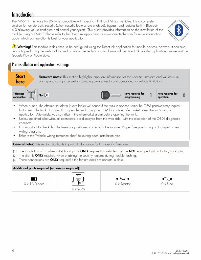
IntroductionThe NISS4HT firmware for DS4+ is compatible with specific Infiniti and Nissan vehicles. It is a complete solution for remote start, security (when security features are enabled), bypass, and features built in Bluetooth 4.0 allowing you to configure and control your system. This guide provides information on the installation of the module using NISS4HT. Please refer to the DirectLink application or www.directechs.com for more information about which configuration is best for your application.
Warning! This module is designed to be configured using the DirectLink application for mobile devices, however it can also be configured using the web tool located at www.directechs.com. To download the DirectLink mobile application, please visit the Google Play or Apple store.
Pre-installation and application warnings
Firmware notes: This section highlights important information for this specific firmware and will assist in pricing accordingly, as well as bringing awareness to any operational or vehicle limitations.
T-Harness compatible
Keys required for programming 1 Keys required for
operation 0
When armed, the aftermarket alarm (if available) will sound if the trunk is opened using the OEM passive entry request button near the trunk. To avoid this, open the trunk using the OEM fob button, aftermarket transmitter or SmartStart application. Alternately, you can disarm the aftermarket alarm before opening the trunk.
Unless specified otherwise, all connectors are displayed from the wire side, with the exception of the OBDII diagnostic connector.
It is important to check that the fuses are positioned correctly in the module. Proper fuse positioning is displayed on each wiring diagram.
Refer to the "Vehicle wiring reference chart" following each installation type.
General notes: This section highlights important information for this specific firmware.
[1] The installation of an aftermarket hood pin is ONLY required on vehicles that are NOT equipped with a factory hood pin.[2] The siren is ONLY required when enabling the security features during module flashing.[3] These connections are ONLY required if the feature does not operate in data.
Additional parts required (maximum required):
Diode 6A0 x 1A Diodes86 8530
87a
87
0 x Relay
Resistor 100Ω0 x Resistor Fuse 7.5A0 x Fuse
4 DS4+ NISS4HT© 2017-12-05 Directed. All rights reserved.

Vehicle application guideThe following table lists the vehicles and features which are compatible with this product. The number assigned to each year allows you to determine which installation type should be used for your vehicle.
Vehicles
20
17
20
16
20
15
20
14
20
13
20
12
20
11
20
10
20
09
PK-I
mm
ob
ilize
r Byp
ass
-Da
ta N
o K
ey R
eq'd
AV
-Pa
rkin
g L
igh
ts C
on
tro
l
DL-
Arm
Fa
cto
ry S
ecu
rity
DL-
Dis
arm
Fa
cto
ry S
ecu
rity
DL-
Do
or
Lock
Co
ntr
ol
DL-
Do
or
Un
lock
DL-
Dri
ver
Prio
rity
Un
lock
DL-
Slid
ing
Do
or
Co
ntr
ol D
rive
r
DL-
Slid
ing
Do
or
Co
ntr
ol Pa
ssen
ger
DL-
Tru
nk
/ H
atc
h R
elea
se
FOB-C
on
tro
l o
f a
fter
ma
rket
ala
rm w
ith
OEM
rem
ote
Key
2G
O
RS-
3x
LOC
K S
TART
(Sta
rt c
on
tro
l u
sin
g O
EM
Rem
ote
)
RS-
3x
LOC
K S
TOP
(Sto
p c
on
tro
l u
sin
g O
EM R
emo
te)
RS-
Acc
esso
ry A
ctiv
atio
n
RS-
Ign
itio
n A
ctiv
atio
n
RS-
Sma
rtSt
art
RS-
Sta
rt (
Cra
nk)
Act
iva
tio
n
RS-
Tach
/ R
PM O
utp
ut
SS-E
ntr
y M
on
ito
rin
g A
LL D
oo
r Pi
ns
SS-E
ntr
y M
on
ito
rin
g H
oo
d P
in
SS-E
ntr
y M
on
ito
rin
g T
run
k/H
atc
h P
in
ST-B
rake
Sta
tus
(fo
ot
bra
ke)
ST-E
-Bra
ke S
tatu
s
InfinitiM35h (Smart Key) 1 1 • • • • • • • • • • • • • • • • • • • • • •M37 (Smart Key) 2 2 2 • • • • • • • • • • • • • • • • • • • • • •M56 (Smart Key) 2 2 2 • • • • • • • • • • • • • • • • • • • • • •Q70 (Smart Key) 1 1 1 1 • • • • • • • • • • • • • • • • • • • • • •QX56 (Smart Key) 8 8 8 • • • • • • • • • • • • • • • • • • • • • •QX80 (Smart Key) 1 1 1 1 • • • • • • • • • • • • • • • • • • • • • •Nissan 17 16 15 14 13 12 11 10 09Armada (Smart Key) 1 • • • • • • • • • • • • • • • • • • • • • •Cube (Smart Key) 1 1 1 1 1 1 • • • • • • • • • • • • • • • • • • • • • •JUKE (Smart Key) 7 7 6 6 6 6 6 • • • • • • • • • • • • • • • • • • • • • •LEAF (Smart Key) 3 • • • • • • • • • • • • • • • • • • • • • •Quest (Smart Key) 1 1 1 1 1 1 1 • • • • • • • • • • • • • • • • • • • • • • • •Sentra (Smart Key) 9 6 6 6 6 • • • • • • • • • • • • • • • • • • • • • •Versa (Smart Key) 4 4 4 4 4 • • • • • • • • • • • • • • • • • • • • • •Versa Note (Smart Key) 5 5 5 5 • • • • • • • • • • • • • • • • • • • • • •
Legend:PK: Transponder & Immobilizer OverrideAV: Horn & Light ControlsDL: OE Door Lock & Alarm ControlsFOB: Sync CAN Interface w/ FOB RemoteRS: Remote Start & Engine ControlsSS: Integrated Security & MonitoringST: Function/Feature Status
5 DS4+ NISS4HT© 2017-12-05 Directed. All rights reserved.

Wiring connectionsThe wiring connections listed below are specific to this firmware.
Main harness (H1), 12-pin black connector
Conn./Pin Color Description
H1/1 Blue/White Relay 1 N.C. – Immo. Data Interrupt (conn. side) 1
H1/2 Blue/Red Relay 1 N.O. – No Connection 1
H1/3 Blue Relay 1 COM – Immo. Data Interrupt (vehicle side) 1
H1/4 White/Brown Relay 3 N.C. – No Connection 1
H1/5 White Relay 3 COM – (+) Brake Output 1
H1/6 Red (+) 12V Input
H1/7 Lt. Green/Red Relay 2 N.O. – No Connection 1
H1/8 Lt. Green Relay 2 COM – No Connection 1
H1/9 Lt. Green/White Relay 2 N.C. – No Connection 1
H1/10 Black (-) Ground
H1/11 White Relay 3 COM – (+) Brake Output 1
H1/12 Red (+) 12V Input
Relay harness (H2), 10-pin white connector
Conn./Pin Color Description
H2/1 N/A No Connection
H2/2 Red/Black (+) 12 Volt Input (Accessory/Starter relay)
H2/3 Pink/Black Relay N.C. – Flex Relay Isolation 1
H2/4 Pink/White Relay COM – Flex Relay Output 1
H2/5 Red (+) 12 Volt Input (Ignition relay)
H2/6 Green Relay COM – (+) Starter Disable (key side) 1
H2/7 Violet Relay N.C. – (+) Starter Output (vehicle side) 1
H2/8 Orange Relay COM – (+) Accessory Output 1
H2/9 Red/White (+) 12 Volt Input (flex relay)
H2/10 Pink Relay COM – (+) Ignition Output
Data harness (H3), 8-pin white connector
Conn./Pin Color Description
H3/1 Tan HS CAN Low
H3/2 Tan/Black HS CAN High
H3/3 Orange/Brown No Connection
H3/4 Orange/Green No Connection
H3/5 Lt. Green No Connection
H3/6 Violet/Brown No Connection
H3/7 Orange/Black Immo. Data Output
H3/8 Yellow/Black Immo. Clock Output
1. If these outputs are not used by the firmware, they can be configured by the installer when the module is flashed.
6 DS4+ NISS4HT© 2017-12-05 Directed. All rights reserved.

Analog input/output harness (H4), 22-pin white connector
Conn./Pin Color Description
H4/1 Lt. Green/Black (-) Push-to-Start Output 1
H4/2 Blue/White (-) Ground When Running (status) Output 1
H4/3 Dk. Green/Black (-) Lock Output 1
H4/4 Red/White (-) Trunk Output 1
H4/5 Brown/Black (-) Horn Output 1
H4/6 Brown/White (-) AUX 1 Output 1
H4/7 White (+) Parking Light Output 1
H4/8 Violet/Black (+) AUX 3 Output 1
H4/9 Dk. Blue/Black (-) Unlock Output 1
H4/10 Lt. Blue/Black (-) RAP Off Output 1
H4/11 Brown/Red (+) Siren Output 1
H4/12 Pink (+) Ignition Sense Input
H4/13 Violet (+) Door Input 2
H4/14 Brown (+) Brake Input 2
H4/15 White/Blue (-) Activation Input 2
H4/16 Red/Blue (-) Valet Switch 2
H4/17 Black/White (-) E-Brake Input (manual transmission) 2
H4/18 Orange/Black (-) Instant Alarm Input 2
H4/19 Blue (-) Trunk Input 2
H4/20 Green (-) Door Input 2
H4/21 Gray (-) Hood Pin Input 2
H4/22 Violet/White (AC) Tach Input
RF Port harness (H5), 2-pin white connector
Conn./Pin Color Description
H5/1 N/A RF Loop
H5/2 N/A RF Loop
D2D harness (H6), 4-pin white (1) and black (2) connectorsConn./Pin Color Description
H6/1 Blue (Data) TX
H6/2 Black (-) Ground
H6/3 Green (Data) RX
H6/4 Red (+) 12 Volt
Temperature sensor harness (H7), 2-pin black connector (optional, 8556T)Conn./Pin Color Description
H7/1 Black Temperature Sensor
H7/2 Black Temperature Sensor
1. If these outputs are not used by the firmware, they can be configured by the installer when the module is flashed. Note that they are low current and a relay may be necessary.
2. These connections are only required if the corresponding statuses are not supported by the firmware. See "Vehicle application guide" on page 5 for a list of compatible features. If these outputs are not used by the firmware, they can be configured by the installer when the module is flashed. Note that they are low current and a relay may be necessary.
7 DS4+ NISS4HT© 2017-12-05 Directed. All rights reserved.

Installation (wiring diagrams, fuse selection & vehicle wiring reference charts)Type 1
Refer to "Pre-installation and application warnings" on page 4 for important information, such as the description of special notes referenced in the diagram ( ).
16
8
9
1
Siren
Hood Pin
NATS Antenna Conn.(behind Push-to-Start button)
HS CAN Low: Pink, pin 14(-) PTS: Pin 4
(-) Driver DoorTrigger: Pin 47
(+) Brake: Pin 2
HS CAN High: Blue, pin 6
Data: Pin 3Clock: Pin 2
Diagnostic Connector OBDII (connector side view)
3
1
4
2
555453525150
45 46 48 4944434241 47
(+)12V: Pin 70
Immo. Data Interrupt (conn side): Blue/White: 1
Immo. Data Interrupt (vehicle side): Blue: 3
(-) Ground: Black: 10
(+) Brake Output: White: 5
HS CAN Low: Tan: 1
(+) Parking Light Output: White: 7
(-) RAP Off Output : Lt. Blue/Black: 10
HS CAN High: Tan/Black: 2
Immo. Data Output (vehicle side): Orange/Black: 7
(-) Push-to-Start (PTS) Output: Lt. Green/Black: 1
Immo. Clock Output: Yellow/Black: 8
(+) 12V Input: Red: 6&12
(-) Hood Input: Gray: 21
(+) Siren Output: Brown/Red: 11
BCM
6968676665
60 61 62 63 6459585756
70
White 4-pin conn.(Brake Switch)
Junction - White 15-pin conn.(left of steering column or
behind instrument cluster on Nissan Quest)
Junction - Black 15-pin conn.(left of steering column or
behind instrument cluster on Nissan Quest)
4
1
5 6 7 8
2 3
(-) Unlock Output: Dk. Blue/Black: 9
(-) Lock Output: Dk. Green/Black: 3
CUT
PTS - Brown or White 8-pin conn.(at PTS switch)
BCM(left of steering column or
behind instrument cluster on Nissan Quest)
228
1012
42
44
2
DS4+
DS4
Slideto open
Proper FusePositioning
DS4+ DS4
It is important to check that the fuses are positioned correctly.
MAIN (5A) (+)
(-) RLY3 PK LIGHT (15A) (+)
(-) ACC & START (30A) (+)
(-) FLEX RLY (20A) (+)
IGN (20A) (+)
MAIN (5A) (+)
(-) RLY3/PK LIGHT(15A) (+)
5
30
20
20
5
15
15
8 DS4+ NISS4HT© 2017-12-05 Directed. All rights reserved.

Vehicle wiring reference chartThis section provides vehicle wiring information to guide you through the various stages of your installation. Refer to www.directechs.com for additional information.
Wire Information Connector Information
Function Color Pin Polarity Location Color Pins Ref.
Infiniti M35h (Smart Key) 2012-2013
Brake Violet 2 (+) Brake switch. White 4 A
Clock Pink 2 Data N.A.T.S antenna connector, behind PTS button. White 4 B
Data Green 3 Data N.A.T.S antenna connector, behind PTS button. White 4 B
PTS Brown 4 (-) PTS switch. Brown 8 C
12V White 70 (+) BCM left of steering column. White 15 D
Drivers Door Trigger Lt. Green 47 (-) BCM left of steering column. Black 15 E
HS CAN High Blue 6 Data OBDII. White 16 F
HS CAN Low Pink 14 Data OBDII. White 16 F
Parking Lights [3] Blue 2 (+) Drivers kick. White 10 or 12 N/A
Lock [3] Brown 15 (-) Driver power window switch. White 16 N/A
Unlock [3] Gray 16 (-) Driver power window switch. White 16 N/A
Infiniti Q70 (Smart Key) 2010-2017
Brake Violet 2 (+) Brake switch. White 4 A
Clock Pink 2 Data N.A.T.S antenna connector, behind PTS button. White 4 B
Data Green 3 Data N.A.T.S antenna connector, behind PTS button. White 4 B
PTS Brown 4 (-) PTS switch. Brown 8 C
12V White 70 (+) BCM left of steering column. White 15 D
Drivers Door Trigger Lt. Green 47 (-) BCM left of steering column. Black 15 E
HS CAN High Blue 6 Data OBDII. White 16 F
HS CAN Low Pink 14 Data OBDII. White 16 F
Parking Lights [3] Blue 4 or 2 (hybrid) (+) Drivers kick. White 12 N/A
Lock [3] Red or Brown (hybrid) 15 (-) Driver power window switch. White 16 N/A
Unlock [3] Green or Gray (hybrid) 16 (-) Driver power window switch. White 16 N/A
9 DS4+ NISS4HT© 2017-12-05 Directed. All rights reserved.

Wire Information Connector Information
Function Color Pin Polarity Location Color Pins Ref.
Infiniti QX80 (Smart Key) 2014-2017
Brake Red 2 (+) Brake switch. White 4 A
Clock Pink 2 Data N.A.T.S antenna connector, behind PTS button. White 4 B
Data Lt. Green/Red 3 Data N.A.T.S antenna connector, behind PTS button. White 4 B
PTS Lt. Blue 4 (-) PTS switch. Brown 8 C
12V Yellow 70 (+) BCM left of steering column. White 15 D
Drivers Door Trigger Gray/Red 47 (-) BCM left of steering column. Black 15 E
HS CAN High Blue 6 Data OBDII. White 16 F
HS CAN Low Pink 14 Data OBDII. White 16 F
Parking Lights [3] Blue/Orange 7 (+) Drivers kick. White 10 N/A
Lock [3] Red 15 (-) Driver power window switch. White 16 N/A
Unlock [3] White 16 (-) Driver power window switch. White 16 N/A
Nissan Armada (Smart Key) 2017
Brake Red 2 (+) Brake switch. White 4 A
Clock Pink 2 Data N.A.T.S antenna connector, behind PTS button. White 4 B
Data Lt. Green/Red 3 Data N.A.T.S antenna connector, behind PTS button. White 4 B
PTS Lt. Blue 4 (-) PTS switch. Brown 8 C
12V Yellow 70 (+) BCM left of steering column. White 15 D
Drivers Door Trigger Gray/Red 47 (-) BCM left of steering column. Black 15 E
HS CAN High Blue 6 Data OBDII. White 16 F
HS CAN Low Pink 14 Data OBDII. White 16 F
Parking Lights [3] Blue/Orange 8 (+) Drivers kick. White 10 N/A
Lock [3] Red 15 (-) Driver power window switch. White 16 N/A
Unlock [3] White 16 (-) Driver power window switch. White 16 N/A
Nissan CUBE (Smart Key) 2009-2014
Brake White 2 (+) Brake switch. White 2 or 4 A
Clock Pink/Blue 2 Data N.A.T.S antenna connector, behind PTS button. White 4 B
Data Lt. Green 3 Data N.A.T.S antenna connector, behind PTS button. White 4 B
PTS Blue/Orange 4 (-) PTS switch. Brown 8 C
12V Yellow 70 (+) BCM behind dash fuse box. White 15 D
Drivers Door Trigger Brown/Yellow 47 (-) BCM behind dash fuse box. Black 15 E
HS CAN High Blue 6 Data OBDII. White 16 F
HS CAN Low Pink 14 Data OBDII. White 16 F
Parking Lights [3] Brown/White 13 (+) Drivers kick. White 16 N/A
Lock [3] White/Black 8 (-) BCM behind dash fuse box. Black 40 N/A
Unlock [3] White/Red 7 (-) BCM behind dash fuse box. Black 40 N/A
Unlock [3] White/Red 7 (-) BCM behind dash fuse box. Black 40 N/A
Parking Lights [3] Violet 70 (+) Drivers kick. White 100 N/A
10 DS4+ NISS4HT© 2017-12-05 Directed. All rights reserved.
Wire Information Connector Information
Function Color Pin Polarity Location Color Pins Ref.
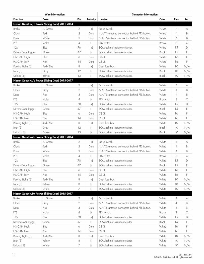
Nissan Quest (w/o Power Sliding Door) 2011-2014
Brake Lt. Green 2 (+) Brake switch. White 4 A
Clock Red 2 Data N.A.T.S antenna connector, behind PTS button. White 4 B
Data White 3 Data N.A.T.S antenna connector, behind PTS button. White 4 B
PTS Violet 4 (-) PTS switch. Brown 8 C
12V Blue 70 (+) BCM behind instrument cluster. White 15 D
Drivers Door Trigger Green 47 (-) BCM behind instrument cluster. Black 15 E
HS CAN High Blue 6 Data OBDII. White 16 F
HS CAN Low Pink 14 Data OBDII. White 16 F
Parking Lights [3] Red/Blue 8 (+) Dash fuse box. White 10 N/A
Lock [3] Gray 12 (-) BCM behind instrument cluster. Black 40 N/A
Unlock [3] Brown 13 (-) BCM behind instrument cluster. Black 40 N/A
Nissan Quest (w/o Power Sliding Door) 2015-2017
Brake Lt. Green 2 (+) Brake switch. White 4 A
Clock Gray 2 Data N.A.T.S antenna connector, behind PTS button. White 4 B
Data Pink 3 Data N.A.T.S antenna connector, behind PTS button. White 4 B
PTS Violet 4 (-) PTS switch. Brown 8 C
12V Blue 70 (+) BCM behind instrument cluster. White 15 D
Drivers Door Trigger Green 47 (-) BCM behind instrument cluster. Black 15 E
HS CAN High Blue 6 Data OBDII. White 16 F
HS CAN Low Pink 14 Data OBDII. White 16 F
Parking Lights [3] Red/Blue 8 (+) Dash fuse box. White 10 N/A
Lock [3] Gray 12 (-) BCM behind instrument cluster. Black 40 N/A
Unlock [3] Brown 13 (-) BCM behind instrument cluster. Black 40 N/A
Nissan Quest (with Power Sliding Door) 2011-2014
Brake Lt. Green 2 (+) Brake switch. White 4 A
Clock Red 2 Data N.A.T.S antenna connector, behind PTS button. White 4 B
Data White 3 Data N.A.T.S antenna connector, behind PTS button. White 4 B
PTS Violet 4 (-) PTS switch. Brown 8 C
12V Blue 70 (+) BCM behind instrument cluster. White 15 D
Drivers Door Trigger Green 47 (-) BCM behind instrument cluster. Black 15 E
HS CAN High Blue 6 Data OBDII. White 16 F
HS CAN Low Pink 14 Data OBDII. White 16 F
Parking Lights [3] Red/Blue 8 (+) Dash fuse box. White 10 N/A
Lock [3] Yellow 8 (-) BCM behind instrument cluster. White 40 N/A
Unlock [3] White 7 (-) BCM behind instrument cluster. White 40 N/A
Nissan Quest (with Power Sliding Door) 2015-2017
Brake Lt. Green 2 (+) Brake switch. White 4 A
Clock Gray 2 Data N.A.T.S antenna connector, behind PTS button. White 4 B
Data Pink 3 Data N.A.T.S antenna connector, behind PTS button. White 4 B
PTS Violet 4 (-) PTS switch. Brown 8 C
12V Blue 70 (+) BCM behind instrument cluster. White 15 D
Drivers Door Trigger Green 47 (-) BCM behind instrument cluster. Black 15 E
HS CAN High Blue 6 Data OBDII. White 16 F
HS CAN Low Pink 14 Data OBDII. White 16 F
Parking Lights [3] Red/Blue 8 (+) Dash fuse box. White 10 N/A
Lock [3] Yellow 8 (-) BCM behind instrument cluster. White 40 N/A
Unlock [3] White 7 (-) BCM behind instrument cluster. White 40 N/A
11 DS4+ NISS4HT© 2017-12-05 Directed. All rights reserved.

Type 2Refer to "Pre-installation and application warnings" on page 4 for important information, such as the description of special notes referenced in the diagram ( ).
16
8
9
1
Hood Pin
Immo. Data Interrupt (conn.side): Blue/White: 1
Immo. Data Interrupt (vehicle side): Blue: 3
(-) Ground: Black: 10
(+) Brake Output: White: 5 & 11
HS CAN Low: Tan: 1
(-) Lock Output: Dk. Green/Black: 3
(-) RAP Off Output : Lt. Blue/Black: 10
(-) Unlock Output : Dk. Blue/Black: 9
HS CAN High: Tan/Black: 2
Immo. Data Output (vehicle. side): Orange/Black: 7
(-) Push-to-Start (PTS) Output: Lt. Green/Black: 1
Immo. Clock Output: Yellow/Black: 8
(+) 12V Input: Red: 6 & 12
(-) Hood Input: Gray: 21Siren
(+) Siren Output: Brown/Red: 11
NATS Antenna Conn.(behind Push-to-Start
button)
HS CAN Low: Pink, pin 14
(-) Driver DoorTrigger: Lt.Green, pin 47
HS CAN High: Blue, pin 6
Data: Green, pin 3
Clock: Pink, pin 2
Diagnostic Connector OBDII (connector side view)
555453525150
45 46 48 4944434241 47
(+)12V: White,pin 70
6968676665
60 61 62 63 645958575670
(+) Brake: Violet, pin 2
3
1
4
2
(+) Parking Light Output: White: 7
BCM
White 4-pin conn.(brake switch)
Junction - White 15-pin conn.(left of steering column)
Junction - Black 15-pin conn.(left of steering column)
CUT
228
1012
42
44
2
DS4+
DS4
Slideto open
Proper FusePositioning
DS4+ DS4
It is important to check that the fuses are positioned correctly.
MAIN (5A) (+)
(-) RLY3 PK LIGHT (15A) (+)
(-) ACC & START (30A) (+)
(-) FLEX RLY (20A) (+)
IGN (20A) (+)
MAIN (5A) (+)
(-) RLY3/PK LIGHT(15A) (+)
5
30
20
20
5
PTS - Brown or White 8-pin conn. (at PTS switch)
4
1
5 6 7 8
2 3
(-) PTS: Brown, pin 4
15
15
12 DS4+ NISS4HT© 2017-12-05 Directed. All rights reserved.

Vehicle wiring reference chartThis section provides vehicle wiring information to guide you through the various stages of your installation. Refer to www.directechs.com for additional information.
Wire Information Connector Information
Function Color Pin Polarity Location Color Pins Ref.
Infiniti M37 (Smart Key) 2011-2013
Brake Violet 2 (+) Brake switch. White 4 A
Clock Pink 2 Data N.A.T.S antenna connector, behind PTS button. White 4 B
Data Green 3 Data N.A.T.S antenna connector, behind PTS button. White 4 B
PTS Brown 4 (-) PTS switch. Brown 8 C
12V White 70 (+) BCM left of steering column. White 15 D
Drivers Door Trigger Lt. Green 47 (-) BCM left of steering column. Black 15 E
HS CAN High Blue 6 Data OBDII. White 16 F
HS CAN Low Pink 14 Data OBDII. White 16 F
Parking Lights [3] Blue 4 (+) Drivers kick. White 10 or 12 N/A
Lock [3] Brown or Red 15 (-) Driver power window switch White 16 N/A
Unlock [3] Green or Gray 16 (-) Driver power window switch. White 16 N/A
Infiniti M56 (Smart Key) 2011-2013
Brake Violet 2 (+) Brake switch. White 4 A
Clock Pink 2 Data N.A.T.S antenna connector, behind PTS button. White 4 B
Data Green 3 Data N.A.T.S antenna connector, behind PTS button. White 4 B
PTS Brown 4 (-) PTS switch. Brown 8 C
12V White 70 (+) BCM left of steering column. White 15 D
Drivers Door Trigger Lt. Green 47 (-) BCM left of steering column. Black 15 E
HS CAN High Blue 6 Data OBDII. White 16 F
HS CAN Low Pink 14 Data OBDII. White 16 F
Parking Lights [3] Blue 4 (+) Drivers kick. White 10 or 12 N/A
Lock [3] Red 15 (-) Driver power window switch White 16 N/A
Unlock [3] Green 16 (-) Driver power window switch. White 16 N/A
13 DS4+ NISS4HT© 2017-12-05 Directed. All rights reserved.

Type 3Refer to "Pre-installation and application warnings" on page 4 for important information, such as the description of special notes referenced in the diagram ( ).
16
8
9
1
Siren
Hood Pin
Immo. Data Interrupt (conn. side): Blue/White: 1
Immo. Data Interrupt (vehicle side): Blue: 3
(-) Ground: Black: 10
(+) Brake Output: White: 5 & 11
HS CAN Low: Tan: 1
(+) Parking Light Output: White: 7
(-) RAP Off Output: Lt. Blue/Black: 10
HS CAN High: Tan/Black: 2
Immo. Data Output (vehicle side): Orange/Black: 7
(-) Push-to-Start (PTS) Output: Lt. Green/Black: 1
Immo. Clock Output: Yellow/Black: 8
(+) 12V Input: Red: 6 & 12
(-) Hood Input: Gray: 21
(+) Siren Output: Brown/Red: 11
(-) Unlock Output: Dk. Blue/Black: 9
(-) Lock Output: Dk. Green/Black: 3
HS CAN Low: Pink, pin 14
HS CAN High: Blue, pin 6
Diagnostic Connector OBDII (connector side view)
NATS Antenna Conn.(behind Push-to-Start button)
Data: Lt.Green, pin 3
Clock: Pink,pin 2
CUT
228
1012
42
44
2
DS4+
DS4
Slideto open
Proper FusePositioning
DS4+ DS4
It is important to check that the fuses are positioned correctly.
MAIN (5A) (+)
(-) RLY3 PK LIGHT (15A) (+)
(-) ACC & START (30A) (+)
(-) FLEX RLY (20A) (+)
IGN (20A) (+)
MAIN (5A) (+)
(-) RLY3/PK LIGHT(15A) (+)
5
30
20
20
5
(+) Brake: Lt.Blue or Brown,pin 2
White 4-pin conn.(brake switch)
3
1
4
2
PTS - White 8-pin conn. (at PTS switch)
4
1
5 6 7 8
2 3
(-) PTS: Lt. Blue, pin 8
(-) Driver DoorTrigger: Lt.Green, pin 47
555453525150
45 46 48 4944434241 47
(+) 12V: Yellow, pin 70
6968676665
60 61 62 63 645958575670
BCM
Junction - White 15-pin conn.(behind dash fuse box)
Junction - Black 15-pin conn.(behind dash fuse box)
15
15
14 DS4+ NISS4HT© 2017-12-05 Directed. All rights reserved.

Vehicle wiring reference chartThis section provides vehicle wiring information to guide you through the various stages of your installation. Refer to www.directechs.com for additional information.
Wire Information Connector Information
Function Color Pin Polarity Location Color Pins Ref.
Nissan LEAF (Smart Key) 2014
Brake Lt. Blue or Brown 2 (+) Brake switch. White 4 A
Clock Pink 2 Data N.A.T.S antenna connector, behind PTS button. White 4 B
Data Lt. Green 3 Data N.A.T.S antenna connector, behind PTS button. White 4 B
PTS Lt. Blue 8 (-) PTS switch. White 8 C
12V Yellow 70 (+) BCM behind dash fuse box. White 15 D
Drivers Door Trigger Lt.Blue 47 (-) BCM behind dash fuse box. Black 15 E
HS CAN High Blue 6 Data OBDII. White 16 F
HS CAN Low Pink 14 Data OBDII. White 16 F
Parking Lights [3] Blue or White 30 (+) Drivers kick. White 32 N/A
Lock [3] Red 8 (-) BCM behind dash fuse box. Black 40 N/A
Unlock [3] Gray 7 (-) BCM behind dash fuse box. Black 40 N/A
15 DS4+ NISS4HT© 2017-12-05 Directed. All rights reserved.
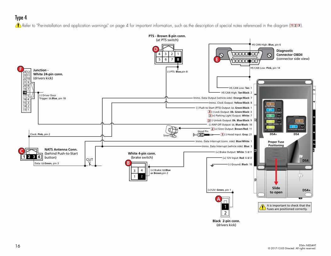
Type 4Refer to "Pre-installation and application warnings" on page 4 for important information, such as the description of special notes referenced in the diagram ( ).
Immo. Data Interrupt (conn. side): Blue/White: 1
Immo. Data Interrupt (vehicle side): Blue: 3
(-) Ground: Black: 10
(+) Brake Output: White: 5 &11
HS CAN Low: Tan: 1
(+) Parking Light Output: White: 7
(-) RAP Off Output: Lt. Blue/Black: 10
(-) Unlock Output: Dk. Blue/Black: 9
HS CAN High: Tan/Black: 2
Immo. Data Output (vehicle side): Orange/Black: 7
(-) Push-to-Start (PTS) Output: Lt. Green/Black: 1
(-) Lock Output: Dk. Green/Black: 3
Immo. Clock Output: Yellow/Black: 8
Siren
Hood Pin
(+) 12V Input: Red: 6 &12
(-) Hood Input: Gray: 21
(+) Siren Output: Brown/Red: 11
HS CAN Low: Pink, pin 14
HS CAN High: Blue, pin 6
16
8
9
1 Diagnostic Connector OBDII (connector side view)
Data: Lt.Green, pin 3
Clock: Pink, pin 2
(-) PTS: Blue,pin 8
(+)12V: Green, pin 1
(-) Driver DoorTrigger: Lt.Blue, pin 18
122411231022921820719618517416315214113
12
8
1234765
NATS Antenna Conn.(behind Push-to-Startbutton)
PTS - Brown 8-pin conn.(at PTS switch)
Black 2-pin conn.(drivers kick)
Junction - White 24-pin conn.(drivers kick)
CUT
228
1012
42
44
2
DS4+
DS4
Slideto open
Proper FusePositioning
DS4+ DS4
It is important to check that the fuses are positioned correctly.
MAIN (5A) (+)
(-) RLY3 PK LIGHT (15A) (+)
(-) ACC & START (30A) (+)
(-) FLEX RLY (20A) (+)
IGN (20A) (+)
MAIN (5A) (+)
(-) RLY3/PK LIGHT(15A) (+)
5
30
20
20
5
(+) Brake: Lt.Blue or Brown,pin 2
White 4-pin conn.(brake switch)
3
1
4
2
15
15
16 DS4+ NISS4HT© 2017-12-05 Directed. All rights reserved.

Vehicle wiring reference chartThis section provides vehicle wiring information to guide you through the various stages of your installation. Refer to www.directechs.com for additional information.
Wire Information Connector Information
Function Color Pin Polarity Location Color Pins Ref.
Nissan Versa (Smart Key) 2013-2017
12V Green 1 (+) Drivers kick. Black 2 A
Brake Lt. Green 2 (+) Brake switch. White 4 B
Clock Pink 2 Data N.A.T.S antenna connector, behind PTS button. White 4 C
Data Lt. Green 3 Data N.A.T.S antenna connector, behind PTS button. White 4 C
PTS Blue 8 (-) PTS switch. Brown 8 D
HS CAN High Blue 6 Data OBDII. White 16 E
HS CAN Low Pink 14 Data OBDII. White 16 E
Drivers Door Trigger Lt. Blue 18 (-) Drivers kick. White 24 F
Parking Lights [3] Red 4 (+) Drivers kick. Gray 16 N/A
Lock [3] Gray 8 (-) BCM behind dash fuse box. Black 40 N/A
Unlock [3] White 7 (-) BCM behind dash fuse box. Black 40 N/A
17 DS4+ NISS4HT© 2017-12-05 Directed. All rights reserved.
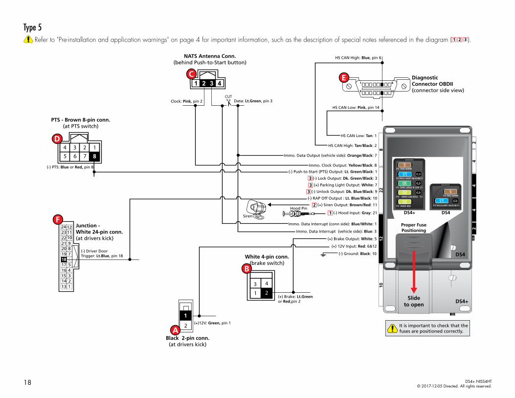
Type 5Refer to "Pre-installation and application warnings" on page 4 for important information, such as the description of special notes referenced in the diagram ( ).
16
8
9
1
Siren
Hood Pin
NATS Antenna Conn.(behind Push-to-Start button)
HS CAN Low: Pink, pin 14
HS CAN High: Blue, pin 6
Data: Lt.Green, pin 3Clock: Pink, pin 2
Diagnostic Connector OBDII (connector side view)
Immo. Data Interrupt (conn side): Blue/White: 1
Immo. Data Interrupt (vehicle side): Blue: 3
(-) Ground: Black: 10
(+) Brake Output: White: 5
HS CAN Low: Tan: 1
(+) Parking Light Output: White: 7
(-) RAP Off Output : Lt. Blue/Black: 10
HS CAN High: Tan/Black: 2
Immo. Data Output (vehicle side): Orange/Black: 7
(-) Push-to-Start (PTS) Output: Lt. Green/Black: 1
Immo. Clock Output: Yellow/Black: 8
(+) 12V Input: Red: 6&12
(-) Hood Input: Gray: 21
(+) Siren Output: Brown/Red: 11
(-) Unlock Output: Dk. Blue/Black: 9
(-) Lock Output: Dk. Green/Black: 3
CUT
228
1012
42
44
2
DS4+
DS4
Slideto open
Proper FusePositioning
DS4+ DS4
It is important to check that the fuses are positioned correctly.
MAIN (5A) (+)
(-) RLY3 PK LIGHT (15A) (+)
(-) ACC & START (30A) (+)
(-) FLEX RLY (20A) (+)
IGN (20A) (+)
MAIN (5A) (+)
(-) RLY3/PK LIGHT(15A) (+)
5
30
20
20
5
(-) Driver DoorTrigger: Lt.Blue, pin 18
122411231022921820719618517416315214113
Junction - White 24-pin conn.(at drivers kick)
(+)12V: Green, pin 1
Black 2-pin conn.(at drivers kick)
1
2
PTS - Brown 8-pin conn.(at PTS switch)
(-) PTS: Blue or Red, pin 8
8
1234765
(+) Brake: Lt.Greenor Red,pin 2
White 4-pin conn.(brake switch)
3
1
4
2
15
15
18 DS4+ NISS4HT© 2017-12-05 Directed. All rights reserved.

Vehicle wiring reference chartThis section provides vehicle wiring information to guide you through the various stages of your installation. Refer to www.directechs.com for additional information.
Wire Information Connector Information
Function Color Pin Polarity Location Color Pins Ref.
Nissan Versa Note (Smart Key) 2014-2017
12V Green 1 (+) Drivers kick. Black 2 A
Brake Lt. Green or Red 2 (+) Brake switch. White 4 B
Clock Pink 2 Data N.A.T.S antenna connector, behind PTS button. White 4 C
Data Lt. Green 3 Data N.A.T.S antenna connector, behind PTS button. White 4 C
PTS Blue or Red 8 (-) PTS switch. Brown 8 D
HS CAN High Blue 6 Data OBDII. White 16 E
HS CAN Low Pink 14 Data OBDII. White 16 E
Drivers Door Trigger Lt. Blue 18 (-) Drivers kick. White 24 F
Parking Lights [3] Red to Blue 3 (+) Drivers kick. White 32 N/A
Lock [3] Gray 8 (-) BCM behind dash fuse box. White 40 N/A
Unlock [3] White or Brown 7 (-) BCM behind dash fuse box. White 40 N/A
19 DS4+ NISS4HT© 2017-12-05 Directed. All rights reserved.

Type 6Refer to "Pre-installation and application warnings" on page 4 for important information, such as the description of special notes referenced in the diagram ( ).
16
8
9
1
Hood Pin
Immo. Data Interrupt (conn.side): Blue/White: 1
Immo. Data Interrupt (vehicle side): Blue: 3
(-) Ground: Black: 10
(+) Brake Output: White: 5 & 11
HS CAN Low: Tan: 1
(-) Lock Output: Dk. Green/Black: 3
(-) RAP Off Output : Lt. Blue/Black: 10
(-) Unlock Output : Dk. Blue/Black: 9
HS CAN High: Tan/Black: 2
Immo. Data Output (vehicle. side): Orange/Black: 7
(-) Push-to-Start (PTS) Output: Lt. Green/Black: 1
Immo. Clock Output: Yellow/Black: 8
(+) 12V Input: Red: 6 & 12
(-) Hood Input: Gray: 21Siren
(+) Siren Output: Brown/Red: 11
NATS Antenna Conn.(behind Push-to-Start
button)
HS CAN Low: Pink, pin 14
(-) Driver DoorTrigger: Lt.Blue or Yellow, pin 47
HS CAN High: Blue, pin 6
Data: Lt.Green, pin 3
Clock: Pink, pin 2
Diagnostic Connector OBDII (connector side view)
555453525150
45 46 48 4944434241 47
(+)12V: Yellow,pin 70
6968676665
60 61 62 63 645958575670
(+) Brake: Lt.Blue or Red, pin 2
3
1
4
2
(-) PTS: Lt.Green, pin 8
(+) Parking Light Output: White: 7
BCM
White 4-pin conn.(brake switch)
PTS - Brown or White 8-pin conn. (at PTS switch)
4
1
5 6 7 8
2 3
Junction - White 15-pin conn.(behind dash fuse box)
Junction - Black 15-pin conn.(behind dash fuse box)
CUT
228
1012
42
44
2
DS4+
DS4
Slideto open
Proper FusePositioning
DS4+ DS4
It is important to check that the fuses are positioned correctly.
MAIN (5A) (+)
(-) RLY3 PK LIGHT (15A) (+)
(-) ACC & START (30A) (+)
(-) FLEX RLY (20A) (+)
IGN (20A) (+)
MAIN (5A) (+)
(-) RLY3/PK LIGHT(15A) (+)
5
30
20
20
5
15
15
20 DS4+ NISS4HT© 2017-12-05 Directed. All rights reserved.

Vehicle wiring reference chartThis section provides vehicle wiring information to guide you through the various stages of your installation. Refer to www.directechs.com for additional information.
Wire Information Connector Information
Function Color Pin Polarity Location Color Pins Ref.
Nissan JUKE (Smart Key) 2011-2015
Brake - Automatic Transmission Lt. Blue or Red 2 (+) Brake switch. White 4 A
Brake - Manual Transmission Red 2 (+) Brake switch. White 2 A
Clutch Brown 4 (+) Clutch switch. White 4 B
Clock Pink 2 Data N.A.T.S antenna connector, behind PTS button. White 4 B
Data Lt. Green 3 Data N.A.T.S antenna connector, behind PTS button. White 4 B
PTS Lt. Green 8 (-) PTS switch. Brown 8 C
12V Yellow 70 (+) BCM behind dash fuse box. White 15 D
Drivers Door Trigger Lt. Blue 47 (-) BCM behind dash fuse box. Black 15 E
HS CAN High Blue 6 Data OBDII. White 16 F
HS CAN Low Pink 14 Data OBDII. White 16 F
Parking Lights [3] Violet 70 (+) Drivers kick. White 100 N/A
Lock [3] Red 8 (-) BCM behind dash fuse box. White 40 N/A
Unlock [3] Blue 7 (-) BCM behind dash fuse box. White 40 N/A
Nissan Sentra (Smart Key) 2013-2016
Brake Lt. Blue or Red 2 (+) Brake switch. White 4 A
Clock Pink 2 Data N.A.T.S antenna connector, behind PTS button. White 4 B
Data Lt. Green 3 Data N.A.T.S antenna connector, behind PTS button. White 4 B
PTS Lt. Green 8 (-) PTS switch. White 8 C
12V Yellow 70 (+) BCM behind dash fuse box. White 15 D
Drivers Door Trigger Yellow 47 (-) BCM behind dash fuse box. Black 15 E
HS CAN High Blue 6 Data OBDII. White 16 F
HS CAN Low Pink 14 Data OBDII. White 16 F
Parking Lights [3] Violet 31 (+) Drivers kick. White 100 N/A
Lock [3] Violet 8 (-) BCM behind dash fuse box. White 40 N/A
Unlock [3] Blue 7 (-) BCM behind dash fuse box. White 40 N/A
21 DS4+ NISS4HT© 2017-12-05 Directed. All rights reserved.

Type 7Refer to "Pre-installation and application warnings" on page 4 for important information, such as the description of special notes referenced in the diagram ( ).
16
8
9
1
Hood Pin
Immo. Data Interrupt (conn.side): Blue/White: 1
Immo. Data Interrupt (vehicle side): Blue: 3
(-) Ground: Black: 10
(+) Brake Output: White: 5 & 11
HS CAN Low: Tan: 1
(-) Lock Output: Dk. Green/Black: 3
(-) RAP Off Output : Lt. Blue/Black: 10
(-) Unlock Output : Dk. Blue/Black: 9
HS CAN High: Tan/Black: 2
Immo. Data Output (vehicle. side): Orange/Black: 7
(-) Push-to-Start (PTS) Output: Lt. Green/Black: 1
Immo. Clock Output: Yellow/Black: 8
(+) 12V Input: Red: 6 & 12
(-) Hood Input: Gray: 21Siren
(+) Siren Output: Brown/Red: 11
NATS Antenna Conn.(behind Push-to-Start
button)
HS CAN Low: Pink, pin 14
(-) Driver DoorTrigger: Lt.Blue, pin 47
HS CAN High: Blue, pin 6
Data: Lt.Green, pin 3
Clock: Pink, pin 2
Diagnostic Connector OBDII (connector side view)
555453525150
45 46 48 4944434241 47
(+)12V: Yellow,pin 70
6968676665
60 61 62 63 645958575670
(+) Brake: Lt.Blue or Red, pin 2
3
1
4
2
(-) PTS: Lt. Green, pin 8
(+) Parking Light Output: White: 7
BCM
White 4-pin conn.(brake switch)
PTS - Brown 8-pin conn. (at PTS switch)
4
1
5 6 7 8
2 3
Junction - White 15-pin conn.(behind dash fuse box)
Junction - Black 15-pin conn.(behind dash fuse box)
CUT
228
1012
42
44
2
DS4+
DS4
Slideto open
Proper FusePositioning
DS4+ DS4
It is important to check that the fuses are positioned correctly.
MAIN (5A) (+)
(-) RLY3 PK LIGHT (15A) (+)
(-) ACC & START (30A) (+)
(-) FLEX RLY (20A) (+)
IGN (20A) (+)
MAIN (5A) (+)
(-) RLY3/PK LIGHT(15A) (+)
5
30
20
20
5
15
15
22 DS4+ NISS4HT© 2017-12-05 Directed. All rights reserved.

Vehicle wiring reference chartThis section provides vehicle wiring information to guide you through the various stages of your installation. Refer to www.directechs.com for additional information.
Wire Information Connector Information
Function Color Pin Polarity Location Color Pins Ref.
Nissan JUKE (Smart Key) 2016-2017
Brake - Automatic Transmission Lt. Blue or Red 2 (+) Brake switch. White 4 A
Brake - Manual Transmission Red 2 (+) Brake switch. White 2 A
Clutch Brown 4 (+) Clutch switch. White 4 B
Clock Pink 2 Data N.A.T.S antenna connector, behind PTS button. White 4 C
Data Lt. Green 3 Data N.A.T.S antenna connector, behind PTS button. White 4 C
PTS Lt. Green 8 (-) PTS switch. Brown 8 D
12V Yellow 70 (+) BCM behind dash fuse box. White 15 E
Drivers Door Trigger Lt. Blue 47 (-) BCM behind dash fuse box. Black 15 F
HS CAN High Blue 6 Data OBDII. White 16 G
HS CAN Low Pink 14 Data OBDII. White 16 G
Parking Lights [3] Violet 70 (+) Drivers kick. White 100 N/A
Lock [3] Red 8 (-) BCM behind dash fuse box. White 40 N/A
Unlock [3] Blue 7 (-) BCM behind dash fuse box. White 40 N/A
23 DS4+ NISS4HT© 2017-12-05 Directed. All rights reserved.
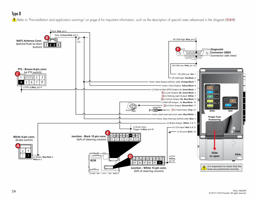
Type 8Refer to "Pre-installation and application warnings" on page 4 for important information, such as the description of special notes referenced in the diagram ( ).
16
8
9
1
Hood Pin
Immo. Data Interrupt (conn.side): Blue/White: 1
Immo. Data Interrupt (vehicle side): Blue: 3
(-) Ground: Black: 10
(+) Brake Output: White: 5 & 11
HS CAN Low: Tan: 1
(-) Lock Output: Dk. Green/Black: 3
(-) RAP Off Output : Lt. Blue/Black: 10
(-) Unlock Output: Dk. Blue/Black: 9
HS CAN High: Tan/Black: 2
Immo. Data Output (vehicle. side): Orange/Black: 7
(-) Push-to-Start (PTS) Output: Lt. Green/Black: 1
Immo. Clock Output: Yellow/Black: 8
(+) 12V Input: Red: 6 & 12
(-) Hood Input: Gray: 21Siren
(+) Siren Output: Brown/Red: 11
NATS Antenna Conn.(behind Push-to-Start
button)
HS CAN Low: Pink, pin 14
(-) Driver DoorTrigger: Lt.Blue, pin 47
HS CAN High: Blue, pin 6
Data: Lt.Green/Red, pin 3
Clock: Pink, pin 2
Diagnostic Connector OBDII (connector side view)
555453525150
45 46 48 4944434241 47
(+)12V: Yellow,pin 70
6968676665
60 61 62 63 645958575670
3
1
4
2
(-) PTS: Lt.Blue, pin 4
(+) Parking Light Output: White: 7
BCM
White 4-pin conn.(brake switch)
PTS - Brown 8-pin conn. (at PTS switch)
4
1
5 6 7 8
2 3
Junction - White 15-pin conn.(left of steering column)
Junction - Black 15-pin conn.(left of steering column)
CUT
228
1012
42
44
2
DS4+
DS4
Slideto open
Proper FusePositioning
DS4+ DS4
It is important to check that the fuses are positioned correctly.
MAIN (5A) (+)
(-) RLY3 PK LIGHT (15A) (+)
(-) ACC & START (30A) (+)
(-) FLEX RLY (20A) (+)
IGN (20A) (+)
MAIN (5A) (+)
(-) RLY3/PK LIGHT(15A) (+)
5
30
20
20
5
(+) Brake: Blue/Red orRed,pin 2
15
15
24 DS4+ NISS4HT© 2017-12-05 Directed. All rights reserved.

Vehicle wiring reference chartThis section provides vehicle wiring information to guide you through the various stages of your installation. Refer to www.directechs.com for additional information.
Wire Information Connector Information
Function Color Pin Polarity Location Color Pins Ref.
Infiniti QX56 (Smart Key) 2011-2013
Brake Blue/Red or Red 4 (+) Brake switch. White 2 or 4 A
Clock Pink 2 Data N.A.T.S antenna connector, behind PTS button. White 4 B
Data Lt.Green/Red 3 Data N.A.T.S antenna connector, behind PTS button. White 4 B
PTS Lt. Blue 4 (-) PTS switch. Brown 8 C
12V Yellow 70 (+) BCM left of steering column White 15 D
Drivers Door Trigger Gray/Red 47 (-) BCM left of steering column Black 15 E
HS CAN High Blue 6 Data OBDII. White 16 F
HS CAN Low Pink 14 Data OBDII. White 16 F
Parking Lights [3] Blue/Orange 8 (+) Drivers kick. White 10 N/A
Lock [3] Red 4 or 15 (-) Driver power window switch White 16 N/A
Unlock [3] White 5 or 16 (-) Driver power window switch White 16 N/A
25 DS4+ NISS4HT© 2017-12-05 Directed. All rights reserved.
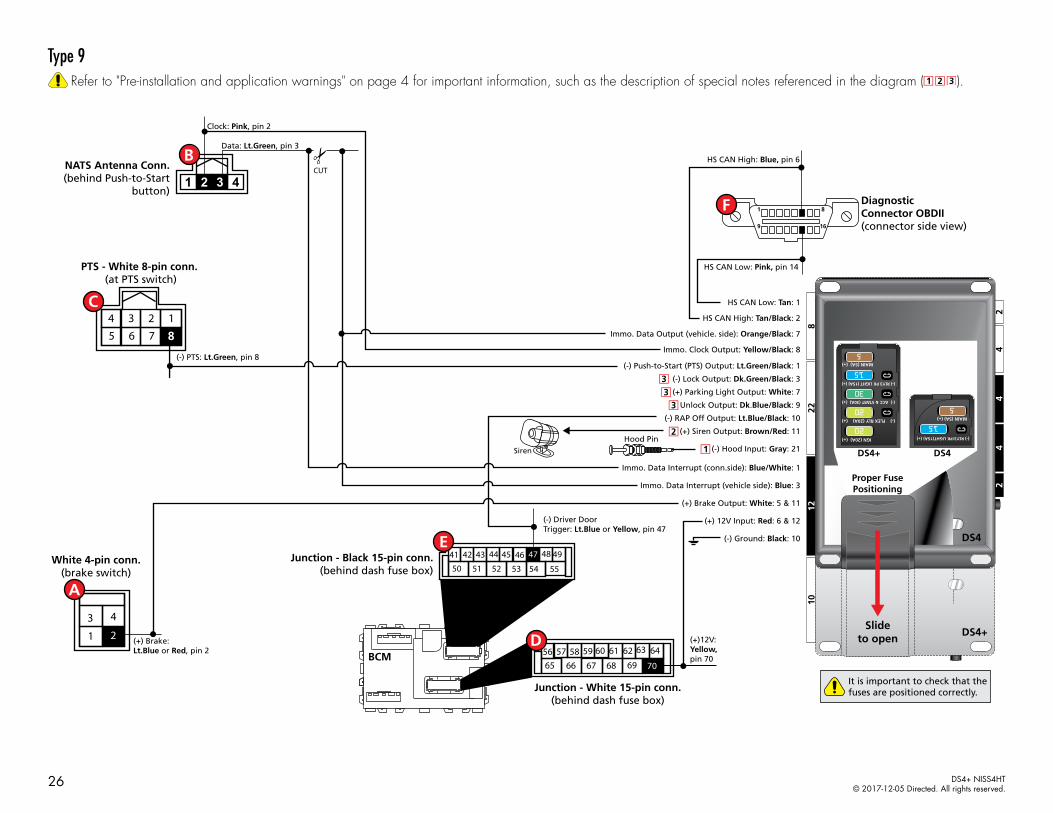
Type 9Refer to "Pre-installation and application warnings" on page 4 for important information, such as the description of special notes referenced in the diagram ( ).
16
8
9
1
Hood Pin
Immo. Data Interrupt (conn.side): Blue/White: 1
Immo. Data Interrupt (vehicle side): Blue: 3
(-) Ground: Black: 10
(+) Brake Output: White: 5 & 11
HS CAN Low: Tan: 1
(-) Lock Output: Dk.Green/Black: 3
(-) RAP Off Output: Lt.Blue/Black: 10
(-) Unlock Output: Dk.Blue/Black: 9
HS CAN High: Tan/Black: 2
Immo. Data Output (vehicle. side): Orange/Black: 7
(-) Push-to-Start (PTS) Output: Lt.Green/Black: 1
Immo. Clock Output: Yellow/Black: 8
(+) 12V Input: Red: 6 & 12
(-) Hood Input: Gray: 21Siren
(+) Siren Output: Brown/Red: 11
NATS Antenna Conn.(behind Push-to-Start
button)
HS CAN Low: Pink, pin 14
(-) Driver DoorTrigger: Lt.Blue or Yellow, pin 47
HS CAN High: Blue, pin 6
Data: Lt.Green, pin 3
Clock: Pink, pin 2
Diagnostic Connector OBDII (connector side view)
555453525150
45 46 48 4944434241 47
(+)12V: Yellow,pin 70
6968676665
60 61 62 63 645958575670
(+) Brake: Lt.Blue or Red, pin 2
3
1
4
2
(-) PTS: Lt.Green, pin 8
(+) Parking Light Output: White: 7
BCM
White 4-pin conn.(brake switch)
PTS - White 8-pin conn. (at PTS switch)
Junction - White 15-pin conn.(behind dash fuse box)
Junction - Black 15-pin conn.(behind dash fuse box)
CUT
228
1012
42
44
2
DS4+
DS4
Slideto open
Proper FusePositioning
DS4+ DS4
It is important to check that the fuses are positioned correctly.
MAIN (5A) (+)
(-) RLY3 PK LIGHT (15A) (+)
(-) ACC & START (30A) (+)
(-) FLEX RLY (20A) (+)
IGN (20A) (+)
MAIN (5A) (+)
(-) RLY3/PK LIGHT(15A) (+)
5
30
20
20
5
15
15
8
1234765
26 DS4+ NISS4HT© 2017-12-05 Directed. All rights reserved.

Vehicle wiring reference chartThis section provides vehicle wiring information to guide you through the various stages of your installation. Refer to www.directechs.com for additional information.
Wire Information Connector Information
Function Color Pin Polarity Location Color Pins Ref.
Nissan Sentra (Smart Key) 2017
Brake Lt. Blue or Red 2 (+) Brake switch. White 4 A
Clock Pink 2 Data N.A.T.S antenna connector, behind PTS button. White 4 B
Data Lt. Green 3 Data N.A.T.S antenna connector, behind PTS button. White 4 B
PTS Lt. Green 8 (-) PTS switch. White 8 C
12V Yellow 70 (+) BCM behind dash fuse box. White 15 D
Drivers Door Trigger Yellow 47 (-) BCM behind dash fuse box. Black 15 E
HS CAN High Blue 6 Data OBDII. White 16 F
HS CAN Low Pink 14 Data OBDII. White 16 F
Parking Lights [3] Violet 31 (+) Drivers kick. White 100 N/A
Lock [3] Violet 8 (-) BCM behind dash fuse box. White 40 N/A
Unlock [3] Blue 7 (-) BCM behind dash fuse box. White 40 N/A
27 DS4+ NISS4HT© 2017-12-05 Directed. All rights reserved.

Configuring the system
Important!Once the DS4+ module is installed in the vehicle following the instructions in "Installation (wiring diagrams, fuse selection & vehicle wiring reference charts)" on page 8, launch the DirectLink application on your mobile device, and select Configure DS4/DS4+. Follow the on-screen instructions to configure the system.
Note: Your system can also be configured using XKLoader2 on www.directechs.com.
Vehicles equipped with a manual transmissionAdditional connections may be required if these functions are not supported by the firmware.
Connection Description
(-) E-Brake Status Input (Black/White, pin 17)
Must be connected to a working emergency brake in the vehicle. Although most vehicles have simple (-) trigger emergency brake circuits note some vehicles do not and may require unique integration methodologies.
(-) Door Trigger Input (Green, pin 20) OR (+) Door Input (Violet, pin 13)
Must be connected to a working door trigger in the vehicle, which monitors all doors. The unit must monitor the door pins to allow the Ready Mode process to be enabled.Note: Some vehicles may require unique integration methodologies for this circuit. For more information, refer to www.directechs.com.
(AC) Tachometer Input (Violet/White, pin 22)
Must be connected to a working tachometer signal in the vehicle (fuel injector, ignition coil, true tach, etc.) and learned successfully to the DS4+.
RF SystemsAn RF System consists of one or multiple remotes, a Control Center (antenna), and an antenna cable – various combinations exist. An RF System allows the vehicle owner to control the system with enhanced range. Two-way models are available. Please follow the instructions included with the kit for appropriate installation and programming information.
8504D Combo SensorThe 8504D Combo Sensor must be paired to the device before it can be used. To enter pairing, turn the vehicle ignition to the ON position, then press and hold the programming button on the Control Center (antenna) until the LED starts flashing. Once pairing mode has been entered, your Combo Sensor is ready to use.
Your Combo Sensor is preset for the majority of applications, however it can be adjusted using the DirectLink application, as well as a compatible LED or LCD remote. Please refer to the instructions included with your sensor for more information on how to make adjustments.
When used in conjunction with SmartStartTo enable D2D communication between the DS4+ and the SmartStart one of the following actions must be executed:• SmartStart with Loops – The brown loop must be cut. • SmartStart with Pigtails – The gray wire must be connected to a ground source.
Loops Pigtails
DO NOT connect the SmartStart 2-pin power harness when using the DS4+. Power and ground will be provided by the D2D connector on main module. Refer to the SmartStart documentation for further details.
28 DS4+ NISS4HT© 2017-12-05 Directed. All rights reserved.
D2D port configurationThe system will automatically configure the D2D ports based on your selections in the module programming. The white D2D port is reserved for SmartStart. To ensure proper functionality with SmartStart, it is important that it is selected in the system programming of the DirectLink application or via the online web tool.
Note: Both black D2D ports are reserved for the Control Center (antenna) and 8504D Combo Sensor.
Module programmingRefer to "LED diagnostics and troubleshooting" on page 30 for more information and for troubleshooting purposes.
To connect the module:
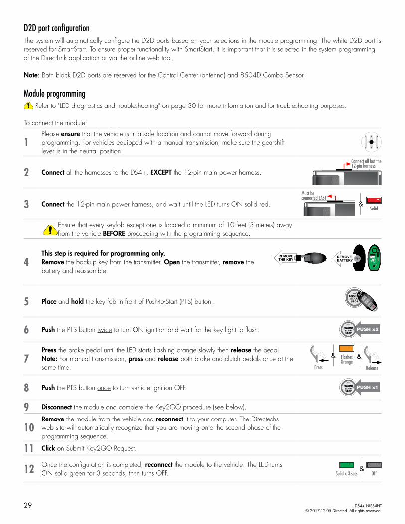
1Please ensure that the vehicle is in a safe location and cannot move forward during programming. For vehicles equipped with a manual transmission, make sure the gearshift lever is in the neutral position.
2 Connect all the harnesses to the DS4+, EXCEPT the 12-pin main power harness.
Connect all but the 12-pin harness
3 Connect the 12-pin main power harness, and wait until the LED turns ON solid red.
Must be connected LAST
&Solid
Ensure that every keyfob except one is located a minimum of 10 feet (3 meters) away from the vehicle BEFORE proceeding with the programming sequence.
4This step is required for programming only.Remove the backup key from the transmitter. Open the transmitter, remove the battery and reassamble.
REMOVEBATTERY
CR 20323V
REMOVETHE KEY
5 Place and hold the key fob in front of Push-to-Start (PTS) button.
REMOVE
BATTERYCR 20
323V
REMOVE
THE KEY
6 Push the PTS button twice to turn ON ignition and wait for the key light to flash.
7Press the brake pedal until the LED starts flashing orange slowly then release the pedal.Note: For manual transmission, press and release both brake and clutch pedals once at the same time.
& &Flashes Orange
Press Release
8 Push the PTS button once to turn vehicle ignition OFF.
9 Disconnect the module and complete the Key2GO procedure (see below).
10Remove the module from the vehicle and reconnect it to your computer. The Directechs web site will automatically recognize that you are moving onto the second phase of the programming sequence.
11 Click on Submit Key2GO Request.
12 Once the configuration is completed, reconnect the module to the vehicle. The LED turns ON solid green for 3 seconds, then turns OFF. Solid x 3 secs Off
&
29 DS4+ NISS4HT© 2017-12-05 Directed. All rights reserved.
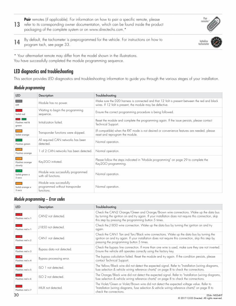
13Pair remotes (if applicable). For information on how to pair a specific remote, please refer to its corresponding owner documentation, which can be found inside the product packaging of the complete system or on www.directechs.com.*
Pair remotes*
14 By default, the tachometer is preprogrammed for the vehicle. For instructions on how to program tach, see page 33.
Initialize tachometer
* Your aftermarket remote may differ from the model shown in the illustrations.You have successfully completed the module programming sequence.
LED diagnostics and troubleshootingThis section provides LED diagnostics and troubleshooting information to guide you through the various stages of your installation.
Module programming
LED Description Troubleshooting
OffModule has no power. Make sure the D2D harness is connected and that 12 Volt is present between the red and black
wires. If 12 Volt is present, the module may be defective.
Solid red
Waiting to begin the programming sequence. Ensure the correct programming procedure is being followed.
Flashes red & green
Initialization failed. Reset the module and complete the programming again. If the issue persists, please contact Technical Support.
Solid orangeTransponder functions were skipped. (If compatible) when the RXT mode is not desired or convenience features are needed, please
reset and reprogram the module.
Flashes green
All required CAN networks has been detected. Normal operation.
Flashes orange1 of 2 CAN networks has been detected. Normal operation.
Flashes orange slowly
Key2GO initiated. Please follow the steps indicated in "Module programming" on page 29 to complete the Key2GO programming.
Solid green x 3 secs
Module was successfully programmed with all functions. Normal operation.
Solid orange x 3 secs
Module was successfullyprogrammed without transponder functions.
Normal operation.
Module programming – Error codes
LED Description Troubleshooting
Flashes red x 1CAN2 not detected.
Check the CAN2 Orange/Green and Orange/Brown wire connections. Wake up the data bus by turning the ignition on and try again. If your installation does not require this connection, skip this step by pressing the programming button 5 times.
Flashes red x 1J1850 not detected. Check the J1850 wire connection. Wake up the data bus by turning the ignition on and try
again.
Flashes red x 2CAN1 not detected.
Check the CAN1 Tan and Tan/Black wire connections. Wake up the data bus by turning the ignition on and try again. If your installation does not require this connection, skip this step by pressing the programming button 5 times.
Flashes red x 3Bypass data not detected. Check the bypass line connection. If more than one wire is used, make sure they are not inverted.
Ensure the vehicle still operates correctly using the factory key.
Flashes red x 4Bypass processing error. The bypass calculation failed. Reset the module and try again. If the condition persists, please
contact Technical Support.
Flashes red x 5ISO 1 not detected. The Yellow/Black wire did not detect the expected signal. Refer to "Installation (wiring diagrams,
fuse selection & vehicle wiring reference charts)" on page 8 to check the connections.
Flashes red x 6ISO 2 not detected. The Orange/Black wire did not detect the expected signal. Refer to "Installation (wiring diagrams,
fuse selection & vehicle wiring reference charts)" on page 8 to check the connections.
Flashes red x 7MUX not detected.
The Violet/Green or Violet/Brown wire did not detect the expected voltage value. Refer to "Installation (wiring diagrams, fuse selection & vehicle wiring reference charts)" on page 8 to check the connections.
30 DS4+ NISS4HT© 2017-12-05 Directed. All rights reserved.

External module synchronization
LED Description Troubleshooting
(Flashes red, red, then orange) x 10
OBDII feature not supported. The diagnostic data bus was not detected, therefore the SmartStart features will be limited.
Active Ground When Running (Status)
LED Description Troubleshooting
Flashes green
Ground When Running (Status) command received. The module has initialized the remote start sequence.
Flashes red & orange
Ignition ON command received. The module has received the Ignition ON command and is processing the remote start sequence.
Flashes green quickly
Start ON command received. The module has received the Start ON command and is processing the remote start sequence.
Flashes red x 10PTS shutdown error. The PTS output from the module was not activated due to safety protection.
Flashes red x 21CAN bus incorrectly detected. Verify the CAN1 and CAN2 connections. Refer to "Installation (wiring diagrams, fuse selection &
vehicle wiring reference charts)" on page 8 to check the connections.
Commands
LED Description Troubleshooting
Flashes orange x 1LOCK command received.
If the bypass module fails to flash, it did not receive the signal. Commands can come from RF or D2D.
Flashes orange x 2UNLOCK command received.
Flashes orange x 3TRUNK command received.
Flashes orange x 4AUX1 command received.
Flashes orange x 5AUX2 command received.
Flashes orange x 6AUX3 command received.
Shutdown codes
LED Description Troubleshooting
Flashes green x 1Takeover successful. Normal operation.
Flashes red x 1Runsafe was not disabled. No UNLOCK command was received prior to opening the door, or the 45 second timer expired
in takeover mode.
Flashes red x 2Brake was not detected. The brakes were not detected, which prevents the system from shutting down the vehicle.
Flashes red x 3Smart key was not detected. The smart key was not detected, which prevents the system from shutting down the vehicle.
Flashes red x 4Speed was detected. The vehicle was detected as moving, which prevents the system from shutting it down.
Analog error codes
LED Description Troubleshooting
Flashes red, green & orange
DEI feature error. A feature config file mismatch was detected. Please contact Technical Support.
31 DS4+ NISS4HT© 2017-12-05 Directed. All rights reserved.

Soft resetA module reset will only erase the steps performed in "Module programming" on page 29. The firmware and settings flashed to the module will not be affected.
1If required for your installation, connect all the harnesses to the DS4+, EXCEPT the 12-pin main power harness. Press and hold the programming button, then connect the 12-pin harness to the module.
Connect all but the 12-pin harness
2 Wait 3 seconds until the LED turns ON solid orange then release the programming button. The LED turns ON solid red.
&&ReleaseSolid Solid
Hard resetWarning Against Executing a Hard Reset! A hard reset will revert the flashed firmware back to its default settings. Depending on the installation, some settings may need to be reconfigured. Connect your module to a computer and use the web configuration tool to edit its programmable features.
1If required for your installation, connect all the harnesses to the DS4+, EXCEPT the 12-pin main power harness. Press and hold the programming button, then connect the 12-pin harness to the module.
Connect all but the 12-pin harness
2 After 3 seconds the LED turns ON solid orange. Keep holding the programming button until the LED flashes red, then orange slowly.
HoldSolid Flashes
&&
3 Release the programming button. The LED turns ON solid red. &Release Solid
32 DS4+ NISS4HT© 2017-12-05 Directed. All rights reserved.

Learning the Tach (not needed with Virtual Tach)Tach comes preprogrammed, therefore learning is not required; however, it can be readjusted with the following operations:1. Start the vehicle using the key. 2. Within 5 seconds, press and hold the Control Center (antenna) or the main module programming button, until the LED on the
Control Center (antenna) or the main module turns ON solid.3. Release the button. The tachometer value is now stored in memory.
If the LED does not turn ON solid, find an alternate tach source.
Note: When the tachometer is programmed, the main module automatically enters the Tachometer engine checking mode.
Initializing Virtual Tach (not needed with hardwired or data tach applications)To program Virtual Tach:1. After the install is complete, remote start the engine. The programming operation may require 3 cranks of the starter before
the engine starts and runs. Do not turn off the remote start if this happens, it is a normal programming operation.2. Once the engine begins running, let it run for at least 30 seconds.3. Using the Remote, send the Remote start command to turn remote start off. Virtual Tach is programmed. To reset Virtual Tach, a
module reset must be done.
Note: Virtual Tach cannot be used in Manual Transmission Mode. It is also not recommended for diesel trucks.
Virtual Tach handles disengaging the starter motor during remote starting – it does not address over-rev. If the customer wants to have the over-rev protection capability, the tach wire or data tach must be used.
Important! After successfully learning Virtual Tach, a small minority of vehicle starters may over crank or under crank during remote start. Use the VirtualTach Fine tune feature using the DirectLink application for mobile devices to adjust the starter output time in 50mS increments to compensate for such an occurrence.
33 DS4+ NISS4HT© 2017-12-05 Directed. All rights reserved.

Limited lifetime consumer warrantyDirected Electronics. (“Directed”) promises to the original purchaser to repair or replace (at Directed’s election) with a comparable reconditioned model any Directed unit (hereafter the “unit”), excluding without limitation the siren, the remote transmitters, the associated sensors and accessories, which proves to be defective in workmanship or material under reasonable use during the lifetime of the vehicle provided the following conditions are met: the unit was purchased from an authorized Directed dealer, the unit was professionally installed and serviced by an authorized Directed dealer; the unit will be professionally reinstalled in the vehicle in which it was originally installed by an authorized Directed dealer; and the unit is returned to Directed, shipping prepaid with a legible copy of the bill of sale or other dated proof of purchase bearing the following information: consumer’s name, telephone number and address; the authorized dealers name, telephone number and address; complete product description, including accessories; the year, make and model of the vehicle; vehicle license number and vehicle identification number. All components other than the unit, including without limitation the siren, the remote transmitters and the associated sensors and accessories, carry a one-year warranty from the date of purchase of the same. ALL PRODUCTS RECEIVED BY DIRECTED FOR WARRANTY REPAIR WITHOUT PROOF OF PURCHASE FROM AN AUTHORIZED DEALER WILL BE DENIED. This warranty is non-transferable and is automatically void if: the unit’s date code or serial number is defaced, missing or altered; the unit has been modified or used in a manner contrary to its intended purpose; the unit has been damaged by accident, unreasonable use, neglect, improper service, installation or other causes not arising out of defects in materials or construction. The warranty does not cover damage to the unit caused by installation or removal of the unit. Directed, in its sole discretion, will determine what constitutes excessive damage and may refuse the return of any unit with excessive damage. TO THE MAXIMUM EXTENT ALLOWED BY LAW, ALL WARRANTIES, INCLUDING BUT NOT LIMITED TO EXPRESS WARRANTY, IMPLIED WARRANTY, WARRANTY OF MERCHANTABILITY, FITNESS FOR PARTICULAR PURPOSE AND WARRANTY OF NON-INFRINGEMENT OF INTELLECTUAL PROPERTY, ARE EXPRESSLY EXCLUDED; AND DIRECTED NEITHER ASSUMES NOR AUTHORIZES ANY PERSON OR ENTITY TO ASSUME FOR IT ANY DUTY, OBLIGATION OR LIABILITY IN CONNECTION WITH ITS PRODUCTS. DIRECTED DISCLAIMS AND HAS ABSOLUTELY NO LIABILITY FOR ANY AND ALL ACTS OF THIRD PARTIES INCLUDING ITS AUTHORIZED DEALERS OR INSTALLERS. DIRECTED SECURITY SYSTEMS, INCLUDING THIS UNIT, ARE DETERRENTS AGAINST POSSIBLE THEFT. DIRECTED IS NOT OFFERING A GUARANTEE OR INSURANCE AGAINST VANDALISM, DAMAGE OR THEFT OF THE AUTOMOBILE, ITS PARTS OR CONTENTS; AND HEREBY EXPRESSLY DISCLAIMS ANY LIABILITY WHATSOEVER, INCLUDING WITHOUT LIMITATION, LIABILITY FOR THEFT, DAMAGE AND/OR VANDALISM. THIS WARRANTY DOES NOT COVER LABOR COSTS FOR MAINTENANCE, REMOVAL OR REINSTALLATION OF THE UNIT OR ANY CONSEQUENTIAL DAMAGES OF ANY KIND. IN THE EVENT OF A CLAIM OR A DISPUTE INVOLVING DIRECTED OR ITS SUBSIDIARY, THE VENUE SHALL BE SAN DIEGO COUNTY IN THE STATE OF CALIFORNIA. CALIFORNIA STATE LAWS AND APPLICABLE FEDERAL LAWS SHALL APPLY AND GOVERN THE DISPUTE. THE MAXIMUM RECOVERY UNDER ANY CLAIM AGAINST DIRECTED SHALL BE STRICTLY LIMITED TO THE AUTHORIZED DIRECTED DEALER’S PURCHASE PRICE OF THE UNIT. DIRECTED SHALL NOT BE RESPONSIBLE FOR ANY DAMAGES WHATSOEVER, INCLUDING BUT NOT LIMITED TO, ANY CONSEQUENTIAL DAMAGES, INCIDENTAL DAMAGES, DAMAGE TO VEHICLE, DAMAGES FOR THE LOSS OF TIME, LOSS OF EARNINGS, COMMERCIAL LOSS, LOSS OF ECONOMIC OPPORTUNITY AND THE LIKE. NOTWITHSTANDING THE ABOVE, THE MANUFACTURER DOES OFFER A LIMITED WARRANTY TO REPLACE OR REPAIR THE CONTROL MODULE SUBJECT TO THE CONDITIONS AS DESCRIBED HEREIN. THIS WARRANTY IS VOID IF THE UNIT HAS NOT BEEN PURCHASED FROM DIRECTED, OR AN AUTHORIZED DIRECTED DEALER, OR IF THE UNIT HAS BEEN DAMAGED BY ACCIDENT, UNREASONABLE USE, NEGLIGENCE, ACTS OF GOD, NEGLECT, IMPROPER SERVICE, OR OTHER CAUSES NOT ARISING OUT OF DEFECT IN MATERIALS OR CONSTRUCTION.
Some states do not allow limitations on how long an implied warranty will last or the exclusion or limitation of incidental or consequential damages. This warranty gives you specific legal rights and you may also have other rights that vary from State to State.
This warranty is only valid for sale of product(s) within the United States of America and in Canada. Product(s) sold outside of the United States of America or Canada are sold “AS-IS” and shall have NO WARRANTY, express or implied.
For further details relating to warranty information of Directed products, please visit the support section of Directed’s website at: www.directed.com.
This product may be covered by a Guaranteed Protection Plan (“GPP”). See your authorized Directed dealer for details of the plan or call Directed Customer Service at 1-800-876-0800.
(920-10011-01 2011-06)
34 DS4+ NISS4HT© 2017-12-05 Directed. All rights reserved.

Quick Reference Guide
Pit stop/idle mode
1 Stop the vehicle in a safe parking spot and put the gear in Park (P).
Put gear in
Park
2Press the Remote Start button on the transmitter.*
The parking lights will flash once to indicate the vehicle is now in Pit Stop Mode.
Parking lights flash x1
14:36
Press Remote Start button*
&
3
It is safe to leave the engine running and exit the vehicle with the factory remote in hand.
Note: We recommend that you always lock the doors of your vehicle when leaving it unattended.
14:36Exit vehicle with remote
* Icon and remote appearance may differ depending on the model purchased.
List of available commandsNote that the information below is for many Viper, Clifford, Python, Avital and Automate models. Icons and commands may differ depending on the model and options purchased. Refer to your authorized installation center for more specific information.
Button(s) Actions
Press & hold for 1 second to lock.
Press & hold for 1 second to unlock.
* Press & hold for 1 second to remote start.
* Press & hold for 5 seconds to activate the trunk release (optional).
* Icon and remote appearance may differ depending on the model purchased.
Sending commands to your vehicleWhether you want to remote start the engine, lock/unlock the doors or pop the trunk, there are 3 possible ways you can send commands to your vehicle, using the:• Factory remote.• Aftermarket remote.• Directed SmartStart application via your smartphone.
If applicable, you can also start the engine remotely by pressing the Lock button 3 times quickly on your factory remote.
Vehicle takeover with Get In and Go
1Close the vehicle doors, hood and trunk, then press the Remote Start button on the transmitter to start the vehicle.*
14:36Press Remote Start button*
2 Press the Unlock button on the factory or aftermarket remote.*
14:36Press Unlock on either remote*
Complete the following steps within 45 seconds or the vehicle will shut down.
3 Enter the vehicle, while making sure the factory remote is inside with you.
14:36Enter vehicle with remote
4 Depress the brake pedal, put the car in gear and drive off.
Ready to drive off
* Icon and remote appearance may differ depending on the model purchased.
Get In and GoGet In and Go is designed to provide users with easy takeover when entering their Push-to-Start (PTS) equipped vehicle, once it has been remote started.
Typically, users would have to remote start their vehicle, then get inside and press the PTS button to perform a takeover. There is therefore a physical action required to drive away. With Get In and Go, you simply remote start the vehicle, unlock the doors, get in and go... All that's left to do is put the gear in drive and drive off.
DS4+ NISS4HT© 2017-12-05 Directed. All rights reserved.

SmartStart compatibleThis system is equipped with a Bluetooth version of SmartStart offering up to 200' of range. The simple graphical interface gives you control over the following features of your installed remote start system or security with remote start system:• Lock/Arm• Unlock/Disarm• Remote Car Starter• Trunk Release• Panic• AUX Channels
You can also control multiple vehicles – great for families – and assign more than one user to control a vehicle. It’s easy with SmartStart! But, this is only the beginning! SmartStart is loaded with additional features including GPS tracking, SmartSchedule, vehicle status, roadside assistance, parked car finder and more.
The application enables a “Cloud-Connected Car” like never before, providing 2-way interaction with your vehicle. Connectivity is managed through the Directed Cloud Services (DCS) network linking car, app, end user, and the Internet.
For more information, visit www.mysmartstart.com.
Notes
DS4+ NISS4HT© 2017-12-05 Directed. All rights reserved.