Embed Size (px)
Citation preview

Nisr UNITED STATESDEPARTMENT OF COMMERCENATIONAL INSTITUTE OF STANDARDSAND TECHNOLOGY
NATL INST OF ST4N0 » TECH R.I C
A111D3 MT7flflE
NIST
PUBLICATIONSNIST Technical Note 1347


OCfOO
NIST Calibration Procedure difor Vertically Polarized
Monopole Antennas,
30 kHz to 300 MHz
D. G. Camel!
E. B. Larsen
J. E. Cruz
D. A. Hill
Electromagnetic Fields Division
Center for Electronics and Electrical Engineering
National Engineering Laboratory
National Institute of Standards and Technology
Boulder, Colorado 80303-3328
\kV^
U.S. DEPARTMENT OF COMMERCE, Robert A. Mosbacher, Secretary
NATIONAL INSTITUTE OF STANDARDS AND TECHNOLOGY, John W. Lyons, Director
Issued January 1991

National Institute of Standards and Technology Technical Note 1347
Natl. Inst. Stand. Technol., Tech. Note 1347, 28 pages (January 1991)
CODEN:NTNOEF
U.S. GOVERNMENT PRINTING OFFICEWASHINGTON: 1991
For sale by the Superintendent of Documents, U.S. Government Printing Office, Washington, DC 20402-9325

CONTENTS
Page
Abstract 1
1 . INTRODUCTION 1
2 . THEORETICAL BASIS 2
3. STANDARD FIELD METHOD FOR CALIBRATING MONOPOLES 4
3 . 1 Description of the Equipment 4
3 . 2 Test Procedure 5
3 . 3 Antenna Factor 6
3 . 4 Calibration Uncertainty 7
4
.
CONCLUSIONS 8
5 . REFERENCES 8
APPENDIX A: SAMPLE TEST REPORT FOR A VERTICAL MONOPOLE 10
iii


NIST CALIBRATION PROCEDURE FOR VERTICALLY POLARIZEDMONOPOLE ANTENNAS, 30 KHZ TO 300 MHZ
D.G. Camell, E.B. Larsen, J.E. Cruz, and D.A. Hill
Electromagnetic Fields DivisionNational Institute of Standards and Technology
Boulder, CO 80303
This report describes the theoretical basis and test procedurefor vertically polarized monopole antenna calibrations at the
National Institute of Standards and Technology (NIST) . The
standard field method applies the theoretical equations of a
vertical monopole antenna to calculate the vertical electricfield. This method is used at the NIST open field site in the
frequency range of 30 kHz to 300 MHz. The uncertainty in the
antenna factor of the antenna under test (AUT) is now ± 1 dB.
Key words: antenna factor; calibration; electromagnetic field;
monopole antenna; open field site; standard field.
1 . INTRODUCTION
The purpose of this report is to provide documentation for the method,
equipment, and facility employed by NIST for calibrating vertically
polarized monopole antennas over the frequency range of 30 kHz to 300 MHz
.
The facility is located at the Department of Commerce Boulder Laboratories,
Boulder, Colorado.
The method used at NIST for calibrating vertically polarized monopole
antennas is called the standard field method [1-4]. This method involves
establishing reference cw fields at specified field strength levels for
specified distances from the transmitting monopole on the NIST open-field
site. This measurement site is used over the frequency range of 30 kHz to
300 MHz for vertically polarized antennas.
At the NIST field site a thin cylindrical monopole antenna is used to
transmit a cw electromagnetic field. The voltage supplied to the
transmitting antenna is measured. The field strength is calculated in terms
of this applied voltage, the length and diameter of the transmitting
antenna, the distance between the transmitting antenna and the AUT, and the

height of the AUT above the ground plane. The ground plane is assumed to be
perfectly conducting.
2. THEORETICAL BASIS
The geometry for a thin cylindrical monopole antenna located over a
perfect ground is shown in figure 1. The monopole has length i and is
assumed to have a sinusoidal current distribution [5]. The monopole
radiates vertical and horizontal electric field components, E and E , and az p
horizontal magnetic field component, H , . Only the vertical electric field<P
E (in V/m) is required for calibration of vertically polarized monopole
antennas, and it is given by [5]
-J30I^ -J^^l -^^^2 -J^^O
E = . rJis [- + - 2cos(0Jt) ], (1)z sinifiJi) r^ r- r- ^
2 2 1/2where r^ = [d + (z - i) ]
^
rj2 , „v2,l/2r^ = [d + (z + i) ]
/
r^2 2,1/2r^ = [d + z ]
/
^ = 2n/X,
I„ (in A) is the base current of the monopole, and A is the free -space
wavelength. All distances and the wavelength are given in meters. By image
theory the EM fields in the half space above the ground plane are the same
as the fields of a center- fed dipole of length 22 in free space. The
expression for E in eq (1) assumes a sinusoidal current distribution on the
monopole [5], and this assumption is valid for i < A/4.

The input impedance of the monopole Z (in fi) is one half that of a
dipole of length 2i in free space:
Z - Z./2. (2)mon 1
where Z. (in Q) is the dipole impedance as given by Schelkunof f' s mode
theory [6, eq (108) on page 433]. At sufficiently low frequencies
(i < A/8), the monopole is electrically short, and the impedance can be
calculated from its capacitive reactance X:
Z == jX « l/(jwC ). (3)mon -^ ' ^-^ a
The monopole capacitance C is given by [6]cl
„ 55.63 i ,
a'~ in(i/a) - 1' ^^
where a is the monopole radius and C is in pF if i is in m.
The monopole impedance as given by eq (2) has been verified
experimentally by measurements with a commercial vector impedance meter.
Calculated and measured values of the monopole reactance at low frequencies
are shown in table 1. The monopole length is 2.5 m, and the radius is 0.813
mm. At all frequencies the measured reactance was within 5 % of the
calculated reactance.
The base current of the monopole is difficult to measure directly; so
the base voltage V- (in V) is measured. The base current is then calculated
from
I^ = V^/Z . (5)mon
The vertical electric field as given by eq (1) has been compared with
measurements made with a small probe which had been calibrated in the known

field of a TEM cell. The agreement between the calculated and measured
electric field was within ± 1 dB.
3. STANDARD FIELD METHOD FOR CALIBRATING MONOPOLES
3.1 Description of the Equipment
The NIST field site facility is designed around a grounded flat screen
mesh on a slab of concrete 30 m wide by 60 m long. A tunnel under this
concrete slab leads to a room approximately 3 m by 3 m in size, where the rf
source and other equipment are located. Several small (15 cm) diameter
tunnels leading from this room to various locations under the ground screen
convey rf transmission cables and ac power cords to devices operating on the
ground screen. The cables, being underground, do not interfere with the EM
fields. The NIST standard transmitting antennas consist of telescoping
monopoles, with adjustable length. Monopole antennas should be used as gain
standards only on large, highly conductive ground screens [7]. Figure 2
shows the NIST field site with the locations of the transmitting and
receiving antennas.
The length of the transmitting monopole is adjustable from 0.25 m to a
maximum of 2.5 m. The electrical length of the fully extended antenna is
1/4 wavelength at 30 MHz, but only 0.00025 wavelength at 30 kHz. At
frequencies above 30 MHz, the antenna length is reduced to 1/4 wavelength.
At frequencies below 30 MHz, the antenna length is kept at its maximum of
2.5 m. The base diameter of the monopole is 0.5 cm, and the diameter
decreases to a minimun of 0.13 cm with the monopole fully extended. Figure
3 shows a picture of a standard transmitting monopole antenna and mount.
The transmitted signal is produced by a signal generator, amplifier,
low-pass filter, low- loss transmission line, and the transmitting monopole.
Figure 2 shows the equipment used for a calibration at the field site. An
rf voltmeter with a 50 Q tee connector is used to measure the level of the
transmitting voltage. A generic list of equipment used on the ground screen
is given in table 2. The cables used are 50 Q coaxial with type N
connectors
.

3.2 Test Procedure
NIST tests monopoles and field strength meters or receiving probes at
specified frequencies and heights above the ground. When a device to be
tested arrives, the serial numbers are logged, a test number is assigned,
and a test folder is issued. The unit is inspected to see if it is
operating correctly. Before the actual testing is done, a review of the
anticipated data and procedure details are clarified. The dimensions of the
AUT are measured and logged for use in the calculations. The test data are
usually reported in terms of the antenna factor, antenna gain, or antenna
output, such as detected voltage. The most common is antenna factor.
All of the serial numbers on the AUT and equipment are recorded, and a
sketch is made of the calibration set up. If the test requires an unusual
arrangement, a photograph of the system is taken. Header titles are written
for each column of data to be taken (along with units) , and any pertinent
information is noted on the data sheet(s) . A sample data sheet is given in
figure 4
.
If the distance between the transmitting and receiving antennas is not
specified, the distance is usually set at 15 to 25 m. If the antenna height
above ground is not specified, the AUT is placed at the height of its normal
operation, which for monopoles is on the ground plane. The equipment is
connected as shown in figure 2. The rf voltmeter and spectrum analyzer are
calibrated by the NIST microwave calibration service (test 61190S) [8] and
verified before each test by means of calibrated power meters.
A standard EM field is generated by the NIST transmitting monopole in
terms of the monopole base current and distance to the AUT. The standard
field is calculated at the center of the AUT from eq (1) . The output of the
AUT is measured with a calibrated spectrum analyzer or in terms of the AUT's
meter dial indication. The antenna factor is then determined by the ratio
of the calculated (standard) field strength to the AUT response, as
described in Section 3.3. A sample test report is shown in the Appendix.
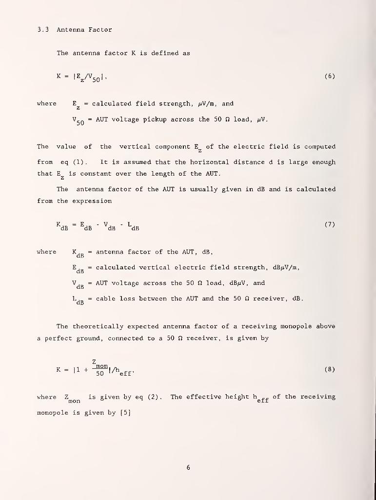
3 . 3 Antenna Factor
The antenna factor K is defined as
K=|E^A5ol. (6)
where E = calculated field strength, /iV/m, and
V _ = AUT voltage pickup across the 50 n load, ;iV.
The value of the vertical component E of the electric field is computed
from eq (1). It is assumed that the horizontal distance d is large enough
that E is constant over the length of the AUT.
The antenna factor of the AUT is usually given in dB and is calculated
from the expression
^dB - ^dB - ^dB - I-dB <^>
where K, = antenna factor of the AUT, dB,do
E = calculated vertical electric field strength, dB/iV/m,dB
V,_ = AUT voltage across the 50 Q load, dB/xV, andUD
Lj = cable loss between the AUT and the 50 Q receiver, dB
,
dB
The theoretically expected antenna factor of a receiving monopole above
a perfect ground, connected to a 50 fi receiver, is given by
Z1 1 mon
, ,, / o \K= |1 +-^IAeff. (8)
where Z is given by eq (2). The effective height h ^^ of the receivingmon a J err
monopole is given by [5]
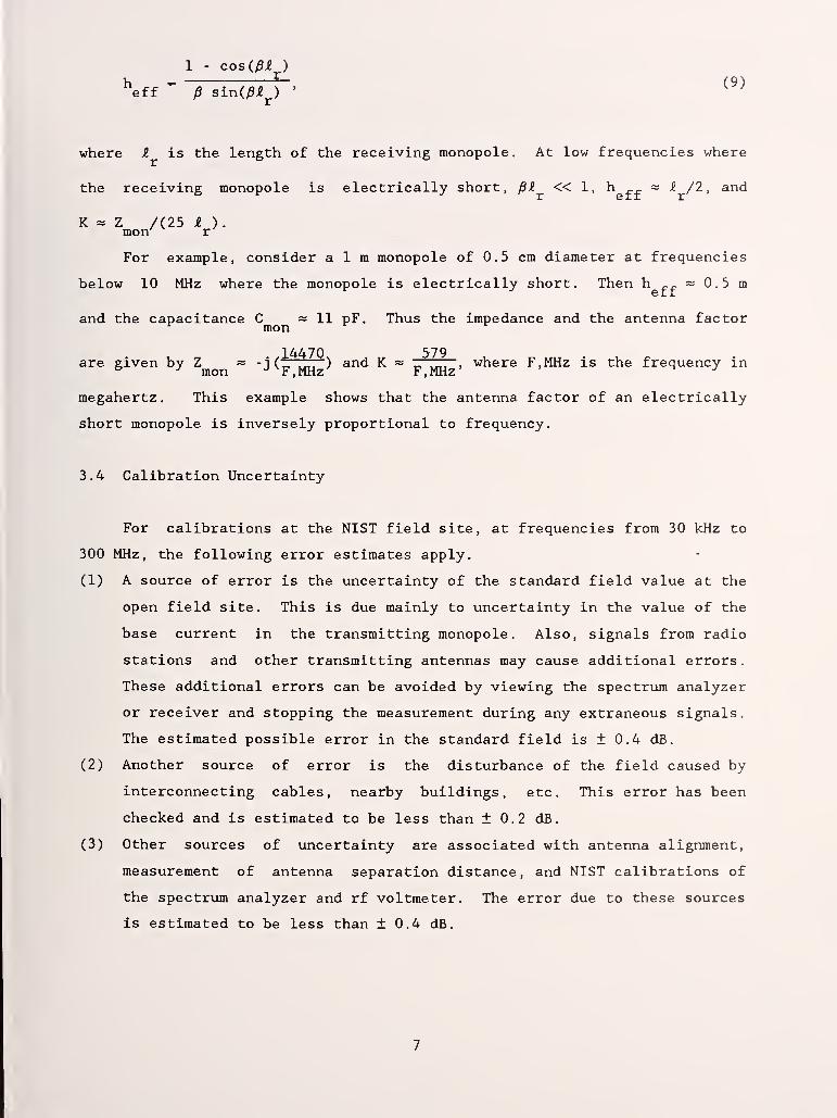
1 - cos(/3i^)
where Z is the length of the receiving monopole. At low frequencies where
the receiving monopole is electrically short, pZ « 1 , h ^^ = -? /2 , and
K = Z /(25 i ).mon r
For example, consider aim monopole of 0.5 cm diameter at frequencies
below 10 MHz where the monopole is electrically short. Then h ^^ ~ . 5 m
and the capacitance C = 11 pF. Thus the impedance and the antenna factor^ mon ^
14470 579are given by Z ~ -i (_, ,.,, ) and K ~ „ .,,, , where F.MHz is the frequency in° ' mon -^ F.MHz F,MHz ^
megahertz. This example shows that the antenna factor of an electrically
short monopole is inversely proportional to frequency.
3.4 Calibration Uncertainty
For calibrations at the NIST field site, at frequencies from 30 kHz to
300 MHz, the following error estimates apply.
(1) A source of error is the uncertainty of the standard field value at the
open field site. This is due mainly to uncertainty in the value of the
base current in the transmitting monopole. Also, signals from radio
stations and other transmitting antennas may cause additional errors.
These additional errors can be avoided by viewing the spectrum analyzer
or receiver and stopping the measurement during any extraneous signals.
The estimated possible error in the standard field is ± 0.4 dB.
(2) Another source of error is the disturbance of the field caused by
interconnecting cables, nearby buildings, etc. This error has been
checked and is estimated to be less than ± 0.2 dB.
(3) Other sources of uncertainty are associated with antenna alignment,
measurement of antenna separation distance, and NIST calibrations of
the spectrum analyzer and rf voltmeter. The error due to these sources
is estimated to be less than ± 0.4 dB.
The overall uncertainty of the calibration is the sum of those listed above,
± 1.0 dB.
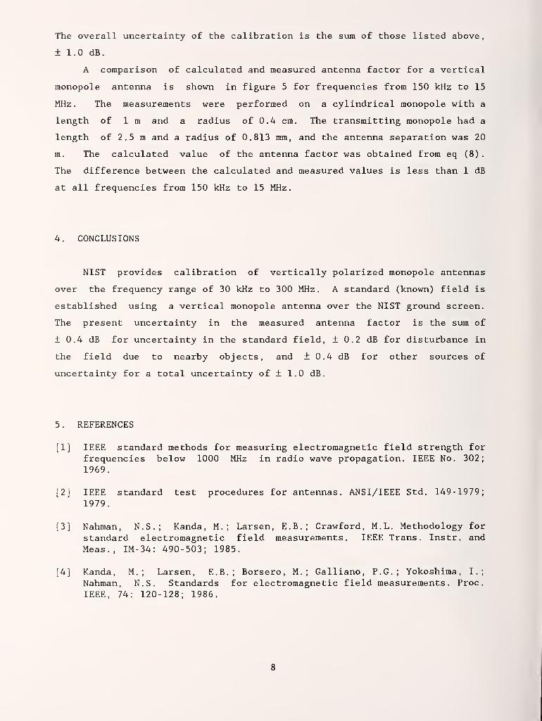
A comparison of calculated and measured antenna factor for a vertical
monopole antenna is shown in figure 5 for frequencies from 150 kHz to 15
MHz. The measurements were performed on a cylindrical monopole with a
length of 1 m and a radius of 0.4 cm. The transmitting monopole had a
length of 2.5 m and a radius of 0.813 mm, and the antenna separation was 20
m. The calculated value of the antenna factor was obtained from eq (8)
.
The difference between the calculated and measured values is less than 1 dB
at all frequencies from 150 kHz to 15 MHz.
4. CONCLUSIONS
NIST provides calibration of vertically polarized monopole antennas
over the frequency range of 30 kHz to 300 MHz. A standard (known) field is
established using a vertical monopole antenna over the NIST ground screen.
The present uncertainty in the measured antenna factor is the sum of
± 0.4 dB for uncertainty in the standard field, ± 0.2 dB for disturbance in
the field due to nearby objects, and ± 0.4 dB for other sources of
uncertainty for a total uncertainty of ± 1.0 dB.
5 . REFERENCES
[1] IEEE standard methods for measuring electromagnetic field strength for
frequencies below 1000 MHz in radio wave propagation. IEEE No. 302;
1969.
[2] IEEE standard test procedures for antennas. ANSI/IEEE Std. 149-1979;
1979.
[3] Nahman, N.S.; Kanda, M. ; Larsen, E.B.; Crawford, M.L. Methodology for
standard electromagnetic field measurements. IEEE Trans. Instr. and
Meas., IM-34: 490-503; 1985.
[4] Kanda, M. ; Larsen, E.B.; Borsero, M. ; Galliano, P.G.; Yokoshima, I.;
Nahman, N.S. Standards for electromagnetic field measurements. Proc
.
IEEE, 74: 120-128; 1986.

[5] Jordan, E.G.; Balmain, K.G. Electromagnetic Waves and RadiatingSystems. Englewood Cliffs, N.J.: Prentice-Hall; 1968.
[6] Schelkunoff, S.A.; Friis, H.T. Antennas, Theory and Practice. New York:Wiley; 1952.
[7] FitzGerrell, R.G. Limitations on vertically polarized ground-basedantennas as gain standards. IEEE Trans. Ant. Propagat
., AP-23: 284-286;
1975.
[8] NBS calibration services users guide 1986-88. Nat. Bur. Stand. (U.S.)
Spec. Pub. 250, 1986 Edition; 1986.

APPENDIX A: SAMPLE TEST REPORT FOR A VERTICAL MONOPOLE
U.S. DEPARTMENT OF COMMERCENATIONAL INSTITUTE OF STANDARDS AND TECHNOLOGY
NATIONAL ENGINEERING LABORATORYBoulder, Colorado 80303
SPECIAL TEST
Broadband Active Monopole AntennaManufacturing CompanyModel ABC, Serial No. xxx
Submitted by:
Submitting CompanyCity, State 12345-6789
I Description of Calibration
The Submitting Company electric-field antenna is an active broadband monopoleantenna system designed to operate in the 30 kHz to 300 MHz frequency range.
The antenna factor to be used for measuring the vertical component of an
electric (E) field was determined by Immersing the receiving antenna undertest (AUT) in a known field 10 meters from the NIST transmitting monopole. A
block diagram of the instrumentation used for this calibration is given in theattached figure. The receiving antenna output was connected to a calibratedcable and 50 q spectrum analyzer. This spectrum analyzer was used as a
frequency-selective voltmeter to measure the pickup at each frequency tested.
The calibration of vertical monopole antennas at NIST is done at an outdoorfield site which has a 30 m x 60 m (100 ft x 200 ft) conducting screen meshstretched over a concrete slab. An underground room is located beneath theconcrete for the transmitter and monitoring Instrumentation. The strength of
the calibrating field is calculated at each frequency in terms of the basecurrent in a thin transmitting vertical monopole antenna. The verticalcomponent of E field, as a function of base current and position, is given bythe equation
30J^^^"
sin(pc)+— -2cos(pC) (1)
Page 1 of 4
Test No. ABCDEFDate of Test:
10

Active Monopole AntennaManufacturing CompanyModel ABC, Serial No. xxx
whereE^ = vertical component of standard E field, RMS V/m,
lo = monopole antenna base current. A,
Q = height of transmitting monopole, m,
p = 27r/wave length, m'S
ri = distance from top of transmitting monopole to field point, m,
r2 = distance from image of top of monopole (in ground) to
field point, m,
ro = distance from bottom of monopole to field point, m.
The above equation is number (10-72) on page 323 of Jordan [1].
The base current of the transmitting monopole antenna is calculated by the
equation
whereVo = measured base voltage of the transmitting monopole antenna, V,
Zin = magnitude of the monopole input impedance, q.
A 2.5 meter transmitting monopole was used to generate a standard field at
each frequency. At frequencies below one-tenth of the self-resonantfrequency, the radiation resistance is negligible and the input impedance is
only capacitive reactance. The capacitance of a thin electrically-short whipcan be calculated from the formula
^_ 55.63{
a
whereC = monopole input capacitance, pF,
Q = monopole height, m,
a = monopole radius, m.
The above equation is twice that of eqn (11) on page 306 of Schelkunoff [21.
Page 2 of 4
Test No. ABCDEFDate of Test:
11

Active Monopole AntennaManufacturing CompanyModel ABC, Serial No. xxx
At frequencies above 1/10 the self-resonant frequency, the input impedance ofthe monopole (Z in) was calculated from Schelkunoff 's "mode" theory usingequation (108) on page 433 of reference [2]. A check of the calculated E
field was made at each frequency with a passive whip antenna with a knownantenna factor. The rf voltage on the transmitting monopole ranged from 0.5volts at 300 MHz up to 80 volts at 30 kHz.
The antenna factor (K), in dB, was determined by the equation
K=E^-V (4)
whereEo = field strength calculated from equation (1), expressed
in dBmV/meter,
V = voltage delivered to the calibrated 50 Q spectrumanalyzer, in dBmV.
II. Calibration Data
The measured values of antenna factor (K) with the antenna rod fully extendedare given in the following table
Table 1. Antenna Factor of the Active Monopole Antenna, Model ABC,Serial No. xxx.
Frequency Antenna Factor(MHz) (dB)
0.030 571
0.100 8.20.500 5.91.00 5.7
5.00 5.5
10.0 4.930.0 3.9100.0 2.1
300.0 1.0
Page 3 of 4
Test No. ABCDEFDate of Test:
12

Active Monopole AntennaManufacturing CompanyModel ABC, Serial No. xxx
An unknown field strength (E) may be measured with the calibrated monopoleantenna by the expression E = K + V, The data in this report are for use in
making cw measurements only, and not necessarily valid for broadbandinterference.
The calibration uncertainty of the antenna factors given is ± 1.5 dB.
III. References
[1] "Electromagnetic Waves and Radiating Systems," E. C.
Jordan, Prentice-Hall, Inc., 1950.
[2] "Antennas, Theory and Practice," S. A. Schelkunoff and H,
T. Friis, John Wiley & Sons, Inc., 1952.
For the DirectorNational Institute of Standardsand Technology
Test performed by:
Motohisa Kanda, Ph. D.
Group Leader, 723.03Fields Characterization GroupElectromagnetic Fields Division
Dennis Camell, Engineer(303) 497-3321
Page 4 of 4
Test No. ABCDEFDate of Test:Reference: P.O. No 12345
13

Table 1. Reactance of a Vertical Monopole (^ = 2.5 m, a = 0.813 mm)
Frequency (MHz) Theoretical Reactance (Q) Measured Reactance (Q)
0.5 - 16 093 - 16 100
1.0 - 8 046 - 8 225
2.0 - 4 023 - 4 100
5.0 - 1 609 - 1 600
7.5 - 1 073 - 1 020
14

Table 2. List of equipment for the open-field site
50 n signal generator, 30 kHz to 300 MHz.
Amplifier, 50 dB gain maximum.
Rf voltmeter with coaxial tee connector, 300 V maximum.
Calibrated spectrum analyzer, covering the frequency range.
Assorted low pass filters, attenuators, and low loss cables withtype N connectors.
15

field
point
image
^ groundplane
Figure 1. Geometry for a transmitting vertical monopole over a ground
plane
.
16

oc:Q UJLU =»h- »-^
*X. UJ I
a: <_)
en UJ•-^ q:_j<c c:<_) o
to
n. UJ cc—> cQ enZC COIS o •-•
I— -J
CD
rE o2: CD
CO
2: 00uj'UJlUJa:h—CJ'UJooict:
2:10r? oo'
g|
ooa:
002:<:a:
oor
anUJ
d:
t
ee
w
Cc0)
cCO
oa-ocoE
bOC•r^
•PCfl
U
«0
o
uo
«4-l
o•H
cd
(U
V4
CO
•H(0
0)
F14
CM
<U
U3bO•H
17

4J
Oe
caouoCQ
outxO
u
o
ocoa
c•Hp4J•r-l
sCO
C(d
4J
CO
0)
18

r*-"A y*
UNITED STATES DEPARTMENT OF COMMEPCENational Institute of Standards and Technology(formerly National Bureau of Standards]325 BroadwayBoL.iOer. CoioracJo 80303-3328
KIMO or MEASUREMENT
IMSTHUMEKT TESTED Ve-vVicJ
-^Ci^YrypV
Date
Sheet no. '^
I
OiSE^VEX
o.Yho\r^O\
^-2.0p}
fa.^Tt,y\Y'0<
yy^ -'^- —
r
AC- Aur
O-Ol Vo.o vv,/ V
e>.o^ 2.3 9^.H y
OJ v.? n^7 y
o.jT yj^o Uho i
; 3c?. Lo.i- y
s /.v Ul.^ y
JO 0.3 (^7'S- y
sc> o,c, Ly-s- 2-
/oo e)./ 3o?. io /
"~~-~-,.^ ^^—-^ L
Figure 4. Sample data sheet for vertical monopole antenna calibrations
19

80
70
^ 60CQ
oCOLL 50
cc
c<
40
30
20
\^,
\
\
Calculated
•
Measured —-^\"^
\
0.1 1
Frequency (MHz)
10 20
Figure 5. Comparison of calculated and measured antenna factors for aimvertical monopole.
20

SL-114A
5-90)
U.S. DEPARTMENT OF COMMERCENATIONAL INSTITUTE OF STANDARDS AND TECHNOLOGY
BIBLIOGRAPHIC DATA SHEET
PUBUCATION OR REPORT NUMBER
NIST/TN-13472. PERFORMING ORGANIZATION REPORT NUMBER
3. PUBUCATION DATE
January 1991
TITLE AND SUBTITLE
NIST Calibration Procedure for Vertically Polarized Monopole Antennas, 30 kHz to 300 MHz
AUTHOR(S)
D. G. Camell, E. B. Larsen, J. E. Cruz, and D. A. Hill
PERFORMING ORGANIZATION OF JOINT OR OTHER THAN NIST. SEE INSTRUCTIONS)
U.S. DEPARTMENT OF COMMERCENATIONAL INSTITUTE OF STANDARDS AND TECHNOLOGYBOULDER, COLORADO 80303.3328
7. CONTRACT/GRANT NUMBER
8. TYPE OF REPORT AND PERIOD COVERED
SPONSORING ORGANIZATION NAME AND COMPLETE ADDRESS (STREET. OTY, STATE. ZIP)
). SUPPLEMENTARY NOTES
ABSTRACT (A 200-WORD OR LESS FACTUAL SUMMARY OF MOST SIGNIFICANT INFORMATION. IF DOCUMENT INCLUDES A SIGNIFICANT BIBUOQRAPHY ORUTERATURE SURVEY. MENTION IT HERE.)
This report describes the theoretical basis and test procedure for vertically polarizedmonopole antenna calibrations at the National Institute of Standards and Technology(NIST). The standard field method applies the theoretical equations of a verticalmonopole antenna to calculate the vertical electric field. This method is used at
the NIST open field site in the frequency range of 30 kHz to 300 MHz. The uncertain-ty in the antenna factor of the antenna under test (AUT) is now + 1 dB.
KEY WORDS (6 TO 12 ENTRIES; ALPHABETICAL ORDER; CAPITAUZb ONLY PROPER NAMES; AND SEPARATE KEY WORDS BY SEMICOLONS)
antenna factor; calibration; electromagnetic field; monopole antenna; open fieldsite; standard field
t. AVAILABIUTY
a UNUMITED
FOR OFFICIAL DISTRIBUTION. DO NOT RELEASE TO NATIONAL TECHNICAL INFORMATION SERVICE (NTIS).
ORDER FROM SUPERINTENDENT OF DOCUMENTS, U.S. GOVERNMENT PRINTING OFFICE,WASHINGTON, DC 20402.
ORDER FROM NATIONAL TECHNICAL INFORMATION SERVICE (NTIS), SPRINGFIELD. VA 22161.
14. NUMBER OF PRINTED PAGES
28
15. PRICE
ILECTRONIC FORM


NIST.Technical Publications
Periodical
Journal of Research of the National Institute of Standards and Technology—Reports NIST research
and development in those disciplines of the physical and engineering sciences in which the Institute
is active. TTiese include physics, chemistry, engineering, mathematics, and computer sciences.
Papers cover a broad range of subjects, with major emphasis on measurement methodology andthe basic technology underlying standardization. Also included from time to time are survey articles
on topics closely related to the Institute's technical and scientific programs. Issued six times a year.
Nonperiodicals
Monographs—Major contributions to the technical literature on various subjects related to the
Institute's scientific and technical activities.
Handbooks—Recommended codes of engineering and industrial practice (including safety codes) de-
veloped in cooperation with interested industries, professional organizations, and regulatory bodies.
Special Publications—Include proceedings of conferences sponsored by NIST, NIST annual reports,
and other special publications appropriate to this grouping such as wall charts, pocket cards, andbibliographies.
Applied Mathematics Series—Mathematical tables, manuals, and studies of special interest to physi-
cists, engineers, chemists, biologists, mathematicians, computer programmers, and others engaged in
scientific and technical work.
National Standard Reference Data Series—Provides quantitative data on the physical and chemicalproperties of materials, compiled from the world's literature and critically evaluated. Developed un-
der a worldwide program coordinated by NIST under the authority of the National Standard DataAct (Public Law 90-396). NOTE: The Journal of Physical and Chemical Reference Data (JPCRD)is published quarterly for NIST by the American Chemical Society (ACS) and the American Insti-
tute of Physics (AIP). Subscriptions, reprints, and supplements are available from ACS, 1155 Six-
teenth St., NW., Washington, DC 20056.
Building Science Series—Disseminates technical information developed at the Institute on building
materials, components, systems, and whole structures. The series presents research results, test
methods, and performance criteria related to the structural and environmental functions and the
durability and safety characteristics of building elements and systems.
Technical Notes—Studies or reports which are complete in themselves but restrictive in their treat-
ment of a subject. Analogous to monographs but not so comprehensive in scope or definitive in
treatment of the subject area. Often serve as a vehicle for final reports of work p)erformed at NISTunder the sponsorship of other government agencies.
Voluntary Product Standards—Developed under procedures published by the Department of Com-merce in Part 10, Title 15, of the Code of Federal Regulations. The standards establish nationally
recognized requirements for products, and provide all concerned interests with a basis for commonunderstanding of the characteristics of the products. NIST administers this program as a supplementto the activities of the private sector standardizing organizations.
Consumer Information Series— Practical information, based on NIST research and experience, cov-ering areas of interest to the consumer. Easily understandable language and illustrations provide use-
ful background knowledge for shopping in today's technological marketplace.Order the above NIST publications from: Superintendent of Documents, Government Printing Office,
Washington, DC 20402.
Order the following NIST publications—FIPS and NISTIRs^from the National Technical Information
Service. Springfield. VA 22161.
Federal Information Processing Standards Publications (FIPS PUB)—Publications in this series col-
lectively constitute the Federal Information Processing Standards Register. The Register serves as
the officizd source of information in the Federal Government regarding standards issued by NISTpursuant to the Federal Property and Administrative Services Act of 1949 as amended. Public Law89-306 (79 Stat. 1127), and as implemented by Executive Order 11717 (38 FR 12315, dated May 11,
1973) and Part 6 of Title 15 CFR (Code of Federal Regulations).
NIST Interagency Reports (NISTIR)—A special series of interim or final reports on work performedby NIST for outside sponsors (both government and non-government). In general, initial distribu-
tion is handled by the sponsor; public distribution is by the National Technical Information Service,
Springfield, VA 22161, in pai>er copy or microfiche form.

U.«. DEPARTMENTOF COMMERCINational Instltuta cH Standards and Tidvwiogy(fonn«r1y Natk>nal Buraau of Standard!)
32SBroa<iwayBouldor. Colorado 80303-3328
OFFICIAL BUSINESSPEfMLTY FOR PRIVATE USE, $300