Embed Size (px)
Citation preview

NIST Special Publication 250-39 2009
NIST Calibration Services for Pressure Using Piston Gauge
Standards
Douglas A. Olson

NIST Special Publication 250-39 2009
NIST Calibration Services for Pressure Using Piston Gauge
Standards
Douglas A. Olson Chemical Science and Technology Laboratory
Process Measurements Division Pressure and Vacuum Group
July 2009
U.S. Department of Commerce Gary Locke, Secretary
National Institute of Standards and Technology
Patrick D. Gallagher, Deputy Director
ii
Certain commercial entities, equipment, or materials may be identified in this
document in order to describe an experimental procedure or concept adequately. Such identification is not intended to imply recommendation or endorsement by the
National Institute of Standards and Technology, nor is it intended to imply that the entities, materials, or equipment are necessarily the best available for the purpose.
National Institute of Standards and Technology Special Publication 250-39 2009 Natl. Inst. Stand. Technol. Spec. Publ. 250-39 2009, 69 pages (July 2009)
CODEN: NSPUE2
iii

NIST Calibration Services for Pressure Using Piston Gauge Standards Table of Contents
1 Introduction.................................................................................................................... 1 2 Description of the measurement service ...................................................................... 1 3 NIST piston gauge pressure standards ........................................................................ 3
3.1 NIST gas primary standards ................................................................................. 6 3.1.1 Dimensional measurements ............................................................................... 6 3.1.2 Force models...................................................................................................... 9 3.1.3 Comparisons between standards ...................................................................... 10 3.1.4 Final result for effective area and uncertainty ................................................. 12
3.2 NIST oil primary standards ................................................................................. 12 3.2.1 Piston area........................................................................................................ 14 3.2.2 Fall rate measurements for determining pz ...................................................... 15 3.2.3 Cross-float measurements for determining d ................................................... 15 3.2.4 Summary for NIST oil primary standards ....................................................... 17
3.3 Other terms in measurement equation ............................................................... 17 3.3.1 Mass ................................................................................................................. 17 3.3.2 Local acceleration due to gravity..................................................................... 17 3.3.3 Ambient density ............................................................................................... 19 3.3.4 Density of masses ............................................................................................ 20 3.3.5 Surface tension and piston circumference ....................................................... 20 3.3.6 Temperature ..................................................................................................... 20 3.3.7 Thermal expansion........................................................................................... 21
3.4 NIST transfer standards....................................................................................... 21 4 Calibration techniques and procedures ..................................................................... 29
4.1 Calibration of piston gauges using the crossfloat method................................. 29 4.1.1 Experimental arrangement for a crossfloat ...................................................... 30 4.1.2 Reference levels in a crossfloat........................................................................ 35 4.1.3 Hydraulic connections ..................................................................................... 36 4.1.4 Cleaning ........................................................................................................... 36 4.1.5 Piston gauge rotation........................................................................................ 37 4.1.6 Measurements and data evaluation .................................................................. 37
4.2 Calibration of sensing-only pressure instruments ............................................. 38 4.2.1 Experimental arrangement and calibration procedure ..................................... 38 4.2.2 Measurements and data evaluation .................................................................. 40
5 Uncertainty analysis..................................................................................................... 40 5.1 Uncertainties in a crossfloat calibration ............................................................. 41
5.1.1 Uncertainty due to reference area .................................................................... 45 5.1.2 Uncertainty due to mass on REF piston gauge ................................................ 45 5.1.3 Uncertainty due to mass on TEST piston gauge.............................................. 45 5.1.4 Uncertainty due to ambient density ................................................................. 46 5.1.5 Uncertainty due to REF gauge mass density ................................................... 46 5.1.6 Uncertainty due to TEST gauge mass density ................................................. 47 5.1.7 Uncertainty due to fluid surface tension .......................................................... 48 5.1.8 Uncertainty due to REF piston circumference................................................. 48
iv

v
5.1.9 Uncertainty due to TEST piston circumference............................................... 48 5.1.10 Uncertainty due to acceleration of gravity..................................................... 48 5.1.11 Uncertainty due to thermal expansion of the REF piston and cylinder ......... 49 5.1.12 Uncertainty due to thermal expansion of the TEST piston and cylinder....... 49 5.1.13 Uncertainty due to temperature of REF piston and cylinder ......................... 49 5.1.14 Uncertainty due to temperature of TEST piston and cylinder ....................... 50 5.1.15 Uncertainty due to density of pressure fluid .................................................. 50 5.1.16 Uncertainty due to reference height difference.............................................. 50 5.1.17 Uncertainty due to pressure difference .......................................................... 51 5.1.18 Summary of uncertainties in a crossfloat calibration..................................... 51
5.2 Uncertainty in pressure sensing-only calibration .............................................. 52 5.2.1 Uncertainty due to reference area .................................................................... 53 5.2.2 Uncertainty due to mass................................................................................... 53 5.2.3 Uncertainty due to ambient density ................................................................. 55 5.2.4 Uncertainty due to mass density ...................................................................... 55 5.2.5 Uncertainty due to fluid surface tension .......................................................... 56 5.2.6 Uncertainty due to piston circumference ......................................................... 56 5.2.7 Uncertainty due to acceleration of gravity....................................................... 56 5.2.8 Uncertainty due to thermal expansion of piston and cylinder ......................... 56 5.2.9 Uncertainty due to temperature of piston and cylinder.................................... 57 5.2.10 Uncertainty due to density of pressure fluid .................................................. 57 5.2.11 Uncertainty due to reference height difference.............................................. 58 5.2.12 Uncertainty due to vacuum pressure.............................................................. 58
6 Quality system .............................................................................................................. 59 7 References ..................................................................................................................... 60 Appendix A. Recommended formula for the calculation of the density of moist air and its uncertainty .......................................................................................................... 61 Appendix B. Sample calibration report of a customer piston gauge ......................... 64
1 Introduction The National Institute of Standards and Technology (NIST) is responsible for realizing, maintaining, and disseminating the derived SI unit of thermodynamic pressure, the pascal (Pa). Pressure is an intrinsic property that is equal to the amount of force applied on a unit of area. Pressure is a key thermodynamic quantity fundamental to defining the state and property of a substance. Currently at NIST, there are no intrinsic methods for determining pressure, i.e., no “fixed points” for establishing pressures that can be calculated from theoretical considerations. As a derived unit of the SI, the practical realization of pressure depends upon measuring other SI units, such as force or length, and then relating that measurement through the physical principles of the measurement to the pascal. The device which realizes an SI unit is often referred to as a standard. This special publication describes the calibration services, methods, standards, and uncertainties for the calibration of pressure measuring devices using NIST piston gauge standards. These standards operate from 10 kPa to 280 MPa (1.4 psi to 40,000 psi). NIST provides other calibration services for devices using manometer standards and vacuum standards for pressures from 10-7 Pa to 360 kPa, which are not covered in this publication. The measurement service is described in Sec. 2. The pressure standards used by NIST are described in Sec. 3, and the calibration techniques are discussed in Sec. 4. Section 5 is a complete uncertainty analysis of the measurements, and Sec. 6 describes the NIST quality system. 2 Description of the measurement service The National Institute of Standards and Technology provides calibration services for pressure measuring instruments known as piston gauges, pressure transducers, electronic barometers, and pressure gauges. Piston gauges are also referred to as pressure balances or dead weight gauges. This document will use the term “sensing-only” instrument for all pressure transducers, electronic barometers, and pressure gauges. For devices using gas as the pressure medium, the pressure range is 10 kPa to 104 MPa (1.4 psi to 15,000 psi). For devices using oil as the pressure medium, the pressure range is 1 MPa to 280 MPa (150 psi to 40,000 psi). Routine calibrations are performed using NIST transfer standard piston gauges. Special calibrations can be performed against NIST primary standard piston gauges, at higher cost and longer turn-around times. The uncertainty in pressure using a NIST piston gauge is dominated by the uncertainty in “effective area” associated with the NIST piston gauge. The effective area is the “calibration factor” of the piston gauge; it is the quantity that when combined with the loaded forces on the gauge produces the pressure in the fluid line connected to the gauge. A complete discussion of uncertainty is found in Sec. 5. Expanded1 (k=2) relative uncertainties in effective area for the NIST transfer standard piston gauges range from 8x10⁻⁶ to 40x10-6 (8 ppm to 40 ppm) for gas, and from 22x10-6 to 37x10-6 (22 ppm to 37 ppm) for oil.
1 All references to expanded uncertainty in this document shall be interpreted as an uncertainty at the k=2 level of the quantity. All references to standard uncertainty in this document represent one standard deviation (k=1) of the quantity.
1
Calibrations are performed using a range of piston gauge standards. Typically, the customer's instrument is calibrated against the NIST standard that best matches the desired pressure range and media. An item can be calibrated against more than one NIST standard; however it will be charged as a multiple calibration. Most NIST piston gauges operate over a pressure range between 20:1 and 10:1. Although any pressure instrument can be calibrated in this service, devices which have a relative expanded uncertainty greater than about 1x10⁻⁴ are commonly calibrated by independent calibration laboratories rather than at NIST. At NIST, all instruments are calibrated using piston gauge standards, and there is no cost reduction for a device with higher uncertainties. A piston gauge is a differential pressure measurement device measuring the difference in pressures applied to the top and bottom of the piston. When the piston gauge is used with the top of the piston at ambient pressure, the unit is operating in “gauge” mode. When the piston gauge is used with the top of the piston in a vacuum, the unit is operating in “absolute” mode. The "gauge" mode is used for all oil calibrations and most gas calibrations; certain gas calibrations can also be performed in the "absolute" mode upon request. Sensing-only instruments can also be calibrated in gauge or absolute mode. Customers should consult the most current version of the NIST Calibration Services Users Guide [1], which can be found on the NIST website at http://ts.nist.gov/MeasurementServices/Calibrations/upload/feesch-09.pdf, to find up-to-date information on calibration services, calibration fees, technical contacts, turn around times, and instrument submittal procedures. The NIST calibration service using piston gauges follows all procedures set forth in the Users Guide. Chapter 2 gives instructions for ordering a calibration for domestic customers, and Chapter 3 gives special instructions for foreign customers. Chapter 6 lists fees and technical contacts. When a piston gauge is calibrated in the present service, the result that is presented to the customer is the effective area of the piston gauge rather than the pressure. The pressure generated by a piston gauge depends on the effective area, the force loaded on the piston (which depends on the local gravitational constant), and local operating conditions such as temperature and pressure. Presenting the result as an effective area allows the piston gauge to be used in a variety of conditions without re-calibration as those conditions change. For the pressure generated by the calibrated piston gauge to be traceable to the SI at the time of use, the masses loaded on the piston, which generates the force, must also be traceable. The calibration service using NIST piston gauges does not include calibration of the customer’s masses. That service is described in Chapter 5 of [1]. A piston gauge is a pressure-generating device, which means that when two of them are connected for calibration a different procedure is required than for a sensing-only pressure instrument. The procedure for calibrating two piston gauges is often referred to as a “crossfloat”. The conceptual difference between a crossfloat calibration and a sensing-only calibration is that in a crossfloat some method is used to determine if the two piston gauges are in pressure equilibrium, and if not, there is a method to adjust the force (mass) on the gauges to bring them into equilibrium. A sensing-only calibration
2

requires recording the output of the pressure instrument at the pressure points established by the piston gauge standard, but no incremental adjustment of the mass on the NIST piston gauge. 3 NIST piston gauge pressure standards A piston gauge is a round piston fitted into a matching cylinder filled with fluid, loaded with weights of known mass and density. A schematic of a typical piston gauge of the “free deformation” type is shown in Fig. 1. The piston is marginally smaller in diameter than the cylinder, and fluid fills the gap between the two components. The piston is rotated with respect to the cylinder (most common is that the cylinder is stationary and the piston rotates). The rotation minimizes the possibility of metal-to-metal contact. The term “free deformation” means that the inside of the cylinder is pressurized by the fluid, and the outside of the cylinder is exposed to ambient pressure and is constrained by the column. The fluid pressure, p, is determined by an equilibrium balance of the downward gravitational force due to the weights plus the surface tension of the fluid on the piston, against the upward force of the pressure acting on the “effective area”, Ae(T,p), of the piston gauge. Or,
( , ) 1 ae i
i mi
pA T p m g Cρ γρ
⎛ ⎞= − +⎜ ⎟
⎝ ⎠∑ . (1)
Here, mi are the masses of the piston and all the weights loaded on it; g is the local acceleration due to gravity; ρa is the density of the ambient gas surrounding the masses (air for gauge mode, vacuum for absolute mode); ρmi is the density of weight mi; γ is the surface tension of the pressurizing fluid; and C is the circumference of the piston. Ae(T,p) is written as a function of temperature and pressure, for reasons which will be explained below. The pressure acts on the “effective area” rather than the piston cross-sectional area, since two other force terms act upward on the piston in addition to the pressure on the bottom of the piston. The effective area accounts for the sum of the three forces. The first additional force is the frictional force of the fluid flowing upward through the gap between the cylinder and piston, acting on the piston. The second additional force is the vertical component of the normal force from the fluid on the piston walls, which is non-zero if there is any slope or “profile” to the piston over its height. In the limit when the gap is small compared to the piston diameter, along with both a straight and round piston and cylinder, it can be shown [2] that the effective area is equal to the average of the piston and cylinder area. The effective area is expressed as a function of temperature and pressure, since the piston and cylinder will distort under pressure, and both components will expand or contract as
3

Cylinder
Piston
Column
Masses
Fluid pressure
Figure 1. Schematic of free deformation piston gauge.
4

the temperature changes. Thermal expansion is accounted through the expansion coefficients, or ( )( )( )( , ) 1e e p cA T p A T Tα α= + + − r , (2)
with Ae is the effective area at pressure p and reference temperature Tr; αp is the linear coefficient of thermal expansion for the piston; αc is the linear coefficient of thermal expansion for the cylinder; and Tr is the reference temperature. The functional dependence of Ae = Ae(p,Tr) is still implied, but the full notation is simplified for all equations which follow. NIST uses 23 ºC as the reference temperature, while 20 ºC is also used at other National Metrology Institutes. Substitution of eq. (2) into eq. (1) gives the measurement equation for pressure from a piston gauge:
( )( )( )
1
1
ai
i mi
e p c r
m g Cp
A T
ρ γρ
α α
⎛ ⎞− +⎜ ⎟
⎝ ⎠=+ + −
∑T
. (3)
All NIST piston gauge pressure standards use eq. (3) to determine pressure. When using a piston gauge, all terms on the right hand side in eq. (3) must be determined: the mass and density values of the weights loaded on the gauge, the density of the ambient gas surrounding the masses, the circumference of the piston and the surface tension of the fluid, the temperature of the gauge, the thermal expansion of the piston and cylinder, and the effective area. A primary standard for pressure is an instrument that does not require a pressure calibration to measure pressure. It is characterized by measuring the fundamental units of mass, time, length and temperature, along with modeling of the physical behavior of the standard. In terms of eq. (3), a primary standard piston gauge has a determination of effective area at p and Tr that does not depend on calibration against another pressure standard. NIST has two gas piston gauge primary standards, designated as PG38 and PG39 [3]. These two gauges were characterized by dimensional measurements and modeling of the fluid forces on the piston. NIST has three oil piston gauge primary standards, designated as PG20, PG27, and PG67 [4]. The primary standards are used to calibrate NIST transfer standard piston gauges; the transfer standards are therefore traceable to the primary standards. Prior to the introduction of PG38 and PG39 into use in 2008, NIST gas piston gauge standards were traceable to a mercury manometer, which was described in the first edition of this SP250 [4]. The effective area for NIST primary standards will be considered in Secs. 3.1 and 3.2. The determination of the remaining terms in eq. (3) follows in 3.3. The effective area of the NIST transfer standards used in the calibration service is discussed in Sec. 3.4.
5

3.1 NIST gas primary standards PG38 and PG39 are gas primary piston gauge standards that operate from 20 kPa to 1 MPa. They were acquired by NIST from Ruska Instrument Corporation in 1989. They are deemed primary standards for pressure as their effective area is derived from dimensional measurements of the piston and cylinder diameters (which in turn are traceable to the wavelength of an atomic transition in a HeNe laser interferometer), along with force models of the gas flow in the gap between the piston and cylinder. A cross-section of the piston/cylinder assemblies is shown in Fig. 2, and a picture of the assemblies is shown in Fig. 3. The assemblies are “twins’ in the sense that they were made from the same casting of tungsten carbide and have the same nominal dimensions. The pistons are hollow, with the hollow end pointed downward in normal operation as shown in Fig. 2 on the left-hand side. Their nominal diameters are approximately 35.8 mm and their length is 75 mm. The radial clearance between pistons and cylinders is about 600 nm. The construction of the pistons is such that they can be inserted into their cylinders either upright or inverted. When operated in the inverted configuration, a special cap with a spherical pivot is placed onto the hollow end to allow the loading of masses. That cap is not sealed to the piston. In the upright position, the interior of the piston is subjected to the system pressure, whereas in the inverted position the piston interior is subjected to ambient pressure. The two orientations of the piston have a different calculable value for the pressure coefficient (relative change in Ae with pressure). The effective area of both PG38 and PG39 is given by the linear distortion equation: ( )0 11eA A b p= + . (4) Here, A0 is the effective area at atmospheric pressure and the reference temperature, 23 ºC, and b1 is the pressure coefficient. There are two components in the establishment of PG38 and PG39 as primary standards. The first is the dimensional measurements of the piston and cylinder diameters; the second is the analysis of that data with force and distortion models to determine the effective area. The modeling and dimensional measurements are used to determine both A0 and the linear pressure distortion coefficient, b1. An important verification of the results is comparisons of the effective area of PG38 and PG39 against each other when operated as pressure standards; and comparison of the gauges against the NIST mercury manometer, which is an independent primary pressure standard traceable to the density and speed of sound of mercury. 3.1.1 Dimensional measurements Both PG38 and PG39 were first dimensioned in 1989 at NIST [5] using a stack of gauge blocks, a precision comparator to compare the length of the gauge blocks to the piston diameters, and a laser interferometer to measure the length of the gauge blocks. Based on those measurements the total relative standard uncertainty of the effective area was
6

Cylinder
36 mm
75 mm
CapPiston
Figure 2. Schematic diagram of the PG38 and PG39 piston/cylinder assembly with the piston in upright (left) and inverted (right) orientations. The cap on the right is used to support the weight carrier plus weights.
7

Figure 3. Picture of PG39 cylinder (left), piston (right), and mass set (top). Closed end of piston is shown.
8

estimated as 10x10-6. In 1999, PG39 was dimensioned by Physikalisch Technische Bundesanstalt (PTB) using a state-of-the art diameter and form comparator in which a calibrating laser interferometer is integral to the apparatus. Absolute diameters were measured at four places on the piston and four places on the cylinder, with a standard uncertainty of 15 nm. Relative roundness was measured at 5 latitudes and relative straightness was measured at 8 longitudes. In 2003, both PG38 and PG39 were measured at PTB with the same device as PG39 was measured in 1999. This time, absolute diameters were measured at 10 places on the piston and 10 places on the cylinder. Four of the locations on PG39 were the same in 2003 as in 1999; the relative difference from the 1999 to 2003 ranged from -0.1x10⁻⁶ to -0.8x10⁻⁶. The standard uncertainty of the absolute diameters in 2003 was 12.5 nm and 25 nm for the piston and cylinder, respectively. Relative roundness and relative straightness were measured again in 2003 for both pistons and both cylinders, at 5 latitudes for roundness and 8 longitudes for straightness. The standard uncertainty for the roundness and straightness measurements was 50 nm. The 2003 data for both PG38 and PG39 showed that the pistons were round to within the standard uncertainty of measurement. Changes in diameter with height for both pistons and both cylinders were larger than the standard uncertainty of the measurement. 3.1.2 Force models The conventional method for determining the uncertainty of the effective area, which is based on the uncertainty of the dimensional measurements only, would imply that A0 has a relative standard uncertainty of 1.0x10⁻⁶. However, the low uncertainty of the dimensional measurements requires that we consider the appropriate model for converting the measurements into “effective area” when the piston gauge is used for generating pressure. The model needs to account for all of the forces on the piston: the external mass load, the normal pressure force on the piston base, the shear forces on the piston flanks, and the normal forces on the piston flanks. It also needs to account for the complete dimensional data which describes the artifacts. In the analysis which establishes PG38 and PG39 as primary standards [3], the data from PTB on roundness, straightness, and absolute diameters were reconstructed in the form of cylindrical “bird-cages” providing longitudinal and latitudinal crevice (piston-cylinder gap) variation. Forces were computed assuming two models of nitrogen flow behavior in the crevice: (1) viscous flow, and (2) flow of gas that interpolated between molecular flow and viscous flow. The effect of operating mode (gauge or absolute) was evaluated for both models. The effect of the dimensional uncertainty on the standard uncertainty in A0 was included by increasing or decreasing all piston and cylinder diameters by their standard uncertainty. A complete mathematical description of the models is given in [6]. The results of the two flow models, including the dimensional uncertainty, gives a distribution of A0 values. The accepted value for A0 was taken as the average of the maximum and minimum value of the results, and the standard uncertainty as one half of the difference between the maximum and minimum. Statistically this means that the distribution of A0 from the models is part of a normal distribution, and that the maximum and minimum results represent about a 2 out of 3 chance that the true quantity lies between those values. The relative standard uncertainty in A0 evaluated in this way is
9

3.0x10⁻⁶ for both PG38 and PG39. The largest A0 occurred for the viscous flow model, and the smallest A0 occurred for the interpolated flow model in absolute mode. The value for the pressure distortion coefficient, b1, was determined from elasticity theory. Two model implementations of elasticity theory were considered. In one, both the cylinder and piston were modeled as infinitely long components subjected to radial forces due to the pressure on the walls, which allowed using analytical formulae. These formulae require a constant pressure (pg) in the piston-cylinder gap, even though the gap pressure varied from p at gap entrance to ambient at the top. The formulae were solved for pg = 0, p/2, and p. In a second model, finite-element analysis was used to include the constraint of the closed-end of the piston (Fig. 2) and vertical loading on both the piston and cylinder; these constraints produce two-dimensional stresses. The two models and three gap boundary conditions produced a distribution of b1 values from 7.95x10⁻¹² Pa-1 to 10.0x10⁻¹² Pa-1. The accepted value, 8.97x10⁻¹² Pa-1, was chosen as the average of the maximum and minimum, and the standard uncertainty was taken as one-half the difference. To within the standard uncertainty of the distortion models, both PG38 and PG39 have the same b1 and uncertainty in b1 due to modeling. The combined standard uncertainty u(b1) includes the standard uncertainty in the Young’s modulus added in quadrature. u(b1) equals 1.12x10⁻¹² Pa-1. 3.1.3 Comparisons between standards NIST also realizes pressure with a primary standard mercury manometer known as the ultrasonic interferometer manometer (UIM) up to 360 kPa. PG38 and PG39 have been compared numerous times since 1989 to the UIM, serving as check standards to confirm UIM stability and also to confirm the stability of the piston gauges. The combined relative standard uncertainty of the UIM from 20 kPa to 360 kPa is 2.6x10⁻⁶. All comparisons of the UIM to the piston gauges has shown agreement to within one standard deviation of the combined standard uncertainty of the difference, with UIM pressures both higher and lower than those of the piston gauges. These comparisons show the combined stability of the UIM and the piston gauges, and given the independent nature of the realization technique, the likely stability of each method. PG38 and PG39 have been compared directly to each other from 20 kPa to 1 MPa, utilizing the unique feature mentioned earlier that both can be operated in the upright and inverted position. This comparison measures the area ratio A38/A39. Four comparisons (PG38-up, PG39-up; PG38-down, PG39-down; PG38-up, PG39-down; PG38-down, PG39-up) were performed, which were compared to predictions from the distortion models. With both gauges in the same orientation, the distortion coefficients should be the same and the slope (Δb1) of A38/A39 should be zero. With the two opposing orientations, the models predict (Δb1) = ± 7.2x10⁻¹² Pa-1. Figure 4 shows the results of the four comparisons along with the predicted slopes from the analytical models. There is good agreement between the experimental result and the modeling. This helps confirm the use of elasticity theory to establish b1 and its uncertainty.
10

0.999990
0.999995
1.000000
1.000005
1.000010
1.000015
0 200 400 600 800 1000 1200
Pressure / kPa
A38
/A39
Up-UpDn-DnDn-UpUp-DnTWF
5 ppm
Figure 4. The ratio of the effective area for PG38 to that of PG39 (A38/A39). Symbols
indicate ratios from crossfloat measurements of PG38 versus PG39 for different combinations of piston orientation (Up-Dn means PG38 upright, PG39 inverted). The dashed lines indicate ratios based on thick wall formulae from elasticity theory and A0 from dimensional characterization.
11

3.1.4 Final result for effective area and uncertainty The final result for the primary standards for Ae in m2 with p in Pa at a temperature of 23 ºC is: PG38: ( )3 11.0079497 10 1 8.97 10eA p− −= × + × 2 , (5) PG39: ( )3 11.0079484 10 1 8.97 10e
2A p− −= × + × . (6) The uncertainties from A0 and b1 are added in quadrature, giving the relative standard uncertainty2 for both as
( ) ( )1/226 12( ) 3.0 10 1.12 10e
e
u A pA
− −⎡= × + ×⎢⎣2 ⎤⎥⎦
. (7)
The coefficient of thermal expansion for the combined piston and cylinder was measured in [6] for PG39, and is assumed the same for PG38. The result is: ( ) 6 18.754 0.03 10 Kp cα α α − −= + = ± × . (8) Eq. (2) is then used to find the effective area when the temperature differs from Tr. 3.2 NIST oil primary standards The NIST oil primary standards are of the type known as controlled clearance piston gauges (CCPG). In this type of piston gauge, shown schematically in Fig. 5, a pressure independent of the system pressure is applied to the outside of the cylinder. This “jacket pressure”, pj, minimizes the elastic distortion of the cylinder and controls the annular gap between the piston and cylinder. The ability to control the width of the gap (clearance) allows one to obtain the best operating conditions of the piston gauge, such as reduced fall rate and high mass sensitivity. However, the main advantage of the CCPG is that it can be characterized as a primary standard without extrapolation from another pressure standard. Heydemann and Welch [7] describe a method for characterizing a CCPG that involves dimensional measurement of the piston area, estimation of the piston distortion with pressure, and estimates of the piston-cylinder gap. The gap is estimated using measurements of fall rate of the piston and changes in system pressure in response to changes in jacket pressure. This method, known as the Heydemann and Welch (HW) method, is used on NIST’s three oil primary standards, PG27, PG20, and PG67. The analysis method presented here is explained in more detail in [7] and [8]. The measured pressure at the reference level of a CCPG at equilibrium conditions is
2 Throughout this document, lower-case u variables refer to standard (k=1) uncertainties; upper-case U variables refer to expanded (k=2) uncertainties.
12

Piston
Cylinder
Jacket pressure
Column
System pressure
Figure 5. Schematic of controlled clearance piston gauge.
13

determined by using the following equation:
( ) ( )( ) ( )( )( )0
1
1 1 1
ai
i mi
p p z j p c r
m g Cp
A b p d p p T T
ρ γρ
α α
⎛ ⎞− +⎜ ⎟
⎝ ⎠=+ + − + + −
∑ . (9)
The reader should note the similarity to eq. (3); the forces due to mass and surface tension form the numerator; and the effective area forms the denominator. Characterizing the CCPG as a primary standard involves determining the effective area at the reference temperature, T = Tr: ( ) ( )( )0 1 1e p p z jA A b p d p p= + + − . (10)
A0p is the area of the piston at ambient pressure and Tr; bp is the distortion coefficient of the piston; pz is a HW modeling parameter, equivalent to the jacket pressure for which the clearance between the piston and cylinder is zero at a given measured pressure; and d is a HW modeling parameter, equivalent to the relative change of effective area due to a change in jacket pressure. The pz and d parameters are determined in the characterization and are a function of p; bp is determined from analytical models; αp and αc are properties of the material; and T and pj are operating conditions. In the HW model, the piston area is estimated from A0p and the (1+bpp) piston distortion multiplier. A0p is determined dimensionally. The final term in the brackets in eq. (10) approximates the additional area due to the gap. We imagine applying sufficient jacket pressure to collapse the cylinder onto the piston, reducing the gap to zero and the effective area equal to the piston area only. We then reduce the jacket pressure, opening up the gap and increasing the effective area. pz is the jacket pressure that reduces the gap to zero, and the amount of area increase per change in pj is determined by the parameter d. One limitation of the HW characterization is that operating the CCPG at jacket pressures close to pz can potentially damage the piston or cylinder, and the mechanical design may not accommodate the high pressure. However, the uncertainties of the HW parameters, and hence the effective area, decrease if the jacket pressure approaches pz during the characterization. A characterization is therefore a compromise between constraints of the system and the desire to reduce uncertainties. 3.2.1 Piston area The piston diameter at ambient pressure, A0p, is measured by the NIST Dimensional Metrology Group in much the same way as was done for PG38 and PG39. The piston area is calculated from the average of the diameter measurements. The standard uncertainty in the diameter measurement for PG27, PG20, and PG67 is 26 nm, 51 nm, and 32 nm, respectively. The piston distortion coefficient, bp, is computed from elasticity theory by modeling the piston as uniformly loaded on the ends at p and pressurized in the gap at common pressure p/2 [7]:
14

( )1 3p
p
bE
μ− −= . (11)
The Poisson’s ratio, μ, and modulus of elasticity, Ep, are material properties of the piston. Typical values for bp are -5x10-13 Pa-1 to -7x10-13 Pa, and the standard uncertainty u(bp) is about 0.03bp. For PG67 at its maximum pressure of 280 MPa, the relative change in piston area is -157x10-6 (157 ppm smaller) from its value at p = 0 MPa. 3.2.2 Fall rate measurements for determining pz Instead of determining pz by operating the CCPG at a jacket pressure that reduces the gap to zero, the HW model assumes that the gap will change linearly with applied jacket pressure, and extrapolates measurements taken at lower pressures. To determine pz, the HW model utilizes viscous flow theory that predicts that the flow rate (Q) of fluid in the piston-cylinder gap is proportional to the third power of clearance (hg) between the cylinder and piston. Or, 3
gQ h∝ . (12) The gap flow rate is directly proportional to the fall rate, v, of the piston, assuming no fluid leakage and neglecting volume changes of the fluid due to thermal expansion. The HW model further assumes that the gap width varies linearly with the jacket pressure at each measured pressure, p. The jacket pressure for which the clearance becomes zero, pz, is computed by measuring v vs. pj (at constant p), and fitting it to the following function: 1/3
z zk v p p j= − . (13) kz and pz are fitting constants, with pz being the intercept of the fitted function at v = 0. Figure 6 shows data of a typical set of measurements of fall rate vs. jacket pressure, with constant system pressures designated by similar symbols. The solid and dashed lines are the fits of the data to eq. (13), showing the extrapolation of the fits to v = 0. pz values obtained for each p are fit to a function of p, usually linear: 0 1z z zp p p p= + . (14) The parameter pz0 can be thought of as the jacket pressure that closes the piston-cylinder gap at zero measured pressure. The Type A standard uncertainty in pz is estimated from the standard uncertainty in the predicted values of the fit of eq. (14) [8]. 3.2.3 Cross-float measurements for determining d The HW parameter d is determined by monitoring the change in measured pressure due to the change in jacket pressure at each constant load:
1
j
pdp p
∂=
∂ . (15)
15

0
20
40
60
80
100
120
140
160
180
200
0.00 0.02 0.04 0.06 0.08 0.10 0.12 0.14 0.16 0.18
v 1/3 / (mm/s)1/3
p j /
MPa
20018016014012010080604020
p / MPa:
Figure 6. Fall rate (v) of a typical CCPG over pj/p = 0 to 0.4, plotted as pj vs. v1/3.
Similar symbols are constant pressure (p). Linear fits of data over same range are extrapolated to v = 0, giving HW parameter pz.
16

The definition of d follows from taking the partial derivative of both sides of eq. (9) with respect to pj, holding the load (mass) constant and neglecting higher order terms. p is measured by cross-float calibration of the CCPG against another piston gauge standard, at each mass load, over a range of jacket pressures. The p versus pj data are fitted to a linear function, and d is the fitted slope divided by the average value of p. Using an average p is justified since the relative change in pressure produced by changes in pj is typically less than 5x10⁻⁴, and this amount of change contributes to an error in the relative effective area of less than 0.2x10⁻⁶ (0.2 ppm). The results for d at each nominal pressure are then fit to a function of p or load force W (W is the numerator in eq. (9)). A linear function for d is most common: 0 1d d d p= + . (16) The Type A standard uncertainty in d is estimated from the standard uncertainty in the predicted values of the fit [8]. The fitting parameters for both pz and d can be dependent on the pressure transmitting fluid. The NIST CCPGs were characterized using Spinesstic oil. 3.2.4 Summary for NIST oil primary standards A summary of the characterization parameters for NIST CCPGs is listed in Table 1. More details on the design of the gauges and their complete uncertainty analysis is given in [4]. The full-scale pressures for PG27, PG20, and PG67 are 28 MPa, 140 MPa, and 280 MPa, respectively. Values for bp and d are larger for PG20 because it is made of stainless steel, which has a lower Young’s modulus (less rigid) than the tungsten carbide of PG27 and PG67. 3.3 Other terms in measurement equation What follows is the NIST treatment of the remaining terms in the measurement equation for pressure, eq. (3). Details of how these terms contribute to the uncertainty of a customer calibration are discussed in Sec. 5. 3.3.1 Mass The values of the masses of all weights used on NIST piston gauges are traceable to the NIST Mass and Force Group. An identifying number inscribed onto each weight is used to recall the appropriate mass value and density. Mass values must be known for all parts of the piston gauge supported by the pressure fluid, including the piston, weight table, and bell. 3.3.2 Local acceleration due to gravity The best value of g for a given laboratory site may be obtained by having on-site measurements made by the Office of National Geodetic Survey, with relative standard uncertainties on the order of 1x10⁻⁷ (0.1 ppm) or better. The next best value of g can be obtained by an interpolation from a grid of measurements prepared by the same organization, with typical relative uncertainties of 1x10⁻⁶ to 5x10⁻⁶ depending on geographical location. The website that provides this interpolation is
17

Table 1. Characteristics of NIST controlled clearance piston gauge primary standards, in terms of HW model. Pressure p in Pa. Relative standard uncertainty in pressure given at maximum operating pressure. ( ) ( )( )0 1 1e p p z jA A b p d p p= + + − .
PG27 PG20 PG67Max p / Pa 28x106 140x106 280x106
A 0p / m2 4.902139x10⁻⁵ 3.218871x10⁻⁵ 1.4219412x10⁻⁵
b p / Pa-1 -5.49x10⁻¹³ -7.23x10⁻¹³ -5.61x10⁻¹³
d / Pa-1 3.425x10⁻¹² - 1.458x10⁻²⁰p 8.662x10⁻¹²e4744210/p 3.691x10⁻¹² - 3.512x10⁻²¹p
p z / Pa 40.13x10⁶ + 0.734p9.31x106 + 0.843p -
8.714x10⁻¹⁰p 2 39.52x10⁶ + 0.422p
α p / ºC-1 4.5x10⁻⁶ 9.41x10⁻⁶ 4.5x10⁻⁶
α c / ºC-1 4.5x10⁻⁶ 9.41x10⁻⁶ 4.5x10⁻⁶
u (A 0p )/A 0p 6.5x10⁻⁶ 15.9x10⁻⁶ 14.8x10⁻⁶
u (b p ) / Pa-1 1.8x10⁻¹⁴ 2.2x10⁻¹⁴ 1.8x10⁻¹⁴
u (d ) / Pa-1 7.4x10⁻¹⁴ 3.0x10⁻¹³ 1.6x10⁻¹³
u (p z ) / Pa 1.5x10⁶ 3.0x10⁶ 0.57x10⁶
u (p )/p 9x10⁻⁶ 20.7x10⁻⁶ 24.4x10⁻⁶
NIST Controlled Clearance Piston GaugesParameter
18

http://www.ngs.noaa.gov/cgi-bin/grav_pdx.prl. For further information on both of these services, contact National Oceanic and Atmospheric Administration, National Ocean Survey, Office of the National Geodetic Survey, Geodetic Information Center, Washington Science Center, Rockville, MD 20852. The value of g used for all piston gauge pressure standards at NIST since 1983 is 9.801011 m/s2 with a standard uncertainty of 0.000002 m/s2. It was measured at that time in Room A46 of the Metrology Building, which is adjacent to the calibration laboratories (Rooms B43 and B55). 3.3.3 Ambient density The ambient density is the density of the gas surrounding the weights loaded on the piston. In gauge mode with no cover on the piston gauge, it is the air surrounding the masses. If there is a tightly fitting cover over the masses, the density will depend on the gas used (often nitrogen) and the pressure within the cover. In absolute mode, the gas within the cover is pumped out and the pressure is near zero, and the atmospheric density can be calculated with the perfect gas equation of state using the measured residual pressure, temperature, and molecular weight of the gas. NIST does not use tightly fitting mass covers with routine customer calibrations except in absolute mode. The term which combines the ambient density with the density of the masses (1 / )a mρ ρ− is called the buoyancy correction. For gauge mode, the internationally accepted formula for the density of moist air is given in [9], and is referred to as the CIPM-2007 equation for the determination of the density of moist air. The relative standard uncertainty from this equation is 2.2x10⁻⁵. The moist air density depends on the air temperature, barometric pressure, mole fraction of water vapor, and to a much lesser degree the mole fraction of carbon dioxide. The CIPM-2007 equation for ρa in kg/m3 is:
( ) ( )2
3CO3.483740 1.4446 0.0004 1 0.3780 10 .a v
px xZT
ρ −⎡ ⎤= + ⋅ − ⋅ − ×⎣ ⎦ (17)
Where p is the air pressure in Pa, T is the thermodynamic temperature in K, Z is the compressibility factor, xv is the mole fraction of water vapor, and
2COx is the mole fraction of carbon dioxide. Details of the derivation of CIPM-2007 and calculation of Z and xv (through relative humidity, h, or dew point temperature, td) are given in Appendix A. In practice, the uncertainties in the air temperature, pressure, and humidity contribute larger components to the air density uncertainty than does the CIPM-2007 equation. When calibrating one piston gauge against another in gauge mode, the masses of both are subjected to the same air density and approximately the same buoyancy correction; a 3 % relative standard uncertainty in air density contributes 3x10⁻⁷ in effective area relative standard uncertainty, even if the difference in mass densities is large (8400 kg/m3 on one gauge and 7800 kg/m3 on the other). When calibrating a pressure transducer in gauge mode, a 3 % relative standard uncertainty in air density of would contribute to a relative standard uncertainty in pressure of about 4x10⁻⁶.
19

3.3.4 Density of masses The density of the masses is required for the buoyancy correction. When the piston gauge is used in the gauge mode, the values of the densities of the masses used in eq. (3) must be identical to the values used during the mass calibration. For this case, the values can be arbitrary in the sense that they need not be correct for the metal in question, but they must be identical to the values used during the mass determination. The situation is different for absolute mode, where the air buoyancy correction is reduced to near zero. An incorrect mass density value used in determining the mass will result in a mass error and therefore a pressure error. For example, a 1 % standard uncertainty in mass density translates into a relative pressure standard uncertainty of 1.3x10⁻⁶. If masses are used in absolute mode it may be necessary to determine density values by hydrostatic weighing, or by determining the volume through dimensional measurement and iterating on the assumed density. 3.3.5 Surface tension and piston circumference As the piston emerges from the fluid, a force is generated by the fluid surface tension, γ, acting on the circumference, C, of the piston. For oils, γ = 3x10⁻² N/m. For a 10 mm diameter piston in oil, the surface tension produces a force equivalent to about 95 mg of additional mass, which represents about 11x10-6 (11 ppm) additional pressure at 1.1 MPa. At higher pressures, the relative magnitude of the force is less. For smaller diameter pistons, the force from the surface tension is also less. It is important to account for surface tension in oil piston gauges but it rarely contributes to the uncertainty of the pressure. For gases, the fluid surface tension is zero and the surface tension force is zero. 3.3.6 Temperature The temperature of a piston gauge is measured with platinum resistance thermometers, thermocouples, or thermistors. A reliable and consistent temperature measurement is important since the area expands or contracts with temperature, and area changes produce pressure changes. For example, every 1 ºC change in temperature in a tungsten carbide piston gauge changes the relative pressure by 9x10⁻⁶. The optimum location for the temperature sensor would be the working area of the piston and cylinder, but this is seldom possible due to practical considerations. Some manufacturers provide an integral sensor mounted in the housing containing the cylinder. Normally, the operating temperature is determined either on the base supporting the cylinder or on the lower end of the cylinder. It is important to keep sources of heat, such as electronics or computers, away from the piston gauge to prevent temperature gradients. If that is not possible, all electronics should be turned on several hours (typically NIST leaves them on overnight) prior to a calibration for temperatures to stabilize. One US piston gauge manufacturer3 has electronics mounted in the base below the piston gauge column, which can generate heat. Such a device should be turned on several hours before a calibration is performed. All the temperature sensing elements used at NIST are traceable to the Kelvin as realized by the NIST Thermometry Group. 3 DH Instruments, a Fluke Company
20

3.3.7 Thermal expansion Coefficients of thermal expansion are material properties for the piston and cylinder. The reference temperature for piston gauge measurements at NIST is 23 ºC, and the coefficients of thermal expansion along with the operating temperature determine the change in effective area compared to the area at the reference temperature. Tungsten carbide is the preferred material for modern piston gauges. Stainless steel is used by some manufacturers for certain designs, such as very low pressure piston gauges (the density of stainless steel is less) or very small diameter pistons (stainless steel tends to be more forgiving to mis-handling than tungsten carbide). 3.4 NIST transfer standards NIST primary standard piston gauges are used to calibrate NIST transfer standard piston gauges, which are then used to calibrate customer pressure gauges and sensing-only instruments. The NIST transfer standard piston gauges area all unmodified, commercially available piston gauges. Use of the transfer standards saves wear on the primary standards, and saves time in the calibration. The primary standards are used only for international comparisons, to calibrate NIST transfer standards, and in rare instances to calibrate customer piston gauges. Such a customer calibration would be considered a special test, and would not follow the same fee schedule as routine calibrations. As of May 1, 2009, NIST uses eleven transfer standards for gas calibrations and three transfer standards for oil calibrations. Their NIST designations, pressure ranges, and pressure media are listed in Table 2. Also listed are their coefficients for effective area (details to follow). Five of the gas ranges use two nominally identical transfer standards, or “twins”. Use of the twin gauges provides redundancy if a gauge is temporarily taken out of service, and also provides a means for checking the relative performance of the gauges without re-calibrating them against the primary standards. A transfer standard is calibrated against a primary standard or another transfer standard using the cross-floating technique. A calibration means the determination of its effective area as a function of pressure. Since both piston gauges are pressure generators, the calibration is done by connecting both gauges to a common pressure line, floating both pistons at their respective reference levels, and determining if the pressures are equal (pressure equilibrium). The process is repeated for several pressures. The effective area of the transfer standard is calculated from the known masses on both gauges, the known effective area of the primary standard, measured temperatures of each gauge, and the pressure difference due the difference in reference levels. The equation of pressure equilibrium is: ( )T R f ap p ghρ ρ P= − − + Δ . (18) where pR is the pressure generated by the piston gauge of known area (REF), pT is the pressure generated by the transfer standard being calibrated (TEST), h is the height difference between the gauge reference levels (positive if TEST is higher than REF), ρf is the density of the pressurizing fluid, and ΔP is the residual pressure difference between the two piston gauge (its value is usually zero but the uncertainty is not). With p for each
21

Table 2. Pressure range, medium, and effective area coefficients of NIST transfer standard piston gauges.
A 0 / m2 b 1 / Pa-1 b 2 / Pa-2
PG22 10 kPa to 150 kPa gas 336 3.357224x10⁻⁴ 0 0
PG36 10 kPa to 150 kPa gas 336 3.357388x10⁻⁴ 0 0
PG28 20 kPa to 300 kPa gas 336 3.358209x10⁻⁴ 0 0
PG29 20 kPa to 300 kPa gas 336 3.357227x10⁻⁴ 0 0
PG34 35 kPa to 1.4 MPa gas 84 8.397281x10⁻⁵ 5.903x10⁻¹² 0
PG37 35 kPa to 1.4 MPa gas 84 8.398156x10⁻⁵ 8.319x10⁻¹² 0
PG13 360 kPa to 7 MPa gas 8.4 8.389145x10⁻⁶ 2.661x10⁻¹² 0
PG35 360 kPa to 7 MPa gas 8.4 8.388724x10⁻⁶ 4.267x10⁻¹² 0
PG23 700 kPa to 17 MPa gas 8.4 8.390295x10⁻⁶ -7.968x10⁻¹³ 0
PG32 700 kPa to 17 MPa gas 8.4 8.389404x10⁻⁶ -7.968x10⁻¹³ 0
PG87 9 MPa to 104 MPa gas 8.4 8.378298x10⁻⁶ -2.120x10⁻¹² 6.39x10⁻²¹
PG42 1 MPa to 26 MPa oil 84 8.402026x10⁻⁵ -2.086x10⁻¹² 0
PG41 7 MPa to 140 MPa oil 16.8 1.680257x10⁻⁵ -2.516x10⁻¹² 0
PG21 14 MPa to 280 MPa oil 8.4 8.402894x10⁻⁶ -2.744x10⁻¹² 0
Effective area coefficientsStandard Pressure range Medium
Nominal Area / mm2
22

standard given by eq. (3), substituted into eq. (18) and rearranged, the unknown is the effective area of the transfer standard, Ae,T:
( )( )( )( )( )( )
( ),, ,,
, ,, ,
,,
1 1 231 .
1 231
ai T T
p R c R R f ami Te T e R
T Tp T c T Tai R R
mi R
m g C T gh PA Ap pTm g C
ρ γα α ρ ρρ
α αρ γρ
⎛ ⎞− +⎜ ⎟⎜ ⎟ ⎛ ⎞+ + − − Δ⎝ ⎠ ⎜ ⎟= ⋅ ⋅ ⋅ + −
⎜ ⎟⎛ ⎞ + + − ⎝ ⎠− +⎜ ⎟⎜ ⎟⎝ ⎠
∑
∑ (19) All subscripts R refer to the REF piston gauge (primary standard or previously calibrated transfer standard), and all T subscripts refer to the TEST piston gauge4. This is the measurement equation for effective area. The calibration process for determining the effective area of a NIST transfer standard against a primary standard is the same process as the calibration of a customer piston gauge against a NIST transfer standard. The details of this procedure are discussed in Sec. 4. The data for the effective area of a transfer standard piston gauge is fit to a function of the pressure. This function is then used as the expression for effective area when the NIST transfer standard is used for the calibration of customer piston gauges. The general form of the equation is: . (20) 2
, 0 1 2(1 )e fA A b p b p= + + The subscript T is dropped since the transfer standard will be used as the REF piston gauge when calibrating a customer’s pressure instrument. The parameter Ae,f designates the fitted function rather than the measured data of eq. (19). The coefficients A0, b1, and b2 are determined by least squares fitting of the measured data. The method of least squares minimizes the residuals of area at the measured pressures. For most transfer standards, b2 is fixed at zero. b1 is also fixed at zero for the low pressure gas gauges since the contribution to the effective area by distortion is less than the standard uncertainty in the area. The three oil transfer standards are calibrated against the CCPG primary standards over the full range of operation of the transfer standards. The collection of the transfer standards, the primary standards, and their interconnecting calibrations is shown in Fig. 7 and is referred to as the oil pressure scale. Each circle on the diagram is a piston gauge standard, and each line connecting the circles is a calibration. PG87, the 104 MPa gas transfer standard, is calibrated against oil transfer standard PG41. These four transfer standards are therefore traceable to the CCPG primary standards.
4 Note that TR is the operating temperature of the REF piston gauge, whereas Tr is the reference temperature for both gauges. Tr = 23 ºC.
23

PG4226
PG41140
PG21280
PG20140
PG2728
PG67280
Primary Standards
Figure 7. NIST pressure scale for oil primary and transfer standard piston gauges.
Circles represent piston gauge standards; the number in a circle is maximum pressure in MPa. Lines between circles represent comparisons between piston gauges.
The remaining ten gas transfer standards (five ranges, two gauges each) are traceable to the gas piston gauges PG38 and PG39. The gas pressure scale is shown in Fig. 8. It is important to note the maximum pressure of three ranges is higher than the maximum pressure of the gas primary standards; hence those transfer standards can not be directly compared to a primary standard over their full pressure range. Due to the large mismatch in effective areas of PG13, PG35, PG23, and PG32 with PG38 and PG39 (nominal area ratio of 1:120), these transfer standards are not calibrated against the primary standards. As shown in the figure, the 7 MPa gauges (PG13 and PG35) are calibrated against the 1.4 MPa gauges (PG34 and PG37), and the 17 MPa gauges (PG23 and PG32) are calibrated against the 7 MPa gauges. When there is a large mismatch in areas between piston gauges, force uncertainties on the smaller gauge become large on a relative basis, and the effective area uncertainty resulting from the calibration becomes large. The gas pressure scale therefore requires extrapolation beyond the range of direct calibration against the primary standard. This is the main reason that uncertainties become higher for the higher-range gas transfer standards. Extrapolation is done by considering several factors, such as the theoretical values of distortion coefficients, measured differences in distortion coefficients between piston gauges of different design or range, and distortion determinations from capacitance measurements. The relative standard uncertainties in the NIST transfer standard piston gauges as of September 2008 are summarized in Table 3. They are plotted for the gas gauges in Fig. 9 and the oil gauges in Fig. 10. For the gas ranges with twin gauges, the gauge with the lowest uncertainty is shown in Fig. 9.
24

Figure 8. NIST pressure scale for gas primary and transfer standard piston gauges.
Circles represent piston gauge standards; the number in a circle is maximum pressure in MPa. Lines between circles represent comparisons between piston gauges.
Primary Standards
PG87104 Gas/Oil
Interface
PG2317
PG3217
PG41140
PG137.0
PG357.0
PG280.3
PG290.3
PG341.4
PG371.4
PG220.15
PG360.15
PG381.0
PG391.0
25

Table 3. Coefficients for Type B relative standard uncertainty in effective area in gauge mode of NIST transfer standard piston gauges. For absolute mode, add uncertainty of 2x10⁻⁶ in quadrature. Relative standard uncertainty calculated from:
( ) ( )( )1/22
22212 3 4 ,
( )eave B
e
u A c c c p c p pA p
⎛ ⎞⎛ ⎞⎜ ⎟= + + −⎜ ⎟⎜ ⎟⎝ ⎠⎝ ⎠
.
c 1 / Pa c 2 c 3 / Pa-1 c 4 / Pa-1 p ave ,B / Pa Low HighPG22 0.106 5.11x10⁻⁶ 1.12x10⁻¹² 0 0 5.2x10⁻⁶ 11.8x10⁻⁶
PG36 0.109 5.11x10⁻⁶ 1.12x10⁻¹² 0 0 5.2x10⁻⁶ 12.0x10⁻⁶
PG28 0.073 4.21x10⁻⁶ 1.12x10⁻¹² 0 0 4.2x10⁻⁶ 5.6x10⁻⁶
PG29 0.147 4.22x10⁻⁶ 1.12x10⁻¹² 0 0 4.3x10⁻⁶ 8.5x10⁻⁶
PG34 0.133 4.20x10⁻⁶ 1.12x10⁻¹² 2.33x10⁻¹² 520335 4.3x10⁻⁶ 5.8x10⁻⁶
PG37 0.144 4.21x10⁻⁶ 1.12x10⁻¹² 2.36x10⁻¹² 530847 4.3x10⁻⁶ 6.0x10⁻⁶
PG13 0.167 5.82x10⁻⁶ 0 1.12x10⁻¹² 828704 5.8x10⁻⁶ 9.0x10⁻⁶
PG35 1.180 6.43x10⁻⁶ 0 1.14x10⁻¹² 828704 6.5x10⁻⁶ 9.5x10⁻⁶
PG23 1.349 6.87x10⁻⁶ 0 1.16x10⁻¹² 828704 7.0x10⁻⁶ 20.0x10⁻⁶
PG32 1.349 6.89x10⁻⁶ 0 1.16x10⁻¹² 828704 7.1x10⁻⁶ 20.0x10⁻⁶
PG87 0 19.5x10⁻⁶ 0 0 0 19.5x10⁻⁶ 19.5x10⁻⁶
PG42 0 11.0x10⁻⁶ 0 0 0 11.0x10⁻⁶ 11.0x10⁻⁶
PG41 0 18.5x10⁻⁶ 0 0 0 18.5x10⁻⁶ 18.5x10⁻⁶
PG21 0 16.0x10⁻⁶ 0 0 0 16.0x10⁻⁶ 16.0x10⁻⁶
Relative standard uncertainty,coefficient values in gauge mode
Range of u (A e )/A e Transfer Standard
26

0
5
10
15
20
10 100 1000 10000 100000
Pressure / kPa
u(A
e)/A
e x 1
06
PG38PG22PG28PG34PG13PG23PG87
Figure 9. Operating ranges and relative standard uncertainties of NIST gas piston
gauges.
27

0
5
10
15
20
0 50 100 150 200 250 300
Pressure / MPa
u(A
e)/A
e x 1
06
PG42PG41PG21
Figure 10. Operating ranges and relative standard uncertainties of NIST oil transfer
standard piston gauges.
28

The relative standard uncertainty for the transfer standard piston gauges is given by the function:
( ) ( )( )1/22
22212 3 4 ,
( )B eave B
e
u A c c c p c p pA p
⎛ ⎞⎛ ⎞⎜ ⎟= + + −⎜ ⎟⎜ ⎟⎝ ⎠⎝ ⎠
. (21)
The coefficients c1, c2, c3, c4, and pave,B are a function of the specific piston gauge, and are given in Table 3. For the gas gauges (except PG87) they are determined in the calibration against PG38 and PG39, or for the higher pressure range gauges, in the calibration against the lower range transfer standards. For the oil gauges, the uncertainty coefficients arise from the calibration against the controlled clearance primary standards. 4 Calibration techniques and procedures The procedures used for calibrating customer pressure instruments depend on which of two general classes the instruments fall within. The first class consists of piston gauges (or ball gauges), which are similar to the NIST transfer standard piston gauges as discussed in Sec. 3.4. These gauges generate pressure based on the incremental masses loaded on them. The second class consists of pressure transducers, electronic barometers, and pressure gauges, which are referred to as sensing-only instruments. As the name implies, this class of instrument senses pressure only, but does not generate pressure. A piston gauge calibration, or “crossfloat calibration”, uses a method to “balance” or equalize the pressure generated by the NIST transfer standard and the customer piston gauge. Once that is done, the masses are tallied on each gauge and eq. (19) is used to calculate the effective area. Although eq. (19) was derived for calibrating a NIST transfer standard against a NIST primary standard, it is equally valid for calibrating a customer piston gauge. For a sensing-only instrument, the pressure is established on the NIST piston gauge, and that pressure along with the output of the customer’s instrument is recorded. 4.1 Calibration of piston gauges using the crossfloat method In the following, all references to piston gauges refer also to ball gauges. For a crossfloat calibration, both the NIST transfer standard and the customer (or test) piston gauge are connected to a pressure line along with an appropriate pressure generator. The pressure generator can be a hand screw pump, a pressure controller, a gas tank with a pressure regulator, or a volume changer. NIST usually uses a common line to both gauges; however, each gauge can have its own generator. The effective area of the test gauge at the operating temperature TT is determined by balancing the mass and surface tension forces loaded onto the piston with the upward force produced by the fluid pressure pT at the reference level, or rearranging eq. (1):
29

,
,,
1( , )
ai T T
i mi Te T T T
T
m g CA T p
p
ρ γρ
⎛ ⎞− +⎜ ⎟⎜ ⎟
⎝ ⎠=∑
(22)
pT is determined by the NIST piston gauge and the difference in reference levels between it and the customer’s gauge. When these expressions are combined with eq. (22), we get the measurement equation for effective area (at reference temperature 23 ºC) of the customer’s gauge, which is identical to eq. (19):
( )( )( )( )( )( )
( ),, ,,
, ,, ,
,,
1 1 231 .
1 231
ai T T
p R c R R f ami Te T e R
T Tp T c T Tai R R
mi R
m g C T gh PA Ap pTm g C
ρ γα α ρ ρρ
α αρ γρ
⎛ ⎞− +⎜ ⎟⎜ ⎟ ⎛ ⎞+ + − − Δ⎝ ⎠ ⎜ ⎟= ⋅ ⋅ ⋅ + −
⎜ ⎟⎛ ⎞ + + − ⎝ ⎠− +⎜ ⎟⎜ ⎟⎝ ⎠
∑
∑ (23) For what follows, subscript T now refers to the customers gauge (the TEST gauge is the one with the undetermined area), and subscript R refers to the NIST transfer standard (it is now the REF piston gauge)5. The two gauges are brought into equilibrium by adjusting the masses on the TEST or REF piston gauges, and then eq. (23) is used to calculate the effective area of the TEST gauge. The measured area data for the TEST gauge are fit to a function very similar to that used in characterizing the NIST transfer standard gauges, that is: . (24) 2
, 0 1 2(1 ) /e fA A b p b p t= + + − p
t is a tare coefficient that may indicate an error in the data, such as an unaccounted for mass, or a low pressure characteristic of the performance of the TEST gauge. 4.1.1 Experimental arrangement for a crossfloat The schematic of the fluid circuit for a crossfloat calibration is shown in Figs. 11 and 12. The only difference between the fluid circuits is the mechanism by which the equilibrium in pressure is established. This general circuit is used for both gas and oil calibrations. In the case of a gas calibration, the gas tank will supply the pressure and a volume changer will adjust the piston heights. For an oil calibration, the reservoir is the source of oil to fill the system, and the screw pump sets the pressure. It is essential that the pistons be vertical so that the force due to the masses is totally supported by the fluid under the piston, and no component of the force is supported by the cylinder wall. Manufacturers usually mount levels on the piston gauge base, and
5 The normal reference temperature for a piston gauge calibration is 23 ºC. Upon request, NIST can provide the effective area at a different reference temperature.
30

Test piston gauge Reference
piston gauge MT
MR
Figure 11. Schematic diagram for fluid circuit for crossfloat calibration of two piston
gauges, when pressure equilibrium is established using a differential pressure cell. SV1, SV2, and SV3 are shut-off valves; CVV1 and CVV2 are constant volume valves. Screw pump below SV2 is optional.
Screw pump or volume changer
CVV1
CVV2
DP Cell
h
Reservoir or gas tank
TR TT Piston
Cylinder
SV1 SV2
SV3
Screw pump (optional)
31

Screw pump or volume changer
CVV1
Reference piston gauge
Test piston gauge
CVV2
Pressure transducer
h
MR
Reservoir or gas tank
MT
TR TT
Screw pump (optional)
SV1 SV2
SV3
Piston
Cylinder
Figure 12. Schematic diagram for fluid circuit for crossfloat calibration of two piston
gauges, when pressure equilibrium is established using the fall rate method or the TAC method. SV1, SV2, and SV3 are shut-off valves; CVV1 and CVV2 are constant volume valves. Screw pump below SV2, pressure transducer, and CVV2 are optional for fall rate method.
32

provide leveling screws to assure that the piston is vertical. With many designs, a level can be placed temporarily on the top of the cylinder. The test piston gauge and the NIST reference piston gauge are connected through a short length of tubing. Shut-off valves SV1, SV2, and SV3 isolate the pumps and fluid source from the piston gauges. Constant volume valves CCV1 and CCV2 isolate the piston gauges from each other and are used in establishing pressure equilibrium. NIST uses a design [10] that is pneumatically operated and limits the movement of fluid, and hence piston position, as the valves are actuated. The valves can be computer controlled through use of a solid-state relay to actuate a solenoid supplying the air to the CVV. The pump/volume changer providing fluid to the test piston gauge through SV2 is only required for one of the methods (described below) for establishing pressure equilibrium. Prior to a calibration, the screw pumps are filled from the reservoir, or the volume changers are loaded from the gas tank. With ambient pressure on the piston gauges, they are loaded with nominal masses to achieve the desired pressure and rotated. Normally, the first mass placed on the piston is called the “bell”. The bell is a hollow cylinder with one closed end, whose inner diameter is large enough to fit over the column containing the piston and cylinder. A narrow lip at the open bottom holds the masses as they are stacked on the bell. The closed end is designed to mate with the top of the piston. For some piston gauge designs, there is an intermediate mass element between the piston and the bell called the “table”. NIST prefers to spin the gauges manually and allow them to coast to avoid possible vertical force components from continuous motor drives. Contact forces between the masses, bell, table, and piston enable spinning the piston by spinning the masses. Both pistons are then raised by means of the pumps/volume changers (if there is only one pump CVV1 and CVV2 are both open). SV1, SV2, and CVV2 are closed and the pistons are left coasting until both gauges have reached temperature equilibrium. Capacitive or inductive proximity sensors monitor the height of the mass stack, and therefore the vertical position of the piston in the cylinder. Most pistons are operated at a vertical position midway between fully up and fully down. Once the piston gauges have reached temperature equilibrium, the pressure of the gauges is brought into equilibrium by adjusting the masses on one or both gauges. The procedure for accomplishing this depends on which technique is used. In the differential pressure cell method (DP Cell, Fig. 11), the output of the DP Cell is monitored. A DP Cell is a differential pressure transducer which has an electronic output proportional to the pressure difference across a diaphragm. With CVV2 closed and CVV1 open, the differential pressure across the cell is zero and output of the cell is electrically adjusted to read zero. Then, CVV1 is closed and CVV2 is open to apply the pressure difference from the piston gauges to the cell, providing a non-zero output. Masses are adjusted to bring the DP Cell to the null position again. This procedure of zeroing the DP Cell, applying the pressure difference, and adjusting the masses may need to be repeated several times due to the coupling of the fluid elements in the circuit. In addition, if the pistons fall or rise from their mid-points, SV1 or SV2 may need to be opened to add/withdraw more fluid. If the pumps are known to be leak-tight, SV1 and SV2 can remain open during the pressure balancing.
33

Although the DP Cell is convenient in determining pressure equilibrium, it is not essential. The fall rate method can be used with the circuit shown in Fig. 12. Although the circuit is shown with CVV2, a pressure transducer, and two screw pumps, the technique can be used with a single pump, one CVV connecting the two piston gauges, and no pressure transducer. After the piston gauges are raised to about mid-stroke, CVV1 is closed (and SV1 if the pump is known to leak), and the only loss of fluid from the system will be the leakage through the piston and cylinder gap. This leakage for each piston is determined by measuring the rate at which the pistons fall in their cylinders, designated as the natural fall rate. This is done by monitoring the proximity sensors, which can be sensitive to 0.01 mm. Position vs. time can be recorded on the computer, or a stop-watch can be used to time the piston fall through a pre-determined distance. CCV1 (and CVV2 if it is in the circuit) is then opened, and the fall rate is measured again. NIST has extensive data on the fall rate of its transfer standards, so it is often sufficient to measure the fall rate of the NIST piston gauge only. If the piston gauges are in pressure equilibrium, there will be no fluid flow in the line connecting the piston gauges, and the fall rate will equal the natural fall rate. A mismatch in fall rate indicates a pressure difference; the masses are adjusted and the fall rate is measured again. Both the DP Cell and fall rate methods are in widespread use; however, they require close interaction and judgment of a skilled calibration technician to measure a system characteristic (DP Cell imbalance or fall rate as appropriate), switch CVVs, and adjust masses. The transducer assisted crossfloat (TAC) method has recently been developed [11, 12], which lends itself to automation and less operator judgment. The TAC method uses the full circuit shown in Fig. 12. A high precision pressure transducer is placed between CVV1 and CVV2. The resolution of the transducer should be 1x10⁻⁶ of the pressure, and it should have an output which is stable to 3x10⁻⁶ to 5x10⁻⁶ of the pressure over 15 minutes. By alternately opening and closing CVV1 and CVV2, the NIST (REF) and customer (TEST) test piston gauges are sequentially connected to the pressure transducer. The difference in pressure between the readings on the TEST and REF piston gauges is used to adjust the mass on the NIST gauge, which can be calculated by the computer with the known effective area of that gauge. It is not necessary to have exact pressure equilibrium between the gauges; it has been shown [11] that a residual pressure difference of up to 1x10⁻⁴ of the system pressure can still yield an effective area of the test gauge with negligible uncertainty. The entire measurement process, once the nominal pressures have been set, can be executed by the computer with computer-controlled CVVs and sampling of the pressure transducer. Current NIST practice is to sample the REF gauge over a period of 30 s, wait 60 s, sample the TEST gauge over 30 s, then repeat. Averaging the REF gauge reading before and after the TEST gauge reading compensates for linear drift errors in the pressure transducer. 5 sets of TEST readings are sandwiched between 6 sets of REF readings, and the 5 sets of difference readings are averaged to yield the pressure difference between the two piston gauges. In addition to eliminating much of the subjective judgment of the calibration technician, the TAC method also eliminates the fluid transients that are inherent in the DP Cell and fall rate methods.
34

4.1.2 Reference levels in a crossfloat For piston gauges with straight pistons, the reference level is normally defined as the lower end of the piston. For pistons with an irregular shape of the submerged part, an adjustment of the reference level is made as illustrated in Fig. 13. In this example the piston has a flange at the lower end of diameter D and height h1 serving as a stop. The reference level is found by determining the mass of the irregular shape and equating that to the mass of an additional length of the piston, at its same nominal area and density. Or, using the flange example, with the flange of density, ρ1, and mass, m1 given as:
2 2
1 1 1 1 1( )
4D dm V h πρ ρ −
= = . (25)
The mass of the piston (density ρ2) lengthened by L is:
2
2 2 2 2 4dm V L πρ ρ= = . (26)
Equating m1 and m2 gives the value of L:
( )2 2
112
2
D dL h
dρρ
−= . (27)
For an irregularly shaped part, m1 represents a sum of the masses of the parts, and the volumes and densities are substituted appropriately. The reference level for a piston of this shape is defined as being L below the bottom of the piston.
d
D
ρ1
ρ2
L
h1
Reference Level
Figure 13. Adjustment of reference level for irregularly shaped piston.
35

The pressure at any other location in the fluid line that connects to the NIST piston gauge is given by the standard hydraulic formula (eq. 18), with the convention that the elevation change, h, is positive when the level is higher than the NIST piston gauge. The fluid density needs to be calculated as a function of operating pressure if ρgh/p is on the order of 1x10⁻⁶ or greater. If the fluid is a gas, density is calculated from the perfect gas equation of state. 4.1.3 Hydraulic connections When connections are made in a pressure system, care should be taken to install the properly rated tubing, fittings, valves, and other components. Plumbing materials should be chosen to be compatible with the pressure fluid. Stainless steels are widely used in liquid systems and high pressure gas systems, whereas copper and plastics are commonly found in low pressure gas systems. When threading and coning high pressure tubing, it is essential that the threads be carefully made and that cones have the correct angle and proper finish. All plumbing should be carefully cleaned. To obtain the optimum response time, lines are usually kept short and internal diameters should be as large as practical. Damping of a system, if necessary, may be achieved though use of needle valves or other types of restrictions. This is usually done where short or long-term oscillations have been detected. In high pressure systems, a needle valve can also be utilized as a volume changer to make fine adjustments of piston height. Non-rotating stem valves offer the advantage of long valve seat life. 4.1.4 Cleaning As in most high precision set-ups containing mechanical components with moving parts, a clean system is necessary. The oil piston gauge will function properly over a longer period of time if the instrument, lines, and fittings are carefully cleaned. Damage can result if particles of dirt become lodged between the piston and cylinder. Oil piston gauges should be cleaned with appropriate solvents whenever a change is made from one oil to another. Gas piston gauges will not function properly when dirty, and if forced to operate under such conditions, damage to the piston and cylinder is likely. The calibration technician should be able to determine from the behavior of the instrument whether it is functioning properly. Common indicators are the rate of decay of spin time, fall rate, and sensitivity to an adjustment in mass. Proper operating specifications should also be available from the operator’s manual provided by the manufacturer. To obtain the highest performance from a gas piston gauge, a good cleaning technique is essential. One method is to use mild soap and water. The piston and cylinder should separately be scrubbed thoroughly, rinsed with room-temperature water, air blasted to remove water droplets, and finally polished with lens tissue. The lens tissue must be lint-free. Before assembling the piston and cylinder, dry, clean air or nitrogen is used to remove any particles. The important points in a good cleaning technique are: 1) remove all foreign material, such as dirt, grease, and fingerprints; 2) leave no residue; 3) polish;
36

4) remove all remaining lint before assembly. It may be necessary to repeat the cleaning process to obtain satisfactory performance. The only way to judge how clean is “clean enough” is by the performance of the gauge. 4.1.5 Piston gauge rotation Many commercial piston gauges provide an electric motor to rotate either the piston or cylinder. In some cases the motor is mounted below the piston gauge column, and in other cases it is located remotely and a drive belt rotates the piston. Heat given off by some motors may increase the temperature of the piston and cylinder above the nominal room temperature. Unless requested by a customer, NIST rotates the piston and mass stack by hand when operating in gauge mode. A rate of 15 to 30 rev/min is adequate for most gauges. For absolute mode with a bell jar covering the masses, NIST uses a motor to rotate the piston and mass stack. 4.1.6 Measurements and data evaluation NIST practice is to situate the customer’s piston gauge, and all masses to be used in the calibration, in the calibration laboratory at least 24 h prior to performing the measurements to allow all components to come to temperature equilibrium. The NIST piston gauge and the customer’s piston gauge are tested for functionality (rotation decay, sensitivity, fall rate) prior to performing the measurement cycle. To calibrate a piston gauge using the cross-float technique, NIST practice is to make a minimum of 10 measurements (observations) at seven pressures ranging from about 10 % of the full range to the full range. The seven pressures are approximately evenly spaced. The lowest pressure is repeated as well as two other pressures to give an estimate of repeatability. Pressures are alternated in the ascending and descending direction. A typical sequence used is (as percent of full scale pressure): 10, 10, 40, 70, 100, 100, 85, 55, 55, 25. The effective area of the customer’s gauge is calculated from eq. (23). The Ae,T vs. p calibration data is fit to eight variations of eq. (24) in the least-squares fitting routine. The eight equations differ by which coefficients are fixed at zero and which are fitted in the regression. With a maximum of 4 coefficients to be fit, the 10 observations ensure that the degrees of freedom exceed the number of coefficients by at least a factor of two. The eight fitting equations are: , 0e fA A= (fit 1) (28) , 0 /e fA A t p= − (fit 2) (29) , 0 1(1 )e fA A b p= + (fit 3) (30) , 0 1(1 ) /e fA A b p t p= + − (fit 4) (31)
(fit 5) (32) 2, 0 1 2(1 )e fA A b p b p= + +
2, 0 1 2(1 ) /e fA A b p b p t= + + − p (fit 6) (33)
2, 0 2(1 )e fA A b p= + (fit 7) (34)
(fit 8) . (35) 2, 0 2(1 ) /e fA A b p t= + − p
37

For gas piston gauges below 17 MPa, pressure coefficient b2 is usually insignificant, and b1 may be insignificant below 1 MPa. For oil piston gauges, b1 is nearly always significant. A computer program developed by the NIST Statistical Engineering Division is used to fit the data to the eight equations. The program provides the coefficients, the standard deviations of the coefficients, the standard deviations of the residuals of the fit, and the standard deviation of the predicted values of the fit. A plot of the residuals as a function of pressures shows whether any gross errors have been made in recording and entering the data, and is a valuable aid in judging which equation is appropriate. The best fit is generally one which has no systematic structure in the plot of the residuals, a minimum in the standard deviation of the residuals, a minimum in the standard deviation of the predicted values, and no coefficient that is smaller than its corresponding doubled standard deviation. All other factors being equal, a fit with fewer coefficients and with t fixed at zero will be chosen. If the residuals are randomly distributed around the fit, then the Type A standard uncertainty is given by the standard deviation of the predicted value of the fit. A typical calibration report is given in Appendix B. 4.2 Calibration of sensing-only pressure instruments Sensing-only pressure instruments (e.g., pressure transducers, pressure gauges, electronic barometers) are also calibrated against NIST piston gauge standards. The procedure is simplified from a cross-float calibration as the sensing-only instrument does not generate a pressure. Calibration of sensing-only instruments is most commonly done in absolute mode using gas. Readings are taken of the customer’s instrument at the pressure points established by the NIST piston gauge. The calibration report lists the instrument output as a function of pressure, and usually a fit of the data (predicted pressure as a function of instrument output) from a linear regressing analysis. The true pressure from the NIST piston gauge is calculated from eq. (3), with the ambient density, ρa, equal to the density surrounding the masses (near zero for absolute mode). 4.2.1 Experimental arrangement and calibration procedure The experimental arrangement for a sensing-only calibration is shown in Fig. 14. The test pressure instrument is shown on the right, and is connected to the pressure produced by the NIST piston gauge through shut-off valve SV2. A “bell jar” is shown covering the piston gauge and masses, which is evacuated with a vacuum pump. For a gauge mode calibration, the bell jar is not required, however it may be placed loosely over the masses to eliminate air currents. The same cleaning procedures and considerations for hydraulic connections as mention in the context of the cross-float calibration are followed. Most pressure instruments have a defined reference level as specified by the manufacturer. The difference in levels between the instrument and the NIST piston gauge are recorded. If the pressure instrument is electronic, the power is turned on at least 24 hours prior to the calibration. To make a measurement, calibrated masses are loaded on the piston gauge corresponding to a pressure point. The piston is raised to the upper-most position, the bell jar is placed over the piston gauge, and the bell jar is evacuated (for absolute mode). The masses are
38

Reservoir or gas tank SV2
Reference piston gauge
h
M
T
Piston
Cylinder
SV4
SV3
SV1
Bell jar, pV
Test pressure
instrument Vacuum
pump
Screw pump or volume changer
Figure 14. Schematic diagram for fluid circuit for sensing-only pressure instrument
calibration. Bell-jar and vacuum pump used for absolute mode calibration. SV1, SV2, SV3, and SV4 are shut-off valves.
39
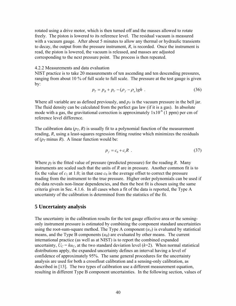
rotated using a drive motor, which is then turned off and the masses allowed to rotate freely. The piston is lowered to its reference level. The residual vacuum is measured with a vacuum gauge. After about 5 minutes to allow any thermal or hydraulic transients to decay, the output from the pressure instrument, R, is recorded. Once the instrument is read, the piston is lowered, the vacuum is released, and masses are adjusted corresponding to the next pressure point. The process is then repeated. 4.2.2 Measurements and data evaluation NIST practice is to take 20 measurements of ten ascending and ten descending pressures, ranging from about 10 % of full scale to full scale. The pressure at the test gauge is given by: ( )T R V f ap p p ghρ ρ= + − − . (36) Where all variable are as defined previously, and pV is the vacuum pressure in the bell jar. The fluid density can be calculated from the perfect gas law (if it is a gas). In absolute mode with a gas, the gravitational correction is approximately 1x10⁻⁶ (1 ppm) per cm of reference level difference. The calibration data (pT, R) is usually fit to a polynomial function of the measurement reading, R, using a least-squares regression fitting routine which minimizes the residuals of (pT minus R). A linear function would be: 0 1fp c c R= + . (37) Where pf is the fitted value of pressure (predicted pressure) for the reading R. Many instruments are scaled such that the units of R are in pressure. Another common fit is to fix the value of c1 at 1.0; in that case c0 is the average offset to correct the pressure reading from the instrument to the true pressure. Higher order polynomials can be used if the data reveals non-linear dependencies, and then the best fit is chosen using the same criteria given in Sec. 4.1.6. In all cases when a fit of the data is reported, the Type A uncertainty of the calibration is determined from the statistics of the fit. 5 Uncertainty analysis The uncertainty in the calibration results for the test gauge effective area or the sensing-only instrument pressure is estimated by combining the component standard uncertainties using the root-sum-square method. The Type A component (uA) is evaluated by statistical means, and the Type B components (uB) are evaluated by other means. The current international practice (as well as at NIST) is to report the combined expanded uncertainty, UC = kuC, at the two standard deviation level (k=2). When normal statistical distributions apply, the expanded uncertainty defines an interval having a level of confidence of approximately 95%. The same general procedures for the uncertainty analysis are used for both a crossfloat calibration and a sensing-only calibration, as described in [13]. The two types of calibration use a different measurement equation, resulting in different Type B component uncertainties. In the following section, values of
40

uncertainty components that are given are typical for routine calibrations at NIST. Reduced uncertainty values may be possible for special calibrations. 5.1 Uncertainties in a crossfloat calibration The standard uncertainty of the effective area of the calibration consists of Type A and Type B components added in quadrature: ( ) ( ) ( )2 2 2
, , , ,C e T Cal A e T B e Tu A u A u A= + . (38) The Type A component, uA(Ae,T), is due to random errors of the NIST standard, the test piston gauge, and the calibration process. Because the result of the calibration is an equation for the effective area, the Type A uncertainty is estimated from the standard deviation of the predicted values associated with the chosen least-squares fit equation (eqs. 28 to 35). Typical values of the Type A relative standard uncertainties range from 1x10⁻⁶ to 10x10-6, and can be a function of pressure. For a fit 1, the Type A uncertainty is constant over the pressure range, and is equal to the standard deviation of the residuals, σ, divided by the square root of the number of observations, n; or
,( )A e Tu An
σ= . (39)
For a fit 3, the Type A uncertainty has a minimum (given by eq. 39) at the mean pressure of the data, and increases as the pressure departs from the mean value. The Type B component is estimated from the uncertainty analysis of the measurement equation for the effective area of the customer’s piston gauge, given earlier as eq. (23):
( )( )( )( )( )( )
( ),, ,,
, ,, ,
,,
1 1 231 .
1 231
ai T T
p R c R R f ami Te T e R
T Tp T c T Tai R R
mi R
m g C T gh PA Ap pTm g C
ρ γα α ρ ρρ
α αρ γρ
⎛ ⎞− +⎜ ⎟⎜ ⎟ ⎛ ⎞+ + − − Δ⎝ ⎠ ⎜ ⎟= ⋅ ⋅ ⋅ + −
⎜ ⎟⎛ ⎞ + + − ⎝ ⎠− +⎜ ⎟⎜ ⎟⎝ ⎠
∑
∑ (40) The uncertainty of the Type B estimates of Ae,T are found using the Law of Propagation of Uncertainty [13]:
( )2 1
2 2,
1 1 1
( ) 2 ( ) ( ) ( , )N N N
B e T i i j i ji i j ii i j
f f fu A u x u x u x r x xx x x
−
= = = +
⎡ ⎤∂ ∂ ∂= +⎢ ⎥∂ ∂ ∂⎣ ⎦
∑ ∑ ∑ . (41)
In eq. (41), the measurement equation is represented symbolically as
41

42
( ), 1 2, ,...,e T NA f x x x= . (42) with x1, x2,…., xN the N variables (called components) on the right hand side of eq. (40).
i
fx
∂∂
is the partial derivative of Ae,T with respect to variable (component) xi, referred to as
the sensitivity coefficient. The standard uncertainty of each component is u(xi). The square of the standard uncertainty, u2(xi), is the variance. r(xi,xj) is the correlation coefficient between variables xi and xj. For a crossfloat calibration, the correlation coefficients are all zero except between the masses and between the densities of the same mass set. Determining the Type B uncertainty thus involves estimating the sensitivity coefficient and standard uncertainty of each component. The following notation is used for the uncertainty in Ae,T due to the uncertainty in component xi:
,( ) ( )e Txi i
i i
Afu u x ux x ix
∂∂= =
∂ ∂ . (43)
The combined standard Type B uncertainty is found by summing the individual variances and taking the square root:
( )
,
2 2 2 2 2 2 2 2 2 2,
2 2 2 2 2 2 2
e R R T a MR MT R T
R T R T f
B e T A M M C C g
T T h P
u A u u u u u u u u u u
u u u u u u uρ ρ ρ γ
α α ρ+ Δ
= + + + + + + + + +
+ + + + + + + +
2
. (44)
The correlation terms are included in the uxi terms as appropriate. The thermal expansion terms for the piston and cylinder for each gauge have been combined into a single variable ( cp ααα += ). Tables 4 and 5 list values for the component uncertainties for typical customer calibrations using NIST transfer standard piston gauges. Each table contains values at a single pressure: Table 4 is for oil at 5 MPa, and Table 5 is for gas at 200 kPa. Evaluations of the individual components will follow, including the sensitivity coefficient and the standard uncertainty. The tables list the definitions of the sensitivity coefficients for the components, values at the conditions of the calibration, values of the standard uncertainty of the components, and the product (eq. 43) which shows the effect of each component on the overall uncertainty in Ae,T. Components which have a relative standard uncertainty on Ae,T of 1.0x10⁻⁶ or greater are shown in bold. As can be seen from the Tables, many of the component uncertainties are negligible (< 1.0x10⁻⁷) when compared to the uncertainty of the effective area of the NIST piston gauges,
,e RAu . Uncertainties in mass, temperature, thermal expansion, fluid density, height difference, and pressure equilibrium should be considered in most cases. What follows are the definitions of the sensitivity coefficients and the standard uncertainties for each component, and comments about their significance or typical value for each term in eq. (44).

Table 4. Type B component standard uncertainties for gauge mode oil piston gauge calibration at 5 MPa, REF piston gauge is PG42, TEST piston gauge of nominal area 8.4x10⁻⁵ m2, and Spinesstic oil as pressure fluid. All uncertainty terms shown for completeness. Relative combined standard uncertainty is 1.20x10⁻⁵ (12.0 ppm).
Rel. unc.Name Symbol Value Units Definition Abs Value Units Value Units on A e,T
REF Area A e,R 8.402E-05 m2 1/A e,R 11901.89 m-2 9.24E-10 m2 1.10E-05REF Mass M R 42.86 kg -1/M R 2.33E-02 kg-1 1.24E-04 kg 2.89E-06
TEST Mass M T 42.85 kg 1/M T 2.33E-02 kg-1 1.24E-04 kg 2.89E-06
Ambient density ρ a 1.18 kg/m3 Δρ M /(ρ MT ρ MR ) -gh /p T
9.80E-08 m3/kg 0.030 kg/m3 2.94E-09
REF mass dens. ρ MR 7800 kg/m3 (ρ a,cal -ρ a )/ρ MR2 4.93E-10 m3/kg 45.0 kg/m3 2.22E-08
TEST mass dens. ρ MT 7800 kg/m3 (ρ a -ρ a,cal )/ρ MT2 4.93E-10 m3/kg 45.0 kg/m3 2.22E-08
Surface tension γ 3.06E-02 N/m CR /(M R g )(D R /D T -1) 9.33E-09 m/N 1.77E-03 N/m 1.65E-11REF piston circ. C R 3.25E-02 m -γ /(M R g ) 7.28E-05 1/m 3.25E-05 m 2.37E-09
TEST piston circ. C T 3.25E-02 m γ /(M T g ) 7.29E-05 1/m 3.25E-05 m 2.37E-09Gravity g 9.801011 m/s2 (ρ f - ρ a )h /p T 8.57E-06 s2/m 2.00E-06 m/s2 1.71E-11
REF therm. exp. α p,R + α c,R 9.10E-06 C-1 T R - 23.00 0.50 C 5.25E-07 C-1 2.63E-07TEST therm. exp. α p,T + α c,T 9.10E-06 C-1 -(T T - 23.00) 0.50 C 5.25E-07 C-1 2.63E-07REF temperature T R 23.50 C α p,R + α c,R 9.10E-06 C-1 0.058 C 5.25E-07
TEST temperature T T 23.50 C −(α p,T + α c,T ) 9.10E-06 C-1 0.058 C 5.25E-07Fluid density ρ f 857.8 kg/m3 gh /p T 9.80E-08 m3/kg 9.91 kg/m3 9.71E-07
Height difference h 0.05 m (ρ f - ρ a )g /p T 1.68E-03 1/m 0.001 m 1.68E-06Press. equilibrium ΔP 0.00 Pa -1/p T 2.00E-07 1/Pa 5.83 Pa 1.17E-06
1.20E-05Relative combinded standard unc.
Uncertainty term Standard uncertaintySensitivity coefficient divided by A e,T
43

44
Table 5. Type B component standard uncertainties for gauge mode gas piston gauge calibration at 200 kPa, REF piston gauge is PG34, TEST piston gauge of nominal area 8.4x10⁻⁵ m2, and nitrogen gas as pressure fluid. All uncertainty terms shown for completeness. Relative combined standard uncertainty is 5.27x10⁻⁶ (5.27 ppm).
Rel. unc.Name Symbol Value Units Definition Abs value Units Value Units on A e,T
REF Area A e,R 8.397E-05 m2 1/A e,R 11909 m-2 3.63E-10 m2 4.33E-06REF Mass M R 1.714 kg -1/M R 0.584 kg-1 3.43E-06 kg 2.00E-06
TEST Mass M T 1.714 kg 1/M T 0.583 kg-1 3.43E-06 kg 2.00E-06
Ambient density ρ a 1.18 kg/m3 Δρ M /(ρ MT ρ MR ) -gh /p T
9.80E-07 m3/kg 0.03 kg/m3 2.94E-08
REF mass dens. ρ MR 7800 kg/m3 (ρ a,cal -ρ a )/ρ MR2 4.93E-10 m3/kg 45.0 kg/m3 2.22E-08
TEST mass dens. ρ MT 7800 kg/m3 (ρ a -ρ a,cal )/ρ MT2 4.93E-10 m3/kg 45.0 kg/m3 2.22E-08
Surface tension γ 0.000 N/m CR /(M R g )(D R /D T -1) 3.11E-07 m/N 0.000 N/m 0.000REF piston circ. C R 3.25E-02 m -γ /(M R g ) 0.000 1/m 3.25E-05 m 0.000
TEST piston circ. C T 3.25E-02 m γ /(M T g ) 0.000 1/m 3.25E-05 m 0.000Gravity g 9.801011 m/s2 (ρ f - ρ a )h /p T 2.33E-07 s2/m 2.00E-06 m/s2 4.66E-13
REF therm. exp. α p,R + α c,R 9.10E-06 C-1 T R - 23.00 0.50 C 5.25E-07 C-1 2.63E-07TEST therm. exp. α p,T + α c,T 9.10E-06 C-1 -(T T - 23.00) 0.50 C 5.25E-07 C-1 2.63E-07REF temperature T R 22.50 C α p,R + α c,R 9.10E-06 C-1 0.058 C 5.25E-07
TEST temperature T T 22.50 C −(α p,T + α c,T ) 9.10E-06 C-1 0.058 C 5.25E-07Fluid density ρ f 3.51 kg/m3 gh /P T 9.80E-07 m3/kg 3.51E-03 kg/m3 3.44E-09
Height difference h 0.02 m (ρ f - ρ a )g /p T 1.14E-04 1/m 0.001 m 1.14E-07Press. equilibrium ΔP 0.00 Pa - 1/p T 5.00E-06 1/Pa 0.12 Pa 5.84E-07
5.27E-06Relative combinded standard unc.
Uncertainty term Standard uncertaintySensitivity coefficient divided by A e,T

5.1.1 Uncertainty due to reference area,
,e RAu
The sensitivity coefficient is given by:
, ,
, ,
e T e T
e R e R
A AA A
∂=
∂ . (45)
The standard uncertainty, u(Ae,R), is a function of the specific NIST piston gauge used. Equations to determine those values are given in Table 3. This term is always one of the largest contributors to the combined uncertainty. 5.1.2 Uncertainty due to mass on REF piston gauge,
RMu The sensitivity coefficient is given by:
, ,e T e T
R R
A AM M
∂= −
∂ . (46)
where . ∑= RiR mM ,
The standard uncertainty, u(MR) is more precisely the uncertainty of all the individual masses placed on the NIST piston gauge. The result depends on the degree of correlation among the masses that are used. Unless there is strong evidence to the contrary, NIST assumes that all the REF masses are correlated together, and that they are uncorrelated with the TEST masses. This is the most conservative approach. Hence, correlated uncertainties add algebraically, and there is no influence of the TEST masses: ,( ) (R
iu M u m= )i R∑ . (47)
This is the assumption for a standard cross-float calibration. This means that if all individual masses have a relative uncertainty of 2x10⁻⁶ (2 ppm), the relative uncertainty on the effective area will also be 2x10⁻⁶. In certain instances where the NIST piston gauge and the customer piston gauge are of the same design and same nominal area, the masses can be interchanged between gauges. Two observations can be made at each nominal pressure, with all masses switched between the observations except for the pistons. In that case, the Type B uncertainties in the loaded masses from the NIST and customer piston gauges cancel out and are not added to the combined Type B uncertainty. 5.1.3 Uncertainty due to mass on TEST piston gauge,
TMu The sensitivity coefficient is given by:
,e T e T
T T
A A ,
M M∂
=∂
. (48)
45

where ,T i TM m= ∑ . As in the REF masses, the standard uncertainty, u(MT) is more precisely the uncertainty of all the individual masses placed on the NIST piston gauge. The same considerations for assumed correlation apply for these masses. ,( ) (T i
iu M u m= )T∑ . (49)
Uncertainties in the REF and TEST masses are usually significant in the overall uncertainty in effective area. 5.1.4 Uncertainty due to ambient density,
auρ
The sensitivity coefficient is given by:
, ,
, , ,,
i R i T
i ie T mi R mi Te T
a R T
m mA ghA
TM M pρ ρ
ρ
⎡ ⎤⎛ ⎞⎢ ⎥⎜ ⎟∂ ⎢ ⎥⎜ ⎟= − −⎢ ⎥⎜ ⎟∂⎢ ⎥⎜ ⎟⎝ ⎠⎣ ⎦
∑ ∑ . (50)
If all the REF masses have the same density ρM,R and all the TEST masses have the same density ρM,T then this simplifies to:
, , ,,
, ,
e T M T M Re T
a M T M R
A ghATp
ρ ρρ ρ ρ
⎡ ⎤∂ −= −⎢ ⎥
∂ ⋅⎢ ⎥⎣ ⎦ . (51)
This assumption is made if the masses are taken from the same mass set. The ambient density is the same surrounding both the REF and TEST masses. The first term in the sensitivity coefficient is the effect of the ambient buoyancy on the masses, and the second term is the effect of the ambient density on the height difference between the reference levels of the piston gauges. Standard uncertainty, u(ρa). If the ambient gas is air (gauge mode calibration), the uncertainty in density due to imprecisely knowing the air temperature and pressure is larger than the uncertainty in the calculation function for the density (Appendix A). Even if u(ρa) = 0.03 kg/m3 and the difference in mass densities between REF and TEST is large, the relative uncertainty in Ae,T due to air density is less than 0.2x10⁻⁶ and is not significant. For absolute mode operation, the density of the air surrounding the masses and its uncertainty is extremely small, and can be taken as zero. 5.1.5 Uncertainty due to REF gauge mass density,
MRuρ
The sensitivity coefficient is gauge mode is:
46

( ),,
, 2, ,
a cal ae Te T
M R M R
AA
ρ ρρ ρ
−∂=
∂ . (52)
Here, ρa,cal is the density of the air at the time the masses were calibrated. To be conservative, the air density difference is taken as 0.03 kg/m3. We again assume that the individual densities of each mass on the REF gauge can be approximated by a common density. This expression assumes that the same numerical value of the mass density is used during the piston gauge calibration as when the masses were calibrated. If that value is changed, then the value of the mass must be changed as well. Because the mass calibration is effectively providing a force on the balance when the mass is weighed (and the mass value comes from inserting the mass density into the force equation), the density and mass must be considered together in the uncertainty of the density. (However, the mass uncertainty considered above, due to the mass calibration process, is not dependent on the density). The sensitivity coefficient in absolute mode is:
, ,, 2
, ,
e T a cale T
M R M
AA
R
ρρ ρ
∂=
∂ . (53)
Note that the sensitivity coefficient is larger in absolute mode calibrations. Standard uncertainty, u(ρM,R): The possible error in the mass density is assumed to have a rectangular distribution with ±0.01ρM,R maximum deviation from a nominal value, or a standard uncertainty of 0.0058ρM,R. The term is negligible for gauge mode calibrations and less than 1x10⁻⁶ in absolute mode calibrations. 5.1.6 Uncertainty due to TEST gauge mass density,
MTuρ
The sensitivity coefficients are similar to those for the reference mass density. In gauge mode it is:
( ),,
, 2, ,
a a cale Te T
M T M T
AA
ρ ρρ ρ
−∂=
∂ . (54)
and in absolute mode it is:
, ,, 2
, ,
e T a cale T
M T M
AA
T
ρρ ρ
∂= −
∂ . (55)
The same arguments apply for the TEST mass densities as for the REF mass densities.
47

Standard uncertainty, u(ρM,T): We use similar arguments as for the REF masses, so the standard uncertainty is therefore 0.0058ρM,T. The term is negligible for gauge mode and less than 1x10⁻⁶ in absolute mode calibrations. 5.1.7 Uncertainty due to fluid surface tension, uγ This term is zero for gas gauges, and negligible for oil gauges of the same nominal area. It needs to be considered only for pressures below 5 MPa and when the nominal areas between the NIST and customer piston gauge differ by a factor of 5. In those cases, the sensitivity coefficient is (with DR and DT the diameters of the REF and TEST piston gauges):
,, 1e T R R
e TR T
A C DAM g Dγ
∂ ⎛ ⎞= ⋅ −⎜ ⎟∂ ⎝ ⎠
. (56)
Standard uncertainty, u(γ). A reasonable assumption is that the surface tension uncertainty is a rectangular distribution of possible relative errors of 10 % of γ. Hence u(γ)=0.058γ. 5.1.8 Uncertainty due to REF piston circumference,
RCu This term is always negligible. For completeness, the sensitivity coefficient is:
,,
e Te T
R R
AA
C M gγ∂
= − ⋅∂
. (57)
5.1.9 Uncertainty due to TEST piston circumference,
TCuThis term is always negligible. For completeness, the sensitivity coefficient is:
,,
e Te T
T T
AA
C M gγ∂
= ⋅∂
. (58)
5.1.10 Uncertainty due to acceleration of gravity, gu The sensitivity coefficient is:
,,
( )f ae Te T
T
hAA
g pρ ρ−∂
=∂
. (59)
In absolute mode, ρa is taken as zero for this term. Because gravity is identical at the REF and TEST masses (even if there is uncertainty on what the value is), the uncertainty on force at the REF piston gauge due to the uncertainty in gravity will cancel with uncertainty on force at the TEST piston gauge due to the uncertainty in gravity. The only contribution to the sensitivity coefficient is the pressure difference due to the difference in reference levels.
48

Standard uncertainty, u(g): The standard uncertainty in g, based on measurements in the NIST calibration laboratory, is 2x0-6 m/s2. gu is negligible for all crossfloats. 5.1.11 Uncertainty due to thermal expansion of the REF piston and cylinder,
Ruα
The sensitivity coefficient is:
,, ( 23e T
e T RR
AA T
α)
∂= −
∂ . (60)
This sensitivity coefficient becomes larger as the temperature of the reference piston gauge departs from 23 ºC. Standard uncertainty, )( Ru α : NIST uses the manufacturer’s stated thermal expansion for the transfer standard piston gauges. We estimate that the uncertainty of the thermal expansion is represented by a rectangular distribution of possible relative errors of 0.1 of the stated value. Hence the standard uncertainty is ( ) 0.058Ru Rα α= . For a tungsten carbide piston and cylinder, 69 10R xα − m/(mK), 6( ) 0.5 10Ru xα −= m/(mK), and the relative uncertainty
Ruα is 0.5x10⁻⁶ if TR is within 1 ºC of 23 ºC. If the temperature is kept
close to the reference temperature, this term is small compared to the uncertainty in the NIST standard, but it should be included. 5.1.12 Uncertainty due to thermal expansion of the TEST piston and cylinder,
Tuα
The sensitivity coefficient is:
,, ( 23e T
e T TT
AA T
α)
∂= − −
∂ . (61)
This sensitivity coefficient becomes larger as the temperature of the customer’s piston gauge departs from the reference temperature (taken as 23 ºC unless otherwise requested). Standard uncertainty, ( )Tu α : NIST uses the manufacturer’s stated thermal expansion for the customer’s piston gauges. We estimate that the uncertainty of the thermal expansion is represented by a rectangular distribution of possible relative errors of 0.1 of the stated value. Hence the standard uncertainty is ( ) 0.058Tu Tα α= . As for the REF piston gauge, for a tungsten carbide piston and cylinder,
Tuα is 0.5x10⁻⁶ if TT is within 1 ºC of 23 ºC. If
the temperature is kept close to the reference temperature, this term is small compared to the uncertainty in the NIST standard, but it should be included. 5.1.13 Uncertainty due to temperature of REF piston and cylinder,
RTu The sensitivity coefficient is:
49

,,
e Te T R
R
AA
Tα
∂=
∂ . (62)
The standard uncertainty, u(TR) is determined assuming a rectangular distribution of possible errors of 0.1 ºC, so u(TR) = 0.058 ºC. A good-quality calibrated thermometer will have an uncertainty better than this, however it is difficult to place the thermometer close to the piston or cylinder, and this uncertainty allows for spatial or time-dependent temperature differences. With tungsten-carbide pistons, the relative uncertainty
RTu is 0.5x10⁻⁶. 5.1.14 Uncertainty due to temperature of TEST piston and cylinder,
TTuThe sensitivity coefficient is:
,,
e Te T T
T
AA
Tα
∂= −
∂ . (63)
The standard uncertainty, u(TT) is determined assuming a rectangular distribution of possible errors of 0.1 ºC, so u(TT) = 0.058 ºC. A good-quality calibrated thermometer will have an uncertainty better than this, however it is difficult to place the thermometer close to the piston or cylinder, and this uncertainty allows for spatial or time-dependent temperature differences. With tungsten-carbide pistons, the relative uncertainty is 0.5x10⁻⁶.
TTu
5.1.15 Uncertainty due to density of pressure fluid,
fuρ
The sensitivity coefficient is:
,,
e Te T
f T
A ghApρ
∂=
∂ . (64)
Standard uncertainty, u(ρf). This term depends on the fluid used. For oils, NIST assumes a rectangular distributions of possible errors of 0.02ρf , hence the standard uncertainty is 0.012ρf . At atmospheric pressure, common hydraulic oils have densities from 860 kg/m3 to 910 kg/m3. The uncertainty term can become significant for pressures below about 10 MPa, especially if h is 0.1 m or greater. For gases below 1 MPa, the uncertainty in density is due to possible differences in temperature along the tubing connecting the gauges. Taking a rectangular distribution of possible errors of 0.5 ºC, u(ρf) = 0.001ρf. The uncertainty term is negligible for h less than 1 m. Above 1 MPa, the density begins to depart from the perfect gas model used in our data reduction program. As long as h is less than 0.1 m, the uncertainty term is less than 0.2x10⁻⁶. 5.1.16 Uncertainty due to reference height difference, uh
50

The sensitivity coefficient is:
,,
( )f ae Te T
T
gAA
h pρ ρ−∂
=∂
. (65)
Standard uncertainty, u(h): The height difference between the gauges is the sum of the difference in the reference levels, hT0-hR0, and the difference between the bottom of each piston position and its reference level (hT-hT0, hR-hR0). Or, . (66) 0 0 0 0( ) ( ) (T R T R T T R Rh h h h h h h h h= − = − + − − − ) The difference in reference levels is measured prior to the calibration. For its uncertainty we assume rectangular distribution with a maximum possible error of 1x10⁻³ m. The other two terms are nominally equal to zero, however the uncertainty is not. The pistons fall during normal operation, and are intermittently raised above the nominal position to allow operational time while establishing equal pressures. For each of the two terms, we take a rectangular distribution of errors with a maximum of 1x10⁻³ m. The combined standard uncertainty is u(h) = 1x10⁻³ m. The term uh is always insignificant for gas gauges. For oil gauges, the relative uncertainty is 1x10⁻⁶ at 10 MPa, and increases as the pressure decreases. 5.1.17 Uncertainty due to pressure difference, uΔP The sensitivity coefficient is:
,,
1e Te T
T
AA
P P∂
= −∂Δ
. (67)
Standard uncertainty, u(ΔP), depends on the method used for determining pressure equilibrium. For the fall rate or DP cell methods, the operator must make a judgment of the standard uncertainty. One method is to estimate the amount of mass, ΔM, that can be added to one of the piston gauges to unequivocally disturb the balance from equilibrium. This can be converted to a pressure using the approximation:
( ) ( )e
gu P u MA
Δ = Δ . (68)
Here, Ae refers to whichever piston gauge was “trimmed” with ΔM. Typical values for gas gauges are u(ΔM) = 1 to 5 mg; typical values for hydraulic gauges are 25 mg to 100 mg. These uncertainties become more significant at the low-pressure end of each calibration. If equilibrium is determined by the TAC method, then u(ΔP) is given by the scatter of the measured pressure differences. 5.1.18 Summary of uncertainties in a crossfloat calibration
51

The Type B combined relative standard uncertainties for typical crossfloat calibrations of a customer’s piston gauge are shown in Tables 4 and 5. For the oil calibration at 5 MPa, the Type B relative standard uncertainty is 12x10-6, with the dominant component being the standard uncertainty in the effective area of the NIST piston gauge. If the Type A relative standard uncertainty were 5x10⁻⁶, then the combined relative standard uncertainty would be 13x10-6, with an expanded relative uncertainty (k=2) of 26x10-6 (26 ppm). For the gas piston gauge calibration at 200 kPa, the Type B relative standard uncertainty is 5.3x10⁻⁶, again dominated by the standard uncertainty in effective area of the NIST piston gauge (4.3x10⁻⁶). An uncertainty analysis including all these components is conducted over the pressure range of the calibration, and is summarized in the calibration report to the customer (Appendix B). 5.2 Uncertainty in pressure sensing-only calibration For a pressure-sensing only calibration, the measurand is pressure produced by the NIST transfer standard at the level of the customer’s instrument. The method for the uncertainty analysis is the same as for the crossfloat calibration, i.e., the uncertainty of the pressure of the calibration consists of Type A and Type B components added in quadrature: ( ) ( ) ( )2 2 2
c T A T B Tu p u p u p= + . (69) The Type A component is due to random errors of the NIST standard, the customer’s instrument, and the calibration process. The Type A uncertainty is estimated from the statistics of the fit provided to the customer. The Type B component is estimated from the uncertainty analysis of the measurement equation for the pressure of the customer’s instrument, which is found by substituting eq. (3) for the pressure from the NIST standard piston gauge into eq. (36) for the pressure at the customer’s instrument:
( )( )( ) ( )
1
1 23
ai
i miT V
e p c
m g C
f ap p gA T
ρ γρ
ρ ρα α
⎛ ⎞− +⎜ ⎟
⎝ ⎠= + −+ + −
∑h− . (70)
The notation of “REF” for the NIST piston gauge standard has been dropped since it is the only piston gauge in the measurement equation. The Type B uncertainty follows from estimating the sensitivity coefficient of each variable, ∂pT/∂xi, and the standard uncertainty of the variable, u(xi). The following notation is used for the uncertainty in pT due to the uncertainty in variable xi that is uncorrelated with other variables:
( )Txi i
i
pu ux
x∂=
∂ . (71)
52

53
Hence the Type B combined standard uncertainty can be written as6: ( )2 2 2 2 2 2 2 2 2 2 2 2
e a M fB T A M C g T h pu p u u u u u u u u u u u uρ ρ γ α ρ= + + + + + + + + + + + 2V
. (72) Table 6 summarizes the Type B component uncertainties for a pressure instrument calibration using PG22 as the NIST piston gauge in absolute mode. The calibration gas is nitrogen, and the pressure is 100 kPa. Shown are the definitions of each sensitivity coefficient, their magnitude, the magnitude of the standard uncertainties of the components, and the relative contribution of each component to the uncertainty in pT. In this example, the relative Type B standard uncertainty in pressure is about 6.1x10⁻⁶ (6.1 ppm), and it is dominated by the uncertainty in effective area of PG22. Components of decreasing importance to the overall uncertainty are mass, density of the masses, piston gauge temperature, piston gauge thermal expansion, and gravity. Details for each component follow. 5.2.1 Uncertainty due to reference area,
eAu The sensitivity coefficient is given by:
T T
e e
p pA A
∂= −
∂ . (73)
The standard uncertainty, u(Ae), is a function of the specific NIST piston gauge used. Equations to determine those values are given in Table 3. This term is always one of the largest contributors to the combined uncertainty. 5.2.2 Uncertainty due to mass, Mu
The sensitivity coefficient is given by:
T Tp pM M
∂=
∂ , (74)
where iM m= ∑ . The standard uncertainty, u(M) is more precisely the uncertainty of all the individual masses placed on the NIST piston gauge. The result depends on the degree of correlation among the masses that are used. Unless there is strong evidence to the contrary, NIST assumes that all the masses are correlated, and that the correlated uncertainties add algebraically. ( ) ( )iu M u m= ∑ . (75)
6 If the customer’s pressure instrument is read with an electronic instrument, such as a voltmeter, the Type B uncertainty of that instrument should be added in quadrature with the other terms of eq. (72).
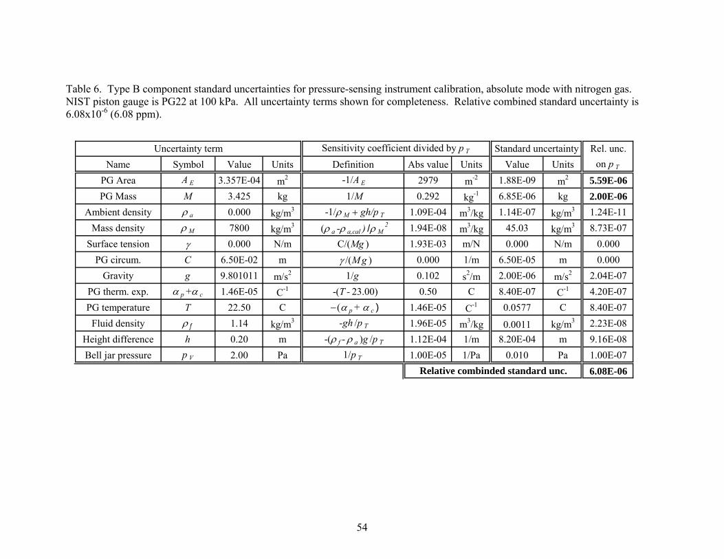
Table 6. Type B component standard uncertainties for pressure-sensing instrument calibration, absolute mode with nitrogen gas. NIST piston gauge is PG22 at 100 kPa. All uncertainty terms shown for completeness. Relative combined standard uncertainty is 6.08x10⁻⁶ (6.08 ppm).
Rel. unc.Name Symbol Value Units Definition Abs value Units Value Units on p T
PG Area A E 3.357E-04 m2 -1/A E 2979 m-2 1.88E-09 m2 5.59E-06PG Mass M 3.425 kg 1/M 0.292 kg-1 6.85E-06 kg 2.00E-06
Ambient density ρ a 0.000 kg/m3 -1/ρ M + gh/p T 1.09E-04 m3/kg 1.14E-07 kg/m3 1.24E-11Mass density ρ M 7800 kg/m3 (ρ a -ρ a,cal ) /ρ M
2 1.94E-08 m3/kg 45.03 kg/m3 8.73E-07Surface tension γ 0.000 N/m C/(Mg ) 1.93E-03 m/N 0.000 N/m 0.000
PG circum. C 6.50E-02 m γ /(M g ) 0.000 1/m 6.50E-05 m 0.000Gravity g 9.801011 m/s2 1/g 0.102 s2/m 2.00E-06 m/s2 2.04E-07
PG therm. exp. α p +α c 1.46E-05 C-1 -(T - 23.00) 0.50 C 8.40E-07 C-1 4.20E-07PG temperature T 22.50 C − (α p + α c ) 1.46E-05 C-1 0.0577 C 8.40E-07
Fluid density ρ f 1.14 kg/m3 -gh /p T 1.96E-05 m3/kg 0.0011 kg/m3 2.23E-08Height difference h 0.20 m -(ρ f - ρ a )g /p T 1.12E-04 1/m 8.20E-04 m 9.16E-08Bell jar pressure p V 2.00 Pa 1/p T 1.00E-05 1/Pa 0.010 Pa 1.00E-07
6.08E-06Relative combinded standard unc.
Uncertainty term Sensitivity coefficient divided by p T Standard uncertainty
54

5.2.3 Uncertainty due to ambient density, a
uρ The sensitivity coefficient is:
T T
a m
p p ghρ ρ
∂= − +
∂ . (76)
The first term in the sensitivity coefficient is the effect of the ambient density on the masses, and the second term is the effect of the ambient density on the height difference between the reference level of the customer’s instrument and the NIST piston gauge. For absolute mode operation, the ambient density surrounding the masses is extremely small, and its standard uncertainty, u(ρa), can be taken as zero. In that case the uncertainty contribution due to ambient density is also zero. Table 6 displays a value for u(ρa) that is determined by the uncertainty in residual pressure in the space surrounding the masses. For gauge mode operation, the ambient gas is air and the uncertainty in density due to imprecisely knowing the air temperature and pressure is typically larger than the uncertainty in the calculation function (Appendix A). If u(ρa) = 0.03 kg/m3, the relative uncertainty in pT due to the uncertainty in the air density is about 4x10⁻⁶. The uncertainty in ambient density has a larger effect on the combined uncertainty in a sensing-only calibration than in a piston gauge calibration for gauge mode. In the crossfloat, both sets of masses are exposed to the same buoyancy correction, so the uncertainty due to air density cancels out. Here, only one set of masses is exposed to air, and more care should be taken in identifying the uncertainty contribution of the ambient density. 5.2.4 Uncertainty due to mass density,
Muρ
The sensitivity coefficient in gauge mode is given by:
( ),
2a a calT
TM M
p pρ ρ
ρ ρ−∂
=∂
. (77)
Here, ρa,cal is the density of the air at the time the masses were calibrated. To be conservative, the air density difference is taken as 0.03 kg/m3. It is assumed that the individual densities of each mass on the piston gauge can be approximated by a common density. This expression assumes that the same numerical value of the mass density is used during the pressure calibration as when the masses were calibrated. If that value is changed, then the value of the mass must be changed as well. In absolute mode the ambient density is negligible, and the sensitivity coefficient is given by:
,2
a calTT
M M
p pρ
ρ ρ∂
= −∂
. (78)
55

The same mass density uncertainty has a larger effect on absolute mode calibrations than it does on gauge mode calibrations. Standard uncertainty, u(ρM): The possible error in the mass density is assumed to have a rectangular distribution with ±0.01ρM maximum deviation from a nominal value, or a standard uncertainty of 0.0058ρM. The term is negligible for gauge mode calibrations and less than 1x10⁻⁶ in absolute mode calibrations. 5.2.5 Uncertainty due to fluid surface tension, uγ The sensitivity coefficient is given by:
TT
p CpMgγ
∂=
∂ . (79)
If the calibration is done in gas, the surface tension and standard uncertainty are zero. If the calibration is in oil, a reasonable assumption is that the surface tension uncertainty is a rectangular distribution of possible relative errors of 10 % of γ. Hence u(γ)=0.058γ. The term is negligible above 5 MPa, and even at 1 MPa the relative contribution is less than 1.0x10⁻⁶. 5.2.6 Uncertainty due to piston circumference, CuThis term is always negligible, whether gas or oil is used for the NIST piston gauge. For completeness, the sensitivity coefficient is:
TT
p pC Mg
γ∂=
∂ . (80)
5.2.7 Uncertainty due to acceleration of gravity, gu The sensitivity coefficient is:
T Tp pg g
∂=
∂ . (81)
The term due to elevation change has been neglected, as it is always much smaller than the term due to mass on the piston gauge. The standard uncertainty, u(g), at NIST is 2.0x10⁻⁶ m/s2, making the relative contribution of gu equal to 0.2x10⁻⁶. Gravity has a larger effect on the uncertainty of the measurand in a sensing-only calibration than in a piston gauge crossfloat calibration, but it is still small compared to the uncertainty in the NIST piston gauge effective area. 5.2.8 Uncertainty due to thermal expansion of piston and cylinder, uα The sensitivity coefficient is:
( 23TT
p p Tα
)∂= − −
∂. (82)
56

This sensitivity coefficient becomes larger as the temperature of the NIST piston gauge departs from 23 ºC. Standard uncertainty, ( )u α : NIST uses the manufacturer’s stated thermal expansion for the transfer standard piston gauges. We estimate that the uncertainty of the thermal expansion is represented by a rectangular distribution of possible relative errors of 0.1 of the stated value. Hence the standard uncertainty is ( ) 0.058u α α= . For the piston gauge used near 100 kPa, the piston is stainless steel and the cylinder is tungsten carbide, so
51.5 10α −× m/(mK), 6( ) 0.5 10u α −= × m/(mK). The relative uncertainty uα is 0.5x10⁻⁶ if T is within 1 ºC of 23 ºC. If the temperature is kept close to the reference temperature, this term is small compared to the uncertainty in the NIST standard, but it should be included. 5.2.9 Uncertainty due to temperature of piston and cylinder, TuThe sensitivity coefficient is:
TT
p pT
α∂= −
∂ . (83)
The standard uncertainty, u(T) is determined assuming a rectangular distribution of possible errors of 0.1 ºC, so u(T) = 0.058 ºC. A good-quality calibrated thermometer will have an uncertainty better than this, however it is difficult to place the thermometer close to the piston or cylinder, and this uncertainty allows for spatial or time-dependent temperature differences. With stainless steel pistons/tungsten carbide cylinders used at 100 kPa, the relative uncertainty is 0.8x10⁻⁶. Tu 5.2.10 Uncertainty due to density of pressure fluid,
fuρ
The sensitivity coefficient is:
T
f
p ghρ
∂= −
∂ . (84)
Standard uncertainty, u(ρf). This term depends on the fluid used. For oils, NIST assumes a rectangular distributions of possible errors of 0.02ρf , hence the standard uncertainty is 0.012ρf . At atmospheric pressure, common hydraulic oils have densities from 860 kg/m3 to 910 kg/m3. The uncertainty term can become significant for pressures below about 10 MPa, especially if h is 0.1 m or greater. For gases below 1 MPa, the uncertainty in density is due to possible differences in temperature along the tubing connecting the gauges. Taking a rectangular distribution of possible errors of 0.5 ºC, u(ρf) = 0.001ρf. The uncertainty term is negligible for h less than 1 m. Above 1 MPa, the density begins to depart from the perfect gas model used in
57

our data reduction program. As long as h is less than 0.1 m, the uncertainty term is less than 0.2x10⁻⁶. 5.2.11 Uncertainty due to reference height difference, uh The sensitivity coefficient is:
( )Tf a
p gh
ρ ρ∂= − −
∂ . (85)
Standard uncertainty, u(h): The height difference between the piston gauge and customer’s instrument is the sum of the difference in the reference levels, hT-hR0, and the difference between the bottom of the piston position and its reference level (hR-hR0). Or, . (86) 0 0( ) (T R T R R Rh h h h h h h= − = − − − ) The difference in reference levels is measured prior to the data-taking. For its uncertainty, NIST takes a rectangular distribution with a maximum possible error of 1x10⁻³ m. The other term is nominally equal to zero, however the uncertainty is not. The piston falls during normal operation, and is intermittently raised above the nominal position to allow operational time during the drop. NIST takes a rectangular distribution of errors with a maximum of 1x10⁻³ m. The combined standard uncertainty is u(h) = 0.8x10⁻³ m. The contribution of uh to the uncertainty in pT is always negligible when the NIST piston gauge uses gas. When oil is used, the relative magnitude is 1x10⁻⁶ at 8 MPa, and increases as 1/pT as the pressure decreases. 5.2.12 Uncertainty due to vacuum pressure, (absolute mode only)
VpuThe sensitivity coefficient is:
1T
V
pp
∂=
∂. (87)
The standard uncertainty, u(pV), depends on the vacuum gauge used to measure the pressure in the bell jar. NIST uses a calibrated capacitance diaphragm gauge. When calibrated, these gauges have a standard uncertainty of 0.05 % of reading. The long-term stability uncertainty is typically 0.5 % of reading. A typical vacuum pressure in an absolute mode calibration is 2 Pa (this depends on the gas flow in the piston-cylinder gap and the capacity of the vacuum pump to evacuate the bell jar). Using these conditions, the standard uncertainty is 0.01 Pa. The relative contribution to the uncertainty in pressure is 0.1x10⁻⁶ at 100 kPa, and 1x10⁻⁶ at 10 kPa.
58

6 Quality system The calibration services performed by the piston gauge standards which are described in this document are support by the NIST quality system. The NIST quality system documentation consists of tiered quality manuals, ranging form the highest level (QM-I) to the Division level (QM-IIs) to the Service level (QM-IIIs). The NIST quality manual (QM-I) is found at http://ts.nist.gov/QualitySystem/ The integrity, reliability, and traceability of the NIST measurement services relies on the NIST Quality System for Measurement Services, which is based on the ISO/IEC 17025 (General requirements for the competence of testing and calibration laboratories) [14] and the relevant requirements of ISO/IEC Guide 34 (General requirements for the competence of reference material producers) [15]. The scope of the NIST Quality System includes the delivery of Calibration Services and the development and certification of Standard Reference Materials. The Measurement Services Advisory Group (MSAG) at NIST serves as the corporate quality manager; they are assisted by staff from the National Voluntary Laboratory Accreditation Program for the implementation of the quality system. The NIST quality system for measurement services satisfies the requirements of the International Committee for Weights and Measures (CIPM) Mutual Recognition Arrangement (MRA) [16] for recognition of national measurement standards; and as such, has been recognized as conformant to the ISO/IEC 17025 and ISO Guide 34 by the Inter-American Metrology System (SIM) Quality System Task Force and the Joint Committee of the Regional Metrology Organizations and the BIPM (JCRB). The BIPM is the International Bureau of Weights and Measures. In order to maintain compliance with the MRA, NIST participates in a large number of international comparisons with other NMIs to support our calibration measurement capabilities and uncertainty claims. Comparisons relevant to the present calibration service can be found at http://kcdb.bipm.org/AppendixB/KCDB_ApB_search.asp, searching on Metrology Area = Mass, Branch = pressure, and Country = United States.
59

7 References 1. NIST Calibration Program, Calibration Services Users Guide SP250 Appendix (2009). 2. Dadson, R.S., Lewis, S.L., and Peggs, G.N., “The pressure balance: theory and practice”, Her Majesty’s Stationery Office, London (1982). 3. Schmidt., J.W., Jain, K., Miiller, A.P., Bowers, W.J., and Olson, D.A., “Primary pressure standards based on dimensionally characterized piston/cylinder assemblies”, Metrologia 43 (2006) 53-59. 4. Bean, V.E., “NIST pressure calibration service”, NIST Special Publication 250-39, US Department of Commerce, Technology Administration, National Institute of Standards and Technology (1994). 5. Veale, R.C., “NBS report of calibration M3565”, Precision Engineering Division (1989). 6. Jain, K., Bowers, W., and Schmidt, J.W., “A primary dead-weight tester for pressures (0.05-1.0) MPa”, J. Res. Natl. Inst. Stand. Technol. 108 (2003) 135-145. 7. Heydemann P.L.M., and Welch, B.E., “Piston Gauges”, in Experimental Thermodynamics, vol. 2, ed. B. Leneindre and B. Voder, London: Butterworths (1975) 147-201. 8. Bandyopadhyay, A.K., and Olson, D.A., “Characterization of a compact 200 MPa controlled clearance piston gauge as a primary standard using the Heydemann and Welch method”, Metrologia 43 (2006) 573-582. 9. Picard, A. Davis, R.S., Gläser, M., and Fujii, K., “Revised formula for the density of moist air (CIPM-2007), Metrologia 45 (2008) 149-155. 10. Markus, W., “A constant volume valve”, Review of Scientific Instruments 43 (1) (1972) 158-159. 11. Kobata, T., and Olson, D. A., “Automating the Calibration of Two Piston Gage Pressure Balances”, Proceedings of the National Conference of Standards Laboratories International, (2002) August. 12. Kobata, T., and Olson, D.A., “Accurate Determination of Equilibrium State Between Two Pressure Balances Using a Pressure Transducer”, Metrologia 42 (2005) S231-S234. 13. B.N. Taylor and C.E. Kuyatt, “Guidelines for evaluating and expressing the uncertainty of NIST measurements and results”, NIST Technical Note 1297, (1994). 14. ISO/IEC 17025:2005(E), “General requirements for the competence of testing and calibration laboratories” (2005). 15. ISO Guide 34:2000(E), “General requirements for the competence of reference material producers” (2000). 16. CIPM, “Mutual recognition of national measurement standards and of calibration and measurement certificates issued by national metrology institutes”, www.bipm.org/utils/en/pdf/mra_2003.pdf, (1999, rev. 2003).
60

Appendix A. Recommended formula for the calculation of the density of moist air and its uncertainty A.1 The CIPM-2007 equation The following is a summary of the method described in [9] for the calculation of the density of moist air, known as CIPM-2007. The formulation begins with the equation of state for the air density:
1 1a va v
a
pM MxZRT M
ρ⎡ ⎤⎛ ⎞
= − −⎢ ⎥⎜ ⎟⎢ ⎥⎝ ⎠⎣ ⎦
. (88)
The quantities and units are p air pressure in Pa t air temperature in ºC T thermodynamic temperature in K, T = 273.15+t xv mole fraction of water vapor Ma molar mass of dry air in kg mol-1
Mv molar mass of water in kg mol-1
Z compressibility factor R molar gas constant in J mol-1 K-1. The value of R is given as: 1 18.314472 J mol KR − −= . The composition of dry air is given in Table 1 of [9], assuming the mole fraction of CO2 is . With those components and their mole fractions, the value of Ma is
2CO 0.0004x = 3 128.96546 10 kg molaM − −= × . If the mole fraction of
2COx is available, Ma is given by: ( )2
3 1CO28.96546 12.011 0.0004 10 kg molaM x − −⎡ ⎤= + ⋅ − ×⎣ ⎦ . (89)
The molar mass of water vapor is given by: 3 118.01528x10 kg molvM − −= . To within typical values of
2COx and uncertainties of other quantities in the formula,
1 0.3780v
a
MM
− = .
61

Substituting eq. (89) and values of the quantities into eq. (88), the formula for ρa in kg/m3 becomes:
( ) ( )2
3CO3.483740 1.4446 0.0004 1 0.3780 10a v
px xZT
ρ −⎡ ⎤= + ⋅ − ⋅ − ×⎣ ⎦ . (90)
Using the formula is:
2CO 0.0004x =
( ) 33.483740 1 0.3780 10ap x
ZTρ v
−= ⋅ − × . (91)
Hence to calculate the density of moist air, p and t are measured, along with either the relative humidity or the dew point temperature. xv and Z are calculated (see below) from the measured quantities; finally ρa is computed from eq. (90) or (91). A.2 Calculation of xv from the measurement of relative humidity or dew-point temperature The mole fraction of water vapor is given by:
( ) ( )( ) ( ), ,sv sv d
v dp t px hf p t f p t tp p
= ⋅ = ⋅ . (92)
Here, h is the relative humidity, td is the dew-point temperature, f is the enhancement factor (which is a function of p and t or td), and psv is the vapor pressure at saturation. Either h or td can be measured to determine xv. psv is given by: ( )21 Pa exp /svp AT BT C D T= × + + + . (93) T is the temperature in K. The constants are given by:
5 2
2 1
3
1.2378847 10 K ,1.9121316 10 K ,
33.93711047 ,6.3431645 10 K .
ABCD
− −
− −
= ×
= − ×=
= − ×
Finally, the enhancement factor, f, is given by: 2f p tα β γ= + + , (94) with the constants given by:
62

8 1
7 2
1.00062 ,3.14 10 Pa ,5.6 10 K .
α
β
γ
− −
− −
=
= ×
= ×
t is the temperature in ºC. A.3 Calculation of compressibility factor, Z The equations for Z and its constants are given by:
( ) ( ) ( )2
2 20 1 2 0 1 0 1 21 v v
p p 2vZ a a t a t b b t x c c t x d ex
T T⎡ ⎤= − ⋅ + + + + + + + ⋅ +⎣ ⎦ . (95)
The constants in the equation are given by:
6 10
8 11
10 1 12
6 10
8 11
4 10
6 11
11 2 2
8 2 2
1.58123 10 K Pa ,
2.9331 10 Pa ,
1.1043 10 K Pa ,
5.707 10 K Pa ,
2.051 10 Pa ,
1.9898 10 K Pa ,
2.376 10 Pa ,
1.83 10 K Pa ,0.765 10 K Pa
a
a
a
b
b
c
c
de
− −
− −
− − −
− −
− −
− −
− −
− −
− −
= ×
= − ×
= ×
= ×
= − ×
= ×
= − ×
= ×
= − × . A.4 Uncertainty of the formula and range of application The relative standard uncertainty of the formula is given in [9] as 2.2x10⁻⁵. The recommended ranges in pressure and temperature over which it can be used are:
60 kPa ≤ p ≤ 110 kPa
15 ºC ≤ t ≤ 27 ºC.
63

64
Appendix B. Sample calibration report of a customer piston gauge Report follows on next page

UNITED STATES DEPARTMENT OF COMMERCE NATIONAL INSTITUTE OF STANDARDS AND TECHNOLOGY
GAITHERSBURG, MARYLAND
REPORT OF CALIBRATION Pressure & Vacuum Group
Bldg 220, Room B43 Requester: No One In Particular 123 Main Street Your Home Town, MD 20899 Test Instrument Data: Manufacturer: ABC Instrument Company Model: 9999 Serial Number: None Piston Number: 99-000 Cylinder Number: 99-000 Maximum Pressure: 28 MPa Cylinder Type: Re-Entrant Thermal Expansion Coefficient of Piston: 4.55x10⁻⁶/ ºC Thermal Expansion Coefficient of Cylinder: 4.55x10⁻⁶/ ºC Nominal Piston Area: 8.4x10⁻⁵ m2
Test Record Data: Purchase Order Number and Date: XXXXX Dated 01/01/09 NIST Identification Number: P-9999A NIST Test Folder Number: TN-999999-09 Date Instrument was Received: January 1, 2009 Date Test was Completed: March 1, 2009
Test Conditions: NIST Standard and Calibration Reference: PG42, Dec 1996 Reference Temperature: 23 ºC Mode of Operation: Gauge Pressure Fluid: Spinesstic Oil Pressure Range of Calibration: 1.4 to 26 MPa Surface Tension of Fluid: 0.0 Rotation of Weights: Manual Test Gauge Weights Provided by: NIST The test gauge was leveled so that the axis of rotation was vertical. Reference level of test piston: The reference level was 0.080 meter below the uppermost surface of
the piston. The gauge was operated at mid-stroke.
The suggested fit for the effective area of the test gauge in m2, is Afit = 8.401099x10⁻⁵ (1 – 2.269x10⁻¹² P) , with P in Pa.
The expanded relative uncertainty in the effective area of the test gauge, including the uncertainty of the NIST standard, ranges from 24x10-6 (24 ppm) to 30x10-6 (30 ppm).
65

The test gauge was cross-floated against the NIST standard. The calibration data are given in Table 1. The pressures (P) are at the reference level of the test gauge as determined by the NIST standard gauge. The temperature corrected forces (F) on the test gauge were calculated using the expression
( )( )231
1
−++
+⎟⎟⎠
⎞⎜⎜⎝
⎛−
=∑
T
CgmF
cp
i mi
ai
αα
γρρ
,
where mi are the masses of the piston, weight hanger and weights corresponding to P, ρa is the density of the ambient air, ρmi is the density of the material from which the weights are made, g is the local acceleration due to gravity, γ is the surface tension of the pressurizing fluid, C is the circumference of the piston in the test gauge, αp and αc are the linear thermal expansion coefficients of the piston and cylinder, and T is the temperature in degrees C of the test gauge when operating at pressure P. Also listed in Table I is the effective area (A) of the test gauge at each pressure calculated using the expression: /A F P= . To obtain an expression for predicting the effective area at any pressure, the P and A data were fitted to the following eight equations using the method of least squares: (fit 1) 0fitA A=
0 /fitA A t P= − (fit 2)
(0 11fit )A A b P= + (fit 3)
(fit 4) ( )0 11fitA A b P t= + − / P
)/
(fit 5) ( 20 1 21fitA A b P b P= + +
( )20 1 21fitA A b P b P t= + + − P
)/ P
(fit 6)
(fit 7) ( 20 21fitA A b P= +
. (fit 8) ( )20 21fitA A b P t= + −
The regression coefficients are interpreted as follows: A0 is the extrapolated area at zero applied pressure and at 23 °C; b1 and b2 are the first and second order pressure coefficients for the area; and t allows for the possibility of a “tare”. The suggested fit based on the calibration data is fit 3, yielding for the effective area: ( )0 11fitA A b P= + . The uncertainty in the calibration results for the test gauge effective area is estimated by combining the component uncertainties using the root-sum-square method. The Type A component (uA) is evaluated by statistical means, and the Type B components (uB) are evaluated by other means. The current international practice (as well as at NIST) is to report the combined expanded uncertainty, UC = kuc, at the
66

two standard deviation level (k=2). When normal statistical distributions apply, the expanded uncertainty defines an interval having a level of confidence of approximately 95%. The Type A component is due to random errors of the NIST standard, the test piston gauge, and the calibration process; it is estimated from the standard deviation of the predicted values associated with the least-squares fit. The dominant Type B component is the uncertainty in the NIST standard. uB also includes uncertainties in the masses used on both the NIST standard and the test gauge, uncertainties in thermal effects on both gauges, and the uncertainty in the reference level correction. The fitted effective area over the pressure range of the calibration is listed in Table 2. Table 2 also lists the Type A and Type B relative standard uncertainties, and the combined relative expanded (k=2) uncertainty of the test gauge effective area, over the pressure range of the calibration. The relative expanded uncertainty in the effective area of the test gauge ranges from 24x10-6 (24 ppm) to 30x10-6 (30 ppm). Note that this uncertainty is applicable only over the stated range of calibration, and is valid only for the specific operating conditions of this calibration, given on page 1. Note: The mass used for the piston assembly was 126.82212 g, based on a density of 15.8 g/cm3,
determined by NIST Mass Group. For the Director, National Institute of Standards and Technology Dr. Douglas A. Olson Leader, Pressure and Vacuum Group Process Measurements Division Chemical Science and Technology Laboratory
67

Table 1. Calibration data of the crossfloat. Listed are pressure (P) on the test gauge at its reference level, force (F) on the test gauge, and effective area (A) of the test gauge.
Obs. P F ANo. (MPa) (N) (m2)
1 1.43275 120.3657 8.401027E-052 2.81103 236.1581 8.401117E-053 13.83783 1162.4950 8.400847E-054 19.35152 1625.6640 8.400703E-055 25.72025 2160.6620 8.400625E-056 20.95730 1760.5590 8.400695E-057 16.59461 1394.0790 8.400791E-058 11.08110 930.9101 8.400881E-059 6.94604 583.5333 8.400946E-0510 4.18937 351.9494 8.401015E-05
68

69
Table 2. Effective area of the test gauge calibration fit (Afit) and its uncertainty, over the pressure range of the calibration. Listed are Type A relative standard uncertainty (uA/A), Type B relative standard uncertainty (uB/A), and combined relative expanded (k=2) uncertainty (2uC/A).
P A fit u A /A u B /A 2u C /A(MPa) (m2) x106 x106 x106
1.40 8.401072E-05 2.1 14.6 29.62.62 8.401049E-05 2.0 12.6 25.63.84 8.401026E-05 1.8 12.2 24.65.06 8.401003E-05 1.7 12.0 24.26.28 8.400979E-05 1.6 11.9 24.07.50 8.400956E-05 1.5 11.9 23.98.72 8.400933E-05 1.4 11.8 23.89.94 8.400910E-05 1.3 11.8 23.811.16 8.400886E-05 1.3 11.8 23.812.38 8.400863E-05 1.3 11.8 23.713.60 8.400840E-05 1.3 11.8 23.714.82 8.400817E-05 1.3 11.8 23.716.04 8.400793E-05 1.4 11.8 23.717.26 8.400770E-05 1.5 11.8 23.818.48 8.400747E-05 1.6 11.8 23.819.70 8.400723E-05 1.7 11.8 23.820.92 8.400700E-05 1.8 11.8 23.822.14 8.400677E-05 2.0 11.8 23.923.36 8.400654E-05 2.1 11.8 23.924.58 8.400630E-05 2.3 11.8 24.025.80 8.400607E-05 2.5 11.8 24.1
End of Calibration Report, Appendix B.