Embed Size (px)
Citation preview

Nitrogen Gas Spring Linked System Components
Catalog No. C09118C
®
Everything You Need to Construct a Linked System
PED97/23/EC
COMPLIANT

734.207.1100 • 800.DADCO.USA • fax 734.207.2222 • www.dadco.net 2®
Linked SystemsIntroduction
Hose Type
Obstructions
Hole Sizes
Burnout Dimensions
Standard or Custom Riser Block Requirements
Control Panel
Gas Spring Model
Finished Plate Thickness
Many customers recognize the benefits of linking nitrogen gas springs; linked systems allow users to easily monitor, control and adjust pressure from outside the die. In this catalog DADCO has brought together all of the components necessary to easily configure a linked system. Choose from the various types of fittings, hose, control panels and specialty components to design a linked system best suited for your application.
DADCO also offers ready-to-install complete linked systems built to customer specifications.
Complete Linked Systems from DADCOSMS®
Numerous Piping Options
For those instances where a customer prefers to have DADCO provide a finished system, DADCO offers several options. First is the Sectional Mounting System (SMS®) where DADCO will mount cylinders to a SMS® plate and link them using hose, fittings and a control panel based on a customer design. For more information on DADCO’s SMS® request bulletin B09114.
Another option, which is new from DADCO, is the Sectional Mounting System - Internal (SMS-i®). DADCO will mount cylinders to a plate that has been piped internally. DADCO recommends using the SMS-i® as an alternative to traditional manifold systems. For more information on DADCO’s SMS-i® request bulletin B07104A.
SMS-i®
Hole Sizes
Burnout DimensionsControl Panel
Gas Spring Model
Finished Plate
Thickness
SMS-i® Connection
DADCO gas springs used in a SMS-i® have a bottom port and are attached to the base plate with a sealing washer and standard mounting hardware.

734.207.1100 • 800.DADCO.USA • fax 734.207.2222 • www.dadco.net
®
3
Linked Systems
Gas Springs with G 1/8 Port:
U.4600 − U.20000
UH Series
UX Series
90.9.03000 − 90.9.07500
90.8 and 90.10 Series
Overview
G 1/8 Large Port
O-Ring Face Seal (ORFS) (9/16-18)
D-24 Tapered(M12 x 1.5)
90.400 (Y-400) Hose 90.250 (Y-250) Hose90.500 (Y-500) Hose
Compatible Fitting Styles
Hose System
Port Style
Zip (CNOMO) (S12.65 x 1.5)
DADCO Gas Springs are grouped by two main classifications: Mini Springs with a M6 Port and Large Springs with a G 1/8 BSPP Port. DADCO recommends choosing control panels, fittings and hose type based on port style and application requirements.
M6 Mini Port
DADCO MINILink®
(M8 x 1)
Gas Springs with M6 Port:
Micro Series
U.0175 − U.2600
LJ and L Series
SCR Series
90.9.01500
Control Panels See pages 5-7
Distribution Blocks
See page 8
See page 15 See page 14 See pages 11-13
Tools See pages
18-19
Surge Tanks See page 9
See page 16
See page 10 See page 10See page 10
Preferred
Preferred
See page 10
90.700 (Y-700) Hose90.705 (Y-705) Hose

734.207.1100 • 800.DADCO.USA • fax 734.207.2222 • www.dadco.net 4®
Linked SystemsLinked Operations
Recommendations for Linked Systems
When linking cylinders allow for ample hose to avoid taut
connections.
Allow ample space to secure hoses to plate. It is preferred that hoses rest side by side.
Arrange gas springs to provide uniformity and balance within the die.Use multiple panels for large systems to allow faster filling and discharging.
Torque SpecificationsTighten fittings to the following torque specifications to prevent damage and loosening from vibration during operation.
Type Thread lb·in lb·ft N·m
M6 Port Adapter M6 x 1 25 2.1 3
MINILink® Hose Adapter M8 x 1 25 2.1 3
G 1/8 Port Adapter BSPP 168 14 19
ORFS Hose Adapter 9/16-18 204 17 23
D-24 Hose Adapter M12 x 1.5 Hand-tight then ¼ turn with wrench
Zip Hose Adapter S12.65 x 1.5 Hand-tight
Converting from Self-Contained to Linked Mode
CAUTIONAlways wear safety
goggles when performing maintenance on nitrogen
gas springs.
1. Remove
Protective Screw
The following basic steps show how to easily convert DADCO gas springs from self-contained to linked mode. For more detailed instructions, refer to the relevant product catalog. (Mini series gas spring with M6 port shown below.)
2. Safely
Exhaust Gas Spring
3. Remove
Valve
4. Install Port
Adapter
The torque requirement for the Mini Port Adapter is smaller than the ORFS Hose Adapter. Refer to the chart above. Do not torque port fitting with larger hose adapter nut.
Mini fittings and hose adapters have low torque values. Refer to the chart above to avoid possible damage
from over-tightening.
Mini Port Adapter + MINILink® Hose Adapter Mini Port Adapter + 9/16-18 ORFS Hose Adapter
Mini Port Adapter 3 N·m
MINILink® Hose Adapter3 N·m
Use two wrenches, one on the port adapter and one on the hose adapter, to avoid over-tightening. The drawings below depict the importance of torque specifications in common port and hose adapter combinations.
Mini Port Adapter3 N·m
ORFS Hose Adapter23 N·m
NOTE: It is important to adhere to these guidelines for the following fittings: 90.505.116 and 90.508.116.

734.207.1100 • 800.DADCO.USA • fax 734.207.2222 • www.dadco.net
®
5
Linked SystemsComponents: Control Panels
Convertible Control Panel
90.406. P 1 NCommon Control Panel Fitting Connection
N = No Fitting Supplied,M = Manifold Seal, S = ORFS Fitting, D = D-24 Fitting, B = Zip Fitting,L = MINILink® FittingWhen not specified, default is N.
Ordering Example:
Gauge StylePSI/Bar Gauge (DPG-3RB) = P,
Bar/MPa Gauge (DPG-3RM) = AWhen not specified, default is P.
DPG-3RB PSI/Bar Gauge
Mounting Options
Shown with optional bottom guard.
GuardTop Guard = 1, Top and Bottom Guards = 2
When not specified, default is 1.
1275.0 2 x M10
SHCS3/8 SHCS
71 2.8
41.3 1.63
4 x G1/8Port
87 3.4
15.9.63
31.8 1.25
63.5 2.50
10.9 .43
19.1.75
The DADCO Convertible Control Panel is used to fill, drain and monitor the pressure of linked DADCO nitrogen gas springs from outside the die. The panel consists of four G 1/8 BSPP ports, a high pressure 63 mm diameter gauge, a quick disconnect fill valve, a bleed valve and a rupture disk to prevent overpressurization. For maximum versatility, the panel is available with a variety of fitting connections. See below for information on the 90.406.220 riser block available for use with the control panel.
763.0
34.41.36
BV-4G Bleed Valve
RD-400G Rupture Disk (BP = 400 bar / 5800 psi)
90.310.110 Filler Valve 47.6 1.88
NOTE: The 90.406.P2S is a direct replacement of DADCO’s 90.406.03.
DADCO offers the 90.406.220 Riser Block for use with the Convertible Control Panel for maximum mounting versatility. It allows for easy mounting of the Control Panel to SMS® plates.
Riser Block90.406.220
12.7.50
112.44.43
101.64.00
M10 SHCS3/8 SHCS
25.41.00
90.506.230 or 90.506.439 recommended
76.23.00
101.64.00
2 x M8SHCS
5/16 SHCS
DefaultPort

734.207.1100 • 800.DADCO.USA • fax 734.207.2222 • www.dadco.net 6®
Linked SystemsComponents: Control Panels
The DADCO Multi Panel features modules that may be filled, monitored, adjusted and vented from outside the die, either commonly or individually. No other control panel offers the advantages of the DADCO Multi Panel. For replacement parts refer to bulletin B04105B.
BVM-4 (Includes bleed
valve, rupture disk and fasteners)
22.4.88
50.82.00
943.7
Rupture Disk ORFSPort Adapter (N) Places
VM-51 Valve Assembly (Assembly includes valve, block and fasteners)
44.5 x (N-1)1.75 x (N-1)
• Open BVM-4 Bleed Valve to bleed
• Close valves to isolate modules
Filler Valve
Optional Port Adapter Location
Standard Port Adapter Location
Optional Port Adapter Location
(N) DPG-3R Gauges
4 x M6 SHCS1/4 SHCS
Mounting Holes
44.5 x (N-1)1.75 x (N-1)
44.5 x (N+1)1.75 x (N+1)
44.5 1.75
763.0
22.1.87
22.1 .87
602.36
N21
Multi Panel
Top Guard – 90.402 Bottom Guard – 90.403 Both Guards – 90.404
Mounting Options
Ordering Example: Guard Location:
Standard (No Guard) = 401, Top = 402, Bottom = 403, Both = 404
For optional reversed mounting, add R.90.401. 3.
Number of Modules: 2-6, 8 or 10
Features• Each module features a simple two position valve for easy operation.• Three port locations on each module give maximum piping flexibility. • Each module is supplied with a straight service fitting. (For unused ports, DADCO recommends closing the module off before
filling or using tube end caps, 90.506.112, on the unused port.)• The panel can be flush mounted on the bottom or back. • An optional tilt-guard protects all control valves and gauges during
operation.
Compact Control Panel
90.405. P N
Mini Control Panel
Fitting Connection N = No Fitting Supplied,S = ORFS Fitting, D = D-24 Fitting, B = Zip Fitting,L = MINILink® Fitting
When not specified, default is N.
Ordering Example:
Gauge StylePSI/Bar Gauge = P
The DADCO Compact Control Panel is used to fill, drain and monitor the pressure of linked DADCO nitrogen gas springs from outside the die. The panel consists of two G 1/8 BSPP ports, a high pressure gauge, a quick disconnect fill valve, a bleed valve and a rupture disk to prevent overpressurization. To allow for connection to pressure monitors, the panel comes standard with a G 1/4 BSPP port. For pressure monitor options, see page 17.
Bleed Valve
321.26
110 4.33
50.82.00
271.06 DPG-3RL
Pressure Gauge
G 1/4 Port
2 x M6 SHCS1/4 SHCS
90.310.110Filler Valve
12.47 90
3.54
31.81.25
RD-400G Rupture Disk (BP=400 bar / 5800 psi)
2 x G 1/8 PortDefault
Port

734.207.1100 • 800.DADCO.USA • fax 734.207.2222 • www.dadco.net
®
7
Linked Systems
Mini Control Panel
The DADCO 90.407.11G Mini Control Panel is used to fill, drain and monitor the pressure of linked DADCO nitrogen gas springs from outside the die. The panel consists of eleven M6 ports, a high pressure gauge, a quick disconnect fill valve, a bleed valve and a rupture disk to prevent overpressurization. To allow for maximum versatility when linking, the panel also contains eleven different port locations.
90.407.11G
Mini Convertible Control Panel
The DADCO Mini Convertible Control Panel is used to fill, drain and monitor the pressure of linked DADCO nitrogen gas springs from outside the die. The panel is compatible with SMS-i® and traditional linked systems and has five M6 ports, a high pressure gauge, a quick disconnect fill valve, a bleed valve and a rupture disk to prevent overpressurization. To allow for maximum versatility when linking, the panel is available with a variety of fitting connections.
45 1.77
24.1 .95
90.310.110Filler Valve
DPG-3RLPressure Gauge
BV-4GBleed Valve
127 5.0
20.1 .79 60.3
2.38
90.407. P N
Mini Control Panel
Fitting Connection N = No Fitting Supplied,M = Manifold Seal,S = ORFS Fitting, D = D-24 Fitting, B = Zip Fitting, L = MINILink® FittingWhen not specified, default is N.
Ordering Example:
Gauge StylePSI/Bar Gauge = P
Mounting Options
21.8 .86
28.7 1.13
M6Port
53.52.11
91 3.6
4 x M6 SHCS
1/4 SHCS
4 x M6Port 2 x G1/8
Port60.3 2.38
21.1 .83
RD-400G Rupture Disk (BP=400 bar / 5800 psi)
53.5 2.11
1275.0
62.52.46
7.28
2 x M6 SHCS 1/4 SHCS
DPG-3RLPressure Gauge BV-4G
Bleed Valve
853.35
41.21.62
41.61.64
11 x M6 Port
25.41.00
Mounting Options
2 x M6 SHCS 1/4 SHCS
90.310.110Filler Valve
RD-400G Rupture Disk (BP=400 bar / 5800 psi)
Components: Control Panels
DefaultM6 Port
DefaultG1/8 Port
Back View

734.207.1100 • 800.DADCO.USA • fax 734.207.2222 • www.dadco.net 8®
Linked Systems
Standard G 1/8 Distribution Blocks
The Standard Distribution Block features 4, 10 or 12 G 1/8 ports. Plug unused ports with 90.505.110 Port Plug before charging the system. Refer to bulletin B03142A for more information.
Components: Distribution Blocks
Mini M6 Distribution Blocks
20.79
2 x M6 SHCS
5.5.22
14.6.58
20.3.80
TYP
69.92.75
25.41.00
24.9.98
The Mini Distribution Blocks feature four or eight M6 port locations. Plug unused ports with 90.607.110 Port Plug before charging the system.
90.411.04 / 90.411.10 / 90.411.12
10.39
M10 SHCS361.42
38 1.50
20.79 32
1.26
722.84
19.75
38 1.50
6 x G 1/8 BSPP Port
19.75
28.71.13
36.61.44
2038.00
381.50
130 5.12
381.50
16.63
23.4.9263.5
2.5070
2.75
2 x M10 SHCS C-Bored Both
Sides
12 x G 1/8 BSPP Port
TYP
2 x M10 SHCS
31.81.25
22.2.88
90.411.04 90.411.10 90.411.12 12-Port model also available, refer to bulletin B03142A.
Compact G 1/8 Distribution BlocksThe Compact Distribution Block has 6-12 G 1/8 ports. Plug unused ports with 90.505.110 Port Plug before charging the system.
L
N x G 1/8
B
25.98
301.18
301.18
501.97
341.34
4 x M10
ModelN
(Total Ports)
End Ports
Top Port
Side Ports
L B
90.412.06 6 2 − 4 80 3.15
64 2.52
90.412.07 7 2 1 4 80 3.15
64 2.52
90.412.08 8 2 − 6 110 4.33
94 3.70
90.412.09 9 2 1 6 110 4.33
94 3.70
90.412.10 10 2 − 8 140 5.51
124 4.88
90.412.12 12 2 − 10 170 6.69
154 6.06
L/2 15.59
8.31
Top Port
8.31
25.98
TYP.
DADCO’s distribution blocks are used with a control panel to simplify piping to multiple cylinders with a uniform system pressure. M6 and G 1/8 port options are available.
90.410.04
Ø25.41.00
12.7.50
12.7.50
12.7.50
4 x M6 Port
12.7.50
6.4.25
8 x M6 Port
90.410.08
6.4.25

734.207.1100 • 800.DADCO.USA • fax 734.207.2222 • www.dadco.net
®
9
Linked Systems
DADCO surge tanks are used with open-flow systems to increase the volume in the system thereby reducing the pressure rise when cylinders are stroked. The Surge Tank is offered in two Models: F – Free Flow Model has multiple open ports supplied as standard for maximum flexibility when piping; M1– SMS-i® Model has a bottom port to attach to a base plate. Gauges and shut-off ball valves are available upon request.
For assistance in determining appropriate surge tank size for your system, contact DADCO with the cylinder size, length of stroke being used and amount of pressure rise desired. DADCO 90.700 (Y-700) / 90.705 (Y-705) hose is generally not recommended for use with surge tanks due to restricted flow capability.
Ordering Example: ST.30. 150. TO. F
Size: 30, 50, 75, 100Length (Y):50,100,150, 200, 250, 300, 400
Mount Option: TO = Basic Model. When not specified, default is TO. Mount ordered with cylinder will be attached at factory.
B11 90.11 B21 90.21
B29 90.29H
G
øD
J
EF
X+Y
X+Y
øD
4 x G 1/8 Port (Plugged)
4 x G 1/8 Port (Supplied with 3 90.505.110 plugs)
See CYL REF
F – Free Flow Model
Safety tab for vertical mounting
Preferred Mounts for Surge Tanks. See the 90.10 Catalog for mount details.
ST.50.150.B29
Components: Surge Tanks
NOTE: B11 mount available with ST.30-ST.75 models only
K
ST 30 50 75 100
D 953.74
1204.72
1505.91
1957.67
X 1174.61
1375.39
1525.98
1576.18
Y Volume of Tank L (in3)501.97
0.59 36
1.0564
1.71 105
2.92 178
1003.94
0.8552
1.4488
2.33142
3.99244
1505.91
1.1067
1.83112
2.94180
5.06309
2007.87
1.3582
2.22136
3.56217
6.13374
2509.84
1.6098
2.62160
4.17254
7.20439
30011.81
1.85113
3.01184
4.78292
8.27505
35013.78
2.10128
3.40208
5.40329
9.34570
40015.74
2.35144
3.79232
6.01367
10.41635
M1 – SMS-i® Model
Operating System:F = Free Flow Fitting, M1 = SMS-i® (Bottom port + sealing component)
SMS-i® Surge Tank Connection
Surge Tank
CYL REF
D E F G H J K
30 3000 953.74
501.97
752.95
4 x M103/8
25.41.00
381.50
50.51.99
50 5000 1204.72
903.54
1204.72
4 x M103/8
25.41.00
381.50
783.07
75 7500 1505.91
903.54
1204.72
4 x M103/8
25.41.00
381.50
853.35
100 10000 1957.67
1003.94
1505.91
4 x M121/2
31.81.25
50.82.00
98.53.88
DADCO surge tanks ordered with the M1 operating system are used in a SMS-i® and have a bottom port. These tanks are attached to the base plate with a sealing washer and standard mounting hardware.
X+Y
øD G 1/8 Port (Plugged)
G 1/8 Port (Plugged)
See CYL REF
M1 Bottom Port

734.207.1100 • 800.DADCO.USA • fax 734.207.2222 • www.dadco.net 10®
Linked Systems
Hose Assembly A DADCO hose assembly consists of a length of hose with a hose adapter on each end. Refer to bulletin 99B105D for more information on ordering a hose assembly.
DADCO offers hydraulically or pneumatically operated crimping units, turn to page 18 for more information.
“I”
L
L
L
“C”
“S”
Orientation
Part No. OD ID Working Pressure Burst Pressure Bend Radius Crimp Die90.700 (Y-700)
5 .20
2 .08
500 bar 7250 psi
1890 bar 27405 psi
6.4 .25 Mini-Crimp 90.710.8
No Ring Required90.705 (Y-705)
5 .20
2 .08
500 bar 7250 psi
1940 bar 28130 psi
20 .79
90.500 (Y-500)
11 .43
5 .19
345 bar 5000 psi
1380 bar 20000 psi
38 1.50
80C-P03 Gray Die82C-R01 Ring
90.400 (Y-400)
13 .51
6.5 .25
345 bar 5000 psi
1380 bar 20000 psi
50 1.97
80C-P04 Red Die82C-R01 Ring
90.250 (Y-250)
12 .47
6.4 .25
190 bar 2750 psi
758 bar 11000 psi
38 1.50
80C-P04J Red Die82C-R01 Ring
DF Tubing 6.4 .25
4.5 .18
260 bar 3750 psi
1000 bar 15000 psi
15.9 .625
Assembly at DADCO
Hose Assembly Ordering Example: 90.500. S843. S854. 600. I
Hose Type
Hose Adapters
Orientation
Length of Hose Assembly (L) in mm Distance between sealing faces
(700, 705, 500, 400 or 250) Hose adapter orientation: I, C or SSealing Type Example
ORFS S943D-24 D843Mini L943Zip B943
Reference appropriate sealing type prefix (S, D, L or B).
Hose Straps
291.14
9.6.38
ø5.2
DADCOFLEX® 90.250 (Y-250) Hose+ Assemble in field without additional tools using non-crimped adapters– 190 bar (2750 psi) is maximum for surging pressure
MINIFLEX® 90.700 (Y-700) Hose+ Offers the smallest possible bend radius available for flexible hose+ Compatible with Mini, ORFS, D-24 and Zip style fittings– Cannot be linked with a surge tank
Components: Hose
DF Tubing DF.________
Length (mm)
NOTE: To order straight lengths of DF Tubing, use the part number above. For curved pieces, it is necessary to provide a drawing. Refer to Bulletin B02118B for more information.
DADCOFLEX® 90.500 (Y-500) Hose+ Higher working pressure than 90.250 (Y-250) without sacrificing bend radius or flow rate+ Compatible with ORFS and D-24 style fittings+ Can be linked with a surge tank
MINIFLEX® 90.705 (Y-705) Hose+ Compatible with Mini, ORFS, D-24 and Zip style fittings+ High burst pressure– Cannot be linked with a surge tank– Large bend radius
DADCOFLEX® 90.400 (Y-400) Hose+ Can withstand high pressures while maintaining a good flow rate+ Can be linked with a surge tank– Least flexible bend radius
+ Extremely durable and compact– Dimensions critical, no flexibility
Preferred
Preferred
21.83 9.5
.38
ø4.4.172
10.39
25.41.00
12.7.50
ø7.1.28
13.5.53
90.504.250 (HS-250)for use with 90.500, 90.400
and 90.250 hose types
90.504.700 (HS-700)for use with 90.700 and
90.705 hose types
90.504.701 (HS-701)for use with 90.700 and
90.705 hose types
30.51.20
12.7.50
ø7.1.28
15.9.63
90.504.500 (HS-500)for use with 90.500 and
90.250 hose types
90.504.400 (HS-400)for use with 90.500, 90.400
and 90.250 hose types
431.70
25.99
ø10.3.41 20
.79ø13.51
734.207.1100 • 800.DADCO.USA • fax 734.207.2222 • www.dadco.net
®
11
Linked SystemsComponents: ORFS Hose Adapters
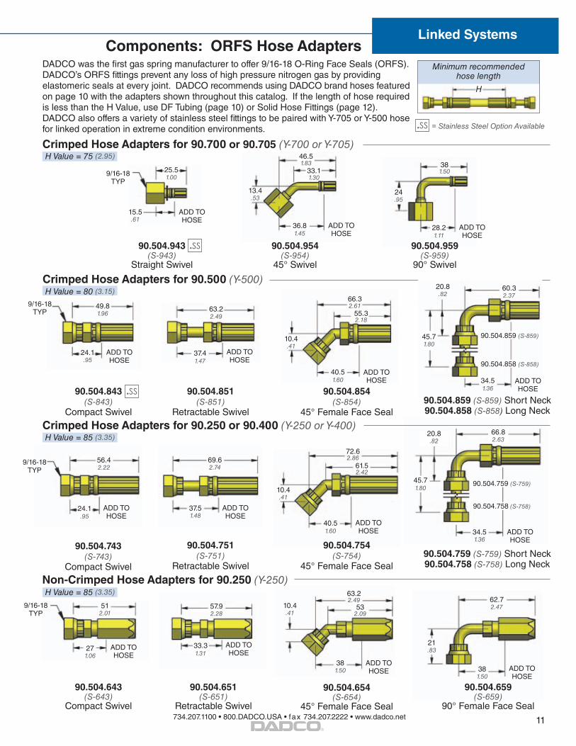
DADCO was the first gas spring manufacturer to offer 9/16-18 O-Ring Face Seals (ORFS). DADCO’s ORFS fittings prevent any loss of high pressure nitrogen gas by providing elastomeric seals at every joint. DADCO recommends using DADCO brand hoses featured on page 10 with the adapters shown throughout this catalog. If the length of hose required is less than the H Value, use DF Tubing (page 10) or Solid Hose Fittings (page 12). DADCO also offers a variety of stainless steel fittings to be paired with Y-705 or Y-500 hose for linked operation in extreme condition environments.
Non-Crimped Hose Adapters for 90.250 (Y-250)
57.92.28
9/16-18TYP
ADD TO HOSE
271.06
512.01
90.504.643 (S-643)
Compact Swivel
63.22.49
532.09
10.4.41
381.50
ADD TO HOSE
90.504.654 (S-654)
45° Female Face Seal
ADD TO HOSE
62.72.47
21.83
381.50
90.504.659 (S-659)
90° Female Face Seal
90.504.651 (S-651)
Retractable Swivel
ADD TO HOSE
Crimped Hose Adapters for 90.250 or 90.400 (Y-250 or Y-400)
69.62.74
56.42.22
9/16-18TYP
37.51.48
ADD TO HOSE
90.504.743 (S-743)
Compact Swivel
ADD TO HOSE
72.62.86
61.52.42
10.4.41
90.504.754 (S-754)
45° Female Face Seal
20.8.82
34.51.36
90.504.751 (S-751)
Retractable Swivel
ADD TO HOSE
90.504.759 (S-759) Short Neck90.504.758 (S-758) Long Neck
66.82.63
ADD TO HOSE
Crimped Hose Adapters for 90.500 (Y-500)
ADD TO HOSE
ADD TO HOSE
90.504.843 (S-843)
Compact Swivel
90.504.851 (S-851)
Retractable Swivel
9/16-18 TYP
49.81.96
63.22.49
Crimped Hose Adapters for 90.700 or 90.705 (Y-700 or Y-705)
33.31.31
45.71.80
40.51.60
24.1.95
24.1.95
37.41.47
20.8.82
ADD TO HOSE
90.504.858 (S-858)
90.504.859 (S-859)45.71.80
34.51.36
60.32.3766.3
2.6155.32.18
10.4.41
40.51.60
ADD TO HOSE
90.504.859 (S-859) Short Neck90.504.858 (S-858) Long Neck
H Value = 85 (3.35)
H Value = 85 (3.35)
H Value = 80 (3.15)
H Value = 75 (2.95)
ADD TO HOSE
ADD TO HOSE
ADD TO HOSE
9/16-18 TYP
25.51.00
15.5.61
13.4.53
38 1.50
24.95
90.504.959 (S-959)
90° Swivel
90.504.954 (S-954)
45° Swivel
90.504.943 (S-943)
Straight Swivel
28.21.11
36.81.45
46.51.83
33.11.30
H
Minimum recommended hose length
90.504.758 (S-758)
90.504.759 (S-759)
.SS
= Stainless Steel Option Available.SS
.SS
90.504.854 (S-854)
45° Female Face Seal

734.207.1100 • 800.DADCO.USA • fax 734.207.2222 • www.dadco.net 12®
Linked Systems
Port Adapters21.3.84
9/16-18ORFS
TYP
30 1.18
11.3.44
ø16.5.65
26.91.06
421.65
90.505.438 (S-438)
Run Tee
90.506.439 (S-439)
Branch Tee
22.87
21.5.85
43.51.71
431.6921.5
.85A
90.506.230 (S-230)
90° Swivel
21.5.85
A
90.505.115 (S-115)
Straight
90.505.117 (S-117)
Extended Straight
90.505.121 (S-121)
Swivel Straight
90.505.330 (S-330)
45° Elbow
90.505.110 (G-109)
Flush Plug
90.505.116 (S-116)
M6 9/16-18
G 1/8 BSPP TYP M6
9/16-18ORFS
TYP
24.1.95
48.51.91
Components: ORFS Fittings
BA
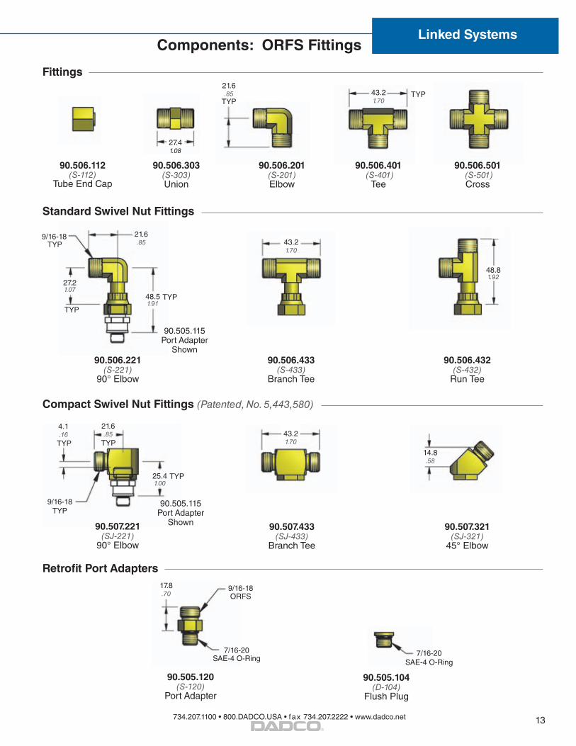
Solid Hose FittingsSolid hose fittings come in predetermined lengths and are ideal for limited space applications. They can replace traditional hose assemblies, particularly when the length of hose required is shorter than DADCO’s recommended minimum hose length (see H Values on page 11). For custom lengths of solid hose, see DF Tubing on page 10.
Metric
Part No. A B
90.503.xxxx (S-9xxx)
mm A − 43.2
9075 75 31.89100 100 56.89120 120 76.89125 125 81.89130 130 86.89140 140 96.89150 150 106.8
English
Part No. A B
90.503.xxx (S-8xx)
in. A − 1.70
830 3.00 1.30832 3.25 1.55835 3.50 1.80837 3.75 2.05840 4.00 2.30845 4.50 2.80850 5.00 3.30855 5.50 3.80860 6.00 4.30
Part No. A
90.506.230 22 .87
90.506.240 36 1.42
90.506.250 43 1.69
Part No. A
90.506.439 22 .87
90.506.449 36 1.42
90.506.459 43 1.69
DADCO’s O-Ring Face Seal (ORFS) Fittings have elastomeric seals at every joint.
.SS= Stainless Steel Option Available.SS
.SS .SS
.SS .SS
90.505.122 (S-122)
Swivel Straight
90.505.123 (S-123)
Swivel Straight
Refer to Page 4 Torque Specifications
9/16-18ORFS
TYP
G 1/4 BSPP
19 HEX19 HEX
19.4.76
G 1/4 BSPP
9/16-18ORFS
16.63
734.207.1100 • 800.DADCO.USA • fax 734.207.2222 • www.dadco.net
®
13
Linked SystemsComponents: ORFS Fittings
Retrofit Port Adapters
90.505.120(S-120)
Port Adapter
7/16-20 SAE-4 O-Ring
9/16-18ORFS
17.8.70
Standard Swivel Nut Fittings
90.506.433(S-433)
Branch Tee
90.506.432(S-432)
Run Tee
TYP48.51.91
43.21.70
48.81.92
90.506.221 (S-221)
90° Elbow
21.6.85TYP
TYP
9/16-18
27.21.07
90.505.115 Port Adapter
Shown
Compact Swivel Nut Fittings (Patented, No. 5,443,580)
TYP
90.507.221 (SJ-221)
90° Elbow
90.507.433(SJ-433)
Branch Tee
90.507.321 (SJ-321)
45° Elbow
90.505.115 Port Adapter
Shown
14.8.58
43.21.70
21.6.85
9/16-18 TYP
4.1.16
TYP
25.41.00
TYP
Fittings
90.506.112 (S-112)
Tube End Cap
90.506.303 (S-303) Union
90.506.201 (S-201) Elbow
90.506.401 (S-401)
Tee
90.506.501 (S-501) Cross
43.21.70
21.6.85
TYPTYP
27.41.08
90.505.104(D-104)
Flush Plug
7/16-20 SAE-4 O-Ring

734.207.1100 • 800.DADCO.USA • fax 734.207.2222 • www.dadco.net 14®
Linked Systems
D-24 Hose System with 90.500 (Y-500)
M12x1.5
90.508.843 (D-843) Compact Hose Adapter
17 .67
34 1.34
36 1.42
13 .51
54 2.13
90.508.854 (D-854) 45° Hose Adapter
28 1.10
25 .98
46 1.81
90.508.858 (D-858) 90° Hose Adapter
Fittings
D-24 Hose System with 90.700 or 90.705 (Y-700 or Y-705)
14 Hex
M12x1.5
90.508.943 (D-943) Compact Hose Adapter
27 1.06
17.5 .69
Components: D-24 Tapered Fittings
G 1/8 BSPP
90.508.115(D-115)
Port Adapter
90.508.221(D-221)
90° Elbow
M12x1.5
19 .75
19 .75
90.508.201(D-201) Elbow
90.508.303(D-303) Union
24 .94
38 1.50
90.508.432(D-432)
Run Tee
90.508.401(D-401)
Tee
90.508.501(D-501) Cross
90.508.433(D-433)
Branch Tee
90.508.112(D-112)
Tube End Cap
38 1.50
19 .75
19 .75
14 .55
90.508.321(D-321)
45° Elbow
11 .4330
1.1819 .75
19 .75
38 1.50
19 .75
19 .75
19 .75
38 1.50
19 .75
19 .75
M12x1.5
21 .83
M12x1.5
90.508.607(D-607)
Reducing Union
M8x17/16-20 SAE-4 O-Ring
90.508.120(D-120)
Port Adapter
M12x1.5
ADD TO HOSE
ADD TO HOSE
ADD TO HOSE
H
Minimum recommended hose length (H) = 80 (3.15)
H
Minimum recommended hose length (H) = 75 (2.95)
ADD TO HOSE
22 .87
21 .81
14 Hex 5/8 Hex
90.508.439(D-439)
Branch Tee
Part No. A
90.508.439 22 .87
90.508.449 36 1.42
90.508.459 43 1.69
381.5
19.75
A
14 Hex
DIN EN ISO 8434 24° Taper + O-Ring
DADCO’s D-24 Fittings have a 24° taper and o-ring.
90.508.116(D-116)
Port Adapter
Part No. A
90.508.438 22 .87
90.508.448 36 1.42
90.508.458 43 1.69
Part No. A
90.508.539 22 .87
90.508.549 36 1.42
90.508.559 43 1.69
90.508.539(D-539) Cross
Refer to Page 4 Torque Specifications
90.508.438(D-438)
Tee
A
A + 21A + 21
A
21 .83
21 .83
19 .75
19 .75
19 .75
M12x1.5
14 Hex
M6
22 .87

734.207.1100 • 800.DADCO.USA • fax 734.207.2222 • www.dadco.net
®
15
Linked Systems
MINILink® Fittings
14.5.57
M8x1M6
M6
13.4 .53
14.7.58
M8x1
M6
13.4.53
M8x1 TYP
14.7.58
29.31.16
281.10 14.7
.58
25.81.01
29.31.16
14.7.58
14.7.58
M8x1TYP
29.31.16
M6
12.8.50
G 1/8BSPP
14.7.58
14.7.58
M6
90.607.120(L-120)
Straight Port Adapter
90.607.220(L-220)
90˚ Port Adapter
90.607.429(L-429)
Branch Tee Port Adapter
90.607.428(L-428)
Run Tee Port Adapter
90.607.035(L-35)
Port Adapter Extension
90.607.401(L-401)
Union Tee
90.607.065(L-65)
ReducerG 1/8 M6
90.607.201(L-201)Elbow
M8x1 TYP
M8x1 TYP
11.1.44
Components: MINILink® Fittings
M6
14.5.57
M6
90.606.303(L-303)Union
90.607.055(L-55)
Reducer7/16-20 M6
7/16-20 SAE
M6
11.43
90.505.116(S-116)
ReducerM6 9/16-18
9/16-18 ORFS
M6
24.1.95
20
.79
M6
A
34
1.34 19 .75
G 1/8 BSPP
M6
A
G 1/8 BSPP
19
.75
28
1.10 10
.39
13
.51
M8x1
90.605.109(L-109)
Fitting Plug
90.607.110 (L-110)
Port Plug
10.39
90.607.115 (L-115)
ReducerG 1/8 M8x1
G 1/8BSPP
M8x1
17.5.69
M6
M6 G 1/8 Port Adapters
Part No. A
90.607.116 33 1.30
90.607.126 46 1.81
Part No. A
90.607.439 18 .71
90.607.449 31 1.22
G 1/8 BSPP
90.607.122(L-122)
Micro Service Fitting
14.5.57
M6M6
14.5.57
M8x1M6
90.607.038(L-38)
Micro Port Adapter Extension
Micro Series (C.045 – C.250) and small Ultra Force® Series (U.0175/U.0325) Port Adapters
Minimum recommended distance between sealing faces (L) = 75 (2.95)
MINIFLEX® Hose System with 90.700 or 90.705 (Y-700 or Y-705) Hose
90.700.L943.L943._____.I
19.1.75
10.39
M8x1 L
Hose Assembly Permanent Hose AdapterL (mm)
90.601.943(L-943)
ADD TO HOSE
4.9.19
4.9.19
Straight Branch Tee
.SS
= Stainless Steel Option Available.SS
.SS .SS .SS
Refer to Page 4 Torque Specifications

734.207.1100 • 800.DADCO.USA • fax 734.207.2222 • www.dadco.net 16®
Linked SystemsComponents: Zip (CNOMO) Fittings
Zip Hose System with 90.700 or 90.705 (Y-700 or Y-705)
90.804.943 (B-943)
Straight Hose Adapter
90.804.954(B-954)
45° Hose Adapter
90.804.959(B-959)
90° Long Neck Hose Adapter
25.98
15.59
12.47
43.51.71
301.18
341.34
33.51.32
24.5.96
24.94
90.805.115 (B-115)
Port Adapter
24.94
41.51.63
A
833.27
41.51.63
A
90.806.401 (B-401)
Tee
411.61
20.5.81
411.61
20.5.81
90.806.501 (B-501) Cross
90.806.230 (B-230)
Angle Swivel Adapter
90.806.439 (B-439)
Two-Way Swivel Adapter
Fittings
S12.65x1.5 Buttress THD
G 1/8 BSPP
S12.65x1.5
H
Minimum recommended hose length (H) = 75 (2.95)
ADD TO HOSE
ADD TO HOSE ADD TO
HOSE
Part No. A
90.806.230 22 .87
90.806.240 36 1.42
90.806.250 43 1.69
Part No. A
90.806.439 22 .87
90.806.449 36 1.42
90.806.459 43 1.69
90.804.958(B-958)
90° Short Neck Hose Adapter
341.34
16.63
24.94
ADD TO HOSE
90.805.190 (B-190)
Port Adapter with Valve
24.94
S12.65x1.5
G 1/8 BSPP
Internal Check Valve

734.207.1100 • 800.DADCO.USA • fax 734.207.2222 • www.dadco.net
®
17
Linked Systems
DADCO offers a variety of pressure monitor options to alert press controllers to changes in system pressure. Some models, including the 90.421.2D, are capable of shutting the press down if it drops below the minimum operating pressure. The new electronic pressure monitors are available in several configurations with different cable, base and fitting options to best suit the application. Refer to the bulletin listed below for more information.
Components: Pressure Monitors
90.421.2D. *BH1. BP. 102
Model Number90.421.1, 90.421.2 or 90.421.2D
Connector BH1 − 90˚ Connector BH3 − Straight Connector(*Connector options are for 90.421.2D Model only.)
Fitting90.505.102−Straight90.505.202−90˚
Backing Plate(optional)
Ordering Example:
90.421.1 / 90.421.2 / 90.421.2D
1505.911254.92
1024.02
752.95
Cable Options
90.454.M12.S 90.454.M12.L
Pressure Switch / Sensor Options
DSK DPT EDS
Base Options
JB CP
Example shown:90.421.CP.S.EDS
With 90.454.M12.S Cable
38 1.50
30 1.181
2 x M6 SHCS
16 .64
35 1.37
51 2.00
96 3.8
Model No.Supply Voltage
OutputElectrical
ConnectionPressure
RangeBulletin No.
90.421.1 (DPM-1)
120 VAC Indicator Light 1/2 NPS 15 – 200 bar 220 – 3000 psi
B00136
90.421.2 (DPM-2)
24 VDC Indicator Light 1/2 NPS 15 – 200 bar 220 – 3000 psi
B01115A
90.421.2D (DPM-2D)
24 VDCIndicator Light
+ SPDT4-Pin Mini-Change
Connector15 – 200 bar 220 – 3000 psi
B00134
DSK250 VAC / 24 VDC
SPDT DIN 43650 0 – 400 bar 0 – 5800 psi
B10105DPT 12 – 32 VDC 0 – 10 V 4-Pin M12 x 1 0 – 600 bar 0 – 8700 psi
EDS 9 – 35 VDC (2) PNP 4-Pin M12 x 1 0 – 400 bar 0 – 5800 psi
Pressure Switch / SensorDSK, DPT or EDS
90.421. CP. S. EDS. G
Model Number
Base OptionJB = Block only (Bleed Valve, Filler Valve and Rupture Disk not included) CP = Block with Bleed Valve, Filler Valve and Rupture Disk
Ordering Example:
DSK / DPT / EDS
Example shown:90.421.2D
4 x M10
133 5.25
Guard OptionProtective Guard Attached. For no guard, leave blank.
Fitting ConnectionN = No Fitting Supplied,S = ORFS Fitting, D = D-24 Fitting, B = Zip Fitting,L = MINILink® FittingWhen not specified, default is N.

734.207.1100 • 800.DADCO.USA • fax 734.207.2222 • www.dadco.net 18®
Linked Systems
Hose Cutters Hose Assembly Clamp
Mini-Crimp90.710.8
Portable Crimping Unit90.720
Used to cut hose to appropriate length. The 90.320.7 works with 90.700 / 90.705 (Y-700 / Y-705) and the 90.320.5 with all hose sizes. For more information, request bulletin B11110A.
Used to secure hose while installing hose adapters. The 90.320.9 works with 90.700 / 90.705 (Y-700 / Y-705) and the 90.320.6 with all hose sizes. For more information, request bulletin B11110A.
Used in a crimping machine to construct hose assemblies using 90.700 / 90.705 (Y-700 / Y-705) hose. For more information, see below or request bulletin B11110A.
Used with appropriate die ring to create permanent hose assemblies. For more information, request bulletin B04112.
Tools for Hose Assembly Construction
Tools
Part No. Crimp Die Crimp Diametermm / inch
90.700 / 90.705 (Y-700 / Y-705)
Mini-Crimp 90.710.8No Ring Required
7.00 – 7.25.276 – .285
90.500 (Y-500)
80C-P03 Gray Die82C-R01 Ring
12.19 – 12.70.480 – .500
90.400 (Y-400)
80C-P04 Red Die82C-R01 Ring
14.22 – 14.73.560 – .580
90.250 (Y-250)
80C-P04J Red Die82C-R01 Ring
13.59 – 14.10.535 – .555
Crimp DiesUsed in Portable Crimping Unit to construct hose assemblies. For information on constructing hose assemblies, refer to bulletins B00120C and B11110A.
1. Place the Mini-Crimp 90.710.8 into the crimping machine. No die ring is required.
2. Insert the hose assembly from below through the center of the Mini-Crimp (F.1). For instructions on constructing a Mini Hose Assembly request bulletin B11110B.
3. Activate the hydraulic or pneumatic crimping machine to permanently crimp fitting to the hose (F.1).
Using DADCO’s Mini-Crimp4. As the DADCO Mini-Crimp begins to close, position the fitting to ensure the entire length of the ferrule is crimped (F.2).
5. Remove completed hose assembly from the Mini-Crimp.
6. Measure the crimped ferrule diameter across the flats to verify it is within the crimp dimension range (F.3).
Die Ring
Crimp Die
Crimp entire length of ferrule
Mini Hose Cutter90.320.7
Hose Cutter90.320.5 (HC-11)
Hose Assembly Clamp90.320.6 (HAC)
Mini Hose Assembly Clamp90.320.9
F.1 F.2 F.3
7.00 – 7.25.276 – .285
Ferrule

734.207.1100 • 800.DADCO.USA • fax 734.207.2222 • www.dadco.net
®
19
Linked Systems
DADCO Tank Analyzer90.316.1 (use with CGA-580 thread)90.316.2 (use with CGA-680 thread)
DADCO’s Nitrogen Gas Booster System, DGB-150, is an all-in-one solution to the problems of low pressure supply tanks and lost nitrogen gas during discharge. For more information on the booster, refer to bulletin B07101.
Nitrogen Gas BoosterDGB-150
Quick Disconnect Charging Nipple90.310.143 (M6 Port)90.310.111 (G 1/8 Port)
Use the appropriate Quick Disconnect Charging Nipple to charge DADCO Nitrogen Gas Springs.
90.310.143 90.310.111
Tools
Charging Accessories
Quick Disconnect Charging Assembly90.310.040
Use the DADCO Quick Disconnect Charging Assembly, 90.310.040, with the 90.310.143 or 90.310.111 Charging Nipple or the 90.315.5 Pressure Analyzer to charge self-contained gas springs. The 90.310.040 can also be used with a DADCO control panel to charge linked systems.
The 90.310.040 includes the 90.310.201 Pressure Regulator, 90.310.252 Hose Assembly and the 90.310.338 Quick Disconnect Filling Assembly.
DADCO recommends using the 90.310.041 High Pressure Charging Assembly to charge Micro Series, SCR Series and U.0175 – U.0400 nitrogen gas springs to maximum pressure.
Pressure Regulator90.310.201
Quick Disconnect Filling Assembly90.310.338
Hose Assembly90.310.2523 m / 10 ft
The DADCO Tank Analyzer easily threads onto a pressure nitrogen tank to verify available pressure. The Tank Analyzer includes a gauge and a bleed valve. Contact DADCO for more information.
Safety Plates
DADCO recommends customers identify tools containing high pressure nitrogen gas springs toensure proper handling of the cylinders. DADCO offers several caution tags to meet specific application needs. For more information request bulletin B01103A.
Quick Disconnect Filling Assembly with Gauge, 90.310.339, is also available.

Printed in USA ©DADCO, Inc. 2012 All Rights Reserved
43850 Plymouth Oaks Blvd. • Plymouth, Michigan • 48170 • USA734.207.1100 • 800.DADCO.USA • fax 734.207.2222 • www.dadco.net
The global leader in nitrogen gas spring technology
®
Complete Linked System Solutions