Embed Size (px)
Citation preview

Level monitoring systemNT 3500Technical information / Instruction manual
page
Table of contents
Subject to technical change. We assume no liability for typing errors.
Page
Safety notes / Technical support 2
------------------------------------------------------------------------------------------------------
Overview 3
------------------------------------------------------------------------------------------------------
Technical Data 4
------------------------------------------------------------------------------------------------------
Electrical installation 4
------------------------------------------------------------------------------------------------------
Commissioning 6
------------------------------------------------------------------------------------------------------
Visualisation - Operation 8
Nivotec® 1
2
3
4
5
6
7
8
9
10
11
12NT 3500 gi010117 1

Level monitoring systemNT 3500Technical information / Instruction manual
page
Safety notes / Technical support
Notes • Installation, maintenance and commissioning must be carried out only by qualified technical personnel. • The product must be used only in the manner outlined in this instruction manual.
Special attention must be paid to warnings and notes as follows:
WARNING
Relates to a caution symbol on the product and means, that a failure to observe the necessary precautions can result in death, serious injury and/or considerable material damage.
WARNING
Relates to a caution symbol on the product and means, that a failure to observe the necessary precautions can result in death, serious injury and/or considerable material damage.
This symbol is used, when there is no corresponding caution symbol on the product.
A failure to observe the necessary precautions can result in considerable material damage. CAUTION
Safety symbols
In manual and on product Description
CAUTION: refer to related documents (manual) for details.
Earth (ground) Terminal
Protective Conductor Terminal
Technical support
Please contact your local supplier (see www.uwt.de for address). Otherwise you can contact:
UWT GmbH Tel. 0049 (0)831 57123-0Westendstr. 5 Fax. 0049 (0)831 7687987488 Betzigau [email protected] www.uwt.de
Nivotec®1
2
3
4
5
6
7
8
9
10
11
12NT 3500gi0101172

Level monitoring systemNT 3500Technical information / Instruction manual
page
Overview
Features
- Fill level visualisation via HTTP-web server - Visualisation via standard Internet browser software on all Ethernet PCs- Password protected- Worldwide remote enquiry of the level password protected - on request- Software operation addtional via a touch panel in the control cabinet or via fill level LEDs- Data in percentage, height, volume or weight- Trend display, data storage, export via .csv- Evaluation of the analogue 4-20 mA signals of any sensors, as well as Modbus RTU of the UWT-systems- Different input signals within the same system is possible- Fill control via full alarm signals and shut off valves- Separate truck module for safe and comfortable monitoring during silo filling
Selection pos.5 B:Display, LED
Selection pos.5 D,E:Display on Touchpanel
NT 3500 control cabinet
The heart of the NT 3500 is a web server module, which the visualisation software uses. All fill level control and display functions can be operated via the visualisation on a PC or a Touch panel with backlight. An Ethernet interface ensures that the visualisation can be simultaneously operated from all PCs which are connected to the interface. Access is password protected. Additionally the control cabinet can be equipped with operating and display elements. Either the 10.4" or 15" touch panel or the digital level display with full and empty LEDs can be choosen. The electromechanical lead system can be started by the visualisation or by a push button. A buzzer for alarm "silo full" can be mounted directly on the silo. Control for pinch valves to stop the filling is available. The NT 3500 is a complete system which also provides the supply voltage for the sensors. The system is delivered with project specific electrical plans.
Functionality of alarm"silo full" and control of the pinch valves:1. The filling (opening of the pinch valve) is enabled eihter via the hose coupling when connecting the filing hose, via a key switch on the cabinet or on the truck module or via PC/Touch panel. 2. In case of an alarm "silo full" the pinch valve closes, the LED "silo full" and the buzzer is switched on, the reset button is blinking. After reset of the alarm the pinch valve opens for ca. 5 min to enable the expulsion of the filling pipe, then it is closed again. Independend from this control the pinch valve can be opened or closed by an authorized user at any time.
Truck module
- One module for a defined number of silos (depending on the project)- Mounting directly at the silo frame- Display silo full/empty and pinch valve status with LEDs- Reset of alarm "silo full"- Key switch for pinch valve control
Example: Truck module
Nivotec® 1
2
3
4
5
6
7
8
9
10
11
12NT 3500 gi010117 3

Level monitoring systemNT 3500Technical information / Instruction manual
page
Technical Data / Electrical installation
Technical dataDimensions Depending on project
Mounting Control cabinet Wall mountingTruck module Mounting on silo filler pipe
Material Steel plate
Ingress protection Control cabinet IP54Truck module IP65
Ambient temperature Control cabinet 0..+55°CTruck module IP65
Power supply 115V or 230V 50/60Hz
Power consumption Depending on project
Technical data of the used Wago Controllers:see www.wago.com, search for 750-881
Handling In case of improper handling or handling malpractice, the electric safety of the device cannot be guaranteed.
Installation regulations The local regulations or VDE 0100 (Regulations of German Electrotechnical Engineers) must be observed.
RCCB protection In case of a fault, the supply voltage must be automatically switched off by a RCCB protection switch to protect against indirect contact with dangerous voltages.
Wiring diagram The electrical connections are made in accordance with the wiring diagram.
Supply voltage Compare the supply voltage applied with the specifications given on the name plate before switching the device on.
Cable gland Make sure that the screwed cable gland safely seals the cable and that it is tight (danger of water intrusion).Cable glands that are not used have to be sealed with a blanking element.
Field wiring cables All field wirings must have insulation suitable for at least 250V AC. The temperature rating must be at least 80°C (176°F).
Installation in Hazardous Locations
The NT 3500 is not permitted for installation in Hazardous Areas. Observe the valid regulations for wiring in Hazardous Areas, if the NB 3000/ 4000 is installed in Hazardous Areas.
Safety Instructions
Electrical installation
Wiring diagramThe NT 3500 will be delivered with detail wiring diagram depending on the project.
Nivotec®1
2
3
4
5
6
7
8
9
10
11
12NT 3500gi0101174

Level monitoring systemNT 3500Technical information / Instruction manual
page
Electrical installation
Modbus network
Modbus MasterNT 3500
Other used notations:D0 = Rx-/Tx- = AD1 = Rx+/Tx+ = B
NB 3000/ NB4000Modbus Slaves
General wiring of a Modbus network
Terminals D0 as well as D1 are internally connected.
Termination Resistor 120 Ohm at the end of the strand. It is present inside each NB 3000/ NB4000 and can be switched in.
NB 3000/ NB4000 NB 3000/ NB4000
Cable recommendations for Modbus network
Shielded cableFunctionality up to 50m Manufacturer: Lapp, Type UNITRONIC LiYCY 2x0.34, Art.no: 0034502
Twisted pair cableFunctionality up to 1000mManufacturer: Lapp, Type UNITRONIC BUS CAN 1x2x0,34, Art.no: 2170263
UV-protection hose with threaded hose coupling M20x1,5UV protection for Modbus cableManufacturer: Flexa, Type Rohrflex PA6, Art.no: 0233.202.012 and Type RQG1-M, Art.no: 5020.055.018
ATEX-protection hose with threaded hose coupling M20x1,5For installation of Modbus cable in ATEX Zone 21Manufacturer: PMA, Type ESX, Art.no: ESXT-12B.50 and Type END, Art.no: BEND-M202GT
Nivotec® 1
2
3
4
5
6
7
8
9
10
11
12NT 3500 gi010117 5

Level monitoring systemNT 3500Technical information / Instruction manual
page
Setting: Biasing and Termination Resistor
For use of NB 4000 units in a external Modbus network, it is possible to set Biasing and Termination Resistor on each unit as required.
*factory provided
Biasing OFF* OFF ON ON
Termination Resistor
OFF* ON OFF ON
*factory provided
Biasing OFF* OFF ON
Termination Resistor
OFF* ON ON
Version with Jumper
Version with DIP switchBiasing OFF* OFF ON ON
Termination Resistor
OFF* ON OFF ON
NB 4000
NB 3000
Electrical installation
DIP Switch position:
Side viewTop view
DIP Switch position:
Side viewTop view
Nivotec®1
2
3
4
5
6
7
8
9
10
11
12NT 3500gi0101176

Level monitoring systemNT 3500Technical information / Instruction manual
page
Commissioning
1. Web server configuration
CAUTION: The configuration should be done by the network administrator only.
The web server is preset to the IP address 192.168.10.70. It must be changed to a company's own IP address as follows:
• Use a PC, which is connected via Ethernet to the Web server. Set in the system control the TCP / IP to address 192.168.10.xx, whereas xx can be any two digit number (the access to the Web server requires the number 192.168.10., the last two digits are not relevant).
• An up to date version of Internet browser must be installed.
• Open the Internet browser and type the IP address 192.168.10.70 of the web server in the command bar. The overview page "Home" of the visualisation opens (see page 8).
• Click the "User" button and set the User Level to 5. The "Config" button will appear in the menu bar.
• Click on this button. The configuration page of the web server will open (see page 10). . • Enter your IP address, sub net mask and gateway, the current date and time
• Then reset to your TCP / IP address in the system control of your PC.
2. Perform the basic settings of the connected sensors
With the following settings, the connected sensors are addressed via the visualisation and give a real measurement result. For this settings the above mentioned synoptical table is helpful:
• Enter in page "Settings" (see page 12), the data under "Hardware", " Signal Input" and, if full detectors are connected, "Full Level Indicator".
• Enter in page "Volume Calculation" (see page 14) the data under "Signal Input", "Silo Profile" and "Silo Data".
3. Perform further user settings
Enter the required user specific settings according to the "Visualisation - Operation" from page 8 onwards.
Nivotec® 1
2
3
4
5
6
7
8
9
10
11
12NT 3500 gi010117 7

Level monitoring systemNT 3500Technical information / Instruction manual
page
Visualisation - Operation
By entering the IP address in the browser (according to the web server configuration) the visualisation starts. After sucessful start the overview page "Home" appears.
Start of the Visualisation
Display of level, level switches, information regarding silo and error messages User Level 0 or higher
The selected number of silos (see page "Config") is presented. If more than 10 silos are defined, a button appears for progression to the next page.
Overview page (Home)
Note: If a distorted image on the PC is present, it should not be viewed in full screen mode, thus the window can be drawn in an undistorted view.
Nivotec®1
2
3
4
5
6
7
8
9
10
11
12NT 3500gi0101178

Level monitoring systemNT 3500Technical information / Instruction manual
page
Visualisation - Operation
The following selections appear depending on the setted User Level:
Silo Single View (click on a silo) The single view for the respective silo will open (see page 11).
E-MailSends an E-mail if a level switch is activated or if an error message of the NB 3000/ 4000 is present.
Config See page 10.
Reset Reset of the full signal (buzzer) and of error messages.
Start Nivobob Starts the measurement of all connected Nivobobs. If more than 10 silos are defined, the measurements of the silos not displayed on the screen are started as well. As long as the measurement is running, a green arrow appears in each silo.
Download Issue of trend data for all silos in .csv format. The level values are stated in the unit as defined under "Volume Calculation" (see page 14).
PasswordUsed for password assignment. Each User Level can change its own password. The higher level can change the password of the lower levels. No password is presetted apart from Level 7.
UserSelecting the User Level with different permissions:
Level 0 - Overview page (Home)
Level 1 Similar to Level 0, additional: - Silo Single View - Start Nivobob - View of Event List - Reset of the full signal (buzzer) and of error messages - Download of trend data
Level 2 Similar to Level 1, additional: - Page "Settings" - Page "Volume calculation"
Level 3 Similar to Level 1, additional: - On Page "Settings": change of "Silo Data" possible - On Page "Volume calculation": change of "Density" possible.
Level 4 Blocked
Level 5 Similar to Level 2, additional: - Page "Setup Nivobob"- - Page "Config" - Page "E-Mail"
Level 6 BLocked
Level 7 UWT Service-Level
Nivotec® 1
2
3
4
5
6
7
8
9
10
11
12NT 3500 gi010117 9

Level monitoring systemNT 3500Technical information / Instruction manual
page
Page "Config"
Setting of date, time, software language, country-specific units, number of displayed silos as well as network settingsUser Level 5 or higher
Visualisation - Operation
Nivotec®1
2
3
4
5
6
7
8
9
10
11
12NT 3500gi01011710

Level monitoring systemNT 3500Technical information / Instruction manual
page
Visualisation - Operation
View of details and settings of the sensors for a silo.Open/close the pinch valve.
User Level 1 or higher
Clicking on a silo in the Overview page (Home) opens the Silo Single View.
The level is displayed in the unit as defined under "Volume Calculation" (see page 14), in addition as a percentage. The colored points display the full, demand and empty detection.
The trend stores a total of 200 data points per silo. The oldest point is deleted when a new value is stored.
Events are displayed in a table. The selection "+" opens the list of the last 17 events.
Page "Silo Single View"
Nivobob Start Starts the measurement of the Nivobob for this silo. During the measurement, the button appears gray. When the measurement is completed, the color changes back to green. The button appears only if on page "Settings" under "Hardware" the selection "Nivobob" has taken place.
Filling Start / Stop Control of the pinch valve.The control of the valve during the filling of the silo is done in combination with the Truck module (see description on page 3).Via the visualisation software the valve can be opened and closed independent by pressing the button "Filling Start/Stop".The button appears only if on page "Settings" the selection "Pinch valve - Yes" is done.
Settings Leads to the page "Volume Calculation" of this silo (see page 12).
Nivotec® 1
2
3
4
5
6
7
8
9
10
11
12NT 3500 gi010117 11
Level monitoring systemNT 3500Technical information / Instruction manual
page
Visualisation - Operation
Detail settings for the respective measurement point User Level 2 or higher
The page opens with cklick on "Settings" in the page "Silo Single View".
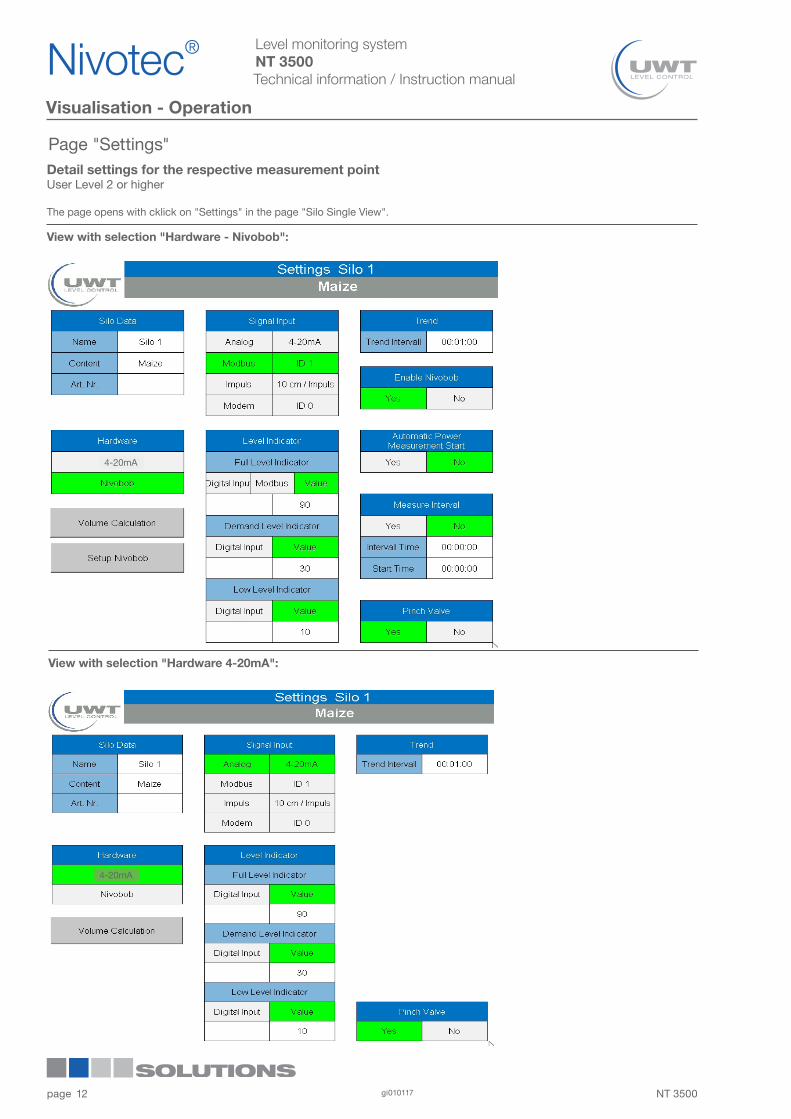
Page "Settings"
View with selection "Hardware - Nivobob":
View with selection "Hardware 4-20mA":
4-20mA
4-20mA
Nivotec®1
2
3
4
5
6
7
8
9
10
11
12NT 3500gi01011712

Level monitoring systemNT 3500Technical information / Instruction manual
page
Visualisation - Operation
Silo DataThe silo shown can be labeled with any text for silo name, content and article number.
HardwareIndication of the sensor used.
Signal Input
• If a Nivobob is connected (with selections "Hardware - Nivobob") :
Selection of the signal output, which is used with the connected Nivobob.
With selection "Modbus" the Modbus adress, which is present on the Nivobob, must be entered. The Modbus address of the Nivobob is setted in the Nivibob communication menu (see manual Nivobob). It is reasonable to use the address 1 for the first device, then ascending to 2, 3, etc. Optional (with selection code 33) the Nivobob devices are delivered with already preset address.
Setting "Modem" is used if a GSM module for remote maintenance is installed at the silos.
• If NR3000 (or another 4-20mA sensor) is connected (with selection "Hardware 4-20mA"):
Setting "Analogue 4-20mA" is setted as standard. Setting "Modbus" and "Pulse" is not active. Setting "Modem" is used if a GSM module for remote maintenance is installed at the silos.
Level Indicator
• If level indicators are connected, the setting is done as follows:
Setting "Digital input", if the level indicator is connected directly to the control cabinet (via I/O module).
Setting "Modbus", if the level indicator is connected to the Nivobob and thus is read by the Modbus connection of the Nivobob (only possible for full detector).
• With setting "Value" no level indicators are connected. The message for full and demand is activated, when the entered value (in percent) is exceeded by the material level. The message for empty is activated, when the material level is below the entered value (in percent).
TrendThe trend stores the level values according to the setted interval (hours : minutes : seconds).A total of 200 data points per silo are stored. The oldest point is deleted when a new value is stored.
Enable NivobobMeasurement start can be blocked by setting to "No", e.g. while a silo is beeing filled.
Automatic Power Measurement StartAfter power up or after power failure of the web server, the Nivobob will start automatically if "Yes" is selected. The level measurement is then immediately updated (the Nivobob gives no actual signal output until a new measurement is started).
Measure IntervalActivation of automatic measurement start of Nivobobs, if setted to "Yes". The start takes place automatically, the first time at the setted start time (time of day), then regularly repeated with the setted interval (hours : minutes : seconds).
Pinch ValveWith use of a pinch valve the selection must be set to "Yes". Explanation of the pinch valve functionality see page 11.
Volume Calculationsee page 14
Setup Nivobobsee page 15
Nivotec® 1
2
3
4
5
6
7
8
9
10
11
12NT 3500 gi010117 13

Level monitoring systemNT 3500Technical information / Instruction manual
page
Visualisation - Operation
Signal inputSelection "Linear", if the level signal output of the connected sensor is linear (relation between the signal output and the level in the silo). Thus the volume-based calculation is performed not in the sensor, but in the visualisation.
Selection "Volume", if the level signal output of the connected sensor is volume based (relation between the signal output and the level in the silo). Thus the volume-based calculation is performed in the sensor and not in the visualisation.
Silo Profile and Silo DataWith the setted data the software calculates the max. volume and (with selection "Signal input - Linear") the volume based display.
For the correct measurement display the connected sensors must be set as follows:
• Nivobob NB 3000/ 4000: Value "Cone Height" - with selection "Signal input - Linear": must be set to 0 - with selection "Signal input - Volume": must correspond to the value K given above Value "Silo Height" must correspond to the value H given above Value "Air Dist" must correspond to the value L given above (H and L are related to the lower edge of the sensor-weight)
• 4-20mA sensors 4mA must correspond to the value 0% given above 20mA must correspond to the value 100% given above (H and L are related to the fixing flange if using NR3000)
UnitThe selected unit is used in the visualisation.
VolumeDisplay of the max. volume (in cubic meters) and input of bulk density to calculate the weight.
Calculated valuesDisplay of the calculated maximum content (according to the entered Silo Profile and Data) and the actual content. Both values are shown in the above selected unit.
Page "Volume Calculation"Settings for volume related measurement display and setting of the silo dimensions User Level 2 or higher
The page opens with click on "Volume Calculation" in the page "Settings".
Nivotec®1
2
3
4
5
6
7
8
9
10
11
12NT 3500gi01011714

Level monitoring systemNT 3500Technical information / Instruction manual
page
Visualisation - Operation
Parameterization and reading diagnostic data from the NivobobUser Level 5 or higher
The page opens with click on "Setup Nivobob" in the page "Settings", if the selection "Signal input - Modbus" is set.
ModbusActivation of parameter setting and value reading with click on "Settings". A list with parameters of Nivobob NB 3000/ 4000 appears. For details of the displayed parameters, see manual of the NB 3000/ 4000.
Selecting "Run" will close again.
ID NivobobEnter the ID number (Modbus address) of the Nivobob which is related to this silo.
Read and Read/WriteThe parameters which are read only, or which are read and write, are displayed. Update the values by clicking the"Value Read" button.After a few seconds, the values are shown. The values 13-16 are always displayed and written in millimeters.
Value writeEnter the number (13-18) of the value, which shall be written, in the "Parameter" box. This value is transferred to the Nivobob by clicking the "Write" button With parameter 17 "Start" set to 1 the Nivobob can be started. Set back to 0 afterwards.With parameter 18 "Inhibit" set to 1 a running measurement of the Nivobob is stopped. Set back to 0 afterwards.
Page "Setup Nivobob"
Nivotec® 1
2
3
4
5
6
7
8
9
10
11
12NT 3500 gi010117 15