Embed Size (px)
Citation preview

Machine Automation ControllerIndustrial PC Platform
NJ/NY-series
NC Integrated Contoller
CPU UnitIndustrial Panel PC
User’s Manual
NJ501-5300NY532-5400
O030-E1-01

All rights reserved. No part of this publication may be reproduced, stored in a retrieval system, or transmitted, in any form, or by any means, mechanical, electronic, photocopying, recording, or otherwise, without the prior written permission of OMRON.
No patent liability is assumed with respect to the use of the information contained herein. Moreover, because OMRON is constantly striving to improve its high-quality products, the information contained in this manual is subject to change without notice. Every precaution has been taken in the preparation of this manual. Neverthe-less, OMRON assumes no responsibility for errors or omissions. Neither is any liability assumed for damages resulting from the use of the information contained in this publication.
• Sysmac and SYSMAC are trademarks or registered trademarks of OMRON Corporation in Japan and other countries for OMRON factory automation products.
• Microsoft, Windows, Excel, and Visual Basic are either registered trademarks or trademarks of Microsoft Corpora-tion in the United States and other countries.
• EtherCAT® is registered trademark and patented technology, licensed by Beckhoff Automation GmbH, Germany.
• ODVA, CIP, CompoNet, DeviceNet, and EtherNet/IP are trademarks of ODVA.
• The SD and SDHC logos are trademarks of SD-3C, LLC.
• Intel and Intel Core are trademarks of Intel Corporation in the U.S. and / or other countries.
Other company names and product names in this document are the trademarks or registered trademarks of their respective companies.
Trademarks
Copyrights
NOTE
Microsoft product screen shots reprinted with permission from Microsoft Corporation.

1
Introduction
NJ/NY-series NC Integrated Controller User’s Manual (O030)
Introduction
Thank you for purchasing an NJ/NY-series NC Integrated Controller. (“NJ/NY-series NC Integrated Controller” is sometimes abbreviated as “NC Integrated Controller”.)
This manual contains information that is necessary to use the NC Integrated Controller. Please read this manual and make sure you understand the functionality and performance of the NC Integrated Controller before you attempt to use it in a control system.
Keep this manual in a safe place where it will be available for reference during operation.
This manual only describes functions that are added to NJ501-5300 or NY532-5400.
When you use NJ501-5300, also consult manuals for the NJ-series listed in Related Manuals on page 25 for functions common to NJ501- Series including NJ501-1.
When you use NY532-5400, also consult manuals for the NY-series listed in Related Manuals on page 25 for functions common to NY532- Series including NY532-1.
This manual is intended for the following personnel, who must also have knowledge of electrical sys-tems (an electrical engineer or the equivalent).
- Personnel in charge of introducing FA systems
- Personnel in charge of designing FA systems
- Personnel in charge of installing and maintaining FA systems
- Personnel in charge of managing FA systems and facilities
This manual is also intended for personnel who understand the following contents.
• For programming, this manual is intended for personnel who understand the programming language specifications in international standard IEC 61131-3 or Japanese standard JIS 3503.
• For NC programming, this manual is intended for personnel who understand the programming lan-guage specifications in international standard ISO 6983-1 or Japanese standard JIS 6315.
This manual covers the following products.
• NJ-series NC Integrated Controller
NJ501-5300
• NY-series NC Integrated Controller
NY532-5400
Intended Audience
Applicable Products

Relevant Manuals
2 NJ/NY-series NC Integrated Controller User’s Manual (O030)
Relevant Manuals
The following table lists the relevant manuals for this product. Read all of the manuals that are relevant to your system configuration and application before you use this product.
Most operations are performed from the Sysmac Studio and CNC Operator Automation Software.
Refer to the Sysmac Studio Version 1 Operation Manual (Cat. No. W504) for information on the Sys-mac Studio, and CNC Operator Operation Manual (Cat. No. O032) for the CNC Operator.
Relevant Manuals for NJ Series
Purpose of use
Manual
Basic information
NJ-series C
PU
Un
it H
ardw
are User’s M
anu
al
NJ/N
X-se
ries C
PU
Un
it S
oftw
are
User’s M
anu
al
NJ/N
X-se
ries In
structio
ns
Referen
ce Man
ual
NJ/N
X-se
ries C
PU
Un
it Mo
tion
Co
ntro
l Us
er’s Man
ual
NJ/N
X-se
ries M
otio
n C
on
trol
Instru
ction
s Re
ference
Man
ual
NJ/N
X-se
ries C
PU
Un
it Bu
ilt-in
Eth
erCA
T®
Po
rt Us
er’s Man
ual
NJ/N
X-se
ries C
PU
Un
it Bu
ilt-inE
therN
et/IP™
Po
rt User’s M
anu
al
NJ/N
Y-series N
C In
tegrate
dC
on
troller U
ser’s M
anu
al
NJ/N
Y-series G
cod
e In
structio
ns R
eferen
ce M
anu
al
NJ/N
X-se
riesT
rou
blesh
oo
ting
Man
ua
l
Introduction to NJ-series Controllers
Setting devices and hardware
Using motion control
Using EtherCAT
Using EtherNet/IP
Software settings
Using motion control
Using EtherCAT
Using EtherNet/IP
Using numerical control
Writing the user program
Using motion control
Using EtherCAT
Using EtherNet/IP
Using numerical control
Programming error processing
Testing operation and debugging
Using motion control
Using EtherCAT
Using EtherNet/IP
Using numerical control
3
Relevant Manuals
NJ/NY-series NC Integrated Controller User’s Manual (O030)
Learning about error management and
corrections*1
Maintenance
Using motion control
Using EtherCAT
Using EtherNet/IP
*1. Refer to the NJ/NX-series Troubleshooting Manual (Cat. No. W503) for error management concepts and an overview of the items subject to errors. Refer to the manuals that are indicated with triangles for details on errors for the corresponding Units.
Purpose of use
Manual
Basic information
NJ-se
ries C
PU
Un
it H
ardw
are User’s M
an
ua
l
NJ/N
X-series C
PU
Un
it S
oftw
are User’s M
anu
al
NJ/N
X-series In
structio
ns
Referen
ce Man
ual
NJ/N
X-series C
PU
Un
it Mo
tion
Co
ntro
l User’s M
anu
al
NJ/N
X-series M
otio
n C
on
trol
Instru
ction
s Referen
ce Man
ual
NJ/N
X-series C
PU
Un
it Bu
ilt-in
Eth
erCA
T®
Po
rt User’s M
anu
al
NJ/N
X-series C
PU
Un
it Bu
ilt-inE
therN
et/IP™
Po
rt User’s M
anu
al
NJ/N
Y-series N
C In
tegrated
Co
ntro
ller User’s M
anu
al
NJ/N
Y-series G
cod
e In
structio
ns R
eference M
anu
al
NJ/N
X-series
Trou
blesh
oo
ting
Man
ual

Relevant Manuals
4 NJ/NY-series NC Integrated Controller User’s Manual (O030)
Relevant Manuals for NY Series
Purpose of use
Manual
Basic information
NY
-series Ind
ustrial P
anel P
CH
ardw
are User’s M
anu
al
NY
-series Ind
ustrial B
ox P
CH
ardw
are User’s M
anu
al
NY
-series Ind
ustrial P
anel P
C / In
du
strial Bo
x PC
Setu
p U
ser’s Man
ual
NY
-series Ind
ustrial P
anel P
C / In
du
strial Bo
x PC
So
ftware U
ser’s Man
ual
NY
-series In
structio
ns R
eference M
anu
al
NY
-series Ind
ustrial P
anel P
C / In
du
strial Bo
x PC
Mo
tion
Co
ntro
l User's M
anu
al
NY
-series Mo
tion
Co
ntro
l In
structio
ns R
eference M
anu
al
NY
-series Ind
ustrial P
anel P
C / In
du
strial Bo
x PC
Bu
ilt-in E
therC
AT
Po
rt User’s M
anu
al
NY
-series Ind
ustrial P
anel P
C / In
du
strial Bo
x PC
Bu
ilt-in E
therN
et/IP P
ort U
ser’s Man
ual
NJ/N
Y-series N
C In
tegrated
Co
ntro
ller U
ser’s Man
ual
NJ/N
Y-series
G co
de In
structio
ns R
eference M
anu
al
NY
-series Tro
ub
lesho
otin
g M
anu
al
Introduction to NY-series Panel PCs
Introduction to NY-series Box PCs
Setting devices and hardware
Using motion control
Using EtherCAT
Using EtherNet/IP
Making setup*1
*1. Refer to the NY-series Industrial Panel PC / Industrial Box PC Setup User’s Manual (Cat. No. W568) for how to set up and how to use theutilities on Windows.
Making initial settings
Preparing to use Controllers
Software settings
Using motion control
Using EtherCAT
Using EtherNet/IP
Using numerical control
Writing the user program
Using motion control
Using EtherCAT
Using EtherNet/IP
Using numerical control
Programming error processing
Testing operation and debugging
Using motion control
Using EtherCAT
Using EtherNet/IP
Using numerical control
Learning about error management and
corrections*2
*2. Refer to the NY-series Troubleshooting Manual (Cat. No. W564) for the error management concepts and an overview of the items subjectto errors.
Maintenance
Using motion control
Using EtherCAT
Using EtherNet/IP

5
Manual Structure
NJ/NY-series NC Integrated Controller User’s Manual (O030)
Manual Structure
The following page structure and symbols are used in this manual.
Note This illustration is only provided as a sample. It may not literally appear in this manual.
Page Structure and Symbols
4-9
4 Installation and Wiring
NJ-series CPU Unit Hardware User’s Manual (W500)
stin
Ugn
itnu
oM
3-4
4
stne
nop
moCr
ellort
noC
gnit
cenn
oC
1-3-
4
4-3 Mounting Units
The Units that make up an NJ-series Controller can be connected simply by pressing the Units togetherand locking the sliders by moving them toward the back of the Units. The End Cover is connected in thesame way to the Unit on the far right side of the Controller.
1 Join the Units so that the connectors fit exactly.
2 The yellow sliders at the top and bottom of each Unit lock the Units together. Move the sliderstoward the back of the Units as shown below until they click into place.
Precautions for Correct UsePrecautions for Correct Use
4-3-1 Connecting Controller Components
ConnectorHook Hook holes
Slider
Lock
Release
Move the sliders toward the back until they lock into place.
Level 1 headingLevel 2 headingLevel 3 headingLevel 2 heading
A step in a procedure
Manual name
Special information
Level 3 heading
Page tab
Gives the current headings.
Indicates a procedure.
Icons indicate precautions, additional information, or reference information.
Gives the number of the main section.
The sliders on the tops and bottoms of the Power Supply Unit, CPU Unit, I/O Units, Special I/O Units, and CPU Bus Units must be completely locked (until they click into place) after connecting the adjacent Unit connectors.

Manual Structure
6 NJ/NY-series NC Integrated Controller User’s Manual (O030)
Special information in this manual is classified as follows:
Precautions for Safe Use
Precautions on what to do and what not to do to ensure safe usage of the product.
Precautions for Correct Use
Precautions on what to do and what not to do to ensure proper operation and performance.
Additional Information
Additional information to read as required.
This information is provided to increase understanding and ease of operation.
Version Information
Information on differences in specifications and functionality for NC Integrated Controller with different unit versions and for different versions of the Sysmac Studio and the CNC Operator are given.
Note References are provided to more detailed or related information.
Special Information
7
Manual Structure
NJ/NY-series NC Integrated Controller User’s Manual (O030)
• In this manual, “download” refers to transferring data from the Sysmac Studio to the physical Control-ler and “upload” refers to transferring data from the physical Controller to the Sysmac Studio.
For the Sysmac Studio, synchronization is used to both upload and download data. Here, “synchro-nize” means to automatically compare the data for the Sysmac Studio on the computer with the data in the physical Controller and transfer the data in the direction that is specified by the user.
• Some of the instructions described in this manual are common to NJ/NY-series as well. Therefore, note the following conditions.
(a) NJ-series enables you to connect a computer that runs the Support Software directly to the CPU Unit with a USB connection. However, NY-series has no peripheral USB port. For details, refer to the NJ/NX-series CPU Unit Software User's Manual (Cat. No. W501) or the NY-series Industrial Panel PC / Industrial Box PC Software User's Manual (Cat. No. W558).
(b) NY-series Controllers have no SD Memory Card slots. Instead, they provide the Virtual SD Memory Card function that uses the Windows shared folder. Therefore, replace the term SD Memory Card with Virtual SD Memory Card. For details on the Virtual SD Memory Card, refer to the NY-series Industrial Panel PC / Industrial Box PC Software User's Manual (Cat. No. W558) or the NY-series Industrial Panel PC / Industrial Box PC Setup User's Manual (Cat. No. W568).
Precaution on Terminology
Manual Structure
8 NJ/NY-series NC Integrated Controller User’s Manual (O030)

9
Sections in this Manual
NJ/NY-series NC Integrated Controller User’s Manual (O030)
1 10
2 11
3
4
5
6
7
8
9
Introduction to the CNC Function Module
CNC System Configu-ration and Principles
Configuring CNC Motors and CNC Coordinate Systems
CNC Instructions
CNC Parameters
Variables and Instructions
12 CNC Coordinate System Instructions
13 Common Command Instructions
14 System Control Instructions
15 Troubleshooting
A Appendices
I
CNC Program
Manual Operation
Realization of CNC Machines
Homing
Control Functions for CNC Motor and CNC Coordinate System Operations
1 10
2 11
3 12
4 13
5 14
6 15
7 A
8
9
Sections in this Manual

CONTENTS
10 NJ/NY-series NC Integrated Controller User’s Manual (O030)
CONTENTS
Introduction ..............................................................................................................1Intended Audience....................................................................................................................................... 1Applicable Products ..................................................................................................................................... 1
Relevant Manuals .....................................................................................................2Relevant Manuals for NJ Series .................................................................................................................. 2Relevant Manuals for NY Series.................................................................................................................. 4
Manual Structure ......................................................................................................5Page Structure and Symbols ....................................................................................................................... 5Special Information ...................................................................................................................................... 6Precaution on Terminology .......................................................................................................................... 7
Sections in this Manual ...........................................................................................9
Terms and Conditions Agreement ........................................................................16Warranty, Limitations of Liability ................................................................................................................ 16Application Considerations ........................................................................................................................ 17Disclaimers ................................................................................................................................................ 17
Safety Precautions .................................................................................................18
Precautions for Safe Use.......................................................................................19
Precautions for Correct Use..................................................................................20
Regulations and Standards ...................................................................................21
Versions ..................................................................................................................22Checking Versions..................................................................................................................................... 22
Related Manuals .....................................................................................................25
Terminology ............................................................................................................28
Revision History .....................................................................................................29
Section 1 Introduction to the CNC Function Module
1-1 Features.................................................................................................................................. 1-2
1-2 System Configuration ........................................................................................................... 1-4
1-3 Basic Flow of Operation ....................................................................................................... 1-6
1-4 Specifications ........................................................................................................................ 1-71-4-1 General Specifications ................................................................................................................ 1-71-4-2 Performance Specifications ........................................................................................................ 1-71-4-3 Function Specifications ............................................................................................................... 1-91-4-4 NC Program Specifications ....................................................................................................... 1-11

11
CONTENTS
NJ/NY-series NC Integrated Controller User’s Manual (O030)
Section 2 CNC System Configuration and Principles
2-1 Internal Structure of NC Integrated Controller ................................................................... 2-2
2-2 CNC System Configuration .................................................................................................. 2-42-2-1 Configuration of CNC Operator and the NC Integrated Controller ............................................. 2-42-2-2 Configuration of NC Integrated Controller and Drive Control ..................................................... 2-52-2-3 Configuration of NC Program ..................................................................................................... 2-6
2-3 Relationship between Sequence Control Program and NC Program............................... 2-8
2-4 Configuration of Variables.................................................................................................. 2-102-4-1 What is the NC Program Variable?........................................................................................... 2-102-4-2 NC Program Variable Types ..................................................................................................... 2-12
2-5 Principle of Task Processing.............................................................................................. 2-14
2-6 Relationship with EtherCAT Communications ................................................................. 2-192-6-1 CAN Application Protocol over EtherCAT (CoE) ...................................................................... 2-192-6-2 Relationship between EtherCAT Master Function Module and CNC Function Module............ 2-202-6-3 Relationship between Process Data Communications Cycle
and the Control Period for Servo Drive..................................................................................... 2-21
Section 3 Configuring CNC Motors and CNC Coordinate Systems
3-1 CNC Motors............................................................................................................................ 3-2
3-2 CNC Coordinate System ....................................................................................................... 3-33-2-1 Configuration of CNC Coordinate System.................................................................................. 3-33-2-2 Types of Coordinate Systems..................................................................................................... 3-43-2-3 Reference Point .......................................................................................................................... 3-6
Section 4 CNC Parameters
4-1 Introduction............................................................................................................................ 4-2
4-2 CNC Common Parameter Settings ...................................................................................... 4-54-2-1 List of CNC Common Parameters .............................................................................................. 4-54-2-2 CNC Planner Service Settings.................................................................................................... 4-5
4-3 CNC Coordinate System Parameter Settings ..................................................................... 4-64-3-1 List of CNC Coordinate System Parameters .............................................................................. 4-64-3-2 CNC Coordinate System Basic Settings..................................................................................... 4-84-3-3 CNC Coordinate System Operation Settings............................................................................ 4-144-3-4 NC Program Default Settings ................................................................................................... 4-154-3-5 Tool Compensation Settings ..................................................................................................... 4-164-3-6 Work Coordinate System Offset Settings ................................................................................. 4-174-3-7 Reference Point Settings.......................................................................................................... 4-184-3-8 M Code Settings ....................................................................................................................... 4-194-3-9 Spindle Axis Operation Settings ............................................................................................... 4-20
4-4 CNC Motor Parameter Settings .......................................................................................... 4-224-4-1 List of CNC Motor Parameters.................................................................................................. 4-224-4-2 CNC Motor Basic Settings ........................................................................................................ 4-244-4-3 Unit Conversion Settings .......................................................................................................... 4-264-4-4 Operation Settings.................................................................................................................... 4-294-4-5 Other Operation Settings.......................................................................................................... 4-304-4-6 Limit Settings ............................................................................................................................ 4-314-4-7 Position Count Settings ............................................................................................................ 4-324-4-8 Servo Drive Settings ................................................................................................................. 4-324-4-9 Homing Settings ....................................................................................................................... 4-334-4-10 Servo Gain Settings.................................................................................................................. 4-35
4-5 CNC Motor Compensation Table Parameter Settings...................................................... 4-36

CONTENTS
12 NJ/NY-series NC Integrated Controller User’s Manual (O030)
Section 5 CNC Program
5-1 Sequence Control Program .................................................................................................. 5-2
5-2 Status Transitions.................................................................................................................. 5-35-2-1 Status of the CNC Function Module............................................................................................ 5-35-2-2 Statuses of CNC Coordinate System.......................................................................................... 5-3
5-3 CNC System-defined Variables ............................................................................................ 5-55-3-1 Overview of CNC System-defined Variables............................................................................... 5-55-3-2 Mechanism of CNC System-defined Variables ........................................................................... 5-75-3-3 Lists of CNC System-defined Variables ...................................................................................... 5-8
5-4 CNC Motor Compensation Table........................................................................................ 5-215-4-1 Editing the CNC Motor Compensation Table ............................................................................ 5-215-4-2 Edit ............................................................................................................................................ 5-225-4-3 Enabling/Disabling CNC Motor Compensation Table................................................................ 5-235-4-4 Saving ....................................................................................................................................... 5-235-4-5 Functions and Purposes of CNC Motor Compensation Table................................................... 5-235-4-6 Terminology............................................................................................................................... 5-245-4-7 Outline....................................................................................................................................... 5-255-4-8 Basic Settings ........................................................................................................................... 5-265-4-9 Setting Example........................................................................................................................ 5-295-4-10 CNC Motor Compensation Table Specifications ....................................................................... 5-34
Section 6 Realization of CNC Machines
6-1 M Codes.................................................................................................................................. 6-2
6-2 Tool Functions ....................................................................................................................... 6-36-2-1 Method for Realizing Tool Data Management ............................................................................. 6-36-2-2 Method for Realizing Tool Change.............................................................................................. 6-4
6-3 Realization of the Function of Spindle Axis........................................................................ 6-86-3-1 Realization of the Function of Spindle Axis with CNC Function Module ..................................... 6-86-3-2 Realization of the Function of Spindle Axis with General-purpose I/O Control
or MC Function Module............................................................................................................. 6-106-3-3 When No Spindle Axis is Assigned ........................................................................................... 6-12
6-4 Connect with MPG............................................................................................................... 6-13
Section 7 Manual Operation
7-1 Turning ON the Servo............................................................................................................ 7-2
7-2 Jogging................................................................................................................................... 7-37-2-1 Jogging Procedure...................................................................................................................... 7-37-2-2 Setting CNC Parameters............................................................................................................. 7-47-2-3 Input Variable Setting Example ................................................................................................... 7-47-2-4 Programming Example................................................................................................................ 7-5

13
CONTENTS
NJ/NY-series NC Integrated Controller User’s Manual (O030)
Section 8 Homing
8-1 Outline .................................................................................................................................... 8-2
8-2 Homing Procedure ................................................................................................................ 8-38-2-1 Setting Homing Parameters........................................................................................................ 8-48-2-2 Monitoring the Homing Operation............................................................................................. 8-10
8-3 Homing Operation ............................................................................................................... 8-11
8-4 Homing with an Absolute Encoder .................................................................................... 8-128-4-1 Outline of Functions.................................................................................................................. 8-138-4-2 Setting Procedure..................................................................................................................... 8-13
Section 9 Control Functions for CNC Motor and CNC Coordinate System Operations
9-1 CNC Motor Position Control................................................................................................. 9-29-1-1 Outline of Operations.................................................................................................................. 9-29-1-2 Absolute Positioning ................................................................................................................... 9-29-1-3 Relative Positioning .................................................................................................................... 9-29-1-4 Cyclic Synchronous Positioning.................................................................................................. 9-39-1-5 Stopping...................................................................................................................................... 9-3
9-2 CNC Motor Velocity Control ................................................................................................. 9-79-2-1 Cyclic Velocity Control ................................................................................................................ 9-79-2-2 Position Loop by Cyclic Velocity Control..................................................................................... 9-7
9-3 Common Functions for CNC Motor Control ....................................................................... 9-99-3-1 Positions ..................................................................................................................................... 9-99-3-2 Velocity ......................................................................................................................................9-119-3-3 Acceleration Control ................................................................................................................. 9-12
9-4 CNC Coordinate System Position Control ........................................................................ 9-139-4-1 Outline of Operations................................................................................................................ 9-139-4-2 Preparatory Function (G code) ................................................................................................. 9-13
9-5 Common Functions for CNC Coordinate System Position Control ............................... 9-14
9-6 Other Functions................................................................................................................... 9-159-6-1 Latching .................................................................................................................................... 9-159-6-2 Software Limit ........................................................................................................................... 9-159-6-3 In-position Check ...................................................................................................................... 9-15
Section 10 CNC Instructions
Overview of CNC Instructions ................................................................................................................ 10-2Basic Information on CNC Instructions .................................................................................................. 10-4
Section 11 Variables and Instructions
11-1 Variables............................................................................................................................... 11-211-1-1 Input Variables for CNC Instructions..........................................................................................11-211-1-2 Output Variables for CNC Instructions.......................................................................................11-811-1-3 In-Out Variables for CNC Instructions........................................................................................11-8
11-2 List of CNC Instructions ..................................................................................................... 11-911-2-1 Common Commands.................................................................................................................11-911-2-2 CNC Coordinate System Commands ........................................................................................11-9
11-3 PDO Mapping ......................................................................................................................11-1111-3-1 Required Objects .....................................................................................................................11-1111-3-2 Objects Required for Specific Instructions ...............................................................................11-12

CONTENTS
14 NJ/NY-series NC Integrated Controller User’s Manual (O030)
Section 12 CNC Coordinate System Instructions
CNC_CoordControl................................................................................................................................. 12-2CNC_CoordCatchMCode ..................................................................................................................... 12-43CNC_CoordResetMCode ..................................................................................................................... 12-59CNC_CoordReset................................................................................................................................. 12-64CNC_CoordStop................................................................................................................................... 12-68CNC_CoordImmediateStop .................................................................................................................. 12-72CNC_CoordHalt.................................................................................................................................... 12-76CNC_Power.......................................................................................................................................... 12-80CNC_MoveJog ..................................................................................................................................... 12-83CNC_Home .......................................................................................................................................... 12-90CNC_HomeWithParameter .................................................................................................................. 12-94CNC_Move ........................................................................................................................................... 12-97CNC_SyncMoveAbsolute ................................................................................................................... 12-108CNC_SpindleGo ................................................................................................................................. 12-113
Section 13 Common Command Instructions
CNC_Write.............................................................................................................................................. 13-2CNC_Read ........................................................................................................................................... 13-11CNC_LoadProgramFile ........................................................................................................................ 13-16
Section 14 System Control Instructions
ResetCNCError....................................................................................................................................... 14-2GetCNCError .......................................................................................................................................... 14-4
Section 15 Troubleshooting
15-1 Errors Related to the CNC Function Module .................................................................... 15-215-1-1 Error Locations Related to the CNC Function Module .............................................................. 15-215-1-2 Types......................................................................................................................................... 15-315-1-3 Event Levels.............................................................................................................................. 15-315-1-4 Errors for each Source in CNC Function Module...................................................................... 15-415-1-5 EtherCAT Communication, EtherCAT Slave, and NX Unit Errors............................................. 15-715-1-6 Servo Drive Errors..................................................................................................................... 15-715-1-7 NX Unit Errors ........................................................................................................................... 15-8
15-2 Troubleshooting .................................................................................................................. 15-915-2-1 How to Check Errors ................................................................................................................. 15-915-2-2 How to Reset Error.................................................................................................................. 15-12
15-3 Error Lists........................................................................................................................... 15-1315-3-1 Interpreting Error Descriptions ................................................................................................ 15-1415-3-2 Error Lists................................................................................................................................ 15-15
15-4 Error Descriptions ............................................................................................................. 15-3715-4-1 How to Check Error Contents ................................................................................................. 15-3715-4-2 Error Descriptions ................................................................................................................... 15-38
15
CONTENTS
NJ/NY-series NC Integrated Controller User’s Manual (O030)
Appendices
A-1 Valid Range of CNC Parameter Settings .............................................................................A-2
A-2 Cancellation of Digits of Real Type Data .............................................................................A-7
A-3 Connecting to 1S-series Servo Drives ..............................................................................A-11A-3-1 Wiring the Servo Drive.............................................................................................................. A-11A-3-2 Servo Drive Settings ................................................................................................................. A-11A-3-3 Object Settings .........................................................................................................................A-14
A-4 Instructions for Which Multi-execution Is Supported ......................................................A-15
Terms and Conditions Agreement
16 NJ/NY-series NC Integrated Controller User’s Manual (O030)
Terms and Conditions Agreement
Exclusive Warranty
Omron’s exclusive warranty is that the Products will be free from defects in materials and workman-ship for a period of twelve months from the date of sale by Omron (or such other period expressed in writing by Omron). Omron disclaims all other warranties, express or implied.
Limitations
OMRON MAKES NO WARRANTY OR REPRESENTATION, EXPRESS OR IMPLIED, ABOUT NON-INFRINGEMENT, MERCHANTABILITY OR FITNESS FOR A PARTICULAR PURPOSE OF THE PRODUCTS. BUYER ACKNOWLEDGES THAT IT ALONE HAS DETERMINED THAT THE PRODUCTS WILL SUITABLY MEET THE REQUIREMENTS OF THEIR INTENDED USE.
Omron further disclaims all warranties and responsibility of any type for claims or expenses based on infringement by the Products or otherwise of any intellectual property right.
Buyer Remedy
Omron’s sole obligation hereunder shall be, at Omron’s election, to (i) replace (in the form originally shipped with Buyer responsible for labor charges for removal or replacement thereof) the non-com-plying Product, (ii) repair the non-complying Product, or (iii) repay or credit Buyer an amount equal to the purchase price of the non-complying Product; provided that in no event shall Omron be responsible for warranty, repair, indemnity or any other claims or expenses regarding the Products unless Omron’s analysis confirms that the Products were properly handled, stored, installed and maintained and not subject to contamination, abuse, misuse or inappropriate modification. Return of any Products by Buyer must be approved in writing by Omron before shipment. Omron Companies shall not be liable for the suitability or unsuitability or the results from the use of Products in combi-nation with any electrical or electronic components, circuits, system assemblies or any other materi-als or substances or environments. Any advice, recommendations or information given orally or in writing, are not to be construed as an amendment or addition to the above warranty.
See http://www.omron.com/global/ or contact your Omron representative for published information.
OMRON COMPANIES SHALL NOT BE LIABLE FOR SPECIAL, INDIRECT, INCIDENTAL, OR CON-SEQUENTIAL DAMAGES, LOSS OF PROFITS OR PRODUCTION OR COMMERCIAL LOSS IN ANY WAY CONNECTED WITH THE PRODUCTS, WHETHER SUCH CLAIM IS BASED IN CONTRACT, WARRANTY, NEGLIGENCE OR STRICT LIABILITY.
Further, in no event shall liability of Omron Companies exceed the individual price of the Product on which liability is asserted.
Warranty, Limitations of Liability
Warranties
Limitation on Liability; Etc
17
Terms and Conditions Agreement
NJ/NY-series NC Integrated Controller User’s Manual (O030)
Omron Companies shall not be responsible for conformity with any standards, codes or regulations which apply to the combination of the Product in the Buyer’s application or use of the Product. At Buyer’s request, Omron will provide applicable third party certification documents identifying ratings and limitations of use which apply to the Product. This information by itself is not sufficient for a com-plete determination of the suitability of the Product in combination with the end product, machine, sys-tem, or other application or use. Buyer shall be solely responsible for determining appropriateness of the particular Product with respect to Buyer’s application, product or system. Buyer shall take applica-tion responsibility in all cases.
NEVER USE THE PRODUCT FOR AN APPLICATION INVOLVING SERIOUS RISK TO LIFE OR PROPERTY WITHOUT ENSURING THAT THE SYSTEM AS A WHOLE HAS BEEN DESIGNED TO ADDRESS THE RISKS, AND THAT THE OMRON PRODUCT(S) IS PROPERLY RATED AND INSTALLED FOR THE INTENDED USE WITHIN THE OVERALL EQUIPMENT OR SYSTEM.
Omron Companies shall not be responsible for the user’s programming of a programmable Product, or any consequence thereof.
Data presented in Omron Company websites, catalogs and other materials is provided as a guide for the user in determining suitability and does not constitute a warranty. It may represent the result of Omron’s test conditions, and the user must correlate it to actual application requirements. Actual perfor-mance is subject to the Omron’s Warranty and Limitations of Liability.
Product specifications and accessories may be changed at any time based on improvements and other reasons. It is our practice to change part numbers when published ratings or features are changed, or when significant construction changes are made. However, some specifications of the Product may be changed without any notice. When in doubt, special part numbers may be assigned to fix or establish key specifications for your application. Please consult with your Omron’s representative at any time to confirm actual specifications of purchased Product.
Information presented by Omron Companies has been checked and is believed to be accurate; how-ever, no responsibility is assumed for clerical, typographical or proofreading errors or omissions.
Application Considerations
Suitability of Use
Programmable Products
Disclaimers
Performance Data
Change in Specifications
Errors and Omissions

Safety Precautions
18 NJ/NY-series NC Integrated Controller User’s Manual (O030)
Safety Precautions
Refer to the following manuals for safety precautions.
• NJ-series CPU Unit Hardware User’s Manual (Cat. No. W500)
• NY-series Industrial Box PC Hardware User’s Manual (Cat. No. W556)
• NY-series Industrial Panel PC Hardware User’s Manual (Cat. No. W557)
• CNC Operator Operation Manual (Cat. No. O032)

19
Precautions for Safe Use
NJ/NY-series NC Integrated Controller User’s Manual (O030)
Precautions for Safe Use
Refer to the following manuals for precautions for safe use.
• NJ-series CPU Unit Hardware User’s Manual (Cat. No. W500)
• NY-series Industrial Box PC Hardware User’s Manual (Cat. No. W556)
• NY-series Industrial Panel PC Hardware User’s Manual (Cat. No. W557)
• CNC Operator Operation Manual (Cat. No. O032)
• When you have changed CNC motor compensation table values with CNC Operator, be sure to save the values to the retained memory or to a file and load them when the power is turned ON again. If the CNC motor compensation table values are not saved, the previous condition will be restored when the power is turned ON thus possibly causing the machine to operate unexpectedly.
• When you execute feed hold reset, the tool automatically returns to the feed hold stop position with rapid feed. For this reason ensure that there are no obstacles in the way of the execution of feed hold reset.
Numerical Control

Precautions for Correct Use
20 NJ/NY-series NC Integrated Controller User’s Manual (O030)
Precautions for Correct Use
Refer to the following manuals for precautions for correct use.
• NJ-series CPU Unit Hardware User’s Manual (Cat. No. W500)
• NY-series Industrial Box PC Hardware User’s Manual (Cat. No. W556)
• NY-series Industrial Panel PC Hardware User’s Manual (Cat. No. W557)
• CNC Operator Operation Manual (Cat. No. O032)
• Use the system-defined variable in the user program to confirm that EtherCAT communications are established before you attempt to execute CNC instructions. CNC instructions are not executed nor-mally if EtherCAT communications are not established.
Numerical Control

21
Regulations and Standards
NJ/NY-series NC Integrated Controller User’s Manual (O030)
Regulations and Standards
Refer to the following manuals for regulations and standards.
• NJ-series CPU Unit Hardware User’s Manual (Cat. No. W500)
• NY-series Industrial Box PC Hardware User’s Manual (Cat. No. W556)
• NY-series Industrial Panel PC Hardware User’s Manual (Cat. No. W557)
Versions
22 NJ/NY-series NC Integrated Controller User’s Manual (O030)
Versions
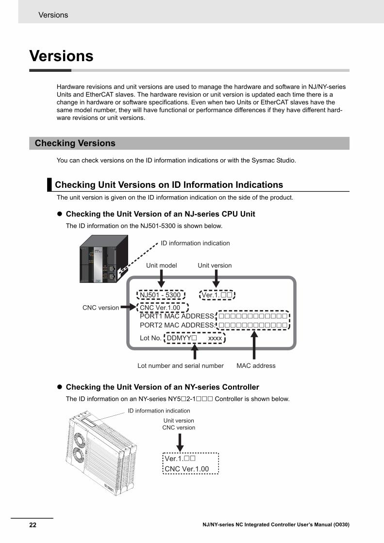
Hardware revisions and unit versions are used to manage the hardware and software in NJ/NY-series Units and EtherCAT slaves. The hardware revision or unit version is updated each time there is a change in hardware or software specifications. Even when two Units or EtherCAT slaves have the same model number, they will have functional or performance differences if they have different hard-ware revisions or unit versions.
You can check versions on the ID information indications or with the Sysmac Studio.
The unit version is given on the ID information indication on the side of the product.
Checking the Unit Version of an NJ-series CPU Unit
The ID information on the NJ501-5300 is shown below.
Checking the Unit Version of an NY-series Controller
The ID information on an NY-series NY52-1 Controller is shown below.
Checking Versions
Checking Unit Versions on ID Information Indications
NJ501 - 5300 Ver.1.
PORT1 MAC ADDRESS: PORT2 MAC ADDRESS:
Lot No. DDMYY xxxx
ID information indication
Unit model Unit version
��
������������
������������
�
MAC addressLot number and serial number
CNC Ver.1.00CNC version
ID information indication
Unit versionCNC version
Ver.1.��
CNC Ver.1.00
23
Versions
NJ/NY-series NC Integrated Controller User’s Manual (O030)
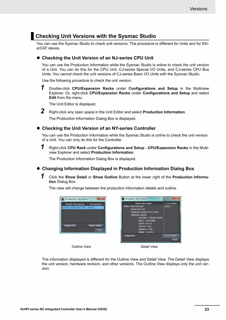
You can use the Sysmac Studio to check unit versions. The procedure is different for Units and for Eth-erCAT slaves.
Checking the Unit Version of an NJ-series CPU Unit
You can use the Production Information while the Sysmac Studio is online to check the unit versionof a Unit. You can do this for the CPU Unit, CJ-series Special I/O Units, and CJ-series CPU BusUnits. You cannot check the unit versions of CJ-series Basic I/O Units with the Sysmac Studio.
Use the following procedure to check the unit version.
1 Double-click CPU/Expansion Racks under Configurations and Setup in the MultiviewExplorer. Or, right-click CPU/Expansion Racks under Configurations and Setup and selectEdit from the menu.
The Unit Editor is displayed.
2 Right-click any open space in the Unit Editor and select Production Information.
The Production Information Dialog Box is displayed.
Checking the Unit Version of an NY-series Controller
You can use the Production Information while the Sysmac Studio is online to check the unit version of a Unit. You can only do this for the Controller.
1 Right-click CPU Rack under Configurations and Setup - CPU/Expansion Racks in the Multi-view Explorer and select Production Information.
The Production Information Dialog Box is displayed.
Changing Information Displayed in Production Information Dialog Box
1 Click the Show Detail or Show Outline Button at the lower right of the Production Informa-tion Dialog Box.
The view will change between the production information details and outline.
The information displayed is different for the Outline View and Detail View. The Detail View displaysthe unit version, hardware revision, and other versions. The Outline View displays only the unit ver-sion.
Checking Unit Versions with the Sysmac Studio
Outline View Detail View

Versions
24 NJ/NY-series NC Integrated Controller User’s Manual (O030)
Checking the Unit Version of an EtherCAT Slave
You can use the Production Information while the Sysmac Studio is online to check the unit versionof an EtherCAT slave. Use the following procedure to check the unit version.
1 Double-click EtherCAT under Configurations and Setup in the Multiview Explorer. Or,right-click EtherCAT under Configurations and Setup and select Edit from the menu.
The EtherCAT Tab Page is displayed.
2 Right-click the master on the EtherCAT Tab Page and select Display Production Information.
The Production Information Dialog Box is displayed.
The unit version is displayed after “Rev.”
Changing Information Displayed in Production Information Dialog Box
1 Click the Show Detail or Show Outline Button at the lower right of the Production Informa-tion Dialog Box.
The view will change between the production information details and outline.
Outline View Detail View

25
Related Manuals
NJ/NY-series NC Integrated Controller User’s Manual (O030)
Related Manuals
The following manuals are related. Use these manuals for reference.
Manual name Cat. No. Model numbers Application Description
NJ-series CPU Unit Hardware User’s Manual
W500 NJ501-NJ301-NJ101-
Learning the basic specifications of the NJ-series CPU Units, including introductory information, designing, installation, and main-tenance. Mainly hardware infor-mation is provided.
An introduction to the entire NJ-series system is provided along with the following informa-tion on the CPU Unit.
• Features and system configuration
• Introduction
• Part names and functions
• General specifications
• Installation and wiring
• Maintenance and inspection
NJ/NX-series CPU Unit Software User’s Manual
W501 NX701-NX1P2-NJ501-NJ301-NJ101-
Learning how to pro-gram and set up an NJ/NX-series CPU Unit. Mainly software infor-mation is provided.
The following information is provided on a Controller built with an NJ/NX-series CPU Unit.
• CPU Unit operation
• CPU Unit features
• Initial settings
• Programming based on IEC 61131-3 lan-guage specifications
NJ/NX-series Instructions Ref-erence Manual
W502 NX701-NX1P2-NJ501-NJ301-NJ101-
Learning detailed specifications on the basic instructions of an NJ/NX-series CPU Unit.
The instructions in the instruction set (IEC 61131-3 specifications) are described.
NJ/NX-series CPU Unit Motion Control User's Manual
W507 NX701-NX1P2-NJ501-NJ301-NJ101-
Learning about motion control set-tings and program-ming concepts.
The settings and operation of the CPU Unit and programming concepts for motion control are described.
NJ/NX-series Motion Control Instructions Reference Manual
W508 NX701-NX1P2-NJ501-NJ301-NJ101-
Learning about the specifications of the motion control instructions.
The motion control instructions are described.
NJ/NX-series CPU Unit Built-in EtherCAT Port User’s Manual
W505 NX701-NX1P2-NJ501-NJ301-NJ101-
Using the built-in Eth-erCAT port on an NJ/NX-series CPU Unit.
Information on the built-in EtherCAT port is provided. This manual provides an introduction and pro-vides information on the configuration, fea-tures, and setup.
NJ/NX-series CPU Unit
Built-in EtherNet/IP Port User's Manual
W506 NX701-NX1P2-NJ501-NJ301-NJ101-
Using the built-in Eth-erNet/IP port on an NJ/NX-series CPU Unit.
Information on the built-in EtherNet/IP port is provided. Information is provided on the basic setup, tag data links, and other features.
NJ/NY-series NC Integrated Controller User's Manual
O030 NJ501-5300 NY532-5400
Performing numeri-cal control with NJ/NY-series Control-lers.
Describes the functionality to perform the numerical control. Use this manual together with the NJ/NY-series G code Instructions Reference Manual (Cat. No. O031) when pro-gramming.
NJ/NY-series G code Instructions Reference Manual
O031 NJ501-5300 NY532-5400
Learning about the specifications of the G code/M code instructions.
The G code/M code instructions are described. Use this manual together with the NJ/NY-series NC Integrated Controller User's Manual (Cat. No. O030) when programming.
NJ/NX-series Troubleshooting Manual
W503 NX701-NX1P2-NJ501-NJ301-NJ101-
Learning about the errors that may be detected in an NJ/NX-series Con-troller.
Concepts on managing errors that may be detected in an NJ/NX-series Controller and information on individual errors are described.

Related Manuals
26 NJ/NY-series NC Integrated Controller User’s Manual (O030)
Sysmac Studio Version 1 Operation Manual
W504 SYSMAC-SE2
Learning about the operating proce-dures and functions of the Sysmac Studio.
Describes the operating procedures of the Sysmac Studio.
CNC OperatorOperation Manual
O032 SYSMAC-RTNC0D
Learning an introduc-tion of the CNC Oper-ator and how to use it.
An introduction of the CNC Operator, installa-tion procedures, basic operations, connection operations, and operating procedures for main functions are described.
NY-series IPC Machine Con-troller Industrial Panel PC Hardware User’s Manual
W557 NY532-1 Learning the basic specifications of the NY-series Industrial Panel PCs, including introductory informa-tion, designing, instal-lation, and maintenance. Mainly hardware infor-mation is provided.
An introduction to the entire NY-series system is provided along with the following informa-tion on the Industrial Panel PC.
• Features and system configuration
• Introduction
• Part names and functions
• General specifications
• Installation and wiring
• Maintenance and inspection
NY-series IPC Machine Con-troller Industrial Box PC Hard-ware User’s Manual
W556 NY512-1 Learning the basic specifications of the NY-series Industrial Box PCs, including introductory informa-tion, designing, instal-lation, and maintenance. Mainly hardware infor-mation is provided.
An introduction to the entire NY-series system is provided along with the following informa-tion on the Industrial Box PC.
• Features and system configuration
• Introduction
• Part names and functions
• General specifications
• Installation and wiring
• Maintenance and inspection
NY-series IPC Machine Con-troller Industrial Panel PC / Industrial Box PC Setup User’s Manual
W568 NY532-1
NY512-1
Learning the initial set-tings of the NY-series Industrial PCs and preparations to use Controllers.
The following information is provided on an introduction to the entire NY-series system.
• Two OS systems
• Initial settings
• Industrial PC Support Utility
• NYCompolet
• Industrial PC API
• Backup & recovery
NY-series IPC Machine Con-troller Industrial Panel PC / Industrial Box PC Software User’s Manual
W558 NY532-1
NY512-1
Learning how to pro-gram and set up the Controller functions of an NY-series Industrial PC.
The following information is provided on the NY-series Controller functions.
• Controller operations
• Controller functions
• Controller settings
• Programming based on IEC 61131-3 lan-guage specifications
NY-series Instructions Refer-ence Manual
W560 NY532-1
NY512-1
Learning detailed specifications on the basic instructions of an NY-series Indus-trial PC.
The instructions in the instruction set (IEC61131-3 specifications) are described.
NY-series IPC Machine Con-troller Industrial Panel PC / Industrial Box PC Motion Con-trol User’s Manual
W559 NY532-1
NY512-1
Learning about motion control settings and programming con-cepts of an NY-series Industrial PC.
The settings and operation of the Controller and programming concepts for motion control are described.
NY-series Motion Control Instructions Reference Manual
W561 NY532-1
NY512-1
Learning about the specifications of the motion control instructions of an NY-series Industrial PC.
The motion control instructions are described.
Manual name Cat. No. Model numbers Application Description
27
Related Manuals
NJ/NY-series NC Integrated Controller User’s Manual (O030)
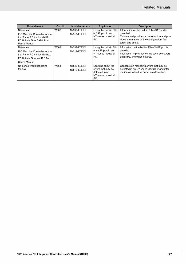
NY-series
IPC Machine Controller Indus-trial Panel PC / Industrial Box PC Built-in EtherCAT Port User’s Manual
W562 NY532-1
NY512-1
Using the built-in Eth-erCAT port in an NY-series Industrial PC.
Information on the built-in EtherCAT port is provided. This manual provides an introduction and pro-vides information on the configuration, fea-tures, and setup.
NY-series
IPC Machine Controller Indus-trial Panel PC / Industrial Box
PC Built-in EtherNet/IP Port
User’s Manual
W563 NY532-1
NY512-1
Using the built-in Eth-erNet/IP port in an NY-series Industrial PC.
Information on the built-in EtherNet/IP port is provided. Information is provided on the basic setup, tag data links, and other features.
NY-series Troubleshooting Manual
W564 NY532-1
NY512-1
Learning about the errors that may be detected in an NY-series Industrial PC.
Concepts on managing errors that may be detected in an NY-series Controller and infor-mation on individual errors are described.
Manual name Cat. No. Model numbers Application Description

Terminology
28 NJ/NY-series NC Integrated Controller User’s Manual (O030)
Terminology
Term Description
NJ501-1 Represents NJ501-1300/-1400/-1500.
NJ-series NJ NC Integrated Controller Represents NJ501-5300. It may also be described as NJ501-5.
NY-series NY NC Integrated Controller Represents NY532-5400. It may also be described as NY5-5400.
Axis Coordinate System
(Axis Coordinate System)
Indicates a rotational coordinate system or orthogonal coordinate system unique to each axis.
It is abbreviated as ACS.
Machine Coordinate System
(Machine Coordinate System)
Indicates an orthogonal coordinate system unique to a machine.
It is abbreviated as MCS.
User Coordinate System
(User Coordinate System)
Indicates an orthogonal coordinate system that the user can define arbitrarily.
It is abbreviated as UCS.
Tool Coordinate System
(Tool Coordinate System)
Indicates an orthogonal coordinate system having TCP as the origin.
It is abbreviated as TCS.
TCS0
(Tool Coordinate System 0)
Indicates the default TCS. The origin is TCP0.
TCSi
(Tool Coordinate System i)
Indicates the TCS that the robot is currently selecting. It represents the TCS whose ToolID is i, where i is a number 1 to 16.
TCP (Tool Center Point) Indicates the end with which the machine (robot) works.
Specify this TCP to set positioning in an orthogonal coordinate system.
TCP0 (Tool Center Point 0) Indicates the default TCP.
29
Revision History
NJ/NY-series NC Integrated Controller User’s Manual (O030)
Revision History
A manual revision code appears as a suffix to the catalog number on the front and back covers of the manual.
Revision code Date Revised content
01 October 2017 Original production
O030-E1-01Cat. No.Revision code

Revision History
30 NJ/NY-series NC Integrated Controller User’s Manual (O030)
1 - 1
1
NJ/NY-series NC Integrated Controller User’s Manual (O030)
This section describes the features, system configuration, and application flow for the CNC Function Module.
1-1 Features . . . . . . . . . . . . . . . . . . . . . . . . . . . . . . . . . . . . . . . . . . . . . . . . . . . . . 1-2
1-2 System Configuration . . . . . . . . . . . . . . . . . . . . . . . . . . . . . . . . . . . . . . . . . . 1-4
1-3 Basic Flow of Operation . . . . . . . . . . . . . . . . . . . . . . . . . . . . . . . . . . . . . . . . 1-6
1-4 Specifications . . . . . . . . . . . . . . . . . . . . . . . . . . . . . . . . . . . . . . . . . . . . . . . . . 1-71-4-1 General Specifications . . . . . . . . . . . . . . . . . . . . . . . . . . . . . . . . . . . . . . . . . . 1-7
1-4-2 Performance Specifications . . . . . . . . . . . . . . . . . . . . . . . . . . . . . . . . . . . . . . 1-7
1-4-3 Function Specifications . . . . . . . . . . . . . . . . . . . . . . . . . . . . . . . . . . . . . . . . . . 1-9
1-4-4 NC Program Specifications . . . . . . . . . . . . . . . . . . . . . . . . . . . . . . . . . . . . . . .1-11
Introduction to the CNC Function Module

1 Introduction to the CNC Function Module
1 - 2 NJ/NY-series NC Integrated Controller User’s Manual (O030)
1-1 Features
The NJ/NY-series Contollers are the machine automation controllers of the next generation. They pro-vide various functionality and high-speed performance required for machine control, as well as safety, reliability, and maintainability required as industrial controllers.
In addition to the functionality given by conventional OMRON PLCs, the NJ/NY-series Controllers, as the integrated controllers, are equipped with multiple functionality required for numeric control, and can control input and output devices such as safety, vision, motion devices, and I/O Units synchronously via high-speed EtherCAT.
OMRON offers Sysmac devices that are control devices built with unified communications and user interface specifications. The NJ/NY-series Controllers are designed to realize the optimum functionality and operability when they are used with the Sysmac devices such as EhtherCAT slaves and the Sys-mac Studio Automation Software. In a system configured with Sysmac devices, you can improve con-nectability and operability as the devices share the consistent usability concept.
The CNC Function Module is a software function module that is built into the NC Integrated Controller.
The CNC Function Module can control CNC coordinate systems via the EtherCAT port that is built into the NC Integrated Controller. Up to four CNC coordinate systems can be controlled with the NJ-series NC Integrated Controller, and up to eight with the NY-series NC Integrated Controller.
Cyclic communications are performed with Servo Drives and other devices that are connected to the EtherCAT port to enable high-speed and high-precision numerical control.
CNC Function Module
NJ-series Controller
EtherCAT control network
Machine visionServo Drives andInverters
Multitasking, Synchronized Control
IEC programming
Motion controlSequence control
Sysmac StudioAutomation Software
I/O controlsSafety devices

1 - 3
1 Introduction to the CNC Function Module
NJ/NY-series NC Integrated Controller User’s Manual (O030)
1-1 Featu
res
1
NC programs for numerical control of the CNC Function Module use languages dedicated to the NC program, represented by G codes. By using NC programs, you can easily machine complex shapes and change machining drawings.
NC programs enable to use the interpolation function that specifies target positions and feed rate, the function of spindle axis that specifies cutting feed rate, and the tool functions such as compensating tool length and radius.
Synchronization with sequence control programs (ladder and ST) is possible by using M codes.
Sequence control programs use CNC instructions to control the CNC Function Module.
In addition to the function block used to start an NC program, the sequence control program has other function blocks used to perform jogging, deceleration stop, and maintenance operation that reads and writes parameters.
The CNC Function Module can be combined with OMRON 1S-series Servo Drives with built-in Ether-CAT communications or G5-series with built-in EtherCAT communications to enable exchange of all control information by using high-speed data communications.
Various control commands are transmitted via data communications. This means that the Servomotor's operational performance is maximized without being limited by interface specifications, such as the response frequency of encoder feedback pulses.
You can use the Servo Drive's various control parameters and monitor data on a host controller to unify system information management.
Additional Information
What is EtherCAT?
EtherCAT is an open ultrahigh-speed industrial network system that conforms to Ethernet (IEEE802.3). Each node achieves a short communication cycle time by transmitting Ethernet frames at a high speed. The mechanism that shares clock information enables high-precision synchronized control with low communications jitter.
NC Program
Sequence Control Program
Data Transmission Using EtherCAT Communications

1 Introduction to the CNC Function Module
1 - 4 NJ/NY-series NC Integrated Controller User’s Manual (O030)
1-2 System Configuration
The CNC Function Module receives sensor signal status from devices and control panels. It receives commands from the CNC instructions that are executed in the NC program or sequence control pro-gram. It uses both of them to control Servo Drives and spindle drivers as well as to perform precise numerical control and spindle axis control.
The CNC Function Module uses the EtherCAT network configuration, the Slave Terminal configurations for EtherCAT Coupler Units, Sysmac Studio, and CNC Operator.
EtherCAT Network Configuration
The CNC Function Module controls Servo Drives and the spindle driver by using the EtherCAT com-munications master port that is built into the NC Integrated Controller.
The EtherCAT network configuration is used to perform precise numerical control in a fixed period with very little deviation.
Slave Terminal Configurations of EtherCAT Coupler Units
The CNC Function Module uses the Pulse Encoder Unit and Digital Input Unit that are mounted under an EtherCAT Coupler Unit to load the MPG and Jog switch.
You can also use this configuration to perform numerical control for maintenance operation that can be carried out from a user program.
CNC System Configuration

1 - 5
1 Introduction to the CNC Function Module
NJ/NY-series NC Integrated Controller User’s Manual (O030)
1-2 System
Co
nfig
uratio
n
1
Sysmac Studio
Sysmac Studio is connected to the peripheral USB port on the NC Integrated Controller using a commercially available USB cable. You can also connect it through an Ethernet cable that is con-nected to the EtherNet/IP port built into the NC Integrated Controller.
CNC Operator
In this system, NC programs are transferred from CNC Operator that is running on a Windows com-puter. To establish a connection to a Windows computer, connect an Ethernet cable to the Ether-net/IP port that is built into the NC Integrated Controller. You cannot use a USB cable to establish the connection.
Sysmac Studio CNC Operator
LAN USB
or
EtherNet/IPEtherNet/IP
EtherCAT
NJ-series Controller Peripheral USB port
Built-in EtherNet/IP port
Built-in EtherCAT port
Slave Terminal
* The NY-series NC Integrated Controller is not equipped with peripheral USB ports.
1S-series Servo Drive
EtherCAT communications built-in type
G5-series Servo Drive
Network configurationsEtherCAT
Encoder input terminalExternal latch input, etc.
Home InputHome Proximity InputImmediate stop inputNegative limit inputPositive limit Input
EtherCAT communications built-in type

1 Introduction to the CNC Function Module
1 - 6 NJ/NY-series NC Integrated Controller User’s Manual (O030)
1-3 Basic Flow of Operation
This section describes the basic procedure to perform numerical control using the CNC Function Mod-ule.
Mechanical wiring check (Sysmac Studio is not used)
Setting of CNC coordinate systems and motors
Programming
Debugging
Maintenance and startup
1 - 7
1 Introduction to the CNC Function Module
NJ/NY-series NC Integrated Controller User’s Manual (O030)
1-4 Sp
ecificatio
ns
1
1-4-1 G
eneral S
pecifications
1-4 Specifications
This section describes the specifications of the CNC Function Module.
General specifications conform to the general specifications of each series of the Controllers.
For details, refer to the NJ-series CPU Unit Hardware User's Manual (Cat. No. W500) or NY-series Industrial Panel PC Hardware User's Manual (Cat. No. W557).
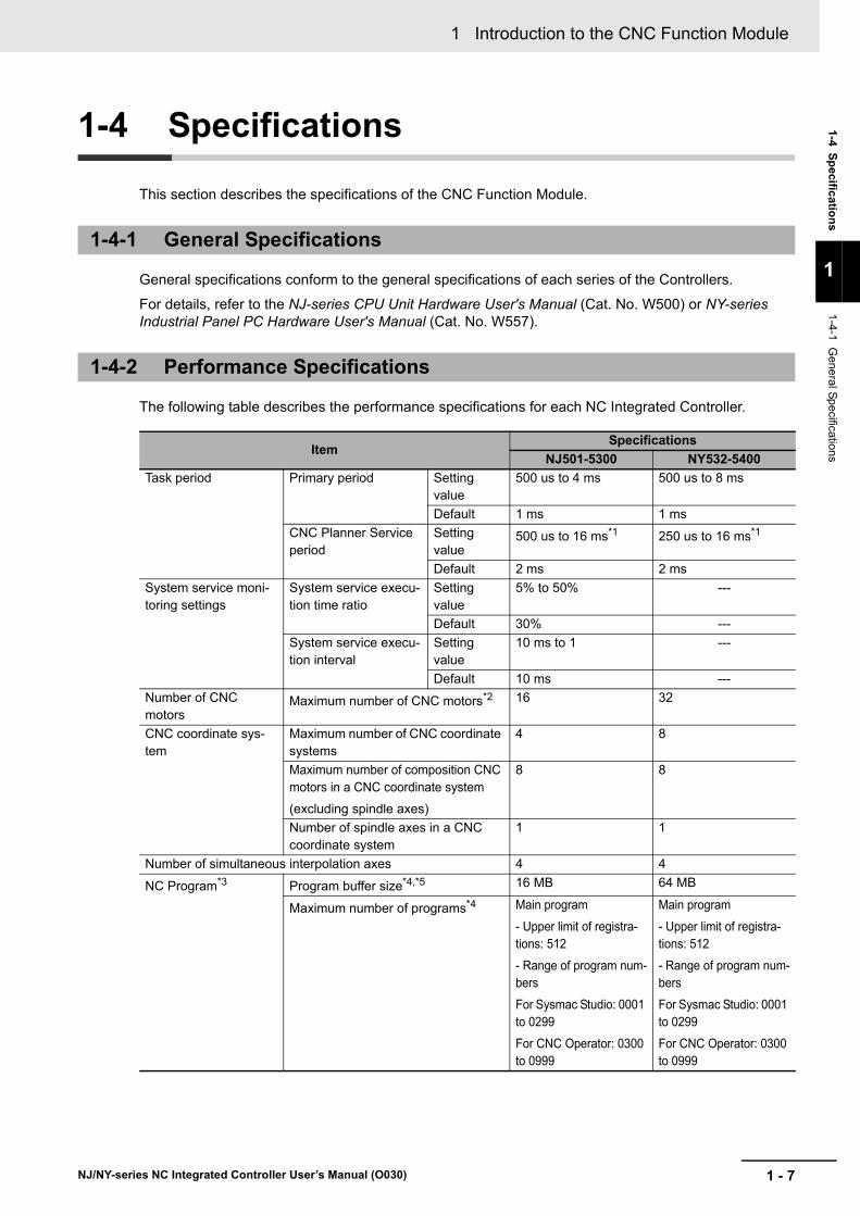
The following table describes the performance specifications for each NC Integrated Controller.
1-4-1 General Specifications
1-4-2 Performance Specifications
ItemSpecifications
NJ501-5300 NY532-5400
Task period Primary period Setting value
500 us to 4 ms 500 us to 8 ms
Default 1 ms 1 ms
CNC Planner Service period
Setting value
500 us to 16 ms*1 250 us to 16 ms*1
Default 2 ms 2 ms
System service moni-toring settings
System service execu-tion time ratio
Setting value
5% to 50% ---
Default 30% ---
System service execu-tion interval
Setting value
10 ms to 1 ---
Default 10 ms ---
Number of CNC motors
Maximum number of CNC motors*2 16 32
CNC coordinate sys-tem
Maximum number of CNC coordinate systems
4 8
Maximum number of composition CNC motors in a CNC coordinate system
(excluding spindle axes)
8 8
Number of spindle axes in a CNC coordinate system
1 1
Number of simultaneous interpolation axes 4 4
NC Program*3 Program buffer size*4,*5 16 MB 64 MB
Maximum number of programs*4 Main program
- Upper limit of registra-tions: 512
- Range of program num-bers
For Sysmac Studio: 0001 to 0299
For CNC Operator: 0300 to 0999
Main program
- Upper limit of registra-tions: 512
- Range of program num-bers
For Sysmac Studio: 0001 to 0299
For CNC Operator: 0300 to 0999

1 Introduction to the CNC Function Module
1 - 8 NJ/NY-series NC Integrated Controller User’s Manual (O030)
Precautions for Correct Use
To run the CNC Function Module, approximately 150 μs must be secured for system service execution time. Adjust the system service execution time ratio, so that the above system ser-vice execution time can be secured.
NC program vari-
ables*3
P variable Long reals
65536 variables
Long reals
65536 variables
Q variable Long reals
8192 variables
Long reals
8192 variables
L variable Long reals
8192 variables
Long reals
8192 variables
CNC motor compensa-tion table
Maximum number of CNC motor compensation tables
32 64
Maximum size of all compensation tables
1 MB 2 MB
*1. They satisfy the following conditions: Primary periodic task ≤ CNC Planner Service period, and Integer multi-ples of primary periodic task.
*2. The number of controlled axes of the MC Control Function Module is included.
*3. Some parts of the area are reserved by the system.
*4. This is the number of programs or their capacities that can be loaded into the NC Integrated Controller at the same time.
*5. The program capacity is the maximum size available. As fragmentation will occur, the size that is actually avail-able will be smaller than the maximum size. As a guideline, limit the size to be used to approximately half the capacity.
ItemSpecifications
NJ501-5300 NY532-5400

1 - 9
1 Introduction to the CNC Function Module
NJ/NY-series NC Integrated Controller User’s Manual (O030)
1-4 Sp
ecificatio
ns
1
1-4-3 F
unction S
pecifications
The following table shows the functions that are supported when the Controller is connected to OMRON control devices.
1-4-3 Function Specifications
Item NJ501-5300
Numeri-cal con-trol
CNC coordi-nate system
Axis type Positioning axis, spindle axis
Control modes
Positioning axis Position control
Spindle axis Velocity control
Positions that can be managed Absolute position (command), absolute position (feedback), program position, remaining travel distance
NC program execution
Execute Executes the NC program.
Reset Interrupts the NC program.
Single block execution Executes the NC program by block.
Back trace Executes back trace of interpolation path.
Feed hold, and feed hold reset Temporarily stops the NC program, and restarts it.
Optional stop Stops the NC program with optional signal.
Option block skip Skips one block of the NC program with optional signal.
Dry run Runs from the NC program.
Machine lock Locks each axis operation during execution of the NC program.
Auxiliary function lock Locks M code output.
Override Overrides the feed rate and spindle velocity.
G code Positioning function
Rapid position-ing
Rapid feed of each CNC motor according to the motor setting
Linear interpo-lation
Interpolates linearly.
Circular inter-polation
Interpolates circularly, helically, spirally, or coni-cally.
Skip function Rapid feed until an external signal is input
Return to reference point Returns to a specified position on the machine.
Fixed cycle Rigid tap Performs tapping machining.
Feed function Exact stop Temporarily prevents blending of positioning oper-ations before and after an exact stop command.
Exact stop mode
Mode in which anteroposterior positioning opera-tions are not blended
Continu-ous-path mode
Mode in which anteroposterior positioning opera-tions are blended
Dwell Waits for the specified period of time.
Coordinate system selec-tion
Dimension Shift Cancel
The coordinate system uses the machine home position as the home of the system.
Zero Shift The coordinate system has work offset for the Machine Coordinate System.
Local Coordi-nate System Set
The coordinate system has additional offset for the Work Coordinate System.
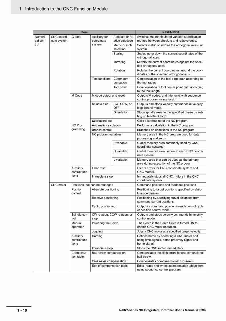
1 Introduction to the CNC Function Module
1 - 10 NJ/NY-series NC Integrated Controller User’s Manual (O030)
Numeri-cal con-trol
CNC coordi-nate system
G code Auxiliary for coordinate system
Absolute or rel-ative selection
Switches the manipulated variable specification method between absolute and relative ones.
Metric or inch selection
Selects metric or inch as the orthogonal axes unit system.
Scaling Scales up or down the current coordinates of the orthogonal axes.
Mirroring Mirrors the current coordinates against the speci-fied orthogonal axes.
Rotation Rotates the current coordinates around the coor-dinates of the specified orthogonal axis.
Tool functions Cutter com-pensation
Compensation of the tool edge path according to the tool radius
Tool offset Compensation of tool center point path according to the tool length
M Code M code output and reset Outputs M codes, and interlocks with sequence control program using reset.
Spindle axis CW, CCW, or OFF
Outputs and stops velocity commands in velocity loop control mode.
Orientation Stops spindle axes to the specified phase by set-ting up feedback loop.
Subroutine call Calls a subroutine of the NC program.
NC Pro-gramming
Arithmetic calculation Performs a calculation in the NC program.
Branch control Branches on conditions in the NC program.
NC program variables Memory area in the NC program used for data processing and so on
P variable Global memory area commonly used by CNC coordinate systems
Q variable Global memory area unique to each CNC coordi-nate system
L variable Memory area that can be used as the primary area during execution of the NC program
Auxiliary control func-tions
Error reset Clears errors for CNC coordinate system and CNC motors.
Immediate stop Immediately stops all CNC motors in the CNC coordinate system.
CNC motor Positions that can be managed Command positions and feedback positions
Position control
Absolute positioning Positioning to target positions specified by abso-lute coordinates.
Relative positioning Positioning by specifying travel distances from command current positions.
Cyclic positioning Outputs a command position in each control cycle of position control mode.
Spindle con-trol
CW rotation, CCW rotation, or stop
Outputs and stops velocity commands in velocity control mode.
Manual operation
Powering the Servo The Servo in the Servo Drive is turned ON to enable CNC motor operation.
Jogging Jogs a CNC motor at a specified target velocity.
Auxiliary control func-tions
Homing Defines home by operating a CNC motor and using limit signals, home proximity signal and home signal.
Immediate stop Stops the CNC motor immediately.
Compensa-tion table
Ball screw compensation Compensates the pitch errors for one-dimensional ball screw.
Cross-axis compensation Compensates one-dimensional cross-axis.
Edit of compensation table Edits (reads and writes) compensation tables from using sequence control program.
Item NJ501-5300

1 - 11
1 Introduction to the CNC Function Module
NJ/NY-series NC Integrated Controller User’s Manual (O030)
1-4 Sp
ecificatio
ns
1
1-4-4 N
C P
rogram S
pecifications
Refer to the NJ/NY-series G code Instructions Reference Manual (Cat. No. O031) for NC program specifications.
Numeri-cal con-trol
CNC motor Auxiliary function
In-position Check You can set an in-position range and in-position check time to confirm when positioning is com-pleted.
Stop method selection You can set the stop method to the immediate stop input signal or limit input signal.
Monitoring functions
Software limits Monitors the movement range of a CNC motor.
Following error Monitors the positional error between the com-mand current value and the feedback current value for a CNC motor.
Absolute encoder support You can use an OMRON G5-series Servo Drive or 1S-series Servomotor with an Absolute Encoder to eliminate the need to perform homing at startup.
Input signal logic inversion You can inverse the logic of immediate stop input signal, positive limit input signal, negative limit input signal, or home proximity input signal.
External interface signals The Servo Drive input signals given below are used.
Home signal, home proximity signal, positive limit signal, negative limit signal, immediate stop sig-nal, and interrupt input signal
Common items
Parameters Changing CNC coordinate sys-tem parameters and CNC motor parameters
References and changes CNC coordinate system parameters and CNC motor parameters from the user program.
1-4-4 NC Program Specifications
Item NJ501-5300
1 Introduction to the CNC Function Module
1 - 12 NJ/NY-series NC Integrated Controller User’s Manual (O030)
2 - 1
2
NJ/NY-series NC Integrated Controller User’s Manual (O030)
This section outlines the internal structure of the NC Integrated Controller and describes the configuration and principles of the CNC Function Module.
2-1 Internal Structure of NC Integrated Controller . . . . . . . . . . . . . . . . . . . . . . 2-2
2-2 CNC System Configuration . . . . . . . . . . . . . . . . . . . . . . . . . . . . . . . . . . . . . . 2-42-2-1 Configuration of CNC Operator and the NC Integrated Controller . . . . . . . . . 2-4
2-2-2 Configuration of NC Integrated Controller and Drive Control . . . . . . . . . . . . . 2-5
2-2-3 Configuration of NC Program . . . . . . . . . . . . . . . . . . . . . . . . . . . . . . . . . . . . . 2-6
2-3 Relationship between Sequence Control Program and NC Program . . . . 2-8
2-4 Configuration of Variables . . . . . . . . . . . . . . . . . . . . . . . . . . . . . . . . . . . . . 2-102-4-1 What is the NC Program Variable? . . . . . . . . . . . . . . . . . . . . . . . . . . . . . . . . 2-10
2-4-2 NC Program Variable Types . . . . . . . . . . . . . . . . . . . . . . . . . . . . . . . . . . . . . 2-12
2-5 Principle of Task Processing . . . . . . . . . . . . . . . . . . . . . . . . . . . . . . . . . . . 2-14
2-6 Relationship with EtherCAT Communications . . . . . . . . . . . . . . . . . . . . . 2-192-6-1 CAN Application Protocol over EtherCAT (CoE) . . . . . . . . . . . . . . . . . . . . . 2-19
2-6-2 Relationship between EtherCAT Master Function Module and CNC Function Module . . . . . . . . . . . . . . . . . . . . . . . . . . . . . . . . . . . . . . . . . . . . . . . . . . . . . 2-20
2-6-3 Relationship between Process Data Communications Cycle and the Control Period for Servo Drive . . . . . . . . . . . . . . . . . . . . . . . . . . . . . . . . . . . . . . . . . 2-21
CNC System Configuration and Principles
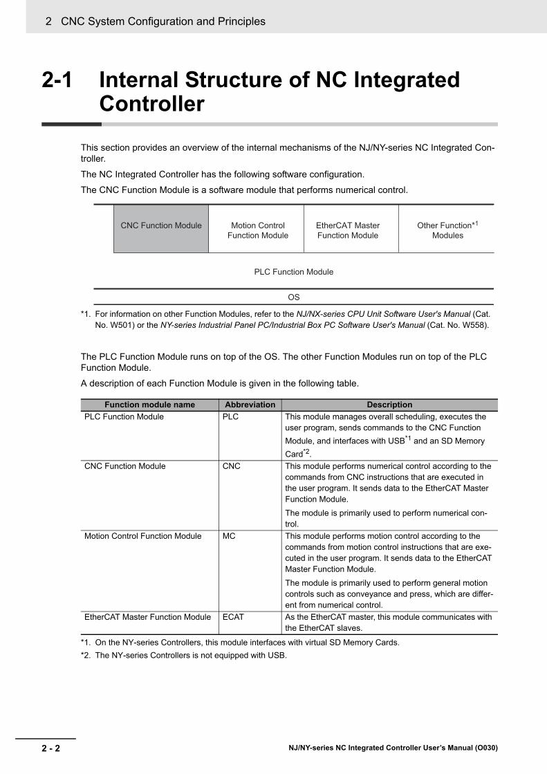
2 CNC System Configuration and Principles
2 - 2 NJ/NY-series NC Integrated Controller User’s Manual (O030)
2-1 Internal Structure of NC Integrated Controller
This section provides an overview of the internal mechanisms of the NJ/NY-series NC Integrated Con-troller.
The NC Integrated Controller has the following software configuration.
The CNC Function Module is a software module that performs numerical control.
*1. For information on other Function Modules, refer to the NJ/NX-series CPU Unit Software User's Manual (Cat. No. W501) or the NY-series Industrial Panel PC/Industrial Box PC Software User's Manual (Cat. No. W558).
The PLC Function Module runs on top of the OS. The other Function Modules run on top of the PLC Function Module.
A description of each Function Module is given in the following table.
Function module name Abbreviation Description
PLC Function Module PLC This module manages overall scheduling, executes the user program, sends commands to the CNC Function
Module, and interfaces with USB*1 and an SD Memory
Card*2.
*1. On the NY-series Controllers, this module interfaces with virtual SD Memory Cards.
*2. The NY-series Controllers is not equipped with USB.
CNC Function Module CNC This module performs numerical control according to the commands from CNC instructions that are executed in the user program. It sends data to the EtherCAT Master Function Module.
The module is primarily used to perform numerical con-trol.
Motion Control Function Module MC This module performs motion control according to the commands from motion control instructions that are exe-cuted in the user program. It sends data to the EtherCAT Master Function Module.
The module is primarily used to perform general motion controls such as conveyance and press, which are differ-ent from numerical control.
EtherCAT Master Function Module ECAT As the EtherCAT master, this module communicates with the EtherCAT slaves.
CNC Function Module Motion Control Function Module
EtherCAT Master Function Module
PLC Function Module
OS
Other Function*1 Modules

2 - 3
2 CNC System Configuration and Principles
NJ/NY-series NC Integrated Controller User’s Manual (O030)
2-1 Intern
al Stru
cture o
f NC
Integ
rated
Co
n-
trolle
r
2
Precautions for Correct Use
For information on other Function Modules, refer to the NJ/NX-series CPU Unit Software User's Manual (Cat. No. W501) or the NY-series Industrial Panel PC/Industrial Box PC Software User's Manual (Cat. No. W558).

2 CNC System Configuration and Principles
2 - 4 NJ/NY-series NC Integrated Controller User’s Manual (O030)
2-2 CNC System Configuration
A CNC system consists of the following two system elements:
• A system for which coordination with CNC Operator is required. Such coordination includes creation, execution, and stop of NC programs (refer to 2-2-1 Configuration of CNC Operator and the NC Inte-grated Controller on page 2-4).
• A system that performs numerical control and controls Servomotors with instructions received from CNC Operator (refer to 2-2-2 Configuration of NC Integrated Controller and Drive Control on page 2-5).
• NC programs are created using CAD/CAM software, or directly created on CNC Operator.
• The created NC program is transferred from CNC Operator to the NC Integrated Controller.
• When executing the CNC_CoordControl (CNC Coordinate System NC Control) instruction in the user program, according to NC program execution processing by CNC Operator, the NC program trans-ferred from CNC Operator is interpreted to perform numerical control.
2-2-1 Configuration of CNC Operator and the NC Integrated Controller
CAD CAM Sysmac Studio
Computer Computer Computer
CNC Operator NC program
NC Integrated Controller
NJ/NY-series
NC program
NC program transfer- Executing the NC program after transfer
DXF, IGES, etc.
SD Memory Card*1
External storage
*1 On the NY-series NC Integrated Controller, this is a virtual SD Memory Card.
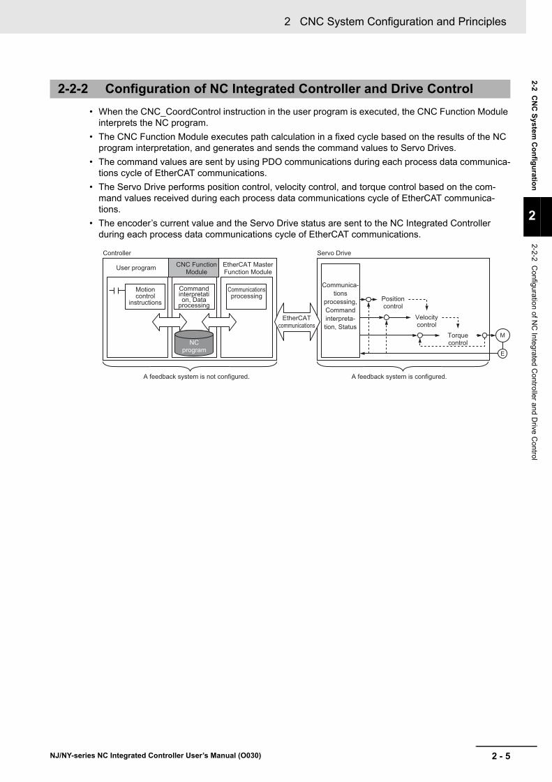
2 - 5
2 CNC System Configuration and Principles
NJ/NY-series NC Integrated Controller User’s Manual (O030)
2-2 C
NC
System
Co
nfig
uratio
n
2
2-2-2 Configuration of N
C Integra
ted Controller and D
rive Control
• When the CNC_CoordControl instruction in the user program is executed, the CNC Function Module interprets the NC program.
• The CNC Function Module executes path calculation in a fixed cycle based on the results of the NC program interpretation, and generates and sends the command values to Servo Drives.
• The command values are sent by using PDO communications during each process data communica-tions cycle of EtherCAT communications.
• The Servo Drive performs position control, velocity control, and torque control based on the com-mand values received during each process data communications cycle of EtherCAT communica-tions.
• The encoder’s current value and the Servo Drive status are sent to the NC Integrated Controller during each process data communications cycle of EtherCAT communications.
2-2-2 Configuration of NC Integrated Controller and Drive Control
M
E
Controller
User program
Motioncontrol
instructions
Communica-tions
processing, Command interpreta-tion, Status
Position control
Velocity control
Torque control
EtherCAT communications
Command interpretation, Data
processing
Communications processing
CNC Function Module
NC program
EtherCAT Master Function Module
A feedback system is not configured. A feedback system is configured.
Servo Drive

2 CNC System Configuration and Principles
2 - 6 NJ/NY-series NC Integrated Controller User’s Manual (O030)
The NC program is a program used to perform numerical control.
The following diagram describes the configuration of the NC program.
*1. The NC program that was created using CAD/CAM software conforms to the grammar of CNC Function Mod-ule when the program is parsed with Sysmac Studio or CNC Operator.
Precautions for Correct Use
• If you have transferred the same NC program number more than once, the program trans-ferred last is enabled. Arrange the user program so that duplication of NC program numbers does not occur.
2-2-3 Configuration of NC Program
NC Program Configuration
Sysmac Studio
CNC Operator
Download and upload
CNC Motor ParametersCNC Coordinate
System ParametersNC program
NC program
CNC Motor Parameters CNC_CoordControl instructions
Subprogram callM98
NC programExternal
non-volatile memory
Built-in non-volatile
memory
Sequence control
programMain memory
ExecutionNC Program
Commandsubprogram
CommandMain program
When the CNC_LoadProgramFile instruction is executed
NC Integrated Controller
CNC Coordinate System Parameters
NC program
Download
CAD/CAM software*1

2 - 7
2 CNC System Configuration and Principles
NJ/NY-series NC Integrated Controller User’s Manual (O030)
2-2 C
NC
System
Co
nfig
uratio
n
2
2-2-3 Configuration of N
C P
rogram
The following three methods are available to transfer an NC program to the NC Integrated Controller.
• Transferring an NC program from Sysmac Studio to the non-volatile memory in the NC Integrated Controller. The NC program that is transferred to the non-volatile memory of the NC Integrated Con-troller is read into the main memory when the power is turned ON or the download process is com-pleted. This method is typically used to download subprograms provided by a machining equipment manufacturer.
• Using FTP or other protocols or methods to transfer intermediate codes, generated by CNC Opera-tor, from the computer to the SD Memory Card. They are transferred from the SD Memory Card into the main memory by executing the dedicated program read instruction. This method is typically used to change recipes more easily by only operating HMI.
• Transferring the NC program from CNC Operator into the main memory by temporarily using an SD Memory Card
Additional Information
To expand the NC program into the main memory via an SD Memory Card, insert the SD Mem-ory Card in advance.
For an NY-series Controller, enable the virtual SD Memory Card.
An NC program executed from CNC instructions of a user program is called the main program. Pro-grams that pick up and summarize similar parts of the main programs, such as machining in the same pattern, are called subprograms.
If the Subprogram Call (M98) instruction is read during execution of the main program, the subprogram is executed. After the execution of the subprogram is completed, the process returns to the main pro-gram and executes the remaining part of the main program.
The following shows an image of the relationship between the main program and the subprogram.
How to Transfer an NC Program
Main Program and Subprogram
// MAIN PROGRAM
M98 P3000
M98 P3001
M30
// SUB PROGRAM
O3000
M98 P1000
M99
// SUB PROGRAM
O1000
M99 // SUB PROGRAM
O3001
M98 P1000
M99
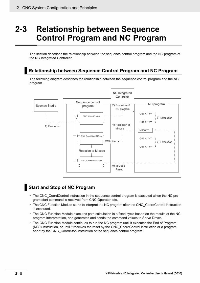
2 CNC System Configuration and Principles
2 - 8 NJ/NY-series NC Integrated Controller User’s Manual (O030)
2-3 Relationship between Sequence Control Program and NC Program
The section describes the relationship between the sequence control program and the NC program of the NC Integrated Controller.
The following diagram describes the relationship between the sequence control program and the NC program.
• The CNC_CoordControl instruction in the sequence control program is executed when the NC pro-gram start command is received from CNC Operator, etc.
• The CNC Function Module starts to interpret the NC program after the CNC_CoordControl instruction is executed.
• The CNC Function Module executes path calculation in a fixed cycle based on the results of the NC program interpretation, and generates and sends the command values to Servo Drives.
• The CNC Function Module continues to run the NC program until it executes the End of Program (M30) instruction, or until it receives the reset by the CNC_CoordControl instruction or a program abort by the CNC_CoordStop instruction of the sequence control program.
Relationship between Sequence Control Program and NC Program
Start and Stop of NC Program
1)
2)
4)
5)
3)
6)
CNC_CoordControl
CNC_CoordMatchMCode
CNC_CoordResetCode
G01 X**Y**
G01 X**Y**
G01 X**Y**
G02 X**Y**
M100 ***
Sysmac Studio
NC Integrated Controller
Sequence control program
Reaction to M code
NC program
Reception of M code
Execution
Execution
Execution of NC program
M Code Reset
Execution
MStrobe
2 - 9
2 CNC System Configuration and Principles
NJ/NY-series NC Integrated Controller User’s Manual (O030)
2-3 Relatio
nsh
ip b
etween
Se
qu
en
ce Co
ntro
lP
rog
ram a
nd
NC
Pro
gram
2
• When the FeedHold input variable under the ControlInputs in-out variable for the CNC_CoordControl (CNC Coordinate System NC Control) instruction is changed to TRUE, the NC program currently under execution is temporarily stopped.
• When the CycleStart input variable under the ControlInputs in-out variable for the CNC_CoordControl (CNC Coordinate System NC Control) instruction is changed to TRUE, the NC program execution is resumed.
• If the CNC Function Module finds an M code during execution of the NC program, the module sends the M code to the sequence control program.
• The sequence control program executes the CNC_CoordCatchMCode (Catch M Code) instruction to receive the M code.
• The sequence control program executes peripheral controls (conveyance control, valve ON/OFF, etc.) corresponding to the received M code.
• After completing peripheral controls, the sequence control program executes the CNC_CoordReset-MCode (Reset M code) instruction to send M code reset.
• The CNC function Module, after receiving the M code reset signal, clears the waiting status for a M code reset, and moves on to the next block.
Feed Hold and Feed Hold Reset of NC Program
M-code and M-code Reset of NC Program
2 CNC System Configuration and Principles
2 - 10 NJ/NY-series NC Integrated Controller User’s Manual (O030)
2-4 Configuration of Variables
This section describes variables provided for the NC Integrated Controller that is equipped with the CNC Function Module.
As is the case with standard CPU Units, the NC Integrated Controller has variables used for the sequence control program to access I/O and information inside the CPU Unit.
In addition, the NC Integrated Controller particularly has variable areas called NC program variables used for data calculations and other processing in NC program.
In this section, user-defined variables and system-defined variables refer to variables that can be accessed from the sequence control program. On the other hand, NC program variables and sys-tem-defined NC program variables refer to variables that can be accessed from the NC program.
The NC program variables refer to variable areas used for data calculations and other processing in NC program.
There are the system global variables (P variables) that are common to CNC coordinate systems, global variables (Q variables) that are unique to individual CNC coordinate systems, and local variables (L variables) that can be used as the primary area during program execution.
Some NC program variable areas are reserved for system definitions. They are called system-defined NC program variables.
The NC program variables are provided as memory areas with which data can be read and written from the NC program. Some of them can be read from the sequence control program.
2-4-1 What is the NC Program Variable?

2 - 11
2 CNC System Configuration and Principles
NJ/NY-series NC Integrated Controller User’s Manual (O030)
2-4 Co
nfig
uratio
n o
f Variab
les
2
2-4-1 What is the N
C P
rogram
Variable
?
The variables are classified into the following categories.
CategoryLimited to CNC
packageRemarks
Variables*1
*1. Can be accessed from the sequence control program.
User-defined variables -
Semi-user-defined variables
Device variable EtherCAT
slaves
device variable
-
CJ-series Unit
device variable*2
*2. You can use CJ-series Units only with NJ-series CPU Units.
-
Cam data variable -
CNC motor compensation table variable Yes -
Sys-tem-defined variable
System-defined variable for PLC Func-tion Module
-
Motion control
system-defined variable
MC common variable -
Axis variable -
Axes group variable -
CNC sys-tem-defined vari-able
CNC common vari-able
Yes -
CNC motor variable Yes -
CNC coordinate sys-tem variable
Yes -
NC program variable monitoring
Yes Among the NC program vari-ables, user areas are monitored
System-defined variable for EtherNet/IP -
System-defined variable for EtherCAT master
-
NC program vari-
ables*3
*3. Can be accessed from NC program
System Global Variables (P Variables) Yes P0 to P65535
System-defined variables Yes P32768 to P65535
CNC coordinate system global variables (Q vari-ables)
Yes Q0 to Q8191
System-defined variables Yes Q4096 to Q8191
Local Variables (L Variables) Yes L0 to L255

2 CNC System Configuration and Principles
2 - 12 NJ/NY-series NC Integrated Controller User’s Manual (O030)
They refer to system global variable areas that are common to CNC coordinate systems. They are used for waiting and data exchange between CNC coordinate systems.
The system global variable is double-precision real type. The CNC Function Module has 65,536 system global variables (P0 to P65535). Among them, P0 to P32767 are used for user areas and P32768 to P65535 are for system-defined areas. User areas can be read from the sequence control program (read only) as they are displayed by the _CNC_ComNCVar system-defined variable.
In NC program, a number is specified after P. This number is specified as a constant right after the letter P. Examples are provided below.
In the system areas of P variables, there is no system-defined NC program variable that is made public to users.
They refer to global variable areas that are unique to each CNC coordinate system. While the same NC program can be executed in multiple CNC coordinate systems, this type of variable enables indepen-dent program operation to each CNC coordinate system.
The CNC coordinate system global variable is double-precision real type. For each CNC coordinate system, there are 8,192 CNC coordinate system global variables (Q0 to Q8191). Among them, Q0 to Q4095 are used for user areas, and Q4096 to Q8191 are for system-defined areas. User areas can be read from the sequence control program as they are displayed by the _CNC_CoordNCVarX sys-tem-defined variable (where X is a CNC coordinate system number).
In NC program, a number is specified after Q. This number is specified as a constant right after the let-ter Q. Examples are provided below.
2-4-2 NC Program Variable Types
System Global Variables (P Variables)
P17=3.14159 P200=P100+1
CNC Coordinate System Global Variables (Q Variable)
Q17=3.14159 Q200=Q100+1

2 - 13
2 CNC System Configuration and Principles
NJ/NY-series NC Integrated Controller User’s Manual (O030)
2-4 Co
nfig
uratio
n o
f Variab
les
2
2-4-2 NC
Program
Variable Types
The following system-defined NC program variables are declared in the system area of the Q variable. They can be accessed from NC program.
They refer to variable areas that can be used as the primary area during execution of an NC program.
The local variable values are saved to the stack when program execution jumps to a subprogram, and restored from the stack when it returns from the subprogram. The local variable values that are changed in an NC program will be cleared when program execution returns from a subprogram.
The local variable is double-precision real type. There are 256 local variables (L0 to L255).
In NC program, a number is specified after L. This number is specified as a constant right after the letter L. Examples are provided below.
System defined Remarks Description
Auxiliary Function Output Reset Return Value
_CNC_MCodeResetRetValue0 Stores a value specified by Inputs[0] of CNC_CoordResetM-Code.
_CNC_MCodeResetRetValue1 Stores a value specified by Inputs[1] of CNC_CoordResetM-Code.
_CNC_MCodeResetRetValue2 Stores a value specified by Inputs[2] of CNC_CoordResetM-Code.
_CNC_MCodeResetRetValue3 Stores a value specified by Inputs[3] of CNC_CoordResetM-Code.
_CNC_MCodeResetRetValue4 Stores a value specified by Inputs[4] of CNC_CoordResetM-Code.
_CNC_MCodeResetRetValue5 Stores a value specified by Inputs[5] of CNC_CoordResetM-Code.
_CNC_MCodeResetRetValue6 Stores a value specified by Inputs[6] of CNC_CoordResetM-Code.
_CNC_MCodeResetRetValue7 Stores a value specified by Inputs[7] of CNC_CoordResetM-Code.
Skip Function (G31) Capture Position _CNC_CapturedPosition0 Logical motor 0 capture position
_CNC_CapturedPosition1 Logical motor 1 capture position
_CNC_CapturedPosition2 Logical motor 2 capture position
_CNC_CapturedPosition3 Logical motor 3 capture position
_CNC_CapturedPosition4 Logical motor 4 capture position
_CNC_CapturedPosition5 Logical motor 5 capture position
_CNC_CapturedPosition6 Logical motor 6 capture position
_CNC_CapturedPosition7 Logical motor 7 capture position
Local Variables (L Variables)
L17=3.14159L200=L100+1
2 CNC System Configuration and Principles
2 - 14 NJ/NY-series NC Integrated Controller User’s Manual (O030)
2-5 Principle of Task Processing
This section provides information on the NC Integrated Controller tasks and how they relate to numeri-cal control.
For details, refer to the NJ/NX-series CPU Unit Motion Control User's Manual (Cat No. W507) or the NY-series Industrial Panel PC/Industrial Box PC Motion Control User’s Manual (Cat. No. W559).
Tasks are the attributes of a user program, etc. that determine execution conditions and the sequence of executions. The NJ/NY-series NC Integrated Controller supports the following tasks. Besides the tasks, three types of services are supported: Tag Data Link Service, System Service, and CNC Planner Service.
Precautions for Correct Use
• CNC instructions can be used in a primary periodic task.
• If CNC instructions are used in any other tasks, an error will occur when the user program is built using Sysmac Studio.
Overall Task Operation
The primary periodic task includes operations such as system common processing, motion control, and the servo processing of the CNC Function Module in addition to I/O refreshing and user pro-gram execution.
The CNC instruction included in the sequence control program is executed during the next servo control period after the END instruction is executed for the task.
NC Integrated Controller Tasks and Services
Task or service type Task or service name
Tasks that execute programs at regular intervals Primary periodic task
Priority 16, 17, and 18 periodic tasks
Tasks that execute programs only once when the execu-tion conditions for the tasks are met
Event tasks (execution priority 8 and 48)
Service that plans NC program execution, calculates the interpolation path for a coordinate system, or performs other processing.
CNC Planner Service (execution priority 6)
Basic Operation of Tasks

2 - 15
2 CNC System Configuration and Principles
NJ/NY-series NC Integrated Controller User’s Manual (O030)
2-5 Prin
ciple o
f Task Pro
cessing
2
The following diagram shows the operation for NJ501-5300.
The CNC Planner Service (execution priority 6) is executed after execution of the primary periodic task is completed.
The Priority 16, 17, and 18 periodic tasks have lower execution priorities than the CNC Planner Service task, so they are executed when the CNC Planner Service is not being executed.
System services are executed in the unused time between execution of tasks.
The following diagram shows the operation for NY532-5400.
Primary period
Primary periodic task Primary periodic task
EtherCAT UPG EtherCAT
(Interrupted)
CNC Planner Service
Primary period
MC
FPGA timer interrupt
High priority task
Low priority task
UPG MC CNC
(Servo control)
CNC
System service
CNC
CNC (Servo control)
Primary period Primary period
UPG ECAT Unpack
(Interrupted)
Primary periodic task
CNC Planner Service task
MC
Hardware timer interrupt
System service
UPG MC
ECATPackECAT
Pack
ECAT Unpack
Core#0
System service
Core#1
CNCCNC
CNC (Servo control)
CNC (Servo control)

2 CNC System Configuration and Principles
2 - 16 NJ/NY-series NC Integrated Controller User’s Manual (O030)
Operation of the Primary Periodic Task
For details, refer to the NY-series Industrial Panel PC/Industrial Box PC Motion Control User's Man-ual (Cat. No. W559).
Processing Processing contents
Output data processing • Output refresh data is generated for Output Units that execute I/O refreshing.
• If forced refreshing is set, the forced refreshing values are reflected in the output refresh data.
Refreshing • Data exchange with I/O is executed.
Input data processing • Whether or not the condition expression for event task execution is met is determined.
• Input refresh data is loaded from Input Units that have executed I/O refresh.
• If forced refreshing is set, the forced refreshing value (input) is reflected on the input refresh data that has been loaded.
System common processing 1 Processing for exclusive control of variables in tasks is performed (when accessing tasks are set).
• Motion input processing is performed.*1
• Data trace processing (sampling and trigger checking) is performed.
Execution of user program • Programs assigned to tasks are executed in the order that they are assigned.
CNC servo control Software tasks that are driven at the control period of Servo Drives include:
• Encoder conversion
• Distribution calculation from interpolation path to motor position
• Updating CNC motor compensation tables
• Closed loop processing for positions
• Equation calculation for CNC motor command travel
• Checking CNC motor status and errors: Deviation, commanded velocity zero, in-position
Motion control • The motion control commands from the motion control instructions in the user programs in the primary periodic task and the priority-16 periodic task are executed.
• Motion output processing is performed.*2
Task period (= primary period)Task execution time
I/O refresh
Out
put d
ata
proc
essin
g
Inpu
t dat
a pr
oces
sing
Syste
m co
mmon
proc
essin
g 1
CNC
Serv
o co
ntro
lM
otio
n co
ntro
l
Syste
m co
mmon
proc
essin
g 2
Refreshing User program execution
Control processing

2 - 17
2 CNC System Configuration and Principles
NJ/NY-series NC Integrated Controller User’s Manual (O030)
2-5 Prin
ciple o
f Task Pro
cessing
2
System common processing 2 Processing for exclusive control of variables in tasks is performed (when refreshing tasks are set).
• Processing for variables accessed from outside of the Controller is per-formed to maintain concurrency with task execution (executed for the variable access time that is set in Task Settings).
• If there is processing for EtherNet/IP tag data links and refreshing tasks are set for the tags (i.e., variables with a Network Publish attribute), vari-able access processing is performed.
*1. The Servo Drive status, axis current values, and other motion control system-defined variables are updated based on data received from Servo Drives, etc.
*2. Data is sent to the Servo Drives during I/O refreshing in the next primary periodic task.
Processing Processing contents
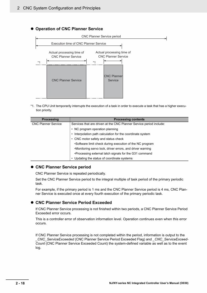
2 CNC System Configuration and Principles
2 - 18 NJ/NY-series NC Integrated Controller User’s Manual (O030)
Operation of CNC Planner Service
*1. The CPU Unit temporarily interrupts the execution of a task in order to execute a task that has a higher execu-tion priority.
CNC Planner Service period
CNC Planner Service is repeated periodically.
Set the CNC Planner Service period to the integral multiple of task period of the primary periodic task.
For example, if the primary period is 1 ms and the CNC Planner Service period is 4 ms, CNC Plan-ner Service is executed once at every fourth execution of the primary periodic task.
CNC Planner Service Period Exceeded
If CNC Planner Service processing is not finished within two periods, a CNC Planner Service Period Exceeded error occurs.
This is a controller error of observation information level. Operation continues even when this error occurs.
If CNC Planner Service processing is not completed within the period, information is output to the _CNC_ServiceExceeded (CNC Planner Service Period Exceeded Flag) and _CNC_ServiceExceed-Count (CNC Planner Service Exceeded Count) the system-defined variable as well as to the event log.
Processing Processing contents
CNC Planner Service Services that are driven at the CNC Planner Service period include:
• NC program operation planning
• Interpolation path calculation for the coordinate system
• CNC motor safety and status check
•Software limit check during execution of the NC program
•Monitoring servo lock, driver errors, and driver warning
•Processing external latch signals for the G31 command
• Updating the status of coordinate systems
*1 *1
CNC Planner Service period
Execution time of CNC Planner Service
Actual processing time of CNC Planner Service
Actual processing time of CNC Planner Service
CNC Planner ServiceCNC Planner
Service

2 - 19
2 CNC System Configuration and Principles
NJ/NY-series NC Integrated Controller User’s Manual (O030)
2-6 Relatio
nsh
ip w
ith E
therC
AT
Co
mm
un
i-ca
tion
s
2
2-6-1 CA
N A
pplication P
rotocol over EtherC
AT
(CoE
)
2-6 Relationship with EtherCAT Commu-nications
The CNC Function Module controls Servo Drives through PDO communications of the EtherCAT Mas-ter Function Module in the NC Integrated Controller.
This section describes EtherCAT communications and other items related to the CNC Function Module.
The CNC Function Module exchanges data with the slaves on EtherCAT using the CAN application protocol over EtherCAT (CoE).
With CoE, the parameters and control information held by the slaves are specified according to data specifications of the object dictionary (OD).
There are two methods that can be used to communicate data between the Controller (communications master) and slaves. One is Process Data Objects (PDO) that are used to periodically exchange data in real time. The other is Service Data Objects (SDO) that are used to exchange data when required.
The CNC Function Module uses PDO communications for commands to refresh I/O data, such as data for Servomotor position control, on a fixed control period.
It uses SDO communications for commands to read and write data at specified times, such as when parameter transfer occurs.
2-6-1 CAN Application Protocol over EtherCAT (CoE)
SlavesController
(communications master)
PDO communications
SDO communications
Executed periodically.
Executed for requests.
Output data
Input data
Data written
Data read
EtherCAT communications line

2 CNC System Configuration and Principles
2 - 20 NJ/NY-series NC Integrated Controller User’s Manual (O030)
The NC Integrated Controller can perform sequence control, motion control, and numerical control through connections to EtherCAT slaves.
• I/O ports for configuration slaves are automatically created when you create the EtherCAT configura-tion in EtherCAT Tab Page in Sysmac Studio.
• You can use the I/O Map Tab Page in Sysmac Studio to assign device variables.
• Perform sequence control through instructions other than CNC instructions.
• I/O ports for configuration slaves are automatically created when you create the EtherCAT configura-tion in EtherCAT Tab Page in Sysmac Studio.
• Create CNC motor variables in the CNC Setup View and assign the EtherCAT slaves for which numerical control is performed.
• Perform numerical control through CNC instructions and the NC program.
Devices that can be assigned to CNC motor variables are EtherCAT slave Servo Drives.
Additional Information
In instructions other than CNC instructions, commands cannot be sent directly from the sequence control program to RxPDO of EtherCAT slaves assigned to CNC motors. On the other hand, the RxPDO data that was not assigned to CNC motors can be changed from the sequence control program.
2-6-2 Relationship between EtherCAT Master Function Module and CNC Function Module
Sequence Control
CNC or Numerical Control
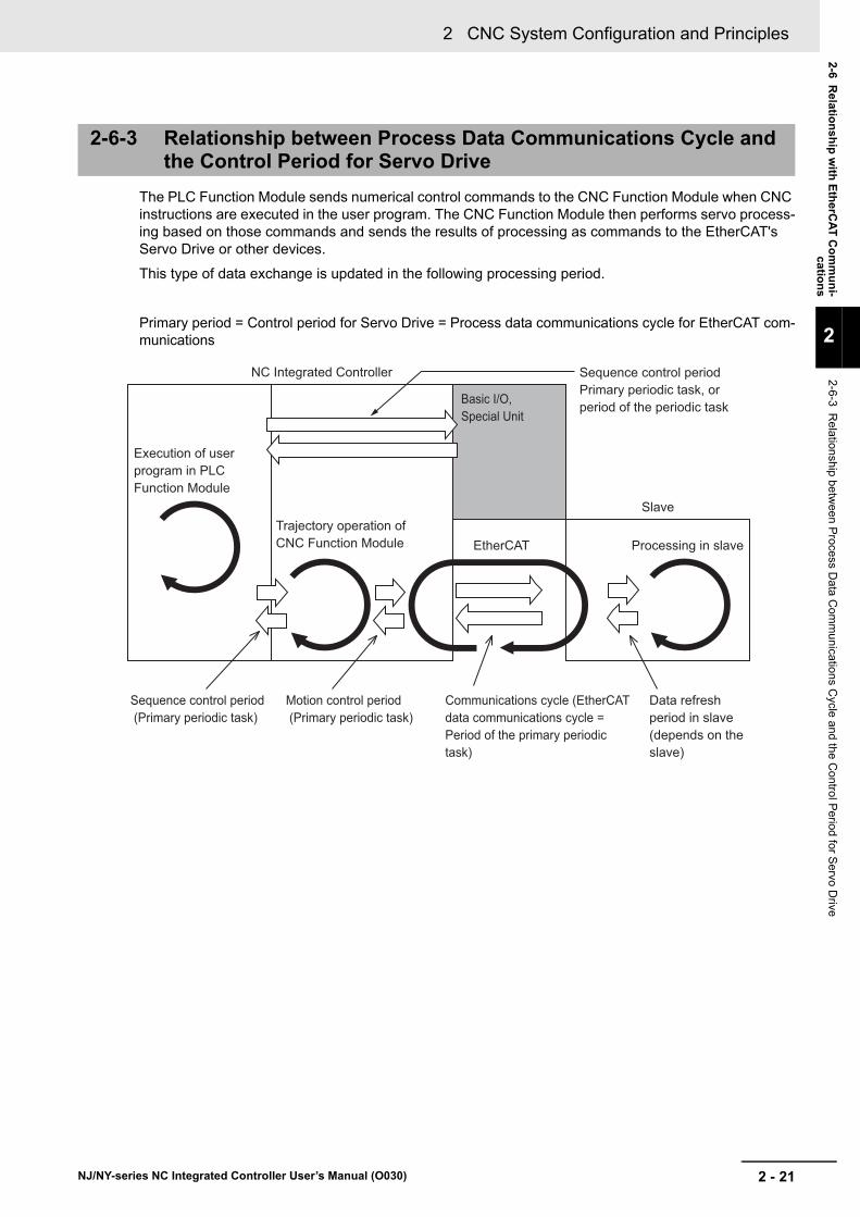
2 - 21
2 CNC System Configuration and Principles
NJ/NY-series NC Integrated Controller User’s Manual (O030)
2-6 Relatio
nsh
ip w
ith E
therC
AT
Co
mm
un
i-ca
tion
s
2
2-6-3 Relationship betw
een P
rocess Data
Com
munica
tions Cycle and the C
ontrol P
eriod for Servo D
rive
The PLC Function Module sends numerical control commands to the CNC Function Module when CNC instructions are executed in the user program. The CNC Function Module then performs servo process-ing based on those commands and sends the results of processing as commands to the EtherCAT's Servo Drive or other devices.
This type of data exchange is updated in the following processing period.
Primary period = Control period for Servo Drive = Process data communications cycle for EtherCAT com-munications
2-6-3 Relationship between Process Data Communications Cycle and the Control Period for Servo Drive
NC Integrated Controller
Slave
EtherCAT Processing in slave
Sequence control period (Primary periodic task)
Motion control period (Primary periodic task)
Communications cycle (EtherCAT data communications cycle = Period of the primary periodic task)
Data refresh period in slave (depends on the slave)
Sequence control periodPrimary periodic task, or period of the periodic task
Execution of user program in PLC Function Module
Trajectory operation of CNC Function Module
Basic I/O,Special Unit

2 CNC System Configuration and Principles
2 - 22 NJ/NY-series NC Integrated Controller User’s Manual (O030)

3 - 1
3
NJ/NY-series NC Integrated Controller User’s Manual (O030)
This section outlines CNC motors and CNC coordinate systems.
3-1 CNC Motors . . . . . . . . . . . . . . . . . . . . . . . . . . . . . . . . . . . . . . . . . . . . . . . . . . 3-2
3-2 CNC Coordinate System . . . . . . . . . . . . . . . . . . . . . . . . . . . . . . . . . . . . . . . . 3-33-2-1 Configuration of CNC Coordinate System . . . . . . . . . . . . . . . . . . . . . . . . . . . 3-3
3-2-2 Types of Coordinate Systems . . . . . . . . . . . . . . . . . . . . . . . . . . . . . . . . . . . . . 3-4
3-2-3 Reference Point . . . . . . . . . . . . . . . . . . . . . . . . . . . . . . . . . . . . . . . . . . . . . . . 3-6
Configuring CNC Motors and CNC Coordinate Systems

3 Configuring CNC Motors and CNC Coordinate Systems
3 - 2 NJ/NY-series NC Integrated Controller User’s Manual (O030)
3-1 CNC Motors
This section describes CNC motors that are used in a CNC Function Module.
In the NC Integrated Controller, CNC motors are elements of the CNC coordinate system.
Typically, CNC motors are assigned one-to-one to logical axes (X, Y, Z, A, B and C axes) of the CNC coordinate system.
It is also possible to assign multiple CNC motors to one logical axis of the CNC coordinate system. Using this assignment process, you can more easily construct a Gantry system.
CNC Motors
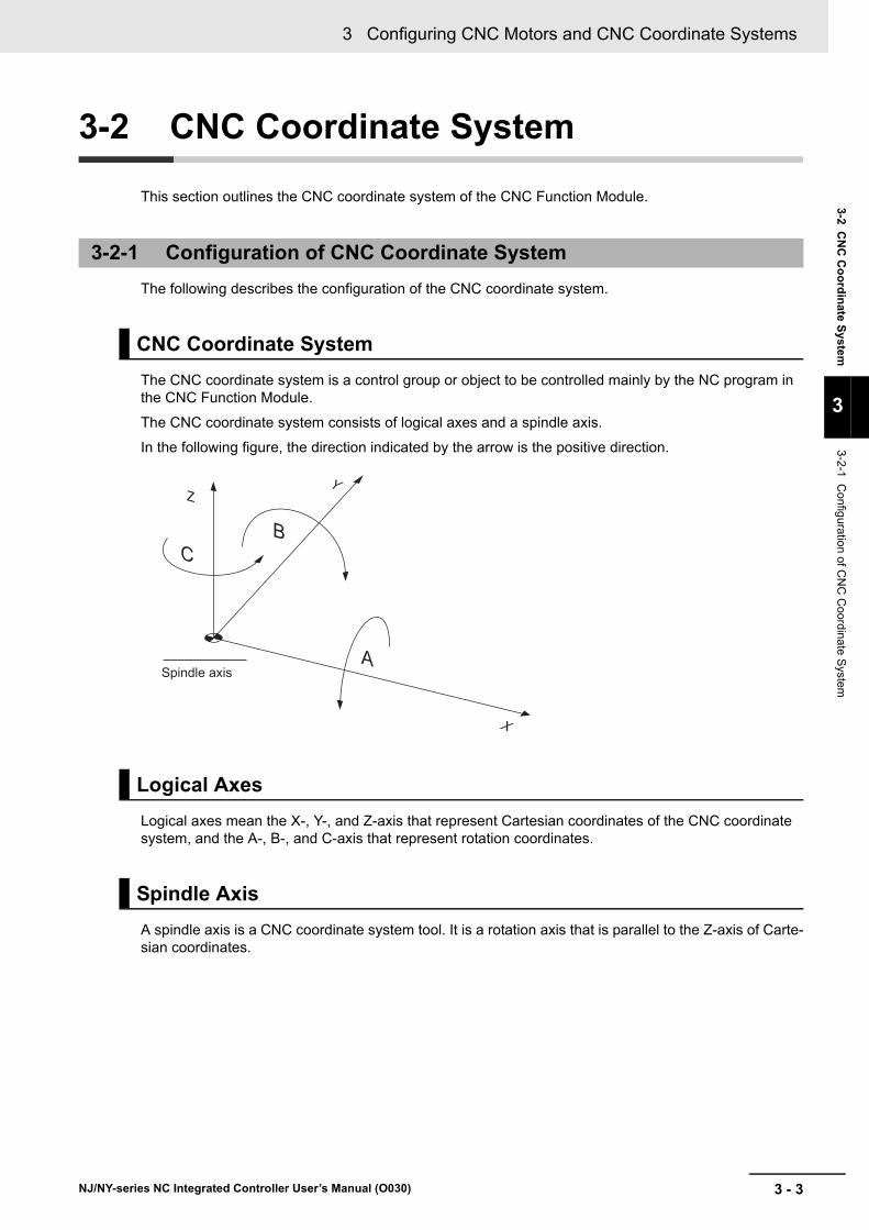
3 - 3
3 Configuring CNC Motors and CNC Coordinate Systems
NJ/NY-series NC Integrated Controller User’s Manual (O030)
3-2 CN
C C
oo
rdin
ate System
3
3-2-1 Config
uration of CN
C C
oordinate S
ystem
3-2 CNC Coordinate System
This section outlines the CNC coordinate system of the CNC Function Module.
The following describes the configuration of the CNC coordinate system.
The CNC coordinate system is a control group or object to be controlled mainly by the NC program in the CNC Function Module.
The CNC coordinate system consists of logical axes and a spindle axis.
In the following figure, the direction indicated by the arrow is the positive direction.
Logical axes mean the X-, Y-, and Z-axis that represent Cartesian coordinates of the CNC coordinate system, and the A-, B-, and C-axis that represent rotation coordinates.
A spindle axis is a CNC coordinate system tool. It is a rotation axis that is parallel to the Z-axis of Carte-sian coordinates.
3-2-1 Configuration of CNC Coordinate System
CNC Coordinate System
Logical Axes
Spindle Axis
ZY
X
CB
ASpindle axis

3 Configuring CNC Motors and CNC Coordinate Systems
3 - 4 NJ/NY-series NC Integrated Controller User’s Manual (O030)
In the CNC Function Module, the coordinate values can be specified in the following three types of coordinate systems.
The position of the tool center point is handled as a coordinate value.
a) Machine Coordinate System (MCS)
b) Workpiece Coordinate System (WCS)
c) Local Coordinate System (LCS)
The following figure describes the relationship between the Machine Coordinate System, Work Coordi-nate System, and Local Coordinate System. With reference to the Machine Coordinate System, a Work Coordinate System possesses work offset to the Machine Coordinate System. With reference to a Work Coordinate System, a Local Coordinate System possesses work offset to the Work Coordinate System.
The point unique to a machine, that is, the reference point for the machine is called the home. A coordi-nate system that references the home as its home position is called the Machine Coordinate System. When homing is completed after the power is turned on, or when communications with the Drive is established while an absolute encoder is used, the Machine Coordinate System is established.
A coordinate system used to machine workpieces is called Work Coordinate System. Up to six work coordinate systems can be configured in one CNC coordinate system.
With reference to the Machine Coordinate System, a Work Coordinate System processes offset to the Machine Coordinate System.
Configure six Work Coordinate Systems in advance as parameters of the CNC coordinate system. Then you can select Work Coordinate Systems to use, by NC program commands G54 to G59.
3-2-2 Types of Coordinate Systems
Relationship between Machine Coordinate System, Work Coordi-nate System, and Local Coordinate System
Machine Coordinate System (MCS)
Work Coordinate System (WCS)
W1
W2
W3
W4
G54
G55 G57
G56
G52
G52
G52
G52
MCS
WCS
LCSOffset
MCS

3 - 5
3 Configuring CNC Motors and CNC Coordinate Systems
NJ/NY-series NC Integrated Controller User’s Manual (O030)
3-2 CN
C C
oo
rdin
ate System
3
3-2-2 Types of C
oordinate S
ystems
A Local Coordinate System is created on a Work Coordinate System to help create programs easier. A Local Coordinate System (G52) is valid on a specified coordinate system of the Work Coordinate Sys-tem (G54 to G59).
Local Coordinate System (LCS)
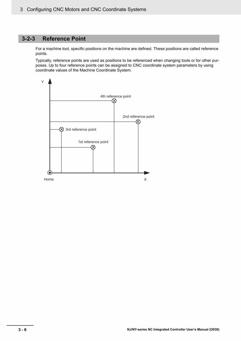
3 Configuring CNC Motors and CNC Coordinate Systems
3 - 6 NJ/NY-series NC Integrated Controller User’s Manual (O030)
For a machine tool, specific positions on the machine are defined. These positions are called reference points.
Typically, reference points are used as positions to be referenced when changing tools or for other pur-poses. Up to four reference points can be assigned to CNC coordinate system parameters by using coordinate values of the Machine Coordinate System.
3-2-3 Reference Point
X
Y
Home
3rd reference point
1st reference point
4th reference point
2nd reference point

4 - 1
4
NJ/NY-series NC Integrated Controller User’s Manual (O030)
This section describes the parameter settings to be configured in the CNC Function Module.
4-1 Introduction . . . . . . . . . . . . . . . . . . . . . . . . . . . . . . . . . . . . . . . . . . . . . . . . . . 4-2
4-2 CNC Common Parameter Settings . . . . . . . . . . . . . . . . . . . . . . . . . . . . . . . . 4-54-2-1 List of CNC Common Parameters . . . . . . . . . . . . . . . . . . . . . . . . . . . . . . . . . 4-5
4-2-2 CNC Planner Service Settings . . . . . . . . . . . . . . . . . . . . . . . . . . . . . . . . . . . . 4-5
4-3 CNC Coordinate System Parameter Settings . . . . . . . . . . . . . . . . . . . . . . . 4-64-3-1 List of CNC Coordinate System Parameters . . . . . . . . . . . . . . . . . . . . . . . . . 4-6
4-3-2 CNC Coordinate System Basic Settings . . . . . . . . . . . . . . . . . . . . . . . . . . . . 4-8
4-3-3 CNC Coordinate System Operation Settings . . . . . . . . . . . . . . . . . . . . . . . . 4-14
4-3-4 NC Program Default Settings . . . . . . . . . . . . . . . . . . . . . . . . . . . . . . . . . . . . 4-15
4-3-5 Tool Compensation Settings . . . . . . . . . . . . . . . . . . . . . . . . . . . . . . . . . . . . . 4-16
4-3-6 Work Coordinate System Offset Settings . . . . . . . . . . . . . . . . . . . . . . . . . . . 4-17
4-3-7 Reference Point Settings . . . . . . . . . . . . . . . . . . . . . . . . . . . . . . . . . . . . . . . 4-18
4-3-8 M Code Settings . . . . . . . . . . . . . . . . . . . . . . . . . . . . . . . . . . . . . . . . . . . . . . 4-19
4-3-9 Spindle Axis Operation Settings . . . . . . . . . . . . . . . . . . . . . . . . . . . . . . . . . . 4-20
4-4 CNC Motor Parameter Settings . . . . . . . . . . . . . . . . . . . . . . . . . . . . . . . . . . 4-224-4-1 List of CNC Motor Parameters . . . . . . . . . . . . . . . . . . . . . . . . . . . . . . . . . . . 4-22
4-4-2 CNC Motor Basic Settings . . . . . . . . . . . . . . . . . . . . . . . . . . . . . . . . . . . . . . 4-24
4-4-3 Unit Conversion Settings . . . . . . . . . . . . . . . . . . . . . . . . . . . . . . . . . . . . . . . 4-26
4-4-4 Operation Settings . . . . . . . . . . . . . . . . . . . . . . . . . . . . . . . . . . . . . . . . . . . . 4-29
4-4-5 Other Operation Settings . . . . . . . . . . . . . . . . . . . . . . . . . . . . . . . . . . . . . . . 4-30
4-4-6 Limit Settings . . . . . . . . . . . . . . . . . . . . . . . . . . . . . . . . . . . . . . . . . . . . . . . . 4-31
4-4-7 Position Count Settings . . . . . . . . . . . . . . . . . . . . . . . . . . . . . . . . . . . . . . . . 4-32
4-4-8 Servo Drive Settings . . . . . . . . . . . . . . . . . . . . . . . . . . . . . . . . . . . . . . . . . . . 4-32
4-4-9 Homing Settings . . . . . . . . . . . . . . . . . . . . . . . . . . . . . . . . . . . . . . . . . . . . . . 4-33
4-4-10 Servo Gain Settings . . . . . . . . . . . . . . . . . . . . . . . . . . . . . . . . . . . . . . . . . . . 4-35
4-5 CNC Motor Compensation Table Parameter Settings . . . . . . . . . . . . . . . 4-36
CNC Parameters

4 CNC Parameters
4 - 2 NJ/NY-series NC Integrated Controller User’s Manual (O030)
4-1 Introduction
With the CNC Function Module of this Controller, you can perform the numerical control of a CNC coor-dinate system with NC programs. You can also operate CNC motors of the CNC coordinate system with CNC instructions of the sequence control program. The CNC motor parameters and CNC coordinate system parameters are set to determine these operations.
In order to run the NC program for a CNC coordinate system, you must set CNC coordinate system parameters, and CNC motor parameters that compose the CNC coordinate system. If you want to oper-ate the system in units of a CNC motor, you must only set CNC motor parameters. These parameters are called CNC parameters.
*1. Use the synchronization function of Sysmac Studio to upload and download the project.
*2. The NC Integrated Controller and Sysmac Studio version 1.20 or higher are required to use CNC instructions such as CNC_Write.
Precautions for Correct Use
• If the CNC parameters are changed by CNC instructions, they are saved to the main memory in the NC Integrated Controller. They are not saved in the non-volatile memory in the NC Integrated Controller. The parameter settings stored in the non-volatile memory are restored when the power is recycled, or when settings are downloaded from Sysmac Studio. You can-not upload these data by using Sysmac Studio.
If you need to save settings to the non-volatile memory, use Sysmac Studio to change the parameter settings and then download the settings to the NC Integrated Controller.
• The CNC_Write instruction can change the CNC parameters.
• Some CNC parameter settings are expressed by floating point reals. Precautions for using them are provided. Refer to A-2 Cancellation of Digits of Real Type Data on page A-7.
Non-volatile memory
CNC Motor Parameters
CNC coordinate system parameter settings
- After download- When power is turned on
Temporarily change or read to some axis parameter settings
NC program cannot be directly converted into the CNC parameters.
Accessing some parameters as variables
Main memory
CNC Motor Parameters
CNC Coordinate System Parameters
CNC_Write instructions, etc.*2
User program
NC program
CNC_Write instructions, etc.*2
Data movement or other instructions
CNC OperatorSysmac Studio
Downloaded*1 Upload*1 Download Upload
Start of NC program Transmission of M signal
NC Integrated Controller

4 - 3
4 CNC Parameters
NJ/NY-series NC Integrated Controller User’s Manual (O030)
4-1 Intro
du
ctio
n
4
• Download your CNC Parameter Settings to the NC Integrated Controller using Sysmac Studio to save those settings to the non-volatile memory in the NC Integrated Controller. When you upload the CNC Parameter Settings to the Sysmac Studio, the CNC Parameter Settings that were saved in the non-volatile memory are uploaded.
• The settings that were saved in the non-volatile memory are applied to the main memory after you download them or when the power is turned ON.
• If there are no problems with the saved settings, the CNC Function Module executes control based on the settings in the main memory.
• The settings of some parameters can be accessed as CNC system-defined variables in the user pro-gram.
• You can upload and download CNC parameter settings regardless of the NC Integrated Controller mode or the status of the CNC Function Module.
• When you start the download process, all CNC motors in motion will stop immediately.
You can also continue sending commands to I/O devices during the download process. Refer to the NJ/NX-series CPU Unit Software User’s Manual (Cat. No. W501) for how to set to stop or continue sending commands to the I/O devices when the download process starts.
Stopping Sending Commands to I/O Devices
During download process, CNC motors enter the Servo OFF state.
Continuing Sending Commands to I/O Devices
During download process, the Servo ON state resulted from the CNC_Power instruction immediately before the download is maintained. The Servo ON state and torque limit are maintained even if the CNC_Power instruction is deleted from the user program after the program is updated by downloading. Depending on the item to download, however, they may not be able to be maintained. Refer to the fol-lowing table.
• You can use the CNC instruction CNC_Write (Write CNC Setting) to change the settings of some of the CNC parameters in the main memory while the sequence control program is running.
• If the specified set value is outside the value range, the Error output variable from the instruction changes to TRUE and the CNC parameter setting is not changed.
• All changes to the parameters for CNC coordinate systems and CNC motors that compose the CNC coordinate system become valid.
• Changes of some parameters are applied immediately, and changes of others are applied when an operation instruction is executed. Refer to the list of each parameter for the application timing of the parameter.
Data Flow for CNC Parameters
Item to download Behavior of CNC Function Module
Sequence control program Continues sending commands to I/O devices.
NC program Stops sending commands to I/O devices.
CNC coordinate system parameters, CNC motor parameters, CNC motor compensation table
Stops sending commands to I/O devices.
Others Conforms to the device output hold setting function
Overwriting CNC Parameters with CNC Instructions

4 CNC Parameters
4 - 4 NJ/NY-series NC Integrated Controller User’s Manual (O030)
• You cannot read or change CNC parameters directly from an NC program.
• To change CNC parameters, rewrite the parameters directly from a sequence control program, or write a sequence control program with which the parameters can be changed indirectly by using M codes.
Relationship between NC Program and CNC Parameters

4 - 5
4 CNC Parameters
NJ/NY-series NC Integrated Controller User’s Manual (O030)
4-2 CN
C C
om
mo
n P
arameter S
etting
s
4
4-2-1 List of CN
C C
omm
on Param
eters
4-2 CNC Common Parameter Settings
The CNC Common Parameters set the CNC Planner Service period and other settings for the CNC Function Module.
One CNC common parameter is provided for each NC Integrated Controller.
Use Sysmac Studio to set the CNC common parameters for each CNC motor.
Select Configurations and Setup - Controller Setup - Task Settings from the Sysmac Studio to set the CNC Planner Service Period.
4-2-1 List of CNC Common Parameters
Classification Parameter name
Temporary changes
Reading variablesSupport Update timing
Applica-ble
instruc-tion
CNC Planner Service Settings
CNC Planner Service Period
--- --- --- ---
4-2-2 CNC Planner Service Settings
Parameter name Function Setting range Default
CNC Planner Service Period*1
*1. Set the CNC Planner Service period to an integer multiple of the task period of the primary periodic task. If the least common multiple of the CNC Planner Service period and a primary task period exceeds 600 ms, you can-not use the two in combination.
Sets the period of Planner Service.
Refer to 1-4-2 Performance Specifications on page 1-7.
2 ms

4 CNC Parameters
4 - 6 NJ/NY-series NC Integrated Controller User’s Manual (O030)
4-3 CNC Coordinate System Parameter Settings
The CNC Coordinate System Parameters set composition CNC motor, the maximum feed rate, and configure other settings for the CNC coordinate system controlled by the CNC Function Module.
The number of CNC coordinate system parameters provided is the same as the maximum number of controlled CNC coordinate systems for each model. For NJ501-5300, parameters are provided for four CNC coordinate systems. For NY532-5400, parameters are provided for eight coordinate systems.
The same parameter settings are applied to all CNC coordinate systems. This section describes the parameters for one CNC coordinate system.
Use Sysmac Studio to set the CNC coordinate system parameters for each CNC coordinate system.
4-3-1 List of CNC Coordinate System Parameters
Classification Parameter nameTemporary changes Read-
ing vari-ables
Sup-port
Update timingApplicable instruction
CNC Coordinate Sys-tem Basic Settings
CNC Coordinate System Num-ber
OK
CNC Coordinate System Use OK
Positioning Axis Assignment OK
Spindle Axis Assignment OK
Unit of Cartesian Axes
CNC Coordinate Sys-tem Operation Settings
Maximum Feedrate
Rotary Axis Velocity OK Immediate CNC_Write
Dry Run Velocity OK Immediate CNC_Write
Immediate Stop Input Stop Method
Limit Input Stop Method
Feed Hold Acceleration/Decel-eration Time
OK When an opera-tion instruction is executed
CNC_Write
In-position Check Time OK When an opera-tion instruction is executed
CNC_Write
Software Overtravel Limit Operation Control
OK When an opera-tion instruction is executed
CNC_Write
NC Program Default Set-tings
Acceleration Time
Deceleration Time
Jerk Time
Tool Compensation Set-tings
Tool Radius OK Immediate CNC_Write
Tool Length OK Immediate CNC_Write
Overcut Mode OK Immediate CNC_Write
Circular Feed Rate Mode OK Immediate CNC_Write
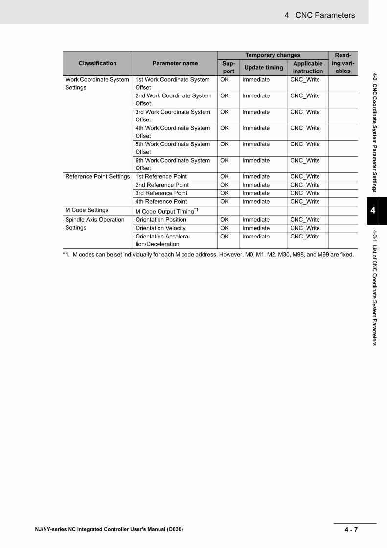
4 - 7
4 CNC Parameters
NJ/NY-series NC Integrated Controller User’s Manual (O030)
4-3 CN
C C
oo
rdin
ate System
Param
eter Settin
gs
4
4-3-1 List of CN
C C
oordinate S
ystem P
aramete
rs
Work Coordinate System Settings
1st Work Coordinate System Offset
OK Immediate CNC_Write
2nd Work Coordinate System Offset
OK Immediate CNC_Write
3rd Work Coordinate System Offset
OK Immediate CNC_Write
4th Work Coordinate System Offset
OK Immediate CNC_Write
5th Work Coordinate System Offset
OK Immediate CNC_Write
6th Work Coordinate System Offset
OK Immediate CNC_Write
Reference Point Settings 1st Reference Point OK Immediate CNC_Write
2nd Reference Point OK Immediate CNC_Write
3rd Reference Point OK Immediate CNC_Write
4th Reference Point OK Immediate CNC_Write
M Code Settings M Code Output Timing*1
Spindle Axis Operation Settings
Orientation Position OK Immediate CNC_Write
Orientation Velocity OK Immediate CNC_Write
Orientation Accelera-tion/Deceleration
OK Immediate CNC_Write
*1. M codes can be set individually for each M code address. However, M0, M1, M2, M30, M98, and M99 are fixed.
Classification Parameter nameTemporary changes Read-
ing vari-ables
Sup-port
Update timingApplicable instruction

4 CNC Parameters
4 - 8 NJ/NY-series NC Integrated Controller User’s Manual (O030)
These parameters are used to set whether or not to enable the CNC coordinate system. To enable the system, set CNC motors to be assigned.
Select the CNC motors to be used in the CNC coordinate system. CNC motors used in the CNC coordi-nate system are called composition CNC motors. Set the axis of the CNC coordinate system to which each composition CNC motor is assigned.
The axis types are: X/Y/Z-axes that constitute the orthogonal axes and A/B/C-axes that are rotational axes. These axes are called the positioning axes as they determine the position of a tool or work object of a machine tool.
Other than positioning axes, an axis is provided to control rotational speed by installing a cutting tool such as a drill or milling cutter used to machine the object. This axis is called the spindle axis.
The CNC motor assigned to the spindle axis must be different from CNC motors assigned to the posi-tioning axes.
Precautions for Correct Use
• If you change the axis assignment for a CNC motor that is set to Positioning Axis Assignment or Spindle Axis Assignment, the command unit of the axis to which the CNC motor is assigned may be different. Accordingly, you must review the unit conversion settings for the CNC motor.
• Refer to Axis and Motor Command Unit on page 4-13 for information on the axis and motor command unit.
• Refer to 4-4-3 Unit Conversion Settings on page 4-26 for information on the unit conversion settings.
4-3-2 CNC Coordinate System Basic Settings
Parameter name Function Setting range Default
CNC Coordinate
System Number*1
*1. You cannot use the same CNC coordinate system number more than once.
Set the logical number of the CNC coordinate sys-tem. The numbers set by this parameter will be applied to the numeric values of the _CNC_Co-ord[0-7] system-defined variable.
0 to (Maximum num-ber of CNC coordi-nate systems)
---
CNC Coordinate
System Use*2
*2. Except for 2: Used CNC coordinate system, parameter settings other than the CNC coordinate system number are not required.
Set whether to enable or disable the CNC coordi-nate system.
0: Undefined CNC coordinate system*3
1: Unused CNC coordinate system
2: Used CNC coordinate system
*3. When a CNC instruction is executed in an undefined or unused CNC coordinate system, Busy (Executing) changes to TRUE.
Busy (Executing) changes to FALSE when Execute or Enable changes to FALSE.
If you select Undefined coordinate system, you do not need to delete the program for the unused axes even if one user program is shared among devices that have different axis configurations.
0 to 2 ---
Composition CNC Motor

4 - 9
4 CNC Parameters
NJ/NY-series NC Integrated Controller User’s Manual (O030)
4-3 CN
C C
oo
rdin
ate System
Param
eter Settin
gs
4
4-3-2 CN
C C
oordinate System
Basic S
ettings
CNC Motors Used to Configure Positioning Axes
Set the CNC motors to be assigned to the positioning axes.
In most cases, one CNC motor is assigned to one positioning axis.
Example 1: Using the X-, Y-, and Z-axes, and assigning a CNC motor to each of the three axes.
However, a one-to-two setting can also be configured for a positioning axis and CNC motors as shown in the following figure.
Example 2: Assigning two CNC motors to the Y-axis to use Gantry Control.
If commands are issued or the status is obtained separately for each CNC motor of the CNC coordi-nate system, the positioning axis composition motor number may be used instead of the CNC motor number in order to increase the reusability of the program.
A composition CNC motor sets the assignment of positioning axis composition motor numbers and the CNC motor numbers belonging to the CNC coordinate system.
Use Sysmac Studio to set the CNC motors in the order from positioning axis composition motor number P0.
Even when you create two or more CNC coordinate systems, you must set the CNC motors in the order of positioning axis composition motor number P0 for each CNC coordinate system.
Parameter name Function Setting range Default
Position Axis Composition Motor Number
Set CNC motor num-bers to use for the posi-tioning axes of the CNC coordinate system.
0 to (Maximum CNC motor number) -1
No assignment
Z-axis
Y-axisX-axis
Y-axis
X-axis
Y-axis
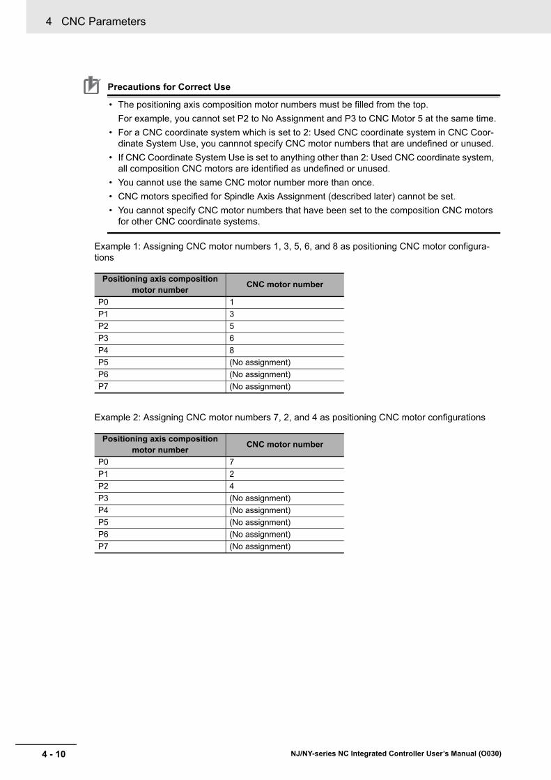
4 CNC Parameters
4 - 10 NJ/NY-series NC Integrated Controller User’s Manual (O030)
Precautions for Correct Use
• The positioning axis composition motor numbers must be filled from the top.
For example, you cannot set P2 to No Assignment and P3 to CNC Motor 5 at the same time.
• For a CNC coordinate system which is set to 2: Used CNC coordinate system in CNC Coor-dinate System Use, you cannnot specify CNC motor numbers that are undefined or unused.
• If CNC Coordinate System Use is set to anything other than 2: Used CNC coordinate system, all composition CNC motors are identified as undefined or unused.
• You cannot use the same CNC motor number more than once.
• CNC motors specified for Spindle Axis Assignment (described later) cannot be set.
• You cannot specify CNC motor numbers that have been set to the composition CNC motors for other CNC coordinate systems.
Example 1: Assigning CNC motor numbers 1, 3, 5, 6, and 8 as positioning CNC motor configura-tions
Example 2: Assigning CNC motor numbers 7, 2, and 4 as positioning CNC motor configurations
Positioning axis composition motor number
CNC motor number
P0 1
P1 3
P2 5
P3 6
P4 8
P5 (No assignment)
P6 (No assignment)
P7 (No assignment)
Positioning axis composition motor number
CNC motor number
P0 7
P1 2
P2 4
P3 (No assignment)
P4 (No assignment)
P5 (No assignment)
P6 (No assignment)
P7 (No assignment)

4 - 11
4 CNC Parameters
NJ/NY-series NC Integrated Controller User’s Manual (O030)
4-3 CN
C C
oo
rdin
ate System
Param
eter Settin
gs
4
4-3-2 CN
C C
oordinate System
Basic S
ettings
Positioning Axis Assignment
Set which CNC motors that are assigned to positioning axes correspond to the axes in the CNC coordinate system.
Set the positioning axis assignment, for each positioning axis composition motor number.
For information on the setting of Positioning Axis Assignment for each positioning axis composition motor number, refer to the following example.
Example 1: Assigning CNC motors 1, 3, and 5 respectively to the X-, Y-, and Z-axes.
Parameter name Function Setting range Default
Positioning Axis
Assignment*1
*1. Two to four types of positioning axes can be set for each CNC coordinate system.
Select the position-ing axis to which a CNC motor is assigned.
0: X-axis
1: Y-axis
2: Z-axis
3: A-axis
4: B-axis
5: C-axis
0 to 5 P0 ... 0: X-axis
P1 ... 1: Y-axis
P2 ... 2: Z-axis
P3 ... 5: C-axis
P4 ... 0: X-axis
P5 ... 0: X-axis
P6 ... 0: X-axis
P7 ... 0: X-axis
* Settings of positioning axis composition motor numbers to which no CNC motor is assigned are invalid.
Positioning axis composi-
tion motor*1
*1. The number in the parentheses is a CNC motor number.
Positioning axis assign-ment
P0 (1) 0: X-axis
P1 (3) 1: Y-axis
P2 (5) 2: Z-axis
MCS home
Z-axis (CNC motor 5)
Y-axis (CNC motor 3)
X-axis (CNC motor 1)
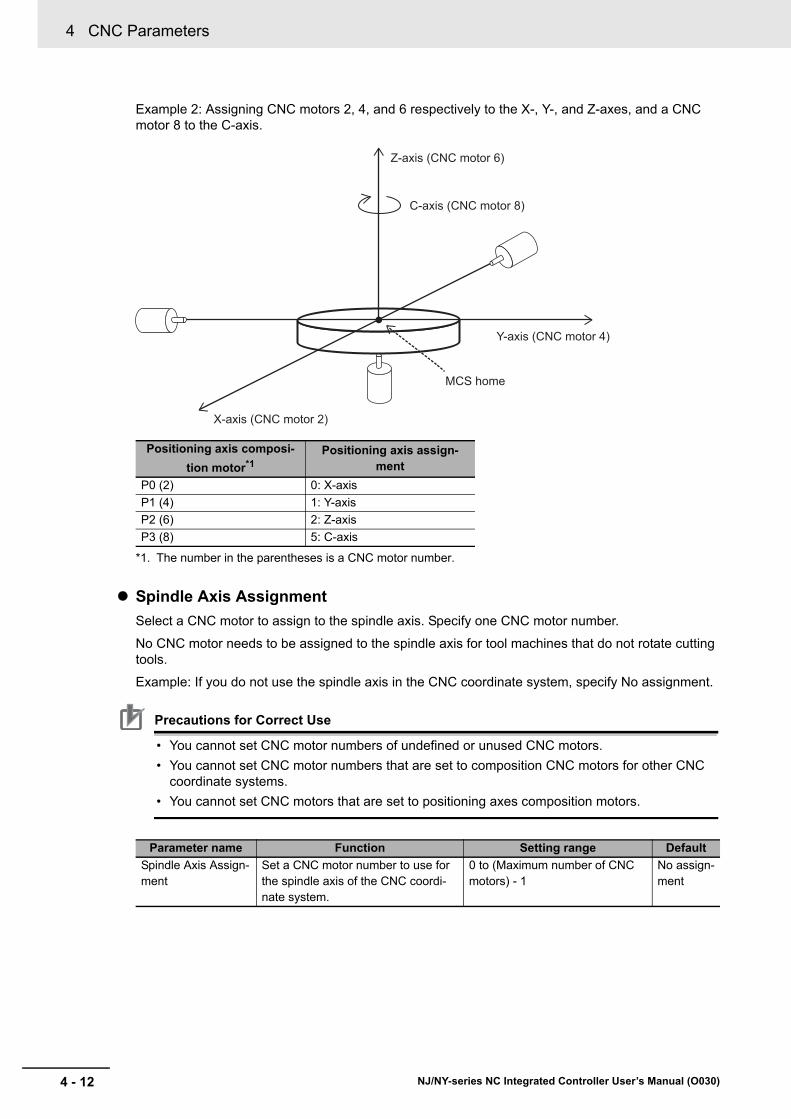
4 CNC Parameters
4 - 12 NJ/NY-series NC Integrated Controller User’s Manual (O030)
Example 2: Assigning CNC motors 2, 4, and 6 respectively to the X-, Y-, and Z-axes, and a CNC motor 8 to the C-axis.
Spindle Axis Assignment
Select a CNC motor to assign to the spindle axis. Specify one CNC motor number.
No CNC motor needs to be assigned to the spindle axis for tool machines that do not rotate cutting tools.
Example: If you do not use the spindle axis in the CNC coordinate system, specify No assignment.
Precautions for Correct Use
• You cannot set CNC motor numbers of undefined or unused CNC motors.
• You cannot set CNC motor numbers that are set to composition CNC motors for other CNC coordinate systems.
• You cannot set CNC motors that are set to positioning axes composition motors.
Positioning axis composi-
tion motor*1
*1. The number in the parentheses is a CNC motor number.
Positioning axis assign-ment
P0 (2) 0: X-axis
P1 (4) 1: Y-axis
P2 (6) 2: Z-axis
P3 (8) 5: C-axis
Parameter name Function Setting range Default
Spindle Axis Assign-ment
Set a CNC motor number to use for the spindle axis of the CNC coordi-nate system.
0 to (Maximum number of CNC motors) - 1
No assign-ment
Z-axis (CNC motor 6)
C-axis (CNC motor 8)
Y-axis (CNC motor 4)
X-axis (CNC motor 2)
MCS home

4 - 13
4 CNC Parameters
NJ/NY-series NC Integrated Controller User’s Manual (O030)
4-3 CN
C C
oo
rdin
ate System
Param
eter Settin
gs
4
4-3-2 CN
C C
oordinate System
Basic S
ettings
The command unit of each axis is shown in the following table. In particular, the unit of position is called the axis command unit.
The axis command unit for orthogonal axes X, Y, and Z can be selected from metric and inch by using Unit of Cartesian Axes.
The command unit system for composition CNC motors assigned to the X-, Y-, and Z-axes also con-form to the Unit of Cartesian Axes settings.
This command unit for the CNC motors is called the motor command unit.
Basically, the axis command unit of the CNC coordinate system is equal to the motor command unit.
However, only for the orthogonal axes of the CNC coordinate system, the command unit can be changed between metric and inch by G codes G20 and G21.
As only the axis command unit is changed at this time, the axis command unit is not equal to the motor command unit.
Axis and Motor Command Unit
Axis type
Unit of position (axis com-mand unit)
Unit of velocityUnit of acceleration and
deceleration rates
metric inch metric inch metric inch
X mm inch mm/min inch/min mm/s2 inch/s2
Y
Z
A degree degree/min degree/s2
B
C
Spindle rev rev/min rev/s2
Parameter name FunctionSetting range
Default
Unit of Cartesian Axes
Set the command unit for the X-, Y-, and Z-orthogonal axes and the unit for CNC motors assigned to these axes collec-tively.
0: Metric (mm)
1: inch (inch)
0 to 1 0
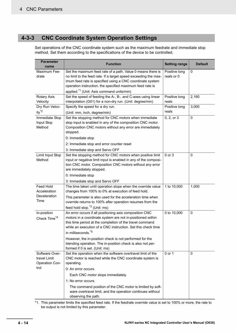
4 CNC Parameters
4 - 14 NJ/NY-series NC Integrated Controller User’s Manual (O030)
Set operations of the CNC coordinate system such as the maximum feedrate and immediate stop method. Set them according to the specifications of the device to be controlled.
4-3-3 CNC Coordinate System Operation Settings
Parameter name
Function Setting range Default
Maximum Fee-drate
Set the maximum feed rate of a path. Value 0 means there is no limit to the feed rate. If a target speed exceeding the max-imum feed rate is specified using a CNC coordinate system operation instruction, the specified maximum feed rate is
applied.*1 (Unit: Axis command units/min)
*1. This parameter limits the specified feed rate. If the feedrate override value is set to 100% or more, the rate to be output is not limited by this parameter.
Positive long reals or 0
0
Rotary Axis Velocity
Set the speed of feeding the A-, B-, and C-axes using linear interpolation (G01) for a non-dry run. (Unit: degree/min)
Positive long reals
2,160
Dry Run Veloc-
ity*2
Specify the speed for a dry run.
(Unit: mm, inch, degree/min)
Positive long reals
3,000
Immediate Stop Input Stop Method
Set the stopping method for CNC motors when immediate stop input is enabled in any of the composition CNC motor. Composition CNC motors without any error are immediately stopped.
0: Immediate stop
2: Immediate stop and error counter reset
3: Immediate stop and Servo OFF
0, 2, or 3 0
Limit Input Stop Method
Set the stopping method for CNC motors when positive limit input or negative limit input is enabled in any of the composi-tion CNC motor. Composition CNC motors without any error are immediately stopped.
0: Immediate stop
3: Immediate stop and Servo OFF
0 or 3 0
Feed Hold Acceleration Deceleration Time
The time taken until operation stops when the override value changes from 100% to 0% at execution of feed hold.
This parameter is also used for the acceleration time when override returns to 100% after operation resumes from the
feed hold stop.*3 (Unit: ms)
1 to 10,000 1,000
In-position
Check Time*4
An error occurs if all positioning axis composition CNC motors in a coordinate system are not in-positioned within this time period at the completion of the travel command while an execution of a CNC instruction. Set this check time
in milliseconds.*5
However, the in-position check is not performed for the blending operation. The in-position check is also not per-formed if 0 is set. (Unit: ms)
0 to 10,000 0
Software Over-travel Limit Operation Con-trol
Set the operation when the software overtravel limit of the CNC motor is reached while the CNC coordinate system is operating.
0: An error occurs.
Each CNC motor stops immediately.
1: No error occurs.
The command position of the CNC motor is limited by soft-ware overtravel limit, and the operation continues without observing the path.
0 or 1 0

4 - 15
4 CNC Parameters
NJ/NY-series NC Integrated Controller User’s Manual (O030)
4-3 CN
C C
oo
rdin
ate System
Param
eter Settin
gs
4
4-3-4 NC
Program
Default S
ettings
Set the default values for the parameters and modal values that can be changed from the NC program, for each CNC coordinate system.
Default values are restored when modal reset is executed.
*2. Set a value less than or equal to the maximum feedrate if the maximum feedrate is not 0.
*3. If feed hold is executed while Multi-block Acceleration/Deceleration Rate Enable (G500) is enabled, operation does not stop according to this parameter. A sudden stop takes place within the range of maximum accelera-tion/deceleration rate of composition motors.
*4. Set a value larger than the number of in-position continuance cycles for the positioning axis composition CNC motor. Example: Suppose that the control cycle time of a primary periodic task is 2 milliseconds, and that the largest number of the in-position check continuance cycles of the composition CNC motors is 100 control cycles. Then the in-position check time must be set to a value larger than 200 milliseconds. Cases where the in-position check time is 0 milliseconds or it is smaller than the CNC Planner Service period are excluded.
*5. The result of an in-position check of the CNC coordinate system is determined by the CNC Planner Service. Actually, therefore, the accuracy of the in-position check time is rounded down to the unit of the CNC Planner Service period. If the in-position check time is smaller than the CNC Planner Service period, it is rounded down to be 0, and the in-position check is not executed.
Example: Suppose that the in-position check time is 6 milliseconds and that the CNC Planner Service period is 4 milliseconds. Then normal operation is performed when the in-position check of all the positioning axis composition CNC motors is completed within one CNC Planner Service period (4 milliseconds) from the CNC Planner Service that has actually finished the travel command. An error occurs if the in-position check takes longer than the period.
4-3-4 NC Program Default Settings
Parameter name Function Setting range Default
Acceleration Time Set the default acceleration time.
(Unit: ms)
Positive long reals or 0 100
Deceleration Time Set the default deceleration time.
(Unit: ms)
Positive long reals or 0 100
Jerk Time*1
*1. Refer to the NJ/NY-series G code Instructions Reference Manual (Cat. No. O031) for Jerk Time.
Set the default jerk time. (Unit: ms) Positive long reals or 0 0

4 CNC Parameters
4 - 16 NJ/NY-series NC Integrated Controller User’s Manual (O030)
Set parameters relevant to compensation of tool radius and length.
4-3-5 Tool Compensation Settings
Parameter name
Function Setting range Default
Tool Radius Set the tool radius for 2D tool system compensation. (Unit: Axis command units)
Positive long reals or 0
0
Tool Length Set the tool length (offset in the Z-axis direction) for tool length compensation.
(Unit: Axis command units)
Negative or positive long reals or 0
0
Overcut Mode Specify the overcut mode for tool radius compensation con-trol.
0: Overcut error
At the instant when an over-cut is detected, the program operation stops in an error state.
1: Overcutting avoidance
In an attempt to avoid overcuts, the corrected path between the first and second intersection points is eliminated. As the result, the entry path and outgoing path at the intersection points are connected directly. This operation mode is nor-mally used for rough machining by large tools which cannot go into detailed profiles of any components.
2: Overcutting ignorance
Continues program operation without detecting overcuts.
3: Overcutting test avoidance
Attempts to avoid an overcut. If the overcut cannot be avoided, it is ignored to continue program operation.
Enumerator
0 to 3
0
Circular Feed Rate Mode
Specify the circular feed rate mode to be applied for tool radius compensation control.
FALSE:
The tool center moves at the programmed feedrate.
The velocity of tool edge along the programmed path becomes lower when tool radius compensation is outside the arc. The velocity becomes higher when tool radius compen-sation is inside the arc.
TRUE:
The tool edge along the programmed path moves at the pro-grammed feedrate. The tool center becomes faster when tool radius compensation is outside the arc. It becomes slower when tool radius compensation is inside the arc.
TRUE or FALSE
FALSE
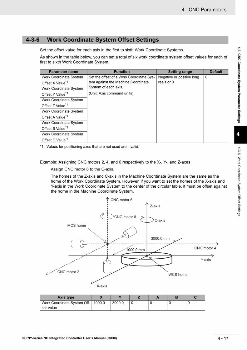
4 - 17
4 CNC Parameters
NJ/NY-series NC Integrated Controller User’s Manual (O030)
4-3 CN
C C
oo
rdin
ate System
Param
eter Settin
gs
4
4-3-6 Work C
oordinate S
ystem O
ffset Settings
Set the offset value for each axis in the first to sixth Work Coordinate Systems.
As shown in the table below, you can set a total of six work coordinate system offset values for each of first to sixth Work Coordinate System.
Example: Assigning CNC motors 2, 4, and 6 respectively to the X-, Y-, and Z-axes
Assign CNC motor 8 to the C-axis.
The homes of the Z-axis and C-axis in the Machine Coordinate System are the same as the home of the Work Coordinate System. However, if you want to set the homes of the X-axis and Y-axis in the Work Coordinate System to the center of the circular table, it must be offset against the home in the Machine Coordinate System.
4-3-6 Work Coordinate System Offset Settings
Parameter name Function Setting range Default
Work Coordinate System
Offset X Value*1
*1. Values for positioning axes that are not used are invalid.
Set the offset of a Work Coordinate Sys-tem against the Machine Coordinate System of each axis.
(Unit: Axis command units)
Negative or positive long reals or 0
0
Work Coordinate System
Offset Y Value*1
Work Coordinate System
Offset Z Value*1
Work Coordinate System
Offset A Value*1
Work Coordinate System
Offset B Value*1
Work Coordinate System
Offset C Value*1
Axis type X Y Z A B C
Work Coordinate System Off-set Value
1000.0 3000.0 0 0 0 0
CNC motor 2
CNC motor 4
CNC motor 8
1000.0 mm
3000.0 mm
MCS home
CNC motor 6
WCS home
X-axis
Y-axis
C-axis
Z-axis

4 CNC Parameters
4 - 18 NJ/NY-series NC Integrated Controller User’s Manual (O030)
The position of each axis that constitutes the reference point can be set.
You can set the first to fourth reference points.
However, you do not have to set reference points for unused positioning axes.
Example: Using the X-, Y-, Z-, and C-axes.
4-3-7 Reference Point Settings
Parameter name Function Setting range Default
Reference Point X*1
*1. Values for positioning axes that are not used are invalid.
Set the positions of reference points for each axis. (Unit: Axis command units)
Negative or positive long reals or 0
0
Reference Point Y*1
Reference Point Z*1
Reference Point A*1
Reference Point B*1
Reference Point C*1
Reference point X-axis Y-axis Z-axis A-axis B-axis C-axis
1st Reference Point Supported Supported Supported Unneces-sary
Unneces-sary
Supported
2nd Reference Point Supported Supported Supported Unneces-sary
Unneces-sary
Supported
3rd Reference Point Supported Supported Supported Unneces-sary
Unneces-sary
Supported
4th Reference Point Supported Supported Supported Unneces-sary
Unneces-sary
Supported

4 - 19
4 CNC Parameters
NJ/NY-series NC Integrated Controller User’s Manual (O030)
4-3 CN
C C
oo
rdin
ate System
Param
eter Settin
gs
4
4-3-8 M C
ode Settings
Select the output timing of M codes.
The timing can be set individually for each M code address. However, M0, M1, M2, M30, M98, and M99 are fixed.
The following is an example of controlling M code output timing using an NC program.
0: Synchronous
• The M10 signal is output when the G01 X1000 travel is completed.
• The next axis motion is not executed until the M10 signal is reset by the sequence control pro-gram.
4-3-8 M Code Settings
Parameter name Function Setting range Default
M Code Output Timing Select the output timing of M codes.
0: Synchronous
1: Immediate
0 to 1 0
M code address Parameters
0 (No output)
1 (No output)
2 (No output)
3 0 or 1
... 0 or 1
29 0 or 1
30 Always 0
31 0 or 1
... 0 or 1
98 (No output)
99 (No output)
... 0 or 1
191 0 or 1
(Sample of NC Program)N10 G01 X1000N20 M10N30 G01 X2000
0 G01 X1000 operation
M code output timing
Velocity
G01 X2000 operation Time

4 CNC Parameters
4 - 20 NJ/NY-series NC Integrated Controller User’s Manual (O030)
1: Immediate
The M10 signal is output at the timing when the line N20 M10 in the NC program is interpreted. It does not synchronize with the operation.
Set orientation operation for the spindle axis assigned to the coordinate system.
Orientation operation is a function to be performed for tool replacement. Orientation operation enables to stop the spindle axis at a specific phase and replace tools.
As shown in the following figure, the orientation position is specified for an offset position within one rotation from position 0.
4-3-9 Spindle Axis Operation Settings
Parameter name Function Setting range Default
Orientation Position Specify the stop position [rev] within one spindle axis rotation at Spindle Orientation (M19).
Long reals
0 ≤ x < 1
0
Orientation Velocity*1
*1. Set a value less than or equal to the maximum velocity of the CNC motor assigned to the spindle axis.
Specify the target velocity [rev/min] in the constant velocity section at Spindle Orientation (M19).
Single-precision reals
Positive number
600.0
Orientation Acceleration/Deceler-
ation*2
*2. Set a value less than or equal to the maximum acceleration of the CNC motor assigned to the spindle axis, if the maximum acceleration is not 0.
Specify an acceleration/deceleration
rate [rev/s2] at Spindle Orientation (M19).
Single-precision reals
Positive number, 0
0
0 G01 X1000 operation
M code output timing
Velocity
TimeG01 X2000 operation
Orientation position [rev]
0 [rev]
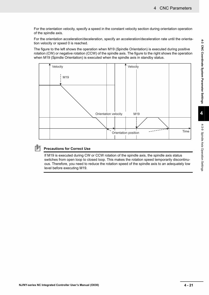
4 - 21
4 CNC Parameters
NJ/NY-series NC Integrated Controller User’s Manual (O030)
4-3 CN
C C
oo
rdin
ate System
Param
eter Settin
gs
4
4-3-9 Spindle A
xis Opera
tion Settings
For the orientation velocity, specify a speed in the constant velocity section during orientation operation of the spindle axis.
For the orientation acceleration/deceleration, specify an acceleration/deceleration rate until the orienta-tion velocity or speed 0 is reached.
The figure to the left shows the operation when M19 (Spindle Orientation) is executed during positive rotation (CW) or negative rotation (CCW) of the spindle axis. The figure to the right shows the operation when M19 (Spindle Orientation) is executed when the spindle axis in standby status.
Precautions for Correct Use
If M19 is executed during CW or CCW rotation of the spindle axis, the spindle axis status switches from open loop to closed loop. This makes the rotation speed temporarily discontinu-ous. Therefore, you need to reduce the rotation speed of the spindle axis to an adequately low level before executing M19.
Velocity Velocity
Time
M19
M19
Orientation position
Orientation velocity
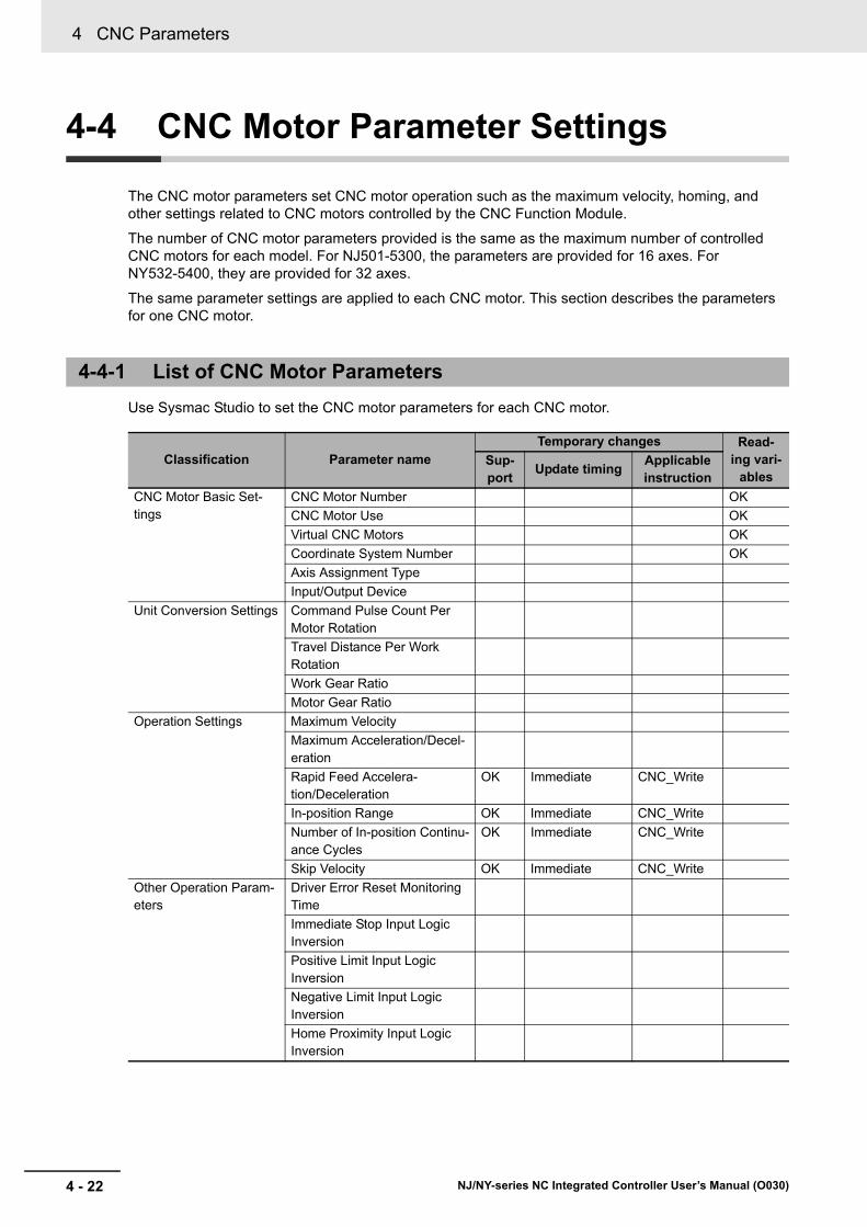
4 CNC Parameters
4 - 22 NJ/NY-series NC Integrated Controller User’s Manual (O030)
4-4 CNC Motor Parameter Settings
The CNC motor parameters set CNC motor operation such as the maximum velocity, homing, and other settings related to CNC motors controlled by the CNC Function Module.
The number of CNC motor parameters provided is the same as the maximum number of controlled CNC motors for each model. For NJ501-5300, the parameters are provided for 16 axes. For NY532-5400, they are provided for 32 axes.
The same parameter settings are applied to each CNC motor. This section describes the parameters for one CNC motor.
Use Sysmac Studio to set the CNC motor parameters for each CNC motor.
4-4-1 List of CNC Motor Parameters
Classification Parameter nameTemporary changes Read-
ing vari-ables
Sup-port
Update timingApplicable instruction
CNC Motor Basic Set-tings
CNC Motor Number OK
CNC Motor Use OK
Virtual CNC Motors OK
Coordinate System Number OK
Axis Assignment Type
Input/Output Device
Unit Conversion Settings Command Pulse Count Per Motor Rotation
Travel Distance Per Work Rotation
Work Gear Ratio
Motor Gear Ratio
Operation Settings Maximum Velocity
Maximum Acceleration/Decel-eration
Rapid Feed Accelera-tion/Deceleration
OK Immediate CNC_Write
In-position Range OK Immediate CNC_Write
Number of In-position Continu-ance Cycles
OK Immediate CNC_Write
Skip Velocity OK Immediate CNC_Write
Other Operation Param-eters
Driver Error Reset Monitoring Time
Immediate Stop Input Logic Inversion
Positive Limit Input Logic Inversion
Negative Limit Input Logic Inversion
Home Proximity Input Logic Inversion

4 - 23
4 CNC Parameters
NJ/NY-series NC Integrated Controller User’s Manual (O030)
4-4 CN
C M
oto
r Param
eter Settin
gs
4
4-4-1 List of CN
C M
otor Param
eters
Limit Settings Software Overtravel Limit OK When an opera-tion instruction is executed
CNC_Write
Positive Software Overtravel Limit
OK When an opera-tion instruction is executed
CNC_Write
Negative Software Overtravel Limit
OK When an opera-tion instruction is executed
CNC_Write
Following Error Over Value OK Immediate CNC_Write
Following Error Warning Value OK Immediate CNC_Write
Position Count Parame-ters
Encoder Type
Servo Drive Types PDS Status Control Method
Homing Settings Homing Operation Mode
Home Input Signal
Homing Start Direction
Home Input Detection Direc-tion
Operation Selection at Positive Limit Input
Operation Selection at Nega-tive Limit Input
Homing Velocity
Homing Approach Velocity
Homing Acceleration/Deceler-ation
Home Input Mask Distance
Home Offset
Homing Holding Time
Homing Compensation Value
Homing Compensation Veloc-ity
Servo Gain Settings Position Loop Gain OK Immediate CNC_Write
Velocity Feedforward Gain OK Immediate CNC_Write
Classification Parameter nameTemporary changes Read-
ing vari-ables
Sup-port
Update timingApplicable instruction

4 CNC Parameters
4 - 24 NJ/NY-series NC Integrated Controller User’s Manual (O030)
Set whether to use CNC motors, and to use real or virtual CNC motors, as well as the node addresses of the EtherCAT slave devices.
Precautions for Correct Use
When absolute encoders are used, the absolute encoder home offset for each CNC motor is associated with a CNC motor number and saved to the non-volatile memory. For the NY-series Controllers, it is saved to the non-volatile memory. If the CNC motor number is changed, the saved offset will be lost. If you change the CNC motor number, set the Homing Settings again.
4-4-2 CNC Motor Basic Settings
Parameter name Function Setting range Default
CNC Motor Num-
ber*1
*1. You cannot use the same CNC motor number more than once.
Set the logical number of the CNC motor. The number speci-fied with this parameter will be the numeric value in _CNC_Motor[0-15] system-defined variable.
0 to (Largest CNC motor number)-1
---
CNC Motor Use*2
*2. These settings are determined in association with the setting for the CNC Coordinate System Use in the CNC Coordinate System Basic Settings of the CNC coordinate system parameters. They cannot be set as CNC mo-tor parameters.
Set whether to use the CNC motor.
0: Undefined CNC motor
1: Unused CNC motor
2: Used CNC motor
0 to 2 ---
Virtual CNC Motor Select whether to enable or disable the virtual CNC motor.
I/O wiring is not required for virtual CNC motors.
0: Disable (Real CNC motor)
1: Enable (Virtual CNC motor)
0 to 1 1
Coordinate Sys-
tem Number*3, *4
*3. These settings are determined when CNC motors are assigned in the CNC Coordinate System Basic Settings of the CNC coordinate system parameters. They cannot be set as CNC motor parameters.
The CNC motor parameter setting screen is shown on the Sysmac Studio, but they cannot be set from the Sysmac Studio.
*4. A CNC motor must be assigned to any CNC coordinate system.
Display the number of the assigned CNC coordinate system. 0 to (Largest CNC coordi-nate system number)-1
--- *5
*5. When you add a CNC motor on Sysmac Studio, the coordinate system number changes to - (none) and an error occurs. Assign it to any CNC coordinate system before transferring the parameter to the NC Integrated Controller.
Axis Assignment
Type*3, *6
*6. This parameter is automatically set from Positioning Axis Assignment or Spindle Axis Assignment of the coor-dinate system to which the CNC motor is assigned.
Display whether the axis is a positioning axis (orthogonal or rotational) or the spindle axis, and the purpose of axis use.
0: Positioning orthogonal axis
1: Positioning rotational axis
2: Spindle axis
0, 1, or 2 ---
Input/Output
Device*7
*7. This setting is not required when a virtual CNC motor is enabled.
Specify the node address of the EtherCAT slave device that is assigned to the CNC motor.
0 to 65,535 ---

4 - 25
4 CNC Parameters
NJ/NY-series NC Integrated Controller User’s Manual (O030)
4-4 CN
C M
oto
r Param
eter Settin
gs
4
4-4-2 CN
C M
otor Basic S
ettings
You can set the numbers for CNC motors up to the maximum number of CNC motors.
Virtual CNC motors are provided in the CNC Function Module. Set to enable or disable the virtual CNC motors.
If the virtual CNC motors are enabled, the EtherCAT slave Servo Drives and EtherCAT spindle driver are not used. By enabling the virtual CNC motors, you can create programs even if you have not yet obtained actual CNC motors and drivers to use when starting up a machine tool.
The virtual CNC motors do not have physical encoders or external I/O signals.
When the virtual CNC motors are enabled, the following points differ from when they are disabled.
• As the feedback current position, the command position that is rounded down to the precision in pulse will be replicated.
• The feedback current velocity is derived from the difference of the feedback current position.
• External input signals cannot be used.
• If the CNC_Home (Homing) or CNC_HomeWithParameter (Home with Parameters) instruction is executed, the instruction is processed as a zero position preset regardless of the setting of the Hom-ing Method of the CNC motor parameter.
• Errors do not occur for immediate stop inputs or positive/negative limit inputs because the input sig-nals do not exist for them.
When the virtual CNC motors are disabled, specify the node address of the EtherCAT slave device that is assigned to the axis.
The node address parameter cannot be selected when the virtual CNC motors are enabled.
Precautions for Correct Use
• OMRON 1S-series Servo Drives and G5-series Servo Drives can be set to specific node addresses by using the node address switches on the front panel. If the node address switches are set to 00, the node address will be determined by the settings set in the Ether-CAT Editor of Sysmac Studio.
If the node address switches are set to 00 for all connected Servo Drives, errors will not occur even if the Servo Drive's connection position is changed. Set the node addresses on the node address switches to assign specific Servo Drives for each machine control.
• The value set on the Servo Drive's node address switches is loaded only once when the Servo Drive's control power is turned ON.
Such changes are enabled only after the power supply is turned ON again.
Do not change the setting on the node address switches after the power supply has been turned ON.
• An error occurs if the same node address is used more than once.
CNC Motor Number
Item NJ501-5300 NY532-5400
Settable CNC motor numbers 0 to 15 0 to 31
Maximum number of CNC motors 16 32
Virtual CNC Motors
Input Device/Output Device

4 CNC Parameters
4 - 26 NJ/NY-series NC Integrated Controller User’s Manual (O030)
Set the units for positions, and determine the electronic gear ratio (unit conversion).
Precautions for Correct Use
When you make a change in the unit conversion settings, there are some differences between the physical position of the machine and the command current position of the CNC Function Module. Therefore, if you made a change in the unit conversion settings, execute the Home instruction to define the home again.
Positions are generally given in pulses between the CNC Function Module and Servo Drives or spindle driver.
For positions used to control a machine tool, use the motor command units such as millimeter, inch, degree, and revolution for easier understanding of actual operations.
4-4-3 Unit Conversion Settings
Parameter name Function Setting range Default
Command Pulse Count Per Motor
Rotation*1
*1. For example, if the encoder resolution is 10,000 pulses/rotation, specify 10,000.
Set the number of pulses per motor rotation for commanded positions according to the encoder resolution.
The command value is converted to a number of pulses based on the electronic gear ratio.
1 to 4,294,967,295 10,000
Travel Distance Per
Work Rotation*2,*3
*2. There is a condition to be satisfied for these settings. Refer to Condition for Unit Conversion Settings on page 4-28 for the condition.
*3. This parameter can only be set when Axis Assignment Type is 0: Positioning orthogonal axis. If Axis Assignment. Type is 1: Positioning rotational axis, the setting is fixed to 360.0 degrees, and if it is 2: Spindle axis, the setting is fixed to 1.0 rev.
Set the work travel distance per work rotation at the commanded position.
This parameter can only be set when Axis Assignment Type is 0: Positioning orthogonal axis. The unit used for this parameter is the orthogonal axis command unit set by the basic settings of the CNC coordinate system to which the CNC motor is assigned.
Positive long reals 10.0
Work Gear Ratio*2 Set the gear ratio for the workpiece.*4
*4. When you do not use a reducer or other gears, do not change the default value 1.
1 to 4,294,967,295 1
Motor Gear Ratio2 Set the gear ratio of the CNC motor.*4 1 to 4,294,967,295 1
Sequence control program
Command unit
Position unit
NC program G code
Pulses
Pulses
Servo Drive
Spindle driver
CNC Instructions
CNC Function Module
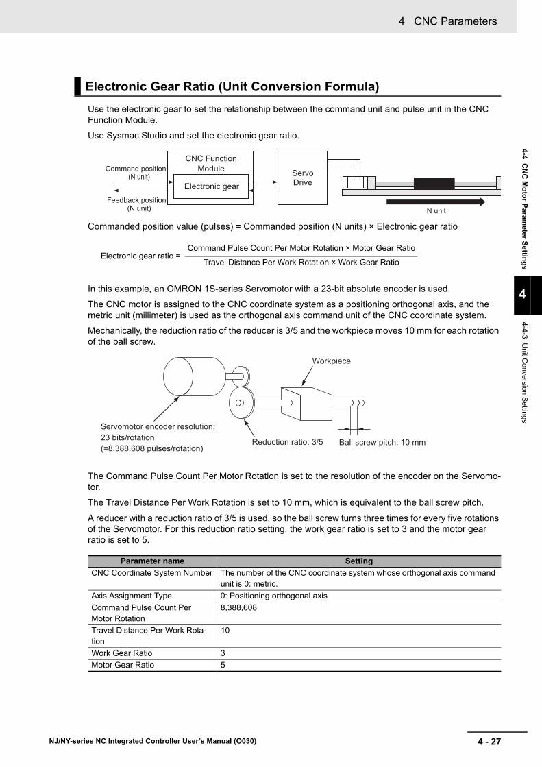
4 - 27
4 CNC Parameters
NJ/NY-series NC Integrated Controller User’s Manual (O030)
4-4 CN
C M
oto
r Param
eter Settin
gs
4
4-4-3 Unit C
onversion Settings
Use the electronic gear to set the relationship between the command unit and pulse unit in the CNC Function Module.
Use Sysmac Studio and set the electronic gear ratio.
Commanded position value (pulses) = Commanded position (N units) × Electronic gear ratio
In this example, an OMRON 1S-series Servomotor with a 23-bit absolute encoder is used.
The CNC motor is assigned to the CNC coordinate system as a positioning orthogonal axis, and the metric unit (millimeter) is used as the orthogonal axis command unit of the CNC coordinate system.
Mechanically, the reduction ratio of the reducer is 3/5 and the workpiece moves 10 mm for each rotation of the ball screw.
The Command Pulse Count Per Motor Rotation is set to the resolution of the encoder on the Servomo-tor.
The Travel Distance Per Work Rotation is set to 10 mm, which is equivalent to the ball screw pitch.
A reducer with a reduction ratio of 3/5 is used, so the ball screw turns three times for every five rotations of the Servomotor. For this reduction ratio setting, the work gear ratio is set to 3 and the motor gear ratio is set to 5.
Electronic Gear Ratio (Unit Conversion Formula)
Parameter name Setting
CNC Coordinate System Number The number of the CNC coordinate system whose orthogonal axis command unit is 0: metric.
Axis Assignment Type 0: Positioning orthogonal axis
Command Pulse Count Per Motor Rotation
8,388,608
Travel Distance Per Work Rota-tion
10
Work Gear Ratio 3
Motor Gear Ratio 5
(N unit)Command position
CNC Function Module
Electronic gearServo Drive
N unit(N unit)Feedback position
Electronic gear ratio =Command Pulse Count Per Motor Rotation × Motor Gear Ratio
Travel Distance Per Work Rotation × Work Gear Ratio
Workpiece
Servomotor encoder resolution: 23 bits/rotation (=8,388,608 pulses/rotation)
Reduction ratio: 3/5 Ball screw pitch: 10 mm
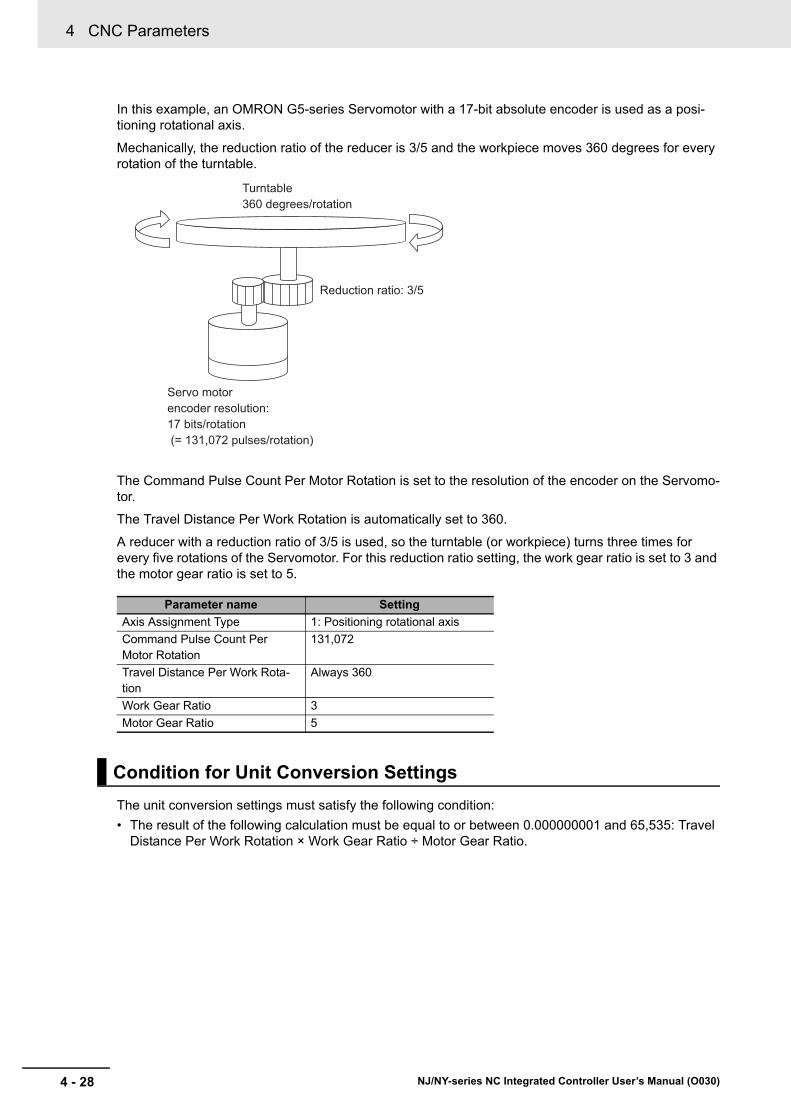
4 CNC Parameters
4 - 28 NJ/NY-series NC Integrated Controller User’s Manual (O030)
In this example, an OMRON G5-series Servomotor with a 17-bit absolute encoder is used as a posi-tioning rotational axis.
Mechanically, the reduction ratio of the reducer is 3/5 and the workpiece moves 360 degrees for every rotation of the turntable.
The Command Pulse Count Per Motor Rotation is set to the resolution of the encoder on the Servomo-tor.
The Travel Distance Per Work Rotation is automatically set to 360.
A reducer with a reduction ratio of 3/5 is used, so the turntable (or workpiece) turns three times for every five rotations of the Servomotor. For this reduction ratio setting, the work gear ratio is set to 3 and the motor gear ratio is set to 5.
The unit conversion settings must satisfy the following condition:
• The result of the following calculation must be equal to or between 0.000000001 and 65,535: Travel Distance Per Work Rotation × Work Gear Ratio ÷ Motor Gear Ratio.
Parameter name Setting
Axis Assignment Type 1: Positioning rotational axis
Command Pulse Count Per Motor Rotation
131,072
Travel Distance Per Work Rota-tion
Always 360
Work Gear Ratio 3
Motor Gear Ratio 5
Condition for Unit Conversion Settings
360 degrees/rotationTurntable
Reduction ratio: 3/5
17 bits/rotation (= 131,072 pulses/rotation)
encoder resolution: Servo motor
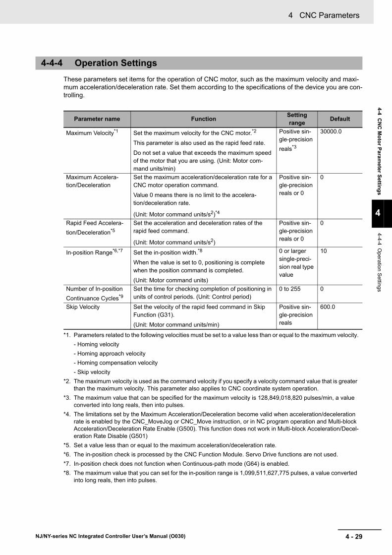
4 - 29
4 CNC Parameters
NJ/NY-series NC Integrated Controller User’s Manual (O030)
4-4 CN
C M
oto
r Param
eter Settin
gs
4
4-4-4 Operation
Se
ttings
These parameters set items for the operation of CNC motor, such as the maximum velocity and maxi-mum acceleration/deceleration rate. Set them according to the specifications of the device you are con-trolling.
4-4-4 Operation Settings
Parameter name FunctionSetting range
Default
Maximum Velocity*1
*1. Parameters related to the following velocities must be set to a value less than or equal to the maximum velocity.
- Homing velocity
- Homing approach velocity
- Homing compensation velocity
- Skip velocity
Set the maximum velocity for the CNC motor.*2
This parameter is also used as the rapid feed rate.
Do not set a value that exceeds the maximum speed of the motor that you are using. (Unit: Motor com-mand units/min)
*2. The maximum velocity is used as the command velocity if you specify a velocity command value that is greater than the maximum velocity. This parameter also applies to CNC coordinate system operation.
Positive sin-gle-precision
reals*3
*3. The maximum value that can be specified for the maximum velocity is 128,849,018,820 pulses/min, a value converted into long reals, then into pulses.
30000.0
Maximum Accelera-tion/Deceleration
Set the maximum acceleration/deceleration rate for a CNC motor operation command.
Value 0 means there is no limit to the accelera-tion/deceleration rate.
(Unit: Motor command units/s2)*4
*4. The limitations set by the Maximum Acceleration/Deceleration become valid when acceleration/deceleration rate is enabled by the CNC_MoveJog or CNC_Move instruction, or in NC program operation and Multi-block Acceleration/Deceleration Rate Enable (G500). This function does not work in Multi-block Acceleration/Decel-eration Rate Disable (G501)
Positive sin-gle-precision reals or 0
0
Rapid Feed Accelera-
tion/Deceleration*5
*5. Set a value less than or equal to the maximum acceleration/deceleration rate.
Set the acceleration and deceleration rates of the rapid feed command.
(Unit: Motor command units/s2)
Positive sin-gle-precision reals or 0
0
In-position Range*6,*7
*6. The in-position check is processed by the CNC Function Module. Servo Drive functions are not used.
*7. In-position check does not function when Continuous-path mode (G64) is enabled.
Set the in-position width.*8
When the value is set to 0, positioning is complete when the position command is completed.
(Unit: Motor command units)
*8. The maximum value that you can set for the in-position range is 1,099,511,627,775 pulses, a value converted into long reals, then into pulses.
0 or larger single-preci-sion real type value
10
Number of In-position
Continuance Cycles*9
Set the time for checking completion of positioning in units of control periods. (Unit: Control period)
0 to 255 0
Skip Velocity Set the velocity of the rapid feed command in Skip Function (G31).
(Unit: Motor command units/min)
Positive sin-gle-precision reals
600.0

4 CNC Parameters
4 - 30 NJ/NY-series NC Integrated Controller User’s Manual (O030)
Precautions for Correct Use
The Maximum Velocity parameter is also used as the speed of the rapid feed command for the CNC coordinate system. Be sure to set a value that is supported by the machine.
The following provides a setting example for the maximum velocity.
Setting Example for the Maximum Velocity
This is an example for orthogonal axis and a Servomotor with a maximum speed of 1,000 r/min.
When calculating from a maximum speed of 1,000 r/min., a reduction ratio of 3/5, and a ball screw pitch of 20 mm, the formula 1,000 r/min × 3/5 × 20 mm yields 1,200 mm/min. Accordingly, specify 1200 for the maximum velocity.
The default setting of 30,000 exceeds the maximum speed of the CNC motor, so you must change the setting.
Set the input logic inversion, etc. of each signal.
*9. Set a value less than the In-position Check Time of the CNC coordinate system to which the CNC motor is assigned.
Example: Suppose that the control period of the primary periodic task is 2 ms and that the in-position check time of the CNC coordinate system is set to 100 ms.
Then the in-position check time must be set to a value less than 50 control periods.
Maximum Velocity
4-4-5 Other Operation Settings
Parameter name Function Setting range Default
Driver Error Reset Monitoring Time
Set the monitor time for a driver error reset. (Unit: ms)
After the monitor time has elapsed, reset processing will end even if the drive error is not yet reset.
1 to 1000 200
Immediate Stop Input Logic Inversion
Set whether to reverse the logic of the immediate stop input signal.
FALSE: Do not reverse.
TRUE: Reverse.
TRUE or FALSE FALSE
Positive Limit Input Logic Inversion
Set whether to reverse the logic of the positive limit input signal.
FALSE: Do not reverse.
TRUE: Reverse.
TRUE or FALSE FALSE
Workpiece
Servomotor encoder resolution: 23 bits/rotation(=8,388,608 pulses/rotation) Reduction ratio: 3/5 Ball screw pitch: 20mm

4 - 31
4 CNC Parameters
NJ/NY-series NC Integrated Controller User’s Manual (O030)
4-4 CN
C M
oto
r Param
eter Settin
gs
4
4-4-6 Limit S
ettings
Use the following parameters to select functions for limiting the following error and for software limits.
Negative Limit Input Logic Inversion
Specify whether to invert the logic of the negative limit input signal.
FALSE: Do not reverse.
TRUE: Reverse.
TRUE or FALSE FALSE
Home Proximity Input Logic Inversion
Set whether to reverse the logic of the home proximity input signal.
FALSE: Do not reverse.
TRUE: Reverse.
TRUE or FALSE FALSE
4-4-6 Limit Settings
Parameter name Function Setting range Default
Software Overtravel Limit*1
*1. This function is activated only when the home is defined.
Enable or disable the software overtravel limit. The stop method is an immediate stop for the command position (stop using remaining pulses).
0: Disabled
1: Enable
0 or 1 0
Positive Software Overtravel
Limit*2,*3,*4
*2. If the software overtravel limit is disabled, the value does not need to be input.
*3. The value obtained through a conversion into a pulse value using the unit conversion setting must be less than or equal to 549755813887.
*4. When assigned to the spindle axis, the software limit does not work.
Set the software overtravel limit in the positive direction.
(Unit: Motor command units)
Positive sin-gle-precision reals
10,000
Negative Software Overtravel
Limit*2,*4,*5
*5. The value obtained through a conversion into a pulse value using the unit conversion setting must be equal to or larger than -549755813888.
Set the software overtravel limit in the negative direction.
(Unit: Motor command units)
Negative sin-gle-precision reals
-10,000
Following Error Over Value*6
*6. The value obtained through a conversion into a pulse value using the unit conversion setting must be less than or equal to 1099511627775.
Set the excessive following error check value.
Set 0 to disable the excessive following error check. (Unit: Motor command units)
Positive long reals or 0
0
Following Error Warning
Value*7
*7. When the Following Error Over Value is not 0, a value that is less than or equal to the Following Error Over Value must be set to this parameter.
Set the following error warning check value.
Set 0 to disable the following error warning check. (Unit: motor command units)
Positive long reals or 0
0
Parameter name Function Setting range Default

4 CNC Parameters
4 - 32 NJ/NY-series NC Integrated Controller User’s Manual (O030)
Set the count mode for the position.
Set the value that is set on the Servo Drive that is connected.
4-4-7 Position Count Settings
Parameter name Function Setting range Default
Encoder Type Set the encoder type.*1,*2
0: Incremental encoder
1: Absolute encoder
*1. If you use any of the following products, set the encoder type to 1: Absolute encoder.
When an OMRON 1S-series or G5-series Servomotor/Servo Drive with an absolute encoder is used
When an OMRON 1S-series or G5-series Servomotor/Servo Drive with an absolute external scale for fully-closed control is used
When an OMRON 1S-series or G5-series Linear Motor Type Servomotor/Servo Drive with built-in EtherCAT communications is used with an absolute external scale
*2. The settings are as follows when you use an OMRON 1S-series or G5-series Servomotor/Servo Drive with an external scale for fully-closed control, or when you use an OMRON 1S-series or G5-series Linear Motor Type Servomotor/Servo Drive with built-in EtherCAT communications.
0: Incremental external scale
1: Absolute external scale
0 to 1 0
4-4-8 Servo Drive Settings
Parameter name Function Setting range Default
PDS Status Control
Method*1
*1. If you set this parameter to 1, the Servo Ready (Switched on) status of OMRON 1S-series Servo Drives or G5-series Servo Drives cannot be used. To use the Servo Ready (Switched on) status, set this parameter to 0.
Set the status to which PDS status changes when Servo is turned OFF by the CNC_Power
instruction.*1
0: Switched on by Servo OFF
1: Ready to switch on by Servo OFF
0 to 1 0
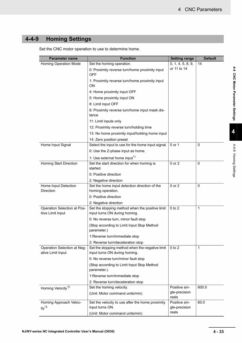
4 - 33
4 CNC Parameters
NJ/NY-series NC Integrated Controller User’s Manual (O030)
4-4 CN
C M
oto
r Param
eter Settin
gs
4
4-4-9 Hom
ing Settings
Set the CNC motor operation to use to determine home.
4-4-9 Homing Settings
Parameter name Function Setting range Default
Homing Operation Mode Set the homing operation.
0: Proximity reverse turn/home proximity input OFF
1: Proximity reverse turn/home proximity input ON
4: Home proximity input OFF
5: Home proximity input ON
8: Limit input OFF
9: Proximity reverse turn/home input mask dis-tance
11: Limit inputs only
12: Proximity reverse turn/holding time
13: No home proximity input/holding home input
14: Zero position preset
0, 1, 4, 5, 8, 9, or 11 to 14
14
Home Input Signal Select the input to use for the home input signal.
0: Use the Z-phase input as home.
1: Use external home input*1
0 or 1 0
Homing Start Direction Set the start direction for when homing is started.
0: Positive direction
2: Negative direction
0 or 2 0
Home Input Detection Direction
Set the home input detection direction of the homing operation.
0: Positive direction
2: Negative direction
0 or 2 0
Operation Selection at Pos-itive Limit Input
Set the stopping method when the positive limit input turns ON during homing.
0: No reverse turn, minor fault stop
(Stop according to Limit Input Stop Method parameter.)
1:Reverse turn/immediate stop
2: Reverse turn/deceleration stop
0 to 2 1
Operation Selection at Neg-ative Limit Input
Set the stopping method when the negative limit input turns ON during homing.
0: No reverse turn/minor fault stop
(Stop according to Limit Input Stop Method parameter.)
1:Reverse turn/immediate stop
2: Reverse turn/deceleration stop
0 to 2 1
Homing Velocity*2 Set the homing velocity.
(Unit: Motor command units/min)
Positive sin-gle-precision reals
600.0
Homing Approach Veloc-
ity*3
Set the velocity to use after the home proximity input turns ON.
(Unit: Motor command units/min)
Positive sin-gle-precision reals
60.0
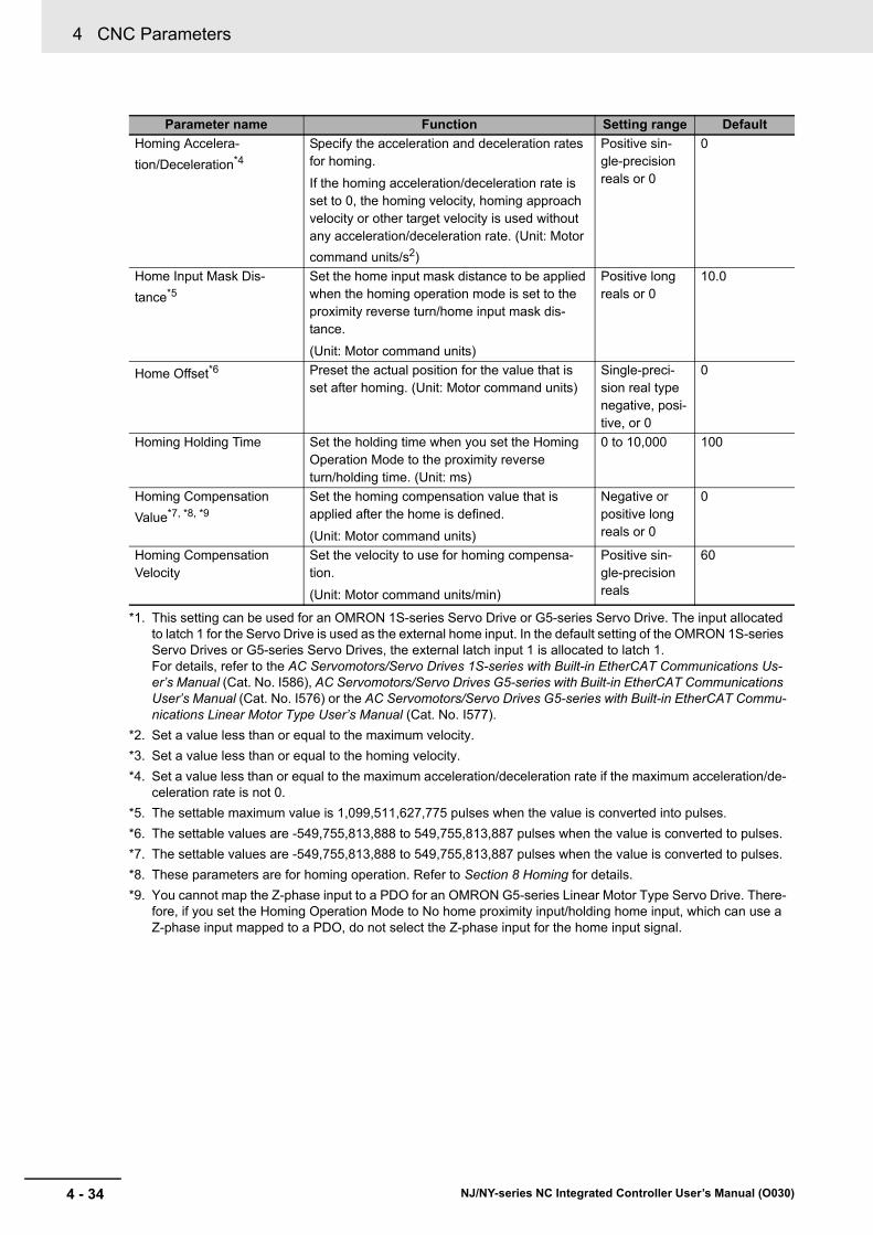
4 CNC Parameters
4 - 34 NJ/NY-series NC Integrated Controller User’s Manual (O030)
Homing Accelera-
tion/Deceleration*4
Specify the acceleration and deceleration rates for homing.
If the homing acceleration/deceleration rate is set to 0, the homing velocity, homing approach velocity or other target velocity is used without any acceleration/deceleration rate. (Unit: Motor
command units/s2)
Positive sin-gle-precision reals or 0
0
Home Input Mask Dis-
tance*5
Set the home input mask distance to be applied when the homing operation mode is set to the proximity reverse turn/home input mask dis-tance.
(Unit: Motor command units)
Positive long reals or 0
10.0
Home Offset*6 Preset the actual position for the value that is set after homing. (Unit: Motor command units)
Single-preci-sion real type negative, posi-tive, or 0
0
Homing Holding Time Set the holding time when you set the Homing Operation Mode to the proximity reverse turn/holding time. (Unit: ms)
0 to 10,000 100
Homing Compensation
Value*7, *8, *9
Set the homing compensation value that is applied after the home is defined.
(Unit: Motor command units)
Negative or positive long reals or 0
0
Homing Compensation Velocity
Set the velocity to use for homing compensa-tion.
(Unit: Motor command units/min)
Positive sin-gle-precision reals
60
*1. This setting can be used for an OMRON 1S-series Servo Drive or G5-series Servo Drive. The input allocated to latch 1 for the Servo Drive is used as the external home input. In the default setting of the OMRON 1S-series Servo Drives or G5-series Servo Drives, the external latch input 1 is allocated to latch 1. For details, refer to the AC Servomotors/Servo Drives 1S-series with Built-in EtherCAT Communications Us-er’s Manual (Cat. No. I586), AC Servomotors/Servo Drives G5-series with Built-in EtherCAT Communications User’s Manual (Cat. No. I576) or the AC Servomotors/Servo Drives G5-series with Built-in EtherCAT Commu-nications Linear Motor Type User’s Manual (Cat. No. I577).
*2. Set a value less than or equal to the maximum velocity.
*3. Set a value less than or equal to the homing velocity.
*4. Set a value less than or equal to the maximum acceleration/deceleration rate if the maximum acceleration/de-celeration rate is not 0.
*5. The settable maximum value is 1,099,511,627,775 pulses when the value is converted into pulses.
*6. The settable values are -549,755,813,888 to 549,755,813,887 pulses when the value is converted to pulses.
*7. The settable values are -549,755,813,888 to 549,755,813,887 pulses when the value is converted to pulses.
*8. These parameters are for homing operation. Refer to Section 8 Homing for details.
*9. You cannot map the Z-phase input to a PDO for an OMRON G5-series Linear Motor Type Servo Drive. There-fore, if you set the Homing Operation Mode to No home proximity input/holding home input, which can use a Z-phase input mapped to a PDO, do not select the Z-phase input for the home input signal.
Parameter name Function Setting range Default

4 - 35
4 CNC Parameters
NJ/NY-series NC Integrated Controller User’s Manual (O030)
4-4 CN
C M
oto
r Param
eter Settin
gs
4
4-4-10 Servo
Gain S
ettings
Set the servo gain parameters of the CNC motor. The setting values are used to calculate the output command based on the command position and feedback position.
These parameters must be set only when you position the CNC motor assigned to the spindle axis with the closed-loop control.
Precautions for Safe Use
• Before adjusting this parameter, adjust the gain on the spindle driver to ensure normal opera-tion of the following functions that perform spindle open-loop control.
• CNC_SpindleGo
• Spindle CW (M03)
• Spindle CCW (M04)
• When adjusting the gain, take sufficient measures to ensure safety.
• If oscillation (abnormal noise or vibration) occurs, immediately turn OFF the power to the driver or turn the Servo OFF.
Refer to 9-2-2 Position Loop by Cyclic Velocity Control on page 9-7 for details on the meaning of each parameter and how to adjust the parameter.
4-4-10 Servo Gain Settings
Parameter name Function Setting range Default
Position Loop Gain Set the value of Position Loop Gain (K_p). (Unit: 1/s)
0 to 3,000
Single-preci-sion reals
40
Velocity Feedforward Gain
Set the value of Velocity Feedforward Gain (K_vff) (Unit: %)
0 to 100
Single-preci-sion reals
0
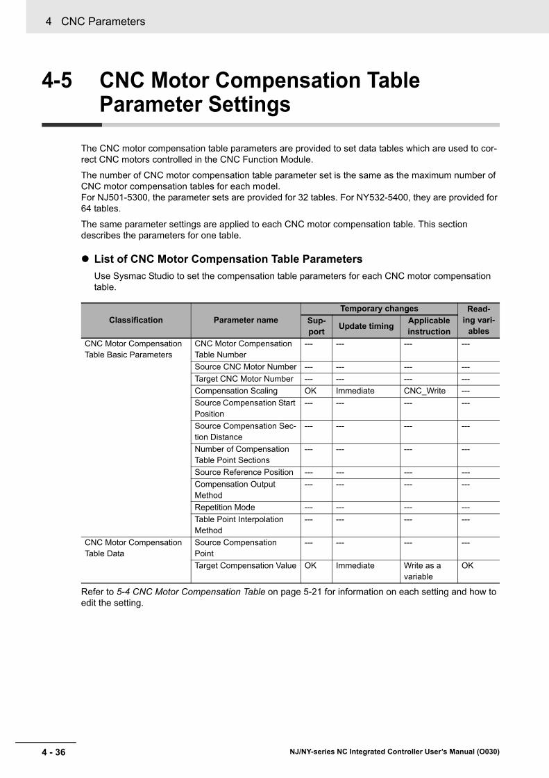
4 CNC Parameters
4 - 36 NJ/NY-series NC Integrated Controller User’s Manual (O030)
4-5 CNC Motor Compensation Table Parameter Settings
The CNC motor compensation table parameters are provided to set data tables which are used to cor-rect CNC motors controlled in the CNC Function Module.
The number of CNC motor compensation table parameter set is the same as the maximum number of CNC motor compensation tables for each model. For NJ501-5300, the parameter sets are provided for 32 tables. For NY532-5400, they are provided for 64 tables.
The same parameter settings are applied to each CNC motor compensation table. This section describes the parameters for one table.
List of CNC Motor Compensation Table Parameters
Use Sysmac Studio to set the compensation table parameters for each CNC motor compensation table.
Refer to 5-4 CNC Motor Compensation Table on page 5-21 for information on each setting and how to edit the setting.
Classification Parameter nameTemporary changes Read-
ing vari-ables
Sup-port
Update timingApplicable instruction
CNC Motor Compensation Table Basic Parameters
CNC Motor Compensation Table Number
--- --- --- ---
Source CNC Motor Number --- --- --- ---
Target CNC Motor Number --- --- --- ---
Compensation Scaling OK Immediate CNC_Write ---
Source Compensation Start Position
--- --- --- ---
Source Compensation Sec-tion Distance
--- --- --- ---
Number of Compensation Table Point Sections
--- --- --- ---
Source Reference Position --- --- --- ---
Compensation Output Method
--- --- --- ---
Repetition Mode --- --- --- ---
Table Point Interpolation Method
--- --- --- ---
CNC Motor Compensation Table Data
Source Compensation Point
--- --- --- ---
Target Compensation Value OK Immediate Write as a variable
OK
5 - 1
5
NJ/NY-series NC Integrated Controller User’s Manual (O030)
This section describes CNC programs.
5-1 Sequence Control Program . . . . . . . . . . . . . . . . . . . . . . . . . . . . . . . . . . . . . . 5-2
5-2 Status Transitions . . . . . . . . . . . . . . . . . . . . . . . . . . . . . . . . . . . . . . . . . . . . . 5-35-2-1 Status of the CNC Function Module . . . . . . . . . . . . . . . . . . . . . . . . . . . . . . . . 5-3
5-2-2 Statuses of CNC Coordinate System . . . . . . . . . . . . . . . . . . . . . . . . . . . . . . . 5-3
5-3 CNC System-defined Variables . . . . . . . . . . . . . . . . . . . . . . . . . . . . . . . . . . . 5-55-3-1 Overview of CNC System-defined Variables . . . . . . . . . . . . . . . . . . . . . . . . . 5-5
5-3-2 Mechanism of CNC System-defined Variables . . . . . . . . . . . . . . . . . . . . . . . . 5-7
5-3-3 Lists of CNC System-defined Variables . . . . . . . . . . . . . . . . . . . . . . . . . . . . . 5-8
5-4 CNC Motor Compensation Table . . . . . . . . . . . . . . . . . . . . . . . . . . . . . . . . 5-215-4-1 Editing the CNC Motor Compensation Table . . . . . . . . . . . . . . . . . . . . . . . . 5-21
5-4-2 Edit . . . . . . . . . . . . . . . . . . . . . . . . . . . . . . . . . . . . . . . . . . . . . . . . . . . . . . . . 5-22
5-4-3 Enabling/Disabling CNC Motor Compensation Table . . . . . . . . . . . . . . . . . . 5-23
5-4-4 Saving . . . . . . . . . . . . . . . . . . . . . . . . . . . . . . . . . . . . . . . . . . . . . . . . . . . . . . 5-23
5-4-5 Functions and Purposes of CNC Motor Compensation Table . . . . . . . . . . . 5-23
5-4-6 Terminology . . . . . . . . . . . . . . . . . . . . . . . . . . . . . . . . . . . . . . . . . . . . . . . . . 5-24
5-4-7 Outline . . . . . . . . . . . . . . . . . . . . . . . . . . . . . . . . . . . . . . . . . . . . . . . . . . . . . 5-25
5-4-8 Basic Settings . . . . . . . . . . . . . . . . . . . . . . . . . . . . . . . . . . . . . . . . . . . . . . . . 5-26
5-4-9 Setting Example . . . . . . . . . . . . . . . . . . . . . . . . . . . . . . . . . . . . . . . . . . . . . . 5-29
5-4-10 CNC Motor Compensation Table Specifications . . . . . . . . . . . . . . . . . . . . . . 5-34
CNC Program

5 CNC Program
5 - 2 NJ/NY-series NC Integrated Controller User’s Manual (O030)
5-1 Sequence Control Program
CNC instructions are used in a sequence control program to execute CNC functions. These instructions are defined as function blocks (FBs).
The CNC Function Module controls CNC motors and CNC coordinate systems. The CNC motor corre-sponds to axis used in the MC Function Module. The CNC coordinate system of the CNC Function Module corresponds to an axes group used in the MC Function Module.
This section describes an overview of the CNC instructions used in the CNC Function Module, and gives the specifications of the CNC Function Module.
For basic information on the function block (FB), refer to the NJ/NX-series CPU Unit Software User's Manual (Cat. No. W501) or the NY-series Industrial Panel PC/Industrial Box PC Software User's Man-ual (Cat. No. W558).
For information on MC Function Module programs, refer to the NJ/NX-series CPU Unit Motion Control User's Manual (Cat. No. W507) or NY-series Industrial Panel PC/Industrial Box PC Motion Control User’s Manual (Cat. No. W559).
CNC Instructions
The procedure for executing CNC instructions conforms to that for executing motion control instruc-tions of the MC Function Module. For this reason, user programs can be more easily reused without hardware dependence.
Costs of training and support can also be reduced.
Refer to Section 10 CNC Instructions for details.

5 - 3
5 CNC Program
NJ/NY-series NC Integrated Controller User’s Manual (O030)
5-2 Statu
s Transitio
ns
5
5-2-1 Status of the C
NC
Fu
nction Module
5-2 Status Transitions
The status transitions of CNC coordinate systems caused by the execution of CNC instructions of the CNC Function Module conform to those of the MC Function Module.
The status transitions of CNC instructions are affected by the composition CNC motor status, start and stop of an NC program, and other factors.
This section describes the statuses and status transitions including those of the overall CNC Function Module.
The status of the overall CNC Function Module are described in the following table.
The status transitions of a CNC coordinate system are shown in the following figure.
*1. Transition into this status occurs from any status when an error occurs in the CNC coordinate system.
*2. Transition into this status occurs when the error is reset by the CNC_CoordReset or ResetCNCError instruc-tion.
5-2-1 Status of the CNC Function Module
Status name Definition
CNC Run Mode*1
*1. This status can be monitored with the CNC Common Variable _CNC_COM.Status.RunMode.
CNC instructions are enabled.
The CNC instructions in the user program are interpreted to perform numerical control.
You can enable CNC Run Mode regardless of the operating mode of the NC Integrated Controller.
5-2-2 Statuses of CNC Coordinate System
*4
*4
*5
*5
*3
*2
*1
Example: CNC_CoordControl
Example: CNC_MoveJog
CNC_CoordStop CNC_CoordImmediateStopTransition occurs when instruction is completed or by other factors.
Transition occurs by execution of instruction.
NC program executionExample: CNC_CoordControl
HoldHolding
ExecutingExecuting
MovingOnHold
Manual Operation While Holding
MovingMoving
StandbyStandby
Stopping
Deceleration stopping
ErrorStop
Error deceleration stopping
Example: CNC_MoveJog

5 CNC Program
5 - 4 NJ/NY-series NC Integrated Controller User’s Manual (O030)
*3. Transition into this status occurs when the Done output from the CNC_CoordStop instruction changes to TRUE and the Execute input is FALSE.
*4. Transition into this status occurs according to the status of executing the NC program by the CNC_CoordCon-trol instruction. Refer to Section 8 Homing for details.
*5. Transition into this status occurs when a certain CNC coordinate system motion instruction is executed. Refer to A-4 Instructions for Which Multi-execution Is Supported on page A-15 for details.
Status name Definition
Standby In this status, no CNC coordinate system motion instruction is executed. The status where the NC program is executed to a specific block line and stopped at a program point is also included.
Moving In this status, a CNC coordinate system motion instruction is running.
Transition into the Standby status occurs when the instruction is completed or interrupted.
Executing In this status, an NC Program is being executed by the CNC_CoordControl instruction. However, the status where the process stops because of the held NC program is not included.
Holding In this status, the NC program is held and being stopped.
Manual Operation While Holding In this status, the NC program is held and being stopped or a CNC coordi-nate system operation instruction is being executed.
Transition into the Hold status occurs when the instruction is completed or interrupted.
Deceleration Stopping In this status, the CNC_CoordStop (CNC Coordinate System Stop) instruc-tion is executing.
The includes when Execute is TRUE after the coordinate system is stopped due to the CNC_CoordStop (CNC Coordinate System Stop).
In this state, it is not possible to execute a CNC instruction.
If one is executed, CommandAborted (Command Aborted) will change to TRUE.
Error Deceleration Stopping In this status, an error has occurred in the CNC coordinate system.
This included during execution of CNC_CoordImmediateStop (CNC Coordi-nate System Immediate Stop) instruction, and when the CNC coordinate sys-tem is decelerating to stop due to an error on the coordinate system.
It is not possible to execute CNC coordinate system instruction in this status.
If an attempt is made to execute one of them, CommandAborted (Command Aborted) will change to TRUE.
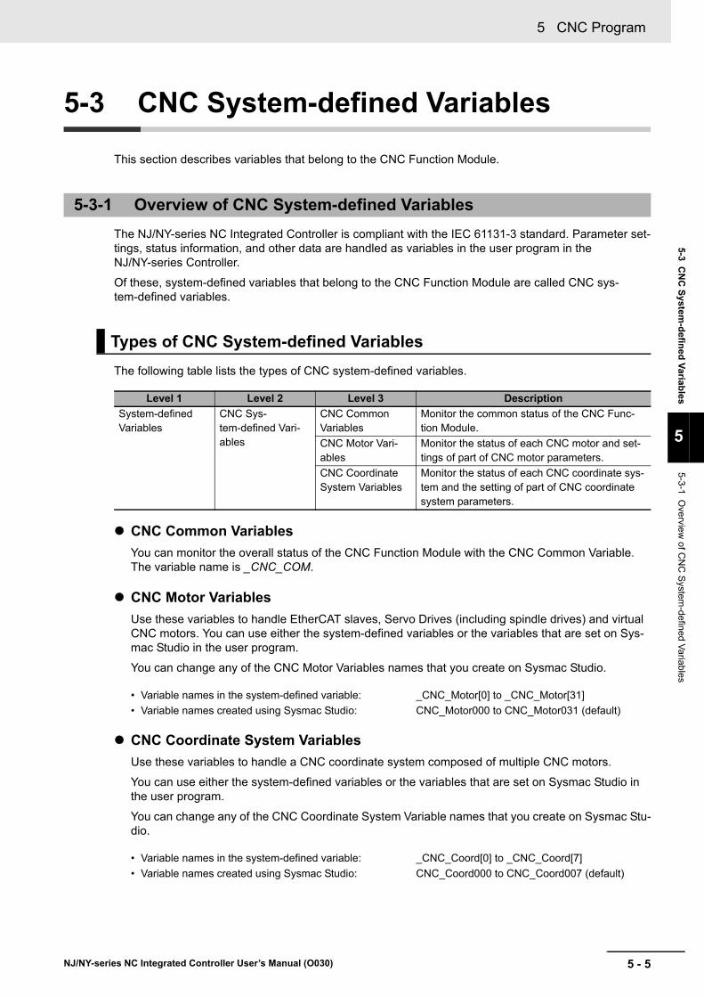
5 - 5
5 CNC Program
NJ/NY-series NC Integrated Controller User’s Manual (O030)
5-3 CN
C S
ystem-d
efined
Variab
les
5
5-3-1 Overview
of CN
C S
ystem-defined V
aria
bles
5-3 CNC System-defined Variables
This section describes variables that belong to the CNC Function Module.
The NJ/NY-series NC Integrated Controller is compliant with the IEC 61131-3 standard. Parameter set-tings, status information, and other data are handled as variables in the user program in the NJ/NY-series Controller.
Of these, system-defined variables that belong to the CNC Function Module are called CNC sys-tem-defined variables.
The following table lists the types of CNC system-defined variables.
CNC Common Variables
You can monitor the overall status of the CNC Function Module with the CNC Common Variable. The variable name is _CNC_COM.
CNC Motor Variables
Use these variables to handle EtherCAT slaves, Servo Drives (including spindle drives) and virtual CNC motors. You can use either the system-defined variables or the variables that are set on Sys-mac Studio in the user program.
You can change any of the CNC Motor Variables names that you create on Sysmac Studio.
CNC Coordinate System Variables
Use these variables to handle a CNC coordinate system composed of multiple CNC motors.
You can use either the system-defined variables or the variables that are set on Sysmac Studio in the user program.
You can change any of the CNC Coordinate System Variable names that you create on Sysmac Stu-dio.
5-3-1 Overview of CNC System-defined Variables
Types of CNC System-defined Variables
Level 1 Level 2 Level 3 Description
System-defined Variables
CNC Sys-tem-defined Vari-ables
CNC Common Variables
Monitor the common status of the CNC Func-tion Module.
CNC Motor Vari-ables
Monitor the status of each CNC motor and set-tings of part of CNC motor parameters.
CNC Coordinate System Variables
Monitor the status of each CNC coordinate sys-tem and the setting of part of CNC coordinate system parameters.
• Variable names in the system-defined variable: _CNC_Motor[0] to _CNC_Motor[31]
• Variable names created using Sysmac Studio: CNC_Motor000 to CNC_Motor031 (default)
• Variable names in the system-defined variable: _CNC_Coord[0] to _CNC_Coord[7]
• Variable names created using Sysmac Studio: CNC_Coord000 to CNC_Coord007 (default)

5 CNC Program
5 - 6 NJ/NY-series NC Integrated Controller User’s Manual (O030)
The types of CNC system-defined variables are basic data types and derivative data types.
Basic Data Types
Data Types Used for CNC System-defined Variables
Category Data type Size Range of values Notation
Boolean BOOL 2*1
*1. BOOL data is only 1 bit in size but it takes up 2 bytes of memory.
TRUE or FALSE
TRUE or FALSE
Integer UINT 2 0 to +65,535 Binary expression: "2#" is prefixed to the
number.*2
Octal notation: "8#" is prefixed to the num-
ber.*3
Decimal notation: "10#" is prefixed to the
number.*4
Hexadecimal notation: "16#" is prefixed to
the number.*5
If you do not prefix any notation to a num-ber, that number is treated as a decimal number.
*2. Example of binary expression: 2#1111_1111, 2#1110_0000
*3. Example of octal notation: 8#377, 8#340
*4. Example of decimal notation: -12, 0, 123_456, +986, 10#1234
*5. Example of hexadecimal notation: 16#FF, 16#ff, 16#E0, 16#e0
UDINT 4 0 to +4,294,967,295
Real numbers
LREAL 8 -1.79769313486231e+308 to -2.22507385850721e-308, 0, 2.22507385850721e-308 to 1.79769313486231e+308,
positive infinity, or negative infinity
Written as (sign) + integer_part + (deci-
mal_point) + (decimal_part) + (exponent).*6
You can omit items in parentheses.
*6. Example: 2, -12.0, 0.0, 0.4560, 3.14159_26, -1.34E-12, -1.34e-12, 1.0E+6, 1.0e+6, 1.234E6, 1.234e6
Dura-
tion*7, *8
*7. Use the NanoSecToTime and TimeToNanoSec instructions for conversion between durations and integer da-ta.
For details on instruction specifications, refer to the NJ/NX-series Instructions Reference Manual (Cat. No. W502), or the NY-series Instructions Reference Manual (Cat. No. W560).
*8. Variables are compared with nanosecond precision for comparison instructions. To change the precision for comparison, use the TruncTime, TruncDt, or TruncTod instruction. For details on instruction specifications, re-fer to the NJ/NX-series Instructions Reference Manual (Cat. No. W502), or the NY-series Instructions Refer-ence Manual (Cat. No. W560).
TIME 8 T#-9223372036854.775808ms (T#-106751d_23h_47m_16s_854.775808ms)
to T#+9223372036854.775807ms (T#+106751d_23h_47m_16s_854.775807ms)
T#12d3h3s
T#3s56ms
TIME#6d_10m
TIME#16d_5h_3m_4s
T#12d3.5h
T#10.12s
T#61m5s (same as T#1h1m5s)
TIME#25h_3m

5 - 7
5 CNC Program
NJ/NY-series NC Integrated Controller User’s Manual (O030)
5-3 CN
C S
ystem-d
efined
Variab
les
5
5-3-2 Mechanism
of CN
C S
ystem-defined V
ariables
Derivative Data Types
The attributes that are shown in the following table are the same for all CNC system-defined variables.
CNC system-defined variables consist of information indicating the status of the CNC Function Module, status information on slave devices connected via EtherCAT communications, and some settings of the CNC motor parameters that are used to perform numerical control.
You can access the CNC system-defined variables as variables in a user program. You can also moni-tor them from Sysmac Studio.
CNC system-defined variables are updated every primary task period.
Type Description
Enumerated data type This data type uses one item from a prepared name list as its value.
Variables of this data type starts with "_e".
Structure data type This data type consists of multiple data types placed together into a single layered structure.
Variables with this data type start with "_s".
Attributes of CNC System-defined Variables
Attribute type Attributes of CNC system-defined variables
Global/local Global variable
R/W access Read only
Retain Non-retain
Network publish Publish*1
*1. Variables are published on the network using the names of the system-defined variables. The variable names that are created when CNC motors or CNC coordinate systems were created on the Sysmac Studio are not published on the network.
Usage in user program Available
5-3-2 Mechanism of CNC System-defined Variables
Update Timing of CNC System-defined Variables
Sysmac Studio
User program
Data transfer instructions CNC common variablesCNC Function
Module processing Status
EtherCAT communi-
cations
Servo Drives and other devices
CNC system-defined
variables
Main memory
CNC motor variablesCNC coordinate system variables
Monitor display
NC Integrated Controller
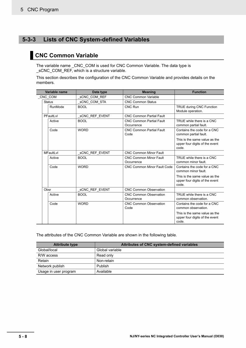
5 CNC Program
5 - 8 NJ/NY-series NC Integrated Controller User’s Manual (O030)
The variable name _CNC_COM is used for CNC Common Variable. The data type is _sCNC_COM_REF, which is a structure variable.
This section describes the configuration of the CNC Common Variable and provides details on the members.
The attributes of the CNC Common Variable are shown in the following table.
5-3-3 Lists of CNC System-defined Variables
CNC Common Variable
Variable name Data type Meaning Function
_CNC_COM _sCNC_COM_REF CNC Common Variable
Status _sCNC_COM_STA CNC Common Status
RunMode BOOL CNC Run TRUE during CNC Function Module operation.
PFaultLvl _sCNC_REF_EVENT CNC Common Partial Fault
Active BOOL CNC Common Partial Fault Occurrence
TRUE while there is a CNC common partial fault.
Code WORD CNC Common Partial Fault Code
Contains the code for a CNC common partial fault.
This is the same value as the upper four digits of the event code.
MFaultLvl _sCNC_REF_EVENT CNC Common Minor Fault
Active BOOL CNC Common Minor Fault Occurrence
TRUE while there is a CNC common minor fault.
Code WORD CNC Common Minor Fault Code Contains the code for a CNC common minor fault.
This is the same value as the upper four digits of the event code.
Obsr _sCNC_REF_EVENT CNC Common Observation
Active BOOL CNC Common Observation Occurrence
TRUE while there is a CNC common observation.
Code WORD CNC Common Observation Code
Contains the code for a CNC common observation.
This is the same value as the upper four digits of the event code.
Attribute type Attributes of CNC system-defined variables
Global/local Global variable
R/W access Read only
Retain Non-retain
Network publish Publish
Usage in user program Available

5 - 9
5 CNC Program
NJ/NY-series NC Integrated Controller User’s Manual (O030)
5-3 CN
C S
ystem-d
efined
Variab
les
5
5-3-3 Lists of C
NC
System
-defined Variables
The variable name _CNC_Coord is used for CNC coordinate system variables. The data type is _sCNC_COORD_REF, which is a structure variable.
This section describes the configuration of the CNC coordinate system variable and provides details on the members.
CNC Coordinate System Variables
Variable name Data type Meaning Function
_CNC_Coord[0..7] _sCNC_COORD_REF CNC Coordinate Sys-tem Variable
Status _sCNC_COORD_STA CNC Coordinate Sys-tem Status
Ready BOOL CNC Coordinate Sys-tem Ready-to-execute
TRUE if the composition CNC motor satisfies all of the following conditions:
• The home is defined for the posi-tioning axis CNC motor.
• The Servo is locked for the position-ing axis CNC motor.
• The Servo is locked for the spindle axis CNC motor.
• The CNC coordinate system is in a Standby status.
Standby BOOL CNC Coordinate Sys-tem Ready
TRUE when a CNC coordinate system motion instructions and the NC pro-gram stop, and when CNC coordinate system operations and the NC pro-gram are ready to start. The following CNC coordinate system statuses are mutually exclusive. Only one of them can be TRUE at a time.
Standby, Moving, Executing, Hold, Mov-ingOnHold, Stopping, or ErrorStop
Moving BOOL CNC Coordinate Sys-tem Moving
TRUE while a CNC operation instruc-tion is executed from a Standby status. This also includes the in-position wait-ing status.
Executing BOOL CNC Coordinate Sys-tem Execution
TRUE during execution of the NC pro-gram. This also includes the in-posi-tion waiting status, a stop occurs due to dwelling, deceleration due to Hold, and acceleration after resuming opera-tion from Hold.
Hold BOOL CNC Coordinate Sys-tem Holding
TRUE when operation stops due to Hold during execution of the NC pro-gram. This changes to FALSE when the NC Program is resumed or inter-rupted.
MovingOnHold BOOL CNC Coordinate Sys-tem Operation Holding
TRUE when a CNC coordinate system motion instruction is executed from a status where the NC program has stopped due to Hold. This also includes the in-position waiting status.
Stopping BOOL Deceleration Stopping TRUE until the CNC coordinate sys-tem stops for the CNC_CoordStop instruction.
This includes a status where Execute is TRUE after the CNC coordinate sys-tem stopped for the CNC_CoordStop instruction.
No CNC coordinate system motion instruction can be executed in this state. (CommandAborted is TRUE.)

5 CNC Program
5 - 10 NJ/NY-series NC Integrated Controller User’s Manual (O030)
ErrorStop BOOL Error Deceleration Stop-ping
TRUE while the CNC coordinate sys-tem is stopping or stopped for the CNC_CoordImmediateStop instruc-tion or a CNC coordinate system minor fault occurrence (when _CNC_Co-ord[*].MFaultLvl.Active is TRUE). No CNC coordinate system motion instruction can be executed in this state. (CommandAborted is TRUE.)
Spindle _sCNC_SPINDLE_STA Spindle Axis Status
Standby BOOL Standby TRUE when the spindle axis stopped and is waiting for start-up from the NC program or a CNC instruction.
TRUE also when the spindle axis is not assigned to the CNC coordinate system.
CW BOOL Forward TRUE when the spindle axis rotates clockwise (CW).
CCW BOOL Reverse TRUE when the spindle axis rotates counterclockwise (CCW).
Orientation BOOL Orientation TRUE when the spindle axis is in Spin-dle Orientation (M19).
Tapping BOOL Tapping TRUE when the spindle axis is in tap-ping cycle (G74, G84).
Moving BOOL Spindle Axis Operating TRUE when the spindle axis is operat-ing, activated by CNC_Move or CNC_Home.
Stopping BOOL Spindle Axis Stopping TRUE until the CNC coordinate sys-tem stops for the CNC_CoordStop instruction.
This includes a status where Execute is TRUE after the CNC coordinate sys-tem stopped for the CNC_CoordStop instruction.
No CNC coordinate system motion instruction can be executed in this state.
(CommandAborted is TRUE.)
ErrorStop BOOL Error Stop TRUE while the CNC coordinate sys-tem is stopping or stopped for the CNC_CoordImmediateStop instruction or a CNC coordinate system minor fault occurrence (when _CNC_Co-ord[*].MFaultLvl.Active is TRUE). No CNC coordinate system motion instruc-tion can be executed in this state.
(CommandAborted is TRUE.)
Variable name Data type Meaning Function

5 - 11
5 CNC Program
NJ/NY-series NC Integrated Controller User’s Manual (O030)
5-3 CN
C S
ystem-d
efined
Variab
les
5
5-3-3 Lists of C
NC
System
-defined Variables
Details _sCNC_COORD_DET CNC Coordinate Sys-tem Control Status
Idle BOOL Standby TRUE when processing is not cur-rently performed for the command value, except when waiting for in-posi-tion state.
Processing status include operation at velocity 0, stop processing when an error occurs, and operating status of the CNC coordinate system.
Homed BOOL Home Defined TRUE when the homes of all the CNC motors assigned to positioning axes are defined.
InPos BOOL In-position Completed TRUE when all the CNC motors assigned to positioning axes satisfy the in-position conditions.
Feedrate _sCNC_FEEDRATE CNC Coordinate Sys-tem Interpolation Veloc-ity
CmdVel LREAL Current Command Interpolation Velocity
Contains the current value of the com-mand interpolation velocity for the X-, Y-, and Z-axes.
ActVel LREAL Feedback Current Inter-polation Velocity
Contains the current value of the feed-back interpolation velocity for the X-, Y-, and Z-axes.
AxCmdPos _sCNC_COORD_AX_DATA Command Position for CNC Coordinate Sys-tem
X LREAL X-axis Position Shows the command position (tool center point) of each axis according to the currently valid CNC coordinate
system parameters.*1 This also shows a position offset from the center of the tool during tool radius compensation.
Unit: Axis command units
Y LREAL Y-axis Position
Z LREAL Z-axis Position
A LREAL A-axis Position
B LREAL B-axis Position
C LREAL C-axis Position
AxProgPos _sCNC_COORD_AX_DATA Target Position for CNC Coordinate System
X LREAL X-axis Position Shows the target program position on each axis of an NC program execution block.
Unit: Axis command units
Y LREAL Y-axis Position
Z LREAL Z-axis Position
A LREAL A-axis Position
B LREAL B-axis Position
C LREAL C-axis Position
AxDistanceToGo _sCNC_COORD_AX_DATA Remaining Travel Dis-tance in the CNC Coor-dinate System
X LREAL Remaining Travel Distance in X-axis
Shows the remaining travel distance to the target position on each axis of an
NC program execution block.*2
Unit: Axis command units
Y LREAL Remaining Travel Distance in Y-axis
Z LREAL Remaining Travel Distance in Z-axis
A LREAL Remaining Travel Distance in A-axis
B LREAL Remaining Travel Distance in B-axis
C LREAL Remaining Travel Distance in C-axis
Variable name Data type Meaning Function

5 CNC Program
5 - 12 NJ/NY-series NC Integrated Controller User’s Manual (O030)
AxActPos _sCNC_COORD_AX_DATA Feedback Current Posi-tion for CNC Coordinate System
X LREAL X-axis Position Shows the feedback current position (tool center point) of each axis accord-ing to the current CNC coordinate sys-
tem parameters.*1
Unit: Axis command units
Y LREAL Y-axis Position
Z LREAL Z-axis Position
A LREAL A-axis Position
B LREAL B-axis Position
C LREAL C-axis Position
AxCmdVel _sCNC_COORD_AX_DATA Command Current Velocity for CNC Coor-dinate System
X LREAL X-axis Velocity Shows the current value of the com-mand velocity of each axis according to the current CNC coordinate system parameters.
Unit: Axis command units
0 is output if no CNC motor is assigned to the axis.
Y LREAL Y-axis Velocity
Z LREAL Z-axis Velocity
A LREAL A-axis Velocity
B LREAL B-axis Velocity
C LREAL C-axis Velocity
AxActVel _sCNC_COORD_AX_DATA Feedback Current Velocity for CNC Coor-dinate System
X LREAL X-axis Velocity Shows the current velocity of each axis according to the current CNC coordinate system settings.
Unit: Axis command units
Y LREAL Y-axis Velocity
Z LREAL Z-axis Velocity
A LREAL A-axis Velocity
B LREAL B-axis Velocity
C LREAL C-axis Velocity
MFaultLvl _sCNC_REF_EVENT CNC Coordinate Sys-tem Minor Fault
Active BOOL CNC Coordinate Sys-tem Minor Fault Occur-rence
TRUE while there is a CNC coordinate system minor fault.
Code WORD CNC Coordinate Sys-tem Minor Fault Code
Contains the code for a CNC coordi-nate system minor fault.
This is the same value as the upper four digits of the event code.
Obsr _sCNC_REF_EVENT CNC Coordinate Sys-tem Observation
Active BOOL CNC Coordinate Sys-tem Observation Occur-rence
TRUE while there is a CNC coordinate system observation.
Code WORD CNC Coordinate Sys-tem Observation Code
Contains the code for CNC coordinate system observation.
This is the same value as the upper four digits of the event code.
Cfg _sCNC_COORD_CFG CNC Coordinate Sys-tem Basic Parameters
CoordNo UINT CNC Coordinate Sys-tem Number
Shows the logical number of the CNC coordinate system.
CoordEnable _eCNC_COORD_USE Using CNC Coordinate System
Shows whether to use the CNC coor-dinate system.
0: _cncNoneCoord (Undefined CNC coordinate system)
1: _cncUnusedICoord (Unused CNC coordinate system)
2: _cncUsedCoord (Used CNC coordinate sys-tem)
PosMotorNum UINT Number of Positioning Axis Composition CNC Motors
Shows the number of CNC motors that are assigned to positioning axes.
Variable name Data type Meaning Function
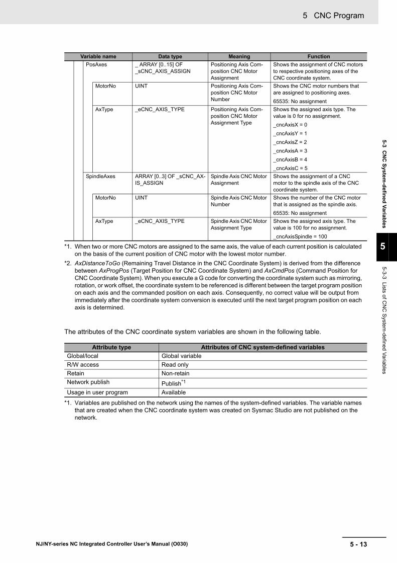
5 - 13
5 CNC Program
NJ/NY-series NC Integrated Controller User’s Manual (O030)
5-3 CN
C S
ystem-d
efined
Variab
les
5
5-3-3 Lists of C
NC
System
-defined Variables
The attributes of the CNC coordinate system variables are shown in the following table.
PosAxes _ ARRAY [0..15] OF _sCNC_AXIS_ASSIGN
Positioning Axis Com-position CNC Motor Assignment
Shows the assignment of CNC motors to respective positioning axes of the CNC coordinate system.
MotorNo UINT Positioning Axis Com-position CNC Motor Number
Shows the CNC motor numbers that are assigned to positioning axes.
65535: No assignment
AxType _eCNC_AXIS_TYPE Positioning Axis Com-position CNC Motor Assignment Type
Shows the assigned axis type. The value is 0 for no assignment.
_cncAxisX = 0
_cncAxisY = 1
_cncAxisZ = 2
_cncAxisA = 3
_cncAxisB = 4
_cncAxisC = 5
SpindleAxes ARRAY [0..3] OF _sCNC_AX-IS_ASSIGN
Spindle Axis CNC Motor Assignment
Shows the assignment of a CNC motor to the spindle axis of the CNC coordinate system.
MotorNo UINT Spindle Axis CNC Motor Number
Shows the number of the CNC motor that is assigned as the spindle axis.
65535: No assignment
AxType _eCNC_AXIS_TYPE Spindle Axis CNC Motor Assignment Type
Shows the assigned axis type. The value is 100 for no assignment.
_cncAxisSpindle = 100
*1. When two or more CNC motors are assigned to the same axis, the value of each current position is calculated on the basis of the current position of CNC motor with the lowest motor number.
*2. AxDistanceToGo (Remaining Travel Distance in the CNC Coordinate System) is derived from the difference between AxProgPos (Target Position for CNC Coordinate System) and AxCmdPos (Command Position for CNC Coordinate System). When you execute a G code for converting the coordinate system such as mirroring, rotation, or work offset, the coordinate system to be referenced is different between the target program position on each axis and the commanded position on each axis. Consequently, no correct value will be output from immediately after the coordinate system conversion is executed until the next target program position on each axis is determined.
Attribute type Attributes of CNC system-defined variables
Global/local Global variable
R/W access Read only
Retain Non-retain
Network publish Publish*1
*1. Variables are published on the network using the names of the system-defined variables. The variable names that are created when the CNC coordinate system was created on Sysmac Studio are not published on the network.
Usage in user program Available
Variable name Data type Meaning Function
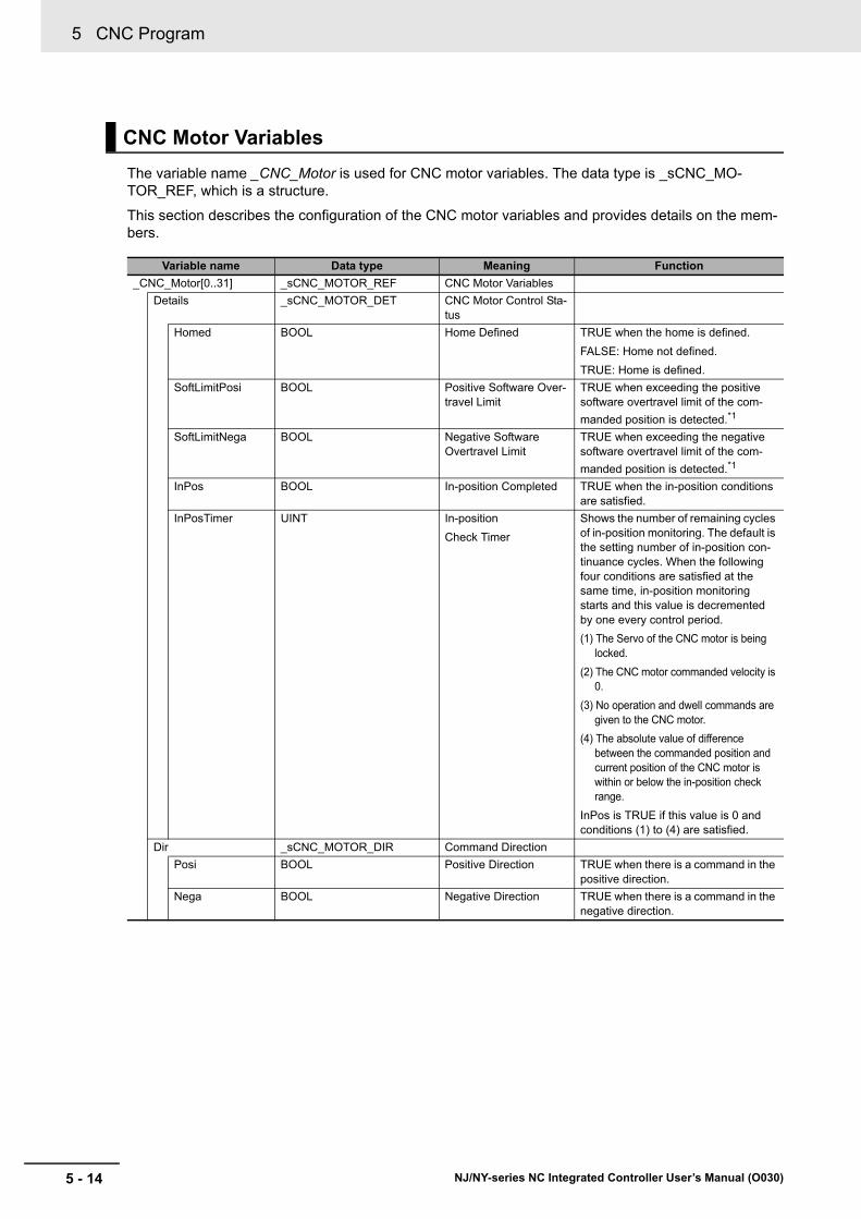
5 CNC Program
5 - 14 NJ/NY-series NC Integrated Controller User’s Manual (O030)
The variable name _CNC_Motor is used for CNC motor variables. The data type is _sCNC_MO-TOR_REF, which is a structure.
This section describes the configuration of the CNC motor variables and provides details on the mem-bers.
CNC Motor Variables
Variable name Data type Meaning Function
_CNC_Motor[0..31] _sCNC_MOTOR_REF CNC Motor Variables
Details _sCNC_MOTOR_DET CNC Motor Control Sta-tus
Homed BOOL Home Defined TRUE when the home is defined.
FALSE: Home not defined.
TRUE: Home is defined.
SoftLimitPosi BOOL Positive Software Over-travel Limit
TRUE when exceeding the positive software overtravel limit of the com-
manded position is detected.*1
SoftLimitNega BOOL Negative Software Overtravel Limit
TRUE when exceeding the negative software overtravel limit of the com-
manded position is detected.*1
InPos BOOL In-position Completed TRUE when the in-position conditions are satisfied.
InPosTimer UINT In-position
Check Timer
Shows the number of remaining cycles of in-position monitoring. The default is the setting number of in-position con-tinuance cycles. When the following four conditions are satisfied at the same time, in-position monitoring starts and this value is decremented by one every control period.
(1) The Servo of the CNC motor is being locked.
(2) The CNC motor commanded velocity is 0.
(3) No operation and dwell commands are given to the CNC motor.
(4) The absolute value of difference between the commanded position and current position of the CNC motor is within or below the in-position check range.
InPos is TRUE if this value is 0 and conditions (1) to (4) are satisfied.
Dir _sCNC_MOTOR_DIR Command Direction
Posi BOOL Positive Direction TRUE when there is a command in the positive direction.
Nega BOOL Negative Direction TRUE when there is a command in the negative direction.

5 - 15
5 CNC Program
NJ/NY-series NC Integrated Controller User’s Manual (O030)
5-3 CN
C S
ystem-d
efined
Variab
les
5
5-3-3 Lists of C
NC
System
-defined Variables
DrvStatus _sCNC_MOTOR_STA_DRV Servo Drive Status
ServoOn BOOL Servo ON TRUE when the Servomotor is pow-ered.
Ready BOOL Servo Ready TRUE when the Servo is ready*2.
MainPower BOOL Main Power TRUE when the Servo Drive main power is ON.
P_OT BOOL Positive Limit Input TRUE when the positive limit input is enabled.
N_OT BOOL Negative Limit Input TRUE when the negative limit input is enabled.
HomeSw BOOL Home Proximity Input TRUE when the home proximity input is enabled.
ImdStop BOOL Immediate Stop Input TRUE when the immediate stop input is enabled.
Latch1 BOOL External Latch Input 1 TRUE when latch input 1 is enabled.
Latch2 BOOL External Latch Input 2 TRUE when latch input 2 is enabled.
DrvAlarm BOOL Driver Error Input TRUE while there is a Servo Drive error.
DrvWarning BOOL Driver Warning Input TRUE while there is a driver warning.
ILA BOOL Driver Internal Limiting TRUE when the Servo Drive limiting function actually limits the axis.
This corresponds to one of the follow-ing limits in the G5-series Servo
Drive.*3
Torque limits, velocity limit, drive pro-hibit inputs, software limits
Cmd _sCNC_MOTOR_CMD_DATA
CNC Motor Command Value
Pos LREAL Command Current Position
Contains the current value of the com-manded position. This variable con-tains the feedback current position while the Servo is OFF. (Unit: Motor
command units)*4
Vel LREAL Command Current Velocity
Contains the current value of the com-manded velocity.
(Unit: Motor command units/min)
CompPos LREAL Current Compensation Position
Contains the current compensation position. (Unit: Motor command units/min)
Act _sCNC_MOTOR_ACT_DATA CNC Motor Current Value
Pos LREAL Feedback Current Posi-tion
Contains the feedback current posi-tion. (Unit: Motor command units)
Vel LREAL Feedback Current Velocity
Contains the feedback current posi-
tion. (Unit: Motor command units/min2)
Trq LREAL Feedback Current Torque
Contains the current value of the feed-back torque. (Unit: %)
A plus sign is added during travel in the positive direction, and a minus sign during travel in the negative direction.
MFaultLvl _sCNC_REF_EVENT CNC Motor Minor Fault
Active BOOL CNC Motor Minor Fault Occurrence
TRUE while there is a CNC motor minor fault.
Code WORD CNC Motor Minor Fault Code
Contains the code for a CNC motor minor fault.
This is the same value as the upper four digits of the event code.
Variable name Data type Meaning Function
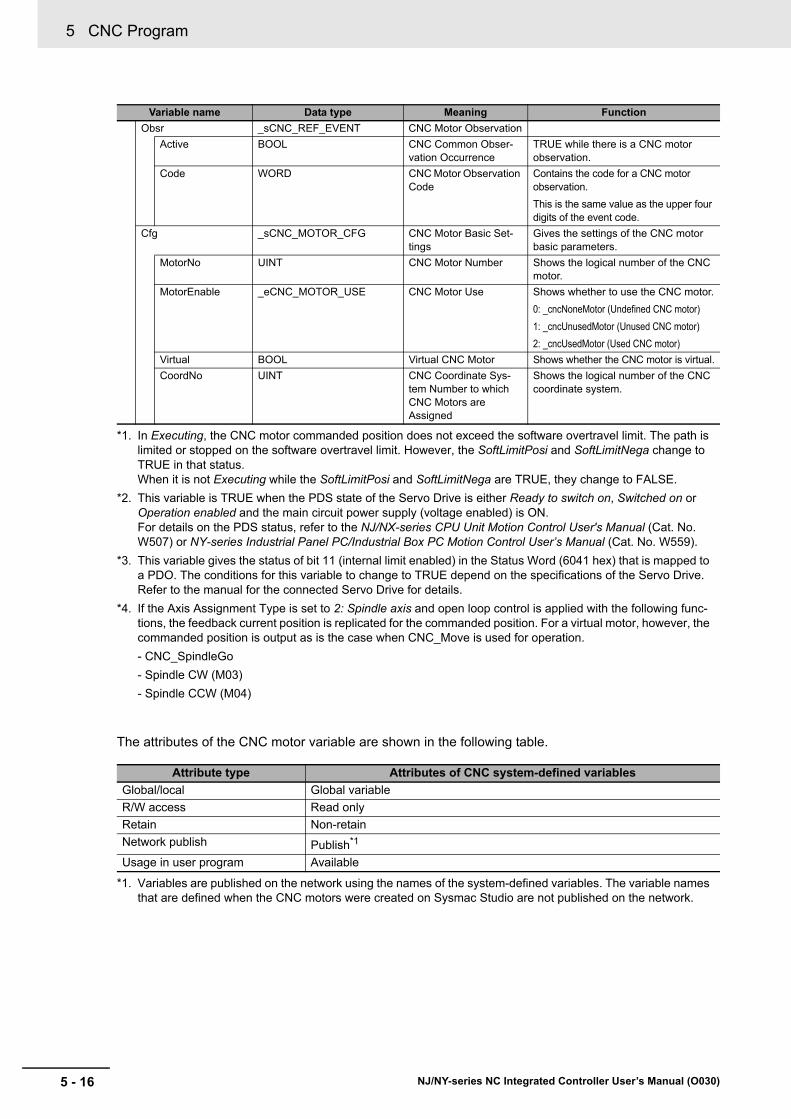
5 CNC Program
5 - 16 NJ/NY-series NC Integrated Controller User’s Manual (O030)
The attributes of the CNC motor variable are shown in the following table.
Obsr _sCNC_REF_EVENT CNC Motor Observation
Active BOOL CNC Common Obser-vation Occurrence
TRUE while there is a CNC motor observation.
Code WORD CNC Motor Observation Code
Contains the code for a CNC motor observation.
This is the same value as the upper four digits of the event code.
Cfg _sCNC_MOTOR_CFG CNC Motor Basic Set-tings
Gives the settings of the CNC motor basic parameters.
MotorNo UINT CNC Motor Number Shows the logical number of the CNC motor.
MotorEnable _eCNC_MOTOR_USE CNC Motor Use Shows whether to use the CNC motor.
0: _cncNoneMotor (Undefined CNC motor)
1: _cncUnusedMotor (Unused CNC motor)
2: _cncUsedMotor (Used CNC motor)
Virtual BOOL Virtual CNC Motor Shows whether the CNC motor is virtual.
CoordNo UINT CNC Coordinate Sys-tem Number to which CNC Motors are Assigned
Shows the logical number of the CNC coordinate system.
*1. In Executing, the CNC motor commanded position does not exceed the software overtravel limit. The path is limited or stopped on the software overtravel limit. However, the SoftLimitPosi and SoftLimitNega change to TRUE in that status. When it is not Executing while the SoftLimitPosi and SoftLimitNega are TRUE, they change to FALSE.
*2. This variable is TRUE when the PDS state of the Servo Drive is either Ready to switch on, Switched on or Operation enabled and the main circuit power supply (voltage enabled) is ON. For details on the PDS status, refer to the NJ/NX-series CPU Unit Motion Control User's Manual (Cat. No. W507) or NY-series Industrial Panel PC/Industrial Box PC Motion Control User’s Manual (Cat. No. W559).
*3. This variable gives the status of bit 11 (internal limit enabled) in the Status Word (6041 hex) that is mapped to a PDO. The conditions for this variable to change to TRUE depend on the specifications of the Servo Drive. Refer to the manual for the connected Servo Drive for details.
*4. If the Axis Assignment Type is set to 2: Spindle axis and open loop control is applied with the following func-tions, the feedback current position is replicated for the commanded position. For a virtual motor, however, the commanded position is output as is the case when CNC_Move is used for operation.
- CNC_SpindleGo
- Spindle CW (M03)
- Spindle CCW (M04)
Attribute type Attributes of CNC system-defined variables
Global/local Global variable
R/W access Read only
Retain Non-retain
Network publish Publish*1
*1. Variables are published on the network using the names of the system-defined variables. The variable names that are defined when the CNC motors were created on Sysmac Studio are not published on the network.
Usage in user program Available
Variable name Data type Meaning Function

5 - 17
5 CNC Program
NJ/NY-series NC Integrated Controller User’s Manual (O030)
5-3 CN
C S
ystem-d
efined
Variab
les
5
5-3-3 Lists of C
NC
System
-defined Variables
Relationship between CNC Motor Variables and Enabled Virtual CNC Motors
CNC motor variables are enabled or disabled depending on the virtual CNC motor settings.
Disabled members are FALSE or 0.
Variable name Data type MeaningPhysical
CNC motorVirtual
CNC Motor
_CNC_Motor[0..31] _sCNC_MOTOR_REF CNC Motor Variables
Details _sCNC_MOTOR_DET CNC Motor Control Status
Homed BOOL Home Defined Enabled Enabled
SoftLimitPosi BOOL Positive Software Overtravel Limit
Enabled Enabled
SoftLimitNega BOOL Negative Software Overtravel Limit
Enabled Enabled
InPos BOOL In-position Completed Enabled Enabled
InPosTimer UINT In-position Check Timer Enabled Enabled
Dir _sCNC_MOTOR_DIR Command Direction Enabled
Posi BOOL Positive Direction Enabled Enabled
Nega BOOL Negative Direction Enabled Enabled
DrvStatus _sCNC_MOTOR_STA_DRV Servo Drive Status
ServoOn BOOL Servo ON Enabled Enabled
Ready BOOL Servo Ready Enabled Always TRUE
MainPower BOOL Main Power Enabled Always TRUE
P_OT BOOL Positive Limit Input Enabled
N_OT BOOL Negative Limit Input Enabled
HomeSw BOOL Home Proximity Input Enabled
ImdStop BOOL Immediate Stop Input Enabled
Latch1 BOOL External Latch Input 1 Enabled
Latch2 BOOL External Latch Input 2 Enabled
DrvAlarm BOOL Driver Error Input Enabled
DrvWarning BOOL Driver Warning Input Enabled
ILA BOOL Driver Internal Limiting Enabled
Cmd _sCNC_MOTOR_CMD_DATA CNC Motor Command Value
Pos LREAL Command Current Position Enabled Enabled
Vel LREAL Command Current Velocity Enabled Enabled
CompPos LREAL Current Compensation Position Enabled Enabled
Act _sCNC_MOTOR_ACT_DATA CNC Motor Current Value
Pos LREAL Feedback Current Position Enabled Enabled
Vel LREAL Feedback Current Velocity Enabled Enabled
Trq LREAL Feedback Current Torque Enabled
MFaultLvl _sCNC_REF_EVENT CNC Motor Minor Fault
Active BOOL CNC Motor Minor Fault Occur-rence
Enabled Enabled
Code WORD CNC Motor Minor Fault Code Enabled Enabled
Obsr _sCNC_REF_EVENT CNC Motor Observation
Active BOOL CNC Common Observation Occurrence
Enabled Enabled
Code WORD CNC Motor Observation Code Enabled Enabled
Cfg _sCNC_MOTOR_CFG CNC Motor Basic Settings
MotorNo UINT CNC Motor Number Enabled Enabled
MotorEnable _eCNC_MOTOR_USE CNC Motor Use Enabled Enabled
Virtual BOOL Virtual CNC Motor Enabled Enabled
CoordNo UINT CNC Coordinate System Num-ber to which CNC Motors are Assigned
Enabled Enabled

5 CNC Program
5 - 18 NJ/NY-series NC Integrated Controller User’s Manual (O030)
This section describes other system-defined variables other than CNC common variables, CNC coordi-nate system variables, and CNC motor variables.
Variable for Monitoring CNC Planner Service Execution Time
The attributes of the variable for Monitoring CNC Planner Service Execution Time are shown in the fol-lowing table.
Other System-defined Variables for CNC Function Module
Variable name Data type Meaning Function
_CNC_ServiceLastExecTime*1
*1. These variables can be reset from the Task Execution Time Monitor on Sysmac Studio. The variables are also reset when NC Integrated Controller Mode is changed.
TIME Previous CNC Planner Service Execution Time
Shows the last execution time of
the CNC Planner Service.*2
*2. The TIME data type can express time in units of nanoseconds, however, the effective accuracy of this variable is in units of one microsecond.
_CNC_ServiceMaxExecTime*1 TIME Maximum CNC Planner Service Execution Time
Contains the maximum value of
the task execution time.*2
_CNC_ServiceMinExecTime*1 TIME Minimum CNC Planner Service Execution Time
Contains the minimum value of
the task execution time.*2
_CNC_ServiceExecCount*1 UDINT CNC Planner Service Execution Count
Contains the number of execu-tions of the task.
If 4,294,967,295 is exceeded, the value returns to 0 and count-ing is continued.
_CNC_ServiceExceeded*1 BOOL CNC Planner Service Period Exceeded Flag
TRUE if the task period was exceeded.
FALSE if task execution was completed within the task period.
_CNC_ServiceExceedCount*1 UDINT CNC Planner Service Exceeded Count
Stores the number of times that the task period is exceeded.
If the current value exceeds 4,294,967,295, the value returns to 0 and counting contin-ues.
Type Attributes of CNC system-defined variables
Global/local Global variable
R/W access Read only
Retain Non-retain
Network publish Publish
Usage in user program Available
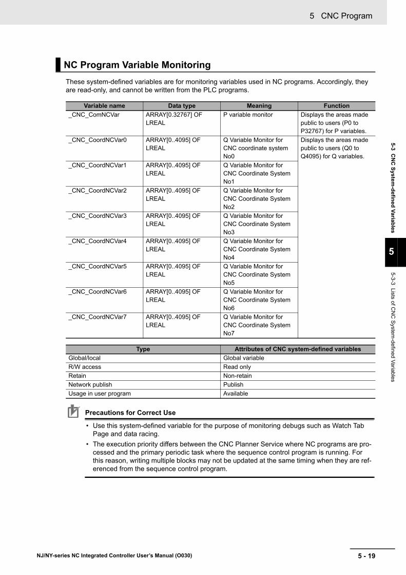
5 - 19
5 CNC Program
NJ/NY-series NC Integrated Controller User’s Manual (O030)
5-3 CN
C S
ystem-d
efined
Variab
les
5
5-3-3 Lists of C
NC
System
-defined Variables
These system-defined variables are for monitoring variables used in NC programs. Accordingly, they are read-only, and cannot be written from the PLC programs.
Precautions for Correct Use
• Use this system-defined variable for the purpose of monitoring debugs such as Watch Tab Page and data racing.
• The execution priority differs between the CNC Planner Service where NC programs are pro-cessed and the primary periodic task where the sequence control program is running. For this reason, writing multiple blocks may not be updated at the same timing when they are ref-erenced from the sequence control program.
NC Program Variable Monitoring
Variable name Data type Meaning Function
_CNC_ComNCVar ARRAY[0.32767] OF LREAL
P variable monitor Displays the areas made public to users (P0 to P32767) for P variables.
_CNC_CoordNCVar0 ARRAY[0..4095] OF LREAL
Q Variable Monitor for CNC coordinate system No0
Displays the areas made public to users (Q0 to Q4095) for Q variables.
_CNC_CoordNCVar1 ARRAY[0..4095] OF LREAL
Q Variable Monitor for CNC Coordinate System No1
_CNC_CoordNCVar2 ARRAY[0..4095] OF LREAL
Q Variable Monitor for CNC Coordinate System No2
_CNC_CoordNCVar3 ARRAY[0..4095] OF LREAL
Q Variable Monitor for CNC Coordinate System No3
_CNC_CoordNCVar4 ARRAY[0..4095] OF LREAL
Q Variable Monitor for CNC Coordinate System No4
_CNC_CoordNCVar5 ARRAY[0..4095] OF LREAL
Q Variable Monitor for CNC Coordinate System No5
_CNC_CoordNCVar6 ARRAY[0..4095] OF LREAL
Q Variable Monitor for CNC Coordinate System No6
_CNC_CoordNCVar7 ARRAY[0..4095] OF LREAL
Q Variable Monitor for CNC Coordinate System No7
Type Attributes of CNC system-defined variables
Global/local Global variable
R/W access Read only
Retain Non-retain
Network publish Publish
Usage in user program Available

5 CNC Program
5 - 20 NJ/NY-series NC Integrated Controller User’s Manual (O030)
CNC Error Status Variables
The attributes of the CNC error status variable are shown in the following table.
Variable name Data type Meaning Function
_CNC_ErrSta WORD CNC Function Module Error Status
Shows the status of errors that are detected in the CNC Func-tion Module.
_CNC_ComErrSta WORD CNC Common Error Status
Shows the status of errors that are detected by common pro-cessing in the CNC Function Module.
_CNC_CoordErrSta ARRAY [0..7] OF WORD
CNC Coordinate Sys-tem Error Status
Shows the status of errors that are detected for each CNC coordinate system. Up to eight coordinate systems are dis-played.
_CNC_MotorErrSta ARRAY [0..31] OF WORD
CNC Motor Error Sta-tus
Shows the status of errors that are detected for each CNC motor. Up to 32 CNC motors are displayed.
Type Attributes of CNC system-defined variables
Global/local Global variable
R/W access Read only
Retain Non-retain
Network publish Publish
Usage in user program Available

5 - 21
5 CNC Program
NJ/NY-series NC Integrated Controller User’s Manual (O030)
5-4 C
NC
Mo
tor C
om
pe
nsatio
n Tab
le
5
5-4-1 Editin
g the CN
C M
otor Com
pensation Table
5-4 CNC Motor Compensation Table
This section describes the CNC motor compensation table.
The CNC Function Module uses the CNC motor compensation table parameter settings that you cre-ated using the CNC Motor Compensation Table Editor of Sysmac Studio as CNC motor compensation tables.
The CNC motor compensation table data is handled as data variables for CNC motor compensation table in the NJ/NX-series Controller.
The CNC motor compensation table function compensates geometrical inclinations, bends, and devia-tions of individual machine tools. The CNC motor compensation table can be edited in Sysmac Studio and CNC Operator.
According to a CNC motor compensation table that you created on Sysmac Studio, data variables for CNC motor compensation table are generated. The data variables for CNC motor compensation table only represent data columns of the CNC motor compensation table. The data variables for CNC motor compensation table are global, which can be edited from the sequence control program.
5-4-1 Editing the CNC Motor Compensation Table
Variable Definition
Configuration element Description
Variable name User-defined on Sysmac Studio
Variable type REAL array type*1
*1. The array size is variable.
Variable scope Global
Network publish Read and write

5 CNC Program
5 - 22 NJ/NY-series NC Integrated Controller User’s Manual (O030)
CNC motor compensation table variables that can referenced from the sequence control program are generated. However, the variables only contain data columns and do not include settings such as source motor numbers and target motor numbers.
Typically, geometrical differences are obtained by using an external measuring instrument, and the CNC motor compensation table is output as a file in CSV or another format. For the NJ series, the CSV file is placed on the SD Memory Card. It is placed on the virtual SD Memory Card for the NY-series. Then the differences are read from the sequence control program, and the file is transferred to CNC motor compensation table data.
Precautions for Correct Use
• Editing the CNC motor compensation table while a CNC motor is running will cause a critical problem. Disable the CNC motor compensation table once if you want to edit it.
• When cycle the power supply, or when data is downloaded from Sysmac Studio, CNC motor compensation table data that you edited by the sequence control program is overwritten by the data stored in the non-volatile memory. You cannot upload these data by using Sysmac Studio.
Creating and Saving CNC Motor Compensation Table
5-4-2 Edit
ID211
01
32
45
76
89
1110
1213
1415
DC24V7mA
COM
MACHNo .
AD042RUNERCERH B1 A1
x101
x100
0
9876
5 4 321
0
9876
5 4 321
0 1 2 3 4 5 6 78 9 10 11 12 13 14 15
Sysmac Studio: Creating a CNC motor compensation table
Non-volatile memory
CNC motor compensation table
Main memory
CNC motor compensation table
data variables
User program
Data movement instructions
NC Integrated Controller
• After download• When power is turned on
Saved
Modified
Uploaded
Download

5 - 23
5 CNC Program
NJ/NY-series NC Integrated Controller User’s Manual (O030)
5-4 C
NC
Mo
tor C
om
pe
nsatio
n Tab
le
5
5-4-3 Enabling/D
isabling C
NC
Motor C
ompensation Table
When you created a CNC motor compensation table on the Sysmac Studio and transferred it, the table is automatically enabled. If you want to disable the CNC motor compensation table, rewrite the com-pensation scale to 0 with the CNC_Write instruction. To enable it again, rewrite it to 1 with the CNC_Write instruction.
Refer to 5-4-8 Basic Settings on page 5-26 for information about the compensation scale.
Refer to the Section 13 Common Command Instructions for how to use the CNC_Write instruction.
When the compensation scale is rewritten, the compensation value is reflected on the position the slave is commanded in the control period. For example, if the compensation value is 100 mm, the com-mand position moves 100 mm per control period. It is recommended that you rewrite the scale with val-ues incremented or decremented step-by-step over several periods if the target value is not minute.
The CNC Function Module does not include a function of automatically saving the CNC motor compen-sation table. Create a user program that makes a CSV file then saves it to the SD Memory Card, and reads the file from the SD Memory Card when cycling the power supply.
The compensation table function compensates the travel distance of a specific CNC motor or other CNC motors according to the commanded position of the CNC motor.
If there is a position-related error between an actual machine tool and a program, the function compen-sates the mechanical error as shown in the following figures.
Example of error 1: Shows a mechanical error generated when the rotation of a ball screw assigned to the X-axis is converted into translatory movement.
Example of error 2: Shows a mechanical error caused by a deflection in the Y-axis.
5-4-3 Enabling/Disabling CNC Motor Compensation Table
5-4-4 Saving
5-4-5 Functions and Purposes of CNC Motor Compensation Table
E M
∆x ∆x ∆x ∆x ∆x
EM
∆y ∆y ∆y ∆y ∆y ∆y

5 CNC Program
5 - 24 NJ/NY-series NC Integrated Controller User’s Manual (O030)
5-4-6 Terminology
Term Description
CNC motor compensation table A data table on which compensation table points are aligned in equal intervals from the source compensation point that is set to current posi-tion 0, the initial point. It is represented as a two-dimensional array of the target compensation value and the source compensation point of com-pensation table points.
This is often referred to as Compensation table.
Source CNC motor A CNC motor of input source for determining the compensation value by the compensation table.
Target CNC motor A CNC motor to be compensated with the source data and CNC motor compensation table. The source CNC motor can also be the target CNC motor.
Source compensation section Shows a section in which to perform compensation on the source CNC motor.
Source compensation point Shows a relative distance from the start position of the source compensa-tion section. This is a value set in the motor command unit system of the source CNC motor.
Target compensation value Shows a compensation value of the target CNC motor position at the source compensation point. This is a value set in the motor command unit system of the target CNC motor.
Compensation table point Data on a set of the source compensation point and target compensation value. This shows the target compensation value of a position on the source CNC motor.
Compensation table point span Shows an interval between the compensation table points that are adja-cent to each other.
The compensation table point spans are equally aligned.
Motor current compensation position A value that stores the compensation amount internally for each CNC motor based on the compensation table.
The value is edited from multiple CNC motor compensation tables when the multiple CNC motor compensation tables are used to compensate a single CNC motor as the target.
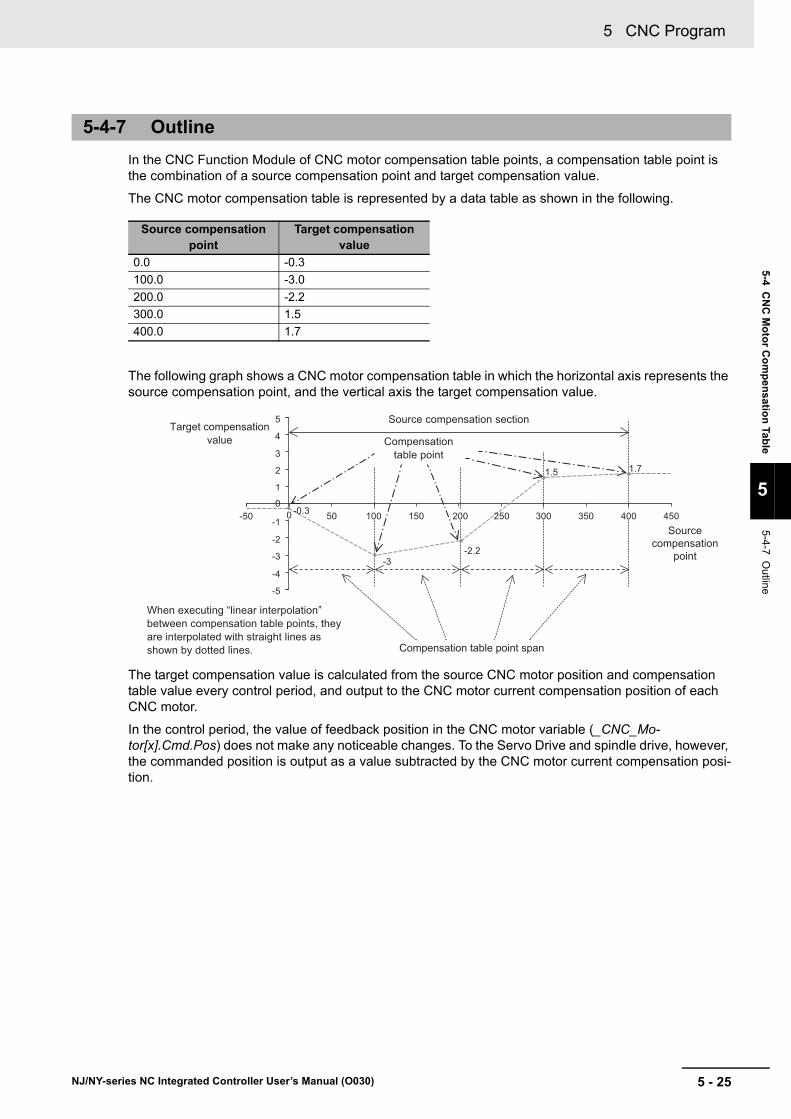
5 - 25
5 CNC Program
NJ/NY-series NC Integrated Controller User’s Manual (O030)
5-4 C
NC
Mo
tor C
om
pe
nsatio
n Tab
le
5
5-4-7 Outline
In the CNC Function Module of CNC motor compensation table points, a compensation table point is the combination of a source compensation point and target compensation value.
The CNC motor compensation table is represented by a data table as shown in the following.
The following graph shows a CNC motor compensation table in which the horizontal axis represents the source compensation point, and the vertical axis the target compensation value.
The target compensation value is calculated from the source CNC motor position and compensation table value every control period, and output to the CNC motor current compensation position of each CNC motor.
In the control period, the value of feedback position in the CNC motor variable (_CNC_Mo-tor[x].Cmd.Pos) does not make any noticeable changes. To the Servo Drive and spindle drive, however, the commanded position is output as a value subtracted by the CNC motor current compensation posi-tion.
5-4-7 Outline
Source compensation point
Target compensation value
0.0 -0.3
100.0 -3.0
200.0 -2.2
300.0 1.5
400.0 1.7
-50 0
5
4
3
2
1
-5
-4
-3
-2
-1
0-0.3
-3-2.2
50 100 150 200 250 300 350 400 450
1.5 1.7
Target compensation value
Source compensation section
Source compensation
point
Compensation table point span
Compensation table point
When executing “linear interpolation” between compensation table points, they are interpolated with straight lines as shown by dotted lines.
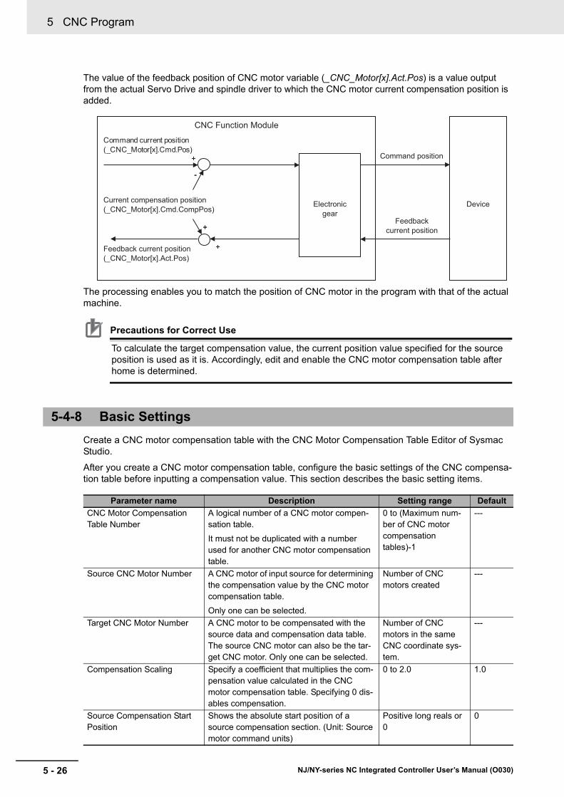
5 CNC Program
5 - 26 NJ/NY-series NC Integrated Controller User’s Manual (O030)
The value of the feedback position of CNC motor variable (_CNC_Motor[x].Act.Pos) is a value output from the actual Servo Drive and spindle driver to which the CNC motor current compensation position is added.
The processing enables you to match the position of CNC motor in the program with that of the actual machine.
Precautions for Correct Use
To calculate the target compensation value, the current position value specified for the source position is used as it is. Accordingly, edit and enable the CNC motor compensation table after home is determined.
Create a CNC motor compensation table with the CNC Motor Compensation Table Editor of Sysmac Studio.
After you create a CNC motor compensation table, configure the basic settings of the CNC compensa-tion table before inputting a compensation value. This section describes the basic setting items.
5-4-8 Basic Settings
Parameter name Description Setting range Default
CNC Motor Compensation Table Number
A logical number of a CNC motor compen-sation table.
It must not be duplicated with a number used for another CNC motor compensation table.
0 to (Maximum num-ber of CNC motor compensation tables)-1
---
Source CNC Motor Number A CNC motor of input source for determining the compensation value by the CNC motor compensation table.
Only one can be selected.
Number of CNC motors created
---
Target CNC Motor Number A CNC motor to be compensated with the source data and compensation data table. The source CNC motor can also be the tar-get CNC motor. Only one can be selected.
Number of CNC motors in the same CNC coordinate sys-tem.
---
Compensation Scaling Specify a coefficient that multiplies the com-pensation value calculated in the CNC motor compensation table. Specifying 0 dis-ables compensation.
0 to 2.0 1.0
Source Compensation Start Position
Shows the absolute start position of a source compensation section. (Unit: Source motor command units)
Positive long reals or 0
0
+
-
+
+
CNC Function Module
(_CNC_Motor[x].Cmd.Pos)Command current position
(_CNC_Motor[x].Cmd.CompPos)Current compensation position
(_CNC_Motor[x].Act.Pos)Feedback current position
Command position
Feedbackcurrent position
Electronic gear
Device
+
-
+
+
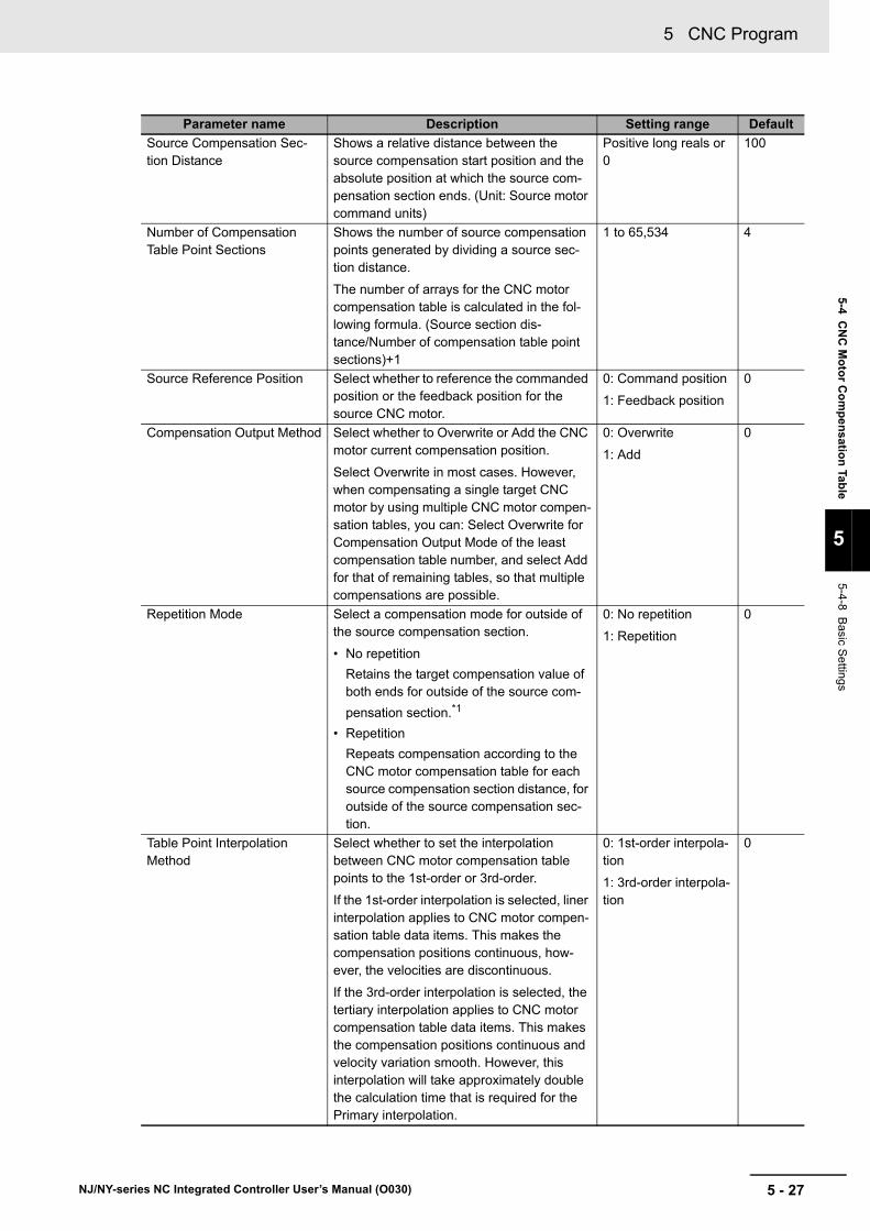
5 - 27
5 CNC Program
NJ/NY-series NC Integrated Controller User’s Manual (O030)
5-4 C
NC
Mo
tor C
om
pe
nsatio
n Tab
le
5
5-4-8 Basic S
ettings
Source Compensation Sec-tion Distance
Shows a relative distance between the source compensation start position and the absolute position at which the source com-pensation section ends. (Unit: Source motor command units)
Positive long reals or 0
100
Number of Compensation Table Point Sections
Shows the number of source compensation points generated by dividing a source sec-tion distance.
The number of arrays for the CNC motor compensation table is calculated in the fol-lowing formula. (Source section dis-tance/Number of compensation table point sections)+1
1 to 65,534 4
Source Reference Position Select whether to reference the commanded position or the feedback position for the source CNC motor.
0: Command position
1: Feedback position
0
Compensation Output Method Select whether to Overwrite or Add the CNC motor current compensation position.
Select Overwrite in most cases. However, when compensating a single target CNC motor by using multiple CNC motor compen-sation tables, you can: Select Overwrite for Compensation Output Mode of the least compensation table number, and select Add for that of remaining tables, so that multiple compensations are possible.
0: Overwrite
1: Add
0
Repetition Mode Select a compensation mode for outside of the source compensation section.
• No repetition
Retains the target compensation value of both ends for outside of the source com-
pensation section.*1
• Repetition
Repeats compensation according to the CNC motor compensation table for each source compensation section distance, for outside of the source compensation sec-tion.
0: No repetition
1: Repetition
0
Table Point Interpolation Method
Select whether to set the interpolation between CNC motor compensation table points to the 1st-order or 3rd-order.
If the 1st-order interpolation is selected, liner interpolation applies to CNC motor compen-sation table data items. This makes the compensation positions continuous, how-ever, the velocities are discontinuous.
If the 3rd-order interpolation is selected, the tertiary interpolation applies to CNC motor compensation table data items. This makes the compensation positions continuous and velocity variation smooth. However, this interpolation will take approximately double the calculation time that is required for the Primary interpolation.
0: 1st-order interpola-tion
1: 3rd-order interpola-tion
0
Parameter name Description Setting range Default

5 CNC Program
5 - 28 NJ/NY-series NC Integrated Controller User’s Manual (O030)
Precautions for Correct Use
When Add is selected for Compensation Output Mode, make sure that multiple CNC motor compensation tables are used for a single target CNC motor, and that the CNC motor compen-sation table number is not the least value.
If Add is selected in other conditions, the compensation value continues to be added every con-trol period. Consequently, the compensation value becomes excessively large and an unin-tended motion may result.
Setting basic settings determines the size of the CNC motor compensation table array, and the value of source compensation point for each CNC motor compensation table point.
Then set the target compensation value in each CNC motor compensation table point.
*1. If No repetition and 3rd-order interpolation are set, there are sections where the target compensation value varies before and after the source compensation section to make the velocities continuous.
Source compensation point Target compensation value
0.0 0.0
Source Compensation Section*1
*1. Source section range = Source compensation section distance/Number of compensation table point sections
0.0
Source Compensation Section*1 0.0
... 0.0
Source Compensation Section Distance 0.0
Parameter name Description Setting range Default
Target Compensation Value
Shows a compensation value of the target CNC motor position at the source compensation point. This is a value set in the motor command unit system of the tar-get CNC motor.
Range of single-precision
reals*1
*1. -∞ and +∞ are excluded.
0.0

5 - 29
5 CNC Program
NJ/NY-series NC Integrated Controller User’s Manual (O030)
5-4 C
NC
Mo
tor C
om
pe
nsatio
n Tab
le
5
5-4-9 Setting E
xample
This section describes the method to set the CNC motor compensation table.
Examples of Ball Screw Pitch Compensation, Ball Screw Deflection, and Rotary Table Compensation are provided.
Suppose that you executed the operation command for five points on the X-axis from absolute position 0 mm to 400 mm at 100 mm intervals, and measured X-axis positions of the actual machine tool. As a result, you obtained the following reproducible errors caused by displacement of the ball screw pitch.
Use the CNC motor compensation table to cancel the error and match the positions in the program with those of the actual machine.
First, input the basic settings.
5-4-9 Setting Example
Ball Screw Pitch Compensation
Setting Value
Source CNC Motor Number 1 (CNC_Motor001)
Target CNC Motor Number 1 (CNC_Motor001)
Compensation Scaling 1.0
Source Compensation Start Posi-tion
0 (mm)
Source Compensation Section Distance
400 (mm)
Number of Compensation Table Point Sections
4
Source Reference Position 0: Command position
Compensation Output Method 0: Overwrite
Repetition Mode 0: No repetition
Table Point Interpolation Method 0: 1st-order interpolation
E
-0.3 97.0 197.8 301.5 401.7 [mm]
[mm]0 100 200 300 400
M
Actual motor position in the machine
Motor position in the program

5 CNC Program
5 - 30 NJ/NY-series NC Integrated Controller User’s Manual (O030)
Then set the displacement of each measurement point (Measured position - Position in the program) for each target compensation value.
Source com-pensation point [mm]
Target compensa-tion value [mm]
0.0 -0.3
100.0 -3.0
200.0 -2.2
300.0 1.5
400.0 1.7
-50 0
5
4
3
2
1
-5
-4
-3
-2
-1
0 -0.3 50 100 150 200 250 300 350 400 450
1.5
-3-2.2
1.7
Source compensation section distance400 mm
Source compensation
point
Target compensation value

5 - 31
5 CNC Program
NJ/NY-series NC Integrated Controller User’s Manual (O030)
5-4 C
NC
Mo
tor C
om
pe
nsatio
n Tab
le
5
5-4-9 Setting E
xample
Suppose that CNC motor 0 is assigned to the X-axis, and CNC motor 1 to the Y-axis. The CNC motor in the X-axis direction deflects in the Y-axis direction.
In this case, use two CNC motor compensation tables. The first one compensates the deflection in the X-axis direction. The second one compensates the deflection in the Y-axis direction.
Compensation in the X-axis direction
Suppose that, without moving the Y-axis from 0 mm, you executed the operation command for eight points on the X-axis from absolute position 0 mm to 700 mm at 100 mm intervals, and measured the X-axis position of the actual tool machine at each point. As a result, you obtained the following reproducible errors caused by displacement of the ball screw pitch.
The following table shows the basic settings of the first CNC motor compensation table (number 0) and CNC motor compensation table data.
The settings must be set in the same way as you did for Ball Screw Pitch Compensation as described in the previous section.
Ball Screw Deflection Compensation
Setting Value
CNC Motor Compensation Table Number
0
Source CNC Motor Number 0 (CNC_Motor000)
Target CNC Motor Number 0 (CNC_Motor000)
Compensation Scaling 1.0
Source Compensation Start Posi-tion
0 (mm)
Source Compensation Section Distance
700 (mm)
Number of Compensation Table Point Sections
7
Source Reference Position 0: Command position
Compensation Output Method 0: Overwrite
Repetition Mode 0: No repetition
Table Point Interpolation Method 1: 3rd-order interpolation
EM
0
0
100 200 300 400 500 600 700
99.5 199.1 298.9 398.8 498.6 598.2 6975
[mm]Actual X-axis position in the machineX-axis position in the program
Source com-pensation point [mm]
Target compensa-tion value [mm]
0.0 0
100.0 -0.5
200.0 -0.9
300.0 -1.1
400.0 -1.2
500.0 -1.4
600.0 -1.8
700.0 -2.5

5 CNC Program
5 - 32 NJ/NY-series NC Integrated Controller User’s Manual (O030)
Compensation in the Y-axis direction
Measure eight points with CNC motor compensation table number 0 enabled, and obtain the follow-ing errors in the Y-axis direction.
Set the basic settings and compensation table data settings for the second CNC motor compensation table (number 1).
This table differs from the first CNC motor compensation table in the following two points:
• The source CNC motor and the target CNC motor are different.
• The source reference position is set to "1: Feedback position".
With these settings, the position set to the input source in the second CNC motor compensation table is the X position, a position of the actual machine that was compensated in the first CNC motor compen-sation table.
When you move the X-axis in the positive direction without moving the Y-axis from 0 mm, the operation actually moves CNC motor 1 on the Y-axis in the negative direction to disable the error.
Setting Value
CNC Motor Compensation Table Number
1
Source CNC Motor Number 0 (CNC_Motor000)
Compensation Scaling 1.0
Target CNC Motor Number 1 (CNC_Motor001)
Source Compensation Start Posi-tion
0 (mm)
Source Compensation Section Distance
700 (mm)
Number of Compensation Table Point Sections
7
Source Reference Position 1: Feedback position
Compensation Output Method 0: Overwrite
Repetition Mode 0: No repetition
Table Point Interpolation Method 1: 3rd-order interpolation
EM
0 100 200 300 400 500 600 700
00.71
1.17 1.32 1.40 1.240.83
0
[mm]Actual X-axis position and
X-axis position in the program
Actual Y-axis position
Source com-pensation point [mm]
Target compensa-tion value [mm]
0.0 0.0
100.0 0.71
200.0 1.17
300.0 1.32
400.0 1.40
500.0 1.24
600.0 0.83
700.0 0.0
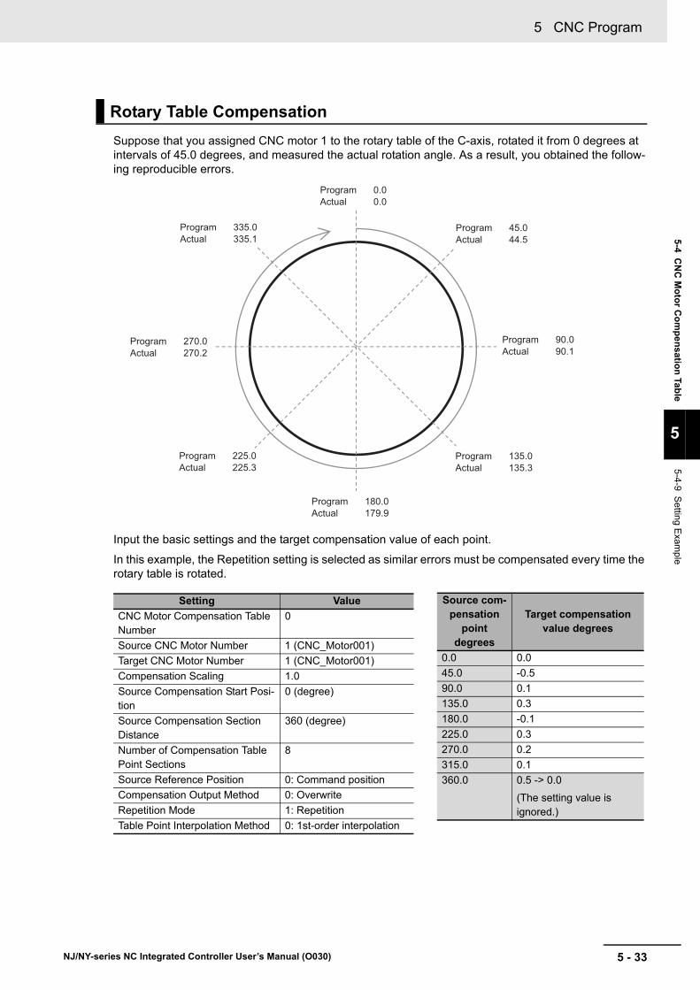
5 - 33
5 CNC Program
NJ/NY-series NC Integrated Controller User’s Manual (O030)
5-4 C
NC
Mo
tor C
om
pe
nsatio
n Tab
le
5
5-4-9 Setting E
xample
Suppose that you assigned CNC motor 1 to the rotary table of the C-axis, rotated it from 0 degrees at intervals of 45.0 degrees, and measured the actual rotation angle. As a result, you obtained the follow-ing reproducible errors.
Input the basic settings and the target compensation value of each point.
In this example, the Repetition setting is selected as similar errors must be compensated every time the rotary table is rotated.
Rotary Table Compensation
Setting Value
CNC Motor Compensation Table Number
0
Source CNC Motor Number 1 (CNC_Motor001)
Target CNC Motor Number 1 (CNC_Motor001)
Compensation Scaling 1.0
Source Compensation Start Posi-tion
0 (degree)
Source Compensation Section Distance
360 (degree)
Number of Compensation Table Point Sections
8
Source Reference Position 0: Command position
Compensation Output Method 0: Overwrite
Repetition Mode 1: Repetition
Table Point Interpolation Method 0: 1st-order interpolation
Program 0.0Actual 0.0
Program 335.0Actual 335.1
Program 270.0Actual 270.2
Program 225.0Actual 225.3
Program 180.0Actual 179.9
Program 135.0Actual 135.3
Program 90.0Actual 90.1
Program 45.0Actual 44.5
Source com-pensation
point degrees
Target compensation value degrees
0.0 0.0
45.0 -0.5
90.0 0.1
135.0 0.3
180.0 -0.1
225.0 0.3
270.0 0.2
315.0 0.1
360.0 0.5 -> 0.0
(The setting value is ignored.)

5 CNC Program
5 - 34 NJ/NY-series NC Integrated Controller User’s Manual (O030)
If 1: Repetition is selected, the target compensation value of the first point is used for that of the last point. The following graph shows the compensation value to be used when 0.5 is set.
This section describes specifications of the CNC motor compensation table.
5-4-10 CNC Motor Compensation Table Specifications
Item Description
Maximum number of compensation table points per CNC motor compensation table
65,535
Upper limit of the size of all CNC motor compensation tables
Maximum size of all compensation tables varies depending on the model. Refer to 1-4-1 General Speci-fications on page 1-7 for details.
Size of a CNC motor compensation table = 100 + CNC motor compensation table points x 4 bytes
Upper limit of the number of CNC motor compensation tables
The upper limit of the maximum number of compensa-tion tables varies depending on the model. Refer to 1-4-1 General Specifications on page 1-7 for details.
Changing a CNC motor compensation table CNC motor compensation table data can be edited from a user program.
Saving a CNC motor compensation table The file read/write instruction enables you to use this function.
Timing to reflect CNC motor compensation tables on main memory
• At power ON
• At synchronous download of Sysmac Studio
-180 -90 0 90 180 270 360 450 540
1
0.8
0.6
0.4
0.2
-1
-0.8
-0.6
-0.4
-0.2
0
DegreesTarget compensation value
Degrees
Source compensation point
0.5 is ignored
Repetition of CNC motor compensation table data
Repetition of CNC motor compensation table data

6 - 1
6
NJ/NY-series NC Integrated Controller User’s Manual (O030)
This section describes the functions and means of producing CNC machine applica-tions with the aid of sequence control programs, NC programs, and CNC functions.
6-1 M Codes . . . . . . . . . . . . . . . . . . . . . . . . . . . . . . . . . . . . . . . . . . . . . . . . . . . . . 6-2
6-2 Tool Functions . . . . . . . . . . . . . . . . . . . . . . . . . . . . . . . . . . . . . . . . . . . . . . . . 6-36-2-1 Method for Realizing Tool Data Management . . . . . . . . . . . . . . . . . . . . . . . . 6-3
6-2-2 Method for Realizing Tool Change . . . . . . . . . . . . . . . . . . . . . . . . . . . . . . . . . 6-4
6-3 Realization of the Function of Spindle Axis . . . . . . . . . . . . . . . . . . . . . . . . 6-86-3-1 Realization of the Function of Spindle Axis with CNC Function Module . . . . . 6-8
6-3-2 Realization of the Function of Spindle Axis with General-purpose I/O Control or MC Function Module . . . . . . . . . . . . . . . . . . . . . . . . . . . . . . . . . . . . . . . . . . 6-10
6-3-3 When No Spindle Axis is Assigned . . . . . . . . . . . . . . . . . . . . . . . . . . . . . . . . 6-12
6-4 Connect with MPG . . . . . . . . . . . . . . . . . . . . . . . . . . . . . . . . . . . . . . . . . . . . 6-13
Realization of CNC Machines

6 Realization of CNC Machines
6 - 2 NJ/NY-series NC Integrated Controller User’s Manual (O030)
6-1 M Codes
This section describes procedures to interlock the sequence control program with an NC program to construct CNC machine applications, by using M codes.
You can transmit M codes to the sequence control program with the CNC_CoordCatchMCode instruc-tion. Up to 192 (M0 to M191) M codes to output from the NC program can be specified for each CNC coordinate system. M code numbers (0 to 191) are used to specify the M codes to accept with the CNC_CoordCatchMCode instruction. A different M code can be programmed for each M code number. The CNC_CoordCatchMCode instruction can also place multiple instances. Accordingly, there is no limit to the number of M codes that can be output simultaneously. After performing processing accord-ing to M codes, such as coolant control and ATC control, the sequence control program executes the CNC_CoordResetMCode instruction to send M code reset to the NC program.
Relationship between Sequence Control Program and NC Program
CNC_CoordControl
CNC_CoordCatchMCode
CNC_CoordResetMCode
G01 X**Y**
G01 X**Y**
G01 X**Y**
G02 X**Y**
M100 ***1)
2)
4)
5)
3)
6)
Sysmac Studio
NC Integrated Controller
NC programSequence
control program
Reaction to M code
MStrobe
Receive M code
Execute
Execute
Execute NC program
Reset M code
Execute

6 - 3
6 Realization of CNC Machines
NJ/NY-series NC Integrated Controller User’s Manual (O030)
6-2 Too
l Fu
nctio
ns
6
6-2-1 Metho
d for Realizing Tool D
ata Ma
nagement
6-2 Tool Functions
This section describes the tool change function and tool data management function.
Tool data includes the tool radius and length used for tool compensation, as well as the usage fre-quency and time recorded for managing the tool life. This Controller does not have a function that man-ages the tool data. Realize the tool data management function with the aid of the sequence control program, which is capable of saving the data to the hold memory inside the program.
Tool data management can be realized, for example, by defining global variables (shown in the follow-ing table) and constructing the following logics using the sequence control program and CNC Operator.
Procedure to manage tool shape data is as follows.
1 Create a CNC Operator screen used to input the tool length and tool radius for each tool ID.
2 Create a logic that initializes the tool life data.
Procedure for managing tool life data is as follows.
1 Create a logic that accumulates the usage frequency, usage time, and abrasion of a tool when the tool is used.
2 Set the thresholds for the usage frequency, usage time, and abrasion, and create a logic that detects errors.
Example : The following table shows an example of tool data management.
6-2-1 Method for Realizing Tool Data Management
Tool Shape Data Management
Tool Life Data Management
Variable name Data type Name Function
ToolManagementData Array[N] of User Define Struct Tool Data Tool data (for each tool ID)
ShapeData User Define Struct Tool Shape Data A data group related to tool com-pensation
Offset LREAL Tool Length A value used for tool length com-pensation
Radius LREAL Tool Radius A value used for tool radius com-pensation
LifecycleData User Define Struct Tool Life Data A data group related to tool life.
UsageCount UDINT Usage Frequency A value indicating the frequency of tool usage
OperationTime Time Usage Time A value indicating the elapsed time of tool usage
LengthWear LREAL Abrasion A value indicating the abrasion of tool length
RadiusWear LREAL Abrasion A value indicating the abrasion of tool radius
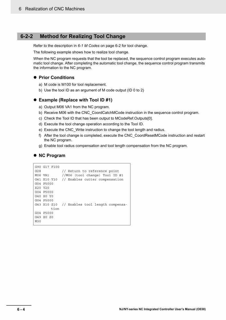
6 Realization of CNC Machines
6 - 4 NJ/NY-series NC Integrated Controller User’s Manual (O030)
Refer to the description in 6-1 M Codes on page 6-2 for tool change.
The following example shows how to realize tool change.
When the NC program requests that the tool be replaced, the sequence control program executes auto-matic tool change. After completing the automatic tool change, the sequence control program transmits the information to the NC program.
Prior Conditions
a) M code is M100 for tool replacement.
b) Use the tool ID as an argument of M code output (ID 0 to 2)
Example (Replace with Tool ID #1)
a) Output M06 VA1 from the NC program.
b) Receive M06 with the CNC_CoordCatchMCode instruction in the sequence control program.
c) Check the Tool ID that has been output to MCodeRef.Outputs[0].
d) Execute the tool change operation according to the Tool ID.
e) Execute the CNC_Write instruction to change the tool length and radius.
f) After the tool change is completed, execute the CNC_CoordResetMCode instruction and restart the NC program.
g) Enable tool radius compensation and tool length compensation from the NC program.
NC Program
6-2-2 Method for Realizing Tool Change
G90 G17 F100G28 // Return to reference pointM06 VA1 //M06 (tool change) Tool ID #1G41 X10 Y10 // Enables cutter compensationG04 P5000X20 Y20G04 P5000G40 X0 Y0G04 P5000G43 X10 Z10 // Enables tool length compensa-
tionG04 P5000G49 X0 Z0M30
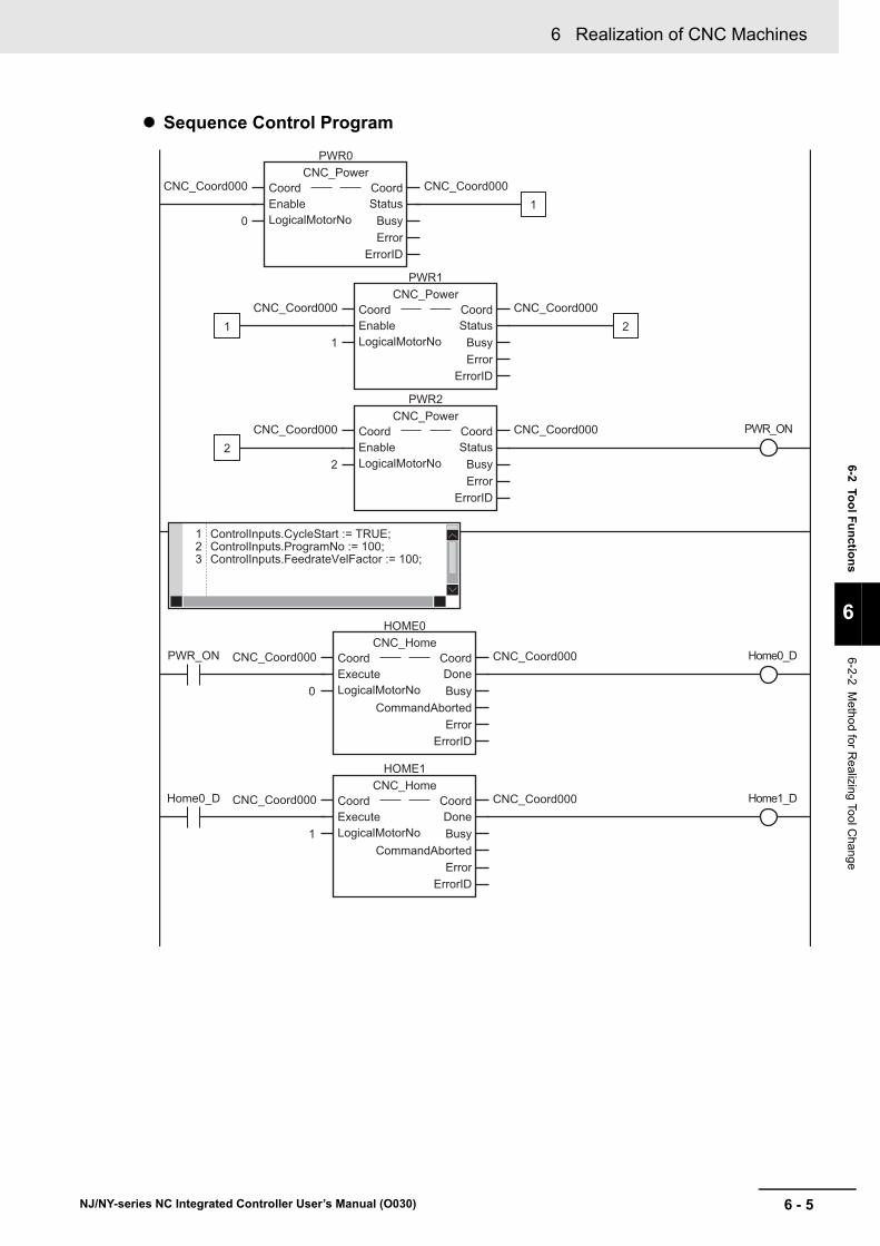
6 - 5
6 Realization of CNC Machines
NJ/NY-series NC Integrated Controller User’s Manual (O030)
6-2 Too
l Fu
nctio
ns
6
6-2-2 Metho
d for Realizing Tool C
hange
Sequence Control Program
0
PWR0CNC_Power
StatusBusyError
ErrorID
Coord CoordEnableLogicalMotorNo
CNC_Coord000 CNC_Coord000
1
PWR1CNC_Power
StatusBusyError
ErrorID
Coord CoordEnableLogicalMotorNo
CNC_Coord000 CNC_Coord000
PWR_ON
1
1
2
PWR2CNC_Power
StatusBusyError
ErrorID
Coord CoordEnableLogicalMotorNo
CNC_Coord000 CNC_Coord000
2
2
1 ControlInputs.CycleStart := TRUE;2 ControlInputs.ProgramNo := 100;3 ControlInputs.FeedrateVelFactor := 100;
PWR_ON Home0_D
HOME0CNC_Home
DoneBusy
CommandAbortedError
ErrorID
Coord CoordExecuteLogicalMotorNo
CNC_Coord000 CNC_Coord000
Home1_D
HOME1CNC_Home
DoneBusy
CommandAbortedError
ErrorID
Coord CoordExecuteLogicalMotorNo
CNC_Coord000 CNC_Coord000Home0_D
0
1

6 Realization of CNC Machines
6 - 6 NJ/NY-series NC Integrated Controller User’s Manual (O030)
Home2_D
HOME2CNC_Home
DoneBusy
CommandAbortedError
ErrorID
Coord CoordExecuteLogicalMotorNo
CNC_Coord000 CNC_Coord000Home1_D
2
CoordControlCNC_CoordControl
BusyEnabled
ErrorErrorID
Coord CoordControlInputs ControlInputsControlOutputs ControlOutputsEnable
CNC_Coord000 CNC_Coord000ControlInputs
ControlOutputsControlInputsControlOutputsHome2_D
MCodeRef
CatchMCode_InstCNC_CoordCatchMCode
MCodeEnabled
StrobeBusyError
ErrorID
Coord CoordMCodeEnableMCodeNo
CNC_Coord000 CNC_Coord000
100
MCodeRef
CatchMCode_Inst.Enabled CatchMCode_Inst.Strobe MCodeRef.ExistsOutputs[0] CatchMCode_ToolChange
CatchMCode_ToolChange
0MCodeRef.Outputs[0]
In1EN
=
In2
1MCodeRef.Outputs[0]
In1EN
=
In2
2MCodeRef.Outputs[0]
In1EN
=
In2
Tool_ID_0
Tool_ID_1
Tool_ID_2
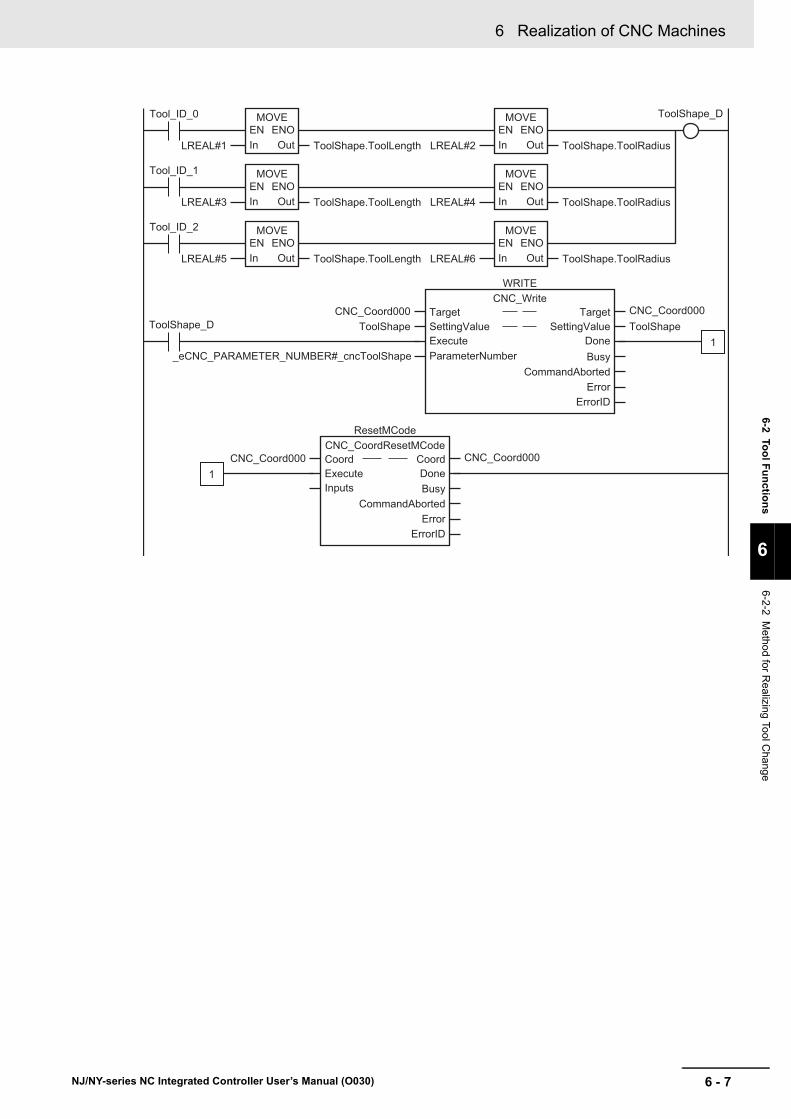
6 - 7
6 Realization of CNC Machines
NJ/NY-series NC Integrated Controller User’s Manual (O030)
6-2 Too
l Fu
nctio
ns
6
6-2-2 Metho
d for Realizing Tool C
hange
Tool_ID_0 ToolShape_D
LREAL#1 ToolShape.ToolLength
MOVEEN ENO
OutIn LREAL#2 ToolShape.ToolRadius
MOVEEN ENO
OutIn
Tool_ID_1
LREAL#3 ToolShape.ToolLength
MOVEEN ENO
OutIn LREAL#4 ToolShape.ToolRadius
MOVEEN ENO
OutIn
Tool_ID_2
LREAL#5 ToolShape.ToolLength
MOVEEN ENO
OutIn LREAL#6 ToolShape.ToolRadius
MOVEEN ENO
OutIn
_eCNC_PARAMETER_NUMBER#_cncToolShape
ToolShape_D
WRITECNC_Write
CommandAbortedBusy
ErrorErrorID
Target TargetSettingValue SettingValueExecute DoneParameterNumber
CNC_Coord000 CNC_Coord000ToolShape ToolShape
ResetMCodeCNC_CoordResetMCode
DoneBusy
CommandAbortedError
ErrorID
Coord CoordExecuteInputs
CNC_Coord000 CNC_Coord000
1
1

6 Realization of CNC Machines
6 - 8 NJ/NY-series NC Integrated Controller User’s Manual (O030)
6-3 Realization of the Function of Spin-dle Axis
This section describes the function of spindle axis. There are two methods to realize the function of spindle axis. One is to use the CNC Function Module, and the other is to use the I/O control or MC Function Module.
Refer to 6-3-3 When No Spindle Axis is Assigned on page 6-12 if spindle axis assignment is not required.
This section describes how to realize the function of spindle axis with the CNC Function Module.
If you control spindle axis with the CNC Function Module, assign a CNC motor to the spindle axis in the CNC coordinate system. The spindle axis must conform to CiA402, and support CSV (Cyclic Synchro-nous Velocity) mode by default.
While the NC program is running, the spindle axis is automatically controlled from the CNC Function Module. The user program does not need to receive Positive (M03), Negative (M04), and Stop (M05). If you want to operate the spindle axis in manual mode, use the CNC_SpindleGo instruction.
The orientation of the spindle axis is automatically controlled from the CNC Function Module. The user program does not need to be used to receive Orientation of Spindle axis (M19). Unlike CW and CCW operations, Orientation of Spindle axis cannot be executed in manual mode.
6-3-1 Realization of the Function of Spindle Axis with CNC Function Module
Spindle Axis Assignment
Positive, Negative, and Stop Operations
Orientation of Spindle Axis

6 - 9
6 Realization of CNC Machines
NJ/NY-series NC Integrated Controller User’s Manual (O030)
6-3 Rea
lization
of th
e Fu
nctio
n o
f Sp
ind
le Ax
is
6
6-3-1 Re
alization o
f the Function of S
pindle A
xis with C
NC
Function M
odule
The status transitions of the spindle axis are shown in the following diagram. The states correspond to respective variables for CNC_Coord[*].Status.Spindle of CNC coordinate system variables.
*1. An error stop event occurs.
*2. A sop event occurs.
*3. If Velocity of CNC_SpindleGo is set to 0, transition takes place in the standby state.
Spindle Axis States
Status Status name Definition
Standby Standby A state where the spindle motor stops.
CW Rotating in CW direction Spindle CW (M03), a state where the spindle axis is rotating in the CW direction with CNC_SpindleGo.
CCW Rotating in CCW direction Spindle CCW (M04), a state where the spindle axis is rotating in the CCW direction with CNC_SpindleGo.
Orientation Orientation operating A state where the spindle axis is positioned to the ori-entation position with Spindle Orientation (M19).
Tapping Tapping A state where the spindle axis is tapping with Left-handed Tapping cycle (G74) and Tapping cycle (G84).
Moving Moved by instruction A state where the spindle axis is being moved with CNC_Move or CNC_Home
Stopping Deceleration Stopping A state until the CNC coordinate system stops for the CNC_CoordStop instruction.
Rotating CCW
TappingStandby
Moving(Deceleration
Stopping)
ErrorStop(Error Deceleration
Stopping)
Moving
Orientation(Orientation operating)
Rotating CW
CNC_CoordImmediateStopCNC_CoordStop
*1
Execution of an instruction.
Completion of an instruction and other
Transition occurs when the instruction is completed or due to other factors.
*2
Error reset
M03, CNC_SpindleGo*3
M05, CNC_SpindleGo*3
M03, CNC_SpindleGo*3
M04, CNC_SpindleGo*3
M19 M19
M19Completion of M19
CNC_Move, CNC_Home
Operation completedCNC_CoordHalt
G74, G84
Tapping completed
M05, CNC_SpindleGo*3
M04, CNC_SpindleGo*3

6 Realization of CNC Machines
6 - 10 NJ/NY-series NC Integrated Controller User’s Manual (O030)
Besides assigning the spindle axis to a CNC coordinate system, the function of spindle axis can also be realized by using I/O control or the MC Function Module. This section describes how to determine the function of the spindle axis with the MC Function Module.
The spindle axis is controlled by the axis assigned to the Motion Control Function Module. Spindle axis operation is realized by programming the transmission of commands from the CNC Function Module to the Motion Control Function Module via an M code and the sequence control program.
Precautions for Correct Use
• When an error occurs for the spindle motor, an appropriate remedy must be programmed so that the sequence control program detects errors and stops the operation of the CNC coordi-nate system.
• In the same way, when an error occurs in the CNC coordinate system, an appropriate rem-edy must be programmed so that the sequence control program detects the error and stops the operation of the spindle motor.
By receiving M03, M04, and M05 using the user program, the following instruction is executed:
MC_SyncMoveVelocity instruction is used for positive/negative operation.
MC_Stop instruction is used for stop operation.
ErrorStop Error Deceleration Stopping A state until the CNC coordinate system stops or a state where it stops for the CNC_CoordImmediateStop instruction or a CNC coordinate system minor fault.
6-3-2 Realization of the Function of Spindle Axis with General-purpose I/O Control or MC Function Module
Spindle Axis Assignment
Positive, Negative, and Stop Operations
Status Status name Definition
Velocity
CNC_CoordCatchMCode
CNC_Coord1MCoordRef
CNC_Coord1MCoordRef
MCoordRefOutputs[0]
--------------G01 X** Y**G01 X** Y**M03 S1000 //Spindle--------------
MC_SyncMoveVelocity
IEC program
Execution
CNC Function Module EtherCAT
M strobe
X/Y/Z/C feed CNC motor
Spindle motorMC Function Module
Velocity loop control

6 - 11
6 Realization of CNC Machines
NJ/NY-series NC Integrated Controller User’s Manual (O030)
6-3 Rea
lization
of th
e Fu
nctio
n o
f Sp
ind
le Ax
is
6
6-3-2 Realization of the F
unction of Spindle A
xis with G
eneral-purpose I/O C
ontrol or M
C F
unction
Module
The sequence control program and MC Function Module are used for the orientation of the spindle axis.
Example
a) Receive the M19 (Spindle Orientation) command.
b) Gradually reduce the velocity instructed for MC_SyncMoveVelocity instruction to the orientation velocity.
c) Detect the Z-phase position with MC_TouchProbe instruction.
d) Consider the Z-phase position and orientation position offset, and perform the positioning to the orientation position with MC_MoveAbsolute instruction.
Orientation of Spindle Axis
a
b
c
d
S-axis velocity
Orientation velocity
S-axis orientation (M19)
Home switch turned on
S-axis orientation completed
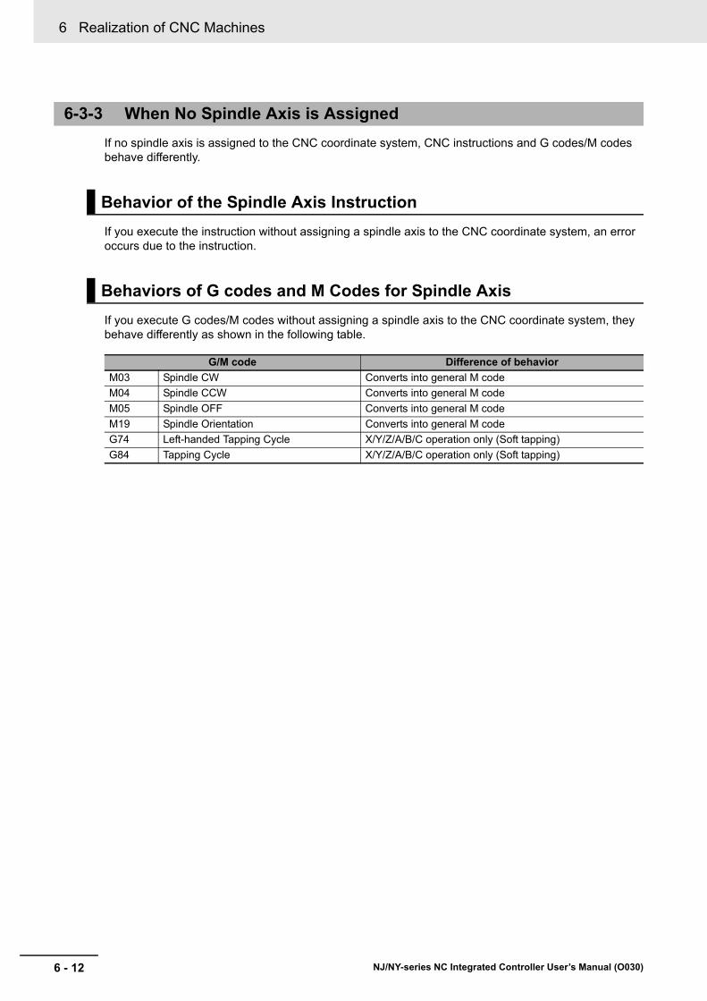
6 Realization of CNC Machines
6 - 12 NJ/NY-series NC Integrated Controller User’s Manual (O030)
If no spindle axis is assigned to the CNC coordinate system, CNC instructions and G codes/M codes behave differently.
If you execute the instruction without assigning a spindle axis to the CNC coordinate system, an error occurs due to the instruction.
If you execute G codes/M codes without assigning a spindle axis to the CNC coordinate system, they behave differently as shown in the following table.
6-3-3 When No Spindle Axis is Assigned
Behavior of the Spindle Axis Instruction
Behaviors of G codes and M Codes for Spindle Axis
G/M code Difference of behavior
M03 Spindle CW Converts into general M code
M04 Spindle CCW Converts into general M code
M05 Spindle OFF Converts into general M code
M19 Spindle Orientation Converts into general M code
G74 Left-handed Tapping Cycle X/Y/Z/A/B/C operation only (Soft tapping)
G84 Tapping Cycle X/Y/Z/A/B/C operation only (Soft tapping)

6 - 13
6 Realization of CNC Machines
NJ/NY-series NC Integrated Controller User’s Manual (O030)
6-4 Co
nn
ect with
MP
G
6
6-4 Connect with MPG
Signals from a manual pulse generator (MPG) or other external input devices are handled as device variables in the sequence control program via EtherCAT slaves such as NX units.
This enables you to connect multiple MPGs without physical limitations, and control the CNC Function Module.
This section provides an example of how to connect an MPG.
Signals from the MPG are received by the NX unit and treated as device variables, and thereby you can control the MPG.
Configuration Diagram
System Configuration
Mode selector switch
Node 2: X-axis
Node 3: Y-axis
Node 1: Slave Terminal
NJ/NY-series NC Integrated Controller
MPG

6 Realization of CNC Machines
6 - 14 NJ/NY-series NC Integrated Controller User’s Manual (O030)
The following table lists the functions of general MPG. Variables described in the table are the variables used in sample programs of each functions.
Example of Function List
Function name FunctionVariables
Device variables Variable name Data type
Mode Selection Switch for selecting jog operation/MPG mode
Mode selection switch input
gMode
0: Edit mode
1: Auto mode
2: MDI mode
3: MPG mode
4: Jog mode
5: Home mode
USINT
Axis Selection Switch for selecting the X/Y-axis
Axis selection input gAxisSelected
0: X, 1: Y
USINT
Positive/Negative Direction Jog Switch
Switch for jog opera-tion of the selected axis
Positive direction jog switch input
gPositiveJogEnable BOOL
Negative direction jog switch input
gNegativeJogEnable BOOL
MPG Operation of the MPG for the selected axis
MPG pulse input gPulseInput DINT
Magnification Ratio Selection
Magnification ratio setting for MPG operation and jog operation
Magnification ratio selection switch input
gRatioSelection
0: 1 time, 1: 10 times, 2: 100 times
USINT

6 - 15
6 Realization of CNC Machines
NJ/NY-series NC Integrated Controller User’s Manual (O030)
6-4 Co
nn
ect with
MP
G
6
Sample Program of Jogging
Application of Jogging
gPositiveJogEnable gNegativeJogEnable PositiveJogEnable
gNegativeJogEnable
PositiveJogEnable
gPositiveJogEnable NegativeJogEnable
0
PWR0CNC_Power
StatusBusyError
ErrorID
Coord CoordEnableLogicalMotorNo
CNC_Coord000 CNC_Coord000
1
PWR1CNC_Power
StatusBusyError
ErrorID
Coord CoordEnableLogicalMotorNo
CNC_Coord000 CNC_Coord000
1
1
gModeUSINT#4
In1EN
=
In2
gModeUSINT#4
In1EN
=
In2
LREAL#1000LREAL#1000
gAxisSelected
JogInst
CNC_MoveJog
ErrorErrorID
Coord CoordPositiveEnable BusyNegativeEnable CommandAbortedLogicalMotorNoVelocityAcceleration
CNC_Coord000 CNC_Coord000
NegativeJogEnable
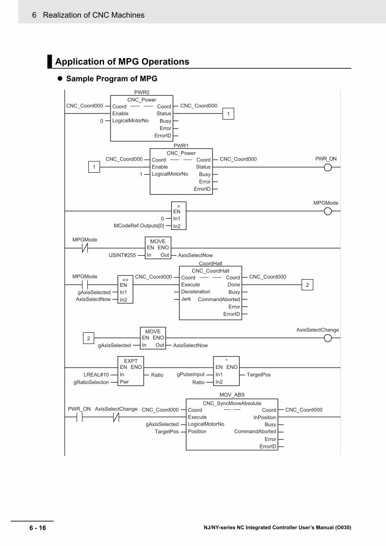
6 Realization of CNC Machines
6 - 16 NJ/NY-series NC Integrated Controller User’s Manual (O030)
Sample Program of MPG
Application of MPG Operations
0MCodeRef.Outputs[0]
In1EN
=
In2
gAxisSelectedAxisSelectNow
In1EN<>
In2
AxisSelectChange
PWR_ON AxisSelectChange
MPGMode
RatiogRatioSelecton
LREAL#10Ratio
gPulseInput TargetPos
MPGMode
0
PWR0CNC_Power
StatusBusyError
ErrorID
Coord CoordEnableLogicalMotorNo
CNC_Coord000 CNC_Coord000
1
PWR1CNC_Power
StatusBusyError
ErrorID
Coord CoordEnableLogicalMotorNo
CNC_Coord000 CNC_Coord000
1
1PWR_ON
USINT#255 AxisSelectNow
MOVEEN ENO
OutIn
MPGMode
CoordHaltCNC_CoordHalt
DoneBusy
CommandAbortedError
ErrorID
Coord CoordExecuteDecelerationJerk
CNC_Coord000 CNC_Coord000
gAxisSelected AxisSelectNow
MOVEEN ENO
OutIn
2
2
EXPTEN ENOInPwr
*EN ENOIn1In2
TargetPos
MOV_ABSCNC_SyncMoveAbsolute
ErrorErrorID
Coord CoordInPositionExecute
BusyLogicalMotorNoCommandAbortedPosition
CNC_Coord000 CNC_Coord000
gAxisSelected
7 - 1
7
NJ/NY-series NC Integrated Controller User’s Manual (O030)
This section describes functions related to manual operation.
7-1 Turning ON the Servo . . . . . . . . . . . . . . . . . . . . . . . . . . . . . . . . . . . . . . . . . . 7-2
7-2 Jogging . . . . . . . . . . . . . . . . . . . . . . . . . . . . . . . . . . . . . . . . . . . . . . . . . . . . . . 7-37-2-1 Jogging Procedure . . . . . . . . . . . . . . . . . . . . . . . . . . . . . . . . . . . . . . . . . . . . . 7-3
7-2-2 Setting CNC Parameters . . . . . . . . . . . . . . . . . . . . . . . . . . . . . . . . . . . . . . . . 7-4
7-2-3 Input Variable Setting Example . . . . . . . . . . . . . . . . . . . . . . . . . . . . . . . . . . . 7-4
7-2-4 Programming Example . . . . . . . . . . . . . . . . . . . . . . . . . . . . . . . . . . . . . . . . . . 7-5
Manual Operation

7 Manual Operation
7 - 2 NJ/NY-series NC Integrated Controller User’s Manual (O030)
7-1 Turning ON the Servo
You can turn the Servo ON or OFF to enable or disable sending operation commands to the Servo Drive. Use the CNC instruction CNC_Power (Power Servo).
Specify the motors to operate with the Coord (CNC Coordinate System Variable)) and LogicalMotorNo (Logical CNC Motor Number) in-out variables. Change the Enable input variable for CNC_Power to TRUE to turn ON the Servo. Change Enable to FALSE to turn OFF the Servo.
Precautions for Correct Use
Manual operation requires CNC coordinate system or CNC motor settings.
Additional Information
• If a Servo Drive with an absolute encoder is used, home is defined when EtherCAT process data communication transitions from the non-established status to the established status.
• If a Servo Drive with an absolute encoder is used, home is defined when the Enable input variable to the CNC_Power instruction changes to TRUE.
----
------------------------
Status1
Input parameter
Output parameter
Output variableInput variable
In-out variable
Instance nameBody name
Coord CoordEnable StatusLogicalMotorNo Busy
ErrorErrorID
Busy1Error1ErrorID1
CNC_PowerA
CNC_Power_instance
Coord1
CNC motor No.

7 - 3
7 Manual Operation
NJ/NY-series NC Integrated Controller User’s Manual (O030)
7-2 Jog
gin
g
7
7-2-1 Jogging P
rocedure
7-2 Jogging
For jogging, use the CNC instruction CNC_MoveJog (Jog).
Specify the axis to jog with the Coord (CNC Coordinate System Variable) and LogicalMotorNo (Logical CNC Motor Number) in-out variables.
Change the PositiveEnable input variable to TRUE to start the axis with the specified positive Velocity (Target Velocity) and Acceleration (Acceleration/Deceleration Rate). Change PositiveEnable to FALSE to decelerate and stop the axis at the specified Acceleration (Acceleration/Deceleration Rate).
Similarly, if you change the NegativeEnable input variable to TRUE, the axis will start in the negative direction. Change NegativeEnable to FALSE to stop the axis.
You can perform jogging even if the home has not yet been defined.
1 Adding and Setting a CNC Coordinate System and CNC Motors
Add and set a CNC coordinate system and CNC motor from Sysmac Studio.
Refer to Section 4 CNC Parameters for details.
2 Setting the CNC Coordinate System and CNC Motor Parameters
Set the CNC coordinate system and CNC motor parameters from Sysmac Studio.
Refer to Section 4 CNC Parameters for details.
3 Writing the User Program
Create the user program from Sysmac Studio.
4 Downloading the CNC Coordinate System Parameters, and CNC Motor Parameters, and User Program
Download the CNC coordinate system and CNC motor parameters you have set, and the user program to the CPU Unit.
Use the Synchronization menu command of the Sysmac Studio to download the project to the CPU Unit.
5 Executing the User Program
Execute the user program and change the Enable input variable for CNC_Power to TRUE to change the Servo Drive to the Servo ON state.
Set either the PositiveEnable or NegativeEnable input variable of the CNC_MoveJog (Jog) instruction to TRUE to start jogging.
7-2-1 Jogging Procedure
----
------------------------
Output variableInput variable
In-out variable
Instance nameBody name
Coord CoordPositiveEnable BusyNegativeEnable CommandAbortedLogicalMotorNo ErrorVelocity ErrorIDAcceleration
CNC_MoveJogA
CNC_MoveJog_instance
Coord Coord
B

7 Manual Operation
7 - 4 NJ/NY-series NC Integrated Controller User’s Manual (O030)
Set the following CNC parameters if you want to jog when home is not defined. The following setting example is for a one-axis device.
This section describes the settings for Velocity (Target Velocity) and Acceleration (Acceleration/Decel-eration Rate) input variables of the CNC_MoveJog (Jog) instruction.
• For example, set Velocity to 6000 to jog at a velocity of 6,000 mm/min.
• Set Acceleration to 500 to accelerate and decelerate at 0.5 m/s2.
7-2-2 Setting CNC Parameters
Parameter name Setting
CNC Motor Variable Name Motor1*1
*1. If there is more than one axis, a different variable name is set for each CNC motor.
CNC Motor Number 1*2
*2. If there is more than one axis, a different value is set for each CNC motor.
CNC Motor Use CNC motor in use
Axis Assignment Type X-axis
Input/Output Device 1*3
*3. Set the node address to the same value as the node address that is set on the Servo Drive. If there is more than one axis, a different value is set for each CNC motor.
Command Pulse Count Per Motor Rotation 8,388,608*4
*4. The position command unit is 1 (mm).
Travel Distance Per Work Rotation 10*4
Unit of Display mm
Maximum Velocity 30,000*5
*5. The maximum velocity will be 3,000 r/min = 30 m/min =30,000 mm/min.
Maximum Acceleration/Deceleration Rate 5,000*6
*6. The maximum acceleration/deceleration rate is 5000mm/s2. The acceleration time to the maximum velocity (3,000 r/min) is 0.1s.
7-2-3 Input Variable Setting Example
Servo motorencoder resolution: 23 bits/rotation
10 mm Ball screwBall screw pitch: 10 mm
1 rotation
Encoder output pulses per motor rotation23 bits = 8,388,608

7 - 5
7 Manual Operation
NJ/NY-series NC Integrated Controller User’s Manual (O030)
7-2 Jog
gin
g
7
7-2-4 P
rogram
ming E
xam
ple
The following programming example jogs a CNC motor named Motor1 in the positive direction for the value of bit A and in the negative direction for the value of bit B.
At this time, MotorNo (Logical CNC Motor Number) is the logical motor number that indicates Motor1, Velocity (Target Velocity) is Velo1, and Acceleration (Acceleration/Deceleration Rate) is Acce1.
Set the values for each variable in the user program in advance to operate the axis with the example input variable settings.
• Coord=CNC_Coord000
• MotorNo = 0
• Velo1 = 1000
• Acce1 = 500
Refer to CNC_MoveJog on page 12-83 for details on the CNC_MoveJog (Jog) instruction.
7-2-4 Programming Example
----
------------------------
Coord CoordPositiveEnable BusyNegativeEnable CommandAbortedLogicalMotorNo ErrorVelocity ErrorIDAcceleration
A
CNC_MoveJog_instance
Coord
BMotorNo
Velo1Acce1
CNC_MoveJog

7 Manual Operation
7 - 6 NJ/NY-series NC Integrated Controller User’s Manual (O030)
8 - 1
8
NJ/NY-series NC Integrated Controller User’s Manual (O030)
This section describes homing.
8-1 Outline . . . . . . . . . . . . . . . . . . . . . . . . . . . . . . . . . . . . . . . . . . . . . . . . . . . . . . . 8-2
8-2 Homing Procedure . . . . . . . . . . . . . . . . . . . . . . . . . . . . . . . . . . . . . . . . . . . . . 8-38-2-1 Setting Homing Parameters . . . . . . . . . . . . . . . . . . . . . . . . . . . . . . . . . . . . . . 8-4
8-2-2 Monitoring the Homing Operation . . . . . . . . . . . . . . . . . . . . . . . . . . . . . . . . . 8-10
8-3 Homing Operation . . . . . . . . . . . . . . . . . . . . . . . . . . . . . . . . . . . . . . . . . . . . 8-11
8-4 Homing with an Absolute Encoder . . . . . . . . . . . . . . . . . . . . . . . . . . . . . . . 8-128-4-1 Outline of Functions . . . . . . . . . . . . . . . . . . . . . . . . . . . . . . . . . . . . . . . . . . . 8-13
8-4-2 Setting Procedure . . . . . . . . . . . . . . . . . . . . . . . . . . . . . . . . . . . . . . . . . . . . . 8-13
Homing

8 Homing
8 - 2 NJ/NY-series NC Integrated Controller User’s Manual (O030)
8-1 Outline
To perform positioning to absolute positions in a positioning system, you first need to define the home.
For example, if you want to position at (Motor 1, Motor 2) = (100 mm, 200 mm) on the XY stage shown below, you must define the home position (0, 0). The process of defining home is called homing.
In the CNC Function Module, use the CNC instruction CNC_Home (Home) or CNC_HomeWithParam-eter (Home with Parameters) to define home.
Additional Information
• If a Servo Drive with an absolute encoder is used, home is defined when EtherCAT process data communication transitions from the non-established status to the established status.
• If a Servo Drive with an absolute encoder is used, home is defined when the Enable input variable to the CNC_Power instruction changes to TRUE.
• No NC program can be executed when the home is not defined.
• The software limit function is disabled when the home is not defined.
Motor 2
Motor 1
(100,200)
(0,0)

8 - 3
8 Homing
NJ/NY-series NC Integrated Controller User’s Manual (O030)
8-2 Ho
min
g P
roced
ure
8
8-2 Homing Procedure
This section describes the procedure to perform homing.
1 Adding and Setting a CNC Coordinate System and CNC Motor
Add and set a CNC motor and a CNC coordinate system from the Sysmac Studio.
2 Setting CNC Motor Parameters
Set the homing method with the homing parameters.
3 Writing the User Program
Create the user program from Sysmac Studio.
4 Downloading the CNC Parameters and the User Program
Download the CNC motor parameters and CNC coordinate system parameters you have set, and the user program to the NC Integrated Controller.
Use the Synchronization menu command of Sysmac Studio to download the project to the NC Integrated Controller.
5 Executing the User Program
Execute the user program and change the Enable input variable for CNC_Power instruction to TRUE to change the Servo Drive to the Servo ON state.
Homing is performed when the Execute input variable of the CNC_Home instruction changes to TRUE.
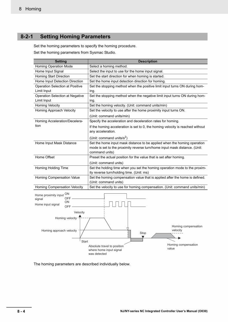
8 Homing
8 - 4 NJ/NY-series NC Integrated Controller User’s Manual (O030)
Set the homing parameters to specify the homing procedure.
Set the homing parameters from Sysmac Studio.
The homing parameters are described individually below.
8-2-1 Setting Homing Parameters
Setting Description
Homing Operation Mode Select a homing method.
Home Input Signal Select the input to use for the home input signal.
Homing Start Direction Set the start direction for when homing is started.
Home Input Detection Direction Set the home input detection direction for homing.
Operation Selection at Positive Limit Input
Set the stopping method when the positive limit input turns ON during hom-ing.
Operation Selection at Negative Limit Input
Set the stopping method when the negative limit input turns ON during hom-ing.
Homing Velocity Set the homing velocity. (Unit: command units/min)
Homing Approach Velocity Set the velocity to use after the home proximity input turns ON.
(Unit: command units/min)
Homing Acceleration/Decelera-tion
Specify the acceleration and deceleration rates for homing.
If the homing acceleration is set to 0, the homing velocity is reached without any acceleration.
(Unit: command units/s2)
Home Input Mask Distance Set the home input mask distance to be applied when the homing operation mode is set to the proximity reverse turn/home input mask distance. (Unit: command units)
Home Offset Preset the actual position for the value that is set after homing.
(Unit: command units)
Homing Holding Time Set the holding time when you set the homing operation mode to the proxim-ity reverse turn/holding time. (Unit: ms)
Homing Compensation Value Set the homing compensation value that is applied after the home is defined. (Unit: command units)
Homing Compensation Velocity Set the velocity to use for homing compensation. (Unit: command units/min)
ONHome proximity input signal
Home input signal
Homing velocity
Homing approach velocity
Velocity
Start
Stop
Homing compensation velocity
Homing compensation value
Absolute travel to position where home input signal was detected
ONOFF
OFF
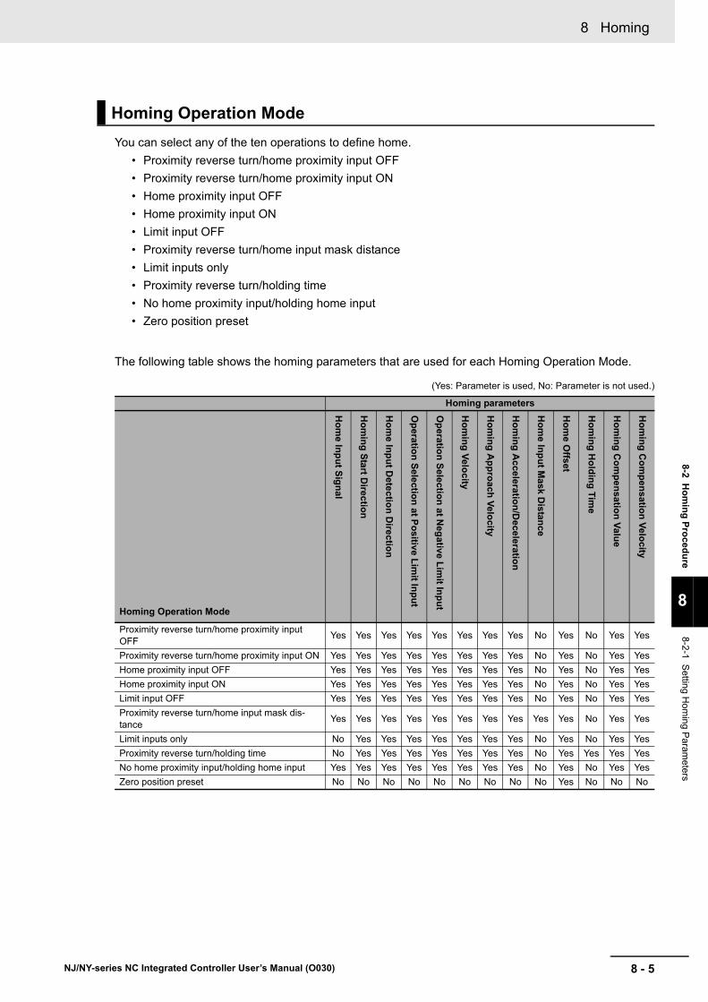
8 - 5
8 Homing
NJ/NY-series NC Integrated Controller User’s Manual (O030)
8-2 Ho
min
g P
roced
ure
8
8-2-1 S
etting Hom
ing Param
eters
You can select any of the ten operations to define home.
• Proximity reverse turn/home proximity input OFF
• Proximity reverse turn/home proximity input ON
• Home proximity input OFF
• Home proximity input ON
• Limit input OFF
• Proximity reverse turn/home input mask distance
• Limit inputs only
• Proximity reverse turn/holding time
• No home proximity input/holding home input
• Zero position preset
The following table shows the homing parameters that are used for each Homing Operation Mode.
(Yes: Parameter is used, No: Parameter is not used.)
Homing Operation Mode
Homing parameters
Homing Operation Mode
Ho
me In
pu
t Sig
nal
Ho
min
g S
tart Direc
tion
Ho
me In
pu
t Detectio
n D
irection
Op
eration
Selectio
n at P
ositive L
imit In
pu
t
Op
eration
Selectio
n at N
egative
Lim
it Inp
ut
Ho
min
g V
elocity
Ho
min
g A
pp
roach
Velo
city
Ho
min
g A
cceleration
/Deceleratio
n
Ho
me In
pu
t Mask D
istanc
e
Ho
me O
ffset
Ho
min
g H
old
ing
Tim
e
Ho
min
g C
om
pen
sation
Valu
e
Ho
min
g C
om
pen
sation
Velo
city
Proximity reverse turn/home proximity input OFF
Yes Yes Yes Yes Yes Yes Yes Yes No Yes No Yes Yes
Proximity reverse turn/home proximity input ON Yes Yes Yes Yes Yes Yes Yes Yes No Yes No Yes Yes
Home proximity input OFF Yes Yes Yes Yes Yes Yes Yes Yes No Yes No Yes Yes
Home proximity input ON Yes Yes Yes Yes Yes Yes Yes Yes No Yes No Yes Yes
Limit input OFF Yes Yes Yes Yes Yes Yes Yes Yes No Yes No Yes Yes
Proximity reverse turn/home input mask dis-tance
Yes Yes Yes Yes Yes Yes Yes Yes Yes Yes No Yes Yes
Limit inputs only No Yes Yes Yes Yes Yes Yes Yes No Yes No Yes Yes
Proximity reverse turn/holding time No Yes Yes Yes Yes Yes Yes Yes No Yes Yes Yes Yes
No home proximity input/holding home input Yes Yes Yes Yes Yes Yes Yes Yes No Yes No Yes Yes
Zero position preset No No No No No No No No No Yes No No No
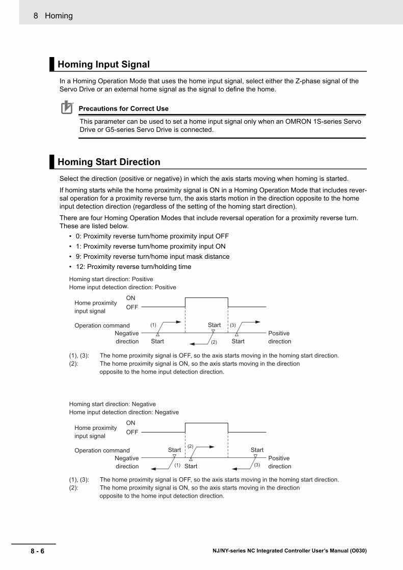
8 Homing
8 - 6 NJ/NY-series NC Integrated Controller User’s Manual (O030)
In a Homing Operation Mode that uses the home input signal, select either the Z-phase signal of the Servo Drive or an external home signal as the signal to define the home.
Precautions for Correct Use
This parameter can be used to set a home input signal only when an OMRON 1S-series Servo Drive or G5-series Servo Drive is connected.
Select the direction (positive or negative) in which the axis starts moving when homing is started.
If homing starts while the home proximity signal is ON in a Homing Operation Mode that includes rever-sal operation for a proximity reverse turn, the axis starts motion in the direction opposite to the home input detection direction (regardless of the setting of the homing start direction).
There are four Homing Operation Modes that include reversal operation for a proximity reverse turn. These are listed below.
• 0: Proximity reverse turn/home proximity input OFF
• 1: Proximity reverse turn/home proximity input ON
• 9: Proximity reverse turn/home input mask distance
• 12: Proximity reverse turn/holding time
Homing Input Signal
Homing Start Direction
(1)
(2)
(3)
ON
Homing start direction: PositiveHome input detection direction: Positive
(1), (3): The home proximity signal is OFF, so the axis starts moving in the homing start direction.(2): The home proximity signal is ON, so the axis starts moving in the direction opposite to the home input detection direction.
Home proximity input signal
Operation commandNegative direction Start
Start
StartPositive direction
OFF
(1)
(2)
(3)
ON
Homing start direction: NegativeHome input detection direction: Negative
Home proximity input signal
Operation commandNegative direction Start
Start StartPositive direction
OFF
(1), (3): The home proximity signal is OFF, so the axis starts moving in the homing start direction.(2): The home proximity signal is ON, so the axis starts moving in the direction opposite to the home input detection direction.

8 - 7
8 Homing
NJ/NY-series NC Integrated Controller User’s Manual (O030)
8-2 Ho
min
g P
roced
ure
8
8-2-1 S
etting Hom
ing Param
eters
Select the direction (positive or negative) in which to detect home.
Refer to Homing Start Direction on page 8-6 for the relationship between the home detection method and the initial direction in which the machine moves when homing starts.
• Select the operation when the axis reaches a limit input in the operating direction during homing: reverse the axis and continue with homing, or do not reverse the axis, create an error, and stop the axis. When you have decided to reverse the direction, also select the method to stop the motor.
• When the motor is set to reverse the direction, an error occurs and the motor stops if the limit signal in the home input detection direction turns ON while the motor travels at the homing approach veloc-ity. However, if the Homing Operation Mode is 13: no home proximity input/holding home input, which does not use proximity signals, no error will occur and the axis will not stop.
When the limit input operations for both directions are set to reverse the directions, an error occurs and the motor stops if home cannot be detected even after the motor moves from one limit input of the home detection direction to the other limit input of the opposite direction.
Set the homing velocity in command units/min.
Set the velocity after the home proximity input turns ON in command units/min.
Home Input Detection Direction
Operation Selection at Positive Limit Input and Operation Selection at Negative Limit Input
Homing Velocity
Homing Approach Velocity
ON
ON
ON
Home proximity input signal
Limit in direction opposite to detection directionLimit in detection direction
Home instruction Homing velocityHoming approach velocity
OFF
OFF
OFF
Start Stop
ON
ON
ON
Home proximity input signal
Limit in direction opposite to detection directionLimit in detection direction
Home instruction Homing velocityHoming approach velocity
OFF
OFF
OFF
Start Stop

8 Homing
8 - 8 NJ/NY-series NC Integrated Controller User’s Manual (O030)
Set the homing acceleration and deceleration rates in command units/s2.
If the homing acceleration and deceleration rates is set to 0, the homing velocity and other target veloc-ities are reached without any acceleration.
Set the home input mask distance in command units when you set the homing operation mode to 9: proximity reverse turn/home input mask distance. This is the distance from the position at which the home proximity input signal is set to OFF to the position at which the home proximity input signal is set to ON to start deceleration.
When the home is defined and the homing compensation value is set, the current value is preset to the specified value after the homing compensation operation is completed.
This function is used when you set home to any specified value rather than to 0.
For systems with absolute encoders, the absolute encoder home offset value is calculated automati-cally and saved in the non-volatile memory in the NC Integrated Controller.
Additional Information
If the target position of the Home Offset overflows or underflows, a Target Position Setting Out of Range (56070000 hex) error is output.
Homing Acceleration/Deceleration
Homing Input Mask Distance
Home Offset
Home detection direction
Home proximity input signalHome input signal
Homing velocityHoming approach velocity
Positive direction
After the proximity input, the motor moves for the home input mask distance
Command output
Negative direction Start Stop
ON
ONOFF
OFF

8 - 9
8 Homing
NJ/NY-series NC Integrated Controller User’s Manual (O030)
8-2 Ho
min
g P
roced
ure
8
8-2-1 S
etting Hom
ing Param
eters
Set the holding time in milliseconds to be applied when you set the homing operation mode to 12: prox-imity reverse turn/holding time.
This is the period from the time when the home proximity input signal is set to OFF to the time when the home proximity input signal is set to ON to start deceleration.
After home is defined, relative positioning is performed at the set value to adjust the position of home. This homing compensation is performed at the homing compensation velocity.
Adjusting the workpiece is sometimes difficult after home is defined. The homing compensation can be used to fine-tune the position of home after it is first determined.
This is useful when you cannot easily replace the home proximity sensor or when home has moved after a motor replacement.
Additional Information
If the target position of the homing compensation value overflows or underflows, a Target Posi-tion Setting Out of Range (56070000 hex) error is output.
If you set a homing compensation value, set the velocity to use for the compensation in command units/min.
Homing Holding Time
Homing Compensation Value
Homing Compensation Velocity
Home proximity input signal
Command output
Homing velocity
Homing velocity
Homing velocity
Torque limit
Command torque from previous operation
Home is defined when the set time elapses
Torque limit is continued even after the set time elapses.
Homing approach velocity
Homing approach velocity
Positive direction
Positive direction
Negative direction
Negative direction
Start
Start
Stop
Stop
ONOFF
Home detection direction
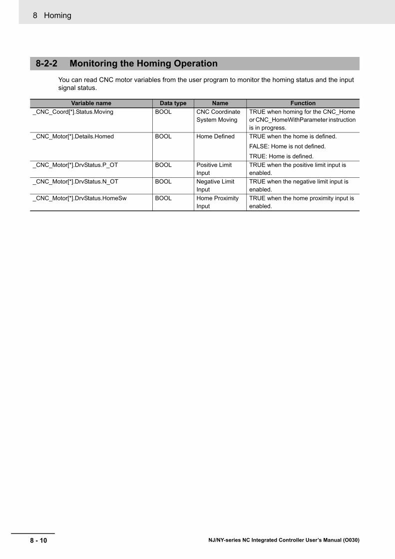
8 Homing
8 - 10 NJ/NY-series NC Integrated Controller User’s Manual (O030)
You can read CNC motor variables from the user program to monitor the homing status and the input signal status.
8-2-2 Monitoring the Homing Operation
Variable name Data type Name Function
_CNC_Coord[*].Status.Moving BOOL CNC Coordinate System Moving
TRUE when homing for the CNC_Home or CNC_HomeWithParameter instruction is in progress.
_CNC_Motor[*].Details.Homed BOOL Home Defined TRUE when the home is defined.
FALSE: Home is not defined.
TRUE: Home is defined.
_CNC_Motor[*].DrvStatus.P_OT BOOL Positive Limit Input
TRUE when the positive limit input is enabled.
_CNC_Motor[*].DrvStatus.N_OT BOOL Negative Limit Input
TRUE when the negative limit input is enabled.
_CNC_Motor[*].DrvStatus.HomeSw BOOL Home Proximity Input
TRUE when the home proximity input is enabled.

8 - 11
8 Homing
NJ/NY-series NC Integrated Controller User’s Manual (O030)
8-3 Ho
min
g O
peratio
n
8
8-3 Homing Operation
Select the home definition method based on the configuration of the positioning system and its pur-pose.
There are ten homing operation modes supported by the CNC Function Module.
You can also fine-tune the home that was once determined with a homing compensation value.
Additional Information
• The most suitable mode depends on the configuration of the positioning system and the application.
Proximity reverse turn /home proximity input OFF is normally used for a machine that is equipped with home proximity sensor, positive limit input, and negative limit input.
• The in-position check will follow the in-position check settings only for the completion of the home definition and homing compensation motions.
Refer to CNC Instructions on page 10-1 for details on homing.

8 Homing
8 - 12 NJ/NY-series NC Integrated Controller User’s Manual (O030)
8-4 Homing with an Absolute Encoder
This section describes how to use an OMRON 1S-series Servomotor/Servo Drive with built-in Ether-CAT communications.
If you use an absolute encoder, the absolute data can be retained by the battery backup function of the encoder even when the power supply to the NC Integrated Controller is turned OFF. When you execute the CNC_Power (Power Servo) instruction or an EtherCAT communication is established, the position is determined by reading the actual position from the absolute encoder.
Unlike the case where an incremental encoder is used, once the home is defined, you do not need to perform the homing operation again.
Precautions for Correct Use
• When using the NJ-series NC Integrated Controller with an OMRON 1S-series Servo Drive, connect the NC Integrated Controller battery to the Servo Drive.
• If you use an absolute encoder in combination with the NJ-series NC Integrated Controller and OMRON G5-series Servo Drive, connect each of the CNC Controller battery and the backup battery of the absolute encoder for the Servo Drive.
• Always execute the CNC_Home or CNC_HomeWithParameter instruction to define home when you use the absolute encoder for the first time, after you replace the motor, when you use an OMRON G5-series Servo Drive, when the battery in the absolute encoder expires, or at any other time when the absolute value data is lost.
• If there is an error for the battery of the NC Integrated Controller, when the power supply to the NC Integrated Controller is turned ON, an Absolute Encoder Home Offset Read Error (event code: 17810000 hex) occurs. In this case, you can use the ResetCNCError (Reset CNC Error) instruction to reset the error and turn the Servo Drive ON.
Additional Information
If you use an OMRON G5-series Linear Motor Type Servomotor/Servo Drive with built-in Ether-CAT communications, you can set the absolute encoder home position. If you use a Linear Motor Type, observe the followings points when reading this section.
• A Linear Motor Type does not use an encoder. It uses an external scale, which functions in a similar way.
• "Absolute encoder" in this section can be read as an absolute external scale.
• An absolute external scale does not have the rotation data of an absolute encoder. Any rota-tion data setting procedures that are required for an absolute encoder are not required. A battery to back up the rotation data is also not required.
• Refer to the AC Servomotors/Servo Drives G5-series with Built-in EtherCATR® Communica-tions Linear Motor Type User's Manual (Cat. No. I577) for the specification of Linear Motor Type.
MNC
Integrated Controller
Servo Drive
Battery Battery
CNC_Power executedMotor (absolute encoder)
Battery backupAbsolute data

8 - 13
8 Homing
NJ/NY-series NC Integrated Controller User’s Manual (O030)
8-4 Ho
min
g w
ith an
Ab
solu
te En
cod
er
8
8-4-1 O
utline of Function
s
To define the home of an absolute encoder system, absolute encoder offset compensation is performed when the CNC_Power (Power Servo) instruction is executed or when EtherCAT process data commu-nications changes from non-established to established state.
The home can be defined by performing the homing operation in the same way as for an incremental encoder. After the home has been defined, the difference between the commanded position and the absolute value data read from the absolute encoder is saved to Absolute Encoder Home Offset in the non-volatile memory of the NC Integrated Controller as an offset.
When the actual position is preset with the CNC_Home (Home) or CNC_HomeWithParameter (Home with Parameters) instruction, the difference between the commanded position and absolute value data after home is defined is also saved to Absolute Encoder Home Offset as an offset.
The CNC Function Module automatically saves Absolute Encoder Home Offset to the non-volatile memory in the NC Integrated Controller. Therefore, you do not need to perform any save operation from Sysmac Studio.
Precautions for Correct Use
• When you replace the NC Integrated Controller or the battery of the NC Integrated Controller, be sure to back up Absolute Encoder Home Offset with the home defined before you start the replacement procedure.
• When absolute encoders are used, the Absolute Encoder Home Offset for each CNC motor is saved to the non-volatile memory along with the CNC motor number. If the CNC motor number is changed, the saved offset will be lost. If you change the CNC motor number, set the Homing Settings again.
• By restoring the backup data after the replacement has been completed, you can use the home defined before the replacement was carried out.
• To back up or restore data, use Sysmac Studio. Refer to the Sysmac Studio Version 1 Oper-ation Manual (Cat. No. W504) for details on the operation procedure.
This section describes the procedure to set the home of an absolute encoder system.
1 Setting the Absolute Encoder
Refer to the Sysmac Studio Version 1 Operation Manual (Cat. No. W504) for the setup proce-dures.
2 Setting the CNC Motor Parameters
Select 1: Absolute encoder for Encoder Type of Position Count Parameters in the CNC motor parameter of the CNC Function Module. Refer to 4-4-7 Position Count Settings on page 4-32 for details.
3 Executing Homing
Set the Homing Operation Mode in Homing Settings in the CNC motor parameter of the CNC Function Module.
After home is defined, the difference between the command position and the absolute value data read from the absolute encoder is automatically saved to Absolute Encoder Home Offset in the non-volatile memory of the NC Integrated Controller as an offset.
8-4-1 Outline of Functions
8-4-2 Setting Procedure

8 Homing
8 - 14 NJ/NY-series NC Integrated Controller User’s Manual (O030)
The absolute encoder must be set up when it is used for the first time, when you want to initialize the rotation data to 0, when the absolute encoder is left for an extended period of time without the battery connected, or in other cases.
Refer to the Sysmac Studio Version 1 Operation Manual (Cat. No. W504) for details on the setup proce-dures.
Precautions for Correct Use
After the absolute encoder is set up, the power supply to the OMRON 1S-series Servo Drive or G5-series Servo Drive must be cycled. When setup processing for the absolute encoder is completed, an Absolute Value Clear Error (A27.1) will occur in the Servo Drive. Cycle the con-trol power supply to the Servo Drive to clear this error and complete the absolute encoder setup procedure.
Absolute Encoder Setup

9 - 1
9
NJ/NY-series NC Integrated Controller User’s Manual (O030)
This section describes the control functions for CNC motor and CNC coordinate sys-tem operations.
9-1 CNC Motor Position Control . . . . . . . . . . . . . . . . . . . . . . . . . . . . . . . . . . . . . 9-29-1-1 Outline of Operations . . . . . . . . . . . . . . . . . . . . . . . . . . . . . . . . . . . . . . . . . . . 9-2
9-1-2 Absolute Positioning . . . . . . . . . . . . . . . . . . . . . . . . . . . . . . . . . . . . . . . . . . . . 9-2
9-1-3 Relative Positioning . . . . . . . . . . . . . . . . . . . . . . . . . . . . . . . . . . . . . . . . . . . . 9-2
9-1-4 Cyclic Synchronous Positioning . . . . . . . . . . . . . . . . . . . . . . . . . . . . . . . . . . . 9-3
9-1-5 Stopping . . . . . . . . . . . . . . . . . . . . . . . . . . . . . . . . . . . . . . . . . . . . . . . . . . . . . 9-3
9-2 CNC Motor Velocity Control . . . . . . . . . . . . . . . . . . . . . . . . . . . . . . . . . . . . . 9-79-2-1 Cyclic Velocity Control . . . . . . . . . . . . . . . . . . . . . . . . . . . . . . . . . . . . . . . . . . 9-7
9-2-2 Position Loop by Cyclic Velocity Control . . . . . . . . . . . . . . . . . . . . . . . . . . . . 9-7
9-3 Common Functions for CNC Motor Control . . . . . . . . . . . . . . . . . . . . . . . . 9-99-3-1 Positions . . . . . . . . . . . . . . . . . . . . . . . . . . . . . . . . . . . . . . . . . . . . . . . . . . . . . 9-9
9-3-2 Velocity . . . . . . . . . . . . . . . . . . . . . . . . . . . . . . . . . . . . . . . . . . . . . . . . . . . . . .9-11
9-3-3 Acceleration Control . . . . . . . . . . . . . . . . . . . . . . . . . . . . . . . . . . . . . . . . . . . 9-12
9-4 CNC Coordinate System Position Control . . . . . . . . . . . . . . . . . . . . . . . . . 9-139-4-1 Outline of Operations . . . . . . . . . . . . . . . . . . . . . . . . . . . . . . . . . . . . . . . . . . 9-13
9-4-2 Preparatory Function (G code) . . . . . . . . . . . . . . . . . . . . . . . . . . . . . . . . . . . 9-13
9-5 Common Functions for CNC Coordinate System Position Control . . . . 9-14
9-6 Other Functions . . . . . . . . . . . . . . . . . . . . . . . . . . . . . . . . . . . . . . . . . . . . . . 9-159-6-1 Latching . . . . . . . . . . . . . . . . . . . . . . . . . . . . . . . . . . . . . . . . . . . . . . . . . . . . 9-15
9-6-2 Software Limit . . . . . . . . . . . . . . . . . . . . . . . . . . . . . . . . . . . . . . . . . . . . . . . . 9-15
9-6-3 In-position Check . . . . . . . . . . . . . . . . . . . . . . . . . . . . . . . . . . . . . . . . . . . . . 9-15
Control Functions for CNC Motor and CNC Coordinate System Operations
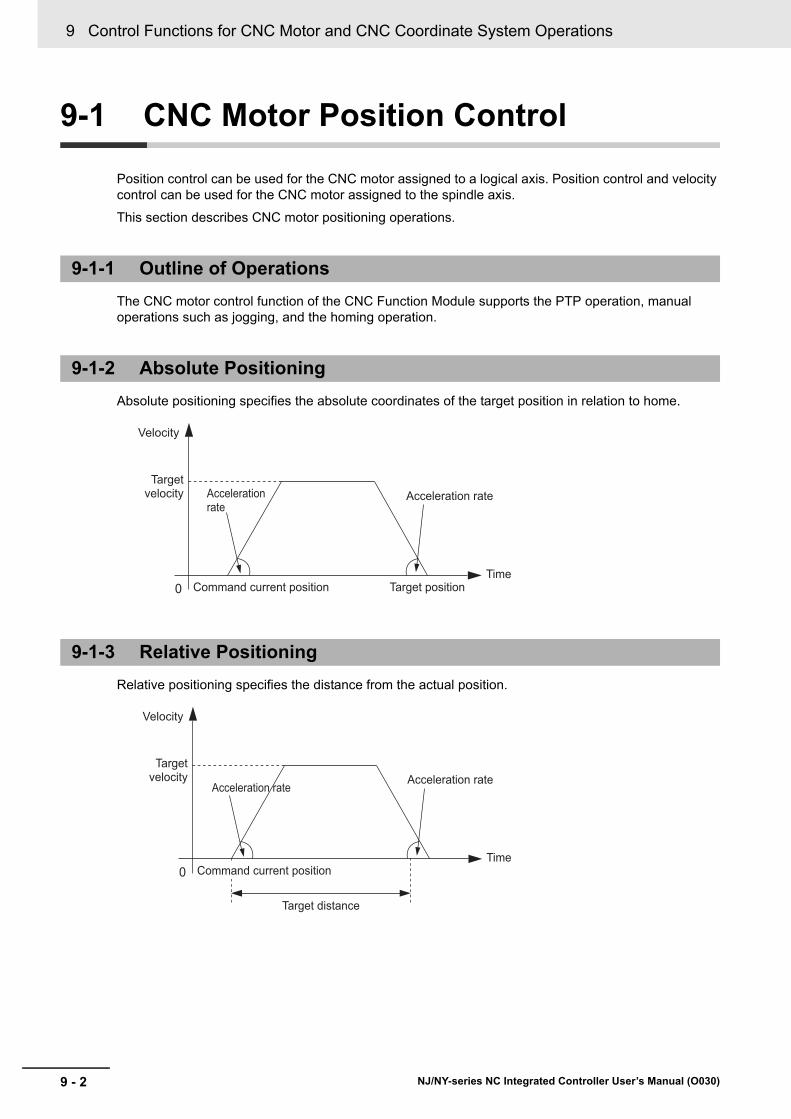
9 Control Functions for CNC Motor and CNC Coordinate System Operations
9 - 2 NJ/NY-series NC Integrated Controller User’s Manual (O030)
9-1 CNC Motor Position Control
Position control can be used for the CNC motor assigned to a logical axis. Position control and velocity control can be used for the CNC motor assigned to the spindle axis.
This section describes CNC motor positioning operations.
The CNC motor control function of the CNC Function Module supports the PTP operation, manual operations such as jogging, and the homing operation.
Absolute positioning specifies the absolute coordinates of the target position in relation to home.
Relative positioning specifies the distance from the actual position.
9-1-1 Outline of Operations
9-1-2 Absolute Positioning
9-1-3 Relative Positioning
0
Velocity
Target velocity Acceleration
rateAcceleration rate
Command current position Target positionTime
0
Velocity
Target velocity
Acceleration rateAcceleration rate
Command current position
Target distance
Time

9 - 3
9 Control Functions for CNC Motor and CNC Coordinate System Operations
NJ/NY-series NC Integrated Controller User’s Manual (O030)
9-1 C
NC
Mo
tor P
ositio
n C
on
trol
9
9-1-4 Cyclic S
ynchronous Positioning
Cyclic synchronous positioning is used to output a target position to a specified CNC coordinate system in each task period. The target position is specified as an absolute position. This function is used to per-form MPG feeding and other operations.
Functions to stop CNC motor operation include immediate stop input signal and limit input signals con-nected to the Servo Drive, stop functions of CNC instructions in the user program, and stopping due to errors.
CNC motor motion is stopped for the immediate stop input signal or a limit input signal from the Servo Drive.
You can select the stop method with the Sysmac Studio.
Immediate Stop Input
Stop processing in the CNC Function Module is executed according to the state of the Servo Drive input signals. You can select one of the following stopping methods for the CNC Function Module.
• Immediate stop
• Immediate stop and error counter reset
• Immediate stop and Servo OFF
Precautions for Correct Use
The immediate stop input for the OMRON 1S-series Servo Drive or G5-series Servo Drive also causes an error and executes stop processes in the Servo Drive itself.
9-1-4 Cyclic Synchronous Positioning
9-1-5 Stopping
Stopping for Servo Drive Input Signals
M
E
Servo DriveCommand position
Command position
Task periodTime
Target positions (black dots) specified with the input parameters
Position

9 Control Functions for CNC Motor and CNC Coordinate System Operations
9 - 4 NJ/NY-series NC Integrated Controller User’s Manual (O030)
Limit Input (Positive Limit Input or Negative Limit Input)
Stop processing in the CNC Function Module is executed according to the state of the Servo Drive input signals.
The CNC motor stop method can be selected from the following based on the Limit Input Stop Method of the CNC motor.
• Immediate stop
• Immediate Stop and Servo OFF
Other CNC motors of the CNC coordinate system stop immediately.
Precautions for Correct Use
If a limit input signal turns ON, do not execute an instruction for CNC coordinate system com-mand in the same direction as the limit input signal.
For information about stopping for a CNC instruction, refer to CNC_CoordStop on page 12-68, CNC_CoordImmediateStop on page 12-72, and CNC_CoordHalt on page 12-76 in Section 12 CNC Coordinate System Instructions.
Stopping for Errors during CNC Motor Operation
When an error occurs during a CNC motor operation, the motor will stop immediately depending on the error.
Stopping for a Software Limit
When Software Overtravel Limit Operation Control is set to 0: An error occurs and the software limit is judged to be exceeded during execution of an NC program, each CNC motor stops immedi-ately. In other cases, adjust the path or target position so that the software limit is not exceeded.
Errors That Cause the Servo to Turn OFF
An immediate stop is performed if an error occurs that causes the Servo to turn OFF. The operation of Servo Drive during Servo OFF state depends on the settings in the Servo Drive.
While an NC program is running, all other CNC motors in the CNC coordinate system will decelerate to stop at their maximum deceleration rate. In other cases, the other CNC motors are not affected.
Stopping for a CNC Instruction
Stopping Due to Errors or Other Problems

9 - 5
9 Control Functions for CNC Motor and CNC Coordinate System Operations
NJ/NY-series NC Integrated Controller User’s Manual (O030)
9-1 C
NC
Mo
tor P
ositio
n C
on
trol
9
9-1-5 Stoppin
g
Stopping Due to Change in the NC Integrated Controller Mode
All CNC motors will immediately stop if the NC Integrated Controller operating mode changes.
Additional Information
• When RUN mode changes to PROGRAM mode, any CNC instructions that are currently in execution are aborted. CommandAborted output variable from the instructions remains FALSE. The Servo ON/OFF status is maintained after the mode has been switched to the PROGRAM mode.
• If the operating mode returns to RUN mode while a immediate stop is in progress after the operating mode changes from RUN to PROGRAM mode, the output variables from CNC instructions are cleared. The CommandAborted output variables from the CNC instructions therefore remain FALSE.
Immediate Stop
Immediate Stop and Servo OFF
Stop Methods
Velocity
Time
The command is no longer updated.The CNC motor moves only for the pulses remaining in the Servo Drive and then stops.The stop position is the command position when the cause of the immediate stop occurred.
Velocity
Time
The command is no longer updated.When the Servo is turned OFF, the CNC motor stopsusing the method that is specified by the DisableOperation Option Code (605C hex) that is set in theServo Drive.
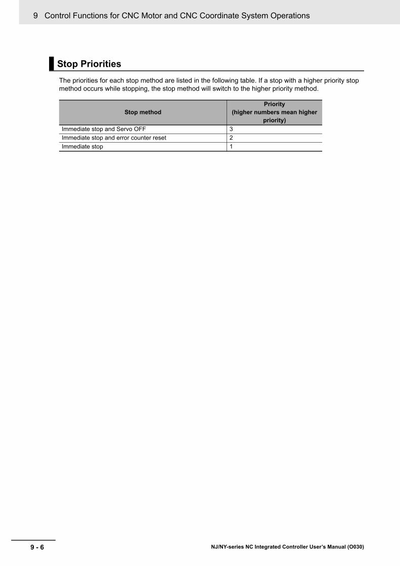
9 Control Functions for CNC Motor and CNC Coordinate System Operations
9 - 6 NJ/NY-series NC Integrated Controller User’s Manual (O030)
The priorities for each stop method are listed in the following table. If a stop with a higher priority stop method occurs while stopping, the stop method will switch to the higher priority method.
Stop Priorities
Stop methodPriority
(higher numbers mean higher priority)
Immediate stop and Servo OFF 3
Immediate stop and error counter reset 2
Immediate stop 1

9 - 7
9 Control Functions for CNC Motor and CNC Coordinate System Operations
NJ/NY-series NC Integrated Controller User’s Manual (O030)
9-2 C
NC
Mo
tor V
elo
city Co
ntro
l
9
9-2-1 Cyclic V
elocity Contro
l
9-2 CNC Motor Velocity Control
Velocity control can be used for the CNC motor assigned to the spindle axis.
This section describes the CNC motor velocity control functions.
The control mode of the Servo Drive is set to Velocity Control Mode and a command speed is output every control period.
Additional Information
The open loop control is set during velocity control processing.
The CNC Function Module controls the spindle axis using the velocity command. However, the posi-tioning is required for some spindle functions. Therefore, the CNC Function Module has a position loop for each CNC motor that is assigned to the spindle axis. To adjust the responsiveness of the position loop, you can set the Position Loop Gain (K_p) and Velocity Feedforward Gain (K_vff) parameters.
9-2-1 Cyclic Velocity Control
9-2-2 Position Loop by Cyclic Velocity Control
M
E
Servo DriveCommand velocity
Command velocity
Primary periodTime
Target velocity (black dots) specified with the input
Velocity
+
1 - z -1 Kvff
Kp
++
-
(command unit)
Target position of CNC function module
(command unit/min)Target velocity of CNC motor
(command unit)Current position of CNC motor

9 Control Functions for CNC Motor and CNC Coordinate System Operations
9 - 8 NJ/NY-series NC Integrated Controller User’s Manual (O030)
Precautions for Safe Use
• Before adjusting this parameter, use the following methods to control the spindle in open-loop and adjust the gain on the spindle driver to ensure normal operation.
• CNC_SpindleGo
• Spindle CW (M03)
• Spindle CCW (M04)
• When adjusting the gain, take sufficient measures to ensure safety.
• If oscillation (abnormal noise or vibration) occurs, immediately turn OFF the power to the Drive or turn the Servo OFF.
The Position Loop Gain (K_p) parameter gives the main gain for servo loop, and it provides control out-puts that are proportional to the position error (i.e. difference between the command position and the current position) of the CNC motor.
Velocity Feedforward Gain K_vff adds the control amount that is proportional to the command velocity of the CNC motor to the control output. This parameter is used to reduce following errors caused by physical damping effects.
If you need adjustments using this parameter, make sure that both adjustments of spindle driver and position loop gain are completed. Increase the setting value gradually from zero. Overshooting will increase if an excessively large value is set at once.
Position Loop Gain
Velocity Feedforward Gain
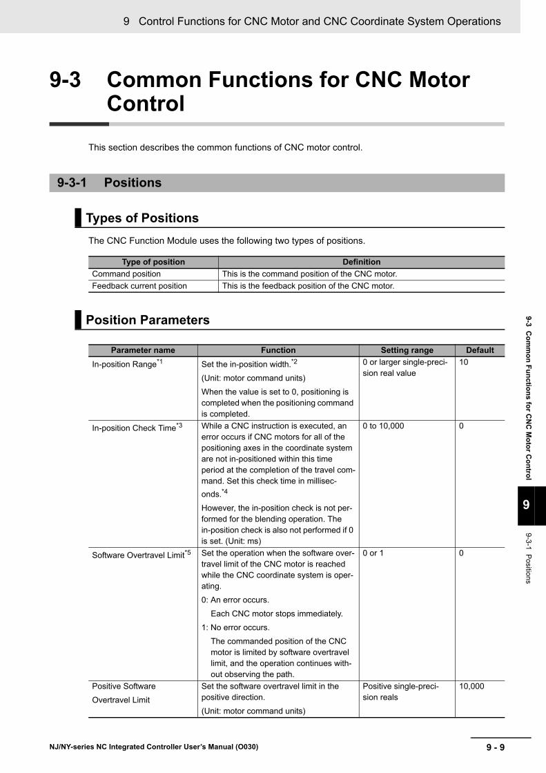
9 - 9
9 Control Functions for CNC Motor and CNC Coordinate System Operations
NJ/NY-series NC Integrated Controller User’s Manual (O030)
9-3 Co
mm
on
Fu
nctio
ns fo
r CN
C M
oto
r Co
ntro
l
9
9-3-1 Positions
9-3 Common Functions for CNC Motor Control
This section describes the common functions of CNC motor control.
The CNC Function Module uses the following two types of positions.
9-3-1 Positions
Types of Positions
Type of position Definition
Command position This is the command position of the CNC motor.
Feedback current position This is the feedback position of the CNC motor.
Position Parameters
Parameter name Function Setting range Default
In-position Range*1 Set the in-position width.*2
(Unit: motor command units)
When the value is set to 0, positioning is completed when the positioning command is completed.
0 or larger single-preci-sion real value
10
In-position Check Time*3 While a CNC instruction is executed, an error occurs if CNC motors for all of the positioning axes in the coordinate system are not in-positioned within this time period at the completion of the travel com-mand. Set this check time in millisec-
onds.*4
However, the in-position check is not per-formed for the blending operation. The in-position check is also not performed if 0 is set. (Unit: ms)
0 to 10,000 0
Software Overtravel Limit*5 Set the operation when the software over-travel limit of the CNC motor is reached while the CNC coordinate system is oper-ating.
0: An error occurs.
Each CNC motor stops immediately.
1: No error occurs.
The commanded position of the CNC motor is limited by software overtravel limit, and the operation continues with-out observing the path.
0 or 1 0
Positive Software
Overtravel Limit
Set the software overtravel limit in the positive direction.
(Unit: motor command units)
Positive single-preci-sion reals
10,000
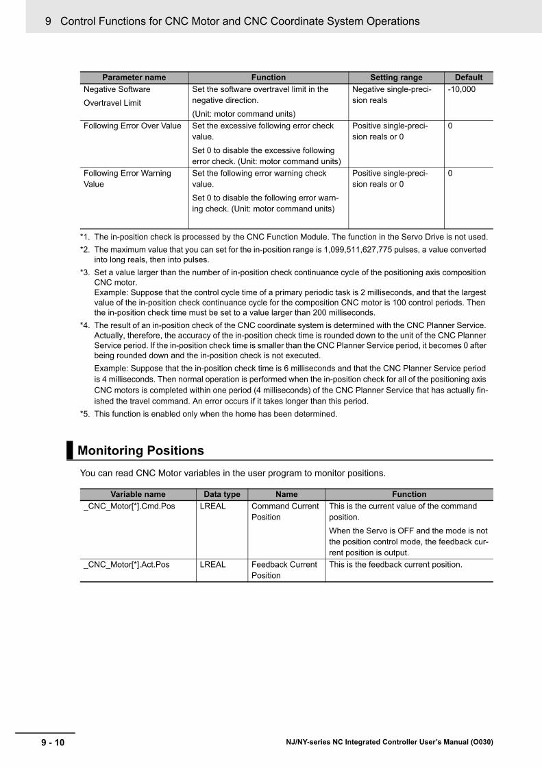
9 Control Functions for CNC Motor and CNC Coordinate System Operations
9 - 10 NJ/NY-series NC Integrated Controller User’s Manual (O030)
You can read CNC Motor variables in the user program to monitor positions.
Negative Software
Overtravel Limit
Set the software overtravel limit in the negative direction.
(Unit: motor command units)
Negative single-preci-sion reals
-10,000
Following Error Over Value Set the excessive following error check value.
Set 0 to disable the excessive following error check. (Unit: motor command units)
Positive single-preci-sion reals or 0
0
Following Error Warning Value
Set the following error warning check value.
Set 0 to disable the following error warn-ing check. (Unit: motor command units)
Positive single-preci-sion reals or 0
0
*1. The in-position check is processed by the CNC Function Module. The function in the Servo Drive is not used.
*2. The maximum value that you can set for the in-position range is 1,099,511,627,775 pulses, a value converted into long reals, then into pulses.
*3. Set a value larger than the number of in-position check continuance cycle of the positioning axis composition CNC motor. Example: Suppose that the control cycle time of a primary periodic task is 2 milliseconds, and that the largest value of the in-position check continuance cycle for the composition CNC motor is 100 control periods. Then the in-position check time must be set to a value larger than 200 milliseconds.
*4. The result of an in-position check of the CNC coordinate system is determined with the CNC Planner Service. Actually, therefore, the accuracy of the in-position check time is rounded down to the unit of the CNC Planner Service period. If the in-position check time is smaller than the CNC Planner Service period, it becomes 0 after being rounded down and the in-position check is not executed.
Example: Suppose that the in-position check time is 6 milliseconds and that the CNC Planner Service period is 4 milliseconds. Then normal operation is performed when the in-position check for all of the positioning axis CNC motors is completed within one period (4 milliseconds) of the CNC Planner Service that has actually fin-ished the travel command. An error occurs if it takes longer than this period.
*5. This function is enabled only when the home has been determined.
Monitoring Positions
Variable name Data type Name Function
_CNC_Motor[*].Cmd.Pos LREAL Command Current Position
This is the current value of the command position.
When the Servo is OFF and the mode is not the position control mode, the feedback cur-rent position is output.
_CNC_Motor[*].Act.Pos LREAL Feedback Current Position
This is the feedback current position.
Parameter name Function Setting range Default
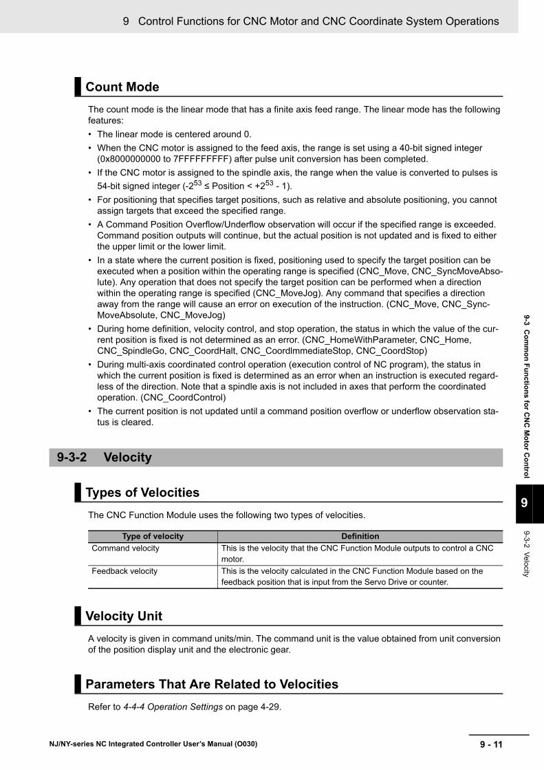
9 - 11
9 Control Functions for CNC Motor and CNC Coordinate System Operations
NJ/NY-series NC Integrated Controller User’s Manual (O030)
9-3 Co
mm
on
Fu
nctio
ns fo
r CN
C M
oto
r Co
ntro
l
9
9-3-2 Velocity
The count mode is the linear mode that has a finite axis feed range. The linear mode has the following features:
• The linear mode is centered around 0.
• When the CNC motor is assigned to the feed axis, the range is set using a 40-bit signed integer (0x8000000000 to 7FFFFFFFFF) after pulse unit conversion has been completed.
• If the CNC motor is assigned to the spindle axis, the range when the value is converted to pulses is
54-bit signed integer (-253 ≤ Position < +253 - 1).
• For positioning that specifies target positions, such as relative and absolute positioning, you cannot assign targets that exceed the specified range.
• A Command Position Overflow/Underflow observation will occur if the specified range is exceeded. Command position outputs will continue, but the actual position is not updated and is fixed to either the upper limit or the lower limit.
• In a state where the current position is fixed, positioning used to specify the target position can be executed when a position within the operating range is specified (CNC_Move, CNC_SyncMoveAbso-lute). Any operation that does not specify the target position can be performed when a direction within the operating range is specified (CNC_MoveJog). Any command that specifies a direction away from the range will cause an error on execution of the instruction. (CNC_Move, CNC_Sync-MoveAbsolute, CNC_MoveJog)
• During home definition, velocity control, and stop operation, the status in which the value of the cur-rent position is fixed is not determined as an error. (CNC_HomeWithParameter, CNC_Home, CNC_SpindleGo, CNC_CoordHalt, CNC_CoordlmmediateStop, CNC_CoordStop)
• During multi-axis coordinated control operation (execution control of NC program), the status in which the current position is fixed is determined as an error when an instruction is executed regard-less of the direction. Note that a spindle axis is not included in axes that perform the coordinated operation. (CNC_CoordControl)
• The current position is not updated until a command position overflow or underflow observation sta-tus is cleared.
The CNC Function Module uses the following two types of velocities.
A velocity is given in command units/min. The command unit is the value obtained from unit conversion of the position display unit and the electronic gear.
Refer to 4-4-4 Operation Settings on page 4-29.
Count Mode
9-3-2 Velocity
Types of Velocities
Type of velocity Definition
Command velocity This is the velocity that the CNC Function Module outputs to control a CNC motor.
Feedback velocity This is the velocity calculated in the CNC Function Module based on the feedback position that is input from the Servo Drive or counter.
Velocity Unit
Parameters That Are Related to Velocities
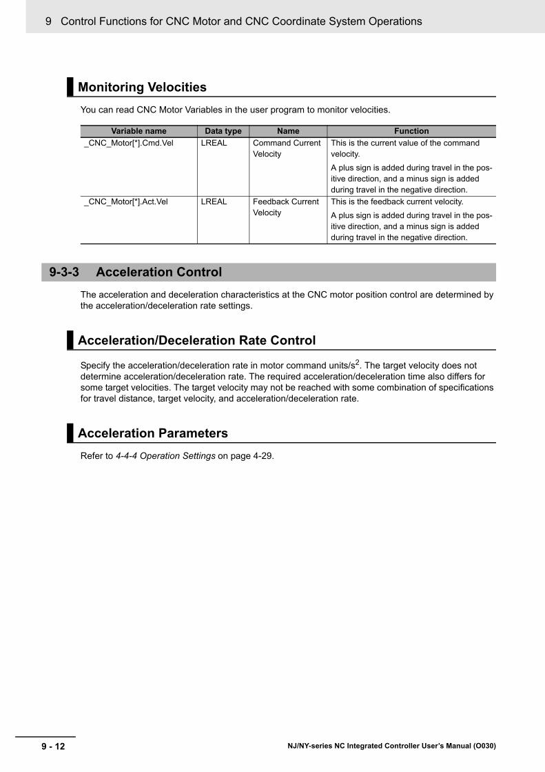
9 Control Functions for CNC Motor and CNC Coordinate System Operations
9 - 12 NJ/NY-series NC Integrated Controller User’s Manual (O030)
You can read CNC Motor Variables in the user program to monitor velocities.
The acceleration and deceleration characteristics at the CNC motor position control are determined by the acceleration/deceleration rate settings.
Specify the acceleration/deceleration rate in motor command units/s2. The target velocity does not determine acceleration/deceleration rate. The required acceleration/deceleration time also differs for some target velocities. The target velocity may not be reached with some combination of specifications for travel distance, target velocity, and acceleration/deceleration rate.
Refer to 4-4-4 Operation Settings on page 4-29.
Monitoring Velocities
Variable name Data type Name Function
_CNC_Motor[*].Cmd.Vel LREAL Command Current Velocity
This is the current value of the command velocity.
A plus sign is added during travel in the pos-itive direction, and a minus sign is added during travel in the negative direction.
_CNC_Motor[*].Act.Vel LREAL Feedback Current Velocity
This is the feedback current velocity.
A plus sign is added during travel in the pos-itive direction, and a minus sign is added during travel in the negative direction.
9-3-3 Acceleration Control
Acceleration/Deceleration Rate Control
Acceleration Parameters
9 - 13
9 Control Functions for CNC Motor and CNC Coordinate System Operations
NJ/NY-series NC Integrated Controller User’s Manual (O030)
9-4 CN
C C
oo
rdin
ate System
Po
sition
Co
ntro
l
9
9-4-1 Outline of O
perations
9-4 CNC Coordinate System Position Control
This section describes the operation of multi-axes coordinated control. With the CNC Function Module, you can set a CNC coordinate system in advance from Sysmac Studio to perform interpolation control for multiple axes.
Multi-axes coordinated control performs a motion with multiple related CNC motors together as a single group to control the path of the target control object such as tool center points.
The CNC Function Module treats all CNC motors that perform coordinated operation as a CNC coordi-nate system. CNC coordinate system are set from the Sysmac Studio. The NC program is used to con-trol the path of the tool center point in the CNC coordinate system.
In the user program, each of the composition CNC motors for a CNC coordinate system are set to Servo ON status and to complete homing. Then, the CNC instruction to start the NC program and path operation is executed. If any error occurs on any CNC motor in the CNC coordinate system, all other CNC motors in the CNC coordinate system stop immediately.
Precautions for Correct Use
You cannot execute NC programs to a coordinate system if a CNC motor that composes the coordinate system is manually operated. In the same way, the manual operation cannot be executed during execution of the NC program except for the Hold (Holding) status.
If an error occurs in a CNC coordinate system, you can use the CNC_CoordReset (CNC Coordinate System Error Reset) instruction to remove the error once you have eliminated the cause.
Refer to the NJ/NY-series G code Instructions Reference Manual (Cat. No. O031).
9-4-1 Outline of Operations
Resetting CNC Coordinate System Errors
9-4-2 Preparatory Function (G code)
9 Control Functions for CNC Motor and CNC Coordinate System Operations
9 - 14 NJ/NY-series NC Integrated Controller User’s Manual (O030)
9-5 Common Functions for CNC Coordi-nate System Position Control
For information about position, feedrate, acceleration time, deceleration time, and override, refer to the NJ/NY-Series G code Instruction Reference Manual (Cat. No. O031).
9 - 15
9 Control Functions for CNC Motor and CNC Coordinate System Operations
NJ/NY-series NC Integrated Controller User’s Manual (O030)
9-6 Oth
er Fu
nctio
ns
9
9-6-1 Latching
9-6 Other Functions
This section describes other functions of the CNC Function Module.
Latching is used to control positioning based on the position where a trigger signal occurs, such as a signal from a sensor input. The position of the CNC motor is recorded (i.e., latched) when the trigger signal occurs.
Latching is required for G31 (Skip Function).
The positive and negative software limit parameters are provided for each CNC motor.
When Software Overtravel Limit Operation Control is set to 0: An error occurs and the software limit is judged to be exceeded during execution of an NC program, each CNC motor stops immediately. In other cases, the path or target position is adjusted so that the software limit is not exceeded.
The software limit is valid only when the home is defined. The software limit is invalid during homing.
For the in-position range, specify the maximum position error value so that the CNC motor can be assumed in the in-position status when any command operations are not executed. For the number of in-position continuance cycles, specify the number of consecutive repetitions during which the in-posi-tion status must be true so that the CNC motor can be assumed in the in-position status.
If the number of in-position continuance cycles is greater than 0, the in-position status must continue to be true for the period specified by the additional number of consecutive check times. The NC Integrated Controller checks these conditions in each primary period for all the active CNC motors. If any of these additional checks detects that any of these conditions is not true, the count must be started again from zero.
9-6-1 Latching
9-6-2 Software Limit
9-6-3 In-position Check
In-position Check for CNC Motors
9 Control Functions for CNC Motor and CNC Coordinate System Operations
9 - 16 NJ/NY-series NC Integrated Controller User’s Manual (O030)
Additional Information
• The following five conditions must be satisfied in order that the CNC motor is assumed to be in the in-position status:
• The CNC motor is in a closed-loop control state.
• The command velocity of the CNC motor is set to 0.
• The CNC motor is not running or dwell processing is not executed for the specified period of time.
• The magnitude of the error is less than or equal to the in-position range.
• The above four conditions are satisfied in the consecutive primary period (i.e., the number of continuous in-position cycles + 1).
• When the number of in-position continuance cycles is set to the default value, if the in-posi-tion conditions (closed-loop, commanded velocity zero, and error less than or equal to the in-position range) are satisfied at the first check, the InPos (in-position completion) CNC motor variable is set.
When the in-position check time of the CNC coordinate system parameters is set to a positive value and blending is disabled between programs, this Controller is specified to check the in-position condi-tions before all axes on the coordinate system start the next motions by the NC program. In this case, specify the in-position check timeout time to the in-position check time. The timeout time is indicated by the number of CNC Planner Service periods (CNC Planner Service Period + 1 servo cycle). If all axes in the coordinate system are not set in the in-position status within this time before the start of the next travel, the NC Program Execution Error (67990000 hex) occurs and the program stops.
When the in-position check time of CNC coordinate system parameter is set to 0 and blending is dis-abled, this Controller instantaneously stops the command position before the next travel is started. However, this does not mean that the actual position of any axis reaches the end point.
When all the CNC motors in the CNC coordinate system are judged to be in the in-position status, the in-position status bit of the CNC coordinate system is set. After the in-position check is completed, a dwell time wait operation is inserted before the next programmed travel is executed.
In-position Check for CNC Coordinate Systems
10 - 1
10
NJ/NY-series NC Integrated Controller User’s Manual (O030)
This section describes CNC instructions.
Overview of CNC Instructions . . . . . . . . . . . . . . . . . . . . . . . . . . . . . . . . . . 10-2
Basic Information on CNC Instructions . . . . . . . . . . . . . . . . . . . . . . . . . . . 10-4
CNC Instructions

10 CNC Instructions
10 - 2 NJ/NY-series NC Integrated Controller User’s Manual (O030)
Overview of CNC Instructions
This section provides an overview of CNC instructions.
The following table shows the types and descriptions of CNC instructions.
State transitions are defined for the CNC coordinate system and instruction execution.
Variables that start instruction execution or that indicate the execution status are defined as common rules for the instructions.
There are two input variables that start instruction execution: Execute and Enable.
The output variables that indicate the execution status of an instruction include Busy, Done, Command-Aborted, and Error.
You execute CNC instructions to implement numerical control with the CNC Function Module. When CNC instructions are executed, input parameters and instruction processing are checked for errors.
If an error occurs in an instruction, the Error output variable from the instruction changes to TRUE and an error code is output to ErrorID (Error Code) output variable.
There are two ways that you can use to program processing of errors for CNC instructions.
Error Processing for Individual Instructions
You can use the Error (Error) and ErrorID (Error Code) output variables from the instruction to pro-cess errors that occur for each instruction.
Error Processing for Different Types of Errors
You can use the error status that is provided by the CNC system-defined variables to process each type of error separately.
Types of CNC Instructions
Type Category Functional group Outline
Common commands Common administra-tion instructions
Parameters These instructions are used to control the common statuses of the CNC Func-tion Module, and to manipulate or mon-itor various data items.
CNC coordinate sys-tem commands
CNC coordinate sys-tem motion instruc-tions
CNC coordinate sys-tem control
These instructions perform coordinated motion of the CNC coordinate system.
CNC coordinate sys-tem administration instructions
Auxiliary functions for CNC coordinate sys-tem control
These instructions are used to control or monitor the CNC coordinate system status.
State Transitions
Execution and Status of CNC Instructions
Error Processing
10 - 3
10 CNC Instructions
NJ/NY-series NC Integrated Controller User’s Manual (O030)
Overview
of C
NC
Instru
ction
s
10
Changing Input V
ariables during E
xecution of CN
C In
struction (Restarting Instructions)
If the input variable Execute of the same instruction instance is changed to TRUE again while the CNC instruction is under execution, an error occurs.
Unlike the Motion Control Function Module, CNC instructions do not have functions for buffer modes.
Whether the multi-execution of instructions is supported in the CNC Function Module depends on by the current status of CNC coordinate system and the instruction to execute. Refer to A-4 Instructions for Which Multi-execution Is Supported on page A-15 for details.
Changing Input Variables during Execution of CNC Instruction (Restart-ing Instructions)
Multi-execution of CNC Instructions
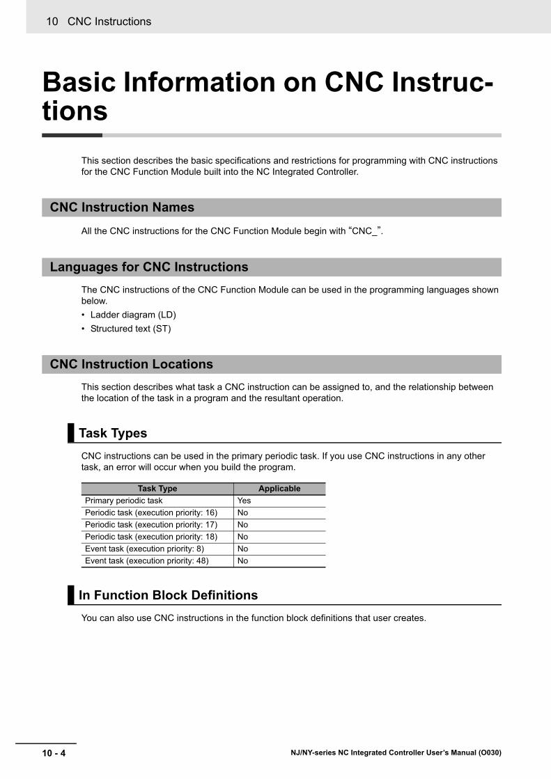
10 CNC Instructions
10 - 4 NJ/NY-series NC Integrated Controller User’s Manual (O030)
Basic Information on CNC Instruc-tions
This section describes the basic specifications and restrictions for programming with CNC instructions for the CNC Function Module built into the NC Integrated Controller.
All the CNC instructions for the CNC Function Module begin with “CNC_”.
The CNC instructions of the CNC Function Module can be used in the programming languages shown below.
• Ladder diagram (LD)
• Structured text (ST)
This section describes what task a CNC instruction can be assigned to, and the relationship between the location of the task in a program and the resultant operation.
CNC instructions can be used in the primary periodic task. If you use CNC instructions in any other task, an error will occur when you build the program.
You can also use CNC instructions in the function block definitions that user creates.
CNC Instruction Names
Languages for CNC Instructions
CNC Instruction Locations
Task Types
Task Type Applicable
Primary periodic task Yes
Periodic task (execution priority: 16) No
Periodic task (execution priority: 17) No
Periodic task (execution priority: 18) No
Event task (execution priority: 8) No
Event task (execution priority: 48) No
In Function Block Definitions

10 - 5
10 CNC Instructions
NJ/NY-series NC Integrated Controller User’s Manual (O030)
Basic In
form
ation
on
CN
CIn
structio
ns
10
CN
C Instruction Locatio
ns
The area in a ladder diagram between the Master Control Start instruction (MC) and the Master Control End instruction (MCR) is the master control region.
If a CNC instruction is located in the master control region, and the MC input condition is FALSE, the following will occur.
• When the CNC instruction is directly input from the left bus bar to the Enable or Execute input vari-able of the CNC instruction, the Enable or Execute input variable is FALSE.
• Inline ST sections are executed normally.
• The values of the output parameters are updated as normal even when the Enable or Execute input variables to the CNC instructions are FALSE.
Master Control Regions
MC
Master control region
MCR

10 CNC Instructions
10 - 6 NJ/NY-series NC Integrated Controller User’s Manual (O030)
Enable-type CNC Instructions
• Instructions located in master control regions are equivalent to the programming shown on the right in the following figure.
• When G0 is TRUE, the CNC_Power is executed normally.
• When G0 is FALSE, the CNC_Power is executed as if the Enable input variable was FALSE.
PW1
CNC_Power
StatusBusyError
ErrorID
Coord CoordEnableLogicalMotorNo
G0
PW1.Busy_PW
PW1.Status_PW
Servo ON/OFF
Enable of the motion control instruction changes to FALSE and the Servo turns OFF.
IN
EquivalentIN
Status_PWBusy_PW
MCR
G0
PW1
CNC_Power
StatusBusyError
ErrorID
Coord CoordEnableLogicalMotorNo
INStatus_PWBusy_PW
G0

10 - 7
10 CNC Instructions
NJ/NY-series NC Integrated Controller User’s Manual (O030)
Basic In
form
ation
on
CN
CIn
structio
ns
10
CN
C Instruction Locatio
ns
Execute-type CNC Instructions
• Instructions located in master control regions are equivalent to the programming shown on the right in the following figure.
• When G0 is TRUE, the CNC_Move is executed normally.
• When G0 is FALSE, the CNC_Move is executed as if the Execute input variable was FALSE.
• Instructions executed when G0 is TRUE continue operation until completion, even if G0 changes to FALSE during operation. The values of output parameters are also updated in the normal way.
G0 IN
G0
IN
CNC_MoveCoord Coord Coord Coord
Execute Done
Busy
Done_1
Busy_1
Done_1
Busy_1
Done
Busy
CNC_Move
Execute
Positioning starts when Execute changes to TRUE.
TRUE only for one period as positioning is completed when Execute is FALSE.
G0
IN
MV1.Execute
MV1.Busy_1
MV1.Done_1
MC
MCR
MV1 MV1
Equivalent

10 CNC Instructions
10 - 8 NJ/NY-series NC Integrated Controller User’s Manual (O030)
This section describes the operation of CNC instructions when they are located in ST statement instruc-tions, such as IF, CASE, WHILE, or REPEAT instructions.
When the evaluation result for the condition expression of an ST statement instruction is FALSE, the CNC instructions within the structure are not executed. Also, the values of the output variables are not updated.
If execution of an execute-type instruction is started and then the evaluation result changes to FALSE, processing is continued until it is completed. In that case, however, the values of the output variables are not updated.
Precautions for Correct Use
The execution status of an execute-type instruction in an ST statement instructions will not be clear if the evaluation result of the condition expression changes to FALSE during execution of the instruction, therefore, we do not recommend using execution-type instructions in ST state-ment instructions.
If they must be used, be careful of the operation.
REAL and LREAL are floating-point decimal data types.
Refer to the NJ/NX-series Motion Control Instructions Reference Manual (Cat. No. W508) or NY-series Motion Control Instructions Reference Manual (Cat. No. W561).
This section describes operations to execute multiple CNC instructions for the same CNC coordinate system in the same task period.
• In the following programming, instruction instances Move_1 and Move_2 start in the same task period when Bit a turns ON.
• Instructions in a program are executed from the top. Therefore Move_1 is started first, and then Move_2 is started before Move_1 is finished.
• This is considered as the multi-execution of CNC instructions. In this example, Move_2 is executed multiple times in relation to Move_1.
CNC Instructions in ST Statement Instructions
Treatment of REAL and LREAL Data
Simultaneous Execution of CNC Instructions
Bit a Coord1
Coord1
CNC_Move (Move_1)
CNC_Move (Move_2)
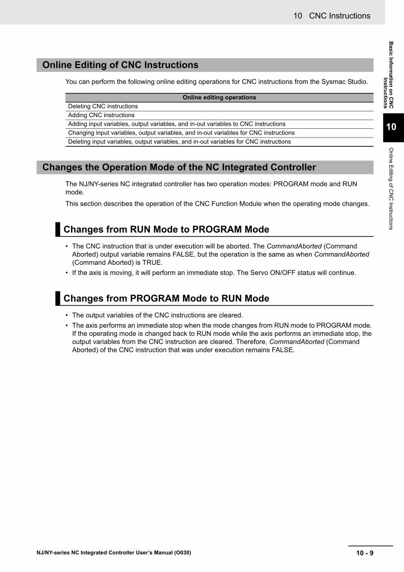
10 - 9
10 CNC Instructions
NJ/NY-series NC Integrated Controller User’s Manual (O030)
Basic In
form
ation
on
CN
CIn
structio
ns
10
Online
Ed
iting of CN
C Instructio
ns
You can perform the following online editing operations for CNC instructions from the Sysmac Studio.
The NJ/NY-series NC integrated controller has two operation modes: PROGRAM mode and RUN mode.
This section describes the operation of the CNC Function Module when the operating mode changes.
• The CNC instruction that is under execution will be aborted. The CommandAborted (Command Aborted) output variable remains FALSE, but the operation is the same as when CommandAborted (Command Aborted) is TRUE.
• If the axis is moving, it will perform an immediate stop. The Servo ON/OFF status will continue.
• The output variables of the CNC instructions are cleared.
• The axis performs an immediate stop when the mode changes from RUN mode to PROGRAM mode. If the operating mode is changed back to RUN mode while the axis performs an immediate stop, the output variables from the CNC instruction are cleared. Therefore, CommandAborted (Command Aborted) of the CNC instruction that was under execution remains FALSE.
Online Editing of CNC Instructions
Online editing operations
Deleting CNC instructions
Adding CNC instructions
Adding input variables, output variables, and in-out variables to CNC instructions
Changing input variables, output variables, and in-out variables for CNC instructions
Deleting input variables, output variables, and in-out variables for CNC instructions
Changes the Operation Mode of the NC Integrated Controller
Changes from RUN Mode to PROGRAM Mode
Changes from PROGRAM Mode to RUN Mode
10 CNC Instructions
10 - 10 NJ/NY-series NC Integrated Controller User’s Manual (O030)
11 - 1
11
NJ/NY-series NC Integrated Controller User’s Manual (O030)
This section describes the variables and instructions for the CNC Function Module.
11-1 Variables . . . . . . . . . . . . . . . . . . . . . . . . . . . . . . . . . . . . . . . . . . . . . . . . . . . . 11-211-1-1 Input Variables for CNC Instructions . . . . . . . . . . . . . . . . . . . . . . . . . . . . . . .11-2
11-1-2 Output Variables for CNC Instructions . . . . . . . . . . . . . . . . . . . . . . . . . . . . . .11-8
11-1-3 In-Out Variables for CNC Instructions . . . . . . . . . . . . . . . . . . . . . . . . . . . . . .11-8
11-2 List of CNC Instructions . . . . . . . . . . . . . . . . . . . . . . . . . . . . . . . . . . . . . . . 11-911-2-1 Common Commands . . . . . . . . . . . . . . . . . . . . . . . . . . . . . . . . . . . . . . . . . . .11-9
11-2-2 CNC Coordinate System Commands . . . . . . . . . . . . . . . . . . . . . . . . . . . . . . .11-9
11-3 PDO Mapping . . . . . . . . . . . . . . . . . . . . . . . . . . . . . . . . . . . . . . . . . . . . . . . .11-1111-3-1 Required Objects . . . . . . . . . . . . . . . . . . . . . . . . . . . . . . . . . . . . . . . . . . . . .11-11
11-3-2 Objects Required for Specific Instructions . . . . . . . . . . . . . . . . . . . . . . . . . .11-12
Variables and Instructions
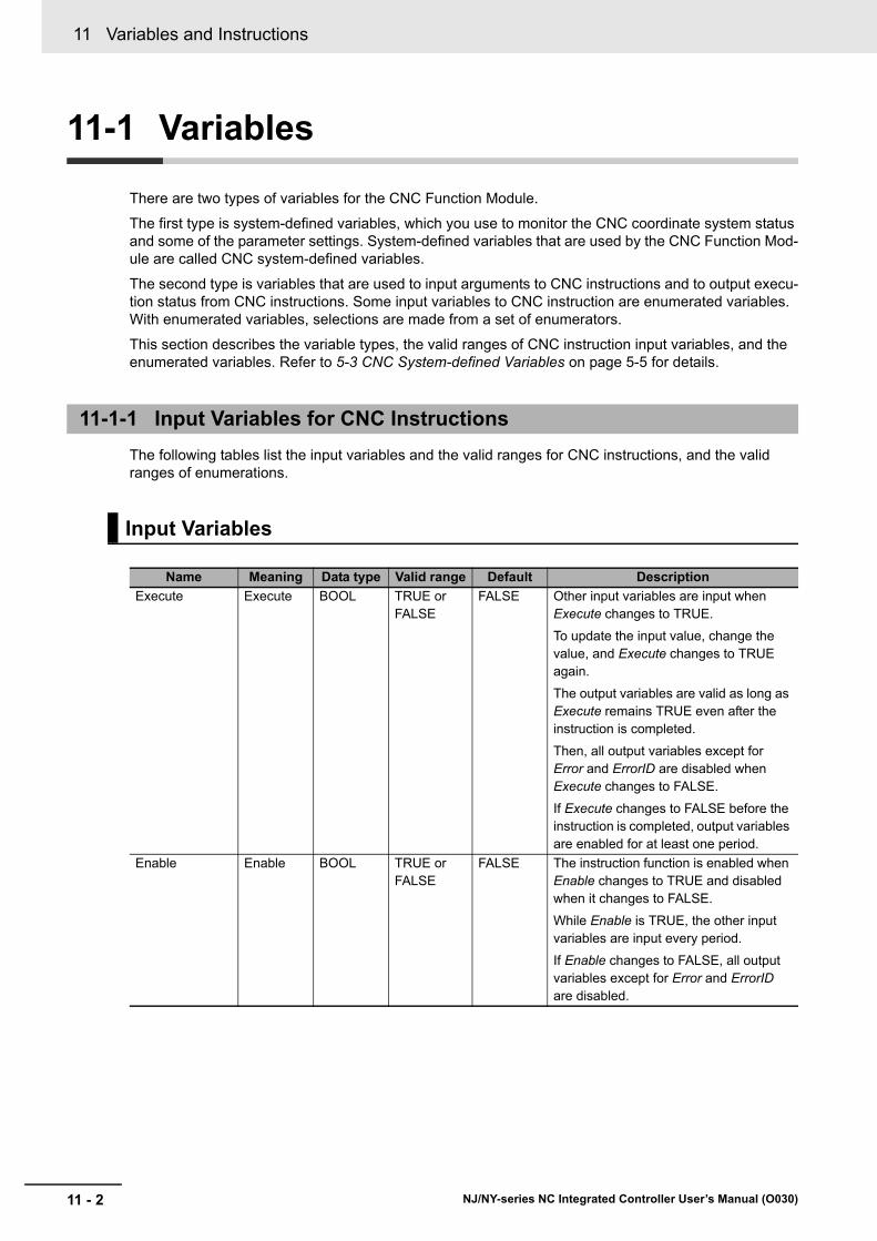
11 Variables and Instructions
11 - 2 NJ/NY-series NC Integrated Controller User’s Manual (O030)
11-1 Variables
There are two types of variables for the CNC Function Module.
The first type is system-defined variables, which you use to monitor the CNC coordinate system status and some of the parameter settings. System-defined variables that are used by the CNC Function Mod-ule are called CNC system-defined variables.
The second type is variables that are used to input arguments to CNC instructions and to output execu-tion status from CNC instructions. Some input variables to CNC instruction are enumerated variables. With enumerated variables, selections are made from a set of enumerators.
This section describes the variable types, the valid ranges of CNC instruction input variables, and the enumerated variables. Refer to 5-3 CNC System-defined Variables on page 5-5 for details.
The following tables list the input variables and the valid ranges for CNC instructions, and the valid ranges of enumerations.
11-1-1 Input Variables for CNC Instructions
Input Variables
Name Meaning Data type Valid range Default Description
Execute Execute BOOL TRUE or FALSE
FALSE Other input variables are input when Execute changes to TRUE.
To update the input value, change the value, and Execute changes to TRUE again.
The output variables are valid as long as Execute remains TRUE even after the instruction is completed.
Then, all output variables except for Error and ErrorID are disabled when Execute changes to FALSE.
If Execute changes to FALSE before the instruction is completed, output variables are enabled for at least one period.
Enable Enable BOOL TRUE or FALSE
FALSE The instruction function is enabled when Enable changes to TRUE and disabled when it changes to FALSE.
While Enable is TRUE, the other input variables are input every period.
If Enable changes to FALSE, all output variables except for Error and ErrorID are disabled.

11 - 3
11 Variables and Instructions
NJ/NY-series NC Integrated Controller User’s Manual (O030)
11-1 V
ariables
11
11-1-1 Input Variables for C
NC
Instructions
This section describes the valid ranges of input variables to CNC instructions.
Refer to individual instruction descriptions for the valid ranges for each instruction.
BOOL Input Variables
Any value other than FALSE is treated as TRUE. For this reason, out-of-range errors do not occur.
Enumerated (ENUM) Input Variables
Values that are outside of the valid range will result in an error.
Input Variables Given as Full Range, Positive Number, or Negative Number
Operation when an input variable is set inside or outside the valid range is described in the following table.
Valid Range of Input Variables
Name Meaning Valid rangeOutside maximum
value range
Outside the minimum value range (excluding
0)
Velocity Target Velocity
0, (-1 ≤ and ≤ -Maximum velocity) or (1 ≤ and ≤ Maxi-
mum velocity)*1
Fixed to the maxi-mum velocity for a positive number,
and to the −maxi-mum velocity for a negative number.
Set to 1 pulse/s when pos-itive number, and -1 pulse/s when negative
number.*2
Acceleration Accelera-tion/Decel-eration Rate
0 or
(0.004 ≤ and ≤ Maximum acceleration/deceleration
rate)*3
Maximum Accelera-tion/Deceleration Rate
If the accelera-tion/deceleration
time*4 is less than 125 μs, it is always fixed at 125 μs.
Fixed to 0.004pulse/s2
when positive number.
If the acceleration/decel-eration time is greater than 250 s, it will always be fixed at 250 s.
Error when negative num-ber.
Position
(Feed axis specification)
Command Position
(ABS speci-fication)
(0xFFFFFF8000000000) ≤
and
<(0x0000007FFFFFFFFF+
1)*5
Error Values outside of the mini-mum value range do not occur.
Travel Dis-tance
(INC speci-fication)
(0xFFFFFF0000000001) ≤
and
≤ (0x000000FFFFFFFFFF)
Error Values outside of the mini-mum value range do not occur.
Position
(Spindle specifi-cation)
Command Position
(ABS speci-fication)
-253 ≤
and
< 253*-1*6
Error Values outside of the mini-mum value range do not occur.
Travel Dis-tance
(INC) speci-fication
(0xFFFFFF0000000001) ≤
and
≤ (0x000000FFFFFFFFFF)
Error Values outside of the mini-mum value range do not occur.
+-
Outside the maximum value range
Outside the minimum value range (excluding 0)
Outside the maximum value range

11 Variables and Instructions
11 - 4 NJ/NY-series NC Integrated Controller User’s Manual (O030)
*1. The upper limit of the Maximum Velocity in the CNC motor parameter is 128,849,018,820 pulses/min.
*2. If a negative number or 0 is specified when a negative number or 0 is not included in the valid range, an error occurs.
*3. The upper limit of the Maximum Acceleration/Deceleration Rate in the CNC motor parameter is 3,200,000,000,000 pulses/s.
*4. Calculated as follows: Acceleration/deceleration time = (| Target velocity - Current command velocity |)/Ac-celeration/deceleration rate
*5. Position must be an absolute value in pulses and within a signed 40-bit range.
*6. Position must be an absolute value in pulses and within a signed 54-bit range. Additionally, one travel dis-tance must be less than a signed 40-bit.

11 - 5
11 Variables and Instructions
NJ/NY-series NC Integrated Controller User’s Manual (O030)
11-1 V
ariables
11
11-1-1 Input Variables for C
NC
Instructions
This is a list of ENUM data used by input variables to CNC instructions.
An enumeration input variable is not actually set to the number, but to the enumerator.
Enumerations
Data type Valid range DescriptionVariable of appro-priate instruction(Variable name)
_eCNC_PARAMETER_NUMBER _cncRotaryVel := 0
_cncDryRunVel := 1
_cncFeedholdTime := 2
_cncInPosTime := 3
_cncSwLmtCtrl := 4
_cncToolShape := 5
_cncToolRadiusCompCtrl := 6
_cncSpindleOrientation := 7
_cncSingleBlockOption := 8
_cncWorkOffset1 := 20
_cncWorkOffset2 := 21
_cncWorkOffset3 := 22
_cncWorkOffset4 := 23
_cncWorkOffset5 := 24
_cncWorkOffset6 := 25
_cncRefPoint1 := 30
_cncRefPoint2:= 31
_cncRefPoint3 := 32
_cncRefPoint4 := 33
_cncFELmt := 50
_cncChkFELmt := 51
_cncSwLmt := 52
_cncPosiSwLmt := 53
_cncNegaSwLmt := 54
_cncInPosCycle := 55
_cncInPosRange := 56
_cncRapidFeedAcc := 57
_cncSkipVel := 58
_cncPIDCtr := 59
_cncCompScaling := 100
Specifies the parameter to write.
0: Rotary Axis Velocity
1: Dry Run Velocity
2: Feed Hold Acceleration Decelera-tion Time
3: In-position Check Time
4: Software Overtravel Limit Opera-tion Control
5: Tool Shape Data
6: Tool Radius Compensation Con-trol
7: Spindle Axis Orientation Opera-tion
8: Single Block Execution Option
20: 1st Work Coordinate System Offset
21: 2nd Work Coordinate System Offset
22: 3rd Work Coordinate System Offset
23: 4th Work Coordinate System Offset
24: 5th Work Coordinate System Offset
25: 6th Work Coordinate System Offset
30: 1st Reference Point
31: 2nd Reference Point
32: 3rd Reference Point
33: 4th Reference Point
50: Following Error Over Value
51: Following Error Warning Value
52: Software Overtravel Limit
53: Positive Software Overtravel Limit
54: Negative Software Overtravel Limit
55: Number of In-position Continu-ance Cycles
56: In-position Range
57: Rapid Feed Accelera-tion/Deceleration
58: Skip Velocity
59: PID Control
100: Compensation Scaling
ParameterNumber
(Parameter Number)
_eCNC_MOVE_MODE _cncAbsolute := 0
_cncRelative := 1
Selects the travel method.
0: Absolute positioning
1: Relative positioning
MoveMode
(Travel Mode)
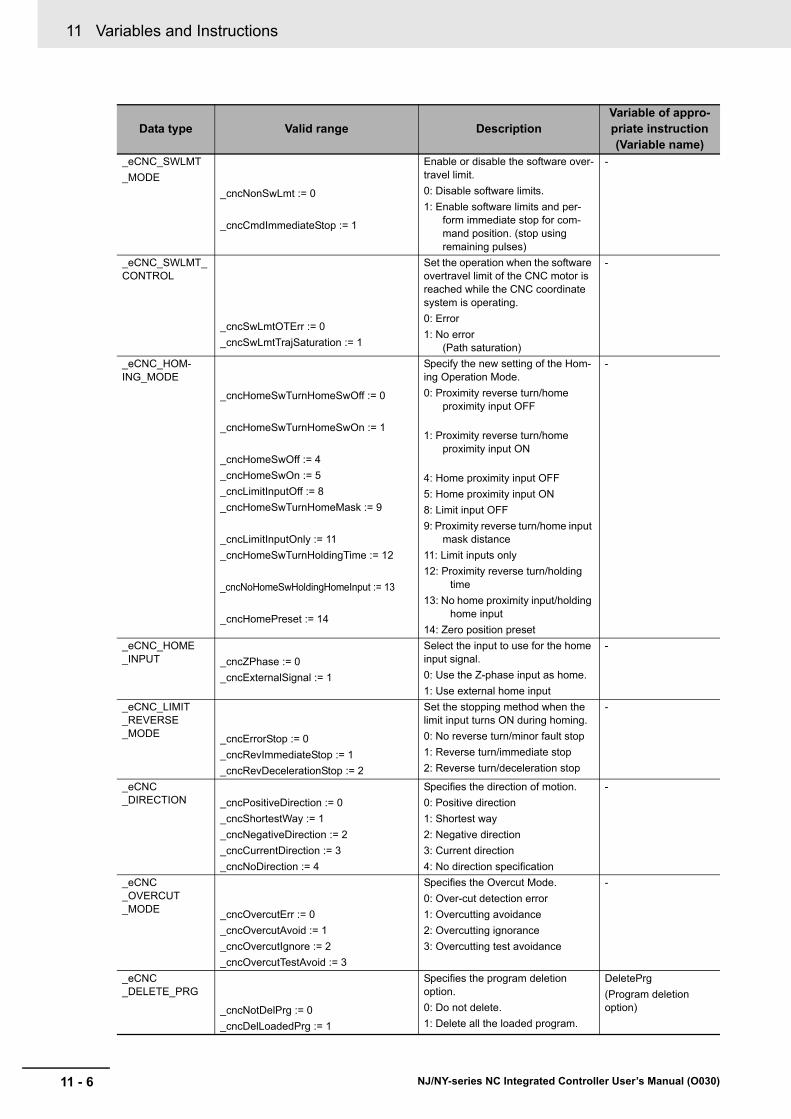
11 Variables and Instructions
11 - 6 NJ/NY-series NC Integrated Controller User’s Manual (O030)
_eCNC_SWLMT
_MODE
_cncNonSwLmt := 0
_cncCmdImmediateStop := 1
Enable or disable the software over-travel limit.
0: Disable software limits.
1: Enable software limits and per-form immediate stop for com-mand position. (stop using remaining pulses)
-
_eCNC_SWLMT_CONTROL
_cncSwLmtOTErr := 0
_cncSwLmtTrajSaturation := 1
Set the operation when the software overtravel limit of the CNC motor is reached while the CNC coordinate system is operating.
0: Error
1: No error (Path saturation)
-
_eCNC_HOM-ING_MODE
_cncHomeSwTurnHomeSwOff := 0
_cncHomeSwTurnHomeSwOn := 1
_cncHomeSwOff := 4
_cncHomeSwOn := 5
_cncLimitInputOff := 8
_cncHomeSwTurnHomeMask := 9
_cncLimitInputOnly := 11
_cncHomeSwTurnHoldingTime := 12
_cncNoHomeSwHoldingHomeInput := 13
_cncHomePreset := 14
Specify the new setting of the Hom-ing Operation Mode.
0: Proximity reverse turn/home proximity input OFF
1: Proximity reverse turn/home proximity input ON
4: Home proximity input OFF
5: Home proximity input ON
8: Limit input OFF
9: Proximity reverse turn/home input mask distance
11: Limit inputs only
12: Proximity reverse turn/holding time
13: No home proximity input/holding home input
14: Zero position preset
-
_eCNC_HOME_INPUT _cncZPhase := 0
_cncExternalSignal := 1
Select the input to use for the home input signal.
0: Use the Z-phase input as home.
1: Use external home input
-
_eCNC_LIMIT_REVERSE_MODE _cncErrorStop := 0
_cncRevImmediateStop := 1
_cncRevDecelerationStop := 2
Set the stopping method when the limit input turns ON during homing.
0: No reverse turn/minor fault stop
1: Reverse turn/immediate stop
2: Reverse turn/deceleration stop
-
_eCNC_DIRECTION _cncPositiveDirection := 0
_cncShortestWay := 1
_cncNegativeDirection := 2
_cncCurrentDirection := 3
_cncNoDirection := 4
Specifies the direction of motion.
0: Positive direction
1: Shortest way
2: Negative direction
3: Current direction
4: No direction specification
-
_eCNC_OVERCUT_MODE _cncOvercutErr := 0
_cncOvercutAvoid := 1
_cncOvercutIgnore := 2
_cncOvercutTestAvoid := 3
Specifies the Overcut Mode.
0: Over-cut detection error
1: Overcutting avoidance
2: Overcutting ignorance
3: Overcutting test avoidance
-
_eCNC_DELETE_PRG
_cncNotDelPrg := 0
_cncDelLoadedPrg := 1
Specifies the program deletion option.
0: Do not delete.
1: Delete all the loaded program.
DeletePrg
(Program deletion option)
Data type Valid range DescriptionVariable of appro-priate instruction(Variable name)

11 - 7
11 Variables and Instructions
NJ/NY-series NC Integrated Controller User’s Manual (O030)
11-1 V
ariables
11
11-1-1 Input Variables for C
NC
Instructions
_eCNC_SINGLE_BLOCK_OPTION _cncSingleBlockOptionDisable := 0
_cncSingleBlockOptionEnable := 1
Specifies the Single block execu-tion option.
0: Disabled Single block execution option.
1: Enabled Single block execution option.
-
Data type Valid range DescriptionVariable of appro-priate instruction(Variable name)
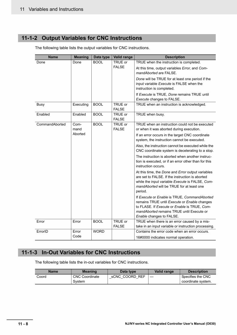
11 Variables and Instructions
11 - 8 NJ/NY-series NC Integrated Controller User’s Manual (O030)
The following table lists the output variables for CNC instructions.
The following table lists the in-out variables for CNC instructions.
11-1-2 Output Variables for CNC Instructions
Name Meaning Data type Valid range Description
Done Done BOOL TRUE or FALSE
TRUE when the instruction is completed.
At this time, output variables Error, and Com-mandAborted are FALSE.
Done will be TRUE for at least one period if the input variable Execute is FALSE when the instruction is completed.
If Execute is TRUE, Done remains TRUE until Execute changes to FALSE.
Busy Executing BOOL TRUE or FALSE
TRUE when an instruction is acknowledged.
Enabled Enabled BOOL TRUE or FALSE
TRUE when busy.
CommandAborted Com-mand Aborted
BOOL TRUE or FALSE
TRUE when an instruction could not be executed or when it was aborted during execution.
If an error occurs in the target CNC coordinate system, the instruction cannot be executed.
Also, the instruction cannot be executed while the CNC coordinate system is decelerating to a stop.
The instruction is aborted when another instruc-tion is executed, or if an error other than for this instruction occurs.
At this time, the Done and Error output variables are set to FALSE. If the instruction is aborted while the input variable Execute is FALSE, Com-mandAborted will be TRUE for at least one period.
If Execute or Enable is TRUE, CommandAborted remains TRUE until Execute or Enable changes to FLASE. If Execute or Enable is TRUE, Com-mandAborted remains TRUE until Execute or Enable changes to FALSE.
Error Error BOOL TRUE or FALSE
TRUE when there is an error caused by a mis-take in an input variable or instruction processing.
ErrorID Error Code
WORD Contains the error code when an error occurs.
16#0000 indicates normal operation.
11-1-3 In-Out Variables for CNC Instructions
Name Meaning Data type Valid range Description
Coord CNC Coordinate System
_sCNC_COORD_REF --- Specifies the CNC coordinate system.

11 - 9
11 Variables and Instructions
NJ/NY-series NC Integrated Controller User’s Manual (O030)
11-2 List o
f CN
C In
struc
tion
s
11
11-2-1 Com
mon C
omm
ands
11-2 List of CNC Instructions
CNC instructions are classified into the following two types.
This section describes the common instructions for the CNC Function Module.
In the Classification column, Administration indicates a non-motion system instruction, and Motion indi-cates a motion system instruction.
This section describes instructions to perform multi-axis coordinated control for the CNC Function Mod-ule.
In the Classification column, Administration indicates a non-motion system instruction, and Motion indi-cates a motion system instruction.
Type Outline
Common commands Common instructions of CNC Function Module
CNC coordinate system com-mands
Instructions for CNC Function Module to control and monitor the CNC coordi-nate system.
11-2-1 Common Commands
Instruction Instruction name OutlineClassifica-
tion
CNC_Write Write CNC Setting Overwrites CNC parameters. Administra-tion
CNC_Read Read CNC Setting Reads CNC parameters. Administra-tion
CNC_LoadProgramFile Load NC Program The CNC_LoadProgramFile instruc-tion loads an NC program from an external non-volatile memory into the main memory.
Administra-tion
11-2-2 CNC Coordinate System Commands
Instruction Instruction name OutlineClassifica-
tion
CNC_CoordControl CNC Coordinate Sys-tem NC Control
Executes the NC program, and starts controlling the specified CNC coordi-nate system.
Administra-tion
CNC_CoordCatchMCode Catch M Code Receives the M code output from the NC program using the sequence con-trol program.
Administra-tion
CNC_CoordResetMCode Reset M Code Resets the M code output from the NC program.
Administra-tion
CNC_CoordReset CNC Coordinate Sys-tem Error Reset
The CNC_CoordReset instruction clears the error detected in the speci-fied CNC coordinate system.
Administra-tion
CNC_CoordStop CNC Coordinate Sys-tem Stop
The CNC_CoordStop instruction decel-erates all the currently running CNC motors in the specified CNC coordinate system to a stop.
Motion

11 Variables and Instructions
11 - 10 NJ/NY-series NC Integrated Controller User’s Manual (O030)
CNC_CoordImmediateStop CNC Coordinate Sys-tem Immediate Stop
The CNC_CoordImmediateStop instruction immediately stops all the currently running CNC motors in the specified CNC coordinate system.
Motion
CNC_CoordHalt CNC Coordinate Sys-tem Halt
Stops the currently running CNC motors assigned to the positioning axes in the specified CNC coordinate system.
Motion
CNC_Power Power Servo Switches the driver status to the Run Enable status.
Administra-tion
CNC_MoveJog Jog Performs jogging according to the specified target velocity.
Motion
CNC_Home Home The CNC_Home instruction operates the Servomotor to determine home using the limit signals, home proximity signal, and home signal.
Motion
CNC_HomeWithParameter Homing with Parame-ters
Sets the homing parameter and oper-ates the Servomotor to determine home. It uses the limit signals, home proximity signal, and home signal.
Motion
CNC_Move Positioning Performs absolute positioning or rela-tive positioning.
Motion
CNC_SyncMoveAbsolute Cyclic Synchronous Absolute Positioning
Outputs the specified target position cyclically.
Motion
CNC_SpindleGo Spindle Control Starts running the CNC motor assigned to the spindle axis.
Motion
Instruction Instruction name OutlineClassifica-
tion

11 - 11
11 Variables and Instructions
NJ/NY-series NC Integrated Controller User’s Manual (O030)
11-3 PD
O M
app
ing
11
11-3-1 Required O
bjects
11-3 PDO Mapping
You need to map the objects required for the CNC functions you will use on process data communica-tions.
The PDO map lists all of the objects that are registered in advance.
There are objects that are required for Positioning axes and objects required for Spindle axis of CNC motor type.
If even one of the required objects is not set, a Required Process Data Object Not Set error (error code: 3780 hex) occurs.
The following object settings must be set to use instructions of the CNC Function Module for the posi-tioning axis:
The following object settings must be set to use instructions of the CNC Function Module for the spindle axis:
11-3-1 Required Objects
Positioning Axis
Input/output Function Process data
Output Control word 6040 hex
Target position 607A hex
Input Status word 6041 hex
Current position 6064 hex
Spindle Axis
Input/output Function Process data
Output Control word 6040 hex
Target velocity 60FF hex
Input Status word 6041 hex
Current position 6064 hex
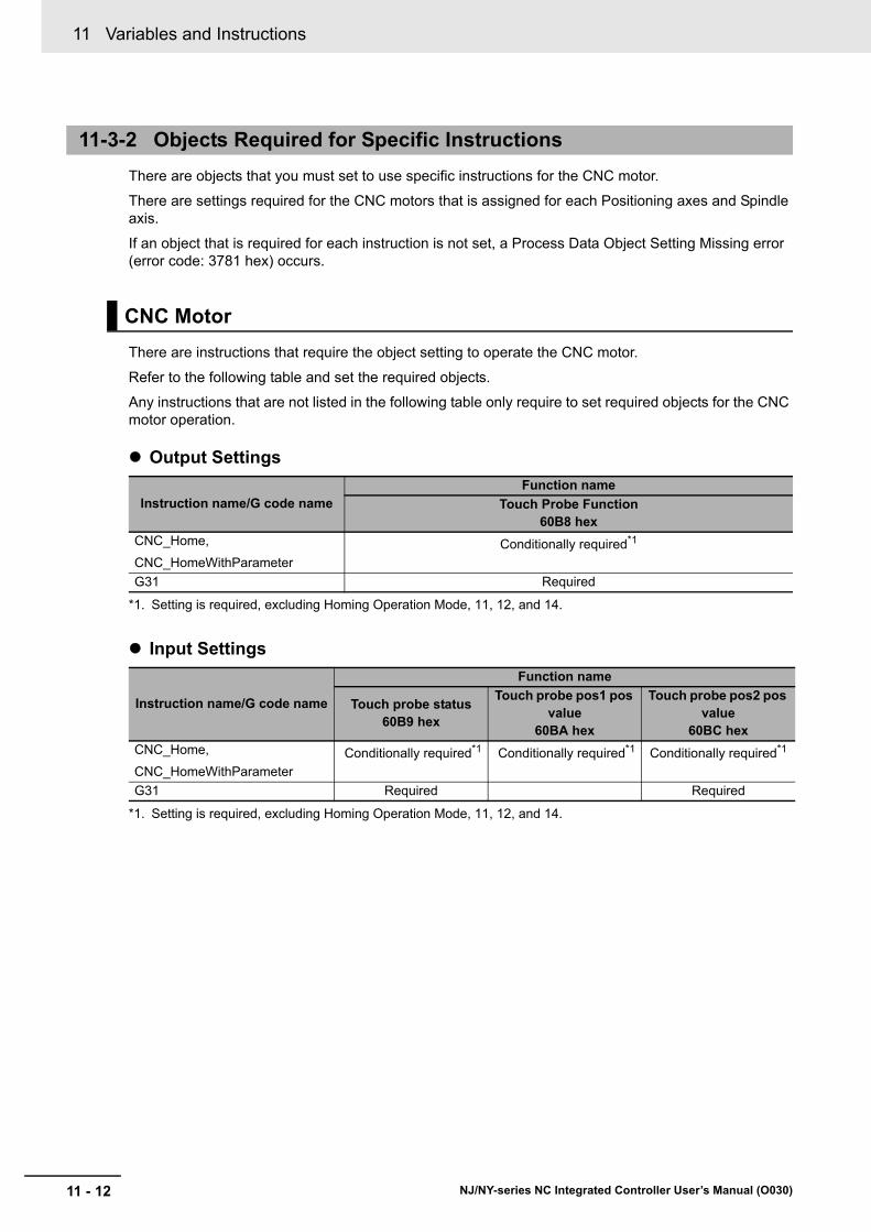
11 Variables and Instructions
11 - 12 NJ/NY-series NC Integrated Controller User’s Manual (O030)
There are objects that you must set to use specific instructions for the CNC motor.
There are settings required for the CNC motors that is assigned for each Positioning axes and Spindle axis.
If an object that is required for each instruction is not set, a Process Data Object Setting Missing error (error code: 3781 hex) occurs.
There are instructions that require the object setting to operate the CNC motor.
Refer to the following table and set the required objects.
Any instructions that are not listed in the following table only require to set required objects for the CNC motor operation.
Output Settings
Input Settings
11-3-2 Objects Required for Specific Instructions
CNC Motor
Instruction name/G code nameFunction name
Touch Probe Function60B8 hex
CNC_Home,
CNC_HomeWithParameter
Conditionally required*1
*1. Setting is required, excluding Homing Operation Mode, 11, 12, and 14.
G31 Required
Instruction name/G code name
Function name
Touch probe status60B9 hex
Touch probe pos1 pos value
60BA hex
Touch probe pos2 pos value
60BC hex
CNC_Home,
CNC_HomeWithParameter
Conditionally required*1
*1. Setting is required, excluding Homing Operation Mode, 11, 12, and 14.
Conditionally required*1 Conditionally required*1
G31 Required Required

12 - 1
12
NJ/NY-series NC Integrated Controller User’s Manual (O030)
This section describes the instructions for the CNC Function Module to perform the control of the CNC coordinate system or the CNC motors.
CNC_CoordControl . . . . . . . . . . . . . . . . . . . . . . . . . . . . . . . . . . . . . . . . . . . 12-2
CNC_CoordCatchMCode . . . . . . . . . . . . . . . . . . . . . . . . . . . . . . . . . . . . . . 12-43
CNC_CoordResetMCode . . . . . . . . . . . . . . . . . . . . . . . . . . . . . . . . . . . . . . 12-59
CNC_CoordReset . . . . . . . . . . . . . . . . . . . . . . . . . . . . . . . . . . . . . . . . . . . . 12-64
CNC_CoordStop . . . . . . . . . . . . . . . . . . . . . . . . . . . . . . . . . . . . . . . . . . . . . 12-68
CNC_CoordImmediateStop . . . . . . . . . . . . . . . . . . . . . . . . . . . . . . . . . . . . 12-72
CNC_CoordHalt . . . . . . . . . . . . . . . . . . . . . . . . . . . . . . . . . . . . . . . . . . . . . 12-76
CNC_Power . . . . . . . . . . . . . . . . . . . . . . . . . . . . . . . . . . . . . . . . . . . . . . . . . 12-80
CNC_MoveJog . . . . . . . . . . . . . . . . . . . . . . . . . . . . . . . . . . . . . . . . . . . . . . 12-83
CNC_Home . . . . . . . . . . . . . . . . . . . . . . . . . . . . . . . . . . . . . . . . . . . . . . . . . 12-90
CNC_HomeWithParameter . . . . . . . . . . . . . . . . . . . . . . . . . . . . . . . . . . . . 12-94
CNC_Move . . . . . . . . . . . . . . . . . . . . . . . . . . . . . . . . . . . . . . . . . . . . . . . . . 12-97
CNC_SyncMoveAbsolute . . . . . . . . . . . . . . . . . . . . . . . . . . . . . . . . . . . . 12-108
CNC_SpindleGo . . . . . . . . . . . . . . . . . . . . . . . . . . . . . . . . . . . . . . . . . . . . 12-113
CNC Coordinate System Instruc-tions

12 CNC Coordinate System Instructions
12 - 2 NJ/NY-series NC Integrated Controller User’s Manual (O030)
CNC_CoordControl
Executes the NC program, and starts controlling the specified CNC coordinate system.
Output Variable Update Timing
Instruction Name FB/FUN Graphic expression ST expression
CNC_CoordControl CNC Coor-dinate Sys-tem NC Control
FB CNC_CoordControl_instance CNC_CoordControl_instance (
Coord :=parameter,
ControlInputs :=parameter,
ControlOutputs :=parameter,
Enable :=parameter,
Enabled =>parameter,
Busy =>parameter,
Error =>parameter,
ErrorID =>parameter
);
Variables
Input Variables
Name Meaning Data type Valid range Default Description
Enable Execute BOOL TRUE or FALSE
FALSE Executes the instruction while this vari-able is TRUE.
Output Variables
Name Meaning Data type Valid range Description
Enabled Enable BOOL TRUE or FALSE
TRUE when the CNC coordinate system is being con-trolled.
Busy Executing BOOL TRUE or FALSE
TRUE when the instruction is acknowledged.
Error Error BOOL TRUE or FALSE
TRUE while there is an error.
ErrorID Error Code WORD *1
*1. Refer to Section 15 Troubleshooting.
Contains the error code when an error occurs.
A value of 16#0000 indicates normal execution.
Name Timing for changing to TRUE Timing for changing to FALSE
Enabled When the instruction is started. • After one period when Enable is FALSE.
• When Error changes to TRUE.
Busy When Enable changes to TRUE. • When Error changes to TRUE.
• When Enable changes to FALSE.
Error When there is an error in the execution condi-tions or input parameters for the instruction.
When the error is cleared.
--------------------------------
Coord CoordControlInputs ControlInputsControlOutputs ControlOutputsEnable Enabled
BusyError
ErrorID
CNC_CoordControl

12 - 3
12 CNC Coordinate System Instructions
NJ/NY-series NC Integrated Controller User’s Manual (O030)
CN
C_C
oo
rdC
on
trol
12
Variab
les
_sCNC_CTR_INPUTS_REF
In-Out Variables
Name Meaning Data type Valid range Description
Coord CNC Coordi-nate System
_sCNC_COORD_REF
--- Specifies the CNC coordinate system.
ControlInputs Numerical Control Input
_sCNC_CTR_INPUTS_REF
--- Specifies the interface from the PLC to the NC.
Create a user-defined variable with a data type of _sCNC_CTR_IN-PUTS_REF.
ControlOutputs Numerical Control Output
_sCNC_CTR_OUTPUTS_REF
--- Specifies the interface from the NC to the PLC.
Create a user-defined variable with a data type of _sCNC_CTR_OUT-PUTS_REF.
Name Meaning Data typeValid range
Function
CycleStart Cycle Start BOOL TRUE or FALSE
Starts the execution of the NC program when this
variable changes to TRUE.*1
SingleBlock Single Block Valid
BOOL TRUE or FALSE
Executes the NC program on a block-by-block basis if this variable changes to TRUE when the
execution of the NC program starts.*2,*3
MachineLock Machine Lock Valid
BOOL TRUE or FALSE
Executes the NC program in MachineLock if this variable changes to TRUE when the execution of
the NC program starts.* 2
DryRun Dry Run Valid
BOOL TRUE or FALSE
Executes the NC program in DryRun if this variable changes to TRUE when the execution of the NC
program starts.*2
AuxiliaryLock M Code Lock Valid
BOOL TRUE or FALSE
Executes the NC program in AuxiliaryLock if this variable changes to TRUE when the execution of the
NC program starts.*2
FeedHold Feed Hold BOOL TRUE or FALSE
Interrupts the NC program when this variable
changes to TRUE.*1
Reset Reset BOOL TRUE or FALSE
Interrupts the NC program that is currently being executed, and initializes its status when this vari-
able changes to TRUE.*1
BackTrace Back Trace Enabled
BOOL TRUE or FALSE
Traces the NC program in Hold backward when this variable changes to TRUE and CycleStart
(Cycle Start) is started.*3
OptionalInputs Optional Input
ARRAY
[0..31] OF BOOL
TRUE or FALSE
Inputs an optional signal to the NC program.
0 bit: Signal for Optional Stop (M01)
1 to 31 bit: Signal for Option block skip
ProgramNo NC Pro-gram Num-ber
UINT 1 to 9999 Specifies the NC program number.*2

12 CNC Coordinate System Instructions
12 - 4 NJ/NY-series NC Integrated Controller User’s Manual (O030)
FeedrateVelFactor Feedrate Override Factor
LREAL 0 to 500 Specifies the feedrate override factor.
The valid range of the override factor is 0.01 to 500.00.
Values of 500.00 or more are treated as 500 and values less than 0.01 (including negative values) are treated as 0.01.
The override factor is 0 only when 0 is specified.
The unit is [%].
FeedrateVelFac-torChangeRate
Feedrate Override Change Rate
LREAL 0 to 500 Specifies the feedrate override change rate.
The valid range of the override change rate is 0.01 to 500.00.
Values of 500.00 or more are treated as 500 and values less than 0.01 (including negative values) are treated as 0.01.
The override change rate is 0 only when 0 is spec-ified.
The unit is [%/s].
SpindleVelFactor Spindle Velocity Override Factor
LREAL 0 to 500 Specifies the spindle velocity override factor.
The valid range of the override factor is 0.01 to 500.00.
Values of 500.00 or more are treated as 500 and values less than 0.01 (including negative values) are treated as 0.01.
The override factor is 0 only when 0 is specified.
The unit is [%].
*1. The inputs to send a command for CNC Coordinate System NC Control are CycleStart, Reset, and FeedHold. If these variables are input simultaneously, the priority order conforms to Reset > FeedHold > CycleStart.
*2. SingleBlock, MachineLock, AuxiliaryLock, DryRun, and ProgramNo are CycleStart input options in Standby. The NC program runs in accordance with these options while Operating.
*3. SingleBlock and BackTrace are CycleStart input options in Hold.
Name Meaning Data typeValid range
Function
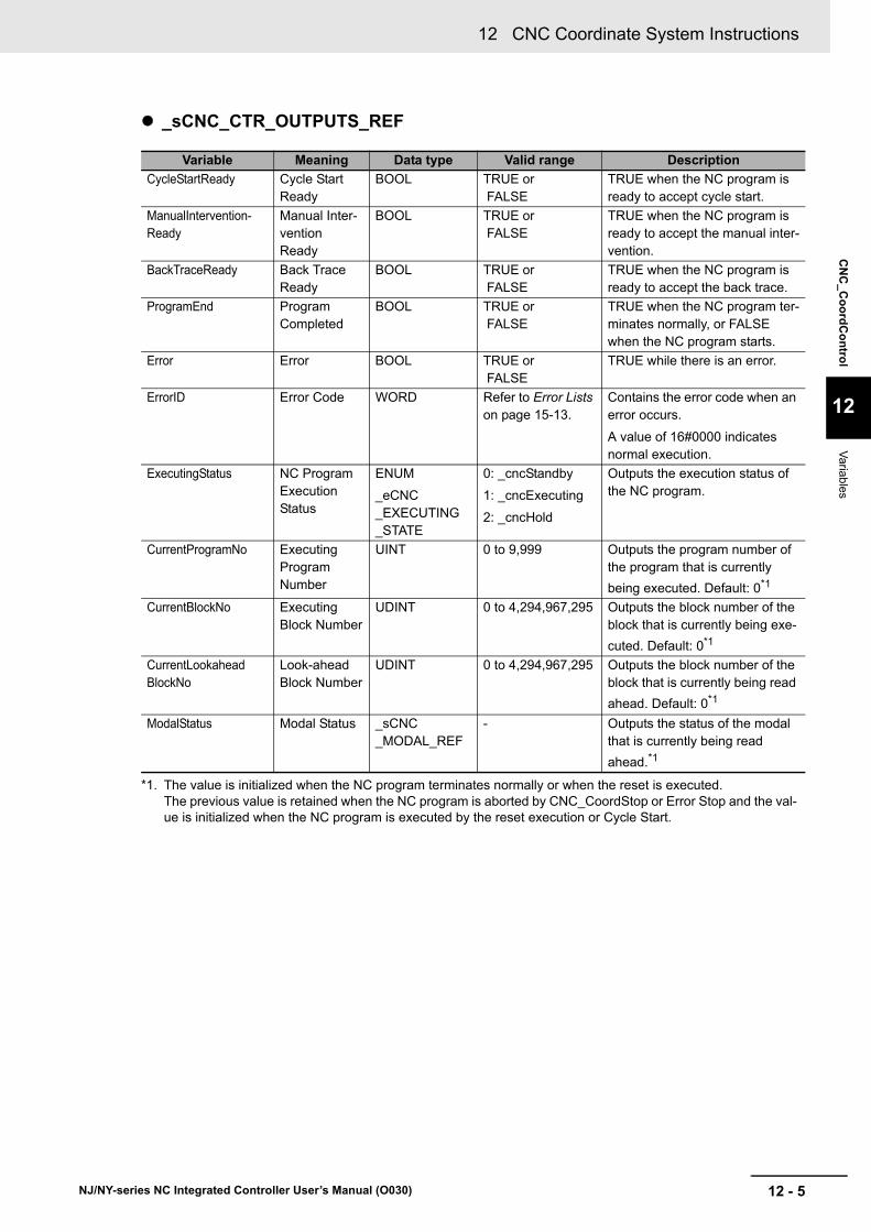
12 - 5
12 CNC Coordinate System Instructions
NJ/NY-series NC Integrated Controller User’s Manual (O030)
CN
C_C
oo
rdC
on
trol
12
Variab
les
_sCNC_CTR_OUTPUTS_REF
Variable Meaning Data type Valid range Description
CycleStartReady Cycle Start Ready
BOOL TRUE or FALSE
TRUE when the NC program is ready to accept cycle start.
ManualIntervention-Ready
Manual Inter-vention Ready
BOOL TRUE or FALSE
TRUE when the NC program is ready to accept the manual inter-vention.
BackTraceReady Back Trace Ready
BOOL TRUE or FALSE
TRUE when the NC program is ready to accept the back trace.
ProgramEnd Program Completed
BOOL TRUE or FALSE
TRUE when the NC program ter-minates normally, or FALSE when the NC program starts.
Error Error BOOL TRUE or FALSE
TRUE while there is an error.
ErrorID Error Code WORD Refer to Error Lists on page 15-13.
Contains the error code when an error occurs.
A value of 16#0000 indicates normal execution.
ExecutingStatus NC Program Execution Status
ENUM
_eCNC_EXECUTING_STATE
0: _cncStandby
1: _cncExecuting
2: _cncHold
Outputs the execution status of the NC program.
CurrentProgramNo Executing Program Number
UINT 0 to 9,999 Outputs the program number of the program that is currently
being executed. Default: 0*1
*1. The value is initialized when the NC program terminates normally or when the reset is executed. The previous value is retained when the NC program is aborted by CNC_CoordStop or Error Stop and the val-ue is initialized when the NC program is executed by the reset execution or Cycle Start.
CurrentBlockNo Executing Block Number
UDINT 0 to 4,294,967,295 Outputs the block number of the block that is currently being exe-
cuted. Default: 0*1
CurrentLookaheadBlockNo
Look-ahead Block Number
UDINT 0 to 4,294,967,295 Outputs the block number of the block that is currently being read
ahead. Default: 0*1
ModalStatus Modal Status _sCNC_MODAL_REF
- Outputs the status of the modal that is currently being read
ahead.*1

12 CNC Coordinate System Instructions
12 - 6 NJ/NY-series NC Integrated Controller User’s Manual (O030)
_sCNC_MODAL_REF
Variable Meaning Data type Valid range Description
NonModal NonModal State
DWORD 0 to FFFFFFFF Outputs the G code modal status that is currently being executed.
Default: 0*1
Bit0: G04
Bit1: G28
Bit2: G30
Bit3: G31
Bit4: G52
Bit5: G53
Motion Motion USINT 0 to 3 Outputs the G code modal status that is currently being executed.
Default: 1*1
0: G00
1: G01
2: G02
3: G03
Plane Plane USINT 0 to 2 Outputs the G code modal status that is currently being executed.
Default: 0*1
0: G17
1: G18
2: G19
Distance Distance USINT 0 to 1 Outputs the G code modal status that is currently being executed.
Default: 0*1
0: G90
1: G91
Units Unit USINT 0 to 1 Outputs the G code modal status that is currently being executed. The default value follows the carte-sian axis command unit of the CNC
coordinate system parameter.*1
0: G20
1: G21
ToolRadius Tool Compen-sation
USINT 0 to 2 Outputs the G code modal status that is currently being executed.
Default: 0*1
0: G40
1: G41
2: G42
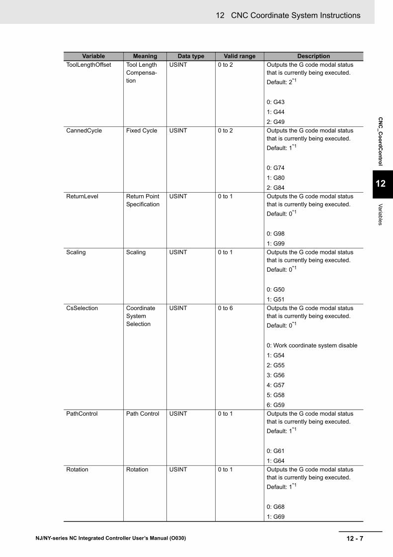
12 - 7
12 CNC Coordinate System Instructions
NJ/NY-series NC Integrated Controller User’s Manual (O030)
CN
C_C
oo
rdC
on
trol
12
Variab
les
ToolLengthOffset Tool Length Compensa-tion
USINT 0 to 2 Outputs the G code modal status that is currently being executed.
Default: 2*1
0: G43
1: G44
2: G49
CannedCycle Fixed Cycle USINT 0 to 2 Outputs the G code modal status that is currently being executed.
Default: 1*1
0: G74
1: G80
2: G84
ReturnLevel Return Point Specification
USINT 0 to 1 Outputs the G code modal status that is currently being executed.
Default: 0*1
0: G98
1: G99
Scaling Scaling USINT 0 to 1 Outputs the G code modal status that is currently being executed.
Default: 0*1
0: G50
1: G51
CsSelection Coordinate System Selection
USINT 0 to 6 Outputs the G code modal status that is currently being executed.
Default: 0*1
0: Work coordinate system disable
1: G54
2: G55
3: G56
4: G57
5: G58
6: G59
PathControl Path Control USINT 0 to 1 Outputs the G code modal status that is currently being executed.
Default: 1*1
0: G61
1: G64
Rotation Rotation USINT 0 to 1 Outputs the G code modal status that is currently being executed.
Default: 1*1
0: G68
1: G69
Variable Meaning Data type Valid range Description
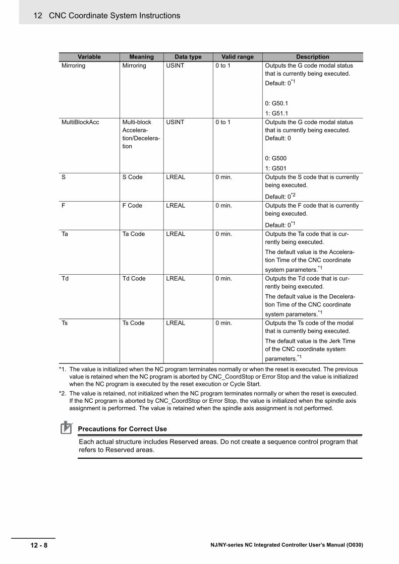
12 CNC Coordinate System Instructions
12 - 8 NJ/NY-series NC Integrated Controller User’s Manual (O030)
Precautions for Correct Use
Each actual structure includes Reserved areas. Do not create a sequence control program that refers to Reserved areas.
Mirroring Mirroring USINT 0 to 1 Outputs the G code modal status that is currently being executed.
Default: 0*1
0: G50.1
1: G51.1
MultiBlockAcc Multi-block Accelera-tion/Decelera-tion
USINT 0 to 1 Outputs the G code modal status that is currently being executed. Default: 0
0: G500
1: G501
S S Code LREAL 0 min. Outputs the S code that is currently being executed.
Default: 0*2
F F Code LREAL 0 min. Outputs the F code that is currently being executed.
Default: 0*1
Ta Ta Code LREAL 0 min. Outputs the Ta code that is cur-rently being executed.
The default value is the Accelera-tion Time of the CNC coordinate
system parameters.*1
Td Td Code LREAL 0 min. Outputs the Td code that is cur-rently being executed.
The default value is the Decelera-tion Time of the CNC coordinate
system parameters.*1
Ts Ts Code LREAL 0 min. Outputs the Ts code of the modal that is currently being executed.
The default value is the Jerk Time of the CNC coordinate system
parameters.*1
*1. The value is initialized when the NC program terminates normally or when the reset is executed. The previous value is retained when the NC program is aborted by CNC_CoordStop or Error Stop and the value is initialized when the NC program is executed by the reset execution or Cycle Start.
*2. The value is retained, not initialized when the NC program terminates normally or when the reset is executed. If the NC program is aborted by CNC_CoordStop or Error Stop, the value is initialized when the spindle axis assignment is performed. The value is retained when the spindle axis assignment is not performed.
Variable Meaning Data type Valid range Description

12 - 9
12 CNC Coordinate System Instructions
NJ/NY-series NC Integrated Controller User’s Manual (O030)
CN
C_C
oo
rdC
on
trol
12
Functions
This instruction updates the values of ControlInputs (Numerical Control Inputs) and ControlOutputs (Numerical Control Outputs) in-out variables that are used to control NC programs in the CNC coordi-nate system. When Enabled is TRUE, the values of ControlInputs (Numerical Control Inputs) and Con-trolOutputs (Numerical Control Outputs) are updated with this instruction.
The instruction can execute the NC program loaded into the NC program buffer. To load data in the NC program buffer, download the NC program created with Sysmac Studio in advance, or load the NC pro-gram saved in the SD Memory Card using the CNC_LoadProgramFile instruction.
Only one NC program can be executed simultaneously in a CNC coordinate system.
The figure below shows the relationships between this instruction’s operations and the CNC coordinate system status.
*1. Except MovingOnHold status and when G74, G84, or M19 is executing. If Reset is TRUE when G74, G84, or M19 is completed, the program is reset at that timing.
*2. Program abort refers to any one of the following states.
• FeedHold execution*3
• M00 or M01 execution
• 1-row execution completion by single block
• Back trace completion
*3. Except when G74, G84, or M19 is executing. If FeedHold (Feed Hold) is TRUE when G74, G84, or M19 is completed, the program is set to Feed Hold at that timing.
• When CycleStart (Cycle Start) is TRUE while Standby and CycleStartReady (Cycle Start Ready) is TRUE, the status transitions to Executing, which starts executing the NC program based on Pro-gramNo (Program Number). However, the transition is not performed when Reset or FeedHold is TRUE.
• When Execute NC program is completed or Reset is changed to TRUE, the status transitions to Standby.
• When FeedHold (Feed Hold) is changed to TRUE during the execution of NC program or when another program is interrupted due to an event, the status transitions to Hold.
• When the status is Hold and ManualInterventionReady (Manual Intervention Ready) is TRUE, the manual intervention is available. Refer to the explanation of Manual Intervention on page 12-11 for details.
• When the Hold and BackTraceReady (Back Trace Ready) is TRUE, BackTrace is available. Refer to the explanation of Back Trace of NC Program on page 12-13 for details.
• When CycleStart (Cycle Start) is TRUE while the status is Hold and CycleStartReady (Cycle Start Ready) is TRUE, the status transitions to Executing again, which restarts Execute NC program.
Functions
Moving Standby Stopping Error
Executing
Program endCycle start execution
Error occursExecution of CNC_CoordStopReset execution*1
MovingOnHold HoldExecution of CNC_MOVE, CNC_SyncMoveAbsolute
Completion of motion or execution of CNC_CoordHalt
Cycle start execution
Abort of program*2

12 CNC Coordinate System Instructions
12 - 10 NJ/NY-series NC Integrated Controller User’s Manual (O030)
Additional Information
• The execution of NC Program is available when CycleStartReady (Cycle Start Ready) is TRUE. All the following conditions must be satisfied.
a)All the positioning axes and the spindle axis in the CNC coordinate system are set to Servo ON.
b)All the positioning axes in the CNC coordinate system have the home defined. (Excluding the spindle)
c) The CNC coordinate system is in Standby or Hold, and axes other than the spindle axis are stopped.
• When the status transitions to Executing, operation starts after in-position check was com-pleted.
• When deceleration stop is set by FeedHold, only all the positioning axes in the CNC coordi-nate system decelerate to a stop. If the multi-block acceleration/deceleration is disabled, deceleration stop are performed based on the feed hold acceleration/deceleration time of the CNC coordinate system parameter. If the multi-block acceleration/deceleration is disabled, deceleration stop are performed based on the maximum acceleration/deceleration rate of each CNC motor parameter.
• When immediate stop is set by Reset, only all the positioning axes in the CNC coordinate system stop immediately. When immediate stop is set by CNC_CoordStop or error detection, all the positioning axes and spindle axis in the CNC coordinate system stop immediately.
Override
This is a function to change the override of the feedrate or spindle velocity in the execution of an NC program.
Changing the override value changes the velocity during the execution of an NC program.
For feedrate override, the override change rate during moving can be controlled by modifying the feedrate override change rate. Setting the feedrate override change rate to a positive value changes the override gradually to the target feedrate override value. Setting the feedrate override change rate to 0 changes the override immediately to the target override value.
When the instruction is not operating at feedrate, the override immediately changes to the target override value regardless of the feedrate override change rate.
Precautions for Correct Use
• The feedrate override is an override value for the feed rate (F). Therefore, for example, the feedrate override does not operate for the G code instructions such as G00 that operates at a rapid feedrate.
• When the feedrate override value is changed while the Multi-block Acceleration/Deceleration is enabled (G500 is enabled), the changed value does not apply to the operations that have been read ahead at the time of change. When the override value is changed, the value applies to the operations that have not been read ahead.
• The override value is disabled for the tapping operation (G74, G84) and the tapping opera-tion is performed at an override value of 100%.
Instruction Details

12 - 11
12 CNC Coordinate System Instructions
NJ/NY-series NC Integrated Controller User’s Manual (O030)
CN
C_C
oo
rdC
on
trol
12
Functions
Manual Intervention
If FeedHold changes to TRUE during execution of an NC program, the NC program decelerates to a stop. When the deceleration stop is completed, the status changes to Hold.
In the Hold status, you can execute some of the other CNC instructions. This is called a manual intervention.
Refer to A-4 Instructions for Which Multi-execution Is Supported on page A-15 for the instructions that enable the manual intervention.
Manual intervention is a function used to temporarily stop the NC program for troubleshooting pur-poses when machine troubles occurred during the processing operation by NC program.
Also, troubleshooting is performed, and continuation is executed by CycleStart. Continuation refers to restarting the execution of the NC program after the CNC coordinate system returned to the posi-tion at which the CNC coordinate system stopped by FeedHold.
Executing continuation performs first to return to the position at which the CNC coordinate system stopped by FeedHold when CycleStart (Cycle Start) is changed to TRUE after manual intervention was completed. It then restarts the execution of the NC program. The return operation is performed independently for each CNC motor, therefore, the tool is positioned in the CNC coordinate system based on a non-linear interpolation manner. The maximum velocity is applied to each CNC motor for the return operation.
Precautions for Safe Use
Be sure to correctly perform manual intervention depending on the working direction and work-piece shape. Otherwise, the workpiece, machine, or tools may be damaged.
Y
X
(2)
(3)
(1)
Returns to point (1) when CycleStart changes to TRUE. The path is not based on the linear interpolation.
The NC program restarts from point (1).
Workpiece
Manual intervention
Decelerates to a stop by FeedHold at point (1).

12 CNC Coordinate System Instructions
12 - 12 NJ/NY-series NC Integrated Controller User’s Manual (O030)
Precautions for Correct Use
To execute the manual intervention, all of the following conditions must be satisfied.
• The Multi-block Acceleration/Deceleration is enabled (G500 is enabled).
• The feed hold is stopped while G01, G02, or G03 is being executed.
Additionally, the above conditions are satisfied when ManualInterventionReady (Manual Intervention Ready) of ControlOutputs (Numerical Control Outputs) is TRUE. The manual intervention program is interlocked using ManualInterventionReady (Manual Intervention Ready). When the CNC instruction for the manual intervention is started if ManualInterven-tionReady (Manual Intervention Ready) is FALSE, the CNC instruction changes to Com-mandAborted (Command Aborted).
(2)
(1)
Y
X
Returns to point (1) when CycleStart changes to TRUE. The path is not based on the linear interpolation.
Workpiece
Manual intervention
Decelerates to a stop by FeedHold at point (1).

12 - 13
12 CNC Coordinate System Instructions
NJ/NY-series NC Integrated Controller User’s Manual (O030)
CN
C_C
oo
rdC
on
trol
12
Functions
Back Trace of NC Program
If FeedHold changes to TRUE during execution of an NC program, the NC program decelerates to a stop. When the deceleration stop is completed, the status transitions to the Hold (Holding) status.
If BackTrace (Back Trace) changes to TRUE and CycleStart (Cycle Start) changes from FALSE to TRUE in the Hold (Holding) status, the back trace can be executed. The back trace function exe-cutes the NC program in backward direction from the stop position. The status transitions to Execut-ing while the back trace is being executed.
However, back trace cannot be executed for the G00 (Positioning) operation of the NC program. When the NC program contains the G00 operation, it stops before the G00 operation.
If the back trace is executed in a status in which the operation is performed using an instruction that enables the manual intervention after the Hold (Holding) status, the back trace execution is dis-abled.
BackTrace is available only for operations of the positioning axis. It is not available for operations of the spindle axis.
The G or M code that is previous executed is not re-executed; therefore, ModalStatus holds the sta-tus that is set at BackTrace execution, and read-ahead processing is stopped.
However, only CurrentBlockNo is updated (rewound).
When the NC program returns to the point at which BackTrace was re-executed by CycleStart after BackTrace was executed once, the update of ModalStatus restarts.
Precautions for Correct Use
To execute the backtrace, all of the following conditions must be satisfied.
• The Multi-block Acceleration/Deceleration is enabled (G500 is enabled).
• The feedhold is stopped while G01, G02, or G03 is being executed.
• The manual intervention is never executed in the Hold status.
Additionally, when BackTraceReady (Back Trace Ready) of ControlOutputs (Numerical Con-trol Outputs) is TRUE, the above conditions are satisfied. The back trace execution program is interlocked using BackTraceReady (Back Trace Ready). If the back trace is executed when BackTraceReady (Back Trace Ready) is FALSE, the execution is disabled.
The execution of back trace is not applied to the single block execution.
Test of NC Program
Created NC program may be checked whether it can operate the machine as intended by executing the NC program before machining workpieces.
You can check the program either by actually operating the machine or, or by displaying the current position without operating the machine.
• Dry run
This is a test run to operate the machine with workpieces removed to check tool operations.
The machine runs at the dry run velocity specified using the relevant CNC coordinate system parameter regardless of the velocity specified by the NC program.
If DryRun (Dry Run Enable) changes to TRUE when the execution of the NC program starts, the dry run is executed.
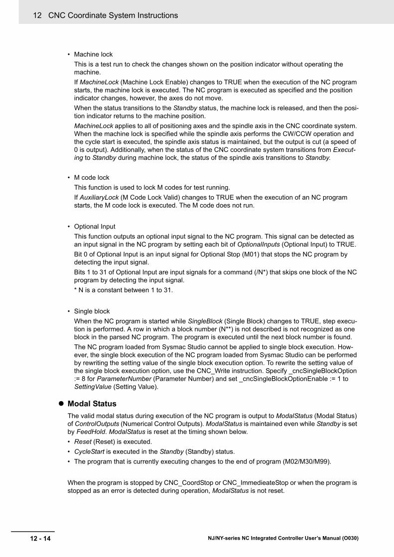
12 CNC Coordinate System Instructions
12 - 14 NJ/NY-series NC Integrated Controller User’s Manual (O030)
• Machine lock
This is a test run to check the changes shown on the position indicator without operating the machine.
If MachineLock (Machine Lock Enable) changes to TRUE when the execution of the NC program starts, the machine lock is executed. The NC program is executed as specified and the position indicator changes, however, the axes do not move.
When the status transitions to the Standby status, the machine lock is released, and then the posi-tion indicator returns to the machine position.
MachineLock applies to all of positioning axes and the spindle axis in the CNC coordinate system. When the machine lock is specified while the spindle axis performs the CW/CCW operation and the cycle start is executed, the spindle axis status is maintained, but the output is cut (a speed of 0 is output). Additionally, when the status of the CNC coordinate system transitions from Execut-ing to Standby during machine lock, the status of the spindle axis transitions to Standby.
• M code lock
This function is used to lock M codes for test running.
If AuxiliaryLock (M Code Lock Valid) changes to TRUE when the execution of an NC program starts, the M code lock is executed. The M code does not run.
• Optional Input
This function outputs an optional input signal to the NC program. This signal can be detected as an input signal in the NC program by setting each bit of OptionalInputs (Optional Input) to TRUE.
Bit 0 of Optional Input is an input signal for Optional Stop (M01) that stops the NC program by detecting the input signal.
Bits 1 to 31 of Optional Input are input signals for a command (/N*) that skips one block of the NC program by detecting the input signal.
* N is a constant between 1 to 31.
• Single block
When the NC program is started while SingleBlock (Single Block) changes to TRUE, step execu-tion is performed. A row in which a block number (N**) is not described is not recognized as one block in the parsed NC program. The program is executed until the next block number is found.
The NC program loaded from Sysmac Studio cannot be applied to single block execution. How-ever, the single block execution of the NC program loaded from Sysmac Studio can be performed by rewriting the setting value of the single block execution option. To rewrite the setting value of the single block execution option, use the CNC_Write instruction. Specify _cncSingleBlockOption := 8 for ParameterNumber (Parameter Number) and set _cncSingleBlockOptionEnable := 1 to SettingValue (Setting Value).
Modal Status
The valid modal status during execution of the NC program is output to ModalStatus (Modal Status) of ControlOutputs (Numerical Control Outputs). ModalStatus is maintained even while Standby is set by FeedHold. ModalStatus is reset at the timing shown below.
• Reset (Reset) is executed.
• CycleStart is executed in the Standby (Standby) status.
• The program that is currently executing changes to the end of program (M02/M30/M99).
When the program is stopped by CNC_CoordStop or CNC_ImmedieateStop or when the program is stopped as an error is detected during operation, ModalStatus is not reset.

12 - 15
12 CNC Coordinate System Instructions
NJ/NY-series NC Integrated Controller User’s Manual (O030)
CN
C_C
oo
rdC
on
trol
12
Functions
A timing chart for the operation of the CNC_CoordControl instruction is shown below.
While Enabled is TRUE, CoordControl is updated.
You cannot re-execute CNC instructions with enable-type inputs.
Only one instance can enable this instruction in the CNC coordinate system.
When this instruction already has an instance enabled in the CNC coordinate system, if an attempt is made to enable this instruction of another instance in the same CNC coordinate system, the instruction is enabled for the subsequent instance.
Refer to A-4 Instructions for Which Multi-execution Is Supported on page A-15 for details on multi-exe-cution of CNC instructions.
If this instruction cannot be executed, an error occurs, and Error will change to TRUE.
You can find out the cause of the error by referring to the value output by ErrorID (Error Code).
Timing Chart When Error Occurs
Error Code
Refer to Section 15 Troubleshooting for errors that occur in instructions.
Timing Chart
Re-execution of CNC Instructions
Multi-execution of CNC Instructions
Error
Enable
Enabled
Busy
Error
ErrorID
CoordControl.CycleStartReady
CoordControl.CycleStart
16#0000
Standby StandbyExecutingCoordControl.ExecutingStatus
Enable
Enabled
Busy
Error
ErrorID Error code16#0000

12 CNC Coordinate System Instructions
12 - 16 NJ/NY-series NC Integrated Controller User’s Manual (O030)
This section shows sample programming about the NC program execution control method.
The minimum settings required for this sample programming are given below.
CNC Coordinate System Settings
Logical CNC motor configuration
Positioning axis configuration
Spindle axis use CNC motor
Use the CNC_CoordControl (CNC Coordinate System NC Control) instruction to execute the following NC program that has been loaded using the CNC_LoadProgramFile (Load NC Program) instruction.
NC Program
Sample Programming
Parameter Settings
CNC coordinate system
Logical CNC motor con-figuration
CNC coordinate system 0
3
CNC coordinate system
Positioning axis CNC motor number
Positioning axis config-uration CNC motor
Positioning axis assignment
CNC coordinate system 0
CNC motor P0 CNC motor 0 X-axis
CNC coordinate system 0
CNC motor P1 CNC motor 1 Y-axis
CNC coordinate system 0
CNC motor P2 CNC motor 2 Z-axis
CNC coordinate system
Spindle axis use CNC motor
CNC coordinate system 0
CNC motor 3
Operation Example
// File name: NCProg1.txt// Program number: 300N00 G17 G91 F500N10 G00 X10 Y10N11 G01 X40N12 Y20N13 X-40N14 Y-20N15 M30

12 - 17
12 CNC Coordinate System Instructions
NJ/NY-series NC Integrated Controller User’s Manual (O030)
CN
C_C
oo
rdC
on
trol
12
Sam
ple Prog
ramm
ing
Operation Pattern 1 (NC Program Execution)
1 Turning ON the Operation Start Switch
When you turn ON the operation start switch, CNC coordinate system 0 operates in accordance with the NC program.
Operation Pattern 2 (Single Block Execution)
1 Turning ON the Single Block Enable Switch
Turn ON the single block enable switch.
2 Turning ON the Operation Start Switch
Every time you turn ON the operation start switch, CNC coordinate system 0 operates block by block in accordance with the NC program.
Y (mm)
0
10
30
10
X (mm)
50
N11N10
N12
N13
N14
0Time
Velocity
N10
N11
Operation starts
XY

12 CNC Coordinate System Instructions
12 - 18 NJ/NY-series NC Integrated Controller User’s Manual (O030)
Operation Pattern 3 (Back Trace Execution)
1 Turning ON the Operation Start Switch
When you turn ON the operation start switch, CNC coordinate system 0 operates in accordance with the NC program.
2 Turning ON the Operation Interrupt Switch
When you turn ON the operation interrupt switch, the executing NC program pauses.
3 Turning ON the Back Trace Enable Switch
When you turn ON the operation start switch in the back trace enable switch ON status, CNC coordinate system 0 rewinds the NC program to run operations.
Operation Pattern 4 (Dry Run Execution)
1 Turning ON the Dry Run Enable Switch
Turn ON the dry run enable switch.
2 Turning ON the Operation Start Switch
When you turn ON the operation start switch, the machine lock and auxiliary function lock are enabled, and then CNC coordinate system 0 runs the NC program in the dry run mode. At this time, the command position moves, but the feedback position does not change from the machine position. The velocity also becomes the dry run velocity and the auxiliary function out-put does not operate.
Y(mm)
0
10
30
10
X(mm)
50
N11
N12
N13
Operation interrupt
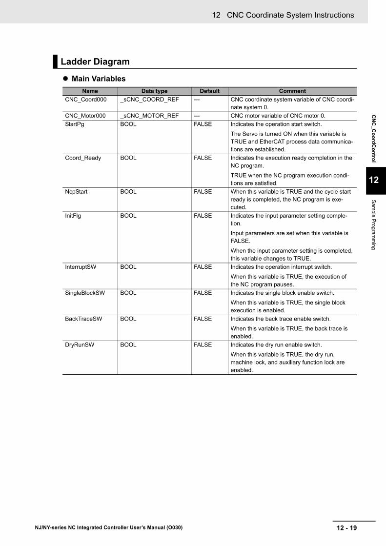
12 - 19
12 CNC Coordinate System Instructions
NJ/NY-series NC Integrated Controller User’s Manual (O030)
CN
C_C
oo
rdC
on
trol
12
Sam
ple Prog
ramm
ing
Main Variables
Ladder Diagram
Name Data type Default Comment
CNC_Coord000 _sCNC_COORD_REF --- CNC coordinate system variable of CNC coordi-nate system 0.
CNC_Motor000 _sCNC_MOTOR_REF --- CNC motor variable of CNC motor 0.
StartPg BOOL FALSE Indicates the operation start switch.
The Servo is turned ON when this variable is TRUE and EtherCAT process data communica-tions are established.
Coord_Ready BOOL FALSE Indicates the execution ready completion in the NC program.
TRUE when the NC program execution condi-tions are satisfied.
NcpStart BOOL FALSE When this variable is TRUE and the cycle start ready is completed, the NC program is exe-cuted.
InitFlg BOOL FALSE Indicates the input parameter setting comple-tion.
Input parameters are set when this variable is FALSE.
When the input parameter setting is completed, this variable changes to TRUE.
InterruptSW BOOL FALSE Indicates the operation interrupt switch.
When this variable is TRUE, the execution of the NC program pauses.
SingleBlockSW BOOL FALSE Indicates the single block enable switch.
When this variable is TRUE, the single block execution is enabled.
BackTraceSW BOOL FALSE Indicates the back trace enable switch.
When this variable is TRUE, the back trace is enabled.
DryRunSW BOOL FALSE Indicates the dry run enable switch.
When this variable is TRUE, the dry run, machine lock, and auxiliary function lock are enabled.
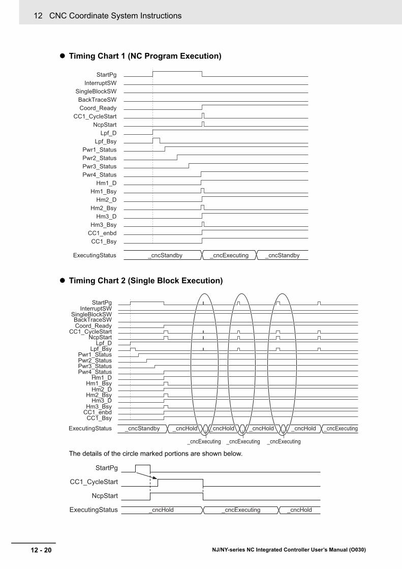
12 CNC Coordinate System Instructions
12 - 20 NJ/NY-series NC Integrated Controller User’s Manual (O030)
Timing Chart 1 (NC Program Execution)
Timing Chart 2 (Single Block Execution)
The details of the circle marked portions are shown below.
ExecutingStatus _cncStandby _cncExecuting _cncStandby
StartPgInterruptSW
SingleBlockSWBackTraceSWCoord_Ready
CC1_CycleStartNcpStart
Lpf_DLpf_Bsy
Pwr1_StatusPwr2_StatusPwr3_StatusPwr4_Status
Hm1_DHm1_Bsy
Hm2_DHm2_Bsy
Hm3_DHm3_Bsy
CC1_enbdCC1_Bsy
ExecutingStatus
StartPgInterruptSW
SingleBlockSWBackTraceSWCoord_Ready
CC1_CycleStartNcpStart
Lpf_DLpf_Bsy
Pwr1_StatusPwr2_StatusPwr3_StatusPwr4_Status
Hm1_DHm1_Bsy
Hm2_DHm2_Bsy
Hm3_DHm3_Bsy
CC1_enbdCC1_Bsy
_cncStandby _cncHold
_cncExecuting _cncExecuting _cncExecuting
_cncHold _cncHold _cncHold _cncExecuting
_cncHold _cncExecuting _cncHold
StartPg
CC1_CycleStart
NcpStart
ExecutingStatus

12 - 21
12 CNC Coordinate System Instructions
NJ/NY-series NC Integrated Controller User’s Manual (O030)
CN
C_C
oo
rdC
on
trol
12
Sam
ple Prog
ramm
ing
Timing Chart 3 (Back Trace Execution)
The details of the circle marked portions are shown below.
StartPgInterruptSW
SingleBlockSWBackTraceSWCoord_Ready
CC1_CycleStartNcpStart
LPF_DLpf_Bsy
Pwr1_StatusPwr2_StatusPwr3_StatusPwr4_Status
Hm1_DHm1_Bsy
Hm2_DHm2_Bsy
Hm3_DHm3_Bsy
CC1_enbdCC1_Bsy
ExecutingStatus _cncStandby _cncExecuting _cncExecuting _cncHold_cncHold
_cncHold _cncExecuting _cncHold
StartPg
CC1_CycleStart
NcpStart
ExecutingStatus

12 CNC Coordinate System Instructions
12 - 22 NJ/NY-series NC Integrated Controller User’s Manual (O030)
Timing Chart 4 (Dry Run Execution)
Sample Programming (NC Program Execution/Single Block Execution/Back Trace Execution)
When contact StartPg is TRUE, the first pressing process of the operation start switch is executed.
When contact StartPgWork is TRUE, check that an SD Memory Card is inserted.
After checking that an SD Memory Card is inserted, start the Load NC Program to load the NC pro-gram.
If a monitoring information error occurs during loading of the NC program, the error handler for the device (FaultHandler) is executed.
Program the FaultHandler according to the device.
StartPgDryRunSW
Coord_ReadyCC1_CycleStart
NcpStartLPF_D
Lpf_BsyPwr1_StatusPwr2_StatusPwr3_StatusPwr4_Status
Hm1_DHm1_Bsy
Hm2_DHm2_Bsy
Hm3_DHm3_Bsy
CC1_enbdCC1_Bsy
ExecutingStatus _cncStandby _cncExecuting
StartPg StartPgWork StartPgWorkS
StartPgWork _Card1Ready _Card1Access
Lpf_D
Card_OK
Card_OK
Card_OK Lpf_D
Lpf_ErrIDLpf_ErrLpf_CaLpf_BsySTRING#’NCProg1.txt’
_cncNotDelPrg
LPF
CNC_LoadProgramFile
CommandAbortedBusy
ErrorErrorID
ExecuteFileNameDeletePrg
Done
_CNC_COM.Obsr.ActiveFHandler
FaultHandlerinput output

12 - 23
12 CNC Coordinate System Instructions
NJ/NY-series NC Integrated Controller User’s Manual (O030)
CN
C_C
oo
rdC
on
trol
12
Sam
ple Prog
ramm
ing
When the Load NC Program is completed, check that the Servo Drive is in the servo ready status and set the X-axis to the Servo ON status.
When the X-axis is in the Servo ON status, check that the Servo Drive is in the servo ready status and set the Y-axis to the Servo ON status.
When the Y-axis is in the Servo ON status, check that the Servo Drive is in the servo ready status and set the Z-axis to the Servo ON status.
When the Z-axis is in the Servo ON status, check that the Servo Drive is in the servo ready status and set the spindle axis to the Servo ON status.
When the positioning axis and spindle axis are in the Servo ON status, execute homing of the X-axis.
Lpf_D
CNC_Motor000.DrvStatus.Ready
Pwr1_Status
UINT#0
PWR1
CNC_Power
StatusBusyError
ErrorID
Coord CoordEnableLogicalMotorNo
CNC_Coord000 CNC_Coord000
Pwr1_BsyPwr1_ErrPwr1_ErrID
CNC_Motor001.DrvStatus.Ready
Pwr2_Status
UINT#1
PWR2
CNC_Power
StatusBusyError
ErrorID
Coord CoordEnableLogicalMotorNo
CNC_Coord000 CNC_Coord000Pwr1_Status
Pwr2_BsyPwr2_ErrPwr2_ErrID
CNC_Motor002.DrvStatus.Ready
Pwr3_Status
UINT#2
PWR3
CNC_Power
StatusBusyError
ErrorID
Coord CoordEnableLogicalMotorNo
CNC_Coord000 CNC_Coord000Pwr2_Status
Pwr3_BsyPwr3_ErrPwr3_ErrID
CNC_Motor003.DrvStatus.Ready
Pwr4_Status
UINT#100
PWR4
CNC_Power
StatusBusyError
ErrorID
Coord CoordEnableLogicalMotorNo
CNC_Coord000 CNC_Coord000Pwr3_Status
Pwr4_BsyPwr4_ErrPwr4_ErrID
Pwr4_Status Hm1_D
Hm1_CaHm1_ErrHm1_ErrID
Hm1_Bsy
HM1
CNC_Home
DoneBusy
CommandAbortedError
ErrorID
Coord CoordExecuteLogicalMotorNo
CNC_Coord000 CNC_Coord000
UINT#0

12 CNC Coordinate System Instructions
12 - 24 NJ/NY-series NC Integrated Controller User’s Manual (O030)
After the home of the X-axis is defined, execute homing of the Y-axis.
After the home of the Y-axis is defined, execute homing of the Z-axis.
If a minor fault level error occurs in CNC coordinate system 0, the error handler for the device (FaultHandler) is executed.
Program the FaultHandler according to the device.
When the NC program execution ready is completed, Coord_Ready changes to TRUE.
When Coord_Ready is TRUE, start the execution control of the NC program.
Pwr2_Status Hm2_DHm1_D
Hm2_CaHm2_ErrHm2_ErrID
Hm2_Bsy
HM2
CNC_Home
DoneBusy
CommandAbortedError
ErrorID
Coord CoordExecuteLogicalMotorNo
CNC_Coord000 CNC_Coord000
UINT#1
Pwr3_Status Hm3_DHm2_D
Hm3_CaHm3_ErrHm3_ErrID
Hm3_Bsy
HM3
CNC_Home
DoneBusy
CommandAbortedError
ErrorID
Coord CoordExecuteLogicalMotorNo
CNC_Coord000 CNC_Coord000
UINT#2
CNC_Coord000.MFaultLvl.ActiveFHandler
FaultHandlerinput output
CNC_Coord000.Status.Ready Hm3_D
Coord_Ready CC1_Err
Coord_Ready
CC1_BusyCC1_ErrorCC1_ErrorID
Coord_Ready CC1_enbd
CNC1
CNC_CoordControl
BusyEnabled
ErrorErrorID
Coord CoordControlInputs ControlInputsControlOutputs ControlOutputsEnable
CNC_Coord000 CNC_Coord000ControlInputs
ControlOutputsControlInputsControlOutputs

12 - 25
12 CNC Coordinate System Instructions
NJ/NY-series NC Integrated Controller User’s Manual (O030)
CN
C_C
oo
rdC
on
trol
12
Sam
ple Prog
ramm
ing
When the execution control of the NC program is started, set the parameters of the CNC_Coord-Control (CNC Coordinate System NC Control) instruction.
When contact StartPg is TRUE, check that the cycle start ready is completed and start the execution of the NC program.
When contact InterruptSW is TRUE, stop the execution of the NC program.
When contact BackTraceSW is TRUE, enable the back trace.
// CNC_CoordControl parameter// Specify the NC program (No.300) that was loaded with the CNC_LoadProgramFile (Load NC Program) instruction.ControlInputs.ProgramNo :=UINT#300;ControlInputs.FeedrateVelFactor:=LREAL#300.0;ControlInputs.SpindleVelFactor:=LREAL#100.0;ControlInputs.AuxiliaryLock:=FALSE;ControlInputs.BackTrace :=FALSE;ControlInputs.DryRun :=FALSE;ControlInputs.FeedHold :=FALSE;ControlInputs.MachineLock:=FALSE;
// Change InitFlag to TRUE after setting the input parameters.InitFlg := TRUE;
// Start the NC program.NcpStart:=TRUE;
InitFlg StartPg StartPgWork NcpStartS
S
S
RStartPg
NcpStart
NcpStart ControlOutputs.CycleStartReady InitFlg CC1_CycleStart
CC1_CycleStart ControlInputs.CycleStart
ControlInputs.CycleStart
ControlOutputs.ExecutingStatus_eCNC_EXECUTING_STATE#_cncExecuting
In1ENEQ
In2
R
CC1_CycleStartR
NcpStartR
S
InterruptSW
InterruptSW
InterruptSW ControlInputs.FeedHold
ControlInputs.FeedHold
ControlOutputs.ExecutingStatus_eCNC_EXECUTING_STATE#_cncHold
In1ENEQ
In2
R
R
BackTraceSW ControlOutputs.BackTraceReady ControlInputs.BackTrace

12 CNC Coordinate System Instructions
12 - 26 NJ/NY-series NC Integrated Controller User’s Manual (O030)
When contact SingleBlockSW is TRUE, enable the single block execution.
Sample Programming (Dry Run Execution)
When contact StartPg is TRUE, the first pressing process of the operation start switch is executed.
When contact StartPgWork is TRUE, check that an SD Memory Card is inserted.
After checking that an SD Memory Card is inserted, start the Load NC Program to load the NC pro-gram.
If a monitoring information error occurs during loading of the NC program, the error handler for the device (FaultHandler) is executed.
Program the FaultHandler according to the device.
When the Load NC Program is completed, check that the Servo Drive is in the servo ready status and set the X-axis to the Servo ON status.
SingleBlockSW ControlInputs.SingleBlock
StartPg StartPgWork StartPgWorkS
StartPgWork _Card1Ready _Card1Access
Lpf_D
Card_OK
Card_OK
Card_OK Lpf_DLPF
CNC_LoadProgramFile
ErrorErrorID
Execute DoneFileName BusyDeletePrg CommandAborted_cncNotDelPrg
Lpf_ErrIDLpf_ErrLpf_CaLpf_BsySTRING#’NCProg1.txt’
_CNC_COM.Obsr.ActiveFHandler
FaultHandlerinput output
Lpf_D
CNC_Motor000.DrvStatus.Ready
Pwr1_Status
UINT#0
PWR1
CNC_Power
StatusBusyError
ErrorID
Coord CoordEnableLogicalMotorNo
CNC_Coord000 CNC_Coord000
Pwr1_BsyPwr1_ErrPwr1_ErrID
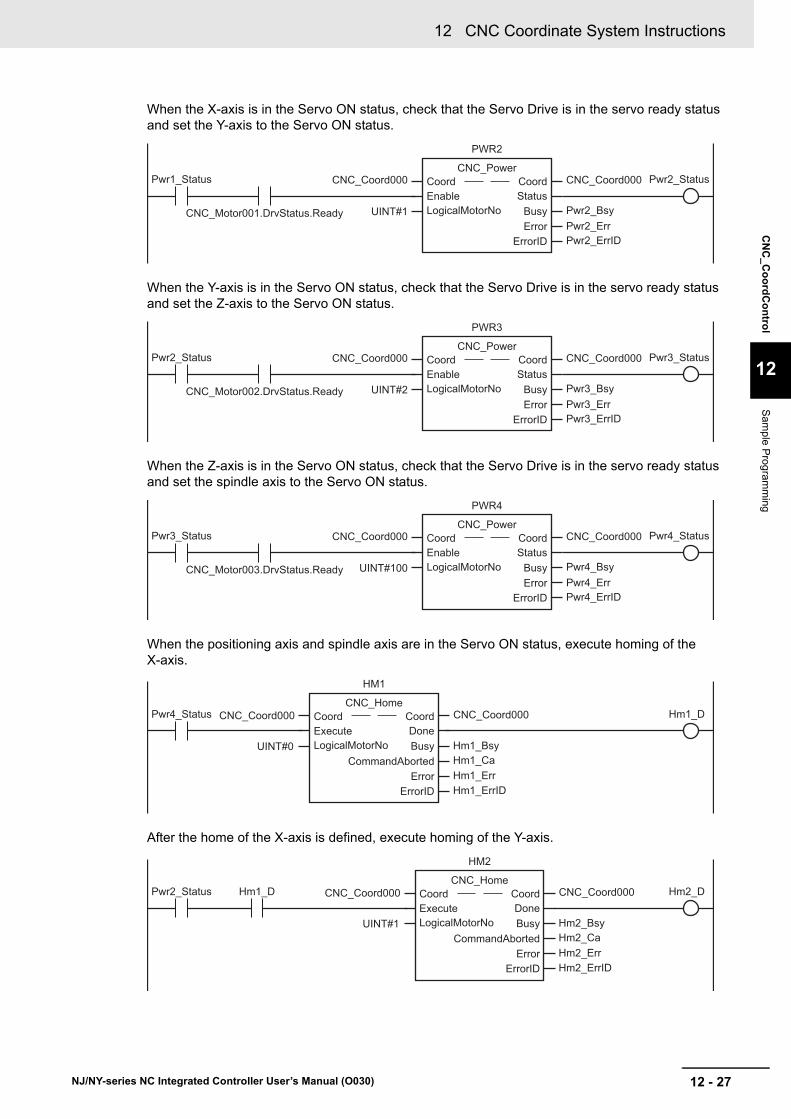
12 - 27
12 CNC Coordinate System Instructions
NJ/NY-series NC Integrated Controller User’s Manual (O030)
CN
C_C
oo
rdC
on
trol
12
Sam
ple Prog
ramm
ing
When the X-axis is in the Servo ON status, check that the Servo Drive is in the servo ready status and set the Y-axis to the Servo ON status.
When the Y-axis is in the Servo ON status, check that the Servo Drive is in the servo ready status and set the Z-axis to the Servo ON status.
When the Z-axis is in the Servo ON status, check that the Servo Drive is in the servo ready status and set the spindle axis to the Servo ON status.
When the positioning axis and spindle axis are in the Servo ON status, execute homing of the X-axis.
After the home of the X-axis is defined, execute homing of the Y-axis.
CNC_Motor001.DrvStatus.Ready
Pwr2_Status
UINT#1
PWR2
CNC_Power
StatusBusyError
ErrorID
Coord CoordEnableLogicalMotorNo
CNC_Coord000 CNC_Coord000Pwr1_Status
Pwr2_BsyPwr2_ErrPwr2_ErrID
CNC_Motor002.DrvStatus.Ready
Pwr3_Status
UINT#2
PWR3
CNC_Power
StatusBusyError
ErrorID
Coord CoordEnableLogicalMotorNo
CNC_Coord000 CNC_Coord000Pwr2_Status
Pwr3_BsyPwr3_ErrPwr3_ErrID
CNC_Motor003.DrvStatus.Ready
Pwr4_Status
UINT#100
PWR4
CNC_Power
StatusBusyError
ErrorID
Coord CoordEnableLogicalMotorNo
CNC_Coord000 CNC_Coord000Pwr3_Status
Pwr4_BsyPwr4_ErrPwr4_ErrID
Pwr4_Status Hm1_D
Hm1_CaHm1_ErrHm1_ErrID
Hm1_Bsy
HM1
CNC_Home
DoneBusy
CommandAbortedError
ErrorID
Coord CoordExecuteLogicalMotorNo
CNC_Coord000 CNC_Coord000
UINT#0
Pwr2_Status Hm2_DHm1_D
Hm2_CaHm2_ErrHm2_ErrID
Hm2_Bsy
HM2
CNC_Home
DoneBusy
CommandAbortedError
ErrorID
Coord CoordExecuteLogicalMotorNo
CNC_Coord000 CNC_Coord000
UINT#1
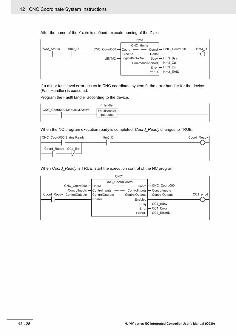
12 CNC Coordinate System Instructions
12 - 28 NJ/NY-series NC Integrated Controller User’s Manual (O030)
After the home of the Y-axis is defined, execute homing of the Z-axis.
If a minor fault level error occurs in CNC coordinate system 0, the error handler for the device (FaultHandler) is executed.
Program the FaultHandler according to the device.
When the NC program execution ready is completed, Coord_Ready changes to TRUE.
When Coord_Ready is TRUE, start the execution control of the NC program.
Pwr3_Status Hm3_DHm2_D
Hm3_CaHm3_ErrHm3_ErrID
Hm3_Bsy
HM3
CNC_Home
DoneBusy
CommandAbortedError
ErrorID
Coord CoordExecuteLogicalMotorNo
CNC_Coord000 CNC_Coord000
UINT#2
CNC_Coord000.MFaultLvl.ActiveFHandler
FaultHandlerinput output
CNC_Coord000.Status.Ready Hm3_D
Coord_Ready CC1_Err
Coord_Ready
CC1_BusyCC1_ErrorCC1_ErrorID
Coord_Ready CC1_enbd
CNC1
CNC_CoordControl
BusyEnabled
ErrorErrorID
Coord CoordControlInputs ControlInputsControlOutputs ControlOutputsEnable
CNC_Coord000 CNC_Coord000ControlInputs
ControlOutputsControlInputsControlOutputs

12 - 29
12 CNC Coordinate System Instructions
NJ/NY-series NC Integrated Controller User’s Manual (O030)
CN
C_C
oo
rdC
on
trol
12
Sam
ple Prog
ramm
ing
When the execution control of the NC program is started, set the parameters of the CNC_Coord-Control (CNC Coordinate System NC Control) instruction.
When contact StartPg is TRUE, check that the cycle start ready is completed and start the execution of the NC program.
When contact DryRunSW is TRUE, enable the dry run, machine lock, and auxiliary function lock.
// CNC_CoordControl parameter// Specify the NC program (No.300) that was loaded with the CNC_LoadProgram-File (Load NC Program) instruction.ControlInputs.ProgramNo :=UINT#300;ControlInputs.FeedrateVelFactor:=LREAL#300.0;ControlInputs.SpindleVelFactor:=LREAL#100.0;ControlInputs.AuxiliaryLock:=FALSE;ControlInputs.BackTrace :=FALSE;ControlInputs.DryRun :=FALSE;ControlInputs.FeedHold :=FALSE;ControlInputs.MachineLock:=FALSE;
// Change InitFlag to TRUE after setting the input parameters.InitFlg := TRUE;
// Start the NC program.NcpStart:=TRUE;
InitFlg StartPg StartPgWork NcpStartS
S
S
RStartPg
NcpStart
NcpStart ControlOutputs.CycleStartReady InitFlg CC1_CycleStart
CC1_CycleStart ControlInputs.CycleStart
ControlInputs.CycleStart
ControlOutputs.ExecutingStatus_eCNC_EXECUTING_STATE#_cncExecuting
In1ENEQ
In2
R
CC1_CycleStartR
NcpStartR
ControlInputs.AuxiliaryLock
ControlInputs.MachineLock
ControlInputs.DryRunDryRunSW

12 CNC Coordinate System Instructions
12 - 30 NJ/NY-series NC Integrated Controller User’s Manual (O030)
Main Variables
Structured Text (ST)
Name Data type Default Comment
CNC_Coord000 _sCNC_COORD_REF --- CNC coordinate system variable of CNC coordi-nate system 0.
CNC_Motor000 _sCNC_MOTOR_REF --- CNC motor variable of CNC motor 0.
StartPg BOOL FALSE Indicates the operation start switch.
The Servo is turned ON when this variable is TRUE and EtherCAT process data communica-tions are established.
Coord_Ready BOOL FALSE Indicates the execution ready completion the NC program.
TRUE when the NC program execution condi-tions are satisfied.
NcpStart BOOL FALSE When this variable is TRUE and the cycle start ready is completed, the NC program is exe-cuted.
InitFlg BOOL FALSE Indicates the input parameter setting comple-tion.
Input parameters are set when this variable is FALSE.
When the input parameter setting is completed, this variable changes to TRUE.
InterruptSW BOOL FALSE Indicates the operation interrupt switch.
When this variable is TRUE, the execution of the NC program pauses.
SingleBlockSW BOOL FALSE Indicates the single block enable switch.
When this variable is TRUE, the single block execution is enabled.
BackTraceSW BOOL FALSE Indicates the back trace enable switch.
When this variable is TRUE, the back trace is enabled.
DryRunSW BOOL FALSE Indicates the dry run enable switch.
When this variable is TRUE, the dry run, machine lock, and auxiliary function lock are enabled.

12 - 31
12 CNC Coordinate System Instructions
NJ/NY-series NC Integrated Controller User’s Manual (O030)
CN
C_C
oo
rdC
on
trol
12
Sam
ple Prog
ramm
ing
Timing Chart 1 (NC Program Execution)
Timing Chart 2 (Single Block Execution)
The details of the circle marked portions are shown below.
ExecutingStatus _cncStandby _cncExecuting _cncStandby
StartPgInterruptSW
SingleBlockSWBackTraceSWCoord_Ready
CC1_CycleStartNcpStart
Lpf_DLpf_Bsy
Pwr1_StatusPwr2_StatusPwr3_StatusPwr4_Status
Hm1_DHm1_Bsy
Hm2_DHm2_Bsy
Hm3_DHm3_Bsy
CC1_enbdCC1_Bsy
ExecutingStatus
StartPgInterruptSW
SingleBlockSWBackTraceSWCoord_Ready
CC1_CycleStartNcpStart
Lpf_DLpf_Bsy
Pwr1_StatusPwr2_StatusPwr3_StatusPwr4_Status
Hm1_DHm1_Bsy
Hm2_DHm2_Bsy
Hm3_DHm3_Bsy
CC1_enbdCC1_Bsy
_cncStandby _cncHold
_cncExecuting _cncExecuting _cncExecuting
_cncHold _cncHold _cncHold _cncExecuting
_cncHold _cncExecuting _cncHold
StartPg
CC1_CycleStart
NcpStart
ExecutingStatus

12 CNC Coordinate System Instructions
12 - 32 NJ/NY-series NC Integrated Controller User’s Manual (O030)
Timing Chart 3 (Back Trace Execution)
The details of the circle marked portions are shown below.
Timing Chart 4 (Dry Run Execution)
StartPgInterruptSW
SingleBlockSWBackTraceSWCoord_Ready
CC1_CycleStartNcpStart
LPF_DLpf_Bsy
Pwr1_StatusPwr2_StatusPwr3_StatusPwr4_Status
Hm1_DHm1_Bsy
Hm2_DHm2_Bsy
Hm3_DHm3_Bsy
CC1_enbdCC1_Bsy
ExecutingStatus _cncStandby _cncExecuting _cncExecuting _cncHold_cncHold
_cncHold _cncExecuting _cncHold
StartPg
CC1_CycleStart
NcpStart
ExecutingStatus
StartPgDryRunSW
Coord_ReadyCC1_CycleStart
NcpStartLPF_D
Lpf_BsyPwr1_StatusPwr2_StatusPwr3_StatusPwr4_Status
Hm1_DHm1_Bsy
Hm2_DHm2_Bsy
Hm3_DHm3_Bsy
CC1_enbdCC1_Bsy
ExecutingStatus _cncStandby _cncExecuting

12 - 33
12 CNC Coordinate System Instructions
NJ/NY-series NC Integrated Controller User’s Manual (O030)
CN
C_C
oo
rdC
on
trol
12
Sam
ple Prog
ramm
ing
Sample Programming (NC Program Execution/Single Block Execution/Back Trace Execution)
// When StartPg is TRUE, execute the first pressing process of the operation start switch.IF (StartPg = TRUE) AND (StartPgWork=FALSE) THEN
StartPgWork:=TRUE;END_IF;
// When StartPgWork is TRUE, check that an SD Memory Card is inserted.IF (StartPgWork = TRUE) THEN
IF ( _Card1Access=FALSE ) AND ( _Card1Ready =TRUE) THENLPF_Ex:=TRUE;
END_IF;END_IF;
// If a monitoring information error occurs during loading of the NC program, exe-cute the error handler for the device (FaultHandler).// Program the FaultHandler according to the device.IF (_CNC_COM.Obsr.Active=TRUE) THEN
FaultHandler();END_IF;
// When the Load NC Program is completed, check that the Servo Drive is in the servo ready status and set the X-axis to the ON status.IF (LPF_Dn = TRUE) AND (CNC_Motor000.DrvStatus.Ready=TRUE) THEN
Pwr1_En:=TRUE;ELSE
Pwr1_En:=FALSE;END_IF;
// When the X-axis is in the Servo ON status, check that the Servo Drive is in the servo ready status and set the Y-axis to the Servo ON status.IF (Pwr1_Status = TRUE) AND (CNC_Motor001.DrvStatus.Ready=TRUE) THEN
Pwr2_En:=TRUE;ELSE
Pwr2_En:=FALSE;END_IF;
// When the Y-axis is in the Servo ON status, check that the Servo Drive is in the servo ready status and set the Z-axis to the Servo ON status.IF (Pwr2_Status = TRUE) AND (CNC_Motor002.DrvStatus.Ready=TRUE) THEN
Pwr3_En:=TRUE;ELSE
Pwr3_En:=FALSE;END_IF;
// When the Z-axis is in the Servo ON status, check that the Servo Drive is in the servo ready status and set the spindle axis to the Servo ON status.IF (Pwr3_Status = TRUE) AND (CNC_Motor003.DrvStatus.Ready=TRUE) THEN
Pwr4_En:=TRUE;ELSE
Pwr4_En:=FALSE;END_IF;

12 CNC Coordinate System Instructions
12 - 34 NJ/NY-series NC Integrated Controller User’s Manual (O030)
// When the positioning axis and spindle axis are in the Servo ON status, execute homing of the X-axis.IF (Pwr4_Status=TRUE) THEN
Hm1_Ex:=TRUE;END_IF;
// After the home of the X-axis is defined, execute homing of the Y-axis.IF (Pwr2_Status=TRUE) AND (Hm1_D=TRUE) THEN
Hm2_Ex:=TRUE;END_IF;
// After the home of the Y-axis is defined, execute homing of the Z-axis.IF (Pwr3_Status=TRUE) AND (Hm2_D=TRUE) THEN
Hm3_Ex:=TRUE;END_IF;
// If a minor fault level error occurs in coordinate system 0, execute the error handler for the device (FaultHandler).// Program the FaultHandler according to the device.IF (CNC_Coord000.MFaultLvl.Active=TRUE) THEN
FaultHandler();END_IF;
// When the NC program execution ready is completed, Coord_Ready changes to TRUE.IF (Hm3_D =TRUE) AND (CNC_Coord000.Status.Ready=TRUE) THEN
Coord_Ready :=TRUE;ELSIF(CC1_Err = TRUE) THEN
Coord_Ready :=FALSE;END_IF;
// When Coord_Ready is TRUE, start the execution control of the NC program.IF (Coord_Ready=TRUE)THEN
CC1_En:=TRUE;ELSE
CC1_En:=FALSE;END_IF;
// Processing when input parameters are not setIF(CC1_enbd= TRUE)AND( InitFlg=FALSE) THEN
// CNC_CoordControl parameter// Specify the NC program (No.300) that was loaded with the CNC_LoadPro-
gramFile (Load NC Program) instruction.ControlInputs.ProgramNo:=UINT#300;ControlInputs.FeedrateVelFactor:=LREAL#300.0;ControlInputs.SpindleVelFactor:=LREAL#100.0;ControlInputs.AuxiliaryLock:=FALSE;ControlInputs.BackTrace:=FALSE;ControlInputs.DryRun:=FALSE;ControlInputs.FeedHold:=FALSE;ControlInputs.MachineLock:=FALSE;// Change InitFlag to TRUE after setting the input parameters.InitFlg := TRUE;// Start the NC program.NcpStart:=TRUE;
END_IF;

12 - 35
12 CNC Coordinate System Instructions
NJ/NY-series NC Integrated Controller User’s Manual (O030)
CN
C_C
oo
rdC
on
trol
12
Sam
ple Prog
ramm
ing
// Check that the cycle start ready is completed and start the execution of the NC program.IF (InitFlg=TRUE) AND (ControlOutputs.CycleStartReady=TRUE) AND (NcpStart=TRUE) THEN
CC1_CycleStart:=TRUE;END_IF;IF( CC1_CycleStart =TRUE) THEN
ControlInputs.CycleStart:=TRUE;END_IF;
// When the NC program is executed, CC1_CycleStart and NcpStart change to FALSE.IF (ControlOutputs.ExecutingStatus = _eCNC_EXECUTING_STATE#_cncExecuting) THEN
NcpStart:=FALSE;CC1_CycleStart:=FALSE;ControlInputs.CycleStart:=FALSE;
END_IF;
// Pressing the operation start switch again re-executes the NC program.IF (StartPg = TRUE) THEN
StartPg := FALSE;IF (StartPgWork = TRUE) AND (InitFlg=TRUE)THEN
NcpStart:=TRUE;END_IF;
END_IF;
// When InterruptSW is TRUE, the execution of the NC program pauses.IF (InterruptSW = TRUE) THEN
ControlInputs.FeedHold :=TRUE;// Check that the NC program stops and set the FeedHold flag to OFF.IF (ControlOutputs.ExecutingStatus= _eCNC_EXECUTING_STATE#_cncHold)THEN
ControlInputs.FeedHold :=FALSE;InterruptSW:=FALSE;
END_IF;END_IF;
// When BackTraceSW is TRUE, determine whether the back trace can be used. When the back trace can be used, enable the back trace.IF (BackTraceSW = TRUE) THEN
IF (ControlOutputs.BackTraceReady=TRUE) THENControlInputs.BackTrace:=TRUE;
END_IF;ELSE
ControlInputs.BackTrace:=FALSE;END_IF;
// When SingleBlockSW is TRUE, enable the single block execution.IF (SingleBlockSW = TRUE) THEN
ControlInputs.SingleBlock:=TRUE;ELSE
ControlInputs.SingleBlock:=FALSE;END_IF;
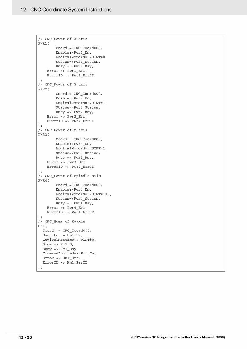
12 CNC Coordinate System Instructions
12 - 36 NJ/NY-series NC Integrated Controller User’s Manual (O030)
// CNC_Power of X-axisPWR1(
Coord:= CNC_Coord000,Enable:=Pwr1_En, LogicalMotorNo:=UINT#0, Status=>Pwr1_Status,Busy => Pwr1_Bsy,
Error => Pwr1_Err, ErrorID => Pwr1_ErrID);// CNC_Power of Y-axisPWR2(
Coord:= CNC_Coord000,Enable:=Pwr2_En, LogicalMotorNo:=UINT#1, Status=>Pwr2_Status,Busy => Pwr2_Bsy,
Error => Pwr2_Err, ErrorID => Pwr2_ErrID);// CNC_Power of Z-axisPWR3(
Coord:= CNC_Coord000,Enable:=Pwr3_En, LogicalMotorNo:=UINT#2, Status=>Pwr3_Status,Busy => Pwr3_Bsy,
Error => Pwr3_Err, ErrorID => Pwr3_ErrID);// CNC_Power of spindle axisPWR4(
Coord:= CNC_Coord000,Enable:=Pwr4_En, LogicalMotorNo:=UINT#100, Status=>Pwr4_Status,Busy => Pwr4_Bsy,
Error => Pwr4_Err, ErrorID => Pwr4_ErrID);// CNC_Home of X-axisHM1( Coord := CNC_Coord000, Execute := Hm1_Ex, LogicalMotorNo :=UINT#0, Done => Hm1_D, Busy => Hm1_Bsy, CommandAborted=> Hm1_Ca, Error => Hm1_Err, ErrorID => Hm1_ErrID);

12 - 37
12 CNC Coordinate System Instructions
NJ/NY-series NC Integrated Controller User’s Manual (O030)
CN
C_C
oo
rdC
on
trol
12
Sam
ple Prog
ramm
ing
// CNC_Home of Y-axisHM2( Coord := CNC_Coord000, Execute := Hm2_Ex, LogicalMotorNo :=UINT#1, Done => Hm2_D, Busy => Hm2_Bsy, CommandAborted=> Hm2_Ca, Error => Hm2_Err, ErrorID => Hm2_ErrID);// CNC_Home of Z-axisHM3( Coord := CNC_Coord000, Execute := Hm3_Ex, LogicalMotorNo :=UINT#2, Done => Hm3_D, Busy => Hm3_Bsy, CommandAborted=> Hm3_Ca, Error => Hm3_Err, ErrorID => Hm3_ErrID);
// CNC_CoordControlCC1(
Coord:= CNC_Coord000,ControlInputs:=ControlInputs,ControlOutputs:=ControlOutputs, Enable:=CC1_En, Enabled=>CC1_enbd, Busy=>CC1_Bsy, Error=>CC1_Err, ErrorID=>CC1_ErrID
);
// CNC_LoadProgramFileLPF(
Execute:=LPF_Ex, FileName:=STRING#'NCProg1.txt', DeletePrg:=_eCNC_DELETE_PRG#_cncNotDelPrg, Done=>LPF_D, Busy=>LPF_Bsy, CommandAborted=>LPF_Ca, Error=>LPF_Err,ErrorID=>LPF_ErrID
);

12 CNC Coordinate System Instructions
12 - 38 NJ/NY-series NC Integrated Controller User’s Manual (O030)
Sample Programming (Dry Run Execution)
// When StartPg is TRUE, execute the first pressing process of the operation start switch.IF (StartPg = TRUE) AND (StartPgWork=FALSE) THEN
StartPgWork:=TRUE;END_IF;
// When StartPgWork is TRUE, check that an SD Memory Card is inserted.IF (StartPgWork = TRUE) THEN
IF ( _Card1Access=FALSE ) AND ( _Card1Ready =TRUE) THENLPF_Ex:=TRUE;
END_IF;END_IF;
// If a monitoring information error occurs during loading of the NC program, exe-cute the error handler for the device (FaultHandler).// Program the FaultHandler according to the device.IF (_CNC_COM.Obsr.Active=TRUE) THEN
FaultHandler();END_IF;
// When the Load NC Program is completed, check that the Servo Drive is in the servo ready status and set the X-axis to the ON status.IF (LPF_Dn = TRUE) AND (CNC_Motor000.DrvStatus.Ready=TRUE) THEN
Pwr1_En:=TRUE;ELSE
Pwr1_En:=FALSE;END_IF;
// When the X-axis is in the Servo ON status, check that the Servo Drive is in the servo ready status and set the Y-axis to the Servo ON status.IF (Pwr1_Status = TRUE) AND (CNC_Motor001.DrvStatus.Ready=TRUE) THEN
Pwr2_En:=TRUE;ELSE
Pwr2_En:=FALSE;END_IF;
// When the Y-axis is in the Servo ON status, check that the Servo Drive is in the servo ready status and set the Z-axis to the Servo ON status.IF (Pwr2_Status = TRUE) AND (CNC_Motor002.DrvStatus.Ready=TRUE) THEN
Pwr3_En:=TRUE;ELSE
Pwr3_En:=FALSE;END_IF;
// When the Z-axis is in the Servo ON status, check that the Servo Drive is in the servo ready status and set the spindle axis to the Servo ON status.IF (Pwr3_Status = TRUE) AND (CNC_Motor003.DrvStatus.Ready=TRUE) THEN
Pwr4_En:=TRUE;ELSE
Pwr4_En:=FALSE;END_IF;
// When the positioning axis and spindle axis are in the Servo ON status, execute homing of the X-axis.IF (Pwr4_Status=TRUE) THEN Hm1_Ex:=TRUE;END_IF;
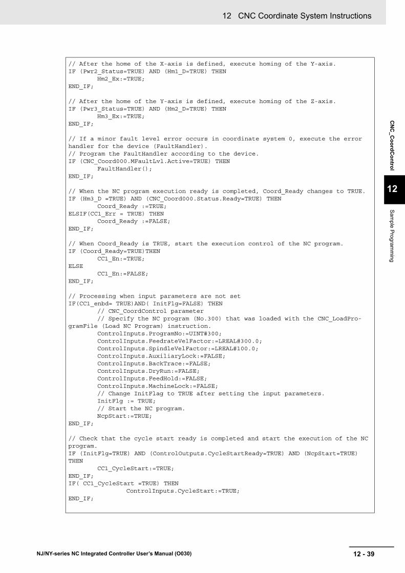
12 - 39
12 CNC Coordinate System Instructions
NJ/NY-series NC Integrated Controller User’s Manual (O030)
CN
C_C
oo
rdC
on
trol
12
Sam
ple Prog
ramm
ing
// After the home of the X-axis is defined, execute homing of the Y-axis.IF (Pwr2_Status=TRUE) AND (Hm1_D=TRUE) THEN
Hm2_Ex:=TRUE;END_IF;
// After the home of the Y-axis is defined, execute homing of the Z-axis.IF (Pwr3_Status=TRUE) AND (Hm2_D=TRUE) THEN
Hm3_Ex:=TRUE;END_IF;
// If a minor fault level error occurs in coordinate system 0, execute the error handler for the device (FaultHandler).// Program the FaultHandler according to the device.IF (CNC_Coord000.MFaultLvl.Active=TRUE) THEN
FaultHandler();END_IF;
// When the NC program execution ready is completed, Coord_Ready changes to TRUE.IF (Hm3_D =TRUE) AND (CNC_Coord000.Status.Ready=TRUE) THEN
Coord_Ready :=TRUE;ELSIF(CC1_Err = TRUE) THEN
Coord_Ready :=FALSE;END_IF;
// When Coord_Ready is TRUE, start the execution control of the NC program.IF (Coord_Ready=TRUE)THEN
CC1_En:=TRUE;ELSE
CC1_En:=FALSE;END_IF;
// Processing when input parameters are not setIF(CC1_enbd= TRUE)AND( InitFlg=FALSE) THEN
// CNC_CoordControl parameter// Specify the NC program (No.300) that was loaded with the CNC_LoadPro-
gramFile (Load NC Program) instruction.ControlInputs.ProgramNo:=UINT#300;ControlInputs.FeedrateVelFactor:=LREAL#300.0;ControlInputs.SpindleVelFactor:=LREAL#100.0;ControlInputs.AuxiliaryLock:=FALSE;ControlInputs.BackTrace:=FALSE;ControlInputs.DryRun:=FALSE;ControlInputs.FeedHold:=FALSE;ControlInputs.MachineLock:=FALSE;// Change InitFlag to TRUE after setting the input parameters.InitFlg := TRUE;// Start the NC program.NcpStart:=TRUE;
END_IF;
// Check that the cycle start ready is completed and start the execution of the NC program.IF (InitFlg=TRUE) AND (ControlOutputs.CycleStartReady=TRUE) AND (NcpStart=TRUE) THEN
CC1_CycleStart:=TRUE;END_IF;IF( CC1_CycleStart =TRUE) THEN
ControlInputs.CycleStart:=TRUE;END_IF;
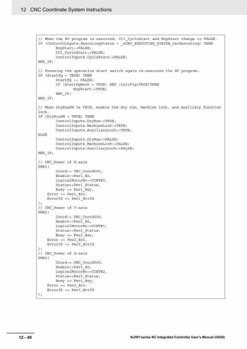
12 CNC Coordinate System Instructions
12 - 40 NJ/NY-series NC Integrated Controller User’s Manual (O030)
// When the NC program is executed, CC1_CycleStart and NcpStart change to FALSE.IF (ControlOutputs.ExecutingStatus = _eCNC_EXECUTING_STATE#_cncExecuting) THEN
NcpStart:=FALSE;CC1_CycleStart:=FALSE;ControlInputs.CycleStart:=FALSE;
END_IF;
// Pressing the operation start switch again re-executes the NC program.IF (StartPg = TRUE) THEN
StartPg := FALSE;IF (StartPgWork = TRUE) AND (InitFlg=TRUE)THEN
NcpStart:=TRUE;END_IF;
END_IF;
// When DryRunSW is TRUE, enable the dry run, machine lock, and auxiliary function lock.IF (DryRunSW = TRUE) THEN
ControlInputs.DryRun:=TRUE;ControlInputs.MachineLock:=TRUE;ControlInputs.AuxiliaryLock:=TRUE;
ELSEControlInputs.DryRun:=FALSE;ControlInputs.MachineLock:=FALSE;ControlInputs.AuxiliaryLock:=FALSE;
END_IF;
// CNC_Power of X-axisPWR1(
Coord:= CNC_Coord000,Enable:=Pwr1_En, LogicalMotorNo:=UINT#0, Status=>Pwr1_Status,Busy => Pwr1_Bsy,
Error => Pwr1_Err, ErrorID => Pwr1_ErrID);// CNC_Power of Y-axisPWR2(
Coord:= CNC_Coord000,Enable:=Pwr2_En, LogicalMotorNo:=UINT#1, Status=>Pwr2_Status,Busy => Pwr2_Bsy,
Error => Pwr2_Err, ErrorID => Pwr2_ErrID);// CNC_Power of Z-axisPWR3(
Coord:= CNC_Coord000,Enable:=Pwr3_En, LogicalMotorNo:=UINT#2, Status=>Pwr3_Status,Busy => Pwr3_Bsy,
Error => Pwr3_Err, ErrorID => Pwr3_ErrID);

12 - 41
12 CNC Coordinate System Instructions
NJ/NY-series NC Integrated Controller User’s Manual (O030)
CN
C_C
oo
rdC
on
trol
12
Sam
ple Prog
ramm
ing
// CNC_Power of spindle axisPWR4(
Coord:= CNC_Coord000,Enable:=Pwr4_En, LogicalMotorNo:=UINT#100, Status=>Pwr4_Status,Busy => Pwr4_Bsy,
Error => Pwr4_Err, ErrorID => Pwr4_ErrID);// CNC_Home of X-axisHM1( Coord := CNC_Coord000, Execute := Hm1_Ex, LogicalMotorNo :=UINT#0, Done => Hm1_D, Busy => Hm1_Bsy, CommandAborted=> Hm1_Ca, Error => Hm1_Err, ErrorID => Hm1_ErrID);// CNC_Home of Y-axisHM2( Coord := CNC_Coord000, Execute := Hm2_Ex, LogicalMotorNo :=UINT#1, Done => Hm2_D, Busy => Hm2_Bsy, CommandAborted=> Hm2_Ca, Error => Hm2_Err, ErrorID => Hm2_ErrID);// CNC_Home of Z-axisHM3( Coord := CNC_Coord000, Execute := Hm3_Ex, LogicalMotorNo :=UINT#2, Done => Hm3_D, Busy => Hm3_Bsy, CommandAborted=> Hm3_Ca, Error => Hm3_Err, ErrorID => Hm3_ErrID);
// CNC_CoordControlCC1(
Coord:= CNC_Coord000,ControlInputs:=ControlInputs,ControlOutputs:=ControlOutputs, Enable:=CC1_En, Enabled=>CC1_enbd, Busy=>CC1_Bsy, Error=>CC1_Err, ErrorID=>CC1_ErrID
);

12 CNC Coordinate System Instructions
12 - 42 NJ/NY-series NC Integrated Controller User’s Manual (O030)
// CNC_LoadProgramFileLPF(
Execute:=LPF_Ex, FileName:=STRING#'NCProg1.txt', DeletePrg:=_eCNC_DELETE_PRG#_cncNotDelPrg, Done=>LPF_D, Busy=>LPF_Bsy, CommandAborted=>LPF_Ca, Error=>LPF_Err,ErrorID=>LPF_ErrID
);
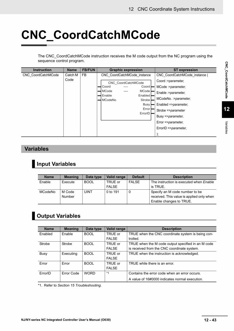
12 - 43
12 CNC Coordinate System Instructions
NJ/NY-series NC Integrated Controller User’s Manual (O030)
CN
C_C
oo
rdC
atchM
Co
de
12
Variab
les
CNC_CoordCatchMCode
The CNC_CoordCatchMCode instruction receives the M code output from the NC program using the sequence control program.
Instruction Name FB/FUN Graphic expression ST expression
CNC_CoordCatchMCode Catch M Code
FB CNC_CoordCatchMCode_instance CNC_CoordCatchMCode_instance (
Coord :=parameter,
MCode :=parameter,
Enable :=parameter,
MCodeNo. :=parameter,
Enabled =>parameter,
Strobe =>parameter
Busy =>parameter,
Error =>parameter,
ErrorID =>parameter,
);
Variables
Input Variables
Name Meaning Data type Valid range Default Description
Enable Execute BOOL TRUE or FALSE
FALSE The instruction is executed when Enable is TRUE.
MCodeNo M Code Number
UINT 0 to 191 0 Specify an M code number to be received. This value is applied only when Enable changes to TRUE.
Output Variables
Name Meaning Data type Valid range Description
Enabled Enable BOOL TRUE or FALSE
TRUE when the CNC coordinate system is being con-trolled.
Strobe Strobe BOOL TRUE or FALSE
TRUE when the M code output specified in an M code is received from the CNC coordinate system.
Busy Executing BOOL TRUE or FALSE
TRUE when the instruction is acknowledged.
Error Error BOOL TRUE or FALSE
TRUE while there is an error.
ErrorID Error Code WORD *1
*1. Refer to Section 15 Troubleshooting.
Contains the error code when an error occurs.
A value of 16#0000 indicates normal execution.
--------------------------------
Coord CoordMCode MCodeEnable EnabledMCodeNo Strobe
BusyError
ErrorID
CNC_CoordCatchMCode

12 CNC Coordinate System Instructions
12 - 44 NJ/NY-series NC Integrated Controller User’s Manual (O030)
Output Variable Update Timing
_sMCODE_REF
Name Timing for changing to TRUE Timing for changing to FALSE
Enabled When Enable changes to TRUE. • When Enable changes to FALSE.
• When Error changes to TRUE.
Busy When Enable changes to TRUE. • When Error changes to TRUE.
• When Enable changes to FALSE.
Error When there is an error in the execution condi-tions or input parameters for the instruction.
When the error is cleared.
Strobe When the M code output specified in an M code is received from the CNC coordinate system.
When the M code output is reset by CNC_Coor-dResetMCode.
In-Out Variables
Name Meaning Data type Valid range Description
Coord CNC Coordi-nate System
_sCNC_COORD_REF
--- Specifies the CNC coordinate system.
MCode M code attached infor-mation
_sMCODE_REF --- Outputs the information attached to the M code output.
(*) Create a user-defined variable of the _sMCODE_REF type.
Name Meaning Data type Valid range Function
ExistsOutputs Attached informa-tion output exis-tence
ARRAY[0..7] OF BOOL
TRUE or FALSE
Outputs whether Outputs exists or not when an M code is received.
The element numbers (0..7) in the array correspond to the arguments (VA..VH) in the M code.
0=VA, 1=VB, 2=VC, 3=VD, 4=VE, 5=VF, 6=VG, 7=VH
Outputs Attached informa-tion output
ARRAY[0..7] OF LREAL
--- Outputs the Outputs when an M code is received.
The element numbers in the array correspond to the arguments (VA..VH) in the M code.
0=VA, 1=VB, 2=VC, 3=VD, 4=VE, 5=VF, 6=VG, 7=VH
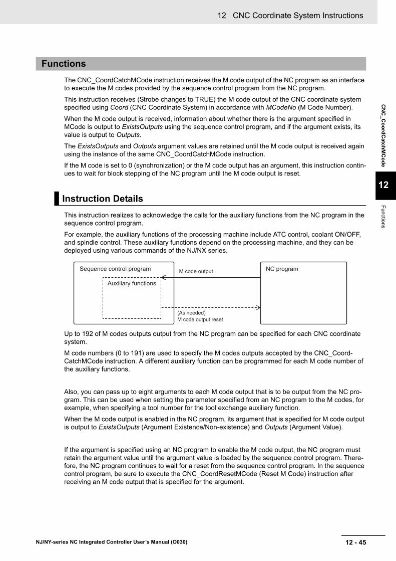
12 - 45
12 CNC Coordinate System Instructions
NJ/NY-series NC Integrated Controller User’s Manual (O030)
CN
C_C
oo
rdC
atchM
Co
de
12
Functions
The CNC_CoordCatchMCode instruction receives the M code output of the NC program as an interface to execute the M codes provided by the sequence control program from the NC program.
This instruction receives (Strobe changes to TRUE) the M code output of the CNC coordinate system specified using Coord (CNC Coordinate System) in accordance with MCodeNo (M Code Number).
When the M code output is received, information about whether there is the argument specified in MCode is output to ExistsOutputs using the sequence control program, and if the argument exists, its value is output to Outputs.
The ExistsOutputs and Outputs argument values are retained until the M code output is received again using the instance of the same CNC_CoordCatchMCode instruction.
If the M code is set to 0 (synchronization) or the M code output has an argument, this instruction contin-ues to wait for block stepping of the NC program until the M code output is reset.
This instruction realizes to acknowledge the calls for the auxiliary functions from the NC program in the sequence control program.
For example, the auxiliary functions of the processing machine include ATC control, coolant ON/OFF, and spindle control. These auxiliary functions depend on the processing machine, and they can be deployed using various commands of the NJ/NX series.
Up to 192 of M codes outputs output from the NC program can be specified for each CNC coordinate system.
M code numbers (0 to 191) are used to specify the M codes outputs accepted by the CNC_Coord-CatchMCode instruction. A different auxiliary function can be programmed for each M code number of the auxiliary functions.
Also, you can pass up to eight arguments to each M code output that is to be output from the NC pro-gram. This can be used when setting the parameter specified from an NC program to the M codes, for example, when specifying a tool number for the tool exchange auxiliary function.
When the M code output is enabled in the NC program, its argument that is specified for M code output is output to ExistsOutputs (Argument Existence/Non-existence) and Outputs (Argument Value).
If the argument is specified using an NC program to enable the M code output, the NC program must retain the argument value until the argument value is loaded by the sequence control program. There-fore, the NC program continues to wait for a reset from the sequence control program. In the sequence control program, be sure to execute the CNC_CoordResetMCode (Reset M Code) instruction after receiving an M code output that is specified for the argument.
Functions
Instruction Details
Sequence control program
Auxiliary functions
M code output
(As needed)M code output reset
NC program

12 CNC Coordinate System Instructions
12 - 46 NJ/NY-series NC Integrated Controller User’s Manual (O030)
A timing chart for the operation of the CNC_CoordCatchMCode instruction is shown below.
While Enabled is TRUE, Strobe is updated.
ExistsOutputs and Outputs are updated at the timing when Strobe is updated from FALSE to TRUE. ExistsOutputs and Outputs are not updated at other timings.
You cannot re-execute CNC instructions with enable-type inputs.
This instruction operates independently for each instruction, therefore it is not affected by the restriction of CNC instruction multi-execution processing.
If this instruction cannot be executed, an error occurs, and Error will change to TRUE.
You can find out the cause of the error by referring to the value output by ErrorID (Error Code).
Timing Chart
Re-execution of CNC Instructions
Multi-execution of CNC Instructions
Errors
Enable
Enabled
Busy
Error
ErrorID
Strobe
ExistsOtputs
Otputs Value
16#0000
Enable
Enabled
Busy
Error
ErrorID
Strobe
ExistsOtputs
Otputs
Error code16#0000

12 - 47
12 CNC Coordinate System Instructions
NJ/NY-series NC Integrated Controller User’s Manual (O030)
CN
C_C
oo
rdC
atchM
Co
de
12
Sam
ple Prog
ramm
ing
This section shows sample programming to receive the auxiliary function output and perform the reset.
The minimum settings required for this sample programming are given below.
CNC Coordinate System Settings
Logical CNC motor configuration
Positioning axis configuration
Spindle axis use CNC motor
M code settings
Sample Programming
Parameter Settings
CNC coordinate system
Logical CNC motor con-figuration
CNC coordinate system 0
3
CNC coordinate system
Positioning axis CNC motor number
Positioning axis config-uration CNC motor
Positioning axis assignment
CNC coordinate system 0
CNC motor P0 CNC motor 0 X-axis
CNC coordinate system 0
CNC motor P1 CNC motor 1 Y-axis
CNC coordinate system 0
CNC motor P2 CNC motor 2 Z-axis
CNC coordinate system
Spindle axis use CNC motor
CNC coordinate system 0
CNC motor 3
M code number Setting value
M101 0 (Synchronous)

12 CNC Coordinate System Instructions
12 - 48 NJ/NY-series NC Integrated Controller User’s Manual (O030)
Set 101 for MCodeNo (M Code Number) using the CNC_CoordCatchMCode (Catch M Code) instruc-tion and run the sequence control program that turns ON the external output using the N11 block of the NC program shown below. After the external output turned ON, the execution of the NC program is con-tinued using the CNC_CoordResetMCode (Reset M Code) instruction.
NC Program
Operation Patterns
1 Turning ON the Operation Start Switch
When you turn ON the operation start switch at the home, CNC motor 0 assigned to the X-axis is positioned to 10.00 mm in the positive direction and the external output turns ON. After that, CNC motor 1 is positioned to 20.00 mm in the positive direction.
Operation Example
N10 G91 F1000 G01 X10N11 M101N12 X20M30
0Time
Velocity
N12N10
External output
Auxiliary function output Reset

12 - 49
12 CNC Coordinate System Instructions
NJ/NY-series NC Integrated Controller User’s Manual (O030)
CN
C_C
oo
rdC
atchM
Co
de
12
Sam
ple Prog
ramm
ing
Main Variables
Timing Chart
Ladder Diagram
Name Data type Default Comment
CNC_Coord000 _sCNC_COORD_REF --- CNC coordinate system variable of CNC coordi-nate system 0.
CNC_Motor000 _sCNC_MOTOR_REF --- CNC motor variable of CNC motor 0.
StartPg BOOL FALSE Indicates the operation start switch.
The Servo is turned ON when this variable is TRUE and EtherCAT process data communica-tions are established.
Coord_Ready BOOL FALSE Indicates the execution ready completion status of the NC program.
This variable changes to TRUE when the NC program execution conditions are satisfied.
NcpStart BOOL FALSE When this variable is TRUE and the cycle start ready is completed, the NC program is exe-cuted.
InitFlg BOOL FALSE Indicates the input parameter setting comple-tion.
Input parameters are set when this variable is FALSE.
When the input parameter setting is completed, this variable changes to TRUE.
ExternalOUT BOOL FALSE Indicates the external output.
StartPg
Coord_Ready
CC1_CycleStart
NcpStart
ExternalOUT
CC1_enbd
CC1_Bsy
CM1_enbd
CM1_str
CM1_Bsy
RM1_D
RM1_bsy
ExecutingStatus _cncStandby _cncExecuting
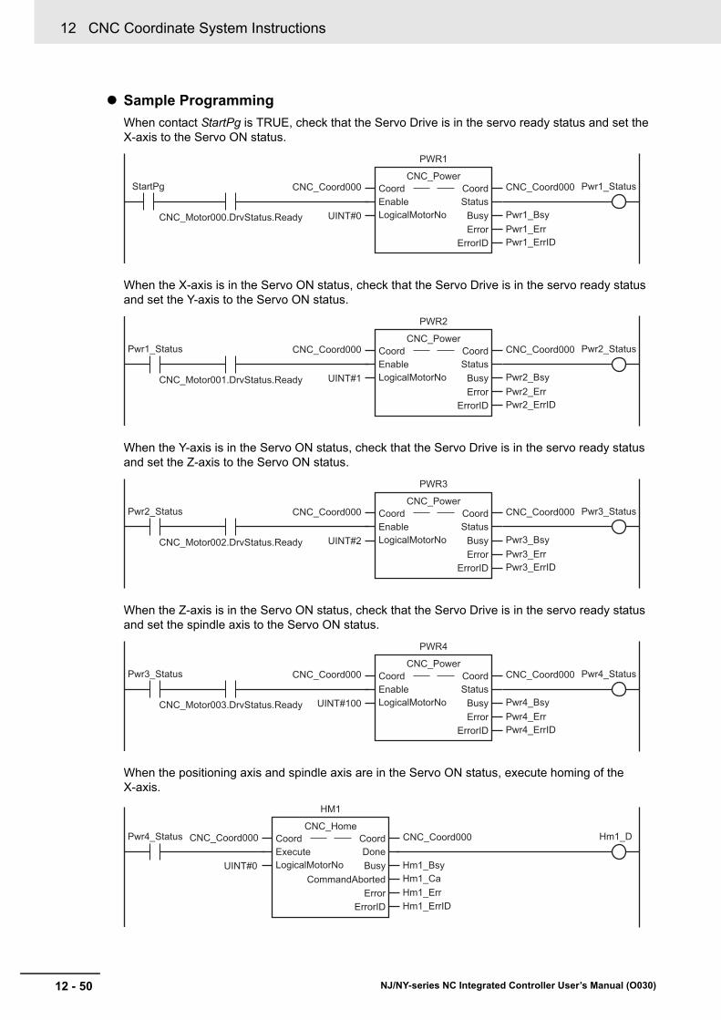
12 CNC Coordinate System Instructions
12 - 50 NJ/NY-series NC Integrated Controller User’s Manual (O030)
Sample Programming
When contact StartPg is TRUE, check that the Servo Drive is in the servo ready status and set the X-axis to the Servo ON status.
When the X-axis is in the Servo ON status, check that the Servo Drive is in the servo ready status and set the Y-axis to the Servo ON status.
When the Y-axis is in the Servo ON status, check that the Servo Drive is in the servo ready status and set the Z-axis to the Servo ON status.
When the Z-axis is in the Servo ON status, check that the Servo Drive is in the servo ready status and set the spindle axis to the Servo ON status.
When the positioning axis and spindle axis are in the Servo ON status, execute homing of the X-axis.
StartPg
CNC_Motor000.DrvStatus.Ready
Pwr1_Status
UINT#0
PWR1
CNC_Power
StatusBusyError
ErrorID
Coord CoordEnableLogicalMotorNo
CNC_Coord000 CNC_Coord000
Pwr1_BsyPwr1_ErrPwr1_ErrID
CNC_Motor001.DrvStatus.Ready
Pwr2_Status
UINT#1
PWR2
CNC_Power
StatusBusyError
ErrorID
Coord CoordEnableLogicalMotorNo
CNC_Coord000 CNC_Coord000Pwr1_Status
Pwr2_BsyPwr2_ErrPwr2_ErrID
CNC_Motor002.DrvStatus.Ready
Pwr3_Status
UINT#2
PWR3
CNC_Power
StatusBusyError
ErrorID
Coord CoordEnableLogicalMotorNo
CNC_Coord000 CNC_Coord000Pwr2_Status
Pwr3_BsyPwr3_ErrPwr3_ErrID
CNC_Motor003.DrvStatus.Ready
Pwr4_Status
UINT#100
PWR4
CNC_Power
StatusBusyError
ErrorID
Coord CoordEnableLogicalMotorNo
CNC_Coord000 CNC_Coord000Pwr3_Status
Pwr4_BsyPwr4_ErrPwr4_ErrID
Pwr4_Status Hm1_D
Hm1_CaHm1_ErrHm1_ErrID
Hm1_Bsy
HM1
CNC_Home
DoneBusy
CommandAbortedError
ErrorID
Coord CoordExecuteLogicalMotorNo
CNC_Coord000 CNC_Coord000
UINT#0

12 - 51
12 CNC Coordinate System Instructions
NJ/NY-series NC Integrated Controller User’s Manual (O030)
CN
C_C
oo
rdC
atchM
Co
de
12
Sam
ple Prog
ramm
ing
After the home of the X-axis is defined, execute homing of the Y-axis.
After the home of the Y-axis is defined, execute homing of the Z-axis.
If a minor fault level error occurs in CNC coordinate system 0, the error handler for the device (FaultHandler) is executed.
Program the FaultHandler according to the device.
When the NC program execution ready is completed, change Coord_Ready to TRUE.
When Coord_Ready changes to TRUE, start the execution control of the NC program.
Pwr2_Status Hm2_DHm1_D
Hm2_CaHm2_ErrHm2_ErrID
Hm2_Bsy
HM2
CNC_Home
DoneBusy
CommandAbortedError
ErrorID
Coord CoordExecuteLogicalMotorNo
CNC_Coord000 CNC_Coord000
UINT#1
Pwr3_Status Hm3_DHm2_D
Hm3_CaHm3_ErrHm3_ErrID
Hm3_Bsy
HM3
CNC_Home
DoneBusy
CommandAbortedError
ErrorID
Coord CoordExecuteLogicalMotorNo
CNC_Coord000 CNC_Coord000
UINT#2
CNC_Coord000.MFaultLvl.ActiveFHandler
FaultHandlerinput output
CNC_Coord000.Status.Ready Hm3_D
Coord_Ready CC1_Err
Coord_Ready
CC1_BusyCC1_ErrorCC1_ErrorID
Coord_Ready CC1_enbd
CC1
CNC_CoordControl
BusyEnabled
ErrorErrorID
Coord CoordControlInputs ControlInputsControlOutputs ControlOutputsEnable
CNC_Coord000 CNC_Coord000ControlInputs
ControlOutputsControlInputsControlOutputs
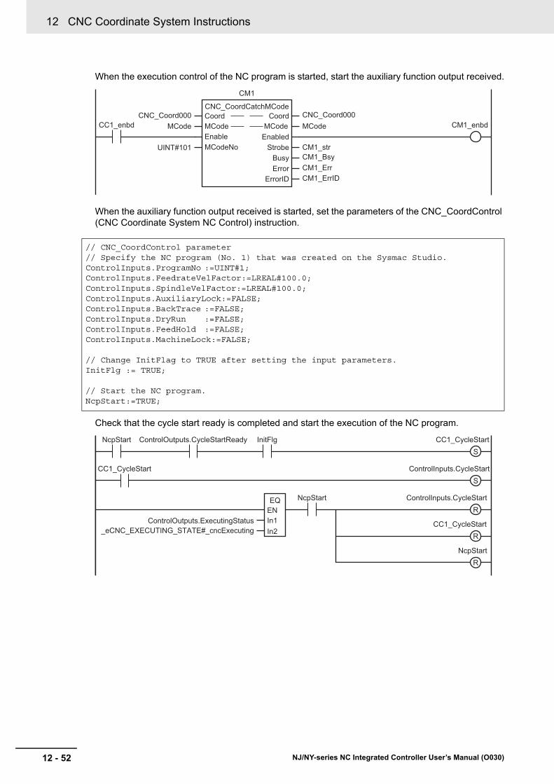
12 CNC Coordinate System Instructions
12 - 52 NJ/NY-series NC Integrated Controller User’s Manual (O030)
When the execution control of the NC program is started, start the auxiliary function output received.
When the auxiliary function output received is started, set the parameters of the CNC_CoordControl (CNC Coordinate System NC Control) instruction.
Check that the cycle start ready is completed and start the execution of the NC program.
// CNC_CoordControl parameter// Specify the NC program (No. 1) that was created on the Sysmac Studio.ControlInputs.ProgramNo :=UINT#1;ControlInputs.FeedrateVelFactor:=LREAL#100.0;ControlInputs.SpindleVelFactor:=LREAL#100.0;ControlInputs.AuxiliaryLock:=FALSE;ControlInputs.BackTrace :=FALSE;ControlInputs.DryRun :=FALSE;ControlInputs.FeedHold :=FALSE;ControlInputs.MachineLock:=FALSE;
// Change InitFlag to TRUE after setting the input parameters.InitFlg := TRUE;
// Start the NC program.NcpStart:=TRUE;
CM1_BsyCM1_ErrCM1_ErrID
UINT#101 CM1_str
MCode
CM1
CNC_CoordCatchMCode
MCodeEnabled
StrobeBusyError
ErrorID
Coord CoordMCodeEnableMCodeNo
CNC_Coord000 CNC_Coord000MCodeCC1_enbd CM1_enbd
S
S
NcpStart
NcpStart ControlOutputs.CycleStartReady InitFlg CC1_CycleStart
CC1_CycleStart ControlInputs.CycleStart
ControlInputs.CycleStart
ControlOutputs.ExecutingStatus_eCNC_EXECUTING_STATE#_cncExecuting
In1ENEQ
In2
R
CC1_CycleStartR
NcpStartR

12 - 53
12 CNC Coordinate System Instructions
NJ/NY-series NC Integrated Controller User’s Manual (O030)
CN
C_C
oo
rdC
atchM
Co
de
12
Sam
ple Prog
ramm
ing
When the auxiliary function output is received, turn ON the external output and start the auxiliary function output reset.
Continue the NC program after the auxiliary function output of the NC program is reset.
S
RM1_CaRM1_ErrRM1_ErrID
CMInputs RM1_bsy
ExternalOUT
RM1
CNC_CoordResetMCode
DoneBusy
CommandAbortedError
ErrorID
Coord CoordExecuteInputs
CNC_Coord000 CNC_Coord000CM1_str RM1_D

12 CNC Coordinate System Instructions
12 - 54 NJ/NY-series NC Integrated Controller User’s Manual (O030)
Main Variables
Timing Chart
Structured Text (ST)
Name Data type Default Comment
CNC_Coord000 _sCNC_COORD_REF --- CNC coordinate system variable of CNC coordi-nate system 0.
CNC_Motor000 _sCNC_MOTOR_REF --- CNC motor variable of CNC motor 0.
StartPg BOOL FALSE Indicates the operation start switch.
The Servo is turned ON when this variable is TRUE and EtherCAT process data communica-tions are established.
Coord_Ready BOOL FALSE Indicates the execution ready completion of the NC program.
This variable changes to TRUE when the NC program execution conditions are satisfied.
NcpStart BOOL FALSE When this variable is TRUE and the cycle start ready is completed, the NC program is exe-cuted.
InitFlg BOOL FALSE Indicates the input parameter setting comple-tion.
Input parameters are set when this variable is FALSE.
When the input parameter setting is completed, this variable changes to TRUE.
ExternalOUT BOOL FALSE Indicates the external output.
StartPg
Coord_Ready
CC1_CycleStart
NcpStart
ExternalOUT
CC1_enbd
CC1_Bsy
CM1_enbd
CM1_str
CM1_Bsy
RM1_D
RM1_bsy
ExecutingStatus _cncStandby _cncExecuting
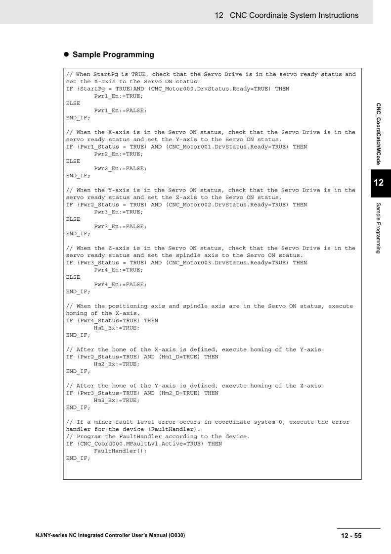
12 - 55
12 CNC Coordinate System Instructions
NJ/NY-series NC Integrated Controller User’s Manual (O030)
CN
C_C
oo
rdC
atchM
Co
de
12
Sam
ple Prog
ramm
ing
Sample Programming
// When StartPg is TRUE, check that the Servo Drive is in the servo ready status and set the X-axis to the Servo ON status.IF (StartPg = TRUE)AND (CNC_Motor000.DrvStatus.Ready=TRUE) THEN
Pwr1_En:=TRUE;ELSE
Pwr1_En:=FALSE;END_IF;
// When the X-axis is in the Servo ON status, check that the Servo Drive is in the servo ready status and set the Y-axis to the Servo ON status.IF (Pwr1_Status = TRUE) AND (CNC_Motor001.DrvStatus.Ready=TRUE) THEN
Pwr2_En:=TRUE;ELSE
Pwr2_En:=FALSE;END_IF;
// When the Y-axis is in the Servo ON status, check that the Servo Drive is in the servo ready status and set the Z-axis to the Servo ON status.IF (Pwr2_Status = TRUE) AND (CNC_Motor002.DrvStatus.Ready=TRUE) THEN
Pwr3_En:=TRUE;ELSE
Pwr3_En:=FALSE;END_IF;
// When the Z-axis is in the Servo ON status, check that the Servo Drive is in the servo ready status and set the spindle axis to the Servo ON status.IF (Pwr3_Status = TRUE) AND (CNC_Motor003.DrvStatus.Ready=TRUE) THEN
Pwr4_En:=TRUE;ELSE
Pwr4_En:=FALSE;END_IF;
// When the positioning axis and spindle axis are in the Servo ON status, execute homing of the X-axis.IF (Pwr4_Status=TRUE) THEN Hm1_Ex:=TRUE;END_IF;
// After the home of the X-axis is defined, execute homing of the Y-axis.IF (Pwr2_Status=TRUE) AND (Hm1_D=TRUE) THEN
Hm2_Ex:=TRUE;END_IF;
// After the home of the Y-axis is defined, execute homing of the Z-axis.IF (Pwr3_Status=TRUE) AND (Hm2_D=TRUE) THEN
Hm3_Ex:=TRUE;END_IF;
// If a minor fault level error occurs in coordinate system 0, execute the error handler for the device (FaultHandler).// Program the FaultHandler according to the device.IF (CNC_Coord000.MFaultLvl.Active=TRUE) THEN
FaultHandler();END_IF;
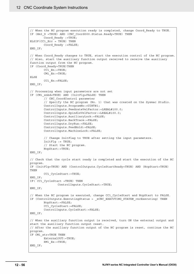
12 CNC Coordinate System Instructions
12 - 56 NJ/NY-series NC Integrated Controller User’s Manual (O030)
// When the NC program execution ready is completed, change Coord_Ready to TRUE.IF (Hm3_D =TRUE) AND (CNC_Coord000.Status.Ready=TRUE) THEN
Coord_Ready :=TRUE;ELSIF(CC1_Err = TRUE) THEN
Coord_Ready :=FALSE;END_IF;
// When Coord_Ready changes to TRUE, start the execution control of the NC program.// Also, start the auxiliary function output received to receive the auxiliary function output from the NC program.IF (Coord_Ready=TRUE)THEN
CC1_En:=TRUE;CM1_En:=TRUE;
ELSECC1_En:=FALSE;
END_IF;
// Processing when input parameters are not setIF (CM1_enbd=TRUE) AND (InitFlg=FALSE) THEN
// CNC_CoordControl parameter// Specify the NC program (No. 1) that was created on the Sysmac Studio.ControlInputs.ProgramNo:=UINT#1;ControlInputs.FeedrateVelFactor:=LREAL#100.0;ControlInputs.SpindleVelFactor:=LREAL#100.0;ControlInputs.AuxiliaryLock:=FALSE;ControlInputs.BackTrace:=FALSE;ControlInputs.DryRun:=FALSE;ControlInputs.FeedHold:=FALSE;ControlInputs.MachineLock:=FALSE;
// Change InitFlag to TRUE after setting the input parameters.InitFlg := TRUE;// Start the NC program.NcpStart:=TRUE;
END_IF;
// Check that the cycle start ready is completed and start the execution of the NC program.IF (InitFlg=TRUE) AND (ControlOutputs.CycleStartReady=TRUE) AND (NcpStart=TRUE) THEN
CC1_CycleStart:=TRUE;END_IF;IF( CC1_CycleStart =TRUE) THEN
ControlInputs.CycleStart:=TRUE;END_IF;
// When the NC program is executed, change CC1_CycleStart and NcpStart to FALSE.IF (ControlOutputs.ExecutingStatus = _eCNC_EXECUTING_STATE#_cncExecuting) THEN
NcpStart:=FALSE;CC1_CycleStart:=FALSE;ControlInputs.CycleStart:=FALSE;
END_IF;
// When the auxiliary function output is received, turn ON the external output and start the auxiliary function output reset.// After the auxiliary function output of the NC program is reset, continue the NC program.IF CM1_str=TRUE THEN
ExternalOUT:=TRUE;RM1_Ex:=TRUE;
END_IF;

12 - 57
12 CNC Coordinate System Instructions
NJ/NY-series NC Integrated Controller User’s Manual (O030)
CN
C_C
oo
rdC
atchM
Co
de
12
Sam
ple Prog
ramm
ing
// Check that the NC program is restarted.IF RM1_D=TRUE THEN
RM1_Ex:=FALSE;END_IF;
// CNC_Power of X-axisPWR1(
Coord:= CNC_Coord000,Enable:=Pwr1_En, LogicalMotorNo:=UINT#0, Status=>Pwr1_Status,Busy => Pwr1_Bsy,
Error => Pwr1_Err, ErrorID => Pwr1_ErrID);// CNC_Power of Y-axisPWR2(
Coord:= CNC_Coord000,Enable:=Pwr2_En, LogicalMotorNo:=UINT#1, Status=>Pwr2_Status,Busy => Pwr2_Bsy,
Error => Pwr2_Err, ErrorID => Pwr2_ErrID);// CNC_Power of Z-axisPWR3(
Coord:= CNC_Coord000,Enable:=Pwr3_En, LogicalMotorNo:=UINT#2, Status=>Pwr3_Status,Busy => Pwr3_Bsy,
Error => Pwr3_Err, ErrorID => Pwr3_ErrID);// CNC_Power of spindle axisPWR4(
Coord:= CNC_Coord000,Enable:=Pwr4_En, LogicalMotorNo:=UINT#100, Status=>Pwr4_Status,Busy => Pwr4_Bsy,
Error => Pwr4_Err, ErrorID => Pwr4_ErrID);// CNC_Home of X-axisHM1( Coord := CNC_Coord000 , Execute := Hm1_Ex, LogicalMotorNo :=UINT#0 , Done => Hm1_D, Busy => Hm1_Bsy, CommandAborted=> Hm1_Ca, Error => Hm1_Err, ErrorID => Hm1_ErrID);// CNC_Home of Y-axisHM2(

12 CNC Coordinate System Instructions
12 - 58 NJ/NY-series NC Integrated Controller User’s Manual (O030)
Coord := CNC_Coord000 , Execute := Hm2_Ex, LogicalMotorNo :=UINT#1 , Done => Hm2_D, Busy => Hm2_Bsy, CommandAborted=> Hm2_Ca, Error => Hm2_Err, ErrorID => Hm2_ErrID);// CNC_Home of Z-axisHM3( Coord := CNC_Coord000 , Execute := Hm3_Ex, LogicalMotorNo :=UINT#2 , Done => Hm3_D, Busy => Hm3_Bsy, CommandAborted=> Hm3_Ca, Error => Hm3_Err, ErrorID => Hm3_ErrID);
// CNC_CoordControlCC1(
Coord:= CNC_Coord000,ControlInputs:=ControlInputs,ControlOutputs:=ControlOutputs, Enable:=CC1_En, Enabled=>CC1_enbd, Busy=>CC1_Bsy, Error=>CC1_Err, ErrorID=>CC1_ErrID
);
// CNC_CoordCatchMCodeCM1(
Coord:=CNC_Coord000,MCode:=MCode,Enable:=CM1_En,MCodeNo:=UINT#101,Enabled=>CM1_enbd,Strobe=>CM1_str,Busy=>CM1_Bsy,Error=>CM1_Err, ErrorID=>CM1_ErrID
);
// CNC_CoordResetMCodeRM1(
Coord:=CNC_Coord000,Execute:=RM1_Ex,Inputs:=CMInputs, Done=>RM1_D,Busy=>RM1_bsy,CommandAborted=>RM1_Ca,Error=>RM1_Err,ErrorID=>RM1_ErrID
);

12 - 59
12 CNC Coordinate System Instructions
NJ/NY-series NC Integrated Controller User’s Manual (O030)
CN
C_C
oo
rdR
esetMC
od
e
12
Variab
les
CNC_CoordResetMCode
The CNC_CoordResetMCode instruction resets the M code output from the NC program.
Instruction Name FB/FUN Graphic expression ST expression
CNC_CoordResetMCode Reset M Code
FB CNC_CoordResetMCode_instance CNC_CoordResetMCode_instance (
Coord :=parameter,
Execute :=parameter,
Inputs :=parameter,
Done =>parameter,
Busy =>parameter,
CommandAborted =>parameter,
Error =>parameter,
ErrorID =>parameter
);
Variables
Input Variables
Name Meaning Data type Valid range Default Description
Execute Execute BOOL TRUE or FALSE
FALSE The instruction is executed when Exe-cute changes to TRUE.
Inputs Reset input ARRAY [0..7] OF LREAL
--- 0 Outputs the Inputs when the auxiliary function is reset.
The element numbers in the array corre-spond to the auxiliary function output reset return value of the auxiliary func-tion output.
Output Variables
Name Meaning Data type Valid range Description
Done Done BOOL TRUE or FALSE
TRUE when the instruction is completed.
Busy Executing BOOL TRUE or FALSE
TRUE when the instruction is acknowledged.
Command-Aborted
Command Aborted
BOOL TRUE or FALSE
TRUE when the instruction is aborted.
Error Error BOOL TRUE or FALSE
TRUE while there is an error.
ErrorID Error Code WORD *1
*1. Refer to Section 15 Troubleshooting.
Contains the error code when an error occurs.
A value of 16#0000 indicates normal execution.
----
------------------------
Coord CoordExecute DoneInputs Busy
CommandAbortedError
ErrorID
CNC_CoordResetMCode

12 CNC Coordinate System Instructions
12 - 60 NJ/NY-series NC Integrated Controller User’s Manual (O030)
Output Variable Update Timing
Variable Timing for changing to TRUE Timing for changing to FALSE
Done When the M code is reset. • When Execute is TRUE and changes to FALSE.
• After one period when Execute is FALSE.
Busy When Execute changes to TRUE. • When Done changes to TRUE.
• When Error changes to TRUE.
• When CommandAborted changes to TRUE.
Command-Aborted
When this instruction is canceled due to an error.
• When Execute is TRUE and changes to FALSE.
• After one period when Execute is FALSE.
Error When there is an error in the execution condi-tions or input parameters for the instruction.
When the error is cleared.
In-Out Variables
Name Meaning Data type Valid range Description
Coord CNC Coordi-nate System
_sCNC_COORD_REF --- Specifies the CNC coordinate system.

12 - 61
12 CNC Coordinate System Instructions
NJ/NY-series NC Integrated Controller User’s Manual (O030)
CN
C_C
oo
rdR
esetMC
od
e
12
Functions
The CNC_CoordResetMCode instruction resets the M code output of the NC program.
You can specify the CNC coordinate system to reset M code by specifying the CNC coordinate system.
The M code outputs are enabled (TRUE) in the NC program, and this instruction resets (FALSE) the M code outputs that accepted TRUE for IO refresh of the task for the sequence control program to be exe-cuted.
The result of the reset execution is applied to Strobe of the CNC_CoordCatchMCode (Catch M Code) instruction in the next and subsequent cycles. (When this reset instruction is executed at the beginning of the sequence control program, the following sequence control program accepts M codes if this occurred in the same scan.)
If an M code output with arguments is reset, the values (8 pieces of LREAL data) can be passed from the sequence control program to NC program. The NC Program stores the received values to NC pro-gram system variable _CNC_MCodeResetRetValueX (where X is a digit from 0 to 7).
For example, an NC program is written as follows,
P0 = _CNC_MCodeResetRetValue0
You can load the inputs[0] value of CNC_CoordResetMCode, executed lastly for the same CNC coordi-nate system, to P0.
Functions
Instruction Details
NC programSequence control program
M code
M code
(If necessary)M code reset
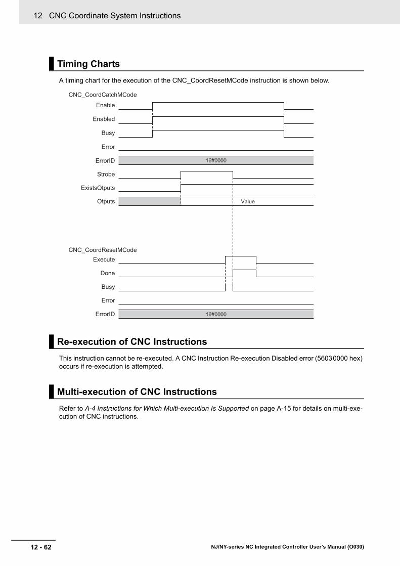
12 CNC Coordinate System Instructions
12 - 62 NJ/NY-series NC Integrated Controller User’s Manual (O030)
A timing chart for the execution of the CNC_CoordResetMCode instruction is shown below.
This instruction cannot be re-executed. A CNC Instruction Re-execution Disabled error (56030000 hex) occurs if re-execution is attempted.
Refer to A-4 Instructions for Which Multi-execution Is Supported on page A-15 for details on multi-exe-cution of CNC instructions.
Timing Charts
Re-execution of CNC Instructions
Multi-execution of CNC Instructions
Enable
Enabled
CNC_CoordCatchMCode
Busy
Error
ErrorID
Strobe
ExistsOtputs
Otputs
CNC_CoordResetMCodeExecute
Done
Busy
Error
ErrorID
Value
16#0000
16#0000

12 - 63
12 CNC Coordinate System Instructions
NJ/NY-series NC Integrated Controller User’s Manual (O030)
CN
C_C
oo
rdR
esetMC
od
e
12
Functions
If this instruction cannot be executed, an error occurs, and Error will change to TRUE.
You can find out the cause of the error by referring to the value output by ErrorID (Error Code).
Errors
Execute
Busy
Error
ErrorID 16#0000 Error code
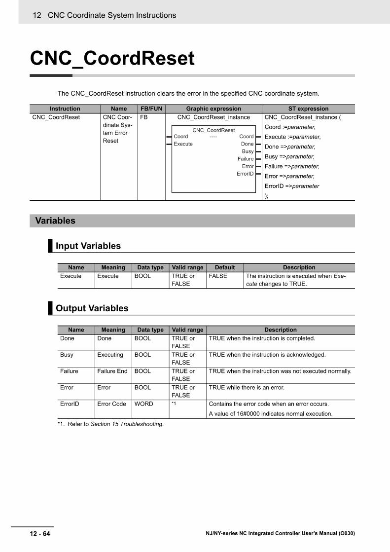
12 CNC Coordinate System Instructions
12 - 64 NJ/NY-series NC Integrated Controller User’s Manual (O030)
CNC_CoordReset
The CNC_CoordReset instruction clears the error in the specified CNC coordinate system.
Instruction Name FB/FUN Graphic expression ST expression
CNC_CoordReset CNC Coor-dinate Sys-tem Error Reset
FB CNC_CoordReset_instance CNC_CoordReset_instance (
Coord :=parameter,
Execute :=parameter,
Done =>parameter,
Busy =>parameter,
Failure =>parameter,
Error =>parameter,
ErrorID =>parameter
);
Variables
Input Variables
Name Meaning Data type Valid range Default Description
Execute Execute BOOL TRUE or FALSE
FALSE The instruction is executed when Exe-cute changes to TRUE.
Output Variables
Name Meaning Data type Valid range Description
Done Done BOOL TRUE or FALSE
TRUE when the instruction is completed.
Busy Executing BOOL TRUE or FALSE
TRUE when the instruction is acknowledged.
Failure Failure End BOOL TRUE or FALSE
TRUE when the instruction was not executed normally.
Error Error BOOL TRUE or FALSE
TRUE while there is an error.
ErrorID Error Code WORD *1
*1. Refer to Section 15 Troubleshooting.
Contains the error code when an error occurs.
A value of 16#0000 indicates normal execution.
----
------------------------
Coord CoordExecute Done
BusyFailure
ErrorErrorID
CNC_CoordReset

12 - 65
12 CNC Coordinate System Instructions
NJ/NY-series NC Integrated Controller User’s Manual (O030)
CN
C_C
oo
rdR
eset
12
Functions
Output Variable Update Timing
This instruction clears an error that is detected in the CNC coordinate system specified in Coord (CNC coordinate system) when Execute changes to TRUE. You can clear minor faults detected in the CNC coordinate system, monitoring information errors and drive errors.
• Error clear processing is performed regardless of whether the CNC motor is set to the Servo ON or Servo OFF status.
• If a driver error occurs on the CNC motor, driver error reset processing is executed first, and then error reset processing is executed.
• Driver error reset processing continues until the driver error is cleared or during the period specified in Driver Error Reset Monitoring Time of the CNC motor parameter. Driver error reset processing is simultaneously performed for the CNC motors in the CNC coordinate system.
• Errors that are detected at the timing when Execute changes to TRUE will be reset.
• Errors that are detected during reset processing will not be reset.
• If an attempt is made to execute this instruction while the CNC coordinate system is decelerated to a stop due to an error, the instruction is not executed, and Failure (Failure End) changes to TRUE. This processing is performed to prevent error reset processing from being started before the target CNC motor stops.
Also, CNC common errors cannot be reset by executing this instruction, therefore, Failure (Failure End) changes to TRUE.
Name Timing for changing to TRUE Timing for changing to FALSE
Done When the M code is reset. • When Execute is TRUE and changes to FALSE.
• After one period when Execute is FALSE.
Busy When Execute changes to TRUE. • When Done changes to TRUE.
• When Error changes to TRUE.
• When CommandAborted changes to TRUE.
Failure • When this instruction is executed while the CNC coordinate system decelerated to a stop due to an error.
• When this instruction is executed while a CNC coordinate system error occurred due to a CNC common error.
• When Execute is TRUE and changes to FALSE.
• After one period when Execute is FALSE.
Error When there is an error in the execution condi-tions or input parameters for the instruction.
When the error is cleared.
In-Out Variables
Name Meaning Data type Valid range Description
Coord CNC Coordi-nate System
_sCNC_COORD_REF
--- Specifies the CNC coordinate system.
Functions

12 CNC Coordinate System Instructions
12 - 66 NJ/NY-series NC Integrated Controller User’s Manual (O030)
Precautions for Correct Use
• Error reset processing initiated by this instruction may span multiple control cycles.
• If the CNC motor is active even when this instruction has been executed, the Failure (Failure End) output variable of this instruction changes to TRUE.
• Eliminate the cause of the error, and execute retry processing until Done changes to TRUE.
• Before eliminating the cause of the error, always check that each CNC motor stopped com-pletely.
• When using this instruction for the OMRON G5-series Servo Drive, perform exclusive pro-cessing to prevent the ResetECError (Reset EtherCAT Error) instruction from being executed simultaneously.
The instruction is aborted if it is not possible to clear errors that occur when the CNC coordinate system is decelerating to a stop for an error or errors that occur during CNC coordinate system errors resulting from CNC common errors.
Timing Chart
Aborting the Instruction
Execute
Done
Busy
Busy
Error
ErrorID Error code 16#0000
Failure
Output parameter of the instruction for whicherror occrred
Execute
Done
Busy
Failure
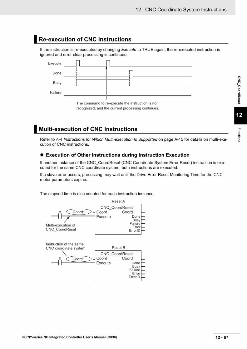
12 - 67
12 CNC Coordinate System Instructions
NJ/NY-series NC Integrated Controller User’s Manual (O030)
CN
C_C
oo
rdR
eset
12
Functions
If the instruction is re-executed by changing Execute to TRUE again, the re-executed instruction is ignored and error clear processing is continued.
Refer to A-4 Instructions for Which Multi-execution Is Supported on page A-15 for details on multi-exe-cution of CNC instructions.
Execution of Other Instructions during Instruction Execution
If another instance of the CNC_CoordReset (CNC Coordinate System Error Reset) instruction is exe-cuted for the same CNC coordinate system, both instructions are executed.
If a slave error occurs, processing may wait until the Drive Error Reset Monitoring Time for the CNC motor parameters expires.
The elapsed time is also counted for each instruction instance.
Re-execution of CNC Instructions
Multi-execution of CNC Instructions
Execute
Done
Busy
Failure
The command to re-execute the instruction is not recognized, and the current processing continues.
ACNC_CoordReset
Coord CoordDoneBusy
FailureError
ErrorID
ExecuteCoord1
Multi-execution of CNC_CoordReset
Instruction of the same CNC coordinate system
Reset A
DoneBusy
FailureError
ErrorID
Coord CoordExecute
CNC_CoordResetB Coord1
Reset B

12 CNC Coordinate System Instructions
12 - 68 NJ/NY-series NC Integrated Controller User’s Manual (O030)
CNC_CoordStop
The CNC_CoordStop instruction performs an immediate stop for all the currently running CNC motors in the specified CNC coordinate system.
Instruction Name FB/FUN Graphic expression ST expression
CNC_CoordStop CNC Coor-dinate Sys-tem Stop
FB CNC_CoordStop_instance CNC_CoordStop_instance (
Coord :=parameter,
Execute :=parameter,
Deceleration :=parameter,
Jerk :=parameter,
Done =>parameter,
Busy =>parameter,
CommandAborted =>parameter,
Error =>parameter,
ErrorID =>parameter
);
Variables
Input Variables
Name Meaning Data type Valid range Default Description
Execute Execute BOOL TRUE or FALSE
FALSE The instruction is executed when Exe-cute changes to TRUE.
Deceleration
(Reserved)
Decelera-tion Rate
ARRAY[0..2] OF LREAL
0 0 Specifies the deceleration rate.
The unit is command units/s2.
Jerk
(Reserved)
Jerk LREAL 0 0 Specify jerk.
The unit is command units/s3.
Output Variables
Name Meaning Data type Valid range Description
Done Done BOOL TRUE or FALSE
TRUE when the instruction is completed.
Busy Executing BOOL TRUE or FALSE
TRUE when the instruction is acknowledged.
Command-Aborted
Command Aborted
BOOL TRUE or FALSE
TRUE when the instruction is aborted.
Error Error BOOL TRUE or FALSE
TRUE while there is an error.
ErrorID Error Code WORD *1
*1. Refer to Section 15 Troubleshooting.
Contains the error code when an error occurs.
A value of 16#0000 indicates normal execution.
----
------------------------
Coord CoordExecute DoneDeceleration BusyJerk CommandAborted
ErrorErrorID
CNC_CoordStop

12 - 69
12 CNC Coordinate System Instructions
NJ/NY-series NC Integrated Controller User’s Manual (O030)
CN
C_C
oo
rdS
top
12
Functions
Output Variable Update Timing
• This function performs an immediate stop for all the currently operating CNC motors in the specified CNC coordinate system.
• CommandAborted (Command Aborted) changes to TRUE for the instruction that is currently in oper-ation when this instruction is executed.
• When Execute changes to TRUE, the operation of stopping starts.
Precautions for Correct Use
If you want to stop the operation of the CNC motor when ErrorStop (Error Deceleration Stop-ping) is TRUE for the CNC coordinate system, use the CNC_CoordImmediateStop (CNC Coor-dinate System Immediate Stop) instruction.
In-position Check
An in-position check is not performed when stopping for this instruction.
Name Timing for changing to TRUE Timing for changing to FALSE
Done When this instruction is completed. • When Execute is TRUE and changes to FALSE.
• After one period when Execute is FALSE.
Busy When Execute changes to TRUE. • When Done changes to TRUE.
• When Error changes to TRUE.
• When CommandAborted changes to TRUE.
Command-Aborted
• When this instruction is canceled due to an error.
• When this instruction is executed while there is an error.
• When Execute is TRUE and changes to FALSE.
• After one period when Execute is FALSE.
Error When there is an error in the execution condi-tions or input parameters for the instruction.
When the error is cleared.
In-Out Variables
Name Meaning Data type Valid range Description
Coord CNC Coordi-nate System
_sCNC_COORD_REF
--- Specifies the CNC coordinate system.
Functions
Instruction Details

12 CNC Coordinate System Instructions
12 - 70 NJ/NY-series NC Integrated Controller User’s Manual (O030)
• Busy (Executing) changes to TRUE at the same time as Execute changes to TRUE.
• Done changes to TRUE when a velocity of 0 is reached.
The following timing chart shows operations to stop the CNC motor during positioning. Command-Aborted (Command Aborted) for the positioning instruction that is currently in operation will change to TRUE when this instruction is executed.
Timing Chart
CNC_Move
Execute
Done
Busy
CommandAborted
Error
ErrorID
CNC_CoordStop
Execute
16#0000
16#0000
Done
Busy
CommandAborted
Error
ErrorID
Velocity
Time

12 - 71
12 CNC Coordinate System Instructions
NJ/NY-series NC Integrated Controller User’s Manual (O030)
CN
C_C
oo
rdS
top
12
Functions
This instruction cannot be re-executed. A CNC Instruction Re-execution Disabled error (56030000 hex) occurs if re-execution is attempted.
Refer to A-4 Instructions for Which Multi-execution Is Supported on page A-15 for details on multi-exe-cution of CNC instructions.
If this instruction cannot be executed, an error occurs, and Error will change to TRUE.
You can find out the cause of the error by referring to the value output by ErrorID (Error Code).
Re-execution of CNC Instructions
Multi-execution of CNC Instructions
Errors

12 CNC Coordinate System Instructions
12 - 72 NJ/NY-series NC Integrated Controller User’s Manual (O030)
CNC_CoordImmediateStop
The CNC_CoordImmediateStop instruction immediately stops all the currently running CNC motors in the specified CNC coordinate system.
Instruction Name FB/FUN Graphic expression ST expression
CNC_CoordImmedia-teStop
CNC Coor-dinate Sys-tem Immediate Stop
FB CNC_CoordImmediate_instance CNC_CoordImmediateStop_instance (
Coord :=parameter,
Execute :=parameter,
Done =>parameter,
Busy =>parameter,
CommandAborted =>parameter,
Error =>parameter,
ErrorID =>parameter
);
Variables
Input Variables
Name Meaning Data type Valid range Default Description
Execute Execute BOOL TRUE or FALSE
FALSE The instruction is executed when Exe-cute changes to TRUE.
Output Variables
Name Meaning Data type Valid range Description
Done Done BOOL TRUE or FALSE
TRUE when the instruction is completed.
Busy Executing BOOL TRUE or FALSE
TRUE when the instruction is acknowledged.
Command-Aborted
Command Aborted
BOOL TRUE or FALSE
TRUE when the instruction is aborted.
Error Error BOOL TRUE or FALSE
TRUE while there is an error.
ErrorID Error Code WORD *1
*1. Refer to Section 15 Troubleshooting.
Contains the error code when an error occurs.
A value of 16#0000 indicates normal execution.
----
------------------------
Coord CoordExecute Done
BusyCommandAborted
ErrorErrorID
CNC_CoordImmediateStop
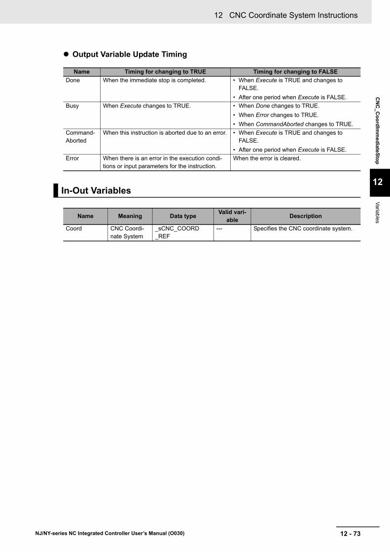
12 - 73
12 CNC Coordinate System Instructions
NJ/NY-series NC Integrated Controller User’s Manual (O030)
CN
C_
Co
ord
Imm
edia
teSto
p
12
Variab
les
Output Variable Update Timing
Name Timing for changing to TRUE Timing for changing to FALSE
Done When the immediate stop is completed. • When Execute is TRUE and changes to FALSE.
• After one period when Execute is FALSE.
Busy When Execute changes to TRUE. • When Done changes to TRUE.
• When Error changes to TRUE.
• When CommandAborted changes to TRUE.
Command-Aborted
When this instruction is aborted due to an error. • When Execute is TRUE and changes to FALSE.
• After one period when Execute is FALSE.
Error When there is an error in the execution condi-tions or input parameters for the instruction.
When the error is cleared.
In-Out Variables
Name Meaning Data typeValid vari-
ableDescription
Coord CNC Coordi-nate System
_sCNC_COORD_REF
--- Specifies the CNC coordinate system.

12 CNC Coordinate System Instructions
12 - 74 NJ/NY-series NC Integrated Controller User’s Manual (O030)
• This instruction can be executed for the CNC coordinate system that is in motion.
• When this instruction is executed, all the composition CNC motor stops immediately according to the setting of the Immediate Stop Method of CNC coordinate system parameter. CommandAborted (Command Aborted) changes to TRUE for the instruction that is currently in operation.
• When this instruction is executed, ErrorStop (Error Deceleration Stopping) changes to TRUE in the CNC coordinate system, and the Immediate Stop Instruction Executed error (560C0000 hex) occurs.
• Busy (Executing) changes to TRUE at the same time as Execute changes to TRUE.
• Done changes to TRUE when processing of this instruction is completed.
Functions
Timing Chart
CNC_Move
Execute
Done
Busy
CommandAborted
Error
ErrorID
CNC_CoordImmediateStop
Execute
16#0000
16#0000
Done
Busy
CommandAborted
Error
ErrorID
Velocity
Time

12 - 75
12 CNC Coordinate System Instructions
NJ/NY-series NC Integrated Controller User’s Manual (O030)
CN
C_
Co
ord
Imm
edia
teSto
p
12
Functions
This instruction cannot be re-executed. A CNC Instruction Re-execution Disabled error (56030000 hex) occurs if re-execution is attempted.
Refer to A-4 Instructions for Which Multi-execution Is Supported on page A-15 for details on multi-exe-cution of CNC instructions.
If this instruction cannot be executed, an error occurs, and Error will change to TRUE.
You can find out the cause of the error by referring to the value output by ErrorID (Error Code).
Re-execution of CNC Instructions
Multi-execution of CNC Instructions
Errors

12 CNC Coordinate System Instructions
12 - 76 NJ/NY-series NC Integrated Controller User’s Manual (O030)
CNC_CoordHalt
The CNC_CoordHalt instruction stops the currently running CNC motor assigned to the positioning axis in the specified CNC coordinate system.
Instruction Name FB/FUN Graphic expression ST expression
CNC_CoordHalt CNC Coor-dinate Sys-tem Halt
FB CNC_CoordHalt_instance CNC_CoordHalt_instance (
Coord :=parameter,
Execute :=parameter,
Deceleration :=parameter,
Jerk :=parameter,
Done =>parameter,
Busy =>parameter,
CommandAborted =>parameter,
Error =>parameter,
ErrorID =>parameter
);
Variables
Input Variables
Name Meaning Data type Valid range Default Description
Execute Execute BOOL TRUE or FALSE
FALSE The instruction is executed when Exe-cute changes to TRUE.
Deceleration
(Reserved)
Decelera-tion Rate
ARRAY[0..1] OF LREAL
0 0 Specifies the deceleration rate of the CNC motor in the CNC coordinate sys-tem.
The unit is command units/s2.
Jerk
(Reserved)
Jerk LREAL 0 0 Specify jerk.
The unit is command units/s3.
----
------------------------
Coord CoordExecute DoneDeceleration BusyJerk CommandAborted
ErrorErrorID
CNC_CoordHalt

12 - 77
12 CNC Coordinate System Instructions
NJ/NY-series NC Integrated Controller User’s Manual (O030)
CN
C_C
oo
rdH
alt
12
Functions
Output Variable Update Timing
• This function immediately stops the currently operating CNC motors in the specified CNC coordinate system.
• When this instruction starts, the instructions that are currently being executed are aborted by Com-mandAborted (Command Aborted).
• When Execute changes to TRUE, the stop processing starts.
• The in-position check is not performed when the CNC motor is stopped by this instruction.
• When this instruction starts, the CNC coordinate system is not changed to the Stopping (Deceleration Stopping) status. The CNC coordinate system transitions to Standby or Hold (Holding). This instruc-tion is mainly used to abort CNC_SyncMoveAbsolute from Hold (Holding) during manual interven-tion.
Output Variables
Name Meaning Data type Valid range Description
Done Done BOOL TRUE or FALSE
TRUE when the instruction is completed.
Busy Executing BOOL TRUE or FALSE
TRUE when the instruction is acknowledged.
Command-Aborted
Command Aborted
BOOL TRUE or FALSE
TRUE when the instruction is aborted.
Error Error BOOL TRUE or FALSE
TRUE while there is an error.
ErrorID Error Code WORD *1
*1. Refer to Section 15 Troubleshooting.
Contains the error code when an error occurs.
A value of 16#0000 indicates normal execution.
Name Timing for changing to TRUE Timing for changing to FALSE
Done When this instruction is completed. • When Execute is TRUE and changes to FALSE.
• After one period when Execute is FALSE.
Busy When Execute changes to TRUE. • When Done changes to TRUE.
• When Error changes to TRUE.
• When CommandAborted changes to TRUE.
Command-Aborted
• When this instruction is canceled due to an error.
• When this instruction is executed while there is an error.
• When Execute is TRUE and changes to FALSE.
• After one period when Execute is FALSE.
Error When there is an error in the execution condi-tions or input parameters for the instruction.
When the error is cleared.
In-Out Variables
Name Meaning Data type Valid range Description
Coord CNC Coordi-nate System
_sCNC_COORD_REF
--- Specifies the CNC coordinate system.
Functions

12 CNC Coordinate System Instructions
12 - 78 NJ/NY-series NC Integrated Controller User’s Manual (O030)
• If this instruction is executed while the CNC coordinate system is set to the Executing status, a multi-execution error occurs.
Precautions for Correct Use
When stopping all the CNC motor configurations including the spindle axis, use the CNC_Co-ordStop instruction.
• Busy (Executing) changes to TRUE at the same time as Execute changes to TRUE.
• Done changes to TRUE when a velocity of 0 is reached.
The following timing chart shows operations to stop the CNC motor during positioning. Command-Aborted (Command Aborted) for the positioning instruction that is currently in operation will change to TRUE when this instruction is executed.
Timing Chart
CNC_Move
Execute
Done
Busy
CommandAborted
Error
ErrorID
CNC_CoordHalt
Execute
16#0000
16#0000
Done
Busy
CommandAborted
Error
ErrorID
Velocity
Time

12 - 79
12 CNC Coordinate System Instructions
NJ/NY-series NC Integrated Controller User’s Manual (O030)
CN
C_C
oo
rdH
alt
12
Functions
This instruction cannot be re-executed. A CNC Instruction Re-execution Disabled error occurs if re-exe-cution is attempted.
Refer to A-4 Instructions for Which Multi-execution Is Supported on page A-15 for details on multi-exe-cution of CNC instructions.
If this instruction cannot be executed, an error occurs, and Error will change to TRUE.
You can find out the cause of the error by referring to the value output by ErrorID (Error Code).
Re-execution of CNC Instructions
Multi-execution of CNC Instructions
Errors

12 CNC Coordinate System Instructions
12 - 80 NJ/NY-series NC Integrated Controller User’s Manual (O030)
CNC_Power
The CNC_Power instruction makes a Servo Drive ready to operate.
Instruction Name FB/FUN Graphic expression ST expression
CNC_Power Power Servo
FB CNC_Power_instance CNC_Power_instance (
Coord :=parameter,
Enable :=parameter,
LogicalMotorNo :=parameter,
Status :=parameter,
Busy =>parameter,
Error =>parameter,
ErrorID =>parameter
);
Variables
Input Variables
Name Meaning Data type Valid range Default Description
Enable Enable BOOL TRUE or FALSE
FALSE The device is ready for operation when Enable is TRUE, and not ready when it is FALSE.
LogicalMotorNo
Logical CNC Motor Number
UINT 0 to (Maximum Positioning Logi-cal CNC Motor Number - 1), 100
0 Specify the logical CNC motor num-ber. When the CNC motor is assigned to the positioning axis, specify the Positioning Logical CNC Motor Number. When it is assigned to the spindle axis, specify 100.
Output Variables
Name Meaning Data type Valid range Description
Status Servo ON BOOL TRUE or FALSE
TRUE when the device is ready for operation.
Busy Executing BOOL TRUE or FALSE
TRUE when the instruction is acknowledged.
Error Error BOOL TRUE or FALSE
TRUE while there is an error.
ErrorID Error Code WORD *1
*1. Refer to Section 15 Troubleshooting.
Contains the error code when an error occurs.
A value of 16#0000 indicates normal execution.
----
------------------------
Coord CoordEnable StatusLogicalMotorNo Busy
ErrorErrorID
CNC_Power

12 - 81
12 CNC Coordinate System Instructions
NJ/NY-series NC Integrated Controller User’s Manual (O030)
CN
C_P
ow
er
12
Functions
Output Variable Update Timing
• When Enable changes to TRUE, the CNC motor specified in LogicalMotorNo is made ready to oper-ate. You can control the CNC motor when it is ready to operate.
• When Enable changes to FALSE, the ready status is cleared for the CNC motor specified by Logi-calMotorNo. You cannot control the CNC motor after the ready status is cleared because it will not acknowledge operation commands. Also, an error occurs if a motion command is executed for a CNC motor for which the ready status is cleared. You can execute the CNC_Power (Power Servo) and CNC_CoordReset (CNC Coordinate System Error Reset) instructions even for CNC motor that are not ready.
• You can use this instruction to disable the operation of CNC motors while they are in motion. In this case, CommandAborted (Command Aborted) will change to TRUE. Output of the operation com-mand will stop and the CNC motor will no longer be ready for operation.
• If home is not defined for a Servomotor with an absolute encoder, compensation is performed using the absolute encoder home offset to define home when the CNC motor is ready to operate. Home is also defined when I/O refresh communications with the I/O device assigned to the CNC motor change from a non-established to an established state.
Relation to CPU Unit Operating Modes
If a CNC motor is placed in ready status during RUN mode, ready status will continue even if the operating mode changes to PROGRAM mode.
Deleting Instruction with Online Editing
If a CNC motor is placed in ready status, ready status will continue even if the instruction is deleted during online editing.
Name Timing for changing to TRUE Timing for changing to FALSE
Status When the specified CNC motor is ready for operation.
When operation ready status for the specified CNC motor is cleared.
Busy When Enable changes to TRUE. • When Enable changes to FALSE.
• When Error changes to TRUE.
Error When there is an error in the execution condi-tions or input parameters for the instruction.
When the error is cleared.
In-Out Variables
Name Meaning Data type Valid range Description
Coord CNC Coordi-nate System
_sCNC_COORD_REF
--- Specifies the CNC coordinate system.
Functions
Instruction Details

12 CNC Coordinate System Instructions
12 - 82 NJ/NY-series NC Integrated Controller User’s Manual (O030)
• When Enable changes to TRUE, Busy (Executing) changes to TRUE to indicate that the instruction was acknowledged.
After the CNC motor becomes ready for operation, Status (Servo ON) changes to TRUE.
• When Enable changes to FALSE, Busy (Executing) changes to FALSE. Status (Servo ON) changes to FALSE when ready status is cleared. Status (Servo ON) outputs the CNC motor ready status regardless of whether Enable is TRUE or FALSE.
Precautions for Correct Use
Status (Servo ON) will not change to TRUE until Enable changes to TRUE and the processing is finished at the CNC motor. Make sure that Status (Servo ON) changes to TRUE before mov-ing the CNC motor.
You cannot re-execute CNC instructions with enable-type inputs.
Refer to A-4 Instructions for Which Multi-execution Is Supported on page A-15 for details on multi-exe-cution of CNC instructions.
Precautions for Correct Use
Do not create a program that starts the CNC_Power instruction of another instance for the CNC motor for which the CNC_Power instruction is currently being executed. Basically, assign a CNC_Power instruction to each CNC motor.
If this instruction cannot be executed, an error occurs, and Error will change to TRUE.
You can find out the cause of the error by referring to the value output by ErrorID (Error Code).
Timing Chart
Re-execution of CNC Instructions
Multi-execution of CNC Instructions
Errors
Enable
Status
Busy
Operation-ready status of the specified CNC motor
Release of the operation-ready status of the specified CNC motor

12 - 83
12 CNC Coordinate System Instructions
NJ/NY-series NC Integrated Controller User’s Manual (O030)
CN
C_M
oveJo
g
12
Variab
les
CNC_MoveJog
The CNC_MoveJog instruction jogs a CNC coordinate system according to the specified target velocity.
Instruction Name FB/FUN Graphic expression ST expression
CNC_MoveJog Jogging FB CNC_MoveJog_instance CNC_MoveJog_instance (
Coord :=parameter,
PositiveEnable :=parameter,
NegativeEnable :=parameter,
LogicalMotorNo :=parameter,
Velocity :=parameter,
Acceleration :=parameter,
Busy =>parameter,
CommandAborted =>parameter,
Error =>parameter,
ErrorID =>parameter
);
Variables
Input Variables
Name Meaning Data type Valid range Default Description
PositiveEnable
Positive Direction Enable
BOOL TRUE or FALSE
FALSE When this variable changes to TRUE, the CNC motor starts moving in the positive direction. When it changes to FALSE, the CNC motor stops moving.
NegativeEnable
Negative Direction Enable
BOOL TRUE or FALSE
FALSE When this variable changes to TRUE, the CNC motor starts moving in the positive direction. When it changes to FALSE, the CNC motor stops moving.
LogicalMotorNo
Logical CNC Motor Number
UINT 0 to (Maximum Positioning Log-ical CNC Motor Number - 1)
0 Specify the logical CNC motor num-ber. When the CNC motor is assigned to the positioning axis, specify the Positioning Logical CNC Motor Number.
Velocity Target Velocity
LREAL Positive num-ber, 0
0 Specify the target velocity. The unit is command units/min.
Acceleration Accelera-tion/Decel-eration Rate
LREAL Positive num-ber, 0
0 Specify the acceleration/decelera-tion rate. The unit is command
units/s2.
----
------------------------
Coord CoordPositiveEnable BusyNegativeEnable CommandAbortedLogicalMotorNo ErrorVelocity ErrorIDAcceleration
CNC_MoveJog

12 CNC Coordinate System Instructions
12 - 84 NJ/NY-series NC Integrated Controller User’s Manual (O030)
Output Variable Update Timing
Output Variables
Name Meaning Data type Valid range Description
Busy Executing BOOL TRUE or FALSE
TRUE when the instruction is acknowledged.
Command-Aborted
Command Aborted
BOOL TRUE or FALSE
TRUE when the instruction is aborted.
Error Error BOOL TRUE or FALSE
TRUE while there is an error.
ErrorID Error Code WORD *1
*1. Refer to Section 15 Troubleshooting.
Contains the error code when an error occurs.
A value of 16#0000 indicates normal execution.
Name Timing for changing to TRUE Timing for changing to FALSE
Busy When PositiveEnable or NegativeEnable changes to TRUE.
• When the CNC motor stops.
• When Error changes to TRUE.
• When CommandAborted changes to TRUE.
Command-Aborted
• When this instruction is aborted because another motion control instruction was multi-executed (Aborting).
• When this instruction is aborted due to an error.
• When this instruction is executed while there is an error.
• When you start this instruction during CNC_CoordStop instruction execution.
• When PositiveEnable changes to FALSE if PositiveEnable is TRUE.
• When NegativeEnable changes to FALSE if NegativeEnable is TRUE.
• After one period when PositiveEnable and NegativeEnable are both FALSE.
Error When there is an error in the execution condi-tions or input parameters for the instruction.
When the error is cleared.
In-Out Variables
Name Meaning Data type Valid range Description
Coord CNC Coordi-nate System
_sCNC_COORD_REF
--- Specifies the CNC coordinate system.

12 - 85
12 CNC Coordinate System Instructions
NJ/NY-series NC Integrated Controller User’s Manual (O030)
CN
C_M
oveJo
g
12
Functions
• The CNC_MoveJog instruction performs jogging according to the specified Velocity (Target Velocity).
• To jog in the positive direction, change PositiveEnable (Positive Direction Enable) to TRUE. To jog in the negative direction, change NegativeEnable (Negative Direction Enable) to TRUE.
• If PositiveEnable (Positive Direction Enable) and NegativeEnable (Negative Direction Enable) are changed to TRUE at the same time, PositiveEnable (Positive Direction Enable) takes priority. As a result, the CNC motor will jog in the positive direction.
• If the command velocity of the CNC_MoveJog (Jog) instruction exceeds the maximum jog velocity that is set in the CNC motor parameters, the maximum jog velocity is used.
• This instruction can be executed even if home is not defined.
• Busy (Executing) changes to TRUE as soon as PositiveEnable (Positive Direction Enable) or Nega-tiveEnable (Negative Direction Enable) changes to TRUE.
• The axis starts deceleration as soon as PositiveEnable (Positive Direction Enable) or NegativeEn-able (Negative Direction Enable) changes to FALSE and Busy (Executing) changes to FALSE when the axis stops completely.
• If another instruction aborts this instruction, CommandAborted (Command Aborted) changes to TRUE and Busy (Executing) changes to FALSE.
You can specify Velocity (Target Velocity) and Acceleration (Acceleration/Deceleration Rate) as the input variables. The Velocity (Target Velocity) and Acceleration (Acceleration/Deceleration Rate) input variables are updated operations only when PositiveEnable (Positive Direction Enable) or NegativeEn-able (Negative Direction Enable) rises. Therefore, the velocity will not change even if Velocity (Target Velocity) changes while PositiveEnable (Positive Direction Enable) or NegativeEnable (Negative Direc-tion Enable) remains TRUE.
Functions
Timing Chart
PositiveEnable
NegativeEnable
Busy
CommandAborted
Error
ErrorID
Target velocity
Acceleration/Deceleration Rate
Decelerates to a stop when another instruction causes an error.
16#0000
Velocity
Time
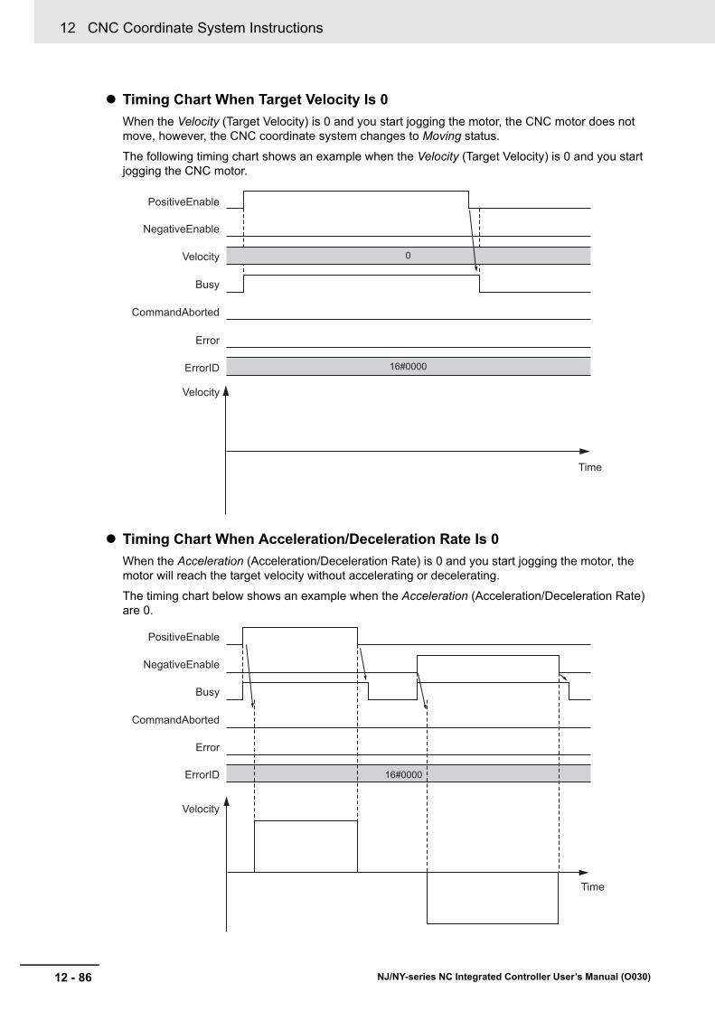
12 CNC Coordinate System Instructions
12 - 86 NJ/NY-series NC Integrated Controller User’s Manual (O030)
Timing Chart When Target Velocity Is 0
When the Velocity (Target Velocity) is 0 and you start jogging the motor, the CNC motor does not move, however, the CNC coordinate system changes to Moving status.
The following timing chart shows an example when the Velocity (Target Velocity) is 0 and you start jogging the CNC motor.
Timing Chart When Acceleration/Deceleration Rate Is 0
When the Acceleration (Acceleration/Deceleration Rate) is 0 and you start jogging the motor, the motor will reach the target velocity without accelerating or decelerating.
The timing chart below shows an example when the Acceleration (Acceleration/Deceleration Rate) are 0.
NegativeEnable
PositiveEnable
Busy
CommandAborted
Error
ErrorID
Velocity
Time
Velocity
16#0000
0
NegativeEnable
PositiveEnable
Busy
CommandAborted
Error
ErrorID
Velocity
Time
16#0000
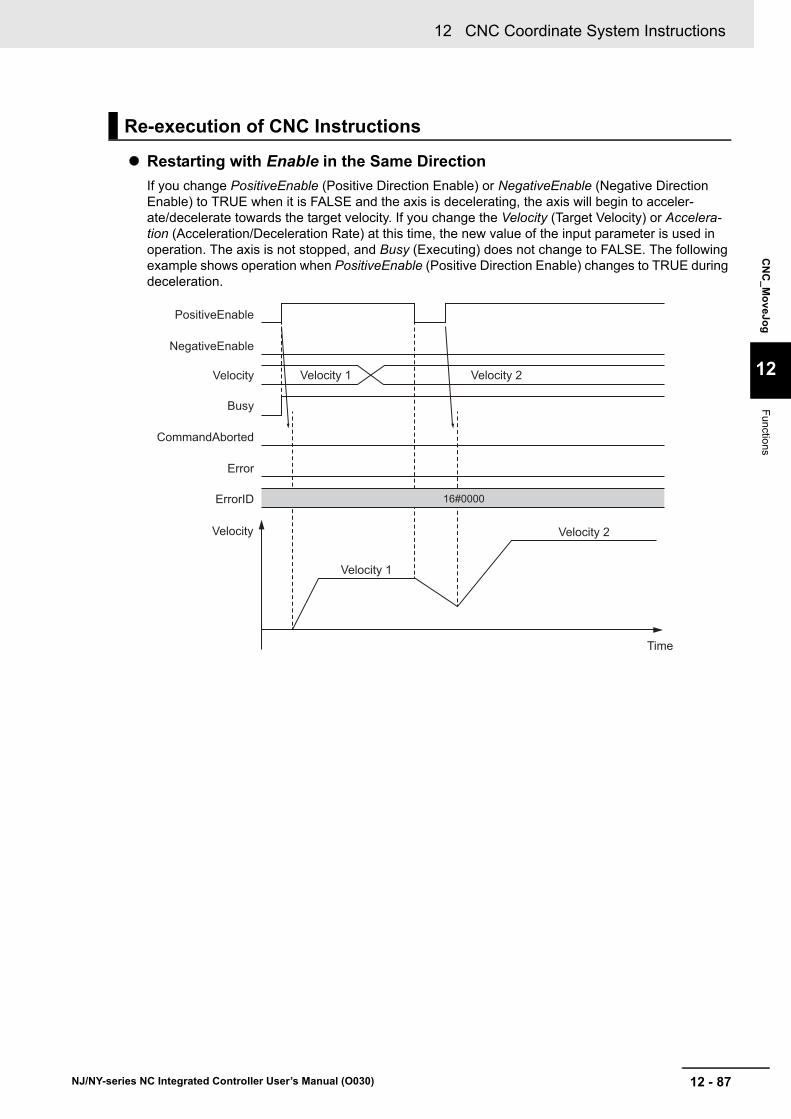
12 - 87
12 CNC Coordinate System Instructions
NJ/NY-series NC Integrated Controller User’s Manual (O030)
CN
C_M
oveJo
g
12
Functions
Restarting with Enable in the Same Direction
If you change PositiveEnable (Positive Direction Enable) or NegativeEnable (Negative Direction Enable) to TRUE when it is FALSE and the axis is decelerating, the axis will begin to acceler-ate/decelerate towards the target velocity. If you change the Velocity (Target Velocity) or Accelera-tion (Acceleration/Deceleration Rate) at this time, the new value of the input parameter is used in operation. The axis is not stopped, and Busy (Executing) does not change to FALSE. The following example shows operation when PositiveEnable (Positive Direction Enable) changes to TRUE during deceleration.
Re-execution of CNC Instructions
NegativeEnable
PositiveEnable
Busy
Velocity Velocity 1
Velocity 1
Velocity 2
Velocity 2
Time
CommandAborted
Error
ErrorID
Velocity
16#0000
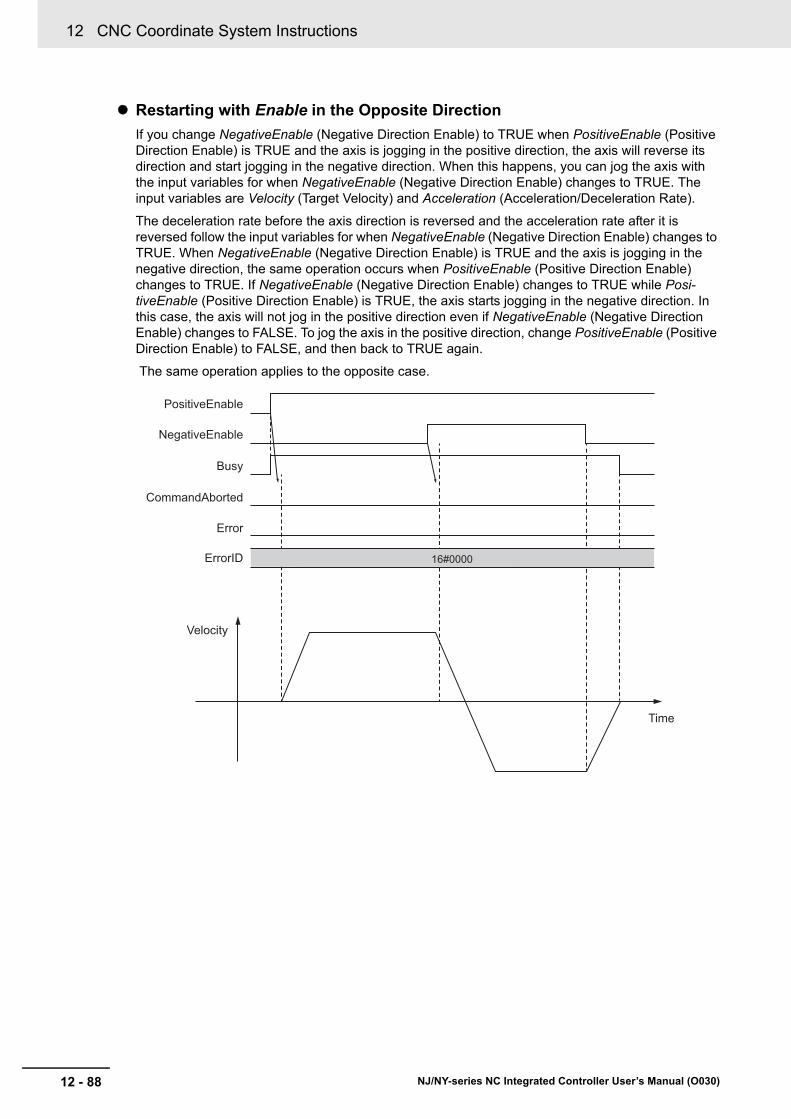
12 CNC Coordinate System Instructions
12 - 88 NJ/NY-series NC Integrated Controller User’s Manual (O030)
Restarting with Enable in the Opposite Direction
If you change NegativeEnable (Negative Direction Enable) to TRUE when PositiveEnable (Positive Direction Enable) is TRUE and the axis is jogging in the positive direction, the axis will reverse its direction and start jogging in the negative direction. When this happens, you can jog the axis with the input variables for when NegativeEnable (Negative Direction Enable) changes to TRUE. The input variables are Velocity (Target Velocity) and Acceleration (Acceleration/Deceleration Rate).
The deceleration rate before the axis direction is reversed and the acceleration rate after it is reversed follow the input variables for when NegativeEnable (Negative Direction Enable) changes to TRUE. When NegativeEnable (Negative Direction Enable) is TRUE and the axis is jogging in the negative direction, the same operation occurs when PositiveEnable (Positive Direction Enable) changes to TRUE. If NegativeEnable (Negative Direction Enable) changes to TRUE while Posi-tiveEnable (Positive Direction Enable) is TRUE, the axis starts jogging in the negative direction. In this case, the axis will not jog in the positive direction even if NegativeEnable (Negative Direction Enable) changes to FALSE. To jog the axis in the positive direction, change PositiveEnable (Positive Direction Enable) to FALSE, and then back to TRUE again.
The same operation applies to the opposite case.
NegativeEnable
PositiveEnable
Busy
Time
CommandAborted
Error
ErrorID
Velocity
16#0000

12 - 89
12 CNC Coordinate System Instructions
NJ/NY-series NC Integrated Controller User’s Manual (O030)
CN
C_M
oveJo
g
12
Functions
Refer to A-4 Instructions for Which Multi-execution Is Supported on page A-15 for details on multi-exe-cution of CNC instructions.
If this instruction cannot be executed, an error occurs, and Error will change to TRUE.
You can find out the cause of the error by referring to the value output by ErrorID (Error Code).
Multi-execution of CNC Instructions
Errors
NegativeEnable
PositiveEnable
Busy
CommandAborted
Error
ErrorID Error code

12 CNC Coordinate System Instructions
12 - 90 NJ/NY-series NC Integrated Controller User’s Manual (O030)
CNC_Home
The CNC_Home instruction operates the Servomotor to determine home using the limit signals, home proximity signal, and home signal.
Instruction Name FB/FUN Graphic expression ST expression
CNC_Home Home FB CNC_Home_instance CNC_Home_instance (
Coord :=parameter,
Execute :=parameter,
LogicalMotorNo :=parameter,
Done =>parameter,
Busy =>parameter,
CommandAborted =>parameter,
Error =>parameter,
ErrorID =>parameter
);
Variables
Input Variables
Name Meaning Data type Valid range Default Description
Execute Execute BOOL TRUE or FALSE
FALSE The instruction is executed when Execute changes to TRUE.
LogicalMotorNo
Logical CNC Motor Number
UINT 0 to (Maximum Positioning Log-ical CNC Motor Number - 1), 100
0 Specify the logical CNC motor num-ber. When the target CNC motor is assigned to the positioning axis, specify the Positioning Logical CNC Motor Number.
Output Variables
Name Meaning Data type Valid range Description
Done Done BOOL TRUE or FALSE
TRUE when the instruction is completed.
Busy Executing BOOL TRUE or FALSE
TRUE when the instruction is acknowledged.
Command-Aborted
Command Aborted
BOOL TRUE or FALSE
TRUE when the instruction is aborted.
Error Error BOOL TRUE or FALSE
TRUE while there is an error.
ErrorID Error Code WORD *1
*1. Refer to Section 15 Troubleshooting.
Contains the error code when an error occurs.
A value of 16#0000 indicates normal execution.
----
------------------------
Coord CoordExecute DoneLogicalMotorNo Busy
CommandAbortedError
ErrorID
CNC_Home

12 - 91
12 CNC Coordinate System Instructions
NJ/NY-series NC Integrated Controller User’s Manual (O030)
CN
C_H
om
e
12
Functions
Output Variable Update Timing
Refer to the description of MC_Home in the NJ/NX-series Motion Control Instructions Reference Man-ual (Cat. No. W508) or NY-series Motion Control Instructions Reference Manual (Cat. No. W561).
The following describes differences from the MC_Home specifications.
Homing Acceleration / Deceleration
You can specify the homing acceleration/deceleration rate as a homing parameter.
The homing acceleration rate and homing deceleration rate cannot be specified individually.
Homing Jerk
You cannot specify the Homing Jerk.
Refer to the description of MC_Home in the NJ/NX-series Motion Control Instructions Reference Man-ual (Cat. No. W508) or NY-series Motion Control Instructions Reference Manual (Cat. No. W561).
Name Timing for changing to TRUE Timing for changing to FALSE
Done When this instruction is completed. • When Execute is TRUE and changes to FALSE.
• After one period when Execute is FALSE.
Busy When Execute changes to TRUE. • When Done changes to TRUE.
• When Error changes to TRUE.
• When CommandAborted changes to TRUE.
Command-Aborted
• When this instruction is aborted because another motion control instruction was multi-executed (Aborting).
• When this instruction is aborted due to an error.
• When this instruction is executed while there is an error.
• When you start this instruction during CNC_CoordStop instruction execution.
• When Execute is TRUE and changes to FALSE.
• After one period when Execute is FALSE.
Error When there is an error in the execution condi-tions or input parameters for the instruction.
When the error is cleared.
In-Out Variables
Name Meaning Data type Valid range Description
Coord CNC Coordi-nate System
_sCNC_COORD_REF
--- Specifies the CNC coordinate system.
Functions
Instruction Details
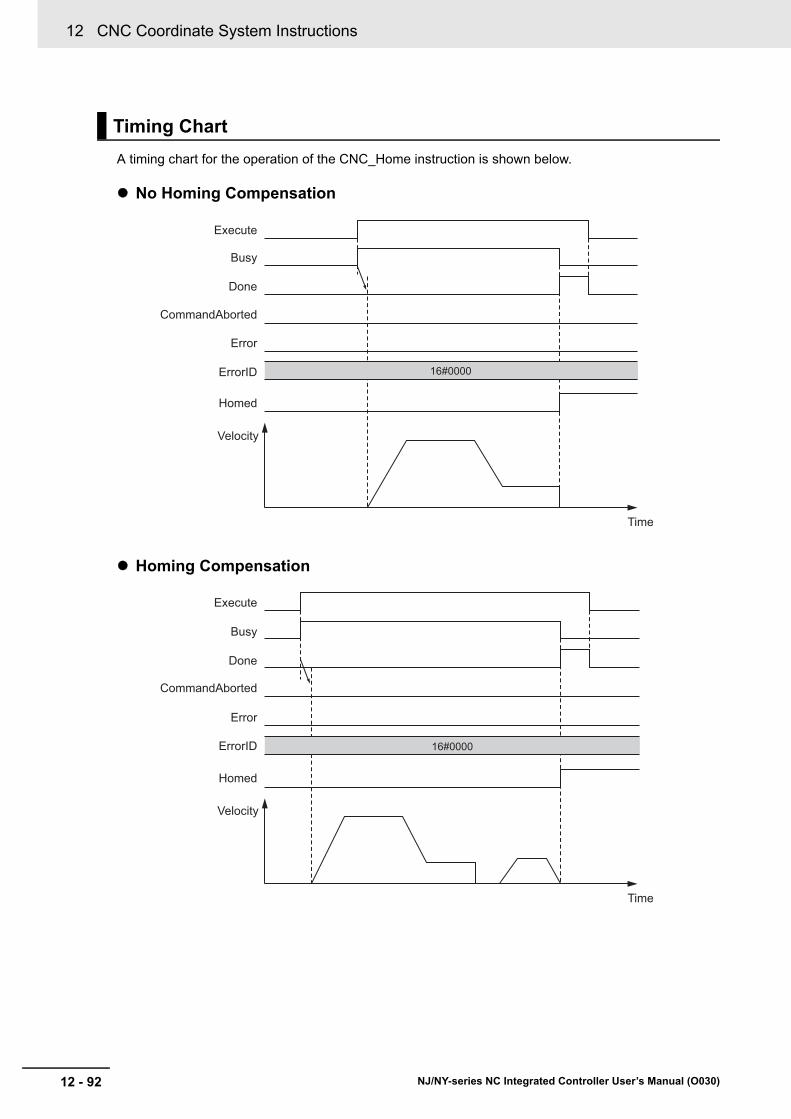
12 CNC Coordinate System Instructions
12 - 92 NJ/NY-series NC Integrated Controller User’s Manual (O030)
A timing chart for the operation of the CNC_Home instruction is shown below.
No Homing Compensation
Homing Compensation
Timing Chart
Homed
Busy
Done
CommandAborted
Error
ErrorID
Execute
Velocity
16#0000
Time
Homed
Busy
Done
CommandAborted
Error
ErrorID
Execute
Time
Velocity
16#0000

12 - 93
12 CNC Coordinate System Instructions
NJ/NY-series NC Integrated Controller User’s Manual (O030)
CN
C_H
om
e
12
Functions
This instruction cannot be re-executed. A CNC Instruction Re-execution Disabled error occurs if re-exe-cution is attempted.
Refer to A-4 Instructions for Which Multi-execution Is Supported on page A-15 for details on multi-exe-cution of CNC instructions.
If this instruction cannot be executed, an error occurs, and Error will change to TRUE.
You can find out the cause of the error by referring to the value output by ErrorID (Error Code).
Re-execution of CNC Instructions
Multi-execution of CNC Instructions
Errors
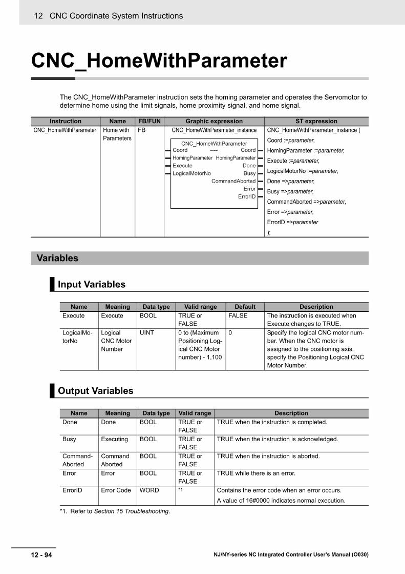
12 CNC Coordinate System Instructions
12 - 94 NJ/NY-series NC Integrated Controller User’s Manual (O030)
CNC_HomeWithParameter
The CNC_HomeWithParameter instruction sets the homing parameter and operates the Servomotor to determine home using the limit signals, home proximity signal, and home signal.
Instruction Name FB/FUN Graphic expression ST expression
CNC_HomeWithParameter Home with Parameters
FB CNC_HomeWithParameter_instance CNC_HomeWithParameter_instance (
Coord :=parameter,
HomingParameter :=parameter,
Execute :=parameter,
LogicalMotorNo :=parameter,
Done =>parameter,
Busy =>parameter,
CommandAborted =>parameter,
Error =>parameter,
ErrorID =>parameter
);
Variables
Input Variables
Name Meaning Data type Valid range Default Description
Execute Execute BOOL TRUE or FALSE
FALSE The instruction is executed when Execute changes to TRUE.
LogicalMo-torNo
Logical CNC Motor Number
UINT 0 to (Maximum Positioning Log-ical CNC Motor number) - 1,100
0 Specify the logical CNC motor num-ber. When the CNC motor is assigned to the positioning axis, specify the Positioning Logical CNC Motor Number.
Output Variables
Name Meaning Data type Valid range Description
Done Done BOOL TRUE or FALSE
TRUE when the instruction is completed.
Busy Executing BOOL TRUE or FALSE
TRUE when the instruction is acknowledged.
Command-Aborted
Command Aborted
BOOL TRUE or FALSE
TRUE when the instruction is aborted.
Error Error BOOL TRUE or FALSE
TRUE while there is an error.
ErrorID Error Code WORD *1
*1. Refer to Section 15 Troubleshooting.
Contains the error code when an error occurs.
A value of 16#0000 indicates normal execution.
----
------------------------
Coord CoordHomingParameter HomingParameterExecute DoneLogicalMotorNo Busy
CommandAbortedError
ErrorID
CNC_HomeWithParameter

12 - 95
12 CNC Coordinate System Instructions
NJ/NY-series NC Integrated Controller User’s Manual (O030)
CN
C_H
om
eWith
Param
eter
12
Variab
les
Output Variable Update Timing
Name Timing for changing to TRUE Timing for changing to FALSE
Done When this instruction is completed. • When Execute is TRUE and changes to FALSE.
• After one period when Execute is FALSE.
Busy When Execute changes to TRUE. • When Done changes to TRUE.
• When Error changes to TRUE.
• When CommandAborted changes to TRUE.
Command-Aborted
• When this instruction is aborted because another motion control instruction was multi-executed (Aborting).
• When this instruction is aborted due to an error.
• When this instruction is executed while there is an error.
• When you start this instruction during CNC_CoordStop instruction execution.
• When Execute is TRUE and changes to FALSE.
• After one period when Execute is FALSE.
Error When there is an error in the execution condi-tions or input parameters for the instruction.
When the error is cleared.
In-Out Variables
Name Meaning Data type Valid range Description
Coord CNC Coordi-nate System
_sCNC_COORD_REF
--- Specifies the CNC coordinate system.
HomingPa-rameter
Homing Parameter
_sCNC_HOMING_REF
--- Specifies a homing parameter.
12 CNC Coordinate System Instructions
12 - 96 NJ/NY-series NC Integrated Controller User’s Manual (O030)
Refer to the description of MC_Home in the NJ/NX-series Motion Control Instructions Reference Man-ual (Cat. No. W508) or NY-series Motion Control Instructions Reference Manual (Cat. No. W561).
The following describes differences from the MC_HomeWithParameter specifications.
Homing Acceleration/Deceleration Rate
The user can specify the acceleration/deceleration rate as a homing parameter.
_sCNC_HOMING_REF.Acc is used to specify the homing acceleration/deceleration rate.
There is no parameter that is equivalent to the Homing Deceleration (_sHOMING_REF.Dec).
Homing Jerk
You cannot specify the Homing Jerk.
There is no parameter that is equivalent to the Homing Jerk (_sHOMING_REF.Jerk).
Refer to the description of MC_HomeWithParameter in the NJ/NX-series Motion Control Instructions Reference Manual (Cat. No. W508) or NY-series Motion Control Instructions Reference Manual (Cat. No. W561).
The timing chart is the same as that for the CNC_Home instruction. Refer to the timing chart shown in CNC_Home on page 12-90.
This instruction cannot be re-executed. A CNC Instruction Re-execution Disabled error occurs if re-exe-cution is attempted.
Refer to A-4 Instructions for Which Multi-execution Is Supported on page A-15 for details on multi-exe-cution of CNC instructions.
If this instruction cannot be executed, an error occurs, and Error will change to TRUE.
You can find out the cause of the error by referring to the value output by ErrorID (Error Code).
Functions
Instruction Details
Timing Chart
Re-execution of CNC Instructions
Multi-execution of CNC Instructions
Errors
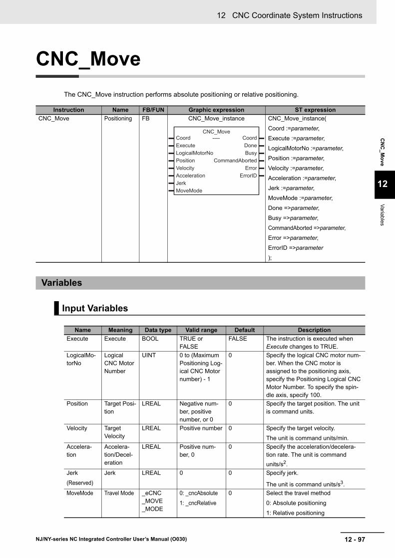
12 - 97
12 CNC Coordinate System Instructions
NJ/NY-series NC Integrated Controller User’s Manual (O030)
CN
C_M
ove
12
Variab
les
CNC_Move
The CNC_Move instruction performs absolute positioning or relative positioning.
Instruction Name FB/FUN Graphic expression ST expression
CNC_Move Positioning FB CNC_Move_instance CNC_Move_instance(
Coord :=parameter,
Execute :=parameter,
LogicalMotorNo :=parameter,
Position :=parameter,
Velocity :=parameter,
Acceleration :=parameter,
Jerk :=parameter,
MoveMode :=parameter,
Done =>parameter,
Busy =>parameter,
CommandAborted =>parameter,
Error =>parameter,
ErrorID =>parameter
);
Variables
Input Variables
Name Meaning Data type Valid range Default Description
Execute Execute BOOL TRUE or FALSE
FALSE The instruction is executed when Execute changes to TRUE.
LogicalMo-torNo
Logical CNC Motor Number
UINT 0 to (Maximum Positioning Log-ical CNC Motor number) - 1
0 Specify the logical CNC motor num-ber. When the CNC motor is assigned to the positioning axis, specify the Positioning Logical CNC Motor Number. To specify the spin-dle axis, specify 100.
Position Target Posi-tion
LREAL Negative num-ber, positive number, or 0
0 Specify the target position. The unit is command units.
Velocity Target Velocity
LREAL Positive number 0 Specify the target velocity.
The unit is command units/min.
Accelera-tion
Accelera-tion/Decel-eration
LREAL Positive num-ber, 0
0 Specify the acceleration/decelera-tion rate. The unit is command
units/s2.
Jerk
(Reserved)
Jerk LREAL 0 0 Specify jerk.
The unit is command units/s3.
MoveMode Travel Mode _eCNC_MOVE_MODE
0: _cncAbsolute
1: _cncRelative
0 Select the travel method
0: Absolute positioning
1: Relative positioning
----
------------------------
Coord CoordExecute DoneLogicalMotorNo BusyPosition CommandAbortedVelocity ErrorAcceleration ErrorIDJerkMoveMode
CNC_Move

12 CNC Coordinate System Instructions
12 - 98 NJ/NY-series NC Integrated Controller User’s Manual (O030)
Output Variable Update Timing
Output Variables
Name Meaning Data type Valid range Description
Done Done BOOL TRUE or FALSE TRUE when the instruction is completed.
Busy Executing BOOL TRUE or FALSE TRUE when the instruction is acknowledged.
Command-Aborted
Command Aborted
BOOL TRUE or FALSE TRUE when the instruction is aborted.
Error Error BOOL TRUE or FALSE TRUE while there is an error.
ErrorID Error Code WORD *1
*1. Refer to Section 15 Troubleshooting.
Contains the error code when an error occurs.
A value of 16#0000 indicates normal execution.
Name Timing for changing to TRUE Timing for changing to FALSE
Done When positioning is completed. • When Execute is TRUE and changes to FALSE.
• After one period when Execute is FALSE.
Busy When Execute changes to TRUE. • When Done is set to TRUE.
• When Error changes to TRUE.
• When CommandAborted changes to TRUE.
Command-Aborted
• When this instruction is aborted because another motion control instruction was multi-executed (Aborting).
• When this instruction is aborted due to an error.
• When this instruction is executed while there is an error.
• When you start this instruction during CNC_CoordStop instruction execution.
• When Execute is TRUE and changes to FALSE.
• After one period when Execute is FALSE.
Error When there is an error in the execution condi-tions or input parameters for the instruction.
When the error is cleared.
In-Out Variables
Name Meaning Data type Valid range Description
Coord CNC Coordi-nate System
_sCNC_COORD_REF
--- Specifies the CNC coordinate system.
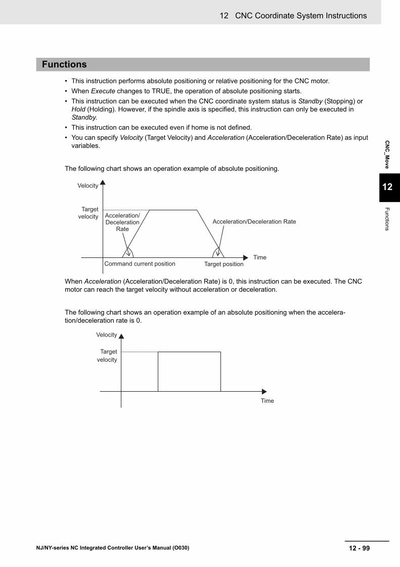
12 - 99
12 CNC Coordinate System Instructions
NJ/NY-series NC Integrated Controller User’s Manual (O030)
CN
C_M
ove
12
Functions
• This instruction performs absolute positioning or relative positioning for the CNC motor.
• When Execute changes to TRUE, the operation of absolute positioning starts.
• This instruction can be executed when the CNC coordinate system status is Standby (Stopping) or Hold (Holding). However, if the spindle axis is specified, this instruction can only be executed in Standby.
• This instruction can be executed even if home is not defined.
• You can specify Velocity (Target Velocity) and Acceleration (Acceleration/Deceleration Rate) as input variables.
The following chart shows an operation example of absolute positioning.
When Acceleration (Acceleration/Deceleration Rate) is 0, this instruction can be executed. The CNC motor can reach the target velocity without acceleration or deceleration.
The following chart shows an operation example of an absolute positioning when the accelera-tion/deceleration rate is 0.
Functions
Velocity
Target velocity Acceleration/
Deceleration Rate
Command current position Target position
Acceleration/Deceleration Rate
Time
Velocity
Target velocity
Time
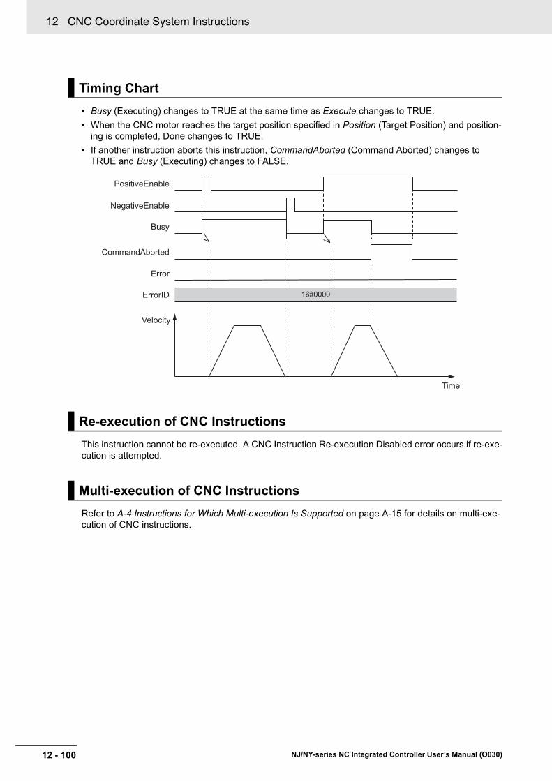
12 CNC Coordinate System Instructions
12 - 100 NJ/NY-series NC Integrated Controller User’s Manual (O030)
• Busy (Executing) changes to TRUE at the same time as Execute changes to TRUE.
• When the CNC motor reaches the target position specified in Position (Target Position) and position-ing is completed, Done changes to TRUE.
• If another instruction aborts this instruction, CommandAborted (Command Aborted) changes to TRUE and Busy (Executing) changes to FALSE.
This instruction cannot be re-executed. A CNC Instruction Re-execution Disabled error occurs if re-exe-cution is attempted.
Refer to A-4 Instructions for Which Multi-execution Is Supported on page A-15 for details on multi-exe-cution of CNC instructions.
Timing Chart
Re-execution of CNC Instructions
Multi-execution of CNC Instructions
NegativeEnable
PositiveEnable
Busy
Time
16#0000
CommandAborted
Error
ErrorID
Velocity
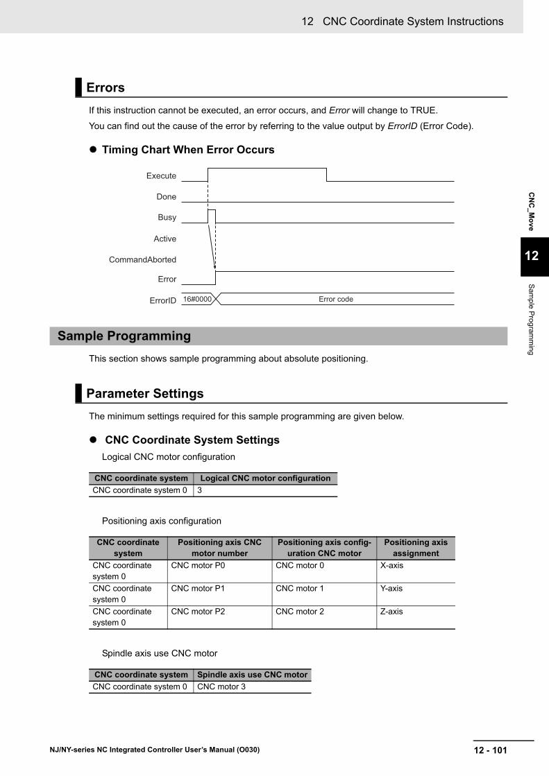
12 - 101
12 CNC Coordinate System Instructions
NJ/NY-series NC Integrated Controller User’s Manual (O030)
CN
C_M
ove
12
Sam
ple Prog
ramm
ing
If this instruction cannot be executed, an error occurs, and Error will change to TRUE.
You can find out the cause of the error by referring to the value output by ErrorID (Error Code).
Timing Chart When Error Occurs
This section shows sample programming about absolute positioning.
The minimum settings required for this sample programming are given below.
CNC Coordinate System Settings
Logical CNC motor configuration
Positioning axis configuration
Spindle axis use CNC motor
Errors
Sample Programming
Parameter Settings
CNC coordinate system Logical CNC motor configuration
CNC coordinate system 0 3
CNC coordinate system
Positioning axis CNC motor number
Positioning axis config-uration CNC motor
Positioning axis assignment
CNC coordinate system 0
CNC motor P0 CNC motor 0 X-axis
CNC coordinate system 0
CNC motor P1 CNC motor 1 Y-axis
CNC coordinate system 0
CNC motor P2 CNC motor 2 Z-axis
CNC coordinate system Spindle axis use CNC motor
CNC coordinate system 0 CNC motor 3
Busy
Execute
Done
CommandAborted
Error
ErrorID Error code16#0000
Active

12 CNC Coordinate System Instructions
12 - 102 NJ/NY-series NC Integrated Controller User’s Manual (O030)
MoveMode (Travel Mode) of the CNC_Move (Positioning) instruction is set to Absolute positioning to move to the target position.
Operation Patterns
1 Turning ON the Operation Start Switch
When you turn ON the operation start switch at the home, CNC motor 0 assigned to the X-axis is positioned to 50.00 mm in the positive direction.
Main Variables
Operation Example
Ladder Diagram
Name Data type Default Comment
CNC_Coord000 _sCNC_COORD_REF --- CNC coordinate system variable of CNC coordi-nate system 0.
CNC_Motor000 _sCNC_MOTOR_REF --- CNC motor variable of CNC motor 0.
CNC_Mo-tor000.MFaultLvl.Active
BOOL FALSE TRUE when a minor fault level error occurs in CNC motor 0.
StartPg BOOL FALSE Indicates the operation start switch.
The Servo is turned ON when this variable is TRUE and EtherCAT process data communica-tions are established.
0
1000
50 (mm)
Velocity (mm/s)
Positive direction
Operation starts

12 - 103
12 CNC Coordinate System Instructions
NJ/NY-series NC Integrated Controller User’s Manual (O030)
CN
C_M
ove
12
Sam
ple Prog
ramm
ing
Timing Chart
Sample Programming
When contact StartPg is TRUE, check that the Servo Drive is in the servo ready status.
When the Servo Drive is in the servo ready status, turn ON the Servo.
If a minor fault level error occurs in CNC motor 0 assigned to the X-axis, the error handler for the device (FaultHandler) is executed.
Program the FaultHandler according to the device.
Pwr_Status
Hm_Bsy
Hm_D
Mv_Bsy
Mv_D
CNC_Motor000.DrvStatus.Ready Lock1StartPg
Lock1 Pwr_Status
0
PWR
CNC_Power
StatusBusyError
ErrorID
Coord CoordEnableLogicalMotorNo
CNC_Coord000 CNC_Coord000
Pwr_BsyPwr_ErrPwr_ErrID
CNC_Coord000.MFaultLvl.ActiveFHandler
FaultHandlerinput output
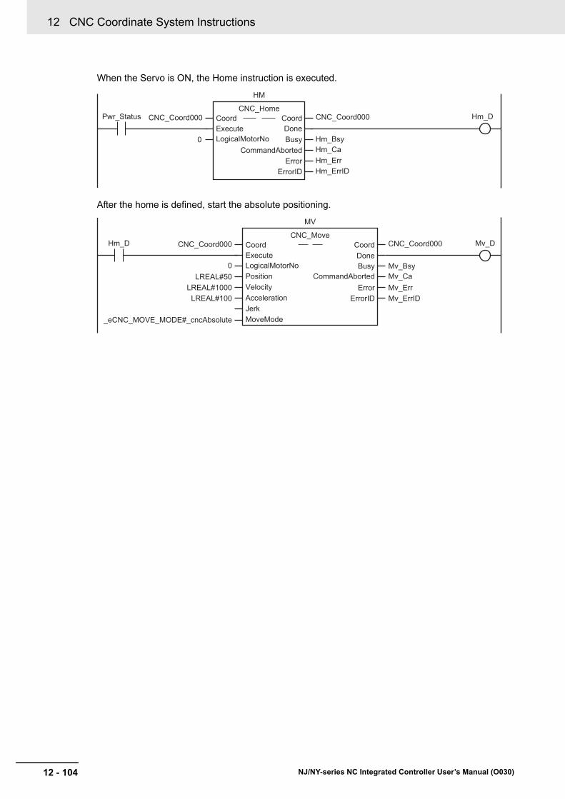
12 CNC Coordinate System Instructions
12 - 104 NJ/NY-series NC Integrated Controller User’s Manual (O030)
When the Servo is ON, the Home instruction is executed.
After the home is defined, start the absolute positioning.
Pwr_Status Hm_D
Hm_CaHm_ErrHm_ErrID
Hm_Bsy
HM
CNC_Home
DoneBusy
CommandAbortedError
ErrorID
Coord CoordExecuteLogicalMotorNo
CNC_Coord000 CNC_Coord000
0
Mv_ErrIDMv_ErrMv_CaMv_Bsy
LREAL#50LREAL#1000
LREAL#100
_eCNC_MOVE_MODE#_cncAbsolute
MV
CNC_Move
ErrorErrorID
Coord CoordDoneExecuteBusyLogicalMotorNo
CommandAbortedPositionVelocityAccelerationJerkMoveMode
CNC_Coord000 CNC_Coord000
0
Hm_D Mv_D

12 - 105
12 CNC Coordinate System Instructions
NJ/NY-series NC Integrated Controller User’s Manual (O030)
CN
C_M
ove
12
Sam
ple Prog
ramm
ing
Main Variables
Timing Chart
Structured Text (ST)
Name Data type Default Comment
CNC_Coord000 _sCNC_COORD_REF --- CNC coordinate system variable of CNC coordi-nate system 0.
CNC_Motor000 _sCNC_MOTOR_REF --- CNC motor variable of CNC motor 0.
CNC_Mo-tor000.MFaultLvl.Active
BOOL FALSE TRUE when a minor fault level error occurs in CNC motor 0.
StartPg BOOL FALSE Indicates the operation start switch.
The Servo is turned ON when this variable is TRUE and EtherCAT process data communica-tions are established.
Pwr_Status
Hm_Bsy
Hm_D
Mv_Bsy
Mv_D

12 CNC Coordinate System Instructions
12 - 106 NJ/NY-series NC Integrated Controller User’s Manual (O030)
Sample Programming
// When StartPg changes to TRUE, check that the Servo Drive is in the servo ready status and turn ON the Servo.// If the Servo is not ready, turn OFF the Servo.IF (StartPg=TRUE) AND (CNC_Motor000.DrvStatus.Ready=TRUE) THEN Pwr_En:=TRUE;ELSE Pwr_En:=FALSE;END_IF;
// If a minor fault level error occurs in CNC motor 0 assigned to the X-axis, the error handler for the device (FaultHandler) is executed.// Program the FaultHandler according to the device.IF CNC_Motor000.MFaultLvl.Active=TRUE THEN FaultHandler();END_IF;
// When the Servo is ON, the Home instruction is executed.IF Pwr_Status=TRUE THEN Hm_Ex:=TRUE;END_IF;
// After the home is defined, start the absolute positioning.IF Hm_D=TRUE THEN Mv_Ex:=TRUE;END_IF;
//CNC_PowerPWR( Coord := CNC_Coord000 , Enable := Pwr_En , LogicalMotorNo := 0 , Status => Pwr_Status , Busy => Pwr_Bsy , Error => Pwr_Err , ErrorID => Pwr_ErrID);
//CNC_HomeHM( Coord := CNC_Coord000 , Execute := Hm_Ex , LogicalMotorNo :=0 , Done => Hm_D , Busy => Hm_Bsy , CommandAborted=> Hm_Ca , Error => Hm_Err , ErrorID => Hm_ErrID);
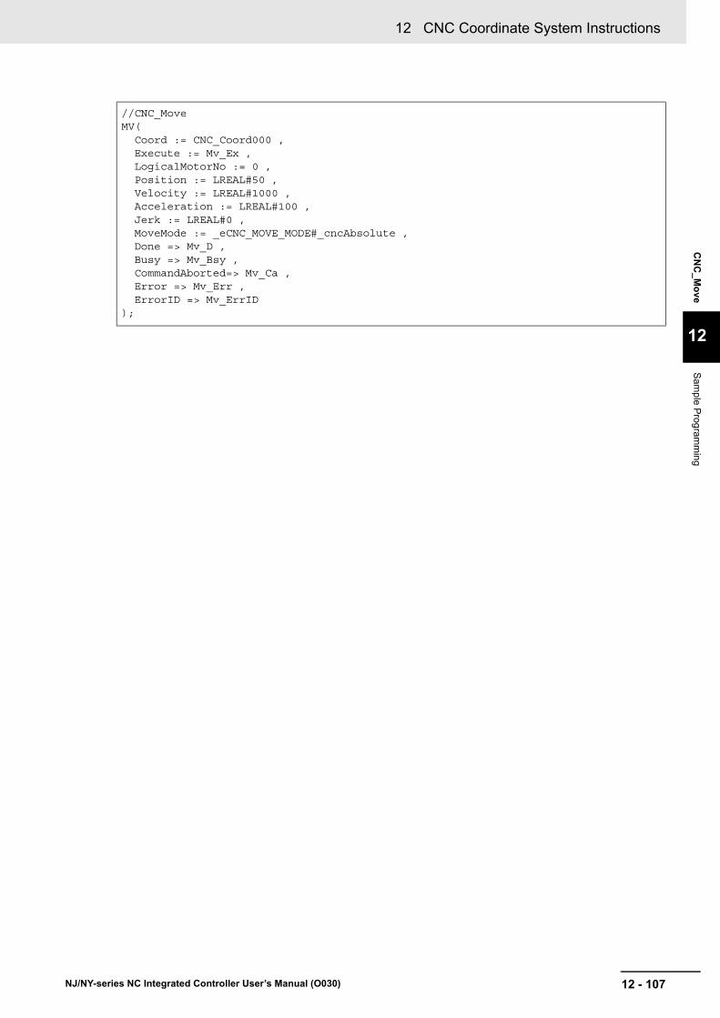
12 - 107
12 CNC Coordinate System Instructions
NJ/NY-series NC Integrated Controller User’s Manual (O030)
CN
C_M
ove
12
Sam
ple Prog
ramm
ing
//CNC_MoveMV( Coord := CNC_Coord000 , Execute := Mv_Ex , LogicalMotorNo := 0 , Position := LREAL#50 , Velocity := LREAL#1000 , Acceleration := LREAL#100 , Jerk := LREAL#0 , MoveMode := _eCNC_MOVE_MODE#_cncAbsolute , Done => Mv_D , Busy => Mv_Bsy , CommandAborted=> Mv_Ca , Error => Mv_Err , ErrorID => Mv_ErrID);
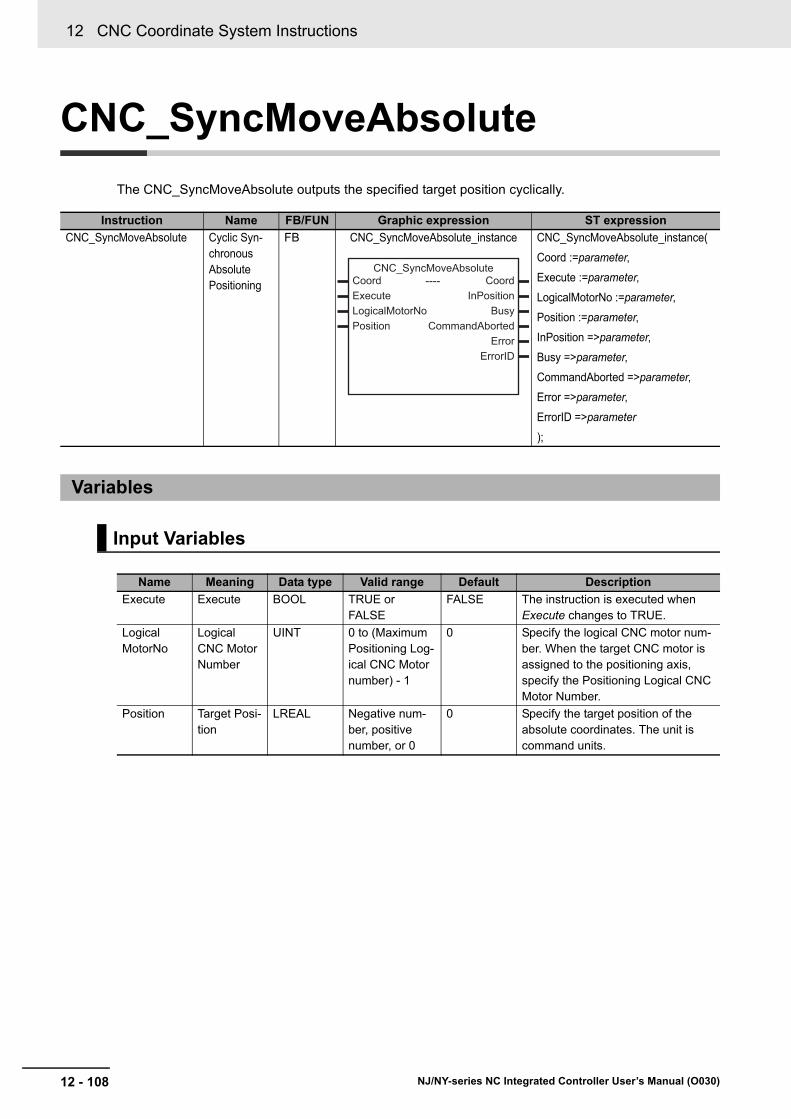
12 CNC Coordinate System Instructions
12 - 108 NJ/NY-series NC Integrated Controller User’s Manual (O030)
CNC_SyncMoveAbsolute
The CNC_SyncMoveAbsolute outputs the specified target position cyclically.
Instruction Name FB/FUN Graphic expression ST expression
CNC_SyncMoveAbsolute Cyclic Syn-chronous Absolute Positioning
FB CNC_SyncMoveAbsolute_instance CNC_SyncMoveAbsolute_instance(
Coord :=parameter,
Execute :=parameter,
LogicalMotorNo :=parameter,
Position :=parameter,
InPosition =>parameter,
Busy =>parameter,
CommandAborted =>parameter,
Error =>parameter,
ErrorID =>parameter
);
Variables
Input Variables
Name Meaning Data type Valid range Default Description
Execute Execute BOOL TRUE or FALSE
FALSE The instruction is executed when Execute changes to TRUE.
LogicalMotorNo
Logical CNC Motor Number
UINT 0 to (Maximum Positioning Log-ical CNC Motor number) - 1
0 Specify the logical CNC motor num-ber. When the target CNC motor is assigned to the positioning axis, specify the Positioning Logical CNC Motor Number.
Position Target Posi-tion
LREAL Negative num-ber, positive number, or 0
0 Specify the target position of the absolute coordinates. The unit is command units.
----
------------------------
Coord CoordExecute InPositionLogicalMotorNo BusyPosition CommandAborted
ErrorErrorID
CNC_SyncMoveAbsolute

12 - 109
12 CNC Coordinate System Instructions
NJ/NY-series NC Integrated Controller User’s Manual (O030)
CN
C_S
yncM
oveA
bso
lute
12
Variab
les
Output Variable Update Timing
Output Variables
Name Meaning Data type Valid range Description
InPosition In-position BOOL TRUE or FALSE
TRUE when the feedback current positions for all com-position axes are within the in-position range of their target positions.
Busy Executing BOOL TRUE or FALSE
TRUE when the instruction is acknowledged.
Command-Aborted
Command Aborted
BOOL TRUE or FALSE
TRUE when the instruction is aborted.
Error Error BOOL TRUE or FALSE
TRUE while there is an error.
ErrorID Error Code WORD *1
*1. Refer to Section 15 Troubleshooting.
Contains the error code when an error occurs.
A value of 16#0000 indicates normal execution.
Variable Timing for changing to TRUE Timing for changing to FALSE
InPosition When the feedback current positions for all composition axes are within the in-position range of their target positions.
• When the feedback current position has been placed out of the in-position range.
• When Execute is TRUE and changes to FALSE.
• After one period when Execute is FALSE.
Busy When Execute changes to TRUE. • When Error is set to TRUE.
• When CommandAborted changes to TRUE.
Command-Aborted
• When this instruction is aborted because another motion control instruction was multi-executed (Aborting).
• When this instruction is aborted due to an error.
• When this instruction is executed while there is an error.
• When you start this instruction during CNC_CoordStop instruction execution.
• When Execute is TRUE and changes to FALSE.
• After one period when Execute is FALSE.
Error When there is an error in the execution condi-tions or input parameters for the instruction.
When the error is cleared.
In-Out Variables
Name Meaning Data type Valid range Description
Coord CNC Coordi-nate System
_sCNC_COORD_REF
--- Specifies the CNC coordinate system.
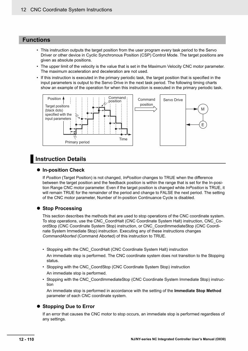
12 CNC Coordinate System Instructions
12 - 110 NJ/NY-series NC Integrated Controller User’s Manual (O030)
• This instruction outputs the target position from the user program every task period to the Servo Driver or other device in Cyclic Synchronous Position (CSP) Control Mode. The target positions are given as absolute positions.
• The upper limit of the velocity is the value that is set in the Maximum Velocity CNC motor parameter. The maximum acceleration and deceleration are not used.
• If this instruction is executed in the primary periodic task, the target position that is specified in the input parameters is output to the Servo Drive in the next task period. The following timing charts show an example of the operation for when this instruction is executed in the primary periodic task.
In-position Check
If Position (Target Position) is not changed, InPosition changes to TRUE when the difference between the target position and the feedback position is within the range that is set for the In-posi-tion Range CNC motor parameter. Even if the target position is changed while InPosition is TRUE, it will remain TRUE for the remainder of the period and change to FALSE the next period. The setting of the CNC motor parameter, Number of In-position Continuance Cycle is disabled.
Stop Processing
This section describes the methods that are used to stop operations of the CNC coordinate system. To stop operations, use the CNC_CoordHalt (CNC Coordinate System Halt) instruction, CNC_Co-ordStop (CNC Coordinate System Stop) instruction, or CNC_CoordImmediateStop (CNC Coordi-nate System Immediate Stop) instruction. Executing any of these instructions changes CommandAborted (Command Aborted) of this instruction to TRUE.
• Stopping with the CNC_CoordHalt (CNC Coordinate System Halt) instruction
An immediate stop is performed. The CNC coordinate system does not transition to the Stopping status.
• Stopping with the CNC_CoordStop (CNC Coordinate System Stop) instruction
An immediate stop is performed.
• Stopping with the CNC_CoordImmediateStop (CNC Coordinate System Immediate Stop) instruc-tion
An immediate stop is performed in accordance with the setting of the Immediate Stop Method parameter of each CNC coordinate system.
Stopping Due to Error
If an error that causes the CNC motor to stop occurs, an immediate stop is performed regardless of any settings.
Functions
Instruction Details
M
E
Servo DriveCommand position
Command position
Primary periodTime
Target positions (black dots) specified with the input parameters
Position

12 - 111
12 CNC Coordinate System Instructions
NJ/NY-series NC Integrated Controller User’s Manual (O030)
CN
C_S
yncM
oveA
bso
lute
12
Functions
• Busy (Executing) changes to TRUE at the same time as Execute changes to TRUE.
• InPosition changes to TRUE when the feedback current positions for all composition axes are within the in-position range from Positions (Target Positions).
• If another instruction aborts this instruction, CommandAborted (Command Aborted) changes to TRUE and Busy (Executing), Active (Controlling), and InPosition change to FALSE.
• The CNC_CoordHalt (CNC Coordinate System Halt) instruction is used to stop this instruction.
The following timing charts show an example of an operation for when this instruction is executed in the primary periodic task.
This instruction cannot be re-executed. A CNC Instruction Re-execution Disabled error (56030000 hex) occurs if re-execution is attempted.
Refer to A-4 Instructions for Which Multi-execution Is Supported on page A-15 for details on multi-exe-cution of CNC instructions.
Timing Chart
Re-execution of CNC Instructions
Multi-execution of CNC Instructions
02030405060
20 30 40 50 60 40
Busy
Position
InPosition
CommandAborted
Error
ErrorID 16#0000
Execute
Busy
Done
Time
Command position
Execute
CNC_SvncMoveAbsolute
CNC_CoordHalt
12 CNC Coordinate System Instructions
12 - 112 NJ/NY-series NC Integrated Controller User’s Manual (O030)
If this instruction cannot be executed, an error occurs, and Error will change to TRUE.
You can find out the cause of the error by referring to the value output by ErrorID (Error Code).
Errors
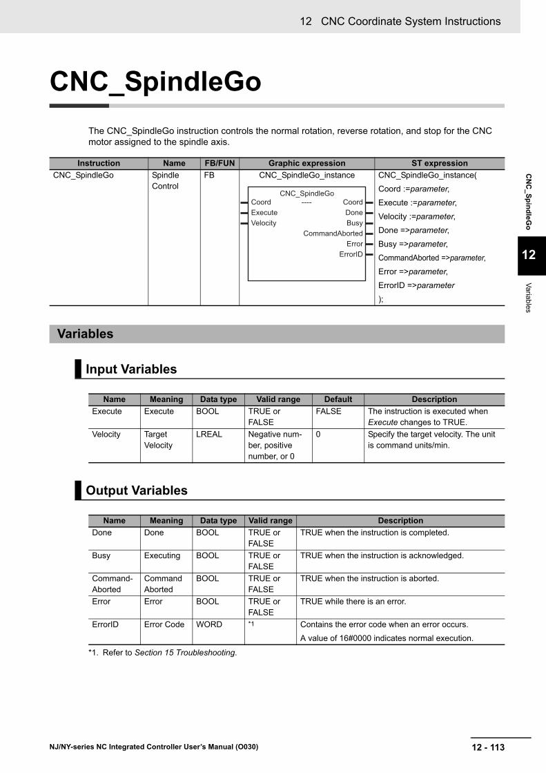
12 - 113
12 CNC Coordinate System Instructions
NJ/NY-series NC Integrated Controller User’s Manual (O030)
CN
C_S
pin
dleG
o
12
Variab
les
CNC_SpindleGo
The CNC_SpindleGo instruction controls the normal rotation, reverse rotation, and stop for the CNC motor assigned to the spindle axis.
Instruction Name FB/FUN Graphic expression ST expression
CNC_SpindleGo Spindle Control
FB CNC_SpindleGo_instance CNC_SpindleGo_instance(
Coord :=parameter,
Execute :=parameter,
Velocity :=parameter,
Done =>parameter,
Busy =>parameter,
CommandAborted =>parameter,
Error =>parameter,
ErrorID =>parameter
);
Variables
Input Variables
Name Meaning Data type Valid range Default Description
Execute Execute BOOL TRUE or FALSE
FALSE The instruction is executed when Execute changes to TRUE.
Velocity Target Velocity
LREAL Negative num-ber, positive number, or 0
0 Specify the target velocity. The unit is command units/min.
Output Variables
Name Meaning Data type Valid range Description
Done Done BOOL TRUE or FALSE
TRUE when the instruction is completed.
Busy Executing BOOL TRUE or FALSE
TRUE when the instruction is acknowledged.
Command-Aborted
Command Aborted
BOOL TRUE or FALSE
TRUE when the instruction is aborted.
Error Error BOOL TRUE or FALSE
TRUE while there is an error.
ErrorID Error Code WORD *1
*1. Refer to Section 15 Troubleshooting.
Contains the error code when an error occurs.
A value of 16#0000 indicates normal execution.
----
------------------------
Coord CoordExecute DoneVelocity Busy
CommandAbortedError
ErrorID
CNC_SpindleGo
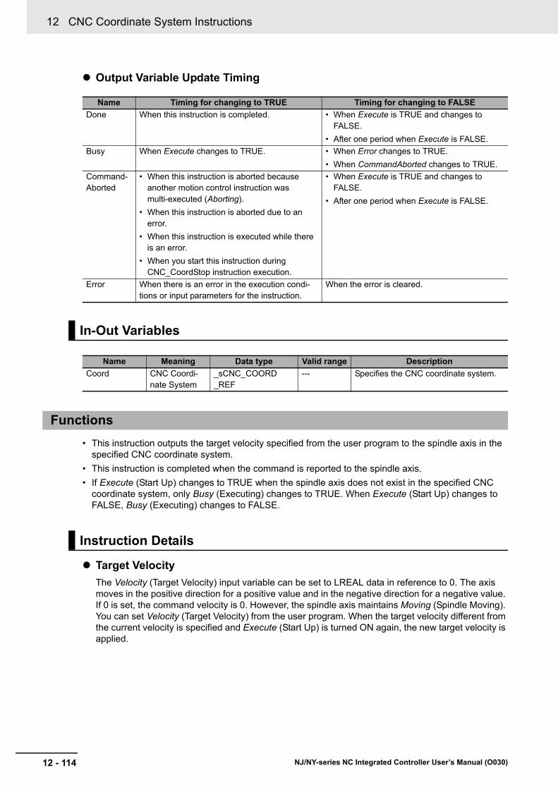
12 CNC Coordinate System Instructions
12 - 114 NJ/NY-series NC Integrated Controller User’s Manual (O030)
Output Variable Update Timing
• This instruction outputs the target velocity specified from the user program to the spindle axis in the specified CNC coordinate system.
• This instruction is completed when the command is reported to the spindle axis.
• If Execute (Start Up) changes to TRUE when the spindle axis does not exist in the specified CNC coordinate system, only Busy (Executing) changes to TRUE. When Execute (Start Up) changes to FALSE, Busy (Executing) changes to FALSE.
Target Velocity
The Velocity (Target Velocity) input variable can be set to LREAL data in reference to 0. The axis moves in the positive direction for a positive value and in the negative direction for a negative value. If 0 is set, the command velocity is 0. However, the spindle axis maintains Moving (Spindle Moving). You can set Velocity (Target Velocity) from the user program. When the target velocity different from the current velocity is specified and Execute (Start Up) is turned ON again, the new target velocity is applied.
Name Timing for changing to TRUE Timing for changing to FALSE
Done When this instruction is completed. • When Execute is TRUE and changes to FALSE.
• After one period when Execute is FALSE.
Busy When Execute changes to TRUE. • When Error changes to TRUE.
• When CommandAborted changes to TRUE.
Command-Aborted
• When this instruction is aborted because another motion control instruction was multi-executed (Aborting).
• When this instruction is aborted due to an error.
• When this instruction is executed while there is an error.
• When you start this instruction during CNC_CoordStop instruction execution.
• When Execute is TRUE and changes to FALSE.
• After one period when Execute is FALSE.
Error When there is an error in the execution condi-tions or input parameters for the instruction.
When the error is cleared.
In-Out Variables
Name Meaning Data type Valid range Description
Coord CNC Coordi-nate System
_sCNC_COORD_REF
--- Specifies the CNC coordinate system.
Functions
Instruction Details

12 - 115
12 CNC Coordinate System Instructions
NJ/NY-series NC Integrated Controller User’s Manual (O030)
CN
C_S
pin
dleG
o
12
Functions
Stop Processing
This section describes the control mode and command velocity used to stop axis operations.
• Stopping with the CNC_CoordImmediateStop (CNC Coordinate System Immediate Stop) instruc-tion
Set the command velocity to 0.
• Stopping by setting the velocity of the CNC_SpindleGo (Spindle Control) instruction to 0.
Set the command velocity to 0.
• Stopping by a minor fault level error
Set the command velocity to 0.
• Stopping by a major fault level error and a partial fault level error
Set the command velocity to 0.
• Stopping by Servo OFF
Set the command velocity to 0 using the specified method.
• Stopping by changing the operating mode of the NC Integrated Controller to the PROGRAM mode
Set the command velocity to 0 using the specified method.
• Busy (Executing) changes to TRUE at the same time as Execute changes to TRUE.
• When a command is acknowledged, Done changes to TRUE. If another instruction aborts this instruction, CommandAborted (Command Aborted) changes to TRUE and Busy (Executing) and Done change to FALSE.
• To stop the spindle axis, set Velocity (Target Velocity) of the CNC_SpindleGo (Spindle Control) instruction to 0, and re-execute.
The following timing chart shows an example of an operation for when this instruction is executed in the primary periodic task.
This instruction cannot be re-executed. A CNC Instruction Re-execution Disabled error (56030000 hex) occurs if re-execution is attempted.
Refer to A-4 Instructions for Which Multi-execution Is Supported on page A-15 for details on multi-exe-cution of CNC instructions.
Timing Chart
Re-execution of CNC Instructions
Multi-execution of CNC Instructions
Busy
Done
CommandAborted
Execute
Error
16#0000ErrorID

12 CNC Coordinate System Instructions
12 - 116 NJ/NY-series NC Integrated Controller User’s Manual (O030)
If this instruction cannot be executed, an error occurs, and Error will change to TRUE.
You can find out the cause of the error by referring to the value output by ErrorID (Error Code).
Timing Chart When Error Occurs
Errors
Busy
CommandAborted
Execute
Error
ErrorID 16#0000 Error code

12 - 117
12 CNC Coordinate System Instructions
NJ/NY-series NC Integrated Controller User’s Manual (O030)
CN
C_S
pin
dleG
o
12
Sam
ple Prog
ramm
ing
This section shows sample programming to control the spindle.
The minimum settings required for this sample programming are given below.
CNC Coordinate System Settings
Logical CNC motor configuration
Positioning axis configuration
Spindle axis use CNC motor
M code settings
Sample Programming
Parameter Settings
CNC coordinate system
Logical CNC motor con-figuration
CNC coordinate system 0
3
CNC coordinate system
Positioning axis CNC motor number
Positioning axis config-uration CNC motor
Positioning axis assignment
CNC coordinate system 0
CNC motor P0 CNC motor 0 X-axis
CNC coordinate system 0
CNC motor P1 CNC motor 1 Y-axis
CNC coordinate system 0
CNC motor P2 CNC motor 2 Z-axis
CNC coordinate system
Spindle axis use CNC motor
CNC coordinate system 0
CNC motor 3
M code number Setting value
M03 1 (Immediate)

12 CNC Coordinate System Instructions
12 - 118 NJ/NY-series NC Integrated Controller User’s Manual (O030)
The spindle axis in feed hold is stopped or restarted with the CNC_SpindleGo (Spindle Control) instruc-tion.
NC Program
Operation Patterns
1 Turning ON the Operation Start Switch
When you turn ON the operation start switch at the home, CNC motor 0 assigned to the X-axis is positioned to 100.00 mm in the positive direction.
2 Turning ON the Operation Interrupt Switch
When you turn ON the operation interrupt switch, the executing NC program pauses.
3 Turning ON the Spindle Stop Switch
When you turn ON the spindle stop switch, CNC motor 3 assigned to the spindle axis stops the rotation.
4 Turning ON the Spindle Start Switch
When you turn ON the spindle start switch, CNC motor 3 assigned to the spindle axis starts the rotation. At this time, the spindle stop switch turns OFF.
Operation Example
N10 M03 S100N20 G91 G01 X100 F50N21 M30
0Time
Velocity
N10
Operation is aborted
X
Spindle stop
Spindle start
Spindle
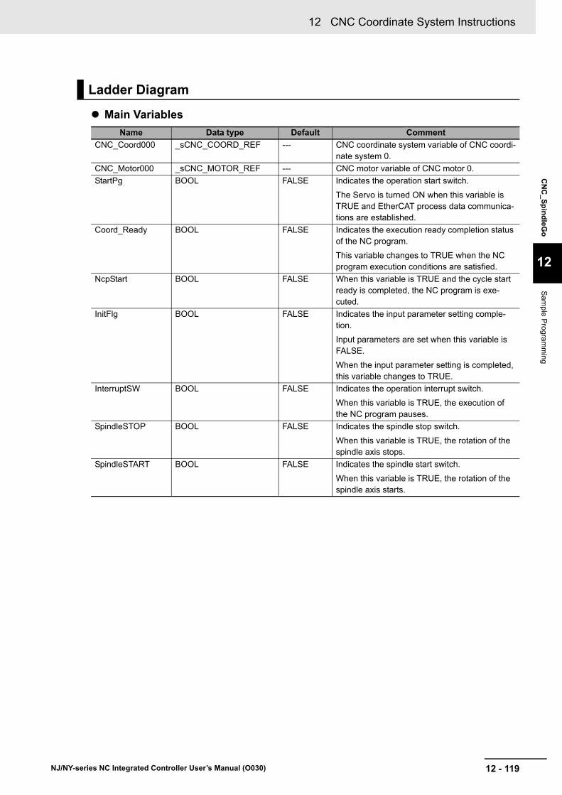
12 - 119
12 CNC Coordinate System Instructions
NJ/NY-series NC Integrated Controller User’s Manual (O030)
CN
C_S
pin
dleG
o
12
Sam
ple Prog
ramm
ing
Main Variables
Ladder Diagram
Name Data type Default Comment
CNC_Coord000 _sCNC_COORD_REF --- CNC coordinate system variable of CNC coordi-nate system 0.
CNC_Motor000 _sCNC_MOTOR_REF --- CNC motor variable of CNC motor 0.
StartPg BOOL FALSE Indicates the operation start switch.
The Servo is turned ON when this variable is TRUE and EtherCAT process data communica-tions are established.
Coord_Ready BOOL FALSE Indicates the execution ready completion status of the NC program.
This variable changes to TRUE when the NC program execution conditions are satisfied.
NcpStart BOOL FALSE When this variable is TRUE and the cycle start ready is completed, the NC program is exe-cuted.
InitFlg BOOL FALSE Indicates the input parameter setting comple-tion.
Input parameters are set when this variable is FALSE.
When the input parameter setting is completed, this variable changes to TRUE.
InterruptSW BOOL FALSE Indicates the operation interrupt switch.
When this variable is TRUE, the execution of the NC program pauses.
SpindleSTOP BOOL FALSE Indicates the spindle stop switch.
When this variable is TRUE, the rotation of the spindle axis stops.
SpindleSTART BOOL FALSE Indicates the spindle start switch.
When this variable is TRUE, the rotation of the spindle axis starts.

12 CNC Coordinate System Instructions
12 - 120 NJ/NY-series NC Integrated Controller User’s Manual (O030)
Timing Chart
Sample Programming
When contact StartPg changes to TRUE, check that the Servo Drive is in the servo ready status and set the X-axis to the Servo ON status.
When the X-axis is in the Servo ON status, check that the Servo Drive is in the servo ready status and set the Y-axis to the Servo ON status.
When the Y-axis is in the Servo ON status, check that the Servo Drive is in the servo ready status and set the Z-axis to the Servo ON status.
When the Z-axis is in the Servo ON status, check that the Servo Drive is in the servo ready status and set the spindle axis to the Servo ON status.
StartPg
InterruptSW
SpindleSTOP
SpindleSTART
Coord_Ready
CC1_CycleStart
NcpStart
CC1_enbd
CC1_Bsy
SG1_Dn
SG1_Bsy
SG2_Dn
SG2_Bsy
ExecutingStatus _cncStandb _cncExecuting _cncHold
StartPg CNC_Motor000.DrvStatus.ReadyPWR1
Pwr1_StatusCNC_PowerCNC_Coord000Pwr1_Bsy
CoordStatus
BusyPwr1_ErrErrorPwr1_ErrIDErrorID
CoordEnableLogicalMotorNo
CNC_Coord000
UINT#0
Pwr1_Status CNC_Motor001.DrvStatus.ReadyPWR2
Pwr2_StatusCNC_PowerCNC_Coord000
Pwr2_BsyCoordStatus
BusyPwr2_ErrErrorPwr2_ErrIDErrorID
CoordEnableLogicalMotorNo
CNC_Coord000UINT#1
Pwr2_Status CNC_Motor002.DrvStatus.ReadyPWR3
Pwr3_StatusCNC_PowerCNC_Coord000Pwr3_Bsy
CoordStatus
BusyPwr3_ErrErrorPwr3_ErrIDErrorID
CoordEnableLogicalMotorNo
CNC_Coord000UINT#2
Pwr3_Status CNC_Motor003.DrvStatus.ReadyPWR4
Pwr4_StatusCNC_PowerCNC_Coord000Pwr4_Bsy
CoordStatus
BusyPwr4_ErrErrorPwr4_ErrIDErrorID
CoordEnableLogicalMotorNo
CNC_Coord000
UINT#100

12 - 121
12 CNC Coordinate System Instructions
NJ/NY-series NC Integrated Controller User’s Manual (O030)
CN
C_S
pin
dleG
o
12
Sam
ple Prog
ramm
ing
When the positioning axis and spindle axis are in the Servo ON status, execute homing of the X-axis.
After the home of the X-axis is defined, execute homing of the Y-axis.
After the home of the Y-axis is defined, execute homing of the Z-axis.
If a minor fault level error occurs in CNC coordinate system 0, the error handler for the device (FaultHandler) is executed.
Program the FaultHandler according to the device.
When the NC program execution ready is completed, change Coord_Ready to TRUE.
When Coord_Ready changes to TRUE, start the execution control of the NC program.
Pwr4_StatusHM1
Hm1_DCNC_Home CNC_Coord000
Hm1_Ca
CoordDone
CommandAbortedHm1_ErrErrorHm1_ErrIDErrorID
CoordExecuteLogicalMotorNo
CNC_Coord000
UINT#0 Hm1_BsyBusy
Pwr2_Status Hm1_DHM2
Hm2_DCNC_Home CNC_Coord000
Hm2_Ca
CoordDone
CommandAbortedHm2_ErrErrorHm2_ErrIDErrorID
CoordExecuteLogicalMotorNo
CNC_Coord000
UINT#1 Hm2_BsyBusy
Pwr3_Status Hm2_DHM3
Hm3_DCNC_Home CNC_Coord000
Hm3_Ca
CoordDone
CommandAbortedHm3_ErrErrorHm3_ErrIDErrorID
CoordExecuteLogicalMotorNo
CNC_Coord000
UINT#2 Hm3_BsyBusy
CNC_Coord000.MFaultLvl.ActiveFHandler
FaultHandlerinput output
CNC_Coord000.Status.Ready Hm3_D
Coord_Ready CC1_Err
Coord_Ready
CC1CNC_CoordControl
CNC_Coord000ControlInputsControlOutputsCC1_BsyCC1_ErrCC1_ErrID
CoordControlInputs
ControlOutputsEnabled
BusyError
ErrorID
CoordControlInputsControlOutputsEnable
CNC_Coord000ControlInputs
ControlOutputsCoord_Ready CC1_enbd

12 CNC Coordinate System Instructions
12 - 122 NJ/NY-series NC Integrated Controller User’s Manual (O030)
When the execution control of the NC program is started, set the parameters of the CNC_CoordControl (CNC Coordinate System NC Control) instruction.
Check that the cycle start ready is completed and start the execution of the NC program.
When contact InterruptSW is TRUE, the execution of the NC program stops.
When contact SpindleSTOP is TRUE, start the spindle control to stop the rotation of the spindle axis.
When contact SpindleSTART is TRUE, start the spindle control to start the rotation of the spindle axis.
// CNC_CoordControl parameter// Specify the NC program (No. 1) that was created on the SysmacStudio.ControlInputs.ProgramNo :=UINT#1;ControlInputs.FeedrateVelFactor:=LREAL#100.0;ControlInputs.SpindleVelFactor:=LREAL#100.0;ControlInputs.AuxiliaryLock:=FALSE;ControlInputs.BackTrace :=FALSE;ControlInputs.DryRun :=FALSE;ControlInputs.FeedHold :=FALSE;ControlInputs.MachineLock:=FALSE;
// Change InitFlag to TRUE after setting the input parameters.InitFlg := TRUE;
// Start the NC program.NcpStart:=TRUE;
NcpStart ControlOutputs.CycleStartReady InitFlg CC1_CycleStartS
CC1_CycleStart ControlInputs.CycleStartS
NcpStart
NcpStart
ControlOutputs.ExecutingStatus_eCNC_EXECUTING_STATE#_cncExecuting
In1ENEQ
In2CC1_CycleStart
R
ControlInputs.CycleStartR
R
InterruptSW
ControlOutputs.ExecutingStatus_eCNC_EXECUTING_STATE#_cncHold
In1ENEQ
In2 InterruptSWR
InterruptSW ControlInputs.FeedHoldS
ControlInputs.FeedHoldR
SpindleSTOP
SG1SG1_DnCNC_SpindleGo
CNC_Coord000
SG1_Ca
CoordDone
CommandAbortedSG1_ErrErrorSG1_ErrIDErrorID
CoordExecuteVelocity
CNC_Coord000LREAL#0.0 SG1_BsyBusy
SpindleSTART
SG2
SG2_Dn
SG2_Dn
CNC_SpindleGoCNC_Coord000
SG2_Ca
CoordDone
CommandAbortedSG2_ErrErrorSG2_ErrIDErrorID
CoordExecuteVelocity
CNC_Coord000LREAL#1000.0 SG2_BsyBusy
SpindleSTOPR

12 - 123
12 CNC Coordinate System Instructions
NJ/NY-series NC Integrated Controller User’s Manual (O030)
CN
C_S
pin
dleG
o
12
Sam
ple Prog
ramm
ing
Main Variables
Structured Text (ST)
Name Data type Default Comment
CNC_Coord000 _sCNC_COORD_REF --- CNC coordinate system variable of CNC coordi-nate system 0.
CNC_Motor000 _sCNC_MOTOR_REF --- CNC motor variable of CNC motor 0.
StartPg BOOL FALSE Indicates the operation start switch.
The Servo is turned ON when this variable is TRUE and EtherCAT process data communica-tions are established.
Coord_Ready BOOL FALSE Indicates the execution ready completion status of the NC program.
This variable changes to TRUE when the NC program execution conditions are satisfied.
NcpStart BOOL FALSE When this variable is TRUE and the cycle start ready is completed, the NC program is exe-cuted.
InitFlg BOOL FALSE Indicates the input parameter setting comple-tion.
Input parameters are set when this variable is FALSE.
When the input parameter setting is completed, this variable changes to TRUE.
InterruptSW BOOL FALSE Indicates the operation interrupt switch.
When this variable is TRUE, the execution of the NC program pauses.
SpindleSTOP BOOL FALSE Indicates the spindle stop switch.
When this variable is TRUE, the rotation of the spindle axis stops.
SpindleSTART BOOL FALSE Indicates the spindle start switch.
When this variable is TRUE, the rotation of the spindle axis starts.
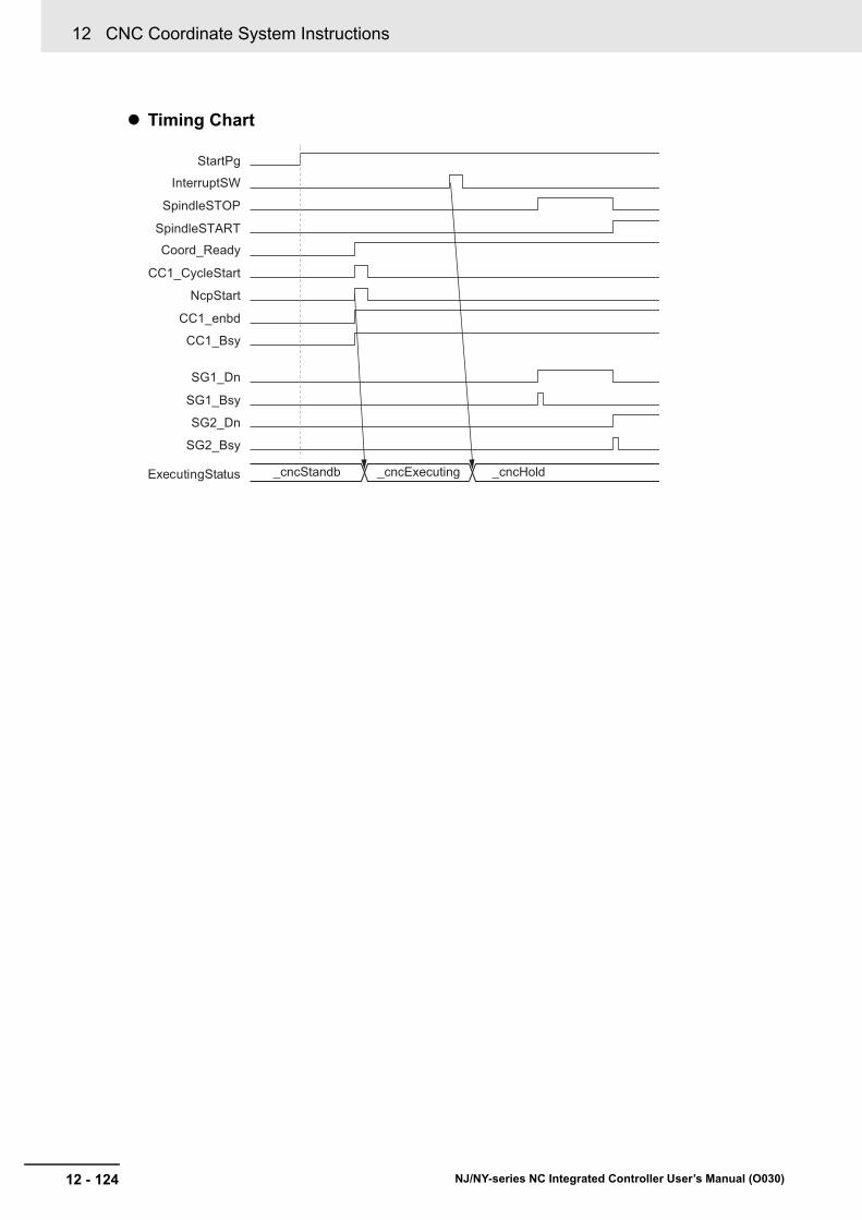
12 CNC Coordinate System Instructions
12 - 124 NJ/NY-series NC Integrated Controller User’s Manual (O030)
Timing Chart
StartPg
InterruptSW
SpindleSTOP
SpindleSTART
Coord_Ready
CC1_CycleStart
NcpStart
CC1_enbd
CC1_Bsy
SG1_Dn
SG1_Bsy
SG2_Dn
SG2_Bsy
ExecutingStatus _cncStandb _cncExecuting _cncHold

12 - 125
12 CNC Coordinate System Instructions
NJ/NY-series NC Integrated Controller User’s Manual (O030)
CN
C_S
pin
dleG
o
12
Sam
ple Prog
ramm
ing
Sample Programming
// When StartPg is TRUE, check that the Servo Drive is in the servo ready status and set the X-axis to the Servo ON status.IF (StartPg = TRUE)AND (CNC_Motor000.DrvStatus.Ready=TRUE) THEN
Pwr1_En:=TRUE;ELSE
Pwr1_En:=FALSE;END_IF;
// When the X-axis is in the Servo ON status, check that the Servo Drive is in the servo ready status and set the Y-axis to the Servo ON status.IF (Pwr1_Status = TRUE) AND (CNC_Motor001.DrvStatus.Ready=TRUE) THEN
Pwr2_En:=TRUE;ELSE
Pwr2_En:=FALSE;END_IF;
// When the Y-axis is in the Servo ON status, check that the Servo Drive is in the servo ready status and set the Z-axis to the Servo ON status.IF (Pwr2_Status = TRUE) AND (CNC_Motor002.DrvStatus.Ready=TRUE) THEN
Pwr3_En:=TRUE;ELSE
Pwr3_En:=FALSE;END_IF;
// When the Z-axis is in the Servo ON status, check that the Servo Drive is in the servo ready status and set the spindle axis to the Servo ON status.IF (Pwr3_Status = TRUE) AND (CNC_Motor003.DrvStatus.Ready=TRUE) THEN
Pwr4_En:=TRUE;ELSE
Pwr4_En:=FALSE;END_IF;
// When the positioning axis and spindle axis are in the Servo ON status, execute homing of the X-axis.IF (Pwr4_Status=TRUE) THEN Hm1_Ex:=TRUE;END_IF;
// After the home of the X-axis is defined, execute homing of the Y-axis.IF (Pwr2_Status=TRUE) AND (Hm1_D=TRUE) THEN
Hm2_Ex:=TRUE;END_IF;
// After the home of the Y-axis is defined, execute homing of the Z-axis.IF (Pwr3_Status=TRUE) AND (Hm2_D=TRUE) THEN
Hm3_Ex:=TRUE;END_IF;
// If a minor fault level error occurs in coordinate system 0, execute the error handler for the device (FaultHandler).// Program the FaultHandler according to the device.IF (CNC_Coord000.MFaultLvl.Active=TRUE) THEN
FaultHandler();END_IF;

12 CNC Coordinate System Instructions
12 - 126 NJ/NY-series NC Integrated Controller User’s Manual (O030)
// When the NC program execution ready is completed, change Coord_Ready to TRUE.IF (Hm3_D =TRUE) AND (CNC_Coord000.Status.Ready=TRUE) THEN
Coord_Ready :=TRUE;ELSIF(CC1_Err = TRUE) THEN
Coord_Ready :=FALSE;END_IF;
// When Coord_Ready is TRUE, start the execution control of the NC program.IF (Coord_Ready=TRUE)THEN
CC1_En:=TRUE;ELSE
CC1_En:=FALSE;END_IF;
// Processing when input parameters are not setIF (InitFlg=FALSE) AND (CC1_enbd=TRUE) THEN
// CNC_CoordControl parameter// Specify the NC program (No. 1) that was created on the SysmacStudio.ControlInputs.ProgramNo:=UINT#1;ControlInputs.FeedrateVelFactor:=LREAL#100.0;ControlInputs.SpindleVelFactor:=LREAL#100.0;ControlInputs.AuxiliaryLock:=FALSE;ControlInputs.BackTrace:=FALSE;ControlInputs.DryRun:=FALSE;ControlInputs.FeedHold:=FALSE;ControlInputs.MachineLock:=FALSE;
// Change InitFlag to TRUE after setting the input parameters.InitFlg := TRUE;// Start the NC program.NcpStart:=TRUE;
END_IF;
// Check that the cycle start ready is completed and start the execution of the NC program.IF (InitFlg=TRUE) AND (ControlOutputs.CycleStartReady=TRUE) AND (NcpStart=TRUE) THEN
CC1_CycleStart:=TRUE;END_IF;IF( CC1_CycleStart =TRUE) THEN
ControlInputs.CycleStart:=TRUE;END_IF;
// When the NC program is executed, change CC1_CycleStart and NcpStart to FALSE.IF (ControlOutputs.ExecutingStatus = _eCNC_EXECUTING_STATE#_cncExecuting) THEN
NcpStart:=FALSE;CC1_CycleStart:=FALSE;ControlInputs.CycleStart:=FALSE;
END_IF;
// When InterruptSW is TRUE, the execution of the NC program pauses.IF (InterruptSW=TRUE) THEN
ControlInputs.FeedHold:=TRUE;END_IF;
// When pausing of the NC program is completed, change InterruptSW to FALSE.IF (ControlOutputs.ExecutingStatus = _cncHold) THEN
InterruptSW:=FALSE;END_IF;

12 - 127
12 CNC Coordinate System Instructions
NJ/NY-series NC Integrated Controller User’s Manual (O030)
CN
C_S
pin
dleG
o
12
Sam
ple Prog
ramm
ing
// When SpindleSTOP is TRUE, stop the rotation of the spindle axis.IF SpindleSTOP=TRUE THEN
SG1_Ex:=TRUE;ELSE
SG1_Ex:=FALSE;END_IF;
// When SpindleSTART is TRUE, start the rotation of the spindle axis.IF SpindleSTART=TRUE THEN
SG2_Ex:=TRUE;END_IF;
// Check that the Spindle Control instruction is completed.IF SG2_Dn=TRUE THEN
SpindleSTOP:=FALSE;END_IF;
// CNC_Power of X-axisPWR1(
Coord:= CNC_Coord000,Enable:=Pwr1_En, LogicalMotorNo:=UINT#0, Status=>Pwr1_Status,Busy => Pwr1_Bsy,
Error => Pwr1_Err, ErrorID => Pwr1_ErrID);// CNC_Power of Y-axisPWR2(
Coord:= CNC_Coord000,Enable:=Pwr2_En, LogicalMotorNo:=UINT#1, Status=>Pwr2_Status,Busy => Pwr2_Bsy,
Error => Pwr2_Err, ErrorID => Pwr2_ErrID);// CNC_Power of Z-axisPWR3(
Coord:= CNC_Coord000,Enable:=Pwr3_En, LogicalMotorNo:=UINT#2, Status=>Pwr3_Status,Busy => Pwr3_Bsy,
Error => Pwr3_Err, ErrorID => Pwr3_ErrID);// CNC_Power of spindle axisPWR4(
Coord:= CNC_Coord000,Enable:=Pwr4_En, LogicalMotorNo:=UINT#100, Status=>Pwr4_Status,Busy => Pwr4_Bsy,
Error => Pwr4_Err, ErrorID => Pwr4_ErrID);

12 CNC Coordinate System Instructions
12 - 128 NJ/NY-series NC Integrated Controller User’s Manual (O030)
// CNC_Home of X-axisHM1( Coord := CNC_Coord000 , Execute := Hm1_Ex, LogicalMotorNo :=UINT#0 , Done => Hm1_D, Busy => Hm1_Bsy, CommandAborted=> Hm1_Ca, Error => Hm1_Err, ErrorID => Hm1_ErrID);// CNC_Home of Y-axisHM2( Coord := CNC_Coord000 , Execute := Hm2_Ex, LogicalMotorNo :=UINT#1 , Done => Hm2_D, Busy => Hm2_Bsy, CommandAborted=> Hm2_Ca, Error => Hm2_Err, ErrorID => Hm2_ErrID);// CNC_Home of Z-axisHM3( Coord := CNC_Coord000 , Execute := Hm3_Ex, LogicalMotorNo :=UINT#2 , Done => Hm3_D, Busy => Hm3_Bsy, CommandAborted=> Hm3_Ca, Error => Hm3_Err, ErrorID => Hm3_ErrID);
// CNC_CoordControlCC1(
Coord:= CNC_Coord000,ControlInputs:=ControlInputs,ControlOutputs:=ControlOutputs, Enable:=CC1_En, Enabled=>CC1_enbd, Busy=>CC1_Bsy, Error=>CC1_Err, ErrorID=>CC1_ErrID
);
// CNC_SpindleGo (for the spindle axis stop)SG1(
Coord:=CNC_Coord000,Execute:=SG1_Ex,Velocity:=LREAL#0.0,Done=>SG1_Dn,Busy=>SG1_Bsy,CommandAborted=>SG1_Ca,Error=>SG1_Err,ErrorID=>SG1_ErrID
);
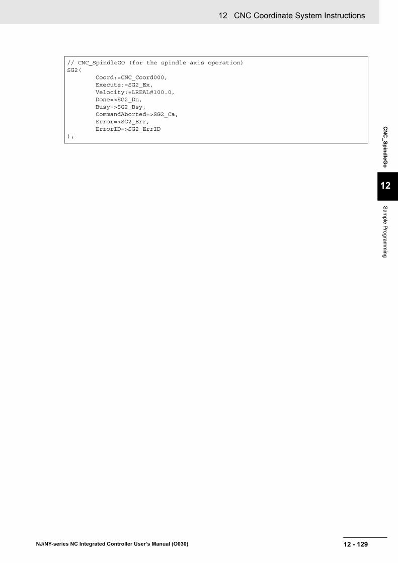
12 - 129
12 CNC Coordinate System Instructions
NJ/NY-series NC Integrated Controller User’s Manual (O030)
CN
C_S
pin
dleG
o
12
Sam
ple Prog
ramm
ing
// CNC_SpindleGO (for the spindle axis operation)SG2(
Coord:=CNC_Coord000,Execute:=SG2_Ex,Velocity:=LREAL#100.0,Done=>SG2_Dn,Busy=>SG2_Bsy,CommandAborted=>SG2_Ca,Error=>SG2_Err,ErrorID=>SG2_ErrID
);

12 CNC Coordinate System Instructions
12 - 130 NJ/NY-series NC Integrated Controller User’s Manual (O030)

13 - 1
13
NJ/NY-series NC Integrated Controller User’s Manual (O030)
This section describes the instructions that are used for both CNC motors and CNC coordinate systems.
CNC_Write . . . . . . . . . . . . . . . . . . . . . . . . . . . . . . . . . . . . . . . . . . . . . . . . . . 13-2
CNC_Read . . . . . . . . . . . . . . . . . . . . . . . . . . . . . . . . . . . . . . . . . . . . . . . . . . 13-11
CNC_LoadProgramFile . . . . . . . . . . . . . . . . . . . . . . . . . . . . . . . . . . . . . . . 13-16
Common Command Instructions

13 Common Command Instructions
13 - 2 NJ/NY-series NC Integrated Controller User’s Manual (O030)
CNC_Write
The CNC_Write instruction overwrites CNC parameters.
Precautions for Correct Use
The values that are written by this instruction are not saved in the non-volatile memory in the NC integrated controller. Any written values are lost when the power supply to the Controller is turned OFF, when settings are downloaded, or when the CNC Function Module is restarted. They return to the values that were set from the Sysmac Studio.
Use the Sysmac Studio and transfer the parameters to save them to the non-volatile memory.
Instruction Name FB/FUN Graphic expression ST expression
CNC_Write Write CNC Setting
FB CNC_Write_instance CNC_Write_instance (
Target :=parameter,
SettingValue :=parameter,
Execute :=parameter,
ParameterNumber :=parameter,
Done =>parameter,
Busy =>parameter,
CommandAborted =>parameter,
Error =>parameter,
ErrorID =>parameter
);
--------------------------------
Target TargetSettingValue SettingValueExecute DoneParameterNumber Busy
CommandAbortedError
ErrorID
CNC_Write

13 - 3
13 Common Command Instructions
NJ/NY-series NC Integrated Controller User’s Manual (O030)
CN
C_W
rite
13
Variables
Variables
Input Variables
Name Meaning Data type Valid range Default Description
Execute Execute BOOL TRUE or FALSE
FALSE The instruction is executed when Execute changes to TRUE.
Parameter Number
Parameter Number
_eCNC_PARAME-TER_NUMBER
0: _cncRotaryVel
1: _cncDryRunVel
2: _cncFeedholdTime
3: _cncInPosTime
4: _cncSwLmtCtrl
5: _cncToolShape
6: _cncToolRadiusCompCtrl
7: _cncSpindleOrientation
8: _cncSingleBlockOption
20: _cncWorkOffset1
21: _cncWorkOffset2
22: _cncWorkOffset3
23: _cncWorkOffset4
24: _cncWorkOffset5
25: _cncWorkOffset6
30: _cncRefPoint1
31: _cncRefPoint2
32: _cncRefPoint3
33: _cncRefPoint4
50: _cncFELmt
51: _cncChkFELmt
52: _cncSwLmt
53: _cncPosiSwLmt
54: _cncNegaSwLmt
55: _cncInPosCycle
56: _cncInPosRange
57: _cncRapidFeedAcc
58: _cncSkipVel
59: _cncPIDCtr
100: _cncCompScaling
0*1
*1. The default value for an enumeration variable is actually not the number, but the enumerator.
Specify the parameter to write.
0: Rotary Axis Velocity
1: Dry Run Velocity
2: Feed Hold Acceleration Deceleration Time
3: In-position Check Time
4: Software Overtravel Limit Operation Control
5: Tool Shape Data
6: Tool Radius Compensation Control
7: Spindle Axis Orientation Operation
8: Single Block Execution Option*2
20: 1st Work Coordinate System Offset
21: 2nd Work Coordinate System Offset
22: 3rd Work Coordinate System Offset
23: 4th Work Coordinate System Offset
24: 5th Work Coordinate System Offset
25: 6th Work Coordinate System Offset
30: 1st Reference Point
31: 2nd Reference Point
32: 3rd Reference Point
33: 4th Reference Point
50: Following Error Over Value
51: Following Error Warning Value
52: Software Overtravel Limit
53: Positive Software Overtravel Limit
54: Negative Software Overtravel Limit
55: Number of In-position Continuance Cycles
56: In-position Range
57: Rapid Feed Acceleration/Deceleration
58: Skip Velocity
59: PID Control
100: Compensation Scailing
*2. The single block execution option is a parameter that can only be changed with CNC_Write.

13 Common Command Instructions
13 - 4 NJ/NY-series NC Integrated Controller User’s Manual (O030)
Parameter Data Types and Setting Ranges
The table below shows the valid range of each parameter. However, this valid range is available for this instruction, and it varies depending on the value of the correlative parameter.
Parameter Data type Valid range Comments
CNC Coordinate System Parameters
Rotation Axis Velocity LREAL Positive number
Dry-Run Speed LREAL Positive number
Feed Hold Acceleration Deceleration Time
UDINT 1 to 10,000 [ms]
In-position Check Time UINT 0 to 10,000 [ms]
Software Overtravel Limit Operation Control
_eCNC_SWLMT_-CONTROL
_cncSwLmtOTErr := 0
_cncSwLmtTrajSaturation := 1
0: Error
1: No error (Path saturation)
Tool Shape Data _sCNC_TOOL_SHAPE
Refer to _sCNC_TOOL_SHAPE.
Refer to _sCNC_TOOL_SHAPE.
Tool Radius Compensa-tion Control
_sCNC_TOOL_RADIUS_COMP
Refer to _sCNC_TOOL_RADIUS_COMP.
Refer to _sCNC_TOOL_RADIUS_-COMP.
Orientation of Spindle Axis
Setting
_sSPINDLE_ORIENTATION
Refer to _sSPIN-DLE_ORIENTATION.
Refer to _sSPINDLE_ORIENTATION.
Single Block Execution
Option
_eCNC_SINGLE_BLOCK_OPTION
_cncSingleBlockOp-tionDisable = 0
_cncSingleBlockOp-tionEnable = 1
0: The single block execution option is disabled.
1: The single block execution option is enabled.
1st Work Coordinate System Offset
_sCNC_COORD_AX_DATA
Negative number, positive number, or 0
2nd Work Coordinate System Offset
_sCNC_COORD_AX_DATA
Negative number, positive number, or 0
3rd Work Coordinate System Offset
_sCNC_COORD_AX_DATA
Negative number, positive number, or 0
4th Work Coordinate System Offset
_sCNC_COORD_AX_DATA
Negative number, positive number, or 0
5th Work Coordinate System Offset
_sCNC_COORD_AX_DATA
Negative number, positive number, or 0
6th Work Coordinate System Offset
_sCNC_COORD_AX_DATA
Negative number, positive number, or 0
1st Reference Point _sCNC_COORD_AX_DATA
Negative number, positive number, or 0
2nd Reference Point _sCNC_COORD_AX_DATA
Negative number, positive number, or 0

13 - 5
13 Common Command Instructions
NJ/NY-series NC Integrated Controller User’s Manual (O030)
CN
C_W
rite
13
Variables
_sCNC_COORD_AX_DATA
_sCNC_TOOL_SHAPE
3rd Reference Point _sCNC_COORD_AX_DATA
Negative number, positive number, or 0
4th Reference Point _sCNC_COORD_AX_DATA
Negative number, positive number, or 0
CNC Motor Parameters
Following Error Over Value
LREAL 0.0 min.
Following Error Warning Value
LREAL 0.0 min.
Software Overtravel Limit
_eCNC_SWLMT_MODE
_cncNonSwLmt := 0
_cncCmdImmedia-teStop := 1
0: Disable software limits.
1: Immediate stop for command posi-tion (stop using remaining pulses)
Positive Software Over-travel Limit
LREAL Positive number
Negative Software Over-travel Limit
LREAL Negative numbers
Number of In-position Continuance Cycles
UINT 0 to 255
In-position Range LREAL 0.0 min.
Rapid Feed Accelera-tion/Deceleration
LREAL 0 min.
Skip Velocity LREAL Positive number
PID Control _sCNC_PID_CONTROL
Refer to _sCNC_PID_CON-TROL
Refer to _sCNC_PID_CONTROL
CNC Motor Compensation Table Parameters
Compensation Scaling LREAL 0 to 2.0
Name Meaning Data type Valid range Function
X X-axis Position LREAL Positive, negative, 0 X-axis value
Y Y-axis Position LREAL Positive, negative, 0 Y-axis value
Z Z-axis Position LREAL Positive, negative, 0 Z-axis value
A A-axis Position LREAL Positive, negative, 0 A-axis value
B B-axis Position LREAL Positive, negative, 0 B-axis value
C C-axis Position LREAL Positive, negative, 0 C-axis value
Name Meaning Data type Valid range Function
ToolRadius Tool Radius LREAL 0.0 min. Tool radius to be compensated
ToolLength Tool Length LREAL Positive, negative, 0 Tool length to be compensated
Parameter Data type Valid range Comments

13 Common Command Instructions
13 - 6 NJ/NY-series NC Integrated Controller User’s Manual (O030)
_sCNC_TOOL_RADIUS_COMP
_sSPINDLE_ORIENTATION
_sCNC_PID_CONTROL
Name Meaning Data type Valid range Function
OvercutMode Over-cut Mode _eCNC_OVER-CUT_MODE
_cncOvercutErr := 0
_cncOvercutAvoid := 1
_cncOvercutIgnore := 2
_cncOvercutTestAvoid := 3
Over-cut mode set-ting
ArcFeedrateMode Circular Feed Rate Mode
BOOL TRUE or FALSE Feedrate compensa-tion setting for circu-lar interpolation with compensation
Name Meaning Data type Valid range Function
OrientationPos Orientation Position LREAL 0 ≤ x < 1 Orientation position set-ting
OrientationVel Orientation Velocity LREAL Positive number Orientation velocity set-ting
OrientationAcc Orientation Accelera-tion/Deceleration
LREAL 0.0 min. Orientation accelera-tion/deceleration setting
Name Meaning Data type Valid range Function
Kp Position Loop Gain REAL 0 to 3000 Position loop gain setting
Kvff Velocity Feedforward Gain REAL 0 to 100 Velocity feedforward setting
Ki Integral Gain REAL 0 Integral gain setting (Reserved)
Kvfb Velocity Feedback Gain REAL 0 Velocity feedback gain set-ting (Reserved)
Kvifb Velocity Feedback Gain (before integrator)
REAL 0 Velocity feedback gain (before integrator) setting (Reserved)
Kviff Velocity Feedforward Gain (before integrator)
REAL 0 Velocity feedforward gain (before integrator) setting (Reserved)
Kaff Acceleration Feedforward Gain
REAL 0 Acceleration feedforward gain setting (Reserved)

13 - 7
13 Common Command Instructions
NJ/NY-series NC Integrated Controller User’s Manual (O030)
CN
C_W
rite
13
Variables
Output Variable Update Timing
Output Variables
Name Meaning Data type Valid range Description
Done Done BOOL TRUE or FALSE
TRUE when the instruction is completed.
Busy Executing BOOL TRUE or FALSE
TRUE when the instruction is acknowledged.
Command-Aborted
Command Aborted
BOOL TRUE or FALSE
TRUE when the instruction is aborted.
Error Error BOOL TRUE or FALSE
TRUE while there is an error.
ErrorID Error Code WORD *1
*1. Refer to Section 15 Troubleshooting.
Contains the error code when an error occurs.
A value of 16#0000 indicates normal execution.
Name Timing for changing to TRUE Timing for changing to FALSE
Done When this instruction is completed. • When Execute is TRUE and changes to FALSE.
• After one period when Execute is FALSE.
Busy When Execute changes to TRUE. • When Done changes to TRUE.
• When Error changes to TRUE.
• When CommandAborted changes to TRUE.
CommandAborted When another instruction causes an error and aborts this instruction.
• When Execute is TRUE and changes to FALSE.
• After one period when Execute is FALSE.
Error When there is an error in the exe-cution conditions or input parame-ters for the instruction.
When the error is cleared.

13 Common Command Instructions
13 - 8 NJ/NY-series NC Integrated Controller User’s Manual (O030)
In-Out Variable Update Timing
In-Out Variables
Name Meaning Data type Valid range Description
Target Write Target _sCNC_COORD_REF, _sCNC_MOTOR_REF,ARRAY[0..N] OF REAL
--- Specify the CNC motor, CNC coordinate system, or CNC compensation table data variable for which to write a param-eter. N in the array variable is set auto-matically by the Sysmac Studio. Specify the CNC motor compensation table data variable created with the CNC motor compensation table editor of Sysmac Studio.
SettingValue Setting Value *1
*1. Depends on the data type of the variable specified.
--- Specify the value to write.
The valid range follows the CNC param-eter that is specified by ParameterNum-ber (Parameter Number). It is set to 0 by default.
Name Write timing
SettingValue When Done changes to TRUE.

13 - 9
13 Common Command Instructions
NJ/NY-series NC Integrated Controller User’s Manual (O030)
CN
C_W
rite
13
Functions
The CNC_Write instruction writes the SettingValue (Setting Value) to the CNC parameter specified by Target (Write Target) and ParameterNumber (Parameter Number) when Execute changes to TRUE. To specify the change target, combine the ParameterNumber (Parameter Number) with the Target (Write Target). If the combination you specified is invalid, it causes the CNC Parameter Setting Read/Write Target Out of Range error (560F0000 hex).
Precautions for Correct Use
The values that are written by this instruction are not saved in the non-volatile memory in the NC integrated controller. Any written values are lost when the power supply to the Controller is turned OFF, when settings are downloaded, or when the CNC Function Module is restarted. They return to the values that were set from the Sysmac Studio.
Use the Sysmac Studio and transfer the parameters to save them to the non-volatile memory.
A timing chart is shown below when data 20 is written to _cncInPosRange (In-position Range) in the CNC motor parameter settings.
If Execute for the same instance of this instruction changes to TRUE while Busy (Executing) is TRUE, the instruction is re-executed. At this time, the instruction overwrites the previous values of the Target (Write Target), ParameterNumber (Parameter Number), and SettingValue (Setting Value) with the val-ues that are specified when Execute rises.
Refer to A-4 Instructions for Which Multi-execution Is Supported on page A-15 for details on multi-exe-cution of CNC instructions.
Functions
Timing Chart
Re-execution of CNC Instructions
Multi-execution of CNC Instructions
Busy
Done
CommandAborted
Error
ErrorID 16#0000
201
Execute
Value
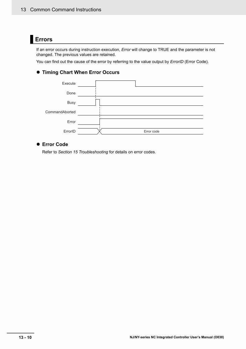
13 Common Command Instructions
13 - 10 NJ/NY-series NC Integrated Controller User’s Manual (O030)
If an error occurs during instruction execution, Error will change to TRUE and the parameter is not changed. The previous values are retained.
You can find out the cause of the error by referring to the value output by ErrorID (Error Code).
Timing Chart When Error Occurs
Error Code
Refer to Section 15 Troubleshooting for details on error codes.
Errors
Busy
Done
CommandAborted
Error
ErrorID Error code
Execute

13 - 11
13 Common Command Instructions
NJ/NY-series NC Integrated Controller User’s Manual (O030)
CN
C_R
ead
13
CNC_Read
The CNC_Read instruction reads CNC parameters.
Instruction Name FB/FUN Graphic expression ST expression
CNC_Read Read CNC Setting
FB CNC_Read_instance CNC_Read_instance (
Target :=parameter,
SettingValue :=parameter,
Execute :=parameter,
ParameterNumber :=parameter,
Done =>parameter,
Busy =>parameter,
CommandAborted =>parameter,
Error =>parameter,
ErrorID =>parameter
);
--------------------------------
Target TargetSettingValue SettingValueExecute DoneParameterNumber Busy
CommandAbortedError
ErrorID
CNC_Read

13 Common Command Instructions
13 - 12 NJ/NY-series NC Integrated Controller User’s Manual (O030)
Variables
Input Variables
Name Meaning Data type Valid range Default Description
Execute Execute BOOL TRUE or FALSE
FALSE The instruction is executed when Execute changes to TRUE.
Parameter Number
Parameter Number
_eCNC_PARAME-TER_NUM-
BER*1
*1. Refer to the CNC_Write instruction for _eCNC_PARAMETER_NUMBER.
0: _cncRotaryVel
1: _cncDryRunVel
2: _cncFeedholdTime
3: _cncInPosTime
4: _cncSwLmtCtrl
5: _cncToolShape
6: _cncToolRadiusCompCtrl
7: _cncSpindleOrientation
8: _cncSingleBlockOption
20: _cncWorkOffset1
21: _cncWorkOffset2
22: _cncWorkOffset3
23: _cncWorkOffset4
24: _cncWorkOffset5
25: _cncWorkOffset6
30: _cncRefPoint1
31: _cncRefPoint2
32: _cncRefPoint3
33: _cncRefPoint4
50: _cncFELmt
51: _cncChkFELmt
52: _cncSwLmt
53: _cncPosiSwLmt
54: _cncNegaSwLmt
55: _cncInPosCycle
56: _cncInPosRange
57: _cncRapidFeedAcc
58: _cncSkipVel
59: _cncPIDCtr
100: _cncCompScaling
0*2
*2. The default value for an enumeration variable is actually not the number, but the enumerator.
Specify the parameter to read.
0: Rotary Axis Velocity
1: Dry Run Velocity
2: Feed Hold Acceleration Deceleration Time
3: In-position Check Time
4: Software Overtravel Limit Operation Control
5: Tool Shape Data
6: Tool Radius Compensation Control
7: Spindle Axis Orientation Operation
8: Single Block Execution Option
20: 1st Work Coordinate System Offset
21: 2nd Work Coordinate System Offset
22: 3rd Work Coordinate System Offset
23: 4th Work Coordinate System Offset
24: 5th Work Coordinate System Offset
25: 6th Work Coordinate System Offset
30: 1st Reference Point
31: 2nd Reference Point
32: 3rd Reference Point
33: 4th Reference Point
50: Following Error Over Value
51: Following Error Warning Value
52: Software Overtravel Limit
53: Positive Software Overtravel Limit
54: Negative Software Overtravel Limit
55: Number of In-position Continuance Cycles
56: In-position Range
57: Rapid Feed Acceleration/Deceleration
58: Skip Velocity
59: PID Control
100: Compensation Scailing
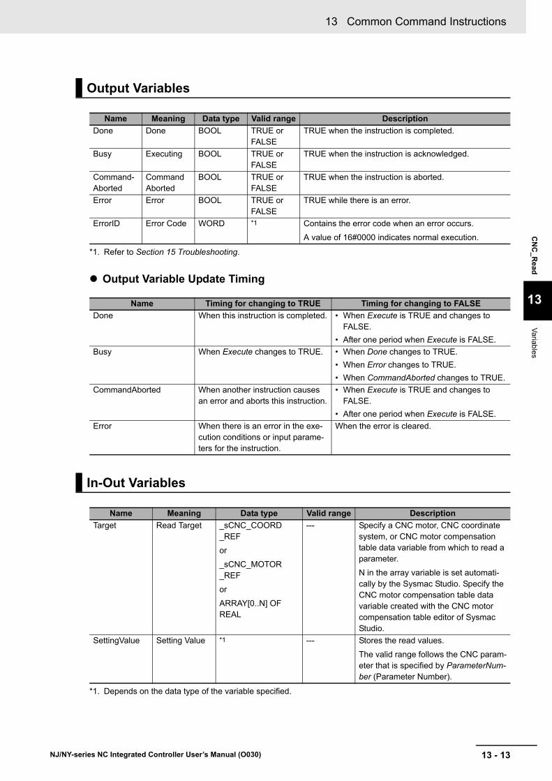
13 - 13
13 Common Command Instructions
NJ/NY-series NC Integrated Controller User’s Manual (O030)
CN
C_R
ead
13
Variables
Output Variable Update Timing
Output Variables
Name Meaning Data type Valid range Description
Done Done BOOL TRUE or FALSE
TRUE when the instruction is completed.
Busy Executing BOOL TRUE or FALSE
TRUE when the instruction is acknowledged.
Command-Aborted
Command Aborted
BOOL TRUE or FALSE
TRUE when the instruction is aborted.
Error Error BOOL TRUE or FALSE
TRUE while there is an error.
ErrorID Error Code WORD *1
*1. Refer to Section 15 Troubleshooting.
Contains the error code when an error occurs.
A value of 16#0000 indicates normal execution.
Name Timing for changing to TRUE Timing for changing to FALSE
Done When this instruction is completed. • When Execute is TRUE and changes to FALSE.
• After one period when Execute is FALSE.
Busy When Execute changes to TRUE. • When Done changes to TRUE.
• When Error changes to TRUE.
• When CommandAborted changes to TRUE.
CommandAborted When another instruction causes an error and aborts this instruction.
• When Execute is TRUE and changes to FALSE.
• After one period when Execute is FALSE.
Error When there is an error in the exe-cution conditions or input parame-ters for the instruction.
When the error is cleared.
In-Out Variables
Name Meaning Data type Valid range Description
Target Read Target _sCNC_COORD_REF
or
_sCNC_MOTOR_REF
or
ARRAY[0..N] OF REAL
--- Specify a CNC motor, CNC coordinate system, or CNC motor compensation table data variable from which to read a parameter.
N in the array variable is set automati-cally by the Sysmac Studio. Specify the CNC motor compensation table data variable created with the CNC motor compensation table editor of Sysmac Studio.
SettingValue Setting Value *1
*1. Depends on the data type of the variable specified.
--- Stores the read values.
The valid range follows the CNC param-eter that is specified by ParameterNum-ber (Parameter Number).

13 Common Command Instructions
13 - 14 NJ/NY-series NC Integrated Controller User’s Manual (O030)
In-Out Variable Update Timing
The CNC_Read instruction reads the CNC parameter specified by Target (Read Target) and Parame-terNumber (Parameter Number) to the SettingValue (Setting Value) when Execute changes to TRUE.
Precautions for Correct Use
The parameter values that can be read by this instruction are not those saved in the non-vola-tile memory in the NC integrated controller but those that is enabled at the timing when this instruction was executed.
For example, if you wrote parameters with the CNC_Write (Write CNC Setting) instruction, the written parameters are read.
A timing chart for execution of the CNC_Read (Read CNC Setting) instruction is shown below.
If Execute for the same instance of this instruction changes to TRUE while Busy (Executing) is TRUE, the instruction is re-executed. The CNC_Read instruction reads the parameter specified by Target (Read Target) and ParameterNumber (Parameter Number) when the last Execute changes to TRUE.
Refer to A-4 Instructions for Which Multi-execution Is Supported on page A-15 for details on multi-exe-cution of CNC instructions.
Name Write timing
SettingValue When Done changes to TRUE.
Functions
Timing Chart
Re-execution of CNC Instructions
Multi-execution of CNC Instructions
Busy
Done
CommandAborted
Error
ErrorID 16#0000
Execute

13 - 15
13 Common Command Instructions
NJ/NY-series NC Integrated Controller User’s Manual (O030)
CN
C_R
ead
13
Functions
If an error occurs during instruction execution, Error will change to TRUE and the parameter is not changed. The previous values are retained.
You can find out the cause of the error by referring to the value output by ErrorID (Error Code).
Timing Chart When Error Occurs
Error Code
Refer to Section 15 Troubleshooting for details on error codes.
Errors
Busy
Done
CommandAborted
Error
ErrorID Error code
Execute

13 Common Command Instructions
13 - 16 NJ/NY-series NC Integrated Controller User’s Manual (O030)
CNC_LoadProgramFile
The CNC_LoadProgramFile instruction loads an NC program from an external non-volatile memory into the main memory.
Instruction Name FB/FUN Graphic expression ST expression
CNC_LoadProgramFile NC program load
FB CNC_LoadProgramFile_instance CNC_LoadProgramFile_instance (
Execute :=parameter,
FileName :=parameter,
DeletePrg :=parameter,
Done =>parameter,
Busy =>parameter,
CommandAborted =>parameter,
Error =>parameter,
ErrorID =>parameter
);
Variables
Input Variables
Name Meaning Data type Valid range Default Description
Execute Execute BOOL TRUE or FALSE
FALSE The instruction is executed when Exe-cute changes to TRUE.
FileName File Name STRING *1
*1. Up to 66 bytes (65 bytes + NULL)
File name to be loaded
DeletePrg Program Deletion
Option
_eCNC_DELETE_PRG
_cncNotDelPrg (0)
_cncDelLoadedPrg (1)
_cncNotDelPrg (0)
Specify whether to delete the NC pro-gram loaded by this instruction.
_cncNotDelPrg: Do not delete NC pro-gram
_cncDelLoadedPrg: Delete all the loaded NC programs
------------------------
Execute DoneFileName BusyDeletePrg CommandAborted
ErrorErrorID
CNC_LoadProgramFile
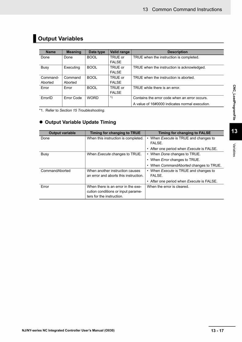
13 - 17
13 Common Command Instructions
NJ/NY-series NC Integrated Controller User’s Manual (O030)
CN
C_L
oad
Pro
gram
File
13
Variables
Output Variable Update Timing
Output Variables
Name Meaning Data type Valid range Description
Done Done BOOL TRUE or FALSE
TRUE when the instruction is completed.
Busy Executing BOOL TRUE or FALSE
TRUE when the instruction is acknowledged.
Command-Aborted
Command Aborted
BOOL TRUE or FALSE
TRUE when the instruction is aborted.
Error Error BOOL TRUE or FALSE
TRUE while there is an error.
ErrorID Error Code WORD *1
*1. Refer to Section 15 Troubleshooting.
Contains the error code when an error occurs.
A value of 16#0000 indicates normal execution.
Output variable Timing for changing to TRUE Timing for changing to FALSE
Done When this instruction is completed. • When Execute is TRUE and changes to FALSE.
• After one period when Execute is FALSE.
Busy When Execute changes to TRUE. • When Done changes to TRUE.
• When Error changes to TRUE.
• When CommandAborted changes to TRUE.
CommandAborted When another instruction causes an error and aborts this instruction.
• When Execute is TRUE and changes to FALSE.
• After one period when Execute is FALSE.
Error When there is an error in the exe-cution conditions or input parame-ters for the instruction.
When the error is cleared.
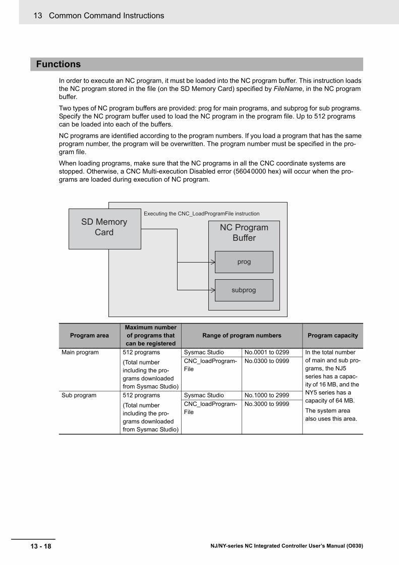
13 Common Command Instructions
13 - 18 NJ/NY-series NC Integrated Controller User’s Manual (O030)
In order to execute an NC program, it must be loaded into the NC program buffer. This instruction loads the NC program stored in the file (on the SD Memory Card) specified by FileName, in the NC program buffer.
Two types of NC program buffers are provided: prog for main programs, and subprog for sub programs. Specify the NC program buffer used to load the NC program in the program file. Up to 512 programs can be loaded into each of the buffers.
NC programs are identified according to the program numbers. If you load a program that has the same program number, the program will be overwritten. The program number must be specified in the pro-gram file.
When loading programs, make sure that the NC programs in all the CNC coordinate systems are stopped. Otherwise, a CNC Multi-execution Disabled error (56040000 hex) will occur when the pro-grams are loaded during execution of NC program.
Functions
Program areaMaximum number of programs that can be registered
Range of program numbers Program capacity
Main program 512 programs
(Total number including the pro-grams downloaded from Sysmac Studio)
Sysmac Studio No.0001 to 0299 In the total number of main and sub pro-grams, the NJ5 series has a capac-ity of 16 MB, and the NY5 series has a capacity of 64 MB.
The system area also uses this area.
CNC_loadProgram-File
No.0300 to 0999
Sub program 512 programs
(Total number including the pro-grams downloaded from Sysmac Studio)
Sysmac Studio No.1000 to 2999
CNC_loadProgram-File
No.3000 to 9999
SD Memory Card NC Program
Buffer
Executing the CNC_LoadProgramFile instruction
prog
subprog

13 - 19
13 Common Command Instructions
NJ/NY-series NC Integrated Controller User’s Manual (O030)
CN
C_L
oad
Pro
gram
File
13
NC
Program
Buffer C
onfiguration and P
rogram D
eletion
The CNC Function Module provides a program buffer. Main and sub programs are stored in the same buffer. NC programs are placed in the following sequence from the head address of the buffer: first the system area reserved for the system and next the area that contains the NC programs downloaded from Sysmac Studio.
The NC programs loaded by this instruction are placed in the areas following the NC program area downloaded from Sysmac Studio in the order in which they are loaded.
*1. The available size of the system area is approximately 1 MB.
*2. The available size of the device manufacturer’s area varies depending on the size of the NC programs down-loaded from Sysmac Studio.
NC Program Buffer Configuration and Program Deletion
0NC Program Buffer
System area Area reserved by the system
*1User area Area where NC programs downloaded
from Sysmac Studio are stored.
*2 User areaLoaded program (1)
User areaLoaded program (2)
User areaLoaded program (3)
The first NC program loaded by this instruc-tion
The second NC program loaded by this instruction.
The third NC program loaded by this instruc-tion.

13 Common Command Instructions
13 - 20 NJ/NY-series NC Integrated Controller User’s Manual (O030)
When a program that has the same program number is loaded, it will be placed at the bottom of the area. An area in which an overwritten NC program exists is not reused and it becomes free space.
Therefore, if NC programs are repeatedly loaded using this instruction, the NC program buffer runs out, and a Load NC Program Size Over error (56230000 hex) is output.
To solve buffer shortage, specify DeletePrg (Program Deletion Option) to _cncDelLoadedPrg (Delete all the loaded NC programs), and execute this instruction at the timing of a setup change. After the loaded NC programs are deleted by this instruction, a new program is loaded.
Even if this DeletePrg (Program Deletion Option) instruction is executed, the NC programs placed in the system area and the NC programs loaded from Sysmac Studio are not deleted.
A timing chart for the execution of the CNC_LoadProgramFile instruction is shown below.
Timing Chart
0NC Program Buffer
System area Area reserved by the system
*1User area Area where NC programs downloaded
from Sysmac Studio are stored.
*2 User areaLoaded program (1)
Not used.
User areaLoaded program (3)
The first NC program loaded by this instruc-tion
Area where the second loaded program was placed.
The third NC program loaded by this instruc-tion.
User areaLoaded program (4)
The fourth NC program loaded by specifying the same program number as that used to load the second NC program.
Busy
Done
CommandAborted
Error
ErrorID 16#0000
Execute
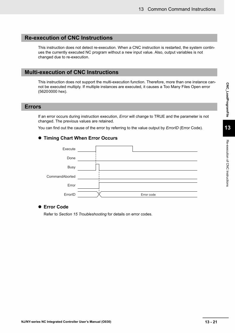
13 - 21
13 Common Command Instructions
NJ/NY-series NC Integrated Controller User’s Manual (O030)
CN
C_L
oad
Pro
gram
File
13
Re
-execution of CN
C Instru
ctions
This instruction does not detect re-execution. When a CNC instruction is restarted, the system contin-ues the currently executed NC program without a new input value. Also, output variables is not changed due to re-execution.
This instruction does not support the multi-execution function. Therefore, more than one instance can-not be executed multiply. If multiple instances are executed, it causes a Too Many Files Open error (56200000 hex).
If an error occurs during instruction execution, Error will change to TRUE and the parameter is not changed. The previous values are retained.
You can find out the cause of the error by referring to the value output by ErrorID (Error Code).
Timing Chart When Error Occurs
Error Code
Refer to Section 15 Troubleshooting for details on error codes.
Re-execution of CNC Instructions
Multi-execution of CNC Instructions
Errors
Busy
Done
CommandAborted
Error
ErrorID Error code
Execute
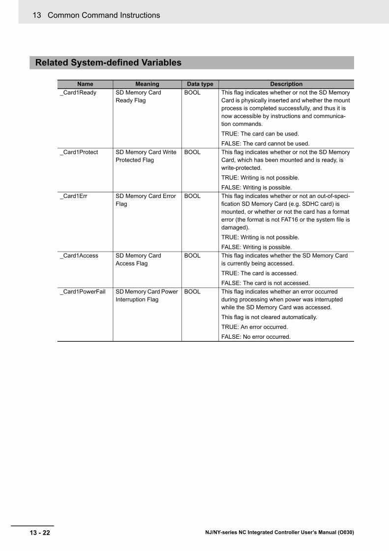
13 Common Command Instructions
13 - 22 NJ/NY-series NC Integrated Controller User’s Manual (O030)
Related System-defined Variables
Name Meaning Data type Description
_Card1Ready SD Memory Card Ready Flag
BOOL This flag indicates whether or not the SD Memory Card is physically inserted and whether the mount process is completed successfully, and thus it is now accessible by instructions and communica-tion commands.
TRUE: The card can be used.
FALSE: The card cannot be used.
_Card1Protect SD Memory Card Write Protected Flag
BOOL This flag indicates whether or not the SD Memory Card, which has been mounted and is ready, is write-protected.
TRUE: Writing is not possible.
FALSE: Writing is possible.
_Card1Err SD Memory Card Error Flag
BOOL This flag indicates whether or not an out-of-speci-fication SD Memory Card (e.g. SDHC card) is mounted, or whether or not the card has a format error (the format is not FAT16 or the system file is damaged).
TRUE: Writing is not possible.
FALSE: Writing is possible.
_Card1Access SD Memory Card Access Flag
BOOL This flag indicates whether the SD Memory Card is currently being accessed.
TRUE: The card is accessed.
FALSE: The card is not accessed.
_Card1PowerFail SD Memory Card Power Interruption Flag
BOOL This flag indicates whether an error occurred during processing when power was interrupted while the SD Memory Card was accessed.
This flag is not cleared automatically.
TRUE: An error occurred.
FALSE: No error occurred.
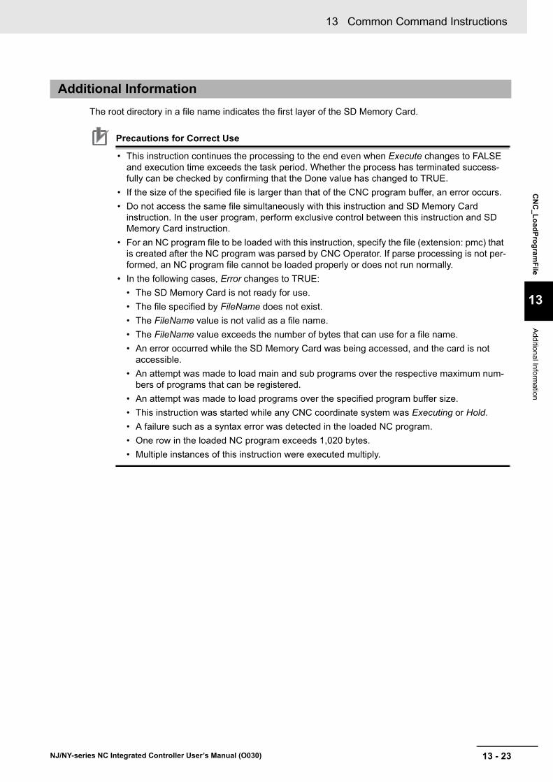
13 - 23
13 Common Command Instructions
NJ/NY-series NC Integrated Controller User’s Manual (O030)
CN
C_L
oad
Pro
gram
File
13
Additional In
formation
The root directory in a file name indicates the first layer of the SD Memory Card.
Precautions for Correct Use
• This instruction continues the processing to the end even when Execute changes to FALSE and execution time exceeds the task period. Whether the process has terminated success-fully can be checked by confirming that the Done value has changed to TRUE.
• If the size of the specified file is larger than that of the CNC program buffer, an error occurs.
• Do not access the same file simultaneously with this instruction and SD Memory Card instruction. In the user program, perform exclusive control between this instruction and SD Memory Card instruction.
• For an NC program file to be loaded with this instruction, specify the file (extension: pmc) that is created after the NC program was parsed by CNC Operator. If parse processing is not per-formed, an NC program file cannot be loaded properly or does not run normally.
• In the following cases, Error changes to TRUE:
• The SD Memory Card is not ready for use.
• The file specified by FileName does not exist.
• The FileName value is not valid as a file name.
• The FileName value exceeds the number of bytes that can use for a file name.
• An error occurred while the SD Memory Card was being accessed, and the card is not accessible.
• An attempt was made to load main and sub programs over the respective maximum num-bers of programs that can be registered.
• An attempt was made to load programs over the specified program buffer size.
• This instruction was started while any CNC coordinate system was Executing or Hold.
• A failure such as a syntax error was detected in the loaded NC program.
• One row in the loaded NC program exceeds 1,020 bytes.
• Multiple instances of this instruction were executed multiply.
Additional Information

13 Common Command Instructions
13 - 24 NJ/NY-series NC Integrated Controller User’s Manual (O030)

14 - 1
14
NJ/NY-series NC Integrated Controller User’s Manual (O030)
This section describes instructions that are used for system control.
ResetCNCError . . . . . . . . . . . . . . . . . . . . . . . . . . . . . . . . . . . . . . . . . . . . . . . 14-2
GetCNCError . . . . . . . . . . . . . . . . . . . . . . . . . . . . . . . . . . . . . . . . . . . . . . . . . 14-4
System Control Instructions

14 System Control Instructions
14 - 2 NJ/NY-series NC Integrated Controller User’s Manual (O030)
ResetCNCError
The ResetCNCError instruction resets Controller errors in the CNC Function Module.
The ResetCNCError instruction resets Controller errors in the CNC Function Module.
If the reset fails, Failure (Failure End) changes to TRUE.
The ResetCNCError instruction applies to all the CNC coordinate systems even if the program that ResetCNCError instruction is executed is written in any task.
Instruction Name FB/FUN Graphic expression ST expression
ResetCNCError CNC Error Reset
FB ResetCNCError_instance ResetCNCError_instance (
Execute :=parameter,
Done =>parameter,
Busy =>parameter,
Failure =>parameter,
Error =>parameter,
ErrorID =>parameter
);
Variables
Input Variables
Name Meaning Data type Valid range Description
Execute Execute BOOL TRUE or FALSE
The instruction is executed when Execute changes to TRUE. The default is FALSE.
Output Variables
Name Meaning Data type Valid range Description
Done Done BOOL TRUE or FALSE
TRUE when the instruction is completed.
Busy Executing BOOL TRUE or FALSE
TRUE when the instruction is acknowledged.
Failure Failure End BOOL TRUE or FALSE
TRUE when the instruction was not executed cor-rectly.
Error Error BOOL TRUE or FALSE
TRUE while there is an error.
ErrorID Error Code WORD *1
*1. Refer to Section 15 Troubleshooting.
Contains the error code when an error occurs.
A value of 16#0000 indicates normal execution.
Functions
------------------------
Execute DoneBusy
FailureError
ErrorID
ResetCNCError
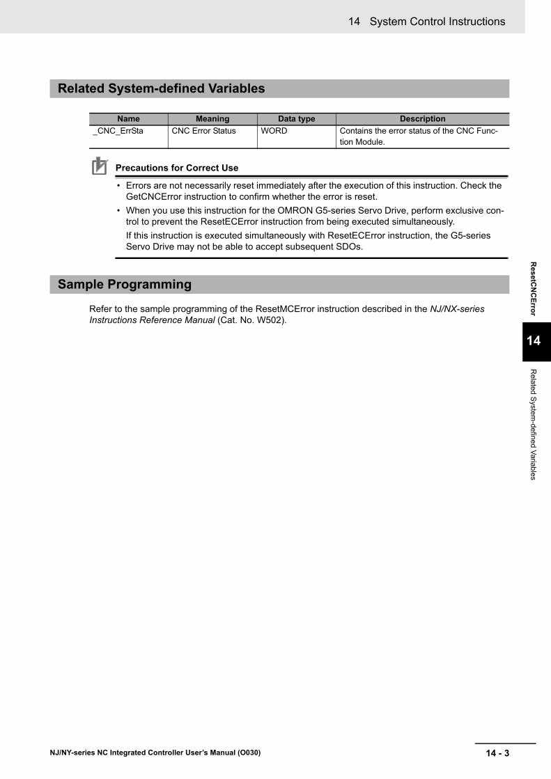
14 - 3
14 System Control Instructions
NJ/NY-series NC Integrated Controller User’s Manual (O030)
ResetC
NC
Erro
r
14
Related S
ystem-defined V
ariables
Precautions for Correct Use
• Errors are not necessarily reset immediately after the execution of this instruction. Check the GetCNCError instruction to confirm whether the error is reset.
• When you use this instruction for the OMRON G5-series Servo Drive, perform exclusive con-trol to prevent the ResetECError instruction from being executed simultaneously.
If this instruction is executed simultaneously with ResetECError instruction, the G5-series Servo Drive may not be able to accept subsequent SDOs.
Refer to the sample programming of the ResetMCError instruction described in the NJ/NX-series Instructions Reference Manual (Cat. No. W502).
Related System-defined Variables
Name Meaning Data type Description
_CNC_ErrSta CNC Error Status WORD Contains the error status of the CNC Func-tion Module.
Sample Programming
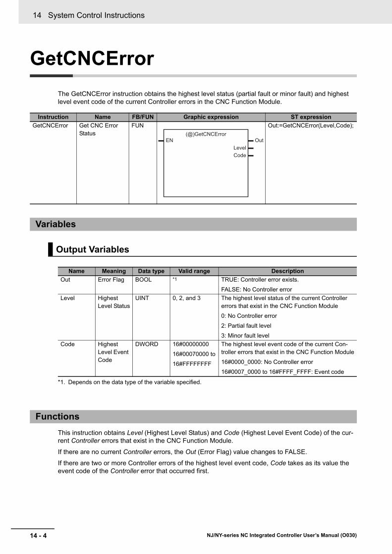
14 System Control Instructions
14 - 4 NJ/NY-series NC Integrated Controller User’s Manual (O030)
GetCNCError
The GetCNCError instruction obtains the highest level status (partial fault or minor fault) and highest level event code of the current Controller errors in the CNC Function Module.
This instruction obtains Level (Highest Level Status) and Code (Highest Level Event Code) of the cur-rent Controller errors that exist in the CNC Function Module.
If there are no current Controller errors, the Out (Error Flag) value changes to FALSE.
If there are two or more Controller errors of the highest level event code, Code takes as its value the event code of the Controller error that occurred first.
Instruction Name FB/FUN Graphic expression ST expression
GetCNCError Get CNC Error Status
FUN Out:=GetCNCError(Level,Code);
Variables
Output Variables
Name Meaning Data type Valid range Description
Out Error Flag BOOL *1
*1. Depends on the data type of the variable specified.
TRUE: Controller error exists.
FALSE: No Controller error
Level Highest Level Status
UINT 0, 2, and 3 The highest level status of the current Controller errors that exist in the CNC Function Module
0: No Controller error
2: Partial fault level
3: Minor fault level
Code Highest Level Event Code
DWORD 16#00000000
16#00070000 to
16#FFFFFFFF
The highest level event code of the current Con-troller errors that exist in the CNC Function Module
16#0000_0000: No Controller error
16#0007_0000 to 16#FFFF_FFFF: Event code
Functions
------------------------
EN OutLevelCode
(@)GetCNCError

14 - 5
14 System Control Instructions
NJ/NY-series NC Integrated Controller User’s Manual (O030)
Ge
tCN
CE
rror
14
Related S
ystem-defined V
ariables
Refer to the sample programming of the ResetMCError instruction described in the NJ/NX-series Instructions Reference Manual (Cat. No. W502).
Related System-defined Variables
Name Meaning Data type Description
_CNC_ErrSta CNC Error Status WORD Contains the error status of the CNC Func-tion Module.
Sample Programming

14 System Control Instructions
14 - 6 NJ/NY-series NC Integrated Controller User’s Manual (O030)
15 - 1
15
NJ/NY-series NC Integrated Controller User’s Manual (O030)
This section describes errors (events) that may occur in the CNC Function Module and measures used to correct those errors.
15-1 Errors Related to the CNC Function Module . . . . . . . . . . . . . . . . . . . . . . . 15-215-1-1 Error Locations Related to the CNC Function Module . . . . . . . . . . . . . . . . . 15-2
15-1-2 Types . . . . . . . . . . . . . . . . . . . . . . . . . . . . . . . . . . . . . . . . . . . . . . . . . . . . . . 15-3
15-1-3 Event Levels . . . . . . . . . . . . . . . . . . . . . . . . . . . . . . . . . . . . . . . . . . . . . . . . . 15-3
15-1-4 Errors for each Source in CNC Function Module . . . . . . . . . . . . . . . . . . . . . 15-4
15-1-5 EtherCAT Communication, EtherCAT Slave, and NX Unit Errors . . . . . . . . 15-7
15-1-6 Servo Drive Errors . . . . . . . . . . . . . . . . . . . . . . . . . . . . . . . . . . . . . . . . . . . . 15-7
15-1-7 NX Unit Errors . . . . . . . . . . . . . . . . . . . . . . . . . . . . . . . . . . . . . . . . . . . . . . . 15-8
15-2 Troubleshooting . . . . . . . . . . . . . . . . . . . . . . . . . . . . . . . . . . . . . . . . . . . . . . 15-915-2-1 How to Check Errors . . . . . . . . . . . . . . . . . . . . . . . . . . . . . . . . . . . . . . . . . . 15-9
15-2-2 How to Reset Error . . . . . . . . . . . . . . . . . . . . . . . . . . . . . . . . . . . . . . . . . . . 15-12
15-3 Error Lists . . . . . . . . . . . . . . . . . . . . . . . . . . . . . . . . . . . . . . . . . . . . . . . . . . 15-1315-3-1 Interpreting Error Descriptions . . . . . . . . . . . . . . . . . . . . . . . . . . . . . . . . . . 15-14
15-3-2 Error Lists . . . . . . . . . . . . . . . . . . . . . . . . . . . . . . . . . . . . . . . . . . . . . . . . . . 15-15
15-4 Error Descriptions . . . . . . . . . . . . . . . . . . . . . . . . . . . . . . . . . . . . . . . . . . . 15-3715-4-1 How to Check Error Contents . . . . . . . . . . . . . . . . . . . . . . . . . . . . . . . . . . . 15-37
15-4-2 Error Descriptions . . . . . . . . . . . . . . . . . . . . . . . . . . . . . . . . . . . . . . . . . . . . 15-38
Troubleshooting

15 Troubleshooting
15 - 2 NJ/NY-series NC Integrated Controller User’s Manual (O030)
15-1 Errors Related to the CNC Function Module
This section describes the errors that are related to the CNC Function Module.
Additional Information
Refer to the NJ/NX-series Troubleshooting Manual (Cat. No. W503) for the NJ-series trouble-shooting.
Refer to the NY-series Troubleshooting Manual (Cat. No. W564) for the NY-series troubleshoot-ing.
In addition to errors that occur in the CNC Function Module, there are errors caused by EtherCAT com-munication that is used for connection with the Servo Drive.
• Inside of CNC Function Module
• EtherCAT Master Function Module
• Built-in EtherCAT communications port hardware
• EtherCAT slaves
You can check the sources and causes of the errors in the system-defined variables or from the Sys-mac Studio or an HMI.
Precautions for Correct Use
Refer to the appendices of the NJ/NX-series Troubleshooting Manual (Cat. No. W503) or NY-series Troubleshooting Manual (Cat. No. W564) for the applicable range of the HMI Trou-bleshooter.
15-1-1 Error Locations Related to the CNC Function Module
Sysmac StudioNJ/NY-series Controller
EtherCAT
Error information
HMI
or
EtherCAT slaves
Built-in EtherCAT communications port
EtherCAT Master Function Module
CNC Function Module
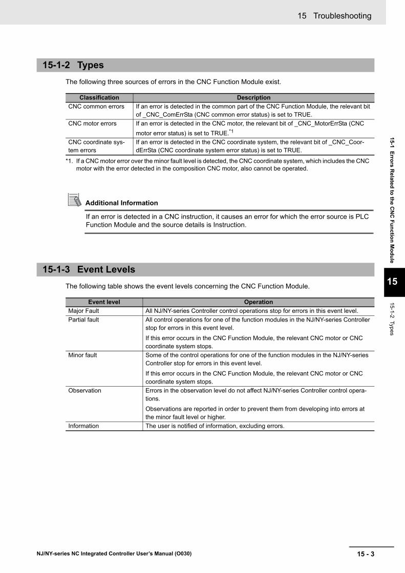
15 - 3
15 Troubleshooting
NJ/NY-series NC Integrated Controller User’s Manual (O030)
15-1 E
rrors R
elated
to th
e CN
C F
un
ction
Mo
du
le
15
15-1-2 Types
The following three sources of errors in the CNC Function Module exist.
Additional Information
If an error is detected in a CNC instruction, it causes an error for which the error source is PLC Function Module and the source details is Instruction.
The following table shows the event levels concerning the CNC Function Module.
15-1-2 Types
Classification Description
CNC common errors If an error is detected in the common part of the CNC Function Module, the relevant bit of _CNC_ComErrSta (CNC common error status) is set to TRUE.
CNC motor errors If an error is detected in the CNC motor, the relevant bit of _CNC_MotorErrSta (CNC
motor error status) is set to TRUE.*1
*1. If a CNC motor error over the minor fault level is detected, the CNC coordinate system, which includes the CNC motor with the error detected in the composition CNC motor, also cannot be operated.
CNC coordinate sys-tem errors
If an error is detected in the CNC coordinate system, the relevant bit of _CNC_Coor-dErrSta (CNC coordinate system error status) is set to TRUE.
15-1-3 Event Levels
Event level Operation
Major Fault All NJ/NY-series Controller control operations stop for errors in this event level.
Partial fault All control operations for one of the function modules in the NJ/NY-series Controller stop for errors in this event level.
If this error occurs in the CNC Function Module, the relevant CNC motor or CNC coordinate system stops.
Minor fault Some of the control operations for one of the function modules in the NJ/NY-series Controller stop for errors in this event level.
If this error occurs in the CNC Function Module, the relevant CNC motor or CNC coordinate system stops.
Observation Errors in the observation level do not affect NJ/NY-series Controller control opera-tions.
Observations are reported in order to prevent them from developing into errors at the minor fault level or higher.
Information The user is notified of information, excluding errors.

15 Troubleshooting
15 - 4 NJ/NY-series NC Integrated Controller User’s Manual (O030)
The following tables list the errors in each event level that can occur for each source.
The table below shows errors detected in the CNC common part for each level.
15-1-4 Errors for each Source in CNC Function Module
CNC Common Errors
Level Error name
Major fault • CNC Parameter Setting Invalid
Partial Fault • CNC Parameter Setting Error
• Absolute Encoder Home Offset Read Error
• CNC Motor Compensation Table Read Error
• Required Process Data Object Not Set
• Network Configuration Information Missing for CNC Motor Slave
• CNC Initialization Error
• CNC Control Period Exceeded
Minor fault • Illegal CNC Coordinate System Specification
• CNC Instruction Re-execution Disabled
• Parameter Selection Out of Range
• CNC Parameter Setting Read/Write Setting Value Out of Range
• CNC Parameter Setting Read/Write Target Out of Range
• Illegal NC Program
• Illegal CNC Motor Specification
• Illegal CNC Motor Compensation Table Specification
• NC Program Capacity Exceeded
Observation • SD Memory Card Access Failure
• File Does Not Exist
• Illegal Load NC Program Number Specification
• Too Many Files Open
• File or Directory Name Is Too Long
• SD Memory Card Access Failed
• Load NC Program Capacity Exceeded
• Number of NC Program Exceeded
• Illegal Load NC Program
• CNC Planner Service Period Exceeded
Information • CNC Function System Information
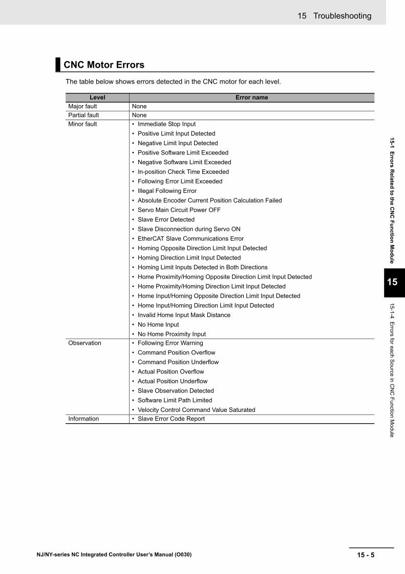
15 - 5
15 Troubleshooting
NJ/NY-series NC Integrated Controller User’s Manual (O030)
15-1 E
rrors R
elated
to th
e CN
C F
un
ction
Mo
du
le
15
15-1-4 Errors for each S
ource in C
NC
Function M
odule
The table below shows errors detected in the CNC motor for each level.
CNC Motor Errors
Level Error name
Major fault None
Partial fault None
Minor fault • Immediate Stop Input
• Positive Limit Input Detected
• Negative Limit Input Detected
• Positive Software Limit Exceeded
• Negative Software Limit Exceeded
• In-position Check Time Exceeded
• Following Error Limit Exceeded
• Illegal Following Error
• Absolute Encoder Current Position Calculation Failed
• Servo Main Circuit Power OFF
• Slave Error Detected
• Slave Disconnection during Servo ON
• EtherCAT Slave Communications Error
• Homing Opposite Direction Limit Input Detected
• Homing Direction Limit Input Detected
• Homing Limit Inputs Detected in Both Directions
• Home Proximity/Homing Opposite Direction Limit Input Detected
• Home Proximity/Homing Direction Limit Input Detected
• Home Input/Homing Opposite Direction Limit Input Detected
• Home Input/Homing Direction Limit Input Detected
• Invalid Home Input Mask Distance
• No Home Input
• No Home Proximity Input
Observation • Following Error Warning
• Command Position Overflow
• Command Position Underflow
• Actual Position Overflow
• Actual Position Underflow
• Slave Observation Detected
• Software Limit Path Limited
• Velocity Control Command Value Saturated
Information • Slave Error Code Report
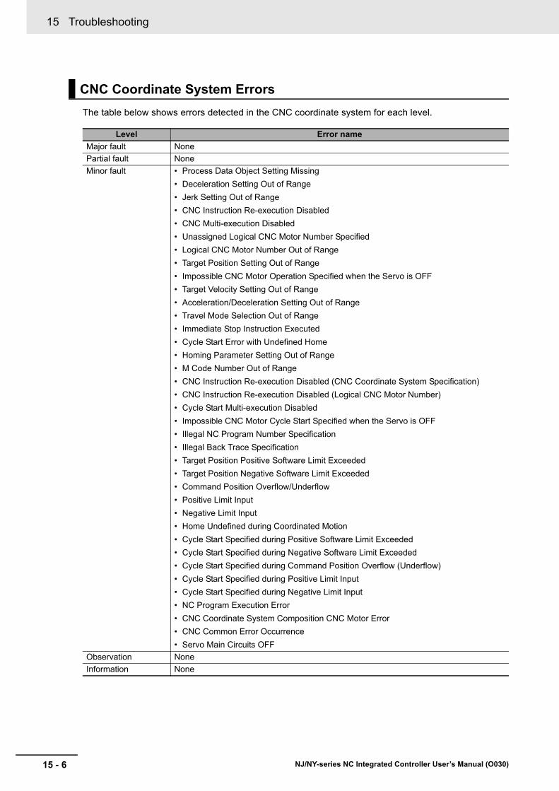
15 Troubleshooting
15 - 6 NJ/NY-series NC Integrated Controller User’s Manual (O030)
The table below shows errors detected in the CNC coordinate system for each level.
CNC Coordinate System Errors
Level Error name
Major fault None
Partial fault None
Minor fault • Process Data Object Setting Missing
• Deceleration Setting Out of Range
• Jerk Setting Out of Range
• CNC Instruction Re-execution Disabled
• CNC Multi-execution Disabled
• Unassigned Logical CNC Motor Number Specified
• Logical CNC Motor Number Out of Range
• Target Position Setting Out of Range
• Impossible CNC Motor Operation Specified when the Servo is OFF
• Target Velocity Setting Out of Range
• Acceleration/Deceleration Setting Out of Range
• Travel Mode Selection Out of Range
• Immediate Stop Instruction Executed
• Cycle Start Error with Undefined Home
• Homing Parameter Setting Out of Range
• M Code Number Out of Range
• CNC Instruction Re-execution Disabled (CNC Coordinate System Specification)
• CNC Instruction Re-execution Disabled (Logical CNC Motor Number)
• Cycle Start Multi-execution Disabled
• Impossible CNC Motor Cycle Start Specified when the Servo is OFF
• Illegal NC Program Number Specification
• Illegal Back Trace Specification
• Target Position Positive Software Limit Exceeded
• Target Position Negative Software Limit Exceeded
• Command Position Overflow/Underflow
• Positive Limit Input
• Negative Limit Input
• Home Undefined during Coordinated Motion
• Cycle Start Specified during Positive Software Limit Exceeded
• Cycle Start Specified during Negative Software Limit Exceeded
• Cycle Start Specified during Command Position Overflow (Underflow)
• Cycle Start Specified during Positive Limit Input
• Cycle Start Specified during Negative Limit Input
• NC Program Execution Error
• CNC Coordinate System Composition CNC Motor Error
• CNC Common Error Occurrence
• Servo Main Circuits OFF
Observation None
Information None

15 - 7
15 Troubleshooting
NJ/NY-series NC Integrated Controller User’s Manual (O030)
15-1 E
rrors R
elated
to th
e CN
C F
un
ction
Mo
du
le
15
15-1-5 EtherC
AT
Com
munication, E
therCA
T S
lave, and NX
Unit E
rrors
The following errors occur in the CNC Function Module due to an EtherCAT communication, EtherCAT slave, or NX unit error.
This section describes error occurrence notifications in the OMRON 1S-series Servo Drive or G5-series Servo Drive.
There is a time lag between the timing when the CNC Function Module detects a Servo Drive error and the timing when the error code is acquired from the Servo Drive.
Therefore, the CNC Function Module notifies Servo Drive error detection and error code in different events.
Error Notification
If the CNC Function Module detects a Servo Drive error, it causes minor fault level, Slave Error Detection (77860000 hex).
At this point, the MC Function Module performs the error operation (i.e., it turns OFF the Servo).
Error Code Notification
When the Servo Drive reports the error code, the MC Function Module generates a Slave Error Code Report information event (97800000 hex). The error code (the main part of the error display number) from the Servo Drive is included in the lower two digits of the attached information of the Slave Error Code Report event.
For example, if the attached information is displayed as FF13, the error with display number 13 (Main Circuit Power Supply Undervoltage) occurred in the Servo Drive.
Precautions for Correct Use
You must change the settings to receive notification of the Slave Error Code Report event.
Map object 603F hex (Error Code) in the PDO Edit Pane.
15-1-5 EtherCAT Communication, EtherCAT Slave, and NX Unit Errors
Error name Event code Cause Operation at error detection
EtherCAT Slave Communications Error
87800000 hex An error occurred in a communica-tion with the EtherCAT slave or NX unit assigned to the CNC motor of
the CNC Function Module.*1
*1. When an error occurs in communications with an EtherCAT slave, an error also occurs in the EtherCAT Master Function Module. While multiple devices are assigned to a single CNC motor, if a communication error occurs in even one device, the CNC motor results in a communication error.
SERVO OFF is performed for the CNC motor with the error detected, and an operation other than error
reset is rejected.*2
*2. If a slave communication error occurs, the CNC motor is placed in the home undefined state.
Slave Error Detected
77860000 hex The EtherCAT slave or NX unit assigned to the CNC motor of the CNC Function Module has detected an error.
SERVO OFF is performed for the CNC motor with the error detected, and an operation other than error reset is rejected.
15-1-6 Servo Drive Errors

15 Troubleshooting
15 - 8 NJ/NY-series NC Integrated Controller User’s Manual (O030)
If an error occurs in the OMRON NX series position interface unit, the error detection and error code are notified in the same way as for the OMRON 1S-series Servo Drive or G5-series Servo Drive.
However, NX-series Position Interface Units do not have an object that corresponds to object 603F hex (Error Code), so 0000 hex is given for the Slave Error Code Report (97800000 hex) in the attached information.
Refer to the NX-series Position Interface Units User’s Manual (Cat. No. W524) and NX-series Ether-CAT Coupler Units User’s Manual (Cat. No. W519) for details on the errors detected in the NX-series position interface unit.
15-1-7 NX Unit Errors

15 - 9
15 Troubleshooting
NJ/NY-series NC Integrated Controller User’s Manual (O030)
15-2 Tro
ub
lesho
otin
g
15
15-2-1 How
to Che
ck Erro
rs
15-2 Troubleshooting
This section describes how to check and reset an error detected in the CNC Function Module.
The detected CNC Function Module error is retained until the controller is turned off or reset.
To reset a Controller error, it is necessary to eliminate the cause of the error. The same error will occur again if you reset the error, but do not eliminate the cause of the error.
An error detected in the CNC Function Module can be checked using the following methods.
• Controller body’s LED
• Sysmac Studio troubleshooting function
• HMI troubleshooter
• CNC Operator troubleshooter
• Error status acquirement instruction
• System-defined variable
Refer to the NJ/NX-series Troubleshooting Manual (Cat. No. W503) or NY-series Troubleshooting Man-ual (Cat. No. W564) for details on how to check errors using the controller body’s LED, Sysmac Studio troubleshooting function, HMI troubleshooter, error status acquirement instruction, or system-defined variable.
Refer to the CNC Operator Operation Manual (Cat. No. O032) for details on how to check errors using the CNC Operator troubleshooter.
The error (event) detected in the CNC Function Module can be acquired using the following instruc-tions. Refer to the explanation of each instruction for details.
15-2-1 How to Check Errors
Instructions to Get Error Detected in the CNC Function Module
Instruction name Instruction Function
Get CNC Error Status GetCNCError The GetCNCError instruction obtains the highest level status (partial fault or minor fault) and highest level event code of the current Controller errors that exist in the CNC Function Module.
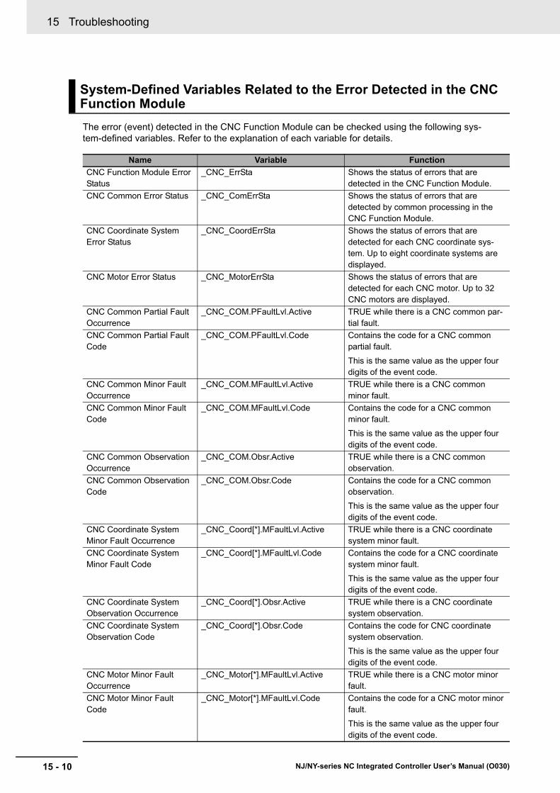
15 Troubleshooting
15 - 10 NJ/NY-series NC Integrated Controller User’s Manual (O030)
The error (event) detected in the CNC Function Module can be checked using the following sys-tem-defined variables. Refer to the explanation of each variable for details.
System-Defined Variables Related to the Error Detected in the CNC Function Module
Name Variable Function
CNC Function Module Error Status
_CNC_ErrSta Shows the status of errors that are detected in the CNC Function Module.
CNC Common Error Status _CNC_ComErrSta Shows the status of errors that are detected by common processing in the CNC Function Module.
CNC Coordinate System Error Status
_CNC_CoordErrSta Shows the status of errors that are detected for each CNC coordinate sys-tem. Up to eight coordinate systems are displayed.
CNC Motor Error Status _CNC_MotorErrSta Shows the status of errors that are detected for each CNC motor. Up to 32 CNC motors are displayed.
CNC Common Partial Fault Occurrence
_CNC_COM.PFaultLvl.Active TRUE while there is a CNC common par-tial fault.
CNC Common Partial Fault Code
_CNC_COM.PFaultLvl.Code Contains the code for a CNC common partial fault.
This is the same value as the upper four digits of the event code.
CNC Common Minor Fault Occurrence
_CNC_COM.MFaultLvl.Active TRUE while there is a CNC common minor fault.
CNC Common Minor Fault Code
_CNC_COM.MFaultLvl.Code Contains the code for a CNC common minor fault.
This is the same value as the upper four digits of the event code.
CNC Common Observation Occurrence
_CNC_COM.Obsr.Active TRUE while there is a CNC common observation.
CNC Common Observation Code
_CNC_COM.Obsr.Code Contains the code for a CNC common observation.
This is the same value as the upper four digits of the event code.
CNC Coordinate System Minor Fault Occurrence
_CNC_Coord[*].MFaultLvl.Active TRUE while there is a CNC coordinate system minor fault.
CNC Coordinate System Minor Fault Code
_CNC_Coord[*].MFaultLvl.Code Contains the code for a CNC coordinate system minor fault.
This is the same value as the upper four digits of the event code.
CNC Coordinate System Observation Occurrence
_CNC_Coord[*].Obsr.Active TRUE while there is a CNC coordinate system observation.
CNC Coordinate System Observation Code
_CNC_Coord[*].Obsr.Code Contains the code for CNC coordinate system observation.
This is the same value as the upper four digits of the event code.
CNC Motor Minor Fault Occurrence
_CNC_Motor[*].MFaultLvl.Active TRUE while there is a CNC motor minor fault.
CNC Motor Minor Fault Code
_CNC_Motor[*].MFaultLvl.Code Contains the code for a CNC motor minor fault.
This is the same value as the upper four digits of the event code.

15 - 11
15 Troubleshooting
NJ/NY-series NC Integrated Controller User’s Manual (O030)
15-2 Tro
ub
lesho
otin
g
15
15-2-1 How
to Che
ck Erro
rs
CNC Common Observation Occurrence
_CNC_Motor[*].Obsr.Active TRUE while there is a CNC motor obser-vation.
CNC Motor Observation Code
_CNC_Motor[*].Obsr.Code Contains the code for a CNC motor obser-vation.
This is the same value as the upper four digits of the event code.
Name Variable Function
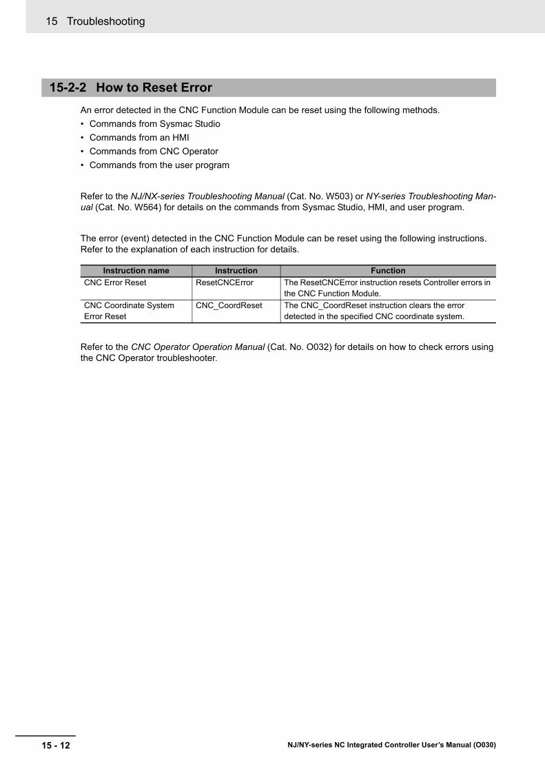
15 Troubleshooting
15 - 12 NJ/NY-series NC Integrated Controller User’s Manual (O030)
An error detected in the CNC Function Module can be reset using the following methods.
• Commands from Sysmac Studio
• Commands from an HMI
• Commands from CNC Operator
• Commands from the user program
Refer to the NJ/NX-series Troubleshooting Manual (Cat. No. W503) or NY-series Troubleshooting Man-ual (Cat. No. W564) for details on the commands from Sysmac Studio, HMI, and user program.
The error (event) detected in the CNC Function Module can be reset using the following instructions. Refer to the explanation of each instruction for details.
Refer to the CNC Operator Operation Manual (Cat. No. O032) for details on how to check errors using the CNC Operator troubleshooter.
15-2-2 How to Reset Error
Instruction name Instruction Function
CNC Error Reset ResetCNCError The ResetCNCError instruction resets Controller errors in the CNC Function Module.
CNC Coordinate System Error Reset
CNC_CoordReset The CNC_CoordReset instruction clears the error detected in the specified CNC coordinate system.

15 - 13
15 Troubleshooting
NJ/NY-series NC Integrated Controller User’s Manual (O030)
15-3 Erro
r Lists
15
15-3 Error Lists
This section shows lists of errors (events) that may occur in the CNC Function Module.
Refer to the NJ/NX-series Troubleshooting Manual (Cat. No. W503) for all the NJ-series event codes.
Refer to the NY-series Troubleshooting Manual (Cat. No. W564) for all the NY-series event codes.
Replacing the Event Explanation in Use of the NY-Series Controller
To describe the events displayed by Sysmac Studio, the events detected commonly in the NY-series Controller and NJ/NX-series Controller are explained as the events detected in the NJ/NX-series Controller. Therefore, it is necessary to interpret the displayed contents when your use an NY-series Controller. Note the following conditions.
• You cannot connect a CJ-series Unit with NY-series Controllers. In the instructions, skip items related to CJ-series Units.
• In explanation of the errors, replace the term CPU Unit with NY-series Controller or NY-series Industrial PC.
• NY-series Controllers have no SD Memory Card slots. Instead, they provide the Virtual SD Mem-ory Card function that uses the Windows shared folder. Therefore, replace the term SD Memory Card with Virtual SD Memory Card. Refer to the NY-series Industrial Panel PC / Industrial Box PC Setup User's Manual (Cat. No. W568) for details on the Virtual SD Memory Card function.
• NY-series Controllers do not have the SD PWR LED and SD BUSY LED indicators. In the instruc-tions, skip items related to the SD PWR LED and SD BUSY LED indicators.
• NY-series Controllers do not have the RUN LED, ERR LED, and LINK/ACT LED indicators for EtherCAT. Skip the items that describe EtherCAT’s RUN LED, ERR LED, and LINK/ACT LED.
• Replace the NJ/NX-series manuals with the NY-series manuals in the Reference column.
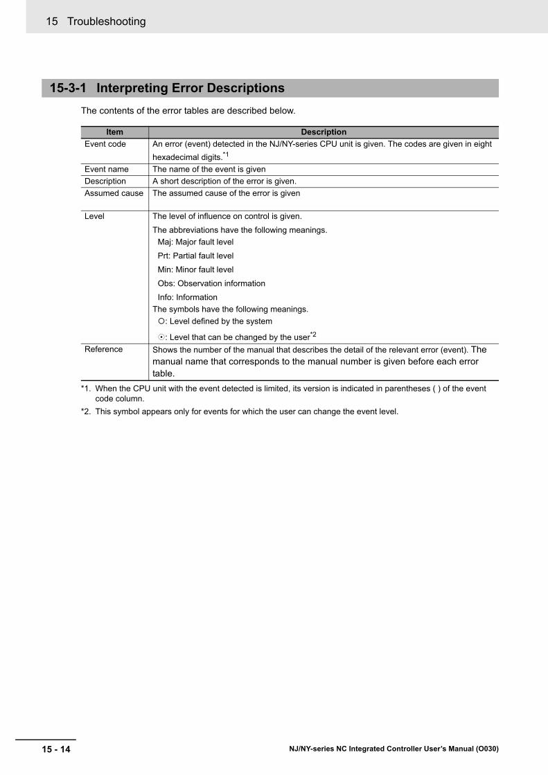
15 Troubleshooting
15 - 14 NJ/NY-series NC Integrated Controller User’s Manual (O030)
The contents of the error tables are described below.
15-3-1 Interpreting Error Descriptions
Item Description
Event code An error (event) detected in the NJ/NY-series CPU unit is given. The codes are given in eight
hexadecimal digits.*1
*1. When the CPU unit with the event detected is limited, its version is indicated in parentheses ( ) of the event code column.
Event name The name of the event is given
Description A short description of the error is given.
Assumed cause The assumed cause of the error is given
Level The level of influence on control is given.
The abbreviations have the following meanings.
Maj: Major fault level
Prt: Partial fault level
Min: Minor fault level
Obs: Observation information
Info: Information
The symbols have the following meanings.
: Level defined by the system
: Level that can be changed by the user*2
*2. This symbol appears only for events for which the user can change the event level.
Reference Shows the number of the manual that describes the detail of the relevant error (event). The manual name that corresponds to the manual number is given before each error table.
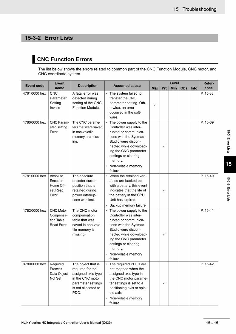
15 - 15
15 Troubleshooting
NJ/NY-series NC Integrated Controller User’s Manual (O030)
15-3 Erro
r Lists
15
15-3-2 Error L
ists
The list below shows the errors related to common part of the CNC Function Module, CNC motor, and CNC coordinate system.
15-3-2 Error Lists
CNC Function Errors
Event codeEvent name
Description Assumed causeLevel Refer-
enceMaj Prt Min Obs Info
47810000 hex CNC Parameter Setting Invalid
A fatal error was detected during setting of the CNC Function Module.
• The system failed to transfer the CNC parameter setting. Oth-erwise, an error occurred in the soft-ware.
P. 15-38
17800000 hex CNC Param-eter Setting Error
The CNC parame-ters that were saved in non-volatile memory are miss-ing.
• The power supply to the Controller was inter-rupted or communica-tions with the Sysmac Studio were discon-nected while download-ing the CNC parameter settings or clearing memory.
• Non-volatile memory failure
P. 15-39
17810000 hex Absolute Encoder Home Off-set Read Error
The absolute encoder current position that is retained during power interrup-tions was lost.
• When the retained vari-ables are backed up with a battery, this event indicates that the life of the battery in the CPU Unit has expired.
• Backup memory failure
P. 15-40
17820000 hex CNC Motor Compensa-tion Table Read Error
The CNC motor compensation table that was saved in non-vola-tile memory is missing.
• The power supply to the Controller was inter-rupted or communica-tions with the Sysmac Studio were discon-nected while download-ing the CNC parameter settings or clearing memory.
• Non-volatile memory failure
P. 15-41
37800000 hex Required Process Data Object Not Set
The object that is required for the assigned axis type in the CNC motor parameter settings is not allocated to PDO.
• The required PDOs are not mapped when the assigned axis type in the CNC motor parame-ter settings is set to a positioning axis or spin-dle axis.
• Non-volatile memory failure
P. 15-42

15 Troubleshooting
15 - 16 NJ/NY-series NC Integrated Controller User’s Manual (O030)
47800000 hex CNC Initial-ization Error
A fatal error occurred in the system and pre-vented initializa-tion of the CNC Function Module.
• Hardware failure
P. 15-42
77800000 hex CNC Con-trol Period Exceeded
The primary peri-odic task process-ing has not been completed within two control cycles.
• The processing load in the primary periodic task is too heavy.
P. 15-43
37810000 hex Process Data Object Setting Missing
The PDO mapping is not correct.
• The PDOs that are required for the CNC instruction are not mapped.
• The relevant instruction was executed for a device that does not have an object that sup-ports the instruction.
P. 15-43
56000000 hex Illegal CNC Coordinate System Specification
The CNC coordi-nate system speci-fied for the Coord in-out variable to a CNC instruction does not exist.
• CNC coordinate system does not exist for the variable specified for the Coord in-out variable to the instruction.
P. 15-44
56010000 hex Decelera-tion Setting Out of Range
The parameter specified for the Deceleration input variable to a CNC instruction is out of range.
• Instruction input param-eter exceeded the valid range of the input vari-able.
P. 15-44
56020000 hex Jerk Setting Out of Range
The parameter specified for the Jerk input variable to a CNC instruc-tion is out of range.
• Instruction input param-eter exceeded the valid range of the input vari-able.
P. 15-45
56030000 hex CNC Instruction Re-execu-tion Dis-abled
A CNC instruction that cannot be re-executed was re-executed.
• A CNC instruction that cannot be re-executed was re-executed.
P. 15-45
56040000 hex CNC Multi-execu-tion Dis-abled
Multiple functions that cannot be exe-cuted simultane-ously were executed for the same target (CNC coordinate sys-tem).
• Multiple functions that cannot be executed simultaneously were executed for the same target (CNC coordinate system).
• The CNC_LoadPro-gramFile instruction was executed when any of CNC coordinate system was Executing (Execut-ing) or Hold (Holding).
P. 15-46
Event codeEvent name
Description Assumed causeLevel Refer-
enceMaj Prt Min Obs Info

15 - 17
15 Troubleshooting
NJ/NY-series NC Integrated Controller User’s Manual (O030)
15-3 Erro
r Lists
15
15-3-2 Error L
ists
56050000 hex Unassigned Logical CNC Motor Num-ber Speci-fied
The CNC motor of the parameter specified for the LogicalMotorNo input variable to the CNC instruc-tion is not assigned.
• The logical CNC motor number for which the CNC motor is not assigned to the Logi-calMotorNo input vari-able to the CNC instruction was speci-fied, and the instruction was executed.
P. 15-46
56060000 hex Logical CNC Motor Num-ber Out of Range
The parameter specified for the LogicalMotorNo input variable to a CNC instruction is out of range.
• Instruction input param-eter exceeded the valid range of the input vari-able.
P. 15-47
56070000 hex Target Posi-tion Setting Out of Range
The parameter specified for the Position input vari-able to a CNC instruction is out of range.
• Instruction input param-eter exceeded the valid range of the input vari-able. Or, there was an overflow/underflow in the target position.
P. 15-47
56080000 hex Impossible CNC Motor Operation Specified when the Servo is OFF
An operation instruction was executed for the CNC motor for which the Servo is OFF.
• Home was preset with the CNC_Home or CNC_HomeWithParam-eter instruction for an axis for which Ether-CAT process data com-munications are not established.
P. 15-48
56090000 hex Target Velocity Set-ting Out of Range
The parameter specified for the Velocity input vari-able to a CNC instruction is out of range.
• Instruction input param-eter exceeded the valid range of the input vari-able.
P. 15-49
560A0000 hex Accelera-tion/Deceler-ation Setting Out of Range
The parameter specified for the Acceleration input variable to a CNC instruction is out of range.
• Instruction input param-eter exceeded the valid range of the input vari-able.
P. 15-49
560B0000 hex Travel Mode Selection Out of Range
The parameter specified for the MoveMode input variable to a CNC instruction is out of range.
• Instruction input param-eter exceeded the valid range of the input vari-able.
P. 15-50
560C0000 hex Immediate Stop Instruc-tion Exe-cuted
An Immediate Stop (CNC_Coor-dImmediateStop) instruction was executed.
• An Immediate Stop instruction was exe-cuted.
P. 15-50
Event codeEvent name
Description Assumed causeLevel Refer-
enceMaj Prt Min Obs Info
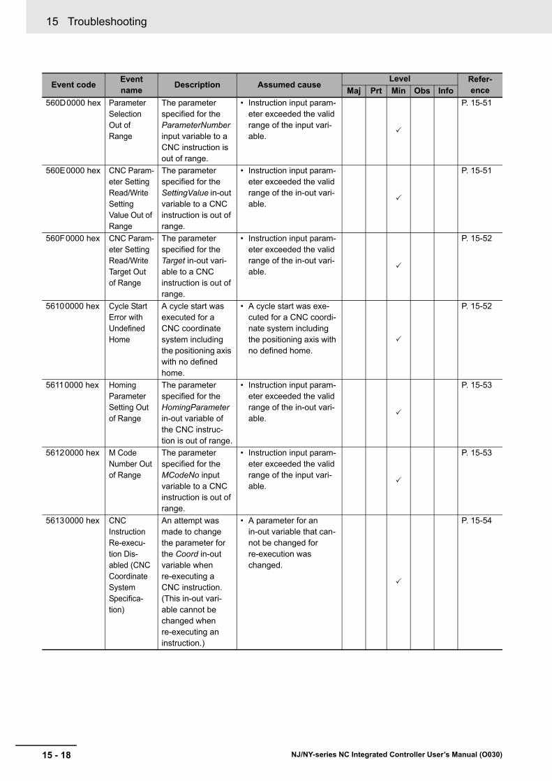
15 Troubleshooting
15 - 18 NJ/NY-series NC Integrated Controller User’s Manual (O030)
560D0000 hex Parameter Selection Out of Range
The parameter specified for the ParameterNumber input variable to a CNC instruction is out of range.
• Instruction input param-eter exceeded the valid range of the input vari-able.
P. 15-51
560E0000 hex CNC Param-eter Setting Read/Write Setting Value Out of Range
The parameter specified for the SettingValue in-out variable to a CNC instruction is out of range.
• Instruction input param-eter exceeded the valid range of the in-out vari-able.
P. 15-51
560F0000 hex CNC Param-eter Setting Read/Write Target Out of Range
The parameter specified for the Target in-out vari-able to a CNC instruction is out of range.
• Instruction input param-eter exceeded the valid range of the in-out vari-able.
P. 15-52
56100000 hex Cycle Start Error with Undefined Home
A cycle start was executed for a CNC coordinate system including the positioning axis with no defined home.
• A cycle start was exe-cuted for a CNC coordi-nate system including the positioning axis with no defined home.
P. 15-52
56110000 hex Homing Parameter Setting Out of Range
The parameter specified for the HomingParameter in-out variable of the CNC instruc-tion is out of range.
• Instruction input param-eter exceeded the valid range of the in-out vari-able.
P. 15-53
56120000 hex M Code Number Out of Range
The parameter specified for the MCodeNo input variable to a CNC instruction is out of range.
• Instruction input param-eter exceeded the valid range of the input vari-able.
P. 15-53
56130000 hex CNC Instruction Re-execu-tion Dis-abled (CNC Coordinate System Specifica-tion)
An attempt was made to change the parameter for the Coord in-out variable when re-executing a CNC instruction. (This in-out vari-able cannot be changed when re-executing an instruction.)
• A parameter for an in-out variable that can-not be changed for re-execution was changed.
P. 15-54
Event codeEvent name
Description Assumed causeLevel Refer-
enceMaj Prt Min Obs Info

15 - 19
15 Troubleshooting
NJ/NY-series NC Integrated Controller User’s Manual (O030)
15-3 Erro
r Lists
15
15-3-2 Error L
ists
56140000 hex CNC Instruction Re-execu-tion Dis-abled (Logical CNC Motor Number)
An attempt was made to change the parameter for the LogicalMo-torNo input vari-able when re-executing a CNC instruction. (This input vari-able cannot be changed when re-executing an instruction.)
• A parameter for an input variable that cannot be changed for re-execu-tion was changed.
P. 15-54
56150000 hex Illegal NC Program
An error was detected in the NC program trans-ferred from Sys-mac Studio.
• NC program transfer processing failed.
P. 15-55
56160000 hex Cycle Start Multi-execu-tion Dis-abled
A cycle start was executed multiple times for the same target (CNC coor-dinate system).
• A cycle start was exe-cuted while the CNC coordinate system is Executing (Executing), MovingOnHold (Manual Operation While Hold-ing), or Moving (Mov-ing).
P. 15-55
56170000 hex Impossible CNC Motor Cycle Start Specified when the Servo is OFF
A cycle start was executed for a CNC coordinate system including the CNC motor for which the Servo is OFF.
• A cycle start was exe-cuted for the CNC motor for which Servo is turned OFF.
P. 15-56
56180000 hex Illegal NC Program Number Specification
The NC program specified for Pro-gramNo in the ControlInputs in-out variable to the CNC_Coord-Control instruction is not loaded.
• A cycle start was exe-cuted after an unloaded NC program is speci-fied for ProgramNo in the ControlInputs in-out variable to the CNC_CoordControl instruction.
P. 15-56
56190000 hex Illegal Back Trace Speci-fication
A cycle start was executed when the CNC coordinate system is Standby (Standby) while BackTrace in the ControlInputs in-out variable to the CNC_Coord-Control instruction is set to TRUE.
• A cycle start was exe-cuted when the CNC coordinate system is Standby (Standby) while BackTrace in the Con-trolInputs in-out vari-able to the CNC_CoordControl instruction is set to TRUE.
P. 15-57
Event codeEvent name
Description Assumed causeLevel Refer-
enceMaj Prt Min Obs Info

15 Troubleshooting
15 - 20 NJ/NY-series NC Integrated Controller User’s Manual (O030)
56250000 hex Illegal CNC Motor Speci-fication
The CNC motor specified for the Target in-out vari-able to a CNC instruction does not exist.
• A CNC motor does not exist for the variable specified for the Target input variable to the instruction.
P. 15-57
56260000 hex Illegal CNC Motor Com-pensation Table Speci-fication
The CNC motor compensation table specified for the Target input variable to a CNC instruction does not exist.
• A CNC motor compen-sation table does not exist for the variable specified for the Target input variable to the instruction.
P. 15-58
56290000 hex NC Pro-gram Capacity Exceeded
Loading failed because the NC program down-loaded from Sys-mac Studio exceeded the max-imum capacity.
• The NC program that has a capacity above the maximum was downloaded from Sys-mac Studio.
P. 15-58
67800000 hex Immediate Stop Input
The immediate stop input turned ON.
• An immediate stop input signal was detected.
• The immediate stop input signal is not con-nected correctly or the logic setting for the immediate stop input is wrong.
P. 15-59
67810000 hex Positive Limit Input Detected
The positive limit input turned ON.
• A positive limit input sig-nal was detected.
• The positive limit input signal is not connected correctly or the logic setting for the positive limit input is wrong.
P. 15-60
67820000 hex Negative Limit Input Detected
The negative limit input turned ON.
• A negative limit input signal was detected.
• The negative limit input signal is not connected correctly or the logic setting for the negative limit input is wrong.
P. 15-61
67830000 hex Target Posi-tion Positive Software Limit Exceeded
The specified posi-tion exceeds the positive software limit.
• The parameter specified for the Position input variable to the instruc-tion is beyond the posi-tive software limit.
• The first position is beyond the positive soft-ware limit and an instruction that speci-fies motion in the oppo-site direction of the software limit was exe-cuted.
P. 15-62
Event codeEvent name
Description Assumed causeLevel Refer-
enceMaj Prt Min Obs Info
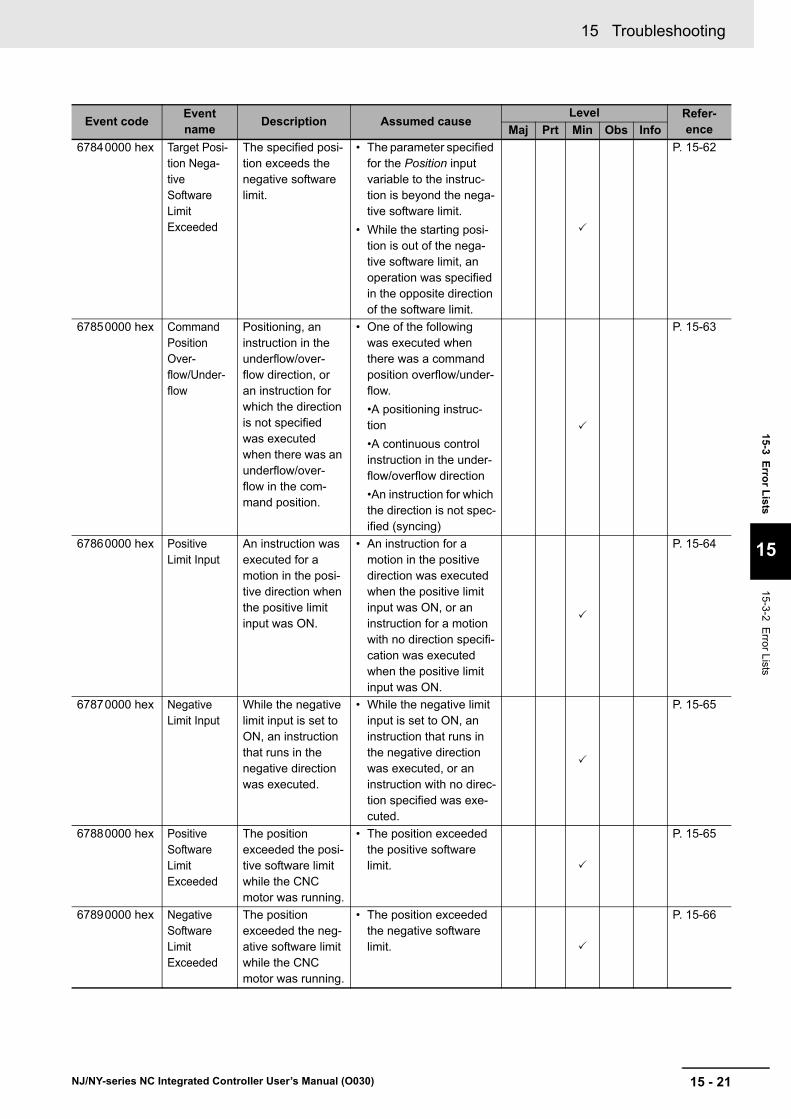
15 - 21
15 Troubleshooting
NJ/NY-series NC Integrated Controller User’s Manual (O030)
15-3 Erro
r Lists
15
15-3-2 Error L
ists
67840000 hex Target Posi-tion Nega-tive Software Limit Exceeded
The specified posi-tion exceeds the negative software limit.
• The parameter specified for the Position input variable to the instruc-tion is beyond the nega-tive software limit.
• While the starting posi-tion is out of the nega-tive software limit, an operation was specified in the opposite direction of the software limit.
P. 15-62
67850000 hex Command Position Over-flow/Under-flow
Positioning, an instruction in the underflow/over-flow direction, or an instruction for which the direction is not specified was executed when there was an underflow/over-flow in the com-mand position.
• One of the following was executed when there was a command position overflow/under-flow.
•A positioning instruc-tion
•A continuous control instruction in the under-flow/overflow direction
•An instruction for which the direction is not spec-ified (syncing)
P. 15-63
67860000 hex Positive Limit Input
An instruction was executed for a motion in the posi-tive direction when the positive limit input was ON.
• An instruction for a motion in the positive direction was executed when the positive limit input was ON, or an instruction for a motion with no direction specifi-cation was executed when the positive limit input was ON.
P. 15-64
67870000 hex Negative Limit Input
While the negative limit input is set to ON, an instruction that runs in the negative direction was executed.
• While the negative limit input is set to ON, an instruction that runs in the negative direction was executed, or an instruction with no direc-tion specified was exe-cuted.
P. 15-65
67880000 hex Positive Software Limit Exceeded
The position exceeded the posi-tive software limit while the CNC motor was running.
• The position exceeded the positive software limit.
P. 15-65
67890000 hex Negative Software Limit Exceeded
The position exceeded the neg-ative software limit while the CNC motor was running.
• The position exceeded the negative software limit.
P. 15-66
Event codeEvent name
Description Assumed causeLevel Refer-
enceMaj Prt Min Obs Info

15 Troubleshooting
15 - 22 NJ/NY-series NC Integrated Controller User’s Manual (O030)
678A0000 hex In-position Check Time Exceeded
The in-position check was not completed within the monitoring time.
• Time is required to com-plete positioning.
P. 15-66
678B0000 hex Following Error Limit Exceeded
The error between the command cur-rent position and actual current value exceeded the Following Error Over Value.
• The positioning opera-tion has poor following performance and the actual motion is slower than the command.
P. 15-67
67910000 hex Illegal Fol-lowing Error
The difference between the com-mand position and the actual current position exceeds the range of 30-bit data when con-verted to pulses.
• The command current position was restricted so that the velocity of the CNC motor would not exceed the maxi-mum velocity for the specified travel dis-tance.
• The CNC motor’s posi-tioning operation has poor following perfor-mance and the actual motion is slower than the command.
P. 15-67
67920000 hex Absolute Encoder Current Position Calculation Failed
It was not possible to correctly restore the current posi-tion from the abso-lute encoder information that was saved when power was inter-rupted.
• The position to restore when converted to pulses exceeded the range of signed 40-bit data.
P. 15-68
Event codeEvent name
Description Assumed causeLevel Refer-
enceMaj Prt Min Obs Info
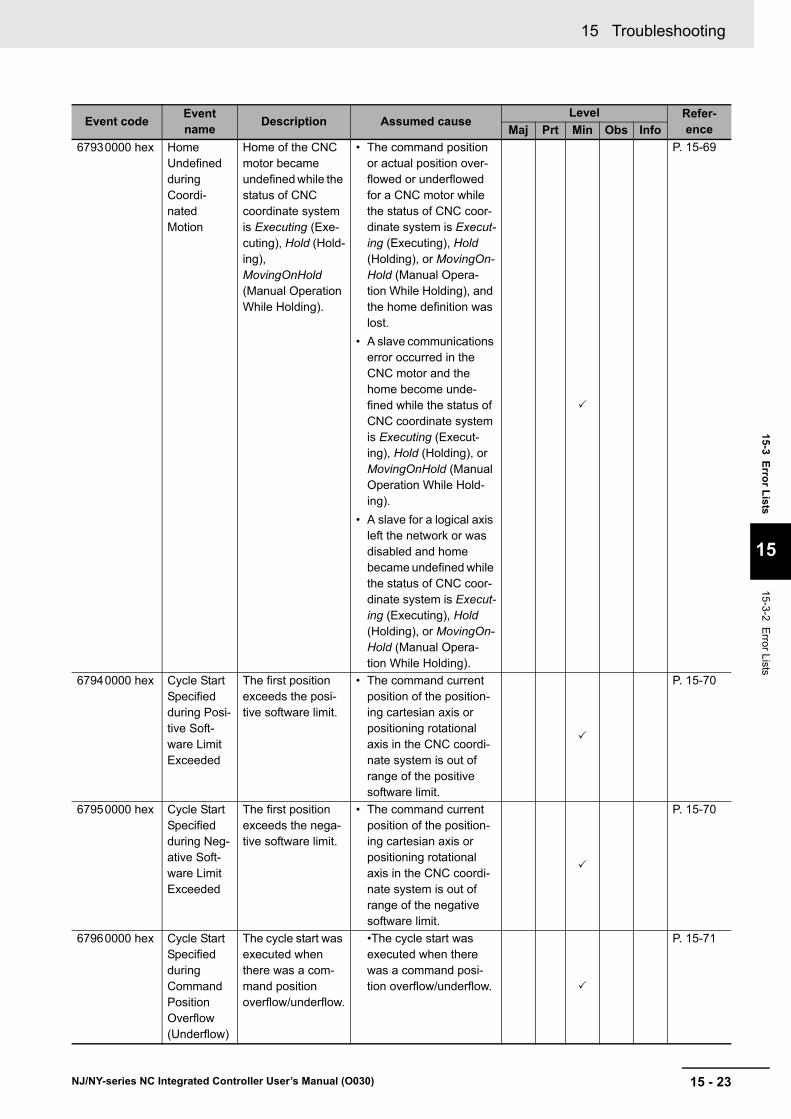
15 - 23
15 Troubleshooting
NJ/NY-series NC Integrated Controller User’s Manual (O030)
15-3 Erro
r Lists
15
15-3-2 Error L
ists
67930000 hex Home Undefined during Coordi-nated Motion
Home of the CNC motor became undefined while the status of CNC coordinate system is Executing (Exe-cuting), Hold (Hold-ing), MovingOnHold (Manual Operation While Holding).
• The command position or actual position over-flowed or underflowed for a CNC motor while the status of CNC coor-dinate system is Execut-ing (Executing), Hold (Holding), or MovingOn-Hold (Manual Opera-tion While Holding), and the home definition was lost.
• A slave communications error occurred in the CNC motor and the home become unde-fined while the status of CNC coordinate system is Executing (Execut-ing), Hold (Holding), or MovingOnHold (Manual Operation While Hold-ing).
• A slave for a logical axis left the network or was disabled and home became undefined while the status of CNC coor-dinate system is Execut-ing (Executing), Hold (Holding), or MovingOn-Hold (Manual Opera-tion While Holding).
P. 15-69
67940000 hex Cycle Start Specified during Posi-tive Soft-ware Limit Exceeded
The first position exceeds the posi-tive software limit.
• The command current position of the position-ing cartesian axis or positioning rotational axis in the CNC coordi-nate system is out of range of the positive software limit.
P. 15-70
67950000 hex Cycle Start Specified during Neg-ative Soft-ware Limit Exceeded
The first position exceeds the nega-tive software limit.
• The command current position of the position-ing cartesian axis or positioning rotational axis in the CNC coordi-nate system is out of range of the negative software limit.
P. 15-70
67960000 hex Cycle Start Specified during Command Position Overflow (Underflow)
The cycle start was executed when there was a com-mand position overflow/underflow.
•The cycle start was executed when there was a command posi-tion overflow/underflow.
P. 15-71
Event codeEvent name
Description Assumed causeLevel Refer-
enceMaj Prt Min Obs Info
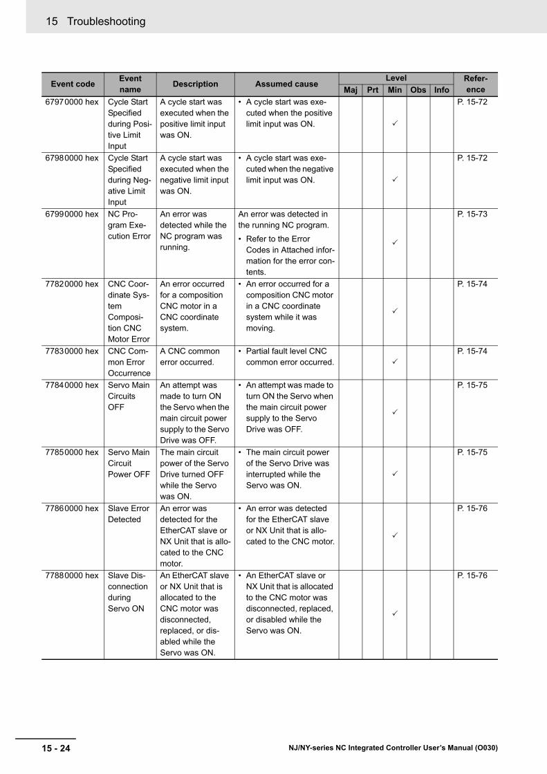
15 Troubleshooting
15 - 24 NJ/NY-series NC Integrated Controller User’s Manual (O030)
67970000 hex Cycle Start Specified during Posi-tive Limit Input
A cycle start was executed when the positive limit input was ON.
• A cycle start was exe-cuted when the positive limit input was ON.
P. 15-72
67980000 hex Cycle Start Specified during Neg-ative Limit Input
A cycle start was executed when the negative limit input was ON.
• A cycle start was exe-cuted when the negative limit input was ON.
P. 15-72
67990000 hex NC Pro-gram Exe-cution Error
An error was detected while the NC program was running.
An error was detected in the running NC program.
• Refer to the Error Codes in Attached infor-mation for the error con-tents.
P. 15-73
77820000 hex CNC Coor-dinate Sys-tem Composi-tion CNC Motor Error
An error occurred for a composition CNC motor in a CNC coordinate system.
• An error occurred for a composition CNC motor in a CNC coordinate system while it was moving.
P. 15-74
77830000 hex CNC Com-mon Error Occurrence
A CNC common error occurred.
• Partial fault level CNC common error occurred.
P. 15-74
77840000 hex Servo Main Circuits OFF
An attempt was made to turn ON the Servo when the main circuit power supply to the Servo Drive was OFF.
• An attempt was made to turn ON the Servo when the main circuit power supply to the Servo Drive was OFF.
P. 15-75
77850000 hex Servo Main Circuit Power OFF
The main circuit power of the Servo Drive turned OFF while the Servo was ON.
• The main circuit power of the Servo Drive was interrupted while the Servo was ON.
P. 15-75
77860000 hex Slave Error Detected
An error was detected for the EtherCAT slave or NX Unit that is allo-cated to the CNC motor.
• An error was detected for the EtherCAT slave or NX Unit that is allo-cated to the CNC motor.
P. 15-76
77880000 hex Slave Dis-connection during Servo ON
An EtherCAT slave or NX Unit that is allocated to the CNC motor was disconnected, replaced, or dis-abled while the Servo was ON.
• An EtherCAT slave or NX Unit that is allocated to the CNC motor was disconnected, replaced, or disabled while the Servo was ON.
P. 15-76
Event codeEvent name
Description Assumed causeLevel Refer-
enceMaj Prt Min Obs Info

15 - 25
15 Troubleshooting
NJ/NY-series NC Integrated Controller User’s Manual (O030)
15-3 Erro
r Lists
15
15-3-2 Error L
ists
77890000 hex Homing Opposite Direction Limit Input Detected
The limit signal in the direction oppo-site to the homing direction was detected during a homing operation.
• The Operation Selection at Negative Limit Input or Operation Selection at Positive Limit Input parameter is set to No reverse turn.
• The location of the hom-ing input signal sensors, homing settings, and homing start position cause a limit input to be reached.
• The input signal sensor wiring is incorrect or the sensor is faulty.
P. 15-77
778A0000 hex Homing Direction Limit Input Detected
The limit signal in the homing direc-tion was detected during a homing operation.
• The Operation Selection at Negative Limit Input or Operation Selection at Positive Limit Input parameter is set to No reverse turn.
• The location of the hom-ing input signal sensors, homing settings, and homing start position cause a limit input to be reached.
• The input signal sensor wiring is incorrect or the sensor is faulty.
P. 15-78
778B0000 hex Homing Limit Inputs Detected in Both Direc-tions
The limit signals in both directions were detected during a homing operation.
• The wiring of the limit signal is incorrect.
• The limit sensor is installed in the wrong location.
• The contact logic of the limit signal is not cor-rect.
• The limit sensor failed.
P. 15-78
778C0000 hex Home Prox-imity/Hom-ing Opposite Direction Limit Input Detected
The home proxim-ity input and the limit signal in the direction opposite to the homing direction were detected at the same time during a homing operation.
• The wiring of the home proximity signal or limit signal is incorrect.
• The home proximity sensor or limit sensor is installed in the wrong location.
• The contact logic of the home proximity signal or limit signal is not cor-rect.
• The home proximity sensor or limit sensor failed.
P. 15-79
Event codeEvent name
Description Assumed causeLevel Refer-
enceMaj Prt Min Obs Info

15 Troubleshooting
15 - 26 NJ/NY-series NC Integrated Controller User’s Manual (O030)
778D0000 hex Home Prox-imity/Hom-ing Direction Limit Input Detected
The home proxim-ity input and the limit signal in the homing direction were detected at the same time during a homing operation.
• The wiring of the home proximity signal or limit signal is incorrect.
• The home proximity sensor or limit sensor is installed in the wrong location.
• The contact logic of the home proximity signal or limit signal is not cor-rect.
• The home proximity sensor or limit sensor failed.
P. 15-80
778E0000 hex Home Input/Hom-ing Oppo-site Direction Limit Input Detected
The home input and the limit signal in the direction opposite to the homing direction were detected at the same time during a homing operation.
• The wiring of the home input signal or limit sig-nal is incorrect.
• The home input sensor or limit sensor is installed in the wrong location.
• The contact logic of the home input signal or limit signal is not cor-rect.
• The home input signal output device or limit sensor failed.
P. 15-81
778F0000 hex Home Input/Hom-ing Direc-tion Limit Input Detected
The home input and the limit signal in the homing direction were detected at the same time during a homing operation.
• The wiring of the home input signal or limit sig-nal is incorrect.
• The home input sensor or limit sensor is installed in the wrong location.
• The contact logic of the home input signal or limit signal is not cor-rect.
• The home input signal output device or limit sensor failed.
P. 15-82
77900000 hex Invalid Home Input Mask Dis-tance
The setting of the home input mask distance is not suit-able for the CNC_Home or CNC_HomeWith-Parameter instruc-tion.
• The set value of the home input mask dis-tance when the operat-ing mode of the MC_Home instruction is set to Proximity Reverse Turn/Home Input Mask Distance is insufficient to decelerate from the homing velocity to the homing approach veloc-ity.
P. 15-83
Event codeEvent name
Description Assumed causeLevel Refer-
enceMaj Prt Min Obs Info
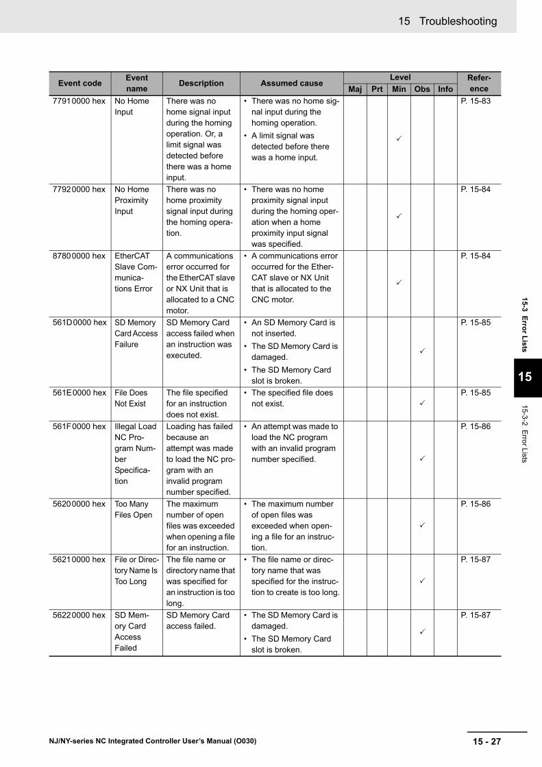
15 - 27
15 Troubleshooting
NJ/NY-series NC Integrated Controller User’s Manual (O030)
15-3 Erro
r Lists
15
15-3-2 Error L
ists
77910000 hex No Home Input
There was no home signal input during the homing operation. Or, a limit signal was detected before there was a home input.
• There was no home sig-nal input during the homing operation.
• A limit signal was detected before there was a home input.
P. 15-83
77920000 hex No Home Proximity Input
There was no home proximity signal input during the homing opera-tion.
• There was no home proximity signal input during the homing oper-ation when a home proximity input signal was specified.
P. 15-84
87800000 hex EtherCAT Slave Com-munica-tions Error
A communications error occurred for the EtherCAT slave or NX Unit that is allocated to a CNC motor.
• A communications error occurred for the Ether-CAT slave or NX Unit that is allocated to the CNC motor.
P. 15-84
561D0000 hex SD Memory Card Access Failure
SD Memory Card access failed when an instruction was executed.
• An SD Memory Card is not inserted.
• The SD Memory Card is damaged.
• The SD Memory Card slot is broken.
P. 15-85
561E0000 hex File Does Not Exist
The file specified for an instruction does not exist.
• The specified file does not exist.
P. 15-85
561F0000 hex Illegal Load NC Pro-gram Num-ber Specifica-tion
Loading has failed because an attempt was made to load the NC pro-gram with an invalid program number specified.
• An attempt was made to load the NC program with an invalid program number specified.
P. 15-86
56200000 hex Too Many Files Open
The maximum number of open files was exceeded when opening a file for an instruction.
• The maximum number of open files was exceeded when open-ing a file for an instruc-tion.
P. 15-86
56210000 hex File or Direc-tory Name Is Too Long
The file name or directory name that was specified for an instruction is too long.
• The file name or direc-tory name that was specified for the instruc-tion to create is too long.
P. 15-87
56220000 hex SD Mem-ory Card Access Failed
SD Memory Card access failed.
• The SD Memory Card is damaged.
• The SD Memory Card slot is broken.
P. 15-87
Event codeEvent name
Description Assumed causeLevel Refer-
enceMaj Prt Min Obs Info
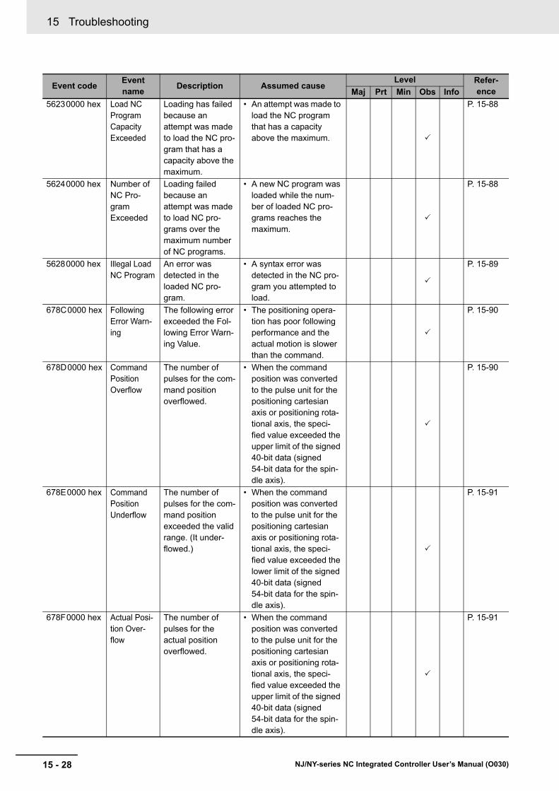
15 Troubleshooting
15 - 28 NJ/NY-series NC Integrated Controller User’s Manual (O030)
56230000 hex Load NC Program Capacity Exceeded
Loading has failed because an attempt was made to load the NC pro-gram that has a capacity above the maximum.
• An attempt was made to load the NC program that has a capacity above the maximum.
P. 15-88
56240000 hex Number of NC Pro-gram Exceeded
Loading failed because an attempt was made to load NC pro-grams over the maximum number of NC programs.
• A new NC program was loaded while the num-ber of loaded NC pro-grams reaches the maximum.
P. 15-88
56280000 hex Illegal Load NC Program
An error was detected in the loaded NC pro-gram.
• A syntax error was detected in the NC pro-gram you attempted to load.
P. 15-89
678C0000 hex Following Error Warn-ing
The following error exceeded the Fol-lowing Error Warn-ing Value.
• The positioning opera-tion has poor following performance and the actual motion is slower than the command.
P. 15-90
678D0000 hex Command Position Overflow
The number of pulses for the com-mand position overflowed.
• When the command position was converted to the pulse unit for the positioning cartesian axis or positioning rota-tional axis, the speci-fied value exceeded the upper limit of the signed 40-bit data (signed 54-bit data for the spin-dle axis).
P. 15-90
678E0000 hex Command Position Underflow
The number of pulses for the com-mand position exceeded the valid range. (It under-flowed.)
• When the command position was converted to the pulse unit for the positioning cartesian axis or positioning rota-tional axis, the speci-fied value exceeded the lower limit of the signed 40-bit data (signed 54-bit data for the spin-dle axis).
P. 15-91
678F0000 hex Actual Posi-tion Over-flow
The number of pulses for the actual position overflowed.
• When the command position was converted to the pulse unit for the positioning cartesian axis or positioning rota-tional axis, the speci-fied value exceeded the upper limit of the signed 40-bit data (signed 54-bit data for the spin-dle axis).
P. 15-91
Event codeEvent name
Description Assumed causeLevel Refer-
enceMaj Prt Min Obs Info
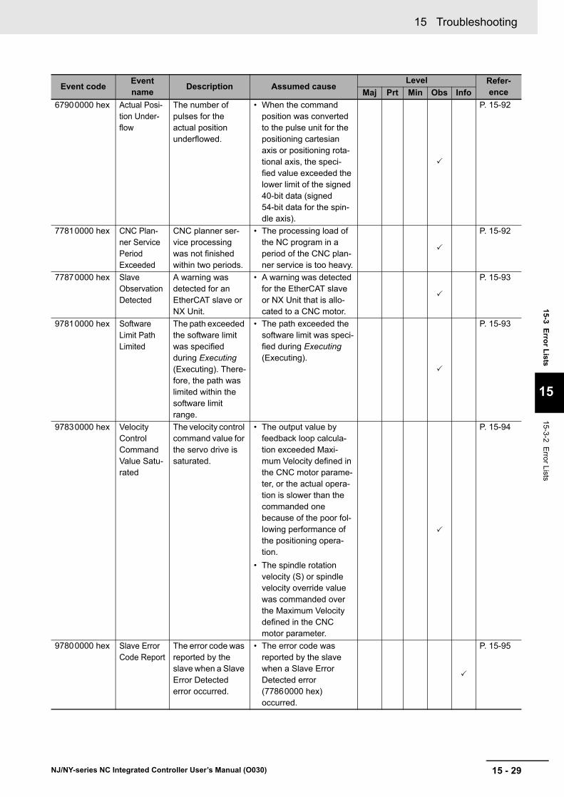
15 - 29
15 Troubleshooting
NJ/NY-series NC Integrated Controller User’s Manual (O030)
15-3 Erro
r Lists
15
15-3-2 Error L
ists
67900000 hex Actual Posi-tion Under-flow
The number of pulses for the actual position underflowed.
• When the command position was converted to the pulse unit for the positioning cartesian axis or positioning rota-tional axis, the speci-fied value exceeded the lower limit of the signed 40-bit data (signed 54-bit data for the spin-dle axis).
P. 15-92
77810000 hex CNC Plan-ner Service Period Exceeded
CNC planner ser-vice processing was not finished within two periods.
• The processing load of the NC program in a period of the CNC plan-ner service is too heavy.
P. 15-92
77870000 hex Slave Observation Detected
A warning was detected for an EtherCAT slave or NX Unit.
• A warning was detected for the EtherCAT slave or NX Unit that is allo-cated to a CNC motor.
P. 15-93
97810000 hex Software Limit Path Limited
The path exceeded the software limit was specified during Executing (Executing). There-fore, the path was limited within the software limit range.
• The path exceeded the software limit was speci-fied during Executing (Executing).
P. 15-93
97830000 hex Velocity Control Command Value Satu-rated
The velocity control command value for the servo drive is saturated.
• The output value by feedback loop calcula-tion exceeded Maxi-mum Velocity defined in the CNC motor parame-ter, or the actual opera-tion is slower than the commanded one because of the poor fol-lowing performance of the positioning opera-tion.
• The spindle rotation velocity (S) or spindle velocity override value was commanded over the Maximum Velocity defined in the CNC motor parameter.
P. 15-94
97800000 hex Slave Error Code Report
The error code was reported by the slave when a Slave Error Detected error occurred.
• The error code was reported by the slave when a Slave Error Detected error (77860000 hex) occurred.
P. 15-95
Event codeEvent name
Description Assumed causeLevel Refer-
enceMaj Prt Min Obs Info

15 Troubleshooting
15 - 30 NJ/NY-series NC Integrated Controller User’s Manual (O030)
97820000 hex CNC Func-tion System Information
This event pro-vides internal infor-mation from the CNC Function Module.
• This event provides internal information from the CNC Function Mod-ule. It is recorded to pro-vide additional information for another event.
P. 15-95
Event codeEvent name
Description Assumed causeLevel Refer-
enceMaj Prt Min Obs Info

15 - 31
15 Troubleshooting
NJ/NY-series NC Integrated Controller User’s Manual (O030)
15-3 Erro
r Lists
15
15-3-2 Error L
ists
This section shows lists of errors (events) that may occur in CNC instructions. The lower four digits of the event code represents the error code for the instruction. For descriptions of an error code, refer to the description of the corresponding event code. For example, when the error code of the target instruc-tion is 16#3781, refer to the explanation of event code, 54013781 hex.
CNC Instruction Errors
Event codeEvent name
Description Assumed causeLevel Refer-
enceMaj Prt Min Obs Info
54013781 hex Process Data Object Setting Missing
The PDO mapping is not correct.
• The PDOs that are required for the CNC instruction are not mapped.
• The relevant instruction was executed for a device that does not have an object that sup-ports the instruction.
P. 15-96
54015600 hex Illegal CNC Coordinate System Specifica-tion
The CNC coordi-nate system speci-fied for the Coord in-out variable to a CNC instruction does not exist.
• CNC coordinate system does not exist for the variable specified for the Coord in-out variable to the instruction.
P. 15-97
54015601 hex Decelera-tion Setting Out of Range
The parameter specified for the Deceleration input variable to a CNC instruction is out of range.
• Instruction input param-eter exceeded the valid range of the input vari-able.
P. 15-97
54015602 hex Jerk Set-ting Out of Range
The parameter specified for the Jerk input variable to a CNC instruc-tion is out of range.
• Instruction input param-eter exceeded the valid range of the input vari-able.
P. 15-98
54015603 hex CNC Instruction Re-execu-tion Dis-abled
A CNC instruction that cannot be re-executed was re-executed.
• A CNC instruction that cannot be re-executed was re-executed.
P. 15-99
54015604 hex CNC Multi-exe-cution Dis-abled
Multiple functions that cannot be exe-cuted simultane-ously were executed for the same target (CNC coordinate sys-tem).
• Multiple functions that cannot be executed simultaneously were executed for the same target (CNC coordinate system).
• The CNC_LoadPro-gramFile instruction was executed when any of CNC coordinate system was Executing (Execut-ing) or Hold (Holding).
P. 15-100

15 Troubleshooting
15 - 32 NJ/NY-series NC Integrated Controller User’s Manual (O030)
54015605 hex Unassigned Logical CNC Motor Num-ber Speci-fied
The CNC motor of the parameter specified for the LogicalMotorNo input variable to the CNC instruc-tion is not assigned.
• The logical CNC motor number for which the CNC motor is not assigned to the Logi-calMotorNo input vari-able to the CNC instruction was speci-fied, and the instruction was executed.
P. 15-101
54015606 hex Logical CNC Motor Number Out of Range
The parameter specified for the LogicalMotorNo input variable to a CNC instruction is out of range.
• Instruction input param-eter exceeded the valid range of the input vari-able.
P. 15-102
54015607 hex Target Posi-tion Setting Out of Range
The parameter specified for the Position input vari-able to a CNC instruction is out of range.
• Instruction input param-eter exceeded the valid range of the input vari-able. Or, there was an overflow/underflow in the target position.
P. 15-102
54015608 hex Impossible CNC Motor Operation Specified when the Servo is OFF
An operation instruction was executed for the CNC motor for which the Servo is OFF.
• An operation instruction was executed for the CNC motor for which the Servo is OFF.
• Home was preset with the CNC_Home or CNC_HomeWithParam-eter instruction for an axis for which Ether-CAT process data com-munications are not established.
P. 15-103
54015609 hex Target Velocity Setting Out of Range
The parameter specified for the Velocity input vari-able to a CNC instruction is out of range.
• Instruction input param-eter exceeded the valid range of the input vari-able.
P. 15-104
5401560A hex Accelera-tion/Decel-eration Setting Out of Range
The parameter specified for the Acceleration input variable to a CNC instruction is out of range.
• Instruction input param-eter exceeded the valid range of the input vari-able.
P. 15-104
5401560B hex Travel Mode Selection Out of Range
The parameter specified for the MoveMode input variable to a CNC instruction is out of range.
• Instruction input param-eter exceeded the valid range of the input vari-able.
P. 15-105
Event codeEvent name
Description Assumed causeLevel Refer-
enceMaj Prt Min Obs Info
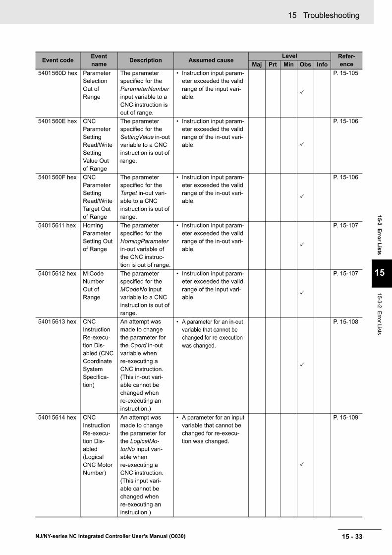
15 - 33
15 Troubleshooting
NJ/NY-series NC Integrated Controller User’s Manual (O030)
15-3 Erro
r Lists
15
15-3-2 Error L
ists
5401560D hex Parameter Selection Out of Range
The parameter specified for the ParameterNumber input variable to a CNC instruction is out of range.
• Instruction input param-eter exceeded the valid range of the input vari-able.
P. 15-105
5401560E hex CNC Parameter Setting Read/Write Setting Value Out of Range
The parameter specified for the SettingValue in-out variable to a CNC instruction is out of range.
• Instruction input param-eter exceeded the valid range of the in-out vari-able.
P. 15-106
5401560F hex CNC Parameter Setting Read/Write Target Out of Range
The parameter specified for the Target in-out vari-able to a CNC instruction is out of range.
• Instruction input param-eter exceeded the valid range of the in-out vari-able.
P. 15-106
54015611 hex Homing Parameter Setting Out of Range
The parameter specified for the HomingParameter in-out variable of the CNC instruc-tion is out of range.
• Instruction input param-eter exceeded the valid range of the in-out vari-able.
P. 15-107
54015612 hex M Code Number Out of Range
The parameter specified for the MCodeNo input variable to a CNC instruction is out of range.
• Instruction input param-eter exceeded the valid range of the input vari-able.
P. 15-107
54015613 hex CNC Instruction Re-execu-tion Dis-abled (CNC Coordinate System Specifica-tion)
An attempt was made to change the parameter for the Coord in-out variable when re-executing a CNC instruction. (This in-out vari-able cannot be changed when re-executing an instruction.)
• A parameter for an in-out variable that cannot be changed for re-execution was changed.
P. 15-108
54015614 hex CNC Instruction Re-execu-tion Dis-abled (Logical CNC Motor Number)
An attempt was made to change the parameter for the LogicalMo-torNo input vari-able when re-executing a CNC instruction. (This input vari-able cannot be changed when re-executing an instruction.)
• A parameter for an input variable that cannot be changed for re-execu-tion was changed.
P. 15-109
Event codeEvent name
Description Assumed causeLevel Refer-
enceMaj Prt Min Obs Info
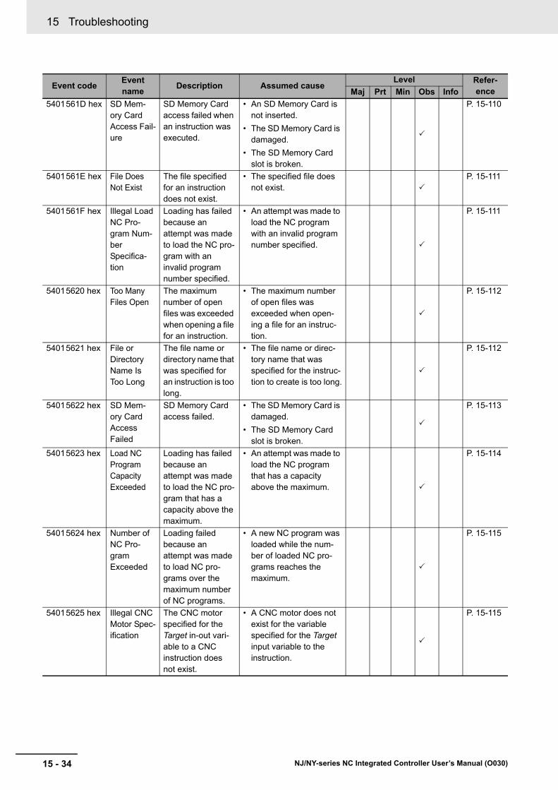
15 Troubleshooting
15 - 34 NJ/NY-series NC Integrated Controller User’s Manual (O030)
5401561D hex SD Mem-ory Card Access Fail-ure
SD Memory Card access failed when an instruction was executed.
• An SD Memory Card is not inserted.
• The SD Memory Card is damaged.
• The SD Memory Card slot is broken.
P. 15-110
5401561E hex File Does Not Exist
The file specified for an instruction does not exist.
• The specified file does not exist.
P. 15-111
5401561F hex Illegal Load NC Pro-gram Num-ber Specifica-tion
Loading has failed because an attempt was made to load the NC pro-gram with an invalid program number specified.
• An attempt was made to load the NC program with an invalid program number specified.
P. 15-111
54015620 hex Too Many Files Open
The maximum number of open files was exceeded when opening a file for an instruction.
• The maximum number of open files was exceeded when open-ing a file for an instruc-tion.
P. 15-112
54015621 hex File or Directory Name Is Too Long
The file name or directory name that was specified for an instruction is too long.
• The file name or direc-tory name that was specified for the instruc-tion to create is too long.
P. 15-112
54015622 hex SD Mem-ory Card Access Failed
SD Memory Card access failed.
• The SD Memory Card is damaged.
• The SD Memory Card slot is broken.
P. 15-113
54015623 hex Load NC Program Capacity Exceeded
Loading has failed because an attempt was made to load the NC pro-gram that has a capacity above the maximum.
• An attempt was made to load the NC program that has a capacity above the maximum.
P. 15-114
54015624 hex Number of NC Pro-gram Exceeded
Loading failed because an attempt was made to load NC pro-grams over the maximum number of NC programs.
• A new NC program was loaded while the num-ber of loaded NC pro-grams reaches the maximum.
P. 15-115
54015625 hex Illegal CNC Motor Spec-ification
The CNC motor specified for the Target in-out vari-able to a CNC instruction does not exist.
• A CNC motor does not exist for the variable specified for the Target input variable to the instruction.
P. 15-115
Event codeEvent name
Description Assumed causeLevel Refer-
enceMaj Prt Min Obs Info
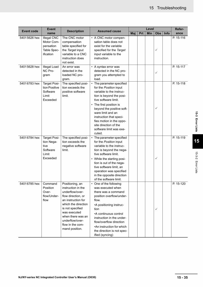
15 - 35
15 Troubleshooting
NJ/NY-series NC Integrated Controller User’s Manual (O030)
15-3 Erro
r Lists
15
15-3-2 Error L
ists
54015626 hex Illegal CNC Motor Com-pensation Table Spec-ification
The CNC motor compensation table specified for the Target input variable to a CNC instruction does not exist.
• A CNC motor compen-sation table does not exist for the variable specified for the Target input variable to the instruction.
P. 15-116
54015628 hex Illegal Load NC Pro-gram
An error was detected in the loaded NC pro-gram.
• A syntax error was detected in the NC pro-gram you attempted to load.
P. 15-117
54016783 hex Target Posi-tion Positive Software Limit Exceeded
The specified posi-tion exceeds the positive software limit.
• The parameter specified for the Position input variable to the instruc-tion is beyond the posi-tive software limit.
• The first position is beyond the positive soft-ware limit and an instruction that speci-fies motion in the oppo-site direction of the software limit was exe-cuted.
P. 15-118
54016784 hex Target Posi-tion Nega-tive Software Limit Exceeded
The specified posi-tion exceeds the negative software limit.
• The parameter specified for the Position input variable to the instruc-tion is beyond the nega-tive software limit.
• While the starting posi-tion is out of the nega-tive software limit, an operation was specified in the opposite direction of the software limit.
P. 15-119
54016785 hex Command Position Over-flow/Under-flow
Positioning, an instruction in the underflow/over-flow direction, or an instruction for which the direction is not specified was executed when there was an underflow/over-flow in the com-mand position.
• One of the following was executed when there was a command position overflow/under-flow.
•A positioning instruc-tion
•A continuous control instruction in the under-flow/overflow direction
•An instruction for which the direction is not spec-ified (syncing)
P. 15-120
Event codeEvent name
Description Assumed causeLevel Refer-
enceMaj Prt Min Obs Info

15 Troubleshooting
15 - 36 NJ/NY-series NC Integrated Controller User’s Manual (O030)
54016786 hex Positive Limit Input
An instruction was executed for a motion in the posi-tive direction when the positive limit input was ON.
• An instruction for a motion in the positive direction was executed when the positive limit input was ON, or an instruction for a motion with no direction specification was exe-cuted when the positive limit input was ON.
P. 15-121
54016787 hex Negative Limit Input
While the negative limit input is set to ON, an instruction that runs in the negative direction was executed.
• While the negative limit input is set to ON, an instruction that runs in the negative direction was executed, or an instruc-tion with no direction specified was executed.
P. 15-122
54017784 hex Servo Main Circuits OFF
An attempt was made to turn ON the Servo when the main circuit power supply to the Servo Drive was OFF.
• An attempt was made to turn ON the Servo when the main circuit power supply to the Servo Drive was OFF.
P. 15-123
Event codeEvent name
Description Assumed causeLevel Refer-
enceMaj Prt Min Obs Info
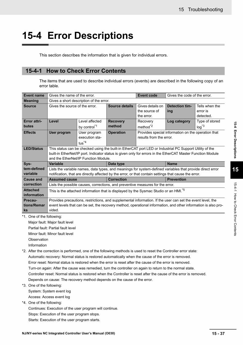
15 - 37
15 Troubleshooting
NJ/NY-series NC Integrated Controller User’s Manual (O030)
15-4 E
rror D
escriptio
ns
15
15-4-1 How
to Che
ck Erro
r Conte
nts
15-4 Error Descriptions
This section describes the information that is given for individual errors.
The items that are used to describe individual errors (events) are described in the following copy of an error table.
15-4-1 How to Check Error Contents
Event name Gives the name of the error. Event code Gives the code of the error.
Meaning Gives a short description of the error.
Source Gives the source of the error. Source details Gives details on the source of the error.
Detection tim-ing
Tells when the error is detected.
Error attri-butes
Level Level affected
by control*1
*1. One of the following:
Major fault: Major fault level
Partial fault: Partial fault level
Minor fault: Minor fault level
Observation
Information
Recovery method
Recovery
method*2
*2. After the correction is performed, one of the following methods is used to reset the Controller error state:
Automatic recovery: Normal status is restored automatically when the cause of the error is removed.
Error reset: Normal status is restored when the error is reset after the cause of the error is removed.
Turn-on again: After the cause was remedied, turn the controller on again to return to the normal state.
Controller reset: Normal status is restored when the Controller is reset after the cause of the error is removed.
Depends on cause: The recovery method depends on the cause of the error.
Log category Type of stored
log*3
*3. One of the following:
System: System event log
Access: Access event log
Effects User program User program execution sta-
tus*4
*4. One of the following:
Continues: Execution of the user program will continue.
Stops: Execution of the user program stops.
Starts: Execution of the user program starts.
Operation Provides special information on the operation that results from the error.
LED/Status This status can be checked using the built-in EtherCAT port LED or Industrial PC Support Utility of the built-in EtherNet/IP port. Indicator status is given only for errors in the EtherCAT Master Function Module and the EtherNet/IP Function Module.
Sys-tem-defined variable
Variable Data type Name
Lists the variable names, data types, and meanings for system-defined variables that provide direct error notification, that are directly affected by the error, or that contain settings that cause the error.
Cause and correction
Assumed cause Correction Prevention
Lists the possible causes, corrections, and preventive measures for the error.
Attached information
This is the attached information that is displayed by the Sysmac Studio or an HMI.*5
Precau-tions/Remarks
Provides precautions, restrictions, and supplemental information. If the user can set the event level, the event levels that can be set, the recovery method, operational information, and other information is also pro-vided.

15 Troubleshooting
15 - 38 NJ/NY-series NC Integrated Controller User’s Manual (O030)
This section describes the meanings of the errors related to common parts of the CNC Function Mod-ule, CNC motor, and CNC coordinate system.
*5. Refer to the NJ/NX-series Troubleshooting Manual (Cat. No. W503) or NY-series Troubleshooting Manual (Cat. No. W564) for the applicable range of the HMI Troubleshooter.
15-4-2 Error Descriptions
CNC function errors
Event name CNC Parameter Setting Invalid Event code 47810000 hex
Meaning A fatal error was detected during setting of the CNC Function Module.
Source CNC Function Module Source details CNC common Detection timing
At power ON, at Controller reset, or when down-loading
Error attri-butes
Level Major fault Recovery Cycle the power supply.
Log category System
Effects User program Stops. Operation It will not be possible to perform CNC motor control. The Controller will stop.
System-defined variables
Variable Data type Name
None --- ---
Cause and correction
Assumed cause Correction Prevention
The system failed to transfer the CNC parameter setting. Other-wise, an error occurred in the soft-ware.
Clear all of memory and then download the project from the Sysmac Studio.
If you cannot perform a Clear All Memory operation from the Sys-mac Studio, transfer the project to the Controller with a restore oper-ation from an SD Memory Card.
If this error recurs after you took the above correction, contact your OMRON representative.
None
Attached information
Attached information 1: System information
Precautions/Remarks
None

15 - 39
15 Troubleshooting
NJ/NY-series NC Integrated Controller User’s Manual (O030)
15-4 E
rror D
escriptio
ns
15
15-4-2 Error D
escriptions
Event name CNC Parameter Setting Error Event code 17800000 hex
Meaning The CNC parameters that were saved in non-volatile memory are missing.
Source CNC Function Module Source details CNC common Detection timing
At power ON, at Controller reset, or when down-loading
Error attri-butes
Level Partial fault Recovery Cycle the power supply or reset the Controller.
Log category System
Effects User program Continues. Operation It will not be possible to perform CNC motor control.
System-defined variables
Variable Data type Name
_CNC_COM.PFaultLvl.Active BOOL CNC Common Partial Fault Occurrence
Cause and correction
Assumed cause Correction Prevention
The power supply to the Controller was interrupted or communica-tions with the Sysmac Studio were disconnected while downloading the CNC parameter settings or clearing memory.
Download the CNC parameters from the Sysmac Studio.
Do not turn OFF the power supply during save processing for the CNC parameters.
Non-volatile memory failure If the error occurs even after the above correction is performed, non-volatile memory has failed. After you replace the CPU Unit, download all settings including the CNC Parameter Settings from the Sysmac Studio.
None
Attached information
None
Precautions/Remarks
None

15 Troubleshooting
15 - 40 NJ/NY-series NC Integrated Controller User’s Manual (O030)
Event name Absolute Encoder Home Offset Read Error Event code 17810000 hex
Meaning The absolute encoder current position that is retained during power interruptions was lost.
Source CNC Function Module Source details CNC common Detection timing
At power ON, at Controller reset, or when down-loading
Error attri-butes
Level Partial fault Recovery Error reset Log category System
Effects User program Continues. Operation It will not be possible to perform CNC motor control.
System-defined variables
Variable Data type Name
_CNC_COM.PFaultLvl.Active BOOL CNC Common Partial Fault Occurrence
Cause and correction
Assumed cause Correction Prevention
When the retained variables are backed up with a battery, this event indicates that the life of the battery in the CPU Unit has expired.
Replace the Battery in the CPU Unit, reset the error, and perform homing to define home.
When the retained variables are backed up with a battery, periodi-cally replace the battery in the CPU Unit. For the Battery life, refer to the NJ-series CPU Unit Hardware User’s Manual (Cat. No. W500).
Backup memory failure If the error occurs even after the above correction is performed, CPU Unit backup memory failed. Replace the CPU Unit and per-form homing to define home.
None
Attached information
None
Precautions/Remarks
None

15 - 41
15 Troubleshooting
NJ/NY-series NC Integrated Controller User’s Manual (O030)
15-4 E
rror D
escriptio
ns
15
15-4-2 Error D
escriptions
Event name CNC Motor Compensation Table Read Error Event code 17820000 hex
Meaning The CNC motor compensation table that was saved in non-volatile memory is missing.
Source CNC Function Module Source details CNC common Detection timing
At power ON, at Controller reset, or when down-loading
Error attri-butes
Level Partial fault Recovery Cycle the power supply or reset the Controller.
Log category System
Effects User program Continues. Operation It will not be possible to perform CNC motor control.
System-defined variables
Variable Data type Name
_CNC_COM.PFaultLvl.Active BOOL CNC Common Partial Fault Occurrence
Cause and correction
Assumed cause Correction Prevention
The power supply to the Controller was interrupted or communica-tions with the Sysmac Studio were disconnected while downloading the CNC parameter settings or clearing memory.
Download the CNC parameters from the Sysmac Studio.
Do not turn OFF the power supply during save processing for the CNC parameters.
Non-volatile memory failure If the error occurs even after the above correction is performed, non-volatile memory has failed. After you replace the CPU Unit, download all settings including the CNC Parameter Settings from the Sysmac Studio.
None
Attached information
None
Precautions/Remarks
None

15 Troubleshooting
15 - 42 NJ/NY-series NC Integrated Controller User’s Manual (O030)
Event name Required Process Data Object Not Set Event code 37800000 hex
Meaning The object that is required for the assigned axis type in the CNC motor parameter settings is not allocated to PDO.
Source CNC Function Module Source details CNC common Detection timing
At power ON, at Controller reset, or when down-loading
Error attri-butes
Level Partial fault Recovery Cycle the power supply or reset the Controller.
Log category System
Effects User program Continues. Operation It will not be possible to perform CNC motor control.
System-defined variables
Variable Data type Name
_CNC_COM.PFaultLvl.Active BOOL CNC Common Partial Fault Occurrence
Cause and correction
Assumed cause Correction Prevention
The required PDOs are not mapped when the assigned axis type in the CNC motor parameter settings is set to a positioning axis or spindle axis.
Map the PDOs that are required for the relevant assigned axis type.
Map the PDOs that are required for the assigned axis type to be used.
Non-volatile memory failure If the error occurs even after the above correction is performed, non-volatile memory has failed. After you replace the CPU Unit, download all settings including the CNC Parameter Settings from the Sysmac Studio.
None
Attached information
None
Precautions/Remarks
None
Event name CNC Initialization Error Event code 47800000 hex
Meaning A fatal error occurred in the system and prevented initialization of the CNC Function Module.
Source CNC Function Module Source details CNC common Detection timing
At power ON, at Controller reset, or when down-loading
Error attri-butes
Level Partial fault Recovery Cycle the power supply.
Log category System
Effects User program Continues. Operation It will not be possible to perform CNC motor control. It will not be possible to execute CNC motor control instructions.
System-defined variables
Variable Data type Name
None --- ---
Cause and correction
Assumed cause Correction Prevention
Hardware has failed. Replace the CPU Unit. None
Attached information
None
Precautions/Remarks
None

15 - 43
15 Troubleshooting
NJ/NY-series NC Integrated Controller User’s Manual (O030)
15-4 E
rror D
escriptio
ns
15
15-4-2 Error D
escriptions
Event name CNC Control Period Exceeded Event code 77800000 hex
Meaning Processing for the primary periodic task was not finished within two control periods.
Source CNC Function Module Source details CNC common Detection timing
Continuously
Error attri-butes
Level Partial fault Recovery Error reset Log category System
Effects User program Continues. Operation Operation is not possible for all the CNC coordinate systems. CNC coordinate systems in motion stop immediately.
System-defined variables
Variable Data type Name
_CNC_COM.PFaultLvl.Active BOOL CNC Common Partial Fault Occurrence
Cause and correction
Assumed cause Correction Prevention
The processing load in the pri-mary periodic task is too heavy.
Reduce the amount of processing in the primary periodic task or set the control period to a value that is long enough not to cause opera-tion problems.
Check the task period in the Task Period Monitor of the Sysmac Stu-dio.
Write the programs for the primary periodic task so that they perform only the processes required in the specified period. Or, set the period of the primary periodic task to be long enough to complete all required processing.
Attached information
None
Precautions/Remarks
None
Event name Process Data Object Setting Missing Event code 37810000 hex
Meaning The PDO mapping is not correct.
Source CNC Function Module Source details CNC coordi-nate system
Detection timing
At instruction execution
Error attri-butes
Level Minor fault Recovery Error reset Log category System
Effects User program Continues. Operation Operation is not possible for the relevant CNC coor-dinate systems.
System-defined variables
Variable Data type Name
_CNC_Coord[*].MFaultLvl.Active BOOL CNC Coordinate System Minor Fault Occurrence
Cause and correction
Assumed cause Correction Prevention
The PDOs that are required for the CNC instruction are not mapped.
Map the PDOs that are required for the instruction.
Map the PDOs that are required for the instructions that are used.
The relevant instruction was exe-cuted for a device that does not have an object that supports the instruction.
Some devices do not support the relevant instruction.
Refer to the manual for the device, check to see if the relevant instruction is supported, and cor-rect the program so that unsup-ported instructions are not executed.
Refer to the manual for the device and write the program so that unsupported instructions are not executed.
Attached information
None
Precautions/Remarks
None

15 Troubleshooting
15 - 44 NJ/NY-series NC Integrated Controller User’s Manual (O030)
Event name Illegal CNC Coordinate System Specification Event code 56000000 hex
Meaning The CNC coordinate system specified for the Coord in-out variable to a CNC instruction does not exist.
Source CNC Function Module Source details CNC common Detection timing
At instruction execution
Error attri-butes
Level Minor fault Recovery Error reset Log category System
Effects User program Continues. Operation The relevant instruction is not executed.
System-defined variables
Variable Data type Name
_CNC_COM.MFaultLvl.Active BOOL CNC Common Minor Fault Occur-rence
Cause and correction
Assumed cause Correction Prevention
CNC coordinate system does not exist for the variable specified for the Coord in-out variable to the instruction.
Correct the instruction so that the variable exists for the CNC coordi-nate system that was specified for the instruction.
Specify a variable that exists when specifying a variable for an input parameter to an instruction.
Attached information
None
Precautions/Remarks
None
Event name Deceleration Setting Out of Range Event code 56010000 hex
Meaning The parameter specified for the Deceleration input variable to a CNC instruction is out of range.
Source CNC Function Module Source details CNC coordi-nate system
Detection timing
At instruction execution
Error attri-butes
Level Minor fault Recovery Error reset Log category System
Effects User program Continues. Operation The relevant instruction is not executed. The relevant CNC coordinate system immediately stops while moving.
System-defined variables
Variable Data type Name
_CNC_Coord[*].MFaultLvl.Active BOOL CNC Coordinate System Minor Fault Occurrence
Cause and correction
Assumed cause Correction Prevention
Instruction input parameter exceeded the valid range of the input variable.
Correct the parameter so that the valid range of the input variable is not exceeded for the relevant instruction.
Set the input parameter to the instruction so that the valid range of the input variable is not exceeded.
Attached information
None
Precautions/Remarks
None

15 - 45
15 Troubleshooting
NJ/NY-series NC Integrated Controller User’s Manual (O030)
15-4 E
rror D
escriptio
ns
15
15-4-2 Error D
escriptions
Event name Jerk Setting Out of Range Event code 56020000 hex
Meaning The parameter specified for the Jerk input variable to a CNC instruction is out of range.
Source CNC Function Module Source details CNC coordi-nate system
Detection timing
At instruction execution
Error attri-butes
Level Minor fault Recovery Error reset Log category System
Effects User program Continues. Operation The relevant instruction is not executed. The relevant CNC coordinate system immediately stops while moving.
System-defined variables
Variable Data type Name
_CNC_Coord[*].MFaultLvl.Active BOOL CNC Coordinate System Minor Fault Occurrence
Cause and correction
Assumed cause Correction Prevention
Instruction input parameter exceeded the valid range of the input variable.
Correct the parameter so that the valid range of the input variable is not exceeded for the relevant instruction.
Set the input parameter to the instruction so that the valid range of the input variable is not exceeded.
Attached information
None
Precautions/Remarks
None
Event name CNC Instruction Re-execution Disabled Event code 56030000 hex
Meaning A CNC instruction that cannot be re-executed was re-executed.
Source CNC Function Module Source details CNC com-mon/CNC coor-dinate system
Detection timing
At instruction re-execution
Error attri-butes
Level Minor fault Recovery Error reset Log category System
Effects User program Continues. Operation The relevant instruction is not executed. The relevant CNC coordinate system immediately stops while moving.
System-defined variables
Variable Data type Name
_CNC_COM.MFaultLvl.Active BOOL CNC Common Minor Fault Occur-rence
_CNC_Coord[*].MFaultLvl.Active BOOL CNC Coordinate System Minor Fault Occurrence
Cause and correction
Assumed cause Correction Prevention
A CNC instruction that cannot be re-executed was re-executed.
Correct the program so that the Execute input variable does not change to TRUE until the Busy output variable from the instruc-tion changes to FALSE.
When using instructions that can-not be re-executed, include a con-dition for the Execute input variable so that it does not change to TRUE unless the Busy output variable for the previous instruc-tion is FALSE. Or, stop the instruc-tion before executing it again.
Attached information
None
Precautions/Remarks
None
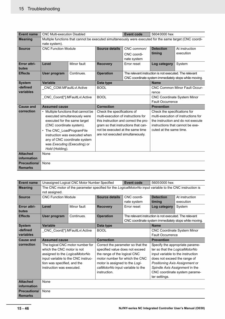
15 Troubleshooting
15 - 46 NJ/NY-series NC Integrated Controller User’s Manual (O030)
Event name CNC Multi-execution Disabled Event code 56040000 hex
Meaning Multiple functions that cannot be executed simultaneously were executed for the same target (CNC coordi-nate system).
Source CNC Function Module Source details CNC common/
CNC coordi-nate system
Detection timing
At instruction execution
Error attri-butes
Level Minor fault Recovery Error reset Log category System
Effects User program Continues. Operation The relevant instruction is not executed. The relevant CNC coordinate system immediately stops while moving.
System-defined variables
Variable Data type Name
_CNC_COM.MFaultLvl.Active BOOL CNC Common Minor Fault Occur-rence
_CNC_Coord[*].MFaultLvl.Active BOOL CNC Coordinate System Minor Fault Occurrence
Cause and correction
Assumed cause Correction Prevention
• Multiple functions that cannot be executed simultaneously were executed for the same target (CNC coordinate system).
• The CNC_LoadProgramFile instruction was executed when any of CNC coordinate system was Executing (Executing) or Hold (Holding).
Check the specifications of multi-execution of instructions for this instruction and correct the pro-gram so that instructions that can-not be executed at the same time are not executed simultaneously.
Check the specifications for multi-execution of instructions for the instruction and do not execute instructions that cannot be exe-cuted at the same time.
Attached information
None
Precautions/Remarks
None
Event name Unassigned Logical CNC Motor Number Specified Event code 56050000 hex
Meaning The CNC motor of the parameter specified for the LogicalMotorNo input variable to the CNC instruction is not assigned.
Source CNC Function Module Source details CNC coordi-nate system
Detection timing
At instruction execution
Error attri-butes
Level Minor fault Recovery Error reset Log category System
Effects User program Continues. Operation The relevant instruction is not executed. The relevant CNC coordinate system immediately stops while moving.
System-defined variables
Variable Data type Name
_CNC_Coord[*].MFaultLvl.Active BOOL CNC Coordinate System Minor Fault Occurrence
Cause and correction
Assumed cause Correction Prevention
The logical CNC motor number for which the CNC motor is not assigned to the LogicalMotorNo input variable to the CNC instruc-tion was specified, and the instruction was executed.
Correct the parameter so that the specified value does not exceed the range of the logical CNC motor number for which the CNC motor is assigned to the Logi-calMotorNo input variable to the instruction.
Specify the appropriate parame-ter so that the LogicalMotorNo input variable to the instruction does not exceed the range of Positioning Axis Assignment or Spindle Axis Assignment in the CNC coordinate system parame-ter settings.
Attached information
None
Precautions/Remarks
None
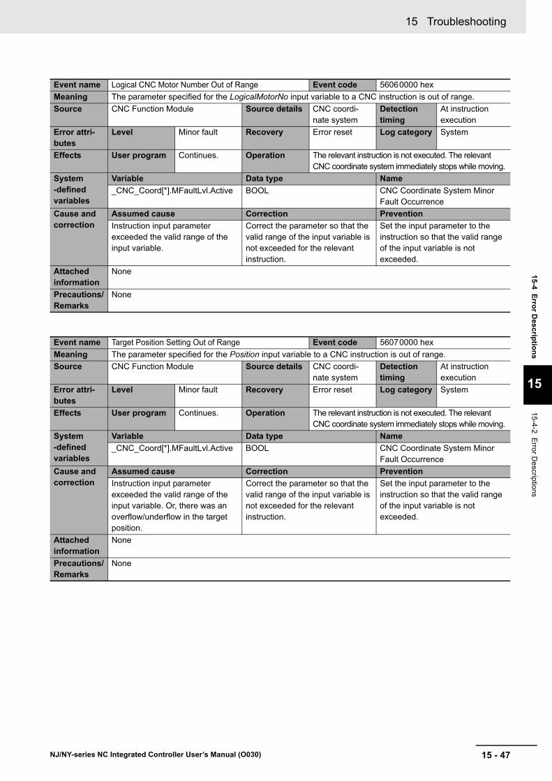
15 - 47
15 Troubleshooting
NJ/NY-series NC Integrated Controller User’s Manual (O030)
15-4 E
rror D
escriptio
ns
15
15-4-2 Error D
escriptions
Event name Logical CNC Motor Number Out of Range Event code 56060000 hex
Meaning The parameter specified for the LogicalMotorNo input variable to a CNC instruction is out of range.
Source CNC Function Module Source details CNC coordi-nate system
Detection timing
At instruction execution
Error attri-butes
Level Minor fault Recovery Error reset Log category System
Effects User program Continues. Operation The relevant instruction is not executed. The relevant CNC coordinate system immediately stops while moving.
System-defined variables
Variable Data type Name
_CNC_Coord[*].MFaultLvl.Active BOOL CNC Coordinate System Minor Fault Occurrence
Cause and correction
Assumed cause Correction Prevention
Instruction input parameter exceeded the valid range of the input variable.
Correct the parameter so that the valid range of the input variable is not exceeded for the relevant instruction.
Set the input parameter to the instruction so that the valid range of the input variable is not exceeded.
Attached information
None
Precautions/Remarks
None
Event name Target Position Setting Out of Range Event code 56070000 hex
Meaning The parameter specified for the Position input variable to a CNC instruction is out of range.
Source CNC Function Module Source details CNC coordi-nate system
Detection timing
At instruction execution
Error attri-butes
Level Minor fault Recovery Error reset Log category System
Effects User program Continues. Operation The relevant instruction is not executed. The relevant CNC coordinate system immediately stops while moving.
System-defined variables
Variable Data type Name
_CNC_Coord[*].MFaultLvl.Active BOOL CNC Coordinate System Minor Fault Occurrence
Cause and correction
Assumed cause Correction Prevention
Instruction input parameter exceeded the valid range of the input variable. Or, there was an overflow/underflow in the target position.
Correct the parameter so that the valid range of the input variable is not exceeded for the relevant instruction.
Set the input parameter to the instruction so that the valid range of the input variable is not exceeded.
Attached information
None
Precautions/Remarks
None

15 Troubleshooting
15 - 48 NJ/NY-series NC Integrated Controller User’s Manual (O030)
Event name Impossible CNC Motor Operation Specified when the Servo is OFF
Event code 56080000 hex
Meaning An operation instruction was executed for the CNC motor for which the Servo is OFF.
Source CNC Function Module Source details CNC coordi-nate system
Detection timing
At instruction execution
Error attri-butes
Level Minor fault Recovery Error reset Log category System
Effects User program Continues. Operation The relevant instruction is not executed. The relevant CNC coordinate system immediately stops while moving.
System-defined variables
Variable Data type Name
_CNC_Coord[*].MFaultLvl.Active BOOL CNC Coordinate System Minor Fault Occurrence
Cause and correction
Assumed cause Correction Prevention
An operation instruction was exe-cuted for the CNC motor for which the Servo is OFF.
Correct the program so that the instruction is executed after the Servo is turned ON.
Make sure to execute the opera-tion instruction after the Servo is turned ON.
Home was preset with the CNC_Home or CNC_HomeWithPa-rameter instruction for an axis for which EtherCAT process data com-munications are not established.
If the _EC_PDSlavTbl (Process Data Communicating Slave Table) system-defined variable for the EtherCAT master of the master axis is FALSE, remove the cause and execute the CNC_Home or CNC_HomeWithParameter instruction to preset home after _EC_PDSlavTbl changes to TRUE.
If you execute the CNC_Home or CNC_HomeWithParameter instruction to preset home imme-diately after you turn ON the power supply to the Controller, download data, reset a slave com-munications error, disconnect the slave, reconnect the slave, or dis-able or enable the slave, write the program to make sure that the _EC_PDSlavTbl (Process Data Communicating Slave Table) sys-tem-defined variable for the Ether-CAT master is TRUE before you execute CNC_Home or CNC_HomeWithParameter.
Attached information
Attached information 1: Logical CNC motor number where the error occurred
Precautions/Remarks
None
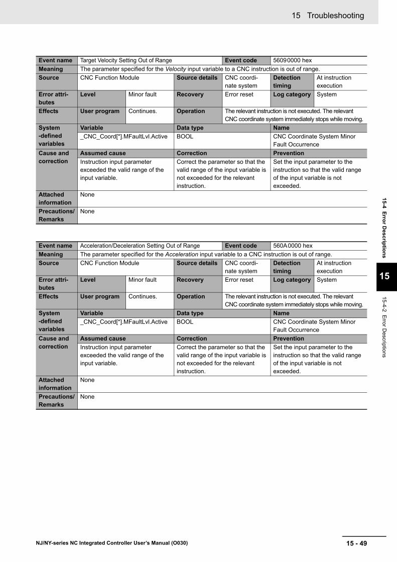
15 - 49
15 Troubleshooting
NJ/NY-series NC Integrated Controller User’s Manual (O030)
15-4 E
rror D
escriptio
ns
15
15-4-2 Error D
escriptions
Event name Target Velocity Setting Out of Range Event code 56090000 hex
Meaning The parameter specified for the Velocity input variable to a CNC instruction is out of range.
Source CNC Function Module Source details CNC coordi-nate system
Detection timing
At instruction execution
Error attri-butes
Level Minor fault Recovery Error reset Log category System
Effects User program Continues. Operation The relevant instruction is not executed. The relevant CNC coordinate system immediately stops while moving.
System-defined variables
Variable Data type Name
_CNC_Coord[*].MFaultLvl.Active BOOL CNC Coordinate System Minor Fault Occurrence
Cause and correction
Assumed cause Correction Prevention
Instruction input parameter exceeded the valid range of the input variable.
Correct the parameter so that the valid range of the input variable is not exceeded for the relevant instruction.
Set the input parameter to the instruction so that the valid range of the input variable is not exceeded.
Attached information
None
Precautions/Remarks
None
Event name Acceleration/Deceleration Setting Out of Range Event code 560A0000 hex
Meaning The parameter specified for the Acceleration input variable to a CNC instruction is out of range.
Source CNC Function Module Source details CNC coordi-nate system
Detection timing
At instruction execution
Error attri-butes
Level Minor fault Recovery Error reset Log category System
Effects User program Continues. Operation The relevant instruction is not executed. The relevant CNC coordinate system immediately stops while moving.
System-defined variables
Variable Data type Name
_CNC_Coord[*].MFaultLvl.Active BOOL CNC Coordinate System Minor Fault Occurrence
Cause and correction
Assumed cause Correction Prevention
Instruction input parameter exceeded the valid range of the input variable.
Correct the parameter so that the valid range of the input variable is not exceeded for the relevant instruction.
Set the input parameter to the instruction so that the valid range of the input variable is not exceeded.
Attached information
None
Precautions/Remarks
None

15 Troubleshooting
15 - 50 NJ/NY-series NC Integrated Controller User’s Manual (O030)
Event name Travel Mode Selection Out of Range Event code 560B0000 hex
Meaning The parameter specified for the MoveMode input variable to a CNC instruction is out of range.
Source CNC Function Module Source details CNC coordi-nate system
Detection timing
At instruction execution
Error attri-butes
Level Minor fault Recovery Error reset Log category System
Effects User program Continues. Operation The relevant instruction is not executed. The relevant CNC coordinate system immediately stops while moving.
System-defined variables
Variable Data type Name
_CNC_Coord[*].MFaultLvl.Active BOOL CNC Coordinate System Minor Fault Occurrence
Cause and correction
Assumed cause Correction Prevention
Instruction input parameter exceeded the valid range of the input variable.
Correct the parameter so that the valid range of the input variable is not exceeded for the relevant instruction.
Set the input parameter to the instruction so that the valid range of the input variable is not exceeded.
Attached information
None
Precautions/Remarks
None
Event name Immediate Stop Instruction Executed Event code 560C0000 hex
Meaning An Immediate Stop (CNC_CoordImmediateStop) instruction was executed.
Source CNC Function Module Source details CNC coordi-nate system
Detection timing
At instruction execution
Error attri-butes
Level Minor fault Recovery Error reset Log category System
Effects User program Continues. Operation The relevant CNC coordinate system immediately stops according to the setting of the Immediate Stop Input Stop Method parameter when it is moving.
System-defined variables
Variable Data type Name
_CNC_Coord[*].MFaultLvl.Active BOOL CNC Coordinate System Minor Fault Occurrence
Cause and correction
Assumed cause Correction Prevention
An Immediate Stop instruction was executed.
--- ---
Attached information
None
Precautions/Remarks
None

15 - 51
15 Troubleshooting
NJ/NY-series NC Integrated Controller User’s Manual (O030)
15-4 E
rror D
escriptio
ns
15
15-4-2 Error D
escriptions
Event name Parameter Selection Out of Range Event code 560D0000 hex
Meaning The parameter specified for the ParameterNumber input variable to a CNC instruction is out of range.
Source CNC Function Module Source details CNC common Detection timing
At instruction execution
Error attri-butes
Level Minor fault Recovery Error reset Log category System
Effects User program Continues. Operation The relevant instruction is not executed.
System-defined variables
Variable Data type Name
_CNC_COM.MFaultLvl.Active BOOL CNC Common Minor Fault Occur-rence
Cause and correction
Assumed cause Correction Prevention
Instruction input parameter exceeded the valid range of the input variable.
Correct the parameter so that the valid range of the input variable is not exceeded for the relevant instruction.
Set the input parameter to the instruction so that the valid range of the input variable is not exceeded.
Attached information
None
Precautions/Remarks
None
Event name CNC Parameter Setting Read/Write Setting Value Out of Range
Event code 560E0000 hex
Meaning The parameter specified for the SettingValue in-out variable to a CNC instruction is out of range.
Source CNC Function Module Source details CNC common Detection timing
At instruction execution
Error attri-butes
Level Minor fault Recovery Error reset Log category System
Effects User program Continues. Operation The relevant instruction is not executed.
System-defined variables
Variable Data type Name
_CNC_COM.MFaultLvl.Active BOOL CNC Common Minor Fault Occur-rence
Cause and correction
Assumed cause Correction Prevention
Instruction input parameter exceeded the valid range of the in-out variable.
Correct the parameter so that the valid range of the in-out variable is not exceeded for the relevant instruction.
Set the input parameter to the instruction so that the valid range of the in-out variable is not exceeded.
Attached information
None
Precautions/Remarks
None

15 Troubleshooting
15 - 52 NJ/NY-series NC Integrated Controller User’s Manual (O030)
Event name CNC Parameter Setting Read/Write Target Out of Range
Event code 560F0000 hex
Meaning The parameter specified for the Target in-out variable to a CNC instruction is out of range.
Source CNC Function Module Source details CNC common Detection timing
At instruction execution
Error attri-butes
Level Minor fault Recovery Error reset Log category System
Effects User program Continues. Operation The relevant instruction is not executed.
System-defined variables
Variable Data type Name
_CNC_COM.MFaultLvl.Active BOOL CNC Common Minor Fault Occur-rence
Cause and correction
Assumed cause Correction Prevention
Instruction input parameter exceeded the valid range of the in-out variable.
Correct the parameter so that the valid range of the in-out variable is not exceeded for the relevant instruction.
Set the input parameter to the instruction so that the valid range of the in-out variable is not exceeded.
Attached information
None
Precautions/Remarks
None
Event name Cycle Start Error with Undefined Home Event code 56100000 hex
Meaning A cycle start was executed for a CNC coordinate system including the positioning axis with no defined home.
Source CNC Function Module Source details CNC coordi-nate system
Detection timing
At Cycle Start
Error attri-butes
Level Minor fault Recovery Error reset Log category System
Effects User program Continues. Operation The cycle start is not executed. The relevant CNC coordinate system immediately stops while moving.
System-defined variables
Variable Data type Name
_CNC_Coord[*].MFaultLvl.Active BOOL CNC Coordinate System Minor Fault Occurrence
Cause and correction
Assumed cause Correction Prevention
A cycle start was executed for a CNC coordinate system including the positioning axis with no defined home.
Perform homing to define home for all positioning axes before exe-cuting the cycle start.
Perform homing to define home for all positioning axes before exe-cuting the cycle start.
Attached information
Attached information 1: Logical CNC motor number where the error occurred
Precautions/Remarks
None

15 - 53
15 Troubleshooting
NJ/NY-series NC Integrated Controller User’s Manual (O030)
15-4 E
rror D
escriptio
ns
15
15-4-2 Error D
escriptions
Event name Homing Parameter Setting Out of Range Event code 56110000 hex
Meaning The parameter specified for the HomingParameter in-out variable to a CNC instruction is out of range.
Source CNC Function Module Source details CNC coordi-nate system
Detection timing
At instruction execution
Error attri-butes
Level Minor fault Recovery Error reset Log category System
Effects User program Continues. Operation The relevant instruction is not executed. The relevant CNC coordinate system immediately stops while moving.
System-defined variables
Variable Data type Name
_CNC_Coord[*].MFaultLvl.Active BOOL CNC Coordinate System Minor Fault Occurrence
Cause and correction
Assumed cause Correction Prevention
Instruction input parameter exceeded the valid range of the in-out variable.
Correct the parameter so that the valid range of the in-out variable is not exceeded for the relevant instruction.
Set the input parameter to the instruction so that the valid range of the in-out variable is not exceeded.
Attached information
Attached information 1: Error Details
1:Homing Method out of range, 2: Home Input Signal out of range, 3: Homing Start Direction out of range, 4: Home Input Detection Direction out of range, 5: Operation Selection at Positive Limit Input out of range, 6: Operation Selection at Negative Limit Input out of range, 7: Homing Velocity out of range, 8: Homing Approach Velocity out of range, 9: Homing Acceleration out of range, 12: Home Input Mask Distance out of range, 13: Absolute Encoder Home Offset out of range, 14: Homing Holding Time out of range, 15: Homing Compensation Value out of range, 16: Homing Compensation Velocity out of range, 100: Home Input Mask Distance exceeded 40-bit range when converted to pulses, 102: Homing Compensation Value exceeded 40-bit range when converted to pulses, 104: Home Offset exceeded 40-bit range (54-bit range for spindle axis) when converted to pulses, 106: Homing Velocity exceeded maximum velocity, 107: Homing Approach Velocity exceeded maximum velocity, 108: Homing Approach Velocity was not less than or equal to Homing Velocity, 109: Homing Compensation Velocity was not less than or equal to Homing Velocity, 110: Homing Acceleration exceeded maximum acceleration rate
Precautions/Remarks
None
Event name M Code Number Out of Range Event code 56120000 hex
Meaning The parameter specified for the MCodeNo input variable to a CNC instruction is out of range.
Source CNC Function Module Source details CNC coordi-nate system
Detection timing
At instruction execution
Error attri-butes
Level Minor fault Recovery Error reset Log category System
Effects User program Continues. Operation The relevant instruction is not executed. The relevant CNC coordinate system immediately stops while moving.
System-defined variables
Variable Data type Name
_CNC_Coord[*].MFaultLvl.Active BOOL CNC Coordinate System Minor Fault Occurrence
Cause and correction
Assumed cause Correction Prevention
Instruction input parameter exceeded the valid range of the input variable.
Correct the parameter so that the valid range of the input variable is not exceeded for the relevant instruction.
Set the input parameter to the instruction so that the valid range of the input variable is not exceeded.
Attached information
None
Precautions/Remarks
None

15 Troubleshooting
15 - 54 NJ/NY-series NC Integrated Controller User’s Manual (O030)
Event name CNC Instruction Re-execution Disabled (CNC Coordi-nate System Specification)
Event code 56130000 hex
Meaning An attempt was made to change the parameter for the Coord in-out variable when re-executing a CNC instruction. (This in-out variable cannot be changed when re-executing an instruction.)
Source CNC Function Module Source details CNC coordi-nate system
Detection timing
At instruction re-execution
Error attri-butes
Level Minor fault Recovery Error reset Log category System
Effects User program Continues. Operation The relevant instruction is not executed. The relevant CNC coordinate system immediately stops while moving.
System-defined variables
Variable Data type Name
_CNC_Coord[*].MFaultLvl.Active BOOL CNC Coordinate System Minor Fault Occurrence
Cause and correction
Assumed cause Correction Prevention
A parameter for an in-out variable that cannot be changed for re-execution was changed.
Correct the program so that the parameter for the relevant in-out variable does not change when the relevant instruction is re-exe-cuted.
Check the manual to see if each in-out variable to the relevant CNC instruction can be changed by re-execution. Write the pro-gram so that the input parameters for any in-out variable that cannot be changed do not change upon re-execution.
Attached information
None
Precautions/Remarks
None
Event name CNC Instruction Re-execution Disabled (Logical CNC Motor Number)
Event code 56140000 hex
Meaning An attempt was made to change the parameter for the LogicalMotorNo input variable when re-executing a CNC instruction. (This input variable cannot be changed when re-executing an instruction.)
Source CNC Function Module Source details CNC coordi-nate system
Detection timing
At instruction re-execution
Error attri-butes
Level Minor fault Recovery Error reset Log category System
Effects User program Continues. Operation The relevant instruction is not executed. The relevant CNC coordinate system immediately stops while moving.
System-defined variables
Variable Data type Name
_CNC_Coord[*].MFaultLvl.Active BOOL CNC Coordinate System Minor Fault Occurrence
Cause and correction
Assumed cause Correction Prevention
A parameter for an input variable that cannot be changed for re-execution was changed.
Correct the program so that the parameter for the relevant input variable does not change when the relevant instruction is re-exe-cuted.
Check the manual to see if each input variable to the relevant CNC instruction can be changed by re-execution. Write the program so that the input parameters for any input variable that cannot be changed do not change upon re-execution.
Attached information
None
Precautions/Remarks
None

15 - 55
15 Troubleshooting
NJ/NY-series NC Integrated Controller User’s Manual (O030)
15-4 E
rror D
escriptio
ns
15
15-4-2 Error D
escriptions
Event name Illegal NC Program Event code 56150000 hex
Meaning An error was detected in the NC program transferred from Sysmac Studio.
Source CNC Function Module Source details CNC common Detection timing
At power ON, at Controller reset, or when down-loading
Error attri-butes
Level Minor fault Recovery Cycle the power supply or reset the Controller.
Log category System
Effects User program Continues. Operation Not affected.
System-defined variables
Variable Data type Name
_CNC_COM.MFaultLvl.Active BOOL CNC Common Minor Fault Occur-rence
Cause and correction
Assumed cause Correction Prevention
NC program transfer processing failed.
Download the NC program from Sysmac Studio again.
If this error recurs after you took the above correction, contact your OMRON representative.
None
Attached information
None
Precautions/Remarks
None
Event name Cycle Start Multi-execution Disabled Event code 56160000 hex
Meaning A cycle start was executed multiple times for the same target (CNC coordinate system).
Source CNC Function Module Source details CNC coordi-nate system
Detection timing
At cycle start
Error attri-butes
Level Minor fault Recovery Error reset Log category System
Effects User program Continues. Operation The cycle start is not executed. The relevant CNC coordinate system immediately stops while moving.
System-defined variables
Variable Data type Name
_CNC_Coord[*].MFaultLvl.Active BOOL CNC Coordinate System Minor Fault Occurrence
Cause and correction
Assumed cause Correction Prevention
A cycle start was executed while the CNC coordinate system is Executing (Executing), MovingOn-Hold (Manual Operation While Holding), or Moving (Moving).
A cycle start cannot be executed multiple times.
Correct the program so that a cycle start is not executed while the CNC coordinate system is Executing (Executing), MovingOn-Hold (Manual Operation While Holding), or Moving (Moving).
A cycle start cannot be executed multiple times.
Write the program so that a cycle start is not executed while the CNC coordinate system is Execut-ing (Executing), MovingOnHold (Manual Operation While Hold-ing), or Moving (Moving).
Attached information
None
Precautions/Remarks
None

15 Troubleshooting
15 - 56 NJ/NY-series NC Integrated Controller User’s Manual (O030)
Event name Impossible CNC Motor Cycle Start Specified when the Servo is OFF
Event code 56170000 hex
Meaning A cycle start was executed for a CNC coordinate system including the CNC motor for which the Servo is OFF.
Source CNC Function Module Source details CNC coordi-nate system
Detection timing
At cycle start
Error attri-butes
Level Minor fault Recovery Error reset Log category System
Effects User program Continues. Operation The cycle start is not executed. The relevant CNC coordinate system immediately stops while moving.
System-defined variables
Variable Data type Name
_CNC_Coord[*].MFaultLvl.Active BOOL CNC Coordinate System Minor Fault Occurrence
Cause and correction
Assumed cause Correction Prevention
A cycle start was executed for the CNC motor for which Servo is turned OFF.
Correct the program so that a cycle start is executed after the Servo is turned ON.
Execute a cycle start after the Servo is turned ON.
Attached information
Attached information 1: Logical CNC motor number where the error occurred
Precautions/Remarks
None
Event name Illegal NC Program Number Specification Event code 56180000 hex
Meaning The NC program specified for ProgramNo in the ControlInputs in-out variable to the CNC_CoordControl instruction is not loaded.
Source CNC Function Module Source details CNC coordi-nate system
Detection timing
At cycle start
Error attri-butes
Level Minor fault Recovery Error reset Log category System
Effects User program Continues. Operation The cycle start is not executed. The relevant CNC coordinate system immediately stops while moving.
System-defined variables
Variable Data type Name
_CNC_Coord[*].MFaultLvl.Active BOOL CNC Coordinate System Minor Fault Occurrence
Cause and correction
Assumed cause Correction Prevention
A cycle start was executed after an unloaded NC program is speci-fied for ProgramNo in the Con-trolInputs in-out variable to the CNC_CoordControl instruction.
Transfer the relevant NC program using Sysmac Studio.
Or, use the CNC_LoadProgram-File instruction to load the relevant NC program from the SD Memory Card.
Specify the NC program trans-ferred by Sysmac Studio or the NC program loaded from the SD Memory Card with the CNC_-LoadProgramFile instruction for ProgramNo in the ControlInputs in-out variable to the CNC_Co-ord-Control instruction.
Attached information
None
Precautions/Remarks
None

15 - 57
15 Troubleshooting
NJ/NY-series NC Integrated Controller User’s Manual (O030)
15-4 E
rror D
escriptio
ns
15
15-4-2 Error D
escriptions
Event name Illegal Back Trace Specification Event code 56190000 hex
Meaning A cycle start was executed when the CNC coordinate system is Standby (Standby) while BackTrace in the ControlInputs in-out variable to the CNC_CoordControl instruction is set to TRUE.
Source CNC Function Module Source details CNC coordi-nate system
Detection timing
At cycle start
Error attri-butes
Level Minor fault Recovery Error reset Log category System
Effects User program Continues. Operation The cycle start is not executed. The relevant CNC coordinate system immediately stops while moving.
System-defined variables
Variable Data type Name
_CNC_Coord[*].MFaultLvl.Active BOOL CNC Coordinate System Minor Fault Occurrence
Cause and correction
Assumed cause Correction Prevention
A cycle start was executed when the CNC coordinate system is Standby (Standby) while Back-Trace in the ControlInputs in-out variable to the CNC_CoordControl instruction is set to TRUE.
Correct the program so that a cycle start is not executed when the CNC coordinate system is Standby (Standby) while Back-Trace in the ControlInputs in-out variable to the CNC_CoordControl instruction is set to TRUE.
Do not execute the cycle start when the CNC coordinate system is Standby (Standby) while Back-Trace in the ControlInputs in-out variable to the CNC_CoordControl instruction is set to TRUE.
Attached information
None
Precautions/Remarks
None
Event name Illegal CNC Motor Specification Event code 56250000 hex
Meaning The CNC motor specified for the Target in-out variable to a CNC instruction is not exist.
Source CNC Function Module Source details CNC common Detection timing
At instruction execution
Error attri-butes
Level Minor fault Recovery Error reset Log category System
Effects User program Continues. Operation The relevant instruction is not executed.
System-defined variables
Variable Data type Name
_CNC_COM.MFaultLvl.Active BOOL CNC Common Minor Fault Occur-rence
Cause and correction
Assumed cause Correction Prevention
A CNC motor does not exist for the variable specified for the Tar-get input variable to the instruc-tion.
Correct the instruction so that the variable exists for the CNC motor that was specified for the instruc-tion.
Specify a variable that exists when specifying a variable for an input parameter to an instruction.
Attached information
None
Precautions/Remarks
None
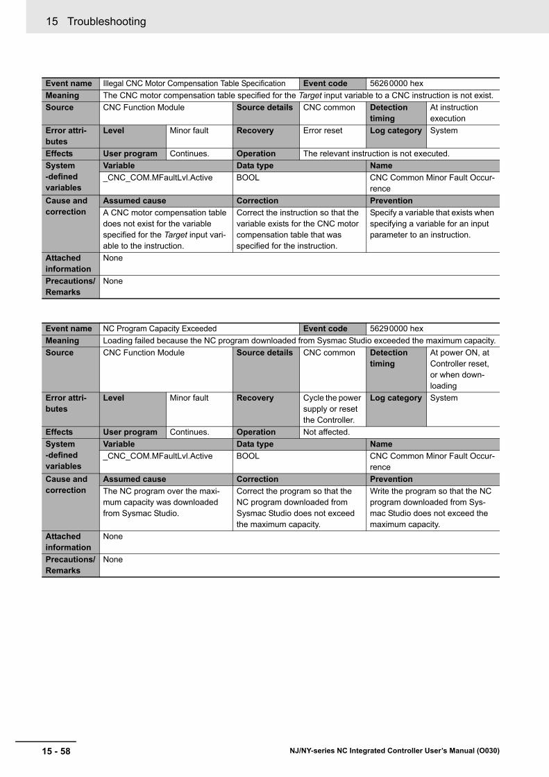
15 Troubleshooting
15 - 58 NJ/NY-series NC Integrated Controller User’s Manual (O030)
Event name Illegal CNC Motor Compensation Table Specification Event code 56260000 hex
Meaning The CNC motor compensation table specified for the Target input variable to a CNC instruction is not exist.
Source CNC Function Module Source details CNC common Detection timing
At instruction execution
Error attri-butes
Level Minor fault Recovery Error reset Log category System
Effects User program Continues. Operation The relevant instruction is not executed.
System-defined variables
Variable Data type Name
_CNC_COM.MFaultLvl.Active BOOL CNC Common Minor Fault Occur-rence
Cause and correction
Assumed cause Correction Prevention
A CNC motor compensation table does not exist for the variable specified for the Target input vari-able to the instruction.
Correct the instruction so that the variable exists for the CNC motor compensation table that was specified for the instruction.
Specify a variable that exists when specifying a variable for an input parameter to an instruction.
Attached information
None
Precautions/Remarks
None
Event name NC Program Capacity Exceeded Event code 56290000 hex
Meaning Loading failed because the NC program downloaded from Sysmac Studio exceeded the maximum capacity.
Source CNC Function Module Source details CNC common Detection timing
At power ON, at Controller reset, or when down-loading
Error attri-butes
Level Minor fault Recovery Cycle the power supply or reset the Controller.
Log category System
Effects User program Continues. Operation Not affected.
System-defined variables
Variable Data type Name
_CNC_COM.MFaultLvl.Active BOOL CNC Common Minor Fault Occur-rence
Cause and correction
Assumed cause Correction Prevention
The NC program over the maxi-mum capacity was downloaded from Sysmac Studio.
Correct the program so that the NC program downloaded from Sysmac Studio does not exceed the maximum capacity.
Write the program so that the NC program downloaded from Sys-mac Studio does not exceed the maximum capacity.
Attached information
None
Precautions/Remarks
None
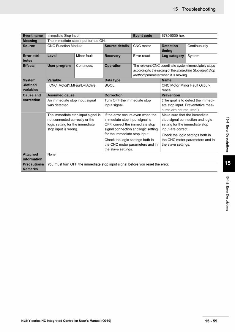
15 - 59
15 Troubleshooting
NJ/NY-series NC Integrated Controller User’s Manual (O030)
15-4 E
rror D
escriptio
ns
15
15-4-2 Error D
escriptions
Event name Immediate Stop Input Event code 67800000 hex
Meaning The immediate stop input turned ON.
Source CNC Function Module Source details CNC motor Detection timing
Continuously
Error attri-butes
Level Minor fault Recovery Error reset Log category System
Effects User program Continues. Operation The relevant CNC coordinate system immediately stops according to the setting of the Immediate Stop Input Stop Method parameter when it is moving.
System-defined variables
Variable Data type Name
_CNC_Motor[*].MFaultLvl.Active BOOL CNC Motor Minor Fault Occur-rence
Cause and correction
Assumed cause Correction Prevention
An immediate stop input signal was detected.
Turn OFF the immediate stop input signal.
(The goal is to detect the immedi-ate stop input. Preventative mea-sures are not required.)
The immediate stop input signal is not connected correctly or the logic setting for the immediate stop input is wrong.
If the error occurs even when the immediate stop input signal is OFF, correct the immediate stop signal connection and logic setting for the immediate stop input.
Check the logic settings both in the CNC motor parameters and in the slave settings.
Make sure that the immediate stop signal connection and logic setting for the immediate stop input are correct.
Check the logic settings both in the CNC motor parameters and in the slave settings.
Attached information
None
Precautions/Remarks
You must turn OFF the immediate stop input signal before you reset the error.
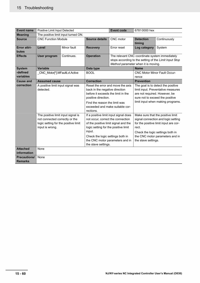
15 Troubleshooting
15 - 60 NJ/NY-series NC Integrated Controller User’s Manual (O030)
Event name Positive Limit Input Detected Event code 67810000 hex
Meaning The positive limit input turned ON.
Source CNC Function Module Source details CNC motor Detection timing
Continuously
Error attri-butes
Level Minor fault Recovery Error reset Log category System
Effects User program Continues. Operation The relevant CNC coordinate system immediately stops according to the setting of the Limit Input Stop Method parameter when it is moving.
System-defined variables
Variable Data type Name
_CNC_Motor[*].MFaultLvl.Active BOOL CNC Motor Minor Fault Occur-rence
Cause and correction
Assumed cause Correction Prevention
A positive limit input signal was detected.
Reset the error and move the axis back in the negative direction before it exceeds the limit in the positive direction.
Find the reason the limit was exceeded and make suitable cor-rections.
The goal is to detect the positive limit input. Preventative measures are not required. However, be sure not to exceed the positive limit input when making programs.
The positive limit input signal is not connected correctly or the logic setting for the positive limit input is wrong.
If a positive limit input signal does not occur, correct the connection of the positive limit signal and the logic setting for the positive limit input.
Check the logic settings both in the CNC motor parameters and in the slave settings.
Make sure that the positive limit signal connection and logic setting for the positive limit input are cor-rect.
Check the logic settings both in the CNC motor parameters and in the slave settings.
Attached information
None
Precautions/Remarks
None
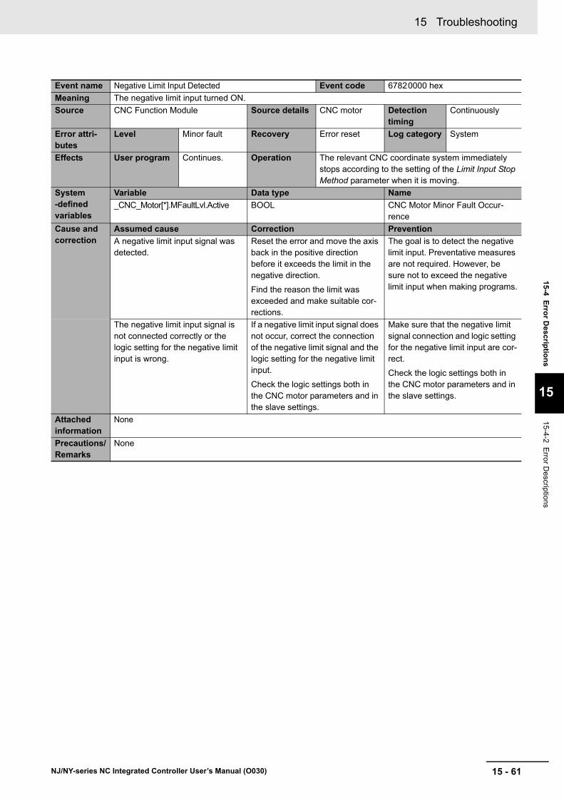
15 - 61
15 Troubleshooting
NJ/NY-series NC Integrated Controller User’s Manual (O030)
15-4 E
rror D
escriptio
ns
15
15-4-2 Error D
escriptions
Event name Negative Limit Input Detected Event code 67820000 hex
Meaning The negative limit input turned ON.
Source CNC Function Module Source details CNC motor Detection timing
Continuously
Error attri-butes
Level Minor fault Recovery Error reset Log category System
Effects User program Continues. Operation The relevant CNC coordinate system immediately stops according to the setting of the Limit Input Stop Method parameter when it is moving.
System-defined variables
Variable Data type Name
_CNC_Motor[*].MFaultLvl.Active BOOL CNC Motor Minor Fault Occur-rence
Cause and correction
Assumed cause Correction Prevention
A negative limit input signal was detected.
Reset the error and move the axis back in the positive direction before it exceeds the limit in the negative direction.
Find the reason the limit was exceeded and make suitable cor-rections.
The goal is to detect the negative limit input. Preventative measures are not required. However, be sure not to exceed the negative limit input when making programs.
The negative limit input signal is not connected correctly or the logic setting for the negative limit input is wrong.
If a negative limit input signal does not occur, correct the connection of the negative limit signal and the logic setting for the negative limit input.
Check the logic settings both in the CNC motor parameters and in the slave settings.
Make sure that the negative limit signal connection and logic setting for the negative limit input are cor-rect.
Check the logic settings both in the CNC motor parameters and in the slave settings.
Attached information
None
Precautions/Remarks
None
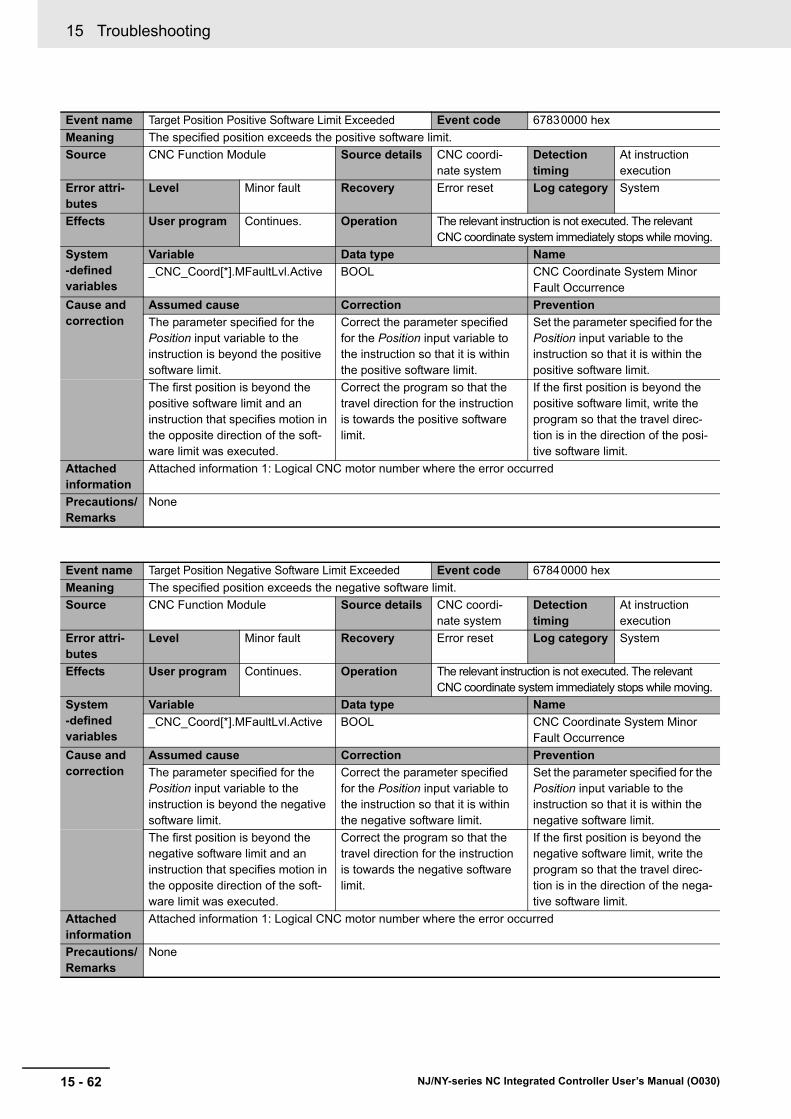
15 Troubleshooting
15 - 62 NJ/NY-series NC Integrated Controller User’s Manual (O030)
Event name Target Position Positive Software Limit Exceeded Event code 67830000 hex
Meaning The specified position exceeds the positive software limit.
Source CNC Function Module Source details CNC coordi-nate system
Detection timing
At instruction execution
Error attri-butes
Level Minor fault Recovery Error reset Log category System
Effects User program Continues. Operation The relevant instruction is not executed. The relevant CNC coordinate system immediately stops while moving.
System-defined variables
Variable Data type Name
_CNC_Coord[*].MFaultLvl.Active BOOL CNC Coordinate System Minor Fault Occurrence
Cause and correction
Assumed cause Correction Prevention
The parameter specified for the Position input variable to the instruction is beyond the positive software limit.
Correct the parameter specified for the Position input variable to the instruction so that it is within the positive software limit.
Set the parameter specified for the Position input variable to the instruction so that it is within the positive software limit.
The first position is beyond the positive software limit and an instruction that specifies motion in the opposite direction of the soft-ware limit was executed.
Correct the program so that the travel direction for the instruction is towards the positive software limit.
If the first position is beyond the positive software limit, write the program so that the travel direc-tion is in the direction of the posi-tive software limit.
Attached information
Attached information 1: Logical CNC motor number where the error occurred
Precautions/Remarks
None
Event name Target Position Negative Software Limit Exceeded Event code 67840000 hex
Meaning The specified position exceeds the negative software limit.
Source CNC Function Module Source details CNC coordi-nate system
Detection timing
At instruction execution
Error attri-butes
Level Minor fault Recovery Error reset Log category System
Effects User program Continues. Operation The relevant instruction is not executed. The relevant CNC coordinate system immediately stops while moving.
System-defined variables
Variable Data type Name
_CNC_Coord[*].MFaultLvl.Active BOOL CNC Coordinate System Minor Fault Occurrence
Cause and correction
Assumed cause Correction Prevention
The parameter specified for the Position input variable to the instruction is beyond the negative software limit.
Correct the parameter specified for the Position input variable to the instruction so that it is within the negative software limit.
Set the parameter specified for the Position input variable to the instruction so that it is within the negative software limit.
The first position is beyond the negative software limit and an instruction that specifies motion in the opposite direction of the soft-ware limit was executed.
Correct the program so that the travel direction for the instruction is towards the negative software limit.
If the first position is beyond the negative software limit, write the program so that the travel direc-tion is in the direction of the nega-tive software limit.
Attached information
Attached information 1: Logical CNC motor number where the error occurred
Precautions/Remarks
None

15 - 63
15 Troubleshooting
NJ/NY-series NC Integrated Controller User’s Manual (O030)
15-4 E
rror D
escriptio
ns
15
15-4-2 Error D
escriptions
Event name Command Position Overflow/Underflow Event code 67850000 hex
Meaning Positioning, an instruction in the underflow/overflow direction, or an instruction for which the direction is not specified was executed when there was an underflow/overflow in the command position.
Source CNC Function Module Source details CNC coordi-nate system
Detection timing
At instruction execution
Error attri-butes
Level Minor fault Recovery Error reset Log category System
Effects User program Continues. Operation The relevant instruction is not executed. The relevant CNC coordinate system immediately stops while moving.
System-defined variables
Variable Data type Name
_CNC_Coord[*].MFaultLvl.Active BOOL CNC Coordinate System Minor Fault Occurrence
Cause and correction
Assumed cause Correction Prevention
One of the following was executed when there was a command posi-tion overflow/underflow.
• A positioning instruction
• A continuous control instruction in the underflow/overflow direc-tion
• An instruction for which the direction is not specified (sync-ing)
Execute an error reset and then clear the overflow or underflow state by executing homing.
Make sure that overflow or under-flow does not occur.
Attached information
Attached information 1: Logical CNC motor number where the error occurred
Precautions/Remarks
None

15 Troubleshooting
15 - 64 NJ/NY-series NC Integrated Controller User’s Manual (O030)
Event name Positive Limit Input Event code 67860000 hex
Meaning An instruction was executed for a motion in the positive direction when the positive limit input was ON.
Source CNC Function Module Source details CNC coordi-nate system
Detection timing
At instruction execution
Error attri-butes
Level Minor fault Recovery Error reset Log category System
Effects User program Continues. Operation The relevant instruction is not executed.
System-defined variables
Variable Data type Name
_CNC_Coord[*].MFaultLvl.Active BOOL CNC Coordinate System Minor Fault Occurrence
Cause and correction
Assumed cause Correction Prevention
An instruction for a motion in the positive direction was executed when the positive limit input was ON, or an instruction for a motion with no direction specification was executed when the positive limit input was ON.
Execute an error reset and then perform a recovery operation in the negative direction. If this error occurs again, check the connec-tion of the positive limit signal, the logic setting for the positive limit input, and the execution condi-tions for the start command, and correct any mistakes.
Check the logic settings both in the CNC motor parameters and in the slave settings.
Check to make sure there are no problems with the positive limit signal connection, the logic setting for the positive limit input, and the execute conditions for the instruc-tion.
Check the logic settings both in the CNC motor parameters and in the slave settings.
Attached information
Attached information 1: Logical CNC motor number where the error occurred
Precautions/Remarks
None

15 - 65
15 Troubleshooting
NJ/NY-series NC Integrated Controller User’s Manual (O030)
15-4 E
rror D
escriptio
ns
15
15-4-2 Error D
escriptions
Event name Negative Limit Input Event code 67870000 hex
Meaning An instruction for a motion in the negative direction was executed when the negative limit input was ON.
Source CNC Function Module Source details CNC coordi-nate system
Detection timing
At instruction execution
Error attri-butes
Level Minor fault Recovery Error reset Log category System
Effects User program Continues. Operation The relevant instruction is not executed.
System-defined variables
Variable Data type Name
_CNC_Coord[*].MFaultLvl.Active BOOL CNC Coordinate System Minor Fault Occurrence
Cause and correction
Assumed cause Correction Prevention
An instruction for a motion in the negative direction was executed when the negative limit input was ON, or an instruction for a motion with no direction specification was executed when the negative limit input was ON.
Execute an error reset and then perform a recovery operation in the positive direction. If this error occurs again, check the connec-tion of the negative limit signal, the logic setting for the negative limit input, and the execution condi-tions for the start command, and correct any mistakes.
Check the logic settings both in the CNC motor parameters and in the slave settings.
Check to make sure there are no problems with the negative limit signal connection, the logic setting for the negative limit input, and the execute conditions for the instruc-tion.
Check the logic settings both in the CNC motor parameters and in the slave settings.
Attached information
Attached information 1: Logical CNC motor number where the error occurred
Precautions/Remarks
None
Event name Positive Software Limit Exceeded Event code 67880000 hex
Meaning The position exceeded the positive software limit while the CNC motor is in motion.
Source CNC Function Module Source details CNC motor Detection timing
During instruc-tion execution
Error attri-butes
Level Minor fault Recovery Error reset Log category System
Effects User program Continues. Operation Follows the setting of the Software Limit Function Selection.
System-defined variables
Variable Data type Name
_CNC_Motor[*].MFaultLvl.Active BOOL CNC Motor Minor Fault Occur-rence
Cause and correction
Assumed cause Correction Prevention
The position exceeded the posi-tive software limit.
Find the reason that the software limit was exceeded and make suit-able corrections.
(The goal is to enable detecting the software limits when they are exceeded due to unanticipated causes. Preventative measures are not required.)
Attached information
None
Precautions/Remarks
Whenever you change the positive software limit setting, make sure that the new setting is safe.

15 Troubleshooting
15 - 66 NJ/NY-series NC Integrated Controller User’s Manual (O030)
Event name Negative Software Limit Exceeded Event code 67890000 hex
Meaning The position exceeded the negative software limit while the CNC motor is in motion.
Source CNC Function Module Source details CNC motor Detection timing
During instruc-tion execution
Error attri-butes
Level Minor fault Recovery Error reset Log category System
Effects User program Continues. Operation Follows the setting of the Software Limit Function Selection.
System-defined variables
Variable Data type Name
_CNC_Motor[*].MFaultLvl.Active BOOL CNC Motor Minor Fault Occur-rence
Cause and correction
Assumed cause Correction Prevention
The position exceeded the nega-tive software limit.
Find the reason that the software limit was exceeded and make suit-able corrections.
(The goal is to enable detecting the software limits when they are exceeded due to unanticipated causes. Preventative measures are not required.)
Attached information
None
Precautions/Remarks
Whenever you change the negative software limit setting, make sure that the new setting is safe.
Event name In-position Check Time Exceeded Event code 678A0000 hex
Meaning The in-position check was not completed within the monitoring time.
Source CNC Function Module Source details CNC motor Detection timing
During instruc-tion execution
Error attri-butes
Level Minor fault Recovery Error reset Log category System
Effects User program Continues. Operation The relevant CNC coordinate system immediately stops while moving.
System-defined variables
Variable Data type Name
_CNC_Motor[*].MFaultLvl.Active BOOL CNC Motor Minor Fault Occur-rence
Cause and correction
Assumed cause Correction Prevention
Time is required to complete posi-tioning.
Determine the cause of the slow positioning and remove the cause of the error. Or, adjust the Servo Drive or adjust the In-position Check Time or In-position Range.
Increase the loop gain if you adjust the Servo Drive. However, make sure that you keep the loop gain low enough so that the con-trol does not oscillate.
Remove the cause of poor follow-ing performance or oscilla-tion/vibration in the positioning operation as much as possible.
Attached information
None
Precautions/Remarks
None

15 - 67
15 Troubleshooting
NJ/NY-series NC Integrated Controller User’s Manual (O030)
15-4 E
rror D
escriptio
ns
15
15-4-2 Error D
escriptions
Event name Following Error Limit Exceeded Event code 678B0000 hex
Meaning The error between the command current position and actual current value exceeded the Following Error Over Value.
Source CNC Function Module Source details CNC motor Detection timing
During instruc-tion execution
Error attri-butes
Level Minor fault Recovery Error reset Log category System
Effects User program Continues. Operation The relevant CNC coordinate system immediately stops while moving.
System-defined variables
Variable Data type Name
_CNC_Motor[*].MFaultLvl.Active BOOL CNC Motor Minor Fault Occur-rence
Cause and correction
Assumed cause Correction Prevention
The positioning operation has poor following performance and the actual motion is slower than the command.
Remove the cause of poor follow-ing performance in the positioning operation.
Or increase the Following Error Over Value within the range that will not create problems.
Remove the cause of poor follow-ing performance in the positioning operation as best you can.
Attached information
None
Precautions/Remarks
None
Event name Illegal Following Error Event code 67910000 hex
Meaning The difference between the command position and the actual current position exceeds the range of 30-bit data when converted to pulses.
Source CNC Function Module Source details CNC motor Detection timing
Continuously
Error attri-butes
Level Minor fault Recovery Error reset Log category System
Effects User program Continues. Operation The Servo for the relevant CNC motor is turned OFF.
System-defined variables
Variable Data type Name
_CNC_Motor[*].MFaultLvl.Active BOOL CNC Motor Minor Fault Occur-rence
Cause and correction
Assumed cause Correction Prevention
The command current position was restricted so that the velocity of the CNC motor would not exceed the maximum velocity for the specified travel distance.
Correct the program or correct the electronic gear ratio so that the CNC motor does not exceed the maximum velocity.
Write the program or set the elec-tronic gear ratio so that the CNC motor does not exceed the maxi-mum velocity.
The CNC motor positioning opera-tion has poor following perfor-mance and the actual motion is slower than the command.
Remove the cause of poor follow-ing performance in the CNC motor positioning operation.
Remove the cause of poor follow-ing performance in the CNC motor positioning operation as best you can.
Attached information
None
Precautions/Remarks
None

15 Troubleshooting
15 - 68 NJ/NY-series NC Integrated Controller User’s Manual (O030)
Event name Absolute Encoder Current Position Calculation Failed Event code 67920000 hex
Meaning It was not possible to correctly restore the current position from the absolute encoder information that was saved when power was interrupted.
Source CNC Function Module Source details CNC motor Detection timing
At power ON, at Controller reset, when download-ing, or when start-ing Servo ON status
Error attri-butes
Level Minor fault Recovery Error reset Log category System
Effects User program Continues. Operation Operation is not possible for relevant CNC motors.
System-defined variables
Variable Data type Name
_CNC_Motor[*].MFaultLvl.Active BOOL CNC Motor Minor Fault Occur-rence
Cause and correction
Assumed cause Correction Prevention
The position to restore when con-verted to pulses exceeded the range of signed 40-bit data.
Reset the error and perform hom-ing. Perform homing near the position where the absolute encoder is set up so that the posi-tion to restore does not exceed the range of signed 40-bit data.
Perform homing again if you changed any parameters related to position. Perform homing near the position where the absolute encoder is set up so that the posi-tion to restore does not exceed the range of signed 40-bit data.
Also, do not execute the CNC_Power (Power Servo) instruction or cycle the power sup-ply when the encoder position exceeds the range of signed 40-bit data.
Attached information
None
Precautions/Remarks
None
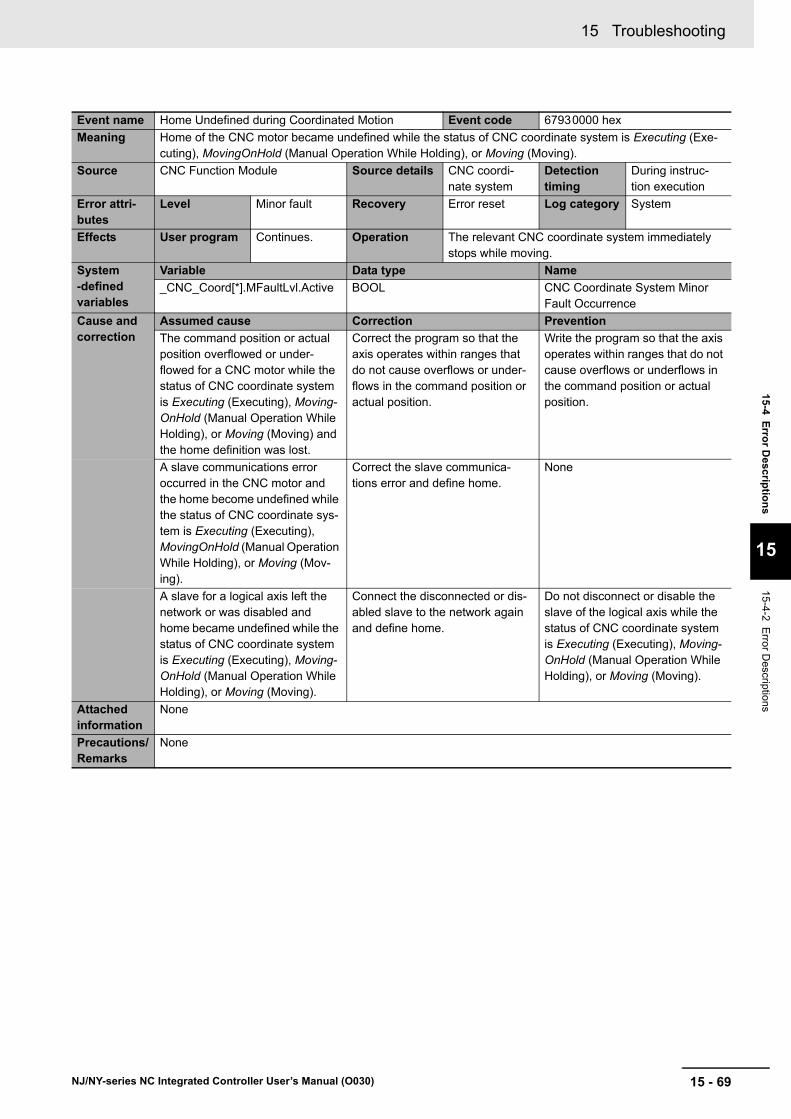
15 - 69
15 Troubleshooting
NJ/NY-series NC Integrated Controller User’s Manual (O030)
15-4 E
rror D
escriptio
ns
15
15-4-2 Error D
escriptions
Event name Home Undefined during Coordinated Motion Event code 67930000 hex
Meaning Home of the CNC motor became undefined while the status of CNC coordinate system is Executing (Exe-cuting), MovingOnHold (Manual Operation While Holding), or Moving (Moving).
Source CNC Function Module Source details CNC coordi-nate system
Detection timing
During instruc-tion execution
Error attri-butes
Level Minor fault Recovery Error reset Log category System
Effects User program Continues. Operation The relevant CNC coordinate system immediately stops while moving.
System-defined variables
Variable Data type Name
_CNC_Coord[*].MFaultLvl.Active BOOL CNC Coordinate System Minor Fault Occurrence
Cause and correction
Assumed cause Correction Prevention
The command position or actual position overflowed or under-flowed for a CNC motor while the status of CNC coordinate system is Executing (Executing), Moving-OnHold (Manual Operation While Holding), or Moving (Moving) and the home definition was lost.
Correct the program so that the axis operates within ranges that do not cause overflows or under-flows in the command position or actual position.
Write the program so that the axis operates within ranges that do not cause overflows or underflows in the command position or actual position.
A slave communications error occurred in the CNC motor and the home become undefined while the status of CNC coordinate sys-tem is Executing (Executing), MovingOnHold (Manual Operation While Holding), or Moving (Mov-ing).
Correct the slave communica-tions error and define home.
None
A slave for a logical axis left the network or was disabled and home became undefined while the status of CNC coordinate system is Executing (Executing), Moving-OnHold (Manual Operation While Holding), or Moving (Moving).
Connect the disconnected or dis-abled slave to the network again and define home.
Do not disconnect or disable the slave of the logical axis while the status of CNC coordinate system is Executing (Executing), Moving-OnHold (Manual Operation While Holding), or Moving (Moving).
Attached information
None
Precautions/Remarks
None
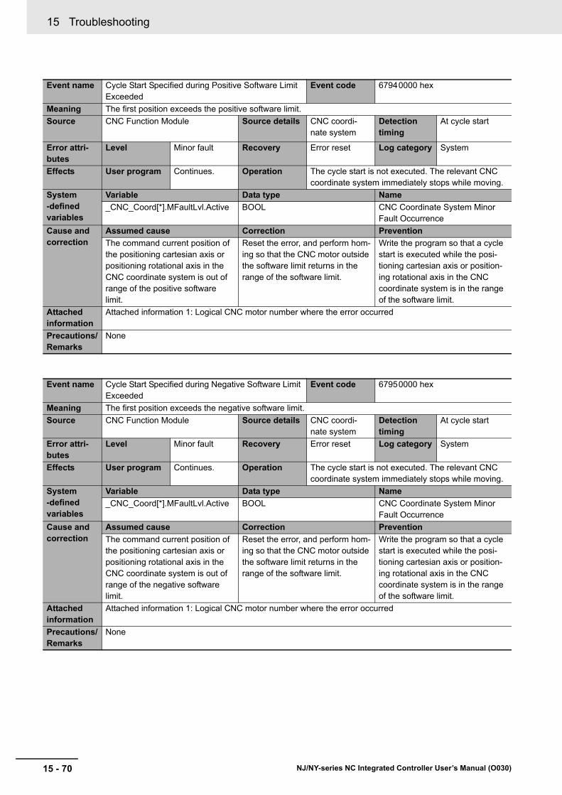
15 Troubleshooting
15 - 70 NJ/NY-series NC Integrated Controller User’s Manual (O030)
Event name Cycle Start Specified during Positive Software Limit Exceeded
Event code 67940000 hex
Meaning The first position exceeds the positive software limit.
Source CNC Function Module Source details CNC coordi-nate system
Detection timing
At cycle start
Error attri-butes
Level Minor fault Recovery Error reset Log category System
Effects User program Continues. Operation The cycle start is not executed. The relevant CNC coordinate system immediately stops while moving.
System-defined variables
Variable Data type Name
_CNC_Coord[*].MFaultLvl.Active BOOL CNC Coordinate System Minor Fault Occurrence
Cause and correction
Assumed cause Correction Prevention
The command current position of the positioning cartesian axis or positioning rotational axis in the CNC coordinate system is out of range of the positive software limit.
Reset the error, and perform hom-ing so that the CNC motor outside the software limit returns in the range of the software limit.
Write the program so that a cycle start is executed while the posi-tioning cartesian axis or position-ing rotational axis in the CNC coordinate system is in the range of the software limit.
Attached information
Attached information 1: Logical CNC motor number where the error occurred
Precautions/Remarks
None
Event name Cycle Start Specified during Negative Software Limit Exceeded
Event code 67950000 hex
Meaning The first position exceeds the negative software limit.
Source CNC Function Module Source details CNC coordi-nate system
Detection timing
At cycle start
Error attri-butes
Level Minor fault Recovery Error reset Log category System
Effects User program Continues. Operation The cycle start is not executed. The relevant CNC coordinate system immediately stops while moving.
System-defined variables
Variable Data type Name
_CNC_Coord[*].MFaultLvl.Active BOOL CNC Coordinate System Minor Fault Occurrence
Cause and correction
Assumed cause Correction Prevention
The command current position of the positioning cartesian axis or positioning rotational axis in the CNC coordinate system is out of range of the negative software limit.
Reset the error, and perform hom-ing so that the CNC motor outside the software limit returns in the range of the software limit.
Write the program so that a cycle start is executed while the posi-tioning cartesian axis or position-ing rotational axis in the CNC coordinate system is in the range of the software limit.
Attached information
Attached information 1: Logical CNC motor number where the error occurred
Precautions/Remarks
None

15 - 71
15 Troubleshooting
NJ/NY-series NC Integrated Controller User’s Manual (O030)
15-4 E
rror D
escriptio
ns
15
15-4-2 Error D
escriptions
Event name Cycle Start Specified during Command Position Overflow/Underflow
Event code 67960000 hex
Meaning The cycle start was executed when there was a command position overflow/underflow.
Source CNC Function Module Source details CNC coordi-nate system
Detection timing
At cycle start
Error attri-butes
Level Minor fault Recovery Error reset Log category System
Effects User program Continues. Operation The cycle start is not executed. The relevant CNC coordinate system immediately stops while moving.
System-defined variables
Variable Data type Name
_CNC_Coord[*].MFaultLvl.Active BOOL CNC Coordinate System Minor Fault Occurrence
Cause and correction
Assumed cause Correction Prevention
• The cycle start was executed when there was a command position overflow/underflow.
Execute an error reset and then clear the overflow/underflow state by executing homing.
Make sure that overflow or under-flow does not occur.
Attached information
Attached information 1: Logical CNC motor number where the error occurred
Precautions/Remarks
None

15 Troubleshooting
15 - 72 NJ/NY-series NC Integrated Controller User’s Manual (O030)
Event name Cycle Start Specified during Positive Limit Input Event code 67970000 hex
Meaning A cycle start was executed when the positive limit input was ON.
Source CNC Function Module Source details CNC coordi-nate system
Detection timing
At cycle start
Error attri-butes
Level Minor fault Recovery Error reset Log category System
Effects User program Continues. Operation The cycle start is not executed. The relevant CNC coordinate system immediately stops while moving.
System-defined variables
Variable Data type Name
_CNC_Coord[*].MFaultLvl.Active BOOL CNC Coordinate System Minor Fault Occurrence
Cause and correction
Assumed cause Correction Prevention
A cycle start was executed when the positive limit input was ON.
Execute an error reset and then perform a recovery operation in the negative direction. If this error occurs again, check the connec-tion of the positive limit signal and the logic setting for the positive limit input, and correct any mis-takes.
Check the logic settings both in the CNC motor parameters and in the slave settings.
Check to make sure there are no problems with the positive limit signal connection and the logic setting for the positive limit input.
Check the logic settings both in the CNC motor parameters and in the slave settings.
Attached information
Attached information 1: Logical CNC motor number where the error occurred
Precautions/Remarks
None
Event name Cycle Start Specified during Negative Limit Input Event code 67980000 hex
Meaning A cycle start was executed when the negative limit input was ON.
Source CNC Function Module Source details CNC coordi-nate system
Detection timing
At cycle start
Error attri-butes
Level Minor fault Recovery Error reset Log category System
Effects User program Continues. Operation The cycle start is not executed. The relevant CNC coordinate system immediately stops while moving.
System-defined variables
Variable Data type Name
_CNC_Coord[*].MFaultLvl.Active BOOL CNC Coordinate System Minor Fault Occurrence
Cause and correction
Assumed cause Correction Prevention
A cycle start was executed when the negative limit input was ON.
Execute an error reset and then perform a recovery operation in the positive direction. If this error occurs again, check the connec-tion of the negative limit signal and the logic setting for the negative limit input, and correct any mis-takes.
Check the logic settings both in the CNC motor parameters and in the slave settings.
Check to make sure there are no problems with the negative limit signal connection and the logic setting for the negative limit input.
Check the logic settings both in the CNC motor parameters and in the slave settings.
Attached information
Attached information 1: Logical CNC motor number where the error occurred
Precautions/Remarks
None
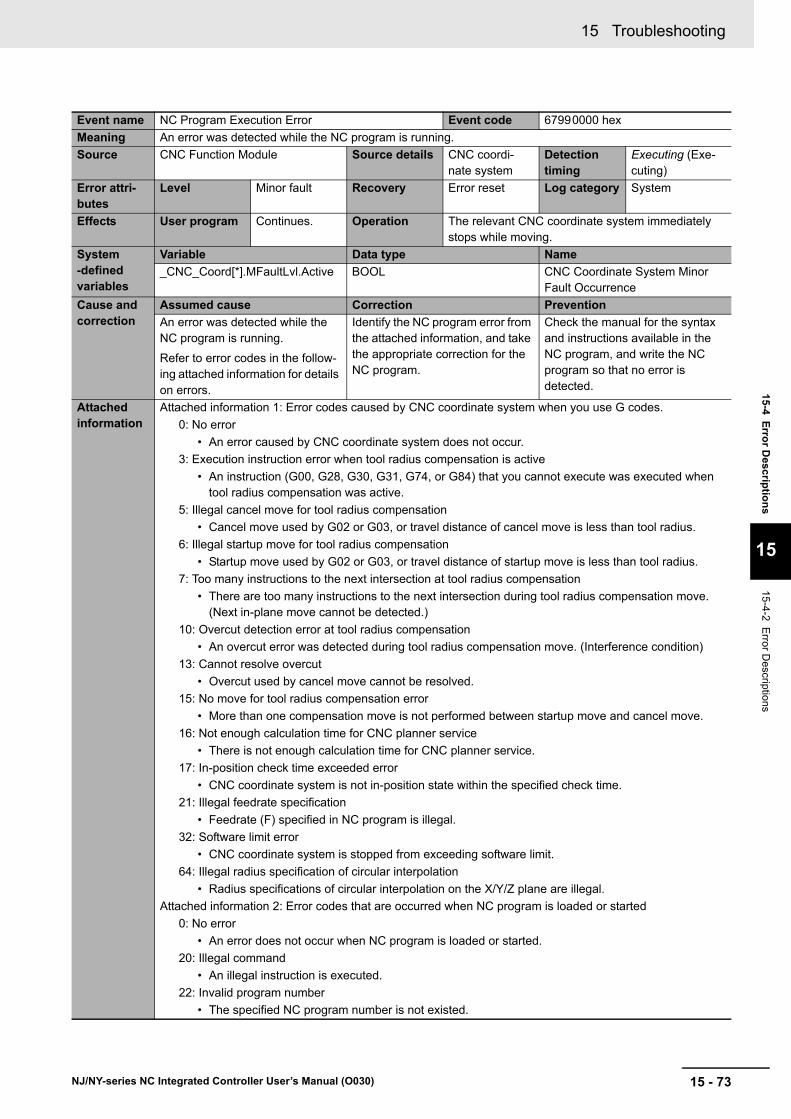
15 - 73
15 Troubleshooting
NJ/NY-series NC Integrated Controller User’s Manual (O030)
15-4 E
rror D
escriptio
ns
15
15-4-2 Error D
escriptions
Event name NC Program Execution Error Event code 67990000 hex
Meaning An error was detected while the NC program is running.
Source CNC Function Module Source details CNC coordi-nate system
Detection timing
Executing (Exe-cuting)
Error attri-butes
Level Minor fault Recovery Error reset Log category System
Effects User program Continues. Operation The relevant CNC coordinate system immediately stops while moving.
System-defined variables
Variable Data type Name
_CNC_Coord[*].MFaultLvl.Active BOOL CNC Coordinate System Minor Fault Occurrence
Cause and correction
Assumed cause Correction Prevention
An error was detected while the NC program is running.
Refer to error codes in the follow-ing attached information for details on errors.
Identify the NC program error from the attached information, and take the appropriate correction for the NC program.
Check the manual for the syntax and instructions available in the NC program, and write the NC program so that no error is detected.
Attached information
Attached information 1: Error codes caused by CNC coordinate system when you use G codes.
0: No error
• An error caused by CNC coordinate system does not occur.
3: Execution instruction error when tool radius compensation is active
• An instruction (G00, G28, G30, G31, G74, or G84) that you cannot execute was executed when tool radius compensation was active.
5: Illegal cancel move for tool radius compensation
• Cancel move used by G02 or G03, or travel distance of cancel move is less than tool radius.
6: Illegal startup move for tool radius compensation
• Startup move used by G02 or G03, or travel distance of startup move is less than tool radius.
7: Too many instructions to the next intersection at tool radius compensation
• There are too many instructions to the next intersection during tool radius compensation move. (Next in-plane move cannot be detected.)
10: Overcut detection error at tool radius compensation
• An overcut error was detected during tool radius compensation move. (Interference condition)
13: Cannot resolve overcut
• Overcut used by cancel move cannot be resolved.
15: No move for tool radius compensation error
• More than one compensation move is not performed between startup move and cancel move.
16: Not enough calculation time for CNC planner service
• There is not enough calculation time for CNC planner service.
17: In-position check time exceeded error
• CNC coordinate system is not in-position state within the specified check time.
21: Illegal feedrate specification
• Feedrate (F) specified in NC program is illegal.
32: Software limit error
• CNC coordinate system is stopped from exceeding software limit.
64: Illegal radius specification of circular interpolation
• Radius specifications of circular interpolation on the X/Y/Z plane are illegal.
Attached information 2: Error codes that are occurred when NC program is loaded or started
0: No error
• An error does not occur when NC program is loaded or started.
20: Illegal command
• An illegal instruction is executed.
22: Invalid program number
• The specified NC program number is not existed.
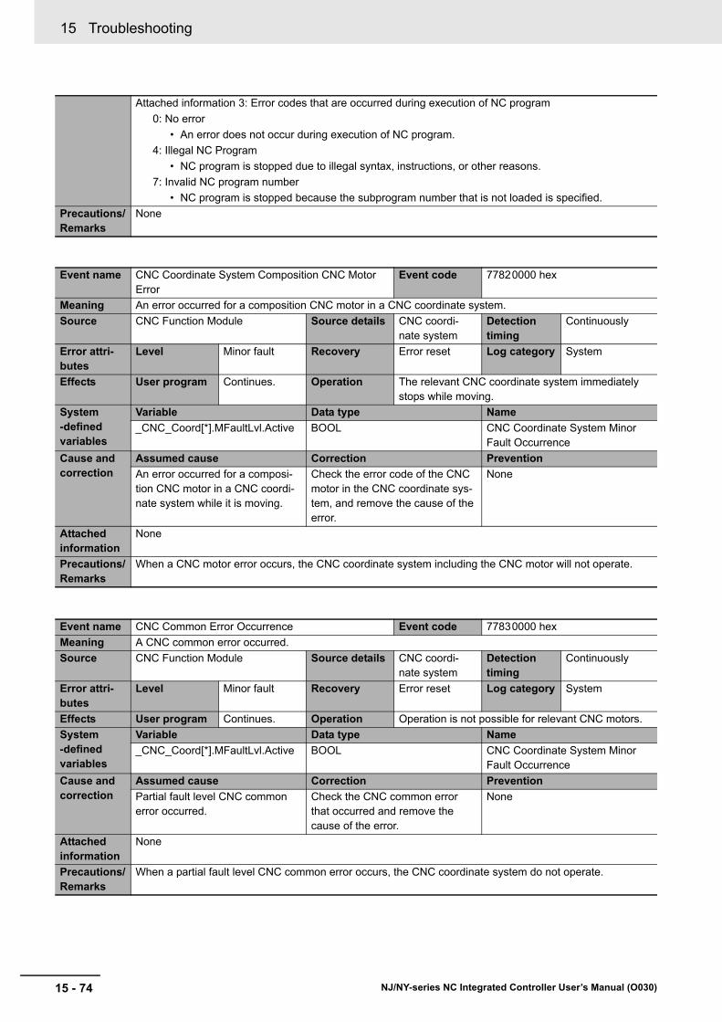
15 Troubleshooting
15 - 74 NJ/NY-series NC Integrated Controller User’s Manual (O030)
Attached information 3: Error codes that are occurred during execution of NC program
0: No error
• An error does not occur during execution of NC program.
4: Illegal NC Program
• NC program is stopped due to illegal syntax, instructions, or other reasons.
7: Invalid NC program number
• NC program is stopped because the subprogram number that is not loaded is specified.
Precautions/Remarks
None
Event name CNC Coordinate System Composition CNC Motor Error
Event code 77820000 hex
Meaning An error occurred for a composition CNC motor in a CNC coordinate system.
Source CNC Function Module Source details CNC coordi-nate system
Detection timing
Continuously
Error attri-butes
Level Minor fault Recovery Error reset Log category System
Effects User program Continues. Operation The relevant CNC coordinate system immediately stops while moving.
System-defined variables
Variable Data type Name
_CNC_Coord[*].MFaultLvl.Active BOOL CNC Coordinate System Minor Fault Occurrence
Cause and correction
Assumed cause Correction Prevention
An error occurred for a composi-tion CNC motor in a CNC coordi-nate system while it is moving.
Check the error code of the CNC motor in the CNC coordinate sys-tem, and remove the cause of the error.
None
Attached information
None
Precautions/Remarks
When a CNC motor error occurs, the CNC coordinate system including the CNC motor will not operate.
Event name CNC Common Error Occurrence Event code 77830000 hex
Meaning A CNC common error occurred.
Source CNC Function Module Source details CNC coordi-nate system
Detection timing
Continuously
Error attri-butes
Level Minor fault Recovery Error reset Log category System
Effects User program Continues. Operation Operation is not possible for relevant CNC motors.
System-defined variables
Variable Data type Name
_CNC_Coord[*].MFaultLvl.Active BOOL CNC Coordinate System Minor Fault Occurrence
Cause and correction
Assumed cause Correction Prevention
Partial fault level CNC common error occurred.
Check the CNC common error that occurred and remove the cause of the error.
None
Attached information
None
Precautions/Remarks
When a partial fault level CNC common error occurs, the CNC coordinate system do not operate.
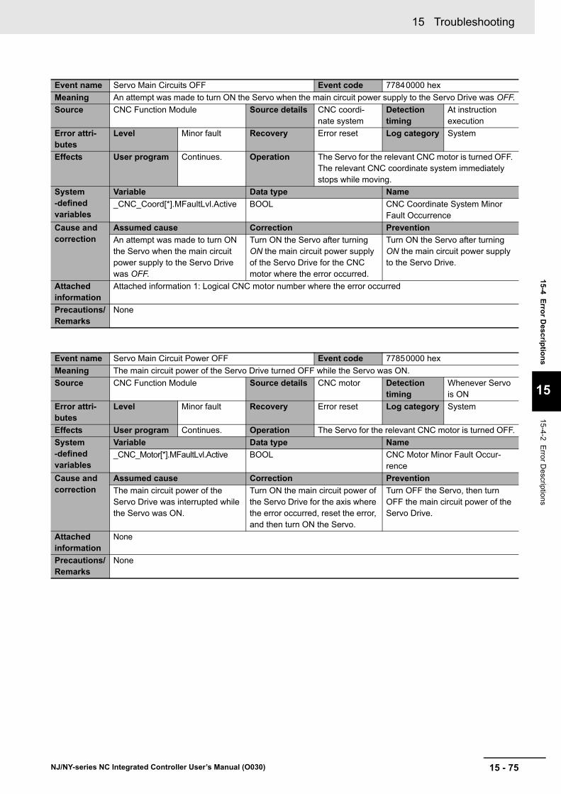
15 - 75
15 Troubleshooting
NJ/NY-series NC Integrated Controller User’s Manual (O030)
15-4 E
rror D
escriptio
ns
15
15-4-2 Error D
escriptions
Event name Servo Main Circuits OFF Event code 77840000 hex
Meaning An attempt was made to turn ON the Servo when the main circuit power supply to the Servo Drive was OFF.
Source CNC Function Module Source details CNC coordi-nate system
Detection timing
At instruction execution
Error attri-butes
Level Minor fault Recovery Error reset Log category System
Effects User program Continues. Operation The Servo for the relevant CNC motor is turned OFF. The relevant CNC coordinate system immediately stops while moving.
System-defined variables
Variable Data type Name
_CNC_Coord[*].MFaultLvl.Active BOOL CNC Coordinate System Minor Fault Occurrence
Cause and correction
Assumed cause Correction Prevention
An attempt was made to turn ON the Servo when the main circuit power supply to the Servo Drive was OFF.
Turn ON the Servo after turning ON the main circuit power supply of the Servo Drive for the CNC motor where the error occurred.
Turn ON the Servo after turning ON the main circuit power supply to the Servo Drive.
Attached information
Attached information 1: Logical CNC motor number where the error occurred
Precautions/Remarks
None
Event name Servo Main Circuit Power OFF Event code 77850000 hex
Meaning The main circuit power of the Servo Drive turned OFF while the Servo was ON.
Source CNC Function Module Source details CNC motor Detection timing
Whenever Servo is ON
Error attri-butes
Level Minor fault Recovery Error reset Log category System
Effects User program Continues. Operation The Servo for the relevant CNC motor is turned OFF.
System-defined variables
Variable Data type Name
_CNC_Motor[*].MFaultLvl.Active BOOL CNC Motor Minor Fault Occur-rence
Cause and correction
Assumed cause Correction Prevention
The main circuit power of the Servo Drive was interrupted while the Servo was ON.
Turn ON the main circuit power of the Servo Drive for the axis where the error occurred, reset the error, and then turn ON the Servo.
Turn OFF the Servo, then turn OFF the main circuit power of the Servo Drive.
Attached information
None
Precautions/Remarks
None
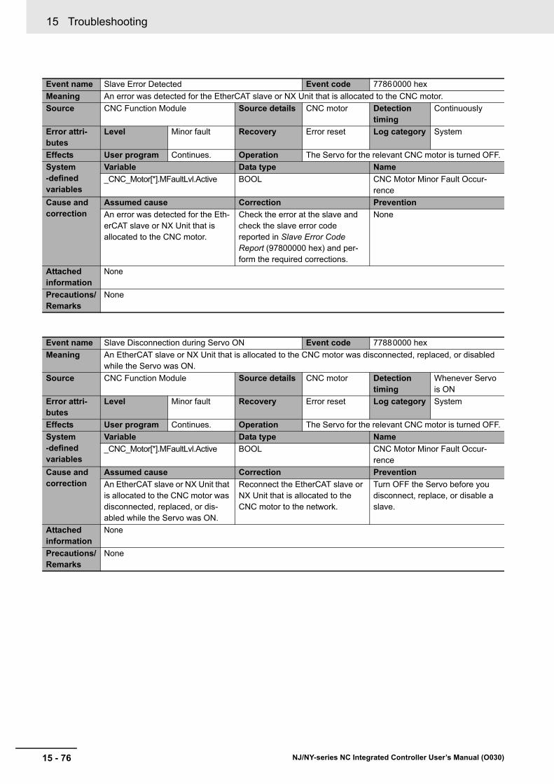
15 Troubleshooting
15 - 76 NJ/NY-series NC Integrated Controller User’s Manual (O030)
Event name Slave Error Detected Event code 77860000 hex
Meaning An error was detected for the EtherCAT slave or NX Unit that is allocated to the CNC motor.
Source CNC Function Module Source details CNC motor Detection timing
Continuously
Error attri-butes
Level Minor fault Recovery Error reset Log category System
Effects User program Continues. Operation The Servo for the relevant CNC motor is turned OFF.
System-defined variables
Variable Data type Name
_CNC_Motor[*].MFaultLvl.Active BOOL CNC Motor Minor Fault Occur-rence
Cause and correction
Assumed cause Correction Prevention
An error was detected for the Eth-erCAT slave or NX Unit that is allocated to the CNC motor.
Check the error at the slave and check the slave error code reported in Slave Error Code Report (97800000 hex) and per-form the required corrections.
None
Attached information
None
Precautions/Remarks
None
Event name Slave Disconnection during Servo ON Event code 77880000 hex
Meaning An EtherCAT slave or NX Unit that is allocated to the CNC motor was disconnected, replaced, or disabled while the Servo was ON.
Source CNC Function Module Source details CNC motor Detection timing
Whenever Servo is ON
Error attri-butes
Level Minor fault Recovery Error reset Log category System
Effects User program Continues. Operation The Servo for the relevant CNC motor is turned OFF.
System-defined variables
Variable Data type Name
_CNC_Motor[*].MFaultLvl.Active BOOL CNC Motor Minor Fault Occur-rence
Cause and correction
Assumed cause Correction Prevention
An EtherCAT slave or NX Unit that is allocated to the CNC motor was disconnected, replaced, or dis-abled while the Servo was ON.
Reconnect the EtherCAT slave or NX Unit that is allocated to the CNC motor to the network.
Turn OFF the Servo before you disconnect, replace, or disable a slave.
Attached information
None
Precautions/Remarks
None

15 - 77
15 Troubleshooting
NJ/NY-series NC Integrated Controller User’s Manual (O030)
15-4 E
rror D
escriptio
ns
15
15-4-2 Error D
escriptions
Event name Homing Opposite Direction Limit Input Detected Event code 77890000 hex
Meaning The limit signal in the direction opposite to the homing direction was detected during a homing operation.
Source CNC Function Module Source details CNC motor Detection timing
During instruc-tion execution
Error attri-butes
Level Minor fault Recovery Error reset Log category System
Effects User program Continues. Operation The axis stops with the stop method for the homing execution status.
System-defined variables
Variable Data type Name
_CNC_Motor[*].MFaultLvl.Active BOOL CNC Motor Minor Fault Occur-rence
Cause and correction
Assumed cause Correction Prevention
The Operation Selection at Nega-tive Limit Input or Operation Selection at Positive Limit Input parameter is set to No reverse turn.
To prevent errors at the limit inputs, set the Operation Selection at Negative Limit Input and Opera-tion Selection at Positive Limit Input parameters to Reverse turn.
Check to see if any of the condi-tions that are given as causes exist in advance.
The location of the homing input signal sensors, homing settings, and homing start position cause a limit input to be reached.
Correct the location of the input signal sensors, homing settings, and homing start position so that a limit input is not reached.
The input signal sensor wiring is incorrect or the sensor is faulty.
Correct the wiring of the input sig-nal sensor or replace the sensor.
Attached information
None
Precautions/Remarks
None

15 Troubleshooting
15 - 78 NJ/NY-series NC Integrated Controller User’s Manual (O030)
Event name Homing Direction Limit Input Detected Event code 778A0000 hex
Meaning The limit signal in the homing direction was detected during a homing operation.
Source CNC Function Module Source details CNC motor Detection timing
During instruc-tion execution
Error attri-butes
Level Minor fault Recovery Error reset Log category System
Effects User program Continues. Operation The axis stops with the stop method for the homing execution status.
System-defined variables
Variable Data type Name
_CNC_Motor[*].MFaultLvl.Active BOOL CNC Motor Minor Fault Occur-rence
Cause and correction
Assumed cause Correction Prevention
The Operation Selection at Nega-tive Limit Input or Operation Selection at Positive Limit Input parameter is set to No reverse turn.
To prevent errors at the limit inputs, set the Operation Selection at Negative Limit Input and Opera-tion Selection at Positive Limit Input parameters to Reverse turn.
Check to see if any of the condi-tions that are given as causes exist in advance.
The location of the homing input signal sensors, homing settings, and homing start position cause a limit input to be reached.
Correct the location of the input signal sensors, homing settings, and homing start position so that a limit input is not reached.
The input signal sensor wiring is incorrect or the sensor is faulty.
Correct the wiring of the input sig-nal sensor or replace the sensor.
Attached information
None
Precautions/Remarks
None
Event name Homing Limit Inputs Detected in Both Directions Event code 778B0000 hex
Meaning The limit signals in both directions were detected during a homing operation.
Source CNC Function Module Source details CNC motor Detection timing
During instruc-tion execution
Error attri-butes
Level Minor fault Recovery Error reset Log category System
Effects User program Continues. Operation The axis stops with the stop method for the homing execution status.
System-defined variables
Variable Data type Name
_CNC_Motor[*].MFaultLvl.Active BOOL CNC Motor Minor Fault Occur-rence
Cause and correction
Assumed cause Correction Prevention
The wiring of the limit signal is incorrect.
Correct the wiring of the limit sig-nal.
Check to see if any of the condi-tions that are given as causes exist in advance.The limit sensor is installed in the
wrong location.Correct the installation locations of the limit sensors so that they do not turn ON at the same time.
The contact logic of the limit signal is not correct.
Correct the contact logic (N.C./N.O.) of the limit signal.
The limit sensor failed. Replace the limit sensor.
Attached information
None
Precautions/Remarks
None

15 - 79
15 Troubleshooting
NJ/NY-series NC Integrated Controller User’s Manual (O030)
15-4 E
rror D
escriptio
ns
15
15-4-2 Error D
escriptions
Event name Home Proximity/Homing Opposite Direction Limit Input Detected
Event code 778C0000 hex
Meaning The home proximity input and the limit signal in the direction opposite to the homing direction were detected at the same time during a homing operation.
Source CNC Function Module Source details CNC motor Detection timing
During instruc-tion execution
Error attri-butes
Level Minor fault Recovery Error reset Log category System
Effects User program Continues. Operation The axis stops with the stop method for the homing execution status.
System-defined variables
Variable Data type Name
_CNC_Motor[*].MFaultLvl.Active BOOL CNC Motor Minor Fault Occur-rence
Cause and correction
Assumed cause Correction Prevention
The wiring of the home proximity signal or limit signal is incorrect.
Correct the wiring of the home proximity signal or limit signal.
Check to see if any of the condi-tions that are given as causes exist in advance.The home proximity sensor or limit
sensor is installed in the wrong location.
Correct the installation location of the home proximity sensor or limit sensor so that they do not turn ON at the same time.
The contact logic of the home proximity signal or limit signal is not correct.
Correct the contact logic (N.C./N.O.) of the home proximity sensor or limit sensor.
The home proximity sensor or limit sensor failed.
Replace the home proximity sen-sor or limit sensor.
Attached information
None
Precautions/Remarks
None

15 Troubleshooting
15 - 80 NJ/NY-series NC Integrated Controller User’s Manual (O030)
Event name Home Proximity/Homing Direction Limit Input Detected
Event code 778D0000 hex
Meaning The home proximity input and the limit signal in the homing direction were detected at the same time during a homing operation.
Source CNC Function Module Source details CNC motor Detection timing
During instruc-tion execution
Error attri-butes
Level Minor fault Recovery Error reset Log category System
Effects User program Continues. Operation The axis stops with the stop method for the homing execution status.
System-defined variables
Variable Data type Name
_CNC_Motor[*].MFaultLvl.Active BOOL CNC Motor Minor Fault Occur-rence
Cause and correction
Assumed cause Correction Prevention
The wiring of the home proximity signal or limit signal is incorrect.
Correct the wiring of the home proximity signal or limit signal.
Check to see if any of the condi-tions that are given as causes exist in advance.The home proximity sensor or limit
sensor is installed in the wrong location.
Correct the installation location of the home proximity sensor or limit sensor so that they do not turn ON at the same time.
The contact logic of the home proximity signal or limit signal is not correct.
Correct the contact logic (N.C./N.O.) of the home proximity sensor or limit sensor.
The home proximity sensor or limit sensor failed.
Replace the home proximity sen-sor or limit sensor.
Attached information
None
Precautions/Remarks
None

15 - 81
15 Troubleshooting
NJ/NY-series NC Integrated Controller User’s Manual (O030)
15-4 E
rror D
escriptio
ns
15
15-4-2 Error D
escriptions
Event name Home Input/Homing Opposite Direction Limit Input Detected
Event code 778E0000 hex
Meaning The home input and the limit signal in the direction opposite to the homing direction were detected at the same time during a homing operation.
Source CNC Function Module Source details CNC motor Detection timing
During instruc-tion execution
Error attri-butes
Level Minor fault Recovery Error reset Log category System
Effects User program Continues. Operation The axis stops with the stop method for the homing execution status.
System-defined variables
Variable Data type Name
_CNC_Motor[*].MFaultLvl.Active BOOL CNC Motor Minor Fault Occur-rence
Cause and correction
Assumed cause Correction Prevention
The wiring of the home input sig-nal or limit signal is incorrect.
Correct the wiring of the home input signal or limit signal.
Check to see if any of the condi-tions that are given as causes exist in advance.The home input sensor or limit
sensor is installed in the wrong location.
Correct the installation location of the home input sensor or limit sen-sor so that they do not turn ON at the same time.
The contact logic of the home input signal or limit signal is not correct.
Correct the contact logic (N.C./N.O.) of the home input sig-nal or limit sensor.
The home input signal output device or limit sensor failed.
Replace the home input signal output device or limit sensor.
Attached information
None
Precautions/Remarks
None

15 Troubleshooting
15 - 82 NJ/NY-series NC Integrated Controller User’s Manual (O030)
Event name Home Input/Homing Direction Limit Input Detected Event code 778F0000 hex
Meaning The home input and the limit signal in the homing direction were detected at the same time during a homing operation.
Source CNC Function Module Source details CNC motor Detection timing
During instruc-tion execution
Error attri-butes
Level Minor fault Recovery Error reset Log category System
Effects User program Continues. Operation The axis stops with the stop method for the homing execution status.
System-defined variables
Variable Data type Name
_CNC_Motor[*].MFaultLvl.Active BOOL CNC Motor Minor Fault Occur-rence
Cause and correction
Assumed cause Correction Prevention
The wiring of the home input sig-nal or limit signal is incorrect.
Correct the wiring of the home input signal or limit signal.
Check to see if any of the condi-tions that are given as causes exist in advance.The home input sensor or limit
sensor is installed in the wrong location.
Correct the installation location of the home input sensor or limit sen-sor so that they do not turn ON at the same time.
The contact logic of the home input signal or limit signal is not correct.
Correct the contact logic (N.C./N.O.) of the home input sig-nal or limit sensor.
The home input signal output device or limit sensor failed.
Replace the home input signal output device or limit sensor.
Attached information
None
Precautions/Remarks
None
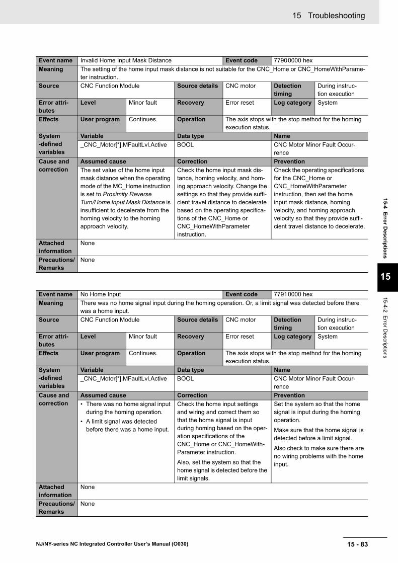
15 - 83
15 Troubleshooting
NJ/NY-series NC Integrated Controller User’s Manual (O030)
15-4 E
rror D
escriptio
ns
15
15-4-2 Error D
escriptions
Event name Invalid Home Input Mask Distance Event code 77900000 hex
Meaning The setting of the home input mask distance is not suitable for the CNC_Home or CNC_HomeWithParame-ter instruction.
Source CNC Function Module Source details CNC motor Detection timing
During instruc-tion execution
Error attri-butes
Level Minor fault Recovery Error reset Log category System
Effects User program Continues. Operation The axis stops with the stop method for the homing execution status.
System-defined variables
Variable Data type Name
_CNC_Motor[*].MFaultLvl.Active BOOL CNC Motor Minor Fault Occur-rence
Cause and correction
Assumed cause Correction Prevention
The set value of the home input mask distance when the operating mode of the MC_Home instruction is set to Proximity Reverse Turn/Home Input Mask Distance is insufficient to decelerate from the homing velocity to the homing approach velocity.
Check the home input mask dis-tance, homing velocity, and hom-ing approach velocity. Change the settings so that they provide suffi-cient travel distance to decelerate based on the operating specifica-tions of the CNC_Home or CNC_HomeWithParameter instruction.
Check the operating specifications for the CNC_Home or CNC_HomeWithParameter instruction, then set the home input mask distance, homing velocity, and homing approach velocity so that they provide suffi-cient travel distance to decelerate.
Attached information
None
Precautions/Remarks
None
Event name No Home Input Event code 77910000 hex
Meaning There was no home signal input during the homing operation. Or, a limit signal was detected before there was a home input.
Source CNC Function Module Source details CNC motor Detection timing
During instruc-tion execution
Error attri-butes
Level Minor fault Recovery Error reset Log category System
Effects User program Continues. Operation The axis stops with the stop method for the homing execution status.
System-defined variables
Variable Data type Name
_CNC_Motor[*].MFaultLvl.Active BOOL CNC Motor Minor Fault Occur-rence
Cause and correction
Assumed cause Correction Prevention
• There was no home signal input during the homing operation.
• A limit signal was detected before there was a home input.
Check the home input settings and wiring and correct them so that the home signal is input during homing based on the oper-ation specifications of the CNC_Home or CNC_HomeWith-Parameter instruction.
Also, set the system so that the home signal is detected before the limit signals.
Set the system so that the home signal is input during the homing operation.
Make sure that the home signal is detected before a limit signal.
Also check to make sure there are no wiring problems with the home input.
Attached information
None
Precautions/Remarks
None

15 Troubleshooting
15 - 84 NJ/NY-series NC Integrated Controller User’s Manual (O030)
Event name No Home Proximity Input Event code 77920000 hex
Meaning There was no home proximity signal input during the homing operation.
Source CNC Function Module Source details CNC motor Detection timing
During instruc-tion execution
Error attri-butes
Level Minor fault Recovery Error reset Log category System
Effects User program Continues. Operation The axis stops with the stop method for the homing execution status.
System-defined variables
Variable Data type Name
_CNC_Motor[*].MFaultLvl.Active BOOL CNC Motor Minor Fault Occur-rence
Cause and correction
Assumed cause Correction Prevention
There was no home proximity sig-nal input during the homing opera-tion when a home proximity input signal was specified.
Check the home proximity input settings and wiring and correct them so that the home proximity signal is input during homing based on the operation specifica-tions of the CNC_Home or CNC_HomeWithParameter instruction.
Set the system so that the home proximity signal is input during the homing operation. Also check to make sure there are no wiring problems with the home proximity input.
Attached information
None
Precautions/Remarks
None
Event name EtherCAT Slave Communications Error Event code 87800000 hex
Meaning A communications error occurred for the EtherCAT slave or NX Unit that is allocated to a CNC motor.
Source CNC Function Module Source details CNC motor Detection timing
Continuously
Error attri-butes
Level Minor fault Recovery Error reset Log category System
Effects User program Continues. Operation The Servo for the relevant CNC motor is turned OFF.
System-defined variables
Variable Data type Name
_CNC_Motor[*].MFaultLvl.Active BOOL CNC Motor Minor Fault Occur-rence
Cause and correction
Assumed cause Correction Prevention
A communications error occurred for the EtherCAT slave or NX Unit that is allocated to a CNC motor.
Check the event log for the Ether-CAT error that occurred. Remove the cause of the error and clear the relevant error.
None
Attached information
None
Precautions/Remarks
Even if this error is reset, the error in the EtherCAT Master Function Module is not reset. This error can be reset without resetting the error in the EtherCAT Master Function Module, but the CNC motor will still set in Servo OFF.

15 - 85
15 Troubleshooting
NJ/NY-series NC Integrated Controller User’s Manual (O030)
15-4 E
rror D
escriptio
ns
15
15-4-2 Error D
escriptions
Event name SD Memory Card Access Failure Event code 561D0000 hex
Meaning SD Memory Card access failed when an instruction was executed.
Source CNC Function Module Source details CNC common Detection timing
At instruction execution
Error attri-butes
Level Observation Recovery Error reset Log category System
Effects User program Continues. Operation The relevant instruction will end according to specifi-cations. The operation of the Unit is not affected.
System-defined variables
Variable Data type Name
_CNC_COM.Obsr.Active BOOL CNC Common Observation Occurrence
Cause and correction
Assumed cause Correction Prevention
An SD Memory Card is not inserted.
Insert an SD Memory Card. Insert an SD Memory Card.
The SD Memory Card is dam-aged.
If none of the above causes applies, replace the SD Memory Card.
Do not remove the SD Memory Card or interrupt the power supply while the SD BUSY indicator is lit. Or, replace the SD Memory Card periodically according to the write life of the SD Memory Card.
The SD Memory Card slot is bro-ken.
If this error recurs after you took the two actions mentioned above, replace the Controller.
None
Attached information
None
Precautions/Remarks
None
Event name File Does Not Exist Event code 561E0000 hex
Meaning The file specified for an instruction does not exist.
Source CNC Function Module Source details CNC common Detection timing
At instruction execution
Error attri-butes
Level Observation Recovery Error reset Log category System
Effects User program Continues. Operation The relevant instruction will end according to specifi-cations. The operation of the Unit is not affected.
System-defined variables
Variable Data type Name
_CNC_COM.Obsr.Active BOOL CNC Common Observation Occurrence
Cause and correction
Assumed cause Correction Prevention
The specified file does not exist. Make sure that the filename that is specified for the instruction exists. Or, modify the filename so that it matches the filename specified for the instruction.
Make sure that the filename that is specified for the instruction exists.
Attached information
None
Precautions/Remarks
None

15 Troubleshooting
15 - 86 NJ/NY-series NC Integrated Controller User’s Manual (O030)
Event name Illegal Load NC Program Number Specification Event code 561F0000 hex
Meaning Loading failed because an attempt was made to load the NC program with an invalid program number spec-ified.
Source CNC Function Module Source details CNC common Detection timing
At instruction execution
Error attri-butes
Level Observation Recovery Error reset Log category System
Effects User program Continues. Operation The relevant instruction will end according to specifi-cations. The operation of the Unit is not affected.
System-defined variables
Variable Data type Name
_CNC_COM.Obsr.Active BOOL CNC Common Observation Occurrence
Cause and correction
Assumed cause Correction Prevention
An attempt was made to load the NC program with an invalid pro-gram number specified.
Correct the parameter so that the NC program number does not exceed the specified range.
Correct the parameter so that the NC program number does not exceed the specified range.
Attached information
Attached information 1: Row number with error detected (Indicates the row number after parsing process-ing.)
Attached information 2: File name of the NC program with error detected (Last 15 characters when the file name length exceeds 16 characters)
Precautions/Remarks
None
Event name Too Many Files Open Event code 56200000 hex
Meaning The maximum number of open files was exceeded when opening a file for an instruction.
Source CNC Function Module Source details CNC common Detection timing
At instruction execution
Error attri-butes
Level Observation Recovery Error reset Log category System
Effects User program Continues. Operation The relevant instruction will end according to specifi-cations. The operation of the Unit is not affected.
System-defined variables
Variable Data type Name
_CNC_COM.Obsr.Active BOOL CNC Common Observation Occurrence
Cause and correction
Assumed cause Correction Prevention
The maximum number of open files was exceeded when opening a file for an instruction.
Correct the program to reduce the number of open files.
Decrease the number of files. Or, write the program so that files that no longer need to be open are closed in order to prevent too many files from being open at once.
Attached information
None
Precautions/Remarks
None
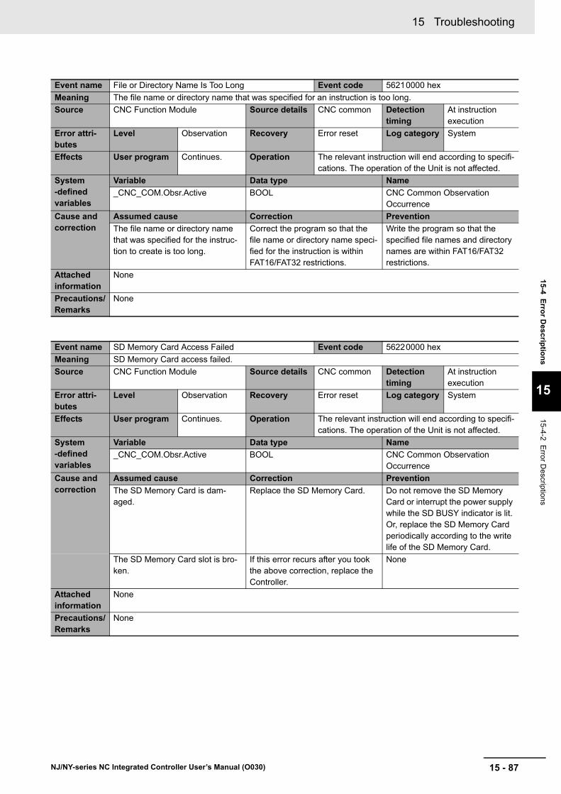
15 - 87
15 Troubleshooting
NJ/NY-series NC Integrated Controller User’s Manual (O030)
15-4 E
rror D
escriptio
ns
15
15-4-2 Error D
escriptions
Event name File or Directory Name Is Too Long Event code 56210000 hex
Meaning The file name or directory name that was specified for an instruction is too long.
Source CNC Function Module Source details CNC common Detection timing
At instruction execution
Error attri-butes
Level Observation Recovery Error reset Log category System
Effects User program Continues. Operation The relevant instruction will end according to specifi-cations. The operation of the Unit is not affected.
System-defined variables
Variable Data type Name
_CNC_COM.Obsr.Active BOOL CNC Common Observation Occurrence
Cause and correction
Assumed cause Correction Prevention
The file name or directory name that was specified for the instruc-tion to create is too long.
Correct the program so that the file name or directory name speci-fied for the instruction is within FAT16/FAT32 restrictions.
Write the program so that the specified file names and directory names are within FAT16/FAT32 restrictions.
Attached information
None
Precautions/Remarks
None
Event name SD Memory Card Access Failed Event code 56220000 hex
Meaning SD Memory Card access failed.
Source CNC Function Module Source details CNC common Detection timing
At instruction execution
Error attri-butes
Level Observation Recovery Error reset Log category System
Effects User program Continues. Operation The relevant instruction will end according to specifi-cations. The operation of the Unit is not affected.
System-defined variables
Variable Data type Name
_CNC_COM.Obsr.Active BOOL CNC Common Observation Occurrence
Cause and correction
Assumed cause Correction Prevention
The SD Memory Card is dam-aged.
Replace the SD Memory Card. Do not remove the SD Memory Card or interrupt the power supply while the SD BUSY indicator is lit. Or, replace the SD Memory Card periodically according to the write life of the SD Memory Card.
The SD Memory Card slot is bro-ken.
If this error recurs after you took the above correction, replace the Controller.
None
Attached information
None
Precautions/Remarks
None

15 Troubleshooting
15 - 88 NJ/NY-series NC Integrated Controller User’s Manual (O030)
Event name Load NC Program Capacity Exceeded Event code 56230000 hex
Meaning Loading failed because an attempt was made to load the NC program over the maximum capacity.
Source CNC Function Module Source details CNC common Detection timing
At instruction execution
Error attri-butes
Level Observation Recovery Error reset Log category System
Effects User program Continues. Operation The relevant instruction will end according to specifi-cations. The operation of the Unit is not affected.
System-defined variables
Variable Data type Name
_CNC_COM.Obsr.Active BOOL CNC Common Observation Occurrence
Cause and correction
Assumed cause Correction Prevention
An attempt was made to load the NC program over the maximum capacity.
Set 1: _cncDelLoadedFile to the DeleteFile input variable for the relevant instruction, and delete the loaded NC program once.
Set 1: _cncDelLoadedFile to the DeleteFile input variable for the relevant instruction when chang-ing the setup so that the NC pro-gram loaded at the same time does not exceed the maximum capacity, and write the program to delete the loaded NC program.
Attached information
None
Precautions/Remarks
None
Event name Number of NC Program Exceeded Event code 56240000 hex
Meaning Loading failed because an attempt was made to load NC programs over the maximum number of NC pro-grams.
Source CNC Function Module Source details CNC common Detection timing
At instruction execution
Error attri-butes
Level Observation Recovery Error reset Log category System
Effects User program Continues. Operation The relevant instruction will end according to specifi-cations. The operation of the Unit is not affected.
System-defined variables
Variable Data type Name
_CNC_COM.Obsr.Active BOOL CNC Common Observation Occurrence
Cause and correction
Assumed cause Correction Prevention
A new NC program was loaded while the number of loaded NC programs reaches the maximum.
Correct the program to reduce the number of NC programs to be loaded.
Write the program so that the pro-gram numbers of unused NC pro-grams are reused to prevent too many NC programs from being loaded.
Attached information
Attached information 1: Row number with error detected (Indicates the row number after parsing process-ing.)
Attached information 2: File name of the NC program with error detected (Last 15 characters when the file name length exceeds 16 characters)
Precautions/Remarks
None
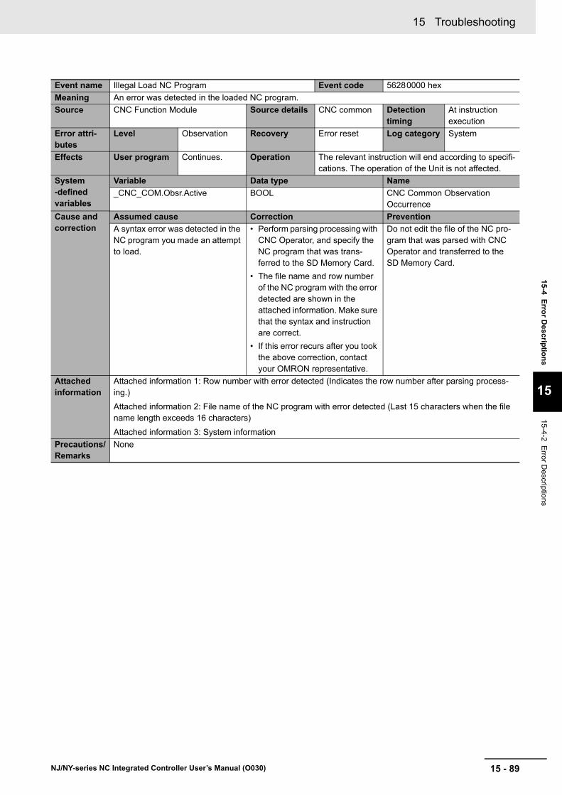
15 - 89
15 Troubleshooting
NJ/NY-series NC Integrated Controller User’s Manual (O030)
15-4 E
rror D
escriptio
ns
15
15-4-2 Error D
escriptions
Event name Illegal Load NC Program Event code 56280000 hex
Meaning An error was detected in the loaded NC program.
Source CNC Function Module Source details CNC common Detection timing
At instruction execution
Error attri-butes
Level Observation Recovery Error reset Log category System
Effects User program Continues. Operation The relevant instruction will end according to specifi-cations. The operation of the Unit is not affected.
System-defined variables
Variable Data type Name
_CNC_COM.Obsr.Active BOOL CNC Common Observation Occurrence
Cause and correction
Assumed cause Correction Prevention
A syntax error was detected in the NC program you made an attempt to load.
• Perform parsing processing with CNC Operator, and specify the NC program that was trans-ferred to the SD Memory Card.
• The file name and row number of the NC program with the error detected are shown in the attached information. Make sure that the syntax and instruction are correct.
• If this error recurs after you took the above correction, contact your OMRON representative.
Do not edit the file of the NC pro-gram that was parsed with CNC Operator and transferred to the SD Memory Card.
Attached information
Attached information 1: Row number with error detected (Indicates the row number after parsing process-ing.)
Attached information 2: File name of the NC program with error detected (Last 15 characters when the file name length exceeds 16 characters)
Attached information 3: System information
Precautions/Remarks
None
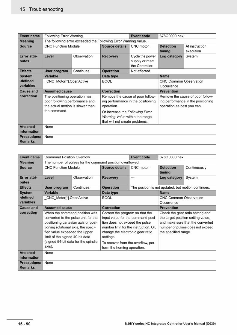
15 Troubleshooting
15 - 90 NJ/NY-series NC Integrated Controller User’s Manual (O030)
Event name Following Error Warning Event code 678C0000 hex
Meaning The following error exceeded the Following Error Warning Value.
Source CNC Function Module Source details CNC motor Detection timing
At instruction execution
Error attri-butes
Level Observation Recovery Cycle the power supply or reset the Controller.
Log category System
Effects User program Continues. Operation Not affected.
System-defined variables
Variable Data type Name
_CNC_Motor[*].Obsr.Active BOOL CNC Common Observation Occurrence
Cause and correction
Assumed cause Correction Prevention
The positioning operation has poor following performance and the actual motion is slower than the command.
Remove the cause of poor follow-ing performance in the positioning operation.
Or increase the Following Error Warning Value within the range that will not create problems.
Remove the cause of poor follow-ing performance in the positioning operation as best you can.
Attached information
None
Precautions/Remarks
None
Event name Command Position Overflow Event code 678D0000 hex
Meaning The number of pulses for the command position overflowed.
Source CNC Function Module Source details CNC motor Detection timing
Continuously
Error attri-butes
Level Observation Recovery --- Log category System
Effects User program Continues. Operation The position is not updated, but motion continues.
System-defined variables
Variable Data type Name
_CNC_Motor[*].Obsr.Active BOOL CNC Common Observation Occurrence
Cause and correction
Assumed cause Correction Prevention
When the command position was converted to the pulse unit for the positioning cartesian axis or posi-tioning rotational axis, the speci-fied value exceeded the upper limit of the signed 40-bit data (signed 54-bit data for the spindle axis).
Correct the program so that the input value for the command posi-tion does not exceed the pulse number limit for the instruction. Or, change the electronic gear ratio settings.
To recover from the overflow, per-form the homing operation.
Check the gear ratio setting and the target position setting value, and make sure that the converted number of pulses does not exceed the specified range.
Attached information
None
Precautions/Remarks
None
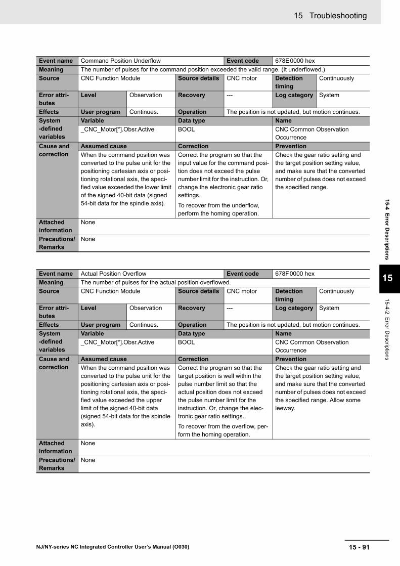
15 - 91
15 Troubleshooting
NJ/NY-series NC Integrated Controller User’s Manual (O030)
15-4 E
rror D
escriptio
ns
15
15-4-2 Error D
escriptions
Event name Command Position Underflow Event code 678E0000 hex
Meaning The number of pulses for the command position exceeded the valid range. (It underflowed.)
Source CNC Function Module Source details CNC motor Detection timing
Continuously
Error attri-butes
Level Observation Recovery --- Log category System
Effects User program Continues. Operation The position is not updated, but motion continues.
System-defined variables
Variable Data type Name
_CNC_Motor[*].Obsr.Active BOOL CNC Common Observation Occurrence
Cause and correction
Assumed cause Correction Prevention
When the command position was converted to the pulse unit for the positioning cartesian axis or posi-tioning rotational axis, the speci-fied value exceeded the lower limit of the signed 40-bit data (signed 54-bit data for the spindle axis).
Correct the program so that the input value for the command posi-tion does not exceed the pulse number limit for the instruction. Or, change the electronic gear ratio settings.
To recover from the underflow, perform the homing operation.
Check the gear ratio setting and the target position setting value, and make sure that the converted number of pulses does not exceed the specified range.
Attached information
None
Precautions/Remarks
None
Event name Actual Position Overflow Event code 678F0000 hex
Meaning The number of pulses for the actual position overflowed.
Source CNC Function Module Source details CNC motor Detection timing
Continuously
Error attri-butes
Level Observation Recovery --- Log category System
Effects User program Continues. Operation The position is not updated, but motion continues.
System-defined variables
Variable Data type Name
_CNC_Motor[*].Obsr.Active BOOL CNC Common Observation Occurrence
Cause and correction
Assumed cause Correction Prevention
When the command position was converted to the pulse unit for the positioning cartesian axis or posi-tioning rotational axis, the speci-fied value exceeded the upper limit of the signed 40-bit data (signed 54-bit data for the spindle axis).
Correct the program so that the target position is well within the pulse number limit so that the actual position does not exceed the pulse number limit for the instruction. Or, change the elec-tronic gear ratio settings.
To recover from the overflow, per-form the homing operation.
Check the gear ratio setting and the target position setting value, and make sure that the converted number of pulses does not exceed the specified range. Allow some leeway.
Attached information
None
Precautions/Remarks
None
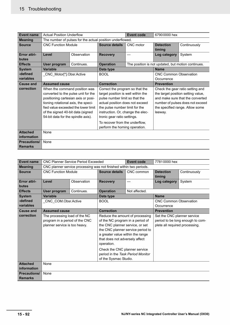
15 Troubleshooting
15 - 92 NJ/NY-series NC Integrated Controller User’s Manual (O030)
Event name Actual Position Underflow Event code 67900000 hex
Meaning The number of pulses for the actual position underflowed.
Source CNC Function Module Source details CNC motor Detection timing
Continuously
Error attri-butes
Level Observation Recovery --- Log category System
Effects User program Continues. Operation The position is not updated, but motion continues.
System-defined variables
Variable Data type Name
_CNC_Motor[*].Obsr.Active BOOL CNC Common Observation Occurrence
Cause and correction
Assumed cause Correction Prevention
When the command position was converted to the pulse unit for the positioning cartesian axis or posi-tioning rotational axis, the speci-fied value exceeded the lower limit of the signed 40-bit data (signed 54-bit data for the spindle axis).
Correct the program so that the target position is well within the pulse number limit so that the actual position does not exceed the pulse number limit for the instruction. Or, change the elec-tronic gear ratio settings.
To recover from the underflow, perform the homing operation.
Check the gear ratio setting and the target position setting value, and make sure that the converted number of pulses does not exceed the specified range. Allow some leeway.
Attached information
None
Precautions/Remarks
None
Event name CNC Planner Service Period Exceeded Event code 77810000 hex
Meaning CNC planner service processing was not finished within two periods.
Source CNC Function Module Source details CNC common Detection timing
Continuously
Error attri-butes
Level Observation Recovery --- Log category System
Effects User program Continues. Operation Not affected.
System-defined variables
Variable Data type Name
_CNC_COM.Obsr.Active BOOL CNC Common Observation Occurrence
Cause and correction
Assumed cause Correction Prevention
The processing load of the NC program in a period of the CNC planner service is too heavy.
Reduce the amount of processing of the NC program in a period of the CNC planner service, or set the CNC planner service period to a greater value within the range that does not adversely affect operation.
Check the CNC planner service period in the Task Period Monitor of the Sysmac Studio.
Set the CNC planner service period to be long enough to com-plete all required processing.
Attached information
None
Precautions/Remarks
None
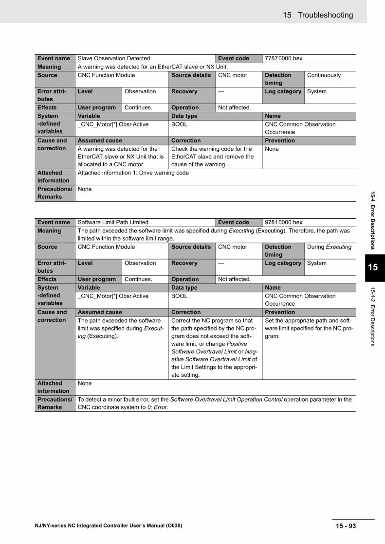
15 - 93
15 Troubleshooting
NJ/NY-series NC Integrated Controller User’s Manual (O030)
15-4 E
rror D
escriptio
ns
15
15-4-2 Error D
escriptions
Event name Slave Observation Detected Event code 77870000 hex
Meaning A warning was detected for an EtherCAT slave or NX Unit.
Source CNC Function Module Source details CNC motor Detection timing
Continuously
Error attri-butes
Level Observation Recovery --- Log category System
Effects User program Continues. Operation Not affected.
System-defined variables
Variable Data type Name
_CNC_Motor[*].Obsr.Active BOOL CNC Common Observation Occurrence
Cause and correction
Assumed cause Correction Prevention
A warning was detected for the EtherCAT slave or NX Unit that is allocated to a CNC motor.
Check the warning code for the EtherCAT slave and remove the cause of the warning.
None
Attached information
Attached information 1: Drive warning code
Precautions/Remarks
None
Event name Software Limit Path Limited Event code 97810000 hex
Meaning The path exceeded the software limit was specified during Executing (Executing). Therefore, the path was limited within the software limit range.
Source CNC Function Module Source details CNC motor Detection timing
During Executing
Error attri-butes
Level Observation Recovery --- Log category System
Effects User program Continues. Operation Not affected.
System-defined variables
Variable Data type Name
_CNC_Motor[*].Obsr.Active BOOL CNC Common Observation Occurrence
Cause and correction
Assumed cause Correction Prevention
The path exceeded the software limit was specified during Execut-ing (Executing).
Correct the NC program so that the path specified by the NC pro-gram does not exceed the soft-ware limit, or change Positive Software Overtravel Limit or Neg-ative Software Overtravel Limit of the Limit Settings to the appropri-ate setting.
Set the appropriate path and soft-ware limit specified for the NC pro-gram.
Attached information
None
Precautions/Remarks
To detect a minor fault error, set the Software Overtravel Limit Operation Control operation parameter in the CNC coordinate system to 0: Error.

15 Troubleshooting
15 - 94 NJ/NY-series NC Integrated Controller User’s Manual (O030)
Event name Velocity Control Command Value Saturated Event code 97830000 hex
Meaning The velocity control command value for the servo drive is saturated.
Source CNC Function Module Source details CNC motor Detection timing
Whenever Servo is ON
Error attri-butes
Level Observation Recovery --- Log category System
Effects User program Continues. Operation Not affected.
System-defined variables
Variable Data type Name
_CNC_Motor[*].Obsr.Active BOOL CNC Common Observation Occurrence
Cause and correction
Assumed cause Correction Prevention
The output value for Feedback loop calculation exceeded the Maximum Velocity for the CNC motor parameter setting, or the positioning operation has poor fol-lowing performance and the actual motion is slower than the com-mand.
Remove the cause of poor follow-ing performance in the positioning operation.
Remove the cause of poor follow-ing performance in the positioning operation as best you can.
The commanded master axis rota-tion rate (S) or master axis veloc-ity override factor exceeded the Maximum Velocity for the CNC motor parameter setting.
Check the command value of the master axis rotation rate (S) and the master axis velocity override factor, and correct the program so that the value does not exceed the Maximum Velocity for the CNC motor parameter setting.
Check to see if any of the condi-tions that are given as causes exist in advance.
Attached information
None
Precautions/Remarks
None

15 - 95
15 Troubleshooting
NJ/NY-series NC Integrated Controller User’s Manual (O030)
15-4 E
rror D
escriptio
ns
15
15-4-2 Error D
escriptions
Event name Slave Error Code Report Event code 97800000 hex
Meaning The error code was reported by the slave when a Slave Error Detected error occurred.
Source CNC Function Module Source details CNC motor Detection timing
After Slave Error Detected error (77860000 hex)
Error attri-butes
Level Information Recovery --- Log category System
Effects User program Continues. Operation Not affected.
System-defined variables
Variable Data type Name
None --- ---
Cause and correction
Assumed cause Correction Prevention
The error code was reported by the slave when a Slave Error Detected error (77860000 hex) occurred.
This error accompanies a Slave Error Detected error (77860000 hex). Check the slave error code in the attached information and make the required corrections.
None
Attached information
Attached information 1: Slave error code
Precautions/Remarks
For the OMRON 1S-series Servo Drive or G5-series Servo Drive, the error code (the main part of the error display number) from the Servo Drive is included in the lower two digits of the attached information.
For example, if the attached information is displayed as FF13, the error with display number 13 (Main Circuit Power Supply Undervoltage) occurred in the Servo Drive.
Event name CNC Function System Information Event code 97820000 hex
Meaning This event provides internal information from the CNC Function Module.
Source CNC Function Module Source details CNC common Detection timing
Continuously
Error attri-butes
Level Information Recovery --- Log category System
Effects User program Continues. Operation Not affected.
System-defined variables
Variable Data type Name
None --- ---
Cause and correction
Assumed cause Correction Prevention
This event provides internal infor-mation from the CNC Function Module. It is recorded to provide additional information for another event.
None None
Attached information
Attached information 1: System information
Attached information 2: System information
Attached information 3: System information
Attached information 4: System information
Precautions/Remarks
None
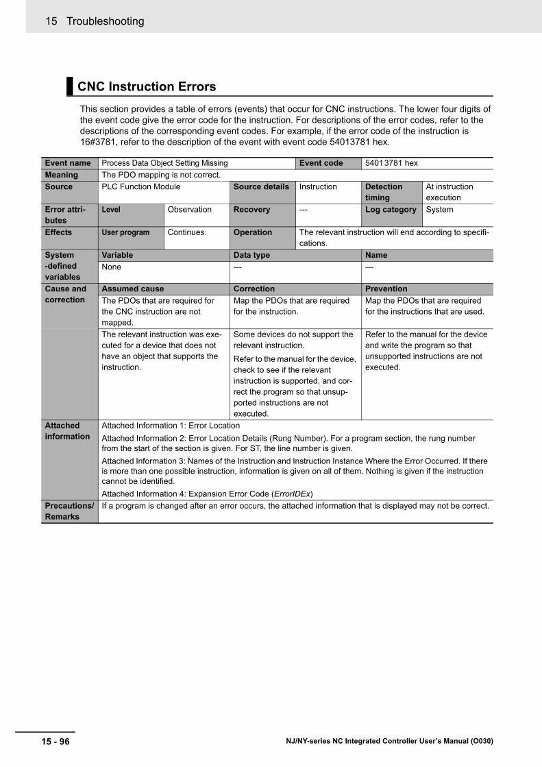
15 Troubleshooting
15 - 96 NJ/NY-series NC Integrated Controller User’s Manual (O030)
This section provides a table of errors (events) that occur for CNC instructions. The lower four digits of the event code give the error code for the instruction. For descriptions of the error codes, refer to the descriptions of the corresponding event codes. For example, if the error code of the instruction is 16#3781, refer to the description of the event with event code 54013781 hex.
CNC Instruction Errors
Event name Process Data Object Setting Missing Event code 54013781 hex
Meaning The PDO mapping is not correct.
Source PLC Function Module Source details Instruction Detection timing
At instruction execution
Error attri-butes
Level Observation Recovery --- Log category System
Effects User program Continues. Operation The relevant instruction will end according to specifi-cations.
System-defined variables
Variable Data type Name
None --- ---
Cause and correction
Assumed cause Correction Prevention
The PDOs that are required for the CNC instruction are not mapped.
Map the PDOs that are required for the instruction.
Map the PDOs that are required for the instructions that are used.
The relevant instruction was exe-cuted for a device that does not have an object that supports the instruction.
Some devices do not support the relevant instruction.
Refer to the manual for the device, check to see if the relevant instruction is supported, and cor-rect the program so that unsup-ported instructions are not executed.
Refer to the manual for the device and write the program so that unsupported instructions are not executed.
Attached information
Attached Information 1: Error Location
Attached Information 2: Error Location Details (Rung Number). For a program section, the rung number from the start of the section is given. For ST, the line number is given.
Attached Information 3: Names of the Instruction and Instruction Instance Where the Error Occurred. If there is more than one possible instruction, information is given on all of them. Nothing is given if the instruction cannot be identified.
Attached Information 4: Expansion Error Code (ErrorIDEx)
Precautions/Remarks
If a program is changed after an error occurs, the attached information that is displayed may not be correct.

15 - 97
15 Troubleshooting
NJ/NY-series NC Integrated Controller User’s Manual (O030)
15-4 E
rror D
escriptio
ns
15
15-4-2 Error D
escriptions
Event name Illegal CNC Coordinate System Specification Event code 54015600 hex
Meaning The CNC coordinate system specified for the Coord in-out variable to a CNC instruction does not exist.
Source PLC Function Module Source details Instruction Detection timing
At instruction execution
Error attri-butes
Level Observation Recovery --- Log category System
Effects User program Continues. Operation The relevant instruction will end according to specifi-cations.
System-defined variables
Variable Data type Name
None --- ---
Cause and correction
Assumed cause Correction Prevention
CNC coordinate system does not exist for the variable specified for the Coord in-out variable to the instruction.
Correct the instruction so that the variable exists for the CNC coordi-nate system that was specified for the instruction.
Specify a variable that exists when specifying a variable for an input parameter to an instruction.
Attached information
Attached Information 1: Error Location
Attached Information 2: Error Location Details (Rung Number). For a program section, the rung number from the start of the section is given. For ST, the line number is given.
Attached Information 3: Names of the Instruction and Instruction Instance Where the Error Occurred. If there is more than one possible instruction, information is given on all of them. Nothing is given if the instruction cannot be identified.
Attached Information 4: Expansion Error Code (ErrorIDEx)
Precautions/Remarks
If a program is changed after an error occurs, the attached information that is displayed may not be correct.
Event name Deceleration Setting Out of Range Event code 54015601 hex
Meaning The parameter specified for the Deceleration input variable to a CNC instruction is out of range.
Source PLC Function Module Source details Instruction Detection timing
At instruction execution
Error attri-butes
Level Observation Recovery --- Log category System
Effects User program Continues. Operation The relevant instruction will end according to specifi-cations.
System-defined variables
Variable Data type Name
None --- ---
Cause and correction
Assumed cause Correction Prevention
Instruction input parameter exceeded the valid range of the input variable.
Correct the parameter so that the valid range of the input variable is not exceeded for the relevant instruction.
Set the input parameter to the instruction so that the valid range of the input variable is not exceeded.
Attached information
Attached Information 1: Error Location
Attached Information 2: Error Location Details (Rung Number). For a program section, the rung number from the start of the section is given. For ST, the line number is given.
Attached Information 3: Names of the Instruction and Instruction Instance Where the Error Occurred. If there is more than one possible instruction, information is given on all of them. Nothing is given if the instruction cannot be identified.
Attached Information 4: Expansion Error Code (ErrorIDEx)
Precautions/Remarks
If a program is changed after an error occurs, the attached information that is displayed may not be correct.
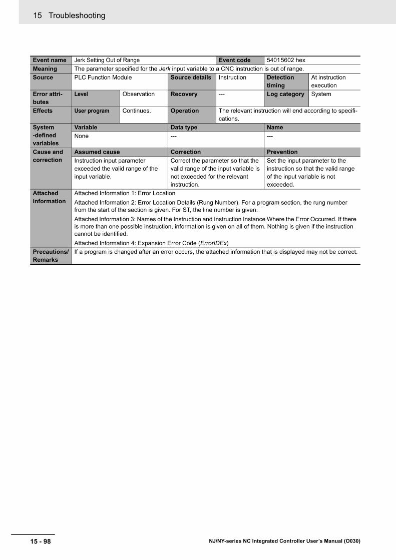
15 Troubleshooting
15 - 98 NJ/NY-series NC Integrated Controller User’s Manual (O030)
Event name Jerk Setting Out of Range Event code 54015602 hex
Meaning The parameter specified for the Jerk input variable to a CNC instruction is out of range.
Source PLC Function Module Source details Instruction Detection timing
At instruction execution
Error attri-butes
Level Observation Recovery --- Log category System
Effects User program Continues. Operation The relevant instruction will end according to specifi-cations.
System-defined variables
Variable Data type Name
None --- ---
Cause and correction
Assumed cause Correction Prevention
Instruction input parameter exceeded the valid range of the input variable.
Correct the parameter so that the valid range of the input variable is not exceeded for the relevant instruction.
Set the input parameter to the instruction so that the valid range of the input variable is not exceeded.
Attached information
Attached Information 1: Error Location
Attached Information 2: Error Location Details (Rung Number). For a program section, the rung number from the start of the section is given. For ST, the line number is given.
Attached Information 3: Names of the Instruction and Instruction Instance Where the Error Occurred. If there is more than one possible instruction, information is given on all of them. Nothing is given if the instruction cannot be identified.
Attached Information 4: Expansion Error Code (ErrorIDEx)
Precautions/Remarks
If a program is changed after an error occurs, the attached information that is displayed may not be correct.
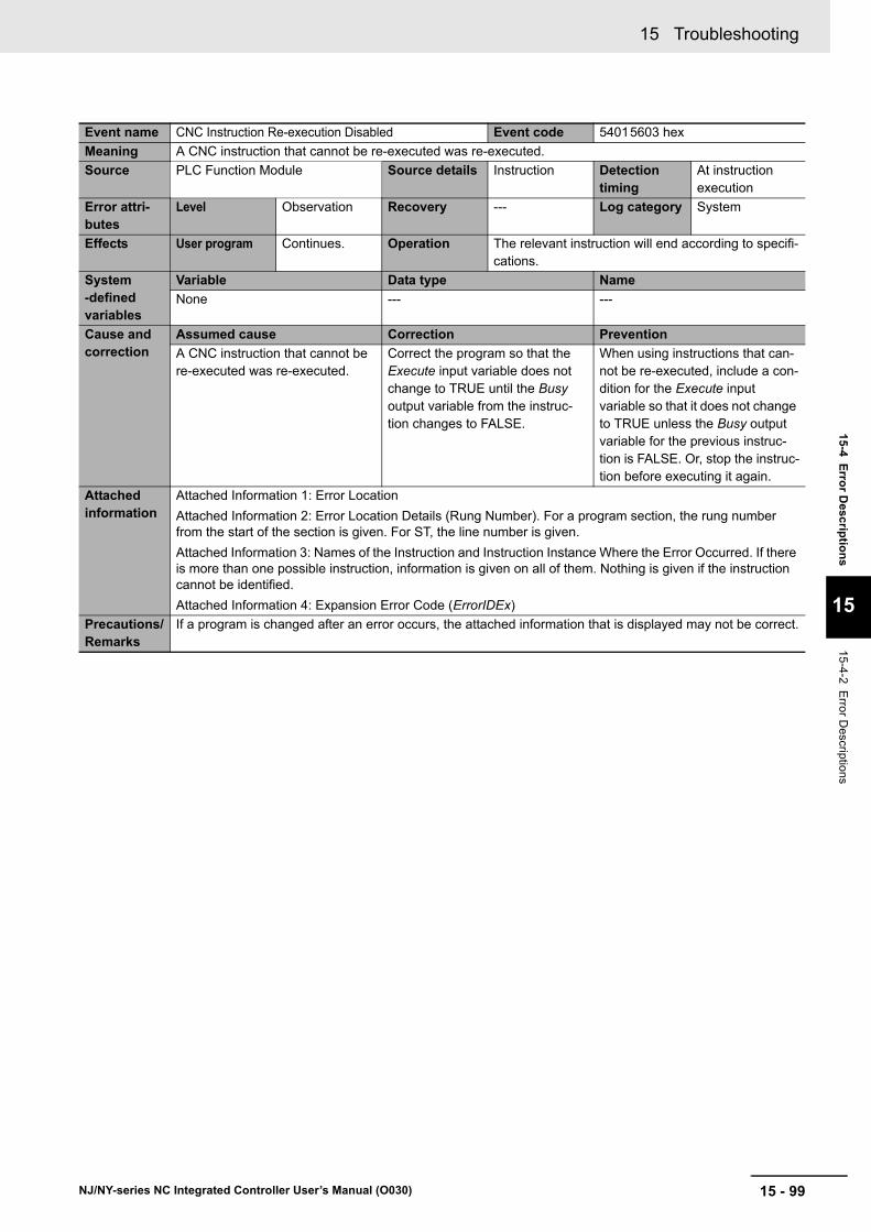
15 - 99
15 Troubleshooting
NJ/NY-series NC Integrated Controller User’s Manual (O030)
15-4 E
rror D
escriptio
ns
15
15-4-2 Error D
escriptions
Event name CNC Instruction Re-execution Disabled Event code 54015603 hex
Meaning A CNC instruction that cannot be re-executed was re-executed.
Source PLC Function Module Source details Instruction Detection timing
At instruction execution
Error attri-butes
Level Observation Recovery --- Log category System
Effects User program Continues. Operation The relevant instruction will end according to specifi-cations.
System-defined variables
Variable Data type Name
None --- ---
Cause and correction
Assumed cause Correction Prevention
A CNC instruction that cannot be re-executed was re-executed.
Correct the program so that the Execute input variable does not change to TRUE until the Busy output variable from the instruc-tion changes to FALSE.
When using instructions that can-not be re-executed, include a con-dition for the Execute input variable so that it does not change to TRUE unless the Busy output variable for the previous instruc-tion is FALSE. Or, stop the instruc-tion before executing it again.
Attached information
Attached Information 1: Error Location
Attached Information 2: Error Location Details (Rung Number). For a program section, the rung number from the start of the section is given. For ST, the line number is given.
Attached Information 3: Names of the Instruction and Instruction Instance Where the Error Occurred. If there is more than one possible instruction, information is given on all of them. Nothing is given if the instruction cannot be identified.
Attached Information 4: Expansion Error Code (ErrorIDEx)
Precautions/Remarks
If a program is changed after an error occurs, the attached information that is displayed may not be correct.

15 Troubleshooting
15 - 100 NJ/NY-series NC Integrated Controller User’s Manual (O030)
Event name CNC Multi-execution Disabled Event code 54015604 hex
Meaning Multiple functions that cannot be executed simultaneously were executed for the same target (CNC coordi-nate system).
Source PLC Function Module Source details Instruction Detection timing
At instruction execution
Error attri-butes
Level Observation Recovery --- Log category System
Effects User program Continues. Operation The relevant instruction will end according to specifi-cations.
System-defined variables
Variable Data type Name
None --- ---
Cause and correction
Assumed cause Correction Prevention
• Multiple functions that cannot be executed simultaneously were executed for the same target (CNC coordinate system).
• The CNC_LoadProgramFile instruction was executed when any of CNC coordinate system was Executing (Executing) or Hold (Holding).
Check the specifications of multi-execution of instructions for this instruction and correct the pro-gram so that instructions that can-not be executed at the same time are not executed simultaneously.
Check the specifications for multi-execution of instructions for the instruction and do not execute instructions that cannot be exe-cuted at the same time.
Attached information
Attached Information 1: Error Location
Attached Information 2: Error Location Details (Rung Number). For a program section, the rung number from the start of the section is given. For ST, the line number is given.
Attached Information 3: Names of the Instruction and Instruction Instance Where the Error Occurred. If there is more than one possible instruction, information is given on all of them. Nothing is given if the instruction cannot be identified.
Attached Information 4: Expansion Error Code (ErrorIDEx)
Precautions/Remarks
If a program is changed after an error occurs, the attached information that is displayed may not be correct.
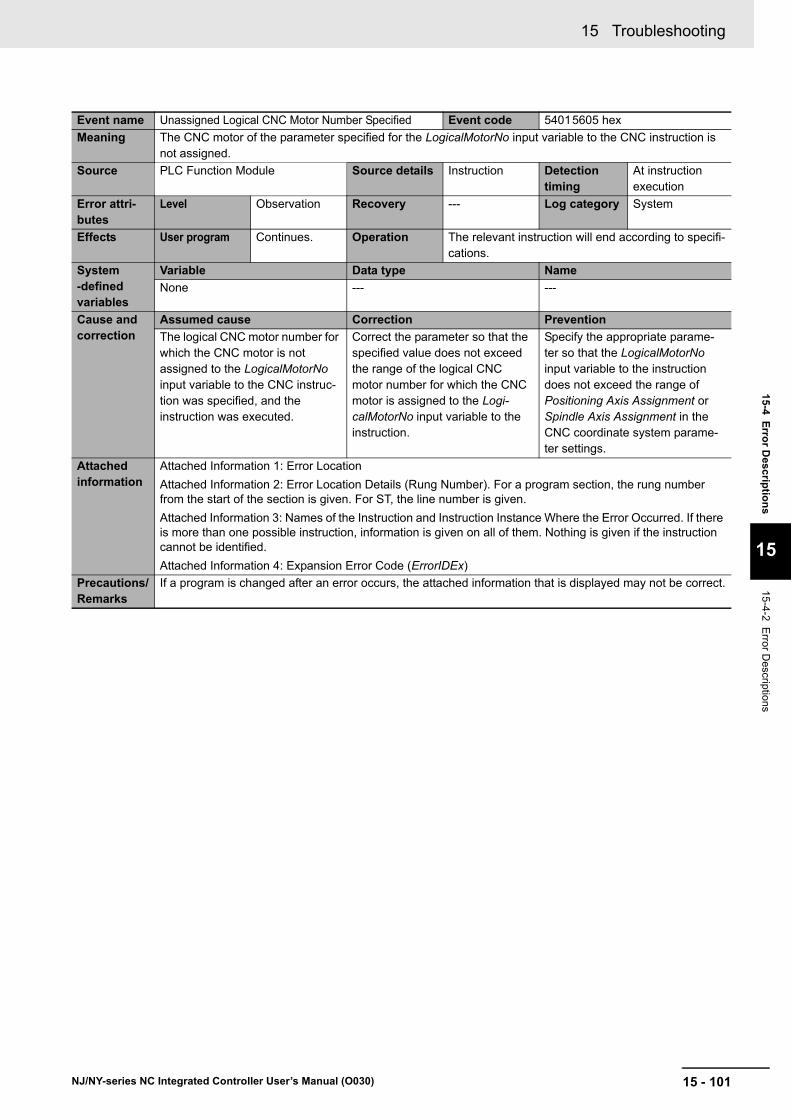
15 - 101
15 Troubleshooting
NJ/NY-series NC Integrated Controller User’s Manual (O030)
15-4 E
rror D
escriptio
ns
15
15-4-2 Error D
escriptions
Event name Unassigned Logical CNC Motor Number Specified Event code 54015605 hex
Meaning The CNC motor of the parameter specified for the LogicalMotorNo input variable to the CNC instruction is not assigned.
Source PLC Function Module Source details Instruction Detection timing
At instruction execution
Error attri-butes
Level Observation Recovery --- Log category System
Effects User program Continues. Operation The relevant instruction will end according to specifi-cations.
System-defined variables
Variable Data type Name
None --- ---
Cause and correction
Assumed cause Correction Prevention
The logical CNC motor number for which the CNC motor is not assigned to the LogicalMotorNo input variable to the CNC instruc-tion was specified, and the instruction was executed.
Correct the parameter so that the specified value does not exceed the range of the logical CNC motor number for which the CNC motor is assigned to the Logi-calMotorNo input variable to the instruction.
Specify the appropriate parame-ter so that the LogicalMotorNo input variable to the instruction does not exceed the range of Positioning Axis Assignment or Spindle Axis Assignment in the CNC coordinate system parame-ter settings.
Attached information
Attached Information 1: Error Location
Attached Information 2: Error Location Details (Rung Number). For a program section, the rung number from the start of the section is given. For ST, the line number is given.
Attached Information 3: Names of the Instruction and Instruction Instance Where the Error Occurred. If there is more than one possible instruction, information is given on all of them. Nothing is given if the instruction cannot be identified.
Attached Information 4: Expansion Error Code (ErrorIDEx)
Precautions/Remarks
If a program is changed after an error occurs, the attached information that is displayed may not be correct.

15 Troubleshooting
15 - 102 NJ/NY-series NC Integrated Controller User’s Manual (O030)
Event name Logical CNC Motor Number Out of Range Event code 54015606 hex
Meaning The parameter specified for the LogicalMotorNo input variable to a CNC instruction is out of range.
Source PLC Function Module Source details Instruction Detection timing
At instruction execution
Error attri-butes
Level Observation Recovery --- Log category System
Effects User program Continues. Operation The relevant instruction will end according to specifi-cations.
System-defined variables
Variable Data type Name
None --- ---
Cause and correction
Assumed cause Correction Prevention
Instruction input parameter exceeded the valid range of the input variable.
Correct the parameter so that the valid range of the input variable is not exceeded for the relevant instruction.
Set the input parameter to the instruction so that the valid range of the input variable is not exceeded.
Attached information
Attached Information 1: Error Location
Attached Information 2: Error Location Details (Rung Number). For a program section, the rung number from the start of the section is given. For ST, the line number is given.
Attached Information 3: Names of the Instruction and Instruction Instance Where the Error Occurred. If there is more than one possible instruction, information is given on all of them. Nothing is given if the instruction cannot be identified.
Attached Information 4: Expansion Error Code (ErrorIDEx)
Precautions/Remarks
If a program is changed after an error occurs, the attached information that is displayed may not be correct.
Event name Target Position Setting Out of Range Event code 54015607 hex
Meaning The parameter specified for the Position input variable to a CNC instruction is out of range.
Source PLC Function Module Source details Instruction Detection timing
At instruction execution
Error attri-butes
Level Observation Recovery --- Log category System
Effects User program Continues. Operation The relevant instruction will end according to specifi-cations.
System-defined variables
Variable Data type Name
None --- ---
Cause and correction
Assumed cause Correction Prevention
Instruction input parameter exceeded the valid range of the input variable. Or, there was an overflow/underflow in the target position.
Correct the parameter so that the valid range of the input variable is not exceeded for the relevant instruction.
Set the input parameter to the instruction so that the valid range of the input variable is not exceeded.
Attached information
Attached Information 1: Error Location
Attached Information 2: Error Location Details (Rung Number). For a program section, the rung number from the start of the section is given. For ST, the line number is given.
Attached Information 3: Names of the Instruction and Instruction Instance Where the Error Occurred. If there is more than one possible instruction, information is given on all of them. Nothing is given if the instruction cannot be identified.
Attached Information 4: Expansion Error Code (ErrorIDEx)
Precautions/Remarks
If a program is changed after an error occurs, the attached information that is displayed may not be correct.
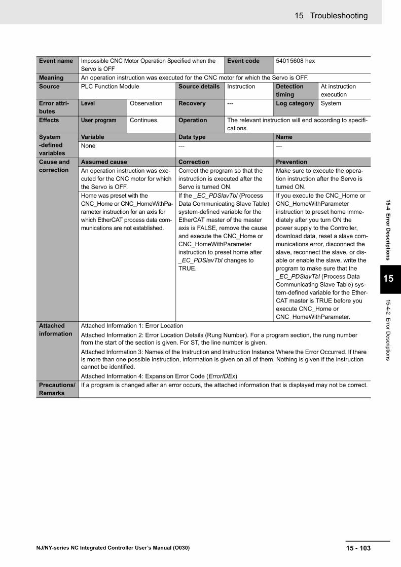
15 - 103
15 Troubleshooting
NJ/NY-series NC Integrated Controller User’s Manual (O030)
15-4 E
rror D
escriptio
ns
15
15-4-2 Error D
escriptions
Event name Impossible CNC Motor Operation Specified when the Servo is OFF
Event code 54015608 hex
Meaning An operation instruction was executed for the CNC motor for which the Servo is OFF.
Source PLC Function Module Source details Instruction Detection timing
At instruction execution
Error attri-butes
Level Observation Recovery --- Log category System
Effects User program Continues. Operation The relevant instruction will end according to specifi-cations.
System-defined variables
Variable Data type Name
None --- ---
Cause and correction
Assumed cause Correction Prevention
An operation instruction was exe-cuted for the CNC motor for which the Servo is OFF.
Correct the program so that the instruction is executed after the Servo is turned ON.
Make sure to execute the opera-tion instruction after the Servo is turned ON.
Home was preset with the CNC_Home or CNC_HomeWithPa-rameter instruction for an axis for which EtherCAT process data com-munications are not established.
If the _EC_PDSlavTbl (Process Data Communicating Slave Table) system-defined variable for the EtherCAT master of the master axis is FALSE, remove the cause and execute the CNC_Home or CNC_HomeWithParameter instruction to preset home after _EC_PDSlavTbl changes to TRUE.
If you execute the CNC_Home or CNC_HomeWithParameter instruction to preset home imme-diately after you turn ON the power supply to the Controller, download data, reset a slave com-munications error, disconnect the slave, reconnect the slave, or dis-able or enable the slave, write the program to make sure that the _EC_PDSlavTbl (Process Data Communicating Slave Table) sys-tem-defined variable for the Ether-CAT master is TRUE before you execute CNC_Home or CNC_HomeWithParameter.
Attached information
Attached Information 1: Error Location
Attached Information 2: Error Location Details (Rung Number). For a program section, the rung number from the start of the section is given. For ST, the line number is given.
Attached Information 3: Names of the Instruction and Instruction Instance Where the Error Occurred. If there is more than one possible instruction, information is given on all of them. Nothing is given if the instruction cannot be identified.
Attached Information 4: Expansion Error Code (ErrorIDEx)
Precautions/Remarks
If a program is changed after an error occurs, the attached information that is displayed may not be correct.
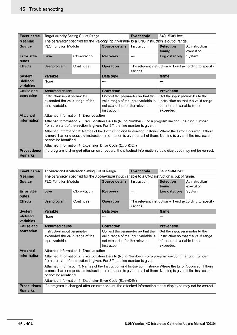
15 Troubleshooting
15 - 104 NJ/NY-series NC Integrated Controller User’s Manual (O030)
Event name Target Velocity Setting Out of Range Event code 54015609 hex
Meaning The parameter specified for the Velocity input variable to a CNC instruction is out of range.
Source PLC Function Module Source details Instruction Detection timing
At instruction execution
Error attri-butes
Level Observation Recovery --- Log category System
Effects User program Continues. Operation The relevant instruction will end according to specifi-cations.
System-defined variables
Variable Data type Name
None --- ---
Cause and correction
Assumed cause Correction Prevention
Instruction input parameter exceeded the valid range of the input variable.
Correct the parameter so that the valid range of the input variable is not exceeded for the relevant instruction.
Set the input parameter to the instruction so that the valid range of the input variable is not exceeded.
Attached information
Attached Information 1: Error Location
Attached Information 2: Error Location Details (Rung Number). For a program section, the rung number from the start of the section is given. For ST, the line number is given.
Attached Information 3: Names of the Instruction and Instruction Instance Where the Error Occurred. If there is more than one possible instruction, information is given on all of them. Nothing is given if the instruction cannot be identified.
Attached Information 4: Expansion Error Code (ErrorIDEx)
Precautions/Remarks
If a program is changed after an error occurs, the attached information that is displayed may not be correct.
Event name Acceleration/Deceleration Setting Out of Range Event code 5401560A hex
Meaning The parameter specified for the Acceleration input variable to a CNC instruction is out of range.
Source PLC Function Module Source details Instruction Detection timing
At instruction execution
Error attri-butes
Level Observation Recovery --- Log category System
Effects User program Continues. Operation The relevant instruction will end according to specifi-cations.
System-defined variables
Variable Data type Name
None --- ---
Cause and correction
Assumed cause Correction Prevention
Instruction input parameter exceeded the valid range of the input variable.
Correct the parameter so that the valid range of the input variable is not exceeded for the relevant instruction.
Set the input parameter to the instruction so that the valid range of the input variable is not exceeded.
Attached information
Attached Information 1: Error Location
Attached Information 2: Error Location Details (Rung Number). For a program section, the rung number from the start of the section is given. For ST, the line number is given.
Attached Information 3: Names of the Instruction and Instruction Instance Where the Error Occurred. If there is more than one possible instruction, information is given on all of them. Nothing is given if the instruction cannot be identified.
Attached Information 4: Expansion Error Code (ErrorIDEx)
Precautions/Remarks
If a program is changed after an error occurs, the attached information that is displayed may not be correct.

15 - 105
15 Troubleshooting
NJ/NY-series NC Integrated Controller User’s Manual (O030)
15-4 E
rror D
escriptio
ns
15
15-4-2 Error D
escriptions
Event name Travel Mode Selection Out of Range Event code 5401560B hex
Meaning The parameter specified for the MoveMode input variable to a CNC instruction is out of range.
Source PLC Function Module Source details Instruction Detection timing
At instruction execution
Error attri-butes
Level Observation Recovery --- Log category System
Effects User program Continues. Operation The relevant instruction will end according to specifi-cations.
System-defined variables
Variable Data type Name
None --- ---
Cause and correction
Assumed cause Correction Prevention
Instruction input parameter exceeded the valid range of the input variable.
Correct the parameter so that the valid range of the input variable is not exceeded for the relevant instruction.
Set the input parameter to the instruction so that the valid range of the input variable is not exceeded.
Attached information
Attached Information 1: Error Location
Attached Information 2: Error Location Details (Rung Number). For a program section, the rung number from the start of the section is given. For ST, the line number is given.
Attached Information 3: Names of the Instruction and Instruction Instance Where the Error Occurred. If there is more than one possible instruction, information is given on all of them. Nothing is given if the instruction cannot be identified.
Attached Information 4: Expansion Error Code (ErrorIDEx)
Precautions/Remarks
If a program is changed after an error occurs, the attached information that is displayed may not be correct.
Event name Parameter Selection Out of Range Event code 5401560D hex
Meaning The parameter specified for the ParameterNumber input variable to a CNC instruction is out of range.
Source PLC Function Module Source details Instruction Detection timing
At instruction execution
Error attri-butes
Level Observation Recovery --- Log category System
Effects User program Continues. Operation The relevant instruction will end according to specifi-cations.
System-defined variables
Variable Data type Name
None --- ---
Cause and correction
Assumed cause Correction Prevention
Instruction input parameter exceeded the valid range of the input variable.
Correct the parameter so that the valid range of the input variable is not exceeded for the relevant instruction.
Set the input parameter to the instruction so that the valid range of the input variable is not exceeded.
Attached information
Attached Information 1: Error Location
Attached Information 2: Error Location Details (Rung Number). For a program section, the rung number from the start of the section is given. For ST, the line number is given.
Attached Information 3: Names of the Instruction and Instruction Instance Where the Error Occurred. If there is more than one possible instruction, information is given on all of them. Nothing is given if the instruction cannot be identified.
Attached Information 4: Expansion Error Code (ErrorIDEx)
Precautions/Remarks
If a program is changed after an error occurs, the attached information that is displayed may not be correct.

15 Troubleshooting
15 - 106 NJ/NY-series NC Integrated Controller User’s Manual (O030)
Event name CNC Parameter Setting Read/Write Setting Value Out of Range
Event code 5401560E hex
Meaning The parameter specified for the SettingValue in-out variable to a CNC instruction is out of range.
Source PLC Function Module Source details Instruction Detection timing
At instruction execution
Error attri-butes
Level Observation Recovery --- Log category System
Effects User program Continues. Operation The relevant instruction will end according to specifi-cations.
System-defined variables
Variable Data type Name
None --- ---
Cause and correction
Assumed cause Correction Prevention
Instruction input parameter exceeded the valid range of the in-out variable.
Correct the parameter so that the valid range of the in-out variable is not exceeded for the relevant instruction.
Set the input parameter to the instruction so that the valid range of the in-out variable is not exceeded.
Attached information
Attached Information 1: Error Location
Attached Information 2: Error Location Details (Rung Number). For a program section, the rung number from the start of the section is given. For ST, the line number is given.
Attached Information 3: Names of the Instruction and Instruction Instance Where the Error Occurred. If there is more than one possible instruction, information is given on all of them. Nothing is given if the instruction cannot be identified.
Attached Information 4: Expansion Error Code (ErrorIDEx)
Precautions/Remarks
If a program is changed after an error occurs, the attached information that is displayed may not be correct.
Event name CNC Parameter Setting Read/Write Target Out of Range
Event code 5401560F hex
Meaning The parameter specified for the Target in-out variable to a CNC instruction is out of range.
Source PLC Function Module Source details Instruction Detection timing
At instruction execution
Error attri-butes
Level Observation Recovery --- Log category System
Effects User program Continues. Operation The relevant instruction will end according to specifi-cations.
System-defined variables
Variable Data type Name
None --- ---
Cause and correction
Assumed cause Correction Prevention
Instruction input parameter exceeded the valid range of the in-out variable.
Correct the parameter so that the valid range of the in-out variable is not exceeded for the relevant instruction.
Set the input parameter to the instruction so that the valid range of the in-out variable is not exceeded.
Attached information
Attached Information 1: Error Location
Attached Information 2: Error Location Details (Rung Number). For a program section, the rung number from the start of the section is given. For ST, the line number is given.
Attached Information 3: Names of the Instruction and Instruction Instance Where the Error Occurred. If there is more than one possible instruction, information is given on all of them. Nothing is given if the instruction cannot be identified.
Attached Information 4: Expansion Error Code (ErrorIDEx)
Precautions/Remarks
If a program is changed after an error occurs, the attached information that is displayed may not be correct.

15 - 107
15 Troubleshooting
NJ/NY-series NC Integrated Controller User’s Manual (O030)
15-4 E
rror D
escriptio
ns
15
15-4-2 Error D
escriptions
Event name Homing Parameter Setting Out of Range Event code 54015611 hex
Meaning The parameter specified for the HomingParameter in-out variable to a CNC instruction is out of range.
Source PLC Function Module Source details Instruction Detection timing
At instruction execution
Error attri-butes
Level Observation Recovery --- Log category System
Effects User program Continues. Operation The relevant instruction will end according to specifi-cations.
System-defined variables
Variable Data type Name
None --- ---
Cause and correction
Assumed cause Correction Prevention
Instruction input parameter exceeded the valid range of the in-out variable.
Correct the parameter so that the valid range of the in-out variable is not exceeded for the relevant instruction.
Set the input parameter to the instruction so that the valid range of the in-out variable is not exceeded.
Attached information
Attached Information 1: Error Location
Attached Information 2: Error Location Details (Rung Number). For a program section, the rung number from the start of the section is given. For ST, the line number is given.
Attached Information 3: Names of the Instruction and Instruction Instance Where the Error Occurred. If there is more than one possible instruction, information is given on all of them. Nothing is given if the instruction cannot be identified.
Attached Information 4: Expansion Error Code (ErrorIDEx)
Precautions/Remarks
If a program is changed after an error occurs, the attached information that is displayed may not be correct.
Event name M Code Number Out of Range Event code 54015612 hex
Meaning The parameter specified for the MCodeNo input variable to a CNC instruction is out of range.
Source PLC Function Module Source details Instruction Detection timing
At instruction execution
Error attri-butes
Level Observation Recovery --- Log category System
Effects User program Continues. Operation The relevant instruction will end according to specifi-cations.
System-defined variables
Variable Data type Name
None --- ---
Cause and correction
Assumed cause Correction Prevention
Instruction input parameter exceeded the valid range of the input variable.
Correct the parameter so that the valid range of the input variable is not exceeded for the relevant instruction.
Set the input parameter to the instruction so that the valid range of the input variable is not exceeded.
Attached information
Attached Information 1: Error Location
Attached Information 2: Error Location Details (Rung Number). For a program section, the rung number from the start of the section is given. For ST, the line number is given.
Attached Information 3: Names of the Instruction and Instruction Instance Where the Error Occurred. If there is more than one possible instruction, information is given on all of them. Nothing is given if the instruction cannot be identified.
Attached Information 4: Expansion Error Code (ErrorIDEx)
Precautions/Remarks
If a program is changed after an error occurs, the attached information that is displayed may not be correct.

15 Troubleshooting
15 - 108 NJ/NY-series NC Integrated Controller User’s Manual (O030)
Event name CNC Instruction Re-execution Disabled (CNC Coordi-nate System Specification)
Event code 54015613 hex
Meaning An attempt was made to change the parameter for the Coord in-out variable when re-executing a CNC instruction. (This in-out variable cannot be changed when re-executing an instruction.)
Source PLC Function Module Source details Instruction Detection timing
At instruction execution
Error attri-butes
Level Observation Recovery --- Log category System
Effects User program Continues. Operation The relevant instruction will end according to specifi-cations.
System-defined variables
Variable Data type Name
None --- ---
Cause and correction
Assumed cause Correction Prevention
A parameter for an in-out variable that cannot be changed for re-execution was changed.
Correct the program so that the parameter for the relevant in-out variable does not change when the relevant instruction is re-exe-cuted.
Check the manual to see if each in-out variable to the relevant CNC instruction can be changed by re-execution. Write the pro-gram so that the input parameters for any in-out variable that cannot be changed do not change upon re-execution.
Attached information
Attached Information 1: Error Location
Attached Information 2: Error Location Details (Rung Number). For a program section, the rung number from the start of the section is given. For ST, the line number is given.
Attached Information 3: Names of the Instruction and Instruction Instance Where the Error Occurred. If there is more than one possible instruction, information is given on all of them. Nothing is given if the instruction cannot be identified.
Attached Information 4: Expansion Error Code (ErrorIDEx)
Precautions/Remarks
If a program is changed after an error occurs, the attached information that is displayed may not be correct.

15 - 109
15 Troubleshooting
NJ/NY-series NC Integrated Controller User’s Manual (O030)
15-4 E
rror D
escriptio
ns
15
15-4-2 Error D
escriptions
Event name CNC Instruction Re-execution Disabled (Logical CNC Motor Number)
Event code 54015614 hex
Meaning An attempt was made to change the parameter for the LogicalMotorNo input variable when re-executing a CNC instruction. (This input variable cannot be changed when re-executing an instruction.)
Source PLC Function Module Source details Instruction Detection timing
At instruction execution
Error attri-butes
Level Observation Recovery --- Log category System
Effects User program Continues. Operation The relevant instruction will end according to specifi-cations.
System-defined variables
Variable Data type Name
None --- ---
Cause and correction
Assumed cause Correction Prevention
A parameter for an input variable that cannot be changed for re-execution was changed.
Correct the program so that the parameter for the relevant input variable does not change when the relevant instruction is re-exe-cuted.
Check the manual to see if each input variable to the relevant CNC instruction can be changed by re-execution. Write the program so that the input parameters for any input variable that cannot be changed do not change upon re-execution.
Attached information
Attached Information 1: Error Location
Attached Information 2: Error Location Details (Rung Number). For a program section, the rung number from the start of the section is given. For ST, the line number is given.
Attached Information 3: Names of the Instruction and Instruction Instance Where the Error Occurred. If there is more than one possible instruction, information is given on all of them. Nothing is given if the instruction cannot be identified.
Attached Information 4: Expansion Error Code (ErrorIDEx)
Precautions/Remarks
If a program is changed after an error occurs, the attached information that is displayed may not be correct.
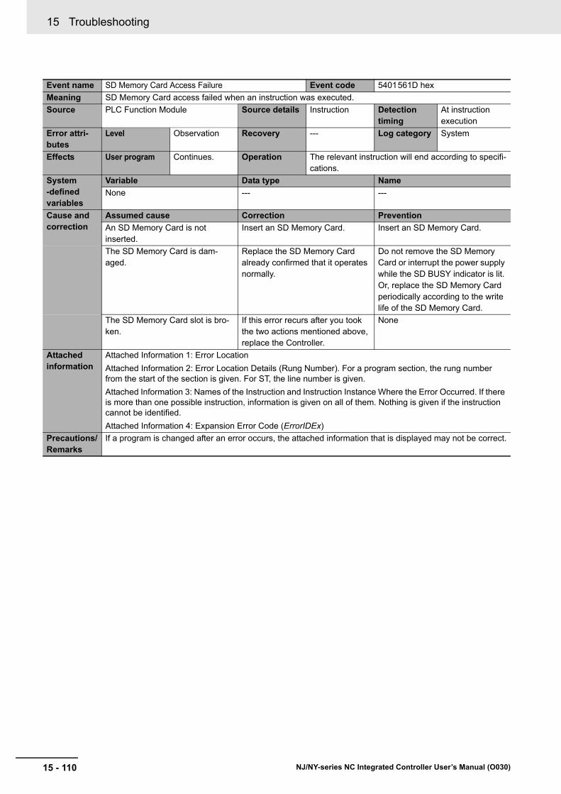
15 Troubleshooting
15 - 110 NJ/NY-series NC Integrated Controller User’s Manual (O030)
Event name SD Memory Card Access Failure Event code 5401561D hex
Meaning SD Memory Card access failed when an instruction was executed.
Source PLC Function Module Source details Instruction Detection timing
At instruction execution
Error attri-butes
Level Observation Recovery --- Log category System
Effects User program Continues. Operation The relevant instruction will end according to specifi-cations.
System-defined variables
Variable Data type Name
None --- ---
Cause and correction
Assumed cause Correction Prevention
An SD Memory Card is not inserted.
Insert an SD Memory Card. Insert an SD Memory Card.
The SD Memory Card is dam-aged.
Replace the SD Memory Card already confirmed that it operates normally.
Do not remove the SD Memory Card or interrupt the power supply while the SD BUSY indicator is lit. Or, replace the SD Memory Card periodically according to the write life of the SD Memory Card.
The SD Memory Card slot is bro-ken.
If this error recurs after you took the two actions mentioned above, replace the Controller.
None
Attached information
Attached Information 1: Error Location
Attached Information 2: Error Location Details (Rung Number). For a program section, the rung number from the start of the section is given. For ST, the line number is given.
Attached Information 3: Names of the Instruction and Instruction Instance Where the Error Occurred. If there is more than one possible instruction, information is given on all of them. Nothing is given if the instruction cannot be identified.
Attached Information 4: Expansion Error Code (ErrorIDEx)
Precautions/Remarks
If a program is changed after an error occurs, the attached information that is displayed may not be correct.

15 - 111
15 Troubleshooting
NJ/NY-series NC Integrated Controller User’s Manual (O030)
15-4 E
rror D
escriptio
ns
15
15-4-2 Error D
escriptions
Event name File Does Not Exist Event code 5401561E hex
Meaning The file specified for an instruction does not exist.
Source PLC Function Module Source details Instruction Detection timing
At instruction execution
Error attri-butes
Level Observation Recovery --- Log category System
Effects User program Continues. Operation The relevant instruction will end according to specifi-cations.
System-defined variables
Variable Data type Name
None --- ---
Cause and correction
Assumed cause Correction Prevention
The specified file does not exist. Make sure that the filename that is specified for the instruction exists. Or, modify the filename so that it matches the filename specified for the instruction.
Make sure that the filename that is specified for the instruction exists.
Attached information
Attached Information 1: Error Location
Attached Information 2: Error Location Details (Rung Number). For a program section, the rung number from the start of the section is given. For ST, the line number is given.
Attached Information 3: Names of the Instruction and Instruction Instance Where the Error Occurred. If there is more than one possible instruction, information is given on all of them. Nothing is given if the instruction cannot be identified.
Attached Information 4: Expansion Error Code (ErrorIDEx)
Precautions/Remarks
If a program is changed after an error occurs, the attached information that is displayed may not be correct.
Event name Illegal Load NC Program Number Specification Event code 5401561F hex
Meaning Loading failed because an attempt was made to load the NC program with an invalid program number spec-ified.
Source PLC Function Module Source details Instruction Detection timing
At instruction execution
Error attri-butes
Level Observation Recovery --- Log category System
Effects User program Continues. Operation The relevant instruction will end according to specifi-cations.
System-defined variables
Variable Data type Name
None --- ---
Cause and correction
Assumed cause Correction Prevention
An attempt was made to load the NC program with an invalid pro-gram number specified.
Correct the parameter so that the NC program number does not exceed the specified range.
Correct the parameter so that the NC program number does not exceed the specified range.
Attached information
Attached Information 1: Error Location
Attached Information 2: Error Location Details (Rung Number). For a program section, the rung number from the start of the section is given. For ST, the line number is given.
Attached Information 3: Names of the Instruction and Instruction Instance Where the Error Occurred. If there is more than one possible instruction, information is given on all of them. Nothing is given if the instruction cannot be identified.
Attached Information 4: Expansion Error Code (ErrorIDEx)
Precautions/Remarks
If a program is changed after an error occurs, the attached information that is displayed may not be correct.

15 Troubleshooting
15 - 112 NJ/NY-series NC Integrated Controller User’s Manual (O030)
Event name Too Many Files Open Event code 54015620 hex
Meaning The maximum number of open files was exceeded when opening a file for an instruction.
Source PLC Function Module Source details Instruction Detection timing
At instruction execution
Error attri-butes
Level Observation Recovery --- Log category System
Effects User program Continues. Operation The relevant instruction will end according to specifi-cations.
System-defined variables
Variable Data type Name
None --- ---
Cause and correction
Assumed cause Correction Prevention
The maximum number of open files was exceeded when opening a file for an instruction.
Correct the program to reduce the number of open files.
Decrease the number of files. Or, write the program so that files that no longer need to be open are closed in order to prevent too many files from being open at once.
Attached information
Attached Information 1: Error Location
Attached Information 2: Error Location Details (Rung Number). For a program section, the rung number from the start of the section is given. For ST, the line number is given.
Attached Information 3: Names of the Instruction and Instruction Instance Where the Error Occurred. If there is more than one possible instruction, information is given on all of them. Nothing is given if the instruction cannot be identified.
Attached Information 4: Expansion Error Code (ErrorIDEx)
Precautions/Remarks
If a program is changed after an error occurs, the attached information that is displayed may not be correct.
Event name File or Directory Name Is Too Long Event code 54015621 hex
Meaning The file name or directory name that was specified for an instruction is too long.
Source PLC Function Module Source details Instruction Detection timing
At instruction execution
Error attri-butes
Level Observation Recovery --- Log category System
Effects User program Continues. Operation The relevant instruction will end according to specifi-cations.
System-defined variables
Variable Data type Name
None --- ---
Cause and correction
Assumed cause Correction Prevention
The file name or directory name that was specified for the instruc-tion to create is too long.
Correct the program so that the file name or directory name speci-fied for the instruction is within FAT16/FAT32 restrictions.
Write the program so that the specified file names and directory names are within FAT16/FAT32 restrictions.
Attached information
Attached Information 1: Error Location
Attached Information 2: Error Location Details (Rung Number). For a program section, the rung number from the start of the section is given. For ST, the line number is given.
Attached Information 3: Names of the Instruction and Instruction Instance Where the Error Occurred. If there is more than one possible instruction, information is given on all of them. Nothing is given if the instruction cannot be identified.
Attached Information 4: Expansion Error Code (ErrorIDEx)
Precautions/Remarks
If a program is changed after an error occurs, the attached information that is displayed may not be correct.
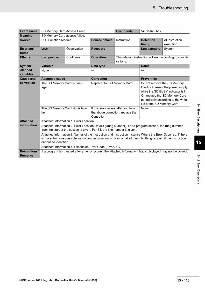
15 - 113
15 Troubleshooting
NJ/NY-series NC Integrated Controller User’s Manual (O030)
15-4 E
rror D
escriptio
ns
15
15-4-2 Error D
escriptions
Event name SD Memory Card Access Failed Event code 54015622 hex
Meaning SD Memory Card access failed.
Source PLC Function Module Source details Instruction Detection timing
At instruction execution
Error attri-butes
Level Observation Recovery --- Log category System
Effects User program Continues. Operation The relevant instruction will end according to specifi-cations.
System-defined variables
Variable Data type Name
None --- ---
Cause and correction
Assumed cause Correction Prevention
The SD Memory Card is dam-aged.
Replace the SD Memory Card. Do not remove the SD Memory Card or interrupt the power supply while the SD BUSY indicator is lit. Or, replace the SD Memory Card periodically according to the write life of the SD Memory Card.
The SD Memory Card slot is bro-ken.
If this error recurs after you took the above correction, replace the Controller.
None
Attached information
Attached Information 1: Error Location
Attached Information 2: Error Location Details (Rung Number). For a program section, the rung number from the start of the section is given. For ST, the line number is given.
Attached Information 3: Names of the Instruction and Instruction Instance Where the Error Occurred. If there is more than one possible instruction, information is given on all of them. Nothing is given if the instruction cannot be identified.
Attached Information 4: Expansion Error Code (ErrorIDEx)
Precautions/Remarks
If a program is changed after an error occurs, the attached information that is displayed may not be correct.
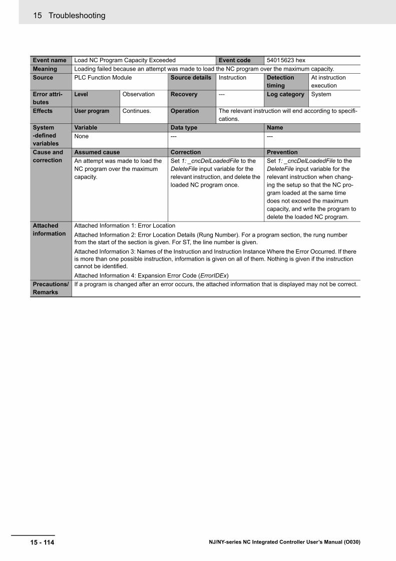
15 Troubleshooting
15 - 114 NJ/NY-series NC Integrated Controller User’s Manual (O030)
Event name Load NC Program Capacity Exceeded Event code 54015623 hex
Meaning Loading failed because an attempt was made to load the NC program over the maximum capacity.
Source PLC Function Module Source details Instruction Detection timing
At instruction execution
Error attri-butes
Level Observation Recovery --- Log category System
Effects User program Continues. Operation The relevant instruction will end according to specifi-cations.
System-defined variables
Variable Data type Name
None --- ---
Cause and correction
Assumed cause Correction Prevention
An attempt was made to load the NC program over the maximum capacity.
Set 1: _cncDelLoadedFile to the DeleteFile input variable for the relevant instruction, and delete the loaded NC program once.
Set 1: _cncDelLoadedFile to the DeleteFile input variable for the relevant instruction when chang-ing the setup so that the NC pro-gram loaded at the same time does not exceed the maximum capacity, and write the program to delete the loaded NC program.
Attached information
Attached Information 1: Error Location
Attached Information 2: Error Location Details (Rung Number). For a program section, the rung number from the start of the section is given. For ST, the line number is given.
Attached Information 3: Names of the Instruction and Instruction Instance Where the Error Occurred. If there is more than one possible instruction, information is given on all of them. Nothing is given if the instruction cannot be identified.
Attached Information 4: Expansion Error Code (ErrorIDEx)
Precautions/Remarks
If a program is changed after an error occurs, the attached information that is displayed may not be correct.
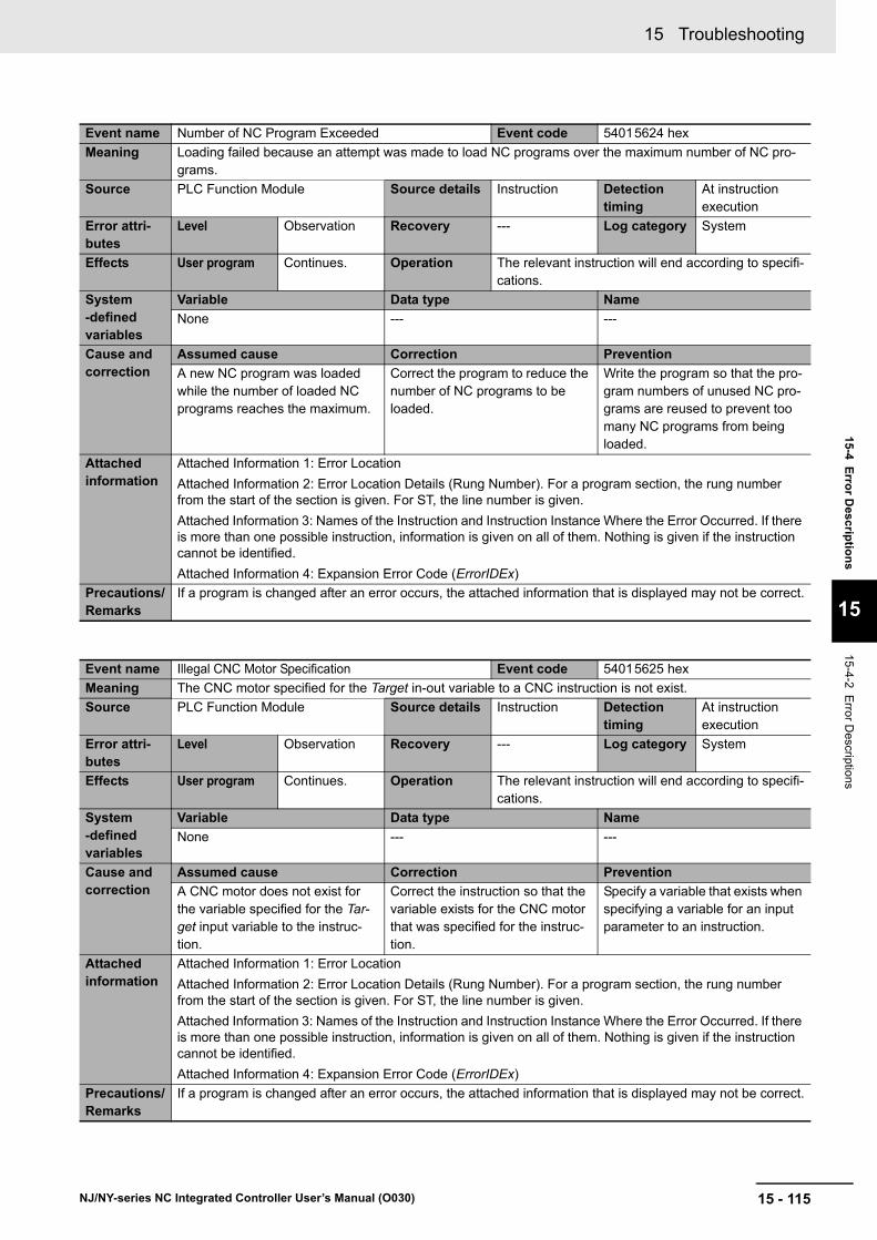
15 - 115
15 Troubleshooting
NJ/NY-series NC Integrated Controller User’s Manual (O030)
15-4 E
rror D
escriptio
ns
15
15-4-2 Error D
escriptions
Event name Number of NC Program Exceeded Event code 54015624 hex
Meaning Loading failed because an attempt was made to load NC programs over the maximum number of NC pro-grams.
Source PLC Function Module Source details Instruction Detection timing
At instruction execution
Error attri-butes
Level Observation Recovery --- Log category System
Effects User program Continues. Operation The relevant instruction will end according to specifi-cations.
System-defined variables
Variable Data type Name
None --- ---
Cause and correction
Assumed cause Correction Prevention
A new NC program was loaded while the number of loaded NC programs reaches the maximum.
Correct the program to reduce the number of NC programs to be loaded.
Write the program so that the pro-gram numbers of unused NC pro-grams are reused to prevent too many NC programs from being loaded.
Attached information
Attached Information 1: Error Location
Attached Information 2: Error Location Details (Rung Number). For a program section, the rung number from the start of the section is given. For ST, the line number is given.
Attached Information 3: Names of the Instruction and Instruction Instance Where the Error Occurred. If there is more than one possible instruction, information is given on all of them. Nothing is given if the instruction cannot be identified.
Attached Information 4: Expansion Error Code (ErrorIDEx)
Precautions/Remarks
If a program is changed after an error occurs, the attached information that is displayed may not be correct.
Event name Illegal CNC Motor Specification Event code 54015625 hex
Meaning The CNC motor specified for the Target in-out variable to a CNC instruction is not exist.
Source PLC Function Module Source details Instruction Detection timing
At instruction execution
Error attri-butes
Level Observation Recovery --- Log category System
Effects User program Continues. Operation The relevant instruction will end according to specifi-cations.
System-defined variables
Variable Data type Name
None --- ---
Cause and correction
Assumed cause Correction Prevention
A CNC motor does not exist for the variable specified for the Tar-get input variable to the instruc-tion.
Correct the instruction so that the variable exists for the CNC motor that was specified for the instruc-tion.
Specify a variable that exists when specifying a variable for an input parameter to an instruction.
Attached information
Attached Information 1: Error Location
Attached Information 2: Error Location Details (Rung Number). For a program section, the rung number from the start of the section is given. For ST, the line number is given.
Attached Information 3: Names of the Instruction and Instruction Instance Where the Error Occurred. If there is more than one possible instruction, information is given on all of them. Nothing is given if the instruction cannot be identified.
Attached Information 4: Expansion Error Code (ErrorIDEx)
Precautions/Remarks
If a program is changed after an error occurs, the attached information that is displayed may not be correct.
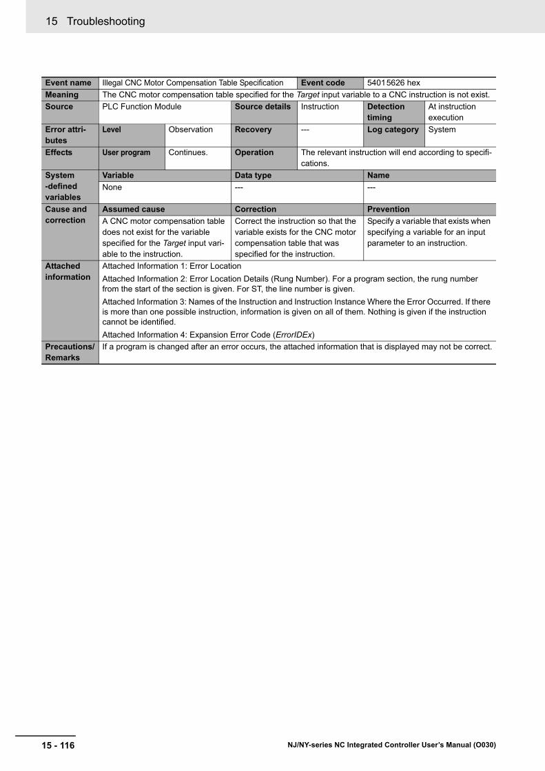
15 Troubleshooting
15 - 116 NJ/NY-series NC Integrated Controller User’s Manual (O030)
Event name Illegal CNC Motor Compensation Table Specification Event code 54015626 hex
Meaning The CNC motor compensation table specified for the Target input variable to a CNC instruction is not exist.
Source PLC Function Module Source details Instruction Detection timing
At instruction execution
Error attri-butes
Level Observation Recovery --- Log category System
Effects User program Continues. Operation The relevant instruction will end according to specifi-cations.
System-defined variables
Variable Data type Name
None --- ---
Cause and correction
Assumed cause Correction Prevention
A CNC motor compensation table does not exist for the variable specified for the Target input vari-able to the instruction.
Correct the instruction so that the variable exists for the CNC motor compensation table that was specified for the instruction.
Specify a variable that exists when specifying a variable for an input parameter to an instruction.
Attached information
Attached Information 1: Error Location
Attached Information 2: Error Location Details (Rung Number). For a program section, the rung number from the start of the section is given. For ST, the line number is given.
Attached Information 3: Names of the Instruction and Instruction Instance Where the Error Occurred. If there is more than one possible instruction, information is given on all of them. Nothing is given if the instruction cannot be identified.
Attached Information 4: Expansion Error Code (ErrorIDEx)
Precautions/Remarks
If a program is changed after an error occurs, the attached information that is displayed may not be correct.

15 - 117
15 Troubleshooting
NJ/NY-series NC Integrated Controller User’s Manual (O030)
15-4 E
rror D
escriptio
ns
15
15-4-2 Error D
escriptions
Event name Illegal Load NC Program Event code 54015628 hex
Meaning An error was detected in the loaded NC program.
Source PLC Function Module Source details Instruction Detection timing
At instruction execution
Error attri-butes
Level Observation Recovery --- Log category System
Effects User program Continues. Operation The relevant instruction will end according to specifi-cations.
System-defined variables
Variable Data type Name
None --- ---
Cause and correction
Assumed cause Correction Prevention
A syntax error was detected in the NC program you made an attempt to load.
• Perform parsing processing with CNC Operator, and specify the NC program that was trans-ferred to the SD Memory Card.
• The file name and row number of the NC program with the error detected are shown in the attached information. Make sure that the syntax and instruction are correct.
• If this error recurs after you took the above correction, contact your OMRON representative.
Do not edit the file of the NC pro-gram that was parsed with CNC Operator and transferred to the SD Memory Card.
Attached information
Attached Information 1: Error Location
Attached Information 2: Error Location Details (Rung Number). For a program section, the rung number from the start of the section is given. For ST, the line number is given.
Attached Information 3: Names of the Instruction and Instruction Instance Where the Error Occurred. If there is more than one possible instruction, information is given on all of them. Nothing is given if the instruction cannot be identified.
Attached Information 4: Expansion Error Code (ErrorIDEx)
Precautions/Remarks
If a program is changed after an error occurs, the attached information that is displayed may not be correct.
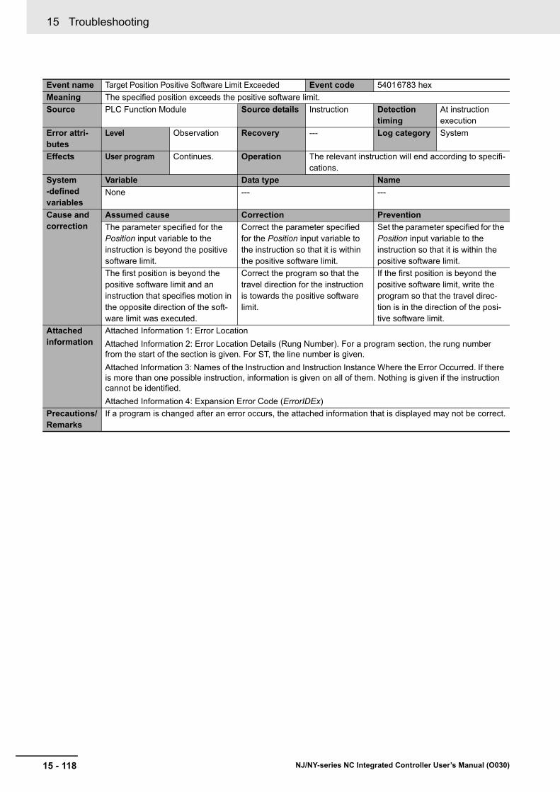
15 Troubleshooting
15 - 118 NJ/NY-series NC Integrated Controller User’s Manual (O030)
Event name Target Position Positive Software Limit Exceeded Event code 54016783 hex
Meaning The specified position exceeds the positive software limit.
Source PLC Function Module Source details Instruction Detection timing
At instruction execution
Error attri-butes
Level Observation Recovery --- Log category System
Effects User program Continues. Operation The relevant instruction will end according to specifi-cations.
System-defined variables
Variable Data type Name
None --- ---
Cause and correction
Assumed cause Correction Prevention
The parameter specified for the Position input variable to the instruction is beyond the positive software limit.
Correct the parameter specified for the Position input variable to the instruction so that it is within the positive software limit.
Set the parameter specified for the Position input variable to the instruction so that it is within the positive software limit.
The first position is beyond the positive software limit and an instruction that specifies motion in the opposite direction of the soft-ware limit was executed.
Correct the program so that the travel direction for the instruction is towards the positive software limit.
If the first position is beyond the positive software limit, write the program so that the travel direc-tion is in the direction of the posi-tive software limit.
Attached information
Attached Information 1: Error Location
Attached Information 2: Error Location Details (Rung Number). For a program section, the rung number from the start of the section is given. For ST, the line number is given.
Attached Information 3: Names of the Instruction and Instruction Instance Where the Error Occurred. If there is more than one possible instruction, information is given on all of them. Nothing is given if the instruction cannot be identified.
Attached Information 4: Expansion Error Code (ErrorIDEx)
Precautions/Remarks
If a program is changed after an error occurs, the attached information that is displayed may not be correct.
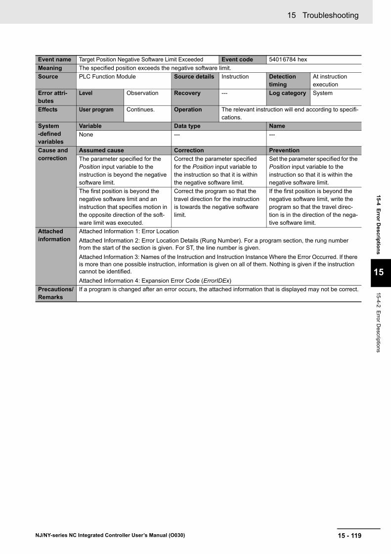
15 - 119
15 Troubleshooting
NJ/NY-series NC Integrated Controller User’s Manual (O030)
15-4 E
rror D
escriptio
ns
15
15-4-2 Error D
escriptions
Event name Target Position Negative Software Limit Exceeded Event code 54016784 hex
Meaning The specified position exceeds the negative software limit.
Source PLC Function Module Source details Instruction Detection timing
At instruction execution
Error attri-butes
Level Observation Recovery --- Log category System
Effects User program Continues. Operation The relevant instruction will end according to specifi-cations.
System-defined variables
Variable Data type Name
None --- ---
Cause and correction
Assumed cause Correction Prevention
The parameter specified for the Position input variable to the instruction is beyond the negative software limit.
Correct the parameter specified for the Position input variable to the instruction so that it is within the negative software limit.
Set the parameter specified for the Position input variable to the instruction so that it is within the negative software limit.
The first position is beyond the negative software limit and an instruction that specifies motion in the opposite direction of the soft-ware limit was executed.
Correct the program so that the travel direction for the instruction is towards the negative software limit.
If the first position is beyond the negative software limit, write the program so that the travel direc-tion is in the direction of the nega-tive software limit.
Attached information
Attached Information 1: Error Location
Attached Information 2: Error Location Details (Rung Number). For a program section, the rung number from the start of the section is given. For ST, the line number is given.
Attached Information 3: Names of the Instruction and Instruction Instance Where the Error Occurred. If there is more than one possible instruction, information is given on all of them. Nothing is given if the instruction cannot be identified.
Attached Information 4: Expansion Error Code (ErrorIDEx)
Precautions/Remarks
If a program is changed after an error occurs, the attached information that is displayed may not be correct.
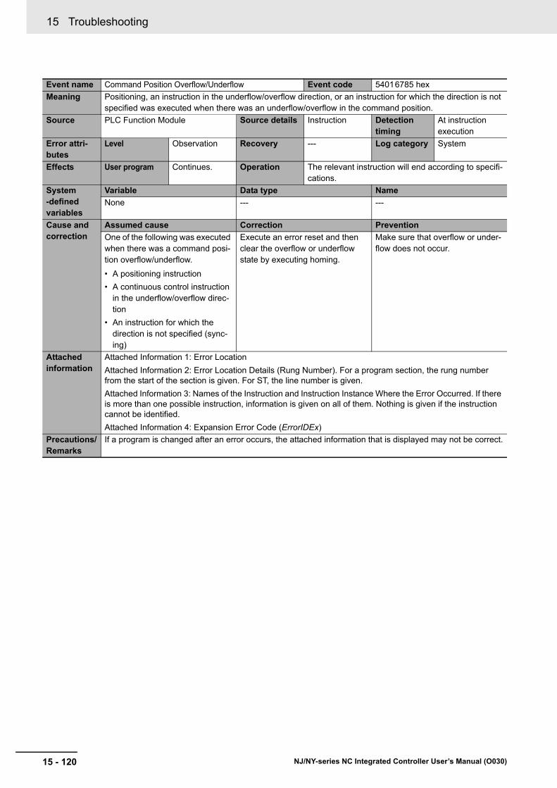
15 Troubleshooting
15 - 120 NJ/NY-series NC Integrated Controller User’s Manual (O030)
Event name Command Position Overflow/Underflow Event code 54016785 hex
Meaning Positioning, an instruction in the underflow/overflow direction, or an instruction for which the direction is not specified was executed when there was an underflow/overflow in the command position.
Source PLC Function Module Source details Instruction Detection timing
At instruction execution
Error attri-butes
Level Observation Recovery --- Log category System
Effects User program Continues. Operation The relevant instruction will end according to specifi-cations.
System-defined variables
Variable Data type Name
None --- ---
Cause and correction
Assumed cause Correction Prevention
One of the following was executed when there was a command posi-tion overflow/underflow.
• A positioning instruction
• A continuous control instruction in the underflow/overflow direc-tion
• An instruction for which the direction is not specified (sync-ing)
Execute an error reset and then clear the overflow or underflow state by executing homing.
Make sure that overflow or under-flow does not occur.
Attached information
Attached Information 1: Error Location
Attached Information 2: Error Location Details (Rung Number). For a program section, the rung number from the start of the section is given. For ST, the line number is given.
Attached Information 3: Names of the Instruction and Instruction Instance Where the Error Occurred. If there is more than one possible instruction, information is given on all of them. Nothing is given if the instruction cannot be identified.
Attached Information 4: Expansion Error Code (ErrorIDEx)
Precautions/Remarks
If a program is changed after an error occurs, the attached information that is displayed may not be correct.

15 - 121
15 Troubleshooting
NJ/NY-series NC Integrated Controller User’s Manual (O030)
15-4 E
rror D
escriptio
ns
15
15-4-2 Error D
escriptions
Event name Positive Limit Input Event code 54016786 hex
Meaning An instruction was executed for a motion in the positive direction when the positive limit input was ON.
Source PLC Function Module Source details Instruction Detection timing
At instruction execution
Error attri-butes
Level Observation Recovery --- Log category System
Effects User program Continues. Operation The relevant instruction will end according to specifi-cations.
System-defined variables
Variable Data type Name
None --- ---
Cause and correction
Assumed cause Correction Prevention
An instruction for a motion in the positive direction was executed when the positive limit input was ON, or an instruction for a motion with no direction specification was executed when the positive limit input was ON.
Execute an error reset and then perform a recovery operation in the negative direction. If this error occurs again, check the connec-tion of the positive limit signal, the logic setting for the positive limit input, and the execution condi-tions for the start command, and correct any mistakes.
Check the logic settings both in the CNC motor parameters and in the slave settings.
Check to make sure there are no problems with the positive limit signal connection, the logic setting for the positive limit input, and the execute conditions for the instruc-tion.
Check the logic settings both in the CNC motor parameters and in the slave settings.
Attached information
Attached Information 1: Error Location
Attached Information 2: Error Location Details (Rung Number). For a program section, the rung number from the start of the section is given. For ST, the line number is given.
Attached Information 3: Names of the Instruction and Instruction Instance Where the Error Occurred. If there is more than one possible instruction, information is given on all of them. Nothing is given if the instruction cannot be identified.
Attached Information 4: Expansion Error Code (ErrorIDEx)
Precautions/Remarks
If a program is changed after an error occurs, the attached information that is displayed may not be correct.

15 Troubleshooting
15 - 122 NJ/NY-series NC Integrated Controller User’s Manual (O030)
Event name Negative Limit Input Event code 54016787 hex
Meaning An instruction for a motion in the negative direction was executed when the negative limit input was ON.
Source PLC Function Module Source details Instruction Detection timing
At instruction execution
Error attri-butes
Level Observation Recovery --- Log category System
Effects User program Continues. Operation The relevant instruction will end according to specifi-cations.
System-defined variables
Variable Data type Name
None --- ---
Cause and correction
Assumed cause Correction Prevention
An instruction for a motion in the negative direction was executed when the negative limit input was ON, or an instruction for a motion with no direction specification was executed when the negative limit input was ON.
Execute an error reset and then perform a recovery operation in the positive direction. If this error occurs again, check the connec-tion of the negative limit signal, the logic setting for the negative limit input, and the execution condi-tions for the start command, and correct any mistakes.
Check the logic settings both in the CNC motor parameters and in the slave settings.
Check to make sure there are no problems with the negative limit signal connection, the logic setting for the negative limit input, and the execute conditions for the instruc-tion.
Check the logic settings both in the CNC motor parameters and in the slave settings.
Attached information
Attached Information 1: Error Location
Attached Information 2: Error Location Details (Rung Number). For a program section, the rung number from the start of the section is given. For ST, the line number is given.
Attached Information 3: Names of the Instruction and Instruction Instance Where the Error Occurred. If there is more than one possible instruction, information is given on all of them. Nothing is given if the instruction cannot be identified.
Attached Information 4: Expansion Error Code (ErrorIDEx)
Precautions/Remarks
If a program is changed after an error occurs, the attached information that is displayed may not be correct.

15 - 123
15 Troubleshooting
NJ/NY-series NC Integrated Controller User’s Manual (O030)
15-4 E
rror D
escriptio
ns
15
15-4-2 Error D
escriptions
Event name Servo Main Circuits OFF Event code 54017784 hex
Meaning An attempt was made to turn ON the Servo when the main circuit power supply to the Servo Drive was OFF.
Source PLC Function Module Source details Instruction Detection timing
At instruction execution
Error attri-butes
Level Observation Recovery --- Log category System
Effects User program Continues. Operation The relevant instruction will end according to specifi-cations.
System-defined variables
Variable Data type Name
None --- ---
Cause and correction
Assumed cause Correction Prevention
An attempt was made to turn ON the Servo when the main circuit power supply to the Servo Drive was OFF.
Turn ON the Servo after turning ON the main circuit power supply of the Servo Drive for the CNC motor where the error occurred.
Turn ON the Servo after turning ON the main circuit power supply to the Servo Drive.
Attached information
Attached Information 1: Error Location
Attached Information 2: Error Location Details (Rung Number). For a program section, the rung number from the start of the section is given. For ST, the line number is given.
Attached Information 3: Names of the Instruction and Instruction Instance Where the Error Occurred. If there is more than one possible instruction, information is given on all of them. Nothing is given if the instruction cannot be identified.
Attached Information 4: Expansion Error Code (ErrorIDEx)
Precautions/Remarks
If a program is changed after an error occurs, the attached information that is displayed may not be correct.

15 Troubleshooting
15 - 124 NJ/NY-series NC Integrated Controller User’s Manual (O030)
A - 1
A
NJ/NY-series NC Integrated Controller User’s Manual (O030)
A-1 Valid Range of CNC Parameter Settings . . . . . . . . . . . . . . . . . . . . . . . . . . . A-2
A-2 Cancellation of Digits of Real Type Data . . . . . . . . . . . . . . . . . . . . . . . . . . . A-7
A-3 Connecting to 1S-series Servo Drives . . . . . . . . . . . . . . . . . . . . . . . . . . . . A-11A-3-1 Wiring the Servo Drive . . . . . . . . . . . . . . . . . . . . . . . . . . . . . . . . . . . . . . . . . A-11
A-3-2 Servo Drive Settings . . . . . . . . . . . . . . . . . . . . . . . . . . . . . . . . . . . . . . . . . . . A-11
A-3-3 Object Settings . . . . . . . . . . . . . . . . . . . . . . . . . . . . . . . . . . . . . . . . . . . . . . . A-14
A-4 Instructions for Which Multi-execution Is Supported . . . . . . . . . . . . . . . . A-15
Appendices

Appendices
A - 2 NJ/NY-series NC Integrated Controller User’s Manual (O030)
A-1 Valid Range of CNC Parameter Set-tings
Some real-type CNC parameters have their valid range in addition to a setting range. The valid range is within the setting range and handled as internally effective. If a setting value is within the setting range but outside the valid range, it is not handled as an error but corrected to a value within the valid range so that it can be used for calculation purposes.
Valid Ranges for Real-type CNC Coordinate System Parameters
CategoryReal number point
parameterSetting range
Valid rangeWithin the setting range but
outside the valid range
CNC Coor-dinate Sys-tem Operation Settings
Maximum Feedrate Positive number, 0
0.0000001 to upper limit*1 Not handled as an error.
0: Set to the upper limit defined to the left.
Larger than 0 and less than 0.0000001: Set to 0.0000001.
Larger than the upper limit defined to the left: Set to the upper limit.
Rotary Axis Velocity Positive number
0.0000001 to upper limit*1 Not handled as an error.
Larger than 0 and less than 0.0000001: Set to 0.0000001.
Larger than the upper limit defined to the left: Set to the upper limit.
Dry Run Velocity Positive number
0.0000001 to upper limit*1 Not handled as an error.
Larger than 0 and less than 0.0000001: Set to 0.0000001.
Larger than the upper limit defined to the left: Set to the upper limit.
NC Pro-gram Default Set-tings
Acceleration Time Positive number, 0
- *2 -
Deceleration Time Positive number, 0
- *2 -
Jerk Time Positive number, 0
- *2 -
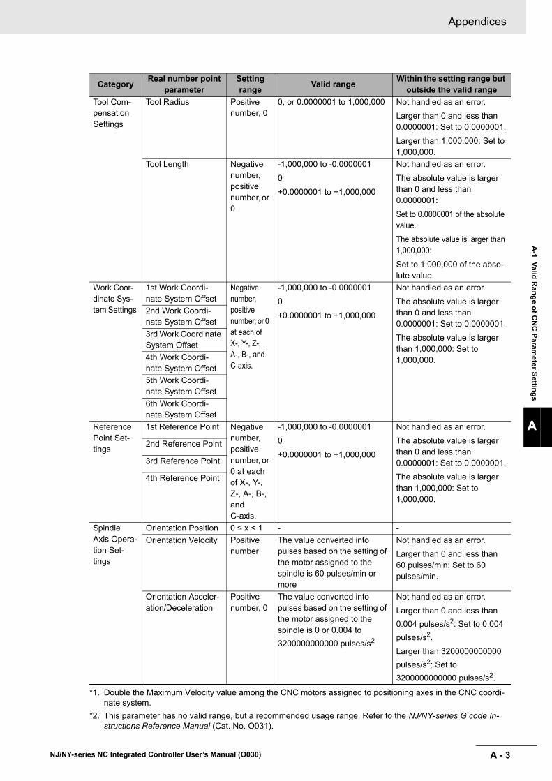
A - 3
Appendices
NJ/NY-series NC Integrated Controller User’s Manual (O030)
A-1 V
alid R
ang
e of C
NC
Param
eter S
etting
s
A
Tool Com-pensation Settings
Tool Radius Positive number, 0
0, or 0.0000001 to 1,000,000 Not handled as an error.
Larger than 0 and less than 0.0000001: Set to 0.0000001.
Larger than 1,000,000: Set to 1,000,000.
Tool Length Negative number, positive number, or 0
-1,000,000 to -0.0000001
0
+0.0000001 to +1,000,000
Not handled as an error.
The absolute value is larger than 0 and less than 0.0000001:
Set to 0.0000001 of the absolute value.
The absolute value is larger than 1,000,000:
Set to 1,000,000 of the abso-lute value.
Work Coor-dinate Sys-tem Settings
1st Work Coordi-nate System Offset
Negative number, positive number, or 0 at each of X-, Y-, Z-, A-, B-, and C-axis.
-1,000,000 to -0.0000001
0
+0.0000001 to +1,000,000
Not handled as an error.
The absolute value is larger than 0 and less than 0.0000001: Set to 0.0000001.
The absolute value is larger than 1,000,000: Set to 1,000,000.
2nd Work Coordi-nate System Offset
3rd Work Coordinate System Offset
4th Work Coordi-nate System Offset
5th Work Coordi-nate System Offset
6th Work Coordi-nate System Offset
Reference Point Set-tings
1st Reference Point Negative number, positive number, or 0 at each of X-, Y-, Z-, A-, B-, and C-axis.
-1,000,000 to -0.0000001
0
+0.0000001 to +1,000,000
Not handled as an error.
The absolute value is larger than 0 and less than 0.0000001: Set to 0.0000001.
The absolute value is larger than 1,000,000: Set to 1,000,000.
2nd Reference Point
3rd Reference Point
4th Reference Point
Spindle Axis Opera-tion Set-tings
Orientation Position 0 ≤ x < 1 - -
Orientation Velocity Positive number
The value converted into pulses based on the setting of the motor assigned to the spindle is 60 pulses/min or more
Not handled as an error.
Larger than 0 and less than 60 pulses/min: Set to 60 pulses/min.
Orientation Acceler-ation/Deceleration
Positive number, 0
The value converted into pulses based on the setting of the motor assigned to the spindle is 0 or 0.004 to
3200000000000 pulses/s2
Not handled as an error.
Larger than 0 and less than
0.004 pulses/s2: Set to 0.004
pulses/s2.
Larger than 3200000000000
pulses/s2: Set to
3200000000000 pulses/s2.
*1. Double the Maximum Velocity value among the CNC motors assigned to positioning axes in the CNC coordi-nate system.
*2. This parameter has no valid range, but a recommended usage range. Refer to the NJ/NY-series G code In-structions Reference Manual (Cat. No. O031).
CategoryReal number point
parameterSetting range
Valid rangeWithin the setting range but
outside the valid range

Appendices
A - 4 NJ/NY-series NC Integrated Controller User’s Manual (O030)
Valid Ranges for Real-type CNC Motor Parameters
CategoryReal number point
parameterSetting range
Valid rangeWithin the setting range but
outside the valid range
Unit Con-version Set-tings
Travel Distance Per Work Rotation
Positive number
- -
Operation Settings
Maximum Velocity Positive number
The value after conversion into pulses is 60 pulses/min or more.
Not handled as an error.
Larger than 0 and less than 60 pulses/min: Set to 60 pulses/min.
Maximum Accelera-tion/Deceleration
Positive number, 0
The value after conversion into pulses is 0 or 0.004 to
3200000000000 pulses/s2.
Not handled as an error.
Larger than 0 and less than
0.004 pulses/s2: Set to 0.004
pulses/s2.
Larger than 3200000000000
pulses/s2: Set to
3200000000000 pulses/s2.
Rapid Feed Acceler-ation/Deceleration
Positive number, 0
The value after conversion into pulses is 0 or 0.004
pulses/s2 or more.
Not handled as an error.
Larger than 0 and less than
0.004 pulses/s2: Set to 0.004
pulses/s2.
In-position Range Positive number, 0
- -
Skip Velocity Positive number
The value after conversion into pulses is 60 pulses/min or more.
Not handled as an error.
Larger than 0 and less than 60 pulses/min: Set to 60 pulses/min.
Limit Set-tings
Positive Software Overtravel Limit
Positive number
- -
Negative Software Overtravel Limit
Negative number
- -
Following Error Over Value
Positive number, 0
- -
Following Error Warning Value
Positive number, 0
- -

A - 5
Appendices
NJ/NY-series NC Integrated Controller User’s Manual (O030)
A-1 V
alid R
ang
e of C
NC
Param
eter S
etting
s
A
Homing Settings
Homing Velocity Positive number
The value after conversion into pulses is 60 pulses/min or more.
Not handled as an error.
Larger than 0 and less than 60 pulses/min: Set to 60 pulses/min.
Homing Approach Velocity
Positive number
The value after conversion into pulses is 60 pulses/min or more.
Not handled as an error.
Larger than 0 and less than 60 pulses/min: Set to 60 pulses/min.
Homing Accelera-tion/Deceleration
Positive number, 0
The value after conversion into pulses is 0 or 0.004
pulses/s2 or more.
Not handled as an error.
Larger than 0 and less than
0.004 pulses/s2: Set to 0.004
pulses/s2.
Home Input Mask Distance
Positive number, 0
- -
Home Offset Positive number, negative number, or 0
- -
Homing Compensa-tion Value
Positive number, negative number, or 0
- -
Homing Compensa-tion Velocity
Positive number
The value after conversion into pulses is 60 pulses/min or more.
Not handled as an error.
Larger than 0 and less than 60 pulses/min: Set to 60 pulses/min.
Servo Gain Settings
Position Loop Gain 0 to 3000 0, or 0.01 to 3000.0 Larger than 0 and less than 0.01: Not handled as an error but set to 0.01.
Velocity Feedfor-ward Gain
0 to 100 0, or 0.01 to 100.0 Larger than 0 and less than 0.01: Not handled as an error but set to 0.01.
CategoryReal number point
parameterSetting range
Valid rangeWithin the setting range but
outside the valid range

Appendices
A - 6 NJ/NY-series NC Integrated Controller User’s Manual (O030)
For information about the valid ranges of input variables for CNC instruction function blocks, refer to 11-1-1 Input Variables for CNC Instructions on page 11-2.
Valid Ranges for Real-type CNC Motor Compensation Table Settings
CategoryReal number point
parameterSetting range
Valid rangeWithin the setting range but
outside the valid range
Basic Set-tings
Compensation Scail-ing
0 to 2.0 - -
Source Compensa-tion Start Position
Positive number, 0, or nega-tive num-ber
-1,000,000 to -0.0000001
0,
+0.0000001 to +1,000,000
Not handled as an error.
The absolute value is larger than 0 and less than 0.0000001: Set to 0.0000001.
The absolute value is larger than 1,000,000: Set to 1,000,000.
Source Compensa-tion Section Dis-tance
Positive number
+0.0000001 to +1,000,000 Not handled as an error.
Larger than 0 and less than 0.0000001: Set to 0.0000001.
Larger than 1,000,000: Set to 10,00,000.
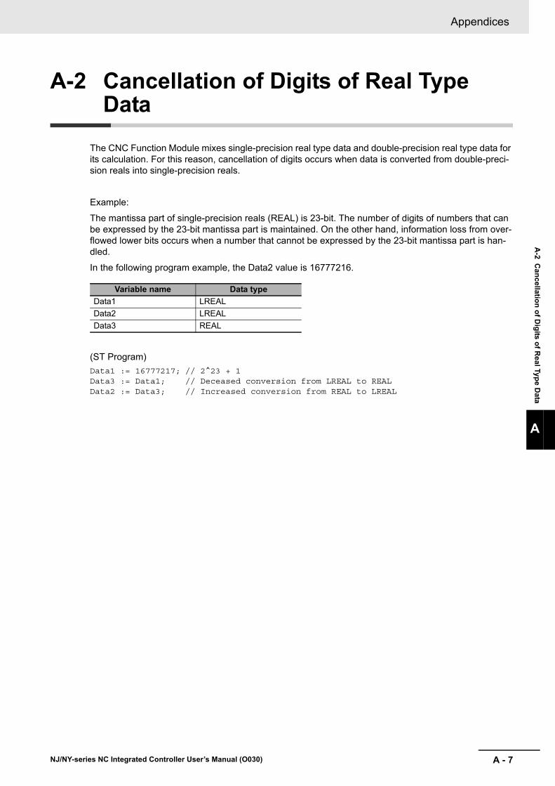
A - 7
Appendices
NJ/NY-series NC Integrated Controller User’s Manual (O030)
A-2 C
ancellatio
n o
f Dig
its of R
eal Type
Data
A
A-2 Cancellation of Digits of Real Type Data
The CNC Function Module mixes single-precision real type data and double-precision real type data for its calculation. For this reason, cancellation of digits occurs when data is converted from double-preci-sion reals into single-precision reals.
Example:
The mantissa part of single-precision reals (REAL) is 23-bit. The number of digits of numbers that can be expressed by the 23-bit mantissa part is maintained. On the other hand, information loss from over-flowed lower bits occurs when a number that cannot be expressed by the 23-bit mantissa part is han-dled.
In the following program example, the Data2 value is 16777216.
(ST Program)
Data1 := 16777217; // 2^23 + 1Data3 := Data1; // Deceased conversion from LREAL to REALData2 := Data3; // Increased conversion from REAL to LREAL
Variable name Data type
Data1 LREAL
Data2 LREAL
Data3 REAL
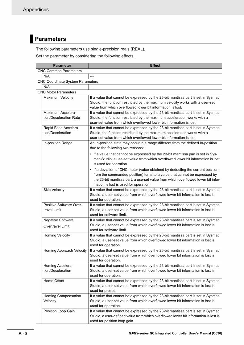
Appendices
A - 8 NJ/NY-series NC Integrated Controller User’s Manual (O030)
The following parameters use single-precision reals (REAL).
Set the parameter by considering the following effects.
Parameters
Parameter Effect
CNC Common Parameters
N/A ---
CNC Coordinate System Parameters
N/A ---
CNC Motor Parameters
Maximum Velocity If a value that cannot be expressed by the 23-bit mantissa part is set in Sysmac Studio, the function restricted by the maximum velocity works with a user-set value from which overflowed lower bit information is lost.
Maximum Accelera-tion/Deceleration Rate
If a value that cannot be expressed by the 23-bit mantissa part is set in Sysmac Studio, the function restricted by the maximum acceleration works with a user-set value from which overflowed lower bit information is lost.
Rapid Feed Accelera-tion/Deceleration
If a value that cannot be expressed by the 23-bit mantissa part is set in Sysmac Studio, the function restricted by the maximum acceleration works with a user-set value from which overflowed lower bit information is lost.
In-position Range An In-position state may occur in a range different from the defined In-position due to the following two reasons:
• If a value that cannot be expressed by the 23-bit mantissa part is set in Sys-mac Studio, a use-set value from which overflowed lower bit information is lost is used for operation.
• If a deviation of CNC motor (value obtained by deducting the current position from the commanded position) turns to a value that cannot be expressed by the 23-bit mantissa part, a use-set value from which overflowed lower bit infor-mation is lost is used for operation.
Skip Velocity If a value that cannot be expressed by the 23-bit mantissa part is set in Sysmac Studio, a user-set value from which overflowed lower bit information is lost is used for operation.
Positive Software Over-travel Limit
If a value that cannot be expressed by the 23-bit mantissa part is set in Sysmac Studio, a user-set value from which overflowed lower bit information is lost is used for software limit.
Negative Software
Overtravel Limit
If a value that cannot be expressed by the 23-bit mantissa part is set in Sysmac Studio, a user-set value from which overflowed lower bit information is lost is used for software limit.
Homing Velocity If a value that cannot be expressed by the 23-bit mantissa part is set in Sysmac Studio, a user-set value from which overflowed lower bit information is lost is used for operation.
Homing Approach Velocity If a value that cannot be expressed by the 23-bit mantissa part is set in Sysmac Studio, a user-set value from which overflowed lower bit information is lost is used for operation.
Homing Accelera-tion/Deceleration
If a value that cannot be expressed by the 23-bit mantissa part is set in Sysmac Studio, a user-set value from which overflowed lower bit information is lost is used for operation.
Home Offset If a value that cannot be expressed by the 23-bit mantissa part is set in Sysmac Studio, a user-set value from which overflowed lower bit information is lost is used for preset.
Homing Compensation Velocity
If a value that cannot be expressed by the 23-bit mantissa part is set in Sysmac Studio, a user-set value from which overflowed lower bit information is lost is used for operation.
Position Loop Gain If a value that cannot be expressed by the 23-bit mantissa part is set in Sysmac Studio, a user-defined value from which overflowed lower bit information is lost is used for position loop gain.
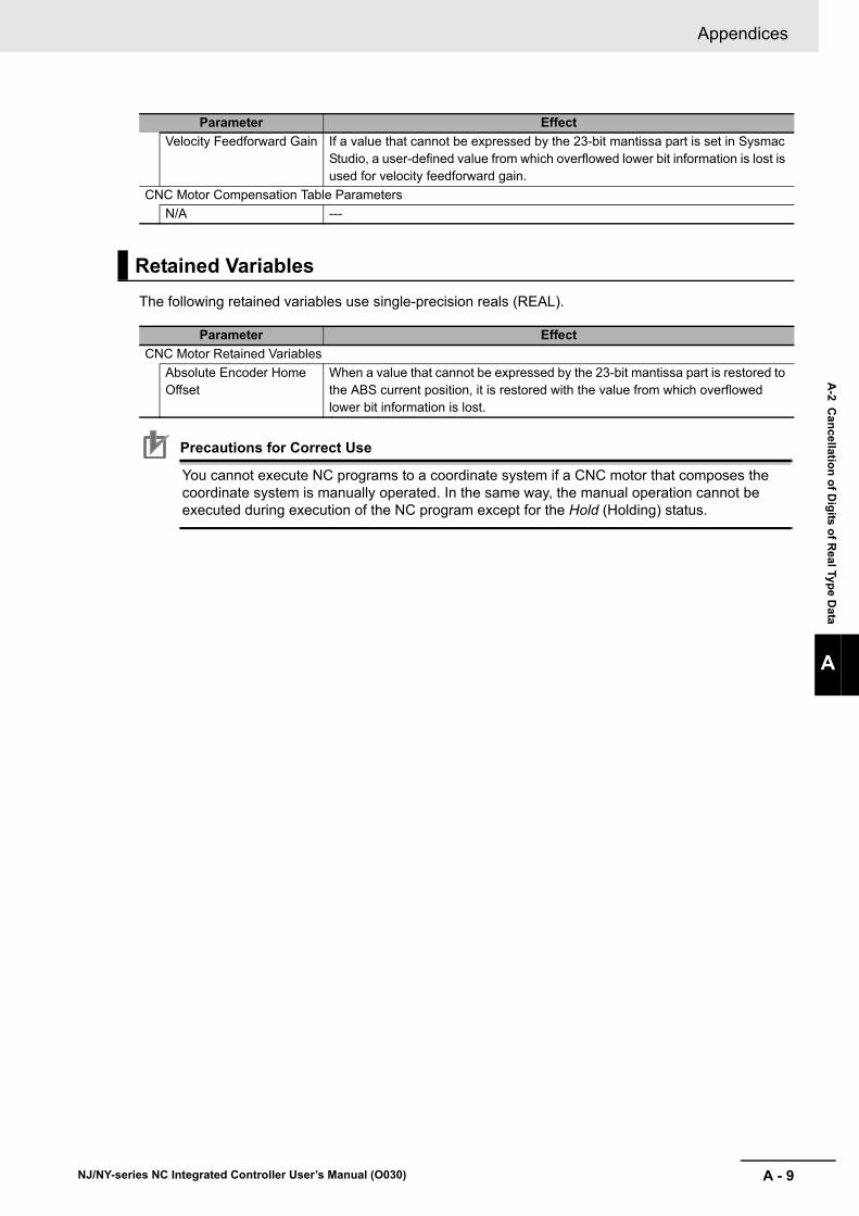
A - 9
Appendices
NJ/NY-series NC Integrated Controller User’s Manual (O030)
A-2 C
ancellatio
n o
f Dig
its of R
eal Type
Data
A
The following retained variables use single-precision reals (REAL).
Precautions for Correct Use
You cannot execute NC programs to a coordinate system if a CNC motor that composes the coordinate system is manually operated. In the same way, the manual operation cannot be executed during execution of the NC program except for the Hold (Holding) status.
Velocity Feedforward Gain If a value that cannot be expressed by the 23-bit mantissa part is set in Sysmac Studio, a user-defined value from which overflowed lower bit information is lost is used for velocity feedforward gain.
CNC Motor Compensation Table Parameters
N/A ---
Retained Variables
Parameter Effect
CNC Motor Retained Variables
Absolute Encoder Home Offset
When a value that cannot be expressed by the 23-bit mantissa part is restored to the ABS current position, it is restored with the value from which overflowed lower bit information is lost.
Parameter Effect

Appendices
A - 10 NJ/NY-series NC Integrated Controller User’s Manual (O030)
To ensure visibility, double-precision reals (LREAL) data is used in PLC program. However, the follow-ing variables use single-precision reals (REAL) data for the internal use.
Input Variables for CNC Instructions
Input variable Effect
CNC_MoveJog
Velocity When a value that cannot be expressed by the 23-bit mantissa part is specified, a user-set value from which the information is lost is used for the velocity.
Acceleration When a value that cannot be expressed by the 23-bit mantissa part is specified, a user-set value from which the information is lost is used for the accelera-tion/deceleration rate.
CNC_Move
Velocity When a value that cannot be expressed by the 23-bit mantissa part is specified, a user-set value from which the information is lost is used for the velocity.
Acceleration When a value that cannot be expressed by the 23-bit mantissa part is specified, a user-set value from which the information is lost is used for the accelera-tion/deceleration rate.
CNC_HomeWithParameter
HomingParameter. Vel Refer to Homing Velocity
HomingParameter. ApproachVel
Refer to Homing Approach Velocity
HomingParameter. Acc Refer to Homing Acceleration/Deceleration
HomingParameter. Offset Refer to Home Offset
HomingParameter. Com-pensationVel
Refer to Homing Compensation Velocity
CNC_SpindleGo
Velocity If a value that cannot be expressed by the 23-bit mantissa part is specified, a user-set value from which overflowed lower bit information is lost is used for operation.
CNC_CoordControl
ControlOutputs. Feedrat-eVelFactor
If a value that cannot be expressed by the 23-bit mantissa part is specified, a user-set value from which overflowed lower bit information is lost is used for operation.
ControlOutputs. Feedrat-eVelFactorChangeRate
If a value that cannot be expressed by the 23-bit mantissa part is specified, a user-set value from which overflowed lower bit information is lost is used for operation.
A - 11
Appendices
NJ/NY-series NC Integrated Controller User’s Manual (O030)
A-3 C
on
nectin
g to
1S-series S
ervo D
rives
A
A-3-1 W
iring the Servo D
rive
A-3 Connecting to 1S-series Servo Drives
This section describes connections to an OMRON 1S-series Servo Drive with built-in EtherCAT com-munications.
Basically, the connections are the same as for the Motion Control Function Module. This section, there-fore, describes only the differences. For details, refer to the NJ/NX-series CPU Unit Motion Control User’s Manual (Cat. No. W507).
Refer to the NJ/NX-series CPU Unit Motion Control User’s Manual (Cat. No. W507).
Refer to the NJ/NX-series CPU Unit Motion Control User’s Manual (Cat. No. W507).
Refer to the NJ/NX-series CPU Unit Motion Control User’s Manual (Cat. No. W507).
Refer to the NJ/NX-series CPU Unit Motion Control User’s Manual (Cat. No. W507).
This function changes from the MC Function Module.
The functions of the CNC Function Module are related to the information in the process data objects.
Depending on the EtherCAT slave configuration and functions that are used by the CNC Function Mod-ule, you may sometimes need to change the relationships.
To access the settings, click the Detailed Settings Button on the CNC Motor Basic Setting Display in Sysmac Studio.
A-3-1 Wiring the Servo Drive
A-3-2 Servo Drive Settings
Assigning External Input Signals
Backlash Compensation
PDO Mapping
Relationships between CNC Function Module and Process Data

Appendices
A - 12 NJ/NY-series NC Integrated Controller User’s Manual (O030)
Output Settings (Controller to Servo Drive)
The settings apply to the command data that is sent from the CNC Function Module to the Servo Drive.
The default settings in Sysmac Studio are listed in the following table. (The mark indicates a required object for positioning axis assignment/The mark indicates a required object for spindle axis assignment
Precautions for Correct Use
• If you change the settings, make sure that the desired operations are performed for the CNC Function Module and process data settings.
• If you are not using an OMRON 1S-series Servo Drive with built-in EtherCAT communica-tions or G5-series Servo Drive with built-in EtherCAT communications, always set the Modes of Operation (6060 hex).
Function name Process data Description
Control Word 6040 hex-00.0
(Controlword)
This data is used to control the status of the Servo Drive.
Set 6040 hex: Controlword.
Target Position 607A hex-00.0
(Target position)
The target position for position control. This is used by the positioning axis.
Set 607A hex: Target position.
It is not used by the spindle axis. 0 is always output.
Target Velocity 60FF hex-00.0
(Target velocity)
The target velocity for velocity control. This is used by the spindle axis.
Normally set 60FF hex: Target velocity.
It is not used by the positioning axis. 0 is always output.
Target Torque 6071 hex-00.0
(Target torque)
The target torque for torque control.
This is not used by the CNC Function Module. 0 is always output.
Max Profile Velocity 607F hex-00.0
(Max profile velocity)
The velocity limit value for torque control.
This is not used by the CNC Function Module. The maximum motor velocity is always output.
Operation Mode 6060 hex-00.0
(Modes of operation)
This data is required to change the control mode.
Normally set 6060 hex: Modes of operation.*1
For the positioning axis, always CSP mode (8) is out-put.
For the spindle axis, always CSV mode (9) is output.
*1. If you set 6060 hex (Modes of operation), also set 6061 hex (Modes of operation display). Normal operation is not possible if only one of these two is set.
Positive Torque Limit Value
60E0 hex-00.0
(Positive torque limit value)
This is the torque limit value in the positive direction.
This is not used by the CNC Function Module. 3000 is always output.
Negative Torque Limit Value
60E1 hex-00.0
(Negative torque limit value)
This is the torque limit value in the negative direction.
This is not used by the CNC Function Module. 3000 is always output.
Touch Probe Function 60B8 hex-00.0
(Touch probe function)
This data is used to control the touch probe function.
It is required for the touch probe functions such as the CNC_Home instruction, CNC_HomeWithParameter instruction, and G31 (Skip Function).
Normally set 60B8 hex: Touch probe function.

A - 13
Appendices
NJ/NY-series NC Integrated Controller User’s Manual (O030)
A-3 C
on
nectin
g to
1S-series S
ervo D
rives
A
A-3-2 S
ervo Drive S
ettings
Input Settings (Servo Drive to Controller)
This is the status data settings from the Servo Drive to the CNC Function Module.
The default settings in Sysmac Studio are listed in the following table. (The mark indicates a required object for positioning axis assignment/The mark indicates a required object for spindle axis assignment
Precautions for Correct Use
• If you change the settings, make sure that the desired operations are performed for the CNC Function Module and process data settings.
• If you are not using an OMRON 1S-series Servo Drive with built-in EtherCAT communica-tions or G5-series Servo Drive with built-in EtherCAT communications, always set the Modes of Operation Display (6061 hex).
Digital Input Settings
Refer to the NJ/NX-series CPU Unit Motion Control User’s Manual (Cat. No. W507).
Function name Process data Description
Status Word 6041 hex-00.0
(Statusword)
The status of the Servo Drive. Set 6041 hex: Sta-tusword.
Position Actual Value 6064 hex-00.0
(Position actual value)
Shows the actual position. Set 6064 hex: Position actual value.
Actual velocity Not set. *1
*1. If required, map the selected process data to a PDO before setting it. The standard setting is 606C hex-00.0 (Velocity actual value).
Shows the actual velocity.
This is not used by the CNC Function Module.
Torque Actual Value 6077 hex
(Torque actual value)
Shows the actual torque.
Normally set 6077 hex: Torque actual value.
Modes of Operation Display
6061 hex-00.0
(Modes of operation dis-play)
Shows the operation mode.
Normally set 6061 hex: Modes of operation display.*2
*2. If you set 6061 hex (Modes of operation display), also set 6060 hex (Modes of operation). Normal operation is not possible if only one of these two is set.
Touch probe status 60B9 hex-00.0
(Touch probe status)
Shows the status of the touch probe function.
It is required for the touch probe functions such as the CNC_Home instruction, CNC_HomeWithParameter instruction, and G31 (Skip Function).
Normally set 60B9 hex: Touch probe status.
Touch probe pos1 pos value
60BA hex-00.0
(Touch probe pos1 pos value)
The latched position for touch probe 1.
It is required for the touch probe functions of the CNC_Home instruction and CNC_HomeWithParame-ter instruction.
Normally set 60BA hex: Touch probe pos1 pos value.
Touch probe pos2 pos value
60BC hex-00.0
(Touch probe pos2 pos value)
The latched position for touch probe 2.
This is required for G31 (skip function).
Normally set 60BC hex: Touch probe pos2 pos value.
Error Code 603F hex-00.0
(Error code)
The error code in the Servo Drive.
Normally set 603F hex: Error code.

Appendices
A - 14 NJ/NY-series NC Integrated Controller User’s Manual (O030)
Refer to the NJ/NX-series CPU Unit Motion Control User’s Manual (Cat. No. W507).
A-3-3 Object Settings

A - 15
Appendices
NJ/NY-series NC Integrated Controller User’s Manual (O030)
A-4 In
structio
ns fo
r Wh
ich M
ulti-execu
tion
Is Su
pp
orted
A
A-4 Instructions for Which Multi-execu-tion Is Supported
Whether multi-execution of CNC instructions is supported depends on the current status of the CNC motor or CNC coordinate system, and on the type of instruction to execute. This section describes the relationships among them.
The following table gives the instructions for which multi-execution is supported and the state transi-tions for instructions when the instructions are executed for a positioning axis or CNC coordinate sys-tem.
The color of the cell in the table shows you if multi-execution of the instruction is supported.
The letters in the table give the state of transition as follows.
White : Multi-execution of the instruction is supported.
Gray : Multi-execution of the instruction is not supported. An error will occur.
Yellow : Multi-execution of the instruction is not supported. CommandAborted changes to TRUE and execu-tion of the instruction is disabled.
A : Standby
B : Moving
C : Executing
D : Hold
E : MovingOnHold
F : Stopping
G : ErrorStop
H : CW/CCW

Appendices
A - 16 NJ/NY-series NC Integrated Controller User’s Manual (O030)
Operations for positioning axis states in CNC coordinate system when instructions are executed
Positioning axis state
Spindle axis state, and servo lock/unlock state of logical motor number
A B C D E F G
Stan
db
y
Mo
ving
Execu
ting
Ho
ld
Mo
vin
gO
nH
old
Sto
pp
ing
Erro
rSto
p
Instruction
Servo lock/unlock
stateLock Unlock Lock Unlock Lock Unlock
CNC Coordi-nate System
axis stateStandby
CW/CCW
---StandbyCW/CCW
Moving --- --- ---
CNC_Power (Enable=TRUE) A B C D E F G G
CNC_Power (Enable=FALSE) A A or B*1
*1. A when the target motor is operating. Otherwise, B.
A A A F G
CNC_MoveJog B G G G E G F G
CNC_Home (Positioning axis)
B G*2
*2. This instruction can be executed only in PresetMode, even when the Servo is unlocked.
G G G G F G
CNC_Home (Spindle axis) B G G G G G F G
CNC_HomeWithParameter (Positioning axis)
B G*2 G G G G F G
CNC_HomeWithParameter (Spindle axis)
B G G G G G F G
CNC_Move (Positioning axis)
B G G G E G F G
CNC_Move (Spindle axis) B G G G G G F G
CNC_SyncMoveAbsolute B G G G E G F G
CNC_SpindleGo A G B*3
*3. Multi-execution of CNC_SpindleGo instruction is not possible while the spindle axis is in Moving.
G*3 G D E F G
CNC_CoordControl *4,*5
*4. CycleStart can be accepted in Standby only if the Servo of all the CNC motors assigned to the coordinate system are locked and home is defined for all the CNC motors of positioning axes. If the conditions for the acceptance are not met, an error occurs.
*5. CycleStart cannot be executed while CNC_LoadProgramFile instruction is running.
A B C D E F G
CNC_CoordReset A B C D E F A
CNC_CoordHalt A A G D D F G
CNC_CoordStop F F F F F F G
CNC_CoordImmdiateStop G G G G G G G
CNC_CoordCatchMCode A B C D E F G
CNC_CoordResetMCode A B C D E F G
ResetCNCError A B C D E F A
CNC_Write A B C D E F G
CNC_Read A B C D E F G
CNC_LoadProgramFile A BC *6
*6. Multi-execution of CNC_LoadProgramFile instruction is not possible while an NC program is running, or in Hold.
D *6
E *6
F G
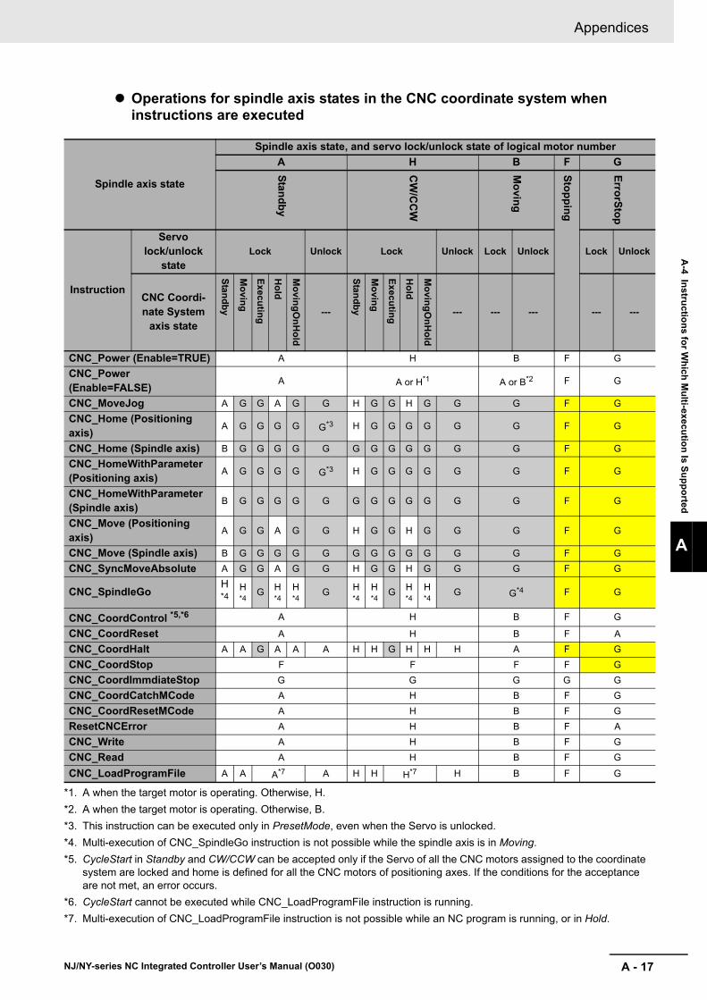
A - 17
Appendices
NJ/NY-series NC Integrated Controller User’s Manual (O030)
A-4 In
structio
ns fo
r Wh
ich M
ulti-execu
tion
Is Su
pp
orted
A
Operations for spindle axis states in the CNC coordinate system when instructions are executed
Spindle axis state
Spindle axis state, and servo lock/unlock state of logical motor number
A H B F G
Stan
db
y
CW
/CC
W
Mo
ving
Sto
pp
ing
Erro
rSto
p
Instruction
Servo lock/unlock
stateLock Unlock Lock Unlock Lock Unlock Lock Unlock
CNC Coordi-nate System
axis state
Stan
db
y
Mo
ving
Execu
ting
Ho
ld
Mo
ving
On
Ho
ld
---
Stan
db
y
Mo
ving
Execu
ting
Ho
ld
Mo
ving
On
Ho
ld
--- --- --- --- ---
CNC_Power (Enable=TRUE) A H B F G
CNC_Power (Enable=FALSE)
A A or H*1
*1. A when the target motor is operating. Otherwise, H.
A or B*2
*2. A when the target motor is operating. Otherwise, B.
F G
CNC_MoveJog A G G A G G H G G H G G G F G
CNC_Home (Positioning axis)
A G G G G G*3
*3. This instruction can be executed only in PresetMode, even when the Servo is unlocked.
H G G G G G G F G
CNC_Home (Spindle axis) B G G G G G G G G G G G G F G
CNC_HomeWithParameter (Positioning axis)
A G G G G G*3 H G G G G G G F G
CNC_HomeWithParameter (Spindle axis)
B G G G G G G G G G G G G F G
CNC_Move (Positioning axis)
A G G A G G H G G H G G G F G
CNC_Move (Spindle axis) B G G G G G G G G G G G G F G
CNC_SyncMoveAbsolute A G G A G G H G G H G G G F G
CNC_SpindleGoH *4
*4. Multi-execution of CNC_SpindleGo instruction is not possible while the spindle axis is in Moving.
H *4
G H *4
H *4
G H *4
H *4
G H *4
H *4
G G*4 F G
CNC_CoordControl *5,*6
*5. CycleStart in Standby and CW/CCW can be accepted only if the Servo of all the CNC motors assigned to the coordinate system are locked and home is defined for all the CNC motors of positioning axes. If the conditions for the acceptance are not met, an error occurs.
*6. CycleStart cannot be executed while CNC_LoadProgramFile instruction is running.
A H B F G
CNC_CoordReset A H B F A
CNC_CoordHalt A A G A A A H H G H H H A F G
CNC_CoordStop F F F F G
CNC_CoordImmdiateStop G G G G G
CNC_CoordCatchMCode A H B F G
CNC_CoordResetMCode A H B F G
ResetCNCError A H B F A
CNC_Write A H B F G
CNC_Read A H B F G
CNC_LoadProgramFile A A A*7
*7. Multi-execution of CNC_LoadProgramFile instruction is not possible while an NC program is running, or in Hold.
A H H H*7 H B F G

Appendices
A - 18 NJ/NY-series NC Integrated Controller User’s Manual (O030)

Authorized Distributor:
In the interest of product improvement, specifications are subject to change without notice.
Cat. No. O030-E1-01 1017
© OMRON Corporation 2017 All Rights Reserved.
OMRON Corporation Industrial Automation Company
OMRON ELECTRONICS LLC2895 Greenspoint Parkway, Suite 200 Hoffman Estates, IL 60169 U.S.A.Tel: (1) 847-843-7900/Fax: (1) 847-843-7787
Regional HeadquartersOMRON EUROPE B.V.Wegalaan 67-69, 2132 JD HoofddorpThe NetherlandsTel: (31)2356-81-300/Fax: (31)2356-81-388
Contact: www.ia.omron.comKyoto, JAPAN
OMRON ASIA PACIFIC PTE. LTD.No. 438A Alexandra Road # 05-05/08 (Lobby 2), Alexandra Technopark, Singapore 119967Tel: (65) 6835-3011/Fax: (65) 6835-2711
OMRON (CHINA) CO., LTD.Room 2211, Bank of China Tower, 200 Yin Cheng Zhong Road, PuDong New Area, Shanghai, 200120, ChinaTel: (86) 21-5037-2222/Fax: (86) 21-5037-2200